
Quick Start Guide
VLS SERIES
VLS 30
Passive Column Array Loudspeaker with 30 Drivers and FAST Dispersion
Control for Installation Applications
VLS 15 (EN 54)
Passive Column Array Loudspeaker with 15 Drivers and FAST Dispersion
Control for Installation Applications (EN 54-24 Certied)
VLS 7 (EN 54)
Passive Column Array Loudspeaker with 7 Full Range Drivers and FAST Dispersion
Control for Installation Applications (EN 54-24 Certied)
V 2.0

2 3VLS SERIES Quick Start Guide
(EN) Safety Instruction
1. Read these instructions.
2. Keep these instructions.
3. Heed all warnings.
4. Follow all instructions.
5. Do not use this apparatus near water.
6. Clean only with dry cloth.
7. Do not block any ventilation openings. Install in
accordance with the manufacturer’s instructions.
8. Do not install near any heat sources such
as radiators, heat registers, stoves, or other apparatus
(including ampliers) that produce heat.
9. Use only attachments/accessories specied
by the manufacturer.
10. Use only with
the cart, stand, tripod,
bracket, or table specied
by the manufacturer, or
sold with the apparatus.
When a cart is used,
use caution when moving
the cart/apparatus
combination to avoid injury from tip-over.
11. Correct disposal of this
product: This symbol indicates that
this product must not be disposed
of with household waste,
according to the WEEE Directive
(2012/19/EU) and your national
law. This product should be taken
to a collection center licensed for
the recycling of waste electrical and electronic equipment
(EEE). The mishandling of this type of waste could have a
possible negative impact on the environment and human
health due to potentially hazardous substances that are
generally associated with EEE. At the same time, your
cooperation in the correct disposal of this product will
contribute to the ecient use of natural resources. For
more information about where you can take your waste
equipment for recycling, please contact your local city
oce, or your household waste collection service.
12. Do not install in a conned space, such as a
book case or similar unit.
13. Do not place naked ame sources, such as lighted
candles, on the apparatus.
(ES) Instrucción de seguridad
1. Lea las instrucciones.
2. Conserve estas instrucciones.
3. Preste atención a todas las advertencias.
4. Siga todas las instrucciones.
5. No use este aparato cerca del agua.
6. Limpie este aparato con un paño seco.
7. No bloquee las aberturas de ventilación.
Instale el equipo de acuerdo con las instrucciones
del fabricante.
8. No instale este equipo cerca de fuentes de calor
tales como radiadores, acumuladores de calor, estufas u
otros aparatos (incluyendo amplicadores) que puedan
producir calor.
9. Use únicamente los dispositivos o accesorios
especicados por el fabricante.
10. Use únicamente la
carretilla, plataforma,
trípode, soporte o mesa
especicados por el
fabricante o suministrados
junto con
el equipo. Al transportar el
equipo, tenga cuidado
para evitar daños y caídas al tropezar con
algún obstáculo.
11. Cómo debe deshacerse de
este aparato: Este símbolo indica
que este aparato no debe ser
tratado como basura orgánica,
según lo indicado en la Directiva
WEEE (2012/19/EU) y a las
normativas aplicables en su país.
En lugar de ello deberá llevarlo al
punto limpio más cercano para el reciclaje de sus
elementos eléctricos / electrónicos (EEE). Al hacer esto
estará ayudando a prevenir las posibles consecuencias
negativas para el medio ambiente y la salud que podrían
ser provocadas por una gestión inadecuada de este tipo
de aparatos. Además, el reciclaje de materiales ayudará a
conservar los recursos naturales. Para más información
acerca del reciclaje de este aparato, póngase en contacto
con el Ayuntamiento de su ciudad o con el punto limpio
local.
12. No instale esta unidad en un espacio muy reducido,
tal como encastrada en una librería o similar.
13. No coloque objetos con llama, como una vela
encendida, sobre este aparato.
(FR) Consignes de sécurité
1. Lisez ces consignes.
2. Conservez ces consignes.
3. Respectez tous les avertissements.
4. Respectez toutes les consignes d’utilisation.
5. N’utilisez jamais l’appareil à proximité
d’un liquide.
6. Nettoyez l’appareil avec un chion sec.
7. Veillez à ne pas empêcher la bonne ventilation
de l’appareil via ses ouïes de ventilation. Respectez les
consignes du fabricant concernant l’installation
de l’appareil.
8. Ne placez pas l’appareil à proximité d’une source
de chaleur telle qu’un chauage, une cuisinière ou tout
appareil dégageant de la chaleur (y compris un ampli de
puissance).
9. Utilisez exclusivement des accessoires et des
appareils supplémentaires recommandés par
le fabricant.
10. Utilisez
exclusivement des
chariots, des diables, des
présentoirs, des pieds et
des surfaces de travail
recommandés par le
fabricant ou livrés avec le
produit. Déplacez
précautionneusement tout chariot ou diable chargé pour
éviter d’éventuelles blessures en cas de chute.
11. Mise au rebut appropriée de
ce produit: Ce symbole indique
qu’en accord avec la directive DEEE
(2012/19/EU) et les lois
en vigueur dans votre pays,
ce produit ne doit pas être jeté
avec les déchets ménagers. Ce
produit doit être déposé dans un
point de collecte agréé pour le recyclage des déchets
d’équipements électriques et électroniques (EEE). Une
mauvaise manipulation de ce type de déchets pourrait
avoir un impact négatif sur l’environnement et la santé à
cause des substances potentiellement dangereuses
généralement associées à ces équipements.
En même temps, votre coopération dans la mise au rebut
de ce produit contribuera à l’utilisation ecace des
ressources naturelles. Pour plus d’informations sur
l’endroit où vous pouvez déposer vos déchets
d’équipements pour le recyclage, veuillez contacter votre
mairie ou votre centre local de collecte
des déchets.
12. N’installez pas l’appareil dans un espace conné tel
qu’une bibliothèque ou meuble similaire.
13. Ne placez jamais d’objets enammés, tels que des
bougies allumées, sur l’appareil.
(DE) Wichtige Sicherhteitshinweise
1. Lesen Sie diese Hinweise.
2. Bewahren Sie diese Hinweise auf.
3. Beachten Sie alle Warnhinweise.
4. Befolgen Sie alle Bedienungshinweise.
5. Betreiben Sie das Gerät nicht in der Nähe
von Wasser.
6. Reinigen Sie das Gerät mit einem trockenen Tuch.
7. Blockieren Sie nicht die Belüftungsschlitze. Beachten
Sie beim Einbau des Gerätes
die Herstellerhinweise.
8. Stellen Sie das Gerät nicht in der Nähe von
Wärmequellen auf. Solche Wärmequellen sind z.
B. Heizkörper, Herde oder andere Wärme erzeugende
Geräte (auch Verstärker).
9. Verwenden Sie nur Zusatzgeräte/Zubehörteile, die
laut Hersteller geeignet sind.
10. Verwenden
Sie nur Wagen,
Standvorrichtungen,
Stative, Halter oder Tische,
die vom Hersteller benannt
oder im Lieferumfang des
Geräts enthalten sind. Falls
Sie einen Wagen benutzen,
seien Sie vorsichtig beim Bewegen der
Wagen- Gerätkombination, um Verletzungen durch
Stolpern zu vermeiden.
11. Korrekte Entsorgung dieses
Produkts: Dieses Symbol weist
darauf hin, das Produkt
entsprechend der WEEE Direktive
(2012/19/EU) und der jeweiligen
nationalen Gesetze nicht
zusammen mit Ihren
Haushaltsabfällen zu entsorgen.
Dieses Produkt sollte bei einer autorisierten Sammelstelle
für Recycling elektrischer und elektronischer Geräte (EEE)
abgegeben werden. Wegen bedenklicher Substanzen, die
generell mit elektrischen und elektronischen Geräten in
Verbindung stehen, könnte eine unsachgemäße
Behandlung dieser Abfallart eine negative Auswirkung
auf Umwelt und Gesundheit haben. Gleichzeitig
gewährleistet Ihr Beitrag zur richtigen Entsorgung dieses
Produkts die eektive Nutzung natürlicher Ressourcen.
Für weitere Informationen zur Entsorgung Ihrer Geräte bei
einer Recycling-Stelle nehmen Sie bitte Kontakt zum
zuständigen städtischen Büro, Entsorgungsamt oder zu
Ihrem Haushaltsabfallentsorger auf.
12. Installieren Sie das Gerät nicht in einer beengten
Umgebung, zum Beispiel Bücherregal oder ähnliches.
13. Stellen Sie keine Gegenstände mit oenen
Flammen, etwa brennende Kerzen, auf das Gerät.
(PT) Instruções de Seguranç
Importantes
1. Leia estas instruções.
2. Guarde estas instruções.
3. Preste atenção a todos os avisos.
4. Siga todas as instruções.
5. Não utilize este dispositivo perto de água.
6. Limpe apenas com um pano seco.
7. Não obstrua as entradas de ventilação. Instale de
acordo com as instruções do fabricante.
8. Não instale perto de quaisquer fontes de calor tais
como radiadores, bocas de ar quente, fogões de sala
ou outros aparelhos (incluindo amplicadores) que
produzam calor.
9. Utilize apenas ligações/acessórios especicados pelo
fabricante.
10. Utilize apenas com o
carrinho, estrutura, tripé,
suporte, ou mesa
especicados pelo
fabricante ou vendidos
com o dispositivo.
Quando utilizar um
carrinho, tenha cuidado ao mover o conjunto carrinho/
dispositivo para evitar danos provocados pela terpidação.
11. Correcta eliminação deste
produto: este símbolo indica que o
produto não deve ser eliminado
juntamente com os resíduos
domésticos, segundo a Directiva
REEE (2012/19/EU) e a legislação
nacional. Este produto deverá ser
levado para um centro de recolha
licenciado para a reciclagem de resíduos de equipamentos
eléctricos e electrónicos (EEE). O tratamento incorrecto
deste tipo de resíduos pode ter um eventual impacto
negativo no ambiente e na saúde humana devido a
substâncias potencialmente perigosas que estão
geralmente associadas aos EEE. Ao mesmo tempo, a sua
colaboração para a eliminação correcta deste produto irá
contribuir para a utilização eciente dos recursos naturais.
Para mais informação acerca dos locais onde poderá
deixar o seu equipamento usado para reciclagem, é favor
contactar os serviços municipais locais, a entidade de
gestão de resíduos ou os serviços de recolha de
resíduos domésticos.
12. Não instale em lugares connados, tais como
estantes ou unidades similares.
13. Não coloque fontes de chama, tais como velas
acesas, sobre o aparelho.
(IT) Istruzioni di sicurezza importanti
1. Leggere queste istruzioni.
2. Conservare queste istruzioni.
3. Prestare attenzione a tutti gli avvisi.
4. Applicare tutte le istruzioni.
5. Non utilizzare questo dispositivo vicino l'acqua.
6. Pulire esclusivamente con un panno asciutto.
7.
Non bloccare le aperture di ventilazione. Installare in
conformità con le istruzioni del produttore.
8. Non installare vicino a fonti di
calore come radiatori, termoregolatori,
stufe o altri apparecchi (inclusi amplicatori) che
producono calore.
9. Utilizzare esclusivamente dispositivi/accessori
specicati dal produttore.
10.
Utilizzare solo carrelli,
supporti, treppiedi, stae
o tavoli indicati dal
produttore o venduti con
l'apparecchio. Utilizzando
un carrello, prestare
attenzione quando si
sposta la combinazione carrello/apparecchio per evitare
lesioni dovute al ribaltamento.
11. Smaltimento corretto di
questo prodotto: questo simbolo
indica che questo dispositivo non
deve essere smaltito insieme ai
riuti domestici, secondo la
Direttiva RAEE (2012/19 / UE) e la
vostra legislazione nazionale.
Questo prodotto deve essere
portato in un centro di raccolta autorizzato per il
riciclaggio di riuti di apparecchiature elettriche ed
elettroniche (RAEE). La cattiva gestione di questo tipo di
riuti potrebbe avere un possibile impatto negativo
sull'ambiente e sulla salute umana a causa di sostanze
potenzialmente pericolose che sono generalmente
associate alle apparecchiature elettriche ed elettroniche.
Nello stesso tempo la vostra collaborazione al corretto
smaltimento di questo prodotto contribuirà all'utilizzo
eciente delle risorse naturali. Per ulteriori informazioni
su dove è possibile trasportare le apparecchiature per il
riciclaggio vi invitiamo a contattare l'ucio comunale
locale o il servizio di raccolta dei
riuti domestici.
12. Non installare in uno spazio ristretto, come in una
libreria o in una struttura simile.
13. Non collocare sul dispositivo fonti di amme libere,
come candele accese.

4 5VLS SERIES Quick Start Guide
(NL) Belangrijke
veiligheidsvoorschriften
1. Lees deze voorschriften.
2. Bewaar deze voorschriften.
3. Neem alle waarschuwingen in acht.
4. Volg alle voorschriften op.
5. Gebruik dit apparaat niet in de buurt van water.
6. Reinig het uitsluitend met een droge doek.
7. Let erop geen van de ventilatie-openingen
te bedekken. Plaats en installeer het volgens de
voor- schriften van de fabrikant.
8. Het apparaat mag niet worden geplaatst in de buurt
van radiatoren, warmte-uitlaten, kachels of andere zaken
(ook versterkers) die warmte afgeven.
9. Gebruik uitsluitend door de producent
gespeci- ceerd toebehoren c.q. onderdelen.
10. Gebruik het apparaat
uitsluitend in combinatie
met de wagen, het statief,
de driepoot, de beugel of
tafel die door de producent
is aangegeven, of die in
combinatie met het
apparaat wordt verkocht. Bij gebruik van een wagen dient
men voorzichtig te zijn bij het verrijden van de combinatie
wagen/apparaat en letsel door vallen te voorkomen.
11. Correcte afvoer van dit
product: dit symbool geeft aan dat
u dit product op grond van de
AEEA-richtlijn (2012/19/EU) en de
nationale wetgeving van uw land
niet met het gewone
huishoudelijke afval mag
weggooien. Dit product moet na
aoop van de nuttige levensduur naar een ociële
inzamelpost voor afgedankte elektrische en elektronische
apparatuur (AEEA) worden gebracht, zodat het kan
worden gerecycleerd. Vanwege de potentieel gevaarlijke
stoen die in elektrische en elektronische apparatuur
kunnen voorkomen, kan een onjuiste afvoer van afval van
het onderhavige type een negatieve invloed op het milieu
en de menselijke gezondheid hebben. Een juiste afvoer
van dit product is echter niet alleen beter voor het milieu
en de gezondheid, maar draagt tevens bij aan een
doelmatiger gebruik van de natuurlijke hulpbronnen.
Voor meer informatie over de plaatsen waar u uw
afgedankte apparatuur kunt inleveren, kunt u contact
opnemen met uw gemeente of de plaatselijke
reinigingsdienst.
12. Installeer niet in een kleine ruimte, zoals een
boekenkast of iets dergelijks.
13. Plaats geen open vlammen, zoals brandende
kaarsen, op het apparaat.
(SE) Viktiga säkerhetsanvisningar
1. Läs dessa anvisningar.
2. Spara dessa anvisningar.
3. Beakta alla varningar.
4. Följ alla anvisningar.
5. Använd inte apparaten i närheten av vatten.
6. Rengör endast med torr trasa.
7. Blockera inte ventilationsöppningarna.
Installera enligt tillverkarens anvisningar.
8. Installera aldrig intill värmekällor som
värme- element, varmluftsintag, spisar eller annan
utrustning som avger värme (inklusive förstärkare).
9. Använd endast tillkopplingar och tillbehör som
angetts av tillverkaren.
10. Använd endast med
vagn, stativ, trefot, hållare
eller bord som angetts av
tillverkaren, eller som sålts
till-sammans med
apparaten. Om du
använder en vagn, var
försiktig, när du föryttar kombinationen vagn-apparat,
för att förhindra olycksfall
genom snubbling.
11. Kassera produkten på rätt
sätt: den här symbolen indikerar
att produkten inte ska kastas i
hushållssoporna, enligt WEEE
direktivet (2012/19/EU) och
gällande, nationell lagstiftning.
Produkten ska lämnas till ett
auktoriserat återvinningsställe för
elektronisk och elektrisk utrustning (EEE). Om den här
sortens avfall hanteras på fel sätt kan miljön, och
människors hälsa, påverkas negativt på grund av
potentiella risksubstanser som ofta associeras med EEE.
Avfallshanteras produkten däremot på rätt sätt bidrar
detta till att naturens resurser används på ett bra sätt.
Kontakta kommun, ansvarig förvaltning eller
avfallshanteringsföretag för mer information om
återvinningscentral där produkten kan lämnas.
12. Installera inte i ett trångt utrymme,
t.ex. i en bokhylsa eller liknande enhet.
13. Placera inte källor med öppen eld,
t.ex. tända ljus, på apparaten.
(PL) Ważne informacje o
bezpieczeństwie
1. Proszę przeczytać poniższe wskazówki.
2. Proszę przechowywać niniejszą instrukcję.
3. Należy przestrzegać wszystkich wskazówek
ostrzegawczych.
4. Należy postępować zgodnie z instrukcją obsługi.
5. Urządzenia nie wolno używać w pobliżu wody.
6. Urządzenie można czyścić wyłącznie
suchą szmatką.
7. Nie zasłaniać otworów wentylacyjnych. W czasie
podłączania urządzenia należy przestrzegać
zaleceń producenta.
8. Nie stawiać urządzenia w pobliżu źródeł ciepła
takich, jak grzejniki, piece lub urządzenia produkujące
ciepło (np. wzmacniacze).
9. Używać wyłącznie sprzętu dodatkowego i
akcesoriów zgodnie z zaleceniami producenta.
10. Używać jedynie zalecanych przez producenta lub
znajdujących się w
zestawie wózków,
stojaków, statywów,
uchwytów i stołów.
W przypadku
posługiwania się wózkiem
należy zachować
szczególną ostrożność w
trakcie przewożenia zestawu, aby uniknąć
niebezpieczeństwa potknięcia się i zranienia.
11. Prawidłowa utylizacja
produktu: Ten symbol wskazuje, że
tego produktu nie należy
wyrzucać razem ze zwykłymi
odpadami domowymi, tylko
zgodnie z dyrektywą w sprawie
zużytego sprzętu elektrycznego i
elektronicznego (WEEE) (2012/19/
EU) oraz przepisami krajowymi. Niniejszy produkt należy
przekazać do autoryzowanego punktu zbiórki zużytego
sprzętu elektrycznego i elektronicznego. Niewłaściwe
postępowanie z tego typu odpadami może wywołać
szkodliwe działanie na środowisko naturalnej i zdrowie
człowieka z powodu potencjalnych substancji
niebezpiecznych zaliczanych jako zużyty sprzęt
elektryczny i elektroniczny. Jednocześnie, Twój wkład w
prawidłową utylizację niniejszego produktu przyczynia się
do oszczędnego wykorzystywania zasobów naturalnych.
Szczegółowych informacji o miejscach, w których można
oddawać zużyty sprzęt do recyklingu, udzielają urzędy
miejskie, przedsiębiorstwa utylizacji odpadów lub
najbliższy zakład utylizacji odpadów.
12. Nie instaluj w ograniczonej przestrzeni, takiej jak
półka na książki lub podobny zestaw.
13. Nie stawiaj na urządzeniu źródeł otwartego ognia,
takich jak zapalone świece.

6 7VLS SERIES Quick Start Guide
Introduction
The latest addition to Tannoy’s extensive line of column loudspeakers, VLS Series introduces another proprietary Tannoy innovation:
FAST (Focussed Asymmetrical Shaping Technology). By combining transducer technology from the acclaimed QFlex Series with an innovative new passive crossover
design, FAST provides exceptional acoustical benets, including an asymmetrical vertical dispersion pattern which gently shapes acoustical coverage toward the lower
quadrant of the vertical axis. The VLS 7 and 15 are EN54-24 certied for use in re detection and re alarm systems.
This Quick Start Guide presents only the essential information required to properly unpack, connect and congure a VLS Series loudspeaker. Please consult the full
VLS Series Operation Manual for additional detailed information on low impedance versus 70/100 V operation, complex loudspeaker system conguration, cable types,
equalization, power handling, rigging and safety procedures, and warranty coverage.
Unpacking
Each Tannoy VLS Series loudspeaker is carefully tested and inspected prior to shipment. After unpacking, please inspect for any exterior physical damage, and save
the carton and any relevant packaging materials in case the loudspeaker again requires packing and shipping. In the event that damage has been sustained in transit,
please notify your dealer and the shipping carrier immediately.
Connectors and cabling
VLS Series loudspeakers are connected to the amplier (or to other loudspeakers in a 70/100 V system or series/parallel conguration) using a pair of internally
paralleled barrier strip connectors.
All VLS Series models can be operated as either a low impedance loudspeaker or within a 70/100 V distributed system. The operation mode is selectable via a single
switch located on the rear of the cabinet (see below).
Operation in low impedance mode often will require use of larger diameter cables than are needed for a 70/100 V distributed system. Please consult the full
VLS Operation Manual for recommended cable types for various applications.
Switch for Low-Z and transformer tap selection
A multi-position rotary switch on the rear input panel selects either the low-impedance operating mode or the high-impedance modes (70 V or 100 V) with available
transformer taps. When using VLS Series loudspeakers in distributed line systems, the transformer can be tapped with available power levels shown in the
table below:
All transformer primaries should be connected in parallel to the output of the amplier. The summed total power rating in watts of the selected tap settings for all
connected loudspeakers must not exceed the total output power rating of the connected amplier output channel in watts. It is recommended that a generous power
safety margin (minimum 3 dB headroom) be maintained between the total loudspeaker power requirements and the amplier output capacity to avoid continuous
amplier operation at full rated output.
70 V 100 V
5 W 9.5 W
9.5 W 19 W
19 W 37.5 W
37.5 W 75 W
75 W 150 W
150 W —
Wiring the connectors
Low Impedance (8 ohm) Mode
If connecting directly to the amplier in low impedance mode, connect the positive (+) conductor to a positive (+) barrier strip terminal and the negative (–)
conductor to a negative (–) terminal. It is preferable to connect several loudspeakers to one amplier output in parallel, series, or series/parallel congurations using
the other internally paralleled barrier strip connector.
For more information on this, please consult the full VLS Series Operation Manual.
Constant voltage (70 V / 100 V) Mode
In constant voltage distributed systems, normally a number of loudspeakers are connected in parallel to a single amplier output. Connect the positive (+) conductor
from the amplier or prior loudspeaker in the system to a positive (+) barrier strip terminal and the negative (–) conductor to a negative (–) terminal. The other
parallel barrier strip is available for connecting additional loudspeakers.
Outdoor Applications
A right angled water tight cable gland is supplied with the VLS 7 (EN 54) and VLS 15 (EN 54) for use in outdoor applications (Fig.1). The VLS 30 has an input panel cover
with rubber wiring grommet for use in outdoor applications (Fig.2). Before making connections, pass the wire(s) through the cable grand/rubber grommet. The input
panel cover is secured to the cabinet using the four screws already inserted around the input.
Fig.1 VLS 7 (EN 54) and VLS 15 (EN 54)
Fig.2 VLS 30
Asymmetric vertical pattern: mounting and ying
VLS Series loudspeakers are designed with an asymmetrical vertical dispersion pattern, a feature which allows improved performance with simplied mounting in
many applications. The vertical dispersion of the VLS 7 (EN 54) and VLS 15 (EN 54) models is +6/-22 degrees from center axis, while the pattern of the VLS 30 is +3/-11
degrees from center axis.
Please be aware of this feature when planning your installation. In many situations where conventional column loudspeakers would require substantial downward tilt,
a VLS Series loudspeaker would require less tilt or even allow ush mounting, thus providing a simpler installation with improved visual aesthetics.

8 9VLS SERIES Quick Start Guide
Mounting and xing
Wall Bracket
Each VLS Series loudspeaker is supplied with a standard wall bracket suitable for mounting on most wall surfaces. The bracket is supplied as two interlocking U plates.
One plate attaches to the rear of the loudspeaker with four supplied screws. The other part is secured to the wall. The bar on the bottom of the speaker plate slides
into the bottom notch of the wall plate, while the top is secured with the two supplied screws. The bracket for the VLS 7 (EN 54) and VLS 15 (EN 54) is slotted to allow
an angle between 0 and 6 degrees (Fig.3). Aligning the top two screw holes of the VLS 30 results in a at ush mount; using the lower two screw positions provides a
4 degree downwardtilt. (Fig.4)
Fig.3 VLS 7 (EN 54) and VLS 15 (EN 54)
Fig.4 VLS 30
Flying Bracket
Each VLS Series loudspeaker is also supplied with a ying bracket. The bracket is attached to the top two inserts using the supplied M6 screws (Fig.5). The two bottom
inserts can be used as pull back if required.
Fig.5 All Models
Pan-Tilt Bracket (optional)
A pan-tilt bracket is available which allows panning and tilting for exible orientation along both horizontal and vertical axes. Installation instructions are provided
with the bracket.
Rigging and safety procedures
The installation of Tannoy loudspeakers using the dedicated hardware should be carried out only by fully qualied installers, in accordance with all the required safety
codes and standards that are applied at the place of installation.
WARNING: As the legal requirements for ying vary from country to country, please consult your local safety standards oce before installing any product.
We also recommend that you thoroughly check any laws and bylaws prior to installation. For more detailed information on rigging hardware and safety procedures,
please consult the full VLS Series Operation Manual.
Outdoor applications
VLS Series loudspeakers are rated IP64 for resistance to dust and moisture ingress, and are resistant to both salt spray and UV exposure, making them suitable for use
in most outdoor applications. Please consult with your Tannoy dealer before installation in applications with extreme exposure to adverse environmental conditions
such as prolonged heavy rainfall, prolonged temperature extremes, etc.
IMPORTANT NOTE: The mounting of a permanently installed sound system may be dangerous unless undertaken by qualied personnel with the required experience
and certication to perform the necessary tasks. Walls, oors or ceilings must be capable of safely and securely supporting the actual load. The mounting accessory
used must be safely and securely xed both to the loudspeaker and to the wall, oor or ceiling.
When mounting rigging components on walls, oors or ceilings, ensure that all xings and fasteners used are of an appropriate size and load rating. Wall and ceiling
claddings, and the construction and composition of walls and ceilings, all need to be taken into account when determining whether a particular xing arrangement
can be safely employed for a particular load. Cavity plugs or other specialist xings, if required, must be of an appropriate type, and must be tted and used in
accordance with the maker’s instructions.
The operation of your speaker cabinet as part of a own system, if installed incorrectly and improperly, can potentially expose persons to serious health risks and
even death. In addition, please ensure that electrical, mechanical and acoustic considerations are discussed with qualied and certied (by local state or national
authorities) personnel prior to any installation or ying.
Make sure that speaker cabinets are set up and own by qualied and certied personnel only, using dedicated equipment and original parts and components
delivered with the unit. If any parts or components are missing please contact your Dealer before attempting to set up the system.
Be sure to observe the local, state and other safety regulations applicable in your country. Music Tribe, including the Music Tribe companies listed on the enclosed
“Service Information Sheet”, assumes no liability for any damage or personal injury resulting from improper use, installation or operation of the product.
Regular checks must be conducted by qualied personnel to ensure that the system remains in a secure and stable condition. Make sure that, where the speaker is
own, the area underneath the speaker is free of human trac. Do not y the speaker in areas that can be entered or used by members of the public.
Speakers create a magnetic eld, even if not in operation. Therefore, please keep all materials that can be aected by such elds (discs, computers, monitors, etc)
at a safe distance. A safe distance is usually between 1 and 2 metres.

10 11VLS SERIES Quick Start Guide
Introducción
La última incorporación a la extensa línea de altavoces de columna de Tannoy, la serie VLS, presenta otra innovación patentada de Tannoy: FAST (tecnología de
modelado asimétrico enfocado). Al combinar la tecnología de transductores de la aclamada Serie QFlex con un nuevo e innovador diseño de cruce pasivo, FAST
proporciona benecios acústicos excepcionales, incluido un patrón de dispersión vertical asimétrico que modela suavemente la cobertura acústica hacia el cuadrante
inferior del eje vertical. Los VLS 7 y 15 cuentan con la certicación EN54-24 para su uso en sistemas de detección y alarma de incendios.
Esta Guía de inicio rápido presenta solo la información esencial necesaria para desembalar, conectar y congurar correctamente un altavoz de la serie VLS. Consulte el
Manual de funcionamiento completo de la serie VLS para obtener información detallada adicional sobre el funcionamiento de baja impedancia en comparación con
el funcionamiento de 70/100 V, la conguración compleja del sistema de altavoces, los tipos de cables, la ecualización, el manejo de potencia, los procedimientos de
manipulación y seguridad, y la cobertura de la garantía.
Desembalaje
Cada altavoz de la serie Tannoy VLS se prueba e inspecciona cuidadosamente antes de su envío. Después de desembalar, inspeccione por cualquier daño físico exterior
y guarde la caja y cualquier material de empaque relevante en caso de que el altavoz requiera empaque y envío nuevamente. En caso de que se hayan producido daños
durante el transporte, notique a su distribuidor y al transportista de inmediato.
Conectores y cableado
Los altavoces de la serie VLS se conectan al amplicador (oa otros altavoces en un sistema de 70/100 V o conguración en serie / paralelo) mediante un par de
conectores de tira de barrera en paralelo internamente.
Todos los modelos de la serie VLS pueden funcionar como un altavoz de baja impedancia o dentro de un sistema distribuido de 70/100 V. El modo de funcionamiento se
puede seleccionar mediante un solo interruptor ubicado en la parte posterior del gabinete (ver más abajo).
El funcionamiento en modo de baja impedancia a menudo requerirá el uso de cables de mayor diámetro que los necesarios para un sistema distribuido de 70/100 V.
Consulte el Manual de funcionamiento completo de VLS para conocer los tipos de cables recomendados para diversas aplicaciones.
Interruptor para selección de derivación de transformador y Low-Z
Un interruptor giratorio de múltiples posiciones en el panel de entrada posterior selecciona el modo de funcionamiento de baja impedancia o los modos de alta
impedancia (70 V o 100 V) con tomas de transformador disponibles. Cuando se utilizan altavoces de la serie VLS en sistemas de línea distribuida, el transformador se
puede conectar con los niveles de potencia disponibles que se muestran en la siguiente tabla::
Todos los primarios del transformador deben conectarse en paralelo a la salida del amplicador. La potencia nominal total sumada en vatios de los ajustes de tap
seleccionados para todos los altavoces conectados no debe exceder la potencia nominal de salida total del canal de salida del amplicador conectado en vatios. Se
recomienda mantener un margen de seguridad de potencia generoso (margen superior mínimo de 3 dB) entre los requisitos de potencia total del altavoz y la capacidad
de salida del amplicador para evitar el funcionamiento continuo del amplicador a la salida nominal completa.
70 V 100 V
5 W 9.5 W
9.5 W 19 W
19 W 37.5 W
37.5 W 75 W
75 W 150 W
150 W —
Cableado de conectores
Modo de baja impedancia (8 ohmios)
Si se conecta directamente al amplicador en modo de baja impedancia, conecte el conductor positivo (+) a un terminal de tira de barrera positivo (+) y el conductor
negativo (-) a un terminal negativo (-). Es preferible conectar varios altavoces a una salida de amplicador en conguraciones en paralelo, serie o serie / paralelo
utilizando el otro conector de tira de barrera en paralelo interno.
Para obtener más información al respecto, consulte el Manual de funcionamiento completo de la serie VLS.
Modo de voltaje constante (70 V / 100 V)
En los sistemas distribuidos de voltaje constante, normalmente varios altavoces están conectados en paralelo a una única salida de amplicador. Conecte el conductor
positivo (+) del amplicador o altavoz anterior en el sistema a un terminal de tira de barrera positivo (+) y el conductor negativo (-) a un terminal negativo (-). La otra
banda de barrera paralela está disponible para conectar altavoces adicionales.
Aplicaciones al aire libre
Se suministra un prensaestopas hermético en ángulo recto con el VLS 7 (EN 54) y VLS 15 (EN 54) para uso en aplicaciones al aire libre (Fig.1). El VLS 30 tiene una
cubierta de panel de entrada con pasacables de goma para uso en aplicaciones al aire libre (Fig.2). Antes de realizar las conexiones, pase el (los) cable (s) a través del
pasacables / pasacables de goma. La cubierta del panel de entrada está asegurada al gabinete con los cuatro tornillos ya insertados alrededor de la entrada.
Fig.1 VLS 7 (EN 54) and VLS 15 (EN 54)
Fig.2 VLS 30
Patrón vertical asimétrico: montaje y vuelo.
Los altavoces de la serie VLS están diseñados con un patrón de dispersión vertical asimétrico, una característica que permite un rendimiento mejorado con un montaje
simplicado en muchas aplicaciones. La dispersión vertical de los modelos VLS 7 (EN 54) y VLS 15 (EN 54) es de + 6 / -22 grados desde el eje central, mientras que el
patrón del VLS 30 es de + 3 / -11 grados desde el eje central..
Tenga en cuenta esta función cuando planique su instalación. En muchas situaciones en las que los altavoces de columna convencionales requerirían una inclinación
sustancial hacia abajo, un altavoz de la serie VLS requeriría menos inclinación o incluso permitiría un montaje empotrado, proporcionando así una instalación más
sencilla con una estética visual mejorada.

12 13VLS SERIES Quick Start Guide
Montaje y jación
Soporte de pared
Cada altavoz de la serie VLS se suministra con un soporte de pared estándar adecuado para montar en la mayoría de las supercies de pared. El soporte se suministra
como dos placas en U entrelazadas. Una placa se ja a la parte posterior del altavoz con los cuatro tornillos suministrados. La otra parte se ja a la pared. La barra en la
parte inferior de la placa del altavoz se desliza en la muesca inferior de la placa de la pared, mientras que la parte superior se ja con los dos tornillos suministrados. El
soporte para VLS 7 (EN 54) y VLS 15 (EN 54) está ranurado para permitir un ángulo entre 0 y 6 grados (Fig.3). La alineación de los dos oricios para tornillos superiores
del VLS 30 da como resultado un montaje empotrado plano; El uso de las dos posiciones inferiores de los tornillos proporciona una inclinación hacia abajo de 4 grados.
(Figura 4)
Fig.3 VLS 7 (EN 54) and VLS 15 (EN 54)
Fig.4 VLS 30
Soporte volador
Cada altavoz de la serie VLS también se suministra con un soporte volador. El soporte se ja a las dos inserciones superiores mediante los tornillos M6 suministrados
(Fig.5). Las dos inserciones inferiores se pueden utilizar como retroceso si es necesario.
Fig.5 All Models
Soporte Pan-Tilt (opcional)
Se encuentra disponible un soporte de giro e inclinación que permite el giro e inclinación para una orientación exible a lo largo de los ejes horizontal y vertical. Las
instrucciones de instalación se proporcionan con el soporte.
Procedimientos de aparejo y seguridad
La instalación de los altavoces Tannoy utilizando el hardware dedicado debe ser realizada únicamente por instaladores totalmente calicados, de acuerdo con todos los
códigos y normas de seguridad requeridos que se aplican en el lugar de instalación.
ADVERTENCIA: Dado que los requisitos legales para volar varían de un país a otro, consulte con la ocina de normas de seguridad local antes de instalar cualquier
producto. También recomendamos que revise minuciosamente las leyes y estatutos antes de la instalación. Para obtener información más detallada sobre el hardware
de aparejo y los procedimientos de seguridad, consulte el Manual de funcionamiento completo de la serie VLS.
Aplicaciones al aire libre
Los altavoces de la serie VLS tienen una clasicación IP64 de resistencia al ingreso de polvo y humedad, y son resistentes tanto a la niebla salina como a la exposición
a los rayos UV, lo que los hace adecuados para su uso en la mayoría de las aplicaciones al aire libre. Consulte con su distribuidor Tannoy antes de la instalación en
aplicaciones con exposición extrema a condiciones ambientales adversas, como lluvias intensas y prolongadas, temperaturas extremas prolongadas, etc.
NOTA IMPORTANTE: El montaje de un sistema de sonido instalado permanentemente puede ser peligroso a menos que sea realizado por personal calicado con la
experiencia y certicación requeridas para realizar las tareas necesarias. Las paredes, pisos o techos deben ser capaces de soportar de manera segura la carga real. El
accesorio de montaje utilizado debe jarse de forma segura tanto al altavoz como a la pared, suelo o techo.
Al montar componentes de aparejos en paredes, pisos o techos, asegúrese de que todas las jaciones y sujetadores utilizados sean del tamaño y la capacidad de carga
adecuados. Los revestimientos de paredes y techos, y la construcción y composición de las paredes y techos, deben tenerse en cuenta al determinar si una disposición
de jación particular puede emplearse de manera segura para una carga particular. Los tapones de cavidad u otras jaciones especializadas, si es necesario, deben ser
del tipo apropiado y deben instalarse y utilizarse de acuerdo con las instrucciones del fabricante.
El funcionamiento de su caja de altavoces como parte de un sistema volado, si se instala de forma incorrecta e inadecuada, puede exponer a las personas a riesgos
graves para la salud e incluso la muerte. Además, asegúrese de que las consideraciones eléctricas, mecánicas y acústicas se analicen con personal calicado y
certicado (por las autoridades estatales o nacionales locales) antes de cualquier instalación o vuelo.
Asegúrese de que los gabinetes de altavoces sean instalados y volados únicamente por personal calicado y certicado, utilizando equipo dedicado y piezas y
componentes originales entregados con la unidad. Si falta alguna pieza o componente, comuníquese con su distribuidor antes de intentar congurar el sistema.
Asegúrese de respetar las normativas de seguridad locales, estatales y de otro tipo aplicables en su país. Music Tribe, incluidas las compañías de Music Tribe
enumeradas en la “Hoja de información de servicio” adjunta, no asume ninguna responsabilidad por cualquier daño o lesión personal que resulte del uso, instalación
u operación inadecuados del producto. Las vericaciones periódicas deben ser realizadas por personal calicado para garantizar que el sistema permanezca en
condiciones seguras y estables. Asegúrese de que, donde se vuela el altavoz, el área debajo del altavoz esté libre de tráco humano. No vuele el altavoz en áreas a las
que el público pueda ingresar o usar.
Los altavoces crean un campo magnético, incluso si no están en funcionamiento. Por lo tanto, mantenga todos los materiales que puedan verse afectados por dichos
campos (discos, computadoras, monitores, etc.) a una distancia segura. Una distancia segura suele estar entre 1 y 2 metros.

14 15VLS SERIES Quick Start Guide
Introduction
Dernier né de la vaste gamme d'enceintes colonnes de Tannoy, la série VLS présente une autre innovation exclusive de Tannoy: FAST (Focussed Asymmetrical Shaping
Technology). En combinant la technologie de transducteur de la célèbre série QFlex avec une nouvelle conception innovante de crossover passif, FAST ore des
avantages acoustiques exceptionnels, y compris un motif de dispersion verticale asymétrique qui façonne doucement la couverture acoustique vers le quadrant
inférieur de l'axe vertical. Les VLS 7 et 15 sont certiés EN54-24 pour une utilisation dans les systèmes de détection et d'alarme incendie.
Ce guide de démarrage rapide ne présente que les informations essentielles nécessaires pour déballer, connecter et congurer correctement une enceinte de la
série VLS. Veuillez consulter le manuel d'utilisation complet de la série VLS pour obtenir des informations détaillées supplémentaires sur le fonctionnement à faible
impédance par rapport à 70/100 V, la conguration complexe du système d'enceintes, les types de câbles, l'égalisation, la gestion de l'alimentation, les procédures de
gréement et de sécurité et la couverture de la garantie.
Déballage
EChaque enceinte de la série Tannoy VLS est soigneusement testée et inspectée avant expédition. Après le déballage, veuillez inspecter pour tout dommage physique
extérieur et conserver le carton et tous les matériaux d'emballage pertinents au cas où l'enceinte aurait à nouveau besoin d'être emballée et expédiée. Si des
dommages ont été subis pendant le transport, veuillez en informer immédiatement votre revendeur et le transporteur
Connecteurs et câblage
Les haut-parleurs de la série VLS sont connectés à l'amplicateur (ou à d'autres haut-parleurs dans un système 70/100 V ou une conguration série / parallèle) à l'aide
d'une paire de connecteurs de barrettes barrières mis en parallèle en interne.
Tous les modèles de la série VLS peuvent être utilisés comme haut-parleur à faible impédance ou dans un système distribué 70/100 V. Le mode de fonctionnement est
sélectionnable via un seul interrupteur situé à l'arrière de l'armoire (voir ci-dessous).
Le fonctionnement en mode basse impédance nécessitera souvent l'utilisation de câbles de plus grand diamètre que ce qui est nécessaire pour un système distribué
70/100 V. Veuillez consulter le manuel d'utilisation complet du VLS pour connaître les types de câbles recommandés pour diverses applications.
Commutateur pour Low-Z et sélection de prise de transformateur
Un commutateur rotatif à plusieurs positions sur le panneau d'entrée arrière sélectionne le mode de fonctionnement basse impédance ou les modes haute impédance
(70 V ou 100 V) avec les prises de transformateur disponibles. Lors de l'utilisation d'enceintes de la série VLS dans des systèmes de lignes distribuées, le transformateur
peut être exploité avec les niveaux de puissance disponibles indiqués dans le tableau ci-dessous:
Tous les primaires du transformateur doivent être connectés en parallèle à la sortie de l'amplicateur. La puissance nominale totale additionnée en watts des réglages
de prise sélectionnés pour toutes les enceintes connectées ne doit pas dépasser la puissance de sortie totale du canal de sortie de l'amplicateur connecté en watts. Il
est recommandé de maintenir une marge de sécurité de puissance généreuse (marge de sécurité minimale de 3 dB) entre les exigences de puissance totale du haut-
parleur et la capacité de sortie de l'amplicateur pour éviter un fonctionnement continu de l'amplicateur à la sortie nominale maximale.
70 V 100 V
5 W 9.5 W
9.5 W 19 W
19 W 37.5 W
37.5 W 75 W
75 W 150 W
150 W —
Câblage des connecteurs
Mode basse impédance (8 ohms)
Si vous vous connectez directement à l'amplicateur en mode basse impédance, connectez le conducteur positif (+) à une borne de barrette de barrière positive (+)
et le conducteur négatif (-) à une borne négative (-). Il est préférable de connecter plusieurs haut-parleurs à une sortie d'amplicateur dans des congurations en
parallèle, en série ou en série / parallèle en utilisant l'autre connecteur de barrette de barrière mis en parallèle interne.
Pour plus d'informations à ce sujet, veuillez consulter le manuel d'utilisation complet de la série VLS.
Mode tension constante (70 V / 100 V)
Dans les systèmes distribués à tension constante, un certain nombre de haut-parleurs sont normalement connectés en parallèle à une seule sortie d'amplicateur.
Connectez le conducteur positif (+) de l'amplicateur ou du haut-parleur précédent du système à une borne à barrette de barrière positive (+) et le conducteur négatif
(-) à une borne négative (-). L'autre bande de barrière parallèle est disponible pour connecter des haut-parleurs supplémentaires.
Applications extérieures
Un presse-étoupe étanche à angle droit est fourni avec le VLS 7 (EN 54) et le VLS 15 (EN 54) pour une utilisation en extérieur (Fig.1). Le VLS 30 a un couvercle de
panneau d'entrée avec un passe-l en caoutchouc pour une utilisation dans des applications extérieures (Fig.2). Avant d'eectuer les connexions, faites passer le (s) l
(s) à travers le passe-câbles / passe-ls en caoutchouc. Le couvercle du panneau d'entrée est xé à l'armoire à l'aide des quatre vis déjà insérées autour de l'entrée.
Fig.1 VLS 7 (EN 54) and VLS 15 (EN 54)
Fig.2 VLS 30
Motif vertical asymétrique: montage et vol
Les enceintes de la série VLS sont conçues avec un modèle de dispersion verticale asymétrique, une caractéristique qui permet des performances améliorées avec un
montage simplié dans de nombreuses applications. La dispersion verticale des modèles VLS 7 (EN 54) et VLS 15 (EN 54) est de + 6 / -22 degrés par rapport à l'axe
central, tandis que le motif du VLS 30 est de + 3 / -11 degrés par rapport à l'axe central.
Veuillez tenir compte de cette fonctionnalité lors de la planication de votre installation. Dans de nombreuses situations où des haut-parleurs à colonne
conventionnels nécessiteraient une inclinaison vers le bas substantielle, un haut-parleur de la série VLS nécessiterait moins d'inclinaison ou même permettrait un
montage encastré, orant ainsi une installation plus simple avec une esthétique visuelle améliorée.

16 17VLS SERIES Quick Start Guide
Montage et xation
Support mural
plaques en U imbriquées. Une plaque se xe à l'arrière de l'enceinte à l'aide des quatre vis fournies. L'autre partie est xée au mur. La barre au bas de la plaque de haut-
parleur glisse dans l'encoche inférieure de la plaque murale, tandis que la partie supérieure est xée avec les deux vis fournies. Le support du VLS 7 (EN 54) et du VLS
15 (EN 54) est fendu pour permettre un angle compris entre 0 et 6 degrés (Fig.3). L'alignement des deux trous de vis supérieurs du VLS 30 donne un montage encastré
plat; l'utilisation des deux positions de vis inférieures fournit un inclinaison vers le bas de 4 degrés. (Fig.4)
Fig.3 VLS 7 (EN 54) and VLS 15 (EN 54)
Fig.4 VLS 30
Support volant
Chaque enceinte de la série VLS est également fournie avec un support volant. Le support est xé aux deux inserts supérieurs à l'aide des vis M6 fournies (Fig.5). Les
deux inserts inférieurs peuvent être utilisés comme retrait si nécessaire.
Fig.5 All Models
Support Pan-Tilt (en option)
Un support pan-tilt est disponible qui permet le panoramique et l'inclinaison pour une orientation exible le long des axes horizontaux et verticaux. Les instructions
d'installation sont fournies avec le support.
Gréement et procédures de sécurité
L'installation d'enceintes Tannoy à l'aide du matériel dédié doit être eectuée uniquement par des installateurs pleinement qualiés, conformément à tous les codes et
normes de sécurité requis qui sont appliqués sur le lieu d'installation.
ATTENTION: Comme les exigences légales pour voler varient d'un pays à l'autre, veuillez consulter votre bureau des normes de sécurité local avant d'installer un
produit. Nous vous recommandons également de vérier soigneusement toutes les lois et règlements avant l'installation. Pour plus d'informations sur le matériel de
gréage et les procédures de sécurité, veuillez consulter le manuel d'utilisation complet de la série VLS.
Applications extérieures
Les haut-parleurs de la série VLS sont classés IP64 pour leur résistance à la poussière et à l'humidité, et résistent à la fois au brouillard salin et à l'exposition aux UV,
ce qui les rend adaptés à une utilisation dans la plupart des applications extérieures. Veuillez consulter votre revendeur Tannoy avant l'installation dans des
applications avec une exposition extrême à des conditions environnementales défavorables telles que des pluies abondantes prolongées, des températures
extrêmes prolongées, etc.
NOTE IMPORTANTE: Le montage d'un système de sonorisation installé en permanence peut être dangereux à moins qu'il ne soit eectué par du personnel qualié
ayant l'expérience et la certication requises pour eectuer les tâches nécessaires. Les murs, les planchers ou les plafonds doivent pouvoir supporter en toute sécurité
et solidement la charge réelle. L'accessoire de montage utilisé doit être xé de manière sûre et sûre à la fois au haut-parleur et au mur, au sol ou au plafond.
Lors du montage de composants d'accrochage sur des murs, des sols ou des plafonds, assurez-vous que toutes les xations et attaches utilisées sont de taille et de
capacité de charge appropriées. Les revêtements de murs et de plafonds, ainsi que la construction et la composition des murs et des plafonds, doivent tous être pris
en compte pour déterminer si un dispositif de xation particulier peut être utilisé en toute sécurité pour une charge particulière. Les bouchons de cavité ou autres
xations spécialisées, si nécessaire, doivent être d'un type approprié et doivent être installés et utilisés conformément aux instructions du fabricant.
Le fonctionnement de votre enceinte dans le cadre d'un système volant, s'il est installé de manière incorrecte et incorrecte, peut potentiellement exposer les
personnes à de graves risques pour la santé, voire la mort. De plus, veuillez vous assurer que les considérations électriques, mécaniques et acoustiques sont discutées
avec un personnel qualié et certié (par les autorités locales ou nationales) avant toute installation ou tout vol.
Assurez-vous que les enceintes sont installées et pilotées uniquement par du personnel qualié et certié, en utilisant un équipement dédié et des pièces et
composants d'origine livrés avec l'unité. S'il manque des pièces ou des composants, veuillez contacter votre revendeur avant de tenter d'installer le système.
Assurez-vous de respecter les réglementations de sécurité locales, régionales et autres applicables dans votre pays. Music Tribe, y compris les sociétés Music Tribe
énumérées sur la «Fiche d'information de service» ci-jointe, n'assume aucune responsabilité pour tout dommage ou blessure corporelle résultant d'une mauvaise
utilisation, installation ou utilisation du produit. Des contrôles réguliers doivent être eectués par du personnel qualié pour s'assurer que le système reste dans un
état sûr et stable. Assurez-vous que, là où le haut-parleur est piloté, la zone située sous le haut-parleur est exempte de trac humain. Ne faites pas voler l'enceinte dans
des zones qui peuvent être pénétrées ou utilisées par des membres du public.
Les haut-parleurs créent un champ magnétique, même s'ils ne fonctionnent pas. Par conséquent, veuillez conserver tous les matériaux susceptibles d'être aectés par
de tels champs (disques, ordinateurs, moniteurs, etc.) à une distance de sécurité. Une distance de sécurité est généralement comprise entre 1 et 2 mètres.

18 19VLS SERIES Quick Start Guide
Einführung
Die VLS-Serie ist die neueste Ergänzung zu Tannoys umfangreichem Sortiment an Säulenlautsprechern und stellt eine weitere proprietäre Tannoy-Innovation vor:
FAST (Focussed Asymmetrical Shaping Technology). Durch die Kombination der Wandlertechnologie aus der renommierten QFlex-Serie mit einem innovativen
neuen passiven Crossover-Design bietet FAST außergewöhnliche akustische Vorteile, einschließlich eines asymmetrischen vertikalen Dispersionsmusters, das die
akustische Abdeckung sanft in Richtung des unteren Quadranten der vertikalen Achse formt. Die VLS 7 und 15 sind nach EN54-24 für den Einsatz in Brandmelde- und
Brandmeldesystemen zertiziert.
Diese Kurzanleitung enthält nur die wesentlichen Informationen, die zum ordnungsgemäßen Auspacken, Anschließen und Kongurieren eines Lautsprechers der
VLS-Serie erforderlich sind. Weitere Informationen zum Betrieb mit niedriger Impedanz im Vergleich zu 70/100 V, zur Konguration komplexer Lautsprechersysteme,
zu Kabeltypen, zum Ausgleich, zur Belastbarkeit, zu Rigging- und Sicherheitsverfahren sowie zur Gewährleistung nden Sie im vollständigen Betriebshandbuch der
VLS-Serie.
Auspacken
Jeder Lautsprecher der Tannoy VLS-Serie wird vor dem Versand sorgfältig getestet und inspiziert. Überprüfen Sie den Karton nach dem Auspacken auf äußere äußere
Schäden und bewahren Sie den Karton und alle relevanten Verpackungsmaterialien auf, falls der Lautsprecher erneut verpackt und versendet werden muss. Falls
während des Transports Schäden entstanden sind, benachrichtigen Sie bitte unverzüglich Ihren Händler und den Spediteur.
Anschlüsse und Verkabelung
Die Lautsprecher der VLS-Serie werden über ein Paar intern parallel geschalteter Sperrstreifenanschlüsse an den Verstärker (oder an andere Lautsprecher in einem
70/100-V-System oder in einer Serien- / Parallelkonguration) angeschlossen.
Alle Modelle der VLS-Serie können entweder als niederohmiger Lautsprecher oder in einem verteilten 70/100-V-System betrieben werden. Der Betriebsmodus kann
über einen einzelnen Schalter auf der Rückseite des Gehäuses ausgewählt werden (siehe unten).
Für den Betrieb im niederohmigen Modus müssen häug Kabel mit größerem Durchmesser verwendet werden, als dies für ein verteiltes 70/100-V-System erforderlich
ist. Die empfohlenen Kabeltypen für verschiedene Anwendungen nden Sie im vollständigen VLS-Betriebshandbuch.
Schalter für Low-Z- und Transformator-Tap-Auswahl
Ein Drehschalter mit mehreren Positionen auf der Rückseite des Eingangsfelds wählt entweder den niederohmigen Betriebsmodus oder den hochohmigen Modus (70
V oder 100 V) mit verfügbaren Transformatorabgrien aus. Bei Verwendung von Lautsprechern der VLS-Serie in verteilten Leitungssystemen kann der Transformator
mit den in der folgenden Tabelle angegebenen verfügbaren Leistungsstufen abgegrien werden:
Alle Transformator-Primärleitungen sollten parallel zum Ausgang des Verstärkers geschaltet werden. Die summierte Gesamtnennleistung in Watt der ausgewählten
Stufeneinstellungen für alle angeschlossenen Lautsprecher darf die Gesamtausgangsleistung des angeschlossenen Verstärkerausgangskanals in Watt nicht
überschreiten. Es wird empfohlen, einen großzügigen Sicherheitsabstand (mindestens 3 dB Headroom) zwischen dem gesamten Leistungsbedarf des Lautsprechers
und der Ausgangsleistung des Verstärkers einzuhalten, um einen kontinuierlichen Verstärkerbetrieb bei voller Nennleistung zu vermeiden.
70 V 100 V
5 W 9.5 W
9.5 W 19 W
19 W 37.5 W
37.5 W 75 W
75 W 150 W
150 W —
Verdrahtung der Steckverbinder
Modus mit niedriger Impedanz (8 Ohm)
Wenn Sie im niederohmigen Modus direkt an den Verstärker anschließen, verbinden Sie den positiven (+) Leiter mit einem positiven (+) Sperrstreifenanschluss und
den negativen (-) Leiter mit einem negativen (-) Anschluss. Es ist vorzuziehen, mehrere Lautsprecher in paralleler, serieller oder serieller / paralleler Konguration an
einen Verstärkerausgang anzuschließen, indem der andere intern parallele Sperrstreifenanschluss verwendet wird.
Weitere Informationen hierzu nden Sie in der vollständigen Bedienungsanleitung der VLS-Serie.
Konstantspannungsmodus (70 V / 100 V)
In Systemen mit konstanter Spannungsverteilung sind normalerweise mehrere Lautsprecher parallel zu einem einzelnen Verstärkerausgang geschaltet. Verbinden Sie
den positiven (+) Leiter des Verstärkers oder des vorherigen Lautsprechers im System mit einem positiven (+) Sperrstreifenanschluss und den negativen (-) Leiter mit
einem negativen (-) Anschluss. Der andere parallele Sperrstreifen ist für den Anschluss zusätzlicher Lautsprecher erhältlich.
Außenanwendungen
Eine rechtwinklige wasserdichte Kabelverschraubung wird mit VLS 7 (EN 54) und VLS 15 (EN 54) für den Einsatz im Außenbereich geliefert (Abb.1). Der VLS 30 verfügt
über eine Abdeckung für das Eingangsfeld mit einer Gummitülle für den Einsatz im Außenbereich (Abb. 2). Führen Sie vor dem Herstellen der Verbindungen
die Drähte durch die Kabel- / Gummitülle. Die Abdeckung des Eingabefelds wird mit den vier Schrauben, die bereits um den Eingang herum angebracht sind, am
Gehäuse befestigt.
Fig.1 VLS 7 (EN 54) and VLS 15 (EN 54)
Fig.2 VLS 30
Asymmetrisches vertikales Muster: Montage und Fliegen
Die Lautsprecher der VLS-Serie sind mit einem asymmetrischen vertikalen Dispersionsmuster ausgestattet. Diese Funktion ermöglicht eine verbesserte Leistung
bei vereinfachter Montage in vielen Anwendungen. Die vertikale Streuung der Modelle VLS 7 (EN 54) und VLS 15 (EN 54) beträgt + 6 / -22 Grad von der Mittelachse,
während das Muster des VLS 30 + 3 / -11 Grad von der Mittelachse beträgt.
Bitte beachten Sie diese Funktion, wenn Sie Ihre Installation planen. In vielen Situationen, in denen herkömmliche Säulenlautsprecher eine erhebliche Neigung nach
unten erfordern würden, würde ein Lautsprecher der VLS-Serie eine geringere Neigung erfordern oder sogar eine Unterputzmontage ermöglichen, wodurch eine
einfachere Installation mit verbesserter visueller Ästhetik ermöglicht würde.

20 21VLS SERIES Quick Start Guide
Montage und Befestigung
Wandhalterung
Jeder Lautsprecher der VLS-Serie wird mit einer Standard-Wandhalterung geliefert, die für die Montage auf den meisten Wandächen geeignet ist. Die Halterung
wird als zwei ineinandergreifende U-Platten geliefert. Eine Platte wird mit vier mitgelieferten Schrauben an der Rückseite des Lautsprechers befestigt. Der andere
Teil ist an der Wand befestigt. Die Stange an der Unterseite der Lautsprecherplatte gleitet in die untere Kerbe der Wandplatte, während die Oberseite mit den
beiden mitgelieferten Schrauben gesichert wird. Die Halterung für VLS 7 (EN 54) und VLS 15 (EN 54) ist geschlitzt, um einen Winkel zwischen 0 und 6 Grad zu
ermöglichen (Abb. 3). Das Ausrichten der beiden oberen Schraubenlöcher des VLS 30 führt zu einer achen Unterputzmontage. Die Verwendung der beiden unteren
Schraubenpositionen ermöglicht eine Neigung von 4 Grad nach unten. (Abb.4)
Fig.3 VLS 7 (EN 54) and VLS 15 (EN 54)
Fig.4 VLS 30
Fliegende Halterung
Jeder Lautsprecher der VLS-Serie wird außerdem mit einer iegenden Halterung geliefert. Die Halterung wird mit den mitgelieferten M6-Schrauben an den beiden
oberen Einsätzen befestigt (Abb. 5). Die beiden unteren Einsätze können bei Bedarf als Rückzug verwendet werden.
Fig.5 All Models
Pan-Tilt-Halterung (optional)
Es ist eine Schwenk-Neige-Halterung erhältlich, die das Schwenken und Neigen für eine exible Ausrichtung sowohl entlang der horizontalen als auch der vertikalen
Achse ermöglicht. Installationsanweisungen werden mit der Halterung geliefert.
Rigging- und Sicherheitsverfahren
Die Installation von Tannoy-Lautsprechern unter Verwendung der dafür vorgesehenen Hardware sollte nur von voll qualizierten Installateuren gemäß allen
erforderlichen Sicherheitscodes und -standards durchgeführt werden, die am Installationsort gelten.
WARNUNG: Da die gesetzlichen Anforderungen für das Fliegen von Land zu Land unterschiedlich sind, wenden Sie sich bitte an Ihr örtliches Büro für
Sicherheitsstandards, bevor Sie ein Produkt installieren. Wir empfehlen Ihnen außerdem, vor der Installation alle Gesetze und Bestimmungen gründlich zu
überprüfen. Ausführlichere Informationen zu Rigging-Hardware und Sicherheitsverfahren nden Sie in der vollständigen Bedienungsanleitung der VLS-Serie.
Außenanwendungen
Die Lautsprecher der VLS-Serie haben die Schutzart IP64 für Beständigkeit gegen Eindringen von Staub und Feuchtigkeit und sind sowohl gegen Salznebel als auch
gegen UV-Strahlung beständig, sodass sie für die meisten Außenanwendungen geeignet sind. Bitte konsultieren Sie Ihren Tannoy-Händler vor der Installation in
Anwendungen, die extremen widrigen Umgebungsbedingungen wie anhaltenden starken Regenfällen, längeren Temperaturextremen usw. ausgesetzt sind.
WICHTIGER HINWEIS: Die Montage eines fest installierten Soundsystems kann gefährlich sein, es sei denn, es wird von qualiziertem Personal durchgeführt, das
über die erforderliche Erfahrung und Zertizierung verfügt, um die erforderlichen Aufgaben auszuführen. Wände, Böden oder Decken müssen in der Lage sein, die
tatsächliche Last sicher und sicher zu tragen. Das verwendete Montagezubehör muss sowohl am Lautsprecher als auch an Wand, Boden oder Decke sicher
befestigt sein.
Stellen Sie bei der Montage von Takelagekomponenten an Wänden, Böden oder Decken sicher, dass alle verwendeten Befestigungen und Befestigungselemente eine
angemessene Größe und Tragfähigkeit haben. Wand- und Deckenverkleidungen sowie die Konstruktion und Zusammensetzung von Wänden und Decken müssen
berücksichtigt werden, wenn bestimmt wird, ob eine bestimmte Befestigungsanordnung für eine bestimmte Last sicher eingesetzt werden kann. Hohlraumstopfen
oder andere Spezialbefestigungen müssen, falls erforderlich, von einem geeigneten Typ sein und gemäß den Anweisungen des Herstellers montiert und verwendet
werden.
Der Betrieb Ihrer Lautsprecherbox als Teil eines geogenen Systems kann bei falscher und unsachgemäßer Installation Personen möglicherweise ernsthaften
Gesundheitsrisiken und sogar dem Tod aussetzen. Stellen Sie außerdem sicher, dass elektrische, mechanische und akustische Überlegungen vor jeder Installation oder
jedem Flug mit qualiziertem und zertiziertem Personal (von den örtlichen oder nationalen Behörden) besprochen werden.
Stellen Sie sicher, dass die Lautsprecherboxen nur von qualiziertem und zertiziertem Personal mit speziellen Geräten und Originalteilen und -komponenten, die mit
dem Gerät geliefert werden, aufgestellt und geogen werden. Wenn Teile oder Komponenten fehlen, wenden Sie sich bitte an Ihren Händler, bevor Sie versuchen, das
System einzurichten.
Beachten Sie unbedingt die in Ihrem Land geltenden örtlichen, staatlichen und sonstigen Sicherheitsbestimmungen. Music Tribe, einschließlich der im beigefügten
„Service Information Sheet“ aufgeführten Music Tribe-Unternehmen, übernimmt keine Haftung für Schäden oder Personenschäden, die durch unsachgemäße
Verwendung, Installation oder Bedienung des Produkts entstehen. Regelmäßige Überprüfungen müssen von qualiziertem Personal durchgeführt werden, um
sicherzustellen, dass das System in einem sicheren und stabilen Zustand bleibt. Stellen Sie sicher, dass der Bereich unter dem Lautsprecher dort, wo der Lautsprecher
geogen wird, frei von menschlichem Verkehr ist. Fliegen Sie den Lautsprecher nicht in Bereichen, die von Mitgliedern der Öentlichkeit betreten oder benutzt
werden können.
Lautsprecher erzeugen ein Magnetfeld, auch wenn sie nicht in Betrieb sind. Bewahren Sie daher alle Materialien, die von solchen Feldern betroen sein können (Discs,
Computer, Monitore usw.), in sicherem Abstand auf. Ein sicherer Abstand liegt normalerweise zwischen 1 und 2 Metern.

22 23VLS SERIES Quick Start Guide
Introdução
A mais recente adição à extensa linha de alto-falantes de coluna da Tannoy, a Série VLS apresenta outra inovação proprietária da Tannoy: FAST (Focussed Asymmetrical
Shaping Technology). Ao combinar a tecnologia de transdutor da aclamada série QFlex com um novo design de crossover passivo inovador, o FAST oferece benefícios
acústicos excepcionais, incluindo um padrão de dispersão vertical assimétrica que molda suavemente a cobertura acústica em direção ao quadrante inferior do eixo
vertical. Os VLS 7 e 15 são certicados pela EN54-24 para uso em sistemas de detecção e alarme de incêndio.
Este Guia de início rápido apresenta apenas as informações essenciais necessárias para desempacotar, conectar e congurar adequadamente um alto-falante Série
VLS. Consulte o Manual de operação da série VLS completo para obter informações detalhadas adicionais sobre a operação de baixa impedância versus 70/100 V,
conguração complexa do sistema de alto-falantes, tipos de cabo, equalização, manuseio de energia, montagem e procedimentos de segurança e cobertura de
garantia.
Desempacotar
Cada alto-falante da série Tannoy VLS é cuidadosamente testado e inspecionado antes do envio. Após desembalar, verique se há danos físicos externos e guarde a
caixa e todos os materiais de embalagem relevantes para o caso de o alto-falante precisar ser embalado e despachado novamente. No caso de danos ocorridos durante
o transporte, notique seu revendedor e a transportadora imediatamente.
Conectores e cabeamento
Os alto-falantes da série VLS são conectados ao amplicador (ou a outros alto-falantes em um sistema 70/100 V ou conguração em série / paralela) usando um par de
conectores de faixa de barreira paralelos internamente.
Todos os modelos da série VLS podem ser operados como alto-falantes de baixa impedância ou em um sistema distribuído de 70/100 V. O modo de operação é
selecionável por meio de um único interruptor localizado na parte traseira do gabinete (veja abaixo).
A operação no modo de baixa impedância frequentemente exigirá o uso de cabos de diâmetro maior do que os necessários para um sistema distribuído de 70/100 V.
Consulte o Manual de Operação VLS completo para os tipos de cabo recomendados para várias aplicações.
Interruptor para Low-Z e seleção de torneira de transformador
Uma chave rotativa de várias posições no painel de entrada traseiro seleciona o modo de operação de baixa impedância ou os modos de alta impedância (70 V ou 100
V) com torneiras de transformador disponíveis. Ao usar os alto-falantes da série VLS em sistemas de linha distribuída, o transformador pode ser conectado com os
níveis de potência disponíveis mostrados na tabela abaixo:
Todos os transformadores primários devem ser conectados em paralelo à saída do amplicador. A classicação de potência total somada em watts das congurações
de tap selecionadas para todos os alto-falantes conectados não deve exceder a classicação de potência de saída total do canal de saída do amplicador conectado
em watts. Recomenda-se que uma margem de segurança de potência generosa (mínimo de 3 dB de headroom) seja mantida entre os requisitos de potência total do
alto-falante e a capacidade de saída do amplicador para evitar a operação contínua do amplicador na saída nominal total.
70 V 100 V
5 W 9.5 W
9.5 W 19 W
19 W 37.5 W
37.5 W 75 W
75 W 150 W
150 W —
Fiação dos conectores
Modo de baixa impedância (8 ohm)
Se estiver conectando diretamente ao amplicador no modo de baixa impedância, conecte o condutor positivo (+) a um terminal de faixa de barreira positivo (+) e o
condutor negativo (-) a um terminal negativo (-). É preferível conectar vários alto-falantes a uma saída do amplicador em congurações paralelas, em série ou série /
paralelas usando o outro conector de faixa de barreira paralelamente interno.
Para obter mais informações sobre isso, consulte o Manual de Operação da Série VLS completo.
Modo de tensão constante (70 V / 100 V)
Em sistemas distribuídos de tensão constante, normalmente vários alto-falantes são conectados em paralelo a uma única saída de amplicador. Conecte o condutor
positivo (+) do amplicador ou alto-falante anterior no sistema a um terminal de faixa de barreira positivo (+) e o condutor negativo (-) a um terminal negativo (-). A
outra faixa de barreira paralela está disponível para conectar alto-falantes adicionais.
Aplicações Exteriores
Um prensa-cabo estanque à água em ângulo reto é fornecido com o VLS 7 (EN 54) e o VLS 15 (EN 54) para uso em aplicações externas (Fig.1). O VLS 30 possui uma
tampa do painel de entrada com ilhó de borracha para uso em aplicações externas (Fig.2). Antes de fazer as conexões, passe o (s) o (s) pelo cabo grande / anel isolante
de borracha. A tampa do painel de entrada é presa ao gabinete usando os quatro parafusos já inseridos ao redor da entrada.
Fig.1 VLS 7 (EN 54) and VLS 15 (EN 54)
Fig.2 VLS 30
Padrão vertical assimétrico: montagem e voo
Os alto-falantes da série VLS são projetados com um padrão de dispersão vertical assimétrica, um recurso que permite melhor desempenho com montagem
simplicada em muitas aplicações. A dispersão vertical dos modelos VLS 7 (EN 54) e VLS 15 (EN 54) é de + 6 / -22 graus do eixo central, enquanto o padrão do VLS 30 é
de + 3 / -11 graus do eixo central.
Esteja ciente desse recurso ao planejar sua instalação. Em muitas situações onde os alto-falantes convencionais de coluna exigiriam uma inclinação substancial para
baixo, um alto-falante da série VLS exigiria menos inclinação ou até mesmo permitiria montagem embutida, proporcionando assim uma instalação mais simples com
estética visual aprimorada.

24 25VLS SERIES Quick Start Guide
Montagem e xação
Suporte de parede
Cada alto-falante da série VLS é fornecido com um suporte de parede padrão adequado para montagem na maioria das superfícies de parede. O suporte é fornecido
como duas placas em U interligadas. Uma placa é conectada à parte traseira do alto-falante com quatro parafusos fornecidos. A outra parte é xada à parede. A barra
na parte inferior da placa do alto-falante desliza para o entalhe inferior da placa da parede, enquanto a parte superior é presa com os dois parafusos fornecidos. O
suporte para o VLS 7 (EN 54) e o VLS 15 (EN 54) é ranhurado para permitir um ângulo entre 0 e 6 graus (Fig.3). O alinhamento dos dois orifícios dos parafusos superiores
do VLS 30 resulta em uma montagem nivelada plana; usar as duas posições de parafuso inferiores fornece um tilt para baixo de 4 graus. (Fig.4)
Fig.3 VLS 7 (EN 54) and VLS 15 (EN 54)
Fig.4 VLS 30
Suporte Voador
Cada alto-falante da série VLS também é fornecido com um suporte móvel. O suporte é preso às duas inserções superiores usando os parafusos M6 fornecidos (Fig.5).
As duas inserções inferiores podem ser usadas como recuo, se necessário.
Fig.5 All Models
Suporte Pan-Tilt (opcional)
Um suporte pan-tilt está disponível, o que permite panoramização e inclinação para orientação exível ao longo dos eixos horizontal e vertical. As instruções de
instalação são fornecidas com o suporte.
Procedimentos de rigging e segurança
A instalação de alto-falantes Tannoy usando o hardware dedicado deve ser realizada apenas por instaladores totalmente qualicados, de acordo com todos os códigos
e padrões de segurança exigidos que são aplicados no local de instalação.
AVISO: Como os requisitos legais para voos variam de país para país, consulte o escritório de normas de segurança local antes de instalar qualquer produto. Também
recomendamos que você verique todas as leis e regulamentos antes da instalação. Para obter informações mais detalhadas sobre o hardware de amarração e os
procedimentos de segurança, consulte o Manual de Operação da Série VLS completo.
Aplicações externas
Os alto-falantes da série VLS são classicados como IP64 para resistência à entrada de poeira e umidade e são resistentes tanto à névoa salina quanto à exposição
aos raios ultravioleta, tornando-os adequados para uso na maioria das aplicações externas. Consulte o seu revendedor Tannoy antes da instalação em aplicações com
exposição extrema a condições ambientais adversas, como chuvas intensas prolongadas, temperaturas extremas prolongadas, etc.
NOTA IMPORTANTE: A montagem de um sistema de som instalado permanentemente pode ser perigosa, a menos que realizada por pessoal qualicado com a
experiência e certicação necessárias para executar as tarefas necessárias. Paredes, pisos ou tetos devem ser capazes de suportar com segurança a carga real. O
acessório de montagem usado deve ser xado de forma segura tanto no alto-falante quanto na parede, no chão ou no teto.
Ao montar componentes de amarração em paredes, pisos ou tetos, certique-se de que todos os xadores e xadores usados sejam de tamanho e capacidade de carga
apropriados. Revestimentos de paredes e tetos, e a construção e composição de paredes e tetos, todos precisam ser levados em consideração ao determinar se um
arranjo de xação particular pode ser empregado com segurança para uma carga particular. Os tampões de cavidade ou outras xações especializadas, se necessários,
devem ser de um tipo apropriado e devem ser encaixados e usados de acordo com as instruções do fabricante.
A operação de seu gabinete de alto-falante como parte de um sistema voado, se instalado incorretamente e inadequadamente, pode expor pessoas a riscos graves
para a saúde e até mesmo a morte. Além disso, certique-se de que as considerações elétricas, mecânicas e acústicas sejam discutidas com pessoal qualicado e
certicado (por autoridades locais ou nacionais) antes de qualquer instalação ou voo.
Certique-se de que os gabinetes de alto-falante sejam instalados e operados apenas por pessoal qualicado e certicado, usando equipamento dedicado e peças
e componentes originais fornecidos com a unidade. Se alguma peça ou componente estiver faltando, entre em contato com seu revendedor antes de tentar
configurar o sistema.
Certique-se de observar os regulamentos locais, estaduais e outros regulamentos de segurança aplicáveis em seu país. A Music Tribe, incluindo as empresas Music
Tribe listadas na “Folha de Informações de Serviço” inclusa, não assume qualquer responsabilidade por quaisquer danos ou ferimentos pessoais resultantes do uso,
instalação ou operação inadequada do produto. Vericações regulares devem ser conduzidas por pessoal qualicado para garantir que o sistema permaneça em uma
condição segura e estável. Certique-se de que, para onde o alto-falante está voando, a área sob o alto-falante esteja livre de tráfego humano. Não voe o alto-falante
em áreas que podem ser acessadas ou usadas por membros do público.
Os alto-falantes criam um campo magnético, mesmo se não estiverem em operação. Portanto, mantenha todos os materiais que podem ser afetados por tais campos
(discos, computadores, monitores, etc.) a uma distância segura. Uma distância segura é geralmente entre 1 e 2 metros.

26 27VLS SERIES Quick Start Guide
Introduzione
L'ultima aggiunta alla vasta linea di altoparlanti a colonna di Tannoy, la serie VLS introduce un'altra innovazione proprietaria di Tannoy: FAST (Focussed Asymmetrical
Shaping Technology). Combinando la tecnologia dei trasduttori dell'acclamata serie QFlex con un nuovo design innovativo di crossover passivo, FAST ore eccezionali
vantaggi acustici, tra cui un modello di dispersione verticale asimmetrico che modella delicatamente la copertura acustica verso il quadrante inferiore dell'asse
verticale. I VLS 7 e 15 sono certicati EN54-24 per l'uso in sistemi di rivelazione e allarme antincendio.
Questa Guida rapida presenta solo le informazioni essenziali richieste per disimballare, collegare e congurare correttamente un altoparlante della serie VLS.
Consultare il manuale operativo completo della serie VLS per ulteriori informazioni dettagliate sul funzionamento a bassa impedenza rispetto al funzionamento a
70/100 V, la congurazione complessa del sistema di altoparlanti, i tipi di cavi, l'equalizzazione, la gestione della potenza, le procedure di rigging e di sicurezza e la
copertura della garanzia.
Disimballaggio
Ogni altoparlante della serie Tannoy VLS viene accuratamente testato e ispezionato prima della spedizione. Dopo il disimballaggio, ispezionare eventuali danni sici
esterni e conservare la scatola e qualsiasi materiale di imballaggio pertinente nel caso in cui l'altoparlante richieda nuovamente l'imballaggio e la spedizione. Nel caso
in cui il danno sia stato subito durante il trasporto, si prega di avvisare immediatamente il proprio rivenditore e il corriere.
Connettori e cablaggio
Gli altoparlanti della serie VLS sono collegati all'amplicatore (o ad altri altoparlanti in un sistema 70/100 V o in congurazione serie / parallelo) utilizzando una coppia
di connettori a striscia di barriera collegati in parallelo.
Tutti i modelli della serie VLS possono essere utilizzati come altoparlanti a bassa impedenza o all'interno di un sistema distribuito da 70/100 V. La modalità di
funzionamento è selezionabile tramite un unico interruttore situato sul retro dell'armadio (vedi sotto).
Il funzionamento in modalità a bassa impedenza spesso richiede l'uso di cavi di diametro maggiore rispetto a quelli necessari per un sistema distribuito da 70/100 V.
Consultare il manuale di funzionamento VLS completo per i tipi di cavi consigliati per varie applicazioni.
Interruttore per Low-Z e selezione del rubinetto del trasformatore
Un interruttore rotante multiposizione sul pannello di ingresso posteriore seleziona la modalità di funzionamento a bassa impedenza o le modalità ad alta impedenza
(70 V o 100 V) con le prese del trasformatore disponibili. Quando si utilizzano altoparlanti della serie VLS in sistemi a linea distribuita, il trasformatore può essere
sfruttato con i livelli di potenza disponibili mostrati nella tabella seguente:
Tutti i primari del trasformatore devono essere collegati in parallelo all'uscita dell'amplicatore. La potenza nominale totale sommata in watt delle impostazioni di
presa selezionate per tutti gli altoparlanti collegati non deve superare la potenza nominale di uscita totale del canale di uscita dell'amplicatore collegato in watt. Si
consiglia di mantenere un ampio margine di sicurezza sulla potenza (minimo 3 dB di headroom) tra i requisiti di potenza totale degli altoparlanti e la capacità di uscita
dell'amplicatore per evitare il funzionamento continuo dell'amplicatore a piena potenza nominale.
70 V 100 V
5 W 9.5 W
9.5 W 19 W
19 W 37.5 W
37.5 W 75 W
75 W 150 W
150 W —
Cablaggio dei connettori
Modalità a bassa impedenza (8 ohm)
Se si collega direttamente all'amplicatore in modalità a bassa impedenza, collegare il conduttore positivo (+) a un terminale della striscia di barriera positivo (+)
e il conduttore negativo (-) a un terminale negativo (-). È preferibile collegare più altoparlanti a un'uscita dell'amplicatore in congurazioni parallele, serie o serie /
parallelo utilizzando l'altro connettore della striscia di barriera in parallelo internamente.
Per ulteriori informazioni in merito, consultare il manuale operativo completo della serie VLS.
Modalità a tensione costante (70 V / 100 V)
Nei sistemi distribuiti a tensione costante, normalmente più altoparlanti sono collegati in parallelo ad una singola uscita dell'amplicatore. Collegare il conduttore
positivo (+) dall'amplicatore o altoparlante precedente nel sistema a un terminale della striscia di barriera positivo (+) e il conduttore negativo (-) a un terminale
negativo (-). L'altra barriera parallela è disponibile per il collegamento di altoparlanti aggiuntivi.
Applicazioni all'aperto
Un pressacavo a tenuta stagna ad angolo retto viene fornito con VLS 7 (EN 54) e VLS 15 (EN 54) per l'uso in applicazioni esterne (Fig.1). Il VLS 30 ha una copertura del
pannello di ingresso con passacavi in gomma per l'uso in applicazioni esterne (Fig.2). Prima di eettuare i collegamenti, far passare il / i lo / i attraverso il passacavo /
passacavo in gomma. Il coperchio del pannello di ingresso è ssato al cabinet utilizzando le quattro viti già inserite attorno all'ingresso.
Fig.1 VLS 7 (EN 54) and VLS 15 (EN 54)
Fig.2 VLS 30
Schema verticale asimmetrico: montaggio e volo
Gli altoparlanti della serie VLS sono progettati con uno schema di dispersione verticale asimmetrico, una caratteristica che consente prestazioni migliorate con
montaggio semplicato in molte applicazioni. La dispersione verticale dei modelli VLS 7 (EN 54) e VLS 15 (EN 54) è di + 6 / -22 gradi dall'asse centrale, mentre lo
schema del VLS 30 è di + 3 / -11 gradi dall'asse centrale.
Tenere presente questa funzione quando si pianica l'installazione. In molte situazioni in cui gli altoparlanti a colonna convenzionali richiederebbero una sostanziale
inclinazione verso il basso, un altoparlante della serie VLS richiederebbe una minore inclinazione o addirittura consentirebbe il montaggio a lo, fornendo così
un'installazione più semplice con un'estetica visiva migliorata.

28 29VLS SERIES Quick Start Guide
Montaggio e ssaggio
Supporto a parete
Ogni altoparlante della serie VLS viene fornito con una staa da parete standard adatta per il montaggio sulla maggior parte delle superci a parete. La staa viene
fornita come due piastre ad U ad incastro. Una piastra si attacca alla parte posteriore dell'altoparlante con quattro viti in dotazione. L'altra parte è ssata al muro. La
barra sulla parte inferiore della piastra dell'altoparlante scorre nella tacca inferiore della piastra a muro, mentre la parte superiore è ssata con le due viti in dotazione.
La staa per VLS 7 (EN 54) e VLS 15 (EN 54) è scanalata per consentire un angolo compreso tra 0 e 6 gradi (Fig.3). Allineando i due fori delle viti superiori del VLS 30 si
ottiene un montaggio a lo piatto; utilizzando le due posizioni delle viti inferiori si ottiene un'inclinazione verso il basso di 4 gradi. (Fig.4)
Fig.3 VLS 7 (EN 54) and VLS 15 (EN 54)
Fig.4 VLS 30
Staa volante
Ogni altoparlante della serie VLS è inoltre fornito con una staa volante. La staa viene ssata ai due inserti superiori utilizzando le viti M6 in dotazione (Fig.5). I due
inserti inferiori possono essere utilizzati come pull back se necessario.
Fig.5 All Models
Staa Pan-Tilt (opzionale)
È disponibile una staa pan-tilt che consente la panoramica e l'inclinazione per un orientamento essibile lungo l'asse orizzontale e verticale. Le istruzioni per
l'installazione sono fornite con la staa.
Manovre e procedure di sicurezza
L'installazione degli altoparlanti Tannoy utilizzando l'hardware dedicato deve essere eseguita solo da installatori qualicati, in conformità con tutti i codici e gli
standard di sicurezza richiesti applicati nel luogo di installazione.
AVVERTIMENTO: Poiché i requisiti legali per il volo variano da paese a paese, consultare l'ucio per gli standard di sicurezza locale prima di installare qualsiasi
prodotto. Si consiglia inoltre di controllare attentamente eventuali leggi e regolamenti prima dell'installazione. Per informazioni più dettagliate sull'hardware di
manovra e sulle procedure di sicurezza, consultare il manuale operativo completo della serie VLS.
Applicazioni all'aperto
Gli altoparlanti della serie VLS sono classicati IP64 per la resistenza alla polvere e all'umidità e sono resistenti sia alla nebbia salina che all'esposizione ai raggi
UV, rendendoli adatti per l'uso nella maggior parte delle applicazioni esterne. Consultare il proprio rivenditore Tannoy prima dell'installazione in applicazioni con
esposizione estrema a condizioni ambientali avverse come piogge intense prolungate, temperature estreme prolungate, ecc.
NOTA IMPORTANTE: Il montaggio di un sistema audio installato in modo permanente può essere pericoloso se non eettuato da personale qualicato con
l'esperienza e la certicazione necessarie per eseguire le attività necessarie. Pareti, pavimenti o sotti devono essere in grado di sostenere in modo sicuro e protetto il
carico eettivo. L'accessorio di montaggio utilizzato deve essere ssato saldamente e saldamente sia all'altoparlante che a parete, pavimento o sotto.
Quando si montano componenti di sartiame su pareti, pavimenti o sotti, assicurarsi che tutti i ssaggi e gli elementi di ssaggio utilizzati siano di dimensioni e
capacità di carico appropriate. I rivestimenti di pareti e sotti, nonché la costruzione e la composizione di pareti e sotti, devono essere tutti presi in considerazione
quando si determina se una particolare disposizione di ssaggio può essere utilizzata in sicurezza per un particolare carico. I tappi per cavità o altri ssaggi specialistici,
se richiesti, devono essere di tipo appropriato e devono essere montati e utilizzati secondo le istruzioni del produttore.
Il funzionamento dell'altoparlante come parte di un sistema in volo, se installato in modo errato e improprio, può potenzialmente esporre le persone a gravi rischi per
la salute e persino alla morte. Inoltre, assicurarsi che le considerazioni elettriche, meccaniche e acustiche siano discusse con personale qualicato e certicato (dalle
autorità locali o nazionali) prima di qualsiasi installazione o volo.
Assicurarsi che le casse acustiche siano installate e pilotate solo da personale qualicato e certicato, utilizzando apparecchiature dedicate e parti e componenti
originali forniti con l'unità. Se mancano parti o componenti, contattare il proprio rivenditore prima di tentare di impostare il sistema.
Assicurati di osservare le norme di sicurezza locali, statali e di altro tipo applicabili nel tuo paese. Music Tribe, comprese le società Music Tribe elencate nel "Foglio
informativo di servizio" allegato, non si assume alcuna responsabilità per eventuali danni o lesioni personali derivanti da uso, installazione o funzionamento improprio
del prodotto. I controlli regolari devono essere eseguiti da personale qualicato per garantire che il sistema rimanga in condizioni sicure e stabili. Assicurati che, nel
punto in cui l'oratore è volato, l'area sotto l'altoparlante sia libera dal traco umano. Non far volare l'altoparlante in aree che possono essere inserite o utilizzate da
membri del pubblico.
Gli altoparlanti creano un campo magnetico, anche se non in funzione. Pertanto, si prega di tenere tutti i materiali che possono essere interessati da tali campi (dischi,
computer, monitor, ecc.) A una distanza di sicurezza. Una distanza di sicurezza è generalmente compresa tra 1 e 2 metri.

30 31VLS SERIES Quick Start Guide
Invoering
De nieuwste toevoeging aan Tannoy's uitgebreide lijn van kolomluidsprekers, de VLS-serie, introduceert nog een gepatenteerde Tannoy-innovatie: FAST (Focussed
Asymmetrical Shaping Technology). Door transducertechnologie uit de veelgeprezen QFlex-serie te combineren met een innovatief nieuw passief crossover-ontwerp,
biedt FAST uitzonderlijke akoestische voordelen, waaronder een asymmetrisch verticaal verspreidingspatroon dat de akoestische dekking voorzichtig vormt naar het
onderste kwadrant van de verticale as. De VLS 7 en 15 zijn EN54-24 gecerticeerd voor gebruik in branddetectie- en brandmeldinstallaties.
Deze snelstartgids bevat alleen de essentiële informatie die nodig is om een luidspreker uit de VLS-serie correct uit te pakken, aan te sluiten en te congureren.
Raadpleeg de volledige VLS Serie Bedieningshandleiding voor aanvullende gedetailleerde informatie over lage impedantie versus 70/100 V werking, complexe
luidsprekersysteemconguratie, kabeltypes, egalisatie, belastbaarheid, rigging en veiligheidsprocedures, en garantiedekking.
Uitpakken
Elke luidspreker uit de Tannoy VLS-serie wordt vóór verzending zorgvuldig getest en geïnspecteerd. Controleer na het uitpakken op fysieke schade aan de buitenkant
en bewaar de doos en alle relevante verpakkingsmaterialen voor het geval de luidspreker opnieuw moet worden verpakt en verzonden. Als er tijdens het transport
schade is opgelopen, dient u uw dealer en de vervoerder onmiddellijk op de hoogte te brengen.
Connectoren en bekabeling
Luidsprekers uit de VLS-serie worden aangesloten op de versterker (of op andere luidsprekers in een 70/100 V-systeem of serie / parallelle conguratie) met behulp
van een paar intern parallel geschakelde barrièrestripconnectoren.
Alle modellen van de VLS-serie kunnen worden gebruikt als luidspreker met lage impedantie of binnen een gedistribueerd systeem van 70/100 V. De bedieningsmodus
is selecteerbaar via een enkele schakelaar aan de achterkant van de kast (zie hieronder).
Gebruik in de modus met lage impedantie vereist vaak het gebruik van kabels met een grotere diameter dan nodig is voor een 70/100 V gedistribueerd systeem.
Raadpleeg de volledige VLS-bedieningshandleiding voor aanbevolen kabeltypen voor verschillende toepassingen.
Schakelaar voor Low-Z en transformatorkraan selectie
Een draaischakelaar met meerdere standen op het achterste ingangspaneel selecteert ofwel de lage impedantie bedrijfsmodus of de hoge impedantie modi (70 V of
100 V) met beschikbare transformatorkranen. Bij gebruik van luidsprekers uit de VLS-serie in gedistribueerde lijnsystemen, kan de transformator worden afgetapt
met beschikbare vermogensniveaus die worden weergegeven in de onderstaande tabel:
Alle primaire transformatoren moeten parallel op de uitgang van de versterker worden aangesloten. Het opgetelde totale vermogen in watt van de geselecteerde
tikinstellingen voor alle aangesloten luidsprekers mag het totale uitgangsvermogen van het aangesloten versterkeruitgangskanaal in watt niet overschrijden. Het
wordt aanbevolen om een royale veiligheidsmarge voor het vermogen (minimum 3 dB hoofdruimte) aan te houden tussen het totale vermogen van de luidsprekers en
het uitgangsvermogen van de versterker om een continue werking van de versterker bij volledig nominaal vermogen te voorkomen.
70 V 100 V
5 W 9.5 W
9.5 W 19 W
19 W 37.5 W
37.5 W 75 W
75 W 150 W
150 W —
Bedrading van de connectoren
Lage impedantie (8 ohm) modus
Als u rechtstreeks op de versterker aansluit in de lage impedantiemodus, sluit u de positieve (+) geleider aan op een positieve (+) afsluitstripklem en de negatieve (-)
geleider op een negatieve (-) klem. Het verdient de voorkeur om meerdere luidsprekers aan te sluiten op één versterkeruitgang in parallelle, serie- of serie / parallelle
conguraties met behulp van de andere intern parallelle barrièrestripconnector.
Raadpleeg de volledige VLS Series Operation Manual voor meer informatie hierover.
Constante spanning (70 V / 100 V) Modus
In systemen met constante spanning worden normaal gesproken een aantal luidsprekers parallel aangesloten op een enkele versterkeruitgang. Sluit de positieve (+)
geleider van de versterker of eerdere luidspreker in het systeem aan op een positieve (+) afsluitstripklem en de negatieve (-) geleider op een negatieve (-) klem. De
andere parallelle barrièrestrip is beschikbaar voor het aansluiten van extra luidsprekers.
Buitentoepassingen
Een haakse waterdichte kabelwartel wordt meegeleverd met de VLS 7 (EN 54) en VLS 15 (EN 54) voor gebruik in buitentoepassingen (Fig.1). De VLS 30 heeft een
ingangspaneelafdekking met rubberen kabeldoorvoer voor gebruik in buitentoepassingen (Fig.2). Voordat u verbindingen maakt, voert u de kabel (s) door de
kabelvleugel / rubberen doorvoertule. Het deksel van het ingangspaneel wordt aan de kast bevestigd met behulp van de vier schroeven die al rond de ingang
zijn gestoken
Fig.1 VLS 7 (EN 54) and VLS 15 (EN 54)
Fig.2 VLS 30
Asymmetrisch verticaal patroon: monteren en vliegen
Luidsprekers uit de VLS-serie zijn ontworpen met een asymmetrisch verticaal verspreidingspatroon, een functie die verbeterde prestaties mogelijk maakt met
vereenvoudigde montage in veel toepassingen. De verticale spreiding van de VLS 7 (EN 54) en VLS 15 (EN 54) modellen is + 6 / -22 graden vanaf de centrale as, terwijl
het patroon van de VLS 30 + 3 / -11 graden vanaf de centrale as is.
Houd rekening met deze functie bij het plannen van uw installatie. In veel situaties waarin conventionele kolomluidsprekers aanzienlijk neerwaarts gekanteld zouden
moeten worden, zou een luidspreker uit de VLS-serie minder kantelen nodig hebben of zelfs verzonken kunnen worden gemonteerd, waardoor een eenvoudigere
installatie wordt geboden met een verbeterde visuele esthetiek.

32 33VLS SERIES Quick Start Guide
Montage en bevestiging
Muurbeugel
Elke VLS-serie luidspreker wordt geleverd met een standaard muurbeugel die geschikt is voor montage op de meeste muuroppervlakken. De beugel wordt geleverd
als twee in elkaar grijpende U-platen. Een plaat wordt met vier meegeleverde schroeven aan de achterkant van de luidspreker bevestigd. Het andere deel is aan de
muur bevestigd. De balk aan de onderkant van de luidsprekerplaat schuift in de onderste inkeping van de muurplaat, terwijl de bovenkant wordt vastgezet met de
twee meegeleverde schroeven. De beugel voor de VLS 7 (EN 54) en VLS 15 (EN 54) is voorzien van sleuven om een hoek tussen 0 en 6 graden mogelijk te maken (Fig.3).
Door de bovenste twee schroefgaten van de VLS 30 uit te lijnen, ontstaat een vlakke inbouwmontage; het gebruik van de onderste twee schroefposities zorgt voor een
neerwaartse kanteling van 4 graden. (Afb.4)
Fig.3 VLS 7 (EN 54) and VLS 15 (EN 54)
Fig.4 VLS 30
Vliegende beugel
Elke VLS-serie luidspreker wordt ook geleverd met een vliegende beugel. De beugel wordt aan de bovenste twee inzetstukken bevestigd met behulp van de
meegeleverde M6-schroeven (Fig.5). De twee onderste inzetstukken kunnen indien nodig als terugtrekmechanisme worden gebruikt.
Fig.5 All Models
Pan-Tilt Bracket (optional)
A pan-tilt bracket is available which allows panning and tilting for exible orientation along both horizontal and vertical axes. Installation instructions are provided
with the bracket.
Rigging and safety procedures
The installation of Tannoy loudspeakers using the dedicated hardware should be carried out only by fully qualied installers, in accordance with all the required safety
codes and standards that are applied at the place of installation.
WARNING: As the legal requirements for ying vary from country to country, please consult your local safety standards oce before installing any product. We also
recommend that you thoroughly check any laws and bylaws prior to installation. For more detailed information on rigging hardware and safety procedures, please
consult the full VLS Series Operation Manual.
Buitentoepassingen
Luidsprekers uit de VLS-serie hebben een IP64-classicatie voor weerstand tegen het binnendringen van stof en vocht, en zijn bestand tegen zowel zoutnevel als
UV-blootstelling, waardoor ze geschikt zijn voor gebruik in de meeste buitentoepassingen. Raadpleeg uw Tannoy-dealer voor installatie in toepassingen met extreme
blootstelling aan ongunstige omgevingsomstandigheden zoals langdurige zware regenval, langdurige extreme temperaturen, enz.
BELANGRIJKE NOTITIE: De montage van een permanent geïnstalleerd geluidssysteem kan gevaarlijk zijn, tenzij dit wordt uitgevoerd door gekwaliceerd personeel
met de vereiste ervaring en certicering om de noodzakelijke taken uit te voeren. Muren, vloeren of plafonds moeten de werkelijke belasting veilig en zeker kunnen
dragen. Het gebruikte montageaccessoire moet veilig en stevig zowel aan de luidspreker als aan de muur, de vloer of het plafond worden bevestigd.
Zorg er bij het monteren van onderdelen aan wanden, vloeren of plafonds voor dat alle gebruikte bevestigingen en bevestigingsmiddelen de juiste maat en
draagvermogen hebben. Wand- en plafondbekledingen en de constructie en samenstelling van wanden en plafonds moeten allemaal in aanmerking worden
genomen bij het bepalen of een bepaalde bevestigingsinrichting veilig kan worden gebruikt voor een bepaalde belasting. Spouwpluggen of andere specialistische
bevestigingen, indien nodig, moeten van een geschikt type zijn en moeten worden aangebracht en gebruikt in overeenstemming met de instructies van de fabrikant.
The operation of your speaker cabinet as part of a own system, if installed incorrectly and improperly, can potentially expose persons to serious health risks and
even death. In addition, please ensure that electrical, mechanical and acoustic considerations are discussed with qualied and certied (by local state or national
authorities) personnel prior to any installation or ying.
Make sure that speaker cabinets are set up and own by qualied and certied personnel only, using dedicated equipment and original parts and components
delivered with the unit. If any parts or components are missing please contact your Dealer before attempting to set up the system.
Zorg ervoor dat u de lokale, provinciale en andere veiligheidsvoorschriften in uw land in acht neemt. Music Tribe, inclusief de Music Tribe-bedrijven die vermeld staan
op het bijgesloten "Service-informatieblad", aanvaardt geen aansprakelijkheid voor enige schade of persoonlijk letsel als gevolg van onjuist gebruik, installatie of
bediening van het product. Regelmatige controles moeten worden uitgevoerd door gekwaliceerd personeel om ervoor te zorgen dat het systeem in een veilige en
stabiele toestand blijft. Zorg ervoor dat, waar de luidspreker wordt gevlogen, het gebied onder de luidspreker vrij is van mensenverkeer. Laat de spreker niet vliegen in
gebieden die kunnen worden betreden of gebruikt door leden van het publiek.
Luidsprekers creëren een magnetisch veld, zelfs als ze niet in gebruik zijn. Bewaar daarom alle materialen die door dergelijke velden kunnen worden beïnvloed
(schijven, computers, monitoren, enz.) Op een veilige afstand. Een veilige afstand is meestal tussen de 1 en 2 meter.

34 35VLS SERIES Quick Start Guide
Introduktion
Det senaste tillskottet till Tannoys omfattande serie kolumnhögtalare introducerar VLS-serien ytterligare en egen Tannoy-innovation: FAST (Focussed Asymmetrical
Shaping Technology). Genom att kombinera transduktorteknik från den hyllade QFlex-serien med en innovativ ny passiv crossover-design ger FAST exceptionella
akustiska fördelar, inklusive ett asymmetriskt vertikalt dispersionsmönster som försiktigt formar akustisk täckning mot den nedre kvadranten av den vertikala axeln.
VLS 7 och 15 är EN54-24 certierade för användning i branddetekterings- och brandlarmsystem.
Denna snabbstartsguide presenterar endast den viktiga information som krävs för att packa upp, ansluta och kongurera en högtalare i VLS-serien. Se hela VLS-
serien Användarmanual för mer detaljerad information om lågimpedans kontra 70/100 V-drift, komplex högtalarsystemkonguration, kabeltyper, utjämning,
strömhantering, riggning och säkerhetsprocedurer och garantitäckning.
Uppackning
Varje högtalare i Tannoy VLS-serien testas noggrant och inspekteras före leverans. Efter uppackning ska du kontrollera om det nns fysiska skador på utsidan, och
spara kartongen och eventuellt relevant förpackningsmaterial om högtalaren igen behöver packas och fraktas. I händelse av att skador har uppstått under transport,
meddela din återförsäljare och rederiet omedelbart.
Kontaktdon och kablar
VLS-högtalare ansluts till förstärkaren (eller till andra högtalare i ett 70/100 V-system eller serie / parallellkonguration) med ett par internt parallella
barriärremsanslutningar.
Alla modeller i VLS-serien kan användas som antingen en lågimpedanshögtalare eller inom ett 70/100 V distribuerat system. Driftläget kan väljas via en enda
omkopplare på skåpets baksida (se nedan).
Drift i lågimpedansläge kräver ofta användning av kablar med större diameter än vad som behövs för ett 70/100 V distribuerat system. Se hela VLS-bruksanvisningen
för rekommenderade kabeltyper för olika applikationer.
Växla för val av låg Z och transformator
En vridomkopplare med era lägen på den bakre ingångspanelen väljer antingen driftläge med låg impedans eller högimpedanslägen (70 V eller 100 V) med
tillgängliga transformatorventiler. När du använder VLS-högtalare i distribuerade linjesystem kan transformatorn utnyttjas med tillgängliga eektnivåer som visas i
tabellen nedan:
Alla transformatorns primärer bör anslutas parallellt med förstärkarens utgång. Den sammanlagda totala eekten i watt för de valda kraninställningarna för
alla anslutna högtalare får inte överstiga den totala uteektens betyg för den anslutna förstärkarens utgångskanal i watt. Det rekommenderas att en generös
energisäkerhetsmarginal upprätthålls (minst 3 dB höjdutrymme) mellan det totala högtalarnas eektbehov och förstärkarens uteekt för att undvika kontinuerlig
förstärkare vid full nominell eekt.
70 V 100 V
5 W 9.5 W
9.5 W 19 W
19 W 37.5 W
37.5 W 75 W
75 W 150 W
150 W —
Anslutningar
Läge med låg impedans (8 ohm)
Om du ansluter direkt till förstärkaren i lågimpedansläge, anslut den positiva (+) ledaren till en positiv (+) barriärremsa och den negativa (-) ledaren till en negativ (-)
terminal. Det är att föredra att ansluta era högtalare till en förstärkarutgång parallellt, i serie eller i serie / parallella kongurationer med den andra internt parallella
barriärremsanslutningen
För mer information om detta, se hela användarhandboken i VLS-serien.
Konstant spänning (70 V / 100 V)
I system med konstant spänning är normalt ett antal högtalare anslutna parallellt till en enda förstärkarutgång. Anslut den positiva (+) ledaren från förstärkaren
eller tidigare högtalare i systemet till en positiv (+) barriärplint och den negativa (-) ledaren till en negativ (-) terminal. Den andra parallella barriärlisten nns för
anslutning av ytterligare högtalare.
Utomhusapplikationer
En rätvinklad vattentät kabelförskruvning levereras med VLS 7 (EN 54) och VLS 15 (EN 54) för användning i utomhusapplikationer (g.1). VLS 30 har ett
ingångspanelhölje med gummikabelgenomföring för användning utomhus (g.2). Innan anslutningar görs, leda kablarna genom kabelgenomföringen /
gummigenomföringen. Ingångspanelens lock är fäst i skåpet med de fyra skruvarna som redan är insatta runt ingången.
Fig.1 VLS 7 (EN 54) and VLS 15 (EN 54)
Fig.2 VLS 30
Asymmetriskt vertikalt mönster: montering och ygning
VLS-högtalarna är utformade med ett asymmetriskt vertikalt spridningsmönster, en funktion som möjliggör förbättrad prestanda med förenklad montering i många
applikationer. Den vertikala spridningen av modellerna VLS 7 (EN 54) och VLS 15 (EN 54) är + 6 / -22 grader från centrumaxeln, medan mönstret för VLS 30 är + 3 / -11
grader från centrumaxeln.
Tänk på den här funktionen när du planerar din installation. I många situationer där konventionella kolumnhögtalare skulle kräva betydande nedåtlutning, skulle en
VLS-högtalare kräva mindre lutning eller till och med möjliggöra infälld montering, vilket ger en enklare installation med förbättrad visuell estetik.

36 37VLS SERIES Quick Start Guide
Montering och xering
Väggfäste
Varje VLS-högtalare levereras med ett standard väggfäste som är lämpligt för montering på de esta väggytor. Fästet levereras som två sammankopplade U-plattor.
En platta fästs på baksidan av högtalaren med fyra medföljande skruvar. Den andra delen är fäst vid väggen. Stången på högtalarplattans botten glider in i den nedre
skåran på väggplattan, medan toppen sitter fast med de två medföljande skruvarna. Fästet för VLS 7 (EN 54) och VLS 15 (EN 54) är slitsat för att möjliggöra en vinkel
mellan 0 och 6 grader (g.3). Justering av de två översta skruvhålen på VLS 30 resulterar i ett platt infällningsfäste. genom att använda de två nedre skruvlägena får
du 4 graders nedåt. (Bild 4)
Fig.3 VLS 7 (EN 54) and VLS 15 (EN 54)
Fig.4 VLS 30
Flygande fäste
Varje VLS-högtalare levereras också med ett ygande fäste. Fästet fästs på de två övre insatserna med de medföljande M6-skruvarna (bild 5). De två nedre insatserna
kan användas som utdragbar vid behov.
Fig.5 All Models
Pan-Tilt-fäste (tillval)
Det nns en pan-tilt-konsol som möjliggör panorering och tiltning för exibel orientering längs både horisontella och vertikala axlar. Installationsanvisningar
medföljer fästet.
Rigg- och säkerhetsförfaranden
Installationen av Tannoy-högtalare med dedikerad hårdvara bör endast utföras av fullt kvalicerade installatörer, i enlighet med alla nödvändiga säkerhetskoder och
standarder som tillämpas på installationsplatsen.
VARNING: Eftersom de juridiska kraven för ygning varierar från land till land, kontakta ditt lokala säkerhetsstandardkontor innan du installerar någon produkt.
Vi rekommenderar också att du noggrant kontrollerar lagar och förordningar innan installationen. För mer detaljerad information om riggning av hårdvara och
säkerhetsprocedurer, se hela VLS-serien Användarmanual.
Utomhusapplikationer
VLS-högtalarna är IP64-klassade för motståndskraft mot damm och fuktintrång och är resistenta mot både saltspray och UV-exponering, vilket gör dem lämpliga
för användning i de esta utomhusapplikationer. Rådgör med din Tannoy-återförsäljare innan installation i applikationer med extrem exponering för ogynnsamma
miljöförhållanden som långvarig kraftig nederbörd, långvarig extrem temperatur etc.
VIKTIG NOTERING: Montering av ett permanent installerat ljudsystem kan vara farligt om det inte utförs av kvalicerad personal med erforderlig erfarenhet och
certiering för att utföra nödvändiga uppgifter. Väggar, golv eller tak måste kunna bära den faktiska belastningen på ett säkert och säkert sätt. Det monterade
tillbehöret som används måste fästas säkert och säkert på högtalaren och på väggen, golvet eller taket.
När du monterar riggkomponenter på väggar, golv eller tak, se till att alla fästanordningar och fästanordningar som används är av lämplig storlek och belastning.
Vägg- och takbeklädnader och konstruktion och sammansättning av väggar och tak måste alla beaktas när man bestämmer om ett visst xeringsarrangemang säkert
kan användas för en viss belastning. Hålighetskontakter eller andra specialfästen, om så krävs, måste vara av lämplig typ och måste monteras och användas i enlighet
med tillverkarens instruktioner.
Användningen av högtalarskåpet som en del av ett ygat system, om det installeras felaktigt och felaktigt, kan potentiellt utsätta personer för allvarliga hälsorisker
och till och med dödsfall. Se också till att elektriska, mekaniska och akustiska överväganden diskuteras med kvalicerad och certierad (av lokala statliga eller
nationella myndigheter) personal före installation eller ygning.
Se till att högtalarskåp endast ställs upp och ygs av kvalicerad och certierad personal med dedikerad utrustning och originaldelar och komponenter som medföljer
enheten. Om några delar eller komponenter saknas, kontakta din återförsäljare innan du försöker installera systemet.
Var noga med att följa de lokala, statliga och andra säkerhetsbestämmelser som är tillämpliga i ditt land. Music Tribe, inklusive Music Tribe-företagen listade på
bifogade "Serviceinformationsblad", tar inget ansvar för skador eller personskador som uppstår på grund av felaktig användning, installation eller drift av produkten.
Regelbundna kontroller måste utföras av kvalicerad personal för att säkerställa att systemet förblir i ett säkert och stabilt skick. Se till att området där högtalaren
yger är området under högtalaren fritt för mänsklig trak. Flyga inte högtalaren i områden som kan komma in eller användas av allmänheten.
Högtalare skapar ett magnetfält, även om de inte är i drift. Håll därför allt material som kan påverkas av sådana fält (skivor, datorer, bildskärmar osv.) På ett säkert
avstånd. Ett säkert avstånd är vanligtvis mellan 1 och 2 meter.

38 39VLS SERIES Quick Start Guide
Wprowadzenie
Najnowszy dodatek do obszernej linii głośników kolumnowych Tannoy, seria VLS wprowadza kolejną opatentowaną innowację Tannoy: FAST (technologia
zogniskowanego asymetrycznego kształtowania). Łącząc technologię przetwornika z uznanej serii QFlex z innowacyjną nową, pasywną konstrukcją zwrotnicy, FAST
zapewnia wyjątkowe korzyści akustyczne, w tym asymetryczny wzór dyspersji pionowej, który delikatnie kształtuje pokrycie akustyczne w kierunku dolnej ćwiartki
osi pionowej. VLS 7 i 15 posiadają certykat EN54-24 do stosowania w systemach wykrywania i sygnalizacji pożaru.
W niniejszej skróconej instrukcji obsługi przedstawiono tylko najważniejsze informacje wymagane do prawidłowego rozpakowania, podłączenia i skongurowania
głośnika z serii VLS. Zapoznaj się z pełną instrukcją obsługi serii VLS, aby uzyskać dodatkowe szczegółowe informacje na temat niskiej impedancji w porównaniu z
pracą przy napięciu 70/100 V, złożonej konguracji systemu głośników, typach kabli, wyrównywaniu, obsłudze zasilania, montażu i procedurach bezpieczeństwa oraz
zakresie gwarancji.
Rozpakowanie
Każdy głośnik z serii Tannoy VLS jest dokładnie testowany i sprawdzany przed wysyłką. Po rozpakowaniu należy sprawdzić, czy nie ma żadnych zewnętrznych
uszkodzeń zycznych oraz zachować karton i odpowiednie materiały opakowaniowe na wypadek, gdyby głośnik ponownie wymagał zapakowania i wysyłki. W
przypadku uszkodzenia podczas transportu, należy natychmiast powiadomić sprzedawcę i przewoźnika.
Złącza i okablowanie
Głośniki z serii VLS są podłączane do wzmacniacza (lub do innych głośników w systemie 70/100 V lub w konguracji szeregowej / równoległej) za pomocą pary
wewnętrznie równoległych łączników paskowych.
Wszystkie modele z serii VLS mogą być używane jako głośniki o niskiej impedancji lub w systemie rozproszonym 70/100 V. Tryb pracy wybiera się za pomocą
pojedynczego przełącznika umieszczonego z tyłu szafy (patrz poniżej).
Praca w trybie niskiej impedancji często wymaga użycia kabli o większej średnicy niż są potrzebne w przypadku systemu rozproszonego 70/100 V. Zapoznaj się z pełną
instrukcją obsługi VLS, aby zapoznać się z zalecanymi typami kabli do różnych zastosowań.
Przełącznik do wyboru zaczepów Low-Z i transformatora
Wielopozycyjny przełącznik obrotowy na tylnym panelu wejściowym wybiera tryb pracy z niską impedancją lub trybami wysokiej impedancji (70 V lub 100 V) z
dostępnymi odczepami transformatora. W przypadku używania głośników z serii VLS w systemach z liniami rozproszonymi, transformator można odczepić z
dostępnymi poziomami mocy przedstawionymi w poniższej tabeli:
Wszystkie obwody pierwotne transformatora należy podłączyć równolegle do wyjścia wzmacniacza. Zsumowana całkowita moc znamionowa w watach wybranych
ustawień zaczepów dla wszystkich podłączonych głośników nie może przekraczać całkowitej znamionowej mocy wyjściowej podłączonego kanału wyjściowego
wzmacniacza w watach. Zaleca się utrzymanie dużego marginesu bezpieczeństwa (minimum 3 dB nadproża) pomiędzy całkowitym zapotrzebowaniem na moc
głośników a mocą wyjściową wzmacniacza, aby uniknąć ciągłej pracy wzmacniacza przy pełnej mocy znamionowej
70 V 100 V
5 W 9.5 W
9.5 W 19 W
19 W 37.5 W
37.5 W 75 W
75 W 150 W
150 W —
Okablowanie złączy
Tryb niskiej impedancji (8 omów)
Jeśli podłączasz bezpośrednio do wzmacniacza w trybie niskiej impedancji, podłącz dodatni (+) przewód do dodatniego (+) zacisku z listwą barierową, a ujemny
(-) przewód do ujemnego (-) zacisku. Zaleca się podłączenie kilku głośników do jednego wyjścia wzmacniacza w konguracjach równoległych, szeregowych lub
szeregowo / równoległych przy użyciu drugiego wewnętrznie równoległego złącza paska barierowego.
Aby uzyskać więcej informacji na ten temat, zapoznaj się z pełną instrukcją obsługi serii VLS.
Tryb stałego napięcia (70 V / 100 V)
W systemach o stałym napięciu zwykle kilka głośników jest podłączonych równolegle do jednego wyjścia wzmacniacza. Podłączyć dodatni (+) przewód ze
wzmacniacza lub poprzedniego głośnika w systemie do dodatniego (+) zacisku z listwą barierową, a ujemny (-) przewód do ujemnego (-) zacisku. Dostępna jest druga
równoległa listwa odgradzająca do podłączenia dodatkowych głośników.
Zastosowania zewnętrzne
Wraz z VLS 7 (EN 54) i VLS 15 (EN 54) do zastosowań zewnętrznych (rys.1) dostarczany jest prostokątny wodoszczelny dławik kablowy. VLS 30 ma osłonę panelu
wejściowego z gumową przelotką do okablowania do zastosowań zewnętrznych (Rys. 2). Przed wykonaniem połączeń, przeprowadź przewód (przewody) przez wielki
przewód / gumową przelotkę. Osłona panelu wejściowego jest mocowana do obudowy za pomocą czterech śrub już włożonych wokół wejścia.
Fig.1 VLS 7 (EN 54) and VLS 15 (EN 54)
Fig.2 VLS 30
Asymetryczny wzór pionowy: montaż i latanie
Głośniki z serii VLS zostały zaprojektowane z asymetrycznym pionowym wzorem rozproszenia, cechą, która umożliwia lepszą wydajność przy uproszczonym montażu
w wielu zastosowaniach. Rozrzut pionowy modeli VLS 7 (EN 54) i VLS 15 (EN 54) wynosi + 6 / -22 stopni od osi środkowej, podczas gdy model VLS 30 wynosi + 3 / -11
stopni od osi środkowej.
Należy pamiętać o tej funkcji podczas planowania instalacji. W wielu sytuacjach, w których konwencjonalne głośniki kolumnowe wymagałyby znacznego nachylenia
w dół, głośniki z serii VLS wymagałyby mniejszego nachylenia lub nawet umożliwiałyby montaż podtynkowy, zapewniając w ten sposób prostszą instalację i lepszą
estetykę wizualną.

40 41VLS SERIES Quick Start Guide
Montaż i mocowanie
Uchwyt ścienny
Każdy głośnik z serii VLS jest dostarczany ze standardowym uchwytem ściennym odpowiednim do montażu na większości powierzchni ściennych. Wspornik jest
dostarczany jako dwie łączące się płyty w kształcie litery U. Jedną płytkę mocuje się z tyłu głośnika za pomocą czterech dostarczonych śrub. Druga część jest
przymocowana do ściany. Listwa w dolnej części płyty głośnika wsuwa się w dolne wycięcie w płycie ściennej, podczas gdy górna część jest zabezpieczona dwoma
dostarczonymi śrubami. Wspornik dla VLS 7 (EN 54) i VLS 15 (EN 54) jest szczelinowy, aby zapewnić kąt od 0 do 6 stopni (Rys. 3). Dopasowanie dwóch górnych
otworów na śruby VLS 30 daje w wyniku płaski montaż wpuszczany; użycie dwóch dolnych pozycji śrub umożliwia odchylenie w dół o 4 stopnie. (Ryc.4)
Fig.3 VLS 7 (EN 54) and VLS 15 (EN 54)
Fig.4 VLS 30
Latający wspornik
Każdy głośnik z serii VLS jest również dostarczany z latającym wspornikiem. Wspornik mocuje się do dwóch górnych wkładek za pomocą dostarczonych śrub M6 (Rys.
5). W razie potrzeby dwie dolne wkładki mogą być używane jako odciągane.
Fig.5 All Models
Wspornik uchylno-obrotowy (opcjonalnie)
Dostępny jest wspornik obrotu i pochylenia, który umożliwia obracanie i pochylanie w celu elastycznej orientacji wzdłuż osi poziomej i pionowej. Instrukcja montażu
jest dostarczana ze wspornikiem.
Olinowanie i procedury bezpieczeństwa
Montaż głośników Tannoy przy użyciu dedykowanego sprzętu powinien być wykonywany wyłącznie przez w pełni wykwalikowanych instalatorów, zgodnie ze
wszystkimi wymaganymi przepisami i normami bezpieczeństwa obowiązującymi w miejscu montażu.
OSTRZEŻENIE: Ponieważ wymagania prawne dotyczące latania różnią się w zależności od kraju, przed zainstalowaniem jakiegokolwiek produktu należy
skonsultować się z lokalnym biurem ds. Standardów bezpieczeństwa. Zalecamy również, aby przed instalacją dokładnie sprawdzić wszelkie przepisy i regulaminy.
Bardziej szczegółowe informacje na temat osprzętu montażowego i procedur bezpieczeństwa można znaleźć w pełnej instrukcji obsługi serii VLS.
Zastosowania zewnętrzne
Głośniki z serii VLS mają stopień ochrony IP64 w zakresie odporności na wnikanie kurzu i wilgoci oraz są odporne na mgłę solną i promieniowanie UV, dzięki czemu
nadają się do większości zastosowań zewnętrznych. Przed montażem w zastosowaniach, w których występuje ekstremalne narażenie na niekorzystne warunki
środowiskowe, takie jak długotrwałe obte opady deszczu, długotrwałe ekstremalne temperatury itp., Należy skonsultować się ze sprzedawcą Tannoy.
WAŻNA UWAGA: Montaż systemu dźwiękowego zainstalowanego na stałe może być niebezpieczny, chyba że zostanie przeprowadzony przez wykwalikowany
personel z wymaganym doświadczeniem i uprawnieniami do wykonywania niezbędnych zadań. Ściany, podłogi lub suty muszą być w stanie bezpiecznie i
niezawodnie unieść rzeczywisty ładunek. Używane akcesoria montażowe muszą być bezpiecznie i pewnie przymocowane zarówno do głośnika, jak i do ściany,
podłogi lub sutu.
Podczas montażu elementów olinowania na ścianach, podłogach lub sutach należy upewnić się, że wszystkie użyte mocowania i elementy mocujące mają
odpowiedni rozmiar i nośność. Okładziny ścienne i sutowe oraz konstrukcja i skład ścian i sutów - wszystko to należy wziąć pod uwagę przy określaniu, czy dany
układ mocowania może być bezpiecznie zastosowany dla określonego obciążenia. Zaślepki lub inne specjalistyczne mocowania, jeśli są wymagane, muszą być
odpowiedniego typu i muszą być zamontowane i używane zgodnie z instrukcjami producenta.
Eksploatacja kolumny głośnikowej jako części systemu latającego, jeśli zostanie zainstalowana nieprawidłowo i nieprawidłowo, może potencjalnie narazić
osoby na poważne zagrożenie dla zdrowia, a nawet śmierć. Ponadto należy upewnić się, że względy elektryczne, mechaniczne i akustyczne zostały omówione z
wykwalikowanym i certykowanym (przez lokalne władze stanowe lub krajowe) personelem przed każdą instalacją lub lotem.
Upewnij się, że kolumny głośnikowe są ustawiane i obsługiwane wyłącznie przez wykwalikowany i certykowany personel, przy użyciu dedykowanego sprzętu oraz
oryginalnych części i komponentów dostarczonych wraz z urządzeniem. Jeśli brakuje jakichkolwiek części lub komponentów, przed przystąpieniem do konguracji
systemu należy skontaktować się ze sprzedawcą.
Upewnij się, że przestrzegasz lokalnych, państwowych i innych przepisów bezpieczeństwa obowiązujących w Twoim kraju. Music Tribe, w tym rmy Music
Tribe wymienione w załączonym „Arkuszu informacyjnym usługi”, nie ponosi żadnej odpowiedzialności za jakiekolwiek szkody lub obrażenia ciała wynikające z
niewłaściwego użytkowania, instalacji lub obsługi produktu. Regularne kontrole muszą być przeprowadzane przez wykwalikowany personel, aby upewnić się,
że system pozostaje w bezpiecznym i stabilnym stanie. Upewnij się, że w miejscu, w którym leci głośnik, obszar pod głośnikiem jest wolny od ruchu ludzi. Nie lataj
prelegentem w miejscach, do których mogą wchodzić osoby postronne lub z których mogą korzystać.
Głośniki wytwarzają pole magnetyczne, nawet jeśli nie działają. Dlatego wszystkie materiały, na które takie pola mogą oddziaływać (dyski, komputery, monitory itp.)
Należy przechowywać w bezpiecznej odległości. Bezpieczna odległość wynosi zwykle od 1 do 2 metrów.

42 43VLS SERIES Quick Start Guide
VLS 7 (EN 54) / VLS 7 (EN 54)-WH VLS 15 (EN 54) / VLS 15 (EN 54)-WH VLS 30 / VLS 30 -WH
System
Frequency response see Graph 1# as below see Graph 2# as below 120 Hz - 22 kHz ±3 dB
90 Hz - 35 kHz -10 dB
Horizontal dispersion (-6 dB) 130° H
Vertical dispersion (-6 dB) +6° / -22° V (-8° bias) +6° / -22° V (-8° bias) +3° / -11° V (-4° bias)
Power handling (IEC) 150 W average, 300 W continuous,
600 W peak
200 W average, 400 W continuous,
800 W peak
400 W average, 800 W continuous,
1600 W peak
Recommended amplier power 450 W @ 8 Ω 600 W @ 8 Ω 1200 W @ 4 Ω
System sensitivity 90 dB (1 m, Lo Z) 91 dB (1 m, Lo Z) 94 dB (1 m, Lo Z)
Sensitivity (per EN54-24) 76 dB (4 M, through transformer) —
Nominal impedance (Lo Z) 12 Ω 6 Ω
Maximum SPL (per EN54-24) 91 dB (4 M, through transformer) 96 dB (4 M, through transformer) —
Rated maximum SPL 112 dB continuous, 118 dB peak (1 m, Lo Z) 114 dB continuous, 120 dB peak (1 m, Lo Z) 120 dB continuous, 126 dB peak (1 m, Lo Z)
Crossover Passive, utilizing Focussed Asymmetrical Shaping Technology (FAST)
Crossover point — 2.5 kHz
Directivity factor (Q) 6.1 averaged, 1 kHz to 10 kHz 9.1 averaged, 1 kHz to 10 kHz 15 averaged, 1 kHz to 10 kHz
Directivity index (DI) 7.9 averaged, 1 kHz to 10 kHz 9.6 average, 1 kHz to 10 kHz 11.8 average, 1 kHz to 10 kHz
Components 7 x 3.5" (89 mm) fullrange drivers 7 x 3.5" (89 mm) woofers
8 x 1" (25 mm) metal dome tweeters
14 x 3.5" (89 mm) woofers
16 x 1" (25 mm) metal dome tweeters
Transformer taps (via rotary switch) (Rated noise power and impedance)
70 V 150 W (33 Ω) / 75 W (66 Ω) / 37.5 W (133 Ω) / 19 W (265 Ω) / 9.5 W (520 Ω) / 5 W (1000 Ω)
OFF & low impedance operation
150 W / 75 W / 37.5 W / 19 W / 9.5 W /
5 W / OFF & low impedance operation
100 V 150 W (66 Ω) / 75 W (133 Ω) / 37.5 W (265 Ω) / 19 W (520 Ω) / 9.5 W (1000 Ω) /
OFF & low impedance operation
150 W / 75 W / 37.5 W / 19 W / 9.5 W /
OFF & low impedance operation
Coverage angles
500 Hz 360° H x 129° V 226° H x 114° V 220° H x 41° V
1 kHz 202° H x 62° V 191° H x 57° V 200° H x 21° V
2 kHz 137° H x 49° V 131° H x 32° V 120° H x 17° V
4 kHz 127° H x 40° V 119° H x 27° V 120° H x 20° V
Enclosure
Connectors Barrier strip
Wiring Terminal 1+ / 2- (input); 3- / 4+ (link)
Dimensions H x W x D 816 x 121 x 147 mm (32.1 x 4.8 x 5.8") 1461 x 121 x 147 mm (57.5 x 4.8 x 5.8")
Net weight 10.8 kg (23.8 lbs) 11.7 kg (25.7 lbs) 19 kg (41.8 lbs)
Construction Aluminium extrusion
Finish Paint RAL 9003 (white) / RAL 9004 (black) Custom RAL colours available (additional cost and lead-time)
Grille Powder coated perforated steel
Flying hardware Flying bracket, wall mount bracket, input panel cover plate and gland
Notes:
(1) Average over stated bandwidth. Measured in an IEC ba e in an Anechoic Chamber
(2) Unweighted pink noise input, measured at 1 metre on axis
(3) Long term power handling capacity as de ned in IEC268-5 test
(4) The reference point for the reference axis (on-axis) is the centre of the bae
20 100 1k 10k
20k
50
60
70
80
90
100
110
Sound Pressure Level (dB)
Frequency (Hz)
Frequency Response Sensitivity 1 W / 1 m
20 100 1k 10k
20k
50
60
70
80
90
100
110
Sound Pressure Level (dB)
Frequency (Hz)
Frequency Response Sensitivity 1 W / 1 m
Graph 1# VLS 7 (EN 54) Graph 2# VLS 15 (EN 54)
Remark: Horizontal is dened as below
Specications

44 45VLS SERIES Quick Start Guide
1. Register online. Please register your new
Music Tribe equipment right after you purchase it by
visiting musictribe.com. Registering your purchase using
our simple online form helps us to process your repair
claims more quickly and eciently. Also, read the terms
and conditions of our warranty, if applicable.
2. Malfunction. Should your Music Tribe
Authorized Reseller not be located in your vicinity,
you may contact the Music Tribe Authorized Fulller for
your country listed under “Support” at musictribe.com.
Should your country not be listed, please check if your
problem can be dealt with by our “Online Support” which
may also be found under “Support” at musictribe.com.
Alternatively, please submit an online warranty claim at
musictribe.com BEFORE returning the product.
3. Power Connections. Before plugging the
unit into a power socket, please make sure you are using
the correct mains voltage for your particular model.
Faulty fuses must be replaced with fuses of the same type
and rating without exception.
1. Registro online. Le recomendamos que
registre su nuevo aparato Music Tribe justo después de
su compra accediendo a la página web musictribe.com.
El registro de su compra a través de nuestro sencillo
sistema online nos ayudará a resolver cualquier
incidencia que se presente a la mayor brevedad posible.
Además, aproveche para leer los términos y condiciones de
nuestra garantía, si es aplicable en su caso.
2. Averías. En el caso de que no exista un distribuidor
Music
Tribe en las inmediaciones, puede ponerse en
contacto con el distribuidor
Music
Tribe de su país,
que encontrará dentro del apartado “Support” de nuestra
página web musictribe.com. En caso de que su país no
aparezca en ese listado, acceda a la sección “Online Support”
(que también encontrará dentro del apartado “Support”
de nuestra página web) y compruebe si su problema aparece
descrito y solucionado allí. De forma alternativa, envíenos a
través de la página web una solicitud online de soporte en
periodo de garantía ANTES de devolvernos el aparato.
3. Conexiones de corriente. Antes de enchufar
este aparato a una salida de corriente, asegúrese de que dicha
salida sea del voltaje adecuado para su modelo concreto.
En caso de que deba sustituir un fusible quemado, deberá
hacerlo por otro de idénticas especicaciones, sin excepción.
1. Enregistrez-vous en ligne. Prenez le
temps d’enregistrer votre produit Music Tribe aussi vite
que possible sur le site Internet musictribe.com. Le fait
d’enregistrer le produit en ligne nous permet de gérer
les réparations plus rapidement et plus ecacement.
Prenez également le temps de lire les termes et conditions
de notre garantie.
2. Dysfonctionnement. Si vous n’avez pas
de revendeur Music Tribe près de chez vous, contactez le
distributeur Music Tribe de votre pays : consultez la liste
des distributeurs de votre pays dans la page “Support”
de notre site Internet musictribe.com. Si votre pays n’est
pas dans la liste, essayez de résoudre votre problème avec
notre “aide en ligne” que vous trouverez également dans
la section “Support” du site musictribe.com. Vous pouvez
également nous faire parvenir directement votre demande
de réparation sous garantie par Internet sur le site
musictribe.com AVANT de nous renvoyer le produit.
3. Raccordement au secteur. Avant de relier
cet équipement au secteur, assurez-vous que la tension
secteur de votre région soit compatible avec l’appareil.
Veillez à remplacer les fusibles uniquement par des
modèles exactement de même taille et de même valeur
électrique — sans aucune exception.
1. Online registrieren. Bitte registrieren Sie
Ihr neues Music Tribe-Gerät direkt nach dem Kauf auf der
website musictribe.com. Wenn Sie Ihren Kauf mit unserem
einfachen online Formular registrieren, können wir Ihre
Reparaturansprüche schneller und ezienter bearbeiten.
Lesen Sie bitte auch unsere Garantiebedingungen,
falls zutreend.
2. Funktionsfehler. Sollte sich kein Music Tribe
Händler in Ihrer Nähe benden, können Sie den
Music Tribe Vertrieb Ihres Landes kontaktieren, der auf
musictribe.com unter „Support“ aufgeführt ist. Sollte Ihr
Land nicht aufgelistet sein, prüfen Sie bitte, ob Ihr Problem
von unserem „Online Support“ gelöst werden kann, den
Sie ebenfalls auf musictribe.com unter „Support“ nden.
Alternativ reichen Sie bitte Ihren Garantieanspruch
online auf musictribe.com ein, BEVOR Sie das
Produkt zurücksenden.
3. Stromanschluss. Bevor Sie das Gerät an
eine Netzsteckdose anschließen, prüfen Sie bitte, ob Sie
die korrekte Netzspannung für Ihr spezielles Modell
verwenden. Fehlerhafte Sicherungen müssen ausnahmslos
durch Sicherungen des gleichen Typs und Nennwerts
ersetzt werden.
1. Registre-se online. Por favor, registre seu
novo equipamento Music Tribe logo após a compra
visitando o site musictribe.com Registrar sua compra
usando nosso simples formulário online nos ajuda a
processar seus pedidos de reparos com maior rapidez e
eciência. Além disso, leia nossos termos e condições de
garantia, caso seja necessário.
2. Funcionamento Defeituoso.
Caso seu fornecedor Music Tribe não esteja localizado
nas proximidades, você pode contatar um distribuidor
Music Tribe para o seu país listado abaixo de “Suporte”
em musictribe.com. Se seu país não estiver na lista,
favor checar se seu problema pode ser resolvido com o
nosso “Suporte Online” que também pode ser achado
abaixo de “Suporte”em musictribe.com. Alternativamente,
favor enviar uma solicitação de garantia online em
musictribe.com ANTES da devolução do produto.
3. Ligações. Antes de ligar a unidade à tomada,
assegure-se de que está a utilizar a voltagem correcta para
o modelo em questão. Os fusíveis com defeito terão de
ser substituídos, sem qualquer excepção, por fusíveis do
mesmo tipo e corrente nominal.
1. Registratevi online. Vi invitiamo a registrare
il nuovo apparecchio Music Tribe subito dopo averlo
acquistato visitando musictribe.com. La registrazione
dell'acquisto tramite il nostro semplice modulo online ci
consente di elaborare le richieste di riparazione in modo
più rapido ed eciente. Leggete anche i termini e le
condizioni della nostra garanzia, qualora applicabile.
2. Malfunzionamento. Nel caso in cui il
rivenditore autorizzato Music Tribe non si trovi nelle vostre
vicinanze, potete contattare il Music Tribe Authorized
Fulller per il vostro paese, elencato in “Support”
@ musictribe.com. Se la vostra nazione non è elencata,
controllate se il problema può essere risolto tramite il
nostro “Online Support”che può anche essere trovato sotto
“Support” @ musictribe.com. In alternativa, inviate una
richiesta di garanzia online su musictribe.com PRIMA di
restituire il prodotto.
3. Collegamento all’alimentazione.
Prima di collegare l'unità a una presa di corrente,
assicuratevi di utilizzare la tensione di rete corretta
per il modello specico. I fusibili guasti devono essere
sostituiti, senza eccezioni, con fusibili dello stesso tipo e
valore nominale.
Important information
Aspectos importantes
Informations importantes
Weitere wichtige
Informationen
Outras Informações
Importantes
Informazioni importanti
1. Registreer online. Registreer uw nieuwe
Music Tribe-apparatuur direct nadat u deze hebt gekocht
door naar musictribe.com te gaan. Door uw aankoop
te registreren via ons eenvoudige online formulier,
kunnen wij uw reparatieclaims sneller en eciënter
verwerken. Lees ook de voorwaarden van onze garantie,
indien van toepassing.
2. Storing. Mocht uw door Music Tribe
geautoriseerde wederverkoper niet bij u in de buurt zijn
gevestigd, dan kunt u contact opnemen met de door Music
Tribe Authorized Fulller voor uw land vermeld onder
“Support” op musictribe.com. Als uw land niet in de lijst
staat, controleer dan of uw probleem kan worden opgelost
door onze "Online Support", die u ook kunt vinden onder
"Support" op musictribe.com. U kunt ook een online
garantieclaim indienen op musictribe.com VOORDAT u het
product retourneert.
3. Stroomaansluitingen. Voordat u het
apparaat op een stopcontact aansluit, moet u ervoor
zorgen dat u de juiste netspanning voor uw specieke
model gebruikt. Defecte zekeringen moeten zonder
uitzondering worden vervangen door zekeringen van
hetzelfde type en dezelfde waarde.
1. Registrera online. Registrera din nya Music
Tribe-utrustning direkt efter att du köpt den genom
att besöka musictribe.com. Att registrera ditt köp med
vårt enkla onlineformulär hjälper oss att behandla dina
reparationsanspråk snabbare och mer eektivt. Läs också
villkoren i vår garanti, om tillämpligt.
2. Fel. Om din Music Tribe-auktoriserade återförsäljare
inte nns i din närhet kan du kontakta Music Tribe
Authorized Fulller för ditt land listat under “Support” på
musictribe.com. Om ditt land inte är listat, kontrollera om
ditt problem kan hanteras av vår “Onlinesupport” som
också nns under “Support” på musictribe.com. Alternativt
kan du skicka in ett online-garantianspråk på musictribe.
com INNAN du returnerar produkten.
3. Strömanslutningar. Innan du ansluter
enheten till ett eluttag, se till att du använder rätt
nätspänning för just din modell. Felaktiga säkringar
måste bytas ut mot säkringar av samma typ och
märkning utan undantag.
1. Zarejestrować online. Zarejestruj swój
nowy sprzęt Music Tribe zaraz po zakupie na stronie
musictribe.com. Zarejestrowanie zakupu za pomocą
naszego prostego formularza online pomaga nam szybciej
i efektywniej rozpatrywać roszczenia dotyczące naprawy.
Przeczytaj również warunki naszej gwarancji, jeśli dotyczy.
2. Awaria. Jeśli Twój autoryzowany sprzedawca
Music Tribe nie znajduje się w pobliżu, możesz
skontaktować się z autoryzowanym dostawcą Music Tribe
dla swojego kraju, wymienionym w sekcji „Wsparcie” na
stronie musictribe.com. Jeśli Twojego kraju nie ma na
liście, sprawdź, czy Twój problem może zostać rozwiązany
przez nasze „Wsparcie online”, które można również
znaleźć w sekcji „Wsparcie” na stronie musictribe.com.
Alternatywnie, prześlij zgłoszenie gwarancyjne online na
musictribe.com PRZED zwrotem produktu.
3. Połączenia zasilania. Przed podłączeniem
urządzenia do gniazdka sieciowego upewnij się, że
używasz odpowiedniego napięcia sieciowego dla danego
modelu. Wadliwe bezpieczniki należy bez wyjątku
wymienić na bezpieczniki tego samego typu i wartości.
Belangrijke informatie
Viktig information
Ważna informacja
Other important information

46 47VLS SERIES Quick Start Guide
Hereby, Music Tribe declares that this product is in compliance
with Directive 2011/65/EU and Amendment 2015/863/EU, Directive 2012/19/EU,
Regulation 519/2012 REACH SVHC and Directive 1907/2006/EC, and this passive
product is not applicable to EMC Directive 2014/30/EU, LV Directive 2014/35/EU.
Full text of EU DoC is available at https://community.musictribe.com/
EU Representative: Music Tribe Brands DK A/S
Address: Gammel Strand 44, DK-1202 København K, Denmark
UK Representative: Music Tribe Brands UK Ltd.
Address: 8th Floor, 20 Farringdon Street London EC4A 4AB, United Kingdom
Music Tribe Commercial MY Sdn. Bhd.
1-17-02, Suntech @ Penang Cybercity 1-12-01,
Lintang Mayang Papir 3 11950 Bayan Baru, Pulau Pinang, Malaysia
CoC No. 1438-CPR-0540
DoP No. CPR-VLSEN54-02
EN 54-24: 2008
Loudspeaker for voice alarm systems
for re detection and re alarm systems for buildings
VLS 7 (EN54), VLS 15 (EN54)
Type B

-
 1
1
-
 2
2
-
 3
3
-
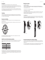 4
4
-
 5
5
-
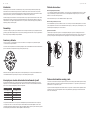 6
6
-
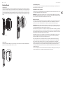 7
7
-
 8
8
-
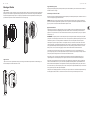 9
9
-
 10
10
-
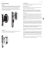 11
11
-
 12
12
-
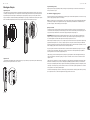 13
13
-
 14
14
-
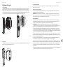 15
15
-
 16
16
-
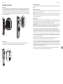 17
17
-
 18
18
-
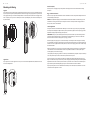 19
19
-
 20
20
-
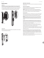 21
21
-
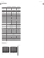 22
22
-
 23
23
-
 24
24
-
 25
25


Tannoy VLS 30 Snelstartgids
- Type
- Snelstartgids
- Deze handleiding is ook geschikt voor
in andere talen
- italiano: Tannoy VLS 30 Guida Rapida
- français: Tannoy VLS 30 Guide de démarrage rapide
- español: Tannoy VLS 30 Guía de inicio rápido
- Deutsch: Tannoy VLS 30 Schnellstartanleitung
- português: Tannoy VLS 30 Guia rápido
- polski: Tannoy VLS 30 Skrócona instrukcja obsługi