Yamaha MG12 Specificatie
- Categorie
- Audiomixers
- Type
- Specificatie
Deze handleiding is ook geschikt voor

1
General Specifications
0 dBu = 0.775 Vrms, Output impedance of signal generator (Rs) = 150 Ω
All level controls are nominal if not specified.
*1 Noise is measured with A-weighting filter.
*2 Crosstalk is measured with 1 kHz band pass filter.
The contents of this manual apply to the latest specifications as of the publishing date. To obtain the latest manual, access the Yamaha website then download
the manual file.
Frequency Response Input to STEREO OUT +0.5 dB/-1.5 dB (20 Hz to 48 kHz),
refer to the nominal output level @ 1 kHz, GAIN knob: Min
Total Harmonic Distortion
(THD+N)
Input to STEREO OUT 0.03 % @ +14 dBu (20 Hz to 20 kHz), GAIN knob: Min
0.005 % @ +24 dBu (1 kHz), GAIN knob: Min
Hum & Noise
*1
(20 Hz to 20 kHz)
Equivalent Input Noise -128 dBu (Mono Input Channel, Rs: 150 Ω, GAIN knob: Max)
Residual Output Noise -102 dBu (STEREO OUT, STEREO master fader: Min)
Crosstalk(1 kHz)
*2
-78 dB
Input Channels 12 channels: Mono [MIC/LINE]: 4, Mono/Stereo [MIC/LINE]: 2, Stereo [LINE]: 2
Output Channels STEREO OUT: 2, PHONES: 1, MONITOR OUT: 1, AUX SEND: 2, GROUP OUT: 2
Bus STEREO : 1, GROUP: 2, AUX: 2 (MG12XU: incl. FX)
Input Channel Function PAD CH 1 – CH 4 26 dB
HPF CH 1 – CH 4,
CH 5/6 (MIC),
CH 7/8 (MIC)
80 Hz, 12 dB/oct
COMP CH 1 – CH 4 1 knob compressor (Gain/Threshold/Ratio)
Threshold: +22 dBu to -8 dBu, Ratio: 1:1 to 4:1,
Output level: 0 dB to 7 dB, Attack time: approx. 25 msec,
Release time: approx. 300 msec
EQ CH 1 – CH 7/8 HIGH: Gain: +15 dB/-15 dB, Frequency: 10 kHz shelving
MID: Gain: +15 dB/-15 dB, Frequency: 2.5 kHz peaking
LOW: Gain: +15 dB/-15 dB, Frequency: 100 Hz shelving
CH 9/10,
CH 11/12
HIGH: Gain: +15 dB/-15 dB, Frequency: 10 kHz shelving
LOW: Gain: +15 dB/-15 dB, Frequency: 100 Hz shelving
PEAK LED CH 1 – CH 7/8 LED turns on when post EQ signal reaches 3 dB below clipping level.
Level Meter Pre Monitor LEVEL 2 × 12 -segment LED meter [PEAK, +10, +6, +3, 0, -3, -6, -10, -15, -20, -25, -30 dB]
Built-in Effect (MG12XU) SPX Algorithm 24 programs, PARAMETER control: 1, FOOT SW: 1 (FX RTN CH on/off)
USB Audio (MG12XU) 2 IN / 2 OUT USB Audio Class 2.0 compliant, Sampling Frequency: Max 192 kHz, Bit Depth: 24-bit
Phantom Power Voltage +48 V
Power Requirements AC 100-240 V, 50 Hz/60 Hz
Power Consumption 22 W
Dimensions (W × H × D) 308 mm × 118 mm × 422 mm (12.1" × 4.6" × 16.6")
Net Weight MG12XU: 4.2 kg (9.3 lbs), MG12: 4.0 kg (8.8 lbs)
Included Accessory AC Power Cord, CUBASE AI DOWNLOAD INFORMATION (MG12XU), Owner’s Manual,
Technical Specifications (this leaflet)
Optional Accessory Rack-Mount Kit: RK-MG12, Foot Switch: FC5 (MG12XU)
Operating Temperature 0 to +40 °C
Analog Input Characteristics
0 dBu = 0.775 Vrms
*1 Sensitivity is the lowest level that will produce an output of +4 dBu (1.228 V) or the nominal output level when the unit is set to maximum gain.
(All level controls are at their maximum position.)
*2 1&Sleeve = GND, 2&Tip = HOT, 3&Ring = COLD
*3 1 = GND, 2 = HOT, 3 = COLD
*4 Tip = Signal, Sleeve = GND
Analog Output Characteristics
0 dBu = 0.775 Vrms
*3 1 = GND, 2 = HOT, 3 = COLD
*5 Tip = HOT, Ring = COLD, Sleeve = GND
Digital Input / Output Characteristics (MG12XU)
Input Jack
PAD
26 dB
GAIN Trim
Position
Actual Load
Impedance
For Use with
Nominal
Input Level
Connector
Sensitivity
*1
Nominal Max. Before Clip
MIC/LINE
1 - 4
OFF
+64 dB
3 kΩ
50–600 Ω
Mics/Lines
-80 dBu
(0.077 mV)
-60 dBu
(0.775 mV)
-40 dBu
(7.75 mV)
Combo jack
*2
(Balanced)
+20 dB
-36 dBu
(12.3 mV)
-16 dBu
(122.8 mV)
+4 dBu
(1.228 V)
ON
+38 dB
-54 dBu
(1.55 mV)
-34 dBu
(15.46 mV)
-14 dBu
(154.6 mV)
-6 dB
-10 dBu
(245 mV)
+10 dBu
(2.451 V)
+30 dBu
(24.51 V)
MIC
5/6, 7/8
—
+64 dB
3 kΩ
50–600 Ω
Mics
-80 dBu
(0.077 mV)
-60 dBu
(0.775 mV)
-40 dBu
(7.75 mV)
XLR-3-31
*3
(Balanced)
+20 dB
-36 dBu
(12.3 mV)
-16 dBu
(122.8 mV)
-6 dBu
(388.2 mV)
LINE
5/6, 7/8
—
+38 dB
10 kΩ 600 Ω Lines
-54 dBu
(1.55 mV)
-34 dBu
(15.46 mV)
-14 dBu
(154.6 mV)
Phone jack
*4
(Unbalanced)
-6 dB
-10 dBu
(245 mV)
+10 dBu
(2.451 V)
+30 dBu
(24.51 V)
LINE
9/10, 11/12
— — 10 kΩ 600 Ω Lines
-30 dBu
(24.5 mV)
-10 dBu
(245 mV)
+10 dBu
(2.45 V)
Phone jack
*4
RCA pin
(Unbalanced)
Output Terminal
Actual Source
Impedance
For Use with Nominal
Output Level
Connector
Nominal Max. Before Clip
STEREO OUT [L, R] 75 Ω 600 Ω Lines +4 dBu (1.228 V) +24 dBu (12.28 V)
XLR-3-32
*3
Phone jack
*5
(Balanced)
MONITOR OUT [L, R]
GROUP OUT [1, 2]
AUX SEND [1, 2]
150 Ω 10 kΩ Lines +4 dBu (1.228 V) +20 dBu (7.750 V)
Phone jack
*5
(Impedance Balanced)
PHONES 110 Ω 40 Ω Phones 3 mW + 3 mW 100 mW + 100 mW Stereo phone jack
Terminal Format Data Length Sampling Frequency Connector
USB USB Audio Class 2.0 16-bit/24-bit 44.1 kHz, 48 kHz, 88.2 kHz, 96 kHz, 176.4 kHz, 192 kHz USB Standard-B
ZT57320
Technical Specifications

2
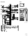
Dimensions
Unit: mm
This illustration shows the MG12XU.
308 118
115
422
416
Manual Development Group
© 2014 Yamaha Corporation
Published 08/2016 POLE*.*-01E0
Printed in Malaysia
Block and Level Diagrams
USB
MONO/ST CH INPUT
MONO CH INPUT MONO/ST CH INPUT
MONO CH INPUT (MIC/LINE)
ST CH INPUT
SEND AUX2
SEND AUX1
GROUP OUT 1
GROUP OUT 2
STEREO OUT L
STEREO OUT R
Digital EFFECT
PHONES
MONITOR OUT L
MONITOR OUT R
ST CH INPUT
Documenttranscriptie
ZT57320 Analog Input Characteristics 0 dBu = 0.775 Vrms Input Jack PAD 26 dB GAIN Trim Position Actual Load Impedance For Use with Nominal +64 dB OFF Technical Specifications +20 dB MIC/LINE 1-4 50–600 Ω Mics/Lines 3 kΩ +38 dB ON -6 dB General Specifications MIC 5/6, 7/8 0 dBu = 0.775 Vrms, Output impedance of signal generator (Rs) = 150 Ω All level controls are nominal if not specified. Frequency Response Input to STEREO OUT +0.5 dB/-1.5 dB (20 Hz to 48 kHz), refer to the nominal output level @ 1 kHz, GAIN knob: Min Total Harmonic Distortion (THD+N) Input to STEREO OUT 0.03 % @ +14 dBu (20 Hz to 20 kHz), GAIN knob: Min 0.005 % @ +24 dBu (1 kHz), GAIN knob: Min Hum & Noise *1 (20 Hz to 20 kHz) Equivalent Input Noise -128 dBu (Mono Input Channel, Rs: 150 Ω, GAIN knob: Max) Residual Output Noise -102 dBu (STEREO OUT, STEREO master fader: Min) Crosstalk(1 kHz) *2 -78 dB Input Channels 12 channels: Mono [MIC/LINE]: 4, Mono/Stereo [MIC/LINE]: 2, Stereo [LINE]: 2 Output Channels STEREO OUT: 2, PHONES: 1, MONITOR OUT: 1, AUX SEND: 2, GROUP OUT: 2 Bus STEREO : 1, GROUP: 2, AUX: 2 (MG12XU: incl. FX) Input Channel Function PAD CH 1 – CH 4 26 dB HPF CH 1 – CH 4, CH 5/6 (MIC), CH 7/8 (MIC) 80 Hz, 12 dB/oct COMP CH 1 – CH 4 1 knob compressor (Gain/Threshold/Ratio) Threshold: +22 dBu to -8 dBu, Ratio: 1:1 to 4:1, Output level: 0 dB to 7 dB, Attack time: approx. 25 msec, Release time: approx. 300 msec EQ STEREO OUT [L, R] 75 Ω Pre Monitor LEVEL 2 × 12 -segment LED meter [PEAK, +10, +6, +3, 0, -3, -6, -10, -15, -20, -25, -30 dB] Built-in Effect (MG12XU) SPX Algorithm 24 programs, PARAMETER control: 1, FOOT SW: 1 (FX RTN CH on/off) PHONES USB Audio (MG12XU) 2 IN / 2 OUT USB Audio Class 2.0 compliant, Sampling Frequency: Max 192 kHz, Bit Depth: 24-bit 308 mm × 118 mm × 422 mm (12.1" × 4.6" × 16.6") Net Weight MG12XU: 4.2 kg (9.3 lbs), MG12: 4.0 kg (8.8 lbs) Included Accessory AC Power Cord, CUBASE AI DOWNLOAD INFORMATION (MG12XU), Owner’s Manual, Technical Specifications (this leaflet) Optional Accessory Rack-Mount Kit: RK-MG12, Foot Switch: FC5 (MG12XU) Operating Temperature 0 to +40 °C The contents of this manual apply to the latest specifications as of the publishing date. To obtain the latest manual, access the Yamaha website then download the manual file. 600 Ω Lines For Use with Nominal Level Meter Dimensions (W × H × D) — Actual Source Impedance LED turns on when post EQ signal reaches 3 dB below clipping level. 22 W 10 kΩ -6 dB Max. Before Clip -80 dBu (0.077 mV) -60 dBu (0.775 mV) -40 dBu (7.75 mV) -36 dBu (12.3 mV) -16 dBu (122.8 mV) +4 dBu (1.228 V) -54 dBu (1.55 mV) -34 dBu (15.46 mV) -14 dBu (154.6 mV) -10 dBu (245 mV) +10 dBu (2.451 V) +30 dBu (24.51 V) -80 dBu (0.077 mV) -60 dBu (0.775 mV) -40 dBu (7.75 mV) -36 dBu (12.3 mV) -16 dBu (122.8 mV) -6 dBu (388.2 mV) -54 dBu (1.55 mV) -34 dBu (15.46 mV) -14 dBu (154.6 mV) -10 dBu (245 mV) +10 dBu (2.451 V) +30 dBu (24.51 V) -30 dBu (24.5 mV) -10 dBu (245 mV) +10 dBu (2.45 V) Connector Combo jack *2 (Balanced) XLR-3-31 *3 (Balanced) Phone jack *4 (Unbalanced) Phone jack *4 RCA pin (Unbalanced) 0 dBu = 0.775 Vrms CH 1 – CH 7/8 AC 100-240 V, 50 Hz/60 Hz 600 Ω Lines Nominal Analog Output Characteristics HIGH: Gain: +15 dB/-15 dB, Frequency: 10 kHz shelving LOW: Gain: +15 dB/-15 dB, Frequency: 100 Hz shelving Power Consumption 10 kΩ Sensitivity *1 *1 Sensitivity is the lowest level that will produce an output of +4 dBu (1.228 V) or the nominal output level when the unit is set to maximum gain. (All level controls are at their maximum position.) *2 1&Sleeve = GND, 2&Tip = HOT, 3&Ring = COLD *3 1 = GND, 2 = HOT, 3 = COLD *4 Tip = Signal, Sleeve = GND CH 9/10, CH 11/12 *1 Noise is measured with A-weighting filter. *2 Crosstalk is measured with 1 kHz band pass filter. 1 — Output Terminal Power Requirements 3 kΩ +38 dB LINE 9/10, 11/12 HIGH: Gain: +15 dB/-15 dB, Frequency: 10 kHz shelving MID: Gain: +15 dB/-15 dB, Frequency: 2.5 kHz peaking LOW: Gain: +15 dB/-15 dB, Frequency: 100 Hz shelving +48 V 50–600 Ω Mics +20 dB — CH 1 – CH 7/8 Phantom Power Voltage — LINE 5/6, 7/8 MONITOR OUT [L, R] GROUP OUT [1, 2] AUX SEND [1, 2] PEAK LED +64 dB Input Level Output Level Connector Nominal Max. Before Clip 600 Ω Lines +4 dBu (1.228 V) +24 dBu (12.28 V) XLR-3-32 *3 Phone jack *5 (Balanced) 150 Ω 10 kΩ Lines +4 dBu (1.228 V) +20 dBu (7.750 V) Phone jack *5 (Impedance Balanced) 110 Ω 40 Ω Phones 3 mW + 3 mW 100 mW + 100 mW Stereo phone jack *3 1 = GND, 2 = HOT, 3 = COLD *5 Tip = HOT, Ring = COLD, Sleeve = GND Digital Input / Output Characteristics (MG12XU) Terminal Format Data Length Sampling Frequency Connector USB USB Audio Class 2.0 16-bit/24-bit 44.1 kHz, 48 kHz, 88.2 kHz, 96 kHz, 176.4 kHz, 192 kHz USB Standard-B Block and Level Diagrams Dimensions STEREO OUT L MONO CH INPUT (MIC/LINE) STEREO OUT R 115 308 118 MONO/ST CH INPUT GROUP OUT 1 GROUP OUT 2 SEND AUX1 SEND AUX2 422 416 ST CH INPUT PHONES USB MONITOR OUT L MONITOR OUT R Digital EFFECT Unit: mm This illustration shows the MG12XU. MONO CH INPUT MONO/ST CH INPUT ST CH INPUT Manual Development Group © 2014 Yamaha Corporation Published 08/2016 POLE*.*-01E0 Printed in Malaysia 2-
 1
1
-
 2
2


Yamaha MG12 Specificatie
- Categorie
- Audiomixers
- Type
- Specificatie
- Deze handleiding is ook geschikt voor
in andere talen
- English: Yamaha MG12 Specification
- italiano: Yamaha MG12 specificazione
- русский: Yamaha MG12 Спецификация
- français: Yamaha MG12 spécification
- español: Yamaha MG12 Especificación
- Deutsch: Yamaha MG12 Spezifikation
- português: Yamaha MG12 Especificação
- dansk: Yamaha MG12 Specifikation
- suomi: Yamaha MG12 määrittely
- čeština: Yamaha MG12 Specifikace
- 日本語: Yamaha MG12 仕様
- svenska: Yamaha MG12 Specifikation
- Türkçe: Yamaha MG12 Şartname
- polski: Yamaha MG12 Specyfikacja
- română: Yamaha MG12 Specificație