Yamaha PMT-H35 de handleiding
- Categorie
- Projectoren
- Type
- de handleiding
Deze handleiding is ook geschikt voor

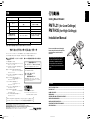
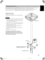
Ceiling Mount Bracket
PMT-L31 (for Low Ceilings)
PMT-H35 (for High Ceilings)
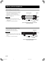
Installation Manual
Be sure to read this manual thoroughly
before using this bracket. After you have
read this manual, retain it for future
reference.
When installing the projector using this
bracket, all installation work must be
performed by a qualified contractor or
dealer personnel. The customer must
never attempt to perform this installation
work.
SAFETY INSTRUCTIONS .............................................................................................................2
PACKING LIST .............................................................................................................................. 4
NAMES OF PARTS ....................................................................................................................... 5
DIMENSIONS ................................................................................................................................ 7
SCREEN SIZE AND SETTING-UP DISTANCE ............................................................................ 8
INSTALLATION EXAMPLES ....................................................................................................... 10
INSTALLING THE PROJECTOR ................................................................................................. 11
ADJUSTING THE PROJECTION ANGLE ................................................................................... 14
SPECIFICATIONS ....................................................................................................................... 16
Contents
English
(PMT-L31)
(PMT-H35)
Printed in Japan PMTL31/H35
YAMAHA ELECTRONICS CORPORATION, USA 6660 ORANGETHORPE AVE., BUENA PARK, CALIF. 90620, U.S.A.
YAMAHA CANADA MUSIC LTD. 135 MILNER AVE., SCARBOROUGH, ONTARIO M1S 3R1, CANADA
YAMAHA ELECTRONIK EUROPA G.m.b.H. SIEMENSSTR. 22-34, 25462 RELLINGEN BEI HAMBURG, F.R. OF GERMANY
YAMAHA ELECTRONIQUE FRANCE S.A. RUE AMBROISE CROIZAT BP70 CROISSY-BEAUBOURG 77312 MARNE-LA-VALLEE CEDEX02, FRANCE
YAMAHA ELECTRONICS (UK) LTD. YAMAHA HOUSE, 200 RICKMANSWORTH ROAD WATFORD, HERTS WD1 7JS, ENGLAND
YAMAHA SCANDINAVIA A.B. J A WETTERGRENS GATA 1, BOX 30053, 400 43 VÄSTRA FRÖLUNDA, SWEDEN
YAMAHA MUSIC AUSTRALIA PTY, LTD. 17-33 MARKET ST., SOUTH MELBOURNE, 3205 VIC., AUSTRALIA
2002.10.16, 18:501

SAFETY INSTRUCTIONS
1. Always follow the instructions set forth in this manual when installing the projector
using this bracket.
Improper or inadequate installation could cause the projector to fall and injure someone.
2. The installation must be secure enough to bear the weight of the projector, the ceiling
bracket, and other hardware indefinitely, and must also be secure enough to withstand
vibration.
Inadequate installation could cause the projector to fall and injure someone.
3. To ensure safety, all bolts and screws must be tightened securely.
Loose bolts or screws could cause the projector to fall and injure someone.
4. Use only the parts provided with the bracket, and any other parts (commrecially
available) that are specified in this manual.
Using other parts could cause the projector to fall and injure someone.
5. Do not modify the bracket or the parts provided with the bracket.
Modifying the bracket or the other parts could cause the projector to fall and injure someone.
6. Do not use damaged parts.
Using damaged parts could cause the projector to fall and injure someone.
If any parts become damaged, contact your dealer.
7. Make sure to leave enough open space around the unit to allow heat generated by the
projector to dissipate.
Failure to provide adequate space around the unit could cause the projector to overheat internally, causing a
fire.
8. Before replacing the lamp cartridge, always remove the projector (with the mounting
adapter attached) from the ceiling bracket.
Attempting to replace the lamp cartridge while the projector is attached to the ceiling bracket could cause
the projector or the ceiling bracket to fall and injure someone.
E-2
J-15
2002.10.08, 15:24Page 2

E-3
English
9. Never hang from the projector or the ceiling bracket.
Hanging from the projector or the ceiling bracket could cause the projector or the ceiling bracket to fall and
injure someone.
10. Do not install the projector in a location near an air conditioning vent or in a location
subject to vibration.
Such conditions could have an adverse effect on the projector, and could even cause a fire or electric shock.
11. Do not install the projector in a location that is subject to high levels of dust or
humidity.
Dust accumulating inside the projector could cause a short circuit that in turn could cause a fire or electric
shock.
12. Do not install the projector in a location that is exposed to direct sunlight or in a
location that is subject to extreme fluctuations in temperature (such as near an air
conditioner).
Such conditions can cause the projector housing to warp or to become discolored.
13. Do not wipe the exterior of the ceiling bracket with benzene, paint thinner or cleaning
compounds.
Doing so could damage the finish.
14. Special techniques and experience are essential when installing the projector using
this bracket. Request that your dealer arrange to have the equipment installed. The
customer should never attempt to suspend the projector from the ceiling.
Improper installation could cause the ceiling bracket or the projector to fall and injure someone.
15. Once the projector is installed, safety checks should be conducted on a regular basis.
If the projector is used over an extended period of time, screws can become loose and the installation can
become weaker due to the passage of time, vibration, etc.
11PMT_p3_E 2002.10.16, 17:383

E-4
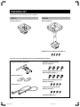
PACKING LIST
Check that all of the following parts are included.
PMT-L31
Ceiling bracket x 1
PMT-H35
Ceiling bracket x 1
Common parts (The following parts are provided with each bracket.)
Projector mounting adapter x 1
Projector mounting screws
(M6, pan head) x 4
Adjustment pole locking screws (M5) x 4
Safety brackets x 2
Safety wires x 2
Vertical angle adjustment screws
(M6, hexagonal head) x 4
Safety bracket mounting screws
(M4, pan head) x 4
Safety wire mounting screws
(M4, pan head) x 4
Installation Manual x 1
12PMT_BODY_E 2002.10.08, 15:144

E-5
English
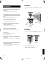
NAMES OF PARTS
PMT-L31
Ceiling bracket
Projector mounting adapter
Tilt angle adjustment screws
(There are also screws on the
opposite side.)
Horizontal angle adjustment
screws
Mounting guide pin
Vertical angle adjustment screws
(There are also screws on the
opposite side.)
12PMT_BODY_E 2002.10.16, 17:375

E-6
PMT-H35
Height locking screw
Ceiling bracket
Projector mounting adapter
Tilt angle adjustment screws
(There are also screws on the
opposite side.)
Horizontal angle adjustment screw
(four in total)
Height adjustment pole
Mounting guide pin
Vertical angle adjustment screws
(There are also screws on the
opposite side.)
12PMT_BODY_E 2002.10.08, 15:146

E-7
English
DIMENSIONS
Projector mounting adapter
with the DPX-1000 installed
[Top View]
PMT-H35
[Front View]
with the DPX-1000 installed
[Top View]
10 mm (3/8 inch)
30 mm
Ø8.8 mm
(Ø3/16 inch)
(fully penetrating holes)
844 to 1414 mm
(33-3/16 to 55-11/16 inch)
787 to 1357 mm
(30-15/16 to 53-3/8 inch)
963 to 1533 mm
(37-7/8 to 60-3/8 inch)
184.5 mm
(7-5/16 inch)
(1-3/16 inch)
495 mm
(19-1/2 inch)
PMT-L31
[Front View]
Ø10 x 13 mm
(Ø3/8 x 1/2 inch)
(elliptical hole)
Ø10 mm
(Ø3/8 inch)
(hole)
Ø9 mm
(Ø3/8 inch)
(hole)
Ø9 x 13 mm
(Ø3/8 x 1/2 inch)
(elliptical hole)
10˚
10˚
196 mm
170 mm
140 mm
120 mm
156 mm
226 mm
162 mm
176 mm
236 mm
(7-3/4 inch)
(6-11/16 inch)
(5-1/2 inch)
(4-3/4 inch)
(6-1/8 inch)
Ø10 mm
(Ø3/8 inch)
(hole)
Ø9 mm
(Ø3/8 inch)
(hole)
(8-7/8 inch)
(6-3/8 inch)
(6-13/16 inch)
(9-5/16 inch)
14.5 mm
(5/8 inch)
297.4 mm
(11-3/4 inch)
17 mm
(3/4 inch)
13 mm
(1/2 inch)
382 mm
(15 inch)
360 mm
(14-3/16 inch)
124 mm
(4-7/8 inch)
155 mm
(6-1/8 inch)
258 mm
(10-3/16 inch)
82 mm
(3-3/16 inch)
139 mm
(5-1/2 inch)
10° 10°
184.5 mm
(7-5/16 inch)
495 mm
(19-1/2 inch)
Projection
direction
120 mm
(4-3/4 inch)
200 mm
(8-7/8 inch)
210 mm
140 mm
(8-5/16 inch)
(5-1/2 inch)
Projection
direction
Ø10 x 13 mm
(Ø3/8 x 1/2 inch)
(elliptical hole)
12PMT_BODY_E 2002.10.16, 17:377

E-8
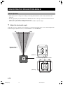
SCREEN SIZE AND SETTING-UP DISTANCE
• The chart and illustration below show the relationship between the projection distance and the screen size. Please
refer to these values for installation of the projector.
• Please align the projected image and the screen using the “V. POS” function of the projector. Refer to the owner’s
manual of the projector for detailes.
*Distance and dimensions should be used as a guide for installation. The actual distance will vary depending on projection conditions.
60"
80"
100"
120"
Screen size
200"
Approximate projection size (m)
1.8 to 2.9
2.4 to 3.85
3.6 to 5.8
3.0 to 4.85
6.05 to 9.75
Distance from center
of ceiling bracket to
front edge of
projector:
Approx. 24 cm
Distance from center
of ceiling bracket to
wall: Approx. 43 cm
Distance from ceiling
surface to center of
lens:
PMT-L31:
Approx. 26 cm
PMT-H35:
96 to 153 cm
< When using a 16:9 screen >
Notes
• The projection distance is the horizontal distance from the surface of the projector lens to the surface of the screen.
• Although the vertical angle of the ceiling bracket can be adjusted in a range of ±15°, a large angle adjustment may
distort the projected image. We recommend you to adjust both the angle of the ceiling bracket and the angle of the
screen.
Screen size (inch)
Approximate projection
distance (m [feet])
60" 1.8 to 2.9 [5.9 to 9.5]
70" 2.1 to 3.35 [6.9 to 11]
80" 2.4 to 3.85 [7.9 to 12.6]
90" 2.7 to 4.35 [8.9 to 14.3]
100" 3.0 to 4.85 [9.8 to 15.9]
110" 3.3 to 5.35 [10.8 to 17.6]
120" 3.6 to 5.8 [11.8 to 16.4]
150" 4.55 to 7.3 [14.9 to 24]
200" 6.05 to 9.75 [19.8 to 32]
Screen size (inch)
Approximate projection
distance (m [feet])
60" 1.65 to 2.65 [5.4 to 8.7]
80" 2.2 to 3.5 [7.2 to 11.5]
100" 2.75 to 4.4 [9 to 14.4]
120" 3.3 to 5.3 [10.8 to 17.4]
200" 5.5 to 8.8 [18 to 28.9]
When using a 16:9 screen
When using a 4:3 screen
12PMT_BODY_E 2002.10.08, 15:148

E-9
English
PMT-H35 height adjustment
The height adjustment pole for the PMT-H35 has holes spaced 3 cm apart that can be used to adjust the
height. When the bracket is shipped from the factory, the pole is set at the shortest height.
Follow the procedure described below to adjust the pole to the appropriate height. For details on the
appropriate height, refer to “SCREEN SIZE AND SETTING-UP DISTANCE” on page 8.
[Adjustment Procedure]
1
Remove the safety pin.
2 Loosen the nut, and then remove the height locking
screw.
Caution
• Removing the height locking screw will unlock the height
adjustment pole from the ceiling bracket. In order to ensure
that the height adjustment pole does not fall, always hold
the pole while performing this work.
3
Determine the correct position in accordance with the
height of the screen, insert the height locking screw,
and then hand-tighten the nut.
4 Securely tighten the four height adjustment pole
locking screws (M5) provided.
5 Securely tighten the nut that was previously hand-
tightened.
6 Be sure to insert the safety pin.
After adjusting the height, make sure that the
adjustment pole locking screws and the nut are all
tightened securely. Also make sure that the safety
pin has been inserted properly.
1
2
3
4
Safety pin
Nut
Adjustment pole locking screws
(Tighten the other side also.)
Height
locking
screw
Hight adjustment pole
Ceiling bracket
12PMT_BODY_E 2002.10.16, 17:379

E-10
INSTALLATION EXAMPLES
When installing to a wooden ceiling
1 Drill matching holes through the reinforcing
plate and the ceiling in the proper locations
and then pass bolts through the holes.
2 Tighten the bolts to secure the reinforcing
plate to a ceiling beam.
Cautions
• Make sure that the reinforcing plate is strong
enough to bear the weight of the projector and the
ceiling bracket.
• Use M8 bolts (commercially available).
When installing to a concrete ceiling
Reinforcing plate
Washer
Nut and
washer
Bolt (M8)
Ceiling
beam
(Use the reinforcing plate, bolts, nuts and washers
commercially available.)
1 Install anchor nuts in the ceiling.
2 Screw the bolts into the anchor nuts.
Cautions
• Make sure that the anchor nuts are strong enough
to bear the weight of the projector and the ceiling
bracket.
• Use M8 bolts (commercially available).
Anchor nut
Ceiling
Nut and
washer
Bolt (M8)
(Use the anchor nuts, bolts, nuts and washers
commercially available.)
12PMT_BODY_E 2002.10.08, 15:1410

E-11
English
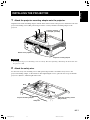
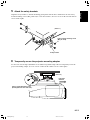
INSTALLING THE PROJECTOR
1 Attach the projector mounting adapter onto the projector.
Align the holes in the mounting adapter with the holes in the bottom of the projector, and then use the four
projector mounting screws (M6, pan head) provided to securely attach the mounting adapter to the
projector.
Caution
• Do not tighten the projector mounting screws excessively. Excessive tightening could damage the mount and cause
the projector to fall.
2 Attach the safety wire.
Use the four safety wire mounting screws (M4, pan head) provided to attach the safety wires to the
projector mounting adapter, as shown below. After tightening the screws, place the wire loops around the
projector’s adjusters, and then tighten the band.
Projector mounting adapter
Projector mounting
screws (M6, pan head)
Bottom of the projector
Safety wire mounting screws
(M4, pan head)
Projector mounting adapter
Band
Safety wire
12PMT_BODY_E 2002.10.16, 17:3711

E-12
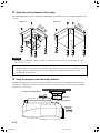
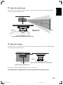
3 Install the ceiling bracket on the ceiling.
First hand-tighten the four nuts (eight nuts for PMT-H35) , determine the position, and then tighten the nuts
securely.
PMT-L31 PMT-H35
Caution
• Use M8 bolts (commercially available) to install the ceiling bracket. Using any bolts other than M8 bolts could
cause the projector to fall.
Note to Dealers and Installers
For the customer’s safety, make sure that the location where the projector is to be installed is strong
enough to bear the weight of the projector, the ceiling bracket, and the other hardware before
installing the ceiling bracket.
4 Hang the projector from the ceiling bracket.
Slide the mounting guide pin all of the way into the notch on the projector mounting adapter. This pin is
only meant to support the projector temporarily, and does not hold the projector securely. Be careful that
the projector does not fall.
(PMT-L31)
Mounting guide pin
Projector mounting adapter
Projection
direction
Projection
direction
Projection
direction
12PMT_BODY_E 2002.10.08, 15:1412

E-13
English
5 Attach the safety brackets.
Align the safety brackets so that the mounting guide pin fits into the hole, and then use the four safety
bracket mounting screws (M4, pan head) to secure the brackets. (Use two screws on the left side and two
screws on the right.)
(PMT-L31)
Safety bracket mounting screw
(M4, pan head)
Safety bracket
6 Temporarily secure the projector mounting adapter.
Use the four vertical angle adjustment screws (M6, hexagonal head) provided to temporarily secure the
projector mounting adapter. (Use two screws on the left side and two screws on the right.)
(PMT-L31)
Vertical angle adjustment screw
(Hand-tighten the other side also.)
Projection
direction
12PMT_BODY_E 2002.10.16, 17:3713

E-14
(PMT-L31)
(PMT-H35)
10˚ 10˚
ADJUSTING THE PROJECTION ANGLE
Before adjustment
• Turn the projector on and project an image, following the instructions on the owner’s manual of the
projector.
• Set the appropriate projection method on “Installation” item in “Set up” menu. For the detail about the
setting, refer to the owner’s manual of the projector.
• First, select a projection size using the zoom feature, and then adjust the angle.
1 Adjust the horizontal angle.
Adjust the projector so that the projected image is centered horizontally on the screen, and then tighten the
horizontal angle adjustment screws (2 on the PMT-L31, 4 on the PMT-H35).
Maximum angle of
adjustment: ±10˚
Horizontal angle adjustment screws
Left
Right
12PMT_BODY_E 2002.10.08, 15:1414

E-15
English
2 Adjust the vertical angle.
Adjust the projector so that the projected image is centered vertically on the screen, and then tighten the
four vertical angle adjustment screws.
3 Adjust the tilt angle.
Adjust the projector so that the projected image is not tilted at all compared to the screen, and then tighten
the four tilt angle adjustment screws.
(PMT-L31)
15˚
15˚
Maximum angle of
adjustment: ±15˚
Vertical angle adjustment screws
(There are also screws located on the opposite side.)
(PMT-L31)
10˚ 10˚
Maximum angle of adjustment: ±10˚
Tilt angle adjustment screws
(There are also screws located on the opposite side.)
If the projector still needs further adjustment, start over from step 1.
After adjustment is completed, make sure that the projector is secured in place.
Top
Bottom
12PMT_BODY_E 2002.10.16, 17:3715

E-16
SPECIFICATIONS
Product Name Ceiling Mount Bracket
Model No. PMT-L31 PMT-H35
Height
844 to 1414 mm (33-3/16 to 55-11/16 inch)
(variable in 30 mm (1-3/16-inch) steps)
Vertical angle ±15˚ ±15˚
Horizontal angle ±10˚ ±10˚
Tilt angle ±10˚ ±10˚
Dimensions of ceiling bracket
(W × D × H)
236 × 226 × 799 to 1369 mm
(9-15/16 × 8-7/8 × 31-1/2 to 53-15/16 inch)
(Height is variable in 30-mm
(1-3/16-inch) steps)
Dimensions of adapter
(W × D × H)
Weight 3.0 kg (6 lbs 10 oz) 6.2 kg (13 lbs 11 oz)
• Specifications are subject to change without notice.
382 × 327.2 × 81.2 mm (15 × 12-7/8 × 3-3/16 inch)
Adjustment
range
1
39 mm (5-1/2 inch)
(fixed)
160 × 196 × 94 mm
(6-5/16 × 7-3/4 × 3-11/16 inch)
12PMT_BODY_E 2002.10.08, 15:1416
Documenttranscriptie
品 名 型 番 PMT-H35 139mm (固定) 844〜1414mm (可変: 30 mm間隔) 上下角度 ±15° ±15° 左右角度 ±10° ±10° 傾き角度 ±10° ±10° 160 × 196 × 94 mm 236 × 226 × 799〜1369 mm (高さ可変: 30 mm可変) さ 天井固定金具外形寸法 (幅 × 奥行き × 高さ) アダプター外形寸法 (幅 × 奥行き × 高さ) 質 Ceiling Mount Bracket PMT-L31 高 調整幅 天吊金具 量 382 ×327.2×81.2 mm 3.0 kg English 仕様 PMT-L31 (for Low Ceilings) PMT-H35 (for High Ceilings) Installation Manual 6.2 kg * 仕様、外観および記載内容は、改良のため予告なく変更することがあります。 ヤマハホットラインサービスネットワーク ヤマハホットラインサービスネットワークは、本機を末永く、安心してご愛用いただけるためのものです。 サービスのご依頼、お問い合わせは、お買上げ店、またはお近くのサービス拠点にご連絡ください。 ■ ヤマハAV製品の修理、サービスパーツに関する お問合せは ■ ヤマハAV製品の機能や取扱いに関するお問合せは (ヤマハ電気音響製品サービス拠点) お客様ご相談センター 北海道 〒064-8543 札幌市中央区南十条西1-1-50 ヤマハセンター内 TEL (011) 512 - 6108 TEL (0570)01 − 1808(ナビダイヤル) 仙 全国どこからでも市内通話料金でご利用いただけます。 台 〒984-0015 仙台市若林区卸町5-7 仙台卸商共同配送センター3F TEL (022) 236 - 0249 首都圏 〒143-0006 東京都大田区平和島2丁目1番1号 京浜トラックターミナル内14号棟A-5F TEL (03) 5762 - 2121 浜 松 〒435-0016 浜松市和田町200 ヤマハ (株) 和田工場内 TEL (053) 465 - 6711 名古屋 〒454-0058 名古屋市中川区玉川町2-1-2 ヤマハ(株)名古屋流通センター3F TEL (052) 652 - 2230 大 阪 〒565-0803 吹田市新芦屋下1-16 ヤマハ(株)千里丘センター内 TEL (06) 6877 - 5262 広 島 〒731-0113 広島市安佐南区西原6-14-14 TEL (082) 874 - 3787 四 国 〒760-0029 高松市丸亀町8-7 (株)ヤマハミュージック神戸 高松店内 TEL (087) 822 - 3045 九 州 〒812-8508 福岡市博多区博多駅前2-11-4 TEL (092) 472 - 2134 携帯電話、PHSからは下記番号におかけください。 (PMT-H35) ご相談受付時間 10:00〜12:00,13:00〜18:00 (日・祝日及び弊社が定めた日は休業とさせていただきます のであらかじめご了承ください。) Contents SAFETY INSTRUCTIONS ............................................................................................................. 2 PACKING LIST .............................................................................................................................. 4 NAMES OF PARTS ....................................................................................................................... 5 DIMENSIONS ................................................................................................................................ 7 SCREEN SIZE AND SETTING-UP DISTANCE ............................................................................ 8 INSTALLATION EXAMPLES ....................................................................................................... 10 INSTALLING THE PROJECTOR ................................................................................................. 11 ADJUSTING THE PROJECTION ANGLE ................................................................................... 14 SPECIFICATIONS ....................................................................................................................... 16 〒430-8650 浜松市中沢町10-1 ヤマハオーディオ&ビジュアルホームページ http://www.yamaha.co.jp/audio/ ] ELECTRONICS CORPORATION, USA 6660 ORANGETHORPE AVE., BUENA PARK, CALIF. 90620, U.S.A. CANADA MUSIC LTD. 135 MILNER AVE., SCARBOROUGH, ONTARIO M1S 3R1, CANADA ELECTRONIK EUROPA G.m.b.H. SIEMENSSTR. 22-34, 25462 RELLINGEN BEI HAMBURG, F.R. OF GERMANY ELECTRONIQUE FRANCE S.A. RUE AMBROISE CROIZAT BP70 CROISSY-BEAUBOURG 77312 MARNE-LA-VALLEE CEDEX02, FRANCE ELECTRONICS (UK) LTD. YAMAHA HOUSE, 200 RICKMANSWORTH ROAD WATFORD, HERTS WD1 7JS, ENGLAND SCANDINAVIA A.B. J A WETTERGRENS GATA 1, BOX 30053, 400 43 VÄSTRA FRÖLUNDA, SWEDEN MUSIC AUSTRALIA PTY, LTD. 17-33 MARKET ST., SOUTH MELBOURNE, 3205 VIC., AUSTRALIA Printed in Japan 1 When installing the projector using this bracket, all installation work must be performed by a qualified contractor or dealer personnel. The customer must never attempt to perform this installation work. FAX (053)460 − 2777 住所 〒 430-8650 静岡県浜松市中沢町 10-1 [ PMT̲Cover1のコピー (PMT-L31) TEL (053)460 − 3409 Above information is applicable to customers who live in Japan only. ヤマハホットラインサ−ビスネットワ−クは、日本国内居住のお客様専用です。 YAMAHA YAMAHA YAMAHA YAMAHA YAMAHA YAMAHA YAMAHA Be sure to read this manual thoroughly before using this bracket. After you have read this manual, retain it for future reference. PMTL31/H35 2002.10.16, 18:50 SAFETY INSTRUCTIONS 2 上下角度の調整をする 映像がスクリーンの上下中心に投影されるように合わせ、上下角度調整ネジ(4本)をしっかり締めつけ ます。 1. Always follow the instructions set forth in this manual when installing the projector using this bracket. Improper or inadequate installation could cause the projector to fall and injure someone. 上 2. The installation must be secure enough to bear the weight of the projector, the ceiling bracket, and other hardware indefinitely, and must also be secure enough to withstand vibration. 15° Inadequate installation could cause the projector to fall and injure someone. 15° 3. To ensure safety, all bolts and screws must be tightened securely. Loose bolts or screws could cause the projector to fall and injure someone. (PMT-L31) 最大調整角度±15° 下 4. Use only the parts provided with the bracket, and any other parts (commrecially available) that are specified in this manual. 上下角度調整ネジ (反対側にもネジがあります。) Using other parts could cause the projector to fall and injure someone. 5. Do not modify the bracket or the parts provided with the bracket. Modifying the bracket or the other parts could cause the projector to fall and injure someone. 6. Do not use damaged parts. 3 傾き角度の調整をする 映像がスクリーンに対して傾かないように合わせ、傾き角度調整ネジ(4本)をしっかり締めつけます。 Using damaged parts could cause the projector to fall and injure someone. If any parts become damaged, contact your dealer. 7. Make sure to leave enough open space around the unit to allow heat generated by the projector to dissipate. Failure to provide adequate space around the unit could cause the projector to overheat internally, causing a fire. (PMT-L31) 8. Before replacing the lamp cartridge, always remove the projector (with the mounting adapter attached) from the ceiling bracket. 10°10° 傾き角度調整ネジ (反対側にもネジがあります。) 最大調整角度±10° Attempting to replace the lamp cartridge while the projector is attached to the ceiling bracket could cause the projector or the ceiling bracket to fall and injure someone. 調整が合わないときは1から調整しなおしてください。 調整後は、しっかり固定されていることを確認してください。 日本語 J-15 E-2 PMT̲Cover1 Page 2 2002.10.08, 15:24 Adobe PageMaker 6.5J/PPC 9. Never hang from the projector or the ceiling bracket. 10. Do not install the projector in a location near an air conditioning vent or in a location subject to vibration. Such conditions could have an adverse effect on the projector, and could even cause a fire or electric shock. 11. Do not install the projector in a location that is subject to high levels of dust or humidity. Dust accumulating inside the projector could cause a short circuit that in turn could cause a fire or electric shock. 12. Do not install the projector in a location that is exposed to direct sunlight or in a location that is subject to extreme fluctuations in temperature (such as near an air conditioner). Such conditions can cause the projector housing to warp or to become discolored. 13. Do not wipe the exterior of the ceiling bracket with benzene, paint thinner or cleaning compounds. Doing so could damage the finish. 14. Special techniques and experience are essential when installing the projector using this bracket. Request that your dealer arrange to have the equipment installed. The customer should never attempt to suspend the projector from the ceiling. Improper installation could cause the ceiling bracket or the projector to fall and injure someone. 15. Once the projector is installed, safety checks should be conducted on a regular basis. If the projector is used over an extended period of time, screws can become loose and the installation can become weaker due to the passage of time, vibration, etc. E-3 11PMT_p3_E 3 2002.10.16, 17:38 English Hanging from the projector or the ceiling bracket could cause the projector or the ceiling bracket to fall and injure someone. PACKING LIST Check that all of the following parts are included. PMT-L31 PMT-H35 Ceiling bracket x 1 Ceiling bracket x 1 Adjustment pole locking screws (M5) x 4 Common parts (The following parts are provided with each bracket.) Projector mounting adapter x 1 Projector mounting screws (M6, pan head) x 4 Vertical angle adjustment screws (M6, hexagonal head) x 4 Safety brackets x 2 Safety bracket mounting screws (M4, pan head) x 4 Safety wires x 2 Safety wire mounting screws (M4, pan head) x 4 Installation Manual x 1 E-4 12PMT_BODY_E 4 2002.10.08, 15:14 English NAMES OF PARTS PMT-L31 Horizontal angle adjustment screws Ceiling bracket Mounting guide pin Vertical angle adjustment screws (There are also screws on the opposite side.) Projector mounting adapter Tilt angle adjustment screws (There are also screws on the opposite side.) E-5 12PMT_BODY_E 5 2002.10.16, 17:37 PMT-H35 Ceiling bracket Height locking screw Horizontal angle adjustment screw (four in total) Height adjustment pole Mounting guide pin Vertical angle adjustment screws (There are also screws on the opposite side.) Tilt angle adjustment screws (There are also screws on the opposite side.) Projector mounting adapter E-6 12PMT_BODY_E 6 2002.10.08, 15:14 Ø9 x 13 mm (Ø3/8 x 1/2 inch) (elliptical hole) 12PMT_BODY_E 120 mm (4-3/4 inch) 156 mm (6-1/8 inch) 7 Ø9 mm (Ø3/8 inch) (hole) 495 mm (19-1/2 inch) 10° 10° [Top View] 210 mm (8-5/16 inch) 140 mm (5-1/2 inch) Projection direction 176 mm (6-13/16 inch) 236 mm (9-5/16 inch) 2002.10.16, 17:37 Ø10 mm (Ø3/8 inch) (hole) 495 mm (19-1/2 inch) Ø10 x 13 mm (Ø3/8 x 1/2 inch) (elliptical hole) 184.5 mm (7-5/16 inch) 258 mm (10-3/16 inch) 297.4 mm (11-3/4 inch) 844 to 1414 mm (33-3/16 to 55-11/16 inch) 14.5 mm (5/8 inch) (1-3/16 inch) 30 mm 963 to 1533 mm (37-7/8 to 60-3/8 inch) 787 to 1357 mm (30-15/16 to 53-3/8 inch) Ø8.8 mm (Ø3/16 inch) (fully penetrating holes) PMT-L31 120 mm (4-3/4 inch) 200 mm (8-7/8 inch) 184.5 mm (7-5/16 inch) 82 mm (3-3/16 inch) 139 mm (5-1/2 inch) 124 mm (4-7/8 inch) 155 mm (6-1/8 inch) 226 mm (8-7/8 inch) 162 mm (6-3/8 inch) Ø10 mm (Ø3/8 inch) (hole) Ø10 x 13 mm (Ø3/8 x 1/2 inch) (elliptical hole) 17 mm 13 mm (3/4 inch) (1/2 inch) 382 mm (15 inch) 360 mm (14-3/16 inch) Ø9 mm (Ø3/8 inch) (hole) 10˚ 10˚ 196 mm (7-3/4 inch) 170 mm (6-11/16 inch) 140 mm (5-1/2 inch) Projector mounting adapter PMT-H35 English DIMENSIONS [Front View] [Front View] 10 mm (3/8 inch) with the DPX-1000 installed with the DPX-1000 installed [Top View] Projection direction E-7 SCREEN SIZE AND SETTING-UP DISTANCE • The chart and illustration below show the relationship between the projection distance and the screen size. Please refer to these values for installation of the projector. • Please align the projected image and the screen using the “V. POS” function of the projector. Refer to the owner’s manual of the projector for detailes. When using a 16:9 screen When using a 4:3 screen Approximate projection distance (m [feet]) 1.8 to 2.9 [5.9 to 9.5] 2.1 to 3.35 [6.9 to 11] 2.4 to 3.85 [7.9 to 12.6] 2.7 to 4.35 [8.9 to 14.3] 3.0 to 4.85 [9.8 to 15.9] 3.3 to 5.35 [10.8 to 17.6] 3.6 to 5.8 [11.8 to 16.4] 4.55 to 7.3 [14.9 to 24] 6.05 to 9.75 [19.8 to 32] Screen size (inch) 60" 70" 80" 90" 100" 110" 120" 150" 200" Screen size (inch) 60" 80" 100" 120" 200" Approximate projection distance (m [feet]) 1.65 to 2.65 [5.4 to 8.7] 2.2 to 3.5 [7.2 to 11.5] 2.75 to 4.4 [9 to 14.4] 3.3 to 5.3 [10.8 to 17.4] 5.5 to 8.8 [18 to 28.9] *Distance and dimensions should be used as a guide for installation. The actual distance will vary depending on projection conditions. < When using a 16:9 screen > 60" Distance from center of ceiling bracket to wall: Approx. 43 cm 80" 1.8 to 2.9 100" 120" 2.4 to 3.85 Distance from center of ceiling bracket to front edge of projector: Approx. 24 cm 3.0 to 4.85 Distance from ceiling surface to center of lens: PMT-L31: Approx. 26 cm PMT-H35: 96 to 153 cm Screen size 200" 3.6 to 5.8 6.05 to 9.75 Approximate projection size (m) Notes • The projection distance is the horizontal distance from the surface of the projector lens to the surface of the screen. • Although the vertical angle of the ceiling bracket can be adjusted in a range of ±15°, a large angle adjustment may distort the projected image. We recommend you to adjust both the angle of the ceiling bracket and the angle of the screen. E-8 12PMT_BODY_E 8 2002.10.08, 15:14 PMT-H35 height adjustment English The height adjustment pole for the PMT-H35 has holes spaced 3 cm apart that can be used to adjust the height. When the bracket is shipped from the factory, the pole is set at the shortest height. Follow the procedure described below to adjust the pole to the appropriate height. For details on the appropriate height, refer to “SCREEN SIZE AND SETTING-UP DISTANCE” on page 8. [Adjustment Procedure] 1 Remove the safety pin. 2 Loosen the nut, and then remove the height locking screw. Caution • Removing the height locking screw will unlock the height adjustment pole from the ceiling bracket. In order to ensure that the height adjustment pole does not fall, always hold the pole while performing this work. Ceiling bracket 3 Determine the correct position in accordance with the height of the screen, insert the height locking screw, and then hand-tighten the nut. 4 Securely tighten the four height adjustment pole locking screws (M5) provided. 5 Securely tighten the nut that was previously handtightened. 6 Be sure to insert the safety pin. After adjusting the height, make sure that the adjustment pole locking screws and the nut are all tightened securely. Also make sure that the safety pin has been inserted properly. 1 Safety pin Nut Height locking screw Adjustment pole locking screws (Tighten the other side also.) 4 3 2 Hight adjustment pole E-9 12PMT_BODY_E 9 2002.10.16, 17:37 INSTALLATION EXAMPLES When installing to a wooden ceiling 1 Drill matching holes through the reinforcing plate and the ceiling in the proper locations and then pass bolts through the holes. 2 Tighten the bolts to secure the reinforcing plate to a ceiling beam. Washer Reinforcing plate Ceiling beam Cautions • Make sure that the reinforcing plate is strong enough to bear the weight of the projector and the ceiling bracket. • Use M8 bolts (commercially available). Nut and washer Bolt (M8) (Use the reinforcing plate, bolts, nuts and washers commercially available.) When installing to a concrete ceiling 1 Install anchor nuts in the ceiling. 2 Screw the bolts into the anchor nuts. Anchor nut Cautions Ceiling • Make sure that the anchor nuts are strong enough to bear the weight of the projector and the ceiling bracket. • Use M8 bolts (commercially available). Nut and washer Bolt (M8) (Use the anchor nuts, bolts, nuts and washers commercially available.) E-10 12PMT_BODY_E 10 2002.10.08, 15:14 1 English INSTALLING THE PROJECTOR Attach the projector mounting adapter onto the projector. Align the holes in the mounting adapter with the holes in the bottom of the projector, and then use the four projector mounting screws (M6, pan head) provided to securely attach the mounting adapter to the projector. Projector mounting screws (M6, pan head) Bottom of the projector Projector mounting adapter Caution • Do not tighten the projector mounting screws excessively. Excessive tightening could damage the mount and cause the projector to fall. 2 Attach the safety wire. Use the four safety wire mounting screws (M4, pan head) provided to attach the safety wires to the projector mounting adapter, as shown below. After tightening the screws, place the wire loops around the projector’s adjusters, and then tighten the band. Band Projector mounting adapter Safety wire mounting screws (M4, pan head) Safety wire E-11 12PMT_BODY_E 11 2002.10.16, 17:37 3 Install the ceiling bracket on the ceiling. First hand-tighten the four nuts (eight nuts for PMT-H35) , determine the position, and then tighten the nuts securely. (PMT-L31) (PMT-H35) Pr dir ojec ec tio tio n n Pr dir ojec ec tio tio n n Caution • Use M8 bolts (commercially available) to install the ceiling bracket. Using any bolts other than M8 bolts could cause the projector to fall. Note to Dealers and Installers For the customer’s safety, make sure that the location where the projector is to be installed is strong enough to bear the weight of the projector, the ceiling bracket, and the other hardware before installing the ceiling bracket. 4 Hang the projector from the ceiling bracket. Slide the mounting guide pin all of the way into the notch on the projector mounting adapter. This pin is only meant to support the projector temporarily, and does not hold the projector securely. Be careful that the projector does not fall. Projector mounting adapter (PMT-L31) Mounting guide pin Projection direction E-12 12PMT_BODY_E 12 2002.10.08, 15:14 5 Attach the safety brackets. (PMT-L31) Safety bracket mounting screw (M4, pan head) Safety bracket 6 Temporarily secure the projector mounting adapter. Use the four vertical angle adjustment screws (M6, hexagonal head) provided to temporarily secure the projector mounting adapter. (Use two screws on the left side and two screws on the right.) (PMT-L31) Projection direction Vertical angle adjustment screw (Hand-tighten the other side also.) E-13 12PMT_BODY_E 13 2002.10.16, 17:37 English Align the safety brackets so that the mounting guide pin fits into the hole, and then use the four safety bracket mounting screws (M4, pan head) to secure the brackets. (Use two screws on the left side and two screws on the right.) ADJUSTING THE PROJECTION ANGLE Before adjustment • Turn the projector on and project an image, following the instructions on the owner’s manual of the projector. • Set the appropriate projection method on “Installation” item in “Set up” menu. For the detail about the setting, refer to the owner’s manual of the projector. • First, select a projection size using the zoom feature, and then adjust the angle. 1 Adjust the horizontal angle. Adjust the projector so that the projected image is centered horizontally on the screen, and then tighten the horizontal angle adjustment screws (2 on the PMT-L31, 4 on the PMT-H35). Right Left 10˚ 10˚ Maximum angle of adjustment: ±10˚ (PMT-L31) Horizontal angle adjustment screws (PMT-H35) E-14 12PMT_BODY_E 14 2002.10.08, 15:14 2 Adjust the vertical angle. Top 15˚ 15˚ Maximum angle of adjustment: ±15˚ (PMT-L31) Bottom Vertical angle adjustment screws (There are also screws located on the opposite side.) 3 Adjust the tilt angle. Adjust the projector so that the projected image is not tilted at all compared to the screen, and then tighten the four tilt angle adjustment screws. (PMT-L31) 10˚ 10˚ Tilt angle adjustment screws (There are also screws located on the opposite side.) Maximum angle of adjustment: ±10˚ If the projector still needs further adjustment, start over from step 1. After adjustment is completed, make sure that the projector is secured in place. E-15 12PMT_BODY_E 15 2002.10.16, 17:37 English Adjust the projector so that the projected image is centered vertically on the screen, and then tighten the four vertical angle adjustment screws. SPECIFICATIONS Product Name Ceiling Mount Bracket Model No. PMT-L31 Height Adjustment range 139 mm (5-1/2 inch) (fixed) PMT-H35 844 to 1414 mm (33-3/16 to 55-11/16 inch) (variable in 30 mm (1-3/16-inch) steps) Vertical angle ±15˚ ±15˚ Horizontal angle ±10˚ ±10˚ Tilt angle ±10˚ ±10˚ Dimensions of ceiling bracket (W × D × H) Dimensions of adapter (W × D × H) Weight 236 × 226 × 799 to 1369 mm (9-15/16 × 8-7/8 × 31-1/2 to 53-15/16 inch) 160 × 196 × 94 mm (6-5/16 × 7-3/4 × 3-11/16 inch) (Height is variable in 30-mm (1-3/16-inch) steps) 382 × 327.2 × 81.2 mm (15 × 12-7/8 × 3-3/16 inch) 3.0 kg (6 lbs 10 oz) 6.2 kg (13 lbs 11 oz) • Specifications are subject to change without notice. E-16 12PMT_BODY_E 16 2002.10.08, 15:14-
 1
1
-
 2
2
-
 3
3
-
 4
4
-
 5
5
-
 6
6
-
 7
7
-
 8
8
-
 9
9
-
 10
10
-
 11
11
-
 12
12
-
 13
13
-
 14
14
-
 15
15
-
 16
16


Yamaha PMT-H35 de handleiding
- Categorie
- Projectoren
- Type
- de handleiding
- Deze handleiding is ook geschikt voor
in andere talen
- English: Yamaha PMT-H35 Owner's manual
- italiano: Yamaha PMT-H35 Manuale del proprietario
- русский: Yamaha PMT-H35 Инструкция по применению
- français: Yamaha PMT-H35 Le manuel du propriétaire
- español: Yamaha PMT-H35 El manual del propietario
- Deutsch: Yamaha PMT-H35 Bedienungsanleitung
- português: Yamaha PMT-H35 Manual do proprietário
- dansk: Yamaha PMT-H35 Brugervejledning
- suomi: Yamaha PMT-H35 Omistajan opas
- čeština: Yamaha PMT-H35 Návod k obsluze
- svenska: Yamaha PMT-H35 Bruksanvisning
- Türkçe: Yamaha PMT-H35 El kitabı
- polski: Yamaha PMT-H35 Instrukcja obsługi
- română: Yamaha PMT-H35 Manualul proprietarului