
IMX644 Manager Owner’s Manual
1
• The software and this manual are the exclusive copyrights of Yamaha Corporation.
• Please read carefully the Software Licensing Agreement at the end of this manual before installing the software.
• Copying of the software or reproduction of this manual in whole or in part by any means is expressly forbidden without the written con-
sent of the manufacturer.
•Yamaha makes no representations or warranties with regard to the use of the software and documentation and cannot be held responsi-
ble for the results of the use of this manual and the software.
• Future upgrades of application and system software and any changes in specifications and functions will be announced at the following
URL.
• The illustrations and screens as shown in this manual are for instructional purposes only, and may appear somewhat different from
those on your computer.
•Windows is a registered trademark of Microsoft
®
Corporation in the United States and other countries.
• The company names and product names in this manual are the trademarks or registered trademarks of their respective companies.
• Specifications and descriptions in this owner’s manual are for information purposes only. Yamaha Corp. reserves the right to change or
modify products or specifications at any time without prior notice. Since specifications, equipment or options may not be the same in
every locale, please check with your Yamaha dealer.
SPECIAL NOTICES
http://www.yamahaproaudio.com/
Precautions when using the [USB] connector
When connecting the computer to the [USB] connector, make sure to observe the following points. Failing to do so risks freezing the
computer and corrupting or losing the data. If the computer or the device freezes, restart the application software or the computer OS,
or turn the power to the device off then on again.
CAUTION
• Use an AB type USB cable of less than about 3 meters.
• Before connecting the computer to the [USB] connector, exit from any power-saving mode of the computer (such as suspend, sleep,
standby).
• Before turning on the power to the device, connect the computer to the [USB] connector.
•Execute the following before turning the power to the device on/off or plugging/unplugging the USB cable to/from the [USB] con-
nector.
- Make sure that data is not being transmitted from the device.
- Quit any open application software on the computer.
• While the computer is connected to the device, you should wait for six seconds or more between these operations: (1) when turning
the power of the device off then on again, or (2) when alternately connecting/disconnecting the USB cable.
Owner’s Manual

IMX644 Manager Owner’s Manual
2
What is IMX644 Manager?...................................................................................... 3
System requirements .............................................................................................3
Installation procedure ............................................................................................4
Installing IMX644 Manager................................................................................4
Installing the IMX644 USB Driver (Windows 7 users) ....................................5
Installing the IMX644 USB Driver (Windows Vista users)..............................8
Installing the IMX644 USB Driver (Windows XP users) ...............................12
Uninstallation procedure .....................................................................................13
Windows 7 users .............................................................................................13
Windows Vista users.......................................................................................13
Windows XP users ..........................................................................................14
Starting IMX644 Manager ..................................................................................... 15
Basic operation in the Parameter Edit screen ...................................................17
BLOCK screen ...................................................................................................... 19
INPUT screen ........................................................................................................ 23
MATRIX screen ..................................................................................................... 24
OUTPUT screen .................................................................................................... 25
OUTPUT EQ screen ..............................................................................................26
MISC screen ..........................................................................................................28
GPI screen............................................................................................................. 30
MEMORY screen ................................................................................................... 31
Troubleshooting ...................................................................................................32
SOFTWARE LICENSE AGREEMENT................................................................... 34
Table of contents

IMX644 Manager Owner’s Manual
3
IMX644 Manager is application software that lets you make detailed parameter settings for the IMX644. IMX644 Manager has the
following functionality.
• Edit the IMX644’s parameters
When connected online with the IMX644, you can perform detailed editing of the IMX644’s parameters in real-time. Edited set-
tings can be saved as a file.
You can use IMX644 Manager to edit offline even when not connected to the IMX644 online. However, some parameters are saved
only in the IMX644, so operation when editing offline will differ in some cases from operation when editing online (e.g., channel
levels and GPI settings). As far as possible, you should use this software when connected online with the IMX644.
• Send files of settings to the IMX644
Files of settings that you saved using IMX644 Manager can be sent and loaded into the IMX644.
NOTE
• Communication between the IMX644 and IMX644 Manager requires that they be connected via a USB cable or RS-232C cable. In order to
connect via USB, you’ll also need to install the IMX644 USB Driver.
In order to use IMX644 Manager, your computer must meet the following requirements.
NOTE
• Depending on the operating system you’re using, your computer may require specifications that exceed these requirements.
• The following system requirements are for IMX644 Manager version 1.02 For the latest information on the most recent version and system
requirements, refer to the following URL.
Windows 7/Vista
Windows XP Professional SP2 or later / XP Home Edition SP2 or later
What is IMX644 Manager?
System requirements
http://www.yamahaproaudio.com/
OS
Windows 7 (64 or 32 bit), Vista (64 or 32 bit), XP Professional (SP2 or later), XP Home Edition (SP2 or
later)
Hard Disk
Free disk space of 50 MB or more
Display
1024 x 768, high color (16 bit) or higher
Other
Mouse / Keyboard / USB connector or RS-232C connector
CPU
Intel Pentium/Celeron 1.4 GHz or higher
Available Memory
1 GB or more (2 GB or more for Windows 7 64-bit version)
CPU
Intel Pentium III 400 MHz or higher
Available Memory
128 MB or more

IMX644 Manager Owner’s Manual
4
This section explains how to install IMX644 Manager and the IMX644 USB Driver.
The IMX644 USB Driver installation procedure will depend on the OS you are using.
Windows 7 users .........................page 5
Windows Vista users ...................page 8
Windows XP users ......................page 12
Installing IMX644 Manager
1
Disconnect all USB devices (other than keyboard and mouse) from your computer, including the IMX644.
2
Log on to Windows using an account that has administrative privileges.
You must also close all application software and windows you’re not using.
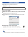
3
Double-click “IMX644Manager.msi,” located where you extracted the compressed file that you down-
loaded.
The setup dialog box for Yamaha IMX644 Manager will appear.
4
Perform the installation as directed by the on-screen instructions.
After installation the IMX644 folder will initially be in the computer’s “C:\Program Files
(x86)\YAMAHA” folder if you’re running the 64-bit version of the OS, or in the “C:\Program
Files\YAMAHA” folder if you’re running the 32-bit version. A shortcut icon will be created on your
desktop.
If you intend to connect IMX644 Manager to the IMX644 via USB, you’ll need to install the IMX644 Manager USB Driver
next.
NOTE
• If you’re using Windows 7/Vista and the “User Account Control” dialog box appears, click [Allow].
• If IMX644 Manager is already installed, a software maintenance screen will appear during installation of IMX644 Manager. Remove
the software by following the on-screen directions. After you’ve removed the software, perform the installation from step 3.
Installation procedure
If this software is already installed in your computer
You’ll need to uninstall any older versions of IMX644 Manager before installing the latest version.
For details on how to uninstall, refer to page 13.

IMX644 Manager Owner’s Manual
5
Installing the IMX644 USB Driver (Windows 7 users)
1
Turn the IMX644 power switch OFF.
2
Turn the IMX644 ON while holding the front-panel MEMORY [D] button, then connect the IMX644 to the
computer’s USB connector.
3
Select [Start]
→
[Control Panel]
→
[Hardware and Sound]
→
[Device Manager].
The “Device Manager” window will appear.
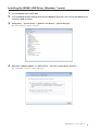
4
Right click “YAMAHA IMX644” in “Other Devices”, and select “Update Driver Software”.
The “Update Driver Software” window will appear.

IMX644 Manager Owner’s Manual
6
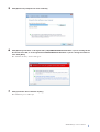
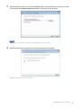
5
Click [Browse my computer for driver software].
6
Click [Browse] and select “C:\Program Files (x86)\YAMAHA\IMX644\usbimx644” if you’re running the 64-
bit version of the OS, or “C:\Program Files\YAMAHA\IMX644\usbimx644” if you’re running the 32-bit ver-
sion. Click [Next].
The “Windows Security” window will appear.
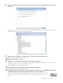
7
Click [Install this driver software anyway].
The installation process will begin.

IMX644 Manager Owner’s Manual
7
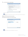
8
When the installation process has finished, “Windows has successfully updated your driver software”
will appear.
Click [Close] to close the window, and check that “Yamaha IMX644 USB Serial Converter” has been added to the “Univer-
sal Serial Bus controllers” item in the Device Manager window.
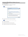
9
Right click “USB Serial port” in “Other Devices”, and select “Update Driver Software”.
The “Update Driver Software” window will appear.
10
Repeat steps 5 through 7, above.
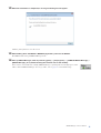
11
“Windows has successfully updated your driver software” will appear.
Click [Close] to close the window, and check that “Yamaha IMX644 USB Serial Port (COMn*)” has been added to the
“Ports (COM & LPT)” item in the Device Manager window.
* The port number “n” will depend on the device.
12
Turn the IMX644 ON while holding the front-panel MEMORY [D] button.
The IMX644 will start up in IMX644 Manager mode.
13
Launch the IMX644 Manager either by selecting [Start]
→
[All Programs]
→
[YAMAHA IMX644 Manager]
→
[IMX644 Manager], or by double-clicking the shortcut icon on the desktop.
If the installation has been successful the IMX644 Manager [Status] indicator will light green and the
device will be online. If the device does not appear online, refer top the “Troubleshooting” section on
page 32.

IMX644 Manager Owner’s Manual
8
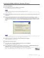
Installing the IMX644 USB Driver (Windows Vista users)
1
Power-off the IMX644.
2
Use a USB cable to connect the IMX644 to your computer.
The “Found New Hardware” screen will appear.
NOTE
• Make the USB connection directly to your computer without going through a USB hub.
3
Click [Locate and Install driver software (recommended)].
NOTE
• If the “User Account Control” dialog box appears, click [Allow] or [Continue].
4
Click [Don’t search online].
5
Click [I don’t have the disc. Show me other options.].
6
Click [Browse my computer for driver software (advanced)].

IMX644 Manager Owner’s Manual
9
7
Click the [Browse] button, and inside the IMX644 folder, select the folder that contains the driver
(“C:\Program Files\YAMAHA\IMX644\Usbimx644” by default), and click [Next].
NOTE
• If a Windows security dialog box appears, click [Install this driver software anyway].
8
When the installation is completed, a message indicating this will appear.
Click the [Close] button to close the screen.

IMX644 Manager Owner’s Manual
10
9
The “Found New Hardware” window will appear.
Click [Don’t search online].
NOTE
• Depending on your computer’s Windows Update driver settings, the above window may not appear. If the window does not appear, go
on to the next step.
10
Click [I don’t have the disk. Show me other options.].
11
Click [Browse my computer for driver software (advanced)].
NOTE
• If the Windows Security dialog box appears, click [Install this driver software anyway].

IMX644 Manager Owner’s Manual
11
12
When the installation is completed, a message indicating this will appear.
Click the [Close] button to close the screen.
13
While holding down the IMX644’s MEMORY [D] button, power-on the IMX644.
The IMX644 will start up in IMX644 Manager mode.
14
Start up IMX644 Manager, either by choosing [Start]
→
[All programs]
→
[YAMAHA IMX644 Manager]
→
[IMX644 Manager], or by double-clicking the shortcut icon on the desktop.
If the software was installed successfully, IMX644 Manager’s [Status] indicator will light green, and it
will be online. If IMX644 Manager does not go online, refer to page 32 of “Troubleshooting.”

IMX644 Manager Owner’s Manual
12
Installing the IMX644 USB Driver (Windows XP users)
1
Power-off the IMX644.
2
Use a USB cable to connect the IMX644 to your computer.
The “Found New Hardware Wizard” screen will appear.
NOTE
• Make the USB connection directly to your computer without going through a USB hub.
•A dialog box may ask you whether you want to connect to Windows Update. If so, select the option button at the left of “No, not this
time,” and click [Next].
3 Select the option button located at the left of “Install from a list or a specified location (advanced),” and
click [Next].
4
Select the option button located at the left of “Search for the best driver in these locations,” select
“Include this location in the search.” Then click the [Browse] button, and inside the IMX644 folder, select
the folder that contains the driver (“C:\Program Files\YAMAHA\IMX644\Usbimx644” by default), and click
[Next].
NOTE
• If a message indicating that the software “has not passed logo testing” appears during the installation, click [Continue].There is no need
to halt the installation. If this message does not appear, simply proceed to the next step.
5 When the installation is completed, a message indicating this will appear.
Click the [Finish] button to close the screen.
6 Repeat steps 3 through 5, above.
7 While holding down the IMX644’s MEMORY [D] button, power-on the IMX644.
The IMX644 will start up in IMX644 Manager mode.
8 Start up IMX644 Manager, either by choosing [Start] → [All programs] → [YAMAHA IMX644 Manager] →
[IMX644 Manager], or by double-clicking the shortcut icon on the desktop.
If the software was installed successfully, IMX644 Manager’s [Status] indicator will light green, and it
will be online. If IMX644 Manager does not go online, refer to page 32 of “Troubleshooting.”

IMX644 Manager Owner’s Manual
13
This section explains how to uninstall IMX644 Manager and the IMX644 USB Driver.
The uninstall procedure will depend on the OS you are using.
Windows 7 users
1
Select [Start] → [Control Panel] → [Uninstall a program] to display the “Uninstall or change a program”
window.
2 Select “Yamaha IMX644 Manager” from the list.
3 Right-click and select “Uninstall”.
A dialog box will appear. Follow the on-screen instructions to initiate the uninstall process.
4 Right-click “Yamaha IMX644 USB Serial Converter” in the “Device Manager” window, and select [Unin-
stall].
A dialog box will appear. Follow the on-screen instructions to initiate the uninstall process.
Windows Vista users
1
Choose [Start] → ([Settings]) → [Control Panel] → [Uninstall a program] to access the “Uninstall or
change a program” screen.
2 In the list, select “Yamaha IMX644 Manager.”
3 Right-click and select “Uninstall”
A dialog box will appear; proceed with the uninstallation as directed by the on-screen instructions.
If the “User Account Control” dialog box appears, click [Allow] or [Continue].
4 With the IMX644 still connected to the computer, select [Start] → [Control Panel] → [Hardware and
Sound] → [Device Manager].
The “Device Manager” window will appear.
5 Right-click “Yamaha IMX644 USB Serial Port (COMn*)” in the “Ports (COM & LPT)” item, and select
“Uninstall”.
A dialog box will appear. Check the “Delete the driver software for this device” checkbox, and execute the uninstall process.
* The port number “n” will depend on the device.
6 Right-click “Yamaha IMX644 Serial Converter” in the “Universal Serial Bus Controllers” item, and select
“Uninstall”.
A dialog box will appear. Check the “Delete the driver software for this device” checkbox, and execute the uninstall process.
Uninstallation procedure

IMX644 Manager Owner’s Manual
14
Windows XP users
1
Choose [Start] → ([Settings]) → [Control Panel] → [Add or Remove Programs] to access the “Add or
Remove Programs” screen.
2 In the upper left of the screen, click [Change or Remove Programs], and in the list at the right, select
“Yamaha IMX644 Manager.”
3 Click [Remove].
A dialog box will appear; proceed with the uninstallation as directed by the on-screen instructions.
4 With the IMX644 still connected to the computer, select [Start] → [Control Panel] → [Performance and
Maintenance] → [System].
The “System Properties” window will appear.
5 Select the “Hardware” tab, and click [Device Manager].
The “Device Manager” window will appear.
6 Right-click “Yamaha IMX644 USB Serial Port (COMn*)” in the “Ports (COM & LPT)” item, and select
“Uninstall”.
A dialog box will appear. Follow the on-screen instructions to initiate the uninstall process.
* The port number “n” will depend on the device.
7 Right-click “Yamaha IMX644 Serial Converter” in the “Universal Serial Bus Controllers” item, and select
“Uninstall”.
A dialog box will appear. Follow the on-screen instructions to initiate the uninstall process.

IMX644 Manager Owner’s Manual
15
NOTE
• In order for the IMX644 and your computer to be connected online, you must connect the IMX644 to your computer and then power-on the
IMX644 while holding down its MEMORY [D] button (IMX644 Manager mode). Use either a USB cable or an RS-232C cable to make this
connection. If you’re using an RS-232C cable, use a female-female cross cable.
• If both a USB cable and an RS-232C cable are connected, the USB connection will take priority.
• Do not switch between USB and RS-232C connections after starting-up the IMX644. If you need to switch connections, you must power-off
the IMX644 and then restart the IMX644 while holding down its MEMORY [D] button.
To start up IMX644 Manager, choose [Start] → [All Programs] → [Yamaha IMX644 Manager] → [IMX644 Manager],
or double-click the shortcut icon on the desktop.
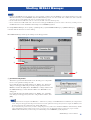
When IMX644 Manager starts up, the starting screen will appear first.
1 [Parameter Edit] button
This button opens the Parameter Edit screen, allowing you to edit parame-
ters or to save parameter settings as a file.
If you click this when the [Status] indicator is “Online,” the “Password”
dialog box will appear. Enter the previously assigned password for the
IMX644, and click the [OK] button. The IMX644’s settings will be loaded
into IMX644 Manager, and the Parameter Edit screen (BLOCK screen)
will appear.
If you click this when the [Status] indicator is “Offline,” the “Confirma-
tion” dialog box will appear. If you want to edit parameters offline, click
[OK].
NOTE
• If no password has been assigned to the IMX644 (i.e. with the factory settings or if the IMX644 has been initialized), the “Register Pass-
word” dialog box will appear. Enter the password (between one and eight characters long) that you want to assign to the IMX644, enter
the same password in the Confirm field, and click the [OK] button.
• If you don’t know the password or if you want to change the password, you’ll need to initialize the IMX644’s internal memory. Initiali-
zation will return the settings to their factory-set state, so be sure to save any important settings as a file before you proceed. The
IMX644 will be initialized if you turn on the power while holding down its MEMORY [A] and [D] buttons.
Starting IMX644 Manager
1
2
3
4

IMX644 Manager Owner’s Manual
16
2 [File Transfer] button
This button loads a file of settings and sends it to the
IMX644.
If you click this when the [Status] indicator is
“Online,” the “Password” dialog box will appear.
Enter the assigned password for the IMX644 and
click the [OK] button; the File Load dialog box will
appear. Select the parameter file (extension “.i6x”)
that you want to send to the connected IMX644, and
click the [Open] button. The Transferring dialog box
will appear, and the settings will be sent.
NOTE
• If no password has been assigned to the IMX644, the
“Register Password” dialog box will appear. Enter the password (between one and eight characters long) that you want to assign to the
IMX644, enter the same password in the Confirm field, and click the [OK] button.
• If you don’t know the password or if you want to change the password, you’ll need to initialize the IMX644’s internal memory. Initiali-
zation will return the settings to their factory-set state, so be sure to save any important settings as a file before you proceed. The
IMX644 will be initialized if you turn on the power while holding down its MEMORY [A] and [D] buttons.
• Use caution; when a parameter file is loaded and sent to the IMX644, some settings may cause high-volume sound to be produced from
the speakers if the levels in the new file are higher than the previous settings.
• If you want to view the contents of the parameter file, click the [Parameter Edit] button while offline to open the Parameter Edit screen,
and then load the parameter value.
3 [Status] indicator
This shows the status of communication between the IMX644 and IMX644 Manager.
4 [Quit] button
This button closes IMX644 Manager. When you click it, a confirmation dialog box will appear; click [OK].
Status Condition
The IMX644 and IMX644 Manager are communicating; i.e., they are online. When you edit a
parameter in IMX644 Manager, that setting will be reflected on the IMX644 in real-time.
To go online, connect your computer to the IMX644 via a cable, and power-on the IMX644
while holding down its MEMORY [D] button.
The IMX644 and IMX644 Manager are not communicating; i.e., they are offline. When you
edit a parameter in IMX644 Manager, the change will not be reflected on the IMX644.In this
state you can perform offline editing or view the contents of a parameter file.
Searching for a connected IMX644. If you click the [Parameter Edit] button in this state, you’ll
be editing offline.

IMX644 Manager Owner’s Manual
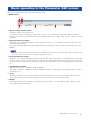
17
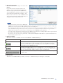
Here you can edit parameters and save parameter settings to a file.
• Header area
1 [Return to start window.] button
Click this to return to the starting screen.
A confirmation dialog box will appear; click [Yes] if you want to save your settings. A confirmation dialog box will ask
whether you want to save to the memory indicated in the Memory field if you’re editing online, or save to a file if you’re edit-
ing offline.
2 [Open parameter file.] button
Click this to access the Open File dialog box. Select the file (extension “.i6x”) containing the settings that you want to load,
and click the [Open] button.
If you open a file while editing online, the Transferring dialog box will appear, and the settings of the file will be sent to the
IMX644.
NOTE
• Use caution; when a parameter file is loaded and sent to the IMX644, some settings may cause high-volume sound to be produced from
the speakers if the levels in the new file are higher than the previous settings.
3 [Save parameter file.] button
Click this to access the Save File dialog box. Enter a file name and click the [Save] button; a confirmation dialog box will ask
whether you want to save the current settings to the memory indicated in the Memory field. If you click [Yes], the settings will
be saved to memory and then saved to a file. If you click [No], the settings will be saved to a file without being saved to mem-
ory.
4 Online/Offline indication
This indicates the state of communication with the IMX644.
If you want to change the communication status from Offline to Online, press the [Return to start window.] button to return to
the starting screen.
5 Venue
This indicates the name of the venue (parameter file name). Click the name to access the “Venue Name” dialog box, where
you can edit the name of the venue. This is also used as the file name when you save the parameter file.
6 Memory
This indicates the name of the currently selected memory. Click the name to access the “Memory Name” dialog box, where
you can edit the name of the memory.
Basic operation in the Parameter Edit screen
123
45 6

IMX644 Manager Owner’s Manual
18
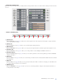
• Parameter editing area
Here you can use mouse operations to visually edit the various parameters. The screen that is shown will depend on the tab that’s
selected.
• Screen switching tabs
1 [BLOCK] tab
Opens the BLOCK screen (page 19). This shows a block diagram of the entire signal route from input to output, and allows
you to make parameter settings.
2 [INPUT] tab
Opens the INPUT screen (page 23). Here you can edit the input channel parameters.
3 [MATRIX] tab
Opens the MATRIX screen (page 24). Here you can specify the output channels to which the input channel signals are sent.
4 [OUTPUT] tab
Opens the OUTPUT screen (page 25). Here you can edit parameters other than EQ for OUTPUT channels 1–4.
5 [OUTPUT EQ] tab
Opens the OUTPUT EQ screen (page 26). Here you can edit the parameters of the 6-band equalizers provided for OUTPUT
channels 1 through 4.
6 [MISC] tab
Opens the MISC screen (page 28). Here you can edit settings for functions such as Priority Ducker, Music Override, and Feed-
back Suppressor.
7 [GPI] tab
Opens the GPI screen (page 30). Here you can specify the memory that will be recalled for each input port of the GPI connec-
tor, and the make/open status for each output port.
8 [MEMORY] tab
Opens the MEMORY screen (page 31). Here you can save your edited parameter settings in sixteen different memories, or
recall previously-saved settings.
1 2 3 4 5 6 7 8

IMX644 Manager Owner’s Manual
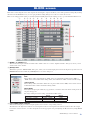
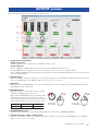
19
This shows a block diagram of the entire signal route from input to output, and allows you to make parameter settings. By clicking
the buttons in the BLOCK screen, you can open parameter editing dialog boxes or move to other edit screens.
This screen will appear first when you click the [Parameter Edit] button in the starting screen to open the Parameter Edit screen.
1 MONO 1–6, STEREO 1–4
These indicate the input channels and their names. Click a name to access the “Input Port Name” dialog box, where you can
edit the name of the channel.
2 [GAIN] button
This button opens the “INPUT GAIN” dialog box, where you can edit the input gain for the head amp that is provided on each
MONO INPUT channel. Click the [CLOSE] button to close the dialog box.
3 Input SIGNAL/PEAK indicator
These indicators light green when an input signal is detected at the corresponding channel.
The indicators also light red to indicate excessive input level. If excessive input level is indicated, either reduce the output
level of the connected source, or reduce the input level via the appropriate rear-panel [PAD] (34 dB) switch or by using INPUT
GAIN.
BLOCK screen
“INPUT GAIN” dialog box
PAD
When editing online, this will indicate “MIC” if the rear panel PAD (34 dB) switch is OFF, or
“LINE” if the switch is ON. When editing offline, this will indicate “MIC” with the default settings.
+48V indicator
When editing online, this will be dark if the rear panel +48V switch is OFF, or lit red if the switch
is ON. This indicator will be dark when editing offline.
INPUT GAIN
This adjusts the input gain. Click the [+]/[-] buttons, or click the value and edit the setting in the di-
alog box that appears.
The range will depend on the setting of the PAD (34 dB) switch.
6 8 9 ) !71 2 3 4 5 5
@
#
Range Default
When PAD is on (LINE) 4.0dB – -20.0dB -1.0dB
When PAD is off (MIC) -30.0dB – -54.0dB -35.0dB

IMX644 Manager Owner’s Manual
20
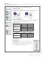
4 [EQ] button
This button opens the “INPUT EQ” dialog box, where you can edit the EQ (equalizer) that is provided on each input channel.
Click the [CLOSE] button to close the dialog box.
“INPUT EQ” dialog box
The editable parameters differ between MONO INPUT channels and STEREO INPUT channels.
Level adjustment knob
This adjusts the gain of each band.
Right-click and hold down the mouse button to increase the value; left-click and hold down the
mouse button to decrease the value. Double-click to reset the value to 0 dB.
Parameter indication (G/F/Q)
These indicate the gain (G), center/cutoff frequency (F), and Q. Click the [ ]/[ ] buttons, or
make changes in the dialog box that appears when you click the value.
The parameters available for each channel are listed below.
[EQ ON]/[EQ OFF] buttons
These turn the EQ on/off.
[COPY to] button
This copies the parameters of the currently-edited EQ to the EQ of
another input channel.
The “EQ COPY” dialog box will appear when you click this button.
Use the option buttons to select the input channel to which you want
to copy the EQ settings, and click the [OK] button.
Press (hold) the
left button
Press (hold) the
right button
MONO INPUT channel
STEREO INPUT channel
Parameter Range Default
HIGH (shelving)
G -15dB – +15dB 0dB
F 2kHz – 18kHz 10kHz
MID (peaking)
G -15dB – +15dB 0dB
F 40Hz – 18kHz 2kHz
Q 0.5 – 12.0 0.7
LOW (shelving)
G -15dB – +15dB 0dB
F 40Hz – 2kHz 100Hz
Parameter Range Default
HIGH (shelving)
G -15dB – +15dB 0dB
F 2kHz – 18kHz 10kHz
LOW (shelving)
G -15dB – +15dB 0dB
F 40Hz – 2kHz 100Hz

IMX644 Manager Owner’s Manual
21
5 [LEVEL] button
This opens the “LEVEL” dialog box, allowing you to adjust the volume of the input/output channels.
6 [MATRIX] button
Opens the MATRIX screen (page 24). Here you can specify the output channels to which the input channel signals are sent.
7 [STEREO/MONO] button
Specifies whether OUTPUT channels 1 and 2 deliver a STEREO or MONO output signal.
The initial setting is [STEREO]. When [STEREO] is selected the left (L) signal is output to channel A and the
right (R) signal is output to channel B.
8 [EQ+FILTER] button
Opens the OUTPUT EQ screen (page 26). Here you can edit the parameters of the 6-band equalizers provided
for OUTPUT channels 1 through 4.
9 [DELAY] button
Opens the “DELAY” dialog box, allowing you to specify the delay time for each OUTPUT channel. Use these settings when
you need to apply a delay to the main speaker outputs so that the sound from the sub-speakers will not be heard with a timing
offset. Click the [CLOSE] button to close the dialog box.
“LEVEL” dialog box
[LINK] button
This specifies whether IMX644’s front panel volume knob values will be linked with the on-screen
fader values.
If this is on (green), the on-screen fader values will change in tandem with the IMX644’s volume
knob settings. When this is on, you will only be able to operate the IMX644’s volume knobs; the on-
screen faders will not be operable. When you save settings to memory, the IMX644’s volume knob
values will be saved.
If this is off (gray), IMX644 Manager’s fader values will not be linked with the IMX644’s volume
knob settings.
When this is off, the volume will be as specified by the on-screen faders; the volume will not match
the settings of the IMX644’s volume knobs. When you save settings to memory, the on-screen fader
values will be saved.
The [LINK] button will return to the On (green) state when you close IMX644 Manager or return to
the starting screen.
If the volumes would increase when you switch this from off to on, a confirmation screen will appear.
Fader
This adjusts the volume. If the [LINK] button is on (green), this will be inoperable.
Markers
The red marker indicates the setting of the IMX644’s volume knob; the blue marker indicates the
volume value saved in memory. This is unavailable when offline.
[LOCK] button
If you turn this off (gray), operations of the volume knob for that channel will be effective if the
IMX644 is locked by its LOCK switch.
If this is on (red), volume knob operations for that channel will be ignored.
“DELAY” dialog box
Time indication
This specifies the delay time. This is linked with the distance indication below. Click the [ ]/[ ]
buttons to edit the value.
Distance indication
This indicates the specified delay time as a distance (meters) at the speed of sound (343.59 m/s).
Click the [ ]/[ ] buttons to edit the value.
Parameter Range Default
Fader Level -∞ – +10dB –
Parameter Range Default
Time Indication 0 – 300msec 0msec
Distance Indication 0 – 103.08m 0m

IMX644 Manager Owner’s Manual
22
) [BAL] button
This opens the “BALANCE” dialog box, allowing you to specify the volume balance between outputs A/B (L/R) of OUTPUT
channels 1 and 2.
Click the [CLOSE] button to close the dialog box.
! Output level meter, output SIGNAL/PEAK indicator
Output level meters
Displays the levels of the signal being output via OUTPUT channels 1 and 2.
Output SIGNAL/PEAK indicators
The SIGNAL/PEAK indicators show the output signal for OUTPUT channels 3 and 4.
If the top segment (PEAK) of the level meter lights red, or if the PEAK indicator lights red, the output signal level is at the
allowable maximum. Lower the input volume or the output volume.
@ OUT 1–4, REC OUT
These indicate the output channels and their names. Click a name to access the “Output Port Name” dialog box, where you can
edit the name of the channel.
# MEMORY [A]–[D] buttons
When you click a button [A]–[D], the memory assigned to that button will be recalled and the parameter settings will be
switched accordingly.
This is the same function as the IMX644’s MEMORY [A]–[D] buttons.
Use the MISC screen (page 28) to assign a memory to each button. Memories A through D all contain the same settings when
the unit is shipped from the factory.
“BALANCE” dialog box
Here you can adjust the volume balance between outputs A/B (L/R).
Right-click the [BALANCE] knob and continue holding down the mouse button to decrease the
A (L) volume; left-click and hold down the mouse button to decrease the B (R) volume. Double-
click to reset the value to center.
Parameter Range Default
Balance 0dB – -20.1dB 0dB
Press (hold) the left button Press (hold) the right button

IMX644 Manager Owner’s Manual
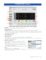
23
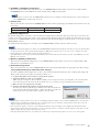
Here you can edit the input channel parameters.
1 PAD
When editing online, this will indicate “MIC” if the rear panel PAD (34 dB) switch is off, or “LINE” if the switch is on. When
editing offline, this will indicate “MIC” by default.
2 +48V indicator
When editing online, this will be dark if the rear panel +48V switch is off, or lit red if the switch is on. When editing offline
this will be dark.
3 INPUT GAIN
This edits the input gain value. Click the [-]/[+] buttons, or make changes in the dialog box that appears when you click the
value.
The range will depend on the setting of the PAD (34 dB) switch.
4 -2 dBFS (PEAK), -38 dBFS indicators
If an input signal of -38 dBFS or higher is detected, the [-38 dBFS] indicator will light green.
If the [-2 dBFS] (PEAK) indicator lights red, the input signal has reached the maximum allowable level. If excessive input
level is indicated, either reduce the output level of the connected source, or reduce the input level via the appropriate rear-panel
[PAD] (34 dB) switch or by using INPUT GAIN.
NOTE
• dBFS stands for “decibels full scale,” and indicates the digital audio level. 0 dBFS is the maximum level.
5 [EQ] button
This button opens the “INPUT EQ” dialog box, where you can edit the EQ that is provided on each input channel. This is the
same as the BLOCK screen’s “INPUT EQ” dialog box; refer to page 20 for details.
6 [F.B. SUP] button
This turns the feedback suppressor on/off (MONO INPUT channels only). The on/off state of this button is linked with the
Feedback Suppressor check box in the MISC screen. For more about the Feedback Suppressor, refer to page 29.
INPUT screen
Range Default
When PAD is on (LINE) 4.0dB – -20.0dB -1.0dB
When PAD is off (MIC) -30.0dB – -54.0dB -35.0dB
5
6
7
3
4
8
9
2
1

IMX644 Manager Owner’s Manual
24
7 [PRIORITY]/[OVERRIDE] button
This turns on/off the Priority Ducker function (MONO INPUT channels only) or the Music Override function (STEREO
INPUT channels only). The on/off state of this button is linked with the Priority Ducker Key Source Select or Music Override
Key Source Select check boxes in the MISC screen. For more about the Priority Ducker function and Music Override function,
refer to page 28.
8 [OUT1]–[OUT4] buttons
Here you can specify the output channels (OUTPUT channels 1- 4) to which the input channel signals are sent. These settings
are linked with the matrix settings in the MATRIX screen.
9 [LINK] button, fader, marker, [LOCK] button
Here you can adjust the volume of the input channel. These parameters are the same as in the BLOCK screen’s “LEVEL” dia-
log box; refer to page 21 for details.
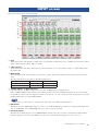
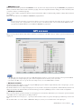
Here you can specify the output channels to which the input channel signals are sent.
The send levels from MONO INPUT channels to the OUTPUT channels can also be adjusted here.
NOTE
• From the IMX644’s panel, you can temporarily turn on a send from a specific input channel to an OUTPUT channel. However, output
assignments made in this way are only temporary and will not be saved to memory. For details, refer to the IMX644 Owner’s Manual.
1 Matrix setting buttons
These turn on/off the send from the input channel to each OUTPUT channel.
When a button is on (green), the signal will be sent from the corresponding input channel to the OUTPUT channel. When a
button is off (gray), the signal will not be output.
Signals can be sent to the REC OUT channel only from OUTPUT channels.
The default settings are: sends to all OUTPUT channels are on, with only OUTPUT channel 1 assigned to the REC OUT chan-
nel.
2 Send level indicator
This sets the level of the signal sent from the MONO INPUT channel to the OUTPUT channel in a range of -Inf (-∞)–0dB.
Click the [ ]/[ ] buttons to edit the value.
MATRIX screen
Parameter Range Default
Send Level -Inf – 0.0dB 0.0dB
1
2

IMX644 Manager Owner’s Manual
25
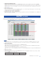
Here you can edit parameters other than EQ for output channels 1–4.
1 Output level meter/indicator
Output level meters
Shows level meters for the output signals of OUTPUT channels 1 and 2.
Output indicators
Shows [-2 dBFS]/[-44 dBFS] indicators for the output signals of OUTPUT channels 3 and 4.
The [-44 dBFS] indicator will light green when an output signal is detected at the corresponding channel.
If the [-2 dBFS] (PEAK) indicator lights red, the output signal has reached the maximum allowable level. Lower the input vol-
ume or the output volume.
2 [DELAY] button
Opens the “DELAY” dialog box, allowing you to specify the delay time for each OUTPUT channel. These parameters are the
same as in the BLOCK screen’s “DELAY” dialog box; refer to page 21 for details.
3 [EQ] button
This button opens the OUTPUT EQ screen (page 26), allowing you to edit the parameters of the 6-band equalizers provided
for OUTPUT channels 1 through 4.
4 [BALANCE] knob
This knob adjusts the volume balance between outputs
A/B (L/R) for OUTPUT channels 1 and 2.
Right-click the [BALANCE] knob and continue holding
down the mouse button to decrease the A (L) volume;
left-click and hold down the mouse button to decrease the
B (R) volume. Double-click to reset the value to center.
5 [STEREO/MONO] button
This button specifies the mode of the output channel. Click it to switch between STEREO and MONO.
6 [LINK] button, fader, marker, [LOCK] button
Here you can adjust the volume of the output channel. These parameters are the same as in the BLOCK screen’s “LEVEL”
dialog box; refer to page 21 for details.
OUTPUT screen
3
5
2
1
4
6
Press (hold)
the left button
Press (hold)
the right button
Parameter Range Default
Balance 0dB – -20.1dB 0dB

IMX644 Manager Owner’s Manual
26
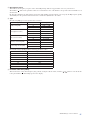
Here you can edit the parameters of the 6-band equalizers provided for OUTPUT channels 1 through 4.
1 CHANNEL
Use this to select the OUTPUT channel whose EQ you want to edit.
2 [A&B]/[A]/[B] buttons
If OUTPUT channel 1 or 2 is selected, you can choose whether to edit channels A and B together or individually.
A dialog box will appear when you switch between [A]/[B] and [A&B], asking you to confirm that you want to copy parame-
ters between channels A/B. Channel A will be copied to B when you switch from [A] to [A&B], and channel B will be copied
to A when you switch from [B] to [A&B].
3 [EQ ON]/[EQ OFF] buttons
These turn the EQ on/off.
4 [COPY to] button
This copies the parameters of the currently-edited EQ to the EQ of another OUTPUT channel.
The “EQ COPY” dialog box will appear when you click this button. Use the option buttons to select a copy-destination OUT-
PUT channel, and click the [OK] button.
5 [Speaker Preset] button
This lets you recall preset parameters for various models of speakers.
The preset parameters contain EQ settings optimized for the response of
various speakers.
A list of speaker presets will appear when you click this button; select the
name of the appropriate speaker. The selected preset parameters will be
recalled and applied to the EQ settings.
Select “-- FLAT- - ”
if you want to return the EQ to the default (flat) settings.
6 DELAY
This sets the delay time of each OUTPUT channel.
These parameters are the same as in the BLOCK screen’s “DELAY” dialog
box; refer to page 21 for details.
OUTPUT EQ screen
4
5
2
1
3
6
8
7
9

IMX644 Manager Owner’s Manual
27
7 EQ response curve
This indicates the frequency response of the current EQ settings. This is an approximate curve for your reference.
The markers ( ) indicate the parameter values for each band. The color of the markers corresponds to the band number (1–6)
shown below.
By dragging a marker (left-click and move the mouse while holding down the button) you can specify the EQ response quickly
and visually. Use the parameter indications below to make fine adjustments to the values.
8 Type
The following EQ types can be specified for each band.
The default setting is [P.EQ] with the following parameter values.
9 Parameter indication (F/G/Q)
These indicate the center/cutoff frequency (F), gain (G), and Q. To edit the values, click the [ ]/[ ] buttons or use the mouse
to drag the markers ( ) in the EQ response curve display.
Type Parameter Range
P.EQ (Peaking EQ)
F 40Hz – 18kHz
G -15dB – +15dB
Q 0.5 – 12.0
HPF (High Pass Filter)
F 40Hz – 18kHz
Slope 12dB/oct (Fixed)
Q 0.7 (Fixed)
LPF (Low Pass Filter)
F 40Hz – 18kHz
Slope 12dB/oct (Fixed)
Q 0.7 (Fixed)
L.Shelf (Low Shelving EQ)
F 40Hz – 18kHz
G -15dB – +15dB
H.Shelf (High Shelving EQ)
F 40Hz – 18kHz
G -15dB – +15dB
Parameter Default
Q 0.7 (common to all bands)
G 0.0dB(common to all bands)
F1 40Hz
F2 100Hz
F3 500Hz
F4 2kHz
F5 5kHz
F6 10kHz

IMX644 Manager Owner’s Manual
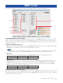
28
Here you can edit settings for functions such as Priority Ducker, Music Override, and Feedback Suppressor.
• Priority Ducker Key Source Select
When a signal is applied to the specified MONO INPUT channel, the level of all STEREO INPUT signals assigned to the same
output are reduced to allow announcements made via the MONO INPUT channel to stand out clearly from background music or
other program material, for example. When input to the specified MONO INPUT channel ceases, the level of the other “ducked”
channels returns to normal.
1 [MONO 1]–[MONO 6] check boxes
These turn on/off the Priority Ducker function for each MONO INPUT channel. These check boxes are linked with the [PRI-
ORITY] buttons of the INPUT screen. The default setting is OFF for all channels.
NOTE
• If this is turned on for more than one MONO INPUT channel, an audio signal being input to any MONO INPUT channel for which this
setting is turned on will reduce the volume from the STEREO INPUT channel that is being input to the same output channel.
2 Mute Level
This specifies the amount of attenuation applied to the STEREO INPUT channel by the Priority Ducker function.
3 Release Time
This specifies the time from when the audio signal disappears from the MONO INPUT channel until the audio signal of the
STEREO INPUT channel returns to its original volume. If the audio signal of the STEREO INPUT channel prematurely
returns to its original volume during breathing spaces or between words, increase the Release Time so that the STEREO
INPUT audio signal does not come back inappropriately.
• Music Override Key Source Select
When a signal is applied to the specified STEREO INPUT channel all other STEREO INPUT channels assigned to the same output
are automatically faded out and muted. When input to the specified STEREO INPUT channel ceases, the level of the other muted
channels fades in and returns to normal.
MISC screen
Parameter Range Default
Mute Level -30.2dB – 0dB -20dB
Parameter Range Default
Release Time 0.0 – 6.0sec 2.0sec
1
2
3
6
4
7
5

IMX644 Manager Owner’s Manual
29
4 [STEREO 1]–[STEREO 4] check boxes
These turn on/off the Music Override function for each STEREO INPUT channel. These check boxes are linked with the
[OVERRIDE] buttons of the INPUT screen. The default setting is OFF for all channels.
NOTE
• If this is turned on for more than one STEREO INPUT channel, the lowest-numbered channel will take priority, and the volume from
other STEREO INPUT channels will be faded-out.
5 Release Time
This specifies the time from when the STEREO INPUT channel’s audio signal disappears until the fade-in returns to the orig-
inal volume.
• Feedback Suppressor
The Feedback Suppressor effectively controls feedback by identifying the feedback frequencies produced by factors such as the
acoustics of the venue and the characteristics of the signal path. The Feedback Suppressor includes static filters that are set based
on analysis of each MONO INPUT channel, and dynamic filters that dynamically suppress feedback when it occurs on the specified
MONO INPUT channel.
By default, the Feedback Suppressor is turned on for all MONO INPUT channels. The static filters are unset.
NOTE
• By default, the Feedback Suppressor is turned on for all MONO INPUT channels. Even though the static filters are unset, the dynamic filters
are still operational so be sure to turn the Feedback Suppressor OFF before using sine waves or test tones to test or calibrate the system.
• Feedback Suppressor settings will be stored in the unit’s 16 memories.
• Static Filter analysis can also be performed from the IMX644’s panel. For details about the analysis procedure on the IMX644, refer to the
IMX644 owner’s manual.
6 [MONO 1]–[MONO 6] check boxes
These turn on/off the Feedback Suppressor for each MONO INPUT channel. These check boxes are linked with the [F.B.
SUP] buttons of the INPUT screen.
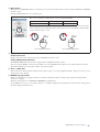
7 [Automatic Setup] button
This consecutively tests each selected MONO INPUT channel and automatically makes the appropriate static filter settings.
<Using Automatic Setup to make Static Filter settings>
To ensure optimum feedback suppression be sure to perform the measurements under the same conditions that will prevail
during actual operation (microphone and speaker positions, etc.).
1. Set up the microphone at least 5 meters away from the speakers.
2. Adjust the output level of the power amplifier.
While speaking or singing into the microphone gradually raise the output level of the power amplifier to the level that will be
used in actual operation. Also make sure that feedback does not occur when you clap your hands near the microphone.
3. Make sure the area being measured is silent.
4. Click the [Automatic Setup] button to begin the measurement.
The dialog box shown at right will appear while the static filter measurement is
being performed. When the measurement is completed, the dialog box will close
and the results of the measurement will be applied to the static filters.
NOTE
• If high-volume sound is produced, an error has occurred during measurement. If this occurs click the [CANCEL] button to abort the meas-
urement. Before performing the measurement again, try changing the location or orientation of the microphone and speakers, lower the
amplifier output, then repeat the procedure from step 1 above.
• If an error message appears, an error has occurred during measurement. To prevent damage to the equipment the measurement will be
aborted and the erroneous data discarded. If this occurs try changing the location or orientation of the microphone and speakers, lower the
amplifier output, then repeat the procedure from step 1 above.
• Static filter measurement may not be successful if the overall level is too high or the microphone is too close to one of the speakers.
Parameter Range Default
Release Time 0.0 – 6.0sec 4.0sec

IMX644 Manager Owner’s Manual
30
• MEMORY Assign
Of the sixteen memories specified in the MEMORY screen, any four can be assigned to the front panel MEMORY [A]–[D] buttons.
When you click the name shown beside each button [A]–[D], a list of the assignable memories will appear. Select the memory that
you want to assign to each button [A]–[D].
When you click a button [A]–[D], the memory assigned to that button will be recalled and the parameter settings will be switched
accordingly.
This is the same function as the IMX644’s MEMORY [A]–[D] buttons.
NOTE
• You may assign the same memory to more than one button. If you select a button to which the same memory has been assigned, one but-
ton in the priority order of [A]–[D] will be selected. If you want to recall memories while connected online with the IMX644, use the
[A]–[D] buttons in IMX644 Manager; not the IMX644’s MEMORY [A]–[D] buttons.
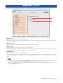
Here you can specify the memory that will be recalled for each input port of the GPI connector, and the open/closed status for each
output port.
NOTE
• The GPI connector is a D-sub 25-pin connector for GPI (General Purpose Interface), used to input and output control signals. The IMX644
has eight input ports and eight output ports, plus a dedicated output that indicates the unit’s power-on/off status.
• For details on the GPI connector’s specifications and example circuits, refer to the IMX644 Owner’s manual.
• GPI Input Terminal
Applying an appropriate input to one of the rear-panel GPI input ports recalls the assigned memory. For each input port, you can
specify the memory that will be recalled.
By default, memories 1–8 are assigned to input ports 1–8. If you want to change these assignments, click the Memory field of each
input port and select the desired memory from the list that appears. Select [NONE] if you don’t want to make an assignment.
• GPI Output Terminal
Here you can specify the open/closed status of each output port for each memory. This allows you to change the open/closed status
of the GPI connector’s output ports by recalling a memory.
By default, all buttons are off (gray); i.e., open. If you click a button to turn it on (green), that output port will change to the closed
state.
Click a name field to access the “Name of GPI OUT” dialog box, where you can edit the name of the output port.
GPI screen

IMX644 Manager Owner’s Manual
31
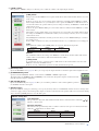
Here you can save your edited parameter settings in sixteen different memories, or recall previously-saved settings.
1 Memory list
This area shows the names of the sixteen memories.
If you want to edit the name of a memory, recall that memory; then click the Memory field in the header area, edit the name,
and re-save the memory.
2 Option buttons
These buttons select the memory to which Store or Recall operations will apply.
3 [Store] button
This stores the edited parameter settings into the specified memory.
Use the option buttons to select the memory number to which you want to store the edited settings, and click the [Store] button;
a confirmation dialog box will appear. Click [OK] to store the memory.
4 [Recall] button
This recalls the parameters stored in the memory.
Use the option buttons to select the number of the memory that you want to recall, and click the [Recall] button. A confirma-
tion dialog box will appear; click [OK] to recall the memory. When the memory has been recalled, the BLOCK screen will
appear.
NOTE
• You can also assign memories to the front panel MEMORY [A]–[D] buttons and use them to recall memories. In order to do this, you’ll
need to make memory assignments in the MEMORY ASSIGN field of the MISC screen (page 30).
• If you want to recall memories while connected online with the IMX644, use the [A]–[D] buttons in IMX644 Manager; not the
IMX644’s MEMORY [A]–[D] buttons.
MEMORY screen
1 2
3
4

IMX644 Manager Owner’s Manual
32
*1 Accessing the Device Manager
• Windows 7 Users
Choose [Start] → [Control Panel] → ([Hardware and Sound]) → [Device Manager]. Yamaha IMX644 USB Serial Converter is
shown in [Universal Serial Bus controllers].
• Windows Vista users
Choose [Start] → ([Settings]) → [Control Panel] → ([System and Maintenance]) → [Device Manager]. “Yamaha IMX644
USB Serial Converter” will appear under the “Universal Serial Bus Controllers” item, and “Yamaha IMX644 USB Serial Port
(COMn
(*2)
)” will appear under the “Ports (COM & LPT)” item.
• Windows XP users
Choose [Start] → ([Settings]) → [Control Panel], and double-click [System]. In the “System Properties” screen, select the
[Hardware] tab and then select [Device Manager]. “Yamaha IMX644 USB Serial Converter” will appear under the “USB (Uni-
versal Serial Bus) Controllers” item, and “Yamaha IMX644 USB Serial Port (COMn
(*2)
)” will appear under the “Ports (COM
& LPT)” item.
*2 The port number “n” will depend on the device.
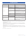
Troubleshooting
Symptom Cause Response
Can’t install IMX644 Manager.
You didn’t log on to Windows using
an account that has administrative
privileges.
Log on to Windows using an account that has administrative
privileges.
Can’t go online.
The IMX644 was not started up in
IMX644 Manager mode.
Power-on the IMX644 while holding down the IMX644’s
MEMORY [D] button.
Cable is disconnected or broken. Connect an unbroken cable.
IMX644 USB Driver is not installed.
Log onto Windows using an account that has administrative
privileges, and install the IMX644 USB Driver (For Win-
dows 7 user, page 5. For Windows Vista user, page 8. For
Windows XP user, page 12.)
IMX644 USB Driver is not installed
correctly.
If an exclamation mark (!) is showing to the left of “Yamaha
IMX644 USB Serial Converter” and/or “Yamaha IMX644
USB Serial Port (COMn
(*2)
)” in the Device Manager
(*1)
,
right-click it and select [Uninstall]. Then re-install the
driver.
The unit is connected via a straight
RS-232C cable.
Use a female-female cross-cable.
IMX644 Manager won’t detect the
IMX644.
Wait several seconds until the [Status] indicator lights
green.
Screen is not displayed correctly.
Not all characters are displayed.
Change the screen’s DPI setting
(*3)
to 96 DPI or 120 DPI.
Screen is not displayed correctly.
The parameter editing window
doesn’t open when the password
is entered.
The password may be incorrect.
If you don’t know the correct password, initialize the inter-
nal IMX644 memory. Initialization will return the settings
to their factory-set state, so be sure to save any important
settings as a file before you proceed. The IMX644 will be
initialized if you turn on the power while holding down its
MEMORY [A] and [D] buttons.

IMX644 Manager Owner’s Manual
33
*3 Accessing the screen DPI setting
• Windows 7 users
Choose [Start] → [Control Panel] → [Appearance and Personalization] → [Personalization]. In the left side of the window,
click [Adjust font size (DPI)] to access the screen DPI setting dialog box.
• Windows Vista users
Choose [Start] → ([Settings]) → [Control Panel] → [Appearance and Personalization] → [Personalization]. In the left side of
the window, click [Adjust font size (DPI)] to access the screen DPI setting dialog box.
• Windows XP users
Choose [Start] → ([Settings]) → [Control Panel] → [Screen] to access the “Display Properties” dialog box. In the [Settings]
tab, choose [Advanced] → [General] to access the DPI setting.

IMX644 Manager Owner’s Manual
34
ATTENTION
PLEASE READ THIS SOFTWARE LICENSE AGREEMENT (“AGREEMENT”) CAREFULLY BEFORE USING THIS SOFTWARE.
YOU ARE ONLY PERMITTED TO USE THIS SOFTWARE PURSUANT TO THE TERMS AND CONDITIONS OF THIS AGREE-
MENT. THIS AGREEMENT IS BETWEEN YOU (AS AN INDIVIDUAL OR LEGAL ENTITY) AND YAMAHA CORPORATION
(“YAMAHA”).
BY DOWNLOADING, INSTALLING, COPYING, OR OTHERWISE USING THIS SOFTWARE YOU ARE AGREEING TO BE
BOUND BY THE TERMS OF THIS LICENSE. IF YOU DO NOT AGREE WITH THE TERMS, DO NOT DOWNLOAD, INSTALL,
COPY, OR OTHERWISE USE THIS SOFTWARE. IF YOU HAVE DOWNLOADED OR INSTALLED THE SOFTWARE AND DO
NOT AGREE TO THE TERMS, PROMPTLY DELETE THE SOFTWARE.
1. GRANT OF LICENSE AND COPYRIGHT
Yamaha hereby grants you the right to use the software program(s) and data (“SOFTWARE”) accompanying this Agreement. The term
SOFTWARE shall encompass any updates to the accompanying software and data. The SOFTWARE is owned by Yamaha and/or
Yamaha’s licensor(s), and is protected by relevant copyright laws and all applicable treaty provisions. While you are entitled to claim
ownership of the data created with the use of SOFTWARE, the SOFTWARE will continue to be protected under relevant copyrights.
• You may use the SOFTWARE on your computer(s).
• You may make one or reasonable copies of the SOFTWARE in machine-readable form for backup purposes only, if the SOFTWARE is
on media where such backup copy is permitted. On the backup copy, you must reproduce Yamaha’s copyright notice and any other pro-
prietary legends that were on the original copy of the SOFTWARE.
• You may permanently transfer to a third party all your rights in the SOFTWARE, provided that you do not retain any copies and the
recipient reads and agrees to the terms of this Agreement.
2. RESTRICTIONS
• You may not engage in reverse engineering, disassembly, decompilation or otherwise deriving a source code form of the SOFTWARE
by any method whatsoever.
• You may not reproduce, modify, change, rent, lease, or distribute the SOFTWARE in whole or in part, or create derivative works of the
SOFTWARE.
• You may not electronically transmit the SOFTWARE from one computer to another or share the SOFTWARE in a network with other
computers.
• You may not use the SOFTWARE to distribute illegal data or data that violates public policy.
• You may not initiate services based on the use of the SOFTWARE without permission by Yamaha Corporation.
Copyrighted data, including but not limited to MIDI data for songs, obtained by means of the SOFTWARE, are subject to the following
restrictions which you must observe.
• Data received by means of the SOFTWARE may not be used for any commercial purposes without permission of the copyright owner.
• Data received by means of the SOFTWARE may not be duplicated, transferred, or distributed, or played back or performed for listeners
in public without permission of the copyright owner.
• The encryption of data received by means of the SOFTWARE may not be removed nor may the electronic watermark be modified with-
out permission of the copyright owner.
3. TERMINATION
This Agreement becomes effective on the day that you receive the SOFTWARE and remains effective until terminated. If any copyright
law or provisions of this Agreement is violated, the Agreement shall terminate automatically and immediately without notice from
Yamaha. Upon such termination, you must immediately destroy the licensed SOFTWARE, any accompanying written documents and all
copies thereof.
4. DISCLAIMER OF WARRANTY ON SOFTWARE
You expressly acknowledge and agree that use of the SOFTWARE is at your sole risk. The SOFTWARE and related documentation are
provided “AS IS” and without warranty of any kind. NOTWITHSTANDING ANY OTHER PROVISION OF THIS AGREEMENT,
YAMAHA EXPRESSLY DISCLAIMS ALL WARRANTIES AS TO THE SOFTWARE, EXPRESS, AND IMPLIED, INCLUDING
BUT NOT LIMITED TO THE IMPLIED WARRANTIES OF MERCHANTABILITY, FITNESS FOR A PARTICULAR PURPOSE
AND NON-INFRINGEMENT OF THIRD PARTY RIGHTS. SPECIFICALLY, BUT WITHOUT LIMITING THE FOREGOING,
YAMAHA DOES NOT WARRANT THAT THE SOFTWARE WILL MEET YOUR REQUIREMENTS, THAT THE OPERATION OF
THE SOFTWARE WILL BE UNINTERRUPTED OR ERROR-FREE, OR THAT DEFECTS IN THE SOFTWARE WILL BE COR-
RECTED.
5. LIMITATION OF LIABILITY
YAMAHA’S ENTIRE OBLIGATION HEREUNDER SHALL BE TO PERMIT USE OF THE SOFTWARE UNDER THE TERMS
HEREOF. IN NO EVENT SHALL YAMAHA BE LIABLE TO YOU OR ANY OTHER PERSON FOR ANY DAMAGES, INCLUD-
ING, WITHOUT LIMITATION, ANY DIRECT, INDIRECT, INCIDENTAL OR CONSEQUENTIAL DAMAGES, EXPENSES, LOST
PROFITS, LOST DATA OR OTHER DAMAGES ARISING OUT OF THE USE, MISUSE OR INABILITY TO USE THE SOFTWARE,
EVEN IF YAMAHA OR AN AUTHORIZED DEALER HAS BEEN ADVISED OF THE POSSIBILITY OF SUCH DAMAGES. In no
event shall Yamaha’s total liability to you for all damages, losses and causes of action (whether in contract, tort or otherwise) exceed the
amount paid for the SOFTWARE.
SOFTWARE LICENSE AGREEMENT

6. THIRD PARTY SOFTWARE
Third party software and data (“THIRD PARTY SOFTWARE”) may be attached to the SOFTWARE. If, in the written materials or the
electronic data accompanying the Software, Yamaha identifies any software and data as THIRD PARTY SOFTWARE, you acknowledge
and agree that you must abide by the provisions of any Agreement provided with the THIRD PARTY SOFTWARE and that the party pro-
viding the THIRD PARTY SOFTWARE is responsible for any warranty or liability related to or arising from the THIRD PARTY SOFT-
WARE. Yamaha is not responsible in any way for the THIRD PARTY SOFTWARE or your use thereof.
•Yamaha provides no express warranties as to the THIRD PARTY SOFTWARE. IN ADDITION, YAMAHA EXPRESSLY DIS-
CLAIMS ALL IMPLIED WARRANTIES, INCLUDING BUT NOT LIMITED TO THE IMPLIED WARRANTIES OF MER-
CHANTABILITY AND FITNESS FOR A PARTICULAR PURPOSE, as to the THIRD PARTY SOFTWARE.
•Yamaha shall not provide you with any service or maintenance as to the THIRD PARTY SOFTWARE.
•Yamaha is not liable to you or any other person for any damages, including, without limitation, any direct, indirect, incidental or conse-
quential damages, expenses, lost profits, lost data or other damages arising out of the use, misuse or inability to use the THIRD PARTY
SOFTWARE.
7. GENERAL
This Agreement shall be interpreted according to and governed by Japanese law without reference to principles of conflict of laws. Any
dispute or procedure shall be heard before the Tokyo District Court in Japan. If for any reason a court of competent jurisdiction finds any
portion of this Agreement to be unenforceable, the remainder of this Agreement shall continue in full force and effect.
8. COMPLETE AGREEMENT
This Agreement constitutes the entire agreement between the parties with respect to use of the SOFTWARE and any accompanying writ-
ten materials and supersedes all prior or contemporaneous understandings or agreements, written or oral, regarding the subject matter of
this Agreement. No amendment or revision of this Agreement will be binding unless in writing and signed by a fully authorized represen-
tative of Yamaha.
U.R.G., Pro Audio Division
© 2009 Yamaha Corporation
008AP B0
-
 1
1
-
 2
2
-
 3
3
-
 4
4
-
 5
5
-
 6
6
-
 7
7
-
 8
8
-
 9
9
-
 10
10
-
 11
11
-
 12
12
-
 13
13
-
 14
14
-
 15
15
-
 16
16
-
 17
17
-
 18
18
-
 19
19
-
 20
20
-
 21
21
-
 22
22
-
 23
23
-
 24
24
-
 25
25
-
 26
26
-
 27
27
-
 28
28
-
 29
29
-
 30
30
-
 31
31
-
 32
32
-
 33
33
-
 34
34
-
 35
35


in andere talen
- English: Yamaha IMX644 Owner's manual
- italiano: Yamaha IMX644 Manuale del proprietario
- русский: Yamaha IMX644 Инструкция по применению
- français: Yamaha IMX644 Le manuel du propriétaire
- español: Yamaha IMX644 El manual del propietario
- Deutsch: Yamaha IMX644 Bedienungsanleitung
- português: Yamaha IMX644 Manual do proprietário
- dansk: Yamaha IMX644 Brugervejledning
- suomi: Yamaha IMX644 Omistajan opas
- čeština: Yamaha IMX644 Návod k obsluze
- svenska: Yamaha IMX644 Bruksanvisning
- Türkçe: Yamaha IMX644 El kitabı
- polski: Yamaha IMX644 Instrukcja obsługi
- română: Yamaha IMX644 Manualul proprietarului