Yamaha DTX900M de handleiding
- Categorie
- Audio-equalizers
- Type
- de handleiding

DTX900
DTX900M
EN
Owner’s Manual

PLEASE KEEP THIS MANUAL
This product utilizes batteries or an external power supply (adapter). DO
NOT connect this product to any power supply or adapter other than one
described in the manual, on the name plate, or specifically recom-
mended by Yamaha.
WARNING: Do not place this product in a position where anyone could
walk on, trip over ,or roll anything over power or connecting cords of any
kind. The use of an extension cord is not recommended! If you must use
an extension cord, the minimum wire size for a 25’ cord (or less ) is 18
AWG. NOTE: The smaller the AWG number ,the larger the current han-
dling capacity. For longer extension cords, consult a local electrician.
This product should be used only with the components supplied or; a
cart, rack, or stand that is recommended by Yamaha. If a cart, etc., is
used, please observe all safety markings and instructions that accom-
pany the accessory product.
SPECIFICATIONS SUBJECT TO CHANGE:
The information contained in this manual is believed to be correct at the
time of printing. However, Yamaha reserves the right to change or modify
any of the specifications without notice or obligation to update existing
units.
This product, either alone or in combination with an amplifier and head-
phones or speaker/s, may be capable of producing sound levels that
could cause permanent hearing loss. DO NOT operate for long periods
of time at a high volume level or at a level that is uncomfortable. If you
experience any hearing loss or ringing in the ears, you should consult an
audiologist.
IMPORTANT: The louder the sound, the shorter the time period before
damage occurs.
Some Yamaha products may have benches and / or accessory mounting
fixtures that are either supplied with the product or as optional accesso-
ries. Some of these items are designed to be dealer assembled or
installed. Please make sure that benches are stable and any optional fix-
tures (where applicable) are well secured BEFORE using.
Benches supplied by Yamaha are designed for seating only. No other
uses are recommended.
NOTICE:
Service charges incurred due to a lack of knowledge relating to how a
function or effect works (when the unit is operating as designed) are not
covered by the manufacturer’s warranty, and are therefore the owners
responsibility. Please study this manual carefully and consult your dealer
before requesting service.
ENVIRONMENTAL ISSUES:
Yamaha strives to produce products that are both user safe and environ-
mentally friendly. We sincerely believe that our products and the produc-
tion methods used to produce them, meet these goals. In keeping with
both the letter and the spirit of the law, we want you to be aware of the
following:
Battery Notice:
This product MAY contain a small non-rechargeable battery which (if
applicable) is soldered in place. The average life span of this type of bat-
tery is approximately five years. When replacement becomes necessary,
contact a qualified service representative to perform the replacement.
This product may also use “household” type batteries. Some of these
may be rechargeable. Make sure that the battery being charged is a
rechargeable type and that the charger is intended for the battery being
charged.
When installing batteries, do not mix batteries with new, or with batteries
of a different type. Batteries MUST be installed correctly. Mismatches or
incorrect installation may result in overheating and battery case rupture.
Warning:
Do not attempt to disassemble, or incinerate any battery. Keep all batter-
ies away from children. Dispose of used batteries promptly and as regu-
lated by the laws in your area. Note: Check with any retailer of
household type batteries in your area for battery disposal information.
Disposal Notice:
Should this product become damaged beyond repair, or for some reason
its useful life is considered to be at an end, please observe all local,
state, and federal regulations that relate to the disposal of products that
contain lead, batteries, plastics, etc. If your dealer is unable to assist
you, please contact Yamaha directly.
NAME PLATE LOCATION:
The name plate is located on the bottom of the product. The model num-
ber, serial number, power requirements, etc., are located on this plate.
You should record the model number, serial number, and the date of pur-
chase in the spaces provided below and retain this manual as a perma-
nent record of your purchase.
Model
Serial No.
Purchase Date
SPECIAL MESSAGE SECTION
92-BP (bottom)
The model number, serial number, power requirements, etc., may be found on or near the name plate,
which is at the bottom of the unit. You should note this serial number in the space provided below and
retain this manual as a permanent record of your purchase to aid identification in the event of theft.
Model No.
Serial No.
(bottom_en_01)

1. IMPORTANT NOTICE: DO NOT MODIFY THIS UNIT!
This product, when installed as indicated in the instructions con-
tained in this manual, meets FCC requirements. Modifications not
expressly approved by Yamaha may void your authority, granted by
the FCC, to use the product.
2. IMPORTANT: When connecting this product to accessories and/
or another product use only high quality shielded cables. Cable/s
supplied with this product MUST be used. Follow all installation
instructions. Failure to follow instructions could void your FCC
authorization to use this product in the USA.
3. NOTE: This product has been tested and found to comply with the
requirements listed in FCC Regulations, Part 15 for Class “B” digital
devices. Compliance with these requirements provides a reason-
able level of assurance that your use of this product in a residential
environment will not result in harmful interference with other elec-
tronic devices. This equipment generates/uses radio frequencies
and, if not installed and used according to the instructions found in
the users manual, may cause interference harmful to the operation
of other electronic devices. Compliance with FCC regulations does
* This applies only to products distributed by YAMAHA CORPORATION OF AMERICA. (class B)
not guarantee that interference will not occur in all installations. If
this product is found to be the source of interference, which can be
determined by turning the unit “OFF” and “ON”, please try to elimi-
nate the problem by using one of the following measures:
Relocate either this product or the device that is being affected by
the interference.
Utilize power outlets that are on different branch (circuit breaker or
fuse) circuits or install AC line filter/s.
In the case of radio or TV interference, relocate/reorient the
antenna. If the antenna lead-in is 300 ohm ribbon lead, change the
lead-in to co-axial type cable.
If these corrective measures do not produce satisfactory results,
please contact the local retailer authorized to distribute this type of
product. If you can not locate the appropriate retailer, please con-
tact Yamaha Corporation of America, Electronic Service Division,
6600 Orangethorpe Ave, Buena Park, CA90620
The above statements apply ONLY to those products distributed by
Yamaha Corporation of America or its subsidiaries.
FCC INFORMATION (U.S.A.)
* This applies only to products distributed by
YAMAHA CORPORATION OF AMERICA.
COMPLIANCE INFORMATION STATEMENT
(DECLARATION OF CONFORMITY PROCEDURE)
Responsible Party : Yamaha Corporation of America
Address : 6600 Orangethorpe Ave., Buena Park, Calif. 90620
Telephone : 714-522-9011
Type of Equipment : DRUM TRIGGER MODULE
Model Name : DTX900/DTX900M
This device complies with Part 15 of the FCC Rules.
Operation is subject to the following two conditions:
1) this device may not cause harmful interference, and
2) this device must accept any interference received including interference
that may cause undesired operation.
See user manual instructions if interference to radio reception is sus-
pected.
(FCC DoC)
IMPORTANT NOTICE FOR THE UNITED KINGDOM
Connecting the Plug and Cord
IMPORTANT. The wires in this mains lead are coloured in
accordance with the following code:
BLUE : NEUTRAL
BROWN : LIVE
As the colours of the wires in the mains lead of this apparatus
may not correspond with the coloured makings identifying the
terminals in your plug proceed as follows:
The wire which is coloured BLUE must be connected to the
terminal which is marked with the letter N or coloured BLACK.
The wire which is coloured BROWN must be connected to the
terminal which is marked with the letter L or coloured RED.
Making sure that neither core is connected to the earth termi-
nal of the three pin plug.
Information for Users on Collection and Disposal of Old Equipment
This symbol on the products, packaging, and/or accompanying documents means that used electrical and electronic products should not be
mixed with general household waste.
For proper treatment, recovery and recycling of old products, please take them to applicable collection points, in accordance with your national
legislation and the Directives 2002/96/EC.
By disposing of these products correctly, you will help to save valuable resources and prevent any potential negative effects on human health
and the environment which could otherwise arise from inappropriate waste handling.
For more information about collection and recycling of old products, please contact your local municipality, your waste disposal service or the
point of sale where you purchased the items.
[For business users in the European Union]
If you wish to discard electrical and electronic equipment, please contact your dealer or supplier for further information.
[Information on Disposal in other Countries outside the European Union]
This symbol is only valid in the European Union. If you wish to discard these items, please contact your local authorities or dealer and ask for the
correct method of disposal.
OBSERVERA!
Apparaten kopplas inte ur växelströmskällan (nätet) så länge som den ar ansluten till vägguttaget,
även om själva apparaten har stängts av.
ADVARSEL: Netspændingen til dette apparat er IKKE afbrudt, sålæenge netledningen siddr i en
stikkontakt, som er t endt — også selvom der or slukket på apparatets afbryder.
VAROITUS: Laitteen toisiopiiriin kytketty käyttökytkin ei irroita koko laitetta verkosta.
(standby)
• This applies only to products distributed by
Yamaha Music U.K. Ltd.
(2 wires)

Sampling memory included as standard
The DTX900M comes with 512 MB of sampling memory (SDRAM) built in. Accordingly, external audio can be sam-
pled without the need for a separately-sold memory chip (DIMM).
Addition of a new Auto Power-Off function
The DTX900M features an Auto Power-Off function that will help to save energy should you forget to turn it off your-
self. This function automatically turns off the drum trigger module after a set period of inactivity.
Setting the Auto Power-Off function
Using the following procedure, you can set the amount of time that the Auto Power-Off function waits before turning
off the drum trigger module.
Shortcut for disabling the Auto Power-Off function
If you hold down the [REC] button while turn-
ing on the DTX900M, the Auto Power-Off
function will be disabled (and the message
“Auto power off disabled” will be displayed).
This function will remain disabled until you set
a new Auto Power-Off time.
IMPORTANT
• Because of the addition of SDRAM, separately-sold memory chips (DIMM) can no longer be installed.
Accordingly, the Optional DIMM Installation section of this Owner’s Manual (on pages 147 to 149) does not
apply to the DTX900M.
• Whenever you encounter the phrase “DIMM (sold separately)” in this Owner’s Manual, you should interpret it
as meaning “SDRAM (built-in)”.
• SDRAM supports both writing and deleting of data; however, the content of this memory is cleared whenever the power is turned off.
Procedure Settings (minutes) Default setting (minutes)
[UTILITY] [F1] GENERAL [SF5] OTHER
Change the AutoPowerOff setting [STORE]
off (Auto Power-Off disabled), 5, 10, 15, 30,
60, 120
30
NOTICE
For DTX900M Owners
Differences from DTX900
Building on the performance and functionality of the DTX900—the flagship model in our lineup
of drum trigger modules—the enhanced DTX900M model delivers added convenience.
These DTX900M enhancements are described in detail below.
Reading this Owner’s Manual
The content of this manual is identical to that of the original DTX900 Owner’s Manual. With the exception of
the functions described in this section, there are no other differences between the DTX900 and the
DTX900M. Therefore, whenever you encounter the term “DTX900” in this Owner’s Manual, you should inter-
pret it as meaning “DTX900M”.

Addition of new Trigger Setups
Two new types of Trigger Setups for DTX920K are now supported. (Page 23)
Accordingly, the complete Trigger Setup List is as follows.
When you specify the model number, the DTX900M will automatically optimize the trigger output levels for all of your
pads.
* In the default setting, “PRE:02 920K Normal” for DTX920K is selected.
Addition of new pad types
New types of pads are now supported as follows. (Page 109)
KP100, KU100, XP80, XP70, TP70S, TP70, PCY100, PCY90
Accordingly, the complete pad-type table is as follows.
Expansion of the input gain setting range
The input gain setting range is expanded from between 0 and 63 to between 0 to 127. (Page 109)
• The DTX900M remains charged and draws a small amount of power even when turned off. To shut it down completely, therefore, unplug it from
the mains power supply.
• In certain modes of operation, the Auto Power-Off function may not turn off the drum module when the set time has elapsed. We recommend,
therefore, that you always turn off the drum module manually when you are finished using it.
• If your drum module is connected to other equipment such as an amplifier, speakers, or a computer, but you do not intend to use it for some time,
we recommend that you turn off all devices as described in their owner’s manuals. Doing so eliminates the risk of damage to the other equipment.
If you do not want the drum module to turn off automatically when connected to other equipment, disable the Auto Power-Off function.
• When the Auto Power-Off function turns off the drum module, any unsaved data will be lost. Be sure, therefore, to store your work before the drum
module turns off.
• If the drum module’s AutoPowerOff parameter is set to “off”, this setting will be retained when you import system data that was stored externally,
regardless of the Auto Power-Off setting contained in that data. If, however, an Auto Power-Off time has been set using the AutoPowerOff parame-
ter and system data is imported, the Auto Power-Off setting contained in that data will be applied.
NOTE
• Settings for the Auto Power-Off function do not represent exact times and actual power-off times may vary to a certain extent.
• To turn the drum module back on after it has been turned off by the Auto Power-Off function, press the (Standby/On) switch once to return it to
the Standby position, and then press it once again to the On position.
No. Name Description
PRE: 01 920K Wide
For DTX920K
Wide dynamic range. This setting is designed for maximum expressive control,
allowing performance subtleties over a wide dynamic range.
PRE: 02 920K Normal Normal setting
PRE: 03 XP Wide
For DTX950K/
900K
Wide dynamic range. This setting is designed for maximum expressive control,
allowing performance subtleties over a wide dynamic range.
PRE: 04 XP Normal Normal setting
PRE: 05 SP Wide
For DTXTREME
III Special
Drum Set
Wide dynamic range. This setting is designed for maximum expressive control,
allowing performance subtleties over a wide dynamic range.
PRE: 06 SP Normal Normal setting
PRE: 07 SP Narrow
Controlled dynamic range delivers stable trigger detection. This setting is designed
for producing a smoother, more uniform sound with reduced volume fluctuations.
PRE: 08 STD Wide
For DTXTREME
III Standard
Drum Set
Wide dynamic range. This setting is designed for maximum expressive control,
allowing performance subtleties over a wide dynamic range.
PRE: 09 STD Normal Normal setting
PRE: 10 STD Narrow
Controlled dynamic range delivers stable trigger detection. This setting is designed
for producing a smoother, more uniform sound with reduced volume fluctuations.
PRE: 11
DT 10/20 —
Use for DT10/20 drum trigger systems applied to acoustic drums.
USR: 01 - 05 User Trigger — Allows creation of custom trigger setups.
Settings
KP125W, KP125, KP100, KP65, KU100, XP120/100 (for snare), XP120/100 (for tom), XP80(for snare), XP80(for tom),
XP70(for snare), XP70(for tom), TP120SD/100 (for snare), TP120SD/100 (for tom), TP70S (for snare), TP70S (for
tom), TP70S(for hihat), TP70, TP65S (for snare), TP65S (for tom), TP65S (for hihat), TP65, PCY155, PCY135,
PCY150S, PCY130SC, PCY130S/130, PCY100, PCY90, PCY65S/65, RHH135, RHH130, DT10/20 (for snare), DT10/
20(for HiTom), DT10/20 (for LoTom), DT10/20 (for Kick), TRG Snare, TRG HiTom, TRG LoTom, TRG Kick
NOTICE

PRECAUTIONS
PLEASE READ CAREFULLY BEFORE PROCEEDING
* Please keep this manual in a safe place for future reference.
WARNING
Always follow the basic precautions listed below to avoid the possibility of serious injury or even death from electrical
shock, short-circuiting, damages, fire or other hazards. These precautions include, but are not limited to, the following:
• Do not place the power cord near heat sources such as heaters or
radiators, and do not excessively bend or otherwise damage the
cord, place heavy objects on it, or place it in a position where
anyone could walk on, trip over, or roll anything over it.
• Only use the voltage specified as correct for the instrument. The
required voltage is printed on the name plate of the instrument.
• Use the specified adaptor (page 155) only. Using the wrong adaptor
can result in damage to the instrument or overheating.
• Check the electric plug periodically and remove any dirt or dust
which may have accumulated on it.
• This instrument contains no user-serviceable parts. Do not open the
instrument or attempt to disassemble or modify the internal
components in any way. If it should appear to be malfunctioning,
discontinue use immediately and have it inspected by qualified
Yamaha service personnel.
• Do not expose the instrument to rain, use it near water or in damp or
wet conditions, or place containers on it containing liquids which
might spill into any openings. If any liquid such as water seeps into
the instrument, turn off the power immediately and unplug the
power cord from the AC outlet. Then have the instrument inspected
by qualified Yamaha service personnel.
• Never insert or remove an electric plug with wet hands.
• Do not put burning items, such as candles, on the unit.
A burning item may fall over and cause a fire.
• When one of the following problems occur, immediately turn off the
power switch and disconnect the electric plug from the outlet. Then
have the device inspected by Yamaha service personnel.
• The power cord or plug becomes frayed or damaged.
• It emits unusual smells or smoke.
• Some object has been dropped into the instrument.
• There is a sudden loss of sound during use of the instrument.
CAUTION
Always follow the basic precautions listed below to avoid the possibility of physical injury to you or others, or damage
to the instrument or other property. These precautions include, but are not limited to, the following:
• Do not connect the instrument to an electrical outlet using a
multiple-connector. Doing so can result in lower sound quality, or
possibly cause overheating in the outlet.
• When removing the electric plug from the instrument or an outlet,
always hold the plug itself and not the cord. Pulling by the cord can
damage it.
• Remove the electric plug from the outlet when the instrument is not
to be used for extended periods of time, or during electrical storms.
• Do not place the instrument in an unstable position where it might
accidentally fall over.
• Before moving the instrument, remove all connected cables.
• When setting up the product, make sure that the AC outlet you are
using is easily accessible. If some trouble or malfunction occurs,
immediately turn off the power switch and disconnect the plug from
the outlet. Even when the power switch is turned off, electricity is
still flowing to the product at the minimum level. When you are not
using the product for a long time, make sure to unplug the power
cord from the wall AC outlet.
• Use only the stand/rack specified for the instrument. When attaching
the stand or rack, use the provided screws only. Failure to do so
could cause damage to the internal components or result in the
instrument falling over.
Power supply/AC power adaptor
Do not open
Water warning
Fire warning
If you notice any abnormality
Power supply/AC power adaptor
Location
(7)-1 1/2

• Before connecting the instrument to other electronic components,
turn off the power for all components. Before turning the power on
or off for all components, set all volume levels to minimum.
• Be sure to set the volumes of all components at their minimum
levels and gradually raise the volume controls while playing the
instrument to set the desired listening level.
• Never insert or drop paper, metallic, or other objects into the gaps
on the panel.
• Do not rest your weight on, or place heavy objects on the
instrument, and do not use excessive force on the buttons, switches
or connectors.
• Do not use the instrument/device or headphones for a long period of
time at a high or uncomfortable volume level, since this can cause
permanent hearing loss. If you experience any hearing loss or
ringing in the ears, consult a physician.
Always turn the power off when the instrument is not in use.
Even when the power switch is in the “STANDBY” position, electricity is still flowing to the instrument at the minimum level. When you are not using
the instrument for a long time, make sure you unplug the power cord from the wall AC outlet.
Connections Handling caution
Yamaha cannot be held responsible for damage caused by improper use or modifications to the instrument, or data that is lost or destroyed.
NOTICE
To avoid the possibility of damage to the product, data or other property, follow the notices below.
■ Handling and Maintenance
• Do not use the instrument in the vicinity of a TV, radio, stereo equipment, mobile phone, or other electric devices. Otherwise, the
instrument, TV, or radio may generate noise.
• Do not expose the instrument to excessive dust or vibrations, or extreme cold or heat (such as in direct sunlight, near a heater, or in a car
during the day) to prevent the possibility of panel disfiguration or damage to the internal components.
• Do not place vinyl, plastic or rubber objects on the instrument, since this might discolor the panel or keyboard.
• When cleaning the instrument, use a soft, dry or slightly damp cloth. Do not use paint thinners, solvents, cleaning fluids, or chemical-
impregnated wiping cloths.
■ Saving data
• DRAM data (page 76) is lost when you turn off the power to the instrument. Save the data to external USB storage device.
•To protect against data loss through media damage, we recommend that you save your important data onto two USB storage devices.
■ About the latest Firmware Version
Yamaha may from time to time update firmware of the product without notice for improvement. We recommend that you check our web site
for later releases and upgrade your firmware of the DTX900.
http://download.yamaha.com/
Note that the explanations in this Owner’s Manual apply to the version of firmware when this Owner’s Manual was produced. For details about
functions added in later releases, refer to the above website.
■ About the pads
This Owner’s Manual described the model names of the drum pads which can be connected to the DTX900. Note that these were the latest
models at the time this Owner’s Manual was produced. For details about more recently released models, refer to the following website.
http://www.yamaha.com/
(7)-2 2/2

6
DTX900 Owner’s Manual
Introduction
Thank you for purchasing the YAMAHA DTX900.
The new DTX900 incorporates the highly acclaimed AWM2 tone generator
and a sophisticated music sequencer.
In addition to the functions of its predecessor, DTX900 provides full support of the current
Yamaha trigger products and also sports a USB terminal for MIDI connections (in addition to conventional MIDI
connectors) — and has a built-in sampling feature that allows you to create your own Drum Voices.
The instrument is ideal for virtually any application — live performance, rhythm training, music creation and
studio recording. To get the most out of your DTX900, please read this manual carefully. After reading through
the manual, make sure to store it in a safe place so that you can refer back to it again as needed.
Included Accessories
● AC Power Adaptor*
*May not be included depending on your particular area. Please check with your Yamaha dealer.
● Module stand
● Module stand fastening screws (4; included)
● Owner’s Manual (this document)
● Data List
● DVD-ROM* (containing software)
*For details on the bundled DVD-ROM, see page 159.
Information
■ About copyrights
• Copying of the commercially available musical data including but not limited to MIDI data and/or audio data is strictly prohibited
except for your personal use.
• This product incorporates and bundles computer programs and contents in which Yamaha owns copyrights or with respect to which
it has license to use others’ copyrights. Such copyrighted materials include, without limitation, all computer software, style files,
MIDI files, WAVE data, musical scores and sound recordings. Any unauthorized use of such programs and contents outside of per-
sonal use is not permitted under relevant laws. Any violation of copyright has legal consequences. DON’T MAKE, DISTRIBUTE
OR USE ILLEGAL COPIES.
■ About functions/data bundled with the instrument
• This device is capable of using various types/formats of music data by optimizing them to the proper format music data for use with
the device in advance. As a result, this device may not play them back precisely as their producers or composers originally intended.
DTX900 : T-1240067
DTX900M : T-1250147
■ About this manual
• The contents of this Owner’s Manual and the copyrights thereof are under exclusive ownership by Yamaha Corporation.
• The illustrations and LCD screens as shown in this manual are for instructional purposes only, and may appear somewhat different
from those on your instrument.
• The company names and product names in this manual are the trademarks or registered trademarks of their respective companies.

DTX900 Owner’s Manual
7
Main Features
Designed primarily for professional drummers, the DTX900 has a Drum Trigger feature, a 64-note polyphonic Tone Gener-
ator, a built-in Sampling feature that lets you expand the available sounds, a high-performance Metronome (Click) feature and
a built-in music sequencer that enables recording and playback of rhythm or accompaniment patterns, and even lets you create
an entire Song. The DTX900 is an exceptionally versatile instrument that can be used in a variety of situations such as live
performance, personal practice, and much more.
■ Drum Trigger
• The DTX900 drum trigger module is compatible with the
new pads (XP series.)
• Built into the unit are 15 Trigger Input jacks and a Hi-Hat
Controller jack.
• The instrument also features jacks that are compatible with
two-zone or three-zone pads (pads that transmit different
signals depending on the area that is hit). Moreover, the
snare drum jack is compatible with pad-controller-equipped
pads. This lets you adjust the ‘virtual’ snares and the tun-
ing—just as you would with a snare drum. All in all, the
DTX900 offers virtually the same playability, expressive-
ness and functionality that you get in an acoustic drum kit.
• By combining the Stack function, which lets you play mul-
tiple voices (MIDI notes) at the same time, along with the
Alternate function, which lets you play a sequence of the
Stack program, you can create complex performances and
play passages in realtime that would otherwise be impossi-
ble on conventional acoustic drums.
■ Tone Generator
• The DTX900 is equipped with a high-quality, 16-bit AWM2
(PCM) tone generator with 64-voice polyphony that pro-
duces dynamic voices or exceptional realism.
• The instrument has a wide variety of Voices including
authentic acoustic drums, unique electronic percussion,
sound effects, and normal keyboard Voices. It can also be
used as a high-quality drum tone generator along with vari-
ous MIDI devices, even without using the Drum Pads.
• Also included in the unit are 50 preset Drum Kits which
contain natural, authentic sounding acoustic Drum Kits, and
cover a wide range of music genres, such as rock, funk,
jazz, reggae, Latin, etc. Moreover, User kit memory is avail-
able for storing 50 sets. With this, you can set up your own
original Drum Kits using the various Drum Voices.
• The Sampling feature lets you record the audio signal to the
DTX900 or load the audio file from the USB storage device
to create your original Voice. The created Voice can be
assigned to the Drum Kit as desired.
• The instrument is equipped with a Variation Effect which
can be used for each Drum Kit as well as Reverb, Chorus
and Master Effects which can be used for the entire
DTX900. In addition, an Insertion Effect for the sound input
via the AUX IN/SAMPLING IN jack is provided, allowing
you to adjust the quality of AUX IN/SAMPLING IN sound
or record an audio signal to which the Insertion Effect is
applied to the DTX900 in the Sampling mode.
■ Music Sequencer (Song)
• The built-in sequencer contains a wide variety of Preset
Songs. The Mute function lets you turn on/off the rhythm
(drum & percussion sound) part, bass part and other accom-
paniment part individually, or turn each track on/off.
• The DTX900 also allows you to record your performance in
real time and allows you to play along with the Song data
while muting the original drum part.
•Four Pad Songs can be individually controlled and simulta-
neously played by trigger input from the pads.
■ High-performance Metronome (Click)
• The DTX900 provides a comprehensive, multi-function
metronome, allowing various click settings such as voice
and tuning for each beat timing. Furthermore, you can
change the accent timing and use the Measure Break feature
that alternates click playback between on and off (mute)
repeatedly.
• The Groove Check Function checks and provides instant
feedback on your rhythmic skills—a powerful tool for
improving your technique. It includes a Rhythm Gate func-
tion that produces sounds only if your timing is accurate.
■ Chain
• Programming a Chain sequence lets you call up the Drum
Kit number, Song number and Click settings (tempo and
beat) in order during your live performance. Each step in
the programmed Chain can be called up by hitting the pad.
■ Interfaces
• The USB terminal and MIDI connectors on the rear panel
let you connect a computer and other MIDI devices to the
DTX900. These enable fast, efficient and comprehensive
music-creation capabilities, letting you play sounds from an
external tone generator as well as record your own perfor-
mance using the included Cubase AI.
• Each of the six INDIVIDUAL OUTPUT jacks can sepa-
rately output any specified Drum Voice such as Snare and
Tom to send each instrument signal to an external mixer for
live performance or recording session. In addition, a Digital
Output (S/PDIF) terminal lets you transfer the DTX900 ste-
reo sounds to other devices with no noise and full digital
quality.
• The instrument has a built-in AUX IN/SAMPLING IN jack
which lets you connect a CD player to the DTX900—allow-
ing you to play the instrument along with CD playback as
well as use the powerful Sampling feature.

8
DTX900 Owner’s Manual
Contents
Introduction .............................................................6
Included Accessories ..............................................6
Main Features .........................................................7
Panel Controls..................................................... 10
Basic Operation................................................... 13
Setting Up ............................................................ 16
Connecting the Pads.............................................16
Setting Up the Power Supply ................................18
Turning the Power On...........................................18
Connecting to Speakers or Headphones..............19
Connecting to External Audio Equipment .............19
Connecting External MIDI Devices .......................20
Connecting a USB Storage Device.......................21
Selecting the Trigger Setup ..................................22
Connecting a Computer ........................................24
Setting up Cubase Remote Control ......................25
Creating a Song by Using a Computer .................26
Adjusting the Sound and Display Contrast ...........27
Quick Guide 28
How to Play the Drum Pads ............................... 28
Playing the DTX900............................................. 30
Hitting the Pads.....................................................30
Selecting a Drum Kit .............................................30
Adjusting the Volume by Using the Sliders...........31
Playing Along With the Click ............................. 32
Start the Click (Metronome) ..................................32
Changing the Tempo and Time Signature
(Beat) of the Click .................................................33
Tap Tempo ........................................................... 34
Playing Along With a Song ................................ 35
Song Playback ......................................................35
Adjusting the Volume of the Song
Accompaniment ....................................................38
Changing the Tempo of the Song.........................38
Song Part Mute Setting.........................................39
Creating a Drum Kit ............................................ 40
Recording Your Drum Performance to a Song
.. 43
Recording System.................................................43
Recording Methods...............................................43
Recording Your Drum Performance to a Song .....44
Recording Additional Notes to an
Already-recorded Track (Overdub) .......................46
Recording Along With the Preset Song ................46
Re-recording a Track After Clearing .....................48
Assigning a Name to a User Song........................49
Using the Groove Check Function.....................50
Setting the Check Timing ..................................... 50
Trying Out Groove Check..................................... 51
Trying Out Rhythm Gate....................................... 52
Saving the Created Data to a USB Storage
Device ...................................................................54
File/Folder Selection............................................. 54
Saving the Created Data to a USB Storage
Device................................................................... 55
Loading a File Saved to a USB Storage Device... 56
Reference 57
Basic Structure of the DTX900 ...........................57
The Functional Blocks .......................................... 57
Pads (Trigger Input Sources) and
Trigger Signals ..................................................... 58
Tone Generator Block (Drum Kits and
Drum Voices)........................................................ 62
Sampling............................................................... 65
Song ..................................................................... 67
Effects................................................................... 68
Internal Memory and File Management................ 76
Drum Kit Mode [DRUM KIT] ................................78
Basic Procedure in the Drum Kit Mode ................ 78
Selecting a Drum Kit [F1] PLAY ........................... 79
Setting Drum Voice Parameters [F2] VOICE........ 79
Programming the Stack/Alternate [F3] STK/ALT.. 86
Effect Settings [F4] EFFECT ................................ 89
Pad Settings [F5] PAD.......................................... 92
Other Settings [F6] OTHER.................................. 95
Song Mode [SONG] .............................................98
Song Play [F1] PLAY............................................ 98
Song Recording [F1] PLAY → [REC] ................... 98
Song Jobs [F2] JOB ............................................. 98
Click Mode [CLICK] ...........................................104
Basic Procedure in the Click Mode..................... 104
Basic Settings of the Click Sound [F1] PLAY ..... 105
Click Voice Settings [F2] VOICE ........................ 106
Tap Tempo Function [F3] TAP ........................... 106
Groove Check Function [F4] GROOVE.............. 106
Click Sound Settings [F5] OTHER...................... 107
Trigger Mode [TRIGGER] ..................................108
Basic Procedure in the Trigger Mode ................. 108
Selecting the Trigger Setup [F1] SELECT.......... 109
Selecting the Pad Type [F2] TYPE..................... 109
Trigger Sensitivity Settings [F3] SENS ............... 109
Setting the Rejection [F4] REJECT .................... 110
Other Settings [F5] OTHER................................ 111

Contents
DTX900 Owner’s Manual
9
File Mode [FILE] .................................................112
Terminology in the File Mode ............................. 112
File Types Compatible With the DTX900 ........... 113
Saving a File [F1] SAVE ..................................... 114
Loading a File [F2] LOAD ................................... 116
Changing the Name of a File or Directory
[F3] RENAME ..................................................... 121
Deleting a File or Directory [F4] DELETE........... 122
Formatting USB Storage Media [F5] FORMAT .. 123
Utility Mode [UTILITY]........................................124
Basic Procedure in the Utility Mode.................... 124
General Settings [F1] GENERAL ....................... 124
Pad Settings [F2] PAD........................................ 126
Effect Settings [F3] EFFECT .............................. 127
External Audio Settings [F4] AUXIN ................... 128
MIDI Settings [F5] MIDI ...................................... 130
Resetting the User Memory to the Initial
Factory Settings [F6] FACTSET ......................... 131
Chain Mode [CHAIN]..........................................132
Using a Programmed Chain [F1] SELECT ......... 132
Programming a Chain [F2] EDIT ........................ 133
Naming the Created Chain [F3] NAME .............. 134
Sampling Mode [SAMPLING] ............................135
Sampling Setup .................................................. 135
Sampling Operation and User Voice Assignment
[F1] SELECT/[F2] SETTING............................... 136
Trimming a User Voice [F3] TRIM ...................... 139
Sampling Jobs [F4] JOB..................................... 142
Appendix 147
Optional DIMM Installation................................147
Troubleshooting.................................................150
Display Messages ..............................................153
DTX900 & DTX900M Specifications..................155
Index....................................................................156
About the Accessory Disk.................................159
SOFTWARE LICENSE AGREEMENT................159

10
DTX900 Owner’s Manual
Panel Controls
■ Front Panel
q LCD display
The large LCD Display shows information and data needed to
operate the DTX900.
w LED display
The LED display indicates the current Drum Kit or tempo value
in three digits.
e [DRUM KIT] button
Pressing this button enters the Drum Kit mode, allowing you to
select the desired Drum Kit (pages 30 and 78).
r [CLICK] button
Pressing this button enters the Click mode, allowing you to per-
form the Click (Metronome) setup (pages 32 and 104).
t [FILE] button
Pressing this button enters the File mode, allowing you to man-
age data created in each of the modes (pages 54 and 112).
y [CHAIN] button
Pressing this button enters the Chain mode, allowing you to
program a Chain, which is a series of Drum Kits and Songs
arranged in the order you want (page 132).
u [SONG] button
Pressing this button enters the Song mode, allowing you to
play an existing Song or record your drum performance (pages
35 and 98).
i [TRIGGER] button
Pressing this button enters the Trigger mode, allowing you to
select or program a Trigger Setup (pages 22 and 108).
o [UTILITY] button
Pressing this button enters the Utility mode, allowing you to set
parameters related to the entire system of the DTX900 (page
124).
!0 [SAMPLING] button
Pressing this button enters the Sampling mode, allowing you to
record the external audio signal then create User Voices (page
135).
888
w
e u
r i
t o
y !0
!1
!2
!3
!6
!7 !8 !9
@0 @1 @2 @3 @4 @5
@7 @8
#0 #1
@6
@9
!4
q
!5
NOTE
• Before use, be sure to remove the transparent film applied to the LCD
display to protect it during transportation.
NOTE
• Before use, be sure to remove the transparent film applied to the LED
display to protect it during transportation.

Panel Controls
DTX900 Owner’s Manual
11
!1
TRIGGER INDICATOR
This lamp indicates whether or not the DTX900 receives the
trigger signal via the Trigger Input jacks. The lamp is turned on
when receiving the trigger signal. This lamp is turned on also
when pressing the Audition button (described below).
!2 Audition button
You can use this button instead of the drum pad. Pressing this
button is equivalent to receiving a signal from the currently
selected trigger input source (page 58). When turning the
power on, pressing this button is equivalent to striking the head
of the snare pad (the pad connected to the SNARE jack).
!3 [F1] – [F6] (Function) buttons
These buttons located directly below the LCD display call up
the corresponding functions indicated in the display. In the dis-
play hierarchy, these functions [F] rank just below the modes.
!4 [SF1] – [SF6] (Sub-Function) buttons
These buttons located directly below the LCD display call up
the corresponding sub functions indicated in the display. In the
display hierarchy, these sub functions [SF] rank just below the
functions [F].
!5 Transport buttons (page 35)
These buttons control recording and playback of the Song
sequence data.
pp
pp
(Top) button
Instantly returns to the beginning of the current Song (i.e.,
the first beat of the first measure).
rr
rr
(Reverse) button
Press briefly to move back one measure at a time, or hold
to continuously rewind.
ff
ff
(Forward) button
Press briefly to move forward one measure at a time, or
hold to continuously fast-forward.
REC (Record) button
Press this to enable Song recording. (The indicator lights.)
>>
>>
/■ (Play/Stop) button
Press to start/stop recording or playback. Pressing this but-
ton during playback stops playback at the current point in
the Song then pressing this again starts playback from that
point. During recording and playback, the indicator lights.
CLICK ON/OFF button
Press this button to start/stop the metronome (click sound).
!6 MASTER slider (page 31)
Adjusts the output volume of the stereo mix from the OUTPUT
L/MONO and R jacks.
!7 PHONES slider (page 31)
Adjusts the output volume of the stereo-mixed sounds for the
PHONES jack. This is independent from the MASTER slider
setting.
!8 CLICK slider (page 31)
Adjusts the output volume of the click sound.
!9 ACCOMP slider (page 31)
Adjusts the output volume of the accompaniment parts (those
other than MIDI channel 10) in the Song.
@0 KICK slider (page 31)
Adjusts the volume of the bass drum.
@1 SNARE slider (page 31)
Adjusts the volume of the snare drum.
@2 TOM slider (page 31)
Adjusts the volume of the toms.
@3 CYMBAL slider (page 31)
Adjusts the volume of the cymbals.
@4 HI-HAT slider (page 31)
Adjusts the volume of the hi-hat cymbals.
@5 MISC slider (page 31)
Adjusts the volume of miscellaneous rhythm or percussion
sounds – other than snare and bass drums, toms, hi-hats, and
ride and crash cymbals.
@6 Data dial
For editing the currently selected parameter. To increase the
value, turn the dial right (clockwise); to decrease the value, turn
the dial left (counter-clockwise). If a parameter with a wide
value range is selected, you can change the value in broader
strokes by quickly turning the dial.
@7 [DEC/NO] button (page 13)
For decreasing the value of the currently selected parameter.
Also use it to cancel a Job or a Store operation.
@8 [INC/YES] button (page 13)
For increasing the value of the currently selected parameter.
Also use it to actually execute a Job or a Store operation.
@9 Cursor buttons (page 13)
The cursor buttons move the “cursor” around the LCD display
screen, highlighting and selecting the various parameters.
#0 [EXIT] button
Press this button to cancel an operation when a confirmation
message is shown in the LCD. This button can be used also
when the drum sound continues inadvertently or unexpectedly
and you want to stop it.
#1 [ENTER/STORE] button
As with the ENTER button, press this to enter the display of the
selected Song Job/Sampling Job, for example.
As with the STORE button, press this to store the edited data in
the Drum Kit mode, Click mode, Trigger mode, Utility mode,
and Chain mode.
You can also use this button when executing the Song Job or
Sampling Job.

Panel Controls
12
DTX900 Owner’s Manual
■ Rear Panel
q F (Standby/On) switch
Press to turn the power ON or OFF.
w DC IN terminal
Connect the AC power adaptor to this terminal.
e Cable clip
Wrap the DC output cable of the adaptor around the cable clip
to prevent accidental unplugging of the cable during operation.
r LCD Contrast Control
Use this control to set the LCD display for optimum legibility.
t GAIN knob
For adjusting the input gain of the audio at the AUX IN/SAM-
PLING IN jack. Depending on the connected device (micro-
phone, CD player, etc.), you may need to adjust this for
optimum level. Increase the gain by rotating the knob clock-
wise, and decrease it by rotating the knob counter-clockwise.
y AUX IN/SAMPLING IN jack
External audio signals can be input via this phone jack (stan-
dard stereo phone plug). This is convenient for playing along
with music from a CD player or other device. In the Sampling
mode, this jack is used for capturing audio data as User Voices.
u OUTPUT L/MONO and R jacks
External audio signals can be input via these phone jacks (1/4"
mono phone plug). Various devices such as microphone, gui-
tar, bass, CD player, can be connected to these jacks. For ste-
reo signals (such as from audio equipment), use both jacks.
For mono signals (such as from a microphone or guitar), use
only the L jack.
i PHONES jack
For connection to a pair of stereo headphones.
o INDIVIDUAL OUTPUT 1 – 6 jacks
Line level audio signals are output from this instrument via
these phone jacks (1/4" mono phone plug). These outputs are
independent of the main output (at the L/MONO and R jacks),
and can be freely assigned to any Drum Voice. This lets you
route specific sounds for processing with a favorite outboard
effect unit.
!0 DIGITAL OUT connector
This is for connecting to a coaxial digital input (S/P DIF) on an
external audio device. This jack digitally outputs stereo audio
signals identical to those from the OUTPUT L/MONO and R
jacks, but is not affected by the !6 MASTER volume slider set-
ting (the digital jack always outputs audio signals at the maxi-
mum volume level).
!1 MIDI IN/OUT connectors
These jacks are for the transfer of MIDI data to and from exter-
nal MIDI devices.
!2 USB terminals
This instrument is equipped with two types of USB terminals on
the rear panel – USB TO HOST and USB TO DEVICE. The
USB TO HOST terminal is used to connect this instrument to
the computer via the USB cable. The USB connection between
the instrument and the computer can only be used for transfer
of MIDI data. No audio data can be transferred via USB. The
USB TO DEVICE terminal is used to connect this instrument to
a USB storage device (flash memory, hard disk drive, etc.) via
the USB cable. This lets you save the data created on this
instrument to an external USB storage device as well as load
data from the device to the instrument. Save/Load operations
can be performed in the File mode.
!3 HI-HAT CONTROL jack
This jack is used to connect a hi-hat controller. Depending on
the setting on the Drum Kit mode (page 78), you can transmit
the MIDI messages such as Control Change by using the Hi-
Hat Controller.
!4 Trigger Input jacks (q SNARE – o HI-HAT)
These jacks, which are compatible with stereo pads (two-zone
and three-zone pads) as well as mono pads, receive the Trigger
Signal transmitted from the drum pads. Furthermore, the q
SNARE – t TOM4 jacks are also compatible with the Pad
Controller (page 59).
!5 Trigger Input jack (!0/!1 KICK)
This jack is designed to accept two separate trigger signals
from two mono (single) pad by using a Y-shaped cable (stereo
phone plug for this jack and two mono plugs for the two pads).
When using the KP125W/KP65 equipped with the PAD INPUT
jack, the Trigger Signals of another pad connected to the PAD
INPUT jack and KP itself can be transferred via a single stereo
cable (no need for a Y-shaped cable) to the DTX900. In this
case, the stereo cable is plugged into the OUTPUT jack of a
pad and this Trigger Input jack.
!6 Trigger Input jacks (!2 – !5)
These jacks, which are compatible with stereo pads (two-zone
and three-zone pads) as well as mono pads, receive the Trigger
Signal transmitted from the drum pads.
wq
e
t
y
u
i
r
o
!0
!1
!2
!5
!3
!6 !4

DTX900 Owner’s Manual
13
Basic Operation
Use these four buttons to navigate through the display,
moving the cursor around the various selectable items and
parameters in the screen. When selected, the relevant item
is highlighted (the cursor appears as a dark block with
inverse characters). You can change the value of the item
(parameter) at which the cursor is located by using the data
dial, [INC/YES] and [DEC/NO] buttons.
Rotating the data dial to the right (clockwise) increases the
value, while rotating it to the left (counter-clockwise)
decreases it. For parameters with large value ranges, you
can increase the value by 10 by simultaneously holding
down the [INC/YES] button and pressing the [DEC/NO]
button. To decrease by 10, do the opposite; simultaneously
hold down the [DEC/NO] button and press the [INC/YES]
button.
Each mode described above contains various displays, with
various functions and parameters. To navigate your way
through these displays and select a desired function, use the
[F1] – [F6] buttons and the [SF1] – [SF6] buttons. When
you select a mode, the available displays or menus appear
directly above the buttons at the bottom of the display (as
shown below).
Depending on the currently selected mode, up to six func-
tions are available and can be called up with the [F1] – [F6]
buttons. Keep in mind that the available functions differ
depending on the selected mode.
Depending on the currently selected mode, up to six func-
tions (sub-functions) are also available and can be called up
with the [SF1] – [SF6] buttons. Keep in mind that the avail-
able functions differ depending on the selected mode.
(Some displays may not have any sub-functions for these
buttons.)
Moving the Cursor
Changing or Editing Parameter Values
IncreaseDecrease
Increase
by 1
Decrease
by 1
Functions and Sub-Functions
These functions can be selected
via the corresponding button
([F1] – [F6]).
These functions can be selected
via the corresponding button
([SF1] – [SF6]).

Basic Operation
14
DTX900 Owner’s Manual
In order to make operation of the DTX900 as comprehen-
sive and as smooth as possible, all functions and operations
have been grouped in “modes.” To enter the desired mode,
press the corresponding Mode button.
The function of each mode is as follows:
You can adjust or set various parameters by using the data
dial, [INC/YES] button and [DEC/NO] button in each
mode. When changing the value of the parameter in these
modes, the [E] (Edit Indicator) will appear on the top left
corner of the LCD display. This indicates that the current
program (Drum Kit, etc.) has been modified but not yet
stored. If you wish to store the status or sound obtained by
editing, be sure to store the current program to internal
User memory by pressing the [ENTER/STORE] button
before selecting another program.
For parameters having large value ranges, you can also
enter the value directly, using the buttons below the LCD
display as a numeric keypad. When the cursor is located on
such a parameter, the [NUM] icon appears at the lower
right corner of the LCD display. When the [SF6] NUM but-
ton is pressed in this status, each digit (1 – 9, 0) is assigned
to the [SF1] – [SF5] and [F1] – [F5] buttons as shown
below, allowing you to input a number directly by using
these buttons.
After completing the number input, press the [ENTER/
STORE] button to actually enter the number.
Note that the cursor highlight can be moved to the currently
edited number by pressing the [F6] CURSOR button, and
then moved from digit to digit by using the Cursor [N] and
[M] buttons. This method is useful when you want to
directly change only one specific digit. The cursor disap-
pears when pressing the [F6] button again.
Modes
Mode Function Page
Drum Kit Selecting/editing a Drum Kit. 78
Click
Setting the Click (Metronome) related
parameters and performing the Groove
Check function.
104
File Managing files and directories (folders). 112
Chain Programming a Chain sequence. 132
Song Selecting/recording a Song. 98
Tr igger Selecting/editing a Trigger Setup. 108
Utility Setting the system related parameters. 124
Sampling
Recording audio signals to create a User
Voice.
135
Edit Indicator
If the Edit Indicator appears...
Inputting a Number Directly
Numeric
Keypad

Basic Operation
DTX900 Owner’s Manual
15
As shown below, you can set the name by repeating the two
operations – moving the cursor to the desired location by
using the Cursor buttons and then selecting a character by
using the data dial, [INC/YES] button, and [DEC/NO] but-
ton.
■ Using the character list
If you find it difficult to select the desired characters with
the above method, you may want to use the following
method – selecting the characters directly from a list.
Inputting Characters (Naming, etc.)
Move the cursor to the desired location in the name
Select a character at the cursor location
When the cursor is located at the Name, this [LIST]
icon appears and you can call up the Character List
display by holding the [SF6] button. Release the
[SF6] button to return back to the original display.
Perform the operations below while holding the [SF6] button.
Move the cursor to the desired location.
Select a character for the cursor location in the name.

16
DTX900 Owner’s Manual
Setting Up
Connecting the Pads
Referring to the illustration below, connect the output cable from each pad to each Trigger Input jack located on the rear
panel of the DTX900. All Trigger Input jacks are conveniently labeled (1 SNARE, etc.), so make sure each pad is connected
to its corresponding Trigger Input jack.
■ DTX900K
IMPORTANT
You’ll need to change the Trigger Settings of the DTX900 according to the type of drum set you are using (Stan-
dard Set/Special Set/Acoustic Drums, etc.). If the setting is not appropriate, problems may occur—such as
improper sound, or inappropriate volume balance among the pads. Refer to the “Selecting the Trigger Setup”
section on page 22 on how to select the appropriate setup.
•To prevent electric shock and damage to the devices, make sure the power is switched OFF on the DTX900 and all
related devices before making any connections to the DTX900’s input and output jacks.
WARNING
PCY135
DTX900
PCY155
PCY135
KP125W
XP120SD
RHH135
XP100T XP100T
XP100T
Attaching the module stand
Attach the included module stand to the
DTX900 using the module stand fastening
screws.
* Be sure to use the included screws.
to 1SNARE
to JKICK/K
to 2TOM1 to 3TOM2
to 4TOM3
to HI-HAT
CONTROL
to 9HI-HAT
to 7CRASH
to 6RIDE
DTX900
Module stand
(included)
Module stand fastening
screws x 4 (included)
* First, connect the RHH135’s
[PAD] output jack to the 9HI-
HAT jack on the DTX900,
then connect the RHH135’s
[HI-HAT CONTROL] output
jack to the HI-HAT CON-
TROL jack on the DTX900.
*Foot pedal is not included
in the Standard Set.
NOTE
• The pad models described in the illustrations were
included in the Standard Set/Special Set at the moment
this Owner’s Manual was produced. Keep in mind that the
model names of your Standard Set or Special Set may be
different from the ones illustrated here. For details about
the latest information on Yamaha drum pads, refer to the
following website.
http://www.yamaha.co.jp/english/product/drums/ed/
to 8CRASH2

Setting Up
DTX900 Owner’s Manual
17
■ DTX950K
■ Setting up with Acoustic Drums
The DTX900 can be played from an acoustic drum kit if the kit is fitted with an optional set of drum triggers (such as
Yamaha DT20 Drum Triggers) and the triggers are properly connected to the input jacks of the DTX900.
PCY135
PCY135
DTX900
PCY155
KP125W
XP120SD
RHH135
XP100T XP100T
XP120T
XP120T
Attaching the module stand
Attach the included module stand to the
DTX900 using the module stand fastening
screws.
* Be sure to use the included screws.
DTX900
Module stand
(included)
Module stand fastening
screws x 4 (included)
to 1SNARE
to JKICK/K
*Foot pedal is not included
in the Special Set.
to 9HI-HAT
to HI-HAT
CONTROL
to 7CRASH1
to 2TOM1 to 3TOM2
to 5TOM4
to 4TOM3
to 6RIDE
to 8CRASH2
* First, connect the RHH135’s
[PAD] output jack to the 9HI-
HAT jack on the DTX900, then
connect the RHH135’s [HI-HAT
CONTROL] output jack to the
HI-HAT CONTROL jack on the
DTX900.

Setting Up
18
DTX900 Owner’s Manual
Setting Up the Power Supply
1
Make sure that the F (Standby/On) switch
of the instrument is set to standby ( ).
2
Connect the DC plug of the included AC
power adaptor to the DC IN jack on the
rear panel. To prevent the cord from being
unplugged accidentally, wrap the cord
around the cable clip and secure it.
3
Connect the other end of the power cord
to an AC outlet.
Turning the Power On
After you’ve made all necessary connections (trigger,
audio, MIDI), turn down all volume controls of the
DTX900 and other audio equipment.
Turn the power on ( ) by pressing the F (Standby/On)
switch on the rear panel of the DTX900, then turn on the
power of the amplifiers.
■ Connecting a mixer or other MIDI
devices
Make sure that all volume settings are turned down all the
way to the minimum. Then turn on the every device in your
setup in the order of MIDI masters (controllers), MIDI
slaves (receivers), then audio equipment (mixers, amplifi-
ers, speakers, etc.).
• Make sure that the power adaptor’s cord is not bent at an extreme
angle when wrapping the cord around the clip. Doing this can dam-
age or sever the cord and create a fire hazard.
• Use only the included power adaptor or an equivalent recom-
mended by Yamaha. The use of any other adaptors may cause
irregular operation or damage to the device.
• Only use the voltage specified as correct for the DTX900.
•Even when the instrument is turned off, electricity is still flowing to
the instrument at the minimum level. When you are not using the
DTX900 for a long time, make sure to unplug the AC power adap-
tor from the wall AC outlet.
CAUTION
WARNING
NOTE
• When powering down the setup, first turn down the volume for each audio
devices, then switch off each device in the reverse order (first audio equip-
ment, then MIDI).
888
1 DTX900
(transmitting device)
2 MIDI slave
3 External audio equipment
(mixer → amplifier)

Setting Up
DTX900 Owner’s Manual
19
Connecting to Speakers or
Headphones
Since the DTX900 has no built-in speakers, you’ll need an
external audio system or a set of stereo headphones to
properly monitor it.
■ OUTPUT L/MONO, R jacks (standard
mono phone)
These jacks allow you to connect the DTX900 to an exter-
nal amplifier/speaker system and produce full, amplified
sound.
• Use the DTX900’s OUTPUT L/MONO jack when
connecting to a device with a mono input.
■ PHONES jack (standard stereo phone
jack)
The overall headphone level is adjusted by the PHONES
slider.
Connecting to External Audio
Equipment
When recording your performance on a DTX900 Drum Kit
or sending its sounds to a mixer, connect your equipment as
follows:
The OUTPUT (L/MONO and R) and INDIVIDUAL OUT-
PUT (1 to 6) jacks produce line level audio signals regard-
less of whether headphones are connected or not. These
jacks are mono phone type. To make audio connections via
these jacks, use cables with a mono phone plug for the
DTX900 and an appropriate plug for the other device.
Use both OUTPUT jacks (L/MONO and R) for stereo out-
put. If the other device has a mono input, use the L/MONO
jack only.
The DIGITAL OUTPUT connector can be connected to a
coaxial digital input (S/P DIF) on an external audio device.
This connector digitally outputs stereo audio signals identi-
cal to those from the OUTPUT L/MONO and R jacks.
External audio signals input to AUX IN/SAMPLING IN
jack can be monitored together with the DTX900 sounds
via headphones connected to the PHONES jack, and can be
recorded to create additional User Voices. If necessary, you
can use the [GAIN] knob on the rear panel to adjust the
gain of the input signal.
• Whenever making connections, make sure that the plug on the cable
being used corresponds to the type of jack on the device.
• Do not use the DTX900 at a high volume level for a long period of time,
or your hearing may be damaged. Doing so may cause hearing loss.
Headphones
Monitor system for the DTX series
MS100DR, MS50DR, etc.
OUTPUT L/MONO, R
PHONES
NOTICE
CAUTION
NOTE
• Connect a set of headphones to the PHONES jack for monitoring the ste-
reo output (identical to that of the OUTPUT jacks). The sounds output from
the INDIVIDUAL OUTPUT jacks cannot be heard from the headphones
connected to the PHONES jack.
• Depending on the connected equipment, you may need to change the
parameter settings in the Utility mode. For details, see page 128.
INDIVIDUAL
OUTPUT
DIGITAL OUT
DIGITAL IN
AUX OUT
LINE OUT
AUX IN
O1V96
SOLO SOLO
ON ON
SOLO
ON
SOLO
ON
SOLO
ON
SOLO
ON
SOLO
ON
SOLO
ON
SOLO
ON
SOLO
ON
SOLO
ON
SOLO
ON
SOLO
ON
SOLO
ON
SOLO
ON
SOLO
ON
SOLO
ON
SOLO
ONON
PEAK
SIGNAL
PEAK
SIGNAL
PEAK
SIGNAL
PEAK
SIGNAL
PEAK
SIGNAL
PEAK
SIGNAL
PEAK
SIGNAL
PEAK
SIGNAL
PEAK
SIGNAL
PEAK
SIGNAL
PEAK
SIGNAL
PEAK
SIGNAL
PEAK
SIGNAL
PEAK
SIGNAL
1-16 17-32 MASTER REMOTE
LAYER
SEL SEL SEL SEL SEL SEL SEL SEL SEL SEL SEL SEL SEL SEL SEL SEL SEL SELSEL
ST IN
ENTER
EQUALIZER
HIGH
HIGH-MID
LOW-MID
LOW
Q
FREQUENCY
GAIN
STEREO
SELECTED CHANNEL
PAN
DEC INC
SOLO CLEAR
RECALL
STORE
SCENE MEMORY
PHONES
MONITOR
OUT
MONITOR
2TR IN
CH15
/
16
2TR IN
LEVEL
PHONES
LEVEL
0
10
0
10
+4
-26
GAIN
+4
-26
GAIN
+4
-26
GAIN
GAIN
+4
-26
GAIN
20dB
-16 -60
GAIN
20dB
-16 -60
GAIN
20dB20dB20dB20dB20dB20dB20dB20dB20dB20dB
-16 -60
GAIN
-16 -60
GAIN
-16 -60
GAIN
-16 -60
GAIN
-16 -60
GAIN
-16 -60
GAIN
-16 -60
GAIN
-16 -60
GAIN
-16 -60
GAIN
-16 -60
PAD
FADER MODE
DISPLAY ACCESS
AUX 1
AUX 1 AUX 2 AUX 3 AUX 4 AUX 5 AUX 6 AUX 7 AUX 8 BUS 1 BUS 2 BUS 3 BUS 4 BUS 5 BUS 6 BUS 7 BUS 8
AUX 2 AUX 3 AUX 4
AUX 8AUX 7AUX 6AUX 5
HOME (METER)
DYNAMICS
EQ EFFECT VIEW
PATCH
UTILITYMIDISCENE
DIO/SETUP
/ INSERT/
DELAY
PAN/
ROUTING
PAIR/
GROUP
A
B
A
B
A
B
A
B
A
B
A
B
A
B
A
B
A
B
A
B
A
B
A
B
16
1513
121110987643215
14
INSERT I
/
OINSERT I
/
OINSERT I
/
OINSERT I
/
OINSERT I
/
OINSERT I
/
OINSERT I
/
OINSERT I
/
OINSERT I
/
OINSERT I
/
OINSERT I
/
OINSERT I
/
O
L
R
IN OUT
2TR
-10dBV (UNBAL)
PHANTOM +48V
CH9-12CH5-8CH1-4
INPUT
(BAL)
INSERT
OUTIN
(UNBAL)
ST IN 1 ST IN 2
USER DEFINED
KEYS
12
34
56
78
55
5
+10
5
1010
10
1515
15
2020
20
303030
30
4040
40
5050
50
6060
7070
20
30
40
40
50
50
60
70
00
5
10
15
20
0
0
5
+10
5
10
15
30
20
30
40
40
50
50
60
70
20
30
40
40
50
50
60
70
20
30
40
40
50
50
60
70
20
30
40
40
50
50
60
70
20
30
40
40
50
50
60
70
15
0
5
10
15
20
0
5
+10
5
10
0
30
15
5
10
15
20
0
5
+10
5
10
0
30
15
5
10
15
20
0
5
+10
5
10
0
30
15
5
10
15
20
0
5
+10
5
10
0
30
15
20
30
40
40
50
50
60
70
30
15
20
30
40
40
20
30
40
20
30
40
20
30
40
50
50505050
20
30
40
50
20
30
40
50
60
70
40
50
60
70
40
50
60
70
40
50
60
70
40
50
60
70
40
50
60
70
40
50
60
70
40
50
60
70
30
15
5
10
15
20
0
5
+10
5
10
0
5
10
15
20
0
5
+10
5
10
0
5
10
15
20
0
30
5
10
15
20
0
30
5
10
15
20
0
30
5
10
15
20
0
30
5
10
15
20
0
303030
5
10
15
20
0
5
10
15
20
0
5
10
15
20
0
5
+10
5
10
0
15
5
+10
5
10
0
15
5
+10
5
10
0
15
5
+10
5
10
0
15
20
30
40
50
15 15
20
30
40
50
15
5
+10
5
10
0
5
+10
5
10
0
5
+10
5
10
0
5
+10
5
10
0
123456
123456
7
891011 12
7
891011 12
13 14 15 16
13 14 15 16
32313029282726252423222120191817
STEREO
13 14 15 16
OVER
0
-3
-6
-9
-12
-15
-18
-24
-30
-36
-48
888
CD player
MD player
DTX900

Setting Up
20
DTX900 Owner’s Manual
Connecting External MIDI Devices
Using a standard MIDI cable (available separately), you can connect an external MIDI device, and control it from the
DTX900.
This connection lets you sound an external MIDI tone generator (synthesizer, tone generator module, etc.) by playing the
DTX900 or playing back a Song on the DTX900. Also, an external sequencer can be used to drive the DTX900’s Tone Gen-
erator. Furthermore, the use of MIDI functions allows for an even greater range of performance and recording possibilities
with the DTX900.
■ Controlling an external tone generator or synthesizer
Use a MIDI cable to connect the MIDI OUT connector on the DTX900 with the MIDI IN connector on the external MIDI
device.
■ Controlling from an external MIDI keyboard or synthesizer
Use a MIDI cable to connect the MIDI IN connector on the DTX900 with the MIDI OUT connector on the external MIDI
device.
NOTE
•Any one of the DTX900 interfaces (MIDI connectors or the USB terminal) can be used for MIDI data transmission/
reception. However, they cannot be used at the same time. Select which connector is used for MIDI data transfer in
the Utility mode with the following operation: [UTILITY] → [F5] MIDI → [SF3] OTHER → MIDI IN/OUT
888
DTX900
MIDI device
MIDI IN connector
MIDI OUT connector
MIDI cable
888
DTX900
MIDI device
MIDI OUT connector
MIDI IN connector
MIDI cable
Synchronizing with an external MIDI instrument (Master and Slave)
The Songs of this instrument can be synchronized to the playback of an external MIDI sequencer, To do this, one device
must be set to internal clock operation and the other (as well as all other devices to be controlled) to external clock. The
device set to internal clock serves as a reference for all connected devices, and is referred to as the “master” instrument.
The connected devices set to external clock are referred to as “slaves.” When recording playback data of an external MIDI
sequencer to a Song of the DTX900 in the above connection example, make sure to set the MIDI synchronization param-
eter to follow external clock with the following operation in the Utility mode.

Setting Up
DTX900 Owner’s Manual
21
Connecting a USB Storage Device
You can connect a USB storage device to the USB TO DEVICE terminal on the rear panel of this instrument.
This instrument features a built-in USB TO DEVICE ter-
minal. When connecting a USB device to the terminal, be
sure to handle the USB device with care. Follow the impor-
tant precautions below.
■ Compatible USB devices
USB storage devices (flash memory, hard disk drive, etc.)
The instrument does not necessarily support all commer-
cially available USB devices. Yamaha cannot guarantee
operation of USB devices that you purchase. Before pur-
chasing a USB device for use with this instrument, please
consult your Yamaha dealer, or an authorized Yamaha dis-
tributor (see list at end of the Owner’s Manual) for advice,
or visit the following web page:
http://www.yamaha.co.jp/english/product/drums/ed/
■ Connecting a USB device
When connecting a USB device to the [USB TO DEVICE]
terminal, make sure that the connector on the device is
appropriate and that it is connected in the proper direction.
Though the instrument supports the USB 1.1 standard, you
can connect and use a USB 2.0 storage device with the
instrument. However, note that the transfer speed is that of
USB 1.1.
By connecting the instrument to a USB storage device, you
can save data you’ve created to the connected device, as
well as read data from the connected device.
■ Formatting USB storage media
When a USB storage device is connected or media is
inserted, a message may appear prompting you to format
the device/media. If so, execute the Format operation (page
123).
■ To protect your data (write-protect)
To prevent important data from being inadvertently erased,
apply the write-protect provided with each storage device
or media. If you are saving data to the USB storage device,
make sure to disable write-protect.
■ Connecting/removing a USB storage
device
Before removing the media from the device, make sure that
the instrument is not accessing data (such as in the Save,
Load and Delete operations).
888
USB flash
memory
or
USB TO DEVICE
terminal
Connecting to a USB storage
device (hard disk drive, etc.)
USB storage device
DTX900
Precautions When Using the USB TO
DEVICE Terminal
NOTE
•For more information about the handling of USB devices, refer to the
owner’s manual of the USB device.
NOTE
• Other USB devices such as a computer keyboard or mouse cannot be
used.
NOTE
• When connecting a USB cable, use it less than 3 meters.
Using USB Storage Devices
NOTE
• Although CD-R/RW drives can be used to read data to the instrument, they
cannot be used for saving data.
• The format operation overwrites any previously existing data. Make
sure that the media you are formatting does not contain important data.
•Avoid frequently turning the power on/off to the USB storage device, or
connecting/disconnecting the device too often. Doing so may result in
the operation of the instrument “freezing” or hanging up. While the
instrument is accessing data (such as during Save, Delete, Load and
Format operations), do NOT unplug the USB connector, do NOT
remove the media from the device, and do NOT turn the power off to
either device. Doing so may corrupt the data on either or both devices.
NOTICE
NOTICE

Setting Up
22
DTX900 Owner’s Manual
Selecting the Trigger Setup
The Trigger Setup contains various settings related to Trigger Input Signals received from pads or drum triggers (Yamaha
DT20, etc.) that are connected to the Trigger Input jacks. These settings let you optimize the DTX900 for best operation and
response to these signals.
Select an appropriate Trigger Setup for your Drum Kit from the pre-programmed Trigger Setups in the DTX900. Use the
operation described below to select the Trigger Setup you want to use.
1
Press the [TRIGGER] button to enter the
Trigger mode.
The Trigger selection display appears.
1 Trigger Setup number
Indicates the current Trigger Setup number.
B Trigger Input Level Indicator
As soon as you strike the pad, the Trigger Input Level is
shown as a bar graph above the number corresponding
to the Trigger Input jack connected to the pad you’ve
hit.
C [SF6] Input Lock
Pressing this button turns the Input Lock (“L” indicator
at the right corner of the display) on or off. Normally,
the Trigger Input jack or Trigger Input Source to be
edited can be determined by hitting the corresponding
pad. If you want to maintain it even if you hit one of the
pads, press this button to turn the Input Lock (“L” indi-
cator) on.
2
Select the desired Trigger Setup number
by using the data dial, [INC/YES] button or
[DEC/NO] button.
For information about each Trigger Setup, refer to the
Trigger Setup List on page 23.
If you want a particular Trigger Setup (i.e., the one you’ve
selected above) to be called up every time the power of the
DTX900 is turned on, follow the instructions below.
1
Press the [UTILITY] button to enter the
Utility mode.
2
Press the [F1] GENERAL button followed by
the [SF4] START UP button to call up the
Start Up display.
1 TriggerNo (Trigger Setup number)
Indicates the Trigger Setup number called up when the
power of the DTX900 is turned on.
3
Move the cursor to the Trigger Setup num-
ber, then select the desired number by
using the data dial, [INC/YES] button or
[DEC/NO] button.
For information about each Trigger Setup, refer to the
Trigger Setup List on page 23.
4
Press the [ENTER/STORE] button to store
the setting.
Selecting the Trigger Setup
Settings PRE: 01 – PRE: 09, USR: 01 – USR: 05
2
1
3
Setting a Default Trigger Setup to be
Called Up When the Power is Turned On
NOTE
•You can create your original Trigger Setup by editing various parame-
ters. For details, see page 108.
•For Factory Set operations that take longer to process, a message
“Please keep power on…” appears during processing. While such
a message is shown (while data is being written to Flash ROM),
never attempt to turn off the power. Turning the power off in this
state results in loss of all user data and may cause the system to
freeze (due to corruption of data in the Flash ROM). This may
cause the instrument to not start up properly, even when turning
the power on next time.
1
NOTICE

Setting Up
DTX900 Owner’s Manual
23
■ Trigger Setup List
* In the default setting, “PRE: 01 XP Wide” for DTX950K/900K is selected.
The original factory settings of this instrument’s User Memory
(page 76) can be restored as follows. For each of all modes,
you can set whether or not User Memory data is initialized.
1
Press the [UTILITY] button to enter the
Utility mode.
2
Press the [F6] FACTSET button to call up
the Factory Set display.
1 Checkbox
If you enter a checkmark for a mode name in the display
(in step 3 below), executing the Factory Set will reset the
User Memory data or settings of the corresponding mode
to the initial factory settings. For those modes without
checkmarks, the User Memory data or settings will be
maintained even if Factory Set is executed.
3
Move the cursor to the checkbox of the
desired mode then enter or remove the
checkmark by using the data dial, [INC/
YES] button or [DEC/NO] button.
4
Press the [ENTER/STORE] button.
The display prompts you for confirmation.
Press the [DEC/NO] button or [EXIT] button to cancel
the operation.
5
Press the [INC/YES] button to execute the
Factory Set operation.
After the Factory Set has been completed, a “Com-
pleted” message appears and operation returns to the
original display.
No. Name Description
PRE: 01 XP Wide
For DTX950K/
900K
Wide dynamic range. This setting is designed for maximum expressive control, allowing
performance subtleties over a wide dynamic range.
PRE: 02 XP Normal Normal setting
PRE: 03 SP Wide
For
DTXTREME III
Special Drum
Set
Wide dynamic range. This setting is designed for maximum expressive control, allowing
performance subtleties over a wide dynamic range.
PRE: 04 SP Normal Normal setting
PRE: 05 SP Narrow
Controlled dynamic range delivers stable trigger detection. This setting is designed for
producing a smoother, more uniform sound with reduced volume fluctuations.
PRE: 06 STD Wide
For
DTXTREME III
Standard Drum
Set
Wide dynamic range. This setting is designed for maximum expressive control, allowing
performance subtleties over a wide dynamic range.
PRE: 07 STD Normal Normal setting
PRE: 08 STD Narrow
Controlled dynamic range delivers stable trigger detection. This setting is designed for
producing a smoother, more uniform sound with reduced volume fluctuations.
PRE: 09 DT10/20 — Use for DT10/20 drum trigger systems applied to acoustic drums.
USR: 01 – 05 User Trigger — Allows creation of custom trigger setups.
Resetting the User Memory to the Initial Factory Settings
• When the factory settings are restored, all the data you created in each
mode will be erased. Make sure you are not overwriting any important
data. Be sure to save all important data to a USB storage device before
executing this procedure (page 114).
NOTICE
1
•For Factory Set operations that take longer to process, a message
“Executing...” or “Please keep power on.” appears during process-
ing. While such a message is shown (while data is being written to
Flash ROM), never attempt to turn off the power. Turning the power
off in this state results in loss of all user data and may cause the
system to freeze (due to corruption of data in the Flash ROM). This
means that this instrument may not be able to start up properly,
even when turning the power on next time.
NOTICE

Setting Up
24
DTX900 Owner’s Manual
Connecting a Computer
Although the DTX900 is exceptionally powerful and versatile all by itself, connecting it to a computer – via USB cable –
provides even greater power and versatility. This feature lets you transfer MIDI data between the DTX900 and your com-
puter. In this section you’ll learn how to make the connections.
1
Download the USB-MIDI driver from our
website:
http://www.global.yamaha.com/download/usb_midi/
2
Install the downloaded USB-MIDI driver to
the computer.
For instructions on installing, refer to the online Instal-
lation Guide included in the downloaded file package.
When connecting the DTX900 to a computer in the
Installation procedure, connect the USB cable to the
USB TO HOST of the DTX900 and the USB terminal
of the computer as shown below.
3
Make sure that the USB TO HOST terminal
of the DTX900 is enabled.
Press the [UTILITY] button to enter the Utility mode,
then press the [F5] MIDI button followed by the [SF3]
OTHER button.
4
Set the MIDI IN/OUT parameter to “USB”
by using the [DEC/NO] button, [INC/YES]
button or data dial.
5
Press the [ENTER/STORE] button to store
this setting.
■
Precautions when using the USB TO
HOST terminal
When connecting the computer to the USB TO HOST
terminal, make sure to observe the following points.
Failing to do so risks freezing the computer and cor-
rupting or losing the data. If the computer or the instru-
ment freezes, restart the application software or the
computer OS, or turn the power to the instrument off
then on again.
NOTE
• Since the DTX900 has no built-in speakers, you’ll need an external audio
system or a set of stereo headphones to properly monitor it. For details,
see page 19.
NOTE
• Information on system requirements is also available at the above
web site.
NOTE
• The USB-MIDI driver may be revised and updated without prior
notice. Make sure to check and download the latest version from the
above site.
USB
terminal
USB TO HOST terminal
USB cable
Rear panel of the
DTX900
• Use an AB type USB cable of less than about 3 meters.
• Before connecting the computer to the USB TO HOST terminal,
exit from any power-saving mode of the computer (such as sus-
pended, sleep, standby).
• Before turning on the power to the instrument, connect the com-
puter to the USB TO HOST terminal.
•Execute the following before turning the power to the instrument
on/off or plugging/unplugging the USB cable to/from the USB TO
HOST terminal.
• Quit any open application software on the computer.
• Make sure that data is not being transmitted from the instru-
ment. (Data is transmitted only by playing pads or playing back
a Song.)
• While a USB device is connected to the instrument, you should
wait for six seconds or more between these operations: (1) when
turning the power of the instrument off then on again, or (2) when
alternately connecting/disconnecting the USB cable.
NOTICE

Setting Up
DTX900 Owner’s Manual
25
Setting up Cubase Remote Control
Using this special feature, the DTX900 can operate as a remote controller for Cubase. For example, you can operate the
Cubase transport, turn its metronome on or off, and control various other functions from the instrument’s front panel, signif-
icantly increasing the efficiency of your music production workflow.
■ Computer settings
When setting up Cubase remote control for the first time,
complete the following steps to properly configure your
computer.
1
Download the latest version of the DTX900
Extension from the following web page.
Save the compressed file in a convenient location and
then expand it.
http://www.yamaha.co.jp/english/product/drums/ed
2
Execute the expanded DTX900 Extension
to carry out the required installation pro-
cedure. For more details, refer to the
owner’s manual included in the down-
loaded package.
■
DTX900 settings
In order to use the Cubase Remote function, the following
steps must be performed on the DTX900.
1
Make sure that the USB TO HOST terminal
of the DTX900 is enabled.
Press the [UTILITY] button to enter the Utility mode,
then press the [F5] MIDI button followed by the [SF3]
OTHER button. For details, see page 131.
2
Set the MIDI IN/OUT parameter to “USB”
by using the [DEC/NO] button, [INC/YES]
button or data dial.
3
Ensure that the DTX900 is connected to
your computer in the correct manner, and
then launch Cubase.
For more details regarding connection, see page 24.
4
Simultaneously hold down the [CHAIN]
button and press the [SAMPLING] button.
The message “Cubase Remote” will be displayed to
confirm that the function has been activated.
5
To deactivate Cubase Remote mode, again
simultaneously hold down the [CHAIN]
button and press the [SAMPLING] button.
■
Button Functions in Cubase Remote
Mode
* You can assign any Cubase function to the button.
NOTE
• Ensure that the latest USB MIDI driver is installed on your computer
(see page 24).
• Information on system requirements is also provided on the above
web page.
• The DTX900 Extension may be revised and updated without prior
notice. Before installing, visit the above web page to confirm the latest
related information and ensure that you have the most up-to-date ver-
sion.
Button Operation
[p]
Returns the transport to the start of the
song (TOP).
[r]Rewinds the transport (REW).
[f]Fast forwards the transport (FF).
[REC] Starts recording.
[>
] Starts and stops playback.
[CLICK ON/OFF] Turns the click track on and off.
[]
Tur ns Solo Defeat of the currently
selected track on and off.
[F1] Quantize*
[F2] Undo*
[F3] Zoom In*
[F4] Zoom Out*
[F5] Zoom in the selected track*
[F6] Zoom out the selected track*
[SF1] Not assigned *
[SF2] Not assigned *
[SF3] Not assigned *
[SF4] Not assigned *
[SF5] Not assigned *
[SF6] Not assigned *
[-1/DEC], [+1/INC] Moves the project cursor by 1 bar.
[INC/YES]
Decreases the program number of the
currently selected VST instrument by 1.
[DEC/NO]
Increases the program number of the
currently selected VST instrument by 1.
[] Selects the previous track.
[] Selects the next track.
[] Selects the previous track.
[] Selects the next track.
[CHAIN]+[SAMPLING]
Tur ns the Cubase Remote function on
and off.

Setting Up
26
DTX900 Owner’s Manual
Creating a Song by Using a Computer
■
Setting up the DTX900
On the DTX900, you need to set the Local Control parame-
ter to “off” in order to avoid a “double” sound.
When MIDI Thru is set to “on” in a DAW/sequencer soft-
ware on your computer, the note events you play on the
DTX900 are transmitted to the computer then returned
back to the DTX900, producing a “double” sound, since
the tone generator block is receiving performance data
(MIDI data) from both the keyboard directly and the com-
puter. To prevent such a situation, you need to separate the
keyboard block from the tone generator block of the
DTX900. This is why Local Control should be set to “off.”
1
Press the [UTILITY] button to enter the
Utility mode, then press the [F5] MIDI but-
ton followed by the [SF1] SWITCH button.
2
Move the cursor to the “LocalCtrl,” then
set this parameter to “off.”
3
Press the [ENTER/STORE] button to store
this setting.
■
Setting up the DAW on the computer
1
Set MIDI Thru to “on” on the DAW.
By setting MIDI Thru to “on,” the MIDI data generated
by playing the pad and transmitted to the computer will
be returned back to the DTX900. As shown in the
example below, the MIDI data transmitted from the
DTX900 then recorded to the computer via MIDI chan-
nel 1 will be returned back from the computer to the
DTX900 via MIDI channel 3 according to the setting of
the recording track. As a result, the tone generator of
the DTX900 will sound the MIDI data generated by
playing the pad as MIDI data of channel 3.
The instructions below show how to use the DTX900 as a
MIDI tone generator. In this case, actual MIDI sequence
data is to be transmitted from a DAW or sequencer on the
computer.
■
Setting up the DAW on the computer
1
Set the MIDI port on the DTX900.
2
Start playback of the MIDI file.
Recording Your Performance on the
DTX900 to Computer
NOTE
• The acronym DAW (digital audio workstation) refers to music software for
recording, editing and mixing audio and MIDI data, such as Cubase.
NOTE
•For detailed instructions, refer to the manual of the DAW you are
using.
Song Playback From a Computer
Using the DTX900 as a Tone Generator
USB TO HOST terminal
Tone generator
block
(recognizing MIDI
Channel 3 data)
Keyboard
(output via
MIDI
Channel 1)
Local Control = off
IN
CH1
OUT
CH3
Computer
(Cubase, etc.)
MIDI Through = on
DTX900

Setting Up
DTX900 Owner’s Manual
27
Adjusting the Sound and Display Contrast
You can adjust the total volume levels of the DTX900 sound. Using the MASTER slider adjusts the output volume of the ste-
reo mix from the OUTPUT L/MONO and R jacks. Using the PHONES slider adjusts the output volume of the stereo-mixed
sounds for the PHONES jack. This is independent from the MASTER slider setting. For details about all of the sliders as
well as the PHONES and MASTER, see page 31.
If the display is not easily visible, use the Contrast control on the rear panel to adjust for optimum visibility.
888
Adjust the total volume by using the
MASTER slider/PHONES slider
Adjust the display contrast
with the Contrast control.
DTX900
NOTE
•Keep in mind that the LCD display is not a touch screen type. Do not touch
and press the display directly or forcefully.

28
DTX900 Owner’s Manual
Quick Guide
How to Play the Drum Pads
Snare/Tom Hi-Hat Cymbal
Just as on an acoustic snare, you can hit the drum pad
(e.g., XP120SD illustrated below) in three different ways
below. Keep in mind that the example XP120SD illus-
trated below is divided into three sections.
Head Shot
Hitting the main surface of the
pad produces the Head Shot
sound.
Open Rim Shot
Hitting the Rim section closest
to you produces the Open Rim
Shot sound.
Closed Rim Shot
Hitting the Rim section farthest from you produces the
Closed Rim Shot sound.
As with an acoustic hi-hat cymbal, you can play the cym-
bal pad (e.g., RHH135 illustrated below) along with the
Hi-Hat Controller (HH65, etc.) via the ways as illustrated
below. Keep in mind that the example RHH135 illustrated
below is divided into two sections.
Open/Close
In addition to the Foot Close sound obtained pressing the
Hi-Hat Controller, you can hold and press the Controller
down even more firmly (in the closed condition) for get-
ting a “tighter” closed hi-hat sound.
Bow Shot
Hitting the main surface of
the pad (the bow section
located between the cup
and edge) produces the
Bow Shot sound.
Edge Shot
Hitting the outside edge of the
pad produces the Edge Shot
sound.
Hi-Hat Splash
Pressing the Hi-Hat Controller then releasing it immedi-
ately produces the Hi-Hat Splash sound.
Closed Rim Shot
(rim 2)
Head Shot
(main pad)
Open Rim Shot (rim 1)
Bow Shot
Edge Shot

How to Play the Drum Pads
Quick Guide
Quick Guide
DTX900 Owner’s Manual
29
Ride Cymbal
As with an acoustic ride cymbal, you can play the cymbal
pad (e.g., PCY155 illustrated below) via the various ways
as illustrated below. Keep in mind that the example
PCY155 illustrated below is divided into three sections.
Bow Shot
Hitting the main surface of the pad (bow section located
between the cup and edge) produces the Bow Shot sound.
Edge Shot
Hitting the outside edge produces the Edge Shot sound.
Bell Shot
Hitting the cup produces the Bell Shot sound.
Choke
Grabbing the edge of the Cymbal pad immediately after
hitting it will stop the sound.
Mute
Hitting the pad while holding the edge produces a muted
sound.
Bell Shot (rim 2)
Bow Shot
Edge Shot (rim 1)
NOTE
• Depending on the voice assigned to the Edge section, the sound may not
stop immediately.

Quick Guide
30
DTX900 Owner’s Manual
Playing the DTX900
Now that your DTX900 is properly connected, it’s time to make some music!
Hitting the Pads
While hitting the pads, move the MASTER slider or PHONES
slider on the panel to raise the overall volume to a comfortable
level.
Selecting a Drum Kit
A ‘Drum Kit’ is a collection of drum sounds (or voices) that play when you hit the pads. Try selecting some of the Drum Kits
and enjoy the variety of sounds and drum setups available.
1
Press the [DRUM KIT] button to enter the Drum Kit Select display.
If another display appears, press the [F1] PLAY button to call up the Drum Kit Select
display.
1 Drum Kit number
Indicates the current Drum Kit bank, number and its name. PRE: 01 – PRE: 50 are
preset kits and USR: 01 – USR: 50 are user kits stored in internal flash ROM, while
EXT-A: 01 – EXT-P: 99 are user kits stored in the external USB storage device con-
nected to the USB TO DEVICE terminal.
B Drum Kit icon
Indicates the music genre of the current Drum Kit.
C [SF1] VAR
When Bypass is turned off (the BYPASS indication is shown with white text in black
), the Variation Effect is applied to the Drum Kit sound. When Bypass is
turned on (the BYPASS indication is shown with black text in white ), the
Variation Effect is not applied to the Drum Kit sound.
D [SF2] REVERB
When Bypass is turned off (the BYPASS indication is shown with white text in black
), the Reverb Effect is applied to the Drum Kit sound. When Bypass is
turned on (the BYPASS indication is shown with black text in white ), the
Reverb Effect is not applied to the Drum Kit sound.
E [SF3] CHORUS
When Bypass is turned off (the BYPASS indication is shown with white text in black
), the Chorus Effect is applied to the Drum Kit sound. When Bypass is
turned on (the BYPASS indication is shown with black text in white ), the
Chorus Effect is not applied to the Drum Kit sound.
F [SF4] <<
<<
<<
<<
BANK
G [SF5] BANK >>
>>
>>
>>
Use these buttons to change the Drum Kit Bank. (PRE, USR, EXT-A, EXT-B … EXT-P)
2
Select the desired Drum Kit by using the [INC/YES] button, [DEC/
NO] button or data dial.
Try out the different Drum Kits and select one Drum Kit you like.
NOTE
•Keep in mind that the example
displays shown in this manual are
for instruction purposes only, and
may appear somewhat different
from those on your instrument.
2
6 74 53
1
NOTE
• With the initial default settings,
the Drum Kit number is shown
also in the LED display.
• Some preset Drum Kits have Pad
Songs and Drum Loop Voices that
will start when the corresponding
pad is hit.
• The Drum Kit icon can be
changed by setting the Icon
parameter in the display called up
via [F6] OTHER → [SF4] NAME
(page 97).
• If identical voices are assigned to
the same Channel-10 MIDI note
numbers in both the newly
selected kit and the previous kit, it
is normal for voices for the corre-
sponding pads to continue to play
when the new drum kit is
selected.

Playing the DTX900
Quick Guide
Quick Guide
DTX900 Owner’s Manual
31
Adjusting the Volume by Using the Sliders
You can change the volume for each pad and adjust the overall balance of the Drum Kit by using the sliders on the front panel.
1 MASTER slider
Adjusts the output volume of the stereo mix from the OUTPUT L/MONO and R
jacks.
B PHONES slider
Adjusts the output volume of the stereo-mixed sounds for the PHONES jack. This is
independent from the MASTER slider setting.
C CLICK slider
Adjusts the output volume of the click sound.
D ACCOMP slider
Adjusts the output volume of the accompaniment parts (those other than MIDI chan-
nel 10) in the Song.
E KICK slider
Adjusts the volume of the bass drum. You can change the destination instruments or
voices of which the volume is adjusted by setting the SliderSel parameter called up
via [DRUM KIT] → [F2] VOICE → [SF4] OTHER.
F SNARE slider
Adjusts the volume of the snare drum. You can change the destination instruments or
voices of which the volume is adjusted by setting the SliderSel parameter called up
via [DRUM KIT] → [F2] VOICE → [SF4] OTHER.
G
TOM slider
Adjusts the volume of the toms. You can change the destination instruments or voices
of which the volume is adjusted by setting the SliderSel parameter called up via
[DRUM KIT] → [F2] VOICE → [SF4] OTHER.
H CYMBAL slider
Adjusts the volume of the cymbals. You can change the destination instruments or
voices of which the volume is adjusted by setting the SliderSel parameter called up
via [DRUM KIT] → [F2] VOICE → [SF4] OTHER.
I
HI-HAT slider
Adjusts the volume of the hi-hat cymbals. You can change the destination instruments
or voices of which the volume is adjusted by setting the SliderSel parameter called up
via [DRUM KIT] → [F2] VOICE → [SF4] OTHER.
J MISC slider
Adjusts the volume of miscellaneous rhythm or percussion sounds – other than snare
and bass drums, toms, hi-hats, and ride and crash cymbals. You can change the desti-
nation instruments or voices of which the volume is adjusted by setting the SliderSel
parameter called up via [DRUM KIT] → [F2] VOICE → [SF4] OTHER.
2134 56789J

Quick Guide
32
DTX900 Owner’s Manual
Playing Along With the Click
Tr y playing the DTX900 along with the click (metronome). The DTX900 is equipped with a high-performance metro-
nome that gives you a comprehensive variety of settings and allows you to create complex rhythms.
Start the Click (Metronome)
Press the [CLICK ON/OFF] button to start the click sound. The red lamp lights on the first
beat of every measure when the click or a Song is playing. The other beats are indicated with
a green light.
Press the [CLICK ON/OFF] button again to stop.
You can adjust the volume of the click sound by moving the CLICK slider.
NOTE
• The current Tempo value can be
shown on the LED display by set-
ting the LED Display parameter to
“tempo” in the display called up
via [UTILITY] → [F1] GENERAL
→ [SF5] OTHER.
Tempo value
Setting the Click volume level
1st beat (red)
Other beats (green)

Playing Along With the Click
Quick Guide
Quick Guide
DTX900 Owner’s Manual
33
Changing the Tempo and Time Signature (Beat) of the Click
1
Press the [CLICK] button to enter the Click mode.
2
Press the [F1] PLAY button to call up the Click Play display, if
necessary.
1 BEAT (Time Signature)
Indicates the time signature of the Click. You can select one of the following values.
B TEMPO
Indicates the tempo value of the Click. You can set the value over the following range.
3
Move the cursor to the TEMPO or BEAT (Time Signature) by using
the Cursor buttons, then set the value by using the [INC/YES] but-
ton, [DEC/NO] button or data dial.
Settings 1/4 – 16/4, 1/8 – 16/8, 1/16 – 16/16
21
NOTE
• When MIDI Sync ([UTILITY] →
[F5] MIDI → [SF2] SYNC → MIDI
Sync) is set to “MIDI,” “MIDI” is
displayed as the TEMPO value
and cannot be set.
Settings 030 – 300
Cursor
Setting the valueMoving the cursor

Quick Guide
34
DTX900 Owner’s Manual
Tap Tempo
With the Tap Tempo Function, you can set the Song or click’s tempo by manually tapping in the tempo on a pad. This
lets you set whatever tempo you desire for playing or practicing. The Audition button can also be used to set the tempo
instead of tapping on a pad.
1
Press the [CLICK] button to enter the Click mode.
2
Press the [F3] TAP button to call up the Tap display.
1 TEMPO
Indicates the tempo value.
3
Tap on the pad at the tempo in which you want to play (or use the
Audition button).
You can hit any of the pads. The tempo is detected from the timing at which you hit
the pad, and is shown in the LED display and indicated as a TEMPO value in the
LCD display. The Tempo value in the LED display will be replaced with the Drum
Kit number in a few seconds after performing the Tap with the initial default status
when shipped from the factory.
4
Press the [CLICK ON/OFF] button to hear your newly set tempo.
The tempo value will be applied to Song playback and Click playback immediately if
you change the tempo during playback.
Settings 030 – 300
1
NOTE
• When the PadFunc parameter
(page 126) is set to “tap tempo” in
the display called up via [UTIL-
ITY] → [F2] PAD → [SF2] PAD-
FUNC, the pad specified as
source in this display can be used
for the Tap Tempo function even if
any display other than the Click
Tap display is shown.
• When MIDI Sync ([UTILITY] →
[F5] MIDI → [SF2] SYNC → MIDI
Sync) is set to “MIDI,” “MIDI” is
displayed as the TEMPO value
and the Tap Tempo function is not
available.
Tempo value

Quick Guide
Quick Guide
DTX900 Owner’s Manual
35
Playing Along With a Song
The DTX900 contains a wide variety of Preset Songs, organized into the following three categories.
Demo Songs
These Songs are created to showcase the high-quality sound of the DTX900.
Practice Songs
These Songs are created to help you practice in a wide variety of musical genres.
Pad Songs (page 93)
These Songs are created to be called up (during a performance, for example) by hitting a pad.
Tr y selecting among these and play along with them—they are effective tools that help you learn how to drum and mas-
ter drumming techniques. The DTX900 conveniently lets you mute the drum part of a Song and have only the bass part
sound during playback, so you can play the drum part yourself.
Song Playback
Select one of the DTX900’s Preset Songs and listen to it. The Preset Songs include accompaniment with keyboard, brass,
and other voices as well as drum sounds. For a list of the Preset Songs, see the separate Data List booklet.
1
Press the [SONG] button to enter the Song mode.
2
Call up the Song Play display by pressing the [F1] PLAY button, if
necessary.
1 Song number
Indicates the current Song number.
When a Preset Song is selected, one of the categories (“Demo,” “Practice” and “Pad-
Song”) is shown at right of the Song number.
PRE: Preset Song
USR: User Song
EXT: External Song saved in the root directory of the USB storage device as a Standard
MIDI file (format 0).
B Song name
Indicates the name of the current Song.
NOTE
•Keep in mind that the example
displays shown in this manual are
for instruction purposes only, and
may appear somewhat different
from those on your instrument.
Settings PRE: 01 – PRE: 87, USR: 01 – USR: 50, EXT: 01 – EXT: 99
2
3
1
4

Playing Along With a Song
Quick Guide
36
DTX900 Owner’s Manual
C Drum Kit
At the top of the display, the Drum Kit specified by the current Song is shown. When
the “L” indication is shown (by pressing the [F6] KITLOCK button), the Drum Kit
cannot be changed.
D [F6] KITLOCK
Press this button to turn the “L” indication (Kit Lock) on. In this status, the current
Drum Kit cannot be changed by the Song data. When Kit Lock is turned off, the
Drum Kit number will change to the one specified in the current Song:
• When a Song is selected.
• When playback of a Song reaches the end and stops automatically.
• When the beginning of the current song is called up by pressing the [p] button.
When Kit Lock is turned on, the Drum Kit number is maintained, even if one of the
operations above are performed.
3
After moving the cursor to the Song number, select the desired
Song by using the [INC/YES] button, [DEC/NO] button or data dial.
Changing the Song calls up the Drum Kit specified by the new Song. When the “L”
indication (Kit Lock) is turned on, the current Drum Kit will be maintained even if
you change the Song number.
4
Press the [>>
>>
/■] (Playback/Stop) button to start the selected
Song.
The lamp lights during Song playback.
5
Press the [>>
>>
/■] (Playback/Stop) button again to stop playback.
Press the [>>
>>
/■] (Playback/Stop) button once more to resume playback from that
point.
To start playback of the Song midway through, set the desired location by using the controls
below, then press the [>/■] (Play) button. These operations can also be executed during
playback.
Playback From the Middle of the Song
Forward Press the [f] (Forward) button.
Fast forward Hold the [
f] (Forward) button.
Rewind Press the [r] (Rewind) button.
Fast Rewind Hold the [
r] (Rewind) button.
Move to the top of the Song Press the [
p] button.

Playing Along With a Song
Quick Guide
Quick Guide
DTX900 Owner’s Manual
37
From the Song Play display, you can change the Song playback position by following the
operations below.
1 MEAS (Measure)
Indicates the current position of the Song.
1
Move the cursor to MEAS (Measure).
2
Move forward or backward through the measures by using the
[INC/YES], [DEC/NO] buttons and the data dial.
You can set repeated Song playback (the Song plays from beginning to end and repeats).
When “ ” is selected, the Song plays from beginning to end and stops automatically.
B Repeat
Fast Forward/Rewind
1
NOTE
• When the cursor is located at
MEAS, the NUM icon is shown at
the menu corresponding to the
[SF6] button. In this condition, you
can use the [SF1] – [SF5] and
[F1] – [F5] buttons as number but-
tons by pressing the [SF6] NUM
button. For details, see page 14.
Repeat Playback
NOTE
• The Song Repeat setting on the
[F1] PLAY display is temporary
and cannot be maintained as
data. If you want to apply the
Repeat setting to the Song data,
set the Repeat parameter in the
display called up via [SONG] →
[F2] JOB → [SF1] SONG → “03:
Song Name, Tempo, Repeat.”
• Preset Songs and User Songs
include the Repeat setting. This is
why the Repeat setting shown on
the [F1] PLAY display is changed
when a certain Preset Song or
User Song is selected. On the
other hand, SMF Songs (EXT: 01
– 99) on the USB storage device
include no Repeat setting. This is
why the Repeat setting shown on
the [F1] PLAY display is main-
tained even when a certain SMF
Song is selected.
Settings
(Normal playback)
(Repeated playback)
2

Playing Along With a Song
Quick Guide
38
DTX900 Owner’s Manual
Adjusting the Volume of the Song Accompaniment
You can adjust the volume of the Song accompaniment part (other than drum part) by moving the ACCOMP slider on the
front panel. Use both the ACCOMP slider and the MASTER slider (overall volume of Song and pads) to adjust the balance
between the Song and your drum part.
Changing the Tempo of the Song
You can change the tempo of the current Song by following the operations below.
1 TEMPO
Indicates the current tempo.
B BEAT (Time Signature)
Indicates the time signature of the Click sound.
1
Use the Cursor buttons to move the cursor to the location to be
edited.
2
Set the value by using the [INC/YES], [DEC/NO] buttons and the
data dial.
Adjusting the overall
volume
Adjusting the accompaniment
part of the Song
1
2
NOTE
• The tempo value can be shown
on the LED display by setting the
LED Display parameter in the dis-
play called up via [UTILITY] →
[F1] GENERAL → [SF5] OTHER.
• Each of the Preset Songs
includes the original tempo set-
ting. This tempo value is called up
automatically when the Song is
selected and the top of the Song
is called up by pressing the [
p]
button.
• If you want to maintain the tempo
value even when you change the
Preset Song, set the Tempo Link
parameter to “off” in the display
called up via [UTILITY] → [F1]
GENERAL → [SF5] OTHER.
• The Song Tempo value on the
[F1] PLAY display is temporary
and cannot be maintained as
data. If you want to apply the
Tempo value to the Song data, set
the Tempo parameter in the dis-
play called up via the [SONG] →
[F2] JOB → [SF1] SONG → “03:
Song Name, Tempo, Repeat.”
Settings 030 – 300
Settings 1/4 – 16/4, 1/8 – 16/8, 1/16 – 16/16

Playing Along With a Song
Quick Guide
Quick Guide
DTX900 Owner’s Manual
39
Song Part Mute Setting
The Mute function lets you turn on/off the rhythm (drum & percussion sound) part, bass part and other accompaniment part
individually, or turn selected tracks on/off. For example, you could mute the rhythm part to play rhythms yourself using the
pads, or you could play along with just the bass part sounding, or you could jam with an actual bass player with all other
accompaniment parts enabled.
The Mute status can be confirmed by checking the tabs corresponding to the [SF1] – [SF3] buttons. A part name indication
of “DRUM,” “BASS,” and “OTHER” in black characters means that the corresponding part is muted while a part name indi-
cation in white characters means that the corresponding part is turned on. Pressing these buttons toggles part playback on
and off (Mute).
1 [SF1] DRUM
Pressing this button toggles DRUM part playback on and off (Mute). This button
does not affect the same part included in Track 2 of the Song.
B [SF2] BASS
Pressing this button toggles BASS part playback on and off (Mute).
C [SF3] OTHER
Pressing this button toggles OTHER part playback on and off (Mute).
D
[SF4] TR1 (Track 1)
Pressing this button toggles Track 1 playback on and off (Mute).
E [SF5] TR2 (Track 2)
Pressing this button toggles Track 2 playback on and off (Mute).
On Off (Mute)
Mute status
Example: DRUM part (rhythm part)
12345
NOTE
• The Preset Songs consist of mul-
tiple parts (MIDI channels) and
have been recorded to a single
track (Track 1). For details about
the Song data structure (relation-
ship between parts and tracks),
see page 67.
• When no data is recorded to Track
1 or 2, the corresponding tab
(“TR1” or “TR2”) is not shown in
the display. When a Preset Song
is selected, “TR2” is not shown in
the display because no data is
recorded to Track 2 for all the Pre-
set Songs.
•Tracks TR1 and TR2 of an exter-
nal Song (EXT: 01 – 99) saved to
a USB storage device cannot be
muted.

Quick Guide
40
DTX900 Owner’s Manual
Creating a Drum Kit
The DTX900 lets you create your own original Drum Kit by assigning your favorite Drum Voice to each pad and setting
its tuning, pan, decay, reverb, etc.
Terminology
● Drum Voice
A Drum Voice is an percussion/drum instrument assigned to each pad. Assigning Drum Voices to pads makes up a
Drum Kit.
● Drum Kit
A Drum Kit is a collection of Drum Voices assigned to the individual pads. Selecting a Drum Kit assigns the Drum
Voice(s) to each pad.
● Voice Set
When you connect a stereo pad (referred to as a “two-zone pad” and “three-zone pad”) to the Trigger Input jack (pages
12 and 60), a different Drum Voice is triggered by the pad depending on the section you hit. A set of Voices that can be
triggered from a single pad is referred to as a “Voice Set.” You can assign a Voice Set to each pad (Trigger Input jacks).
Here, select a Voice Set for each of pads (Trigger Input jacks) to create your original Drum Kit.
1
Press the [DRUM KIT] button to enter the Drum Kit mode, then
press the [F1] PLAY button as necessary.
2
Select the desired Drum Kit by using the data dial, [INC/YES] and
[DEC/NO] buttons.
A good idea is to select a Drum Kit that is close in sound to the type of kit you intend
to create. Here, select “PRE: 01.”
3
Press the [F2] VOICE button, then the [SF1] SELECT button to
call up the display shown below.
1 INPUT or SOURCE
When “INPUT” is shown here, the Trigger Input jack (pages 12 and 60) is currently
selected for editing, and you can change it to the desired one to which you want to
assign the Voice Set. When “SOURCE” is shown here, the Trigger Input Source
(page 61) is currently selected for editing, and you can change it to the desired one to
which you want to assign the Voice.
B
Voice Set category
Preset Voice Sets are divided into the following categories, which you can select here.
5
4
1
2
3
NOTE
• The Voice Set does not include
the User Voice assignment.
Settings kick, snare, tom, cymbal, hihat, perc, efct

Creating a Drum Kit
Quick Guide
Quick Guide
DTX900 Owner’s Manual
41
C Voice Set number
You can select the Voice Set number here from the Voice Set category selected above.
In the INPUT display, an asterisk (*) will appear when the Voice set at each Trigger
Input source is different from that in the current Voice Set.
D [SF5] SOURCE or INPUT
Pressing this button toggles the indication at the top left corner between INPUT
(Trigger Input jack) and SOURCE (Trigger Input Source).
E [SF6] Input Lock
Pressing this button turns the Input Lock (“L” indicator at the right corner of the dis-
play) on or off. Normally, the Trigger Input jack or Trigger Input Source to be edited
can be determined by hitting the corresponding pad. If you want to maintain it even if
you hit any pad, press this button to turn the Input Lock (“L” indicator) on.
4
When “INPUT” is shown at the tab corresponding to the [SF5]
button, press the [SF5] button so that “INPUT” is shown at the
right corner of the display.
5
Select the Trigger Input jack by hitting the corresponding pad or
by moving the cursor to the INPUT then using the data dial, [INC/
YES] and [DEC/NO] buttons.
The corresponding illustration appears.
6
Move the cursor to the Voice Set category, then select the desired
category by using the data dial, [INC/YES] and [DEC/NO] buttons.
7
Move the cursor to the Voice Set number, then select the desired
number by using the data dial, [INC/YES] and [DEC/NO] buttons.
■
The [E] indicator
When changing the value of the parameter in the Drum Kit mode, the [E] (Edit) Indicator
will appear on the top left corner of the LCD display. This gives a quick confirmation that
the current Drum Kit has been modified but not yet stored. To store the current edited status,
follow the instructions on the next page.
Settings 0 – 127 (0: No Assign)
Edit Indicator

Creating a Drum Kit
Quick Guide
42
DTX900 Owner’s Manual
To store the original Drum Kit you’ve created thus far, follow the instructions below.
1
Press the [ENTER/STORE] button.
The following display appears.
2
Select the destination Drum Kit memory.
First, move the cursor to the Drum Kit bank then select the desired one from
“USR” and “EXT-A” through “EXT-P.” When you want to select a Drum Kit from
“EXT-A” through “EXT-P,” make sure to connect the appropriate USB storage
device to the USB TO DEVICE terminal.
Second, move the cursor to the Drum Kit number, then select the desired one.
3
Press the [ENTER/STORE] button again.
The display prompts you for confirmation. To cancel the Store operation, press the
[DEC/NO] button.
4
Press the [INC/YES] button to execute the Store operation.
Storing the Edited Drum Kit
• When the [E] indicator is shown (meaning that the current Drum Kit has been modified
but not yet stored), all your edits will be lost when selecting a different Drum Kit. Keep
in mind that the Drum Kit may also be inadvertently changed by selecting a different
Song. Make sure to store the edited Drum Kit before selecting a different Drum Kit or
Song.
NOTICE
•Never attempt to turn off the power while the message “Please keep power on” is
shown; all data you have created may be lost. Only use the voltage specified as correct
for the DTX900.
Destination Drum Kit numberDestination Drum Kit bank
NOTICE

Quick Guide
Quick Guide
DTX900 Owner’s Manual
43
Recording Your Drum Performance to a Song
In this section, you’ll learn how to record your performances and create Songs using the Song Recording features.
Recording System
• Recording can be done with any of the User Songs. You cannot record your performance to Preset Songs.
• Each User Song contains two tracks available for recording. Recording can be done to one of the tracks at a time.
•A recorded Song doesn’t contain recordings of the audio sounds of the drums, but rather the performance information or
data of precisely when and how each pad was hit as MIDI events. Also, MIDI data produced by an external MIDI key-
board connected to the MIDI IN connector can be recorded as well as MIDI sequence data received via the USB TO
HOST terminal from your computer.
• The recorded Song data is not audio data but MIDI sequence data, allowing you to freely change the tempo, Drum Kit and
Drum Voice when playing back the recorded Song.
• The tempo and time signature (Beat parameter) can be recorded only as the header data. During Song recording, these
cannot be recorded, although the tempo can be changed.
For more information about the Song data structure, see page 67.
Recording Methods
Generally, MIDI sequencers provide two methods of recording: Realtime Recording and Step Recording. The DTX900 provides only
Realtime Recording. This method lets you record the performance data as it is played, allowing you to capture all the nuances of an actual
drum performance.
When “replace” is selected as Recording Type in the REC STANDBY display (called up via the [REC] button in the Song mode), you can
record your drum performance to a track which contains no data. Keep in mind that you cannot record your drum performance to a track
which contains any data. If you want to replace your performance data with already-recorded data, use the Clear Track Job (page 101) or
Clear Song Job (page 99) before recording.
When “overdub” is selected as the Recording Type in the REC STANDBY display (called up via the [REC] button in the Song mode),
loop recording is enabled, allowing you to add more performance data to a track that already contains data. The first ‘lap’ in the loop
recording is kept, and other parts you play in the successive laps are added on top. This method lets you build up complex phrases.
The built-in sequencer offers two sequence tracks (Tr1 and Tr2) for each Song, and you can use them for both recording and playback.
Each track can contain any event on any MIDI channel (1 to 16). This means you can connect a keyboard to the MIDI IN connector of the
DTX900 and (with the help of a keyboard playing friend) record both the keyboard performance and your Drum Kit playing in real time
onto a single track.
If you merge contents on both tracks into one track and empty the other track by using the Mix Track Job (page 100), you can record the
new data to the empty track separately.
Realtime Recording
Replace and Overdub (Loop)
Two Tracks and Multi-channel Recording

Recording Your Drum Performance to a Song
Quick Guide
44
DTX900 Owner’s Manual
Recording Your Drum Performance to a Song
1
Select the desired Drum Kit in the Drum Kit mode.
2
Press the [SONG] button to enter the Song mode then press the
[F1] PLAY button to call up the Song Play display as necessary.
3
Press the [F6] KITLOCK button so that the “L” indicator appears
at the top right of the display.
This step is necessary because selecting a Song may change a Drum Kit.
4
Select a User Song to be recorded by using the [INC/YES], [DEC/
NO] buttons and the data dial.
Make sure to select a User Song that contains no data and does not indicate “TR1”
and “TR2” in the display.
5
Press the [REC] button to call up the REC STANDBY display.
1 Type (Recording Type)
Determines the Recording Type. You can select “replace” or “overdub.” For details,
see page 43.
B
Track (Recording Track)
Determines the track to be recorded.
C
Quantize
Determines the Record Quantize value. Record Quantize automatically aligns the
timing of notes as you record. When the cursor is located at the Quantize value, the
note type icon is shown at the menu corresponding to the [SF6] button. In this condi-
tion, you can call up a list of the note type icons by pressing the [SF6] button, then
select the desired item from the list.
NOTE
• When a Preset Song is
selected, this step may not be
necessary, since pressing the
[REC] button selects an empty
User Song. If all the User
Songs contain data (if there is
no empty Song), the message
“Seq data is not empty”
appears, indicating that you
cannot call up the REC
STANDBY display by pressing
the [REC] button in step 5. In
this case, step 4 here is neces-
sary.
Settings replace, overdub
Settings 1, 2
Settings
When “3/8,” “6/8,” “9/8,” “12/8” or “15/8” is selected: off, 16th
note triplet, 16th note, 8th note triplet, 8th note, 1/4 note, dot-
ted 1/4 note
When another value is selected: off, 16th note triplet, 16th
note, 8th note triplet, 8th note, 1/4 note triplet, 1/4 note
54
67
2
3
1

Recording Your Drum Performance to a Song
Quick Guide
Quick Guide
DTX900 Owner’s Manual
45
■ How Quantize Works (example)
D Beat (Time Signature)
Determines the time signature of the Song.
E Tempo
Determines the tempo of the Song.
F MeasLength (Measure Length)
Determines the length of the Song to be recorded.
G Meas (Measure)
Determines the measure from which recording starts.
6
Set the Type parameter to “replace” by using the [INC/YES],
[DEC/NO] buttons and data dial.
7
Move the cursor to “Track,” then select a track to be recorded.
Set other parameters as necessary, such as Tempo, Beat (time signature), Measure
(from which recording starts) and Quantize.
8
Turn [CLICK ON/OFF] on if you want to use the Click sound.
For details about the Click, see page 32.
9
Press the [>>
>>
/■] (Play/Stop) button to start recording.
10
After recording stops automatically when the last measure
(specified by the Measure Length) is reached, press the [>>
>>
/■]
(Play/Stop) button to hear the newly recorded Song.
You can stop recording at the middle of the Song by pressing the [>/■] button.
11
Save the recorded Song to a USB storage device.
Settings 1/4 – 16/4, 1/8 – 16/8, 1/16 – 16/16
Range 030 – 300
Recorded notes were not played in time.
The Quantize Function aligns the timing.
Perfect timing
NOTE
• When you select an already-
recorded Song, you cannot set
the Measure Length to a value
greater than that of the selected
Song. If you need to set a greater
Measure Length, add measures
to the Song manually by using the
Create Measure Job (page 102)
before recording.
Range
001 – 999 (differs depending on the status of the User Song
and starting measure of recording)
Settings 001 – 999 (differs depending on the status of the User Song)
• Be careful to avoid turning the power off or disconnecting the AC adaptor during record-
ing; otherwise your recorded data will be lost.
• The recorded Song data resides temporarily in DRAM (page 76). Because data con-
tained in DRAM is lost when the power is turned off, you should always save any data
residing in DRAM to a USB storage device before turning off the power.
NOTICE
NOTICE

Recording Your Drum Performance to a Song
Quick Guide
46
DTX900 Owner’s Manual
Recording Additional Notes to an Already-recorded Track (Overdub)
Use the Overdub recording method when you want to add more data to a track that already contains data. The Overdub
Recording procedure is almost the same as Replace except that the Record type is set to “overdub” and you need to press the
[>/■] (Play/Stop) button when you want to stop recording.
When the song reaches the end of the last measure, it will automatically start again from the beginning and new data will be
added to the track’s previous data.
Recording Along With the Preset Song
Although your drum performance cannot be recorded to a Preset Song, you can add your own drum performance data to a
Preset Song by copying the Preset Song data to a User Song.
1
Select an empty User Song (containing no data) in the Song
mode.
Note that the “TR1” and “TR2” indications are not shown in the display when an
empty User Song is selected.
2
Press the [F2] JOB button followed by the [SF1] SONG button to
call up the SONG JOB SELECT display.
3
Move the cursor to “01: Copy Song” then press the [ENTER/
STORE] button to call up the Copy Song Job display.
This Job lets you copy the source Song (specified in this Job display) to the current
Song.
1 Song bank and number
Indicates the bank number and name of the source Song.
Type = overdub
1

Recording Your Drum Performance to a Song
Quick Guide
Quick Guide
DTX900 Owner’s Manual
47
4
Select the desired Preset Song as the copy source then press the
[ENTER/STORE] button.
The display prompts you for confirmation. To cancel the Copy Song operation, press
the [DEC/NO] button.
5
Press the [INC/YES] button to execute the Copy Song operation.
6
Press the [REC] button to call up the REC STANDBY display.
7
Move the cursor to “Type,” then set this parameter to “replace.”
8
Move the cursor to “Track,” then set this parameter to “2.”
Because the Preset Song data is recorded only to track 1, you can record your drum
performance to track 2 along while track 1 plays back.
9
Press the [SF1] DRUM button to mute the drum part of the Preset
Song data.
10
Press the [>>
>>
/■] (Play/Stop) button to start recording.
11
After recording stops automatically when the last measure is
reached, press the [>>
>>
/■] (Play/Stop) button to hear the newly
recorded Song.
You can stop recording at the middle of the Song by pressing the [>/■] button.
12
Save the recorded Song to a USB storage device.
• Be careful to avoid turning the power off or disconnecting the AC adaptor during record-
ing; otherwise your recorded data will be lost.
Tra ck = 2
Type = replace
NOTICE

Recording Your Drum Performance to a Song
Quick Guide
48
DTX900 Owner’s Manual
Re-recording a Track After Clearing
To record again, use the following procedure to clear previously recorded data in the track, then try recording again.
1
With the User Song to be re-recorded selected, press the [F2]
JOB button followed by the [SF2] TRACK button in the Song
mode to call up the TRACK JOB SELECT display.
2
Move the cursor to “04: Clear Track,” then press the [ENTER/
STORE] button to call up the Clear Track Job display.
1 Track
Indicates the track to be cleared.
3
Select a track to be cleared.
If you have copied the Preset Song data to the User Song and then recorded your
drum performance to track 2, select “2” here.
4
Press the [ENTER/STORE] button.
The display prompts you for confirmation. To cancel the Clear Track operation, press
the [DEC/NO] button.
5
Press the [INC/YES] button to execute the Clear Track operation.
The data recorded to the specified track will be erased.
6
Re-record your drum performance to the cleared track.
Follow the instructions on page 44.
1

Recording Your Drum Performance to a Song
Quick Guide
Quick Guide
DTX900 Owner’s Manual
49
Assigning a Name to a User Song
You can assign an original name to a User Song.
1
With the desired User Song selected, press the [F2] JOB button
followed by the [SF1] SONG button in the Song mode to call up
the SONG JOB SELECT display.
2
Move the cursor to “03: Song Name, Tempo, Repeat” then press
the [ENTER/STORE] button to call up the Job display.
1 Name
Determines the Song name, which can contain up to 10 characters. For detailed
instructions on naming, refer to “Basic Operation” on page 15.
B [SF6] LIST
When the cursor is located at Name, this [LIST] icon appears at the right bottom of
the display indicating that you can call up the Character List display by holding the
[SF6] button. For details, see page 15.
3
Enter the Song name by following the instructions on page 15.
You can call up the character list by pressing the [SF6] LIST button, then select the
desired one from the list.
2
1

Quick Guide
50
DTX900 Owner’s Manual
Using the Groove Check Function
Another highly useful feature of the DTX900 is the Groove Check function. As you play
along with a song or the click, Groove Check compares your timing with the song or click
playback and lets you know how accurate your playing is. The related Rhythm Gate func-
tion—in which the sound is cancelled if your timing is off—also provides a great way for
you to improve your technique.
Setting the Check Timing
This section describes how to specify the note timing to which the Groove Check and Rhythm Gate is applied.
1
Press the [CLICK] button to enter the Click mode.
2
Press the [F4] GROOVE button, then the [SF3] SETTING button.
1 Note
Determines the note timing to which Groove Check and Rhythm Gate are applied.
B Swing
This parameter is available only when 8th note triplet is selected in the Note parameter.
This parameter lets you specify the third note timing of the triplet as correct. In other
words, this determines how your swing feel will be evaluated with Groove Check.
NOTE
• Groove Check can only be used
during song or click playback, and
only from the Groove Check dis-
play called up via [CLICK] → [F4]
GROOVE → [SF1] G.CHECK,
while Rhythm Gate can only be
used during song or click play-
back, and only from the Rhythm
Gate display called up via
[CLICK] → [F4] GROOVE →
[SF2] R.GATE.
2
1
Settings
When “3/8,” “6/8,” “9/8,” “12/8” or “15/8” is selected: whole note,
dotted 1/4 note, 8th note, 16th note
When another value is selected:
whole note
, 1/4 note, 8th
note, 16th note, 8th note triplet
Range
-39 – 0 – +39
0 (standard): Assumes that the correct timing is exactly at the
third note of the triplet.
-39 (minimum): Assumes that the correct timing is close to the
third note at 16th note resolution.
+39 (maximum): Assumes that the correct timing is close to
the fourth note at 16th note resolution.
swing = 0 swing = -39 swing = +39
Assuming the timing around here is correct.

Using the Groove Check Function
Quick Guide
Quick Guide
DTX900 Owner’s Manual
51
3
Move the cursor to the Note parameter by using the Cursor but-
tons, then select the desired note type by using the [INC/YES],
[DEC/NO] buttons and data dial.
4
If the 8th note triplet is selected in step 3, move the cursor to the
Swing parameter, then select the desired value.
Trying Out Groove Check
1
Select the desired Song (if you are using a Song).
2
Press the [CLICK] button to enter the Click mode, then set the
Note and Swing parameters by following the instructions on page
50.
3
Press the [F4] GROOVE button, then the [SF1] G.CHECK button
to call up the Groove Check display.
1 Trigger Input 1 – 5
Here, you can set which pads (signals received via the Trigger Input jacks) will be
monitored by Groove Check. Any (or all) pads can be selected, and up to five differ-
ent pads can be monitored at once.
The “ALL” indication shows the result for all sounds (from all pads). The “NO
ASGN” indication means no pad is selected. Lines showing other values indicate the
result for the signal received via the corresponding Trigger Input jack.
4
Move the cursor to the Trigger Input, then select the desired one.
5
After the setup is completed, start the selected Song or Click
sound, then play the drum pads along with playback.
Groove Check starts as soon as you hit the drum pad. The result for each hit (accu-
racy of the hit timing) is shown in the display in real time.
6
Stop playback then confirm the result of the Groove Check.
For details on the Groove Check display indications, see below.
1
Settings NO ASGN, SNARE … PAD15, ALL

Using the Groove Check Function
Quick Guide
52
DTX900 Owner’s Manual
■ Groove Check Results
In the Groove Check display, you can view the result of the check and see how accurate your
timing is in real time. With the center line being correct timing, hits indicated at the left are
early, and hits on the right are late. For details on each indication, see below.
Trying Out Rhythm Gate
The Rhythm Gate function lets you check the accuracy of your hit timing more finely and strictly. The sound is produced
only when you hit at the correct (allowable) timing, which can be specified beforehand.
1
Select the desired Song (if you are using a Song).
2
Press the [CLICK] button to enter the Click mode, then set the Note
and Swing parameters by following the instructions on page
50
.
3
Press the [F4] GROOVE button, then the [SF2] R.GATE button to
call up the Rhythm Gate display.
1 Trigger Input 1 – 5
Here, you can set which pads (signals received via the Trigger Input jacks) will be
monitored by Rhythm Gate. Any (or all) pads can be selected, and up to five different
pads can be monitored at once.
The “ALL” indication shows the result for all sounds (from all pads). The “NO
ASGN” indication means no pad is selected. Lines showing other values indicate the
result for the signal received via the corresponding Trigger Input jack.
B Rhythm Gate Range
The crosshatch bar graph which indicates the hit timing range (regarded by Rhythm
Gate as correct) is specified by setting the EARLY value and LATE value for each
Trigger Input. From this display, the pad sound is produced only when hitting the pad
within this timing window.
NOTE
• The interval between the left end
(EARLY position) and the right
end (LATE position) is equivalent
to the length of a 16
th
note.
Actual timing at which
the pad was hit last.
This crosshatch area indicates the range
of all your hits so far in this session.
This white line represents the average timing
of all your hits so far in this session.
Center line; indicates the correct timing.
1
2 2
Settings NO ASGN, SNARE … PAD15, ALL
NOTE
• This parameter can be set in 1/
120 of a 16
th
note. The distance
from the left edge to the right
edge of the display will be equiva-
lent to length of 16
th
note.
Range -59 – +59

Using the Groove Check Function
Quick Guide
Quick Guide
DTX900 Owner’s Manual
53
4
Move the cursor to the Trigger Input, then select the desired one.
When “ALL” is selected for any one of the lines, no other lines can be used.
5
Move the cursor to the EARLY or LATE column, then set the
allowable range by using the [INC/YES], [DEC/NO] buttons and
data dial.
According to the value set here, the Rhythm Gate range (crosshatch bar) becomes
wider or narrower.
6
After the setup is completed, start the selected Song or Click
sound, then play the drum pads along with playback.
The Rhythm Gate starts as soon as you hit the drum pad. The result for each hit
(accuracy of the hit timing) is shown in the display in real time.
7
Stop playback, then confirm the result of the Rhythm Gate.
For details on the Rhythm Gate display indications, see below.
■ Rhythm Gate Results
In the Rhythm Gate display, you can view the result of the check and see how accurate your
timing is in real time. With the center line being correct timing, hits indicated at the left are
early, and hits on the right are late. For details on each indication, see below.
Indicates the actual timing at which you hit the pad. The sound
is produced only when this timing is within the bar graph.
This bar graph indicates the allowable range (the timing range
within which sound is produced). This is different from the bar
graph in the Groove Check display, indicates the timing range
of all your actual hits.

Quick Guide
54
DTX900 Owner’s Manual
Saving the Created Data to a USB Storage Device
The File mode provides tools for transferring data between the instrument and the USB stor-
age device connected to the USB TO DEVICE connector. This section describes how to save
all the data (including Drum Kit, Drum Voice, Song, and Trigger Setup, etc.) to a USB stor-
age device as a single file and load it from the device to the instrument.
File/Folder Selection
The illustrations and instructions below show you how to select files and folders on the USB storage devices within the File
mode.
NOTE
•For details about USB storage
devices, see page 21.
Select the File Type (page 113) from the TYPE column, then
press the Cursor [M] button to move the cursor to the File/
Directory box at the right section in the display.
Select the directory or file by using the [INC/DEC],
[DEC/NO], Cursor [B]/[V] buttons and data dial.
To return to the next
highest level, press the
[EXIT] button.
To go to the next lowest
level, highlight the desired
folder and press the
[ENTER/STORE] button.

Saving the Created Data to a USB Storage Device
Quick Guide
Quick Guide
DTX900 Owner’s Manual
55
Saving the Created Data to a USB Storage Device
The Save operation can be done via various methods, such as saving all data as a single file or saving a specified type of data
(e.g., only Drum Kits) as a single file. This section describes instructions on saving all the data you created in each mode of
the DTX900 to a USB storage device as a single file.
After connecting the USB storage device, follow the instructions below.
1
Press the [FILE] button to enter the File mode.
2
Press the [F1] SAVE button to call up the Save display.
3
Move the cursor to the TYPE parameter, then set the File type to
“AllData” by using the data dial or the [INC/YES] and [DEC/NO]
buttons.
4
Move the cursor to the file name input location, then input a file
name.
For detailed instructions on naming, refer to page 15 in the Basic Operation section.
You can call up a convenient character list for easier name entry by pressing the
[SF6] button.
5
Press the Cursor [MM
MM
] button to move the cursor to the file/direc-
tory select box, then select a destination directory.
This step is necessary if you have created a directory as destination on the USB stor-
age device. This is step is not necessary if you want to save the file to the root direc-
tory.
6
Press the [SF1] EXEC to execute the Save operation.
If you are about to overwrite an existing file, the display prompts you for confirma-
tion. Press the [INC/YES] button to execute the Save operation to overwrite the exist-
ing file, or press the [DEC/NO] button to cancel it, then enter the file name again.
After the data has been saved, a “Completed” message appears and operation returns
to the original display.
NOTE
• If you want to call up a sub direc-
tory, move the cursor to the
desired directory then press the
[ENTER/STORE] button.
While the data is being saved, make sure to follow these precautions:
•Never remove or eject the media from the device (USB storage).
•Never unplug or disconnect any of the devices.
•Never turn off the power of the DTX900 or the relevant devices.
NOTICE

Saving the Created Data to a USB Storage Device
Quick Guide
56
DTX900 Owner’s Manual
Loading a File Saved to a USB Storage Device
This section describes instructions on loading a file saved to a USB storage device as an “AllData” file.
1
Press the [FILE] button to enter the File mode.
2
Press the [F2] LOAD button to call up the Load display.
3
Move the cursor to the TYPE parameter, then set the File type to
“AllData” by using the data dial or the [INC/YES] and [DEC/NO]
buttons.
4
Press the Cursor [MM
MM
] button to move the cursor to the file/direc-
tory select box, then select the desired file to be loaded.
If the file is saved under any directory, select the directory including the desired file,
then press the [ENTER/STORE] button to find the desired file.
5
Press the [SF1] EXEC to execute the Load operation.
After the data has been loaded, a “Completed” message appears and operation returns
to the original display.
• Loading a file (extension: T3A) to the DTX900 automatically erases and replaces all exist-
ing data in the User memory. Make sure to save any important data to a USB storage
device before performing any Load operations.
While the data is being loaded, make sure to follow these precautions:
•Never remove or eject the media from the device (USB storage).
•Never unplug or disconnect any of the devices.
•Never turn off the power of the DTX900 or the relevant devices.
NOTICE
NOTICE

DTX900 Owner’s Manual
57
Drum Kit mode
Reference
Song modeClick modeTr igger modeFile modeUtility modeChain modeSampling mode
Reference
Basic Structure of the DTX900
This section describes the internal design of the DTX900 so that you can fully take advantage of the advanced and con-
venient functions of this instrument. Take a few moments here to understand how trigger signals are generated and
transferred to the DTX900 when you hit the pads and how the sound is produced.
The Functional Blocks
Pad (Trigger Input Source)
Tr igger Signal
Trigger Input jacks
● Trigger Setup
• Preset
• User
Recording your drum perfor-
mance as MIDI data.
Playing the tone generator by
hitting the pad.
or
or
MIDI
output
Audio
output
Tone Generator
● Drum Kit
Created by assigning a Drum
Voice to each of the Trigger
Input Sources on the pad. The
following banks are available.
• Preset Drum Kit
• User Drum Kit
• External Drum Kit A – P
● Drum Voice
Assigned to each Trigger Input
Source of the pad to make up
a Drum Kit.
• Preset Voice
• User Voice
Sampling
Assigns the audio
signal (obtained from the
external device) to a User Voice.
Audio signal
Recording the audio signal from the external audio device or microphone
in the Sampling mode, or loading the audio file from the USB storage
device in the File mode.
Effect
● Set for each
Drum Kit
• Reverb
• Chorus
• Variation
● Set in the Utility
mode
• Master Effect
• Master EQ
Song
● Playback
• Preset Song
• User Song
• External Song
● Recording
Recording your drum
performance to a User
Song as MIDI data.
Playback
[DRUM KIT] → [F2] VOICE →
[SF2] OUT-TUNE → OutputSel
[UTILITY] → [F5] MIDI → [SF3]
OTHER → MIDI IN/OUT
Microphone, etc.
CD, MD, etc.
Tr igger Signal
DTX900

Basic Structure of the DTX900
Reference
58
DTX900 Owner’s Manual
Pads (Trigger Input Sources) and Trigger Signals
Hitting the pad produces a trigger signal which includes information about how strongly you hit the pad and what section of
the pad you hit. The signal is transmitted via the cable and Trigger Input jack (pages 12 and 60) to the DTX900. The corre-
sponding drum sound is triggered in the Tone Generator Block by this trigger signal. One trigger signal triggers one Drum
Voice when setting the pad to sound only a single sound at a time. One pad generates one type of trigger signal or multiple
types of trigger signals according to the pad model, what section of the pad you hit, how you play the pad and the particular
pad settings. The pad generating the trigger signal may be also referred to as “Trigger Input Source.”
■
Mono pads generating one type of trigger signal
Mono pads such as the TP65 drum pad and PCY65 cymbal pad can generate and transmit only one type
of the trigger signal to the DTX900 regardless of where on the pad you hit.
■ 2-zone pads/3-zone pads generating multiple types of trigger signal
The PCY65S generates two different types of trigger signals and the PCY155 generates three different
types of trigger signals depending on where you hit the pad, while the PCY65 generates one type of
trigger signal regardless of the location of the hit.
Pads generating multiple types of trigger signals depending on where they are hit commonly come in
two different types: 2-zone pads or 3-zone pads. The PCY155 illustrated below as example can gener-
ate three types of trigger signals from the Pad section, Edge section and Cup section, each of which is a
separate Trigger Input Source.
Three Trigger Input Sources on the cymbal pad and the corresponding trigger signals
NOTE
• The KICK jack is a mono jack and cannot handle multiple trigger signals
even when a 2-zone pad or 3-zone pad is connected.
The Voice assigned to the Trigger Input
Source A (Bow section) is triggered.
The Voice assigned to the Trigger Input
Source B (Edge section) is triggered.
The Voice assigned to the Trigger Input
Source C (Cup section) is triggered.
One cable and One Trigger Input jack
handle three types of trigger signals.
Tr igger Signal A
Tr igger Signal B
Tr igger Signal C
Example: PCY155
A:
Bow section
B:
Edge section
C:
Cup section

Basic Structure of the DTX900
Reference
DTX900 Owner’s Manual
59
Drum Kit mode
Reference
Song modeClick modeTr igger modeFile modeUtility modeChain modeSampling mode
■ Pad Controllers generating different types of trigger signals according to the settings
Different types of Trigger Signal are generated also by using the Pad Controller of a drum pad. When a
3-zone snare drum pad (e.g., XP120SD) equipped with a Pad Controller is connected to the SNARE
jack and the Pad Controller Type parameter is set to “snares” in the display called up via [DRUM KIT]
→ [F5] PAD → [SF1] PADCTRL, the XP120SD can generate two different types of trigger signals
according to the snappy setting’s on/off status controlled by the Pad Controller. By combining these
two types with the three types generated depending on the particular zone you hit, a total of six differ-
ent types of trigger signals can be generated from the XP120SD. For details, see below.
Six types of trigger signals generated by using a 3-zone pad and turning the Snappy setting On/Off
■
Hi-Hat Controllers generating different types of trigger signals according to the pressure applied
Hi-Hat cymbal pads (e.g., RHH135, 2-zone pad) can generate various types of trigger signal according
to how deeply you press the Hi-Hat Controller (e.g., HH65 connected to the RHH135) as well as the
two different types of signals generated depending where on the pad you hit.
Obtaining trigger signals from an acoustic drum
You can get trigger signals from an acoustic drum or similar percussion instrument by installing
an appropriate drum trigger product (e.g., DT10 or DT20). This lets you trigger sounds on the
DTX900 by playing the acoustic drum or percussion imt.
A
C
B
A
C
B
Six types of trigger
signals for a single pad
Example: XP120SD
● When you turn the Pad Controller right
to set the Snares On/Off to “on”:
● When you turn the Pad Controller left
to set the Snares On/Off to “off”:
Tr igger Signal B
Tr igger Signal C
Tr igger Signal A
One cable and One Trigger Input jack
handle six types of trigger signals.
Tr igger Signal B’
Tr igger Signal C’
Tr igger Signal A’

Basic Structure of the DTX900
Reference
60
DTX900 Owner’s Manual
The DTX900 provides Trigger Setup parameters for optimum handling of the trigger signals transmitted from the pads and
to ensure the expected sounds are produced. The Trigger Setup parameters include sensitivity (determining how the DTX900
responds to the trigger signal) and settings for avoiding problems such as double-triggering (two sounds played at the same
time) and cross-talk (mixed input signals between the jacks).
The DTX900 lets you create up to five original settings as User Trigger Setups as well as the nine preset Trigger Setups.
As described above, some pads feature multiple Trigger Input Sources, each of which can generate its own trigger signal.
Depending on the jack to which the pad is connected, however, some trigger signals cannot be transmitted to the DTX900.
To avoid trigger signal drop outs, refer to the list below when connecting pads to the jacks on the rear panel of the DTX900.
Indicates the corresponding pad model is compatible with 3-zone pads.
In case of the XP model and the TP model, three types (two rim sections and head section) of trigger signals are recognized.
In case of the PCY model, three types (bow, edge and cup sections) of trigger signals are recognized.
Indicates the corresponding pad model is compatible with 2-zone pads.
In case of the RHH model, two types (bow and edge sections) of trigger signals are recognized.
In case of the PCY model, three types (bow and edge sections) of trigger signals are recognized.
Indicates the corresponding pad functions as a mono pad.
( ) Indicates the corresponding pad can be connected to the corresponding jack although the preset data such as Drum Kit and Drum Voice
will not assume such a case.
Trigger Setup
Pad and Trigger Input Jack
Pads Trigger Input jacks of the DTX900
Model Product name
(1) SNARE
(2) TOM1
(3) TOM2
(4) TOM3
(5) TOM4
(6) RIDE
(7) CRASH 1
(8) CRASH 2
(9) HI-HAT (10) KICK/(11) (12)
(13)
(14)
(15)
Compatible with 2-
zone/3-zone pads
and Pad Controllers
Compatible with 2-
zone/3-zone pads,
but not compatible
with Pad Controllers
Compatible with 2-
zone/3-zone pads,
but not compatible
with Pad Controllers
Not compatible with
2-zone/3-zone pads
Compatible with 2-
zone/3-zone pads,
but not compatible
with Pad Controllers
XP100T Tom pad ( ) ( ) ( )
XP120T Tom pad ( ) ( ) ( )
XP100SD Snare pad ( ) ( ) ( )
XP120SD Snare pad ( ) ( ) ( )
TP65 Tom pad ( ) ( ) ( )
TP65S Tom pad ( ) ( )
TP100 Tom pad ( ) ( ) ( )
TP120SD Snare pad ( ) ( ) ( )
RHH130 Hi-Hat pad ( ) ( ) ( ) ( )
RHH135 Hi-Hat pad ( ) ( ) ( ) ( )
PCY65 Cymbal pad ( ) ( ) ( )
PCY65S Cymbal pad ( ) ( ) ( )
PCY130 Cymbal pad ( ) ( ) ( )
PCY130S Cymbal pad ( ) ( ) ( )
PCY130SC Cymbal pad ( ) ( ) ( )
PCY135 Cymbal pad ( ) ( ) ( )
PCY150S Cymbal pad ( ) ( ) ( )
PCY155 Cymbal pad ( ) ( ) ( )
KP65 Kick pad ( ) ( ) ( ) ( )
KP125 Kick pad ( ) ( ) ( ) ( )
KP125W Kick pad ( ) ( ) ( ) ( )
DT10 Drum trigger
DT20 Drum trigger

Basic Structure of the DTX900
Reference
DTX900 Owner’s Manual
61
Drum Kit mode
Reference
Song modeClick modeTr igger modeFile modeUtility modeChain modeSampling mode
An entire pad, the particular section you hit and how you play the pad as a source of the trigger signal are collectively
referred to as a “Trigger Input Source.” One Trigger Source generates one type of trigger signal. Depending on the model, up
to six Trigger Input Sources are provided in one pad. You can assign a Drum Voice to each Trigger Input Source on the
DTX900 by following the instructions on page 79. Refer to the following list when assigning a Drum Voice.
■ Trigger Input Source List
Trigger Input Sources
Trigger Source
Trigger
Input jack
How the Trigger Signal is generated
LCD indication Full spell
snareHd Snare Head (1) SNARE Hitting the head section of the snare drum pad (e.g., XP120SD).
snareOp Snare Open Rim (1) SNARE Hitting the open rim shot section of the snare drum pad (e.g., XP120SD).
snareCl Snare Closed Rim (1) SNARE Hitting the closed rim shot section of the snare drum pad (e.g., XP120SD).
snrHdOff Snare Head Off (1) SNARE
Hitting the head section of the snare drum pad (e.g., XP120SD) when the
snappy setting (SnaresOn/Off parameter) is turned off.
snrOpOff Snare Open Rim Off (1) SNARE
Hitting the open rim shot section of the snare drum pad (e.g., XP120SD)
when the snappy setting (SnaresOn/Off parameter) is turned off.
snrClOff Snare Closed Rim Off (1) SNARE
Hitting the closed rim shot section of the snare drum pad (e.g., XP120SD)
when the snappy setting (SnaresOn/Off parameter) is turned off.
tom1Hd Tom 1 Head (2) TOM1 Hitting the head section of the tom pad (e.g., XP120T).
tom1Rm1 Tom 1 Rim 1 (2) TOM1 Hitting the rim 1 section of the tom pad (e.g., XP120T).
tom1Rm2 Tom 1 Rim 2 (2) TOM1 Hitting the rim 2 section of the tom pad (e.g., XP120T).
:: ::
tom4Hd Tom 4 Head (5) TOM4 Hitting the head section of the tom pad (e.g., XP120T).
tom4Rm1 Tom 4 Rim 1 (5) TOM4 Hitting the rim 1 section of the tom pad (e.g., XP120T).
tom4Rm2 Tom 4 Rim 2 (5) TOM4 Hitting the rim 2 section of the tom pad (e.g., XP120T).
rideBw Ride Cymbal Bow (6) RIDE Hitting the bow section of the cymbal pad.
rideEg Ride Cymbal Edge (6) RIDE Hitting the edge section of the cymbal pad.
rideCp Ride Cymbal Cup (6) RIDE Hitting the cup section of the cymbal pad.
crash1Bw Crash Cymbal 1 Bow (7) CRASH1 Hitting the bow section of the cymbal pad.
crash1Eg Crash Cymbal 1 Edge (7) CRASH1 Hitting the edge section of the cymbal pad.
crash1Cp Crash Cymbal 1 Cup (7) CRASH1 Hitting the cup section of the cymbal pad.
crash2Bw Crash Cymbal 2 Bow (8) CRASH2 Hitting the bow section of the cymbal pad.
crash2Eg Crash Cymbal 2 Edge (8) CRASH2 Hitting the edge section of the cymbal pad.
crash2Cp Crash Cymbal 2 Cup (8) CRASH2 Hitting the cup section of the cymbal pad.
hhBwOp Hi-Hat Cymbal Open (9) HI-HAT
Hitting the bow section of the cymbal pad when it is not closed by the hi-hat
controller.
hhEgOp Hi-Hat Cymbal Edge Open (9) HI-HAT
Hitting the edge section of the cymbal pad when it is not closed by the hi-hat
controller.
hhBwCl Hi-Hat Cymbal Close (9) HI-HAT
Hitting the bow section of the cymbal pad when it is closed by the hi-hat con-
troller.
hhEgCl Hi-Hat Cymbal Edge Close (9) HI-HAT
Hitting the edge section of the cymbal pad when it is closed by the hi-hat
controller.
hhFtCl Hi-Hat Cymbal Foot Close (9) HI-HAT Pressing and holding the hi-hat controller by your foot.
hhSplsh Hi-Hat Cymbal Foot Splash (9) HI-HAT Pressing and immediately releasing the hi-hat controller.
kick Kick (10) KICK Pressing the kick pad by your foot.
pad11 Pad 11 (11) PAD11 Hitting the snare pad or tom pad.
pad12Hd Pad 12 Head (12) PAD12 Hitting the head section of the tom pad (e.g., XP120T).
pad12Rm1 Pad 12 Rim 1 (12) PAD12 Hitting the rim 1 section of the tom pad (e.g., XP120T).
pad12Rm2 Pad 12 Rim 2 (12) PAD12 Hitting the rim 2 section of the tom pad (e.g., XP120T).
:: ::
pad15Hd Pad 15 Head (12) PAD15 Hitting the head section of the tom pad (e.g., XP120T).
pad15Rm1 Pad 15 Rim 1 (12) PAD15 Hitting the rim 1 section of the tom pad (e.g., XP120T).
pad15Rm2 Pad 15 Rim 2 (12) PAD15 Hitting the rim 2 section of the tom pad (e.g., XP120T).

Basic Structure of the DTX900
Reference
62
DTX900 Owner’s Manual
Tone Generator Block (Drum Kits and Drum Voices)
The tone generator block is the section of the DTX900 which plays the Drum Voice assigned to the Trigger Input Source
which transmits the trigger signal. Assigning each of Drum Voices to each of the Trigger Input Sources makes up a Drum
Kit. A total of 50 Preset Drum Kits are provided in the DTX900. Drum Kits can be edited or created as desired and then
stored to up to 50 User Drum Kit locations in internal memory, or stored to a maximum 1584 External Drum Kits (16 Banks
x 99 kits = 1584 kits) in an external USB storage device connected to the USB TO DEVICE connector.
The DTX900 is a comprehensive sound source in it own right just with the built-in Preset Drum Kits; however, you get even
more out of the instrument by understanding the internal structure and creating your own original Drum Kits.
■ Drum Voices assigned to each of the Trigger Input Sources
You can create your own original Drum Kit by assigning the desired Drum Voice to each of the Trigger
Input Sources coming from the pad. For instructions, see page 61.
■ Convenient Voice Set assignment for each Trigger Input jack
Assign Drum Voices to each of the Trigger Input Sources may be time-consuming and even tedious,
difficult work. This is why the DTX900 provides the Voice Set parameter. Simply by selecting a value
of the Voice Set parameter, you can assign the Drum Voices to all the Trigger Input Sources corre-
sponding to the respective Trigger Input jacks. For instructions, see page 79.
Assigning a Drum Voice to each of the Trigger Input Sources
A: Assigning a Drum Voice to Trigger Input Source A.
B: Assigning a Drum Voice to Trigger Input Source B.
C: Assigning a Drum Voice to Trigger Input Source C.
Assigning a Voice Set to each of the Trigger Input jacks
Assigning a Drum Voice to each of three Trigger Input
Sources by assigning the Voice Set to the Trigger Input jack.

Basic Structure of the DTX900
Reference
DTX900 Owner’s Manual
63
Drum Kit mode
Reference
Song modeClick modeTr igger modeFile modeUtility modeChain modeSampling mode
■ Drum Kits consisting of Voice Sets (Drum Voices)
For many players and composers, the Preset Drum Kits have all the sound variations you need. How-
ever, if you’re looking for something different or want to customize the Kits, you change the sound by
making Voice Set assignments for each of the Trigger Input jacks and create your original Drum Kit. If
you want to go even further, you change the sound and create a Drum Kit by assigning Drum Voices to
each of the Trigger Input Sources.
Mono Pad
3-zone
pad
3-zone
pad
2-zone
pad
Trigger Input Source
Tr igger signal
Drum Voice
Drum Voice
Drum Voice
Drum Voice
Drum Voice
Drum Voice
Drum Voice
Drum Voice
Voice Set
Voice Set
Voice Set
Voice Set
Drum Kit
For each Trigger Input Source
(For each SOURCE)
For each Trigger Input jack
(For each INPUT)
[DRUM KIT] → [F2] VOICE → [SF1] SELECT
[DRUM KIT] → [F1] PLAY
Drum Voice

Basic Structure of the DTX900
Reference
64
DTX900 Owner’s Manual
■ Drum Voices and MIDI note numbers
One important thing to understand is that separate Drum Voices are assigned to MIDI note numbers
when using the Stack/Alternate function (page 86). While you may not need to pay attention to MIDI
note numbers when using other functions, using the Stack/Alternate function requires that you set the
MIDI note number instead of the Drum Voice.
For the currently selected Drum Kit, you can confirm which Drum Voice is assigned to each MIDI note
number in the display called up by pressing the [DRUM KIT] , [F2] VOICE, [SF1] SELECT buttons in
order, setting the SOURCE to MIDI, then selecting a MIDI note number on the “NOTE NO” column.
From this display, you can change the Drum Voice assigned to the MIDI note number, meaning that
you can change the Drum Voice assigned to the Trigger Input Source (pad).
In the examples above, the Trigger Input Sources and Drum Voices listed below are assigned to the MIDI note numbers C1,
C3 and C5 respectively.
MIDI note number Trigger Input Source Drum Voice
C1 Head section of the XP120SD Head shot sound of the snare drum
C3 Edge section of the RHH135 Edge shot sound of the hi-hat cymbal
C5 KP125W Kick sound of the bass drum
C0
240
C1
36
C2
48
C3
60
C4
72
C5 C6 C7
84 96 108 127
Trigger Input Source
XP120SD RHH135 KP125W
Drum Voice
Head Shot sound Hi-hat Edge
Shot sound
Bass Drum Kick
sound
MIDI Note Number

Basic Structure of the DTX900
Reference
DTX900 Owner’s Manual
65
Drum Kit mode
Reference
Song modeClick modeTr igger modeFile modeUtility modeChain modeSampling mode
Sampling
The Sampling function lets you record audio signals such as vocals and CD playback sound to the DTX900 and play those
sounds by hitting the drum pads. Recording audio signals to the DTX900 is referred to as “sampling.” In addition to being able
to record audio signals directly to the DTX900, you can also import existing audio data (in WAV or AIFF file format) in the File
mode. This lets you use audio you’ve recorded and edited on computer with the DTX900. Once you’ve recorded or loaded the
audio, you’ll need to assign it to a User Voice which can be selected in the Drum Kit mode.
• The User Voices created in the Sampling mode reside temporarily in the optionally installed DIMMs (pages 76 and
147). Because data contained in DIMM is lost when the power is turned off, you should always save the User
Voices created by recording, editing, and using Jobs to a USB storage device before turning off the power. For
information on how to save, see pages 54 and 114.
NOTICE
Sampling source
USB storage device
AIFF, WAV
file, etc.
Microphone, etc.
CD, MD, etc.
User Voice
Specified before the Sampling is started in the display called up via [SAMPLING] → [F1] SELECT.
or
Specified before the Load is executed in the display called up via [FILE] → [F2] LOAD.
DIMM (sold separately)
Max. 512MB
USB storage device
File type
= AllData, AllVoice,
Wav, Aiff
Sampling
Performed in the
Sampling mode
Load
Performed in the File mode
(File type = Wave )
Destination to which the recorded audio signal is assigned
Save/Load
Performed in the File mode
Pad (Trigger Input Source)
Specified after Sampling is completed (Sampling mode).
or
Specified in the display called up via [DRUM KIT] → [F2] VOICE → [SF1] SELECT.

Basic Structure of the DTX900
Reference
66
DTX900 Owner’s Manual
■
Trigger mode
[SAMPLING] → [F6] REC → Trigger Mode
The Trigger mode is a convenient feature in Sampling that lets you determine how recording is
started—manually or automatically, based on the audio level.
● Starting recording manually
[SAMPLING]
→
[F6] REC
→
Trigger Mode = manual
Regardless of the audio input signal level, sampling starts soon after you press the [F6] START button
in the Sampling Standby display.
● Starting recording when the input signal exceeds the Trigger Level
[SAMPLING]
→
[F6] REC
→
Trigger Mode = level
After pressing the [F6] START button in the Sampling Standby display, sampling starts as soon as a
strong enough audio signal is received. The threshold for this audio-triggered start is called the Trigger
Level (explained in the illustration below).
As you can see, the higher the Trigger Level setting, the louder the input audio needs to be in order to
start sampling. On the other hand, if the Trigger Level is set too low, a soft noise may be enough to
inadvertently start sampling.
ABC D E
ABC D E
ABC D E
Sample recording starts here.
Level
Sample recording starts here.
Recording
trigger level
Level
Recording
trigger level

Basic Structure of the DTX900
Reference
DTX900 Owner’s Manual
67
Drum Kit mode
Reference
Song modeClick modeTr igger modeFile modeUtility modeChain modeSampling mode
Song
A song consists of two sequence tracks (Tracks 1 and 2) and header data.
Each of two sequence tracks contains MIDI sequence data of 16 MIDI channels (channel 1 – 16). The DRUM, BASS and
OTHER parts correspond to MIDI channels 10, 3, and the other channels respectively. These parts can be muted, regardless
of which tracks they are on, by pressing the [SF1], [SF2] and [SF3] buttons.
The header data at the beginning of the song contains general song information such as Drum Kit number, tempo and time
signature (BEAT), as well as program change and volume data for each MIDI channel. These types of data are automatically
transmitted to the tone generator block when you select a song.
When song playback is started, this data is transmitted to the tone generator block for the sounds to be played back.
Playback of each Song can be started by hitting the specified pad as well as pressing the [>/■] (Start/Stop) button. The func-
tion that lets you start/stop playback of a Song by hitting the specified pad is referred to as “Pad Song” (Page 93). Each Drum
Kit can feature up to four Trigger Input Sources to which a Pad Song is assigned. Some Preset Drum Kits provide special
Pad Song settings.
Since the DTX900 can play one main Song (normally started via the [>/■] button) and up to four Pad Songs at a time, you
can play short phrases, such as a guitar riff or a chorded brass hit by hitting pads while playing the drum kit along with the
main Song.
The Pad Song settings for each Drum Kit can be performed in the display called up via [DRUM KIT] → [F5] PAD → [SF3]
PADSONG.
NOTE
• All the Preset Songs are recorded to the track 1.
NOTE
•Even if the [SF1] DRUM button is turned off, the drum part of only track 1
can be muted.
Song
Track 1 Track 2
DRUM — MIDI channel 10
BASS — MIDI channel 3
OTHER — MIDI channels 1, 2, 4-9, 11-16

Basic Structure of the DTX900
Reference
68
DTX900 Owner’s Manual
Effects
This block applies effects to the output of the tone generator block, processing and enhancing the sound using sophisticated
DSP (digital signal processing) technology. Effects are applied in the final stages of editing, letting you change the sound as
desired.
■ Effect Structure
The Effects of the DTX900 consist of the following blocks.
● Reverb
The Reverb effects add a warm ambience to the sound, simulating the complex reflections of actual
performance spaces, such as a concert hall or a small club. The Effect type of the Reverb block can be
selected for each Drum Kit in the display called up via [DRUM KIT] → [F4] EFFECT → [SF1] CON-
NECT or [SF3] REVERB. The Effect of this block is applied to the overall sound of the DTX900.
● Chorus
The Chorus effects use various types of modulation processing, including flanger and phaser, to
enhance the sound in a variety of ways. The Effect type of the Chorus block can be selected for each
Drum Kit in the display called up via [DRUM KIT] → [F4] EFFECT → [SF1] CONNECT or [SF4]
CHORUS. The Effect of this block is applied to the overall sound of the DTX900.
● Variation
The Effects of this block is applied only to the current Drum Kit sound. The Effect type of the Variation
block can be selected for each Drum Kit in the display called up via [DRUM KIT] → [F4] EFFECT →
[SF1] CONNECT or [SF2] VAR.
● Insertion A and Insertion B
The Effects of these two blocks is applied only to the audio signal coming from the external audio
device or microphone. The Effect type for each of Insertion A and B can be selected in the display
called up via [UTILITY] → [F4] AUX IN → [SF3] INS A and [SF4] INS B respectively.
● Master Effect
This block applies effects to the final stereo output signal of the entire sound. The Master Effect type
can be selected in the display called up via [UTILITY] → [F3] EFFECT → [SF2] MEF.
● Master EQ
Master EQ is applied to the final, overall (post-effect) sound of the instrument. The Master EQ can be
set in the display called up via [UTILITY] → [F3] EFFECT → [SF1] MEQ.
NOTE
•For detailed information about the Effect Types and related parameters,
refer to pages 70 and 72 respectively. For a complete list of the available
Effect Types for each Effect block, refer to the Effect Type List in the sepa-
rate Data List booklet.

Basic Structure of the DTX900
Reference
DTX900 Owner’s Manual
69
Drum Kit mode
Reference
Song modeClick modeTr igger modeFile modeUtility modeChain modeSampling mode
■ Effect Connection
Insertion Effect A
Insertion Effect B
Insertion Effect A
Insertion Effect B
or
[UTILITY] → [F4] AUX IN
→ [SF2] INS TYPE
External Audio signal
via
AUX IN/
SAMPLING IN
Drum Voice
(MIDI channel 10)
Other Voices
(Other than
MIDI channel 10)
Master
Effect
Master
EQ
Click Voice
Variation*
1
Variation
Return*
1
Variation
Send*
2
Chorus*
1
Reverb*
1
Reverb Send*
2
Chorus Send*
2
Reverb
Return*
1
Chorus
Return*
1
Reverb
Return*
1
Chorus
Return*
1
Chorus to
Reverb*
1
Reverb Send*
2
Chorus Send*
2
*
1
[DRUM KIT] → [F4] EFFECT → [SF1] CONNECT
*
2
[DRUM KIT] → [F2] VOICE → [SF2] OUT-TUNE
[UTILITY]
→ [F3] EFFECT
→ [SF2] MEF
[UTILITY]
→ [F3] EFFECT
→ [SF1] MEQ
Variation to Reverb*
1
Variation
to Chorus*
1

Basic Structure of the DTX900
Reference
70
DTX900 Owner’s Manual
The DTX900 provides such a wide and extensive variety of
Effect types that it may be difficult to find the desired
Effect type out of the great number that are available. This
is why all the Effect types are divided into convenient
Effect categories.
This section explains the Effect categories and their types.
The Effect Type list described below for each category con-
tains the columns: REV (Reverb), CHO (Chorus), VAR
(Variation), INS (Insertion) and MEF (Master Effect). The
checkmarks indicated in these columns means the Effect
Type is available for each block. These Effect types (with
the checkmarks indicated in each list) can be selected from
the panel controls.
■ COMPRESSOR & EQ
Compressor is an effect commonly used to limit and com-
press the dynamics (softness/loudness) of an audio signal.
For signals that vary widely in dynamics, such as
vocals and guitar parts, it “squeezes” the dynamic range,
effectively making soft sounds louder and loud sounds
softer. When used with gain to boost the overall level, this
creates a more powerful, more consistently high-level
sound. Compression can be used to increase sustain for
electric guitar, smooth out the volume of a vocal, or bring a
drum kit or rhythm pattern further up-front in the mix.
■ LO-FI
This effect intentionally degrades the audio quality of the
input signal via several methods, including lowering of the
sampling frequency.
■ FLANGER & PHASER
The flanger creates a swirling, metallic sound. The phaser
modulates cyclically to add movement and animation to the
sound.
■ DISTORTION
This effect type is used mainly for guitar, adding distortion
with an edge to the sound.
■ WAH
This effect cyclically modulates the tone brightness (cutoff
frequency of a filter). Auto Wah modulates the tone via
LFO, Touch Wah modulates the tone via volume (note-on
velocity) and Pedal Wah modulates the tone the pedal con-
trol.
Effect Types and Effect Categories
Effect Type
VAR
INS
MEF
Description
COMPRES-
SOR
✔✔✔
Vintage sounding compres-
sion.
CLASSIC
COMPRES-
SOR
✔✔ –
Conventional type of com-
pressor.
MULTI BAND
COMP
✔✔✔3-band type compressor.
EQ ✔✔ –
Vintage 5-band parametric
EQ.
HARMONIC
ENHANCER
✔✔ –
Adds new harmonics to the
input signal to make the
sound stand out.
Effect Type
VAR
INS
MEF
Description
LO-FI ✔✔✔
Degrades the audio quality of
the input signal for a lo-fi
sound.
NOISY ✔✔ –
Adds noise to the current
sound.
DIGITAL
TURNTABLE
✔✔ –
Simulates the noise,
scratches and pops of a vinyl
record.
Effect Type
VAR
INS
CHO
Description
FLANGER ✔✔✔Vintage sounding flanger.
CLASSIC
FLANGER
✔✔✔Conventional type of flanger.
TEMPO
FLANGER
✔✔✔Tempo-synchronized flanger.
DYNAMIC
FLANGER
✔✔ –
Dynamically controlled
flanger.
PHASER
MONO
✔✔✔
Vintage sounding mono
phaser.
PHASER
STEREO
✔✔✔
Vintage sounding stereo
phaser.
TEMPO
PHASER
✔✔✔Tempo-synchronized phaser.
DYNAMIC
PHASER
✔✔ –
Dynamically controlled phase
shifter.
Effect Type
VAR
INS
MEF
Description
AMP
SIMULATOR 1
✔✔ – Simulation of a guitar amp.
AMP
SIMULATOR 2
✔✔ – Simulation of a guitar amp.
COMP
DISTORTION
✔✔ –
Since compression is
included in the first stage,
steady distortion can be pro-
duced regardless of changes
in input level.
COMP
DISTORTION
DELAY
✔✔✔
Compressor, Distortion and
Delay effects are connected
in series.
Effect Type
VAR
INS Description
AUTO WAH ✔✔Modulates the tone via LFO.
TOUCH WAH ✔✔
Modulates the tone via volume
(note-on velocity).

Basic Structure of the DTX900
Reference
DTX900 Owner’s Manual
71
Drum Kit mode
Reference
Song modeClick modeTr igger modeFile modeUtility modeChain modeSampling mode
■ REVERB
Also called “reverberation,” this refers to the sound energy
remaining in a room or closed space after the original
sound stops. Similar to yet different from echo, reverb is
the indirect, diffuse sound of reflections from the walls and
ceiling that accompany the direct sound. The characteris-
tics of this indirect sound depends on the size of the room
or space and the materials and furnishings in the room.
Reverb Effect types use digital signal processing to simu-
late these characteristics.
■ CHORUS
Depending on the particular chorus type and parameters,
this can make a voice sound “larger,” as if several identical
instruments were playing in unison, or it can give a voice
greater warmth and depth.
■ TREMOLO & ROTARY
The tremolo effect cyclically modulates the volume. The
Rotary Speaker effect simulates the characteristic vibrato
effect of a rotary speaker.
■ DELAY
An effect (or device) that delays an audio signal for ambi-
ent or rhythmic effects.
Effect Type
VAR
INS
REV
CHO
Description
REV-X HALL ––✔ –
Reverb emulating the
acoustics of a concert
hall using REV-X tech-
nology.
R3 HALL ––✔ –
Reverb emulating the
acoustics of a concert
hall using an algorithm
derived from the
Yamaha ProR3.
SPX HALL ✔✔✔ –
Reverb emulating the
acoustics of a concert
hall derived from the
Yamaha SPX1000.
REV-X ROOM ––✔ –
Reverb emulating the
acoustics of a room
using the REV-X tech-
nology.
R3 ROOM ––✔ –
Reverb emulating the
acoustics of a room
using an algorithm
derived from the
Yamaha ProR3.
SPX ROOM ✔✔✔ –
Reverb emulating the
acoustics of a room
derived from the
Yamaha SPX1000.
R3 PLATE ––✔ –
Reverb emulating a
metal plate using an
algorithm derived from
the Yamaha ProR3.
SPX STAGE ✔✔✔ –
Reverb designed for
enhancing solo instru-
ments, derived from the
Yamaha SPX1000.
SPACE
SIMULATOR
––✔ –
Reverb which lets you
set the space size by
specifying the width,
height, and depth.
EARLY
REFLECTION
✔✔ – ✔
This effect isolates only
the early reflection com-
ponents of the reverb.
Effect Type
VAR
INS
CHO
Description
G CHORUS ✔✔✔
This chorus effect produces a
richer and more complex mod-
ulation than conventional cho-
rus.
2 MODULA-
TOR
✔✔✔
This chorus effect consists of
pitch modulation and ampli-
tude modulation.
SPX CHORUS ✔✔✔
This effect uses a 3-phase
LFO to add modulation and
spaciousness to the sound.
SYMPHONIC ✔✔✔
A multi-stage version of SPX
CHORUS modulation.
ENSEMBLE
DETUNE
✔✔✔
Chorus effect without modula-
tion, created by adding a
slightly pitch-shifted sound.
Effect Type
VAR
INS Description
AUTO PAN ✔✔
Cyclically moves the sound left/right
and front/back.
TREMOLO ✔✔Cyclically modulates the volume.
ROTARY
SPEAKER
✔✔Simulation of a rotary speaker.
Effect Type
CHO
VAR
INS
MEF
Description
CROSS DELAY ✔✔✔ –
The feedback of the
two delayed sounds is
crossed.
TEMPO
CROSS DELAY
✔✔✔ –
Cross delay synchro-
nized with the tempo.
TEMPO DELAY
MONO
✔✔✔ –
Mono delay synchro-
nized with the tempo.
TEMPO DELAY
STEREO
✔✔✔ –
Mono delay synchro-
nized with the tempo.
CONTROL
DELAY
– ✔✔ –
Delay with delay time
controllable in real
time.
DELAY LR ✔✔✔ –
Produces two delayed
sounds: L and R.
DELAY LCR ✔✔✔ –
Produces three
delayed sounds: L, R
and C (center).
DELAY LR
(Stereo)
✔✔✔✔
Produces two delayed
sounds in stereo: L and
R.

Basic Structure of the DTX900
Reference
72
DTX900 Owner’s Manual
■ TECH
This effect radically changes the tonal characteristics by
using a filter and modulation.
■ MISC
This category includes effect types not included in the
other categories.
REV-X is a reverb algorithm developed by Yamaha. It pro-
vides high-density, richly reverberant sound quality, with
smooth attenuation, spread and depth that work together to
enhance the original sound. The DTX900 features two
types of REV-X effects: REV-X Hall and REV-X Room.
Each of the Effect Types has parameters that determine
how the Effect is applied to the sound. A variety of sounds
can be obtained from a single effect type by setting these
parameters. For information about the Effect parameters,
see below.
■ Preset settings for Effect parameters
Preset settings for parameters of each effect type are pro-
vided as templates and can be selected in the Effect Type
selection display. To get a desired effect sound, try first
selecting one of the Presets close to your imagined sound,
then change the parameters as necessary.
■ Effect parameters
Effect Type
VAR
INS
MEF
Description
RING
MODULATOR
✔✔✔
An effect that modifies the
pitch by applying amplitude
modulation to the frequency of
the input.
DYNAMIC
RING
MODULATOR
✔✔ –
Dynamically controlled ring
modulation.
DYNAMIC
FILTER
✔✔✔Dynamically controlled filter.
AUTO SYNTH ✔✔ –
Processes the input signal into
a synthesizer-type sound.
ISOLATOR ✔✔✔
Controls the level of a speci-
fied frequency band of the
input signal.
SLICE ✔✔✔
Cuts the Voice sound into sep-
arate segments for special
rhythmic effects.
TECH MODU-
LATION
✔✔ –
Adds a unique feeling of mod-
ulation similar to ring modula-
tion.
Effect Type
VAR
INS Description
TALKING
MODULATOR
✔✔
Adds a vowel sound to the input sig-
nal.
PITCH
CHANGE
✔✔
Changes the pitch of the input sig-
nal.
REV-X
Effect Parameters
NOTE
• Some parameters below may appear in different effect types with the
same name, but actually have different functions depending on the partic-
ular effect type. For these parameters, two or three types of explanations
are given.
Paramater
name
Descriptions
AEGPhs Offsets the phase of the AEG.
AMDepth Determines the depth of the amplitude modulation.
AMInvR
Determines the phase of the amplitude modulation
for the R channel.
AmpType Selects the amplifier type to be simulated.
AMSpeed Determines the amplitude modulation speed.
AMWave Determines the wave of the amplitude modulation.
Analog
Adds the characteristics of an analog flanger to the
sound.
AtkOfst
Determines the amount of time that elapses between
the hitting of a pad (or playing of a key) and the start
of the wah effect.
AtkTime Determines the attack time of the envelope follower.
Attack
Determines the amount of time that elapses between
the hitting of a pad (or playing of a key) and the start
of the compressor effect.
BitAsgn
Determines the degree to which the Word Length is
applied to the sound, and affects the resolution of the
sound.
Bottom
*1
Determines the minimum value of the wah filter.
ClickDensity Determines the frequency at which the click sounds.
ClickLvl Determines the click level.
Color
*2
Determines the fixed phase modulation.
CommonRel
This is one of the Multi Band Comp parameters and
determines the amount of time that elapses between
the releasing of a note and the end of the effect.
Compres
Determines the minimum input level at which the
compressor effect is applied.
CtrType
This one of the Control Delay parameters. When set
to “Normal,” the delay effect is always applied to the
sound. When set to “Scratch,” the delay effect is not
applied if both the Delay Time and Delay Time Offset
are set to “0.”
Decay Controls how the reverb sound decays.
Delay
[For TEMPO DELAY MONO, TEMPO DELAY STE-
REO]
Determines the delay of the sound in note value. This
helps in setting rhythmic delays that match the timing
of the music.
[For TEC effects, CONTROL DELAY]
Determines the delay time.

Basic Structure of the DTX900
Reference
DTX900 Owner’s Manual
73
Drum Kit mode
Reference
Song modeClick modeTr igger modeFile modeUtility modeChain modeSampling mode
DelayC Determines the delay time for the center channel.
DelayL Determines the delay time for the L channel.
DelayL>R
Determines the amount of time between the moment
the sound is input from the L channel and the
moment the sound is output to the R channel.
DelayOfstR
Determines the delay time for the R channel as off-
set.
DelayR Determines the delay time for the R channel.
DelayR>L
Determines the amount of time between the moment
the sound is input from the R channel and the
moment the sound is output to the L channel.
Density
[For REVERB effects, except EARLY REFLECTION]
Determines the density of the reverberations.
[For EARLY REFLECTION]
Determines the density of the reflections.
Depth
[For FLANGER]
Determines the amplitude of the LFO wave which
controls the cyclic change of the delay modulation.
[For PHASER MONO, PHASER STEREO]
Determines the amplitude of the LFO wave which
controls the cyclic change of the phase modulation.
[For SPACE SIMULATOR]
Determines the depth of the simulated room.
Detune Determines the amount of detuning of the pitch.
Device
Selects the device for changing how the sound is to
be distorted.
Diffuse
[For TEMPO PHASER, EARLY REFLECTION]
Determines the spread of the selected effect.
[For REVERB effects, except EARLY REFLECTION]
Determines the spread of the reverb.
Directn
Determines the direction of the modulation controlled
by the envelope follower.
Div.Lvl
Determines the minimum level of the portions
extracted via the slice effect.
DivFreqH
Determines the high frequency for dividing the entire
sound into three bands.
DivFreqL
Determines the low frequency for dividing the entire
sound into three bands.
DivideType
Determines how the sound (wave) is sliced by the
note length. This helps in setting rhythmic effects that
match the timing of the music.
DlyLvl Determines the level of the delayed sound.
DlyLvlC
Determines the level of the delayed sound for the
center channel.
DlyMix Determines the mixing level of the delayed sound.
DlyOfst Determines the offset value of the delay modulation.
DlyTrnsit
Determines the speed (rate) at which the delay time
is changed from the current value to the specified
new value.
Drive
[For HARMONIC ENHANCER, TALKING MODULA-
TOR]
Determines the extent to which the enhancer or talk-
ing modulator is applied.
[For NOISY, SLICE]
Determines the degree and character of the distor-
tion effect.
DriveHorn
Determines the depth of the modulation generated
via the rotation of the horn.
DriveRotor
Determines the depth of the modulation generated
via the rotation of the rotor.
Dry/Wet
Determines the balance of the dry sound and effect
sound.
DryLPF
Determines the cutoff frequency of the low pass filter
applied to the dry sound.
DryLvl
Determines the level of the dry sound (the unproc-
essed sound).
DryMixLvl
Determines the level of the dry sound (the unproc-
essed sound).
DrySndNoise
Determines the level of the dry signal sent to the
noise effect.
Paramater
name
Descriptions
DyLvlOfs
Determines the offset value added to the output from
the envelope follower.
DyThreshLvl
Determines the minimum level at which the envelope.
follower starts.
Edge
Sets the curve that determines how the sound is dis-
torted.
Emphasi
Determines the change of the characteristics in high
frequencies.
EQ1Freq
Determines the Cutoff frequency of EQ1 (Low Shelv-
ing).
EQ1Gain Determines the level gain of EQ 1 (Low Shelving).
EQ2Freq Determines the center frequency of EQ2.
EQ2Gain Determines the level gain of EQ2.
EQ2Q Determines the Q of EQ2.
EQ3Freq Determines the center frequency of EQ3.
EQ3Gain Determines the level gain of EQ3.
EQ3Q Determines the Q of EQ3.
EQ4Freq Determines the center frequency of EQ4.
EQ4Gain Determines the level gain of EQ4.
EQ4Q Determines the Q of EQ4.
EQ5Freq
Determines the Cutoff frequency of EQ5 (High
Shelving).
EQ5Gain Determines the level gain of EQ5 (High Shelving).
EQFreq
Determines the center frequency for each band of
the EQ.
EQGain
Determines the level gain of the EQ center frequency
for each band.
EQWidth Determines the width of the EQ band.
ER/Rev
Determines the level balance of the early reflection
and reverb sound.
F/RDpth
This Auto Pan parameter (available when PAN Direc-
tion is set to “L turn” and “R turn”) determines the
depth of the F/R (front/rear) pan.
FBHiDmp
Determines how the high frequencies of the feedback
sound decay.
FBHiDmR
Determines the amount of decay in high frequencies
for the R channel as offset.
FBLevel
[For CHORUS effects, DELAY effects, TECH effects,
CLASSIC FLANGER, TEMPO FLANGER, DYNAMIC
FLANGER, COMP DISTORTION DELAY]
Determines the feedback level output from the delay
and returned to the input.
[For TEMPO PHASER, DYNAMIC PHASER]
Determines the feedback level output from the delay
and returned to the input.
[For REVERB effects]
Determines the feedback level of the initial delay.
FBLvl1
Determines the feedback level of the delayed sound
in the 1st series.
FBLvl2
Determines the feedback level of the delayed sound
in the 2nd series.
FBLvlR
Determines the feedback level for the R channel as
offset.
FBTime Determines the delay time of the feedback.
FBTime1 Determines the delay time of feedback 1.
FBTime2 Determines the delay time of feedback 2.
FBTimeL
Determines the delay time of the feedback for the left
channel.
FBTimeR
Determines the delay time of the feedback for the
right channel.
Feedback
Determines the level of the sound signal output from
the effect block and returned to its own input.
Fine1 Determines the fine pitch setting for the 1st series.
Fine2 Determines the fine pitch setting for the 2nd series.
FltType
[For LO-FI]
Determines the type of tonal characteristics.
[For DYNAMIC FILTER]
Determines the filter type.
Paramater
name
Descriptions

Basic Structure of the DTX900
Reference
74
DTX900 Owner’s Manual
GateTime Determines the gate time of the sliced portion.
H.Freq
Determines the center frequency of the high EQ
band that is attenuated/boosted.
H.Gain
Determines the amount of boost or attenuation
applied to the high EQ band.
Height Determines the height of the simulated room.
HiAtk
Determines the amount of time from the moment a
note is played to the moment the compressor is
applied to the high frequencies.
HiGain Determines the output gain for the high frequencies.
HiLvl Determines the level of the high frequencies.
HiMute Switches the mute status of the high frequencies.
HiRat
[For MULTI BAND COMP]
Determines the ratio of the compressor for the high
frequencies.
HiRat
[For REVERB effects]
Adjusts the resonance of the high frequencies.
HiTh
Determines the minimum input level at which the
effect is applied to the high frequencies.
HornF
Determines the speed of the horn when the slow/fast
switch is set to “fast.”
HornS
Determines the speed of the horn when the slow/fast
switch is set to “slow.”
HPF
Determines the Cutoff frequency of the High Pass
Filter.
InitDly
Determines the amount of time that elapses between
the direct, original sound and the initial reflections.
InitDly1 Determines the delay time for the 1st series.
InitDly2 Determines the delay time for the 2nd series.
InitDlyL Determines the delay time of the left channel.
InitDlyR Determines the delay time of the right channel.
InpLvl Determines the input level.
InpMode
Selects mono or stereo configuration for the input
sound.
InpSelect Selects an input.
L.Freq
Determines the center frequency of the low EQ band
that is attenuated/boosted.
L.Gain
Determines the amount of boost or attenuation
applied to the low EQ band.
L/RDiffuse Determines the spread of the sound.
L/RDpth Determines the depth of the L/R pan effect.
Lag
Determines the lagging time additionally applied to
the delayed sound, and is specified via a note length.
This helps in setting rhythmic effects that match the
timing of the music.
LFODpth
[For CHORUS effects, RING MODULATOR, CLAS-
SIC FLANGER, TEMPO FLANGER]
Determines the depth of the modulation.
[For TEMPO PHASER]
Determines the depth of the phase modulation.
LFOPhDiff
Determines the L/R phase difference of the modu-
lated wave.
LFOPhRst Determines how the initial phase of the LFO is reset.
LFOSpeed
[For CHORUS effects, TREMOLO, RING MODULA-
TOR, CLASSIC FLANGER, TEMPO FLANGER]
Determines the frequency of the modulation.
[For TEMPO PHASER]
Determines the modulation speed via a note length.
This helps in setting rhythmic effects that match the
timing of the music.
[For AUTO PAN]
Determines the frequency of the Auto Pan.
LFOWave
[For CLASSIC FLANGER, RING MODULATOR]
Selects the wave for modulation.
[For AUTO WAH]
Selects the wave, sine or square.
[For AUTO PAN]
Determines the panning curve.
Paramater
name
Descriptions
Livenss
Determines the decay characteristics of Early Reflec-
tion.
LowAtk
Determines the amount of time from the moment a
note is pressed to the moment the compressor is
applied to the low frequencies.
LowGain Determines the output gain for the low frequencies.
LowLvl Determines the output level for the low frequencies.
LowMute
Determines whether the low frequency band is off or
on.
LowRat
[For MULTI BAND COMP]
Determines the ratio of the compressor for the low
frequencies.
LowRat
[For REVERB effects]
Determines the ratio of the low frequencies.
LowTh
Determines the minimum input level at which the
effect is applied to the low frequencies.
LPF Determines the cutoff frequency of the low pass filter.
LPFReso
Determines the Resonance of the Low Pass Filter for
the input sound.
M.Freq
Determines the center frequency of the middle EQ
band that is attenuated/boosted.
M.Gain
Determines the amount of boost or attenuation
applied to the middle EQ band.
M.Width Determines the width of the middle EQ band.
Manual
[For FLANGER]
Determines the offset value of the delay modulation.
[For PHASER MONO, PHASER STEREO]
Determines the offset value of the phase modulation.
MicAngl Determines the L/R angle of the microphone.
MidAtk
Determines the amount of time from the moment a
note is pressed to the moment the compressor is
applied to the mid frequencies.
MidGain Determines the output gain for the mid frequencies.
MidLvl Determines the output level for the mid frequencies.
MidMute Switches the mute status of the mid frequencies.
MidRat
Determines the ratio of the compressor for the mid
frequencies.
MidTh
Determines the minimum input level at which the
effect is applied for the mid frequencies.
Mix Determines the volume of the effect sound.
MixLvl
Determines the level of the effect sound mixed to the
dry sound.
ModDpth Determines the depth of the modulation.
ModDptR
Determines the depth of the modulation for the right
channel as offset.
Mode
Determines the phaser type, or more specifically, the
factor for forming the phaser effect.
ModFB Determines the feedback level to the modulation.
ModGain Determines the gain of the modulation.
ModLPF
Determines the cutoff frequency of the low pass filter
applied to the modulated sound.
ModLPFReso
Determines the resonance of the low pass filter for
the modulated sound.
ModMix
Determines the mix balance of the modulated ele-
ment.
ModPh
Determines the L/R phase difference of the modu-
lated wave.
ModSpd Determines the modulation speed.
ModWave Selects the wave type for modulation.
MoveSpeed
Determines how long it takes to move the sound from
the current status to the sound specified via the
Vowel parameter.
NoiseQ
Determines the resonance of the low pass filter
applied to the noise.
NoisLPF
Determines the cutoff frequency of the low pass filter
applied to the noise.
NoisLvl Determines the noise level.
Paramater
name
Descriptions

Basic Structure of the DTX900
Reference
DTX900 Owner’s Manual
75
Drum Kit mode
Reference
Song modeClick modeTr igger modeFile modeUtility modeChain modeSampling mode
*1 The Bottom parameter is available only when the value is less than
that of the Top parameter.
*2 The Color parameter may not be effective depending on the values
of the Mode and Stage parameters.
*3 The Top parameter is available only when the value is more than that
of the Bottom parameter.
NoisModDpt Determines the depth of the noise modulation.
NoisModSpd Determines the speed of the noise modulation.
NoisTon Determines the characteristics of the noise.
On/Off Turns the isolator on or off.
OSCFrqCors
Determines the frequency for modulating the input
wave.
OSCFrqFine
Finely determines the frequency for modulating the
input wave.
OutGain Determines the level gain.
OutLvl Determines the output level.
OutLvl1 Determines the output level for the 1st series.
OutLvl2 Determines the output level for the 2nd series.
Output Determines the output level.
OverDr
Determines the degree and character of the distor-
tion effect.
Pan1 Determines the pan position for the 1st series.
Pan2 Determines the pan position for the 2nd series.
PanAEGLvl
This parameter of the Slice effect determines the
minimum level of the AEG applied to the panned
sound.
PanAEGType
This parameter of the Slice effect determines the
type of the AEG applied to the panned sound
PanDirectn Determines the type of the Auto Pan.
PanDpth Determines the depth of the pan effect.
PanType Determines the pan type.
PhShiftOfst Determines the offset value of the phase modulation.
Pitch1 Determines the pitch in semitones for the 1st series.
Pitch2 Determines the pitch in semitones for the 2nd series.
PMDepth Determines the depth of the pitch modulation.
Pre-LPF
Determines the Cutoff frequency of the Low Pass Fil-
ter before the modulation.
PreLPFReso
Determines the Resonance of the Low Pass Filter for
the input sound.
PreModHPF
Determines the Cutoff frequency of the High Pass
Filter before the modulation.
Presenc
This guitar amp effect parameter controls the high
frequencies.
Ratio Determines the ratio of the compressor.
RelCurv
Determines the release curve of the envelope fol-
lower.
Release
Determines the amount of time that elapses between
the release or end of a sound and the end of the
compressor effect.
RelTime Determines the release time of the envelope follower.
Reso Determines the resonance of the filter.
ResoOfst Determines the resonance as offset.
RevDly
Determines the delay time from the early reflections
until the reverberations.
RevTime Determines the reverb time.
RoomSize Determines the room capacity.
Rotor/Horn
Determines the volume balance of the horn and
rotor.
RotorF
Determines the speed of the rotor when the slow/fast
switch is set to “fast.”
RotorS
Determines the speed of the rotor when the slow/fast
switch is set to “slow.”
Sens
[For FLANGER&PHASER effects, TECH effects]
Determines the sensitivity of the modulation applied
to the input change.
[For TOUCH WAH]
Determines the sensitivity of the wah filter’s change
applied to the input change.
S-FTmHorn
Determines how long it takes for the rotation speed of
the horn to change from the current speed (slow or
fast) to another speed (fast or slow) when the rotation
speed is switched.
Paramater
name
Descriptions
S-FTmRotor
Determines how long it takes for the rotation speed of
the rotor to change from the current speed (slow or
fast) to the another speed (fast or slow) when the
rotation speed is switched.
SmplFrqCtr Controls the sampling frequency.
SpcType Selects the type of space simulation.
Speaker Selects the type of speaker simulation.
Speed
[For FLANGER]
Determines the frequency of the LFO wave which
controls the cyclic change of the delay modulation.
[For PHASER MONO, PHASER STEREO]
Determines the frequency of the LFO wave which
controls the cyclic change of the phase modulation.
[For AUTO WAH]
Determines the speed of the LFO.
SpeedCtrl Switches the rotary speed.
Spread Determines the spread of the sound.
Stage Determines the step number of the phase shifter.
Thresh
Determines the minimum input level at which the
effect is applied.
Top
*3
Determines the maximum value of the wah filter.
Type
[For FLANGER]
Determines the type of flanger.
[For WAH effects]
Determines the type of Wah.
[For EARLY REFLECTION]
Determines the type of the reflection sound.
Vowel Selects a vowel type.
WallVary
Determines the wall status of the simulated room.
Higher settings produces more diffuse reflections.
Width Determines the width of the simulated room.
WordLen
Determines the resolution of the sound, or how
“rough” the sound is.
Paramater
name
Descriptions

Basic Structure of the DTX900
Reference
76
DTX900 Owner’s Manual
Internal Memory and File Management
As you use the DTX900, you’ll create many different kinds of data, including Drum Kits, Drum Voices, Songs and Chain
programs. This section describes how to maintain the various types of data and use the memory devices/media for storing
them.
The chart below lists the data types you can create on the
instrument and the internal memory locations to which they
are stored, permanently or temporarily. Keep in mind that
certain types of data are lost when you turn off the power
and you should always prepare a USB storage device for
use BEFORE you start creating or editing data.
Below are explanations of the basic terms used in the
Memory Structure illustration on the next page.
● Flash ROM
ROM (Read Only Memory) is memory designed specifi-
cally for reading out data, and as such data cannot be writ-
ten to it. Unlike conventional ROM, Flash ROM can be
overwritten – allowing you to store your own original data.
The contents of Flash ROM are maintained even when the
power is turned off.
● DRAM
RAM (Random Access Memory) is memory designed spe-
cifically for data writing and data reading operations. There
are two different kinds of RAM, depending on the condi-
tion for storing the data: SRAM (Static RAM) and DRAM
(Dynamic RAM). The created data stored on DRAM is lost
when the power is turned off. Because of this, you should
always store any data residing in DRAM to the USB stor-
age device before turning off the power.
● DIMM (sold separately)
DIMM modules must be installed in order for using the
Sampling function or for loading audio data (User Voice/
WAV file/AIFF file) to the instrument. As with DRAM
described above, the created data stored on DIMM is lost
when the power is turned off. Because of this, you should
always store any data residing in DIMM to the USB stor-
age device before turning off the power.
● User Memory
The internal memory to which all the data you have created
can be stored, permanently or temporarily is referred to as
“User Memory.”
Among various types of data created on the DTX900, data
stored on Flash ROM can be maintained even if you turn
the power off. On the other hand, data on DRAM (User
Song) and DIMM (User Voice) should be saved to the USB
storage device before turning the power off because these
types of data will be lost when you turn the power off.
Data Lost and Retained When Power
is Turned Off
Data types
Internal memory types to which
data is stored
Drum Kit Flash ROM
Click settings Flash ROM
Tr igger Setups Flash ROM
Utility settings Flash ROM
Chain Flash ROM
User Song
DRAM
→ Will be lost when turning the power off!
User Voice
DIMM
→ Will be lost when turning the power off!
• Among the data types above, the User Song and User Voice data
should be saved to a USB storage device connected to the USB TO
DEVICE connector before turning the power off. Otherwise, the cre-
ated data will be lost.
NOTICE
Internal Memory

Basic Structure of the DTX900
Reference
DTX900 Owner’s Manual
77
Drum Kit mode
Reference
Song modeClick modeTr igger modeFile modeUtility modeChain modeSampling mode
This diagram details the relationship among the functions of the DTX900 and the internal memory and USB storage device.
* External Drum Kits stored in the root directory of the USB storage device can be called up
directly in the Drum Kit mode without the Load operation in the File mode. The file (Exten-
sion:.T3E) will be created automatically when storing the drum kit to an external bank. Do
not change the file name.
** Standard MIDI file Songs (format 0) saved in the root directory of the USB storage device
can be called up directly in the Song mode and played back. This type of Songs can be
loaded in the File mode with the File type “Song” as a User Song.
Memory Structure
• Drum Kit
• Voice
• Song
• Trigger Setup
Preset data (ROM)
Internal Memory
User Memory
Flash ROM
DRAM
DIMM
Data Creation function
• User Drum Kit 1 – 50
• Click settings
• User Trigger
Setups 1 – 5
• Utility settings
• Chains 1 – 64
File extensions: .wav
(File type = Wav)
• User Song 1 – 50
File extensions: .aif
(File type = Aiff)
Standard MIDI file
(SMF Format
= 0)**
File extensions: .T3V
(File type = AllVoice)
File extensions: .T3S
(File type = AllSong)
File extensions: .T3H
(File type = AllChain)
File extensions: .T3U
(File type = Utility)
File extensions:
.T3A
(File type
= AllData)
File extensions: .T3T
(File type = AllTrigger)
File extensions: .T3C
(File type = Click)
File extensions: .T3K
(File type = AllKit)
External Drum Kit*
EXT-A 01 – 99
EXT-B 01 – 99
:
EXT-P 01 – 99
Load/Save
Store
• User Voice
USR-A: 001 – 127
USR-B: 001 – 127
:
USR-H: 001 – 127
• Drum Kit Edit
• Click settings
• Trigger Setup
• Utility settings
• Chain Edit
• Song Record
• Sampling
External USB storage device

Reference
78
DTX900 Owner’s Manual
Drum Kit Mode [DRUM KIT]
This chapter explains the Drum Kit mode called up via the [DRUM KIT] button.
In the Drum Kit mode, you can select and play the desired Drum Kit from 50 Preset Drum Kits (PRE: 01 to 50), with
another 50 User Drum Kits (USR: 01 to 50) available for editing and creating your own kits. In addition, you can create
and store original kits to the 1584 External Drum Kits (EXT-A: 01 – 99 … EXT-P: 01 – 99) by using an external USB
storage device connected to the USB TO DEVICE terminal. These Drum Kits can be called up directly, even though
they are stored to an external device.
Basic Procedure in the Drum Kit Mode
1
Press the [DRUM KIT] button to enter the
Drum Kit mode, then select a Drum Kit that
most closely matches your desired set-
tings.
2
Select the menu you wish to edit by press-
ing the [F1] – [F6] buttons.
When sub menus are assigned to the [SF1] – [SF6] buttons,
select the desired sub menu for editing by pressing the [SF1]
– [SF6] buttons.
When editing parameters in the [F2] VOICE, [F3] STK/ALT
and [F5] PAD display, follow the procedure below.
2-1 From the [F2] VOICE display, press the [SF5] but-
ton to select “INPUT” or “SOURCE.”
When “INPUT” is selected, you can edit the parameters
for each Trigger Input jack (pages 12 and 60). When
“SOURCE” is selected, you can edit the parameters for
each Trigger Source (page 61).
2-2 Select the Trigger Input jack or Trigger Input
Source by hitting the corresponding pad or by using
the [INC/YES], [DEC/NO] buttons and data dial
with the cursor located on the INPUT or SOURCE
position.
3
Move the cursor to the desired parameter
by using the Cursor buttons, then set the
value by using the [INC/YES], [DEC/NO]
buttons and data dial.
4
Press the [ENTER/STORE] button after
making the settings.
The following display appears.
5
Select the Drum Kit bank and number as
destination by using the [INC/YES], [DEC/
NO] buttons and data dial.
6
Press the [ENTER/STORE] button.
The display prompts you for confirmation. To cancel the Store
operation, press the [DEC/NO] button.
7
Press the [INC/YES] button to execute the
Store operation.
NOTE
• When a USB storage device is connected to the USB TO DEVICE ter-
minal, you can store your original Drum Kit to the external (“EXT-A” –
“EXT-P”) banks as well as the internal User (“USR”) bank.
• The edited Drum Kit will be lost when selecting a different Drum
Kit or turning the power off. Make sure to store the Drum Kit data
to internal memory by pressing the [ENTER/STORE] button
before selecting a different Drum Kit or turning the power off.
•Never attempt to turn off the power while data is being written to
Flash ROM (while a “Please keep power on” message is shown),
otherwise all the User Drum Kit data on the instrument may be
damaged or lost.
NOTICE

Drum Kit Mode [DRUM KIT]
Reference
DTX900 Owner’s Manual
79
Drum Kit mode
Reference
Song modeClick modeTr igger modeFile modeUtility modeChain modeSampling mode
Selecting a Drum Kit [F1] PLAY
Explanations about the display called up via the [DRUM KIT] → [F1] PLAY are described on page 30 in the Quick Guide.
Setting Drum Voice Parameters [F2] VOICE
Each of the displays called up via the [F2] button and [SF1] – [SF4] buttons provides two indication types: INPUT and
SOURCE, which are shown at the top left of the display. From these displays, pressing the [SF5] button toggles the display
type between “INPUT” (meaning that parameters can be edited for each Trigger Input jack) and “SOURCE” (meaning that
parameters can be edited for each Trigger Input Source).
When the INPUT display is called up, you can assign a Voice
Set to each of the Trigger Input jacks. When the SOURCE
display is called up, you can assign a Drum Voice to each of
the Trigger Input Sources of the pad. By setting the
SOURCE to MIDI on the SOURCE display, you can assign
the Drum Voice to each MIDI note number. This is conve-
nient when using the Stack/Alternate function (page 86).
When the INPUT display is called up:
1 INPUT
Determines the Trigger Input jack (to which the desired pad is
connected). When Input Lock
5 is turned off, you can select
the Trigger Input jack also by hitting the corresponding pad.
B Voice Set category
Determines the Voice Set category.
C Voice Set number
Determines the Voice Set number included in the Voice Set
category selected at
2.
D [SF5] SOURCE
Pressing the [SF5] button toggles the display type between
“INPUT” (meaning that parameters can be edited for each
Trigger Input jack) and “SOURCE” (meaning that parameters
can be edited for each Trigger Input Source).
E [SF6] Input Lock
You can turn the Input Lock on or off by pressing this button.
When Input Lock is turned on (the [L] indicator appears at the
top right of the display), the Trigger Input jack
1
cannot be
changed even if you hit any pad. This function is useful when
you want to adjust the parameters of the current pad (connected
to the current Trigger Input jack) while hitting other pads.
When the SOURCE display is called up:
1 SOURCE
Determines the Trigger Input Source. When Input Lock 5 is
turned off, you can select the Trigger Input Source also by hit-
ting the corresponding section of the pad.
B Voice category
Determines the Voice Category.
Assigning the Drum Voice to the Pad
[SF1] SELECT
NOTE
•For information about the relationship between Drum Kits, Drum Voices,
Voice Sets, Trigger Input Sources and Trigger Input jacks, see page 62.
Settings
snare, tom1, tom2, tom3, tom4, ride, crash1,
crash2, hihat, kick, pad11, pad12, pad13, pad14,
pad15
Settings kick, snare, tom, cymbal, hihat, perc, efct
NOTE
• In the INPUT display, an asterisk (*) will appear when the Voice set at
each Trigger Input source is different from that in the current Voice
Set.
4
1
3
2
5
Settings Refer to the separate Data List booklet.
Settings
Refer to the Trigger Input Source List on page
61. When “MIDI” is selected, you can assign the
Drum Voice to each of the MIDI note numbers.
Settings
kick1, kick2, snare1, snare2, snare3, tom1,
tom2, cymbal, hihat, perc1, perc2, efct1, efct2,
USR-A, USR-B, USR-C, USR-D, USR-E, USR-F,
USR-G, USR-H
4
1
3
2
5

Drum Kit Mode [DRUM KIT]
Reference
80
DTX900 Owner’s Manual
C Voice number
Determines the Voice number included in the Voice category
selected at
2.
D [SF5] INPUT
Pressing the [SF5] button toggles the display type between
“INPUT” (meaning that parameters can be edited for each
Trigger Input jack) and “SOURCE” (meaning that parameters
can be edited for each Trigger Input Source).
E [SF6] Input Lock
You can turn Input Lock on or off by pressing this button.
When Input Lock is turned on (the [L] indicator appears at the
top right of the display), the Trigger Input Source
1
cannot be
changed even if you hit any pad. This function is useful when
you want to adjust the parameters of the current Trigger Input
Source while hitting the pads of other Trigger Input Sources.
When “MIDI” is selected as SOURCE, the following dis-
play appears.
1 Note number
Determines the MIDI note number to which you can assign
the desired Drum Voice.
From this display, you can set parameters such as volume
and tuning. This display consists of two pages, which can
be called up via the Cursor [N] and [M] buttons.
The first page when the INPUT display is called up:
The first page when the SOURCE display is called up:
The initial page when the SOURCE display is called
up and “MIDI” is selected:
1 Volume
When the INPUT display is called up, this parameter (for
which the value is indicated in the knob icon) determines the
volume of each selected Trigger Input Jack. When the
SOURCE display is called up, this parameter determines the
volume of each selected Trigger Input Source. You can adjust
the volume balance among the Voices assigned to the pads by
setting this parameter.
B Tuning
When the INPUT display is called up, this parameter (for
which the value is indicated in the knob icon) determines the
pitch of each selected Trigger Input Jack. When the SOURCE
display is called up, this parameter determines the pitch of
each selected Trigger Input Source. The Tuning parameter can
be adjusted finely in cents.
C PAGE >
This appears when another page can be called up from the
current page. Use the Cursor [
M] or [N] button to call up
another page.
Settings Refer to the separate Data List booklet.
NOTE
• Check the Stack/Alternate settings; when “----” is displayed, you can-
not select the voice category and number (page 86 and 126).
Settings C#1 – A#5
NOTE
• MIDI note messages from an external MIDI device can also be used
to set this parameter. Once this is set via MIDI, Input Lock can be
used to disable further inadvertent editing.
1
Setting Volume, Tuning and Other
Parameters
[SF2] OUT-TUNE
Range 0 – 127
Range -24.00 – +24.00
3
2 1
3
2 1
3
2 1

Drum Kit Mode [DRUM KIT]
Reference
DTX900 Owner’s Manual
81
Drum Kit mode
Reference
Song modeClick modeTr igger modeFile modeUtility modeChain modeSampling mode
The second page when the INPUT display is called up:
The second page when the SOURCE display is
called up:
D
RevSend (Reverb Send)
When the INPUT display is called up, this parameter (for
which the value is indicated in the knob icon) determines the
Reverb Send level of each selected Trigger Input Jack. When
the SOURCE display is called up, this parameter determines
the Reverb Send level of each selected Trigger Input Source.
E
ChoSend (Chorus Send)
When the INPUT display is called up, this parameter (for
which the value is indicated in the knob icon) determines the
Chorus Send level of each selected Trigger Input Jack. When
the SOURCE display is called up, this parameter determines
the Chorus Send level of each selected Trigger Input Source.
F
VarSend (Variation Send)
When the INPUT display is called up, this parameter (for
which the value is indicated in the knob icon) determines the
Variation Send level of each selected Trigger Input Jack.
When the SOURCE display is called up, this parameter deter-
mines the Variation Send level of each selected Trigger Input
Source.
G
Dry Level
When the INPUT display is called up, this parameter (for
which the value is indicated in the knob icon) determines the
unprocessed (dry) level of the Reverb/Chorus effects’ signal
for each selected Trigger Input Jack. When the SOURCE dis-
play is called up, this parameter determines the unprocessed
(dry) level of the Reverb/Chorus effects’ signal for each
selected Trigger Input Source.
H Pan
When the INPUT display is called up, this parameter (for
which the value is indicated in the knob icon) determines the
pan (stereo) position of each selected Trigger Input Jack.
When the SOURCE display is called up, this parameter deter-
mines the pan (stereo) position of each selected Trigger Input
Source.
I OutputSel (Output Select)
When the INPUT display is called up, this parameter (for
which the value is indicated in the knob icon) determines the
Output jack of each selected Trigger Input Jack will be trans-
mitted to the external device. When the SOURCE display is
called up, this parameter determines the Output jack of each
selected Trigger Input Source will be transmitted to the exter-
nal device.
Range 0 – 127
Range 0 – 127
Range 0 – 127
Range 0 – 127
4 8567 9
4 8567 9
Range L63 – C – R63
Settings
L&R+ph (OUTPUT and PHONES), phones
(PHONES), ind1&2 – ind5&6 (INDIVIDUAL
OUTPUT 1 and 2 – 5 and 6), ind1 – ind6
(one of the INDIVIDUAL OUTPUTs), dryL&R
(OUTPUT, Effect is not applied.)
NOTE
• In the INPUT display, an asterisk (*) will appear when the value set at
each Trigger Input source is different from this parameter.

Drum Kit Mode [DRUM KIT]
Reference
82
DTX900 Owner’s Manual
From this display, you can set the EQ related parameters
and the Tone related parameters such as attack and release.
This display consists of two pages, which can be called up
via the Cursor [N] and [M] buttons.
The first page when the INPUT display is called up:
The first page when the SOURCE display is called up:
The first page when the SOURCE display is called
up and “MIDI” is selected:
1 Low Frequency
When the INPUT display is called up, this parameter (for
which the value is indicated in the knob icon) determines the
center frequency of the low EQ band that is attenuated/
boosted for each selected Trigger Input Jack. When the
SOURCE display is called up, this parameter determines the
center frequency of the low EQ band that is attenuated/
boosted for each selected Trigger Input Source.
B Low Gain
When the INPUT display is called up, this parameter (for
which the value is indicated in the knob icon) determines the
amount of boost or attenuation applied to the low EQ band for
each selected Trigger Input Jack. When the SOURCE display
is called up, this parameter determines the amount of boost or
attenuation applied to the low EQ band for each selected Trig-
ger Input Source.
C Mid Frequency
When the INPUT display is called up, this parameter (for
which the value is indicated in the knob icon) determines the
center frequency of the middle EQ band that is attenuated/
boosted for each selected Trigger Input Jack. When the
SOURCE display is called up, this parameter determines the
center frequency of the middle EQ band that is attenuated/
boosted for each selected Trigger Input Source.
D Mid Gain
When the INPUT display is called up, this parameter (for
which the value is indicated in the knob icon) determines the
amount of boost or attenuation applied to the middle EQ band
for each selected Trigger Input Jack. When the SOURCE dis-
play is called up, this parameter determines the amount of
boost or attenuation applied to the middle EQ band for each
selected Trigger Input Source.
E MID Q
When the INPUT display is called up, this parameter (for
which the value is indicated in the knob icon) determines the
frequency bandwidth of the middle EQ band for each selected
Trigger Input Jack. When the SOURCE display is called up,
this parameter determines the frequency bandwidth of the
middle EQ band for each selected Trigger Input Source.
F High Frequency
When the INPUT display is called up, this parameter (for
which the value is indicated in the knob icon) determines the
center frequency of the high EQ band that is attenuated/
boosted for each selected Trigger Input Jack. When the
SOURCE display is called up, this parameter determines the
center frequency of the high EQ band that is attenuated/
boosted for each selected Trigger Input Source.
G High Gain
When the INPUT display is called up, this parameter (for
which the value is indicated in the knob icon) determines the
amount of boost or attenuation applied to the high EQ band
for each selected Trigger Input Jack. When the SOURCE dis-
play is called up, this parameter determines the amount of
boost or attenuation applied to the high EQ band for each
selected Trigger Input Source.
H PAGE >
This appears when another page can be called up from the
current page. Use the Cursor [
M] or [N] button to call up
another page.
Setting EQ- and Tone-related
Parameters
[SF3] EQ-TONE
Range 50.1 – 2.00k
Range -32 – +32
8
7621 43 5
8
1 3 55 6
2 4 7
8
1 3 55 6
2 4 7
Range 139.7 – 10.1k
Range -32 – +32
Range 0 – 31
Range 503.8 – 14.0k
Range -32 – +32

Drum Kit Mode [DRUM KIT]
Reference
DTX900 Owner’s Manual
83
Drum Kit mode
Reference
Song modeClick modeTr igger modeFile modeUtility modeChain modeSampling mode
The second page when the INPUT display is called up:
The second page when the SOURCE display is
called up:
I Attack
When the INPUT display is called up, this parameter (for
which the value is indicated in the knob icon) determines the
attack time (from the moment a pad is hit until the moment
the maximum initial level of the volume is reached) of each
selected Trigger Input Jack. When the SOURCE display is
called up, this parameter determines the attack time of each
selected Trigger Input Source.
J Decay
When the INPUT display is called up, this parameter (for
which the value is indicated in the knob icon) determines the
decay time (indicating how fast the volume falls from maxi-
mum attack level) of each selected Trigger Input Jack. When
the SOURCE display is called up, this parameter determines
the decay time of each selected Trigger Input Source.
K Release
When the INPUT display is called up, this parameter (for
which the value is indicated in the knob icon) determines the
release time of each selected Trigger Input Jack. When the
SOURCE display is called up, this parameter determines the
release time of each selected Trigger Input Source.
L Filter
When the INPUT display is called up, this parameter (for
which the value is indicated in the knob icon) determines the
cutoff frequency of the low pass filter for each selected Trig-
ger Input Jack. When the SOURCE display is called up, this
parameter determines the cutoff frequency of the low pass fil-
ter for each selected Trigger Input Source.
M Q (Resonance)
When the INPUT display is called up, this parameter (for
which the value is indicated in the knob icon) determines the
resonance of the low pass filter for each selected Trigger Input
Jack. When the SOURCE display is called up, this parameter
determines the resonance of the low pass filter for each
selected Trigger Input Source. You can use this parameter to
add further character to the sound or change the sound in
more dramatic ways.
Range -64 – +63
Range -64 – +63
Range -64 – +63
NOTE
• This parameter is available only when the RcvKeyOff parameter is set
to “on.”
9 MJ K L
9 MJ K L
Range -64 – +63
Range -64 – +63
These frequencies are
“passed” by the filter.
High sounds
are muted.
Frequency (pitch)
Cutoff frequency
Low Pass Filter
Volume
Resonance
Frequency
Cutoff frequency
Level

Drum Kit Mode [DRUM KIT]
Reference
84
DTX900 Owner’s Manual
From this display, you can set parameters such as Mono/
Poly and Alternate Group. This display consists of two
pages, which can be called up via the Cursor [N] and [M]
buttons.
The first page when the INPUT display is called up:
The first page when the SOURCE display is called up:
The first page when the SOURCE display is called
up and “MIDI” is selected:
1 Mono/Poly
When the INPUT display is called up, this parameter deter-
mines the playback of each selected Trigger Input Jack, mono
or polyphonic. When the SOURCE display is called up, this
parameter determines the playback of each selected Trigger
Input Source, mono or polyphonic.
If “Mono” is selected, hitting the same pad repeatedly in suc-
cession will stop the sound generated by the previous hit, then
start the same sound again. If “Poly” is selected, this limita-
tion does not apply.
B AltGroup (Alternate Group)
When the INPUT display is called up, this parameter deter-
mines the Alternate Group to which each selected Trigger
Input Jack is assigned. When the SOURCE display is called
up, this parameter determines the Alternate Group to which
each selected Trigger Input Source is assigned.
In a real acoustic drum kit, some drum sounds cannot physi-
cally be played simultaneously, such as open and closed hi-
hats. You can prevent Drum Voices from playing back simulta-
neously by assigning them to the same Alternate Group. Up to
127 Alternate Groups can be defined. You can also select “off”
here if you wish to allow the simultaneous playback of sounds.
C RcvKeyOff (Receive Key Off)
When the INPUT display is called up, this parameter deter-
mines whether or not each selected Trigger Input Jack
responds to MIDI Note Off messages. When the SOURCE
display is called up, this parameter determines whether or not
each selected Trigger Input Source responds to MIDI Note
Off messages.
This parameter is normally set to off since the sounds of many
Drum Voices naturally decay and stop without the need for
Note Off messages. This parameter should be set to on when
the current Drum Voice has a sustained, non-decaying sound,
so that you can stop the sound by sending MIDI note off mes-
sages to the internal tone generator. The timing the MIDI note
off message is transmitted to the internal tone generator is
determined by the Gate Time parameter in the STK/ALT dis-
play. You can also use the Hold Mode parameter to control
MIDI Note Off messages (page 94).
D PAGE >
This appears when another page can be called up from the
current page. Use the Cursor [
M] or [N] button to call up
another page.
Setting Other Parameters
[SF4] OTHER
Settings mono, poly
NOTE
• In the INPUT display, an asterisk (*) will appear when the value set at
each Trigger Input source is different from this parameter.
21
3
4
21
3
4
21
3
4
Settings off, HHOpen, HHClose, 1 – 124
NOTE
• Concerning the Drum Voices assigned to the same number (1 – 124) of
the Alternate Group, only one of these Voices will be played back fol-
lowing the last-hitting priority. Concerning the Drum Voices assigned to
the “HHOpen” and “HHClose,” a special rule (below) is applied.
• Playing the Voice assigned to “HHOpen” will not stop the sound of the
Voice assigned to “HHOpen” or “HHClose.” Playing the Voice
assigned “HHClose” will stop the sound of the Voice assigned to
“HHOpen”.
• In the INPUT display, an asterisk (*) will appear when the value set at
each Trigger Input source is different from this parameter.
Settings off, on
NOTE
• In the INPUT display, an asterisk (*) will appear when the value set at
each Trigger Input source is different from this parameter.

Drum Kit Mode [DRUM KIT]
Reference
DTX900 Owner’s Manual
85
Drum Kit mode
Reference
Song modeClick modeTr igger modeFile modeUtility modeChain modeSampling mode
The second page when the INPUT display is called up:
The second page when the SOURCE display is
called up:
E VelSensDpt (Velocity Sensitivity Depth)
When the INPUT display is called up, this parameter (for
which the value is indicated in the knob icon) determines the
degree to which the resulting volume of each selected Trigger
Input Jack responds to the strength with which you hit the
pad. When the SOURCE display is called up, this parameter
determines the degree to which the resulting volume of each
selected Trigger Input Source responds to the strength with
which you hit the pad.
The higher the value, the more the volume changes in
response to your hitting strength (as shown below).
F VelSensOfs (Velocity Sensitivity Offset)
When the INPUT display is called up, this parameter (for
which the value is indicated in the knob icon) determines how
the played velocities of each selected Trigger Input Jack affect
the actual resulting velocity. When the SOURCE display is
called up, this parameter determines how the played velocities
of each selected Trigger Input Source affect the actual result-
ing velocity.
This lets you raise or lower all velocities by the same
amount—allowing you to automatically compensate for play-
ing too strongly or too softly. If the result is 0 or less, the
value is set to 0. If the result is higher than 127, the value is
set to 127.
G SliderSel (Slider Select)
When the INPUT display is called up, this parameter deter-
mines the Slider with which you can adjust the volume of
each selected Trigger Input Jack. When the SOURCE display
is called up, this parameter determines the Slider with which
you can adjust the volume of each selected Trigger Input
Source.
Range 0 – 127
Range 0 – 127
56 7
7
56
127
0
127
Depth=64
Depth=32
Depth=0
Depth=127
Actual resulting velocity
(affecting the tone
generator block)
Velocity at which pad is hit
When the VelSensOfs parameter below is set to 64:
Settings kick, snare, tom, cymbal, hihat, misc
127
0
12764
127
0
12764
127
0
12764
Actual resulting velocity
(affecting the tone
generator)
Actual resulting velocity
(affecting the tone
generator)
Actual resulting velocity
(affecting the tone
generator)
Velocity at which pad is hit
Velocity at which pad is hit
Velocity at which pad is hit
When Depth (above) = 64 and Offset = 64
When Depth (above) = 64 and Offset = 96
When Depth (above) = 64 and Offset = 32

Drum Kit Mode [DRUM KIT]
Reference
86
DTX900 Owner’s Manual
Programming the Stack/Alternate [F3] STK/ALT
The Stack function lets you play several Drum Voices simultaneously by hitting only a single pad, while the Alternate func-
tion lets you play different Drum Voice(s) alternately.
In addition, the Stack function lets you play chords by using pitched Voices (called “Normal Voices” in Yamaha synthesizers)
which can be called up by setting the CH (MIDI channel) to a number other than 10 (this channel is normally used by the
DTX900 to play the Drum Voice) and assigning the Voice number to the corresponding channel in the display called up via
[F6] OTHER → [SF3] MIDI.
Note that the Stack/Alternate parameters can be set only for each Trigger Input Source.
When the cursor is located on the STEP column:
1 SOURCE (Trigger Input Source)
Determines the Trigger Input Source which triggers the Stack/
Alternate function. You can change the Trigger Input Source
by hitting the corresponding pad when Input Lock is turned
off.
B STEP
Determines the step number of the Alternate function. Only
one Step 001 is preprogrammed in most preset Drum Kits.,
meaning that the Stack/Alternate function is not used.
For example, each of the STEP “001” lines indicates the pro-
gram when hitting the pad for the first time. Each of the STEP
“002” lines indicates the program when hitting the pad for the
second time. Likewise, the rest of the numbers such as “003”
and “004” are the same as above.
When the number of the existing step is changed, the new step
number’s line blinks. Pressing the [ENTER/STORE] button
to fix the step number and stop blinking.
C [SF1] INSERT
Pressing this button inserts a new step at the current cursor
location and increases the numbers of all the already-pro-
grammed steps after the cursor location by 1.
D [SF2] ADD
Pressing this button adds a new step of the same number as
that at the current cursor location without affecting the num-
bers of the other steps.
E [SF3] DELETE
Pressing this button deletes the step at the current cursor loca-
tion. If the step number is gone by deleting a certain step, the
numbers of all the already-programmed steps after the cursor
location are decreased by 1.
F [SF4] CLEAR
Pressing this button clears the step at the current cursor loca-
tion without affecting the numbers of the other steps.
G [SF5] CHORD
Pressing this button calls up the different display used when
you enter the Stack program by playing the external MIDI
keyboard connected to the MIDI IN connector. For details,
see page 87.
H [SF6] Input Lock
You can turn Input Lock on or off by pressing this button.
When Input Lock is turned on (the [L] indicator appears at the
top right of the display), the Trigger Input jack 1 cannot be
changed even if you hit any pad. This function is useful when
you want to adjust the parameters of the current pad (con-
nected to the current Trigger Input jack) while hitting other
pads.
The first page when the cursor is not located on the
STEP column:
1 CH (MIDI channel)
Determines the MIDI channel. With the default initial set-
tings, this parameter is set to 10, which is normally used for
the Drum Voice. If you want to play a pitched Voice, set this
parameter to a number other than 10.
NOTE
• In the internal tone generator of the DTX900, MIDI channel 10 is exclusively used for the Drum Voices. The MIDI messages
generated by your drum performance will be transmitted to the internal tone generator over MIDI channel 10.
Programming the Stack/Alternate
Settings Refer to page 61.
Settings 001 – 100
NOTE
• Up to 100 events for each Trigger Input Source (a total of 500 events
for each Drum Kit) can be entered. An error message appears when
you try to enter more steps than the limitation.
3
1
2
4
5 6 7 8
Settings 1 – 16
NOTE
•You can assign the Voice to each of the MIDI channels 1 – 16 on the
display called up via the [DRUM KIT] → [F6] OTHER → [SF3] MIDI.
This setting can be performed for each of the Drum Kits.
1 2 3
4
5
6

Drum Kit Mode [DRUM KIT]
Reference
DTX900 Owner’s Manual
87
Drum Kit mode
Reference
Song modeClick modeTr igger modeFile modeUtility modeChain modeSampling mode
B NOTE
Determines the MIDI note number of the corresponding step.
C GATETIME
Determines the gate time (length from the moment you hit the
pad to the moment the corresponding note off is transmitted to
the tone generator block). In effect, this determines how long
the resulting sound lasts.
D [SF3] ALL
Regarding the CH, NOTE, GATE TIME and VELOCITY
LIMIT parameters, you can change the current values of all
the steps by simultaneously holding this button and using the
data dial, [INC/DEC] and [DEC/NO] buttons.
E [SF4] STEP
Regarding the CH, NOTE, GATE TIME and VELOCITY
LIMIT parameters, you can change the current values of the
current step number by simultaneously holding this button
and using the data dial, [INC/DEC] and [DEC/NO] buttons.
F > (page)
This appears when another page can be called up from the
current page. Use the Cursor [
M] or [N] button to call up
another page.
The second page:
1 VELOCITY LIMIT
Determines the minimum and maximum values of the veloc-
ity range within which the Drum Voice will sound. The Drum
Voice will sound only when you hit the pad at velocities
within the range specified here.
■ Example Stack/Alternate program
Here is an example of how you can use Stack/Alternate.
In this example, hitting the pad once produces a C major
chord. Hitting it a second time produces a G major chord,
and a third hit produces a C major chord again.
To create the above program, follow the procedure below.
1
Press the [F6] OTHER button followed by
the [SF3] MIDI button to call up the MIDI
display, allowing you to set the tone gener-
ator settings for each of the MIDI 16 chan-
nels.
2
Move the cursor to channel 11.
3
Move the cursor down to the TRANSMIT
row, then set the TRANSMIT parameter of
channel 11 to “All” or “PC.”
Settings off, C#-2 – G8
NOTE
•For details about the relationship between the Drum Voices and MIDI
note numbers, see page 62.
Range 0.0s – 9.9s
Range 0 – 127
1
Example program of the Stack/Alternate
Step 001
The program for hitting the pad for the first time.
Step 002
The program for hitting the pad for the second time.
Step 003
The program for hitting the pad for the third time.

Drum Kit Mode [DRUM KIT]
Reference
88
DTX900 Owner’s Manual
4
Move the cursor down again and set the
VCE NUM, BANK MSB and BANK LSB,
which determine the Voice program num-
ber.
For a complete list of available Voices, refer to the Data List
booklet.
5
Call up the Stack/Alternate display again
by pressing the [F3] STK/ALT button.
6
Create the program as illustrated above.
Enter the appropriate values shown in the Example Program
illustration at the top of this section, using the [INC/YES],
[DEC/NO] buttons and data dial. (You can also enter the notes
directly from a MIDI keyboard; see “Programming the Stack
from an external MIDI keyboard” below.)
7
Try out the newly created Stack/Alternate
program by hitting the pad as many times
as the step number.
8
Store the settings as a User Drum Kit by
pressing the [ENTER/STORE] button.
You can enter note events from an external MIDI keyboard
connected to the MIDI IN connector of the DTX900. This
conveniently lets you play the chords and notes and
directly enter them to the Stack program.
1
Connect one end of the MIDI cable to the
MIDI OUT connector of the MIDI keyboard
and the other to the MIDI IN connector of
the DTX900.
2
On the MIDI keyboard, make the appropri-
ate settings so that the MIDI connector is
active.
If the MIDI keyboard is equipped with a USB TO HOST ter-
minal, you may need to manually enable MIDI operation,
depending on the MIDI parameter settings of your keyboard.
For details, refer to the Owner’s Manual of the MIDI key-
board.
3
On the DTX900, set the MIDI IN/OUT
parameter to enable MIDI operation.
From the display called up via the [UTILITY] → [F5] MIDI
→ [SF3] OTHER, set the MIDI IN/OUT parameter to MIDI.
4
Call up the Stack/Alternate display again
by pressing the [F3] STK/ALT button.
5
Press the [SF5] CHORD button to call up
the Chord display.
This display is used for receiving MIDI note events from an
external MIDI device and applying them to the current Stack/
Alternate program.
6
Set the Step number by using the data
dial, [INC/DEC] and [DEC/NO] buttons.
7
Play the MIDI keyboard.
The notes you play on the MIDI keyboard (along with the cor-
responding MIDI channel) appear in the display.
8
Press the [F6] OK button to actually apply
the received notes to the current Stack/
Alternate program.
If you do not want to apply the received notes to the program,
press the [F5] CANCEL button to go back to the original dis-
play.
9
Repeat steps 6 – 8 as desired.
10
Store the settings as a User Drum Kit by
pressing the [ENTER/STORE] button.
Programming the Stack From an
External MIDI Keyboard
[SF5] CHORD

Drum Kit Mode [DRUM KIT]
Reference
DTX900 Owner’s Manual
89
Drum Kit mode
Reference
Song modeClick modeTr igger modeFile modeUtility modeChain modeSampling mode
Effect Settings [F4] EFFECT
From the displays called up via the [F4] EFFECT button, you can set the Effect related parameters for the current Drum Kit.
In the Drum Kit mode, you can set the parameters of the Reverb effects, Chorus effects and Variation Effects. The Reverb
and Chorus effects are applied to the entire DTX900 sound as well as the Drum Kit sound while the Variation effects are
applied only to the Drum Kit sound. For details about the Effect structure, see page 68.
This display gives you at-a-glance, overall view of the
effect routing and comprehensive control over the effects.
1 Variation Effect Category
Determines the Variation Effect Category.
B Variation Effect Type
Determines the Variation Effect Type.
C Chorus Effect Category
Determines the Chorus Effect Category.
D Chorus Effect Type
Determines the Chorus Effect Type.
E Reverb Effect Type
Determines the Reverb Effect Type. You need not select the
Reverb Effect Category because the effect types of the Reverb
block are not divided into multiple categories.
F Variation Return
Determines the Return level of the Variation Effect.
G
Variation To Chorus
Determines the Send level of the signal sent from the Varia-
tion Effect to the Chorus Effect.
H
Variation To Reverb
Determines the Send level of the signal sent from the Varia-
tion Effect to the Reverb Effect.
I Variation Pan
Determines the pan position of the Variation effect sound.
J Chorus Return
Determines the Return level of the Chorus Effect.
K
Chorus To Reverb
Determines the Send level of the signal sent from the Chorus
Effect to the Reverb Effect.
L Chorus Pan
Determines the pan position of the Chorus effect sound.
M Reverb Return
Determines the Return level of the Reverb Effect.
N Reverb Pan
Determines the pan position of the Reverb effect sound.
O [SF5] BYPASS
Pressing this button toggles the bypass status of all three
Effect blocks (Reverb, Chorus and Variation) between on and
off.
When Bypass is turned off (the BYPASS indication is shown
with white text in black), the Reverb, Chorus and Variation
Effects are applied to the Drum Kit sound. When Bypass is
turned on (the BYPASS indication is shown with black text in
white), one or two or all three of the Effects will be bypassed
for the Drum Kit sound. The box surrounding the bypassed
Effect block (either of C: VAR, C: CHO, and REV) is indi-
cated with a dotted line while the box surrounding the non-
bypassed Effect block is indicated with a solid line.
Effect Connection Settings
[SF1] CONNECT
Settings
Details about the Effect categories and types
are described on page 70.
Settings
Details about the Effect categories and types
are described on page 70.
Settings
Details about the Effect categories and types
are described on page 70.
Settings
Details about the Effect categories and types
are described on page 70.
Settings
Details about the Effect categories and types
are described on page 70.
Range 0 – 127
1 2 8 7 3 4 K 5
MLJ6 N9 O
Range 0 – 127
Range 0 – 127
Range L63 (far left) – C (center) – R63 (far right)
Range 0 – 127
Range 0 – 127
Range L63 (far left) – C (center) – R63 (far right)
Range 0 – 127
Range L63 (far left) – C (center) – R63 (far right)

Drum Kit Mode [DRUM KIT]
Reference
90
DTX900 Owner’s Manual
1 Category
B Type
Equivalent to 1 and 2 of the [SF1] CONNECT display. You
can select the Variation Effect type from the Type column. If it
is difficult to find the desired Effect type, select the Category
first, then select the Type.
C Preset
You can set various parameters in order to change how the
sound is affected by the selected Effect type. This parameter
lets you call up the pre-programmed settings of these effect
parameters.
D Effect Parameters
The number of parameters and values available differs
depending on the currently selected effect type. Refer to page
72 for details about the Effect parameters. Refer to the sepa-
rate Data List booklet for information on the parameters for
each Effect type.
E PAGE >
This appears when another page can be called up from the
current page. Use the Cursor [
M] or [N] button to call up
another page.
F [SF5] BYPASS
Pressing this button toggles the bypass status of the Variation
Effect between on and off.
When Bypass is turned off (the BYPASS indication is shown
with white text in black), the Variation Effect is applied to the
Drum Kit sound. When Bypass is turned on (the BYPASS
indication is shown with black text in white), the Variation
Effect is not applied to the Drum Kit sound.
1 Type
Equivalent to 5 of the [SF1] CONNECT display. You can
select the Reverb Effect type from the Type column.
B Preset
You can set various parameters in order to change how the
sound is affected by the selected Effect type. This parameter
lets you call up the pre-programmed settings of these effect
parameters.
C Effect Parameters
The number of parameters and values available differs
depending on the currently selected effect type. Refer to page
72 for details about the Effect parameters. Refer to the sepa-
rate Data List booklet for information on the parameters for
each Effect type.
D PAGE >
This appears when another page can be called up from the
current page. Use the Cursor [
M] or [N] button to call up
another page.
E [SF5] BYPASS
Pressing this button toggles the bypass status of the Reverb
Effect between on and off.
When Bypass is turned off (the BYPASS indication is shown
with white text in black), the Reverb Effect is applied to the
Drum Kit sound. When Bypass is turned on (the BYPASS
indication is shown with black text in white), the Reverb
Effect is not applied to the Drum Kit sound.
Variation Effect Settings
[SF2] VAR
Settings
Details about the Effect categories and types
are described on page 70.
Settings Refer to the separate Data List booklet.
5
3
2
1
6
4
Reverb Effect Settings
[SF3] REVERB
Settings
Details about the Effect categories and types
are described on page 70.
Settings Refer to the separate Data List booklet.
1 3
5
4
2

Drum Kit Mode [DRUM KIT]
Reference
DTX900 Owner’s Manual
91
Drum Kit mode
Reference
Song modeClick modeTr igger modeFile modeUtility modeChain modeSampling mode
1 Category
B Type
Equivalent to 3 and 4 of the [SF1] CONNECT display. You
can select the Chorus Effect type from the Type column. If it
is difficult to find the desired Effect type, select the Category
first, then select the Type.
C Preset
You can set various parameters in order to change how the
sound is affected by the selected Effect type. This parameter
lets you call up the pre-programmed settings of these effect
parameters.
D Effect Parameters
The number of parameters and values available differs
depending on the currently selected effect type. Refer to page
72 for details about the Effect parameters. Refer to the sepa-
rate Data List booklet for information on the parameters for
each Effect type.
E PAGE >
This appears when another page can be called up from the
current page. Use the Cursor [
M] or [N] button to call up
another page.
F [SF5] BYPASS
Pressing this button toggles the bypass status of the Chorus
Effect between on and off.
When Bypass is turned off (the BYPASS indication is shown
with white text in black), the Chorus Effect is applied to the
Drum Kit sound. When Bypass is turned on (the BYPASS
indication is shown with black text in white), the Chorus
Effect is not applied to the Drum Kit sound.
Chorus Effect Settings
[SF4] CHORUS
Settings
Details about the Effect categories and types
are described on page 70.
Settings Refer to the separate Data List booklet.
5
3
2
1
6
4

Drum Kit Mode [DRUM KIT]
Reference
92
DTX900 Owner’s Manual
Pad Settings [F5] PAD
From this display, you can assign a function to the Pad
Controller with which the TP100 and XP120SD are
equipped.
1 INPUT (Trigger Input jack)
Determines the Trigger Input jack (equivalent to the con-
nected pad) to be edited. Note that this parameter can be set
only for each Trigger Input jack.
B Pad Controller Type
Determines the function assigned to the Pad Controller of the
pad connected to the Trigger Input jack specified at 1.
off No function is assigned to the Pad Controller.
snares Turning the Pad Controller adjusts how strongly
or softly the snappy parameter is “stretched,” or
adjusts the Snares On/Off and Snares Adjust
parameters in the display called up via the
[DRUM KIT] → [F5] PAD → [SF2] SNARES.
Tur ning the Pad Controller to the left (counter-
clockwise) progressively loosens the snappy
effect, and finally unlocks it. Turning the Pad
Controller to the right (clockwise) tightens the
snappy effect. If the snappy effect is unlocked,
turn the Pad Controller to the right to lock it.
tuning The Pad Controller adjusts the tuning of the
Drum Voice, or adjusts the Tuning parameters in
the display called up via the [DRUM KIT] → [F2]
VOICE → [SF2] OUT-TUNE.
Tur ning the Pad Controller to the left (counter-
clockwise) lowers the pitch. Turning the Pad
Controller to the right (clockwise) raises the
pitch.
tempo The Pad Controller adjusts the tempo of the
Song playback or Click sound. The LED display
shows the tempo of the Song or Click sound
while turning the Pad Controller.
filter The Pad Controller adjusts the tonal character-
istics of the Drum Voice, or adjusts the Filter
parameter in the display called up via the
[DRUM KIT] → [F2] VOICE → [SF3] EQ-TONE.
Tur ning the Pad Controller to the left (counter-
clockwise) makes the Drum Voice sound more
muffled or darker. Turning the Pad Controller to
the right (clockwise) makes the Drum Voice
sound brighter.
voice Turning the Pad Controller sets the snappy on/
off status or sets the Snares On/Off parameters
in the display called up via the [DRUM KIT] →
[F5] PAD → [SF2] SNARES.
Tur ning the Pad Controller to the left (counter-
clockwise) unlocks the snappy effect, or sets the
Snares On/Off parameters to off. Turning the
Pad Controller to the right (clockwise) locks the
snappy effect, or sets the Snares On/Off param-
eters to on.
C [SF6] Input Lock
You can turn the Input Lock on or off by pressing this button.
When the Input Lock is turned on (the [L] indicator appears at
the top right of the display), the Trigger Input jack 1 cannot
be changed even if you hit any pad. This function is useful
when you want to adjust the parameters of the current pad
(connected to the current Trigger Input jack) while hitting
other pads.
From this display, you can set the parameters related to the
snappy effect of the snare drum pad connected to the
SNARE jack. These parameters can be changed also from
the Pad Controller of the drum pad connected to the
SNARE jack.
Keep in mind that the settings in this display are available
only for the drum pad connected to the SNARE jack.
1 Snares On/Off
Determines the snappy effect’s status. When set to on, the
snappy effect is locked. When set to off, it is unlocked.
Assigning a Function to the Pad
Controller
[SF1] PADCTRL
Settings
snare, tom1, tom2, tom3, tom4, ride, crash1,
crash2, hihat, kick, pad11, pad12, pad13,
pad14, pad15
Settings off, snares, tuning, tempo, filter, voice
2
3
1
NOTE
• The initial default setting of the Pad Controller Type differs depending
on the Drum Kit.
• The available value above differs depending on the selected Trigger
Input jack. For example, “snares” and “voice” are available only when
the INPUT (Trigger Input jack) is set to “snare.”
Snappy Settings
[SF2] SNARES
Settings off, on
1
2 3

Drum Kit Mode [DRUM KIT]
Reference
DTX900 Owner’s Manual
93
Drum Kit mode
Reference
Song modeClick modeTr igger modeFile modeUtility modeChain modeSampling mode
B Snares Adjust
Determines the degree to which the snappy effect is
“stretched.” Setting this to “1” makes the snappy effect most
loose. The higher the value, the tighter the stretching is.
C Snare Buzz
Determines whether or not the snappy effect resonates with
the Kick or Tom sound. When set to on, the snappy effect res-
onates with the Kick or Tom sound.
From this display, you can set the parameters related to the
Pad Song for each Trigger Input Source. The Pad Song
function lets you play a Song by hitting the pad instead of
pressing the [>/■] button. One Song is assigned to one
Trigger Input Source and up to four Pad Songs can be set.
1 SOURCE (Trigger Input Source)
Determines the Trigger Input Source to which you want to
assign the Pad Song. You can change the Trigger Input Source
by hitting the corresponding pad when Input Lock is turned
off.
B Pad Song
Determines whether or not the Pad Song is assigned to the
selected Trigger Input Source. When set to on, the Trigger
Input Source can be used to start playback of the Song speci-
fied below. When set to off, the rest of the parameters below
cannot be set.
C Song No (Song number)
Determines the Song number when the Pad Song is set to on.
You can start playback of the Song specified here by hitting
the pad corresponding to the Trigger Input Source. When the
Pad Song is set to off, this parameter cannot be set.
D Repeat
Determines whether or not the song plays back repeatedly.
When set to on, the Song (started by hitting the pad) will play
back repeatedly. When set to off, the Song playback will stop
automatically when it reaches the end.
E Mode
Determines how the Song playback responds to your pad hit-
ting. When “play” is selected, hitting the pad starts or stops
the specified Song. When “chase” is selected, hitting the pad
plays only one measure of the specified Song. When “cutoff”
is selected, hitting the pad stops any Songs started by hitting
other pads (for which the Mode parameter is set to “cutoff”)
then starts the specified Song. Hitting the pad again stops the
specified Song. Keep in mind that only a single Song can play
back from all the Pad Songs for which the Mode parameter is
set to “cutoff.”
F [SF5] INFO (Information)
Pressing this button calls up the display which indicates the
Pad Song settings.
Range 1 – 24
NOTE
• Setting this parameter changes the Decay parameter of “snareHd”
and “snareOp” in the display called up via the [DRUM KIT] → [F2]
VOICE → [SF3] EQ-TONE.
Settings off, 1 – 5
Pad Song Settings
[SF3] PADSONG
Settings
Refer to the Trigger Input Source List on
page 61.
Settings off, on
NOTE
•You can play up to four pad songs from one drum kit. If you have
already specified four pad songs for other trigger input sources, the
following parameter 3 – 5 cannot be set and “– –” is shown in the
display.
Settings PRE: 01 – 87, USR: 01 – 50
1
3
2
4
65
Settings off, on
Settings play, chase, cutoff
NOTE
• The Pad Song plays back according to the tempo specified in the
Song mode or Click mode. The DTX900 has only the single tempo
value.
•Keep in mind that hitting the pad softly may not start the Pad Song.
Make sure to hit the pad more strongly than a specified level.
• If both the Pad Function (which can be set in the display called up via
the [UTILITY] → [F2] PAD → [SF2] PADFUNC) and Pad Song are
assigned to the Trigger Input Source, the Pad Song setting is can-
celed.
• Depending on the selected Pad Songs and normal Song, an unex-
pected sound may be produced. This is because each Song may be
transmitting different setups to the internal tone generator via the
same MIDI channel. If you plan on using two or more Songs together,
you should make sure that the MIDI channels used for the Songs are
all set to different values.

Drum Kit Mode [DRUM KIT]
Reference
94
DTX900 Owner’s Manual
From this display, you can set the parameters which deter-
mine how the DTX900 responds to the Trigger Signal for
each Trigger Input Source. This display consists of two
pages.
1 SOURCE (Trigger Input Source)
Determines the Trigger Input Source to be edited. You can
change the Trigger Input Source by hitting the corresponding
pad when Input Lock is turned off.
B TrigLink (Trigger Link)
When any other value than “off” is selected here, different
Trigger Input Sources (on the same pad) can generate the
Trigger Signals simultaneously by simply hitting a certain
Trigger Input Source. Keep in mind that the available values
(Trigger Input Source) differ depending on the Trigger Input
Source specified at 1.
C TrigVelocity (Trigger Velocity)
Determines the value of velocity generated by hitting the pad
corresponding to the SOURCE specified at 1. When “vari-
able” is selected, the velocity value is determined by your hit-
ting strength. When a value between “1” – “127” is selected,
the corresponding value is used as the velocity regardless of
your hitting strength.
D PAGE >
This appears when another page can be called up from the
current page. Use the Cursor [
M] or [N] button to call up
another page.
E [SF6] Input Lock
You can turn Input Lock on or off by pressing this button.
When Input Lock is turned on (the [L] indicator appears at the
top right of the display), the Trigger Input jack 1 cannot be
changed even if you hit any pad. This function is useful when
you want to adjust the parameters of the current pad (con-
nected to the current Trigger Input jack) while hitting other
pads.
F TrigAltGroup (Trigger Alternate Group)
Determines the Alternate Group to which the Trigger Input
Source is assigned. If multiple Trigger Input Source are
grouped with the same number assigned, only one input from
that group is enabled at a time. When a Trigger Input Source
is enabled from a trigger alternate group, other Trigger Input
Source from the same group respectively generate a MIDI
note off event for the corresponding MIDI note number. The
RcvKeyOff parameter for the drum Voice (10 ch) should be
set to “on” in the display called up via the [DRUM KIT] →
[F2] VOICE → [SF4] OTHER.
Up to 32 Alternate Groups can be defined. You can also select
“off” here if you wish to allow the simultaneous playback of
sounds.
G TrigMono/Poly (Trigger Mono/Poly)
Determines whether the current Trigger Input Source is
played back monophonically or polyphonically. If “mono” is
selected, triggering the same Voice continuously will stop the
previous sound, then start the same Voice sound. Note that the
previous sound is stopped by a note off message, unlike the
Mono/Poly parameter in the display called up via the [DRUM
KIT] → [F2] VOICE → [SF4] OTHER. Accordingly, the
RcvKeyOff parameter for the Voice (current Trigger Input
Source) should be set to “on” in the display called up via the
[DRUM KIT] → [F2] VOICE → [SF4] OTHER. If “Poly” is
selected, there is no such limitation.
H Mask Time
Determines the amount of time within which the DTX900
does not accept the Trigger Signal from the current Trigger
Input Source after you hit the corresponding pad. When this
parameter is set to “2.0s” for example, the DTX900 ignores
the Trigger Signal for two seconds after you hit the corre-
sponding pad.
I Hold Mode
This parameter is normally set to “off,” so that that hitting the
same pad (current Trigger Input Source) only triggers (starts)
the corresponding Voice sound. On the other hand, when set
to “on,” hitting the same pad alternately both triggers and
stops the corresponding Voice sound. Because note off mes-
sages are used for stopping the Voice sound, you need to set
the RcvKeyOff parameter to on in the display called up via
[DRUM KIT] → [F2] VOICE → [SF4] OTHER.
Trigger Signal Settings
[SF4] TRIGGER
Settings
Refer to the Trigger Input Source List on
page 61.
Settings off, head, rim1, rim2, rim1&2, bow, pad11
NOTE
• When SOURCE is set to “hhFtCl,” “hhSplsh,” or “pad11,” the Trigger
Link parameter is not available.
Settings variable, 1 – 127
3
4
5
2
1
6
7
8
9
Settings off, 1 – 32
Settings mono, poly
Settings
off, 20ms, 40ms – 10.00s (by 20ms), 20.00s,
30.00s
Settings off, on

Drum Kit Mode [DRUM KIT]
Reference
DTX900 Owner’s Manual
95
Drum Kit mode
Reference
Song modeClick modeTr igger modeFile modeUtility modeChain modeSampling mode
Other Settings [F6] OTHER
From this display, you can set the parameters applied to the
entire sound of the current Drum Kit.
1 Volume
Determines the volume of the entire Drum Kit.
B Tempo
Determines the tempo value called up when you select the
current Drum Kit. When “off” is selected, the tempo value is
maintained when you select the current Drum Kit.
C RevSend (Reverb Send)
Determines the Reverb depth applied to the Drum Kit. This
parameter offsets the same parameter for each of the Drum
Voices assigned to the current Drum Kit.
D ChoSend (Chorus Send)
Determines the Chorus depth applied to the Drum Kit. This
parameter offsets the same parameter for each of the Drum
Voices assigned to the current Drum Kit.
E TrigSetupLink (Trigger setup link)
Use this parameter to specify the trigger setup to be used
when the current kit is selected. A trigger setup can be
assigned to each different drum kit. Select “off” if the cur-
rently selected drum kit does not need a special trigger setup.
From this display, you can set the parameters related to the
Hi-Hat Controller (Foot Controller) connected to the HI-
HAT jack (page 12).
1 Function
Determines the function assigned to the Hi-Hat Controller.
When “Hi-Hat” is selected, you can use the Hi-Hat Controller
normally for playing the hi-hat cymbal. When “MIDI” is
selected, you can generate MIDI messages by pressing the Hi-
Hat Controller according to the settings of the MIDI Ch
parameter and MIDI Type parameter described below.
B MIDI Ch
Determines the MIDI channel over which operating the Hi-
Hat Controller generates MIDI messages. This parameter is
available only when the Function parameter is set to MIDI.
C MIDI Type
Determines the type of MIDI messages generated by operat-
ing the Hi-Hat Controller. This parameter is available only
when the Function parameter is set to MIDI. “Ctl000” –
“Ctl119” represent Control Change messages, “AT” repre-
sents Aftertouch, “PB up” represents Pitch Bend upward
(when pressing) and “PB down” represents Pitch Bend down-
ward (when pressing).
Settings Common to the Entire
Drum Kit
[SF1] COMMON
Range 0 – 127
Range off, 30 – 300
Range 0 – 127
Range 0 – 127
Settings off, PRE:01 – 09, USR:01 – 05
NOTE
• If TrigSetupLink is set to “off,” the trigger setup selected on the Utility
mode will be loaded by default whenever the DTX900 is turned on.
(See page 125.) Following this, the trigger setup can be freely
changed in the Trigger Mode. (See page 108.)
5
1 3
42
Hi-Hat Controller Settings
[SF2] HH CTRL
Settings HiHat, MIDI
Settings 1 – 16
Settings Ctl000 – Ctl119, AT, PB up, PB down
1 2
3

Drum Kit Mode [DRUM KIT]
Reference
96
DTX900 Owner’s Manual
From this display, you can perform the MIDI settings
called up when the current Drum Kit is selected. According
to the settings here, MIDI messages for 16 channels will be
transmitted to the internal tone generator or the external
MIDI device via MIDI when the current Drum Kit is
selected. This display consists of five pages.
First page
1 TG SW (Tone Generator Switch)
Determines whether or not the MIDI messages will be trans-
mitted to the internal tone generator when the current Drum
Kit is selected. When set to on, selecting the current Drum Kit
transmits the MIDI messages for the corresponding channel
to the internal tone generator according to the settings at 3 –
K.
B MIDI SW (MIDI Switch)
Determines whether or not the MIDI messages will be trans-
mitted to the external tone generator via MIDI OUT for each
MIDI channel when the current Drum Kit is selected. When
set to on, selecting the current Drum Kit transmits the MIDI
messages for the corresponding channel to the external tone
generator via MIDI OUT according to the settings at 3 – K.
Second page
C TRANSMIT
Determines the type of MIDI messages transmitted to the
internal tone generator or external MIDI device. When “off”
is selected, no MIDI message will be transmitted even if the
TG SW and MIDI SW parameters are set to on. When “all” is
selected, both Program Change and Control Change messages
will be transmitted. When “PC” is selected, only Program
Change messages will be transmitted.
D VOLUME
Determines the value of the Volume (Control Change number
7) for each MIDI channel.
E PAN
Determines the value of the Pan (Control Change number 10)
for each MIDI channel.
Third page
F VCE NUM (Voice Number)
Determines the Program Change number for each MIDI chan-
nel.
G BANK MSB/LSB
Determines the Program Change number (by Bank MSB/LSB
values) for each MIDI channel.
Fourth page
H REV SEND (Reverb Send)
Determines the value of the Reverb Send Level (Control
Change number 91) for each MIDI channel.
I CHO SEND (Chorus Send)
Determines the value of the Chorus Send Level (Control
Change number 93) for each MIDI channel.
Fifth page
J CC NUM
Determines the Control Change number for each MIDI chan-
nel.
K CC VALUE
Determines the value of the specified Control Change number
for each MIDI channel.
MIDI Settings
[SF3] MIDI
Settings Off, On
Settings Off, On
Settings Off, All, PC
Range 0 – 127
Range L63 (far left) – C (center) – R63 (far right)
1
2
4
3
5
Settings 1 – 128
Settings 0 – 127
NOTE
•For details about the Bank MSB, Bank LSB and Program Change
messages and how they determine the Voice of the DTX900, refer to
the Voice List in the separate Data List booklet.
Range 0 – 127
Range 0 – 127
Settings Off, 1 – 95
Range 0 – 127
NOTE
• If you set a Control change event
JK that duplicates the VOLUME
4, PAN 5, REV SEND 8, or CHO SEND 9 setting, the Control
Change event
JK will take priority.
6
7
9
8
K
J

Drum Kit Mode [DRUM KIT]
Reference
DTX900 Owner’s Manual
97
Drum Kit mode
Reference
Song modeClick modeTr igger modeFile modeUtility modeChain modeSampling mode
From this display, you can assign an original name to the
Drum Kit.
1 Name
Enters the characters of the Drum Kit name (up to 12). You
can call up the Character List by pressing the [SF6] LIST but-
ton and enter the name. For detailed instructions on naming,
refer to “Basic Operation” on page 15.
B Icon
Determines the Drum Kit icon shown on the [F1] PLAY dis-
play. When “off” is selected, no icon will be shown in the [F1]
PLAY display.
C [SF6] LIST
When the cursor is located on the Name box, you can call up
the Character List by pressing the [SF6] LIST button and
enter the name. For detailed instructions on naming, refer to
“Basic Operation” on page 15.
From this display, you can copy the parameter settings
from the specified Trigger Input jack/Trigger Input Source/
MIDI note of the specified Drum Kit to the specified Trig-
ger Input jack/Trigger Input Source/MIDI note of the spec-
ified User Drum Kit.
After setting the parameters of copy source and destination,
press the [ENTER/STORE] button to perform the Copy
operation.
The available parameters differ depending on the value of
the Type parameter located at the left top corner.
When the Type is set to “Input” (Trigger Input jack):
When the Type is set to Source:
When the Type is set to MIDI:
1 Type
Determines which segment is used as copy source and copy
destination: the Trigger Input jack (Voice Set), Trigger Input
Source (Voice) or MIDI (MIDI note).
B Source Drum Kit number
Determines the Drum Kit number used as the source. “Cur-
rent” means the currently edited Drum Kit.
C Copy Source
Determines the source of the Copy operation. When the Type
is set to “Input,” this parameter determines the Trigger Input
jack used as the source. When the Type is set to “Source,” this
parameter determines the Trigger Input Source used as the
source. When the Type is set to “MIDI,” this parameter deter-
mines the MIDI note name used as the source.
D Destination Drum Kit number
Determines the Drum Kit number used as the destination.
“Current” means the currently edited Drum Kit.
E Copy Destination
Determines the destination of the Copy operation. When the
Type is set to “Input,” this parameter determines the Trigger
Input jack used as the destination. When the Type is set to
“Source,” this parameter determines the Trigger Input Source
used as the destination. When the Type is set to “MIDI,” this
parameter determines the MIDI note name used as the desti-
nation.
F STACK/ALTERNATE COPY
When this checkmark is entered to this box, the Stack/Alter-
nate settings are also copied. When this checkmark is
removed from this box, the Stack/Alternate settings are not
copied, with the exception of the first note setting. Keep in
mind that this parameter is not available when the Type is set
to “MIDI.”
Naming the Drum Kit
[SF4] NAME
Settings
Acoustic, Rock, Electric, Percuss, Rhythm-
Box, Effect, R&B/H-Hop, PadSong, off
Copying the Parameter Settings
[SF5] COPY
1
3
2
4
31 2
5
6
Settings
Input (Trigger Input jack), Source (Trigger
Input Source), MIDI
Settings Current, PRE: 01 – USR: 50
Settings Current, USR: 01 – 50
6
4
31 2
5
4
31 2
5

Reference
98
DTX900 Owner’s Manual
Song Mode [SONG]
This chapter explains the Song mode called up via the [SONG] button.
In the Song mode, you can select a desired Song from the Preset Songs (PRE: 01 – 87) for performing and practicing
along with, and another 50 User Songs (USR: 01 – 50) for recording and editing your own songs. In addition, you can
select one of the SMF Songs (EXT: 01 – 99) saved to an external USB storage device connected to the USB TO
DEVICE terminal. These Songs can be called up directly even though they are stored in the external device.
Song Play [F1] PLAY
Explanations about the display called up via the [SONG] → [F1] PLAY are described on page 35 in the Quick Guide.
Song Recording [F1] PLAY → [REC]
Explanations about the Song Record mode called up via the [SONG] → [F1] PLAY → [REC] are described on page 43 in
the Quick Guide.
Song Jobs [F2] JOB
The Song Job mode contains a comprehensive set of editing tools and data transform functions you can use to change the
sound of the Song. It also includes a variety of convenient operations, such as copying or erasing data.
NOTE
• In addition to the Song selected in the Song mode and started/stopped via the [>/■] button on the panel, you can use Pad Songs
which let you start the specified Song by hitting the pad. For more information about Pad Songs, see page 93.
• Song data recorded in the Song Record mode and edited in the Song Job mode resides in the DRAM temporarily, meaning that
it will be lost by turning the power off. Make sure to save the Song data in the File mode to an external USB storage device con-
nected to the USB TO DEVICE terminal before turning the power off.
Functions Descriptions
[SF1] SONG Song Job
01: Copy Song This Job copies all data from a selected source Song to the current Song.
02: Clear Song This Job clears all data from the current Song.
03: Song Name,
Tempo, Repeat
This Job lets you set the name, tempo and repeat on/off settings for the current Song.
[SF2] TRACK Track Job
01: Quantize
This job (applied to the current Song and specified track) adjusts the timing of note events by moving them closer to
the nearest exact beat.
02: Mix Track This job mixes all data from both tracks 1 and 2 of the current Song to either track 1 or 2 of the current Song.
03: Copy Track This job copies all data from the specified track of the specified Song to the specified track of the current Song.
04: Clear Track This job clears all data from the specified track of the current Song.
[SF3] MEAS Measure Job
01: Copy Measure
This job copies all data from the specified measure range of the specified track of the specified Song to the specified
measure range of the specified track of the current Song.
02: Create Measure This job creates empty measures at the specified location in the specified track or tracks of the current Song.
03: Delete Measure This job deletes the specified measures of the current Song.
04: Erase Measure This job clears all data from the specified measure range of the current Song, producing a segment of silence.
[SF4] VOICE Voice Job
This job sets tone generator parameters, such as voice, volume and pan, for all 16 MIDI channels.
NOTICE

Song Mode [SONG]
Reference
DTX900 Owner’s Manual
99
Drum Kit mode
Reference
Song modeClick modeTr igger modeFile modeUtility modeChain modeSampling mode
1
In the Song mode, select the desired User
Song (to which you want to apply the Job)
then press the [F2] JOB button to enter the
Song Job mode.
2
Select the desired Job menu by pressing
one of the [SF1] – [SF4] buttons.
3
Move the cursor to the desired Job by
using the data dial, cursor buttons, [INC/
YES] and [DEC/NO] buttons, then press
the [ENTER/STORE] button to call up the
Job display.
Pressing the [EXIT] button returns to the Job menu display.
4
Move the cursor to the desired parameter,
then set the value by using the data dial,
[INC/YES] and [DEC/NO] buttons.
5
After setting, press the [ENTER/STORE]
button to execute the Job.
6
Save the Song to a USB storage device in
the File mode.
For details, see pages 54 and 114.
01: Copy Song
This Job copies all data from a selected source Song to the
current Song.
1 Song number
Determines the source Song number to be copied. The corre-
sponding Song name is shown at right of the Song number.
02: Clear Song
This Job clears all data from the current Song.
Basic Procedure in the Song Job Mode
NOTE
•Keep in mind that the Song Job mode can be entered only when a
User Song is selected.
•Keep in mind that executing the Job will result in loss of your origi-
nal data, since any data once changed by executing the Job can-
not be restored.
• In some Jobs, the operation overwrites any data previously exist-
ing in the destination memory. Important data should always be
saved to a USB storage device connected to the USB TO DEVICE
terminal.
NOTICE
NOTICE
• Song data created by executing the Job resides in the DRAM tem-
porarily, meaning that it will be lost by turning the power off. Make
sure to save the Song data in the File mode to an external USB
storage device connected to the USB TO DEVICE terminal before
turning the power off.
Song Jobs
[SF1] SONG
Settings PRE: 01 – 87, USR: 01 – 50
NOTE
• If you want to clear the track data instead of the entire Song, use the
Clear Track Job on page 101.
NOTICE
1

Song Mode [SONG]
Reference
100
DTX900 Owner’s Manual
03: Song Name, Tempo, Repeat
This Job lets you set the name, tempo and repeat on/off set-
tings for the current Song.
1 Name
Enters the characters of the current Song name (up to 10). You
can call up the Character List by pressing the [SF6] LIST but-
ton and enter the name. For detailed instructions on naming,
refer to “Basic Operation” on page 15.
B Tempo
Determines the tempo called up when the current Song is
selected.
C Repeat
Determines whether or not Song playback is repeated. Setting
this parameter to on plays the current Song repeatedly, while
setting this parameter to off plays through the current Song to
the end, then stops.
D [SF6] LIST
When the cursor is located on the Name box, you can call up
the Character List by pressing the [SF6] LIST button and
enter the name. For detailed instructions on naming, refer to
“Basic Operation” on page 15.
01: Quantize
This job (applied to the current Song and the specified
track) adjusts the timing of note events by moving them
closer to the nearest exact beat.
1 Track
Determines the track (1 or 2) to which Quantize is applied.
B Quantize (Resolution)
Determines the note timing to which the note data will be
aligned. You can select the desired value by pressing the [SF6]
button to call up the value list.
16
th
note triplet
16
th
note
8
th
note triplet
8
th
note
1/4 note triplet
1/4 note
Dotted 1/4 note
C [SF6] (note type icon)
When the cursor is located on the Quantize value, the note
type icon is shown at the tab menu corresponding to the [SF6]
button. In this condition, you can call up a list of the note type
icons by pressing the [SF6] button, then select the desired
item from the list.
02: Mix Track
This job mixes all data from both tracks 1 and 2 of the cur-
rent Song to either track 1 or 2 of the current Song.
1 Track
Determines the track (1 or 2) to which the mixed track is cop-
ied. The track which is not selected here will have no data
after executing the Mix Track Job.
NOTE
•Keep in mind that the pressing the [ENTER/STORE] button (execut-
ing the Job) is not necessary for the Song Name, Tempo, Repeat job.
Range 30 – 300
Settings off, on
Track Jobs
[SF2] TRACK
•Keep in mind that executing this Job may irrevocably change the rhythm
feeling of your original performance (such as intentional early or late
hits), because once the data is changed by executing the Job, it cannot
be restored.
1
4
2
3
NOTICE
Settings 1, 2
Settings
When “3/8,” “6/8,” “9/8,” “12/8” or “15/8” is
selected:
16th note triplet, 16th note, 8th note triplet,
8th note, 1/4 note, dotted 1/4 note
When another value is selected:
16th note triplet, 16th note, 8th note triplet,
8th note, 1/4 note triplet, 1/4 note
Settings 1, 2
1 2 3
1

Song Mode [SONG]
Reference
DTX900 Owner’s Manual
101
Drum Kit mode
Reference
Song modeClick modeTr igger modeFile modeUtility modeChain modeSampling mode
03: Copy Track
This job copies all data from the specified track of the spec-
ified Song to the specified track of the current Song.
1
Source Song number
Determines the copy source Song number.
B Source Track number
Determines the copy source track number of the Song speci-
fied at 1.
C Destination Track number
Determines the destination track number of the current Song.
04: Clear Track
This job clears all data from the specified track of the cur-
rent Song.
1
Track
Determines the track number to be cleared.
01: Copy Measure
This job copies all data from the specified measure range of
the specified track of the specified Song to the specified
measure range of the specified track of the current Song.
1 Source Song number
Determines the source Song number.
B Source Track number
Determines the source track number of the Song number
specified at 1.
C Starting measure number of source measure
range
Determines the starting measure of the source measure range.
D Ending measure number of source measure
range
Determines the ending measure of the source measure range.
E Destination Track number
Determines the destination track number of the current Song.
F Destination measure number
Determines the starting measure of the destination measure
range.
Settings PRE: 01 – 87, USR: 01 – 50
NOTE
• The songs “EXT: 01” – “EXT: 99” (SMF songs saved in the root direc-
tory of the USB storage device connected to the USB TO DEVICE ter-
minal) cannot be selected here.
Settings 1, 2
Settings 1, 2
• This Job overwrites any data already existing in the destination
track.
Settings 1, 2
1
2
3
NOTICE
1
Measure Jobs
[SF3] MEAS
NOTE
• When the cursor is located at a measure-related parameter, “NUM” is indi-
cated in the tab corresponding to the [SF6] button, meaning that you can
use the [F1] – [F6] buttons and the [SF1] – [SF5] buttons as numeric key
pads by pressing the [SF6] NUM button.
• This Job overwrites any data already existing in the destination mea-
sure range of the track.
Settings PRE: 01 – 87, USR: 01 – 50
Settings 1, 2
Range 001 – 999
Range 001 – 999
Settings 1, 2
Range 001 – 999
NOTICE
1 2 3 4
5 6

Song Mode [SONG]
Reference
102
DTX900 Owner’s Manual
02: Create Measure
This job creates empty measures at the specified location in
the specified track or tracks of the current Song. When
empty measures are inserted, measure and meter data fol-
lowing the insert point are moved backward accordingly.
1 Beat
Determines the time signature of the newly created (inserted)
measure.
B Number of measures to be inserted
Determines the number of empty measures to be created and
inserted.
C Track
Determines the track to which this Job is applied. When
“1+2” is selected, executing the Job adds the new measures to
both the two tracks, with the result that the length of two
tracks becomes the same. When “1” or “2” is selected, execut-
ing the Job adds new measures only to track 1 or 2, with the
result that the length of the two tracks will be different.
D Meas (Insertion point)
Determines the insertion point (measure number) at which the
newly created blank measures will be inserted.
03: Delete Measure
This job deletes the specified measures of the current Song.
Measure and meter data following the deleted measures are
moved forward accordingly.
1 Track
Determines the track number to be deleted. When “1+2” is
selected, executing the Job removes the specified measures
from both the two tracks, with the result that the length of two
tracks becomes the same. When “1” or “2” is selected, execut-
ing the Job removes the specified measures only from track 1
or 2, with the result that the length of the two tracks will be
different.
B Starting measure number of measure range
Determines the starting measure of the measure range to be
deleted.
C Ending measure number of measure range
Determines the ending measure of the measure range to be
deleted.
04: Erase Measure
This job clears all data from the specified measure range of
the current Song, producing a segment of silence.
1
Track
Determines the track number to be erased.
B Starting measure number of measure range
Determines the starting measure of the measure range to be
erased.
C Ending measure number of measure range
Determines the ending measure of the measure range to be
erased.
Settings
1/4 – 16/4, 1/8 – 16/8, 1/16 – 16/16
Settings 001 – 999
Settings 1+2, 1, 2
Range 001 – 999
4
1 2
3
Settings 1+2, 1, 2
Range 001 – 999
Range 001 – 999
Settings 1, 2
Range 001 – 999
Range 001 – 999
1 2 3
1 2 3

Song Mode [SONG]
Reference
DTX900 Owner’s Manual
103
Drum Kit mode
Reference
Song modeClick modeTr igger modeFile modeUtility modeChain modeSampling mode
This job sets tone generator parameters, such as voice, vol-
ume and pan, for all 16 MIDI channels. According to the
settings here, the parameter values for all MIDI channels
are transmitted to the internal tone generator or external
tone generator via MIDI OUT when the current Song is
selected.
This Job display consists of three pages.
The first page of the Voice Job
1 CH
Indicates the MIDI channel.
B TRANSMIT
Determines whether or not the MIDI messages will be trans-
mitted to the internal and external tone generator when the
current Song is selected. When set to All, selecting the current
Song transmits all MIDI messages for the corresponding
channel to the internal and external tone generator according
to the settings made at 3 – L. When set to PC, selecting the
current Song transmits only the Voice-related settings made at
5 – 6. When set to off, selecting the current Song transmits
no MIDI messages and the following parameters 3 – L are
not available.
C VOLUME
Determines the value of the Volume (Control Change number
7) for each MIDI channel.
D PAN
Determines the value of the Pan (Control Change number 10)
for each MIDI channel.
The second page of the Voice Job
E VOICE NUM (Voice Number)
Determines the Program Change number for each MIDI chan-
nel.
F BANK MSB/LSB
Determines the number of the Bank Select MSB and LSB for
each MIDI channel. You can specify a specific Voice by set-
ting the Bank Select MSB, LSB and Program Change (Voice
number).
G [F4] PRE.KIT
This menu appears only when the cursor is located on any of
the VCE NUM, BANK MSB, and BANK LSB settings of
channel 10. Pressing this button calls up the Bank Select MSB
and LSB values corresponding to the Preset Drum Kit of the
DTX900.
H [F4] USR.KIT
This menu appears only when the cursor is located on any of
the VCE NUM, BANK MSB, and BANK LSB settings of
channel 10. Pressing this button calls up the Bank Select MSB
and LSB values corresponding to the User Drum Kit of the
DTX900.
I [F4] EXT.KIT
This menu appears only when the cursor is located on any of
the VCE NUM, BANK MSB, and BANK LSB settings of
channel 10. Pressing this button calls up the Bank Select MSB
and LSB values corresponding to the External Drum Kit of
the DTX900.
The third page of the Voice Job
J FILTER
Determines the value of the Brightness (Control Change num-
ber 74) for each MIDI channel.
K REV SEND (Reverb Send)
Determines the value of the Reverb Send Level (Control
Change number 91) for each MIDI channel.
L CHO SEND (Chorus Send)
Determines the value of the Chorus Send Level (Control
Change number 93) for each MIDI channel.
Voice Job
[SF4] VOICE
NOTE
•Keep in mind that the pressing the [ENTER/STORE] button (executing the
Job) is not necessary for the Voice Job.
Settings Off, All, PC
Range 0 – 127
Range 0 – 127
2
1
4
3
6
5
7 8 9
Range 1 – 128
Range 0 – 127
NOTE
• If you set the Bank Select for MIDI channel 10 to 125 or 127, the Pro-
gram Change number (Drum Kit number) set for MIDI channel 10 will
be automatically applied to ALL other MIDI channels for the internal
tone generator.
Range 0 – 127
Range 0 – 127
Range 0 – 127
K
J
L

Reference
104
DTX900 Owner’s Manual
Click Mode [CLICK]
This chapter explains the Click mode called up via the [CLICK] button.
In the Click mode, you can set the Click (Metronome) related parameters such as Click Voice, time signature and tempo
for the entire DTX900. In addition, you can use the Groove Check function and Rhythm Gate function for rhythm train-
ing and practice.
Basic Procedure in the Click Mode
1
Press the [CLICK] button to enter the Click
mode.
2
Note the tab menus (corresponding to the
[F1] – [F5] and [SF1] – [SF3] buttons) to
find the desired function, then press the
relevant button to call up the desired dis-
play.
3
Move the cursor to each parameter, then
set the value by using the data dial, [INC/
YES] and [DEC/NO] button.
4
After setting, press the [ENTER/STORE]
button to store all the settings in the Click
mode, other than tempo, beat (time signa-
ture) and subdivide.
• All the settings in the Click mode will be lost if the power is turned
off without storing.
•Never attempt to turn off the power while the message “Please
keep power on” is shown on the display; otherwise, all the settings
in the Click mode may be lost.
NOTICE

Click Mode [CLICK]
Reference
DTX900 Owner’s Manual
105
Drum Kit mode
Reference
Song modeClick modeTr igger modeFile modeUtility modeChain modeSampling mode
Basic Settings of the Click Sound [F1] PLAY
From this display, you can set the basic parameters of the Click sound such as Voice, time signature and tempo.
1 BEAT (Time Signature)
Determines the time signature of the Click sound.
B TEMPO
Determines the tempo of the Click sound.
C SUBDIVIDE
Determines the accent beat of the Click. Beats are divided at
the accent beat specified here. When BEAT is set to “5/4,”
SUBDIVIDE is set to “2+3,” the accent is applied to the first
beat and the third beat. When BEAT is set to “9/4,” SUBDI-
VIDE is set to “4+5,” the accent is applied to the first beat and
the fifth beat.
D CLICK VOICE
Determines the Click Voice.
E VOLUME (ACC)
For adjusting the volume of the accent beat determined by the
SUBDIVIDE parameter.
F VOLUME (quarter note)
Determines the volume of click timing for quarter notes.
G VOLUME (eighth notes)
Determines the volume of click timing for eighth notes.
H VOLUME (sixteenth notes)
Determines the volume of click timing for sixteenth notes.
I VOLUME (eighth note triplet)
Determines the volume of click timing for eighth note triplet
notes.
NOTE
• The note types shown in VOLUME will differ depending on the BEAT settings.
2
987654
1
3
Settings 1/4 – 16/4, 1/8 – 16/8, 1/16 – 16/16
NOTE
• When a Song having a different Beat (time signature) setting is
selected in the Song mode, the Beat of the new Song is applied also
to the Click sound.
Settings 030 – 300
NOTE
• When a Song having a different tempo setting is selected in the Song
mode, the tempo value of the new Song is applied also to the Click
sound.
• The tempo can also be set using the Tap Tempo function, letting you
set the tempo by tapping it on a pad. With this, you can conveniently
set the tempo to one that feels best to you. For details, see page 34.
Settings
off, 2+3, 3+2, 3+4, 4+3, 4+5, 5+4, 5+6, 6+5,
6+7, 7+6, 7+8, 8+7
Settings
Metronome, Claves, Cowbell, Shaker, Stick,
CrossStick, Pulse, Human, UserVoice
Range 0 – 127
Range 0 – 127
Range 0 – 127
Range 0 – 127
Range 0 – 127

Click Mode [CLICK]
Reference
106
DTX900 Owner’s Manual
Click Voice Settings [F2] VOICE
From this display (available only when the Click Voice is set to “User Voice”), you can set a different Click Voice for each
beat timing.
1 Voice category
Determines the voice category for the click sound.
B Voice number
Determines the voice number for the click sound. If the voice
number is set to “000,” the indication “no assign” is shown for
the voice name and no sound will be produced.
C TUNING
Determines the pitch of the Voice specified at 2.
Tap Tempo Function [F3] TAP
The Tap Tempo function is described in the Quick Guide section on page 34.
Groove Check Function [F4] GROOVE
Explanations about this display are described in the Quick
Guide section on page 51.
Explanations about this display are described in the Quick
Guide section on page 52.
Explanations about this display are described in the Quick
Guide section on page 50.
Settings
kick1 – 2, snare1 – 3, tom1 – 2, cymbal,
hihat, perc1 – 2, efct1 – 2, USR-A – H
2 31
Settings Refer to the separate Data List booklet.
NOTE
• The amount of Voices differs depending on the selected Voice cate-
gory.
Range
-24.00 – +24.00 (1.0 indicates one semi-
tone.)
NOTE
•A User Voice assigned to a Click Voice will be played back with just
one shot, even if the User Voice is set to “loop” in the Sampling mode.
• When you want to use the Click Voice having a User Voice, it is a
good idea to save the file including your desired User Voice in the
AUTOLOAD folder (page 125) of the USB storage device and use the
Auto Load function (page 125).
Performing the Groove Check
[SF1] G.CHECK
Performing the Rhythm Gate
[SF2] R.GATE
Parameter Settings for the Groove
Check and Rhythm Gate
[SF3] SETTING

Click Mode [CLICK]
Reference
DTX900 Owner’s Manual
107
Drum Kit mode
Reference
Song modeClick modeTr igger modeFile modeUtility modeChain modeSampling mode
Click Sound Settings [F5] OTHER
From this display, you can set the parameters which deter-
mine under what circumstances the click and the output for
the click sound.
1 Mode
Determines how and under what circumstances the click is
played. The click can be started or stopped in synchronization
with song playback/recording according to the setting here, as
well as by pressing the [CLICK ON/OFF] button.
manual The Click is started/stopped only by pressing
the [CLICK ON/OFF] button.
play The Click is started/stopped by starting/stop-
ping the Song playback, as well as by pressing
the [CLICK ON/OFF] button.
rec The Click is started/stopped by starting/stop-
ping the Song recording, as well as by pressing
the [CLICK ON/OFF] button.
play&rec The Click is started/stopped by starting/stop-
ping the Song playback/recording, as well as by
pressing the [CLICK ON/OFF] button.
B MIDI Out
Determines whether or not the MIDI note number corre-
sponding to the Click Voice is transmitted via MIDI OUT.
When this parameter is set to on, the following MIDI events
are transmitted via MIDI OUT.
C OutputSel (Output Select)
Determines the output jack for the click sound.
From this display, you can set the parameters related to the
Measure Break function. By using this function, the Click
Voice can be played back for specified measures and muted
for specified measures repeatedly.
This function can be effectively used to bring your rhythm
technique and timing up to a higher level—letting you play
a certain drum phrase for several measures while listening
to the Click Voice, then play the next several measures with
no Click sound. For example, to have four measures with
the Click Voice followed by four measures without, set the
Measure parameter to 4 and the Break parameter to 4.
1 Measure/Break
Determines whether the Measure Break function is active or
not. When set to on, the Click Voice is played back for mea-
sures specified at 2 and muted for measures specified at 3
repeatedly.
B Measure
Determines the amount of measure range within which the
Click sound is played (not muted).
C Break
Determines the amount of measure range within which the
Click sound is muted.
Setting How the Click Sound is Played
[SF1] OUTPUT
Settings manual, play, rec, play&rec
MIDI channel Note Velocity
Accent note 10 B#-1 127
1/4 note 10 C0 127
Other notes 10 B-1 127
Settings off, on
NOTE
• The MIDI note events corresponding to the Click sound will be trans-
mitted via MIDI OUT only when the Click sound is produced. The
MIDI note events corresponding to the Click sound for which the Vol-
ume is turned down to the minimum level on the [F1] PLAY display will
not be transmitted via MIDI OUT. Likewise, the MIDI note events cor-
responding to the Click sound during “Break” of the Measure Break
function will not be transmitted via MIDI OUT.
Settings
L&R+ph (OUTPUT and PHONES), Phones
(PHONES), L&R (OUTPUT), ind1&2 –
ind5&6 (INDIVIDUAL OUTPUT 1 and 2 – 5
and 6), ind1 – ind6 (one of the INDIVIDUAL
OUTPUTs)
1 32
Using the Measure Break Function
[SF2] MEASBRK
Settings off, on
Range 1 – 9
Range 1 – 9
1 32

Reference
108
DTX900 Owner’s Manual
Trigger Mode [TRIGGER]
This chapter explains the Trigger mode called up via the [TRIGGER] button.
In the Trigger mode, you can set the parameters related to the trigger signals received from the pads or Drum Triggers
(such as Yamaha DT20) which are connected to the Trigger Input jacks. These settings let you optimize the DTX900 for
best operation and response to the trigger signals. If you are using drum triggers attached to acoustic drums, or pads
you’ve bought separately, you’ll need to adjust the sensitivity and assign Voices to the individual Trigger Input Sources.
This mode also has settings that help prevent crosstalk* and double triggering*.
* Crosstalk
A triggering problem in which the vibration generated by hitting a certain pad may cause unwanted triggering in
another (usually adjacent) pad.
* Double triggering
A triggering problem in which two or more trigger signals may be generated simply by hitting a certain pad once.
Basic Procedure in the Trigger Mode
1
Press the [TRIGGER] button to enter the
TRIGGER mode.
2
Note the tab menus (corresponding to the
[F1] – [F5] and [SF1] – [SF2] buttons) to
find the desired function, then press the
relevant button to call up the desired dis-
play.
3
Move the cursor to each parameter, then
set the value by using the data dial, or
[INC/YES] and [DEC/NO] buttons.
4
After setting, press the [ENTER/STORE]
button.
The following display will appear.
5
Select the destination Trigger Setup num-
ber by using the data dial.
6
Press the [ENTER/STORE] button.
The following display prompts you for confirmation before
executing the store operation.
7
Press the [INC/YES] button to execute the
Store operation.
NOTE
• Creating an appropriate Trigger Setup is necessary to get optimum results and obtain the expected response and sound when
you hit the pads. One good way to ensure this is to find an exisiting Trigger Setup close to your favorite one, then edit it.
• Once you have found or created your favorite Trigger Setup, it is a good idea to assign the Trigger Setup number to the TriggerNo
parameter in the display called up via the [UTILUITY] → [F1] GENERAL → [SF4] STARTUP. In this way, you can have your favor-
ite Trigger Setup number automatically called up every time you turn the power on.
• Refer to page 22 for details about the [SF6] Input Lock.
NOTE
• The Trigger Input jack, the level of the Trigger Signal and velocity are
shown at the top of the display when one of the [F1] – [F4] displays is
called up.
Destination Trigger Setup number
• The edited Trigger Setup will be lost when selecting a different
Tr igger Setup or turning the power off. Make sure to store the Trig-
ger Setup data to internal memory by pressing the [ENTER/
STORE] button before selecting a different Trigger Setup or turn-
ing the power off.
•Never attempt to turn off the power while the message “Please
keep power on” is shown on the display; otherwise, all the settings
in the Trigger mode may be lost.
NOTICE
NOTICE

Trigger Mode [TRIGGER]
Reference
DTX900 Owner’s Manual
109
Drum Kit mode
Reference
Song modeClick modeTr igger modeFile modeUtility modeChain modeSampling mode
Selecting the Trigger Setup [F1] SELECT
Explanations about this display is described in the Quick Guide section on page 22.
Selecting the Pad Type [F2] TYPE
From this display, you can set the type of pad or drum trigger connected to the Trigger Input jack. Make sure to select the
appropriate type matching to the particular pad or drum trigger, in order to use it at its full potential.
1
INPUT (Trigger Input jack)
Determines a target Trigger Input jack. You can select the
Trigger Input jack by hitting the desired pad when Input Lock
(page 79) is turned off (when the L indicator is not shown at
the right top of the LCD display).
B Pad Type
Determines the pad type for the Trigger Input jack specified at
1. The list below shows the pad types that can be set for the
connected pads or drum triggers.
Trigger Sensitivity Settings [F3] SENS
From this display, you can set the sensitivity-related parameters, which determine how the DTX900 responds to the trigger
signals received via the Trigger Input jacks. In other words, the parameters here determine how the level of the trigger signal
(strength of your hits) is converted to the velocity recognized by the tone generator block. Keep in mind that the level and
velocity generated by hitting a pad are shown at the top of the LCD display in real time.
1 INPUT (Trigger Input jack)
Determines a target Trigger Input jack. You can select the
Trigger Input jack by hitting the desired pad when Input Lock
(page 79) is turned off (when the L indicator is not shown at
the right top of the LCD display).
B Gain
Determines the gain with which the DTX900 receives the
trigger signal from the pad. The higher the value, the more
easily you can get sound even when hitting the pad softly.
NOTE
•Keep in mind that each number in the display corresponds to the number of the Trigger Input jack printed at the top of the front
panel. Above each number, the status of the trigger signal received from the pad is shown in real time.
Settings snare – pad15
1
2
Settings
KP125W, KP125, KP65, XP120/100 (for
snare), XP120/100 (for tom), TP120SD/100
(for snare), TP120SD/100 (for tom), TP65S
(for snare), TP65S (for tom), TP65S (for
hihat), TP65, PCY155, PCY135, PCY150S,
PCY130SC, PCY130S/130, PCY65S/65,
RHH135, RHH130, DT10/20 (for snare),
DT10/20 (for HiTom), DT10/20 (for LoTom),
DT10/20 (for Kick), TRG Snare, TRG HiTom,
TRG LoTom, TRG Kick
NOTE
• When XP120SD/T, XP100SD/T, TP120SD/100 or TP65S is used as a
snare pad, set the pad type to “for snare.” As the sensitivity of the
closed rim shot section increases, the closed rim shot will become
easier to sound.
5
1
234
Settings snare – pad15
Range 0 – 63

Trigger Mode [TRIGGER]
Reference
110
DTX900 Owner’s Manual
C Curve
Determines how the actual velocity will be generated and
transmitted according to the level (strength) with which you
hit the pad. The “loud2” curve, for example, provides
increased response, especially for lower velocities. The
“hard2” curve, for example, effectively lessens the overall
response compared to the other curves.
D LEVEL
Determines the level range within which the velocity is
changed.
If the trigger signal is below the minimum level set here, no
sound is produced. Even if the trigger signal exceeds the max-
imum level, the sound is produced with the maximum veloc-
ity and no greater.
E VEL (Velocity)
Determines the velocity range within which the Voice sound
is produced.
Setting the Rejection [F4] REJECT
From this display, you can set the Rejection-related parameters, letting you prevent “false hits”—such as double triggering
caused by stick rebounds, and crosstalk cause by pad vibration. The trigger signals regarded as “false hits” will be ignored by
proper setting of the Rejection parameters.
1 INPUT (Trigger Input jack)
Determines a target Trigger Input jack. You can select the
Trigger Input jack by hitting the desired pad when Input Lock
(page 79) is turned off (when the L indicator is not shown at
the right top of the LCD display).
B Reject Time
Determines the amount of time within which the current Trig-
ger Input jack will not accept new trigger signals from the
moment receiving the previous trigger signal. The setting here
prevents unexpected sounds generated via double triggering.
C Reject Level From ALL
Determines the minimum level of the trigger signals (gener-
ated by hitting any other pads) which the current Trigger
Input jack will accept. In other words, the current Trigger
Input jack will not accept trigger signals (generated by hitting
any other pads) having a level lower than that specified here.
The higher the value, the less unexpected sounds are gener-
ated via crosstalk.
D Reject Level From ***
Determines the specific Trigger Input jack and the minimum
level of the trigger signals (generated by hitting the pad corre-
sponding to the Trigger Input jack specified here) which the
current Trigger Input jack will accept. In other words, the cur-
rent Trigger Input jack will not accept trigger signals (gener-
ated by hitting the pad corresponding to the Trigger Input jack
specified here) having a level lower than that specified here.
The higher the value, the less unexpected sounds are gener-
ated by crosstalk between the pad corresponding to the cur-
rent Trigger Input jack and the pad corresponding to the
Trigger Input jack specified here.
Settings loud2, loud1, normal, hard1, hard2
loud2
Velocity →
Level (Strength of your pad hitting) →
loud1 norm hard1 hard2
Range
minimum level: 0% – 99%,
maximum level: 1% – 100%
Range
minimum velocity: 0 – 126,
maximum velocity: 1 – 127
Settings snare – pad15
Range 4ms – 500ms
Range 0% – 99%
1 3
4
2
Range 0% – 99%
Settings
snare, tom1-4, ride, crash1-2, hihat, kick,
pad11-15, tom1&2, tom1&3, tom2&3,
tom2&4, tom3&4, tom2&3&4, tom all, cym all
Setting example for preventing Crosstalk
When the Crash1 sound is triggered even though
only TOM1 is hit:
1. Set INPUT to “crash1,” set Reject Level From *** to “tom1,”
then turn Input Lock (page 79) to on by pressing the [SF6] but-
ton.
1
Input Lock
4

Trigger Mode [TRIGGER]
Reference
DTX900 Owner’s Manual
111
Drum Kit mode
Reference
Song modeClick modeTr igger modeFile modeUtility modeChain modeSampling mode
Other Settings [F5] OTHER
You can enter a name of up to 12 characters for the Trigger
Setup currently being edited. For detailed instructions on
naming, refer to “Basic Operation” on page 15.
1 [SF6] LIST
When the cursor is located on the Name box, you can call up
the Character List by pressing the [SF6] LIST button and
enter the name. For detailed instructions on naming, refer to
“Basic Operation” on page
15.
From this display, you can copy a Trigger Setup (from a
specific Trigger Input jack of a specific Trigger Setup num-
ber) to the same or different Trigger Input jack of the same
or different Trigger Setup number. For example, if you
want to copy the Trigger Setup of the TOM1 jack to TOM4
within the current Trigger Setup, set the copy source to
”Current” and “tom1,” then set the copy destination to
”Current” and “tom5,” and execute the Copy operation.
The Copy operation can be executed by pressing the
[ENTER/STORE] button after making the parameter set-
tings.
1
Trigger Setup number as copy source
Determines the Trigger Setup number as copy source. “Cur-
rent” refers to the currently edited Trigger Setup.
B Trigger Input jack as copy source
Determines the Trigger Input jack as copy source.
C Trigger Setup number as copy destination
Determines the Trigger Setup number as copy destination.
“Current” refers to the currently edited Trigger Setup.
D Trigger Input jack as copy destination
Determines the Trigger Input jack as copy destination.
2. Adjust the “tom1” value of Reject Level From so that the
Crash1 sound is not triggered, even if hitting the pad connected
to the TOM1 jack.
The higher the value, the less likely the Crash1 sound will be
accidentally triggered.
3. After finding and setting the appropriate value, store the setting
as a User Trigger Setup and turn Input Lock off so that you can
play the drum performance.
NOTE
• If the “tom1” value of the Reject Level From is too large, the Crash1
sound may not be triggered properly when you hit both the Crash1
and Tom1 at the same time.
Naming the Trigger Setup
[SF1] NAME
Copying the Trigger Setup
[SF2] COPY
1
• When the Trigger Setup Copy operation is executed, the destination
Tr igger Setup will be replaced with the settings of the copy source.
• When setting the copy destination to “Current” and executing the Copy
operation, make sure to store the current Trigger Setup by pressing the
[ENTER/STORE] button on another display. This is necessary because
the edited Trigger Setup will be lost when selecting a different Trigger
Setup or when turning the power off; it also is necessary since the
Store operation cannot be performed from the [SF2] COPY display.
Settings Current, PRE: 01 – USR: 05
Settings snare – pad15
Settings Current, USR: 01 – USR: 05
Settings snare – pad15
NOTICE
NOTICE
42
31

Reference
112
DTX900 Owner’s Manual
File Mode [FILE]
This chapter explains the File mode called up via the [FILE] button.
The File mode provides tools for transferring data (such as Songs and User Voices) between the DTX900 and external
storage devices, such as a USB storage device or hard disk drive connected to the USB TO DEVICE terminal.
Terminology in the File Mode
■ File
Just as with a computer, various data types such as Drum
Kit, User Voice, Song and Trigger Setup created on the
DTX900 can be treated as a file and saved to an external
USB storage device. Each file features a file name and file
extension.
■ File Name
Just as with a computer, you can assign a name to the file in
the File mode. Files having the same name cannot be saved
in the same directory.
■ File extension
The three letters following the file name (after the period)
such as “.mid” and “.wav” are referred to as a file “exten-
sion.” The extension indicates the type of file and cannot be
changed by the panel operation of the DTX900. The File
mode of the DTX900 supports ten different extension types,
according to the particular data. For details, see page 113.
■ File size
This refers to the memory amount of the file. The file size is deter-
mined by the amount of data saved to the file. Generally, the size of
an audio file (AIFF, WAV, etc.) is much larger than the size of a
MIDI file. On the DTX900, the size of file including the User
Voices (consisting of audio signals obtained via the Sampling
function) is much larger than other files. File sizes are indicated in
conventional computer terms by B (Byte), KB (Kilo Byte), MB
(Mega Byte) and GB (Giga Byte). 1KB is equivalent to 1024 Byte,
1MB is equivalent to 1024KB, and 1GB is equivalent to 1024MB.
■ Device
Refers to a memory storage unit (such as a hard disk) to which the
file is saved. The DTX900 can handle and mount various types of
USB storage devices connected to the USB TO DEVICE terminal.
■ Directory (Folder)
This is an organizational feature on a data storage device
(such as hard disk), allowing you to group data files
together according to type or application. Directories can be
nested in hierarchical order for organizing data. The “direc-
tory” is equivalent to the computer term “folder.” The File
mode of the DTX900 allows you to assign a name to a
directory as with files. Please note that the directory name
does not contain an extension.
■ Format
The operation of initializing a storage device (such as a hard
disk) is referred to as “format.” The File mode of the
DTX900 allows you to format the USB memory storage
device connected to the USB TO DEVICE connector. The
format operation erases all data from the target memory
device and automatically creates an “AUTOLOAD” direc-
tory.
■ Save/Load
“Save” means that the data created on the DTX900 is saved
to an external memory device as a file, while “Store” means
that the data created on the DTX900 is stored to internal
memory. “Load” means that the file on the external memory
device is loaded to internal memory.

File Mode [FILE]
Reference
DTX900 Owner’s Manual
113
Drum Kit mode
Reference
Song modeClick modeTr igger modeFile modeUtility modeChain modeSampling mode
File Types Compatible With the DTX900
The DTX900 supports various file types that can be saved and loaded.
■ File types that can be saved
■ File types that can be loaded
File types File extension Information
AllData .T3A
All data in this DTX900’s internal User Memory (Flash ROM, DRAM and optionally installed DIMM) is
treated as a single file, and can be saved to the USB storage device.
Utility .T3U
Utility setup data in this DTX900’s internal User Memory (Flash ROM) is treated as a single file, and can be
saved to the USB storage device.
Click .T3C
Click setup in this DTX900’s internal User Memory (Flash ROM) is treated as a single file, and can be
saved to the USB storage device.
AllTrigger .T3T
All the Trigger Setup data in the DTX900’s internal User Memory (Flash ROM) is treated as a single file,
and can be saved to the USB storage device.
AllKit .T3K
All the Drum Kit data in the DTX900’s internal User Memory (Flash ROM) is treated as a single file, and
can be saved to the USB storage device.
AllChain .T3H
All the Chain data in the DTX900’s internal User Memory (Flash ROM) is treated as a single file, and can
be saved to the USB storage device.
AllSong .T3S
All the Song data in the DTX900’s internal User Memory (DRAM) is treated as a single file, and can be
saved to the USB storage device.
AllVoice .T3V
All the User Voice data in the DTX900’s internal User Memory (DRAM) is treated as a single file, and can
be saved to the USB storage device.
Wav .WAV
A User Voice created in the Sampling mode can be saved to the USB storage device as a WAV file (Win-
dows audio format).
Aiff .AIF
A User Voice created in the Sampling mode can be saved to the USB storage device as an AIFF file (Mac-
intosh audio format).
File types File extension Information
AllData .T3A Files of the “AllData” type saved to the USB storage device can be loaded and restored to the instrument.
Utility .T3U
Files of the “AllData” or “Utility” type saved to the USB storage device can be loaded and restored to the
instrument.
Click .T3C
Files of the “AllData” or “Click” type saved to the USB storage device can be loaded and restored to the
instrument.
AllTrigger .T3T
Files of the “AllTrigger” type saved to the USB storage device can be loaded and restored to the instru-
ment.
Tr igger
.T3A
.T3T
A specified Trigger Setup data in a file that is saved to the USB storage device as “AllData” or AllTrigger”
type can be individually selected and loaded to the instrument.
AllKit .T3K Files of the “AllKit” type saved to the USB storage device can be loaded and restored to the instrument.
Kit
.T3A
.T3K
A specified Drum kit data in a file that is saved to the USB storage device as “AllData” or AllKit” type can be
individually selected and loaded to the instrument.
AllChain .T3H Files of the “AllChain” type saved to the USB storage device can be loaded and restored to the instrument.
Chain
.T3A
.T3H
A specified Chain data in a file that is saved to the USB storage device as “AllData” or AllChain” type can
be individually selected and loaded to the instrument.
AllSong .T3S Files of the “AllSong” type saved to the USB storage device can be loaded and restored to the instrument.
Song
.T3A
.T3S
.MID
A specified Song in a file that is saved to the USB storage device as “AllData” or “AllSong” type can be indi-
vidually selected and loaded to the instrument.
AllVoice .T3V Files of the “AllVoice” type saved to the USB storage device can be loaded and restored to the instrument.
Voice
.T3A
.T3V
A specified Voice in a file that is saved to the USB storage device as “AllData” or AllVoice” type can be indi-
vidually selected and loaded to the instrument.
Wave
.WAV
.AIF
WAV files (extension: .WAV) or AIFF files (extension: .AIF) can be loaded to the User Voice.

File Mode [FILE]
Reference
114
DTX900 Owner’s Manual
Saving a File [F1] SAVE
After connecting the USB storage device to the instrument,
follow the instructions below.
1
Press the [FILE] button to enter the File
mode, then press the [F1] SAVE button to
call up the Save display.
1 TYPE
Among the various types of data created on this instrument,
you can save all of them or data created in each mode to a sin-
gle file. This parameter determines which specific type of data
will be saved to a single file.
B File name input location
You can enter a name of up to eight characters for the file you
are about to save. For detailed instructions on naming, refer to
“Basic Operation” on page 15.
C Current
Indicates the current directory (folder). This indication is
automatically changed according to the current directory
(folder) specified in the File/Directory (Folder) selection box.
The “root” directory is the highest directory.
D File /Directory (Folder) selection box
Indicates the directories and files in the current Directory. In
this box, the directories and files are listed in alphabetical
order. Pressing the [ENTER/STORE] button enters the
selected directory (folder) while pressing the [EXIT] button
returns to the next highest directory.
You can distinguish the directory and file by the indicator at
left end of each line.
...........Directory (Folder)
............File
E [SF1] EXEC
Pressing this button saves the file to the currently selected
directory.
F [SF2] SET NAME
Pressing this button copies the file/directory name selected
from the File/Directory (Folder) selection box to the File
name input location.
G [F6] NEW
Pressing this button creates a new directory named
“NEWDIR**” within the currently selected directory. You
can change this name from the [F3] RENAME display.
2
Set the desired TYPE parameter to one of
the following: “AllData,” “Utility,” “Click,”
“AllTrigger,” “AllKit,” “AllChain,” “AllSong,”
or “AllVoice.”
For details about each of the file types, see page 113.
3
Move the cursor to the file name input
location, then input a file name.
For detailed instructions on naming, refer to “Basic Opera-
tion” on page 15. You can call up the Character List by press-
ing the [SF6] button.
4
Move the cursor to the File/Directory
selection box, then select the destination
directory.
Pressing the [ENTER/STORE] button enters the selected
directory (folder) while pressing the [EXIT] button returns to
the next highest directory. When you want to save the file to
the root directory and “root” is not shown as “Current Dir” at
the right top of the display, press the [EXIT] button a few
times to go to the root directory.
5
Press the [SF1] EXEC button to execute
the Save operation.
If you are about to overwrite an existing file, the display
prompts you for confirmation. Press the [INC/YES] button to
execute the Save operation, or press the [DEC/NO] button to
cancel it.
While the data is being saved, make sure to follow these precautions:
•Never remove or eject the media from the device (USB storage).
•Never unplug or disconnect any of the devices.
•Never turn off the power of the DTX900 or the relevant devices.
Saving All User Data or All Data of a
Specific Type
Settings
AllData, Utility, Click, AllTrigger, AllKit,
AllChain, AllSong, AllVoice, Wav, Aiff
NOTICE
431
52 76

File Mode [FILE]
Reference
DTX900 Owner’s Manual
115
Drum Kit mode
Reference
Song modeClick modeTr igger modeFile modeUtility modeChain modeSampling mode
You can save the audio data assigned to a User Voice as a
WAV file (Windows audio format) or an AIFF file (Macin-
tosh audio format). After connecting the USB storage
device to the instrument, follow the instructions below.
1
Press the [FILE] button to enter the File
mode, then press the [F1] SAVE button to
call up the Save display.
1 TYPE
Among the various types of data created on this instrument,
you can save all of them or data created in each mode to a sin-
gle file. This parameter determines which specific type of data
will be saved to a single file.
B File name input location
You can enter a name of up to eight characters for the file you
are about to save. For detailed instructions on naming, refer to
“Basic Operation” on page 15.
2
Move the cursor to TYPE, then select
“Wav” or “Aiff” by using the data dial,
[INC/YES] and [DEC/NO] button.
3
Move the cursor to the file name input
location, then input a file name.
For detailed instructions on naming, refer to “Basic Opera-
tion” on page 15.
You can call up the Character List by pressing the [SF6] but-
ton.
4
Select the destination directory for saving,
if you have created any directory.
Pressing the [ENTER/STORE] button enters the selected
directory (folder) while pressing the [EXIT] button returns to
the next highest directory. When you want to save the file to
the root directory and “root” is not shown as “Current Dir” at
the right top of the display, press the [EXIT] button a few
times to go to the root directory.
5
Press the [SF1] EXEC button.
The User Voice bank and number to be saved appear on the
left half of the display. You can select the Voice including the
desired audio signals.
1 User Voice bank and number
Determines the User Voice bank and number which includes
the audio signals you want to save as a WAV file or AIFF file.
6
Select the User Voice bank and number
including the audio signals you want to
save as a WAV file or AIFF file.
7
Press the [SF1] EXEC button to execute
the Save operation.
Saving the Audio Data Assigned to a
User Voice as a WAV or AIFF File
Settings
AllData, Utility, Click, AllTrigger, AllKit,
AllChain, AllSong, AllVoice, Wav, Aiff
1
2
1

File Mode [FILE]
Reference
116
DTX900 Owner’s Manual
Loading a File [F2] LOAD
1
Press the [FILE] button to enter the File
mode, then press the [F2] LOAD button to
call up the Load display.
1 TYPE
Among the various types of data saved in a single file on a
USB storage device, you can load all of them at once or load
only a specific type of data to this instrument. This parameter
determines which specific type of data will be loaded from a
single file.
2
Move the cursor to TYPE, then set the
desired File type to one of the following:
“AllData,” “AllTrigger,” “AllKit,” “AllChain,”
“AllSong,” or “AllVoice.”
Only available files according to the Type are listed in the
Directory/File list box on the display.
3
Move the cursor to the Directory/File list
box, then select the file to be loaded.
You can select any of the files listed in the Directory/File list
box on the display.
4
Press the [SF1] EXEC button to execute
the Load operation.
• The Load operation overwrites any data previously existing in the des-
tination internal memory. Important data should always be saved to a
USB storage device connected to the USB TO DEVICE terminal.
While the data is being loaded, make sure to follow these precautions:
•Never remove or eject the media from the device (USB storage).
•Never unplug or disconnect any of the devices.
•Never turn off the power of the DTX900 or the relevant devices.
Loading All User Data or All Data of
a Specific Type
Settings
AllData, Utility, Click, AllTrigger, Trigger,
AllKit, Kit, AllChain, Chain, AllSong, Song,
AllVoice, Voice, Wave
NOTICE
NOTICE
1

File Mode [FILE]
Reference
DTX900 Owner’s Manual
117
Drum Kit mode
Reference
Song modeClick modeTr igger modeFile modeUtility modeChain modeSampling mode
You can also load a single, specific Drum Kit from the file
(File extension: .T3A or T3K) to the desired User Drum
Kit number.
1
Press the [FILE] button to enter the File
mode, then press the [F2] LOAD button to
call up the Load display.
2
Move the cursor to TYPE, then set the File
type to “Kit.”
Only available files according to the Type are listed in the
Directory/File list box on the display.
3
Move the cursor to the Directory/File list
box, then select the file to be loaded.
You can select any of the files listed in the Directory/File list
box on the display.
4
Press the [ENTER/STORE] button so that
the Drum Kits included in the selected file
are shown in the Directory/File list box.
5
Move the cursor to the desired Drum Kit
then press the [SF1] EXEC button.
The Drum Kit number and name for the Load destination
appear on the left half of the display.
6
Select the User Drum Kit number for the
Load destination.
7
Press the [SF1] EXEC button again to exe-
cute the Load operation.
You can also load a single, specific Song from the file (File
extension: .T3A or .T3S) to the desired User Song number.
1
Press the [FILE] button to enter the File
mode, then press the [F2] LOAD button to
call up the Load display.
2
Move the cursor to TYPE, then set the File
type to “Song.”
Only available files according to the Type are listed in the
Directory/File list box on the display.
3
Move the cursor to the Directory/File list
box, then select the file to be loaded.
You can select any of the files listed in the Directory/File list
box on the display.
4
Press the [ENTER/STORE] button so that
the Songs included in the selected file are
shown in the Directory/File list box.
Empty Songs (having no data) are not shown in the Directory/
File list box.
5
Move the cursor to the desired Song then
press the [SF1] EXEC button.
The Song number and name for the Load destination appear
on the left half of the display.
6
Select the Song number for the Load des-
tination.
7
Press the [SF1] EXEC button again to exe-
cute the Load operation.
Loading a Specific Drum Kit From an
“All Data” or “All Kit” File
Loading a Specific Song From an
“All Data” or “All Song” File

File Mode [FILE]
Reference
118
DTX900 Owner’s Manual
You can also load a single, specific Trigger Setup from the
file (File extension: .T3A or .T3T) to the desired Trigger
Setup number.
1
Press the [FILE] button to enter the File
mode, then press the [F2] LOAD button to
call up the Load display.
2
Move the cursor to TYPE, then set the File
type to “Trigger.”
Only available files according to the Type are listed in the
Directory/File list box on the display.
3
Move the cursor to the Directory/File list
box, then select the file to be loaded.
You can select any of the files listed in the Directory/File list
box on the display.
4
Press the [ENTER/STORE] button so that
the Trigger Setups included in the selected
file are shown in the Directory/File list box.
5
Move the cursor to the desired Trigger
Setup as Load source then press the [SF1]
EXEC button.
The Trigger Setup number and name for the Load destination
appear on the left half of the display.
6
Select the Trigger Setup number for the
Load destination.
7
Press the [SF1] EXEC button again to exe-
cute the Load operation.
You can also load a single, specific Chain from the file (File
extension: .T3A or .T3H) to the desired Chain number.
1
Press the [FILE] button to enter the File
mode, then press the [F2] LOAD button to
call up the Load display.
2
Move the cursor to TYPE, then set the File
type to “Chain.”
Only available files according to the Type are listed in the
Directory/File list box on the display.
3
Move the cursor to the Directory/File list
box, then select the file to be loaded.
You can select any of the files listed in the Directory/File list
box on the display.
4
Press the [ENTER/STORE] button so that
the Chains included in the selected file are
shown in the Directory/File list box.
5
Move the cursor to the desired Chain as
Load source then press the [SF1] EXEC
button.
The Chain number and name for the Load destination appear
on the left half of the display.
6
Select the Chain number for the Load des-
tination.
7
Press the [SF1] EXEC button again to exe-
cute the Load operation.
Loading a Specific Trigger Setup From
an “All Data” or “All Trigger” File
Loading a Specific Chain From an
“All Data” or “All Chain” File

File Mode [FILE]
Reference
DTX900 Owner’s Manual
119
Drum Kit mode
Reference
Song modeClick modeTr igger modeFile modeUtility modeChain modeSampling mode
You can also load a single, specific Voice from the file (File
extension: .T3A or .T3V) to the desired User Voice num-
ber.
1
Press the [FILE] button to enter the File
mode, then press the [F2] LOAD button to
call up the Load display.
2
Move the cursor to TYPE, then set the File
type to “Voice.”
Only available files according to the Type are listed in the
Directory/File list box on the display.
3
Move the cursor to the Directory/File list
box, then select the file to be loaded.
You can select any of the files listed in the Directory/File list
box on the display.
4
Press the [ENTER/STORE] button so that
the Voices included in the selected file are
shown in the Directory/File list box.
Empty Voices (having no audio signal) are not listed in the
Directory/File list box.
5
Move the cursor to the desired Voice as
Load source then press the [SF1] EXEC
button.
The Voice number and name for the Load destination appear
on the left half of the display.
6
Select the User Voice bank and number for
the Load destination.
7
Press the [SF1] EXEC button again to exe-
cute the Load operation.
Any audio data created and edited on a computer and saved
in the WAV or AIFF format can also be used as material for
a User Voice on the DTX900. After connect a USB storage
device containing the desired WAV/AIFF audio files then
follow the instructions below.
1
Press the [FILE] button to enter the File
mode, then press the [F2] LOAD button to
call up the Load display.
2
Move the cursor to TYPE, then set the File
type to “Wave.”
Only available files according to the Type are listed in the
Directory/File list box on the display.
3
Move the cursor to the Directory/File list
box, then select the file to be loaded.
You can select any of the files listed in the Directory/File list
box on the display.
4
After selecting the file, press the [SF1]
EXEC button.
The User Voice bank, number and name as Load destination
appear on the left half of the display.
5
Select the User Voice bank and number as
Load destination.
6
Press the [SF1] EXEC button again to exe-
cute the Load operation.
Loading a Specific Voice From an
“All Data” or “All Voice” File
Loading WAV or AIFF Audio Files
to Create a User Voice
NOTE
• The WAV/AIFF file can be loaded is only 16bit (sample size).
• An error message appears when you try to load an unavailable file.

File Mode [FILE]
Reference
120
DTX900 Owner’s Manual
A Standard MIDI file (a common file format with the file
extension: “.MID” for MIDI sequence data, also called
“MIDI file” or “SMF”) format 0 can be loaded from the
USB storage device to the DTX900 and can be used as a
User Song.
1
Press the [FILE] button to enter the File
mode, then press the [F2] LOAD button to
call up the Load display.
2
Move the cursor to TYPE, then set the File
type to “Song.”
Only available files according to the Type are listed in the
Directory/File list box on the display.
3
Move the cursor to the Directory/File list
box, then select the MIDI file (Extension:
.MID) to be loaded.
You can select any of the files listed in the Directory/File list
box on the display.
4
After selecting the MIDI file, press the
[SF1] EXEC button.
The User Song number and name for the Load destination
appear on the left half of the display.
5
Select the User Song number for the Load
destination.
6
Press the [SF1] EXEC button again to exe-
cute the Load operation.
Loading Standard MIDI files (SMF)
NOTE
• Only Format 0 Standard MIDI Files (SMFs) can be loaded.
• When a Standard MIDI file song (format 0) is loaded, parameters
such as volume, pan, and program change located at the very top of
the song (001:01:000) are handled as header data and applied to the
settings on the Voice Job display called up via [SONG] → [F2] JOB →
[SF4] VOICE. The settings on the Voice Job are not transmitted to the
internal tone generator or the external MIDI device even when the
Song is started although they are transmitted to the internal tone gen-
erator or the external MIDI device when the Song is selected.
Because of this, the following problems may occur.
• When a Song that includes settings such as volume, pan and pro-
gram change somewhere in the middle is played back with the
Repeat setting “on” (in the display called up via [SONG] → [F1]
PLAY, or the display called up via [SONG] → [F2] JOB → [SF1]
SONG → 03: Song Name, Tempo, Repeat) by pressing the [>/■]
button, the sound originally at the top of the Song may differ in sub-
sequent playbacks.
• When a Song that includes settings such as volume, pan and pro-
gram change somewhere in the middle is played back with the
Repeat setting “on” (in the display called up via [DRUM KIT] → [F5]
PAD → [SF3] PADSONG) by using the Pad Song function (page
93), the sound originally at the top of the Song may differ in subse-
quent playbacks.
To avoid the problems described above, move the parameter settings
at the top of the SMF Song to a few clocks later on your computer or
MIDI sequencer before executing the Load operation in the File mode.
These parameter settings will then not be handled as header data,
meaning that they will be properly transmitted to the internal tone
generator or external MIDI device when the Song is started.

File Mode [FILE]
Reference
DTX900 Owner’s Manual
121
Drum Kit mode
Reference
Song modeClick modeTr igger modeFile modeUtility modeChain modeSampling mode
Changing the Name of a File or Directory [F3] RENAME
This lets you rename the selected file/directory selected on the current drive.
You can rename files using up to eight alphabetic and numeric characters. Files having the same name cannot be saved in the
same directory.
Files are named according to MS-DOS naming conventions. If the file name contains spaces and other characters unrecog-
nized in MS-DOS, these characters will automatically be replaced by “_” (underscore) characters when saving.
1
Press the [FILE] button to enter the File
mode then press the [F3] RENAME button
to call up the Rename display.
1 TYPE
Determines the desired File type. For details about the File
type, see page 113.
B File /Directory (Folder) selection box
Indicates the directories and files in the current Directory. In
this box, the directories and files are listed in alphabetical
order. Pressing the [ENTER/STORE] button enters the
selected directory (folder) while pressing the [EXIT] button
returns to the next highest directory.
You can distinguish the directory and file by the indicator at
left end of each line.
...........Directory (Folder)
............File
C File name input location
You can enter a name of up to eight characters for the file you
are about to save. For detailed instructions on naming, refer to
“Basic Operation” on page 15.
D [SF1] EXEC
Pressing this button executes the rename of selected file.
E [SF2] SET NAME
Pressing this button copies the file/directory name selected at
the file/directory selection box to the file name input location.
F [F6] NEW
Pressing this button creates a new directory in the current
directory.
2
Move the cursor to TYPE, then set the
desired file type by using the data dial, or
the [INC/YES] and [DEC/NO] buttons.
3
Move the cursor to the file/directory selec-
tion box, then select the desired file or
directory to be renamed by using the data
dial, or the [INC/YES] and [DEC/NO] but-
tons.
4
Press the [SF2] SET NAME button.
The name of the selected file is copied to the file name input
location.
5
Enter the new name.
Follow the instructions for “Inputting Characters (Naming,
etc.)” on page 15. You can call up the Character List by press-
ing the [SF6] button.
6
Press the [SF1] EXEC button to execute
the Rename operation.
1 2
4 5 63

File Mode [FILE]
Reference
122
DTX900 Owner’s Manual
Deleting a File or Directory [F4] DELETE
1
Press the [FILE] button to enter the File
mode, then press the [F4] DELETE button
to call up the Delete display.
1 TYPE
Determines the desired File type. For details about File types,
see page 113.
2
Move the cursor to TYPE, then select the
File Type to which the file to be deleted
belongs.
For details about the File type, see page 113.
3
Move the cursor to the Directory/File list
box, then select the file to be deleted.
4
Press the [SF1] EXEC button.
A confirmation message will appear. Press the [DEC/NO] or
[EXIT] button to cancel the Delete operation.
5
Press the [INC/YES] button to execute the
Delete operation.
1
NOTE
• When you wish to delete a directory, delete all the files and folders
contained in the directory beforehand. Please keep in mind that only
directories that contain no files or other nested folders can be deleted.

File Mode [FILE]
Reference
DTX900 Owner’s Manual
123
Drum Kit mode
Reference
Song modeClick modeTr igger modeFile modeUtility modeChain modeSampling mode
Formatting USB Storage Media [F5] FORMAT
Before you can use a new USB storage device with this instrument, you will need to format it. Follow the instructions below.
1
Connect a USB storage device to the USB
TO DEVICE terminal.
2
Press the [FILE] button to enter the File
mode, then press the [F5] FORMAT button
to call up the Format display.
1 Volume Label
Determines the name of the Volume Label. The Volume Label
is the name assigned to the USB storage device. The Volume
Label can contain up to 11 characters. For detailed instruc-
tions on naming, refer to “Basic Operation” on page 15.
B [SF1] EXEC
Pressing this button executes the Format operation.
C [SF6] LIST
You can call up the Character List by pressing this button.
Refer to “Using the character list,” page 15, for more informa-
tion on name entry.
3
Enter the name of the Volume Label as
desired.
4
Press the [SF1] EXEC button. (The display
prompts you for confirmation.)
Press the [DEC/NO] button to cancel the Format.
5
Press the [INC/YES] button to execute the
Format.
• Make sure there is no important data in the USB storage device before
formatting; otherwise all data will be deleted.
NOTE
•You can also format the USB storage device on the computer; however, for
best results and to avoid load/save errors, always use USB storage devices
that have been formatted on the DTX900.
NOTICE
1
32
NOTE
• The format operation erases all data from the target memory device
and automatically creates an “AUTOLOAD” directory, see page 125.

Reference
124
DTX900 Owner’s Manual
Utility Mode [UTILITY]
This chapter explains the Utility mode called up via the [UTILITY] button.
In the Utility mode, you can set parameters that apply to the entire system of the DTX900.
Basic Procedure in the Utility Mode
1
Press the [UTILITY] button to enter the
Utility mode.
2
Note the tab menus (corresponding to the
[F1] – [F6] and [SF1] – [SF5] buttons) to
find the desired function, then press the
relevant button to call up the desired dis-
play.
3
Move the cursor to each parameter, then
set the value by using the data dial, or the
[INC/YES] and [DEC/NO] buttons.
4
After setting, press the [ENTER/STORE]
button to store the Utility settings.
General Settings [F1] GENERAL
From this display, you can make overall settings for the
internal tone generator. The settings here only affect the
internal tone generator block. The MIDI output will not be
affected.
1 Volume
Determines the overall volume for the tone generator. The
lower the value, the lower the actual volume will be when set-
ting the slider on the front panel to maximum.
B Pan Depth
Determines the pan depth (the left and right stereo spread),
maintaining the current pan balance between various parts.
C Tune
Determines the fine tuning of the overall sound. You can
adjust the tuning in cent increments.
From this display, you can set the output gain for individual
Output jacks. The higher the value, the louder the actual
volume of the sound output via the specified Output jack.
1 L&RGain
Determines the output gain of the OUTPUT L/MONO, R and
PHONES jacks.
B IndivOutGain
Determines the output gain of the INDIVIDUAL OUTPUT
jacks. The setting here is applied to all the INDIVIDUAL
OUTPUT jacks.
• All Utility settings will be lost if the power is turned off without stor-
ing.
NOTICE
Tone Generator Settings
[SF1] TG
Settings 0 – 127
Settings 1 – 127
Settings -102.4 – 0 – +102.3
1
2 3
Output Gain Settings of the Output
Jacks
[SF2] OUTGAIN
Settings 0dB, +6dB
Settings 0dB, +6dB
1
2

Utility Mode [UTILITY]
Reference
DTX900 Owner’s Manual
125
Drum Kit mode
Reference
Song modeClick modeTr igger modeFile modeUtility modeChain modeSampling mode
1 Play Count
Enables or disables a two-measure lead-in click count before
actual song playback, after you press the [>>
>>
/
■] button.
B RecCount
Enables or disables a two-measure lead-in click count before
actual song recording, after you press the [>>
>>
/
■] button.
From this display, you can set the Drum Kit number, Song
number and Trigger Setup number called up automatically
every time you turn the power on.
1 Drum Kit Bank
Determines the Drum Kit Bank that is called up automatically
every time you turn the power on.
B Drum Kit No
Determines the Drum Kit number of the Drum Kit Bank spec-
ified above that is called up automatically every time you turn
the power on.
C Song Bank
Determines the Song Bank that is called up automatically
every time you turn the power on.
D Song No
Determines the Song number of the Bank specified above that
is called up automatically every time you turn the power on.
E Trigger No
Determines the Trigger Setup number that is called up auto-
matically every time you turn the power on.
1 AutoLoad
Determines whether the Auto Load function is on or off.
When this is on, the instrument will automatically load the
files in the AUTOLOAD directory (from the USB storage
device) to User memory – whenever the power is turned on.
When you use the Auto Load function, you must put the files
of “AllData,” “Utility,” “Click,” “AllTrigger,” “AllKit,” “All-
Chain,” “AllSong,” and “AllVoice” in the AUTOLOAD direc-
tory. You can put only one file for each type in the
AUTOLOAD directory. When an “AllData” file exists in the
AUTOLOAD directory, only the “AllData” file will be loaded,
and other files will not be loaded.
B LED Display
Determines the information which is indicated on the LED dis-
play. When “KitNo” is selected, the current Drum Kit number
is indicated on the LED display. When “tempo” is selected, the
current tempo value is indicated on the LED display. When
“mode” is selected, the program number of the current mode
(Drum Kit number in the Drum Kit mode, Song number in the
Song mode, Trigger Setup number in the Trigger mode, Step
number in the Chain mode and User Voice number in the Sam-
pling mode) is indicated on the LED display.
C Tempo Link
When this parameter is set to “kit/song,” changing the Drum
Kit or Song will change the tempo value according to the set-
ting of the new Drum Kit or Song. When this parameter is set
to “off,” changing the Drum Kit or Song will maintain the
tempo value even if the new Drum Kit or Song has the tempo
value setting. Normally, set this to “kit/song.”
D IndivOutAssign
Determines the specific outputs for each part.
off: Each part will be output according to the OutputSel
parameter called up via [DRUM KIT] → [VOICE] →
[OUTTUNE].
6paraOut/8paraOut: Each part will be output as follows.
Count Settings
[SF3] COUNT
Settings off, on
Settings off, on
Initial Settings Called Up When
Turning the Power On
[SF4] STARTUP
Settings PRE, USR, EXT-A – EXT-P
Range 01 – 50 (01 – 99 when EXT is selected)
Settings PRE, USR, EXT
Range 01 – 99
Settings PRE: 01 – USR: 05
1
2
2
3
1
45
Other Settings
[SF5] OTHER
Settings off, on
Settings kitNo., tempo, mode
Settings off, kit/song
Part
Output Jack 6paraOut 8paraOut
indiv1 KICK
indiv2 SNARE
indiv3 TOM (Left)
indiv4 TOM (Right)
indiv5
CYMBAL/HI-HAT/
MISC (Left)
HI-HAT
indiv6
CYMBAL/HI-HAT/
MISC (Right)
MISC
OUTPUT L/MONO — CYMBAL (Left)
OUTPUT R — CYMBAL (Right)
Settings off, 6paraOut, 8paraOut
NOTE
• If you select a setting other than “off,” Normal voices on MIDI chan-
nels other than channel 10 will be output to the OUTPUT L/MONO
and R connectors as well as the PHONES jack.
12 3
4

Utility Mode [UTILITY]
Reference
126
DTX900 Owner’s Manual
Pad Settings [F2] PAD
1 FootClosePosi (Foot Close Position)
Determines the amount of time it takes to detect a foot splash
(from the start of a downward press to the opening of the hi-
hat controller). The smaller the value, the more narrow the
“virtual” open position is. Larger values increase the size of
the gap between the top and bottom cymbals, and this can pre-
vent foot close or foot splash sounds from being produced
when you operate the pedal.
B FootSplashSens (Foot Splash Sensitivity)
Determines the length of time from the moment you apply a
foot-splash performance to the Hi-Hat Controller to the
moment the foot-splashed hi-hat sound is actually triggered.
For larger values, you can play the foot-splashed sound more
easily; however, slight movements of the pedal may trigger
the sound inadvertently. It is a good idea to set this parameter
to “off” if you do not play foot-splashes.
C SendHH
Determines whether or not the continuous change of the
sound generated by opening/closing the Hi-Hit cymbal (by
pressing/releasing the Hi-Hat Controller) is transmitted as
MIDI messages via MIDI OUT.
From this display, you can assign functions other than trig-
gering the drum sound to the pad (Trigger Input Source).
1 SOURCE (Trigger Input source)
Determines the Trigger Input Source to which the specified
function is assigned. When Input Lock (page 79) is turned off,
you can select the Trigger Input Source also by hitting the
corresponding section of the pad.
B PadFunc
Determines the function assigned to the Trigger Input Source
specified above.
Off No function is assigned. Normal operation.
inc kitNo. Hitting the pad increases the Drum Kit num-
ber by 1.
dec kitNo. Hitting the pad decreases the Drum Kit num-
ber by 1.
inc chain Hitting the pad increases the Chain Step
number by 1.
dec chain Hitting the pad decreases the Chain Step
number by 1.
inc tempo Hitting the pad increases the value of the
tempo by 1.
dec tempo Hitting the pad decreases the value of the
tempo by 1.
tap tempo Hitting the pad three times sets the tempo
value even when the Tap display is not called
up.
clk on/off Hitting the pad starts/stops Click playback.
1 TrigBypass
When this parameter is set to on, the DTX900 will not accept
any Trigger Signals coming from all Trigger Input Sources.
This parameter is useful when you want to cancel all Trigger
Signals temporarily in order to change the pad connection
setup. This parameter should be set to off normally.
Hi-Hat Settings
[SF1] HI HAT
Range -32 – +32
Range off, 1 – 127
Settings off, on
Pad Function Settings
[SF2] PADFUNC
1
2 3
2
1
Settings
Refer to the Trigger Input Source List on
page 61.
NOTE
• The Pad Function setting overcomes the Pad Song setting (page 93)
if both of them are assigned to the same Trigger Input Source.
Settings See below.
Trigger Bypass Settings
[SF3] TRGBYPS
Settings off, on
1

Utility Mode [UTILITY]
Reference
DTX900 Owner’s Manual
127
Drum Kit mode
Reference
Song modeClick modeTr igger modeFile modeUtility modeChain modeSampling mode
Effect Settings [F3] EFFECT
Among the entire Effect system (page 68) of the DTX900, the parameters related to the Master EQ and Master Effect can be
set in the Utility mode.
From this display you can apply five-band equalization to
the entire sound of the DTX900.
1 SHAPE
Determines whether the equalizer type used is Shelving or
Peaking. The Peaking type attenuates/boosts the signal at the
specified Frequency setting, whereas the Shelving type atten-
uates/boosts the signal at frequencies above or below the
specified Frequency setting. This parameter is available only
for the LOW and HIGH frequency bands.
● shelv (Shelving type)
This type of EQ shape lets you attenuate/boost the signal at
frequencies above or below the specified Frequency setting.
● peak (Peaking type)
This type of EQ shape lets you attenuate/boost the signal at
the specified Frequency setting.
B FREQ (Frequency)
Determines the center frequency. Frequencies around this
point are attenuated/boosted by the Gain setting.
LOW When the Shape is set to “shelv”:
32Hz – 2.0kHz
When the Shape is set to “peak”:
63Hz – 2.0kHz
LOWMID, MID, HIGHMID
100Hz – 10kHz
HIGH 500Hz – 16kHz
C GAIN
Determines the level gain for the Frequency (set above), or
the amount the selected frequency band is attenuated or
boosted.
D Q (frequency bandwidth)
This varies the signal level at the Frequency setting to create
various frequency curve characteristics. The higher the set-
ting, the smaller the Q (Bandwidth). The lower the setting, the
greater the Q (Bandwidth).
E [SF5] BYPASS
Pressing this button toggles the bypass status of the Master
EQ between on and off. When Bypass is turned off (BYPASS
is shown with white text in black), the Master EQ will be
applied to the entire sound of the DTX900. When Bypass is
turned on (BYPASS is shown with black text in white), the
Master EQ will be bypassed for the entire sound of the
DTX900.
NOTE
•For details about the Effect structure of the DTX900, see page 68.
Master EQ Settings
[SF1] MEQ
Settings shelv (Shelving type), peak (Peaking type)
Low HighHi-MidMidLo-Mid
–
+
0
Q (frequency bandwidth)
5 bands
Gain
Frequency
2
3
1
4
5
–
+
0
–
+
0
EQ Low EQ High
Gain
Frequency
Gain
Frequency
Frequency Frequency
Range See below.
Range -12 dB – +0 dB – +12 dB
Range 0.1 – 12.0
–
+
0
Gain
Frequency
Frequency
–
+
0
0.1
12.0
Frequency
Frequency

Utility Mode [UTILITY]
Reference
128
DTX900 Owner’s Manual
1 Switch
Determines whether Master Effect is applied or not to the
entire sound of the DTX900.
B Type
Determines the Master Effect type.
C Pre
You can set various parameters in order to change how the
sound is affected by the selected Effect type. This parameter
lets you call up the pre-programmed settings of these effect
parameters. Data List booklet for information on the parame-
ters for each Effect preset.
D Effect parameter
The number of parameters and values available differs
depending on the currently selected effect type. Refer to page
72 for details about the Effect parameters. Refer to the sepa-
rate Data List booklet for information on the parameters for
each Effect type.
E PAGE >>
>>
This appears when another page can be called up from the
current page. Use the Cursor [MM
MM
] or [NN
NN
] button to call up
another page.
External Audio Settings [F4] AUXIN
You can set parameters related to audio signals input via the AUX IN/SAMPLING IN jack.
From this display, you can set parameters such as volume
and pan of the audio signals input via the AUX IN/SAM-
PLING IN jack. These parameters are useful, for example,
when playing or practicing along with a CD or other source
connected to the AUX IN/SAMPLING IN jack.
1 Volume
Determines the output level of the audio signals input via the
AUX IN/SAMPLING IN jack.
B Pan
Determines the stereo pan position of the audio signals input
via the AUX IN/SAMPLING IN jack.
C Mono/Stereo
Determines the signal configuration for the audio signals
input via the AUX IN/SAMPLING IN jack, or how the signal
or signals are routed (stereo or mono).
L mono Only the L channel of the audio input is used.
R mono Only the R channel of the audio input is used.
L+Rmono The L and R channels of the audio input are
mixed and processed in mono.
Stereo Both the L and R channels of the audio input
are used.
D OutputSel
Determines the output jack assignment for the audio signals
input via the AUX IN/SAMPLING IN jack.
E Mic/Line
When using the AUX IN/SAMPLING IN jacks, this deter-
mines the input source, microphone (mic) or line.
mic Intended for low output equipment, such as a
microphone, electric guitar or bass.
line Intended for high output equipment, such as a
keyboard, synthesizer, or CD player.
Master Effect Settings
[SF2] MEF
Settings off, on
Settings
Details about the Effect types are described
on page 70.
1
3
52 4
Output Settings
[SF1] OUTPUT
Range 0 – 127
Range L63 (far left) – C (center) – R63 (far right)
Settings L mono, R mono, L+Rmono, stereo
1
2
3
45
Settings See the table below.
LCD Output jacks Stereo/Mono
L&R+ph OUTPUT L/R and PHONES Stereo
Phones PHONES Stereo
L&R OUTPUT L/R Stereo
Ind1&2 INDIVIDUAL OUTPUT 1 and 2 Stereo (1: L, 2: R)
Ind3&4 INDIVIDUAL OUTPUT 3 and 4 Stereo (3: L, 4: R)
Ind5&6 INDIVIDUAL OUTPUT 5 and 6 Stereo (5: L, 6: R)
Ind1 INDIVIDUAL OUTPUT 1 Mono
:: :
Ind6 INDIVIDUAL OUTPUT 6 Mono
Settings mic, line

Utility Mode [UTILITY]
Reference
DTX900 Owner’s Manual
129
Drum Kit mode
Reference
Song modeClick modeTr igger modeFile modeUtility modeChain modeSampling mode
From this display, you can set the parameters related to the
Insertion Effect Types applied to audio signals input via the
AUX IN/SAMPLING IN jack.
1 InsConnect
Determines the effect routing for Insertion Effects A and B.
The setting changes are shown on the diagram in the display,
giving you a clear picture of how the signal is routed.
Ins A to B Signals processed with Insertion Effect A will
be sent to Insertion Effect B.
Ins B to A Signals processed with Insertion Effect B will
be sent to Insertion Effect A.
B Insertion A (Insertion A Category/Type)
C Insertion B (Insertion B Category/Type)
Determines the Insertion Effect A/B type after selecting a cat-
egory. From the Category column, you can select one of the
Effect Categories, each of which contains similar Effect types.
From the Type column, you can select one of the Effect Types
listed in the selected Category.
D [SF5] BYPASS
Pressing this button toggles the bypass status of the Insertion
Effect between on and off. When Bypass is turned off
(BYPASS is shown with white text in black), the Insertion
Effect will be applied to the audio signals input via the AUX
IN/SAMPLING IN jack. When Bypass is turned on (BYPASS
is shown with black text in white), the Insertion Effect will be
bypassed for the audio signals input via the AUX IN/SAM-
PLING IN jack.
From these displays, you can set the Insertion Effect Types
applied to the audio signals input via the AUX IN/SAM-
PLING IN jack.
1 Category
B Type
From the Category column, you can select one of the Effect
Categories, each of which contains similar Effect types. From
the Type column, you can select one of the Effect Types listed
in the selected Category.
C Pre
You can set various parameters in order to change how the
sound is affected by the selected Effect type. This parameter
lets you call up the pre-programmed settings of these effect
parameters.
D Effect parameters
The number of parameters and values available differs
depending on the currently selected effect type. Refer to page
72 for details about the Effect parameters. Refer to the sepa-
rate Data List booklet for information on the parameters for
each Effect type.
E [SF5] BYPASS
Pressing this button toggles the bypass status of the Insertion
Effect between on and off. When Bypass is turned off
(BYPASS is shown with white text in black), the Insertion
Effect will be applied to the audio signals input via the AUX
IN/SAMPLING IN jack. When Bypass is turned on (BYPASS
is shown with black text in white), the Insertion Effect will be
bypassed for the audio signals input via the AUX IN/SAM-
PLING IN jack.
F PAGE >>
>>
This appears when another page can be called up from the
current page. Use the Cursor [MM
MM
] or [NN
NN
] button to call up
another page.
Insertion Effect Connection Settings
[SF2] INSTYPE
NOTE
•For details about the Effect structure of the DTX900, see page 68.
Settings Ins A to B, Ins B to A
Settings
Details about the Effect categories are
described on page 70.
1 4
2
3
Insertion Effect Type Settings
[SF3] Ins A, [SF4] Ins B
Settings
Details about the Effect categories are
described on page 70.
3
1
2
6
5
4

Utility Mode [UTILITY]
Reference
130
DTX900 Owner’s Manual
MIDI Settings [F5] MIDI
From these displays called up via the [F5] MIDI button, you can set the MIDI related parameters. The tone generator block
of the DTX900 can handle MIDI messages on 16 channels simultaneously. Among these channels, MIDI channel 10 is used
to handle the Drum Voices triggered by hitting the pads.
The tone generator block of the DTX900 can play various
types of Voices as well as Drum Voices by receiving Pro-
gram Change messages over MIDI channels other than 10.
The related parameters can be set from this display.
1 Receive10ch
Determines whether or not the DTX900 receives MIDI chan-
nel messages over channel 10 from the external MIDI device.
When set to on, the DTX900 will receive messages over
MIDI channel 10. When set to off, the DTX900 will ignore
them, meaning that the sound of the DTX900 will be trig-
gered only by hitting the connected pad or pressing the Audi-
tion button.
B ReceivePC
Determines whether or not the DTX900 receives Program
Change messages from an external MIDI device. When set to
on, the DTX900 will receive Program Change messages from
the external MIDI device. When set to off, the DTX900 will
ignore them.
C ReceivePC10ch
Determines whether or not the DTX900 receives Program
Change messages over MIDI channel 10 (which handles the
part of the Drum Voice triggered by hitting the pads). If you
want to change the Drum Kit number from the external MIDI
device, this parameter should be set to on. Keep in mind that
this parameter is effective only when the Receive PC parame-
ter 2 is set to on.
D LocalCtrl (Local Control)
This determines whether or not the tone generator of the
instrument responds to your pad playing. Normally, this
should be set to “on” – since you’ll want to hear the sound of
the DTX900 as you play it. When this parameter is set to
“off,” no sound is produced even if you hit the pads, but the
corresponding MIDI messages will be transmitted via MIDI.
Also, the internal tone generator block will respond to mes-
sages received via MIDI. You may want to set this to “off”
when you are recording your drum performance as MIDI data
to another device, such as a sequencer or DAW.
Setting Program Change Reception
On/Off
[SF1] SWITCH
Settings off, on
NOTE
• MIDI channel messages include Note on/off, Program Change, Con-
trol Change, Pitch Bend Change, and so on.
Settings off, on
Settings off, on
1
2 3
4
Settings off, on

Utility Mode [UTILITY]
Reference
DTX900 Owner’s Manual
131
Drum Kit mode
Reference
Song modeClick modeTr igger modeFile modeUtility modeChain modeSampling mode
Song or Click playback of the DTX900 can be synchro-
nized with the external MIDI clock coming from the MIDI
device connected to the DTX900. (Song or Click conven-
tionally plays according to the internal clock.) From this
display, the related parameters can be set.
1 MIDI Sync
Determines whether Song playback will be synchronized to
the instrument’s internal clock or an external MIDI clock.
Internal Synchronization to internal clock. Use this set-
ting when this instrument is to be used alone or
as the master clock source for other equipment.
MIDI MIDI Synchronization to a MIDI clock received
from an external MIDI instrument via MIDI.
B ClockOut
Determines whether MIDI clock (F8H) messages will be
transmitted from the DTX900 via MIDI.
C SeqCtrl
Determines whether Sequencer Control signals – start (FAH),
continue (FBH), and stop (FCH) – will be received and/or
transmitted via the MIDI OUT/USB terminal.
off Not transmitted/recognized.
In Recognized but not transmitted.
out Transmitted but not recognized.
in/out Transmitted/recognized.
1 MIDI IN/OUT
Determines which physical output/input terminal(s) will be
used for transmitting/receiving MIDI data.
B ThruPort
When using the USB terminal for MIDI transmission/recep-
tion, you can have the DTX900 respond to MIDI data over
one port, while relaying the data for another port number
(which can be set here) to a separate tone generator (con-
nected to the MIDI OUT terminal).
C Merge
This parameter allows you to mix incoming MIDI data
(received via MIDI IN) with MIDI data generated on the
DTX900, and output them together from MIDI OUT. Merge
is enabled when this is set to on. This parameter is useful
when you want to control a MIDI tone generator connected to
the DTX900 by playing a different MIDI keyboard connected
to the DTX900 and playing the drum pads at the same time.
D DeviceNo.
Determines the device number used by the DTX900 in receiv-
ing or transmitting data. This number must match the device
number of the external MIDI device when transmitting/
receiving bulk data, parameter changes or other system exclu-
sive messages.
all When this is selected, system exclusive mes-
sages for all MIDI device numbers are received.
The DTX900 is recognized as Device Number
1.
off When this is selected, system exclusive mes-
sages such as bulk dump and parameter
change cannot be transmitted or received.
When you try to execute transmission or recep-
tion of system exclusive messages, an error
message appears.
Resetting the User Memory to the Initial Factory Settings [F6] FACTSET
The original factory settings of the DTX900’s User Memory (page 76) can be restored. For details and instructions, see page
23.
MIDI Sync Settings
[SF2] SYNC
Settings internal, MIDI
NOTE
• When the MIDI Sync parameter is set to MIDI, make sure that the
external MIDI equipment or computer connected to the DTX900 can
transmit MIDI clock data.
Settings off, on
Settings off, in, out, in/out
1
2 3
MIDI Other Settings
[SF3] OTHER
Settings MIDI, USB
Settings 1, 2
Settings off, on
Settings 1 – 16, all, off
1
2
3
4

Reference
132
DTX900 Owner’s Manual
Chain Mode [CHAIN]
This chapter explains the Chain mode called up via the [CHAIN] button.
In the Chain mode, you can program Chains, each consisting of up to 64 Steps and each of which has its own Drum Kit
number, Song number or Click settings (only tempo and time signature). Each Step of the programmed Chain can be
called up in order one by one by selecting a Step number in the [F1] SELECT display in the Chain mode or hitting the
pad to which the “inc chain” or “dec chain” operation is assigned as the Pad Function (page 126) in the Utility mode. By
using the Chain feature, for example, you can arrange different Drum Kits to be selected in your desired order to match
your live performance, or you can arrange the different Songs to be selected in order of difficulty to suit your practice
needs.
The DTX900 can memorize up to 64 Chains for recalling them instantly recall whenever you want.
Using a Programmed Chain [F1] SELECT
From this display, you can use a Chain programmed from the [F2] EDIT display, and call up Steps in the Chain one by one.
1
Press the [CHAIN] button to enter the Chain
mode.
2
Press the [F1] SELECT button to call up
the Chain Select display.
1 NUMBER (Chain number)
Determines the Chain number.
B STEP
Determines the Step number of the selected Chain.
C KIT
Indicates the currently specified Drum Kit number and name.
D SONG
Indicates the currently specified Song number and name.
E CLICK
Indicates the currently specified tempo and time signature.
3
Move the cursor to the Chain number, then
select the desired Chain by using the data
dial, or the [INC/YES] and [DEC/NO] but-
tons.
Selecting the Chain number calls up the settings programmed
for Step 01.
4
Use the selected Chain program.
● To start/stop the Song or Click programmed in each
Step:
Each Step of the Chain does not start a Song or Click, but
simply calls up the specified Drum Kit, Song number or Click
settings. Pressing the [>>
>>
/
■] button starts/stops the Song
while pressing the [CLICK ON/OFF] button to starts/stops
the Click.
● To change the Step number:
Two methods are available.
You can change the Step number from the [F1] SELECT dis-
play by moving the cursor to STEP, then using the data dial,
[INC/YES] and [DEC/NO] buttons. This method is available
only in the Chain mode.
You can change the Step number also by hitting the pad to
which “inc chain” or “dec chain” has been assigned as the Pad
Function (in the display called up via the [UTILITY] → [F2]
PAD → [SF2] PAD FUNC.) This method is available in any
mode. It is a good idea to use this method when you want to
change the Chain Step number quickly as you perform.
Settings 01 – 64
Settings 01 – 64
2
3
4
5
1
NOTE
• If you select a Step to which JUMP is assigned, the Step switches to
the specified different Chain number.
• If you select a Step which is grouped with other different Steps, all
settings of the grouped Steps are called up simultaneously.

Chain Mode [CHAIN]
Reference
DTX900 Owner’s Manual
133
Drum Kit mode
Reference
Song modeClick modeTr igger modeFile modeUtility modeChain modeSampling mode
Programming a Chain [F2] EDIT
From this display, you can program a Chain by setting the parameters for each Step.
1
In the Chain Select display, move the cur-
sor to the chain number, then select the
desired Chain number by using the data
dial, [INC/YES] and [DEC/NO] buttons.
2
Press the [F2] EDIT button to call up the
Chain Edit display.
1 STEP
Indicates the Step number. You can use the checkbox when
you want to group a few Steps together. For details about Step
Grouping, see page 134.
B TYPE
Determines the type of data called up when the corresponding
Step is selected. Selecting “KIT” or “SONG” calls up the
respective Drum Kit number or Song number shown at right.
Selecting “CLICK” calls up the tempo and time signature
(BEAT) shown at right. When “JUMP” is selected, the Chain
sequence switches to the Chain number shown at right. When
“END” is selected, the Chain program ends when the corre-
sponding Step is selected.
C KIT NO./ SONG NO./ TEMPO and BEAT/CHAIN
NO.
The indication of this column differs depending on the
selected TYPE. When TYPE is set to “KIT,” this column
determines the Drum Kit number called up when the corre-
sponding Step is selected. When TYPE is set to “SONG,” this
column determines the Song number called up when the cor-
responding Step is selected. When TYPE is set to “CLICK,”
this column determines the tempo and time signature called
up when the corresponding Step is selected. When TYPE is
set to “JUMP,” this column determines the Chain number
called up when the corresponding Step is selected.
3
Program the Chain.
● Setting the parameters for each Step
Move the cursor to Step 01, then set the desired TYPE by
using the data dial, [INC/YES] and [DEC/NO] buttons. When
setting TYPE to “KIT,” move the cursor and select the desired
Drum Kit bank and number. When setting TYPE to “SONG,”
select the desired Song number. When setting TYPE to
“CLICK,” select the desired tempo and time signature
(BEAT). When setting TYPE to “JUMP,” select the desired
Chain number. In the same manner, continue making settings
for the rest of the steps as desired.
● Step Grouping
If you want to call up multiple Steps simultaneously (for
example, if you want to call up a specific Drum Kit number
and Song number simultaneously), you can use the Step
Grouping function by entering checkmarks to the appropriate
boxes at the left of the Step number. For details, see below.
● Jumping to a different Chain
Each Chain can contain up to 64 Steps. However, if you want
to make more than 64 Steps, you can use the Jump function
which allows you link the currently edited Chain to a different
Chain. Set the TYPE to “JUMP” then set the desired Chain
number for the Jump destination in the right column.
4
After making the desired Step settings,
move the cursor to the Step just after the
last Step programmed, then set TYPE to
END.
This operation is necessary in order to avoid calling up unnec-
essary Steps. When “END” is assigned to a step, no Step
numbers following the END step can be selected.
5
Press the [ENTER/STORE] button after
completing the Chain.
The following display appears.
6
Select the Chain number for the destina-
tion by using the [INC/YES], [DEC/NO] but-
tons and data dial.
NOTE
•Keep in mind that only the checkbox of Step 1 cannot be entered.
Settings KIT (Drum Kit), SONG, CLICK, JUMP, END
213

Chain Mode [CHAIN]
Reference
134
DTX900 Owner’s Manual
7
Press the [ENTER/STORE] button.
The display prompts you for confirmation. To cancel the Store
operation, press the [DEC/NO] button.
8
Press the [INC/YES] button to execute the
Store operation.
This feature is useful when you want to call up multiple
Steps simultaneously (for example, calling up the Drum
Kit number and tempo simultaneously). In the [F2] EDIT
display in the Chain mode, enter the checkmark(s) to the
checkbox(es) at left of the Step number(s) following the
first Step number of the group.
Example 1)
The Steps below are called up via 01 → 02 → 03 → 04 →
05 in order.
Example 2)
The Steps below are called up via 01 and 02 → 03 and 04
→ 05 in order.
The settings of Steps 01 and 02 are called up simulta-
neously when this Chain is selected. Selecting the next
Step (Step 03) calls up the settings of Steps 03 and 04, then
selecting the next Step calls up the settings of Step 05.
Example 3)
The Steps below are called up via 01 → 02, 03 and 04 →
05.
The settings of the Steps 01 are called up when this Chain
is selected. Selecting the next Step calls up the settings of
Steps 02 – 04 simultaneously.
Naming the Created Chain [F3] NAME
From this display, you can enter the desired name for the current Chain (up to eight characters).
1
After the Chain programming is com-
pleted, press the [F3] NAME button.
2
Enter a name for the current Chain.
For detailed instructions on naming, refer to “Basic Opera-
tion” on page 15.
1 [SF6] LIST
You can call up the Character List by pressing this button.
Refer to “Using the character list,” page 15, for more informa-
tion on name entry.
3
Press the [ENTER/STORE] button after
making the settings.
4
Select the Chain number for the destina-
tion by using the [INC/YES], [DEC/NO] but-
tons and data dial.
5
Press the [ENTER/STORE] button.
The display prompts you for confirmation. To cancel the Store
operation, press the [DEC/NO] button.
6
Press the [INC/YES] button to execute the
Store operation.
• The edited Chain will be lost when selecting a different Chain or
turning the power off. Make sure to store the Chain data to internal
memory by pressing the [ENTER/STORE] button before selecting
a different Chain or turning the power off.
•Never attempt to turn off the power while the message “Please
keep power on” is shown. All Chain data may be lost.
Step Grouping
NOTICE
1

Reference
DTX900 Owner’s Manual
135
Drum Kit mode
Reference
Song modeClick modeTr igger modeFile modeUtility modeChain modeSampling mode
Sampling Mode [SAMPLING]
The Sampling Record function lets you record sounds—such as vocals from a connected microphone, the signal from
an electric guitar, or audio from an external CD or MP3 player—directly to the DTX900, and assign them to the DTX900
as User Drum Voices. The User Drum Voices obtained via the Sampling function can be assigned to the Drum Kit and
played back by hitting the pads.
Sampling Setup
1
Turn the power off and set the GAIN knob
on the rear panel to the minimum.
2
Connect an audio device (CD player, etc.)
to the AUX IN/SAMPLING IN jack on the
rear panel.
3
Turn the power of the DTX900 on.
4
Press the [UTILITY] button to enter the
Utility mode, press the [F4] AUXIN button,
then press the [SF1] OUTPUT button to
call up the Output display.
5
Set the Mic/Line parameter.
When connecting low output equipment, such as a micro-
phone, electric guitar or bass, set the Mic/Line parameter to
“mic.” When connecting high output equipment, such as a
keyboard, synthesizer or CD player, set the Mic/Line parame-
ter to “line.”
6
Press the [ENTER/STORE] button to store
these settings.
● User Voice
In addition to Preset Voices, the DTX900 has User Voices, which you can create in the following ways: Recording audio sig-
nals in the Sampling mode or loading WAV files or AIFF files from the USB storage device connected to the DTX900 in the
File mode.
NOTE
•For details about how to turn the power on/off, see page 18.

Sampling Mode [SAMPLING]
Reference
136
DTX900 Owner’s Manual
Sampling Operation and User Voice Assignment [F1] SELECT/[F2] SETTING
This section describes the instructions on executing the Sampling operation and creating a User Voice. The created User
Voice can be assigned to the Drum Kit and played back by hitting the pad.
1
Connect a microphone or audio equip-
ment to the DTX900.
2
Press the [DRUM KIT] button, and then
select the Drum Kit to which you want to
assign the User Voice.
3
Press the [SAMPLING] button to enter the
Sampling mode.
The User Voice Select display appears. From this display, you
can select the User Voice number (USR-A: 001 – USR-H:
127) as Sampling destination. The Sampling operation
assigns the recorded audio data to the User Voice selected
here.
1 User Voice
Determines the User Voice to which the audio signals
obtained via the Sampling operation are assigned.
B [SF1] AUDITION
You can hear the currently selected User Voice by holding this
button. (If the User Voice is empty, no sound will result.)
C [F6] REC
Pressing this button calls up the Sampling Record Standby
display.
D [SF6] INF
Pressing this button indicates the amount of Sampling mem-
ory used. Pressing this button again returns to the original dis-
play.
1 Used/Total
Indicates the amount of memory being used and the total
amount available.
B Recordable Size
Indicates the amount of free memory.
C Recordable Time
Indicates the available Sampling time according to the
available memory.
4
Press the [F2] SETTING button to call up
the Sampling Setting display, then make
the necessary settings.
From this display, you can set the basic parameters such as
recording source and sampling frequency.
1 Source (Sampling Source)
Determines the input connector via which the signal to be
sampled will be received.
AUX IN Analog audio from the AUX IN/SAMPLING IN
jacks is recognized as the recording source.
resample Audio signal from the output of the DTX900 is
received internally and recognized as the
recording source.
B Mono/Stereo
Determines whether new samples will be recorded as stereo
or mono samples.
monoL The L-channel signal will be recorded as a
mono sample.
monoR The R-channel signal will be recorded as a
mono sample.
monoL+R The L-channel and R-channel signals will be
mixed and recorded as a mono sample.
stereo A stereo sample will be recorded.
C Frequency
Determines the sampling frequency. The rate at which digital
readings are taken is referred to as the sampling frequency.
Higher sampling frequencies result in higher quality sound.
Normally, this parameter should be set to “44.1kHz,” the
highest setting. If you wish to obtain a lo-fi sound, select a
value other than 44.1 kHz. At settings other than 44.1 kHz, the
sound monitored during recording may be different from the
recorded sound, depending on the source signal.
Settings USR-A: 001 – USR-H: 127
2
1
4
3
2
1
3
NOTE
• Depending on the Sampling Frequency settings, the available Sam-
pling time differs as follows:
44.1kHz: 6 min. 20 sec.
22.05kHz: 12 min. 40 sec.
11.025kHz: 25 min. 20 sec.
5.5125kHz: 55 min. 40 sec.
* Applied to both Mono and Stereo
Settings AUX IN, resample
Settings monoL, monoR, monoL+R, stereo
Settings
44.1k (44.1 kHz), 22.0kLo (22.05 kHz Lo-Fi),
11.0kLo (11.025 kHz Lo-Fi), 5.5kLo (5.5125
kHz Lo-Fi)
1
2 3

Sampling Mode [SAMPLING]
Reference
DTX900 Owner’s Manual
137
Drum Kit mode
Reference
Song modeClick modeTr igger modeFile modeUtility modeChain modeSampling mode
5
Press the [F1] SELECT button, then press
the [F6] REC button.
When the User Voice indicated on the [F1] SELECT display
contains no audio data, the Sampling Standby display
appears.
When the User Voice indicated on the [F1] SELECT display
contains the audio data, a confirmation message prompts you
whether or not to overwrite the already recorded User Voice.
If you do not want to overwrite the User Voice, press the
[DEC/NO] button, select a different User Voice having no
audio data, then press the [F6] REC button again.
1 TriggerMode
Determines the method by which Sampling will be triggered.
Normally, set this to “level.”
level Sampling starts as soon as an input signal
exceeding the specified Trigger Level
2 is
received.
manual Sampling starts soon after you press the [F6]
START button. This setting lets you manually
start Sampling, regardless of the input level
from audio source.
B Trigger Level
When the Trigger Mode 1 is set to “level,” you’ll also need
to set the Trigger Level. The level set here will be indicated as
a triangle in the level meter. For best results, set this as low as
possible to capture the entire signal, but not so low as to
record unwanted noise.
C RecMonitor
Determines the output level of the monitor for the input sig-
nal. This monitor signal is output from the PHONES jack or
the OUTPUT R and L/MONO jacks.
D RecGain
This parameter is available only when the Source is set to
“resample” and determines the recording gain when resam-
pling. The higher the value, the greater the volume of the res-
ampled sound. Before executing the Sampling (Recording)
operation, you can set the appropriate gain by checking the
volume via the Level Meter while hitting the pad.
E [F6] START
Press this button to start Sampling. When the Trigger mode 1
is set to “level,” pressing the [F6] START button calls up the
WAITING indication on the display, and actual Sampling
does not start until the proper level signal is received. When
audio signal exceeding the specified Trigger Level 2 is input
to the instrument, the RECORDING indication replaces the
WAITING indication and Sampling starts. When the Trigger
Mode 1 is set to “manual,” pressing this button starts Sam-
pling immediately.
6
Adjust the input sound level for optimum
level.
Try to set the input level as high as possible without clipping
for the best sound quality.
Follow the instructions below to adjust the input level.
• When the Recording Source is set to “AUX IN,”
adjust the input signal level by using the GAIN knob
on the rear panel. If you cannot adjust the input level
appropriately, change the Mic/Line setting (page 128)
in the Utility mode.
• When the Recording Source is set to “resample,”
adjust the input signal level by setting the RecGain
parameter.
7
Press the [F6] START button to start the
Sampling operation.
• When the Trigger Mode 1 is set to “manual,” press-
ing the button immediately starts Sampling (a
RECORDING indication appears in the display).
• When the Trigger Mode 1 is set to “level,” pressing
the button enables Sampling but does not start it (a
WAITING indication appears in the display).
8
Play the sound to be sampled.
When the Trigger Mode 1 is set to “level” and an audio sig-
nal exceeding the specified Trigger Level 2 is input to the
instrument, the RECORDING indication replaces the WAIT-
ING indication and Sampling starts. During Sampling, a
graphic representation of the recorded audio appears in the
display.
Settings level, manual
Range 1 – 127
Range 0 – 127
Settings -12dB, -6dB, +0dB, +6dB, +12dB
1
5
3
4
2

Sampling Mode [SAMPLING]
Reference
138
DTX900 Owner’s Manual
9
Press the [F6] STOP button to stop Sam-
pling.
The Pad Assign display appears. From this display, you can
hear the result of the Sampling operation by holding the [F3]
AUDITION button and assign the recorded audio signal (or
User Voice) to the Trigger Input Source (or pad).
1 Pad Assign
Determines the Trigger Input Source to which the recorded
audio signal (in other words, User Voice) is assigned. When
“no assign” is selected, the recorded audio signal is not
assigned to any Trigger Input Source but only to the User
Voice selected on the [F1] SELECT display.
B [F3] AUDITION
You can hear the recorded User Voice by holding this button.
This lets you check whether the Sampling has been executed
appropriately or not.
10
Press the [F3] AUDITION button to hear
the sampled sound.
If you are not satisfied with the results and you wish to try
again, press the [F4] CANCEL button to return to the
Standby display and try Sampling from step 4.
11
Select the desired Trigger Input Source
by setting the Pad Assign parameter.
The recorded audio signal (User Voice) will be assigned to
the Trigger Input Source selected here instead of the previ-
ously assigned Voice.
12
If you are satisfied with the results,
press the [F5] OK button to store the
sampled sound as a “User voice.”
The [F1] SELECT display appears again.
13
If necessary, repeat steps 5 – 12 to
assign another User Voice to a different
pad.
14
Press the [DRUM KIT] button to enter
the Drum Kit mode, and then press the
[ENTER/STORE] button to store the
Drum Kit settings.
For instructions, see page 42. This makes it possible to
store the User Voice Assignment as a Drum Kit. If you
wish to use a User Voice obtained via Sampling, select the
Drum Kit number that you have stored here.
15
Save the created User Voice data to a
USB storage device.
For detailed instructions on saving, see pages 55 and 114.
Settings
Refer to the Trigger Input Source on page
61.
NOTE
• If you exit from the Sampling operation display without assigning the
User Voice to the pad, confirm that the [SOURCE] is shown in the top
left of the display via [DRUM KIT] → [F2] VOICE → [SF1] SELECT,
then assign the User Voice. If the [INPUT] is shown in the top left of
the display, press the [SF5] button to alternate the display type to
[SOURCE]. For details, see “When the INPUT display is called up:”
on page 79.
2
1
• The recorded audio data resides temporarily in DIMM (pages 76
and 147). Any data in DIMM will be lost when turning the power
off. You should always save any data residing in DIMM to a USB
storage device before turning off the power.
NOTICE

Sampling Mode [SAMPLING]
Reference
DTX900 Owner’s Manual
139
Drum Kit mode
Reference
Song modeClick modeTr igger modeFile modeUtility modeChain modeSampling mode
Trimming a User Voice [F3] TRIM
From this display, you can use the Trim function to delete unwanted portions of the User Voice selected on the [F1] SELECT
display, located ahead of the Start point and located after the End point.
1
Press the [SAMPLING] button to enter the
Sampling mode.
The Sampling Select display appears.
2
Select the User Voice to be trimmed on the
[F1] SELECT display.
3
Press the [F3] TRIM button to call up the
Trimming display.
1 Start (Start point)
Determines the Start point for playback of the audio data
included in the User Voice. The portion of the audio to the left
of this point will not be played back. When the cursor is
located on the Start parameter, the Start Point is indicated as a
vertical full line in the waveform display. When the cursor is
not located on the Start parameter, the Start Point is indicated
as a vertical dotted line in the waveform display.
B Loop (Loop Point)
Determines the Loop point at which loop playback starts.
When the Play mode is set to “loop,” the audio data included
in the User Voice is played back between this Loop point and
the End point. When the cursor is located on the Loop param-
eter, the Loop Point is indicated as a vertical full line in the
waveform display. When the cursor is not located on the Loop
parameter, the Loop Point is indicated as a vertical dotted line
in the waveform display.
C End (End Point)
Determines the End point for playback of the audio data
included in the User Voice. The portion of the audio to the
right of this point will not be played back. When the cursor is
located on the End parameter, the End Point is indicated as a
vertical full line in the waveform display. When the cursor is
not located on the End parameter, the End Point is indicated
as a vertical dotted line in the waveform display.
D Play Mode
Determines how the selected User Voice is to be played back.
oneshot The User Voice plays back one time from Start
point to End point. This setting can be used for
solos, sound effects and vocal passages that
are used once without looping.
reverse The User Voice plays back one time in reverse
from End point to Start point.
This is useful for creating reversed cymbal
sounds and other special effects.
loop The User Voice plays back begins from the Start
point, continues to the Loop point, then repeats
indefinitely between the Loop point and End
point. This setting is useful for short rhythmic
passages, riffs and beats that you want to play
back repeatedly and continuously.
NOTE
• When a User Voice having no audio data is selected on the [F1]
SELECT display, pressing the [F3] button cannot call up the Trimming
display.
1
6 7 8 9 J5
2 3
123 4
K
Settings oneshot, reverse, loop
Start Point End Point
Start Point End Point
Start Point End Point
Loop Playback
Top Point

Sampling Mode [SAMPLING]
Reference
140
DTX900 Owner’s Manual
E [SF1] AUDITION
You can hear the selected User Voice by holding this button.
F [SF2] LP=ST
When the menu indication here is “LP=ST,” the Start (Start
Point) and the Loop (Loop Start Point) will share the same
address, meaning that both of them will be changed simulta-
neously, even if just one of them is changed. Pressing the
[SF2] button in this condition changes the menu from
“LP=ST” to “LP≠ST.” When the menu indication here is
“LP≠ST,” the Start (Start Point) and the Loop (Loop Start
Point) can be changed independently. When pressing the
[SF2] button in this condition, the address value of the Start
will be copied to that of the Loop, with the result that both of
them share the same address value. The menu indication also
changes from “LP≠ST” to “LP=ST.”
G [SF3] ZOOM –
H [SF4] ZOOM +
Press these buttons to zoom in and out of the waveform dis-
play of the User Voice in the display.
I [SF5] SET END >>
>>
Pressing this button calls up the display for determining the
End Point, from which you can set the tempo, beat, and mea-
sure for the audio data included in the User Voice. For details,
see page 141.
J [SF6] NUM
You can use the [SF1] – [SF5] and [F1] – [F6] buttons as
number buttons by pressing the [SF6] NUM button. For
details, see page 14.
K [F5] DISPLAY
This menu item appears only when zooming in on the wave-
form display beyond a certain point (usually several presses
of the ZOOM + button). When you zoom beyond this point,
the display changes to a split screen, with the left side show-
ing the Start Point area and the right side showing the End
Point area. Pressing the [F5] DISPLAY in this condition alter-
nates between the split screen display and a display showing
either the Start Point area, Loop Point area, or the End Point
area (depending on which parameter has been selected).
4
Specify the playback-only portion of the
audio data in the User Voice by using the
data dial, [INC/YES] and [DEC/NO] but-
tons.
In this step, you can set the Start Point, Loop Point and the
End Point—all of which determine how much of the audio
will play back and how it will play back. Use the ZOOM +/-
controls (as well as the AUDITION control) to adjust how
much of the waveform is displayed, making it easier to spec-
ify the playback-only portion.
5
If necessary, set the End Point as desired
by using the display called up via the [SF5]
SET END button.
From the display called up via the [SF5] SET END button, set
the related parameters to determine the End Point. After set-
ting the parameters, press the [SF1] AUDITION button to
hear the result of your settings. If you are satisfied with the
result, press the [F6] OK button to return to the original dis-
play.
For details, see page 141.
6
From the [F3] TRIM display, press the [SF1]
AUDITION button to hear the result of the
settings.
If you are not satisfied with the result, repeat Steps 3 – 5 as
desired.
7
Save the created User Voice data to a USB
storage device.
For detailed instructions on saving, see pages 55 and 114.
• The User Voice data resides temporarily in DIMM (pages 76 and
147). Any data in DIMM will be lost when turning the power off.
You should always save any data residing in DIMM to a USB stor-
age device before turning off the power.
NOTICE

Sampling Mode [SAMPLING]
Reference
DTX900 Owner’s Manual
141
Drum Kit mode
Reference
Song modeClick modeTr igger modeFile modeUtility modeChain modeSampling mode
Explanations here apply to step 5 on page 140.
From the display called up via the [SF5] SET END button
on the [F3] TRIM display, you can set the tempo, beat
(time signature) and measure for the audio data included in
the User Voice, resulting that the End Point is automatically
determined. If you are satisfied with the result (press [SF1]
to audition the result), press the [F6] OK button to return to
the original display. If not, manually edit the End Point
until you are satisfied.
1
Tempo
Determines the tempo of User Voice playback. Setting the
value here changes the End Point so that the length between
the Start Point and the End Point matches the settings of the
Beat (time signature) and Measure.
B Beat (Time signature)
Determines the time signature of User Voice playback. Setting
the value here changes the End Point so that the length
between the Start Point and the End Point matches the set-
tings of the Tempo and Measure.
C Meas (Measure and beat)
Determines the length (measure and beat) of User Voice play-
back. Setting the value here changes the End Point so that the
length between the Start Point and the End Point matches the
settings of the Tempo and Beat (time signature).
Setting the End Point by Specifying
Tempo, Beat and Measure
[SF5] SET END >>
>>
Range 30 – 300
Settings 1/4 – 16/4, 1/8 – 16/8, 1/16 – 16/16
Range
Measure: 000 – 032
Beat: 00 – 15 (Varies depending on the Beat
setting.)
NOTE
• The Measure setting here indicates the length between the Start
Point and End Point of the audio data included in the User Voice.
When you wish to play two measures beginning from the Start Point
of the User Voice, set the Measure parameter to “002:00.”
1
2
3

Sampling Mode [SAMPLING]
Reference
142
DTX900 Owner’s Manual
Sampling Jobs [F4] JOB
The Sampling Job lets you process and modify User Voices you have recorded. 14 Sampling Jobs are available.
01: Normalize 06: Stereo to Mono 11: Delete
02: Time-Stretch 07: Loop-Remix 12: Delete All
03: Convert Pitch 08: Slice 13: Extract
04: Fade In/Out 09: Name 14: Optimize Memory
05: Convert Freq 10: Copy
1
From the [F1] SELECT display, select the
User Voice to which the Job is applied.
2
Press the [F4] JOB button.
3
Move the cursor to the desired Job by
using the data dial, [INC/DEC] and [DEC/
NO] buttons or Cursor up/down buttons,
then press the [ENTER/STORE] button.
The selected Job display appears.
Press the [EXIT] button to go back to the Job menu display.
4
Move the cursor to the desired parameter,
then set the value by using the data dial,
[INC/YES] and [DEC/NO] buttons.
5
Press the [ENTER/STORE] button to exe-
cute the Job.
If “Are you sure?” appears, go to Step 6. If not, go to step 7.
6
Press the [INC/YES] button.
To cancel the Job, press the [DEC/NO] button then go back to
step 4.
7
Press the [SF1] AUDITION button to hear
the modified sound.
At this time, the User Voice has been modified temporarily
and is not fixed as data.
8
Press the [F6] OK button if you are satis-
fied with the result of the Job operation.
If you are not satisfied with the result of the Job operation,
press the [F5] CANCEL button and go back to Step 4.
9
Save the created User Voice data to a USB
storage device.
For detailed instructions on saving, see pages 55 and 114.
Basic Procedure of the Sampling
Jobs
NOTE
• When the User Voice contains no audio data, pressing the [ENTER/
STORE] button cannot call up the Job display, depending on the
selected Job.
NOTE
• When executing the “08: Slice” Job, you will need to set additional
parameters: Select and Save To. Set these parameters, press the
[ENTER/STORE] button, then press the [INC/YES] button to assign
the sliced audio data to the specified User Voice. Repeat this proce-
dure as desired (depending on the Subdivide setting) then go to Step
9.
•You cannot return the modified User Voice to the original after fix-
ing the Job result. Important data should always be saved to a
USB storage device connected to the USB TO DEVICE terminal
(pages 55 and 114).
• The recorded audio data resides temporarily in DIMM (pages 76
and 147). Any data in DIMM will be lost when turning the power
off. You should always save any data residing in DIMM to a USB
storage device before turning off the power.
NOTICE
NOTICE

Sampling Mode [SAMPLING]
Reference
DTX900 Owner’s Manual
143
Drum Kit mode
Reference
Song modeClick modeTr igger modeFile modeUtility modeChain modeSampling mode
The explanations here apply to Steps 4 – 8 of “Basic Proce-
dure of the Sampling Jobs” on page 142.
01: Normalize
This Job maximizes (normalizes) the overall level of the
specified User Voice. This is useful for bringing up the vol-
ume of a User voice that was inadvertently recorded at a
low level.
1 Ratio
Determines the post-normalization level of the User Voice. A
setting of 100% maximizes the level so that the highest peak
level in the User Voice is just below clipping (maximum digi-
tal signal level). Settings higher than 100% will raise the User
Voice level above the maximum, producing deliberate clip-
ping. Normally, set this to 100% or less.
02: Time Stretch
This Job lets you change the length of the User Voice with-
out changing the pitch. By using this Job, you can synchro-
nize playback of the audio data included in the User Voice
with Song/Click playback, since changing the length of the
User Voice also changes the playback tempo of the audio
data included in the User Voice.
1 Ratio
Determines the length of the post-process Voice as a ratio of
the length of the original Voice (100%). The tempo change
and the appropriate Ratio value can be calculated as follows.
Ratio value = (original tempo/modified tempo) x 100.
B Accuracy
Determines the quality of the resulting Voice by specifying
which aspect of the original is to be emphasized: sound qual-
ity or rhythmic feel.
sound4 – sound1 These settings place emphasis on
sound quality, with the “sound4” set-
ting producing the highest sound
quality.
normal Produces an optimum balance of
sound quality and rhythmic feel.
rhythm1 – rhythm2 These settings place emphasis on
rhythmic feel, with the “rhythm2” set-
ting producing the most accurate
rhythmic feel.
03: Convert Pitch
This Job lets you change the pitch of the User Voice with-
out changing the tempo.
1 Pitch
Determines the amount and direction of pitch shift in semi-
tone increments.
B Fine
Determines the amount and direction of pitch shift in cent
increments. 1 cent is equivalent to 1/100th of a semitone.
Sampling Jobs
Range 1% – 800%
Range 1% – 400%
1
1
2
Settings
sound4 – sound1, normal, rhythm1 –
rhythm2
Range -12 – +0 – +12
Range -50 – +0 – +50
1
2

Sampling Mode [SAMPLING]
Reference
144
DTX900 Owner’s Manual
04: Fade In/Out
This Job lets you create a fade-in for the starting portion of
the User Voice and a fade-out for the ending section of the
User Voice.
1 Type (Fade Type)
Determines the type of level fade: fade-in or fade-out.
B Length
Determines the length of the fade-in or fade-out. When a fade-
in is selected, this parameter specifies the length of the fade
starting at the specified Start point. When a fade-out is
selected, this parameter specifies the length of the fade start-
ing at the beginning of the fade and ending at the specified
End point. A Length setting of 4410 is roughly equivalent to
0.1 seconds when the Frequency is set to 44.1 kHz in the Set-
ting display (page 136) of the Sampling mode.
05: Convert Freq
This Job lets you halve the sampling frequency of the spec-
ified User Voice. This can be used to convert hi-fi Voices to
a lo-fi sound, as well as reduce the User Voice size by half.
06: Stereo to Mono
This Job lets you convert a stereo User Voice to a mono
User Voice.
1 Type
Determines which channel, or both channels, of the stereo
User Voice will be converted to a mono User Voice.
L+R>mono The left and right channels of a stereo Sam-
ple are mixed and converted to a mono Sam-
ple.
L>mono The left channel of a stereo Sample is con-
verted to a mono Sample.
R>mono The right channel of the stereo sample is con-
verted to a mono sample.
07: Loop-Remix
This Job lets you automatically cut the audio data included
in the User Voice into separate “slices” and randomly rear-
range the slices for special effects and unusual rhythmic
variations.
1 Type
Determines the degree to which the looped portion of the
User Voice will be sliced.
B Variation
Determines how the original User Voice is varied by this Job.
normal1 – 2 These settings slice and rearrange the User
Voice data, without performing any other
audio changes.
reverse1 – 2 In addition to slicing and rearranging, these
settings reverse the playback of some of the
slices.
Settings in (fade-in), out (fade-out)
Range 00000000 – End point
1
2
Fade In
Fade Out
Length
End point
Length
Start point
Settings L+R>mono, L>mono, R>mono
Settings 1 – 4
Settings normal1 – 2, reverse1 – 2
1
1
2

Sampling Mode [SAMPLING]
Reference
DTX900 Owner’s Manual
145
Drum Kit mode
Reference
Song modeClick modeTr igger modeFile modeUtility modeChain modeSampling mode
08: Slice
This Job lets you divide the audio data included in the cur-
rent User Voice into separate “slices” and assign them to
the different User Voices.
This Job consists of two displays. The first display shown
before executing the Slice operation lets you set how the
audio data is divided while the second display shown after
executing the Slice operation lets you assign the created
“slice” to a different User Voice.
The first display (for setting the related parameters)
1 Type
Determines the type that best suits the original phrase. Speci-
fies how the User Voice is sliced, and to some extent deter-
mines the resulting sound quality.
beat This slice type is suited for percussive
phrases such as drums or bass with a fast
attack and short decay.
phrase1 – 4 Ideal for phrases containing cymbals or
other instruments with a long decay.
quick Regardless of the phrase content, the audio
data included in the User Voice is divided at
numbers specified as the Sub Divide
parameter.
B SubDivide
Determines the number of slices.
The second display (for setting the slice number and
User Voice number as destination)
From this display (which appears after executing the Slice
operation), you can assign each of the slices to a different
User Voice. Set the Select parameter to the desired slice
number, set the Save To parameter to the User Voice num-
ber as assignment destination, then press the [ENTER/
STORE] button to execute the Assignment operation.
The advantage of this feature is that you can assign each
rhythmic slice to be triggered by a different pad (or note
number), and thus the rhythm can be reconstructed in vari-
ous ways by playing of the individual slices.
C
Select
Determines the slice number.
D SaveTo
Determines the User Voice number to which the specified
slice is to be assigned.
E [SF1] AUDITION
You can hear the created slice one by one by selecting the
slice number 3 and holding the [SF1] AUDITION button. If
you are satisfied with the result of each slice, assign each slice
to a separate User Voice. If you are not satisfied with the
result, press the [EXIT] button to go back to the first display,
then execute the Slice operation again.
09: Name
Use this job to enter or change the name of the current User
Voice.
1 Name
Determines the User Voice name (up to 10 characters). For
detailed instructions on naming, refer to “Basic Operation” on
page 15.
B [SF6] LIST
When the cursor is located on the Name box, you can call up
the Character List by pressing the [SF6] LIST button and
enter the name. For detailed instructions on naming, refer to
“Basic Operation” on page 15.
Settings beat, phase1 – 4, quick
Range 2 – 16
1
2
Settings USR-A: 001 – USR-H: 127
3
4
5
1
2

Sampling Mode [SAMPLING]
Reference
146
DTX900 Owner’s Manual
10: Copy
This Job lets you copy the data of one User Voice to
another.
1 User Voice bank and number as Source
B User Voice bank and number as Destination
Determines the User Voice banks and numbers as source and
destination.
11: Delete
This Job lets you delete a specific User Voice from mem-
ory.
1
User Voice bank and number
Determines the User Voice bank and number to be deleted.
12: Delete All
This Job lets you delete all User Voices. After calling up
this display, press the [ENTER/STORE] button to delete all
User Voices.
13: Extract
This Job lets you delete from memory all unnecessary
audio data included in the User Voice (located ahead of the
Start Point and located after the End Point), leaving only
the portion of the sample you wish to keep.
1 User Voice bank and number
Determines the User Voice bank and number of which the
unnecessary portion is to be extracted.
14: Optimize Memory
This Job optimizes the memory (DIMM) for Sampling.
Optimization consolidates areas of used and unused (avail-
able) memory to create the largest possible area of contigu-
ous available memory. In some cases, the amount of
remaining memory will be increased when you execute the
Optimize Memory Job.
After calling up this display, press the [ENTER/STORE]
button to execute the Optimize Memory Job.
• This operation overwrites any data previously existing at the desti-
nation User Voice number.
2
1
NOTICE
1
1

DTX900 Owner’s Manual
147
Appendix
Appendix
Optional DIMM Installation
This section explains how to install DIMM memory modules to the DTX900.
The DTX900 does not necessarily support all commer-
cially available DIMMs. Yamaha cannot guarantee opera-
tion of DIMMs that you purchase.
Before purchasing DIMMs, please consult your Yamaha
dealer, or an authorized Yamaha distributor (see list at end
of the Owner’s Manual) for advice, or visit the following
website:
http://www.yamaha.co.jp/english/product/drums/ed/
•Yamaha recommends that you purchase DIMMs that
conform to the JEDEC* standard. Please be aware, how-
ever, that conformance to this standard does not consti-
tute a guarantee that the DIMMs will operate correctly
on the DTX900.
* JEDEC (Joint Electron Device Engineering Council)
sets standards for terminal configurations within elec-
tronic devices.
• Use only 168-pin DIMMs of 64, 128 or 256 MB capac-
ity (synchronized DRAM; PC100 or PC133).
• When installing DIMMs, make sure to install them in a
matched pair of the same capacity. You cannot install
only one module and leave the second memory socket
open. Also make sure each DIMM in the pair is of the
same manufacturer and the same type. DIMMs of differ-
ent makers and configurations may not work together.
• When purchasing DIMMs, make sure that the DIMM
design does not utilize more than 18 memory chips per
module. (DIMMs comprised of more than 18 chips do
not operate correctly on the DTX900.)
IMPORTANT
The DTX900M comes with SDRAM built-in, and for this reason, separately-sold memory chips (DIMM) can
no longer be installed.
Installation Precautions
• Before beginning installation, switch off the power to the instrument and
connected peripherals, and unplug them from the power outlet. Installa-
tion or removal of any devices should be started ONLY after the instru-
ment (and the optional hardware) returns to normal room temperature.
Then remove all cables connecting the instrument to other devices.
(Leaving the power cord connected while working can result in electric
shock. Leaving other cables connected can interfere with work.)
• Be careful not to drop any screws inside the instrument during installa-
tion. (This can be prevented by keeping the optional units and cover
away from the instrument while attaching). If this does happen, be sure
to remove the screw(s) from inside the unit before turning the power on.
Loose screws inside the instrument can cause improper operation or
serious damage. If you are unable to retrieve a dropped screw, consult
your Yamaha dealer for advice.
• Install the optional units carefully as described in the procedure below.
Improper installation can cause shorts which may result in irreparable
damage and pose a fire hazard.
• Do not disassemble, modify, or apply excessive force to board areas
and connectors on optional units. Bending or tampering with boards
and connectors may lead to electric shock, fire, or equipment failures.
• It is recommended that you wear gloves to protect your hands from
metallic projections on optional units and other components. Touching
leads or connectors with bare hands may cause finger cuts, and may
also result in poor electrical contact or electrostatic damage.
• Be careful of static electricity. Static electricity discharge can damage
the IC chips on the DIMM. Before you handle the optional DIMM, to
reduce the possibility of static electricity, touch unpainted metal parts or
a ground wire on the devices that are grounded.
• Handle the optical units with care. Dropping or subjecting them to any
kind of shock may cause damage or result in a malfunction.
• Do not touch the exposed metal parts in the circuit board. Touching
these parts may result in a faulty contact.
• Be careful not to misplace any of the screws.
• Do not use any screws other than what are installed on the instrument.
Use of incorrect screws can cause damage.
Compatible DIMMs
WARNING
CAUTION
NOTICE
DIMM Type and DIMM Configuration
64MB x 2 = 128MB 128MB x 2 = 256MB
256MB x 2 = 512MB

Optional DIMM Installation
Appendix
148
DTX900 Owner’s Manual
1
Turn the DTX900 power off, and discon-
nect the power cord.
2
Turn over the DTX900 so you can have
direct access to the underside.
To protect the data dial and sliders from damage, place the
DTX900 so the four corners are supported by something that
provides sufficient support, such as magazines or cushions.
Place supports at all four corners, taking care not to touch the
Data dial and Sliders.
3
Remove the slot cover.
Remove the screws from the slot cover by using a Phillips
screwdriver.
4
Insert the two DIMMs into the DIMM sock-
ets.
Location for DIMM installation
Installing the DIMM modules to the sockets
4-1 Press the ejector levers to the outside of the
socket.
4-2 Insert the DIMM vertically in the socket.
Press the DIMM in firmly until it “snaps” or
locks in place.
Confirm whether or not both the levers are
firmly locked.
DIMM Installation
IMPORTANT
Keep the removed screws in a safe place. They will
be used when re-attaching the cover to the instru-
ment after installing the DIMMs.
Rear panel
Bottom surface of the
DTX900
Slot cover
Underside of the DTX900
DIMM slot x 2
Make sure that the DIMM module is aligned
correctly before you install it.
Ejector lever
Notch for alignment

Optional DIMM Installation
Appendix
DTX900 Owner’s Manual
149
Appendix
5
Re-install the cover you removed in step 3,
in reverse order.
6
Check that the installed DIMMs are func-
tioning properly.
Set the DTX900 right-side up, and connect the AC power
adaptor to the DC IN jack of the DTX900 and an AC wall out-
let.
Turn on the power, go to the Sampling mode by pressing the
[SAMPLING] button, then press the [SF6] INF button (page
136). If the DIMMs have been installed properly, the appro-
priate available memory size is indicated in the display.
1
Press the ejector lever until the DIMM
unlocks.
2
Pull the DIMM vertically out of the socket.
NOTE
• When you re-install the cover, make sure to steady the cover from the
side with your hand.
NOTE
• If the DIMMs have not been installed properly, the Sampling function
will not work correctly. If this occurs, turn the power off, perform the
instructions above again, and make sure to install the DIMMs firmly.
Memory size
Removing DIMMs

Appendix
150
DTX900 Owner’s Manual
Troubleshooting
No sound, even when the pad is hit.
● Check whether or not the lamp of the TRIGGER INDICA-
TOR lights when you hit the pad. If not, make sure the
pads and Drum triggers (Yamaha DT20, etc.) are con-
nected correctly to the input jacks of the DTX900. (page
12)
● Is the DTX900 properly connected to headphones or an
external audio device such as an amplifier and speaker ?
(page 19)
● Is there a problem with the cable you are using ?
● Check whether or not the power of the external audio
device connected to the DTX900 is turned on. Also
check whether or not the volume level of the external
audio device is adjusted properly.
● Check whether or not the Pad Function is assigned to the
pad you hit. The Pad Function parameter setting can be
confirmed in the display called up via [UTILITY] → [F2]
PAD → [SF2] PAD FUNC. If a specific function is
assigned to the corresponding pad, hitting the pad trig-
gers no sound.
● Check the Trigger Bypass parameter (page 126) in the
display called up via [UTILITY] → [F2] PAD → [SF3]
TRGBYPS. If this parameter is set to on, no sound is pro-
duced even if you hit any pad.
● Check the Local Control parameter (page 130) in the dis-
play called up via [UTILITY] → [F5] MIDI → [SF1]
SWITCH. If this parameter is set to off, the internal tone
generator will not accept the Trigger Input Signals.
No sound or the sound volume is lower than
expected.
● Check whether or not the volume sliders (page 31) on
the front panel of the DTX900 are set properly.
● Check the Volume parameter (page 80) in the display
called up via [DRUM KIT] → [F2] VOICE → [SF2] OUT-
TUNE. If this parameter value is too low, raise the value.
● Check the Volume parameter (page 95) in the display
called up via [DRUM KIT] → [F6] OTHER → [SF1] COM-
MON. If this parameter value is too low, raise the value.
● Check the Volume parameter (page 124) in the display
called up via [UTILITY] → [F1] GENERAL → [SF1] TG. If
this parameter value is too low, raise the value.
● Check the Gain and Velocity Curve parameters (page
109) in the display called up via [TRIGGER] → [F3]
SENS. No sound may be produced depending on the
settings on this display.
● Check the OutputSel parameter (page 81) in the display
called up via [DRUM KIT] → [F2] VOICE → [SF2] OUT-
TUNE. If this parameter is set to a value other than
“L&R+ph,” the sound of the corresponding pad is not
output via the PHONES jack and OUTPUT jacks.
● Check the Attack and Decay parameters (page 83) in
the display called up via [DRUM KIT] → [F2] VOICE →
[SF3] EQ-TONE. No sound may be produced depending
on the settings of these parameters.
● Check the Effect and Filter settings. No sound may be
produced especially depending on the Filter settings.
The external MIDI tone generator produces no
sound.
● Is the MIDI cable (connector) properly connected? (page
20)
● Make sure the MIDI Transmit Channels of the DTX900
match the MIDI Receive Channels of the connected
external MIDI tone generators. For information about the
MIDI settings in the Drum Kit mode, see page 96. For
information about the MIDI settings during Song play-
back, see page 103.
● Check whether or not a specific drum instrument of the
external tone generator is properly assigned to the corre-
sponding MIDI note number (generated by hitting the
pad connected to the DTX900). If no instrument is
assigned, no sound is produced on the external tone
generator even if you hit the pad.
● Make sure the Trigger Bypass parameter (page 126) is
set to off in the display called up via [UTILITY] → [F2]
PAD → [SF3] TRGBYPS.
● Check the MIDI IN/OUT parameter (page 131) in the dis-
play via [UTILITY] → [F5] MIDI → [SF3] OTHER. If this
parameter is set to “USB,” the DTX900 cannot communi-
cate with the external MIDI tone generator connected via
the MIDI cables.
Unexpected sound is produced.
● Check the Pad Type parameter in the display called up
via [TRIGGER] → [F2] TYPE. If the combination between
the Input and the Pad Type is not appropriate, unex-
pected sound may be produced.
● When the external tone generator connected to the
DTX900 via MIDI produces unexpected sound, check
whether or not the Voice setting for the tone generator’s
MIDI channel equivalent to the Transmit channel of the
DTX900 is properly set.
● Make sure you have not plugged the monaural phone
plug or monaural pad when the power is still ON. This
sets the rim switch ON on the DTX900. Turn the power
OFF and ON again.
Sound is distorted.
● Are the Effect settings appropriate? Use of an Effect at
certain settings may produce distortion.
● Check the Filter and Resonance parameters (page 83) in
the display called up via the [DRUM KIT] → [F2] VOICE
→ [SF3] EQ-TONE. Distorted sound may be produced
depending on the settings of these parameters. Exces-
sively high filter resonance settings can cause distortion.
● Is the MASTER VOLUME set so high that clipping is
occurring?
Wrong pitch or unexpected pitch.
● Check the Tune parameter (page 124) in the display
called up via [UTILITY] → [F1] GENERAL → [SF1] TG. If
this parameter is set to a value other than “0,” unex-
pected sound may be produced.
● Check the Tune parameter (page 80) in the display
called up via [DRUM KIT] → [F2] VOICE → [SF2] OUT-
TUNE. If this parameter is set to a value other than “0,”
unexpected sound may be produced.

Troubleshooting
Appendix
DTX900 Owner’s Manual
151
Appendix
No effects are applied.
● Check the Effect Bypass settings (page 89) in the dis-
plays called up via [DRUM KIT] → [F4] EFFECT. If
Bypass is turned on, the corresponding Effect is not
applied to the sound.
● Check the Switch parameter (page 128) in the display
called up via [UTILITY] → [F3] EFFECT → [SF2] MEF. If
this parameter is set to “off,” the Master Effect is not
applied to the sound.
● Check the Reverb Send, Chorus Send and Variation
Send parameters (page 80) in the display called up via
[DRUM KIT] → [F2] VOICE → [SF2] OUT-TUNE. If these
parameters are set to minimum values close to 0, it may
sound as if no Effect is being applied to the sound.
● Check the Reverb Send and Chorus Send parameters
(page 95) in the display called up via [DRUM KIT] → [F6]
OTHER → [SF1] COMMON. If these parameters are set
to minimum values close to 0, it may sound as if no Effect
is being applied to the sound.
A Song cannot be started even when pressing the
[>>
>>
/■] button.
● Does the selected Song actually contain data?
● Check the MIDI Sync parameter (page 131) in the dis-
play called up via [UTILITY] → [F5] MIDI → [SF2] SYNC.
If this parameter is set to “MIDI,” the Song of the DTX900
will play back only upon reception of external MIDI clock
coming from the external MIDI sequencer or computer.
In other words, the Song cannot play back even if you
press the [>>
>>
/■] button.
Connected microphone does not work properly.
● Check the Mic/Line parameter (page 128) in the display
called up via the [UTILITY] → [F4] AUX IN → [SF1] OUT-
PUT. This parameter should be set to “mic” when using
the microphone.
● Check whether the GAIN Knob (page 12) on the rear
panel is set to minimum position or not.
Cannot record audio signals in the Sampling
mode.
● If you cannot enter the Sampling mode even though
you’ve pressed the [SAMPLING] button, check whether
DIMMs have been installed or not. In order to enter the
Sampling mode, DIMM modules must be installed. (page
147)
● Is there enough Sample Memory available? (page 136)
● Is the Sampling Source setting appropriate? (page 136)
● Is the Trigger Mode set appropriately? (page 137)
Computer/MIDI instrument problems.
● Check the MIDI IN/OUT parameter (page 131) in the dis-
play called up via [UTILITY] → [F5] MIDI → [SF3]
OTHER. If you are connecting a computer to the DTX900
via USB, this parameter should be set to “USB”; if you
are connecting a MIDI device to the DTX900 via MIDI,
this parameter should be set to “MIDI.”
Cannot save data to the external USB storage
device.
● Has the USB storage device you’re using been properly
formatted? (page 123)
● Is the USB storage device being used write protected?
(Write-protect should be set to off for saving data.) (page
21)
● Is there enough empty memory space in USB memory?
To check the amount of free capacity in USB memory,
press the [SF6] button in the File mode.
The Trigger Signal from the acoustic drum is not
stable.
● Check whether or not the Drum Trigger (Yamaha DT20,
etc.) is attached to the acoustic drum with adhesive
tape.
● Check all the items of “No sound or the sound volume is
lower than expected” above.
● Is the cable securely connected to the Drum Trigger
(Yamaha DT20, etc.) jack?
Double triggering problem.
● If the connected pads have an output or velocity control
volume, adjust them. It may be a good idea to lower
them.
● Check the Gain parameter (page 109) in the display
called up via [TRIGGER] → [F3] SENS. It may be a good
idea to lower the value of this parameter.
● When using acoustic drums, are you using Drum Trig-
gers (trigger sensors) made by manufacturers other than
Yamaha? To ensure optimum operation, use only Yamaha
Drum Triggers.
● When using acoustic drums, check whether or not the
head of the drum is generating irregular vibration. If so, it
may be necessary to mute the head.
● When using acoustic drums, make sure the Drum Trigger
is attached near the rim (above the bearing) and not near
the center of the head.
● When using acoustic drums, make sure that nothing is
touching the Drum Trigger.
● Try increasing the value of the Reject Time parameter
(page 110) to avoid double triggering. Note that the
sound of a roll or flam cannot be properly produced if
this parameter value is too high.
Crosstalk problem (unexpected sound is pro-
duced by other pads)
● When using acoustic drums, place the Drum Trigger
away from any nearby drum.
● Try adjusting the Reject Level parameter (page 110) in
the display called up via [TRIGGER] → [F4] REJECT.
● If the pads have a level adjustment knob, adjust them.
● Try adjusting the minimum level parameter (page 110) in
the display called up via [TRIGGER] → [F3] SENS.

Troubleshooting
Appendix
152
DTX900 Owner’s Manual
Sound is missing when performing a roll or flam
on the pad.
● Check the Reject Level parameter (page 110) in the dis-
play called up via [TRIGGER] → [F4] REJECT. It may be
a good idea to lower the value of this parameter.
● Check the Mask Time parameter (page 94) in the display
called up via [DRUM KIT] → [F5] PAD → [SF4] TRIG-
GER. It may be a good idea to lower the value of this
parameter.
Sound is cut off.
● Check the Mono/Poly parameter (page 84) in the display
called up via [DRUM KIT] → [F2] VOICE → [SF4]
OTHER. Set this parameter to “poly.”
● Check the note settings in the Stack/Alternate display of
the Drum Kit mode. If unnecessary notes are set, delete
them.
Only one sound is produced even when two pads
(drums) are hit.
● Try raising the value of the Gain parameter (page 109)
for the pad (Trigger Input) that is not producing sound in
the display called up via [TRIGGER] → [F3] SENS.
● Try lowering the value of the Reject Level parameter
(page 110) for the pad (Trigger Input) that is not produc-
ing sound.
● Check the Alternate Group parameter (page 84) for both
of the pads in the display called up via [DRUM KIT] →
[F2] VOICE → [SF4] OTHER. If both of the pads are
assigned to the same Alternate Group, change the set-
ting of either pad to a different value.
The sound volume is louder than expected.
● Check the Gain parameter (page 109) in the display
called up via [TRIGGER] → [F3] SENS. Try lowering the
value of this parameter.
● Check the velocity curve settings (page 110) in the dis-
play called up via [TRIGGER] → [F3] SENS. Set the
appropriate velocity curve.
● Check the Trigger Velocity parameter (page 94) in the
display called up via [DRUM KIT] → [F5] PAD → [SF4]
TRIGGER. If this parameter is set to “127,” for example,
the maximum volume sound is produced regardless of
how soft your pad hitting may be. Change the value of
this parameter to the appropriate one.
● Are you using a pad made by a manufacturer other than
Yamaha? Depending on the manufacturer, output levels
might be too large.
The sound does not stop.
● Press the [EXIT] button to stop the sound. The sound
may continue when the Receive Key Off parameter is set
to “off” in the display called up via [DRUM KIT] → [F2]
VOICE → [SF4] OTHER.
The Pad Controller does not work as expected.
● Check the Pad Controller Type parameter (page 92) in
the display called up via [DRUM KIT] → [F5] PAD →
[SF1] PAD CTRL. If this parameter is set to “off,” the Pad
Controller installed to the connected pad does not work.
Select the appropriate value.
● Check the Pad Type parameter (page 109) in the display
called up via [TRIGGER] → [F2] TYPE. If this parameter
is not set to “TP120SD/100” (equipped with the Pad Con-
troller), the Pad Controller does not work.
● Check whether or not the rim section is pressed. If so,
the Pad Controller does not work.
The Closed Hi-Hat sound is not produced even if
you press the Hi-Hat Controller by foot.
● Check the Pad Type parameter (page 109) in the display
called up via [TRIGGER] → [F2] TYPE. If the RHH135 or
RHH130 is connected to the HI-HAT CONTROL jack as
well as the HI-HAT jack, the Pad Type parameter with the
INPUT set to “hihat” should be set to “RHH135” or
“RHH130.”
No sound results even if you hit the edge or cup
section of the cymbal pad. The choke functions
do not work.
● Check the Pad Type parameter (page 109) in the display
called up via [TRIGGER] → [F2] TYPE. If this parameter
is set to an improper value (such as the model name of a
snare or tom pad) and the INPUT parameter at left is set
to ride (to which the ride cymbal pad is connected),
select the appropriate value (model name of the ride
cymbal).
Hi-hat splashes are not produced.
● Is the foot controller connected to the HI-HAT CONTROL
jack?
● Check the Foot Splash Sensitivity parameter (page 126)
in the display called up via [UTILITY] → [F2] PAD →
[SF1] HI HAT. If this parameter is set to “off,” the hi-hat
splash sound will not be produced.
Sound is maintained even if the [>>
>>
/■] button is
pressed during Song playback.
● Check whether or not hitting the pad to which the Pad
Song is assigned is recorded to the Song. If so and the
Mode parameter is set to “play” or “cutoff” on the display
called up via the [DRUM KIT] → [F5] PAD → [SF3] PAD-
SONG, only the Pad Song playback cannot be stopped
depending on the timing you press the [>>
>>
/■] button dur-
ing playback. If you cannot find the pad, you can stop
the sound by changing the Drum Kit in the Drum Kit
mode.

Appendix
DTX900 Owner’s Manual
153
Appendix
Display Messages
LCD Description
Are you sure? Confirms whether you want to execute a specified operation or not.
Can’t play SMF Format 1 data.
This message appears when you select and start the song with the SMF format 1 on the USB storage
device. Convert the song to the SMF format 0, then play it again, since the DTX900 can handle only
SMF format 0 song data.
Choose user song.
This message appears when you press the [F2] JOB button in the Song mode with a Preset Song
selected. When you want to call up the Job display, select a User Song.
Click stored. The settings in the Click mode have been stored.
Completed. This appears when an operation such as Load, Save, Format and other Job has been completed.
Connecting USB device...
The DTX900 is currently recognizing the USB storage device connected to the USB TO DEVICE termi-
nal.
Copy protected. You have attempted to export or save a copy-protected digital audio source.
USB device full.
The USB storage device is full and no more data can be saved. Use a new USB storage device, or
make space by erasing unwanted data from the storage device.
USB device not ready. A USB storage device is not properly inserted in or connected to the DTX900.
USB device read/write error. An error occurred while reading or writing to/from a USB storage device.
USB device write protected.
A USB storage device is write protected, or you have attempted to write to a read-only medium such
as CD-ROM.
Executing... A format operation or Job is being executed.
File already exists. A file having the same name as the one you are about to save already exists.
File not found. The specified file was not found on the external USB storage device during a Load operation.
Folder is not empty. You have attempted to delete a folder that contains data.
Folder is too deep. Directories below this level cannot be accessed.
Illegal file. The file specified for loading is unusable by the DTX900 or cannot be loaded in the current mode.
Illegal file name. The specified file name is invalid. Try entering a different name.
Illegal input. An invalid input or value has been specified. Check the input method or value.
Illegal sample data. The sample file specified for loading is unusable by the DTX900.
Illegal selection. An unacceptable file has been specified in the Song job mode.
Illegal song number. An unacceptable song number has been specified in the Song job mode. Select the song again.
Illegal track number. An unacceptable track number has been specified in the Song job mode. Select the track again.
Incompatible USB device.
A USB device which cannot be used with the DTX900 has been connected to the USB TO DEVICE
connector.
Invalid USB device. The USB storage device is unusable. Format the USB storage device and try again.
MIDI buffer full. Failed to process the MIDI data because too much data was received at one time.
MIDI data error. An error occurred when receiving MIDI data.
No data.
When a Song Job was executed, the selected track or range contained no data. Select an appropriate
track or range.
No DIMM memory installed.
An appropriate pair of expansion DIMMs has not been properly installed, or the pair is not properly
matched.
No response from USB device. There is no response from the USB device connected to the USB TO DEVICE terminal.
No sample data.
This message appears when a Sample-related Job cannot be executed because the specified Sample
is not available.
Now loading... (xxxx) Indicates that a file is being loaded.
Now saving... (xxxx) Indicates that a file is being saved.
Now scanning autoloaded files. The DTX900 is currently scanning for the files specified for Auto Load.
Now working...
The DTX900 is currently executing the memory arrangement after you have finished Sampling or have
cancelled the Load/Save operation by pressing the [EXIT] button.
Overwrite? [YES]/[NO]
This message appears when the Save operation in the File mode will overwrite data on the USB stor-
age device or the Sampling operation will overwrite the User Voice containing data. This message
prompts you to confirm whether it is OK to continue the operation or not.

Display Messages
Appendix
154
DTX900 Owner’s Manual
Please keep power on.
The data is being written to Flash ROM. Never attempt to turn off the power while data is being written
to Flash ROM. Turning the power off while this message is shown results in loss of all user data and
may cause the system to freeze (due to corruption of data in the Flash ROM). This may also result in
the DTX900 being unable to properly start up the next time the power is turned on.
Please stop sequencer. The operation you have attempted to execute cannot be done during Song playback.
Sample freq is too low. The sampling frequency is too low and the Frequency Convert Job cannot be executed.
Sample is protected. The sample cannot be overwritten because it is protected.
Sample is too long. The Sample size is too large and the Time Stretch Job cannot be executed.
Sample is too short. The Sample length is too short and the Frequency Convert Job cannot be executed.
Sample memory full.
The Sample memory is full and further Sampling operations, Jobs, or load operations cannot be exe-
cuted.
Seq data is not empty.
This message appears if you attempt to record to a track that already contains data. Clear the track
data in the Song Job mode or select a different track, then perform the Record operation.
Seq memory full.
The internal memory for Sequence data is full, preventing any further operation (such as recording,
Job execution, or loading from the USB storage device). Try again after erasing unwanted user song.
System memory crashed. Writing data to Flash ROM has failed.
Too many stk/alt.
Displayed when the memory for Stack/Alternate is full and cannot copy the drum kit or add new steps.
Free up space by deleting unwanted Stack/Alternate data, then try again.
USB connection terminated.
A break in the connection with the USB storage device has occurred because of an abnormal electric
current. Disconnect the USB storage device from the USB TO DEVICE connector, then press the
[ENTER/STORE] button.
USB power consumption
exceeded.
The power consumption of the USB storage device connected to the USB TO DEVICE connector
exceeds the regulated value.
USB transmission error. An error has occurred when communicating with the USB storage device.
Utility stored. The settings in the Utility mode have been stored.
LCD Description

Appendix
DTX900 Owner’s Manual
155
Appendix
DTX900 & DTX900M Specifications
• Specifications and descriptions in this owner’s manual are for information purposes only. Yamaha Corp. reserves
the right to change or modify products or specifications at any time without prior notice. Since specifications,
equipment or options may not be the same in every locale, please check with your Yamaha dealer.
Tone Generator Tone Generator AWM2
Polyphony 64 notes
Wave 205MB (when converted to 16-bit linear format)
Voice Preset: 1,115 drum voices, 211 melody voices (GM)
Drum Kit Preset: 50 kits
User: 50 kits (in the Flash ROM)
External: 1584 kits (or 99 x 16, in the external USB storage device)
Effects Reverb 9 types
Chorus 19 types
Variation 51 types (Drum Kit)
Insertion 51 types (AUX IN/SAMPLING IN)
Master Effect 9 types
Master EQ 5 bands
Trigger Tr igger Setup Preset: 9
User: 5
Pad songs play, chase, cutoff
4 songs (max.) can be played simultaneously.
Sequencer Note Capacity Approx. 152,000 notes
Note Resolution 480 ppq (parts per quarter note)
Song Recording type Real time
Song tracks 2 tracks
Songs Demo: 3 songs
Practice: 44 songs
Pad song: 40 songs
User: 50 songs
Sequence Formay DTX900 Original Format, SMF format 0
Click Tempo 30 – 300 , Tap tempo
Beat 1/4 – 16/4, 1/8 – 16/8, 1/16 – 16/16
Timing Accent, Quarter note, Eighth note, Sixteenth note, Triplet
Click Voices Preset: 8
User: 1
Training Functions Measure break, Groove check, Rhythm gate
Sampling Samples 1,016 (for the User Voices)
Sampling Sources Audio input signals via AUX IN/SAMPLING IN, Audio output signals via OUTPUT (Resample)
Sample Data Bits 16bit
Sampling Frequency 44.1kHz, 22.05 kHz, 11.025 kHz, 5.5125 kHz (stereo/mono)
Sampling Memory • DTX900: Expandable to 512 MB (i.e., 256-MB DIMM x 2)
*: The DTX900 does not come with DIMM chips built-in.
• DTX900M: 512 MB (SDRAM built-in)
Sample Length Mono: 32MB
Stereo: 64MB
Sampling Time 44.1kHz: 6 min. 20 sec.
22.05kHz: 12 min. 40 sec.
11.025kHz: 25 min. 20 sec.
5.5125kHz: 55 min. 40 sec.
*Mono/Stereo
Sample Format DTX900 Original format, WAV, AIFF
Others Controllers ■ Sliders
MASTER, PHONES, CLICK, ACCOMP., KICK, SNARE, TOM, CYMBAL, HI-HAT, MISC.
■ Data dial
Displays 240 x 64 dot graphic backlit LCD, 7-segment LED (3-digit)
Connectors • MIDI IN/OUT
• USB TO DEVICE/TO HOST
• OUTPUT L/MONO, R (standard phone jack)
• DIGITAL OUT (EIAJ CP1201, IEC60958, S/P DIF)
• INDIVIDUAL OUTPUT 1 – 6 (standard phone jack)
•Trigger Input jacks 1 – 9, 12 – 15 (Standard stereo phone jack, L: Trigger Signal, R: Rim Switch)
•Trigger Input jacks 10 and 11 (Standard stereo phone jack, L: Trigger Signal, R: Trigger Signal)
•AUX IN/SAMPLING IN (Standard stereo phone jack)
• PHONES (Standard stereo phone jack)
• HI-HAT CONTROL (Standard stereo phone jack)
• DC IN 16V
Power Consumption 18W
Dimensions, Weight 334(W) x 285(D) x 96(H) mm, 3.6kg
Accessories AC Power Adaptor (Yamaha PA-300C, or an equivalent), Module stand, Module stand fastening
screws (4; included)
Owner’s Manual (this document), Data List, DVD-ROM

156
DTX900 Owner’s Manual
Symbols
(note type icon) ...........................100
> (page) ............................................87
F (Standby/On) switch ....................12
A
AC Power Adaptor ..............................6
ACCOMP slider ..........................11, 31
Accuracy .........................................143
ADD ..................................................86
ALL ...................................................87
AltGroup (Alternate Group) .............84
Attack ................................................83
AUDITION ............. 136, 138, 140, 145
Audition button .................................11
AutoLoad ........................................125
AUX IN/SAMPLING IN jack ..........12
B
BANK ...............................................30
BANK MSB/LSB .....................96, 103
BASS .................................................39
BEAT ..........................33, 38, 105, 133
Beat ...................................45, 102, 141
Bell Shot ............................................29
Bow Shot .....................................28, 29
Break ...............................................107
BYPASS ...............89, 90, 91, 127, 129
C
Cable clip ..........................................12
Category ..............................90, 91, 129
CC NUM ........................................... 96
CC VALUE .......................................96
CH ...................................................103
CH (MIDI channel) ...........................86
Chain ...................................................7
[CHAIN] button ................................10
CHAIN NO. ....................................133
Checkbox ..........................................23
CHO SEND (Chorus Send) ......96, 103
Choke ................................................29
CHORD .............................................86
Chorus .........................................68, 71
Chorus Effect Category ..................... 89
Chorus Effect Type ...........................89
Chorus Pan ........................................89
Chorus Return ...................................89
Chorus To Reverb .............................89
ChoSend (Chorus Send) ..............81, 95
CLEAR .............................................86
Clear Song .........................................99
Clear Track ...................................... 101
CLICK .............................................132
Click (Metronome) ............................ 32
[CLICK] button .................................10
CLICK slider ...............................11, 31
CLICK VOICE ...............................105
ClockOut .........................................131
Closed Rim Shot ............................... 28
COMPRESSOR & EQ ...................... 70
Convert Freq ................................... 144
Convert Pitch .................................. 143
Copy ................................................146
Copy Destination .............................. 97
Copy Measure ................................. 101
Copy Song ......................................... 99
Copy Source ...................................... 97
Copy Track ...................................... 101
Create Measure ............................... 102
Crosstalk ......................................... 108
Current ............................................114
Cursor buttons ................................... 11
Curve ...............................................110
CYMBAL slider .......................... 11, 31
D
Data dial ............................................11
Data List .............................................. 6
DC IN terminal ................................. 12
[DEC/NO] button .............................. 11
Decay ................................................83
DELAY .............................................71
DELETE ........................................... 86
Delete ..............................................146
Delete All ........................................146
Delete Measure ............................... 102
Demo Songs ......................................35
Destination Drum Kit number .......... 97
Destination measure number ........... 101
Destination Track number ............... 101
DeviceNo. ....................................... 131
DIGITAL OUT connector ................ 12
DIMM ....................................... 76, 147
DISPLAY ........................................ 140
DISTORTION ................................... 70
Double triggering ............................108
DRAM ...............................................76
DRUM ...............................................39
Drum Kit ......................... 30, 36, 40, 62
Drum Kit Bank ................................ 125
[DRUM KIT] button .........................10
Drum Kit icon ................................... 30
Drum Kit No ................................... 125
Drum Kit number .............................. 30
Drum Trigger ...................................... 7
Drum Voice .................................40, 62
Dry Level .......................................... 81
DTX900K ......................................... 16
DTX950K ......................................... 17
E
Edge Shot ....................................28, 29
Edit Indicator .................................... 14
Effect Parameters ........ 90, 91, 128, 129
Effect Types ......................................70
Effects ...............................................68
End (End Point) ............................... 139
Ending measure number of
measure range ................................. 102
Ending measure number of
source measure range ...................... 101
[ENTER/STORE] button .................. 11
Erase Measure ................................. 102
EXEC .............................. 114, 121, 123
[EXIT] button ................................... 11
EXT.KIT ......................................... 103
External Drum Kit ............................ 77
Extract ............................................. 146
F
[F1] – [F6] (Function) buttons .......... 11
Factory Settings ................................ 23
Fade In/Out ..................................... 144
Fast Forward ..................................... 37
[FILE] button .................................... 10
File name input location
........................................ 114, 115, 121
File Type ......................................... 113
File/Directory (Folder)
selection box ........................... 114, 121
FILTER ........................................... 103
Filter .................................................. 83
Fine ................................................. 143
FLANGER & PHASER .................... 70
Flash ROM ........................................ 76
FootClosePosi
(Foot Close Position) ...................... 126
FootSplashSens
(Foot Splash Sensitivity) ................. 126
FREQ (Frequency) .......................... 127
Frequency ........................................ 136
Function ............................................ 95
Functions ........................................... 13
G
GAIN .............................................. 127
Gain ................................................. 109
GAIN knob ....................................... 12
GATETIME ...................................... 87
Groove Check ............................. 50, 51
H
Head Shot .......................................... 28
High Frequency ................................. 82
High Gain .......................................... 82
HI-HAT CONTROL jack ................. 12
Hi-Hat Controller ........................ 59, 95
Hi-Hat Cymbal .................................. 28
HI-HAT slider ............................. 11, 31
Hi-Hat Splash .................................... 28
Hold Mode ........................................ 94
I
Icon ................................................... 97
[INC/YES] button ............................. 11
Index

Index
DTX900 Owner’s Manual
157
Appendix
INDIVIDUAL OUTPUT
1 – 6 jacks .........................................12
IndivOutGain ..................................124
INF ..................................................136
INFO (Information) ...........................93
INPUT .............................40, 41, 79, 80
INPUT (Trigger Input jack)
...........................................92, 109, 110
Input Lock ...........41, 79, 80, 86, 92, 94
InsConnect ......................................129
INSERT .............................................86
Insertion ............................................68
Insertion A
(Insertion A Category/Type) ...........129
Insertion B
(Insertion B Category/Type) ...........129
Internal Memory .........................76, 77
K
KICK slider .................................11, 31
KIT ..................................................132
KIT NO. ..........................................133
KITLOCK .........................................36
L
L&RGain .........................................124
LCD Contrast Control .......................12
LCD display ......................................10
LED Display .............................10, 125
Length .............................................144
LEVEL ............................................110
LIST .... 49, 97, 100, 111, 123, 134, 145
Local Control ..................................130
LocalCtrl .........................................130
LO-FI ................................................70
Loop (Loop Point) ........................... 139
Loop-Remix ....................................144
Low Frequency .................................82
Low Gain ...........................................82
LP=ST .............................................140
M
manual .....................................107, 137
Mask Time ........................................94
Master Effect .....................................68
Master EQ .........................................68
MASTER slider ...........................11, 31
Meas (Insertion point) .....................102
Meas (Measure and beat) ................141
MEAS (Measure) ..............................37
Meas (Measure) .................................45
MeasLength (Measure Length) .........45
Measure ...........................................107
Measure Jobs ...................................101
Measure/Break ................................107
Memory Structure .............................77
Merge ..............................................131
Mic/Line ..........................................128
Mid Frequency ..................................82
Mid Gain ...........................................82
MID Q ...............................................82
MIDI Ch ............................................95
MIDI IN/OUT ................................. 131
MIDI IN/OUT connectors .................12
MIDI note numbers ...........................64
MIDI Out ........................................107
MIDI SW (MIDI Switch) ..................96
MIDI Sync ......................................131
MIDI Type ........................................95
MISC .................................................72
MISC slider ................................. 11, 31
Mix Track ........................................ 100
Mode .........................................93, 107
Module stand ...............................16, 17
Module stand fastening screws ... 16, 17
Mono/Poly .........................................84
Mono/Stereo ............................128, 136
Mute ..................................................29
N
Name ...........................49, 97, 100, 145
NEW .......................................114, 121
Normalize ........................................143
Note ...................................................50
NOTE NO. ........................................87
Note number ...................................... 80
NUM ...............................................140
NUMBER (Chain number) .............132
Number of measures to be inserted .102
O
Open Rim Shot ..................................28
Open/Close ........................................28
Optimize Memory ........................... 146
OTHER .............................................39
OUTPUT L/MONO and R jacks ...... 12
OutputSel ........................................128
OutputSel (Output Select) ......... 81, 107
Overdub .............................................43
P
Pad .....................................................16
Pad Assign ......................................138
Pad Controller ............................. 59, 92
Pad Controller Type .......................... 92
Pad Function ................................... 126
Pad Song ..................................... 35, 93
Pad Type ......................................... 109
PadFunc ...........................................126
PAGE >
............. 80, 82, 84, 90, 91, 94, 128, 129
PAN ...........................................96, 103
Pan .............................................81, 128
Pan Depth ........................................124
PHONES jack ................................... 12
PHONES slider ........................... 11, 31
Pitch ................................................143
play ..................................................107
Play Count .......................................125
Play Mode .......................................139
play&rec ..........................................107
Practice Songs ................................... 35
Pre ........................................... 128, 129
PRE.KIT ......................................... 103
Preset ........................................... 90, 91
Q
Q (frequency bandwidth) ................ 127
Q (Resonance) ................................... 83
Quantize .................................... 44, 100
Quantize (Resolution) ..................... 100
R
Ratio ................................................ 143
RcvKeyOff (Receive Key Off) ......... 84
Realtime Recording .......................... 43
REC ................................................. 136
rec .................................................... 107
RecCount ........................................ 125
Receive10ch .................................... 130
ReceivePC ....................................... 130
ReceivePC10ch ............................... 130
RecGain .......................................... 137
RecMonitor ..................................... 137
Recordable Size .............................. 136
Recordable Time ............................. 136
Reject Level From .......................... 110
Reject Level From ALL .................. 110
Reject Time ..................................... 110
Release .............................................. 83
Repeat ................................. 37, 93, 100
Repeat Playback ................................ 37
Replace .............................................. 43
REV SEND (Reverb Send) ....... 96, 103
Reverb ......................................... 68, 71
Reverb Effect Type ........................... 89
Reverb Pan ........................................ 89
Reverb Return ................................... 89
RevSend (Reverb Send) .............. 81, 95
Rewind .............................................. 37
Rhythm Gate ..................................... 52
Rhythm Gate Range .......................... 52
Ride Cymbal ..................................... 29
S
Sampling ........................................... 65
[SAMPLING] button ........................ 10
Sampling Jobs ................................. 143
SaveTo ............................................ 145
Select ............................................... 145
SendHH ........................................... 126
SeqCtrl ............................................ 131
SET END > .................................... 140
SET NAME ............................. 114, 121
[SF1] – [SF6] (Sub-Function)
buttons ............................................... 11
SHAPE ............................................ 127
Slice ................................................ 145
SliderSel (Slider Select) .................... 85
SMF .................................................. 77
Snare ................................................. 28
Snare Buzz ........................................ 93
SNARE slider ............................. 11, 31

Index
158
DTX900 Owner’s Manual
Snares Adjust ....................................93
Snares On/Off ...................................92
SONG ..............................................132
Song Bank ....................................... 125
Song bank and number ...................... 46
[SONG] button ..................................10
Song Jobs ..........................................99
Song name .........................................35
Song Name, Tempo, Repeat ...........100
Song No ..........................................125
Song No (Song number) ...................93
SONG NO. ...................................... 133
Song number ...............................35, 99
SOURCE ...............................40, 41, 79
Source .............................................136
SOURCE (Trigger
Input Source) ................. 86, 93, 94, 126
Source Drum Kit number ..................97
Source Song number .......................101
Source Track number ...................... 101
STACK/ALTERNATE COPY .........97
Standard MIDI file ............................ 77
Standby/On switch ............................12
START ............................................137
Start (Start point) ............................. 139
Starting measure number of
measure range .................................102
Starting measure number of
source measure range ...................... 101
STEP ...........................86, 87, 132, 133
Stereo to Mono ................................144
SUBDIVIDE ...................................105
SubDivide .......................................145
Sub-Functions ...................................13
Swing ................................................50
Switch .............................................128
T
Tap Tempo ........................................34
TECH ................................................72
TEMPO .................33, 34, 38, 105, 133
Tempo .........................45, 95, 100, 141
Tempo Link .....................................125
TG SW (Tone Generator Switch) .....96
ThruPort ..........................................131
Time Signature ......33, 38, 45, 105, 141
Time Stretch ....................................143
Tom ...................................................28
TOM slider ..................................11, 31
Tone Generator .............................7, 57
TR1 (Track 1) ...................................39
TR2 (Track 2) ...................................39
Track .........................48, 100, 101, 102
Track (Recording Track) ................... 44
Track Jobs .......................................100
TRANSMIT ..............................96, 103
Transport buttons ..............................11
TREMOLO & ROTARY ..................71
TrggrMode (Trigger Mode) ............137
TrigAltGroup
(Trigger Alternate Group) .................94
TrigBypass ......................................126
[TRIGGER] button ........................... 10
TRIGGER INDICATOR .................. 11
Trigger Input ............................... 51, 52
Trigger Input jack ....................... 12, 60
Trigger Input jack as copy
destination ....................................... 111
Trigger Input jack as copy source ... 111
Trigger Input Level Indicator ............ 22
Trigger Input Source ...................58, 61
Trigger Level .................................. 137
Trigger No .......................................125
Trigger Setup .............................. 22, 60
Trigger Setup List ............................. 23
Trigger Setup number ....................... 22
Trigger Setup number as
copy destination .............................. 111
Trigger Setup number as
copy source ..................................... 111
Trigger Signals .................................. 58
TriggerNo .......................................... 22
TrigLink (Trigger Link) .................... 94
TrigMono/Poly
(Trigger Mono/Poly) ......................... 94
TrigVelocity (Trigger Velocity) ....... 94
Tune ................................................124
TUNING ......................................... 106
Tuning ...............................................80
TYPE ............... 114, 115, 116, 121, 133
Type ...... 90, 91, 97, 128, 129, 144, 145
Type (Fade Type) ............................144
Type (Recording Type) ..................... 44
U
USB terminals ................................... 12
Used/Total ....................................... 136
User Drum Kit ................................... 77
User Memory .................................... 76
User Song .......................................... 77
User Trigger Setups .......................... 77
User Voice ...................................... 136
User Voice bank and number .. 115, 146
User Voice bank and number as
Destination ...................................... 146
User Voice bank and number as
Source .............................................146
USR.KIT ......................................... 103
[UTILITY] button ............................. 10
V
Variation ................................... 68, 144
Variation Effect Category .................89
Variation Effect Type ....................... 89
Variation Pan .................................... 89
Variation Return ................................ 89
Variation To Chorus ......................... 89
Variation To Reverb ......................... 89
VarSend (Variation Send) ................. 81
VCE NUM (Voice Number) ............. 96
VEL (Velocity) ............................... 110
VELOCITY LIMIT .......................... 87
VelSensDpt
(Velocity Sensitivity Depth) ............. 85
VelSensOfs
(Velocity Sensitivity Offset) ............. 85
Voice category .......................... 79, 106
Voice Job ........................................ 103
VOICE NUM (Voice Number) ....... 103
Voice number ............................ 80, 106
Voice Set ..................................... 40, 62
Voice Set category ...................... 40, 79
Voice Set number ........................ 41, 79
VOLUME ................................. 96, 103
Volume ........................ 80, 95, 124, 128
VOLUME (ACC) ........................... 105
VOLUME (eighth note triplet) ....... 105
VOLUME (eighth notes) ................ 105
VOLUME (quarter note) ................ 105
VOLUME (sixteenth notes) ............ 105
Volume Label ................................. 123
W
WAH ................................................. 70
Z
ZOOM –, + ..................................... 140

DTX900 Owner’s Manual
159
About the Accessory Disk
SPECIAL NOTICE
The software included in the accessory disk and the copyrights thereof are under
exclusive ownership by Steinberg Media Technologies GmbH.
• Use of the software and this manual is governed by the license agreement which
the purchaser fully agrees to upon breaking the seal of the software packaging.
(Please read carefully the Software Licensing Agreement at the end of this man-
ual before installing the application.)
• Copying of the software or reproduction of this manual in whole or in part by any
means is expressly forbidden without the written consent of the manufacturer.
•Yamaha makes no representations or warranties with regard to the use of the
software and documentation and cannot be held responsible for the results of
the use of this manual and the software.
• This disk is NOT for audio/visual purpose. Do not attempt to play the disk on an
audio/visual CD/DVD player. Doing so may result in irreparable damage to your
player.
• Note that Yamaha does not offer technical support for the DAW software in the
accessory disk.
About the DAW software in the accessory disk
The accessory disk contains DAW software both for Windows and Macintosh.
• Make sure to install DAW software under the “Administrator” account.
• In order to have continuous use of the DAW software in the accessory disk,
including support and other benefits, you will need to register the software and
activate your software license by starting the software while the computer is con-
nected to the Internet. Click the “Register Now” button shown when the software
is started, then fill in all required fields for registration. If you do not register the
software, you will be unable to use it after a limited period of time expires.
• If you are using a Macintosh computer, double-click the “***.mpkg” file to start
installation.
For information about the minimum system requirements and latest information on
the software in the disk, check the web site below.
<http://www.yamahasynth.com/>
About software support
Support for the DAW software in the accessory disk is provided by Steinberg on its
website at the following address.
http://www.steinberg.net
You can visit the Steinberg site also via the Help menu of the included DAW soft-
ware. (The Help menu also includes the PDF manual and other information on the
software.)
ATTENTION
SOFTWARE LICENSE AGREEMENT
PLEASE READ THIS SOFTWARE LICENSE AGREEMENT (“AGREEMENT”) CAREFULLY BEFORE USING THIS SOFTWARE. YOU ARE ONLY PERMITTED TO USE THIS
SOFTWARE PURSUANT TO THE TERMS AND CONDITIONS OF THIS AGREEMENT. THIS AGREEMENT IS BETWEEN YOU (AS AN INDIVIDUAL OR LEGAL ENTITY) AND
YAMAHA CORPORATION (“YAMAHA”).
BY BREAKING THE SEAL OF THIS PACKAGE YOU ARE AGREEING TO BE BOUND BY THE TERMS OF THIS LICENSE. IF YOU DO NOT AGREE WITH THE TERMS, DO
NOT INSTALL, COPY, OR OTHERWISE USE THIS SOFTWARE.
THIS AGREEMENT PROVIDES YOUR USE-CONDITIONS ABOUT THE “DAW” SOFTWARE OF STEINBERG MEDIA TECHNOLOGIES GMBH(“STEINBERG”) WHICH IS
BUNDLED WITH THIS PRODUCT. SINCE THE END-USER SOFTWARE LICENSE AGREEMENT (EUSLA) SHOWN ON YOUR PC-DISPLAY IN YOUR INSTALLING THE “DAW”
SOFTWARE IS REPLACED BY THIS AGREEMENT, YOU SHOULD DISREGARD THE EUSLA. THAT IS, IN THE INSTALLING PROCESS, YOU SHOULD SELECT “AGREE”
WITH THE EUSLA, WITHOUT YOUR JUDGMENT THERETO, SO AS TO PROCEED TO THE NEXT PAGE.
1. GRANT OF LICENSE AND COPYRIGHT
Yamaha hereby grants you the right to use one copy of the software program(s)
and data (“SOFTWARE”) accompanying this Agreement. The term SOFTWARE
shall encompass any updates to the accompanying software and data. The SOFT-
WARE is owned by STEINBERG, and is protected by relevant copyright laws and
all applicable treaty provisions. Yamaha has acquired the sublicense right to
license you to use the SOFTWARE. While you are entitled to claim ownership of the
data created with the use of SOFTWARE, the SOFTWARE will continue to be pro-
tected under relevant copyrights.
•You may use the SOFTWARE on a single computer.
•You may make one copy of the SOFTWARE in machine-readable form for backup
purposes only, if the SOFTWARE is on media where such backup copy is permit-
ted. On the backup copy, you must reproduce Yamaha’s copyright notice and
any other proprietary legends that were on the original copy of the SOFTWARE.
•You may permanently transfer to a third party all your rights in the SOFTWARE
only when you transfer this product together, provided that you do not retain any
copies and the recipient reads and agrees to the terms of this Agreement.
2. RESTRICTIONS
You may not engage in reverse engineering, disassembly, decompilation or other-
wise deriving a source code form of the SOFTWARE by any method whatsoever.
You may not reproduce, modify, change, rent, lease, or distribute the SOFTWARE
in whole or in part, or create derivative works of the SOFTWARE.
You may not electronically transmit the SOFTWARE from one computer to another
or share the SOFTWARE in a network with other computers.
You may not use the SOFTWARE to distribute illegal data or data that violates pub-
lic policy.
You may not initiate services based on the use of the SOFTWARE without permis-
sion by Yamaha Corporation.
Copyrighted data, including but not limited to MIDI data for songs, obtained by
means of the SOFTWARE, are subject to the following restrictions which you must
observe.
Data received by means of the SOFTWARE may not be used for any commercial
purposes without permission of the copyright owner.
Data received by means of the SOFTWARE may not be duplicated, transferred, or
distributed, or played back or performed for listeners in public without permission
of the copyright owner.
The encryption of data received by means of the SOFTWARE may not be removed
nor may the electronic watermark be modified without permission of the copyright
owner.
3. TERMINATION
This Agreement becomes effective on the day that you receive the SOFTWARE
and remains effective until terminated. If any copyright law or provisions of this
Agreement is violated, the Agreement shall terminate automatically and immedi-
ately without notice from Yamaha. Upon such termination, you must immediately
destroy the licensed SOFTWARE, any accompanying written documents and all
copies thereof.
4. LIMITED WARRANTY ON MEDIA
As to SOFTWARE sold on tangible media, Yamaha warrants that the tangible
media on which the SOFTWARE is recorded will be free from defects in materials
and workmanship under normal use for a period of fourteen (14) days from the
date of receipt, as evidenced by a copy of the receipt. Yamaha’s entire liability and
your exclusive remedy will be replacement of the defective media if it is returned to
Yamaha or an authorized Yamaha dealer within fourteen days with a copy of the
receipt. Yamaha is not responsible for replacing media damaged by accident,
abuse or misapplication. TO THE FULLEST EXTENT PERMITTED BY LAW,
YAMAHA EXPRESSLY DISCLAIMS ANY IMPLIED WARRANTIES ON THE TANGI-
BLE MEDIA, INCLUDING THE IMPLIED WARRANTIES OF MERCHANTABILITY
AND FITNESS FOR A PARTICULAR PURPOSE.
5. DISCLAIMER OF WARRANTY ON SOFTWARE
You expressly acknowledge and agree that use of the SOFTWARE is at your sole
risk. The SOFTWARE and related documentation are provided “AS IS” and without
warranty of any kind. NOTWITHSTANDING ANY OTHER PROVISION OF THIS
AGREEMENT, YAMAHA EXPRESSLY DISCLAIMS ALL WARRANTIES AS TO THE
SOFTWARE, EXPRESS, AND IMPLIED, INCLUDING BUT NOT LIMITED TO THE
IMPLIED WARRANTIES OF MERCHANTABILITY, FITNESS FOR A PARTICULAR
PURPOSE AND NON-INFRINGEMENT OF THIRD PARTY RIGHTS. SPECIFICALLY,
BUT WITHOUT LIMITING THE FOREGOING, YAMAHA DOES NOT WARRANT
THAT THE SOFTWARE WILL MEET YOUR REQUIREMENTS, THAT THE OPERA-
TION OF THE SOFTWARE WILL BE UNINTERRUPTED OR ERROR-FREE, OR
THAT DEFECTS IN THE SOFTWARE WILL BE CORRECTED.
6. LIMITATION OF LIABILITY
YAMAHA’S ENTIRE OBLIGATION HEREUNDER SHALL BE TO PERMIT USE OF
THE SOFTWARE UNDER THE TERMS HEREOF. IN NO EVENT SHALL YAMAHA BE
LIABLE TO YOU OR ANY OTHER PERSON FOR ANY DAMAGES, INCLUDING,
WITHOUT LIMITATION, ANY DIRECT, INDIRECT, INCIDENTAL OR CONSEQUEN-
TIAL DAMAGES, EXPENSES, LOST PROFITS, LOST DATA OR OTHER DAMAGES
ARISING OUT OF THE USE, MISUSE OR INABILITY TO USE THE SOFTWARE,
EVEN IF YAMAHA OR AN AUTHORIZED DEALER HAS BEEN ADVISED OF THE
POSSIBILITY OF SUCH DAMAGES. In no event shall Yamaha’s total liability to you
for all damages, losses and causes of action (whether in contract, tort or other-
wise) exceed the amount paid for the SOFTWARE.
7. GENERAL
This Agreement shall be interpreted according to and governed by Japanese law
without reference to principles of conflict of laws. Any dispute or procedure shall
be heard before the Tokyo District Court in Japan. If for any reason a court of com-
petent jurisdiction finds any portion of this Agreement to be unenforceable, the
remainder of this Agreement shall continue in full force and effect.
8. COMPLETE AGREEMENT
This Agreement constitutes the entire agreement between the parties with respect
to use of the SOFTWARE and any accompanying written materials and supersedes
all prior or contemporaneous understandings or agreements, written or oral,
regarding the subject matter of this Agreement. No amendment or revision of this
Agreement will be binding unless in writing and signed by a fully authorized repre-
sentative of Yamaha.
NOTE


MEMO

Manual Development Department
© 2012 Yamaha Corporation
Published 12
/2015 POTO*.*-**A0
Printed in Japan
ZU16390
http://dtxdrums.yamaha.com
Yamaha Electronic Drums web site
Yamaha Downloads
http://download.yamaha.com/
Documenttranscriptie
DTX900 DTX900M Owner’s Manual EN SPECIAL MESSAGE SECTION This product utilizes batteries or an external power supply (adapter). DO NOT connect this product to any power supply or adapter other than one described in the manual, on the name plate, or specifically recommended by Yamaha. WARNING: Do not place this product in a position where anyone could walk on, trip over ,or roll anything over power or connecting cords of any kind. The use of an extension cord is not recommended! If you must use an extension cord, the minimum wire size for a 25’ cord (or less ) is 18 AWG. NOTE: The smaller the AWG number ,the larger the current handling capacity. For longer extension cords, consult a local electrician. This product should be used only with the components supplied or; a cart, rack, or stand that is recommended by Yamaha. If a cart, etc., is used, please observe all safety markings and instructions that accompany the accessory product. SPECIFICATIONS SUBJECT TO CHANGE: The information contained in this manual is believed to be correct at the time of printing. However, Yamaha reserves the right to change or modify any of the specifications without notice or obligation to update existing units. This product, either alone or in combination with an amplifier and headphones or speaker/s, may be capable of producing sound levels that could cause permanent hearing loss. DO NOT operate for long periods of time at a high volume level or at a level that is uncomfortable. If you experience any hearing loss or ringing in the ears, you should consult an audiologist. IMPORTANT: The louder the sound, the shorter the time period before damage occurs. Some Yamaha products may have benches and / or accessory mounting fixtures that are either supplied with the product or as optional accessories. Some of these items are designed to be dealer assembled or installed. Please make sure that benches are stable and any optional fixtures (where applicable) are well secured BEFORE using. Benches supplied by Yamaha are designed for seating only. No other uses are recommended. NOTICE: Battery Notice: This product MAY contain a small non-rechargeable battery which (if applicable) is soldered in place. The average life span of this type of battery is approximately five years. When replacement becomes necessary, contact a qualified service representative to perform the replacement. This product may also use “household” type batteries. Some of these may be rechargeable. Make sure that the battery being charged is a rechargeable type and that the charger is intended for the battery being charged. When installing batteries, do not mix batteries with new, or with batteries of a different type. Batteries MUST be installed correctly. Mismatches or incorrect installation may result in overheating and battery case rupture. Warning: Do not attempt to disassemble, or incinerate any battery. Keep all batteries away from children. Dispose of used batteries promptly and as regulated by the laws in your area. Note: Check with any retailer of household type batteries in your area for battery disposal information. Disposal Notice: Should this product become damaged beyond repair, or for some reason its useful life is considered to be at an end, please observe all local, state, and federal regulations that relate to the disposal of products that contain lead, batteries, plastics, etc. If your dealer is unable to assist you, please contact Yamaha directly. NAME PLATE LOCATION: The name plate is located on the bottom of the product. The model number, serial number, power requirements, etc., are located on this plate. You should record the model number, serial number, and the date of purchase in the spaces provided below and retain this manual as a permanent record of your purchase. Service charges incurred due to a lack of knowledge relating to how a function or effect works (when the unit is operating as designed) are not covered by the manufacturer’s warranty, and are therefore the owners responsibility. Please study this manual carefully and consult your dealer before requesting service. Model ENVIRONMENTAL ISSUES: Purchase Date Serial No. Yamaha strives to produce products that are both user safe and environmentally friendly. We sincerely believe that our products and the production methods used to produce them, meet these goals. In keeping with both the letter and the spirit of the law, we want you to be aware of the following: 92-BP (bottom) PLEASE KEEP THIS MANUAL The model number, serial number, power requirements, etc., may be found on or near the name plate, which is at the bottom of the unit. You should note this serial number in the space provided below and retain this manual as a permanent record of your purchase to aid identification in the event of theft. Model No. Serial No. (bottom_en_01) FCC INFORMATION (U.S.A.) 1. IMPORTANT NOTICE: DO NOT MODIFY THIS UNIT! This product, when installed as indicated in the instructions contained in this manual, meets FCC requirements. Modifications not expressly approved by Yamaha may void your authority, granted by the FCC, to use the product. 2. IMPORTANT: When connecting this product to accessories and/ or another product use only high quality shielded cables. Cable/s supplied with this product MUST be used. Follow all installation instructions. Failure to follow instructions could void your FCC authorization to use this product in the USA. 3. NOTE: This product has been tested and found to comply with the requirements listed in FCC Regulations, Part 15 for Class “B” digital devices. Compliance with these requirements provides a reasonable level of assurance that your use of this product in a residential environment will not result in harmful interference with other electronic devices. This equipment generates/uses radio frequencies and, if not installed and used according to the instructions found in the users manual, may cause interference harmful to the operation of other electronic devices. Compliance with FCC regulations does not guarantee that interference will not occur in all installations. If this product is found to be the source of interference, which can be determined by turning the unit “OFF” and “ON”, please try to eliminate the problem by using one of the following measures: Relocate either this product or the device that is being affected by the interference. Utilize power outlets that are on different branch (circuit breaker or fuse) circuits or install AC line filter/s. In the case of radio or TV interference, relocate/reorient the antenna. If the antenna lead-in is 300 ohm ribbon lead, change the lead-in to co-axial type cable. If these corrective measures do not produce satisfactory results, please contact the local retailer authorized to distribute this type of product. If you can not locate the appropriate retailer, please contact Yamaha Corporation of America, Electronic Service Division, 6600 Orangethorpe Ave, Buena Park, CA90620 The above statements apply ONLY to those products distributed by Yamaha Corporation of America or its subsidiaries. * This applies only to products distributed by YAMAHA CORPORATION OF AMERICA. (class B) COMPLIANCE INFORMATION STATEMENT (DECLARATION OF CONFORMITY PROCEDURE) Responsible Party : Address : Telephone : Type of Equipment : Model Name : Yamaha Corporation of America 6600 Orangethorpe Ave., Buena Park, Calif. 90620 714-522-9011 DRUM TRIGGER MODULE DTX900/DTX900M This device complies with Part 15 of the FCC Rules. Operation is subject to the following two conditions: 1) this device may not cause harmful interference, and 2) this device must accept any interference received including interference that may cause undesired operation. See user manual instructions if interference to radio reception is suspected. * This applies only to products distributed by YAMAHA CORPORATION OF AMERICA. (FCC DoC) IMPORTANT NOTICE FOR THE UNITED KINGDOM Connecting the Plug and Cord IMPORTANT. The wires in this mains lead are coloured in accordance with the following code: BLUE : NEUTRAL BROWN : LIVE As the colours of the wires in the mains lead of this apparatus may not correspond with the coloured makings identifying the terminals in your plug proceed as follows: The wire which is coloured BLUE must be connected to the terminal which is marked with the letter N or coloured BLACK. The wire which is coloured BROWN must be connected to the terminal which is marked with the letter L or coloured RED. Making sure that neither core is connected to the earth terminal of the three pin plug. • This applies only to products distributed by Yamaha Music U.K. Ltd. (2 wires) Information for Users on Collection and Disposal of Old Equipment This symbol on the products, packaging, and/or accompanying documents means that used electrical and electronic products should not be mixed with general household waste. For proper treatment, recovery and recycling of old products, please take them to applicable collection points, in accordance with your national legislation and the Directives 2002/96/EC. By disposing of these products correctly, you will help to save valuable resources and prevent any potential negative effects on human health and the environment which could otherwise arise from inappropriate waste handling. For more information about collection and recycling of old products, please contact your local municipality, your waste disposal service or the point of sale where you purchased the items. [For business users in the European Union] If you wish to discard electrical and electronic equipment, please contact your dealer or supplier for further information. [Information on Disposal in other Countries outside the European Union] This symbol is only valid in the European Union. If you wish to discard these items, please contact your local authorities or dealer and ask for the correct method of disposal. OBSERVERA! Apparaten kopplas inte ur växelströmskällan (nätet) så länge som den ar ansluten till vägguttaget, även om själva apparaten har stängts av. ADVARSEL: Netspændingen til dette apparat er IKKE afbrudt, sålæenge netledningen siddr i en stikkontakt, som er t endt — også selvom der or slukket på apparatets afbryder. VAROITUS: Laitteen toisiopiiriin kytketty käyttökytkin ei irroita koko laitetta verkosta. (standby) For DTX900M Owners Differences from DTX900 Building on the performance and functionality of the DTX900—the flagship model in our lineup of drum trigger modules—the enhanced DTX900M model delivers added convenience. These DTX900M enhancements are described in detail below. Reading this Owner’s Manual The content of this manual is identical to that of the original DTX900 Owner’s Manual. With the exception of the functions described in this section, there are no other differences between the DTX900 and the DTX900M. Therefore, whenever you encounter the term “DTX900” in this Owner’s Manual, you should interpret it as meaning “DTX900M”. Sampling memory included as standard The DTX900M comes with 512 MB of sampling memory (SDRAM) built in. Accordingly, external audio can be sampled without the need for a separately-sold memory chip (DIMM). IMPORTANT • Because of the addition of SDRAM, separately-sold memory chips (DIMM) can no longer be installed. Accordingly, the Optional DIMM Installation section of this Owner’s Manual (on pages 147 to 149) does not apply to the DTX900M. • Whenever you encounter the phrase “DIMM (sold separately)” in this Owner’s Manual, you should interpret it as meaning “SDRAM (built-in)”. NOTICE • SDRAM supports both writing and deleting of data; however, the content of this memory is cleared whenever the power is turned off. Addition of a new Auto Power-Off function The DTX900M features an Auto Power-Off function that will help to save energy should you forget to turn it off yourself. This function automatically turns off the drum trigger module after a set period of inactivity. Setting the Auto Power-Off function Using the following procedure, you can set the amount of time that the Auto Power-Off function waits before turning off the drum trigger module. Procedure [UTILITY] [F1] GENERAL [SF5] OTHER Change the AutoPowerOff setting [STORE] Settings (minutes) off (Auto Power-Off disabled), 5, 10, 15, 30, 60, 120 Shortcut for disabling the Auto Power-Off function If you hold down the [REC] button while turning on the DTX900M, the Auto Power-Off function will be disabled (and the message “Auto power off disabled” will be displayed). This function will remain disabled until you set a new Auto Power-Off time. Default setting (minutes) 30 NOTICE • The DTX900M remains charged and draws a small amount of power even when turned off. To shut it down completely, therefore, unplug it from the mains power supply. • In certain modes of operation, the Auto Power-Off function may not turn off the drum module when the set time has elapsed. We recommend, therefore, that you always turn off the drum module manually when you are finished using it. • If your drum module is connected to other equipment such as an amplifier, speakers, or a computer, but you do not intend to use it for some time, we recommend that you turn off all devices as described in their owner’s manuals. Doing so eliminates the risk of damage to the other equipment. If you do not want the drum module to turn off automatically when connected to other equipment, disable the Auto Power-Off function. • When the Auto Power-Off function turns off the drum module, any unsaved data will be lost. Be sure, therefore, to store your work before the drum module turns off. • If the drum module’s AutoPowerOff parameter is set to “off”, this setting will be retained when you import system data that was stored externally, regardless of the Auto Power-Off setting contained in that data. If, however, an Auto Power-Off time has been set using the AutoPowerOff parameter and system data is imported, the Auto Power-Off setting contained in that data will be applied. NOTE • Settings for the Auto Power-Off function do not represent exact times and actual power-off times may vary to a certain extent. • To turn the drum module back on after it has been turned off by the Auto Power-Off function, press the the Standby position, and then press it once again to the On position. (Standby/On) switch once to return it to Addition of new Trigger Setups Two new types of Trigger Setups for DTX920K are now supported. (Page 23) Accordingly, the complete Trigger Setup List is as follows. When you specify the model number, the DTX900M will automatically optimize the trigger output levels for all of your pads. No. Name Description Wide dynamic range. This setting is designed for maximum expressive control, allowing performance subtleties over a wide dynamic range. PRE: 01 920K Wide PRE: 02 920K Normal PRE: 03 XP Wide PRE: 04 XP Normal PRE: 05 SP Wide PRE: 06 SP Normal PRE: 07 SP Narrow PRE: 08 STD Wide PRE: 09 STD Normal PRE: 10 STD Narrow PRE: 11 DT 10/20 — Use for DT10/20 drum trigger systems applied to acoustic drums. USR: 01 - 05 User Trigger — Allows creation of custom trigger setups. For DTX920K Normal setting For DTX950K/ 900K For DTXTREME III Special Drum Set For DTXTREME III Standard Drum Set Wide dynamic range. This setting is designed for maximum expressive control, allowing performance subtleties over a wide dynamic range. Normal setting Wide dynamic range. This setting is designed for maximum expressive control, allowing performance subtleties over a wide dynamic range. Normal setting Controlled dynamic range delivers stable trigger detection. This setting is designed for producing a smoother, more uniform sound with reduced volume fluctuations. Wide dynamic range. This setting is designed for maximum expressive control, allowing performance subtleties over a wide dynamic range. Normal setting Controlled dynamic range delivers stable trigger detection. This setting is designed for producing a smoother, more uniform sound with reduced volume fluctuations. * In the default setting, “PRE:02 920K Normal” for DTX920K is selected. Addition of new pad types New types of pads are now supported as follows. (Page 109) KP100, KU100, XP80, XP70, TP70S, TP70, PCY100, PCY90 Accordingly, the complete pad-type table is as follows. Settings KP125W, KP125, KP100, KP65, KU100, XP120/100 (for snare), XP120/100 (for tom), XP80(for snare), XP80(for tom), XP70(for snare), XP70(for tom), TP120SD/100 (for snare), TP120SD/100 (for tom), TP70S (for snare), TP70S (for tom), TP70S(for hihat), TP70, TP65S (for snare), TP65S (for tom), TP65S (for hihat), TP65, PCY155, PCY135, PCY150S, PCY130SC, PCY130S/130, PCY100, PCY90, PCY65S/65, RHH135, RHH130, DT10/20 (for snare), DT10/ 20(for HiTom), DT10/20 (for LoTom), DT10/20 (for Kick), TRG Snare, TRG HiTom, TRG LoTom, TRG Kick Expansion of the input gain setting range The input gain setting range is expanded from between 0 and 63 to between 0 to 127. (Page 109) PRECAUTIONS PLEASE READ CAREFULLY BEFORE PROCEEDING * Please keep this manual in a safe place for future reference. WARNING Always follow the basic precautions listed below to avoid the possibility of serious injury or even death from electrical shock, short-circuiting, damages, fire or other hazards. These precautions include, but are not limited to, the following: Power supply/AC power adaptor Water warning • Do not place the power cord near heat sources such as heaters or radiators, and do not excessively bend or otherwise damage the cord, place heavy objects on it, or place it in a position where anyone could walk on, trip over, or roll anything over it. • Only use the voltage specified as correct for the instrument. The required voltage is printed on the name plate of the instrument. • Use the specified adaptor (page 155) only. Using the wrong adaptor can result in damage to the instrument or overheating. • Check the electric plug periodically and remove any dirt or dust which may have accumulated on it. • Do not expose the instrument to rain, use it near water or in damp or wet conditions, or place containers on it containing liquids which might spill into any openings. If any liquid such as water seeps into the instrument, turn off the power immediately and unplug the power cord from the AC outlet. Then have the instrument inspected by qualified Yamaha service personnel. • Never insert or remove an electric plug with wet hands. Fire warning • Do not put burning items, such as candles, on the unit. A burning item may fall over and cause a fire. Do not open • This instrument contains no user-serviceable parts. Do not open the instrument or attempt to disassemble or modify the internal components in any way. If it should appear to be malfunctioning, discontinue use immediately and have it inspected by qualified Yamaha service personnel. If you notice any abnormality • When one of the following problems occur, immediately turn off the power switch and disconnect the electric plug from the outlet. Then have the device inspected by Yamaha service personnel. • The power cord or plug becomes frayed or damaged. • It emits unusual smells or smoke. • Some object has been dropped into the instrument. • There is a sudden loss of sound during use of the instrument. CAUTION Always follow the basic precautions listed below to avoid the possibility of physical injury to you or others, or damage to the instrument or other property. These precautions include, but are not limited to, the following: Power supply/AC power adaptor • Do not connect the instrument to an electrical outlet using a multiple-connector. Doing so can result in lower sound quality, or possibly cause overheating in the outlet. • When removing the electric plug from the instrument or an outlet, always hold the plug itself and not the cord. Pulling by the cord can damage it. • Remove the electric plug from the outlet when the instrument is not to be used for extended periods of time, or during electrical storms. Location • Before moving the instrument, remove all connected cables. • When setting up the product, make sure that the AC outlet you are using is easily accessible. If some trouble or malfunction occurs, immediately turn off the power switch and disconnect the plug from the outlet. Even when the power switch is turned off, electricity is still flowing to the product at the minimum level. When you are not using the product for a long time, make sure to unplug the power cord from the wall AC outlet. • Use only the stand/rack specified for the instrument. When attaching the stand or rack, use the provided screws only. Failure to do so could cause damage to the internal components or result in the instrument falling over. • Do not place the instrument in an unstable position where it might accidentally fall over. (7)-1 1/2 Connections Handling caution • Before connecting the instrument to other electronic components, turn off the power for all components. Before turning the power on or off for all components, set all volume levels to minimum. • Be sure to set the volumes of all components at their minimum levels and gradually raise the volume controls while playing the instrument to set the desired listening level. • Never insert or drop paper, metallic, or other objects into the gaps on the panel. • Do not rest your weight on, or place heavy objects on the instrument, and do not use excessive force on the buttons, switches or connectors. • Do not use the instrument/device or headphones for a long period of time at a high or uncomfortable volume level, since this can cause permanent hearing loss. If you experience any hearing loss or ringing in the ears, consult a physician. Yamaha cannot be held responsible for damage caused by improper use or modifications to the instrument, or data that is lost or destroyed. Always turn the power off when the instrument is not in use. Even when the power switch is in the “STANDBY” position, electricity is still flowing to the instrument at the minimum level. When you are not using the instrument for a long time, make sure you unplug the power cord from the wall AC outlet. NOTICE To avoid the possibility of damage to the product, data or other property, follow the notices below. ■ Handling and Maintenance • Do not use the instrument in the vicinity of a TV, radio, stereo equipment, mobile phone, or other electric devices. Otherwise, the instrument, TV, or radio may generate noise. • Do not expose the instrument to excessive dust or vibrations, or extreme cold or heat (such as in direct sunlight, near a heater, or in a car during the day) to prevent the possibility of panel disfiguration or damage to the internal components. • Do not place vinyl, plastic or rubber objects on the instrument, since this might discolor the panel or keyboard. • When cleaning the instrument, use a soft, dry or slightly damp cloth. Do not use paint thinners, solvents, cleaning fluids, or chemicalimpregnated wiping cloths. ■ Saving data • DRAM data (page 76) is lost when you turn off the power to the instrument. Save the data to external USB storage device. • To protect against data loss through media damage, we recommend that you save your important data onto two USB storage devices. ■ About the latest Firmware Version Yamaha may from time to time update firmware of the product without notice for improvement. We recommend that you check our web site for later releases and upgrade your firmware of the DTX900. http://download.yamaha.com/ Note that the explanations in this Owner’s Manual apply to the version of firmware when this Owner’s Manual was produced. For details about functions added in later releases, refer to the above website. ■ About the pads This Owner’s Manual described the model names of the drum pads which can be connected to the DTX900. Note that these were the latest models at the time this Owner’s Manual was produced. For details about more recently released models, refer to the following website. http://www.yamaha.com/ (7)-2 2/2 Introduction Thank you for purchasing the YAMAHA DTX900. The new DTX900 incorporates the highly acclaimed AWM2 tone generator and a sophisticated music sequencer. In addition to the functions of its predecessor, DTX900 provides full support of the current Yamaha trigger products and also sports a USB terminal for MIDI connections (in addition to conventional MIDI connectors) — and has a built-in sampling feature that allows you to create your own Drum Voices. The instrument is ideal for virtually any application — live performance, rhythm training, music creation and studio recording. To get the most out of your DTX900, please read this manual carefully. After reading through the manual, make sure to store it in a safe place so that you can refer back to it again as needed. Included Accessories ● AC Power Adaptor* * May not be included depending on your particular area. Please check with your Yamaha dealer. ● ● ● ● ● Module stand Module stand fastening screws (4; included) Owner’s Manual (this document) Data List DVD-ROM* (containing software) * For details on the bundled DVD-ROM, see page 159. Information ■ About copyrights • Copying of the commercially available musical data including but not limited to MIDI data and/or audio data is strictly prohibited except for your personal use. • This product incorporates and bundles computer programs and contents in which Yamaha owns copyrights or with respect to which it has license to use others’ copyrights. Such copyrighted materials include, without limitation, all computer software, style files, MIDI files, WAVE data, musical scores and sound recordings. Any unauthorized use of such programs and contents outside of personal use is not permitted under relevant laws. Any violation of copyright has legal consequences. DON’T MAKE, DISTRIBUTE OR USE ILLEGAL COPIES. ■ About functions/data bundled with the instrument • This device is capable of using various types/formats of music data by optimizing them to the proper format music data for use with the device in advance. As a result, this device may not play them back precisely as their producers or composers originally intended. DTX900 : T-1240067 DTX900M : T-1250147 ■ About this manual • The contents of this Owner’s Manual and the copyrights thereof are under exclusive ownership by Yamaha Corporation. • The illustrations and LCD screens as shown in this manual are for instructional purposes only, and may appear somewhat different from those on your instrument. • The company names and product names in this manual are the trademarks or registered trademarks of their respective companies. 6 DTX900 Owner’s Manual Main Features Designed primarily for professional drummers, the DTX900 has a Drum Trigger feature, a 64-note polyphonic Tone Generator, a built-in Sampling feature that lets you expand the available sounds, a high-performance Metronome (Click) feature and a built-in music sequencer that enables recording and playback of rhythm or accompaniment patterns, and even lets you create an entire Song. The DTX900 is an exceptionally versatile instrument that can be used in a variety of situations such as live performance, personal practice, and much more. ■ Drum Trigger • The DTX900 drum trigger module is compatible with the new pads (XP series.) • Built into the unit are 15 Trigger Input jacks and a Hi-Hat Controller jack. • The instrument also features jacks that are compatible with two-zone or three-zone pads (pads that transmit different signals depending on the area that is hit). Moreover, the snare drum jack is compatible with pad-controller-equipped pads. This lets you adjust the ‘virtual’ snares and the tuning—just as you would with a snare drum. All in all, the DTX900 offers virtually the same playability, expressiveness and functionality that you get in an acoustic drum kit. • By combining the Stack function, which lets you play multiple voices (MIDI notes) at the same time, along with the Alternate function, which lets you play a sequence of the Stack program, you can create complex performances and play passages in realtime that would otherwise be impossible on conventional acoustic drums. ■ Tone Generator • The DTX900 is equipped with a high-quality, 16-bit AWM2 (PCM) tone generator with 64-voice polyphony that produces dynamic voices or exceptional realism. • The instrument has a wide variety of Voices including authentic acoustic drums, unique electronic percussion, sound effects, and normal keyboard Voices. It can also be used as a high-quality drum tone generator along with various MIDI devices, even without using the Drum Pads. • Also included in the unit are 50 preset Drum Kits which contain natural, authentic sounding acoustic Drum Kits, and cover a wide range of music genres, such as rock, funk, jazz, reggae, Latin, etc. Moreover, User kit memory is available for storing 50 sets. With this, you can set up your own original Drum Kits using the various Drum Voices. • The Sampling feature lets you record the audio signal to the DTX900 or load the audio file from the USB storage device to create your original Voice. The created Voice can be assigned to the Drum Kit as desired. • The instrument is equipped with a Variation Effect which can be used for each Drum Kit as well as Reverb, Chorus and Master Effects which can be used for the entire DTX900. In addition, an Insertion Effect for the sound input via the AUX IN/SAMPLING IN jack is provided, allowing you to adjust the quality of AUX IN/SAMPLING IN sound or record an audio signal to which the Insertion Effect is applied to the DTX900 in the Sampling mode. ■ Music Sequencer (Song) • The built-in sequencer contains a wide variety of Preset Songs. The Mute function lets you turn on/off the rhythm (drum & percussion sound) part, bass part and other accompaniment part individually, or turn each track on/off. • The DTX900 also allows you to record your performance in real time and allows you to play along with the Song data while muting the original drum part. • Four Pad Songs can be individually controlled and simultaneously played by trigger input from the pads. ■ High-performance Metronome (Click) • The DTX900 provides a comprehensive, multi-function metronome, allowing various click settings such as voice and tuning for each beat timing. Furthermore, you can change the accent timing and use the Measure Break feature that alternates click playback between on and off (mute) repeatedly. • The Groove Check Function checks and provides instant feedback on your rhythmic skills—a powerful tool for improving your technique. It includes a Rhythm Gate function that produces sounds only if your timing is accurate. ■ Chain • Programming a Chain sequence lets you call up the Drum Kit number, Song number and Click settings (tempo and beat) in order during your live performance. Each step in the programmed Chain can be called up by hitting the pad. ■ Interfaces • The USB terminal and MIDI connectors on the rear panel let you connect a computer and other MIDI devices to the DTX900. These enable fast, efficient and comprehensive music-creation capabilities, letting you play sounds from an external tone generator as well as record your own performance using the included Cubase AI. • Each of the six INDIVIDUAL OUTPUT jacks can separately output any specified Drum Voice such as Snare and Tom to send each instrument signal to an external mixer for live performance or recording session. In addition, a Digital Output (S/PDIF) terminal lets you transfer the DTX900 stereo sounds to other devices with no noise and full digital quality. • The instrument has a built-in AUX IN/SAMPLING IN jack which lets you connect a CD player to the DTX900—allowing you to play the instrument along with CD playback as well as use the powerful Sampling feature. DTX900 Owner’s Manual 7 Contents Introduction .............................................................6 Included Accessories ..............................................6 Main Features .........................................................7 Panel Controls..................................................... 10 Basic Operation................................................... 13 Setting Up ............................................................ 16 Connecting the Pads.............................................16 Setting Up the Power Supply ................................18 Turning the Power On...........................................18 Connecting to Speakers or Headphones ..............19 Connecting to External Audio Equipment .............19 Connecting External MIDI Devices .......................20 Connecting a USB Storage Device.......................21 Selecting the Trigger Setup ..................................22 Connecting a Computer ........................................24 Setting up Cubase Remote Control ......................25 Creating a Song by Using a Computer .................26 Adjusting the Sound and Display Contrast ...........27 Quick Guide 28 How to Play the Drum Pads ............................... 28 Playing the DTX900............................................. 30 Hitting the Pads.....................................................30 Selecting a Drum Kit .............................................30 Adjusting the Volume by Using the Sliders ...........31 Using the Groove Check Function.....................50 Setting the Check Timing ..................................... 50 Trying Out Groove Check..................................... 51 Trying Out Rhythm Gate....................................... 52 Saving the Created Data to a USB Storage Device ...................................................................54 File/Folder Selection............................................. 54 Saving the Created Data to a USB Storage Device................................................................... 55 Loading a File Saved to a USB Storage Device... 56 Reference 57 Basic Structure of the DTX900 ...........................57 The Functional Blocks .......................................... 57 Pads (Trigger Input Sources) and Trigger Signals ..................................................... 58 Tone Generator Block (Drum Kits and Drum Voices)........................................................ 62 Sampling............................................................... 65 Song ..................................................................... 67 Effects................................................................... 68 Internal Memory and File Management................ 76 Drum Kit Mode [DRUM KIT] ................................78 Start the Click (Metronome) ..................................32 Changing the Tempo and Time Signature (Beat) of the Click .................................................33 Basic Procedure in the Drum Kit Mode ................ 78 Selecting a Drum Kit [F1] PLAY ........................... 79 Setting Drum Voice Parameters [F2] VOICE........ 79 Programming the Stack/Alternate [F3] STK/ALT.. 86 Effect Settings [F4] EFFECT ................................ 89 Pad Settings [F5] PAD.......................................... 92 Other Settings [F6] OTHER.................................. 95 Tap Tempo ........................................................... 34 Song Mode [SONG] .............................................98 Playing Along With a Song ................................ 35 Song Play [F1] PLAY............................................ 98 Song Recording [F1] PLAY → [REC] ................... 98 Song Jobs [F2] JOB ............................................. 98 Playing Along With the Click ............................. 32 Song Playback ......................................................35 Adjusting the Volume of the Song Accompaniment ....................................................38 Changing the Tempo of the Song .........................38 Song Part Mute Setting.........................................39 Creating a Drum Kit ............................................ 40 Recording Your Drum Performance to a Song .. 43 Recording System.................................................43 Recording Methods...............................................43 Recording Your Drum Performance to a Song .....44 Recording Additional Notes to an Already-recorded Track (Overdub) .......................46 Recording Along With the Preset Song ................46 Re-recording a Track After Clearing .....................48 Assigning a Name to a User Song........................49 8 DTX900 Owner’s Manual Click Mode [CLICK] ...........................................104 Basic Procedure in the Click Mode..................... 104 Basic Settings of the Click Sound [F1] PLAY ..... 105 Click Voice Settings [F2] VOICE ........................ 106 Tap Tempo Function [F3] TAP ........................... 106 Groove Check Function [F4] GROOVE.............. 106 Click Sound Settings [F5] OTHER...................... 107 Trigger Mode [TRIGGER] ..................................108 Basic Procedure in the Trigger Mode ................. 108 Selecting the Trigger Setup [F1] SELECT.......... 109 Selecting the Pad Type [F2] TYPE..................... 109 Trigger Sensitivity Settings [F3] SENS ............... 109 Setting the Rejection [F4] REJECT .................... 110 Other Settings [F5] OTHER................................ 111 Contents File Mode [FILE] .................................................112 Terminology in the File Mode ............................. 112 File Types Compatible With the DTX900 ........... 113 Saving a File [F1] SAVE ..................................... 114 Loading a File [F2] LOAD ................................... 116 Changing the Name of a File or Directory [F3] RENAME ..................................................... 121 Deleting a File or Directory [F4] DELETE........... 122 Formatting USB Storage Media [F5] FORMAT .. 123 Utility Mode [UTILITY]........................................124 Basic Procedure in the Utility Mode.................... 124 General Settings [F1] GENERAL ....................... 124 Pad Settings [F2] PAD........................................ 126 Effect Settings [F3] EFFECT .............................. 127 External Audio Settings [F4] AUXIN ................... 128 MIDI Settings [F5] MIDI ...................................... 130 Resetting the User Memory to the Initial Factory Settings [F6] FACTSET ......................... 131 Chain Mode [CHAIN] ..........................................132 Using a Programmed Chain [F1] SELECT ......... 132 Programming a Chain [F2] EDIT ........................ 133 Naming the Created Chain [F3] NAME .............. 134 Sampling Mode [SAMPLING] ............................135 Sampling Setup .................................................. 135 Sampling Operation and User Voice Assignment [F1] SELECT/[F2] SETTING............................... 136 Trimming a User Voice [F3] TRIM ...................... 139 Sampling Jobs [F4] JOB..................................... 142 Appendix 147 Optional DIMM Installation ................................147 Troubleshooting.................................................150 Display Messages ..............................................153 DTX900 & DTX900M Specifications..................155 Index....................................................................156 About the Accessory Disk.................................159 SOFTWARE LICENSE AGREEMENT ................159 DTX900 Owner’s Manual 9 Panel Controls ■ Front Panel w 888 q e u r i t o y !0 !4 !1 !2 @6 !3 !6 !7 !8 !9 @0 @1 @2 @3 @4 @5 @7 @8 @9 !5 #0 #1 q LCD display y [CHAIN] button The large LCD Display shows information and data needed to operate the DTX900. Pressing this button enters the Chain mode, allowing you to program a Chain, which is a series of Drum Kits and Songs arranged in the order you want (page 132). NOTE • Before use, be sure to remove the transparent film applied to the LCD display to protect it during transportation. w LED display The LED display indicates the current Drum Kit or tempo value in three digits. NOTE • Before use, be sure to remove the transparent film applied to the LED display to protect it during transportation. e [DRUM KIT] button Pressing this button enters the Drum Kit mode, allowing you to select the desired Drum Kit (pages 30 and 78). r [CLICK] button Pressing this button enters the Click mode, allowing you to perform the Click (Metronome) setup (pages 32 and 104). t [FILE] button Pressing this button enters the File mode, allowing you to manage data created in each of the modes (pages 54 and 112). 10 DTX900 Owner’s Manual u [SONG] button Pressing this button enters the Song mode, allowing you to play an existing Song or record your drum performance (pages 35 and 98). i [TRIGGER] button Pressing this button enters the Trigger mode, allowing you to select or program a Trigger Setup (pages 22 and 108). o [UTILITY] button Pressing this button enters the Utility mode, allowing you to set parameters related to the entire system of the DTX900 (page 124). !0 [SAMPLING] button Pressing this button enters the Sampling mode, allowing you to record the external audio signal then create User Voices (page 135). Panel Controls !1 TRIGGER INDICATOR @2 TOM slider (page 31) This lamp indicates whether or not the DTX900 receives the trigger signal via the Trigger Input jacks. The lamp is turned on when receiving the trigger signal. This lamp is turned on also when pressing the Audition button (described below). Adjusts the volume of the toms. !2 Audition button @4 HI-HAT slider (page 31) You can use this button instead of the drum pad. Pressing this button is equivalent to receiving a signal from the currently selected trigger input source (page 58). When turning the power on, pressing this button is equivalent to striking the head of the snare pad (the pad connected to the SNARE jack). !3 [F1] – [F6] (Function) buttons These buttons located directly below the LCD display call up the corresponding functions indicated in the display. In the display hierarchy, these functions [F] rank just below the modes. !4 [SF1] – [SF6] (Sub-Function) buttons These buttons located directly below the LCD display call up the corresponding sub functions indicated in the display. In the display hierarchy, these sub functions [SF] rank just below the functions [F]. !5 Transport buttons (page 35) These buttons control recording and playback of the Song sequence data. p (Top) button Instantly returns to the beginning of the current Song (i.e., the first beat of the first measure). r (Reverse) button Press briefly to move back one measure at a time, or hold to continuously rewind. f (Forward) button Press briefly to move forward one measure at a time, or hold to continuously fast-forward. REC (Record) button Press this to enable Song recording. (The indicator lights.) >/■ (Play/Stop) button Press to start/stop recording or playback. Pressing this button during playback stops playback at the current point in the Song then pressing this again starts playback from that point. During recording and playback, the indicator lights. CLICK ON/OFF button @3 CYMBAL slider (page 31) Adjusts the volume of the cymbals. Adjusts the volume of the hi-hat cymbals. @5 MISC slider (page 31) Adjusts the volume of miscellaneous rhythm or percussion sounds – other than snare and bass drums, toms, hi-hats, and ride and crash cymbals. @6 Data dial For editing the currently selected parameter. To increase the value, turn the dial right (clockwise); to decrease the value, turn the dial left (counter-clockwise). If a parameter with a wide value range is selected, you can change the value in broader strokes by quickly turning the dial. @7 [DEC/NO] button (page 13) For decreasing the value of the currently selected parameter. Also use it to cancel a Job or a Store operation. @8 [INC/YES] button (page 13) For increasing the value of the currently selected parameter. Also use it to actually execute a Job or a Store operation. @9 Cursor buttons (page 13) The cursor buttons move the “cursor” around the LCD display screen, highlighting and selecting the various parameters. #0 [EXIT] button Press this button to cancel an operation when a confirmation message is shown in the LCD. This button can be used also when the drum sound continues inadvertently or unexpectedly and you want to stop it. #1 [ENTER/STORE] button As with the ENTER button, press this to enter the display of the selected Song Job/Sampling Job, for example. As with the STORE button, press this to store the edited data in the Drum Kit mode, Click mode, Trigger mode, Utility mode, and Chain mode. You can also use this button when executing the Song Job or Sampling Job. Press this button to start/stop the metronome (click sound). !6 MASTER slider (page 31) Adjusts the output volume of the stereo mix from the OUTPUT L/MONO and R jacks. !7 PHONES slider (page 31) Adjusts the output volume of the stereo-mixed sounds for the PHONES jack. This is independent from the MASTER slider setting. !8 CLICK slider (page 31) Adjusts the output volume of the click sound. !9 ACCOMP slider (page 31) Adjusts the output volume of the accompaniment parts (those other than MIDI channel 10) in the Song. @0 KICK slider (page 31) Adjusts the volume of the bass drum. @1 SNARE slider (page 31) Adjusts the volume of the snare drum. DTX900 Owner’s Manual 11 Panel Controls ■ Rear Panel r q y t w o i u !1 !0 !2 e !3 !6 !5 !4 q F (Standby/On) switch !1 MIDI IN/OUT connectors Press to turn the power ON or OFF. These jacks are for the transfer of MIDI data to and from external MIDI devices. w DC IN terminal Connect the AC power adaptor to this terminal. e Cable clip Wrap the DC output cable of the adaptor around the cable clip to prevent accidental unplugging of the cable during operation. r LCD Contrast Control Use this control to set the LCD display for optimum legibility. t GAIN knob For adjusting the input gain of the audio at the AUX IN/SAMPLING IN jack. Depending on the connected device (microphone, CD player, etc.), you may need to adjust this for optimum level. Increase the gain by rotating the knob clockwise, and decrease it by rotating the knob counter-clockwise. y AUX IN/SAMPLING IN jack External audio signals can be input via this phone jack (standard stereo phone plug). This is convenient for playing along with music from a CD player or other device. In the Sampling mode, this jack is used for capturing audio data as User Voices. u OUTPUT L/MONO and R jacks External audio signals can be input via these phone jacks (1/4" mono phone plug). Various devices such as microphone, guitar, bass, CD player, can be connected to these jacks. For stereo signals (such as from audio equipment), use both jacks. For mono signals (such as from a microphone or guitar), use only the L jack. i PHONES jack For connection to a pair of stereo headphones. o INDIVIDUAL OUTPUT 1 – 6 jacks Line level audio signals are output from this instrument via these phone jacks (1/4" mono phone plug). These outputs are independent of the main output (at the L/MONO and R jacks), and can be freely assigned to any Drum Voice. This lets you route specific sounds for processing with a favorite outboard effect unit. !0 DIGITAL OUT connector This is for connecting to a coaxial digital input (S/P DIF) on an external audio device. This jack digitally outputs stereo audio signals identical to those from the OUTPUT L/MONO and R jacks, but is not affected by the !6 MASTER volume slider setting (the digital jack always outputs audio signals at the maximum volume level). 12 DTX900 Owner’s Manual !2 USB terminals This instrument is equipped with two types of USB terminals on the rear panel – USB TO HOST and USB TO DEVICE. The USB TO HOST terminal is used to connect this instrument to the computer via the USB cable. The USB connection between the instrument and the computer can only be used for transfer of MIDI data. No audio data can be transferred via USB. The USB TO DEVICE terminal is used to connect this instrument to a USB storage device (flash memory, hard disk drive, etc.) via the USB cable. This lets you save the data created on this instrument to an external USB storage device as well as load data from the device to the instrument. Save/Load operations can be performed in the File mode. !3 HI-HAT CONTROL jack This jack is used to connect a hi-hat controller. Depending on the setting on the Drum Kit mode (page 78), you can transmit the MIDI messages such as Control Change by using the HiHat Controller. !4 Trigger Input jacks (q SNARE – o HI-HAT) These jacks, which are compatible with stereo pads (two-zone and three-zone pads) as well as mono pads, receive the Trigger Signal transmitted from the drum pads. Furthermore, the q SNARE – t TOM4 jacks are also compatible with the Pad Controller (page 59). !5 Trigger Input jack (!0/!1 KICK) This jack is designed to accept two separate trigger signals from two mono (single) pad by using a Y-shaped cable (stereo phone plug for this jack and two mono plugs for the two pads). When using the KP125W/KP65 equipped with the PAD INPUT jack, the Trigger Signals of another pad connected to the PAD INPUT jack and KP itself can be transferred via a single stereo cable (no need for a Y-shaped cable) to the DTX900. In this case, the stereo cable is plugged into the OUTPUT jack of a pad and this Trigger Input jack. !6 Trigger Input jacks (!2 – !5) These jacks, which are compatible with stereo pads (two-zone and three-zone pads) as well as mono pads, receive the Trigger Signal transmitted from the drum pads. Basic Operation Moving the Cursor Functions and Sub-Functions Use these four buttons to navigate through the display, moving the cursor around the various selectable items and parameters in the screen. When selected, the relevant item is highlighted (the cursor appears as a dark block with inverse characters). You can change the value of the item (parameter) at which the cursor is located by using the data dial, [INC/YES] and [DEC/NO] buttons. Each mode described above contains various displays, with various functions and parameters. To navigate your way through these displays and select a desired function, use the [F1] – [F6] buttons and the [SF1] – [SF6] buttons. When you select a mode, the available displays or menus appear directly above the buttons at the bottom of the display (as shown below). Depending on the currently selected mode, up to six functions are available and can be called up with the [F1] – [F6] buttons. Keep in mind that the available functions differ depending on the selected mode. Depending on the currently selected mode, up to six functions (sub-functions) are also available and can be called up with the [SF1] – [SF6] buttons. Keep in mind that the available functions differ depending on the selected mode. (Some displays may not have any sub-functions for these buttons.) Changing or Editing Parameter Values Rotating the data dial to the right (clockwise) increases the value, while rotating it to the left (counter-clockwise) decreases it. For parameters with large value ranges, you can increase the value by 10 by simultaneously holding down the [INC/YES] button and pressing the [DEC/NO] button. To decrease by 10, do the opposite; simultaneously hold down the [DEC/NO] button and press the [INC/YES] button. Decrease Decrease by 1 These functions can be selected via the corresponding button ([F1] – [F6]). These functions can be selected via the corresponding button ([SF1] – [SF6]). Increase Increase by 1 DTX900 Owner’s Manual 13 Basic Operation Modes Inputting a Number Directly In order to make operation of the DTX900 as comprehensive and as smooth as possible, all functions and operations have been grouped in “modes.” To enter the desired mode, press the corresponding Mode button. The function of each mode is as follows: Mode Drum Kit Click File Chain Song Trigger Utility Sampling Function Selecting/editing a Drum Kit. Setting the Click (Metronome) related parameters and performing the Groove Check function. Managing files and directories (folders). Programming a Chain sequence. Selecting/recording a Song. Selecting/editing a Trigger Setup. Setting the system related parameters. Recording audio signals to create a User Voice. For parameters having large value ranges, you can also enter the value directly, using the buttons below the LCD display as a numeric keypad. When the cursor is located on such a parameter, the [NUM] icon appears at the lower right corner of the LCD display. When the [SF6] NUM button is pressed in this status, each digit (1 – 9, 0) is assigned to the [SF1] – [SF5] and [F1] – [F5] buttons as shown below, allowing you to input a number directly by using these buttons. After completing the number input, press the [ENTER/ STORE] button to actually enter the number. Note that the cursor highlight can be moved to the currently edited number by pressing the [F6] CURSOR button, and then moved from digit to digit by using the Cursor [N] and [M] buttons. This method is useful when you want to directly change only one specific digit. The cursor disappears when pressing the [F6] button again. Page 78 104 112 132 98 108 124 135 Edit Indicator You can adjust or set various parameters by using the data dial, [INC/YES] button and [DEC/NO] button in each mode. When changing the value of the parameter in these modes, the [E] (Edit Indicator) will appear on the top left corner of the LCD display. This indicates that the current program (Drum Kit, etc.) has been modified but not yet stored. If you wish to store the status or sound obtained by editing, be sure to store the current program to internal User memory by pressing the [ENTER/STORE] button before selecting another program. If the Edit Indicator appears... 14 DTX900 Owner’s Manual Numeric Keypad Basic Operation Inputting Characters (Naming, etc.) As shown below, you can set the name by repeating the two operations – moving the cursor to the desired location by using the Cursor buttons and then selecting a character by using the data dial, [INC/YES] button, and [DEC/NO] button. ■ Using the character list If you find it difficult to select the desired characters with the above method, you may want to use the following method – selecting the characters directly from a list. When the cursor is located at the Name, this [LIST] icon appears and you can call up the Character List display by holding the [SF6] button. Release the [SF6] button to return back to the original display. Move the cursor to the desired location in the name Perform the operations below while holding the [SF6] button. Move the cursor to the desired location. Select a character at the cursor location Select a character for the cursor location in the name. DTX900 Owner’s Manual 15 Setting Up IMPORTANT You’ll need to change the Trigger Settings of the DTX900 according to the type of drum set you are using (Standard Set/Special Set/Acoustic Drums, etc.). If the setting is not appropriate, problems may occur—such as improper sound, or inappropriate volume balance among the pads. Refer to the “Selecting the Trigger Setup” section on page 22 on how to select the appropriate setup. Connecting the Pads Referring to the illustration below, connect the output cable from each pad to each Trigger Input jack located on the rear panel of the DTX900. All Trigger Input jacks are conveniently labeled (1 SNARE, etc.), so make sure each pad is connected to its corresponding Trigger Input jack. WARNING • To prevent electric shock and damage to the devices, make sure the power is switched OFF on the DTX900 and all related devices before making any connections to the DTX900’s input and output jacks. ■ DTX900K DTX900 NOTE • The pad models described in the illustrations were included in the Standard Set/Special Set at the moment this Owner’s Manual was produced. Keep in mind that the model names of your Standard Set or Special Set may be different from the ones illustrated here. For details about the latest information on Yamaha drum pads, refer to the following website. http://www.yamaha.co.jp/english/product/drums/ed/ Attaching the module stand Attach the included module stand to the DTX900 using the module stand fastening screws. * Be sure to use the included screws. Module stand (included) Module stand fastening screws x 4 (included) DTX900 PCY135 to 7CRASH to 2TOM1 to 3TOM2 to 6RIDE PCY155 XP100T XP100T PCY135 to 8CRASH2 RHH135 XP120SD XP100T KP125W to 9HI-HAT to HI-HAT CONTROL to 4TOM3 * First, connect the RHH135’s [PAD] output jack to the 9HIHAT jack on the DTX900, then connect the RHH135’s [HI-HAT CONTROL] output jack to the HI-HAT CONTROL jack on the DTX900. to 1SNARE * Foot pedal is not included in the Standard Set. to JKICK/K 16 DTX900 Owner’s Manual Setting Up ■ DTX950K * First, connect the RHH135’s [PAD] output jack to the 9HIHAT jack on the DTX900, then connect the RHH135’s [HI-HAT CONTROL] output jack to the HI-HAT CONTROL jack on the DTX900. to 7CRASH1 PCY135 PCY155 to 2TOM1 to 6RIDE to 3TOM2 to 9HI-HAT PCY135 to HI-HAT CONTROL XP100T to 8CRASH2 XP100T RHH135 DTX900 XP120T XP120SD KP125W XP120T to 4TOM3 to 5TOM4 to JKICK/K to 1SNARE DTX900 * Foot pedal is not included in the Special Set. Attaching the module stand Attach the included module stand to the DTX900 using the module stand fastening screws. * Be sure to use the included screws. Module stand (included) Module stand fastening screws x 4 (included) ■ Setting up with Acoustic Drums The DTX900 can be played from an acoustic drum kit if the kit is fitted with an optional set of drum triggers (such as Yamaha DT20 Drum Triggers) and the triggers are properly connected to the input jacks of the DTX900. DTX900 Owner’s Manual 17 Setting Up Setting Up the Power Supply Turning the Power On 1 Make sure that the F (Standby/On) switch of the instrument is set to standby ( ). After you’ve made all necessary connections (trigger, audio, MIDI), turn down all volume controls of the DTX900 and other audio equipment. Turn the power on ( ) by pressing the F (Standby/On) switch on the rear panel of the DTX900, then turn on the power of the amplifiers. ■ Connecting a mixer or other MIDI devices Make sure that all volume settings are turned down all the way to the minimum. Then turn on the every device in your setup in the order of MIDI masters (controllers), MIDI slaves (receivers), then audio equipment (mixers, amplifiers, speakers, etc.). 2 Connect the DC plug of the included AC power adaptor to the DC IN jack on the rear panel. To prevent the cord from being unplugged accidentally, wrap the cord around the cable clip and secure it. 1 DTX900 (transmitting device) 2 MIDI slave 888 3 External audio equipment (mixer → amplifier) CAUTION • Make sure that the power adaptor’s cord is not bent at an extreme angle when wrapping the cord around the clip. Doing this can damage or sever the cord and create a fire hazard. 3 Connect the other end of the power cord to an AC outlet. WARNING • Use only the included power adaptor or an equivalent recommended by Yamaha. The use of any other adaptors may cause irregular operation or damage to the device. • Only use the voltage specified as correct for the DTX900. • Even when the instrument is turned off, electricity is still flowing to the instrument at the minimum level. When you are not using the DTX900 for a long time, make sure to unplug the AC power adaptor from the wall AC outlet. 18 DTX900 Owner’s Manual NOTE • When powering down the setup, first turn down the volume for each audio devices, then switch off each device in the reverse order (first audio equipment, then MIDI). Setting Up Connecting to Speakers or Headphones Since the DTX900 has no built-in speakers, you’ll need an external audio system or a set of stereo headphones to properly monitor it. Connecting to External Audio Equipment When recording your performance on a DTX900 Drum Kit or sending its sounds to a mixer, connect your equipment as follows: O1V96 Monitor system for the DTX series MS100DR, MS50DR, etc. CH1-4 1 Headphones 2 3 4 5 6 7 8 9 10 11 CH5-8 12 13 15 CH9-12 PHANTOM +48V L A A A A A A A A A A A A B B B B B B B B B B B B 14 16 R IN INPUT OUT 2TR (BAL) -10dBV (UNBAL) PHONES INSERT OUT IN (UNBAL) INSERT I/O INSERT I/O INSERT I/O INSERT I/O INSERT I/O INSERT I/O INSERT I/O INSERT I/O INSERT I/O INSERT I/O INSERT I/O INSERT I/O 20dB 20dB 20dB 20dB 20dB 20dB 20dB 20dB 20dB 20dB 20dB 20dB CH15/16 2TR IN MONITOR 2TR IN PAD +4 GAIN -26 +4 GAIN -26 +4 GAIN -26 +4 GAIN -26 0 LEVEL 0 10 -60 -16 GAIN -60 -16 -60 GAIN PEAK SIGNAL -16 -60 -16 -60 -16 -60 -16 -60 -16 -60 -16 -60 -16 -60 -16 GAIN GAIN GAIN GAIN GAIN GAIN GAIN GAIN PEAK SIGNAL PEAK SIGNAL PEAK SIGNAL PEAK SIGNAL PEAK SIGNAL PEAK SIGNAL PEAK SIGNAL PEAK SIGNAL PEAK SIGNAL PEAK SIGNAL DIO/SETUP -60 GAIN DISPLAY ACCESS SCENE -16 -60 GAIN PEAK SIGNAL 13 PEAK 14 15 SIGNAL 10 PEAK 16 SIGNAL SCENE MEMORY MIDI UTILITY PAIR/ GROUP PATCH STORE RECALL SOLO CLEAR SELECTED CHANNEL OVER PAN/ / INSERT/ ROUTING DELAY LEVEL PHONES MONITOR OUT -16 0 -3 PAN -6 EQ DYNAMICS EFFECT DEC INC -9 VIEW -12 FADER MODE -15 EQUALIZER -18 -24 -30 AUX 1 AUX 2 AUX 3 AUX 4 AUX 5 AUX 6 AUX 7 AUX 8 -36 HIGH Q -48 STEREO CD player FREQUENCY HOME (METER) LOW-MID LAYER ENTER 1-16 17-32 ST IN SEL SEL SEL SEL SEL SEL SEL SEL SEL SEL SEL SEL SEL SEL SEL SOLO SOLO SOLO SOLO SOLO SOLO SOLO SOLO SOLO SOLO SOLO SOLO SOLO SOLO SOLO ON ON ON ON ON ON ON ON ON ON ON ON ON ON ON ON 1 2 3 4 5 6 7 8 9 10 11 12 13 14 15 16 0 +10 5 0 +10 5 15 15 15 15 15 15 15 15 15 15 15 15 15 15 15 5 5 10 15 15 20 10 20 10 20 10 20 10 20 10 20 20 30 15 30 15 30 15 30 15 30 15 30 15 30 15 30 15 30 15 30 15 30 15 30 15 30 15 30 15 30 15 30 30 40 20 40 20 40 20 40 20 40 20 40 20 40 20 40 20 40 20 40 20 40 20 40 20 40 20 40 20 40 20 40 30 50 30 60 40 70 50 50 30 60 40 70 50 50 30 60 40 70 50 50 30 60 40 70 50 50 30 60 40 70 50 50 30 60 40 70 50 50 30 60 40 70 50 50 30 60 40 70 50 50 30 60 40 70 50 50 30 60 40 70 50 50 30 60 40 70 50 50 30 60 40 70 50 50 30 60 40 70 50 50 30 60 40 70 50 50 30 60 40 70 50 50 50 60 70 60 70 20 10 50 1 20 10 20 10 2 3 20 10 4 5 6 7 20 10 8 20 10 9 20 10 10 20 10 11 12 13 20 10 14 ON ST IN 2 0 5 10 0 10 5 20 40 SEL SOLO ON ST IN 1 15 10 SEL SOLO ON 0 5 0 10 5 SEL 5 5 0 10 5 0 +10 5 5 0 10 5 0 +10 5 5 0 10 5 0 +10 5 5 0 10 5 0 +10 5 5 0 10 5 0 +10 5 5 0 10 5 0 +10 5 5 0 10 5 0 +10 5 5 0 10 5 0 +10 5 5 0 10 5 0 +10 5 5 0 10 5 0 +10 5 5 0 10 5 0 +10 5 5 0 10 5 0 +10 5 5 0 10 5 0 +10 5 5 0 OUTPUT L/MONO, R LOW GAIN MASTER REMOTE SEL SOLO +10 AUX OUT LINE OUT HIGH-MID 20 10 15 40 USER DEFINED KEYS 1 2 3 4 5 6 7 8 16 17 18 19 20 21 22 23 24 25 26 27 28 29 30 31 32 AUX 1 AUX 2 AUX 3 AUX 4 AUX 5 AUX 6 AUX 7 AUX 8 BUS 1 BUS 2 BUS 3 BUS 4 BUS 5 BUS 6 BUS 7 BUS 8 STEREO AUX IN PHONES DIGITAL OUT INDIVIDUAL OUTPUT DIGITAL IN 888 MD player NOTICE • Whenever making connections, make sure that the plug on the cable being used corresponds to the type of jack on the device. ■ OUTPUT L/MONO, R jacks (standard mono phone) These jacks allow you to connect the DTX900 to an external amplifier/speaker system and produce full, amplified sound. • Use the DTX900’s OUTPUT L/MONO jack when connecting to a device with a mono input. ■ PHONES jack (standard stereo phone jack) The overall headphone level is adjusted by the PHONES slider. DTX900 The OUTPUT (L/MONO and R) and INDIVIDUAL OUTPUT (1 to 6) jacks produce line level audio signals regardless of whether headphones are connected or not. These jacks are mono phone type. To make audio connections via these jacks, use cables with a mono phone plug for the DTX900 and an appropriate plug for the other device. Use both OUTPUT jacks (L/MONO and R) for stereo output. If the other device has a mono input, use the L/MONO jack only. NOTE • Connect a set of headphones to the PHONES jack for monitoring the stereo output (identical to that of the OUTPUT jacks). The sounds output from the INDIVIDUAL OUTPUT jacks cannot be heard from the headphones connected to the PHONES jack. • Depending on the connected equipment, you may need to change the parameter settings in the Utility mode. For details, see page 128. The DIGITAL OUTPUT connector can be connected to a coaxial digital input (S/P DIF) on an external audio device. This connector digitally outputs stereo audio signals identical to those from the OUTPUT L/MONO and R jacks. CAUTION • Do not use the DTX900 at a high volume level for a long period of time, or your hearing may be damaged. Doing so may cause hearing loss. External audio signals input to AUX IN/SAMPLING IN jack can be monitored together with the DTX900 sounds via headphones connected to the PHONES jack, and can be recorded to create additional User Voices. If necessary, you can use the [GAIN] knob on the rear panel to adjust the gain of the input signal. DTX900 Owner’s Manual 19 Setting Up Connecting External MIDI Devices Using a standard MIDI cable (available separately), you can connect an external MIDI device, and control it from the DTX900. This connection lets you sound an external MIDI tone generator (synthesizer, tone generator module, etc.) by playing the DTX900 or playing back a Song on the DTX900. Also, an external sequencer can be used to drive the DTX900’s Tone Generator. Furthermore, the use of MIDI functions allows for an even greater range of performance and recording possibilities with the DTX900. NOTE • Any one of the DTX900 interfaces (MIDI connectors or the USB terminal) can be used for MIDI data transmission/ reception. However, they cannot be used at the same time. Select which connector is used for MIDI data transfer in the Utility mode with the following operation: [UTILITY] → [F5] MIDI → [SF3] OTHER → MIDI IN/OUT ■ Controlling an external tone generator or synthesizer Use a MIDI cable to connect the MIDI OUT connector on the DTX900 with the MIDI IN connector on the external MIDI device. MIDI cable MIDI IN connector MIDI OUT connector MIDI device 888 DTX900 ■ Controlling from an external MIDI keyboard or synthesizer Use a MIDI cable to connect the MIDI IN connector on the DTX900 with the MIDI OUT connector on the external MIDI device. MIDI cable MIDI IN connector MIDI OUT connector 888 MIDI device DTX900 Synchronizing with an external MIDI instrument (Master and Slave) The Songs of this instrument can be synchronized to the playback of an external MIDI sequencer, To do this, one device must be set to internal clock operation and the other (as well as all other devices to be controlled) to external clock. The device set to internal clock serves as a reference for all connected devices, and is referred to as the “master” instrument. The connected devices set to external clock are referred to as “slaves.” When recording playback data of an external MIDI sequencer to a Song of the DTX900 in the above connection example, make sure to set the MIDI synchronization parameter to follow external clock with the following operation in the Utility mode. 20 DTX900 Owner’s Manual Setting Up Connecting a USB Storage Device You can connect a USB storage device to the USB TO DEVICE terminal on the rear panel of this instrument. USB flash memory or USB storage device USB TO DEVICE terminal 888 DTX900 Connecting to a USB storage device (hard disk drive, etc.) Precautions When Using the USB TO DEVICE Terminal This instrument features a built-in USB TO DEVICE terminal. When connecting a USB device to the terminal, be sure to handle the USB device with care. Follow the important precautions below. NOTE • For more information about the handling of USB devices, refer to the owner’s manual of the USB device. ■ Compatible USB devices USB storage devices (flash memory, hard disk drive, etc.) The instrument does not necessarily support all commercially available USB devices. Yamaha cannot guarantee operation of USB devices that you purchase. Before purchasing a USB device for use with this instrument, please consult your Yamaha dealer, or an authorized Yamaha distributor (see list at end of the Owner’s Manual) for advice, or visit the following web page: http://www.yamaha.co.jp/english/product/drums/ed/ NOTE • Other USB devices such as a computer keyboard or mouse cannot be used. ■ Connecting a USB device When connecting a USB device to the [USB TO DEVICE] terminal, make sure that the connector on the device is appropriate and that it is connected in the proper direction. Though the instrument supports the USB 1.1 standard, you can connect and use a USB 2.0 storage device with the instrument. However, note that the transfer speed is that of USB 1.1. NOTE • When connecting a USB cable, use it less than 3 meters. Using USB Storage Devices By connecting the instrument to a USB storage device, you can save data you’ve created to the connected device, as well as read data from the connected device. NOTE • Although CD-R/RW drives can be used to read data to the instrument, they cannot be used for saving data. ■ Formatting USB storage media When a USB storage device is connected or media is inserted, a message may appear prompting you to format the device/media. If so, execute the Format operation (page 123). NOTICE • The format operation overwrites any previously existing data. Make sure that the media you are formatting does not contain important data. ■ To protect your data (write-protect) To prevent important data from being inadvertently erased, apply the write-protect provided with each storage device or media. If you are saving data to the USB storage device, make sure to disable write-protect. ■ Connecting/removing a USB storage device Before removing the media from the device, make sure that the instrument is not accessing data (such as in the Save, Load and Delete operations). NOTICE • Avoid frequently turning the power on/off to the USB storage device, or connecting/disconnecting the device too often. Doing so may result in the operation of the instrument “freezing” or hanging up. While the instrument is accessing data (such as during Save, Delete, Load and Format operations), do NOT unplug the USB connector, do NOT remove the media from the device, and do NOT turn the power off to either device. Doing so may corrupt the data on either or both devices. DTX900 Owner’s Manual 21 Setting Up Selecting the Trigger Setup The Trigger Setup contains various settings related to Trigger Input Signals received from pads or drum triggers (Yamaha DT20, etc.) that are connected to the Trigger Input jacks. These settings let you optimize the DTX900 for best operation and response to these signals. Select an appropriate Trigger Setup for your Drum Kit from the pre-programmed Trigger Setups in the DTX900. Use the operation described below to select the Trigger Setup you want to use. Selecting the Trigger Setup 1 Press the [TRIGGER] button to enter the Trigger mode. If you want a particular Trigger Setup (i.e., the one you’ve selected above) to be called up every time the power of the DTX900 is turned on, follow the instructions below. The Trigger selection display appears. 1 Setting a Default Trigger Setup to be Called Up When the Power is Turned On 2 1 Press the [UTILITY] button to enter the Utility mode. 3 1 Trigger Setup number Indicates the current Trigger Setup number. Settings 2 Press the [F1] GENERAL button followed by the [SF4] START UP button to call up the Start Up display. 1 PRE: 01 – PRE: 09, USR: 01 – USR: 05 B Trigger Input Level Indicator As soon as you strike the pad, the Trigger Input Level is shown as a bar graph above the number corresponding to the Trigger Input jack connected to the pad you’ve hit. C [SF6] Input Lock Pressing this button turns the Input Lock (“L” indicator at the right corner of the display) on or off. Normally, the Trigger Input jack or Trigger Input Source to be edited can be determined by hitting the corresponding pad. If you want to maintain it even if you hit one of the pads, press this button to turn the Input Lock (“L” indicator) on. 2 Select the desired Trigger Setup number by using the data dial, [INC/YES] button or [DEC/NO] button. For information about each Trigger Setup, refer to the Trigger Setup List on page 23. 1 TriggerNo (Trigger Setup number) Indicates the Trigger Setup number called up when the power of the DTX900 is turned on. 3 Move the cursor to the Trigger Setup number, then select the desired number by using the data dial, [INC/YES] button or [DEC/NO] button. For information about each Trigger Setup, refer to the Trigger Setup List on page 23. 4 Press the [ENTER/STORE] button to store the setting. NOTE • You can create your original Trigger Setup by editing various parameters. For details, see page 108. NOTICE • For Factory Set operations that take longer to process, a message “Please keep power on…” appears during processing. While such a message is shown (while data is being written to Flash ROM), never attempt to turn off the power. Turning the power off in this state results in loss of all user data and may cause the system to freeze (due to corruption of data in the Flash ROM). This may cause the instrument to not start up properly, even when turning the power on next time. 22 DTX900 Owner’s Manual Setting Up ■ Trigger Setup List No. Name PRE: 01 XP Wide PRE: 02 XP Normal PRE: 03 SP Wide PRE: 04 SP Normal PRE: 05 SP Narrow PRE: 06 STD Wide PRE: 07 STD Normal PRE: 08 STD Narrow For DTXTREME III Standard Drum Set PRE: 09 USR: 01 – 05 DT10/20 User Trigger — — For DTX950K/ 900K For DTXTREME III Special Drum Set Description Wide dynamic range. This setting is designed for maximum expressive control, allowing performance subtleties over a wide dynamic range. Normal setting Wide dynamic range. This setting is designed for maximum expressive control, allowing performance subtleties over a wide dynamic range. Normal setting Controlled dynamic range delivers stable trigger detection. This setting is designed for producing a smoother, more uniform sound with reduced volume fluctuations. Wide dynamic range. This setting is designed for maximum expressive control, allowing performance subtleties over a wide dynamic range. Normal setting Controlled dynamic range delivers stable trigger detection. This setting is designed for producing a smoother, more uniform sound with reduced volume fluctuations. Use for DT10/20 drum trigger systems applied to acoustic drums. Allows creation of custom trigger setups. * In the default setting, “PRE: 01 XP Wide” for DTX950K/900K is selected. Resetting the User Memory to the Initial Factory Settings The original factory settings of this instrument’s User Memory (page 76) can be restored as follows. For each of all modes, you can set whether or not User Memory data is initialized. NOTICE 3 Move the cursor to the checkbox of the desired mode then enter or remove the checkmark by using the data dial, [INC/ YES] button or [DEC/NO] button. • When the factory settings are restored, all the data you created in each mode will be erased. Make sure you are not overwriting any important data. Be sure to save all important data to a USB storage device before executing this procedure (page 114). 1 Press the [UTILITY] button to enter the Utility mode. 4 Press the [ENTER/STORE] button. The display prompts you for confirmation. Press the [DEC/NO] button or [EXIT] button to cancel the operation. 2 Press the [F6] FACTSET button to call up the Factory Set display. 1 5 Press the [INC/YES] button to execute the Factory Set operation. After the Factory Set has been completed, a “Completed” message appears and operation returns to the original display. NOTICE 1 Checkbox If you enter a checkmark for a mode name in the display (in step 3 below), executing the Factory Set will reset the User Memory data or settings of the corresponding mode to the initial factory settings. For those modes without checkmarks, the User Memory data or settings will be maintained even if Factory Set is executed. • For Factory Set operations that take longer to process, a message “Executing...” or “Please keep power on.” appears during processing. While such a message is shown (while data is being written to Flash ROM), never attempt to turn off the power. Turning the power off in this state results in loss of all user data and may cause the system to freeze (due to corruption of data in the Flash ROM). This means that this instrument may not be able to start up properly, even when turning the power on next time. DTX900 Owner’s Manual 23 Setting Up Connecting a Computer Although the DTX900 is exceptionally powerful and versatile all by itself, connecting it to a computer – via USB cable – provides even greater power and versatility. This feature lets you transfer MIDI data between the DTX900 and your computer. In this section you’ll learn how to make the connections. NOTE • Since the DTX900 has no built-in speakers, you’ll need an external audio system or a set of stereo headphones to properly monitor it. For details, see page 19. 1 Download the USB-MIDI driver from our website: http://www.global.yamaha.com/download/usb_midi/ NOTE • Information on system requirements is also available at the above web site. 4 Set the MIDI IN/OUT parameter to “USB” by using the [DEC/NO] button, [INC/YES] button or data dial. NOTE • The USB-MIDI driver may be revised and updated without prior notice. Make sure to check and download the latest version from the above site. 2 Install the downloaded USB-MIDI driver to the computer. For instructions on installing, refer to the online Installation Guide included in the downloaded file package. When connecting the DTX900 to a computer in the Installation procedure, connect the USB cable to the USB TO HOST of the DTX900 and the USB terminal of the computer as shown below. USB TO HOST terminal USB terminal 5 Press the [ENTER/STORE] button to store this setting. ■ Precautions when using the USB TO HOST terminal When connecting the computer to the USB TO HOST terminal, make sure to observe the following points. Failing to do so risks freezing the computer and corrupting or losing the data. If the computer or the instrument freezes, restart the application software or the computer OS, or turn the power to the instrument off then on again. NOTICE • Use an AB type USB cable of less than about 3 meters. USB cable Rear panel of the DTX900 • Before connecting the computer to the USB TO HOST terminal, exit from any power-saving mode of the computer (such as suspended, sleep, standby). • Before turning on the power to the instrument, connect the computer to the USB TO HOST terminal. 3 Make sure that the USB TO HOST terminal of the DTX900 is enabled. Press the [UTILITY] button to enter the Utility mode, then press the [F5] MIDI button followed by the [SF3] OTHER button. • Execute the following before turning the power to the instrument on/off or plugging/unplugging the USB cable to/from the USB TO HOST terminal. • Quit any open application software on the computer. • Make sure that data is not being transmitted from the instrument. (Data is transmitted only by playing pads or playing back a Song.) • While a USB device is connected to the instrument, you should wait for six seconds or more between these operations: (1) when turning the power of the instrument off then on again, or (2) when alternately connecting/disconnecting the USB cable. 24 DTX900 Owner’s Manual Setting Up Setting up Cubase Remote Control Using this special feature, the DTX900 can operate as a remote controller for Cubase. For example, you can operate the Cubase transport, turn its metronome on or off, and control various other functions from the instrument’s front panel, significantly increasing the efficiency of your music production workflow. ■ Computer settings When setting up Cubase remote control for the first time, complete the following steps to properly configure your computer. 1 Download the latest version of the DTX900 Extension from the following web page. 5 To deactivate Cubase Remote mode, again simultaneously hold down the [CHAIN] button and press the [SAMPLING] button. Save the compressed file in a convenient location and then expand it. http://www.yamaha.co.jp/english/product/drums/ed NOTE • Ensure that the latest USB MIDI driver is installed on your computer (see page 24). • Information on system requirements is also provided on the above web page. • The DTX900 Extension may be revised and updated without prior notice. Before installing, visit the above web page to confirm the latest related information and ensure that you have the most up-to-date version. 2 Execute the expanded DTX900 Extension to carry out the required installation procedure. For more details, refer to the owner’s manual included in the downloaded package. ■ Button Functions in Cubase Remote Mode Button Operation Returns the transport to the start of the song (TOP). [p] [r] Rewinds the transport (REW). [f] Fast forwards the transport (FF). [REC] Starts recording. [> /■ ] Starts and stops playback. [CLICK ON/OFF] Turns the click track on and off. [ Turns Solo Defeat of the currently selected track on and off. ] [F1] Quantize* [F2] Undo* ■ DTX900 settings [F3] Zoom In* In order to use the Cubase Remote function, the following steps must be performed on the DTX900. [F4] Zoom Out* [F5] Zoom in the selected track* 1 Make sure that the USB TO HOST terminal of the DTX900 is enabled. Press the [UTILITY] button to enter the Utility mode, then press the [F5] MIDI button followed by the [SF3] OTHER button. For details, see page 131. 2 Set the MIDI IN/OUT parameter to “USB” by using the [DEC/NO] button, [INC/YES] button or data dial. 3 Ensure that the DTX900 is connected to your computer in the correct manner, and then launch Cubase. [F6] Zoom out the selected track* [SF1] Not assigned * [SF2] Not assigned * [SF3] Not assigned * [SF4] Not assigned * [SF5] Not assigned * [SF6] Not assigned * [-1/DEC], [+1/INC] Moves the project cursor by 1 bar. [INC/YES] Decreases the program number of the currently selected VST instrument by 1. [DEC/NO] Increases the program number of the currently selected VST instrument by 1. [ ] Selects the previous track. [ ] ] Selects the previous track. [ ] Selects the next track. For more details regarding connection, see page 24. [CHAIN]+[SAMPLING] 4 Simultaneously hold down the [CHAIN] button and press the [SAMPLING] button. Selects the next track. [ Turns the Cubase Remote function on and off. * You can assign any Cubase function to the button. The message “Cubase Remote” will be displayed to confirm that the function has been activated. DTX900 Owner’s Manual 25 Setting Up Creating a Song by Using a Computer Recording Your Performance on the DTX900 to Computer NOTE • The acronym DAW (digital audio workstation) refers to music software for recording, editing and mixing audio and MIDI data, such as Cubase. ■ Setting up the DTX900 On the DTX900, you need to set the Local Control parameter to “off” in order to avoid a “double” sound. When MIDI Thru is set to “on” in a DAW/sequencer software on your computer, the note events you play on the DTX900 are transmitted to the computer then returned back to the DTX900, producing a “double” sound, since the tone generator block is receiving performance data (MIDI data) from both the keyboard directly and the computer. To prevent such a situation, you need to separate the keyboard block from the tone generator block of the DTX900. This is why Local Control should be set to “off.” 1 Press the [UTILITY] button to enter the Utility mode, then press the [F5] MIDI button followed by the [SF1] SWITCH button. ■ Setting up the DAW on the computer 1 Set MIDI Thru to “on” on the DAW. By setting MIDI Thru to “on,” the MIDI data generated by playing the pad and transmitted to the computer will be returned back to the DTX900. As shown in the example below, the MIDI data transmitted from the DTX900 then recorded to the computer via MIDI channel 1 will be returned back from the computer to the DTX900 via MIDI channel 3 according to the setting of the recording track. As a result, the tone generator of the DTX900 will sound the MIDI data generated by playing the pad as MIDI data of channel 3. NOTE • For detailed instructions, refer to the manual of the DAW you are using. USB TO HOST terminal Keyboard (output via MIDI Channel 1) Tone generator block (recognizing MIDI Channel 3 data) Local Control = off DTX900 Computer (Cubase, etc.) 2 Move the cursor to the “LocalCtrl,” then set this parameter to “off.” 3 Press the [ENTER/STORE] button to store IN CH1 OUT CH3 MIDI Through = on Song Playback From a Computer Using the DTX900 as a Tone Generator The instructions below show how to use the DTX900 as a MIDI tone generator. In this case, actual MIDI sequence data is to be transmitted from a DAW or sequencer on the computer. this setting. ■ Setting up the DAW on the computer 1 Set the MIDI port on the DTX900. 2 Start playback of the MIDI file. 26 DTX900 Owner’s Manual Setting Up Adjusting the Sound and Display Contrast You can adjust the total volume levels of the DTX900 sound. Using the MASTER slider adjusts the output volume of the stereo mix from the OUTPUT L/MONO and R jacks. Using the PHONES slider adjusts the output volume of the stereo-mixed sounds for the PHONES jack. This is independent from the MASTER slider setting. For details about all of the sliders as well as the PHONES and MASTER, see page 31. If the display is not easily visible, use the Contrast control on the rear panel to adjust for optimum visibility. Adjust the total volume by using the MASTER slider/PHONES slider Adjust the display contrast with the Contrast control. 888 DTX900 NOTE • Keep in mind that the LCD display is not a touch screen type. Do not touch and press the display directly or forcefully. DTX900 Owner’s Manual 27 Quick Guide How to Play the Drum Pads Snare/Tom Hi-Hat Cymbal Just as on an acoustic snare, you can hit the drum pad (e.g., XP120SD illustrated below) in three different ways below. Keep in mind that the example XP120SD illustrated below is divided into three sections. As with an acoustic hi-hat cymbal, you can play the cymbal pad (e.g., RHH135 illustrated below) along with the Hi-Hat Controller (HH65, etc.) via the ways as illustrated below. Keep in mind that the example RHH135 illustrated below is divided into two sections. Closed Rim Shot (rim 2) Head Shot (main pad) Bow Shot Open Rim Shot (rim 1) Edge Shot Head Shot Hitting the main surface of the pad produces the Head Shot sound. Open Rim Shot Hitting the Rim section closest to you produces the Open Rim Shot sound. Closed Rim Shot Hitting the Rim section farthest from you produces the Closed Rim Shot sound. Open/Close In addition to the Foot Close sound obtained pressing the Hi-Hat Controller, you can hold and press the Controller down even more firmly (in the closed condition) for getting a “tighter” closed hi-hat sound. Bow Shot Hitting the main surface of the pad (the bow section located between the cup and edge) produces the Bow Shot sound. Edge Shot Hitting the outside edge of the pad produces the Edge Shot sound. Hi-Hat Splash Pressing the Hi-Hat Controller then releasing it immediately produces the Hi-Hat Splash sound. 28 DTX900 Owner’s Manual Quick Guide Quick Guide How to Play the Drum Pads Ride Cymbal As with an acoustic ride cymbal, you can play the cymbal pad (e.g., PCY155 illustrated below) via the various ways as illustrated below. Keep in mind that the example PCY155 illustrated below is divided into three sections. Choke Grabbing the edge of the Cymbal pad immediately after hitting it will stop the sound. Bell Shot (rim 2) Bow Shot Edge Shot (rim 1) Bow Shot Hitting the main surface of the pad (bow section located between the cup and edge) produces the Bow Shot sound. NOTE • Depending on the voice assigned to the Edge section, the sound may not stop immediately. Mute Hitting the pad while holding the edge produces a muted sound. Edge Shot Hitting the outside edge produces the Edge Shot sound. Bell Shot Hitting the cup produces the Bell Shot sound. DTX900 Owner’s Manual 29 Quick Guide Playing the DTX900 Now that your DTX900 is properly connected, it’s time to make some music! Hitting the Pads While hitting the pads, move the MASTER slider or PHONES slider on the panel to raise the overall volume to a comfortable level. Selecting a Drum Kit A ‘Drum Kit’ is a collection of drum sounds (or voices) that play when you hit the pads. Try selecting some of the Drum Kits and enjoy the variety of sounds and drum setups available. 1 Press the [DRUM KIT] button to enter the Drum Kit Select display. If another display appears, press the [F1] PLAY button to call up the Drum Kit Select display. 1 2 3 4 5 6 7 1 Drum Kit number Indicates the current Drum Kit bank, number and its name. PRE: 01 – PRE: 50 are preset kits and USR: 01 – USR: 50 are user kits stored in internal flash ROM, while EXT-A: 01 – EXT-P: 99 are user kits stored in the external USB storage device connected to the USB TO DEVICE terminal. B Drum Kit icon Indicates the music genre of the current Drum Kit. C [SF1] VAR When Bypass is turned off (the BYPASS indication is shown with white text in black ), the Variation Effect is applied to the Drum Kit sound. When Bypass is turned on (the BYPASS indication is shown with black text in white ), the Variation Effect is not applied to the Drum Kit sound. D [SF2] REVERB When Bypass is turned off (the BYPASS indication is shown with white text in black ), the Reverb Effect is applied to the Drum Kit sound. When Bypass is turned on (the BYPASS indication is shown with black text in white ), the Reverb Effect is not applied to the Drum Kit sound. E [SF3] CHORUS When Bypass is turned off (the BYPASS indication is shown with white text in black ), the Chorus Effect is applied to the Drum Kit sound. When Bypass is turned on (the BYPASS indication is shown with black text in white ), the Chorus Effect is not applied to the Drum Kit sound. F [SF4] << BANK G [SF5] BANK >> Use these buttons to change the Drum Kit Bank. (PRE, USR, EXT-A, EXT-B … EXT-P) 2 Select the desired Drum Kit by using the [INC/YES] button, [DEC/ NO] button or data dial. Try out the different Drum Kits and select one Drum Kit you like. 30 DTX900 Owner’s Manual NOTE • Keep in mind that the example displays shown in this manual are for instruction purposes only, and may appear somewhat different from those on your instrument. NOTE • With the initial default settings, the Drum Kit number is shown also in the LED display. • Some preset Drum Kits have Pad Songs and Drum Loop Voices that will start when the corresponding pad is hit. • The Drum Kit icon can be changed by setting the Icon parameter in the display called up via [F6] OTHER → [SF4] NAME (page 97). • If identical voices are assigned to the same Channel-10 MIDI note numbers in both the newly selected kit and the previous kit, it is normal for voices for the corresponding pads to continue to play when the new drum kit is selected. Quick Guide Adjusting the Volume by Using the Sliders You can change the volume for each pad and adjust the overall balance of the Drum Kit by using the sliders on the front panel. 1 2 3 4 5 6 7 8 9 J 1 MASTER slider Adjusts the output volume of the stereo mix from the OUTPUT L/MONO and R jacks. B PHONES slider Adjusts the output volume of the stereo-mixed sounds for the PHONES jack. This is independent from the MASTER slider setting. C CLICK slider Adjusts the output volume of the click sound. D ACCOMP slider Adjusts the output volume of the accompaniment parts (those other than MIDI channel 10) in the Song. E KICK slider Adjusts the volume of the bass drum. You can change the destination instruments or voices of which the volume is adjusted by setting the SliderSel parameter called up via [DRUM KIT] → [F2] VOICE → [SF4] OTHER. F SNARE slider Adjusts the volume of the snare drum. You can change the destination instruments or voices of which the volume is adjusted by setting the SliderSel parameter called up via [DRUM KIT] → [F2] VOICE → [SF4] OTHER. G TOM slider Adjusts the volume of the toms. You can change the destination instruments or voices of which the volume is adjusted by setting the SliderSel parameter called up via [DRUM KIT] → [F2] VOICE → [SF4] OTHER. H CYMBAL slider Adjusts the volume of the cymbals. You can change the destination instruments or voices of which the volume is adjusted by setting the SliderSel parameter called up via [DRUM KIT] → [F2] VOICE → [SF4] OTHER. I HI-HAT slider Adjusts the volume of the hi-hat cymbals. You can change the destination instruments or voices of which the volume is adjusted by setting the SliderSel parameter called up via [DRUM KIT] → [F2] VOICE → [SF4] OTHER. J MISC slider Adjusts the volume of miscellaneous rhythm or percussion sounds – other than snare and bass drums, toms, hi-hats, and ride and crash cymbals. You can change the destination instruments or voices of which the volume is adjusted by setting the SliderSel parameter called up via [DRUM KIT] → [F2] VOICE → [SF4] OTHER. DTX900 Owner’s Manual 31 Quick Guide Playing the DTX900 Quick Guide Playing Along With the Click Try playing the DTX900 along with the click (metronome). The DTX900 is equipped with a high-performance metronome that gives you a comprehensive variety of settings and allows you to create complex rhythms. Start the Click (Metronome) Press the [CLICK ON/OFF] button to start the click sound. The red lamp lights on the first beat of every measure when the click or a Song is playing. The other beats are indicated with a green light. Setting the Click volume level 1st beat (red) Other beats (green) Tempo value Press the [CLICK ON/OFF] button again to stop. You can adjust the volume of the click sound by moving the CLICK slider. 32 DTX900 Owner’s Manual NOTE • The current Tempo value can be shown on the LED display by setting the LED Display parameter to “tempo” in the display called up via [UTILITY] → [F1] GENERAL → [SF5] OTHER. Quick Guide Quick Guide Playing Along With the Click Changing the Tempo and Time Signature (Beat) of the Click 1 Press the [CLICK] button to enter the Click mode. 2 Press the [F1] PLAY button to call up the Click Play display, if necessary. 1 2 1 BEAT (Time Signature) Indicates the time signature of the Click. You can select one of the following values. Settings 1/4 – 16/4, 1/8 – 16/8, 1/16 – 16/16 B TEMPO Indicates the tempo value of the Click. You can set the value over the following range. Settings 030 – 300 NOTE • When MIDI Sync ([UTILITY] → [F5] MIDI → [SF2] SYNC → MIDI Sync) is set to “MIDI,” “MIDI” is displayed as the TEMPO value and cannot be set. 3 Move the cursor to the TEMPO or BEAT (Time Signature) by using the Cursor buttons, then set the value by using the [INC/YES] button, [DEC/NO] button or data dial. Moving the cursor Cursor Setting the value DTX900 Owner’s Manual 33 Quick Guide Tap Tempo With the Tap Tempo Function, you can set the Song or click’s tempo by manually tapping in the tempo on a pad. This lets you set whatever tempo you desire for playing or practicing. The Audition button can also be used to set the tempo instead of tapping on a pad. 1 Press the [CLICK] button to enter the Click mode. 2 Press the [F3] TAP button to call up the Tap display. 1 1 TEMPO Indicates the tempo value. Settings 030 – 300 3 Tap on the pad at the tempo in which you want to play (or use the Audition button). You can hit any of the pads. The tempo is detected from the timing at which you hit the pad, and is shown in the LED display and indicated as a TEMPO value in the LCD display. The Tempo value in the LED display will be replaced with the Drum Kit number in a few seconds after performing the Tap with the initial default status when shipped from the factory. Tempo value 4 Press the [CLICK ON/OFF] button to hear your newly set tempo. The tempo value will be applied to Song playback and Click playback immediately if you change the tempo during playback. 34 DTX900 Owner’s Manual NOTE • When the PadFunc parameter (page 126) is set to “tap tempo” in the display called up via [UTILITY] → [F2] PAD → [SF2] PADFUNC, the pad specified as source in this display can be used for the Tap Tempo function even if any display other than the Click Tap display is shown. • When MIDI Sync ([UTILITY] → [F5] MIDI → [SF2] SYNC → MIDI Sync) is set to “MIDI,” “MIDI” is displayed as the TEMPO value and the Tap Tempo function is not available. Quick Guide Quick Guide Playing Along With a Song The DTX900 contains a wide variety of Preset Songs, organized into the following three categories. Demo Songs These Songs are created to showcase the high-quality sound of the DTX900. Practice Songs These Songs are created to help you practice in a wide variety of musical genres. Pad Songs (page 93) These Songs are created to be called up (during a performance, for example) by hitting a pad. Try selecting among these and play along with them—they are effective tools that help you learn how to drum and master drumming techniques. The DTX900 conveniently lets you mute the drum part of a Song and have only the bass part sound during playback, so you can play the drum part yourself. Song Playback Select one of the DTX900’s Preset Songs and listen to it. The Preset Songs include accompaniment with keyboard, brass, and other voices as well as drum sounds. For a list of the Preset Songs, see the separate Data List booklet. 1 Press the [SONG] button to enter the Song mode. NOTE • Keep in mind that the example displays shown in this manual are for instruction purposes only, and may appear somewhat different from those on your instrument. 2 Call up the Song Play display by pressing the [F1] PLAY button, if necessary. 3 1 2 4 1 Song number Indicates the current Song number. When a Preset Song is selected, one of the categories (“Demo,” “Practice” and “PadSong”) is shown at right of the Song number. Settings PRE: 01 – PRE: 87, USR: 01 – USR: 50, EXT: 01 – EXT: 99 PRE: Preset Song USR: User Song EXT: External Song saved in the root directory of the USB storage device as a Standard MIDI file (format 0). B Song name Indicates the name of the current Song. DTX900 Owner’s Manual 35 Quick Guide Playing Along With a Song C Drum Kit At the top of the display, the Drum Kit specified by the current Song is shown. When the “L” indication is shown (by pressing the [F6] KITLOCK button), the Drum Kit cannot be changed. D [F6] KITLOCK Press this button to turn the “L” indication (Kit Lock) on. In this status, the current Drum Kit cannot be changed by the Song data. When Kit Lock is turned off, the Drum Kit number will change to the one specified in the current Song: • When a Song is selected. • When playback of a Song reaches the end and stops automatically. • When the beginning of the current song is called up by pressing the [p] button. When Kit Lock is turned on, the Drum Kit number is maintained, even if one of the operations above are performed. 3 After moving the cursor to the Song number, select the desired Song by using the [INC/YES] button, [DEC/NO] button or data dial. Changing the Song calls up the Drum Kit specified by the new Song. When the “L” indication (Kit Lock) is turned on, the current Drum Kit will be maintained even if you change the Song number. 4 Press the [>/■] (Playback/Stop) button to start the selected Song. The lamp lights during Song playback. 5 Press the [>/■] (Playback/Stop) button again to stop playback. Press the [>/■] (Playback/Stop) button once more to resume playback from that point. Playback From the Middle of the Song To start playback of the Song midway through, set the desired location by using the controls below, then press the [>/■] (Play) button. These operations can also be executed during playback. 36 Forward Press the [f] (Forward) button. Fast forward Hold the [f] (Forward) button. Rewind Press the [r] (Rewind) button. Fast Rewind Hold the [r] (Rewind) button. Move to the top of the Song Press the [p] button. DTX900 Owner’s Manual Quick Guide Quick Guide Playing Along With a Song Fast Forward/Rewind From the Song Play display, you can change the Song playback position by following the operations below. 1 1 MEAS (Measure) Indicates the current position of the Song. 1 Move the cursor to MEAS (Measure). 2 Move forward or backward through the measures by using the [INC/YES], [DEC/NO] buttons and the data dial. NOTE • When the cursor is located at MEAS, the NUM icon is shown at the menu corresponding to the [SF6] button. In this condition, you can use the [SF1] – [SF5] and [F1] – [F5] buttons as number buttons by pressing the [SF6] NUM button. For details, see page 14. Repeat Playback You can set repeated Song playback (the Song plays from beginning to end and repeats). When “ ” is selected, the Song plays from beginning to end and stops automatically. 2 B Repeat Settings (Normal playback) (Repeated playback) NOTE • The Song Repeat setting on the [F1] PLAY display is temporary and cannot be maintained as data. If you want to apply the Repeat setting to the Song data, set the Repeat parameter in the display called up via [SONG] → [F2] JOB → [SF1] SONG → “03: Song Name, Tempo, Repeat.” • Preset Songs and User Songs include the Repeat setting. This is why the Repeat setting shown on the [F1] PLAY display is changed when a certain Preset Song or User Song is selected. On the other hand, SMF Songs (EXT: 01 – 99) on the USB storage device include no Repeat setting. This is why the Repeat setting shown on the [F1] PLAY display is maintained even when a certain SMF Song is selected. DTX900 Owner’s Manual 37 Quick Guide Playing Along With a Song Adjusting the Volume of the Song Accompaniment You can adjust the volume of the Song accompaniment part (other than drum part) by moving the ACCOMP slider on the front panel. Use both the ACCOMP slider and the MASTER slider (overall volume of Song and pads) to adjust the balance between the Song and your drum part. Adjusting the overall volume Adjusting the accompaniment part of the Song Changing the Tempo of the Song You can change the tempo of the current Song by following the operations below. 1 2 1 TEMPO Indicates the current tempo. Settings 030 – 300 B BEAT (Time Signature) Indicates the time signature of the Click sound. Settings 1/4 – 16/4, 1/8 – 16/8, 1/16 – 16/16 1 Use the Cursor buttons to move the cursor to the location to be edited. 2 Set the value by using the [INC/YES], [DEC/NO] buttons and the data dial. 38 DTX900 Owner’s Manual NOTE • The tempo value can be shown on the LED display by setting the LED Display parameter in the display called up via [UTILITY] → [F1] GENERAL → [SF5] OTHER. • Each of the Preset Songs includes the original tempo setting. This tempo value is called up automatically when the Song is selected and the top of the Song is called up by pressing the [p] button. • If you want to maintain the tempo value even when you change the Preset Song, set the Tempo Link parameter to “off” in the display called up via [UTILITY] → [F1] GENERAL → [SF5] OTHER. • The Song Tempo value on the [F1] PLAY display is temporary and cannot be maintained as data. If you want to apply the Tempo value to the Song data, set the Tempo parameter in the display called up via the [SONG] → [F2] JOB → [SF1] SONG → “03: Song Name, Tempo, Repeat.” Quick Guide Song Part Mute Setting The Mute function lets you turn on/off the rhythm (drum & percussion sound) part, bass part and other accompaniment part individually, or turn selected tracks on/off. For example, you could mute the rhythm part to play rhythms yourself using the pads, or you could play along with just the bass part sounding, or you could jam with an actual bass player with all other accompaniment parts enabled. The Mute status can be confirmed by checking the tabs corresponding to the [SF1] – [SF3] buttons. A part name indication of “DRUM,” “BASS,” and “OTHER” in black characters means that the corresponding part is muted while a part name indication in white characters means that the corresponding part is turned on. Pressing these buttons toggles part playback on and off (Mute). Mute status Example: DRUM part (rhythm part) On 1 Off (Mute) 2 3 4 5 1 [SF1] DRUM Pressing this button toggles DRUM part playback on and off (Mute). This button does not affect the same part included in Track 2 of the Song. B [SF2] BASS Pressing this button toggles BASS part playback on and off (Mute). C [SF3] OTHER Pressing this button toggles OTHER part playback on and off (Mute). D [SF4] TR1 (Track 1) Pressing this button toggles Track 1 playback on and off (Mute). E [SF5] TR2 (Track 2) Pressing this button toggles Track 2 playback on and off (Mute). NOTE • The Preset Songs consist of multiple parts (MIDI channels) and have been recorded to a single track (Track 1). For details about the Song data structure (relationship between parts and tracks), see page 67. • When no data is recorded to Track 1 or 2, the corresponding tab (“TR1” or “TR2”) is not shown in the display. When a Preset Song is selected, “TR2” is not shown in the display because no data is recorded to Track 2 for all the Preset Songs. • Tracks TR1 and TR2 of an external Song (EXT: 01 – 99) saved to a USB storage device cannot be muted. DTX900 Owner’s Manual 39 Quick Guide Playing Along With a Song Quick Guide Creating a Drum Kit The DTX900 lets you create your own original Drum Kit by assigning your favorite Drum Voice to each pad and setting its tuning, pan, decay, reverb, etc. Terminology ● Drum Voice A Drum Voice is an percussion/drum instrument assigned to each pad. Assigning Drum Voices to pads makes up a Drum Kit. ● Drum Kit A Drum Kit is a collection of Drum Voices assigned to the individual pads. Selecting a Drum Kit assigns the Drum Voice(s) to each pad. ● Voice Set When you connect a stereo pad (referred to as a “two-zone pad” and “three-zone pad”) to the Trigger Input jack (pages 12 and 60), a different Drum Voice is triggered by the pad depending on the section you hit. A set of Voices that can be triggered from a single pad is referred to as a “Voice Set.” You can assign a Voice Set to each pad (Trigger Input jacks). Here, select a Voice Set for each of pads (Trigger Input jacks) to create your original Drum Kit. 1 Press the [DRUM KIT] button to enter the Drum Kit mode, then press the [F1] PLAY button as necessary. 2 Select the desired Drum Kit by using the data dial, [INC/YES] and [DEC/NO] buttons. A good idea is to select a Drum Kit that is close in sound to the type of kit you intend to create. Here, select “PRE: 01.” 3 Press the [F2] VOICE button, then the [SF1] SELECT button to call up the display shown below. 2 3 1 5 4 1 INPUT or SOURCE When “INPUT” is shown here, the Trigger Input jack (pages 12 and 60) is currently selected for editing, and you can change it to the desired one to which you want to assign the Voice Set. When “SOURCE” is shown here, the Trigger Input Source (page 61) is currently selected for editing, and you can change it to the desired one to which you want to assign the Voice. B Voice Set category Preset Voice Sets are divided into the following categories, which you can select here. Settings 40 kick, snare, tom, cymbal, hihat, perc, efct DTX900 Owner’s Manual NOTE • The Voice Set does not include the User Voice assignment. Quick Guide Quick Guide Creating a Drum Kit C Voice Set number You can select the Voice Set number here from the Voice Set category selected above. In the INPUT display, an asterisk (*) will appear when the Voice set at each Trigger Input source is different from that in the current Voice Set. Settings 0 – 127 (0: No Assign) D [SF5] SOURCE or INPUT Pressing this button toggles the indication at the top left corner between INPUT (Trigger Input jack) and SOURCE (Trigger Input Source). E [SF6] Input Lock Pressing this button turns the Input Lock (“L” indicator at the right corner of the display) on or off. Normally, the Trigger Input jack or Trigger Input Source to be edited can be determined by hitting the corresponding pad. If you want to maintain it even if you hit any pad, press this button to turn the Input Lock (“L” indicator) on. 4 When “INPUT” is shown at the tab corresponding to the [SF5] button, press the [SF5] button so that “INPUT” is shown at the right corner of the display. 5 Select the Trigger Input jack by hitting the corresponding pad or by moving the cursor to the INPUT then using the data dial, [INC/ YES] and [DEC/NO] buttons. The corresponding illustration appears. 6 Move the cursor to the Voice Set category, then select the desired category by using the data dial, [INC/YES] and [DEC/NO] buttons. 7 Move the cursor to the Voice Set number, then select the desired number by using the data dial, [INC/YES] and [DEC/NO] buttons. ■ The [E] indicator When changing the value of the parameter in the Drum Kit mode, the [E] (Edit) Indicator will appear on the top left corner of the LCD display. This gives a quick confirmation that the current Drum Kit has been modified but not yet stored. To store the current edited status, follow the instructions on the next page. Edit Indicator DTX900 Owner’s Manual 41 Quick Guide Creating a Drum Kit Storing the Edited Drum Kit To store the original Drum Kit you’ve created thus far, follow the instructions below. NOTICE • When the [E] indicator is shown (meaning that the current Drum Kit has been modified but not yet stored), all your edits will be lost when selecting a different Drum Kit. Keep in mind that the Drum Kit may also be inadvertently changed by selecting a different Song. Make sure to store the edited Drum Kit before selecting a different Drum Kit or Song. 1 Press the [ENTER/STORE] button. The following display appears. Destination Drum Kit bank Destination Drum Kit number 2 Select the destination Drum Kit memory. First, move the cursor to the Drum Kit bank then select the desired one from “USR” and “EXT-A” through “EXT-P.” When you want to select a Drum Kit from “EXT-A” through “EXT-P,” make sure to connect the appropriate USB storage device to the USB TO DEVICE terminal. Second, move the cursor to the Drum Kit number, then select the desired one. 3 Press the [ENTER/STORE] button again. The display prompts you for confirmation. To cancel the Store operation, press the [DEC/NO] button. 4 Press the [INC/YES] button to execute the Store operation. NOTICE • Never attempt to turn off the power while the message “Please keep power on” is shown; all data you have created may be lost. Only use the voltage specified as correct for the DTX900. 42 DTX900 Owner’s Manual Quick Guide Quick Guide Recording Your Drum Performance to a Song In this section, you’ll learn how to record your performances and create Songs using the Song Recording features. Recording System • Recording can be done with any of the User Songs. You cannot record your performance to Preset Songs. • Each User Song contains two tracks available for recording. Recording can be done to one of the tracks at a time. • A recorded Song doesn’t contain recordings of the audio sounds of the drums, but rather the performance information or data of precisely when and how each pad was hit as MIDI events. Also, MIDI data produced by an external MIDI keyboard connected to the MIDI IN connector can be recorded as well as MIDI sequence data received via the USB TO HOST terminal from your computer. • The recorded Song data is not audio data but MIDI sequence data, allowing you to freely change the tempo, Drum Kit and Drum Voice when playing back the recorded Song. • The tempo and time signature (Beat parameter) can be recorded only as the header data. During Song recording, these cannot be recorded, although the tempo can be changed. For more information about the Song data structure, see page 67. Recording Methods Realtime Recording Generally, MIDI sequencers provide two methods of recording: Realtime Recording and Step Recording. The DTX900 provides only Realtime Recording. This method lets you record the performance data as it is played, allowing you to capture all the nuances of an actual drum performance. Replace and Overdub (Loop) When “replace” is selected as Recording Type in the REC STANDBY display (called up via the [REC] button in the Song mode), you can record your drum performance to a track which contains no data. Keep in mind that you cannot record your drum performance to a track which contains any data. If you want to replace your performance data with already-recorded data, use the Clear Track Job (page 101) or Clear Song Job (page 99) before recording. When “overdub” is selected as the Recording Type in the REC STANDBY display (called up via the [REC] button in the Song mode), loop recording is enabled, allowing you to add more performance data to a track that already contains data. The first ‘lap’ in the loop recording is kept, and other parts you play in the successive laps are added on top. This method lets you build up complex phrases. Two Tracks and Multi-channel Recording The built-in sequencer offers two sequence tracks (Tr1 and Tr2) for each Song, and you can use them for both recording and playback. Each track can contain any event on any MIDI channel (1 to 16). This means you can connect a keyboard to the MIDI IN connector of the DTX900 and (with the help of a keyboard playing friend) record both the keyboard performance and your Drum Kit playing in real time onto a single track. If you merge contents on both tracks into one track and empty the other track by using the Mix Track Job (page 100), you can record the new data to the empty track separately. DTX900 Owner’s Manual 43 Quick Guide Recording Your Drum Performance to a Song Recording Your Drum Performance to a Song 1 Select the desired Drum Kit in the Drum Kit mode. 2 Press the [SONG] button to enter the Song mode then press the [F1] PLAY button to call up the Song Play display as necessary. 3 Press the [F6] KITLOCK button so that the “L” indicator appears at the top right of the display. This step is necessary because selecting a Song may change a Drum Kit. 4 Select a User Song to be recorded by using the [INC/YES], [DEC/ NO] buttons and the data dial. Make sure to select a User Song that contains no data and does not indicate “TR1” and “TR2” in the display. 5 Press the [REC] button to call up the REC STANDBY display. 1 2 3 4 5 7 6 1 Type (Recording Type) Determines the Recording Type. You can select “replace” or “overdub.” For details, see page 43. Settings replace, overdub B Track (Recording Track) Determines the track to be recorded. Settings 1, 2 C Quantize Determines the Record Quantize value. Record Quantize automatically aligns the timing of notes as you record. When the cursor is located at the Quantize value, the note type icon is shown at the menu corresponding to the [SF6] button. In this condition, you can call up a list of the note type icons by pressing the [SF6] button, then select the desired item from the list. Settings 44 When “3/8,” “6/8,” “9/8,” “12/8” or “15/8” is selected: off, 16th note triplet, 16th note, 8th note triplet, 8th note, 1/4 note, dotted 1/4 note When another value is selected: off, 16th note triplet, 16th note, 8th note triplet, 8th note, 1/4 note triplet, 1/4 note DTX900 Owner’s Manual NOTE • When a Preset Song is selected, this step may not be necessary, since pressing the [REC] button selects an empty User Song. If all the User Songs contain data (if there is no empty Song), the message “Seq data is not empty” appears, indicating that you cannot call up the REC STANDBY display by pressing the [REC] button in step 5. In this case, step 4 here is necessary. Quick Guide Recording Your Drum Performance to a Song Quick Guide ■ How Quantize Works (example) Recorded notes were not played in time. The Quantize Function aligns the timing. Perfect timing D Beat (Time Signature) Determines the time signature of the Song. Settings 1/4 – 16/4, 1/8 – 16/8, 1/16 – 16/16 E Tempo Determines the tempo of the Song. Range 030 – 300 F MeasLength (Measure Length) Determines the length of the Song to be recorded. Range 001 – 999 (differs depending on the status of the User Song and starting measure of recording) G Meas (Measure) Determines the measure from which recording starts. Settings 001 – 999 (differs depending on the status of the User Song) NOTE • When you select an alreadyrecorded Song, you cannot set the Measure Length to a value greater than that of the selected Song. If you need to set a greater Measure Length, add measures to the Song manually by using the Create Measure Job (page 102) before recording. 6 Set the Type parameter to “replace” by using the [INC/YES], [DEC/NO] buttons and data dial. 7 Move the cursor to “Track,” then select a track to be recorded. Set other parameters as necessary, such as Tempo, Beat (time signature), Measure (from which recording starts) and Quantize. 8 Turn [CLICK ON/OFF] on if you want to use the Click sound. For details about the Click, see page 32. >/■] (Play/Stop) button to start recording. 9 Press the [> 10 After recording stops automatically when the last measure >/■] (specified by the Measure Length) is reached, press the [> (Play/Stop) button to hear the newly recorded Song. You can stop recording at the middle of the Song by pressing the [>/■] button. NOTICE • Be careful to avoid turning the power off or disconnecting the AC adaptor during recording; otherwise your recorded data will be lost. 11 Save the recorded Song to a USB storage device. NOTICE • The recorded Song data resides temporarily in DRAM (page 76). Because data contained in DRAM is lost when the power is turned off, you should always save any data residing in DRAM to a USB storage device before turning off the power. DTX900 Owner’s Manual 45 Quick Guide Recording Your Drum Performance to a Song Recording Additional Notes to an Already-recorded Track (Overdub) Use the Overdub recording method when you want to add more data to a track that already contains data. The Overdub Recording procedure is almost the same as Replace except that the Record type is set to “overdub” and you need to press the [>/■] (Play/Stop) button when you want to stop recording. Type = overdub When the song reaches the end of the last measure, it will automatically start again from the beginning and new data will be added to the track’s previous data. Recording Along With the Preset Song Although your drum performance cannot be recorded to a Preset Song, you can add your own drum performance data to a Preset Song by copying the Preset Song data to a User Song. 1 Select an empty User Song (containing no data) in the Song mode. Note that the “TR1” and “TR2” indications are not shown in the display when an empty User Song is selected. 2 Press the [F2] JOB button followed by the [SF1] SONG button to call up the SONG JOB SELECT display. 3 Move the cursor to “01: Copy Song” then press the [ENTER/ STORE] button to call up the Copy Song Job display. This Job lets you copy the source Song (specified in this Job display) to the current Song. 1 1 Song bank and number Indicates the bank number and name of the source Song. 46 DTX900 Owner’s Manual Quick Guide Recording Your Drum Performance to a Song Quick Guide 4 Select the desired Preset Song as the copy source then press the [ENTER/STORE] button. The display prompts you for confirmation. To cancel the Copy Song operation, press the [DEC/NO] button. 5 Press the [INC/YES] button to execute the Copy Song operation. 6 Press the [REC] button to call up the REC STANDBY display. 7 Move the cursor to “Type,” then set this parameter to “replace.” 8 Move the cursor to “Track,” then set this parameter to “2.” Because the Preset Song data is recorded only to track 1, you can record your drum performance to track 2 along while track 1 plays back. 9 Press the [SF1] DRUM button to mute the drum part of the Preset Song data. Type = replace Track = 2 >/■] (Play/Stop) button to start recording. 10 Press the [> 11 After recording stops automatically when the last measure is >/■] (Play/Stop) button to hear the newly reached, press the [> recorded Song. You can stop recording at the middle of the Song by pressing the [>/■] button. NOTICE • Be careful to avoid turning the power off or disconnecting the AC adaptor during recording; otherwise your recorded data will be lost. 12 Save the recorded Song to a USB storage device. DTX900 Owner’s Manual 47 Quick Guide Recording Your Drum Performance to a Song Re-recording a Track After Clearing To record again, use the following procedure to clear previously recorded data in the track, then try recording again. 1 With the User Song to be re-recorded selected, press the [F2] JOB button followed by the [SF2] TRACK button in the Song mode to call up the TRACK JOB SELECT display. 2 Move the cursor to “04: Clear Track,” then press the [ENTER/ STORE] button to call up the Clear Track Job display. 1 1 Track Indicates the track to be cleared. 3 Select a track to be cleared. If you have copied the Preset Song data to the User Song and then recorded your drum performance to track 2, select “2” here. 4 Press the [ENTER/STORE] button. The display prompts you for confirmation. To cancel the Clear Track operation, press the [DEC/NO] button. 5 Press the [INC/YES] button to execute the Clear Track operation. The data recorded to the specified track will be erased. 6 Re-record your drum performance to the cleared track. Follow the instructions on page 44. 48 DTX900 Owner’s Manual Quick Guide Quick Guide Recording Your Drum Performance to a Song Assigning a Name to a User Song You can assign an original name to a User Song. 1 With the desired User Song selected, press the [F2] JOB button followed by the [SF1] SONG button in the Song mode to call up the SONG JOB SELECT display. 2 Move the cursor to “03: Song Name, Tempo, Repeat” then press the [ENTER/STORE] button to call up the Job display. 1 2 1 Name Determines the Song name, which can contain up to 10 characters. For detailed instructions on naming, refer to “Basic Operation” on page 15. B [SF6] LIST When the cursor is located at Name, this [LIST] icon appears at the right bottom of the display indicating that you can call up the Character List display by holding the [SF6] button. For details, see page 15. 3 Enter the Song name by following the instructions on page 15. You can call up the character list by pressing the [SF6] LIST button, then select the desired one from the list. DTX900 Owner’s Manual 49 Quick Guide Using the Groove Check Function Another highly useful feature of the DTX900 is the Groove Check function. As you play along with a song or the click, Groove Check compares your timing with the song or click playback and lets you know how accurate your playing is. The related Rhythm Gate function—in which the sound is cancelled if your timing is off—also provides a great way for you to improve your technique. NOTE • Groove Check can only be used during song or click playback, and only from the Groove Check display called up via [CLICK] → [F4] GROOVE → [SF1] G.CHECK, while Rhythm Gate can only be used during song or click playback, and only from the Rhythm Gate display called up via [CLICK] → [F4] GROOVE → [SF2] R.GATE. Setting the Check Timing This section describes how to specify the note timing to which the Groove Check and Rhythm Gate is applied. 1 Press the [CLICK] button to enter the Click mode. 2 Press the [F4] GROOVE button, then the [SF3] SETTING button. 1 2 1 Note Determines the note timing to which Groove Check and Rhythm Gate are applied. Settings When “3/8,” “6/8,” “9/8,” “12/8” or “15/8” is selected: whole note, dotted 1/4 note, 8th note, 16th note When another value is selected: whole note, 1/4 note, 8th note, 16th note, 8th note triplet B Swing This parameter is available only when 8th note triplet is selected in the Note parameter. This parameter lets you specify the third note timing of the triplet as correct. In other words, this determines how your swing feel will be evaluated with Groove Check. Range -39 – 0 – +39 0 (standard): Assumes that the correct timing is exactly at the third note of the triplet. -39 (minimum): Assumes that the correct timing is close to the third note at 16th note resolution. +39 (maximum): Assumes that the correct timing is close to the fourth note at 16th note resolution. swing = 0 swing = -39 Assuming the timing around here is correct. 50 DTX900 Owner’s Manual swing = +39 Quick Guide Using the Groove Check Function Quick Guide 3 Move the cursor to the Note parameter by using the Cursor buttons, then select the desired note type by using the [INC/YES], [DEC/NO] buttons and data dial. 4 If the 8th note triplet is selected in step 3, move the cursor to the Swing parameter, then select the desired value. Trying Out Groove Check 1 Select the desired Song (if you are using a Song). 2 Press the [CLICK] button to enter the Click mode, then set the Note and Swing parameters by following the instructions on page 50. 3 Press the [F4] GROOVE button, then the [SF1] G.CHECK button to call up the Groove Check display. 1 1 Trigger Input 1 – 5 Here, you can set which pads (signals received via the Trigger Input jacks) will be monitored by Groove Check. Any (or all) pads can be selected, and up to five different pads can be monitored at once. The “ALL” indication shows the result for all sounds (from all pads). The “NO ASGN” indication means no pad is selected. Lines showing other values indicate the result for the signal received via the corresponding Trigger Input jack. Settings NO ASGN, SNARE … PAD15, ALL 4 Move the cursor to the Trigger Input, then select the desired one. 5 After the setup is completed, start the selected Song or Click sound, then play the drum pads along with playback. Groove Check starts as soon as you hit the drum pad. The result for each hit (accuracy of the hit timing) is shown in the display in real time. 6 Stop playback then confirm the result of the Groove Check. For details on the Groove Check display indications, see below. DTX900 Owner’s Manual 51 Quick Guide Using the Groove Check Function ■ Groove Check Results In the Groove Check display, you can view the result of the check and see how accurate your timing is in real time. With the center line being correct timing, hits indicated at the left are early, and hits on the right are late. For details on each indication, see below. This white line represents the average timing of all your hits so far in this session. Center line; indicates the correct timing. Actual timing at which the pad was hit last. NOTE • The interval between the left end (EARLY position) and the right end (LATE position) is equivalent to the length of a 16th note. This crosshatch area indicates the range of all your hits so far in this session. Trying Out Rhythm Gate The Rhythm Gate function lets you check the accuracy of your hit timing more finely and strictly. The sound is produced only when you hit at the correct (allowable) timing, which can be specified beforehand. 1 Select the desired Song (if you are using a Song). 2 Press the [CLICK] button to enter the Click mode, then set the Note and Swing parameters by following the instructions on page 50. 3 Press the [F4] GROOVE button, then the [SF2] R.GATE button to call up the Rhythm Gate display. 2 2 1 1 Trigger Input 1 – 5 Here, you can set which pads (signals received via the Trigger Input jacks) will be monitored by Rhythm Gate. Any (or all) pads can be selected, and up to five different pads can be monitored at once. The “ALL” indication shows the result for all sounds (from all pads). The “NO ASGN” indication means no pad is selected. Lines showing other values indicate the result for the signal received via the corresponding Trigger Input jack. Settings NO ASGN, SNARE … PAD15, ALL B Rhythm Gate Range The crosshatch bar graph which indicates the hit timing range (regarded by Rhythm Gate as correct) is specified by setting the EARLY value and LATE value for each Trigger Input. From this display, the pad sound is produced only when hitting the pad within this timing window. Range 52 -59 – +59 DTX900 Owner’s Manual NOTE • This parameter can be set in 1/ 120 of a 16th note. The distance from the left edge to the right edge of the display will be equivalent to length of 16th note. Quick Guide Using the Groove Check Function Quick Guide 4 Move the cursor to the Trigger Input, then select the desired one. When “ALL” is selected for any one of the lines, no other lines can be used. 5 Move the cursor to the EARLY or LATE column, then set the allowable range by using the [INC/YES], [DEC/NO] buttons and data dial. According to the value set here, the Rhythm Gate range (crosshatch bar) becomes wider or narrower. 6 After the setup is completed, start the selected Song or Click sound, then play the drum pads along with playback. The Rhythm Gate starts as soon as you hit the drum pad. The result for each hit (accuracy of the hit timing) is shown in the display in real time. 7 Stop playback, then confirm the result of the Rhythm Gate. For details on the Rhythm Gate display indications, see below. ■ Rhythm Gate Results In the Rhythm Gate display, you can view the result of the check and see how accurate your timing is in real time. With the center line being correct timing, hits indicated at the left are early, and hits on the right are late. For details on each indication, see below. Indicates the actual timing at which you hit the pad. The sound is produced only when this timing is within the bar graph. This bar graph indicates the allowable range (the timing range within which sound is produced). This is different from the bar graph in the Groove Check display, indicates the timing range of all your actual hits. DTX900 Owner’s Manual 53 Quick Guide Saving the Created Data to a USB Storage Device The File mode provides tools for transferring data between the instrument and the USB storage device connected to the USB TO DEVICE connector. This section describes how to save all the data (including Drum Kit, Drum Voice, Song, and Trigger Setup, etc.) to a USB storage device as a single file and load it from the device to the instrument. NOTE • For details about USB storage devices, see page 21. File/Folder Selection The illustrations and instructions below show you how to select files and folders on the USB storage devices within the File mode. Select the File Type (page 113) from the TYPE column, then press the Cursor [M] button to move the cursor to the File/ Directory box at the right section in the display. To return to the next highest level, press the [EXIT] button. To go to the next lowest level, highlight the desired folder and press the [ENTER/STORE] button. Select the directory or file by using the [INC/DEC], [DEC/NO], Cursor [B]/[V] buttons and data dial. 54 DTX900 Owner’s Manual Quick Guide Saving the Created Data to a USB Storage Device The Save operation can be done via various methods, such as saving all data as a single file or saving a specified type of data (e.g., only Drum Kits) as a single file. This section describes instructions on saving all the data you created in each mode of the DTX900 to a USB storage device as a single file. After connecting the USB storage device, follow the instructions below. 1 Press the [FILE] button to enter the File mode. 2 Press the [F1] SAVE button to call up the Save display. 3 Move the cursor to the TYPE parameter, then set the File type to “AllData” by using the data dial or the [INC/YES] and [DEC/NO] buttons. 4 Move the cursor to the file name input location, then input a file name. For detailed instructions on naming, refer to page 15 in the Basic Operation section. You can call up a convenient character list for easier name entry by pressing the [SF6] button. 5 Press the Cursor [MM] button to move the cursor to the file/directory select box, then select a destination directory. NOTE • If you want to call up a sub directory, move the cursor to the desired directory then press the [ENTER/STORE] button. This step is necessary if you have created a directory as destination on the USB storage device. This is step is not necessary if you want to save the file to the root directory. 6 Press the [SF1] EXEC to execute the Save operation. If you are about to overwrite an existing file, the display prompts you for confirmation. Press the [INC/YES] button to execute the Save operation to overwrite the existing file, or press the [DEC/NO] button to cancel it, then enter the file name again. After the data has been saved, a “Completed” message appears and operation returns to the original display. NOTICE While the data is being saved, make sure to follow these precautions: • Never remove or eject the media from the device (USB storage). • Never unplug or disconnect any of the devices. • Never turn off the power of the DTX900 or the relevant devices. DTX900 Owner’s Manual 55 Quick Guide Saving the Created Data to a USB Storage Device Quick Guide Saving the Created Data to a USB Storage Device Loading a File Saved to a USB Storage Device This section describes instructions on loading a file saved to a USB storage device as an “AllData” file. NOTICE • Loading a file (extension: T3A) to the DTX900 automatically erases and replaces all existing data in the User memory. Make sure to save any important data to a USB storage device before performing any Load operations. 1 Press the [FILE] button to enter the File mode. 2 Press the [F2] LOAD button to call up the Load display. 3 Move the cursor to the TYPE parameter, then set the File type to “AllData” by using the data dial or the [INC/YES] and [DEC/NO] buttons. 4 Press the Cursor [MM] button to move the cursor to the file/directory select box, then select the desired file to be loaded. If the file is saved under any directory, select the directory including the desired file, then press the [ENTER/STORE] button to find the desired file. 5 Press the [SF1] EXEC to execute the Load operation. After the data has been loaded, a “Completed” message appears and operation returns to the original display. NOTICE While the data is being loaded, make sure to follow these precautions: • Never remove or eject the media from the device (USB storage). • Never unplug or disconnect any of the devices. • Never turn off the power of the DTX900 or the relevant devices. 56 DTX900 Owner’s Manual Reference This section describes the internal design of the DTX900 so that you can fully take advantage of the advanced and convenient functions of this instrument. Take a few moments here to understand how trigger signals are generated and transferred to the DTX900 when you hit the pads and how the sound is produced. Drum Kit mode The Functional Blocks Song mode Pad (Trigger Input Source) Trigger Signal MIDI output Playing the tone generator by hitting the pad. [UTILITY] → [F5] MIDI → [SF3] OTHER → MIDI IN/OUT Tone Generator Effect ● Playback • Preset Song • User Song • External Song ● Drum Kit Created by assigning a Drum Voice to each of the Trigger Input Sources on the pad. The following banks are available. • Preset Drum Kit • User Drum Kit • External Drum Kit A – P ● Set for each Drum Kit • Reverb • Chorus • Variation ● Recording Recording your drum performance to a User Song as MIDI data. Playback Song ● Drum Voice Assigned to each Trigger Input Source of the pad to make up a Drum Kit. • Preset Voice Trigger mode Recording your drum performance as MIDI data. or Audio output ● Set in the Utility mode • Master Effect • Master EQ File mode ● Trigger Setup • Preset • User Click mode DTX900 Trigger Input jacks Utility mode Trigger Signal Reference Basic Structure of the DTX900 or Sampling Chain mode • User Voice [DRUM KIT] → [F2] VOICE → [SF2] OUT-TUNE → OutputSel Recording the audio signal from the external audio device or microphone in the Sampling mode, or loading the audio file from the USB storage device in the File mode. Microphone, etc. Sampling mode Assigns the audio signal (obtained from the external device) to a User Voice. Audio signal CD, MD, etc. DTX900 Owner’s Manual 57 Reference Basic Structure of the DTX900 Pads (Trigger Input Sources) and Trigger Signals Hitting the pad produces a trigger signal which includes information about how strongly you hit the pad and what section of the pad you hit. The signal is transmitted via the cable and Trigger Input jack (pages 12 and 60) to the DTX900. The corresponding drum sound is triggered in the Tone Generator Block by this trigger signal. One trigger signal triggers one Drum Voice when setting the pad to sound only a single sound at a time. One pad generates one type of trigger signal or multiple types of trigger signals according to the pad model, what section of the pad you hit, how you play the pad and the particular pad settings. The pad generating the trigger signal may be also referred to as “Trigger Input Source.” ■ Mono pads generating one type of trigger signal Mono pads such as the TP65 drum pad and PCY65 cymbal pad can generate and transmit only one type of the trigger signal to the DTX900 regardless of where on the pad you hit. ■ 2-zone pads/3-zone pads generating multiple types of trigger signal The PCY65S generates two different types of trigger signals and the PCY155 generates three different types of trigger signals depending on where you hit the pad, while the PCY65 generates one type of trigger signal regardless of the location of the hit. Pads generating multiple types of trigger signals depending on where they are hit commonly come in two different types: 2-zone pads or 3-zone pads. The PCY155 illustrated below as example can generate three types of trigger signals from the Pad section, Edge section and Cup section, each of which is a separate Trigger Input Source. Three Trigger Input Sources on the cymbal pad and the corresponding trigger signals Example: PCY155 A: Bow section B: Edge section C: Cup section Trigger Signal A The Voice assigned to the Trigger Input Source A (Bow section) is triggered. Trigger Signal B The Voice assigned to the Trigger Input Source B (Edge section) is triggered. Trigger Signal C The Voice assigned to the Trigger Input Source C (Cup section) is triggered. One cable and One Trigger Input jack handle three types of trigger signals. NOTE • The KICK jack is a mono jack and cannot handle multiple trigger signals even when a 2-zone pad or 3-zone pad is connected. 58 DTX900 Owner’s Manual Reference Basic Structure of the DTX900 ■ Pad Controllers generating different types of trigger signals according to the settings Reference Different types of Trigger Signal are generated also by using the Pad Controller of a drum pad. When a 3-zone snare drum pad (e.g., XP120SD) equipped with a Pad Controller is connected to the SNARE jack and the Pad Controller Type parameter is set to “snares” in the display called up via [DRUM KIT] → [F5] PAD → [SF1] PADCTRL, the XP120SD can generate two different types of trigger signals according to the snappy setting’s on/off status controlled by the Pad Controller. By combining these two types with the three types generated depending on the particular zone you hit, a total of six different types of trigger signals can be generated from the XP120SD. For details, see below. Drum Kit mode Six types of trigger signals generated by using a 3-zone pad and turning the Snappy setting On/Off Example: XP120SD Trigger Signal B C Trigger Signal C A Trigger Signal A Click mode B Song mode Six types of trigger signals for a single pad B Trigger Signal B’ C Trigger Signal C’ A Trigger Signal A’ Trigger mode One cable and One Trigger Input jack handle six types of trigger signals. ● When you turn the Pad Controller left to set the Snares On/Off to “off”: File mode ● When you turn the Pad Controller right to set the Snares On/Off to “on”: ■ Hi-Hat Controllers generating different types of trigger signals according to the pressure applied Utility mode Hi-Hat cymbal pads (e.g., RHH135, 2-zone pad) can generate various types of trigger signal according to how deeply you press the Hi-Hat Controller (e.g., HH65 connected to the RHH135) as well as the two different types of signals generated depending where on the pad you hit. Obtaining trigger signals from an acoustic drum Sampling mode Chain mode You can get trigger signals from an acoustic drum or similar percussion instrument by installing an appropriate drum trigger product (e.g., DT10 or DT20). This lets you trigger sounds on the DTX900 by playing the acoustic drum or percussion imt. DTX900 Owner’s Manual 59 Reference Basic Structure of the DTX900 Trigger Setup The DTX900 provides Trigger Setup parameters for optimum handling of the trigger signals transmitted from the pads and to ensure the expected sounds are produced. The Trigger Setup parameters include sensitivity (determining how the DTX900 responds to the trigger signal) and settings for avoiding problems such as double-triggering (two sounds played at the same time) and cross-talk (mixed input signals between the jacks). The DTX900 lets you create up to five original settings as User Trigger Setups as well as the nine preset Trigger Setups. Pad and Trigger Input Jack As described above, some pads feature multiple Trigger Input Sources, each of which can generate its own trigger signal. Depending on the jack to which the pad is connected, however, some trigger signals cannot be transmitted to the DTX900. To avoid trigger signal drop outs, refer to the list below when connecting pads to the jacks on the rear panel of the DTX900. Pads Model Product name Trigger Input jacks of the DTX900 (1) SNARE (2) TOM1 (3) TOM2 (4) TOM3 (5) TOM4 (6) RIDE (7) CRASH 1 (8) CRASH 2 (9) HI-HAT (10) KICK/(11) (12) (13) (14) (15) Compatible with 2zone/3-zone pads and Pad Controllers Compatible with 2zone/3-zone pads, but not compatible with Pad Controllers Compatible with 2zone/3-zone pads, but not compatible with Pad Controllers Not compatible with 2-zone/3-zone pads Compatible with 2zone/3-zone pads, but not compatible with Pad Controllers XP100T Tom pad ( ) ( ) ( XP120T Tom pad ( ) ( ) ( ) ) XP100SD Snare pad ( ) ( ) ( ) XP120SD Snare pad ( ) ( ) ( ) TP65 Tom pad ( ) ( ) ( ) TP65S Tom pad ( ) ( ) TP100 Tom pad ( ) ( ) ( ) TP120SD Snare pad ( ) ( ) ( ) RHH130 Hi-Hat pad ( ) ( ) ( ) ( ) RHH135 Hi-Hat pad ( ) ( ) ( ) ( ) PCY65 Cymbal pad ( ) ( ) ( ) PCY65S Cymbal pad ( ) ( ) ( ) PCY130 Cymbal pad ( ) ( ) ( ) ( ) PCY130S Cymbal pad ( ) ( ) ( ) PCY130SC Cymbal pad ( ) ( ) ( ) PCY135 Cymbal pad ( ) ( ) ( ) PCY150S Cymbal pad ( ) ( ) ( ) PCY155 Cymbal pad ( ) ( ) ( ) KP65 Kick pad ( ) ( ) ( ) KP125 Kick pad ( ) ( ) ( ) ( ) KP125W Kick pad ( ) ( ) ( ) ( ) DT10 Drum trigger DT20 Drum trigger Indicates the corresponding pad model is compatible with 3-zone pads. In case of the XP model and the TP model, three types (two rim sections and head section) of trigger signals are recognized. In case of the PCY model, three types (bow, edge and cup sections) of trigger signals are recognized. Indicates the corresponding pad model is compatible with 2-zone pads. In case of the RHH model, two types (bow and edge sections) of trigger signals are recognized. In case of the PCY model, three types (bow and edge sections) of trigger signals are recognized. Indicates the corresponding pad functions as a mono pad. ( ) Indicates the corresponding pad can be connected to the corresponding jack although the preset data such as Drum Kit and Drum Voice will not assume such a case. 60 DTX900 Owner’s Manual Reference Basic Structure of the DTX900 An entire pad, the particular section you hit and how you play the pad as a source of the trigger signal are collectively referred to as a “Trigger Input Source.” One Trigger Source generates one type of trigger signal. Depending on the model, up to six Trigger Input Sources are provided in one pad. You can assign a Drum Voice to each Trigger Input Source on the DTX900 by following the instructions on page 79. Refer to the following list when assigning a Drum Voice. ■ Trigger Input Source List Trigger Input jack Snare Head (1) SNARE Hitting the head section of the snare drum pad (e.g., XP120SD). snareOp Snare Open Rim (1) SNARE Hitting the open rim shot section of the snare drum pad (e.g., XP120SD). snareCl Snare Closed Rim (1) SNARE Hitting the closed rim shot section of the snare drum pad (e.g., XP120SD). snrHdOff Snare Head Off (1) SNARE Hitting the head section of the snare drum pad (e.g., XP120SD) when the snappy setting (SnaresOn/Off parameter) is turned off. snrOpOff Snare Open Rim Off (1) SNARE Hitting the open rim shot section of the snare drum pad (e.g., XP120SD) when the snappy setting (SnaresOn/Off parameter) is turned off. snrClOff Snare Closed Rim Off (1) SNARE Hitting the closed rim shot section of the snare drum pad (e.g., XP120SD) when the snappy setting (SnaresOn/Off parameter) is turned off. tom1Hd Tom 1 Head (2) TOM1 Hitting the head section of the tom pad (e.g., XP120T). tom1Rm1 Tom 1 Rim 1 (2) TOM1 Hitting the rim 1 section of the tom pad (e.g., XP120T). tom1Rm2 Tom 1 Rim 2 (2) TOM1 Hitting the rim 2 section of the tom pad (e.g., XP120T). : : : Song mode snareHd Drum Kit mode How the Trigger Signal is generated Click mode Full spell : Tom 4 Head (5) TOM4 Hitting the head section of the tom pad (e.g., XP120T). tom4Rm1 Tom 4 Rim 1 (5) TOM4 Hitting the rim 1 section of the tom pad (e.g., XP120T). tom4Rm2 Tom 4 Rim 2 (5) TOM4 Hitting the rim 2 section of the tom pad (e.g., XP120T). rideBw Ride Cymbal Bow (6) RIDE Hitting the bow section of the cymbal pad. rideEg Ride Cymbal Edge (6) RIDE Hitting the edge section of the cymbal pad. Trigger mode tom4Hd Ride Cymbal Cup (6) RIDE Hitting the cup section of the cymbal pad. crash1Bw Crash Cymbal 1 Bow (7) CRASH1 Hitting the bow section of the cymbal pad. crash1Eg Crash Cymbal 1 Edge (7) CRASH1 Hitting the edge section of the cymbal pad. crash1Cp Crash Cymbal 1 Cup (7) CRASH1 Hitting the cup section of the cymbal pad. crash2Bw Crash Cymbal 2 Bow (8) CRASH2 Hitting the bow section of the cymbal pad. crash2Eg Crash Cymbal 2 Edge (8) CRASH2 Hitting the edge section of the cymbal pad. crash2Cp Crash Cymbal 2 Cup (8) CRASH2 Hitting the cup section of the cymbal pad. hhBwOp Hi-Hat Cymbal Open (9) HI-HAT Hitting the bow section of the cymbal pad when it is not closed by the hi-hat controller. hhEgOp Hi-Hat Cymbal Edge Open (9) HI-HAT Hitting the edge section of the cymbal pad when it is not closed by the hi-hat controller. hhBwCl Hi-Hat Cymbal Close (9) HI-HAT Hitting the bow section of the cymbal pad when it is closed by the hi-hat controller. hhEgCl Hi-Hat Cymbal Edge Close (9) HI-HAT Hitting the edge section of the cymbal pad when it is closed by the hi-hat controller. File mode rideCp (9) HI-HAT Pressing and holding the hi-hat controller by your foot. Hi-Hat Cymbal Foot Splash (9) HI-HAT Pressing and immediately releasing the hi-hat controller. kick Kick (10) KICK Pressing the kick pad by your foot. pad11 Pad 11 (11) PAD11 Hitting the snare pad or tom pad. pad12Hd Pad 12 Head (12) PAD12 Hitting the head section of the tom pad (e.g., XP120T). pad12Rm1 Pad 12 Rim 1 (12) PAD12 Hitting the rim 1 section of the tom pad (e.g., XP120T). pad12Rm2 Pad 12 Rim 2 (12) PAD12 Hitting the rim 2 section of the tom pad (e.g., XP120T). : : : Chain mode Hi-Hat Cymbal Foot Close hhSplsh Sampling mode hhFtCl : pad15Hd Pad 15 Head (12) PAD15 Hitting the head section of the tom pad (e.g., XP120T). pad15Rm1 Pad 15 Rim 1 (12) PAD15 Hitting the rim 1 section of the tom pad (e.g., XP120T). pad15Rm2 Pad 15 Rim 2 (12) PAD15 Hitting the rim 2 section of the tom pad (e.g., XP120T). DTX900 Owner’s Manual Utility mode Trigger Source LCD indication Reference Trigger Input Sources 61 Reference Basic Structure of the DTX900 Tone Generator Block (Drum Kits and Drum Voices) The tone generator block is the section of the DTX900 which plays the Drum Voice assigned to the Trigger Input Source which transmits the trigger signal. Assigning each of Drum Voices to each of the Trigger Input Sources makes up a Drum Kit. A total of 50 Preset Drum Kits are provided in the DTX900. Drum Kits can be edited or created as desired and then stored to up to 50 User Drum Kit locations in internal memory, or stored to a maximum 1584 External Drum Kits (16 Banks x 99 kits = 1584 kits) in an external USB storage device connected to the USB TO DEVICE connector. The DTX900 is a comprehensive sound source in it own right just with the built-in Preset Drum Kits; however, you get even more out of the instrument by understanding the internal structure and creating your own original Drum Kits. ■ Drum Voices assigned to each of the Trigger Input Sources You can create your own original Drum Kit by assigning the desired Drum Voice to each of the Trigger Input Sources coming from the pad. For instructions, see page 61. Assigning a Drum Voice to each of the Trigger Input Sources A: Assigning a Drum Voice to Trigger Input Source A. B: Assigning a Drum Voice to Trigger Input Source B. C: Assigning a Drum Voice to Trigger Input Source C. ■ Convenient Voice Set assignment for each Trigger Input jack Assign Drum Voices to each of the Trigger Input Sources may be time-consuming and even tedious, difficult work. This is why the DTX900 provides the Voice Set parameter. Simply by selecting a value of the Voice Set parameter, you can assign the Drum Voices to all the Trigger Input Sources corresponding to the respective Trigger Input jacks. For instructions, see page 79. Assigning a Voice Set to each of the Trigger Input jacks Assigning a Drum Voice to each of three Trigger Input Sources by assigning the Voice Set to the Trigger Input jack. 62 DTX900 Owner’s Manual Reference Basic Structure of the DTX900 ■ Drum Kits consisting of Voice Sets (Drum Voices) Reference For many players and composers, the Preset Drum Kits have all the sound variations you need. However, if you’re looking for something different or want to customize the Kits, you change the sound by making Voice Set assignments for each of the Trigger Input jacks and create your original Drum Kit. If you want to go even further, you change the sound and create a Drum Kit by assigning Drum Voices to each of the Trigger Input Sources. [DRUM KIT] → [F2] VOICE → [SF1] SELECT For each Trigger Input jack (For each INPUT) For each Trigger Input Source (For each SOURCE) Voice Set Drum Voice Drum Kit mode Trigger Input Source [DRUM KIT] → [F1] PLAY Trigger signal Song mode Mono Pad Drum Voice Drum Voice 3-zone pad Click mode Voice Set Drum Voice Voice Set Drum Voice Trigger mode Drum Voice Drum Kit 3-zone pad File mode Drum Voice Drum Voice Utility mode 2-zone pad Chain mode Drum Voice Sampling mode Voice Set DTX900 Owner’s Manual 63 Reference Basic Structure of the DTX900 ■ Drum Voices and MIDI note numbers One important thing to understand is that separate Drum Voices are assigned to MIDI note numbers when using the Stack/Alternate function (page 86). While you may not need to pay attention to MIDI note numbers when using other functions, using the Stack/Alternate function requires that you set the MIDI note number instead of the Drum Voice. For the currently selected Drum Kit, you can confirm which Drum Voice is assigned to each MIDI note number in the display called up by pressing the [DRUM KIT] , [F2] VOICE, [SF1] SELECT buttons in order, setting the SOURCE to MIDI, then selecting a MIDI note number on the “NOTE NO” column. From this display, you can change the Drum Voice assigned to the MIDI note number, meaning that you can change the Drum Voice assigned to the Trigger Input Source (pad). Trigger Input Source XP120SD RHH135 KP125W MIDI Note Number 0 C0 C1 C2 C3 C4 C5 C6 C7 24 36 48 60 72 84 96 108 Head Shot sound Hi-hat Edge Shot sound 127 Bass Drum Kick sound Drum Voice In the examples above, the Trigger Input Sources and Drum Voices listed below are assigned to the MIDI note numbers C1, C3 and C5 respectively. MIDI note number C1 C3 C5 64 Trigger Input Source Head section of the XP120SD Edge section of the RHH135 KP125W DTX900 Owner’s Manual Drum Voice Head shot sound of the snare drum Edge shot sound of the hi-hat cymbal Kick sound of the bass drum Reference Basic Structure of the DTX900 The Sampling function lets you record audio signals such as vocals and CD playback sound to the DTX900 and play those sounds by hitting the drum pads. Recording audio signals to the DTX900 is referred to as “sampling.” In addition to being able to record audio signals directly to the DTX900, you can also import existing audio data (in WAV or AIFF file format) in the File mode. This lets you use audio you’ve recorded and edited on computer with the DTX900. Once you’ve recorded or loaded the audio, you’ll need to assign it to a User Voice which can be selected in the Drum Kit mode. Drum Kit mode NOTICE USB storage device CD, MD, etc. Sampling Load Performed in the Sampling mode Performed in the File mode (File type = Wave ) Click mode AIFF, WAV file, etc. Trigger mode Microphone, etc. Song mode • The User Voices created in the Sampling mode reside temporarily in the optionally installed DIMMs (pages 76 and 147). Because data contained in DIMM is lost when the power is turned off, you should always save the User Voices created by recording, editing, and using Jobs to a USB storage device before turning off the power. For information on how to save, see pages 54 and 114. Sampling source Reference Sampling Destination to which the recorded audio signal is assigned User Voice File mode Specified before the Sampling is started in the display called up via [SAMPLING] → [F1] SELECT. or Specified before the Load is executed in the display called up via [FILE] → [F2] LOAD. DIMM (sold separately) Max. 512MB Utility mode Pad (Trigger Input Source) Chain mode Specified after Sampling is completed (Sampling mode). or Specified in the display called up via [DRUM KIT] → [F2] VOICE → [SF1] SELECT. Save/Load Sampling mode Performed in the File mode USB storage device File type = AllData, AllVoice, Wav, Aiff DTX900 Owner’s Manual 65 Reference Basic Structure of the DTX900 ■ Trigger mode [SAMPLING] → [F6] REC → Trigger Mode The Trigger mode is a convenient feature in Sampling that lets you determine how recording is started—manually or automatically, based on the audio level. ● Starting recording manually [SAMPLING] → [F6] REC → Trigger Mode = manual Regardless of the audio input signal level, sampling starts soon after you press the [F6] START button in the Sampling Standby display. ● Starting recording when the input signal exceeds the Trigger Level [SAMPLING] → [F6] REC → Trigger Mode = level After pressing the [F6] START button in the Sampling Standby display, sampling starts as soon as a strong enough audio signal is received. The threshold for this audio-triggered start is called the Trigger Level (explained in the illustration below). Level Sample recording starts here. Recording trigger level A B C D E D E Sample recording starts here. Level A B C Recording trigger level As you can see, the higher the Trigger Level setting, the louder the input audio needs to be in order to start sampling. On the other hand, if the Trigger Level is set too low, a soft noise may be enough to inadvertently start sampling. 66 DTX900 Owner’s Manual Reference Basic Structure of the DTX900 Track 1 Song mode Song Drum Kit mode A song consists of two sequence tracks (Tracks 1 and 2) and header data. Each of two sequence tracks contains MIDI sequence data of 16 MIDI channels (channel 1 – 16). The DRUM, BASS and OTHER parts correspond to MIDI channels 10, 3, and the other channels respectively. These parts can be muted, regardless of which tracks they are on, by pressing the [SF1], [SF2] and [SF3] buttons. The header data at the beginning of the song contains general song information such as Drum Kit number, tempo and time signature (BEAT), as well as program change and volume data for each MIDI channel. These types of data are automatically transmitted to the tone generator block when you select a song. When song playback is started, this data is transmitted to the tone generator block for the sounds to be played back. Reference Song Track 2 DRUM — MIDI channel 10 BASS — MIDI channel 3 Click mode OTHER — MIDI channels 1, 2, 4-9, 11-16 Sampling mode Chain mode Playback of each Song can be started by hitting the specified pad as well as pressing the [>/■] (Start/Stop) button. The function that lets you start/stop playback of a Song by hitting the specified pad is referred to as “Pad Song” (Page 93). Each Drum Kit can feature up to four Trigger Input Sources to which a Pad Song is assigned. Some Preset Drum Kits provide special Pad Song settings. Since the DTX900 can play one main Song (normally started via the [>/■] button) and up to four Pad Songs at a time, you can play short phrases, such as a guitar riff or a chorded brass hit by hitting pads while playing the drum kit along with the main Song. The Pad Song settings for each Drum Kit can be performed in the display called up via [DRUM KIT] → [F5] PAD → [SF3] PADSONG. Utility mode NOTE • Even if the [SF1] DRUM button is turned off, the drum part of only track 1 can be muted. File mode Trigger mode NOTE • All the Preset Songs are recorded to the track 1. DTX900 Owner’s Manual 67 Reference Basic Structure of the DTX900 Effects This block applies effects to the output of the tone generator block, processing and enhancing the sound using sophisticated DSP (digital signal processing) technology. Effects are applied in the final stages of editing, letting you change the sound as desired. ■ Effect Structure The Effects of the DTX900 consist of the following blocks. NOTE • For detailed information about the Effect Types and related parameters, refer to pages 70 and 72 respectively. For a complete list of the available Effect Types for each Effect block, refer to the Effect Type List in the separate Data List booklet. ● Reverb The Reverb effects add a warm ambience to the sound, simulating the complex reflections of actual performance spaces, such as a concert hall or a small club. The Effect type of the Reverb block can be selected for each Drum Kit in the display called up via [DRUM KIT] → [F4] EFFECT → [SF1] CONNECT or [SF3] REVERB. The Effect of this block is applied to the overall sound of the DTX900. ● Chorus The Chorus effects use various types of modulation processing, including flanger and phaser, to enhance the sound in a variety of ways. The Effect type of the Chorus block can be selected for each Drum Kit in the display called up via [DRUM KIT] → [F4] EFFECT → [SF1] CONNECT or [SF4] CHORUS. The Effect of this block is applied to the overall sound of the DTX900. ● Variation The Effects of this block is applied only to the current Drum Kit sound. The Effect type of the Variation block can be selected for each Drum Kit in the display called up via [DRUM KIT] → [F4] EFFECT → [SF1] CONNECT or [SF2] VAR. ● Insertion A and Insertion B The Effects of these two blocks is applied only to the audio signal coming from the external audio device or microphone. The Effect type for each of Insertion A and B can be selected in the display called up via [UTILITY] → [F4] AUX IN → [SF3] INS A and [SF4] INS B respectively. ● Master Effect This block applies effects to the final stereo output signal of the entire sound. The Master Effect type can be selected in the display called up via [UTILITY] → [F3] EFFECT → [SF2] MEF. ● Master EQ Master EQ is applied to the final, overall (post-effect) sound of the instrument. The Master EQ can be set in the display called up via [UTILITY] → [F3] EFFECT → [SF1] MEQ. 68 DTX900 Owner’s Manual Reference Basic Structure of the DTX900 ■ Effect Connection Reference Insertion Effect A Insertion Effect B External Audio signal via AUX IN/ SAMPLING IN or Drum Kit mode Insertion Effect A Insertion Effect B Variation to Reverb*1 Reverb*1 Click mode Chorus to Reverb*1 Variation*1 Variation Send*2 Song mode *1 [DRUM KIT] → [F4] EFFECT → [SF1] CONNECT *2 [DRUM KIT] → [F2] VOICE → [SF2] OUT-TUNE [UTILITY] → [F4] AUX IN → [SF2] INS TYPE Chorus*1 Variation to Chorus*1 Drum Voice (MIDI channel 10) Reverb Send*2 Chorus Send*2 Other Voices (Other than MIDI channel 10) Reverb Return*1 Chorus Return*1 Master Effect Master EQ [UTILITY] → [F3] EFFECT → [SF1] MEQ File mode Variation Return*1 [UTILITY] → [F3] EFFECT → [SF2] MEF Utility mode Reverb Return*1 Chorus Return*1 Trigger mode Reverb Send*2 Chorus Send*2 Sampling mode Chain mode Click Voice DTX900 Owner’s Manual 69 Reference Basic Structure of the DTX900 Effect Types and Effect Categories The DTX900 provides such a wide and extensive variety of Effect types that it may be difficult to find the desired Effect type out of the great number that are available. This is why all the Effect types are divided into convenient Effect categories. This section explains the Effect categories and their types. The Effect Type list described below for each category contains the columns: REV (Reverb), CHO (Chorus), VAR (Variation), INS (Insertion) and MEF (Master Effect). The checkmarks indicated in these columns means the Effect Type is available for each block. These Effect types (with the checkmarks indicated in each list) can be selected from the panel controls. ■ COMPRESSOR & EQ Compressor is an effect commonly used to limit and compress the dynamics (softness/loudness) of an audio signal. For signals that vary widely in dynamics, such as vocals and guitar parts, it “squeezes” the dynamic range, effectively making soft sounds louder and loud sounds softer. When used with gain to boost the overall level, this creates a more powerful, more consistently high-level sound. Compression can be used to increase sustain for electric guitar, smooth out the volume of a vocal, or bring a drum kit or rhythm pattern further up-front in the mix. Effect Type COMPRESSOR VAR INS MEF ✔ ✔ Description ✔ Vintage sounding compression. ■ FLANGER & PHASER The flanger creates a swirling, metallic sound. The phaser modulates cyclically to add movement and animation to the sound. Effect Type VAR INS CHO Description FLANGER ✔ ✔ ✔ Vintage sounding flanger. CLASSIC FLANGER ✔ ✔ ✔ Conventional type of flanger. TEMPO FLANGER ✔ ✔ ✔ Tempo-synchronized flanger. DYNAMIC FLANGER ✔ ✔ – Dynamically controlled flanger. PHASER MONO ✔ ✔ ✔ Vintage sounding mono phaser. PHASER STEREO ✔ ✔ ✔ Vintage sounding stereo phaser. TEMPO PHASER ✔ ✔ ✔ Tempo-synchronized phaser. DYNAMIC PHASER ✔ ✔ – Dynamically controlled phase shifter. ■ DISTORTION This effect type is used mainly for guitar, adding distortion with an edge to the sound. Effect Type VAR INS MEF Description AMP SIMULATOR 1 ✔ ✔ – Simulation of a guitar amp. AMP SIMULATOR 2 ✔ ✔ – Simulation of a guitar amp. COMP DISTORTION ✔ ✔ – Since compression is included in the first stage, steady distortion can be produced regardless of changes in input level. COMP DISTORTION DELAY ✔ ✔ ✔ Compressor, Distortion and Delay effects are connected in series. CLASSIC COMPRESSOR ✔ ✔ – Conventional type of compressor. MULTI BAND COMP ✔ ✔ ✔ 3-band type compressor. ■ WAH This effect cyclically modulates the tone brightness (cutoff frequency of a filter). Auto Wah modulates the tone via LFO, Touch Wah modulates the tone via volume (note-on velocity) and Pedal Wah modulates the tone the pedal control. EQ ✔ ✔ – Vintage 5-band parametric EQ. HARMONIC ENHANCER ✔ ✔ – Adds new harmonics to the input signal to make the sound stand out. ■ LO-FI Effect Type This effect intentionally degrades the audio quality of the input signal via several methods, including lowering of the sampling frequency. Effect Type VAR INS MEF Description LO-FI ✔ ✔ ✔ Degrades the audio quality of the input signal for a lo-fi sound. NOISY ✔ ✔ – Adds noise to the current sound. DIGITAL TURNTABLE ✔ ✔ – Simulates the noise, scratches and pops of a vinyl record. 70 DTX900 Owner’s Manual VAR INS Description AUTO WAH ✔ ✔ Modulates the tone via LFO. TOUCH WAH ✔ ✔ Modulates the tone via volume (note-on velocity). Reference Also called “reverberation,” this refers to the sound energy remaining in a room or closed space after the original sound stops. Similar to yet different from echo, reverb is the indirect, diffuse sound of reflections from the walls and ceiling that accompany the direct sound. The characteristics of this indirect sound depends on the size of the room or space and the materials and furnishings in the room. Reverb Effect types use digital signal processing to simulate these characteristics. Depending on the particular chorus type and parameters, this can make a voice sound “larger,” as if several identical instruments were playing in unison, or it can give a voice greater warmth and depth. R3 ROOM SPX ROOM R3 PLATE – ✔ – – – ✔ – ✔ ✔ ✔ ✔ ✔ – Reverb emulating the acoustics of a concert hall using an algorithm derived from the Yamaha ProR3. – Reverb emulating the acoustics of a concert hall derived from the Yamaha SPX1000. – Reverb emulating the acoustics of a room using the REV-X technology. – Reverb emulating the acoustics of a room using an algorithm derived from the Yamaha ProR3. – Reverb emulating the acoustics of a room derived from the Yamaha SPX1000. – Reverb emulating a metal plate using an algorithm derived from the Yamaha ProR3. SPX STAGE ✔ ✔ ✔ – Reverb designed for enhancing solo instruments, derived from the Yamaha SPX1000. SPACE SIMULATOR – – ✔ – EARLY REFLECTION ✔ ✔ – ✔ ✔ 2 MODULATOR ✔ ✔ ✔ This chorus effect consists of pitch modulation and amplitude modulation. SPX CHORUS ✔ ✔ ✔ This effect uses a 3-phase LFO to add modulation and spaciousness to the sound. SYMPHONIC ✔ ✔ ✔ A multi-stage version of SPX CHORUS modulation. ENSEMBLE DETUNE ✔ ✔ ✔ Chorus effect without modulation, created by adding a slightly pitch-shifted sound. ■ TREMOLO & ROTARY The tremolo effect cyclically modulates the volume. The Rotary Speaker effect simulates the characteristic vibrato effect of a rotary speaker. Effect Type VAR INS Description AUTO PAN ✔ ✔ Cyclically moves the sound left/right and front/back. TREMOLO ✔ ✔ Cyclically modulates the volume. ROTARY SPEAKER ✔ ✔ Simulation of a rotary speaker. ■ DELAY An effect (or device) that delays an audio signal for ambient or rhythmic effects. Effect Type Click mode – ✔ ✔ – ✔ CHO VAR INS MEF Trigger mode REV-X ROOM ✔ – ✔ ✔ File mode SPX HALL – – Reverb emulating the acoustics of a concert hall using REV-X technology. G CHORUS Description CROSS DELAY ✔ ✔ ✔ – The feedback of the two delayed sounds is crossed. Reverb which lets you set the space size by specifying the width, height, and depth. TEMPO CROSS DELAY ✔ ✔ ✔ – Cross delay synchronized with the tempo. TEMPO DELAY MONO ✔ ✔ ✔ – Mono delay synchronized with the tempo. This effect isolates only the early reflection components of the reverb. TEMPO DELAY STEREO ✔ ✔ ✔ – Mono delay synchronized with the tempo. CONTROL DELAY – ✔ ✔ – Delay with delay time controllable in real time. DELAY LR ✔ ✔ ✔ – Produces two delayed sounds: L and R. DELAY LCR ✔ ✔ ✔ – Produces three delayed sounds: L, R and C (center). DELAY LR (Stereo) ✔ ✔ ✔ ✔ Produces two delayed sounds in stereo: L and R. DTX900 Owner’s Manual Utility mode R3 HALL – Description Description This chorus effect produces a richer and more complex modulation than conventional chorus. Chain mode REV-X HALL VAR INS REV CHO VAR INS CHO 71 Sampling mode Effect Type Effect Type Drum Kit mode ■ CHORUS Song mode ■ REVERB Reference Basic Structure of the DTX900 Reference Basic Structure of the DTX900 ■ TECH This effect radically changes the tonal characteristics by using a filter and modulation. Effect Type VAR INS MEF Description RING MODULATOR ✔ ✔ ✔ An effect that modifies the pitch by applying amplitude modulation to the frequency of the input. DYNAMIC RING MODULATOR ✔ ✔ – Dynamically controlled ring modulation. DYNAMIC FILTER ✔ ✔ ✔ Dynamically controlled filter. AUTO SYNTH ✔ ✔ – Processes the input signal into a synthesizer-type sound. ISOLATOR ✔ ✔ ✔ Controls the level of a specified frequency band of the input signal. SLICE ✔ ✔ ✔ Cuts the Voice sound into separate segments for special rhythmic effects. – Adds a unique feeling of modulation similar to ring modulation. TECH MODULATION ✔ ✔ ■ MISC This category includes effect types not included in the other categories. Effect Type TALKING MODULATOR PITCH CHANGE VAR INS ✔ ✔ ✔ ✔ Description Adds a vowel sound to the input signal. Changes the pitch of the input signal. REV-X REV-X is a reverb algorithm developed by Yamaha. It provides high-density, richly reverberant sound quality, with smooth attenuation, spread and depth that work together to enhance the original sound. The DTX900 features two types of REV-X effects: REV-X Hall and REV-X Room. 72 DTX900 Owner’s Manual Effect Parameters Each of the Effect Types has parameters that determine how the Effect is applied to the sound. A variety of sounds can be obtained from a single effect type by setting these parameters. For information about the Effect parameters, see below. ■ Preset settings for Effect parameters Preset settings for parameters of each effect type are provided as templates and can be selected in the Effect Type selection display. To get a desired effect sound, try first selecting one of the Presets close to your imagined sound, then change the parameters as necessary. ■ Effect parameters NOTE • Some parameters below may appear in different effect types with the same name, but actually have different functions depending on the particular effect type. For these parameters, two or three types of explanations are given. Paramater name Descriptions AEGPhs Offsets the phase of the AEG. AMDepth Determines the depth of the amplitude modulation. AMInvR Determines the phase of the amplitude modulation for the R channel. AmpType Selects the amplifier type to be simulated. AMSpeed Determines the amplitude modulation speed. AMWave Determines the wave of the amplitude modulation. Analog Adds the characteristics of an analog flanger to the sound. AtkOfst Determines the amount of time that elapses between the hitting of a pad (or playing of a key) and the start of the wah effect. AtkTime Determines the attack time of the envelope follower. Attack Determines the amount of time that elapses between the hitting of a pad (or playing of a key) and the start of the compressor effect. BitAsgn Determines the degree to which the Word Length is applied to the sound, and affects the resolution of the sound. Bottom*1 Determines the minimum value of the wah filter. ClickDensity Determines the frequency at which the click sounds. ClickLvl Determines the click level. Color*2 Determines the fixed phase modulation. CommonRel This is one of the Multi Band Comp parameters and determines the amount of time that elapses between the releasing of a note and the end of the effect. Compres Determines the minimum input level at which the compressor effect is applied. CtrType This one of the Control Delay parameters. When set to “Normal,” the delay effect is always applied to the sound. When set to “Scratch,” the delay effect is not applied if both the Delay Time and Delay Time Offset are set to “0.” Decay Controls how the reverb sound decays. Delay [For TEMPO DELAY MONO, TEMPO DELAY STEREO] Determines the delay of the sound in note value. This helps in setting rhythmic delays that match the timing of the music. [For TEC effects, CONTROL DELAY] Determines the delay time. Reference Basic Structure of the DTX900 Determines the offset value added to the output from the envelope follower. DyThreshLvl Determines the minimum level at which the envelope. follower starts. Edge Sets the curve that determines how the sound is distorted. Emphasi Determines the change of the characteristics in high frequencies. Determines the amount of time between the moment the sound is input from the R channel and the moment the sound is output to the L channel. EQ1Freq Determines the Cutoff frequency of EQ1 (Low Shelving). EQ1Gain Determines the level gain of EQ 1 (Low Shelving). [For REVERB effects, except EARLY REFLECTION] Determines the density of the reverberations. [For EARLY REFLECTION] Determines the density of the reflections. EQ2Freq Determines the center frequency of EQ2. DelayOfstR Determines the delay time for the R channel as offset. DelayR Determines the delay time for the R channel. DelayR>L Density EQ2Gain Determines the level gain of EQ2. EQ2Q Determines the Q of EQ2. [For FLANGER] Determines the amplitude of the LFO wave which controls the cyclic change of the delay modulation. [For PHASER MONO, PHASER STEREO] Determines the amplitude of the LFO wave which controls the cyclic change of the phase modulation. [For SPACE SIMULATOR] Determines the depth of the simulated room. EQ3Freq Determines the center frequency of EQ3. Detune Device Depth EQ3Gain Determines the level gain of EQ3. EQ3Q Determines the Q of EQ3. EQ4Freq Determines the center frequency of EQ4. Song mode Determines the amount of time between the moment the sound is input from the L channel and the moment the sound is output to the R channel. EQ4Gain Determines the level gain of EQ4. EQ4Q Determines the Q of EQ4. Determines the amount of detuning of the pitch. EQ5Freq Selects the device for changing how the sound is to be distorted. Determines the Cutoff frequency of EQ5 (High Shelving). EQ5Gain Determines the level gain of EQ5 (High Shelving). [For TEMPO PHASER, EARLY REFLECTION] Determines the spread of the selected effect. [For REVERB effects, except EARLY REFLECTION] Determines the spread of the reverb. EQFreq Determines the center frequency for each band of the EQ. EQGain Determines the level gain of the EQ center frequency for each band. Determines the direction of the modulation controlled by the envelope follower. EQWidth Determines the width of the EQ band. Determines the minimum level of the portions extracted via the slice effect. ER/Rev Div.Lvl Determines the level balance of the early reflection and reverb sound. DivFreqH Determines the high frequency for dividing the entire sound into three bands. F/RDpth This Auto Pan parameter (available when PAN Direction is set to “L turn” and “R turn”) determines the depth of the F/R (front/rear) pan. DivFreqL Determines the low frequency for dividing the entire sound into three bands. FBHiDmp Determines how the high frequencies of the feedback sound decay. DivideType Determines how the sound (wave) is sliced by the note length. This helps in setting rhythmic effects that match the timing of the music. FBHiDmR Determines the amount of decay in high frequencies for the R channel as offset. DlyLvl Determines the level of the delayed sound. DlyLvlC Determines the level of the delayed sound for the center channel. DlyMix Determines the mixing level of the delayed sound. FBLevel DlyOfst Determines the offset value of the delay modulation. DlyTrnsit Determines the speed (rate) at which the delay time is changed from the current value to the specified new value. [For CHORUS effects, DELAY effects, TECH effects, CLASSIC FLANGER, TEMPO FLANGER, DYNAMIC FLANGER, COMP DISTORTION DELAY] Determines the feedback level output from the delay and returned to the input. [For TEMPO PHASER, DYNAMIC PHASER] Determines the feedback level output from the delay and returned to the input. [For REVERB effects] Determines the feedback level of the initial delay. FBLvl1 Determines the feedback level of the delayed sound in the 1st series. Drive [For HARMONIC ENHANCER, TALKING MODULATOR] Determines the extent to which the enhancer or talking modulator is applied. [For NOISY, SLICE] Determines the degree and character of the distortion effect. FBLvl2 Determines the feedback level of the delayed sound in the 2nd series. FBLvlR Determines the feedback level for the R channel as offset. FBTime Determines the delay time of the feedback. FBTime1 Determines the delay time of feedback 1. Diffuse Directn DriveHorn Determines the depth of the modulation generated via the rotation of the horn. DriveRotor Determines the depth of the modulation generated via the rotation of the rotor. Dry/Wet Determines the balance of the dry sound and effect sound. DryLPF Determines the cutoff frequency of the low pass filter applied to the dry sound. DryLvl Determines the level of the dry sound (the unprocessed sound). DryMixLvl Determines the level of the dry sound (the unprocessed sound). DrySndNoise Determines the level of the dry signal sent to the noise effect. FBTime2 Determines the delay time of feedback 2. FBTimeL Determines the delay time of the feedback for the left channel. FBTimeR Determines the delay time of the feedback for the right channel. Feedback Determines the level of the sound signal output from the effect block and returned to its own input. Fine1 Determines the fine pitch setting for the 1st series. Fine2 Determines the fine pitch setting for the 2nd series. FltType [For LO-FI] Determines the type of tonal characteristics. [For DYNAMIC FILTER] Determines the filter type. DTX900 Owner’s Manual 73 Click mode DelayL>R Trigger mode Determines the delay time for the L channel. File mode Determines the delay time for the center channel. DelayL Drum Kit mode DyLvlOfs DelayC Reference Descriptions Utility mode Paramater name Chain mode Descriptions Sampling mode Paramater name Reference Basic Structure of the DTX900 Paramater name Descriptions Paramater name Descriptions Livenss Determines the decay characteristics of Early Reflection. LowAtk H.Gain Determines the amount of boost or attenuation applied to the high EQ band. Determines the amount of time from the moment a note is pressed to the moment the compressor is applied to the low frequencies. Height Determines the height of the simulated room. LowGain Determines the output gain for the low frequencies. Determines the output level for the low frequencies. HiAtk Determines the amount of time from the moment a note is played to the moment the compressor is applied to the high frequencies. LowLvl LowMute Determines whether the low frequency band is off or on. HiGain Determines the output gain for the high frequencies. HiLvl Determines the level of the high frequencies. LowRat [For MULTI BAND COMP] Determines the ratio of the compressor for the low frequencies. LowRat [For REVERB effects] Determines the ratio of the low frequencies. LowTh Determines the minimum input level at which the effect is applied to the low frequencies. GateTime Determines the gate time of the sliced portion. H.Freq Determines the center frequency of the high EQ band that is attenuated/boosted. HiMute Switches the mute status of the high frequencies. HiRat [For MULTI BAND COMP] Determines the ratio of the compressor for the high frequencies. HiRat [For REVERB effects] Adjusts the resonance of the high frequencies. LPF Determines the cutoff frequency of the low pass filter. HiTh Determines the minimum input level at which the effect is applied to the high frequencies. LPFReso Determines the Resonance of the Low Pass Filter for the input sound. HornF Determines the speed of the horn when the slow/fast switch is set to “fast.” M.Freq Determines the center frequency of the middle EQ band that is attenuated/boosted. HornS Determines the speed of the horn when the slow/fast switch is set to “slow.” M.Gain Determines the amount of boost or attenuation applied to the middle EQ band. Determines the Cutoff frequency of the High Pass Filter. M.Width Determines the width of the middle EQ band. HPF InitDly Determines the amount of time that elapses between the direct, original sound and the initial reflections. Manual InitDly1 Determines the delay time for the 1st series. [For FLANGER] Determines the offset value of the delay modulation. [For PHASER MONO, PHASER STEREO] Determines the offset value of the phase modulation. InitDly2 Determines the delay time for the 2nd series. InitDlyL Determines the delay time of the left channel. InitDlyR Determines the delay time of the right channel. InpLvl Determines the input level. MidGain Determines the output gain for the mid frequencies. InpMode Selects mono or stereo configuration for the input sound. MidLvl Determines the output level for the mid frequencies. InpSelect Selects an input. L.Freq Determines the center frequency of the low EQ band that is attenuated/boosted. L.Gain Determines the amount of boost or attenuation applied to the low EQ band. L/RDiffuse Determines the spread of the sound. L/RDpth Determines the depth of the L/R pan effect. ModDpth Determines the depth of the modulation. Lag Determines the lagging time additionally applied to the delayed sound, and is specified via a note length. This helps in setting rhythmic effects that match the timing of the music. ModDptR Determines the depth of the modulation for the right channel as offset. Mode Determines the phaser type, or more specifically, the factor for forming the phaser effect. LFODpth [For CHORUS effects, RING MODULATOR, CLASSIC FLANGER, TEMPO FLANGER] Determines the depth of the modulation. [For TEMPO PHASER] Determines the depth of the phase modulation. ModFB Determines the feedback level to the modulation. LFOPhDiff Determines the L/R phase difference of the modulated wave. LFOPhRst Determines how the initial phase of the LFO is reset. LFOSpeed [For CHORUS effects, TREMOLO, RING MODULATOR, CLASSIC FLANGER, TEMPO FLANGER] Determines the frequency of the modulation. [For TEMPO PHASER] Determines the modulation speed via a note length. This helps in setting rhythmic effects that match the timing of the music. [For AUTO PAN] Determines the frequency of the Auto Pan. LFOWave 74 [For CLASSIC FLANGER, RING MODULATOR] Selects the wave for modulation. [For AUTO WAH] Selects the wave, sine or square. [For AUTO PAN] Determines the panning curve. DTX900 Owner’s Manual MicAngl Determines the L/R angle of the microphone. MidAtk Determines the amount of time from the moment a note is pressed to the moment the compressor is applied to the mid frequencies. MidMute Switches the mute status of the mid frequencies. MidRat Determines the ratio of the compressor for the mid frequencies. MidTh Determines the minimum input level at which the effect is applied for the mid frequencies. Mix Determines the volume of the effect sound. MixLvl Determines the level of the effect sound mixed to the dry sound. ModGain Determines the gain of the modulation. ModLPF Determines the cutoff frequency of the low pass filter applied to the modulated sound. ModLPFReso Determines the resonance of the low pass filter for the modulated sound. ModMix Determines the mix balance of the modulated element. ModPh Determines the L/R phase difference of the modulated wave. ModSpd Determines the modulation speed. ModWave Selects the wave type for modulation. MoveSpeed Determines how long it takes to move the sound from the current status to the sound specified via the Vowel parameter. NoiseQ Determines the resonance of the low pass filter applied to the noise. NoisLPF Determines the cutoff frequency of the low pass filter applied to the noise. NoisLvl Determines the noise level. Reference Basic Structure of the DTX900 Determines how long it takes for the rotation speed of the rotor to change from the current speed (slow or fast) to the another speed (fast or slow) when the rotation speed is switched. NoisTon Determines the characteristics of the noise. On/Off Turns the isolator on or off. SmplFrqCtr Controls the sampling frequency. OSCFrqCors Determines the frequency for modulating the input wave. SpcType Selects the type of space simulation. OSCFrqFine Finely determines the frequency for modulating the input wave. OutGain Determines the level gain. OutLvl Determines the output level. OutLvl1 Determines the output level for the 1st series. OutLvl2 Determines the output level for the 2nd series. Speaker Selects the type of speaker simulation. Speed [For FLANGER] Determines the frequency of the LFO wave which controls the cyclic change of the delay modulation. [For PHASER MONO, PHASER STEREO] Determines the frequency of the LFO wave which controls the cyclic change of the phase modulation. [For AUTO WAH] Determines the speed of the LFO. Switches the rotary speed. Output Determines the output level. SpeedCtrl OverDr Determines the degree and character of the distortion effect. Spread Determines the spread of the sound. Pan1 Determines the pan position for the 1st series. Stage Determines the step number of the phase shifter. Thresh Determines the minimum input level at which the effect is applied. Top*3 Determines the maximum value of the wah filter. Type [For FLANGER] Determines the type of flanger. [For WAH effects] Determines the type of Wah. [For EARLY REFLECTION] Determines the type of the reflection sound. Vowel Selects a vowel type. WallVary Determines the wall status of the simulated room. Higher settings produces more diffuse reflections. PanAEGType This parameter of the Slice effect determines the type of the AEG applied to the panned sound PanDirectn Determines the type of the Auto Pan. PanDpth Determines the depth of the pan effect. PanType Determines the pan type. PhShiftOfst Determines the offset value of the phase modulation. Pitch1 Determines the pitch in semitones for the 1st series. Pitch2 Determines the pitch in semitones for the 2nd series. PMDepth Determines the depth of the pitch modulation. Pre-LPF Determines the Cutoff frequency of the Low Pass Filter before the modulation. PreLPFReso Determines the Resonance of the Low Pass Filter for the input sound. PreModHPF Determines the Cutoff frequency of the High Pass Filter before the modulation. Presenc This guitar amp effect parameter controls the high frequencies. Ratio Determines the ratio of the compressor. RelCurv Determines the release curve of the envelope follower. Release Determines the amount of time that elapses between the release or end of a sound and the end of the compressor effect. RelTime Determines the release time of the envelope follower. Reso Determines the resonance of the filter. ResoOfst Determines the resonance as offset. RevDly Determines the delay time from the early reflections until the reverberations. RevTime Determines the reverb time. RoomSize Determines the room capacity. Rotor/Horn Determines the volume balance of the horn and rotor. RotorF Determines the speed of the rotor when the slow/fast switch is set to “fast.” RotorS Determines the speed of the rotor when the slow/fast switch is set to “slow.” Sens [For FLANGER&PHASER effects, TECH effects] Determines the sensitivity of the modulation applied to the input change. [For TOUCH WAH] Determines the sensitivity of the wah filter’s change applied to the input change. S-FTmHorn Determines how long it takes for the rotation speed of the horn to change from the current speed (slow or fast) to another speed (fast or slow) when the rotation speed is switched. Width Determines the width of the simulated room. WordLen Determines the resolution of the sound, or how “rough” the sound is. *1 The Bottom parameter is available only when the value is less than that of the Top parameter. *2 The Color parameter may not be effective depending on the values of the Mode and Stage parameters. *3 The Top parameter is available only when the value is more than that of the Bottom parameter. Utility mode PanAEGLvl Chain mode Determines the pan position for the 2nd series. This parameter of the Slice effect determines the minimum level of the AEG applied to the panned sound. Sampling mode Pan2 Reference S-FTmRotor Drum Kit mode Determines the speed of the noise modulation. Song mode Determines the depth of the noise modulation. NoisModSpd Descriptions Click mode NoisModDpt Paramater name Trigger mode Descriptions File mode Paramater name DTX900 Owner’s Manual 75 Reference Basic Structure of the DTX900 Internal Memory and File Management As you use the DTX900, you’ll create many different kinds of data, including Drum Kits, Drum Voices, Songs and Chain programs. This section describes how to maintain the various types of data and use the memory devices/media for storing them. Data Lost and Retained When Power is Turned Off The chart below lists the data types you can create on the instrument and the internal memory locations to which they are stored, permanently or temporarily. Keep in mind that certain types of data are lost when you turn off the power and you should always prepare a USB storage device for use BEFORE you start creating or editing data. Data types Drum Kit Click settings Trigger Setups Utility settings Chain User Song User Voice Internal memory types to which data is stored Flash ROM Flash ROM Flash ROM Flash ROM Flash ROM DRAM → Will be lost when turning the power off! DIMM → Will be lost when turning the power off! NOTICE • Among the data types above, the User Song and User Voice data should be saved to a USB storage device connected to the USB TO DEVICE connector before turning the power off. Otherwise, the created data will be lost. Internal Memory Below are explanations of the basic terms used in the Memory Structure illustration on the next page. ● Flash ROM ROM (Read Only Memory) is memory designed specifically for reading out data, and as such data cannot be written to it. Unlike conventional ROM, Flash ROM can be overwritten – allowing you to store your own original data. The contents of Flash ROM are maintained even when the power is turned off. ● DRAM RAM (Random Access Memory) is memory designed specifically for data writing and data reading operations. There are two different kinds of RAM, depending on the condition for storing the data: SRAM (Static RAM) and DRAM (Dynamic RAM). The created data stored on DRAM is lost when the power is turned off. Because of this, you should always store any data residing in DRAM to the USB storage device before turning off the power. ● DIMM (sold separately) DIMM modules must be installed in order for using the Sampling function or for loading audio data (User Voice/ WAV file/AIFF file) to the instrument. As with DRAM described above, the created data stored on DIMM is lost when the power is turned off. Because of this, you should always store any data residing in DIMM to the USB storage device before turning off the power. ● User Memory The internal memory to which all the data you have created can be stored, permanently or temporarily is referred to as “User Memory.” Among various types of data created on the DTX900, data stored on Flash ROM can be maintained even if you turn the power off. On the other hand, data on DRAM (User Song) and DIMM (User Voice) should be saved to the USB storage device before turning the power off because these types of data will be lost when you turn the power off. 76 DTX900 Owner’s Manual Reference Basic Structure of the DTX900 Memory Structure External USB storage device Preset data (ROM) File extensions: .T3K (File type = AllKit) • Click settings • Click settings File extensions: .T3C (File type = Click) • Trigger Setup • User Trigger Setups 1 – 5 File extensions: .T3T (File type = AllTrigger) • Utility settings • Utility settings File extensions: .T3U (File type = Utility) • Chain Edit • Chains 1 – 64 Load/Save • User Drum Kit 1 – 50 Store • Drum Kit Edit Click mode Flash ROM File extensions: .T3A (File type = AllData) Trigger mode User Memory Song mode External Drum Kit* EXT-A 01 – 99 EXT-B 01 – 99 : EXT-P 01 – 99 File extensions: .T3H (File type = AllChain) • User Song 1 – 50 DIMM • Sampling • User Voice USR-A: 001 – 127 USR-B: 001 – 127 : USR-H: 001 – 127 File extensions: .T3S (File type = AllSong) File extensions: .T3V (File type = AllVoice) Utility mode • Song Record File mode DRAM File extensions: .aif (File type = Aiff) File extensions: .wav (File type = Wav) Standard MIDI file (SMF Format = 0)** * External Drum Kits stored in the root directory of the USB storage device can be called up directly in the Drum Kit mode without the Load operation in the File mode. The file (Extension:.T3E) will be created automatically when storing the drum kit to an external bank. Do not change the file name. ** Standard MIDI file Songs (format 0) saved in the root directory of the USB storage device can be called up directly in the Song mode and played back. This type of Songs can be loaded in the File mode with the File type “Song” as a User Song. DTX900 Owner’s Manual 77 Chain mode Data Creation function Drum Kit mode • Drum Kit • Voice • Song • Trigger Setup Sampling mode Internal Memory Reference This diagram details the relationship among the functions of the DTX900 and the internal memory and USB storage device. Reference Drum Kit Mode [DRUM KIT] This chapter explains the Drum Kit mode called up via the [DRUM KIT] button. In the Drum Kit mode, you can select and play the desired Drum Kit from 50 Preset Drum Kits (PRE: 01 to 50), with another 50 User Drum Kits (USR: 01 to 50) available for editing and creating your own kits. In addition, you can create and store original kits to the 1584 External Drum Kits (EXT-A: 01 – 99 … EXT-P: 01 – 99) by using an external USB storage device connected to the USB TO DEVICE terminal. These Drum Kits can be called up directly, even though they are stored to an external device. Basic Procedure in the Drum Kit Mode 1 Press the [DRUM KIT] button to enter the Drum Kit mode, then select a Drum Kit that most closely matches your desired settings. 4 Press the [ENTER/STORE] button after making the settings. The following display appears. 2 Select the menu you wish to edit by pressing the [F1] – [F6] buttons. When sub menus are assigned to the [SF1] – [SF6] buttons, select the desired sub menu for editing by pressing the [SF1] – [SF6] buttons. When editing parameters in the [F2] VOICE, [F3] STK/ALT and [F5] PAD display, follow the procedure below. 2-1 2-2 From the [F2] VOICE display, press the [SF5] button to select “INPUT” or “SOURCE.” When “INPUT” is selected, you can edit the parameters for each Trigger Input jack (pages 12 and 60). When “SOURCE” is selected, you can edit the parameters for each Trigger Source (page 61). Select the Trigger Input jack or Trigger Input Source by hitting the corresponding pad or by using the [INC/YES], [DEC/NO] buttons and data dial with the cursor located on the INPUT or SOURCE position. NOTE • When a USB storage device is connected to the USB TO DEVICE terminal, you can store your original Drum Kit to the external (“EXT-A” – “EXT-P”) banks as well as the internal User (“USR”) bank. 5 Select the Drum Kit bank and number as destination by using the [INC/YES], [DEC/ NO] buttons and data dial. 6 Press the [ENTER/STORE] button. The display prompts you for confirmation. To cancel the Store operation, press the [DEC/NO] button. 3 Move the cursor to the desired parameter by using the Cursor buttons, then set the value by using the [INC/YES], [DEC/NO] buttons and data dial. 7 Press the [INC/YES] button to execute the Store operation. NOTICE • The edited Drum Kit will be lost when selecting a different Drum Kit or turning the power off. Make sure to store the Drum Kit data to internal memory by pressing the [ENTER/STORE] button before selecting a different Drum Kit or turning the power off. • Never attempt to turn off the power while data is being written to Flash ROM (while a “Please keep power on” message is shown), otherwise all the User Drum Kit data on the instrument may be damaged or lost. 78 DTX900 Owner’s Manual Reference Drum Kit Mode [DRUM KIT] Selecting a Drum Kit [F1] PLAY Reference Explanations about the display called up via the [DRUM KIT] → [F1] PLAY are described on page 30 in the Quick Guide. Setting Drum Voice Parameters C Voice Set number Determines the Voice Set number included in the Voice Set category selected at 2. [SF1] SELECT Settings When the INPUT display is called up, you can assign a Voice Set to each of the Trigger Input jacks. When the SOURCE display is called up, you can assign a Drum Voice to each of the Trigger Input Sources of the pad. By setting the SOURCE to MIDI on the SOURCE display, you can assign the Drum Voice to each MIDI note number. This is convenient when using the Stack/Alternate function (page 86). D [SF5] SOURCE Pressing the [SF5] button toggles the display type between “INPUT” (meaning that parameters can be edited for each Trigger Input jack) and “SOURCE” (meaning that parameters can be edited for each Trigger Input Source). 3 1 4 5 1 INPUT Determines the Trigger Input jack (to which the desired pad is connected). When Input Lock 5 is turned off, you can select the Trigger Input jack also by hitting the corresponding pad. Settings snare, tom1, tom2, tom3, tom4, ride, crash1, crash2, hihat, kick, pad11, pad12, pad13, pad14, pad15 B Voice Set category 4 1 SOURCE Determines the Trigger Input Source. When Input Lock 5 is turned off, you can select the Trigger Input Source also by hitting the corresponding section of the pad. Settings Determines the Voice Set category. Settings kick, snare, tom, cymbal, hihat, perc, efct NOTE • In the INPUT display, an asterisk (*) will appear when the Voice set at each Trigger Input source is different from that in the current Voice Set. 5 Refer to the Trigger Input Source List on page 61. When “MIDI” is selected, you can assign the Drum Voice to each of the MIDI note numbers. B Voice category Determines the Voice Category. Settings kick1, kick2, snare1, snare2, snare3, tom1, tom2, cymbal, hihat, perc1, perc2, efct1, efct2, USR-A, USR-B, USR-C, USR-D, USR-E, USR-F, USR-G, USR-H DTX900 Owner’s Manual 79 File mode 2 1 Utility mode When the SOURCE display is called up: Chain mode When the INPUT display is called up: Sampling mode You can turn the Input Lock on or off by pressing this button. When Input Lock is turned on (the [L] indicator appears at the top right of the display), the Trigger Input jack 1 cannot be changed even if you hit any pad. This function is useful when you want to adjust the parameters of the current pad (connected to the current Trigger Input jack) while hitting other pads. Trigger mode E [SF6] Input Lock NOTE • For information about the relationship between Drum Kits, Drum Voices, Voice Sets, Trigger Input Sources and Trigger Input jacks, see page 62. 3 Refer to the separate Data List booklet. Click mode Assigning the Drum Voice to the Pad 2 Song mode Each of the displays called up via the [F2] button and [SF1] – [SF4] buttons provides two indication types: INPUT and SOURCE, which are shown at the top left of the display. From these displays, pressing the [SF5] button toggles the display type between “INPUT” (meaning that parameters can be edited for each Trigger Input jack) and “SOURCE” (meaning that parameters can be edited for each Trigger Input Source). Drum Kit mode [F2] VOICE Reference Drum Kit Mode [DRUM KIT] C Voice number Determines the Voice number included in the Voice category selected at 2. Settings Setting Volume, Tuning and Other Parameters Refer to the separate Data List booklet. NOTE • Check the Stack/Alternate settings; when “----” is displayed, you cannot select the voice category and number (page 86 and 126). D [SF5] INPUT Pressing the [SF5] button toggles the display type between “INPUT” (meaning that parameters can be edited for each Trigger Input jack) and “SOURCE” (meaning that parameters can be edited for each Trigger Input Source). [SF2] OUT-TUNE From this display, you can set parameters such as volume and tuning. This display consists of two pages, which can be called up via the Cursor [N] and [M] buttons. The first page when the INPUT display is called up: 2 3 1 E [SF6] Input Lock You can turn Input Lock on or off by pressing this button. When Input Lock is turned on (the [L] indicator appears at the top right of the display), the Trigger Input Source 1 cannot be changed even if you hit any pad. This function is useful when you want to adjust the parameters of the current Trigger Input Source while hitting the pads of other Trigger Input Sources. The first page when the SOURCE display is called up: When “MIDI” is selected as SOURCE, the following display appears. 3 2 1 1 1 Note number Determines the MIDI note number to which you can assign the desired Drum Voice. Settings The initial page when the SOURCE display is called up and “MIDI” is selected: 3 C#1 – A#5 2 1 NOTE • MIDI note messages from an external MIDI device can also be used to set this parameter. Once this is set via MIDI, Input Lock can be used to disable further inadvertent editing. 1 Volume When the INPUT display is called up, this parameter (for which the value is indicated in the knob icon) determines the volume of each selected Trigger Input Jack. When the SOURCE display is called up, this parameter determines the volume of each selected Trigger Input Source. You can adjust the volume balance among the Voices assigned to the pads by setting this parameter. Range 0 – 127 B Tuning When the INPUT display is called up, this parameter (for which the value is indicated in the knob icon) determines the pitch of each selected Trigger Input Jack. When the SOURCE display is called up, this parameter determines the pitch of each selected Trigger Input Source. The Tuning parameter can be adjusted finely in cents. Range -24.00 – +24.00 C PAGE > This appears when another page can be called up from the current page. Use the Cursor [M] or [N] button to call up another page. 80 DTX900 Owner’s Manual Reference Drum Kit Mode [DRUM KIT] 8 When the INPUT display is called up, this parameter (for which the value is indicated in the knob icon) determines the pan (stereo) position of each selected Trigger Input Jack. When the SOURCE display is called up, this parameter determines the pan (stereo) position of each selected Trigger Input Source. Range L63 – C – R63 I OutputSel (Output Select) 7 6 54 9 8 Settings D RevSend (Reverb Send) When the INPUT display is called up, this parameter (for which the value is indicated in the knob icon) determines the Reverb Send level of each selected Trigger Input Jack. When the SOURCE display is called up, this parameter determines the Reverb Send level of each selected Trigger Input Source. NOTE • In the INPUT display, an asterisk (*) will appear when the value set at each Trigger Input source is different from this parameter. 0 – 127 Trigger mode Range L&R+ph (OUTPUT and PHONES), phones (PHONES), ind1&2 – ind5&6 (INDIVIDUAL OUTPUT 1 and 2 – 5 and 6), ind1 – ind6 (one of the INDIVIDUAL OUTPUTs), dryL&R (OUTPUT, Effect is not applied.) Click mode The second page when the SOURCE display is called up: When the INPUT display is called up, this parameter (for which the value is indicated in the knob icon) determines the Output jack of each selected Trigger Input Jack will be transmitted to the external device. When the SOURCE display is called up, this parameter determines the Output jack of each selected Trigger Input Source will be transmitted to the external device. E ChoSend (Chorus Send) When the INPUT display is called up, this parameter (for which the value is indicated in the knob icon) determines the Chorus Send level of each selected Trigger Input Jack. When the SOURCE display is called up, this parameter determines the Chorus Send level of each selected Trigger Input Source. 0 – 127 File mode Range F VarSend (Variation Send) Utility mode When the INPUT display is called up, this parameter (for which the value is indicated in the knob icon) determines the Variation Send level of each selected Trigger Input Jack. When the SOURCE display is called up, this parameter determines the Variation Send level of each selected Trigger Input Source. Range Reference 9 Drum Kit mode 7 6 54 H Pan Song mode The second page when the INPUT display is called up: 0 – 127 G Dry Level Sampling mode Range Chain mode When the INPUT display is called up, this parameter (for which the value is indicated in the knob icon) determines the unprocessed (dry) level of the Reverb/Chorus effects’ signal for each selected Trigger Input Jack. When the SOURCE display is called up, this parameter determines the unprocessed (dry) level of the Reverb/Chorus effects’ signal for each selected Trigger Input Source. 0 – 127 DTX900 Owner’s Manual 81 Reference Drum Kit Mode [DRUM KIT] C Mid Frequency Setting EQ- and Tone-related Parameters [SF3] EQ-TONE From this display, you can set the EQ related parameters and the Tone related parameters such as attack and release. This display consists of two pages, which can be called up via the Cursor [N] and [M] buttons. The first page when the INPUT display is called up: 8 1 23 45 6 7 When the INPUT display is called up, this parameter (for which the value is indicated in the knob icon) determines the center frequency of the middle EQ band that is attenuated/ boosted for each selected Trigger Input Jack. When the SOURCE display is called up, this parameter determines the center frequency of the middle EQ band that is attenuated/ boosted for each selected Trigger Input Source. Range 139.7 – 10.1k D Mid Gain When the INPUT display is called up, this parameter (for which the value is indicated in the knob icon) determines the amount of boost or attenuation applied to the middle EQ band for each selected Trigger Input Jack. When the SOURCE display is called up, this parameter determines the amount of boost or attenuation applied to the middle EQ band for each selected Trigger Input Source. Range -32 – +32 E MID Q The first page when the SOURCE display is called up: 8 1 3 5 6 When the INPUT display is called up, this parameter (for which the value is indicated in the knob icon) determines the frequency bandwidth of the middle EQ band for each selected Trigger Input Jack. When the SOURCE display is called up, this parameter determines the frequency bandwidth of the middle EQ band for each selected Trigger Input Source. Range 0 – 31 F High Frequency 2 4 7 The first page when the SOURCE display is called up and “MIDI” is selected: 81 3 5 When the INPUT display is called up, this parameter (for which the value is indicated in the knob icon) determines the center frequency of the high EQ band that is attenuated/ boosted for each selected Trigger Input Jack. When the SOURCE display is called up, this parameter determines the center frequency of the high EQ band that is attenuated/ boosted for each selected Trigger Input Source. Range 6 503.8 – 14.0k G High Gain When the INPUT display is called up, this parameter (for which the value is indicated in the knob icon) determines the amount of boost or attenuation applied to the high EQ band for each selected Trigger Input Jack. When the SOURCE display is called up, this parameter determines the amount of boost or attenuation applied to the high EQ band for each selected Trigger Input Source. 2 4 7 -32 – +32 1 Low Frequency H PAGE > When the INPUT display is called up, this parameter (for which the value is indicated in the knob icon) determines the center frequency of the low EQ band that is attenuated/ boosted for each selected Trigger Input Jack. When the SOURCE display is called up, this parameter determines the center frequency of the low EQ band that is attenuated/ boosted for each selected Trigger Input Source. This appears when another page can be called up from the current page. Use the Cursor [M] or [N] button to call up another page. Range 50.1 – 2.00k B Low Gain When the INPUT display is called up, this parameter (for which the value is indicated in the knob icon) determines the amount of boost or attenuation applied to the low EQ band for each selected Trigger Input Jack. When the SOURCE display is called up, this parameter determines the amount of boost or attenuation applied to the low EQ band for each selected Trigger Input Source. Range 82 Range -32 – +32 DTX900 Owner’s Manual Reference Drum Kit Mode [DRUM KIT] 9 J K L M L Filter When the INPUT display is called up, this parameter (for which the value is indicated in the knob icon) determines the cutoff frequency of the low pass filter for each selected Trigger Input Jack. When the SOURCE display is called up, this parameter determines the cutoff frequency of the low pass filter for each selected Trigger Input Source. Range -64 – +63 Low Pass Filter Reference The second page when the INPUT display is called up: M High sounds are muted. Frequency (pitch) These frequencies are “passed” by the filter. I Attack Range -64 – +63 J Decay When the INPUT display is called up, this parameter (for which the value is indicated in the knob icon) determines the decay time (indicating how fast the volume falls from maximum attack level) of each selected Trigger Input Jack. When the SOURCE display is called up, this parameter determines the decay time of each selected Trigger Input Source. Range M Q (Resonance) When the INPUT display is called up, this parameter (for which the value is indicated in the knob icon) determines the resonance of the low pass filter for each selected Trigger Input Jack. When the SOURCE display is called up, this parameter determines the resonance of the low pass filter for each selected Trigger Input Source. You can use this parameter to add further character to the sound or change the sound in more dramatic ways. Range -64 – +63 Level File mode When the INPUT display is called up, this parameter (for which the value is indicated in the knob icon) determines the attack time (from the moment a pad is hit until the moment the maximum initial level of the volume is reached) of each selected Trigger Input Jack. When the SOURCE display is called up, this parameter determines the attack time of each selected Trigger Input Source. Resonance -64 – +63 K Release Utility mode When the INPUT display is called up, this parameter (for which the value is indicated in the knob icon) determines the release time of each selected Trigger Input Jack. When the SOURCE display is called up, this parameter determines the release time of each selected Trigger Input Source. -64 – +63 Cutoff frequency Frequency Chain mode NOTE • This parameter is available only when the RcvKeyOff parameter is set to “on.” Sampling mode Range Song mode L Click mode J K Cutoff frequency Trigger mode 9 Drum Kit mode Volume The second page when the SOURCE display is called up: DTX900 Owner’s Manual 83 Reference Drum Kit Mode [DRUM KIT] B AltGroup (Alternate Group) Setting Other Parameters [SF4] OTHER From this display, you can set parameters such as Mono/ Poly and Alternate Group. This display consists of two pages, which can be called up via the Cursor [N] and [M] buttons. The first page when the INPUT display is called up: 4 1 2 3 The first page when the SOURCE display is called up: When the INPUT display is called up, this parameter determines the Alternate Group to which each selected Trigger Input Jack is assigned. When the SOURCE display is called up, this parameter determines the Alternate Group to which each selected Trigger Input Source is assigned. In a real acoustic drum kit, some drum sounds cannot physically be played simultaneously, such as open and closed hihats. You can prevent Drum Voices from playing back simultaneously by assigning them to the same Alternate Group. Up to 127 Alternate Groups can be defined. You can also select “off” here if you wish to allow the simultaneous playback of sounds. Settings off, HHOpen, HHClose, 1 – 124 NOTE • Concerning the Drum Voices assigned to the same number (1 – 124) of the Alternate Group, only one of these Voices will be played back following the last-hitting priority. Concerning the Drum Voices assigned to the “HHOpen” and “HHClose,” a special rule (below) is applied. • Playing the Voice assigned to “HHOpen” will not stop the sound of the Voice assigned to “HHOpen” or “HHClose.” Playing the Voice assigned “HHClose” will stop the sound of the Voice assigned to “HHOpen”. • In the INPUT display, an asterisk (*) will appear when the value set at each Trigger Input source is different from this parameter. C RcvKeyOff (Receive Key Off) 4 1 2 3 The first page when the SOURCE display is called up and “MIDI” is selected: 4 1 2 When the INPUT display is called up, this parameter determines whether or not each selected Trigger Input Jack responds to MIDI Note Off messages. When the SOURCE display is called up, this parameter determines whether or not each selected Trigger Input Source responds to MIDI Note Off messages. This parameter is normally set to off since the sounds of many Drum Voices naturally decay and stop without the need for Note Off messages. This parameter should be set to on when the current Drum Voice has a sustained, non-decaying sound, so that you can stop the sound by sending MIDI note off messages to the internal tone generator. The timing the MIDI note off message is transmitted to the internal tone generator is determined by the Gate Time parameter in the STK/ALT display. You can also use the Hold Mode parameter to control MIDI Note Off messages (page 94). Settings off, on NOTE • In the INPUT display, an asterisk (*) will appear when the value set at each Trigger Input source is different from this parameter. D PAGE > 3 1 Mono/Poly When the INPUT display is called up, this parameter determines the playback of each selected Trigger Input Jack, mono or polyphonic. When the SOURCE display is called up, this parameter determines the playback of each selected Trigger Input Source, mono or polyphonic. If “Mono” is selected, hitting the same pad repeatedly in succession will stop the sound generated by the previous hit, then start the same sound again. If “Poly” is selected, this limitation does not apply. Settings mono, poly NOTE • In the INPUT display, an asterisk (*) will appear when the value set at each Trigger Input source is different from this parameter. 84 DTX900 Owner’s Manual This appears when another page can be called up from the current page. Use the Cursor [M] or [N] button to call up another page. Reference Drum Kit Mode [DRUM KIT] The second page when the INPUT display is called up: 6 5 When Depth (above) = 64 and Offset = 32 7 127 0 64 Reference Actual resulting velocity (affecting the tone generator) 127 The second page when the SOURCE display is called up: 6 5 Drum Kit mode Velocity at which pad is hit When Depth (above) = 64 and Offset = 96 127 7 0 64 Song mode Actual resulting velocity (affecting the tone generator) 127 Velocity at which pad is hit Actual resulting velocity (affecting the tone generator) 0 When the VelSensOfs parameter below is set to 64: Depth=127 Actual resulting velocity (affecting the tone generator block) 64 127 Velocity at which pad is hit 0 – 127 127 Click mode 127 Trigger mode Range When Depth (above) = 64 and Offset = 64 Depth=64 Depth=32 G SliderSel (Slider Select) When the INPUT display is called up, this parameter determines the Slider with which you can adjust the volume of each selected Trigger Input Jack. When the SOURCE display is called up, this parameter determines the Slider with which you can adjust the volume of each selected Trigger Input Source. Settings kick, snare, tom, cymbal, hihat, misc Depth=0 0 127 File mode When the INPUT display is called up, this parameter (for which the value is indicated in the knob icon) determines the degree to which the resulting volume of each selected Trigger Input Jack responds to the strength with which you hit the pad. When the SOURCE display is called up, this parameter determines the degree to which the resulting volume of each selected Trigger Input Source responds to the strength with which you hit the pad. The higher the value, the more the volume changes in response to your hitting strength (as shown below). Utility mode E VelSensDpt (Velocity Sensitivity Depth) Chain mode Velocity at which pad is hit F VelSensOfs (Velocity Sensitivity Offset) Range Sampling mode When the INPUT display is called up, this parameter (for which the value is indicated in the knob icon) determines how the played velocities of each selected Trigger Input Jack affect the actual resulting velocity. When the SOURCE display is called up, this parameter determines how the played velocities of each selected Trigger Input Source affect the actual resulting velocity. This lets you raise or lower all velocities by the same amount—allowing you to automatically compensate for playing too strongly or too softly. If the result is 0 or less, the value is set to 0. If the result is higher than 127, the value is set to 127. 0 – 127 DTX900 Owner’s Manual 85 Reference Drum Kit Mode [DRUM KIT] Programming the Stack/Alternate [F3] STK/ALT The Stack function lets you play several Drum Voices simultaneously by hitting only a single pad, while the Alternate function lets you play different Drum Voice(s) alternately. In addition, the Stack function lets you play chords by using pitched Voices (called “Normal Voices” in Yamaha synthesizers) which can be called up by setting the CH (MIDI channel) to a number other than 10 (this channel is normally used by the DTX900 to play the Drum Voice) and assigning the Voice number to the corresponding channel in the display called up via [F6] OTHER → [SF3] MIDI. Note that the Stack/Alternate parameters can be set only for each Trigger Input Source. NOTE • In the internal tone generator of the DTX900, MIDI channel 10 is exclusively used for the Drum Voices. The MIDI messages generated by your drum performance will be transmitted to the internal tone generator over MIDI channel 10. E [SF3] DELETE Programming the Stack/Alternate Pressing this button deletes the step at the current cursor location. If the step number is gone by deleting a certain step, the numbers of all the already-programmed steps after the cursor location are decreased by 1. When the cursor is located on the STEP column: 2 F [SF4] CLEAR Pressing this button clears the step at the current cursor location without affecting the numbers of the other steps. 1 G [SF5] CHORD 4 3 5 6 7 8 Pressing this button calls up the different display used when you enter the Stack program by playing the external MIDI keyboard connected to the MIDI IN connector. For details, see page 87. H [SF6] Input Lock 1 SOURCE (Trigger Input Source) Determines the Trigger Input Source which triggers the Stack/ Alternate function. You can change the Trigger Input Source by hitting the corresponding pad when Input Lock is turned off. Settings Refer to page 61. You can turn Input Lock on or off by pressing this button. When Input Lock is turned on (the [L] indicator appears at the top right of the display), the Trigger Input jack 1 cannot be changed even if you hit any pad. This function is useful when you want to adjust the parameters of the current pad (connected to the current Trigger Input jack) while hitting other pads. B STEP Determines the step number of the Alternate function. Only one Step 001 is preprogrammed in most preset Drum Kits., meaning that the Stack/Alternate function is not used. For example, each of the STEP “001” lines indicates the program when hitting the pad for the first time. Each of the STEP “002” lines indicates the program when hitting the pad for the second time. Likewise, the rest of the numbers such as “003” and “004” are the same as above. When the number of the existing step is changed, the new step number’s line blinks. Pressing the [ENTER/STORE] button to fix the step number and stop blinking. Settings The first page when the cursor is not located on the STEP column: 1 2 3 6 001 – 100 4 5 C [SF1] INSERT Pressing this button inserts a new step at the current cursor location and increases the numbers of all the already-programmed steps after the cursor location by 1. D [SF2] ADD Pressing this button adds a new step of the same number as that at the current cursor location without affecting the numbers of the other steps. NOTE • Up to 100 events for each Trigger Input Source (a total of 500 events for each Drum Kit) can be entered. An error message appears when you try to enter more steps than the limitation. 86 DTX900 Owner’s Manual 1 CH (MIDI channel) Determines the MIDI channel. With the default initial settings, this parameter is set to 10, which is normally used for the Drum Voice. If you want to play a pitched Voice, set this parameter to a number other than 10. Settings 1 – 16 NOTE • You can assign the Voice to each of the MIDI channels 1 – 16 on the display called up via the [DRUM KIT] → [F6] OTHER → [SF3] MIDI. This setting can be performed for each of the Drum Kits. Reference Drum Kit Mode [DRUM KIT] ■ Example Stack/Alternate program NOTE • For details about the relationship between the Drum Voices and MIDI note numbers, see page 62. C GATETIME Example program of the Stack/Alternate Step 001 The program for hitting the pad for the first time. Drum Kit mode Determines the gate time (length from the moment you hit the pad to the moment the corresponding note off is transmitted to the tone generator block). In effect, this determines how long the resulting sound lasts. Range Here is an example of how you can use Stack/Alternate. In this example, hitting the pad once produces a C major chord. Hitting it a second time produces a G major chord, and a third hit produces a C major chord again. Reference off, C#-2 – G8 0.0s – 9.9s D [SF3] ALL Regarding the CH, NOTE, GATE TIME and VELOCITY LIMIT parameters, you can change the current values of the current step number by simultaneously holding this button and using the data dial, [INC/DEC] and [DEC/NO] buttons. Step 002 The program for hitting the pad for the second time. Click mode E [SF4] STEP Song mode Regarding the CH, NOTE, GATE TIME and VELOCITY LIMIT parameters, you can change the current values of all the steps by simultaneously holding this button and using the data dial, [INC/DEC] and [DEC/NO] buttons. F > (page) This appears when another page can be called up from the current page. Use the Cursor [M] or [N] button to call up another page. Step 003 The program for hitting the pad for the third time. Trigger mode 1 File mode The second page: 1 VELOCITY LIMIT Determines the minimum and maximum values of the velocity range within which the Drum Voice will sound. The Drum Voice will sound only when you hit the pad at velocities within the range specified here. Range 0 – 127 To create the above program, follow the procedure below. 1 Press the [F6] OTHER button followed by the [SF3] MIDI button to call up the MIDI display, allowing you to set the tone generator settings for each of the MIDI 16 channels. 2 Move the cursor to channel 11. 3 Move the cursor down to the TRANSMIT row, then set the TRANSMIT parameter of channel 11 to “All” or “PC.” DTX900 Owner’s Manual 87 Utility mode Settings Chain mode Determines the MIDI note number of the corresponding step. Sampling mode B NOTE Reference Drum Kit Mode [DRUM KIT] 4 Move the cursor down again and set the VCE NUM, BANK MSB and BANK LSB, which determine the Voice program number. For a complete list of available Voices, refer to the Data List booklet. 3 On the DTX900, set the MIDI IN/OUT parameter to enable MIDI operation. From the display called up via the [UTILITY] → [F5] MIDI → [SF3] OTHER, set the MIDI IN/OUT parameter to MIDI. 4 Call up the Stack/Alternate display again by pressing the [F3] STK/ALT button. 5 Press the [SF5] CHORD button to call up the Chord display. 5 Call up the Stack/Alternate display again This display is used for receiving MIDI note events from an external MIDI device and applying them to the current Stack/ Alternate program. by pressing the [F3] STK/ALT button. 6 Create the program as illustrated above. Enter the appropriate values shown in the Example Program illustration at the top of this section, using the [INC/YES], [DEC/NO] buttons and data dial. (You can also enter the notes directly from a MIDI keyboard; see “Programming the Stack from an external MIDI keyboard” below.) 6 Set the Step number by using the data dial, [INC/DEC] and [DEC/NO] buttons. 7 Play the MIDI keyboard. The notes you play on the MIDI keyboard (along with the corresponding MIDI channel) appear in the display. 7 Try out the newly created Stack/Alternate program by hitting the pad as many times as the step number. 8 Store the settings as a User Drum Kit by pressing the [ENTER/STORE] button. Programming the Stack From an External MIDI Keyboard [SF5] CHORD You can enter note events from an external MIDI keyboard connected to the MIDI IN connector of the DTX900. This conveniently lets you play the chords and notes and directly enter them to the Stack program. 1 Connect one end of the MIDI cable to the MIDI OUT connector of the MIDI keyboard and the other to the MIDI IN connector of the DTX900. 2 On the MIDI keyboard, make the appropriate settings so that the MIDI connector is active. If the MIDI keyboard is equipped with a USB TO HOST terminal, you may need to manually enable MIDI operation, depending on the MIDI parameter settings of your keyboard. For details, refer to the Owner’s Manual of the MIDI keyboard. 88 DTX900 Owner’s Manual 8 Press the [F6] OK button to actually apply the received notes to the current Stack/ Alternate program. If you do not want to apply the received notes to the program, press the [F5] CANCEL button to go back to the original display. 9 Repeat steps 6 – 8 as desired. 10 Store the settings as a User Drum Kit by pressing the [ENTER/STORE] button. Reference Drum Kit Mode [DRUM KIT] Effect Settings From the displays called up via the [F4] EFFECT button, you can set the Effect related parameters for the current Drum Kit. In the Drum Kit mode, you can set the parameters of the Reverb effects, Chorus effects and Variation Effects. The Reverb and Chorus effects are applied to the entire DTX900 sound as well as the Drum Kit sound while the Variation effects are applied only to the Drum Kit sound. For details about the Effect structure, see page 68. K 5 H Variation To Reverb Determines the Send level of the signal sent from the Variation Effect to the Reverb Effect. Range Song mode 7 34 0 – 127 0 – 127 I Variation Pan Determines the pan position of the Variation effect sound. Range MN O 1 Variation Effect Category Determines the Variation Effect Category. Settings Details about the Effect categories and types are described on page 70. B Variation Effect Type Determines the Variation Effect Type. Settings Details about the Effect categories and types are described on page 70. C Chorus Effect Category Determines the Chorus Effect Category. Settings Details about the Effect categories and types are described on page 70. D Chorus Effect Type Determines the Chorus Effect Type. Settings Details about the Effect categories and types are described on page 70. E Reverb Effect Type Determines the Reverb Effect Type. You need not select the Reverb Effect Category because the effect types of the Reverb block are not divided into multiple categories. Settings Details about the Effect categories and types are described on page 70. F Variation Return Determines the Return level of the Variation Effect. Range 0 – 127 J Chorus Return Click mode J L Determines the Return level of the Chorus Effect. Range 0 – 127 K Chorus To Reverb Determines the Send level of the signal sent from the Chorus Effect to the Reverb Effect. Range 0 – 127 L Chorus Pan Determines the pan position of the Chorus effect sound. Range L63 (far left) – C (center) – R63 (far right) File mode 9 M Reverb Return Determines the Return level of the Reverb Effect. Range 0 – 127 N Reverb Pan Determines the pan position of the Reverb effect sound. Range Utility mode 6 L63 (far left) – C (center) – R63 (far right) Trigger mode 8 Range L63 (far left) – C (center) – R63 (far right) O [SF5] BYPASS Pressing this button toggles the bypass status of all three Effect blocks (Reverb, Chorus and Variation) between on and off. When Bypass is turned off (the BYPASS indication is shown with white text in black), the Reverb, Chorus and Variation Effects are applied to the Drum Kit sound. When Bypass is turned on (the BYPASS indication is shown with black text in white), one or two or all three of the Effects will be bypassed for the Drum Kit sound. The box surrounding the bypassed Effect block (either of C: VAR, C: CHO, and REV) is indicated with a dotted line while the box surrounding the nonbypassed Effect block is indicated with a solid line. DTX900 Owner’s Manual 89 Chain mode This display gives you at-a-glance, overall view of the effect routing and comprehensive control over the effects. Determines the Send level of the signal sent from the Variation Effect to the Chorus Effect. Sampling mode [SF1] CONNECT Drum Kit mode G Variation To Chorus Effect Connection Settings 12 Reference [F4] EFFECT Reference Drum Kit Mode [DRUM KIT] Variation Effect Settings Reverb Effect Settings [SF2] VAR 3 21 5 [SF3] REVERB 1 4 2 6 3 5 1 Category 1 Type B Type Equivalent to 5 of the [SF1] CONNECT display. You can select the Reverb Effect type from the Type column. Equivalent to 1 and 2 of the [SF1] CONNECT display. You can select the Variation Effect type from the Type column. If it is difficult to find the desired Effect type, select the Category first, then select the Type. Settings Details about the Effect categories and types are described on page 70. C Preset You can set various parameters in order to change how the sound is affected by the selected Effect type. This parameter lets you call up the pre-programmed settings of these effect parameters. Settings Refer to the separate Data List booklet. D Effect Parameters The number of parameters and values available differs depending on the currently selected effect type. Refer to page 72 for details about the Effect parameters. Refer to the separate Data List booklet for information on the parameters for each Effect type. E PAGE > This appears when another page can be called up from the current page. Use the Cursor [M] or [N] button to call up another page. F [SF5] BYPASS Pressing this button toggles the bypass status of the Variation Effect between on and off. When Bypass is turned off (the BYPASS indication is shown with white text in black), the Variation Effect is applied to the Drum Kit sound. When Bypass is turned on (the BYPASS indication is shown with black text in white), the Variation Effect is not applied to the Drum Kit sound. 90 4 DTX900 Owner’s Manual Settings Details about the Effect categories and types are described on page 70. B Preset You can set various parameters in order to change how the sound is affected by the selected Effect type. This parameter lets you call up the pre-programmed settings of these effect parameters. Settings Refer to the separate Data List booklet. C Effect Parameters The number of parameters and values available differs depending on the currently selected effect type. Refer to page 72 for details about the Effect parameters. Refer to the separate Data List booklet for information on the parameters for each Effect type. D PAGE > This appears when another page can be called up from the current page. Use the Cursor [M] or [N] button to call up another page. E [SF5] BYPASS Pressing this button toggles the bypass status of the Reverb Effect between on and off. When Bypass is turned off (the BYPASS indication is shown with white text in black), the Reverb Effect is applied to the Drum Kit sound. When Bypass is turned on (the BYPASS indication is shown with black text in white), the Reverb Effect is not applied to the Drum Kit sound. Reference Drum Kit Mode [DRUM KIT] Chorus Effect Settings [SF4] CHORUS 4 Reference 5 Drum Kit mode 3 21 6 1 Category B Type Settings Song mode Equivalent to 3 and 4 of the [SF1] CONNECT display. You can select the Chorus Effect type from the Type column. If it is difficult to find the desired Effect type, select the Category first, then select the Type. Details about the Effect categories and types are described on page 70. Click mode C Preset You can set various parameters in order to change how the sound is affected by the selected Effect type. This parameter lets you call up the pre-programmed settings of these effect parameters. Refer to the separate Data List booklet. Trigger mode Settings D Effect Parameters File mode The number of parameters and values available differs depending on the currently selected effect type. Refer to page 72 for details about the Effect parameters. Refer to the separate Data List booklet for information on the parameters for each Effect type. E PAGE > This appears when another page can be called up from the current page. Use the Cursor [M] or [N] button to call up another page. Utility mode F [SF5] BYPASS Sampling mode Chain mode Pressing this button toggles the bypass status of the Chorus Effect between on and off. When Bypass is turned off (the BYPASS indication is shown with white text in black), the Chorus Effect is applied to the Drum Kit sound. When Bypass is turned on (the BYPASS indication is shown with black text in white), the Chorus Effect is not applied to the Drum Kit sound. DTX900 Owner’s Manual 91 Reference Drum Kit Mode [DRUM KIT] Pad Settings [F5] PAD voice Assigning a Function to the Pad Controller [SF1] PADCTRL From this display, you can assign a function to the Pad Controller with which the TP100 and XP120SD are equipped. 2 Turning the Pad Controller sets the snappy on/ off status or sets the Snares On/Off parameters in the display called up via the [DRUM KIT] → [F5] PAD → [SF2] SNARES. Turning the Pad Controller to the left (counterclockwise) unlocks the snappy effect, or sets the Snares On/Off parameters to off. Turning the Pad Controller to the right (clockwise) locks the snappy effect, or sets the Snares On/Off parameters to on. NOTE • The initial default setting of the Pad Controller Type differs depending on the Drum Kit. • The available value above differs depending on the selected Trigger Input jack. For example, “snares” and “voice” are available only when the INPUT (Trigger Input jack) is set to “snare.” 1 3 1 INPUT (Trigger Input jack) Determines the Trigger Input jack (equivalent to the connected pad) to be edited. Note that this parameter can be set only for each Trigger Input jack. Settings snare, tom1, tom2, tom3, tom4, ride, crash1, crash2, hihat, kick, pad11, pad12, pad13, pad14, pad15 C [SF6] Input Lock You can turn the Input Lock on or off by pressing this button. When the Input Lock is turned on (the [L] indicator appears at the top right of the display), the Trigger Input jack 1 cannot be changed even if you hit any pad. This function is useful when you want to adjust the parameters of the current pad (connected to the current Trigger Input jack) while hitting other pads. B Pad Controller Type Determines the function assigned to the Pad Controller of the pad connected to the Trigger Input jack specified at 1. Settings off snares tuning tempo filter 92 Snappy Settings [SF2] SNARES off, snares, tuning, tempo, filter, voice No function is assigned to the Pad Controller. Turning the Pad Controller adjusts how strongly or softly the snappy parameter is “stretched,” or adjusts the Snares On/Off and Snares Adjust parameters in the display called up via the [DRUM KIT] → [F5] PAD → [SF2] SNARES. Turning the Pad Controller to the left (counterclockwise) progressively loosens the snappy effect, and finally unlocks it. Turning the Pad Controller to the right (clockwise) tightens the snappy effect. If the snappy effect is unlocked, turn the Pad Controller to the right to lock it. The Pad Controller adjusts the tuning of the Drum Voice, or adjusts the Tuning parameters in the display called up via the [DRUM KIT] → [F2] VOICE → [SF2] OUT-TUNE. Turning the Pad Controller to the left (counterclockwise) lowers the pitch. Turning the Pad Controller to the right (clockwise) raises the pitch. The Pad Controller adjusts the tempo of the Song playback or Click sound. The LED display shows the tempo of the Song or Click sound while turning the Pad Controller. The Pad Controller adjusts the tonal characteristics of the Drum Voice, or adjusts the Filter parameter in the display called up via the [DRUM KIT] → [F2] VOICE → [SF3] EQ-TONE. Turning the Pad Controller to the left (counterclockwise) makes the Drum Voice sound more muffled or darker. Turning the Pad Controller to the right (clockwise) makes the Drum Voice sound brighter. DTX900 Owner’s Manual From this display, you can set the parameters related to the snappy effect of the snare drum pad connected to the SNARE jack. These parameters can be changed also from the Pad Controller of the drum pad connected to the SNARE jack. Keep in mind that the settings in this display are available only for the drum pad connected to the SNARE jack. 2 1 3 1 Snares On/Off Determines the snappy effect’s status. When set to on, the snappy effect is locked. When set to off, it is unlocked. Settings off, on Reference Drum Kit Mode [DRUM KIT] B Snares Adjust D Repeat Determines the degree to which the snappy effect is “stretched.” Setting this to “1” makes the snappy effect most loose. The higher the value, the tighter the stretching is. Determines whether or not the song plays back repeatedly. When set to on, the Song (started by hitting the pad) will play back repeatedly. When set to off, the Song playback will stop automatically when it reaches the end. Settings off, 1 – 5 Determines how the Song playback responds to your pad hitting. When “play” is selected, hitting the pad starts or stops the specified Song. When “chase” is selected, hitting the pad plays only one measure of the specified Song. When “cutoff” is selected, hitting the pad stops any Songs started by hitting other pads (for which the Mode parameter is set to “cutoff”) then starts the specified Song. Hitting the pad again stops the specified Song. Keep in mind that only a single Song can play back from all the Pad Songs for which the Mode parameter is set to “cutoff.” Settings Pad Song Settings 1 23 4 6 5 1 SOURCE (Trigger Input Source) Determines the Trigger Input Source to which you want to assign the Pad Song. You can change the Trigger Input Source by hitting the corresponding pad when Input Lock is turned off. Pressing this button calls up the display which indicates the Pad Song settings. Click mode From this display, you can set the parameters related to the Pad Song for each Trigger Input Source. The Pad Song function lets you play a Song by hitting the pad instead of pressing the [>/■] button. One Song is assigned to one Trigger Input Source and up to four Pad Songs can be set. Settings play, chase, cutoff F [SF5] INFO (Information) [SF3] PADSONG NOTE • The Pad Song plays back according to the tempo specified in the Song mode or Click mode. The DTX900 has only the single tempo value. • Keep in mind that hitting the pad softly may not start the Pad Song. Make sure to hit the pad more strongly than a specified level. • If both the Pad Function (which can be set in the display called up via the [UTILITY] → [F2] PAD → [SF2] PADFUNC) and Pad Song are assigned to the Trigger Input Source, the Pad Song setting is canceled. • Depending on the selected Pad Songs and normal Song, an unexpected sound may be produced. This is because each Song may be transmitting different setups to the internal tone generator via the same MIDI channel. If you plan on using two or more Songs together, you should make sure that the MIDI channels used for the Songs are all set to different values. Refer to the Trigger Input Source List on page 61. B Pad Song Chain mode Determines whether or not the Pad Song is assigned to the selected Trigger Input Source. When set to on, the Trigger Input Source can be used to start playback of the Song specified below. When set to off, the rest of the parameters below cannot be set. Settings off, on Sampling mode NOTE • You can play up to four pad songs from one drum kit. If you have already specified four pad songs for other trigger input sources, the following parameter 3 – 5 cannot be set and “– –” is shown in the display. C Song No (Song number) Determines the Song number when the Pad Song is set to on. You can start playback of the Song specified here by hitting the pad corresponding to the Trigger Input Source. When the Pad Song is set to off, this parameter cannot be set. Settings Reference E Mode Drum Kit mode Determines whether or not the snappy effect resonates with the Kick or Tom sound. When set to on, the snappy effect resonates with the Kick or Tom sound. off, on Song mode C Snare Buzz Settings Trigger mode NOTE • Setting this parameter changes the Decay parameter of “snareHd” and “snareOp” in the display called up via the [DRUM KIT] → [F2] VOICE → [SF3] EQ-TONE. File mode 1 – 24 Utility mode Range PRE: 01 – 87, USR: 01 – 50 DTX900 Owner’s Manual 93 Reference Drum Kit Mode [DRUM KIT] E [SF6] Input Lock Trigger Signal Settings [SF4] TRIGGER From this display, you can set the parameters which determine how the DTX900 responds to the Trigger Signal for each Trigger Input Source. This display consists of two pages. 4 1 23 5 7 6 9 8 You can turn Input Lock on or off by pressing this button. When Input Lock is turned on (the [L] indicator appears at the top right of the display), the Trigger Input jack 1 cannot be changed even if you hit any pad. This function is useful when you want to adjust the parameters of the current pad (connected to the current Trigger Input jack) while hitting other pads. F TrigAltGroup (Trigger Alternate Group) Determines the Alternate Group to which the Trigger Input Source is assigned. If multiple Trigger Input Source are grouped with the same number assigned, only one input from that group is enabled at a time. When a Trigger Input Source is enabled from a trigger alternate group, other Trigger Input Source from the same group respectively generate a MIDI note off event for the corresponding MIDI note number. The RcvKeyOff parameter for the drum Voice (10 ch) should be set to “on” in the display called up via the [DRUM KIT] → [F2] VOICE → [SF4] OTHER. Up to 32 Alternate Groups can be defined. You can also select “off” here if you wish to allow the simultaneous playback of sounds. Settings off, 1 – 32 G TrigMono/Poly (Trigger Mono/Poly) 1 SOURCE (Trigger Input Source) Determines the Trigger Input Source to be edited. You can change the Trigger Input Source by hitting the corresponding pad when Input Lock is turned off. Settings Refer to the Trigger Input Source List on page 61. B TrigLink (Trigger Link) When any other value than “off” is selected here, different Trigger Input Sources (on the same pad) can generate the Trigger Signals simultaneously by simply hitting a certain Trigger Input Source. Keep in mind that the available values (Trigger Input Source) differ depending on the Trigger Input Source specified at 1. Settings off, head, rim1, rim2, rim1&2, bow, pad11 NOTE • When SOURCE is set to “hhFtCl,” “hhSplsh,” or “pad11,” the Trigger Link parameter is not available. C TrigVelocity (Trigger Velocity) Determines the value of velocity generated by hitting the pad corresponding to the SOURCE specified at 1. When “variable” is selected, the velocity value is determined by your hitting strength. When a value between “1” – “127” is selected, the corresponding value is used as the velocity regardless of your hitting strength. Settings variable, 1 – 127 D PAGE > This appears when another page can be called up from the current page. Use the Cursor [M] or [N] button to call up another page. 94 DTX900 Owner’s Manual Determines whether the current Trigger Input Source is played back monophonically or polyphonically. If “mono” is selected, triggering the same Voice continuously will stop the previous sound, then start the same Voice sound. Note that the previous sound is stopped by a note off message, unlike the Mono/Poly parameter in the display called up via the [DRUM KIT] → [F2] VOICE → [SF4] OTHER. Accordingly, the RcvKeyOff parameter for the Voice (current Trigger Input Source) should be set to “on” in the display called up via the [DRUM KIT] → [F2] VOICE → [SF4] OTHER. If “Poly” is selected, there is no such limitation. Settings mono, poly H Mask Time Determines the amount of time within which the DTX900 does not accept the Trigger Signal from the current Trigger Input Source after you hit the corresponding pad. When this parameter is set to “2.0s” for example, the DTX900 ignores the Trigger Signal for two seconds after you hit the corresponding pad. Settings off, 20ms, 40ms – 10.00s (by 20ms), 20.00s, 30.00s I Hold Mode This parameter is normally set to “off,” so that that hitting the same pad (current Trigger Input Source) only triggers (starts) the corresponding Voice sound. On the other hand, when set to “on,” hitting the same pad alternately both triggers and stops the corresponding Voice sound. Because note off messages are used for stopping the Voice sound, you need to set the RcvKeyOff parameter to on in the display called up via [DRUM KIT] → [F2] VOICE → [SF4] OTHER. Settings off, on Reference Drum Kit Mode [DRUM KIT] Other Settings [F6] OTHER Settings Common to the Entire Drum Kit [SF2] HH CTRL 2 Song mode 3 Drum Kit mode 1 4 3 1 Volume 1 Function Determines the volume of the entire Drum Kit. Determines the function assigned to the Hi-Hat Controller. When “Hi-Hat” is selected, you can use the Hi-Hat Controller normally for playing the hi-hat cymbal. When “MIDI” is selected, you can generate MIDI messages by pressing the HiHat Controller according to the settings of the MIDI Ch parameter and MIDI Type parameter described below. 0 – 127 B Tempo Determines the tempo value called up when you select the current Drum Kit. When “off” is selected, the tempo value is maintained when you select the current Drum Kit. Range off, 30 – 300 C RevSend (Reverb Send) Determines the Reverb depth applied to the Drum Kit. This parameter offsets the same parameter for each of the Drum Voices assigned to the current Drum Kit. Range 0 – 127 D ChoSend (Chorus Send) Determines the Chorus depth applied to the Drum Kit. This parameter offsets the same parameter for each of the Drum Voices assigned to the current Drum Kit. Range 0 – 127 E TrigSetupLink (Trigger setup link) Use this parameter to specify the trigger setup to be used when the current kit is selected. A trigger setup can be assigned to each different drum kit. Select “off” if the currently selected drum kit does not need a special trigger setup. Settings Settings HiHat, MIDI B MIDI Ch Determines the MIDI channel over which operating the HiHat Controller generates MIDI messages. This parameter is available only when the Function parameter is set to MIDI. Settings 1 – 16 C MIDI Type Determines the type of MIDI messages generated by operating the Hi-Hat Controller. This parameter is available only when the Function parameter is set to MIDI. “Ctl000” – “Ctl119” represent Control Change messages, “AT” represents Aftertouch, “PB up” represents Pitch Bend upward (when pressing) and “PB down” represents Pitch Bend downward (when pressing). Settings Ctl000 – Ctl119, AT, PB up, PB down off, PRE:01 – 09, USR:01 – 05 Chain mode Range Click mode 2 Trigger mode 5 1 File mode From this display, you can set the parameters applied to the entire sound of the current Drum Kit. From this display, you can set the parameters related to the Hi-Hat Controller (Foot Controller) connected to the HIHAT jack (page 12). Utility mode [SF1] COMMON Reference Hi-Hat Controller Settings Sampling mode NOTE • If TrigSetupLink is set to “off,” the trigger setup selected on the Utility mode will be loaded by default whenever the DTX900 is turned on. (See page 125.) Following this, the trigger setup can be freely changed in the Trigger Mode. (See page 108.) DTX900 Owner’s Manual 95 Reference Drum Kit Mode [DRUM KIT] Third page MIDI Settings [SF3] MIDI 6 From this display, you can perform the MIDI settings called up when the current Drum Kit is selected. According to the settings here, MIDI messages for 16 channels will be transmitted to the internal tone generator or the external MIDI device via MIDI when the current Drum Kit is selected. This display consists of five pages. 7 F VCE NUM (Voice Number) Determines the Program Change number for each MIDI channel. Settings First page 1 G BANK MSB/LSB Determines the Program Change number (by Bank MSB/LSB values) for each MIDI channel. Settings 2 1 TG SW (Tone Generator Switch) Determines whether or not the MIDI messages will be transmitted to the internal tone generator when the current Drum Kit is selected. When set to on, selecting the current Drum Kit transmits the MIDI messages for the corresponding channel to the internal tone generator according to the settings at 3 – K. Settings 1 – 128 0 – 127 NOTE • For details about the Bank MSB, Bank LSB and Program Change messages and how they determine the Voice of the DTX900, refer to the Voice List in the separate Data List booklet. Fourth page 8 9 Off, On B MIDI SW (MIDI Switch) Determines whether or not the MIDI messages will be transmitted to the external tone generator via MIDI OUT for each MIDI channel when the current Drum Kit is selected. When set to on, selecting the current Drum Kit transmits the MIDI messages for the corresponding channel to the external tone generator via MIDI OUT according to the settings at 3 – K. Settings Off, On H REV SEND (Reverb Send) Determines the value of the Reverb Send Level (Control Change number 91) for each MIDI channel. Range 0 – 127 I CHO SEND (Chorus Send) Determines the value of the Chorus Send Level (Control Change number 93) for each MIDI channel. Second page Range 0 – 127 3 4 Fifth page J 5 K C TRANSMIT Determines the type of MIDI messages transmitted to the internal tone generator or external MIDI device. When “off” is selected, no MIDI message will be transmitted even if the TG SW and MIDI SW parameters are set to on. When “all” is selected, both Program Change and Control Change messages will be transmitted. When “PC” is selected, only Program Change messages will be transmitted. Settings Off, All, PC D VOLUME Determines the value of the Volume (Control Change number 7) for each MIDI channel. Range 0 – 127 E PAN Determines the value of the Pan (Control Change number 10) for each MIDI channel. Range 96 L63 (far left) – C (center) – R63 (far right) DTX900 Owner’s Manual J CC NUM Determines the Control Change number for each MIDI channel. Settings Off, 1 – 95 K CC VALUE Determines the value of the specified Control Change number for each MIDI channel. Range 0 – 127 NOTE • If you set a Control change event JK that duplicates the VOLUME 4, PAN 5, REV SEND 8, or CHO SEND 9 setting, the Control Change event JK will take priority. Reference Drum Kit Mode [DRUM KIT] When the Type is set to Source: Naming the Drum Kit 1 2 3 6 [SF4] NAME 4 5 4 5 Reference From this display, you can assign an original name to the Drum Kit. 2 When the Type is set to MIDI: 1 2 3 3 When the cursor is located on the Name box, you can call up the Character List by pressing the [SF6] LIST button and enter the name. For detailed instructions on naming, refer to “Basic Operation” on page 15. Copying the Parameter Settings [SF5] COPY From this display, you can copy the parameter settings from the specified Trigger Input jack/Trigger Input Source/ MIDI note of the specified Drum Kit to the specified Trigger Input jack/Trigger Input Source/MIDI note of the specified User Drum Kit. After setting the parameters of copy source and destination, press the [ENTER/STORE] button to perform the Copy operation. The available parameters differ depending on the value of the Type parameter located at the left top corner. When the Type is set to “Input” (Trigger Input jack): 1 2 3 6 4 5 Click mode Input (Trigger Input jack), Source (Trigger Input Source), MIDI B Source Drum Kit number Determines the Drum Kit number used as the source. “Current” means the currently edited Drum Kit. Settings Trigger mode C [SF6] LIST Settings Current, PRE: 01 – USR: 50 C Copy Source Determines the source of the Copy operation. When the Type is set to “Input,” this parameter determines the Trigger Input jack used as the source. When the Type is set to “Source,” this parameter determines the Trigger Input Source used as the source. When the Type is set to “MIDI,” this parameter determines the MIDI note name used as the source. File mode Settings Acoustic, Rock, Electric, Percuss, RhythmBox, Effect, R&B/H-Hop, PadSong, off D Destination Drum Kit number Determines the Drum Kit number used as the destination. “Current” means the currently edited Drum Kit. Settings Utility mode Determines the Drum Kit icon shown on the [F1] PLAY display. When “off” is selected, no icon will be shown in the [F1] PLAY display. Determines which segment is used as copy source and copy destination: the Trigger Input jack (Voice Set), Trigger Input Source (Voice) or MIDI (MIDI note). Current, USR: 01 – 50 E Copy Destination Determines the destination of the Copy operation. When the Type is set to “Input,” this parameter determines the Trigger Input jack used as the destination. When the Type is set to “Source,” this parameter determines the Trigger Input Source used as the destination. When the Type is set to “MIDI,” this parameter determines the MIDI note name used as the destination. F STACK/ALTERNATE COPY When this checkmark is entered to this box, the Stack/Alternate settings are also copied. When this checkmark is removed from this box, the Stack/Alternate settings are not copied, with the exception of the first note setting. Keep in mind that this parameter is not available when the Type is set to “MIDI.” DTX900 Owner’s Manual 97 Chain mode B Icon 1 Type Sampling mode Enters the characters of the Drum Kit name (up to 12). You can call up the Character List by pressing the [SF6] LIST button and enter the name. For detailed instructions on naming, refer to “Basic Operation” on page 15. Song mode 1 Name Drum Kit mode 1 Reference Song Mode [SONG] This chapter explains the Song mode called up via the [SONG] button. In the Song mode, you can select a desired Song from the Preset Songs (PRE: 01 – 87) for performing and practicing along with, and another 50 User Songs (USR: 01 – 50) for recording and editing your own songs. In addition, you can select one of the SMF Songs (EXT: 01 – 99) saved to an external USB storage device connected to the USB TO DEVICE terminal. These Songs can be called up directly even though they are stored in the external device. NOTE • In addition to the Song selected in the Song mode and started/stopped via the [>/■] button on the panel, you can use Pad Songs which let you start the specified Song by hitting the pad. For more information about Pad Songs, see page 93. NOTICE • Song data recorded in the Song Record mode and edited in the Song Job mode resides in the DRAM temporarily, meaning that it will be lost by turning the power off. Make sure to save the Song data in the File mode to an external USB storage device connected to the USB TO DEVICE terminal before turning the power off. Song Play [F1] PLAY Explanations about the display called up via the [SONG] → [F1] PLAY are described on page 35 in the Quick Guide. Song Recording [F1] PLAY → [REC] Explanations about the Song Record mode called up via the [SONG] → [F1] PLAY → [REC] are described on page 43 in the Quick Guide. Song Jobs [F2] JOB The Song Job mode contains a comprehensive set of editing tools and data transform functions you can use to change the sound of the Song. It also includes a variety of convenient operations, such as copying or erasing data. Functions Descriptions [SF1] SONG Song Job 01: Copy Song This Job copies all data from a selected source Song to the current Song. 02: Clear Song This Job clears all data from the current Song. 03: Song Name, Tempo, Repeat This Job lets you set the name, tempo and repeat on/off settings for the current Song. [SF2] TRACK Track Job 01: Quantize This job (applied to the current Song and specified track) adjusts the timing of note events by moving them closer to the nearest exact beat. 02: Mix Track This job mixes all data from both tracks 1 and 2 of the current Song to either track 1 or 2 of the current Song. 03: Copy Track This job copies all data from the specified track of the specified Song to the specified track of the current Song. 04: Clear Track This job clears all data from the specified track of the current Song. [SF3] MEAS Measure Job 01: Copy Measure This job copies all data from the specified measure range of the specified track of the specified Song to the specified measure range of the specified track of the current Song. 02: Create Measure This job creates empty measures at the specified location in the specified track or tracks of the current Song. 03: Delete Measure This job deletes the specified measures of the current Song. 04: Erase Measure This job clears all data from the specified measure range of the current Song, producing a segment of silence. [SF4] VOICE Voice Job This job sets tone generator parameters, such as voice, volume and pan, for all 16 MIDI channels. 98 DTX900 Owner’s Manual Reference Song Mode [SONG] 2 Select the desired Job menu by pressing 6 Save the Song to a USB storage device in Reference the File mode. For details, see pages 54 and 114. NOTICE • Song data created by executing the Job resides in the DRAM temporarily, meaning that it will be lost by turning the power off. Make sure to save the Song data in the File mode to an external USB storage device connected to the USB TO DEVICE terminal before turning the power off. one of the [SF1] – [SF4] buttons. Song Jobs [SF1] SONG 01: Copy Song 3 Move the cursor to the desired Job by This Job copies all data from a selected source Song to the current Song. 1 Trigger mode using the data dial, cursor buttons, [INC/ YES] and [DEC/NO] buttons, then press the [ENTER/STORE] button to call up the Job display. Drum Kit mode NOTE • Keep in mind that the Song Job mode can be entered only when a User Song is selected. button to execute the Job. Song mode 1 In the Song mode, select the desired User Song (to which you want to apply the Job) then press the [F2] JOB button to enter the Song Job mode. 5 After setting, press the [ENTER/STORE] Click mode Basic Procedure in the Song Job Mode Determines the source Song number to be copied. The corresponding Song name is shown at right of the Song number. Settings PRE: 01 – 87, USR: 01 – 50 4 Move the cursor to the desired parameter, Utility mode NOTICE 02: Clear Song This Job clears all data from the current Song. • Keep in mind that executing the Job will result in loss of your original data, since any data once changed by executing the Job cannot be restored. NOTICE • In some Jobs, the operation overwrites any data previously existing in the destination memory. Important data should always be saved to a USB storage device connected to the USB TO DEVICE terminal. NOTE • If you want to clear the track data instead of the entire Song, use the Clear Track Job on page 101. DTX900 Owner’s Manual 99 Chain mode then set the value by using the data dial, [INC/YES] and [DEC/NO] buttons. Sampling mode Pressing the [EXIT] button returns to the Job menu display. File mode 1 Song number Reference Song Mode [SONG] 03: Song Name, Tempo, Repeat 1 2 3 This Job lets you set the name, tempo and repeat on/off settings for the current Song. NOTE • Keep in mind that the pressing the [ENTER/STORE] button (executing the Job) is not necessary for the Song Name, Tempo, Repeat job. 1 1 Track Determines the track (1 or 2) to which Quantize is applied. 2 3 Settings 1, 2 B Quantize (Resolution) Determines the note timing to which the note data will be aligned. You can select the desired value by pressing the [SF6] button to call up the value list. 4 When “3/8,” “6/8,” “9/8,” “12/8” or “15/8” is selected: 16th note triplet, 16th note, 8th note triplet, 8th note, 1/4 note, dotted 1/4 note When another value is selected: 16th note triplet, 16th note, 8th note triplet, 8th note, 1/4 note triplet, 1/4 note 1 Name Enters the characters of the current Song name (up to 10). You can call up the Character List by pressing the [SF6] LIST button and enter the name. For detailed instructions on naming, refer to “Basic Operation” on page 15. Settings 16th note triplet 16th note 8th note triplet 8th note 1/4 note triplet 1/4 note Dotted 1/4 note B Tempo Determines the tempo called up when the current Song is selected. Range 30 – 300 C Repeat Determines whether or not Song playback is repeated. Setting this parameter to on plays the current Song repeatedly, while setting this parameter to off plays through the current Song to the end, then stops. Settings off, on D [SF6] LIST When the cursor is located on the Name box, you can call up the Character List by pressing the [SF6] LIST button and enter the name. For detailed instructions on naming, refer to “Basic Operation” on page 15. C [SF6] (note type icon) When the cursor is located on the Quantize value, the note type icon is shown at the tab menu corresponding to the [SF6] button. In this condition, you can call up a list of the note type icons by pressing the [SF6] button, then select the desired item from the list. 02: Mix Track This job mixes all data from both tracks 1 and 2 of the current Song to either track 1 or 2 of the current Song. Track Jobs [SF2] TRACK 1 01: Quantize This job (applied to the current Song and the specified track) adjusts the timing of note events by moving them closer to the nearest exact beat. NOTICE • Keep in mind that executing this Job may irrevocably change the rhythm feeling of your original performance (such as intentional early or late hits), because once the data is changed by executing the Job, it cannot be restored. 100 DTX900 Owner’s Manual 1 Track Determines the track (1 or 2) to which the mixed track is copied. The track which is not selected here will have no data after executing the Mix Track Job. Settings 1, 2 Reference Song Mode [SONG] 03: Copy Track Measure Jobs This job copies all data from the specified track of the specified Song to the specified track of the current Song. NOTE • When the cursor is located at a measure-related parameter, “NUM” is indicated in the tab corresponding to the [SF6] button, meaning that you can use the [F1] – [F6] buttons and the [SF1] – [SF5] buttons as numeric key pads by pressing the [SF6] NUM button. 2 3 1 Source Song number 01: Copy Measure This job copies all data from the specified measure range of the specified track of the specified Song to the specified measure range of the specified track of the current Song. Determines the copy source Song number. NOTICE NOTE • The songs “EXT: 01” – “EXT: 99” (SMF songs saved in the root directory of the USB storage device connected to the USB TO DEVICE terminal) cannot be selected here. • This Job overwrites any data already existing in the destination measure range of the track. 1 2 3 Song mode PRE: 01 – 87, USR: 01 – 50 4 B Source Track number Settings Click mode Determines the copy source track number of the Song specified at 1. 1, 2 C Destination Track number Determines the destination track number of the current Song. Settings 5 6 1, 2 Trigger mode 1 Source Song number Determines the source Song number. NOTICE • This Job overwrites any data already existing in the destination track. Settings PRE: 01 – 87, USR: 01 – 50 B Source Track number 04: Clear Track This job clears all data from the specified track of the current Song. Determines the source track number of the Song number specified at 1. Settings 1, 2 C Starting measure number of source measure File mode Settings Drum Kit mode 1 Reference [SF3] MEAS range Determines the starting measure of the source measure range. Range Utility mode 1 001 – 999 D Ending measure number of source measure range Determines the ending measure of the source measure range. 001 – 999 1 Track E Destination Track number Determines the track number to be cleared. Determines the destination track number of the current Song. 1, 2 Settings 1, 2 F Destination measure number Sampling mode Settings Determines the starting measure of the destination measure range. Range 001 – 999 DTX900 Owner’s Manual Chain mode Range 101 Reference Song Mode [SONG] 02: Create Measure 03: Delete Measure This job creates empty measures at the specified location in the specified track or tracks of the current Song. When empty measures are inserted, measure and meter data following the insert point are moved backward accordingly. This job deletes the specified measures of the current Song. Measure and meter data following the deleted measures are moved forward accordingly. 1 1 2 3 2 1 Track 3 4 1 Beat Determines the time signature of the newly created (inserted) measure. Settings 1/4 – 16/4, 1/8 – 16/8, 1/16 – 16/16 B Number of measures to be inserted Determines the number of empty measures to be created and inserted. Settings 001 – 999 Determines the track to which this Job is applied. When “1+2” is selected, executing the Job adds the new measures to both the two tracks, with the result that the length of two tracks becomes the same. When “1” or “2” is selected, executing the Job adds new measures only to track 1 or 2, with the result that the length of the two tracks will be different. 1+2, 1, 2 B Starting measure number of measure range Determines the starting measure of the measure range to be deleted. 001 – 999 C Ending measure number of measure range Determines the ending measure of the measure range to be deleted. Range 001 – 999 1+2, 1, 2 D Meas (Insertion point) Determines the insertion point (measure number) at which the newly created blank measures will be inserted. Range Settings Range C Track Settings Determines the track number to be deleted. When “1+2” is selected, executing the Job removes the specified measures from both the two tracks, with the result that the length of two tracks becomes the same. When “1” or “2” is selected, executing the Job removes the specified measures only from track 1 or 2, with the result that the length of the two tracks will be different. 04: Erase Measure This job clears all data from the specified measure range of the current Song, producing a segment of silence. 001 – 999 1 2 3 1 Track Determines the track number to be erased. Settings 1, 2 B Starting measure number of measure range Determines the starting measure of the measure range to be erased. Range 001 – 999 C Ending measure number of measure range Determines the ending measure of the measure range to be erased. Range 102 DTX900 Owner’s Manual 001 – 999 Reference Song Mode [SONG] E VOICE NUM (Voice Number) 0 – 127 NOTE • If you set the Bank Select for MIDI channel 10 to 125 or 127, the Program Change number (Drum Kit number) set for MIDI channel 10 will be automatically applied to ALL other MIDI channels for the internal tone generator. 2 3 This menu appears only when the cursor is located on any of the VCE NUM, BANK MSB, and BANK LSB settings of channel 10. Pressing this button calls up the Bank Select MSB and LSB values corresponding to the Preset Drum Kit of the DTX900. 4 H [F4] USR.KIT This menu appears only when the cursor is located on any of the VCE NUM, BANK MSB, and BANK LSB settings of channel 10. Pressing this button calls up the Bank Select MSB and LSB values corresponding to the User Drum Kit of the DTX900. 1 CH Indicates the MIDI channel. B TRANSMIT Determines whether or not the MIDI messages will be transmitted to the internal and external tone generator when the current Song is selected. When set to All, selecting the current Song transmits all MIDI messages for the corresponding channel to the internal and external tone generator according to the settings made at 3 – L. When set to PC, selecting the current Song transmits only the Voice-related settings made at 5 – 6. When set to off, selecting the current Song transmits no MIDI messages and the following parameters 3 – L are not available. I [F4] EXT.KIT This menu appears only when the cursor is located on any of the VCE NUM, BANK MSB, and BANK LSB settings of channel 10. Pressing this button calls up the Bank Select MSB and LSB values corresponding to the External Drum Kit of the DTX900. The third page of the Voice Job J Off, All, PC K L C VOLUME Determines the value of the Volume (Control Change number 7) for each MIDI channel. 0 – 127 J FILTER D PAN Determines the value of the Pan (Control Change number 10) for each MIDI channel. Range Determines the value of the Brightness (Control Change number 74) for each MIDI channel. Range 0 – 127 0 – 127 Chain mode Range K REV SEND (Reverb Send) Determines the value of the Reverb Send Level (Control Change number 91) for each MIDI channel. Range 5 L CHO SEND (Chorus Send) 6 Determines the value of the Chorus Send Level (Control Change number 93) for each MIDI channel. Range 7 8 0 – 127 Sampling mode The second page of the Voice Job Drum Kit mode Range Reference Determines the number of the Bank Select MSB and LSB for each MIDI channel. You can specify a specific Voice by setting the Bank Select MSB, LSB and Program Change (Voice number). G [F4] PRE.KIT 1 Settings F BANK MSB/LSB Song mode The first page of the Voice Job 1 – 128 Click mode NOTE • Keep in mind that the pressing the [ENTER/STORE] button (executing the Job) is not necessary for the Voice Job. Range Trigger mode This job sets tone generator parameters, such as voice, volume and pan, for all 16 MIDI channels. According to the settings here, the parameter values for all MIDI channels are transmitted to the internal tone generator or external tone generator via MIDI OUT when the current Song is selected. This Job display consists of three pages. Determines the Program Change number for each MIDI channel. File mode [SF4] VOICE Utility mode Voice Job 0 – 127 9 DTX900 Owner’s Manual 103 Reference Click Mode [CLICK] This chapter explains the Click mode called up via the [CLICK] button. In the Click mode, you can set the Click (Metronome) related parameters such as Click Voice, time signature and tempo for the entire DTX900. In addition, you can use the Groove Check function and Rhythm Gate function for rhythm training and practice. Basic Procedure in the Click Mode 1 Press the [CLICK] button to enter the Click mode. 2 Note the tab menus (corresponding to the [F1] – [F5] and [SF1] – [SF3] buttons) to find the desired function, then press the relevant button to call up the desired display. 3 Move the cursor to each parameter, then set the value by using the data dial, [INC/ YES] and [DEC/NO] button. 104 DTX900 Owner’s Manual 4 After setting, press the [ENTER/STORE] button to store all the settings in the Click mode, other than tempo, beat (time signature) and subdivide. NOTICE • All the settings in the Click mode will be lost if the power is turned off without storing. • Never attempt to turn off the power while the message “Please keep power on” is shown on the display; otherwise, all the settings in the Click mode may be lost. Reference Click Mode [CLICK] Basic Settings of the Click Sound [F1] PLAY From this display, you can set the basic parameters of the Click sound such as Voice, time signature and tempo. 2 Drum Kit mode 1 Reference NOTE • The note types shown in VOLUME will differ depending on the BEAT settings. 8 9 1 BEAT (Time Signature) D CLICK VOICE Determines the time signature of the Click sound. Determines the Click Voice. Settings 1/4 – 16/4, 1/8 – 16/8, 1/16 – 16/16 NOTE • When a Song having a different Beat (time signature) setting is selected in the Song mode, the Beat of the new Song is applied also to the Click sound. B TEMPO Determines the tempo of the Click sound. Settings 030 – 300 Settings Song mode 7 Metronome, Claves, Cowbell, Shaker, Stick, CrossStick, Pulse, Human, UserVoice E VOLUME (ACC) For adjusting the volume of the accent beat determined by the SUBDIVIDE parameter. Range 0 – 127 F VOLUME (quarter note) Determines the volume of click timing for quarter notes. Range 0 – 127 G VOLUME (eighth notes) Determines the volume of click timing for eighth notes. Range 0 – 127 C SUBDIVIDE H VOLUME (sixteenth notes) Determines the accent beat of the Click. Beats are divided at the accent beat specified here. When BEAT is set to “5/4,” SUBDIVIDE is set to “2+3,” the accent is applied to the first beat and the third beat. When BEAT is set to “9/4,” SUBDIVIDE is set to “4+5,” the accent is applied to the first beat and the fifth beat. Determines the volume of click timing for sixteenth notes. I VOLUME (eighth note triplet) Determines the volume of click timing for eighth note triplet notes. Range 0 – 127 Chain mode off, 2+3, 3+2, 3+4, 4+3, 4+5, 5+4, 5+6, 6+5, 6+7, 7+6, 7+8, 8+7 0 – 127 Sampling mode Settings Range File mode NOTE • When a Song having a different tempo setting is selected in the Song mode, the tempo value of the new Song is applied also to the Click sound. • The tempo can also be set using the Tap Tempo function, letting you set the tempo by tapping it on a pad. With this, you can conveniently set the tempo to one that feels best to you. For details, see page 34. Click mode 5 6 Trigger mode 4 Utility mode 3 DTX900 Owner’s Manual 105 Reference Click Mode [CLICK] Click Voice Settings [F2] VOICE From this display (available only when the Click Voice is set to “User Voice”), you can set a different Click Voice for each beat timing. 1 2 3 B Voice number Determines the voice number for the click sound. If the voice number is set to “000,” the indication “no assign” is shown for the voice name and no sound will be produced. Settings Refer to the separate Data List booklet. NOTE • The amount of Voices differs depending on the selected Voice category. C TUNING 1 Voice category Determines the voice category for the click sound. Settings kick1 – 2, snare1 – 3, tom1 – 2, cymbal, hihat, perc1 – 2, efct1 – 2, USR-A – H Determines the pitch of the Voice specified at 2. Range -24.00 – +24.00 (1.0 indicates one semitone.) NOTE • A User Voice assigned to a Click Voice will be played back with just one shot, even if the User Voice is set to “loop” in the Sampling mode. • When you want to use the Click Voice having a User Voice, it is a good idea to save the file including your desired User Voice in the AUTOLOAD folder (page 125) of the USB storage device and use the Auto Load function (page 125). Tap Tempo Function [F3] TAP The Tap Tempo function is described in the Quick Guide section on page 34. Groove Check Function [F4] GROOVE Performing the Groove Check [SF1] G.CHECK Explanations about this display are described in the Quick Guide section on page 51. Performing the Rhythm Gate [SF2] R.GATE Explanations about this display are described in the Quick Guide section on page 52. 106 DTX900 Owner’s Manual Parameter Settings for the Groove Check and Rhythm Gate [SF3] SETTING Explanations about this display are described in the Quick Guide section on page 50. Reference Click Mode [CLICK] Click Sound Settings [F5] OTHER From this display, you can set the parameters which determine under what circumstances the click and the output for the click sound. From this display, you can set the parameters related to the Measure Break function. By using this function, the Click Voice can be played back for specified measures and muted for specified measures repeatedly. This function can be effectively used to bring your rhythm technique and timing up to a higher level—letting you play a certain drum phrase for several measures while listening to the Click Voice, then play the next several measures with no Click sound. For example, to have four measures with the Click Voice followed by four measures without, set the Measure parameter to 4 and the Break parameter to 4. 1 2 3 1 Mode 1 Settings 23 Click mode Determines how and under what circumstances the click is played. The click can be started or stopped in synchronization with song playback/recording according to the setting here, as well as by pressing the [CLICK ON/OFF] button. manual, play, rec, play&rec manual Accent note 1/4 note Other notes MIDI channel 10 10 10 Settings off, on Note B#-1 C0 B-1 Velocity 127 127 127 Settings off, on B Measure File mode Determines whether or not the MIDI note number corresponding to the Click Voice is transmitted via MIDI OUT. When this parameter is set to on, the following MIDI events are transmitted via MIDI OUT. Determines whether the Measure Break function is active or not. When set to on, the Click Voice is played back for measures specified at 2 and muted for measures specified at 3 repeatedly. Determines the amount of measure range within which the Click sound is played (not muted). Range 1–9 C Break Utility mode B MIDI Out 1 Measure/Break Determines the amount of measure range within which the Click sound is muted. Range 1–9 Chain mode The Click is started/stopped only by pressing the [CLICK ON/OFF] button. play The Click is started/stopped by starting/stopping the Song playback, as well as by pressing the [CLICK ON/OFF] button. rec The Click is started/stopped by starting/stopping the Song recording, as well as by pressing the [CLICK ON/OFF] button. play&rec The Click is started/stopped by starting/stopping the Song playback/recording, as well as by pressing the [CLICK ON/OFF] button. Sampling mode NOTE • The MIDI note events corresponding to the Click sound will be transmitted via MIDI OUT only when the Click sound is produced. The MIDI note events corresponding to the Click sound for which the Volume is turned down to the minimum level on the [F1] PLAY display will not be transmitted via MIDI OUT. Likewise, the MIDI note events corresponding to the Click sound during “Break” of the Measure Break function will not be transmitted via MIDI OUT. C OutputSel (Output Select) Determines the output jack for the click sound. Settings Drum Kit mode [SF2] MEASBRK Song mode [SF1] OUTPUT Reference Using the Measure Break Function Trigger mode Setting How the Click Sound is Played L&R+ph (OUTPUT and PHONES), Phones (PHONES), L&R (OUTPUT), ind1&2 – ind5&6 (INDIVIDUAL OUTPUT 1 and 2 – 5 and 6), ind1 – ind6 (one of the INDIVIDUAL OUTPUTs) DTX900 Owner’s Manual 107 Reference Trigger Mode [TRIGGER] This chapter explains the Trigger mode called up via the [TRIGGER] button. In the Trigger mode, you can set the parameters related to the trigger signals received from the pads or Drum Triggers (such as Yamaha DT20) which are connected to the Trigger Input jacks. These settings let you optimize the DTX900 for best operation and response to the trigger signals. If you are using drum triggers attached to acoustic drums, or pads you’ve bought separately, you’ll need to adjust the sensitivity and assign Voices to the individual Trigger Input Sources. This mode also has settings that help prevent crosstalk* and double triggering*. * Crosstalk A triggering problem in which the vibration generated by hitting a certain pad may cause unwanted triggering in another (usually adjacent) pad. * Double triggering A triggering problem in which two or more trigger signals may be generated simply by hitting a certain pad once. NOTE • Creating an appropriate Trigger Setup is necessary to get optimum results and obtain the expected response and sound when you hit the pads. One good way to ensure this is to find an exisiting Trigger Setup close to your favorite one, then edit it. • Once you have found or created your favorite Trigger Setup, it is a good idea to assign the Trigger Setup number to the TriggerNo parameter in the display called up via the [UTILUITY] → [F1] GENERAL → [SF4] STARTUP. In this way, you can have your favorite Trigger Setup number automatically called up every time you turn the power on. • Refer to page 22 for details about the [SF6] Input Lock. Basic Procedure in the Trigger Mode 1 Press the [TRIGGER] button to enter the TRIGGER mode. 5 Select the destination Trigger Setup number by using the data dial. 6 Press the [ENTER/STORE] button. 2 Note the tab menus (corresponding to the The following display prompts you for confirmation before executing the store operation. [F1] – [F5] and [SF1] – [SF2] buttons) to find the desired function, then press the relevant button to call up the desired display. NOTE • The Trigger Input jack, the level of the Trigger Signal and velocity are shown at the top of the display when one of the [F1] – [F4] displays is called up. 3 Move the cursor to each parameter, then set the value by using the data dial, or [INC/YES] and [DEC/NO] buttons. 4 After setting, press the [ENTER/STORE] button. The following display will appear. Destination Trigger Setup number 108 DTX900 Owner’s Manual 7 Press the [INC/YES] button to execute the Store operation. NOTICE • The edited Trigger Setup will be lost when selecting a different Trigger Setup or turning the power off. Make sure to store the Trigger Setup data to internal memory by pressing the [ENTER/ STORE] button before selecting a different Trigger Setup or turning the power off. NOTICE • Never attempt to turn off the power while the message “Please keep power on” is shown on the display; otherwise, all the settings in the Trigger mode may be lost. Reference Trigger Mode [TRIGGER] Selecting the Trigger Setup [F1] SELECT Explanations about this display is described in the Quick Guide section on page 22. Settings Determines a target Trigger Input jack. You can select the Trigger Input jack by hitting the desired pad when Input Lock (page 79) is turned off (when the L indicator is not shown at the right top of the LCD display). Settings snare – pad15 KP125W, KP125, KP65, XP120/100 (for snare), XP120/100 (for tom), TP120SD/100 (for snare), TP120SD/100 (for tom), TP65S (for snare), TP65S (for tom), TP65S (for hihat), TP65, PCY155, PCY135, PCY150S, PCY130SC, PCY130S/130, PCY65S/65, RHH135, RHH130, DT10/20 (for snare), DT10/20 (for HiTom), DT10/20 (for LoTom), DT10/20 (for Kick), TRG Snare, TRG HiTom, TRG LoTom, TRG Kick NOTE • When XP120SD/T, XP100SD/T, TP120SD/100 or TP65S is used as a snare pad, set the pad type to “for snare.” As the sensitivity of the closed rim shot section increases, the closed rim shot will become easier to sound. Trigger Sensitivity Settings [F3] SENS From this display, you can set the sensitivity-related parameters, which determine how the DTX900 responds to the trigger signals received via the Trigger Input jacks. In other words, the parameters here determine how the level of the trigger signal (strength of your hits) is converted to the velocity recognized by the tone generator block. Keep in mind that the level and velocity generated by hitting a pad are shown at the top of the LCD display in real time. 1 3 2 5 4 1 INPUT (Trigger Input jack) Determines a target Trigger Input jack. You can select the Trigger Input jack by hitting the desired pad when Input Lock (page 79) is turned off (when the L indicator is not shown at the right top of the LCD display). Settings snare – pad15 B Gain Determines the gain with which the DTX900 receives the trigger signal from the pad. The higher the value, the more easily you can get sound even when hitting the pad softly. Range 0 – 63 DTX900 Owner’s Manual 109 Drum Kit mode Song mode Click mode 1 INPUT (Trigger Input jack) Determines the pad type for the Trigger Input jack specified at 1. The list below shows the pad types that can be set for the connected pads or drum triggers. Trigger mode 1 B Pad Type File mode 2 Utility mode From this display, you can set the type of pad or drum trigger connected to the Trigger Input jack. Make sure to select the appropriate type matching to the particular pad or drum trigger, in order to use it at its full potential. Chain mode [F2] TYPE Sampling mode Selecting the Pad Type Reference NOTE • Keep in mind that each number in the display corresponds to the number of the Trigger Input jack printed at the top of the front panel. Above each number, the status of the trigger signal received from the pad is shown in real time. Reference Trigger Mode [TRIGGER] C Curve D LEVEL Determines how the actual velocity will be generated and transmitted according to the level (strength) with which you hit the pad. The “loud2” curve, for example, provides increased response, especially for lower velocities. The “hard2” curve, for example, effectively lessens the overall response compared to the other curves. Determines the level range within which the velocity is changed. If the trigger signal is below the minimum level set here, no sound is produced. Even if the trigger signal exceeds the maximum level, the sound is produced with the maximum velocity and no greater. Settings loud1 norm hard1 Range hard2 minimum level: 0% – 99%, maximum level: 1% – 100% E VEL (Velocity) Velocity → loud2 loud2, loud1, normal, hard1, hard2 Determines the velocity range within which the Voice sound is produced. Range Level (Strength of your pad hitting) → minimum velocity: 0 – 126, maximum velocity: 1 – 127 Setting the Rejection [F4] REJECT From this display, you can set the Rejection-related parameters, letting you prevent “false hits”—such as double triggering caused by stick rebounds, and crosstalk cause by pad vibration. The trigger signals regarded as “false hits” will be ignored by proper setting of the Rejection parameters. 1 3 2 4 1 INPUT (Trigger Input jack) Determines a target Trigger Input jack. You can select the Trigger Input jack by hitting the desired pad when Input Lock (page 79) is turned off (when the L indicator is not shown at the right top of the LCD display). Settings D Reject Level From *** Determines the specific Trigger Input jack and the minimum level of the trigger signals (generated by hitting the pad corresponding to the Trigger Input jack specified here) which the current Trigger Input jack will accept. In other words, the current Trigger Input jack will not accept trigger signals (generated by hitting the pad corresponding to the Trigger Input jack specified here) having a level lower than that specified here. The higher the value, the less unexpected sounds are generated by crosstalk between the pad corresponding to the current Trigger Input jack and the pad corresponding to the Trigger Input jack specified here. Range Settings snare – pad15 0% – 99% snare, tom1-4, ride, crash1-2, hihat, kick, pad11-15, tom1&2, tom1&3, tom2&3, tom2&4, tom3&4, tom2&3&4, tom all, cym all B Reject Time Determines the amount of time within which the current Trigger Input jack will not accept new trigger signals from the moment receiving the previous trigger signal. The setting here prevents unexpected sounds generated via double triggering. Range 4ms – 500ms C Reject Level From ALL Determines the minimum level of the trigger signals (generated by hitting any other pads) which the current Trigger Input jack will accept. In other words, the current Trigger Input jack will not accept trigger signals (generated by hitting any other pads) having a level lower than that specified here. The higher the value, the less unexpected sounds are generated via crosstalk. Range 110 0% – 99% DTX900 Owner’s Manual Setting example for preventing Crosstalk When the Crash1 sound is triggered even though only TOM1 is hit: 1. Set INPUT to “crash1,” set Reject Level From *** to “tom1,” then turn Input Lock (page 79) to on by pressing the [SF6] button. 1 4 Input Lock Reference Adjust the “tom1” value of Reject Level From so that the Crash1 sound is not triggered, even if hitting the pad connected to the TOM1 jack. The higher the value, the less likely the Crash1 sound will be accidentally triggered. 3. After finding and setting the appropriate value, store the setting as a User Trigger Setup and turn Input Lock off so that you can play the drum performance. Drum Kit mode NOTE • If the “tom1” value of the Reject Level From is too large, the Crash1 sound may not be triggered properly when you hit both the Crash1 and Tom1 at the same time. Other Settings [F5] OTHER Naming the Trigger Setup NOTICE Click mode You can enter a name of up to 12 characters for the Trigger Setup currently being edited. For detailed instructions on naming, refer to “Basic Operation” on page 15. • When the Trigger Setup Copy operation is executed, the destination Trigger Setup will be replaced with the settings of the copy source. NOTICE • When setting the copy destination to “Current” and executing the Copy operation, make sure to store the current Trigger Setup by pressing the [ENTER/STORE] button on another display. This is necessary because the edited Trigger Setup will be lost when selecting a different Trigger Setup or when turning the power off; it also is necessary since the Store operation cannot be performed from the [SF2] COPY display. 1 Trigger mode [SF1] NAME Song mode 2. Reference Trigger Mode [TRIGGER] 3 File mode 1 1 [SF6] LIST 2 4 1 Trigger Setup number as copy source Determines the Trigger Setup number as copy source. “Current” refers to the currently edited Trigger Setup. From this display, you can copy a Trigger Setup (from a specific Trigger Input jack of a specific Trigger Setup number) to the same or different Trigger Input jack of the same or different Trigger Setup number. For example, if you want to copy the Trigger Setup of the TOM1 jack to TOM4 within the current Trigger Setup, set the copy source to ”Current” and “tom1,” then set the copy destination to ”Current” and “tom5,” and execute the Copy operation. The Copy operation can be executed by pressing the [ENTER/STORE] button after making the parameter settings. Settings Current, PRE: 01 – USR: 05 Chain mode [SF2] COPY B Trigger Input jack as copy source Determines the Trigger Input jack as copy source. Settings snare – pad15 C Trigger Setup number as copy destination Determines the Trigger Setup number as copy destination. “Current” refers to the currently edited Trigger Setup. Settings Sampling mode Copying the Trigger Setup Utility mode When the cursor is located on the Name box, you can call up the Character List by pressing the [SF6] LIST button and enter the name. For detailed instructions on naming, refer to “Basic Operation” on page 15. Current, USR: 01 – USR: 05 D Trigger Input jack as copy destination Determines the Trigger Input jack as copy destination. Settings snare – pad15 DTX900 Owner’s Manual 111 Reference File Mode [FILE] This chapter explains the File mode called up via the [FILE] button. The File mode provides tools for transferring data (such as Songs and User Voices) between the DTX900 and external storage devices, such as a USB storage device or hard disk drive connected to the USB TO DEVICE terminal. Terminology in the File Mode ■ File Just as with a computer, various data types such as Drum Kit, User Voice, Song and Trigger Setup created on the DTX900 can be treated as a file and saved to an external USB storage device. Each file features a file name and file extension. ■ File Name Just as with a computer, you can assign a name to the file in the File mode. Files having the same name cannot be saved in the same directory. ■ File extension The three letters following the file name (after the period) such as “.mid” and “.wav” are referred to as a file “extension.” The extension indicates the type of file and cannot be changed by the panel operation of the DTX900. The File mode of the DTX900 supports ten different extension types, according to the particular data. For details, see page 113. ■ File size This refers to the memory amount of the file. The file size is determined by the amount of data saved to the file. Generally, the size of an audio file (AIFF, WAV, etc.) is much larger than the size of a MIDI file. On the DTX900, the size of file including the User Voices (consisting of audio signals obtained via the Sampling function) is much larger than other files. File sizes are indicated in conventional computer terms by B (Byte), KB (Kilo Byte), MB (Mega Byte) and GB (Giga Byte). 1KB is equivalent to 1024 Byte, 1MB is equivalent to 1024KB, and 1GB is equivalent to 1024MB. 112 DTX900 Owner’s Manual ■ Device Refers to a memory storage unit (such as a hard disk) to which the file is saved. The DTX900 can handle and mount various types of USB storage devices connected to the USB TO DEVICE terminal. ■ Directory (Folder) This is an organizational feature on a data storage device (such as hard disk), allowing you to group data files together according to type or application. Directories can be nested in hierarchical order for organizing data. The “directory” is equivalent to the computer term “folder.” The File mode of the DTX900 allows you to assign a name to a directory as with files. Please note that the directory name does not contain an extension. ■ Format The operation of initializing a storage device (such as a hard disk) is referred to as “format.” The File mode of the DTX900 allows you to format the USB memory storage device connected to the USB TO DEVICE connector. The format operation erases all data from the target memory device and automatically creates an “AUTOLOAD” directory. ■ Save/Load “Save” means that the data created on the DTX900 is saved to an external memory device as a file, while “Store” means that the data created on the DTX900 is stored to internal memory. “Load” means that the file on the external memory device is loaded to internal memory. Reference File Mode [FILE] File Types Compatible With the DTX900 ■ File types that can be saved Information .T3A Utility .T3U Utility setup data in this DTX900’s internal User Memory (Flash ROM) is treated as a single file, and can be saved to the USB storage device. Click .T3C Click setup in this DTX900’s internal User Memory (Flash ROM) is treated as a single file, and can be saved to the USB storage device. AllTrigger .T3T All the Trigger Setup data in the DTX900’s internal User Memory (Flash ROM) is treated as a single file, and can be saved to the USB storage device. AllKit .T3K All the Drum Kit data in the DTX900’s internal User Memory (Flash ROM) is treated as a single file, and can be saved to the USB storage device. AllChain .T3H All the Chain data in the DTX900’s internal User Memory (Flash ROM) is treated as a single file, and can be saved to the USB storage device. AllSong .T3S All the Song data in the DTX900’s internal User Memory (DRAM) is treated as a single file, and can be saved to the USB storage device. AllVoice .T3V All the User Voice data in the DTX900’s internal User Memory (DRAM) is treated as a single file, and can be saved to the USB storage device. Wav .WAV A User Voice created in the Sampling mode can be saved to the USB storage device as a WAV file (Windows audio format). Aiff .AIF A User Voice created in the Sampling mode can be saved to the USB storage device as an AIFF file (Macintosh audio format). Click mode Song mode AllData All data in this DTX900’s internal User Memory (Flash ROM, DRAM and optionally installed DIMM) is treated as a single file, and can be saved to the USB storage device. ■ File types that can be loaded Information .T3A Files of the “AllData” type saved to the USB storage device can be loaded and restored to the instrument. Utility .T3U Files of the “AllData” or “Utility” type saved to the USB storage device can be loaded and restored to the instrument. Click .T3C Files of the “AllData” or “Click” type saved to the USB storage device can be loaded and restored to the instrument. AllTrigger .T3T Files of the “AllTrigger” type saved to the USB storage device can be loaded and restored to the instrument. Trigger .T3A .T3T A specified Trigger Setup data in a file that is saved to the USB storage device as “AllData” or AllTrigger” type can be individually selected and loaded to the instrument. AllKit .T3K Files of the “AllKit” type saved to the USB storage device can be loaded and restored to the instrument. Kit .T3A .T3K A specified Drum kit data in a file that is saved to the USB storage device as “AllData” or AllKit” type can be individually selected and loaded to the instrument. AllChain .T3H Files of the “AllChain” type saved to the USB storage device can be loaded and restored to the instrument. Chain .T3A .T3H A specified Chain data in a file that is saved to the USB storage device as “AllData” or AllChain” type can be individually selected and loaded to the instrument. AllSong .T3S Files of the “AllSong” type saved to the USB storage device can be loaded and restored to the instrument. Song .T3A .T3S .MID A specified Song in a file that is saved to the USB storage device as “AllData” or “AllSong” type can be individually selected and loaded to the instrument. AllVoice .T3V Files of the “AllVoice” type saved to the USB storage device can be loaded and restored to the instrument. Voice .T3A .T3V A specified Voice in a file that is saved to the USB storage device as “AllData” or AllVoice” type can be individually selected and loaded to the instrument. Wave .WAV .AIF WAV files (extension: .WAV) or AIFF files (extension: .AIF) can be loaded to the User Voice. DTX900 Owner’s Manual Utility mode AllData File mode File extension 113 Chain mode File types Trigger mode File extension Sampling mode File types Drum Kit mode Reference The DTX900 supports various file types that can be saved and loaded. Reference File Mode [FILE] Saving a File [F1] SAVE D File NOTICE While the data is being saved, make sure to follow these precautions: • Never remove or eject the media from the device (USB storage). • Never unplug or disconnect any of the devices. • Never turn off the power of the DTX900 or the relevant devices. Saving All User Data or All Data of a Specific Type /Directory (Folder) ............File After connecting the USB storage device to the instrument, follow the instructions below. E [SF1] EXEC 1 Press the [FILE] button to enter the File F [SF2] SET NAME mode, then press the [F1] SAVE button to call up the Save display. 1 3 4 selection box Indicates the directories and files in the current Directory. In this box, the directories and files are listed in alphabetical order. Pressing the [ENTER/STORE] button enters the selected directory (folder) while pressing the [EXIT] button returns to the next highest directory. You can distinguish the directory and file by the indicator at left end of each line. ...........Directory (Folder) Pressing this button saves the file to the currently selected directory. Pressing this button copies the file/directory name selected from the File/Directory (Folder) selection box to the File name input location. G [F6] NEW Pressing this button creates a new directory named “NEWDIR**” within the currently selected directory. You can change this name from the [F3] RENAME display. 2 Set the desired TYPE parameter to one of 2 5 6 7 For details about each of the file types, see page 113. 1 TYPE Among the various types of data created on this instrument, you can save all of them or data created in each mode to a single file. This parameter determines which specific type of data will be saved to a single file. Settings the following: “AllData,” “Utility,” “Click,” “AllTrigger,” “AllKit,” “AllChain,” “AllSong,” or “AllVoice.” AllData, Utility, Click, AllTrigger, AllKit, AllChain, AllSong, AllVoice, Wav, Aiff B File name input location You can enter a name of up to eight characters for the file you are about to save. For detailed instructions on naming, refer to “Basic Operation” on page 15. C Current Indicates the current directory (folder). This indication is automatically changed according to the current directory (folder) specified in the File/Directory (Folder) selection box. The “root” directory is the highest directory. 3 Move the cursor to the file name input location, then input a file name. For detailed instructions on naming, refer to “Basic Operation” on page 15. You can call up the Character List by pressing the [SF6] button. 4 Move the cursor to the File/Directory selection box, then select the destination directory. Pressing the [ENTER/STORE] button enters the selected directory (folder) while pressing the [EXIT] button returns to the next highest directory. When you want to save the file to the root directory and “root” is not shown as “Current Dir” at the right top of the display, press the [EXIT] button a few times to go to the root directory. 5 Press the [SF1] EXEC button to execute the Save operation. If you are about to overwrite an existing file, the display prompts you for confirmation. Press the [INC/YES] button to execute the Save operation, or press the [DEC/NO] button to cancel it. 114 DTX900 Owner’s Manual Reference File Mode [FILE] You can save the audio data assigned to a User Voice as a WAV file (Windows audio format) or an AIFF file (Macintosh audio format). After connecting the USB storage device to the instrument, follow the instructions below. 5 Press the [SF1] EXEC button. The User Voice bank and number to be saved appear on the left half of the display. You can select the Voice including the desired audio signals. Reference Saving the Audio Data Assigned to a User Voice as a WAV or AIFF File 1 mode, then press the [F1] SAVE button to call up the Save display. 1 Drum Kit mode 1 Press the [FILE] button to enter the File 1 User Voice bank and number Determines the User Voice bank and number which includes the audio signals you want to save as a WAV file or AIFF file. 2 6 Select the User Voice bank and number Song mode including the audio signals you want to save as a WAV file or AIFF file. 7 Press the [SF1] EXEC button to execute 1 TYPE Click mode the Save operation. Among the various types of data created on this instrument, you can save all of them or data created in each mode to a single file. This parameter determines which specific type of data will be saved to a single file. AllData, Utility, Click, AllTrigger, AllKit, AllChain, AllSong, AllVoice, Wav, Aiff Trigger mode Settings B File name input location File mode You can enter a name of up to eight characters for the file you are about to save. For detailed instructions on naming, refer to “Basic Operation” on page 15. 2 Move the cursor to TYPE, then select Utility mode “Wav” or “Aiff” by using the data dial, [INC/YES] and [DEC/NO] button. 3 Move the cursor to the file name input location, then input a file name. Chain mode For detailed instructions on naming, refer to “Basic Operation” on page 15. You can call up the Character List by pressing the [SF6] button. 4 Select the destination directory for saving, if you have created any directory. Sampling mode Pressing the [ENTER/STORE] button enters the selected directory (folder) while pressing the [EXIT] button returns to the next highest directory. When you want to save the file to the root directory and “root” is not shown as “Current Dir” at the right top of the display, press the [EXIT] button a few times to go to the root directory. DTX900 Owner’s Manual 115 Reference File Mode [FILE] Loading a File [F2] LOAD 3 Move the cursor to the Directory/File list NOTICE • The Load operation overwrites any data previously existing in the destination internal memory. Important data should always be saved to a USB storage device connected to the USB TO DEVICE terminal. NOTICE While the data is being loaded, make sure to follow these precautions: • Never remove or eject the media from the device (USB storage). • Never unplug or disconnect any of the devices. • Never turn off the power of the DTX900 or the relevant devices. Loading All User Data or All Data of a Specific Type 1 Press the [FILE] button to enter the File mode, then press the [F2] LOAD button to call up the Load display. 1 1 TYPE Among the various types of data saved in a single file on a USB storage device, you can load all of them at once or load only a specific type of data to this instrument. This parameter determines which specific type of data will be loaded from a single file. Settings AllData, Utility, Click, AllTrigger, Trigger, AllKit, Kit, AllChain, Chain, AllSong, Song, AllVoice, Voice, Wave 2 Move the cursor to TYPE, then set the desired File type to one of the following: “AllData,” “AllTrigger,” “AllKit,” “AllChain,” “AllSong,” or “AllVoice.” Only available files according to the Type are listed in the Directory/File list box on the display. 116 DTX900 Owner’s Manual box, then select the file to be loaded. You can select any of the files listed in the Directory/File list box on the display. 4 Press the [SF1] EXEC button to execute the Load operation. Reference File Mode [FILE] 3 Move the cursor to the Directory/File list box, then select the file to be loaded. You can select any of the files listed in the Directory/File list box on the display. 4 Press the [ENTER/STORE] button so that the Drum Kits included in the selected file are shown in the Directory/File list box. 5 Move the cursor to the desired Drum Kit then press the [SF1] EXEC button. The Drum Kit number and name for the Load destination appear on the left half of the display. 6 Select the User Drum Kit number for the Load destination. 7 Press the [SF1] EXEC button again to execute the Load operation. Reference Drum Kit mode Only available files according to the Type are listed in the Directory/File list box on the display. Song mode Only available files according to the Type are listed in the Directory/File list box on the display. type to “Song.” 3 Move the cursor to the Directory/File list box, then select the file to be loaded. You can select any of the files listed in the Directory/File list box on the display. Click mode type to “Kit.” 2 Move the cursor to TYPE, then set the File 4 Press the [ENTER/STORE] button so that the Songs included in the selected file are shown in the Directory/File list box. Empty Songs (having no data) are not shown in the Directory/ File list box. 5 Move the cursor to the desired Song then Trigger mode 2 Move the cursor to TYPE, then set the File mode, then press the [F2] LOAD button to call up the Load display. File mode mode, then press the [F2] LOAD button to call up the Load display. 1 Press the [FILE] button to enter the File Utility mode 1 Press the [FILE] button to enter the File You can also load a single, specific Song from the file (File extension: .T3A or .T3S) to the desired User Song number. press the [SF1] EXEC button. The Song number and name for the Load destination appear on the left half of the display. 6 Select the Song number for the Load destination. 7 Press the [SF1] EXEC button again to execute the Load operation. DTX900 Owner’s Manual 117 Chain mode You can also load a single, specific Drum Kit from the file (File extension: .T3A or T3K) to the desired User Drum Kit number. Loading a Specific Song From an “All Data” or “All Song” File Sampling mode Loading a Specific Drum Kit From an “All Data” or “All Kit” File Reference File Mode [FILE] Loading a Specific Trigger Setup From an “All Data” or “All Trigger” File You can also load a single, specific Trigger Setup from the file (File extension: .T3A or .T3T) to the desired Trigger Setup number. 1 Press the [FILE] button to enter the File mode, then press the [F2] LOAD button to call up the Load display. 2 Move the cursor to TYPE, then set the File type to “Trigger.” Only available files according to the Type are listed in the Directory/File list box on the display. 3 Move the cursor to the Directory/File list box, then select the file to be loaded. You can select any of the files listed in the Directory/File list box on the display. 4 Press the [ENTER/STORE] button so that the Trigger Setups included in the selected file are shown in the Directory/File list box. 5 Move the cursor to the desired Trigger Setup as Load source then press the [SF1] EXEC button. The Trigger Setup number and name for the Load destination appear on the left half of the display. 6 Select the Trigger Setup number for the Loading a Specific Chain From an “All Data” or “All Chain” File You can also load a single, specific Chain from the file (File extension: .T3A or .T3H) to the desired Chain number. 1 Press the [FILE] button to enter the File mode, then press the [F2] LOAD button to call up the Load display. 2 Move the cursor to TYPE, then set the File type to “Chain.” Only available files according to the Type are listed in the Directory/File list box on the display. 3 Move the cursor to the Directory/File list box, then select the file to be loaded. You can select any of the files listed in the Directory/File list box on the display. 4 Press the [ENTER/STORE] button so that the Chains included in the selected file are shown in the Directory/File list box. 5 Move the cursor to the desired Chain as Load source then press the [SF1] EXEC button. The Chain number and name for the Load destination appear on the left half of the display. 6 Select the Chain number for the Load destination. Load destination. 7 Press the [SF1] EXEC button again to execute the Load operation. 118 DTX900 Owner’s Manual 7 Press the [SF1] EXEC button again to execute the Load operation. Reference File Mode [FILE] 2 Move the cursor to TYPE, then set the File 1 Press the [FILE] button to enter the File mode, then press the [F2] LOAD button to call up the Load display. type to “Voice.” 3 Move the cursor to the Directory/File list type to “Wave.” Only available files according to the Type are listed in the Directory/File list box on the display. box, then select the file to be loaded. You can select any of the files listed in the Directory/File list box on the display. 3 Move the cursor to the Directory/File list box, then select the file to be loaded. Trigger mode You can select any of the files listed in the Directory/File list box on the display. 4 Press the [ENTER/STORE] button so that Empty Voices (having no audio signal) are not listed in the Directory/File list box. 5 Move the cursor to the desired Voice as Load source then press the [SF1] EXEC button. The Voice number and name for the Load destination appear on the left half of the display. 4 After selecting the file, press the [SF1] EXEC button. The User Voice bank, number and name as Load destination appear on the left half of the display. Utility mode the Voices included in the selected file are shown in the Directory/File list box. Reference 2 Move the cursor to TYPE, then set the File Song mode Only available files according to the Type are listed in the Directory/File list box on the display. Drum Kit mode mode, then press the [F2] LOAD button to call up the Load display. Click mode 1 Press the [FILE] button to enter the File Any audio data created and edited on a computer and saved in the WAV or AIFF format can also be used as material for a User Voice on the DTX900. After connect a USB storage device containing the desired WAV/AIFF audio files then follow the instructions below. File mode You can also load a single, specific Voice from the file (File extension: .T3A or .T3V) to the desired User Voice number. Loading WAV or AIFF Audio Files to Create a User Voice 5 Select the User Voice bank and number as Load destination. 6 Press the [SF1] EXEC button again to exe- Chain mode Loading a Specific Voice From an “All Data” or “All Voice” File NOTE • The WAV/AIFF file can be loaded is only 16bit (sample size). • An error message appears when you try to load an unavailable file. 6 Select the User Voice bank and number for the Load destination. 7 Press the [SF1] EXEC button again to execute the Load operation. DTX900 Owner’s Manual 119 Sampling mode cute the Load operation. Reference File Mode [FILE] Loading Standard MIDI files (SMF) A Standard MIDI file (a common file format with the file extension: “.MID” for MIDI sequence data, also called “MIDI file” or “SMF”) format 0 can be loaded from the USB storage device to the DTX900 and can be used as a User Song. 1 Press the [FILE] button to enter the File mode, then press the [F2] LOAD button to call up the Load display. 2 Move the cursor to TYPE, then set the File type to “Song.” Only available files according to the Type are listed in the Directory/File list box on the display. 3 Move the cursor to the Directory/File list box, then select the MIDI file (Extension: .MID) to be loaded. You can select any of the files listed in the Directory/File list box on the display. 4 After selecting the MIDI file, press the [SF1] EXEC button. The User Song number and name for the Load destination appear on the left half of the display. 5 Select the User Song number for the Load destination. 120 DTX900 Owner’s Manual 6 Press the [SF1] EXEC button again to execute the Load operation. NOTE • Only Format 0 Standard MIDI Files (SMFs) can be loaded. • When a Standard MIDI file song (format 0) is loaded, parameters such as volume, pan, and program change located at the very top of the song (001:01:000) are handled as header data and applied to the settings on the Voice Job display called up via [SONG] → [F2] JOB → [SF4] VOICE. The settings on the Voice Job are not transmitted to the internal tone generator or the external MIDI device even when the Song is started although they are transmitted to the internal tone generator or the external MIDI device when the Song is selected. Because of this, the following problems may occur. • When a Song that includes settings such as volume, pan and program change somewhere in the middle is played back with the Repeat setting “on” (in the display called up via [SONG] → [F1] PLAY, or the display called up via [SONG] → [F2] JOB → [SF1] SONG → 03: Song Name, Tempo, Repeat) by pressing the [>/■] button, the sound originally at the top of the Song may differ in subsequent playbacks. • When a Song that includes settings such as volume, pan and program change somewhere in the middle is played back with the Repeat setting “on” (in the display called up via [DRUM KIT] → [F5] PAD → [SF3] PADSONG) by using the Pad Song function (page 93), the sound originally at the top of the Song may differ in subsequent playbacks. To avoid the problems described above, move the parameter settings at the top of the SMF Song to a few clocks later on your computer or MIDI sequencer before executing the Load operation in the File mode. These parameter settings will then not be handled as header data, meaning that they will be properly transmitted to the internal tone generator or external MIDI device when the Song is started. Reference File Mode [FILE] Changing the Name of a File or Directory 2 3 Move the cursor to the file/directory selection box, then select the desired file or directory to be renamed by using the data dial, or the [INC/YES] and [DEC/NO] buttons. 4 5 6 4 Press the [SF2] SET NAME button. 1 TYPE Determines the desired File type. For details about the File type, see page 113. B File /Directory (Folder) selection box Indicates the directories and files in the current Directory. In this box, the directories and files are listed in alphabetical order. Pressing the [ENTER/STORE] button enters the selected directory (folder) while pressing the [EXIT] button returns to the next highest directory. You can distinguish the directory and file by the indicator at left end of each line. ...........Directory (Folder) The name of the selected file is copied to the file name input location. 5 Enter the new name. Follow the instructions for “Inputting Characters (Naming, etc.)” on page 15. You can call up the Character List by pressing the [SF6] button. File mode 3 Drum Kit mode 1 desired file type by using the data dial, or the [INC/YES] and [DEC/NO] buttons. Song mode mode then press the [F3] RENAME button to call up the Rename display. 2 Move the cursor to TYPE, then set the Click mode 1 Press the [FILE] button to enter the File Trigger mode This lets you rename the selected file/directory selected on the current drive. You can rename files using up to eight alphabetic and numeric characters. Files having the same name cannot be saved in the same directory. Files are named according to MS-DOS naming conventions. If the file name contains spaces and other characters unrecognized in MS-DOS, these characters will automatically be replaced by “_” (underscore) characters when saving. Reference [F3] RENAME ............File You can enter a name of up to eight characters for the file you are about to save. For detailed instructions on naming, refer to “Basic Operation” on page 15. Utility mode C File name input location 6 Press the [SF1] EXEC button to execute the Rename operation. D [SF1] EXEC Pressing this button executes the rename of selected file. Chain mode E [SF2] SET NAME Pressing this button copies the file/directory name selected at the file/directory selection box to the file name input location. F [F6] NEW Sampling mode Pressing this button creates a new directory in the current directory. DTX900 Owner’s Manual 121 Reference File Mode [FILE] Deleting a File or Directory 1 Press the [FILE] button to enter the File mode, then press the [F4] DELETE button to call up the Delete display. [F4] DELETE 4 Press the [SF1] EXEC button. A confirmation message will appear. Press the [DEC/NO] or [EXIT] button to cancel the Delete operation. 1 5 Press the [INC/YES] button to execute the 1 TYPE Determines the desired File type. For details about File types, see page 113. 2 Move the cursor to TYPE, then select the File Type to which the file to be deleted belongs. For details about the File type, see page 113. 3 Move the cursor to the Directory/File list box, then select the file to be deleted. 122 DTX900 Owner’s Manual Delete operation. NOTE • When you wish to delete a directory, delete all the files and folders contained in the directory beforehand. Please keep in mind that only directories that contain no files or other nested folders can be deleted. Reference File Mode [FILE] Formatting USB Storage Media [F5] FORMAT • Make sure there is no important data in the USB storage device before formatting; otherwise all data will be deleted. NOTE • You can also format the USB storage device on the computer; however, for best results and to avoid load/save errors, always use USB storage devices that have been formatted on the DTX900. 1 Connect a USB storage device to the USB TO DEVICE terminal. desired. 4 Press the [SF1] EXEC button. (The display prompts you for confirmation.) Press the [DEC/NO] button to cancel the Format. 5 Press the [INC/YES] button to execute the Format. 2 Press the [FILE] button to enter the File Click mode mode, then press the [F5] FORMAT button to call up the Format display. NOTE • The format operation erases all data from the target memory device and automatically creates an “AUTOLOAD” directory, see page 125. Trigger mode 1 2 Song mode 3 Enter the name of the Volume Label as NOTICE Drum Kit mode Reference Before you can use a new USB storage device with this instrument, you will need to format it. Follow the instructions below. 3 File mode 1 Volume Label Determines the name of the Volume Label. The Volume Label is the name assigned to the USB storage device. The Volume Label can contain up to 11 characters. For detailed instructions on naming, refer to “Basic Operation” on page 15. B [SF1] EXEC Utility mode Pressing this button executes the Format operation. C [SF6] LIST Sampling mode Chain mode You can call up the Character List by pressing this button. Refer to “Using the character list,” page 15, for more information on name entry. DTX900 Owner’s Manual 123 Reference Utility Mode [UTILITY] This chapter explains the Utility mode called up via the [UTILITY] button. In the Utility mode, you can set parameters that apply to the entire system of the DTX900. Basic Procedure in the Utility Mode 1 Press the [UTILITY] button to enter the Utility mode. 3 Move the cursor to each parameter, then set the value by using the data dial, or the [INC/YES] and [DEC/NO] buttons. 4 After setting, press the [ENTER/STORE] 2 Note the tab menus (corresponding to the [F1] – [F6] and [SF1] – [SF5] buttons) to find the desired function, then press the relevant button to call up the desired display. button to store the Utility settings. NOTICE • All Utility settings will be lost if the power is turned off without storing. General Settings [F1] GENERAL Tone Generator Settings [SF1] TG From this display, you can make overall settings for the internal tone generator. The settings here only affect the internal tone generator block. The MIDI output will not be affected. Output Gain Settings of the Output Jacks [SF2] OUTGAIN From this display, you can set the output gain for individual Output jacks. The higher the value, the louder the actual volume of the sound output via the specified Output jack. 1 23 1 Volume Determines the overall volume for the tone generator. The lower the value, the lower the actual volume will be when setting the slider on the front panel to maximum. Settings 0 – 127 1 1 L&RGain Determines the output gain of the OUTPUT L/MONO, R and PHONES jacks. Settings 0dB, +6dB B Pan Depth B IndivOutGain Determines the pan depth (the left and right stereo spread), maintaining the current pan balance between various parts. Determines the output gain of the INDIVIDUAL OUTPUT jacks. The setting here is applied to all the INDIVIDUAL OUTPUT jacks. Settings 1 – 127 C Tune Determines the fine tuning of the overall sound. You can adjust the tuning in cent increments. Settings 124 2 -102.4 – 0 – +102.3 DTX900 Owner’s Manual Settings 0dB, +6dB Reference Utility Mode [UTILITY] Count Settings Other Settings [SF3] COUNT 2 1 1 3 4 1 AutoLoad Enables or disables a two-measure lead-in click count before >/■] button. actual song playback, after you press the [> Determines whether the Auto Load function is on or off. When this is on, the instrument will automatically load the files in the AUTOLOAD directory (from the USB storage device) to User memory – whenever the power is turned on. When you use the Auto Load function, you must put the files of “AllData,” “Utility,” “Click,” “AllTrigger,” “AllKit,” “AllChain,” “AllSong,” and “AllVoice” in the AUTOLOAD directory. You can put only one file for each type in the AUTOLOAD directory. When an “AllData” file exists in the AUTOLOAD directory, only the “AllData” file will be loaded, and other files will not be loaded. B RecCount Enables or disables a two-measure lead-in click count before >/■] button. actual song recording, after you press the [> Settings off, on Settings Initial Settings Called Up When Turning the Power On [SF4] STARTUP From this display, you can set the Drum Kit number, Song number and Trigger Setup number called up automatically every time you turn the power on. 531 24 off, on B LED Display Determines the information which is indicated on the LED display. When “KitNo” is selected, the current Drum Kit number is indicated on the LED display. When “tempo” is selected, the current tempo value is indicated on the LED display. When “mode” is selected, the program number of the current mode (Drum Kit number in the Drum Kit mode, Song number in the Song mode, Trigger Setup number in the Trigger mode, Step number in the Chain mode and User Voice number in the Sampling mode) is indicated on the LED display. Settings kitNo., tempo, mode Click mode off, on Trigger mode Settings Song mode 1 Play Count Drum Kit mode Reference 2 [SF5] OTHER PRE, USR, EXT-A – EXT-P B Drum Kit No Determines the Drum Kit number of the Drum Kit Bank specified above that is called up automatically every time you turn the power on. Range D IndivOutAssign Determines the specific outputs for each part. off: Each part will be output according to the OutputSel parameter called up via [DRUM KIT] → [VOICE] → [OUTTUNE]. 6paraOut/8paraOut: Each part will be output as follows. 01 – 50 (01 – 99 when EXT is selected) C Song Bank Determines the Song Bank that is called up automatically every time you turn the power on. Settings PRE, USR, EXT Part Output Jack indiv1 indiv2 indiv3 indiv4 D Song No indiv5 Determines the Song number of the Bank specified above that is called up automatically every time you turn the power on. indiv6 Range 01 – 99 E Trigger No Determines the Trigger Setup number that is called up automatically every time you turn the power on. Settings off, kit/song PRE: 01 – USR: 05 6paraOut OUTPUT L/MONO OUTPUT R Settings 8paraOut KICK SNARE TOM (Left) TOM (Right) CYMBAL/HI-HAT/ HI-HAT MISC (Left) CYMBAL/HI-HAT/ MISC MISC (Right) — CYMBAL (Left) — CYMBAL (Right) off, 6paraOut, 8paraOut NOTE • If you select a setting other than “off,” Normal voices on MIDI channels other than channel 10 will be output to the OUTPUT L/MONO and R connectors as well as the PHONES jack. DTX900 Owner’s Manual 125 Utility mode Settings Settings Chain mode Determines the Drum Kit Bank that is called up automatically every time you turn the power on. Sampling mode 1 Drum Kit Bank When this parameter is set to “kit/song,” changing the Drum Kit or Song will change the tempo value according to the setting of the new Drum Kit or Song. When this parameter is set to “off,” changing the Drum Kit or Song will maintain the tempo value even if the new Drum Kit or Song has the tempo value setting. Normally, set this to “kit/song.” File mode C Tempo Link Reference Utility Mode [UTILITY] Pad Settings [F2] PAD 1 SOURCE (Trigger Input source) Hi-Hat Settings [SF1] HI HAT 1 2 3 Determines the Trigger Input Source to which the specified function is assigned. When Input Lock (page 79) is turned off, you can select the Trigger Input Source also by hitting the corresponding section of the pad. Settings Refer to the Trigger Input Source List on page 61. NOTE • The Pad Function setting overcomes the Pad Song setting (page 93) if both of them are assigned to the same Trigger Input Source. B PadFunc 1 FootClosePosi (Foot Close Position) Determines the amount of time it takes to detect a foot splash (from the start of a downward press to the opening of the hihat controller). The smaller the value, the more narrow the “virtual” open position is. Larger values increase the size of the gap between the top and bottom cymbals, and this can prevent foot close or foot splash sounds from being produced when you operate the pedal. Range -32 – +32 B FootSplashSens (Foot Splash Sensitivity) Determines the length of time from the moment you apply a foot-splash performance to the Hi-Hat Controller to the moment the foot-splashed hi-hat sound is actually triggered. For larger values, you can play the foot-splashed sound more easily; however, slight movements of the pedal may trigger the sound inadvertently. It is a good idea to set this parameter to “off” if you do not play foot-splashes. Range off, 1 – 127 C SendHH Determines whether or not the continuous change of the sound generated by opening/closing the Hi-Hit cymbal (by pressing/releasing the Hi-Hat Controller) is transmitted as MIDI messages via MIDI OUT. Settings Determines the function assigned to the Trigger Input Source specified above. Settings See below. Off inc kitNo. No function is assigned. Normal operation. Hitting the pad increases the Drum Kit number by 1. dec kitNo. Hitting the pad decreases the Drum Kit number by 1. inc chain Hitting the pad increases the Chain Step number by 1. dec chain Hitting the pad decreases the Chain Step number by 1. inc tempo Hitting the pad increases the value of the tempo by 1. dec tempo Hitting the pad decreases the value of the tempo by 1. tap tempo Hitting the pad three times sets the tempo value even when the Tap display is not called up. clk on/off Hitting the pad starts/stops Click playback. Trigger Bypass Settings off, on [SF3] TRGBYPS 1 Pad Function Settings [SF2] PADFUNC From this display, you can assign functions other than triggering the drum sound to the pad (Trigger Input Source). 1 2 1 TrigBypass When this parameter is set to on, the DTX900 will not accept any Trigger Signals coming from all Trigger Input Sources. This parameter is useful when you want to cancel all Trigger Signals temporarily in order to change the pad connection setup. This parameter should be set to off normally. Settings 126 DTX900 Owner’s Manual off, on Reference Utility Mode [UTILITY] Effect Settings Among the entire Effect system (page 68) of the DTX900, the parameters related to the Master EQ and Master Effect can be set in the Utility mode. NOTE • For details about the Effect structure of the DTX900, see page 68. [SF1] MEQ ● peak (Peaking type) This type of EQ shape lets you attenuate/boost the signal at the specified Frequency setting. Gain + From this display you can apply five-band equalization to the entire sound of the DTX900. Drum Kit mode Master EQ Settings Frequency 0 Frequency 2 3 – 4 B FREQ (Frequency) Range + – Mid Hi-Mid High C GAIN 1 SHAPE Determines whether the equalizer type used is Shelving or Peaking. The Peaking type attenuates/boosts the signal at the specified Frequency setting, whereas the Shelving type attenuates/boosts the signal at frequencies above or below the specified Frequency setting. This parameter is available only for the LOW and HIGH frequency bands. shelv (Shelving type), peak (Peaking type) ● shelv (Shelving type) This type of EQ shape lets you attenuate/boost the signal at frequencies above or below the specified Frequency setting. EQ Low Determines the level gain for the Frequency (set above), or the amount the selected frequency band is attenuated or boosted. Range -12 dB – +0 dB – +12 dB D Q (frequency bandwidth) This varies the signal level at the Frequency setting to create various frequency curve characteristics. The higher the setting, the smaller the Q (Bandwidth). The lower the setting, the greater the Q (Bandwidth). Range 0.1 – 12.0 + Frequency 0.1 12.0 EQ High Gain File mode Lo-Mid Chain mode Low When the Shape is set to “shelv”: 32Hz – 2.0kHz When the Shape is set to “peak”: 63Hz – 2.0kHz LOWMID, MID, HIGHMID 100Hz – 10kHz HIGH 500Hz – 16kHz Trigger mode Frequency Settings See below. LOW 0 5 bands Click mode Q (frequency bandwidth) Gain + 0 Frequency Frequency 0 0 – – – Frequency Frequency Frequency Utility mode Gain Determines the center frequency. Frequencies around this point are attenuated/boosted by the Gain setting. E [SF5] BYPASS Pressing this button toggles the bypass status of the Master EQ between on and off. When Bypass is turned off (BYPASS is shown with white text in black), the Master EQ will be applied to the entire sound of the DTX900. When Bypass is turned on (BYPASS is shown with black text in white), the Master EQ will be bypassed for the entire sound of the DTX900. DTX900 Owner’s Manual 127 Sampling mode 5 Song mode 1 + Reference [F3] EFFECT Reference Utility Mode [UTILITY] C Pre Master Effect Settings [SF2] MEF 2 3 1 5 4 You can set various parameters in order to change how the sound is affected by the selected Effect type. This parameter lets you call up the pre-programmed settings of these effect parameters. Data List booklet for information on the parameters for each Effect preset. D Effect parameter The number of parameters and values available differs depending on the currently selected effect type. Refer to page 72 for details about the Effect parameters. Refer to the separate Data List booklet for information on the parameters for each Effect type. 1 Switch E PAGE > Determines whether Master Effect is applied or not to the entire sound of the DTX900. Settings This appears when another page can be called up from the M] or [N N] button to call up current page. Use the Cursor [M another page. off, on B Type Determines the Master Effect type. Settings Details about the Effect types are described on page 70. External Audio Settings [F4] AUXIN You can set parameters related to audio signals input via the AUX IN/SAMPLING IN jack. Output Settings [SF1] OUTPUT From this display, you can set parameters such as volume and pan of the audio signals input via the AUX IN/SAMPLING IN jack. These parameters are useful, for example, when playing or practicing along with a CD or other source connected to the AUX IN/SAMPLING IN jack. 2 1 5 3 4 1 Volume Determines the output level of the audio signals input via the AUX IN/SAMPLING IN jack. Range 0 – 127 D OutputSel Determines the output jack assignment for the audio signals input via the AUX IN/SAMPLING IN jack. Settings See the table below. LCD Output jacks L&R+ph OUTPUT L/R and PHONES Phones PHONES Stereo/Mono Stereo Stereo L&R Ind1&2 Ind3&4 Ind5&6 Ind1 : Ind6 Stereo Stereo (1: L, 2: R) Stereo (3: L, 4: R) Stereo (5: L, 6: R) Mono : Mono OUTPUT L/R INDIVIDUAL OUTPUT 1 and 2 INDIVIDUAL OUTPUT 3 and 4 INDIVIDUAL OUTPUT 5 and 6 INDIVIDUAL OUTPUT 1 : INDIVIDUAL OUTPUT 6 B Pan E Mic/Line Determines the stereo pan position of the audio signals input via the AUX IN/SAMPLING IN jack. When using the AUX IN/SAMPLING IN jacks, this determines the input source, microphone (mic) or line. Range L63 (far left) – C (center) – R63 (far right) C Mono/Stereo Determines the signal configuration for the audio signals input via the AUX IN/SAMPLING IN jack, or how the signal or signals are routed (stereo or mono). Settings 128 L mono Only the L channel of the audio input is used. R mono Only the R channel of the audio input is used. L+Rmono The L and R channels of the audio input are mixed and processed in mono. Stereo Both the L and R channels of the audio input are used. L mono, R mono, L+Rmono, stereo DTX900 Owner’s Manual Settings mic line mic, line Intended for low output equipment, such as a microphone, electric guitar or bass. Intended for high output equipment, such as a keyboard, synthesizer, or CD player. Reference Utility Mode [UTILITY] Insertion Effect Type Settings [SF2] INSTYPE [SF3] Ins A, [SF4] Ins B From this display, you can set the parameters related to the Insertion Effect Types applied to audio signals input via the AUX IN/SAMPLING IN jack. From these displays, you can set the Insertion Effect Types applied to the audio signals input via the AUX IN/SAMPLING IN jack. 1 4 3 2 1 6 4 5 Drum Kit mode 2 Reference Insertion Effect Connection Settings C Insertion B (Insertion B Category/Type) Determines the Insertion Effect A/B type after selecting a category. From the Category column, you can select one of the Effect Categories, each of which contains similar Effect types. From the Type column, you can select one of the Effect Types listed in the selected Category. Details about the Effect categories are described on page 70. D [SF5] BYPASS Pressing this button toggles the bypass status of the Insertion Effect between on and off. When Bypass is turned off (BYPASS is shown with white text in black), the Insertion Effect will be applied to the audio signals input via the AUX IN/SAMPLING IN jack. When Bypass is turned on (BYPASS is shown with black text in white), the Insertion Effect will be bypassed for the audio signals input via the AUX IN/SAMPLING IN jack. You can set various parameters in order to change how the sound is affected by the selected Effect type. This parameter lets you call up the pre-programmed settings of these effect parameters. D Effect parameters The number of parameters and values available differs depending on the currently selected effect type. Refer to page 72 for details about the Effect parameters. Refer to the separate Data List booklet for information on the parameters for each Effect type. E [SF5] BYPASS Pressing this button toggles the bypass status of the Insertion Effect between on and off. When Bypass is turned off (BYPASS is shown with white text in black), the Insertion Effect will be applied to the audio signals input via the AUX IN/SAMPLING IN jack. When Bypass is turned on (BYPASS is shown with black text in white), the Insertion Effect will be bypassed for the audio signals input via the AUX IN/SAMPLING IN jack. Song mode F PAGE > This appears when another page can be called up from the M] or [N N] button to call up current page. Use the Cursor [M another page. Chain mode B Insertion A (Insertion A Category/Type) C Pre Click mode Details about the Effect categories are described on page 70. Ins A to B, Ins B to A Ins A to B Signals processed with Insertion Effect A will be sent to Insertion Effect B. Ins B to A Signals processed with Insertion Effect B will be sent to Insertion Effect A. Settings Settings Sampling mode Settings From the Category column, you can select one of the Effect Categories, each of which contains similar Effect types. From the Type column, you can select one of the Effect Types listed in the selected Category. Trigger mode 1 InsConnect Determines the effect routing for Insertion Effects A and B. The setting changes are shown on the diagram in the display, giving you a clear picture of how the signal is routed. B Type File mode NOTE • For details about the Effect structure of the DTX900, see page 68. 1 Category Utility mode 3 DTX900 Owner’s Manual 129 Reference Utility Mode [UTILITY] MIDI Settings [F5] MIDI From these displays called up via the [F5] MIDI button, you can set the MIDI related parameters. The tone generator block of the DTX900 can handle MIDI messages on 16 channels simultaneously. Among these channels, MIDI channel 10 is used to handle the Drum Voices triggered by hitting the pads. Setting Program Change Reception On/Off [SF1] SWITCH The tone generator block of the DTX900 can play various types of Voices as well as Drum Voices by receiving Program Change messages over MIDI channels other than 10. The related parameters can be set from this display. 2 1 3 4 1 Receive10ch Determines whether or not the DTX900 receives MIDI channel messages over channel 10 from the external MIDI device. When set to on, the DTX900 will receive messages over MIDI channel 10. When set to off, the DTX900 will ignore them, meaning that the sound of the DTX900 will be triggered only by hitting the connected pad or pressing the Audition button. Settings off, on NOTE • MIDI channel messages include Note on/off, Program Change, Control Change, Pitch Bend Change, and so on. B ReceivePC Determines whether or not the DTX900 receives Program Change messages from an external MIDI device. When set to on, the DTX900 will receive Program Change messages from the external MIDI device. When set to off, the DTX900 will ignore them. Settings off, on C ReceivePC10ch Determines whether or not the DTX900 receives Program Change messages over MIDI channel 10 (which handles the part of the Drum Voice triggered by hitting the pads). If you want to change the Drum Kit number from the external MIDI device, this parameter should be set to on. Keep in mind that this parameter is effective only when the Receive PC parameter 2 is set to on. Settings 130 off, on DTX900 Owner’s Manual D LocalCtrl (Local Control) This determines whether or not the tone generator of the instrument responds to your pad playing. Normally, this should be set to “on” – since you’ll want to hear the sound of the DTX900 as you play it. When this parameter is set to “off,” no sound is produced even if you hit the pads, but the corresponding MIDI messages will be transmitted via MIDI. Also, the internal tone generator block will respond to messages received via MIDI. You may want to set this to “off” when you are recording your drum performance as MIDI data to another device, such as a sequencer or DAW. Settings off, on Reference Utility Mode [UTILITY] MIDI Sync Settings MIDI Other Settings [SF2] SYNC [SF3] OTHER Song or Click playback of the DTX900 can be synchronized with the external MIDI clock coming from the MIDI device connected to the DTX900. (Song or Click conventionally plays according to the internal clock.) From this display, the related parameters can be set. 4 3 Reference 2 1 MIDI IN/OUT Determines which physical output/input terminal(s) will be used for transmitting/receiving MIDI data. Settings MIDI, USB B ThruPort NOTE • When the MIDI Sync parameter is set to MIDI, make sure that the external MIDI equipment or computer connected to the DTX900 can transmit MIDI clock data. B ClockOut off, on C SeqCtrl Determines whether Sequencer Control signals – start (FAH), continue (FBH), and stop (FCH) – will be received and/or transmitted via the MIDI OUT/USB terminal. Settings off In out in/out C Merge This parameter allows you to mix incoming MIDI data (received via MIDI IN) with MIDI data generated on the DTX900, and output them together from MIDI OUT. Merge is enabled when this is set to on. This parameter is useful when you want to control a MIDI tone generator connected to the DTX900 by playing a different MIDI keyboard connected to the DTX900 and playing the drum pads at the same time. off, in, out, in/out Not transmitted/recognized. Recognized but not transmitted. Transmitted but not recognized. Transmitted/recognized. off, on Click mode 1, 2 Settings Determines whether MIDI clock (F8H) messages will be transmitted from the DTX900 via MIDI. Settings Settings Trigger mode internal, MIDI Internal Synchronization to internal clock. Use this setting when this instrument is to be used alone or as the master clock source for other equipment. MIDI MIDI Synchronization to a MIDI clock received from an external MIDI instrument via MIDI. D DeviceNo. Determines the device number used by the DTX900 in receiving or transmitting data. This number must match the device number of the external MIDI device when transmitting/ receiving bulk data, parameter changes or other system exclusive messages. Settings all off File mode Settings 1 – 16, all, off When this is selected, system exclusive messages for all MIDI device numbers are received. The DTX900 is recognized as Device Number 1. When this is selected, system exclusive messages such as bulk dump and parameter change cannot be transmitted or received. When you try to execute transmission or reception of system exclusive messages, an error message appears. Resetting the User Memory to the Initial Factory Settings [F6] FACTSET The original factory settings of the DTX900’s User Memory (page 76) can be restored. For details and instructions, see page 23. DTX900 Owner’s Manual 131 Utility mode Determines whether Song playback will be synchronized to the instrument’s internal clock or an external MIDI clock. When using the USB terminal for MIDI transmission/reception, you can have the DTX900 respond to MIDI data over one port, while relaying the data for another port number (which can be set here) to a separate tone generator (connected to the MIDI OUT terminal). Chain mode 1 MIDI Sync Song mode Drum Kit mode 23 Sampling mode 1 1 Reference Chain Mode [CHAIN] This chapter explains the Chain mode called up via the [CHAIN] button. In the Chain mode, you can program Chains, each consisting of up to 64 Steps and each of which has its own Drum Kit number, Song number or Click settings (only tempo and time signature). Each Step of the programmed Chain can be called up in order one by one by selecting a Step number in the [F1] SELECT display in the Chain mode or hitting the pad to which the “inc chain” or “dec chain” operation is assigned as the Pad Function (page 126) in the Utility mode. By using the Chain feature, for example, you can arrange different Drum Kits to be selected in your desired order to match your live performance, or you can arrange the different Songs to be selected in order of difficulty to suit your practice needs. The DTX900 can memorize up to 64 Chains for recalling them instantly recall whenever you want. Using a Programmed Chain [F1] SELECT From this display, you can use a Chain programmed from the [F2] EDIT display, and call up Steps in the Chain one by one. 1 Press the [CHAIN] button to enter the Chain mode. 2 Press the [F1] SELECT button to call up the Chain Select display. 3 Move the cursor to the Chain number, then select the desired Chain by using the data dial, or the [INC/YES] and [DEC/NO] buttons. Selecting the Chain number calls up the settings programmed for Step 01. 2 4 Use the selected Chain program. 1 3 4 5 1 NUMBER (Chain number) Determines the Chain number. Settings 01 – 64 B STEP Determines the Step number of the selected Chain. Settings 01 – 64 C KIT Indicates the currently specified Drum Kit number and name. D SONG Indicates the currently specified Song number and name. E CLICK Indicates the currently specified tempo and time signature. 132 DTX900 Owner’s Manual ● To start/stop the Song or Click programmed in each Step: Each Step of the Chain does not start a Song or Click, but simply calls up the specified Drum Kit, Song number or Click >/■] button starts/stops the Song settings. Pressing the [> while pressing the [CLICK ON/OFF] button to starts/stops the Click. ● To change the Step number: Two methods are available. You can change the Step number from the [F1] SELECT display by moving the cursor to STEP, then using the data dial, [INC/YES] and [DEC/NO] buttons. This method is available only in the Chain mode. You can change the Step number also by hitting the pad to which “inc chain” or “dec chain” has been assigned as the Pad Function (in the display called up via the [UTILITY] → [F2] PAD → [SF2] PAD FUNC.) This method is available in any mode. It is a good idea to use this method when you want to change the Chain Step number quickly as you perform. NOTE • If you select a Step to which JUMP is assigned, the Step switches to the specified different Chain number. • If you select a Step which is grouped with other different Steps, all settings of the grouped Steps are called up simultaneously. Reference Chain Mode [CHAIN] Programming a Chain [F2] EDIT 2 3 4 After making the desired Step settings, Indicates the Step number. You can use the checkbox when you want to group a few Steps together. For details about Step Grouping, see page 134. NOTE • Keep in mind that only the checkbox of Step 1 cannot be entered. B TYPE Determines the type of data called up when the corresponding Step is selected. Selecting “KIT” or “SONG” calls up the respective Drum Kit number or Song number shown at right. Selecting “CLICK” calls up the tempo and time signature (BEAT) shown at right. When “JUMP” is selected, the Chain sequence switches to the Chain number shown at right. When “END” is selected, the Chain program ends when the corresponding Step is selected. move the cursor to the Step just after the last Step programmed, then set TYPE to END. This operation is necessary in order to avoid calling up unnecessary Steps. When “END” is assigned to a step, no Step numbers following the END step can be selected. Drum Kit mode 5 Press the [ENTER/STORE] button after completing the Chain. Utility mode 1 STEP The following display appears. KIT (Drum Kit), SONG, CLICK, JUMP, END Chain mode Settings ● Jumping to a different Chain Each Chain can contain up to 64 Steps. However, if you want to make more than 64 Steps, you can use the Jump function which allows you link the currently edited Chain to a different Chain. Set the TYPE to “JUMP” then set the desired Chain number for the Jump destination in the right column. C KIT NO./ SONG NO./ TEMPO and BEAT/CHAIN NO. The indication of this column differs depending on the selected TYPE. When TYPE is set to “KIT,” this column determines the Drum Kit number called up when the corresponding Step is selected. When TYPE is set to “SONG,” this column determines the Song number called up when the corresponding Step is selected. When TYPE is set to “CLICK,” this column determines the tempo and time signature called up when the corresponding Step is selected. When TYPE is set to “JUMP,” this column determines the Chain number called up when the corresponding Step is selected. 6 Select the Chain number for the destina- tion by using the [INC/YES], [DEC/NO] buttons and data dial. DTX900 Owner’s Manual 133 Sampling mode 1 Song mode Chain Edit display. ● Step Grouping If you want to call up multiple Steps simultaneously (for example, if you want to call up a specific Drum Kit number and Song number simultaneously), you can use the Step Grouping function by entering checkmarks to the appropriate boxes at the left of the Step number. For details, see below. Click mode 2 Press the [F2] EDIT button to call up the ● Setting the parameters for each Step Move the cursor to Step 01, then set the desired TYPE by using the data dial, [INC/YES] and [DEC/NO] buttons. When setting TYPE to “KIT,” move the cursor and select the desired Drum Kit bank and number. When setting TYPE to “SONG,” select the desired Song number. When setting TYPE to “CLICK,” select the desired tempo and time signature (BEAT). When setting TYPE to “JUMP,” select the desired Chain number. In the same manner, continue making settings for the rest of the steps as desired. Trigger mode sor to the chain number, then select the desired Chain number by using the data dial, [INC/YES] and [DEC/NO] buttons. 3 Program the Chain. File mode 1 In the Chain Select display, move the cur- Reference From this display, you can program a Chain by setting the parameters for each Step. Reference Chain Mode [CHAIN] 7 Press the [ENTER/STORE] button. The display prompts you for confirmation. To cancel the Store operation, press the [DEC/NO] button. 8 Press the [INC/YES] button to execute the Store operation. NOTICE • The edited Chain will be lost when selecting a different Chain or turning the power off. Make sure to store the Chain data to internal memory by pressing the [ENTER/STORE] button before selecting a different Chain or turning the power off. Example 1) The Steps below are called up via 01 → 02 → 03 → 04 → 05 in order. Example 2) The Steps below are called up via 01 and 02 → 03 and 04 → 05 in order. The settings of Steps 01 and 02 are called up simultaneously when this Chain is selected. Selecting the next Step (Step 03) calls up the settings of Steps 03 and 04, then selecting the next Step calls up the settings of Step 05. • Never attempt to turn off the power while the message “Please keep power on” is shown. All Chain data may be lost. Step Grouping This feature is useful when you want to call up multiple Steps simultaneously (for example, calling up the Drum Kit number and tempo simultaneously). In the [F2] EDIT display in the Chain mode, enter the checkmark(s) to the checkbox(es) at left of the Step number(s) following the first Step number of the group. Example 3) The Steps below are called up via 01 → 02, 03 and 04 → 05. The settings of the Steps 01 are called up when this Chain is selected. Selecting the next Step calls up the settings of Steps 02 – 04 simultaneously. Naming the Created Chain [F3] NAME From this display, you can enter the desired name for the current Chain (up to eight characters). 1 After the Chain programming is com- 3 Press the [ENTER/STORE] button after 2 Enter a name for the current Chain. 4 Select the Chain number for the destina- pleted, press the [F3] NAME button. making the settings. For detailed instructions on naming, refer to “Basic Operation” on page 15. tion by using the [INC/YES], [DEC/NO] buttons and data dial. 5 Press the [ENTER/STORE] button. 1 1 [SF6] LIST You can call up the Character List by pressing this button. Refer to “Using the character list,” page 15, for more information on name entry. 134 DTX900 Owner’s Manual The display prompts you for confirmation. To cancel the Store operation, press the [DEC/NO] button. 6 Press the [INC/YES] button to execute the Store operation. Reference Sampling Mode [SAMPLING] Sampling Setup Utility mode, press the [F4] AUXIN button, then press the [SF1] OUTPUT button to call up the Output display. 3 Turn the power of the DTX900 on. 5 Set the Mic/Line parameter. When connecting low output equipment, such as a microphone, electric guitar or bass, set the Mic/Line parameter to “mic.” When connecting high output equipment, such as a keyboard, synthesizer or CD player, set the Mic/Line parameter to “line.” 6 Press the [ENTER/STORE] button to store these settings. Drum Kit mode Chain mode to the AUX IN/SAMPLING IN jack on the rear panel. Sampling mode 2 Connect an audio device (CD player, etc.) Trigger mode NOTE • For details about how to turn the power on/off, see page 18. File mode on the rear panel to the minimum. 4 Press the [UTILITY] button to enter the Utility mode 1 Turn the power off and set the GAIN knob Song mode In addition to Preset Voices, the DTX900 has User Voices, which you can create in the following ways: Recording audio signals in the Sampling mode or loading WAV files or AIFF files from the USB storage device connected to the DTX900 in the File mode. Click mode ● User Voice Reference The Sampling Record function lets you record sounds—such as vocals from a connected microphone, the signal from an electric guitar, or audio from an external CD or MP3 player—directly to the DTX900, and assign them to the DTX900 as User Drum Voices. The User Drum Voices obtained via the Sampling function can be assigned to the Drum Kit and played back by hitting the pads. DTX900 Owner’s Manual 135 Reference Sampling Mode [SAMPLING] Sampling Operation and User Voice Assignment [F1] SELECT/[F2] SETTING This section describes the instructions on executing the Sampling operation and creating a User Voice. The created User Voice can be assigned to the Drum Kit and played back by hitting the pad. 1 Connect a microphone or audio equip- NOTE • Depending on the Sampling Frequency settings, the available Sampling time differs as follows: 44.1kHz: 6 min. 20 sec. 22.05kHz: 12 min. 40 sec. 11.025kHz: 25 min. 20 sec. 5.5125kHz: 55 min. 40 sec. * Applied to both Mono and Stereo ment to the DTX900. 2 Press the [DRUM KIT] button, and then select the Drum Kit to which you want to assign the User Voice. 3 Press the [SAMPLING] button to enter the Sampling mode. The User Voice Select display appears. From this display, you can select the User Voice number (USR-A: 001 – USR-H: 127) as Sampling destination. The Sampling operation assigns the recorded audio data to the User Voice selected here. 1 2 3 4 the Sampling Setting display, then make the necessary settings. From this display, you can set the basic parameters such as recording source and sampling frequency. 1 2 3 1 Source (Sampling Source) Determines the input connector via which the signal to be sampled will be received. 1 User Voice Determines the User Voice to which the audio signals obtained via the Sampling operation are assigned. Settings 4 Press the [F2] SETTING button to call up Settings AUX IN USR-A: 001 – USR-H: 127 B [SF1] AUDITION resample You can hear the currently selected User Voice by holding this button. (If the User Voice is empty, no sound will result.) AUX IN, resample Analog audio from the AUX IN/SAMPLING IN jacks is recognized as the recording source. Audio signal from the output of the DTX900 is received internally and recognized as the recording source. C [F6] REC B Mono/Stereo Pressing this button calls up the Sampling Record Standby display. Determines whether new samples will be recorded as stereo or mono samples. D [SF6] INF Settings Pressing this button indicates the amount of Sampling memory used. Pressing this button again returns to the original display. monoL 1 monoL, monoR, monoL+R, stereo The L-channel signal will be recorded as a mono sample. monoR The R-channel signal will be recorded as a mono sample. monoL+R The L-channel and R-channel signals will be mixed and recorded as a mono sample. stereo A stereo sample will be recorded. C Frequency 2 3 1 Used/Total Indicates the amount of memory being used and the total amount available. B Recordable Size Indicates the amount of free memory. C Recordable Time Indicates the available Sampling time according to the available memory. 136 DTX900 Owner’s Manual Determines the sampling frequency. The rate at which digital readings are taken is referred to as the sampling frequency. Higher sampling frequencies result in higher quality sound. Normally, this parameter should be set to “44.1kHz,” the highest setting. If you wish to obtain a lo-fi sound, select a value other than 44.1 kHz. At settings other than 44.1 kHz, the sound monitored during recording may be different from the recorded sound, depending on the source signal. Settings 44.1k (44.1 kHz), 22.0kLo (22.05 kHz Lo-Fi), 11.0kLo (11.025 kHz Lo-Fi), 5.5kLo (5.5125 kHz Lo-Fi) Reference Sampling Mode [SAMPLING] 1 2 3 4 level. Try to set the input level as high as possible without clipping for the best sound quality. Follow the instructions below to adjust the input level. • When the Recording Source is set to “AUX IN,” adjust the input signal level by using the GAIN knob on the rear panel. If you cannot adjust the input level appropriately, change the Mic/Line setting (page 128) in the Utility mode. • When the Recording Source is set to “resample,” adjust the input signal level by setting the RecGain parameter. 7 Press the [F6] START button to start the Sampling operation. 5 • When the Trigger Mode 1 is set to “manual,” pressing the button immediately starts Sampling (a RECORDING indication appears in the display). 1 TriggerMode Reference When the User Voice indicated on the [F1] SELECT display contains no audio data, the Sampling Standby display appears. When the User Voice indicated on the [F1] SELECT display contains the audio data, a confirmation message prompts you whether or not to overwrite the already recorded User Voice. If you do not want to overwrite the User Voice, press the [DEC/NO] button, select a different User Voice having no audio data, then press the [F6] REC button again. Drum Kit mode the [F6] REC button. 6 Adjust the input sound level for optimum Song mode 5 Press the [F1] SELECT button, then press Determines the method by which Sampling will be triggered. Normally, set this to “level.” manual Click mode level, manual Sampling starts as soon as an input signal exceeding the specified Trigger Level 2 is received. Sampling starts soon after you press the [F6] START button. This setting lets you manually start Sampling, regardless of the input level from audio source. • When the Trigger Mode 1 is set to “level,” pressing the button enables Sampling but does not start it (a WAITING indication appears in the display). B Trigger Level Range 1 – 127 C RecMonitor Determines the output level of the monitor for the input signal. This monitor signal is output from the PHONES jack or the OUTPUT R and L/MONO jacks. Range File mode When the Trigger Mode 1 is set to “level,” you’ll also need to set the Trigger Level. The level set here will be indicated as a triangle in the level meter. For best results, set this as low as possible to capture the entire signal, but not so low as to record unwanted noise. 0 – 127 D RecGain 8 Play the sound to be sampled. When the Trigger Mode 1 is set to “level” and an audio signal exceeding the specified Trigger Level 2 is input to the instrument, the RECORDING indication replaces the WAITING indication and Sampling starts. During Sampling, a graphic representation of the recorded audio appears in the display. Chain mode This parameter is available only when the Source is set to “resample” and determines the recording gain when resampling. The higher the value, the greater the volume of the resampled sound. Before executing the Sampling (Recording) operation, you can set the appropriate gain by checking the volume via the Level Meter while hitting the pad. -12dB, -6dB, +0dB, +6dB, +12dB Sampling mode Settings Trigger mode level Utility mode Settings E [F6] START Press this button to start Sampling. When the Trigger mode 1 is set to “level,” pressing the [F6] START button calls up the WAITING indication on the display, and actual Sampling does not start until the proper level signal is received. When audio signal exceeding the specified Trigger Level 2 is input to the instrument, the RECORDING indication replaces the WAITING indication and Sampling starts. When the Trigger Mode 1 is set to “manual,” pressing this button starts Sampling immediately. DTX900 Owner’s Manual 137 Reference Sampling Mode [SAMPLING] 9 Press the [F6] STOP button to stop Sampling. The Pad Assign display appears. From this display, you can hear the result of the Sampling operation by holding the [F3] AUDITION button and assign the recorded audio signal (or User Voice) to the Trigger Input Source (or pad). 1 13 If necessary, repeat steps 5 – 12 to assign another User Voice to a different pad. 14 Press the [DRUM KIT] button to enter the Drum Kit mode, and then press the [ENTER/STORE] button to store the Drum Kit settings. For instructions, see page 42. This makes it possible to store the User Voice Assignment as a Drum Kit. If you wish to use a User Voice obtained via Sampling, select the Drum Kit number that you have stored here. 2 1 Pad Assign Determines the Trigger Input Source to which the recorded audio signal (in other words, User Voice) is assigned. When “no assign” is selected, the recorded audio signal is not assigned to any Trigger Input Source but only to the User Voice selected on the [F1] SELECT display. Settings Refer to the Trigger Input Source on page 61. B [F3] AUDITION You can hear the recorded User Voice by holding this button. This lets you check whether the Sampling has been executed appropriately or not. 10 Press the [F3] AUDITION button to hear the sampled sound. If you are not satisfied with the results and you wish to try again, press the [F4] CANCEL button to return to the Standby display and try Sampling from step 4. 11 Select the desired Trigger Input Source by setting the Pad Assign parameter. The recorded audio signal (User Voice) will be assigned to the Trigger Input Source selected here instead of the previously assigned Voice. NOTE • If you exit from the Sampling operation display without assigning the User Voice to the pad, confirm that the [SOURCE] is shown in the top left of the display via [DRUM KIT] → [F2] VOICE → [SF1] SELECT, then assign the User Voice. If the [INPUT] is shown in the top left of the display, press the [SF5] button to alternate the display type to [SOURCE]. For details, see “When the INPUT display is called up:” on page 79. 12 If you are satisfied with the results, press the [F5] OK button to store the sampled sound as a “User voice.” The [F1] SELECT display appears again. 138 DTX900 Owner’s Manual 15 Save the created User Voice data to a USB storage device. For detailed instructions on saving, see pages 55 and 114. NOTICE • The recorded audio data resides temporarily in DIMM (pages 76 and 147). Any data in DIMM will be lost when turning the power off. You should always save any data residing in DIMM to a USB storage device before turning off the power. Reference Sampling Mode [SAMPLING] Trimming a User Voice From this display, you can use the Trim function to delete unwanted portions of the User Voice selected on the [F1] SELECT display, located ahead of the Start point and located after the End point. Determines how the selected User Voice is to be played back. Settings The Sampling Select display appears. 2 Select the User Voice to be trimmed on the [F1] SELECT display. oneshot, reverse, loop oneshot The User Voice plays back one time from Start point to End point. This setting can be used for solos, sound effects and vocal passages that are used once without looping. Song mode 3 Press the [F3] TRIM button to call up the Trimming display. NOTE • When a User Voice having no audio data is selected on the [F1] SELECT display, pressing the [F3] button cannot call up the Trimming display. 5 41 6 7 2 8 K 3 9 Start Point reverse End Point The User Voice plays back one time in reverse from End point to Start point. This is useful for creating reversed cymbal sounds and other special effects. Trigger mode 321 Drum Kit mode Sampling mode. D Play Mode Click mode 1 Press the [SAMPLING] button to enter the Reference [F3] TRIM J Determines the Loop point at which loop playback starts. When the Play mode is set to “loop,” the audio data included in the User Voice is played back between this Loop point and the End point. When the cursor is located on the Loop parameter, the Loop Point is indicated as a vertical full line in the waveform display. When the cursor is not located on the Loop parameter, the Loop Point is indicated as a vertical dotted line in the waveform display. loop End Point The User Voice plays back begins from the Start point, continues to the Loop point, then repeats indefinitely between the Loop point and End point. This setting is useful for short rhythmic passages, riffs and beats that you want to play back repeatedly and continuously. Utility mode B Loop (Loop Point) Start Point Loop Playback Chain mode Determines the Start point for playback of the audio data included in the User Voice. The portion of the audio to the left of this point will not be played back. When the cursor is located on the Start parameter, the Start Point is indicated as a vertical full line in the waveform display. When the cursor is not located on the Start parameter, the Start Point is indicated as a vertical dotted line in the waveform display. File mode 1 Start (Start point) Determines the End point for playback of the audio data included in the User Voice. The portion of the audio to the right of this point will not be played back. When the cursor is located on the End parameter, the End Point is indicated as a vertical full line in the waveform display. When the cursor is not located on the End parameter, the End Point is indicated as a vertical dotted line in the waveform display. Start Point Top Point Sampling mode C End (End Point) End Point DTX900 Owner’s Manual 139 Reference Sampling Mode [SAMPLING] E [SF1] AUDITION You can hear the selected User Voice by holding this button. F [SF2] LP=ST When the menu indication here is “LP=ST,” the Start (Start Point) and the Loop (Loop Start Point) will share the same address, meaning that both of them will be changed simultaneously, even if just one of them is changed. Pressing the [SF2] button in this condition changes the menu from “LP=ST” to “LP≠ST.” When the menu indication here is “LP≠ST,” the Start (Start Point) and the Loop (Loop Start Point) can be changed independently. When pressing the [SF2] button in this condition, the address value of the Start will be copied to that of the Loop, with the result that both of them share the same address value. The menu indication also changes from “LP≠ST” to “LP=ST.” 5 If necessary, set the End Point as desired by using the display called up via the [SF5] SET END button. From the display called up via the [SF5] SET END button, set the related parameters to determine the End Point. After setting the parameters, press the [SF1] AUDITION button to hear the result of your settings. If you are satisfied with the result, press the [F6] OK button to return to the original display. For details, see page 141. G [SF3] ZOOM – H [SF4] ZOOM + Press these buttons to zoom in and out of the waveform display of the User Voice in the display. I [SF5] SET END > Pressing this button calls up the display for determining the End Point, from which you can set the tempo, beat, and measure for the audio data included in the User Voice. For details, see page 141. J [SF6] NUM You can use the [SF1] – [SF5] and [F1] – [F6] buttons as number buttons by pressing the [SF6] NUM button. For details, see page 14. K [F5] DISPLAY This menu item appears only when zooming in on the waveform display beyond a certain point (usually several presses of the ZOOM + button). When you zoom beyond this point, the display changes to a split screen, with the left side showing the Start Point area and the right side showing the End Point area. Pressing the [F5] DISPLAY in this condition alternates between the split screen display and a display showing either the Start Point area, Loop Point area, or the End Point area (depending on which parameter has been selected). 4 Specify the playback-only portion of the audio data in the User Voice by using the data dial, [INC/YES] and [DEC/NO] buttons. In this step, you can set the Start Point, Loop Point and the End Point—all of which determine how much of the audio will play back and how it will play back. Use the ZOOM +/controls (as well as the AUDITION control) to adjust how much of the waveform is displayed, making it easier to specify the playback-only portion. 140 DTX900 Owner’s Manual 6 From the [F3] TRIM display, press the [SF1] AUDITION button to hear the result of the settings. If you are not satisfied with the result, repeat Steps 3 – 5 as desired. 7 Save the created User Voice data to a USB storage device. For detailed instructions on saving, see pages 55 and 114. NOTICE • The User Voice data resides temporarily in DIMM (pages 76 and 147). Any data in DIMM will be lost when turning the power off. You should always save any data residing in DIMM to a USB storage device before turning off the power. Reference Sampling Mode [SAMPLING] Setting the End Point by Specifying Tempo, Beat and Measure [SF5] SET END > Drum Kit mode Reference Explanations here apply to step 5 on page 140. From the display called up via the [SF5] SET END button on the [F3] TRIM display, you can set the tempo, beat (time signature) and measure for the audio data included in the User Voice, resulting that the End Point is automatically determined. If you are satisfied with the result (press [SF1] to audition the result), press the [F6] OK button to return to the original display. If not, manually edit the End Point until you are satisfied. Song mode 1 2 3 Click mode 1 Tempo Determines the tempo of User Voice playback. Setting the value here changes the End Point so that the length between the Start Point and the End Point matches the settings of the Beat (time signature) and Measure. 30 – 300 Trigger mode Range B Beat (Time signature) Determines the time signature of User Voice playback. Setting the value here changes the End Point so that the length between the Start Point and the End Point matches the settings of the Tempo and Measure. 1/4 – 16/4, 1/8 – 16/8, 1/16 – 16/16 File mode Settings C Meas (Measure and beat) Range Utility mode Determines the length (measure and beat) of User Voice playback. Setting the value here changes the End Point so that the length between the Start Point and the End Point matches the settings of the Tempo and Beat (time signature). Measure: 000 – 032 Beat: 00 – 15 (Varies depending on the Beat setting.) Sampling mode Chain mode NOTE • The Measure setting here indicates the length between the Start Point and End Point of the audio data included in the User Voice. When you wish to play two measures beginning from the Start Point of the User Voice, set the Measure parameter to “002:00.” DTX900 Owner’s Manual 141 Reference Sampling Mode [SAMPLING] Sampling Jobs [F4] JOB The Sampling Job lets you process and modify User Voices you have recorded. 14 Sampling Jobs are available. 01: Normalize 02: Time-Stretch 03: Convert Pitch 04: Fade In/Out 05: Convert Freq 06: Stereo to Mono 07: Loop-Remix 08: Slice 09: Name 10: Copy Basic Procedure of the Sampling Jobs 1 From the [F1] SELECT display, select the User Voice to which the Job is applied. 2 Press the [F4] JOB button. 11: Delete 12: Delete All 13: Extract 14: Optimize Memory 5 Press the [ENTER/STORE] button to execute the Job. If “Are you sure?” appears, go to Step 6. If not, go to step 7. NOTE • When executing the “08: Slice” Job, you will need to set additional parameters: Select and Save To. Set these parameters, press the [ENTER/STORE] button, then press the [INC/YES] button to assign the sliced audio data to the specified User Voice. Repeat this procedure as desired (depending on the Subdivide setting) then go to Step 9. 6 Press the [INC/YES] button. To cancel the Job, press the [DEC/NO] button then go back to step 4. 3 Move the cursor to the desired Job by using the data dial, [INC/DEC] and [DEC/ NO] buttons or Cursor up/down buttons, then press the [ENTER/STORE] button. The selected Job display appears. 7 Press the [SF1] AUDITION button to hear the modified sound. At this time, the User Voice has been modified temporarily and is not fixed as data. 8 Press the [F6] OK button if you are satisfied with the result of the Job operation. If you are not satisfied with the result of the Job operation, press the [F5] CANCEL button and go back to Step 4. NOTICE Press the [EXIT] button to go back to the Job menu display. NOTE • When the User Voice contains no audio data, pressing the [ENTER/ STORE] button cannot call up the Job display, depending on the selected Job. • You cannot return the modified User Voice to the original after fixing the Job result. Important data should always be saved to a USB storage device connected to the USB TO DEVICE terminal (pages 55 and 114). 9 Save the created User Voice data to a USB storage device. 4 Move the cursor to the desired parameter, then set the value by using the data dial, [INC/YES] and [DEC/NO] buttons. 142 DTX900 Owner’s Manual For detailed instructions on saving, see pages 55 and 114. NOTICE • The recorded audio data resides temporarily in DIMM (pages 76 and 147). Any data in DIMM will be lost when turning the power off. You should always save any data residing in DIMM to a USB storage device before turning off the power. Reference Sampling Mode [SAMPLING] B Accuracy 01: Normalize sound4 – sound1, normal, rhythm1 – rhythm2 sound4 – sound1 This Job maximizes (normalizes) the overall level of the specified User Voice. This is useful for bringing up the volume of a User voice that was inadvertently recorded at a low level. 1 These settings place emphasis on sound quality, with the “sound4” setting producing the highest sound quality. normal Produces an optimum balance of sound quality and rhythmic feel. rhythm1 – rhythm2 These settings place emphasis on rhythmic feel, with the “rhythm2” setting producing the most accurate rhythmic feel. 03: Convert Pitch This Job lets you change the pitch of the User Voice without changing the tempo. 1 Ratio Determines the post-normalization level of the User Voice. A setting of 100% maximizes the level so that the highest peak level in the User Voice is just below clipping (maximum digital signal level). Settings higher than 100% will raise the User Voice level above the maximum, producing deliberate clipping. Normally, set this to 100% or less. Click mode 1 2 02: Time Stretch 1 Pitch This Job lets you change the length of the User Voice without changing the pitch. By using this Job, you can synchronize playback of the audio data included in the User Voice with Song/Click playback, since changing the length of the User Voice also changes the playback tempo of the audio data included in the User Voice. Determines the amount and direction of pitch shift in semitone increments. Range -12 – +0 – +12 B Fine Determines the amount and direction of pitch shift in cent increments. 1 cent is equivalent to 1/100th of a semitone. Range -50 – +0 – +50 2 Chain mode Utility mode 1 Trigger mode 1% – 800% File mode Range Reference Settings Drum Kit mode The explanations here apply to Steps 4 – 8 of “Basic Procedure of the Sampling Jobs” on page 142. Determines the quality of the resulting Voice by specifying which aspect of the original is to be emphasized: sound quality or rhythmic feel. Song mode Sampling Jobs 1 Ratio Range Sampling mode Determines the length of the post-process Voice as a ratio of the length of the original Voice (100%). The tempo change and the appropriate Ratio value can be calculated as follows. Ratio value = (original tempo/modified tempo) x 100. 1% – 400% DTX900 Owner’s Manual 143 Reference Sampling Mode [SAMPLING] 04: Fade In/Out 06: Stereo to Mono This Job lets you create a fade-in for the starting portion of the User Voice and a fade-out for the ending section of the User Voice. This Job lets you convert a stereo User Voice to a mono User Voice. 1 1 2 1 Type 1 Type (Fade Type) Determines the type of level fade: fade-in or fade-out. Settings in (fade-in), out (fade-out) B Length Determines the length of the fade-in or fade-out. When a fadein is selected, this parameter specifies the length of the fade starting at the specified Start point. When a fade-out is selected, this parameter specifies the length of the fade starting at the beginning of the fade and ending at the specified End point. A Length setting of 4410 is roughly equivalent to 0.1 seconds when the Frequency is set to 44.1 kHz in the Setting display (page 136) of the Sampling mode. Range 00000000 – End point Fade In Determines which channel, or both channels, of the stereo User Voice will be converted to a mono User Voice. Settings L+R>mono, L>mono, R>mono L+R>mono The left and right channels of a stereo Sample are mixed and converted to a mono Sample. L>mono The left channel of a stereo Sample is converted to a mono Sample. R>mono The right channel of the stereo sample is converted to a mono sample. 07: Loop-Remix This Job lets you automatically cut the audio data included in the User Voice into separate “slices” and randomly rearrange the slices for special effects and unusual rhythmic variations. 1 2 Length Start point Fade Out Length End point 1 Type Determines the degree to which the looped portion of the User Voice will be sliced. Settings 05: Convert Freq This Job lets you halve the sampling frequency of the specified User Voice. This can be used to convert hi-fi Voices to a lo-fi sound, as well as reduce the User Voice size by half. 144 DTX900 Owner’s Manual 1–4 B Variation Determines how the original User Voice is varied by this Job. Settings normal1 – 2, reverse1 – 2 normal1 – 2 These settings slice and rearrange the User Voice data, without performing any other audio changes. reverse1 – 2 In addition to slicing and rearranging, these settings reverse the playback of some of the slices. Reference Sampling Mode [SAMPLING] The first display (for setting the related parameters) 2 3 4 Song mode 1 From this display (which appears after executing the Slice operation), you can assign each of the slices to a different User Voice. Set the Select parameter to the desired slice number, set the Save To parameter to the User Voice number as assignment destination, then press the [ENTER/ STORE] button to execute the Assignment operation. The advantage of this feature is that you can assign each rhythmic slice to be triggered by a different pad (or note number), and thus the rhythm can be reconstructed in various ways by playing of the individual slices. Reference This Job lets you divide the audio data included in the current User Voice into separate “slices” and assign them to the different User Voices. This Job consists of two displays. The first display shown before executing the Slice operation lets you set how the audio data is divided while the second display shown after executing the Slice operation lets you assign the created “slice” to a different User Voice. The second display (for setting the slice number and User Voice number as destination) Drum Kit mode 08: Slice This slice type is suited for percussive phrases such as drums or bass with a fast attack and short decay. phrase1 – 4 Ideal for phrases containing cymbals or other instruments with a long decay. quick Regardless of the phrase content, the audio data included in the User Voice is divided at numbers specified as the Sub Divide parameter. B SubDivide D SaveTo Determines the User Voice number to which the specified slice is to be assigned. Settings USR-A: 001 – USR-H: 127 E [SF1] AUDITION You can hear the created slice one by one by selecting the slice number 3 and holding the [SF1] AUDITION button. If you are satisfied with the result of each slice, assign each slice to a separate User Voice. If you are not satisfied with the result, press the [EXIT] button to go back to the first display, then execute the Slice operation again. Determines the number of slices. 09: Name Use this job to enter or change the name of the current User Voice. 1 Utility mode 2 – 16 Chain mode Range Trigger mode beat, phase1 – 4, quick beat Determines the slice number. 2 1 Name Determines the User Voice name (up to 10 characters). For detailed instructions on naming, refer to “Basic Operation” on page 15. B [SF6] LIST When the cursor is located on the Name box, you can call up the Character List by pressing the [SF6] LIST button and enter the name. For detailed instructions on naming, refer to “Basic Operation” on page 15. DTX900 Owner’s Manual 145 Sampling mode Settings C Select File mode Determines the type that best suits the original phrase. Specifies how the User Voice is sliced, and to some extent determines the resulting sound quality. Click mode 5 1 Type Reference Sampling Mode [SAMPLING] 10: Copy 13: Extract This Job lets you copy the data of one User Voice to another. This Job lets you delete from memory all unnecessary audio data included in the User Voice (located ahead of the Start Point and located after the End Point), leaving only the portion of the sample you wish to keep. 1 1 2 1 User Voice bank and number as Source B User Voice bank and number as Destination Determines the User Voice banks and numbers as source and destination. 1 User Voice bank and number Determines the User Voice bank and number of which the unnecessary portion is to be extracted. NOTICE • This operation overwrites any data previously existing at the destination User Voice number. 14: Optimize Memory 11: Delete This Job lets you delete a specific User Voice from memory. 1 1 User Voice bank and number Determines the User Voice bank and number to be deleted. 12: Delete All This Job lets you delete all User Voices. After calling up this display, press the [ENTER/STORE] button to delete all User Voices. 146 DTX900 Owner’s Manual This Job optimizes the memory (DIMM) for Sampling. Optimization consolidates areas of used and unused (available) memory to create the largest possible area of contiguous available memory. In some cases, the amount of remaining memory will be increased when you execute the Optimize Memory Job. After calling up this display, press the [ENTER/STORE] button to execute the Optimize Memory Job. Appendix Optional DIMM Installation This section explains how to install DIMM memory modules to the DTX900. IMPORTANT The DTX900M comes with SDRAM built-in, and for this reason, separately-sold memory chips (DIMM) can no longer be installed. Installation Precautions WARNING • Before beginning installation, switch off the power to the instrument and connected peripherals, and unplug them from the power outlet. Installation or removal of any devices should be started ONLY after the instrument (and the optional hardware) returns to normal room temperature. Then remove all cables connecting the instrument to other devices. (Leaving the power cord connected while working can result in electric shock. Leaving other cables connected can interfere with work.) • Be careful not to drop any screws inside the instrument during installation. (This can be prevented by keeping the optional units and cover away from the instrument while attaching). If this does happen, be sure to remove the screw(s) from inside the unit before turning the power on. Loose screws inside the instrument can cause improper operation or serious damage. If you are unable to retrieve a dropped screw, consult your Yamaha dealer for advice. • Install the optional units carefully as described in the procedure below. Improper installation can cause shorts which may result in irreparable damage and pose a fire hazard. • Do not disassemble, modify, or apply excessive force to board areas and connectors on optional units. Bending or tampering with boards and connectors may lead to electric shock, fire, or equipment failures. CAUTION • It is recommended that you wear gloves to protect your hands from metallic projections on optional units and other components. Touching leads or connectors with bare hands may cause finger cuts, and may also result in poor electrical contact or electrostatic damage. • Be careful of static electricity. Static electricity discharge can damage the IC chips on the DIMM. Before you handle the optional DIMM, to reduce the possibility of static electricity, touch unpainted metal parts or a ground wire on the devices that are grounded. DIMM Type and DIMM Configuration • Yamaha recommends that you purchase DIMMs that conform to the JEDEC* standard. Please be aware, however, that conformance to this standard does not constitute a guarantee that the DIMMs will operate correctly on the DTX900. * JEDEC (Joint Electron Device Engineering Council) sets standards for terminal configurations within electronic devices. • Use only 168-pin DIMMs of 64, 128 or 256 MB capacity (synchronized DRAM; PC100 or PC133). • When installing DIMMs, make sure to install them in a matched pair of the same capacity. You cannot install only one module and leave the second memory socket open. Also make sure each DIMM in the pair is of the same manufacturer and the same type. DIMMs of different makers and configurations may not work together. • When purchasing DIMMs, make sure that the DIMM design does not utilize more than 18 memory chips per module. (DIMMs comprised of more than 18 chips do not operate correctly on the DTX900.) 64MB x 2 = 128MB 128MB x 2 = 256MB • Handle the optical units with care. Dropping or subjecting them to any kind of shock may cause damage or result in a malfunction. • Do not touch the exposed metal parts in the circuit board. Touching these parts may result in a faulty contact. 256MB x 2 = 512MB • Be careful not to misplace any of the screws. NOTICE • Do not use any screws other than what are installed on the instrument. Use of incorrect screws can cause damage. Compatible DIMMs Appendix The DTX900 does not necessarily support all commercially available DIMMs. Yamaha cannot guarantee operation of DIMMs that you purchase. Before purchasing DIMMs, please consult your Yamaha dealer, or an authorized Yamaha distributor (see list at end of the Owner’s Manual) for advice, or visit the following website: http://www.yamaha.co.jp/english/product/drums/ed/ DTX900 Owner’s Manual 147 Appendix Optional DIMM Installation 4 Insert the two DIMMs into the DIMM sock- DIMM Installation ets. 1 Turn the DTX900 power off, and disconnect the power cord. Location for DIMM installation DIMM slot x 2 2 Turn over the DTX900 so you can have direct access to the underside. To protect the data dial and sliders from damage, place the DTX900 so the four corners are supported by something that provides sufficient support, such as magazines or cushions. Place supports at all four corners, taking care not to touch the Data dial and Sliders. Installing the DIMM modules to the sockets Make sure that the DIMM module is aligned correctly before you install it. Notch for alignment Bottom surface of the DTX900 Rear panel Ejector lever 4-1 Press the ejector levers to the outside of the socket. 3 Remove the slot cover. Remove the screws from the slot cover by using a Phillips screwdriver. Slot cover 4-2 Insert the DIMM vertically in the socket. Press the DIMM in firmly until it “snaps” or locks in place. Underside of the DTX900 IMPORTANT Keep the removed screws in a safe place. They will be used when re-attaching the cover to the instrument after installing the DIMMs. Confirm whether or not both the levers are firmly locked. 148 DTX900 Owner’s Manual Appendix Optional DIMM Installation 5 Re-install the cover you removed in step 3, in reverse order. NOTE • When you re-install the cover, make sure to steady the cover from the side with your hand. Removing DIMMs 1 Press the ejector lever until the DIMM unlocks. 6 Check that the installed DIMMs are functioning properly. Set the DTX900 right-side up, and connect the AC power adaptor to the DC IN jack of the DTX900 and an AC wall outlet. Turn on the power, go to the Sampling mode by pressing the [SAMPLING] button, then press the [SF6] INF button (page 136). If the DIMMs have been installed properly, the appropriate available memory size is indicated in the display. 2 Pull the DIMM vertically out of the socket. Memory size Appendix NOTE • If the DIMMs have not been installed properly, the Sampling function will not work correctly. If this occurs, turn the power off, perform the instructions above again, and make sure to install the DIMMs firmly. DTX900 Owner’s Manual 149 Appendix Troubleshooting No sound, even when the pad is hit. ● Check whether or not the lamp of the TRIGGER INDICA- TOR lights when you hit the pad. If not, make sure the pads and Drum triggers (Yamaha DT20, etc.) are connected correctly to the input jacks of the DTX900. (page 12) ● Is the DTX900 properly connected to headphones or an external audio device such as an amplifier and speaker ? (page 19) ● Is there a problem with the cable you are using ? ● Check whether or not the power of the external audio device connected to the DTX900 is turned on. Also check whether or not the volume level of the external audio device is adjusted properly. ● Check whether or not the Pad Function is assigned to the pad you hit. The Pad Function parameter setting can be confirmed in the display called up via [UTILITY] → [F2] PAD → [SF2] PAD FUNC. If a specific function is assigned to the corresponding pad, hitting the pad triggers no sound. ● Check the Trigger Bypass parameter (page 126) in the display called up via [UTILITY] → [F2] PAD → [SF3] TRGBYPS. If this parameter is set to on, no sound is produced even if you hit any pad. ● Check the Local Control parameter (page 130) in the display called up via [UTILITY] → [F5] MIDI → [SF1] SWITCH. If this parameter is set to off, the internal tone generator will not accept the Trigger Input Signals. No sound or the sound volume is lower than expected. ● Check whether or not the volume sliders (page 31) on the front panel of the DTX900 are set properly. ● Check the Volume parameter (page 80) in the display called up via [DRUM KIT] → [F2] VOICE → [SF2] OUTTUNE. If this parameter value is too low, raise the value. ● Check the Volume parameter (page 95) in the display called up via [DRUM KIT] → [F6] OTHER → [SF1] COMMON. If this parameter value is too low, raise the value. ● Check the Volume parameter (page 124) in the display called up via [UTILITY] → [F1] GENERAL → [SF1] TG. If this parameter value is too low, raise the value. ● Check the Gain and Velocity Curve parameters (page 109) in the display called up via [TRIGGER] → [F3] SENS. No sound may be produced depending on the settings on this display. ● Check the OutputSel parameter (page 81) in the display called up via [DRUM KIT] → [F2] VOICE → [SF2] OUTTUNE. If this parameter is set to a value other than “L&R+ph,” the sound of the corresponding pad is not output via the PHONES jack and OUTPUT jacks. ● Check the Attack and Decay parameters (page 83) in the display called up via [DRUM KIT] → [F2] VOICE → [SF3] EQ-TONE. No sound may be produced depending on the settings of these parameters. ● Check the Effect and Filter settings. No sound may be produced especially depending on the Filter settings. 150 DTX900 Owner’s Manual The external MIDI tone generator produces no sound. ● Is the MIDI cable (connector) properly connected? (page 20) ● Make sure the MIDI Transmit Channels of the DTX900 match the MIDI Receive Channels of the connected external MIDI tone generators. For information about the MIDI settings in the Drum Kit mode, see page 96. For information about the MIDI settings during Song playback, see page 103. ● Check whether or not a specific drum instrument of the external tone generator is properly assigned to the corresponding MIDI note number (generated by hitting the pad connected to the DTX900). If no instrument is assigned, no sound is produced on the external tone generator even if you hit the pad. ● Make sure the Trigger Bypass parameter (page 126) is set to off in the display called up via [UTILITY] → [F2] PAD → [SF3] TRGBYPS. ● Check the MIDI IN/OUT parameter (page 131) in the display via [UTILITY] → [F5] MIDI → [SF3] OTHER. If this parameter is set to “USB,” the DTX900 cannot communicate with the external MIDI tone generator connected via the MIDI cables. Unexpected sound is produced. ● Check the Pad Type parameter in the display called up via [TRIGGER] → [F2] TYPE. If the combination between the Input and the Pad Type is not appropriate, unexpected sound may be produced. ● When the external tone generator connected to the DTX900 via MIDI produces unexpected sound, check whether or not the Voice setting for the tone generator’s MIDI channel equivalent to the Transmit channel of the DTX900 is properly set. ● Make sure you have not plugged the monaural phone plug or monaural pad when the power is still ON. This sets the rim switch ON on the DTX900. Turn the power OFF and ON again. Sound is distorted. ● Are the Effect settings appropriate? Use of an Effect at certain settings may produce distortion. ● Check the Filter and Resonance parameters (page 83) in the display called up via the [DRUM KIT] → [F2] VOICE → [SF3] EQ-TONE. Distorted sound may be produced depending on the settings of these parameters. Excessively high filter resonance settings can cause distortion. ● Is the MASTER VOLUME set so high that clipping is occurring? Wrong pitch or unexpected pitch. ● Check the Tune parameter (page 124) in the display called up via [UTILITY] → [F1] GENERAL → [SF1] TG. If this parameter is set to a value other than “0,” unexpected sound may be produced. ● Check the Tune parameter (page 80) in the display called up via [DRUM KIT] → [F2] VOICE → [SF2] OUTTUNE. If this parameter is set to a value other than “0,” unexpected sound may be produced. Appendix Troubleshooting ● Check the Effect Bypass settings (page 89) in the dis- plays called up via [DRUM KIT] → [F4] EFFECT. If Bypass is turned on, the corresponding Effect is not applied to the sound. ● Check the Switch parameter (page 128) in the display called up via [UTILITY] → [F3] EFFECT → [SF2] MEF. If this parameter is set to “off,” the Master Effect is not applied to the sound. ● Check the Reverb Send, Chorus Send and Variation Send parameters (page 80) in the display called up via [DRUM KIT] → [F2] VOICE → [SF2] OUT-TUNE. If these parameters are set to minimum values close to 0, it may sound as if no Effect is being applied to the sound. ● Check the Reverb Send and Chorus Send parameters (page 95) in the display called up via [DRUM KIT] → [F6] OTHER → [SF1] COMMON. If these parameters are set to minimum values close to 0, it may sound as if no Effect is being applied to the sound. A Song cannot be started even when pressing the >/■] button. [> ● Does the selected Song actually contain data? ● Check the MIDI Sync parameter (page 131) in the dis- play called up via [UTILITY] → [F5] MIDI → [SF2] SYNC. If this parameter is set to “MIDI,” the Song of the DTX900 will play back only upon reception of external MIDI clock coming from the external MIDI sequencer or computer. In other words, the Song cannot play back even if you >/■] button. press the [> Connected microphone does not work properly. ● Check the Mic/Line parameter (page 128) in the display called up via the [UTILITY] → [F4] AUX IN → [SF1] OUTPUT. This parameter should be set to “mic” when using the microphone. ● Check whether the GAIN Knob (page 12) on the rear panel is set to minimum position or not. Cannot record audio signals in the Sampling mode. ● If you cannot enter the Sampling mode even though you’ve pressed the [SAMPLING] button, check whether DIMMs have been installed or not. In order to enter the Sampling mode, DIMM modules must be installed. (page 147) ● Is there enough Sample Memory available? (page 136) ● Is the Sampling Source setting appropriate? (page 136) ● Is the Trigger Mode set appropriately? (page 137) Computer/MIDI instrument problems. ● Check the MIDI IN/OUT parameter (page 131) in the dis- play called up via [UTILITY] → [F5] MIDI → [SF3] OTHER. If you are connecting a computer to the DTX900 via USB, this parameter should be set to “USB”; if you are connecting a MIDI device to the DTX900 via MIDI, this parameter should be set to “MIDI.” Cannot save data to the external USB storage device. ● Has the USB storage device you’re using been properly formatted? (page 123) ● Is the USB storage device being used write protected? (Write-protect should be set to off for saving data.) (page 21) ● Is there enough empty memory space in USB memory? To check the amount of free capacity in USB memory, press the [SF6] button in the File mode. The Trigger Signal from the acoustic drum is not stable. ● Check whether or not the Drum Trigger (Yamaha DT20, etc.) is attached to the acoustic drum with adhesive tape. ● Check all the items of “No sound or the sound volume is lower than expected” above. ● Is the cable securely connected to the Drum Trigger (Yamaha DT20, etc.) jack? Double triggering problem. ● If the connected pads have an output or velocity control volume, adjust them. It may be a good idea to lower them. ● Check the Gain parameter (page 109) in the display called up via [TRIGGER] → [F3] SENS. It may be a good idea to lower the value of this parameter. ● When using acoustic drums, are you using Drum Triggers (trigger sensors) made by manufacturers other than Yamaha? To ensure optimum operation, use only Yamaha Drum Triggers. ● When using acoustic drums, check whether or not the head of the drum is generating irregular vibration. If so, it may be necessary to mute the head. ● When using acoustic drums, make sure the Drum Trigger is attached near the rim (above the bearing) and not near the center of the head. ● When using acoustic drums, make sure that nothing is touching the Drum Trigger. ● Try increasing the value of the Reject Time parameter (page 110) to avoid double triggering. Note that the sound of a roll or flam cannot be properly produced if this parameter value is too high. Crosstalk problem (unexpected sound is produced by other pads) ● When using acoustic drums, place the Drum Trigger away from any nearby drum. ● Try adjusting the Reject Level parameter (page 110) in the display called up via [TRIGGER] → [F4] REJECT. ● If the pads have a level adjustment knob, adjust them. ● Try adjusting the minimum level parameter (page 110) in the display called up via [TRIGGER] → [F3] SENS. Appendix No effects are applied. DTX900 Owner’s Manual 151 Appendix Troubleshooting Sound is missing when performing a roll or flam on the pad. The Pad Controller does not work as expected. ● Check the Reject Level parameter (page 110) in the dis- the display called up via [DRUM KIT] → [F5] PAD → [SF1] PAD CTRL. If this parameter is set to “off,” the Pad Controller installed to the connected pad does not work. Select the appropriate value. ● Check the Pad Type parameter (page 109) in the display called up via [TRIGGER] → [F2] TYPE. If this parameter is not set to “TP120SD/100” (equipped with the Pad Controller), the Pad Controller does not work. ● Check whether or not the rim section is pressed. If so, the Pad Controller does not work. play called up via [TRIGGER] → [F4] REJECT. It may be a good idea to lower the value of this parameter. ● Check the Mask Time parameter (page 94) in the display called up via [DRUM KIT] → [F5] PAD → [SF4] TRIGGER. It may be a good idea to lower the value of this parameter. Sound is cut off. ● Check the Mono/Poly parameter (page 84) in the display called up via [DRUM KIT] → [F2] VOICE → [SF4] OTHER. Set this parameter to “poly.” ● Check the note settings in the Stack/Alternate display of the Drum Kit mode. If unnecessary notes are set, delete them. Only one sound is produced even when two pads (drums) are hit. ● Try raising the value of the Gain parameter (page 109) for the pad (Trigger Input) that is not producing sound in the display called up via [TRIGGER] → [F3] SENS. ● Try lowering the value of the Reject Level parameter (page 110) for the pad (Trigger Input) that is not producing sound. ● Check the Alternate Group parameter (page 84) for both of the pads in the display called up via [DRUM KIT] → [F2] VOICE → [SF4] OTHER. If both of the pads are assigned to the same Alternate Group, change the setting of either pad to a different value. The sound volume is louder than expected. ● Check the Gain parameter (page 109) in the display called up via [TRIGGER] → [F3] SENS. Try lowering the value of this parameter. ● Check the velocity curve settings (page 110) in the display called up via [TRIGGER] → [F3] SENS. Set the appropriate velocity curve. ● Check the Trigger Velocity parameter (page 94) in the display called up via [DRUM KIT] → [F5] PAD → [SF4] TRIGGER. If this parameter is set to “127,” for example, the maximum volume sound is produced regardless of how soft your pad hitting may be. Change the value of this parameter to the appropriate one. ● Are you using a pad made by a manufacturer other than Yamaha? Depending on the manufacturer, output levels might be too large. The sound does not stop. ● Press the [EXIT] button to stop the sound. The sound may continue when the Receive Key Off parameter is set to “off” in the display called up via [DRUM KIT] → [F2] VOICE → [SF4] OTHER. 152 DTX900 Owner’s Manual ● Check the Pad Controller Type parameter (page 92) in The Closed Hi-Hat sound is not produced even if you press the Hi-Hat Controller by foot. ● Check the Pad Type parameter (page 109) in the display called up via [TRIGGER] → [F2] TYPE. If the RHH135 or RHH130 is connected to the HI-HAT CONTROL jack as well as the HI-HAT jack, the Pad Type parameter with the INPUT set to “hihat” should be set to “RHH135” or “RHH130.” No sound results even if you hit the edge or cup section of the cymbal pad. The choke functions do not work. ● Check the Pad Type parameter (page 109) in the display called up via [TRIGGER] → [F2] TYPE. If this parameter is set to an improper value (such as the model name of a snare or tom pad) and the INPUT parameter at left is set to ride (to which the ride cymbal pad is connected), select the appropriate value (model name of the ride cymbal). Hi-hat splashes are not produced. ● Is the foot controller connected to the HI-HAT CONTROL jack? ● Check the Foot Splash Sensitivity parameter (page 126) in the display called up via [UTILITY] → [F2] PAD → [SF1] HI HAT. If this parameter is set to “off,” the hi-hat splash sound will not be produced. >/■] button is Sound is maintained even if the [> pressed during Song playback. ● Check whether or not hitting the pad to which the Pad Song is assigned is recorded to the Song. If so and the Mode parameter is set to “play” or “cutoff” on the display called up via the [DRUM KIT] → [F5] PAD → [SF3] PADSONG, only the Pad Song playback cannot be stopped >/■] button durdepending on the timing you press the [> ing playback. If you cannot find the pad, you can stop the sound by changing the Drum Kit in the Drum Kit mode. Appendix Display Messages Description Are you sure? Confirms whether you want to execute a specified operation or not. Can’t play SMF Format 1 data. This message appears when you select and start the song with the SMF format 1 on the USB storage device. Convert the song to the SMF format 0, then play it again, since the DTX900 can handle only SMF format 0 song data. Choose user song. This message appears when you press the [F2] JOB button in the Song mode with a Preset Song selected. When you want to call up the Job display, select a User Song. Click stored. The settings in the Click mode have been stored. Completed. This appears when an operation such as Load, Save, Format and other Job has been completed. Connecting USB device... The DTX900 is currently recognizing the USB storage device connected to the USB TO DEVICE terminal. Copy protected. You have attempted to export or save a copy-protected digital audio source. USB device full. The USB storage device is full and no more data can be saved. Use a new USB storage device, or make space by erasing unwanted data from the storage device. USB device not ready. A USB storage device is not properly inserted in or connected to the DTX900. USB device read/write error. An error occurred while reading or writing to/from a USB storage device. USB device write protected. A USB storage device is write protected, or you have attempted to write to a read-only medium such as CD-ROM. Executing... A format operation or Job is being executed. File already exists. A file having the same name as the one you are about to save already exists. File not found. The specified file was not found on the external USB storage device during a Load operation. Folder is not empty. You have attempted to delete a folder that contains data. Folder is too deep. Directories below this level cannot be accessed. Illegal file. The file specified for loading is unusable by the DTX900 or cannot be loaded in the current mode. Illegal file name. The specified file name is invalid. Try entering a different name. Illegal input. An invalid input or value has been specified. Check the input method or value. Illegal sample data. The sample file specified for loading is unusable by the DTX900. Illegal selection. An unacceptable file has been specified in the Song job mode. Illegal song number. An unacceptable song number has been specified in the Song job mode. Select the song again. Illegal track number. An unacceptable track number has been specified in the Song job mode. Select the track again. Incompatible USB device. A USB device which cannot be used with the DTX900 has been connected to the USB TO DEVICE connector. Invalid USB device. The USB storage device is unusable. Format the USB storage device and try again. MIDI buffer full. Failed to process the MIDI data because too much data was received at one time. MIDI data error. An error occurred when receiving MIDI data. No data. When a Song Job was executed, the selected track or range contained no data. Select an appropriate track or range. No DIMM memory installed. An appropriate pair of expansion DIMMs has not been properly installed, or the pair is not properly matched. No response from USB device. There is no response from the USB device connected to the USB TO DEVICE terminal. No sample data. This message appears when a Sample-related Job cannot be executed because the specified Sample is not available. Now loading... (xxxx) Indicates that a file is being loaded. Now saving... (xxxx) Indicates that a file is being saved. Now scanning autoloaded files. The DTX900 is currently scanning for the files specified for Auto Load. Now working... The DTX900 is currently executing the memory arrangement after you have finished Sampling or have cancelled the Load/Save operation by pressing the [EXIT] button. Overwrite? [YES]/[NO] This message appears when the Save operation in the File mode will overwrite data on the USB storage device or the Sampling operation will overwrite the User Voice containing data. This message prompts you to confirm whether it is OK to continue the operation or not. DTX900 Owner’s Manual 153 Appendix LCD Appendix Display Messages LCD Description Please keep power on. The data is being written to Flash ROM. Never attempt to turn off the power while data is being written to Flash ROM. Turning the power off while this message is shown results in loss of all user data and may cause the system to freeze (due to corruption of data in the Flash ROM). This may also result in the DTX900 being unable to properly start up the next time the power is turned on. Please stop sequencer. The operation you have attempted to execute cannot be done during Song playback. Sample freq is too low. The sampling frequency is too low and the Frequency Convert Job cannot be executed. Sample is protected. The sample cannot be overwritten because it is protected. Sample is too long. The Sample size is too large and the Time Stretch Job cannot be executed. Sample is too short. The Sample length is too short and the Frequency Convert Job cannot be executed. Sample memory full. The Sample memory is full and further Sampling operations, Jobs, or load operations cannot be executed. Seq data is not empty. This message appears if you attempt to record to a track that already contains data. Clear the track data in the Song Job mode or select a different track, then perform the Record operation. Seq memory full. The internal memory for Sequence data is full, preventing any further operation (such as recording, Job execution, or loading from the USB storage device). Try again after erasing unwanted user song. System memory crashed. Writing data to Flash ROM has failed. Too many stk/alt. Displayed when the memory for Stack/Alternate is full and cannot copy the drum kit or add new steps. Free up space by deleting unwanted Stack/Alternate data, then try again. USB connection terminated. A break in the connection with the USB storage device has occurred because of an abnormal electric current. Disconnect the USB storage device from the USB TO DEVICE connector, then press the [ENTER/STORE] button. USB power consumption exceeded. The power consumption of the USB storage device connected to the USB TO DEVICE connector exceeds the regulated value. USB transmission error. An error has occurred when communicating with the USB storage device. Utility stored. The settings in the Utility mode have been stored. 154 DTX900 Owner’s Manual Appendix DTX900 & DTX900M Specifications Trigger Sequencer Click Sampling Others AWM2 64 notes 205MB (when converted to 16-bit linear format) Preset: 1,115 drum voices, 211 melody voices (GM) Preset: 50 kits User: 50 kits (in the Flash ROM) External: 1584 kits (or 99 x 16, in the external USB storage device) Effects Reverb 9 types Chorus 19 types Variation 51 types (Drum Kit) Insertion 51 types (AUX IN/SAMPLING IN) Master Effect 9 types Master EQ 5 bands Trigger Setup Preset: 9 User: 5 Pad songs play, chase, cutoff 4 songs (max.) can be played simultaneously. Note Capacity Approx. 152,000 notes Note Resolution 480 ppq (parts per quarter note) Song Recording type Real time Song tracks 2 tracks Songs Demo: 3 songs Practice: 44 songs Pad song: 40 songs User: 50 songs Sequence Formay DTX900 Original Format, SMF format 0 Tempo 30 – 300 , Tap tempo Beat 1/4 – 16/4, 1/8 – 16/8, 1/16 – 16/16 Timing Accent, Quarter note, Eighth note, Sixteenth note, Triplet Click Voices Preset: 8 User: 1 Training Functions Measure break, Groove check, Rhythm gate Samples 1,016 (for the User Voices) Sampling Sources Audio input signals via AUX IN/SAMPLING IN, Audio output signals via OUTPUT (Resample) Sample Data Bits 16bit Sampling Frequency 44.1kHz, 22.05 kHz, 11.025 kHz, 5.5125 kHz (stereo/mono) Sampling Memory • DTX900: Expandable to 512 MB (i.e., 256-MB DIMM x 2) *: The DTX900 does not come with DIMM chips built-in. • DTX900M: 512 MB (SDRAM built-in) Sample Length Mono: 32MB Stereo: 64MB Sampling Time 44.1kHz: 6 min. 20 sec. 22.05kHz: 12 min. 40 sec. 11.025kHz: 25 min. 20 sec. 5.5125kHz: 55 min. 40 sec. *Mono/Stereo Sample Format DTX900 Original format, WAV, AIFF Controllers ■ Sliders MASTER, PHONES, CLICK, ACCOMP., KICK, SNARE, TOM, CYMBAL, HI-HAT, MISC. ■ Data dial Displays 240 x 64 dot graphic backlit LCD, 7-segment LED (3-digit) Connectors • MIDI IN/OUT • USB TO DEVICE/TO HOST • OUTPUT L/MONO, R (standard phone jack) • DIGITAL OUT (EIAJ CP1201, IEC60958, S/P DIF) • INDIVIDUAL OUTPUT 1 – 6 (standard phone jack) • Trigger Input jacks 1 – 9, 12 – 15 (Standard stereo phone jack, L: Trigger Signal, R: Rim Switch) • Trigger Input jacks 10 and 11 (Standard stereo phone jack, L: Trigger Signal, R: Trigger Signal) • AUX IN/SAMPLING IN (Standard stereo phone jack) • PHONES (Standard stereo phone jack) • HI-HAT CONTROL (Standard stereo phone jack) • DC IN 16V Power Consumption 18W Dimensions, Weight 334(W) x 285(D) x 96(H) mm, 3.6kg Accessories AC Power Adaptor (Yamaha PA-300C, or an equivalent), Module stand, Module stand fastening screws (4; included) Owner’s Manual (this document), Data List, DVD-ROM • Specifications and descriptions in this owner’s manual are for information purposes only. Yamaha Corp. reserves the right to change or modify products or specifications at any time without prior notice. Since specifications, equipment or options may not be the same in every locale, please check with your Yamaha dealer. DTX900 Owner’s Manual 155 Appendix Tone Generator Tone Generator Polyphony Wave Voice Drum Kit Index Symbols (note type icon) ...........................100 > (page) ............................................87 F (Standby/On) switch .................... 12 A AC Power Adaptor ..............................6 ACCOMP slider ..........................11, 31 Accuracy .........................................143 ADD ..................................................86 ALL ...................................................87 AltGroup (Alternate Group) ............. 84 Attack ................................................83 AUDITION ............. 136, 138, 140, 145 Audition button .................................11 AutoLoad ........................................125 AUX IN/SAMPLING IN jack .......... 12 B BANK ...............................................30 BANK MSB/LSB ..................... 96, 103 BASS .................................................39 BEAT ..........................33, 38, 105, 133 Beat ...................................45, 102, 141 Bell Shot ............................................29 Bow Shot .....................................28, 29 Break ...............................................107 BYPASS ............... 89, 90, 91, 127, 129 C Cable clip ..........................................12 Category ..............................90, 91, 129 CC NUM ...........................................96 CC VALUE .......................................96 CH ...................................................103 CH (MIDI channel) ...........................86 Chain ...................................................7 [CHAIN] button ................................10 CHAIN NO. ....................................133 Checkbox ..........................................23 CHO SEND (Chorus Send) ...... 96, 103 Choke ................................................29 CHORD .............................................86 Chorus .........................................68, 71 Chorus Effect Category ..................... 89 Chorus Effect Type ...........................89 Chorus Pan ........................................89 Chorus Return ...................................89 Chorus To Reverb .............................89 ChoSend (Chorus Send) .............. 81, 95 CLEAR .............................................86 Clear Song .........................................99 Clear Track ......................................101 CLICK .............................................132 Click (Metronome) ............................32 [CLICK] button .................................10 CLICK slider ...............................11, 31 CLICK VOICE ...............................105 ClockOut .........................................131 156 DTX900 Owner’s Manual Closed Rim Shot ............................... 28 COMPRESSOR & EQ ...................... 70 Convert Freq ................................... 144 Convert Pitch .................................. 143 Copy ................................................ 146 Copy Destination .............................. 97 Copy Measure ................................. 101 Copy Song ......................................... 99 Copy Source ...................................... 97 Copy Track ...................................... 101 Create Measure ............................... 102 Crosstalk ......................................... 108 Current ............................................ 114 Cursor buttons ................................... 11 Curve ............................................... 110 CYMBAL slider .......................... 11, 31 D Data dial ............................................ 11 Data List .............................................. 6 DC IN terminal ................................. 12 [DEC/NO] button .............................. 11 Decay ................................................ 83 DELAY ............................................. 71 DELETE ........................................... 86 Delete .............................................. 146 Delete All ........................................ 146 Delete Measure ............................... 102 Demo Songs ...................................... 35 Destination Drum Kit number .......... 97 Destination measure number ........... 101 Destination Track number ............... 101 DeviceNo. ....................................... 131 DIGITAL OUT connector ................ 12 DIMM ....................................... 76, 147 DISPLAY ........................................ 140 DISTORTION ................................... 70 Double triggering ............................ 108 DRAM ............................................... 76 DRUM ............................................... 39 Drum Kit ......................... 30, 36, 40, 62 Drum Kit Bank ................................ 125 [DRUM KIT] button ......................... 10 Drum Kit icon ................................... 30 Drum Kit No ................................... 125 Drum Kit number .............................. 30 Drum Trigger ...................................... 7 Drum Voice ................................. 40, 62 Dry Level .......................................... 81 DTX900K ......................................... 16 DTX950K ......................................... 17 E Edge Shot .................................... 28, 29 Edit Indicator .................................... 14 Effect Parameters ........ 90, 91, 128, 129 Effect Types ...................................... 70 Effects ............................................... 68 End (End Point) ............................... 139 Ending measure number of measure range ................................. 102 Ending measure number of source measure range ...................... 101 [ENTER/STORE] button .................. 11 Erase Measure ................................. 102 EXEC .............................. 114, 121, 123 [EXIT] button ................................... 11 EXT.KIT ......................................... 103 External Drum Kit ............................ 77 Extract ............................................. 146 F [F1] – [F6] (Function) buttons .......... 11 Factory Settings ................................ 23 Fade In/Out ..................................... 144 Fast Forward ..................................... 37 [FILE] button .................................... 10 File name input location ........................................ 114, 115, 121 File Type ......................................... 113 File/Directory (Folder) selection box ........................... 114, 121 FILTER ........................................... 103 Filter .................................................. 83 Fine ................................................. 143 FLANGER & PHASER .................... 70 Flash ROM ........................................ 76 FootClosePosi (Foot Close Position) ...................... 126 FootSplashSens (Foot Splash Sensitivity) ................. 126 FREQ (Frequency) .......................... 127 Frequency ........................................ 136 Function ............................................ 95 Functions ........................................... 13 G GAIN .............................................. 127 Gain ................................................. 109 GAIN knob ....................................... 12 GATETIME ...................................... 87 Groove Check ............................. 50, 51 H Head Shot .......................................... 28 High Frequency ................................. 82 High Gain .......................................... 82 HI-HAT CONTROL jack ................. 12 Hi-Hat Controller ........................ 59, 95 Hi-Hat Cymbal .................................. 28 HI-HAT slider ............................. 11, 31 Hi-Hat Splash .................................... 28 Hold Mode ........................................ 94 I Icon ................................................... 97 [INC/YES] button ............................. 11 Index MIDI Ch ............................................ 95 MIDI IN/OUT ................................. 131 MIDI IN/OUT connectors ................. 12 MIDI note numbers ........................... 64 MIDI Out ........................................ 107 MIDI SW (MIDI Switch) .................. 96 MIDI Sync ...................................... 131 MIDI Type ........................................ 95 MISC ................................................. 72 MISC slider ................................. 11, 31 Mix Track ........................................ 100 Mode ......................................... 93, 107 Module stand ............................... 16, 17 Module stand fastening screws ... 16, 17 Mono/Poly ......................................... 84 Mono/Stereo ............................ 128, 136 Mute .................................................. 29 K N KICK slider .................................11, 31 KIT ..................................................132 KIT NO. ..........................................133 KITLOCK .........................................36 Name ........................... 49, 97, 100, 145 NEW ....................................... 114, 121 Normalize ........................................ 143 Note ................................................... 50 NOTE NO. ........................................ 87 Note number ...................................... 80 NUM ............................................... 140 NUMBER (Chain number) ............. 132 Number of measures to be inserted . 102 L L&RGain .........................................124 LCD Contrast Control .......................12 LCD display ......................................10 LED Display .............................10, 125 Length .............................................144 LEVEL ............................................110 LIST ....49, 97, 100, 111, 123, 134, 145 Local Control ..................................130 LocalCtrl .........................................130 LO-FI ................................................70 Loop (Loop Point) ...........................139 Loop-Remix ....................................144 Low Frequency .................................82 Low Gain ...........................................82 LP=ST .............................................140 M manual .....................................107, 137 Mask Time ........................................94 Master Effect .....................................68 Master EQ .........................................68 MASTER slider ...........................11, 31 Meas (Insertion point) .....................102 Meas (Measure and beat) ................141 MEAS (Measure) ..............................37 Meas (Measure) .................................45 MeasLength (Measure Length) .........45 Measure ...........................................107 Measure Jobs ...................................101 Measure/Break ................................107 Memory Structure .............................77 Merge ..............................................131 Mic/Line ..........................................128 Mid Frequency ..................................82 Mid Gain ...........................................82 MID Q ...............................................82 O Open Rim Shot .................................. 28 Open/Close ........................................ 28 Optimize Memory ........................... 146 OTHER ............................................. 39 OUTPUT L/MONO and R jacks ...... 12 OutputSel ........................................ 128 OutputSel (Output Select) ......... 81, 107 Overdub ............................................. 43 P Pad ..................................................... 16 Pad Assign ...................................... 138 Pad Controller ............................. 59, 92 Pad Controller Type .......................... 92 Pad Function ................................... 126 Pad Song ..................................... 35, 93 Pad Type ......................................... 109 PadFunc ........................................... 126 PAGE > ............. 80, 82, 84, 90, 91, 94, 128, 129 PAN ........................................... 96, 103 Pan ............................................. 81, 128 Pan Depth ........................................ 124 PHONES jack ................................... 12 PHONES slider ........................... 11, 31 Pitch ................................................ 143 play .................................................. 107 Play Count ....................................... 125 Play Mode ....................................... 139 play&rec .......................................... 107 Practice Songs ................................... 35 Pre ........................................... 128, 129 PRE.KIT ......................................... 103 Preset ........................................... 90, 91 Q Q (frequency bandwidth) ................ 127 Q (Resonance) ................................... 83 Quantize .................................... 44, 100 Quantize (Resolution) ..................... 100 R Ratio ................................................ 143 RcvKeyOff (Receive Key Off) ......... 84 Realtime Recording .......................... 43 REC ................................................. 136 rec .................................................... 107 RecCount ........................................ 125 Receive10ch .................................... 130 ReceivePC ....................................... 130 ReceivePC10ch ............................... 130 RecGain .......................................... 137 RecMonitor ..................................... 137 Recordable Size .............................. 136 Recordable Time ............................. 136 Reject Level From .......................... 110 Reject Level From ALL .................. 110 Reject Time ..................................... 110 Release .............................................. 83 Repeat ................................. 37, 93, 100 Repeat Playback ................................ 37 Replace .............................................. 43 REV SEND (Reverb Send) ....... 96, 103 Reverb ......................................... 68, 71 Reverb Effect Type ........................... 89 Reverb Pan ........................................ 89 Reverb Return ................................... 89 RevSend (Reverb Send) .............. 81, 95 Rewind .............................................. 37 Rhythm Gate ..................................... 52 Rhythm Gate Range .......................... 52 Ride Cymbal ..................................... 29 S Sampling ........................................... 65 [SAMPLING] button ........................ 10 Sampling Jobs ................................. 143 SaveTo ............................................ 145 Select ............................................... 145 SendHH ........................................... 126 SeqCtrl ............................................ 131 SET END > .................................... 140 SET NAME ............................. 114, 121 [SF1] – [SF6] (Sub-Function) buttons ............................................... 11 SHAPE ............................................ 127 Slice ................................................ 145 SliderSel (Slider Select) .................... 85 SMF .................................................. 77 Snare ................................................. 28 Snare Buzz ........................................ 93 SNARE slider ............................. 11, 31 DTX900 Owner’s Manual 157 Appendix INDIVIDUAL OUTPUT 1 – 6 jacks .........................................12 IndivOutGain ..................................124 INF ..................................................136 INFO (Information) ...........................93 INPUT .............................40, 41, 79, 80 INPUT (Trigger Input jack) ...........................................92, 109, 110 Input Lock ...........41, 79, 80, 86, 92, 94 InsConnect ......................................129 INSERT .............................................86 Insertion ............................................68 Insertion A (Insertion A Category/Type) ...........129 Insertion B (Insertion B Category/Type) ...........129 Internal Memory .........................76, 77 Index Snares Adjust ....................................93 Snares On/Off ...................................92 SONG ..............................................132 Song Bank .......................................125 Song bank and number ...................... 46 [SONG] button ..................................10 Song Jobs ..........................................99 Song name .........................................35 Song Name, Tempo, Repeat ........... 100 Song No ..........................................125 Song No (Song number) ................... 93 SONG NO. ......................................133 Song number ...............................35, 99 SOURCE ...............................40, 41, 79 Source .............................................136 SOURCE (Trigger Input Source) ................. 86, 93, 94, 126 Source Drum Kit number .................. 97 Source Song number ....................... 101 Source Track number ...................... 101 STACK/ALTERNATE COPY ......... 97 Standard MIDI file ............................77 Standby/On switch ............................12 START ............................................137 Start (Start point) .............................139 Starting measure number of measure range .................................102 Starting measure number of source measure range ...................... 101 STEP ...........................86, 87, 132, 133 Stereo to Mono ................................144 SUBDIVIDE ...................................105 SubDivide .......................................145 Sub-Functions ...................................13 Swing ................................................50 Switch .............................................128 T Tap Tempo ........................................34 TECH ................................................72 TEMPO ................. 33, 34, 38, 105, 133 Tempo .........................45, 95, 100, 141 Tempo Link .....................................125 TG SW (Tone Generator Switch) ..... 96 ThruPort ..........................................131 Time Signature ...... 33, 38, 45, 105, 141 Time Stretch ....................................143 Tom ...................................................28 TOM slider ..................................11, 31 Tone Generator .............................7, 57 TR1 (Track 1) ...................................39 TR2 (Track 2) ...................................39 Track .........................48, 100, 101, 102 Track (Recording Track) ................... 44 Track Jobs .......................................100 TRANSMIT ..............................96, 103 Transport buttons ..............................11 TREMOLO & ROTARY .................. 71 TrggrMode (Trigger Mode) ............ 137 TrigAltGroup (Trigger Alternate Group) ................. 94 TrigBypass ......................................126 158 DTX900 Owner’s Manual [TRIGGER] button ........................... 10 TRIGGER INDICATOR .................. 11 Trigger Input ............................... 51, 52 Trigger Input jack ....................... 12, 60 Trigger Input jack as copy destination ....................................... 111 Trigger Input jack as copy source ... 111 Trigger Input Level Indicator ............ 22 Trigger Input Source ................... 58, 61 Trigger Level .................................. 137 Trigger No ....................................... 125 Trigger Setup .............................. 22, 60 Trigger Setup List ............................. 23 Trigger Setup number ....................... 22 Trigger Setup number as copy destination .............................. 111 Trigger Setup number as copy source ..................................... 111 Trigger Signals .................................. 58 TriggerNo .......................................... 22 TrigLink (Trigger Link) .................... 94 TrigMono/Poly (Trigger Mono/Poly) ......................... 94 TrigVelocity (Trigger Velocity) ....... 94 Tune ................................................ 124 TUNING ......................................... 106 Tuning ............................................... 80 TYPE ............... 114, 115, 116, 121, 133 Type ...... 90, 91, 97, 128, 129, 144, 145 Type (Fade Type) ............................ 144 Type (Recording Type) ..................... 44 U USB terminals ................................... 12 Used/Total ....................................... 136 User Drum Kit ................................... 77 User Memory .................................... 76 User Song .......................................... 77 User Trigger Setups .......................... 77 User Voice ...................................... 136 User Voice bank and number .. 115, 146 User Voice bank and number as Destination ...................................... 146 User Voice bank and number as Source ............................................. 146 USR.KIT ......................................... 103 [UTILITY] button ............................. 10 V Variation ................................... 68, 144 Variation Effect Category ................. 89 Variation Effect Type ....................... 89 Variation Pan .................................... 89 Variation Return ................................ 89 Variation To Chorus ......................... 89 Variation To Reverb ......................... 89 VarSend (Variation Send) ................. 81 VCE NUM (Voice Number) ............. 96 VEL (Velocity) ............................... 110 VELOCITY LIMIT .......................... 87 VelSensDpt (Velocity Sensitivity Depth) ............. 85 VelSensOfs (Velocity Sensitivity Offset) ............. 85 Voice category .......................... 79, 106 Voice Job ........................................ 103 VOICE NUM (Voice Number) ....... 103 Voice number ............................ 80, 106 Voice Set ..................................... 40, 62 Voice Set category ...................... 40, 79 Voice Set number ........................ 41, 79 VOLUME ................................. 96, 103 Volume ........................ 80, 95, 124, 128 VOLUME (ACC) ........................... 105 VOLUME (eighth note triplet) ....... 105 VOLUME (eighth notes) ................ 105 VOLUME (quarter note) ................ 105 VOLUME (sixteenth notes) ............ 105 Volume Label ................................. 123 W WAH ................................................. 70 Z ZOOM –, + ..................................... 140 About the Accessory Disk SPECIAL NOTICE NOTE The software included in the accessory disk and the copyrights thereof are under exclusive ownership by Steinberg Media Technologies GmbH. • Use of the software and this manual is governed by the license agreement which the purchaser fully agrees to upon breaking the seal of the software packaging. (Please read carefully the Software Licensing Agreement at the end of this manual before installing the application.) • Copying of the software or reproduction of this manual in whole or in part by any means is expressly forbidden without the written consent of the manufacturer. • Yamaha makes no representations or warranties with regard to the use of the software and documentation and cannot be held responsible for the results of the use of this manual and the software. • This disk is NOT for audio/visual purpose. Do not attempt to play the disk on an audio/visual CD/DVD player. Doing so may result in irreparable damage to your player. • Note that Yamaha does not offer technical support for the DAW software in the accessory disk. • Make sure to install DAW software under the “Administrator” account. • In order to have continuous use of the DAW software in the accessory disk, including support and other benefits, you will need to register the software and activate your software license by starting the software while the computer is connected to the Internet. Click the “Register Now” button shown when the software is started, then fill in all required fields for registration. If you do not register the software, you will be unable to use it after a limited period of time expires. • If you are using a Macintosh computer, double-click the “***.mpkg” file to start installation. About the DAW software in the accessory disk Support for the DAW software in the accessory disk is provided by Steinberg on its website at the following address. http://www.steinberg.net The accessory disk contains DAW software both for Windows and Macintosh. For information about the minimum system requirements and latest information on the software in the disk, check the web site below. <http://www.yamahasynth.com/> About software support You can visit the Steinberg site also via the Help menu of the included DAW software. (The Help menu also includes the PDF manual and other information on the software.) ATTENTION SOFTWARE LICENSE AGREEMENT PLEASE READ THIS SOFTWARE LICENSE AGREEMENT (“AGREEMENT”) CAREFULLY BEFORE USING THIS SOFTWARE. YOU ARE ONLY PERMITTED TO USE THIS SOFTWARE PURSUANT TO THE TERMS AND CONDITIONS OF THIS AGREEMENT. THIS AGREEMENT IS BETWEEN YOU (AS AN INDIVIDUAL OR LEGAL ENTITY) AND YAMAHA CORPORATION (“YAMAHA”). BY BREAKING THE SEAL OF THIS PACKAGE YOU ARE AGREEING TO BE BOUND BY THE TERMS OF THIS LICENSE. IF YOU DO NOT AGREE WITH THE TERMS, DO NOT INSTALL, COPY, OR OTHERWISE USE THIS SOFTWARE. THIS AGREEMENT PROVIDES YOUR USE-CONDITIONS ABOUT THE “DAW” SOFTWARE OF STEINBERG MEDIA TECHNOLOGIES GMBH(“STEINBERG”) WHICH IS BUNDLED WITH THIS PRODUCT. SINCE THE END-USER SOFTWARE LICENSE AGREEMENT (EUSLA) SHOWN ON YOUR PC-DISPLAY IN YOUR INSTALLING THE “DAW” SOFTWARE IS REPLACED BY THIS AGREEMENT, YOU SHOULD DISREGARD THE EUSLA. THAT IS, IN THE INSTALLING PROCESS, YOU SHOULD SELECT “AGREE” WITH THE EUSLA, WITHOUT YOUR JUDGMENT THERETO, SO AS TO PROCEED TO THE NEXT PAGE. 1. GRANT OF LICENSE AND COPYRIGHT 4. LIMITED WARRANTY ON MEDIA Yamaha hereby grants you the right to use one copy of the software program(s) and data (“SOFTWARE”) accompanying this Agreement. The term SOFTWARE shall encompass any updates to the accompanying software and data. The SOFTWARE is owned by STEINBERG, and is protected by relevant copyright laws and all applicable treaty provisions. Yamaha has acquired the sublicense right to license you to use the SOFTWARE. While you are entitled to claim ownership of the data created with the use of SOFTWARE, the SOFTWARE will continue to be protected under relevant copyrights. • You may use the SOFTWARE on a single computer. • You may make one copy of the SOFTWARE in machine-readable form for backup purposes only, if the SOFTWARE is on media where such backup copy is permitted. On the backup copy, you must reproduce Yamaha’s copyright notice and any other proprietary legends that were on the original copy of the SOFTWARE. • You may permanently transfer to a third party all your rights in the SOFTWARE only when you transfer this product together, provided that you do not retain any copies and the recipient reads and agrees to the terms of this Agreement. As to SOFTWARE sold on tangible media, Yamaha warrants that the tangible media on which the SOFTWARE is recorded will be free from defects in materials and workmanship under normal use for a period of fourteen (14) days from the date of receipt, as evidenced by a copy of the receipt. Yamaha’s entire liability and your exclusive remedy will be replacement of the defective media if it is returned to Yamaha or an authorized Yamaha dealer within fourteen days with a copy of the receipt. Yamaha is not responsible for replacing media damaged by accident, abuse or misapplication. TO THE FULLEST EXTENT PERMITTED BY LAW, YAMAHA EXPRESSLY DISCLAIMS ANY IMPLIED WARRANTIES ON THE TANGIBLE MEDIA, INCLUDING THE IMPLIED WARRANTIES OF MERCHANTABILITY AND FITNESS FOR A PARTICULAR PURPOSE. 2. RESTRICTIONS You may not engage in reverse engineering, disassembly, decompilation or otherwise deriving a source code form of the SOFTWARE by any method whatsoever. You may not reproduce, modify, change, rent, lease, or distribute the SOFTWARE in whole or in part, or create derivative works of the SOFTWARE. You may not electronically transmit the SOFTWARE from one computer to another or share the SOFTWARE in a network with other computers. You may not use the SOFTWARE to distribute illegal data or data that violates public policy. You may not initiate services based on the use of the SOFTWARE without permission by Yamaha Corporation. Copyrighted data, including but not limited to MIDI data for songs, obtained by means of the SOFTWARE, are subject to the following restrictions which you must observe. Data received by means of the SOFTWARE may not be used for any commercial purposes without permission of the copyright owner. Data received by means of the SOFTWARE may not be duplicated, transferred, or distributed, or played back or performed for listeners in public without permission of the copyright owner. The encryption of data received by means of the SOFTWARE may not be removed nor may the electronic watermark be modified without permission of the copyright owner. 3. TERMINATION This Agreement becomes effective on the day that you receive the SOFTWARE and remains effective until terminated. If any copyright law or provisions of this Agreement is violated, the Agreement shall terminate automatically and immediately without notice from Yamaha. Upon such termination, you must immediately destroy the licensed SOFTWARE, any accompanying written documents and all copies thereof. 5. DISCLAIMER OF WARRANTY ON SOFTWARE You expressly acknowledge and agree that use of the SOFTWARE is at your sole risk. The SOFTWARE and related documentation are provided “AS IS” and without warranty of any kind. NOTWITHSTANDING ANY OTHER PROVISION OF THIS AGREEMENT, YAMAHA EXPRESSLY DISCLAIMS ALL WARRANTIES AS TO THE SOFTWARE, EXPRESS, AND IMPLIED, INCLUDING BUT NOT LIMITED TO THE IMPLIED WARRANTIES OF MERCHANTABILITY, FITNESS FOR A PARTICULAR PURPOSE AND NON-INFRINGEMENT OF THIRD PARTY RIGHTS. SPECIFICALLY, BUT WITHOUT LIMITING THE FOREGOING, YAMAHA DOES NOT WARRANT THAT THE SOFTWARE WILL MEET YOUR REQUIREMENTS, THAT THE OPERATION OF THE SOFTWARE WILL BE UNINTERRUPTED OR ERROR-FREE, OR THAT DEFECTS IN THE SOFTWARE WILL BE CORRECTED. 6. LIMITATION OF LIABILITY YAMAHA’S ENTIRE OBLIGATION HEREUNDER SHALL BE TO PERMIT USE OF THE SOFTWARE UNDER THE TERMS HEREOF. IN NO EVENT SHALL YAMAHA BE LIABLE TO YOU OR ANY OTHER PERSON FOR ANY DAMAGES, INCLUDING, WITHOUT LIMITATION, ANY DIRECT, INDIRECT, INCIDENTAL OR CONSEQUENTIAL DAMAGES, EXPENSES, LOST PROFITS, LOST DATA OR OTHER DAMAGES ARISING OUT OF THE USE, MISUSE OR INABILITY TO USE THE SOFTWARE, EVEN IF YAMAHA OR AN AUTHORIZED DEALER HAS BEEN ADVISED OF THE POSSIBILITY OF SUCH DAMAGES. In no event shall Yamaha’s total liability to you for all damages, losses and causes of action (whether in contract, tort or otherwise) exceed the amount paid for the SOFTWARE. 7. GENERAL This Agreement shall be interpreted according to and governed by Japanese law without reference to principles of conflict of laws. Any dispute or procedure shall be heard before the Tokyo District Court in Japan. If for any reason a court of competent jurisdiction finds any portion of this Agreement to be unenforceable, the remainder of this Agreement shall continue in full force and effect. 8. COMPLETE AGREEMENT This Agreement constitutes the entire agreement between the parties with respect to use of the SOFTWARE and any accompanying written materials and supersedes all prior or contemporaneous understandings or agreements, written or oral, regarding the subject matter of this Agreement. No amendment or revision of this Agreement will be binding unless in writing and signed by a fully authorized representative of Yamaha. DTX900 Owner’s Manual 159 MEMO Yamaha Electronic Drums web site http://dtxdrums.yamaha.com Yamaha Downloads http://download.yamaha.com/ Manual Development Department © 2012 Yamaha Corporation Published 12/2015 POTO*.*-**A0 Printed in Japan ZU16390-
 1
1
-
 2
2
-
 3
3
-
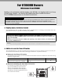 4
4
-
 5
5
-
 6
6
-
 7
7
-
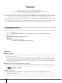 8
8
-
 9
9
-
 10
10
-
 11
11
-
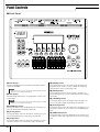 12
12
-
 13
13
-
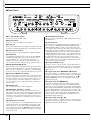 14
14
-
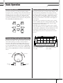 15
15
-
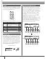 16
16
-
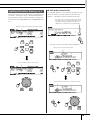 17
17
-
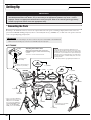 18
18
-
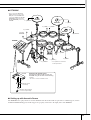 19
19
-
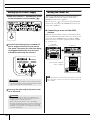 20
20
-
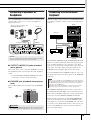 21
21
-
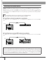 22
22
-
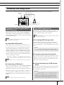 23
23
-
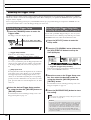 24
24
-
 25
25
-
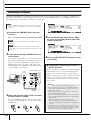 26
26
-
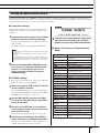 27
27
-
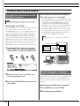 28
28
-
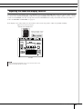 29
29
-
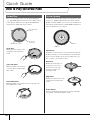 30
30
-
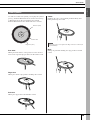 31
31
-
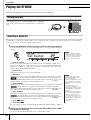 32
32
-
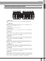 33
33
-
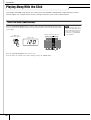 34
34
-
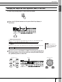 35
35
-
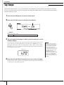 36
36
-
 37
37
-
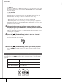 38
38
-
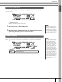 39
39
-
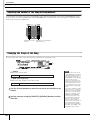 40
40
-
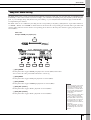 41
41
-
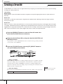 42
42
-
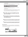 43
43
-
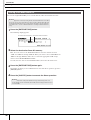 44
44
-
 45
45
-
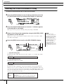 46
46
-
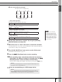 47
47
-
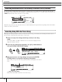 48
48
-
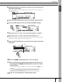 49
49
-
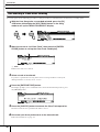 50
50
-
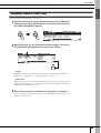 51
51
-
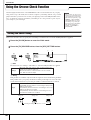 52
52
-
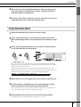 53
53
-
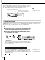 54
54
-
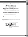 55
55
-
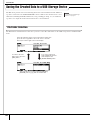 56
56
-
 57
57
-
 58
58
-
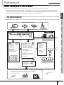 59
59
-
 60
60
-
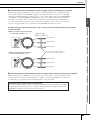 61
61
-
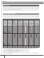 62
62
-
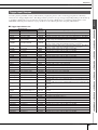 63
63
-
 64
64
-
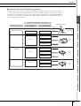 65
65
-
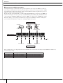 66
66
-
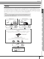 67
67
-
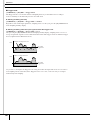 68
68
-
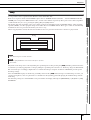 69
69
-
 70
70
-
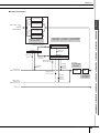 71
71
-
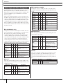 72
72
-
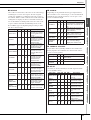 73
73
-
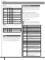 74
74
-
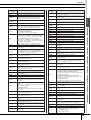 75
75
-
 76
76
-
 77
77
-
 78
78
-
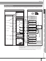 79
79
-
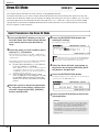 80
80
-
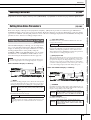 81
81
-
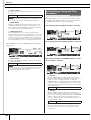 82
82
-
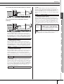 83
83
-
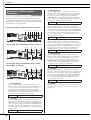 84
84
-
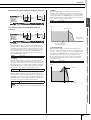 85
85
-
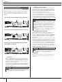 86
86
-
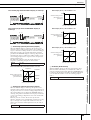 87
87
-
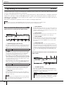 88
88
-
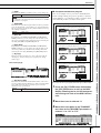 89
89
-
 90
90
-
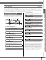 91
91
-
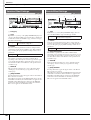 92
92
-
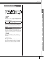 93
93
-
 94
94
-
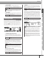 95
95
-
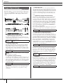 96
96
-
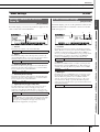 97
97
-
 98
98
-
 99
99
-
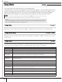 100
100
-
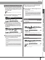 101
101
-
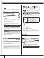 102
102
-
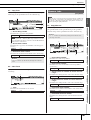 103
103
-
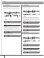 104
104
-
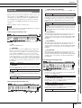 105
105
-
 106
106
-
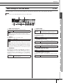 107
107
-
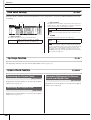 108
108
-
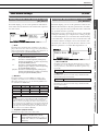 109
109
-
 110
110
-
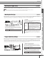 111
111
-
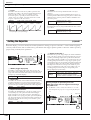 112
112
-
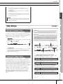 113
113
-
 114
114
-
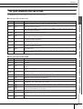 115
115
-
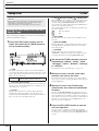 116
116
-
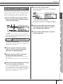 117
117
-
 118
118
-
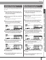 119
119
-
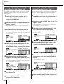 120
120
-
 121
121
-
 122
122
-
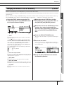 123
123
-
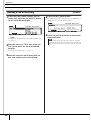 124
124
-
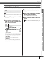 125
125
-
 126
126
-
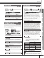 127
127
-
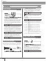 128
128
-
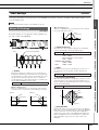 129
129
-
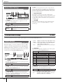 130
130
-
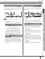 131
131
-
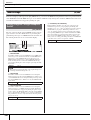 132
132
-
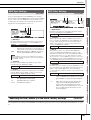 133
133
-
 134
134
-
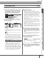 135
135
-
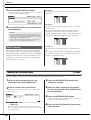 136
136
-
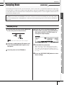 137
137
-
 138
138
-
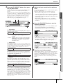 139
139
-
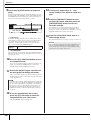 140
140
-
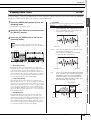 141
141
-
 142
142
-
 143
143
-
 144
144
-
 145
145
-
 146
146
-
 147
147
-
 148
148
-
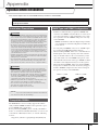 149
149
-
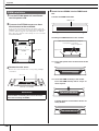 150
150
-
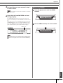 151
151
-
 152
152
-
 153
153
-
 154
154
-
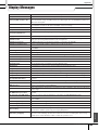 155
155
-
 156
156
-
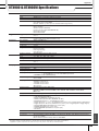 157
157
-
 158
158
-
 159
159
-
 160
160
-
 161
161
-
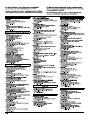 162
162
-
 163
163
-
 164
164


Yamaha DTX900M de handleiding
- Categorie
- Audio-equalizers
- Type
- de handleiding
in andere talen
- English: Yamaha DTX900M Owner's manual
- italiano: Yamaha DTX900M Manuale del proprietario
- русский: Yamaha DTX900M Инструкция по применению
- français: Yamaha DTX900M Le manuel du propriétaire
- español: Yamaha DTX900M El manual del propietario
- Deutsch: Yamaha DTX900M Bedienungsanleitung
- português: Yamaha DTX900M Manual do proprietário
- dansk: Yamaha DTX900M Brugervejledning
- suomi: Yamaha DTX900M Omistajan opas
- čeština: Yamaha DTX900M Návod k obsluze
- svenska: Yamaha DTX900M Bruksanvisning
- Türkçe: Yamaha DTX900M El kitabı
- polski: Yamaha DTX900M Instrukcja obsługi
- română: Yamaha DTX900M Manualul proprietarului
Gerelateerde papieren
-
Yamaha DTX450K de handleiding
-
-
Yamaha FGDP-30 Gebruikershandleiding
-
-
Yamaha EAD10 Acoustic Drum Module Mic Trigger de handleiding
-
-
-
Yamaha KP100 de handleiding
-
-