
EAD10 Reference Manual (Advanced)
1
How the Triggers Generate Sounds ........................ 2
About the Pads.......................................................... 2
The Relationship Between Trigger Input Jacks,
Trigger Inputs, Trigger Input Sources ............. 3
Trigger Sound (Instrument, Voice) ....................... 4
EAD10 Internal Memory....................................... 5
MENU.......................................................................... 6
Basic Screen Operations .......................................... 6
Selecting the Trigger Input or Trigger Input Source .. 7
Menu Function List................................................... 8
Parameter Descriptions........................................... 11
Scene Edit.......................................................... 11
Trigger................................................................ 25
Utility .................................................................. 32
Job ..................................................................... 39
File ..................................................................... 47
Factory Reset..................................................... 57
Connecting a Computer.......................................... 59
Installing the Yamaha Steinberg USB Driver .......... 59
Using DAW Software............................................... 60
Yamaha USB-MIDI Driver ....................................... 60
With the EAD10 Reference Manual (Advanced) (this document), you can click on an item you want to dis-
play with the link function or use the term search function.
When you click on any of the tabs on the right side of the page, you will be taken to the first page of the cor-
responding section.
Contents
How to Use This Manual
Scene Edit
InstEffect Voice
Reference Manual
(Advanced)
Electronic Acoustic
Drum Module
EN

EAD10 Reference Manual (Advanced)
2
How the Triggers Generate Sounds
How the EAD10 produces sound is explained in the Owner’s Manual.
Here, we provide detailed information on how trigger signals generate Trigger Sounds.
Pads that can be used with the EAD10 include drum triggers and electronic drum pads.
Types of pads include two piezo type and one piezo type.
Specific areas of the pad are called Zones.
Pad Type Two Piezo One Piezo
Number of
Input Sources
212 3
Description Produces two different
trigger signals.
Produces the same trig-
ger signal regardless of
where the pad is struck.
Produces a different trigger signal depending upon where the pad is struck.
Produces two different
trigger signals.
Produces three different trigger signals.
Plays two Trigger
Sounds.
Plays one Trigger
Sound.
Plays two Trigger
Sounds.
Plays three Trigger Sounds.
Example Drum Trigger
DT50S
Sensor Unit
Drum Pad
TP70
Drum Trigger
DT50K
Cymbal Pad
PCY100
(When using a 2-Zone
setting)
Cymbal Pad
PCY135
Snare Pad / Tom Pad
TP70S
Zone
The EAD10 is not compatible with pad controllers.
About the Pads
Sensor
Pad
Bow
Edge
BowCup
Edge
Pad
Rim BRim A
NOTE

How the Triggers Generate Sounds
EAD10 Reference Manual (Advanced)
3
The Relationship Between Trigger Input Jacks, Trigger Inputs, Trigger Input
Sources
This section explains the relationship between the Trigger Input jack, Trigger Input, and Trigger Input Source.
Trigger Input Jack (Trigger Input)
By switching the input mode on the [qKICK] jack, [w] jack, [eSNARE] jack, [r] jack, you can change the Trigger Input and Trigger
Input Source. The [t] jack and [y] jack are 3-Zone compatible inputs and cannot be changed.
Trigger Input Source
Each Zone transmits a different signal, which is called a Trigger Input Source.
When the EAD10 receives a trigger signal from the pad, the Main Unit plays the Trigger Input Source.
A Trigger Sound is assigned to the Trigger Input Source.
Default Input Mode Setting
The default input mode settings are [qKICK/w] jack separate, [eSNARE/r] jack paired.
q
w
e
r
t
y
Kick
Trg2
Snare
Trg5
Trg6
Kick
Trg2
Snare
Snare-R
Trg5
Trg5-R1
Trg5-R2
Trg6
Trg6-R1
Trg6-R2
Voice
Voice
Voice
Voice
Voice
Voice
Voice
Inst
Inst
Inst
Inst
Inst
Jack
Number
Sounds are
assigned to
input jacks
Sounds are
assigned the
input source
Trigger Input
Name
Trigger Input
Source Name
Voice
Voice
Voice

How the Triggers Generate Sounds
EAD10 Reference Manual (Advanced)
4
separate
With the “separate” setting, the [qKICK/w] jack (or the [eSNARE/r] jack) is separated into single inputs in which each is assigned
one Instrument. For example, the trigger signal received by the [w] jack is connected to the Trigger Input Source “Trg2.” The “Kick-R”
sound is not produced.
paired
With the “paired” setting, the [qKICK/w] jack (or the [eSNARE/r] jack) is assigned one Instrument. For example, the trigger signal
received by the [r] jack is connected to the Trigger Input Source “Snare-R.” The “Trg4” signal is not produced.
Trigger Sound (Instrument, Voice)
A Trigger Sound is the sound assigned to and produced by each Trigger Input or Trigger Input Source.
Instrument
“Instrument” refers to each of the percussion instruments (snare drum, tom, cymbals, and bass drum) used in a drum set. With the EAD10,
you can use a different Instrument on each Trigger Input. When you add an electric drum pad, you can assign a snare drum sound, for
example, to the pad.
Voice
“Voice” refers to a sound that makes up an Instrument. With the EAD10, you can use a different Voice for each Trigger Input Source. For
example, on an acoustic snare drum you can play a head shot sound, open rim shot sound, and a closed rim shot sound all from the same
drum. Each one of these different sounds is called a Voice, and the EAD10 has internal Voices that include various percussion instruments,
sound effects, electronic sounds, and more. In addition to the internal Voices, you can import waveforms (audio files) and play them as
User Voices.
For example, when you assign an acoustic drum Instrument to a 3-Zone pad, a head sound, open rim sound, and closed rim sound are gen-
erated from the corresponding Zones. When you assign the same Instrument to a 2-Zone pad, the head sound and open rim sound are gen-
erated.
Bass drum and electronic snare Instruments are 1-Zone pads, so the same sound is generated regardless of where the pad is struck.
You can use imported waveforms when you select “WAVE” from the Voice category. Waveforms imported into the Main Unit are called “Wave.”
Waveforms before importing are called “audio file (.wav).”
For the [qKICK/w] jack
Trigger Input
Name
Trigger Input
Source Name
Kick
Trg2
Kick
Trg2
Kick-R
For the [eSNARE/r] jack
Trigger Input
Name
Trigger Input
Source Name
Snare
Trg4
Snare
Trg4
Snare-R
NOTE

How the Triggers Generate Sounds
EAD10 Reference Manual (Advanced)
5
EAD10 Internal Memory
Saving Scenes that you have created or edited to the internal memory lets you hold the data even after the power has been turned off.
You can also save System settings such as Trigger settings (MENU/ Trigger) and other general settings such as Utility (MENU/Utility) set-
tings.
Data That Can Be Saved in the EAD10
The following types of data can be stored in the Main Unit.
• Scene (200)
• Wave (Up to 100)
• Trigger Settings
• Other general settings
Saving (Save) and Loading (Load) Data Files
All data stored in the EAD10 can be saved to a USB flash drive. Files saved to a USB flash drive can also be loaded back into the Main
Unit. For more information, see MENU/File (page 47).
• Recording data in the Main Unit will be lost when the power is turned off.
• Up to 100 Waves can be imported, as long as you don’t exceed the total capacity limit.
NOTE

EAD10 Reference Manual (Advanced)
6
MENU
The screen appears when you press the [MENU] button.
Navigating the MENU
Changing the Setting Values
Basic Screen Operations
“ ” ([F1]) and “ ” ([F2])
move the cursor up and down
“ENTER” ([F3]) opens
the screen
[–], [+]:
Changes the value of the item selected with the cursor

MENU
EAD10 Reference Manual (Advanced)
7
The Trigger name is displayed in the upper right of the screen for any parameters in which the Trigger Input or Trigger Input Source settings
are required.
Individual Trigger Input Settings
In the setting screen for each Trigger Input such as MENU/Scene Edit/Inst/InstNumber or MENU/Trigger/Pad Type, press the TRG
([F3]) button to open the screen for changing Trigger Inputs.
Individual Trigger Input Source Settings
In MENU/Utility/PadFunction, for example, or in any setting screen in which the Trigger Input Source setting is required, press the TRG
([F3]) button to open the screen for changing the Trigger Input Source.
• When the Input Mode is “paired,” selecting “Trg2” or “Trg4” does not affect the settings (nor generate any triggers).
• In MENU/ Trigger/Pad Type, “ ” (FootSW) is not displayed.
When the Input Mode is “paired,” selecting “Trg2” or “Trg4” does not affect the settings (nor generate any triggers). When the Input Mode is
“separate,” selecting “Kick-R” or “Snare-R” does not affect the setting (nor generate any triggers).
Selecting the Trigger Input or Trigger Input Source
Screen for Changing Trigger Inputs
With the Input Mode set to
“separate”
Name of the currently
selected Trigger Input
Switching the
Trigger Input
Auditioning
Sounds
With the Input Mode set to “paired”
L: Volume level
V: Velocity
NOTE
Name of the currently selected
Trigger Input Source
Trigger Input Source
Screen for Changing the Trigger Input Source
Auditioning
Sounds
Switch the Trigger
Input Source
NOTE

MENU
EAD10 Reference Manual (Advanced)
8
Menu Function List
Scene Edit
Inst Instrument Settings
Category . . . . . . . . . . . . . . . . . . . . . . Instrument Category
InstNumber . . . . . . . . . . . . . . . . . . . . Instrument Number
InstTune . . . . . . . . . . . . . . . . . . . . . . Instrument Tuning
InstDecay . . . . . . . . . . . . . . . . . . . . . Instrument Decay
InstPan . . . . . . . . . . . . . . . . . . . . . . . Instrument Pan
Voice Voice Settings
Category . . . . . . . . . . . . . . . . . . . . . . Voice Category
VoiceNumber . . . . . . . . . . . . . . . . . . Voice Number
VoiceTune . . . . . . . . . . . . . . . . . . . . . Voice Tuning
VoiceDecay. . . . . . . . . . . . . . . . . . . . Voice Decay
VoicePan. . . . . . . . . . . . . . . . . . . . . . Voice Pan
VoiceFilter . . . . . . . . . . . . . . . . . . . . . Voice Filter Cutoff Frequency
VoiceQ . . . . . . . . . . . . . . . . . . . . . . . Voice Filter Resonance (Q)
VoiceAltGrp. . . . . . . . . . . . . . . . . . . . Voice Alternate Group
VoiceHoldMode. . . . . . . . . . . . . . . . . Voice Hold Mode
MessageType . . . . . . . . . . . . . . . . . . Select MIDI Message Type
MENU
Effect Effect Settings
ReverbType. . . . . . . . . . . . . . . . . . . . Reverb Type
ReverbSend . . . . . . . . . . . . . . . . . . . Reverb Send
RevReturn. . . . . . . . . . . . . . . . . . . . . Reverb Return
Mic RevSend. . . . . . . . . . . . . . . . . . . Mic Reverb Send
TriggerRevSend . . . . . . . . . . . . . . . . Trigger Sound Reverb Send
Voice RevSend . . . . . . . . . . . . . . Trigger Sound Voice Reverb Send
MicEffType . . . . . . . . . . . . . . . . . . . . Mic Effect Type
MicEffDepth . . . . . . . . . . . . . . . . . . . Mic Effect Depth
TrgEffType . . . . . . . . . . . . . . . . . . . . . Trigger Sound Effect Type
TrgEffSend . . . . . . . . . . . . . . . . . . . . Trigger Sound Effect Send and Dry Balance
TrgEffReturn . . . . . . . . . . . . . . . . . . . Trigger Sound Effect Return
TrgEffToRev. . . . . . . . . . . . . . . . . . . . Trigger Voice Effect Reverb Send
Volume Volume Settings
Scene Volume. . . . . . . . . . . . . . . . . . Overall Scene Volume
Mic Volume. . . . . . . . . . . . . . . . . Mic Volume
TriggerVolume. . . . . . . . . . . . . . . Trigger Sound Overall Volume
Inst Volume. . . . . . . . . . . . . . Trigger Sound Instrument Volume
Voice Volume . . . . . . . . . Trigger Sound Voice Volume
Tempo Tempo Settings
Tempo . . . . . . . . . . . . . . . . . . . . . . . . Tempo for Selected Scene
[For note]
Note . . . . . . MIDI Note Output
MIDI Ch. . . . MIDI Channel
GateTime . . Gate Time
TrgVel . . . . . Trigger Velocity
[For REVERB]
MinValue . . . Minimum
Value
MaxValue . . . Maximum
Value
[For EFFECT]
MinValue . . . Minimum
Value
MaxValue . . Maximum
Value
[For CC01 to CC95]
MinValue. . . Minimum Value
MaxValue . . Maximum Value
MIDI Ch . . . MIDI Channel

MENU
EAD10 Reference Manual (Advanced)
9
MENU
Trigger
Input Mode Input Mode Settings
Trg1/Trg2. . . . . . . . . . . . . . . . Trigger 1/Trigger 2 Input Mode
Trg3/Trg4. . . . . . . . . . . . . . . . Trigger 3/Trigger 4 Input Mode
Curve Curve Settings
Velocity Curve. . . . . . . . . . . . Velocity Curve
Pad Type Pad Type Settings
PadType . . . . . . . . . . . . . . . . Select Pad Type
Gain . . . . . . . . . . . . . . . . Gain
Sensitivity . . . . . . . . . . . . Sensitivity
RejectTime . . . . . . . . . . . Reject Time
MinLevel . . . . . . . . . . . . . Minimum Level
MaxLevel . . . . . . . . . . . . Maximum Level
MinVelocity . . . . . . . . . . . Minimum Velocity
MaxVelocity . . . . . . . . . . Maximum Velocity
WaitTime . . . . . . . . . . . . Wait Time
RimGain . . . . . . . . . . . . . Rim Gain
H/R Balance . . . . . . . . . . H/R Balance
Crosstalk Crosstalk Prevention Settings
All Reject Lvl . . . . . . . . . . . . . All Rejection Level
Reject Lvl . . . . . . . . . . . . . . . Rejection Level (Source Pad)
FootSwSelect Foot Switch Select Settings
FootSwSelect . . . . . . . . . . . . Select Foot Switch
Utility
General General Utility Settings
SceneKnob . . . . . . . . . . . . . . Scene Knob
AutoPowerOff . . . . . . . . . . . . Auto Power Off
LCD Contrast . . . . . . . . . . . . LCD Contrast
ClickOutput . . . . . . . . . . . . . . Click Output Destination
ClickCountOff . . . . . . . . . . . . Click Count off
L&R Volume . . . . . . . . . . . . . External Device Output Volume
MicNoiseGate . . . . . . . . . . . . Mic Noise Gate
AudioOutGain . . . . . . . . . . . . Audio Out Gain
AudioMix . . . . . . . . . . . . . . . . Audio Mix
USB To Host . . . . . . . . . . . . . [USB TO HOST] Terminal Setting
MIDI LocalCtrl . . . . . . . . . . . . MIDI Local Control
AuxInVolume. . . . . . . . . . . . . [AUX IN] Volume
USB Volume . . . . . . . . . . . . . USB Audio or Recorder Playback Volume
ClickVolume . . . . . . . . . . . . . Click Volume
PadFunction Pad Function Settings
PadFunction . . . . . . . . . . . . . Pad Function
BypassSw . . . . . . . . . . . . . . . Bypass Switch
Phones EQ Headphone EQ Settings
EQ LowGain . . . . . . . . . . . . . EQ Low Gain
EQ HighGain. . . . . . . . . . . . . EQ High Gain

MENU
EAD10 Reference Manual (Advanced)
10
MENU
Job
Scene Scene Settings
Recall . . . . . . . . . . . . . . . Recall
Sort . . . . . . . . . . . . . . . . . Sort
Exchange . . . . . . . . . . . . Exchange
Clear . . . . . . . . . . . . . . . . Clear
Wave Wave Settings
Import . . . . . . . . . . . . . . . Import Selected Audio File
Import All . . . . . . . . . . . . Import All Audio Files
Delete . . . . . . . . . . . . . . . Delete Selected Audio File
Delete All . . . . . . . . . . . . Delete All Audio Files
Optimize . . . . . . . . . . . . . Optimize Memory
Memory Info . . . . . . . . . . Memory Information
Recorder Recorder Settings
Export Audio . . . . . . . . . . Export Audio
File
Save . . . . . . . . . . . . . . . . . . . Save File
Load . . . . . . . . . . . . . . . . . . . Load File
Rename. . . . . . . . . . . . . . . . . Rename File
Delete . . . . . . . . . . . . . . . . . . Delete File
Format. . . . . . . . . . . . . . . . . . Format USB Flash Drive
Memory Info . . . . . . . . . . . . . USB Flash Drive Memory Information
Factory Reset
Factory Reset . . . . . . . . . . . . Factory Reset

MENU
EAD10 Reference Manual (Advanced)
11
Scene Edit
Parameter Descriptions
Scene Edit
This section explains the “Scene Edit” settings in the menu.
Reverb, Effects (Mic Sound), and Trigger Sounds for Scenes can be customized to your liking.
Trigger Sounds have their own Effects available for use. Also, there are various settings for each Trigger Input or Trigger
Input Source.
After customizing the Scene, save (Store) it as a User Scene (EAD10 Owner’s Manual). Customized Scene data will be lost when you select
another Scene without first storing the settings.
NOTE
Scene Block Diagram
Trigger sensor
Mic sensor
Trigger input
Mic input
Control of tempo-related Effects
Scene Edit / Inst
Instrument Settings
Scene Edit / Effect
Effect Settings
Scene Edit / Volume
Volume Settings
Scene Edit / Voice
Voice Settings
Inst
Voice
Mic Effect Mic Volume
Trigger
Volume
Trigger
Effect
Tempo
Scene Edit / Tempo
Tempo Settings
Scene Edit
InstVoiceEffectVolumeTe mp o
Scene Edit

MENU
EAD10 Reference Manual (Advanced)
12
Scene Edit
Inst
Category : Instrument Category
Sets the Instrument Category for each Trigger Input.
The Instrument can also be selected by pressing the “TRG” ([F3]) button on the Scene screen.
Refer to the Data List.
InstNumber : Instrument Number
Sets the Instrument Number for each Trigger Input.
The Instrument can also be selected by pressing the “TRG” ([F3]) button on the Scene screen.
Refer to the Data List.
Settings Screen Structure
Scene Edit
Inst Instrument Settings
Voice Voice Settings
Effect Effect Settings
Volume Volume Settings
Tempo Tempo Settings
Scene Edit / Inst Instrument Settings
Settings Screen Structure
Scene Edit
Inst
1/2
Category Instrument Category
InstNumber Instrument Number
2/2
InstTune Instrument Tuning
InstDecay Instrument Decay
InstPan Instrument Pan
Scene Edit / Inst 1/2
Settings
Settings
Scene Edit
InstVoiceEffectVolumeTe mp o

MENU
EAD10 Reference Manual (Advanced)
13
Scene Edit
InstTune : Instrument Tuning
The parameter adjusts the pitch of each Trigger Input in units of 25 cents. 0.01 corresponds to 1 cent.
-12.00 to +0.00 to +12.00
InstDecay : Instrument Decay
Sets the decay (the time it takes for the sound to fade away to silence) for the Instrument assigned to each Trigger Input. Positive values pro-
duce a crisper sound.
-10 to +0 to +10
InstPan : Instrument Pan
Sets the position in the stereo field (pan) of each Trigger Input.
L64 to C to R63
Scene Edit / Inst 2/2
Settings
A “cent” is a unit of pitch defined as one hundredth of a semitone. (100 cents = 1 semitone)
NOTE
Settings
Settings
Scene Edit
InstVoiceEffectVolumeTe mp o

MENU
EAD10 Reference Manual (Advanced)
14
Scene Edit
Voi ce
Scene Edit / Voice Voice Settings
Settings Screen Structure
Scene Edit
Voice
1/4
Category Voice Category
VoiceNumber Voice Number
2/4
VoiceTune Voice Tuning
VoiceDecay Voice Decay
VoicePan Voice Pan
3/4
VoiceFilter Voice Filter Cutoff Frequency
VoiceQ Voice Filter Resonance (Q)
VoiceAltGrp Voice Alternate Group
VoiceHoldMode Voice Hold Mode
4/4
MessageType Select MIDI Message Type
[For note]
Note MIDI Note Output
MIDI Ch MIDI Channel
GateTime Gate Time
TrgVel Trigger Velocity
[For REVERB]
MinValue Minimum Value
MaxValue Maximum Value
[For EFFECT]
MinValue Minimum Value
MaxValue Maximum Value
[For CC01 to CC95]
MinValue Minimum Value
MaxValue Maximum Value
MIDI Ch MIDI Channel
Scene Edit
InstVoiceEffectVolumeTe mp o

MENU
EAD10 Reference Manual (Advanced)
15
Scene Edit
Category : Voice Category
Sets the Voice Category for each Trigger Input Source.
Refer to the Data List.
VoiceNumber : Voice Number
Sets the Voice Number for each Trigger Input Source.
Refer to the Data List.
VoiceTune : Voice Tuning
Sets the tuning of the Voice assigned to each Trigger Input Source. 0.1 corresponds to 10 cents.
-24.0 to +0.0 to +24.0
VoiceDecay : Voice Decay
Sets the decay (the time it takes for the voice to fade away to silence) for the Voice assigned to each Trigger Input Source. Positive values
produce a crisper sound.
-64 to +0 to +63
VoicePan : Voice Pan
Sets the stereo pan of each Trigger Input Source.
L64 to C to R63
Scene Edit / Voice 1/4
Settings
Settings
Scene Edit / Voice 2/4
Settings
A “cent” is a unit of pitch defined as one hundredth of a semitone. (100 cents = 1 semitone)
NOTE
Settings
Settings
Scene Edit
InstVoiceEffectVolumeTe mp o

MENU
EAD10 Reference Manual (Advanced)
16
Scene Edit
VoiceFilter : Voice Filter Cutoff Frequency
Sets the filter cutoff frequency for the Voice assigned to each Trigger Input Source. Negative values produce a darker sound, while positive
values produce a brighter sound.
-64 to +0 to +63
VoiceQ : Voice Filter Resonance (Q)
Sets the Q (Filter Resonance) for the Voice assigned to each Trigger Input Source. Increases the signal near the Filter Cutoff Frequency add-
ing character to the sound.
-64 to +0 to +63
VoiceAltGrp : Voice Alternate Group
Sets the Alternate Group of sounds to be produced for each Trigger Input Source.
An alternate group is a set of Voices that you do not want produced simultaneously, such as Hi-Hat Close and Hi-Hat Open. When a Voice is
triggered while another Voice from the same alternate group is already being played, the first Voice is silenced and only the second Voice is
produced.
Off, HHOpen, HHClose, 1 to 9
VoiceHoldMode : Voice Hold Mode
Sets the hold mode for the Voice produced by each Trigger Input Source.
on, off
Scene Edit / Voice 3/4
Settings
Settings
Off Voice is not assigned to an alternate group
HHOpen Hi-Hat Open group
HHClose Hi-Hat Close group
1 to 9 Alternate group number. Use the same group number for Voices that you do not want produced at the same time.
Settings
The “HHOpen” group and “HHClose” group operate according to the following rules.
• When a Voice from the “HHOpen” group is triggered, other Voices from the “HHOpen” or “HHClose” groups are not silenced.
• When a Voice from the “HHClose” group is triggered, all Voices from the “HHOpen” group are silenced.
NOTE
on When Wave is selected for the Voice category, striking the pad starts the playback in repeat, and striking the pad again
stops playback. MIDI Key On and Key Off messages are sent alternately each time the pad is struck.
off This setting corresponds to normal operation. A MIDI Key On message is output when the pad is struck, and the corre-
sponding MIDI Key Off message is output automatically after the gate time has elapsed.
Settings
Scene Edit
InstVoiceEffectVolumeTe mp o


MENU
EAD10 Reference Manual (Advanced)
18
Scene Edit
MessageType : Select MIDI Message Type
Sets the type of MIDI message to be sent when the pad is struck.
[For note]
Sends a MIDI note. Use this parameter to set the pad to produce a sound when struck.
Note : MIDI Note Output
Sets the MIDI note that is sent by the Trigger Input Source. Set the MIDI note number to be sent whenever a Trigger signal is
received from the specified Trigger Input Source. Settings are displayed as “Note number/Note name.”
MIDI Ch : MIDI Channel
Set which MIDI channel to use for sending out the MIDI message to play the Trigger Input Source.
GateTime : Gate Time
Sets the gate time (the time that passes between the output of MIDI Key On and Key Off messages) for the Trigger Input for each
Trigger Input Source.
TrgVel : Trigger Velocity
Sets the velocity value of the MIDI signal that is sent whenever a Trigger Input is received from a Trigger Input Source.
[For REVERB]
Controls the amount of Reverb (knob) according to how the pedal depressed or how hard the pad is struck. No sound is produced
even when the pad is struck.
MinValue : Minimum Value
Sets the amount (minimum) of Reverb applied when the pedal is released or when the pad is struck lightly.
MaxValue : Maximum Value
Sets the amount (maximum) of Reverb applied when the pedal is depressed fully or when the pad is struck hard.
Any setting other than note does not produce a sound when the pad is struck.
NOTE
note
variable The velocity value reflects the strength with which the pad is struck.
1 to 127 MIDI notes are sent with Velocity at the fixed value, regardless of how hard or soft the pad is struck.
REVERB
Scene Edit
InstVoiceEffectVolumeTe mp o

MENU
EAD10 Reference Manual (Advanced)
19
Scene Edit
[For EFFECT]
Controls the amount of Effect (knob) according to how the pedal depressed or how hard the pad is struck. No sound is produced even
when the pad is struck.
MinValue : Minimum Value
Sets the amount (minimum) of Effect applied when the pedal is released or when the pad is struck lightly.
MaxValue : Maximum Value
Sets the amount (maximum) of Effect applied when the pedal is depressed fully or when the pad is struck hard.
[For CC01 to CC95]
Sends Control Change message according to how the pedal pressed or how hard the pad is struck. No sound is produced even when
the pad is struck.
MinValue : Minimum Value
Sets the minimum value used when the pedal is released or when the pad is struck lightly.
MaxValue : Maximum Value
Sets the maximum value used when the pedal is depressed fully or when the pad is struck hard.
MIDI Ch : MIDI Channel
Sets the MIDI channel for sending the specified MIDI messages.
Note (MIDI Note Output): 0 to 127 / C-2 to G8 (note number / note name)
MIDI Ch (MIDI Channel): 1 to 16
GateTime (Gate Time): 0.0s to 9.9s
TrgVel (Trigger Velocity): variable, 1 to 127
MinValue (Minimum Value): 0 to 127
MaxValue (Maximum Value): 0 to 127
EFFECT
CC01 to CC95
Settings
Scene Edit
InstVoiceEffectVolumeTe mp o

MENU
EAD10 Reference Manual (Advanced)
20
Scene Edit
Effect
Effect
Scene Edit / Effect Effect Settings
Trigger
Mic
TrgEffSend
Voice RevSend
TrgEffSend (Dry)
TrgEffSend (Wet)
Trg Eff ToR ev
TriggerRevSend ReverbSend
Mic RevSend
RevReturn
Trg Eff Ret ur n
MicEffType
(MicEffDepth)
ReverbType
TrgEffType
Mixing
Voice (Kick, Kick-R Trg2... )
Settings Screen Structure
Scene Edit
Effect
1/4
ReverbType Reverb Type
ReverbSend Reverb Send
RevReturn Reverb Return
2/4
Mic RevSend Mic Reverb Send
TriggerRevSend Trigger Sound Reverb Send
Voice RevSend Trigger Sound Voice Reverb Send
3/4
MicEffType Mic Effect Type
MicEffDepth Mic Effect Depth
4/4
TrgEffType Trigger Sound Effect Type
TrgEffSend Trigger Sound Effect Send and Dry Balance
TrgEffReturn Trigger Sound Effect Return
TrgEffToRev Trigger Voice Effect Reverb Send
Scene Edit
InstVoiceEffectVolumeTe mp o

MENU
EAD10 Reference Manual (Advanced)
21
Scene Edit
ReverbType : Reverb Type
Selects the Reverb type.
The Reverb Type can also be selected by pressing the “REV” button ([F1]) on the Scene screen.
Refer to the Data List.
ReverbSend : Reverb Send
Sets how much of the sound is sent to the Reverb effect (Send Level). Changes Reverb Send Levels of both the Mic Sound and Trigger Sound
(internal Voice).
You can fine-adjust the values controlled with the [REVERB] knob.
RevReturn : Reverb Return
Sets how much of the sound is returned from the Return effect (Return Level).
0 to 127
Mic RevSend : Mic Reverb Send
Sets how much of the sound is sent from the Mic Sound (after applying Effects to the Mic sound) to the Reverb effect.
TriggerRevSend : Trigger Sound Reverb Send
Sets how much of the sound is sent from the entire Trigger Sound Reverb effect (Send Level).
Voice RevSend : Trigger Sound Voice Reverb Send
Sets how much of the Voice for each Trigger Input Source is sent (send level) to the Reverb.
0 to 127
Scene Edit / Effect 1/4
Settings
Settings
Scene Edit / Effect 2/4
Settings
Scene Edit
InstVoiceEffectVolumeTe mp o

MENU
EAD10 Reference Manual (Advanced)
22
Scene Edit
Mic Effect
Trigger Effec t
MicEffType : Mic Effect Type
Selects the type of Effect that is applied to the Mic Sound.
The Mic Effect Type can also be selected by pressing the “EFF” ([F2]) button on the Scene screen.
Refer to the Data List.
MicEffDepth : Mic Effect Depth
Sets depth of the Effect to be applied to the Mic Sound.
You can fine-adjust the values controlled with the [EFFECT] knob.
0 to 127
TrgEffType : Trigger Sound Effect Type
Sets the type of Effect to be applied to the Trigger Sound.
Refer to the Data List.
TrgEffSend : Trigger Sound Effect Send and Dry Balance
Specifies the balance between the Trigger Sound to be sent to the Effects (Send Level) and the Trigger Sound not to be sent to the Effects
(Dry Level).
TrgEffReturn : Trigger Sound Effect Return
Sets the level of the Effect applied to the Trigger Sound to be returned to the Reverb effect.
TrgEffToRev : Trigger Voice Effect Reverb Send
Sets the Send Level from the Effect applied to the Trigger Sound to the Reverb Effect.
0 to 127
Scene Edit / Effect 3/4
Settings
Settings
Scene Edit / Effect 4/4
Settings
Settings
Scene Edit
InstVoiceEffectVolumeTe mp o

MENU
EAD10 Reference Manual (Advanced)
23
Scene Edit
Vol um e
Mic Volume
Scene Volume : Overall Scene Volume
Sets the overall volume for the Scene. Adjusts the balance between Scenes.
0 to 127
Mic Volume : Mic Volume
Sets the volume of the mic (after effects have been applied to the Mic sound). Adjusts the balance between the Mic Sound and Trig-
ger Sound within the same Scene.
0 to 127
Scene Edit / Volume Volume Settings
Scene
Trigger
Inst
Inst
Trigger
Mic
Voice
Voice
Voice
Voice
Voice Volume
Voice Volume
Voice Volume
Voice Volume
Inst Volume
Inst Volume
TriggerVolume
Mic Volume
Scene Volume
Settings Screen Structure
Scene Edit
Volume
Scene Volume Overall Scene Volume
Mic Volume Mic Volume
TriggerVolume Trigger Sound Overall Volume
Inst Volume Trigger Sound Instrument Volume
Voice Volume Trigger Sound Voice Volume
Settings
Settings
Scene Edit
InstVoiceEffectVolumeTe mp o

MENU
EAD10 Reference Manual (Advanced)
24
Scene Edit
Tri gg er Vo l u me
Te mp o
TriggerVolume : Trigger Sound Overall Volume
Sets the overall volume for the Trigger Sound (internal Voice). Use this parameter to adjust the balance between the Mic Sound and
Trigger Sound within the same Scene.
0 to 127
Inst Volume : Trigger Sound Instrument Volume
Sets the volume of the Instrument for each Trigger Input. Use this parameter to adjust the balance between the Instruments
within the same Scene.
You can fine-adjust the values controlled with the [TRIGGER] knob.
0 to 127
Voice Volume : Trigger Sound Voice Volume
Sets the volume of the Voice for each Trigger Input Source. Use this parameter to adjust the balance between Zones
in the same Instrument.
0 to 127
Tempo : Tempo for Selected Scene
Sets the Metronome tempo for the selected Scene. When set to “off,” the tempo stays the same even when you switch Scenes. For any setting
other than off, the tempo is displayed at the top of the Scene Screen.
The Scene Tempo setting is convenient for using the Metronome to check the tempo in live situations or when using tempo sync effects.
off, 30 to 300
Settings
Settings
Settings
Scene Edit / Tempo Tempo Settings
Settings Screen Structure
Scene Edit
Tempo
Tempo Tempo for Selected Scene
Settings
Scene Edit
InstVoiceEffectVolumeTempo

EAD10 Reference Manual (Advanced)
25
Trigger
This section explains the “Trigger” settings in the menu. Depending on the pad you have connected, different Trigger sig-
nals are generated when you strike the pad during the performance. The “Trigger” settings allow you to optimize Trig-
ger signals for each pad for processing by the Main Unit.
The settings are saved when the power is turned off.
Select the appropriate pad type when you connect the pad.
When you connect the pad to the [qKICK/w] jack and [eSNARE/r] jack, make sure to switch the Input Mode.
Input Mode
Trg1 / Trg2 : Trigger 1/Trigger 2 Input Mode
Sets the [qKICK/w] jack to use the qKICK and w Trigger Inputs as a set or used separately.
Trg3 / Trg4 : Trigger 3/Trigger 4 Input Mode
Sets whether the [eSNARE/r] jack eSNARE and r Trigger Inputs will be used as a set or used separately.
paired, separate
Settings Screen Structure
Trigger
Input Mode Input Mode Settings
Curve Curve Settings
Pad Type Pad Type Settings
Crosstalk Crosstalk Prevention Settings
FootSwSelect Foot Switch Select Settings
Trigger/Input Mode Input Mode Settings
Settings Screen Structure
Trigger
Input Mode
Trg1/Trg2 Trigger 1/Trigger 2 Input Mode
Trg3/Trg4 Trigger 3/Trigger 4 Input Mode
Sets how to use the mono × 2 input jack.
Select “paired” when using a drum trigger (DT50S) or similar device.
Settings
Trigger
Input ModeCurvePad TypeCrosstalk
FootSwSelect
Tri g ge r

MENU
EAD10 Reference Manual (Advanced)
26
Trigger
Curve
Velocity Curve : Velocity Curve
Selects a Velocity Curve for the selected pad. A Velocity Curve determines how the Velocity (or strength) of the sound is affected by how
hard you strike the pad.
loud2, loud1, norm, hard1, hard2, Fix1 to Fix5, Spl11 to Spl15, Spl21 to Spl25, ofs1 to ofs5
Trigger/Curve Curve Settings
Settings Screen Structure
Trigger
Curve
Velocity Curve Velocity Curve
Settings
ofs3
ofs4
ofs5
ofs2
ofs1
norm
loud1
hard1
hard2
loud2
Fix1
Fix2
Fix3
Fix4
Fix5
Spl15
Spl13
Spl12
Spl11
Spl14
Spl25
Spl24
Spl23
Spl22
Spl21
Trigger input level
Velocity
Trigger input level
Velocity
Trigger input level
Velocity
Trigger input level
Velocit y
Trigger input level
Velocit y
Trigger
Input ModeCurvePad TypeCrosstalk
FootSwSelect

MENU
EAD10 Reference Manual (Advanced)
27
Trigger
Pad Type
Trigger/Pad Type Pad Type Settings
Settings Screen Structure
Trigger
Pad Type
1/4
PadType Select Pad Type
2/4
Gain Gain
Sensitivity Sensitivity
RejectTime Reject Time
3/4
MinLevel Minimum Level
MaxLevel Maximum Level
MinVelocity Minimum Velocity
MaxVelocity Maximum Velocity
4/4
WaitTime Wait Time
RimGain Rim Gain
H/R Balance H/R Balance
Selecting a pad type causes settings from Gain to H/R Balance to change.
Trigger
Input ModeCurvePad TypeCrosstalk
FootSwSelect

MENU
EAD10 Reference Manual (Advanced)
28
Trigger
PadType : Select Pad Type
Sets the Pad Type.
OFF: --
KK: SENSOR, KP125W/125, KP100, KP65, KU100
SN: XP120/100, XP80, XP70, TP120SD/100, TP70S/70, TP65S/65
TM: XP120/100, XP80, XP70, TP120SD/100, TP70S/70, TP65S/65
CY: PCY155, PCY135, PCY100, PCY90, PCY65S/65
DT: 50S SN, 50S tomH, 50S tomL, 50K, 10/20SN, 10/20tomH, 10/20tomL, 10/20kick
Gain : Gain
Sets the gain (amplification) of the input signal for when hitting the pad selected in Pad Type.
1 to 127
Trigger/Pad Type 1/4
[Tips] What is a Pad Type?
In order to ensure that you get the best sound from each and every pad, we have prepared a full range of optimized trigger
parameters (i.e., various values related to pad input signals and the like), and named them accordingly. These groupings of
parameters are referred to as “pad types.” Given that pads come in many different varieties, such as kicks, snares, toms,
cymbals, and drum triggers, it follows that pad characteristics vary widely. The EAD10 comes preloaded with pad types for
each different set of characteristics, allowing you to use them to their maximum potential.
Settings
Trigger/Pad Type 2/4
Settings
With a high setting, all input signals above a certain level will be amplified to the same level (i.e., the maximum level). This means that
variation in the softness or hardness with which the pad is struck can be smoothed out. Meanwhile, when a low setting is used, the
softness or hardness of playing will be reflected to a much greater degree in the output trigger signal, allowing for more expressive per-
formances.
NOTE
Trigger
Input ModeCurvePad TypeCrosstalk
FootSwSelect

MENU
EAD10 Reference Manual (Advanced)
29
Trigger
Sensitivity : Sensitivity
Sets sensitivity for when the pad is struck lightly.
1 to 13
RejectTime : Reject Time
Trigger signals that occur within the time set here are regarded as double triggers and will not produce any sound. Larger values
increase the amount of time that no sound is produced.
4ms to 500ms
MinLevel : Minimum Level
MaxLevel : Maximum Level
These parameters set the range of Trigger Input signals that convert to velocity values from minimum (%) to maximum (%). Trigger
signals that are below the minimum level set here will not produce any sound. Meanwhile, the Trigger signals above the maximum
level will be set as a Maximum Velocity, as explained in MinVelocity / MaxVelocity shown below.
Minimum level: 0 to 99
Maximum level: 1 to 100
MinVelocity : Minimum Velocity
MaxVelocity : Maximum Velocity
These parameters set the minimum and maximum velocities corresponding to the MinLevel / MaxLevel parameters above. Sound
will be produced between the velocities set here.
Minimum velocity: 0 to 126
Maximum velocity: 1 to 127
Settings
Using a value that is too low may result in no sound when struck too lightly or when playing a fast roll. Using a value that is too large
may result in crosstalk. If you must make an adjustment, try to do so in a way that does not hinder your performances.
NOTE
Settings
In the following case, a sound is output with the second input even though it occurs within the reject time.
• When Trigger Level of the second strike within the RejectTime is at least twice as strong as that of the first.
NOTE
Trigger/Pad Type 3/4
Settings
Settings
Trigger
Input ModeCurvePad TypeCrosstalk
FootSwSelect

MENU
EAD10 Reference Manual (Advanced)
30
Trigger
WaitTime : Wait Time
This parameter is used to set the time until the target pad detects a trigger signal. Set this parameter to adjust the time so that the trig-
ger signal is detected at its peak and that the strength for striking the pad corresponds to the volume of the sound produced.
1 to 64 (msec)
RimGain : Rim Gain
Sets the rim gain level for a two piezo pad such as the DT50S connected to the mono × 2 input jack. This parameter is only effective
when the input mode is set to “paired.”
1 to 127
H/R Balance : H/R Balance
It sets the balance between the two piezo head and rim (H49 to H1, 0, R1 to R49). If the head sound is produced when the rim is
struck, increase the R value to make the rim sound louder. If the rim sound is produced when the head is struck, press the [–] button
to increase the H value, which makes the head sound louder.
This parameter is only effective when the input mode is set to “paired.”
H49 to H1, 0, R1 to R49
Trigger/Pad Type 4/4
Settings
Settings
Settings
Trigger
Input ModeCurvePad TypeCrosstalk
FootSwSelect

MENU
EAD10 Reference Manual (Advanced)
31
Trigger
Crosstalk
FootSwSelect
All Reject Lvl : All Rejection Level
Resolves crosstalk between the pad that is displayed at the upper right of the screen and all other pads.
While higher values are better at preventing crosstalk, they can also make it difficult to play other sounds at the same time.
Level: 0 to 99
Reject Lvl : Rejection Level (Source Pad)
Resolves crosstalk between the pad that is displayed at the upper right of the screen and other individual pads.
For example, in a case where Trg2 mistakenly produces a sound when hitting Trg1, set Trg2 to be displayed in the upper right of the screen,
place a check mark on Trg1, then raise the Reject Lvl.
While higher values are better at preventing crosstalk, they can also make it difficult to play other sounds at the same time.
Level: 0 to 99
Source Pad: Trg 1, Trg 2, Trg 3, Trg 4, Trg 5, Trg 6
FootSwSelect : Select Foot Switch
Choose from HH65 (hi-hat controller), FC3 (foot pedal), FC4/5 (foot pedal or foot switch), or FC7 (foot controller) for the controller con-
nected to the [FOOT SW] jack.
HH65, FC3, FC4/5, FC7
Trigger/Crosstalk Crosstalk Prevention Settings
Settings Screen Structure
Trigger
Crosstalk
All Reject Lvl All Rejection Level
Reject Lvl Rejection Level (Source Pad)
The term “crosstalk” refers to the output of trigger signals from an electronic drum pad (including an acoustic drum with a drum trigger
attached) other than the one that was struck as a result of vibrations or interference between pads. Crosstalk is prevented by suppressing any
Trigger Signal sound that is lower than the specified value.
Settings
Settings
When the Input Mode is set to “paired,” Trg2 and Trg4 will not be set as the rejection source even when both are checked.
NOTE
Trigger/FootSwSelect Foot Switch Select Settings
Settings Screen Structure
Trigger
FootSwSelect
FootSwSelect Select Foot Switch
Settings
Trigger
Input ModeCurvePad TypeCrosstalk
FootSwSelect

EAD10 Reference Manual (Advanced)
32
Utility
This section explains the “Utility” settings in the menu.
General Settings, Pad Functions, and Headphone EQ are set here.
General
Settings Screen Structure
Utility
General General Utility Settings
PadFunction Pad Function Settings
Phones EQ Headphone EQ Settings
Utility/General General Utility Settings
Settings Screen Structure
Utility
General
1/4
SceneKnob Scene Knob
AutoPowerOff Auto Power Off
LCD Contrast LCD Contrast
2/4
ClickOutput Click Output Destination
ClickCountOff Click Count off
L&R Volume External Device Output Volume
MicNoiseGate Mic Noise Gate
3/4
AudioOutGain Audio Out Gain
AudioMix Audio Mix
USB To Host [USB TO HOST] Terminal Setting
MIDI LocalCtrl MIDI Local Control
4/4
AuxInVolume [AUX IN] Volume
USB Volume USB Audio or Recorder Playback Volume
ClickVolume Click Volume
Utility
GeneralPadFunctionPhones EQ
Utility

MENU
EAD10 Reference Manual (Advanced)
33
Utility
SceneKnob : Scene Knob
Set the [SCENE] knob to use for Scenes only, or for data entry (instead of the [–] or [+] buttons).
scene, data
AutoPowerOff : Auto Power Off
Set the time until the power is turned off by the Auto Power-Off function, or set to (off) to disable the Auto Power-Off function.
off, 5, 10, 15, 30, 60, 120 (min)
LCD Contrast : LCD Contrast
Adjusts the contrast on the screen.
0 to 63
Utility/General 1/4
Settings
Settings
• The time setting for the Auto Power-Off function is approximate.
• The Main Unit automatically saves all settings when the power is turned off.
NOTE
Settings
Utility
GeneralPadFunctionPhones EQ

MENU
EAD10 Reference Manual (Advanced)
34
Utility
ClickOutput : Click Output Destination
Sets the destination for the Click sound.
L&R+ph, phones
ClickCountOff : Click Count off
Set the Click sound to stop after playing for one measure or for two measures. When set to off, the Click sound continues to play.
off, 1, 2
L&R Volume : External Device Output Volume
Sets the volume of the external output.
In live situations, for example, set the external output volume to a fixed value, so that you can adjust only the Headphone volume with the
[MASTER VOLUME] knob. When set to “variable,” you can adjust the Headphone volume and the external output volume with the [MAS-
TER VOLUME] knob.
variable (works with the [MASTER VOLUME] knob), 1 to 127 (fixed value)
MicNoiseGate : Mic Noise Gate
Sets the Mic noise gate.
off, on
Utility/General 2/4
L&R+ph Sent to both the OUTPUT [R]/[L/MONO] jacks and [PHONES] jack.
phones Sent only to the [PHONES] jack.
Settings
Settings
Settings
The volume for the AUX IN can be adjusted with the [MASTER VOLUME] knob even when a fixed value is set for this parameter.
NOTE
Settings
Utility
GeneralPadFunctionPhones EQ

MENU
EAD10 Reference Manual (Advanced)
35
Utility
AudioOutGain : Audio Out Gain
For USB audio, set the USB output gain.
For using the recorder, set the input gain for recording.
-12dB, -6dB, 0dB, +6dB, +12dB
AudioMix : Audio Mix
For USB audio, set whether the USB input is sent to the USB OUT or not.
When using the recorder, sets whether recorder playback records together with your performance or not.
With the “auto” setting, the USB input is sent to the USB OUT for USB audio, and playback records together when using the recorder.
auto, off, on
USB To Host : [USB TO HOST] Terminal Setting
Select what type of data to transmit or receive via the [USB TO HOST] terminal.
The “Audio+MIDI” setting handles both audio and MIDI data, while the “MIDI” setting handles only MIDI data.
The auto setting switches settings automatically so that only MIDI data is exchanged when using the recorder, and audio and MIDI are
exchanged at all other times.
The recorder is disabled when set to Audio+MIDI.
auto, Audio+MIDI, MIDI
MIDI LocalCtrl : MIDI Local Control
Enables (on) or disables (off) the internal tone generator when performing with pads. Normally, set this parameter to “on.” When set to “off,”
the Trigger Input section and Tone Generator section are disconnected within the Main Unit so no sound is produced when the pads are
struck. However, regardless of this setting, performance information on the Main Unit is transmitted as MIDI data, and MIDI messages
received from other devices are processed by the Main Unit. An “off” setting is useful when you want to record your drum performance as
MIDI data to a sequencer or DAW software.
off, on
Utility/General 3/4
Settings
Settings
Settings
Settings
Utility
GeneralPadFunctionPhones EQ

MENU
EAD10 Reference Manual (Advanced)
36
Utility
Use these three parameters to set the balance between volumes beforehand to maintain balance when using the [AUDIO/CLICK VOLUME]
knob.
PadFunction
AuxInVolume : [AUX IN] Volume
Sets the volume for the signal received via the [AUX IN] jack.
USB Volume : USB Audio or Recorder Playback Volume
Sets the volume for the USB audio input or Recorder playback.
ClickVolume : Click Volume
Sets the Click volume.
0 to 127
Utility/General 4/4
Settings
Utility/PadFunction Pad Function Settings
Settings Screen Structure
Utility
PadFunction
1/2
PadFunction Pad Function
2/2
BypassSw Bypass Switch
Utility
GeneralPadFunctionPhones EQ

MENU
EAD10 Reference Manual (Advanced)
37
Utility
PadFunction : Pad Function
Instead of playing a sound, you can perform functions such as changing a Scene number or tempo by striking a pad. By striking the pad you
want to set, or by pressing the TRG ([F3]) button to select a pad, you can select a function you want to assign.
off, inc scene, dec scene, select scene, toggle scene, inc tempo, dec tempo, tap tempo, clickOn/Off, bypassOn/Off, RevKnob,
EffKnob, CC01 to CC95
select scene: scene number
toggle scene: scene number1, number2
REVERB, EFFECT: variable, Min, Max
CC: CC number, MIDI Ch, value (variable, Min, Max)
Utility/PadFunction 1/2
off Pad produces sound as usual.
inc scene Increases the Scene number by one.
dec scene Decreases the Scene number by one.
select scene Selects the Scene.
Scene number
toggle scene Selects a Scene.
Every time the pad is struck, the Scene changes between two Scenes.
Scene number 1
Scene number 2
inc tempo Increases the tempo value by one.
dec tempo Decreases the tempo value by one.
tap tempo Sets the tap tempo.
clickOn/Off Switches the Click on and off.
bypassOn/Off Switches the bypass on and off. Useful for switching Effect or Trigger effects on and off while playing. To bypass, use
the BypassSW (Bypass Switch).
REVERB Controls the amount of Reverb ([REVERB] knob value) according to how far the pedal pressed or how hard the pad is
struck.
MinValue: The amount (minimum) of Reverb applied when the pedal is released or the pad is struck lightly
MaxValue: The amount (maximum) of Reverb applied when the pedal is depressed fully or when the pad is struck
hard
EFFECT Controls the amount of Effect ([EFFECT] knob value) according to how far the pedal pressed or how hard the pad is
struck.
MinValue: The amount (minimum) of Effect applied when the pedal is released or the pad is struck lightly
MaxValue: The amount (maximum) of Effect applied when the pedal is depressed fully or when the pad is struck
hard
CC01 to CC95 Sends Control Change message according to how far the pedal pressed or how hard the pad is struck.
MinValue: The minimum value when the pedal is released or when the pad is struck lightly
MaxValue: The maximum value when the pedal is fully depressed or when the pad is struck hard
MIDI Ch: MIDI Channel
Settings
Utility
GeneralPadFunctionPhones EQ

MENU
EAD10 Reference Manual (Advanced)
38
Utility
Phones EQ
BypassSw : Bypass Switch
Selects the bypassOn/Off target setting in the PadFunction. This is a General setting, not an individual pad setting.
With all of the check boxes checked to set the bypass to “on,” Reverb and Effects will not be applied to the sound that passes through the
EAD, and Trigger Sounds will not be produced. The acoustic drum sound received from the mic does not change, it sounds as it is.
on, off
Headphone EQ does not affect audio received from the [AUX IN] jack.
EQ LowGain : EQ Low Gain
EQ HighGain : EQ High Gain
-12 to 0 to +12
Utility/PadFunction 2/2
Rev Applies Reverb or not
Eff Applies the Effect or not
Trg1 to Trg6 Plays the Trigger Sound or not
Settings
Utility/Phones EQ Headphone EQ Settings
Settings Screen Structure
Utility
Phones EQ
EQ LowGain EQ Low Gain
EQ HighGain EQ High Gain
NOTE
EQ LowGain Sets the headphone equalizer (two-band shelving) low-end gain (dB).
The higher the value, the more the low end will be boosted.
EQ HighGain Sets the headphone equalizer (two-band shelving) high-end gain.
The higher the value, the more the high end will be boosted.
Settings
Utility
GeneralPadFunctionPhones EQ

EAD10 Reference Manual (Advanced)
39
Job
The job menu contains Scene, Wave, and Recorder related jobs.
Scene
Only the User Scene settings can be changed from the Scene Settings (Job/Scene). Preset Scenes cannot be changed.
Recall : Recall
Changes to Scenes will be lost if you select another Scene before saving (storing) the settings. However, edits are actually retained in recall
memory, so changes can be recalled using the Recall function.
1. Press the “RECALL” button ([F3]) and the confirmation screen appears.
2. Press the “YES” button ([F1]) to Recall the data.
“Completed.” appears when Recall is complete and the screen returns to the Recall screen.
Settings Screen Structure
Job
Scene Scene Settings
Wave Wave Settings
Recorder Recorder Settings
Job/Scene Scene Settings
Settings Screen Structure
Job
Scene
Recall Recall
Sort Sort
Exchange Exchange
Clear Clear
The edited Scene number and Scene name are displayed. If there is no recall data, “No data.” is displayed for the Scene name.
NOTE
Procedure
Job
SceneWaveRecorder
Job

MENU
EAD10 Reference Manual (Advanced)
40
Job
Sort : Sort
Changes the order of Scenes to call back when turning the [SCENE] knob.
1. Press the “ ” and “ ” buttons ([F1] and [F2]) to move the cursor.
2. Press the “SELECT” button ([F3]) to select the Scene that you want to move.
3. Press the “ ” and “ ” buttons ([F1] and [F2]), or the [–] and [+] buttons to move the selected Scene.
4. After moving the Scene to the position where you want it, press the “INSERT” button ([F3]).
Pressing the “INSERT” button ([F3]) sets the rearranged order and changes the Scene numbers accordingly.
Procedure
To cancel the order sort, press the [EXIT] button.
NOTE
Job
SceneWaveRecorder

MENU
EAD10 Reference Manual (Advanced)
41
Job
Exchange : Exchange
Exchanges the order of two Scenes.
1. Select the two Scenes that you want to swap.
2. Press the “EXCHNG” button ([F3]) and the confirmation screen appears.
3. Press the “YES” button ([F1]) to change the order of the two Scenes.
“Completed.” appears when the Exchange is complete, and the screen returns to the Exchange screen.
Clear : Clear
Initialize the Scene.
1. Use the [–] and [+] buttons to select the Scene you want to initialize.
2. Press the “CLEAR” button ([F3]) and the confirmation screen appears.
3. Press the “YES” button ([F1]) to Initialize the selected Scene.
“Completed.” appears when the Initialization is complete, and the screen returns to the Clear screen.
Procedure
Procedure
Job
SceneWaveRecorder

MENU
EAD10 Reference Manual (Advanced)
42
Job
Wave
Import : Import Selected Audio File
Select which audio file (.WAV) saved on a USB flash drive to import into the EAD10.
Assigns the selected Wave imported into the EAD, to a Trigger Input Source. When “off” is selected, no assignment will be made. When you
have assigned the imported Wave to a Trigger Input Source, perform the Scene store operation.
Job/Wave Wave Settings
Settings Screen Structure
Job
Wave
1/2
Import Import Selected Audio File
Import All Import All Audio Files
Delete Delete Selected Audio File
Delete All Delete All Audio Files
Optimize Optimize Memory
2/2
Memory Info Memory Information
Job/Wave 1/2
VoiceAssign: Trigger assignment
File: File to import
Job
SceneWaveRecorder

MENU
EAD10 Reference Manual (Advanced)
43
Job
1. Press the “IMPORT” button ([F3]) and the confirmation screen appears.
2. Press the “YES” button ([F1]) to Import.
Press the “NO” button ([F3]) to cancel the Import and the screen returns to Step 1.
Press the “CANCEL” button ([F3]) during Import to stop the Import and the screen returns to Step 1.
“Completed.” appears when the Import is complete, and the screen returns to the Import screen.
off, Kick, Kick-R, Trg2, Snare, Snare-R, Trg4, Trg5, Trg5-R1, Trg5-R2, Trg6, Trg6-R1, Trg6-R2, FootSW
Import All : Import All Audio Files
Imports all audio files (.wav) saved in the root directory of the USB flash drive into the Wave Memory of the EAD10.
1. Press the “IMPORT” button ([F3]) and the confirmation screen appears.
2. Press the “YES” button ([F1]) to Import.
Press the “NO” button ([F3]) to cancel the Import and the screen returns to Step 1.
Press the “CANCEL” button ([F3]) during Import to stop the Import and the screen returns to Step 1.
“Completed.” appears when the Import is complete, and the screen returns to the Import All screen.
Procedure
Settings
• Only 16-bit audio files (.WAV) can be used with the EAD10.
• The maximum length of a single file that can be imported is approximately 20 seconds (in the case of 44.1 kHz, 16-bit audio).
• Some audio files may not import even when all of the above conditions are met.
• The imported Waves can be used later for other Scenes by choosing the Wave from the Instrument or Voice Category.
NOTE
Procedure
Depending on the type or number of audio files, some files may fail to be imported.
NOTE
Job
SceneWaveRecorder

MENU
EAD10 Reference Manual (Advanced)
44
Job
Delete : Delete Selected Audio File
Deletes the selected Wave from the EAD10.
1. Press the [–] and [+] buttons to select the Wave you want to delete.
2. Press the “DELETE” button ([F3]) and the confirmation screen appears.
3. Press the “YES” button ([F1]) to delete the selected Wave.
Press the “NO” button ([F3]) to cancel deletion and the screen returns to Step 1.
“Completed.” appears when the Delete is complete, and the screen returns to the Delete Screen.
Delete All : Delete All Audio Files
Deletes all Waves from the internal Wave memory of the EAD10.
1. Press the “DELETE” button ([F3]) and the confirmation screen appears.
2. Press the “YES” button ([F1]) to delete all Waves.
Press the “NO” button ([F3]) to cancel deletion and the screen returns to Step 1.
“Completed.” appears when the Delete is complete, and the screen returns to the Delete All screen.
Procedure
Use the “ ” button ([F2]) to audition the file.
NOTE
Procedure
Job
SceneWaveRecorder

MENU
EAD10 Reference Manual (Advanced)
45
Job
Optimize : Optimize Memory
Optimizes the Wave memory of the EAD10. Optimization reorganizes the memory content to make more efficient and effective use of mem-
ory space. Optimizing memory may increase the amount of free contiguous memory space.
1. Press the “OPTIMIZ” button ([F3]) and the confirmation screen appears.
2. Press the “YES” button ([F1]) to optimize the memory.
Press the “NO” button ([F3]) to cancel optimization and the screen returns to Step 1.
“Completed.” appears when Optimization is complete, and the screen returns to the Optimize screen.
Memory Info : Memory Information
Displays the usage of the Wave memory of the EAD10.
Procedure
Job/Wave 2/2
Total: Total memory size (MB)
Displays the total memory size in units of MB (megabytes).
Free: Free memory space (MB) (free memory space (%))
Free space is displayed in units of MB (megabytes). Also, displays the free space for the entire memory in %.
Fragmented memory may prevent importing of audio files even if there is sufficient space.
Units used to denote capacity change according to memory size (KB: kilobyte, MB: megabyte).
NOTE
Job
SceneWaveRecorder

MENU
EAD10 Reference Manual (Advanced)
46
Job
Record er
Export Audio : Export Audio
This saves the audio file recorded in the internal recorder to a USB flash drive.
1. If you want to add a name to the file, press the “NAME” button ([F2]) and enter a name.
2. Press the “EXPORT” button ([F3]) and the confirmation screen appears.
3. Press the “YES” button ([F1]) to export.
Press the “NO” button ([F3]) to cancel the export and the screen returns to Step 1.
“Completed.” appears when the export is complete, and the screen returns to the Export screen.
Job/Recorder Recorder Settings
Settings Screen Structure
Job
Recorder
Export Audio Export Audio
Procedure
Entering the File Name
1. Use the [–] and [+] buttons to select a character, and then use the “<” and “>” buttons ([F1] and [F3]) to move
the cursor to the next character position. A file name of up to 16 characters can be assigned.
2. When you are finished entering all characters, press the “OK” button ([F2]).
• Recording data will be lost when the power is turned off or when performing a factory reset.
• Audio data is not backed up in “All” files.
NOTE
Job
SceneWaveRecorder

EAD10 Reference Manual (Advanced)
47
File
A knowledge of terms is required to understand the functions and operations of the MENU/File section. This section
explains the terminology used in the MENU/File section.
File
The term “file” is used to define a set of data saved on a USB flash drive. Data exchanged between the EAD10 and a USB flash drive is
carried out in the form of files.
File Name
The name given to the file is called a file name. Files names are important for distinguishing files, and the same file name cannot be used
in the same directory. While computers can handle long names, and even include non-English characters, the EAD10 can only use alpha-
numeric characters.
Extensions
The “period + three letters,” such as “.wav” at the end of the file name, is referred to as a “file extension.” The extension indicates the type
of file. Files that the EAD10 use have a “.bin” extension, which is not displayed on the EAD10 Screen.
File size
This refers to the size of the file. The file size is determined by the amount of data saved in the file. File size is measured in units indicated
with a B (byte). Large files and also the memory capacity of devices are represented using units of KB (kilobytes), MB (megabytes), and
GB (gigabytes). 1 KB=1024 B, 1 MB=1024 KB, and 1 GB=1024 MB.
Format
Initializing the USB flash drive is known as “formatting.” Formatting a USB flash drive using the EAD10 will erase all files and directories
(or folders).
Save, Load
“Save” refers to the writing of data to a USB flash drive, while “load” refers to the reading of files from a USB flash drive.
The EAD10 can handle a maximum of 100 “.wav” files, and 100 “.bin” files.
For more information on cursor operations, refer to page 6.
NOTE
Settings Screen Structure
File
1/2
Save Save File
Load Load File
Rename Rename File
Delete Delete File
Format Format USB Flash Drive
2/2
Memory Info USB Flash Drive Memory Information
NOTE
File
SaveLoadRenameDeleteFormatMemory Info
File

MENU
EAD10 Reference Manual (Advanced)
48
File
Save
Saves the file to a USB flash drive.
1. Connect a USB flash drive to the [USB TO DEVICE] terminal.
2. Navigate to MENU/File/Save.
The following screen appears.
3. Select the Type (file type).
3-1.
Use the [–] and [+] buttons to select the file type you want to save.
All, AllScene, OneScene, Trigger
3-2.
For OneScene, select the Scene you want to save.
Press the “ ” button ([F1]), to move the cursor to the Scene number, and then use the [–] and [+] buttons to select the Scene you
want to save.
When the Scene contains User Waves, the User Waves are also saved.
File 1/2
Save: Save File
Procedure
All All data (all Scenes, all Waves, Utility data, and Trigger settings)
AllScene Scene data for all Scenes
OneScene Scene Data
Scene: Select the Scene you want to save.
Trigger Trigger Settings
Settings
Songs recorded with the Recorder (internal memory) are not saved in “All” files. Use JOB/RECORDER/EXPORT to save data
recorded by the recorder as a file.
NOTICE
As all four file types are saved as files using the same extension (.bin), do not use the same file name when saving, even
if you change file type. Using the same file name may result in overwriting the same file.
NOTE
File
SaveLoadRenameDeleteFormatMemory Info

MENU
EAD10 Reference Manual (Advanced)
49
File
4. Enter a name for the file to be saved.
4-1.
Press the “NAME” button ([F2]).
The NAME Edit screen appears.
5. Save the file.
5-1.
Press the “SAVE” button ([F3]).
The File Save confirmation screen appears.
5-2.
To save the file, press the “YES” button ([F1]). If you do not want to save the file, press the “NO” button ([F3]) and the screen
returns to Step 2.
If a file with the same file name already exists, the overwrite confirmation screen, as shown below, appears.
To save under a different file name, press the “NO” button ([F3]) and the screen returns to Step 2.
Entering the File Name
1. Use the [–] and [+] buttons to select a character, and then use the “<” and “>” buttons ([F1] and [F3]) to
move the cursor to the next character position. A file name of up to 16 characters can be assigned.
2. When you are finished entering all characters, press the “OK” button ([F2]).
File
SaveLoadRenameDeleteFormatMemory Info

MENU
EAD10 Reference Manual (Advanced)
50
File
Load
6. Press the “YES” button ([F1]) to save.
A message similar to that shown below appears during the Save process.
Pressing the “CANCEL” button ([F3]) during the Save process stops the process, and the screen returns to Step 2.
“Completed.” appears when the Save process is complete, and the screen returns to Step 2.
Loads a file previously saved to a USB flash drive into the EAD10.
When you have moved files to a computer for file management, make sure to move the files back to the root directory of the USB flash drive.
1. Connect the USB flash drive containing the files saved with the EAD10 into the [USB TO DEVICE] terminal.
2. Navigate to MENU/File/Load.
The following screen appears.
NOTICE
Do not disconnect the USB flash drive from the [USB TO DEVICE] terminal or turn off the power to the EAD10 while data is being
saved. Doing so may cause the EAD10 to malfunction, or corrupt memory in the USB flash drive.
Load: Load File
The EAD10 cannot load the file if it is in a sub directory (folder).
NOTE
Procedure
File
SaveLoadRenameDeleteFormatMemory Info

MENU
EAD10 Reference Manual (Advanced)
51
File
3. Select the Type (file type).
3-1.
Use the [–] and [+] buttons to select the file type you want to load.
All, AllScene, OneScene, Trigger
4. Select the file you want to load.
4-1.
Use the “ ” and “ ” buttons ([F1] and [F2]) to move the cursor to “File,” and then use the [–] and [+] buttons to select the file
you want to load. Only those files matching your selected file type will be presented for loading.
4-2.
For OneScene, select the Scene you want OneScene to load to.
Use the “ ” and “ ” buttons ([F1] and [F2]) to move the cursor to the Scene number, and then use the [–] and [+] buttons to
select the Scene you want OneScene to load to.
If the Scene contains User Waves, the User Waves are also loaded.
5. Press the “LOAD” button ([F3]).
The File Load confirmation screen appears.
6. Press the “YES” button ([F1]) to load.
A message similar to that shown below appears during the Load process.
Pressing the “CANCEL” button ([F3]) during the Load process stops the process, and the screen returns to Step 2.
“Completed.” appears when the Load process is complete, and the screen returns to Step 2.
All All data (all Scenes, all Waves, Utility data, and Trigger settings)
AllScene Scene data for all Scenes
OneScene Scene Data
Trigger Trigger Settings
Settings
NOTICE
Do not disconnect the USB flash drive from the [USB TO DEVICE] terminal or turn off the power to the EAD10 while data is being
loaded. Doing so may cause the EAD10 to malfunction, or corrupt memory in the USB flash drive.
File
SaveLoadRenameDeleteFormatMemory Info

MENU
EAD10 Reference Manual (Advanced)
52
File
Rename
Renames the file saved on a USB flash drive.
1. Connect the USB flash drive into the [USB TO DEVICE] terminal.
2. Navigate to MENU/File/Rename.
The following screen appears.
3. Select the type (Type) of the file that you want to rename.
3-1.
Use the [–] and [+] buttons to select the file type you want to rename.
All, AllScene, OneScene, Trigger, Wav
4. Select the file to be renamed.
4-1.
Press the “ ” button ([F2]) to move the cursor to “File.”
4-2.
Use the [–] and [+] buttons to select the file to be renamed.
5. Set a new name for the file.
Press the “ ” button ([F2]) to move the cursor to the bottom of the screen.
Press the “Name” button ([F2]) to display the Enter File Name screen.
Rename: Rename File
Procedure
All All data (all Scenes, all Waves, Utility data, and Trigger settings)
AllScene Scene data for all Scenes
OneScene Scene Data
Trigger Trigger Settings
Wav Wave File
Settings
Entering the File Name
1. Use the [–] and [+] buttons to select a character, and then use the “<” and “>” buttons ([F1] and [F3]) to move
the cursor to the next character position. A file name of up to 16 characters can be assigned.
2. After entering all characters, press the “OK” button ([F2]).
File
SaveLoadRenameDeleteFormatMemory Info

MENU
EAD10 Reference Manual (Advanced)
53
File
Delete
6. Press the “RENAME” button ([F3]).
The confirmation screen appears.
7. Press the “YES” button ([F1]) to change the name.
“Completed.” appears when the Rename process is complete, and the screen returns to Step 2.
This operation deletes a file in the USB flash drive.
1. Connect the USB flash drive containing the saved file you want to delete using the EAD10 into the [USB TO
DEVICE] terminal.
2. Navigate to MENU/File/Delete.
The following screen appears.
NOTICE
Do not disconnect the USB flash drive from the [USB TO DEVICE] terminal or turn off the power to the EAD10 while file is being
renamed. Doing so may cause the EAD10 to malfunction, or corrupt memory in the USB flash drive.
Delete: Delete File
Procedure
File
SaveLoadRenameDeleteFormatMemory Info

MENU
EAD10 Reference Manual (Advanced)
54
File
3. Select the type of file you wish to delete.
3-1.
Use the “ ” and “ ” buttons ([F1] and [F2]) to move the cursor to “Type.”
3-2.
Use the [–] and [+] buttons to select the file type.
All, AllScene, OneScene, Trigger, Wav
4. Use the “ ” and “ ” buttons ([F1] and [F2]) to move the cursor to “File.”
5. Use the [–] and [+] buttons to select the file you want to delete.
Depending on the files selected in Step 3, only the files you can delete are presented.
6. Press the “DELETE” button ([F3]).
The Delete confirmation screen appears.
7. Press the “YES” button ([F1]) to delete the file.
“Completed.” appears when the Delete process is complete, and the screen returns to Step 2.
All All data (all Scenes, all Waves, Utility data, and Trigger settings)
AllScene Scene data for all Scenes
OneScene Scene Data
Trigger Trigger Settings
Wav Wave File
Settings
NOTICE
Do not disconnect the USB flash drive from the [USB TO DEVICE] terminal or turn off the power to the EAD10 while file is being
deleted. Doing so may cause the EAD10 to malfunction, or corrupt memory in the USB flash drive.
File
SaveLoadRenameDeleteFormatMemory Info

MENU
EAD10 Reference Manual (Advanced)
55
File
Form at
Sometimes the USB flash drives are not usable as they are. In such cases, format the USB flash drive by following the procedures shown
below.
1. Connect the USB flash drive into the [USB TO DEVICE] terminal.
2. Navigate to MENU/File/Format.
The following screen appears.
3. Press the “FORMAT” button ([F3]).
The Format USB flash drive confirmation screen appears.
Format: Format USB Flash Drive
NOTICE
Formatting erases all data in the USB flash drive. Before formatting, ensure that the USB flash drive does not contain any important
data.
Procedure
File
SaveLoadRenameDeleteFormatMemory Info

MENU
EAD10 Reference Manual (Advanced)
56
File
Memory Info
4. Press the “YES” button ([F1]) to format.
“Completed.” appears when the Format process is complete, and the screen returns to Step 2.
Shows the memory usage of the USB flash drive.
NOTICE
Do not disconnect the USB flash drive from the [USB TO DEVICE] terminal or turn off the power to the EAD10 while the USB
flash drive is being formatted. Doing so may cause the EAD10 to malfunction, or corrupt memory in the USB flash drive.
File 2/2
Memory Info: USB Flash Drive Memory Information
Total: Total memory size (MB)
Displays the total memory size in units of MB (megabytes).
Free: Free memory space (MB) (free memory space (%))
Free space is displayed in units of MB (megabytes). Also, displays the free space for the entire memory in %.
Units used to denote capacity change according to memory size (KB: kilobyte, MB: megabyte, GB: gigabyte).
NOTE
File
SaveLoadRenameDeleteFormatMemory Info

EAD10 Reference Manual (Advanced)
57
Factory Reset
Restores all data in the User settings (User Scenes, Trigger settings, Wave, Utility, Recorder internal memory) back to
their factory default settings.
1. Navigate to MENU/Factory Reset.
The following screen appears.
2. Press the “RESET” button ([F3]).
The factory reset confirmation screen appears.
3. Press the “YES” button ([F1]) to carry out the Factory Reset.
If you do not want to carry out the Factory Reset, press the “NO” button ([F3]).
Settings Screen Structure
Factory Reset
Factory Reset Factory Reset
Factory Reset: Factory Reset
NOTICE
A factory rest erases all data in the user settings restoring them to the factory default settings. Be sure to save any important data to
a USB flash drive beforehand (page 48).
Restoring Defaults
Factory Reset
Factory Reset


EAD10 Reference Manual (Advanced)
59
Connecting a Computer
Connecting the Main Unit to a computer using a USB cable lets you send and receive audio or MIDI data.
This section explains how to connect the Main Unit and the computer.
To use audio data with a Windows computer, you need to install the Yamaha Steinberg USB Driver.
1. Download the latest Yamaha Steinberg USB Driver from the following URL.
http://download.yamaha.com/
Press the [ (driver name)] button, download and open the file.
USB cable is not included. To connect your computer to the Main Unit, use a USB A-B type cable of no more than 3 meters.
When you use a macOS computer or when you use a Windows computer only to handle MIDI data, installation of the Yamaha Steinberg USB
Driver is not required.
Computer
[USB TO HOST] terminal (Rear Panel)
[USB]
terminal
USB cable
Main Unit
NOTE
Precautions when using the [USB TO HOST] terminal
When connecting the computer to the [USB TO HOST] terminal, make sure to observe the following points. Failing to do so
risks freezing the computer and corrupting or losing the data.
If the computer or the EAD10 freezes, restart the application software or the computer OS, or turn the power to the EAD10
off and then on again.
NOTICE
• Use an A-B type USB cable. Also, make sure the cable is less than 3 meters long. USB 3.0 cables cannot be used.
• Before connecting a computer to the [USB TO HOST] terminal, disable any power-saving mode of the computer (such as sus-
pend, sleep, or standby).
• Perform the following before turning the power to the EAD10 on/off or plugging/unplugging the USB cable to/from the [USB TO
HOST] terminal.
- Quit any open application software on the computer.
• Please wait at least six seconds between turning the Main Unit on/off and connecting or disconnecting the USB cable.
Installing the Yamaha Steinberg USB Driver
NOTE

Connecting a Computer
EAD10 Reference Manual (Advanced)
60
2. Install the Yamaha Steinberg USB Driver on your computer.
For more information, please refer to the Yamaha Steinberg USB Driver Installation Guide.
For more information on recording or audio playback, please refer to the Owner’s Manual for your DAW software.
USB audio and the recorder function cannot be used simultaneously on the EAD10.
The factory default setting automatically switches to handle only MIDI over USB while the recorder is in use.
Normally, driver installation is not necessary. If, however, you are experiencing unstable operation or other troubles, please download the
USB-MIDI driver from the web page listed below and install it on your computer.
Yamaha Downloads: http://download.yamaha.com/
Enter the model name, and then select the USB-MIDI driver that corresponds to your operating system.
For instructions on installing the driver, refer to the Installation Guide included with the download file.
• Information on system requirements is provided on the above web page.
• For improvement, the Yamaha Steinberg USB Driver may be upgraded without notice. For details and the most up-to-date information,
please visit the above website.
• Depending upon the operating system you are using, the standard Yamaha USB-MIDI driver may not be compatible.
• For Mac computers, the installation of drivers is not needed because the standard drivers included in macOS are used.
NOTE
Using DAW Software
MIDI-related Reference
Information related to MIDI and creating music with a computer, is provided in the Data List (PDF).
The Data List (PDF) is available for download at the following web page.
http://download.yamaha.com/
* Yamaha Corporation reserves the right to modify this URL at any time without prior notice.
Yamaha USB-MIDI Driver
NOTE
Manual Development Group
© 2017 Yamaha Corporation
Published 10/2017 PO-A0
-
 1
1
-
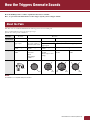 2
2
-
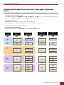 3
3
-
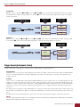 4
4
-
 5
5
-
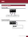 6
6
-
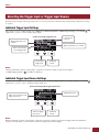 7
7
-
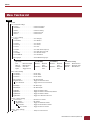 8
8
-
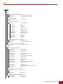 9
9
-
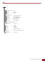 10
10
-
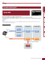 11
11
-
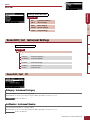 12
12
-
 13
13
-
 14
14
-
 15
15
-
 16
16
-
 17
17
-
 18
18
-
 19
19
-
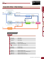 20
20
-
 21
21
-
 22
22
-
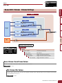 23
23
-
 24
24
-
 25
25
-
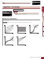 26
26
-
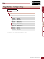 27
27
-
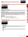 28
28
-
 29
29
-
 30
30
-
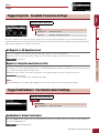 31
31
-
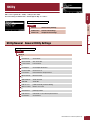 32
32
-
 33
33
-
 34
34
-
 35
35
-
 36
36
-
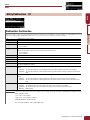 37
37
-
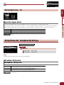 38
38
-
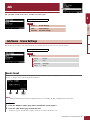 39
39
-
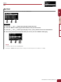 40
40
-
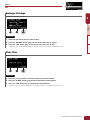 41
41
-
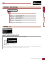 42
42
-
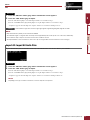 43
43
-
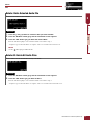 44
44
-
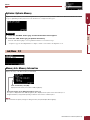 45
45
-
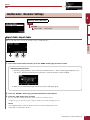 46
46
-
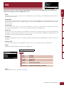 47
47
-
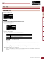 48
48
-
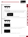 49
49
-
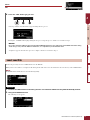 50
50
-
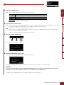 51
51
-
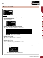 52
52
-
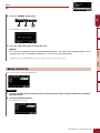 53
53
-
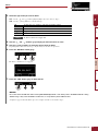 54
54
-
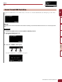 55
55
-
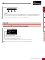 56
56
-
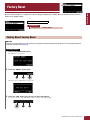 57
57
-
 58
58
-
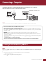 59
59
-
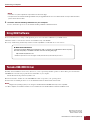 60
60


Yamaha EAD10 Acoustic Drum Module Mic Trigger de handleiding
- Type
- de handleiding
- Deze handleiding is ook geschikt voor
in andere talen
- English: Yamaha EAD10 Acoustic Drum Module Mic Trigger Owner's manual
- italiano: Yamaha EAD10 Acoustic Drum Module Mic Trigger Manuale del proprietario
- русский: Yamaha EAD10 Acoustic Drum Module Mic Trigger Инструкция по применению
- français: Yamaha EAD10 Acoustic Drum Module Mic Trigger Le manuel du propriétaire
- español: Yamaha EAD10 Acoustic Drum Module Mic Trigger El manual del propietario
- Deutsch: Yamaha EAD10 Acoustic Drum Module Mic Trigger Bedienungsanleitung
- português: Yamaha EAD10 Acoustic Drum Module Mic Trigger Manual do proprietário
- dansk: Yamaha EAD10 Acoustic Drum Module Mic Trigger Brugervejledning
- suomi: Yamaha EAD10 Acoustic Drum Module Mic Trigger Omistajan opas
- čeština: Yamaha EAD10 Acoustic Drum Module Mic Trigger Návod k obsluze
- 日本語: Yamaha EAD10 Acoustic Drum Module Mic Trigger 取扱説明書
- svenska: Yamaha EAD10 Acoustic Drum Module Mic Trigger Bruksanvisning
- Türkçe: Yamaha EAD10 Acoustic Drum Module Mic Trigger El kitabı
- polski: Yamaha EAD10 Acoustic Drum Module Mic Trigger Instrukcja obsługi
- română: Yamaha EAD10 Acoustic Drum Module Mic Trigger Manualul proprietarului
Gerelateerde papieren
-
Yamaha EAD10 Acoustic Drum Module Mic Trigger Handleiding
-
Yamaha 502 Handleiding
-
-
-
Yamaha DTX900M de handleiding
-
-
-
Yamaha ES8 Handleiding
-
-