Yamaha CBX-D5 Handleiding
- Categorie
- Digitale videorecorders (DVR)
- Type
- Handleiding

CBX-D5
DIGITAL RECORDING PROCESSOR
Owner's Manual 2
OPERATING MANUAL

* This applies only to products distributed by YAMAHA CORPORATION OF AMERICA
FCC INFORMATION (U.S.A.)
1. IMPORTANT NOTICE: DO NOT MODIFY THIS UNIT!
This product, when installed as indicated in the instructions contained in this manual, meets FCC requirements. Modifications not expressly approved by
Yamaha may void your authority, granted by the FCC, to use the product.
2. IMPORTANT: When connecting this product to accessories and/or another product use only high quality shielded cables. Cable/s supplied with this product
MUST be used. Follow all installation instructions. Failure to follow instructions could void your FCC authorization to use this product in the USA.
3. NOTE: This product has been tested and found to comply with the requirements listed in FCC Regulations, Part 15 for Class “B” digital devices. Compliance
with these requirements provides a reasonable level of assurance that your use of this product in a residential environment will not result in harmful interfer-
ence with other electronic devices. This equipment generates/uses radio frequencies and, if not installed and used according to the instructions found in the
users manual, may cause interference harmful to the operation of other electronic devices. Compliance with FCC regulations does not guarantee that interfer-
ence will not occur in all installations. If this product is found to be the source of interference, which can be determined by turning the unit “OFF” and “ON”,
please try to eliminate the problem by using one of the following measures:
Relocate either this product or the device that is being affected by the interference.
Utilize power outlets that are on different branch (circuit breaker or fuse) circuits or install AC line filter/s.
In the case of radio or TV interference, relocate/reorient the antenna. If the antenna lead-in is 300 ohm ribbon lead, change the lead-in to co-axial type cable.
If these corrective measures do not produce satisfactory results, please contact the local retailer authorized to distribute this type of product. If you can not
locate the appropriate retailer, please contact Yamaha Corporation of America, Electronic Service Division, 6600 Orangethorpe Ave, Buena Park, CA 90620
Dette apparat overholder det gaeldende EF-direktiv vedrørende
radiostøj.
Cet appareil est conforme aux prescriptions de la directive com-
munautaire 87/308/CEE.
Diese Geräte entsprechen der EG-Richtlinie 82/499/EWG und/
oder 87/308/EWG.
This product complies with the radio frequency interference
requirements of the Council Directive 82/499/EEC and/or 87/
308/EEC.
Questo apparecchio è conforme al D.M.13 aprile 1989 (Direttiva
CEE/87/308) sulla soppressione dei radiodisturbi.
Este producto está de acuerdo con los requisitos sobre interferen-
cias de radio frequencia fijados por el Consejo Directivo 87/308/
CEE.
YAMAHA CORPORATION
IMPORTANT NOTICE FOR THE UNITED KINGDOM
Connecting the Plug and Cord
IMPORTANT: The wires in this mains lead are coloured in accordance
with the following code:
GREEN-AND-YELLOW : EARTH
BLUE : NEUTRAL
BROWN : LIVE
As the colours of the wires in the mains lead of this apparatus may not
correspond with the coloured markings identifying the terminals in your
plug, proceed as follows:
The wire which is coloured GREEN and YELLOW must be connected to
the terminal in the plug which is marked by the letter E or by the safety
earth symbol or coloured GREEN and YELLOW.
The wire which is coloured BLUE must be connected to the terminal
which is marked with the letter N or coloured BLACK.
The wire which is coloured BROWN must be connected to the terminal
which is marked with the letter L or coloured RED.

SPECIAL MESSAGE SECTION
PRODUCT SAFETY MARKINGS: Yamaha electronic prod-
ucts may have either labels similar to the graphics shown
below or molded/stamped facsimiles of these graphics on the
enclosure. The explanation of these graphics appears on this
page. Please observe all cautions indicated on this page and
those indicated in the safety instruction section.
● Explanation of Graphical Symbols
The exclamation point within the equilat-
eral triangle is intended to alert the user to
the presence of important operating and
maintenance (servicing) instructions in the
literature accompanying the product.
The lightning flash with arrowhead symbol
within the equilateral triangle is intended to
alert the user to the presence of uninsulated
“dangerous voltage” within the product’s
enclosure that may be of sufficient magni-
tude to constitute a risk of electrical shock.
IMPORTANT NOTICE: All Yamaha electronic products are
tested and approved by an independent safety testing labora-
tory in order that you may be sure that when it is properly
installed and used in its normal and customary manner, all
foreseeable risks have been eliminated. DO NOT modify this
unit or commission others to do so unless specifically autho-
rized by Yamaha. Product performance and/or safety stan-
dards may be diminished. Claims filed under the expressed
warranty may be denied if the unit is/has been modified.
Implied warranties may also be affected.
SPECIFICATIONS SUBJECT TO CHANGE: The informa-
tion contained in this manual is believed to be correct at the
time of printing. However, Yamaha reserves the right to
change or modify any of the specifications without notice or
obligation to update existing units.
CAUTION: TO REDUCE THE RISK OF ELEC
-
TRIC SHOCK, DO NOT REMOVE COVER (O
R
BACK). NO USER-SERVICEABLE PART
S
INSIDE. REFER SERVICING TO QUALIFIE
D
SERVICE PERSONNEL.
ENVIRONMENTAL ISSUES: Yamaha strives to produce
products that are both user safe and environmentally friendly.
We sincerely believe that our products and the production
methods used to produce them, meet these goals. In keeping
with both the letter and the spirit of the law, we want you to
be aware of the following:
Battery Notice: This product MAY contain a small nonre-
chargeable battery which (if applicable) is soldered in place.
The average life span of this type of battery is approximately
five years. When replacement becomes neccessary, contact a
qualified service representative to perform the replacement.
Warning: Do not attempt to recharge, disassemble, or inciner-
ate this type of battery. Keep all batteries away from children.
Dispose of used batteries promptly and as regulated by appli-
cable laws. Note: In some areas, the servicer is required by
law to return the defective parts. However, you do have the
option of having the servicer dispose of these parts for you.
Disposal Notice: Should this product become damaged
beyond repair, or for some reason its useful life is considered
to be at an end, please observe all local, state, and federal reg-
ulations that relate to the disposal of products that contain
lead, batteries, plastics, etc.
NOTICE: Service charges incurred due to lack of knowledge
relating to how a function or effect works (when the unit is
operating as designed) are not covered by the manufacturer’s
warranty, and are therefore the owners responsibility. Please
study this manual carefully and consult your dealer before
requesting service.
NAME PLATE LOCATION: The graphic below indicates the
location of the name plate. The model number, serial number,
power requirements, etc., are located on this plate. You
should record the model number, serial number, and the date
of purchase in the spaces provided below and retain this man-
ual as a permanent record of your purchase.
Model
Serial No.
Purchase Date
92-469 1

IMPORTANT SAFETY INSTRUCTIONS
INFORMATION RELATING TO PERSONAL INJURY, ELECTRICAL SHOCK,
AND FIRE HAZARD POSSIBILITIES HAS BEEN INCLUDED IN THIS LIST.
WARNING — When using any electrical or electronic prod-
uct, basic precautions should always be followed. These pre-
cautions include, but are not limited to, the following:
Read all Safety Instructions, Installation Instructions,
Special Message Section items, and any Assembly
Instructions found in this manual BEFORE making any con-
nections, including connection to the main supply.
Main Power Supply Verification: Yamaha products are
manufactured specifically for the supply voltage in the
area where they are to be sold. If you should move, or if any
doubt exists about the supply voltage in your area, please
contact your dealer for supply voltage verification and (if
applicable) instructions. The required supply voltage is
printed on the name plate. For name plate location, please
refer to the graphic found in the Special Message Section of
this manual.
This product may be equipped with a polarized plug
(one blade wider than the other). If you are unable to
insert the plug into the outlet, turn the plug over and try again.
If the problem persists, contact an electrician to have the
obsolete outlet replaced. DO NOT defeat the safety purpose
of the plug.
Some electronic products utilize external power
supplies or adapters. DO NOT connect this type of
product to any power supply or adapter other than one
described in the owners manual, on the name plate, or specif-
ically recommended by Yamaha.
WARNING: Do not place this product or any other
objects on the power cord or place it in a position where
anyone could walk on, trip over, or roll anything over power
or connecting cords of any kind. The use of an extension cord
is not recommended! If you must use an extension cord, the
minimum wire size for a 25’ cord (or less) is 18 AWG.
NOTE: The smaller the AWG number, the larger the current
handling capacity. For longer extension cords, consult a local
electrician.
Ventilation: Electronic products, unless specifically
designed for enclosed installations, should be placed in
locations that do not interfere with proper ventilation. If
instructions for enclosed installations are not provided, it
must be assumed that unobstructed ventilation is required.
Temperature considerations: Electronic products
should be installed in locations that do not significantly
contribute to their operating temperature. Placement of this
product close to heat sources such as; radiators, heat registers
and other devices that produce heat should be avoided.
1.
2.
3.
4.
5.
6.
7.
This product was NOT designed for use in wet/damp
locations and should not be used near water or exposed
to rain. Examples of wet/damp locations are; near a swim-
ming pool, spa, tub, sink, or wet basement.
This product should be used only with the components
supplied or; a cart, rack, or stand that is recommended
by the manufacturer. If a cart, rack, or stand is used, please
observe all safety markings and instructions that accompany
the accessory product.
The power supply cord (plug) should be disconnected
from the outlet when electronic products are to be left
unused for extended periods of time. Cords should also be
disconnected when there is a high probability of lightening
and/or electrical storm activity.
Care should be taken that objects do not fall and liquids
are not spilled into the enclosure through any openings
that may exist.
Electrical/electronic products should be serviced by a
qualified service person when:
a. The power supply cord has been damaged; or
b. Objects have fallen, been inserted, or liquids have
been spilled into the enclosure through openings; or
c. The product has been exposed to rain; or
d. The product does not operate, exhibits a marked
change in performance; or
e. The product has been dropped, or the enclosure of
the product has been damaged.
Do not attempt to service this product beyond that
described in the user-maintenance instructions. All
other servicing should be referred to qualified service person-
nel.
This product, either alone or in combination with an
amplifier and headphones or speaker/s, may be capable
of producing sound levels that could cause permanent hearing
loss. DO NOT operate for a long period of time at a high vol-
ume level or at a level that is uncomfortable. If you experi-
ence any hearing loss or ringing in the ears, you should
consult an audiologist. IMPORTANT: The louder the sound,
the shorter the time period before damage occurs.
Some Yamaha products may have benches and/or
accessory mounting fixtures that are either supplied as a
part of the product or as optional accessories. Some of these
items are designed to be dealer assembled or installed. Please
make sure that benches are stable and any optional fixtures
(where applicable) are well secured BEFORE using. Benches
supplied by Yamaha are designed for seating only. No other
uses are recommended.
8.
9.
10.
11.
12.
13.
14.
15.
PLEASE KEEP THIS MANUAL
This information on safety is provided to comply with U.S.A. laws, but should be observed by users in all countiries.
92-469 2


1 Chapter : 1 Chapter :
Table of Contents
1
Introduction
..............................................1
Welcome to the CBX-D5...............................1
CBX-D5 features............................................1
Operating manual organization......................1
Important Notice............................................1
Unpacking .....................................................2
Installation......................................................2
Trademarks.....................................................2
Powering up a CBX-D5 System ....................2
2
CBX-D5 Terminology
..........................3
3
What is the CBX-D5?
...........................5
Inside the CBX-D5.........................................6
The CBX-D5 in a MIDI recording system.....7
4
Controls & Connections
...................8
Front panel .....................................................8
Rear panel ....................................................10
5
Connecting Hard Disk Drives
......13
What type of hard disk?...............................13
Hard disk size...............................................13
Choosing a hard disk....................................14
SCSI ............................................................14
SCSI cables..................................................15
Computer connection...................................15
SCSI ID setting ............................................16
SCSI termination..........................................17
6
Working with Hard Disks
...............18
Formatting....................................................18
Sound file management................................18
Sound file backup.........................................18
Computer utilities.........................................18
Hard disk fragmentation...............................19
Hard disk partitioning ..................................19
7
Recording
................................................20
Sampling frequency (REC FREQ)...............20
Digital input levels.......................................21
Setting the analog input level.......................21
Input level meters.........................................21
Headphone monitoring.................................21
Digital audio data containing SCMS ...........22
Digital audio data with emphasis.................22
20-bit digital audio.......................................22
8
Playback
.................................................. 23
Playback frequency (PB FREQ) ................. 23
Output level meters ..................................... 23
Sound file playback compatibility............... 23
Sound file regions........................................ 24
9
Converting the Sampling
Frequency & Digital Audio
Format in Real Time
...................... 25
10
Inputs & Outputs Explained
..... 26
ANALOG IN............................................... 26
ANALOG OUT........................................... 26
AES/EBU IN 1/2......................................... 27
AES/EBU OUT 1/2, 3/4.............................. 27
CD/DAT IN................................................. 27
CD/DAT OUT............................................. 27
Y2 IN........................................................... 28
Y2 OUT....................................................... 28
WORD CLK IN/OUT................................. 28
11
TO HOST connection
.................... 30
MIDI ........................................................... 30
Mac ............................................................. 31
PC-1 ............................................................ 32
PC-2 ............................................................ 32
TO HOST computer connecting cables ...... 33
12
Glossary
............................................... 34
13
Recording setup table
.................. 36
14
CBX-D5 Specifications
................ 37
Index
............................................................... 38
Appendix
.............................................. Add-1
Preset Effects ................................. Add-1
DSP/DEQ/DMIX Block Diagram.. Add-2
Preset effects parameter values ..... Add-3
Data-Value Assign Table ............... Add-5
Effect parameters............................ Add-8
MIDI Parameter............................ Add-24
MIDI Data Format........................ Add-28
MIDI Implementation chart.......... Add-32

Introduction 1Introduction 1Introduction 1
1 Introduction
Welcome to the CBX-D5
Thank you for purchasing a CBX-D5 Digital Recording Processor. Connecting the
CBX-D5 to a controlling computer with supporting software and an external hard disk will
provide up to four channels of CD quality audio recording, processing, and playback.
CBX-D5 features
• 4-channel system: 2-channel simultaneous recording, 4-channel playback.
• A/D conversion: 16-bit linear ∆ Σ modulation.
• D/A conversion: 18-bit with 8-times oversampling digital filter.
• Multi-band parametric DEQ for each channel.
• DSP provides 82 different reverb and modulation type effects.
• 4-input, 4-bus, 2-send digital mixer.
• Sampling frequencies: 48kHz, 44.1kHz, 32kHz, (22.05kHz analog input only).
• Analog inputs and outputs use professional style XLR type connectors.
• Digital I/O includes AES/EBU, CD/DAT & Y2 Yamaha format.
• 10 minutes of stereo audio requires approximately 100MB hard disk (fs=44.1kHz).
• Total recording time can be increased by adding more SCSI hard disks.
• All audio data processing is carried out within the CBX-D5, so much less is demanded
of the computer, eliminating data bottlenecks and slow screen redraws.
• Host computer connection allows direct connection to a computer without a MIDI
interface.
Operating manual organization
The CBX-D5 is supplied with three manuals: this Operating Manual, the System Setup
Guide, and a Test Program manual.
This Operating Manual contains full details about the CBX-D5 Digital Recording
Processor: what it is, how it works, and how to use it. It also contains an index that will
allow you to locate information quickly, and also a glossary of CBX-D5 terminology.
The System Setup Guide describes how to set up a recording system using the current
supporting computers and music programs. From time to time this guide will be updated
using single sheet supplements. Please see your Yamaha dealer for the latest supplement.
The Test Program manual should be used in conjunction with the Hardware Test Program
Disk for testing the CBX-D5 hardware.
Important Notice
YAMAHA AND THE SOFTWARE COMPANIES THAT PRODUCE CBX-D5
CONTROLLING SOFTWARE CANNOT BE HELD RESPONSIBLE FOR ANY LOSS
OF DATA OR FOR ANY DIRECT, INDIRECT, SPECIAL INCIDENTAL,
CONSEQUENTIAL OR OTHER DAMAGES SUFFERED BY THE USER OR OTHERS
RESULTING FROM THE USE OR PURCHASE OF THE CBX-D5, ITS
DOCUMENTATION, OR SUPPORTING SOFTWARE.

2 Chapter 1 : Introduction2 Chapter 1 : Introduction2 Chapter 1 : Introduction
Unpacking
The CBX-D5 packaging should contain the following items.
Store the packaging materials for future use.
Installation
The cosmetic appearance of the CBX-D5 has been designed to match typical computer
hardware. Its “footprint” size matches that of many computers so that it can easily be
installed with your other computer equipment.
The CBX-D5 should be placed on a flat, stable surface.
The CBX-D5 can also be rack mounted using the supplied rack-mount kit. When installed
in the rack-mount kit the CBX-D5 requires 3U of rack space.
Trademarks
IBM
, PC-AT
, PS/1
, and PS/2
are registered trademarks of International Business
Machines Corporation.
Apple
and Macintosh
are registered trademarks of Apple Computer, Inc.
Atari
, ST
, TT
, and STE
are registered trademarks of Atari Corporation.
Mark of the Unicorn
is a registered trademark of Mark of the Unicorn, Inc.
All other trademarks are the property of their respective holders.
Powering up a CBX-D5 System
Some computer systems are a little bit fussy about which devices are switched on first,
especially when a SCSI daisy chain is introduced into the system. As a good rule of
thumb, switch on all connected SCSI devices first, then the computer.
1 CBX-D5 Serial No:
1 Power cable
1 8-pin mini DIN cable
1 MIDI cable
1 SCSI cable (50 to 50 Amphenol)
1 SCSI terminator
1 Rack-mount kit (L & R set)
1
Hardware Test Program Disk
1
Test Program Manual
1 This
Operating Manual
1
System Setup Guide
1 User Registration Card
NOTE: While using your CBX-D5 computer music system, do not switch off or
disconnect any device connected in the SCSI chain. Doing so will probably
lead to a system crash and you could loose valuable data.

CBX-D5 Terminology 3CBX-D5 Terminology 3CBX-D5 Terminology 3
2 CBX-D5 Terminology
SCSI
Pronounced scuzzy, the Small Computer System Interface is a connection format used for
connecting peripheral devices such as hard disks, printers, scanners, etc., to a computer.
Up to eight SCSI devices can be connected together in a daisy chain including the
controlling computer. Each device is given its own identity number from 0 to 7, this is
called the SCSI ID number.
The CBX-D5, a computer, and a hard disk are all connected as part of a SCSI daisy chain.
The SCSI connection carries audio data between the CBX-D5 and hard disk for recording
and playback, and also control data from the computer to the CBX-D5. The controlling
computer can also access the hard disk to perform basic sound file copy, delete, and backup
type functions. With the necessary software, digital audio data could be transferred
directly to the computer for on-screen waveform editing, etc.
The SCSI standard is quite a robust format, although, some care must be taken when
connecting and setting up SCSI devices. For full details about connecting SCSI hard disk
drives to the CBX-D5 see “Connecting Hard Disk Drives” on page 13.
Sound files
Just like other types of computer data, digital audio data is stored in files – sound files.
When recording starts, a sound file is created on the hard disk. This sound file can be given
a name, copied, and deleted just like any other computer file.
AES/EBU format
AES/EBU is a digital interface format established by the AES (Audio Engineering
Society) and EBU (European Broadcasting Union). It is used to transfer digital audio data
between professional digital audio equipment. Usually, two channels of digital audio (left
& right) are carried in one XLR type connection.
Although similar to the CD/DAT format, it is primarily intended for professional usage.
AES/EBU format connections can be found on most professional digital audio equipment
including hard disk recorders, digital mixers, professional DAT recorders, and many
digital VTRs.
CD/DAT format
Similar to the professional AES/EBU format, CD/DAT, or S/PDIF (Sony/Philips Digital
Interface Format) as it is otherwise known, is a digital interface format that is used to
transfer digital audio data between consumer type digital audio equipment such as CD
players, consumer DAT recorders, and the new DCC recorders.
Like the AES/EBU format, two channels of digital audio (left & right) are carried in one
connection, usually a phono/RCA jack type connection. Some MIDI samplers are fitted
with a CD/DAT connection so that sample data can be transferred directly to a DAT
recorder for storage.
Y2 format
Y2 Yamaha format is a digital interface format developed by Yamaha that is used to
transfer digital audio data between Yamaha’s professional digital audio equipment. Two
channels of digital audio (left & right) are carried in one connection, usually an 8-pin DIN
type connection.
Yamaha’s professional digital audio products usually include the AES/EBU and CD/DAT
type formats as well as Y2, and the Y2 format can also be found on some other
manufacturers’ digital audio products. Yamaha’s professional digital audio products that
use Y2 include the DMR8 Digital Mixer/Recorder, DMC1000 Digital Mixing Console,
DRU8 Digital Recorder, and the DMP series of Digital Mixers.

4 Chapter 2 : CBX-D5 Terminology4 Chapter 2 : CBX-D5 Terminology4 Chapter 2 : CBX-D5 Terminology
Sampling frequency (REC FREQ)
During the analog to digital conversion process, the level of the analog audio signal is
sampled (measured) many times per second. Each of these sample measurements is then
stored as a 16-bit binary value. For digital to analog conversion (playback), these 16-bit
binary values are used to reconstruct the analog audio signal. The rate at which these
sample measurements take place is called the sampling frequency and you may already
know that the sampling frequency used by CD players is 44.1kHz.
The CBX-D5 can record audio using any one of four sampling frequencies: 48kHz,
44.1kHz, 32kHz, and 22.05kHz. The audio quality (bandwidth) of a digital system is
directly affected by the sampling frequency. Essentially, the audio bandwidth will be
roughly half the chosen sampling frequency. See “Sampling frequency (REC FREQ)” on
page 20 for more details.
Word clock
When a number of digital audio devices are connected together and data is digitally
transferred between them, it is essential that the data processing circuits of all devices are
synchronized. To achieve this, one device operates as a word clock master and all other
devices operate as word clock slaves. The frequency of the word clock corresponds
directly to the digital audio data’s sampling frequency.
If you only connect two digital audio devices, say the CBX-D5 to a DAT recorder, word
clock setup is quite straight forward and no word clock connections will be required.
However, when three devices are connected, serious thought will need to be given as to
which device is word clock master and how to make the word clock connections. See
“WORD CLK IN/OUT” on page 28 for more details.
To Host
An 8-pin mini DIN connector that allows direct connection to a computer that is running
CBX-D5 supporting software. This can be used when your computer does not have a
MIDI interface, i.e. MIDI input and output connections. See “TO HOST connection” on
page 30 for more details.
NOTE:
Word clock signals should not be confused with other synchronizing signals
such as SMPTE timecode and MTC (MIDI Timecode). Although both may
be used in a digital audio system, word clocks are for synchronizing digital
audio data processing circuits such as CPUs, D/A, A/D converters, etc., while
SMPTE and MTC timecodes are for synchronizing audio and video tape
machines, MIDI sequencers, etc., relative to time – hours, minutes, seconds,
and frames.
NOTE:
Not all CBX-D5 supporting music software can use this type of connection,
so please consult your Yamaha dealer before making a purchase.

What is the CBX-D5? 5What is the CBX-D5? 5What is the CBX-D5? 5
3 What is the CBX-D5?
The CBX-D5 is a Digital Recording Processor that, when connected to a controlling
computer with supporting software and an external hard disk, provides up to four channels
of CD quality audio recording, processing, and playback.
Computer based
The CBX-D5 is controlled by a computer that is running CBX-D5 supporting software.
All audio data processing takes place inside the CBX-D5, so there is very little demand on
the controlling computer. For this reason the CBX-D5 can be used with some of the less
powerful, less expensive computers such as the Apple Macintosh SE/30, Classic II, and
LC; and the Atari ST/STE. It also leaves the computer free to get on with other jobs such
as processing MIDI sequence data and screen updates.
The CBX-D5, computer, and hard disk are all connected as part of a SCSI daisy chain. The
SCSI connection carries audio data between the CBX-D5 and hard disk for recording and
playback, and also control data from the computer to the CBX-D5. A MIDI connection
between the CBX-D5 and computer carries continuous controller information for
real-time volume, EQ, and pan control of the CBX-D5’s digital mixer.
Four-channel system
The CBX-D5 is a 4-channel system, i.e., 2-channel simultaneous recording and
4-channel playback. Channels can be recorded while other channels playback.
The CBX-D5 needs about 100Mbytes of hard disk space to record 10 minutes of stereo
digital audio (fs = 44.1kHz). The available recording time can be increased by simply
adding more, or larger hard disk drives to the SCSI daisy chain.
CD quality & editing
The CBX-D5 records audio data at a 16-bit resolution, and with 44.1kHz and 48kHz
sampling frequencies it provides all the sound quality benefits of the Compact Disc format
such as faithful reproduction, low noise, minimal distortion, etc.
Analog input and output signals are processed by 16-bit linear ∆ Σ modulation A/D and
18-bit 8-times oversampling D/A converters. Analog connections use balanced XLR type
connectors. Digital I/O consists of AES/EBU, CD/DAT, and Y2. Allowing digital audio
data transfer between the CBX-D5 and other digital audio equipment.
As well as the A/D, D/A converters, the CBX-D5 also contains a 4-input, 4-bus, 2-send
digital mixer; a DSP for digital effects; DEQ for real-time EQ control; and sampling
frequency converters that allow recording and playback at differing sampling frequencies.
As well as the sound quality, two other benefits of recording with a CBX-D5 system as
opposed to analog tape are, the ability to nondestructively edit recordings and being able
to move audio data relative to time, a feature often referred to as audio time slip.
For a listing of some other CBX-D5 features, see “CBX-D5 features” on page 1.
The future
The CBX-D5 is a software dependent device, so with future supporting software it may be
possible to use the CBX-D5 for digital mixing with digital EQ and effects, sampling,
2-track mastering, waveform editing, and multimedia type applications.

6 Chapter 3 : What is the CBX-D5?6 Chapter 3 : What is the CBX-D5?6 Chapter 3 : What is the CBX-D5?
Inside the CBX-D5
The following block diagram shows how the CBX-D5 processes audio data as it travels
from input to output and to the external SCSI hard disks.
DIGITAL
MIXER
4 INPUT
4 BUS
2 SEND
A/D
CONVERTER
DIGITAL
INTERFACE
A/D
CONVERTER
CBX-D5
SCSI
CONTROLLER
PLAY BUFFER
(RAM)
Fs
CONVERTER
PLAY
CONTROL
DEQ
DEQPLAY
CONTROL
Fs
CONVERTER
DEQPLAY
CONTROL
Fs
CONVERTER
DEQPLAY
CONTROL
Fs
CONVERTER
CONTROLLER
DSP
EFFECTS
Fs
CONVERTER
Fs
CONVERTER
Fs
CONVERTER
Fs
CONVERTER
Fs
CONVERTER
Fs
CONVERTER
PLAYBACK
WORDCLOCK
RECORD
WORDCLOCK
RECORD
BUFFER
(RAM)
Y2
INTERFACE
S/PDIF
INTERFACE
AES/EBU
INTERFACE
AES/EBU
INTERFACE
D/A
CONVERTER
D/A
CONVERTER
D/A
CONVERTER
D/A
CONVERTER
ANALOG IN 1
ANALOG IN 2
AES/EBU
IN 1/2
CD/DAT
IN 1/2
Y2 IN 1/2
WORD
CLK IN
WORD
CLK OUT
ANALOG
OUT 1
ANALOG
OUT 2
ANALOG
OUT 3
ANALOG
OUT 4
CD/DAT
OUT 1/2
Y2 OUT 1/2
AES/EBU
OUT 1/2
AES/EBU
OUT 3/4
VOLUME, PITCH
SYNC
EQ
MIDI
MIDI OUT, or
Serial port
MIDI IN, or
TO HOST
HARD
DISK 1
HARD
DISK 2
SCSI
SCSI
SCSI
INPUT MONITOR
SIGNAL PATH
Fs = Sampling Frequency
WORDCLOCK
AUDIO
MIDI
HOST COMPUTER
INPUT LEVEL
METER
S
OUTPUT
LEVEL
METERS

The CBX-D5 in a MIDI recording system 7The CBX-D5 in a MIDI recording system 7The CBX-D5 in a MIDI recording system 7
The CBX-D5 in a MIDI recording system
The following diagram shows how the CBX-D5 can be integrated into a MIDI sequencer
based music production system.
MIDI OUT
MIDI
OUT
SERIAL PORT
TO HOST
MIDI IN
MIDI SOUND
SAMPLER
MIDI DRUM MODULE
MIDI TONE
GENERATOR
MIDI
MULTI-EFFECTOR
MASTER
RECORDER
MONITOR AMP
HOST CABLE
AUDIO CABLE
MIDI CABLE
SCSI
HARD
DISK
CD/DAT
YAMAHA
CBX-D5
SCSI
GROUP
OUT x2
LINE IN x4
DIGITAL
TRANSFER

8 Chapter 4 : Controls & Connections8 Chapter 4 : Controls & Connections8 Chapter 4 : Controls & Connections
4 Controls & Connections
Front panel
1 POWER switch
Used to turn the power on and off. Press once to switch on, press again to switch off.
2 SOURCE indicators
Indicates the input selected for recording: AES/EBU, Y2, CD/DAT, or ANALOG. The
source input selection is made by the controlling software.
3 REC FREQ indicators
Indicates the selected sampling frequency for recording: 48kHz, 44.1kHz, 32kHz, and
22.05kHz (analog inputs only). The sampling frequency selection is made by the
controlling software.
4 PB FREQ indicators
Indicates the sampling frequency of the digital audio data that is being output by the
CBX-D5: 48kHz, or 44.1kHz. The playback sampling frequency setting is made by the
controlling software.
When the CBX-D5 is used with an external word clock, the digital outputs will operate at
the same frequency as the external word clock and that frequency will not be indicated by
the “PB FREQ” indicators.

Front panel 9Front panel 9Front panel 9
5 INPUT LEVEL meters
Two 12-segment LED bargraphs indicate the level of the incoming digital audio when the
input source is set to AES/EBU, CD/DAT, or Y2 (not affected by the level controls), or the
level of the analog input signals when the input source is set to ANALOG (controlled by
the “ANALOG IN” level controls).
6 OUTPUT LEVEL meters
Four 12-segment LED bargraphs that indicate the output level of channels 1 ~ 4. The
“CLIP” LED indicates an output level of +17dBm.
7 ANALOG IN LEVEL control
Independent level controls for analog input channels 1 and 2. As well as independent level
control, these controls can also be used to balance the left and right channels of a stereo
source connected to the analog inputs.
8 PHONES VOL
Adjusts the volume level of the headphones.
9 PHONES connection
A stereo 6.35 mm (1/4 inch) phone jack used for connecting a pair of stereo headphones.
All four CBX-D5 audio channels can be monitored – channels 1 and 3 appear in the left
speaker and channels 2 and 4 in the right.
NOTE:
Unlike peak meters on analog equipment that light up approximately 3 ~ 6dB
before signal clipping, CLIP LEDs on digital equipment light up when the
signal has actually clipped. Digital audio signal clipping normally produces
unpleasant distortion, pops, and clicks, so care must be taken when setting
the recording level for analog input signals. See “Recording” on page 20 for
more details.
NOTE:
Just like the input level meters, lighting an output level meter’s “CLIP” LED
should be avoided to prevent signal distortion. This situation may occur when
two or more CBX-D5 audio channels are mixed, or if excessive EQ is
applied. The CBX-D5 does not have any output level controls, the output
level is set by the controlling software.
NOTE:
These controls have no effect on the AES/EBU, CD/DAT, and Y2 digital
inputs and outputs.

10 Chapter 4 : Controls & Connections10 Chapter 4 : Controls & Connections10 Chapter 4 : Controls & Connections
Rear panel
The explanations below are only brief introductions to the CBX-D5’s rear panel
connections. For full details about the inputs and outputs, see “Inputs & Outputs
Explained” on page 26.
1 ANALOG IN 1&2
A pair of female XLR 3-31 type connectors used for inputting analog audio signals. These
are balanced inputs with a nominal input level of +4dBm and a maximum input level of
+22dBm. These could be connected to the outputs of a mixer, synthesizer, drum machine,
etc. Microphones, guitars, and equipment with an output level less than –20dBm must first
be connected to a preamplifier, then to the CBX-D5.
2 ANALOG OUT 1 ~ 4
Four male XLR 3-32 type connectors used for outputting channels 1 ~ 4 as analog audio
signals. These are balanced outputs with a nominal output level of 0dBm and a maximum
output level of +17dBm. These could be connected to the inputs of a mixer, amplifier, tape
recorder, or DAT recorder.
3 AES/EBU IN 1/2
A female XLR 3-31 type connector for inputting AES/EBU format digital audio. Only one
input connection is required for channels 1 and 2 because the AES/EBU format carries two
signals in one connection. These could be used when recording digital audio data from
professional digital audio equipment such as another hard disk recorder, a digital mixer,
digital recorder, or digital VTR.
NOTE:
When the Analog inputs are used unbalanced, the maximum input level is
reduced to +16dBm.

Rear panel 11Rear panel 11Rear panel 11
4 AES/EBU OUT 1/2 & 3/4
Two male XLR 3-32 type connectors for outputting AES/EBU format digital audio.
Channels 1 and 2 are output via “OUT 1/2”, and channels 3 and 4 via “OUT 3/4”. These
could be used to transfer digital audio data from the CBX-D5 to professional digital audio
equipment.
5 CD/DAT IN 1/2
A Phono/RCA jack for inputting CD/DAT format digital audio. Channels 1 and 2 are
carried in the same connection. This connection could be connected to the digital output
of a CD player or DAT recorder and allows digital audio recording without multiple D/A,
A/D audio data conversions. Some MIDI samplers are fitted with this type of connection.
In this case your sound samples could be recorded directly to your CBX-D5 system.
6 CD/DAT OUT 1/2
A Phono/RCA jack for outputting CD/DAT format digital audio. Channels 1 and 2 are
carried in the same connection. This could be connected to the digital input of a DAT
recorder or DCC recorder, and allows digital audio recording without multiple D/A, A/D
audio data conversions.
7 Y2 IN 1/2
An 8-pin DIN socket for inputting Y2 Yamaha format digital audio. As with the AES/EBU
and CD/DAT formats, two audio channels are carried in the same connection. This could
be connected to one of Yamaha’s digital audio products such as a DMR8 Digital
Mixer/Recorder, DMC1000 Digital Mixing Console, DRU8 Digital Recorder, SPX1000
Effect Processor, or the DMP series of Digital Mixers.
8 Y2 OUT 1/2
An 8-pin DIN socket for outputting Y2 Yamaha format digital audio. This could be used
to transfer digital audio data from the CBX-D5 to one of the Yamaha professional digital
audio products listed above. You might not own one of these products yourself, but you
may need to transfer some of your audio data to a recording studio that does.
9 WORD CLK IN/OUT
Two BNC type connectors for inputting and outputting word clock signals. A common
word clock signal is used to synchronize data processing circuits when a number of digital
audio devices are connected together. For a full description of how and when to use these
connections, see “WORD CLK IN/OUT” on page 28.
NOTE:
It is widely known that the weakest links in a digital audio system are the A/D
and D/A converters. For once the audio has been converted into a digital
form, it is immune from all the problems usually associated with analog
equipment such as distortions and noise. Although the effects of multiple
conversions will be hard to spot, even for the best trained ears, it makes sense
that once converted, we try and keep the audio in a digital form by using these
digital I/O connections wherever possible.

12 Chapter 4 : Controls & Connections12 Chapter 4 : Controls & Connections12 Chapter 4 : Controls & Connections
0 MIDI IN
The CBX-D5 receives MIDI control data from the computer via this connection. To
prevent the CBX-D5’s control data being delayed by other MIDI devices, the CBX-D5
should be the first device connected to your computer. Other MIDI devices should then be
connected to the CBX-D5’s MIDI THRU connection.
If your computer’s MIDI interface has two or three MIDI outputs, dedicate one for use
with the CBX-D5.
A MIDI OUT
When the CBX-D5 is being used as a MIDI interface, that is, a direct connection to a
computer via the To Host connection, MIDI data from the computer is output to other
MIDI devices from this connection. Also used for MIDI bulk dump.
B MIDI THRU
MIDI data appearing at the MIDI IN connection is buffered, then output from this
connection. In other words, all MIDI data appearing at the MIDI IN connector is output to
the MIDI THRU connector unaffected by the CBX-D5.
C TO HOST connector
An 8-pin mini DIN connector that allows direct connection to a computer that is running
CBX-D5 supporting software. This can be used when your computer does not have a
MIDI interface, i.e., MIDI input and output connections. See “TO HOST connection” on
page 30 for more details.
D TO HOST select switch
This switch setting depends on the type of computer connected to the “TO HOST”
connector. See “TO HOST connection” on page 30 for full details.
E SCSI connectors
Two 50-way Amphenol type connectors used to connect the CBX-D5 into the SCSI daisy
chain.
F SCSI ID selector
A thumb wheel type switch used to set the SCSI ID number of the CBX-D5. See “SCSI
ID setting” on page 16 for more details.
G Power inlet
A 3-pin power inlet socket. Connect the supplied power cable to this socket, then plug the
other end of the cable into an AC receptacle of the correct type.
NOTE:
Although not usually a problem on a small MIDI system, when more than
three MIDI devices are daisy chained together using MIDI IN and THRU
connections, MIDI data can sometimes be delayed, especially if you transmit
a lot of continuous controller data such as pitch bend or modulation wheel. If
MIDI delays do become a problem, use a MIDI THRU Box to distribute the
MIDI signal to each MIDI device.
NOTE:
The operation of the MIDI IN and MIDI OUT connections varies depending
on the position of the CBX-D5’s Host select switch. See “TO HOST
connection” on page 30 for full details.

Connecting Hard Disk Drives 13Connecting Hard Disk Drives 13Connecting Hard Disk Drives 13
5 Connecting Hard Disk Drives
Before connecting a hard disk drive, read through this chapter to familiarize yourself with
SCSI and how a SCSI daisy chain should be setup.
What type of hard disk?
If you don’t already have a hard disk or are thinking of buying a larger one, see the supplied
card for a listing of recommended disk drives.
Hard disk size
The following table shows approximate available recording times for various sizes of hard
disk. Available recording times are shown for all of the CBX-D5’s sampling frequencies,
and as you can see, with a higher sampling frequency – less time is available. This is
because using a high sampling frequency produces much more digital data, which means
a bigger sound file. See “Sampling frequency (REC FREQ)” on page 20 for more details
about selecting a sampling frequency.
Although it is doubtful that you will ever buy a hard disk smaller than 40MB for use with
the CBX-D5, the values below 40MB will be useful for checking the remaining record
time that is available on a hard disk that already contains some sound files.
Hard disk / Max.
Sound File Size
Stereo Recording (minutes) Mono Recording (minutes)
22.05
kHz
32
kHz
44.1
kHz
48
kHz
22.05
kHz
32
kHz
44.1
kHz
48
kHz
2000MB (2GB) 380 260 190 174 760 760 380 348
1000MB (1GB) 190 130 95 87 380 380 190 174
660MB 124 85 62 57 248 248 124 114
330MB 62 42 31 28 124 124 62 56
200MB 40 25 20 17 80 50 40 34
100MB 20 13 10 8 40 26 20 16
40MB 8 5 4 3.30 16 10 8 7
20MB 4 3 2 1.42 8 6 4 3.24
10MB 2 1.18 1 51
secs
4 2.36 2 1.42
5MB 1 38
secs
30
secs
26
secs
2 1.16 1 52
secs
1MB 12
secs
7 secs 6 secs 5 secs 24
secs
24
secs
12
secs
10
secs

14 Chapter 5 : Connecting Hard Disk Drives14 Chapter 5 : Connecting Hard Disk Drives14 Chapter 5 : Connecting Hard Disk Drives
Choosing a hard disk
If you plan to buy a hard disk that is not listed on the supplied card, the following
specifications should be checked first.
SCSI
For an general introduction to SCSI, see “SCSI” on page 3.
Setting up a SCSI daisy chain requires a little more than just making connections. SCSI
devices require ID numbers and the daisy chain must be terminated correctly. These are
explained in the following three sections, “SCSI cables”, “SCSI ID setting”, and “SCSI
termination”.
When using a SCSI daisy chain, the following points should be borne in mind.
• Allocate each device its own SCSI ID number.
• Terminate the SCSI bus correctly.
• Use quality cables and keep the length down.
• Use the little wire clips (or screws) on a SCSI connector to fasten the cable plugs
securely.
• All devices connected in the daisy chain must be switched on to use the system.
• Never switch off, or disconnect a device once the system has been switched on.
Specification Check Notes
Is it compatible with your computer?
Maybe it is advertised as compatible, or your
dealer recommends it.
Does it have two SCSI connectors? You need two to continue the SCSI daisy chain.
Are the SCSI connectors 25-pin
D-SUB, or 50-way Amphenol?
Macintosh computers are fitted with a 25-pin
D-SUB connector, while most other SCSI devices
have a 50-way Amphenol connector.
Are the SCSI cables supplied? If not, you will need to purchase them separately.
Can the SCSI ID be set from 0 ~ 7? (for
Macintosh you only need 0 ~ 6)
If not, it might clash with another device’s ID, in
which case you may have to rearrange the ID
numbers of some other SCSI devices in the
chain.
Does it have internal or external
termination?
External terminators are normally connected to
the rear of the SCSI device. If the device has an
internal terminator, make sure it can be switched
off so that any device can be positioned at the
end of the SCSI daisy chain.
Access Time?
Measured in milliseconds, this is an indication of
how fast data from different areas of the disk can
be retrieved. The maximum we recommend is
30ms. An access time slower than this may affect
the performance of the CBX-D5.
Data Transfer Rate?
Usually measured in Megabits per second
(Mbit/s), this shows how fast data can be written
to and read from the hard disk. The minimum we
recommend is 16Mbits/s. A transfer rate less than
this may affect the performance of the CBX-D5.
NOTE:
Switch off all your equipment before making any SCSI connections.

SCSI cables 15SCSI cables 15SCSI cables 15
SCSI cables
Most SCSI devices are supplied with a SCSI cable, but if you need to buy one, make sure
that it is designed for SCSI usage and that the connecters on either end of the cable are
correct for your application.
Cable length is an important issue, but it’s not the length of each individual SCSI cable,
it’s the total length of the SCSI daisy chain that must not exceed 6m (20ft).
Computer connection
Apple Macintosh
Apple Macintosh computers use a 25-pin D-SUB connector for the SCSI port, so use a
25-pin D-SUB to 50-way Amphenol type SCSI cable, usually supplied with an external
Macintosh hard disk drive.
Atari ST/STE
For Atari ST/STE computers, a Steinberg SCSI adaptor is required. This should be
connected to the Atari ST/STE’s “HARD DISK” port (DMA) using a 19-pin DSUB to
19-pin DSUB cable. An external hard disk drive can then be connected to the SCSI
adaptor’s SCSI connector using a 50-way to 25-pin SCSI cable.
Although it is possible to use just one external hard disk, it is highly recommended, for the
sake of data integrity, that you use at least two external hard disks: one disk for your
computer software and data such as Cubase Audio, MIDI song files, etc., and the other disk
purely for recording CBX-D5 sound files.
Atari TT
The Atari TT has a SCSI connection built-in, so a SCSI hard disk drive can be connected
directly.
Atari TT computers are fitted with an internal hard disk as standard. The internal disk
should be used for your computer software and data such as Cubase Audio, MIDI song
files, etc., and an external hard disk should be used purely for recording CBX-D5 sound
files. An external hard disk must be used with an Atari TT, because it supplies the
termination power that is required by the SCSI bus.
IBM PC/AT compatible
For an IBM PC/AT compatible computer, a SCSI adaptor card is required. This should be
installed into one of the computer’s internal expansion slots.
NOTE:
Some Atari ST/STE hard disk drives already contain a SCSI adaptor,
however, they cannot be used as a substitute for the Steinberg adaptor.
HARD
DISK 1
CBX-D5HARD
DISK 2
SCSI SCSISCSI
Total length of SCSI daisy chain must not exceed 6m (20ft)

16 Chapter 5 : Connecting Hard Disk Drives16 Chapter 5 : Connecting Hard Disk Drives16 Chapter 5 : Connecting Hard Disk Drives
SCSI ID setting
The SCSI bus is a parallel type connection, and data on the bus is available to all devices.
However, communication will usually be between two devices only, so each device is
allocated an ID number, like an address number. In this way, only the device with the ID
number that is specified in the data will actually read and respond to the data.
If two devices share the same ID number, the system will probably crash, so make sure that
each device has its own ID number. SCSI devices usually have a DIP switch or, like the
CBX-D5, a thumb wheel switch for ID setting. Refer to the instructions supplied with your
particular SCSI device.
The Apple Macintosh example above shows six devices connected in a SCSI daisy chain
(seven including the computer). Each device has its own ID number. Note that the last
device in the chain is terminated. On a Apple Macintosh computer, SCSI ID 7 is reserved
for use by the computer, and ID 0 for the internal hard disk. Do not use either of these
IDs for any other SCSI device.
In the Atari ST/STE system shown above, five SCSI devices are connected in a daisy
chain. Hard disks must be set with continuous SCSI IDs starting from 0 (0, 1, 2, 3…).
However, the CBX-D5 can be set to SCSI ID 5 or 6. Do not set any device to SCSI ID 7.
In the Atari TT system shown above, six SCSI devices are connected in a daisy chain. Hard
disks must be set with continuous SCSI IDs starting from 1 (1, 2, 3, 4…). However, the
CBX-D5 can be set to SCSI ID 5 or 6. Do not set any device to SCSI ID 7.
HARD
DISK 1
CBX-D5HARD
DISK 2
SCSI SCSISCSI
ID No. 1 ID No. 2 ID No. 3
HARD
DISK 3
SCSI
SCSI
DEVICE
SCSI
ID No. 4ID No. 5
SCSI
DEVICE
SCSI
ID No. 6
This device is
terminated
SCSI
Adaptor
HARD
DISK 2
HARD
DISK 1
SCSI SCSI
ID No. 0 ID No. 1
ID No. 2
HARD
DISK 3
SCSI
HARD
DISK 4
SCSI
ID No. 3ID No. 6
CBX-D5
SCSI
This device is
terminated
ATARI
ST/STE
19-pin
DSUB
HARD
DISK 1
HARD
DISK 2
HARD
DISK 1
SCSI SCSI
(internal hard disk
set to SCSI ID 0)
ID No. 1 ID No. 2
HARD
DISK 3
SCSI
HARD
DISK 4
SCSI
ID No. 3
ID No. 6
CBX-D5
SCSI
This device is
terminated
ATARI
TT
SCSI
ID No. 4ID No. 5

SCSI termination 17SCSI termination 17SCSI termination 17
SCSI termination
Unlike audio signals, digital signals only have two values: high and low (+5V and 0V).
When no data is being transmitted, it is important that SCSI bus lines are kept in the high
state (+5V), so that when data is transmitted there is a clear distinction between high and
low pulses and the data is transferred without error. To achieve this, a device known as a
SCSI terminator is connected in the SCSI daisy chain. A terminator is usually fitted to the
last device in the chain.
Some SCSI devices have a terminator built-in. In this case that device should be connected
at the end of the daisy chain. Other devices, like the CBX-D5, are supplied with an in-line
type terminator and this can be connected as shown below.
NOTE:
If the SCSI daisy chain is not terminated correctly, numerous problems
including data corruption, system crashes, and intermittent glitches can
occur. If you have just set up your SCSI daisy chain or have added a new
SCSI device to it and it is not working as it should, check that the SCSI daisy
chain is terminated correctly. If the problem persists, try connecting the SCSI
devices in a different order.
Terminate
this device
HARD
DISK 1
CBX-D5HARD
DISK 2
SCSI SCSISCSI
To the next
SCSI device
CBX-D5 (Top view)
(In this case the CBX-D5 is the last device
connected in the daisy chain, so the SCSI
terminator is connected as shown)
SCSI PLUG SCSI
TERMINATOR
HARD DISK 2
SCSI PLUGSCSI PLUG
SCSI CABLE

18 Chapter 6 : Working with Hard Disks18 Chapter 6 : Working with Hard Disks18 Chapter 6 : Working with Hard Disks
6 Working with Hard Disks
After connecting your hard disk, setting the SCSI ID, and installing the SCSI terminator,
you will need to format the hard disk before it can be used. If you have already powered
up your system you will notice that there isn’t a disk icon representing the new disk drive
on the desktop. This is because your computer could not mount the hard disk during
boot-up, due to it not being formatted.
Formatting
Most SCSI hard disks are supplied with their own disk formatting software, so please refer
to the hard disk’s Manual, and format the disk as specified.
Before disk formatting begins you will probably be asked to supply the SCSI ID of the
hard disk and maybe the required interleave value. The SCSI ID will be the number that
you set on that hard disk using its SCSI ID DIP switch or thumb wheel switch. If you have
to specify an interleave value, check the hard disk’s Manual. Also see the “Adding SCSI
disk drives” section of your computer manual.
When the disk has been formatted correctly and any supplied hard disk driver software has
been installed, a disk icon should appear on your computer’s desktop.
Sound file management
By double clicking on the disk’s icon you will be able to access sound files stored on the
disk. Sound files can be copied, deleted, size checked, etc., using the same menu
commands that you would use for your other computer files.
Sound file backup
Because the CBX-D5’s sound files can be managed just like your other computer files,
sound files can be backed up in much the same way using data compression and backup
utilities. However, due to the relatively large size of sound files, floppy disks are not the
most effective backup media. Removable hard disks and magneto optical disks are well
suited to this task and commonly available sizes include 44MB, 88MB, 128MB, and
650MB.
Another backup option is to digitally transfer your sound files to a DAT recorder. Then, if
you want them again in the future, just record them back to the CBX-D5.
Computer utilities
There are many computer utilities and desk accessories available for managing files and
hard disks such as a “file squashers”, “auto savers”, “hard disk size doublers”, etc. If you
choose to use a utility to work along side the CBX-D5, YOU DO SO AT YOUR OWN
RISK and no responsibility can be claimed for lost data, system crashes, and hardware
damage.
The CBX-D5 is designed to work with the software described in the System Setup Guide,
why risk losing your valuable audio data by using a “super disk space doubler”, or
“real-time data compressor”?

Hard disk fragmentation 19Hard disk fragmentation 19Hard disk fragmentation 19
Hard disk fragmentation
Hard disks record data into pre-formatted concentric tracks on a number of magnetic disks
that are mounted around a common spindle. Tracks are further divided into sectors, and
each sector can store 512bytes of data. On a newly formatted disk, files are recorded into
a continuous series of sectors as shown below.
As files are deleted and new files saved, files may be split (fragmented) over different areas
of the disk, losing the continuity of sectors. In this case, reading one file may cause the disk
drive to read sectors from many different parts of the disk, thus slowing down the overall
data read rate and making the disk drive work harder.
Disk defragmentation is quite important for hard disk audio recording, as it is better to
record data into a continuous series of empty hard disk sectors. If recording starts in an
empty sector, but then subsequent sectors in the series are used by another file, because
there is so much data being recorded, the disk drive does not have time to find, then move
to another area on the disk, so recording may stop.
This is not a problem with a completely empty disk, but if a sound file is deleted, the next
recording might start in the deleted space, and recording might stop because there is not
enough continuous empty sectors available. This will be more noticeable on a smaller hard
disk where you have to keep deleting unwanted sound files to make way for new
recordings.
The answer is to use a good hard disk defragmentation utility when a sound file has been
deleted. By defragmenting the disk, all sound files will be moved up to the front end of the
disk, leaving the available disk space as a series of continuous sectors at the end of the disk.
Hard disk partitioning
Because the CBX-D5 can read and write to any hard disk drive connected in the SCSI
chain, it is able to use individual partitions of a hard disk drive that has been partitioned.
However, the CBX-D5 cannot record across hard disks or partitions, so the available
recording time will be limited to the size of the partition.
NOTE:
The time available for all recordings is not limited by the size of a hard disk
partition, it is the time available for one continuous recording, or one take
that is limited.
SECTOR
TRACK
FILE 1 FILE 2 FILE 3
6
SECTORS
10
SECTORS
8
SECTORS
FILE 1 FILE 4 FILE 3FILE 5a FILE 5b
Space previously
occupied b
y
file 2
FILE 5 has been
split – fragmented.

20 Chapter 7 : Recording20 Chapter 7 : Recording20 Chapter 7 : Recording
7 Recording
Sampling frequency (REC FREQ)
The CBX-D5 can record at any one of four sampling frequencies: 48kHz, 44.1kHz, 32kHz
(as specified by the AES), or 22.05kHz (analog input only). These sampling frequencies
are commonly used for digital audio, and each has its own specific applications.
The sampling frequency is set by the controlling software and the CBX-D5’s front panel
REC FREQ indicators show the selected frequency. The selected REC FREQ also
determines the clock rate for all internal processing, i.e., DSP, digital mixer, DEQ, etc.,
except for the output Fs converters, whose clock rate is determined by the PB FREQ.
48kHz
At 48kHz an audio bandwidth of about 22kHz is possible. Consumer DAT and DCC
recorders can record at 48kHz only. Professional equipment also supports this frequency.
44.1kHz
With this sampling frequency an audio bandwidth of about 20kHz is possible. This
frequency is used for all prerecorded CDs, DATs (if there are any), and DCC cassettes.
Although a higher audio bandwidth is possible using 48kHz, 44.1kHz is considered to be
good enough for most applications, and most professional digital audio engineers use this
sampling frequency.
32kHz
At this sampling frequency an audio bandwidth of about 15kHz is possible. This frequency
is widely used for broadcast applications where a 15kHz audio bandwidth, roughly that of
FM radio, is acceptable. Many DSB (Direct Satellite Broadcasting) transmissions use this
frequency, although, some may also use 48kHz.
22.05kHz
At this frequency an audio bandwidth of about 10kHz is available. This frequency is
widely used in multimedia applications. It might not seem very useful for your audio
applications, but if you are limited by hard disk space or the audio material you are
recording already has a limited bandwidth it may be useful.
Which sampling frequency?
Since the CBX-D5 contains a sampling frequency converter, digital audio can be output at
a different sampling frequency to that which was used during recording. However, playing
back a sound file at a higher sampling frequency will not improve the audio quality, as the
audio frequency bandwidth of a sound file is determined by the record sampling frequency,
not the playback frequency.
This leaves you with two deciding factors for choosing a sampling frequency. Firstly, what
audio bandwidth (audio quality) do you want to use, and secondly, how much free disk
space is available? See “Hard disk size” on page 13 for a listing of recording times that are
available at each sampling frequency for a given size of hard disk (free disk space).
Varispeed
With some tape based digital recorders it is possible to vary the speed of playback and
recording. When varispeed is used the sampling frequency of the digital audio is changed.
Since the CBX-D5 can playback digital audio at a sampling frequency different to that
used for recording, varispeed digital audio can be recorded.
NOTE:
When using the digital inputs, you should set the CBX-D5’s REC FREQ to
match the digital input signal’s sampling frequency. It is not essential, but we
recommend it.

Digital input levels 21Digital input levels 21Digital input levels 21
Digital input levels
Digital input signals entering the CBX-D5 cannot be level adjusted. This is the same for
most digital audio equipment, the idea being that once the level has been set during the
original A/D conversion it should not need readjustment. It also simplifies the interfacing
of digital audio signals between equipment.
The level of the audio signal output via the CBX-D5’s digital outputs, however, can be
level adjusted, and this is set by the controlling software.
Setting the analog input level
The recording level for analog input signals can be set using the CBX-D5’s ANALOG IN
LEVEL controls. These controls allows independent level setting for channels 1 and 2 and
they can also be used to balance the left and right channels of a stereo source connected to
the analog inputs. The maximum analog input level is +22dBm.
These controls should be used in conjunction with the input level meters, which are
described below.
Input level meters
Unlike analog tape recorders, digital audio recorders are very unforgiving when it comes
to excessive signal levels. Digital audio signal clipping normally produces unpleasant
distortion, pops, and clicks, and unless you have some very sophisticated editing
equipment it is impossible to remove it after the event. So great care must be taken when
setting the recording level.
With a digital audio recorder such as the CBX-D5, noise and hiss produced by setting the
recording level too low is not a problem. However, setting the recording level too low will
reduce the effective dynamic range of the recording and with a dynamic range of 96dB
*
available it makes sense to use as much of it as possible.
Basically, the recording level should set so that the loudest signals light the –3, –6, –9
LEDs, but never light the CLIP LEDs. When recording with microphones, where sudden
signal increases are possible, it may be worth having a “dry run” before you hit the record
button. A compressor is a useful tool when recording vocals and acoustic instruments.
Headphone monitoring
During recording and playback, the four audio channels can be monitored using a pair of
stereo headphones. Headphones should be connected to the PHONES jack on the front
panel. The volume can be adjusted using the PHONES VOLUME control.
As you can see from the diagram below, channels 1 and 3 appear in the left speaker and
channels 2 and 4 in the right speaker.
* 96dB is the dynamic range available with a 16-bit digital system (6dB per bit).
Channel 1
RL
Channel 2
Channel 3 Channel 4

22 Chapter 7 : Recording22 Chapter 7 : Recording22 Chapter 7 : Recording
Digital audio data containing SCMS
SCMS (Serial Copy Management System) is a protection system designed to stop illegal
digital copying of audio material. When a SCMS DAT recorder (most consumer DAT
recorders) receives a digital input signal with the copy protect flag set to “protect”, it
cannot enter record mode, making digital tape duplication impossible.
If a digital signal that contains SCMS is input to the CBX-D5 it will not prevent the
CBX-D5 from recording. The digital audio will be recorded in a sound file without SCMS.
When digital audio data containing SCMS is input into the CBX-D5, and the output format
(set from the host computer) is set to Professional, output from the digital output jacks may
be muted. When the output format is set to Consumer however, the digital and analog
outputs will be unaffected.
It is possible to record a copyrighted musical composition, edit it and replay it with the
CBX-D5. However, the user will be held responsible for its use.
Digital audio data with emphasis
For some recordings, emphasis is applied to a digital audio signal. During playback, this
emphasis is automatically detected by the replay device and de-emphasis applied. You
may have seen the word EMPHASIS appear on a CD player or DAT recorder when a
prerecorded disc or tape with emphasis was played back.
The CBX-D5 has no emphasis functions, so if a digital signal that has been emphasized
is input to the CBX-D5 it will not automatically be de-emphasized and the CBX-D5 will
record the signal with the emphasis. During playback, a slight boosting of frequencies
above 3.5kHz will be noticeable.
20-bit digital audio
Some CD players are now 20-bit and there is a small but growing selection of 20-bit CD
recordings available. Some 20-bit recorders are already being used for professional
applications including Yamaha’s DMR8 and DRU8 recorders, which have always offered
20-bit recording.
If a 20-bit digital signal is input to the CBX-D5, it will be converted to a 16-bit signal
before recording. For the technically minded, 4-bits, starting from the LSB (Least
Significant Bit) will be chopped off.
NOTE:
SCMS does not affect recordings made using analog connections, and it is only
second generation digital copying (copy of a copy) that is prohibited.

Playback 23Playback 23Playback 23
8 Playback
Playback frequency (PB FREQ)
During playback, sound files are read from disk, processed in the CBX-D5, then output.
The CBX-D5 can read sound files that were recorded at sampling frequencies between
11.025kHz and 48kHz. Once inside the CBX-D5, the data is processed at the currently set
REC FREQ. Then it is output to the digital outputs at a rate determined by the PB FREQ,
and to the analog outputs after analog to digital conversion.
The CBX-D5 can output digital audio at one of two sampling frequencies: 44.1kHz and
48kHz. The playback frequency is set by the controlling software and the CBX-D5’s PB
FREQ indicators show the selection.
The choice of playback frequency will usually be determined by the sampling frequency
of the device to which the digital audio is being sent, i.e., a DAT recorder, DCC recorder,
digital mixer, etc. There is nothing to be gained by playing a 44.1kHz recorded sound file
at 48kHz, and little to be lost by playing a 48kHz recorded sound file at 44.1kHz.
Output level meters
The four output level meters show the output level of each channel. The output level of
each channel can be controlled by the controlling software. The maximum output level is
+18dBm. So an analog output signal of about +18dBm will light the CLIP LED.
Sound file playback compatibility
As well as its own sound files, the CBX-D5 can also playback the following sound file
formats. These sound file formats are often used with the Apple Macintosh computer.
Sound Designer
Sound Designer II (mono and stereo)
Audio IFF (Interchange File Format)
The CBX-D5 can record and playback mono and stereo 2-channel interleave files.
4-channel interleave files can be played back only.
NOTE:
When the CBX-D5 is used with an external word clock, the digital outputs will
operate at the same frequency as the external word clock and that frequency
will not be indicated by the “PB FREQ” indicators.
1
MONO FILE
DATA
1 1 1 1 2 1 2 1 2 3 4 1 2 3 4
STEREO 2-CHANNEL
INTERLEAVE FILE DATA
4-CHANNEL INTERLEAVE
FILE DATA

24 Chapter 8 : Playback24 Chapter 8 : Playback24 Chapter 8 : Playback
Sound file regions
Your controlling software may allow you to select a section of a sound file so that it can
effectively be handled as an independent piece of sound data. Using different channels, the
CBX-D5 can playback two overlapping sections from the same sound file simultaneously.
REGIONS A & B CAN BE
PLAYED SIMULTANEOUSLY
REGION B
REGION A
SOUND FILE

Converting the Sampling Frequency & Digital Audio Format in Real Time 25Converting the Sampling Frequency & Digital Audio Format in Real Time 25Converting the Sampling Frequency & Digital Audio Format in Real Time 25
9 Converting the Sampling Frequency & Digital
Audio Format in Real Time
When transferring digital audio data between equipment, it is sometimes necessary to
convert from one digital audio format to another, say from CD/DAT to AES/EBU, or Y2
to CD/DAT. The CBX-D5 allows you to convert the digital audio format between
CD/DAT, AES/EBU, and Y2 in real time.
Real time means that you don’t actually have to record the digital audio, you just input it
to the CBX-D5, the CBX-D5 converts it, then outputs it for record monitoring.
As well as the digital audio format, the CBX-D5 also allows you to convert from one
sampling frequency to another, say from 44.1kHz to 48kHz or vice versa. Sampling
frequency conversion is useful if you have some DAT tapes, maybe masters, recorded at
48kHz and you want to transfer them directly to a CD disc recorder that will only accept
digital audio data at 44.1kHz.
Digital input and output source, record and playback sampling frequency settings are all
made via the controlling software, so you will need to refer to your Software Manuals. The
diagram below shows the conversion possibilities.
In the system shown below, 48kHz data from DAT recorder No. 1 is fed to the CBX-D5
using the CD/DAT connections. The CBX-D5 converts the sampling frequency to
44.1kHz, then outputs the data to DAT recorder No. 2 via the AES/EBU connections.
NOTE:
In this configuration, SCMS and emphasis information will pass through the
CBX-D5 and will be output unchanged.
CBX-D5
AES/EBU
48, 44.1, 32kHz
Y2
48, 44.1, 32kHz
CD/DAT (SPDIF)
48, 44.1, 32kHz
AES/EBU
48, 44.1kHz
Y2
48, 44.1kHz
CD/DAT (SPDIF)
48, 44.1kHz
AES/EBU OUT
CBX-D5
(48 to 44.1kHz)
DAT
RECORDER
No.2 (44.1kHz)
AES/EBU IN
DAT
RECORDER
No.1 (48kHz)
CD/DAT IN
S/PDIF OUT
REC FREQ = 48kHz
PB FREQ = 44.1kHz

26 Chapter 10 : Inputs & Outputs Explained26 Chapter 10 : Inputs & Outputs Explained26 Chapter 10 : Inputs & Outputs Explained
10 Inputs & Outputs Explained
ANALOG IN
A pair of female XLR 3-31 type connectors used for inputting analog audio signals. These
are balanced inputs with a nominal input level of +4dBm and a maximum input level of
+22dBm. These inputs are intended for use with balanced line level signals, i.e., from a
mixer, synthesizer, drum machine, etc. Microphones, guitars, and equipment with an
output level less than –20dBm must first be connected to a preamplifier, then to the
CBX-D5.
The illustration below shows how an XLR to XLR type cable is wired.
XLR to XLR cable
XLR to phone jack cable
Although balanced, these inputs can be used with unbalanced signals. The diagram below
shows how a balanced XLR to unbalanced phone jack connecting cable should be wired.
ANALOG OUT
Four male XLR 3-32 type connectors used for outputting channels 1 ~ 4 as analog audio.
These are balanced outputs with a nominal output level of 0dBm and a maximum output
level of +17dBm. These could be connected to the inputs of a mixer, amplifier, tape
recorder, DAT recorder, etc.
Cable wiring is the same as the “XLR to XLR cable” shown above. Connection to
unbalanced inputs is also possible by using an XLR to phone jack cable like the one shown
above. Note, however, that a 3-pin female XLR line socket would be used, not a 3-pin male
XLR plug as shown in the illustration.
NOTE:
You may buy your XLR connecting cables or you may decide to make your
own, either way always use good quality connectors and cable.
1
3
2
3-PIN MALE
XLR PLUG
PIN 1
PIN 3
PIN 2
PIN 1
PIN 3
PIN 2
3-PIN FEMALE
XLR LINE
SOCKET
1
3
2
1/4" PHONE JACK (mono)3-PIN MALE
XLR PLUG
SLEEVE
TIP
1
3
2
PIN 1
PIN 3
PIN 2

AES/EBU IN 1/2 27AES/EBU IN 1/2 27AES/EBU IN 1/2 27
AES/EBU IN 1/2
A female XLR 3-31 type connector for inputting AES/EBU format digital audio. This is a
balanced type connection and two channels, 1 and 2, are carried in the same connection.
This connection could be used when recording digital audio data from another hard disk
recorder, a digital mixer, DAT recorder, or digital VTR. The AES/EBU format is used
mainly on professional digital audio equipment.
Although an XLR to XLR type connecting cable is required, the recommended cable
impedance is different to that of typical audio XLR type connecting cables. You may find
that typical audio XLR type cables work successfully, but to eliminate any risk of data
corruption it is best to use a cable that is specifically made for use with the AES/EBU
format. The recommended cable impedance for AES/EBU is 110Ω.
AES/EBU OUT 1/2, 3/4
Two male XLR 3-32 type connectors for outputting AES/EBU format digital audio.
Channels 1 and 2 are output via OUT 1/2, and channels 3 and 4 through OUT 3/4. These
connections could be used to transfer digital audio data from the CBX-D5 to professional
digital audio equipment.
Here again, it is best to use a cable that is specifically made for use with the AES/EBU
format. Follow the same recommendations given above for the AES/EBU IN connection.
CD/DAT IN
A Phono/RCA jack for inputting CD/DAT format digital audio. Two channels, 1 and 2
(left, right), are carried in the same connection. This connection could be connected to the
digital output of a CD player or DAT recorder and allows digital audio recording without
multiple D/A, A/D audio data conversions. Some MIDI samplers are fitted with this type
of connection. In this case, sound samples could be transferred digitally between a sampler
and the CBX-D5. The CD/DAT format is found mainly on consumer type digital audio
equipment, although, most professional digital audio equipment supports it, too.
Phono/RCA type cables and connectors are commonly used for hi-fi equipment, however,
there are connecting cables designed specifically for use with the CD/DAT format and
wherever possible they should be used.
CD/DAT OUT
A Phono/RCA jack for outputting CD/DAT format digital audio. Two channels, 1 and 2
(left/right), are carried in the same connection. This could be connected to the digital input
of a DAT recorder or DCC recorder, and it allows digital audio recording without multiple
D/A, A/D audio data conversions.
Like the CD/DAT IN connection, it’s best to use cables specifically made for the job.
NOTE:
You might have heard or read that AES/EBU type connections can be
connected directly to CD/DAT connections and vice versa. In some cases this
may work, but it is not recommended. To ensure data integrity, connect
AES/EBU outputs to AES/EBU inputs, and CD/DAT inputs to CD/DAT
outputs.

28 Chapter 10 : Inputs & Outputs Explained28 Chapter 10 : Inputs & Outputs Explained28 Chapter 10 : Inputs & Outputs Explained
Y2 IN
An 8-pin DIN socket for inputting Y2 Yamaha format digital audio. Two channels, 1 and
2 (left/right), are carried in the same connection. This could be connected to one of
Yamaha’s digital audio products including the DMR8 Digital Mixer/Recorder, DMC1000
Digital Mixing Console, DRU8 Digital Recorder, SPX1000 Effect Processor, and the
DMP series of Digital Mixers.
Special cables are available for use with this format. See your Yamaha dealer for details.
Y2 OUT
An 8-pin DIN socket for outputting Y2 Yamaha format digital audio. Two channels, 1 and
2 (left/right), are carried in the same connection. This could be used to transfer digital
audio data from the CBX-D5 to one of the Yamaha professional digital audio products
listed above.
Again, use the cables specifically recommended for use with the Y2 format.
WORD CLK IN/OUT
As we explained on page 4, when a number of digital audio devices are connected together
and data is digitally transferred between them, it is essential that the data processing
circuits of all devices are synchronized. To achieve this, one device operates as a word
clock master and all other devices operate as word clock slaves.
If you connect only two digital audio devices, say the CBX-D5 to a DAT recorder, word
clock setup is quite straight forward and no external word clock connections will be
required. This is because the AES/EBU, CD/DAT, and Y2 formats carry word clock
information within the digital audio data. However, when three or more devices are
connected in a digital system, word clock connections will be required.
The CBX-D5 can operate as either word clock master, using its own internal clock, or as
a slave sourcing its word clock from one of the digital inputs or from the WORD CLK IN
connection. This setting is made via the controlling software. The CBX-D5’s word clock
output signal is always at the same frequency as the digital outputs.
NOTE:
If all your audio connections are analog, no word clock connections are
required.
NOTE:
Although we have said that a word clock connection is not required when
only two devices are used, some devices may require a BNC word clock
connection as well as the digital audio connection. Making a separate
connection using the CBX-D5’s BNC connectors may also improve data
transfer and eliminate any chance of data errors.
NOTE:
Because the CBX-D5 can convert the sampling frequency of incoming
digital audio signals, the word clock output signal will not necessarily match
the recording sampling frequency.

WORD CLK IN/OUT 29WORD CLK IN/OUT 29WORD CLK IN/OUT 29
The following table shows how the WORD CLK IN/OUT connections work with each
word clock source. Word clock connections use coaxial BNC to BNC type cables.
If, for some reason the external word clock source should become disconnected or the
CBX-D5 cannot synchronize to it, the CBX-D5 will automatically switch to internal clock.
When the digital output signal is synced to an external word clock, the exact sampling
frequency cannot be guaranteed. So the sampling frequency specified in the digital
output’s channel status bits may be different to the actual output sampling frequency.
In the following example, data from the four CBX-D5 channels are being transferred to a
digital mixer, which is also connected to a Yamaha DRU8 8-Track Digital Recorder. The
DRU8 is word clock master supplying both the CBX-D5 and the DMC1000 Digital Mixer.
In this system, the external word clock connections are essential.
In this example, audio data from two DAT recorders is being mixed via a digital mixer.
DAT No. 1 does not have any word clock connections, so the digital audio is fed to the
CBX-D5 first, then to the digital mixer. The CBX-D5 generates a word clock signal based
on the data from DAT No. 1 and feeds this signal to DAT No. 2, which syncs to the external
wordclock. The digital mixer derives its word clock from the AES/EBU inputs.
WORD CLOCK
SOURCE
CBX-D5 WORD CLK OUT CBX-D5 WORD CLK IN
AES/EBU Input
Outputs a word clock signal at the internal clock rate
(REC FREQ).
N/C
CD/DAT Input
Outputs a word clock signal at the internal clock rate
(REC FREQ).
N/C
Y2 Input
Outputs a word clock signal at the internal clock rate
(REC FREQ).
N/C
Internal Clock
Outputs a word clock signal at the internal clock rate
(REC FREQ).
N/C
WORD CLK IN
Outputs a word clock signal at the same rate as the
word clock at the WORD CLK IN.
Receives the external word
clock
WORD
CLK OUT
AES/EBU 1/2 OUT
CBX-D5
DMC1000
DIGITAL MIXER
WORDCLOCK SLAVE
(WORD CLK IN)
WORDCLOCK SLAVE
(wordclock sourced from
the WORD CLK IN
connectionl)
AES/EBU IN
WORD CLK IN
AES/EBU IN
AES/EBU 3/4 OUT
DRU8 DIGITAL
RECORDER
A Yamaha format connection
that can carry up to 8 digital
signals
WORDCLOCK MASTER
(Internal clock source)
WORD
CLK IN
CBX-D5
(synced to
AES/EBU input)
DIGITAL MIXER
(synced to
AES/EBU inputs)
AES/EBU
DAT No. 2
(synced to external
wordclock)
DAT No. 1
(no wordclock
connections)
AES/EBU
AES/EBU
WORD CLOCK

30 Chapter 11 : TO HOST connection30 Chapter 11 : TO HOST connection30 Chapter 11 : TO HOST connection
11 TO HOST connection
As well as the standard MIDI IN, OUT, and THRU connections, the CBX-D5 also has a
“TO HOST” connection. This allows direct connection to computers that do not have a
built-in or external MIDI interface.
The CBX-D5 has four interface modes for connecting to a controlling computer: MIDI,
Mac, PC-1, and PC-2. These interface modes are explained below.
MIDI
This mode is for use with a computer that has a MIDI interface. That is, a computer with
a built-in MIDI interface, such as the Atari ST, STE, and TT range of computers, an Apple
Macintosh computer with an external MIDI interface unit, or a PC-9801 or IBM PC/AT
compatible type computer fitted with a MIDI interface. Most MIDI music software can be
used with this type of connection.
The “HOST SELECT” switch should be set to MIDI.
The connecting MIDI cable should be of the type described in the “TO HOST computer
connecting cables” on page 33.
The table below explains how the MIDI signals are handled in MIDI mode.
Connection Function
TO HOST
RECEIVE No function.
SEND No function.
MIDI IN MIDI data is input and processed.
MIDI OUT System Exclusive data is output.
MIDI THRU Data appearing at the MIDI IN port is fed directly to the MIDI THRU port.
NOTE: Depending on the application software used, it is possible that the HOST
function on the CBX-D5 (the function that allows you to make a MIDI
connection to a host computer without a MIDI interface) may not work.
MIDI
OU
T
OTHER MIDI
DEVICES
CBX-D5
MIDI INMIDI THRUMIDI IN
MIDI OUT
MIDI IN
HARD
DISK
SCSI
SCSI

Mac 31Mac 31Mac 31
Mac
This mode is for use with an Apple Macintosh computer that is not connected to an
external MIDI interface unit. The CBX-D5 can be connected directly to one of the Apple
Mac's serial (RS-422) ports.
1) Connect the CBX-D5’s “TO HOST” connector to one of the Apple Mac’s serial ports
using the “Mac” connecting cable shown on page 33.
2) Set the CBX-D5’s “HOST SELECT” switch to Mac.
3) Switch on the Apple Mac and the CBX-D5.
4) Start the Apple Mac music software.
Your music software will probably require you to specify the type of MIDI interface you
are using. You should specify “Standard MIDI interface”. If it has a “MIDI Time Piece
option”, turn it off. If your software also requires you to specify the data rate, select 1MHz.
The table below explains how MIDI signals are handled in “Mac” mode. MIDI data is
carried to and from the computer via the “TO HOST” connection.
Connection Function Details
TO HOST
RECEIVE
MIDI data is input, processed, then fed to
the MIDI OUT port.
Synchronized. Data format: 8 bit, 1 stop
bit, no parity. 1MHz clock from CBX-D5 to
serial ports' HSKi data pin.
SEND
MIDI data received at the MIDI IN port is
output.
When the CBX-D5 is transmitting its Bulk
Dump data to the host computer, data
from the MIDI IN port is not sent to the host
computer. Any MIDI data received while a
Bulk Dump is in progress will be ignored.
MIDI IN
MIDI data received is output to the TO
HOST SEND.
The CBX-D5 does not respond to the MIDI
data appearing at the MIDI IN port, but to
the MIDI data from TO HOST RECEIVE.
MIDI OUT
MIDI data received at the TO HOST
RECEIVE is output.
MIDI THRU
MIDI data appearing at the MIDI IN port is
fed directly to the MIDI THRU.
MIDI
THRU ON
SERIAL
PORT
TO HOST
MIDI
OU
T
OTHER MIDI
DEVICES
CBX-D5
MIDI INMIDI OUTMIDI IN
HARD
DISK
SCSI
SCSI

32 Chapter 11 : TO HOST connection32 Chapter 11 : TO HOST connection32 Chapter 11 : TO HOST connection
PC-1
This mode is for use with an NEC PC-9801 type computer. The PC-9801 is a very popular
computer in Japan. The specifications are the same as those for “PC-2” mode except for
the baud rate. See “CBX-D5 Specifications” on page 37.
PC-2
This mode is for use with an IBM PC/AT compatible, PS/1, or PS/2 type computer that
does not have a MIDI interface card installed. The CBX-D5 can be connected directly to
the computers serial (RS-232C) port.
The music software used must be able support the CBX-D5’s “TO HOST” connection.
Please consult your Yamaha dealer for more details. If your software does not support the
“TO HOST” connection, the CBX-D5 can still be connected to this type of computer by
installing a MIDI interface card in the computer or by using an external MIDI interface.
1) Connect the CBX-D5’s “TO HOST” connector to one of the computer’s serial ports
using the “PC-2” connecting cable shown on page 33.
2) Set the CBX-D5’s “HOST SELECT” switch to PC-2.
3) Switch on the computer and the CBX-D5.
4) Start the computer music software.
The table below explains how the MIDI signals are handled in PC-2 mode. MIDI data is
carried to and from the computer via the “TO HOST” connection.
Connection Function Details
TO HOST
RECEIVE
MIDI data is input, processed, then fed to
the MIDI OUT port.
Synchronized. Data format: 8 bit, 1 stop
bit, no parity.
SEND
MIDI data received at the MIDI IN port is
output.
When the CBX-D5 is transmitting its Bulk
Dump data to the host computer, data
from the MIDI IN port is not sent to the host
computer. Any MIDI data received while a
Bulk Dump is in progress will be ignored.
MIDI IN
MIDI data received is output to the TO
HOST SEND.
The CBX-D5 does not respond to the MIDI
data appearing at the MIDI IN port, but to
the MIDI data from TO HOST RECEIVE.
MIDI OUT
MIDI data received at the TO HOST
RECEIVE is output.
MIDI THRU
MIDI data appearing at the MIDI IN port is
fed directly to the MIDI THRU.
MIDI
THRU
ON
SERIAL
PORT
TO HOST
MIDI
OU
T
OTHER MIDI
DEVICES
CBX-D5
MIDI INMIDI OUTMIDI IN
HARD
DISK
SCSI
SCSI
SCSI
CARD

TO HOST computer connecting cables 33TO HOST computer connecting cables 33TO HOST computer connecting cables 33
TO HOST computer connecting cables
MIDI
Standard MIDI cable. Maximum length 15 meters.
Mac
Apple Macintosh Peripheral cable “M0197”). Maximum length 2 meters.
PC-1
8-pin MINI DIN to D-SUB 25-pin cable. If your PC-1 type computer has a 9-pin serial
port, use the PC-2 type cable. Maximum length 1.8 meters.
PC-2
8-pin MINI DIN to D-SUB 9-pin cable. Maximum length 1.8 meters.
2
5
4
5
2
4
DIN 5-PINDIN 5-PIN
(GND)
1
5
2
3
2
1
MINI DIN
8-PIN
MINI DIN
8-PIN
4
4
3
5
8
6
7
7
6
8
(HSK o)
(RxD -)
(HSK i)
(GND)
(TxD -)
RxD +)
(GP i)
(TxD +)
4
3
5
3
2
1
D-SUB
25
-
PIN
MINI DIN
8
-
PIN
7
4
8
2
5
(TxD)
(GND)
(RxD)
(RTS)
(CTS)
7
2
8
3
2
1
5
4
8
3
5
(TxD)
(GND)
(RxD)
(RTS)
(CTS)
D-SUB
9-PIN
MINI DIN
8
-
PIN

34 Chapter 12 : Glossary34 Chapter 12 : Glossary34 Chapter 12 : Glossary
12 Glossary
A/D Converter: (Analog to Digital converter) A device
used to convert analog audio signals into PCM (Pulse Code
Modulated) digital audio. The CBX-D5 uses 16-bit linear ∆
Σ modulation A/D converters.
Access time: Measured in milliseconds, this is an
indication of how fast data from different areas of a hard disk
can be accessed.
AES/EBU: A digital interface format established by the
AES (Audio Engineering Society) and EBU (European
Broadcasting Union) that is used to transfer digital audio
data between professional digital audio equipment. Two
channels of digital audio (left & right) are carried in one
connection, usually an XLR type connection.
Audio IFF: (Audio Interchange File Format) A type of
sound file that is used by various Apple Macintosh based
digital audio devices. It is recommended by Apple
Computer, Inc.
Byte: A digital “word” containing 8 bits. A CBX-D5 digital
audio word contains 16 bits.
CD/DAT: See S/PDIF.
Cubase Audio: An integrated MIDI sequencer, digital
audio recording and editing program that can be used to
control the CBX-D5 via an Atari ST/STE or TT computer.
D/A converter: (Digital to Analog converter) The opposite
of an A/D converter, this device is used to convert PCM
digital audio data into an analog audio signal. The CBX-D5
uses 18-bit 8-times oversampling D/A converters.
Delta Sigma coding (∆ Σ): A digital audio coding format
that greatly improves a digital audio system’s performance
by using a very high sampling frequency and a 1-bit
resolution.
DEQ: (Digital Equalizer) An IC (Integrated Circuit)
designed specifically for equalizing digital audio data. The
CBX-D5’s DEQ IC is made by Yamaha.
Destructive editing: Editing an original recording that
cannot be recovered if you make a bad edit. For example,
razor blade editing a tape.
Digital Performer: An integrated MIDI sequencer, digital
audio recording and editing program that can be used to
control the CBX-D5 via an Apple Macintosh computer.
DMA: (Direct Memory Access) The ability to transfer data
to and from a system’s RAM without involving the CPU.
The Atari ST/STE computer has a DMA port.
DMA to SCSI Controller II: A hardware device made
by Steinberg that allows the connection of SCSI devices to
the DMA port of an Atari ST or STE.
DSP: (Digital Signal Processor) An IC (Integrated Circuit)
designed specifically for digital audio data processing. The
CBX-D5 uses the same Yamaha DSP IC as those used in
the SPX900 Multi-effect Processor and the DMR8 Digital
Mixer/Recorder.
Emphasis: Before A/D conversion a 6dB/octave boost
starting at 3.5kHz is applied to the audio signal. During D/A
conversion the emphasis is automatically detected by the
replay device and de-emphasis is applied.
Fragmentation: When a file is split into sections and
stored in different areas of a hard disk, i.e., in an
uncontinuous series of sectors.
Host connection: Used to connect the CBX-D5 to a
computer that does not have a MIDI interface. Connection
is made directly to one of the computer’s serial ports.
Mark of the Unicorn Digital Performer: A program
that integrates MIDI sequencing, digital audio recording and
editing and can be used to control the CBX-D5 via an Apple
Macintosh computer.
MIDI: (Musical Instrument Digital Interface) MIDI
allows electronic musical instruments to communicate with
each other.
MTC: (MIDI Timecode) The transmission of SMPTE
timecode via MIDI.
Nondestructive editing: As opposed to editing analog
tape, which is a once only – get it right first time or else
procedure, hard disk recording allows nondestructive
editing. This means when you edit, you don’t actually edit
the sound file, you edit information that tells the CBX-D5
how to play the sound file. So if you make an accidental cut
or split, all is not lost because you still have the original
sound file.
Nyquist frequency: The audio frequency at which very
sharp low pass filtering is applied to an analog signal before
A/D conversion. The nyquist theorem states that the
sampling frequency of a digital audio system must be at least
twice that of the highest audio frequency, otherwise severe
distortion called aliasing will occur.
Oversampling: A technique used to improve the noise and
distortion performance of a digital audio system by
increasing the effective sampling frequency so that the
nyquist frequency is set much higher than the highest audio
frequency.
PCM: (Pulse code modulation) The type of coding used to
represent analog audio as a series of pulses. The amplitude
of each pulse is stored as a binary word. The CBX-D5 uses
16-bit binary words.
Region: A section of a sound file that can be handled as an
independent piece of sound data, but is in fact identified
using start and end pointers to a region of a sound file
RS-232C: A serial communication protocol used on PC
compatible and Atari ST/STE computers, usually a 9- or
25-pin D-SUB type connector.

Glossary 35Glossary 35Glossary 35
RS-422: A balanced serial communication protocol used on
Macintosh computers, usually an 8-pin mini DIN connector.
Sampling frequency: The number of times per second
that sample measurements of an analog audio signal are
taken during A/D conversion. Typical sampling frequencies
are 32kHz, 44.1kHz, and 48kHz.
SCMS: (Serial Copy Management System) A protection
code designed to stop illegal digital copying of audio
material. When a consumer type DAT recorder receives a
digital input signal that contains SCMS, it cannot enter
record mode, so digital copying is impossible.
Serial port: A computer connection that can receive and
transmit computer data serially (RS-232C or RS-422).
SCSI: (Small Computer Systems Interface) Pronounced
Scuzzy, it is a connection format used for connecting
peripheral devices such as hard disks, printers, scanners, etc.,
to a computer. Up to eight SCSI devices can be connected
together in a daisy chain, with the controlling computer
connected at the end of the chain. See “SCSI” on page 3.
SCSI ID: The identifying address number allocated to each
device in a SCSI daisy chain. IDs from 0 to 7 are available.
See “SCSI ID setting” on page 16.
SCSI terminator: A device connected at the end of a
SCSI daisy chain to stabilize the SCSI bus. See “SCSI
termination” on page 17.
SMPTE timecode: A bi-phase code used to synchronize
audio and video equipment by communicating hours,
minutes, seconds, and frame information.
Sound file: A type of computer file that contains digital
audio data.
Soundbite: A term used by Mark of the Unicorn’s Digital
Performer software to describe a section of a sound file that
can be handled as an independent piece of sound data, but is
in fact identified using start and end pointers to a region of a
sound file.
Sound Designer files: A type of sound file that is used by
various Apple Macintosh and Digi Design digital audio
devices. There are two types of file: I & II.
S/PDIF: (Sony/Philips Digital Interface Format) A digital
interface format established by Sony and Philips that is used
to transfer digital audio data between consumer type digital
audio equipment such as CD players, consumer DAT
recorders, and the new DCC recorders. Two channels of
digital audio (left & right) are carried in one connection,
usually a phono/RCA jack type connection. On the CBX-D5
this format is referred to as CD/DAT.
Steinberg Cubase Audio: A program that integrates
MIDI sequencing, digital audio recording, and editing and
can be used to control the CBX-D5 via an Atari ST/STE or
TT type computer.
Time slip: The ability to move individual segments of
audio data relative to time.
Transfer rate: Usually measured in Megabits per second
(Mbit/s), this shows how fast data can be written to and read
from a hard disk.
Word clock: A clock signal that is used to synchronize the
data processing circuits of all devices connected in a digital
audio system. See “Word clock” on page 4.
Y2: A digital interface format developed by Yamaha that is
used to transfer digital audio data between Yamaha’s
professional digital audio equipment. Two channels of
digital audio (left & right) are carried in one connection,
usually an 8-pin DIN type connection. See “Y2 format” on
page 3.
Further reading
For those users who would like to know more about the
fascinating world of digital audio here are a few suggested
books:
1) “Tapeless Sound Recording”, Francis Rumsey, Focal
Press (Butterworth Group), 1990. A good introduction
to tapeless recording including its advantages over tape,
digital audio basics, digital interfaces, synchronization,
and computer storage media.
2) “Principles of Digital Audio”, Ken C. Pohlmann,
Howard W.Sams & Co, 1989. Covering all aspects of
digital audio, this book is ideal for the newcomer who
wants to know the basics – plus a bit more.
3) “The Art of digital Audio”, John Watkinson, Focal Press
(Butterworth Group), 1990. An essential read for digital
audio professionals – but only for the serious!
Any books related to the following subjects may also be of
interest: digital audio, hard disk recording, compact disc,
DAT, MIDI, computer music.

36 Chapter 13 : Recording setup table36 Chapter 13 : Recording setup table36 Chapter 13 : Recording setup table
13 Recording setup table
Sound files
Recording Project
Date
Notes
Sound File
No.
Sound File name Sound File Contents
Sampling
Frequency
Input
Source
Length
(Time)
File Size
(MB)
1
2
3
4
5
6
7
8
9
10
11
12
13
14
15
16
17
18
19
20
21
22
23
24
25

CBX-D5 Specifications 37CBX-D5 Specifications 37CBX-D5 Specifications 37
14 CBX-D5 Specifications
0dB = 0.775V rms
Specifications subject to change without notice.
Data format 16-bit PCM
Number of channels
4-channel system:
2-channel simultaneous record, 4-channel playback (combination
of playback and record available)
Sampling frequency
Sound File Recording 22.05kHz, 32kHz, 44.1kHz, 48kHz
Sound File Playback 11.025 ~ 48kHz
Digital in 32kHz, 44.1kHz, 48kHz
Digital out 44.1kHz, 48kHz, external word clock
For digital I/O, internal sampling frequency conversion is available
File format Mono, 2-channel interleave, 4-channel interleave
A/D converter 16-bit linear
∆ Σ modulation
D/A converter 18-bit with 8-times oversampling digital filter
DEQ (equalizer) 4-channels of multi-band parametric equalization
DSP (effector) 82 reverb & modulation type effects
Digital mixer 4-input, 4-bus, 2-send, 4-return
Connectors
ANALOG IN 1,2 XLR-3-31 type x2, +22dB (max)
ANALOG OUT 1,2,3,4 XLR-3-32 type x4, +17dB (max)
AES/EBU IN 1/2 XLR-3-31 type x1
AES/EBU OUT 1/2, 3/4 XLR-3-32 type x2
CD/DAT IN/ OUT 1/2 Phono/RCA jack x2
Y2 IN/OUT 1/2 8-pin DIN x2
WORD CLK IN/OUT BNC x2
MIDI IN, OUT, THRU 5-pin DIN x3
TO HOST 8-pin mini DIN x1
MIDI baud rate 31, 250 bps (bits per second)
Mac baud rate 31, 250 bps (1MHz clock)
PC1 baud rate 31, 250 bps
PC2 baud rate 38,400 bps
SCSI 50-way Amphenol x2 (ANSI X3.131-1986)
Headphones 6.35mm (1/4”) stereo phone jack x1
Controls
ANALOG IN Independent control for channel 1 & 2
PHONES VOLUME
Host select Mac, PC1, PC2, MIDI
SCSI ID switch 0 ~ 7
Power switch on/off
Indicators
Record source AES/EBU, CD/DAT, Y2, ANALOG
Record Freq 48k, 44.1k, 32k, 22.05k (22.05k analog inputs only)
Playback Digital Out Freq 48k, 44.1k
Input level 12-segment LED level meters x 2 (channels 1 & 2)
Output level 12-segment LED level meters x 4 (channels 1,2,3,4)
Power requirements
U.S. model 120V AC, 60Hz
General model 220-240V AC 50Hz
Power consumption
U.S. model 35W
General model 35W
Dimensions (W x H x D) 310 x 113.6 x 378.2 mm (12.2˝ x 4.5˝ x 14.9˝)
Weight 7.5 kg (16.5 lbs)
A list of supplied accessories is given on page 2.

38 Index38 Index38 Index
Index
A
Access time, hard disk 14
AES/EBU format
1/2 inputs 27
1/2, 3/4 outputs 27
what is it? 3
Amphenol, SCSI connection 12
Analog input level 21
Analog inputs 26
Analog outputs 26
Apple Macintosh
hard disks 15
To Host 31
Atari ST/STE
hard disks 15
Atari TT
hard disks 15
Audio IFF sound files 23
B
Backing up sound files 18
Block diagram 6
C
CBX-D5
what is it? 5
CD/DAT format
input 27
output 27
CD/DAT format, what is it? 3
Cleaning 2
Controls & Connections 8
Converting
digital audio format 25
sampling frequency 25
D
Daisy chain, see SCSI
Digital input level 21
Disk, see Hard disks
E
Emphasis 22
F
Features 1
Formatting hard disks 18
Fragmentation, sound files 19
Front panel, an explanation 8
Further reading 35
G
Glossary 34
H
Hard disks
access time 14
Apple Macintosh 15
Atari ST/STE 15
Atari TT 15
choosing 14
connecting 13
data transfer rate 14
formatting 18
fragmentation 19
partitioning 19
PC/AT 15
SCSI 14
SCSI ID setting 16
SCSI termination 17
size 13
what type? 13
working with 18
Headphone monitoring 21
I
ID, SCSI setting 16
Input level meters 21
Installation 2
Introduction 1
M
MIDI
IN, OUT, THRU 12
To Host 30
O
Output level meters 23
P
Partitioning hard disks 19
PB FREQ 23
PC/AT
hard disks 15
Playback 23
R
Rear panel, an explanation 10
REC FREQ
choosing 20
what is it? 4
Recording 20
S
Safety information 2
Sampling frequency
choosing 20
converting 25
what is it? 4
SCMS 22
SCSI
cables 15
hard disks 14
ID setting 16
termination 17
what is it? 3
Setup table 36
Sound Designer sound files 23
Sound files
backup 18
compatibility 23
fragmentation 19
interleave 23
managing 18
regions 24
what are they? 3
Specifications 37
System example 7
T
Termination, SCSI 17
Terminology 3
To Host
connecting cables 33
Mac 31
MIDI 30
PC-1 (PC-9801) 32
PC-2 (PC/AT) 32
what is it? 4
Trademarks 2
Transfer rate, hard disk 14
U
Unpacking 2
V
Varispeed 20
W
Warnings 2
Welcome 1
Word clock
input and output 28
setup examples 28
X
XLR to phone jack cable 26
XLR to XLR input cable 26
Y
Y2 format
input 28
output 28
Y2 format, what is it? 3

11Add-1
Appendix
Preset Effects
* Aural Exciter is a registered trademark and manufactured
under license from Aphex Systems Ltd.
Effect Name Category Effect Name Category
0 Orchestra Hall S:Rev Hall 47 Stadium C:Echo->Rev
1 Concert Hall 48 Delay L,R->Rev C:Delay L,R->Rev
2 Warm Hall 49 Flange->Rev C:Flange->Rev
3 Vocal Hall 50 Gtr Cho Reverb C:Chorus->Rev
4 Vocal Large Hall 51 Sympho->Rev C:Sympho->Rev
5 Vocal Small Hall 52 Phaser->Rev C:Phaser->Rev
6 Large Room S:Rev Room 53 Aural Exc->Rev C:Aural Exc->Rev
7 Bright Small Room 54 Dist->Rev C:Dist->Rev
8 Backing Vocal Tight Room 55 Dist->Dly L,R C:Dist->Dly L,R
9 Smooth Room 56 Dist->Echo C:Dist->Echo
10 Small Vocal Room 57 High Cut Reverb C:EQ->Rev
11 Slap Room 58 EQ Mid Reverb
12 Vocal Stage S:Rev Stage 59 Sparkling Reverb
13 Vocal Club 60 Mid Delay C:EQ->Dly L,R
14 Female Vocal Club 61 Deep Echo C:EQ->Echo
15 Sax Stage 62 EQ->Flange C:EQ->Flange
16 Vocal Plate S:Rev Plate 63 Bass Chorus C:EQ->Chorus
17 Percussion Plate 64 Elec Guitar EQ/Sympho C:EQ->Symphonic
18 Big Plate 65 Warm Phase C:EQ->Phaser
19 Distant Plate 66 St.Flange->Dly LR C:St.Flange->Dly LR
20 Stone Room S:Rev White Room 67 St.Chorus->Dly LR C:St.Chorus->Dly LR
21 Cathedral 68 Symph->Dly LR C:Symph->Dly LR
22 Dark Church S:Rev Tunnel 69 St.Phasing->Dly LR C:St.Phasing->Dly LR
23 Tunnel 70 Hall & Plate D:Hall & Plate
24 Cavern S:Rev Canyon 71 Echo & Rev D:Echo & Rev
25 Soft Caynon 72 Delay & Rev D:Delay & Rev
26 Alhambra Guitar S:Rev Basement 73 Flange & Chorus D:Flange & Chorus
27 Small Cellar 74 Flange & Sympho D:Flange & Sympho
28 Drum Room
75 Sympho & Chorus D:Sympho & Chorus
29 Bathroom Vocals 76 Flange & Rev D:Flange & Rev
30 Early Ref Vocal S:Early Ref. 77 Chorus & Rev D:Chorus & Rev
31 Early Ref Special Effect 78 Sympho & Rev D:Sympho & Rev
32 Early Ref Hall 79 Flange & Dly LR D:Flange & Dly LR
33 Early Ref Slap Plate 80 Chorus & Dly LR D:Chorus & Dly LR
34 Early Ref Spring Vocal 81 Sympho & Dly LR D:Sympho & Dly LR
35 Early Ref Reverse Vocal
36 Gate Reverb S:Gate Reverb The letter at the beginning of the "Category"
indicates the Effect Mode.
37 Reverse Gate S:Reverse Gate
38 Delay L,R S:Delay L,R S:Single
39 Vocal Multi Delay S:Delay L,C,R C:Cascade
40 Stereo Echo S:Stereo Echo D:Dual
41 Subtle Pitch Change S:Pitch Change
42 Wide Guitar
43 Multi Pitch Delay
44 Aural Exciter S:Aural Exciter
45 Rotary Speaker S:Rotary Speaker
46 Ring Modulator S:Ring Modulator

2 Chapter : 2 Chapter : Add-2
DSP/DEQ/DMIX Block Diagram

33Add-3
Preset effects parameter values
Effect Name
Parameter Number
No. 1234567891011121314
0 Orchestra Hall 19 8 10 319 199 4 60 8 6 20 0
1 Concert Hall 23 8 10 639 479 4 75 8 6 20 0
2 Warm Hall 17 1 10 149 299 4 80 9 3 17 0
3 Vocal Hall 21 1 10 99 239 3 75 8 7 20 6
4 Vocal Large Hall 34 4 8 239 319 2 55 8 6 18 0
5 Vocal Small Hall 19 2 7 119 239 4 64 8 6 18 6
6 Large Room 11 6 9 159 999 4 52 6 7 24 0
7 Bright Small Room 9 7 6 199 249 4 64 6 9 24 12
8 Backing Vocal Tight Room 9 5 8 319 499 4 86 8 8 22 0
9 Smooth Room 5 2 6 319 239 4 72 7 6 20 0
10 Small Vocal Room 9 3 5 159 249 4 60 8 8 17 0
11 Slap Room 3 3 8 332 399 3 40 9 4 18 19
12 Vocal Stage 13 5 10 479 319 4 72 10 6 22 7
13 Vocal Club 15 3 9 319 179 4 40 9 6 16 0
14 Female Vocal Club 13 3 8 319 199 4 70 10 5 22 10
15 Sax Stage 13 6 8 79 0 4 65 8 6 24 0
16 Vocal Plate 15 5 10 479 199 4 72 8 8 22 0
17 Percussion Plate 11 7 5 639 319 4 64 6 9 23 13
18 Big Plate 33 3 7 101 304 4 33 8 4 16 0
19 Distant Plate 17 3 10 99 913 4 25 8 9 25 0
20 Stone Room 9 5 4 99 29 15 11 30 7 20 99 4 60 0
21 Cathedral 33 7 10 639 98 99 93 4 0 20 299 4 30 2
22 Dark Church 19 3 10 299 84 58 73 20 0 17 199 4 40 0
23 Tunnel 31 4 2 299 68 9 103 4 0 22 299 4 10 2
24 Cavern 25 5 10 639 40 60 66 10 0 24 399 4 70 2
25 Soft Caynon 24 4 10 1109 74 55 41 20 21 10 399 4 70 2
26 Alhambra Guitar 21 8 10 79 72 79 103 4 0 23 499 4 70 1
27 Small Cellar 9 3 5 79 22 18 38 26 0 22 199 4 70 1
28 Drum Room 17 4 9 79 18 29 38 28 3 24 199 4 70 1
29 Bathroom Vocals 5 8 3 79 32 15 31 6 6 22 99 4 70 1
30 Early Ref Vocal 2 14 10 10 379 9 2499 111 0 13
31 Early Ref Special Effect 3 159 10 10 639 18 7999 100 0 23
32 Early Ref Hall 1 27 8 8 199 1 459 108 0 22
33 Early Ref Slap Plate 4 15 10 10 299 6 2399 105 7 23
34 Early Ref Spring Vocal 5 15 6 8 239 13 239 123 0 22
35 Early Ref Reverse Vocal 3 27 10 10 1999 18 3999 119 0 23
36 Gate Reverb 0 21 5 10 49 12 199 99 0 16
37 Reverse Gate 1 21 10 10 399 18 3999 109 0 24
38 Delay L,R 9999 9999 9999 9999 109 4 3 0 22
39 Vocal Multi Delay 8999 13499 4499 6749 8999 124 8 8 0 24
40 Stereo Echo 4998 4998 124 4999 4999 124 9 9 0 24
41 Subtle Pitch Change 24 108 179 108 100 24 88 319 100 100
42 Wide Guitar 24 111 299 99 24 89 399 100
43 Multi Pitch Delay 24 92 359 24 106 3999 24 112 7999
44 Aural Exciter
0 80 75 579
45 Rotary Speaker 74 48 40 49 1 8 7
46 Ring Modulator 20 28 100 96 5 8
47 Stadium 3199 119 1599 119 43 1 45 70 0 15
48 Delay L,R->Rev 474 6399 107 9 11 8 78 75 0 22
49 Flange->Rev 13 90 11 75 17 7 399 20 0 24
50 Gtr Cho Reverb 16 56 40 20 2 148 15 0 15
51 Sympho->Rev 13 45 13 6 499 20 0 22

4 Chapter : 4 Chapter : Add-4
* Aural Exciter is a registered trademark and manufactured
under license from Aphex Systems Ltd.
52 Phaser->Rev 24 100 32 9 3 239 24 0 18
53 Aural Exc->Rev 1 62 72 9 0 10 219 20 24 15
54 Dist->Rev 66 6979135940019
55 Dist->Dly L,R 75 3 0 9 9030 3008 129 40 0 21
56 Dist->Echo 80 3 11 8 2999 3199 84 50 0 20
57 High Cut Reverb 98941133579640403104
58 EQ Mid Reverb 15 988812626570403106
59 Sparkling Reverb 11 4 14 7 13 9 14 421 26 35 3 8 9
60 Mid Delay 14 8589112806 5628 100 40
61 Deep Echo 10 12 66764799 4999 67 29
62 EQ->Flange 11 87577113572100
63 Bass Chorus 10 98687285030100
64 Elec Guitar EQ/Sympho 7 8 10 10 3 9 14 69 100
65 Warm Phase 11 983892810045100
66 St.Flange->Dly LR 8 86 11 80 4149 4299 4149 4299 123 100
67 St.Chorus->Dly LR 17 70 60 4149 4299 4149 4299 126 40
68 Symph->Dly LR 15 80 3405 4299 4299 4149 122 40
69 St.Phasing->Dly LR 11 100 45 3718 2081 7999 3988 119 40
70 Hall & Plate 29 2 7 663 15 9 7 8 897 17
71 Echo & Rev 3199 2999 74 19 2 10 299 78 3 15
72 Delay & Rev 4799 4949 79 30 6 7 599 40 24 15
73 Flange & Chorus 6 68 18 80 18 75 45
74 Flange & Sympho 16 45 40 85 19 75
75 Sympho & Chorus 19 75 18 75 45
76 Flange & Rev 7 70 13 90 15 3 7 249 6 16
77 Chorus & Rev 27 80 55 30 2 6 449 0 20
78 Sympho & Rev 32 70 10 2 10 726 22 25
79 Flange & Dly LR 15 50 27 80 3749 1559 3530 7079 133 24
80 Chorus & Dly LR 29 60 50 4149 4299 4149 4299 113 24
81 Sympho & Dly LR 29 80 2499 3749 4999 5099 133 25
Effect Name
Parameter Number
No. 1234567891011121314

55Add-5
Data-Value Assign Table
Table 1
Rev Time
Table 2
LPF
Table 3
HPF1
Data Value (sec) Data Value (sec) Data Value (KHz) Data Value (Hz)
0 0.3 40 4.3 0 1.0 0 Thru
1 0.4 41 4.4 1 1.1 1 32
2 0.5 42 4.5 2 1.2 2 35
3 0.6 43 4.6 3 1.4 3 40
4 0.7 44 4.7 4 1.6 4 45
5 0.8 45 4.8 5 1.8 5 50
6 0.9 46 4.9 6 2.0 6 56
7 1.0 47 5.0 7 2.2 7 63
8 1.1 48 5.5 8 2.5 8 70
9 1.2 49 6.0 9 2.8 9 80
10 1.3 50 6.5 10 3.2 10 90
11 1.4 51 7.0 11 3.6 11 100
12 1.5 52 7.5 12 4.0 12 110
13 1.6 53 8.0 13 4.5 13 125
14 1.7 54 8.5 14 5.0 14 140
15 1.8 55 9.0 15 5.6 15 160
16 1.9 56 9.5 16 6.3 16 180
17 2.0 57 10.0 17 7.0 17 200
18 2.1 58 11.0 18 8.0 18 220
19 2.2 59 12.0 19 9.0 19 250
20 2.3 60 13.0 20 10.0 20 280
21 2.4 61 14.0 21 11.0 21 315
22 2.5 62 15.0 22 12.0 22 355
23 2.6 63 16.0 23 14.0 23 400
24 2.7 64 17.0 24 16.0 24 450
25 2.8 65 18.0 25 Thru 25 500
26 2.9 66 19.0 26 560
27 3.0 67 20.0 27 630
28 3.1 68 25.0 28 700
29 3.2 69 30.0 29 800
30 3.3 30 900
31 3.4 31 1000
32 3.5
33 3.6
34 3.7
35 3.8
36 3.9
37 4.0
38 4.1
39 4.2

6 Chapter : 6 Chapter : Add-6
Data-Value Assign Table
Table 4
HPF2
Table 5
Low Shelving
Table 6
Mid Presence
Table 7
High Shelving
Data Value (Hz) Data Value (Hz) Data Value (Hz) Data Value (Hz)
0 500 0 32 0 315 0 500
1 630 1 40 1 400 1 630
2 800 2 50 2 500 2 800
3 1000 3 63 3 630 3 1000
4 1200 4 80 4 800 4 1200
5 1600 5 100 5 900 5 1600
6 2000 6 125 6 1000 6 2000
7 2500 7 160 7 1200 7 2500
8 3200 8 200 8 1600 8 3200
9 4000 9 250 9 2000 9 4000
10 5000 10 315 10 2500 10 5000
11 6300 11 400 11 3200 11 6300
12 8000 12 500 12 4000 12 8000
13 10000 13 630 13 5000 13 10000
14 12000 14 800 14 6300 14 12000
15 16000 15 1000 15 16000
16 1200
17 1600
18 2000

77Add-7
Data-Value Assign Table
Table 8
Length
Table 9
Trans Time
Data
Value (m)
Data
Value (m)
Data
Value (m)
Data
Value (ms)
Data
Value (ms)
0 0.5 40 11.2 80 22.7 0 2 40 3100
1 0.8 41 11.5 81 23.0 1 3 41 3600
2 1.0 42 11.8 82 23.3 2 4 42 4400
3 1.3 43 12.1 83 23.6 3 5 43 5400
4 1.5 44 12.3 84 23.9 4 6 44 6200
5 1.8 45 12.6 85 24.2 5 7 45 7200
6 2.0 46 12.9 86 24.5 6 8 46 8700
7 2.3 47 13.1 87 24.9 7 11 47 11000
8 2.6 48 13.4 88 25.2 8 12 48 12500
9 2.8 49 13.7 89 25.5 9 14 49 14500
10 3.1 50 14.0 90 25.8 10 17 50 17500
11 3.6 51 14.2 91 26.1 11 21 51 22000
12 3.9 52 14.5 92 26.5 12 24
13 4.1 53 14.8 93 26.8 13 28
14 4.4 54 15.1 94 27.1 14 34
15 4.6 55 15.4 95 27.5 15 43
16 4.9 56 15.6 96 27.8 16 49
17 5.2 57 15.9 97 28.1 17 57
18 5.4 58 16.2 98 28.5 18 68
19 5.7 59 16.5 99 28.8 19 85
20 5.9 60 16.8 100 29.2 20 97
21 6.2 61 17.1 101 29.5 21 114
22 6.5 62 17.3 102 29.9 22 137
23 6.7 63 17.6 103 30.2 23 170
24 7.0 64 17.9 24 195
25 7.2 65 18.2 25 230
26 7.5 66 18.5 26 280
27 7.8 67 18.8 27 340
28 8.0 68 19.1 28 390
29 8.3 69 19.4 29 450
30 8.6 70 19.7 30 550
31 8.8 71 20.0 31 680
32 9.1 72 20.2 32 780
33 9.4 73 20.5 33 910
34 9.6 74 20.8 34 1100
35 9.9 75 21.1 35 1400
36 10.2 76 21.4 36 1600
37 10.4 77 21.7 37 1800
38 10.7 78 22.0 38 2200
39 11.0 79 22.4 39 2700

8 Chapter : 8 Chapter : Add-8
Effect parameters
Type 0:Orchestra Hall ~ 19:Distant Plate
(Reverb Type)
No. Parameter Name Unit Minimum Maximum Step/Table Max.Int.
1 Reverb Time sec 0.3 30.0 Table #1 69
2 High - 0.1 1.0 0.1 9
3 Diffusion - 0 10 1 10
4 Initial Delay ms 0.1 200.0 0.1 1999
5 Reverb Delay ms 0.1 200.0 0.1 1999
6 Density - 0414
7 ER/Rev Balance % 0 100 1 100
8 Low Gain dB -12 12 2 12
9 High Gain dB -12 12 2 12
10 LPF KHz 1 Thru Table #2 25
11 HPF Hz Thru 1000 Table #3 31
Type 20:Stone Room ~ 29:Bathroom Vocal
(Room Simulation Type)
No. Parameter Name Unit Minimum Maximum Step/Table Max.Int. Local
Table 1
1 Reverb Time sec 0.3 30.0 Table #1 69 Data Value
2 High - 0.1 1.0 0.1 9
3 Diffusion - 0 10 1 10 0 Front
4 Initial Delay ms 0.1 200.0 0.1 1999 1 Center
5 Width m 0.5 30.2 Table #8 103 2 Rear
6 Height m 0.5 30.2 Table #8 103
7 Depth m 0.5 30.2 Table #8 103
8 Wall Vary - 0 30 1 30
9 HPF Hz Thru 1000 Table #3 31
10 LPF KHz 1 Thru Table #2 25
11 Reverb Delay ms 0.1 200.0 0.1 1999
12 Density - 0414
13 ER/Rev Balance % 0 100 1 100
14 Listening Position - Front Rear LocalTab 1 2

99Add-9
Type 30:Early Ref Vocal ~ 35:Early Ref Reverse Vocal
(Early Reflection Type)
No. Parameter Name Unit Minimum Maximum Step/Table Max.Int. Local
Table 1
1 Type sec S-Hall Spring LocalTab
1
5 Data Value
2 Room Size - 0.1 20.0 0.1 199
3 Liveness - 0 10 1 10 0 S-Hall
4 Diffusion - 0 10 1 10 1 L-Hall
5 Initial Delay ms 0.1 400.0 0.1 3999 2 Random
6 ER Number - 1 19 1 18 3 Reverse
7 Feedback Delay ms 0.1 800.0 0.1 7999 4 Plate
8 Feedback Gain % -99 99 1 198 5 Spring
9 HPF Hz Thru 1000 Table #3 31
10 LPF KHz 1 Thru Table #2 25
Type 36:Gate Reverb ~ 37:Reverse Gate
No. Parameter Name Unit Minimum Maximum Step/Table Max.Int. Local
Table 1
1 Type sec Type-A Type-B LocalTab
1
1 Data Value
2 Room Size - 0.1 20.0 0.1 199
3 Liveness - 0 10 1 10 0 Type-A
4 Diffusion - 0 10 1 10 1 Type-B
5 Initial Delay ms 0.1 400.0 0.1 3999
6 ER Number - 1 19 1 18
7 Feedback Delay ms 0.1 800.0 0.1 7999
8 Feedback Gain % -99 99 1 198
9 HPF Hz Thru 1000 Table #3 31
10 LPF KHz 1 Thru Table #2 25
Type 38:Delay L,R
No. Parameter Name Unit Minimum Maximum Step/Table Max.Int.
1 Lch Delay Time ms 0.1 1360.0 0.1 13599
2 Rch Delay Time ms 0.1 1360.0 0.1 13599
3
4 FB1 Delay Time ms 0.1 1360.0 0.1 13599
5 FB2 Delay Time ms 0.1 1360.0 0.1 13599
6 FB Gain % -99 99 1 198
7 FB1 High Control - 0.1 1.0 0.1 9
8 FB2 High Control - 0.1 1.0 0.1 9
9 HPF Hz Thru 1000 Table #3 31
10 LPF KHz 1 Thru Table #2 25

10 Chapter : 10 Chapter : Add-10
Type 39:Vocal Multi Delay
(Delay L,C,R)
No. Parameter Name Unit Minimum Maximum Step/Table Max.Int.
1 Lch Delay Time ms 0.1 1360.0 0.1 13599
2 Rch Delay Time ms 0.1 1360.0 0.1 13599
3 Center Delay Time ms 0.1 1360.0 0.1 13599
4 FB1 Delay Time ms 0.1 1360.0 0.1 13599
5 FB2 Delay Time ms 0.1 1360.0 0.1 13599
6 FB Gain % -99 99 1 198
7 FB1 High Control - 0.1 1.0 0.1 9
8 FB2 High Control - 0.1 1.0 0.1 9
9 HPF Hz Thru 1000 Table #3 31
10 LPF KHz 1 Thru Table #2 25
Type 40:Stereo Echo
No. Parameter Name Unit Minimum Maximum Step/Table Max.Int.
1 Lch Init Delay Time ms 0.1 680.0 0.1 6799
2 Lch FB Delay Time ms 0.1 680.0 0.1 6799
3 Lch FB Gain % -99 99 1 198
4 Rch Init Delay Time ms 0.1 680.0 0.1 6799
5 Rch FB Delay Time ms 0.1 680.0 0.1 6799
6 Rch FB Gain % -99 99 1 198
7 Lch FB High Control - 0.1 1.0 0.1 9
8 Rch FB High Control - 0.1 1.0 0.1 9
9 HPF Hz Thru 1000 Table #3 31
10 LPF KHz 1 Thru Table #2 25
Type 41:Subtle Pitch Change
(Pitch Change 1)
No. Parameter Name Unit Minimum Maximum Step/Table Max.Int.
1 1 Pitch - -24 24 1 48
2 1 Fine cent -100 100 1 200
3 1 Delay ms 0.1 650.0 0.1 6499
4 1 FB Gain % -99 99 1 198
5 1 Level % 0 100 1 100
6 2 Pitch - -24 24 1 48
7 2 Fine cent -100 100.0 1 200
8 2 Delay ms 0.1 650.0 0.1 6499
9 2 FB Gain % -99 99 1 198
10 2 Level % 0 100 1 100

1111Add-11
Type 42:Wide Guitar
(Pitch Change2)
No. Parameter Name Unit Minimum Maximum Step/Table Max.Int.
1 L Pitch - -24 24 1 48
2 L Fine cent -100 100 1 200
3 L Delay ms 0.1 650.0 0.1 6499
4 L FB Gain % -99 99 1 198
5 R Pitch - -24 24 1 48
6 R Fine cent -100 100.0 1 200
7 R Delay ms 0.1 650.0 0.1 6499
8 R FB Gain % -99 99 1 198
9
10
Type 43:Multi Pitch Delay
(Pitch Change3)
No. Parameter Name Unit Minimum Maximum Step/Table Max.Int.
1 1 Pitch - -24 24 1 48
2 1 Fine cent -100 100 1 200
3 1 Delay ms 0.1 1300.0 0.1 12999
4 2 Pitch - -24 24 1 48
5 2 Fine cent -100 100 1 200
6 2 Delay ms 0.1 1300.0 0.1 12999
7 3 Pitch - -24 24.0 1 48
8 3 Fine cent -100 100 1 200
9 3 Delay ms 0.1 1300.0 0.1 12999
10
Type 44:Aural Exciter
® *
No. Parameter Name Unit Minimum Maximum Step/Table Max.Int.
1 HPF Hz 500 16000 Table #4 15
2 Enhance % 0 100 1 100
3 Mix Level % 0 100 1 100
4 Delay Time ms 0.1 650.0 0.1 6499
5
6
7
8
9
10
* Aural Exciter® is a registered trademark and is manufactured under
license from APHEX Systems Ltd.

12 Chapter : 12 Chapter : Add-12
Type 45:Rotary Speaker
No. Parameter Name Unit Minimum Maximum Step/Table Max.Int. Local
Table1
1 Middle Speed Hz 0.05 40.00 0.05 799 Data Value
2 Depth % 0 100 1 100
3 Transition Time ms 2 22000 Table #9 51 0 Low
4 L/M/H Speed Diff Hz 0.05 5.80 0.05 115 1 Middle
5 Switch L/M/H - Low High LocalTab1 2 2 High
6 Low Gain dB -12 12 2 12
7 High Gain dB -12 12 2 12
8
9
10
Type 46:Ring Modulator
No. Parameter Name Unit Minimum Maximum Step/Table Max.Int.
1 Wave PM Depth % 0 100 1 100
2 Wave PM Freq Hz 0.05 40 0.05 799
3 Wave AM Depth % 0 100 1 100
4 Wave AM Freq Hz 0.05 40 0.05 799
5 Low Gain dB -12 12 2 12
6 High Gain dB -12 12 2 12
7
8
9
10
Type 47:Stadium
(Echo->Reverb)
No. Parameter Name Unit Minimum Maximum Step/Table Max.Int.
1 Echo Lch Delay ms 0.1 320.0 0.1 3199
2 Echo Lch FB Gain % -99 99.0 1 198
3 Echo Rch Delay ms 0.1 320 0.1 3199
4 Echo Rch FB Gain % -99 99.0 1 198
5 Reverb Time sec 0.3 30.0 Table #1 69
6 Reverb High - 0.1 1 0.1 9
7 ER/Rev Balance % 0 100 1 100
8 Rev Mix Level % 0 100 1 100
9 HPF Hz Thru 1000 Table #3 31
10 LPF KHz 1 Thru Table #2 25

1313Add-13
Type 48: Delay L,R -> Rev
No. Parameter Name Unit Minimum Maximum Step/Table Max.Int.
1 Dly Lch Delay ms 0.1 640.0 0.1 6399
2 Dly Rch Delay ms 0.1 640.0 0.1 6399
3 Dly Lch FB Gain % -99 99 1 198
4 Dly Rch FB Gain % -99 99 1 198
5 Reverb Time sec 0.3 30.0 Table #1 69
6 Reverb High - 0.1 1 0.1 9
7 ER/Rev Balance % 0 100 1 100
8 Rev Mix Level % 0 100 1 100
9 HPF Hz Thru 1000 Table #3 31
10 LPF KHz 1 Thru Table #2 25
Type 49: Flange -> Rev
No. Parameter Name Unit Minimum Maximum Step/Table Max.Int.
1 Modulation Freq Hz 0.05 40.00 0.05 799
2 Modulation Depth % 0 100 1 100
3 Modulation Delay % 0.1 100.0 0.1 999
4 Modulation FB Gain % 0 99 1 99
5 Reverb Time sec 0.3 30.0 Table #1 69
6 Reverb High - 0.1 1 0.1 9
7 Rev Initial Delay ms 0.1 200 0.1 1999
8 Rev Mix Level % 0 100 1 100
9 HPF Hz Thru 1000 Table #3 31
10 LPF KHz 1 Thru Table #2 25
Type 50: Guitar Chorus Reverb
(Chorus->Rev)
No. Parameter Name Unit Minimum Maximum Step/Table Max.Int.
1 Chorus Mod Freq Hz 0.05 40.00 0.05 799
2 Chorus PM Depth % 0 100 1 100
3 Chorus AM Depth % 0 100.0 1 100
4
5 Reverb Time sec 0.3 30.0 Table #1 69
6 Reverb High - 0.1 1 0.1 9
7 Rev Initial Delay ms 0.1 200 0.1 1999
8 Rev Mix Level % 0 100 1 100
9 HPF Hz Thru 1000 Table #3 31
10 LPF KHz 1 Thru Table #2 25

14 Chapter : 14 Chapter : Add-14
* Aural Exciter® is a registered trademark and is manufactured under
license from APHEX Systems Ltd.
Type 51: Sympho -> Rev
No. Parameter Name Unit Minimum Maximum Step/Table Max.Int.
1 Modulation Freq Hz 0.05 40.00 0.05 799
2 Modulation Depth % 0 100 1 100
3
4
5 Reverb Time sec 0.3 30.0 Table #1 69
6 Reverb High - 0.1 1 0.1 9
7 Rev Initial Delay ms 0.1 200 0.1 1999
8 Rev Mix Level % 0 100 1 100
9 HPF Hz Thru 1000 Table #3 31
10 LPF KHz 1 Thru Table #2 25
Type 52: Phaser -> Rev
No. Parameter Name Unit Minimum Maximum Step/Table Max.Int.
1 Modulation Freq Hz 0.05 40.00 0.05 799
2 Modulation Depth % 0 100 1 100
3 Modulation Delay % 0.1 5.0 0.1 49
4
5 Reverb Time sec 0.3 30.0 Table #1 69
6 Reverb High - 0.1 1 0.1 9
7 Rev Initial Delay ms 0.1 200 0.1 1999
8 Rev Mix Level % 0 100 1 100
9 HPF Hz Thru 1000 Table #3 31
10 LPF KHz 1 Thru Table #2 25
Type 53:Aural Exciter*->Rev
No. Parameter Name Unit Minimum Maximum Step/Table Max.Int.
1 HPF Hz 500 16000 Table #4 15
2 Enhance % 0 100 1 100
3 Mix Level % 0 100 1 100
4 Reverb Time sec 0.3 30.0 Table #1 69
5 High - 0.1 1.0 0.1 9
6 Diffusion - 0 10 1 10
7 Initial Delay ms 0.1 200.0 0.1 1999
8 Rev Mix Level % 0 100 1 100
9 HPF Hz Thru 1000 Table #3 31
10 LPF KHz 1 Thru Table #2 25

1515Add-15
Type 54: Distortion -> Rev
No. Parameter Name Unit Minimum Maximum Step/Table Max.Int.
1 Distortion Level % 0 100 1 100
2 Middle Freq Hz 315 6300 Table #6 14
3 Middle Gain dB -12 12 2 12
4 Treble Gain dB -12 12 2 12
5 Reverb Time sec 0.3 30.0 Table #1 69
6 Reverb High - 0.1 1.0 0.1 9
7 Rev Initial Delay ms 0.1 200 0.1 1999
8 Rev Mix Level % 0 100 1 100
9 HPF Hz Thru 1000 Table #3 31
10 LPF KHz 1 Thru Table #2 25
Type 55: Distortion->Delay L,R
No. Parameter Name Unit Minimum Maximum Step/Table Max.Int.
1 Distortion Level % 0 100 1 100
2 Middle Freq Hz 315 6300 Table #6 14
3 Middle Gain dB -12 12 2 12
4 Treble Gain dB -12 12 2 12
5 Dly Lch Delay ms 0.1 1360.0 0.1 13599
6 Dly Rch Delay ms 0.1 1360.0 0.1 13599
7 Dly FB Gain % -99 99 1 198
8 Delay Mix Level % 0 100 1 100
9 HPF Hz Thru 1000 Table #3 31
10 LPF KHz 1 Thru Table #2 25
Type 56: Distortion->Echo
No. Parameter Name Unit Minimum Maximum Step/Table Max.Int.
1 Distortion Level % 0 100 1 100
2 Middle Freq Hz 315 6300 Table #6 14
3 Middle Gain dB -12 12 2 12
4 Treble Gain dB -12 12 2 12
5 Echo Lch Delay ms 0.1 680.0 0.1 6799
6 Echo Rch Delay ms 0.1 680.0 0.1 6799
7 Echo FB Gain % -99 99 1 198
8 Echo Mix Level % 0 100 1 100
9 HPF Hz Thru 1000 Table #3 31
10 LPF KHz 1 Thru Table #2 25

16 Chapter : 16 Chapter : Add-16
Type 57: HighCut Reverb ~ 59: Sparkling Reverb
(EQ->Rev)
No. Parameter Name Unit Minimum Maximum Step/Table Max.Int.
1 Low Freq Hz 32 2000 Table #5 18
2 Low Gain dB -12 12 2 12
3 Mid Freq Hz 315 6300 Table #6 14
4 Mid Gain dB -12 12 2 12
5 High Freq Hz 500 16000 Table #7 15
6 High Gain dB -12 12 2 12
7 Reverb Time sec 0.3 30 Table #1 69
8 Initial Delay ms 0.1 200.0 0.1 1999
9 ER/Rev Balance % 0 100 1 100
10 Rev Mix Level % 0 100 1 100
11 Density - 0 3 1 3
12 Diffusion - 0 10 1 10
13 High - 0.1 1.0 0.1 9
Type 60: Mid Delay
(EQ->Delay L,R)
No. Parameter Name Unit Minimum Maximum Step/Table Max.Int.
1 Low Freq Hz 32 2000 Table #5 18
2 Low Gain dB -12 12 2 12
3 Mid Freq Hz 315 6300 Table #6 14
4 Mid Gain dB -12 12 2 12
5 High Freq Hz 500 16000 Table #7 15
6 High Gain dB -12 12 2 12
7 Dly Lch Delay ms 0.1 1360.0 0.1 13599
8 Dly Rch Delay ms 0.1 1360.0 0.1 13599
9 Dly FB Gain % -99 99 1 198
10 Delay Mix Level % 0 100 1 100
Type 61: Deep Echo
(EQ->Echo)
No. Parameter Name Unit Minimum Maximum Step/Table Max.Int.
1 Low Freq Hz 32 2000 Table #5 18
2 Low Gain dB -12 12 2 12
3 Mid Freq Hz 315 6300 Table #6 14
4 Mid Gain dB -12 12 2 12
5 High Freq Hz 500 16000 Table #7 15
6 High Gain dB -12 12 2 12
7 Echo Lch Delay ms 0.1 680.0 0.1 6799
8 Echo Rch Delay ms 0.1 680.0 0.1 6799
9 Echo FB Gain % -99 99 1 198
10 Echo Mix Level % 0 100 1 100

1717Add-17
Type 62: EQ->Flange
No. Parameter Name Unit Minimum Maximum Step/Table Max.Int.
1 Low Freq Hz 32 2000 Table #5 18
2 Low Gain dB -12 12 2 12
3 Mid Freq Hz 315 6300 Table #6 14
4 Mid Gain dB -12 12 2 12
5 High Freq Hz 500 16000 Table #7 15
6 High Gain dB -12 12 2 12
7 Modulation Freq Hz 0.05 40.0 0.05 799
8 Modulation Depth % 0 100 1 100
9 Modulation FB Gain % 0 99 1 99
10 Flange Mix Level % 0 100 1 100
Type 63: Bass Chorus
(EQ->Chorus)
No. Parameter Name Unit Minimum Maximum Step/Table Max.Int.
1 Low Freq Hz 32 2000 Table #5 18
2 Low Gain dB -12 12 2 12
3 Mid Freq Hz 315 6300 Table #6 14
4 Mid Gain dB -12 12 2 12
5 High Freq Hz 500 16000 Table #7 15
6 High Gain dB -12 12 2 12
7 Chorus Mod Freq Hz 0.05 40.0 0.05 799
8 Chorus PM Depth % 0 100 1 100
9 Chorus AM Depth % 0 100 1 100
10 Chorus Mix Level % 0 100 1 100
Type 64: Elec Guitar EQ/Sympho
(EQ->Sympho)
No. Parameter Name Unit Minimum Maximum Step/Table Max.Int.
1 Low Freq Hz 32 2000 Table #5 18
2 Low Gain dB -12 12 2 12
3 Mid Freq Hz 315 6300 Table #6 14
4 Mid Gain dB -12 12 2 12
5 High Freq Hz 500 16000 Table #7 15
6 High Gain dB -12 12 2 12
7 Modulation Freq Hz 0.05 40.0 0.05 799
8 Modulation Depth % 0 100 1 100
9
10 Sympho Mix Level % 0 100 1 100

18 Chapter : 18 Chapter : Add-18
Type 65: Warm Phase
(EQ->Phaser)
No. Parameter Name Unit Minimum Maximum Step/Table Max.Int.
1 Low Freq Hz 32 2000 Table #5 18
2 Low Gain dB -12 12 2 12
3 Mid Freq Hz 315 6300 Table #6 14
4 Mid Gain dB -12 12 2 12
5 High Freq Hz 500 16000 Table #7 15
6 High Gain dB -12 12 2 12
7 Modulation Freq Hz 0.05 40.0 0.05 799
8 Modulation Depth % 0 100 1 100
9 Modulation Delay ms 0.1 5.0 0.1 49
10 Phaser Mix Level % 0 100 1 100
Type 66: Flange -> Delay L,R
No. Parameter Name Unit Minimum Maximum Step/Table Max.Int.
1 Modulation Freq Hz 0.05 40.00 0.05 799
2 Modulation Depth % 0 100 1 100
3 Modulation Delay % 0.1 100.0 0.1 999
4 Modulation FB Gain % 0 99 1 99
5 Delay Lch Delay ms 0.1 800.0 0.1 7999
6 Delay Rch Delay ms 0.1 800.0 0.1 7999
7 Delay FB1 Delay ms 0.1 800.0 0.1 7999
8 Delay FB2 Delay ms 0.1 800.0 0.1 7999
9 Delay FB Gain % -99 99 1 198
10 Delay Mix Level % 0 100 1 100
Type 67: St.Chorus -> Delay L,R
No. Parameter Name Unit Minimum Maximum Step/Table Max.Int.
1 Chorus Mod Freq Hz 0.05 40.00 0.05 799
2 Chorus PM Depth % 0 100 1 100
3 Chorus AM Depth % 0 100.0 1 100
4
5 Delay Lch Delay ms 0.1 800.0 0.1 7999
6 Delay Rch Delay ms 0.1 800.0 0.1 7999
7 Delay FB1 Delay ms 0.1 800.0 0.1 7999
8 Delay FB2 Delay ms 0.1 800.0 0.1 7999
9 Delay FB Gain % -99 99 1 198
10 Delay Mix Level % 0 100 1 100

1919Add-19
Type 68: Sympho -> Delay L,R
No. Parameter Name Unit Minimum Maximum Step/Table Max.Int.
1 Modulation Freq Hz 0.05 40.00 0.05 799
2 Modulation Depth % 0 100 1 100
3
4
5 Delay Lch Delay ms 0.1 800.0 0.1 7999
6 Delay Rch Delay ms 0.1 800.0 0.1 7999
7 Delay FB1 Delay ms 0.1 800.0 0.1 7999
8 Delay FB2 Delay ms 0.1 800.0 0.1 7999
9 Delay FB Gain % -99 99 1 198
10 Delay Mix Level % 0 100 1 100
Type 69: Phaser -> Delay L,R
No. Parameter Name Unit Minimum Maximum Step/Table Max.Int.
1 Modulation Freq Hz 0.05 40.00 0.05 799
2 Modulation Depth % 0 100 1 100
3 Modulation Delay % 0.1 5.0 0.1 49
4
5 Delay Lch Delay ms 0.1 800.0 0.1 7999
6 Delay Rch Delay ms 0.1 800.0 0.1 7999
7 Delay FB1 Delay ms 0.1 800.0 0.1 7999
8 Delay FB2 Delay ms 0.1 800.0 0.1 7999
9 Delay FB Gain % -99 99 1 198
10 Delay Mix Level % 0 100 1 100
Type 70: Hall & Plate
No. Parameter Name Unit Minimum Maximum Step/Table Max.Int.
1 Hall Reverb Time sec 0.3 30.0 Table #1 69
2 Hall High - 0.1 1.0 0.1 9
3 Hall Diffusion - 0 10 1 10
4 Hall Initial Delay ms 0.1 200.0 0.1 1999
5 Hall LPF KHz 1 Thru Table #2 25
6 Plate Reverb Time sec 0.3 30 Table #1 69
7 Plate High - 0.1 1 0.1 9
8 Plate Diffusion - 0 10 1 10
9 Plate Initial Delay ms 0.1 200 0.1 1999
10 Plate LPF KHz 1 Thru Table #2 25

20 Chapter : 20 Chapter : Add-20
Type 71: Echo & Reverb
No. Parameter Name Unit Minimum Maximum Step/Table Max.Int.
1 Echo Lch Delay ms 0.1 320.0 0.1 3199
2 Echo Rch Delay ms 0.1 320.0 0.1 3199
3 Echo FB Gain % -99 99 1 198
4 Reverb Time sec 0.3 30.0 Table #1 69
5 Rev High - 0.1 1.0 0.1 9
6 Rev Diffusion - 0 10 1 10
7 Rev Initial Delay ms 0.1 200.0 0.1 1999
8 Rev ER/Rev Balance % 0 100 1 100
9 Rev HPF Hz Thru 1000 Table #3 31
10 Rev LPF KHz 1 Thru Table #2 25
Type 72: Delay & Reverb
No. Parameter Name Unit Minimum Maximum Step/Table Max.Int.
1 Delay Lch Delay ms 0.1 640.0 0.1 6399
2 Delay Rch Delay ms 0.1 640.0 0.1 6399
3 Delay FB Gain % -99 99 1 198
4 Reverb Time sec 0.3 30.0 Table #1 69
5 Rev High - 0.1 1.0 0.1 9
6 Rev Diffusion - 0 10 1 10
7 Rev Initial Delay ms 0.1 200.0 0.1 1999
8 Rev ER/Rev Balance % 0 100 1 100
9 Rev HPF Hz Thru 1000 Table #3 31
10 Rev LPF KHz 1 Thru Table #2 25
Type 73: Flange & Chorus
No. Parameter Name Unit Minimum Maximum Step/Table Max.Int.
1 Flange Mod Freq Hz 0.05 40.0 0.05 799
2 Flange Mod Depth % 0 100.0 1 100
3 Flange Mod Delay % 0.1 100 0.1 999
4 Flange Mod FB Gain % 0 99.0 1 99
5
6 Chorus Mod Freq Hz 0.05 40 0.05 799
7 Chorus PM Depth % 0 100.0 1 100
8 Chorus AM Depth % 0 100 1 100
9
10

2121Add-21
Type 74: Flange & Sympho
No. Parameter Name Unit Minimum Maximum Step/Table Max.Int.
1 Flange Mod Freq Hz 0.05 40.0 0.05 799
2 Flange Mod Depth % 0 100.0 1 100
3 Flange Mod Delay % 0.1 100 0.1 999
4 Flange Mod FB Gain % 0 99.0 1 99
5
6 Sympho Mod Freq Hz 0.05 40 0.05 799
7 Sympho Mod Depth % 0 100.0 1 100
8
9
10
Type 75:Sympho & Chorus
No. Parameter Name Unit Minimum Maximum Step/Table Max.Int.
1 Sympho Mod Freq Hz 0.05 40.0 0.05 799
2 Sympho Mod Depth % 0 100.0 1 100
3
4
5
6 Chorus Mod Freq Hz 0.05 40 0.05 799
7 Chorus PM Depth % 0 100.0 1 100
8 Chorus AM Depth % 0 100 1 100
9
10
Type 76: Flange & Rev
No. Parameter Name Unit Minimum Maximum Step/Table Max.Int.
1 Flange Mod Freq Hz 0.05 40.0 0.05 799
2 Flange Mod Depth % 0 100.0 1 100
3 Flange Mod Delay % 0.1 100 0.1 999
4 Flange Mod FB Gain % 0 99.0 1 99
5 Reverb Time sec 0.3 30.0 Table #1 69
6 Reverb High - 0.1 1 0.1 9
7 Rev Diffusion - 0 10 1 10
8 Rev Initial Delay ms 0.1 200 0.1 1999
9 HPF Hz Thru 1000 Table #3 31
10 LPF KHz 1 Thru Table #2 25

22 Chapter : 22 Chapter : Add-22
Type 77: Chorus & Rev
No. Parameter Name Unit Minimum Maximum Step/Table Max.Int.
1 Chorus Mod Freq Hz 0.05 40.0 0.05 799
2 Chorus PM Depth % 0 100.0 1 100
3 Chorus AM Depth % 0 100 1 100
4
5 Reverb Time sec 0.3 30.0 Table #1 69
6 Reverb High - 0.1 1 0.1 9
7 Rev Diffusion - 0 10 1 10
8 Rev Initial Delay ms 0.1 200 0.1 1999
9 HPF Hz Thru 1000 Table #3 31
10 LPF KHz 1 Thru Table #2 25
Type 78: Sympho & Rev
No. Parameter Name Unit Minimum Maximum Step/Table Max.Int.
1 Modulation Freq Hz 0.05 40.0 0.05 799
2 Modulation Depth % 0 100.0 1 100
3
4
5 Reverb Time sec 0.3 30.0 Table #1 69
6 Reverb High - 0.1 1 0.1 9
7 Rev Diffusion - 0 10 1 10
8 Rev Initial Delay ms 0.1 200 0.1 1999
9 HPF Hz Thru 1000 Table #3 31
10 LPF KHz 1 Thru Table #2 25
Type 79: Flange & Delay L,R
No. Parameter Name Unit Minimum Maximum Step/Table Max.Int.
1 Modulation Freq Hz 0.05 40.00 0.05 799
2 Modulation Depth % 0 100 1 100
3 Modulation Delay % 0.1 100.0 0.1 999
4 Modulation FB Gain % 0 99 1 99
5 Delay Lch Delay ms 0.1 800.0 0.1 7999
6 Delay Rch Delay ms 0.1 800.0 0.1 7999
7 Delay FB1 Delay ms 0.1 800.0 0.1 7999
8 Delay FB2 Delay ms 0.1 800.0 0.1 7999
9 Delay FB Gain % -99 99 1 198
10 LPF KHz 1 Thru Table #2 25

2323Add-23
Type 80: Chorus & Delay L,R
No. Parameter Name Unit Minimum Maximum Step/Table Max.Int.
1 Chorus Mod Freq Hz 0.05 40.00 0.05 799
2 Chorus PM Depth % 0 100 1 100
3 Chorus AM Depth % 0 100.0 1 100
4
5 Delay Lch Delay ms 0.1 800.0 0.1 7999
6 Delay Rch Delay ms 0.1 800.0 0.1 7999
7 Delay FB1 Delay ms 0.1 800.0 0.1 7999
8 Delay FB2 Delay ms 0.1 800.0 0.1 7999
9 Delay FB Gain % -99 99 1 198
10 LPF KHz 1 Thru Table #2 25
Type 81: Sympho & Delay L,R
No. Parameter Name Unit Minimum Maximum Step/Table Max.Int.
1 Modulation Freq Hz 0.05 40.00 0.05 799
2 Modulation Depth % 0 100 1 100
3
4
5 Delay Lch Delay ms 0.1 800.0 0.1 7999
6 Delay Rch Delay ms 0.1 800.0 0.1 7999
7 Delay FB1 Delay ms 0.1 800.0 0.1 7999
8 Delay FB2 Delay ms 0.1 800.0 0.1 7999
9 Delay FB Gain % -99 99 1 198
10 LPF KHz 1 Thru Table #2 25

24 Chapter : 24 Chapter : Add-24
MIDI Parameter
Common parameter Channel parameter
System System (ch 0,1 only)
parameter name value parameter name value
Rec Source *1 Rec Monitor on/off *4
Rec Frequency *2
Play Back Frequency *3
Trigger Rec Mode on/off *4 Volume, Effect Send
Trigger Rec Level *5 parameter name value
Sync Mode Select *6 Channel Volume 0~127
MIDI Sync on/off *4 Bus 1 Select *7
Channel Status bit0 (out) *13 Bus 2 Select *7
Channel Status Sampling Freq *14 Bus 3 Select *7
Bus 4 Select *7
Bus 1 Volume 0~127
Bus 2 Volume 0~127
Effect Return Sel/Level Bus 3 Volume 0~127
parameter name value Bus 4 Volume 0~127
Effect Return 1 Select 1 *7 Effect Send 1 Level 0~127
Effect Return 1 Select 2 *7 Effect Send 2 Level 0~127
Effect Return 2 Select 1 *7
Effect Return 2 Select 2 *7
Effect Return 3 Select 1 *7 DEQ
Effect Return 3 Select 2 *7 parameter name value
Effect Return 4 Select 1 *7 IIR1 Parameter **
Effect Return 4 Select 2 *7
Effect Return 1 Level 1 0~127 IIR2 Parameter **
Effect Return 1 Level 2 0~127
Effect Return 2 Level 1 0~127 IIR3 Parameter **
Effect Return 2 Level 2 0~127
Effect Return 3 Level 1 0~127 IIR4 Parameter **
Effect Return 3 Level 2 0~127
Effect Return 4 Level 1 0~127
Effect Return 4 Level 2 0~127
DEQ
parameter name value ** IIR n parameter (n=1~4)
Mode *8 parameter name value
Type *9
Frequency *10
DSP2 Gain *11
parameter name value Q *12
Type 0~81
Parameter 1 0~? (word)
Parameter 2 0~? (word)
::
::
Parameter 30 0~? (word)

2525Add-25
*1 value source *10 value Freq (Hz) *11 value Gain (dB)
0 AES/EBU 0 18 0 –15
1Y2 120 ::
2 CD/DAT 2 22 30 15
3 ANALOG 3 25
428 *12 value Q
*2 value Freq (KHz) 5 32 0 0.1
048 636 ::
1 44.4 7 40 49 5.0
232 845
3 22.05 9 50 *13 value bit0
10 56 0 consumer
*3 Sync mode Select = internal 11 63 1 professional
value Freq (KHz) 12 70
048 1380*14 Sync mode Select =
Channel status sampling
Freq. other than internal
1 44.1 14 90
15 100
*4 value on/off 16 110 value Freq (KHz)
0 off 17 125 048
1 on 18 140 1 44.1
19 160 2 32
*5 value Level (dB) 20 180
0 –9 21 200
1 –15 22 220
2 –18 23 250
3 –24 24 280
4 –30 25 315
5 –36 26 355
6 –42 27 400
7 –48 28 450
8–∞ 29 500
30 560
*6 value Mode 31 630
0 internal 32 700
1 external 33 800
2 AES/EBU 34 900
3 Y2 35 1000
4 CD/DAT 36 1100
37 1200
*7 value Select 38 1400
0 OUT1 39 1600
1 OUT2 40 1800
2 OUT3 41 2000
3 OUT4 42 2200
4 mute 43 2500
44 2800
*8 value Mode 45 3200
0 Reserved 46 3600
1 Thru Software Thru 47 4000
2 PEQ 4IIR/4Ch 48 4500
49 5000
*9 value Type Freq Gain Q 50 5600
0 Through 000 51 6300
1 Lo1 100 52 7000
2 Lo2 101 53 8000
3 Hi1 1 0 0 54 9000
4 Hi2 1 0 1 55 10000
5 LoSh 1 1 0 56 11000
6 HISh 1 1 0 57 12000
7 Presence 1 1 1 58 14000
8 BandE1 1 0 1 0:invalid 59 16000 When RecFreq=32kHz,
values 59 & 60 are 15000Hz9 BandPass 1 0 1 1:valid 60 18000

26 Chapter : 26 Chapter : Add-26
MIDI Parameter Map
Common parameter
Common Parameter
(base address=h’2000)
System Rec Source 0 Parameter 6 MSB 50
Rec Frequency 1 Parameter 6 LSB 51
Play Back Frequency 2 Parameter 7 MSB 52
Channel 0 Parameter
(base address=h’0)
Trigger Rec Mode on/off 3 Parameter 7 LSB 53
Trigger Rec Level 4 Parameter 8 MSB 54
Sync Mode Select 5 Parameter 8 LSB 55
Channel 1 Parameter
(base address=h’0)
MIDI Sync on/off 6 Parameter 9 MSB 56
Channel Status bit0 7 Parameter 9 LSB 57
Channel Status Sampling Freq 8 Parameter 10 MSB 58
Channel 2 Parameter
(base address=h’0)
Reserved 9 Parameter 10 LSB 59
Reserved 10 Parameter 11 MSB 60
Reserved 11 Parameter 11 LSB 61
Channel 3 Parameter
(base address=h’0)
Efct Rtn Effect Return 1 Select 1 12 Parameter 12 MSB 62
Effect Return 1 Select 2 13 Parameter 12 LSB 63
Effect Return 2 Select 1 14 Parameter 13 MSB 64
Effect Return 2 Select 2 15 Parameter 13 LSB 65
Effect Return 3 Select 1 16 Parameter 14 MSB 66
Effect Return 3 Select 2 17 Parameter 14 LSB 67
Effect Return 4 Select 1 18 Parameter 15 MSB 68
Effect Return 4 Select 2 19 Parameter 15 LSB 69
Effect Return 1 Level 1 20 Parameter 16 MSB 70
Effect Return 1 Level 2 21 Parameter 16 LSB 71
Effect Return 2 Level 1 22 Parameter 17 MSB 72
Effect Return 2 Level 2 23 Parameter 17 LSB 73
Effect Return 3 Level 1 24 Parameter 18 MSB 74
Effect Return 3 Level 2 25 Parameter 18 LSB 75
Effect Return 4 Level 1 26 Parameter 19 MSB 76
Effect Return 4 Level 2 27 Parameter 19 LSB 77
Reserved 28 Parameter 20 MSB 78
Reserved 29 Parameter 20 LSB 79
Reserved 30 Parameter 21 MSB 80
Reserved 31 Parameter 21 LSB 81
DEQ Mode 32 Parameter 22 MSB 82
Reserved 33 Parameter 22 LSB 83
Reserved 34 Parameter 23 MSB 84
Reserved 35 Parameter 23 LSB 85
Reserved 36 Parameter 24 MSB 86
Reserved 37 Parameter 24 LSB 87
DSP2 Reserved 38 Parameter 25 MSB 88
Type 39 Parameter 25 LSB 89
Parameter 1 MSB 40 Parameter 26 MSB 90
Parameter 1 LSB 41 Parameter 26 LSB 91
Parameter 2 MSB 42 Parameter 27 MSB 92
Parameter 2 LSB 43 Parameter 27 LSB 93
Parameter 3 MSB 44 Parameter 28 MSB 94
Parameter 3 LSB 45 Parameter 28 LSB 95
Parameter 4 MSB 46 Parameter 29 MSB 96
Parameter 4 LSB 47 Parameter 29 LSB 97
Parameter 5 MSB 48 Parameter 30 MSB 98
Parameter 5 LSB 49 Parameter 30 LSB 99

2727Add-27
Channel N parameter
System Rec Monitor on/off 0 Valid only for ch 0, 1
Reserved 1
Reserved 2
Reserved 3
Reserved 4
Reserved 5
Vol,Efct Snd Channel Volume 6
Reserve 7
Bus 1 Select 8
Bus 2 Select 9
Bus 3 Select 10
Bus 4 Select 11
Bus 1 Volume 12
Bus 2 Volume 13
Bus 3 Volume 14
Bus 4 Volume 15
Effect Send 1 Level 16
Effect Send 2 Level 17
Reserved 18
Reserved 19
Reserved 20
Reserved 21
Reserved 22
Reserved 23
DEQ Reserved 24
Reserved 25
Reserved 26
Reserved 27
Reserved 28
Reserved 29
IIR 1 Parameter *
30 * IIR n Parameter
Type 0
37 Frequency 1
IIR 2 Parameter * 38 Gain 2
Q3
45 Reserved 4
IIR 3 Parameter * 46 Reserved 5
Reserved 6
53 Reserved 7
IIR 4 Parameter * 54
61
Reserved
:
Reserved
62
69

28 Chapter : 28 Chapter : Add-28
MIDI Data Format
1. Block Diagram of MIDI Reception/Transmission
<MIDI Reception Conditions>
*
If the Host Selector switch is set to anything other than “MIDI”, the MIDI data are echoed back to HOST IN
→ MIDI OUT and MIDI IN → HOST OUT, respectively.
<MIDI Transmission Conditions>
*
If the Host Selector switch is set to anything other than “MIDI”, the MIDI data are echoed back to HOST IN
→ MIDI OUT and MIDI IN → HOST OUT, respectively.
2. Channel Messages
Channel messages are not transmitted or received.
If the Host Selector switch is set to anything other than “MIDI”, the MIDI data are echoed back to HOST
IN → MIDI OUT and MIDI IN → HOST OUT, respectively.
3. System Messages
The CBX-D5 handles System Exclusive messages like those below.
Digital Track Message (Note 1)
(Note 1) The Digital Track Message (hereafter referred to as DT) is comprised of the Yamaha System Exclu-
sive ID and a Digital Track Command, and is a System Exclusive message.
The Digital Track Messages used with this equipment are formatted as shown below.
General format for the Digital Track Message
11110000 F0
01000011 43 YAMAHA System Exclusive ID
01111000 78 YAMAHA System Exclusive Sub ID
<ab> *1 DT command
data bytes *2
11110111 F7
MIDI IN or
TO HOST
$F0,$43,$78,$41,$[ch#],$[pa/H],$[pa/L],$[bc/H],$[bc/L],$F7
PARAMETER REQUEST
$F0,$43,$78,$41,$[ch#],$[pa/H],$[pa/L],$[bc/H],$[bc/L],{$[d/H],$[d/L]},$F7
PARAMETER DUMP
MIDI IN or
TO HOST
$F0,$43,$78,$41,$[ch#],$[pa/H],$[pa/L],$[bc/H],$[bc/L],{$[d/H],$[d/L]},$F7
PARAMETER DUMP

2929Add-29
*1 <ab>
(See Table 1 for DT command formats.)
*2 data bytes
The format and length vary depending on the DT status byte.
The first byte of the DT message is the channel number (It is usually from 0 to 3).
Several DT commands may be contained in one DT message.
The EOX (F7) command is used at the end of the DT message.
From a standpoint of error correction, we recommend inserting breaks in DT messages at 100 ms intervals.
DT command format (Table 1)
1: Encapsulated MIDI command (for details, see Table 2)
2: Device specific messages
2.1 parameter dump
CAUTION: When recording to a hard disk, one unit is used for multi-channel recording/
playback. For this reason, parameters are separated into Common and
Channel parameters. The parameter addresses used are as follows:
Channel parameter base address = h'0
Common parameter base address = h'2000
DT status (MS 3 bits) Sub status (LS 4 bits)
0-2: Reserved
3: DT status of encapsulated MIDI command Sub status equals to MIDI status code
4: DT status of device specific messages Substatus=0 → parameter dump
Substatus=1 → parameter request
5 - 7: Reserved
Status 3
Substatus MIDI status byte
Databyte[0] channel
Databyte[1...] MIDI data bytes
Status 4
Substatus 0
Databyte[0] channel
Databyte[1 - 2] parameter address
Databyte[3 - 4] byte count
Databyte[5...] data

30 Chapter : 30 Chapter : Add-30
Parameter Dump Format (Appendix 2.1)
2.2 parameter dump
Parameter Request Format (Appendix 2.2)
11110000 F0
01000011 43 YAMAHA system exclusive ID
01111000 78 YAMAHA system exclusive sub ID
01000000 40 parameter dump status
0ccccccc nn channel number
0
mmmmmmm mm
parameter address Most significant 7bits [pa/H]
0IIIIIII II parameter address Least significant 7bits [pa/L]
parameter address = 0×80 *[pa/H] + [pa/L]
0x0000-0xx1FFF: channel parameter 0x0000-0x1FFF
0x2000-0xx3FFF: common parameter 0x0000-0x1FFF
0
mmmmmmm
*
mm
byte count Most significant 7bits [bc/H]
0IIIIIII II byte count Least significant 7bits [bc/L]
byte count = 0×80 *[bc/H] + [bc/L]
0ddddddd data
0ddddddd data
11110111 F7
Status 4
Substatus 1
Databyte[0] channel
Databyte[1 - 2] parameter address
Databyte[3 - 4] byte count
11110000 F0
01000011 43 YAMAHA system exclusive ID
01111000 78 YAMAHA system exclusive sub ID
01000001 41 parameter request status
0ccccccc nn channel number
0
mmmmmmm mm
parameter address Most significant 7bits [pa/H]
0IIIIIII II parameter address Least significant 7bits [pa/L]
parameter address = 0×80 *[pa/H] + [pa/L]
0x0000-0xx1FFF: channel parameter 0x0000-0x1FFF
0x2000-0xx3FFF: common parameter 0x0000-0x1FFF
0
mmmmmmm mm
byte count Most significant 7bits [bc/H]
0IIIIIII II byte count Least significant 7bits [bc/L]
byte count = 0×80 *[bc/H] + [bc/L]
0ddddddd data
0ddddddd data
11110111 F7
.
.
.
.
.
.
.
.
.
.
.
.
.
.
.
.
.
.
.
.

3131Add-31
Encapsulated MIDI command (Table 2)
Control changes (Assignable)
No control numbers other than these may be used.
Also, control values are not stored in the memory.
RPN
Pitch bend
Channel mode message
00000110 06 data entry for RPN
00000111 07 channel volume
00001011 0B channel expression
00010000 10
01100000 60 data increment for RPN
01100001 61 data decrement for RPN
01111000 78 All sound off
00000000 00 Pitch bend range
01111001 79 reset all controllers

32 Chapter : 32 Chapter : Add-32
MIDI Implementation chart
Documenttranscriptie
DIGITAL RECORDING PROCESSOR CBX-D5 Owner's Manual 2 OPERATING MANUAL FCC INFORMATION (U.S.A.) 1. IMPORTANT NOTICE: DO NOT MODIFY THIS UNIT! This product, when installed as indicated in the instructions contained in this manual, meets FCC requirements. Modifications not expressly approved by Yamaha may void your authority, granted by the FCC, to use the product. 2. IMPORTANT: When connecting this product to accessories and/or another product use only high quality shielded cables. Cable/s supplied with this product MUST be used. Follow all installation instructions. Failure to follow instructions could void your FCC authorization to use this product in the USA. 3. NOTE: This product has been tested and found to comply with the requirements listed in FCC Regulations, Part 15 for Class “B” digital devices. Compliance with these requirements provides a reasonable level of assurance that your use of this product in a residential environment will not result in harmful interference with other electronic devices. This equipment generates/uses radio frequencies and, if not installed and used according to the instructions found in the users manual, may cause interference harmful to the operation of other electronic devices. Compliance with FCC regulations does not guarantee that interference will not occur in all installations. If this product is found to be the source of interference, which can be determined by turning the unit “OFF” and “ON”, please try to eliminate the problem by using one of the following measures: Relocate either this product or the device that is being affected by the interference. Utilize power outlets that are on different branch (circuit breaker or fuse) circuits or install AC line filter/s. In the case of radio or TV interference, relocate/reorient the antenna. If the antenna lead-in is 300 ohm ribbon lead, change the lead-in to co-axial type cable. If these corrective measures do not produce satisfactory results, please contact the local retailer authorized to distribute this type of product. If you can not locate the appropriate retailer, please contact Yamaha Corporation of America, Electronic Service Division, 6600 Orangethorpe Ave, Buena Park, CA 90620 * This applies only to products distributed by YAMAHA CORPORATION OF AMERICA Dette apparat overholder det gaeldende EF-direktiv vedrørende radiostøj. Cet appareil est conforme aux prescriptions de la directive communautaire 87/308/CEE. Diese Geräte entsprechen der EG-Richtlinie 82/499/EWG und/ oder 87/308/EWG. This product complies with the radio frequency interference requirements of the Council Directive 82/499/EEC and/or 87/ 308/EEC. Questo apparecchio è conforme al D.M.13 aprile 1989 (Direttiva CEE/87/308) sulla soppressione dei radiodisturbi. Este producto está de acuerdo con los requisitos sobre interferencias de radio frequencia fijados por el Consejo Directivo 87/308/ CEE. YAMAHA CORPORATION IMPORTANT NOTICE FOR THE UNITED KINGDOM Connecting the Plug and Cord IMPORTANT: The wires in this mains lead are coloured in accordance with the following code: GREEN-AND-YELLOW : EARTH BLUE : NEUTRAL BROWN : LIVE As the colours of the wires in the mains lead of this apparatus may not correspond with the coloured markings identifying the terminals in your plug, proceed as follows: The wire which is coloured GREEN and YELLOW must be connected to the terminal in the plug which is marked by the letter E or by the safety earth symbol or coloured GREEN and YELLOW. The wire which is coloured BLUE must be connected to the terminal which is marked with the letter N or coloured BLACK. The wire which is coloured BROWN must be connected to the terminal which is marked with the letter L or coloured RED. SPECIAL MESSAGE SECTION PRODUCT SAFETY MARKINGS: Yamaha electronic products may have either labels similar to the graphics shown below or molded/stamped facsimiles of these graphics on the enclosure. The explanation of these graphics appears on this page. Please observe all cautions indicated on this page and those indicated in the safety instruction section. CAUTION: TO REDUCE THE RISK OF ELECTRIC SHOCK, DO NOT REMOVE COVER (OR BACK). NO USER-SERVICEABLE PARTS INSIDE. REFER SERVICING TO QUALIFIED SERVICE PERSONNEL. ● Explanation of Graphical Symbols The exclamation point within the equilateral triangle is intended to alert the user to the presence of important operating and maintenance (servicing) instructions in the literature accompanying the product. The lightning flash with arrowhead symbol within the equilateral triangle is intended to alert the user to the presence of uninsulated “dangerous voltage” within the product’s enclosure that may be of sufficient magnitude to constitute a risk of electrical shock. IMPORTANT NOTICE: All Yamaha electronic products are tested and approved by an independent safety testing laboratory in order that you may be sure that when it is properly installed and used in its normal and customary manner, all foreseeable risks have been eliminated. DO NOT modify this unit or commission others to do so unless specifically authorized by Yamaha. Product performance and/or safety standards may be diminished. Claims filed under the expressed warranty may be denied if the unit is/has been modified. Implied warranties may also be affected. SPECIFICATIONS SUBJECT TO CHANGE: The information contained in this manual is believed to be correct at the time of printing. However, Yamaha reserves the right to change or modify any of the specifications without notice or obligation to update existing units. 92-469 1 ENVIRONMENTAL ISSUES: Yamaha strives to produce products that are both user safe and environmentally friendly. We sincerely believe that our products and the production methods used to produce them, meet these goals. In keeping with both the letter and the spirit of the law, we want you to be aware of the following: Battery Notice: This product MAY contain a small nonrechargeable battery which (if applicable) is soldered in place. The average life span of this type of battery is approximately five years. When replacement becomes neccessary, contact a qualified service representative to perform the replacement. Warning: Do not attempt to recharge, disassemble, or incinerate this type of battery. Keep all batteries away from children. Dispose of used batteries promptly and as regulated by applicable laws. Note: In some areas, the servicer is required by law to return the defective parts. However, you do have the option of having the servicer dispose of these parts for you. Disposal Notice: Should this product become damaged beyond repair, or for some reason its useful life is considered to be at an end, please observe all local, state, and federal regulations that relate to the disposal of products that contain lead, batteries, plastics, etc. NOTICE: Service charges incurred due to lack of knowledge relating to how a function or effect works (when the unit is operating as designed) are not covered by the manufacturer’s warranty, and are therefore the owners responsibility. Please study this manual carefully and consult your dealer before requesting service. NAME PLATE LOCATION: The graphic below indicates the location of the name plate. The model number, serial number, power requirements, etc., are located on this plate. You should record the model number, serial number, and the date of purchase in the spaces provided below and retain this manual as a permanent record of your purchase. Model Serial No. Purchase Date IMPORTANT SAFETY INSTRUCTIONS INFORMATION RELATING TO PERSONAL INJURY, ELECTRICAL SHOCK, AND FIRE HAZARD POSSIBILITIES HAS BEEN INCLUDED IN THIS LIST. WARNING — When using any electrical or electronic product, basic precautions should always be followed. These precautions include, but are not limited to, the following: Read all Safety Instructions, Installation Instructions, Special Message Section items, and any Assembly Instructions found in this manual BEFORE making any connections, including connection to the main supply. 1. Main Power Supply Verification: Yamaha products are manufactured specifically for the supply voltage in the area where they are to be sold. If you should move, or if any doubt exists about the supply voltage in your area, please contact your dealer for supply voltage verification and (if applicable) instructions. The required supply voltage is printed on the name plate. For name plate location, please refer to the graphic found in the Special Message Section of this manual. 2. This product may be equipped with a polarized plug (one blade wider than the other). If you are unable to insert the plug into the outlet, turn the plug over and try again. If the problem persists, contact an electrician to have the obsolete outlet replaced. DO NOT defeat the safety purpose of the plug. 3. This product was NOT designed for use in wet/damp locations and should not be used near water or exposed to rain. Examples of wet/damp locations are; near a swimming pool, spa, tub, sink, or wet basement. 8. This product should be used only with the components supplied or; a cart, rack, or stand that is recommended by the manufacturer. If a cart, rack, or stand is used, please observe all safety markings and instructions that accompany the accessory product. 9. The power supply cord (plug) should be disconnected from the outlet when electronic products are to be left unused for extended periods of time. Cords should also be disconnected when there is a high probability of lightening and/or electrical storm activity. 10. Care should be taken that objects do not fall and liquids are not spilled into the enclosure through any openings that may exist. 11. 12. a. The power supply cord has been damaged; or b. Objects have fallen, been inserted, or liquids have been spilled into the enclosure through openings; or c. The product has been exposed to rain; or d. The product does not operate, exhibits a marked change in performance; or e. The product has been dropped, or the enclosure of the product has been damaged. Some electronic products utilize external power supplies or adapters. DO NOT connect this type of product to any power supply or adapter other than one described in the owners manual, on the name plate, or specifically recommended by Yamaha. 4. WARNING: Do not place this product or any other objects on the power cord or place it in a position where anyone could walk on, trip over, or roll anything over power or connecting cords of any kind. The use of an extension cord is not recommended! If you must use an extension cord, the minimum wire size for a 25’ cord (or less) is 18 AWG. NOTE: The smaller the AWG number, the larger the current handling capacity. For longer extension cords, consult a local electrician. 5. Ventilation: Electronic products, unless specifically designed for enclosed installations, should be placed in locations that do not interfere with proper ventilation. If instructions for enclosed installations are not provided, it must be assumed that unobstructed ventilation is required. 6. Temperature considerations: Electronic products should be installed in locations that do not significantly contribute to their operating temperature. Placement of this product close to heat sources such as; radiators, heat registers and other devices that produce heat should be avoided. 7. Electrical/electronic products should be serviced by a qualified service person when: Do not attempt to service this product beyond that described in the user-maintenance instructions. All other servicing should be referred to qualified service personnel. 13. This product, either alone or in combination with an amplifier and headphones or speaker/s, may be capable of producing sound levels that could cause permanent hearing loss. DO NOT operate for a long period of time at a high volume level or at a level that is uncomfortable. If you experience any hearing loss or ringing in the ears, you should consult an audiologist. IMPORTANT: The louder the sound, the shorter the time period before damage occurs. 14. Some Yamaha products may have benches and/or accessory mounting fixtures that are either supplied as a part of the product or as optional accessories. Some of these items are designed to be dealer assembled or installed. Please make sure that benches are stable and any optional fixtures (where applicable) are well secured BEFORE using. Benches supplied by Yamaha are designed for seating only. No other uses are recommended. 15. PLEASE KEEP THIS MANUAL This information on safety is provided to comply with U.S.A. laws, but should be observed by users in all countiries. 92-469 2 1 Chapter : Table of Contents 1 Introduction ..............................................1 Welcome to the CBX-D5...............................1 CBX-D5 features............................................1 Operating manual organization......................1 Important Notice ............................................1 Unpacking .....................................................2 Installation......................................................2 Trademarks.....................................................2 Powering up a CBX-D5 System ....................2 2 CBX-D5 Terminology ..........................3 3 What is the CBX-D5? ...........................5 Inside the CBX-D5.........................................6 The CBX-D5 in a MIDI recording system.....7 4 Controls & Connections ...................8 Front panel .....................................................8 Rear panel ....................................................10 5 Connecting Hard Disk Drives ......13 8 Playback .................................................. 23 Playback frequency (PB FREQ) ................. 23 Output level meters ..................................... 23 Sound file playback compatibility............... 23 Sound file regions........................................ 24 9 Converting the Sampling Frequency & Digital Audio Format in Real Time ...................... 25 10 Inputs & Outputs Explained ..... 26 ANALOG IN............................................... 26 ANALOG OUT........................................... 26 AES/EBU IN 1/2......................................... 27 AES/EBU OUT 1/2, 3/4.............................. 27 CD/DAT IN................................................. 27 CD/DAT OUT............................................. 27 Y2 IN........................................................... 28 Y2 OUT....................................................... 28 WORD CLK IN/OUT ................................. 28 What type of hard disk? ...............................13 Hard disk size...............................................13 Choosing a hard disk....................................14 SCSI ............................................................14 SCSI cables ..................................................15 Computer connection ...................................15 SCSI ID setting ............................................16 SCSI termination..........................................17 11 TO HOST connection .................... 30 6 Working with Hard Disks ...............18 13 Recording setup table .................. 36 Formatting....................................................18 Sound file management................................18 Sound file backup.........................................18 Computer utilities.........................................18 Hard disk fragmentation...............................19 Hard disk partitioning ..................................19 7 Recording ................................................20 Sampling frequency (REC FREQ)...............20 Digital input levels .......................................21 Setting the analog input level.......................21 Input level meters.........................................21 Headphone monitoring.................................21 Digital audio data containing SCMS ...........22 Digital audio data with emphasis .................22 20-bit digital audio .......................................22 MIDI ........................................................... 30 Mac ............................................................. 31 PC-1 ............................................................ 32 PC-2 ............................................................ 32 TO HOST computer connecting cables ...... 33 12 Glossary ............................................... 34 14 CBX-D5 Specifications ................ 37 Index ............................................................... 38 Appendix .............................................. Add-1 Preset Effects ................................. Add-1 DSP/DEQ/DMIX Block Diagram .. Add-2 Preset effects parameter values ..... Add-3 Data-Value Assign Table ............... Add-5 Effect parameters............................ Add-8 MIDI Parameter............................ Add-24 MIDI Data Format........................ Add-28 MIDI Implementation chart.......... Add-32 Introduction Introduction 1 1 1 Introduction Welcome to the CBX-D5 Thank you for purchasing a CBX-D5 Digital Recording Processor. Connecting the CBX-D5 to a controlling computer with supporting software and an external hard disk will provide up to four channels of CD quality audio recording, processing, and playback. CBX-D5 features • • • • • • • • • • • • 4-channel system: 2-channel simultaneous recording, 4-channel playback. A/D conversion: 16-bit linear ∆ Σ modulation. D/A conversion: 18-bit with 8-times oversampling digital filter. Multi-band parametric DEQ for each channel. DSP provides 82 different reverb and modulation type effects. 4-input, 4-bus, 2-send digital mixer. Sampling frequencies: 48kHz, 44.1kHz, 32kHz, (22.05kHz analog input only). Analog inputs and outputs use professional style XLR type connectors. Digital I/O includes AES/EBU, CD/DAT & Y2 Yamaha format. 10 minutes of stereo audio requires approximately 100MB hard disk (fs=44.1kHz). Total recording time can be increased by adding more SCSI hard disks. All audio data processing is carried out within the CBX-D5, so much less is demanded of the computer, eliminating data bottlenecks and slow screen redraws. • Host computer connection allows direct connection to a computer without a MIDI interface. Operating manual organization The CBX-D5 is supplied with three manuals: this Operating Manual, the System Setup Guide, and a Test Program manual. This Operating Manual contains full details about the CBX-D5 Digital Recording Processor: what it is, how it works, and how to use it. It also contains an index that will allow you to locate information quickly, and also a glossary of CBX-D5 terminology. The System Setup Guide describes how to set up a recording system using the current supporting computers and music programs. From time to time this guide will be updated using single sheet supplements. Please see your Yamaha dealer for the latest supplement. The Test Program manual should be used in conjunction with the Hardware Test Program Disk for testing the CBX-D5 hardware. Important Notice YAMAHA AND THE SOFTWARE COMPANIES THAT PRODUCE CBX-D5 CONTROLLING SOFTWARE CANNOT BE HELD RESPONSIBLE FOR ANY LOSS OF DATA OR FOR ANY DIRECT, INDIRECT, SPECIAL INCIDENTAL, CONSEQUENTIAL OR OTHER DAMAGES SUFFERED BY THE USER OR OTHERS RESULTING FROM THE USE OR PURCHASE OF THE CBX-D5, ITS DOCUMENTATION, OR SUPPORTING SOFTWARE. 2 2 Chapter Chapter 1 : Introduction 1 : Introduction Unpacking The CBX-D5 packaging should contain the following items. 1 CBX-D5 1 Power cable 1 8-pin mini DIN cable 1 MIDI cable 1 SCSI cable (50 to 50 Amphenol) 1 SCSI terminator 1 Rack-mount kit (L & R set) 1 Hardware Test Program Disk 1 Test Program Manual 1 This Operating Manual 1 System Setup Guide 1 User Registration Card Serial No: Store the packaging materials for future use. Installation The cosmetic appearance of the CBX-D5 has been designed to match typical computer hardware. Its “footprint” size matches that of many computers so that it can easily be installed with your other computer equipment. The CBX-D5 should be placed on a flat, stable surface. The CBX-D5 can also be rack mounted using the supplied rack-mount kit. When installed in the rack-mount kit the CBX-D5 requires 3U of rack space. Trademarks IBM, PC-AT, PS/1, and PS/2 are registered trademarks of International Business Machines Corporation. Appleand Macintosh are registered trademarks of Apple Computer, Inc. Atari, ST, TT, and STE are registered trademarks of Atari Corporation. Mark of the Unicorn is a registered trademark of Mark of the Unicorn, Inc. All other trademarks are the property of their respective holders. Powering up a CBX-D5 System Some computer systems are a little bit fussy about which devices are switched on first, especially when a SCSI daisy chain is introduced into the system. As a good rule of thumb, switch on all connected SCSI devices first, then the computer. NOTE: While using your CBX-D5 computer music system, do not switch off or disconnect any device connected in the SCSI chain. Doing so will probably lead to a system crash and you could loose valuable data. CBX-D5 CBX-D5 Terminology Terminology 3 3 2 CBX-D5 Terminology SCSI Pronounced scuzzy, the Small Computer System Interface is a connection format used for connecting peripheral devices such as hard disks, printers, scanners, etc., to a computer. Up to eight SCSI devices can be connected together in a daisy chain including the controlling computer. Each device is given its own identity number from 0 to 7, this is called the SCSI ID number. The CBX-D5, a computer, and a hard disk are all connected as part of a SCSI daisy chain. The SCSI connection carries audio data between the CBX-D5 and hard disk for recording and playback, and also control data from the computer to the CBX-D5. The controlling computer can also access the hard disk to perform basic sound file copy, delete, and backup type functions. With the necessary software, digital audio data could be transferred directly to the computer for on-screen waveform editing, etc. The SCSI standard is quite a robust format, although, some care must be taken when connecting and setting up SCSI devices. For full details about connecting SCSI hard disk drives to the CBX-D5 see “Connecting Hard Disk Drives” on page 13. Sound files Just like other types of computer data, digital audio data is stored in files – sound files. When recording starts, a sound file is created on the hard disk. This sound file can be given a name, copied, and deleted just like any other computer file. AES/EBU format AES/EBU is a digital interface format established by the AES (Audio Engineering Society) and EBU (European Broadcasting Union). It is used to transfer digital audio data between professional digital audio equipment. Usually, two channels of digital audio (left & right) are carried in one XLR type connection. Although similar to the CD/DAT format, it is primarily intended for professional usage. AES/EBU format connections can be found on most professional digital audio equipment including hard disk recorders, digital mixers, professional DAT recorders, and many digital VTRs. CD/DAT format Similar to the professional AES/EBU format, CD/DAT, or S/PDIF (Sony/Philips Digital Interface Format) as it is otherwise known, is a digital interface format that is used to transfer digital audio data between consumer type digital audio equipment such as CD players, consumer DAT recorders, and the new DCC recorders. Like the AES/EBU format, two channels of digital audio (left & right) are carried in one connection, usually a phono/RCA jack type connection. Some MIDI samplers are fitted with a CD/DAT connection so that sample data can be transferred directly to a DAT recorder for storage. Y2 format Y2 Yamaha format is a digital interface format developed by Yamaha that is used to transfer digital audio data between Yamaha’s professional digital audio equipment. Two channels of digital audio (left & right) are carried in one connection, usually an 8-pin DIN type connection. Yamaha’s professional digital audio products usually include the AES/EBU and CD/DAT type formats as well as Y2, and the Y2 format can also be found on some other manufacturers’ digital audio products. Yamaha’s professional digital audio products that use Y2 include the DMR8 Digital Mixer/Recorder, DMC1000 Digital Mixing Console, DRU8 Digital Recorder, and the DMP series of Digital Mixers. 4 4 Chapter Chapter 2 : CBX-D5 2 : CBX-D5 Terminology Terminology Sampling frequency (REC FREQ) During the analog to digital conversion process, the level of the analog audio signal is sampled (measured) many times per second. Each of these sample measurements is then stored as a 16-bit binary value. For digital to analog conversion (playback), these 16-bit binary values are used to reconstruct the analog audio signal. The rate at which these sample measurements take place is called the sampling frequency and you may already know that the sampling frequency used by CD players is 44.1kHz. The CBX-D5 can record audio using any one of four sampling frequencies: 48kHz, 44.1kHz, 32kHz, and 22.05kHz. The audio quality (bandwidth) of a digital system is directly affected by the sampling frequency. Essentially, the audio bandwidth will be roughly half the chosen sampling frequency. See “Sampling frequency (REC FREQ)” on page 20 for more details. Word clock When a number of digital audio devices are connected together and data is digitally transferred between them, it is essential that the data processing circuits of all devices are synchronized. To achieve this, one device operates as a word clock master and all other devices operate as word clock slaves. The frequency of the word clock corresponds directly to the digital audio data’s sampling frequency. If you only connect two digital audio devices, say the CBX-D5 to a DAT recorder, word clock setup is quite straight forward and no word clock connections will be required. However, when three devices are connected, serious thought will need to be given as to which device is word clock master and how to make the word clock connections. See “WORD CLK IN/OUT” on page 28 for more details. NOTE: Word clock signals should not be confused with other synchronizing signals such as SMPTE timecode and MTC (MIDI Timecode). Although both may be used in a digital audio system, word clocks are for synchronizing digital audio data processing circuits such as CPUs, D/A, A/D converters, etc., while SMPTE and MTC timecodes are for synchronizing audio and video tape machines, MIDI sequencers, etc., relative to time – hours, minutes, seconds, and frames. To Host An 8-pin mini DIN connector that allows direct connection to a computer that is running CBX-D5 supporting software. This can be used when your computer does not have a MIDI interface, i.e. MIDI input and output connections. See “TO HOST connection” on page 30 for more details. NOTE: Not all CBX-D5 supporting music software can use this type of connection, so please consult your Yamaha dealer before making a purchase. What What is the is the CBX-D5? CBX-D5? 5 5 3 What is the CBX-D5? The CBX-D5 is a Digital Recording Processor that, when connected to a controlling computer with supporting software and an external hard disk, provides up to four channels of CD quality audio recording, processing, and playback. Computer based The CBX-D5 is controlled by a computer that is running CBX-D5 supporting software. All audio data processing takes place inside the CBX-D5, so there is very little demand on the controlling computer. For this reason the CBX-D5 can be used with some of the less powerful, less expensive computers such as the Apple Macintosh SE/30, Classic II, and LC; and the Atari ST/STE. It also leaves the computer free to get on with other jobs such as processing MIDI sequence data and screen updates. The CBX-D5, computer, and hard disk are all connected as part of a SCSI daisy chain. The SCSI connection carries audio data between the CBX-D5 and hard disk for recording and playback, and also control data from the computer to the CBX-D5. A MIDI connection between the CBX-D5 and computer carries continuous controller information for real-time volume, EQ, and pan control of the CBX-D5’s digital mixer. Four-channel system The CBX-D5 is a 4-channel system, i.e., 2-channel simultaneous recording and 4-channel playback. Channels can be recorded while other channels playback. The CBX-D5 needs about 100Mbytes of hard disk space to record 10 minutes of stereo digital audio (fs = 44.1kHz). The available recording time can be increased by simply adding more, or larger hard disk drives to the SCSI daisy chain. CD quality & editing The CBX-D5 records audio data at a 16-bit resolution, and with 44.1kHz and 48kHz sampling frequencies it provides all the sound quality benefits of the Compact Disc format such as faithful reproduction, low noise, minimal distortion, etc. Analog input and output signals are processed by 16-bit linear ∆ Σ modulation A/D and 18-bit 8-times oversampling D/A converters. Analog connections use balanced XLR type connectors. Digital I/O consists of AES/EBU, CD/DAT, and Y2. Allowing digital audio data transfer between the CBX-D5 and other digital audio equipment. As well as the A/D, D/A converters, the CBX-D5 also contains a 4-input, 4-bus, 2-send digital mixer; a DSP for digital effects; DEQ for real-time EQ control; and sampling frequency converters that allow recording and playback at differing sampling frequencies. As well as the sound quality, two other benefits of recording with a CBX-D5 system as opposed to analog tape are, the ability to nondestructively edit recordings and being able to move audio data relative to time, a feature often referred to as audio time slip. For a listing of some other CBX-D5 features, see “CBX-D5 features” on page 1. The future The CBX-D5 is a software dependent device, so with future supporting software it may be possible to use the CBX-D5 for digital mixing with digital EQ and effects, sampling, 2-track mastering, waveform editing, and multimedia type applications. HOST COMPUTER SCSI HARD DISK 1 SCSI HARD DISK 2 MIDI MIDI AUDIO WORDCLOCK Fs CONVERTER MIDI IN, or TO HOST EQ DEQ DEQ DEQ DEQ RECORD WORDCLOCK INPUT MONITOR SIGNAL PATH CONTROLLER VOLUME, PITCH SYNC PLAY CONTROL PLAY CONTROL PLAY CONTROL Fs CONVERTER Fs CONVERTER PLAY CONTROL Fs CONVERTER Fs = Sampling Frequency PLAY BUFFER (RAM) CBX-D5 SCSI CONTROLLER MIDI OUT, or Serial port SCSI RECORD BUFFER (RAM) INPUT LEVEL METERS OUTPUT LEVEL METERS DSP EFFECTS 4 INPUT 4 BUS 2 SEND DIGITAL MIXER Fs CONVERTER Fs CONVERTER Fs CONVERTER Fs CONVERTER Fs CONVERTER Fs CONVERTER A/D CONVERTER A/D CONVERTER Y2 INTERFACE S/PDIF INTERFACE AES/EBU INTERFACE AES/EBU INTERFACE D/A CONVERTER D/A CONVERTER D/A CONVERTER D/A CONVERTER PLAYBACK WORDCLOCK DIGITAL INTERFACE Y2 OUT 1/2 CD/DAT OUT 1/2 AES/EBU OUT 3/4 AES/EBU OUT 1/2 ANALOG OUT 4 ANALOG OUT 3 ANALOG OUT 2 ANALOG OUT 1 WORD CLK OUT WORD CLK IN Y2 IN 1/2 CD/DAT IN 1/2 AES/EBU IN 1/2 ANALOG IN 2 ANALOG IN 1 6 6 Chapter Chapter 3 : What 3 : What is the is the CBX-D5? CBX-D5? Inside the CBX-D5 The following block diagram shows how the CBX-D5 processes audio data as it travels from input to output and to the external SCSI hard disks. TheThe CBX-D5 CBX-D5 in ainMIDI a MIDI recording recording system system 7 7 The CBX-D5 in a MIDI recording system The following diagram shows how the CBX-D5 can be integrated into a MIDI sequencer based music production system. MONITOR AMP MIDI MULTI-EFFECTOR MIDI TONE GENERATOR MASTER RECORDER MIDI DRUM MODULE MIDI SOUND SAMPLER GROUP OUT x2 LINE IN x4 MIDI OUT YAMAHA CBX-D5 SERIAL PORT TO HOST SCSI MIDI IN DIGITAL TRANSFER MIDI OUT CD/DAT MIDI CABLE AUDIO CABLE HOST CABLE HARD DISK SCSI 8 8 Chapter Chapter 4 : Controls 4 : Controls & Connections & Connections 4 Controls & Connections Front panel 1 POWER switch Used to turn the power on and off. Press once to switch on, press again to switch off. 2 SOURCE indicators Indicates the input selected for recording: AES/EBU, Y2, CD/DAT, or ANALOG. The source input selection is made by the controlling software. 3 REC FREQ indicators Indicates the selected sampling frequency for recording: 48kHz, 44.1kHz, 32kHz, and 22.05kHz (analog inputs only). The sampling frequency selection is made by the controlling software. 4 PB FREQ indicators Indicates the sampling frequency of the digital audio data that is being output by the CBX-D5: 48kHz, or 44.1kHz. The playback sampling frequency setting is made by the controlling software. When the CBX-D5 is used with an external word clock, the digital outputs will operate at the same frequency as the external word clock and that frequency will not be indicated by the “PB FREQ” indicators. Front Front panel panel 9 5 9 INPUT LEVEL meters Two 12-segment LED bargraphs indicate the level of the incoming digital audio when the input source is set to AES/EBU, CD/DAT, or Y2 (not affected by the level controls), or the level of the analog input signals when the input source is set to ANALOG (controlled by the “ANALOG IN” level controls). NOTE: 6 Unlike peak meters on analog equipment that light up approximately 3 ~ 6dB before signal clipping, CLIP LEDs on digital equipment light up when the signal has actually clipped. Digital audio signal clipping normally produces unpleasant distortion, pops, and clicks, so care must be taken when setting the recording level for analog input signals. See “Recording” on page 20 for more details. OUTPUT LEVEL meters Four 12-segment LED bargraphs that indicate the output level of channels 1 ~ 4. The “CLIP” LED indicates an output level of +17dBm. NOTE: 7 Just like the input level meters, lighting an output level meter’s “CLIP” LED should be avoided to prevent signal distortion. This situation may occur when two or more CBX-D5 audio channels are mixed, or if excessive EQ is applied. The CBX-D5 does not have any output level controls, the output level is set by the controlling software. ANALOG IN LEVEL control Independent level controls for analog input channels 1 and 2. As well as independent level control, these controls can also be used to balance the left and right channels of a stereo source connected to the analog inputs. NOTE: 8 These controls have no effect on the AES/EBU, CD/DAT, and Y2 digital inputs and outputs. PHONES VOL Adjusts the volume level of the headphones. 9 PHONES connection A stereo 6.35 mm (1/4 inch) phone jack used for connecting a pair of stereo headphones. All four CBX-D5 audio channels can be monitored – channels 1 and 3 appear in the left speaker and channels 2 and 4 in the right. 10 10 Chapter Chapter 4 : Controls 4 : Controls & Connections & Connections Rear panel The explanations below are only brief introductions to the CBX-D5’s rear panel connections. For full details about the inputs and outputs, see “Inputs & Outputs Explained” on page 26. 1 ANALOG IN 1&2 A pair of female XLR 3-31 type connectors used for inputting analog audio signals. These are balanced inputs with a nominal input level of +4dBm and a maximum input level of +22dBm. These could be connected to the outputs of a mixer, synthesizer, drum machine, etc. Microphones, guitars, and equipment with an output level less than –20dBm must first be connected to a preamplifier, then to the CBX-D5. NOTE: 2 When the Analog inputs are used unbalanced, the maximum input level is reduced to +16dBm. ANALOG OUT 1 ~ 4 Four male XLR 3-32 type connectors used for outputting channels 1 ~ 4 as analog audio signals. These are balanced outputs with a nominal output level of 0dBm and a maximum output level of +17dBm. These could be connected to the inputs of a mixer, amplifier, tape recorder, or DAT recorder. 3 AES/EBU IN 1/2 A female XLR 3-31 type connector for inputting AES/EBU format digital audio. Only one input connection is required for channels 1 and 2 because the AES/EBU format carries two signals in one connection. These could be used when recording digital audio data from professional digital audio equipment such as another hard disk recorder, a digital mixer, digital recorder, or digital VTR. RearRear panel panel 11 11 4 AES/EBU OUT 1/2 & 3/4 Two male XLR 3-32 type connectors for outputting AES/EBU format digital audio. Channels 1 and 2 are output via “OUT 1/2”, and channels 3 and 4 via “OUT 3/4”. These could be used to transfer digital audio data from the CBX-D5 to professional digital audio equipment. 5 CD/DAT IN 1/2 A Phono/RCA jack for inputting CD/DAT format digital audio. Channels 1 and 2 are carried in the same connection. This connection could be connected to the digital output of a CD player or DAT recorder and allows digital audio recording without multiple D/A, A/D audio data conversions. Some MIDI samplers are fitted with this type of connection. In this case your sound samples could be recorded directly to your CBX-D5 system. 6 CD/DAT OUT 1/2 A Phono/RCA jack for outputting CD/DAT format digital audio. Channels 1 and 2 are carried in the same connection. This could be connected to the digital input of a DAT recorder or DCC recorder, and allows digital audio recording without multiple D/A, A/D audio data conversions. NOTE: 7 It is widely known that the weakest links in a digital audio system are the A/D and D/A converters. For once the audio has been converted into a digital form, it is immune from all the problems usually associated with analog equipment such as distortions and noise. Although the effects of multiple conversions will be hard to spot, even for the best trained ears, it makes sense that once converted, we try and keep the audio in a digital form by using these digital I/O connections wherever possible. Y2 IN 1/2 An 8-pin DIN socket for inputting Y2 Yamaha format digital audio. As with the AES/EBU and CD/DAT formats, two audio channels are carried in the same connection. This could be connected to one of Yamaha’s digital audio products such as a DMR8 Digital Mixer/Recorder, DMC1000 Digital Mixing Console, DRU8 Digital Recorder, SPX1000 Effect Processor, or the DMP series of Digital Mixers. 8 Y2 OUT 1/2 An 8-pin DIN socket for outputting Y2 Yamaha format digital audio. This could be used to transfer digital audio data from the CBX-D5 to one of the Yamaha professional digital audio products listed above. You might not own one of these products yourself, but you may need to transfer some of your audio data to a recording studio that does. 9 WORD CLK IN/OUT Two BNC type connectors for inputting and outputting word clock signals. A common word clock signal is used to synchronize data processing circuits when a number of digital audio devices are connected together. For a full description of how and when to use these connections, see “WORD CLK IN/OUT” on page 28. 12 12 Chapter Chapter 4 : Controls 4 : Controls & Connections & Connections 0 MIDI IN The CBX-D5 receives MIDI control data from the computer via this connection. To prevent the CBX-D5’s control data being delayed by other MIDI devices, the CBX-D5 should be the first device connected to your computer. Other MIDI devices should then be connected to the CBX-D5’s MIDI THRU connection. If your computer’s MIDI interface has two or three MIDI outputs, dedicate one for use with the CBX-D5. NOTE: Although not usually a problem on a small MIDI system, when more than three MIDI devices are daisy chained together using MIDI IN and THRU connections, MIDI data can sometimes be delayed, especially if you transmit a lot of continuous controller data such as pitch bend or modulation wheel. If MIDI delays do become a problem, use a MIDI THRU Box to distribute the MIDI signal to each MIDI device. A MIDI OUT When the CBX-D5 is being used as a MIDI interface, that is, a direct connection to a computer via the To Host connection, MIDI data from the computer is output to other MIDI devices from this connection. Also used for MIDI bulk dump. NOTE: The operation of the MIDI IN and MIDI OUT connections varies depending on the position of the CBX-D5’s Host select switch. See “TO HOST connection” on page 30 for full details. B MIDI THRU MIDI data appearing at the MIDI IN connection is buffered, then output from this connection. In other words, all MIDI data appearing at the MIDI IN connector is output to the MIDI THRU connector unaffected by the CBX-D5. C TO HOST connector An 8-pin mini DIN connector that allows direct connection to a computer that is running CBX-D5 supporting software. This can be used when your computer does not have a MIDI interface, i.e., MIDI input and output connections. See “TO HOST connection” on page 30 for more details. D TO HOST select switch This switch setting depends on the type of computer connected to the “TO HOST” connector. See “TO HOST connection” on page 30 for full details. E SCSI connectors Two 50-way Amphenol type connectors used to connect the CBX-D5 into the SCSI daisy chain. F SCSI ID selector A thumb wheel type switch used to set the SCSI ID number of the CBX-D5. See “SCSI ID setting” on page 16 for more details. G Power inlet A 3-pin power inlet socket. Connect the supplied power cable to this socket, then plug the other end of the cable into an AC receptacle of the correct type. Connecting Connecting Hard Hard DiskDisk Drives Drives 13 13 5 Connecting Hard Disk Drives Before connecting a hard disk drive, read through this chapter to familiarize yourself with SCSI and how a SCSI daisy chain should be setup. What type of hard disk? If you don’t already have a hard disk or are thinking of buying a larger one, see the supplied card for a listing of recommended disk drives. Hard disk size The following table shows approximate available recording times for various sizes of hard disk. Available recording times are shown for all of the CBX-D5’s sampling frequencies, and as you can see, with a higher sampling frequency – less time is available. This is because using a high sampling frequency produces much more digital data, which means a bigger sound file. See “Sampling frequency (REC FREQ)” on page 20 for more details about selecting a sampling frequency. Hard disk / Max. Sound File Size Stereo Recording (minutes) Mono Recording (minutes) 22.05 kHz 32 kHz 44.1 kHz 48 kHz 22.05 kHz 32 kHz 44.1 kHz 48 kHz 2000MB (2GB) 380 260 190 174 760 760 380 348 1000MB (1GB) 190 130 95 87 380 380 190 174 660MB 124 85 62 57 248 248 124 114 330MB 62 42 31 28 124 124 62 56 200MB 40 25 20 17 80 50 40 34 100MB 20 13 10 8 40 26 20 16 40MB 8 5 4 3.30 16 10 8 7 20MB 4 3 2 1.42 8 6 4 3.24 10MB 2 1.18 1 51 secs 4 2.36 2 1.42 5MB 1 38 secs 30 secs 26 secs 2 1.16 1 52 secs 1MB 12 secs 7 secs 6 secs 5 secs 24 secs 24 secs 12 secs 10 secs Although it is doubtful that you will ever buy a hard disk smaller than 40MB for use with the CBX-D5, the values below 40MB will be useful for checking the remaining record time that is available on a hard disk that already contains some sound files. 14 14 Chapter Chapter 5 : Connecting 5 : Connecting Hard Hard DiskDisk Drives Drives Choosing a hard disk If you plan to buy a hard disk that is not listed on the supplied card, the following specifications should be checked first. Specification Check Is it compatible with your computer? Notes Maybe it is advertised as compatible, or your dealer recommends it. Does it have two SCSI connectors? You need two to continue the SCSI daisy chain. Are the SCSI connectors 25-pin D-SUB, or 50-way Amphenol? Macintosh computers are fitted with a 25-pin D-SUB connector, while most other SCSI devices have a 50-way Amphenol connector. Are the SCSI cables supplied? If not, you will need to purchase them separately. Can the SCSI ID be set from 0 ~ 7? (for Macintosh you only need 0 ~ 6) If not, it might clash with another device’s ID, in which case you may have to rearrange the ID numbers of some other SCSI devices in the chain. Does it have internal or external termination? External terminators are normally connected to the rear of the SCSI device. If the device has an internal terminator, make sure it can be switched off so that any device can be positioned at the end of the SCSI daisy chain. Access Time? Measured in milliseconds, this is an indication of how fast data from different areas of the disk can be retrieved. The maximum we recommend is 30ms. An access time slower than this may affect the performance of the CBX-D5. Data Transfer Rate? Usually measured in Megabits per second (Mbit/s), this shows how fast data can be written to and read from the hard disk. The minimum we recommend is 16Mbits/s. A transfer rate less than this may affect the performance of the CBX-D5. SCSI For an general introduction to SCSI, see “SCSI” on page 3. Setting up a SCSI daisy chain requires a little more than just making connections. SCSI devices require ID numbers and the daisy chain must be terminated correctly. These are explained in the following three sections, “SCSI cables”, “SCSI ID setting”, and “SCSI termination”. When using a SCSI daisy chain, the following points should be borne in mind. • Allocate each device its own SCSI ID number. • Terminate the SCSI bus correctly. • Use quality cables and keep the length down. • Use the little wire clips (or screws) on a SCSI connector to fasten the cable plugs securely. • All devices connected in the daisy chain must be switched on to use the system. • Never switch off, or disconnect a device once the system has been switched on. NOTE: Switch off all your equipment before making any SCSI connections. SCSI SCSI cables cables 15 15 SCSI cables Most SCSI devices are supplied with a SCSI cable, but if you need to buy one, make sure that it is designed for SCSI usage and that the connecters on either end of the cable are correct for your application. Cable length is an important issue, but it’s not the length of each individual SCSI cable, it’s the total length of the SCSI daisy chain that must not exceed 6m (20ft). SCSI HARD DISK 1 SCSI HARD DISK 2 SCSI CBX-D5 Total length of SCSI daisy chain must not exceed 6m (20ft) Computer connection Apple Macintosh Apple Macintosh computers use a 25-pin D-SUB connector for the SCSI port, so use a 25-pin D-SUB to 50-way Amphenol type SCSI cable, usually supplied with an external Macintosh hard disk drive. Atari ST/STE For Atari ST/STE computers, a Steinberg SCSI adaptor is required. This should be connected to the Atari ST/STE’s “HARD DISK” port (DMA) using a 19-pin DSUB to 19-pin DSUB cable. An external hard disk drive can then be connected to the SCSI adaptor’s SCSI connector using a 50-way to 25-pin SCSI cable. NOTE: Some Atari ST/STE hard disk drives already contain a SCSI adaptor, however, they cannot be used as a substitute for the Steinberg adaptor. Although it is possible to use just one external hard disk, it is highly recommended, for the sake of data integrity, that you use at least two external hard disks: one disk for your computer software and data such as Cubase Audio, MIDI song files, etc., and the other disk purely for recording CBX-D5 sound files. Atari TT The Atari TT has a SCSI connection built-in, so a SCSI hard disk drive can be connected directly. Atari TT computers are fitted with an internal hard disk as standard. The internal disk should be used for your computer software and data such as Cubase Audio, MIDI song files, etc., and an external hard disk should be used purely for recording CBX-D5 sound files. An external hard disk must be used with an Atari TT, because it supplies the termination power that is required by the SCSI bus. IBM PC/AT compatible For an IBM PC/AT compatible computer, a SCSI adaptor card is required. This should be installed into one of the computer’s internal expansion slots. 16 16 Chapter Chapter 5 : Connecting 5 : Connecting Hard Hard DiskDisk Drives Drives SCSI ID setting The SCSI bus is a parallel type connection, and data on the bus is available to all devices. However, communication will usually be between two devices only, so each device is allocated an ID number, like an address number. In this way, only the device with the ID number that is specified in the data will actually read and respond to the data. If two devices share the same ID number, the system will probably crash, so make sure that each device has its own ID number. SCSI devices usually have a DIP switch or, like the CBX-D5, a thumb wheel switch for ID setting. Refer to the instructions supplied with your particular SCSI device. ID No. 1 SCSI HARD DISK 1 ID No. 2 SCSI HARD DISK 2 ID No. 3 SCSI CBX-D5 SCSI ID No. 5 ID No. 6 SCSI DEVICE SCSI SCSI DEVICE ID No. 4 SCSI HARD DISK 3 This device is terminated The Apple Macintosh example above shows six devices connected in a SCSI daisy chain (seven including the computer). Each device has its own ID number. Note that the last device in the chain is terminated. On a Apple Macintosh computer, SCSI ID 7 is reserved for use by the computer, and ID 0 for the internal hard disk. Do not use either of these IDs for any other SCSI device. ID No. 0 ATARI ST/STE 19-pin DSUB SCSI Adaptor SCSI HARD DISK 1 ID No. 1 SCSI HARD DISK 2 SCSI ID No. 6 CBX-D5 ID No. 3 SCSI HARD DISK 4 ID No. 2 SCSI HARD DISK 3 This device is terminated In the Atari ST/STE system shown above, five SCSI devices are connected in a daisy chain. Hard disks must be set with continuous SCSI IDs starting from 0 (0, 1, 2, 3…). However, the CBX-D5 can be set to SCSI ID 5 or 6. Do not set any device to SCSI ID 7. ID No. 1 ATARI TT SCSI HARD DISK 1 ID No. 2 SCSI HARD DISK 1 ID No. 3 SCSI HARD DISK 2 SCSI ID No. 5 ID No. 6 (internal hard disk set to SCSI ID 0) CBX-D5 SCSI HARD DISK 4 ID No. 4 SCSI HARD DISK 3 This device is terminated In the Atari TT system shown above, six SCSI devices are connected in a daisy chain. Hard disks must be set with continuous SCSI IDs starting from 1 (1, 2, 3, 4…). However, the CBX-D5 can be set to SCSI ID 5 or 6. Do not set any device to SCSI ID 7. SCSI SCSI termination termination 17 17 SCSI termination Unlike audio signals, digital signals only have two values: high and low (+5V and 0V). When no data is being transmitted, it is important that SCSI bus lines are kept in the high state (+5V), so that when data is transmitted there is a clear distinction between high and low pulses and the data is transferred without error. To achieve this, a device known as a SCSI terminator is connected in the SCSI daisy chain. A terminator is usually fitted to the last device in the chain. Terminate this device HARD DISK 1 SCSI SCSI HARD DISK 2 SCSI CBX-D5 Some SCSI devices have a terminator built-in. In this case that device should be connected at the end of the daisy chain. Other devices, like the CBX-D5, are supplied with an in-line type terminator and this can be connected as shown below. CBX-D5 (Top view) HARD DISK 2 (In this case the CBX-D5 is the last device connected in the daisy chain, so the SCSI terminator is connected as shown) SCSI PLUG To the next SCSI device NOTE: SCSI PLUG SCSI PLUG SCSI TERMINATOR SCSI CABLE If the SCSI daisy chain is not terminated correctly, numerous problems including data corruption, system crashes, and intermittent glitches can occur. If you have just set up your SCSI daisy chain or have added a new SCSI device to it and it is not working as it should, check that the SCSI daisy chain is terminated correctly. If the problem persists, try connecting the SCSI devices in a different order. 18 18 Chapter Chapter 6 : Working 6 : Working withwith Hard Hard Disks Disks 6 Working with Hard Disks After connecting your hard disk, setting the SCSI ID, and installing the SCSI terminator, you will need to format the hard disk before it can be used. If you have already powered up your system you will notice that there isn’t a disk icon representing the new disk drive on the desktop. This is because your computer could not mount the hard disk during boot-up, due to it not being formatted. Formatting Most SCSI hard disks are supplied with their own disk formatting software, so please refer to the hard disk’s Manual, and format the disk as specified. Before disk formatting begins you will probably be asked to supply the SCSI ID of the hard disk and maybe the required interleave value. The SCSI ID will be the number that you set on that hard disk using its SCSI ID DIP switch or thumb wheel switch. If you have to specify an interleave value, check the hard disk’s Manual. Also see the “Adding SCSI disk drives” section of your computer manual. When the disk has been formatted correctly and any supplied hard disk driver software has been installed, a disk icon should appear on your computer’s desktop. Sound file management By double clicking on the disk’s icon you will be able to access sound files stored on the disk. Sound files can be copied, deleted, size checked, etc., using the same menu commands that you would use for your other computer files. Sound file backup Because the CBX-D5’s sound files can be managed just like your other computer files, sound files can be backed up in much the same way using data compression and backup utilities. However, due to the relatively large size of sound files, floppy disks are not the most effective backup media. Removable hard disks and magneto optical disks are well suited to this task and commonly available sizes include 44MB, 88MB, 128MB, and 650MB. Another backup option is to digitally transfer your sound files to a DAT recorder. Then, if you want them again in the future, just record them back to the CBX-D5. Computer utilities There are many computer utilities and desk accessories available for managing files and hard disks such as a “file squashers”, “auto savers”, “hard disk size doublers”, etc. If you choose to use a utility to work along side the CBX-D5, YOU DO SO AT YOUR OWN RISK and no responsibility can be claimed for lost data, system crashes, and hardware damage. The CBX-D5 is designed to work with the software described in the System Setup Guide, why risk losing your valuable audio data by using a “super disk space doubler”, or “real-time data compressor”? Hard Hard diskdisk fragmentation fragmentation 19 19 Hard disk fragmentation Hard disks record data into pre-formatted concentric tracks on a number of magnetic disks that are mounted around a common spindle. Tracks are further divided into sectors, and each sector can store 512bytes of data. On a newly formatted disk, files are recorded into a continuous series of sectors as shown below. TRACK 6 SECTORS 10 SECTORS 8 SECTORS FILE 1 FILE 2 FILE 3 SECTOR As files are deleted and new files saved, files may be split (fragmented) over different areas of the disk, losing the continuity of sectors. In this case, reading one file may cause the disk drive to read sectors from many different parts of the disk, thus slowing down the overall data read rate and making the disk drive work harder. Space previously occupied by file 2 FILE 1 FILE 4 FILE 5a FILE 3 FILE 5b FILE 5 has been split – fragmented. Disk defragmentation is quite important for hard disk audio recording, as it is better to record data into a continuous series of empty hard disk sectors. If recording starts in an empty sector, but then subsequent sectors in the series are used by another file, because there is so much data being recorded, the disk drive does not have time to find, then move to another area on the disk, so recording may stop. This is not a problem with a completely empty disk, but if a sound file is deleted, the next recording might start in the deleted space, and recording might stop because there is not enough continuous empty sectors available. This will be more noticeable on a smaller hard disk where you have to keep deleting unwanted sound files to make way for new recordings. The answer is to use a good hard disk defragmentation utility when a sound file has been deleted. By defragmenting the disk, all sound files will be moved up to the front end of the disk, leaving the available disk space as a series of continuous sectors at the end of the disk. Hard disk partitioning Because the CBX-D5 can read and write to any hard disk drive connected in the SCSI chain, it is able to use individual partitions of a hard disk drive that has been partitioned. However, the CBX-D5 cannot record across hard disks or partitions, so the available recording time will be limited to the size of the partition. NOTE: The time available for all recordings is not limited by the size of a hard disk partition, it is the time available for one continuous recording, or one take that is limited. 20 20 Chapter Chapter 7 : Recording 7 : Recording 7 Recording Sampling frequency (REC FREQ) The CBX-D5 can record at any one of four sampling frequencies: 48kHz, 44.1kHz, 32kHz (as specified by the AES), or 22.05kHz (analog input only). These sampling frequencies are commonly used for digital audio, and each has its own specific applications. The sampling frequency is set by the controlling software and the CBX-D5’s front panel REC FREQ indicators show the selected frequency. The selected REC FREQ also determines the clock rate for all internal processing, i.e., DSP, digital mixer, DEQ, etc., except for the output Fs converters, whose clock rate is determined by the PB FREQ. NOTE: When using the digital inputs, you should set the CBX-D5’s REC FREQ to match the digital input signal’s sampling frequency. It is not essential, but we recommend it. 48kHz At 48kHz an audio bandwidth of about 22kHz is possible. Consumer DAT and DCC recorders can record at 48kHz only. Professional equipment also supports this frequency. 44.1kHz With this sampling frequency an audio bandwidth of about 20kHz is possible. This frequency is used for all prerecorded CDs, DATs (if there are any), and DCC cassettes. Although a higher audio bandwidth is possible using 48kHz, 44.1kHz is considered to be good enough for most applications, and most professional digital audio engineers use this sampling frequency. 32kHz At this sampling frequency an audio bandwidth of about 15kHz is possible. This frequency is widely used for broadcast applications where a 15kHz audio bandwidth, roughly that of FM radio, is acceptable. Many DSB (Direct Satellite Broadcasting) transmissions use this frequency, although, some may also use 48kHz. 22.05kHz At this frequency an audio bandwidth of about 10kHz is available. This frequency is widely used in multimedia applications. It might not seem very useful for your audio applications, but if you are limited by hard disk space or the audio material you are recording already has a limited bandwidth it may be useful. Which sampling frequency? Since the CBX-D5 contains a sampling frequency converter, digital audio can be output at a different sampling frequency to that which was used during recording. However, playing back a sound file at a higher sampling frequency will not improve the audio quality, as the audio frequency bandwidth of a sound file is determined by the record sampling frequency, not the playback frequency. This leaves you with two deciding factors for choosing a sampling frequency. Firstly, what audio bandwidth (audio quality) do you want to use, and secondly, how much free disk space is available? See “Hard disk size” on page 13 for a listing of recording times that are available at each sampling frequency for a given size of hard disk (free disk space). Varispeed With some tape based digital recorders it is possible to vary the speed of playback and recording. When varispeed is used the sampling frequency of the digital audio is changed. Since the CBX-D5 can playback digital audio at a sampling frequency different to that used for recording, varispeed digital audio can be recorded. Digital Digital input input levels levels 21 21 Digital input levels Digital input signals entering the CBX-D5 cannot be level adjusted. This is the same for most digital audio equipment, the idea being that once the level has been set during the original A/D conversion it should not need readjustment. It also simplifies the interfacing of digital audio signals between equipment. The level of the audio signal output via the CBX-D5’s digital outputs, however, can be level adjusted, and this is set by the controlling software. Setting the analog input level The recording level for analog input signals can be set using the CBX-D5’s ANALOG IN LEVEL controls. These controls allows independent level setting for channels 1 and 2 and they can also be used to balance the left and right channels of a stereo source connected to the analog inputs. The maximum analog input level is +22dBm. These controls should be used in conjunction with the input level meters, which are described below. Input level meters Unlike analog tape recorders, digital audio recorders are very unforgiving when it comes to excessive signal levels. Digital audio signal clipping normally produces unpleasant distortion, pops, and clicks, and unless you have some very sophisticated editing equipment it is impossible to remove it after the event. So great care must be taken when setting the recording level. With a digital audio recorder such as the CBX-D5, noise and hiss produced by setting the recording level too low is not a problem. However, setting the recording level too low will reduce the effective dynamic range of the recording and with a dynamic range of 96dB* available it makes sense to use as much of it as possible. Basically, the recording level should set so that the loudest signals light the –3, –6, –9 LEDs, but never light the CLIP LEDs. When recording with microphones, where sudden signal increases are possible, it may be worth having a “dry run” before you hit the record button. A compressor is a useful tool when recording vocals and acoustic instruments. Headphone monitoring During recording and playback, the four audio channels can be monitored using a pair of stereo headphones. Headphones should be connected to the PHONES jack on the front panel. The volume can be adjusted using the PHONES VOLUME control. As you can see from the diagram below, channels 1 and 3 appear in the left speaker and channels 2 and 4 in the right speaker. Channel 1 L R Channel 3 * 96dB is the dynamic range available with a 16-bit digital system (6dB per bit). Channel 2 Channel 4 22 22 Chapter Chapter 7 : Recording 7 : Recording Digital audio data containing SCMS SCMS (Serial Copy Management System) is a protection system designed to stop illegal digital copying of audio material. When a SCMS DAT recorder (most consumer DAT recorders) receives a digital input signal with the copy protect flag set to “protect”, it cannot enter record mode, making digital tape duplication impossible. NOTE: SCMS does not affect recordings made using analog connections, and it is only second generation digital copying (copy of a copy) that is prohibited. If a digital signal that contains SCMS is input to the CBX-D5 it will not prevent the CBX-D5 from recording. The digital audio will be recorded in a sound file without SCMS. When digital audio data containing SCMS is input into the CBX-D5, and the output format (set from the host computer) is set to Professional, output from the digital output jacks may be muted. When the output format is set to Consumer however, the digital and analog outputs will be unaffected. It is possible to record a copyrighted musical composition, edit it and replay it with the CBX-D5. However, the user will be held responsible for its use. Digital audio data with emphasis For some recordings, emphasis is applied to a digital audio signal. During playback, this emphasis is automatically detected by the replay device and de-emphasis applied. You may have seen the word EMPHASIS appear on a CD player or DAT recorder when a prerecorded disc or tape with emphasis was played back. The CBX-D5 has no emphasis functions, so if a digital signal that has been emphasized is input to the CBX-D5 it will not automatically be de-emphasized and the CBX-D5 will record the signal with the emphasis. During playback, a slight boosting of frequencies above 3.5kHz will be noticeable. 20-bit digital audio Some CD players are now 20-bit and there is a small but growing selection of 20-bit CD recordings available. Some 20-bit recorders are already being used for professional applications including Yamaha’s DMR8 and DRU8 recorders, which have always offered 20-bit recording. If a 20-bit digital signal is input to the CBX-D5, it will be converted to a 16-bit signal before recording. For the technically minded, 4-bits, starting from the LSB (Least Significant Bit) will be chopped off. Playback Playback 23 23 8 Playback Playback frequency (PB FREQ) During playback, sound files are read from disk, processed in the CBX-D5, then output. The CBX-D5 can read sound files that were recorded at sampling frequencies between 11.025kHz and 48kHz. Once inside the CBX-D5, the data is processed at the currently set REC FREQ. Then it is output to the digital outputs at a rate determined by the PB FREQ, and to the analog outputs after analog to digital conversion. The CBX-D5 can output digital audio at one of two sampling frequencies: 44.1kHz and 48kHz. The playback frequency is set by the controlling software and the CBX-D5’s PB FREQ indicators show the selection. NOTE: When the CBX-D5 is used with an external word clock, the digital outputs will operate at the same frequency as the external word clock and that frequency will not be indicated by the “PB FREQ” indicators. The choice of playback frequency will usually be determined by the sampling frequency of the device to which the digital audio is being sent, i.e., a DAT recorder, DCC recorder, digital mixer, etc. There is nothing to be gained by playing a 44.1kHz recorded sound file at 48kHz, and little to be lost by playing a 48kHz recorded sound file at 44.1kHz. Output level meters The four output level meters show the output level of each channel. The output level of each channel can be controlled by the controlling software. The maximum output level is +18dBm. So an analog output signal of about +18dBm will light the CLIP LED. Sound file playback compatibility As well as its own sound files, the CBX-D5 can also playback the following sound file formats. These sound file formats are often used with the Apple Macintosh computer. Sound Designer Sound Designer II (mono and stereo) Audio IFF (Interchange File Format) The CBX-D5 can record and playback mono and stereo 2-channel interleave files. 4-channel interleave files can be played back only. MONO FILE DATA 1 1 1 STEREO 2-CHANNEL INTERLEAVE FILE DATA 1 1 2 1 2 4-CHANNEL INTERLEAVE FILE DATA 1 2 3 4 1 2 3 4 24 24 Chapter Chapter 8 : Playback 8 : Playback Sound file regions Your controlling software may allow you to select a section of a sound file so that it can effectively be handled as an independent piece of sound data. Using different channels, the CBX-D5 can playback two overlapping sections from the same sound file simultaneously. REGION B SOUND FILE REGION A REGIONS A & B CAN BE PLAYED SIMULTANEOUSLY Converting Converting the the Sampling Sampling Frequency Frequency & Digital & Digital Audio Audio Format Format in Real in Real Time Time 25 25 9 Converting the Sampling Frequency & Digital Audio Format in Real Time When transferring digital audio data between equipment, it is sometimes necessary to convert from one digital audio format to another, say from CD/DAT to AES/EBU, or Y2 to CD/DAT. The CBX-D5 allows you to convert the digital audio format between CD/DAT, AES/EBU, and Y2 in real time. Real time means that you don’t actually have to record the digital audio, you just input it to the CBX-D5, the CBX-D5 converts it, then outputs it for record monitoring. As well as the digital audio format, the CBX-D5 also allows you to convert from one sampling frequency to another, say from 44.1kHz to 48kHz or vice versa. Sampling frequency conversion is useful if you have some DAT tapes, maybe masters, recorded at 48kHz and you want to transfer them directly to a CD disc recorder that will only accept digital audio data at 44.1kHz. Digital input and output source, record and playback sampling frequency settings are all made via the controlling software, so you will need to refer to your Software Manuals. The diagram below shows the conversion possibilities. AES/EBU 48, 44.1, 32kHz AES/EBU 48, 44.1kHz Y2 48, 44.1, 32kHz Y2 48, 44.1kHz CBX-D5 CD/DAT (SPDIF) 48, 44.1, 32kHz NOTE: CD/DAT (SPDIF) 48, 44.1kHz In this configuration, SCMS and emphasis information will pass through the CBX-D5 and will be output unchanged. In the system shown below, 48kHz data from DAT recorder No. 1 is fed to the CBX-D5 using the CD/DAT connections. The CBX-D5 converts the sampling frequency to 44.1kHz, then outputs the data to DAT recorder No. 2 via the AES/EBU connections. DAT RECORDER No.1 (48kHz) S/PDIF OUT CD/DAT IN CBX-D5 (48 to 44.1kHz) REC FREQ = 48kHz PB FREQ = 44.1kHz AES/EBU OUT AES/EBU IN DAT RECORDER No.2 (44.1kHz) 26 26 Chapter Chapter 10 :10 Inputs : Inputs & Outputs & Outputs Explained Explained 10 Inputs & Outputs Explained ANALOG IN A pair of female XLR 3-31 type connectors used for inputting analog audio signals. These are balanced inputs with a nominal input level of +4dBm and a maximum input level of +22dBm. These inputs are intended for use with balanced line level signals, i.e., from a mixer, synthesizer, drum machine, etc. Microphones, guitars, and equipment with an output level less than –20dBm must first be connected to a preamplifier, then to the CBX-D5. The illustration below shows how an XLR to XLR type cable is wired. XLR to XLR cable 2 2 3 3 1 1 3-PIN MALE XLR PLUG PIN 2 PIN 2 PIN 3 PIN 3 PIN 1 PIN 1 3-PIN FEMALE XLR LINE SOCKET XLR to phone jack cable Although balanced, these inputs can be used with unbalanced signals. The diagram below shows how a balanced XLR to unbalanced phone jack connecting cable should be wired. 2 3 1 3-PIN MALE XLR PLUG 1/4" PHONE JACK (mono) PIN 2 TIP PIN 3 PIN 1 SLEEVE ANALOG OUT Four male XLR 3-32 type connectors used for outputting channels 1 ~ 4 as analog audio. These are balanced outputs with a nominal output level of 0dBm and a maximum output level of +17dBm. These could be connected to the inputs of a mixer, amplifier, tape recorder, DAT recorder, etc. Cable wiring is the same as the “XLR to XLR cable” shown above. Connection to unbalanced inputs is also possible by using an XLR to phone jack cable like the one shown above. Note, however, that a 3-pin female XLR line socket would be used, not a 3-pin male XLR plug as shown in the illustration. NOTE: You may buy your XLR connecting cables or you may decide to make your own, either way always use good quality connectors and cable. AES/EBU AES/EBU IN 1/2 IN 1/2 27 27 AES/EBU IN 1/2 A female XLR 3-31 type connector for inputting AES/EBU format digital audio. This is a balanced type connection and two channels, 1 and 2, are carried in the same connection. This connection could be used when recording digital audio data from another hard disk recorder, a digital mixer, DAT recorder, or digital VTR. The AES/EBU format is used mainly on professional digital audio equipment. Although an XLR to XLR type connecting cable is required, the recommended cable impedance is different to that of typical audio XLR type connecting cables. You may find that typical audio XLR type cables work successfully, but to eliminate any risk of data corruption it is best to use a cable that is specifically made for use with the AES/EBU format. The recommended cable impedance for AES/EBU is 110Ω. AES/EBU OUT 1/2, 3/4 Two male XLR 3-32 type connectors for outputting AES/EBU format digital audio. Channels 1 and 2 are output via OUT 1/2, and channels 3 and 4 through OUT 3/4. These connections could be used to transfer digital audio data from the CBX-D5 to professional digital audio equipment. Here again, it is best to use a cable that is specifically made for use with the AES/EBU format. Follow the same recommendations given above for the AES/EBU IN connection. CD/DAT IN A Phono/RCA jack for inputting CD/DAT format digital audio. Two channels, 1 and 2 (left, right), are carried in the same connection. This connection could be connected to the digital output of a CD player or DAT recorder and allows digital audio recording without multiple D/A, A/D audio data conversions. Some MIDI samplers are fitted with this type of connection. In this case, sound samples could be transferred digitally between a sampler and the CBX-D5. The CD/DAT format is found mainly on consumer type digital audio equipment, although, most professional digital audio equipment supports it, too. Phono/RCA type cables and connectors are commonly used for hi-fi equipment, however, there are connecting cables designed specifically for use with the CD/DAT format and wherever possible they should be used. CD/DAT OUT A Phono/RCA jack for outputting CD/DAT format digital audio. Two channels, 1 and 2 (left/right), are carried in the same connection. This could be connected to the digital input of a DAT recorder or DCC recorder, and it allows digital audio recording without multiple D/A, A/D audio data conversions. Like the CD/DAT IN connection, it’s best to use cables specifically made for the job. NOTE: You might have heard or read that AES/EBU type connections can be connected directly to CD/DAT connections and vice versa. In some cases this may work, but it is not recommended. To ensure data integrity, connect AES/EBU outputs to AES/EBU inputs, and CD/DAT inputs to CD/DAT outputs. 28 28 Chapter Chapter 10 :10 Inputs : Inputs & Outputs & Outputs Explained Explained Y2 IN An 8-pin DIN socket for inputting Y2 Yamaha format digital audio. Two channels, 1 and 2 (left/right), are carried in the same connection. This could be connected to one of Yamaha’s digital audio products including the DMR8 Digital Mixer/Recorder, DMC1000 Digital Mixing Console, DRU8 Digital Recorder, SPX1000 Effect Processor, and the DMP series of Digital Mixers. Special cables are available for use with this format. See your Yamaha dealer for details. Y2 OUT An 8-pin DIN socket for outputting Y2 Yamaha format digital audio. Two channels, 1 and 2 (left/right), are carried in the same connection. This could be used to transfer digital audio data from the CBX-D5 to one of the Yamaha professional digital audio products listed above. Again, use the cables specifically recommended for use with the Y2 format. WORD CLK IN/OUT NOTE: If all your audio connections are analog, no word clock connections are required. As we explained on page 4, when a number of digital audio devices are connected together and data is digitally transferred between them, it is essential that the data processing circuits of all devices are synchronized. To achieve this, one device operates as a word clock master and all other devices operate as word clock slaves. If you connect only two digital audio devices, say the CBX-D5 to a DAT recorder, word clock setup is quite straight forward and no external word clock connections will be required. This is because the AES/EBU, CD/DAT, and Y2 formats carry word clock information within the digital audio data. However, when three or more devices are connected in a digital system, word clock connections will be required. NOTE: Although we have said that a word clock connection is not required when only two devices are used, some devices may require a BNC word clock connection as well as the digital audio connection. Making a separate connection using the CBX-D5’s BNC connectors may also improve data transfer and eliminate any chance of data errors. The CBX-D5 can operate as either word clock master, using its own internal clock, or as a slave sourcing its word clock from one of the digital inputs or from the WORD CLK IN connection. This setting is made via the controlling software. The CBX-D5’s word clock output signal is always at the same frequency as the digital outputs. NOTE: Because the CBX-D5 can convert the sampling frequency of incoming digital audio signals, the word clock output signal will not necessarily match the recording sampling frequency. WORD WORD CLK CLK IN/OUT IN/OUT 29 29 The following table shows how the WORD CLK IN/OUT connections work with each word clock source. Word clock connections use coaxial BNC to BNC type cables. WORD CLOCK SOURCE CBX-D5 WORD CLK OUT CBX-D5 WORD CLK IN Outputs a word clock signal at the internal clock rate (REC FREQ). Outputs a word clock signal at the internal clock rate (REC FREQ). Outputs a word clock signal at the internal clock rate (REC FREQ). Outputs a word clock signal at the internal clock rate (REC FREQ). Outputs a word clock signal at the same rate as the word clock at the WORD CLK IN. AES/EBU Input CD/DAT Input Y2 Input Internal Clock WORD CLK IN N/C N/C N/C N/C Receives the external word clock If, for some reason the external word clock source should become disconnected or the CBX-D5 cannot synchronize to it, the CBX-D5 will automatically switch to internal clock. When the digital output signal is synced to an external word clock, the exact sampling frequency cannot be guaranteed. So the sampling frequency specified in the digital output’s channel status bits may be different to the actual output sampling frequency. In the following example, data from the four CBX-D5 channels are being transferred to a digital mixer, which is also connected to a Yamaha DRU8 8-Track Digital Recorder. The DRU8 is word clock master supplying both the CBX-D5 and the DMC1000 Digital Mixer. In this system, the external word clock connections are essential. WORD CLK OUT WORD CLK IN WORD CLK IN CBX-D5 AES/EBU 1/2 OUT AES/EBU IN AES/EBU 3/4 OUT AES/EBU IN WORDCLOCK SLAVE (WORD CLK IN) DRU8 DIGITAL RECORDER DMC1000 DIGITAL MIXER A Yamaha format connection that can carry up to 8 digital signals WORDCLOCK SLAVE (wordclock sourced from the WORD CLK IN connectionl) WORDCLOCK MASTER (Internal clock source) In this example, audio data from two DAT recorders is being mixed via a digital mixer. DAT No. 1 does not have any word clock connections, so the digital audio is fed to the CBX-D5 first, then to the digital mixer. The CBX-D5 generates a word clock signal based on the data from DAT No. 1 and feeds this signal to DAT No. 2, which syncs to the external wordclock. The digital mixer derives its word clock from the AES/EBU inputs. DAT No. 1 (no wordclock connections) AES/EBU CBX-D5 AES/EBU (synced to AES/EBU input) (synced to AES/EBU inputs) WORD CLOCK DAT No. 2 (synced to external wordclock) DIGITAL MIXER AES/EBU 30 30 Chapter Chapter 11 :11 TO: TO HOST HOST connection connection 11 TO HOST connection As well as the standard MIDI IN, OUT, and THRU connections, the CBX-D5 also has a “TO HOST” connection. This allows direct connection to computers that do not have a built-in or external MIDI interface. The CBX-D5 has four interface modes for connecting to a controlling computer: MIDI, Mac, PC-1, and PC-2. These interface modes are explained below. MIDI This mode is for use with a computer that has a MIDI interface. That is, a computer with a built-in MIDI interface, such as the Atari ST, STE, and TT range of computers, an Apple Macintosh computer with an external MIDI interface unit, or a PC-9801 or IBM PC/AT compatible type computer fitted with a MIDI interface. Most MIDI music software can be used with this type of connection. The “HOST SELECT” switch should be set to MIDI. The connecting MIDI cable should be of the type described in the “TO HOST computer connecting cables” on page 33. HARD DISK SCSI SCSI OTHER MIDI DEVICES MIDI IN CBX-D5 MIDI OUT MIDI THRU MIDI IN MIDI IN MIDI OUT The table below explains how the MIDI signals are handled in MIDI mode. Connection TO HOST Function RECEIVE No function. SEND No function. MIDI IN MIDI data is input and processed. MIDI OUT System Exclusive data is output. MIDI THRU Data appearing at the MIDI IN port is fed directly to the MIDI THRU port. NOTE: Depending on the application software used, it is possible that the HOST function on the CBX-D5 (the function that allows you to make a MIDI connection to a host computer without a MIDI interface) may not work. MacMac 31 31 Mac This mode is for use with an Apple Macintosh computer that is not connected to an external MIDI interface unit. The CBX-D5 can be connected directly to one of the Apple Mac's serial (RS-422) ports. 1) Connect the CBX-D5’s “TO HOST” connector to one of the Apple Mac’s serial ports using the “Mac” connecting cable shown on page 33. 2) Set the CBX-D5’s “HOST SELECT” switch to Mac. 3) Switch on the Apple Mac and the CBX-D5. 4) Start the Apple Mac music software. Your music software will probably require you to specify the type of MIDI interface you are using. You should specify “Standard MIDI interface”. If it has a “MIDI Time Piece option”, turn it off. If your software also requires you to specify the data rate, select 1MHz. HARD DISK MIDI THRU ON SCSI SCSI OTHER MIDI DEVICES MIDI IN CBX-D5 TO HOST MIDI OUT SERIAL PORT MIDI IN MIDI OUT The table below explains how MIDI signals are handled in “Mac” mode. MIDI data is carried to and from the computer via the “TO HOST” connection. Connection Function Details Synchronized. Data format: 8 bit, 1 stop MIDI data is input, processed, then fed to RECEIVE bit, no parity. 1MHz clock from CBX-D5 to the MIDI OUT port. serial ports' HSKi data pin. MIDI data received at the MIDI IN port is output. When the CBX-D5 is transmitting its Bulk Dump data to the host computer, data from the MIDI IN port is not sent to the host computer. Any MIDI data received while a Bulk Dump is in progress will be ignored. MIDI IN MIDI data received is output to the TO HOST SEND. The CBX-D5 does not respond to the MIDI data appearing at the MIDI IN port, but to the MIDI data from TO HOST RECEIVE. MIDI OUT MIDI data received at the TO HOST RECEIVE is output. MIDI THRU MIDI data appearing at the MIDI IN port is fed directly to the MIDI THRU. TO HOST SEND 32 32 Chapter Chapter 11 :11 TO: TO HOST HOST connection connection PC-1 This mode is for use with an NEC PC-9801 type computer. The PC-9801 is a very popular computer in Japan. The specifications are the same as those for “PC-2” mode except for the baud rate. See “CBX-D5 Specifications” on page 37. PC-2 This mode is for use with an IBM PC/AT compatible, PS/1, or PS/2 type computer that does not have a MIDI interface card installed. The CBX-D5 can be connected directly to the computers serial (RS-232C) port. The music software used must be able support the CBX-D5’s “TO HOST” connection. Please consult your Yamaha dealer for more details. If your software does not support the “TO HOST” connection, the CBX-D5 can still be connected to this type of computer by installing a MIDI interface card in the computer or by using an external MIDI interface. 1) Connect the CBX-D5’s “TO HOST” connector to one of the computer’s serial ports using the “PC-2” connecting cable shown on page 33. 2) Set the CBX-D5’s “HOST SELECT” switch to PC-2. 3) Switch on the computer and the CBX-D5. 4) Start the computer music software. HARD DISK MIDI THRU ON SCSI SCSI OTHER MIDI DEVICES MIDI IN SCSI CARD CBX-D5 TO HOST MIDI OUT SERIAL PORT MIDI IN MIDI OUT The table below explains how the MIDI signals are handled in PC-2 mode. MIDI data is carried to and from the computer via the “TO HOST” connection. Connection Function Details MIDI data is input, processed, then fed to Synchronized. Data format: 8 bit, 1 stop RECEIVE the MIDI OUT port. bit, no parity. MIDI data received at the MIDI IN port is output. When the CBX-D5 is transmitting its Bulk Dump data to the host computer, data from the MIDI IN port is not sent to the host computer. Any MIDI data received while a Bulk Dump is in progress will be ignored. MIDI IN MIDI data received is output to the TO HOST SEND. The CBX-D5 does not respond to the MIDI data appearing at the MIDI IN port, but to the MIDI data from TO HOST RECEIVE. MIDI OUT MIDI data received at the TO HOST RECEIVE is output. MIDI THRU MIDI data appearing at the MIDI IN port is fed directly to the MIDI THRU. TO HOST SEND TO TO HOST HOST computer computer connecting connecting cables cables 33 33 TO HOST computer connecting cables MIDI Standard MIDI cable. Maximum length 15 meters. DIN 5-PIN 4 4 2 2 5 5 DIN 5-PIN (GND) Mac Apple Macintosh Peripheral cable “M0197”). Maximum length 2 meters. MINI DIN 8-PIN 1 2 (HSK i) 2 1 (HSK o) 3 5 (RxD -) 4 4 (GND) 5 3 (TxD -) 6 8 RxD +) 7 7 (GP i) 8 6 (TxD +) MINI DIN 8-PIN PC-1 8-pin MINI DIN to D-SUB 25-pin cable. If your PC-1 type computer has a 9-pin serial port, use the PC-2 type cable. Maximum length 1.8 meters. MINI DIN 8-PIN 1 5 (CTS) 2 4 (RTS) 3 3 (RxD) 4 7 (GND) D-SUB 25-PIN 8 5 2 (TxD) PC-2 8-pin MINI DIN to D-SUB 9-pin cable. Maximum length 1.8 meters. MINI DIN 8-PIN 1 8 (CTS) 2 7 (RTS) 3 2 (RxD) 4 5 (GND) 8 5 3 (TxD) D-SUB 9-PIN 34 34 Chapter Chapter 12 :12 Glossary : Glossary 12 Glossary A/D Converter: (Analog to Digital converter) A device used to convert analog audio signals into PCM (Pulse Code Modulated) digital audio. The CBX-D5 uses 16-bit linear ∆ Σ modulation A/D converters. Access time: Measured in milliseconds, this is an indication of how fast data from different areas of a hard disk can be accessed. AES/EBU: A digital interface format established by the AES (Audio Engineering Society) and EBU (European Broadcasting Union) that is used to transfer digital audio data between professional digital audio equipment. Two channels of digital audio (left & right) are carried in one connection, usually an XLR type connection. Audio IFF: (Audio Interchange File Format) A type of sound file that is used by various Apple Macintosh based digital audio devices. It is recommended by Apple Computer, Inc. Byte: A digital “word” containing 8 bits. A CBX-D5 digital the SPX900 Multi-effect Processor and the DMR8 Digital Mixer/Recorder. Emphasis: Before A/D conversion a 6dB/octave boost starting at 3.5kHz is applied to the audio signal. During D/A conversion the emphasis is automatically detected by the replay device and de-emphasis is applied. Fragmentation: When a file is split into sections and stored in different areas of a hard disk, i.e., in an uncontinuous series of sectors. Host connection: Used to connect the CBX-D5 to a computer that does not have a MIDI interface. Connection is made directly to one of the computer’s serial ports. Mark of the Unicorn Digital Performer: A program that integrates MIDI sequencing, digital audio recording and editing and can be used to control the CBX-D5 via an Apple Macintosh computer. MIDI: (Musical Instrument Digital Interface) MIDI audio word contains 16 bits. allows electronic musical instruments to communicate with each other. CD/DAT: See S/PDIF. Cubase Audio: An integrated MIDI sequencer, digital MTC: (MIDI Timecode) The transmission of SMPTE audio recording and editing program that can be used to control the CBX-D5 via an Atari ST/STE or TT computer. Nondestructive editing: As opposed to editing analog D/A converter: (Digital to Analog converter) The opposite of an A/D converter, this device is used to convert PCM digital audio data into an analog audio signal. The CBX-D5 uses 18-bit 8-times oversampling D/A converters. Delta Sigma coding (∆ Σ): A digital audio coding format that greatly improves a digital audio system’s performance by using a very high sampling frequency and a 1-bit resolution. DEQ: (Digital Equalizer) An IC (Integrated Circuit) designed specifically for equalizing digital audio data. The CBX-D5’s DEQ IC is made by Yamaha. Destructive editing: Editing an original recording that cannot be recovered if you make a bad edit. For example, razor blade editing a tape. Digital Performer: An integrated MIDI sequencer, digital audio recording and editing program that can be used to control the CBX-D5 via an Apple Macintosh computer. DMA: (Direct Memory Access) The ability to transfer data to and from a system’s RAM without involving the CPU. The Atari ST/STE computer has a DMA port. timecode via MIDI. tape, which is a once only – get it right first time or else procedure, hard disk recording allows nondestructive editing. This means when you edit, you don’t actually edit the sound file, you edit information that tells the CBX-D5 how to play the sound file. So if you make an accidental cut or split, all is not lost because you still have the original sound file. Nyquist frequency: The audio frequency at which very sharp low pass filtering is applied to an analog signal before A/D conversion. The nyquist theorem states that the sampling frequency of a digital audio system must be at least twice that of the highest audio frequency, otherwise severe distortion called aliasing will occur. Oversampling: A technique used to improve the noise and distortion performance of a digital audio system by increasing the effective sampling frequency so that the nyquist frequency is set much higher than the highest audio frequency. PCM: (Pulse code modulation) The type of coding used to represent analog audio as a series of pulses. The amplitude of each pulse is stored as a binary word. The CBX-D5 uses 16-bit binary words. DMA to SCSI Controller II: A hardware device made by Steinberg that allows the connection of SCSI devices to the DMA port of an Atari ST or STE. Region: A section of a sound file that can be handled as an DSP: (Digital Signal Processor) An IC (Integrated Circuit) RS-232C: A serial communication protocol used on PC designed specifically for digital audio data processing. The CBX-D5 uses the same Yamaha DSP IC as those used in compatible and Atari ST/STE computers, usually a 9- or 25-pin D-SUB type connector. independent piece of sound data, but is in fact identified using start and end pointers to a region of a sound file Glossary Glossary 35 35 RS-422: A balanced serial communication protocol used on Macintosh computers, usually an 8-pin mini DIN connector. Sampling frequency: The number of times per second Transfer rate: Usually measured in Megabits per second (Mbit/s), this shows how fast data can be written to and read from a hard disk. that sample measurements of an analog audio signal are taken during A/D conversion. Typical sampling frequencies are 32kHz, 44.1kHz, and 48kHz. Word clock: A clock signal that is used to synchronize the SCMS: (Serial Copy Management System) A protection code designed to stop illegal digital copying of audio material. When a consumer type DAT recorder receives a digital input signal that contains SCMS, it cannot enter record mode, so digital copying is impossible. Y2: A digital interface format developed by Yamaha that is Serial port: A computer connection that can receive and data processing circuits of all devices connected in a digital audio system. See “Word clock” on page 4. used to transfer digital audio data between Yamaha’s professional digital audio equipment. Two channels of digital audio (left & right) are carried in one connection, usually an 8-pin DIN type connection. See “Y2 format” on page 3. transmit computer data serially (RS-232C or RS-422). SCSI: (Small Computer Systems Interface) Pronounced Scuzzy, it is a connection format used for connecting peripheral devices such as hard disks, printers, scanners, etc., to a computer. Up to eight SCSI devices can be connected together in a daisy chain, with the controlling computer connected at the end of the chain. See “SCSI” on page 3. Further reading SCSI ID: The identifying address number allocated to each 1) “Tapeless Sound Recording”, Francis Rumsey, Focal Press (Butterworth Group), 1990. A good introduction to tapeless recording including its advantages over tape, digital audio basics, digital interfaces, synchronization, and computer storage media. device in a SCSI daisy chain. IDs from 0 to 7 are available. See “SCSI ID setting” on page 16. SCSI terminator: A device connected at the end of a SCSI daisy chain to stabilize the SCSI bus. See “SCSI termination” on page 17. SMPTE timecode: A bi-phase code used to synchronize audio and video equipment by communicating hours, minutes, seconds, and frame information. Sound file: A type of computer file that contains digital audio data. Soundbite: A term used by Mark of the Unicorn’s Digital Performer software to describe a section of a sound file that can be handled as an independent piece of sound data, but is in fact identified using start and end pointers to a region of a sound file. Sound Designer files: A type of sound file that is used by various Apple Macintosh and Digi Design digital audio devices. There are two types of file: I & II. S/PDIF: (Sony/Philips Digital Interface Format) A digital interface format established by Sony and Philips that is used to transfer digital audio data between consumer type digital audio equipment such as CD players, consumer DAT recorders, and the new DCC recorders. Two channels of digital audio (left & right) are carried in one connection, usually a phono/RCA jack type connection. On the CBX-D5 this format is referred to as CD/DAT. Steinberg Cubase Audio: A program that integrates MIDI sequencing, digital audio recording, and editing and can be used to control the CBX-D5 via an Atari ST/STE or TT type computer. Time slip: The ability to move individual segments of audio data relative to time. For those users who would like to know more about the fascinating world of digital audio here are a few suggested books: 2) “Principles of Digital Audio”, Ken C. Pohlmann, Howard W.Sams & Co, 1989. Covering all aspects of digital audio, this book is ideal for the newcomer who wants to know the basics – plus a bit more. 3) “The Art of digital Audio”, John Watkinson, Focal Press (Butterworth Group), 1990. An essential read for digital audio professionals – but only for the serious! Any books related to the following subjects may also be of interest: digital audio, hard disk recording, compact disc, DAT, MIDI, computer music. 36 36 Chapter Chapter 13 :13 Recording : Recording setup setup table table 13 Recording setup table Recording Project Date Notes Sound files Sound File No. 1 2 3 4 5 6 7 8 9 10 11 12 13 14 15 16 17 18 19 20 21 22 23 24 25 Sound File name Sound File Contents Sampling Frequency Input Source Length (Time) File Size (MB) CBX-D5 CBX-D5 Specifications Specifications 37 37 14 CBX-D5 Specifications Data format Number of channels Sampling frequency File format A/D converter 16-bit PCM 4-channel system: 2-channel simultaneous record, 4-channel playback (combination of playback and record available) Sound File Recording 22.05kHz, 32kHz, 44.1kHz, 48kHz Sound File Playback 11.025 ~ 48kHz Digital in 32kHz, 44.1kHz, 48kHz Digital out 44.1kHz, 48kHz, external word clock For digital I/O, internal sampling frequency conversion is available Mono, 2-channel interleave, 4-channel interleave 16-bit linear ∆ Σ modulation D/A converter DEQ (equalizer) DSP (effector) Digital mixer Connectors Controls Indicators Power requirements Power consumption ANALOG IN 1,2 ANALOG OUT 1,2,3,4 AES/EBU IN 1/2 AES/EBU OUT 1/2, 3/4 CD/DAT IN/ OUT 1/2 Y2 IN/OUT 1/2 WORD CLK IN/OUT MIDI IN, OUT, THRU TO HOST MIDI baud rate Mac baud rate PC1 baud rate PC2 baud rate SCSI Headphones ANALOG IN PHONES VOLUME Host select SCSI ID switch Power switch Record source Record Freq Playback Digital Out Freq Input level Output level U.S. model General model U.S. model General model (W x H x D) Dimensions Weight A list of supplied accessories is given on page 2. 0dB = 0.775V rms Specifications subject to change without notice. 18-bit with 8-times oversampling digital filter 4-channels of multi-band parametric equalization 82 reverb & modulation type effects 4-input, 4-bus, 2-send, 4-return XLR-3-31 type x2, +22dB (max) XLR-3-32 type x4, +17dB (max) XLR-3-31 type x1 XLR-3-32 type x2 Phono/RCA jack x2 8-pin DIN x2 BNC x2 5-pin DIN x3 8-pin mini DIN x1 31, 250 bps (bits per second) 31, 250 bps (1MHz clock) 31, 250 bps 38,400 bps 50-way Amphenol x2 (ANSI X3.131-1986) 6.35mm (1/4”) stereo phone jack x1 Independent control for channel 1 & 2 Mac, PC1, PC2, MIDI 0~7 on/off AES/EBU, CD/DAT, Y2, ANALOG 48k, 44.1k, 32k, 22.05k (22.05k analog inputs only) 48k, 44.1k 12-segment LED level meters x 2 (channels 1 & 2) 12-segment LED level meters x 4 (channels 1,2,3,4) 120V AC, 60Hz 220-240V AC 50Hz 35W 35W 310 x 113.6 x 378.2 mm (12.2˝ x 4.5˝ x 14.9˝) 7.5 kg (16.5 lbs) 38 38 Index Index Index A Access time, hard disk 14 AES/EBU format 1/2 inputs 27 1/2, 3/4 outputs 27 what is it? 3 Amphenol, SCSI connection 12 Analog input level 21 Analog inputs 26 Analog outputs 26 Apple Macintosh hard disks 15 To Host 31 Atari ST/STE hard disks 15 Atari TT hard disks 15 Audio IFF sound files 23 H Hard disks access time 14 Apple Macintosh 15 Atari ST/STE 15 Atari TT 15 choosing 14 connecting 13 data transfer rate 14 formatting 18 fragmentation 19 partitioning 19 PC/AT 15 SCSI 14 SCSI ID setting 16 SCSI termination 17 size 13 what type? 13 working with 18 Headphone monitoring 21 I ID setting 16 termination 17 what is it? 3 Setup table 36 Sound Designer sound files 23 Sound files backup 18 compatibility 23 fragmentation 19 interleave 23 managing 18 regions 24 what are they? 3 Specifications 37 System example 7 T Termination, SCSI 17 Terminology 3 To Host connecting cables 33 Mac 31 MIDI 30 PC-1 (PC-9801) 32 PC-2 (PC/AT) 32 what is it? 4 Trademarks 2 Transfer rate, hard disk 14 Backing up sound files 18 Block diagram 6 ID, SCSI setting 16 Input level meters 21 Installation 2 Introduction 1 C M CBX-D5 what is it? 5 CD/DAT format input 27 output 27 CD/DAT format, what is it? 3 Cleaning 2 Controls & Connections 8 Converting digital audio format 25 sampling frequency 25 MIDI IN, OUT, THRU 12 To Host 30 U O V Output level meters 23 Varispeed 20 P W Partitioning hard disks 19 PB FREQ 23 PC/AT hard disks 15 Playback 23 Warnings 2 Welcome 1 Word clock input and output 28 setup examples 28 R X Rear panel, an explanation 10 REC FREQ choosing 20 what is it? 4 Recording 20 XLR to phone jack cable 26 XLR to XLR input cable 26 B D Daisy chain, see SCSI Digital input level 21 Disk, see Hard disks E Emphasis 22 F Features 1 Formatting hard disks 18 Fragmentation, sound files 19 Front panel, an explanation 8 Further reading 35 G Glossary 34 S Safety information 2 Sampling frequency choosing 20 converting 25 what is it? 4 SCMS 22 SCSI cables 15 hard disks 14 Unpacking 2 Y Y2 format input 28 output 28 Y2 format, what is it? 3 Add-11 Appendix Preset Effects 0 1 2 3 4 5 6 7 8 9 10 11 12 13 14 15 16 17 18 19 20 21 22 23 24 25 26 27 28 29 30 31 32 33 34 35 36 37 38 39 40 41 42 43 44 45 46 Effect Name Orchestra Hall Concert Hall Warm Hall Vocal Hall Vocal Large Hall Vocal Small Hall Large Room Bright Small Room Backing Vocal Tight Room Smooth Room Small Vocal Room Slap Room Vocal Stage Vocal Club Female Vocal Club Sax Stage Vocal Plate Percussion Plate Big Plate Distant Plate Stone Room Cathedral Dark Church Tunnel Cavern Soft Caynon Alhambra Guitar Small Cellar Drum Room Bathroom Vocals Early Ref Vocal Early Ref Special Effect Early Ref Hall Early Ref Slap Plate Early Ref Spring Vocal Early Ref Reverse Vocal Gate Reverb Reverse Gate Delay L,R Vocal Multi Delay Stereo Echo Subtle Pitch Change Wide Guitar Multi Pitch Delay Aural Exciter Rotary Speaker Ring Modulator Category S:Rev Hall S:Rev Room S:Rev Stage S:Rev Plate S:Rev White Room S:Rev Tunnel S:Rev Canyon S:Rev Basement S:Early Ref. S:Gate Reverb S:Reverse Gate S:Delay L,R S:Delay L,C,R S:Stereo Echo S:Pitch Change 47 48 49 50 51 52 53 54 55 56 57 58 59 60 61 62 63 64 65 66 67 68 69 70 71 72 73 74 75 76 77 78 79 80 81 Effect Name Stadium Delay L,R->Rev Flange->Rev Gtr Cho Reverb Sympho->Rev Phaser->Rev Aural Exc->Rev Dist->Rev Dist->Dly L,R Dist->Echo High Cut Reverb EQ Mid Reverb Sparkling Reverb Mid Delay Deep Echo EQ->Flange Bass Chorus Elec Guitar EQ/Sympho Warm Phase St.Flange->Dly LR St.Chorus->Dly LR Symph->Dly LR St.Phasing->Dly LR Hall & Plate Echo & Rev Delay & Rev Flange & Chorus Flange & Sympho Sympho & Chorus Flange & Rev Chorus & Rev Sympho & Rev Flange & Dly LR Chorus & Dly LR Sympho & Dly LR Category C:Echo->Rev C:Delay L,R->Rev C:Flange->Rev C:Chorus->Rev C:Sympho->Rev C:Phaser->Rev C:Aural Exc->Rev C:Dist->Rev C:Dist->Dly L,R C:Dist->Echo C:EQ->Rev C:EQ->Dly L,R C:EQ->Echo C:EQ->Flange C:EQ->Chorus C:EQ->Symphonic C:EQ->Phaser C:St.Flange->Dly LR C:St.Chorus->Dly LR C:Symph->Dly LR C:St.Phasing->Dly LR D:Hall & Plate D:Echo & Rev D:Delay & Rev D:Flange & Chorus D:Flange & Sympho D:Sympho & Chorus D:Flange & Rev D:Chorus & Rev D:Sympho & Rev D:Flange & Dly LR D:Chorus & Dly LR D:Sympho & Dly LR The letter at the beginning of the "Category" indicates the Effect Mode. S:Single C:Cascade D:Dual S:Aural Exciter S:Rotary Speaker S:Ring Modulator * Aural Exciter is a registered trademark and manufactured under license from Aphex Systems Ltd. Add-2 2 Chapter : DSP/DEQ/DMIX Block Diagram Add-33 Preset effects parameter values No. 0 1 2 3 4 5 6 7 8 9 10 11 12 13 14 15 16 17 18 19 20 21 22 23 24 25 26 27 28 29 30 31 32 33 34 35 36 37 38 39 40 41 42 43 44 45 46 47 48 49 50 51 Effect Name 1 Orchestra Hall 19 Concert Hall 23 Warm Hall 17 Vocal Hall 21 Vocal Large Hall 34 Vocal Small Hall 19 Large Room 11 Bright Small Room 9 Backing Vocal Tight Room 9 Smooth Room 5 Small Vocal Room 9 Slap Room 3 Vocal Stage 13 Vocal Club 15 Female Vocal Club 13 Sax Stage 13 Vocal Plate 15 Percussion Plate 11 Big Plate 33 Distant Plate 17 Stone Room 9 Cathedral 33 Dark Church 19 Tunnel 31 Cavern 25 Soft Caynon 24 Alhambra Guitar 21 Small Cellar 9 Drum Room 17 Bathroom Vocals 5 Early Ref Vocal 2 Early Ref Special Effect 3 Early Ref Hall 1 Early Ref Slap Plate 4 Early Ref Spring Vocal 5 Early Ref Reverse Vocal 3 Gate Reverb 0 Reverse Gate 1 Delay L,R 9999 Vocal Multi Delay 8999 Stereo Echo 4998 Subtle Pitch Change 24 Wide Guitar 24 Multi Pitch Delay 24 0 Aural Exciter Rotary Speaker 74 Ring Modulator 20 Stadium 3199 Delay L,R->Rev 474 Flange->Rev 13 Gtr Cho Reverb 16 Sympho->Rev 13 2 8 8 1 1 4 2 6 7 5 2 3 3 5 3 3 6 5 7 3 3 5 7 3 4 5 4 8 3 4 8 14 159 27 15 15 27 21 21 9999 13499 4998 108 111 92 80 48 28 119 6399 90 56 45 3 10 10 10 10 8 7 9 6 8 6 5 8 10 9 8 8 10 5 7 10 4 10 10 2 10 10 10 5 9 3 10 10 8 10 6 10 5 10 4 319 639 149 99 239 119 159 199 319 319 159 332 479 319 319 79 479 639 101 99 99 639 299 299 639 1109 79 79 79 79 10 10 8 10 8 10 10 10 9999 4499 6749 124 4999 179 108 299 99 359 24 75 579 40 49 100 96 1599 119 107 9 11 75 40 13 Parameter Number 5 6 7 8 9 199 4 60 8 6 479 4 75 8 6 299 4 80 9 3 239 3 75 8 7 319 2 55 8 6 239 4 64 8 6 999 4 52 6 7 249 4 64 6 9 499 4 86 8 8 239 4 72 7 6 249 4 60 8 8 399 3 40 9 4 319 4 72 10 6 179 4 40 9 6 199 4 70 10 5 0 4 65 8 6 199 4 72 8 8 319 4 64 6 9 304 4 33 8 4 913 4 25 8 9 29 15 11 30 7 98 99 93 4 0 84 58 73 20 0 68 9 103 4 0 40 60 66 10 0 74 55 41 20 21 72 79 103 4 0 22 18 38 26 0 18 29 38 28 3 32 15 31 6 6 379 9 2499 111 0 639 18 7999 100 0 199 1 459 108 0 299 6 2399 105 7 239 13 239 123 0 1999 18 3999 119 0 49 12 199 99 0 399 18 3999 109 0 9999 109 4 3 0 8999 124 8 8 0 4999 124 9 9 0 100 24 88 319 100 24 89 399 100 106 3999 24 112 7999 1 5 43 11 17 20 8 8 1 8 7 2 6 10 20 20 17 20 18 18 24 24 22 20 17 18 22 16 22 24 22 23 16 25 20 20 17 22 24 10 23 22 24 22 13 23 22 23 22 23 16 24 22 24 24 100 7 45 78 399 148 499 70 75 20 15 20 0 0 0 0 0 15 22 24 15 22 11 0 0 0 6 0 6 0 12 0 0 0 19 7 0 10 0 0 13 0 0 99 299 199 299 399 399 499 199 199 99 12 13 14 4 4 4 4 4 4 4 4 4 4 60 30 40 10 70 70 70 70 70 70 0 2 0 2 2 2 1 1 1 1 Add-4 4 No. 52 53 54 55 56 57 58 59 60 61 62 63 64 65 66 67 68 69 70 71 72 73 74 75 76 77 78 79 80 81 Chapter : Effect Name Phaser->Rev Aural Exc->Rev Dist->Rev Dist->Dly L,R Dist->Echo High Cut Reverb EQ Mid Reverb Sparkling Reverb Mid Delay Deep Echo EQ->Flange Bass Chorus Elec Guitar EQ/Sympho Warm Phase St.Flange->Dly LR St.Chorus->Dly LR Symph->Dly LR St.Phasing->Dly LR Hall & Plate Echo & Rev Delay & Rev Flange & Chorus Flange & Sympho Sympho & Chorus Flange & Rev Chorus & Rev Sympho & Rev Flange & Dly LR Chorus & Dly LR Sympho & Dly LR 1 2 24 100 1 62 66 6 75 3 80 3 9 8 15 9 11 4 14 8 10 12 11 8 10 9 7 8 11 9 8 86 17 70 15 80 11 100 29 2 3199 2999 4799 4949 6 68 16 45 19 75 7 70 27 80 32 70 15 50 29 60 29 80 3 32 72 9 0 11 9 8 14 5 6 7 8 10 8 11 60 45 7 74 79 18 40 4 9 7 9 8 4 8 7 8 6 5 6 10 3 80 663 19 30 80 85 13 55 90 27 50 80 Parameter Number 6 7 8 9 3 239 24 0 10 219 20 24 1 359 40 0 3008 129 40 0 3199 84 50 0 3 35 796 40 12 6 265 70 9 14 421 26 11 2806 5628 100 6 4799 4999 67 7 11 35 72 7 28 50 30 9 14 69 9 28 100 45 4299 4149 4299 123 4299 4149 4299 126 4299 4299 4149 122 2081 7999 3988 119 9 7 8 897 10 299 78 3 7 599 40 24 18 75 45 19 75 18 75 45 15 3 7 249 6 30 2 6 449 0 10 2 10 726 22 3749 1559 3530 7079 133 4149 4299 4149 4299 113 2499 3749 4999 5099 133 5 9 0 9 9030 2999 11 8 13 9 7 7 8 3 8 4149 4149 3405 3718 15 2 6 10 18 15 19 21 20 40 40 35 40 29 100 100 100 100 100 40 40 40 17 15 15 11 12 13 3 3 3 10 10 8 4 6 9 14 16 20 25 24 24 25 * Aural Exciter is a registered trademark and manufactured under license from Aphex Systems Ltd. Add-55 Data-Value Assign Table Table 1 Rev Time Data Value (sec) Table Data Value (sec) 2 LPF Data Table Value (KHz) 3 HPF1 Data Value (Hz) 0 0.3 40 4.3 0 1.0 0 Thru 1 0.4 41 4.4 1 1.1 1 32 2 0.5 42 4.5 2 1.2 2 35 3 0.6 43 4.6 3 1.4 3 40 4 0.7 44 4.7 4 1.6 4 45 5 0.8 45 4.8 5 1.8 5 50 6 0.9 46 4.9 6 2.0 6 56 7 1.0 47 5.0 7 2.2 7 63 8 1.1 48 5.5 8 2.5 8 70 9 1.2 49 6.0 9 2.8 9 80 10 1.3 50 6.5 10 3.2 10 90 11 1.4 51 7.0 11 3.6 11 100 12 1.5 52 7.5 12 4.0 12 110 13 1.6 53 8.0 13 4.5 13 125 14 1.7 54 8.5 14 5.0 14 140 15 1.8 55 9.0 15 5.6 15 160 16 1.9 56 9.5 16 6.3 16 180 17 2.0 57 10.0 17 7.0 17 200 18 2.1 58 11.0 18 8.0 18 220 19 2.2 59 12.0 19 9.0 19 250 20 2.3 60 13.0 20 10.0 20 280 21 2.4 61 14.0 21 11.0 21 315 22 2.5 62 15.0 22 12.0 22 355 23 2.6 63 16.0 23 14.0 23 400 24 2.7 64 17.0 24 16.0 24 450 25 2.8 65 18.0 25 Thru 25 500 26 2.9 66 19.0 26 560 27 3.0 67 20.0 27 630 28 3.1 68 25.0 28 700 29 3.2 69 30.0 29 800 30 3.3 30 900 31 3.4 31 1000 32 3.5 33 3.6 34 3.7 35 3.8 36 3.9 37 4.0 38 4.1 39 4.2 Add-6 6 Chapter : Data-Value Assign Table Table 4 HPF2 Data Value (Hz) Table 5 Low Shelving Data Value (Hz) Table 6 Mid Presence Data Value (Hz) Table 7 High Shelving Data Value (Hz) 0 500 0 32 0 315 0 500 1 630 1 40 1 400 1 630 2 800 2 50 2 500 2 800 3 1000 3 63 3 630 3 1000 4 1200 4 80 4 800 4 1200 5 1600 5 100 5 900 5 1600 6 2000 6 125 6 1000 6 2000 7 2500 7 160 7 1200 7 2500 8 3200 8 200 8 1600 8 3200 9 4000 9 250 9 2000 9 4000 10 5000 10 315 10 2500 10 5000 11 6300 11 400 11 3200 11 6300 12 8000 12 500 12 4000 12 8000 13 10000 13 630 13 5000 13 10000 14 12000 14 800 14 6300 14 12000 15 16000 15 16000 15 1000 16 1200 17 1600 18 2000 Add-77 Data-Value Assign Table Table 8 Length Data Table Value (m) Data Value (m) Data Value (m) 0 0.5 40 11.2 80 22.7 0 1 0.8 41 11.5 81 23.0 1 2 1.0 42 11.8 82 23.3 3 1.3 43 12.1 83 4 1.5 44 12.3 5 1.8 45 12.6 6 2.0 46 7 2.3 8 9 9 Trans Time Data Data Value (ms) 2 40 3100 3 41 3600 2 4 42 4400 23.6 3 5 43 5400 84 23.9 4 6 44 6200 85 24.2 5 7 45 7200 12.9 86 24.5 6 8 46 8700 47 13.1 87 24.9 7 11 47 11000 2.6 48 13.4 88 25.2 8 12 48 12500 2.8 49 13.7 89 25.5 9 14 49 14500 10 3.1 50 14.0 90 25.8 10 17 50 17500 11 3.6 51 14.2 91 26.1 11 21 51 22000 12 3.9 52 14.5 92 26.5 12 24 13 4.1 53 14.8 93 26.8 13 28 14 4.4 54 15.1 94 27.1 14 34 15 4.6 55 15.4 95 27.5 15 43 16 4.9 56 15.6 96 27.8 16 49 17 5.2 57 15.9 97 28.1 17 57 18 5.4 58 16.2 98 28.5 18 68 19 5.7 59 16.5 99 28.8 19 85 20 5.9 60 16.8 100 29.2 20 97 21 6.2 61 17.1 101 29.5 21 114 22 6.5 62 17.3 102 29.9 22 137 23 6.7 63 17.6 103 30.2 23 170 24 7.0 64 17.9 24 195 25 7.2 65 18.2 25 230 26 7.5 66 18.5 26 280 27 7.8 67 18.8 27 340 28 8.0 68 19.1 28 390 29 8.3 69 19.4 29 450 30 8.6 70 19.7 30 550 31 8.8 71 20.0 31 680 32 9.1 72 20.2 32 780 33 9.4 73 20.5 33 910 34 9.6 74 20.8 34 1100 35 9.9 75 21.1 35 1400 36 10.2 76 21.4 36 1600 37 10.4 77 21.7 37 1800 38 10.7 78 22.0 38 2200 39 11.0 79 22.4 39 2700 Value (ms) Add-8 8 Chapter : Effect parameters Type No. 1 2 3 4 5 6 7 8 9 10 11 0:Orchestra Hall ~ 19:Distant Plate (Reverb Type) Parameter Name Reverb Time High Diffusion Initial Delay Reverb Delay Density ER/Rev Balance Low Gain High Gain LPF HPF Unit sec ms ms % dB dB KHz Hz Minimum 0.3 0.1 0 0.1 0.1 0 0 -12 -12 1 Thru Maximum 30.0 1.0 10 200.0 200.0 4 100 12 12 Thru 1000 Step/Table Table #1 0.1 1 0.1 0.1 1 1 2 2 Table #2 Table #3 Max.Int. 69 9 10 1999 1999 4 100 12 12 25 31 Type 20:Stone Room ~ 29:Bathroom Vocal (Room Simulation Type) No. Parameter Name Unit Minimum 1 2 3 4 5 6 7 8 9 10 11 12 13 14 Reverb Time High Diffusion Initial Delay Width Height Depth Wall Vary HPF LPF Reverb Delay Density ER/Rev Balance Listening Position sec ms m m m Hz KHz ms % - 0.3 0.1 0 0.1 0.5 0.5 0.5 0 Thru 1 0.1 0 0 Front Maximum Step/Table 30.0 1.0 10 200.0 30.2 30.2 30.2 30 1000 Thru 200.0 4 100 Rear Table #1 0.1 1 0.1 Table #8 Table #8 Table #8 1 Table #3 Table #2 0.1 1 1 LocalTab 1 Max.Int. 69 9 10 1999 103 103 103 30 31 25 1999 4 100 2 Local Table 1 Data Value 0 1 2 Front Center Rear Add-99 Type No. 30:Early Ref Vocal ~ 35:Early Ref Reverse Vocal (Early Reflection Type) Parameter Name Unit 1 Type sec S-Hall Spring 2 3 4 5 6 7 8 9 10 Room Size Liveness Diffusion Initial Delay ER Number Feedback Delay Feedback Gain HPF LPF ms ms % Hz KHz 0.1 0 0 0.1 1 0.1 -99 Thru 1 20.0 10 10 400.0 19 800.0 99 1000 Thru Type No. Minimum Maximum Step/Table Unit 1 Type sec Type-A Type-B 2 3 4 5 6 7 8 9 10 Room Size Liveness Diffusion Initial Delay ER Number Feedback Delay Feedback Gain HPF LPF ms ms % Hz KHz 0.1 0 0 0.1 1 0.1 -99 Thru 1 20.0 10 10 400.0 19 800.0 99 1000 Thru No. 1 2 3 4 5 6 7 8 9 10 5 199 10 10 3999 18 7999 198 31 25 Local Table 1 Data Value 0 1 2 3 4 5 S-Hall L-Hall Random Reverse Plate Spring Local Table 1 Data Value 0 1 Type-A Type-B 36:Gate Reverb ~ 37:Reverse Gate Parameter Name Type LocalTab 1 0.1 1 1 0.1 1 0.1 1 Table #3 Table #2 Max.Int. Minimum Maximum Step/Table LocalTab 1 0.1 1 1 0.1 1 0.1 1 Table #3 Table #2 Max.Int. 1 199 10 10 3999 18 7999 198 31 25 38:Delay L,R Parameter Name Lch Delay Time Rch Delay Time Unit ms ms FB1 Delay Time FB2 Delay Time FB Gain FB1 High Control FB2 High Control HPF LPF ms ms % Hz KHz Minimum Maximum Step/Table 0.1 1360.0 0.1 0.1 1360.0 0.1 0.1 0.1 -99 0.1 0.1 Thru 1 1360.0 1360.0 99 1.0 1.0 1000 Thru 0.1 0.1 1 0.1 0.1 Table #3 Table #2 Max.Int. 13599 13599 13599 13599 198 9 9 31 25 Add-10 10 Type No. 1 2 3 4 5 6 7 8 9 10 Type No. 1 2 3 4 5 6 7 8 9 10 Type No. 1 2 3 4 5 6 7 8 9 10 Chapter : 39:Vocal Multi Delay (Delay L,C,R) Parameter Name Lch Delay Time Rch Delay Time Center Delay Time FB1 Delay Time FB2 Delay Time FB Gain FB1 High Control FB2 High Control HPF LPF Unit ms ms ms ms ms % Hz KHz Minimum Maximum Step/Table 0.1 1360.0 0.1 0.1 1360.0 0.1 0.1 1360.0 0.1 0.1 1360.0 0.1 0.1 1360.0 0.1 -99 99 1 0.1 1.0 0.1 0.1 1.0 0.1 Thru 1000 Table #3 1 Thru Table #2 Max.Int. 13599 13599 13599 13599 13599 198 9 9 31 25 Unit ms ms % ms ms % Hz KHz Minimum Maximum Step/Table 0.1 680.0 0.1 0.1 680.0 0.1 -99 99 1 0.1 680.0 0.1 0.1 680.0 0.1 -99 99 1 0.1 1.0 0.1 0.1 1.0 0.1 Thru 1000 Table #3 1 Thru Table #2 Max.Int. 6799 6799 198 6799 6799 198 9 9 31 25 Unit cent ms % % cent ms % % Minimum Maximum Step/Table -24 24 1 -100 100 1 0.1 650.0 0.1 -99 99 1 0 100 1 -24 24 1 -100 100.0 1 0.1 650.0 0.1 -99 99 1 0 100 1 Max.Int. 48 200 6499 198 100 48 200 6499 198 100 40:Stereo Echo Parameter Name Lch Init Delay Time Lch FB Delay Time Lch FB Gain Rch Init Delay Time Rch FB Delay Time Rch FB Gain Lch FB High Control Rch FB High Control HPF LPF 41:Subtle Pitch Change (Pitch Change 1) Parameter Name 1 Pitch 1 Fine 1 Delay 1 FB Gain 1 Level 2 Pitch 2 Fine 2 Delay 2 FB Gain 2 Level Add-11 11 Type No. 1 2 3 4 5 6 7 8 9 10 42:Wide Guitar (Pitch Change2) Unit cent ms % cent ms % Minimum Maximum Step/Table -24 24 1 -100 100 1 0.1 650.0 0.1 -99 99 1 -24 24 1 -100 100.0 1 0.1 650.0 0.1 -99 99 1 Max.Int. 48 200 6499 198 48 200 6499 198 Unit cent ms cent ms cent ms Minimum Maximum Step/Table -24 24 1 -100 100 1 0.1 1300.0 0.1 -24 24 1 -100 100 1 0.1 1300.0 0.1 -24 24.0 1 -100 100 1 0.1 1300.0 0.1 Max.Int. 48 200 12999 48 200 12999 48 200 12999 No. Parameter Name Unit Minimum Maximum Step/Table 1 HPF Hz 500 16000 Table #4 2 Enhance % 0 100 1 3 Mix Level % 0 100 1 4 Delay Time ms 0.1 650.0 0.1 5 6 7 8 9 10 * Aural Exciter® is a registered trademark and is manufactured under license from APHEX Systems Ltd. Max.Int. 15 100 100 6499 Type No. 1 2 3 4 5 6 7 8 9 10 Type Parameter Name L Pitch L Fine L Delay L FB Gain R Pitch R Fine R Delay R FB Gain 43:Multi Pitch Delay (Pitch Change3) Parameter Name 1 Pitch 1 Fine 1 Delay 2 Pitch 2 Fine 2 Delay 3 Pitch 3 Fine 3 Delay 44:Aural Exciter® * Add-12 12 Chapter : Type 45:Rotary Speaker No. Parameter Name Unit 1 2 3 4 5 6 7 8 9 10 Middle Speed Depth Transition Time L/M/H Speed Diff Switch L/M/H Low Gain High Gain Hz % ms Hz dB dB Type 46:Ring Modulator No. 1 2 3 4 5 6 7 8 9 10 Parameter Name Wave PM Depth Wave PM Freq Wave AM Depth Wave AM Freq Low Gain High Gain Type No. 1 2 3 4 5 6 7 8 9 10 Minimum Maximum Step/Table 0.05 0 2 0.05 Low -12 -12 40.00 100 22000 5.80 High 12 12 0.05 1 Table #9 0.05 LocalTab1 2 2 Max.Int. 799 100 51 115 2 12 12 Unit % Hz % Hz dB dB Minimum Maximum Step/Table 0 100 1 0.05 40 0.05 0 100 1 0.05 40 0.05 -12 12 2 -12 12 2 Max.Int. 100 799 100 799 12 12 Unit ms % ms % sec % % Hz KHz Minimum Maximum Step/Table 0.1 320.0 0.1 -99 99.0 1 0.1 320 0.1 -99 99.0 1 0.3 30.0 Table #1 0.1 1 0.1 0 100 1 0 100 1 Thru 1000 Table #3 1 Thru Table #2 Max.Int. 3199 198 3199 198 69 9 100 100 31 25 47:Stadium (Echo->Reverb) Parameter Name Echo Lch Delay Echo Lch FB Gain Echo Rch Delay Echo Rch FB Gain Reverb Time Reverb High ER/Rev Balance Rev Mix Level HPF LPF Local Table1 Data Value 0 1 2 Low Middle High Add-13 13 Type 48: Delay L,R -> Rev No. 1 2 3 4 5 6 7 8 9 10 Parameter Name Dly Lch Delay Dly Rch Delay Dly Lch FB Gain Dly Rch FB Gain Reverb Time Reverb High ER/Rev Balance Rev Mix Level HPF LPF Type 49: Flange -> Rev No. 1 2 3 4 5 6 7 8 9 10 Type No. 1 2 3 4 5 6 7 8 9 10 Unit ms ms % % sec % % Hz KHz Minimum Maximum Step/Table 0.1 640.0 0.1 0.1 640.0 0.1 -99 99 1 -99 99 1 0.3 30.0 Table #1 0.1 1 0.1 0 100 1 0 100 1 Thru 1000 Table #3 1 Thru Table #2 Max.Int. 6399 6399 198 198 69 9 100 100 31 25 Unit Hz % % % sec ms % Hz KHz Minimum Maximum Step/Table 0.05 40.00 0.05 0 100 1 0.1 100.0 0.1 0 99 1 0.3 30.0 Table #1 0.1 1 0.1 0.1 200 0.1 0 100 1 Thru 1000 Table #3 1 Thru Table #2 Max.Int. 799 100 999 99 69 9 1999 100 31 25 Parameter Name Chorus Mod Freq Chorus PM Depth Chorus AM Depth Unit Hz % % Minimum Maximum Step/Table 0.05 40.00 0.05 0 100 1 0 100.0 1 Max.Int. 799 100 100 Reverb Time Reverb High Rev Initial Delay Rev Mix Level HPF LPF sec ms % Hz KHz Parameter Name Modulation Freq Modulation Depth Modulation Delay Modulation FB Gain Reverb Time Reverb High Rev Initial Delay Rev Mix Level HPF LPF 50: Guitar Chorus Reverb (Chorus->Rev) 0.3 0.1 0.1 0 Thru 1 30.0 1 200 100 1000 Thru Table #1 0.1 0.1 1 Table #3 Table #2 69 9 1999 100 31 25 Add-14 14 Chapter : Type 51: Sympho -> Rev No. 1 2 3 4 5 6 7 8 9 10 Parameter Name Modulation Freq Modulation Depth Unit Hz % Reverb Time Reverb High Rev Initial Delay Rev Mix Level HPF LPF sec ms % Hz KHz Type 52: Phaser -> Rev No. 1 2 3 4 5 6 7 8 9 10 Parameter Name Modulation Freq Modulation Depth Modulation Delay Unit Hz % % Reverb Time Reverb High Rev Initial Delay Rev Mix Level HPF LPF sec ms % Hz KHz Type No. 1 2 3 4 5 6 7 8 9 10 Minimum Maximum Step/Table 0.05 40.00 0.05 0 100 1 0.3 0.1 0.1 0 Thru 1 30.0 1 200 100 1000 Thru Table #1 0.1 0.1 1 Table #3 Table #2 Minimum Maximum Step/Table 0.05 40.00 0.05 0 100 1 0.1 5.0 0.1 0.3 0.1 0.1 0 Thru 1 30.0 1 200 100 1000 Thru Table #1 0.1 0.1 1 Table #3 Table #2 Max.Int. 799 100 69 9 1999 100 31 25 Max.Int. 799 100 49 69 9 1999 100 31 25 53:Aural Exciter*->Rev Parameter Name HPF Enhance Mix Level Reverb Time High Diffusion Initial Delay Rev Mix Level HPF LPF Unit Hz % % sec ms % Hz KHz Minimum Maximum Step/Table 500 16000 Table #4 0 100 1 0 100 1 0.3 30.0 Table #1 0.1 1.0 0.1 0 10 1 0.1 200.0 0.1 0 100 1 Thru 1000 Table #3 1 Thru Table #2 * Aural Exciter® is a registered trademark and is manufactured under license from APHEX Systems Ltd. Max.Int. 15 100 100 69 9 10 1999 100 31 25 Add-15 15 Type No. 1 2 3 4 5 6 7 8 9 10 Type No. 1 2 3 4 5 6 7 8 9 10 Type No. 1 2 3 4 5 6 7 8 9 10 54: Distortion -> Rev Parameter Name Distortion Level Middle Freq Middle Gain Treble Gain Reverb Time Reverb High Rev Initial Delay Rev Mix Level HPF LPF Unit % Hz dB dB sec ms % Hz KHz Minimum Maximum Step/Table 0 100 1 315 6300 Table #6 -12 12 2 -12 12 2 0.3 30.0 Table #1 0.1 1.0 0.1 0.1 200 0.1 0 100 1 Thru 1000 Table #3 1 Thru Table #2 Max.Int. 100 14 12 12 69 9 1999 100 31 25 Unit % Hz dB dB ms ms % % Hz KHz Minimum Maximum Step/Table 0 100 1 315 6300 Table #6 -12 12 2 -12 12 2 0.1 1360.0 0.1 0.1 1360.0 0.1 -99 99 1 0 100 1 Thru 1000 Table #3 1 Thru Table #2 Max.Int. 100 14 12 12 13599 13599 198 100 31 25 Unit % Hz dB dB ms ms % % Hz KHz Minimum Maximum Step/Table 0 100 1 315 6300 Table #6 -12 12 2 -12 12 2 0.1 680.0 0.1 0.1 680.0 0.1 -99 99 1 0 100 1 Thru 1000 Table #3 1 Thru Table #2 Max.Int. 100 14 12 12 6799 6799 198 100 31 25 55: Distortion->Delay L,R Parameter Name Distortion Level Middle Freq Middle Gain Treble Gain Dly Lch Delay Dly Rch Delay Dly FB Gain Delay Mix Level HPF LPF 56: Distortion->Echo Parameter Name Distortion Level Middle Freq Middle Gain Treble Gain Echo Lch Delay Echo Rch Delay Echo FB Gain Echo Mix Level HPF LPF Add-16 16 Type Chapter : 57: HighCut Reverb ~ 59: Sparkling Reverb (EQ->Rev) No. 1 2 3 4 5 6 7 8 9 10 11 12 13 Parameter Name Low Freq Low Gain Mid Freq Mid Gain High Freq High Gain Reverb Time Initial Delay ER/Rev Balance Rev Mix Level Density Diffusion High Type 60: Mid Delay (EQ->Delay L,R) No. 1 2 3 4 5 6 7 8 9 10 Parameter Name Low Freq Low Gain Mid Freq Mid Gain High Freq High Gain Dly Lch Delay Dly Rch Delay Dly FB Gain Delay Mix Level Type No. 1 2 3 4 5 6 7 8 9 10 Unit Hz dB Hz dB Hz dB sec ms % % - Minimum Maximum Step/Table 32 2000 Table #5 -12 12 2 315 6300 Table #6 -12 12 2 500 16000 Table #7 -12 12 2 0.3 30 Table #1 0.1 200.0 0.1 0 100 1 0 100 1 0 3 1 0 10 1 0.1 1.0 0.1 Max.Int. 18 12 14 12 15 12 69 1999 100 100 3 10 9 Unit Hz dB Hz dB Hz dB ms ms % % Minimum Maximum Step/Table 32 2000 Table #5 -12 12 2 315 6300 Table #6 -12 12 2 500 16000 Table #7 -12 12 2 0.1 1360.0 0.1 0.1 1360.0 0.1 -99 99 1 0 100 1 Max.Int. 18 12 14 12 15 12 13599 13599 198 100 Unit Hz dB Hz dB Hz dB ms ms % % Minimum Maximum Step/Table 32 2000 Table #5 -12 12 2 315 6300 Table #6 -12 12 2 500 16000 Table #7 -12 12 2 0.1 680.0 0.1 0.1 680.0 0.1 -99 99 1 0 100 1 Max.Int. 18 12 14 12 15 12 6799 6799 198 100 61: Deep Echo (EQ->Echo) Parameter Name Low Freq Low Gain Mid Freq Mid Gain High Freq High Gain Echo Lch Delay Echo Rch Delay Echo FB Gain Echo Mix Level Add-17 17 Type No. 1 2 3 4 5 6 7 8 9 10 Type No. 1 2 3 4 5 6 7 8 9 10 Type No. 1 2 3 4 5 6 7 8 9 10 62: EQ->Flange Parameter Name Low Freq Low Gain Mid Freq Mid Gain High Freq High Gain Modulation Freq Modulation Depth Modulation FB Gain Flange Mix Level Unit Hz dB Hz dB Hz dB Hz % % % Minimum Maximum Step/Table 32 2000 Table #5 -12 12 2 315 6300 Table #6 -12 12 2 500 16000 Table #7 -12 12 2 0.05 40.0 0.05 0 100 1 0 99 1 0 100 1 Max.Int. 18 12 14 12 15 12 799 100 99 100 Unit Hz dB Hz dB Hz dB Hz % % % Minimum Maximum Step/Table 32 2000 Table #5 -12 12 2 315 6300 Table #6 -12 12 2 500 16000 Table #7 -12 12 2 0.05 40.0 0.05 0 100 1 0 100 1 0 100 1 Max.Int. 18 12 14 12 15 12 799 100 100 100 Parameter Name Low Freq Low Gain Mid Freq Mid Gain High Freq High Gain Modulation Freq Modulation Depth Unit Hz dB Hz dB Hz dB Hz % Minimum Maximum Step/Table 32 2000 Table #5 -12 12 2 315 6300 Table #6 -12 12 2 500 16000 Table #7 -12 12 2 0.05 40.0 0.05 0 100 1 Max.Int. 18 12 14 12 15 12 799 100 Sympho Mix Level % 63: Bass Chorus (EQ->Chorus) Parameter Name Low Freq Low Gain Mid Freq Mid Gain High Freq High Gain Chorus Mod Freq Chorus PM Depth Chorus AM Depth Chorus Mix Level 64: Elec Guitar EQ/Sympho (EQ->Sympho) 0 100 1 100 Add-18 18 Type No. 1 2 3 4 5 6 7 8 9 10 Type No. 1 2 3 4 5 6 7 8 9 10 Type No. 1 2 3 4 5 6 7 8 9 10 Chapter : 65: Warm Phase (EQ->Phaser) Parameter Name Low Freq Low Gain Mid Freq Mid Gain High Freq High Gain Modulation Freq Modulation Depth Modulation Delay Phaser Mix Level Unit Hz dB Hz dB Hz dB Hz % ms % Minimum Maximum Step/Table 32 2000 Table #5 -12 12 2 315 6300 Table #6 -12 12 2 500 16000 Table #7 -12 12 2 0.05 40.0 0.05 0 100 1 0.1 5.0 0.1 0 100 1 Max.Int. 18 12 14 12 15 12 799 100 49 100 Unit Hz % % % ms ms ms ms % % Minimum Maximum Step/Table 0.05 40.00 0.05 0 100 1 0.1 100.0 0.1 0 99 1 0.1 800.0 0.1 0.1 800.0 0.1 0.1 800.0 0.1 0.1 800.0 0.1 -99 99 1 0 100 1 Max.Int. 799 100 999 99 7999 7999 7999 7999 198 100 Parameter Name Chorus Mod Freq Chorus PM Depth Chorus AM Depth Unit Hz % % Minimum Maximum Step/Table 0.05 40.00 0.05 0 100 1 0 100.0 1 Max.Int. 799 100 100 Delay Lch Delay Delay Rch Delay Delay FB1 Delay Delay FB2 Delay Delay FB Gain Delay Mix Level ms ms ms ms % % 66: Flange -> Delay L,R Parameter Name Modulation Freq Modulation Depth Modulation Delay Modulation FB Gain Delay Lch Delay Delay Rch Delay Delay FB1 Delay Delay FB2 Delay Delay FB Gain Delay Mix Level 67: St.Chorus -> Delay L,R 0.1 0.1 0.1 0.1 -99 0 800.0 800.0 800.0 800.0 99 100 0.1 0.1 0.1 0.1 1 1 7999 7999 7999 7999 198 100 Add-19 19 Type No. 1 2 3 4 5 6 7 8 9 10 Type No. 1 2 3 4 5 6 7 8 9 10 Type No. 1 2 3 4 5 6 7 8 9 10 68: Sympho -> Delay L,R Parameter Name Modulation Freq Modulation Depth Unit Hz % Delay Lch Delay Delay Rch Delay Delay FB1 Delay Delay FB2 Delay Delay FB Gain Delay Mix Level ms ms ms ms % % Minimum Maximum Step/Table 0.05 40.00 0.05 0 100 1 0.1 0.1 0.1 0.1 -99 0 800.0 800.0 800.0 800.0 99 100 0.1 0.1 0.1 0.1 1 1 Max.Int. 799 100 7999 7999 7999 7999 198 100 69: Phaser -> Delay L,R Parameter Name Modulation Freq Modulation Depth Modulation Delay Unit Hz % % Delay Lch Delay Delay Rch Delay Delay FB1 Delay Delay FB2 Delay Delay FB Gain Delay Mix Level ms ms ms ms % % Minimum Maximum Step/Table 0.05 40.00 0.05 0 100 1 0.1 5.0 0.1 0.1 0.1 0.1 0.1 -99 0 800.0 800.0 800.0 800.0 99 100 0.1 0.1 0.1 0.1 1 1 Max.Int. 799 100 49 7999 7999 7999 7999 198 100 70: Hall & Plate Parameter Name Hall Reverb Time Hall High Hall Diffusion Hall Initial Delay Hall LPF Plate Reverb Time Plate High Plate Diffusion Plate Initial Delay Plate LPF Unit sec ms KHz sec ms KHz Minimum Maximum Step/Table 0.3 30.0 Table #1 0.1 1.0 0.1 0 10 1 0.1 200.0 0.1 1 Thru Table #2 0.3 30 Table #1 0.1 1 0.1 0 10 1 0.1 200 0.1 1 Thru Table #2 Max.Int. 69 9 10 1999 25 69 9 10 1999 25 Add-20 20 Type No. 1 2 3 4 5 6 7 8 9 10 Type Chapter : 71: Echo & Reverb Parameter Name Echo Lch Delay Echo Rch Delay Echo FB Gain Reverb Time Rev High Rev Diffusion Rev Initial Delay Rev ER/Rev Balance Rev HPF Rev LPF Unit ms ms % sec ms % Hz KHz Minimum Maximum Step/Table 0.1 320.0 0.1 0.1 320.0 0.1 -99 99 1 0.3 30.0 Table #1 0.1 1.0 0.1 0 10 1 0.1 200.0 0.1 0 100 1 Thru 1000 Table #3 1 Thru Table #2 Max.Int. 3199 3199 198 69 9 10 1999 100 31 25 Unit ms ms % sec ms % Hz KHz Minimum Maximum Step/Table 0.1 640.0 0.1 0.1 640.0 0.1 -99 99 1 0.3 30.0 Table #1 0.1 1.0 0.1 0 10 1 0.1 200.0 0.1 0 100 1 Thru 1000 Table #3 1 Thru Table #2 Max.Int. 6399 6399 198 69 9 10 1999 100 31 25 Minimum Maximum Step/Table 0.05 40.0 0.05 0 100.0 1 0.1 100 0.1 0 99.0 1 Max.Int. 799 100 999 99 72: Delay & Reverb No. 1 2 3 4 5 6 7 8 9 10 Parameter Name Delay Lch Delay Delay Rch Delay Delay FB Gain Reverb Time Rev High Rev Diffusion Rev Initial Delay Rev ER/Rev Balance Rev HPF Rev LPF Type 73: Flange & Chorus No. 1 2 3 4 5 6 7 8 9 10 Parameter Name Flange Mod Freq Flange Mod Depth Flange Mod Delay Flange Mod FB Gain Unit Hz % % % Chorus Mod Freq Chorus PM Depth Chorus AM Depth Hz % % 0.05 0 0 40 100.0 100 0.05 1 1 799 100 100 Add-21 21 Type 74: Flange & Sympho No. 1 2 3 4 5 6 7 8 9 10 Parameter Name Flange Mod Freq Flange Mod Depth Flange Mod Delay Flange Mod FB Gain Unit Hz % % % Sympho Mod Freq Sympho Mod Depth Hz % Type 75:Sympho & Chorus No. 1 2 3 4 5 6 7 8 9 10 Parameter Name Sympho Mod Freq Sympho Mod Depth Unit Hz % Chorus Mod Freq Chorus PM Depth Chorus AM Depth Hz % % Type No. 1 2 3 4 5 6 7 8 9 10 Minimum Maximum Step/Table 0.05 40.0 0.05 0 100.0 1 0.1 100 0.1 0 99.0 1 0.05 0 40 100.0 0.05 1 Minimum Maximum Step/Table 0.05 40.0 0.05 0 100.0 1 0.05 0 0 40 100.0 100 0.05 1 1 Max.Int. 799 100 999 99 799 100 Max.Int. 799 100 799 100 100 76: Flange & Rev Parameter Name Flange Mod Freq Flange Mod Depth Flange Mod Delay Flange Mod FB Gain Reverb Time Reverb High Rev Diffusion Rev Initial Delay HPF LPF Unit Hz % % % sec ms Hz KHz Minimum Maximum Step/Table 0.05 40.0 0.05 0 100.0 1 0.1 100 0.1 0 99.0 1 0.3 30.0 Table #1 0.1 1 0.1 0 10 1 0.1 200 0.1 Thru 1000 Table #3 1 Thru Table #2 Max.Int. 799 100 999 99 69 9 10 1999 31 25 Add-22 22 Chapter : Type 77: Chorus & Rev No. 1 2 3 4 5 6 7 8 9 10 Parameter Name Chorus Mod Freq Chorus PM Depth Chorus AM Depth Unit Hz % % Reverb Time Reverb High Rev Diffusion Rev Initial Delay HPF LPF sec ms Hz KHz Type 78: Sympho & Rev No. 1 2 3 4 5 6 7 8 9 10 Parameter Name Modulation Freq Modulation Depth Unit Hz % Reverb Time Reverb High Rev Diffusion Rev Initial Delay HPF LPF sec ms Hz KHz Type No. 1 2 3 4 5 6 7 8 9 10 Minimum Maximum Step/Table 0.05 40.0 0.05 0 100.0 1 0 100 1 0.3 0.1 0 0.1 Thru 1 30.0 1 10 200 1000 Thru Table #1 0.1 1 0.1 Table #3 Table #2 Minimum Maximum Step/Table 0.05 40.0 0.05 0 100.0 1 0.3 0.1 0 0.1 Thru 1 30.0 1 10 200 1000 Thru Table #1 0.1 1 0.1 Table #3 Table #2 Max.Int. 799 100 100 69 9 10 1999 31 25 Max.Int. 799 100 69 9 10 1999 31 25 79: Flange & Delay L,R Parameter Name Modulation Freq Modulation Depth Modulation Delay Modulation FB Gain Delay Lch Delay Delay Rch Delay Delay FB1 Delay Delay FB2 Delay Delay FB Gain LPF Unit Hz % % % ms ms ms ms % KHz Minimum Maximum Step/Table 0.05 40.00 0.05 0 100 1 0.1 100.0 0.1 0 99 1 0.1 800.0 0.1 0.1 800.0 0.1 0.1 800.0 0.1 0.1 800.0 0.1 -99 99 1 1 Thru Table #2 Max.Int. 799 100 999 99 7999 7999 7999 7999 198 25 Add-23 23 Type No. 1 2 3 4 5 6 7 8 9 10 Type No. 1 2 3 4 5 6 7 8 9 10 80: Chorus & Delay L,R Parameter Name Chorus Mod Freq Chorus PM Depth Chorus AM Depth Unit Hz % % Delay Lch Delay Delay Rch Delay Delay FB1 Delay Delay FB2 Delay Delay FB Gain LPF ms ms ms ms % KHz Minimum Maximum Step/Table 0.05 40.00 0.05 0 100 1 0 100.0 1 0.1 0.1 0.1 0.1 -99 1 800.0 800.0 800.0 800.0 99 Thru 0.1 0.1 0.1 0.1 1 Table #2 Max.Int. 799 100 100 7999 7999 7999 7999 198 25 81: Sympho & Delay L,R Parameter Name Modulation Freq Modulation Depth Unit Hz % Delay Lch Delay Delay Rch Delay Delay FB1 Delay Delay FB2 Delay Delay FB Gain LPF ms ms ms ms % KHz Minimum Maximum Step/Table 0.05 40.00 0.05 0 100 1 0.1 0.1 0.1 0.1 -99 1 800.0 800.0 800.0 800.0 99 Thru 0.1 0.1 0.1 0.1 1 Table #2 Max.Int. 799 100 7999 7999 7999 7999 198 25 Add-24 24 Chapter : MIDI Parameter Common parameter Channel parameter System parameter name Rec Source Rec Frequency Play Back Frequency Trigger Rec Mode on/off Trigger Rec Level Sync Mode Select MIDI Sync on/off Channel Status bit0 (out) Channel Status Sampling Freq value *1 *2 *3 *4 *5 *6 *4 *13 *14 Effect Return Sel/Level parameter name Effect Return 1 Select 1 Effect Return 1 Select 2 Effect Return 2 Select 1 Effect Return 2 Select 2 Effect Return 3 Select 1 Effect Return 3 Select 2 Effect Return 4 Select 1 Effect Return 4 Select 2 Effect Return 1 Level 1 Effect Return 1 Level 2 Effect Return 2 Level 1 Effect Return 2 Level 2 Effect Return 3 Level 1 Effect Return 3 Level 2 Effect Return 4 Level 1 Effect Return 4 Level 2 value *7 *7 *7 *7 *7 *7 *7 *7 0~127 0~127 0~127 0~127 0~127 0~127 0~127 0~127 DEQ parameter name Mode value *8 DSP2 parameter name Type Parameter 1 Parameter 2 : : Parameter 30 value 0~81 0~? (word) 0~? (word) : : 0~? (word) System (ch 0,1 only) parameter name Rec Monitor on/off value *4 Volume, Effect Send parameter name Channel Volume Bus 1 Select Bus 2 Select Bus 3 Select Bus 4 Select Bus 1 Volume Bus 2 Volume Bus 3 Volume Bus 4 Volume Effect Send 1 Level Effect Send 2 Level value 0~127 *7 *7 *7 *7 0~127 0~127 0~127 0~127 0~127 0~127 DEQ parameter name IIR1 Parameter value ** IIR2 Parameter ** IIR3 Parameter ** IIR4 Parameter ** ** IIR n parameter (n=1~4) parameter name Type Frequency Gain Q value *9 *10 *11 *12 Add-25 25 *1 value 0 1 2 3 source AES/EBU Y2 CD/DAT ANALOG *2 value 0 1 2 3 Freq (KHz) 48 44.4 32 22.05 *3 Sync mode Select = internal value Freq (KHz) 0 48 1 44.1 *4 value 0 1 on/off off on *5 value 0 1 2 3 4 5 6 7 8 Level (dB) –9 –15 –18 –24 –30 –36 –42 –48 –∞ *6 value 0 1 2 3 4 Mode internal external AES/EBU Y2 CD/DAT *7 value 0 1 2 3 4 Select OUT1 OUT2 OUT3 OUT4 mute *8 value 0 1 2 Mode Reserved Thru PEQ value 0 1 2 3 4 5 6 7 8 9 Type Through Lo1 Lo2 Hi1 Hi2 LoSh HISh Presence BandE1 BandPass *9 *10 Software Thru 4IIR/4Ch Freq 0 1 1 1 1 1 1 1 1 1 Gain 0 0 0 0 0 1 1 1 0 0 Q 0 0 1 0 1 0 0 1 1 1 0:invalid 1:valid value 0 1 2 3 4 5 6 7 8 9 10 11 12 13 14 15 16 17 18 19 20 21 22 23 24 25 26 27 28 29 30 31 32 33 34 35 36 37 38 39 40 41 42 43 44 45 46 47 48 49 50 51 52 53 54 55 56 57 58 59 60 Freq (Hz) 18 20 22 25 28 32 36 40 45 50 56 63 70 80 90 100 110 125 140 160 180 200 220 250 280 315 355 400 450 500 560 630 700 800 900 1000 1100 1200 1400 1600 1800 2000 2200 2500 2800 3200 3600 4000 4500 5000 5600 6300 7000 8000 9000 10000 11000 12000 14000 16000 18000 *11 value 0 : 30 Gain (dB) –15 : 15 *12 value 0 : 49 Q 0.1 : 5.0 *13 value 0 1 bit0 consumer professional *14 Sync mode Select = Channel status sampling Freq. other than internal value Freq (KHz) 0 48 1 44.1 2 32 When RecFreq=32kHz, values 59 & 60 are 15000Hz Add-26 26 Chapter : MIDI Parameter Map Common parameter Common Parameter (base address=h’2000) System Channel 0 Parameter (base address=h’0) Channel 1 Parameter (base address=h’0) Channel 2 Parameter (base address=h’0) Channel 3 Parameter (base address=h’0) Efct Rtn DEQ DSP2 Rec Source Rec Frequency Play Back Frequency Trigger Rec Mode on/off Trigger Rec Level Sync Mode Select MIDI Sync on/off Channel Status bit0 Channel Status Sampling Freq Reserved Reserved Reserved Effect Return 1 Select 1 Effect Return 1 Select 2 Effect Return 2 Select 1 Effect Return 2 Select 2 Effect Return 3 Select 1 Effect Return 3 Select 2 Effect Return 4 Select 1 Effect Return 4 Select 2 Effect Return 1 Level 1 Effect Return 1 Level 2 Effect Return 2 Level 1 Effect Return 2 Level 2 Effect Return 3 Level 1 Effect Return 3 Level 2 Effect Return 4 Level 1 Effect Return 4 Level 2 Reserved Reserved Reserved Reserved Mode Reserved Reserved Reserved Reserved Reserved Reserved Type Parameter 1 MSB Parameter 1 LSB Parameter 2 MSB Parameter 2 LSB Parameter 3 MSB Parameter 3 LSB Parameter 4 MSB Parameter 4 LSB Parameter 5 MSB Parameter 5 LSB 0 1 2 3 4 5 6 7 8 9 10 11 12 13 14 15 16 17 18 19 20 21 22 23 24 25 26 27 28 29 30 31 32 33 34 35 36 37 38 39 40 41 42 43 44 45 46 47 48 49 Parameter 6 MSB Parameter 6 LSB Parameter 7 MSB Parameter 7 LSB Parameter 8 MSB Parameter 8 LSB Parameter 9 MSB Parameter 9 LSB Parameter 10 MSB Parameter 10 LSB Parameter 11 MSB Parameter 11 LSB Parameter 12 MSB Parameter 12 LSB Parameter 13 MSB Parameter 13 LSB Parameter 14 MSB Parameter 14 LSB Parameter 15 MSB Parameter 15 LSB Parameter 16 MSB Parameter 16 LSB Parameter 17 MSB Parameter 17 LSB Parameter 18 MSB Parameter 18 LSB Parameter 19 MSB Parameter 19 LSB Parameter 20 MSB Parameter 20 LSB Parameter 21 MSB Parameter 21 LSB Parameter 22 MSB Parameter 22 LSB Parameter 23 MSB Parameter 23 LSB Parameter 24 MSB Parameter 24 LSB Parameter 25 MSB Parameter 25 LSB Parameter 26 MSB Parameter 26 LSB Parameter 27 MSB Parameter 27 LSB Parameter 28 MSB Parameter 28 LSB Parameter 29 MSB Parameter 29 LSB Parameter 30 MSB Parameter 30 LSB 50 51 52 53 54 55 56 57 58 59 60 61 62 63 64 65 66 67 68 69 70 71 72 73 74 75 76 77 78 79 80 81 82 83 84 85 86 87 88 89 90 91 92 93 94 95 96 97 98 99 Add-27 27 Channel N parameter System Vol,Efct Snd DEQ Rec Monitor on/off Reserved Reserved Reserved Reserved Reserved Channel Volume Reserve Bus 1 Select Bus 2 Select Bus 3 Select Bus 4 Select Bus 1 Volume Bus 2 Volume Bus 3 Volume Bus 4 Volume Effect Send 1 Level Effect Send 2 Level Reserved Reserved Reserved Reserved Reserved Reserved Reserved Reserved Reserved Reserved Reserved Reserved IIR 1 Parameter * IIR 2 Parameter * IIR 3 Parameter * IIR 4 Parameter * Reserved : Reserved 0 Valid only for ch 0, 1 1 2 3 4 5 6 7 8 9 10 11 12 13 14 15 16 17 18 19 20 21 22 23 24 25 26 27 28 29 30 * IIR n Parameter Type 37 Frequency 38 Gain Q 45 Reserved 46 Reserved Reserved 53 Reserved 54 61 62 69 0 1 2 3 4 5 6 7 Add-28 28 Chapter : MIDI Data Format 1. Block Diagram of MIDI Reception/Transmission <MIDI Reception Conditions> MIDI IN or TO HOST $F0,$43,$78,$41,$[ch#],$[pa/H],$[pa/L],$[bc/H],$[bc/L],$F7 PARAMETER REQUEST $F0,$43,$78,$41,$[ch#],$[pa/H],$[pa/L],$[bc/H],$[bc/L],{$[d/H],$[d/L]},$F7 PARAMETER DUMP switch is set to anything other than “MIDI”, the MIDI data are echoed back to HOST IN * If→theMIDIHostOUTSelector and MIDI IN → HOST OUT, respectively. <MIDI Transmission Conditions> MIDI IN or TO HOST $F0,$43,$78,$41,$[ch#],$[pa/H],$[pa/L],$[bc/H],$[bc/L],{$[d/H],$[d/L]},$F7 PARAMETER DUMP switch is set to anything other than “MIDI”, the MIDI data are echoed back to HOST IN * If→theMIDIHostOUTSelector and MIDI IN → HOST OUT, respectively. 2. Channel Messages Channel messages are not transmitted or received. If the Host Selector switch is set to anything other than “MIDI”, the MIDI data are echoed back to HOST IN → MIDI OUT and MIDI IN → HOST OUT, respectively. 3. System Messages The CBX-D5 handles System Exclusive messages like those below. Digital Track Message (Note 1) (Note 1) The Digital Track Message (hereafter referred to as DT) is comprised of the Yamaha System Exclusive ID and a Digital Track Command, and is a System Exclusive message. The Digital Track Messages used with this equipment are formatted as shown below. General format for the Digital Track Message 11110000 01000011 01111000 11110111 F0 43 78 <ab> *1 data bytes *2 F7 YAMAHA System Exclusive ID YAMAHA System Exclusive Sub ID DT command Add-29 29 *1 <ab> DT status (MS 3 bits) Sub status (LS 4 bits) 0-2: Reserved 3: DT status of encapsulated MIDI command Sub status equals to MIDI status code 4: DT status of device specific messages Substatus=0 → parameter dump Substatus=1 → parameter request 5 - 7: Reserved (See Table 1 for DT command formats.) *2 data bytes The format and length vary depending on the DT status byte. The first byte of the DT message is the channel number (It is usually from 0 to 3). Several DT commands may be contained in one DT message. The EOX (F7) command is used at the end of the DT message. From a standpoint of error correction, we recommend inserting breaks in DT messages at 100 ms intervals. DT command format (Table 1) 1: Encapsulated MIDI command (for details, see Table 2) Status 3 Substatus MIDI status byte Databyte[0] channel Databyte[1...] MIDI data bytes 2: Device specific messages 2.1 parameter dump Status 4 Substatus 0 Databyte[0] channel Databyte[1 - 2] parameter address Databyte[3 - 4] byte count Databyte[5...] data CAUTION: When recording to a hard disk, one unit is used for multi-channel recording/ playback. For this reason, parameters are separated into Common and Channel parameters. The parameter addresses used are as follows: Channel parameter base address = h'0 Common parameter base address = h'2000 Add-30 30 Chapter : Parameter Dump Format (Appendix 2.1) 11110000 F0 01000011 43 YAMAHA system exclusive ID 01111000 78 YAMAHA system exclusive sub ID 01000000 40 parameter dump status 0ccccccc nn channel number 0mmmmmmm mm parameter address Most significant 7bits [pa/H] 0I I I I I I I II parameter address Least significant 7bits [pa/L] parameter address = 0×80 *[pa/H] + [pa/L] 0x0000-0xx1FFF: channel parameter 0x0000-0x1FFF 0x2000-0xx3FFF: common parameter 0x0000-0x1FFF 0mmmmmmm* mm byte count Most significant 7bits [bc/H] 0I I I I I I I II byte count Least significant 7bits [bc/L] byte count = 0×80 *[bc/H] + [bc/L] 0ddddddd data .. .. .. .. . . 0ddddddd data 11110111 F7 2.2 parameter dump Status 4 Substatus 1 Databyte[0] channel Databyte[1 - 2] parameter address Databyte[3 - 4] byte count Parameter Request Format (Appendix 2.2) 11110000 F0 01000011 43 YAMAHA system exclusive ID 01111000 78 YAMAHA system exclusive sub ID 01000001 41 parameter request status 0ccccccc nn channel number 0mmmmmmm mm parameter address Most significant 7bits [pa/H] 0I I I I I I I II parameter address Least significant 7bits [pa/L] parameter address = 0×80 *[pa/H] + [pa/L] 0x0000-0xx1FFF: channel parameter 0x0000-0x1FFF 0x2000-0xx3FFF: common parameter 0x0000-0x1FFF 0mmmmmmm mm byte count Most significant 7bits [bc/H] 0I I I I I I I II byte count Least significant 7bits [bc/L] byte count = 0×80 *[bc/H] + [bc/L] 0ddddddd data .. .. .. .. . . 0ddddddd data 11110111 F7 Add-31 31 Encapsulated MIDI command (Table 2) Control changes (Assignable) 00000110 06 data entry for RPN 00000111 07 channel volume 00001011 0B channel expression 00010000 10 01100000 60 data increment for RPN 01100001 61 data decrement for RPN 01111000 78 All sound off No control numbers other than these may be used. Also, control values are not stored in the memory. RPN 00000000 00 Pitch bend range 79 reset all controllers Pitch bend Channel mode message 01111001 Add-32 32 Chapter : MIDI Implementation chart-
 1
1
-
 2
2
-
 3
3
-
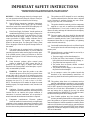 4
4
-
 5
5
-
 6
6
-
 7
7
-
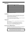 8
8
-
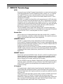 9
9
-
 10
10
-
 11
11
-
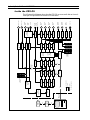 12
12
-
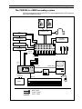 13
13
-
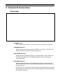 14
14
-
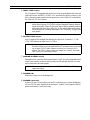 15
15
-
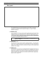 16
16
-
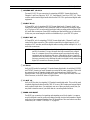 17
17
-
 18
18
-
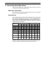 19
19
-
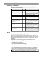 20
20
-
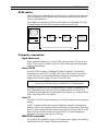 21
21
-
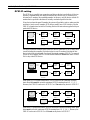 22
22
-
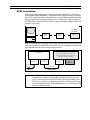 23
23
-
 24
24
-
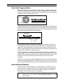 25
25
-
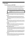 26
26
-
 27
27
-
 28
28
-
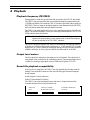 29
29
-
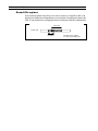 30
30
-
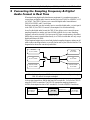 31
31
-
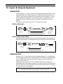 32
32
-
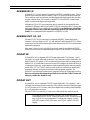 33
33
-
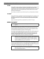 34
34
-
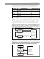 35
35
-
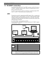 36
36
-
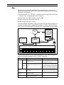 37
37
-
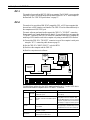 38
38
-
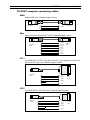 39
39
-
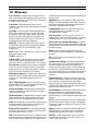 40
40
-
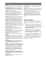 41
41
-
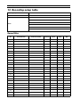 42
42
-
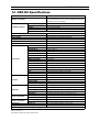 43
43
-
 44
44
-
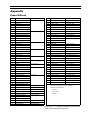 45
45
-
 46
46
-
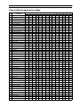 47
47
-
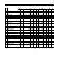 48
48
-
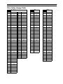 49
49
-
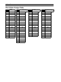 50
50
-
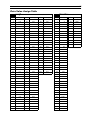 51
51
-
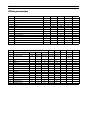 52
52
-
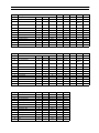 53
53
-
 54
54
-
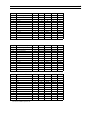 55
55
-
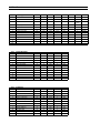 56
56
-
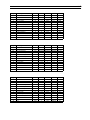 57
57
-
 58
58
-
 59
59
-
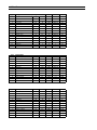 60
60
-
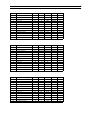 61
61
-
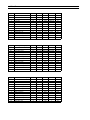 62
62
-
 63
63
-
 64
64
-
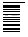 65
65
-
 66
66
-
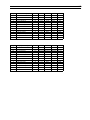 67
67
-
 68
68
-
 69
69
-
 70
70
-
 71
71
-
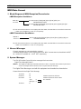 72
72
-
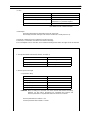 73
73
-
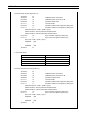 74
74
-
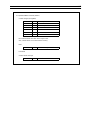 75
75
-
 76
76


Yamaha CBX-D5 Handleiding
- Categorie
- Digitale videorecorders (DVR)
- Type
- Handleiding
in andere talen
- English: Yamaha CBX-D5 User manual
- italiano: Yamaha CBX-D5 Manuale utente
- русский: Yamaha CBX-D5 Руководство пользователя
- français: Yamaha CBX-D5 Manuel utilisateur
- español: Yamaha CBX-D5 Manual de usuario
- Deutsch: Yamaha CBX-D5 Benutzerhandbuch
- português: Yamaha CBX-D5 Manual do usuário
- dansk: Yamaha CBX-D5 Brugermanual
- suomi: Yamaha CBX-D5 Ohjekirja
- čeština: Yamaha CBX-D5 Uživatelský manuál
- svenska: Yamaha CBX-D5 Användarmanual
- Türkçe: Yamaha CBX-D5 Kullanım kılavuzu
- polski: Yamaha CBX-D5 Instrukcja obsługi
- română: Yamaha CBX-D5 Manual de utilizare
