
BEDIENUNGSANLEITUNG
MODE D’EMPLOI
OWNER’S MANUAL
VR57110 JEABR1CR13.2CP
VR57100 JEABR1CR13.2CP
GUITAR PERFORMANCE EFFECTOR

This product utilizes batteries or an external
power supply (adapter). DO NOTconnect this
product to any power supply or adapter other than
one described in the manual, on the name pIate,
or specifically recommended by Yamaha.
This Product should be used only with the compo-
nents supplied or; a cart, rack, or stand that is
recommended by Yamaha. If a cart, etc., is used,
please observe all safety markings and instruc-
tions that accompany the accessory product.
SPEClFlCATIONS SUBJECT TO CHANGE:
The information contained in this manual is
believed to be correct at the time of printing.
However, Yamaha reserves the right to change or
modify any of the specifications without notice or
obligation to update existing units.
This product, either aIone or in combination with
an amplifier and headphones or speaker/s, may
be capable of producing sound levels that could
cause permanent hearing loss. DO NOT operate
for Iong periods of time at a high volume level or
at a level that is uncomfortabIe. lf you experience
any hearing Ioss or ringing in the ears, you
should consult an audiologist. lMPORTANT: The
louder the sound, the shorter the time period
before damage occurs.
NOTlCE:
Service charges incurred due to Iack of knowl-
edge relating to how a function or effect
works(when the unit is operating as designed)are
not covered by the manufacturer’s warranty, and
are therefore the owners responsibility. Please
study this manual carefulIy and consult your
dealer before requesting service.
ENVIRONMENTAL lSSUES:
Yamaha strives to produce products that are both
user safe and environmentalIy friendIy. We
sincerely believe that our products and the
production methods used to produce them, meet
these goals . ln keeping with both the letter and
the spirit of the law, we want you to be aware of
the following:
Battery Notice: This product MAY contain a
small non-rechargeable battery which (if
applicabIe)is soldered in PIace. The average life
span of this type of battery is approximately five
years. When repIacement becomes necessary,
contact a qualified service representative to
perform the replacement.
This Product may also use “household”type
batteries. Some of these may be rechargeable.
Make sure that the battery being charged is a
rechargeable type and that the charger is in-
tended for the battery being charged.
When installing batteries, do not mix old batteries
with new, or with batteries of a different type.
Batteries MUST be installed correctly. Mismatches
or incorrect instalIation may result in overheating
and battery case rupture.
Warning: Do not attempt to disassemble, or
incinerate any battery. Keep alI batteries away
from chiIdren. Dispose of used batteries promptly
and as regulated by the laws in your area.
Note: Check with any retailer of household type
batteries in your area for battery disposal informa-
tion.
Disposal Notice: Should this Product become
damaged beyond repair, or for some reason its
useful life is considered to be at an end, pIease
observe aII IocaI, state, and federaI regulations
that relate to the disposal of products that contain
lead, batteries, plastics, etc. if your dealer is
unable to assist you, Please contact Yamaha
directly.
NAME PLATE LOCATlON:
The name Plate is located on the bottom of the
product. The model number, serial number, power
requirements, etc., are located on this plate. You
should record the seriaI number and the date of
purchase in the spaces provided beIow and retain
this manual as a permanent record of your
purchase.
Model GW10
Serial No.
Purchase Date
SPECIAL MESSAGE SECTION (USA)
PLEASE KEEP THIS MANUAL
92-BP

Congratulations and thank you for purchasing the Yamaha GW10
Guitar Performance Effector. The GW10 is a portable and conven-
ient multi-effect device for guitar (as well as other instruments).
The high-quality effect sound and the flexible pedal control over
certain parameters make the GW10 ideal for signal processing in
home recording, studio, and live performance applications.
Some of the advanced features of the GW10 include:
• Three basic effect blocks, featuring Distortion, Chorus and Delay.
• Additional effect types within each block, such as Compressor,
Overdrive, Crunch, Wah, Amp Simulator, Equalizer and Pitch Shifter
— plus a built-in Noise Gate.
• High-quality sound in all effects, plus added benefit of having all
effects integrated into one unit.
• Convenient parameter control over all effects, yet exceptional ease-
of-use — you can adjust the parameters of the effect blocks much as
you would on conventional pedal effects.
• Built-in Foot Controller, which not only allows for easy volume
adjustment, but gives you realtime control over one of various effect
parameters. It also features a switch (past the maximum point) for
instantly turning selected effects on and off.
• User memory for storing up to 20 effect programs, selectable with
the Pedal Switch.
• Built-in tuner, allowing you to tune your instrument without remov-
ing it from the signal chain.
IMPORTANT NOTICE FOR THE UNITED KINGDOM
Connecting the Plug and Cord
(YAMAHA PA-3 AC adaptor)
IMPORTANT: THE WIRES IN MAINS LEAD ARE COLOURED IN ACCORDANCE WITH
THE FOLLOWING CODE:
BLUE : NEUTRAL
BROWN : LIVE
As the colours of the wires in the mains lead of this apparatus may not correspond with the
coloured markings identifying the terminals in your plug, proceed as follows:
The wire which is coloured BLUE must be connected to the terminal which is marked with
the letter N or coloured BLACK.
The wire which is coloured BROWN must be connected to the terminal which is marked with
the letter L or coloured RED. Making sure that neither core is connected to the earth
terminal of the three pin plug.

TABLE OF CONTENTS
HOW TO USE THIS MANUAL (READ THIS FIRST!!) . . . . . . . . . . . . . . . . . . . 1
PRECAUTIONS . . . . . . . . . . . . . . . . . . . . . . . . . . . . . . . . . . . . . . . . . . . . . . . . . . . . . . 2
PANEL CONTROLS AND TERMINALS . . . . . . . . . . . . . . . . . . . . . . . . . . . . . . . . 4
SYSTEM OVERVIEW . . . . . . . . . . . . . . . . . . . . . . . . . . . . . . . . . . . . . . . . . . . . . . . . 8
GW10 Internal Structure . . . . . . . . . . . . . . . . . . . . . . . . . . . . . . . . . . . . . . . . . . . . 8
The Effect Structure of the GW10 . . . . . . . . . . . . . . . . . . . . . . . . . . . . . . . . . . . . 9
Memory Structure . . . . . . . . . . . . . . . . . . . . . . . . . . . . . . . . . . . . . . . . . . . . . . . . 10
GUIDED TOUR
SETTING UP AND PLAYING YOUR GW10 . . . . . . . . . . . . . . . . . . . . . . . . . . . . 12
THE EFFECTS OF THE GW10 . . . . . . . . . . . . . . . . . . . . . . . . . . . . . . . . . . . . . . . 15
PLAYING WITH THE PRESET EFFECTS . . . . . . . . . . . . . . . . . . . . . . . . . . . . . 16
USING THE FOOT CONTROLLER TO CHANGE THE SOUND . . . . . . . . . 17
TURNING SPECIFIC EFFECTS ON AND OFF . . . . . . . . . . . . . . . . . . . . . . . . . 18
CHANGING THE SOUND OF THE EFFECTS . . . . . . . . . . . . . . . . . . . . . . . . . . 20
SAVING AN EFFECT PROGRAM . . . . . . . . . . . . . . . . . . . . . . . . . . . . . . . . . . . . 23
REFERENCE
SELECTING EFFECT PROGRAMS . . . . . . . . . . . . . . . . . . . . . . . . . . . . . . . . . . . 24
TURNING EFFECT BLOCKS ON AND OFF . . . . . . . . . . . . . . . . . . . . . . . . . . . 24
Using the Panel Buttons to Turn Effect Blocks On and Off . . . . . . . . . . . . . . 24
Using the Foot Controller to Turn Effect Blocks On and Off . . . . . . . . . . . . . 25
Assigning Effect Block On/Off Groups . . . . . . . . . . . . . . . . . . . . . . . . . . . . . . . 25
CHANGING THE EFFECT TYPE . . . . . . . . . . . . . . . . . . . . . . . . . . . . . . . . . . . . . 25
EDITING EFFECT PARAMETERS . . . . . . . . . . . . . . . . . . . . . . . . . . . . . . . . . . . . 26
EFFECTS AND PARAMETERS . . . . . . . . . . . . . . . . . . . . . . . . . . . . . . . . . . . . . . . 27
DISTORTION BLOCK . . . . . . . . . . . . . . . . . . . . . . . . . . . . . . . . . . . . . . . . . . . . 27
Overdrive/Distortion (OD/DST) . . . . . . . . . . . . . . . . . . . . . . . . . . . . . . . . 27
Compressor (COMP) . . . . . . . . . . . . . . . . . . . . . . . . . . . . . . . . . . . . . . . . . 27
CHORUS BLOCK . . . . . . . . . . . . . . . . . . . . . . . . . . . . . . . . . . . . . . . . . . . . . . . . 28
Chorus . . . . . . . . . . . . . . . . . . . . . . . . . . . . . . . . . . . . . . . . . . . . . . . . . . . . . 28
Pitch Shift . . . . . . . . . . . . . . . . . . . . . . . . . . . . . . . . . . . . . . . . . . . . . . . . . . 28
Wah . . . . . . . . . . . . . . . . . . . . . . . . . . . . . . . . . . . . . . . . . . . . . . . . . . . . . . . 29
Equalizer (EQ) . . . . . . . . . . . . . . . . . . . . . . . . . . . . . . . . . . . . . . . . . . . . . . 30
Amp Simulator (AMP) . . . . . . . . . . . . . . . . . . . . . . . . . . . . . . . . . . . . . . . . 30
DELAY BLOCK . . . . . . . . . . . . . . . . . . . . . . . . . . . . . . . . . . . . . . . . . . . . . . . . . 31
Delay . . . . . . . . . . . . . . . . . . . . . . . . . . . . . . . . . . . . . . . . . . . . . . . . . . . . . . 31
NOISE GATE . . . . . . . . . . . . . . . . . . . . . . . . . . . . . . . . . . . . . . . . . . . . . . . . . . . 32
FOOT CONTROLLER OPERATIONS . . . . . . . . . . . . . . . . . . . . . . . . . . . . . . . . . 33
Volume Pedal Control — Volume Position and Minimum Volume . . . . . . . . 33
Parameter Control . . . . . . . . . . . . . . . . . . . . . . . . . . . . . . . . . . . . . . . . . . . . . . . . 34
Effect Block On/Off Control . . . . . . . . . . . . . . . . . . . . . . . . . . . . . . . . . . . . . . . 35
■
DISABLING THE EFFECT ON/OFF SWITCHING OF THE FOOT CONTROLLER
. . . 35
SAVING AN EFFECT PROGRAM (WRITE OPERATION) . . . . . . . . . . . . . . 37
COPY AND SWAP OPERATIONS . . . . . . . . . . . . . . . . . . . . . . . . . . . . . . . . . . . . . 38
Copying One Effect Program to Another Program Number . . . . . . . . . . . . . . 38
Swapping One Effect Program with Another . . . . . . . . . . . . . . . . . . . . . . . . . . 39
RESTORING FACTORY PRESET EFFECT PROGRAMS . . . . . . . . . . . . . . . 40
TUNER . . . . . . . . . . . . . . . . . . . . . . . . . . . . . . . . . . . . . . . . . . . . . . . . . . . . . . . . . . . . . 41
Tuning the Pitch of the Connected Instrument . . . . . . . . . . . . . . . . . . . . . . . . . 41
Changing the Standard Pitch of the Tuner Function . . . . . . . . . . . . . . . . . . . . . 41
APPENDICES
TROUBLESHOOTING . . . . . . . . . . . . . . . . . . . . . . . . . . . . . . . . . . . . . . . . . . . . . . . 42
PRESET EFFECT PROGRAM/PARAMETER LIST . . . . . . . . . . . . . . . . . . . . . 44
BLANK EFFECT PARAMETER CHART . . . . . . . . . . . . . . . . . . . . . . . . . . . . . . 48
SPECIFICATIONS . . . . . . . . . . . . . . . . . . . . . . . . . . . . . . . . . . . . . . . . . . . . . . . . . . . 49
INDEX . . . . . . . . . . . . . . . . . . . . . . . . . . . . . . . . . . . . . . . . . . . . . . . . . . . . . . . . . . . . . 50

1
You are probably eager to try out your new GW10 right away and hear what it
can do, rather than have to read through a lot of instructions before you can
even get a sound out of it.
Before you do anything else, however, you should read the PRECAUTIONS
section (page 2). This tells you briefly how to care for your new GW10, how to
avoid damaging it, and how to ensure long-term, reliable operation.
Next, read the SYSTEM OVERVIEW (page 8). This provides an important
introduction to the internal organization of the GW10, enabling you to better
understand its various functions and use the device to its full potential.
To actually start using the GW10, read the GUIDED TOUR (page 12). It
guides you step-by-step in setting up your GW10, connecting it properly, and
(most importantly!) getting sound out of it. The section also introduces you to
the effect programs by letting you hear what they are capable of, and explains
how to use some of the other main functions of the device.
The REFERENCE section (page 24), on the other hand, is a comprehensive
guide to all functions. You won’t need (or want) to read through all of it at
once, but it is there for you to refer to when you need information about a
certain feature or function.
The PANEL CONTROLS AND TERMINALS (page 4) is also mainly for
reference. In general, look through this section to familiarize yourself with the
controls, and refer to it when necessary.
The INDEX in the APPENDICES section (page 50) is also very helpful. It lists
page numbers for virtually every function, feature, control and terminal found on
the GW10, and lets you find the information you need quickly and easily.
Other parts of the APPENDICES section provide additional useful information:
lists of the effect programs of the GW10, tips on troubleshooting (when some-
thing doesn’t work as expected), and other important information.
HOW TO USE THIS MANUAL (READ THIS FIRST!!)

2
PRECAUTIONS
■ USE THE CORRECT POWER SUPPLY
Power to the GW10 should be supplied only from the appropriate Yamaha
AC adaptor (the PA-3 or another adaptor specifically recommended by
Yamaha). Use of another adaptor may cause serious damage to the unit.
Also make sure that the adaptor you have is appropriate for the AC mains
supply voltage in the area where you intend to use the GW10. (The correct
input voltage is marked on the adaptor.)
■ MEMORY BACKUP
The GW10 contains a special long-life lithium battery that retains the
contents of the internal RAM memory even when the power is turned off.
The battery should last for approximately five years from the date of
manufacture. When the backup battery power becomes too low to maintain
the memory contents, the MEMORY/TUNER Indicator lights “L” then “o”
three times when the power is turned on.
When this happens, write down all necessary settings to a piece of paper
(or on copies of the chart provided on page 48), then have the battery
replaced by qualified Yamaha service personnel as soon as possible. DO
NOT ATTEMPT TO REPLACE THE BACKUP BATTERY YOURSELF!
(Keeping records of your original settings is necessary since the memory
contents cannot be preserved when the battery is changed.)
■ AVOID EXCESSIVE HEAT, HUMIDITY, DUST AND VIBRA-
TION
Keep the unit away from locations where it is likely to be exposed to high
temperatures (such as direct sunlight) or humidity. Also avoid locations
which are subject to excessive dust accumulation or vibration which could
cause mechanical damage.
■ AVOID PHYSICAL SHOCKS
Although the GW10 has been constructed to withstand the normal rigors of
stage and studio use for optimum sturdiness and reliability, avoid subject-
ing it to strong physical shocks (such as dropping or hitting it), since this
may damage the unit. Since the GW10 is a precision-made electronic
device, also avoid applying excessive force to the various controls.
■ DO NOT OPEN THE CASE OR ATTEMPT REPAIRS OR
MODIFICATIONS YOURSELF
This product contains no user-serviceable parts. Refer all maintenance to
qualified Yamaha service personnel. Opening the case and/or tampering in
any way with the internal circuitry will void the warranty.
■ MAKE SURE POWER IS OFF BEFORE MAKING OR REMOV-
ING CONNECTIONS
Always turn the power off prior to connecting or disconnecting cables.
■ HANDLE ALL CONNECTIONS CAREFULLY
Always be careful to connect and disconnect all cables and cords by
gripping the connector itself, not by pulling on the cord.

3
■ CLEAN WITH A SOFT, DRY CLOTH
Never use solvents such as benzine or thinner to clean the unit, since these
will damage the finish. Wipe clean with a soft, dry cloth. If necessary,
use a soft, clean cloth slightly moistened only with water — making sure
to wipe the case off again with a dry cloth.
■ FOOT CONTROLLER
Do not put your fingers underneath or inside the Foot Controller pedal,
since some of the parts there have a lubricant or grease applied to them.
Doing so may not only get your hands dirty, but also remove some of the
grease necessary for smooth pedal operation.
■ ELECTRICAL INTERFERENCE
Since the GW10 contains digital circuitry, it may cause interference and
noise if placed too close to TV sets, radios or similar equipment. If such a
problem occurs, move the GW10 further away from the affected equip-
ment.

4
PANEL CONTROLS AND TERMINALS
This section shows and explains all of the controls and terminals of the GW10.
Since the explanations below are fairly brief, you should turn to the page
references given for more information on individual buttons and features. Refer
to this section also as necessary when using the GW10, when you need specific
information on a certain control or terminal.
■ Top Panel
GUITAR PERFORMANCE EFFECTOR
MEMORY /
BANK(HOLD)
NO
YES
WRITE
BLOCK
TYPE
ON OFF GROUP / TUNER
INPUT PEAK
DST CHO DLY
WRITE COPY SWAP
VOLUME POSITION
RELTHR NOISE GATE
MIN VOL
WAH
OD / DST
COMP
CHORUS
P . SHIFT
WAH
EQ
AMP
DELAY
DLY
CHO
DST
DST
CHO
DLY
MEMORY / TUNER
BANK
A=44✱
Hz
TIME
TYPE
LOW
SENSE
PITCH L
SPEED
SENSE
DRIVE
FEEDBACK
TONE
MID
FREQ
PITCH R
FEEDBACK
ATTACK
TYPE
MIX
HIGH
RANGE
MIX
DEPTH
OUTPUT
OUTPUT
MIX
e w qrt y
i
!0
!1
!2 o !3
u

5
q INPUT PEAK LED
For monitoring of the input signal level. (This lights intermittently at
optimum level; see page 14.)
w MEMORY/TUNER Indicator
Displays the program number. (See page 10.) During Tuner operation,
this displays the name of the note or string played. (See page 41.)
e BANK LEDs / Sharp (¶) LED
Bank LEDs
The two LEDs (green and red) indicate which of the four banks of
programs is selected. (See page 10.)
Sharp LED
The top LED also serves as a sharp indicator during Tuner operation
(functioning along with the note name shown in the MEMORY/
TUNER indicator), lighting in the case of an accidental. (See page
10.)
r ON OFF GROUP / TUNER Indicators
These LEDs serve two purposes:
• As ON OFF GROUP indicators, they correspond to the Effect Block
buttons directly below them and light to indicate which effect blocks
can be turned on and off with the Foot Controller. (See pages 19,
35.)
• As TUNER indicators (during Tuner operation), they show whether
the input signal is in tune or not; when all three indicators light
simultaneously, the signal is in tune. (See page 41.)
t WRITE, COPY, SWAP LEDs
These LEDs serve two purposes:
• As WRITE/COPY/SWAP indicators, they flash when the respective
Write, Copy, or Swap operation is active. (See pages 37–39.)
• In normal operation, these are effect block indicators, and correspond
to the Effect Block buttons directly below them and light to indicate
which effect blocks are on. (See page 18.)
y Effect Block / Group Set / Utility Buttons
These buttons serve three purposes:
• In normal operation, they correspond to the three effect blocks
(Distortion, Chorus, and Delay) and are used to turn those effect
blocks on and off. (See pages 18, 24.)
• Also, in normal operation, they are used to set the on/off group for
the effect blocks (which effect blocks will be turned on/off by press-
ing the Foot Controller). (See page 25.)
• In Write, Copy, and Swap operations, they are used to select the
respective utility operation. (See pages 37–39.)
Bank LEDs
Sharp LED
Effect program number
MEMORY / TUNER
BANK
A=44✱
Hz

6
u VOLUME POSITION Indicators
When the Foot Controller is used as a volume pedal, one of these lights to
indicate the position of the volume pedal in the effect chain. (See page 33.)
i Effect Type Indicators
These light to indicate the selected effect type in the effect block (or the
selected parameter category in the Foot Controller block, indicated by the
Foot Controller symbol). Only one of these in each block can be selected
at a time. (See pages 21, 25, 26.) When one of these indicators flashes,
the respective parameters can be edited. (See pages 20, 26.)
o Parameter Dials
For adjusting the three parameters of a selected effect. The parameters in a
single column correspond to the dial in that column.
!0 BLOCK / WRITE NO Button
This button serves several purposes:
• In normal operation, this is used to select effect blocks for editing.
(See pages 20, 25, 26.)
• When this is held down for a couple of seconds (until all LEDs go
out), it calls up the Tuner operation. Pressing it during the Tuner
operation returns to normal operation. (See page 41.)
• When this is held down and the T button is pressed, it calls up
the Write, Copy, and Swap operations. (See pages 37–39.)
• During Write, Copy, and Swap operations, this is used to cancel the
respective operation. (See pages 37–39.)
!1 TYPE / WRITE YES Button
This button serves several purposes:
• In normal operation, this is used to select effect types for editing.
(See pages 21, 25, 26.)
• Also, in normal operation (when no LEDs are flashing), this is used to
advance through the effect program numbers. (See pages 10, 11, 24.)
• In Tuner operation, this is used to adjust the tuning standard for the
note A above middle C (from 440 to 445). (See page 41.)
• When this is pressed while the B button is held down, it calls
up the Write, Copy, and Swap operations. (See pages 37–39.)
• During Write, Copy, and Swap operations, this is used to execute the
respective operation. (See pages 37–39.)
!2 MEMORY/BANK Pedal Switch
• In normal operation and in Write, Copy, and Swap operations,
pressing this steps through the effect program numbers. Holding the
switch down advances through the bank numbers. (See pages 10, 24.)
• During Tuner operation, pressing this returns to normal operation.
(See page 41.)
!3 Foot Controller
For continuous control over volume or a selected effect parameter. When
pressed firmly beyond the maximum, this turns selected effect blocks on or
off. (See pages 19, 25.) Pressing this firmly beyond the maximum and
holding it down for a couple of seconds (until all LEDs go out) calls up the
Tuner operation. (See page 41.)

7
■ Rear Panel
q INPUT LEVEL Control
For adjusting the level of the input signal. (See page 14.)
w INPUT Jack
For connection of an instrument (guitar, bass, etc.). (See pages 12–13 for
more information on input/output connections.)
e L/MONO and R OUTPUT Jacks
For stereo or mono output of the instrument sound. Connect both of these
to the corresponding left and right channels of your stereo amplification
system to take full advantage of the stereo effects of the GW10. For mono
operation, connect your system only to the L/MONO jack; this provides a
mono mix of the instrument sound when the R OUTPUT jack is not
connected.
r DC IN Terminal
For connection to the AC adaptor.
t POWER ON/OFF Switch
AC adaptor
Cable clip
DC IN
ON / OFF
POWER
INPUT
R L / MONO
LEVEL
OUTPUT
q w r te

8
SYSTEM OVERVIEW
This section provides a brief overview of the GW10 — the basic structure of its
various functions and the memory system. Once you gain a general understand-
ing of the internal workings of the GW10 as given here, you’ll have the tools for
taking full advantage of its features.
The diagram below shows the internal system of the effects and other functions
of the GW10.
■ GW10 Internal Structure
ON OFF GROUP / TUNER
INPUT PEAK
MEMORY / TUNER
BANK
A=44✱
Hz
OD/DST
Overdrive
Crunch
Distortion
COMP
Guitar
MULTI-EFFECT SECTION
FOOT PEDAL CONTROL AUTOMATIC TUNER
DST CHO DLY
Noise Gate
INPUT
INPUT
LEVEL
INPUT
PEAK
L/MONO
R
OUTPUT
Amplifiers
Built-in pedal switch allows
on/off control of effect
groups.
When the Distortion
block is on and
OD/DST is active,
Noise Gate is on;
when COMP is active,
Noise Gate is off.
CHORUS
P.SHIFT
WAH *
EQ
AMP
DELAY
Volume pedal
MIN VOL
Distortion block
parameter
control
Wah pedal
Chorus block
parameter
control
Delay Mix
parameter control
Volume pedal
MIN VOL
Volume
pedal
MIN VOL
THR REL
Tuner
switch
*
DST
CHO
DLY
Noise Gate
WAH
THR REL
When Wah is selected in the Chorus block and the OD/DST is active, the order of the effects
changes as shown here:

9
Keep in mind as you use the GW10 that the structure of its effects is basically in
a four-part hierarchy: 1) Effect programs, 2) Effect blocks, 3) Effect types, and
4) Effect parameters.
An effect program is made up of three effect blocks and a Foot Controller
block, all of which can be used simultaneously. A block includes one or more
effect types, one of which can be used at a time. And each effect type (except
Noise Gate) is made up of three parameters, which allow you to set the sound
of the effect. The logic of this structure is reflected in the panel layout, with
effect blocks, types and parameters printed in a matrix from left to right.
■ The Effect Structure of the GW10
OD/DST (Overdrive/
Crunch/Distortion)
COMP (Compressor)
CHORUS
P.SHIFT (Pitch Shift)
WAH
EQ (Equalizer)
AMP (Amp Simulator)
DST
CHO
Effect
Blocks
Effect Types
Effect Parameters*
OUTPUT
OUTPUT
DEPTH
MIX
RANGE
HIGH
MIX
TYPE
ATTACK
FEEDBACK
PITCH R
FREQ
MID
TONE
DRIVE
SENSE
SPEED
PITCH L
SENSE
LOW
TYPE
DELAYDLY
TIME FEEDBACK MIX
(* arranged in columns corresponding to their controlling parameter dials)

10
■ Memory Structure
The 20 effect programs of the GW10 are organized in four banks, each with five
programs.
Program 5
Bank 1
Program 4
Program 3
Program 2
Program 1
Program 5
Bank 2
Program 4
Program 3
Program 2
Program 1
Program 5
Bank 3
Program 4
Program 3
Program 2
Program 1
Program 5
Bank 4
Program 4
Program 3
Program 2
Program 1
To select an effect program:
1
Make sure that the GW10 is in normal operation. (In other words, make
sure that the Tuner function or the Write/Copy/Swap operations are not
active.) To return to normal operation, press the B(NO) button or
simply turn the power off and on again. In this condition, some LEDs will
be lit, but none will be flashing.
NOTE ■
Alternatively, you can exit the Tuner function by pressing the
M
Pedal Switch or the Foot Controller.
■
2
Advance through the various effect programs by pressing the
M Pedal Switch or the T(YES) button.
NO
YES
WRITE
BLOCK
TYPE
The selected effect program number appears in the MEMORY/TUNER
indicator and the bank number is indicated by the BANK LEDs.
The four banks are indicated by the LEDs as shown below. (For instruc-
tions on how to select different banks, see step #3 below.)
Shows the current
bank number
Shows the current effect
program number
MEMORY / TUNER
BANK
A=44✱
Hz
Each press of either of these advances to the next effect program.
Bank 1 Bank 2 Bank 3 Bank 4
both LEDs off green LED lit red LED lit both LEDs lit
BANK BANK BANK BANK

11
When using the T(YES) button, the effect programs and banks are
selected in order. After the last effect in a bank is selected, the GW10
advances to the first effect in the next bank, as shown here:
NO
YES
WRITE
BLOCK
TYPE
Bank 1 Bank 2 Bank 3 Bank 4
After reaching the last effect program, the GW10 “wraps around” to return
to the first effect program.
When using the M Pedal Switch, only the effect programs of
the currently selected bank are selected in order.
After reaching the last effect program, the GW10 “wraps around” to return
to the first effect program in the bank.
3
To select a different bank number with the M Pedal Switch,
hold down the Pedal Switch until the desired bank is shown.
Bank 1
both LEDs off
Bank 2
green LED lit
Bank 3
red LED lit
Bank 4
both LEDs lit
BANK BANK BANK BANK
As with effect program selection, after the last bank is selected, the GW10
“wraps around” to return to the first bank.
● Bank/Program Indications
Program No.
Display
Bank No.
1
12
234512345
1
34
234512345
Program No.
Display
Bank No.

12
Guided Tour
Guided Tour
Once you’ve taken your GW10 out of the box and are ready to use it, you’ll
have to make a few connections and follow some simple instructions on setting
it up.
1
First, make sure that the power switch on the GW10 is off before making
ANY connections.
2
Plug the DC output cable from the power adaptor into the DC IN terminal
on the rear panel, then plug the adaptor into a convenient AC outlet.
SETTING UP AND PLAYING YOUR GW10
The cable clip located next to this terminal helps to prevent accidental
unplugging of the power supply during use. Wrap the adaptor cord firmly
around the clip (see the Rear Panel illustration, page 7).
CAUTION! ■
Do not attempt to use a different AC adaptor with the GW10.
Also, be sure to check whether the rated voltage is appropriate. (See the
precaution “USE THE CORRECT POWER SUPPLY” on page 2.)
■
3
Plug your instrument into the INPUT jack on the rear panel.
For the sake of these instructions, we’ll assume you’re using an electric
guitar; however, most any electronic instrument can be used.
INPUT
DC IN
ON / OFF
POWER
INPUT
R L / MONO
LEVEL
OUTPUT
DC IN
ON / OFF
POWER
INPUT
R L / MONO
LEVEL
OUTPUT
DC IN
AC outlet

13
Guided Tour
NOTE ■
You should be careful if you are connecting a synthesizer or
electronic keyboard; generally their output level is much higher than that of
a guitar and the input level, as well as the volume control on the keyboard,
should be turned down accordingly (see step #4 below).
■
4
Connect the GW10 output or outputs to your amplifier/speaker system.
Before you do this, however, make sure that the power on the system is
first turned off and all volume controls are set to zero — this includes the
guitar controls, the INPUT LEVEL and the Foot Controller on the GW10
itself, and the volume on the connected amp (or mixing console).
NOTE ■
To set the INPUT LEVEL on the GW10 to the minimum, turn the
control all the way counterclockwise.
■
Two example connection systems are shown below. Use the one which
most closely resembles your own system.
EX.1
Here, the left and right outputs of the GW10 are sent to two
separate guitar amps.
If you are using a single guitar amp, connect it to the L/MONO OUTPUT
jack.
EX. 2
EX.2
In this system for studio recording applications, the left and right
channels of the instrument/effect sound go into separate mixer
channels. For best results with this setup, use the Amp Simulator
effect in the Chorus block (see page 30).
5
Turn on the power of all the equipment, starting with the GW10, and
turning on the connected amplifier last.
DC IN
ON / OFF
POWER
INPUT
R L / MONO
LEVEL
OUTPUT
L/MONOR
DC IN
ON / OFF
POWER
INPUT
R L / MONO
LEVEL
OUTPUT
L/MONOR

14
Guided Tour
6
While playing your guitar, bring up the level on your guitar and adjust the
INPUT LEVEL control on the rear panel of the GW10. Increase the level
slowly as you play the guitar while looking at the INPUT PEAK LED on
the panel. When you play your guitar the loudest, the indicator should
light intermittently.
INPUT PEAK
ON OFF GROUP / TUNER
WRITE COPY SWAP
7
Next, slowly bring the volume up with the Foot Controller on the GW10.
8
Now that you’ve properly set the level on the GW10, slowly bring up the
other volume controls to suitable levels — starting with the amp.
If you’ve followed all these instructions carefully, you should now be able
to hear your guitar sound processed by the effects of the GW10.

15
Guided Tour
THE EFFECTS OF THE GW10
The GW10 is equipped with a comprehensive set of effects designed specifically
for the guitar player. You can switch these effects on and off as needed and
adjust them quickly and easily from the panel controls.
There are three groups or “blocks” of effects — Distortion, Chorus and Delay —
plus a special Foot Controller block that includes a Noise Gate effect and the
Foot Controller settings. The Distortion block includes Crunch, Overdrive and
Compressor effects, while the Chorus block also features Pitch Shift, Wah,
Equalizer, and Amp Simulator effects.
(Refer to the EFFECTS AND PARAMETERS section, page 27, for more
detailed descriptions and explanations of these effects.)
With these three effect blocks, used individually or simultaneously, the GW10
has all you need to augment your sound, whatever the application. Plus, flexible
effect bypass (on/off) functions give you even more realtime control over the
sound.

16
Guided Tour
PLAYING WITH THE PRESET EFFECTS
Now that you’ve set up your GW10 and are ready to use it, let’s try playing
with some of the preset effects. (If you haven’t already done so, read through
the SYSTEM OVERVIEW section on pages 8–11 for information on the basic
structure of the GW10 and how to select effect programs.)
1
First, try playing with a bright chorus effect. Use the M Pedal
Switch to select bank 3, program number 5. (Hold down the Pedal Switch
to select the desired bank, and press it repeatedly to advance to the proper
program number; see pages 10–11.)
NOTE ■
For this and the other examples that follow, make sure that the
Foot Controller is at or near the maximum position, to ensure proper
volume.
■
2
Now, try a heavy distortion sound. Use the M Pedal Switch
again, this time selecting bank 2, program number 1.
3
Next, let’s call up an interesting delay effect. Use the M
Pedal Switch to select bank 1, program number 3.
4
Before going on to the next section, try exploring some of the other effect
programs of the GW10. Look through the Preset Effect Program list on
page 44 for more information about the programs, and play with a few of
them to hear how they sound.
MEMORY / TUNER
BANK
A=44✱
Hz
MEMORY / TUNER
BANK
A=44✱
Hz

17
Guided Tour
The Foot Controller is one of the most convenient and flexible features of the
GW10. It not only allows you to control volume, but also lets you continuously
change certain effect parameters as you play. The examples below should give
you a taste of what the Foot Controller functions can do for your sound.
1
Let’s use one of the volume functions of the Foot Controller first. Select
bank 4, program number 3.
2
Bring the Foot Controller to the maximum position and play your guitar.
This is the maximum volume and is ideal for playing a solo.
3
Now, stop playing and bring the pedal all the way to the minimum posi-
tion, then start playing again.
Notice how the volume of the sound changes to a level suitable for backing
parts. As you can see, the Foot Controller is an easy and instant way to
change from one volume setting to another.
4
Next, let’s use the Foot Controller to change the sound in realtime. Select
bank 1, program number 2.
As you play your guitar, slowly rock the pedal back and forth. Listen to the
“wah-wah” effect in the sound as you move the Foot Controller.
5
Finally, select bank 3, program number 2.
In this example, set the Foot Controller first to the minimum position and play
your guitar. As you continue playing, slowly bring the pedal to the maximum
position. Notice how a rich, natural chorus effect gradually blends in with the
sound as you press the pedal toward the maximum.
As you can see, the Foot Controller is an extremely versatile and powerful
performance tool, giving you broad control over the sound as you play, without
forcing you to take your hands from your instrument.
Look again through the Preset Effect Program list on page 44, noting which
programs take advantage of the Foot Controller functions, and try playing with a
few of them to hear how they sound.
USING THE FOOT CONTROLLER
TO CHANGE THE SOUND

18
Guided Tour
TURNING SPECIFIC EFFECTS ON AND OFF
Since the sound of an effect preset is actually made up of three different effects,
you can make distinct changes in the sound by turning individual effect blocks
on and off.
1
For this example, select bank 1, program number 2. This effect program
has Distortion, Wah, and Delay.
MEMORY / TUNER
BANK
A=44✱
Hz
DST CHO DLY
WRITE COPY SWAP
The LEDs above all three Effect Block buttons (D, H, L) should
be lit, indicating that all effects are active. Play your guitar and listen to
the sound of effect program.
2
Press D to turn off the Distortion block. (The LED will turn off.)
Now, play your guitar again and hear how the sound has changed. Try
pressing H and L as well, seeing how turning the effect blocks on
and off affects the overall sound.
3
In this effect program, you can also use the Foot Controller to simultane-
ously turn both the Chorus and Delay blocks on or off. Push the Foot
Controller down to its maximum setting, then firmly press it once. The
CHO and DLY LEDs will turn off, indicating that the two effect blocks are
off.
DST CHO DLY
WRITE COPY SWAP
DST CHO DLY
WRITE COPY SWAP
DST CHO DLY
WRITE COPY SWAP
DST CHO DLY
WRITE COPY SWAP
MEMORY / TUNER
BANK
A=44✱
Hz

19
Guided Tour
Depending on the preset selected, the Foot Controller turns different groups
of effect blocks on and off. You can instantly check which effect blocks
are enabled for this function by looking at the green ON OFF GROUP
LEDs above the Effect Block buttons. For example, in bank 1, program
number 2, the ON OFF GROUP LEDs above CHO and DLY are lit.
ON OFF GROUP / TUNER
DST CHO DLY
WRITE COPY SWAP
These are lit to indicate that the two
corresponding effect blocks can be
turned on/off with the Foot Controller.
NOTE ■
Be sure to press the Foot Controller down firmly when using this
function; the effect block or blocks may not be properly turned on or off if
the Foot Controller is not pressed down all the way.
■

20
Guided Tour
CHANGING THE SOUND OF THE EFFECTS
The GW10 makes it extremely easy to adjust or change the sound of the effects.
As you saw in the section TURNING SPECIFIC EFFECTS ON AND OFF
above, you can easily change the sound by turning the effect blocks on and off.
In this section, you’ll learn how to change the effect type and use the parameter
dials to change effect settings.
CAUTION! ■
If you wish to save the changes that you make here, be
careful not to press the
M
Pedal Switch while making changes.
If you do, the next effect program will be called up, erasing all settings you
had made to that point.
■
1
Select an effect program with the M Pedal Switch. Since
you’ll be completely changing the settings, any effect program will do.
NOTE ■
Even though creating and saving your own effect program erases
the original factory preset program, you can restore that particular factory
preset program. Refer to RESTORING FACTORY PRESET EFFECT
PROGRAMS on page 40 for details. Keep in mind, however, that restoring
the factory preset program will irretrievably erase the effect that you
created. For this reason, you should always make a written record of the
settings you make (see page 48), so that you can reprogram the effect later
if necessary.
■
2
Next, make sure that the Distortion and Delay blocks are turned off. If you
recall from the last section, you can do this by pressing the D and L
buttons so that their LEDs turn off. Also, make sure that the Chorus block
is on.
3
Press the B button repeatedly until one of the effect type LEDs in
the Chorus (CHO) block flashes.
You’ve now selected the Chorus block for editing.
DST CHO DLY
WRITE COPY SWAP
DST CHO DLY
WRITE COPY SWAP
ON OFFOFF
Press B repeatedly …
NO
YES
WRITE
BLOCK
TYPE
WAH
OD / DST
COMP
CHORUS
P . SHIFT
WAH
EQ
AMP
DELAY
DLY
CHO
DST
DST
CHO
DLY
… until one of these
LEDs flashes.

21
Guided Tour
4
Press the T button repeatedly to select an effect type. For this exam-
ple, select Chorus. (The CHORUS LED will flash.)
Press T repeatedly …
NO
YES
WRITE
BLOCK
TYPE
CHORUS
P . SHIFT
WAH
EQ
AMP
CHO
… until the CHORUS LED
flashes.
You’ve now selected the Chorus effect for editing.
5
Before making any other settings, make sure that the right parameter dial is
turned to at least the halfway position or higher.
While the CHORUS LED is flashing, this dial controls the Chorus Depth
parameter. (The matrix on the panel clearly shows the effect/parameter/
parameter dial relationship; notice that DEPTH is in the same row as the
flashing CHORUS LED, and in the same column as the right parameter
dial.)
This step is necessary since you may not be able to hear any changes made
to the other two parameters if Chorus Depth is not set to a high enough
value.
6
While playing your guitar, try adjusting the left and middle parameter
dials. These control the Chorus Speed and Feedback, respectively.
Adjust the right parameter dial as well, to “fine-tune” the sound.
TYPE
LOW
SENSE
PITCH L
SPEED
TONE
MID
FREQ
PITCH R
FEEDBACK
MIX
HIGH
RANGE
MIX
DEPTH
CHORUS
P . SHIFT
WAH
EQ
AMP
CHO
Set to roughly this
position.
TYPE
LOW
SENSE
PITCH L
SPEED
TONE
MID
FREQ
PITCH R
FEEDBACK
MIX
HIGH
RANGE
MIX
DEPTH
CHORUS
P . SHIFT
WAH
EQ
AMP
CHO
Adjust the left and
middle parameter dials

22
Guided Tour
7
Now, use the Effect Block buttons (D and L) to turn the Distortion
and Delay effects back on.
Play your guitar again and listen to the changes as you turn these effects
on again. As you listen to how they affect the overall sound, you can
continue to adjust the Chorus settings to further fine-tune the sound. If
you wish, you can even select the Distortion and Delay effects and edit
them as well.
NOTE ■
In some cases, undesirable feedback or noise may result if you
adjust the value of a parameter while playing your guitar. In general, adjust
a parameter, then play your guitar to hear the change in the sound.
■
When you’ve adjusted the sound to your satisfaction, you may wish to save it
for future recall. You can either copy the settings down on paper (using a copy
of the Blank Effect Parameter Chart on page 48) or go on to the next section and
save the settings to the GW10’s memory.
DST CHO DLY
WRITE COPY SWAP
DST CHO DLY
WRITE COPY SWAP

23
Guided Tour
SAVING AN EFFECT PROGRAM
Now that you’ve created your own original effect program, you will want to
save the settings to a program number, so that you can recall your new effect
program in the future. (For more information on saving effect programs and
other matters relating to memory, see SYSTEM OVERVIEW on page 8.)
1
If you’ve continued from the last section and have new settings you want
to save, hold down the B(NO) button, then press T(YES).
The program number in the MEMORY/TUNER indicator and the WRITE
LED both flash to indicate that the GW10 is ready to write the settings to
memory at the selected program number.
NOTE ■
All LEDs may temporarily go out while holding down the
B
(NO) button. This is normal and should be no cause for concern.
However, if you lift up on the
B
(NO) button, the LEDs may stay off. If
this happens, simply press
B
(NO) again, and start all over with step #1
above.
■
2
If you want to save the settings to a different program number, use the
M Pedal Switch to select another bank and program number.
(See pages 10–11.) (The BANK LED(s) and MEMORY/TUNER indicator
flash.)
NOTE ■
The
T
(YES) button CANNOT be used here to change the
effect program number; its only use is in step #3 below.
■
3
To actually save the new settings, press T(YES).
To cancel the operation and continue editing, press B(NO).
1) Simultaneously hold B (NO) down...
2) ...and press
T (YES)
DST CHO DLY
WRITE COPY SWAP
MEMORY / TUNER
BANK
A=44✱
Hz
NO
YES
WRITE
BLOCK
TYPE
MEMORY / TUNER
BANK
A=44✱
Hz
NO
YES
WRITE
BLOCK
TYPE
Press
T
(YES) to save the settings.
NO
YES
WRITE
BLOCK
TYPE
Press B (NO) to cancel the operation.

24
Reference
Reference
This section of the manual explains briefly, yet completely, all of the features
and functions of the GW10. Refer to it when you need information about a
specific feature or function.
SELECTING EFFECT PROGRAMS
OPERATION
1
To select one of the four banks, press and
hold the M Pedal Switch, then
release it when the desired bank number is
shown in the BANK LEDs.
2
Press the Pedal Switch (or the T(YES)
button) once to advance to the next effect
program number. The current effect program
number is shown in the MEMORY/TUNER
indicator.
(For more information on the bank/program
configuration of the GW10 and the selection of
effect programs, see pages 10–11 in SYSTEM
OVERVIEW.)
TURNING EFFECT BLOCKS ON AND OFF
You can change the sound of an effect program by turning any of its three effect
blocks on or off. This can be done either by using the panel buttons or the Foot
Controller.
OPERATION
Press the Effect Block button (D, H, or
L) corresponding to the effect block you wish
to turn on or off. The button’s red LED is lit
when the effect block is on, and goes out when
the block is turned off.
Using the Panel Buttons to Turn Effect Blocks On and Off

25
Reference
The Foot Controller can be used to instantly turn
pre-assigned effect blocks on and off. The green
ON OFF GROUP LEDs above the Effect Block
buttons indicate which effect blocks are assigned
for this. For example, if the green LEDs above
H and L are lit, the Chorus and Delay
blocks can be turned on or off with the Foot
Controller. (For instructions on how to set the
on/off group, see “Assigning Effect Block On/
Off Groups” below.)
OPERATION
Push the Foot Controller down to its maximum
setting, then firmly press it once. The selected
effect block or blocks (along with their LEDs)
will appropriately turn on or off.
Using the Foot Controller to Turn Effect Blocks On and Off
CHANGING THE EFFECT TYPE
OPERATION
1
Press B repeatedly until the desired
block is selected. (One of the effect type
LEDs in the block will flash.)
2
Press T repeatedly until the desired
effect type is selected. (The selected effect
type LED in the block will flash.)
3
Write (save) the new setting to memory, if
desired. (See SAVING AN EFFECT
PROGRAM on page 37 for details.)
Assigning Effect Block On/Off Groups
OPERATION
To set which effect blocks are to be turned on
and off with the Foot Controller, press and hold
the appropriate Effect Block button(s) (D,
H, or L) corresponding to the effect block
or blocks you wish to turn on or off. Hold the
button or buttons for about one second, or until
the green LEDs above the selected Effect Block
buttons light.
NOTE ■
At least one of these LEDs will always
be lit in normal operation, meaning that at least
one block will always be assigned for on/off
control with the Foot Controller. However, you
can disable this on/off switching entirely; see
DISABLING THE EFFECT ON/OFF SWITCHING
OF THE FOOT CONTROLLER, page 35.
■

26
Reference
EDITING EFFECT PARAMETERS
The effect programs of the GW10 can be easily “tweaked” or edited with the
convenient parameter dials.
CAUTION! ■
Be careful NOT to press the
M
Pedal Switch at
any time during editing. Doing so will switch to the next preset and erase
all settings you had made to that point.
■
OPERATION
1
First, turn off all effect blocks (using the
Effect Block buttons; see page 24), except
for the one you wish to edit.
Doing this lets you clearly hear only the
effect you wish to edit.
NOTE ■
One possible exception to this
guideline is the Amp Simulator effect,
changes to which are easier to hear when
Distortion is also on.
■
2
Select the effect you wish to edit. Use
B to select the desired effect block,
then T to select the desired effect type.
(The LED of the selected effect will flash.)
3
While playing the connected instrument,
adjust the parameter dials. The relevant
parameters are in the same row as the
flashing effect LED. For example, if you
wish to edit the MID parameter of the
Equalizer effect, the EQ LED should be
flashing and you should adjust the middle
parameter dial.
NOTE ■
In some cases, undesirable feed-
back or noise may result if you adjust the
value of a parameter while playing your
guitar. In general, adjust a parameter, then
play your guitar to hear the change in the
sound.
■
For information about each of the effects and
their parameters, refer to the section EF-
FECTS AND PARAMETERS on page 27.
HINT ■
In general, when editing an effect,
you should turn up the right parameter dial to
a relatively high setting before adjusting the
other two.
Doing this ensures that any changes you
make with the other dials will be fairly
noticeable. This technique particularly
applies to effects whose third parameter is
Output or Mix, since these parameters
directly affect the level of the effect sound.
■
4
While editing, turn one or both of the other
effects back on to hear how the changes
you’ve made affect the overall sound. If you
like, select those effects and edit them as
well.
5
You can also make changes to the Foot
Controller: selecting the controllable param-
eter or volume pedal position, and setting the
Minimum Volume. (See pages 33 and 34.)
6
Write (save) the new settings to memory, if
desired. (See SAVING AN EFFECT
PROGRAM on page 37 for details.)
Set this dial
relatively
high at first.

27
Reference
EFFECTS AND PARAMETERS
This section briefly explains each of the effect types and their parameters. For
information on how to select effects and edit them, see the sections SELECTING
EFFECT PROGRAMS (page 24), CHANGING THE EFFECT TYPE (page 25)
and EDITING EFFECT PARAMETERS (page 26).
The Distortion block features the following
effects: Overdrive, Crunch, Distortion, and
Compressor.
Overdrive/Distortion (OD/DST)
Drive
Determines the intensity of the Overdrive,
Crunch or Distortion sound. The higher the
value, the greater the distortion.
HINT ■
For best results, set the Drive parameter
roughly between the 12:00 and 3:00 positions.
■
Type
Determines the type of distortion effect: Over-
drive, Crunch, or Distortion. Overdrive recreates
the warm, natural sound of a tube amp being
overdriven. Crunch is a rich distortion effect
ideal for power chords and Rock’n’Roll. Distor-
tion is a hard, more metallic distortion sound,
and is excellent for screaming lead lines.
The positions from minimum to roughly 10:00
correspond to Overdrive, from about 11:00 to
1:00 corresponds to Crunch, and from about 2:00
to maximum corresponds to Distortion. Within
each effect is also three separate settings: Low,
Mid, and High.
A definite change in the sound can be heard
when crossing the “line” between two separate
types or settings.
DISTORTION BLOCK
Output
Determines the output level of the Distortion
sound.
HINT ■
This should be set to an appropriate value
to avoid sudden jumps or drops in level when
switching the effect on and off.
■
Compressor (COMP)
The Compressor is especially effective for guitar
since it smooths out the “peaks” and “valleys” in
the sound. Compression “squashes” the dynamic
range of the signal, making loud signals softer
and soft signals louder. Normally, the Compres-
sor limits signals of widely varying loudness to a
dynamic range more suitable for use with the
other effects. For this reason, compression is
effective on guitar in smoothing out the level
differences caused by uneven picking technique.
Sense
Determines the threshold level of compression.
Compression is applied to signal levels above the
Sense point, while signals below this point are
unaffected. The minimum setting virtually
allows the entire signal to pass without being
compressed (minimum compression), while the
maximum setting applies compression to the
entire signal (maximum compression).
Attack
Determines the amount of time it takes for
compression to begin after an input signal is
detected. Longer attack times (when dial is
turned toward maximum) let through more of the
natural attack of the input signal.
Output
Determines the level of the Compressor sound.
Settings past the 12:00 position are used for
boosting the overall signal to an appropriate
level, since compression effectively lowers the
level of the sound.
SENSE
DRIVE
ATTACK
TYPE OUTPUT
OUTPUT
OD / DST
COMP
DST
Crunch
Distortion
Overdrive
L
M
H
L
M
H
L
M
H

28
Reference
CHORUS BLOCK
The Chorus block features a wide range of
modulation and tone control effects, including
Chorus, Pitch Shift, Wah, Equalizer, and Amp
Simulator.
Chorus
Chorus uses modulation of the pitch and separa-
tion of the signal into stereo to greatly enhance
the sound, generally making it richer, fatter and
warmer.
Speed
Determines the speed of the pitch modulation.
Settings higher than around 4:00 produce very
high speed modulation for special effects.
Feedback
Determines the amount of Chorus signal that fed
back again to the Chorus input. Higher values
result in a stronger, flanger-like sound.
Depth
Determines the depth of the pitch modulation, or
how widely the pitch is varied.
Pitch Shift
Pitch Shift lets you change the pitch of the sound, up
to an octave above or below the pitch of the input
signal. Since the effect is stereo, you can set the
amount of pitch shift independently for the left and
right channels, creating three separate pitches (includ-
ing the original direct signal). One application for
this would be to create a natural, spacious stereo
chorus effect in which the left and right pitches are
detuned slightly relative to the direct sound. Other
applications include setting the pitch shift to an octave
below or above (to make a six-string guitar sound like
a twelve-string), or setting the pitch to other intervals
(such as a fourth or fifth) to create instant harmonies
and fill out the sound.
Pitch Left (PITCH L)
Determines the amount of pitch shift for the left
channel, up to one octave above or below the
input pitch. The 12:00 position on the dial
corresponds to unison pitch, while the pitch can
be continuously detuned between the 9:00 and
3:00 positions. Fixed pitch shifts are available
past those positions: an octave down at 7:00, a
5th down at 8:00, a 4th down at around 9:00, a
4th up at around 3:00, a 5th up at 4:00, and an
octave up at 5:00.
Pitch Right (PITCH R)
Determines the amount of pitch shift for the
right channel, up to one octave above or below
the input pitch. (The settings are the same as in
Pitch Left above.)
Mix
Determines the level of the Pitch Shift sound.
The minimum setting corresponds to 0%, or no
TYPE
LOW
SENSE
PITCH L
SPEED
TONE
MID
FREQ
PITCH R
FEEDBACK
MIX
HIGH
RANGE
MIX
DEPTH
CHORUS
P . SHIFT
WAH
EQ
AMP
CHO
HINT — ABOUT THE OUTPUT LEVEL
■
Since
the Output parameter of the Distortion block
determines the loudness of the overall sound, the
Distortion block is placed first in the effect chain
(except when the Wah effect is used; see
illustration in the SYSTEM OVERVIEW section on
page 8). In general, you should set Output so
that the level of the sound is constant, even when
turning the Distortion block on and off. If the
Output parameter is set too high or low, you may
get unwanted sudden jumps or drops in the level
of the sound when turning Distortion on and off.
Moreover, if Output is set to the minimum, you
won’t get any sound at all.
■
Unison pitch
4th down
5th down
octave down
4th up
5th up
octave up
detuneddetuned

29
Reference
Pitch Shift output (only the original sound is
heard). The midpoint setting corresponds to
50%, or an equal mix of the original direct
sound and the Pitch Shift output. The maximum
setting corresponds to 100%, or no original
sound output (only the Pitch Shift sounds are
heard).
Wah
Wah is a filter sweep effect that, as its name
implies, produces a “wah” type sound. Two
different Wah types are available: Touch and
Pedal. Touch lets you vary the sweep of the
filter according to the input level (how hard or
loud you play) while Pedal lets you “play” the
Wah effect with the Foot Controller. The Touch
type is normally active; to select Pedal, make
sure WAH is enabled in the Foot Controller
block. The illustration below shows how the
various parameters and two types are related.
HINT — About the Wah Types (Touch and
Pedal) ■
The Touch type lets you control the
Wah effect by the level of the input signal (or how
hard you play). In Touch, the filter sweep (or
“wah” sound) starts at the beginning each time it
is triggered. Touch is normally active when you
select the Wah effect.
The Pedal setting lets you sweep the filter
manually with the Foot Controller. This setting is
available only when WAH has been selected in
the Foot Controller block. If the WAH LED in the
Foot Controller block is already lit, the Pedal type
is active.
To change between the two types, press
B
until one of the Foot Controller block LEDs
flashes, then press
T
to either select WAH
(for Pedal type) or another parameter’s LED (for
Touch type).
■
Sense
Determines how sensitive the Wah effect is to
the instrument input. (Not available for Pedal
Wah operation.) The higher the value, the more
sensitive the trigger of the Wah effect becomes
to low level signals; the movement of the band
pass filter responds to even slight level changes.
HINT ■
For best results, when playing a solo or a
line, try setting Sense to a high value; when
performing backing or rhythm parts, try setting
Sense to a low value. (This is because playing a
single string results in a lower level than playing
all six strings.)
■
Frequency (FREQ)
Determines the center frequency of the band pass
filter. The Wah effect sweeps this isolated
portion below and above the center frequency,
over a specific frequency range determined by
the Range parameter. (See illustration at left.)
Range
Determines the width of the frequency sweep, or
how far the sweep extends above and below the
center frequency. Higher values create a more
pronounced “wah” sound. (See illustration at
left.)
Pedal, the movement of the Foot Controller determines the
movement of the isolated frequency across the set range.
Touch, the level of the guitar signal determines the position
of the isolated frequency within the set Range. When the
level of the guitar is low, the isolated frequency remains
around the minimum frequency of the set Range. As the
guitar level increases, the isolated frequency moves further
toward the maximum.
Frequency
Pedal
minimum
Pedal
Touch
Pedal
maximum
Guitar
minimum
Guitar
maximum
FREQ
RANGE
(Center Frequency: surrounding
frequencies are cut.)
The Wah effect employs a movable band pass filter to create
the filter sweep or filter emphasis effect. Frequencies on
either side of the center frequency (set in the Frequency
parameter) are cut or filtered out, isolating the center
frequency. This frequency band is then moved across the
specified frequency range (set in Range), as shown in the
Pedal and Touch portions of the graph above.

30
Reference
Equalizer (EQ)
The Equalizer effect provides fine tone control
over the sound with a three-band equalizer.
Low
Determines the amount of boost or cut applied to
the low frequencies. The 12:00 position corre-
sponds to flat response or no equalization.
Mid
Determines the amount of boost or cut applied to
the midrange frequencies. The 12:00 position
corresponds to flat response or no equalization.
High
Determines the amount of boost or cut applied to
the high frequencies. The 12:00 position corre-
sponds to flat response or no equalization.
HINT ■
Take care when using maximum levels;
distortion could result, especially when all
parameters are set to the maximum.
■
Amp Simulator (AMP)
This effect realistically reproduces the character-
istic sound of a guitar amplifier, and provides a
natural sound for direct recording purposes when
not using an external amplifier. When using an
amplifier, it also provides a convenient way to
change the sound characteristics of that ampli-
fier. Amp Simulator is particularly effective
when used with one of the Distortion effects.
Type
Determines the type of amplifier that is simu-
lated: Stack, Combo, or Tube. Stack recreates
the powerful sound of a huge amp/speaker setup,
Combo recreates a compact amp cabinet, and
Tube recreates the warm sound of a tube ampli-
fier.
The positions from minimum to roughly 10:00
correspond to Stack, from about 11:00 to 1:00
corresponds to Combo, and from about 2:00 to
maximum corresponds to Tube.
A definite change in the sound can be heard
when crossing the “line” between two separate
types.
Tone
Determines the degree to which high frequencies
are cut or boosted. Turning the parameter dial
counterclockwise decreases the high frequencies,
while turning it clockwise boosts them.
Mix
Determines the level of the Amp Simulator
effect. The minimum setting corresponds to 0%,
or no Amp Simulator output (only the original
signal is heard). The midpoint setting corre-
sponds to 50%, or an equal mix of the original
direct signal and the Amp Simulator output. The
maximum setting corresponds to 100%, or no
original signal output (only the Amp Simulator
effect is heard).
HINT ■
For direct recording purposes, a setting of
100% is recommended.
■
Combo
TubeStack

31
Reference
DELAY BLOCK
9:00 add a single delayed repeat without Dou-
bling. Settings between 9:00 and 12:00 repeat
the delay and Doubling a few times, while for
higher values the repeats carry on almost indefi-
nitely. The repeat sounds gradually decay to
silence, and the time it takes for them to decay is
also controlled by Feedback.
Mix
Determines the level of the Delay sound. The
minimum setting corresponds to 0%, or no Delay
output (only the original signal is heard). The
maximum setting corresponds to 50%, or an
equal mix of the original direct signal and the
Delay output.
TIME
FEEDBACK MIX
DELAY
DLY
Delay
The Delay effect allows you to add delayed,
echo-like repeats to the original sound. Subtle
use of Delay helps in creating a sense of space
and depth in the sound — especially since this is
a stereo delay effect. Generally, it is an effec-
tive way to bring the sound to life and make it
sound more natural. Delay can also be used for
special applications, such as creating rhythmic
repeats in the sound.
The Delay effect of the GW10 also has a special
Doubling feature, which adds two slightly delayed
repeats to the original signal, and outputs them
separately in the left and right outputs (as shown in
the Delay Parameters illustration at right). The
Doubling sound is too fast to be heard as a distinct
delay, but instead adds depth and fullness to the
direct sound, giving the impression of more than
one instrument being played.
Delay has been placed last in the effect chain of
the GW10, since it is most often used to repro-
duce the echoes and ambience that follow a
sound when heard in an actual performance
environment.
Time — Range: 5 - 660 ms
Determines the time between delayed repeats of
the main delay. Very short delays make it
possible to make one instrument sound like two
separate instruments. Slightly longer delays can
be used for creating slap-back echo or a reverb-
type effect. Longer times are used for special
effects, like creating long echoes or steady
rhythmic pulses.
Feedback
Determines the number of the delayed repeats
and the level of the doubling sound. As shown
in the illustration above, settings between 7:00
and 8:00 result in only the direct and Doubling
sounds being heard. Settings between 8:00 and
The Doubling sounds are repeats
of the direct signal, coming almost
immediately after the direct sound,
and are output separately in
stereo.
■ When Feedback = 8:00 - 9:00
When Feedback is
set to roughly
between 8:00 and
9:00, the direct
sound (plus
Doubling) and a
single delayed
repeat of only the
direct sound is
heard. (in this
case, the repeat
sound does not
include Doubling.)
When Feedback is
set to roughly the
minimum position
(7:00 - 8:00), only
the direct sound
and the Doubling
delay are heard.
Level
Direct sound
Time
Doubling sound
(right, left)
TIME
(Delay time)
Feedback settings greater than 9:00 add multiple
delayed repeats at gradually decreasing volume.
■ When Feedback = 7:00 - 8:00
■ When Feedback = 9:00 - maximum
Level
Time
Level
Time

32
Reference
NOISE GATE
Noise Gate is a separate effect that is placed
between the Distortion block and the other two
blocks, and is used to eliminate any noise or
hum in the signal when the instrument isn’t
being played. All signals below the Threshold
point are filtered out, thus cutting off the noise.
Noise Gate is active only when the Distortion
block is also active and one of the distortion-
type effects has been selected (Overdrive,
Crunch, or Distortion); when Compressor is
selected, the Noise Gate is off.
To adjust the Noise Gate parameters, select the
Foot Controller block with the B button,
then use the two parameter dials below NOISE
GATE.
Threshold
Determines the sensitivity of the noise gate, or
how loud an input signal is required to open the
gate (letting the signal through). The higher the
value, the louder the signal needs to be to open
the gate. For optimum operation, Threshold
should be set just above the level of the noise;
setting it too high may cause notes to be cut off
too abruptly.
Release
Determines the time of the decay, from when the
input signal crosses the Threshold point. (Since
this control introduces subtle changes to the
sound, some experimentation may be necessary;
also see Hint below.)
HINT ■
Achieving the best results with the Noise
Gate may take some experimentation. When
Release is set too close to the minimum and the
Threshold setting is not low enough, the noise
may come back in soon after the sound dies out,
creating an unnatural sounding decay. When
Release is set too close to the maximum, the
noise may remain too long and sound as if it is
gradually increasing in volume. For optimum
results, avoid the extreme settings (especially in
Release) and use low-to-median values.
■
This part of signal is filtered out.
Level
Noise Noise
Threshold level
Guitar signal
Time
Release time

33
Reference
FOOT CONTROLLER OPERATIONS
The Foot Controller of the GW10 can be used as a volume pedal or as a realtime
controller for specific effect parameters. Moreover, when used as a volume
pedal, it can be placed in one of three positions in the effect chain, and be given
a minimum volume setting other than zero (for when you need to easily change
between two different volume settings).
The Foot Controller also features a switch (just beyond the maximum setting)
for turning selected effect blocks on and off.
Volume Pedal Control —
Volume Position and Minimum Volume
The Volume Position feature lets you specify the
point in the effect chain at which the volume
pedal control is placed.
Minimum Volume can be set to a level some-
where between no sound at all and maximum
volume, letting you use the Foot Controller to
easily move between two volume settings. For
example, if you set the Minimum Volume to a
level somewhat less than maximum, you can
instantly change from a solo level to a backing
level by bringing the Foot Controller up to the
minimum position.
OPERATION
1
First, press B repeatedly until the Foot
Controller block is selected. (One of the
LEDs in the Foot Controller block will
flash.)
2
To set the Volume Position for the Foot
Controller, press T repeatedly until the
desired position is selected. (The selected
VOLUME POSITION LED will flash.)
Three positions are available: q D —
just before the Distortion block, w H —
following the output of the Chorus block,
and e L — following the output of the
Delay block or at the end of the effect chain.
If q D is selected, the Distortion sound can be
controlled with the Foot Controller.
If w H is selected, the Foot Controller can be used
to control the Distortion and Chorus sound, even to the
point of taking out Distortion and Chorus at the
minimum position but leaving the Delay sound.
If e L is selected, the entire sound level is
controlled with the Foot Controller.
DST CHO DLY
qwe
When Wah is selected in the Chorus block and the
OD/DST is active, the order of the effects changes as
shown here:
■
DSTCHO DLY
qwe
3
To set the Minimum Volume, lift up on the
Foot Controller so that it is at the minimum
position and play the connected instrument,
adjusting the right parameter dial (corre-
sponding to MIN VOL) until you reach the
desired Minimum Volume.
4
Write (save) the new settings to memory, if
desired. (See SAVING AN EFFECT
PROGRAM on page 37 for details.)

34
Reference
Parameter Control
3
Play the connected instrument and try using
the Foot Controller to control the selected
parameter. (When the Foot Controller is
enabled for parameter control, the corre-
sponding parameter knob is disabled.) The
Foot Controller changes the value of the
selected parameter over its entire range.
NOTE ■
Depending on the parameter and
program you’ve selected, very fast movement
of the Foot Controller may result in some
undesirable noise.
■
NOTE ■
If you’ve assigned the Foot Control-
ler to control a parameter and move it while
turning off that parameter’s effect block, the
Foot Controller will function as a volume
pedal (in the position following Delay and the
Minimum Volume setting will be active).
Thus, if you move the Foot Controller, not
being aware that the block is off, the sound
may be different from what you expect.
■
4
Write (save) the new settings to memory, if
desired. (See SAVING AN EFFECT
PROGRAM on page 37 for details.)
(Refer to the section EFFECTS AND
PARAMETERS on page 27 for more
information about these parameters.)
NOTE ■
The “parameter” Wah Filter Sweep
is not actually included among the three
parameters of the Wah effect. In fact, it is
not a parameter at all; it is a special control
for moving the Frequency of the Wah effect
across the set Range. (See page 29 for
more information on the Wah effect.)
■
WAH Wah Filter Sweep
DST Overdrive/Distortion Drive
Compressor Sense
CHO Chorus Depth
Pitch Shift Mix Balance
Wah Range
Equalizer High Gain
Amp Simulator Mix Balance
DLY Delay Mix
The Foot Controller can be used to continuously
change an effect parameter in realtime, as you
play. One of nine different parameters can be
selected: Wah Filter Sweep, Distortion Drive,
Compressor Sense, Chorus Depth, Pitch Shift
Mix Balance, Wah Range, Equalizer High Gain,
Amp Simulator Mix Balance, or Delay Mix.
OPERATION
1
To select the parameter for Foot Controller
control, press B repeatedly until the
Foot Controller block is selected. (One of
the LEDs in the Foot Controller block will
flash.)
2
Press T repeatedly until the appropriate
effect category (WAH, DST, CHO, or DLY)
is selected. (The LED of the selected
category will flash.)
The chart below shows the effect blocks and
parameters that correspond to the four effect
categories.

35
Reference
Effect Block On/Off Control
The Foot Controller can also be used to instantly
turn a selected effect block (or blocks) on and
off. The green ON OFF GROUP LEDs above
the Effect Block buttons indicate which block or
blocks have been enabled for this function.
To turn the selected effects on or off, push the
Foot Controller down to its maximum setting,
then firmly press it once.
To select the effect blocks for on/off switching
with the Foot Controller, press and hold down
the appropriate Effect Block button(s) for about
one second, until the green ON OFF GROUP
LED above the button lights. Any or all effect
blocks can be selected.
4
Using a Phillips screwdriver with a shaft
long and thin enough to fit into the open-
ing, carefully loosen the spring screw
inside the GW10, turning it in a
counterclockwise direction.
Be careful to press down hard enough on
the screw, making sure that the driver is
securely in the slots of the head as you
loosen it, in order to avoid stripping the
head.
■ DISABLING THE EFFECT ON/OFF SWITCHING OF THE FOOT
CONTROLLER
Large screw
Screw cap
Inside spring screw
Loosen
Press
The GW10 features a “hidden” switch for
disabling effect block on/off control with the
Foot Controller. Doing this also gives you
increased range in the Foot Controller opera-
tion. Normally, the Foot Controller range stops
not at the absolute maximum, but at the point
where spring pressure starts. By disabling on/
off control, the Foot Controller range can be
extended to cover up to the absolute maximum.
NOTE ■
Disabling the effect on/off control here
also disables Tuner on/off control with the Foot
Controller. However, an alternate method for
turning on the Tuner function is available; see
the Hint on page 41.
■
To disable both the mechanical spring and
the effect block on/off control:
1
Turn the power off.
2
Turn the GW10 upside down, and use a
Phillips screwdriver to take out the large
screw on the back plate.
3
With the screw out or sufficiently loosened,
use a slotted screwdriver to pry out the
plastic screw cap.

36
Reference
The MEMORY/TUNER indicator displays
the current setting.
Repeat step #6 above to switch back to Normal
mode. To re-enable the mechanical spring,
take the screw cap off again and turn the inside
spring screw clockwise until it is tight. This
returns the spring pressure on the Foot Control-
ler to normal.
5
Replace the screw cap and large screw.
6
Finally, set the GW10 to Full Range mode
to disable effect block on/off switching.
To do this, turn on the power while simul-
taneously holding down both the
B(NO) and T(YES) buttons.
MEMORY / TUNER
BANK
A=44✱
Hz
MEMORY / TUNER
BANK
A=44✱
Hz
Full Range mode
(effect block switch is
disabled).
Normal mode
(effect block switch
is enabled).
ON / OFF
POWER
NO
YES
WRITE
BLOCK
TYPE
While holding these down... ... turn on the power.

37
Reference
SAVING AN EFFECT PROGRAM
(WRITE OPERATION)
OPERATION
1
After making the desired parameter settings,
simultaneously hold down the B(NO)
button and press T(YES). (The
MEMORY/TUNER indicator, BANK LEDs
and WRITE LED all flash.)
2
If desired, select the bank number and effect
program number to which you wish to save
the new settings by using the M
Pedal Switch. (See pages 10–11.) If you
want to use the same preset number, skip
this step.
NOTE ■
The
T
(YES) button CANNOT be
used here to change the effect program
number; its only use is in step #3 below.
■
3
To actually save the new settings, press
T(YES). To cancel the operation, press
B(NO).
Pressing B(NO) returns to the program
that you’ve been editing. The settings are
stored temporarily, and you can continue
editing the program.
HINT ■
Even if you have properly saved your
new settings to a program, you should also
write down those settings on a piece of paper
or on a copy of the Blank Effect Parameter
Chart (on page 48) to avoid the possibility of
losing them later, should you decide to edit
over the same program.
■
Once you’ve edited an effect program to your satisfaction, you should save the
settings to a program number, so that you can recall your new effect program in
the future.

38
Reference
COPY AND SWAP OPERATIONS
Copying One Effect Program to Another Program Number
The Copy operation copies the settings of one
program number to another program number.
The program at the destination is erased and
replaced with the copy.
3
Select the destination bank number and
program number with the M
Pedal Switch. (See pages 10–11.)
NOTE ■
The
T
(YES) button CANNOT be
used here to change the effect program
number; its only use is in step #4 below.
■
4
To actually copy the program to the destina-
tion, press T(YES). To cancel the
operation, press B(NO).
Pressing B(NO) returns to the previ-
ously selected program. If you were previ-
ously editing a program, the edited settings
have been stored temporarily. Pressing
T(YES) executes the copy operation and
erases the settings stored in the edit buffer.
If you wish to retain these settings, use the
Write operation (page 37) to save the
settings to an effect program number, before
executing the Copy operation.
The GW10 has two convenient operations that allow you to manage the effect
programs: Copy and Swap. These operations let you organize the effect pro-
grams of the GW10 and put them in any order you wish, so that you can call up
the right effect programs easily in succession onstage or in the studio.
BANK # 1
PROGRAM # 1
BANK # 1
PROGRAM # 2
BANK # 1
PROGRAM # 1
BANK # 1
PROGRAM # 2
The program that was copied is now at two
different numbers; the other program is lost
from memory.
A
B
A A
Before copying:
After copying:
C
O
P
Y
OPERATION
1
Simultaneously hold down the B(NO)
button and press T(YES). (The
MEMORY/TUNER indicator, BANK LEDs
and WRITE LED all flash.)
2
Press the C button. (The COPY LED
will now flash.)

39
Reference
Swapping One Effect Program with Another
The Swap operation simply exchanges two
selected programs, swapping the data of one
program number for that of the other.
3
Press the S button. (The SWAP LED
will now flash.)
4
Select the other program number (and bank
number, if desired) with the M
Pedal Switch.
NOTE ■
The
T
(YES) button CANNOT be
used here to change the effect program
number; its only use is in step #5 below.
■
5
To actually swap the two programs, press
T(YES). To cancel the operation, press
B(NO).
Pressing B(NO) returns to the previ-
ously selected program. If you were previ-
ously editing a program, the edited settings
have been stored temporarily. Pressing
T(YES) executes the swap operation
and erases the settings stored in the edit
buffer. If you wish to retain these settings,
use the Write operation (page 37) to save the
settings to an effect program number, before
executing the Swap operation.
BANK # 1
PROGRAM # 1
BANK # 1
PROGRAM # 2
BANK # 1
PROGRAM # 1
BANK # 1
PROGRAM # 2
A
B
B A
Before swapping:
After swapping:
S
W
A
P
OPERATION
1
Select a bank number and program number
with the M Pedal Switch. (See
pages 10–11.)
2
Simultaneously hold down the B(NO)
button and press T(YES). (The
MEMORY/TUNER indicator, BANK LEDs
and WRITE LED all flash.)

40
Reference
If you’ve erased one or more of the factory preset effect programs by replacing it
with one of your own creation, you can use this function to restore the original
preset or presets.
NOTE ■
Remember that restoring a factory preset program will irretrievably
erase whatever effect that you created and stored to the corresponding
effect program number. For this reason, you should always make a written
record of the settings you make (using a copy of the BLANK EFFECT
PARAMETER CHART on page 48), so that you can reprogram the effect
later if necessary.
■
RESTORING FACTORY PRESET
EFFECT PROGRAMS
OPERATION
1
Simultaneously hold down the
M Pedal Switch and turn the
power on. (The currently selected effect
program number flashes.)
MEMORY / TUNER
BANK
A=44✱
Hz
2
Select the bank and program number of the
effect you wish to restore. Do this normally,
holding down the M Pedal
Switch to change the bank, and/or pressing it
repeatedly to change the program.
3
Press the T(YES) button to restore the
factory preset program, or press
B(NO) to cancel and return to normal
operation.
4
Repeat steps #2 and #3 above to restore
other programs, if desired.

41
Reference
TUNER
The Tuner function allows you to quickly and accurately tune your guitar without
having to disconnect it from the GW10. It also temporarily cuts off the sound,
so that you can tune it silently and inconspicuously during a performance.
OPERATION
1
With your toes, press down firmly on the
Foot Controller — as far as the pedal can go
— and hold it there a couple of seconds until
all the LEDs of the GW10 go out, and only
the MEMORY/TUNER indicator is lit
(indicating the current standard pitch).
Release the Foot Controller and all display
indications will go out. This indicates that
the Tuner function is now active.
HINT ■
If you have disabled the switching
function of the Foot Controller, you can use
the
B
button instead to activate the
Tuner function. Simply hold down the
B
button until all the LEDs of the GW10 go out.
■
2
Play a single note on your instrument (an
open string, in the case of a guitar).
The note name appears in the MEMORY/
TUNER indicator. Accidentals (sharps) are
indicated by the Sharp (ª) LED. How close
the note is to being in tune is indicated by
the ON OFF GROUP / TUNER LEDs, as
shown below.
Tuning the Pitch of the Connected Instrument
3
Let the note ring out consistently, and tune
the instrument so that all three indicators are
lit continuously.
4
Continue with other notes (the other strings
on your guitar) until the instrument is in
tune.
5
Return to normal operation by pressing the
B button or the M Pedal
Switch, or by pressing down fully with your
toes on the Foot Controller.
No input signal, or
input signal is too
low to be read.
Pitch is flat.
Pitch is sharp
Note is in tune.
ON OFF GROUP / TUNER
ON OFF GROUP / TUNER
ON OFF GROUP / TUNER
ON OFF GROUP / TUNER
Changing the Standard Pitch of the Tuner Function
The Tuner is set to tune to a standard pitch of A
= 440 Hz. However, this can be raised to as
high as 445 Hz. The pitch setting made here is
memorized by the GW10 even when the power
is turned off.
To change the standard pitch, press the
T(YES) button.
NO
YES
WRITE
BLOCK
TYPE
MEMORY / TUNER
BANK
A=44✱
Hz
: 440 Hz : 441 Hz : 442 Hz
: 443 Hz : 444 Hz : 445 Hz
The pitch value is indicated briefly in the MEMORY
TUNER indicator; “0” corresponds to 440, “1” to 441, ,
“2” to 442, and so on up to 445. The current standard
pitch value is also shown briefly when pressing the
Foot Controller down to activate the Tuner.

42
Appendices
Appendices
TROUBLESHOOTING
Even though the GW10 is exceptionally easy to use, it may occasionally not
function as you expect it to. Note that the problems covered here are not mal-
functions of the GW10.
POSSIBLE CAUSE AND SOLUTIONPROBLEM
• Check that all connections have been properly made and that all
levels have been appropriately set (including the INPUT LEVEL
control on the rear panel and the Foot Controller).
• Check that the Output parameter of the Distortion block is set to an
appropriate level.
• Make sure that the Tuner is not active. (See Tuner operation step
#5, page 41.)
• Check all of the above points (for when the instrument sound
cannot be heard).
• Check that the desired effect blocks are turned on (LEDs are lit).
• Check that the Mix, Depth and Range parameters of the Chorus and
Delay blocks are set to appropriate levels.
• The guitar level is too loud (the INPUT PEAK LED is lit continu-
ously). Set the input level of the GW10 and the output level of the
guitar appropriately. (See pages 13, 14).
• In general, remember that the parameters within an effect interact
with and depend on each other. If you are using more than one
effect, try each effect block separately, checking and adjusting all
parameters in the effect until you get the sound you want.
• If there is too much distortion or noise, check:
• That the Drive and Output parameters of the Distortion block
are set to appropriate levels.
• That the Equalizer gain controls (Low, Mid and High) have not
been set too high.
• That the Mix parameters of the Chorus and Delay blocks are set
to appropriate levels.
• That the Noise Gate settings are appropriate.
• Also check your connected amplifier. If you are getting too much
distortion, check that the GW10 is connected to the clean channel
and not to the distortion channel.
The instrument (guitar)
sound cannot be heard.
The effect sound cannot
be heard or is nearly
inaudible.
The sound is too loud or
the effect sound is abnor-
mal or unexpected.

43
Appendices
POSSIBLE CAUSE AND SOLUTIONPROBLEM
• Make sure that the effect in question is enabled.
• This may happen when the Foot Controller is used for parameter
control; the controlled parameter’s parameter knob is disabled.
• If you are using the Foot Controller to control volume, make sure
that the Minimum Volume has not been set to the maximum. If it
has been, moving the Foot Controller will not change the volume of
the sound. (See page 33.)
• If you are using the Foot Controller to change an effect’s parameter
(such as Wah or Chorus Depth), make sure that the effect block of
the parameter to be controlled has been turned on; otherwise the
Foot Controller functions only as a volume pedal. (See third note
on page 34.)
• Make sure that you first hold down the B(NO) button, then
press the T(YES) button.
The effect sound doesn’t
change, even when the
parameter dials are
adjusted.
The Foot Controller
doesn’t have any effect
on the sound.
The Write, Copy or Swap
operations cannot be
selected.

44
Appendices
PRESET EFFECT PROGRAM/PARAMETER LIST
This list shows the preset effect programs of the GW10 and their settings, along with a short
description of each program. The Chart Key below indicates how the chart is to be read.
OUTPUT
DST
DELAY
TIME
FEED
BACK
MIX
NOISE GATE
THR
MIN
VOL
REL
No. 1 - 1
CHO DLY
OD/DST P. SHIFT
DRIVE
TYPE
(DST-H)
MIX
PITCH L
(DETUNE)
PITCH R
(DETUNE)
VOL
OUTPUT
DST
DELAY
TIME
FEED
BACK
MIX
NOISE GATE
THR
MIN
VOL
REL
No. 1 - 2
CHO DLY
DRIVE
TYPE
(DST-H)
RANGESENSE FREQ
OD/DST WAH
WAH
OUTPUT
DST
DELAY
TIME
FEED
BACK
MIX
NOISE GATE
THR
MIN
VOL
REL
No. 1 - 3
CHO DLY
OUTPUT
DRIVE
TYPE
(OD-H)
MIX
TYPE
(COMBO)
TONE
OD/DST AMP
VOL
OUTPUT
DST
DELAY
TIME
FEED
BACK
MIX
NOISE GATE
THR
MIN
VOL
REL
No. 1 - 4
CHO DLY
OD/DST P. SHIFT
DRIVE
TYPE
(CR-M)
MIX
PITCH L
(DETUNE)
PITCH R
(DETUNE)
VOL
OUTPUT
DST
DELAY
TIME
FEED
BACK
MIX
NOISE GATE
THR
MIN
VOL
REL
No. 1 - 5
CHO DLY
COMP P. SHIFT
SENSE
ATTACK
MIX
PITCH L
(DETUNE)
PITCH R
(DETUNE)
PRM
■ Chart key
: ON : OFF
TYPE
PARAMETER
SETTINGS
BLOCK
EFFECT ON/OFF
GROUP ON/OFF
OD/DST
DRIVE
TYPE
OUTPUT
DST
■ Foot controller setting
VOL
VOL: VOLUME PEDAL
PRM: PARAMETER CONTROL
WAH: WAH PEDAL
: Versatile, all-purpose Distortion with good response to picking techniques. Can be used
for backing parts as well as solos.
: Combination of Distortion and Pedal Wah.
: Crisp American rock sound, good for backing parts if Delay is bypassed.
: Versatile Crunch distortion sound for use in various music styles.
: A tight Chorus sound, without excessive pitch detuning. Ideal for enhancing arpeggios.

45
Appendices
OUTPUT
DST
DELAY
TIME
FEED
BACK
MIX
NOISE GATE
THR
MIN
VOL
REL
No. 2 - 1
CHO DLY
OD/DST
DRIVE
TYPE
(DST-H)
VOL
HIGH
EQ
LOW
MID
OUTPUT
DST
DELAY
TIME
FEED
BACK
MIX
NOISE GATE
THR
MIN
VOL
REL
No. 2 - 2
CHO DLY
P. SHIFT
MIX
PITCH L
(PITCH:–5)
PITCH R
(DETUNE)
DRIVE
TYPE
(DST-H)
OD/DST
PRM
OUTPUT
DST
DELAY
TIME
FEED
BACK
MIX
NOISE GATE
THR
MIN
VOL
REL
No. 2 - 3
CHO DLY
OUTPUT
DRIVE
TYPE
(OD-H)
MIX
TYPE
(STACK)
TONE
OD/DST AMP
VOL
DST
DELAY
TIME
FEED
BACK
MIX
NOISE GATE
THR
MIN
VOL
REL
No. 2 - 4
CHO DLY
VOL
OUTPUT
COMP
SENSE
ATTACK
MIX
TYPE
(COMBO)
TONE
AMP
OUTPUT
DST
DELAY
TIME
FEED
BACK
MIX
NOISE GATE
THR
MIN
VOL
REL
No. 2 - 5
CHO DLY
COMP CHORUS
SENSE
ATTACK
DEPTH
SPEED
FEED
BACK
VOL
: British rock sound, with a powerful lower end.
: Progressive rock sound updated for the 90’s. For best results, set the Foot Controller to
roughly the midway position.
: Overdrive ideal for R&B music.
: Ideal for rhythmic chops and backing parts using a single pickup.
: All-purpose flanging sound, good for both arpeggios and solos.

46
Appendices
OUTPUT
DST
DELAY
TIME
FEED
BACK
MIX
NOISE GATE
THR
MIN
VOL
REL
No. 3 - 1
CHO DLY
OD/DST
DRIVE
TYPE
(DST-H)
VOL
MIX
TYPE
(COMBO)
TONE
AMP
OUTPUT
DST
DELAY
TIME
FEED
BACK
MIX
NOISE GATE
THR
MIN
VOL
REL
No. 3 - 2
CHO DLY
DRIVE
TYPE
(DST-M)
OD/DST
PRM
CHORUS
DEPTH
SPEED
FEED
BACK
OUTPUT
DST
DELAY
TIME
FEED
BACK
MIX
NOISE GATE
THR
MIN
VOL
REL
No. 3 - 3
CHO DLY
OUTPUT
DRIVE
TYPE
(OD-L)
MIX
TYPE
(TUBE)
TONE
OD/DST AMP
VOL
DST
DELAY
TIME
FEED
BACK
MIX
NOISE GATE
THR
MIN
VOL
REL
No. 3 - 4
CHO DLY
VOL
OUTPUT
COMP
SENSE
ATTACK
MIX
TYPE
(COMBO)
TONE
AMP
OUTPUT
DST
DELAY
TIME
FEED
BACK
MIX
NOISE GATE
THR
MIN
VOL
REL
No. 3 - 5
CHO DLY
COMP CHORUS
SENSE
ATTACK
DEPTH
SPEED
FEED
BACK
VOL
: Rich sound ideal for rock ‘n’ roll, but can be used in various styles.
: Hard-edged Distortion, ideal for screaming solos.
: This program has a fat Distortion sound, and lets you change the character of the Chorus
with the Foot Controller.
: Versatile clean sound, good especially for jazz guitar.
: A luscious, all-purpose Chorus effect with a spacious sound.

47
Appendices
OUTPUT
DST
DELAY
TIME
FEED
BACK
MIX
NOISE GATE
THR
MIN
VOL
REL
No. 4 - 1
CHO DLY
OD/DST
P. SHIFT
DRIVE
TYPE
(DST-H)
MIX
PITCH L
(–OCT.)
PITCH R
(DETUNE)
VOL
OUTPUT
DST
DELAY
TIME
FEED
BACK
MIX
NOISE GATE
THR
MIN
VOL
REL
No. 4 - 2
CHO DLY
DRIVE
TYPE
(CR-L)
OD/DST
MIX
TYPE
(STACK)
TONE
AMP
VOL
OUTPUT
DST
DELAY
TIME
FEED
BACK
MIX
NOISE GATE
THR
MIN
VOL
REL
No. 4 - 3
CHO DLY
OUTPUT
DRIVE
TYPE
(OD-M)
OD/DST
HIGH
EQ
LOW
MID
VOL
DST
DELAY
TIME
FEED
BACK
MIX
NOISE GATE
THR
MIN
VOL
REL
No. 4 - 4
CHO DLY
OUTPUT
DRIVE
TYPE
(CR-H)
OD/DST
P. SHIFT
MIX
PITCH L
(DETUNE)
PITCH R
(DETUNE)
PRM
OUTPUT
DST
DELAY
TIME
FEED
BACK
MIX
NOISE GATE
THR
MIN
VOL
REL
No. 4 - 5
CHO DLY
COMP
SENSE
ATTACK
VOL
RANGESENSE FREQ
WAH
: This Wah effect lets you change the character by the strength of your picking. Good for
rhythmic chops using a single pickup.
: Moving the Foot Controller here results in an unusual, special effect sound.
: An Overdrive effect good for everything from blues to fusion.
: Crunch distortion sound that responds well to various picking techniques.
: This program adds a second pitch one octave below, creating a thick, fat sound.

48
Appendices
BLANK EFFECT PARAMETER CHART
MEMO :
Foot Controller Setting :
BANK No. MEMORY No.
DLY
CHO
DST
WAH
VOLUME POSITION
OD / DST
COMP
CHORUS
P . SHIFT
WAH
EQ
AMP
DELAY
DLY
CHO
DST
ON OFF GROUP / TUNER
DST CHO DLY
WRITE COPY SWAP
RELTHR NOISE GATE
MIN VOL
BLOCK
TYPE
FEEDBACKTIME MIX
MEMORY / TUNER
BANK
A=44✱
Hz
: OFF: ON
Copy this page and use it for keeping records of your own original parameter
settings.
MEMO :
Foot Controller Setting :
BANK No. MEMORY No.
DLY
CHO
DST
WAH
VOLUME POSITION
OD / DST
COMP
CHORUS
P . SHIFT
WAH
EQ
AMP
DELAY
DLY
CHO
DST
ON OFF GROUP / TUNER
DST CHO DLY
WRITE COPY SWAP
RELTHR NOISE GATE
MIN VOL
BLOCK
TYPE
FEEDBACKTIME MIX
MEMORY / TUNER
BANK
A=44✱
Hz
: OFF: ON

49
Appendices
SPECIFICATIONS
Memory 20 effect programs (factory-set/user-programmable)
Effect Blocks/Types
● Distortion Block
Overdrive/Crunch/Distortion
Compressor
● Chorus Block
Chorus
Pitch Shift (Pitch range = ± 1 octave)
Wah
Equalizer
Amp Simulator (Stack/Combo/Tube)
● Delay Block
Delay
Effect Functions
Effect program selection (with M Pedal Switch or
T button)
Group or individual on/off (with Foot Controller, Effect Block
buttons)
Minimum volume (with Foot Controller)
Parameter control (with Foot Controller)
Tuner Function
Built-in chromatic tuner, with adjustable standard pitch
(440–445 Hz; in 1-Hz steps)
Display MEMORY/TUNER indicator, with 7-segment LED and BANK
LEDs (top LED also functions as Sharp LED); INPUT PEAK LED;
other LEDs x 21
Input Jack/Control
INPUT jack; INPUT LEVEL control
Output Jacks
L/MONO, R jacks
Other Controls, Fittings
POWER switch, DC IN jack, AC adaptor cable clip
Power Supply
YAMAHA PA-3 AC adaptor (or another YAMAHA-recommended
adaptor)
Dimensions (W x D x H)
229mm x 213mm x 69mm (9” x 8-3/8” x 2-3/4”)
Weight 2.0 kg (4 lbs., 7 oz.)
* Specifications subject to change without notice.

50
Appendices
A
Amp Simulator . . . . . . . . . . . . . . . . . . . . . . . . . . . . . 30
Attack . . . . . . . . . . . . . . . . . . . . . . . . . . . . . . . . . . . . . 27
B
BANK LEDs . . . . . . . . . . . . . . . . . . . . . . . . . . . . . 5, 10
Bank/Program indications . . . . . . . . . . . . . . . . . . . . . 11
BLOCK / WRITE NO button . . . . . . . . . . . . . 6, 20, 37
C
cable clip . . . . . . . . . . . . . . . . . . . . . . . . . . . . . . . . . . . 7
Chorus . . . . . . . . . . . . . . . . . . . . . . . . . . . . . . . . . . . . 28
Chorus block . . . . . . . . . . . . . . . . . . . . . . . . . . . . . . . 28
Combo . . . . . . . . . . . . . . . . . . . . . . . . . . . . . . . . . . . . 30
Compressor . . . . . . . . . . . . . . . . . . . . . . . . . . . . . . . . 27
connection examples . . . . . . . . . . . . . . . . . . . . . . . . . 13
COPY LED . . . . . . . . . . . . . . . . . . . . . . . . . . . . . . . . . 5
Copy operation . . . . . . . . . . . . . . . . . . . . . . . . . . . . . 38
Crunch . . . . . . . . . . . . . . . . . . . . . . . . . . . . . . . . . . . . 27
D
DC IN terminal . . . . . . . . . . . . . . . . . . . . . . . . . . . . . . 7
Delay block . . . . . . . . . . . . . . . . . . . . . . . . . . . . . . . . 31
Depth . . . . . . . . . . . . . . . . . . . . . . . . . . . . . . . . . . . . . 28
Distortion . . . . . . . . . . . . . . . . . . . . . . . . . . . . . . . . . . 27
Distortion block . . . . . . . . . . . . . . . . . . . . . . . . . . . . . 27
Doubling . . . . . . . . . . . . . . . . . . . . . . . . . . . . . . . . . . . 31
Drive . . . . . . . . . . . . . . . . . . . . . . . . . . . . . . . . . . . . . . 27
E
editing effect parameters . . . . . . . . . . . . . . . . . . . 20, 26
editing effect programs . . . . . . . . . . . . . . . . . . . . . . . 20
Effect Block / Group Set / Utility buttons . . . . . . . . 5
effect block on/off groups . . . . . . . . . . . . . . . . . . 18, 25
assigning . . . . . . . . . . . . . . . . . . . . . . . . . . . . 25
effect blocks
turning on and off . . . . . . . . . . . . . . . . . . 18, 24
turning on and off with the Foot Controller . . .
25
effect parameters
editing . . . . . . . . . . . . . . . . . . . . . . . . . . . 20, 26
effect programs
changing the sound of (editing) . . . . . . . . . . 20
copying . . . . . . . . . . . . . . . . . . . . . . . . . . . . . 38
restoring factory preset . . . . . . . . . . . . . . . . . 40
saving . . . . . . . . . . . . . . . . . . . . . . . . . . . . 23, 37
selecting . . . . . . . . . . . . . . . . . . . . . . . . . . 10, 24
swapping . . . . . . . . . . . . . . . . . . . . . . . . . . . . 39
effect type indicators . . . . . . . . . . . . . . . . . . . . . . . . . . 6
effect types
changing . . . . . . . . . . . . . . . . . . . . . . . . . . . . 25
Equalizer . . . . . . . . . . . . . . . . . . . . . . . . . . . . . . . . . . 30
F
Feedback (Chorus) . . . . . . . . . . . . . . . . . . . . . . . . . . 28
Feedback (Delay) . . . . . . . . . . . . . . . . . . . . . . . . . . . . 31
Foot Controller . . . . . . . . . . . . . . . . . . . . . . . . . . . . . . 6
disabling effect on/off switching . . . . . . . . . 35
effect block on/off control . . . . . . . . . . . 25, 35
Minimum Volume . . . . . . . . . . . . . . . . . . . . . 33
parameter control . . . . . . . . . . . . . . . . . . . . . 34
using to change the sound . . . . . . . . . . . . . . 17
using to turn effect blocks on and off . . . . . 18
volume pedal control . . . . . . . . . . . . . . . . . . 33
Volume Position . . . . . . . . . . . . . . . . . . . . . . 33
Frequency . . . . . . . . . . . . . . . . . . . . . . . . . . . . . . . . . . 29
Full Range mode . . . . . . . . . . . . . . . . . . . . . . . . . . . . 36
H
High . . . . . . . . . . . . . . . . . . . . . . . . . . . . . . . . . . . . . . 30
I
INPUT jack . . . . . . . . . . . . . . . . . . . . . . . . . . . . . . . . . 7
INPUT LEVEL control . . . . . . . . . . . . . . . . . . . . . . . . 7
INPUT PEAK LED . . . . . . . . . . . . . . . . . . . . . . . . 5, 14
L
Low . . . . . . . . . . . . . . . . . . . . . . . . . . . . . . . . . . . . . . . 30
M
MEMORY BANK Pedal Switch . . . . . . . . . . . . . . . . 6
MEMORY/TUNER indicator . . . . . . . . . . . . . . . . . . . 5
Mid . . . . . . . . . . . . . . . . . . . . . . . . . . . . . . . . . . . . 30
Minimum Volume . . . . . . . . . . . . . . . . . . . . . . . . . . . 33
Mix (Amp Simulator) . . . . . . . . . . . . . . . . . . . . . . 30
(Delay) . . . . . . . . . . . . . . . . . . . . . . . . . . . . . . 31
(Pitch Shift) . . . . . . . . . . . . . . . . . . . . . . . . . . 28
N
Noise Gate . . . . . . . . . . . . . . . . . . . . . . . . . . . . . . . . . 32
Normal mode . . . . . . . . . . . . . . . . . . . . . . . . . . . . . . . 36
O
ON OFF GROUP / TUNER indicators . . . . . . . . . . . 5
Output (Compressor) . . . . . . . . . . . . . . . . . . . . . . . . . 27
(Distortion) . . . . . . . . . . . . . . . . . . . . . . . . . . 27
OUTPUT jacks . . . . . . . . . . . . . . . . . . . . . . . . . . . . . . 7
Overdrive . . . . . . . . . . . . . . . . . . . . . . . . . . . . . . . . . . 27
P
Parameter dials . . . . . . . . . . . . . . . . . . . . . . . . . . . . . . 6
Pedal Wah . . . . . . . . . . . . . . . . . . . . . . . . . . . . . . . . . 29
Pitch Left . . . . . . . . . . . . . . . . . . . . . . . . . . . . . . . . . . 28
Pitch Shift . . . . . . . . . . . . . . . . . . . . . . . . . . . . . . . . . 28
R
Range . . . . . . . . . . . . . . . . . . . . . . . . . . . . . . . . . . . . . 29
Release . . . . . . . . . . . . . . . . . . . . . . . . . . . . . . . . . . . . 32
restoring factory preset effect programs . . . . . . . . . 40
S
saving effect programs . . . . . . . . . . . . . . . . . . . . 23, 37
selecting effect programs . . . . . . . . . . . . . . . . . . 10, 24
Sense (Compressor) . . . . . . . . . . . . . . . . . . . . . . . . . 27
(Wah) . . . . . . . . . . . . . . . . . . . . . . . . . . . . . . . 29
Sharp LED . . . . . . . . . . . . . . . . . . . . . . . . . . . . . . . . . . 5
Speed . . . . . . . . . . . . . . . . . . . . . . . . . . . . . . . . . . . . . 28
Stack . . . . . . . . . . . . . . . . . . . . . . . . . . . . . . . . . . . . . . 30
SWAP LED . . . . . . . . . . . . . . . . . . . . . . . . . . . . . . . . . 5
Swap operation . . . . . . . . . . . . . . . . . . . . . . . . . . . . . 39
T
Threshold . . . . . . . . . . . . . . . . . . . . . . . . . . . . . . . . . . 32
Time . . . . . . . . . . . . . . . . . . . . . . . . . . . . . . . . . . . . . . 31
Tone . . . . . . . . . . . . . . . . . . . . . . . . . . . . . . . . . . . . . . 30
Touch Wah . . . . . . . . . . . . . . . . . . . . . . . . . . . . . . . . . 29
Tube . . . . . . . . . . . . . . . . . . . . . . . . . . . . . . . . . . . . . . 30
Tuner function . . . . . . . . . . . . . . . . . . . . . . . . . . . . . . 41
Tuner pitch, changing . . . . . . . . . . . . . . . . . . . . . . . . 41
Type (Amp Simulator) . . . . . . . . . . . . . . . . . . . . . . 30
(Distortion) . . . . . . . . . . . . . . . . . . . . . . . . . . 27
TYPE / WRITE YES button . . . . . . . . . . . . . . 6, 21, 37
V
volume pedal control . . . . . . . . . . . . . . . . . . . . . . . . . 33
Volume Position . . . . . . . . . . . . . . . . . . . . . . . . . . . . 33
VOLUME POSITION indicators . . . . . . . . . . . . . . . . 6
W
Wah . . . . . . . . . . . . . . . . . . . . . . . . . . . . . . . . . . . . . . 29
WRITE LED . . . . . . . . . . . . . . . . . . . . . . . . . . . . . . . . 5
Write operation . . . . . . . . . . . . . . . . . . . . . . . . . . . . . 37
INDEX

FCC INFORMATION (U.S.A)
1. IMPORTANT NOTICE : DO NOT MODIFY THIS UNIT!
This product, when installed as indicated in the instructions contained in this manual, meets FCC require-
ments. Modifications not expressly approved by Yamaha may void your authority, granted by the FCC, to
use the product.
2. IMPORTANT: When connecting this product to accessories and/or another product use only high quality
shielded cables. Cable/s supplied with this product MUST be used. Follow all installation instructions.
Failure to follow instructions could void your FCC authorization to use this product in the USA.
3. NOTE: This product has been tested and found to comply with the requirements listed in FCC Regulations,
Part 15 for Class“B”digital devices. Compliance with these requirements provides a reasonable level of
assurance that your use of this product in a residential environment will not result in harmful interference
with other electronic devices. This equipment generates/uses radio frequencies and, if not installed and
used according to the instructions found in the user’s manual, may cause interference harmful to the
operation of other electronic devices. Compliance with FCC regulations does not guarantee that interfer-
ence will not occur in all installations. If this product is found to be the source of interference, which can be
determined by turning the unit “OFF” and “ON”, please try to eliminate the problem by using one of the
following measures :
Relocate either this product or the device that is being affected by the interference.
Utilize power outlets that are on different branch (circuit breaker or fuse) circuits or install AC line filter/s.
In the case of radio or TV interference, relocate/reorient the antenna. If the antenna lead-in is 300 ohm
ribbon lead, change the lead-in to co-axial type cable.
If these corrective measures do not produce satisfactory results, please contact the your local retailer
authorized to distribute this type of product. If you can not locate the appropriate retailer, please contact
Yamaha Corporation of America, Electronic Service Division, 6600 Orangethorpe Ave, Buena Park, CA
90620
* The above statements apply ONLY to those products distributed by Yamaha Corporation of America or its
subsidiaries.
CANADA
THIS DIGITAL APPARATUS DOES NOT EXCEED THE “CLASS B” LIMITS FOR RADIO NOISE EMISSIONS
FROM DIGITAL APPARATUS SET OUT IN THE RADIO INTERFERENCE REGULATION OF THE CANA-
DIAN DEPARTMENT OF COMMUNICATIONS.
LE PRESENT APPAREIL NUMERIQUE N’EMET PAS DE BRUITS RADIOELECTRIQUES DEPASSANT LES
LIMITES APPLICABLES AUX APPAREILS NUMERIQUES DE LA “CLASSE B” PRESCRITES DANS LE
REGLEMENT SUR LE BROUILLAGE RADIOELECTRIQUE EDICTE PAR LE MINISTERE DES COMMUNICA-
TIONS DU CANADA.
* This applies only to products distributed by Yamaha Canada Music LTD.
* Ceci ne s’applique qu’aux produits distribués par Yamaha Canada Music LTD.
ADVARSEL!
Lithiumbatteri—Eksplosionsfare ved fejlagtig
håndtering. Udskiftning må kun ske med batteri
af samme fabrikat og type. Levér det brugte
batteri tilbage til leverandoren.
VARNING
Explosionsfara vid felaktigt batteribyte. Använd
samma batterityp eller en ekvivalent typ som
rekommenderas av apparattillverkaren. Kassera
använt batteri enligt fabrikantens instruktion.
VAROITUS!
Paristo voi räjähtää, jos se on virheellisesti
asennettu. Vaihda paristo ainoastaan
laitevalmistajan suosittelemaan tyyppiin. Hävitä
käytetty paristo valmistajan ohjeiden mukaisesti.
The serial number of this product may be found on
the bottom of the unit. You should note this serial
number in the space provided below and retain this
manual as a permanent record of your purchase to
aid identification in the event of theft.
Model No. GW10
Serial No.

ADVARSEL!
Lithiumbatteri—Eksplosionsfare ved fejlagtig
håndtering. Udskiftning må kun ske med batteri
af samme fabrikat og type. Levér det brugte
batteri tilbage til leverandoren.
VARNING
Explosionsfara vid felaktigt batteribyte. Använd
samma batterityp eller en ekvivalent typ som
rekommenderas av apparattillverkaren. Kassera
använt batteri enligt fabrikantens instruktion.
VAROITUS!
Paristo voi räjähtää, jos se on virheellisesti
asennettu. Vaihda paristo ainoastaan
laitevalmistajan suosittelemaan tyyppiin. Hävitä
käytetty paristo valmistajan ohjeiden mukaisesti.
Die Seriennummer befindet sich an der Unterseite
des Instruments. Wir empfehlen, diese Nummer
sicherheitshalber an der unten vorgesehenen Stelle
einzutragen, um sie auch im Falle eines Diebstahls
jederzeit zur Hand zu haben.
Model-Nr. GW10
Serien-Nr.
Wichtiger Hinweis für die Benutzung in der Bundesrepublik
Deutschland.
Bescheinigung des Importeurs
Hiermit wird bescheinigt, daß der/die/das
Musikinstrument Typ: GW10
(Gerät, typ, Bezeichnung)
in Übereinstimmung mit den Bestimmungen der
VERFÜGUNG 1046/84
(Amtsblattverfügung)
funk-entstört ist.
Der Deutschen Bundespost wurde das Inverkehrbringen dieses
Gerätes angezeigt und die Berechtigung zur Überprüfung der Serie
auf Einhaltung der Bestimmungen eingeräumt.
Yamaha Europa GmbH
Name des lmporteurs.
• This applies only to products distributed by Yamaha Europa GmbH.
• Dies bezieht sich nur auf die von der Yamaha Europa GmbH Vertriebenen Produkte.
• Ceci ne s’applique qu’aux produits distribués par Yamaha Europa GmbH.
• Esto se aplica solamente a productos distoribuidos por Yamaha Europa GmbH.

For details of products, please contact your nearest Yamaha or the author-
ized distributor listed below.
Pour plus de détails sur les produits, veuillez-vous adresser à Yamaha ou au
distributeur le plus proche de vous figurant dans la liste suivante.
Die Einzelheiten zu Produkten sind bei Ihrer unten aufgeführten
Niederlassung und bei Yamaha Vertragshändlern in den jeweiligen
Bestimmungsländern erhältlich.
Para detalles sobre productos, contacte su tienda Yamaha más cercana o el
distribuidor autorizado que se lista debajo.
NORTH AMERICA
CANADA
Yamaha Canada Music Ltd.
135 Milner Avenue, Scarborough, Ontario,
M1S 3R1, Canada
Tel: 416-298-1311
U.S.A.
Yamaha Corporation of America
6600 Orangethorpe Ave., Buena Park, Calif. 90620,
U.S.A.
Tel: 714-522-9011
MIDDLE & SOUTH AMERICA
MEXICO
Yamaha De Mexico S.A. De C.V.,
Departamento de ventas
Javier Rojo Gomez No.1149, Col. Gpe Del
Moral, Deleg. Iztapalapa, 09300 Mexico, D.F.
Tel: 686-00-33
BRASIL
Yamaha Musical Do Brasil LTDA.
Ave. Reboucas 2636, São Paulo, Brasil
Tel: 55-11 853-1377
PANAMA
Yamaha De Panama S.A.
Edificio Interseco, Calle Elvira Mendez no.10,
Piso 3, Oficina #105, Ciudad de Panama, Panama
Tel: 507-69-5311
OTHER LATIN AMERICAN COUN-
TRIES
AND CARIBBEAN COUNTRIES
Yamaha Music Latin America Corp.
6101 Blue Lagoon Drive, Miami, Florida 33126,
U.S.A.
Tel: 305-261-4111
EUROPE
THE UNITED KINGDOM
Yamaha-Kemble Music (U.K.) Ltd.
Sherbourne Drive, Tilbrook, Milton Keynes,
MK7 8BL, England
Tel: 0908-366700
IRELAND
Danfay Limited
61D, Sallynoggin Road, Dun Laoghaire, Co. Dublin
Tel: 01-2859177
GERMANY/SWITZERLAND
Yamaha Europa GmbH.
Siemensstraße 22-34, D-2084 Rellingen, F.R. of
Germany
Tel: 04101-3030
AUSTRIA/HUNGARY/SLOVENIA/
ROMANIA/BULGARIA
Yamaha Music Austria GesmbH.
Schleiergasse 20, A-1100 Wien Austria
Tel: 0222-60203900
THE NETHERLANDS
Yamaha Music Benelux B.V.,
Verkoop Administratie
Kanaalweg 18G, 3526KL, Utrecht, The Netherlands
Tel: 030-828411
BELGIUM/LUXEMBOURG
Yamaha Music Benelux B.V.,
Brussels-office
Keiberg Imperiastraat 8, 1930 Zaventem, Belgium
Tel: 02-7258220
FRANCE
Yamaha Musique France,
Division Instruments Electroniques et de Scène
BP 70-77312 Marne-la-Valée Cedex 2, France
Tel: 01-64-61-4000
ITALY
Yamaha Musica Italia S.P.A.,
Combo Division
Viale Italia 88, 20020 Lainate (Milano), Italy
Tel: 02-935-771
SPAIN
Yamaha-Hazen Electronica Musical, S.A.
Jorge Juan 30, 28001, Madrid, Spain
Tel: 91-577-7270
PORTUGAL
Valentim de Carvalho CI SA
Estrada de Porto Salvo, Paço de Arcos 2780 Oeiras,
Portugal
Tel: 01-443-3398/4030/1823
GREECE
Philippe Nakas S.A.
Navarinou Street 13, P.Code 10680, Athens, Greece
Tel: 01-364-7111
SWEDEN
Yamaha Scandinavia AB
J.A. Wettergrens gata 1, Box 30053, 400 43
Göteborg, Sweden
Tel: 031-496090
DENMARK
YS Copenhagen Liaison Office
Finsensvej 86, DK-2000 Frederiksberg, Denmark
Tel: 31-87 30 88
FINLAND
Fazer Music Inc.
Aleksanterinkatu 11, SF 00100 Helsinki, Finland
Tel: 0435 011
NORWAY
Narud Yamaha AS
Østerndalen 29, 1345 Østerås
Tel: 02-24 47 90
ICELAND
Páll H. Pálsson
P.O. Box 85, 121 Reykjavik, Iceland
Tel: 01-19440
EAST EUROPEAN COUNTRIES
(Except HUNGARY)
Yamaha Europa GmbH.
Siemensstraße 22-34, D-2084 Rellingen, F.R. of
Germany
Tel: 04101-3030
ASIA
HONG KONG
Tom Lee Music Co., Ltd.
11/F., Silvercord Tower 1, 30 Canton Road,
Tsimshatsui, Kowloon, Hong Kong
Tel: 730-1098
INDONESIA
PT. Yamaha Music Indonesia(Distributor)
PT. Nusantik
Gedung Yamaha Music Center, Jalan Jend. Gatot
Subroto Kav. 4, Jakarta 12930, Indonesia
Tel: 21-520-2577
KOREA
Cosmos Corporation
#131-31, Neung-Dong, Sungdong-Ku, Seoul
Korea
Tel: 02-466-0021~5
MALAYSIA
Yamaha Music Malaysia, Sdn., Bhd.
16-28, Jalan SS 2/72, Petaling Jaya, Selangor,
Malaysia
Tel: 3-717-8977
PHILIPPINES
Yupangco Music Corporation
339 Gil J. Puyat Avenue, P.O. BOX 885 MCPO,
Makati, Metro Manila, Philippines
Tel: 819-7551
SINGAPORE
Yamaha Music Asia Pte., Ltd.
Blk 17A Toa Payoh #01-190 Lorong 7
Singapore 1231
Tel: 354-0133
TAIWAN
Kung Hsue She Trading Co., Ltd.
No. 322, Section 1, FuHsing S. Road,
Taipei 106, Taiwan. R.O.C.
Tel: 02-709-1266
THAILAND
Siam Music Yamaha Co., Ltd.
865 Phornprapha Building, Rama I Road,
Patumwan, Bangkok 10330, Thailand
Tel: 2-215-3443
THE PEOPLE’S REPUBLIC OF CHINA
AND OTHER ASIAN COUNTRIES
Yamaha Corporation,
International Marketing Division
Nakazawa-cho 10-1, Hamamatsu, Japan 430
Tel: 053-460-2311
AFRICA
Yamaha Corporation,
International Marketing Division
Nakazawa-cho 10-1, Hamamatsu, Japan 430
Tel: 053-460-2311
MIDDLE EAST
TURKEY/CYPRUS
Yamaha Musique France, Division Export
BP 70-77312 Marne-la-Valée Cedex 2, France
Tel: 01-64-61-4000
OTHER COUNTRIES
Yamaha Corporation,
International Marketing Division
Nakazawa-cho 10-1, Hamamatsu, Japan 430
Tel: 053-460-2311
OCEANIA
AUSTRALIA
Yamaha Music Australia Pty. Ltd.
17-33 Market Street, South Melbourne, Vic. 3205,
Australia
Tel: 3-699-2388
NEW ZEALAND
Music Houses of N.Z. Ltd.
146/148 Captain Springs Road, Te Papapa,
Auckland, New Zealand
Tel: 9-634-0099
COUNTRIES AND TRUST
TERRITORIES IN PACIFIC OCEAN
Yamaha Corporation,
International Marketing Division
Nakazawa-cho 10-1, Hamamatsu, Japan 430
Tel: 053-460-2311
HEAD OFFICE Yamaha Corporation, Electronic Musical Instrument Division
Nakazawa-cho 10-1, Hamamatsu, Japan 430
Tel: 053-460-2445
SY04
M.D.G., EMI Division, © Yamaha Corporation 1993, Printed in Japan
VR57080 JEABR1PT2.3CP
Documenttranscriptie
OWNER’S MANUAL MODE D’EMPLOI BEDIENUNGSANLEITUNG GUITAR PERFORMANCE EFFECTOR VR57100 JEABR1CR13.2CP VR57110 JEABR1CR13.2CP SPECIAL MESSAGE SECTION (USA) This product utilizes batteries or an external power supply (adapter). DO NOTconnect this product to any power supply or adapter other than one described in the manual, on the name pIate, or specifically recommended by Yamaha. This Product should be used only with the components supplied or; a cart, rack, or stand that is recommended by Yamaha. If a cart, etc., is used, please observe all safety markings and instructions that accompany the accessory product. SPEClFlCATIONS SUBJECT TO CHANGE: The information contained in this manual is believed to be correct at the time of printing. However, Yamaha reserves the right to change or modify any of the specifications without notice or obligation to update existing units. This product, either aIone or in combination with an amplifier and headphones or speaker/s, may be capable of producing sound levels that could cause permanent hearing loss. DO NOT operate for Iong periods of time at a high volume level or at a level that is uncomfortabIe. lf you experience any hearing Ioss or ringing in the ears, you should consult an audiologist. lMPORTANT: The louder the sound, the shorter the time period before damage occurs. NOTlCE: Service charges incurred due to Iack of knowledge relating to how a function or effect works(when the unit is operating as designed)are not covered by the manufacturer’s warranty, and are therefore the owners responsibility. Please study this manual carefulIy and consult your dealer before requesting service. ENVIRONMENTAL lSSUES: Yamaha strives to produce products that are both user safe and environmentalIy friendIy. We sincerely believe that our products and the production methods used to produce them, meet these goals . ln keeping with both the letter and the spirit of the law, we want you to be aware of the following: Battery Notice: This product MAY contain a small non-rechargeable battery which (if applicabIe)is soldered in PIace. The average life span of this type of battery is approximately five years. When repIacement becomes necessary, contact a qualified service representative to perform the replacement. This Product may also use “household”type batteries. Some of these may be rechargeable. Make sure that the battery being charged is a rechargeable type and that the charger is intended for the battery being charged. When installing batteries, do not mix old batteries with new, or with batteries of a different type. Batteries MUST be installed correctly. Mismatches or incorrect instalIation may result in overheating and battery case rupture. Warning: Do not attempt to disassemble, or incinerate any battery. Keep alI batteries away from chiIdren. Dispose of used batteries promptly and as regulated by the laws in your area. Note: Check with any retailer of household type batteries in your area for battery disposal information. Disposal Notice: Should this Product become damaged beyond repair, or for some reason its useful life is considered to be at an end, pIease observe aII IocaI, state, and federaI regulations that relate to the disposal of products that contain lead, batteries, plastics, etc. if your dealer is unable to assist you, Please contact Yamaha directly. NAME PLATE LOCATlON: The name Plate is located on the bottom of the product. The model number, serial number, power requirements, etc., are located on this plate. You should record the seriaI number and the date of purchase in the spaces provided beIow and retain this manual as a permanent record of your purchase. Model GW10 Serial No. 92-BP Purchase Date PLEASE KEEP THIS MANUAL Congratulations and thank you for purchasing the Yamaha GW10 Guitar Performance Effector. The GW10 is a portable and convenient multi-effect device for guitar (as well as other instruments). The high-quality effect sound and the flexible pedal control over certain parameters make the GW10 ideal for signal processing in home recording, studio, and live performance applications. Some of the advanced features of the GW10 include: • Three basic effect blocks, featuring Distortion, Chorus and Delay. • Additional effect types within each block, such as Compressor, Overdrive, Crunch, Wah, Amp Simulator, Equalizer and Pitch Shifter — plus a built-in Noise Gate. • High-quality sound in all effects, plus added benefit of having all effects integrated into one unit. • Convenient parameter control over all effects, yet exceptional easeof-use — you can adjust the parameters of the effect blocks much as you would on conventional pedal effects. • Built-in Foot Controller, which not only allows for easy volume adjustment, but gives you realtime control over one of various effect parameters. It also features a switch (past the maximum point) for instantly turning selected effects on and off. • User memory for storing up to 20 effect programs, selectable with the Pedal Switch. • Built-in tuner, allowing you to tune your instrument without removing it from the signal chain. IMPORTANT NOTICE FOR THE UNITED KINGDOM Connecting the Plug and Cord (YAMAHA PA-3 AC adaptor) IMPORTANT: THE WIRES IN MAINS LEAD ARE COLOURED IN ACCORDANCE WITH THE FOLLOWING CODE: BLUE : NEUTRAL BROWN : LIVE As the colours of the wires in the mains lead of this apparatus may not correspond with the coloured markings identifying the terminals in your plug, proceed as follows: The wire which is coloured BLUE must be connected to the terminal which is marked with the letter N or coloured BLACK. The wire which is coloured BROWN must be connected to the terminal which is marked with the letter L or coloured RED. Making sure that neither core is connected to the earth terminal of the three pin plug. TABLE OF CONTENTS HOW TO USE THIS MANUAL (READ THIS FIRST!!) . . . . . . . . . . . . . . . . . . . 1 PRECAUTIONS . . . . . . . . . . . . . . . . . . . . . . . . . . . . . . . . . . . . . . . . . . . . . . . . . . . . . . 2 PANEL CONTROLS AND TERMINALS . . . . . . . . . . . . . . . . . . . . . . . . . . . . . . . . 4 SYSTEM OVERVIEW . . . . . . . . . . . . . . . . . . . . . . . . . . . . . . . . . . . . . . . . . . . . . . . . 8 GW10 Internal Structure . . . . . . . . . . . . . . . . . . . . . . . . . . . . . . . . . . . . . . . . . . . . 8 The Effect Structure of the GW10 . . . . . . . . . . . . . . . . . . . . . . . . . . . . . . . . . . . . 9 Memory Structure . . . . . . . . . . . . . . . . . . . . . . . . . . . . . . . . . . . . . . . . . . . . . . . . 10 GUIDED TOUR SETTING UP AND PLAYING YOUR GW10 . . . . . . . . . . . . . . . . . . . . . . . . . . . . THE EFFECTS OF THE GW10 . . . . . . . . . . . . . . . . . . . . . . . . . . . . . . . . . . . . . . . PLAYING WITH THE PRESET EFFECTS . . . . . . . . . . . . . . . . . . . . . . . . . . . . . USING THE FOOT CONTROLLER TO CHANGE THE SOUND . . . . . . . . . TURNING SPECIFIC EFFECTS ON AND OFF . . . . . . . . . . . . . . . . . . . . . . . . . CHANGING THE SOUND OF THE EFFECTS . . . . . . . . . . . . . . . . . . . . . . . . . . SAVING AN EFFECT PROGRAM . . . . . . . . . . . . . . . . . . . . . . . . . . . . . . . . . . . . 12 15 16 17 18 20 23 REFERENCE SELECTING EFFECT PROGRAMS . . . . . . . . . . . . . . . . . . . . . . . . . . . . . . . . . . . TURNING EFFECT BLOCKS ON AND OFF . . . . . . . . . . . . . . . . . . . . . . . . . . . Using the Panel Buttons to Turn Effect Blocks On and Off . . . . . . . . . . . . . . Using the Foot Controller to Turn Effect Blocks On and Off . . . . . . . . . . . . . Assigning Effect Block On/Off Groups . . . . . . . . . . . . . . . . . . . . . . . . . . . . . . . CHANGING THE EFFECT TYPE . . . . . . . . . . . . . . . . . . . . . . . . . . . . . . . . . . . . . EDITING EFFECT PARAMETERS . . . . . . . . . . . . . . . . . . . . . . . . . . . . . . . . . . . . EFFECTS AND PARAMETERS . . . . . . . . . . . . . . . . . . . . . . . . . . . . . . . . . . . . . . . DISTORTION BLOCK . . . . . . . . . . . . . . . . . . . . . . . . . . . . . . . . . . . . . . . . . . . . Overdrive/Distortion (OD/DST) . . . . . . . . . . . . . . . . . . . . . . . . . . . . . . . . Compressor (COMP) . . . . . . . . . . . . . . . . . . . . . . . . . . . . . . . . . . . . . . . . . CHORUS BLOCK . . . . . . . . . . . . . . . . . . . . . . . . . . . . . . . . . . . . . . . . . . . . . . . . Chorus . . . . . . . . . . . . . . . . . . . . . . . . . . . . . . . . . . . . . . . . . . . . . . . . . . . . . Pitch Shift . . . . . . . . . . . . . . . . . . . . . . . . . . . . . . . . . . . . . . . . . . . . . . . . . . Wah . . . . . . . . . . . . . . . . . . . . . . . . . . . . . . . . . . . . . . . . . . . . . . . . . . . . . . . Equalizer (EQ) . . . . . . . . . . . . . . . . . . . . . . . . . . . . . . . . . . . . . . . . . . . . . . Amp Simulator (AMP) . . . . . . . . . . . . . . . . . . . . . . . . . . . . . . . . . . . . . . . . DELAY BLOCK . . . . . . . . . . . . . . . . . . . . . . . . . . . . . . . . . . . . . . . . . . . . . . . . . Delay . . . . . . . . . . . . . . . . . . . . . . . . . . . . . . . . . . . . . . . . . . . . . . . . . . . . . . NOISE GATE . . . . . . . . . . . . . . . . . . . . . . . . . . . . . . . . . . . . . . . . . . . . . . . . . . . FOOT CONTROLLER OPERATIONS . . . . . . . . . . . . . . . . . . . . . . . . . . . . . . . . . Volume Pedal Control — Volume Position and Minimum Volume . . . . . . . . Parameter Control . . . . . . . . . . . . . . . . . . . . . . . . . . . . . . . . . . . . . . . . . . . . . . . . Effect Block On/Off Control . . . . . . . . . . . . . . . . . . . . . . . . . . . . . . . . . . . . . . . ■ DISABLING THE EFFECT ON/OFF SWITCHING OF THE FOOT CONTROLLER . . . SAVING AN EFFECT PROGRAM (WRITE OPERATION) . . . . . . . . . . . . . . COPY AND SWAP OPERATIONS . . . . . . . . . . . . . . . . . . . . . . . . . . . . . . . . . . . . . Copying One Effect Program to Another Program Number . . . . . . . . . . . . . . Swapping One Effect Program with Another . . . . . . . . . . . . . . . . . . . . . . . . . . RESTORING FACTORY PRESET EFFECT PROGRAMS . . . . . . . . . . . . . . . TUNER . . . . . . . . . . . . . . . . . . . . . . . . . . . . . . . . . . . . . . . . . . . . . . . . . . . . . . . . . . . . . Tuning the Pitch of the Connected Instrument . . . . . . . . . . . . . . . . . . . . . . . . . Changing the Standard Pitch of the Tuner Function . . . . . . . . . . . . . . . . . . . . . 24 24 24 25 25 25 26 27 27 27 27 28 28 28 29 30 30 31 31 32 33 33 34 35 35 37 38 38 39 40 41 41 41 APPENDICES TROUBLESHOOTING . . . . . . . . . . . . . . . . . . . . . . . . . . . . . . . . . . . . . . . . . . . . . . . PRESET EFFECT PROGRAM/PARAMETER LIST . . . . . . . . . . . . . . . . . . . . . BLANK EFFECT PARAMETER CHART . . . . . . . . . . . . . . . . . . . . . . . . . . . . . . SPECIFICATIONS . . . . . . . . . . . . . . . . . . . . . . . . . . . . . . . . . . . . . . . . . . . . . . . . . . . INDEX . . . . . . . . . . . . . . . . . . . . . . . . . . . . . . . . . . . . . . . . . . . . . . . . . . . . . . . . . . . . . 42 44 48 49 50 HOW TO USE THIS MANUAL (READ THIS FIRST!!) You are probably eager to try out your new GW10 right away and hear what it can do, rather than have to read through a lot of instructions before you can even get a sound out of it. Before you do anything else, however, you should read the PRECAUTIONS section (page 2). This tells you briefly how to care for your new GW10, how to avoid damaging it, and how to ensure long-term, reliable operation. Next, read the SYSTEM OVERVIEW (page 8). This provides an important introduction to the internal organization of the GW10, enabling you to better understand its various functions and use the device to its full potential. To actually start using the GW10, read the GUIDED TOUR (page 12). It guides you step-by-step in setting up your GW10, connecting it properly, and (most importantly!) getting sound out of it. The section also introduces you to the effect programs by letting you hear what they are capable of, and explains how to use some of the other main functions of the device. The REFERENCE section (page 24), on the other hand, is a comprehensive guide to all functions. You won’t need (or want) to read through all of it at once, but it is there for you to refer to when you need information about a certain feature or function. The PANEL CONTROLS AND TERMINALS (page 4) is also mainly for reference. In general, look through this section to familiarize yourself with the controls, and refer to it when necessary. The INDEX in the APPENDICES section (page 50) is also very helpful. It lists page numbers for virtually every function, feature, control and terminal found on the GW10, and lets you find the information you need quickly and easily. Other parts of the APPENDICES section provide additional useful information: lists of the effect programs of the GW10, tips on troubleshooting (when something doesn’t work as expected), and other important information. 1 PRECAUTIONS ■ USE THE CORRECT POWER SUPPLY Power to the GW10 should be supplied only from the appropriate Yamaha AC adaptor (the PA-3 or another adaptor specifically recommended by Yamaha). Use of another adaptor may cause serious damage to the unit. Also make sure that the adaptor you have is appropriate for the AC mains supply voltage in the area where you intend to use the GW10. (The correct input voltage is marked on the adaptor.) ■ MEMORY BACKUP The GW10 contains a special long-life lithium battery that retains the contents of the internal RAM memory even when the power is turned off. The battery should last for approximately five years from the date of manufacture. When the backup battery power becomes too low to maintain the memory contents, the MEMORY/TUNER Indicator lights “L” then “o” three times when the power is turned on. When this happens, write down all necessary settings to a piece of paper (or on copies of the chart provided on page 48), then have the battery replaced by qualified Yamaha service personnel as soon as possible. DO NOT ATTEMPT TO REPLACE THE BACKUP BATTERY YOURSELF! (Keeping records of your original settings is necessary since the memory contents cannot be preserved when the battery is changed.) ■ AVOID EXCESSIVE HEAT, HUMIDITY, DUST AND VIBRATION Keep the unit away from locations where it is likely to be exposed to high temperatures (such as direct sunlight) or humidity. Also avoid locations which are subject to excessive dust accumulation or vibration which could cause mechanical damage. ■ AVOID PHYSICAL SHOCKS Although the GW10 has been constructed to withstand the normal rigors of stage and studio use for optimum sturdiness and reliability, avoid subjecting it to strong physical shocks (such as dropping or hitting it), since this may damage the unit. Since the GW10 is a precision-made electronic device, also avoid applying excessive force to the various controls. ■ DO NOT OPEN THE CASE OR ATTEMPT REPAIRS OR MODIFICATIONS YOURSELF This product contains no user-serviceable parts. Refer all maintenance to qualified Yamaha service personnel. Opening the case and/or tampering in any way with the internal circuitry will void the warranty. ■ MAKE SURE POWER IS OFF BEFORE MAKING OR REMOVING CONNECTIONS Always turn the power off prior to connecting or disconnecting cables. ■ HANDLE ALL CONNECTIONS CAREFULLY Always be careful to connect and disconnect all cables and cords by gripping the connector itself, not by pulling on the cord. 2 ■ CLEAN WITH A SOFT, DRY CLOTH Never use solvents such as benzine or thinner to clean the unit, since these will damage the finish. Wipe clean with a soft, dry cloth. If necessary, use a soft, clean cloth slightly moistened only with water — making sure to wipe the case off again with a dry cloth. ■ FOOT CONTROLLER Do not put your fingers underneath or inside the Foot Controller pedal, since some of the parts there have a lubricant or grease applied to them. Doing so may not only get your hands dirty, but also remove some of the grease necessary for smooth pedal operation. ■ ELECTRICAL INTERFERENCE Since the GW10 contains digital circuitry, it may cause interference and noise if placed too close to TV sets, radios or similar equipment. If such a problem occurs, move the GW10 further away from the affected equipment. 3 PANEL CONTROLS AND TERMINALS This section shows and explains all of the controls and terminals of the GW10. Since the explanations below are fairly brief, you should turn to the page references given for more information on individual buttons and features. Refer to this section also as necessary when using the GW10, when you need specific information on a certain control or terminal. ■ Top Panel e w t r q y u INPUT PEAK ON OFF GROUP / TUNER WRITE A=44✱ Hz COPY SWAP BANK MEMORY / DST TUNER DST CHO DLY VOLUME POSITION WAH THR NOISE GATE REL MIN VOL CHO DLY i DST CHO DLY BLOCK OD / DST DRIVE TYPE OUTPUT COMP SENSE ATTACK OUTPUT CHORUS SPEED FEEDBACK DEPTH P . SHIFT PITCH L PITCH R MIX SENSE FREQ RANGE WAH EQ LOW MID HIGH AMP TYPE TONE MIX DELAY TIME FEEDBACK MIX TYPE !0 NO WRITE YES MEMORY / BANK(HOLD) GUITAR PERFORMANCE EFFECTOR !1 !2 4 o !3 q INPUT PEAK LED For monitoring of the input signal level. (This lights intermittently at optimum level; see page 14.) w MEMORY/TUNER Indicator Displays the program number. (See page 10.) During Tuner operation, this displays the name of the note or string played. (See page 41.) e BANK LEDs / Sharp (¶) LED Bank LEDs The two LEDs (green and red) indicate which of the four banks of programs is selected. (See page 10.) Sharp LED A=44✱ Hz Bank LEDs Effect program number BANK MEMORY / TUNER Sharp LED The top LED also serves as a sharp indicator during Tuner operation (functioning along with the note name shown in the MEMORY/ TUNER indicator), lighting in the case of an accidental. (See page 10.) r ON OFF GROUP / TUNER Indicators These LEDs serve two purposes: • As ON OFF GROUP indicators, they correspond to the Effect Block buttons directly below them and light to indicate which effect blocks can be turned on and off with the Foot Controller. (See pages 19, 35.) • As TUNER indicators (during Tuner operation), they show whether the input signal is in tune or not; when all three indicators light simultaneously, the signal is in tune. (See page 41.) t WRITE, COPY, SWAP LEDs These LEDs serve two purposes: • As WRITE/COPY/SWAP indicators, they flash when the respective Write, Copy, or Swap operation is active. (See pages 37–39.) • In normal operation, these are effect block indicators, and correspond to the Effect Block buttons directly below them and light to indicate which effect blocks are on. (See page 18.) y Effect Block / Group Set / Utility Buttons These buttons serve three purposes: • In normal operation, they correspond to the three effect blocks (Distortion, Chorus, and Delay) and are used to turn those effect blocks on and off. (See pages 18, 24.) • Also, in normal operation, they are used to set the on/off group for the effect blocks (which effect blocks will be turned on/off by pressing the Foot Controller). (See page 25.) • In Write, Copy, and Swap operations, they are used to select the respective utility operation. (See pages 37–39.) 5 u VOLUME POSITION Indicators When the Foot Controller is used as a volume pedal, one of these lights to indicate the position of the volume pedal in the effect chain. (See page 33.) i Effect Type Indicators These light to indicate the selected effect type in the effect block (or the selected parameter category in the Foot Controller block, indicated by the Foot Controller symbol). Only one of these in each block can be selected at a time. (See pages 21, 25, 26.) When one of these indicators flashes, the respective parameters can be edited. (See pages 20, 26.) o Parameter Dials For adjusting the three parameters of a selected effect. The parameters in a single column correspond to the dial in that column. !0 BLOCK / WRITE NO Button This button serves several purposes: • In normal operation, this is used to select effect blocks for editing. (See pages 20, 25, 26.) • When this is held down for a couple of seconds (until all LEDs go out), it calls up the Tuner operation. Pressing it during the Tuner operation returns to normal operation. (See page 41.) • When this is held down and the T button is pressed, it calls up the Write, Copy, and Swap operations. (See pages 37–39.) • During Write, Copy, and Swap operations, this is used to cancel the respective operation. (See pages 37–39.) !1 TYPE / WRITE YES Button This button serves several purposes: • In normal operation, this is used to select effect types for editing. (See pages 21, 25, 26.) • Also, in normal operation (when no LEDs are flashing), this is used to advance through the effect program numbers. (See pages 10, 11, 24.) • In Tuner operation, this is used to adjust the tuning standard for the note A above middle C (from 440 to 445). (See page 41.) • When this is pressed while the B button is held down, it calls up the Write, Copy, and Swap operations. (See pages 37–39.) • During Write, Copy, and Swap operations, this is used to execute the respective operation. (See pages 37–39.) !2 MEMORY/BANK Pedal Switch • In normal operation and in Write, Copy, and Swap operations, pressing this steps through the effect program numbers. Holding the switch down advances through the bank numbers. (See pages 10, 24.) • During Tuner operation, pressing this returns to normal operation. (See page 41.) !3 Foot Controller 6 For continuous control over volume or a selected effect parameter. When pressed firmly beyond the maximum, this turns selected effect blocks on or off. (See pages 19, 25.) Pressing this firmly beyond the maximum and holding it down for a couple of seconds (until all LEDs go out) calls up the Tuner operation. (See page 41.) ■ Rear Panel R LEVEL q INPUT L / MONO OUTPUT w e DC IN r ON / OFF POWER t q INPUT LEVEL Control For adjusting the level of the input signal. (See page 14.) w INPUT Jack For connection of an instrument (guitar, bass, etc.). (See pages 12–13 for more information on input/output connections.) e L/MONO and R OUTPUT Jacks For stereo or mono output of the instrument sound. Connect both of these to the corresponding left and right channels of your stereo amplification system to take full advantage of the stereo effects of the GW10. For mono operation, connect your system only to the L/MONO jack; this provides a mono mix of the instrument sound when the R OUTPUT jack is not connected. r DC IN Terminal For connection to the AC adaptor. AC adaptor Cable clip t POWER ON/OFF Switch 7 SYSTEM OVERVIEW This section provides a brief overview of the GW10 — the basic structure of its various functions and the memory system. Once you gain a general understanding of the internal workings of the GW10 as given here, you’ll have the tools for taking full advantage of its features. ■ GW10 Internal Structure The diagram below shows the internal system of the effects and other functions of the GW10. Amplifiers Guitar INPUT L/MONO OUTPUT INPUT LEVEL INPUT PEAK MULTI-EFFECT SECTION DST CHO DLY Noise Gate Tuner switch THR REL When the Distortion block is on and OD/DST is active, Noise Gate is on; when COMP is active, Noise Gate is off. OD/DST Overdrive Crunch Distortion COMP DELAY CHORUS P.SHIFT WAH * EQ AMP Volume pedal Wah pedal Chorus block parameter control MIN VOL Distortion block parameter control Delay Mix parameter control Volume pedal Volume pedal MIN VOL MIN VOL FOOT PEDAL CONTROL AUTOMATIC TUNER Built-in pedal switch allows on/off control of effect groups. INPUT PEAK ON OFF GROUP / TUNER A=44✱ Hz BANK MEMORY / TUNER * When Wah is selected in the Chorus block and the OD/DST is active, the order of the effects changes as shown here: CHO DST DLY Noise Gate THR REL WAH 8 R ■ The Effect Structure of the GW10 Keep in mind as you use the GW10 that the structure of its effects is basically in a four-part hierarchy: 1) Effect programs, 2) Effect blocks, 3) Effect types, and 4) Effect parameters. An effect program is made up of three effect blocks and a Foot Controller block, all of which can be used simultaneously. A block includes one or more effect types, one of which can be used at a time. And each effect type (except Noise Gate) is made up of three parameters, which allow you to set the sound of the effect. The logic of this structure is reflected in the panel layout, with effect blocks, types and parameters printed in a matrix from left to right. Effect Blocks DST CHO DLY Effect Parameters* Effect Types OD/DST (Overdrive/ Crunch/Distortion) DRIVE TYPE OUTPUT COMP (Compressor) SENSE ATTACK OUTPUT CHORUS SPEED FEEDBACK DEPTH P.SHIFT (Pitch Shift) PITCH L PITCH R MIX WAH SENSE FREQ RANGE EQ (Equalizer) LOW MID HIGH AMP (Amp Simulator) TYPE TONE MIX DELAY TIME FEEDBACK MIX (* arranged in columns corresponding to their controlling parameter dials) 9 ■ Memory Structure The 20 effect programs of the GW10 are organized in four banks, each with five programs. Bank 1 Bank 2 Bank 3 Bank 4 Program 5 Program 5 Program 5 Program 5 Program 4 Program 3 Program 2 Program 1 Program 4 Program 4 Program 3 Program 4 Program 3 Program 2 Program 3 Program 2 Program 1 Program 2 Program 1 Program 1 To select an effect program: 1 Make sure that the GW10 is in normal operation. (In other words, make sure that the Tuner function or the Write/Copy/Swap operations are not active.) To return to normal operation, press the B(NO) button or simply turn the power off and on again. In this condition, some LEDs will be lit, but none will be flashing. NOTE ■ Alternatively, you can exit the Tuner function by pressing the M Pedal Switch or the Foot Controller. ■ 2 Advance through the various effect programs by pressing the M Pedal Switch or the T(YES) button. TYPE BLOCK NO WRITE YES Each press of either of these advances to the next effect program. The selected effect program number appears in the MEMORY/TUNER indicator and the bank number is indicated by the BANK LEDs. Shows the current bank number A=44✱ Hz Shows the current effect program number BANK MEMORY / TUNER The four banks are indicated by the LEDs as shown below. (For instructions on how to select different banks, see step #3 below.) 10 Bank 1 Bank 2 Bank 3 Bank 4 BANK BANK BANK BANK both LEDs off green LED lit red LED lit both LEDs lit When using the T(YES) button, the effect programs and banks are selected in order. After the last effect in a bank is selected, the GW10 advances to the first effect in the next bank, as shown here: BLOCK TYPE NO WRITE YES Bank 1 Bank 2 Bank 3 Bank 4 After reaching the last effect program, the GW10 “wraps around” to return to the first effect program. When using the M Pedal Switch, only the effect programs of the currently selected bank are selected in order. After reaching the last effect program, the GW10 “wraps around” to return to the first effect program in the bank. 3 To select a different bank number with the M Pedal Switch, hold down the Pedal Switch until the desired bank is shown. Bank 1 Bank 2 BANK BANK both LEDs off Bank 3 Bank 4 BANK green LED lit BANK red LED lit both LEDs lit As with effect program selection, after the last bank is selected, the GW10 “wraps around” to return to the first bank. ● Bank/Program Indications 1 2 1 3 4 5 1 2 2 3 4 5 1 2 3 3 4 5 1 2 4 3 4 5 Bank No. Program No. Display Bank No. Program No. Display 11 Guided Tour SETTING UP AND PLAYING YOUR GW10 Once you’ve taken your GW10 out of the box and are ready to use it, you’ll have to make a few connections and follow some simple instructions on setting it up. 1 2 First, make sure that the power switch on the GW10 is off before making ANY connections. Plug the DC output cable from the power adaptor into the DC IN terminal on the rear panel, then plug the adaptor into a convenient AC outlet. AC outlet R LEVEL INPUT L / MONO OUTPUT DC IN ON / OFF POWER DC IN The cable clip located next to this terminal helps to prevent accidental unplugging of the power supply during use. Wrap the adaptor cord firmly around the clip (see the Rear Panel illustration, page 7). CAUTION! ■ Do not attempt to use a different AC adaptor with the GW10. Also, be sure to check whether the rated voltage is appropriate. (See the precaution “USE THE CORRECT POWER SUPPLY” on page 2.) ■ 3 Plug your instrument into the INPUT jack on the rear panel. R LEVEL INPUT L / MONO OUTPUT DC IN ON / OFF POWER INPUT For the sake of these instructions, we’ll assume you’re using an electric guitar; however, most any electronic instrument can be used. 12 Guided Tour NOTE ■ You should be careful if you are connecting a synthesizer or electronic keyboard; generally their output level is much higher than that of a guitar and the input level, as well as the volume control on the keyboard, should be turned down accordingly (see step #4 below). ■ 4 Connect the GW10 output or outputs to your amplifier/speaker system. Before you do this, however, make sure that the power on the system is first turned off and all volume controls are set to zero — this includes the guitar controls, the INPUT LEVEL and the Foot Controller on the GW10 itself, and the volume on the connected amp (or mixing console). NOTE ■ To set the INPUT LEVEL on the GW10 to the minimum, turn the control all the way counterclockwise. ■ Two example connection systems are shown below. Use the one which most closely resembles your own system. EX.1 R LEVEL INPUT L / MONO OUTPUT R DC IN ON / OFF POWER L/MONO Here, the left and right outputs of the GW10 are sent to two separate guitar amps. If you are using a single guitar amp, connect it to the L/MONO OUTPUT jack. EX.2 EX. 2 R LEVEL INPUT R L / MONO OUTPUT DC IN ON / OFF POWER L/MONO In this system for studio recording applications, the left and right channels of the instrument/effect sound go into separate mixer channels. For best results with this setup, use the Amp Simulator effect in the Chorus block (see page 30). 5 Turn on the power of all the equipment, starting with the GW10, and turning on the connected amplifier last. Guided Tour 13 6 While playing your guitar, bring up the level on your guitar and adjust the INPUT LEVEL control on the rear panel of the GW10. Increase the level slowly as you play the guitar while looking at the INPUT PEAK LED on the panel. When you play your guitar the loudest, the indicator should light intermittently. INPUT PEAK ON OFF GROUP / TUNER WRITE 7 8 COPY SWAP Next, slowly bring the volume up with the Foot Controller on the GW10. Now that you’ve properly set the level on the GW10, slowly bring up the other volume controls to suitable levels — starting with the amp. If you’ve followed all these instructions carefully, you should now be able to hear your guitar sound processed by the effects of the GW10. 14 Guided Tour THE EFFECTS OF THE GW10 The GW10 is equipped with a comprehensive set of effects designed specifically for the guitar player. You can switch these effects on and off as needed and adjust them quickly and easily from the panel controls. There are three groups or “blocks” of effects — Distortion, Chorus and Delay — plus a special Foot Controller block that includes a Noise Gate effect and the Foot Controller settings. The Distortion block includes Crunch, Overdrive and Compressor effects, while the Chorus block also features Pitch Shift, Wah, Equalizer, and Amp Simulator effects. (Refer to the EFFECTS AND PARAMETERS section, page 27, for more detailed descriptions and explanations of these effects.) With these three effect blocks, used individually or simultaneously, the GW10 has all you need to augment your sound, whatever the application. Plus, flexible effect bypass (on/off) functions give you even more realtime control over the sound. Guided Tour 15 PLAYING WITH THE PRESET EFFECTS Now that you’ve set up your GW10 and are ready to use it, let’s try playing with some of the preset effects. (If you haven’t already done so, read through the SYSTEM OVERVIEW section on pages 8–11 for information on the basic structure of the GW10 and how to select effect programs.) 1 First, try playing with a bright chorus effect. Use the M Pedal Switch to select bank 3, program number 5. (Hold down the Pedal Switch to select the desired bank, and press it repeatedly to advance to the proper program number; see pages 10–11.) A=44✱ Hz BANK MEMORY / TUNER NOTE ■ For this and the other examples that follow, make sure that the Foot Controller is at or near the maximum position, to ensure proper volume. ■ 2 Now, try a heavy distortion sound. Use the M Pedal Switch again, this time selecting bank 2, program number 1. A=44✱ Hz BANK MEMORY 3 4 16 Guided Tour / TUNER Next, let’s call up an interesting delay effect. Use the M Pedal Switch to select bank 1, program number 3. Before going on to the next section, try exploring some of the other effect programs of the GW10. Look through the Preset Effect Program list on page 44 for more information about the programs, and play with a few of them to hear how they sound. USING THE FOOT CONTROLLER TO CHANGE THE SOUND The Foot Controller is one of the most convenient and flexible features of the GW10. It not only allows you to control volume, but also lets you continuously change certain effect parameters as you play. The examples below should give you a taste of what the Foot Controller functions can do for your sound. 1 2 3 Let’s use one of the volume functions of the Foot Controller first. Select bank 4, program number 3. Bring the Foot Controller to the maximum position and play your guitar. This is the maximum volume and is ideal for playing a solo. Now, stop playing and bring the pedal all the way to the minimum position, then start playing again. Notice how the volume of the sound changes to a level suitable for backing parts. As you can see, the Foot Controller is an easy and instant way to change from one volume setting to another. 4 Next, let’s use the Foot Controller to change the sound in realtime. Select bank 1, program number 2. As you play your guitar, slowly rock the pedal back and forth. Listen to the “wah-wah” effect in the sound as you move the Foot Controller. 5 Finally, select bank 3, program number 2. In this example, set the Foot Controller first to the minimum position and play your guitar. As you continue playing, slowly bring the pedal to the maximum position. Notice how a rich, natural chorus effect gradually blends in with the sound as you press the pedal toward the maximum. As you can see, the Foot Controller is an extremely versatile and powerful performance tool, giving you broad control over the sound as you play, without forcing you to take your hands from your instrument. Look again through the Preset Effect Program list on page 44, noting which programs take advantage of the Foot Controller functions, and try playing with a few of them to hear how they sound. Guided Tour 17 TURNING SPECIFIC EFFECTS ON AND OFF Since the sound of an effect preset is actually made up of three different effects, you can make distinct changes in the sound by turning individual effect blocks on and off. 1 For this example, select bank 1, program number 2. This effect program has Distortion, Wah, and Delay. WRITE COPY SWAP A=44✱ Hz BANK DST MEMORY / CHO DLY TUNER The LEDs above all three Effect Block buttons (D, H, L) should be lit, indicating that all effects are active. Play your guitar and listen to the sound of effect program. 2 Press D to turn off the Distortion block. (The LED will turn off.) WRITE DST COPY CHO SWAP WRITE DLY DST COPY CHO SWAP DLY Now, play your guitar again and hear how the sound has changed. Try pressing H and L as well, seeing how turning the effect blocks on and off affects the overall sound. 3 In this effect program, you can also use the Foot Controller to simultaneously turn both the Chorus and Delay blocks on or off. Push the Foot Controller down to its maximum setting, then firmly press it once. The CHO and DLY LEDs will turn off, indicating that the two effect blocks are off. WRITE DST COPY CHO SWAP DLY A=44✱ Hz BANK MEMORY / TUNER WRITE DST 18 Guided Tour COPY CHO SWAP DLY Depending on the preset selected, the Foot Controller turns different groups of effect blocks on and off. You can instantly check which effect blocks are enabled for this function by looking at the green ON OFF GROUP LEDs above the Effect Block buttons. For example, in bank 1, program number 2, the ON OFF GROUP LEDs above CHO and DLY are lit. These are lit to indicate that the two corresponding effect blocks can be turned on/off with the Foot Controller. ON OFF GROUP / TUNER WRITE DST COPY CHO SWAP DLY NOTE ■ Be sure to press the Foot Controller down firmly when using this function; the effect block or blocks may not be properly turned on or off if the Foot Controller is not pressed down all the way. ■ Guided Tour 19 CHANGING THE SOUND OF THE EFFECTS The GW10 makes it extremely easy to adjust or change the sound of the effects. As you saw in the section TURNING SPECIFIC EFFECTS ON AND OFF above, you can easily change the sound by turning the effect blocks on and off. In this section, you’ll learn how to change the effect type and use the parameter dials to change effect settings. CAUTION! ■ If you wish to save the changes that you make here, be careful not to press the M Pedal Switch while making changes. If you do, the next effect program will be called up, erasing all settings you had made to that point. ■ 1 Select an effect program with the M Pedal Switch. Since you’ll be completely changing the settings, any effect program will do. NOTE ■ Even though creating and saving your own effect program erases the original factory preset program, you can restore that particular factory preset program. Refer to RESTORING FACTORY PRESET EFFECT PROGRAMS on page 40 for details. Keep in mind, however, that restoring the factory preset program will irretrievably erase the effect that you created. For this reason, you should always make a written record of the settings you make (see page 48), so that you can reprogram the effect later if necessary. ■ 2 Next, make sure that the Distortion and Delay blocks are turned off. If you recall from the last section, you can do this by pressing the D and L buttons so that their LEDs turn off. Also, make sure that the Chorus block is on. OFF WRITE DST 3 COPY CHO SWAP WRITE DLY DST ON COPY CHO OFF SWAP DLY Press the B button repeatedly until one of the effect type LEDs in the Chorus (CHO) block flashes. WAH DST CHO DLY BLOCK TYPE DST OD / DST COMP CHORUS P . SHIFT NO WRITE YES CHO WAH EQ Press B repeatedly … AMP DLY DELAY You’ve now selected the Chorus block for editing. 20 Guided Tour … until one of these LEDs flashes. 4 Press the T button repeatedly to select an effect type. For this example, select Chorus. (The CHORUS LED will flash.) CHORUS TYPE BLOCK P . SHIFT CHO WAH EQ NO WRITE YES AMP Press T repeatedly … … until the CHORUS LED flashes. You’ve now selected the Chorus effect for editing. 5 Before making any other settings, make sure that the right parameter dial is turned to at least the halfway position or higher. Set to roughly this position. CHO CHORUS SPEED FEEDBACK P . SHIFT PITCH L PITCH R MIX SENSE FREQ RANGE WAH DEPTH EQ LOW MID HIGH AMP TYPE TONE MIX While the CHORUS LED is flashing, this dial controls the Chorus Depth parameter. (The matrix on the panel clearly shows the effect/parameter/ parameter dial relationship; notice that DEPTH is in the same row as the flashing CHORUS LED, and in the same column as the right parameter dial.) This step is necessary since you may not be able to hear any changes made to the other two parameters if Chorus Depth is not set to a high enough value. 6 While playing your guitar, try adjusting the left and middle parameter dials. These control the Chorus Speed and Feedback, respectively. Adjust the left and middle parameter dials CHO CHORUS SPEED FEEDBACK P . SHIFT PITCH L PITCH R MIX SENSE FREQ RANGE WAH DEPTH EQ LOW MID HIGH AMP TYPE TONE MIX Adjust the right parameter dial as well, to “fine-tune” the sound. Guided Tour 21 7 Now, use the Effect Block buttons (D and L) to turn the Distortion and Delay effects back on. WRITE DST COPY CHO SWAP DLY WRITE DST COPY CHO SWAP DLY Play your guitar again and listen to the changes as you turn these effects on again. As you listen to how they affect the overall sound, you can continue to adjust the Chorus settings to further fine-tune the sound. If you wish, you can even select the Distortion and Delay effects and edit them as well. NOTE ■ In some cases, undesirable feedback or noise may result if you adjust the value of a parameter while playing your guitar. In general, adjust a parameter, then play your guitar to hear the change in the sound. ■ When you’ve adjusted the sound to your satisfaction, you may wish to save it for future recall. You can either copy the settings down on paper (using a copy of the Blank Effect Parameter Chart on page 48) or go on to the next section and save the settings to the GW10’s memory. 22 Guided Tour SAVING AN EFFECT PROGRAM Now that you’ve created your own original effect program, you will want to save the settings to a program number, so that you can recall your new effect program in the future. (For more information on saving effect programs and other matters relating to memory, see SYSTEM OVERVIEW on page 8.) 1 If you’ve continued from the last section and have new settings you want to save, hold down the B(NO) button, then press T(YES). BLOCK TYPE A=44✱ Hz NO WRITE YES WRITE COPY SWAP BANK MEMORY / TUNER DST CHO DLY 1) Simultaneously hold B (NO) down... 2) ...and press T (YES) The program number in the MEMORY/TUNER indicator and the WRITE LED both flash to indicate that the GW10 is ready to write the settings to memory at the selected program number. NOTE ■ All LEDs may temporarily go out while holding down the B(NO) button. This is normal and should be no cause for concern. However, if you lift up on the B(NO) button, the LEDs may stay off. If this happens, simply press B(NO) again, and start all over with step #1 above. ■ 2 If you want to save the settings to a different program number, use the M Pedal Switch to select another bank and program number. (See pages 10–11.) (The BANK LED(s) and MEMORY/TUNER indicator flash.) A=44✱ Hz BANK MEMORY / TUNER NOTE ■ The T(YES) button CANNOT be used here to change the effect program number; its only use is in step #3 below. ■ 3 To actually save the new settings, press T(YES). BLOCK TYPE NO WRITE YES Press T (YES) to save the settings. To cancel the operation and continue editing, press B(NO). BLOCK TYPE NO WRITE YES Press B (NO) to cancel the operation. Guided Tour 23 Reference This section of the manual explains briefly, yet completely, all of the features and functions of the GW10. Refer to it when you need information about a specific feature or function. SELECTING EFFECT PROGRAMS OPERATION 1 2 To select one of the four banks, press and hold the M Pedal Switch, then release it when the desired bank number is shown in the BANK LEDs. Press the Pedal Switch (or the T(YES) button) once to advance to the next effect program number. The current effect program number is shown in the MEMORY/TUNER indicator. (For more information on the bank/program configuration of the GW10 and the selection of effect programs, see pages 10–11 in SYSTEM OVERVIEW.) TURNING EFFECT BLOCKS ON AND OFF You can change the sound of an effect program by turning any of its three effect blocks on or off. This can be done either by using the panel buttons or the Foot Controller. Using the Panel Buttons to Turn Effect Blocks On and Off OPERATION Press the Effect Block button (D, H, or L) corresponding to the effect block you wish to turn on or off. The button’s red LED is lit when the effect block is on, and goes out when the block is turned off. 24 Reference Using the Foot Controller to Turn Effect Blocks On and Off The Foot Controller can be used to instantly turn pre-assigned effect blocks on and off. The green ON OFF GROUP LEDs above the Effect Block buttons indicate which effect blocks are assigned for this. For example, if the green LEDs above H and L are lit, the Chorus and Delay blocks can be turned on or off with the Foot Controller. (For instructions on how to set the on/off group, see “Assigning Effect Block On/ Off Groups” below.) OPERATION Push the Foot Controller down to its maximum setting, then firmly press it once. The selected effect block or blocks (along with their LEDs) will appropriately turn on or off. Assigning Effect Block On/Off Groups OPERATION To set which effect blocks are to be turned on and off with the Foot Controller, press and hold the appropriate Effect Block button(s) (D, H, or L) corresponding to the effect block or blocks you wish to turn on or off. Hold the button or buttons for about one second, or until the green LEDs above the selected Effect Block buttons light. NOTE ■ At least one of these LEDs will always be lit in normal operation, meaning that at least one block will always be assigned for on/off control with the Foot Controller. However, you can disable this on/off switching entirely; see DISABLING THE EFFECT ON/OFF SWITCHING OF THE FOOT CONTROLLER, page 35. ■ CHANGING THE EFFECT TYPE OPERATION 1 Press B repeatedly until the desired block is selected. (One of the effect type LEDs in the block will flash.) 2 Press T repeatedly until the desired effect type is selected. (The selected effect type LED in the block will flash.) 3 Write (save) the new setting to memory, if desired. (See SAVING AN EFFECT PROGRAM on page 37 for details.) Reference 25 EDITING EFFECT PARAMETERS The effect programs of the GW10 can be easily “tweaked” or edited with the convenient parameter dials. CAUTION! ■ Be careful NOT to press the M Pedal Switch at any time during editing. Doing so will switch to the next preset and erase all settings you had made to that point. ■ OPERATION 1 HINT ■ In general, when editing an effect, you should turn up the right parameter dial to a relatively high setting before adjusting the other two. First, turn off all effect blocks (using the Effect Block buttons; see page 24), except for the one you wish to edit. Set this dial relatively high at first. Doing this lets you clearly hear only the effect you wish to edit. NOTE ■ One possible exception to this guideline is the Amp Simulator effect, changes to which are easier to hear when Distortion is also on. ■ 2 3 Select the effect you wish to edit. Use B to select the desired effect block, then T to select the desired effect type. (The LED of the selected effect will flash.) While playing the connected instrument, adjust the parameter dials. The relevant parameters are in the same row as the flashing effect LED. For example, if you wish to edit the MID parameter of the Equalizer effect, the EQ LED should be flashing and you should adjust the middle parameter dial. NOTE ■ In some cases, undesirable feedback or noise may result if you adjust the value of a parameter while playing your guitar. In general, adjust a parameter, then play your guitar to hear the change in the sound. ■ For information about each of the effects and their parameters, refer to the section EFFECTS AND PARAMETERS on page 27. 26 Reference Doing this ensures that any changes you make with the other dials will be fairly noticeable. This technique particularly applies to effects whose third parameter is Output or Mix, since these parameters directly affect the level of the effect sound. ■ 4 While editing, turn one or both of the other effects back on to hear how the changes you’ve made affect the overall sound. If you like, select those effects and edit them as well. 5 You can also make changes to the Foot Controller: selecting the controllable parameter or volume pedal position, and setting the Minimum Volume. (See pages 33 and 34.) 6 Write (save) the new settings to memory, if desired. (See SAVING AN EFFECT PROGRAM on page 37 for details.) EFFECTS AND PARAMETERS This section briefly explains each of the effect types and their parameters. For information on how to select effects and edit them, see the sections SELECTING EFFECT PROGRAMS (page 24), CHANGING THE EFFECT TYPE (page 25) and EDITING EFFECT PARAMETERS (page 26). DISTORTION BLOCK DST OD / DST DRIVE TYPE COMP SENSE ATTACK OUTPUT OUTPUT The Distortion block features the following effects: Overdrive, Crunch, Distortion, and Compressor. Output Determines the output level of the Distortion sound. HINT ■ This should be set to an appropriate value to avoid sudden jumps or drops in level when switching the effect on and off. ■ Compressor (COMP) Overdrive/Distortion (OD/DST) Drive Determines the intensity of the Overdrive, Crunch or Distortion sound. The higher the value, the greater the distortion. HINT ■ For best results, set the Drive parameter roughly between the 12:00 and 3:00 positions. ■ Type Determines the type of distortion effect: Overdrive, Crunch, or Distortion. Overdrive recreates the warm, natural sound of a tube amp being overdriven. Crunch is a rich distortion effect ideal for power chords and Rock’n’Roll. Distortion is a hard, more metallic distortion sound, and is excellent for screaming lead lines. The positions from minimum to roughly 10:00 correspond to Overdrive, from about 11:00 to 1:00 corresponds to Crunch, and from about 2:00 to maximum corresponds to Distortion. Within each effect is also three separate settings: Low, Mid, and High. Crunch L M H H Overdrive M L L M The Compressor is especially effective for guitar since it smooths out the “peaks” and “valleys” in the sound. Compression “squashes” the dynamic range of the signal, making loud signals softer and soft signals louder. Normally, the Compressor limits signals of widely varying loudness to a dynamic range more suitable for use with the other effects. For this reason, compression is effective on guitar in smoothing out the level differences caused by uneven picking technique. Sense Determines the threshold level of compression. Compression is applied to signal levels above the Sense point, while signals below this point are unaffected. The minimum setting virtually allows the entire signal to pass without being compressed (minimum compression), while the maximum setting applies compression to the entire signal (maximum compression). Attack Determines the amount of time it takes for compression to begin after an input signal is detected. Longer attack times (when dial is turned toward maximum) let through more of the natural attack of the input signal. Distortion H A definite change in the sound can be heard when crossing the “line” between two separate types or settings. Output Determines the level of the Compressor sound. Settings past the 12:00 position are used for boosting the overall signal to an appropriate level, since compression effectively lowers the level of the sound. Reference 27 HINT — ABOUT THE OUTPUT LEVEL ■ Since the Output parameter of the Distortion block determines the loudness of the overall sound, the Distortion block is placed first in the effect chain (except when the Wah effect is used; see illustration in the SYSTEM OVERVIEW section on page 8). In general, you should set Output so that the level of the sound is constant, even when turning the Distortion block on and off. If the Output parameter is set too high or low, you may get unwanted sudden jumps or drops in the level of the sound when turning Distortion on and off. Moreover, if Output is set to the minimum, you won’t get any sound at all. ■ CHORUS BLOCK CHO CHORUS SPEED FEEDBACK P . SHIFT PITCH L PITCH R MIX SENSE FREQ RANGE WAH DEPTH EQ LOW MID HIGH AMP TYPE TONE MIX The Chorus block features a wide range of modulation and tone control effects, including Chorus, Pitch Shift, Wah, Equalizer, and Amp Simulator. Chorus Chorus uses modulation of the pitch and separation of the signal into stereo to greatly enhance the sound, generally making it richer, fatter and warmer. Speed Determines the speed of the pitch modulation. Settings higher than around 4:00 produce very high speed modulation for special effects. Feedback Determines the amount of Chorus signal that fed back again to the Chorus input. Higher values result in a stronger, flanger-like sound. Depth Determines the depth of the pitch modulation, or how widely the pitch is varied. 28 amount of pitch shift independently for the left and right channels, creating three separate pitches (including the original direct signal). One application for this would be to create a natural, spacious stereo chorus effect in which the left and right pitches are detuned slightly relative to the direct sound. Other applications include setting the pitch shift to an octave below or above (to make a six-string guitar sound like a twelve-string), or setting the pitch to other intervals (such as a fourth or fifth) to create instant harmonies and fill out the sound. Pitch Left (PITCH L) Determines the amount of pitch shift for the left channel, up to one octave above or below the input pitch. The 12:00 position on the dial corresponds to unison pitch, while the pitch can be continuously detuned between the 9:00 and 3:00 positions. Fixed pitch shifts are available past those positions: an octave down at 7:00, a 5th down at 8:00, a 4th down at around 9:00, a 4th up at around 3:00, a 5th up at 4:00, and an octave up at 5:00. Unison pitch detuned detuned 4th down 4th up 5th down 5th up octave down octave up Pitch Shift Pitch Right (PITCH R) Determines the amount of pitch shift for the right channel, up to one octave above or below the input pitch. (The settings are the same as in Pitch Left above.) Pitch Shift lets you change the pitch of the sound, up to an octave above or below the pitch of the input signal. Since the effect is stereo, you can set the Mix Determines the level of the Pitch Shift sound. The minimum setting corresponds to 0%, or no Reference Pitch Shift output (only the original sound is heard). The midpoint setting corresponds to 50%, or an equal mix of the original direct sound and the Pitch Shift output. The maximum setting corresponds to 100%, or no original sound output (only the Pitch Shift sounds are heard). Wah Wah is a filter sweep effect that, as its name implies, produces a “wah” type sound. Two different Wah types are available: Touch and Pedal. Touch lets you vary the sweep of the filter according to the input level (how hard or loud you play) while Pedal lets you “play” the Wah effect with the Foot Controller. The Touch type is normally active; to select Pedal, make sure WAH is enabled in the Foot Controller block. The illustration below shows how the various parameters and two types are related. RANGE Frequency HINT — About the Wah Types (Touch and Pedal) ■ The Touch type lets you control the Wah effect by the level of the input signal (or how hard you play). In Touch, the filter sweep (or “wah” sound) starts at the beginning each time it is triggered. Touch is normally active when you select the Wah effect. The Pedal setting lets you sweep the filter manually with the Foot Controller. This setting is available only when WAH has been selected in the Foot Controller block. If the WAH LED in the Foot Controller block is already lit, the Pedal type is active. To change between the two types, press B until one of the Foot Controller block LEDs flashes, then press T to either select WAH (for Pedal type) or another parameter’s LED (for Touch type). ■ Sense Determines how sensitive the Wah effect is to the instrument input. (Not available for Pedal Wah operation.) The higher the value, the more sensitive the trigger of the Wah effect becomes to low level signals; the movement of the band pass filter responds to even slight level changes. HINT ■ For best results, when playing a solo or a line, try setting Sense to a high value; when performing backing or rhythm parts, try setting Sense to a low value. (This is because playing a single string results in a lower level than playing all six strings.) ■ FREQ (Center Frequency: surrounding frequencies are cut.) Pedal Pedal minimum Pedal maximum Guitar minimum Guitar maximum Frequency (FREQ) Determines the center frequency of the band pass filter. The Wah effect sweeps this isolated portion below and above the center frequency, over a specific frequency range determined by the Range parameter. (See illustration at left.) Touch Pedal, the movement of the Foot Controller determines the movement of the isolated frequency across the set range. Touch, the level of the guitar signal determines the position of the isolated frequency within the set Range. When the level of the guitar is low, the isolated frequency remains around the minimum frequency of the set Range. As the guitar level increases, the isolated frequency moves further toward the maximum. Range Determines the width of the frequency sweep, or how far the sweep extends above and below the center frequency. Higher values create a more pronounced “wah” sound. (See illustration at left.) The Wah effect employs a movable band pass filter to create the filter sweep or filter emphasis effect. Frequencies on either side of the center frequency (set in the Frequency parameter) are cut or filtered out, isolating the center frequency. This frequency band is then moved across the specified frequency range (set in Range), as shown in the Pedal and Touch portions of the graph above. Reference 29 Equalizer (EQ) Combo The Equalizer effect provides fine tone control over the sound with a three-band equalizer. Low Determines the amount of boost or cut applied to the low frequencies. The 12:00 position corresponds to flat response or no equalization. Mid Determines the amount of boost or cut applied to the midrange frequencies. The 12:00 position corresponds to flat response or no equalization. High Determines the amount of boost or cut applied to the high frequencies. The 12:00 position corresponds to flat response or no equalization. HINT ■ Take care when using maximum levels; distortion could result, especially when all parameters are set to the maximum. ■ Amp Simulator (AMP) This effect realistically reproduces the characteristic sound of a guitar amplifier, and provides a natural sound for direct recording purposes when not using an external amplifier. When using an amplifier, it also provides a convenient way to change the sound characteristics of that amplifier. Amp Simulator is particularly effective when used with one of the Distortion effects. Type Determines the type of amplifier that is simulated: Stack, Combo, or Tube. Stack recreates the powerful sound of a huge amp/speaker setup, Combo recreates a compact amp cabinet, and Tube recreates the warm sound of a tube amplifier. The positions from minimum to roughly 10:00 correspond to Stack, from about 11:00 to 1:00 corresponds to Combo, and from about 2:00 to maximum corresponds to Tube. 30 Reference Stack Tube A definite change in the sound can be heard when crossing the “line” between two separate types. Tone Determines the degree to which high frequencies are cut or boosted. Turning the parameter dial counterclockwise decreases the high frequencies, while turning it clockwise boosts them. Mix Determines the level of the Amp Simulator effect. The minimum setting corresponds to 0%, or no Amp Simulator output (only the original signal is heard). The midpoint setting corresponds to 50%, or an equal mix of the original direct signal and the Amp Simulator output. The maximum setting corresponds to 100%, or no original signal output (only the Amp Simulator effect is heard). HINT ■ For direct recording purposes, a setting of 100% is recommended. ■ DELAY BLOCK DLY DELAY TIME FEEDBACK MIX Delay The Delay effect allows you to add delayed, echo-like repeats to the original sound. Subtle use of Delay helps in creating a sense of space and depth in the sound — especially since this is a stereo delay effect. Generally, it is an effective way to bring the sound to life and make it sound more natural. Delay can also be used for special applications, such as creating rhythmic repeats in the sound. The Delay effect of the GW10 also has a special Doubling feature, which adds two slightly delayed repeats to the original signal, and outputs them separately in the left and right outputs (as shown in the Delay Parameters illustration at right). The Doubling sound is too fast to be heard as a distinct delay, but instead adds depth and fullness to the direct sound, giving the impression of more than one instrument being played. 9:00 add a single delayed repeat without Doubling. Settings between 9:00 and 12:00 repeat the delay and Doubling a few times, while for higher values the repeats carry on almost indefinitely. The repeat sounds gradually decay to silence, and the time it takes for them to decay is also controlled by Feedback. Mix Determines the level of the Delay sound. The minimum setting corresponds to 0%, or no Delay output (only the original signal is heard). The maximum setting corresponds to 50%, or an equal mix of the original direct signal and the Delay output. Level Direct sound Doubling sound (right, left) Time TIME (Delay time) Delay has been placed last in the effect chain of the GW10, since it is most often used to reproduce the echoes and ambience that follow a sound when heard in an actual performance environment. Time — Range: 5 - 660 ms Determines the time between delayed repeats of the main delay. Very short delays make it possible to make one instrument sound like two separate instruments. Slightly longer delays can be used for creating slap-back echo or a reverbtype effect. Longer times are used for special effects, like creating long echoes or steady rhythmic pulses. Feedback Determines the number of the delayed repeats and the level of the doubling sound. As shown in the illustration above, settings between 7:00 and 8:00 result in only the direct and Doubling sounds being heard. Settings between 8:00 and The Doubling sounds are repeats of the direct signal, coming almost immediately after the direct sound, and are output separately in stereo. ■ When Feedback = 7:00 - 8:00 When Feedback is set to roughly the minimum position (7:00 - 8:00), only the direct sound and the Doubling delay are heard. Level Time ■ When Feedback = 8:00 - 9:00 When Feedback is set to roughly between 8:00 and 9:00, the direct sound (plus Doubling) and a single delayed repeat of only the direct sound is heard. (in this case, the repeat sound does not include Doubling.) Level Time ■ When Feedback = 9:00 - maximum Feedback settings greater than 9:00 add multiple delayed repeats at gradually decreasing volume. Reference 31 NOISE GATE Release Determines the time of the decay, from when the input signal crosses the Threshold point. (Since this control introduces subtle changes to the sound, some experimentation may be necessary; also see Hint below.) Noise Gate is a separate effect that is placed between the Distortion block and the other two blocks, and is used to eliminate any noise or hum in the signal when the instrument isn’t being played. All signals below the Threshold point are filtered out, thus cutting off the noise. Noise Gate is active only when the Distortion block is also active and one of the distortiontype effects has been selected (Overdrive, Crunch, or Distortion); when Compressor is selected, the Noise Gate is off. HINT ■ Achieving the best results with the Noise Gate may take some experimentation. When Release is set too close to the minimum and the Threshold setting is not low enough, the noise may come back in soon after the sound dies out, creating an unnatural sounding decay. When Release is set too close to the maximum, the noise may remain too long and sound as if it is gradually increasing in volume. For optimum results, avoid the extreme settings (especially in Release) and use low-to-median values. ■ To adjust the Noise Gate parameters, select the Foot Controller block with the B button, then use the two parameter dials below NOISE GATE. Threshold Determines the sensitivity of the noise gate, or how loud an input signal is required to open the gate (letting the signal through). The higher the value, the louder the signal needs to be to open the gate. For optimum operation, Threshold should be set just above the level of the noise; setting it too high may cause notes to be cut off too abruptly. Level Guitar signal Release time Threshold level Noise Noise This part of signal is filtered out. 32 Reference Time FOOT CONTROLLER OPERATIONS The Foot Controller of the GW10 can be used as a volume pedal or as a realtime controller for specific effect parameters. Moreover, when used as a volume pedal, it can be placed in one of three positions in the effect chain, and be given a minimum volume setting other than zero (for when you need to easily change between two different volume settings). The Foot Controller also features a switch (just beyond the maximum setting) for turning selected effect blocks on and off. Volume Pedal Control — Volume Position and Minimum Volume The Volume Position feature lets you specify the point in the effect chain at which the volume pedal control is placed. DST CHO q Minimum Volume can be set to a level somewhere between no sound at all and maximum volume, letting you use the Foot Controller to easily move between two volume settings. For example, if you set the Minimum Volume to a level somewhat less than maximum, you can instantly change from a solo level to a backing level by bringing the Foot Controller up to the minimum position. 2 First, press B repeatedly until the Foot Controller block is selected. (One of the LEDs in the Foot Controller block will flash.) e If w H is selected, the Foot Controller can be used to control the Distortion and Chorus sound, even to the point of taking out Distortion and Chorus at the minimum position but leaving the Delay sound. If e L is selected, the entire sound level is controlled with the Foot Controller. ■ When Wah is selected in the Chorus block and the OD/DST is active, the order of the effects changes as shown here: CHO DST w q DLY e 3 To set the Minimum Volume, lift up on the Foot Controller so that it is at the minimum position and play the connected instrument, adjusting the right parameter dial (corresponding to MIN VOL) until you reach the desired Minimum Volume. 4 Write (save) the new settings to memory, if desired. (See SAVING AN EFFECT PROGRAM on page 37 for details.) To set the Volume Position for the Foot Controller, press T repeatedly until the desired position is selected. (The selected VOLUME POSITION LED will flash.) Three positions are available: q D — just before the Distortion block, w H — following the output of the Chorus block, and e L — following the output of the Delay block or at the end of the effect chain. w If q D is selected, the Distortion sound can be controlled with the Foot Controller. OPERATION 1 DLY Reference 33 Parameter Control The Foot Controller can be used to continuously change an effect parameter in realtime, as you play. One of nine different parameters can be selected: Wah Filter Sweep, Distortion Drive, Compressor Sense, Chorus Depth, Pitch Shift Mix Balance, Wah Range, Equalizer High Gain, Amp Simulator Mix Balance, or Delay Mix. 3 NOTE ■ Depending on the parameter and program you’ve selected, very fast movement of the Foot Controller may result in some undesirable noise. ■ OPERATION 1 2 To select the parameter for Foot Controller control, press B repeatedly until the Foot Controller block is selected. (One of the LEDs in the Foot Controller block will flash.) WAH Wah Filter Sweep DST Overdrive/Distortion Compressor Drive Sense CHO Chorus Pitch Shift Wah Equalizer Amp Simulator Depth Mix Balance Range High Gain Mix Balance DLY Delay Mix (Refer to the section EFFECTS AND PARAMETERS on page 27 for more information about these parameters.) NOTE ■ The “parameter” Wah Filter Sweep is not actually included among the three parameters of the Wah effect. In fact, it is not a parameter at all; it is a special control for moving the Frequency of the Wah effect across the set Range. (See page 29 for more information on the Wah effect.) ■ 34 NOTE ■ If you’ve assigned the Foot Controller to control a parameter and move it while turning off that parameter’s effect block, the Foot Controller will function as a volume pedal (in the position following Delay and the Minimum Volume setting will be active). Thus, if you move the Foot Controller, not being aware that the block is off, the sound may be different from what you expect. ■ Press T repeatedly until the appropriate effect category (WAH, DST, CHO, or DLY) is selected. (The LED of the selected category will flash.) The chart below shows the effect blocks and parameters that correspond to the four effect categories. Reference Play the connected instrument and try using the Foot Controller to control the selected parameter. (When the Foot Controller is enabled for parameter control, the corresponding parameter knob is disabled.) The Foot Controller changes the value of the selected parameter over its entire range. 4 Write (save) the new settings to memory, if desired. (See SAVING AN EFFECT PROGRAM on page 37 for details.) Effect Block On/Off Control The Foot Controller can also be used to instantly turn a selected effect block (or blocks) on and off. The green ON OFF GROUP LEDs above the Effect Block buttons indicate which block or blocks have been enabled for this function. To select the effect blocks for on/off switching with the Foot Controller, press and hold down the appropriate Effect Block button(s) for about one second, until the green ON OFF GROUP LED above the button lights. Any or all effect blocks can be selected. To turn the selected effects on or off, push the Foot Controller down to its maximum setting, then firmly press it once. ■ DISABLING THE EFFECT ON/OFF SWITCHING OF THE FOOT CONTROLLER The GW10 features a “hidden” switch for disabling effect block on/off control with the Foot Controller. Doing this also gives you increased range in the Foot Controller operation. Normally, the Foot Controller range stops not at the absolute maximum, but at the point where spring pressure starts. By disabling on/ off control, the Foot Controller range can be extended to cover up to the absolute maximum. NOTE ■ Disabling the effect on/off control here also disables Tuner on/off control with the Foot Controller. However, an alternate method for turning on the Tuner function is available; see the Hint on page 41. ■ To disable both the mechanical spring and the effect block on/off control: 1 Turn the power off. 2 Turn the GW10 upside down, and use a Phillips screwdriver to take out the large screw on the back plate. 3 With the screw out or sufficiently loosened, use a slotted screwdriver to pry out the plastic screw cap. Large screw Screw cap 4 Using a Phillips screwdriver with a shaft long and thin enough to fit into the opening, carefully loosen the spring screw inside the GW10, turning it in a counterclockwise direction. Inside spring screw Loosen Press Be careful to press down hard enough on the screw, making sure that the driver is securely in the slots of the head as you loosen it, in order to avoid stripping the head. Reference 35 5 Replace the screw cap and large screw. 6 Finally, set the GW10 to Full Range mode to disable effect block on/off switching. To do this, turn on the power while simultaneously holding down both the B(NO) and T(YES) buttons. The MEMORY/TUNER indicator displays the current setting. A=44✱ Hz BANK MEMORY ON / OFF POWER BLOCK TYPE NO WRITE YES While holding these down... 36 Reference ... turn on the power. A=44✱ Hz BANK / TUNER MEMORY / TUNER Full Range mode Normal mode (effect block switch is disabled). (effect block switch is enabled). Repeat step #6 above to switch back to Normal mode. To re-enable the mechanical spring, take the screw cap off again and turn the inside spring screw clockwise until it is tight. This returns the spring pressure on the Foot Controller to normal. SAVING AN EFFECT PROGRAM (WRITE OPERATION) Once you’ve edited an effect program to your satisfaction, you should save the settings to a program number, so that you can recall your new effect program in the future. OPERATION 1 After making the desired parameter settings, simultaneously hold down the B(NO) button and press T(YES). (The MEMORY/TUNER indicator, BANK LEDs and WRITE LED all flash.) 2 If desired, select the bank number and effect program number to which you wish to save the new settings by using the M Pedal Switch. (See pages 10–11.) If you want to use the same preset number, skip this step. NOTE ■ The T(YES) button CANNOT be used here to change the effect program number; its only use is in step #3 below. ■ 3 To actually save the new settings, press T(YES). To cancel the operation, press B(NO). Pressing B(NO) returns to the program that you’ve been editing. The settings are stored temporarily, and you can continue editing the program. HINT ■ Even if you have properly saved your new settings to a program, you should also write down those settings on a piece of paper or on a copy of the Blank Effect Parameter Chart (on page 48) to avoid the possibility of losing them later, should you decide to edit over the same program. ■ Reference 37 COPY AND SWAP OPERATIONS The GW10 has two convenient operations that allow you to manage the effect programs: Copy and Swap. These operations let you organize the effect programs of the GW10 and put them in any order you wish, so that you can call up the right effect programs easily in succession onstage or in the studio. Copying One Effect Program to Another Program Number The Copy operation copies the settings of one program number to another program number. The program at the destination is erased and replaced with the copy. 3 NOTE ■ The T(YES) button CANNOT be used here to change the effect program number; its only use is in step #4 below. ■ Before copying: BANK # 1 PROGRAM # 1 A BANK # 1 PROGRAM # 2 COPY B After copying: BANK # 1 PROGRAM # 1 A BANK # 1 PROGRAM # 2 A The program that was copied is now at two different numbers; the other program is lost from memory. OPERATION 38 1 Simultaneously hold down the B(NO) button and press T(YES). (The MEMORY/TUNER indicator, BANK LEDs and WRITE LED all flash.) 2 Press the C button. (The COPY LED will now flash.) Reference Select the destination bank number and program number with the M Pedal Switch. (See pages 10–11.) 4 To actually copy the program to the destination, press T(YES). To cancel the operation, press B(NO). Pressing B(NO) returns to the previously selected program. If you were previously editing a program, the edited settings have been stored temporarily. Pressing T(YES) executes the copy operation and erases the settings stored in the edit buffer. If you wish to retain these settings, use the Write operation (page 37) to save the settings to an effect program number, before executing the Copy operation. Swapping One Effect Program with Another The Swap operation simply exchanges two selected programs, swapping the data of one program number for that of the other. 3 Press the S button. (The SWAP LED will now flash.) 4 Select the other program number (and bank number, if desired) with the M Pedal Switch. Before swapping: BANK # 1 PROGRAM # 1 A BANK # 1 PROGRAM # 2 SWAP After swapping: BANK # 1 PROGRAM # 1 B NOTE ■ The T (YES) button CANNOT be used here to change the effect program number; its only use is in step #5 below. ■ B BANK # 1 PROGRAM # 2 A OPERATION 1 Select a bank number and program number with the M Pedal Switch. (See pages 10–11.) 2 Simultaneously hold down the B(NO) button and press T(YES). (The MEMORY/TUNER indicator, BANK LEDs and WRITE LED all flash.) 5 To actually swap the two programs, press T(YES). To cancel the operation, press B(NO). Pressing B(NO) returns to the previously selected program. If you were previously editing a program, the edited settings have been stored temporarily. Pressing T(YES) executes the swap operation and erases the settings stored in the edit buffer. If you wish to retain these settings, use the Write operation (page 37) to save the settings to an effect program number, before executing the Swap operation. Reference 39 RESTORING FACTORY PRESET EFFECT PROGRAMS If you’ve erased one or more of the factory preset effect programs by replacing it with one of your own creation, you can use this function to restore the original preset or presets. NOTE ■ Remember that restoring a factory preset program will irretrievably erase whatever effect that you created and stored to the corresponding effect program number. For this reason, you should always make a written record of the settings you make (using a copy of the BLANK EFFECT PARAMETER CHART on page 48), so that you can reprogram the effect later if necessary. ■ OPERATION 1 Simultaneously hold down the M Pedal Switch and turn the power on. (The currently selected effect program number flashes.) A=44✱ Hz BANK MEMORY 40 / TUNER 2 Select the bank and program number of the effect you wish to restore. Do this normally, holding down the M Pedal Switch to change the bank, and/or pressing it repeatedly to change the program. 3 Press the T(YES) button to restore the factory preset program, or press B(NO) to cancel and return to normal operation. 4 Repeat steps #2 and #3 above to restore other programs, if desired. Reference TUNER The Tuner function allows you to quickly and accurately tune your guitar without having to disconnect it from the GW10. It also temporarily cuts off the sound, so that you can tune it silently and inconspicuously during a performance. Tuning the Pitch of the Connected Instrument OPERATION 1 With your toes, press down firmly on the Foot Controller — as far as the pedal can go — and hold it there a couple of seconds until all the LEDs of the GW10 go out, and only the MEMORY/TUNER indicator is lit (indicating the current standard pitch). No input signal, or input signal is too low to be read. HINT ■ If you have disabled the switching function of the Foot Controller, you can use the B button instead to activate the Tuner function. Simply hold down the B button until all the LEDs of the GW10 go out. ■ 2 Pitch is sharp Note is in tune. ON OFF GROUP / TUNER ON OFF GROUP / TUNER 3 Let the note ring out consistently, and tune the instrument so that all three indicators are lit continuously. 4 Continue with other notes (the other strings on your guitar) until the instrument is in tune. 5 Return to normal operation by pressing the B button or the M Pedal Switch, or by pressing down fully with your toes on the Foot Controller. Play a single note on your instrument (an open string, in the case of a guitar). The note name appears in the MEMORY/ TUNER indicator. Accidentals (sharps) are indicated by the Sharp (ª) LED. How close the note is to being in tune is indicated by the ON OFF GROUP / TUNER LEDs, as shown below. ON OFF GROUP / TUNER Pitch is flat. Release the Foot Controller and all display indications will go out. This indicates that the Tuner function is now active. ON OFF GROUP / TUNER Changing the Standard Pitch of the Tuner Function The Tuner is set to tune to a standard pitch of A = 440 Hz. However, this can be raised to as high as 445 Hz. The pitch setting made here is memorized by the GW10 even when the power is turned off. To change the standard pitch, press the T(YES) button. BLOCK TYPE A=44✱ Hz NO WRITE YES BANK MEMORY / TUNER : 440 Hz : 441 Hz : 442 Hz : 443 Hz : 444 Hz : 445 Hz The pitch value is indicated briefly in the MEMORY TUNER indicator; “0” corresponds to 440, “1” to 441, , “2” to 442, and so on up to 445. The current standard pitch value is also shown briefly when pressing the Foot Controller down to activate the Tuner. Reference 41 Appendices TROUBLESHOOTING Even though the GW10 is exceptionally easy to use, it may occasionally not function as you expect it to. Note that the problems covered here are not malfunctions of the GW10. PROBLEM POSSIBLE CAUSE AND SOLUTION The instrument (guitar) sound cannot be heard. • Check that all connections have been properly made and that all levels have been appropriately set (including the INPUT LEVEL control on the rear panel and the Foot Controller). • Check that the Output parameter of the Distortion block is set to an appropriate level. • Make sure that the Tuner is not active. (See Tuner operation step #5, page 41.) The effect sound cannot be heard or is nearly inaudible. • Check all of the above points (for when the instrument sound cannot be heard). • Check that the desired effect blocks are turned on (LEDs are lit). • Check that the Mix, Depth and Range parameters of the Chorus and Delay blocks are set to appropriate levels. The sound is too loud or the effect sound is abnormal or unexpected. • The guitar level is too loud (the INPUT PEAK LED is lit continuously). Set the input level of the GW10 and the output level of the guitar appropriately. (See pages 13, 14). • In general, remember that the parameters within an effect interact with and depend on each other. If you are using more than one effect, try each effect block separately, checking and adjusting all parameters in the effect until you get the sound you want. • If there is too much distortion or noise, check: • That the Drive and Output parameters of the Distortion block are set to appropriate levels. • That the Equalizer gain controls (Low, Mid and High) have not been set too high. • That the Mix parameters of the Chorus and Delay blocks are set to appropriate levels. • That the Noise Gate settings are appropriate. • Also check your connected amplifier. If you are getting too much distortion, check that the GW10 is connected to the clean channel and not to the distortion channel. 42 Appendices PROBLEM POSSIBLE CAUSE AND SOLUTION The effect sound doesn’t change, even when the parameter dials are adjusted. • Make sure that the effect in question is enabled. The Foot Controller doesn’t have any effect on the sound. • If you are using the Foot Controller to control volume, make sure that the Minimum Volume has not been set to the maximum. If it has been, moving the Foot Controller will not change the volume of the sound. (See page 33.) • This may happen when the Foot Controller is used for parameter control; the controlled parameter’s parameter knob is disabled. • If you are using the Foot Controller to change an effect’s parameter (such as Wah or Chorus Depth), make sure that the effect block of the parameter to be controlled has been turned on; otherwise the Foot Controller functions only as a volume pedal. (See third note on page 34.) The Write, Copy or Swap operations cannot be selected. • Make sure that you first hold down the B(NO) button, then press the T(YES) button. Appendices 43 PRESET EFFECT PROGRAM/PARAMETER LIST This list shows the preset effect programs of the GW10 and their settings, along with a short description of each program. The Chart Key below indicates how the chart is to be read. ■ Chart key BLOCK OD/DST TYPE PARAMETER GROUP ON/OFF EFFECT ON/OFF DST DRIVE : ON ■ Foot controller setting : OFF TYPE OUTPUT VOL SETTINGS No. 1 - 1 VOL: VOLUME PEDAL PRM: PARAMETER CONTROL WAH: WAH PEDAL : Versatile, all-purpose Distortion with good response to picking techniques. Can be used for backing parts as well as solos. DST CHO OD/DST D LY P. SHIFT TYPE PITCH L PITCH R DRIVE (DST-H) OUTPUT (DETUNE) (DETUNE) NOISE GATE DELAY MIX TIME FEED BACK THR MIX REL MIN VOL VOL No. 1 - 2 : Combination of Distortion and Pedal Wah. DST CHO OD/DST D LY NOISE GATE DELAY WAH TYPE DRIVE (DST-H) OUTPUT SENSE FREQ RANGE TIME FEED BACK THR MIX REL MIN VOL WAH No. 1 - 3 : Crisp American rock sound, good for backing parts if Delay is bypassed. DST CHO OD/DST D LY AMP TYPE TYPE DRIVE (OD-H) OUTPUT (COMBO) TONE NOISE GATE DELAY MIX TIME FEED BACK THR MIX REL MIN VOL VOL No. 1 - 4 : Versatile Crunch distortion sound for use in various music styles. DST CHO OD/DST D LY P. SHIFT TYPE PITCH L PITCH R DRIVE (CR-M) OUTPUT (DETUNE) (DETUNE) NOISE GATE DELAY MIX TIME FEED BACK THR MIX REL MIN VOL VOL No. 1 - 5 : A tight Chorus sound, without excessive pitch detuning. Ideal for enhancing arpeggios. DST COMP CHO D LY MIX PRM 44 Appendices NOISE GATE DELAY P. SHIFT PITCH L PITCH R SENSE ATTACK OUTPUT (DETUNE) (DETUNE) TIME FEED BACK MIX THR REL MIN VOL No. 2 - 1 : British rock sound, with a powerful lower end. DST CHO EQ OD/DST TYPE DRIVE (DST-H) OUTPUT D LY LOW NOISE GATE DELAY HIGH MID TIME FEED BACK THR MIX REL MIN VOL VOL No. 2 - 2 : Progressive rock sound updated for the 90’s. For best results, set the Foot Controller to roughly the midway position. DST CHO OD/DST D LY NOISE GATE DELAY P. SHIFT TYPE PITCH L PITCH R DRIVE (DST-H) OUTPUT (PITCH:–5) (DETUNE) MIX TIME FEED BACK MIX THR REL MIN VOL PRM No. 2 - 3 : Overdrive ideal for R&B music. DST CHO OD/DST D LY AMP NOISE GATE DELAY TYPE TYPE DRIVE (OD-H) OUTPUT (STACK) TONE MIX TIME FEED BACK MIX THR REL MIN VOL VOL No. 2 - 4 : Ideal for rhythmic chops and backing parts using a single pickup. DST CHO COMP D LY AMP NOISE GATE DELAY TYPE SENSE ATTACK OUTPUT (COMBO) TONE MIX TIME FEED BACK MIX THR REL MIN VOL VOL No. 2 - 5 : All-purpose flanging sound, good for both arpeggios and solos. DST COMP CHO D LY DEPTH NOISE GATE DELAY CHORUS FEED SENSE ATTACK OUTPUT SPEED BACK TIME FEED BACK MIX THR REL MIN VOL VOL Appendices 45 No. 3 - 1 : Hard-edged Distortion, ideal for screaming solos. DST CHO D LY AMP OD/DST NOISE GATE DELAY TYPE TYPE DRIVE (DST-H) OUTPUT (COMBO) TONE MIX TIME FEED BACK THR MIX REL MIN VOL VOL No. 3 - 2 : This program has a fat Distortion sound, and lets you change the character of the Chorus with the Foot Controller. DST CHO D LY CHORUS OD/DST FEED TYPE DRIVE (DST-M) OUTPUT SPEED BACK NOISE GATE DELAY DEPTH TIME FEED BACK THR MIX REL MIN VOL PRM No. 3 - 3 : Rich sound ideal for rock ‘n’ roll, but can be used in various styles. DST CHO OD/DST DRIVE D LY AMP TYPE TYPE (OD-L) OUTPUT (TUBE) NOISE GATE DELAY TONE MIX TIME FEED BACK THR MIX REL MIN VOL VOL No. 3 - 4 : Versatile clean sound, good especially for jazz guitar. DST CHO COMP D LY AMP NOISE GATE DELAY TYPE SENSE ATTACK OUTPUT (COMBO) TONE MIX TIME FEED BACK MIX THR REL MIN VOL VOL No. 3 - 5 : A luscious, all-purpose Chorus effect with a spacious sound. DST COMP CHO D LY DEPTH TIME VOL 46 Appendices NOISE GATE DELAY CHORUS FEED SENSE ATTACK OUTPUT SPEED BACK FEED BACK MIX THR REL MIN VOL No. 4 - 1 : This program adds a second pitch one octave below, creating a thick, fat sound. DST CHO D LY P. SHIFT OD/DST PITCH L PITCH R TYPE DRIVE (DST-H) OUTPUT (–OCT.) (DETUNE) NOISE GATE DELAY MIX TIME FEED BACK THR MIX REL MIN VOL VOL No. 4 - 2 : Crunch distortion sound that responds well to various picking techniques. DST CHO OD/DST NOISE GATE DELAY AMP TYPE TYPE (CR-L) OUTPUT (STACK) TONE DRIVE D LY MIX TIME FEED BACK THR MIX REL MIN VOL VOL No. 4 - 3 : An Overdrive effect good for everything from blues to fusion. DST CHO OD/DST TYPE DRIVE (OD-M) OUTPUT D LY MID NOISE GATE DELAY EQ LOW HIGH TIME FEED BACK THR MIX REL MIN VOL VOL No. 4 - 4 : Moving the Foot Controller here results in an unusual, special effect sound. DST CHO OD/DST D LY P. SHIFT TYPE PITCH L PITCH R DRIVE (CR-H) OUTPUT (DETUNE) (DETUNE) NOISE GATE DELAY MIX TIME FEED BACK THR MIX REL MIN VOL PRM No. 4 - 5 : This Wah effect lets you change the character by the strength of your picking. Good for rhythmic chops using a single pickup. DST COMP CHO D LY SENSE ATTACK OUTPUT SENSE FREQ RANGE NOISE GATE DELAY WAH TIME FEED BACK THR MIX REL MIN VOL VOL Appendices 47 48 Appendices BANK No. MEMORY No. BANK No. : ON MEMORY No. : OFF : ON Foot Controller Setting : MEMO : MEMO : WRITE A=44✱ Hz COPY ON OFF GROUP / TUNER SWAP BANK MEMORY / DST TUNER DST CHO BLOCK CHO DLY MEMORY THR NOISE GATE REL / DST MIN VOL CHO CHO DLY DLY OD / DST DST COMP SWAP CHORUS P . SHIFT CHO EQ AMP AMP TYPE VOLUME POSITION THR NOISE GATE MIX TIME DLY BLOCK REL MIN VOL WAH EQ FEEDBACK DLY OD / DST CHORUS WAH CHO COMP P . SHIFT DELAY DST TUNER WAH VOLUME POSITION TIME DLY COPY BANK WAH DST WRITE A=44✱ Hz DELAY TYPE FEEDBACK MIX BLANK EFFECT PARAMETER CHART ON OFF GROUP / TUNER Copy this page and use it for keeping records of your own original parameter settings. Foot Controller Setting : : OFF SPECIFICATIONS Memory 20 effect programs (factory-set/user-programmable) Effect Blocks/Types ● Distortion Block Overdrive/Crunch/Distortion Compressor ● Chorus Block Chorus Pitch Shift (Pitch range = ± 1 octave) Wah Equalizer Amp Simulator (Stack/Combo/Tube) ● Delay Block Delay Effect Functions Effect program selection (with M Pedal Switch or T button) Group or individual on/off (with Foot Controller, Effect Block buttons) Minimum volume (with Foot Controller) Parameter control (with Foot Controller) Tuner Function Built-in chromatic tuner, with adjustable standard pitch (440–445 Hz; in 1-Hz steps) Display MEMORY/TUNER indicator, with 7-segment LED and BANK LEDs (top LED also functions as Sharp LED); INPUT PEAK LED; other LEDs x 21 Input Jack/Control INPUT jack; INPUT LEVEL control Output Jacks L/MONO, R jacks Other Controls, Fittings POWER switch, DC IN jack, AC adaptor cable clip Power Supply YAMAHA PA-3 AC adaptor (or another YAMAHA-recommended adaptor) Dimensions (W x D x H) 229mm x 213mm x 69mm (9” x 8-3/8” x 2-3/4”) Weight 2.0 kg (4 lbs., 7 oz.) * Specifications subject to change without notice. Appendices 49 INDEX A I Amp Simulator . . . . . . . . . . . . . . . . . . . . . . . . . . . . . 30 Attack . . . . . . . . . . . . . . . . . . . . . . . . . . . . . . . . . . . . . 27 INPUT jack . . . . . . . . . . . . . . . . . . . . . . . . . . . . . . . . . 7 INPUT LEVEL control . . . . . . . . . . . . . . . . . . . . . . . . 7 INPUT PEAK LED . . . . . . . . . . . . . . . . . . . . . . . . 5, 14 B BANK LEDs . . . . . . . . . . . . . . . . . . . . . . . . . . . . . 5, 10 Bank/Program indications . . . . . . . . . . . . . . . . . . . . . 11 BLOCK / WRITE NO button . . . . . . . . . . . . . 6, 20, 37 L C MEMORY BANK Pedal Switch . . . . . . . . . . . . . . . . 6 MEMORY/TUNER indicator . . . . . . . . . . . . . . . . . . . 5 Mid . . . . . . . . . . . . . . . . . . . . . . . . . . . . . . . . . . . . 30 Minimum Volume . . . . . . . . . . . . . . . . . . . . . . . . . . . 33 Mix (Amp Simulator) . . . . . . . . . . . . . . . . . . . . . . 30 (Delay) . . . . . . . . . . . . . . . . . . . . . . . . . . . . . . 31 (Pitch Shift) . . . . . . . . . . . . . . . . . . . . . . . . . . 28 cable clip . . . . . . . . . . . . . . . . . . . . . . . . . . . . . . . . . . . 7 Chorus . . . . . . . . . . . . . . . . . . . . . . . . . . . . . . . . . . . . 28 Chorus block . . . . . . . . . . . . . . . . . . . . . . . . . . . . . . . 28 Combo . . . . . . . . . . . . . . . . . . . . . . . . . . . . . . . . . . . . 30 Compressor . . . . . . . . . . . . . . . . . . . . . . . . . . . . . . . . 27 connection examples . . . . . . . . . . . . . . . . . . . . . . . . . 13 COPY LED . . . . . . . . . . . . . . . . . . . . . . . . . . . . . . . . . 5 Copy operation . . . . . . . . . . . . . . . . . . . . . . . . . . . . . 38 Crunch . . . . . . . . . . . . . . . . . . . . . . . . . . . . . . . . . . . . 27 D DC IN terminal . . . . . . . . . . . . . . . . . . . . . . . . . . . . . . 7 Delay block . . . . . . . . . . . . . . . . . . . . . . . . . . . . . . . . 31 Depth . . . . . . . . . . . . . . . . . . . . . . . . . . . . . . . . . . . . . 28 Distortion . . . . . . . . . . . . . . . . . . . . . . . . . . . . . . . . . . 27 Distortion block . . . . . . . . . . . . . . . . . . . . . . . . . . . . . 27 Doubling . . . . . . . . . . . . . . . . . . . . . . . . . . . . . . . . . . . 31 Drive . . . . . . . . . . . . . . . . . . . . . . . . . . . . . . . . . . . . . . 27 E editing effect parameters . . . . . . . . . . . . . . . . . . . 20, 26 editing effect programs . . . . . . . . . . . . . . . . . . . . . . . 20 Effect Block / Group Set / Utility buttons . . . . . . . . 5 effect block on/off groups . . . . . . . . . . . . . . . . . . 18, 25 assigning . . . . . . . . . . . . . . . . . . . . . . . . . . . . 25 effect blocks turning on and off . . . . . . . . . . . . . . . . . . 18, 24 turning on and off with the Foot Controller . . . 25 effect parameters editing . . . . . . . . . . . . . . . . . . . . . . . . . . . 20, 26 effect programs changing the sound of (editing) . . . . . . . . . . 20 copying . . . . . . . . . . . . . . . . . . . . . . . . . . . . . 38 restoring factory preset . . . . . . . . . . . . . . . . . 40 saving . . . . . . . . . . . . . . . . . . . . . . . . . . . . 23, 37 selecting . . . . . . . . . . . . . . . . . . . . . . . . . . 10, 24 swapping . . . . . . . . . . . . . . . . . . . . . . . . . . . . 39 effect type indicators . . . . . . . . . . . . . . . . . . . . . . . . . . 6 effect types changing . . . . . . . . . . . . . . . . . . . . . . . . . . . . 25 Equalizer . . . . . . . . . . . . . . . . . . . . . . . . . . . . . . . . . . 30 F Feedback (Chorus) . . . . . . . . . . . . . . . . . . . . . . . . . . 28 Feedback (Delay) . . . . . . . . . . . . . . . . . . . . . . . . . . . . 31 Foot Controller . . . . . . . . . . . . . . . . . . . . . . . . . . . . . . 6 disabling effect on/off switching . . . . . . . . . 35 effect block on/off control . . . . . . . . . . . 25, 35 Minimum Volume . . . . . . . . . . . . . . . . . . . . . 33 parameter control . . . . . . . . . . . . . . . . . . . . . 34 using to change the sound . . . . . . . . . . . . . . 17 using to turn effect blocks on and off . . . . . 18 volume pedal control . . . . . . . . . . . . . . . . . . 33 Volume Position . . . . . . . . . . . . . . . . . . . . . . 33 Frequency . . . . . . . . . . . . . . . . . . . . . . . . . . . . . . . . . . 29 Full Range mode . . . . . . . . . . . . . . . . . . . . . . . . . . . . 36 H High . . . . . . . . . . . . . . . . . . . . . . . . . . . . . . . . . . . . . . 30 50 Appendices Low . . . . . . . . . . . . . . . . . . . . . . . . . . . . . . . . . . . . . . . 30 M N Noise Gate . . . . . . . . . . . . . . . . . . . . . . . . . . . . . . . . . 32 Normal mode . . . . . . . . . . . . . . . . . . . . . . . . . . . . . . . 36 O ON OFF GROUP / TUNER indicators . . . . . . . . . . . 5 Output (Compressor) . . . . . . . . . . . . . . . . . . . . . . . . . 27 (Distortion) . . . . . . . . . . . . . . . . . . . . . . . . . . 27 OUTPUT jacks . . . . . . . . . . . . . . . . . . . . . . . . . . . . . . 7 Overdrive . . . . . . . . . . . . . . . . . . . . . . . . . . . . . . . . . . 27 P Parameter dials . . . . . . . . . . . . . . . . . . . . . . . . . . . . . . 6 Pedal Wah . . . . . . . . . . . . . . . . . . . . . . . . . . . . . . . . . 29 Pitch Left . . . . . . . . . . . . . . . . . . . . . . . . . . . . . . . . . . 28 Pitch Shift . . . . . . . . . . . . . . . . . . . . . . . . . . . . . . . . . 28 R Range . . . . . . . . . . . . . . . . . . . . . . . . . . . . . . . . . . . . . 29 Release . . . . . . . . . . . . . . . . . . . . . . . . . . . . . . . . . . . . 32 restoring factory preset effect programs . . . . . . . . . 40 S saving effect programs . . . . . . . . . . . . . . . . . . . . 23, 37 selecting effect programs . . . . . . . . . . . . . . . . . . 10, 24 Sense (Compressor) . . . . . . . . . . . . . . . . . . . . . . . . . 27 (Wah) . . . . . . . . . . . . . . . . . . . . . . . . . . . . . . . 29 Sharp LED . . . . . . . . . . . . . . . . . . . . . . . . . . . . . . . . . . 5 Speed . . . . . . . . . . . . . . . . . . . . . . . . . . . . . . . . . . . . . 28 Stack . . . . . . . . . . . . . . . . . . . . . . . . . . . . . . . . . . . . . . 30 SWAP LED . . . . . . . . . . . . . . . . . . . . . . . . . . . . . . . . . 5 Swap operation . . . . . . . . . . . . . . . . . . . . . . . . . . . . . 39 T Threshold . . . . . . . . . . . . . . . . . . . . . . . . . . . . . . . . . . Time . . . . . . . . . . . . . . . . . . . . . . . . . . . . . . . . . . . . . . Tone . . . . . . . . . . . . . . . . . . . . . . . . . . . . . . . . . . . . . . Touch Wah . . . . . . . . . . . . . . . . . . . . . . . . . . . . . . . . . Tube . . . . . . . . . . . . . . . . . . . . . . . . . . . . . . . . . . . . . . Tuner function . . . . . . . . . . . . . . . . . . . . . . . . . . . . . . Tuner pitch, changing . . . . . . . . . . . . . . . . . . . . . . . . Type (Amp Simulator) . . . . . . . . . . . . . . . . . . . . . . (Distortion) . . . . . . . . . . . . . . . . . . . . . . . . . . TYPE / WRITE YES button . . . . . . . . . . . . . . 6, 21, 32 31 30 29 30 41 41 30 27 37 V volume pedal control . . . . . . . . . . . . . . . . . . . . . . . . . 33 Volume Position . . . . . . . . . . . . . . . . . . . . . . . . . . . . 33 VOLUME POSITION indicators . . . . . . . . . . . . . . . . 6 W Wah . . . . . . . . . . . . . . . . . . . . . . . . . . . . . . . . . . . . . . 29 WRITE LED . . . . . . . . . . . . . . . . . . . . . . . . . . . . . . . . 5 Write operation . . . . . . . . . . . . . . . . . . . . . . . . . . . . . 37 FCC INFORMATION (U.S.A) 1. IMPORTANT NOTICE : DO NOT MODIFY THIS UNIT! This product, when installed as indicated in the instructions contained in this manual, meets FCC requirements. Modifications not expressly approved by Yamaha may void your authority, granted by the FCC, to use the product. 2. IMPORTANT: When connecting this product to accessories and/or another product use only high quality shielded cables. Cable/s supplied with this product MUST be used. Follow all installation instructions. Failure to follow instructions could void your FCC authorization to use this product in the USA. 3. NOTE: This product has been tested and found to comply with the requirements listed in FCC Regulations, Part 15 for Class“B”digital devices. Compliance with these requirements provides a reasonable level of assurance that your use of this product in a residential environment will not result in harmful interference with other electronic devices. This equipment generates/uses radio frequencies and, if not installed and used according to the instructions found in the user’s manual, may cause interference harmful to the operation of other electronic devices. Compliance with FCC regulations does not guarantee that interference will not occur in all installations. If this product is found to be the source of interference, which can be determined by turning the unit “OFF” and “ON”, please try to eliminate the problem by using one of the following measures : Relocate either this product or the device that is being affected by the interference. Utilize power outlets that are on different branch (circuit breaker or fuse) circuits or install AC line filter/s. In the case of radio or TV interference, relocate/reorient the antenna. If the antenna lead-in is 300 ohm ribbon lead, change the lead-in to co-axial type cable. If these corrective measures do not produce satisfactory results, please contact the your local retailer authorized to distribute this type of product. If you can not locate the appropriate retailer, please contact Yamaha Corporation of America, Electronic Service Division, 6600 Orangethorpe Ave, Buena Park, CA 90620 * The above statements apply ONLY to those products distributed by Yamaha Corporation of America or its subsidiaries. CANADA THIS DIGITAL APPARATUS DOES NOT EXCEED THE “CLASS B” LIMITS FOR RADIO NOISE EMISSIONS FROM DIGITAL APPARATUS SET OUT IN THE RADIO INTERFERENCE REGULATION OF THE CANADIAN DEPARTMENT OF COMMUNICATIONS. LE PRESENT APPAREIL NUMERIQUE N’EMET PAS DE BRUITS RADIOELECTRIQUES DEPASSANT LES LIMITES APPLICABLES AUX APPAREILS NUMERIQUES DE LA “CLASSE B” PRESCRITES DANS LE REGLEMENT SUR LE BROUILLAGE RADIOELECTRIQUE EDICTE PAR LE MINISTERE DES COMMUNICATIONS DU CANADA. * This applies only to products distributed by Yamaha Canada Music LTD. * Ceci ne s’applique qu’aux produits distribués par Yamaha Canada Music LTD. ADVARSEL! Lithiumbatteri—Eksplosionsfare ved fejlagtig håndtering. Udskiftning må kun ske med batteri af samme fabrikat og type. Levér det brugte batteri tilbage til leverandoren. The serial number of this product may be found on the bottom of the unit. You should note this serial number in the space provided below and retain this manual as a permanent record of your purchase to aid identification in the event of theft. VARNING Explosionsfara vid felaktigt batteribyte. Använd samma batterityp eller en ekvivalent typ som rekommenderas av apparattillverkaren. Kassera använt batteri enligt fabrikantens instruktion. Model No. VAROITUS! Paristo voi räjähtää, jos se on virheellisesti asennettu. Vaihda paristo ainoastaan laitevalmistajan suosittelemaan tyyppiin. Hävitä käytetty paristo valmistajan ohjeiden mukaisesti. Serial No. GW10 Wichtiger Hinweis für die Benutzung in der Bundesrepublik Deutschland. Bescheinigung des Importeurs Hiermit wird bescheinigt, daß der/die/das Musikinstrument Typ: GW10 (Gerät, typ, Bezeichnung) in Übereinstimmung mit den Bestimmungen der VERFÜGUNG 1046/84 (Amtsblattverfügung) funk-entstört ist. Der Deutschen Bundespost wurde das Inverkehrbringen dieses Gerätes angezeigt und die Berechtigung zur Überprüfung der Serie auf Einhaltung der Bestimmungen eingeräumt. Yamaha Europa GmbH Name des lmporteurs. • This applies only to products distributed by Yamaha Europa GmbH. • Dies bezieht sich nur auf die von der Yamaha Europa GmbH Vertriebenen Produkte. • Ceci ne s’applique qu’aux produits distribués par Yamaha Europa GmbH. • Esto se aplica solamente a productos distoribuidos por Yamaha Europa GmbH. ADVARSEL! Lithiumbatteri—Eksplosionsfare ved fejlagtig håndtering. Udskiftning må kun ske med batteri af samme fabrikat og type. Levér det brugte batteri tilbage til leverandoren. VARNING Explosionsfara vid felaktigt batteribyte. Använd samma batterityp eller en ekvivalent typ som rekommenderas av apparattillverkaren. Kassera använt batteri enligt fabrikantens instruktion. VAROITUS! Paristo voi räjähtää, jos se on virheellisesti asennettu. Vaihda paristo ainoastaan laitevalmistajan suosittelemaan tyyppiin. Hävitä käytetty paristo valmistajan ohjeiden mukaisesti. Die Seriennummer befindet sich an der Unterseite des Instruments. Wir empfehlen, diese Nummer sicherheitshalber an der unten vorgesehenen Stelle einzutragen, um sie auch im Falle eines Diebstahls jederzeit zur Hand zu haben. Model-Nr. Serien-Nr. GW10 For details of products, please contact your nearest Yamaha or the authorized distributor listed below. Pour plus de détails sur les produits, veuillez-vous adresser à Yamaha ou au distributeur le plus proche de vous figurant dans la liste suivante. NORTH AMERICA CANADA Yamaha Canada Music Ltd. 135 Milner Avenue, Scarborough, Ontario, M1S 3R1, Canada Tel: 416-298-1311 U.S.A. Yamaha Corporation of America 6600 Orangethorpe Ave., Buena Park, Calif. 90620, U.S.A. Tel: 714-522-9011 MIDDLE & SOUTH AMERICA MEXICO Yamaha De Mexico S.A. De C.V., Departamento de ventas Javier Rojo Gomez No.1149, Col. Gpe Del Moral, Deleg. Iztapalapa, 09300 Mexico, D.F. Tel: 686-00-33 Die Einzelheiten zu Produkten sind bei Ihrer unten aufgeführten Niederlassung und bei Yamaha Vertragshändlern in den jeweiligen Bestimmungsländern erhältlich. Para detalles sobre productos, contacte su tienda Yamaha más cercana o el distribuidor autorizado que se lista debajo. FRANCE Yamaha Musique France, Division Instruments Electroniques et de Scène BP 70-77312 Marne-la-Valée Cedex 2, France Tel: 01-64-61-4000 ITALY Yamaha Musica Italia S.P.A., Combo Division Viale Italia 88, 20020 Lainate (Milano), Italy Tel: 02-935-771 SPAIN Yamaha-Hazen Electronica Musical, S.A. Jorge Juan 30, 28001, Madrid, Spain Tel: 91-577-7270 PORTUGAL Valentim de Carvalho CI SA Estrada de Porto Salvo, Paço de Arcos 2780 Oeiras, Portugal Tel: 01-443-3398/4030/1823 GREECE BRASIL Yamaha Musical Do Brasil LTDA. Ave. Reboucas 2636, São Paulo, Brasil Tel: 55-11 853-1377 Philippe Nakas S.A. Navarinou Street 13, P.Code 10680, Athens, Greece Tel: 01-364-7111 Yamaha De Panama S.A. Edificio Interseco, Calle Elvira Mendez no.10, Piso 3, Oficina #105, Ciudad de Panama, Panama Tel: 507-69-5311 OTHER LATIN AMERICAN COUNTRIES AND CARIBBEAN COUNTRIES Yamaha Music Latin America Corp. 6101 Blue Lagoon Drive, Miami, Florida 33126, U.S.A. Tel: 305-261-4111 EUROPE THE UNITED KINGDOM Yamaha-Kemble Music (U.K.) Ltd. Sherbourne Drive, Tilbrook, Milton Keynes, MK7 8BL, England Tel: 0908-366700 IRELAND Danfay Limited 61D, Sallynoggin Road, Dun Laoghaire, Co. Dublin Tel: 01-2859177 GERMANY/SWITZERLAND Yamaha Europa GmbH. Siemensstraße 22-34, D-2084 Rellingen, F.R. of Germany Tel: 04101-3030 AUSTRIA/HUNGARY/SLOVENIA/ ROMANIA/BULGARIA Yamaha Music Austria Ges mbH. Schleiergasse 20, A-1100 Wien Austria Tel: 0222-60203900 Yamaha Scandinavia AB J.A. Wettergrens gata 1, Box 30053, 400 43 Göteborg, Sweden Tel: 031-496090 BELGIUM/LUXEMBOURG Yamaha Music Benelux B.V., Brussels-office Keiberg Imperiastraat 8, 1930 Zaventem, Belgium Tel: 02-7258220 YS Copenhagen Liaison Office Finsensvej 86, DK-2000 Frederiksberg, Denmark Tel: 31-87 30 88 FINLAND Fazer Music Inc. Aleksanterinkatu 11, SF 00100 Helsinki, Finland Tel: 0435 011 NORWAY Narud Yamaha AS Østerndalen 29, 1345 Østerås Tel: 02-24 47 90 ICELAND Páll H. Pálsson P.O. Box 85, 121 Reykjavik, Iceland Tel: 01-19440 EAST EUROPEAN COUNTRIES (Except HUNGARY) Yamaha Europa GmbH. Siemensstraße 22-34, D-2084 Rellingen, F.R. of Germany Tel: 04101-3030 AFRICA Yamaha Corporation, International Marketing Division Nakazawa-cho 10-1, Hamamatsu, Japan 430 Tel: 053-460-2311 PT. Yamaha Music Indonesia(Distributor) PT. Nusantik Gedung Yamaha Music Center, Jalan Jend. Gatot Subroto Kav. 4, Jakarta 12930, Indonesia Tel: 21-520-2577 KOREA Cosmos Corporation #131-31, Neung-Dong, Sungdong-Ku, Seoul Korea Tel: 02-466-0021~5 MALAYSIA Yamaha Music Malaysia, Sdn., Bhd. 16-28, Jalan SS 2/72, Petaling Jaya, Selangor, Malaysia Tel: 3-717-8977 Yupangco Music Corporation 339 Gil J. Puyat Avenue, P.O. BOX 885 MCPO, Makati, Metro Manila, Philippines Tel: 819-7551 Yamaha Music Asia Pte., Ltd. Blk 17A Toa Payoh #01-190 Lorong 7 Singapore 1231 Tel: 354-0133 TAIWAN Kung Hsue She Trading Co., Ltd. No. 322, Section 1, FuHsing S. Road, Taipei 106, Taiwan. R.O.C. Tel: 02-709-1266 THAILAND Siam Music Yamaha Co., Ltd. 865 Phornprapha Building, Rama I Road, Patumwan, Bangkok 10330, Thailand Tel: 2-215-3443 THE PEOPLE’S REPUBLIC OF CHINA AND OTHER ASIAN COUNTRIES Yamaha Corporation, International Marketing Division Nakazawa-cho 10-1, Hamamatsu, Japan 430 Tel: 053-460-2311 OCEANIA AUSTRALIA Yamaha Music Australia Pty. Ltd. 17-33 Market Street, South Melbourne, Vic. 3205, Australia Tel: 3-699-2388 NEW ZEALAND MIDDLE EAST TURKEY/CYPRUS Yamaha Musique France, Division Export BP 70-77312 Marne-la-Valée Cedex 2, France Tel: 01-64-61-4000 OTHER COUNTRIES Yamaha Corporation, International Marketing Division Nakazawa-cho 10-1, Hamamatsu, Japan 430 Tel: 053-460-2311 HEAD OFFICE Yamaha Corporation, Electronic Musical Instrument Division SY04 Nakazawa-cho 10-1, Hamamatsu, Japan 430 Tel: 053-460-2445 VR57080 JEABR1PT2.3CP INDONESIA SINGAPORE DENMARK THE NETHERLANDS Yamaha Music Benelux B.V., Verkoop Administratie Kanaalweg 18G, 3526KL, Utrecht, The Netherlands Tel: 030-828411 Tom Lee Music Co., Ltd. 11/F., Silvercord Tower 1, 30 Canton Road, Tsimshatsui, Kowloon, Hong Kong Tel: 730-1098 PHILIPPINES SWEDEN PANAMA ASIA HONG KONG Music Houses of N.Z. Ltd. 146/148 Captain Springs Road, Te Papapa, Auckland, New Zealand Tel: 9-634-0099 COUNTRIES AND TRUST TERRITORIES IN PACIFIC OCEAN Yamaha Corporation, International Marketing Division Nakazawa-cho 10-1, Hamamatsu, Japan 430 Tel: 053-460-2311 M.D.G., EMI Division, © Yamaha Corporation 1993, Printed in Japan-
 1
1
-
 2
2
-
 3
3
-
 4
4
-
 5
5
-
 6
6
-
 7
7
-
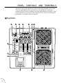 8
8
-
 9
9
-
 10
10
-
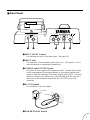 11
11
-
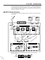 12
12
-
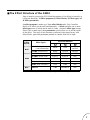 13
13
-
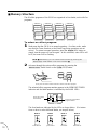 14
14
-
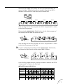 15
15
-
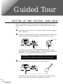 16
16
-
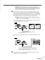 17
17
-
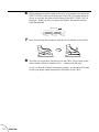 18
18
-
 19
19
-
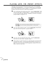 20
20
-
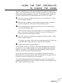 21
21
-
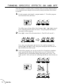 22
22
-
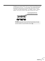 23
23
-
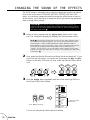 24
24
-
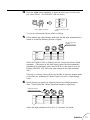 25
25
-
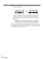 26
26
-
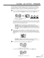 27
27
-
 28
28
-
 29
29
-
 30
30
-
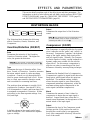 31
31
-
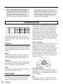 32
32
-
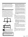 33
33
-
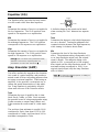 34
34
-
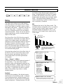 35
35
-
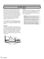 36
36
-
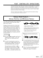 37
37
-
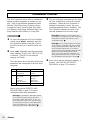 38
38
-
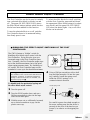 39
39
-
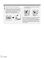 40
40
-
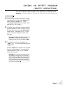 41
41
-
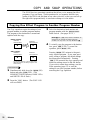 42
42
-
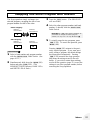 43
43
-
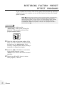 44
44
-
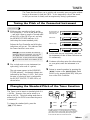 45
45
-
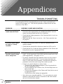 46
46
-
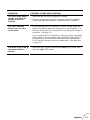 47
47
-
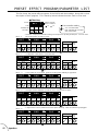 48
48
-
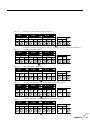 49
49
-
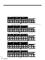 50
50
-
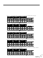 51
51
-
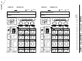 52
52
-
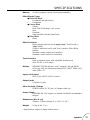 53
53
-
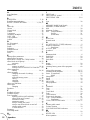 54
54
-
 55
55
-
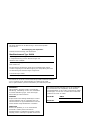 56
56
-
 57
57


in andere talen
- English: Yamaha GW10 Owner's manual
- italiano: Yamaha GW10 Manuale del proprietario
- русский: Yamaha GW10 Инструкция по применению
- français: Yamaha GW10 Le manuel du propriétaire
- español: Yamaha GW10 El manual del propietario
- Deutsch: Yamaha GW10 Bedienungsanleitung
- português: Yamaha GW10 Manual do proprietário
- dansk: Yamaha GW10 Brugervejledning
- čeština: Yamaha GW10 Návod k obsluze
- svenska: Yamaha GW10 Bruksanvisning
- Türkçe: Yamaha GW10 El kitabı
- polski: Yamaha GW10 Instrukcja obsługi
- română: Yamaha GW10 Manualul proprietarului