
SONY CDX-HR910UI (GB,FR,ES,DE,NL,IT) 4-127-575-21 (1) SONY CDX-HR910UI (GB,FR,ES,DE,NL,IT) 4-127-575-21 (1)
SONY CDX-HR910UI (GB,FR,ES,DE,NL,IT) 4-127-575-
21 (1)SONY CDX-HR910UI (GB,FR,ES,DE,NL,IT) 4-127-575-21 (1)
BUS
CONTROL IN
FRONT
AUDIO OUT
REAR
FRONT
BUS
IN
AUDIO OUT
REAR
AUDIO OUT
L
R
BUS
AU
DIO IN
AUX IN
SUB OUT (MONO)
1 3 5 7
2 4 6 8
5 7
4 8
6
*
5
REMOTE
IN
Attenzione
• Questo apparecchio è stato progettato per l’uso solo a
12 V CC con massa negativa.
• Evitare che i cavi rimangano bloccati da una vite o
incastrati nelle parti mobili (ad esempio nelle guide
scorrevoli dei sedili).
• Prima di effettuare i collegamenti, spegnere il motore
dell’imbarcazione onde evitare di causare cortocircuiti.
• Collegare il cavo di collegamento dell’alimentazione
all’apparecchio e ai diffusori prima di collegarlo al
connettore di alimentazione accessoria.
• Portare tutti i cavi di massa a un punto di
massa comune.
• Per sicurezza, assicurarsi di isolare qualsiasi cavo non
collegato utilizzando del nastro adesivo.
Note sul cavo di alimentazione (giallo)
• Se il presente apparecchio viene collegato in
combinazione con altri componenti stereo, la potenza
nominale dei circuiti dell’imbarcazione deve essere
superiore a quella prodotta dalla somma dei fusibili di
ciascun componente.
• Se la potenza nominale dei circuiti dell’imbarcazione
non è sufficiente, collegare l’apparecchio direttamente
alla batteria.
Elenco dei componenti
I numeri nella lista corrispondono a quelli riportati nelle
istruzioni.
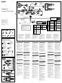
Esempio di collegamento
Note (-
A
)
• Assicurarsi di collegare il cavo di terra prima di collegare
l’apparecchio all’amplificatore.
• L’allarme viene emesso solo se è in uso l’amplificatore
incorporato.
Suggerimenti
(-
B
- )
• Se si collega unicamente un singolo cambia CD o un altro
dispositivo opzionale, effettuare il collegamento direttamente
alla presente unità.
• Per effettuare il collegamento di due o più cambia CD o altri
dispositivi opzionali, è necessario utilizzare il selettore di
sorgente XA-C40 (non in dotazione).
Schema di collegamento
A AMP REMOTE IN di un amplificatore di
potenza opzionale
Questo collegamento è riservato esclusivamente agli
amplificatori. Non collegare un tipo di sistema diverso onde
evitare di causare danni all’apparecchio.
Al cavo di interfaccia di un telefono
Avvertenza
Quando si collega l’apparecchio con il cavo di
alimentazione in dotazione , si potrebbe danneggiare
l’antenna elettrica se questa non dispone di scatola a relè.
Note sui cavi di controllo e di alimentazione
• Il cavo (blu) di controllo dell’antenna elettrica fornisce
alimentazione pari a +12 V CC quando si attiva il
sintonizzatore oppure la funzione TA (notiziario sul traffico) o
AF (frequenza alternativa).
• Se l’imbarcazione dispone di un’antenna FM/MW/LW
incorporata sul vetro laterale, collegare il cavo (blu) di
controllo dell’antenna elettrica o il cavo (rosso) di ingresso
dell’alimentazione accessoria al terminale di alimentazione
del preamplificatore dell’antenna esistente. Per ulteriori
informazioni, consultare il proprio fornitore.
• Non è possibile usare un’antenna elettrica senza scatola a relè
con questo apparecchio.
Collegamento per la conservazione della memoria
Quando il cavo di ingresso alimentazione giallo è collegato,
viene sempre fornita alimentazione al circuito di memoria anche
quando l’interruttore di accensione è spento.
Note sul collegamento dei diffusori
• Prima di collegare i diffusori spegnere l’apparecchio.
• Usare diffusori di impedenza compresa tra 4 e 8 ohm e con
capacità di potenza adeguata, altrimenti i diffusori potrebbero
venire danneggiati.
• Non collegare i terminali dei diffusori al telaio dell’imbarcazione
e non collegare i terminali del diffusore destro con quelli del
diffusore sinistro.
• Non collegare il cavo di terra di questo apparecchio al
terminale negativo (–) del diffusore.
• Non collegare i diffusori in parallelo.
• Assicurarsi di collegare soltanto diffusori passivi, poiché
il collegamento di diffusori attivi, dotati di amplificatori
incorporati, ai terminali dei diffusori potrebbe danneggiare
l’apparecchio.
• Onde evitare problemi di funzionamento, non utilizzare i
cavi dei diffusori incorporati installati nell’imbarcazione se
l’apparecchio condivide un cavo comune negativo (–) per i
diffusori destro e sinistro.
• Non collegare fra loro i cavi dei diffusori dell’apparecchio.
Nota sui collegamenti
Se l’amplificatore e il diffusore non sono collegati correttamente,
“FAILURE” viene visualizzato nel display. In tal caso, accertarsi
che l’amplificatore e il diffusore siano collegati correttamente.
Cautions
• This unit is designed for negative ground (earth) 12 V
DC operation only.
• Do not get the leads under a screw, or caught in moving
parts (e.g. seat railing).
• Before making connections, turn the boat’s ignition off
to avoid short circuits.
• Connect the power connecting lead
to the unit and
speakers before connecting it to the auxiliary power
connector.
• Run all ground (earth) leads to a common
ground (earth) point.
• Be sure to insulate any loose unconnected leads with
electrical tape for safety.
• The use of optical instruments with this product will
increase eye hazard.
Notes on the power supply lead (yellow)
• When connecting this unit in combination with other
stereo components, the connected boat circuit’s rating
must be higher than the sum of each component’s fuse.
• When no boat circuits are rated high enough, connect
the unit directly to the battery.
Parts Iist
The numbers in the list are keyed to those in the
instructions.
Connection example
Notes (-
A
)
• Be sure to connect the ground (earth) lead before connecting
the amplifier.
• The alarm will only sound if the built-in amplifier is used.
Tips (-
B
-
)
• When connecting only a single CD changer or other optional
device, connect directly to this unit.
• For connecting two or more CD changers or other optional
devices, the source selector XA-C40 (not supplied) is
necessary.
Connection diagram
To AMP REMOTE IN of an optional power
amplifier
This connection is only for amplifiers. Connecting any other
system may damage the unit.
To the interface cable of a telephone
Warning
If you have a power antenna (aerial) without a relay box,
connecting this unit with the supplied power connecting
lead may damage the antenna (aerial).
Notes on the control and power supply leads
• The power antenna (aerial) control lead (blue) supplies +12 V
DC when you turn on the tuner, or when you activate the AF
(Alternative Frequency) or TA (Traffic Announcement) function.
• When your boat has built-in FM/MW/LW antenna (aerial) in
the rear/side glass, connect the power antenna (aerial) control
lead (blue) or the accessory power supply lead (red) to the
power terminal of the existing antenna (aerial) booster. For
details, consult your dealer.
• A power antenna (aerial) without a relay box cannot be used
with this unit.
Memory hold connection
When the yellow power supply lead is connected, power will
always be supplied to the memory circuit even when the ignition
switch is turned off.
Notes on speaker connection
• Before connecting the speakers, turn the unit off.
• Use speakers with an impedance of 4 to 8 ohms, and with
adequate power handling capacities to avoid its damage.
• Do not connect the speaker terminals to the boat chassis, or
connect the terminals of the right speakers with those of the
left speaker.
• Do not connect the ground (earth) lead of this unit to the
negative (–) terminal of the speaker.
• Do not attempt to connect the speakers in parallel.
• Connect only passive speakers. Connecting active speakers
(with built-in amplifiers) to the speaker terminals may damage
the unit.
• To avoid a malfunction, do not use the built-in speaker leads
installed in your boat if the unit shares a common negative (–)
lead for the right and left speakers.
• Do not connect the unit’s speaker leads to each other.
Note on connection
If speaker and amplifier are not connected correctly, “FAILURE”
appears in the display. In this case, make sure the speaker and
amplifier are connected correctly.
*
1
from boat antenna (aerial)
de l’antenne du bateau
desde la antena del barco
von Bootsantenne
van de antenne van de boot
dall’antenna dell’imbarcazione
Fuse (10 A)
Fusible (10 A)
Fusible (10 A)
Sicherung (10 A)
Zekering (10 A)
Fusibile (10 A)
AMP REM
Blue/white striped / Rayé bleu/blanc /
Con rayas azules y blancas / Blauweiß gestreift /
Blauw/wit gestreept / Rigato blu e bianco
*
1
Note for the antenna (aerial) connecting
If your boat antenna (aerial) is an ISO (International
Organization for Standardization) type, use the
supplied adaptor to connect it. First connect the
boat antenna (aerial) to the supplied adaptor, then
connect it to the antenna (aerial) jack of the master
unit.
*
2
RCA pin cord (not supplied)
*
3
Insert with the cord upwards.
*
4
Supplied with the marine remote commander.
*
5
The RM-X4S, RM-X60M and RM-X11M cannot be
connected to this unit at the same time.
*
6
Auxiliary equipment such as portable DVD player
(not supplied)
Max. supply current 0.3 A
Courant d’alimentation maximum 0,3 A
Corriente máx. de alimentación de 0,3 A
max. Versorgungsstrom 0,3 A
Max. voedingsstroom 0,3 A
Alimentazione massima fornita 0,3 A
Supplied with XA-C40
Fourni avec le XA-C40
Suministrado con el XA-C40
Mit dem XA-C40 geliefert
Geleverd met de XA-C40
In dotazione con il modello XA-C40
Supplied with the CD changer
Fourni avec le changeur de CD
Suministrado con el cambiador de CD
Mit dem CD-Wechsler geliefert
Geleverd met de CD-wisselaar
In dotazione con il cambia CD
Source selector
(not supplied)
Sélecteur de source
(non fourni)
Selector de fuente
(no suministrado)
Signalquellenwähler
(nicht mitgeliefert)
Geluidsbronkiezer
(niet bijgeleverd)
Selettore di fonte
(non in dotazione)
XA-C40
*
2
*
2
ATT
*
6
× 2
× 2
See “Power connection diagram” on the reverse side for details.
Voir le « Schéma de raccordement d’alimentation » au verso pour
plus de détails.
Para obtener más información, consulte el “Diagrama de conexión
de la alimentación” que encontrará al dorso.
Näheres dazu finden Sie im „Stromanschlussdiagramm“. Blättern
Sie dazu bitte um.
Zie "Voedingsaansluitschema" op de achterkant voor meer details.
Per ulteriori informazioni, vedere “Diagramma dei collegamenti di
alimentazione” che si trova sul retro.
Light blue / Bleu ciel /
Azul celeste / Hellblau /
Lichtblauw / Azzurro
from the boat’s power connector
du connecteur d’alimentation du bateau
desde el conector de alimentación del barco
vom Stromanschluss des Boots
van de voedingsstekker van de boot
dal connettore di alimentazione dell’imbarcazione
Negative polarity positions 2, 4, 6, and 8 have striped leads.
Les positions de polarité négative 2, 4, 6 et 8 sont dotées de cordons rayés.
Los cables de las posiciones de polaridad negativa 2, 4, 6 y 8 son rayados.
An den negativ gepolten Positionen 2, 4, 6 und 8 befinden sich gestreifte Adern.
De posities voor negatieve polariteit (2, 4, 6 en 8) hebben gestreepte kabels.
Le posizioni a polarità negativa 2, 4, 6 e 8 hanno cavi rigati.
1
Purple
Mauve
Morado
Violett
Paars
Viola
+
Speaker, Rear, Right
Haut-parleur, arrière, droit
Altavoz, posterior, derecho
Lautsprecher hinten rechts
Luidspreker, achter, rechts
Diffusore, posteriore, destro
5
White
Blanc
Blanco
Weiß
Wit
Bianco
+
Speaker, Front, Left
Haut-parleur, avant, gauche
Altavoz, frontal, izquierdo
Lautsprecher vorne links
Luidspreker, voor, links
Diffusore, anteriore, sinistro
2 –
Speaker, Rear, Right
Haut-parleur, arrière, droit
Altavoz, posterior, derecho
Lautsprecher hinten rechts
Luidspreker, achter, rechts
Diffusore, posteriore, destro
6 –
Speaker, Front, Left
Haut-parleur, avant, gauche
Altavoz, frontal, izquierdo
Lautsprecher vorne links
Luidspreker, voor, links
Diffusore, anteriore, sinistro
3
Gray
Gris
Gris
Grau
Grijs
Grigio
+
Speaker, Front, Right
Haut-parleur, avant, droit
Altavoz, frontal, derecho
Lautsprecher vorne rechts
Luidspreker, voor, rechts
Diffusore, anteriore, destro
7
Green
Vert
Verde
Grün
Groen
Verde
+
Speaker, Rear, Left
Haut-parleur, arrière, gauche
Altavoz, posterior, izquierdo
Lautsprecher hinten links
Luidspreker, achter, links
Diffusore, posteriore, sinistro
4 –
Speaker, Front, Right
Haut-parleur, avant, droit
Altavoz, frontal, derecho
Lautsprecher vorne rechts
Luidspreker, voor, rechts
Diffusore, anteriore, destro
8 –
Speaker, Rear, Left
Haut-parleur, arrière, gauche
Altavoz, posterior, izquierdo
Lautsprecher hinten links
Luidspreker, achter, links
Diffusore, posteriore, sinistro
from the boat’s speaker connector
du connecteur du haut-parleur du bateau
desde el conector de los altavoces del barco
vom Lautsprecheranschluss des Boots
van de luidsprekerstekker van de boot
dal connettore del diffusore dell’imbarcazione
Positions 1, 2 and 3 do not have pins.
Les positions 1, 2 et 3 ne comportent pas de broches.
Las posiciones 1, 2 y 3 no tienen pines.
An Position 1, 2 und 3 befinden sich keine Stifte.
De posities 1, 2 en 3 hebben geen pins.
Le posizioni 1, 2 e 3 non hanno piedini.
4
Yellow
Jaune
Amarillo
Gelb
Geel
Giallo
continuous power supply
alimentation continue
fuente de alimentación continua
permanente Stromversorgung
continu voeding
alimentazione continua
5
Blue
Bleu
Azul
Blau
Blauw
Blu
power aerial control
antenne électrique
control de la antena motorizada
Motorantennensteuerung
elektrische antenne
comando dell’antenna elettrica
6
Orange/White
Rayé orange/
blanc
Naranjas y
blancas
Orangeweiß
gestreift
Oranje/wit
Arancione/
bianco
switched illumination power supply
alimentation de l’éclairage
commutée
fuente de alimentación de
iluminación conmutada
geschaltete
Beleuchtungsstromversorgung
geschakelde voeding voor
verlichting
alimentazione illuminazione
commutata
7
Red
Rouge
Rojo
Rot
Rood
Rosso
switched power supply
alimentation commutée
fuente de alimentación conmutada
geschaltete Stromversorgung
geschakelde voeding
alimentazione commutata
8
Black
Noir
Negro
Schwarz
Zwart
Nero
earth
masse
masa
Masse
aarding
terra
*
1
Remarque sur le raccordement de l’antenne
Si l’antenne de votre bateau est de type ISO
(Organisation internationale de normalisation),
raccordez-la à l’aide de l’adaptateur fourni
.
Raccordez tout d’abord l’antenne du bateau à
l’adaptateur fourni, puis raccordez-la à la prise
d’antenne de l’appareil principal.
*
2
Cordon à broche RCA (non fourni)
*
3
Insérez avec le câble vers le haut.
*
4
Fourni avec la télécommande marine.
*
5
Il est impossible de raccorder simultanément les
télécommandes RM-X4S, RM-X60M et RM-X11M à
cet appareil.
*
6
Equipement auxiliaire comme un lecteur de DVD
portable (non fourni)
*
1
Nota para la conexión de la antena
Si la antena del barco cumple con la norma ISO
(Organización internacional de normalización),
utilice el adaptador suministrado
para conectarla.
Primero conecte la antena del barco al adaptador
suministrado y, a continuación, conecte éste a la
toma de la antena de la unidad principal.
*
2
Cable con terminales RCA (no suministrado)
*
3
Insertar con el cable hacia arriba.
*
4
Suministrado con el mando a distancia subacuático.
*
5
No es posible conectar el RM-X4S, el RM-X60M y el
RM-X11M a la vez a esta unidad.
*
6
Equipo opcional auxiliar como un reproductor de
DVD portátil (no suministrado)
*
1
Hinweis zum Anschließen der Antenne
Wenn Ihre Bootsantenne der ISO-Norm
(Internationale Normungsgemeinschaft) entspricht,
schließen Sie sie mithilfe des mitgelieferten Adapters
an. Verbinden Sie zuerst die Bootsantenne
mit dem mitgelieferten Adapter und verbinden
Sie diesen dann mit der Antennenbuchse des
Hauptgeräts.
*
2
Cinchkabel (nicht mitgeliefert)
*
3
Mit dem Kabel nach oben einsetzen.
*
4
Mit der bootstauglichen Fernbedienung mitgeliefert.
*
5
Sie können nicht gleichzeitig die RM-X4S, die
RM-X60M und die RM-X11M an dieses Gerät
anschließen.
*
6
Zusätzliche Geräte wie z. B. der tragbare DVD-Player
(nicht mitgeliefert)
*
1
Opmerking bij de antenne-aansluiting
Als uw boot is uitgerust met een antenne van
het type ISO (International Organization for
Standardization), moet u deze aansluiten met de
bijgeleverde adapter
. Sluit eerst de antenne
van de boot aan op de bijgeleverde adapter en
vervolgens de antennestekker op de hoofdeenheid.
*
2
Tulpstekkersnoer (niet bijgeleverd)
*
3
Plaatsen met het snoer naar boven.
*
4
Geleverd bij de maritieme afstandsbediening.
*
5
De RM-X4S, de RM-X60M en de RM-X11M kunnen
niet tegelijk op dit apparaat worden aangesloten.
*
6
Optionele apparatuur zoals de draagbare DVD-
speler (niet bijgeleverd)
*
1
Nota per il collegamento dell’antenna
Se l’antenna dell’imbarcazione è di tipo ISO
(International Organization for Standardization),
utilizzare l’adattatore in dotazione per collegarla.
Collegare prima l’antenna dell’imbarcazione
all’adattatore in dotazione, quindi collegarla alla
presa dell’antenna dell’apparecchio principale.
*
2
Cavo a piedini RCA (non in dotazione)
*
3
Inserire con il cavo rivolto verso l’alto.
*
4
In dotazione con il telecomando per uso in ambiente
marino.
*
5
Non è possibile collegare contemporaneamente i
modelli RM-X4S, RM-X60M e RM-X11M al presente
apparecchio.
*
6
Apparecchio ausiliario quale un lettore DVD portatile
(non in dotazione)
× 6
Précautions
• Cet appareil est conçu pour fonctionner sur un courant
continu de 12 V avec masse négative.
• Evitez de coincer les câbles sous des vis ou dans des
pièces mobiles (par exemple, armature de siège).
• Avant d’effectuer les raccordements, coupez le contact
du bateau pour éviter les courts-circuits.
• Branchez le câble d’alimention
sur l’appareil et les
haut-parleurs avant de le brancher sur le connecteur
d’alimentation auxiliaire.
• Rassemblez tous les câbles de terre en un
point de masse commun.
• Veillez à isoler tout câble lâche ou non connecté avec
du ruban isolant.
• L’utilisation d’instruments optiques avec ce produit
augmente les risques pour les yeux.
Remarques sur le câble d’alimentation (jaune)
• Lorsque cet appareil est raccordé en combinaison
avec d’autres appareils stéréo, la valeur nominale des
circuits du bateau raccordés doit être supérieure à la
somme de la valeur des fusibles de chaque élément.
• Si aucun circuit du bateau n’est assez puissant,
raccordez directement l’appareil à la batterie.
Liste des composants
Les numéros de la liste correspondent à ceux des
instructions.
Exemple de raccordement
Remarques (-
A
)
• Raccordez d’abord le câble de mise à la masse avant de
connecter l’amplificateur.
• L’alarme est émise uniquement lorsque l’amplificateur intégré
est utilisé.
Conseils (-
B
- )
• En cas de raccordement d’un seul changeur CD uniquement
ou d’autres appareils en option, raccordez-le/les directement à
cet appareil.
• Le sélecteur de source XA-C40 (non fourni) est nécessaire
pour raccorder deux changeurs CD ou plus ou d’autres
appareils en option.
Schémas de raccordement
Vers AMP REMOTE IN de l’amplificateur de
puissance en option
Ce raccordement s’applique uniquement aux amplificateurs.
Le raccordement de tout autre système risque
d’endommager l’appareil.
Vers le câble d’interface d’un téléphone
Avertissement
Si vous disposez d’une antenne électrique sans boîtier
de relais, le raccordement de cet appareil au moyen du
cordon d’alimentation fourni risque d’endommager
l’antenne.
Remarques sur les câbles de commande et d’alimentation
• Le câble de commande (bleu) fournit du courant continu de
+12 V lorsque vous mettez le tuner sous tension ou lorsque
vous activez la fonction AF (fréquence alternative) ou TA
(informations de circulation).
• Lorsque votre bateau est équipé d’une antenne FM/MW
(PO)/LW (GO) intégrée dans la vitre arrière/latérale, raccordez
le câble de commande d’antenne électrique (bleu) ou le
câble d’alimentation des accessoires (rouge) à la borne
d’alimentation de l’amplificateur d’antenne existant. Pour plus
de détails, consultez votre revendeur.
• Une antenne électrique sans boîtier de relais ne peut pas être
utilisée avec cet appareil.
Raccordement pour la conservation de la mémoire
Lorsque le câble de commande d’antenne jaune est connecté, le
circuit de la mémoire est alimenté en permanence même si la clé
de contact est en position d’arrêt.
Remarques sur le raccordement des haut-parleurs
• Avant de raccorder les haut-parleurs, mettez l’appareil hors
tension.
• Utilisez des haut-parleurs ayant une impédance de 4 à 8 ohms
et une capacité adéquate sous peine de les endommager.
• Ne raccordez pas les bornes des haut-parleurs au châssis du
bateau, et ne raccordez pas les bornes du haut-parleur droit à
celles du haut-parleur gauche.
• Ne raccordez pas le câble de mise à la masse de cet appareil
à la borne négative (–) du haut-parleur.
• Ne tentez pas de raccorder les haut-parleurs en parallèle.
• Raccordez uniquement des haut-parleurs passifs. Le
raccordement de haut-parleurs actifs (avec des amplificateurs
intégrés) aux bornes des haut-parleurs pourrait endommager
l’appareil.
• Pour éviter tout problème de fonctionnement, n’utilisez pas les
câbles des haut-parleurs intégrés installés dans votre bateau
si l’appareil dispose d’un câble négatif commun (–) pour les
haut-parleurs droit et gauche.
• Ne raccordez pas entre eux les cordons des haut-parleurs de
l’appareil.
Remarque sur le raccordement
Si les enceintes et l’amplificateur ne sont pas raccordés
correctement, le message « FAILURE » s’affiche. Dans ce cas,
assurez-vous que les enceintes et l’amplificateur sont raccordés
correctement.
Precauciones
• Esta unidad ha sido diseñada para alimentarse sólo con
cc de 12 V de masa negativa.
• No coloque los cables debajo de ningún tornillo, ni
los aprisione con partes móviles (p.ej. los raíles del
asiento).
• Antes de realizar las conexiones, desactive el
encendido del barco para evitar cortocircuitos.
• Conecte el cable de alimentación
a la unidad y
a los altavoces antes de conectarlo al conector de
alimentación auxiliar.
• Conecte todos los cables de conexión a masa
a un punto común.
• Por razones de seguridad, asegúrese de aislar con cinta
aislante los cables sueltos que no estén conectados.
Notas sobre el cable de fuente de alimentación
(amarillo)
• Cuando conecte esta unidad en combinación con otros
componentes estéreo, la capacidad nominal del circuito
conectado del barco debe ser superior a la suma del
fusible de cada componente.
• Si no hay circuitos del barco con capacidad nominal
suficientemente alta, conecte la unidad directamente a
la batería.
Lista de componentes
Los números de la lista corresponden a los de las
instrucciones.
Ejemplo de conexiones
Notas (-
A
)
• Asegúrese de conectar primero el cable de conexión a masa
antes de realizar la conexión del amplificador.
• La alarma sonará únicamente si se utiliza el amplificador
incorporado.
Sugerencias
(-
B
-
)
• Al conectar únicamente un solo cambiador de CD u otros
dispositivos opcionales, conéctelos directamente a esta
unidad.
• Para conectar dos o más cambiadores de CD u otros
dispositivos opcionales, se precisa el selector de fuente XA-
C40 (no suministrado).
Diagrama de conexión
A AMP REMOTE IN de un amplificador de
potencia opcional
Esta conexión es sólo para amplificadores. La conexión de
cualquier otro sistema puede dañar la unidad.
Al cable de interfaz de un teléfono
Advertencia
Si la antena motorizada no dispone de caja de relé, es
posible que la conexión de esta unidad mediante el cable
de alimentación suministrado provoque daños en la
antena.
Notas sobre los cables de control y de fuente de
alimentación
• El cable de control de la antena motorizada (azul) suministrará
cc de +12 V cuando encienda el sintonizador o active la
función AF (Frecuencias alternativas) o TA (Notificación de
tráfico).
• Si el barco tiene una antena de FM/MW/LW incorporada en el
cristal trasero/lateral, conecte el cable de control de la antena
motorizada (azul) o el cable de fuente de alimentación auxiliar
(rojo) al terminal de alimentación del amplificador de señal de
la antena existente. Para obtener más información, consulte a
su distribuidor.
• Con esta unidad no es posible utilizar una antena motorizada
sin caja de relé.
Conexión para protección de la memoria
Si conecta el cable de fuente de alimentación amarillo, el circuito
de la memoria recibirá siempre alimentación, aunque apague el
interruptor de encendido.
Notas sobre la conexión de los altavoces
• Antes de conectar los altavoces, desconecte la alimentación
de la unidad.
• Utilice altavoces con una impedancia de 4 a 8
Ω
con la
capacidad de potencia adecuada para evitar que se dañen.
• No conecte los terminales de altavoz al chasis del barco,
ni conecte los terminales del altavoz derecho con los del
izquierdo.
• No conecte el cable de conexión a masa de esta unidad al
terminal negativo (–) del altavoz.
• No intente conectar los altavoces en paralelo.
• Conecte solamente altavoces pasivos. Si conecta altavoces
activos (con amplificadores incorporados) a los terminales de
altavoz, puede dañar la unidad.
• Para evitar fallos de funcionamiento, no utilice los cables
de altavoz incorporados instalados en el barco si su unidad
comparte un cable negativo común (–) para los altavoces
derecho e izquierdo.
• No conecte los cables de altavoz de la unidad entre sí.
Nota sobre la conexión
Si el altavoz no está conectado correctamente, aparecerá
“FAILURE” en la pantalla. Si es así, compruebe la conexión del
altavoz.
Vorsichtsmaßnahmen
• Dieses Gerät ist ausschließlich für den Betrieb bei 12 V
Gleichstrom (negative Erdung) bestimmt.
• Achten Sie darauf, dass die Kabel nicht unter einer
Schraube oder zwischen beweglichen Teilen wie
z. B. in einer Sitzschiene eingeklemmt werden.
• Schalten Sie, bevor Sie irgendwelche Anschlüsse
vornehmen, die Zündung des Boots aus, um
Kurzschlüsse zu vermeiden.
• Verbinden Sie das Stromversorgungskabel
mit dem
Gerät und den Lautsprechern, bevor Sie es mit dem
Hilfsstromanschluss verbinden.
• Schließen Sie alle Erdungskabel an einen
gemeinsamen Massepunkt an.
• Aus Sicherheitsgründen müssen alle losen, nicht
angeschlossenen Drähte mit Isolierband abgeklebt
werden.
Hinweise zum Stromversorgungskabel (gelb)
• Wenn Sie dieses Gerät zusammen mit anderen
Stereokomponenten anschließen, muss der
Bootsstromkreis, an den die Geräte angeschlossen sind,
eine höhere Leistung aufweisen als die Summe der
Sicherungen der einzelnen Komponenten.
• Wenn kein Bootsstromkreis eine so hohe Leistung
aufweist, schließen Sie das Gerät direkt an die Batterie
an.
Teileliste
Die Nummern in der Liste sind dieselben wie im
Erläuterungstext.
Anschlussbeispiel
Hinweise (-
A
)
• Schließen Sie unbedingt zuerst das Massekabel an, bevor Sie
den Verstärker anschließen.
• Der Warnton wird nur ausgegeben, wenn der integrierte
Verstärker verwendet wird.
Tipps (-
B
- )
• Wenn Sie nicht mehr als einen CD-Wechsler oder ein anderes
gesondert erhältliches Gerät anschließen wollen, schließen
Sie es direkt an dieses Gerät an.
• Wenn Sie mindestens zwei CD-Wechsler oder andere
gesondert erhältliche Geräte anschließen wollen, ist der
Signalquellenwähler XA-C40 (nicht mitgeliefert) erforderlich.
Anschlussdiagramm
An AMP REMOTE IN des gesondert
erhältlichen Endverstärkers
Dieser Anschluss ist ausschließlich für Verstärker gedacht.
Schließen Sie nichts anderes daran an. Andernfalls kann
das Gerät beschädigt werden.
An das Schnittstellenkabel eines Telefons
Warnung
Wenn Sie eine Motorantenne ohne Relaiskästchen
verwenden, kann durch Anschließen dieses Geräts mit
dem mitgelieferten Stromversorgungskabel
die
Antenne beschädigt werden.
Hinweise zu den Steuer- und Stromversorgungsleitungen
• Die Motorantennen-Steuerleitung (blau) liefert +12 V
Gleichstrom, wenn Sie den Tuner einschalten oder die
AF- (Alternativfrequenzsuche) oder die TA-Funktion
(Verkehrsdurchsagen) aktivieren.
• Wenn das Boot mit einer in der Heck-/Seitenfensterscheibe
integrierten FM (UKW)/MW/LW-Antenne ausgestattet ist,
schließen Sie die Motorantennen-Steuerleitung (blau) oder die
Zubehörstromversorgungsleitung (rot) an den
Stromversorgungsanschluss des vorhandenen
Antennenverstärkers an. Näheres dazu erfahren Sie bei Ihrem
Händler.
• Es kann nur eine Motorantenne mit Relaiskästchen
angeschlossen werden.
Stromversorgung des Speichers
Wenn die gelbe Stromversorgungsleitung angeschlossen ist,
wird der Speicher stets (auch bei ausgeschalteter Zündung) mit
Strom versorgt.
Hinweise zum Lautsprecheranschluss
• Schalten Sie das Gerät aus, bevor Sie die Lautsprecher
anschließen.
•
Verwenden Sie Lautsprecher mit einer Impedanz zwischen 4 und
8 Ohm und ausreichender Belastbarkeit. Ansonsten können die
Lautsprecher beschädigt werden.
• Verbinden Sie die Lautsprecheranschlüsse nicht mit dem
Bootschassis und verbinden Sie auch nicht die Anschlüsse
des rechten mit denen des linken Lautsprechers.
• Verbinden Sie die Masseleitung dieses Geräts nicht mit dem
negativen (–) Lautsprecheranschluss.
•
Versuchen Sie nicht, Lautsprecher parallel anzuschließen.
•
An die Lautsprecheranschlüsse dieses Geräts dürfen nur
Passivlautsprecher angeschlossen werden. Schließen Sie
keine Aktivlautsprecher (Lautsprecher mit eingebauten
Verstärkern) an, da das Gerät sonst beschädigt werden könnte.
• Um Fehlfunktionen zu vermeiden, verwenden Sie nicht die im
Boot installierten, integrierten Lautsprecherleitungen, wenn am
Ende eine gemeinsame negative (–) Leitung für den rechten
und den linken Lautsprecher verwendet wird.
• Verbinden Sie nicht die Lautsprecherkabel des Geräts
miteinander.
Hinweis zum Anschließen
Wenn Lautsprecher und Verstärker nicht richtig angeschlossen
sind, erscheint „FAILURE“ im Display. Vergewissern Sie sich
in diesem Fall, dass Lautsprecher und Verstärker richtig
angeschlossen sind.
Let op
• Dit apparaat is ontworpen voor gebruik op 12 V
gelijkstroom, negatief geaard.
• Zorg ervoor dat de draden niet onder een schroef
of tussen bewegende onderdelen (b.v. zetelrail)
terechtkomen.
• Voordat u aansluitingen maakt, moet u de motor van de
boot uitschakelen om kortsluiting te voorkomen.
• Sluit het netsnoer
aan op het apparaat en
de luidsprekers voordat u het aansluit op de
hulpvoedingsaansluiting.
• Sluit alle aarddraden op een
gemeenschappelijk aardpunt aan.
• Voorzie niet aangesloten draden om veiligheidsredenen
altijd van isolatietape.
Opmerkingen bij de voedingskabel (geel)
• Als u dit apparaat installeert in combinatie met
andere stereo-onderdelen, moet het vermogen van de
aangesloten stroomkring hoger zijn dan de som van de
zekeringen van elk onderdeel.
• Wanneer het vermogen ontoereikend is, moet u het
apparaat rechtstreeks aansluiten op de accu.
Onderdelenlijst
De nummers in de afbeelding verwijzen naar die in de
instructies.
Voorbeeldaansluitingen
Opmerkingen (-
A
)
• Sluit eerst de aarddraad aan voordat u de versterker aansluit.
• U hoort de pieptoon alleen als de ingebouwde versterker wordt
gebruikt.
Tips (-
B
- )
• Wanneer u slechts één CD-wisselaar of een ander optioneel
apparaat wilt aansluiten, moet u deze rechtstreeks op dit
apparaat aansluiten.
• Als u twee of meer CD-wisselaars of andere optionele
apparaten wilt aansluiten, moet u de geluidsbronkiezer XA-
C40 (niet bijgeleverd) gebruiken.
Aansluitschema
Naar AMP REMOTE IN van een optionele
eindversterker
Deze aansluiting is alleen bedoeld voor versterkers. Door
een ander systeem aan te sluiten kan het apparaat worden
beschadigd.
Naar het interface-snoer van een telefoon
Waarschuwing
Indien u een elektrische antenne hebt zonder relaiskast,
kan het aansluiten van dit apparaat met het bijgeleverde
netsnoer de antenne beschadigen.
Opmerkingen over de bedienings- en voedingskabels
• De antennevoedingskabel (blauw) levert +12 V gelijkstroom
wanneer u de tuner inschakelt of de AF (Alternative
Frequency) of TA (Traffic Announcement) functie activeert.
• Wanneer uw boot is uitgerust met een FM/MW/LW-antenne
in de achterruit/zijruit, moet u de antennevoedingskabel
(blauw) of de hulpvoedingskabel (rood) aansluiten op de
voedingsingang van de bestaande antenneversterker.
Raadpleeg de handelaar voor meer informatie.
• Met dit apparaat is het niet mogelijk een elektrische antenne
zonder relaiskast te gebruiken.
Instandhouden van het geheugen
Zolang de gele stroomdraad is aangesloten, blijft de
stroomvoorziening van het geheugen intact, ook wanneer het
contact van de boot wordt uitgeschakeld.
Opmerkingen betreffende het aansluiten van de luidsprekers
• Zorg dat het apparaat is uitgeschakeld, alvorens de
luidsprekers aan te sluiten.
• Gebruik luidsprekers met een impedantie van 4 tot 8 Ohm
en let op dat die het vermogen van de versterker kunnen
verwerken. Als u dit niet doet, kunnen de luidsprekers ernstig
beschadigd raken.
• Verbind de aansluitingen van de luidsprekers niet met de
romp van de boot en sluit de aansluitingen van de rechter- en
linkerluidspreker niet op elkaar aan.
• Verbind de aarddraad van dit apparaat niet met de negatieve
(–) aansluiting van de luidspreker.
• Probeer nooit de luidsprekers parallel aan te sluiten.
• Sluit geen actieve luidsprekers (met ingebouwde versterkers)
aan op de luidsprekeraansluiting van dit apparaat. Dit zal
leiden tot beschadiging van de actieve luidsprekers. Sluit dus
altijd uitsluitend luidsprekers zonder ingebouwde versterker
aan.
• Om defecten te vermijden mag u de ingebouwde
luidsprekerbedrading in de boot niet gebruiken wanneer er een
gemeenschappelijke negatieve draad (–) is voor de rechter- en
linkerluidsprekers.
• Verbind de luidsprekerdraden niet met elkaar.
Opmerking over aansluiten
Als de luidspreker en versterker niet correct zijn aangesloten,
wordt "FAILURE" in het display weergegeven. In dit geval moet u
zorgen dat de luidspreker en versterker correct zijn aangesloten.
M3 × 35
× 6
M3 × 40
× 2
M3 NUT
× 2
A
B
SUB OUT
(MONO)
REAR
AUDIO OUT
FRONT
AUDIO OUT
BUS AUDIO IN
BUS CONTROL IN
REMOTE IN
BUS AUDIO IN
BUS CONTROL IN
* not supplied
non fourni
no suministrado
nicht mitgeliefert
niet bijgeleverd
non in dotazione
Source selector
*
Sélecteur de source
*
Selector de fuente*
Signalquellenwähler*
Geluidsbronkiezer
*
Selettore di fonte
*
XA-C40
Equipment used in illustrations (not supplied)
Appareils utilisés dans les illustrations (non fournis)
Equipo utilizado en las ilustraciones (no suministrado)
In Abbildungen dargestellte Geräte (nicht mitgeliefert)
Apparatuur gebruikt in de afbeeldingen (niet bijgeleverd)
Apparecchiatura utilizzata nelle illustrazioni (non in dotazione)
Marine speaker
Haut-parleur étanche
Altavoz acuático
Spritzwassergeschützte
Lautsprecher
Waterdichte luidspreker
Diffusore per uso in ambiente
marino
XS-MP1620W/MP1620B
XS-MP1610W/MP1610B
Marine power amplifier
*
Amplificateur de puissance étanche
*
Amplificador de potencia acuático
*
Spritzwassergeschützter
Endverstärker
*
Waterdichte eindversterker
*
Amplificatore di potenza per uso in
ambiente marino*
XM-604M
Marine subwoofer
Caisson de graves étanche
Altavoz potenciador de
graves acuático
Spritzwassergeschützter
Tiefsttöner
Waterdichte subwoofer
Subwoofer per uso in
ambiente marino
XS-L100P5M
Marine remote commander
Télécommande marine
Mando a distancia subacuático
Bootsfernbedienung
Maritieme afstandsbediening
Telecomando per uso in
ambiente marino
* not waterproof
non étanche
no es resistente al agua
nicht wasserdicht
niet waterdicht
non resistente all’acqua
CD changer
*
Changeur CD
*
Cambiador de CD*
CD-Wechsler
*
CD-wisselaar*
Cambia CD*
RM-X60M RM-X11M
iPod*
*
3
*
4
*
4
*
4
*
4
4-127-575-21(1)
Installation/Connections
Installation/Connexions
Instalación/Conexiones
Installation/Anschluss
Montage/Aansluitingen
Installazione/Collegamenti
FM/MW/LW
Compact Disc Player
CDX-HR910UI
©2008 Sony Corporation Printed in Thailand
USB device*
Périphérique USB*
Dispositivo USB
*
USB-Gerät*
USB-apparaat*
Dispositivo USB
*
*
2
*
3
Rotary commander RM-X4S*
Satellite de commande RM-X4S*
Mando rotatorio RM-X4S
*
Joystick RM-X4S
*
Bedieningssatelliet RM-X4S*
Telecomando a rotazione RM-X4S
*

SONY CDX-HR910UI (GB,FR,ES,DE,NL,IT) 4-127-575-21 (1) SONY CDX-HR910UI (GB,FR,ES,DE,NL,IT) 4-127-575-21 (1)
SONY CDX-HR910UI (GB,FR,ES,DE,NL,IT) 4-127-575-
21 (1)SONY CDX-HR910UI (GB,FR,ES,DE,NL,IT) 4-127-575-21 (1)
Precautions
• Choose the installation location carefully so that the
unit will not interfere with normal boating or car
driving operations.
• Avoid installing the unit in areas subject to dust, dirt,
excessive vibration, or high temperature, such as in
direct sunlight or near heater ducts.
• Only the front panel of this unit is water resistant.
Select carefully the mounting location to avoid internal
damage by water entering the unit. Areas subject to
water splashes should be avoided.
• Use only the supplied mounting hardware for a safe
and secure installation.
Mounting angle adjustment
Adjust the mounting angle to less than 45°.
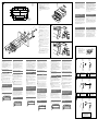
Mounting example
-A-1 Mounting Dimensions
Cut/drill the holes shown in solid lines on
.
Drill 6 holes for the supplied M3 screws, configured on
this template. Pay careful attention to the board material
and its thickness before drilling to avoid any damage to
the interior panel.
Note
If any modification to the boat is required, such as drilling holes,
etc., consult your dealer or manufacturer beforehand.
-B Installation of USB device or iPod
Notes
• Make sure that the USB device/iPod is placed where boating
operations are not obstructed, such as the glove box of the
boat, etc.
• The length of USB connector cable is 1.5 m (4.9 ft). Install the
USB device/iPod within the reach of the USB connector cable.
Warning if your boat’s ignition
has no ACC position
Be sure to set the Auto Off function. For details, see the
supplied Operating Instructions.
The unit will shut off completely and automatically in
the set time after the unit is turned off, which prevents
battery drain.
If you do not set the Auto Off function, press and hold
until the display disappears each time you turn
the ignition off.
RESET button
When the installation and connections are completed, be
sure to press the RESET button with a ball-point pen, etc.
35 (1
7
/16)
155 (6
1
/
8
)
128 (5
1
/8)
182 (7
1
/4)
38 (1
1
/2)
34.4
(1
3
/8)
33.2
(1
5
/16)
31.2
(1
1
/4)
52 (2
1
/8)
Holes (× 6)
Trous (
× 6)
Agujeros (
× 6)
Bohrungen (
× 6)
Gaten (× 6)
Fori (× 6)
Hole / Trou / Agujero /
Bohrung / Gat / Foro
Unit: mm (in)
Unité : mm (po)
Unidad: mm
Einheit: mm
Eenheid: mm
Unità: mm
Auxiliary power connector
Connecteur d’alimentation auxiliaire
Conector de alimentación auxiliar
Hilfsstromanschluss
Hulpvoedingsaansluiting
Connettore di alimentazione accessoria
Red
Rouge
Rojo
Rot
Rood
Rosso
Yellow
Jaune
Amarillo
Gelb
Geel
Giallo
Voedingsaansluitschema
De hulpvoedingsaansluiting kan verschillen afhankelijk
van de boot. Controleer het hulpvoedingsaansluitschema
van uw boot om te zien of de aansluitingen correct zijn.
Er zijn drie basistypes (zie afbeelding hieronder). Het
is mogelijk dat u de posities van de rode en gele kabels
in het netsnoer van het stereosysteem van de boot moet
omwisselen.
Als de aansluitingen en geschakelde voedingskabels
correct zijn, sluit u het apparaat aan op de voeding van
de boot. Als u nog vragen of problemen hebt in verband
met het aansluiten van het apparaat die niet in deze
handleiding vermeld staan, raadpleegt u uw dealer.
Diagramma dei collegamenti di
alimentazione
Il connettore di alimentazione accessoria può variare a
seconda dell’imbarcazione. Controllare il diagramma del
connettore di alimentazione accessoria dell’imbarcazione
per assicurarsi che i collegamenti corrispondano
correttamente. Vi sono tre tipi di base (come illustrato
di seguito). Potrebbe essere necessario modificare le
posizioni dei fili rosso e giallo nel cavo di alimentazione
dello stereo dell’imbarcazione.
Dopo aver fatto corrispondere i collegamenti e
aver commutato i cavi di alimentazione, collegare
l’apparecchio all’alimentazione dell’imbarcazione.
Per eventuali domande e problemi riguardanti il
collegamento dell’apparecchio non trattati nel presente
manuale, rivolgersi al proprio rivenditore.
Power connection diagram
Auxiliary power connector may vary depending on
the boat. Check your boat’s auxiliary power connector
diagram to make sure the connections match correctly.
There are three basic types (illustrated below). You may
need to switch the positions of the red and yellow leads
in the boat stereo’s power connecting lead.
After matching the connections and switched power
supply leads correctly, connect the unit to the boat’s
power supply. If you have any questions and problems
connecting your unit that are not covered in this manual,
please consult your dealer.
Schéma de raccordement
d’alimentation
Le connecteur d’alimentation auxiliaire peut varier
en fonction du bateau. Reportez-vous au schéma du
connecteur d’alimentation auxiliaire de votre bateau pour
vous assurer que les raccordements correspondent. Il en
existe trois types de base (illustrés ci-dessous). Il se peut
que vous deviez commuter la position des fils rouge et
jaune du cordon d’alimentation du lecteur audio marin.
Après avoir effectué les raccordements et commuté
correctement les cordons d’alimentation, raccordez
l’appareil à l’alimentation du bateau. Si vous avez des
questions ou des problèmes concernant le raccordement
de cet appareil, qui ne sont pas abordés dans ce mode
d’emploi, consultez votre revendeur.
Stromanschlussdiagramm
Der Hilfsstromanschluss kann je nach Bootstyp
unterschiedlich sein. Sehen Sie im Hilfsstrom-
anschlussdiagramm für Ihr Boot nach, wie die
Verbindung ordnungsgemäß vorgenommen werden muss.
Es gibt, wie unten abgebildet, drei grundlegende Typen.
Sie müssen möglicherweise die rote und gelbe Leitung
des Stromversorgungskabels der Bootsstereoanlage
vertauschen.
Stellen Sie die Anschlüsse her, schließen Sie die
geschalteten Stromversorgungsleitungen richtig an und
verbinden Sie dann das Gerät mit der Stromversorgung
Ihres Boots. Wenn beim Anschließen des Geräts
Fragen oder Probleme auftreten, die in dieser
Bedienungsanleitung nicht erläutert werden, wenden Sie
sich bitte an Ihren Händler.
the boat without ACC position
Bateau sans position ACC
Barco sin posición ACC
Boot ohne Zubehörposition (ACC oder I)
Boot zonder ACC-positie
Imbarcazione priva della posizione ACC
4
Yellow
Jaune
Amarillo
Gelb
Geel
Giallo
continuous power supply
alimentation continue
fuente de alimentación continua
permanente Stromversorgung
continu voeding
alimentazione continua
7
Red
Rouge
Rojo
Rot
Rood
Rosso
switched power supply
alimentation commutée
fuente de alimentación conmutada
geschaltete Stromversorgung
geschakelde voeding
alimentazione commutata
4
Yellow
Jaune
Amarillo
Gelb
Geel
Giallo
switched power supply
alimentation commutée
fuente de alimentación conmutada
geschaltete Stromversorgung
geschakelde voeding
alimentazione commutata
7
Red
Rouge
Rojo
Rot
Rood
Rosso
continuous power supply
alimentation continue
fuente de alimentación continua
permanente Stromversorgung
continu voeding
alimentazione continua
Diagrama de conexión de la
alimentación
El conector de alimentación auxiliar puede variar
según el barco. Consulte el diagrama de conexión de la
alimentación auxiliar del barco para asegurarse de que
realiza las conexiones correctamente. Hay tres tipos
básicos de diagramas (se muestran a continuación).
Es posible que deba intercambiar las posiciones de
los cables rojo y amarillo del cable de conexión de la
alimentación del equipo estéreo del barco.
Una vez que haya realizado las conexiones de los cables
de la fuente de alimentación conmutada correctamente,
conecte la unidad a la alimentación del barco. Si desea
realizar alguna consulta o solucionar algún problema
relativo a la conexión de la unidad que no se trate en este
manual, póngase en contacto con el distribuidor.
Red
Rouge
Rojo
Rot
Rood
Rosso
Yellow
Jaune
Amarillo
Gelb
Geel
Giallo
Red
Rouge
Rojo
Rot
Rood
Rosso
Red
Rouge
Rojo
Rot
Rood
Rosso
Yellow
Jaune
Amarillo
Gelb
Geel
Giallo
Yellow
Jaune
Amarillo
Gelb
Geel
Giallo
Red
Rouge
Rojo
Rot
Rood
Rosso
Red
Rouge
Rojo
Rot
Rood
Rosso
Yellow
Jaune
Amarillo
Gelb
Geel
Giallo
Yellow
Jaune
Amarillo
Gelb
Geel
Giallo
Sheet
Feuille
Hoja
Blatt
Blad
Protezione
*
2
*
1
Lift the sheet, and attach to the position of figure.
Soulevez la feuille, puis fixez l’accessoire
comme
illustré.
Levante la hoja y colóquela
en la posición que se
muestra en la ilustración.
Heben Sie das Blatt an und bringen Sie
in der
abgebildeten Position an.
Til het blad op en bevestig het
op de positie die in de
afbeelding wordt weergegeven.
Sollevare la protezione e applicare la parte
come
illustrato.
Précautions
• Choisissez soigneusement l’emplacement d’installation
afin que l’appareil ne gêne pas la navigation ni la
conduite.
• Eviter d’installer l’appareil dans un endroit exposé à de
la poussière, de la saleté, des vibrations violentes ou à
des températures élevées, comme en plein soleil ou à
proximité d’un conduit de chauffage.
• Seule la façade de l’appareil est étanche. Sélectionnez
soigneusement l’emplacement d’installation afin
d’éviter que l’eau ne pénètre à l’intérieur de l’appareil
et n’entraîne des problèmes de fonctionnement. Evitez
les zones sujettes aux projections d’eau.
• Pour garantir un montage sûr, n’utilisez que le matériel
fourni.
Réglage de l’angle de montage
Réglez l’inclinaison à un angle inférieur à 45°.
Exemple de montage
-A-1 Dimensions du support
Découpez/percez les trous indiqués en traits pleins à .
Percez 6 trous pour les vis M3 fournies, en utilisant ce
modèle. Faites très attention au matériau de la planche
et à son épaisseur avant de percer afin d’éviter tout
dommage sur le panneau intérieur.
Remarque
En cas de modification sur le bateau, telle que le perçage
de trous, etc., contactez d’abord votre concessionnaire ou le
fabricant.
-B Installation du périphérique USB ou de
l’iPod
Remarques
• Assurez-vous que le périphérique USB/l’iPod est placé à un
endroit qui ne gêne pas la navigation tel que la boîte à gants
du bateau, etc.
• La longueur du câble du connecteur USB est de 1,5 m.
Installez le périphérique USB/l’iPod à une distance maximale
égale à la longueur du câble du connecteur USB.
Avertissement au cas où le
contact de votre bateau ne
dispose pas d’une position ACC
Veillez à régler la fonction de mise hors tension
automatique. Pour obtenir davantage d’informations,
reportez-vous au mode d’emploi fourni.
L’appareil s’éteint complètement et automatiquement
après le laps de temps choisi une fois l’appareil mis hors
tension afin d’éviter que la batterie ne se décharge.
Si vous ne réglez pas la fonction de mise hors tension
automatique, appuyez sur la touche et maintenez-
la enfoncée jusqu’à ce que l’affichage disparaisse à
chaque fois que vous coupez le contact.
Touche RESET
Une fois l’installation et les raccordements terminés,
appuyez sur la touche RESET à l’aide d’un stylo à bille,
etc.
Precauciones
• Elija cuidadosamente el lugar de montaje de forma que
la unidad no interfiera con las funciones normales de
navegación o de conducción.
• Evite instalar la unidad donde pueda quedar sometida
a polvo, suciedad, vibraciones excesivas o altas
temperaturas como, por ejemplo, a la luz solar directa o
cerca de conductos de calefacción.
• Sólo el panel frontal de la unidad es resistente al agua.
Seleccione cuidadosamente el lugar de montaje para
evitar que el agua provoque daños internos. Deben
evitarse las zonas sujetas a salpicaduras de agua.
• Para realizar una instalación segura y firme, utilice
solamente la ferretería de montaje suministrada.
Ajuste del ángulo de montaje
Ajuste el ángulo de montaje a menos de 45°.
Ejemplo de montaje
-A-1 Dimensiones del montaje
Corte o taladre los orificios que se muestran entre líneas
continuas en .
Taladre 6 orificios para los tornillos del tipo M3
suministrados, configurados para esta plantilla. Preste
especial atención al material y grosor de la placa antes de
taladrar para evitar dañar el panel interior.
Nota
Si es necesario realizar cualquier modificación en el barco, como
taladrar, etc., consulte al distribuidor o fabricante primero.
-B Instalación de un dispositivo USB o un
iPod
Notas
• Asegúrese de colocar el dispositivo USB o el iPod en una
ubicación donde no dificulte las operaciones del bote como,
por ejemplo, en la guantera de bote, etc.
• La longitud del cable del conector USB es de 1,5 m. Instale
el dispositivo USB o el iPod dentro del alcance del cable del
conector USB.
Advertencia: si el encendido
del barco no dispone de una
posición ACC
Asegúrese de ajustar la función de desconexión
automática. Para obtener más información, consulte el
manual de instrucciones suministrado.
La unidad se apagará completa y automáticamente en
el tiempo establecido después de que se desconecte la
unidad, lo que evita que se desgaste la batería.
Si no ha ajustado la función de desconexión automática,
mantenga pulsado
cada vez que apague
el interruptor de encendido, hasta que la pantalla
desaparezca.
Botón RESET
Una vez finalizada la instalación y las conexiones,
asegúrese de pulsar el botón RESET con un bolígrafo o
un objeto similar.
Sicherheitshinweise
• Wählen Sie den Einbauort sorgfältig so aus, dass das
Gerät beim Steuern des Boots oder Wagens nicht
hinderlich ist.
• Bauen Sie das Gerät so ein, dass es keinen hohen
Temperaturen (keinem direkten Sonnenlicht, keiner
Warmluft von der Heizung), keinem Staub, keinem
Schmutz und keinen starken Vibrationen ausgesetzt ist.
• Nur die Frontplatte des Geräts ist wassergeschützt.
Wählen Sie den Einbauort sorgfältig so aus, dass das
Gerät nicht durch eindringendes Wasser beschädigt
werden kann. Bauen Sie das Gerät nicht an einer Stelle
ein, an der es Spitzwasser ausgesetzt ist.
• Für eine sichere Befestigung verwenden Sie stets die
mitgelieferten Montageteile.
Hinweis zum Montagewinkel
Das Gerät sollte in einem Winkel von weniger als 45°
montiert werden.
Montagebeispiel
-A-1 Einbaumaße
Schneiden Sie die Öffnung und bohren Sie die Löcher,
die in mit durchgezogenen Linien markiert sind.
Bohren Sie, wie auf der Schablone angegeben, 6 Löcher
für die mitgelieferten M3-Schrauben. Vergewissern Sie
sich vor dem Bohren, dass das Wandmaterial an der
gewählten Stelle geeignet und dick genug ist, damit
es nicht zu Beschädigungen an der Innenverkleidung
kommt.
Hinweis
Bevor Sie Modifikationen am Boot vornehmen, zum Beispiel
Löcher bohren, konsultieren Sie Ihren Händler oder den
Hersteller.
-B Installation von USB-Gerät oder iPod
Hinweise
• Platzieren Sie das USB-Gerät/den iPod unbedingt an einer
Stelle, an der es bzw. er beim Steuern des Boots nicht
hinderlich ist, also z. B. im Handschuhfach des Boots usw.
• Die Länge des USB-Anschlusskabels beträgt 1,5 m.
Installieren Sie das USB-Gerät/den iPod so, dass es bzw. er an
das USB-Anschlusskabel angeschlossen werden kann.
Warnhinweis, wenn die Zündung
Ihres Boots nicht über eine
Zubehörposition (ACC oder I)
verfügt
Aktivieren Sie unbedingt die Abschaltautomatik.
Näheres dazu finden Sie in der mitgelieferten
Bedienungsanleitung.
Nach dem Ausschalten wird das Gerät dann nach
der voreingestellten Zeit automatisch vollständig
abgeschaltet, so dass der Batterie kein Strom mehr
entzogen wird.
Wenn Sie die Abschaltautomatik nicht aktivieren, müssen
Sie jedes Mal, wenn Sie die Zündung ausschalten,
die Taste
gedrückt halten, bis die Anzeige
ausgeblendet wird.
Taste RESET
Wenn Sie das Gerät eingebaut und alle Anschlüsse
vorgenommen haben, drücken Sie mit einem
Kugelschreiber oder einem ähnlichen Gerät die Taste
RESET.
Voorzorgsmaatregelen
• Kies de installatieplaats zorgvuldig zodat het apparaat
de stuurman niet hindert tijdens het varen of de
bestuurder tijdens het autorijden.
• Installeer het apparaat niet op plaatsen waar het
blootgesteld wordt aan hoge temperaturen, b.v. in
direct zonlicht of bij de warme luchtstroom van de
verwarming, aan sterke trillingen, of waar het in
contact komt met veel stof of vuil.
• Alleen het voorpaneel van dit apparaat is
waterbestendig. Selecteer de installatieplaats
zorgvuldig om interne schade te voorkomen die wordt
veroorzaakt door water dat in het apparaat terechtkomt.
Plaatsen die worden blootgesteld aan opspattend water,
moeten worden vermeden.
• Gebruik voor het veilig en stevig monteren van
het apparaat uitsluitend de bijgeleverde montage-
onderdelen.
Maximale montagehoek
Installeer het apparaat nooit onder een hoek van meer
dan 45° met het horizontale vlak.
Montagevoorbeeld
-A-1 Montage-afmetingen
Snijd de opening en boor de gaten die met
ononderbroken lijnen in
zijn gemarkeerd.
Boor 6 gaten voor de bijgeleverde M3-schroeven, zoals
aangegeven op deze sjabloon. Houd rekening met het
bordmateriaal en de dikte hiervan voordat u gaat boren
om schade aan het interne paneel te voorkomen.
Opmerking
Als een aanpassing aan de boot is vereist, zoals het boren van
gaten, enzovoort, moet u uw dealer of fabrikant van tevoren
raadplegen.
-B USB-apparaat of iPod installeren
Opmerkingen
• Leg het USB-apparaat/de iPod neer op een plaats waar deze
het varen niet belemmerd, zoals in het handschoenenkastje
van de boot, enzovoort.
• De lengte van de USB-connectorkabel is 1,5 m. Installeer
het USB-apparaat/de iPod binnen het bereik van de USB-
connectorkabel.
Waarschuwing als het
contactslot van de boot geen
ACC-positie heeft
Zorg ervoor dat u de functie voor automatisch
uitschakelen instelt. Raadpleeg de bijgeleverde
gebruiksaanwijzing voor meer informatie.
Het apparaat wordt na de ingestelde tijd automatisch
volledig uitgeschakeld nadat het apparaat is
uitgeschakeld. Zo wordt voorkomen dat de accu
leegloopt.
Als u de functie voor automatisch uitschakelen niet
instelt, moet u ingedrukt houden tot het display
verdwijnt telkens wanneer u het contact uitschakelt.
RESET-toets
Als u de installatie en aansluitingen hebt voltooid,
moet u met een puntig voorwerp, zoals de punt van een
balpen, op RESET drukken om het apparaat opnieuw in
te stellen.
Precauzioni
• Scegliere con attenzione la posizione per l’installazione
in modo che l’apparecchio non interferisca con le
normali operazioni di navigazione o di guida.
• Evitare di installare l’apparecchio dove sia soggetto ad
alte temperature, come alla luce solare diretta o al getto
di aria calda dell’impianto di riscaldamento, o dove
possa essere soggetto a polvere, sporcizia e vibrazioni
eccessive.
• Poiché soltanto il pannello anteriore del presente
apparecchio è resistente all’acqua, scegliere con
attenzione la posizione di installazione onde evitare
danni interni dovuti ad un’eventuale infiltrazione
di acqua nell’apparecchio. A tale scopo, evitare
l’installazione in luoghi soggetti a spruzzi di acqua.
• Usare solo il materiale di montaggio in dotazione per
un’installazione stabile e sicura.
Regolazione dell’angolo di montaggio
Regolare l’angolo di montaggio in modo che sia inferiore
a 45°.
Esempio di montaggio
-A-1 Dimensioni di montaggio
Ritagliare/praticare i fori lungo linee continue come
mostrato nella parte .
Praticare 6 fori per le viti M3 in dotazione, in base alla
configurazione della parte di cui sopra. Prima di praticare
i fori, prestare particolare attenzione al materiale di bordo
e al relativo spessore onde evitare danni al pannello
interno.
Nota
Se è necessario apportare delle modifiche all’imbarcazione, ad
esempio se occorre praticare dei fori e così via, rivolgersi prima
al rivenditore o al produttore.
-B Installazione del dispositivo USB o
dell’iPod
Note
• Accertarsi che il dispositivo USB/l’iPod sia posizionato in un
punto in cui non intralci la navigazione, ad esempio nel vano
portaoggetti dell’imbarcazione e così via.
• La lunghezza del cavo del connettore USB è 1,5 m. Installare
il dispositivo USB/l’iPod in un punto raggiungibile dal cavo del
connettore USB.
Avvertenza relativa all’installazione
su un’imbarcazione sprovvista della
posizione ACC (accessoria) sul
blocchetto di accensione
Accertarsi di impostare la funzione di spegnimento
automatico. Per ulteriori informazioni, fare riferimento
alle istruzioni per l’uso in dotazione.
L’apparecchio si spegne completamente e
automaticamente all’ora impostata dopo che è stato
disattivato, onde evitare che la batteria si scarichi.
Se la funzione di spegnimento automatico non è stata
impostata, ogni volta che il motore viene spento tenere
premuto finché il display non viene disattivato.
Tasto RESET
Una volta completate le procedure di installazione e i
collegamenti, accertarsi di premere il tasto RESET con
una penna a sfera o un oggetto simile.
1
A
2
3
B
*
1
If board thickness is not enough, use the speed nut .
*
2
is used to fix to a wall, etc., of the boat.
Note
If you cannot attach this unit using parts
to for the board, use
the tapping screw
and speed nut .
*
1
Si l’épaisseur de la planche est insuffisante, utilisez
l’écrou à ressort
.
*
2
L’accessoire permet de fixer un élément sur une
paroi, etc., du bateau.
Remarque
Si vous n’arrivez pas à fixer cet appareil à l’aide des pièces
à
sur la planche, utilisez la vis autotaraudeuse
et l’écrou à ressort
.
*
1
Si el grosor de la placa no es suficiente, utilice una
tuerca rápida
.
*
2
se utilizan para fijar en una pared, etc., de un barco.
Nota
Si no puede fijar la unidad con las piezas
a para la placa,
utilice el tornillo de rosca
y la tuerca rápida .
*
1
Wenn die Platte nicht dick genug ist, verwenden Sie die
Schnellschlussmutter
.
*
2
dient zur Befestigung an der Wand usw. des Boots.
Hinweis
Wenn sich das Gerät mit den Teilen
bis nicht an der Platte
befestigen lässt, verwenden Sie die Schneidschraube
und die
Schnellschlussmutter
.
*
1
Als de plaat niet dik genoeg is, gebruikt u de clipmoer
.
*
2
wordt gebruikt voor bevestiging aan een wand,
enzovoort van de boot.
Opmerking
Als u dit apparaat niet kunt bevestigen met onderdelen
tot en
met voor de plaat, gebruikt u de zelftappende schroef en
clipmoer .
*
1
Se lo spessore di installazione del pannello non è
sufficiente, utilizzare una piastrina per viti autofilettanti
.
*
2
La parte viene utilizzata per il fissaggio ad una
parete e simili dell’imbarcazione.
Nota
Se non è possibile applicare l’apparecchio utilizzando le parti
indicate dai numeri da
a per il pannello, utilizzare la vite
autofilettante
e l’apposita piastrina .
-
 1
1
-
 2
2


in andere talen
- italiano: Sony CDX-HR910UI Istruzioni per l'uso
- français: Sony CDX-HR910UI Mode d'emploi
- español: Sony CDX-HR910UI Instrucciones de operación
- Deutsch: Sony CDX-HR910UI Bedienungsanleitung
Gerelateerde papieren
-
Sony CDX-MR60UI Handleiding
-
Sony CDX-GT828 Installatie gids
-
-
-
-
-
-
-
Sony CDX-R35MR Installatie gids
-
Sony CDX-M60UI Handleiding