
Hotte
Hood
Cappa
CornuFé
FR INSTRUCTIONS POUR L’INSTALLATION, L’EMPLOI
ET L’ENTRETIEN DE LA HOTTE CornuFé
GB INSTALLATION, USE AND MAINTENANCE OF
HOOD CornuFé
IT ISTRUZIONI PER L’INSTALLAZIONE, L’USO E LA
MANUTENZIONE DEL PRODOTTO CornuFé
Hotte
Hood
Cappa
CornuFé
FR INSTRUCTIONS POUR L’INSTALLATION, L’EMPLOI
ET L’ENTRETIEN DE LA HOTTE CornuFé
GB INSTALLATION, USE AND MAINTENANCE OF
HOOD CornuFé
IT ISTRUZIONI PER L’INSTALLAZIONE, L’USO E LA
MANUTENZIONE DEL PRODOTTO CornuFé
FR INSTRUCTIONS POUR L’INSTALLATION, L’EMPLOI
ET L’ENTRETIEN DE LA HOTTE CornuFè
EN INSTALLATION, USE AND MAINTENANCE OF
HOOD CornuFè
IT ISTRUZIONE PER L’INSTALLAZIONE, L’USO E LA
MANUTENZIONE DEL PRODOTTO CornuFè
DE BEDIENUNGSANLEITUNG MIT MONTAGEANWEISUNGEN
FÜR CornuFé
ES INSTRUCCIONES PARA LA INSTALACIÓN, USO Y MANTENIMIENTO
DEL PRODUCTO CornuFé
NL INSTRUCTIES VOOR DE INSTALLATIE, HET GEBRUIK EN HET
ONDERHOUD VAN HET PRODUCT CornuFé
Hotte
Hood
Cappa
Dunstabzugshaube
Campana
Afzuigkap
Hotte
Hood
Cappa
CornuFé
FR INSTRUCTIONS POUR L’INSTALLATION, L’EMPLOI
ET L’ENTRETIEN DE LA HOTTE CornuFé
GB INSTALLATION, USE AND MAINTENANCE OF
HOOD CornuFé
IT ISTRUZIONI PER L’INSTALLAZIONE, L’USO E LA
MANUTENZIONE DEL PRODOTTO CornuFé

15
- Warnings
- Uses
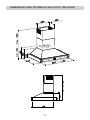
- Dimensions and technical sketch of the product
- Conformity to the European directives on the Recycling Of Electrical And
Electronic Equipment
- Electrical diagram
- Installation
- Working
- Maintenance
CONTENTS EN

-This appliance can be used by children aged from 8 years and above and per-
sons with reduced physical, sensory or mental capabilities or lack of experien-
ce and knowledge if they have been given supervision or instruction concer-
ning use of the appliance in a safe way and understand the hazards involved.
Children shall not play with the appliance.
Cleaning and user maintenance shall not be made by children without super-
vision.
Children less than 8 years of age shall be kept away unless continuously su-
pervised.
- Do not ambé under the range hood
- WORNING: Accessible parts can become very hot if used with cooking ap-
pliances.
- There shall be adequate ventilation of the room when the range hood is used
at the same time as appliances burning gas or other fuels (not applicable to
appliances that only discharge the air back into the room);
- Air captured shall not be conveyed in a duct used for the discharge of fumes
from appliances burning gas or other fuels.
- After changing the transmission code on the radio control, it is necessary to
transmit the new code to the electronic control board of the range hood, in the
following way : push the red button placed inside the range hood (Fig.9) and
turn it to the “OFF” position and then back to the “ON” position after a few se-
conds. In this way, the electronic control board is disconnected and reconnec-
ted to power supply. Push the light button in the radio control within the next
15 seconds, in order to synchronise the range hood with the radio control.
16

17
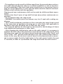
WARNINGS
- READ AND SAVE THESE INSTRUCTION before installing and using this pro-
duct.
We are not responsible for any damage or re caused by the non-respect of
the warnings described in this manual.
- Keep this manual with you. If you sell or leave this unit in the future, the
new customer will be informed about the functioning and the warnings here
described.
- The cooker surface and the inferior part of the cooker hood must be at a
minimum distance of 65 cm.
- Air captured shall not be conveyed in a duct used for the discharge of fumes
from appliances burning gas or other fuels. (eg. centralized heating, radiators,
water-heaters, etc.).
- To evacuate the air outlet, please comply with the pertaining rules given by
competent authorities.
- There shall be adequate ventilation of the room when the range hood is used
at the same time as appliances burning gas or other fuels (not applicable to
appliances that only discharge the air back into the room); (gas-, oil-, or coal-
stoves, etc.) are used simultaneously. The cooker hood, when evacuating the
sucked air, could generate a negative pressure in the room- which can’t exceed
the limit of 0.04 mbar, in order to avoid the suck of exhausts deriving from the
heat-source. Therefore the room should be provided with air-intakes to allow
a constant ow of fresh air.
- When performing the electrical connections on the appliance, please make
sure that the current-tap is provided with earth connection and that voltage
values correspond to those indicated on the label placed inside the appliance
itself.
- Before carrying out any cleaning or maintaining operations, the appliance
needs to be removed from the electric grid.
- If the appliance is not provided with a non-separable exible cable and plug,
or with another device ensuring omnipolar disconnections from the grid, with
an opening distance between the contacts of at least 3 mm, then such discon-
necting devices must be supplied within the xed installation.
- If the xed appliance is endowed with a supply cord and a plug, the appliance
has to be put in a place where the plug can be reached easily.
- Do not ambé under the range hood.
- WORNING: Accessible parts can become very hot if used with cooking ap-
pliances.

18
WARNING – TO REDUCE THE RISK OF FIRE, ELECTRIC SHOCK, OR INJURY TO
PERSONS, OBSERVE THE FOLLOWING
A) Use this unit only in the manner intended by the manufacturer. If you have
questions,contact the manufacturer
B) Before servicing or cleaning unit, switch power o at service panel and lock the
service disconnecting means to prevent power from being switched on accidentally.
When the service disconnecting means cannot be locked,securely fasten a promi-
nent warning device,such as a tag, to the service panel.
C) Installation work and electrical wiring must be done by qualied person(s) in ac-
cordance with all applicable codes and standards,including re-rated construction.
D) Sucient air is needed for proper combustion and exhausting of gases through
the ue (chimney) of fuel burning equipment to prevent back drafting. Follow the
heating equipment manufacturer’s guideline and safety standards such as those
published by the National Fire Protection Association (NFPA), and the American So-
ciety for Heating, Refrigeration and Air Conditioning Engineers (ASHRAE), and the
local code authorities.
E) When cutting or drilling into wall or ceiling,do not damage electrical wiring and
other hidden utilities
F) Ducted fans must always be vented to the outdoors
WARNING - TO REDUCE THE RISK OF FIRE, USE ONLY METAL DUCTWORK.
WARNING - TO REDUCE THE RISK OF A RANGE TOP GREASE FIRE:
A) Never leave surface units unattended athigh settings. Boilovers cause smoking
andgreasy spillovers that may ignite. Heat oils slowly on low or medium settings
B) Always turn hood ON when cooking at high heat or when ambeing food (i.e.
Crepes Suzette, Cherries Jubilee, Peppercorn Beef Flambe’).
C) Clean ventilating fans frequently. Grease should not be allowed to accumulate
on fan or lter.
D) Use proper pan size. Always use cookware appropriate for the size of the surfa-
ce element.

19
WARNING – TO REDUCE THE RISK OF INJURY TO PERSONS IN THE EVENT OF A
RANGE TOP GREASE FIRE, OBSERVE THE FOLLOWING:
A) SMOTHER FLAMES with a close-tting lid,cookie sheet, or metal tray, then turn
o the burner. BE CAREFUL TO PREVENT BURNS. If the ames do not go out imme-
diately, EVACUATE AND CALL THE FIRE DEPARTMENT.
B) NEVER PICK UP A FLAMING PAN – You may be burned.
C) DO NOT USE WATER, including wet dishcloths or towels – a violent steam explo-
sion will result.
D) Use an extinguisher ONLY if:
1) You know you have a Class ABC extinguisher, and you already know how
operate it.
2) The re is small and contained in the area where it started
3) The re department is being called.
4) You can ght the re with your back to an exit.
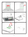
USES
The appliance is already arranged both for ltering and for suction performances.
In its ltering version (Fig.1), the air and fumes conveyed by the appliance are clea-
ned both by a grease lter and by an active coal lter, and put again into circulation
through the side-grids of the chimney.
In its sucking version (Fig.2), fumes are directly conveyed outside, through an eva-
cuation duct connected with the superior part of the wall or the ceiling. Both coal
lter and air deector are not necessary in this case.

20
DIMENSIONS AND TECHNICAL SKETCH OF THE HOOD

21
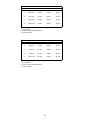
italiano francese inglese
Motore 1000m3/h - Alluminio EUROPA 230V Débits de moteurs 1000m3/h - 230V Motor 1000m3/h - Alluminium EUR 230V
Vel. Portataoraria Rumorosità Pressione Potenza Vitesse Débit NiveaudeBrui
t
Pression Puissance speed Capacity Noise
level Pressure Absorption
1° 330m3/h 45dba 275Pa W90 1° 330m3/h 45dba 275Pa W90 1°
330m3/h 45dba 275Pa W90
2° 490m3/h 50dba 410Pa W145 2° 490m3/h 50dba 410Pa W145 2°
490m3/h 50dba 410Pa W145
3° 730m3/h 56dba 440Pa W250 3° 730m3/h 56dba 440Pa W250 3°
730m3/h 56dba 440Pa W250
4° 1.000m3/h 63dba 480Pa W265 4° 1.000m3/
h
63dba 480Pa W265 4°
1.000m3/
h
63dba 480Pa W265
3XLampadadicroica20
W
3Xhalogènes20
W
3Xlamp20W
2Xfiltroantigrasso415mmX350mmX25m
m
2Xfiltres415mmX350mmX25m
m
2Xfilter415mmX350mmX25m
m
Diametrotubouscitaaria150mm Diamètredecollerettedesortiemm15
0
Airoutlet150mm
Motore 600cfm - Alluminio USA 120V Débits de moteurs 600cfm USA 120V Motor 600cfm - Alluminium USA 120V
Vel. Portataoraria Rumorosità Pressione Potenza Vitesse Débit NiveaudeBrui
t
Pression Puissance speed Capacity Noise
level Pressure Absorption
1°
330 m3/h 41 dba 280 Pa W 120 1° 330 m3/h 41 dba 280 Pa W 120
1° 330 m3/h 41 dba 280 Pa W 120
2° 490 m3/h 50 dba 470 Pa W 175 2° 490 m3/h 50 dba 470 Pa W 175
2° 490 m3/h 50 dba 470 Pa W 175
3° 730 m3/h 56 dba 500 Pa W 280 3° 730 m3/h 56 dba 500 Pa W 280
3° 730 m3/h 56 dba 500 Pa W 280
4° 1000 m3/h 63 dba 620 Pa W 320 4° 1000 m3/h 63 dba 620 Pa W 320
4° 1000 m3/h 63 dba 620 Pa W 320
3XLampadadicroica20
W
3Xhalogènes20
W
3Xlamp20
W
2Xfiltroantigrasso415mmX350mmX25m
m
2Xfiltres415mmX350mmX25m
m
2Xfilter415mmX350mmX25m
m
Diametrotubouscitaaria150mm Diamètredecollerettedesortiemm15
0
Airoutlet150mm

All of our products are conforming to the following European directives:
Directive 2006/95/ CE “LOW TENSION”
Directive 2004/108/ CE “ELECTROMAGNETIC COMPATIBILITY”
Directive 2012/19/ CE “RAEE” – “DISPOSAL OF ELECTRIC EQUIPMENTS AND
ELECTRONICS”
Directive 2002 / 95/ CE “RoHS” - “LIMITATION OF DANGEROUS SUBSTANCES”
RECYCLING OF ELECTRICAL AND ELECTRONIC EQUIPMENT
The symbol on the product or on its packaging indicates that this product may not
be treated as house hold waste.
Instead it shall be handed over to the applicable collection point for the recycling of
electrical and electronic equipment.
By ensuring this product is disposed of correctly, you will help prevent
potential negative consequences for the environment and human health,
which could otherwise be caused by inappropriate waste handling of this product.
For more detailed information about recycling of this product,
please contact your local city oce, your household waste
disposal service or the shop where you purchased the product.
This appliance is marked according to the European directive 2012/19/CE
On waste electrical and electronic equipment (WEEE).
Compliance with directives and standards
Range hoods manufactured for USA and Canada are cCSAus certied according to
standard requirements
CONFORMITY TO THE EUROPEANDIRECTIVES ON THE RE-
CYCLING OF ELECTRICAL AND ELECTRONIC EQUIPMENT
CONFORMITEAUXDIRECTIVESEUROPEENNES
Tousnosappareils,sontconformesauxDirectivesEuropéennessuivantes:
‐laDirective2006/95/CE"BASSETENSION"
‐laDirective89/336/CEE"COMPATIBILITEELECTROMAGNETIQUE"
‐ la Directive 2002 / 96 / CEE "DEEE – DECHETS D'EQUIPEMENTS
ELECTRIQUESETELECTRONIQUES"
‐ la Directive 2002 / 95 / CEE "RoHS – LIMITATION SUBSTANCES
DANGEREUSES"
DECHETSD’EQUIPEMENTSELECTRIQUESETELECTRONIQUES
La Directive 2002/96/CE du Parlement Européen relative aux déchets
d'équipements électriques et électroniques (DEEE), exige que les appareils
ménagers usagés ne soient pas jetés dans les déchets municipaux non triés et
doivent être collectés séparément afin d'optimiser letaux de récupération et le
recyclage des matériaux qui les composent et réduire l'impact sur la santé
humaineetl'environnement.Lesconsommateursdevrontcontacterlesautorités
localesouleurrevendeurconcernantladémarcheàsuivrepourl'enlèvementde
leurvieilappareil.Pourlamiseaurebutdumatérield'emballageconformez‐vous
aux réglementations locales. Les emballages pourront ainsi être recyclés. Ce
pictogramme de la "poubelle barrée" apposé sur tous les produits signifie que
l'équipement ne peut être jeté avec les autres déchets, qu'il fait l'objet d'une
collectesélectiveenvuedesavalorisation,
réutilisationourecyclage.
INSTALLATION
Avantd’effectuerl’assemblage,pouréviterdesdommagesàl’appareil,enlever
lagrilleanti‐graisse.Pourretirerlagrilleanti‐graisse,poussezlapoignéeversle
basdelahotteetfaitestournerlagrilleverslebas,en la retirantdesaplace
(Fig.3).
Al’aidedugabaritdeperçage(Fig.4A),faiteslestrousdefixationprévuspour
votremodèle,enfaisantattentionànepasendommagerdestuyauteriesd’eau
oudelignesélectriques.Percezlestrousdanslaparoiavecunforetdeø8mm.
Danscestrousinsérezleschevillesenplastique.L’étriersupportdelahotteest
appliquéaumoyendesvisfournies(Fig.5).
Accrocherlahottesurlesupport et ajusterla positionhorizontaleet verticale
del’appareilparlesvismétriquesderéglage(Fig.6V‐T).
INSTALLATION
Before installing the appliance, in order not to damage the appliance itself, the me-
tal grease lter should be removed. Such lter can be removed by pushing the spe-
cial lter handle toward the back side of the cooker hood and turning it downwards
so to unfasten it from its slot (Fig.3)
By using the special drilling jig (Fig.4), perforate the wall according to the pattern
indicated by the jig itself, and pay attention in order not to damage water pipes and
electric wires. Perforation should be performed with a Ø 8 mm wall-drill.
22

with a Ø 8 mm wall-drill
Then insert into the proper plastic reinforcements . The hood-bearing stirrup can
be applied by using the screws provided with the equipment.
Now hook the cooker hood onto its bearing and then adjust horizontally and verti-
cally the position of the appliance by acting on the special metric screws.
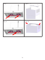
to complete the installation insert the two xing screws in the rear of the cooker
hoods in the 2 holes previously made.
Before xing the chimneys connect the power supply behind the decorative chim-
ney.
Install the chimneys on the hood by raising the upper chimneys till the height requi-
red and secure the xing brackets with the screws and the washers supplied.(Fig. 8)
Afterwards raise the upper chimney and secure it through the 2 lateral screws.(Fig.
9)
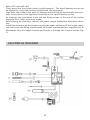
ELECTRICAL DIAGRAM
23

24
UP USAPOWERSUPPLYSUT69
EP EUROPEPOWERSOPPLYSLT69
B ELECTRONICCARD
I GENERALSWITCH
P CONTROLS
RC REMOTECONTROLS
TR transformer12V
M MOTOR
L HALOGENLAMP
C CAPACITORS
Working
Followingthefunctionsaredescribedattributedtothekeysofthepushbotton:
A: Lightswitchon/off
B: Motorswitchon/off(1stratelevel)
C: 2ndratelevelswitch
D: 3rdratelevelswitch
E: 4thratelevelswitch
F: 10‐minutetimer.
remotecontrolforthecommandtodistanceofcookerhoods
TECHNICALDATA:
Alkalinebatterypowered:12VMod.23A
Operatingfrequency433.92Mhz
Combinations:4096
consumption:25mA
Operatingtemperature‐20+55°C
DESCRIPTIONOFOPERATION:
‐ Toswitchthecookerhoodonortoswitchitoffpressthebutton:
‐ Toincreasethespeeduptothefourthonepressthebutton:
‐ Toreducethespeeduptothesecondonepressthebutton:
‐ Togofromahighspeedbacktothefirstonepresstwicethebutton:
‐ Tolightonortolightoffthehoodpressthebutton:

25
WORKING
Generatiing a new transmiissiion code:
The radio control system is provided with
preset codes. Should new codes be requi-
red, proceed as follows: Press simultaneously
buttons:
for two seconds. When Leds light on, press
buttons:
(within 5 seconds). Leds ashing 3 times in-
dicate
the procedure is completed.
WARNING! This operation deletes perma-
nently the preset codes.
Learniing the new transmiissiion code:
Once the transmission code is changed in the
radio control unit, the electronic central unit
of the cooker hood must be made to set the
new code in the fol- lowing way:
Press the main power-o button of the hood
and then restore power to the electronic con-
trol unit. Within the next 15 seconds, press
the Liight Button to synchronise the cen-
tral unit with the code.
Reset of the Factory coniguratiion:
To restore the Factory conguration, follow
the pro- cedure described below: press si-
multaneously buttons:
for 2 seconds. When Leds light on, press but-
tons:
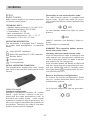
RC001
RADIO CONTROL
Radio control used for the remote operation
of ducted cooker hoods.
TECHNICAL DATA
- Alkaline battery powered: 12 V mod. 23 A
- Operating frequency: 433.92 Mhz
- Combinations: 32.768
- Max. consumption: 25 mA
- Operating temperature: -20 ÷ + 55 °C
- Dimensions: 120 x 45 x 15 mm.
OPERATING DESCRIPTION
The transmitter is equipped with 5 buttons
for cooker hood management, as specied
below:
: Light ON/OFF command.
: Motor ON (speed level 1) / OFF command.
: Reduce speed.
: Increase speed.
: 10-minute timer.
INITIAL OPERATING CONDITION
The manufacturer supplies the radio control
unit ready to be used with codes preset in the
Factory
OPERATION MODE
Standard conguration:
Standard conguration requires all “cooker
hoods – radio control - system” to be pro-
vided with the same transmission code. In
the event two cooker hoods – radio control
system are installed in the same room or ne-
arby, each system may aect the operation of
the another. Therefore, the code of one radio
control system must be changed.

(within 5 seconds). Leds ashing 6 times in-
dicate the procedure is completed.
WARNING! This operation deletes perma-
nently the preset codes.
Emergency button:
In the event that the radio control does not
work, use the emergency button to switch
the appliance o. After any necessary repairs
have been performed, reset the emergency
button.
WARNIING
The battery should be replaced every year
to guarantee the optimal range of the
transmitter.
To replace the exhausted battery, take
the plastic lid o, remove the battery and
replace it with a new one, observing the
correct battery polarities.
Used batteries should be discarded in
special collection bins.
The below product:
RC001 Radiio Controll
complies with the specications set out in
the R&TTE Directive 99/5/EC.
WARNING
Any adjustments or modications which
have not been expressly approved by the
holder of the legal conformity certicate
may invalidate the user’s rights relating to
the operation of the device.
Rev. 0 26/08/14
26

27
MAINTENANCE
An accurate maintenance guarantees good functioning and long-lasting perfor-
mance.
Particular care is due to the grease lter panel.
It can be removed by pushing its special handle toward the back-side of the cooker
hood and turning the lter downwards so to unfasten it from its slot (Fig.3).
To insert the lter just perform the opposite operation.
After 30 hours working, the push button control panel will signal the saturation of
the grease lter by lighting all the buttons.
Press the timer button to reset.
The grease lter needs cleaning by regular hand-washing or in dishwashers every
two months at least or depending on its use.
To clean the appliance itself tepid water and neutral detergent are recommended,
while abrasive products should be avoided. For steel appliances specialized deter-
gents are recommended.
To replace the dichroic lamp, remove the lamp by inserting a screwdriver or another
sharp tool between the lamp and its chrome support and replace it with a lamp of
the same kind 20W 12V
If the supply cord is damaged, it must be replaced by the manufacturer or its service
agent or a similarly qualied person in order to avoid a hazard.

(binnen 5 secondeb), 6 knipperingen van de
Led’s geven aan dat de handeling voltooid is.
OPGEPAST! Deze handeling wist denitief
de vooraf bestaande codes.
Noodtoets:
Als de afstandsbediening niet functioneert
drukt u voor het uitschakelen van het appa-
raat op de noodtoets. Na een eventuele repa-
ratie dient u de noodtoets weer te herstellen.
Bellangrijk
De batterij moet elk jaar worden vervan-
gen om een optimaal bereik van de zender
te garanderen.
Om de lege batterij te vervangen dient u
het plastic deksel te verwijderen, de oude
batterij te verwijderen en er een nieuwe in
te plaatsen. Zorg ervoor de aangegeven
polariteit in de houder aan te houden. De
oude batterij moet worden weggegooid in
de speciale houders voor klein chemisch
afval.
Het product
Afstandsbediening RC001
voldoet aan de specicaties van de
Richtlijn R&TTE 99/5/EG.
WAARSCHUWINGEN
Veranderingen of wijzigingen die niet ui-
tdrukkelijk worden goedgekeurd door de
houder van het certicaat van de compati-
biliteit met de normen kunnen de eigenaar
van het product het recht tot gebruik van
de apparatuur ontnemen.
Rev. 0 26/08/14
73

74
Een zorgvuldig uitgevoerd onderhoud garandeert dat het apparaat altijd goed blijft
renderen in de tijd.
Besteed bijzondere aandacht aan het vetpaneel.
Duw de knop op de verlter naar achter en draai hem naar onder om de metalen
vetlter te verwijderen.(Afb.3). Op de andersomme manier plaatst u de lter weer
terug.
Als de kap 30 uur gewerkt heeft, signaleert de kap dat de lter vol is door alle to-
etsen te laten knipperen.
Druk voor de reset op de timertoets.
U mag de vetlter wassen in de vaatwasmachine of met de hand. Hoe vaak u de lter
reinigt, hangt af van het gebruik, maar de lter moet minstens om de twee maanden
worden gereinigd.
Reinig het apparaat zelf met lauw water en neutrale detergenten en gebruik geen
schurende producten of middelen. Om stalen apparaten te reinigen, zijn speciale
producten aanbevolen. Volg de instructies op de producten.
Om de dicroïsche lamp te vervangen haalt u de oude eruit met een kleine schroe-
vendraaier of een ander puntig voorwerp dat u tussen de lamp en de stalen zitting
steekt. Vervang de lamp door een andere met dezelfde kenmerken van 20W 12V.
Alleen gespecialiseerd personeel mag het stroomsnoer vervangen.
ONDERHOUD

75
Fig. 1 Fig. 2
Fig. 3 Fig. 4
Fig. 5 Fig. 6

Fig. 7 Fig. 8
Fig. 9 Fig. 10
76

Ateliers La Cornue
14, rue du Bois du Pont - Z.I. les Béthunes - 95310 Saint-Ouen-l’Aumône
FRANCE
Adresse postale :
La Cornue SAS - B.P. 99006 - 95070 Cergy-Pontoise Cedex - FRANCE
Tél. : +33 (0)1 34 48 36 36 – Fax : +33 (0)1 34 64 32 65
E-mail : a.table@la-cornue.com
www.lacornue.com
90004608415 - GM 06/15
-
 1
1
-
 2
2
-
 3
3
-
 4
4
-
 5
5
-
 6
6
-
 7
7
-
 8
8
-
 9
9
-
 10
10
-
 11
11
-
 12
12
-
 13
13
-
 14
14
-
 15
15
-
 16
16
-
 17
17
-
 18
18
-
 19
19


La Cornue H1VN Hood Installation Guide
- Type
- Hood Installation Guide
- Deze handleiding is ook geschikt voor
in andere talen
- English: La Cornue H1VN