
PNI GD-01
Gas detector / Детектор за газ / Gasmelder / Detector de gas / Détecteur de gaz
Gázérzékelő / Rilevatore di gas / Gas detector / Detektor gazu / Senzor gaz
EN User manual ......................................................... 3
BG Ръководство за употреба ............................. 5
DE Benutzerhandbuch .............................................. 7
ES Manual de usuario ............................................... 9
FR Manuel utilisateur ............................................... 11
HU Használati utasítás .............................................. 13
IT Manuale utente .................................................. 15
NL Handleiding ........................................................ 17
PL Instrukcja obsługi ............................................... 19
RO Manual de utilizare ............................................. 21


EN
3
INTRODUCTION
This product is a detector designed to identify gas leaks.
GAS DETECTOR DESCRIPTION
Main features
- High reliability sensor
- Auto reset after alarm
- Induced gas - natural gas / LPG
- Indoor use, wall mounting
TECHNICAL SPECIFICATIONS
Power voltage 230V
Output voltage for the gas valve 9 - 12V (impulse)
Standby current ≤ 1W
Alarme current ≤ 2.5W
Rated power 3W (@230V)
Warm-up time about 180 seconds
Sound level ≥ 70dB/m
Alarm level 20% LEL (Lower Explosive Limit)
Alarm gas density level 0.1% - 0.5%
Operating temperature -26°C ~ +80°C
Dimensions 110 x 73 x 41 mm
INSTALLATION
1. Please confirm the induced gas is heavier than air or lighter than air. Gas heavier than air: LPG etc. Gas lighter
than air: natural gas, marsh gas and etc.
2. Depending on the weight of the gas, choose the correct location of the gas detector. If the gas is heavier than
the air, position the gas detector at 0.3 - 1.0 m up from the oor, over a range of max. 1.5 m of the gas source. If the
gas is lighter than the air, position the gas detector at 0.3 - 1.0 m down from the ceiling, over a range of max. 1.5 m
of the gas source.
3. Fasten the screws firmly into the wall, then hang the gas detector.
4. Avoid installing the gas detector near the following sources: direct air ow caused by wind, ventilators, open
doors or windows, steam sources, oil vapor, etc.
5. The wires must have the correct size and color to avoid damages to the device or shortcircuit. A faulty wire
connection may have repercussions in the event of an alarm due to gas leakage.

EN
4
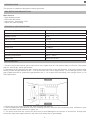
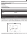
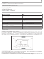
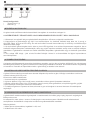
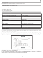
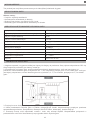
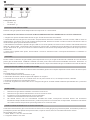
TERMINAL BLOCK
Power input Gas valve
Wires conguration:
• Brown wire: (+)
• Blue wire: (-)
OPERATING INSTRUCTIONS
The gas detector can be used stand alone or with a wired gas valve.
USING THE GAS DETECTOR INDEPENDENTLY OR TOGETHER WITH A SOLENOID VALVE
1. Choose the right place to install the gas detector. Follow the installation instructions.
2. Power the gas detector to a 230V source. During the priming period of the sensor, for about 3 minutes, the green
LED will remain lit and the red LED will blink. After this period, the detector will enter the normal operating mode.
The green light stays on for the entire duration of operation.
3. If the detector identifies a gas leak, the red LED will light and the siren will sound continuously. If the detector
is connected to an solenoid valve, it will transmit to it an impulse that will cause this device to stop the gas supply.
The gas detector will return to its initial state of operation after the gas dispersion or after restarting the detector.
4. If the yellow LED is lit - indicates an internal sensor error. Disconnect power and contact a service center.
TESTING THE PRODUCT
To test an installed gas detector, you can spread in the air a bit of lighter gas to about 5 cm from the detector gas
slots. CAUTION: Frequent testing may cause sensitivity reduction. The detector will interrupt the alarm and return
to the normal mode after the gas density drops below the alarm level.
PROCEDURES IN THE EVENT OF AN ALARM
The gas detector enters the alarm condition if the gas density inside the room exceeds the minimum alarm level
(20% LEL).
Proceed as follows:
1. Close the gas supply immediately
2. Open the window and let air quickly penetrate into the room
3. Close any source of fire and do not use anything that could cause fire, for example lighters, matches
4. Avoid lighting any electrical equipment
5. Try to find the exact location where the gas leak occurs and immediately notify the specialized institutions or a
qualified person
NOTICE
1. The gas detector must be installed and connected correctly.
2. The gas detector must be supplied with a current source.
3. Regularly maintain the detector as directed.
4. Test the detector every six months.
5. For various reasons, such as changing environmental conditions, disruption of electricity, or fraudulent action
on the electronic system, the product may not work properly. The user is advised to take all safety precautions.
CONNECTING THE GAS VALVE AND THE GAS SENSOR
Connecting the gas sensor with the gas valve can be done using the plug & play connector. Both products can be
adapted for other valves / sensors if changing the connections system.
Cable recommendations:
1. Cable type: two-wire, 2 x 0.3 mm² or higher
2. Cable length < 20 meters

BG
5
ВЪВЕДЕНИЕ
Този продукт е детектор, предназначен да идентифицира течове на газ.
ОПИСАНИЕ НА ГАЗОВ ДЕТЕКТОР
Основните функции:
- Сензор с висока надеждност
- Автоматично нулиране след аларма
- Индуциран газ - природен газ / LPG
- Използване на закрито, монтаж на стена
ТЕХНИЧЕСКИ СПЕЦИФИКАЦИИ
Захранващо напрежение 230V
Изходно напрежение за газовия клапан 9 - 12V (импулс)
Ток в режим на готовност ≤ 1W
Алармен ток ≤ 2.5W
Оценена сила 3W (@230V)
Време за загряване около 180 секунди
Ниво на звука ≥ 70dB/m
Ниво на аларма 20% LEL (Lower Explosive Limit)
Алармено ниво на плътност на газа 0.1% - 0.5%
Работна температура -26°C ~ +80°C
Размери 110 x 73 x 41 mm
ИНСТАЛАЦИЯ
1. Моля, потвърдете, че индуцираният газ е по-тежък от въздуха или по-лек от въздуха. Газ, по-тежък от въздуха:
пропан-бутан и др. Газ, по-лек от въздуха: природен газ, блатен газ и др.
2. В зависимост от теглото на газа изберете правилното местоположение на газовия детектор. Ако газът е по-
тежък от въздуха, поставете газовия детектор на 0,3 - 1,0 m нагоре от пода, в диапазон от макс. 1,5 m от източника
на газ. Ако газът е по-лек от въздуха, поставете газовия детектор на 0,3 - 1,0 m надолу от тавана, в диапазон от
макс. 1,5 m от източника на газ.
3. Закрепете здраво винтовете в стената, след което окачете детектора за газ.
4. Избягвайте да инсталирате газовия детектор в близост до следните източници: директен въздушен поток,
причинен от вятър, вентилатори, отворени врати или прозорци, източници на пара, маслени пари и др.
5. Проводниците трябва да имат правилния размер и цвят, за да се избегнат повреди на устройството или късо
съединение. Повредена кабелна връзка може да има последствия в случай на аларма поради изтичане на газ.

BG
6
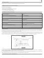
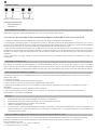
ФИГУРА НА КЛЕМНИЯ БЛОК
Входяща мощност Газов клапан
Конфигурация на проводници:
• Кафяв конец: (+)
• Синя нишка: (-)
ИНСТРУКЦИИ ЗА РАБОТА
Газовият детектор може да се използва самостоятелно или с кабелен газов вентил.
ИЗПОЛЗВАНЕ НА ДЕТЕКТОРА ЗА ГАЗ САМОСТОЯТЕЛНО ИЛИ ЗАЕДНО С ЕЛЕКТРОМАГНИТЕН КЛАПАН
1. Изберете правилното място за инсталиране на газов детектор. Следвайте инструкциите за инсталиране.
2. Захранете газовия детектор към източник 230V. По време на периода на зареждане на сензора, за около 3
минути, зеленият светодиод ще остане да свети, а червеният светодиод ще мига. След този период детекторът
ще влезе в нормален работен режим. Зелената светлина свети през цялото време на операцията.
3. Ако детекторът идентифицира изтичане на газ, червеният светодиод ще светне и сирената ще звучи
непрекъснато. Ако детекторът е свързан към електромагнитен клапан, той ще му предаде импулс, който ще
накара това устройство да спре подаването на газ. Газовият детектор ще се върне в първоначалното си състояние
на работа след разпръскването на газа или след рестартиране на детектора.
4. Ако жълтият светодиод свети - показва вътрешна грешка в сензора. Изключете захранването и се свържете
със сервизен център.
ТЕСТВАНЕ НА ПРОДУКТА
За да тествате инсталиран детектор за газ, можете да разпръснете във въздуха малко по-лек газ на около
5 см от слотовете за газ на детектора. ВНИМАНИЕ: Честото тестване може да доведе до намаляване на
чувствителността. Детекторът ще прекъсне алармата и ще се върне в нормален режим, след като плътността на
газа падне под нивото на алармата.
ПРОЦЕДУРИ В СЛУЧАЙ НА АЛАРМА
Газовият детектор влиза в алармено състояние, ако плътността на газа вътре в помещението надвиши
минималното ниво на аларма (20% LEL).
Продължете както следва:
1. Незабавно затворете подаването на газ
2. Отворете прозореца и оставете въздуха бързо да проникне в стаята
3. Затворете всички източници на огън и не използвайте нищо, което може да причини пожар, например
запалки, кибрит
4. Избягвайте да запалвате електрическо оборудване
5. Опитайте се да намерите точното място на изтичане на газ и незабавно уведомете специализираните
институции или квалифицирано лице
ЗАБЕЛЕЖЕТЕ
1. Детекторът за газ трябва да бъде инсталиран и свързан правилно.
2. Детекторът за газ трябва да бъде снабден с източник на ток.
3. Поддържайте редовно детектора според указанията.
4. Тествайте детектора на всеки шест месеца.
5. Поради различни причини, като промяна на условията на околната среда, прекъсване на електричеството
или измамни действия върху електронната система, продуктът може да не работи правилно. Потребителят
се съветва да вземе всички предпазни мерки.
СВЪРЗВАНЕ НА ГАЗОВИЯ КЛАПАН И ГАЗОВИЯ СЕНЗОР
Свързването на газовия сензор с газовия клапан може да се извърши с помощта на конектора plug & play. И
двата продукта могат да бъдат адаптирани за други клапани/датчици при смяна на системата за свързване.
Препоръки за кабели:
1. Тип кабел: двужилен, 2 x 0,3 mm² или по-висок
2. Дължина на кабела < 20 метра

DE
7
EINLEITUNG
Dieses Produkt ist ein Detektor zur Erkennung von Gaslecks.
BESCHREIBUNG DES GASDETEKTORS
Haupteigenschaften
- Hochzuverlässiger Sensor
- Auto-Reset nach Alarm
- Induziertes Gas - Erdgas / Flüssiggas
- Innenanwendung, Wandmontage
TECHNISCHE SPEZIFIKATIONEN
Netzspannung 230V
Ausgangsspannung für das Gasventil 9 - 12V (impulse)
Standby-Strom ≤ 1W
Alarmstrom ≤ 2.5W
Nennleistung 3W (@230V)
Aufwärmzeit ca. 180 Sekunden
Lautstärke ≥ 70dB/m
Alarmstufe 20% LEL (Lower Explosive Limit)
Alarmgasdichtestufe 0.1% - 0.5%
Betriebstemperatur -26°C ~ +80°C
Maße 110 x 73 x 41 mm
INSTALLATION
1. Bitte vergewissern Sie sich, dass das eingeleitete Gas schwerer als Luft oder leichter als Luft ist. Gas schwerer als Luft:
LPG usw. Gas leichter als Luft: Erdgas, Sumpfgas usw.
2. Wählen Sie je nach Gewicht des Gases den richtigen Standort des Gasdetektors. Wenn das Gas schwerer als die Luft
ist, positionieren Sie den Gasdetektor in einer Höhe von 0,3 - 1,0 m über dem Boden, über eine Reichweite von max. 1,5
m der Gasquelle. Wenn das Gas leichter als die Luft ist, positionieren Sie das Gaswarngerät 0,3 - 1,0 m von der Decke
entfernt über eine Reichweite von max. 1,5 m der Gasquelle.
3. Befestigen Sie die Schrauben fest in der Wand und hängen Sie dann den Gasdetektor auf.
4. Vermeiden Sie die Installation des Gasdetektors in der Nähe der folgenden Quellen: direkter Luftstrom durch Wind,
Ventilatoren, oene Türen oder Fenster, Dampfquellen, Öldämpfe usw.
5. Die Drähte müssen die richtige Größe und Farbe haben, um Schäden am Gerät oder Kurzschlüsse zu vermeiden. Eine
fehlerhafte Kabelverbindung kann im Alarmfall wegen Gaslecks Auswirkungen habene.

DE
8
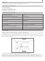
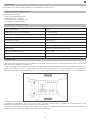
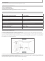
KLEMMENBLOCKABBILDUNG
Leistungsaufnahme Gasventil
Kabelkonguration:
• Brauner Draht: (+)
• Blaues Kabel: (-)
BEDIENUNGSANLEITUNG
Der Gasdetektor kann allein oder mit einem kabelgebundenen Gasventil verwendet werden.
VERWENDUNG DES GASDETEKTORS UNABHÄNGIG ODER ZUSAMMEN MIT EINEM MAGNETVENTIL
1. Wählen Sie den richtigen Ort für die Installation des Gasdetektors. Folgen Sie den Installationsanweisungen.
2. Versorgen Sie den Gasdetektor mit einer 230-V-Quelle. Während der Vorbereitungszeit des Sensors leuchtet die grüne
LED etwa 3 Minuten lang und die rote LED blinkt. Nach dieser Zeit geht der Detektor in den normalen Betriebsmodus über.
Das grüne Licht bleibt während der gesamten Dauer des Vorgangs an.
3. Wenn der Detektor ein Gasleck erkennt, leuchtet die rote LED und die Sirene ertönt kontinuierlich. Wenn der Detektor
an ein Magnetventil angeschlossen ist, sendet er diesem einen Impuls, der dazu führt, dass dieses Gerät die Gaszufuhr
stoppt. Der Gasdetektor kehrt nach der Gasverteilung oder nach einem Neustart des Detektors in seinen ursprünglichen
Betriebszustand zurück.
4. Wenn die gelbe LED leuchtet - zeigt einen internen Sensorfehler an. Trennen Sie die Stromversorgung und wenden Sie
sich an ein Servicecenter.
DAS PRODUKT TESTEN
Um einen installierten Gasmelder zu testen, können Sie in der Luft etwas Feuerzeuggas bis ca. 5 cm von den Gasschlitzen
des Melders verteilen. VORSICHT: Häufiges Testen kann zu einer Verringerung der Empfindlichkeit führen. Der Detektor
unterbricht den Alarm und kehrt in den Normalmodus zurück, wenn die Gasdichte unter den Alarmwert fällt.
VORGEHEN IM ALARMFALL
Der Gasdetektor geht in den Alarmzustand über, wenn die Gasdichte im Raum den Mindestalarmwert (20% UEG)
überschreitet.
Gehen Sie wie folgt vor:
1. Schließen Sie sofort die Gaszufuhr
2. Önen Sie das Fenster und lassen Sie Luft schnell in den Raum eindringen
3. Schließen Sie alle Feuerquellen und verwenden Sie keine Gegenstände, die einen Brand verursachen könnten, z. B.
Feuerzeuge, Streichhölzer
4. Vermeiden Sie es, elektrische Geräte anzuzünden
5. Versuchen Sie, den genauen Ort zu finden, an dem das Gasleck auftritt, und benachrichtigen Sie sofort die
Fachinstitutionen oder eine qualifizierte Person
NOTIZ
1. Der Gasdetektor muss korrekt installiert und angeschlossen sein.
2. Das Gaswarngerät muss mit einer Stromquelle versorgt werden.
3. Warten Sie den Detektor regelmäßig wie angewiesen.
4. Testen Sie den Detektor alle sechs Monate.
5. Aus verschiedenen Gründen, wie sich ändernde Umgebungsbedingungen, Stromausfall oder betrügerische Eingrie
in das elektronische System, kann es sein, dass das Produkt nicht richtig funktioniert. Dem Benutzer wird empfohlen,
alle Sicherheitsvorkehrungen zu treen.
ANSCHLUSS DES GASVENTILS UND DES GASSENSORS
Connecting the gas sensor with the gas valve can be done using the plug & play connector. Both products can be adapted
for other valves / sensors if changing the connections system.
Cable recommendations:
1. Cable type: two-wire, 2 x 0.3 mm² or higher
2. Cable length < 20 meters

ES
9
INTRODUCCIÓN
Este producto es un detector diseñado para identificar fugas de gas..
DESCRIPCIÓN DEL DETECTOR DE GAS
Principales características
- Sensor de alta confiabilidad
- Reinicio automático después de la alarma
- Gas inducido - gas natural / GLP
- Uso en interiores, montaje en pared
ESPECIFICACIONES TÉCNICAS
Voltaje de potencia 230V
Voltaje de salida para la válvula de gas 9 - 12V (impulso)
Corriente de espera ≤ 1W
Corriente alarmante ≤ 2.5W
Potencia nominal 3W (@230V)
Tiempo de calentamiento unos 180 segundos
Nivel de sonido ≥ 70dB/m
Nivel de alarma 20% LEL (Lower Explosive Limit)
Nivel de densidad de gas de alarma 0.1% - 0.5%
Temperatura de funcionamiento -26°C ~ +80°C
Dimensiones 110 x 73 x 41 mm
INSTALACIÓN
1. Confirme que el gas inducido es más pesado que el aire o más ligero que el aire. Gas más pesado que el aire: GLP, etc.
Gas más ligero que el aire: gas natural, gas de marisma, etc.
2. Dependiendo del peso del gas, elija la ubicación correcta del detector de gas. Si el gas es más pesado que el aire,
coloque el detector de gas a 0.3 - 1.0 m del piso, en un rango de máx. 1,5 m de la fuente de gas. Si el gas es más ligero que
el aire, coloque el detector de gas a 0,3 - 1,0 m del techo, en un rango de máx. 1,5 m de la fuente de gas.
3. Apriete los tornillos firmemente en la pared y luego cuelgue el detector de gas.
4. Evite instalar el detector de gas cerca de las siguientes fuentes: ujo de aire directo causado por el viento, ventiladores,
puertas o ventanas abiertas, fuentes de vapor, vapor de aceite, etc.
5. Los cables deben tener el tamaño y el color correctos para evitar daños al dispositivo o cortocircuitos. Una conexión de
cable defectuosa puede tener repercusiones en caso de alarma por fuga de gas.
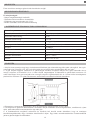
FIGURA DE BLOQUE DE TERMINALES

ES
10
Entrada de alimentación Válvula de gas
Conguración de cables:
• Hilo marrón: (+)
• Hilo azul: (-)
INSTRUCCIONES DE OPERACIÓN
El detector de gas se puede utilizar de forma independiente o con una válvula de gas cableada.
USO DEL DETECTOR DE GAS DE FORMA INDEPENDIENTE O JUNTO CON UNA VÁLVULA SOLENOIDE
1. Elija el lugar correcto para instalar el detector de gas. Siga las instrucciones de instalación.
2. Encienda el detector de gas a una fuente de 230V. Durante el período de cebado del sensor, durante unos 3 minutos, el
LED verde permanecerá encendido y el LED rojo parpadeará. Después de este período, el detector entrará en el modo de
funcionamiento normal. La luz verde permanece encendida durante todo el funcionamiento.
3. Si el detector identifica una fuga de gas, el LED rojo se encenderá y la sirena sonará continuamente. Si el detector está
conectado a una válvula solenoide, le transmitirá un impulso que hará que este dispositivo detenga el suministro de gas.
El detector de gas volverá a su estado inicial de funcionamiento después de la dispersión del gas o después de reiniciar
el detector.
4. Si el LED amarillo está encendido, indica un error interno del sensor. Desconecte la energía y comuníquese con un
centro de servicio.
PROBANDO EL PRODUCTO
Para probar un detector de gas instalado, puede esparcir en el aire un poco de gas más ligero a unos 5 cm de las ranuras
de gas del detector. PRECAUCIÓN: Las pruebas frecuentes pueden causar una reducción de la sensibilidad. El detector
interrumpirá la alarma y volverá al modo normal después de que la densidad del gas caiga por debajo del nivel de alarma..
PROCEDIMIENTOS EN CASO DE ALARMA
El detector de gas entra en condición de alarma si la densidad del gas dentro de la habitación excede el nivel mínimo de
alarma (20% LEL).
Proceder de la siguiente:
1. Cierre el suministro de gas inmediatamente.
2. Abra la ventana y deje que el aire penetre rápidamente en la habitación.
3. Cierre cualquier fuente de fuego y no utilice nada que pueda provocar un incendio, por ejemplo, encendedores,
fósforos.
4. Evite encender cualquier equipo eléctrico.
5. Intente encontrar el lugar exacto donde ocurre la fuga de gas y notifique inmediatamente a las instituciones
especializadas o una persona calificada
AVISO
1. El detector de gas debe estar instalado y conectado correctamente.
2. El detector de gas debe estar provisto de una fuente de corriente.
3. Mantenga regularmente el detector según las instrucciones.
4. Pruebe el detector cada seis meses.
5. Por diversas razones, como condiciones ambientales cambiantes, interrupción del suministro eléctrico o acción
fraudulenta en el sistema electrónico, es posible que el producto no funcione correctamente. Se aconseja al usuario
que tome todas las precauciones de seguridad.
CONECTAR LA VÁLVULA DE GAS Y EL SENSOR DE GAS
La conexión del sensor de gas con la válvula de gas se puede realizar mediante el conector plug & play. Ambos
productos se pueden adaptar para otras válvulas / sensores si se cambia el sistema de conexiones.
Recomendaciones de cables:
1. Tipo de cable: dos hilos, 2 x 0,3 mm² o superior
2. Longitud del cable <20 metros

FR
11
INTRODUCTION
Ce produit est un détecteur conçu pour identifier les fuites de gaz.
DESCRIPTION DU DÉTECTEUR DE GAZ
Caractéristiques principales
- Capteur haute fiabilité
- Réinitialisation automatique après alarme
- Gaz induit - gaz naturel / GPL
- Utilisation en intérieur, montage mural
SPÉCIFICATIONS TECHNIQUES
Tension d'alimentation 230V
Tension de sortie pour la vanne gaz 9 - 12V (impulsion)
Courant de veille ≤ 1W
Courant d'alarme ≤ 2.5W
Puissance nominale 3W (@230V)
Temps de préchauage environ 180 secondes
Niveau sonore ≥ 70dB/m
Niveau d'alarme 20% LEL (Lower Explosive Limit)
Niveau de densité de gaz d'alarme 0.1% - 0.5%
Température de fonctionnement -26°C ~ +80°C
Dimensions 110 x 73 x 41 mm
INSTALLATION
1. Veuillez confirmer que le gaz induit est plus lourd que l’air ou plus léger que l’air. Gaz plus lourd que l’air : GPL etc. Gaz
plus léger que l’air : gaz naturel, gaz des marais etc.
2. En fonction du poids du gaz, choisissez le bon emplacement du détecteur de gaz. Si le gaz est plus lourd que l’air,
positionnez le détecteur de gaz à 0,3 - 1,0 m du sol, sur une plage de max. 1,5 m de la source de gaz. Si le gaz est plus
léger que l’air, positionnez le détecteur de gaz à 0,3 - 1,0 m du plafond, sur une plage de max. 1,5 m de la source de gaz.
3. Vissez fermement les vis dans le mur, puis suspendez le détecteur de gaz.
4. Évitez d’installer le détecteur de gaz à proximité des sources suivantes : ux d’air direct causé par le vent, ventilateurs,
portes ou fenêtres ouvertes, sources de vapeur, vapeur d’huile, etc.
5. Les fils doivent avoir la bonne taille et la bonne couleur pour éviter d’endommager l’appareil ou un court-circuit. Une
mauvaise connexion filaire peut avoir des répercussions en cas d’alarme due à une fuite de gaz.

FR
12
FIGURE DU BORNIER
Entrée de puissance Vanne à gaz
Conguration des ls :
• Fil marron : (+)
• Fil bleu : (-)
MODE D’EMPLOI
Le détecteur de gaz peut être utilisé seul ou avec une vanne de gaz filaire.
UTILISATION DU DÉTECTEUR DE GAZ INDÉPENDAMMENT OU AVEC UNE ÉLECTROVANNE
1. Choisissez le bon endroit pour installer le détecteur de gaz. Suivez les instructions d’installation.
2. Alimentez le détecteur de gaz à une source 230V. Pendant la période d’amorçage du capteur, pendant environ 3
minutes, la LED verte restera allumée et la LED rouge clignotera. Après cette période, le détecteur entrera en mode de
fonctionnement normal. Le voyant vert reste allumé pendant toute la durée de fonctionnement.
3. Si le détecteur identifie une fuite de gaz, la LED rouge s’allumera et la sirène retentira en continu. Si le détecteur est
connecté à une électrovanne, il lui transmettra une impulsion qui provoquera l’arrêt de l’alimentation en gaz de cet appareil.
Le détecteur de gaz reviendra à son état initial de fonctionnement après la dispersion du gaz ou après le redémarrage du
détecteur.
4. Si la LED jaune est allumée - indique une erreur de capteur interne. Débranchez l’alimentation et contactez un centre
de service.
TESTER LE PRODUIT
Pour tester un détecteur de gaz installé, vous pouvez répandre dans l’air un peu de gaz plus léger à environ 5 cm des fentes
de gaz du détecteur. ATTENTION : des tests fréquents peuvent entraîner une réduction de la sensibilité. Le détecteur
interrompra l’alarme et reviendra en mode normal une fois que la densité du gaz sera inférieure au niveau d’alarme.
PROCÉDURES EN CAS D’ALARME
Le détecteur de gaz entre en condition d’alarme si la densité de gaz à l’intérieur de la pièce dépasse le niveau d’alarme
minimum (20 % LIE).
Procédez comme suit:
1. Fermez immédiatement l’alimentation en gaz
2. Ouvrez la fenêtre et laissez l’air pénétrer rapidement dans la pièce
3. Fermez toute source d’incendie et n’utilisez rien qui puisse provoquer un incendie, par exemple des briquets, des
allumettes
4. Évitez d’allumer tout équipement électrique
5. Essayez de trouver l’emplacement exact où se produit la fuite de gaz et avertissez immédiatement les institutions
spécialisées ou une personne qualifiée
REMARQUER
1. Le détecteur de gaz doit être installé et connecté correctement.
2. Le détecteur de gaz doit être alimenté par une source de courant.
3. Entretenez régulièrement le détecteur comme indiqué.
4. Testez le détecteur tous les six mois.
5. Pour diverses raisons, telles que des conditions environnementales changeantes, une interruption de l’électricité ou
une action frauduleuse sur le système électronique, le produit peut ne pas fonctionner correctement. L’utilisateur est
invité à prendre toutes les précautions de sécurité.
CONNEXION DE LA VANNE GAZ ET DU CAPTEUR DE GAZ
Le raccordement du capteur de gaz à la vanne gaz peut se faire à l’aide du connecteur plug & play. Les deux produits
peuvent être adaptés pour d’autres vannes / capteurs en cas de changement du système de connexions.
Recommandations de câbles :
1. Type de câble : deux fils, 2 x 0,3 mm² ou plus
2. Longueur de câble < 20 mètres

HU
13
BEVEZETÉS
Ezen termék az esetleges gázszivárás észelésére szolgál.
GÁZSZIVÁRGÁS ÉRZÉKELŐ
Fő tulajdonságok:
- Magas megbízhatóságú érzékelők
- Riasztás utáni automatikus visszaállítás
- Előidézett vagy természetes gáz / LPG
- Beltéri használat, falra való felszerelhetőség
GÁZÉRZÉKELŐ TECHNIKAI TUDLAJDONSÁGOK
Áramerősség 230V
Gázszelep kimeneti feszültsége 9 - 12V (impulzív)
Készenléti áramerősség ≤ 1W
Riasztási áramerősség ≤ 2.5W
Szabályozási áramerősség 3W (@230V)
Felmelegedési idő Körülbelül 180 másodperc
Hengerő ≥ 70dB/m
Riasztási szint 20% LEL (Alacsony robbanási eshetőségi)
Gázsűrűség riasztási szint 0.1% - 0.5%
Működési hőmérséklet -26°C ~ +80°C
Méretek 110 x 73 x 41 mm
TELEPÍTÉS
1. Kerjük, bizonyosodjon meg hogy a keletkezett/előizdézett gáz nehezebb vagy könnyebb a levegőnél. Ha a gáz
nehezebb mint a levegő: LPG. Ha a gáz könnyebb mint a levegő akkor természetes gáz van jelen.
2. A gáz súlyától függően válassza ki a gázszivárgás érzékelő megfelelő helyét. Ha a gáz nehezebb mint a
levegő, helyezze az érzékelőt 0,3 és 1 méter közötti magasságban a földszinttől a gázforrástól maximum 1,5
méter távolságra. Ha a gáz könnyebb mint a levegő, helyezze a gázérzékelőt 0,3 és 1 méter közötti távolságban a
plafontól és maximum 1,5 méter távolságra a gázforrástól a megfelelő működés érdekében.
4. Biztosítson csavarozott felszerelést a falon az eszköznek, majd helyezze fel azt a falra.
5. Ne helyezze a gázszűrő berendezést a következő helyek közelébe: tiszta levegőáramlás, ventillátorok, nyitott
ajtók, párát kibocsátó berendezések és olaj utáni gőz.
6. A csatlakozóknak megfelelő méretűnek és színűnek kell lenniük annak érdekében, hogy az esetleges
készülékmeghibásodás vagy rövidzálat elkerülhetővé váljon. Egy hibás vezetékcsatlakozás visszaáramlással
járhat a gázszivárgás következtében. .

HU
14
TERMINÁL JELMAGYARÁZAT
BEMENET Gáz szelep
Huzal konguráció:
• Tengeri fenyő: (+)
• Kék szál: (-)
MŰKÖDÉSI INSTRUKCIÓK
Az gázszivárás szűrőberendezés használható önmagában és vezetékes szeleppel is.
A GÁZÉRZÉKELŐT FÜGGETLENÜL VAGY MÁGNESSZELEPPEL EGYÜTT KELL HASZNÁLNI
1. Válassza ki a megfelelő helyet a gázérzékelő telepítéséhez. Kövesse a telepítési utasításokat.
2. Kapcsolja be a gázérzékelőt egy 230 V-os áramforráshoz. Az érzékelő feltöltési ideje alatt, kb. 3 percig, a
zöld LED világít, és a piros LED villog. Ez után az érzékelő normál üzemmódba lép. A zöld fény a működés teljes
időtartama alatt világít.
3. Ha az érzékelő gázszivárgást észlel, akkor a piros LED kigyullad, és a sziréna folyamatosan megszólal. Ha az
érzékelőt mágnesszelephez csatlakoztatják, akkor egy olyan impulzust továbbít, amely miatt az eszköz leállítja a
gázellátást. A gázdetektor visszatér az eredeti működési állapotába a gázszétadás vagy az érzékelő újraindítása
után.
4. Ha a sárga LED világít - jelzi a belső érzékelő hibáját. Húzza ki az áramellátást és lépjen kapcsolatba a
szervizközponttal
A TERMÉK TESZTELÉSE
A telepített szűrőberendezés tesztelése érdekében engedjen egy kis gázt a légtérbe körülbelül 5cm távolságra a
készülék gáznyílásaitól. A gyakori tesztelés az érzékenység romlásához vezethet. A szűrőberendezés megszakítja
a riasztást és visszaáll az alapmódba miután a gázsűrűség a riasztási szint alá esik.
RIASZTÁSI HELYZET ESETÉN TÖRTÉNŐ ELJÁRÁS
A gázszűrő berendezés automatikusan riasztási állapotba lép amikor a gáz sűrűsége a szobában a minimum
riasztási szintet (20% LEL) eléri.
Kövesse az alábbi utasításokat:
1. Azonnal zárja el a gázellátást.
2. Nyisson ablakot, hogy friss levegő jusson a szobába a káros gázok kijuttatása érdekében.
3. Minden tűzforrást zárjon el és ne használjon semmit, amely tűzet generálhat, mint például gyufák, gyújtók.
4. Ne használjon semmilyen elektromos felszerelést.
5. Próbálja megkeresni a pontos területet, ahonnan a gáz szivároghat és azonnal keressen fel szakképzett
segítséget.
A GÁZSZELEP ÉS GÁZÉRZÉKELŐ CSATLAKOZTATÁSA
A gázérzékelő csatlakoztatása végrehajtható a csatlakoztatás és indítás (plug & play) kapcsoló segítségével.
Both products can
be adapted for other valves / sensors if changing the connections system. Mindkét termék alkalmazható
szelepekhez/ érzékelőkhöz a kapcsolati rendszer megváltoztatásának esetében.
Kábel-ajánlások:
1. Kábel típusa: kétvezetékes, legalább 2 x 0,3 mm²
2. Kábelhossz <20 méter

IT
15
INTRODUZIONE
Questo prodotto è un rilevatore progettato per identificare fughe di gas.
DESCRIZIONE DEL RIVELATORE DI GAS
Caratteristiche principali
- Sensore ad alta adabilità
- Ripristino automatico dopo l’allarme
- Gas indotto - metano / GPL
- Uso interno, montaggio a paret
SPECIFICHE TECNICHE
Tensione di alimentazione 230V
Tensione di uscita per la valvola del gas 9 - 12V (impulso)
Corrente di standby ≤ 1W
Corrente di allarme ≤ 2.5W
Potenza nominale 3W (@230V)
Tempo di riscaldamento circa 180 secondi
Livello sonoro ≥ 70dB/m
Livello di allarme 20% LEL (Lower Explosive Limit)
Livello di densità del gas di allarme 0.1% - 0.5%
Temperatura di esercizio -26°C ~ +80°C
Dimensioni 110 x 73 x 41 mm
INSTALLAZIONE
1. Confermare che il gas indotto è più pesante dell’aria o più leggero dell’aria. Gas più pesante dell’aria: GPL, ecc. Gas più
leggero dell’aria: gas naturale, gas di palude, ecc.
2. A seconda del peso del gas, scegliere la posizione corretta del rilevatore di gas. Se il gas è più pesante dell’aria,
posizionare il rilevatore di gas a 0,3 - 1,0 m dal pavimento, in un intervallo di max. 1,5 m della fonte di gas. Se il gas è più
leggero dell’aria, posizionare il rilevatore di gas a 0,3 - 1,0 m dal sotto, in un intervallo di max. 1,5 m della fonte di gas.
3. Fissare saldamente le viti alla parete, quindi appendere il rilevatore di gas.
4. Evitare di installare il rilevatore di gas vicino alle seguenti fonti: usso d’aria diretto causato da vento, ventilatori, porte o
finestre aperte, fonti di vapore, vapore d’olio, ecc.
5. I cavi devono avere la dimensione e il colore corretti per evitare danni al dispositivo o cortocircuiti. Un collegamento
difettoso del cavo può avere ripercussioni in caso di allarme per perdita di gas.

IT
16
CONNECTIONS
Ingresso alimentazione Valvola del gas
Congurazione dei li:
• Filo marrone: (+)
• Filo blu: (-)
ISTRUZIONI PER L’USO
Il rilevatore di gas può essere utilizzato da solo o con una valvola del gas cablata.
UTILIZZO DEL RILEVATORE DI GAS INDIPENDENTEMENTE O INSIEME A UN’ELETTROVALVOLA
1. Scegliere il posto giusto per installare il rilevatore di gas. Segui le istruzioni di installazione.
2. Alimentare il rilevatore di gas a una sorgente da 230 V. Durante il periodo di adescamento del sensore, per circa 3
minuti, il LED verde rimarrà acceso e il LED rosso lampeggerà. Dopo questo periodo, il rilevatore entrerà nella modalità di
funzionamento normale. La spia verde rimane accesa per tutta la durata del funzionamento.
3. Se il rilevatore identifica una fuga di gas, il LED rosso si accenderà e la sirena suonerà continuamente. Se il rivelatore è
collegato ad un’elettrovalvola, trasmetterà ad essa un impulso che farà sì che questo dispositivo interrompa l’erogazione
del gas. Il rilevatore di gas tornerà allo stato di funzionamento iniziale dopo la dispersione del gas o dopo aver riavviato il
rilevatore.
4. Se il LED giallo è acceso, indica un errore del sensore interno. Scollegare l’alimentazione e contattare un centro di
assistenza.
TESTARE IL PRODOTTO
Per testare un rilevatore di gas installato, è possibile diondere nell’aria un po’ di gas più leggero a circa 5 cm dalle
fessure del gas del rilevatore. ATTENZIONE: test frequenti possono causare una riduzione della sensibilità. Il rilevatore
interromperà l’allarme e tornerà alla modalità normale dopo che la densità del gas scende al di sotto del livello di allarme.
PROCEDURE IN CASO DI ALLARME
Il rilevatore di gas entra in condizione di allarme se la densità del gas all’interno della stanza supera il livello minimo di
allarme (20% LEL).
Procedi come segue:
1. Chiudere immediatamente l’alimentazione del gas
2. Apri la finestra e lascia che l’aria penetri rapidamente nella stanza
3. Chiudere qualsiasi fonte di fuoco e non utilizzare nulla che possa provocare un incendio, ad esempio accendini,
fiammiferi
4. Evitare di accendere qualsiasi apparecchiatura elettrica
5. Cercare di individuare il luogo esatto in cui si verifica la fuga di gas e avvisare immediatamente le istituzioni
specializzate o una persona qualificata
AVVISO
1. Il rilevatore di gas deve essere installato e collegato correttamente.
2. Il rilevatore di gas deve essere alimentato con una sorgente di corrente.
3. Mantenere regolarmente il rilevatore come indicato.
4. Testare il rilevatore ogni sei mesi.
5. Per vari motivi, come cambiamenti delle condizioni ambientali, interruzione dell’elettricità o azioni fraudolente sul
sistema elettronico, il prodotto potrebbe non funzionare correttamente. Si consiglia all’utente di prendere tutte le
precauzioni di sicurezza.
COLLEGAMENTO DELLA VALVOLA DEL GAS E DEL SENSORE DEL GAS
Il collegamento del sensore di gas con la valvola del gas può essere eettuato utilizzando il connettore plug & play.
Entrambi i prodotti possono essere adattati per altre valvole/sensori se si cambia il sistema di connessioni.
Raccomandazioni sui cavi:
1. Tipo di cavo: a due fili, 2 x 0,3 mm² o superiore
2. Lunghezza del cavo < 20 metri

NL
17
INVOERING
Dit product is een detector die is ontworpen om gaslekken te identificeren.
BESCHRIJVING GASDETECTOR
Belangrijkste kenmerken:
- Hoge betrouwbaarheidssensor
- Automatische reset na alarm
- Geïnduceerd gas - aardgas / LPG
- Binnengebruik, wandmontage
TECHNISCHE SPECIFICATIES
Voedingsspanning: 230V
Uitgangsspanning voor de gasklep 9 - 12V (impuls)
Stand-by stroom ≤ 1W
Alarme stroom ≤ 2.5W
Nominaal vermogen: 3W (@230V)
Opwarmingstijd ongeveer 180 seconden
Geluidsniveau ≥ 70dB/m
Alarmniveau 20% LEL (Lower Explosive Limit)
Alarmgasdichtheidsniveau 0.1% - 0.5%
Bedrijfstemperatuur: -26°C ~ +80°C
Dimensies 110 x 73 x 41 mm
INSTALLATIE
1. Bevestig dat het geïnduceerde gas zwaarder is dan lucht of lichter dan lucht. Gas zwaarder dan lucht: LPG etc. Gas
lichter dan lucht: aardgas, moerasgas etc.
2. Kies, afhankelijk van het gewicht van het gas, de juiste plaats van de gasdetector. Als het gas zwaarder is dan de lucht,
plaatst u de gasdetector op 0,3 - 1,0 m boven de vloer, binnen een bereik van max. 1,5 m van de gasbron. Als het gas lichter
is dan de lucht, plaatst u de gasdetector op 0,3 - 1,0 m van het plafond, binnen een bereik van max. 1,5 m van de gasbron.
3. Draai de schroeven stevig in de muur en hang de gasdetector op.
4. Installeer de gasdetector niet in de buurt van de volgende bronnen: directe luchtstroom veroorzaakt door wind,
ventilatoren, open deuren of ramen, stoombronnen, oliedamp, enz.
5. De draden moeten de juiste maat en kleur hebben om schade aan het apparaat of kortsluiting te voorkomen. Een defecte
draadverbinding kan gevolgen hebben bij een alarm door gaslekkage.

NL
18
KLEMMENBLOK
Stroomaansluiting Gasklep
Draden conguratie:
• Bruine draad: (+)
• Blauwe draad: (-)
GEBRUIKSAANWIJZING
De gasdetector kan stand alone of met een bedrade gasklep worden gebruikt.
DE GASDETECTOR AFZONDERLIJK OF SAMEN MET EEN MAGNEETVENTIEL GEBRUIKEN
1. Kies de juiste plaats om de gasdetector te installeren. Volg de installatie-instructies.
2. Sluit de gasdetector aan op een 230V-bron. Tijdens de aanzuigperiode van de sensor, gedurende ongeveer 3 minuten,
blijft de groene LED branden en knippert de rode LED. Na deze periode gaat de detector naar de normale bedrijfsmodus.
Het groene lampje blijft gedurende de gehele werkingsduur branden.
3. Als de detector een gaslek identificeert, gaat de rode LED branden en klinkt de sirene continu. Als de detector is
aangesloten op een magneetklep, zendt hij een impuls naar de detector die ervoor zorgt dat dit apparaat de gastoevoer
stopt. De gasdetector keert terug naar de oorspronkelijke bedrijfstoestand na de gasverspreiding of na het opnieuw
opstarten van de detector.
4. Als de gele LED brandt, duidt dit op een interne sensorfout. Koppel de stroom los en neem contact op met een
servicecentrum.
HET PRODUCT TESTEN
To test an installed gas detector, you can spread in the air a bit of lighter gas to about 5 cm from the detector gas slots.
CAUTION: Frequent testing may cause sensitivity reduction. The detector will interrupt the alarm and return to the normal
mode after the gas density drops below the alarm level.
PROCEDURES BIJ EEN ALARM
De gasdetector gaat in de alarmtoestand als de gasdichtheid in de kamer het minimale alarmniveau (20% LEL)
overschrijdt.
Ga als volgt verder:
1. Sluit de gastoevoer onmiddellijk af
2. Open het raam en laat de lucht snel de kamer binnendringen
3. Sluit elke vuurbron en gebruik niets dat brand kan veroorzaken, bijvoorbeeld aanstekers, lucifers
4. Vermijd het aansteken van elektrische apparatuur;
5. Probeer de exacte locatie te vinden waar het gaslek optreedt en waarschuw onmiddellijk de gespecialiseerde
instellingen of een gekwalificeerd persoon.
MERK OP
1. De gasdetector moet correct worden geïnstalleerd en aangesloten.
2. De gasdetector moet worden voorzien van een stroombron.
3. Onderhoud de detector regelmatig zoals aangegeven.
4. Test de detector elke zes maanden.
5. Om verschillende redenen, zoals veranderende omgevingsomstandigheden, stroomstoring of frauduleuze
handelingen met het elektronische systeem, is het mogelijk dat het product niet goed werkt. De gebruiker wordt
geadviseerd om alle veiligheidsmaatregelen te nemen.
DE GASKLEP EN DE GASSENSOR AANSLUITEN
Het aansluiten van de gassensor op de gasklep kan middels de plug & play connector. Beide producten kunnen worden
aangepast voor andere kleppen / sensoren als het aansluitsysteem wordt gewijzigd.
Kabelaanbevelingen:
1. Kabeltype: tweedraads, 2 x 0,3 mm² of hoger
2. Kabellengte < 20 meter

PL
19
WPROWADZENIE
Ten produkt jest czujnikiem przeznaczonym do identyfikacji ulatniania się gazu.
OPIS CZUJNIKA GAZU
Główne cechy:
- Czujnik o wysokiej wrażliwości
- Automatyczne resetowanie po alarmie
- Wykrywa gaz ziemny, gaz płynny (LPG) i czad
- Stosowany tylko we wnętrznach, zawieszany na ścianie
SPECYFIKACJE TECHNICZNE CZUJNIKA GAZU
Napięcie zasilania 230V
Wyjście napięcia dla zaworu elektromagnetycznego 9 - 12V (impuls)
Zużycie w trybie stand-by ≤ 1W
Zużycie w stanie alarmowym ≤ 2.5W
Zużycie maksymalne 3W (@230V)
Czas zalewania czujnika Ok 180 sekund
Intensywność dźwięku ≥ 70dB/m
Poziom alarmu 20% LEL (Lower Explosive Limit)
Poziom gęstości gazu dla alarmu 0.1% - 0.5%
Temperatura użytkowania -5 ~ +60°C
Wymiary 110 x 73 x 41 mm
INSTRUKCJA INSTALACJI
1. Najpierw sprawdź, czy gaz ze źródła jest cięższy lub lżejszy od powietrza. Gazy cięższe od powietrza: GPL itp.
Gazy lżejsze od powietrza: gaz ziemny, metan itp.
2. W zależności od ciężaru gazu, wybierz właściwe położenie detektora gazu. Jeśli gaz jest cięższy od
powietrza, umieść detektor gazu na wysokości 0,3 - 1,0 m od podłogi, powyżej max. 1,5 m źródła gazu. Jeśli gaz
jest lżejszy od powietrza, umieść detektor gazu na wysokości 0,3 - 1,0 m od sufitu, powyżej max. 1,5 m źródła
gazu.
3. Przykręć mocno śruby do ściany, a następnie umieść czujnik gazu.
4. Unikaj instalowania czujnika gazu w pobliżu następujących źródeł: bezpośredniego przepływu powietrza
spowodowanego wiatrem, wentylatorów, otwartych drzwi lub okien, źródeł pary, oparów oleju itp.
5. Przewody muszą mieć odpowiedni rozmiar i kolor, aby uniknąć błędów. Nieprawidłowe połączenie z
przekaźnikiem może mieć konsekwencje w przypadku alarmu wycieku gazu.

PL
20
POŁĄCZENIA
Wejście zasilania Elektrozawór
Konguracja przewodów:
• Jodła morska: (+)
• Niebieska nić: (-)
INSTRUKCJA UŻYTKOWANIA E
Czujnik gazu może być używany niezależnie lub razem z elektrozaworem.
UŻYWANIE DETEKTORA GAZU NIEZALEŻNIE LUB RAZEM Z ZAWOREM ELEKTROMAGNETYCZNYM
1. Wybierz odpowiednie miejsce do zainstalowania detektora gazu. Postępuj zgodnie z instrukcjami instalacji.
2. Podłączyć wykrywacz gazu do źródła zasilania 230 V. Podczas okresu zalewania czujnika przez około 3 minuty
zielona dioda LED pozostanie zapalona, a czerwona dioda LED będzie migać. Po tym czasie czujka przejdzie w
normalny tryb pracy. Zielone światło pozostaje włączone przez cały czas działania.
3. Jeśli wykrywacz wykryje wyciek gazu, czerwona dioda LED zaświeci się, a syrena będzie wydawać ciągły
dźwięk. Jeśli detektor jest podłączony do elektrozaworu, przekaże mu impuls, który spowoduje zatrzymanie
dopływu gazu przez to urządzenie. Detektor gazu powróci do początkowego stanu działania po rozproszeniu gazu
lub po ponownym uruchomieniu detektora.
4. Jeśli świeci żółta dioda LED - oznacza błąd czujnika wewnętrznego. Odłącz zasilanie i skontaktuj się z centrum
serwisowym
TESTOWANIE
Aby przetestować zainstalowany czujnik gazu, można rozproszyć trochę gazu z zapalniczki w odległości 5 cm od
czujnika. UWAGA: Testowanie częstotliwości może spowodować zmniejszenie czułości. Detektor przerwie alarm i
powróci do normalnej pracy po spadku gęstości gazu poniżej poziomu alarmu.
PROCEDURY W PRZYPADKU ALARMU
Czujnik gazu wchodzi w stan alarmowy, jeśli gęstość gazu w pomieszczeniu przekracza minimalny poziom
alarmowy (20% DGW).
Postępuj w następujący sposób:
1. Natychmiast zamknij dopływ gazu
2. Otwórz okno i pozwól powietrzu szybko wniknąć do pomieszczenia
3. Zamknij wszelkie źródła ognia i nie używaj niczego, co mogłoby spowodować pożar, na przykład zapalniczka,
zapałki
4. Unikaj włączania jakiegokolwiek sprzętu elektrycznego
5. Spróbuj znaleźć dokładne miejsce ulatniania gazu i niezwłocznie powiadom wyspecjalizowane instytucje lub
wykwalifikowaną osobę
OSTRZEŻENIA
1. Czujnik gazu musi być zainstalowany i podłączony prawidłowo.
2. Czujnik gazu musi być zaopatrzony w źródło prądu.
3. Regularnie konserwuj czujnik zgodnie z zaleceniami.
4. Testuj czujnik co sześć miesięcy.
5. Z różnych powodów, takich jak zmieniające się warunki środowiskowe, zakłócenia energii elektrycznej
lub fałszywe działanie w systemie elektronicznym, produkt może nie działać prawidłowo. Zaleca się, aby
użytkownik podjął wszelkie środki ostrożności.
POŁĄCZENIE CZUJNIKA Z ELEKTROZAWOREM
Podłączenie czujnika gazu z zaworem elektromagnetycznym sprawia, że wtyczka w plug & play nie wymaga
żadnych regulacji, produkty można dostosować do innych zaworów elektrozaworu lub czujnika.
Zalecenia dotyczące kabli:
1. Kabel: biofilar, 2 x 0.3 mm² większy
2. Długość kabla < 20 metrów

RO
21
INTRODUCERE
Acest produs este un detector destinat identificarii pierderilor de gaz.
CARACTERISTICI PRINCIPALE
- Senzor cu fiabilitate ridicata
- Resetare automata dupa alarma
- Detecteaza gaze naturale, GPL (gaz petrolier lichefiat) si gaze naturale
- Utilizat doar la interior, montaj pe perete
SPECIFICATII TEHNICE
Tensiune de alimentare 230V
Tensiune de iesire pentru electrovalva 9 - 12V (impuls)
Consum in stand-by ≤ 1W
Consum in alarma ≤ 2.5W
Consum maxim 3W (@230V)
Timp amorsare senzor Aprox. 180 secunde
Intensitate sonora ≥ 70dB/m
Nivel de alarma 20% LEL (Lower Explosive Limit)
Nivel alarma (densitate gaz) 0.1% - 0.5%
Temperatura de utilizare -26°C ~ +80°C
Dimensiuni 110 x 73 x 41 mm
INSTRUCTIUNI DE INSTALARE
1. Mai intai identificati daca gazul de la sursa este mai greu sau mai usor decat aerul. Gaze mai grele decat aerul: GPL
etc. Gaze mai usoare decat aerul: gaz natural, gaz metan etc.
2. In functie de greutatea gazului, alegeti amplasarea corecta a detectorului de gaz. In cazul in care gazul este mai greu
decat aerul, pozitionati detectorul de gaz la o inaltime de 0,3 - 1,0 m fata de podea, pe o raza de max. 1,5 m de sursa de
gaz. In cazul in care gazul este mai usor decat aerul, pozitionati detectorul de gaz la o inaltime de 0,3 - 1,0 m fata de tavan,
pe o raza de max. 1,5 m de sursa de gaz.
3. Fixati bine suruburile in perete, dupa care pozitionati detectorul de gaz.
4. Evitati sa instalati detectorul de gaz in apropierea urmatoarelor surse: ux direct de aer cauzat de vant, ventilatoare, usi
sau ferestre deschise, surse de abur, vapori de ulei etc.
5. Firele trebuie sa aiba dimensiunea si culoarea corecte, pentru a evita legaturi eronate. O conexiune gresita a firelor poate
avea repercursiuni negative in caz de alarma cauzata de pierderi de gaz.

RO
22
CONEXIUNI
Intrare alimentare Electrovalva
Conguratie re:
• Fir maro: (+)
• Fir albastru: (-)
INSTRUCTIUNI DE FOLOSIRE
Detectorul de gaz poate fi folosit independent sau impreuna cu o electrovalva.
FOLOSIREA DETECTORULUI DE GAZ IN MOD INDEPENDENT SAU IMPREUNA CU O ELECTROVALVA
1. Alegeti locul potrivit instalarii detectorului de gaz. Urmati instructiunile de instalare.
2. Alimentati detectorul de gaz la o sursa 230V. Pe perioada de amorsare a senzorului, de circa 3 minute, LED-ul verde va
ramane aprins, iar LED-ul rosu va clipi. Dupa aceasta perioada, detectorul va intra in modul normal de functionare. LED-ul
verde ramane aprins pe toata durata functionarii.
3. Daca detectorul identifica o pierdere de gaz, LED-ul rosu se va aprinde, iar sirena va suna continuu. Daca detectorul este
legat de o electrovalva, va transmite catre aceasta un impuls care va determina acest dispozitiv sa opreasca furnizarea
cu gaz. Detectorul de gaz se va intoarce la starea initiala de functionare dupa dispersarea gazului sau dupa repornirea
detectorului.
4. Daca LED-ul galben este aprins, acesta indica o eroare a senzorului intern. Intrerupeti alimentarea si contactati un
centru service.
TESTARE
Pentru a testa un detector de gaz instalat, puteti raspandi in aer un pic de gaz de bricheta la o distanta de 5 cm de fantele
pentru gaz ale detectorului. ATENTIE: testarea frecventa poate cauza reducerea sensibilitatii senzorului. Detectorul va
intrerupe alarma si va reintra in modul normal de functionare, dupa ce densitatea de gaz va scadea sub nivelul de alarma.
PROCEDURI DE URMAT IN CAZ DE ALARMA
Detectorul de gaz intra in starea de alarma daca densitatea gazului din incapere depaseste nivelul minim de alarma (20%
LEL).
Procedati dupa cum urmeaza:
1. Inchideti imediat valva de alimentare cu gaz
2. Deschideti fereastra si lasati sa patrunda rapid aer in incapere
3. Inchideti orice sursa de foc si nu folositi nimic care ar putea cauza un foc, de exemplu brichete, chibrituri
4. Evitati sa aprindeti orice echipament electric
5. Incercati sa gasiti locul exact unde are loc scurgerea de gaz si anuntati imediat institutiile specializate sau o persoana
calificata
AVERTIZARI
1. Detectorul de gaz trebuie instalat si conectat in mod corect.
2. Detectorul de gaz trebuie alimentat la o sursa de curent de 230V.
3. Intretineti in mod regulat detectorul conform indicatiilor.
4. Testati functionarea detectorului la fiecare sase luni.
5. Din diferite motive, cum ar fi schimbarea conditiilor de mediu, intreruperea curentului electric sau actionarea
frauduloasa asupra sistemului electronic, produsul ar putea sa nu functioneze corespunzator. Utilizatorul este sfatuit
sa ia toate masurile de precautie privind siguranta sa si a bunurilor sale.
CONECTAREA SENZORULUI CU ELECTROVALVA
Conectarea senzorului de gaz cu electrovalva se face mufa in mufa (plug & play) fara alte ajustari, insa ambele produse se
pot adapta si pentru alte aparate de tip electrovalva, respectiv senzor, daca se schimba sistemul de mufare.
Recomandari pentru cablu:
1. Cablu: bifilar, 2 x 0.3 mm² sau mai mare
2. Lungimea cablului < 20 metri

EN:
EU Simplied Declaration of Conformity
SC ONLINESHOP SRL declares that Gas detector PNI GD-01 complies with the Directive EMC 2014/30/EU. The
full text of the EU declaration of conformity is available at the following Internet address:
https://www.mypni.eu/products/1039/download/certifications
BG:
Опростена декларация за съответствие на ЕС
SC ONLINESHOP SRL декларира, че Газов детектор PNI GD-01 спазва директивата EMC 2014/30/EU.
Пълният текст на ЕС декларацията за съответствие е достъпен на следния интернет адрес:
https://www.mypni.eu/products/1039/download/certifications
DE:
Vereinfachte EU- Konformitätserklärung
SC ONLINESHOP SRL erklärt, dass das Gasmelder PNI GD-01 der Richtlinie EMC 2014/30/EU entspricht. Sie
finden den ganzen Text der EU-Konformitätserklärung an der folgenden Internetadresse:
https://www.mypni.eu/products/1039/download/certifications
ES:
Declaración UE de conformidad simplicada
SC ONLINESHOP SRL declara que el Detector de gas PNI GD-01 cumple con la Directiva EMC 2014/30/EU. El
texto completo de la declaración de conformidad de la UE está disponible en la siguiente dirección de Internet:
https://www.mypni.eu/products/1039/download/certifications
FR
Déclaration de conformité simpliée de l’UE
SC ONLINESHOP SRL déclare que Détecteur de gaz PNI GD-01 est conforme à la directive EMC 2014/30/EU. Le
texte complet de la déclaration de conformité UE est disponible à l’adresse Internet suivante:
https://www.mypni.eu/products/1039/download/certifications
HU:
Egyszerűsített EU Megfelelési Közlemény
SC ONLINESHOP SRL kijelenti azt, hogy a PNI GD-01 gázérzékelő megfelel az EMC 2014/30/EU irányelvnek. Az
EU-megfelelőségi nyilatkozat teljes szövege a következő internetes címen érhető el:
https://www.mypni.eu/products/1039/download/certifications
IT:
Dichiarazione UE di conformità semplicata
SC ONLINESHOP SRL dichiara che il Rivelatore di gas PNI GD-01 è conforme alla direttiva EMC 2014/30/UE. Il
testo completo della dichiarazione di conformità europea è disponibile al seguente indirizzo Internet:
https://www.mypni.eu/products/1039/download/certifications
PL:
Uproszczona deklaracja zgodności UE
SC ONLINESHOP SRL oświadcza, że Detektor gazu PNI GD-01 jest zgodny z dyrektywą EMC 2014/30/EU.
Pełny tekst deklaracji zgodności UE dostępny jest pod następującym adresem internetowym:
https://www.mypni.eu/products/1039/download/certifications
RO:
Declaratie UE de conformitate simplicata
SC ONLINESHOP SRL declara ca Senzor de gaz PNI GD-01 este in conformitate cu Directiva EMC 2014/30/EU.
Textul integral al declarației UE de conformitate este disponibil la urmatoarea adresa de internet:
https://www.mypni.eu/products/1039/download/certifications

-
 1
1
-
 2
2
-
 3
3
-
 4
4
-
 5
5
-
 6
6
-
 7
7
-
 8
8
-
 9
9
-
 10
10
-
 11
11
-
 12
12
-
 13
13
-
 14
14
-
 15
15
-
 16
16
-
 17
17
-
 18
18
-
 19
19
-
 20
20
-
 21
21
-
 22
22
-
 23
23
-
 24
24


in andere talen
- English: PNI GD-01 Gas Detector User manual
- italiano: PNI GD-01 Gas Detector Manuale utente
- français: PNI GD-01 Gas Detector Manuel utilisateur
- español: PNI GD-01 Gas Detector Manual de usuario
- Deutsch: PNI GD-01 Gas Detector Benutzerhandbuch
- polski: PNI GD-01 Gas Detector Instrukcja obsługi
- română: PNI GD-01 Gas Detector Manual de utilizare
Gerelateerde papieren
Andere documenten
-
HQ EL-GD10 Specificatie
-
Vetus PD1000 Handleiding
-
Satel XD-2 Handleiding
-
-
 JBM 53484 Gebruikershandleiding
-
Stanley STHT77588 Handleiding
-
Crowcon M07692 Handleiding
-
Alecto GA-10 Handleiding
-
-
Waeco MagicSafe MSG150 Installatie gids
