
CobraNet
TM
Manager
Lite for Yamaha
Version 1.1
Owner’s Manual
CobraNet Manager Lite for Yamaha Owner’s Manual
EN

Table of contents
1. Setup Guide....................................................................................................................... 4
1.1. Connections................................................................................................................ 4
1.2. CobraNet Manager Startup and Initial Settings ......................................................... 5
1.3. Select an MY16-CII to be Set Up from the CobraNet Manager................................ 8
1.4. MY16-CII Bundle Settings ........................................................................................ 9
2. MY16-CII Device Settings ............................................................................................. 16
2.1. MY16-CII Serial Control and Latency Settings....................................................... 17
2.2. Advanced MY16-CII Settings.................................................................................. 18
2.3. Clock Synchronization Mode................................................................................... 20
Introduction
CobraNet Manager Lite for Yamaha (CobraNet Manager) allows MY16-CII related CobraNet
parameters such as bundle numbers to be displayed and edited. The MY16-CII is the only
Yamaha product supported by this software. Unsupported products will be displayed, but cannot
be controlled or edited. Please be sure to only use the CobraNet Manager when one or more
MY16-CII cards are online.
This manual describes procedures for using the CobraNet Manager with the MY16-CII. Further
details about the software can be found in the “D&R CobraNet Manager Lite User Manual”.
CobraNet Manager Lite for Yamaha Owner’s Manual 2

Special Notices
● This software is the exclusive copyright of D&R.
● Use of the software and this manual is governed by the Software Licensing Agreement which
the purchaser fully agrees to upon breaking the seal of the software packaging. (Carefully read
the agreement at the end of the MY16-CII owner’s manual before installing the software.)
● Copying of the software or reproduction of this manual in whole or in part by any means is
expressly forbidden without the written consent of the manufacturer.
● Yamaha makes no representations or warranties with regard to the use of the software and
documentation and cannot be held responsible for the results of the use of this manual and the
software.
● This disc is a CD-ROM. Do not attempt to play the disc on an audio CD player. Doing so may
result in irreparable damage to your audio system.
● The screen displays as illustrated in this manual are for instructional purposes, and may appear
somewhat different from the screens which appear on your computer.
● Future upgrades of application and system software and any changes in specifications and
functions will be announced separately.
● Specifications and descriptions in this owner’s manual are for information purposes only.
Yamaha Corp. reserves the right to change or modify specifications at any time without prior
notice. Since specifications may not be the same in every locale, please check with your Yamaha
dealer.
● The company names and product names in this owner’s manual are the trademarks or
registered trademarks of their respective companies.
CobraNet Manager Lite for Yamaha Owner’s Manual 3

1. Setup Guide
In order to use the MY16-CII it is first necessary to set the appropriate bundle number and other
CobraNet parameters. This section will describe the procedure for using the CobraNet Manager
to make the initial CobraNet settings for the MY16-CII.
Note: Use the following methods to set up CobraNet devices other than the MY16-CII:
・ Use the DME Designer software to set up the DME8i-C/DME8o-C/DME4io-C.
・ Use the NetworkAmp Manager software to set up the ACU16-C/NHB32-C.
・ Use the on-board rotary switches to set up the MY16-C.
Or use the setup facilities provided for devices not listed above.
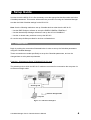
1.1. Connections
Begin by making the connections illustrated below in order to set up the CobraNet parameters
using the CobraNet Manager.
These connections are made specifically to set up the CobraNet parameters, and can be
changed later to suit system requirements.
Example 1: Simultaneous Setup of Multiple MY16-CII cards
The switching hub to which the MY16-CII cards are connected is connected to the computer via
an Ethernet straight cable.
Switching Hub
Ethernet Straight Cable
Computer
Figure 1: Connection Example 1
CobraNet Manager Lite for Yamaha Owner’s Manual 4

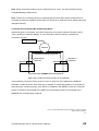
Example 2: Setting Up a Single MY16-CII card
Directly connect the MY16-CII card to the computer via an Ethernet cross cable. Alternatively,
connect via a switching hub and connect the hub to the computer via an Ethernet straight cable.
Switching Hub
Ethernet Cross Cable
Ethernet Straight Cable
Computer Computer
Figure 2: Connection Example 2
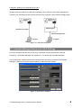
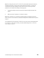
1.2. CobraNet Manager Startup and Initial Settings
Once the computer and MY16-CII have been connected, from the [Start] menu click [All
Programs] -> [CobraNet Manager Lite Yamaha V1.1] to launch the CobraNet Manager.
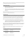
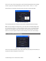
The “Preferences” window shown below will appear the first time you launch the CobraNet
Manager. Follow the procedure outlined below to make the initial settings.
Figure 3: “Preferences” Window
CobraNet Manager Lite for Yamaha Owner’s Manual 5

Note: The “Preferences” window can be opened after the CobraNet Manager has been launched
by selecting [General Preferences] from the [Setup] menu.
Network Adaptor Setup
1. Select the network adaptor (primary network) connected to the MY16-CII from the “Select
primary network adaptor” selection box.
2. Select “None” or a secondary network (a backup network that will take over if the primary
network connection is interrupted) adaptor from the “Select secondary network adaptor”
selection box.
Note: The CobraNet Manager can be used even if secondary network is not selected. Be sure to
select “None” if no secondary network will be used.
IP Address Setup
In order to set the bundle number and other CobraNet parameters using the CobraNet Manager,
it is necessary to assign IP addresses to the MY16-CII cards. The CobraNet Manager has a
function that will automatically assign IP numbers, which can normally be used as follows.
Note: It is not necessary to assign IP addresses if the CobraNet Manager will not be used.
1. The range over which IP address will be automatically assigned is specified by the “IP
Range Start” and “IP Range End” parameters. IP addresses having the same network
address as the computer but different host addresses will be assigned.
Note: The first time the CobraNet Manager is launched the IP address range is automatically set
based on the computer’s IP address (network address and host address). If these settings are
acceptable they do not need to be changed.
Note: Be sure that the specified IP address range does not include the computer’s own IP
address.
If the computer IP address is 192.168.0.1 and the subnet mask is 255.255.255.0
IP Range Start 192.168.0.2
IP Range End 192.168.0.253
If the computer IP address is 172.16.0.1 and the subnet mask is 255.255.0.0
IP Range Start 172.16.0.2
IP Range End 172.16.254.253
CobraNet Manager Lite for Yamaha Owner’s Manual 6

2. Check the “Assign IP automatically to CobraNet devices” checkbox.
Note: The IP address that was assigned automatically is retained even if the power is turned off.
Moreover, IP addresses cannot be automatically re-assigned to the MY16-CII cards that already
have their own IP addresses. If you want to assign IP addresses manually, refer to page 15.
This completes setup for automatic assignment of IP addresses to MY16-CII cards.
Community String Setup
The “Default read community” should be set to “public”, and the “Default write community” to
“private”. These are the default settings when the CobraNet Manager is initially launched, so they
do not need to be changed.
Completion of Initial Setup
The above settings make it possible to control MY16-CII cards from the CobraNet Manager.
Click [OK] to close the “Preferences” window.
CobraNet Manager Lite for Yamaha Owner’s Manual 7

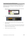
1.3. Select an MY16-CII to be Set Up from the CobraNet Manager
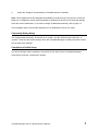
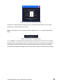
1. When the “Preferences” window is closed the “Select Devices” window will open.
Note: The “Select Devices” window will open automatically first instead of the “Preferences”
window from the second time the CobraNet manager is launched onward.
Figure 4: Select Devices Window
The MAC addresses of MY16-CII currently connected to the network will appear in the left list
(“Online Devices”). If IP address is assigned, MAC addresses, device names and location will be
displayed.
Note: Nothing will appear in the list if the CobraNet Manager is offline. In such a case click the
[Close] button to close the window, then turn on the Online switch in the lower right area of the
main window.
2. Double-click the device you want to access in the “Online Devices” list (the left list) to
move that device to the “Selected Devices” list (the right list).
Note: The Lite version of this software can manage a maximum of four devices simultaneously.
The full version has no limit to the number of devices that can be managed. Refer to the
CobraNet Manager website for details.
http://www.cobranetmanager.com
3. Click the [Close] button to close the “Select Devices” window.
CobraNet Manager Lite for Yamaha Owner’s Manual 8

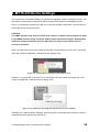
1.4. MY16-CII Bundle Settings
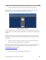
When the “Select Devices” window is closed the main window – like the one shown below – will
appear. This is the Matrix View window. Make the required MY16-CII bundle settings as
described below.
Figure 5: Matrix View
Device Names
The CobraNet Manager allows individual names to be assigned to each device. When using
multiple MY16-CII cards, be sure to give each card a different name to facilitate identification. The
name assigned here will be displayed in the “Select Devices” and “Matrix View” windows.
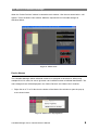
1. Right click on a Tx or Rx block on the border of the Matrix View window to open the pop-up
menu shown below.
Figure 6: Matrix View Pop-up Menu
CobraNet Manager Lite for Yamaha Owner’s Manual 9

2. Select “Device Properties” to open the “Device properties” window.
Figure 7: Device Properties Window
3. To refresh the display to show the current MY16-CII settings click [Get information from
device].
4. Edit the name in the “Global” section “Name” field.
Note: To identify the MY16-CII card between individual cards, please check the MAC address
displayed in the “Global” section “MAC” field with that labeled on the card panel.
5. Click [Store] to apply and save the new name.
Note: If the new name cannot be saved, the IP address might not be assigned properly (see
page 15).
CobraNet Manager Lite for Yamaha Owner’s Manual 10

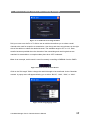
Bundle Numbers
Set the appropriate bundle numbers using one of the methods described below to allow transfer
of audio signals between transmitting and receiving devices.
Connecting Multiple MY16-CII Cards Only via Matrix View
This method selects the bundle numbers automatically and is only useful for setting up bundles
that will be transmitted and received between the MY16-CII cards displayed in the Matrix View.
1. Click on the Matrix View to create a connection or “point,” as described below.
When a connection is created, bundle numbers are set for the transmitting and receiving
devices, allowing audio signal transfer. “Tx” is the transmit bundle and “Rx” is the receive
bundle. The numbers following Tx or Rx are the socket numbers that indicate the order of
the transmit and receive bundles.
When a new connection point is created, unicast bundles (black lines) are specified by default.
Note: Audio signals cannot be transferred if the latencies of the transmitting and receiving
devices differ. Set the same latency for both devices via the “Yamaha Device Settings” window
(page 16).
Figure 8: Matrix View
CobraNet Manager Lite for Yamaha Owner’s Manual 11

2. To change a connection to multicast or multi-unicast bundles, click on the vertical line that
goes through the target connection point to open the bundle type editing window.
Note: Unicast bundles are only transmitted to single devices which have been set to the same
bundle number as the transmitting device. Multicast bundles are transmitted to all devices on the
network regardless of their settings, but only bundles with the specified bundle number(s) are
processed. For this reason, multicast bundles make heavy use of network bandwidth and it is
recommended that the maximum number of multicast bundles be limited to 4 (32 channels).
Multi-unicast bundles are only transmitted to up to four devices simultaneously, saving network
bandwidth compared to multicast bundles.
Figure 9: Bundle type editing window
3. Click “Multicast” to change the connection to multicast, or “Multi-unicast” to change the
connection to multi-unicast.
This completes MY16-CII bundle setup. The MY16-CII can now be used for audio signal transfer.
For information on setting MY16-CII latency and other detailed settings skip ahead to “2. MY16-
CII Device Settings” on page 16.
Connecting MY16-CII Cards and Other CobraNet Devices via the Device Properties
Window
Bundle numbers can be set if the system includes devices not directly supported by the CobraNet
Manager (such as the MY16-C) by using the procedure described below.
1. Right click on a Tx or Rx block on the border of the Matrix View window to open the pop-
up menu shown below.
CobraNet Manager Lite for Yamaha Owner’s Manual 12

Figure 10: Matrix View Pop-up Menu
2. Select “Device Properties” to open the “Device properties” window.
Figure 11: Device Properties Window
3. Click the tab corresponding to the Rx or Tx socket you want to set in the “Sockets”
section in the lower area of the window.
Figure 12: Sockets Section
4. Enter the bundle number in the “Bundle” field and click the [Set Socket] button.
CobraNet Manager Lite for Yamaha Owner’s Manual 13

Note: Don’t change the value in the Tx “Ch” field. The communication load can be reduced by
changing this parameter, but some audio channels will become inoperative. To reduce the
communication load without disabling the audio channels, edit the “Channels per Bundle”
parameter in the “Yamaha Device Settings” window (page 18).
5. To refresh the display to show the current device settings click [Get information from
device].
6. Make sure that the “Persistence on” checkbox is checked.
Note: When “Persistence on” is checked the CobraNet settings are retained even when the
power is turned off. If this checkbox is unchecked the settings will be initialized when the power is
turned off.
This completes MY16-CII bundle setup. The MY16-CII can now be used for audio signal transfer.
For information on setting MY16-CII latency and other detailed settings refer to “2. MY16-CII
Device Settings” on page 16.
CobraNet Manager Lite for Yamaha Owner’s Manual 14

If Cannot Change Device Name and Bundle Numbers
If the device name and bundle numbers cannot be changed, the IP address might not be
assigned properly. Moreover, IP addresses cannot be automatically re-assigned to the MY16-CII
cards that already have their own IP addresses. If you want to assign IP addresses manually,
follow the procedure below.
1. Right click on a Tx or Rx block on the border of the Matrix View window to open the pop-
up menu shown below.
Figure 13: Matrix View Pop-up Menu
2. Select “Device Properties” to open the “Device properties” window.
Figure 14: “Device Properties” Window
3. Right-click the IP address, and select “Get Free IP” from the pop-up menu to assign a
tentative IP address.
4. Right-click the IP address, select “Assign if static IP” (Assign as static IP address which is
retained even after the power is turned off) or “Assign if current IP” (Assign as temporary
IP address), then enter the desired IP address.
5. Click [Store] to apply and save the new IP address.
CobraNet Manager Lite for Yamaha Owner’s Manual 15

2. MY16-CII Device Settings
This version of the CobraNet Manager is optimized for operation with the Yamaha MY16-CII. For
this reason it incorporates some special features that provide optimum compatibility with the
MY16-CII. Parameters specific to the MY16-CII can be accessed via the Matrix View window as
well as the device overview window.
CAUTION!
The SNMP indicator may remain lit while large volumes of data are being transferred. Wait
for the SNMP indicator to go out before making further parameter changes. Attempting to
make new changes before the previous data has been fully transferred can result in
erroneous operation.
When you right click on the matrix border at a location corresponding to an MY16-CII, the popup
menu will contain an additional “YAMAHA Device Settings” item.
Figure 15: Yamaha Device Settings from the Matrix View
Similarly, if you right click on an MY16-CII in the device overview window the popup menu will
contain an additional “YAMAHA Device Settings” item.
Figure 16: Yamaha Device Settings from the Device Overview Window
Selecting the “YAMAHA Device Settings” item brings up a new window that contains a number of
parameters that are specific to the MY16-CII.
CobraNet Manager Lite for Yamaha Owner’s Manual 16

2.1. MY16-CII Serial Control and Latency Settings
Figure 17: Yamaha Device Settings Window
Roll your cursor over the Rx or Tx field to see an edit box that allows you to select a serial
channel to be used for reception or transmission. Use the up and down arrow buttons on the right
side of the edit box to select the desired channel. The available range is OFF or 1-15. Data
transfer becomes possible when the channels of the transmitting and receiving devices are
matched. No transmission or reception takes place when OFF is selected.
Hint: As an example, serial control is used for remotely controlling a DME64N from the PM5D.
Figure 18: Rx/Tx Serial channel edit box
Click on the “Bit Length” field to change the audio bit length to be transferred via the CobraNet
network. A popup menu will appear allowing you to select “Bit Off”, “16bit”, “20bit”, or “24bit”.
Figure 19: Bit Length popup menu
CobraNet Manager Lite for Yamaha Owner’s Manual 17

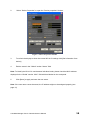
Click on the “Latency” field to change latency mode for audio data transferred via the CobraNet
network. A popup menu will appear allowing you to select “5.33ms”, “2.67ms”, or “1.33ms”.
Note that latency of transmitter and receiver must be the same to transmit audio data.
Figure 20: Latency popup menu
Click the [Advanced] button to bring up a second window containing the advanced settings.
Note: If MY16-CII settings are changed from a source other than the CobraNet Manager while
the “Yamaha Device Settings” or “Advanced Settings” window is open, the CobraNet Manager
displays will not be updated to reflect those changes. Click the [Get information from device]
button in the “Device Properties” window to refresh the display and show the current settings.
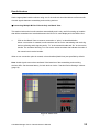
2.2. Advanced MY16-CII Settings
Figure 21: “Advanced Settings” window
Click on the “Channel per Bundle” Input or Output field to bring up a popup menu that allows you
to specify the channel configuration of the MY16-CII.
CobraNet Manager Lite for Yamaha Owner’s Manual 18

Figure 22: Channel per Bundle popup menu
The MY16-CII handles input and output of up to 16 monaural audio channels. Up to 8 input
bundles and 4 output bundles can be used.
Note: For information on the “Conductor Priority” setting, refer to “2.3. Clock Synchronization
Mode”.
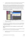
Figure 23: Initialization of all parameters
The “Initialization of All Parameters” [Execute] button will reset all of the MY16-CII’s CobraNet
parameters back to their default values. This means that the MY16-CII will not be connected to
the CobraNet network until the receive and transmit sockets are reconfigured. All CobraNet
settings will be initialized, including those that cannot be accessed via Yamaha Device Settings.
CobraNet Manager Lite for Yamaha Owner’s Manual 19

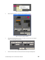
2.3. Clock Synchronization Mode
Like the MY16-C, the MY16-CII provides three clock synchronization modes: Network Sync, Host
Sync 1, and Host Sync 2. The clock synchronization mode is automatically selected according to
the word clock status of the host device into which the MY16-CII is installed.
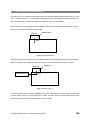
If the device into which the MY16-CII is installed receives its clock signal from the MY16-CII, the
MY16-CII will operate in Network Sync mode.
Network Sync
MY16-CII
Clock
PM5D etc
Figure 24: Network Sync
If the device into which the MY16-CII is installed receives its clock signal from an external device
which is not part of the CobraNet network, the MY16-CII will operate in Host Sync 1 mode.
Host Sync 1
MY16-CII
Device external to
CobraNet network
Clock
PM5D etc
Figure 25: Host Sync 1
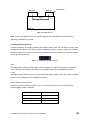
If two or more MY16-CII cards are installed in the same host device, and the host device receives
its clock signal from one of those MY16-CII cards, all other MY16-CII cards that receive their
clock signal from the host will operate in Host Sync 2 mode.
CobraNet Manager Lite for Yamaha Owner’s Manual 20

Host Sync 2
MY16-CII
Clock
MY16-CII
PM5D etc
Figure 26: Host Sync 2
Note: In this case the MY16-CII card that is supplying the clock signal to the host device is
operating in Network Sync mode.
Conductor Priority Settings
"Conductor Priority" is a setting related to the Network Sync mode. The “Conductor Priority” filed
is located at the center of “MY16-CII Advanced Settings” window. Roll your cursor over this field
to see an edit box via which you can specify conductor priority by using the up and down buttons
on the right side of the box.
Figure 27: Conductor priority edit box
Auto:
The appropriate conductor priority will be set according to the MY16-CII clock synchronization
mode. Use this mode unless you need to set a specific device as the CobraNet conductor.
0-255:
Specifies a fixed conductor priority. A fixed conductor priority setting can be used when a specific
device is to be assigned as the CobraNet conductor.
Auto Conductor Priority Value
When the conductor priority setting is “Auto”, the conductor priority is set according to the
synchronization mode, as follows.
MY16-CII Sync Mode Conductor Priority
Network Sync 32
Host Sync 1 128
Host Sync 2 0
CobraNet Manager Lite for Yamaha Owner’s Manual 21

Note: When Conductor Priority is set to a value other than “Auto”, the value specified via the
CobraNet Manager takes priority.
Note: The MY16-C conductor priority is automatically set to the same values as the MY16-CII
according to the three available clock modes, but the MY16-C conductor priority setting cannot be
changed manually.
Conductor Priority Should Be Set Manually When...
With some types of connection, word clock loops may occur when Conductor Priority is set to
“Auto” resulting in network instability. In such cases set conductor priority to prevent the
occurrence of loops.
Figure 28: Conductor Priority needs to be set manually
In this example Conductor Priority is set to “Auto” so the MY16-CII installed in the DME64N
becomes a conductor and a word clock loop is created. To rectify this problem it is necessary to
either lower the conductor priority of the MY16-CII installed in the DME64 or raise the conductor
priority of the MY16-CII installed in the PM5D, thus preventing the MY16-CII installed in the
DME64N from functioning as conductor.
U.R.G.,Pro Audio& Digital Musical Instrument Division, Yamaha Corporation
©2006 Yamaha Corporation
B0
MY16-CII
Clock
Host Sync 1
conductor
PM5D
MY16-CII
DME64N
Network Sync
performer
Network
CobraNet device
CobraNet Synchronization signal flow
CobraNet Manager Lite for Yamaha Owner’s Manual 22
Documenttranscriptie
CobraNetTM Manager Lite for Yamaha Version 1.1 Owner’s Manual EN CobraNet Manager Lite for Yamaha Owner’s Manual Table of contents 1. 2. Setup Guide....................................................................................................................... 4 1.1. Connections................................................................................................................ 4 1.2. CobraNet Manager Startup and Initial Settings ......................................................... 5 1.3. Select an MY16-CII to be Set Up from the CobraNet Manager................................ 8 1.4. MY16-CII Bundle Settings ........................................................................................ 9 MY16-CII Device Settings ............................................................................................. 16 2.1. MY16-CII Serial Control and Latency Settings....................................................... 17 2.2. Advanced MY16-CII Settings.................................................................................. 18 2.3. Clock Synchronization Mode................................................................................... 20 Introduction CobraNet Manager Lite for Yamaha (CobraNet Manager) allows MY16-CII related CobraNet parameters such as bundle numbers to be displayed and edited. The MY16-CII is the only Yamaha product supported by this software. Unsupported products will be displayed, but cannot be controlled or edited. Please be sure to only use the CobraNet Manager when one or more MY16-CII cards are online. This manual describes procedures for using the CobraNet Manager with the MY16-CII. Further details about the software can be found in the “D&R CobraNet Manager Lite User Manual”. CobraNet Manager Lite for Yamaha Owner’s Manual 2 Special Notices ● This software is the exclusive copyright of D&R. ● Use of the software and this manual is governed by the Software Licensing Agreement which the purchaser fully agrees to upon breaking the seal of the software packaging. (Carefully read the agreement at the end of the MY16-CII owner’s manual before installing the software.) ● Copying of the software or reproduction of this manual in whole or in part by any means is expressly forbidden without the written consent of the manufacturer. ● Yamaha makes no representations or warranties with regard to the use of the software and documentation and cannot be held responsible for the results of the use of this manual and the software. ● This disc is a CD-ROM. Do not attempt to play the disc on an audio CD player. Doing so may result in irreparable damage to your audio system. ● The screen displays as illustrated in this manual are for instructional purposes, and may appear somewhat different from the screens which appear on your computer. ● Future upgrades of application and system software and any changes in specifications and functions will be announced separately. ● Specifications and descriptions in this owner’s manual are for information purposes only. Yamaha Corp. reserves the right to change or modify specifications at any time without prior notice. Since specifications may not be the same in every locale, please check with your Yamaha dealer. ● The company names and product names in this owner’s manual are the trademarks or registered trademarks of their respective companies. CobraNet Manager Lite for Yamaha Owner’s Manual 3 1. Setup Guide In order to use the MY16-CII it is first necessary to set the appropriate bundle number and other CobraNet parameters. This section will describe the procedure for using the CobraNet Manager to make the initial CobraNet settings for the MY16-CII. Note: Use the following methods to set up CobraNet devices other than the MY16-CII: ・ Use the DME Designer software to set up the DME8i-C/DME8o-C/DME4io-C. ・ Use the NetworkAmp Manager software to set up the ACU16-C/NHB32-C. ・ Use the on-board rotary switches to set up the MY16-C. Or use the setup facilities provided for devices not listed above. 1.1. Connections Begin by making the connections illustrated below in order to set up the CobraNet parameters using the CobraNet Manager. These connections are made specifically to set up the CobraNet parameters, and can be changed later to suit system requirements. Example 1: Simultaneous Setup of Multiple MY16-CII cards The switching hub to which the MY16-CII cards are connected is connected to the computer via an Ethernet straight cable. Switching Hub Ethernet Straight Cable Computer Figure 1: Connection Example 1 CobraNet Manager Lite for Yamaha Owner’s Manual 4 Example 2: Setting Up a Single MY16-CII card Directly connect the MY16-CII card to the computer via an Ethernet cross cable. Alternatively, connect via a switching hub and connect the hub to the computer via an Ethernet straight cable. Switching Hub Ethernet Cross Cable Ethernet Straight Cable Computer Computer Figure 2: Connection Example 2 1.2. CobraNet Manager Startup and Initial Settings Once the computer and MY16-CII have been connected, from the [Start] menu click [All Programs] -> [CobraNet Manager Lite Yamaha V1.1] to launch the CobraNet Manager. The “Preferences” window shown below will appear the first time you launch the CobraNet Manager. Follow the procedure outlined below to make the initial settings. Figure 3: “Preferences” Window CobraNet Manager Lite for Yamaha Owner’s Manual 5 Note: The “Preferences” window can be opened after the CobraNet Manager has been launched by selecting [General Preferences] from the [Setup] menu. Network Adaptor Setup 1. Select the network adaptor (primary network) connected to the MY16-CII from the “Select primary network adaptor” selection box. 2. Select “None” or a secondary network (a backup network that will take over if the primary network connection is interrupted) adaptor from the “Select secondary network adaptor” selection box. Note: The CobraNet Manager can be used even if secondary network is not selected. Be sure to select “None” if no secondary network will be used. IP Address Setup In order to set the bundle number and other CobraNet parameters using the CobraNet Manager, it is necessary to assign IP addresses to the MY16-CII cards. The CobraNet Manager has a function that will automatically assign IP numbers, which can normally be used as follows. Note: It is not necessary to assign IP addresses if the CobraNet Manager will not be used. 1. The range over which IP address will be automatically assigned is specified by the “IP Range Start” and “IP Range End” parameters. IP addresses having the same network address as the computer but different host addresses will be assigned. Note: The first time the CobraNet Manager is launched the IP address range is automatically set based on the computer’s IP address (network address and host address). If these settings are acceptable they do not need to be changed. Note: Be sure that the specified IP address range does not include the computer’s own IP address. If the computer IP address is 192.168.0.1 and the subnet mask is 255.255.255.0 IP Range Start 192.168.0.2 IP Range End 192.168.0.253 If the computer IP address is 172.16.0.1 and the subnet mask is 255.255.0.0 IP Range Start 172.16.0.2 IP Range End 172.16.254.253 CobraNet Manager Lite for Yamaha Owner’s Manual 6 2. Check the “Assign IP automatically to CobraNet devices” checkbox. Note: The IP address that was assigned automatically is retained even if the power is turned off. Moreover, IP addresses cannot be automatically re-assigned to the MY16-CII cards that already have their own IP addresses. If you want to assign IP addresses manually, refer to page 15. This completes setup for automatic assignment of IP addresses to MY16-CII cards. Community String Setup The “Default read community” should be set to “public”, and the “Default write community” to “private”. These are the default settings when the CobraNet Manager is initially launched, so they do not need to be changed. Completion of Initial Setup The above settings make it possible to control MY16-CII cards from the CobraNet Manager. Click [OK] to close the “Preferences” window. CobraNet Manager Lite for Yamaha Owner’s Manual 7 1.3. Select an MY16-CII to be Set Up from the CobraNet Manager 1. When the “Preferences” window is closed the “Select Devices” window will open. Note: The “Select Devices” window will open automatically first instead of the “Preferences” window from the second time the CobraNet manager is launched onward. Figure 4: Select Devices Window The MAC addresses of MY16-CII currently connected to the network will appear in the left list (“Online Devices”). If IP address is assigned, MAC addresses, device names and location will be displayed. Note: Nothing will appear in the list if the CobraNet Manager is offline. In such a case click the [Close] button to close the window, then turn on the Online switch in the lower right area of the main window. 2. Double-click the device you want to access in the “Online Devices” list (the left list) to move that device to the “Selected Devices” list (the right list). Note: The Lite version of this software can manage a maximum of four devices simultaneously. The full version has no limit to the number of devices that can be managed. Refer to the CobraNet Manager website for details. http://www.cobranetmanager.com 3. Click the [Close] button to close the “Select Devices” window. CobraNet Manager Lite for Yamaha Owner’s Manual 8 1.4. MY16-CII Bundle Settings When the “Select Devices” window is closed the main window – like the one shown below – will appear. This is the Matrix View window. Make the required MY16-CII bundle settings as described below. Figure 5: Matrix View Device Names The CobraNet Manager allows individual names to be assigned to each device. When using multiple MY16-CII cards, be sure to give each card a different name to facilitate identification. The name assigned here will be displayed in the “Select Devices” and “Matrix View” windows. 1. Right click on a Tx or Rx block on the border of the Matrix View window to open the pop-up menu shown below. Figure 6: Matrix View Pop-up Menu CobraNet Manager Lite for Yamaha Owner’s Manual 9 2. Select “Device Properties” to open the “Device properties” window. Figure 7: Device Properties Window 3. To refresh the display to show the current MY16-CII settings click [Get information from device]. 4. Edit the name in the “Global” section “Name” field. Note: To identify the MY16-CII card between individual cards, please check the MAC address displayed in the “Global” section “MAC” field with that labeled on the card panel. 5. Click [Store] to apply and save the new name. Note: If the new name cannot be saved, the IP address might not be assigned properly (see page 15). CobraNet Manager Lite for Yamaha Owner’s Manual 10 Bundle Numbers Set the appropriate bundle numbers using one of the methods described below to allow transfer of audio signals between transmitting and receiving devices. Connecting Multiple MY16-CII Cards Only via Matrix View This method selects the bundle numbers automatically and is only useful for setting up bundles that will be transmitted and received between the MY16-CII cards displayed in the Matrix View. 1. Click on the Matrix View to create a connection or “point,” as described below. When a connection is created, bundle numbers are set for the transmitting and receiving devices, allowing audio signal transfer. “Tx” is the transmit bundle and “Rx” is the receive bundle. The numbers following Tx or Rx are the socket numbers that indicate the order of the transmit and receive bundles. When a new connection point is created, unicast bundles (black lines) are specified by default. Note: Audio signals cannot be transferred if the latencies of the transmitting and receiving devices differ. Set the same latency for both devices via the “Yamaha Device Settings” window (page 16). Figure 8: Matrix View CobraNet Manager Lite for Yamaha Owner’s Manual 11 2. To change a connection to multicast or multi-unicast bundles, click on the vertical line that goes through the target connection point to open the bundle type editing window. Note: Unicast bundles are only transmitted to single devices which have been set to the same bundle number as the transmitting device. Multicast bundles are transmitted to all devices on the network regardless of their settings, but only bundles with the specified bundle number(s) are processed. For this reason, multicast bundles make heavy use of network bandwidth and it is recommended that the maximum number of multicast bundles be limited to 4 (32 channels). Multi-unicast bundles are only transmitted to up to four devices simultaneously, saving network bandwidth compared to multicast bundles. Figure 9: Bundle type editing window 3. Click “Multicast” to change the connection to multicast, or “Multi-unicast” to change the connection to multi-unicast. This completes MY16-CII bundle setup. The MY16-CII can now be used for audio signal transfer. For information on setting MY16-CII latency and other detailed settings skip ahead to “2. MY16CII Device Settings” on page 16. Connecting MY16-CII Cards and Other CobraNet Devices via the Device Properties Window Bundle numbers can be set if the system includes devices not directly supported by the CobraNet Manager (such as the MY16-C) by using the procedure described below. 1. Right click on a Tx or Rx block on the border of the Matrix View window to open the popup menu shown below. CobraNet Manager Lite for Yamaha Owner’s Manual 12 Figure 10: Matrix View Pop-up Menu 2. Select “Device Properties” to open the “Device properties” window. Figure 11: Device Properties Window 3. Click the tab corresponding to the Rx or Tx socket you want to set in the “Sockets” section in the lower area of the window. Figure 12: Sockets Section 4. Enter the bundle number in the “Bundle” field and click the [Set Socket] button. CobraNet Manager Lite for Yamaha Owner’s Manual 13 Note: Don’t change the value in the Tx “Ch” field. The communication load can be reduced by changing this parameter, but some audio channels will become inoperative. To reduce the communication load without disabling the audio channels, edit the “Channels per Bundle” parameter in the “Yamaha Device Settings” window (page 18). 5. To refresh the display to show the current device settings click [Get information from device]. 6. Make sure that the “Persistence on” checkbox is checked. Note: When “Persistence on” is checked the CobraNet settings are retained even when the power is turned off. If this checkbox is unchecked the settings will be initialized when the power is turned off. This completes MY16-CII bundle setup. The MY16-CII can now be used for audio signal transfer. For information on setting MY16-CII latency and other detailed settings refer to “2. MY16-CII Device Settings” on page 16. CobraNet Manager Lite for Yamaha Owner’s Manual 14 If Cannot Change Device Name and Bundle Numbers If the device name and bundle numbers cannot be changed, the IP address might not be assigned properly. Moreover, IP addresses cannot be automatically re-assigned to the MY16-CII cards that already have their own IP addresses. If you want to assign IP addresses manually, follow the procedure below. 1. Right click on a Tx or Rx block on the border of the Matrix View window to open the popup menu shown below. Figure 13: Matrix View Pop-up Menu 2. Select “Device Properties” to open the “Device properties” window. Figure 14: “Device Properties” Window 3. Right-click the IP address, and select “Get Free IP” from the pop-up menu to assign a tentative IP address. 4. Right-click the IP address, select “Assign if static IP” (Assign as static IP address which is retained even after the power is turned off) or “Assign if current IP” (Assign as temporary IP address), then enter the desired IP address. 5. Click [Store] to apply and save the new IP address. CobraNet Manager Lite for Yamaha Owner’s Manual 15 2. MY16-CII Device Settings This version of the CobraNet Manager is optimized for operation with the Yamaha MY16-CII. For this reason it incorporates some special features that provide optimum compatibility with the MY16-CII. Parameters specific to the MY16-CII can be accessed via the Matrix View window as well as the device overview window. CAUTION! The SNMP indicator may remain lit while large volumes of data are being transferred. Wait for the SNMP indicator to go out before making further parameter changes. Attempting to make new changes before the previous data has been fully transferred can result in erroneous operation. When you right click on the matrix border at a location corresponding to an MY16-CII, the popup menu will contain an additional “YAMAHA Device Settings” item. Figure 15: Yamaha Device Settings from the Matrix View Similarly, if you right click on an MY16-CII in the device overview window the popup menu will contain an additional “YAMAHA Device Settings” item. Figure 16: Yamaha Device Settings from the Device Overview Window Selecting the “YAMAHA Device Settings” item brings up a new window that contains a number of parameters that are specific to the MY16-CII. CobraNet Manager Lite for Yamaha Owner’s Manual 16 2.1. MY16-CII Serial Control and Latency Settings Figure 17: Yamaha Device Settings Window Roll your cursor over the Rx or Tx field to see an edit box that allows you to select a serial channel to be used for reception or transmission. Use the up and down arrow buttons on the right side of the edit box to select the desired channel. The available range is OFF or 1-15. Data transfer becomes possible when the channels of the transmitting and receiving devices are matched. No transmission or reception takes place when OFF is selected. Hint: As an example, serial control is used for remotely controlling a DME64N from the PM5D. Figure 18: Rx/Tx Serial channel edit box Click on the “Bit Length” field to change the audio bit length to be transferred via the CobraNet network. A popup menu will appear allowing you to select “Bit Off”, “16bit”, “20bit”, or “24bit”. Figure 19: Bit Length popup menu CobraNet Manager Lite for Yamaha Owner’s Manual 17 Click on the “Latency” field to change latency mode for audio data transferred via the CobraNet network. A popup menu will appear allowing you to select “5.33ms”, “2.67ms”, or “1.33ms”. Note that latency of transmitter and receiver must be the same to transmit audio data. Figure 20: Latency popup menu Click the [Advanced] button to bring up a second window containing the advanced settings. Note: If MY16-CII settings are changed from a source other than the CobraNet Manager while the “Yamaha Device Settings” or “Advanced Settings” window is open, the CobraNet Manager displays will not be updated to reflect those changes. Click the [Get information from device] button in the “Device Properties” window to refresh the display and show the current settings. 2.2. Advanced MY16-CII Settings Figure 21: “Advanced Settings” window Click on the “Channel per Bundle” Input or Output field to bring up a popup menu that allows you to specify the channel configuration of the MY16-CII. CobraNet Manager Lite for Yamaha Owner’s Manual 18 Figure 22: Channel per Bundle popup menu The MY16-CII handles input and output of up to 16 monaural audio channels. Up to 8 input bundles and 4 output bundles can be used. Note: For information on the “Conductor Priority” setting, refer to “2.3. Clock Synchronization Mode”. Figure 23: Initialization of all parameters The “Initialization of All Parameters” [Execute] button will reset all of the MY16-CII’s CobraNet parameters back to their default values. This means that the MY16-CII will not be connected to the CobraNet network until the receive and transmit sockets are reconfigured. All CobraNet settings will be initialized, including those that cannot be accessed via Yamaha Device Settings. CobraNet Manager Lite for Yamaha Owner’s Manual 19 2.3. Clock Synchronization Mode Like the MY16-C, the MY16-CII provides three clock synchronization modes: Network Sync, Host Sync 1, and Host Sync 2. The clock synchronization mode is automatically selected according to the word clock status of the host device into which the MY16-CII is installed. If the device into which the MY16-CII is installed receives its clock signal from the MY16-CII, the MY16-CII will operate in Network Sync mode. Network Sync MY16-CII Clock PM5D etc Figure 24: Network Sync If the device into which the MY16-CII is installed receives its clock signal from an external device which is not part of the CobraNet network, the MY16-CII will operate in Host Sync 1 mode. MY16-CII Device external to CobraNet network Host Sync 1 Clock PM5D etc Figure 25: Host Sync 1 If two or more MY16-CII cards are installed in the same host device, and the host device receives its clock signal from one of those MY16-CII cards, all other MY16-CII cards that receive their clock signal from the host will operate in Host Sync 2 mode. CobraNet Manager Lite for Yamaha Owner’s Manual 20 MY16-CII MY16-CII Host Sync 2 Clock PM5D etc Figure 26: Host Sync 2 Note: In this case the MY16-CII card that is supplying the clock signal to the host device is operating in Network Sync mode. Conductor Priority Settings "Conductor Priority" is a setting related to the Network Sync mode. The “Conductor Priority” filed is located at the center of “MY16-CII Advanced Settings” window. Roll your cursor over this field to see an edit box via which you can specify conductor priority by using the up and down buttons on the right side of the box. Figure 27: Conductor priority edit box Auto: The appropriate conductor priority will be set according to the MY16-CII clock synchronization mode. Use this mode unless you need to set a specific device as the CobraNet conductor. 0-255: Specifies a fixed conductor priority. A fixed conductor priority setting can be used when a specific device is to be assigned as the CobraNet conductor. Auto Conductor Priority Value When the conductor priority setting is “Auto”, the conductor priority is set according to the synchronization mode, as follows. MY16-CII Sync Mode Conductor Priority Network Sync 32 Host Sync 1 128 Host Sync 2 0 CobraNet Manager Lite for Yamaha Owner’s Manual 21 Note: When Conductor Priority is set to a value other than “Auto”, the value specified via the CobraNet Manager takes priority. Note: The MY16-C conductor priority is automatically set to the same values as the MY16-CII according to the three available clock modes, but the MY16-C conductor priority setting cannot be changed manually. Conductor Priority Should Be Set Manually When... With some types of connection, word clock loops may occur when Conductor Priority is set to “Auto” resulting in network instability. In such cases set conductor priority to prevent the occurrence of loops. CobraNet device Network CobraNet Synchronization signal flow MY16-CII Network Sync performer MY16-CII Host Sync 1 conductor DME64N PM5D Clock Figure 28: Conductor Priority needs to be set manually In this example Conductor Priority is set to “Auto” so the MY16-CII installed in the DME64N becomes a conductor and a word clock loop is created. To rectify this problem it is necessary to either lower the conductor priority of the MY16-CII installed in the DME64 or raise the conductor priority of the MY16-CII installed in the PM5D, thus preventing the MY16-CII installed in the DME64N from functioning as conductor. U.R.G.,Pro Audio& Digital Musical Instrument Division, Yamaha Corporation ©2006 Yamaha Corporation B0 CobraNet Manager Lite for Yamaha Owner’s Manual 22-
 1
1
-
 2
2
-
 3
3
-
 4
4
-
 5
5
-
 6
6
-
 7
7
-
 8
8
-
 9
9
-
 10
10
-
 11
11
-
 12
12
-
 13
13
-
 14
14
-
 15
15
-
 16
16
-
 17
17
-
 18
18
-
 19
19
-
 20
20
-
 21
21
-
 22
22


in andere talen
- English: Yamaha MY16 Owner's manual
- italiano: Yamaha MY16 Manuale del proprietario
- français: Yamaha MY16 Le manuel du propriétaire
- español: Yamaha MY16 El manual del propietario
- Deutsch: Yamaha MY16 Bedienungsanleitung
- português: Yamaha MY16 Manual do proprietário
- dansk: Yamaha MY16 Brugervejledning
- suomi: Yamaha MY16 Omistajan opas
- čeština: Yamaha MY16 Návod k obsluze
- svenska: Yamaha MY16 Bruksanvisning
- Türkçe: Yamaha MY16 El kitabı
- polski: Yamaha MY16 Instrukcja obsługi
- română: Yamaha MY16 Manualul proprietarului