Zanussi zhc 6141 x Handleiding
- Categorie
- Afzuigkappen
- Type
- Handleiding

User
Manual
Manual de in-
strucciones
Manuel d’Instruc-
tions
Model ZHC7141
Bedienungs
anleitung
Manual de In-
struções
Gebruiksaanwi-
jzing
Model ZHC9141
Model ZHC6141
Инструкция
по монтажу и
эксплуатации

EN
2
2
Instructions Manual
INDEX
WARNINGS - COMPONENTS...............................................................................................................................................8
INSTALLATION......................................................................................................................................................................9
USE - MAINTENANCE.........................................................................................................................................................10

DE
3
3
Bedienungsanleitung
INHALTSVERZEICHNIS
HINWEIS - KOMPONENTEN...............................................................................................................................................11
MONTAGE............................................................................................................................................................................12
BEDIENUNG - WARTUNG..................................................................................................................................................13

FR
4
4
Manuel d’Instructions
SOMMAIRE
ATTENTION - COMPOSANTS.............................................................................................................................................14
INSTALLATION....................................................................................................................................................................15
UTILISATION - ENTRETIEN................................................................................................................................................16

NL
5
5
Gebruiksaanwijzing
INHOUDSOPGAVE
AANWIJZINGEN - ONDERDELEN......................................................................................................................................17
INSTALLATIE .......................................................................................................................................................................18
GEBRUIK - ONDERHOUD...................................................................................................................................................19

ES
6
6
6
6
Инструкция по монтажу и эксплуатации
ÍNDICE
ADVERTENCIAS - COMPONENTES..................................................................................................................................20
INSTALACIÓN......................................................................................................................................................................21
USO - MANTENIMIENTO.....................................................................................................................................................22

PT
7
7
7
7
Manual de Instruções
ÍNDICE
ADVERTÊNCIAS - COMPONENTES..................................................................................................................................23
INSTALAÇÃO.......................................................................................................................................................................24
UTILIZAÇÃO - MANUTENÇÃO............................................................................................................................................25

PT
8
8
8
8
Manual de Instruções
УКАЗАТЕЛЬ
ПРАВИЛА ТЕХНИКИ БЕЗОПАСНОСТИ - ПРИНАДЛЕЖНОСТИ....................................................................................26
УСТАНОВКА ........................................................................................................................................................................27
ЭКСПЛУАТАЦИЯ - ТЕХНИЧЕСКОЕ ОБСЛУЖИВАНИЕ..................................................................................................28

EN
9
9
WARNINGS - COMPONENTS
WARNINGS
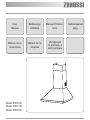
This appliance has been designed for use as either an EXTRACTION (ducting to the outside) or RE-
CIRCULATION (filtering) hood. The measurements contained on the drawings in this booklet refer to
two models of cooker hood. Therefore, it is essential that you refer to the correct drawing when taking
measurements for installation.
- The minimum distance between the cooking surface and the metal grease filters on the underside of the
hood must be 650mm.
- This cooker hood must be installed in accordance with the installation instructions and all requirements
must be adhered to.
- If the room where the cooker hood is to be used contains a fuel burning appliance such as a central heat-
ing boiler then its flue must be of the room sealed or balance flue type.
- If other types of flue or appliances are fitted ensure that there is an adequate supply of air to the room.
- When the range hood and appliance supplied with energy other than electricity are simultaneously in
operation, the negative pressure in the room must not exceed 4 Pa (4x10⁻⁵ bar).
- Exhaust air may be discharged in accordance with official and statutory regulations only (e.g. national buil-
ding regulations).
- The ducting system for this appliance must not be connected to any ventilation system which is being
used for any other purpose.
- The ducting system for this appliance must not be connected to any existing ventilation system which is
being used for any other purpose.
- Do not leave naked flames or carry out flambè cooking under this cooker hood.
- This appliance is not intended for use by persons (including children) with reduced physical, sensory or
mental capabilities, or lack of experience and knowledge, unless they have been given supervision or in-
struction concerning use of the appliance by a person responsible for their safety.
- Children should be supervised to ensure that they do not play with the appliance
The symbol on the product or on its packaging indicates that this product may not be treated as household waste. Instead it shall
be handed over to the applicable collection point for the recycling of electrical and electronic equipment. By ensuring this product is
disposed of correctly, you will help prevent potential negative consequences for the environment and human health, which could o-
therwise be caused by inappropriate waste handling of this product. For more detailed information about recycling of this product, plea-
se contact your local city office, your household waste disposal service or the shop where you purchased the product.
CONNECTING THE POWER CABLE TO THE MAINS POWER SUPPLY
Before installation, check that the mains voltage indicated on the rating plate inside the appliance corre-
sponds to the voltage available in your home. If the Hood is not fitted with a plug, fit the power cable with
a plug of a type approved for the load indicated on the rating plate; when connecting directly to the mains,
insert an omnipolar circuit breaker with a minimum contact aperture of 3mm and a size suitable for the
load in question between the appliance and the mains supply, making sure it is of a type that complies with
current regulations.
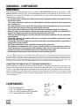
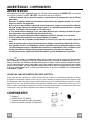
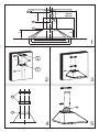
COMPONENTS
- 2 No Wall Brackets C
- 1 No 150-120mm Ducting Spigot G
- 1 No Air Outlet Connection H (Optional)
- 2 No Charcoal Filters L (Optional)

EN
1
0
10
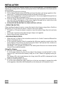
INSTALLATION
The cooker hood must be installed centrally over a cooking appliance. The minimum distance
between the cooking surface and the metal grease filters on the underside of the hood must be
at least 650mm.
To install the hood proceed as follows:
1) Drill six 8mm diameter holes at X1-X2-J and insert the plastic rawl plugs supplied as illus-
trated in fig. 2 ensuring the brackets are fitted as shown in the blow up.
2) Secure the two brackets C to the wall inserting two of the screws supplied through the two
holes on line X1-X2 as illustrated in fig. 2.
3) Slide the canopy down the wall to locate the key hole over the washer then secure the can-
opy to the wall by inserting two of the screws supplied through the two outer holes in the
rim of the canopy J1 and J2 as illustrated in fig. 3.
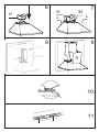
4) EXTRACTION OR RECIRCULATION INSTALLATION:
• EXTRACTION (DUCTED)
When installing the ducted version, connect the hood to the chimney using either a flexible or
rigid pipe ø 150 or 120 mm, the choice of which is left to the installer.
• To install a ø 120 mm air exhaust connection, insert the reducer flange 9 on the hood body
outlet.
• Fix the pipe in position using sufficient pipe clamps (not supplied).
• Remove any activated charcoal filters.
• RECIRCULATION (FILTERED)
• When the hood is fitted in the recirculation mode the Air Outlet Connection H should be
fitted as illustrated in fig. 6.
• Fit the (optional) charcoal filters by repeating the following operation on each side of the
motor housing. Place the two key hole slots in the filter L and turn the filter clockwise to
lock the filter in position as illustrated in fig. 7.
WARNING: It is a possible fire hazard if the metal grease filters are not cleaned and the
charcoal filters replaced regularly.
Fitting The Chimney
5) FITTING THE CHIMNEY UPPER
To fit the upper chimney A, place the top edge of the chimney over the bracket C as illus-
trated in fig. 8 and secure the chimney using two of the 2.9mm self tapping screws pro-
vided.
The distance H in the height between the fixing holes X1 and X2 is determined by the
height of the upper chimney A.
6) FITTING THE CHIMNEY LOWER
To fit the lower chimney B, apply slight force to the two rear edges to increase the width
of the apperture, then sleeve the chimney B over the chimney A as illustrated in fig. 9.

EN
1
1
11
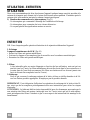
USE - MAINTENANCE
USE
The cooker hood functions are controlled by a series of slider or push button switches mounted
on the front of the hood and control the worktop lighting and fan motor speeds. This cooker hood
will not remove steam.
1) SLIDER SWITCHES (fig.11):
- A switch controls the wotktop lighting - ON/OFF.
- A switch controls the fan speeds - OFF/ON-1-2-3.
- The red neon lamp illuminates when the motor is switched ON .
MAINTENANCE
N.B. Before carring out any kind of maintenance, cleaning or replacing lamps, disconnect the
hood from the mains supply.
1. Lighting
40 W incandescent light (fig.10):
• Remove the metal grease filters.
• Unscrew the bulbs and replace them with new ones having the same characteristics.
• Replace the metal grease filters.
2. Filters
ATTENTION- There could be a possible fire hazard if the filters are not replaced ac-
cording to these instructions.
- The metal grease filter should be cleaned every two months or more frequently if the hood is
used consistently and can be cleaned in a dishwasher or by hand using a mild detergent or
liquid soap. When replacing, ensure that they are dry.
- The charcoal filter cannot be washed and should be replaced at least every 2 months or more
frequently if the hood is used consistently.
3. Cleaning
When cleaning the hood, it is recommended to use a damp cloth and mild liquid household
cleaner. Never use abrasive cleaning materials.
ATTENTION: The manufacturer declines all responsibility for any damage or injury caused
as a result of not following the instructions for installation, for maintenance and replacement
times of filters indicated (in order to avoid a possible risk of fire when the filters are saturated
with grease).

DE
1
2
12
HINWEIS - KOMPONENTEN
HINWEISE
Dieses Gerät ist sowohl als ABLUFTHAUBE (Abführung der Luft nach außen), als auch als UMLUFT-
HAUBE (Filtrierung der Dünste im Innern) verwendbar.
- Der Mindestabstand zwischen Kochfeld und Unterseite der Haube soll 650 mm betragen.
- Wenn die Luft nach Außen abgeführt wird (Abluftbetrieb), muss die Haube nach den folgenden Anweisun-
gen installiert werden.
- Bei gleichzeitigem Betrieb der Dunstabzugshaube im Abluftbetrieb und Feuerstätten darf im Aufstellraum
der Feuerstätte der Unterdruck nicht größer als 4 Pa (4x10
-5
bar) sein.
- Bei der Abluft sind die einschlägigen Verwaltungs-und Gesetzesvorschriften einzuhalten (z. B. nationale
Bauvorschriften).
- Das Abluftrohr der Haube darf keinesfalls an den Rauchabzug von Feuerstätten angeschlossen werden.
- Die Abluftvorschriften der zuständigen Behörden beachten.
- Niemals eine Flamme unter der Dunsthaube unbedeckt lassen.
- Das Gerät entspricht der Schutzklasse II und muss daher nicht geerdet werden.
- Vor Wartungsarbeiten muss das Gerät spannungslos gemacht werden.
- Dieses Gerät darf nicht von Personen, auch Kindern, mit verminderten psychischen, sensorischen und
geistigern Fähigkeiten, oder von Personen ohne Erfahrung und Kenntnisse benutzt werden, sofern sie
nicht von für ihre Sicherheit verantwortlichen Personen beaufsichtigt und beim Gebrauch des Geräts ange-
leitet werden.
- Kinder dürfen sich nicht unbeaufsichtigt in der Nähe des Geräts aufhalten und auf keinen Fall mit dem Ge-
rät spielen.
Das Symbol
auf dem Produkt oder seiner Verpackung weist darauf hin, dass dieses Produkt nicht als normaler
Haushaltsabfall zu behandeln ist, sondern an einem Sammelpunkt für das Recycling von elektrischen und
elektronischen Geräten abgegeben werden muss. Durch Ihren Beitrag zum korrekten Entsorgen dieses Produkts
schützen Sie die Umwelt und die Gesundheit Ihrer Mitmenschen. Umwelt und Gesundheit werden durch falsches
Entsorgen gefährdet. Weitere Informationen über das Recycling dieses Produkts erhalten Sie von Ihrem Rathaus,
Ihrer Müllabfuhr oder dem Geschäft, in dem Sie das Produkt gekauft haben.
ANSCHLUSS DES STROMKABELS AN DAS NETZ
Vor der Installation muss kontrolliert werden, ob die am Typenschild im Geräteinnern angegebene Netz-
spannung der Spannung Ihres Haushalts entspricht. Falls das Gerät ohne Stecker ist, muss das Kabel mit
einem genormten, für die am Typenschild angegebene Last ausreichenden Stecker versehen werden; bei
direktem Anschluss an das Netz muss ein korrekt dimensionierter allpoliger Schalter mit einer Mindest-
kontaktöffnung von 3 mm zwischengeschaltet werden, der den einschlägigen Vorschriften entspricht.
KOMPONENTEN
- 2 Wandhalterungen C
- 1 Reduzierflansch G
- 1 Filterstutzen H (Option)
- 2 Aktivkohlefilter L (Option)

DE
1
3
13
MONTAGE
Die Haube muss mittig über dem Kochfeld installiert werden. Der Mindestabstand zwischen
Kochfeld und Unterseite der Haube soll 650 mm betragen.
Für die Installation wie folgt vorgehen:
1) 6 Löcher (X1-X2-J) mit 8 mm Durchmesser nach den Maßangaben der Abb.1 ausführen.
2) Die für die jeweilige Montage mitgelieferten Schrauben und Dübel verwenden.
3) Die Wandhalterungen C (Abb. 2) mittels der Bohrungen X1-X2 an der Wand befestigen.
4) Die Haube mittels der externen Bohrlöcher J1 und J2 (Abb. 3) an der Wand befestigen.
5) Montage als ABLUFTHAUBE oder UMLUFTHAUBE:
ABLUFTBETRIEB
Bei Abluftbetrieb kann die Haube vom Installateur wahlweise mittels Rohr oder Schlauch (ø
150 oder 120 mm) an den Auslass angeschlossen werden.
- Bei Verwendung eines Anschlussrohres ø 120 den Reduzierflansch 9 am Haubenausgang
anbringen.
- Das Rohr mit passenden Rohrschellen fixieren. Das hierzu erforderliche Material wird
nicht mitgeliefert.
- Eventuell vorhandene Aktivkohlefilter ausbauen.
UMLUFTBETRIEB (OPTION)
- Den Filterstutzen H einbauen (Abb. 6).
- Den Aktivkohlefilter L (Abb.7) einlegen und durch Drehen im Uhrzeigersinn (um zirka
10°) einrasten lassen. Zum Ausbauen in umgekehrter Reihenfolge vorgehen.
Montage der Kamine:
6) Befestigen Sie das obere Kaminteil A (Abb. 8) mit den vier beiliegenden, selbstschneiden-
den Schrauben Ø 2,9 mm an den Halterungen C (Abb.2/Abb.8). Der Abstand zwischen
den Bohrlöchern X1 und X2 hängt von der Höhe des oberen Kaminteils H ab.
7) Um das untere Kaminteil B (Abb. 9) anzubringen die beiden Seitenteile leicht auseinan-
derbiegen und dann an der Haube einsetzen (Abb. 9).

DE
1
4
14
BEDIENUNG - WARTUNG
BEDIENUNG
Es empfiehlt sich, die Dunsthaube, noch bevor Sie mit dem Kochen beginnen, einzuschalten und
auch danach noch ungefähr 15 Minuten, oder jedenfalls bis alle Gerüche beseitigt sind, laufen zu
lassen.
1) Bedienleiste mit Schiebeschaltern (Abb.11):
Ein Schalter schaltet die Beleuchtung ein - ON/OFF.
Ein Schalter steuert die drei Gebläsestufen - OFF/ON-1-2-3.
Eine Kontrolllampe zeigt den Motorbetrieb an.
WARTUNG
NB: Vor sämtlichen Wartungs- und Reparaturarbeiten, sowie dem Auswechseln der Lampen muss
die Stromzufuhr zum Gerät unterbrochen werden.
1. Beleuchtung
40W Glühlampen (Abb.10):
• Die Metallfettfilter entfernen.
• Die Lampen ausschrauben und durch gleichwertige ersetzen.
• Die Metallfettfilter wieder montieren.
2. Filter
ACHTUNG - Die angegebenen Wartungsintervalle sind unbedingt einzuhalten, da
fettgetränkte Filter leicht brennbar sind.
Je nachdem, wie intensiv die Haube gebraucht wird, müssen die Metallfettfilter in entsprechen-
den Zeitabständen (mindestens alle 2 Monate) ausgebaut und mit warmem Seifenwasser bzw.
im Geschirrspüler gewaschen und nach dem Trocknen wieder eingebaut werden (Aktivkohlefil-
ter dürfen keinesfalls gewaschen werden, sondern sind alle 2 Monate auszuwechseln).
3. Pflege
Zur äußeren Reinigung der Haube einen mit Alkohol oder einem handelsüblichen Reinigungs-
mittel angefeuchteten Lappen verwenden. Keine scheuernden Mittel oder Utensilien benutzen.
ACHTUNG: Die Herstellerfirma übernimmt keine Haftung für solche Schäden, die durch die
mangelnde Wartung des Fettfilters (alle zwei Monate waschen), unterlassenes Auswechseln des
Aktivkohlefilters und Nichtbeachtung der obigen Anleitungen zu Montage und Elektronan-
schluss entstehen können.

FR
1
4
14
ATTENTION - COMPOSANTS
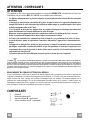
ATTENTION
Cet appareil a été conçu pour être employé en version ASPIRANTE (évacuation de l'air vers
l'extérieur) ou en version RECYCLAGE (air conduite vers l'intérieur).
- La distance minimum entre le plan de cuisson et la partie inférieure de la hotte doit être au moins
de 650mm.
- Il faut prévoir une aération convenable de la pièce lorsque la hotte et les appareils alimentés avec
énergie différente de celle éléctrique sont utilisés en même temps; la pression négative de la pièce
ne doit pas dépasser 4Pa (4x10
-5
bar).
- L'air recueillie ne doit pas être dirigée dans un conduit utilisé pour la décharge des fumées des
appareils alimentés avec énergie différente de celle éléctrique.
- Respecter les prescriptions des autorités compétentes relatives à la décharge de l'air à evacuer.
- Eviter la présence de flammes libres dans l'espace au dessous de la hotte.
- La hotte a été construite avec isolement en classe II, donc il n'y a pas besoin de la relier à la terre.
- Avant d'effectuer toutes les opérations d'entretien, débrancher l'appareil de l'alimentation éléc-
trique.
- Cet appareil ne doit pas être utilisé par des personnes (y compris les enfants) ayant des capacités
psychiques, sensorielles ou mentales réduites, ni par des personnes n’ayant pas l’expérience et la
connaissance de ce type d’appareils, à moins d'être sous le contrôle et la formation de personnes
responsables de leur sécurité.
- Les enfants doivent être surveillés pour s'assurer qu'ils ne jouent pas avec l'appareil.
Le symbole sur le produit ou son emballage indique que ce produit ne peut être traité comme déchet ménager. Il doit plutôt être
remis au point de ramassage concerné, se chargeant du recyclage du matériel électrique et électronique. En vous assurant que ce
produit est éliminé correctement, vous favorisez la prévention des conséquences négatives pour l’environnement et la santé humaine
qui, sinon, seraient le résultat d’un traitement inapproprié des déchets de ce produit. Pour obtenir plus de détails sur le recyclage de
ce produit, veuillez prendre contact avec le bureau municipal de votre région, votre service d’élimination des déchets ménagers ou le
magasin où vous avez acheté le produit.
BRANCHEMENT DU CÂBLE ÉLECTRIQUE AU RÉSEAU
Avant l’installation, vérifier que la tension du réseau indiquée sur la plaquette se trouvant à l’intérieur de
l’appareil correspond à la tension électrique de votre habitation. Si la hotte n’est pas munie de fiche élec-
trique, monter une fiche à norme sur le câble d’alimentation qui soit adaptée à la tension indiquée sur la
plaquette des caractéristiques. En cas de branchement électrique direct sur le réseau, il faudra placer un
interrupteur omnipolaire entre l’appareil et le réseau ayant une ouverture minimum entre les contacts de 3
mm, et adapté à la tension et répondant aux normes en vigueur.
COMPOSANTS
- 2 brides C
- 1 bride de réduction G
- 1 raccord filtrant H (optionnel)
- 2 filtres charbon actif L (optionnel)

FR
1
5
15
INSTALLATION
La hotte doit être assemblée au centre du plan de cuisson. La distance minimum entre le plan
de cuisson et la surface inférieure de la hotte doit être de 650mm.
Pour l'assemblage de la hotte procéder de la manière suivante:
1)Faire n°6 trous (X1-X2-J) de 8mm respectant les chiffres indiqués à la fig. 1.
2) Pour les différents assemblages utiliser les vis et les vis tamponnées fournies..
3) Bloquer l'étrier C (fig. 2) à la paroi dans les trous X1-X2.
4) Fixer la hotte à la paroi dans les trous J1 et J2 (fig. 3) .
5) Assemblage ASPIRANTE ou FILTRANT.
ASPIRANTE
En cas d’installation en version aspirante, brancher la hotte à la tuyauterie de sortie via un tube
rigide ou flexible de ø 150 ou 120 mm, au choix de l’installateur.
- En cas de branchement avec un tube de ø120 mm, insérer le flasque de réduction 9 sur la
sortie du corps de la hotte.
- Fixer le tube par des colliers appropriés. Le matériau nécessaire n’est pas fourni.
- Retirer les éventuels filtres anti-odeur au charbon actif.
FILTRANT (OPTION)
- Insérer le Raccord Sortie Air H (fig. 6).
- Assembler les filtres charbon actif L (fig. 7) en les centrant dans le support moteur M et
les bloquer en tournant dans sens horaire (environ 10°) jusqu'à l'arret. Pour les opérations
de démontage faire les opérations inverses.
6) Fixer la cheminée supérieure A (fig. 8) à l'étrier C (fig. 2/fig. 8) utilisant 4 vis autotarau-
deuses de Ø 2,9mm en dotation. La distance entre les alésages de fixation X1 et X2 est dé-
terminée par la hauteur de la cheminée supérieure H.
7) Appliquer frontalement la cheminée inférieure B (fig. 9) en élargissant légèrement les deux
parties latérales et l'insérer ensuite dans la hotte (fig. 9).

FR
1
6
16
UTILISATION - ENTRETIEN
UTILISATION
Nous vous recommandons de faire fonctionner l'appareil quelque temps avant de procéder à la
cuisson de n'importe quel aliment, de le laisser fonctionner encore pendant 15 minutes après la
cuisson et de toute manière tant que les odeurs n'auront pas disparu.
1) Bandeau de commandes avec interrupteurs (Fig.11)
- Un interrupteur qui commande l'allumage de l'installation d'éclairage.
- Un interrupteur pour commuter les trois vitesses d'exercice.
- Un voyant général de signalisation moteur en service.
ENTRETIEN
N.B. Pour n'importe quelle opération d'entretien et de réparation débranchez l'appareil.
1. Eclairage
Lampes à incandescence de 40 W (Fig.10)
• Retirer les filtres anti-graisse métalliques.
• Dévisser les lampes et les remplacer par de nouvelles avec les mêmes caractéristiques.
• Remonter les filtres anti-graisse métalliques.
2. Filtres
A des intervalles plus ou moins fréquents en fonction de leur utilisation, mais en tout cas
une fois tous les 2 mois, les filtres métalliques doivent être lavés dans le lave-vaisselle ou à
la main dans de l'eau tiède savonneuse (les filtres au charbon actif ne doivent jamais etre
lavés et doivent être remplacés tous les 2 mois).
3. Nettoyage
Pour ce qui concerne le nettoyage externe de la hotte, utiliser un chiffon humide et de l'al-
cool ou d'autres produits appropriés. N'employez pas de produits abrasifs.
IMPORTANT: Il est obligatoire d'effectuer les opérations de nettoyage de la hotte et des fil-
tres, ainsi que de les remplacer périodiquement selon nos instructions pour éviter les risques
d'incendie.
ATTENTION: Le fabricant décline toute résponsabilité pour les dommages provoqués par le
non entretien des filtres anti-graisse (nettoyage tous les 2 mois) ainsi que par le non replace-
ment périodiques des filtres à charbon et par le non respect des instructions de montage et de
branchement.

NL
1
7
17
AANWIJZINGEN - ONDERDELEN
AANWIJZINGEN
Dit apparaat werd ontworpen om zowel in AFZUIGVERSIE (luchtafvoer naar buiten) als ook
in FILTRERENDE VERSIE (recyclage van de lucht) gebruikt te worden.
- De minimumafstand tussen het kookvlak en de onderkant van de afzuigkap moet minstens
650mm zijn.
- Neem de volgende voorschriften betreffende de werking van de afzuigkap in acht wanneer de
lucht naar buiten wordt geleid. (afzuigversie)
- Er moet voor voldoende verluchting worden gezorgd wanneer de afzuigkap gelijktijdig met ande-
re niet-elektrische apparaten wordt gebruikt; de negatieve druk in het vertrek mag niet meer zijn
als 4 Pa (4x10
-5
bar).
- De verzamelde lucht mag niet in een leiding worden gevoerd die voor de afvoer van rook van niet-
elektrische apparaten dient.
- Respecteer de voorschriften van de verantwoordelijke autoriteiten betreffende de luchtafvoer
naar buiten.
- Vermijd open vlammen onder de afzuigkap.
- De afzuigkap werd in klasse 2 geïsoleerd; aarden is dus niet noodzakelijk.
- Alvorens enige onderhoudsbeurten uit te voeren, dient u het apparaat stroomloos te maken.
- Dit apparaat mag niet worden gebruikt door personen (inclusief kinderen) met beperkte psychi-
sche, sensorische en geestelijke vermogens, of door personen zonder ervaring en kennis, tenzij ze
onder toezicht staan of worden geïnstrueerd over het gebruik van het apparaat door personen die
verantwoordelijk zijn voor hun veiligheid.
- Kinderen moeten worden gecontroleerd om er zeker van te zijn dat ze niet met het apparaat spe-
len.
Het symbool op het product of op de verpakking wijst erop dat dit product niet als huishoudafval mag worden behandeld. Het
moet echter naar een plaats worden gebracht waar elektrische en elektronische apparatuur wordt gerecycled. Als u ervoor zorgt dat
dit product op de correcte manier wordt verwijderd, voorkomt u mogelijk voor mens en milieu negatieve gevolgen die zich zouden
kunnen voordoen in geval van verkeerde afvalbehandeling. Voor meer details in verband met het recyclen van dit product, neemt u
het best contact op met de gemeentelijke instanties, het bedrijf of de dienst belast met de verwijdering van huishoudafval of de winkel
waar u het product hebt gekocht.
AANSLUITEN VAN DE VOEDINGSKABEL OP HET ELEKTRICITEITSNET
Controleer voor de installatie of de netspanning die op het plaatje in het apparaat is aangegeven overeen-
stemt met de netspanning in uw woning. Indien de afzuigkap niet is uitgerust met een stekker, moet een
genormaliseerde stekker voor het vermogen dat op het gegevensplaatje is aangegeven op de kabel worden
gemonteerd. Bij een rechtstreekse elektrische aansluiting op het elektriciteitsnet moet tussen het apparaat
en het elektriciteitsnet een meerpolige schakelaar met een minimale opening tussen de contacten van 3mm
worden geplaatst. Deze schakelaar moet gedimensioneerd zijn op het vermogen en voldoen aan de gelden-
de voorschriften.
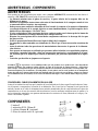
ONDERDELEN
- 2 beugels C
- 1 reduceerflens Ø 150-120mm G
- 1 Verbindingsstuk luchtuitlaat H (optie)
- 2 koolstoffilters L (optie)

NL
1
8
18
INSTALLATIE
De afzuigkap moet in het midden van het kookvlak worden gemonteerd. De afstand tussen het
kookvlak en de onderkant van de afzuigkap moet minstens 650mm zijn.
Voor de montage van de afzuigkap gaat u als volgt te werk:
1) Boor 6 gaten (X1-X2-J) Ø 8mm, gebruik makend van de afmetingen in fig. 1.
2) Voor de verschillende montages gebruikt u de meegeleverde schroeven en pluggen.
3) Bevestig de beugel C (fig. 2) aan de muur in de 4 gaten X1-X2.
4) Bevestig de afzuigkap aan de muur in de buitenste gaten J1 en J2 (fig. 3).
5) Installatie AFZUIG- of FILTRERENDE versie
AFZUIGVERSIE
Bij installatie in afzuigversie, moet u de wasemkap met de uitlaatleiding verbinden door mid-
del van een starre of buigzame leiding van ø 150 of 120 mm, naar keuze van de installateur.
• Voor verbinding met een leiding van ø120 mm, moet de reductieflens 9 op de uitlaat van
de wasemkap worden aangebracht.
• Zet de leiding vast met geschikt leidingklemmen. Het benodigde materiaal wordt niet bij
de wasemkap geleverd.
• Verwijder de eventuele geurfilters met actieve koolstof.
FILTRERENDE VERSIE
• Bevestig het filtrerende tussenschot H (fig. 6).
• Monteer de koolstoffilters L (fig. 7) centraal in de moterhouders M en blokkeer ze door ze
in wijzerzin (ongeveer 10°) te draaien tot aan de stop. Om ze te demonteren voert u de te-
gengestelde handeling uit.
6) Bevestig de hoge lange schouw A (fig. 8) aan de beugels C (fig. 2/fig. 8) met de 4 meege-
leverde schroeven Ø 2,9mm. De afstand tussen de bevestigingsopeningen X1 en X2 wordt
bepaald door de hoogte van de Verbindingsstuk luchtuitlaat H.
7) Breng de lage korte schouw B (fig. 9) aan de voorkant aan door hem zijdelings lichtjes
open te plooien en hem dan in de kap te plaatsen (fig. 9).

NL
1
9
19
GEBRUIK - ONDERHOUD
GEBRUIK
Wij adviseren het apparaat al aan te zetten voordat u voedsel gaat bereiden, en het nog 15 mi-
nuten na de bereiding te laten, of totdat alle geuren verdwenen zijn.
1) Bedieningspaneel met schakelaars (Fig.11)
- Een bedieningsschakelaar voor de verlichting.
- Een schakelaar voor instelling van de afzuigsnelheid.
- Een indicatielampje dat aangeeft dat de motor in werking is.
ONDERHOUD
N.B. Voor elke onderhoudsbeurt, reparatie of vervanging van de lampen dient het apparaat
stroomloos te worden gemaakt.
1. Verlichting (Fig.10)
Gloeilampen van 40 W
• Verwijder de metalen vetfilters.
• Schroef de lampen los en vervang ze door nieuwe lampen met dezelfde eigenschappen.
• Plaats de metalen vetfilters terug.
2. Filter
Op min of meer regelmatige tijdstippen, naar gelang het gebruik van de afzuigkap, maar
tenminste elke twee maanden, moeten de metalen filters in lauw zeepwater of in de af-
wasmachine gewassen worden. Voor u ze terug monteert moeten ze goed droog zijn (de
koolstoffilters mogen niet worden gewassen en dienen elke 2 maanden vervangen te wor-
den).
3. Reiniging
Voor de reiniging van de buitenkant van de afzuigkap gebruikt u best een vochtige doek
met alcohol of een ander geschikt product. Vermijd het gebruik van schuurmiddelen.
BELANGRIJK: Open vlammen kunnen schade veroorzaken aan de filters, vandaar is het
raadzaam geen gasbrander zonder kookpot te laten branden. Het is verplicht de maatregelen ter
reiniging van de kap of van de filters in acht te nemen, evenals hun tijdige vervanging volgens
onze voorschriften om brandgevaar te voorkomen.
OPGELET: De fabrikant is niet verantwoordelijk voor eventuele schade, ontstaan door het
niet opvolgen van bovenvermelde voorschriften i.v.m. het onderhoud van de vetfilter (elke 2
maanden wassen) of de vervanging van de koolstoffilter en het niet respecteren van de aanwij-
zingen voor montage en elektrische aansluiting.

ES
2
0
20
ADVERTENCIAS - COMPONENTES
ADVERTENCIAS
Este aparato ha sido proyectado para usarlo como campana ASPIRANTE (evacuación del aire hacia el
exterior) o FILTRANTE (reactivación del aire en el interior).
- La distancia mínima entre el plano de cocción y la parte inferior de la campana debe ser de
650mm por lo menos.
- Observar las siguientes instrucciones referentes al funcionamiento de la campana cuando el aire
es encauzado hacia el exterior. (uso aspirante)
- Debe preverse una ventilación adecuada del local cuando la campana o los aparatos alimentados
con energía diferente de la energía eléctrica se usan simultáneamente; la presión negativa de la
habitación no debe superar 4 Pa (4x10
-5
bar).
- El aire recolectado no debe encauzarse hacia un conducto usado para la descarga de los humos de
aparatos alimentados con energía diferente de la energía eléctrica.
- Respetar las prescripciones de las Autoridades competentes relativas a la descarga del aire que
hay que evacuar.
- Evitar la presencia de llamas libres en el espacio debajo de la campana.
- La campana ha sido construida con aislamiento de Clase II por lo tanto no necesita conexiones de
tierra.
- Antes de efectuar todas las operaciones de mantenimiento desconectar el aparato de la alimenta-
ción eléctrica.
- Este aparato no tiene que ser utilizado por personas (niños incluídos) con capacidades psíquicas,
sensoriales o mentales reducidas, o bien por personas sin experiencia y conocimientos en la mate-
ria, a menos que no lo hagan bajo el control, o instruídos, por personas responsables de su seguri-
dad.
- Controlar que los niños no jueguen con el aparato.
El símbolo
en el producto o en su embalaje indica que este producto no se puede tratar como desperdicios
normales del hogar. Este producto se debe entregar al punto de recolección de equipos eléctricos y electrónicos
para reciclaje. Al asegurarse de que este producto se deseche correctamente, usted ayudará a evitar posibles con-
secuencias negativas para el ambiente y la salud pública, lo cual podría ocurrir si este producto no se manipula de
forma adecuada. Para obtener información más detallada sobre el reciclaje de este producto, póngase en contacto
con la administración de su ciudad, con su servicio de desechos del hogar o con la tienda donde compró el produc-
to.
CONEXIÓN DEL CABLE DE ALIMENTACIÓN A LA RED
Antes de la instalación verificar que la tensión de la red indicada en la placa específica aplicada en el inter-
ior del aparato, corresponda a la tensión de su habitación. En el caso que la Campana no esté provista de
enchufe, montar en el cable de alimentación un enchufe normalizado para la carga indicada en la placa de
características; en el caso de conexión eléctrica directa a la red es necesario interponer entre el aparato y la
red un interruptor omnipolar con apertura mínima entre los contactos de 3mm, adecuado a la carga y con-
forme a las normas vigentes.
COMPONENTES
- 2 bridas C
- 1 reducción Ø150-120mm G
- 1 collarin filtrante H (opcional)
- 2 filtros de carbón activo L (opcional)

ES
2
1
21
INSTALACIÓN
La campana debe montarse al centro del plano de cocción. La distancia mínima entre el plano
de cocción y la superficie inferior de la campana debe ser de 650mm.
Para el montaje de la campana proceder de la manera siguiente:
1) Hacer n°6 orificios (X1-X2-J) Ø 8mm respetando las cotas indicadas en la fig. 1.
2) Para los diferentes montajes usar los tornillos y los tornillos de expansión suministrados en
dotación.
3) Bloquear los bridas C (fig. 2) a la pared en los orificios X.
5) Fijar la campana a la pared en los orificios externos J1 e J2 (fig. 3).
6) Fijar la brida de empalme E con los correspondientes tornillos autorroscantes Ø 2,9mm en
la boca de salida del aire del motor en los orificios Z predispuestos (fig. 4).
7) Montaje ASPIRANTE o FILTRANTE:
ASPIRANTE
Para la instalación de la versión aspirante, conectar la campana al tubo de salida mediante un
tubo rígido o flexible de ø150 o 120 mm, a discreción del instalador.
• Para la conexión con el tubo de ø120 mm, introducir la brida de reducción 9 en la salida
del cuerpo de la campana.
• Fijar el tubo con abrazaderas adecuadas. Este material no se proporciona en dotación.
• Quitar los filtros antiolor al carbón activo.
FILTRANTE (OPCIÓN)
- Introducir el collarin filtrante H (fig. 6).
- Montar los filtros de carbón activo L (fig. 7) y bloquearlos girando en sentido horario
(aproximadamente 10°) hasta que se acciona el tope de parada. Para desmontar efectuar las
operaciones en orden inverso.
8) Fijar la chimenea superior A (fig. 8) en los bridas C (fig. 2/fig. 8) usando n°4 tornillos au-
torroscantes Ø2,9mm suministrados en dotación. La distancia entre los orificios de fijación
X1 y X2, queda determinada por la altura de la chimenea superior H.
9) Aplicar frontalmente la chimenea inferior B (fig. 9) ensanchando ligeramente las dos par-
tes laterales y luego insertarla en la campana (fig. 9).

ES
2
2
22
USO - MANTENIMIENTO
USO
Les recomendamos hacer funcionar el aparato un poco antes de proceder a la cocción de cual-
quier alimento y dejarlo funcionar hasta 15 minutos después de la cocción, en todo caso hasta
que haya desaparecido todo el olor.
1) Tablero de mandos con interruptores (Fig.11)
- Un interruptor que manda el encendido de la instalación de iluminación.
- Un interruptor para conmutar las tres velocidades de ejercicio.
- Una luz indicadora general que señala que el motor está en función.
MANTENIMIENTO
NOTA. Antes de cualquier intervención de mantenimiento, reparación y eventual sustitución
de las lámparas, desconectar el aparato de la red eléctrica.
1. Iluminación (Fig.10)
Lámparas incandescentes de 40 W
• Quitar los filtros antigrasa metálicos, o abrir la rejilla portafiltros.
• Destornillar las lámparas y sustituirlas con nuevas que tengan las mismas características.
• Montar nuevamente los filtros antigrasa metálicos, o cerrar la rejilla portafiltros.
2. Filtros
Con intervalos más o menos frecuentes, según el uso de la campana, en todo caso una vez
cada 2 meses, los filtros metálicos deben desmontarse y lavarse con agua caliente jabono-
sa, o ser directamente lavados en lavavajillas y deben montarse nuevamente cuando están
secos (los filtros de carbón activo no deben lavarse en absoluto y deben ser sustituidos ca-
da 2 meses).
3. Limpieza
Para la limpieza externa de la campana usar un paño húmedo con alcohol o con productos
adecuados que se encuentran en el comercio. Evite usar elementos abrasivos.
IMPORTANTE: El empleo de llamas libres es dañoso para los filtros, por lo tanto se aconseja
no dejar encendido un quemador de gas sin olla. Es obligatorio limpiar la campana y los fil-
tros, además de sustituirlos periódicamente según nuestras instrucciones para evitar peligros de
incendio.
ATENCIÓN: La casa productora no responde por eventuales daños causados por la falta de
mantenimiento del filtro anti-grasa (lavado cada dos meses), sustitución del filtro carbón y por
no respetar las instrucciones de montaje y conexión eléctrica antes descritas.

PT
2
3
23
ADVERTÊNCIAS - COMPONENTES
ADVERTÊNCIAS
Este aparelho tem sido desenhado para ser utilizado como campana ASPIRANTE (evacuação
do ar para o exterior) ou FILTRANTE (reactivação do ar no interior).
- A distância mínima entre o plano de cozedura e a parte inferior da campana deve ser de 650 mm
pelo menos.
- Observar as seguintes instruções referentes ao funcionamento da campana quando o ar é evacua-
do para o exterior (uso aspirante).
- Deve se prever uma ventilação adequada do local enquanto a campana ou os aparelhos alimenta-
dos com energia diferente da energia eléctrica estão a ser utilizados simultaneamente; a pressão
negativa da habitação não deve superar 4 Pa (4x10
-5
bar).
- O ar evacuado não deve despejar-se por um conduto utilizado para a descarga de fumos de apare-
lhos alimentados com energia diferente da energia eléctrica.
- Respeitar as prescrições das autoridades competentes relativas à descarga do ar evacuado.
- Evitar a presença de chamas livres no espaço debaixo da campana.
- A campana tem sido construída com isolamento de Classe II por tanto não necessita ligação de
terra.
- Antes de efectuar todas as operações de manutenção desligar o aparelho de alimentação eléctrica.
- Este aparelho não deve ser utilizado por pessoas (incluindo crianças) diminuídas psíquica, senso-
rial ou mentalmente nem por indivíduos sem experiência e conhecimento, salvo se vigiados ou ins-
truídos para utilização do aparelho por pessoas responsáveis pela respectiva segurança.
- As crianças devem ser vigiadas no sentido de assegurar que não brinquem com o aparelho.
O símbolo no produto ou na embalagem indica que este produto não pode ser tratado como lixo doméstico.
Em vez disso, deve ser entregue ao centro de recolha selectiva para a reciclagem de equipamento eléctrico e elec-
trónico. Ao garantir uma eliminação adequada deste produto, irá ajudar a evitar eventuais consequências negati-
vas para o meio ambiente e para a saúde pública, que, de outra forma, poderiam ser provocadas por um tratamen-
to incorrecto do produto. Para obter informações mais pormenorizadas sobre a reciclagem deste produto, contacte
os serviços municipalizados locais, o centro de recolha selectiva da sua área de residência ou o estabelecimento
onde adquiriu o produto.
LIGAÇÃO DO CABO DE ALIMENTAÇÃO À REDE ELÉCTRICA
Antes da instalação, verifique se a tensão de rede indicada na placa de características aplicada no interior
do aparelho corresponde à tensão de sua casa. No caso do exaustor ser desprovido de ficha, monte no cabo
de alimentação uma ficha própria para a tensão indicada na placa de características que cumpra os regula-
mentos de lei. No caso da ligação eléctrica ser feita directamente à rede, è necessário colocar, entre o apa-
relho e a rede, um interruptor omnipolar com 3mm de abertura mínima entre os contactos que tenha capa-
cidade para a carga que deverá aguentar e que cumpra as normas em vigor.
COMPONENTES
- 2 chapas C
- 1 redutor Ø150-120 mm G
- 1 Conexão da saída de ar H (Opcional)
- 2 filtros de carvão activado L (Opcional)

PT
2
4
24
INSTALAÇÃO
A campana deve ser montada no centro em relação ao plano de cozinhar. A distância mínima
entre o plano de cozinhar e a superfície inferior da campana deve ser de 650 mm.
Para a montagem da campana proceder da seguinte maneira:
1) Fazer nº 6 furos (X1-X2-J) Ø 8 mm respeitando as medidas indicadas na fig.1.
2) Para as diferentes montagens utilizar os parafusos e tacos de expansão fornecidos em dota-
ção.
3) Sitiar as chapas C (fig.2) à parede nos orifícios X.
5) Fixar a campana à parede nos orifícios externos J1 e J2 (fig.3).
6) Fixar a chapa de junção E com os correspondentes parafusos autoroscantes Ø 2,9 mm na
boca de saída do ar do motor nos orifícios Z predispostos (fig.4).
7) Montagem ASPIRANTE ou FILTRANTE:
ASPIRANTE
Para a instalação na Versão Aspirante, ligue o exaustor ao tubo de saída utilizando um tubo
rígido ou flexível de ø150 ou 120 mm; esta escolha deve ser feita pelo instalador.
• Para a ligação com um tubo de ø120 mm, instale a flange de redução 9 na saída do corpo
do exaustor.
• Fixe o tubo com braçadeiras de aperto adequadas. O material necessário não é fornecido
com o aparelho.
• Tire os filtros anti-odor de carvão activo, se presentes..
FILTRANTE (OPÇÃO)
- Introduzir o Conexão da saída de ar H (fig.6).
- Montar os filtros de carvão activado L (fig.7) bloqueá-los girando no sentido dos ponteiros
do relógio (aproximadamente 10°) até que se accionara a paragem máxima. Para desmon-
tar efectuar as operações em ordem inverso.
8) Fixar a chaminé larga superior A (fig.8) nas chapas C (fig.2/fig.8) usando nº 4 parafusos
autoroscantes Ø 2,9 mm fornecidos em dotação. A distância entre os orifícios de fixação
X1 e X2, fica determinada pela altura da chaminé superior H.
9) Aplicar frontalmente a chaminé corta inferior B (fig.9) alargando ligeiramente as duas par-
tes laterais e logo inserir na chaminé (fig.9).

PT
2
5
25
UTILIZAÇÃO - MANUTENÇÃO
UTILIZAÇÃO
Recomendamos pôr a funcionar o aparelho um pouco antes de cozinhar qualquer alimento e
deixar funcionar até 15 minutos após o cozinhar ou, em qualquer caso, até que desapareçam
todos os odores.
1) Comandos com botões (Fig.11)
- Um botão que comanda a ligação da iluminação
- Um botão para comutar as três velocidades de funcionamento.
- Uma luz indicadora geral que indica que o motor está em funcionamento
MANUTENÇÃO
NOTA. Antes de qualquer intervenção de manutenção, reparação e eventual substituição das
lâmpadas, desligar o aparelho da rede eléctrica.
1. Iluminação
Lâmpadas incandescentes de 40 W (Fig.10)
• Tire os filtros metálicos antigordura ou abra a grade porta-filtros.
• Desatarraxe as lâmpadas e substitua-as por novas de características iguais.
• Reinstale os filtros metálicos antigordura ou feche a grade porta-filtros.
2. Filtros
Com intervalos mais ou menos frequentes, segundo a utilização da campana, em todo caso
uma vez cada 2 meses, os filtros metálicos devem desmontar-se e lavar-se com agua quen-
te com sabão ou ser directamente lavados no lava-louça e devem montar-se novamente
quando estejam secos (os filtros de carvão activado não devem lavar-se no absoluto e de-
vem ser substituídos cada 2 meses).
3. Limpeza
Para a limpeza externa da campana utilizar um pano húmido com álcool ou com produtos
adequados que se encontram à venda no comércio. Evite utilizar elementos abrasivos.
IMPORTANTE: A utilização de chamas livres pode causar danos nos filtros e por tanto
aconselhamos não deixar ligado o queimador a gás sem colocar nada por cima. É obrigatório
limpar a campana e os filtros, além de substituí-los periodicamente de acordo com as nossas
instruções para evitar perigo de incêndio.
ATENÇÃO: O fabricante não responde pelos eventuais danos causados pela falta de manu-
tenção dos filtro anti-gordura (lavar cada dois meses), substituição do filtro de carvão e por
não respeitar as instruções de montagem e ligação eléctrica antes descritas.

RU
2
6
26
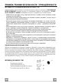
ПРАВИЛА ТЕХНИКИ БЕЗОПАСНОСТИ - ПРИНАДЛЕЖНОСТИ
ПРАВИЛА ТЕХНИКИ БЕЗОПАСНОСТИ
Данный прибор спроектирован для использования в качестве вытяжки с ВЫТЯЖНОЙ
ВЕНТИЛЯЦИЕЙ (отводом воздуха из помещения наружу) или вытяжки с РЕЖИ-
МОМ РЕЦИРКУЛЯЦИИ (очищением воздуха с возвратом в то же помещение).
- Минимальное расстояние между варочной панелью и нижней частью вытяжки должно
составлять не менее 650 мм.
- Необходимо соблюдать приведенные ниже указания по работе вытяжки с отводом воздуха
наружу (режим вытяжной вентиляции).
- Необходимо предусмотреть надлежащую вентиляцию помещения в тех случаях, когда вы-
тяжка и приборы, потребляющие энергию, отличную от электрической, используются од-
новременно; отрицательное давление в помещении не должно превышать 4 Па (4х10
-5
бар).
- Нельзя выполнять отвод воздуха через дымоходы, предназначенные для вывода паров и
газов от приборов, которые потребляют энергию, отличную от электрической.
- Необходимо соблюдать нормы коммунальных служб по отводу удаляемого воздуха.
- Следует избегать наличия открытого пламени в пространстве под вытяжкой.
- В вытяжке предусмотрена степень изоляции класса II, поэтому нет необходимости выпол-
нять заземление.
- Прежде чем выполнять какие-либо операции по техобслуживанию, необходимо отключить
прибор от электрической сети.
- Запрещается пользоваться прибором людям (и детям) с ограниченными психическими,
сенсорными и умственными способностями, а также лицам, не обладающим опытом и не-
обходимыми знаниями, без контроля и предварительного обучения пользованием прибора
со стороны ответственных за их безопасность лиц.
- Дети должны находиться под надзором взрослых и не играть с прибором.
ПОДКЛЮЧЕНИЕ КАБЕЛЯ ПИТАНИЯ К СЕТИ
Прежде чем произвести установку вытяжки, проверьте соответствие напряжения, ука-
занного на специальной табличке внутри прибора, напряжению сети вашей квартиры.
Если на вытяжке отс утствует вилка, установите на кабеле питания стандартную вилку,
соответствующую указанному на табличке характеристик напряжению. В случае прямо-
го подключения прибора к сети между ним и сетью необходимо установить многопо-
люсный выключатель с минимальным разведением контактов 3 мм. Выключатель дол-
жен выдерживать нагрузку сети и соответствовать действующим нормам.
ПРИНАДЛЕЖНОСТИ
- 2 крепежные скобы C
- 1 переходной фланец G
- 1 фильтрующий штуцер H (по заказу)
- 2 угольных фильтра L (по заказу)

RU
2
7
27
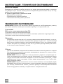
УСТАНОВКА
Вытяжка должна быть установлена над центром варочной панели. Минимальное рас-
стояние между варочной панелью и нижней частью вытяжки должно составлять не ме-
нее 650 мм.
Для монтажа вытяжки необходимо выполнить описанные ниже действия.
1) Просверлить 6 отверстий (X1-X2-J) Ø 8 мм, соблюдая размеры, указанные на Рис. 1.
2) Для монтажа воспользоваться винтами и дюбелями, поставляемыми в комплекте.
3) Закрепить скобы C (Рис. 2) на стене в отверстиях X1-X2.
4) Закрепить вытяжку на стене во внешних отверстиях J1 и J2 (Рис. 3).
5) Смонтировать исполнение с ВЫТЯЖНОЙ ВЕНТИЛЯЦИЕЙ или РЕЖИМОМ
РЕЦИРКУЛЯЦИИ
• ВЫТЯЖНАЯ ВЕНТИЛЯЦИЯ
Для установки исполнения с вытяжной вентиляцией подсоединить вытяжку к отводя-
щим трубам посредством жесткой или гибкой трубы ø150 или 120 мм (на усмотрение
лица, выполняющего установку).
• При подсоединении посредством трубы ø120 мм вставить переходной фланец 9 в
выпускное отверстие корпуса вытяжки.
• Закрепить трубу соответствующими трубными зажимами. Необходимые для этого
детали не входят в комплект поставки.
• Снять, если имеются, угольные фильтры, предотвращающие появление запахов.
• ИСПОЛНЕНИЕ С РЕЖИМОМ РЕЦИРКУЛЯЦИИ (ПО ЗАКАЗУ)
- Вставить фильтрующий штуцер H (Рис. 6).
- Установить угольные фильтры L (Рис. 7) и закрепить их, повернув по часовой
стрелке (около 10°) до щелчка. Для демонтажа выполнить указанные действия в об-
ратной последовательности.
Монтаж дымоходов
6) Закрепить верхний дымоход A (Рис. 8) на скобах C (Рис. 2/Рис. 8), пользуясь 4 само-
нарезающими винтами Ø2,9 мм, поставляемыми в комплекте. Расстояние между
крепежными отверстиями X1 и X2 определяется высотой верхнего дымохода H.
7) Приложить спереди нижний дымоход B (Рис. 9), раздвинув немного две боковые
стороны, и вставить его затем в вытяжку (Рис. 9).

RU
2
8
28
ЭКСПЛУАТАЦИЯ - ТЕХНИЧЕСКОЕ ОБСЛУЖИВАНИЕ
КСПЛУАТАЦИЯ
Рекомендуется включать прибор незадолго до начала приготовления пищи и оставлять
его работать еще в течение 15 минут после завершения приготовления или до тех пор,
пока не будут устранены запахи.
1) Панель управления с выключателями
- Выключатель освещения.
- Переключатель скоростей работы
- Сигнальная лампочка работы двигателя
ТЕХНИЧЕСКОЕ ОБСЛУЖИВАНИЕ
ВНИМАНИЕ! Прежде чем выполнять любые операции по техобслуживанию, ремонту
или замене лампочек, необходимо отключить прибор от электрической сети.
1. Освещение
40 Вт света лампы накаливания (рис.10):
• удаление смазки металлических фильтров.
• Отвинтите лампочек и заменить их новыми, имеющих одинаковые характеристики.
• Замените смазка металлических фильтров.
2. Фильтры
Необходимо достаточно часто (с учетом режима использования вытяжки), но не ре-
же раза в 2 месяца, снимать металлические фильтры и мыть их в теплой мыльной
воде или же непосредственно в посудомоечной машине. После этого фильтры необ-
ходимо высушить и установить на свое место (угольные фильтры никогда не моют-
ся; их следует менять каждые 2 месяца).
3. Чистка
Для чистки внешних поверхностей вытяжки пользоваться мягкой тканью со спиртом
или другими подходящими средствами, имеющимися в продаже. Не следует пользо-
ваться абразивными составами.
ВНИМАНИЕ! Наличие открытого огня п редставляет опасность для фильтров, по-
этому не рекомендуется оставлять горелку включенной без установленной сверху
посуды. Необходимо выполнять операции по чистке вытяжки и фильтров, а также
периодическую замену последних, следуя нашим инструкциям с тем, чтобы избе-
жать опасности пожара.
ВНИМАНИЕ! Фирма-изготовитель не несет ответственности за возможный ущерб,
возникший в результате недостаточного ухода за жировым фильтром (мойка каждые
два месяца), невыполнения замены угольного фильтра и несоблюдения описанных
выше инструкций по монтажу и подключению к электрической сети.

X
X1
J
1
2
C
X2
H
J
1
2
600
700
900
290
15
H
J
X1
A
B
275
180
==
X2
180
180
==
==
J
C
1
2
3
45
G
750 min
1050 max

6
7
8
9
10
B
H
H
L
L
M
11
1
0
1
0
2
3
L
M

www.electrolux.com
436003948_03 - 081008
-
 1
1
-
 2
2
-
 3
3
-
 4
4
-
 5
5
-
 6
6
-
 7
7
-
 8
8
-
 9
9
-
 10
10
-
 11
11
-
 12
12
-
 13
13
-
 14
14
-
 15
15
-
 16
16
-
 17
17
-
 18
18
-
 19
19
-
 20
20
-
 21
21
-
 22
22
-
 23
23
-
 24
24
-
 25
25
-
 26
26
-
 27
27
-
 28
28
-
 29
29
-
 30
30
-
 31
31
-
 32
32


Zanussi zhc 6141 x Handleiding
- Categorie
- Afzuigkappen
- Type
- Handleiding
in andere talen
- English: Zanussi zhc 6141 x User manual
- français: Zanussi zhc 6141 x Manuel utilisateur
- español: Zanussi zhc 6141 x Manual de usuario
- Deutsch: Zanussi zhc 6141 x Benutzerhandbuch
- português: Zanussi zhc 6141 x Manual do usuário

