Pagina wordt geladen...
Pagina wordt geladen...
Pagina wordt geladen...

11
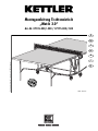
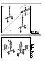
Checkliste (Packungsinhalt)
Checklist (contents of packaging)
Liste de vérification (contenu de l’emballage)
Checklijst (verpakkingsinhoud)
Lista de control (contenido del paquete)
Lista di controllo (contenuto del pacco)
Lista kontrolna (zawartość opakowania)
GB
F
NL
E
I
PL
2x
4x
4xM6x60
8x
20xM6
2x
26x
18x
2x
2x
8x 3,9x13
2 x
2x M6x37
2x M6x30
4x
8x
2x
2x
2x
2x
1x
2x
8x
4x
2x
2x
2x2x
2x
4xM8x45
4x M6x25
4xM6x49
4x
4x
07175-000
07175-500
2x
07135-000
07135-500
2x
2x 4,8x25
4x
2x
26x19x6
2x
ø12x6
ø25
1x
4x
ø25
SW13
07175-000
SW10
2x1x 2x
Sie benötigen zusätzlich folgendes Werkzeug (Gehört nicht zum Lieferumfang):
You also need the following tools (Not included):
Vous avez besoin de cet util en complément (con compris dans la livraison)
U heeft tevens volgend gereedschap nodig (Is niet in de levering ingesloten):
Usted necesita adicionalmente la siguiente herramienta (no pertenece al volumen de suministro):
Per eseguire il montaggio, Vi occorre il seguente attrezzo (non è incluso nel volume di fornitura):
Dodatkowo potrzebne są następujące narzędzia (nie objęte zakresem dostawy):
PL
I
E
NL
F
GB
D
Messhilfe für Verschraubungsmaterial
Measuring help for screw connections
Gabarit pour système de serrage
Meethulp voor schroefmateriaal
Ayuda para la medición del material de atornilladura
Misura per materiale di avvitamento
Wzornik do połączeń śrubowych
GB
F
NL
E
I
PL
Pagina wordt geladen...

13
3
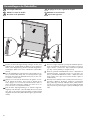
2x
M8x45
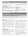
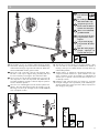
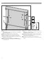
Verschrauben Sie nun ein seitliches Verbindungsrohr mit den
Seitenteilen. Achtung: dieses Rohr wird nur zur Stabilisierung
während der Montage eingesetzt und muß beim Anbau der
zweiten Plattenhälfte wieder gelöst werden!
Now bolt a side connecting rod to the side elements. Note:
This bar is used only for support during assembly and must
be removed when positioning the other half of the table.
Visser ensuite un tube de liaison latérale avec les pièces de
côté. Important: ce tube sert uniquement à la stabilisation de
l’ensemble pendant le montage et doit être déposé quand on
monte le deuxième plateau.
Schroef nu een verbindingsbuis aan de andere zijdelen vast.
Attentie: deze buis dient alleen tijdens de montage voor sta-
bilisering en moet bij de montage van de tweede bladhelft
weer verwijderd worden!
F
GB
D
NL
Atornille ahora un tubo lateral con las partes laterales. ¡Aten-
ción: este tubo se usa sólo para la estabilización durante el
montaje y tiene que ser soltado durante el montaje de la seg-
unda media plancha!
Avvitare adesso un tubolare di collegamento laterale con i
componenti laterali. Attenzione: questo tubolare viene utili-
zzato unicamente in fase di montaggio per stabilizzare la
struttura, per cui quando si monta il secondo semipiano esso
va daccapo svitato!
Przykręcić tylko jedną boczną rurę łączącą z częściami
bocznymi. Uwaga: rura ta potrzebna jest do stabilizacji po-
dczas montażu i musi zostać ponownie odkręcona przy mon-
tażu drugiej połowy płyty!
I
E
PL
2x
ø12
2x
M6
2x
M6x50
2x
SFL 14
nur für wetter-
feste Tischtennis-
tische
for weatherproof
table-tennis tables only
uniquement pour les ta-
bles de tennis de table ré-
sistantes aux intempéries
alleen voor weerbestendi-
ge tafeltennistafels
sólo para mesas de ping-
pong resistentes a la in-
temperie
solo per tavoli da ping-
pong resistenti alle intem-
perie
Tylko dla stołów pingpon-
gowych odpornych na
warunki atmosferyczne.
GB
D
F
NL
E
I
PL
2x
Pagina wordt geladen...

15
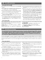
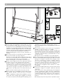
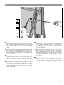
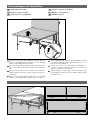
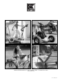
B: Die Streben des Tragrahmens müssen hierbei ein wenig
zur Seite gebogen werden; gehen Sie hierbei vorsichtig vor!
C: Setzen Sie nun eine Plattenhälfte auf. Sichern Sie die Plat-
tenhälfte für die folgenden Montageschritte unbedingt gegen
Abrutschen und/oder Umkippen! Lassen Sie von einer zwei-
ten Person auf jeder Seite die Schubstrebe und die Tragrah-
menstrebe auf das letzte Verbindungsrohr aufschieben.
D: Das Verbindungsrohr wird nun mit den Seitenteilen ver-
schraubt.
B: To do this, the braces for the frame must be bent slightly to
the side. Proceed with care when doing this.
C: Position one of the table halves and ensure that it cannot
slip or tilt over. Ask another person to attach the push bar and
the support-frame brace to the last connecting bar.
D: The connecting bar is now bolted to the side elements.
B: Pour cela les jambes de forces du cadre porteur doivent
être pliées un peu de côté; pratiquer là avec précaution.
C: Poser un plateau. Il est absolument nécessaire de sécuriser
les plateaux pour les opérations de montage qui suivront, afin
qu’ils ne puissent ni glisser ni se renverser. Demander à une
autre personne de glisser de chaque côté l’entretoise et la
jambe de force du cadre porteur sur le dernier tube de jonc-
tion.
D: Visser ensuite le tube de jonction aux pièces de côté.
B: De stangen van het draagframe moeten hierbij aan de
kant enigszins gebogen worden; ga bierbij voorzichtig te
werk!
C: Stel een bladhelft op. Blokkeer deze bladhelft voor het vol-
gende deel van de montage tegen wegglijden en/of kante-
len. Laat een volwassene aan elke zijde de schuifstang en het
NL
F
GB
D
draagframe over de laatste verbindinggsbuis schuiven.
D: De verbindingsbuis moet nu aan de zijdelen worden vast-
geschroefd.
B: Los puntales del marco soporte tienen que ser ligeramente
doblados; ¡ejecute este proceso con cuidado!
C: Ponga la mitad de la plancha. ¡Asegure la mitad de la
plancha para los próximos pasos de montaje contra desliza-
miento y/o vuelco! Deje que una segunda persona empuje a
cada lado el puntal de empuje y el puntal del marco en el úl-
timo tubo de unión.
D: El tubo de unión es atornillado con las partes laterales.
B: A questo proposito è necessario piegare leggermente verso
il lato i montanti della staffa di supporto; procedere con cautela!
C: Dispore un semipiano. Assicurarsi che il semipiano sia fis-
sato bene, in modo da non scivolare o ribaltarsi durante le
fasi successive di montaggio! Da una seconda persona far
posizionare i sostegni scorrevoli su ciascun lato e il sostegno
del telaio portante sull’ultimo tubolare di collegamento.
D: Il tubolare di collegamento adesso avvitato con i compo-
nenti laterali.
B: Poprzeczki pałąka podporowego muszą zostać przy tym
nieznacznie rozgięte na zewnątrz. Zachować przy tym
ostrożność!
C: Po jednej stronie ułożyć połówkę płyty. Dla następnych
operacji montażowych należy koniecznie zabezpieczyć
połówkę płyty przed ześlizgnięciem się i/lub przewróceniem
się! Poprosić drugą osobę o nasunięcie po obu stronach po-
pychaczy ukośnych i podpór ukośnych ramy na ostatnią rurę
łączącą.
D: ura łącząca skręcona zostaje teraz z częściami bocznymi.
I
E
PL
6
2x
4x
M8x45
26x19x6 mm
A
B
C
D
D

16
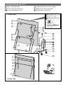
7
M6x60
1x
2x
M6x37
2x
4x
2x
3x
2x
A
B
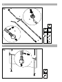
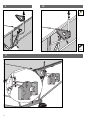
A: Verschrauben Sie die linke Schubstrebe mit dem Tragrah-
men.
B: Verschrauben Sie die rechte Schubstrebe mit Standsiche-
rung mit dem Tragrahmen.
A: Bolt the left-hand push bar to the support frame.
B: Bolt the right-hand push bar (with lock) to the frame.
A: Visser la jambe de force de gauche au cadre porteur.
B: Visser au cadre porteur la jambe de force de droite avec
stabilisation au renversement.
A: Schroef de linker schuifstang op het draagframe vast.
B: Schroef de rechter schuifstang aan de standbeveiliging op
het draagframe vast.
F
GB
D
NL
A: Atornille el puntal de empuje izquierdo con el marco so-
porte.
B: Atornille el puntal de empuje derecho con seguro de la
estabilidad con el marco soporte.
A: Avvitare al telaio portante il sostegno scorrevole sinistro.
B: Avvitare al telaio portante il sostegno scorrevole destro as-
sieme al dispositivo stabilizzatore.
A: Skręcić lewy popychacz ukośny z ramą nośną.
B: Przykręcić prawy popychacz ukośny z podporą do ramy
nośnej.
I
E
PL

17
8
M6x49
2x
Verschrauben Sie die Kippsicherung mit Feststeller auf der lin-
ken Plattenseite. Rechts wird ebenso verfahren. Lösen Sie nun
das vormontierte Verbindungsrohr auf der anderen Seite und
führen Sie die Schritte 4 bis 8 für die zweite Plattenhälfte
durch. Denken Sie auch hier wieder an die Sicherung der
Platte!
Bolt the anti-tilt device with lock to the left-hand side of the ta-
ble. Repeat this for the right-hand side. Now remove the tem-
porary bar from the other side and carry out steps 4 – 8 for
the second half of the table. Again, ensure that the table can-
not slip or tilt over!
Visser du côté gauche du plateau, la sécurité au renverse-
ment avec dispositif de fixation. Procéder de même à droite.
Enlever alors le tube de jonction prémonté de l’autre côté et
effectuer les opérations 4 à 8 pour la deuxième moitié de ta-
ble. Là non plus, ne pas oublier la sécurisation du plateau.
Schroef de kiepvergrendeling met vergrendeling op de linker
bladhelft vast. Rechts dient u hetzelfde te werk de gaan.
Schroef nu de voorgemonteerde verbindingsbuis aan de an-
dere kant los en voer de montagestappen 4 tot 8 voor de
tweede bladhelft uit. Denk ook hierbij weer aan de vergren-
deling van het blad!
NL
F
GB
D
Atornille el seguro contra vuelco con encastramiento en el
lado izquierdo de la plancha. Proceda de la misma forma en
el lado derecho. Suelto ahora el tubo de unión premontado
en el lado opuesto y ejecute los pasos 4 a 8 para la segun-
da mitad de la plancha.¡Piense también aquí que tiene que
asegurar la plancha!
Avvitare il pulsante antiribaltamento con la levetta di fis-
saggio sul lato sinistro del piano. Procedere allo stesso modo
anche a destra. Svitare adesso il tubolare di collegamento
precedentemente montato sull’altro lato, e ripetere le opera-
zioni da 4 a 8 anche per il sesondo semipiano. Anche in
questa fase operativa fare attenzione a fissare e assicurare
bene il piano!
Skręcić zabezpieczenie przed przewrotem z ustalaczem po
lewej stronie blatu. Tak samo postąpić po prawej stronie.
Teraz zwolnić premontowaną rurę łączącą po drugiej stronie
i wykonać kroki 4 do 8 dla drugiej połowy blatu. Także i tu
należy pamiętać o zabezpieczeniu blatu!
PL
I
E
Pagina wordt geladen...

19
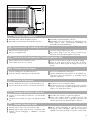
1 Slide the tension pin through net.
2 Place pin in designated slots.
3 Tie tension string to plastic tension tab.
4 Place tension string in slots over tension pin and net post.
Adjust net tension by adjusting plastic tension tab.
1 Introducir la barra de la red por el borde lateral de la red.
2 Insertar la barra de la red en las escotaduras del portared.
3 Anudar el hilo tensor al artefacto plástico.
4 Introducir el hilo tensor en la barra de la red por la muesca
superior. Tensar la red encajando debidamente al artefacto
plástico en el clavillo del portared.
Montaje del portared
E
1 Passez la barre de tension à travers le filet.
2 Fixez la barre de tension sur le poteau.
1
2
3
4
3 Prenez la corde et faite un noeud sur la patte de réglage.
4 Passez la corde dans la rainure de la barre de tension.
Tendre le filet en fixant la patte de réglage sur la pointe du
poteau.
1 Netzstange durch seitliche Netzkante schieben.
2 Netzstange in Aussparungen am Netzhalter einstecken.
3 Spannfaden mit Kunststofflasche verknoten.
4 Spannfaden über obere Einkerbung in Netzstange führen.
Netz spannen durch entsprechende Einklinkung der
Kunststofflasche am Netzhalter-Dorn.
1 Schuif de netstang door de zijkant van het net.
2 Steek de netstang in uitsparingen van de nethouder.
3 Knoop het spandraad door kunststof lus.
4 Laat het spandraad via inkeping boven in de netstang lopen.
Span het net door de kunststof lus op het haakje van de
nethouder te klemmen.
Montage des Netzhalters
Instructions for Assembling the net set
GB
D
Instructions de montage pour l’ensemble poteaux-filet
F
Montage van de netpost
NL
1 Spingere la stecca della rete attraverso il bordo laterale
della rete.
2 Introdurre la stecca della rete negli incavi dell’attacco della
rete.
3 Annodare il fito tenditore e il passante di plastica.
4 Tirare il filo tenditore attraverso l’intaglio superiore nella
stecca di rete. Tendere la rete scegliendo una posizione del
passante di plastica sulla spina dell’attacco della rete.
Montaggio dell’attacco della rete
I
1 Wsunąć pręty mocujące w boczne kieszenie siatki.
2 Wetknąć pręty mocujące siatkę do nacięć w uchwytach siatki.
3 Związać sznurek naciągający z nakładką z tworzywa
sztucznego.
4 Włożyć sznurek napinający do górnego nacięcia pręta
mocującego siatkę. Naciągnąć siatkę przez zaczepienie
nakładki z tworzywa sztucznego na trzpieniu uchwytu siatki.
Montaż uchwytów siatki
PL

20
A
B
C
Herunterklappen der Plattenhälften
Lowering the table halve
Rabattre les moitiés de la table
Neerslaan van de plaathelften
Despliegue de los dos segmentos de la placa
Ribaltare le metà del tavolo
Opuszczanie płyt stołu
GB E
F
NL
I
PL
Drücken Sie die linke Kippsicherung und legen Sie den Fest-
stellknebel um. Anschließend die Platte mit einer Hand fest-
halten, rechte Kippsicherung drücken und Platte langsam her-
unterklappen (Platte unter keinen Umständen einfach fallen
lassen!).
Press the left-hand tip lock and turn the locking toggle into po-
sition. Hold the table firmly with one hand, press the right-
hand lock and lower the table-half slowly into position. Ne-
ver allow it to drop down!
Appuyer sur la sécurité de basculement de gauche et inver-
ser la manette de fixation. Tenir ensuite le plateau d’une
main, appuyer sur la sécurité de basculement de droite et
laisser descendre lentement le plateau (en aucun cas on ne
pourra le laisser tout simplement tomber).
Druk de linker kiepvergrendeling in en haal de vergrende-
lingsknop naar beneden. Houd het blad dan met een hand
vast, druk op de rechter kiepvergrendeling en klap het blad
langzaam naar beneden (laat het blad in geen geval zomaar
vallen!).
F
GB
D
NL
Presione el seguro izquierdo y vuelque la manilla de fijación.
Sujete a continuación la plancha con una mano y presione el
seguro derecho contra vuelco. Baje lentamente la plancha
(¡no deje caer la plancha por ningún motivo!).
Premiere il pulsante antiribaltamento sinistro e abbassare la
levetta di fissaggio. Sostenendo il piano con una mano, pre-
mere il pulsante antiribaltamento destro e abbassare lenta-
mente il piano stesso (per nessun motivo lasciare il piano in
caduta libera!)
Nacisnąć lewe zabezpieczenie przed przewróceniem się i
przestawić dźwignię blokującą. Następnie przytrzymać
płytę jedną ręką, nacisnąć zabezpieczenie przed przewró-
ceniem się po prawej stronie i powoli opuścić płytę (pod żad-
nym pozorem nie pozwolić płycie opaść pod własnym cięża-
rem!).
I
E
PL

21
max 1 cm = ok.
max 1 cm = ok.
max 1 cm = ok.
A
B
Zusammenklappen der Plattenhälften
Collapsing the table halves
Replier les moitiés de la table
Tesamenslaan van de plaathelften
Plegar los segmentos de las placas
Chiudere le metà del tavolo
Składanie płyt stołu
GB E
F
NL
I
PL
Drücken Sie den Hebel der Standsicherung nach oben und
heben Sie die Plattenhälfte an. Behalten Sie in der Anfangs-
phase des Hochklappens den Druck bei.
Press the locking lever up and lift the table half upwards. Con-
tinue to press the lever during the first part of the upward mo-
tion.
Pousser le levier de la sécurité vers le haut et soulever le demi-
plateau. Maintenir la pression dans la phase initiale du re-
dressement.
Druk de linker kiepvergrendeling naar boven en til de blad-
helften op. In het begin dient u hierbij druk uit te oefenen.
F
GB
D
NL
Presione la palanca de seguro de la estabilidad hacia arriba
y levante la mitad de la mesa. Mantenga la presión en la
fase inicial del levantamiento.
Premere verso l’alto la leva del dispositivo stabilizzatore e
sollevare il semipiano. Mantenere la pressione nella fase ini-
ziale del sollevamento del semipiano.
Obrócić dźwignie podpór w górę i podnieść połówkę płyty.
W początkowej fazie podnoszenia należy nadal naciskać
zabezpieczenia.
E
I
PL
Pagina wordt geladen...

23
6
11
7
1917
12
26
16
16
28
37
29
30
9
11
31
4
10
13
4
1
3
4
15 32
20
14
5
5
2
2
22
24
35
36
38
35
34
21
1
3
40
39
41
7135-000/-500
7175-000/-500
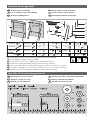
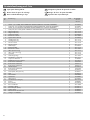
Ersatzteilzeichnung und –liste
Spare parts drawing and list
Dessin et liste des pièces de rechange
Reserveonderdeeltekening en -lijst
Designación y lista de las piezas de recambio
Disegno ed elenco dei pezzi di ricambio
Rysunek i lista części zamiennych
GB E
F
NL
I
PL
Typenschild – Seriennummer
Type label – Serial number
Plaque signalétique – Numèro de serie
Typeplaatje – Seriennummer
Placa identificativa – Número de serie
Targhetta tecnica – Numero di serie
Tabliczka identyfikacyjna – Numer serii
HEINZ KETTLER GmbH & Co. KG
D-59469 Ense-Parsit
Art.-Nr. 07044-000
1-334 O - 1801 00001
geprüft nach prEN 14468-1, -2
Klasse C, Typ 4
Made in Germany
Pagina wordt geladen...
Documenttranscriptie
Checkliste (Packungsinhalt) GB Checklist (contents of packaging) F Liste de vérification (contenu de l’emballage) NL Checklijst (verpakkingsinhoud) E Lista de control (contenido del paquete) I Lista di controllo (contenuto del pacco) PL Lista kontrolna (zawartość opakowania) 2x 07135-000 07135-500 07175-000 07175-500 2x 1x 2x 2x 2x 2x 2x 2x 1x 2x 2x 2x 4xM8x45 4x M6x25 2x 26x ø12x6 8x 4xM6x60 2x M6x30 8x 18x ø25 4x 4xM6x49 2x M6x37 4x 8x 8x 3,9x13 2x 4x 07175-000 2x 4x 26x19x6 4x 2x 4x 2x 2x 4,8x25 2x U heeft tevens volgend gereedschap nodig (Is niet in de levering ingesloten): E Usted necesita adicionalmente la siguiente herramienta (no pertenece al volumen de suministro): I Per eseguire il montaggio, Vi occorre il seguente attrezzo (non è incluso nel volume di fornitura): PL SW13 SW10 2x 2x You also need the following tools (Not included): Vous avez besoin de cet util en complément (con compris dans la livraison) F NL 2x 2x 20xM6 Sie benötigen zusätzlich folgendes Werkzeug (Gehört nicht zum Lieferumfang): D GB 4x ø25 1x Dodatkowo potrzebne są następujące narzędzia (nie objęte zakresem dostawy): Messhilfe für Verschraubungsmaterial GB Measuring help for screw connections F Gabarit pour système de serrage NL Meethulp voor schroefmateriaal E Ayuda para la medición del material de atornilladura I Misura per materiale di avvitamento PL Wzornik do połączeń śrubowych 11 3 D nur für wetterfeste Tischtennistische 2x GB for weatherproof table-tennis tables only F uniquement pour les tables de tennis de table résistantes aux intempéries NL alleen voor weerbestendige tafeltennistafels E sólo para mesas de pingpong resistentes a la intemperie I solo per tavoli da pingpong resistenti alle intemperie PL Tylko dla stołów pingpongowych odpornych na warunki atmosferyczne. M8x45 2x D Verschrauben Sie nun ein seitliches Verbindungsrohr mit den Seitenteilen. Achtung: dieses Rohr wird nur zur Stabilisierung während der Montage eingesetzt und muß beim Anbau der zweiten Plattenhälfte wieder gelöst werden! E Atornille ahora un tubo lateral con las partes laterales. ¡Atención: este tubo se usa sólo para la estabilización durante el montaje y tiene que ser soltado durante el montaje de la segunda media plancha! GB Now bolt a side connecting rod to the side elements. Note: This bar is used only for support during assembly and must be removed when positioning the other half of the table. I F Visser ensuite un tube de liaison latérale avec les pièces de côté. Important: ce tube sert uniquement à la stabilisation de l’ensemble pendant le montage et doit être déposé quand on monte le deuxième plateau. Avvitare adesso un tubolare di collegamento laterale con i componenti laterali. Attenzione: questo tubolare viene utilizzato unicamente in fase di montaggio per stabilizzare la struttura, per cui quando si monta il secondo semipiano esso va daccapo svitato! PL Przykręcić tylko jedną boczną rurę łączącą z częściami bocznymi. Uwaga: rura ta potrzebna jest do stabilizacji podczas montażu i musi zostać ponownie odkręcona przy montażu drugiej połowy płyty! NL Schroef nu een verbindingsbuis aan de andere zijdelen vast. Attentie: deze buis dient alleen tijdens de montage voor stabilisering en moet bij de montage van de tweede bladhelft weer verwijderd worden! 2x M6x50 2x SFL 14 2x ø12 2x M6 13 6 D D M8x45 2x 4x 26x19x6 mm A B C D GB F NL B: Die Streben des Tragrahmens müssen hierbei ein wenig zur Seite gebogen werden; gehen Sie hierbei vorsichtig vor! C: Setzen Sie nun eine Plattenhälfte auf. Sichern Sie die Plattenhälfte für die folgenden Montageschritte unbedingt gegen Abrutschen und/oder Umkippen! Lassen Sie von einer zweiten Person auf jeder Seite die Schubstrebe und die Tragrahmenstrebe auf das letzte Verbindungsrohr aufschieben. D: Das Verbindungsrohr wird nun mit den Seitenteilen verschraubt. B: To do this, the braces for the frame must be bent slightly to the side. Proceed with care when doing this. C: Position one of the table halves and ensure that it cannot slip or tilt over. Ask another person to attach the push bar and the support-frame brace to the last connecting bar. D: The connecting bar is now bolted to the side elements. B: Pour cela les jambes de forces du cadre porteur doivent être pliées un peu de côté; pratiquer là avec précaution. C: Poser un plateau. Il est absolument nécessaire de sécuriser les plateaux pour les opérations de montage qui suivront, afin qu’ils ne puissent ni glisser ni se renverser. Demander à une autre personne de glisser de chaque côté l’entretoise et la jambe de force du cadre porteur sur le dernier tube de jonction. D: Visser ensuite le tube de jonction aux pièces de côté. B: De stangen van het draagframe moeten hierbij aan de kant enigszins gebogen worden; ga bierbij voorzichtig te werk! C: Stel een bladhelft op. Blokkeer deze bladhelft voor het volgende deel van de montage tegen wegglijden en/of kantelen. Laat een volwassene aan elke zijde de schuifstang en het draagframe over de laatste verbindinggsbuis schuiven. D: De verbindingsbuis moet nu aan de zijdelen worden vastgeschroefd. E B: Los puntales del marco soporte tienen que ser ligeramente doblados; ¡ejecute este proceso con cuidado! C: Ponga la mitad de la plancha. ¡Asegure la mitad de la plancha para los próximos pasos de montaje contra deslizamiento y/o vuelco! Deje que una segunda persona empuje a cada lado el puntal de empuje y el puntal del marco en el último tubo de unión. D: El tubo de unión es atornillado con las partes laterales. I B: A questo proposito è necessario piegare leggermente verso il lato i montanti della staffa di supporto; procedere con cautela! C: Dispore un semipiano. Assicurarsi che il semipiano sia fissato bene, in modo da non scivolare o ribaltarsi durante le fasi successive di montaggio! Da una seconda persona far posizionare i sostegni scorrevoli su ciascun lato e il sostegno del telaio portante sull’ultimo tubolare di collegamento. D: Il tubolare di collegamento adesso avvitato con i componenti laterali. PL B: Poprzeczki pałąka podporowego muszą zostać przy tym nieznacznie rozgięte na zewnątrz. Zachować przy tym ostrożność! C: Po jednej stronie ułożyć połówkę płyty. Dla następnych operacji montażowych należy koniecznie zabezpieczyć połówkę płyty przed ześlizgnięciem się i/lub przewróceniem się! Poprosić drugą osobę o nasunięcie po obu stronach popychaczy ukośnych i podpór ukośnych ramy na ostatnią rurę łączącą. D: ura łącząca skręcona zostaje teraz z częściami bocznymi. 15 7 A B M6x60 4x 2x M6x37 1x 2x D GB F NL 16 2x 3x 2x A: Verschrauben Sie die linke Schubstrebe mit dem Tragrahmen. B: Verschrauben Sie die rechte Schubstrebe mit Standsicherung mit dem Tragrahmen. E A: Atornille el puntal de empuje izquierdo con el marco soporte. B: Atornille el puntal de empuje derecho con seguro de la estabilidad con el marco soporte. A: Bolt the left-hand push bar to the support frame. B: Bolt the right-hand push bar (with lock) to the frame. I A: Avvitare al telaio portante il sostegno scorrevole sinistro. B: Avvitare al telaio portante il sostegno scorrevole destro assieme al dispositivo stabilizzatore. PL A: Skręcić lewy popychacz ukośny z ramą nośną. B: Przykręcić prawy popychacz ukośny z podporą do ramy nośnej. A: Visser la jambe de force de gauche au cadre porteur. B: Visser au cadre porteur la jambe de force de droite avec stabilisation au renversement. A: Schroef de linker schuifstang op het draagframe vast. B: Schroef de rechter schuifstang aan de standbeveiliging op het draagframe vast. 8 M6x49 2x D Verschrauben Sie die Kippsicherung mit Feststeller auf der linken Plattenseite. Rechts wird ebenso verfahren. Lösen Sie nun das vormontierte Verbindungsrohr auf der anderen Seite und führen Sie die Schritte 4 bis 8 für die zweite Plattenhälfte durch. Denken Sie auch hier wieder an die Sicherung der Platte! E Atornille el seguro contra vuelco con encastramiento en el lado izquierdo de la plancha. Proceda de la misma forma en el lado derecho. Suelto ahora el tubo de unión premontado en el lado opuesto y ejecute los pasos 4 a 8 para la segunda mitad de la plancha.¡Piense también aquí que tiene que asegurar la plancha! GB Bolt the anti-tilt device with lock to the left-hand side of the table. Repeat this for the right-hand side. Now remove the temporary bar from the other side and carry out steps 4 – 8 for the second half of the table. Again, ensure that the table cannot slip or tilt over! I F Visser du côté gauche du plateau, la sécurité au renversement avec dispositif de fixation. Procéder de même à droite. Enlever alors le tube de jonction prémonté de l’autre côté et effectuer les opérations 4 à 8 pour la deuxième moitié de table. Là non plus, ne pas oublier la sécurisation du plateau. Avvitare il pulsante antiribaltamento con la levetta di fissaggio sul lato sinistro del piano. Procedere allo stesso modo anche a destra. Svitare adesso il tubolare di collegamento precedentemente montato sull’altro lato, e ripetere le operazioni da 4 a 8 anche per il sesondo semipiano. Anche in questa fase operativa fare attenzione a fissare e assicurare bene il piano! PL Skręcić zabezpieczenie przed przewrotem z ustalaczem po lewej stronie blatu. Tak samo postąpić po prawej stronie. Teraz zwolnić premontowaną rurę łączącą po drugiej stronie i wykonać kroki 4 do 8 dla drugiej połowy blatu. Także i tu należy pamiętać o zabezpieczeniu blatu! NL Schroef de kiepvergrendeling met vergrendeling op de linker bladhelft vast. Rechts dient u hetzelfde te werk de gaan. Schroef nu de voorgemonteerde verbindingsbuis aan de andere kant los en voer de montagestappen 4 tot 8 voor de tweede bladhelft uit. Denk ook hierbij weer aan de vergrendeling van het blad! 17 1 2 3 4 D Montage des Netzhalters 1 Netzstange durch seitliche Netzkante schieben. 3 Spannfaden mit Kunststofflasche verknoten. 2 Netzstange in Aussparungen am Netzhalter einstecken. 4 Spannfaden über obere Einkerbung in Netzstange führen. Netz spannen durch entsprechende Einklinkung der Kunststofflasche am Netzhalter-Dorn. GB Instructions for Assembling the net set 1 Slide the tension pin through net. 3 Tie tension string to plastic tension tab. 2 Place pin in designated slots. 4 Place tension string in slots over tension pin and net post. Adjust net tension by adjusting plastic tension tab. F Instructions de montage pour l’ensemble poteaux-filet 1 Passez la barre de tension à travers le filet. 3 Prenez la corde et faite un noeud sur la patte de réglage. 2 Fixez la barre de tension sur le poteau. 4 Passez la corde dans la rainure de la barre de tension. Tendre le filet en fixant la patte de réglage sur la pointe du poteau. NL Montage van de netpost 1 Schuif de netstang door de zijkant van het net. 3 Knoop het spandraad door kunststof lus. 2 Steek de netstang in uitsparingen van de nethouder. 4 Laat het spandraad via inkeping boven in de netstang lopen. Span het net door de kunststof lus op het haakje van de nethouder te klemmen. E Montaje del portared 1 Introducir la barra de la red por el borde lateral de la red. 3 Anudar el hilo tensor al artefacto plástico. 2 Insertar la barra de la red en las escotaduras del portared. 4 Introducir el hilo tensor en la barra de la red por la muesca superior. Tensar la red encajando debidamente al artefacto plástico en el clavillo del portared. I Montaggio dell’attacco della rete 1 Spingere la stecca della rete attraverso il bordo laterale della rete. 2 Introdurre la stecca della rete negli incavi dell’attacco della rete. PL 3 Annodare il fito tenditore e il passante di plastica. 4 Tirare il filo tenditore attraverso l’intaglio superiore nella stecca di rete. Tendere la rete scegliendo una posizione del passante di plastica sulla spina dell’attacco della rete. Montaż uchwytów siatki 1 Wsunąć pręty mocujące w boczne kieszenie siatki. 2 Wetknąć pręty mocujące siatkę do nacięć w uchwytach siatki. 3 Związać sznurek naciągający z nakładką z tworzywa sztucznego. 4 Włożyć sznurek napinający do górnego nacięcia pręta mocującego siatkę. Naciągnąć siatkę przez zaczepienie nakładki z tworzywa sztucznego na trzpieniu uchwytu siatki. 19 Herunterklappen der Plattenhälften GB Lowering the table halve F Rabattre les moitiés de la table E Despliegue de los dos segmentos de la placa I Ribaltare le metà del tavolo PL NL Neerslaan van de plaathelften Opuszczanie płyt stołu C A B D Drücken Sie die linke Kippsicherung und legen Sie den Feststellknebel um. Anschließend die Platte mit einer Hand festhalten, rechte Kippsicherung drücken und Platte langsam herunterklappen (Platte unter keinen Umständen einfach fallen lassen!). GB Press the left-hand tip lock and turn the locking toggle into position. Hold the table firmly with one hand, press the righthand lock and lower the table-half slowly into position. Never allow it to drop down! F Appuyer sur la sécurité de basculement de gauche et inverser la manette de fixation. Tenir ensuite le plateau d’une main, appuyer sur la sécurité de basculement de droite et laisser descendre lentement le plateau (en aucun cas on ne pourra le laisser tout simplement tomber). NL Druk de linker kiepvergrendeling in en haal de vergrendelingsknop naar beneden. Houd het blad dan met een hand vast, druk op de rechter kiepvergrendeling en klap het blad langzaam naar beneden (laat het blad in geen geval zomaar vallen!). 20 E Presione el seguro izquierdo y vuelque la manilla de fijación. Sujete a continuación la plancha con una mano y presione el seguro derecho contra vuelco. Baje lentamente la plancha (¡no deje caer la plancha por ningún motivo!). I Premiere il pulsante antiribaltamento sinistro e abbassare la levetta di fissaggio. Sostenendo il piano con una mano, premere il pulsante antiribaltamento destro e abbassare lentamente il piano stesso (per nessun motivo lasciare il piano in caduta libera!) PL Nacisnąć lewe zabezpieczenie przed przewróceniem się i przestawić dźwignię blokującą. Następnie przytrzymać płytę jedną ręką, nacisnąć zabezpieczenie przed przewróceniem się po prawej stronie i powoli opuścić płytę (pod żadnym pozorem nie pozwolić płycie opaść pod własnym ciężarem!). Zusammenklappen der Plattenhälften GB Collapsing the table halves E Plegar los segmentos de las placas Replier les moitiés de la table I Chiudere le metà del tavolo NL Tesamenslaan van de plaathelften PL F Składanie płyt stołu B A Drücken Sie den Hebel der Standsicherung nach oben und heben Sie die Plattenhälfte an. Behalten Sie in der Anfangsphase des Hochklappens den Druck bei. E Presione la palanca de seguro de la estabilidad hacia arriba y levante la mitad de la mesa. Mantenga la presión en la fase inicial del levantamiento. GB Press the locking lever up and lift the table half upwards. Continue to press the lever during the first part of the upward motion. I Premere verso l’alto la leva del dispositivo stabilizzatore e sollevare il semipiano. Mantenere la pressione nella fase iniziale del sollevamento del semipiano. F Pousser le levier de la sécurité vers le haut et soulever le demiplateau. Maintenir la pression dans la phase initiale du redressement. PL Obrócić dźwignie podpór w górę i podnieść połówkę płyty. W początkowej fazie podnoszenia należy nadal naciskać zabezpieczenia. NL Druk de linker kiepvergrendeling naar boven en til de bladhelften op. In het begin dient u hierbij druk uit te oefenen. max 1 cm = ok. max 1 cm = ok. max 1 cm = ok. D 21 Ersatzteilzeichnung und –liste GB Spare parts drawing and list F Dessin et liste des pièces de rechange E Designación y lista de las piezas de recambio I Disegno ed elenco dei pezzi di ricambio PL NL Reserveonderdeeltekening en -lijst Rysunek i lista części zamiennych Typenschild – Seriennummer Type label – Serial number Plaque signalétique – Numèro de serie Typeplaatje – Seriennummer Placa identificativa – Número de serie Targhetta tecnica – Numero di serie Tabliczka identyfikacyjna – Numer serii 7135-000/-500 1 HEINZ KETTLER GmbH & Co. KG D-59469 Ense-Parsit 4 Art.-Nr. 07044-000 1-334 O - 1801 00001 geprüft nach prEN 14468-1, -2 Klasse C, Typ 4 Made in Germany 2 22 13 20 21 38 3 24 36 10 26 5 31 39 15 11 32 12 17 35 14 6 19 34 40 7 16 9 4 2 4 41 5 3 28 29 37 30 35 1 7175-000/-500 23-
 1
1
-
 2
2
-
 3
3
-
 4
4
-
 5
5
-
 6
6
-
 7
7
-
 8
8
-
 9
9
-
 10
10
-
 11
11
-
 12
12
-
 13
13
-
 14
14
-
 15
15
-
 16
16
-
 17
17


in andere talen
- English: Kettler 7135-500 User manual
- italiano: Kettler 7135-500 Manuale utente
- français: Kettler 7135-500 Manuel utilisateur
- español: Kettler 7135-500 Manual de usuario
- Deutsch: Kettler 7135-500 Benutzerhandbuch
- polski: Kettler 7135-500 Instrukcja obsługi
Gerelateerde papieren
-
Kettler CHAMP 5.0 Handleiding
-
-
-
-
-
-
-
-
-