Yamaha DTLK9 Handleiding
- Categorie
- Muziekinstrumenten
- Type
- Handleiding
Deze handleiding is ook geschikt voor

Before using, please read this “Owner’s Manual” sheet, and
use this product in a safe and proper manner.
Especially for children, parents or an instructor should teach
the children the proper manner in which to use the device.
* After reading this Owner’s Manual, please keep it in a place where it
can be accessed by the user at anytime.
PRECAUTIONS
Caution (including danger, or warning). This mark
indicates cautions in which you should pay close
attention to.
Acts indicated with this icon are prohibited and
should not be attempted.
To prevent against accidents and injury
Please follow the cautions listed below
Do not place the rack stand (RS40) on an unstable surface when the pads are attached.
Watch your hands, fingers, feet, etc., when assembling the product system or attaching the pads to the rack system (RS40). They can become
pinched between parts causing injury.
If this symbol is ignored and the equipment is used improperly, fatal injury to persons or serious
damage could occur.
WARNING
CAUTION
If this symbol is ignored and the equipment is used improperly, there is a danger of injury to
persons handling the equipment, and material damage could occur.
When the pads are attached to the rack system (RS40), make sure that all nuts and bolts, etc., are tightened firmly. Never loosen the nuts and bolts,
etc. suddenly. It may cause pads or rack/stand parts to drop or fall off resulting in injury.
Please be watchful when children are in the vicinity of the product so as to prevent injuries from occurring.
When setting up the pads, pay close attention to the manner in which the cables are connected, etc. Feet can become entangled in the cables
resulting in injury.
Do not put your hands or feet under the foot pedal (FP6110) or the hi-hat control pedal (HH65) or around their moving parts. Doing so can result in
injury.
Some of the parts included with the product may have sharp edges or ends (spurs on the HH65 and KP65, etc.). Take care when handling their parts.
Not doing so can result in injury.
* Due to improvements, specifications and appearance are subject to change without notice.
● TP65 (Tom Pad)
This pad is used for the system's snare drum, tom
toms (x3) and hi-hat. Slide the pad onto the tom
holder (hexagonal bar) attached to the rack sys-
tem (RS40) and firmly tighten the clamp bolt to se-
cure.
● PCY65 (Cymbal Pad)
This pad is used for the system's crash and ride
cymbals. Place the pad between the two felts and
then secure onto the rack system's (RS40) cymbal
holder.
Wing Nut
Felt
Felt
Cymbal Holder
Tom Holder
Insert
Clamp Bolt
● HH65 (Hi-Hat Control Pedal)
This pedal is used to control the opening and closing of the hi-hat cymbal. Position the pedal underneath
the rack mounted hi-hat cymbal pad (TP65) in a manner that provides both player comfort and pedal
stability.
• HH65 Functions
• The hi-hat's closed sound is produced when the pedal on the HH65 is depressed.
• A foot-splash can be produced by quickly pressing and releasing the foot pedal.
• The hi-hat's sound (fully closed, half open, fully open) changes in relation to the foot pedal's position.
Square Bolt
Wider Stroke
• Adjusting the Pedal Stroke
• The pedal stroke can be adjusted to fit your particular
playing needs.
• Change the position of the adjustment bolt to adjust the
pedal's stroke.
• The stroke increases as the adjustment bolt is positioned
higher and decreases as the adjustment bolt is positioned
lower.
• Use the supplied drum key to loosen the square tighten-
ing bolt and adjust its position, then firmly tighten the
square bolt to secure.
NOTE: If the product is set up on a special purpose drum riser, or if damage to the floor is not a concern, extend the pedal's spurs so that
their points grip the riser or floor to prevent the HH65 from moving during performance.
NOTE: To prevent damage to the floor, rotate the spurs counter-clockwise so that their tips do not come in contact with the floor.
Narrower Stroke
Spur
Continues on back
ENGLISH
INTRODUCTION
Thank you for purchasing the DTXPLORER Electronic Drum Set by Yamaha. The DTLK9 Pad Set is a special pad set
that is supplied with the DTXPLORER. Before using the pads, please read this Owner’s Manual thoroughly and use
the product in a safe and proper manner. After reading this manual, please keep it in a safe place for future
reference.
■ Inside This Package
Before using the product, make sure that all of the items listed below are present and accounted for. If anything is
missing, please contact the dealer from whom you purchased the product.
● Drum Pads TP65 x5 ● Cymbal Pads PCY65 x2
● 9-Channel Snake Cable x1
● Kick Pad KP65 x1
● Drum Key x1
● HI-Hat Control Pedal
HH65 x1
● Foot Pedal
FP6110 x1
Clamp bolts x5 (For TP65)
● Owner’s Manual (this sheet) x1
Body
Base
■ Handling Precautions
• Do not disassemble or alter the product. Doing so may result in damage or deterioration to the product.
• Do not step on or place heavy objects on the product. It may result in damage.
• Do not use or keep the product in places with extremely high temperature (places in direct sunlight, close to a heater, in a closed car,
etc.) or damp (bathroom, outside on a rainy day, etc.). It may result in deformation, discoloration, damage or deterioration.
• When connecting or disconnecting the cable, make sure that you hold the plug, not the cable. Also, never place any heavy objects on the
cable and never allow any sharp objects to come into contact with the cable. Applying excessive force to the cable may result in damage
to the cable such as cutting the wires, etc.
•To clean the product, please wipe with a soft cloth or a damp cloth that been wrung out thoroughly, If the product is soiled, use a neutral
detergent on a cloth then wipe with a damp cloth that has been wrung out thoroughly to remove any remaining detergent.
Do not use
benzine, thinner or alcohol as it may result in discoloration or deformation. Also pay close attention so as not to let the water and
detergent come into contact with the cushions used in the product, it may result in deterioration.
*A white powdery substance may be present on the backside of the pad’s rubber. This powder is a remnant of one of the ingredients found in the rubber and will
not cause have any negative impact on the function or performance of the pad. We apologize for the inconvenience but if the powder is present, please follow
the instructions above and clean the pad to remove the powder.
■ Set up example
FOOT PEDAL
(FP6110)
RS40
RIDE
(PCY65)
TOM 3
(TP65)
CRASH
(PCY65)
DTXPLORER
TOM 2
(TP65)
TOM 1
(TP65)
SNARE
(TP65)
HI HAT
(TP65)
HI HAT CONTROL
(HH65)
KICK
(KP65)
● Mode d’emploi (la présente feuille) x 1
■ Exemple de configuration
PÉDALE DE GROSSE CAISSE
(FP6110)
RS40
RIDE
(PCY65)
TOM 3
(TP65)
CRASH
(PCY65)
DTXPLORER
TOM 2
(TP65)
TOM 1
(TP65)
CAISSE CLAIRE (SNARE)
(TP65)
CHARLESTON (HI HAT)
(TP65)
COMMANDE DE CHARLESTON
(HH CONTROL) (HH65)
GROSSE CAISSE (KICK)
(KP65)
● HH65 (Pédale de charleston)
Cette pédale sert à commander l’ouverture et la fermeture de la cymbale charleston. Placez la pédale à
l’aplomb du pad de cymbale charleston (TP65) de façon à ce que le jeu puisse être confortable et la
pédale stable.
• Fonctionnement de la pédale HH65
• Le son de charleston fermé est obtenu lorsqu’on appuie sur la pédale HH65.
• On peut obtenir un coup de cymbale charleston en enfonçant et en relâchant rapidement la pédale.
• Le son de charleston (complètement fermée, demi-ouverte, complètement ouverte) varie en fonction de l’enfoncement
de la pédale.
REMARQUE : Si le produit est installé sur un podium spécial pour batterie, ou si les atteintes au plancher ne posent pas de problème,
sortez les ergots de la pédale de sorte que leurs pointes agrippent le podium ou le sol, afin d’empêcher la pédale de
bouger pendant le jeu.
REMARQUE :Pour prévenir toute atteinte au plancher, faites tourner les ergots dans le sens anti-horaire pour que leurs pointes ne
soient pas en contact avec le sol.
Boulon à pans carrés
Course plus longue
Course plus courte
Ergot
Continues on back
● TP65 (Pad de fût)
Ce type de pad est utilisé pour la caisse claire, les
toms (x 3) et la cymbale charleston de l’ensemble.
Faites glisser le pad sur le support de fût (tige
hexagonale) fixé au rack RS40 et serrez bien le
boulon de la bride de fixation.
● PCY65 (Pad de cymbale)
Ce type de pad est utilisé pour les cymbales ride et
crash de l’ensemble. Placez le pad entre les deux
tampons de feutre, puis fixez-le au support de
cymbale du rack RS40.
Support de tom
Introduire
Boulon de fixation
Écrou à oreilles
Feutre
Feutre
Support de cymbale
■ Contenu de l’ensemble
Avant d’utiliser le produit, assurez-vous que tous les éléments énumérés ci-après sont bien présents dans l’ensemble.
Si un ou plusieurs éléments manquent, contactez le revendeur chez qui vous avez acheté le produit.
● Pads de fûts TP65 x5 ● Pads de cymbales PCY65 x2
● Câble mille-pattes à 9 canaux x1
● Pad de grosse caisse
KP65 x1
● Clef de réglage des
pads
x1
● Pédale de charleston
HH65 x1
● Pédale de grosse caisse
FP6110 x 1
Boulons de fixation des brides x5 (pour TP65)
Corps
Base
INTRODUCTION
Merci d’avoir fait l’acquisition de l’ensemble de batterie électronique DTXPLORER de Yamaha. L’ensemble de
pads DTLK9 est un ensemble spécial fourni avec le DTXPLORER. Lisez ce mode d’emploi attentivement avant
d’utiliser ces pads et servez-vous de ces derniers en respectant les instructions pour en profiter en toute sécurité.
Après lecture de ce manuel, rangez-le en lieu sûr afin de pouvoir le retrouver facilement quand vous aurez
besoin de le consulter.
Avant d’utiliser ce produit, lisez ce mode d’emploi attentivement
et servez-vous du produit en respectant les instructions pour
en profiter en toute sécurité.
Plus particulièrement concernant les enfants, les parents ou
le professeur doivent indiquer à l’enfant la façon adéquate de
se servir du produit.
* Après avoir lu ce mode d’emploi, rangez-le de façon à ce qu’il soit
accessible à tout moment à l’utilisateur du rack.
PRÉCAUTIONS A PRENDRE
Avertissement (danger réel ou potentiel). Ce symbole
signale des avertissements auxquels vous devez être
attentif.
Les manipulations signalées par ce symbole sont
interdites et ne doivent pas être tentées.
Pour prévenir les accidents et les blessures
Conformez-vous aux prescriptions ci-dessous.
FRANÇAIS
■ Précautions de manipulation
• Ne cherchez pas à démonter ou à modifier le produit. Vous risqueriez de l’endommager.
• Ne tentez ni de monter sur le produit, ni d’y placer des objets lourds. Il pourrait s’en trouver endommagé.
• Ne tentez ni d’utiliser ni de ranger le produit dans des lieux exposés à des températures élevées (rayons du soleil, chauffage, véhicule
fermé, etc.) ou à un degré d’humidité élevé (salle de bains, plein air par temps pluvieux, etc.). Il pourrait en résulter une déformation, une
décoloration, des dommages ou une détérioration.
• Lorsque vous branchez ou débranchez un câble, veillez à le faire en tenant le connecteur et non le câble lui-même. Ne placez aucun
objet lourd sur les câbles et veillez à ce qu’aucun objet tranchant ou pointu ne vienne en contact avec eux. N’appliquez pas de force
excessive aux câbles, vous risqueriez de les endommager, notamment de rompre les conducteurs qui se trouvent à l’intérieur.
•Pour nettoyer le produit, essuyez-le avec un chiffon doux ou un chiffon mouillé bien essoré. Si le produit est sale, servez-vous d’un
détergent neutre étalé sur un chiffon, puis essuyez les surfaces avec un chiffon humide bien essoré pour retirer toute trace de détergent.
N’utilisez ni benzène, ni white spirit, ni alcool car cela pourrait entraîner une décoloration ou une déformation des surfaces. Faites
attention à ce que l’eau et le détergent n’entre pas en contact avec les rembourrages et coussinets du produit, car cela pourrait les
détériorer.
* Une substance poudreuse blanche peut se trouver sur la partie arrière des caoutchoucs de pad. Cette poudre est le reste d’un des ingrédients que
l’on trouve dans le caoutchouc et n’a aucun effet négatif sur la fonction ou les performances du pad. Nous vous prions de nous excuser pour cet
inconvénient, mais si de la poudre est présente, veuillez suivre les instructions ci-dessus pour nettoyer le pad et retirer la poudre.
Ne placez pas le rack RS40 sur une surface instable lorsque les pads sont montés sur le rack.
Lorsque vous montez l’ensemble ou lorsque vous fixez les pads au rack RS40, faites attention à vos mains, à vos doigts, à vos pieds, etc. Ils pourraient
être pris en tenaille entre deux pièces et se blesser.
Si les avertissements signalés par ce symbole sont ignorés, il y a risque de blessure
pouvant être fatale ou de dommage.
AVERTISSEMENT
ATTENTION
Si les avertissements signalés par ce symbole sont ignorés et si le matériel n’est pas utilisé correctement,
il y a risque de blessure pour la personne qui le manipule et risque de dommages matériels.
Lorsque les pads sont fixés au rack RS40, assurez-vous que tous les boulons sont bien serrés. Ne desserrez jamais les boulons trop rapidement. Vous
risqueriez de faire chuter les pads ou des pièces du rack, ce qui pourrait vous blesser.
Soyez particulièrement attentif lorsque des enfants sont à proximité du rack, afin de prévenir toute atteinte corporelle.
Lors de l’installation des pads, soyez attentifs à la façon dont les câbles sont raccordés, etc. Si vous vous prenez les pieds dans les câbles, vous
pourriez vous blesser.
Ne mettez pas les mains ou les pieds sous la pédale de grosse caisse (FP6110) ou sous la pédale de charleston (HH65), ou sur leurs parties mobiles.
Vous risqueriez de vous blesser.
Certaines des pièces fournies avec le produit peuvent avoir des bords ou des extrémités coupants (protubérances des HH65 et KP65, etc.). Faites
attention lorsque vous manipulez ces pièces. Dans le cas contraire, vous risqueriez de vous blesser.
* Les caractéristiques du produit sont susceptibles d’améliorations et de modifications sans préavis.
• Réglage de la course de la pédale
• La course de la pédale peut être réglée en fonction de
vos préférences.
•Pour modifier sa course, changez la position du boulon
de réglage.
• Plus le boulon de réglage est réglé en position haute et
plus la course est longue, et vice versa.
• Servez-vous de la clef de réglage fournie pour desserrer
le boulon à pans carrés et régler sa position, puis
resserrezle bien pour sécuriser le réglage.
EINLEITUNG
Zunächst einmal vielen Dank für den Kauf des DTXPLORER E-Drum-Sets von Yamaha. Das DTLK9 ist ein spezielles
Pad-Set, das mit dem DTXPLORER geliefert wird. Bevor Sie die Pads verwenden, lesen Sie bitte diese
Bedienungsanleitung vollständig durch, damit ein sicherer und vorschriftsmäßiger Gebrauch gewährleistet ist.
Bewahren Sie die Anleitung nach dem Durchlesen zur späteren Bezugnahme an einem sicheren Platz auf.
● Bedienungsanleitung (dieses Blatt) x 1
■ Lieferumfang
Vergewissern Sie vor dem Gebrauch, dass die nachfolgend aufgeführten Gegenstände vollzählig vorhanden sind.
Sollte etwas fehlen, wenden Sie sich bitte an den Händler, bei dem das Produkt erworben wurde.
● Drum-Pads TP65 x5 ● Cymbal-Pads PCY65 x2
● 9-Kanal Snake-Kabel x 1
● Kick-Pad KP65 x1
● Stimmschlüssel x1
● Hi-Hat-Control-Pedal
HH65 x 1
● Fußmaschine FP6110 x1
Spannschrauben x5 (für TP65)
Corps
Base
Bitte lesen Sie diese “Bedienungsanleitung” vor Gebrauch
aufmerksam durch und achten Sie auf einen sicheren und
vorschriftsmäßigen Einsatz des Produkts.
Insbesondere wenn Kinder das Produkt verwenden, sollte
ein Elternteil oder Lehrkörper die Kinder vom
ordnungsgemäßen Gebrauch unterrichten.
* Bewahren Sie diese Bedienungsanleitung griffbereit auf.
VORSICHTSHINWEISE
Vorsicht (einschl. Gefahr, Warnung). Dieses Sym-
bol kennzeichnet Vorsichtshinweise, die unbedingt
zu lesen und zu beachten sind.
Durch dieses Symbol gekennzeichnete Handlungen
sind untersagt und dürfen nicht versucht werden.
Zum Schutz gegen Unfälle und Verletzungen
Bitte beachten Sie die nachfolgend aufgeführten Vorsichtshinweise.
DEUTSCH
● HH65 (Hi-Hat-Control-Pedal)
Mit diesem Pedal steuern Sie das Öffnen und Schließen des Hi-Hat-Cymbals (Charlestonmaschine).
Stellen Sie das Pedal unter dem am Rack angebrachten Hi-Hat-Pad (TP65) so auf, dass es bequem
betätigt werden kann und sicher steht.
• HH65-Funktionen
• Der Sound “Hi-Hat geschlossen” wird bei betätigtem HH65 erzeugt.
• Durch schnelles Betätigen und Freigeben des Pedals lässt sich ein Splash-Effekt erzielen.
• Der Sound des Hi-Hat (ganz geschlossen, halb offen, gang offen) ändert sich in Übereinstimmung zum Pedal-
Betätigungswinkel.
HINWEIS: Wenn das Produkt auf einem speziellen Drum-Riser aufgestellt wird oder Schäden an der Bodenfläche ohne Belang sind,
fahren Sie die Stachel des Pedals aus, so dass deren Spitzen fest in den Boden greifen und ein Verrutschen des HH65 beim
Spielen verhindern.
HINWEIS: Um ein Verkratzen der Bodenfläche zu vermeiden, fahren Sie die Stachel durch Drehen nach links ein, damit ihre Spitzen den
Boden nicht berühren.
Einstellschraube
Größerer Hub
Kleinerer Hub
Stachel
● TP65 (Tom-Pad)
Dieser Pad-Typ wird für die Snaredrum, die
Tomtoms (x3) und das Hi-Hat des Systems
verwendet. Stecken Sie das Pad auf den Tom-Hal-
ter (Sechskantrohr) am Rack-System (RS40) und
ziehen Sie die Spannschraube fest an.
● PCY65 (Cymbal-Pad)
Dieser Pad-Typ wird für die Becken (Crash- und
Ride-Cymbal) des Systems verwendet. Befestigen
Sie die Pads mit jeweils einem Filz darunter und
darüber am Rack-System (RS40).
Tom-Halter
Aufstecken
Spannschraube
Flügelmutter
Filz
Filz
Cymbal-Halter
Fortsetzung auf der Rückseite
• Einstellen des Pedalhubs
• Der Pedalhub kann je nach Bevorzugung und
Einsatzzweck eingestellt werden.
• Zum Verstellen des Pedalhubs ändern Sie die Position
der Einstellschraube.
•Positionieren der Schraube nach oben vergrößert den
Hub, Positionieren nach unten verkleinert ihn.
•Verwenden Sie den mitgelieferten Stimmschlüssel, um
die Einstellschraube (Vierkant) zu lösen und ihre Posi-
tion zu ändern, und ziehen Sie die Schraube danach
wieder fest an.
■ Setup-Beispiel
FUSSMASCHINE (FP6110)
RS40
RIDE
(PCY65)
TOM 3
(TP65)
CRASH
(PCY65)
DTXPLORER
TOM 2
(TP65)
TOM 1
(TP65)
SNARE (TP65)
HI-HAT (TP65)
HI-HAT-CONTROL (HH65)
KICK (KP65)
■ Vorsichtsmaßregeln zur Handhabung
• Das Produkt nicht zerlegen oder abändern. Dies kann eine Beschädigung des Produkts oder eine Beeinträchtigung seiner
Leistungsfähigkeit zur Folge haben.
• Nicht auf das Produkt treten und keine schweren Gegenstände auf das Produkt stellen. Dies kann Schäden verursachen.
• Das Produkt nicht an Orten mit extrem hohen Temperaturen (in direktem Sonnenlicht, neben einem Heizkörper, in einem geschlossenen
Fahrzeug o. dgl.) oder feuchten Plätzen (Badezimmer, im Regen o. dgl.) verwenden bzw. aufbewahren. Dies könnte eine Verformung,
Verfärbung, Beschädigung oder Leistungsbeeinträchtigung verursachen.
• Beim Anschließen oder Abziehen des Kabels stets den Kabelstecker fassen und nicht am Kabel ziehen. Auch niemals schwere
Gegenstände auf das Kabel stellen und darauf achten, dass es keine scharfen Kanten berührt. Hohe Krafteinwirkung auf das Kabel
(auch durch Knicken) kann seine Adern und andere Kabelteile beschädigen.
• Zum Reinigen das Produkt bitte mit einem weichen, ggf. leicht angefeuchteten und gut ausgewrungenen Tuch abwischen. Bei hartnäckigem
Schmutz ein Tuch mit einem neutralen Reinigungsmittel anfeuchten und dann mit einem zweiten Tuch nachwischen, das mit Wasser
angefeuchtet und gut ausgewrungen wurde.
Niemals Benzin, Verdünner oder Alkohol verwenden, da solche Lösungsmittel eine Verfärbung
oder Verformung verursachen. Auch sorgfältigst darauf achten, dass weder Wasser noch Reinigungsmittel auf die Pad-Polster des
Produkts gerät, da dies die Funktion des Geräts beeinträchtigen würde.
* Die Rückseite des Pad-Gummis kann eine weiße pulverartige Substanz aufweisen. Diese Substanz ist ein Rückstand einer der Bestandteile in der
Gummimischung und hat keinen negativen Einfluss auf die Arbeitsweise oder Leistung des Pads. Wir möchten uns für diesen Umstand entschuldigen und
bitten Sie, Pads den obigen Anweisungen gemäßvon eventuellen Pulverresten zu befreien.
Den Rack-Ständer (RS40) mit angebrachten Pads nicht auf eine instabile Fläche stellen.
Beim Zusammenbauen des Systems oder Montieren der Pads am Rack-System (RS40) vorsichtig arbeiten, um ein Einklemmen von Fingern und
Händen mit möglicher Verletzung zu vermeiden.
Wenn dieses Symbol nicht beachtet und das Produkt als Ergebnis nicht vorschriftsmäßig
eingesetzt wird, können tödliche Körperverletzungen oder schwere Sachschäden entstehen.
WARNUNG
VORSICHT
Wenn dieses Symbol nicht beachtet und das Produkt als Ergebnis nicht vorschriftsmäßig eingesetzt wird,
besteht Verletzungsgefahr für die Personen, die das Produkt handhaben, und es können Sachschäden entstehen.
Bei Anbringung der Pads am Rack-System (RS40) darauf achten, dass alle Muttern und Schrauben fest angezogen werden. Die Muttern, Schrauben
usw. niemals unvermittelt lösen. Die kann einen Fall von Pads bzw. Rack-/Ständerteilen mit daraus resultierenden Verletzungen zur Folge haben.
Besondere Wachsamkeit walten lassen, wenn Kinder sich in der Nähe des Produkts befinden, damit keine Verletzungen auftreten.
Beim Anbringen und Einrichten der Pads die Hinweise für Kabelanschlüsse, -verlegung u. dgl. beachten. Lose Kabel können Personen zum Stolpern
bringen und Verletzungen verursachen.
Hände und Füße nicht unter das Pedal der Fußmaschine (FP6110) oder das Hi-Hat-Control-Pedal (HH65) bringen, da dies eine Verletzung zur Folge
haben kann.
Manche der mit dem Produkte gelieferten Teile sind scharfkantig oder spitz (Stachel am HH65 und KP65 o. dgl.). Solche Teile mit entsprechender
Vorsicht handhaben, um Verletzungen zu vermeiden.
* Änderungen an technischen Daten und Erscheinungsbild zum Zwecke der Verbesserung vorbehalten.

ENGLISH
● KP65 (Kick Pad)
This pad is used as the system's bass drum.
1.Assemble the KP65. As shown in the illustration,
remove the base attachment wing bolts, washers
and spring washers (4 each) that are attached to
the main body, and use those to attach the base to
the main body. Only loosely tighten the wing bolts
in this step.
2. Attach the foot pedal (FP6110, shown below) to the
KP65. When attaching the pedal, make sure that
the pedal's hoop clamp firmly clamps onto the ridge
that runs across the front of the KP65's base. Ro-
tate the T-handled bolt to the left to loosen the hoop
clamp and to the right to tighten.
3. Adjust the base's position so that the DP65 pad's
playing surface is vertical when the foot pedal is
attached, and make sure that the KP65 is stable
when the beater hits the pad. After the position is
determined, firmly tighten the wing bolts to secure.
4. Adjust the pedal's position and the shaft length of
the beater so that the foot pedal's beater hits in the
center of the kick pad.
Main Body
Base
Velcro
Spring Washer
Wing Bolt
Washer
Spur
Hoop Clamp
Beater
T-Handlet Bolt
Beater
Beater
(Double Foot Pedal)
The PCY65 and KP65 are equipped with level adjust-
ment knobs for adjusting the trigger output level. The
pad's output level should be adjusted in regard to how
hard you hit the pad when playing and the dynamic
level which you require. Rotate the level adjustment
knob to the right (+) to increase the output level, and
to the left to decrease output level.
■ Adjusting the Output Level (LEVEL): PCY65/KP65
NOTE: The KP65 can be configured with a double foot pedal (Yamaha DFP7210, etc., sold separately). When using a double foot pedal
configuration, adjust the pedal's position and the length of the beaters so that the space between the two beaters is positioned
in the center of the head.
NOTE: If the product is set up on a special purpose drum riser, or if damage to the floor is not a concern, extend the foot pedal's spurs
so that their points grip the riser or floor to prevent the KP65 from moving during performance.
● FP6110 (Foot Pedal)
The FP6110 foot pedal attaches to the KP65.
First, assemble the pedal as shown in the illustration.
1. Insert the foot board stabilizer rods into the holes
on the frame as shown in the illustration.
2. Attach the beater to the pedal as shown in the illus-
tration, and use the beater fixing bolt to secure the
beater in a suitable position.
If necessary, carry out the adjustments described be-
low.
• Adjusting the Beater Angle
Use a drum key (not supplied) to loosen the beater
angle adjustment bolt and adjust the angle of the
beater, then secure.
◆ KP65
LEVEL Adjustment Knob
◆ PCY65
LEVEL Adjustment
Knob
• Adjusting the Spring Tension
The recoil tension of the foot board is adjustable.
• To increase spring tension, loosen nut A then tighten nut B shown in the illustration.
• To decrease spring tension, loosen nut B shown in the illustration. Once the desired spring tension
has been obtained,firmly tighten nuts A and B.
NOTE: Adjust the level so that the DTXPLORER'S input level dis-
play registers 90-95% when you play ff (fortissimo : the
loudest playing level). Please refer to the Owner's Manual
that came with the DTXPLORER for more information.
Too high of an output level setting will result in a narrow
dynamic range (the difference between loud and soft) or
may produce trouble such as double triggers (a single hit
produces multiple sounds), etc.
: Do not put excessive pressure on the level adjustment
knob, it may result in damage.
■ Specifications
● PCY65
• Dimensions 312(W) X 245(D) X 46.5(H) mm
• Weight 620g
•
Sensor System
Tr igger Sensor (Piezo) x 1
• Output Jack ............. Standard Monaural Phone Jack
● HH65
• Dimensions
142mm (W) X 398mm (D) X 104mm (H)
• Weight 1.5Kg
•
Sensor System
Continuous Switch x1
• Output Jack Standard Stereo Phone Jack
● TP65
• Dimensions ............. 220(diameter) X 61(H)
(excluding the clamp bolt)
• Weight ...................... 980g (including the clamp bolt)
•
Sensor System
.......... Trigger Sensor (piezo-electric) x1
• Output Jack ............. Standard Monaural Phone Jack
* Improvements may result in a change in the specifications and/or
design of the product without notice.
● KP65
• Dimensions ............. 233(W) x 271(D) x 416(H) mm
(When Assembled)
• Weigh ....................... 2.7kg
•
Sensor System
.......... Trigger Sensor (Piezo) x 1
• Input Jack ................ Standard Monaural Phone Jack
• Output Jack ............. Standard Stereo Phone Jack
● FP6110
• Dimensions ............. 138(W) x 329(D) x 210(H) mm
(when assembled: excludes beater)
• Weight ...................... 1.2kg (includes beater)
• Drive System ........... Belt
• Beater ...................... Felt
■ Replacing Worn Out Parts
• After extended use, some of the product's parts will wear out or their quality will deteriorate (pad rubber, cushion
material used inside the pads, switches, jacks, etc.). The life of these parts will vary depending upon the circumstances
under which the product is used.
•Please contact the dealer from whom you purchased the product about replacing worn parts.
■ Troubleshooting
If you experience any problems when using the pads that came with the set, such as sound not being produced, etc.,
please carefully read the Owner's Manual that came with the DTXPLORER, and check the connections and settings
before requesting repair. If a solution to the problem cannot be found and the problem persists, please contact the dealer
from whom you purchased the product.
Foot Board
Stabilizer Rod
Beater Locking
Bolt
Foot Board
Beater Head
Beater Angle
Adjustment Bolt
Belt
A Nut
B Nut
Spring Roller
Frame
■ Connections
Use the supplied 9ch snake cable to connect the pad's OUTPUTs to the pad inputs on the DTXPLORER
Drum Trigger Module. Connect the cable's L-shaped plugs to the pads.
◆ TP65 ◆ PCY65 ◆ HH65 ◆ KP65
If the pads are positioned as shown in the illustration in the "Setup" section, follow the labels on 9ch snake
cable's plugs (SNARE, TOM1 , etc.) and connect the cable's plugs to their corresponding pads. If a setup
other than the one shown above is used, connect the plugs to the pads according to the cable's length.
←
←SNARE
←TOM 1
←TOM 2
←TOM 3
←RIDE
←CRASH
←HI HAT
←KICK
←
HH CONTROL
1 SNARE
2 TOM 1
3 TOM 2
4 TOM 3
5 RIDE
6 CRASH 1
7 HI HAT
8 KICK
HH CONTROL
KICK
↓
KICK
(KP65)
SNARE
↓
SNARE
(TP65)
HI HAT
↓
HI HAT
(TP65)
TOM 1
↓
TOM 1
(TP65)
TOM 2
↓
TOM 2
(TP65)
TOM 3
↓
TOM 3
(TP65)
RIDE
↓
RIDE
(PCY65)
CRASH
↓
CRASH
(PCY65)
HH CONTROL
↓
HI HAT CONTROL
(HH65)
←
■ Connecting an External Pad: KP65
The KP65's external pad input jack can be used to
connect an additional pad to the system. In this case,
the external pad's trigger signal is sent to the
DTXPLORER's Input 9 (the KP65 is connected to In-
put 8).
NOTE: Any of the pads in the DTX series can be used as an
external pad however, pads equipped with rim switches
(TP65S, PCY65S, etc.) will not be able to produce
sounds from their rims. Functions that utilize the rim
switch (choke, mute) are also not available.
DTXPLORER (INPUT 8 KICK/9)
TP65
PCY65
PCY10 etc.
9-Channel Snake Cable
(KICK)
←
←SNARE
←TOM 1
←TOM 2
←TOM 3
←RIDE
←CRASH
←HI HAT
←KICK
←
HH CONTROL
1 SNARE
2 TOM 1
3 TOM 2
4 TOM 3
5 RIDE
6 CRASH 1
7 HI HAT
8 KICK
HH CONTROL
KICK
↓
KICK
(KP65)
SNARE
↓
SNARE
(TP65)
HI HAT
↓
HI HAT
(TP65)
TOM 1
↓
TOM 1
(TP65)
TOM 2
↓
TOM 2
(TP65)
TOM 3
↓
TOM 3
(TP65)
RIDE
↓
RIDE
(PCY65)
CRASH
↓
CRASH
(PCY65)
HH CONTROL
↓
HI HAT CONTROL
(HH65)
←
WG12370
● KP65 (Pad de grosse caisse)
Ce pad est utilisé comme pad de grosse caisse du
système.
1. Montez le KP65. Comme illustré sur la figure, retirez les
boulons à oreilles de fixation de la base, ainsi que les rondelles
et rondelles à ressort (4 de chaque) qui sont fixés au corps du
pad, et utilisez-les pour fixer le corps à la base. À cette étape,
contentez-vous de serrer légèrement les boulons.
2. Fixez la pédale de grosse caisse (FP6110, illustrée ci-dessous)
au pad KP65. Lors du montage de la pédale, veillez à ce que
la bride à cerclage de la pédale serre bien la protubérance
avant de la base du pad KP65. Faites tourner le boulon à
manette de serrage en T vers la gauche pour desserrer la
bride à cerclage, ou vers la droite pour la resserrer.
3. Ajustez la position de la base de telle sorte que la surface de
jeu du pad KP65 soit verticale lorsque la pédale est fixée, et
assurez-vous que le pad reste bien stable lorsqu’il est frappé
par le battant. Une fois la bonne position des deux pièces
déterminée, serrez bien les boulons à oreilles pour la fixer.
4. Réglez la position de la pédale et la longueur de l’axe du battant
de telle sorte que le battant frappe bien le pad de grosse caisse
en son centre.
Corps du pad
Base
Velcro
Rondelle à ressort
Boulon à oreilles
Rondelle
Ergot
Bride à cerclage
Battant
Boulon à manette
de serrage en T
Battant
Battants
(Pédale double)
REMARQUE : Le pad KP65 peut être monté avec une pédale à double battant (Yamaha DFP7210, etc., vendue séparément). Lorsque
vous utilisez une pédale à double battant, réglez sa position et les longueurs des battants de telle sorte que l’espace
entre les deux têtes des battants se situe au centre du pad.
REMARQUE : Si le produit est installé sur un podium spécial pour batterie, ou si les atteintes au plancher ne posent pas de problème,
sortez les ergots de la pédale de sorte que leurs pointes agrippent le podium ou le sol, afin d’empêcher l’ensemble de
bouger pendant le jeu.
● FP6110 (Pédale de grosse caisse)
La pédale de grosse caisse FP6110 se fixe au pad
de grosse caisse KP65.
Assemblez d’abord la pédale comme illustré sur la
figure.
1. Introduisez la tige de stabilisation de la pédale dans
les orifices du cadre comme illustré.
2. Fixez le battant comme illustré, et servez-vous du
boulon de fixation pour fixer le battant dans la posi-
tion adéquate.
Si nécessaire, effectuez les réglages ci-après.
• Réglage de l’angle du battant
Utilisez une clef de réglage de batterie (non fournie) pour desserrer le boulon de réglage de l’angle du battant, réglez
l’angle voulu, puis resserrez.
• Réglage de la tension du ressort
Le ressort qui assure le retour en position haute de la pédale est réglable.
•Pour augmenter la tension du ressort, desserrez l’écrou A puis serrez l’écrou B illustrés sur la figure.
•Pour réduire la tension du ressort, desserrez l’écrou B illustré sur la figure. Une fois obtenue une tension satisfaisante
du ressort, resserrez bien les écrous A et B.
■ Remplacement des pièces usées
• Après une longue période d’utilisation, certaines pièces du produit peuvent s’user et leur qualité se détériorer (caoutch-
ouc des pads, matériau de rembourrage utilisé à l’intérieur des pads, contacteurs, jacks, etc.). La durée de vie de ces
pièces dépend des conditions d’utilisation du produit.
•Pour remplacer ces pièces, contactez le revendeur chez qui vous avez acheté l’appareil.
■ Dépannage
Si vous rencontrez des problèmes dans votre utilisation des pads livrés avec l’ensemble, par exemple s’ils ne semblent
pas produire de son, etc., veuillez lire attentivement le mode d’emploi du DTXPLORER, vérifier tous les branchements du
système et effectuer tous les réglages indiqués avant de contacter le service après vente pour une réparation. Si, en
procédant ainsi, vous n’arrivez pas à faire disparaître le problème et si celui-ci persiste, contactez le revendeur chez qui
vous avez acheté le produit.
● PCY65
• Dimensions .................. 312(l) X 245(p) X 46,5(h) mm
• Poids ............................ 620g
• Type de capteur ........... Capteur de déclenchement (Piézo) x 1
• Connecteur de sortie .. Jack standard monophonique
● HH65
• Dimensions .................. 142 mm (l) X 398 mm (p) X 104 mm (h)
• Poids ............................ 1,5 kg
• Type de capteur ........... À variation continue x 1
• Connecteur de sortie .. Jack standard stéréo
● TP65
• Dimensions .................. 220 mm (D) X 61 mm (h)
(hors boulon de serrage)
• Poids ............................ 980 g (boulon de serrage compris)
• Type de capteur ........... Capteur de déclenchement
(piézo-électrique) x 1
• Connecteur de sortie .. Jack standard monophonique
● KP65
• Dimensions .................. 233 (l) X 271 (p) X 416 (h) mm
(une fois monté)
• Poids ............................ 2,7kg
• Type de capteur ........... Capteur de déclenchement (Piézo) x 1
• Connecteur d’entrée ... Jack standard monophonique
• Connecteur de sortie .. Jack standard stéréo
● FP6110
• Dimensions .................. 138 (l) X 329 (p) X 210 (h) mm
(une fois monté, hors battant)
• Poids ............................ 1,2 kg (battant compris)
• Entraînement ............... Courroie
• Battant .......................... Feutre
*Dans un but d’amélioration du produit, ces caractéristiques et la conception
des pièces peuvent être modifiées sans préavis.
■ Caractéristiques techniques
FRANÇAIS
■ Raccordement d’un pad externe : KP65
La prise d’entrée de pad externe du pad KP65 peut
servir à ajouter un pad supplémentaire au système.
Dans ce cas, le signal de déclenchement du pad externe
est envoyé à l’entrée 9 du DTXPLORER (le KP65 étant
relié à l’entrée 8).
REMARQUE :
Tout pad de la gamme DTX peut être utilisé comme
pad externe, mais les pads équipés de contacteurs de couronne («
rim ») comme le TP65S, le PCY65S, etc. ne produisent pas de son
« rim » dans cette configuration. Les autres fonctions faisant appel
à ce contacteur (atténuation, silence) sont pareillement indisponibles.
DTXPLORER (INPUT 8 KICK/9)
TP65
PCY65
PCY10 etc.
Câble mille-pattes à 9 canaux
(KICK)
Les pads PCY65 et KP65 sont équipés de molettes de
réglage de niveau qui permettent de régler le niveau de
sortie déclencheur. Ce niveau de sortie doit être régler en
fonction de l’intensité de vos frappes sur les pads et du
niveau dynamique que vous recherchez. Tournez la molette
de réglage de niveau vers la droite (+) pour augmenter le
niveau de sortie, ou vers la gauche pour le réduire.
■ Réglage du niveau de sortie (LEVEL) : PCY65/KP65
◆ PCY65
Molette de réglage
du niveau
REMARQUE : Réglez le niveau de telle sorte que l’affichage de
niveau d’entrée du DTXPLORER indique 90 à 95% lorsque vous
jouez ff (fortissimo : niveau sonore de jeu le plus élevé). Pour
plus de précisions, consultez le mode d’emploi du DTXPLORER.
Un niveau de sortie trop élevé correspond à une plage dynamique
(différence entre le son le plus fort et le son le plus faible) plus
étroite et peut entraîner des phénomènes de double
déclenchement (un seul coup produit plusieurs sons), etc.
◆ KP65
Molette de réglage du niveau
: N’exercez pas de force excessive sur la mollette de
réglage de niveau, vous pourriez l’endommager.
■ Branchements
Servez-vous du câble mille-pattes à 9 canaux fourni pour raccorder les sorties (OUTPUT) des pads aux entrées
correspondantes du module Drum Trigger DTXPLORER. Branchez les connecteurs en forme de L dans les pads.
◆ TP65 ◆ PCY65 ◆ HH65 ◆ KP65
Si les pads sont positionnés comme illustré à la section « Exemple de configuration », conformez-vous aux indications des libellés de
chaque connecteur du câble (SNARE1, TOM1, etc.) pour brancher ces connecteurs aux pads correspondants. Si vous utilisez une
autre configuration, branchez les connecteurs aux pads en fonction de l’éloignement respectif de chaque pad du module DTXPLORER.
←
Câble à
9 canaux
←SNARE
←TOM 1
←TOM 2
←TOM 3
←RIDE
←CRASH
←HI HAT
←KICK
←
HH CONTROL
1 SNARE
2 TOM 1
3 TOM 2
4 TOM 3
5 RIDE
6 CRASH 1
7 HI HAT
8 KICK
HH CONTROL
KICK
↓
KICK
(KP65)
SNARE
↓
SNARE
(TP65)
HI HAT
↓
HI HAT
(TP65)
TOM 1
↓
TOM 1
(TP65)
TOM 2
↓
TOM 2
(TP65)
TOM 3
↓
TOM 3
(TP65)
RIDE
↓
RIDE
(PCY65)
CRASH
↓
CRASH
(PCY65)
HH CONTROL
↓
HI HAT CONTROL
(HH65)
Câble à
9 canaux
No. d’entrée du
DTXPLORER
←
Pads
Tige de stabilisation de la pédale
Boulon de verrouillage
du battant
Pédale
Tête du battant
Boulon de réglage de
l’angle du battant
Courroie
Écrou A
Écrou B
Rouleau à
ressorts
Cadre
DEUTSCH
● KP65 (Kick-Pad)
Dieses Pad übernimmt im System die Funktion der
Bassdrum.
1. Bauen Sie das KP65 zusammen. Entfernen Sie die in der
Abbildung gezeigten Sockelbefestigungs-Flügelschrauben mit
Unterlegscheiben und Federringen (jeweils 4) von der
Haupteinheit, und befestigen Sie den Sockel mit diesen Teilen
an der Haupteinheit. Ziehen Sie die Flügelschrauben in
diesem Schritt zunächst nur leicht an.
2. Befestigen Sie die Fußmaschine (FP6110, nachfolgend
beschrieben) am KP65. Achten Sie bei der Anbringung des
Pedals darauf, dass dessen Schelle fest um den Flansch an
der Vorderseite des KP65-Sockels greift. Die Schelle wird
durch Drehen der T-Schraube nach links gelöst und durch
Drehen nach rechts festgezogen.
3. Richten Sie den Sockel so aus, dass die Schlagfläche des
Pads DP65 bei angebrachter Fußmaschine senkrecht steht,
und vergewissern Sie sich, dass sich das KP65 nicht bewegt,
wenn es vom Schlegel getroffen wird. Ziehen Sie die
Flügelschrauben nach beendeter Ausrichtung fest an.
4. Richten Sie die Pedalposition und die Länge des
Schlegelschafts so ein, dass der Schlegelkopf beim Betätigen
der Fußmaschine genau im Zentrum des Kick-Pads auftrifft.
Haupteinheit
Sockel
Klettband
Federring
Flügelschraube
Unterlegscheibe
Stachel
Schelle
Schlegel
T-Schraube
Schlegel
Schlegel (Doppel-
Fußmaschine)
HINWEIS: Das KP65 kann mit einer Doppel-Fußmaschine (Yamaha DFP7210 usw., separat erhältlich) konfiguriert werden. Richten Sie
die Doppel-Fußmaschine so ein, dass der Zwischenraum zwischen den beiden Schlegelköpfen genau im Zentrum der
Schlagfläche liegt.
HINWEIS: Wenn das Produkt auf einem speziellen Drum-Riser aufgestellt wird oder Schäden an der Bodenfläche ohne Belang sind,
fahren Sie die Stachel der Fußmaschine aus, so dass deren Spitzen fest in den Boden greifen und ein Verrutschen des KP65
beim Spielen verhindern.
● FP6110 (Fußmaschine)
Die Fußmaschine FP6110 wird mit dem KP65
verschraubt.
1. Bauen Sie die Fußmaschine zunächst wie in der
Abbildung zusammen.
Stecken Sie den Stabilisierungsstab in die
Bohrungen am Rahmen, wie in der Abbildung
dargestellt.
2. Bringen Sie den Schlegel wie in der Abbildung an
der Fußmaschine an und stellen Sie ihn mit der
Schlegel-Arretierschraube in einer geeigneten
Länge fest.
Stabilisierungsstab
Schlegel-
Arretierschraube
Pedal
Schlegelkopf
Schlegelwinkel-
Einstellschraube
Riemen
Mutter A
Mutter B
Federrolle
Rahmen
Nehmen Sie die nachfolgend beschriebenen Einstellungen vor, sofern dies erforderlich ist.
• Einstellen des Schlegelwinkels
Lösen Sie die Schlegelwinkel-Einstellschraube mit einem Stimmschlüssel (nicht im Lieferumfang), um den Schlegelwinkel
wunschgemäß einzustellen, und ziehen Sie die Schraube dann wieder fest an.
• Einstellen der Federspannung
Die Rückholkraft des Pedals ist einstellbar.
• Zum Erhöhen der Kraft lösen Sie Mutter A und ziehen dann Mutter B an (siehe Abbildung).
• Zum Vermindern der Kraft lösen Sie Mutter B (siehe Abbildung). Sobald die gewünschte Rückholkraft vorliegt, ziehen
Sie Muttern A und B fest an.
■ Anschlüsse
Verbinden Sie die OUTPUT-Buchsen der Pads über das mitgelieferte 9-Kanal Snake-Kabel mit den entsprechenden
Eingängen am DTXPLORER Drum-Trigger-Modul. Die L-förmigen Stecker werden an die Pads angeschlossen.
◆ TP65 ◆ PCY65 ◆ HH65 ◆ KP65
Wenn die Pads wie in der Abbildung unter “Setup-Beispiel” angeordnet sind, folgen Sie der Beschriftung an
den Steckern des 9-Kanal Snake-Kabels (SNARE, TOM1 usw.) und schließen die Kabelstecker an die
zugehörigen Pads an. Bei abweichender Anordnung schließen Sie die Stecker ihrer Kabellänge gemäß an.
←9-Kanal
Snake-Kabel
←SNARE
←TOM 1
←TOM 2
←TOM 3
←RIDE
←CRASH
←HI HAT
←KICK
←
HH CONTROL
1 SNARE
2 TOM 1
3 TOM 2
4 TOM 3
5 RIDE
6 CRASH 1
7 HI HAT
8 KICK
HH CONTROL
KICK
↓
KICK
(KP65)
SNARE
↓
SNARE
(TP65)
HI HAT
↓
HI HAT
(TP65)
TOM 1
↓
TOM 1
(TP65)
TOM 2
↓
TOM 2
(TP65)
TOM 3
↓
TOM 3
(TP65)
RIDE
↓
RIDE
(PCY65)
CRASH
↓
CRASH
(PCY65)
HH CONTROL
↓
HI HAT CONTROL
(HH65)
9-Kanal
SNAKE-Kabel
DTXPLORER
Eingang Nr.
←
Pads
Die Pads PCY65 und KP65 sind mit LEVEL-
Einstellknöpfen für die Justage des Trigger-
Ausgangspegels ausgestattet. Der Ausgangspegel des
jeweiligen Pads sollte der Schlagstärke beim Spielen sowie
der erforderlichen Dynamik gemäß eingestellt werden.
Durch Drehen des Knopfs nach rechts (+) wird der Pegel
angehoben, durch Drehen nach links abgesenkt.
■ Einstellen des Ausgangspegels (LEVEL): PCY65/KP65
◆ PCY65
LEVEL-Einstellknopf
HINWEIS: Justieren Sie den Pegel so ein, dass die Eingangspegelanzeige
am DTXPLORER bei “ff” (fortissimo: größte Schlagstärke beim Spielen)
90-95% meldet. Weitergehende Informationen entnehmen Sie bitte der
Bedienungsanleitung des DTXPLORER.
Eine zu hohe Ausgangspegeleinstellung hat einen geringen
Dynamikumfang (Bereich zwischen “laut” und “leise”) zur Folge oder kann
Probleme wie Doppelauslösung (ein Anschlag erzeugt mehrere Sounds)
u. dgl. verursachen.
◆ KP65
LEVEL-Einstellknopf
: Verstellen Sie die Einstellknöpfe mit der entsprechenden
Vorsicht, da sie leicht beschädigt werden können.
■ Anschluss eines zusätzlichen Pads: KP65
Über die Pad-Eingangsbuchse am KP65 können Sie ein
zusätzliches Pad an das System anschließen. In diesem
Fall wird das Triggersignal des externen Pads an Eingang 9
des DTXPLORER eingegeben (das KP65 ist an Eingang 8
angeschlossen).
HINWEIS: Es kann ein beliebiges Pad der DTX-Serie
angeschlossen werden, wobei jedoch Pads mit Randschlag-
Schalter (TP65S, PCY65S usw.) keinen Randschlag-Sound
erzeugen. Auch andere Funktionen, die auf dem Randschlag-
Schalter basieren (Choke, Mute) arbeiten nicht.
DTXPLORER (INPUT 8 KICK/9)
TP65
PCY65
PCY10 usw.
9-Kanal Snake-Kabel
(KICK)
● PCY65
• Abmessungen ......... 312 (B) x 245 (T) x 46,5 (H) mm
• Gewicht .................... 620 g
• Sensorsystem ......... Triggersensor (piezoelektrisch) x 1
• Ausgangsbuchse .... Standard-Monoklinke
● HH65
• Abmessungen ......... 142 (B) x 398 (T) x 104 (H) mm
• Gewicht .................... 1,5 kg
• Sensorsystem ......... Kontinuierlich x 1
• Ausgangsbuchse .... Standard-Stereoklinke
● TP65
• Abmessungen ......... 220 (Durchm.) x 61 (H)
(ausschließlich Spannschraube)
• Gewicht .................... 920 g (einschließlich Spannschraube)
• Sensorsystem ......... Triggersensor (piezoelektrisch) x 1
• Ausgangsbuchse .... Standard-Monoklinke
● KP65
• Abmessungen ......... 233 (B) x 271 (T) x 416 (H) mm
(zusammengebaut)
• Gewicht .................... 2,7 kg
• Sensorsystem ......... Tr iggersensor (piezoelektrisch) x 1
• Eingangsbuchse ..... Standard-Monoklinke
• Ausgangsbuchse .... Standard-Stereoklinke
● FP6110
• Abmessungen ......... 138 (B) x 329 (T) x 210 (H) mm
(zusammengebaut, ausschließlich Schlegel)
• Gewicht .................... 1,2 kg
• Antrieb ..................... Riemen
• Schlegel ................... Filz
* Änderungen an technischen Daten und/oder der Ausführung des Produkts zum
Zwecke der Verbesserung vorbehalten.
■ Technische Daten
■ Auswechseln von Verschleißteilen
•Gewisse Teile des Produkts (Pad-Gummis, Polstermaterial in den Pads, Schalter, Buchsen usw.) weisen nach längerem Gebrauch
Verschleißerscheinungen auf, die Leistungseinbußen mit sich bringen. Die Lebensdauer dieser Teile hängt von den Einsatzbedingungen
des Produkts ab.
•Wenn ein Auswechseln von Verschleißteilen erforderlich wird, wenden Sie sich bitte an den Händler, bei dem das Produkt erworben wurde.
■ Problembeseitigung
Sollten hinsichtlich der mit dem Set gelieferten Pads beim Gebrauch Probleme (“kein Ton” usw.) auftreten, lesen Sie bitte in der
Bedienungsanleitung des DTXPLORER nach und prüfen die Anschlüsse und Einstellungen, bevor Sie das System in Reparatur
geben. Sollte sich ein Problem nicht beseitigen lassen, wenden Sie sich bitte an den Händler, bei dem das Produkt erworben wurde.
Documenttranscriptie
FRANÇAIS Electronic Drum Pad Set・Ensemble Complet de Pads De Batterie Electronique・ E-Drum Pad-Set・ ・電子ドラムパッドセット DTLK9 Owner’ s Manual・ Mode D’ emploi・ Bedienungsanleitung・ ・ 取扱説明書 ENGLISH INTRODUCTION Merci d’avoir fait l’acquisition de l’ensemble de batterie électronique DTXPLORER de Yamaha. L’ensemble de pads DTLK9 est un ensemble spécial fourni avec le DTXPLORER. Lisez ce mode d’emploi attentivement avant d’utiliser ces pads et servez-vous de ces derniers en respectant les instructions pour en profiter en toute sécurité. Après lecture de ce manuel, rangez-le en lieu sûr afin de pouvoir le retrouver facilement quand vous aurez besoin de le consulter. Zunächst einmal vielen Dank für den Kauf des DTXPLORER E-Drum-Sets von Yamaha. Das DTLK9 ist ein spezielles Pad-Set, das mit dem DTXPLORER geliefert wird. Bevor Sie die Pads verwenden, lesen Sie bitte diese Bedienungsanleitung vollständig durch, damit ein sicherer und vorschriftsmäßiger Gebrauch gewährleistet ist. Bewahren Sie die Anleitung nach dem Durchlesen zur späteren Bezugnahme an einem sicheren Platz auf. missing, please contact the dealer from whom you purchased the product. このたびは、ヤマハ電子ドラム「DTXPLORERセット」 をお買い上げいただきまして、まことにありがとうございます。DTLK9 は「DTXPLORERセット」の電子ドラムパッドセットです。DTLK9に同梱されている各製品をご使用になる前に、必ずこの取 扱説明書をよくお読みになり、安全に正しくお使いいただきますようお願いいたします。また、ご一読いただいた後も不明な 点が生じた場合に備え、本書を大切に保管いただきますようお願い申し上げます。 ■ Lieferumfang Avant d’utiliser le produit, assurez-vous que tous les éléments énumérés ci-après sont bien présents dans l’ensemble. Vergewissern Sie vor dem Gebrauch, dass die nachfolgend aufgeführten Gegenstände vollzählig vorhanden sind. Si un ou plusieurs éléments manquent, contactez le revendeur chez qui vous avez acheté le produit. Sollte etwas fehlen, wenden Sie sich bitte an den Händler, bei dem das Produkt erworben wurde. ● Pads de cymbales PCY65 x2 Boulons de fixation des brides x5 (pour TP65) ● Pad de grosse caisse ● Pédale de grosse caisse KP65 x1 ● Drum-Pads TP65 x5 ● Cymbal-Pads PCY65 x2 Spannschrauben x5 (für TP65) ● Kick-Pad KP65 x1 ● Stimmschlüssel x1 ● Pédale de charleston FP6110 x 1 ■ 同梱品確認のお願い ● Fußmaschine FP6110 x1 ● チューニングキー x1 HH65 x 1 Corps ● シンバルパッド PCY65 x2 クランプボルト x5 (TP65 用) ● キックパッド ● フットペダル KP65 x1 Base ● ハイハットコントロールペダル FP6110 x1 HH65 x1 Corps ● Câble mille-pattes à 9 canaux x1 ● 9-Kanal Snake-Kabel x 1 ● 9chマルチケーブル x1 ● Cymbal Pads PCY65 x2 Clamp bolts x5 (For TP65) ご使用になる前に、以下のものが同梱されているかどうか確認してください。万一不足のものがありましたら、お買い 上げ店または本取扱説明書巻末に記載のヤマハ電気音響製品サービス拠点へご連絡下さい。 ● タムパッド TP65 x5 ● Hi-Hat-Control-Pedal HH65 x1 Base Before using the product, make sure that all of the items listed below are present and accounted for. If anything is はじめに ■ Contenu de l’ensemble ● Clef de réglage des pads x1 ■ Inside This Package ● Drum Pads TP65 x5 EINLEITUNG ● Pads de fûts TP65 x5 Thank you for purchasing the DTXPLORER Electronic Drum Set by Yamaha. The DTLK9 Pad Set is a special pad set that is supplied with the DTXPLORER. Before using the pads, please read this Owner’s Manual thoroughly and use the product in a safe and proper manner. After reading this manual, please keep it in a safe place for future reference. 日本語 DEUTSCH INTRODUCTION ● Mode d’emploi (la présente feuille) x 1 ● Bedienungsanleitung (dieses Blatt) x 1 ● 取扱説明書(本紙)x1 ● Kick Pad KP65 x1 ● Drum Key x1 ● Foot Pedal ● HI-Hat Control Pedal FP6110 x1 Avant d’utiliser ce produit, lisez ce mode d’emploi attentivement et servez-vous du produit en respectant les instructions pour en profiter en toute sécurité. Plus particulièrement concernant les enfants, les parents ou le professeur doivent indiquer à l’enfant la façon adéquate de se servir du produit. Base Body ● 9-Channel Snake Cable x1 AVERTISSEMENT PRECAUTIONS To prevent against accidents and injury Please follow the cautions listed below Especially for children, parents or an instructor should teach the children the proper manner in which to use the device. Caution (including danger, or warning). This mark indicates cautions in which you should pay close attention to. * After reading this Owner’s Manual, please keep it in a place where it can be accessed by the user at anytime. If this symbol is ignored and the equipment is used improperly, fatal injury to persons or serious damage could occur. WARNING Do not place the rack stand (RS40) on an unstable surface when the pads are attached. When the pads are attached to the rack system (RS40), make sure that all nuts and bolts, etc., are tightened firmly. Never loosen the nuts and bolts, etc. suddenly. It may cause pads or rack/stand parts to drop or fall off resulting in injury. If this symbol is ignored and the equipment is used improperly, there is a danger of injury to persons handling the equipment, and material damage could occur. Watch your hands, fingers, feet, etc., when assembling the product system or attaching the pads to the rack system (RS40). They can become pinched between parts causing injury. Do not put your hands or feet under the foot pedal (FP6110) or the hi-hat control pedal (HH65) or around their moving parts. Doing so can result in injury. Some of the parts included with the product may have sharp edges or ends (spurs on the HH65 and KP65, etc.). Take care when handling their parts. Not doing so can result in injury. * Due to improvements, specifications and appearance are subject to change without notice. ■ Handling Precautions • • * Les manipulations signalées par ce symbole sont interdites et ne doivent pas être tentées. Do not disassemble or alter the product. Doing so may result in damage or deterioration to the product. Do not step on or place heavy objects on the product. It may result in damage. Do not use or keep the product in places with extremely high temperature (places in direct sunlight, close to a heater, in a closed car, etc.) or damp (bathroom, outside on a rainy day, etc.). It may result in deformation, discoloration, damage or deterioration. When connecting or disconnecting the cable, make sure that you hold the plug, not the cable. Also, never place any heavy objects on the cable and never allow any sharp objects to come into contact with the cable. Applying excessive force to the cable may result in damage to the cable such as cutting the wires, etc. To clean the product, please wipe with a soft cloth or a damp cloth that been wrung out thoroughly, If the product is soiled, use a neutral detergent on a cloth then wipe with a damp cloth that has been wrung out thoroughly to remove any remaining detergent. Do not use benzine, thinner or alcohol as it may result in discoloration or deformation. Also pay close attention so as not to let the water and detergent come into contact with the cushions used in the product, it may result in deterioration. A white powdery substance may be present on the backside of the pad’s rubber. This powder is a remnant of one of the ingredients found in the rubber and will not cause have any negative impact on the function or performance of the pad. We apologize for the inconvenience but if the powder is present, please follow the instructions above and clean the pad to remove the powder. Bitte beachten Sie die nachfolgend aufgeführten Vorsichtshinweise. Vorsicht (einschl. Gefahr, Warnung). Dieses Symbol kennzeichnet Vorsichtshinweise, die unbedingt zu lesen und zu beachten sind. Si les avertissements signalés par ce symbole sont ignorés, il y a risque de blessure pouvant être fatale ou de dommage. Lorsque les pads sont fixés au rack RS40, assurez-vous que tous les boulons sont bien serrés. Ne desserrez jamais les boulons trop rapidement. Vous risqueriez de faire chuter les pads ou des pièces du rack, ce qui pourrait vous blesser. Bei Anbringung der Pads am Rack-System (RS40) darauf achten, dass alle Muttern und Schrauben fest angezogen werden. Die Muttern, Schrauben usw. niemals unvermittelt lösen. Die kann einen Fall von Pads bzw. Rack-/Ständerteilen mit daraus resultierenden Verletzungen zur Folge haben. Soyez particulièrement attentif lorsque des enfants sont à proximité du rack, afin de prévenir toute atteinte corporelle. Besondere Wachsamkeit walten lassen, wenn Kinder sich in der Nähe des Produkts befinden, damit keine Verletzungen auftreten. Lors de l’installation des pads, soyez attentifs à la façon dont les câbles sont raccordés, etc. Si vous vous prenez les pieds dans les câbles, vous pourriez vous blesser. Beim Anbringen und Einrichten der Pads die Hinweise für Kabelanschlüsse, -verlegung u. dgl. beachten. Lose Kabel können Personen zum Stolpern bringen und Verletzungen verursachen. VORSICHT 警告 この表示内容を無視した取り扱いをすると、死亡や重傷を負う可能性が想定されます。 このセットの製品を電子ドラム ラックシステム(RS40)にセットする際、ラックシステムは不安定な場所(水平でない場所、ぐらついている台の上など)に設置しないでくださ い。転倒、落下などにより、ケガの原因となります。 ケガをする恐れがありますので、小さいお子様が取り扱いされる際はじゅうぶん注意してください。 このセットの製品を設置される際、接続ケーブルなどの引き回しにはじゅうぶん注意してください。足を掛けて転倒するなど、ケガの原因となります。 注意 この表示を無視して誤った取扱いをすると、人が傷害を負ったり、財産が損害を受ける危険の恐れがある内容を示しています。 このセットの製品を組み立てる際や、電子ドラム ラックシステム(RS40)にセットする際は、挟まれてケガをする恐れがありますので、手指や足などにじゅうぶん注意してくだ さい。 Wenn dieses Symbol nicht beachtet und das Produkt als Ergebnis nicht vorschriftsmäßig eingesetzt wird, besteht Verletzungsgefahr für die Personen, die das Produkt handhaben, und es können Sachschäden entstehen. Lorsque vous montez l’ensemble ou lorsque vous fixez les pads au rack RS40, faites attention à vos mains, à vos doigts, à vos pieds, etc. Ils pourraient être pris en tenaille entre deux pièces et se blesser. Beim Zusammenbauen des Systems oder Montieren der Pads am Rack-System (RS40) vorsichtig arbeiten, um ein Einklemmen von Fingern und Händen mit möglicher Verletzung zu vermeiden. Ne mettez pas les mains ou les pieds sous la pédale de grosse caisse (FP6110) ou sous la pédale de charleston (HH65), ou sur leurs parties mobiles. Vous risqueriez de vous blesser. Hände und Füße nicht unter das Pedal der Fußmaschine (FP6110) oder das Hi-Hat-Control-Pedal (HH65) bringen, da dies eine Verletzung zur Folge haben kann. Certaines des pièces fournies avec le produit peuvent avoir des bords ou des extrémités coupants (protubérances des HH65 et KP65, etc.). Faites attention lorsque vous manipulez ces pièces. Dans le cas contraire, vous risqueriez de vous blesser. Manche der mit dem Produkte gelieferten Teile sind scharfkantig oder spitz (Stachel am HH65 und KP65 o. dgl.). Solche Teile mit entsprechender Vorsicht handhaben, um Verletzungen zu vermeiden. ケガをする恐れがありますので、フットペダル(FP6110)、ハイハットコントロールペダル(HH65)のペダルの下や可動部に手指や足などを挟まないよう、じゅうぶん注意 してください。 このセットの製品にはとがっている部分をもつものがあります(HH65やKP65のずれ防止すパーなど)。ケガの原因になりますので、取り扱いにはじゅうぶん注意してください。 * 仕様および外観は改良のため予告なく変更する場合があります。 ■ 製品取扱上のご注意 * Änderungen an technischen Daten und Erscheinungsbild zum Zwecke der Verbesserung vorbehalten. ■ Vorsichtsmaßregeln zur Handhabung • Ne cherchez pas à démonter ou à modifier le produit. Vous risqueriez de l’endommager. • Ne tentez ni de monter sur le produit, ni d’y placer des objets lourds. Il pourrait s’en trouver endommagé. • Ne tentez ni d’utiliser ni de ranger le produit dans des lieux exposés à des températures élevées (rayons du soleil, chauffage, véhicule fermé, etc.) ou à un degré d’humidité élevé (salle de bains, plein air par temps pluvieux, etc.). Il pourrait en résulter une déformation, une décoloration, des dommages ou une détérioration. • Lorsque vous branchez ou débranchez un câble, veillez à le faire en tenant le connecteur et non le câble lui-même. Ne placez aucun objet lourd sur les câbles et veillez à ce qu’aucun objet tranchant ou pointu ne vienne en contact avec eux. N’appliquez pas de force excessive aux câbles, vous risqueriez de les endommager, notamment de rompre les conducteurs qui se trouvent à l’intérieur. • Pour nettoyer le produit, essuyez-le avec un chiffon doux ou un chiffon mouillé bien essoré. Si le produit est sale, servez-vous d’un détergent neutre étalé sur un chiffon, puis essuyez les surfaces avec un chiffon humide bien essoré pour retirer toute trace de détergent. N’utilisez ni benzène, ni white spirit, ni alcool car cela pourrait entraîner une décoloration ou une déformation des surfaces. Faites attention à ce que l’eau et le détergent n’entre pas en contact avec les rembourrages et coussinets du produit, car cela pourrait les détériorer. * Une substance poudreuse blanche peut se trouver sur la partie arrière des caoutchoucs de pad. Cette poudre est le reste d’un des ingrédients que l’on trouve dans le caoutchouc et n’a aucun effet négatif sur la fonction ou les performances du pad. Nous vous prions de nous excuser pour cet inconvénient, mais si de la poudre est présente, veuillez suivre les instructions ci-dessus pour nettoyer le pad et retirer la poudre. ■ Exemple de configuration • Das Produkt nicht zerlegen oder abändern. Dies kann eine Beschädigung des Produkts oder eine Beeinträchtigung seiner Leistungsfähigkeit zur Folge haben. • Nicht auf das Produkt treten und keine schweren Gegenstände auf das Produkt stellen. Dies kann Schäden verursachen. • Das Produkt nicht an Orten mit extrem hohen Temperaturen (in direktem Sonnenlicht, neben einem Heizkörper, in einem geschlossenen Fahrzeug o. dgl.) oder feuchten Plätzen (Badezimmer, im Regen o. dgl.) verwenden bzw. aufbewahren. Dies könnte eine Verformung, Verfärbung, Beschädigung oder Leistungsbeeinträchtigung verursachen. • Beim Anschließen oder Abziehen des Kabels stets den Kabelstecker fassen und nicht am Kabel ziehen. Auch niemals schwere Gegenstände auf das Kabel stellen und darauf achten, dass es keine scharfen Kanten berührt. Hohe Krafteinwirkung auf das Kabel (auch durch Knicken) kann seine Adern und andere Kabelteile beschädigen. • Zum Reinigen das Produkt bitte mit einem weichen, ggf. leicht angefeuchteten und gut ausgewrungenen Tuch abwischen. Bei hartnäckigem Schmutz ein Tuch mit einem neutralen Reinigungsmittel anfeuchten und dann mit einem zweiten Tuch nachwischen, das mit Wasser angefeuchtet und gut ausgewrungen wurde. Niemals Benzin, Verdünner oder Alkohol verwenden, da solche Lösungsmittel eine Verfärbung oder Verformung verursachen. Auch sorgfältigst darauf achten, dass weder Wasser noch Reinigungsmittel auf die Pad-Polster des Produkts gerät, da dies die Funktion des Geräts beeinträchtigen würde. ● このセットの製品を分解したり、改造したりしないでください。故障や性能劣化の原因になります。 ● このセットの製品の上に乗ったり、重いものを乗せたりしないでください。故障の原因になります。 ● 温度が極端に高い場所(直射日光の当たる場所、暖房器具の近く、閉めきった車内など)や、湿気の多い場所(風呂場、雨天の屋外など)での使用、保管 はしないでください。変形、変色、故障や性能劣化の原因になります。 ● ケーブルの抜き差しは必ずプラグ部分を持って行ってください。また、ケーブルの線の部分に重いものを乗せたり、とがったものが触れたりしないよう注 意してください。線の部分に無理な力がかかると断線などのトラブルの原因になります。 ● このセットの製品をお手入れする際は、やわらかい布で乾拭きするか、水を含ませて固く絞った布を用いて汚れをふき取ってください。汚れがひどいとき は、中性洗剤を含ませた布を固く絞って汚れを拭き取り、その後水を含ませ固く絞った布を用いて洗剤を拭き取ってください。 ベンジンやシンナー、アルコール類は製品を変色、変形させる恐れがありますので、使用しないでください。 ※ 各パッドのパッドゴムの表面に白い粉のようなものが付着していることがあります。これは、パッドゴム中の余剰な成分が表出したもので、機能や性能に影響を与えるものではありま せん。このような状態がみられた場合は、お手数ですが、上記の方法にしたがってお手入れしていただくようお願いします。 ■ セットアップ例 CRASH (PCY65) DTXPLORER * Die Rückseite des Pad-Gummis kann eine weiße pulverartige Substanz aufweisen. Diese Substanz ist ein Rückstand einer der Bestandteile in der Gummimischung und hat keinen negativen Einfluss auf die Arbeitsweise oder Leistung des Pads. Wir möchten uns für diesen Umstand entschuldigen und bitten Sie, Pads den obigen Anweisungen gemäßvon eventuellen Pulverresten zu befreien. TOM 1 (TP65) TOM 2 (TP65) RS40 CRASH (PCY65) CRASH (PCY65) RIDE (PCY65) DTXPLORER RIDE (PCY65) DTXPLORER HI HAT (TP65) ■ Set up example TOM 2 (TP65) KICK (KP65) TOM 1 (TP65) TOM 2 (TP65) RS40 RIDE (PCY65) DTXPLORER RIDE (PCY65) ■ Setup-Beispiel TOM 1 (TP65) CRASH (PCY65) 記号は、危険、警告または注意を示します。 記号は、禁止行為を示します。記号の中に具体的な内容が描かれているものもあ ります。 このセットの製品を電子ドラム ラックシステム(RS40)にセットする際、固定用のボルト等はしっかり締め付けてください。また、固定用ボルト類をゆるめる際は急激にゆるめ ないでください。この製品や電子ドラム ラックシステム、スタンドの部品の落下、転倒などにより、ケガの原因となります。 Den Rack-Ständer (RS40) mit angebrachten Pads nicht auf eine instabile Fläche stellen. Si les avertissements signalés par ce symbole sont ignorés et si le matériel n’est pas utilisé correctement, il y a risque de blessure pour la personne qui le manipule et risque de dommages matériels. 記号表示について この機器に表示されている記号や取扱説明書に表示されている記号には、次のような意 味があります。 ※ お読みになった後は、使用される方がいつでも見られる所に必ず保管してください。 Wenn dieses Symbol nicht beachtet und das Produkt als Ergebnis nicht vorschriftsmäßig eingesetzt wird, können tödliche Körperverletzungen oder schwere Sachschäden entstehen. WARNUNG ここに示した注意事項は、製品を安全に正しくご使用いただき、あなたや他の 人々への危害や損害を未然に防止するためのものです。注意事項は、危害や損 害の大きさと切迫の程度を明示するために、誤った取り扱いをすると生じるこ とが想定される内容を 「警告」 と 「注意」 に区分しています。いずれもお客様の安 全や機器の保全に関する重要な内容ですので、必ずお守りください。 Durch dieses Symbol gekennzeichnete Handlungen sind untersagt und dürfen nicht versucht werden. * Bewahren Sie diese Bedienungsanleitung griffbereit auf. ■ Précautions de manipulation When setting up the pads, pay close attention to the manner in which the cables are connected, etc. Feet can become entangled in the cables resulting in injury. • • • Avertissement (danger réel ou potentiel). Ce symbole signale des avertissements auxquels vous devez être attentif. * Les caractéristiques du produit sont susceptibles d’améliorations et de modifications sans préavis. Please be watchful when children are in the vicinity of the product so as to prevent injuries from occurring. CAUTION Conformez-vous aux prescriptions ci-dessous. Zum Schutz gegen Unfälle und Verletzungen Ne placez pas le rack RS40 sur une surface instable lorsque les pads sont montés sur le rack. ATTENTION Acts indicated with this icon are prohibited and should not be attempted. 安全上のご注意 ご使用の前に、必ずこの「安全上のご注意」をよくお読みください。 Bitte lesen Sie diese “Bedienungsanleitung” vor Gebrauch aufmerksam durch und achten Sie auf einen sicheren und vorschriftsmäßigen Einsatz des Produkts. Insbesondere wenn Kinder das Produkt verwenden, sollte e i n E l t e r n t e i l o d e r L e h r k ö r p e r d i e K i n d e r vo m ordnungsgemäßen Gebrauch unterrichten. Pour prévenir les accidents et les blessures * Après avoir lu ce mode d’emploi, rangez-le de façon à ce qu’il soit accessible à tout moment à l’utilisateur du rack. ● Owner’s Manual (this sheet) x1 Before using, please read this “Owner’s Manual” sheet, and use this product in a safe and proper manner. VORSICHTSHINWEISE PRÉCAUTIONS A PRENDRE HH65 x1 RS40 TOM 3 SNARE (TP65) (TP65) HI HAT CONTROL (HH65) TOM 1 (TP65) CHARLESTON (HI HAT) (TP65) TOM 2 (TP65) HI-HAT (TP65) GROSSE CAISSE (KICK) (KP65) RS40 KICK (KP65) TOM 3 (TP65) CAISSE CLAIRE (SNARE) (TP65) HI HAT (TP65) FOOT PEDAL (FP6110) COMMANDE DE CHARLESTON (HH CONTROL) (HH65) KICK (KP65) TOM 3 (TP65) SNARE (TP65) ● TP65(タムパッド) HI-HAT-CONTROL (HH65) タムホルダー スネア、 タム (x3) 、ハイハットシンバルとして使用します。 電子ドラム ラックシステム (RS40) のタムホルダー (6角棒) を 差し込む パッドに差し込み、クランプボルトでしっかり締め付けて固定 TOM 3 (TP65) SNARE (TP65) します。 HI HAT CONTROL (HH65) ● TP65 (Pad de fût) クラッシュシンバル、 ライドシンバルとして使用します。 ● TP65 (Tom-Pad) Introduire Boulon de fixation 枚のフェルトで挟み込むようにして固定します。 Tom-Halter Aufstecken フェルト Spannschraube ● PCY65 (Pad de cymbale) Wing Nut ○ ○ ○ ○ ○ ○ ○ ○ ○ ○ ○ ○ Cymbal Holder ○ ○ ○ ○ ○ ○ ○ ○ ○ ○ ○ ○ ○ ○ ○ ○ ○ ○ ○ ○ ○ ○ ○ ○ ○ ○ • The hi-hat's closed sound is produced when the pedal on the HH65 is depressed. • A foot-splash can be produced by quickly pressing and releasing the foot pedal. • The hi-hat's sound (fully closed, half open, fully open) changes in relation to the foot pedal's position. NOTE: If the product is set up on a special purpose drum riser, or if damage to the floor is not a concern, extend the pedal's spurs so that their points grip the riser or floor to prevent the HH65 from moving during performance. NOTE: To prevent damage to the floor, rotate the spurs counter-clockwise so that their tips do not come in contact with the floor. • Adjusting the Pedal Stroke ○ ○ ○ ○ ○ ○ ○ ○ ○ ○ Filz プン)。 ● HH65 (Hi-Hat-Control-Pedal) • Fonctionnement de la pédale HH65 ○ ○ ○ ○ ○ ○ ○ ○ ○ ○ ○ ○ ○ ○ ○ ○ ○ ○ ○ ○ ○ ○ ○ ○ ○ ○ ○ ○ ○ ○ ○ ○ • Le son de charleston fermé est obtenu lorsqu’on appuie sur la pédale HH65. • On peut obtenir un coup de cymbale charleston en enfonçant et en relâchant rapidement la pédale. • Le son de charleston (complètement fermée, demi-ouverte, complètement ouverte) varie en fonction de l’enfoncement de la pédale. REMARQUE : Si le produit est installé sur un podium spécial pour batterie, ou si les atteintes au plancher ne posent pas de problème, sortez les ergots de la pédale de sorte que leurs pointes agrippent le podium ou le sol, afin d’empêcher la pédale de bouger pendant le jeu. REMARQUE : Pour prévenir toute atteinte au plancher, faites tourner les ergots dans le sens anti-horaire pour que leurs pointes ne soient pas en contact avec le sol. Mit diesem Pedal steuern Sie das Öffnen und Schließen des Hi-Hat-Cymbals (Charlestonmaschine). Stellen Sie das Pedal unter dem am Rack angebrachten Hi-Hat-Pad (TP65) so auf, dass es bequem betätigt werden kann und sicher steht. • HH65-Funktionen ○ ○ ○ ○ ○ ○ ○ ○ ○ ○ ○ ○ ○ ○ ○ ○ ○ ○ ○ ○ ○ ○ ○ ○ ○ ○ ○ ○ ○ ○ ○ ○ ○ ○ ○ ○ ○ ○ ○ ○ ○ ○ ○ ○ ○ ○ ○ ○ ○ ○ ○ ○ ○ ○ ○ ○ ○ ○ ○ ○ ・HH65単体を踏み込むことにより、 クローズ音が発音されます。 ・HH65単体をすばやく踏み込んで離すことにより、 スプラッシュ音が発音されます (フットスプラッシュ奏法) 。 ・HH65を踏み込む量 (強さ) に対応して、 ハイハットシンバル用パッドを叩く際の音色が変化します (クローズ/ハーフオープン/オー ○ ○ ○ ○ ○ ○ ○ ○ ○ ○ ○ ○ ○ ○ ○ ○ ○ ○ ○ ○ ○ ○ ○ ○ ○ ○ • Der Sound “Hi-Hat geschlossen” wird bei betätigtem HH65 erzeugt. • Durch schnelles Betätigen und Freigeben des Pedals lässt sich ein Splash-Effekt erzielen. • Der Sound des Hi-Hat (ganz geschlossen, halb offen, gang offen) ändert sich in Übereinstimmung zum PedalBetätigungswinkel. HINWEIS: Wenn das Produkt auf einem speziellen Drum-Riser aufgestellt wird oder Schäden an der Bodenfläche ohne Belang sind, fahren Sie die Stachel des Pedals aus, so dass deren Spitzen fest in den Boden greifen und ein Verrutschen des HH65 beim Spielen verhindern. HINWEIS: Um ein Verkratzen der Bodenfläche zu vermeiden, fahren Sie die Stachel durch Drehen nach links ein, damit ihre Spitzen den Boden nicht berühren. NOTE : 専用台を用いる場合や、床に傷がついてもかまわない場合は、ずれ防止スパーを下に伸ばして、先端が台や床にくい込むようにします。 演奏の際にHH65本体がずれるのを防ぐことができます。 NOTE : 床に傷をつけたくない場合は、ずれ防止スパーを反時計方向に 回し、先端が床に触れない状態で使用してください。 ・ペダルストローク調節 ○ ○ ○ ○ ○ ○ ○ ○ ○ ○ ○ ○ ○ ○ ○ ○ ○ ○ ○ ○ ○ ○ ○ ○ ○ ○ ○ ○ ○ ○ ○ ○ ○ ○ ○ ○ ○ ○ ○ ○ ○ ・好みに合わせてペダルストローク (踏み込み量) を調節する ことができます。 ・調節ボルトを固定する位置でストロークが変わります。 ・上方で固定するほどストロークが大きく、 下方で固定する ほど小さくなります。 ・締付角ボルトを付属のチューニングキーを使ってゆるめ、 位置を調節した後、締付角ボルトをしっかりと締めて固定 します。 Square Bolt • Réglage de la course de la pédale Wider Stroke Spur Narrower Stroke Continues on back ○ ○ ○ ○ ○ ○ • La course de la pédale peut être réglée en fonction de vos préférences. • Pour modifier sa course, changez la position du boulon de réglage. • Plus le boulon de réglage est réglé en position haute et plus la course est longue, et vice versa. • Servez-vous de la clef de réglage fournie pour desserrer le boulon à pans carrés et régler sa position, puis resserrezle bien pour sécuriser le réglage. • Einstellen des Pedalhubs Boulon à pans carrés ○ Course plus longue Ergot Course plus courte Continues on back ○ ○ ○ ○ ○ ○ ○ ○ ○ ○ ○ ○ ずれ防止スパー ストローク(小) ● KP65(キックパッド) バスドラムとして使用します。 ワッシャ 1. KP65を組み立てます。 図のように、 ボディに付いているベース ばねワッシャ 取り付け用蝶ボルトとワッシャ、バネワッシャ(4個ずつ)を外 • Der Pedalhub kann je nach Bevorzugung und Einsatzzweck eingestellt werden. • Zum Verstellen des Pedalhubs ändern Sie die Position der Einstellschraube. • Positionieren der Schraube nach oben vergrößert den Hub, Positionieren nach unten verkleinert ihn. • Verwenden Sie den mitgelieferten Stimmschlüssel, um die Einstellschraube (Vierkant) zu lösen und ihre Position zu ändern, und ziehen Sie die Schraube danach wieder fest an. ボディ 蝶ボルト し、 それらを使ってベースをボディに組み付けます。 ここではあ ベース ずれ防止スパー (FP6110:下記) をKP65にセットします。 フープ 2. フットペダル Einstellschraube ストローク (大) 締付角ボルト まり強く締め付けないでおきます。 ○ • The pedal stroke can be adjusted to fit your particular playing needs. • Change the position of the adjustment bolt to adjust the pedal's stroke. • The stroke increases as the adjustment bolt is positioned higher and decreases as the adjustment bolt is positioned lower. • Use the supplied drum key to loosen the square tightening bolt and adjust its position, then firmly tighten the square bolt to secure. ・HH65の機能 Cymbal-Halter Cette pédale sert à commander l’ouverture et la fermeture de la cymbale charleston. Placez la pédale à l’aplomb du pad de cymbale charleston (TP65) de façon à ce que le jeu puisse être confortable et la pédale stable. Felt This pedal is used to control the opening and closing of the hi-hat cymbal. Position the pedal underneath the rack mounted hi-hat cymbal pad (TP65) in a manner that provides both player comfort and pedal stability. ○ Feutre ます。 Filz Dieser Pad-Typ wird für die Becken (Crash- und Ride-Cymbal) des Systems verwendet. Befestigen Sie die Pads mit jeweils einem Filz darunter und darüber am Rack-System (RS40). ● HH65 (Pédale de charleston) ● HH65 (Hi-Hat Control Pedal) ○ Feutre Flügelmutter Support de cymbale This pad is used for the system's crash and ride cymbals. Place the pad between the two felts and then secure onto the rack system's (RS40) cymbal holder. ○ 電子ドラム ラックシステム(RS40) にセットしたハイハットシンバル用パッド (TP65) の下の、 演奏しやすい水平な場所にセットし ● PCY65 (Cymbal-Pad) Écrou à oreilles Ce type de pad est utilisé pour les cymbales ride et crash de l’ensemble. Placez le pad entre les deux tampons de feutre, puis fixez-le au support de cymbale du rack RS40. Felt ● PCY65 (Cymbal Pad) シンバルホルダー ● HH65 (ハイハットコントロールペダル) ハイハットシンバルの開閉をコントロールするペダルとして使用します。 Insert Clamp Bolt 蝶ナット フェルト 電子ドラム ラックシステム (RS40) のシンバルホルダーに、 2 Dieser Pad-Typ wird für die Snaredrum, die Tomtoms (x3) und das Hi-Hat des Systems verwendet. Stecken Sie das Pad auf den Tom-Halter (Sechskantrohr) am Rack-System (RS40) und ziehen Sie die Spannschraube fest an. Tom Holder This pad is used for the system's snare drum, tom toms (x3) and hi-hat. Slide the pad onto the tom holder (hexagonal bar) attached to the rack system (RS40) and firmly tighten the clamp bolt to secure. ○ ● PCY65 (シンバルパッド) FUSSMASCHINE (FP6110) Support de tom Ce type de pad est utilisé pour la caisse claire, les toms (x 3) et la cymbale charleston de l’ensemble. Faites glisser le pad sur le support de fût (tige hexagonale) fixé au rack RS40 et serrez bien le boulon de la bride de fixation. FOOT PEDAL (FP6110) ● TP65 (Tom Pad) • HH65 Functions PÉDALE DE GROSSE CAISSE (FP6110) クランプボルト クランプをKP65ボディの凸部にかませて固定します。 フープク Größerer Hub Stachel ランプはT型ボルトを左に回すと開き、右に回すと閉じます。 マジックテープ 3. フットペダルが付いた状態でKP65の打面が垂直になるよう、 また、 実際にペダルを踏んで打撃を加えた際にKP65がふらつ Kleinerer Hub ビーター かないよう、 ベースの取り付け位置を調整します。 位置が決まっ たら蝶ボルトをしっかり締め付けて固定します。 4. フットペダルのピーターが、 パッドの中央に正しく当たるよう、 ペダルの位置、 ビーターの伸ばし具合などを調整します。 Fortsetzung auf der Rückseite フープクランプ T 型ボルト 裏面へ 日本語 DEUTSCH NOTE : KP65では、ダブルフットペダル(別売:YAMAHA DFP7210など)を使用するこ とができます。ダブルフットペダルをご使用の際は、2つのビーターヘッドの中央が パッドのほぼ中央になるよう、ペダルの位置、ビーターの伸ばし具合などを調整して ください。 NOTE : 専用台を用いる場合や、床に傷がついてもかまわない場合は、ずれ防止スパーを下に 伸ばして、先端が台や床にくい込むようにします。演奏の際にKP65本体がずれるの を防ぐことができます。 NOTE : 床に傷をつけたくない場合は、ずれ防止スパーを外して使用してください。この場合、 マットやじゅうたんを下に敷いて、KP65ベースの裏のマジックテープを利用する ことで、演奏の際にKP65本体がずれるのを防ぐことができます。 ビーター (ダブルフットペダル) ビーター ● KP65 (Kick-Pad) 1. ● FP6110 (フットペダル) ビーターヘッド KP65に取り付けて使用します。 あらかじめ図のように組み立てておきます。 1. 連結棒をフレームの穴に図のように差し込みます。 2. ビーターアングル 調整ボルト 2. ビーターを図のように差し込み、 ビーター固定ボルトで適当な位置に固定します。 必要に応じて下記の調整をおこなってください。 ビーター固定ボルト 付属のチューニングキーでビーターアングル調整ボルトをゆるめ、 ビーターの スプリング ローラー フレーム アングルを調整し、 固定します。 Aナット ・ ビーターアングルの調整 ○ ○ ○ ○ ○ ○ ○ ○ ○ ○ ○ ○ ○ ○ ○ ○ ○ ・ スプリングテンションの調整 ○ ○ ○ ○ ○ ○ ○ ○ ○ ○ ○ ○ ○ ○ ○ ○ ベルト フットボード フットボードの戻りの強さを調整することができます。 テンションを強くした い場合は、 Aナットをゆるめた後、 Bナットを締めます。 テンションを弱くした い場合は、 Bナットをゆるめます。 お好みのテンションに調整したら、 A、 B両方 のナットを締めます。 3. Bナット 連結棒 4. ■ 接続のしかた 付属の9chマルチケーブルを使って、 パッドの出力 (OUTPUT) をドラムトリガーモジュールDTXPLORERのパッド入力に接続します。 ケーブルの L字プラグ側を各パッドに差し込みます。 ◆ TP65 ◆ PCY65 ◆ HH65 ◆ KP65 各パッドを上記セッティング例のように配置した場合は、 9chマルチケーブルに印字されているパッド名 (SNARE、 TOM1など) にしたがって、 該当 するパッドを接続します。 上記以外のセッティングをされる場合は、 ケーブルの長さにあわせ、 適宜パッド名とインプット名の対応を換えて接続して ください。 DTXPLORER インプット 1 SNARE 2 TOM 1 3 TOM 2 4 TOM 3 5 RIDE 6 CRASH 1 7 HI HAT 8 KICK HH CONTROL 9chマルチ ケーブル KICK ↓ KICK (KP65) HH CONTROL SNARE ↓ ↓ HI HAT CONTROL SNARE (TP65) (HH65) HI HAT ↓ HI HAT (TP65) TOM 1 ↓ TOM 1 (TP65) CRASH ↓ CRASH (PCY65) TOM 2 ↓ TOM 2 (TP65) RIDE ↓ RIDE (PCY65) TOM 3 ←9chマルチ ケーブル ↓ TOM 3 ←パッド (TP65) ■ 出力(LEVEL)調整:PCY65/KP65 PCY65とKP65にはレベル調節つまみが設けられており、 トリガー出力の大きさを 調整することができます。 レベル調整つまみを右(+)に回すと出力が上がり、 左(−)に 回すと下がります。 パッドを叩く強さや、 必要とされるダイナミックレンジに応じて 調節してください。 NOTE : ff(フォルテシモ:最強奏)のとき、DTXPLORERのインプットレベル表示が90∼95% になるように調節します。詳しくはDTXPLORERに付属の取扱説明書を参照してくださ い。出力が大きすぎると、ダイナミックレンジ(強弱の差)が狭くなったり、ダブルトリ ガー(1回の打撃に対し複数回音が出てしまう)などのトラブルが起きやすくなったりし ます。 故障の原因になりますので、 レベル調節つまみに過大な力を加えないでください。 ◆ PCY65 1. Flügelschraube Sockel Haupteinheit Stachel Klettband 2. Schlegel Schelle T-Schraube 3. Schlegel ● FP6110 (Fußmaschine) Schlegel (DoppelFußmaschine) 4. ○ ○ ○ ○ ○ ○ ○ ○ ○ ○ ○ ○ ○ ○ ○ ○ ○ ○ ○ ○ ○ ○ ○ ○ ○ ○ ○ ○ ○ ○ ○ ○ ○ ○ ○ ○ ○ ○ ○ ○ ○ ○ ○ ○ ○ ○ ○ ○ ○ ○ ○ Federrolle Rahmen Mutter A Mutter B • Réglage de l’angle du battant ○ ○ ○ ○ ○ ○ ○ ○ ○ ○ ○ ○ ○ ○ ○ ○ ○ ◆ TP65 ◆ PCY65 ◆ HH65 Wenn die Pads wie in der Abbildung unter “Setup-Beispiel” angeordnet sind, folgen Sie der Beschriftung an den Steckern des 9-Kanal Snake-Kabels (SNARE, TOM1 usw.) und schließen die Kabelstecker an die zugehörigen Pads an. Bei abweichender Anordnung schließen Sie die Stecker ihrer Kabellänge gemäß an. DTXPLORER (INPUT 8 KICK/9) ■ 仕様 DTXPLORER 9-Kanal Eingang Nr. SNAKE-Kabel ◆ TP65 ◆ HH65 ・外形寸法 ・重量 ・センサー方式 ・出力端子 Φ220X 61(H) mm(クランプボルトを除く) 980g (クランプボルトを含む) トリガーセンサー(圧電素子) X1 標準モノラルフォーンジャック ◆ FP6110 ・外形寸法 ・重量 ・センサー方式 ・出力端子 ◆ PCY65 142(W) X 398(D) X 104(H) mm 1.5kg 多段スイッチ 標準ステレオフォーンジャック ◆ KP65 ・外形寸法 ・重量 ・センサー方式 ・出力端子 312(W) X 245(D) X 46.5(H) mm 620g トリガーセンサー(圧電素子) X1 標準モノラルフォーンジャック ・外形寸法 ・重量 ・センサー方式 ・出力端子 ・入力端子 233(W) X 271(D) X 416(H) mm(組立時) 2.7kg トリガーセンサー(圧電素子) X1 標準ステレオフォーンジャック 標準モノラルフォーンジャック ・外形寸法 138(W) X 329(D) X 210(H) mm (組立時:ビーターを除く) 1.2kg(ビーターを含む) ベルト フェルト ・重量 ・ドライブ方式 ・ビーター ※ 製品の仕様および外観は、 改良のため予告無く変更することが あります。 1 SNARE 2 TOM 1 3 TOM 2 4 TOM 3 5 RIDE 6 CRASH 1 7 HI HAT 8 KICK HH CONTROL ←SNARE ←TOM 1 ←TOM 2 ←TOM 3 ←RIDE ←CRASH ←HI HAT ←KICK ←HH CONTROL ■ 消耗部品の交換について このセットに同梱されている各パッドをご使用の際、 音が出なくなるなどのトラブルが出たら、 修理を依頼される前にドラムトリガーモジュール DTXPLORER に付属の取扱説明書をよくお読みになり、接続や設定の確認をおこなってください。 それでもトラブルが解消されない場合は、お買い上げ店または巻末に記載のヤマハ電気音響製品サービス拠点へご相談下さい。 なお、このセットに同梱されている各パッドやドラムトリガーモジュール DTXPLORERの使用方法についてのお問い合わせは、 下記お客様相談口にて承ります。 ■ お客様相談窓口 ヤマハ管弦打楽器インフォメーションセンター 〒430-8650 浜松市中沢町10-1 TEL:(053) 411-4744 受付日:月曜日∼土曜日(日曜、祝日およびセンター指定休日を除く) 受付時間:10:30 ∼ 19:00 ヤマハ株式会社 LM 営業部 各地域お問い合わせ先 LM 企画推進室 GD 担当 LM 北海道 LM 東京 LM 名古屋 LM 大阪 LM 九州 〒 108-8568 〒 064-8543 〒 108-8568 〒 460-8588 〒 542-0081 〒 812-8508 HH CONTROL ↓ HI HAT CONTROL (HH65) SNARE ↓ SNARE (TP65) HI HAT ↓ HI HAT (TP65) CRASH ↓ CRASH (PCY65) TOM 1 ↓ TOM 1 (TP65) TOM 2 ↓ TOM 2 (TP65) RIDE ↓ RIDE (PCY65) TOM 3 ←9-Kanal Snake-Kabel ↓ TOM 3 ←Pads (TP65) ■ Einstellen des Ausgangspegels (LEVEL): PCY65/KP65 ■ 故障かな?と思ったら 東京都港区高輪 2-17-11 札幌市中央区南 10 条西1丁目 1-50 東京都港区高輪 2-17-11 名古屋市中区錦 1-18-28 大阪市中央区南船場 3-12-9 福岡市博多区博多駅前 2-11-4 TEL(03)5488-5445 TEL(011)512-6113 TEL(03)5488-5471 TEL(052)201-5199 TEL(06)6252-5231 TEL(092)472-2130 ■ アフターサービス サービスのご依頼、お問い合わせは、お買い上げ店、またはお近くのヤマハ電気音響製品サービス拠点にご連絡ください。 ● 保証書 D i e Pa d s P C Y 6 5 u n d K P 6 5 s i n d m i t L E V E L E i n s t e l l k n ö p fe n f ü r d i e Ju s t a g e d e s Tr i g g e r Ausgangspegels ausgestattet. Der Ausgangspegel des jeweiligen Pads sollte der Schlagstärke beim Spielen sowie der erforderlichen Dynamik gemäß eingestellt werden. Durch Drehen des Knopfs nach rechts (+) wird der Pegel angehoben, durch Drehen nach links abgesenkt. HINWEIS: Justieren Sie den Pegel so ein, dass die Eingangspegelanzeige am DTXPLORER bei “ff” (fortissimo: größte Schlagstärke beim Spielen) 90-95% meldet. Weitergehende Informationen entnehmen Sie bitte der Bedienungsanleitung des DTXPLORER. Eine zu hohe Ausgangspegeleinstellung hat einen ger ingen Dynamikumfang (Bereich zwischen “laut” und “leise”) zur Folge oder kann Probleme wie Doppelauslösung (ein Anschlag erzeugt mehrere Sounds) u. dgl. verursachen. ◆ PCY65 LEVEL-Einstellknopf ◆ KP65 LEVEL-Einstellknopf : Verstellen Sie die Einstellknöpfe mit der entsprechenden Vorsicht, da sie leicht beschädigt werden können. ● 保証期間経過後の修理について 保証書は、販売店にて「販売店印、お買い上げ年月日」の押印、記入をしてお渡し致しま すので、お買い上げの際にご確認の上、大切に保管してください。 ● 保証期間 修理可能な部分は、ご要望により有料にて修理させて頂きます。但し、修理料金や補修部 品の保有期間の都合によって、相当品の代替購入をおすすめする場合もございます。 ● 補修用性能部品の最低保有期間 お買い上げ日から 6ヶ月です。 製品の機能を維持するために必要な部品の最低保有期間は、製造打ち切り後 8 年です。 ● 保証対象 ● 持ち込み修理のお願い パッドセット DTLK9 に含まれるパッド(TP65,PCY65,HH65,KP65)本体および 9ch マルチケーブル(フットペダル FP6110 は、保証の対象とはなりません。サービス のご依頼、お問い合わせは、お買い上げ店、または上記お客様相談窓口にご連絡くださ い。 ) ● 保証期間中の修理 まず本書をよくお読みのうえ、もう一度お調べください。それでも異常のあるときは、お 買い上げの販売店、 または最寄りのヤマハ電気音響製品サービス拠点へ本機をご持参くだ さい。 ● 製品の状態は詳しく 修理をご依頼いただくときは、製品名、モデル名などとあわせて、故障の状態をできるだ け詳しくお知らせください。 保証書記載内容に基づいて修理致します。詳しくは保証書をご覧ください。 ■ Anschluss eines zusätzlichen Pads: KP65 Über die Pad-Eingangsbuchse am KP65 können Sie ein zusätzliches Pad an das System anschließen. In diesem Fall wird das Triggersignal des externen Pads an Eingang 9 des DTXPLORER eingegeben (das KP65 ist an Eingang 8 angeschlossen). TP65 ○ • Réglage de la tension du ressort ○ ○ ○ ○ ○ ○ ○ ○ ○ ○ ○ ◆ TP65 HINWEIS: Es kann ein beliebiges Pad der DTX-Serie angeschlossen werden, wobei jedoch Pads mit RandschlagSchalter (TP65S, PCY65S usw.) keinen Randschlag-Sound erzeugen. Auch andere Funktionen, die auf dem RandschlagSchalter basieren (Choke, Mute) arbeiten nicht. No. d’entrée du DTXPLORER 1 SNARE 2 TOM 1 3 TOM 2 4 TOM 3 5 RIDE 6 CRASH 1 7 HI HAT 8 KICK HH CONTROL 0570-012-808 PCY10 usw. * 一般電話・公衆電話からは、市内通話料金でご利用いただけます。 DTXPLORER (INPUT 8 KICK/9) ■ Technische Daten 月曜日∼金曜日 9:00 ∼ 17:45 (祝祭日および弊社休業日を除く) 〒 064-8543 〒 143-0006 〒 435-0016 〒 454-0058 〒 564-0052 〒 812-8508 札幌市中央区南 10 条西 1 丁目 1-50 ヤマハセンター内 東京都大田区平和島 2 丁目 1-1 京浜トラックターミナル内 14 号棟 A-5F 浜松市和田町 200 ヤマハ(株)和田工場内 名古屋市中川区玉川町 2 丁目 1-2 ヤマハ(株)名古屋倉庫 3F 吹田市広芝町 10-28 オーク江坂ビルディング 2F 福岡市博多区博多駅前 2 丁目 11-4 FAX(011)512-6109 FAX(03)5762-2125 FAX(053)462-9244 FAX(052)652-0043 FAX(06)6330-5535 FAX(092)472-2137 ●音を楽しむエチケット● 楽しい音楽も時と場所によっては、大変気になるものです。隣近所への配慮をじゅうぶんにいたしましょう。静かな夜間には小さな音でも良 く通り、特に低音は床や壁などを伝わりやすく、思わぬところで迷惑をかけてしまうことがあります。夜間の演奏には特に気を配りましょう。 お互いに心を配り、快い生活環境を守りましょう。 PA・DMI 事業部 〒 430-8650 浜松市中沢町 10-1 WG12370 保 証 書 この度はヤマハ・DTXPLORERセットをお買上げ戴きましてありがとうございます。本書は、 本書記載内容で修理を行なう事をお約束するものです。 お買上げの日から下記期間 中に故障が発生した場合は、本書をご提示の上お買上げの販売店または最寄りのヤマハ電気音響製品サービス拠点に修理をご依頼ください。 持込修理 ご販売店様へ ※印欄は必ずご記入の上お渡しください。 ※ 販 売 店 品 名 / 品 番 電子ドラムパッドセット DTLK9 保 証 対 象 パッドセット DTLK9 に含まれるパッド(TP65,PCY65,HH65,KP65)本体 および 9ch マルチケーブル 保 証 期 間 お買い上げの日から6ヶ月 お 客 様 ○ Boulon de verrouillage du battant Rouleau à ressorts Courroie Cadre Écrou A Pédale Écrou B Tige de stabilisation de la pédale ○ ○ ○ ○ ○ ○ ○ ○ ○ ○ ○ ○ ○ ○ 製番 店 名 年 月 日 住 所 住 所 〒 お名前 様 ○ ○ ○ ○ ○ ○ ○ ○ ○ ○ ○ ○ ○ ○ ○ ○ ○ ○ ○ ○ ○ ○ ○ ○ ◆ HH65 ○ ○ ○ ○ ○ ○ ○ ○ ○ ○ ○ ○ ○ ○ ○ ○ Beater Hoop Clamp T-Handlet Bolt Beater ←SNARE ←TOM 1 ←TOM 2 ←TOM 3 ←RIDE ←CRASH ←HI HAT ←KICK ←HH CONTROL HH CONTROL ↓ HI HAT CONTROL (HH65) SNARE ↓ SNARE (TP65) HI HAT ↓ HI HAT (TP65) TOM 1 ↓ TOM 1 (TP65) CRASH ↓ CRASH (PCY65) TOM 2 ↓ TOM 2 (TP65) RIDE ↓ RIDE (PCY65) TOM 3 ←Câble à 9 canaux ↓ TOM 3 ←Pads (TP65) ■ Réglage du niveau de sortie (LEVEL) : PCY65/KP65 Les pads PCY65 et KP65 sont équipés de molettes de réglage de niveau qui permettent de régler le niveau de sortie déclencheur. Ce niveau de sortie doit être régler en fonction de l’intensité de vos frappes sur les pads et du niveau dynamique que vous recherchez. Tournez la molette de réglage de niveau vers la droite (+) pour augmenter le niveau de sortie, ou vers la gauche pour le réduire. REMARQUE : Réglez le niveau de telle sorte que l’affichage de niveau d’entrée du DTXPLORER indique 90 à 95% lorsque vous jouez ff (fortissimo : niveau sonore de jeu le plus élevé). Pour plus de précisions, consultez le mode d’emploi du DTXPLORER. Un niveau de sortie trop élevé correspond à une plage dynamique (différence entre le son le plus fort et le son le plus faible) plus étroite et peut entraîner des phénomènes de double déclenchement (un seul coup produit plusieurs sons), etc. ◆ PCY65 Molette de réglage du niveau ◆ KP65 Molette de réglage du niveau : N’exercez pas de force excessive sur la mollette de réglage de niveau, vous pourriez l’endommager. ■ Raccordement d’un pad externe : KP65 La prise d’entrée de pad externe du pad KP65 peut servir à ajouter un pad supplémentaire au système. Dans ce cas, le signal de déclenchement du pad externe est envoyé à l’entrée 9 du DTXPLORER (le KP65 étant relié à l’entrée 8). Beater Head The FP6110 foot pedal attaches to the KP65. First, assemble the pedal as shown in the illustration. 1. Insert the foot board stabilizer rods into the holes on the frame as shown in the illustration. 2. Attach the beater to the pedal as shown in the illustration, and use the beater fixing bolt to secure the beater in a suitable position. If necessary, carry out the adjustments described below. • Adjusting the Beater Angle ○ ○ ○ ○ ○ ○ ○ ○ ○ Beater Angle Adjustment Bolt Beater Locking Bolt Spring Roller Belt ○ ○ ○ ○ ○ ○ ○ ○ ● PCY65 • Abmessungen ......... 312 (B) x 245 (T) x 46,5 (H) mm • Gewicht .................... 620 g • Sensorsystem ......... Triggersensor (piezoelektrisch) x 1 • Ausgangsbuchse .... Standard-Monoklinke ● HH65 • Abmessungen ......... 142 (B) x 398 (T) x 104 (H) mm • Gewicht .................... 1,5 kg • Sensorsystem ......... Kontinuierlich x 1 • Ausgangsbuchse .... Standard-Stereoklinke ● TP65 • Abmessungen ......... 220 (Durchm.) x 61 (H) (ausschließlich Spannschraube) • Gewicht .................... 920 g (einschließlich Spannschraube) • Sensorsystem ......... Triggersensor (piezoelektrisch) x 1 • Ausgangsbuchse .... Standard-Monoklinke ● KP65 • Abmessungen ......... 233 (B) x 271 (T) x 416 (H) mm (zusammengebaut) • Gewicht .................... 2,7 kg • Sensorsystem ......... Triggersensor (piezoelektrisch) x 1 • Eingangsbuchse ..... Standard-Monoklinke • Ausgangsbuchse .... Standard-Stereoklinke REMARQUE : Tout pad de la gamme DTX peut être utilisé comme pad externe, mais les pads équipés de contacteurs de couronne (« rim ») comme le TP65S, le PCY65S, etc. ne produisent pas de son « rim » dans cette configuration. Les autres fonctions faisant appel à ce contacteur (atténuation, silence) sont pareillement indisponibles. Foot Board Stabilizer Rod ○ ○ ○ ● FP6110 • Abmessungen ......... 138 (B) x 329 (T) x 210 (H) mm (zusammengebaut, ausschließlich Schlegel) • Gewicht .................... 1,2 kg • Antrieb ..................... Riemen • Schlegel ................... Filz * Änderungen an technischen Daten und/oder der Ausführung des Produkts zum Zwecke der Verbesserung vorbehalten. 印 電 話 ( ) ○ ○ ○ ○ ○ ○ ○ ○ ○ ○ ○ ○ ○ ○ ○ ○ ○ ○ ○ ○ ○ ○ ○ ○ ○ ○無償修理規定 ○ ○ ○ ○ ○ ○ ○ ○ ○ ○ ○ ○ ○ ○ ○ ○ ○ ○ ○ ○ ○ ○ ○ ○ ○ ○ ○ ○ ○ ○ ○ (4) お買上げ後の移動、輸送、落下などによる故障及び損傷。 (5) 火災、地震、風水害、落雷、その他の天災地変、公害、塩害、異常電圧などによる故障及び損傷。 (6) 消耗部品の交換。 (7) お客様のご要望により出張修理を行なう場合の出張料金。 5. この保証書は日本国内においてのみ有効です。 This warranty is valid only in Japan. 6. この保証書は再発行致しませんので大切に保管してください。 ※ この保証書は本書に示した期間、条件のもとにおいて無料修理をお約束するものです。 したがってこの保証書によってお客様の 法律上の権利を制限するものではありませんので、保証期間経過後の修理などについてご不明の場合は、お買上げの販売店、 ヤマハ電気音響製品アフターサービス拠点にお問い合わせください。 • Gewisse Teile des Produkts (Pad-Gummis, Polstermaterial in den Pads, Schalter, Buchsen usw.) weisen nach längerem Gebrauch Verschleißerscheinungen auf, die Leistungseinbußen mit sich bringen. Die Lebensdauer dieser Teile hängt von den Einsatzbedingungen des Produkts ab. • Wenn ein Auswechseln von Verschleißteilen erforderlich wird, wenden Sie sich bitte an den Händler, bei dem das Produkt erworben wurde. ■ Problembeseitigung Sollten hinsichtlich der mit dem Set gelieferten Pads beim Gebrauch Probleme (“kein Ton” usw.) auftreten, lesen Sie bitte in der Bedienungsanleitung des DTXPLORER nach und prüfen die Anschlüsse und Einstellungen, bevor Sie das System in Reparatur geben. Sollte sich ein Problem nicht beseitigen lassen, wenden Sie sich bitte an den Händler, bei dem das Produkt erworben wurde. ○ ○ ○ ○ ○ ○ ○ ○ ○ ○ ○ ○ ○ ○ ○ ○ ○ ○ ○ ○ ○ ○ ○ The recoil tension of the foot board is adjustable. • To increase spring tension, loosen nut A then tighten nut B shown in the illustration. • To decrease spring tension, loosen nut B shown in the illustration. Once the desired spring tension has been obtained,firmly tighten nuts A and B. ■ Connections ◆ TP65 ◆ PCY65 ◆ HH65 ◆ KP65 If the pads are positioned as shown in the illustration in the "Setup" section, follow the labels on 9ch snake cable's plugs (SNARE, TOM1 , etc.) and connect the cable's plugs to their corresponding pads. If a setup other than the one shown above is used, connect the plugs to the pads according to the cable's length. DTXPLORER Input No. 9ch SNAKE Cable 1 SNARE 2 TOM 1 3 TOM 2 4 TOM 3 5 RIDE 6 CRASH 1 7 HI HAT 8 KICK HH CONTROL ←SNARE ←TOM 1 ←TOM 2 ←TOM 3 ←RIDE ←CRASH ←HI HAT ←KICK ←HH CONTROL KICK ↓ KICK (KP65) SNARE HH CONTROL ↓ ↓ HI HAT CONTROL SNARE (TP65) (HH65) HI HAT ↓ HI HAT (TP65) TOM 1 ↓ TOM 1 (TP65) CRASH ↓ CRASH (PCY65) TOM 2 ↓ TOM 2 (TP65) RIDE ↓ RIDE (PCY65) TOM 3 ←9ch SNAKE Cable ↓ TOM 3 ←Pads (TP65) ■ Adjusting the Output Level (LEVEL): PCY65/KP65 The PCY65 and KP65 are equipped with level adjustment knobs for adjusting the trigger output level. The pad's output level should be adjusted in regard to how hard you hit the pad when playing and the dynamic level which you require. Rotate the level adjustment knob to the right (+) to increase the output level, and to the left to decrease output level. NOTE: Adjust the level so that the DTXPLORER'S input level display registers 90-95% when you play ff (fortissimo : the loudest playing level). Please refer to the Owner's Manual that came with the DTXPLORER for more information. Too high of an output level setting will result in a narrow dynamic range (the difference between loud and soft) or may produce trouble such as double triggers (a single hit produces multiple sounds), etc. : Do not put excessive pressure on the level adjustment knob, it may result in damage. ◆ PCY65 LEVEL Adjustment Knob ◆ KP65 LEVEL Adjustment Knob ■ Connecting an External Pad: KP65 The KP65's external pad input jack can be used to connect an additional pad to the system. In this case, the external pad's trigger signal is sent to the DTXPLORER's Input 9 (the KP65 is connected to Input 8). TP65 PCY65 NOTE: Any of the pads in the DTX series can be used as an external pad however, pads equipped with rim switches (TP65S, PCY65S, etc.) will not be able to produce sounds from their rims. Functions that utilize the rim switch (choke, mute) are also not available. PCY65 9-Channel Snake Cable (KICK) PCY10 etc. ■ Caractéristiques techniques ● KP65 312(l) X 245(p) X 46,5(h) mm 620g Capteur de déclenchement (Piézo) x 1 Jack standard monophonique ● HH65 • Dimensions .................. • Poids ............................ • Type de capteur ........... • Connecteur de sortie .. A Nut B Nut Use a drum key (not supplied) to loosen the beater angle adjustment bolt and adjust the angle of the beater, then secure. • Adjusting the Spring Tension Frame Foot Board DTXPLORER (INPUT 8 KICK/9) DTXPLORER (INPUT 8 KICK/9) • Dimensions .................. • Poids ............................ • Type de capteur ........... • Connecteur de sortie .. Beater (Double Foot Pedal) ◆ KP65 Câble à 9 canaux ● PCY65 ■ Auswechseln von Verschleißteilen 電 話 ( ) 1. 正常な使用状態 (取扱説明書、本体貼り付けラベルなどの注意書に従った使用状態) で故障した場合には、お買上げの販売店が無 料修理を致します。 2. 保証期間内(6ヶ月間) に故障して無料修理をお受けになる場合は、お買上げの販売店に商品と本書をご持参のうえご依頼くださ い。 3. ご贈答品、ご転居後の修理についてお買上げ販売店にご依頼できない場合には、最寄りのヤマハ電気音響製品アフターサービス 拠点にお問い合わせください。 4. 保証期間内(6ヶ月間) でも次の場合は有料となります。 (1) 本書のご提示がない場合。 (2) 本書にお買上げの年月日、お客様、お買上げの販売店の記入がない場合、及び本書の字句を書き替えられた場合。 (3) 使用上の誤り、他の機器から受けた障害または不当な修理や改造による故障及び損傷。 Velcro Use the supplied 9ch snake cable to connect the pad's OUTPUTs to the pad inputs on the DTXPLORER Drum Trigger Module. Connect the cable's L-shaped plugs to the pads. 9-Kanal Snake-Kabel (KICK) 月曜日∼金曜日 9:00∼19:00、 土曜日 9:00∼17:30 (祝祭日および弊社休業日を除く) ※住所及び電話番号は変更になる場合があります。 ※お買上げ日 ○ Boulon de réglage de l’angle du battant PCY10 etc. * お電話は、電気音響製品修理受付センターでお受けします。 北海道サービスステーション 首都圏サービスセンター 浜松サービスステーション 名古屋サービスセンター 大阪サービスセンター 九州サービスステーション Spur NOTE: The KP65 can be configured with a double foot pedal (Yamaha DFP7210, etc., sold separately). When using a double foot pedal configuration, adjust the pedal's position and the length of the beaters so that the space between the two beaters is positioned in the center of the head. NOTE: If the product is set up on a special purpose drum riser, or if damage to the floor is not a concern, extend the foot pedal's spurs so that their points grip the riser or floor to prevent the KP65 from moving during performance. Tête du battant ◆ PCY65 TP65 Main Body Wing Bolt Base Câble mille-pattes à 9 canaux (KICK) ◆ 修理品お持込み窓口 Battants (Pédale double) Washer Spring Washer PCY65 (053)463-1127 受付時間 Battant Si les pads sont positionnés comme illustré à la section « Exemple de configuration », conformez-vous aux indications des libellés de chaque connecteur du câble (SNARE1, TOM1, etc.) pour brancher ces connecteurs aux pads correspondants. Si vous utilisez une autre configuration, branchez les connecteurs aux pads en fonction de l’éloignement respectif de chaque pad du module DTXPLORER. ヤマハ電気音響製品修理受付センター FAX Boulon à manette de serrage en T ■ Branchements ◆ 修理のご依頼 / 修理についてのご相談窓口 ナビダイヤル (全国共通番号) Bride à cerclage This pad is used as the system's bass drum. 1. Assemble the KP65. As shown in the illustration, remove the base attachment wing bolts, washers and spring washers (4 each) that are attached to the main body, and use those to attach the base to the main body. Only loosely tighten the wing bolts in this step. 2. Attach the foot pedal (FP6110, shown below) to the KP65. When attaching the pedal, make sure that the pedal's hoop clamp firmly clamps onto the ridge that runs across the front of the KP65's base. Rotate the T-handled bolt to the left to loosen the hoop clamp and to the right to tighten. 3. Adjust the base's position so that the DP65 pad's playing surface is vertical when the foot pedal is attached, and make sure that the KP65 is stable when the beater hits the pad. After the position is determined, firmly tighten the wing bolts to secure. 4. Adjust the pedal's position and the shaft length of the beater so that the foot pedal's beater hits in the center of the kick pad. ● FP6110 (Foot Pedal) ヤマハ電気音響製品アフターサービス拠点 (修理、サービス問い合わせ先) 受付時間 Battant Le ressort qui assure le retour en position haute de la pédale est réglable. • Pour augmenter la tension du ressort, desserrez l’écrou A puis serrez l’écrou B illustrés sur la figure. • Pour réduire la tension du ressort, desserrez l’écrou B illustré sur la figure. Une fois obtenue une tension satisfaisante du ressort, resserrez bien les écrous A et B. KICK ↓ KICK (KP65) KICK ↓ KICK (KP65) ● 本部品には使用年月とともに消耗したり、性能が劣化したりする消耗部品(パッドゴム、パッド内部に使用しているクッション、スイッチ、接続端子など) が使用されています。消耗部品の消耗や劣化の進行度合いは、使用環境や使用時間などによって異なります。 ● 消耗部品の交換は、お買い上げ店または巻末のヤマハ電気音響製品サービス拠点へご相談下さい。 Velcro ◆ KP65 付属 9ch マルチケーブル (KICK) PCY10 など Corps du pad Ergot Servez-vous du câble mille-pattes à 9 canaux fourni pour raccorder les sorties (OUTPUT) des pads aux entrées correspondantes du module Drum Trigger DTXPLORER. Branchez les connecteurs en forme de L dans les pads. Verbinden Sie die OUTPUT-Buchsen der Pads über das mitgelieferte 9-Kanal Snake-Kabel mit den entsprechenden Eingängen am DTXPLORER Drum-Trigger-Modul. Die L-förmigen Stecker werden an die Pads angeschlossen. 外部パッドにはDTXシリーズ用としてライナップされてい るすべてのパッドを使用できますが、リムスイッチ付きの もの(TP65S, PCY65Sなど)を接続した場合、リム部の音 は発音されません。リムスイッチを使った機能(チョーク奏 法、ミュート奏法)も使用できません。 Boulon à oreilles Base Utilisez une clef de réglage de batterie (non fournie) pour desserrer le boulon de réglage de l’angle du battant, réglez l’angle voulu, puis resserrez. ■ Anschlüsse NOTE : Rondelle à ressort La pédale de grosse caisse FP6110 se fixe au pad de grosse caisse KP65. Assemblez d’abord la pédale comme illustré sur la figure. 1. Introduisez la tige de stabilisation de la pédale dans les orifices du cadre comme illustré. 2. Fixez le battant comme illustré, et servez-vous du boulon de fixation pour fixer le battant dans la position adéquate. Si nécessaire, effectuez les réglages ci-après. Die Rückholkraft des Pedals ist einstellbar. • Zum Erhöhen der Kraft lösen Sie Mutter A und ziehen dann Mutter B an (siehe Abbildung). • Zum Vermindern der Kraft lösen Sie Mutter B (siehe Abbildung). Sobald die gewünschte Rückholkraft vorliegt, ziehen Sie Muttern A und B fest an. レベル調節つまみ Rondelle ● FP6110 (Pédale de grosse caisse) SchlegelwinkelEinstellschraube ○ Ce pad est utilisé comme pad de grosse caisse du système. Montez le KP65. Comme illustré sur la figure, retirez les boulons à oreilles de fixation de la base, ainsi que les rondelles et rondelles à ressort (4 de chaque) qui sont fixés au corps du pad, et utilisez-les pour fixer le corps à la base. À cette étape, contentez-vous de serrer légèrement les boulons. Fixez la pédale de grosse caisse (FP6110, illustrée ci-dessous) au pad KP65. Lors du montage de la pédale, veillez à ce que la bride à cerclage de la pédale serre bien la protubérance avant de la base du pad KP65. Faites tourner le boulon à manette de serrage en T vers la gauche pour desserrer la bride à cerclage, ou vers la droite pour la resserrer. Ajustez la position de la base de telle sorte que la surface de jeu du pad KP65 soit verticale lorsque la pédale est fixée, et assurez-vous que le pad reste bien stable lorsqu’il est frappé par le battant. Une fois la bonne position des deux pièces déterminée, serrez bien les boulons à oreilles pour la fixer. Réglez la position de la pédale et la longueur de l’axe du battant de telle sorte que le battant frappe bien le pad de grosse caisse en son centre. REMARQUE : Le pad KP65 peut être monté avec une pédale à double battant (Yamaha DFP7210, etc., vendue séparément). Lorsque vous utilisez une pédale à double battant, réglez sa position et les longueurs des battants de telle sorte que l’espace entre les deux têtes des battants se situe au centre du pad. REMARQUE : Si le produit est installé sur un podium spécial pour batterie, ou si les atteintes au plancher ne posent pas de problème, sortez les ergots de la pédale de sorte que leurs pointes agrippent le podium ou le sol, afin d’empêcher l’ensemble de bouger pendant le jeu. Schlegelkopf • Einstellen der Federspannung ◆ KP65 PCY65 TP65 Federring Lösen Sie die Schlegelwinkel-Einstellschraube mit einem Stimmschlüssel (nicht im Lieferumfang), um den Schlegelwinkel wunschgemäß einzustellen, und ziehen Sie die Schraube dann wieder fest an. ■ 外部パッドの接続:KP65 KP65の外部パッド入力を使って、 1台のパッドを増設することができます。 この場 合、外部パッドからのトリガー信号はDTXPLORERの9番(KP65は8番)のイン プットに入力されます。 Unterlegscheibe HINWEIS: Das KP65 kann mit einer Doppel-Fußmaschine (Yamaha DFP7210 usw., separat erhältlich) konfiguriert werden. Richten Sie die Doppel-Fußmaschine so ein, dass der Zwischenraum zwischen den beiden Schlegelköpfen genau im Zentrum der Schlagfläche liegt. HINWEIS: Wenn das Produkt auf einem speziellen Drum-Riser aufgestellt wird oder Schäden an der Bodenfläche ohne Belang sind, fahren Sie die Stachel der Fußmaschine aus, so dass deren Spitzen fest in den Boden greifen und ein Verrutschen des KP65 beim Spielen verhindern. • Einstellen des Schlegelwinkels レベル調節つまみ ● KP65 (Kick Pad) ● KP65 (Pad de grosse caisse) Dieses Pad übernimmt im System die Funktion der Bassdrum. Bauen Sie das KP65 zusammen. Entfernen Sie die in der Abbildung gezeigten Sockelbefestigungs-Flügelschrauben mit Unterlegscheiben und Federringen (jeweils 4) von der Haupteinheit, und befestigen Sie den Sockel mit diesen Teilen an der Haupteinheit. Ziehen Sie die Flügelschrauben in diesem Schritt zunächst nur leicht an. Befestigen Sie die Fußmaschine (FP6110, nachfolgend beschrieben) am KP65. Achten Sie bei der Anbringung des Pedals darauf, dass dessen Schelle fest um den Flansch an der Vorderseite des KP65-Sockels greift. Die Schelle wird durch Drehen der T-Schraube nach links gelöst und durch Drehen nach rechts festgezogen. Richten Sie den Sockel so aus, dass die Schlagfläche des Pads DP65 bei angebrachter Fußmaschine senkrecht steht, und vergewissern Sie sich, dass sich das KP65 nicht bewegt, wenn es vom Schlegel getroffen wird. Ziehen Sie die Flügelschrauben nach beendeter Ausrichtung fest an. Richten Sie die Pedalposition und die Länge des Schlegelschafts so ein, dass der Schlegelkopf beim Betätigen der Fußmaschine genau im Zentrum des Kick-Pads auftrifft. Die Fußmaschine FP6110 wird mit dem KP65 verschraubt. Schlegel1. Bauen Sie die Fußmaschine zunächst wie in der Arretierschraube Abbildung zusammen. Riemen Stecken Sie den Stabilisierungsstab in die Bohrungen am Rahmen, wie in der Abbildung Pedal dargestellt. 2. Bringen Sie den Schlegel wie in der Abbildung an der Fußmaschine an und stellen Sie ihn mit der Stabilisierungsstab Schlegel-Arretierschraube in einer geeigneten Länge fest. Nehmen Sie die nachfolgend beschriebenen Einstellungen vor, sofern dies erforderlich ist. ←SNARE ←TOM 1 ←TOM 2 ←TOM 3 ←RIDE ←CRASH ←HI HAT ←KICK ←HH CONTROL ENGLISH FRANÇAIS 142 mm (l) X 398 mm (p) X 104 mm (h) 1,5 kg À variation continue x 1 Jack standard stéréo ● TP65 • Dimensions .................. 220 mm (D) X 61 mm (h) (hors boulon de serrage) • Poids ............................ 980 g (boulon de serrage compris) • Type de capteur ........... Capteur de déclenchement (piézo-électrique) x 1 • Connecteur de sortie .. Jack standard monophonique • Dimensions .................. 233 (l) X 271 (p) X 416 (h) mm (une fois monté) • Poids ............................ 2,7kg • Type de capteur ........... Capteur de déclenchement (Piézo) x 1 • Connecteur d’entrée ... Jack standard monophonique • Connecteur de sortie .. Jack standard stéréo ● FP6110 • Dimensions .................. 138 (l) X 329 (p) X 210 (h) mm (une fois monté, hors battant) • Poids ............................ 1,2 kg (battant compris) • Entraînement ............... Courroie • Battant .......................... Feutre * Dans un but d’amélioration du produit, ces caractéristiques et la conception des pièces peuvent être modifiées sans préavis. ■ Remplacement des pièces usées • Après une longue période d’utilisation, certaines pièces du produit peuvent s’user et leur qualité se détériorer (caoutchouc des pads, matériau de rembourrage utilisé à l’intérieur des pads, contacteurs, jacks, etc.). La durée de vie de ces pièces dépend des conditions d’utilisation du produit. • Pour remplacer ces pièces, contactez le revendeur chez qui vous avez acheté l’appareil. ■ Dépannage Si vous rencontrez des problèmes dans votre utilisation des pads livrés avec l’ensemble, par exemple s’ils ne semblent pas produire de son, etc., veuillez lire attentivement le mode d’emploi du DTXPLORER, vérifier tous les branchements du système et effectuer tous les réglages indiqués avant de contacter le service après vente pour une réparation. Si, en procédant ainsi, vous n’arrivez pas à faire disparaître le problème et si celui-ci persiste, contactez le revendeur chez qui vous avez acheté le produit. ■ Specifications ● PCY65 ● KP65 • Dimensions ............. 233(W) x 271(D) x 416(H) mm (When Assembled) • Weigh ....................... 2.7kg • Sensor System .......... Trigger Sensor (Piezo) x 1 • Input Jack ................ Standard Monaural Phone Jack • Output Jack ............. Standard Stereo Phone Jack • Dimensions ............... 312(W) X 245(D) X 46.5(H) mm • Weight ......................... 620g • Sensor System ............ Trigger Sensor (Piezo) x 1 • Output Jack ............. Standard Monaural Phone Jack ● HH65 • Dimensions ............... 142mm (W) X 398mm (D) X 104mm (H) • Weight ......................... 1.5Kg • Sensor System ............ Continuous Switch x1 • Output Jack ............... Standard Stereo Phone Jack ● FP6110 • Dimensions ............. 138(W) x 329(D) x 210(H) mm (when assembled: excludes beater) • Weight ...................... 1.2kg (includes beater) • Drive System ........... Belt • Beater ...................... Felt ● TP65 • Dimensions ............. 220(diameter) X 61(H) (excluding the clamp bolt) • Weight ...................... 980g (including the clamp bolt) • Sensor System .......... Trigger Sensor (piezo-electric) x1 • Output Jack ............. Standard Monaural Phone Jack * Improvements may result in a change in the specifications and/or design of the product without notice. ■ Replacing Worn Out Parts • After extended use, some of the product's parts will wear out or their quality will deteriorate (pad rubber, cushion material used inside the pads, switches, jacks, etc.). The life of these parts will vary depending upon the circumstances under which the product is used. • Please contact the dealer from whom you purchased the product about replacing worn parts. ■ Troubleshooting If you experience any problems when using the pads that came with the set, such as sound not being produced, etc., please carefully read the Owner's Manual that came with the DTXPLORER, and check the connections and settings before requesting repair. If a solution to the problem cannot be found and the problem persists, please contact the dealer from whom you purchased the product. WG12370-
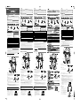 1
1
-
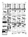 2
2


Yamaha DTLK9 Handleiding
- Categorie
- Muziekinstrumenten
- Type
- Handleiding
- Deze handleiding is ook geschikt voor
in andere talen
- English: Yamaha DTLK9 User manual
- italiano: Yamaha DTLK9 Manuale utente
- русский: Yamaha DTLK9 Руководство пользователя
- français: Yamaha DTLK9 Manuel utilisateur
- español: Yamaha DTLK9 Manual de usuario
- Deutsch: Yamaha DTLK9 Benutzerhandbuch
- português: Yamaha DTLK9 Manual do usuário
- dansk: Yamaha DTLK9 Brugermanual
- suomi: Yamaha DTLK9 Ohjekirja
- čeština: Yamaha DTLK9 Uživatelský manuál
- 日本語: Yamaha DTLK9 ユーザーマニュアル
- svenska: Yamaha DTLK9 Användarmanual
- Türkçe: Yamaha DTLK9 Kullanım kılavuzu
- polski: Yamaha DTLK9 Instrukcja obsługi
- română: Yamaha DTLK9 Manual de utilizare