
Precision 7550
Service Manual
Regulatory Model: P93F
Regulatory Type: P93F001
May 2020
Rev. A00

Opmerkingen, voorzorgsmaatregelen,en waarschuwingen
OPMERKING: Een OPMERKING duidt belangrijke informatie aan voor een beter gebruik van het product.
WAARSCHUWING: WAARSCHUWINGEN duiden potentiële schade aan hardware of potentieel gegevensverlies aan en
vertellen u hoe het probleem kan worden vermeden.
GEVAAR: LET OP duidt het risico van schade aan eigendommen, lichamelijk letsel of overlijden aan.
© 2020 Dell Inc. of haar dochterondernemingen. Alle rechten voorbehouden. Dell, EMC, en andere handelsmerken zijn handelsmerken van
Dell Inc. of zijn dochterondernemingen. Andere handelsmerken zijn mogelijk handelsmerken van hun respectieve eigenaren.

1 Aan de computer werken............................................................................................................... 6
Veiligheidsinstructies............................................................................................................................................................. 6
Voordat u in de computer gaat werken........................................................................................................................ 6
Veiligheidsmaatregelen....................................................................................................................................................7
Bescherming tegen elektrostatische ontlading (electrostatic discharge, ESD)...................................................... 7
ESD-onderhoudskit..........................................................................................................................................................8
Nadat u aan de computer heeft gewerkt..................................................................................................................... 9
2 Technologie en onderdelen.......................................................................................................... 10
USB-functies........................................................................................................................................................................ 10
USB Type-C...........................................................................................................................................................................11
HDMI 2.0............................................................................................................................................................................... 13
NVIDIA Quadro T1000......................................................................................................................................................... 14
NVIDIA Quadro T2000.........................................................................................................................................................14
NVIDIA Quadro RTX3000................................................................................................................................................... 15
NVIDIA Quadro RTX4000................................................................................................................................................... 15
NVIDIA Quadro RTX5000................................................................................................................................................... 16
3 Demonteren en hermonteren........................................................................................................17
SD-kaart................................................................................................................................................................................ 17
De SD-kaart verwijderen............................................................................................................................................... 17
De SD-kaart installeren.................................................................................................................................................. 17
SSD-deur............................................................................................................................................................................... 17
Removing SSD door....................................................................................................................................................... 17
Installing SSD door......................................................................................................................................................... 18
Secundaire M.2 Solid State-schijf......................................................................................................................................19
Removing the secondary M.2 Solid-state drive......................................................................................................... 19
Installing the secondary M.2 SSD module.................................................................................................................. 20
Onderplaat.............................................................................................................................................................................21
Removing the base cover..............................................................................................................................................21
Installing the base cover............................................................................................................................................... 24
Batterij...................................................................................................................................................................................26
Voorzorgsmaatregelen voor de lithium-ionbatterij....................................................................................................26
Removing the battery................................................................................................................................................... 26
Installing the battery......................................................................................................................................................27
Solid-state-schijf..................................................................................................................................................................28
Removing the primary M.2 Solid-state drive............................................................................................................. 28
Installing the primary M.2 SSD module.......................................................................................................................30
Secundaire geheugenmodule..............................................................................................................................................31
Removing the secondary memory module..................................................................................................................31
Installing the secondary memory module................................................................................................................... 32
simkaart................................................................................................................................................................................ 32
Removing the SIM card................................................................................................................................................ 32
Installing the SIM card...................................................................................................................................................33
Contents
Contents 3

WLAN-kaart......................................................................................................................................................................... 34
Removing the WLAN card............................................................................................................................................34
Installing the WLAN card.............................................................................................................................................. 35
WWAN-kaart........................................................................................................................................................................36
Removing the WWAN card.......................................................................................................................................... 36
Installing the WWAN card............................................................................................................................................ 36
Toetsenbordrooster.............................................................................................................................................................37
Removing the keyboard lattice.................................................................................................................................... 37
Installing the keyboard lattice.......................................................................................................................................38
Toetsenbord.........................................................................................................................................................................38
Removing the keyboard................................................................................................................................................38
Installing the keyboard.................................................................................................................................................. 39
Primaire geheugenmodule...................................................................................................................................................41
Removing the primary memory module.......................................................................................................................41
Installing the primary memory module........................................................................................................................ 42
Warmteafleider.................................................................................................................................................................... 43
Removing the heat-sink assembly...............................................................................................................................43
Installing the heat sink assembly..................................................................................................................................44
Voedingsadapterpoort........................................................................................................................................................ 45
Removing the power-adapter port............................................................................................................................. 45
Installing the power-adapter port................................................................................................................................45
Aan-uitknopkaart................................................................................................................................................................. 46
Removing the power button board............................................................................................................................. 46
Installing the power button board................................................................................................................................47
Aan/uit-knopkaart met vingerafdruklezer........................................................................................................................48
Removing the power button assembly with fingerprint reader...............................................................................48
Installing the power button assembly with fingerprint reader................................................................................. 49
Binnenframe.........................................................................................................................................................................49
Removing the inner frame............................................................................................................................................49
Installing the inner frame.............................................................................................................................................. 50
Smartcardhouder................................................................................................................................................................. 51
Removing the smart-card reader.................................................................................................................................51
Installing the smart-card reader...................................................................................................................................52
Touchpadknop..................................................................................................................................................................... 53
Removing the Touchpad buttons................................................................................................................................53
Installing the Touchpad buttons.................................................................................................................................. 54
SD-kaartlezer.......................................................................................................................................................................55
Removing SD card reader............................................................................................................................................ 55
Installing SD card reader...............................................................................................................................................56
Aan/uit-knop........................................................................................................................................................................57
Removing the power button........................................................................................................................................ 57
Installing the power button...........................................................................................................................................57
Aan/uit-knopeenheid met vingerafdruklezer...................................................................................................................58
Removing the power button assembly with fingerprint reader...............................................................................58
Installing the power button assembly with fingerprint reader................................................................................. 59
GPU-voedingskabel.............................................................................................................................................................60
Removing the GPU power cable................................................................................................................................. 60
Installing the GPU power cable.................................................................................................................................... 61
Moederbord..........................................................................................................................................................................62
Removing the system board........................................................................................................................................ 62
4
Contents

Installing the system board...........................................................................................................................................64
GPU-kaart............................................................................................................................................................................ 67
De GPU-kaart verwijderen........................................................................................................................................... 67
De GPU-kaart plaatsen.................................................................................................................................................68
Luidspreker...........................................................................................................................................................................68
Removing the speaker.................................................................................................................................................. 68
Installing the speaker.....................................................................................................................................................69
Middenkapje.......................................................................................................................................................................... 71
Removing the middle cap.............................................................................................................................................. 71
Installing the middle cap................................................................................................................................................72
Beeldschermassemblage.................................................................................................................................................... 73
Removing the display assembly................................................................................................................................... 73
Installing the display assembly......................................................................................................................................75
Polssteun.............................................................................................................................................................................. 78
Removing the palmrest................................................................................................................................................. 78
Installing the palmrest................................................................................................................................................... 79
Montagekader van het beeldscherm................................................................................................................................ 80
Removing the display bezel (non-touch)................................................................................................................... 80
Installing the display bezel (non-touch).......................................................................................................................81
Beeldschermpaneel............................................................................................................................................................. 83
Removing the display panel (non-touch)................................................................................................................... 83
Installing the display panel (non-touch)......................................................................................................................85
Beeldschermscharnieren.................................................................................................................................................... 86
Removing the display hinge..........................................................................................................................................86
Installing the display hinge (non-touch)......................................................................................................................87
Camera..................................................................................................................................................................................89
Removing the camera (non-touch)............................................................................................................................ 89
Installing the camera..................................................................................................................................................... 90
P-sensorkaart....................................................................................................................................................................... 91
De P-sensorkaart verwijderen...................................................................................................................................... 91
De P-sensorkaart plaatsen........................................................................................................................................... 92
Beeldschermkabel................................................................................................................................................................92
Removing the display cable..........................................................................................................................................92
Installing the display cable............................................................................................................................................ 94
Display back cover...............................................................................................................................................................95
Replacing the display cable.......................................................................................................................................... 95
4 Problemen oplossen....................................................................................................................97
Dell SupportAssist Pre-Boot System prestatiecontrole uitvoeren................................................................................97
De PerformanceAssist Pre-Boot System prestatiecontrole uitvoeren...................................................................97
Ingebouwde zelftest van de systeemkaart (M-BIST).................................................................................................... 98
Geïntegreerde zelftest van de stroomrail van het beeldscherm (L-BIST)...................................................................98
Ingebouwde zelftest van het beeldscherm (LCD-BIST)................................................................................................99
System diagnostic lights.....................................................................................................................................................99
Wifi-stroomcyclus...............................................................................................................................................................101
5 Behulpzame informatie vinden................................................................................................... 102
Contact opnemen met Dell...............................................................................................................................................102
Contents
5

Aan de computer werken
Veiligheidsinstructies
Vereisten
Volg de onderstaande veiligheidsrichtlijnen om uw persoonlijke veiligheid te garanderen en de computer te beschermen tegen mogelijke
schade. Tenzij anders aangegeven, wordt er bij elke procedure in dit document van de volgende veronderstellingen uitgegaan:
• U hebt de veiligheidsinformatie geraadpleegd die bij uw computer is geleverd.
• Een onderdeel kan worden vervangen of, indien afzonderlijk aangeschaft, worden geplaatst door de verwijderingsprocedure in
omgekeerde volgorde uit te voeren.
Over deze taak
OPMERKING: Koppel alle voedingsbronnen los voordat u de computerbehuizing of -panelen opent. Zodra u klaar bent
met de werkzaamheden in de computer, plaatst u de behuizing en alle panelen en schroeven terug voordat u de
computer weer aansluit op de voedingsbron.
GEVAAR: Volg de veiligheidsinstructies die bij de computer werden geleverd alvorens u werkzaamheden binnen de
computer uitvoert. Zie voor extra informatie over de beste veiligheidsmaatregelen de startpagina over de naleving van
wet- en regelgeving
WAARSCHUWING: Een groot aantal reparaties mag alleen door een erkend servicemonteur worden uitgevoerd. U mag
alleen probleemoplossing en eenvoudige reparaties uitvoeren zoals toegestaan volgens de documentatie bij uw product
of zoals geïnstrueerd door het online of telefonische team voor service en support. Schade als gevolg van
onderhoudswerkzaamheden die niet door Dell zijn goedgekeurd, valt niet onder de garantie. Lees de
veiligheidsinstructies die bij het product zijn geleverd en leef deze na.
WAARSCHUWING: Voorkom elektrostatische ontlading door uzelf te aarden met een aardingspolsbandje of door
regelmatig zowel een ongeverfd metalen oppervlak als een connector aan de achterkant van de computer tegelijkertijd
aan te raken.
WAARSCHUWING: Ga voorzichtig met componenten en kaarten om. Raak de componenten en de contacten op kaarten
niet aan. Pak kaarten vast bij de uiteinden of bij de metalen bevestigingsbeugel. Houd een component, zoals een
processor, vast aan de uiteinden, niet aan de pinnen.
WAARSCHUWING: Verwijder kabels door aan de stekker of aan de kabelontlastingslus te trekken en niet aan de kabel
zelf. Sommige kabels zijn voorzien van een connector met borglippen. Als u dit type kabel loskoppelt, moet u de
borglippen ingedrukt houden voordat u de kabel verwijdert. Trek connectoren in een rechte lijn uit elkaar om te
voorkomen dat connectorpinnen verbuigen. Ook moet u voordat u een kabel verbindt, controleren of beide connectoren
op juiste wijze zijn opgesteld en uitgelijnd.
OPMERKING: De kleur van uw computer en bepaalde componenten kunnen verschillen van de kleur die in dit document
is afgebeeld.
Voordat u in de computer gaat werken
Over deze taak
Om schade aan de computer te voorkomen, moet u de volgende instructies opvolgen voordat u in de computer gaat werken.
1
6 Aan de computer werken

Stappen
1. Zorg dat u de Veiligheidsinstructies volgt.
2. Zorg ervoor dat het werkoppervlak vlak en schoon is, om te voorkomen dat de computerkap bekrast raakt.
3. Zet de computer uit.
4. Verwijder alle stekkers van netwerkkabels uit de computer.
WAARSCHUWING: Wanneer u een netwerkkabel wilt verwijderen, moet u eerst de connector van de netwerkkabel uit
de computer verwijderen en daarna de netwerkkabel loskoppelen van het netwerkapparaat.
5. Haal de stekker van de computer en van alle aangesloten apparaten uit het stopcontact.
6. Houd de aan-uitknop ingedrukt terwijl de stekker van de computer uit het stopcontact is verwijderd om het moederbord te aarden.
OPMERKING: Voorkom elektrostatische ontlading door uzelf te aarden met een aardingspolsbandje of door
regelmatig zowel een ongeverfd metalen oppervlak als een connector aan de achterkant van de computer
tegelijkertijd aan te raken.
Veiligheidsmaatregelen
In het hoofdstuk veiligheidsmaatregelen worden de primaire stappen genoemd die moeten worden genomen voordat demontage-
instructies worden uitgevoerd.
Neem de volgende voorzorgsmaatregelen in acht voordat u een installatie of break/fix-procedures uitvoert die montage of demontage
vereisen.
• Zet het systeem uit, inclusief eventueel aangesloten randapparatuur.
• Koppel het systeem en alle aangesloten randapparatuur los van het stopcontact.
• Koppel alle netwerkkabels, telefoon- en telecommunicatielijnen los van het systeem.
• Gebruik een ESD-servicekit wanneer u werkzaamheden aan de binnenkant van een tabletnotebook uitvoert om schade door
elektrostatische ontlading (ESD) te voorkomen.
• Plaats, na het verwijderen van een systeemonderdeel, het verwijderde onderdeel zorgvuldig op een anti-statische mat.
• Draag schoenen met niet-geleidende rubberen zolen om de kans op elektrocutie te verminderen.
Stand-bystand
Dell producten met stand-bystand moeten worden losgekoppeld voordat u de behuizing opent. Systemen die zijn uitgerust met de stand-
bystand worden in wezen gevoed wanneer deze uit staan. Door de interne voeding kan het systeem op afstand worden ingeschakeld
(Wake on LAN) en onderbroken in een slaapstand en heeft andere geavanceerde functies voor energiebeheer.
Door ontkoppeling en het ingedrukt houden van de aan-/uitknop gedurende 15 seconden zou de reststroom in de systeemkaart moeten
ontladen. Verwijder de batterij uit tabletsnotebooks.
Binding
Binding is een methode voor het verbinden van twee of meer aardingsgeleiders met dezelfde elektrische potentiaal. Dit wordt gedaan door
het gebruik van een ESD-buitendienstkit. Zorg er bij het aansluiten van een bindingsdraad voor dat deze is aangesloten op blank metaal en
nooit op een geverfd of niet-metalen oppervlak. De polsband moet goed vastzitten en volledig in contact zijn met uw huid. Zorg er tevens
voor dat u altijd alle sieraden, zoals horloges, armbanden of ringen, verwijdert voordat u uzelf en de apparatuur met elkaar verbindt.
Bescherming tegen elektrostatische ontlading
(electrostatic discharge, ESD)
ESD is een belangrijk aandachtspunt bij het werken met elektronische onderdelen, vooral gevoelige onderdelen zoals uitbreidingskaarten,
processoren, geheugen-DIMM's, en moederborden. Zeer geringe ladingen kunnen schade aan circuits veroorzaken op manieren die
mogelijk niet vanzelfsprekend zijn, zoals onregelmatige problemen of een verkorte levensduur. Hoe meer de industrie lagere
energievereisten en hogere dichtheid promoot, des te belangrijker wordt ESD-bescherming.
Vanwege de hogere dichtheid van halfgeleiders in recente Dell producten, is de gevoeligheid voor schade door statische elektriciteit nu
hoger dan in eerdere Dell producten. Daarom zijn sommige eerder goedgekeurde methoden van het omgaan met onderdelen niet langer
van toepassing.
Twee erkende soorten ESD-schade zijn fatale en onregelmatige storingen.
Aan de computer werken
7

• Fataal: Fatale storingen vertegenwoordigen ongeveer 20 procent van de aan ESD gerelateerde storingen. De schade veroorzaakt een
onmiddellijk en volledig verlies van functionaliteit van het apparaat. Een voorbeeld van een fatale fout is een geheugen-DIMM die een
statische schok heeft ontvangen en onmiddellijk een 'No POST/No Video’-symptoom genereert, waarbij een pieptoon wordt
uitgezonden voor ontbrekend of niet-functioneel geheugen.
• Onregelmatig – Onregelmatige storingen vertegenwoordigen ongeveer 80 procent van de aan ESD gerelateerde storingen. De hoge
frequentie van onregelmatige fouten betekent dat wanneer schade plaatsvindt, dit meestal niet onmiddellijk wordt herkend. De DIMM
ontvangt een statische schok, maar hierdoor wordt de tracing alleen verzwakt en worden geen onmiddellijk externe symptomen van
de schade veroorzaakt. Het kan weken of maanden duren voordat de verzwakte tracing smelt. In de tussentijd kan dit leiden tot
verslechtering van geheugenintegriteit, onregelmatige geheugenstoringen, enz.
De soort schade die moeilijker te herkennen en op te lossen is, is de onregelmatige storing (ook wel latente storing of` ‘walking wounded’
genoemd).
Voer de volgende stappen uit om ESD-schade te voorkomen:
• Gebruik een bedrade ESD-polsband die goed is geaard. Het gebruik van draadloze antistatische banden is niet meer toegestaan; deze
bieden onvoldoende bescherming. Het aanraken van het chassis alvorens onderdelen te hanteren zorgt niet voor adequate
bescherming tegen ESD op onderdelen met verhoogde gevoeligheid voor ESD-schade.
• Werk met alle elektrostatisch gevoelige onderdelen in een ruimte die vrij is van statische elektriciteit. Gebruik indien mogelijk
antistatische vloer- en werkbankmatten.
• Wanneer u een voor statische elektriciteit gevoelig onderdeel uit de verzenddoos haalt, verwijdert u het onderdeel pas uit de
antistatische verpakking op het moment dat u het gaat installeren. Voordat u het onderdeel uit de antistatische verpakking verwijdert,
zorgt u ervoor dat u de statische elektriciteit van uw lichaam ontlaadt.
• Plaats een gevoelig onderdeel voor transport eerst in een antistatische doos of andere verpakking.
ESD-onderhoudskit
De onbewaakte onderhoudskit is de meest gebruikte servicekit. Elke onderhoudskit bestaat uit drie hoofdcomponenten: antistatische mat,
polsbandje en aardingssnoer.
Componenten van een ESD-onderhoudskit
De componenten van een ESD-onderhoudskit zijn:
• Antistatische mat - De antistatische mat is dissipatief en tijdens serviceprocedures kunnen er onderdelen op worden geplaatst. Uw
polsband moet nauwsluitend zitten en het aardingssnoer moet aan de mat en aan onbewerkt metaal van het systeem waaraan u werkt
zijn bevestigd wanneer u de antistatische mat gebruikt. Wanneer u het bovenstaande goed hebt uitgevoerd, kunt u serviceonderdelen
uit de ESD-tas halen en die direct op de mat plaatsen. ESD-gevoelige items zijn veilig in uw hand, op de ESD-mat, in het systeem of in
een zak.
• Polsband en aardingssnoer - De polsband en het aardingssnoer kunnen ofwel direct tussen uw pols en blank metaal op de hardware
worden bevestigd als de ESD-mat niet vereist is, of worden verbonden met de antistatische mat om hardware te beschermen die
tijdelijk op de mat is geplaatst. De fysieke verbinding van de polsband en het aardingssnoer tussen uw huid, de ESD-mat en de
hardware staat bekend als hechting. Gebruik alleen onderhoudskits met een polsband, mat en aardingssnoer. Gebruik nooit draadloze
polsbanden. Houd er altijd rekening mee dat de interne draden van een polsband gevoelig zijn voor schade door slijtage en dat die dus
regelmatig gecontroleerd moeten worden met een polsbandtester om mogelijke ESD-hardwareschade te voorkomen. Het wordt
aanbevolen om de polsband en het aardingssnoer ten minste eenmaal per week te testen.
• ESD-polsbandtester - De draden in een ESD-polsbandje kunnen na verloop van tijd beschadigd raken. Bij gebruik van een
onbewaakte kit wordt het aanbevolen om de band regelmatig voor elke servicebeurt of minimaal eenmaal per week te testen. Een
polsbandtester is de beste methode voor het uitvoeren van deze test. Als u zelf geen polsbandtester hebt, kunt u kijken of uw
regionale kantoor er wel een heeft. Voor het uitvoeren van de test sluit u het aardingssnoer van de polsband aan op de tester terwijl
die aan uw pols is bevestigd en drukt u vervolgens op de knop om de test uit te voeren. Een groene LED geeft aan dat de test
succesvol is; een rode LED geeft aan dat de test is mislukt.
• Isolatorelementen - Het is belangrijk om ESD-gevoelige apparaten, zoals plastic warmteafleiderbehuizingen uit de buurt te houden
van interne onderdelen zoals isolatoren omdat die vaak geladen zijn.
• Werkomgeving - Voor het gebruik van de ESD-onderhoudskit dient u de situatie op de klantlocatie te beoordelen. Het implementeren
van de kit voor een serveromgeving is anders dan voor een desktop- of draagbare omgeving. Servers zijn doorgaans geïnstalleerd in
een patchkast in een datacenter; desktops of laptops worden doorgaans geplaatst op kantoorbureaus of in kantoorhokjes. Zoek altijd
een grote, open en vlakke ruimte zonder rommel die groot genoeg is om de ESD-kit te gebruiken waarbij er genoeg ruimte is voor het
systeem dat moet worden gerepareerd. Er mogen geen geleiders in de werkruimte liggen die voor ESD kunnen zorgen. Op de werkplek
moeten isolators zoals piepschuim en andere kunststofmaterialen altijd minstens 30 centimeter van gevoelige onderdelen worden
geplaatst voordat u fysiek omgaat met hardwarecomponenten.
• ESD-verpakking - Alle ESD-gevoelige apparaten moeten worden verzonden en ontvangen in statisch-veilige verpakking. Metalen,
statisch afgeschermde zakken krijgen de voorkeur. U moet het beschadigde onderdeel echter altijd in dezelfde ESD-tas en -verpakking
doen als waarin het nieuwe onderdeel arriveerde. De ESD-tas moet om worden gevouwen en worden afgeplakt en hetzelfde
8
Aan de computer werken

schuimverpakkingsmateriaal moet worden gebruikt met de originele doos van het nieuwe onderdeel. ESD-gevoelige apparaten dienen
alleen op ESD-beschermde ondergrond te worden geplaatst en onderdelen mogen nooit op de ESD-tas worden geplaatst omdat alleen
de binnenkant daarvan is beschermd. Plaats onderdelen altijd in uw hand, op de ESD-mat, in het systeem of in een antistatische zak.
• Het transporteren van gevoelige componenten - Bij het transporteren van ESD-gevoelige componenten zoals vervangende
onderdelen of onderdelen die naar Dell teruggestuurd moeten worden, is het zeer belangrijk om deze onderdelen voor veilig transport
in de antistatische tassen te plaatsen.
Overzicht van ESD-bescherming
Het wordt onderhoudstechnici aanbevolen om de traditionele bedraade ESD-aardingspolsband en beschermende antistatische mat te allen
tijde te gebruiken wanneer service wordt verleend voor Dell producten. Daarnaast is het van essentieel belang dat technici de gevoelige
onderdelen apart houden van alle isolatoronderdelen wanneer service wordt verleend en dat ze antistatische tassen gebruiken voor het
transport van gevoelige onderdelen.
Nadat u aan de computer heeft gewerkt
Over deze taak
Nadat u de onderdelen hebt vervangen of teruggeplaatst, moet u controleren of u alle externe apparaten, kaarten, kabels etc. hebt
aangesloten voordat u de computer inschakelt.
Stappen
1. Sluit alle telefoon- of netwerkkabels aan op uw computer.
WAARSCHUWING:
Steek voor het aansluiten van een netwerkkabel de kabel eerst in het netwerkapparaat en daarna
in de computer.
2. Sluit uw computer en alle aangesloten apparaten aan op het stopcontact.
3. Schakel de computer in.
4. Controleer, indien nodig, of de computer correct functioneert door SupportAssist diagnostics (SupportAssist-diagnose) uit te
voeren.
Aan de computer werken
9

Technologie en onderdelen
In dit hoofdstuk worden de technologie en onderdelen beschreven die beschikbaar zijn in het systeem.
Onderwerpen:
• USB-functies
• USB Type-C
• HDMI 2.0
• NVIDIA Quadro T1000
• NVIDIA Quadro T2000
• NVIDIA Quadro RTX3000
• NVIDIA Quadro RTX4000
• NVIDIA Quadro RTX5000
USB-functies
Universal Serial Bus of USB, werd in 1996 op de markt gebracht. USB heeft de verbinding tussen hostcomputers en randapparatuur, zoals
muizen, toetsenborden, externe schijven en printers, enorm vereenvoudigd.
Tabel 1. Evolutie van USB
Type Dataoverdrachtssnelheid Categorie Jaar van introductie
USB 2.0 480 Mbps Hoge snelheid 2000
USB 3.2 Gen 1
(voorheen USB
3.0/USB 3.1 Gen 1)
5 Gbps SuperSpeed 2010
USB 3.1 Gen 2 10 Gbps SuperSpeed Plus 2013
USB 3.2 Gen 1 (SuperSpeed USB)
USB 2.0 staat al een aantal jaren goed bekend als de interfacestandaard in de wereld van de personal computers met ongeveer 6 miljard
verkochte apparaten. Toch wordt de behoefte aan meer snelheid steeds groter door de vraag naar snellere hardware en meer
bandbreedte. USB 3.0/USB 3.1 Gen 1 voldoet met een theoretisch 10 maal hogere snelheid dan zijn voorganger eindelijk aan de vraag van
de consument. Kort samengevat heeft USB 3.2 Gen 1 de volgende functies:
• Hogere overdrachtssnelheden (tot 20 Gbps).
• Een grotere Multilane-werking van 10 Gbps elk.
• Grotere maximale buskracht en meer stroomopname van het apparaat om beter te kunnen voldoen aan de vraag van apparaten die
veel stroom verbruiken.
• Nieuwe energiebeheerfuncties.
• Full-duplex dataoverdracht en ondersteuning voor nieuwe overdrachtstypen.
• Achterwaartse compatibiliteit met USB 3.1/3.0 en USB 2.0.
• Nieuwe connectoren en kabel.
De onderstaande onderwerpen behandelen enkele van de meest gestelde vragen over USB 3.0/USB 3.2 Gen 1.
2
10 Technologie en onderdelen

Snelheid
Momenteel zijn er vijf snelheidsmodi gedefinieerd in de nieuwste USB 3.0/USB 3.1 Gen 1-specificatie. Op basis van USB
gegevensoverdracht worden ze gecategoriseerd als Lage snelheid, Volle snelheid, Hoge snelheid (vanaf versie 2.0 van de specificatie),
SuperSpeed (vanaf versie 3.0) en SuperSpeed+ (vanaf versie 3.1). De nieuwe SuperSpeed+-modus heeft een overdrachtssnelheid van 20
Gbps. De USB 3.2-standaard is achterwaarts compatibel met USB 3.1/3.0 en USB 2.0.
USB 3.2 Gen 1 behaalt de veel hogere prestaties door de volgende technische wijzigingen:
• Een extra fysieke bus die parallel aan de bestaande USB 2.0-bus wordt toegevoegd (zie de afbeelding hieronder).
• USB 2.0 bevatte vier draden (voeding, aarde en een paar voor differentiële gegevens); USB 3.1 Gen 1 voegt nog vier draden toe voor
twee paar differentiële signalen (ontvangen en verzenden) voor een totaal van acht aansluitingen in de connectoren en bekabeling.
• USB 3.2 Gen 1 maakt gebruik van de bi-directionele data-interface in plaats van de half-duplex opstelling van USB 2.0. Hierdoor is de
theoretische bandbreedte 10 keer hoger.
Toepassingen
USB 3.1 Gen 1 ontsluit nieuw terrein en biedt meer ruimte voor apparaten voor het leveren van een betere gebruikerservaring. Waar USB-
video in het verleden eigenlijk niet haalbaar was (met betrekking tot de maximumresolutie, latentie en videocompressie), kunt u zich
voorstellen dat de nieuwe USB-oplossingen met een bandbreedte die 5 tot 10 keer hoger ligt, dit moeiteloos aankunnen. Single-link DVI
vereist bijna 2 Gbps doorvoer. Terwijl 480 Mbps een beperking vormde, biedt 5 Gbps veelbelovende resultaten. Met een beloofde snelheid
van 4,8 Gbps is deze standaard nu gebruikelijk voor apparaten die voorheen buiten het USB-territorium vielen, zoals externe RAID-
storagesystemen.
Hieronder staan enkele beschikbare SuperSpeed USB 3.0/USB 3.1 Gen 1-producten:
• Harde schijven met USB 3.0/USB 3.2 Gen 1 voor externe desktop
• Draagbare USB 3.2 Gen 1-harde schijven
• Docks en adapters voor schijven met USB 3.2 Gen 1
• Flashdrives en lezers met USB 3.2 Gen 1
• Solid State-schijven met USB 3.2 Gen 1
• RAIDs met USB 3.2 Gen 1
• Optische mediastations
• Multimedia-apparaten
• Networking
• Adapterkaarten en -hubs met USB 3.2 Gen 1
Compatibiliteit
Het goede nieuws is dat vanaf het begin zorgvuldig gepland is dat USB 3.2 Gen 1 compatibel is met USB 2.0. Voor USB 3.2 Gen 1 worden
wel nieuwe fysieke verbindingen gespecificeerd, en dus nieuwe kabels om te profiteren van de mogelijkheden van het nieuwe protocol met
hogere snelheid. De aansluiting zelf behoudt echter dezelfde rechthoekige vorm met de vier USB 2.0-contacten in precies dezelfde locatie
als voorheen. Op nieuwe USB 3.0/USB 3.2 Gen 1-kabels zitten vijf nieuwe verbindingen voor het onafhankelijk doorgeven van ontvangen
en verzonden gegevens. Deze komen alleen in contact wanneer ze zijn aangesloten op een correcte SuperSpeed USB-verbinding.
USB Type-C
USB Type-C is een nieuwe, kleine, fysieke connector. De connector zelf ondersteunt diverse interessante nieuwe USB-standaarden, zoals
USB 3.1 en USB Power Delivery (USB PD).
Alternatieve modus
USB Type-C is een nieuwe, kleine verbindingsstandaard. De grootte bedraagt ongeveer een derde van de oude USB Type-A-stekker. Dit is
een standaard met enkele connector die elk apparaat kan gebruiken. USB Type-C-poorten bieden ondersteuning voor verschillende
protocollen die 'alternatieve modi' gebruiken. Hiermee kunt u adapters gebruiken met HDMI-, VGA- en DisplayPort-uitvoer of andere typen
aansluitingen via die enkele USB-poort.
Technologie en onderdelen
11

USB Power Delivery
De specificatie USB PD is nauw verbonden aan USB Type-C. Vandaag de dag maken smartphones, tablets en andere mobiele apparaten
vaak gebruik van een USB-verbinding om op te laden. Een USB 2.0-aansluiting biedt maximaal 2,5 watt vermogen. Hierdoor wordt uw
telefoon opgeladen, maar dat is het wel zo ongeveer. Een laptop heeft bijvoorbeeld tot wel 60 watt nodig. De specificatie USB Power
Delivery verhoogt deze vermogenslevering tot 100 watt. Het werkt bi-directioneel, zodat een apparaat vermogen kan verzenden of
ontvangen. Dit vermogen kan worden overgedragen op hetzelfde moment waarop het apparaat gegevens via de verbinding verzendt.
Dit zou het einde kunnen betekenen van alle bedrijfseigen oplaadkabels voor laptops. Alles wordt dan opgeladen via een standaard USB-
aansluiting. U kunt uw laptop dan opladen met zo'n draagbare accu waarmee u tegenwoordig al smartphones en andere mobiele apparaten
oplaadt. Plug uw laptop in een extern beeldscherm dat is aangesloten op een voedingskabel en dat externe beeldscherm laadt uw laptop
op terwijl u deze gebruikt als een extern beeldscherm. En dat allemaal met die ene kleine USB Type-C aansluiting. Om deze functie te
kunnen gebruiken, moeten het apparaat en de kabel USB Power Delivery ondersteunen. Het hebben van een USB Type-C aansluiting
betekent niet noodzakelijkerwijs dat die ondersteuning wordt geboden.
USB Type-C en USB 3.2
USB 3.2 is een nieuwe USB-standaard. De theoretische bandbreedte van USB 3 is 5 Gbps en USB 3.2 is 20 Gbps, dat wil zeggen dat de
bandbreedte twee keer zo snel is als een eerste generatie Thunderbolt-connector. USB Type-C is niet hetzelfde als USB 3.2. USB Type-C
is slechts een aansluitingsvorm en de onderliggende technologie kan gewoon USB 2 of USB 3.0 zijn. De Android-tablet N1 van Nokia,
bijvoorbeeld, maakt gebruik van een USB Type-C aansluiting, maar aan de binnenkant is alles USB 2.0 - zelfs geen USB 3.0. Deze
technologieën zijn echter wel nauw gerelateerd.
Thunderbolt via USB Type-C
Thunderbolt is een hardware-interface die gegevens, video, audio en stroom combineert met één enkele verbinding. Thunderbolt
combineert PCI Express (PCIe) en DisplayPort (DP) met één serieel signaal, en biedt bovendien DC-stroom, allemaal met één kabel.
Thunderbolt 1 en Thunderbolt 2 gebruiken dezelfde connector als mini-DP (DisplayPort) om randapparatuur te verbinden, terwijl
Thunderbolt 3 gebruik maakt van een USB Type-C-aansluiting.
Afbeelding 1. Thunderbolt 1 en Thunderbolt 3
1. Thunderbolt 1 en Thunderbolt 2 (via een miniDP-connector)
2. Thunderbolt 3 (via een USB Type-C-aansluiting)
Thunderbolt 3 via USB Type C
Thunderbolt 3 brengt Thunderbolt naar USB-type C met snelheden tot 40 Gbps, waardoor er één compacte poort ontstaat die alles kan:
het levert de snelste, meest veelzijdige verbinding naar elke dock, beeldscherm of gegevensapparaat, zoals een externe harde schijf.
Thunderbolt 3 maakt gebruik van een USB Type-C aansluiting/-poort om verbinding te maken met ondersteunde randapparatuur.
1. Thunderbolt 3 maakt gebruik van USB Type-C aansluiting en -kabels - het is compact en omkeerbaar.
2. Thunderbolt 3 ondersteunt snelheden tot 40 Gbps.
3. DisplayPort 1.4 - compatibel met bestaande DisplayPort-monitoren, -apparaten en -kabels.
4. USB-vermogensafgifte - tot 130 W op ondersteunde computers.
12
Technologie en onderdelen

Belangrijkste kenmerken van de Thunderbolt 3 via USB
Type-C
1. Thunderbolt, USB, DisplayPort en stroom via USB Type-C, met één enkele kabel (functies verschillen tussen verschillende producten).
2. USB Type-C aansluiting en -kabels die compact en omkeerbaar zijn.
3. Ondersteunt Thunderbolt Networking (*varieert tussen verschillende producten).
4. Ondersteunt beeldschermen tot 4K.
5. Tot 40 Gbps
OPMERKING: Snelheid van dataoverdracht kan variëren tussen verschillende apparaten.
Thunderbolt-pictogrammen
Afbeelding 2. Variaties Thunderbolt-pictogrammen
HDMI 2.0
In dit onderwerp leest u meer over High-Definition Multimedia Interface (HDMI) 2.0 en de functies en voordelen ervan.
HDMI is een ondersteunde, niet-gecomprimeerde, digitale audio/video-interface. HDMI biedt een interface tussen een compatibele digitale
audio/video-bron, zoals een dvd-speler, of A/V-ontvanger en een compatibel digitaal audioapparaat en/of een videomonitor, zoals een
digitale tv (DTV). De beoogde toepassingen voor HDMI-tv's en dvd-spelers. Het primaire voordeel is een vermindering van het aantal
kabels en voorzieningen voor contentbescherming. HDMI ondersteunt standaard, verbeterde of high-definition video, plus meerkanaals
digitaal geluid op één enkele kabel.
Functies HDMI 2.0
• HDMI Ethernet-kanaal : voegt een snelle netwerkverbinding toe aan een HDMI-koppeling, waardoor gebruikers hun IP-apparaten
ten volle kunnen benutten zonder een afzonderlijke Ethernet-kabel.
• Audio Return-kanaal: hiermee kan een op HDMI aangesloten tv met een geïntegreerde tuner audiodata 'upstream' verzenden naar
een surround audiosysteem, waardoor een afzonderlijke audiokabel niet meer nodig is.
• 3D - definieert ingangs-/uitgangsprotocollen voor grote 3D-video-indelingen, wat mogelijkheden biedt voor echte 3D-games en 3D
home cinema-toepassingen
• Type inhoud: realtime signalering van typen inhoud tussen het beeldscherm en de bronapparaten, waardoor een TV de
beeldinstellingen kan optimaliseren op basis van het type inhoud
• Extra kleurruimten : voegt ondersteuning toe voor extra kleurmodellen die worden gebruikt bij digitale fotografie en
computerbeelden.
• 4K-ondersteuning: voor videoresoluties die veel groter zijn dan 1080p, ondersteuning voor next-generation beeldschermen die
vergelijkbaar zijn met de Digital Cinema-systemen in veel commerciële bioscopen.
• HDMI Micro-connector - een nieuwe, kleinere connector voor telefoons en andere draagbare apparaten, ondersteunt videoresoluties
tot 1080p
• Automotive Connection System: nieuwe kabels en connectoren voor videosystemen in de auto-industrie die zijn ontworpen om te
voldoen aan de unieke vereisten van de auto-industrie en tegelijk echte HD-kwaliteit leveren.
Voordelen van HDMI
• HDMI van hoge kwaliteit zorgt voor overdracht van ongecomprimeerde digitale audio en video voor de hoogste, helderste
beeldkwaliteit.
• Goedkope HDMI biedt de kwaliteit en functionaliteit van een digitale interface en biedt ook op een eenvoudige, rendabele manier
ondersteuning voor ongecomprimeerde video-indelingen
Technologie en onderdelen
13

• Audio-HDMI ondersteunt meerdere audio-indelingen, van standaard stereo tot meerkanaals surround-geluid
• HDMI combineert video en multichannel audio in één kabel voor lagere kosten, minder complexiteit en een einde aan de wirwar van
kabels die worden gebruikt in A/V-systemen.
• HDMI ondersteunt communicatie tussen de videobron (zoals een dvd-speler) en de DTV, waardoor nieuwe functionaliteit mogelijk
wordt
NVIDIA Quadro T1000
Tabel 2. NVIDIA Quadro T1000
Functie Waarden
Grafisch geheugen 4 GB
Kernen 768
Geheugenbandbreedte 128 Gbps
Geheugentype GDDR6
Geheugeninterface 128-bits
Kloksnelheden 1395-1455 (Boost) MHz
GPU-basisklok 8000 MHz (min. bij P0)
Geschat maximaal stroomverbruik 50 W
Beeldschermsupport eDP/mDP/HDMI/Type-C
Maximale kleurdiepte Maximaal 10 bits/kleur
Support van grafische kaart/Video-API voor besturingssystemen DirectX 12.0, OpenGL 4.6 DisplayPort 1.4, DirectX 12.1
Ondersteunde resoluties en max. vernieuwingsfrequenties (Hz)
• Max. digitaal: enkele DisplayPort 1.4 - 7680 x 4320 (8k) op 30
Hz (mDP/Type-C-naar-DP)
• Max. digitaal: dubbele DisplayPort 1.4 - 7680 x 4320 (8k) op 60
Hz (mDP/Type-C-naar-DP)
Nummers van beeldschermondersteuning Maximaal 4 beeldschermen
NVIDIA Quadro T2000
Tabel 3. NVIDIA Quadro T2000
Functie Waarden
Grafisch geheugen 4 GB
Kernen 1024
Geheugenbandbreedte 128 Gbps
Geheugentype GDDR6
Geheugeninterface 128-bits
Kloksnelheden 1575 - 1785 (Boost) MHz
GPU-basisklok 3504 MHz (min. bij P0)
Geschat maximaal stroomverbruik 60 W
Beeldschermsupport eDP/mDP/HDMI/Type-C
Maximale kleurdiepte Maximaal 10 bits/kleur
Support van grafische kaart/Video-API voor besturingssystemen DirectX 12.0, OpenGL 4.6 DisplayPort 1.4, DirectX 12.1
14 Technologie en onderdelen

Tabel 3. NVIDIA Quadro T2000(vervolg)
Functie Waarden
Ondersteunde resoluties en max. vernieuwingsfrequenties (Hz)
• Max Digital: Enkele DisplayPort 1.4 - 7680 x 4320 (8k) op 30
Hz (mDP/Type-C-naar-DP)
• Dubbele DisplayPort 1.4 - 7680 x 4320 (8k) op 60 Hz (mDP/
Type-C-naar-DP)
Nummers van beeldschermondersteuning Maximaal 4 beeldschermen
NVIDIA Quadro RTX3000
Tabel 4. NVIDIA Quadro RTX3000
Functie Waarden
Grafisch geheugen 6 GB
Kernen 2304
Geheugenbandbreedte 336 Gbps
Geheugentype GDDR6
Geheugeninterface 192-bits
Kloksnelheden 945-1380 (Boost) MHz
GPU-basisklok 3504 MHz (min. bij P0)
Geschat maximaal stroomverbruik 80 W
Beeldschermsupport eDP/mDP/HDMI/Type-C
Maximale kleurdiepte Maximaal 10 bits/kleur
Support van grafische kaart/Video-API voor besturingssystemen DirectX 12.0, OpenGL 4.6 DisplayPort 1.4, DirectX 12.1
Ondersteunde resoluties en max. vernieuwingsfrequenties (Hz)
• Max. digitaal: enkele DisplayPort 1.4 - 7680 x 4320 (8k) op 30
Hz (mDP/Type-C-naar-DP)
• Max. digitaal: dubbele DisplayPort 1.4 - 7680 x 4320 (8k) op 60
Hz (mDP/Type-C-naar-DP)
Nummers van beeldschermondersteuning Maximaal 4 beeldschermen
NVIDIA Quadro RTX4000
Table 5. NVIDIA Quadro RTX4000
Feature Values
Graphics memory 8 GB
Cores 2560
Memory bandwidth 448 Gbps
Memory type GDDR6
Memory Interface 256-bit
Clock Speeds 1110 - 1560 (Boost) MHz
GPU base clock 14000 MHz
Estimated Maximum Power 80 W
Technologie en onderdelen 15

Table 5. NVIDIA Quadro RTX4000(continued)
Feature Values
Display Support eDP/mDP/HDMI/Type-C
Maximum Color Depth Up to 10 bit/color
Operating Systems Graphics/ Video API Support DirectX 12.0, OpenGL 4.6, DisplayPort 1.4, DirectX 12.1
Supported Resolutions and Max Refresh Rates (Hz)
• Max Digital : Single DisplayPort 1.4 - 7680 x 4320 (8k) @ 30 Hz
(mDP/Type-c to DP)
• Max Digital : Dual DisplayPort 1.4 - 7680 x 4320 (8k) @ 60 Hz
(mDP/Type-c to DP)
Numbers of Display Support Up to 4 displays
NVIDIA Quadro RTX5000
Table 6. NVIDIA Quadro RTX5000
Feature Values
Graphics memory 16 GB
Cores 3072
Memory bandwidth 448 Gbps
Memory type GDDR6
Memory Interface 256-bit
Clock Speeds 1035 / 1350 - 1545 / 1770 (Boost) MHz
GPU base clock 14000 MHz
Estimated Maximum Power 80 W
Display Support eDP/mDP/HDMI/Type-C
Maximum Color Depth Up to 10 bit/color
Operating Systems Graphics/ Video API Support DirectX 12.0, OpenGL 4.6, DisplayPort 1.4, DirectX 12.1
Supported Resolutions and Max Refresh Rates (Hz)
• Max Digital : Single DisplayPort 1.4 - 7680 x 4320 (8k) @ 30 Hz
(mDP/Type-C to DP)
• Max Digital : Dual DisplayPort 1.4 - 7680 x 4320 (8k) @ 60 Hz
(mDP/Type-C to DP)
Numbers of Display Support Up to 4 displays
16 Technologie en onderdelen

Demonteren en hermonteren
SD-kaart
De SD-kaart verwijderen
Vereisten
1. Volg de procedure in Voordat u in de computer gaat werken.
Over deze taak
De afbeelding geeft de locatie van de SD-kaart aan en biedt een visuele weergave van de verwijderingsprocedure. Afbeeldingen die tijdens
de volgende revisiecyclus moeten worden geüpload.
Stappen
1. Druk op de SD-kaart om deze uit de computer te verwijderen.
2. Schuif de SD-kaart uit de computer.
De SD-kaart installeren
Vereisten
Als u een onderdeel vervangt, dient u het bestaande onderdeel te verwijderen alvorens de installatieprocedure uit te voeren.
Over deze taak
De afbeelding geeft de locatie van de onderplaat aan en biedt een visuele weergave van de installatieprocedure.
Afbeeldingen die tijdens de volgende revisiecyclus moeten worden geüpload
Stappen
Schuif de SD-kaart in de sleuf in de computer totdat de kaart op zijn plaats klikt.
Vervolgstappen
1. Volg de procedure in Nadat u in de computer hebt gewerkt.
SSD-deur
Removing SSD door
Prerequisites
1. Follow the procedure in before working inside your computer.
2. Remove the SD card.
About this task
The figure indicates the location of the SSD door reader and provides a visual representation of the removal procedure.
3
Demonteren en hermonteren 17

Steps
1. Push the SSD door towards left side to release the SSD door from the base cover.
2. Remove the SSD door from the base cover.
Installing SSD door
Prerequisites
If you are replacing a component, remove the existing component before performing the installation procedure.
About this task
The figure indicates the location of the SSD door and provides a visual representation of the installation procedure.
18
Demonteren en hermonteren

Steps
1. Place the SSD door into its slot on the base cover.
2. Push the SSD door towards right side to lock the SSD door.
Next steps
1. Install the SD card.
2. Follow the procedure in after working inside your computer.
Secundaire M.2 Solid State-schijf
Removing the secondary M.2 Solid-state drive
Prerequisites
NOTE: For computers shipped with M.2 2280 or 2230 SSD installed in slot 4.
1. Follow the procedure in before working inside your computer.
2. Remove the SD card.
3. Remove the SSD door.
About this task
The figure indicates the location of the secondary M.2 SSD and provides a visual representation of the removal procedure.
Demonteren en hermonteren
19

Steps
1. Slide the SSD release latch to unlock the SSD module.
2. Remove the (M2x3) screw that secures the SSD module into its slot on the computer.
3. Remove the SSD module from the computer.
4. Remove the (M2x3) screw that secures the SSD thermal pad to the SSD carrier.
5. Remove the SSD thermal pad from the SSD module.
6. For M.2 2280 SSD:
a. Remove the M.2 2280 SSD from the SSD carrier.
7. For M.2 2230 SSD:
a. Remove the M.2 2230 SSD with its holder from the SSD carrier.
b. Remove the (M2x2) screw to secure the M.2 2230 SSD to its holder.
c. Remove the SSD from the holder.
Installing the secondary M.2 SSD module
Prerequisites
NOTE: For computers shipped with M.2 2280 or 2230 SSD installed in slot 4.
If you are replacing a component, remove the existing component before performing the installation procedure.
About this task
The figure indicates the location of the secondary M.2 SSD and provides a visual representation of the installation procedure.
20
Demonteren en hermonteren

Steps
1. For M.2 2280 SSD:
a. Place the M.2 SSD onto its slot on SSD carrier.
2. For M.2 2230 SSD:
a. Place the M.2 SSD into the SSD holder.
b. Replace the (M2x2) screw to secure the M.2 SSD to the holder.
c. Place the M.2 SSD with its holder on the SSD carrier.
3. Place the thermal plate above the M.2 SSD module.
4. Replace the (M2x3) screw to secure the SSD thermal plate to the M.2 SSD.
5. Replace the SSD module in its slot on the computer.
6. Replace the (M2x3) screw to secure the SSD module in place.
Next steps
1. Install the SSD door.
2. Install the SD card.
3. Follow the procedure in after working inside your computer.
Onderplaat
Removing the base cover
Prerequisites
1. Follow the procedure in before working inside your computer.
2. Remove the SD card.
About this task
The figure indicates the location of the base cover and provides a visual representation of the removal procedure
Demonteren en hermonteren
21

22 Demonteren en hermonteren

Steps
1. Loosen the eight captive screws that secure the base cover to the computer.
2. Using a plastic scribe, pry open the base cover starting from bottom edge of the cover.
NOTE:
For models shipped without SmartCard reader, pry open the base cover from the smart card reader slot. Use
your fingers to pry open the base cover as the use of plastic scribe or any other sharp objects may damage the base
cover.
Demonteren en hermonteren 23

3. Lift the base cover starting from the bottom edge and remove it from the computer.
4. Disconnect the battery cable from the connector on the system board.
Installing the base cover
Prerequisites
If you are replacing a component, remove the existing component before performing the installation procedure.
About this task
The figure indicates the location of the base cover and provides a visual representation of the installation procedure.
24
Demonteren en hermonteren

Demonteren en hermonteren 25

Steps
1. Connect the battery cable to the connector on the system board.
2. Slide the base cover into its slot until it clicks into place.
3. Tighten the eight captive screws to secure the base cover to the computer.
Next steps
1. Install the SD card.
2. Follow the procedure in after working inside your computer.
Batterij
Voorzorgsmaatregelen voor de lithium-ionbatterij
WAARSCHUWING:
• Wees voorzichtig bij het hanteren van lithium-ionbatterijen.
• Ontlaad de batterij zo veel mogelijk voordat u deze uit het systeem verwijdert. Dit kan gedaan worden door de
netadapter los te koppelen van het systeem, zodat de batterij kan leeglopen.
• U moet de batterij niet pletten, laten vallen, beschadigen of doorboren met vreemde voorwerpen.
• Stel de batterij niet bloot aan hoge temperaturen en haal batterijpacks cellen niet uit elkaar.
• Oefen geen druk uit op het oppervlak van de batterij.
• Buig de batterij niet.
• Gebruik geen gereedschap om te wrikken op of langs de batterij.
• Zorg dat er tijdens het onderhoud van dit product geen schroeven zoekraken of verloren gaan om te voorkomen dat
de batterij en andere systeemonderdelen per ongeluk worden doorboord of schade oplopen.
• Als de batterij vast komt te zitten in de computer als gevolg van zwellen, moet u niet proberen deze los te maken
omdat het doorboren, buigen of pletten van een lithium-ionbatterij gevaarlijk kan zijn. Neem in een dergelijk geval
contact op met de technische support van Dell voor hulp. Ga naar www.dell.com/contactdell.
• Schaf altijd originele batterijen aan op www.deel.com of bij geautoriseerde Dell partners en verkopers.
Removing the battery
Prerequisites
1. Follow the procedure in before working inside your computer.
2. Remove the SD card.
3. Remove the base cover.
About this task
The figure indicates the location of the battery and provides a visual representation of the removal procedure.
26
Demonteren en hermonteren

Steps
1. Remove the three (M2x5) screws that secure the battery to the computer.
2. Slightly lift the battery and disconnect the battery cable from the connector on the battery.
3. Remove the battery away from the computer.
Installing the battery
Prerequisites
If you are replacing a component, remove the existing component before performing the installation procedure.
About this task
The figure indicates the location of the battery and provides a visual representation of the installation procedure.
Demonteren en hermonteren
27

Steps
1. Connect the battery cable to the connector in the battery.
2. Place the battery onto its slot in the computer.
3. Replace the three (M2x5) screws to secure the battery to the computer.
Next steps
1. Install the base cover.
2. Install the SD card.
3. Follow the procedure in after working inside your computer.
Solid-state-schijf
Removing the primary M.2 Solid-state drive
Prerequisites
NOTE: For computers shipped with M.2 2280 or 2230 SSD installed in slot 3 and/or slot 5.
1. Follow the procedure in before working inside your computer.
2. Remove the SD card.
3. Remove the base cover.
About this task
The figure indicates the location of the primary M.2 SSD and provides a visual representation of the removal procedure.
28
Demonteren en hermonteren

Steps
1. Remove the (M2x3) screw that secures the SSD thermal plate to the M.2 SSD module.
2. Remove the SSD thermal plate.
3. For M.2 2280 SSD:
a. Remove the (M2x3) screw that secures the M.2 SSD to the computer.
b. Remove the M.2 SSD.
4. For M.2 2230 SSD:
a. Remove the (M2x3) screw that secures the SSD module.
b. Remove the SSD module from the computer.
c. Remove the (M2x2) screw that secures the SSD to SSD holder.
d. Remove the SSD from the holder.
5. Repeat the above steps to remove the other SSD modules in the computer.
Demonteren en hermonteren
29

Installing the primary M.2 SSD module
Prerequisites
NOTE: For computers shipped with M.2 2280 or 2230 SSD installed in slot 3 and/or slot 5.
If you are replacing a component, remove the existing component before performing the installation procedure.
About this task
The figure indicates the location of the primary M.2 SSD and provides a visual representation of the installation procedure.
Steps
1. For M.2 2280 SSD:
a. Place the M.2 SSD onto its slot on the computer.
b. Replace the (M2x3) screw to secure the M.2 SSD to the computer.
30
Demonteren en hermonteren

2. For M.2 2230 SSD:
a. Place the M.2 SSD into the SSD holder.
b. Replace the (M2x2) screw to secure the M.2 SSD to the holder.
c. Place the M.2 SSD module onto its slot on the computer.
d. Replace the (M2x3) screw to secure the M.2 SSD module to the computer.
3. Place the thermal plate above the M.2 SSD module.
4. Replace the (M2x3) screw to secure the SSD thermal plate to the M.2 SSD.
5. Repeat the above steps to install the other SSD modules in the computer.
Next steps
1. Install the base cover.
2. Install the SD card.
3. Follow the procedure in after working inside your computer.
Secundaire geheugenmodule
Removing the secondary memory module
Prerequisites
1. Follow the procedure in before working inside your computer.
2. Remove the SD card.
3. Remove the base cover.
About this task
The figure indicates the location of the secondary memory module and provides a visual representation of the removal procedure.
Steps
1. Pry the securing clips from both side of the memory module until the memory module pops up.
2. Remove the memory module from the memory-module slot.
Demonteren en hermonteren
31

Installing the secondary memory module
Prerequisites
If you are replacing a component, remove the existing component before performing the installation procedure.
About this task
The figure indicates the location of the secondary and provides a visual representation of the installation procedure.
Steps
1. Align the notch on the memory module with the tab on the memory-module slot.
2. Slide the memory module firmly into the slot and press the memory module until it clicks into place.
NOTE: If you do not hear the click, remove the memory module and reinstall it.
Next steps
1. Install the base cover.
2. Install the SD card.
3. Follow the procedure in after working inside your computer.
simkaart
Removing the SIM card
Prerequisites
1. Follow the procedure in before working inside your computer.
2. Remove the SD card.
3. Remove the base cover.
About this task
The figure indicates the location of the SIM card and provides a visual representation of the removal procedure.
32
Demonteren en hermonteren

Steps
1. Gently slide the SIM card cover towards the left side of the system to unlock the SIM card cover.
CAUTION: The SIM card cover is very fragile and can be easily damaged if it is not properly unlocked before opening.
2. Filp the right edge of the SIM card cover to open it.
3. Remove the SIM card from the SIM card slot.
Installing the SIM card
Prerequisites
If you are replacing a component, remove the existing component before performing the installation procedure.
About this task
The figure indicates the location of the SIM card and provides a visual representation of the installation procedure.
Demonteren en hermonteren
33

Steps
1. Slide the SIM card into the SIM card slot.
2. Snap the SIM card cover down.
3. Slide the SIM card cover towards the right of the system to lock the cover.
Next steps
1. Install the base cover.
2. Install the SD card.
3. Follow the procedure in after working inside your computer.
WLAN-kaart
Removing the WLAN card
Prerequisites
1. Follow the procedure in before working inside your computer.
2. Remove the SD card.
3. Remove the base cover.
About this task
The figure indicates the location of the WLAN card and provides a visual representation of the removal procedure.
34
Demonteren en hermonteren

Steps
1. Loosen the captive screw that secures the WLAN card bracket to the system board.
2. Remove the WLAN card bracket away from the WLAN card.
3. Disconnect the antenna cables from the WLAN card.
4. Slide at an angle and remove the WLAN card from the connector on the system board.
Installing the WLAN card
Prerequisites
If you are replacing a component, remove the existing component before performing the installation procedure.
About this task
The figure indicates the location of the WLAN card and provides a visual representation of the installation procedure.
Steps
1. Insert the WLAN card to the connector on the system board.
2. Connect the antenna cables to the WLAN card.
3. Align and place the WLAN card bracket above the WLAN card to secure the antenna cables.
4. Tighten the captive screw to secure the WLAN card bracket to the system board.
Next steps
1. Install the base cover.
Demonteren en hermonteren
35

2. Install the SD card.
3. Follow the procedure in after working inside your computer.
WWAN-kaart
Removing the WWAN card
Prerequisites
1. Follow the procedure in before working inside your computer.
2. Remove the SD card.
3. Remove the base cover.
About this task
The figure indicates the location of the WWAN card and provides a visual representation of the removal procedure.
Steps
1. Loosen the (M2x3) screw that secures the WWAN card bracket to the system board.
2. Lift the WWAN card bracket from the WWAN card.
3. Disconnect the antenna cables from the connector on the WWAN card.
4. Slide and remove the WWAN card from its slot on the system board.
Installing the WWAN card
Prerequisites
If you are replacing a component, remove the existing component before performing the installation procedure.
About this task
The figure indicates the location of the WWAN card and provides a visual representation of the installation procedure.
Steps
1. Align and slide the WWAN card to its slot on the system board.
36
Demonteren en hermonteren

2. Connect the antenna cables to the connectors on the WWAN card.
3. Place the WWAN card bracket above the WWAN card to secure the antenna cables.
4. Tighten the (M2x3) screw to secure the WWAN card bracket to the system board.
Next steps
1. Install the base cover.
2. Install the SD card.
3. Follow the procedure in after working inside your computer.
Toetsenbordrooster
Removing the keyboard lattice
Prerequisites
1. Follow the procedure in before working inside your computer.
2. Remove the SD card.
3. Remove the base cover.
About this task
The figure indicates the location of the keyboard lattice and provides a visual representation of the removal procedure.
Steps
1. Using a plastic scribe, pry the top edge of the keyboard lattice starting from the recess points and working your way around the sides
and bottom edge.
2. Remove the keyboard lattice from the keyboard.
Demonteren en hermonteren
37

Installing the keyboard lattice
Prerequisites
If you are replacing a component, remove the existing component before performing the installation procedure.
About this task
The figure indicates the location of the M.2 SSD and provides a visual representation of the installation procedure.
Steps
1. Align the keyboard lattice to its position on the keyboard.
2. Press the edges on the keyboard lattice until it clicks into place.
Next steps
1. Install the base cover.
2. Install the SD card.
3. Follow the procedure in after working inside your computer.
Toetsenbord
Removing the keyboard
Prerequisites
1. Follow the procedure in before working inside your computer.
2. Remove the SD card.
3. Remove the base cover.
4. Remove the battery.
5. Remove the keyboard lattice.
38
Demonteren en hermonteren

About this task
The figure indicates the location of the keyboard and provides a visual representation of the removal procedure.
Steps
1. Lift the latch and disconnect the keyboard cable and the keyboard backlight cable from the connectors on the touchpad module.
2. Turn-over and open the system at 90° angle.
3. Remove the seven (M2x2) screws that secure the keyboard to the palmrest.
4. Pry the bottom edge of the keyboard and then work along the left and the right sides of the keyboard.
5. Carefully unroute the keyboard backlight cable and the keyboard cable through the palmrest.
6. Remove the keyboard from the system.
Installing the keyboard
Prerequisites
If you are replacing a component, remove the existing component before performing the installation procedure.
About this task
The figure indicates the location of the keyboard and provides a visual representation of the installation procedure.
Demonteren en hermonteren
39

Steps
1. Align the keyboard to its slot on the palmrest
2. Route the keyboard cable and the keyboard backlight cable through the bottom of the palmrest.
3. Replace the seven (M2x2) screws to secure the keyboard to the palmrest.
4. Turn-over the system at 90° angle to access the keyboard and the keyboard backlight cables.
5. Connect the keyboard backlight cable and the keyboard cable to the connectors on the system board.
NOTE: Ensure that you fold the keyboard data cable in perfect alignment.
Next steps
1. Install the keyboard lattice.
2. Install the battery.
3. Install the base cover.
4. Install the SD card.
5. Follow the procedure in after working inside your computer.
40
Demonteren en hermonteren

Primaire geheugenmodule
Removing the primary memory module
Prerequisites
1. Follow the procedure in before working inside your computer.
2. Remove the SD card.
3. Remove the base cover.
4. Remove the battery.
5. Remove the keyboard lattice.
6. Remove the keyboard.
About this task
The figure indicates the location of the primary memory module and provides a visual representation of the removal procedure.
Steps
1. Remove the (M2x3) screw that secures the memory shield in place.
Demonteren en hermonteren
41

2. Lift the memory shield from the memory module to remove it from the computer.
3. Pry the securing clips from both side of the memory module until the memory module pops up.
4. Remove the memory module from the memory-module slot.
NOTE: Repeat the above steps if there are other memory installed.
Installing the primary memory module
Prerequisites
If you are replacing a component, remove the existing component before performing the installation procedure.
About this task
The figure indicates the location of the primary memory module and provides a visual representation of the installation procedure.
Steps
1. Align the notch on the memory module with the tab on the memory-module slot.
2. Slide the memory module firmly into the slot at an angle and press the memory module down until it clicks into place.
3. Carefully align the two clips on the memory shield with the slots on the computer chassis and insert the clips under the chassis.
42
Demonteren en hermonteren

4. Place the memory shield above the memory module.
5. Replace the (M2x3) screw to secure the memory shield to the memory module.
Next steps
1. Install the keyboard.
2. Install the keyboard lattice.
3. Install the battery.
4. Install the base cover.
5. Install the SD card.
6. Follow the procedure in after working inside your computer.
Warmteafleider
Removing the heat-sink assembly
Prerequisites
1. Follow the procedure in before working inside your computer.
2. Remove the SD card.
3. Remove the base cover.
4. Remove the battery.
About this task
The figure indicates the location of the heat-sink assembly and provides a visual representation of the removal procedure.
Steps
1. Peel the power-adapter cable from the heat-sink assembly.
2. Disconnect the two fan cables from the connectors on the system board.
3. Loosen the eight captive screws that secure the heat-sink assembly to the system board.
NOTE:
Loosen the captive screws in the order stamped onto the heat-sink assembly next to the screws [1 > 2 > 3 > 4
> 5 > 6 > 7 > 8].
Demonteren en hermonteren 43

4. Lift the heat-sink assembly to remove it from the computer.
Installing the heat sink assembly
Prerequisites
If you are replacing a component, remove the existing component before performing the installation procedure.
About this task
The figure indicates the location of the keyboard and provides a visual representation of the installation procedure.
Steps
1. Align and insert the heat-sink assembly into its slot on the computer.
2. Tighten the eight captive screws to secure the heat-sink assembly to the system board.
NOTE:
Tighten the captive screws in the order stamped onto the heat sink next to the screws [1 > 2 > 3 > 4 > 5 > 6 >
7 > 8].
3. Connect the two fan cables to the connector on the system board.
4. Adhere the power-adapter cable on the heat-sink assembly.
Next steps
1. Install the battery.
2. Install the base cover.
3. Install the SD card.
4. Follow the procedure in after working inside your computer.
44
Demonteren en hermonteren

Voedingsadapterpoort
Removing the power-adapter port
Prerequisites
1. Follow the procedure in before working inside your computer.
2. Remove the SD card.
3. Remove the base cover.
4. Remove the battery.
5. Remove the heat-sink assembly.
About this task
The figure indicates the location of the power-adapter port and provides a visual representation of the removal procedure.
Steps
1. Remove the (M2x3) screw that secures power-adapter cable bracket.
2. Remove the power-adapter cable bracket from the computer.
3. Lift the power-adapter port from its slot on the palmrest.
4. Slide the power-adapter cable towards the rear side of the computer to remove the cable from the computer.
Installing the power-adapter port
Prerequisites
If you are replacing a component, remove the existing component before performing the installation procedure.
About this task
The figure indicates the location of the power-adapter port and provides a visual representation of the installation procedure.
Demonteren en hermonteren
45

Steps
1. Align and place the power-adapter cable on the computer.
2. Place the power-adapter port into its slot on the plamrest.
3. Replace the power-adapter cable bracket on the power-adapter port.
4. Replace the (M2x3) screw to secure the power-adapter cable bracket to the computer.
5. Connect the power-adapter cable to the connector on the system board.
Next steps
1. Install the heat-sink assembly.
2. Install the battery.
3. Install the base cover.
4. Install the SD card.
5. Follow the procedure in after working inside your computer.
Aan-uitknopkaart
Removing the power button board
Prerequisites
1. Follow the procedure in before working inside your computer.
2. Remove the SD card.
3. Remove the base cover.
4. Remove the battery.
5. Remove the heat-sink assembly.
About this task
The figure indicates the location of the power button board and provides a visual representation of the removal procedure.
46
Demonteren en hermonteren

Steps
1. Disconnect the power button board cable from the connector on the system board.
2. Peel the power button board cable from the palmrest.
3. Remove the (M2x3) screw that secures the power button board to the computer.
4. Remove the power button board with the power button board cable from the computer.
5. Disconnect the power button board cable from the power button board.
Installing the power button board
Prerequisites
If you are replacing a component, remove the existing component before performing the installation procedure.
About this task
The figure indicates the location of the power button board and provides a visual representation of the installation procedure.
Demonteren en hermonteren
47

Steps
1. Connect the power button board cable to the power button board.
2. Align and place the power button board with power button cable into its slot on the computer.
3. Replace the (M2x3) screw to secure the power button board.
4. Adhere the power button board cable to the palmrest.
5. Connect the power button board cable to the connector on the system board.
Next steps
1. Install the heat-sink assembly.
2. Install the battery.
3. Install the base cover.
4. Install the SD card.
5. Follow the procedure in after working inside your computer.
Aan/uit-knopkaart met vingerafdruklezer
Removing the power button assembly with fingerprint
reader
Prerequisites
1. Follow the procedure in before working inside your computer.
2. Remove the SD card.
3. Remove the base cover.
4. Remove the battery.
5. Remove the heat-sink assembly.
About this task
The figure indicates the location of the power button assembly with fingerprint reader and provides a visual representation of the removal
procedure.
48
Demonteren en hermonteren

Steps
1. Remove the (M2.5x2.5) screw that secures the power button assembly with fingerprint reader cable bracket to the power button
board.
2. Remove the power button assembly with fingerprint reader cable bracket from the power button board.
3. Disconnect the power button assembly with fingerprint reader cable from the power button board.
4. Disconnect the power button board cable from the connector on the system board.
5. Peel the power button board cable from the palmrest.
6. Remove the (M2x3) screw that secures the power button board to the computer.
7. Remove the power button board with the power button board cable from the computer.
8. Disconnect the power button board cable from the power button board.
Installing the power button assembly with fingerprint
reader
Prerequisites
If you are replacing a component, remove the existing component before performing the installation procedure.
About this task
The figure indicates the location of the power button assembly with fingerprint reader and provides a visual representation of the
installation procedure.
Steps
1. Connect the power button board cable to the power button board.
2. Align and place the power button board with power button cable into its slot on the computer.
3. Replace the (M2x3) screw to secure the power button board.
4. Adhere the power button board cable to the palmrest.
5. Connect the power button board cable to the connector on the system board.
6. Connect the power button assembly with fingerprint reader cable to the power button board,
7. Replace the power button assembly with fingerprint reader cable bracket above the power button daughter board.
8. Replace the (M2.5x2.5) screw to secure the power button assembly with fingerprint reader cable bracket in place.
Next steps
1. Install the heat-sink assembly.
2. Install the battery.
3. Install the base cover.
4. Install the SD card.
5. Follow the procedure in after working inside your computer.
Binnenframe
Removing the inner frame
Prerequisites
1. Follow the procedure in before working inside your computer.
2. Remove the SD card.
3. Remove the base cover.
4. Remove the battery.
5. Remove the WLAN card.
6. Remove the WWAN card.
7. Remove the primary M.2 SSD.
Demonteren en hermonteren
49

About this task
The figure indicates the location of the inner frame and provides a visual representation of the removal procedure.
Steps
1. Unroute the WLAN and WWAN antenna cables from the routing guide.
2. Remove the eight (M2x5) and the ten (M2x2.5) screws that secure the inner frame to the computer chassis.
3. Remove the inner frame from the computer.
Installing the inner frame
Prerequisites
If you are replacing a component, remove the existing component before performing the installation procedure.
About this task
The figure indicates the location of the inner frame and provides a visual representation of the installation procedure.
50
Demonteren en hermonteren

Steps
1. Align and place the inner frame in the computer chassis.
2. Replace the eight (M2x5) and the ten (M2x2.5) screws to secure the inner frame in place.
3. Route the WLAN and WWAN antenna cables through the routing guide.
Next steps
1. Install the WLAN card.
2. Install the WWAN card.
3. Install the primary M.2 SSD.
4. Install the battery.
5. Install the base cover.
6. Install the SD card.
7. Follow the procedure in after working inside your computer.
Smartcardhouder
Removing the smart-card reader
Prerequisites
1. Follow the procedure in before working inside your computer.
2. Remove the SD card.
3. Remove the base cover.
4. Remove the battery.
5. Remove the primary M.2 SSD.
6. Remove the inner frame.
Demonteren en hermonteren
51

About this task
The figure indicates the location of the smart-card reader and provides a visual representation of the removal procedure.
Steps
1. Disconnect the touchpad buttons cable from the touchpad.
2. Disconnect the smart-card reader cable from the connector on the USH daughter board.
3. Peel the smart-card reader cable from the touchpad.
4. Remove the two (M2x2.5) screws that secure the smart-card reader to the computer.
5. Remove the smart-card reader from the computer.
Installing the smart-card reader
Prerequisites
If you are replacing a component, remove the existing component before performing the installation procedure.
About this task
The figure indicates the location of the smart-card reader and provides a visual representation of the installation procedure.
52
Demonteren en hermonteren

Steps
1. Align and place the smart-card reader into its slot on the computer.
2. Replace the two (M2x2.5) screws to secure the smart-card reader in place.
3. Adhere the smart-card reader cable to the touchpad.
4. Connect the smart-card reader cable to the connector on the USH daughter board.
5. Connect the touchpad button cable to the connector on the touchpad.
Next steps
1. Install the primary M.2 SSD.
2. Install the inner frame.
3. Install the battery.
4. Install the base cover.
5. Install the SD card.
6. Follow the procedure in after working inside your computer.
Touchpadknop
Removing the Touchpad buttons
Prerequisites
1. Follow the procedure in before working inside your computer.
2. Remove the SD card.
3. Remove the base cover.
4. Remove the battery.
5. Remove the primary M.2 SSD.
6. Remove the inner frame.
About this task
The figure indicates the location of the touchpad buttons and provides a visual representation of the removal procedure.
Demonteren en hermonteren
53

Steps
1. Disconnect the touchpad buttons cable from the connector on the touchpad.
2. Remove the two (M2x2.5) screws that secure the touchpad buttons to the palmrest.
3. Remove the touchpad buttons from the palmrest.
Installing the Touchpad buttons
Prerequisites
If you are replacing a component, remove the existing component before performing the installation procedure.
About this task
The figure indicates the location of the touchpad buttons and provides a visual representation of the installation procedure.
54
Demonteren en hermonteren

Steps
1. Place the touchpad buttons into its slot in the palmrest.
2. Replace the two (M2x2.5) screws to secure the touchpad buttons to the palmrest
3. Connect the touchpad buttons cable to the connector in the touchpad.
Next steps
1. Install the inner frame.
2. Install the primary M.2 SSD.
3. Install the battery.
4. Install the base cover.
5. Install the SD card.
6. Follow the procedure in after working inside your computer.
SD-kaartlezer
Removing SD card reader
Prerequisites
1. Follow the procedure in before working inside your computer.
2. Remove the SD card.
3. Remove the base cover.
4. Remove the battery.
5. Remove the primary M.2 SSD.
6. Remove the WWAN card.
7. Remove the WLAN card.
8. Remove the inner frame.
About this task
The figure indicates the location of the SD card reader and provides a visual representation of the removal procedure.
Steps
1. Disconnect the SD card reader cable from the connector on the system board.
Demonteren en hermonteren
55

2. Disconnect the LED board cable from the SD card reader on the bottom side of the computer.
3. Remove the (M2x2) screw that secures the SD card reader in place.
4. Slide and remove the SD card reader with its cable out of the computer.
Installing SD card reader
Prerequisites
If you are replacing a component, remove the existing component before performing the installation procedure.
About this task
The figure indicates the location of the SD card reader and provides a visual representation of the installation procedure.
Steps
1. Align and place the SD care reader with its slot on the palmrest.
2. Replace the (M2x2) screw to secure the SD card reader to the palmrest.
3. Connect the LED board cable to the SD card reader on the bottom side of the computer.
4. Connect the SD card reader cable to the connector on the system board.
Next steps
1. Install the inner frame.
2. Install the WLAN card.
3. Install the WWAN card.
4. Install the primary M.2 SSD.
5. Install the inner frame.
6. Install the battery.
7. Install the base cover.
8. Install the SD card.
9. Follow the procedure in after working inside your computer.
56
Demonteren en hermonteren

Aan/uit-knop
Removing the power button
Prerequisites
1. Follow the procedure in before working inside your computer.
2. Remove the SD card.
3. Remove the base cover.
4. Remove the battery.
5. Remove the heat-sink assembly.
6. Remove the power button board.
About this task
The figure indicates the location of the power button and provides a visual representation of the removal procedure.
Steps
1. Remove the two (M2x3) screws that secure the power button in its slot on the computer.
2. Remove the power button from the computer.
Installing the power button
Prerequisites
If you are replacing a component, remove the existing component before performing the installation procedure.
About this task
The figure indicates the location of the power button and provides a visual representation of the installation procedure.
Demonteren en hermonteren
57

Steps
1. Place the power button into its slot on the computer.
2. Replace the two (M2x3) screws to secure the power button in place.
Next steps
1. Install the power button board.
2. Install the heat-sink assembly.
3. Install the battery.
4. Install the base cover.
5. Install the SD card.
6. Follow the procedure in after working inside your computer.
Aan/uit-knopeenheid met vingerafdruklezer
Removing the power button assembly with fingerprint
reader
Prerequisites
1. Follow the procedure in before working inside your computer.
2. Remove the SD card.
3. Remove the base cover.
4. Remove the battery.
5. Remove the heat-sink assembly.
6. Remove the power button board assembly with fingerprint reader.
About this task
The figure indicates the location of the power button and provides a visual representation of the removal procedure.
58
Demonteren en hermonteren

Steps
1. Remove the two (M2x3) screws that secure the power button assembly with fingerprint reader in its slot on the computer.
2. Remove the power button assembly with fingerprint reader from the computer.
Installing the power button assembly with fingerprint
reader
Prerequisites
If you are replacing a component, remove the existing component before performing the installation procedure.
About this task
The figure indicates the location of the power button and provides a visual representation of the installation procedure.
Demonteren en hermonteren
59

Steps
1. Place the power button assembly with fingerprint reader into its slot on the computer.
2. Replace the two (M2x3) screws to secure the power button assembly with fingerprint reader in place.
Next steps
1. Install the power button board assembly with fingerprint reader.
2. Install the heat-sink assembly.
3. Install the battery.
4. Install the base cover.
5. Install the SD card.
6. Follow the procedure in after working inside your computer.
GPU-voedingskabel
Removing the GPU power cable
Prerequisites
1. Follow the procedure in before working inside your computer.
2. Remove the SD card.
3. Remove the base cover.
4. Remove the battery.
5. Remove the keyboard lattice.
6. Remove the keyboard.
About this task
The figure indicates the location of the GPU power cable and provides a visual representation of the removal procedure.
Steps
1. Carefully pry the GPU power cable connector outside the end of the connector head to unlock the GPU power cable connector from
the GPU card.
60
Demonteren en hermonteren

2. Slightly slide the GPU power cable connector outwards to disconnect the GPU power cable from the GPU card.
3. Repeat the above steps to disconnect the GPU power cable from the system board.
4. Peel the GPU power cable from the computer.
Installing the GPU power cable
Prerequisites
If you are replacing a component, remove the existing component before performing the installation procedure.
About this task
The figure indicates the location of the GPU power cable and provides a visual representation of the installation procedure.
Steps
1. Adhere the GPU power cable into its slot on the computer.
2. Disconnect the GPU power cable from the connector on the system board.
3. Slide the GPU power cable connector into its slot to connect the GPU power cable to the GPU card.
4. Lock the GPU power cable connector to secure the GPU card.
Next steps
1. Install the keyboard.
2. Install the keyboard lattice.
3. Install the battery.
4. Install the base cover.
5. Install the SD card.
6. Follow the procedure in after working inside your computer.
Demonteren en hermonteren
61

Moederbord
Removing the system board
Prerequisites
1. Follow the procedure in before working inside your computer.
2. Remove the SD card.
3. Remove the SSD door.
4. Remove the secondary M.2 SSD.
5. Remove the base cover.
6. Remove the battery.
7. Remove the primary M.2 SSD.
8. Remove the SIM card.
9. Remove the secondary memory.
10. Remove the WWAN card.
11. Remove the WLAN card.
12. Remove the keyboard lattice.
13. Remove the keyboard.
14. Remove the primary memory.
15. Remove the heat-sink assembly.
16. Remove the inner frame.
About this task
The figure indicates the location of the system board and provides a visual representation of the removal procedure. Images to be
uploaded in the next review cycle.
NOTE: For discrete models shipped with GPU card:
62 Demonteren en hermonteren

Steps
1. Carefully pry the GPU power cable connector outside the end of the connector head to unlock the GPU power cable connector from
the system board on top side of the system.
2. Slightly slide the GPU power cable connector outwards to disconnect the GPU power cable from the connector on the system board.
3. Disconnect the speaker cable and the SD card reader cable from the connectors on the system board.
4. Disconnect the touch screen cable (for models shipped with a touch screen) or IR camera cable (for models shipped with an IR
camera), power adapter cable, touchpad cable, USH daughter board cable (for models shipped with a USH daughter board), and
power button board cable from the system board.
5. Remove the (M2x3) screw that secures the Darwin cable bracket in place.
6. Remove the Darwin cable bracket.
7. Disconnect the Darwin cables from the connectors on the system board.
8. Remove the six (M2x3) screws that secure the three beam connectors in place on the bottom of the system.
NOTE: This step is applicable for discrete models shipped with 256 MB VRAM GPU card.
9. Remove the four (M2x3) screws that secure the two beam connectors in place on the bottom of the system.
NOTE: This step is applicable for discrete models shipped with 128 MB VRAM GPU card.
Demonteren en hermonteren 63

NOTE: For UMA models, remove the two (M2x3) screws that secure the single beam connector in place on the
bottom of the system.
10. Remove the beam connectors from the computer.
11. Remove the (M2x5) screw that secures the display cable bracket in place.
12. Remove the display cable bracket from the computer.
13. Disconnect the display cable from the connector on the system board.
14. Remove the three (M2x5) screws that secure the system board to the computer.
15. Pry the coin-cell battery, located under the system board, from the palmrest while lifting the system board.
16. Remove the system board from the computer.
Installing the system board
Prerequisites
If you are replacing a component, remove the existing component before performing the installation procedure.
About this task
The figure indicates the location of the system board and provides a visual representation of the installation procedure.
64 Demonteren en hermonteren

Demonteren en hermonteren 65

Steps
1. Adhere the coin-cell battery to the palmrest and then place the system board on its slot on the palmrest.
2. Replace the three (M2x5) screws to secure the system board to the palmrest.
3. Connect the display cable, touch screen cable (for models shipped with a touch screen) or IR camera cable (for models shipped with
an IR camera), power adapter cable, touchpad cable, USH daughter board FFC (for models shipped with a USH daughter board), and
power button board cable to the connectors on the system board.
4. Replace the display cable bracket on the display cable.
5. Replace the (M2x5) screw to secure the display cable bracket to the system board.
6. Connect the Darwin cables to the connectors on the system board.
7. Replace the Darwin cable bracket on the Darwin cable connector.
8. Replace the (M2x3) screw to secure the Darwin cable bracket to the system board.
9. Connect the beam connectors on the system board.
NOTE:
• For UMA models, replace the two (M2x3) screws to secure the single beam connector in place on the bottom side
of the system.
• For discrete models shipped with a 128 MB vram GPU card, replace the four (M2x3) screws to secure the two
beam connector in place on the bottom side of the system.
• For discrete models shipped with a 256 MB vram GPU card, replace the six (M2x3) screws to secure the three
beam connector in place on the bottom side of the system.
10. Connect the speaker cable and SD card reader cable to the connectors on the system board.
11. Connect the GPU power cable to the connector on the system board on the top side of the
12. Lock the GPU power cable connector on the system board.
Next steps
1. Install the inner frame.
2. Install the heat-sink assembly.
3. Install the primary memory.
66
Demonteren en hermonteren

4. Install the keyboard.
5. Install the keyboard lattice.
6. Install the WLAN card.
7. Install the WWAN card.
8. Install the secondary memory.
9. Install the SIM card.
10. Install the primary M.2 SSD.
11. Install the inner frame.
12. Install the battery.
13. Install the base cover.
14. Install the secondary M.2 SSD.
15. Install the SSD door.
16. Install the SD card.
17. Follow the procedure in after working inside your computer.
GPU-kaart
De GPU-kaart verwijderen
Vereisten
1. Volg de procedure in Voordat u in de computer gaat werken.
2. Verwijder de SD-kaart.
3. Verwijder de deur van de SSD-kaart
4. Verwijder de secundaire M.2 SSD.
5. Verwijder de onderplaat.
6. Verwijder de batterij.
7. Verwijder de primaire M.2 SSD.
8. Verwijder de simkaart.
9. Verwijder het secundaire geheugen.
10. Verwijder de WWAN-kaart.
11. Verwijder de WLAN-kaart.
12. Verwijder het toetsenbordrooster.
13. Verwijder het toetsenbord.
14. Verwijder de GPU-voedingskabel.
15. Verwijder het primaire geheugen.
16. Verwijder de warmteafleiderassemblage.
17. Verwijder het binnenframe.
18. Verwijder de systeemkaart.
Over deze taak
De afbeelding geeft de locatie van de systeemkaart aan en biedt een visuele weergave van de verwijderingsprocedure. Afbeeldingen die
tijdens de volgende revisiecyclus moeten worden geüpload.
OPMERKING: Voor afzonderlijke modellen die worden geleverd met GPU-kaart:
Stappen
1. Verwijder de drie schroeven (M2x5) waarmee de GPU-kaart aan de palmsteun is bevestigd.
2. Verwijder de GPU-kaart uit de computer.
Demonteren en hermonteren
67

De GPU-kaart plaatsen
Vereisten
Als u een onderdeel vervangt, dient u het bestaande onderdeel te verwijderen alvorens de installatieprocedure uit te voeren.
Over deze taak
De afbeelding geeft de locatie van de GPU-kaart aan en biedt een visuele weergave van de installatieprocedure.
Afbeeldingen die tijdens de volgende revisiecyclus moeten worden geüpload
Stappen
1. Lijn de GPU-kaart uit en plaats deze in de sleuf op de palmsteun.
2. Plaats de drie schroeven (M2x5) terug waarmee de GPU-kaart aan de palmsteun is bevestigd.
Vervolgstappen
1. Installeer de systeemkaart.
2. Plaats het binnenframe.
3. Plaats de koelplaat.
4. Plaats het primaire geheugen.
5. Plaats de GPU-voedingskabel.
6. Het toetsenbord plaatsen.
7. Plaats het toetsenbordrooster.
8. Plaats de WLAN-kaart.
9. Plaats de WWAN-kaart.
10. Plaats het secundaire geheugen.
11. Plaats de simkaart.
12. Plaats de primaire M.2 SSD.
13. Installeer de batterij.
14. Installeer de onderplaat.
15. Plaats de secundaire M.2 SSD.
16. Plaats de SSD-deur.
17. Plaats de SD-kaart.
18. Volg de procedure in Nadat u in de computer hebt gewerkt.
Luidspreker
Removing the speaker
Prerequisites
1. Follow the procedure in before working inside your computer.
2. Remove the SD card.
3. Remove the SSD door.
4. Remove the secondary M.2 SSD.
5. Remove the base cover.
6. Remove the battery.
7. Remove the primary M.2 SSD.
8. Remove the SIM card.
9. Remove the secondary memory.
10. Remove the WWAN card.
11. Remove the WLAN card.
12. Remove the keyboard lattice.
13. Remove the keyboard.
68
Demonteren en hermonteren

14. Remove the primary memory.
15. Remove the heat-sink assembly.
16. Remove the inner frame.
17. Remove the GPU power cable.
18. Remove the GPU card.
19. Remove the system board.
About this task
The figure indicates the location of the speaker and provides a visual representation of the removal procedure. Images to be uploaded in
the next review cycle.
Steps
1. Peel the pieces of adhesive tape that secures the speaker cable to the palmrest.
2. Pry the speaker module from its slot on the top edge of the palmrest.
3. Remove the speaker module from the computer.
Installing the speaker
Prerequisites
If you are replacing a component, remove the existing component before performing the installation procedure.
About this task
The figure indicates the location of the speaker and provides a visual representation of the installation procedure.
Demonteren en hermonteren
69

Steps
1. Align and place the speaker module into its slot on the top edge of the palmrest.
2. Adhere the three piece adhesive tape to secure the speaker cable in place on the palmrest.
Next steps
1. Install the system board.
2. Install the GPU card.
3. Install the GPU power cable.
4. Install the inner frame.
5. Install the heat-sink assembly.
6. Install the primary memory.
7. Install the keyboard.
8. Install the keyboard lattice.
9. Install the WLAN card.
10. Install the WWAN card.
11. Install the secondary memory.
12. Install the SIM card.
13. Install the primary M.2 SSD.
14. Install the battery.
15. Install the base cover.
16. Install the secondary M.2 SSD.
17. Install the SSD door.
18. Install the SD card.
19. Follow the procedure in after working inside your computer.
70
Demonteren en hermonteren

Middenkapje
Removing the middle cap
Prerequisites
1. Follow the procedure in before working inside your computer.
2. Remove the SD card.
3. Remove the SSD door.
4. Remove the secondary M.2 SSD.
5. Remove the base cover.
6. Remove the battery.
7. Remove the primary M.2 SSD.
8. Remove the SIM card.
9. Remove the secondary memory.
10. Remove the WWAN card.
11. Remove the WLAN card.
12. Remove the keyboard lattice.
13. Remove the keyboard.
14. Remove the primary memory.
15. Remove the heat-sink assembly.
16. Remove the inner frame.
17. Remove the GPU power cable.
18. Remove the GPU card.
19. Remove the system board.
About this task
The figure indicates the location of the speaker and provides a visual representation of the removal procedure. Images to be uploaded in
the next review cycle.
Steps
1. Remove the four (M2x3) screws that secures the middle cap in place.
Demonteren en hermonteren
71

2. Remove the middle cap from the computer.
Installing the middle cap
Prerequisites
If you are replacing a component, remove the existing component before performing the installation procedure.
About this task
The figure indicates the location of the middle cap and provides a visual representation of the installation procedure.
Steps
1. Align and insert the middle cap onto the palmrest.
NOTE: Ensure that the middle cap is secured in place by the two pegs on the palmrest.
2. Replace the four (M2x3) screws to secure the middle cap in place.
Next steps
1. Install the system board.
2. Install the GPU card.
3. Install the GPU power cable.
4. Install the inner frame.
5. Install the heat-sink assembly.
6. Install the primary memory.
7. Install the keyboard.
8. Install the keyboard lattice.
9. Install the WLAN card.
10. Install the WWAN card.
11. Install the secondary memory.
12. Install the SIM card.
13. Install the primary M.2 SSD.
14. Install the battery.
72
Demonteren en hermonteren

15. Install the base cover.
16. Install the secondary M.2 SSD.
17. Install the SSD door.
18. Install the SD card.
19. Follow the procedure in after working inside your computer.
Beeldschermassemblage
Removing the display assembly
Prerequisites
1. Follow the procedure in before working inside your computer.
2. Remove the SD card.
3. Remove the SSD door.
4. Remove the secondary M.2 SSD.
5. Remove the base cover.
6. Remove the battery.
7. Remove the primary M.2 SSD.
8. Remove the SIM card.
9. Remove the secondary memory.
10. Remove the WWAN card.
11. Remove the WLAN card.
12. Remove the keyboard lattice.
13. Remove the keyboard.
14. Remove the primary memory.
15. Remove the heat-sink assembly.
About this task
The figure indicates the location of the display assembly and provides a visual representation of the removal procedure.
Demonteren en hermonteren
73

74 Demonteren en hermonteren

Steps
1. Open the display assembly to a 140-degree angle and place the computer at the edge of a flat table so that the display assembly can
extend below the table.
2. Disconnect the power button board cable from the power button board.
3. Remove the (M2x5) screw that secures the display bracket to the palmrest.
4. Disconnect the display cable from the connector on the system board.
5. Remove the (M2x5) screw that secures the Darwin bracket.
6. Peel and remove the WWAN cables and Darwin cables from the palmrest.
7. Remove the eight (M2.5x2.5) screws that secures the hinges to the palmrest.
8. Remove the display assembly from the palmrest.
NOTE:
The touch display assembly for Precision 7550 is a Hinge-Up Design (HUD) assembly and cannot be further
disassembled once it is removed from the bottom chassis. If any components in the touch display assembly are
malfunctioning and need to be replaced, replace the entire touch display assembly.
Installing the display assembly
Prerequisites
If you are replacing a component, remove the existing component before performing the installation procedure.
About this task
The figure indicates the location of the display assembly and provides a visual representation of the installation procedure.
Demonteren en hermonteren
75

76 Demonteren en hermonteren

Steps
1.
NOTE:
Before installing the display assembly, ensure that the display hinges are opened to a 140-degree angle
against the display assembly, to fit the display assembly to the palmrest.
Align the screw holes on the hinges on the display assembly to the screw holes on the palmrest.
2. Replace the eight (M2.5x2.5) screws to secure the hinges to the palmrest.
3. Replace the (M2x5) screw to secure the display bracket to the palmrest.
4. Connect the display cable to the connector on the system board.
5. Replace the (M2x5) screw to secure the Darwin bracket.
6. Adhere the WWAN cables and Darwin cables to the palmrest.
7. Connect the power button board cable to the power button board.
Next steps
1. Install the heat-sink assembly.
2. Install the primary memory.
3. Install the keyboard.
4. Install the keyboard lattice.
5. Install the WLAN card.
6. Install the WWAN card.
7. Install the secondary memory.
8. Install the SIM card.
9. Install the primary M.2 SSD.
10. Install the battery.
11. Install the base cover.
Demonteren en hermonteren
77

12. Install the secondary M.2 SSD.
13. Install the SSD door.
14. Install the SD card.
15. Follow the procedure in after working inside your computer.
Polssteun
Removing the palmrest
Prerequisites
1. Follow the procedure in before working inside your computer.
2. Remove the SD card.
3. Remove the SSD door.
4. Remove the secondary M.2 SSD.
5. Remove the base cover.
6. Remove the battery.
7. Remove the primary M.2 SSD.
8. Remove the SIM card.
9. Remove the secondary memory.
10. Remove the WWAN card.
11. Remove the WLAN card.
12. Remove the keyboard lattice.
13. Remove the keyboard.
14. Remove the primary memory.
15. Remove the power adapter port.
16. Remove the power button board.
17. Remove the smart card reader.
18. Remove the touchpad buttons.
19. Remove the SD card reader.
20. Remove the power button. or power button assembly with fingerprint reader
21. Remove the heat-sink assembly.
22. Remove the inner frame.
23. Remove the GPU power cable.
24. Remove the GPU card.
25. Remove the system board.
26. Remove the speaker.
27. Remove the middle cap.
28. Remove the display assembly.
About this task
The picture below shows the palmrest after performing the pre-removal parts procedures for any palm rest replacement
78
Demonteren en hermonteren

Installing the palmrest
Prerequisites
If you are replacing a component, remove the existing component before performing the installation procedure.
About this task
The figure indicates the palmrest and before performing the pre-installation parts procedures for any palmrest installation procedure.
Next steps
1. Install the display assembly.
Demonteren en hermonteren
79

2. Install the middle cap.
3. Install the speaker.
4. Install the system board.
5. Install the GPU card.
6. Install the GPU power cable.
7. Install the inner frame.
8. Install the heat-sink assembly.
9. Install the power button or power button assembly with fingerprint reader.
10. Install the SD card reader.
11. Install the smart card reader.
12. Install the touchpad buttons.
13. Install the power button board.
14. Install the power adapter port.
15. Install the primary memory.
16. Install the keyboard.
17. Install the keyboard lattice.
18. Install the WLAN card.
19. Install the WWAN card.
20. Install the secondary memory.
21. Install the SIM card.
22. Install the primary M.2 SSD.
23. Install the battery.
24. Install the base cover.
25. Install the secondary M.2 SSD.
26. Install the SSD door.
27. Install the SD card.
28. Follow the procedure in after working inside your computer.
Montagekader van het beeldscherm
Removing the display bezel (non-touch)
Prerequisites
1. Follow the procedure in before working inside your computer.
2. Remove the SD card.
3. Remove the SSD door.
4. Remove the secondary M.2 SSD.
5. Remove the base cover.
6. Remove the battery.
7. Remove the primary M.2 SSD.
8. Remove the SIM card.
9. Remove the secondary memory.
10. Remove the WWAN card.
11. Remove the WLAN card.
12. Remove the keyboard lattice.
13. Remove the keyboard.
14. Remove the primary memory.
15. Remove the heat-sink assembly.
16. Remove the inner frame.
17. Remove the GPU power cable.
18. Remove the GPU card.
19. Remove the system board.
20. Remove the speaker.
21. Remove the middle cap.
80
Demonteren en hermonteren

22. Remove the display assembly.
About this task
The figure indicates the location of the display bezel and provides a visual representation of the removal procedure. Images to be uploaded
in the next review cycle.
Steps
1. Using a flat head tool or a plastic scribe, pry open the display bezel from the two recess points on the bottom edge of the display
bezel.
2. Working your way from the bottom edge, pry around the sides and top edge of the display bezel.
NOTE:
While prying the display bezel, make sure to pry along the outside edge of the display bezel using your hands-
using a screw driver or other sharp objects may damage the display cover.
3. Remove the display bezel from the display assembly.
Installing the display bezel (non-touch)
Prerequisites
If you are replacing a component, remove the existing component before performing the installation procedure.
About this task
The figure indicates the display bezel and provides a visual representation of the installation procedure.
Demonteren en hermonteren
81

Steps
1. Place the display bezel on the display assembly.
2. Press the edges of the display bezel until it clicks onto the display assembly.
Next steps
1. Install the display assembly.
2. Install the middle cap.
3. Install the speaker.
4. Install the system board.
5. Install the GPU card.
6. Install the GPU power cable.
7. Install the inner frame.
8. Install the heat-sink assembly.
9. Install the primary memory.
10. Install the keyboard.
11. Install the keyboard lattice.
12. Install the WLAN card.
13. Install the WWAN card.
14. Install the secondary memory.
15. Install the SIM card.
16. Install the primary M.2 SSD.
17. Install the battery.
18. Install the base cover.
19. Install the secondary M.2 SSD.
20. Install the SSD door.
82
Demonteren en hermonteren

21. Install the SD card.
22. Follow the procedure in after working inside your computer.
Beeldschermpaneel
Removing the display panel (non-touch)
Prerequisites
1. Follow the procedure in before working inside your computer.
2. Remove the SD card.
3. Remove the SSD door.
4. Remove the secondary M.2 SSD.
5. Remove the base cover.
6. Remove the battery.
7. Remove the primary M.2 SSD.
8. Remove the SIM card.
9. Remove the secondary memory.
10. Remove the WWAN card.
11. Remove the WLAN card.
12. Remove the keyboard lattice.
13. Remove the keyboard.
14. Remove the primary memory.
15. Remove the heat-sink assembly.
16. Remove the inner frame.
17. Remove the GPU power cable.
18. Remove the GPU card.
19. Remove the system board.
20. Remove the display assembly.
21. Remove the speaker.
22. Remove the middle cap.
23. Remove the display assembly.
24. Remove the display bezel.
About this task
The figure indicates the location of the display panel and provides a visual representation of the removal procedure. Images to be uploaded
in the next review cycle.
Demonteren en hermonteren
83

Steps
1. Remove the two (M2.5x2.5) screws and the two (M2x2.5) screws that secures the display panel to the display assembly.
2. Lift the display panel and turn the display panel over to access the display cable
3. Peel the conductive tape covering the display cable.
4. Peel the adhesive tapes that secures the display cable.
5. Peel the adhesive rubber strip covering the display cable.
6. Unlock the display cable connector and then disconnect the display cable from the back of the display panel.
7. Remove the display panel form the display assembly.
8. Remove the display panel.
NOTE:
The support brackets attached to the display panel are defined as a single service assembly part and cannot
be further disassembled.
84 Demonteren en hermonteren

Installing the display panel (non-touch)
Prerequisites
If you are replacing a component, remove the existing component before performing the installation procedure.
About this task
The figure indicates the display panel and provides a visual representation of the installation procedure.
Steps
1. Connect the display cable to the connector on the back of the display panel and lock the display cable connector.
2. Adhere the adhesive rubber strip to cover the display cable.
3. Adhere the transparent tape and conductive tape above the rubber strip to cover the display cable.
4. Align the display panel with the tabs on the display assembly.
Demonteren en hermonteren
85

5. Replace the two (M2.5X2.5) and two (M2x2.5) screws to secure the display panel to the display assembly.
Next steps
1. Install the display bezel.
2. Install the display assembly.
3. Install the middle cap.
4. Install the speaker.
5. Install the display assembly.
6. Install the system board.
7. Install the GPU card.
8. Install the GPU power cable.
9. Install the inner frame.
10. Install the heat-sink assembly.
11. Install the primary memory.
12. Install the keyboard.
13. Install the keyboard lattice.
14. Install the WLAN card.
15. Install the WWAN card.
16. Install the secondary memory.
17. Install the SIM card.
18. Install the primary M.2 SSD.
19. Install the battery.
20. Install the base cover.
21. Install the secondary M.2 SSD.
22. Install the SSD door.
23. Install the SD card.
24. Follow the procedure in after working inside your computer.
Beeldschermscharnieren
Removing the display hinge
Prerequisites
1. Follow the procedure in before working inside your computer.
2. Remove the SD card.
3. Remove the SSD door.
4. Remove the secondary M.2 SSD.
5. Remove the base cover.
6. Remove the battery.
7. Remove the primary M.2 SSD.
8. Remove the SIM card.
9. Remove the secondary memory.
10. Remove the WWAN card.
11. Remove the WLAN card.
12. Remove the keyboard lattice.
13. Remove the keyboard.
14. Remove the primary memory.
15. Remove the heat-sink assembly.
16. Remove the inner frame.
17. Remove the GPU power cable.
18. Remove the GPU card.
19. Remove the system board.
20. Remove the display assembly.
21. Remove the speaker.
86
Demonteren en hermonteren

22. Remove the display bezel.
23. Remove the display panel.
About this task
The figure indicates the location of the display hinge and provides a visual representation of the removal procedure. Images to be uploaded
in the next review cycle.
Steps
1. Remove the eight (M2.5x2.5) screws that secures the display hinges to the display assembly.
2. Remove the display hinges.
Installing the display hinge (non-touch)
Prerequisites
If you are replacing a component, remove the existing component before performing the installation procedure.
About this task
The figure indicates the display hinge and provides a visual representation of the installation procedure.
Demonteren en hermonteren
87

Steps
1. Place the display hinge in its slot on the display assembly.
2. Replace the eight (M2.5x2.5) screws to secure the display hinge to the display assembly.
Next steps
1. Install the display panel.
2. Install the display bezel.
3. Install the speaker.
4. Install the display assembly.
5. Install the system board.
6. Install the GPU card.
7. Install the GPU power cable.
8. Install the inner frame.
9. Install the heat-sink assembly.
10. Install the primary memory.
11. Install the keyboard.
12. Install the keyboard lattice.
13. Install the WLAN card.
14. Install the WWAN card.
15. Install the secondary memory.
16. Install the SIM card.
17. Install the primary M.2 SSD.
18. Install the battery.
19. Install the base cover.
20. Install the secondary M.2 SSD.
21. Install the SSD door.
22. Install the SD card.
23. Follow the procedure in after working inside your computer.
88
Demonteren en hermonteren

Camera
Removing the camera (non-touch)
Prerequisites
1. Follow the procedure in before working inside your computer.
2. Remove the SD card.
3. Remove the SSD door.
4. Remove the secondary M.2 SSD.
5. Remove the base cover.
6. Remove the battery.
7. Remove the primary M.2 SSD.
8. Remove the SIM card.
9. Remove the secondary memory.
10. Remove the WWAN card.
11. Remove the WLAN card.
12. Remove the keyboard lattice.
13. Remove the keyboard.
14. Remove the primary memory.
15. Remove the heat-sink assembly.
16. Remove the inner frame.
17. Remove the GPU power cable.
18. Remove the GPU card.
19. Remove the system board.
20. Remove the display assembly.
21. Remove the speaker.
22. Remove the display bezel.
23. Remove the display panel.
About this task
The figure indicates the location of the camera and provides a visual representation of the removal procedure. Images to be uploaded in
the next review cycle.
Demonteren en hermonteren
89

Steps
1. Peel the adhesive tape that covers the camera module.
2. Disconnect the display cable from the camera module.
3. Gently pry the camera shutter cap from the top edge of the camera shutter and remove it from the display back cover.
4. Gently pry the camera module from the display back cover.
Installing the camera
Prerequisites
If you are replacing a component, remove the existing component before performing the installation procedure.
About this task
The figure indicates the camera and provides a visual representation of the installation procedure.
Steps
1. Place the camera module in its slot on the display back cover.
2. Place the camera shutter cap on the top edge of the camera shutter.
3. Connect the display cable to the camera module.
4. Adhere the adhesive tape to cover the camera module.
Next steps
1. Install the display panel.
2. Install the display bezel.
3. Install the speaker.
4. Install the display assembly.
5. Install the system board.
6. Install the GPU card.
7. Install the GPU power cable.
8. Install the inner frame.
9. Install the heat-sink assembly.
10. Install the primary memory.
11. Install the keyboard.
12. Install the keyboard lattice.
90
Demonteren en hermonteren

13. Install the WLAN card.
14. Install the WWAN card.
15. Install the secondary memory.
16. Install the SIM card.
17. Install the primary M.2 SSD.
18. Install the battery.
19. Install the base cover.
20. Install the secondary M.2 SSD.
21. Install the SSD door.
22. Install the SD card.
23. Follow the procedure in after working inside your computer.
P-sensorkaart
De P-sensorkaart verwijderen
Vereisten
1. Volg de procedure in Voordat u in de computer gaat werken.
2. Verwijder de SD-kaart.
3. Verwijder de deur van de SSD-kaart
4. Verwijder de secundaire M.2 SSD.
5. Verwijder de onderplaat.
6. Verwijder de batterij.
7. Verwijder de primaire M.2 SSD.
8. Verwijder de simkaart.
9. Verwijder het secundaire geheugen.
10. Verwijder de WWAN-kaart.
11. Verwijder de WLAN-kaart.
12. Verwijder het toetsenbordrooster.
13. Verwijder het toetsenbord.
14. Verwijder het primaire geheugen.
15. Verwijder de warmteafleiderassemblage.
16. Verwijder het binnenframe.
17. Verwijder de GPU-voedingskabel.
18. Verwijder de GPU-kaart.
19. Verwijder de systeemkaart.
20. Verwijder de beeldschermassemblage.
21. Verwijder de luidspreker.
22. Verwijder het montagekader van het beeldscherm.
23. Verwijder het beeldschermpaneel.
Over deze taak
De afbeelding geeft de locatie van de P-sensorkaart aan en biedt een visuele weergave van de verwijderingsprocedure. Afbeeldingen die
tijdens de volgende revisiecyclus moeten worden geüpload.
Afbeeldingen worden tijdens de volgende revisiecyclus verstrekt
Stappen
1. Wrik de P-sensorkaart voorzichtig uit de sleuf op de achterplaat van het beeldscherm.
2. Draai de P-sensorkaart om.
3. Koppel de beeldschermkabel los van de P-sensorkaart.
4. Verwijder de P-sensorkaart.
Demonteren en hermonteren
91

De P-sensorkaart plaatsen
Vereisten
Als u een onderdeel vervangt, dient u het bestaande onderdeel te verwijderen alvorens de installatieprocedure uit te voeren.
Over deze taak
De afbeelding geeft de locatie van de P-sensorkaart aan en biedt een visuele weergave van de installatieprocedure.
Afbeeldingen die tijdens de volgende revisiecyclus moeten worden geüpload
Stappen
1. Sluit de beeldschermkabel aan op de P-sensorkaart.
2. Draai de P-sensorkaart om en plaats deze voorzichtig in de sleuf op de achterplaat van het beeldscherm.
Vervolgstappen
1. Plaats het beeldschermpaneel.
2. Plaats het montagekader van het beeldscherm.
3. Plaats de luidspreker.
4. Installeer de beeldschermeenheid.
5. Installeer de systeemkaart.
6. Plaats de GPU-kaart.
7. Plaats de GPU-voedingskabel.
8. Plaats het binnenframe.
9. Plaats de koelplaat.
10. Plaats het primaire geheugen.
11. Het toetsenbord plaatsen.
12. Plaats het toetsenbordrooster.
13. Plaats de WLAN-kaart.
14. Plaats de WWAN-kaart.
15. Plaats het secundaire geheugen.
16. Plaats de simkaart.
17. Plaats de primaire M.2 SSD.
18. Installeer de batterij.
19. Installeer de onderplaat.
20. Plaats de secundaire M.2 SSD.
21. Plaats de SSD-deur.
22. Plaats de SD-kaart.
23. Volg de procedure in Nadat u in de computer hebt gewerkt.
Beeldschermkabel
Removing the display cable
Prerequisites
1. Follow the procedure in before working inside your computer.
2. Remove the SD card.
3. Remove the SSD door.
4. Remove the secondary M.2 SSD.
5. Remove the base cover.
6. Remove the battery.
7. Remove the primary M.2 SSD.
8. Remove the SIM card.
92
Demonteren en hermonteren

9. Remove the secondary memory.
10. Remove the WWAN card.
11. Remove the WLAN card.
12. Remove the keyboard lattice.
13. Remove the keyboard.
14. Remove the primary memory.
15. Remove the heat-sink assembly.
16. Remove the inner frame.
17. Remove the GPU power cable.
18. Remove the GPU card.
19. Remove the system board.
20. Remove the display assembly.
21. Remove the speaker.
22. Remove the display bezel.
23. Remove the display panel.
24. Remove the P-sensor board.
About this task
The figure indicates the location of the display cable and provides a visual representation of the removal procedure. Images to be uploaded
in the next review cycle.
Steps
1. Peel the adhesive tape covering the camera module.
2. Disconnect the display cable from the camera module.
3. Peel the display cable from the display cover and unroute the cable from the routing channels
Demonteren en hermonteren
93

4. Remove the display cable from the display back cover.
Installing the display cable
Prerequisites
If you are replacing a component, remove the existing component before performing the installation procedure.
About this task
The figure indicates the display cable and provides a visual representation of the installation procedure.
Steps
1. Route and adhere the display cable on the display back cover.
2. Connect the display cable to the connector on the camera module.
3. Adhere the adhesive tape to cover the camera module.
Next steps
1. Install the P-sensor board.
2. Install the display panel.
3. Install the display bezel.
4. Install the speaker.
5. Install the display assembly.
6. Install the system board.
7. Install the GPU card.
94
Demonteren en hermonteren

8. Install the GPU power cable.
9. Install the inner frame.
10. Install the heat-sink assembly.
11. Install the primary memory.
12. Install the keyboard.
13. Install the keyboard lattice.
14. Install the WLAN card.
15. Install the WWAN card.
16. Install the secondary memory.
17. Install the SIM card.
18. Install the primary M.2 SSD.
19. Install the battery.
20. Install the base cover.
21. Install the secondary M.2 SSD.
22. Install the SSD door.
23. Install the SD card.
24. Follow the procedure in after working inside your computer.
Display back cover
Replacing the display cable
Prerequisites
1. Follow the procedure in before working inside your computer.
2. Remove the SD card.
3. Remove the SSD door.
4. Remove the secondary M.2 SSD.
5. Remove the base cover.
6. Remove the battery.
7. Remove the primary M.2 SSD.
8. Remove the SIM card.
9. Remove the secondary memory.
10. Remove the WWAN card.
11. Remove the WLAN card.
12. Remove the keyboard lattice.
13. Remove the keyboard.
14. Remove the primary memory.
15. Remove the heat-sink assembly.
16. Remove the inner frame.
17. Remove the GPU power cable.
18. Remove the GPU card.
19. Remove the system board.
20. Remove the display assembly.
21. Remove the speaker.
22. Remove the display bezel.
23. Remove the display panel.
24. Remove the P-sensor board.
25. Remove the display hinges.
26. Remove the camera .
27. Remove the display cable.
About this task
The picture below shows the display back cover after performing the pre-removal parts procedures for any display back cover
replacement
Demonteren en hermonteren
95

For installing the components, place the display back cover on a flat surface.
1. Install the display cable.
2. Install the camera.
3. Install the display hinges.
4. Install the P-sensor board.
5. Install the display panel.
6. Install the display bezel.
7. Install the speaker.
8. Install the display assembly.
9. Install the system board.
10. Install the GPU card.
11. Install the GPU power cable.
12. Install the inner frame.
13. Install the heat-sink assembly.
14. Install the primary memory.
15. Install the keyboard.
16. Install the keyboard lattice.
17. Install the WLAN card.
18. Install the WWAN card.
19. Install the secondary memory.
20. Install the SIM card.
21. Install the primary M.2 SSD.
22. Install the battery.
23. Install the base cover.
24. Install the secondary M.2 SSD.
25. Install the SSD door.
26. Install the SD card.
27. Follow the procedure in after working inside your computer.
96
Demonteren en hermonteren

Problemen oplossen
Dell SupportAssist Pre-Boot System
prestatiecontrole uitvoeren
Over deze taak
De SupportAssist-diagnose (ook bekend als systeemdiagnose) voert een volledige controle van uw hardware uit. Dell SupportAssist Pre-
Boot prestatiecontrole maakt deel uit van het BIOS en wordt door het BIOS intern gestart. De ingebouwde systeemdiagnostiek biedt een
aantal opties voor specifieke apparaten of apparaatgroepen waarmee u het volgende kunt doen:
• automatische tests kunt laten uitvoeren of in interactieve modus
• tests herhalen
• testresultaten weergeven of opslaan
• grondige testen kunt laten uitvoeren voor extra testmogelijkheden voor nog meer informatie over het/de defecte apparaat/apparaten
• statusmeldingen weergeven waarin staat of de tests goed verlopen zijn
• foutmeldingen weergeven waarin staat of er tijdens het testen problemen zijn opgetreden
OPMERKING:
Voor sommige testen voor specifieke apparaten is gebruikersinteractie vereist. Zorg er voor dat u altijd
aanwezig bent bij de computerterminal wanneer er diagnostische testen worden uitgevoerd.
Zie voor meer informatie Hardwareproblemen oplossen met ingebouwde en online diagnostische gegevens (SupportAssist ePSA, ePSA- of
PSA-foutcodes) .
De PerformanceAssist Pre-Boot System prestatiecontrole
uitvoeren
Stappen
1. Schakel de computer in.
2. Druk tijdens het opstarten van de computer op F12 wanneer het logo van Dell verschijnt.
3. Selecteer in het opstartmenu de optie Diagnostics (Diagnose).
4. Klik op de pijl in de linkerbenedenhoek.
De voorpagina voor diagnostiek wordt weergegeven.
5. Klik op de pijl in de rechterbenedenhoek om naar de paginalijst te gaan.
De gedetecteerde items worden vermeld.
6. Als u alleen een test voor een specifiek apparaat wilt laten uitvoeren, drukt u op Esc en klikt u op Yes om de diagnosetest te stoppen.
7. Selecteer het apparaat in het linkervenster en klik op Run Tests (Tests starten).
8. Van eventuele problemen worden foutcodes weergegeven.
Noteer de foutcode en het validatienummer en neem contact op met Dell.
4
Problemen oplossen 97

Ingebouwde zelftest van de systeemkaart (M-
BIST)
Over deze taak
Stappen
1. Houd zowel de M-toets als de aan/uit-knop ingedrukt om de M-BIST te starten.
2. Het batterijstatuslampje gaat oranje branden wanneer er een defect is op de systeemkaart.
3. Plaats de systeemkaart terug om het probleem op te lossen.
OPMERKING: De batterijstatus-LED gaat niet branden wanneer de systeemkaart naar behoren functioneert.
Geïntegreerde zelftest van de stroomrail van het
beeldscherm (L-BIST)
Over deze taak
Vervolgstappen
L-BIST (LCD Power Rail Test) is een verbetering van de enkele LED-foutcodediagnostiek en wordt automatisch gestart tijdens POST.
L-BIST isoleert wanneer de LCD stroom krijgt van de systeemkaart. L-BIST controleert of de systeemkaart stroom levert aan de LCD door
een LCD Power Rail test uit te voeren. Als er geen stroom naar de LCD gaat, knippert de LED voor de batterijstatus een [2, 8] LED-
foutcode.
98
Problemen oplossen

Ingebouwde zelftest van het beeldscherm (LCD-
BIST)
Over deze taak
Stappen
1. Houd de D-toets ingedrukt en druk vervolgens op de aan/uit-knop.
2. Laat de D-toets en de aan/uit-knop los wanneer de computer POST begint.
3. Het beeldscherm begint met het weergeven van een effen kleur of het bladeren door verschillende kleuren.
OPMERKING:
De volgorde van de kleuren kan variëren, afhankelijk van de verschillende leveranciers van
beeldschermen. De gebruiker moet er alleen voor zorgen dat de kleuren correct worden weergegeven zonder
vervorming of grafische afwijkingen.
4. De computer wordt opnieuw opgestart aan het einde van de laatste effen kleur.
System diagnostic lights
Battery-status light
Indicates the power and battery-charge status.
Solid white — Power adapter is connected and the battery has more than 5 percent charge.
Amber — Computer is running on battery and the battery has less than 5 percent charge.
Off
• Power adapter is connected, and the battery is fully charged.
• Computer is running on battery, and the battery has more than 5 percent charge.
• Computer is in sleep state, hibernation, or turned off.
The power and battery-status light blinks amber along with beep codes indicating failures.
For example, the power and battery-status light blinks amber two times followed by a pause, and then blinks white three times followed by
a pause. This 2,3 pattern continues until the computer is turned off indicating no memory or RAM is detected.
The following table shows different power and battery-status light patterns and associated problems.
Problemen oplossen
99

Table 7. LED codes
Diagnostic light codes Problem description Recommended Solution
1,1 TPM Detection Failure Replace System Board
1,2 Unrecoverable SPI Flash Failure Replace System Board
1, 5 EC unable to program i-Fuse Replace System Board
1, 6 Generic catch-all for ungraceful EC code flow
errors
Disconnect all power source (AC, battery, coin cell) and
drain flea power by pressing & holding down power button
2,1 CPU failure Run the Intel CPU diagnostics tools. If problem persists,
replace the system board
2,2 Motherboard covers BIOS corruption or
ROM error
Flash latest BIOS version. If problem persists, replace the
system board
2,3 No Memory/RAM detected Confirm that the memory module is installed properly. If
problem persists, replace the memory module
2,4 Memory/RAM Failure Reset the memory module. If problem persists, replace the
memory module
2,5 Invalid memory installed Reset the memory module. If problem persists, replace the
memory module
2,6 Motherboard/Chipset Error Flash latest BIOS version. If problem persists, replace the
system board
2,7 LCD failure - SBIOS message Flash latest BIOS version. If problem persists, replace the
LCD module
2,8 LCD failure - EC detection of power rail
failure
Replace the system board
3,1 CMOS battery failure Reset the CMOS battery connection. If problem persists,
replace the RTC battery
3,2 PCI of Video card/chip failure Replace the system board
3,3 BIOS Recovery Image not found Flash latest BIOS version. If problem persists, replace the
system board
3,4 Recovery Image found but invalid Flash latest BIOS version. If problem persists, replace the
system board
3,5 EC ran into power sequencing failure Replace the system board
3,6 Flash corruption detected by SBIOS Replace the system board
3,7 Timeout waiting on ME to reply to HECI
message
Replace the system board
Camera status indicator: Indicates whether the camera is in use.
• Solid white — Camera is in use.
• Off — Camera is not in use.
Caps Lock status indicator: Indicates whether Caps Lock is enabled or disabled.
• Solid white — Caps Lock enabled.
• Off—Caps Lock disabled.
100
Problemen oplossen

Wifi-stroomcyclus
Over deze taak
Als uw computer geen toegang tot het internet heeft vanwege problemen met Wifi kan een Wifi-stroomcyclusprocedure worden
uitgevoerd. De volgende procedure bevat de instructies voor het uitvoeren van een Wifi-stroomcyclus:
OPMERKING: Sommige ISP's (Internet Service Providers) bieden een gecombineerde modem/router.
Stappen
1. Zet de computer uit.
2. Schakel de modem uit.
3. Schakel de draadloze router uit.
4. Wacht 30 seconden.
5. Schakel de draadloze router in.
6. Schakel de modem in.
7. Zet de computer aan.
Problemen oplossen 101

Behulpzame informatie vinden
Onderwerpen:
• Contact opnemen met Dell
Contact opnemen met Dell
Vereisten
OPMERKING: Als u geen actieve internetverbinding hebt, kunt u contactgegevens ook vinden op uw factuur, pakbon,
rekening of productcatalogus van Dell.
Over deze taak
Dell biedt diverse online en telefonische ondersteunings- en servicemogelijkheden. De beschikbaarheid verschilt per land en product en
sommige services zijn mogelijk niet beschikbaar in uw regio. Wanneer u met Dell contact wilt opnemen voor vragen over de verkoop,
technische ondersteuning of de klantenservice:
Stappen
1. Ga naar Dell.com/support.
2. Selecteer uw ondersteuningscategorie.
3. Zoek naar uw land of regio in het vervolgkeuzemenu Kies een land/regio onderaan de pagina.
4. Selecteer de juiste service- of ondersteuningslink op basis van uw probleem.
5
102 Behulpzame informatie vinden
-
 1
1
-
 2
2
-
 3
3
-
 4
4
-
 5
5
-
 6
6
-
 7
7
-
 8
8
-
 9
9
-
 10
10
-
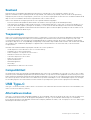 11
11
-
 12
12
-
 13
13
-
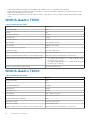 14
14
-
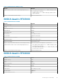 15
15
-
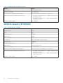 16
16
-
 17
17
-
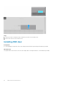 18
18
-
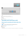 19
19
-
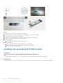 20
20
-
 21
21
-
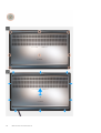 22
22
-
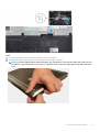 23
23
-
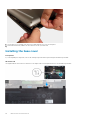 24
24
-
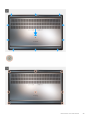 25
25
-
 26
26
-
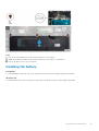 27
27
-
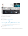 28
28
-
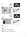 29
29
-
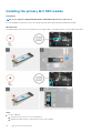 30
30
-
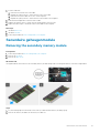 31
31
-
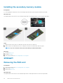 32
32
-
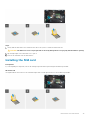 33
33
-
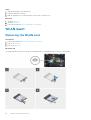 34
34
-
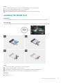 35
35
-
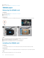 36
36
-
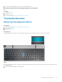 37
37
-
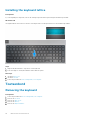 38
38
-
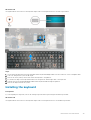 39
39
-
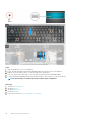 40
40
-
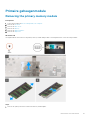 41
41
-
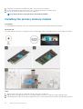 42
42
-
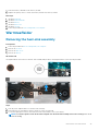 43
43
-
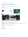 44
44
-
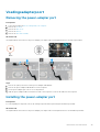 45
45
-
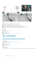 46
46
-
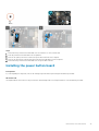 47
47
-
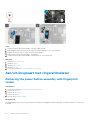 48
48
-
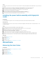 49
49
-
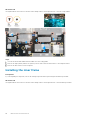 50
50
-
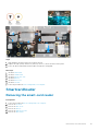 51
51
-
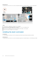 52
52
-
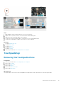 53
53
-
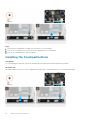 54
54
-
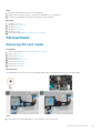 55
55
-
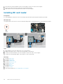 56
56
-
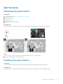 57
57
-
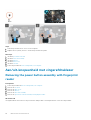 58
58
-
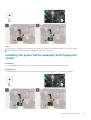 59
59
-
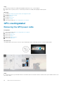 60
60
-
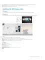 61
61
-
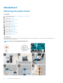 62
62
-
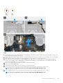 63
63
-
 64
64
-
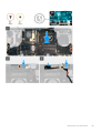 65
65
-
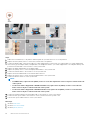 66
66
-
 67
67
-
 68
68
-
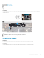 69
69
-
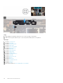 70
70
-
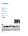 71
71
-
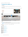 72
72
-
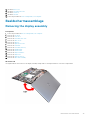 73
73
-
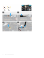 74
74
-
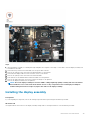 75
75
-
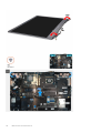 76
76
-
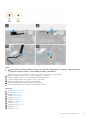 77
77
-
 78
78
-
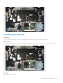 79
79
-
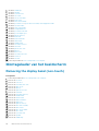 80
80
-
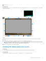 81
81
-
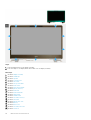 82
82
-
 83
83
-
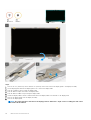 84
84
-
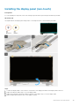 85
85
-
 86
86
-
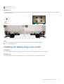 87
87
-
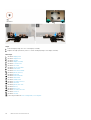 88
88
-
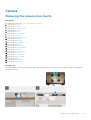 89
89
-
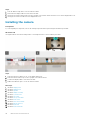 90
90
-
 91
91
-
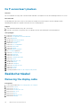 92
92
-
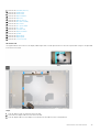 93
93
-
 94
94
-
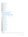 95
95
-
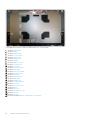 96
96
-
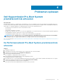 97
97
-
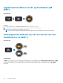 98
98
-
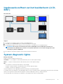 99
99
-
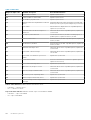 100
100
-
 101
101
-
 102
102


in andere talen
- English: Dell Precision 7550 Owner's manual
Gerelateerde papieren
-
Dell Precision 7750 de handleiding
-
-
Dell Precision 7550 de handleiding
-
Dell Precision 3240 Compact de handleiding
-
Dell Latitude 5400 Chromebook Enterprise de handleiding
-
Dell Latitude 5411 de handleiding
-
Dell OptiPlex 5080 de handleiding
-
-
Dell Precision 5540 Handleiding
-
Dell Latitude 5401 de handleiding