Yamaha AW 16G Handleiding
- Categorie
- Muziekinstrumenten
- Type
- Handleiding
Deze handleiding is ook geschikt voor

E
Owner’s ManualOwner’s Manual
Owner’s Manual
Keep This Manual For Future Reference.

FCC INFORMATION (U.S.A.)
1. IMPORTANT NOTICE: DO NOT MODIFY THIS UNIT! This product, when installed as indicated in the instructions contained in this manual, meets FCC
requirements. Modifications not expressly approved by Yamaha may void your authority, granted by the FCC, to use the product.
2. IMPORTANT: When connecting this product to accessories and/or another product use only high quality shielded cables. Cable/s supplied with this product MUST
be used. Follow all installation instructions. Failure to follow instructions could void your FCC authorization to use this product in the USA.
3. NOTE: This product has been tested and found to comply with the requirements listed in FCC Regulations, Part 15 for Class “B” digital devices. Compliance with
these requirements provides a reasonable level of assurance that your use of this product in a residential environment will not result in harmful interference with
other electronic devices. This equipment generates/uses radio frequencies and, if not installed and used according to the instructions found in the users manual, may
cause interference harmful to the operation of other electronic devices. Compliance with FCC regulations does not guarantee that interference will not occur in all
installations. If this product is found to be the source of interference, which can be determined by turning the unit “OFF” and “ON”, please try to eliminate the
problem by using one of the following measures: Relocate either this product or the device that is being affected by the interference. Utilize power outlets that are on
different branch (circuit breaker or fuse) circuits or install AC line filter/s. In the case of radio or TV interference, relocate/reorient the antenna. If the antenna lead-in
is 300 ohm ribbon lead, change the lead-in to coaxial type cable. If these corrective measures do not produce satisfactory results, please contact the local retailer
authorized to distribute this type of product. If you can not locate the appropriate retailer, please contact Yamaha Corporation of America, Electronic Service
Division, 6600 Orangethorpe Ave, Buena Park, CA 90620
The above statements apply ONLY to those products distributed by Yamaha Corporation of America or its subsidiaries.
IMPORTANT
THE WIRES IN MAINS LEAD ARE COLOURED IN
ACCORDANCE WITH THE FOLLOWING CODE:
BLUE : NEUTRAL
BROWN : LIVE
As the colours of the wires in the mains lead of this apparatus
may not correspond with the coloured markings identifying the
terminals in your plug proceed as follows:
The wire which is coloured BLUE must be connected to the
terminal which is marked with the letter N or coloured BLACK.
The wire which is coloured BROWN must be connected to the
terminal which is marked with the letter L or coloured RED.
Making sure that neither core is connected to the earth terminal of
the three pin plug.
* This applies only to products distributed by YAMAHA KEMBLE
MUSIC (U.K.) LTD.

3
WARNING
•Connect this unit’s power cord only to an AC outlet
of the type stated in this Owner’s Manual or as
marked on the unit. Failure to do so is a fire and elec-
trical shock hazard.
•Do not allow water to enter this unit or allow the
unit to become wet. Fire or electrical shock may
result.
•Do not place a container with liquid or small metal
objects on top of this unit. Liquid or metal objects
inside this unit are a fire and electrical shock hazard.
•Do not place heavy objects, including this unit, on
top of the power cord. A damaged power cord is a
fire and electrical shock hazard. In particular, be
careful not to place heavy objects on a power cord
covered by a carpet.
•Do not install a CD-RW drive into this device while
the power cable is plugged into an AC outlet. Doing
so is an electrical shock hazard.
•Use the ground connector on the rear panel to
securely ground the device. If the device is not
grounded, you may suffer a dangerous electrical
shock.
•Do not scratch, bend, twist, pull, or heat the power
cord. A damaged power cord is a fire and electrical
shock hazard.
•Do not modify the unit. Doing so is a fire and electri-
cal shock hazard.
•If lightning begins to occur, turn off the power
switch of the unit as soon as possible, and unplug the
power cable plug from the electrical outlet.
•If there is a possibility of lightning, do not touch the
power cable plug if it is still connected. Doing so may
be an electrical shock hazard.
•Use only the included AC adaptor (PA-300) for this
unit. Using other types may be a fire and electrical
shock hazard.
•If the power cord is damaged (i.e., cut or a bare wire
is exposed), ask your dealer for a replacement. Using
the unit with a damaged power cord is a fire and elec-
trical shock hazard.
• Should this unit and AC adaptor be dropped or the
cabinet be damaged, turn the power switch off,
remove the power plug from the AC outlet, and con-
tact your dealer. If you continue using the unit with-
out heeding this instruction, fire or electrical shock
may result.
•If you notice any abnormality, such as smoke, odor,
or noise, or if a foreign object or liquid gets inside the
unit, turn it off immediately. Remove the power cord
from the AC outlet. Consult your dealer for repair.
Using the unit in this condition is a fire and electrical
shock hazard.
CAUTION
•Hold the power cord plug when disconnecting it
from an AC outlet. Never pull the cord. A damaged
power cord is a potential fire and electrical shock
hazard.
•Do not touch the power plug with wet hands. Doing
so is a potential electrical shock hazard.
•This unit has ventilation holes at the bottom and rear
to prevent the internal temperature rising too high.
Do not block them. Blocked ventilation holes are a
fire hazard.
In particular, do not
- place the unit on its side or upside down,
- place the unit in any poorly-ventilated location
such as a bookcase or closet.
-cover the unit with a table cloth or place it on a
carpet or bed.
•Always touch a well-grounded metal surface or the
like to fully discharge any static electric charge on
your body and clothing before handling a CD-RW
drive.
Neglecting this precaution can cause damage to the
unit from static electricity.
•Be careful not to touch the leads (metal feet) on the
rear side when handling a CD-RW drive. Touching
the leads can cause contact defects.
•Do not cover or wrap the AC adaptor with a cloth or
blanket. Heat may build up under the cloth or blan-
ket, melting the case, or causing fire. Use only in a
well-ventilated environment.
PRECAUTIONS – for safe operation –
Operation
Installation
In case an abnormality occurs during operation
Installation
Operation

PRECAUTIONS
4
• XLR-type connectors are wired as follows: pin 1:
ground, pin 2: hot (+), and pin 3: cold (–).
•The performance of components with moving con-
tacts, such switches, rotary controls, faders, and con-
nectors, deteriorates over time. The rate of
deterioration depends on the operating environment
and is unavoidable. Consult your dealer about
replacing defective components.
•The digital circuits of this unit may induce a slight
noise into nearby radios and TVs. If noise occurs,
relocate the affected equipment.
•Using a mobile telephone near this unit may induce
noise. If noise occurs, use the telephone away from
the unit.
■
Be sure to turn off the power when you are finished
When using the AC adaptor, a small amount of electrical current will still be flowing even if the power is turned off
(i.e., the power switch set to “STANDBY”). The standby current consumption is designed to be as small as possible.
If you will not be using this product for an extended period of time, be sure to unplug the AC adaptor from the AC
outlet.
Please observe the following points when handling the disc.
Failure to do so may cause problems such as the recorded data being lost, the drive to malfunction, or the
printed label to become blurred.
•Do not place the disc in locations of direct sunlight, high temperature, or high humidity.
•Do not touch either surface of the disc.
Hold the disc at the edges.
•Gently wipe dust or dirt off of the recording surface of the disc.
Use an air duster or cleaner to remove dust. Vigorously rubbing the surface of the disc with a dry cloth may
scratch the disc.
•Do not write on the disc or affix labels to it.
•Do not wipe the disc with chemicals or detergents.
•Do not bend or drop the disc.
Produced data can be lost due to breakdown or mistaken operation. We strongly recommend that you store all
data on CD-R/CD-RW discs.
Yamaha will accept no responsibility for any damages (including consequential or incidental) incurred by the
customer or any third party as a result of loss or impairment of the data stored on the CD-R media, regardless
of whether such loss could have been or actually was foreseen by Yamaha.
Nor does Yamaha guarantee the media against any defect that may render it unusable.
PRECAUTIONS – for correct operation –
Connector pin assignments
Replacing abrasive parts
Interference with other electrical devices
Influence on cell phone usage
Handling the CD-R/RW media
Storing produced data
Responsibility for loss of data, etc.

5
•For inquiries concerning CD-RW drive handling, please consult your Yamaha dealer.
•Always switch off the power for the main unit and all peripherals, unplug the AC adaptor for the main unit
and the outlet, then disconnect the cables connecting the main unit with the peripherals before starting
installation work.
•Wear thick gloves when working on this equipment to avoid cutting your hands on metal fittings or the like
on the main unit or CD-RW drive.
•Always touch a well-grounded metal surface or the like to fully discharge any static electric charge on your
body and clothing before starting to work on this equipment.
•Take extreme care to avoid touching any terminals or board surface parts.
•In order to protect the electronic circuits of the CD-RW drive, etc. from damage due to static electricity,
when handling any of this equipment, take the most extreme care to avoid touching IC leads or other elec-
tronic parts.
•Be careful not to drop any screws into the main unit. If you switch the power on with a dropped screw still in
the main unit, the main unit may malfunction or break down. If a dropped screw can not be retrieved, con-
sult your Yamaha dealer.
•If the CD-RW drive breaks down, contact the store where you purchased that equipment.
Copyright and other intellectual property laws in various countries permit reproduction of copyrighted mate-
rials under certain requirements. The observance of applicable laws for use of this product, however, is your
responsibility. Yamaha disclaims any liability for violation of such laws in association with the use of this prod-
uct.
Although this product is designed for original music production, it can be utilized to make reproduction of
copyrighted music and other sound products. While certain reproduction and use of reproduced materials are
permitted under applicable laws, such reproduction and use without license may constitute copyright infringe-
ment and other violation of laws. Since violation of such laws can have serious consequences, you may wish to
consult a legal expert about your planned use of this product.
This product incorporates and bundles computer programs and contents in which Yamaha owns copyrights or
with respect to which it has license to use others' copyrights. Such copyrighted materials include, without lim-
itation, all computer software, styles files, MIDI files, WAVE data and sound recordings. Any unauthorized use
of such programs and contents outside of personal use is not permitted under relevant laws. Any violation of
copyright has legal consequences. DON'T MAKE, DISTRIBUTE OR USE ILLEGAL COPIES.
Cautions for handling optional equipment
Copyright Notice
The illustrations and LCD screens as shown in this owner’s manual are for instructional purposes only, and
may appear somewhat different from those on your instrument.

Contents
6
Contents
1 Before you start ...............................9
Introduction...............................................................9
Remember to back up your data ................................9
About the CD-RW drive............................................10
Installing the CD-RW drive .......................................10
Removing the CD-RW drive......................................11
Using the CD-RW drive ............................................11
Connecting the AC adaptor .....................................12
Turning the power on/off.........................................12
2 Introducing the AW16G ................13
Features of the AW16G ............................................13
AW16G terminology ................................................15
Recorder section .................................................15
Mixer section......................................................15
Quick Loop Sampler section ...............................16
Overall................................................................16
Parts of the AW16G and what they do .....................17
Top panel ...........................................................17
Rear panel ..........................................................21
Front panel .........................................................22
Basic operation on the AW16G.................................23
Viewing the display.............................................23
Accessing a screen/page/channel........................23
Switching a button on/off...................................24
Editing a value in the display ..............................24
Inputting text .....................................................24
Using the Selected Channel section ....................25
3 Listening to the demo song...........27
Connect external devices and turn on the
power ....................................................................27
Loading the demo song ...........................................28
Playing the demo song ............................................29
Mixing the demo song.............................................30
4 Recording to a sound clip ..............33
Connecting your instrument or mic .........................33
Adjusting the input level ..........................................34
Recording/playing a sound clip ................................35
5 Track recording .............................39
Creating a new song ................................................39
Direct recording and Bus recording..........................40
Assigning input signals to tracks (Direct
recording)..............................................................42
Assigning input signals to tracks (Bus recording) ......45
Enabling the metronome .........................................47
Recording on a track ................................................48
Pairing input channels/track channels ......................49
Using the input library..............................................50
Using the EQ library .................................................52
Using the dynamics library .......................................53
6 Overdubbing.................................. 55
About overdubbing..................................................55
Assigning the input signal to a track.........................56
Instantly recalling an EQ library ................................56
Instantly recalling a dynamics library ........................57
Setting the mix balance and pan..............................57
Overdubbing ...........................................................58
Punch-in/out............................................................59
Manual punch-in/out .........................................59
Auto punch-in/out..............................................59
Using the Undo List..................................................61
Switching virtual tracks ............................................62
Saving the current song ...........................................63
Loading an existing song .........................................64
7 Various types of playback ............. 65
Using the locator......................................................65
Using markers ..........................................................67
Adjusting the position of a locate point or
marker ...................................................................68
Erasing a locate point or marker ...............................69
Repeatedly playing a specific region (the A-B
Repeat function) ....................................................70
Finding a location while you listen to the
sound (the Nudge function) ..................................71
Finding a location while you view the waveform ......72
8 Using libraries and scene
memories.................................. 73
About the libraries....................................................73
About scene memories.............................................73
Basic operation for libraries and scene memories......74
Storing library or scene data ...............................74
Recalling library or scene data.............................75
Deleting library or scene data .............................75
Naming library or scene data..............................76
Details on libraries and scene memory .....................77
Input library........................................................77
EQ library ...........................................................77
Dynamics library.................................................78
Effect library .......................................................78
Mastering library ................................................78
Sample library ....................................................78
Channel library ...................................................79
Scene memories .................................................79
Using the Recall Safe function ..................................80
9 Mixdown and bounce operations . 81
About mixdown and bouncing ................................81
Preparing for mixdown ............................................83
Using the internal effects via send/return .................84
Recording on the stereo track...................................86
Bounce (ping-pong) recording procedure ................87
Convenient functions during mixdown/bounce
operations..............................................................89

7
Adding input signals or pad performances
during mixdown .............................................. 89
Using meters to check the level of each
channel............................................................ 90
Viewing all parameters for a certain channel....... 90
Initializing a channel .......................................... 91
Editing the EQ parameters.................................. 92
Editing the dynamics parameters........................ 93
Editing the parameters of an internal effect ........ 94
Inserting an effect into a track channel ............... 96
10 Creating an audio CD .................. 97
Creating an audio CD ..............................................97
Types of media that you can use with the CD-
RW drive................................................................ 97
Methods of writing an audio CD.............................. 98
Basic settings for the CD-RW drive ........................... 99
Writing audio data (Track At Once) ....................... 100
Writing audio data (Disc At Once) ......................... 102
Finalizing CD-R/RW media ..................................... 104
Erasing CD-RW media............................................ 105
Playing an audio CD .............................................. 106
11 Quick loop sampler.................... 107
About the quick loop sampler................................ 107
Using sample libraries ............................................ 109
Recording/playing a pad performance ................... 110
Importing from an audio CD/WAV file to a pad ..... 112
Importing from an audio track/stereo track to a
pad ..................................................................... 114
Sampling an external input signal.......................... 115
Editing the sample name ....................................... 117
Trimming the playback region ...............................118
Switching the playback mode for each pad ........... 119
Using the Slice function ......................................... 120
Deleting an unwanted sample ............................... 122
12 Track editing .............................123
What you can do using editing commands............ 123
Basic procedure for track editing ...................... 124
List of editing commands....................................... 126
ERASE............................................................... 126
DELETE............................................................. 127
INSERT ............................................................. 127
COPY ............................................................... 128
MOVE ..............................................................129
EXCHANGE ...................................................... 130
TIME COMP/EXP (Time Compression/
Expansion) ..................................................... 130
PITCH CHANGE................................................ 131
EXPORT............................................................ 131
Exporting WAV files and importing audio CD or
WAV files ............................................................. 132
Exporting WAV files.......................................... 132
Importing from an audio CD or WAV file.......... 133
13 Song management..................... 137
About songs .......................................................... 137
Editing the song name........................................... 138
Editing various settings for the song ......................139
Copying or deleting a song ................................... 140
Optimizing a song ................................................. 141
Creating a tempo map .......................................... 142
Importing data from an existing song.................... 144
Backing up songs and sample libraries ................... 145
Restoring songs or sample libraries ........................ 147
Exchanging song data with the AW4416/AW2816 148
14 MIDI and utility functions......... 149
What you can do using MIDI ................................. 149
Basic MIDI settings ................................................ 150
Transmitting the AW16G’s settings via MIDI
(Bulk Dump)........................................................ 154
Using the MIDI Remote function............................ 155
About the MIDI Remote function ..................... 155
Using the MIDI Remote function presets .......... 155
Using the user-defined Remote function........... 157
Using the test tone oscillator.................................. 159
Digital input settings/Checking and initializing the
internal hard disk................................................. 160
Overall settings for the AW16G.............................. 162
15 Using the AW16G with
external devices ..................... 163
Using the AW16G with a “workstation synth”........ 163
Synchronizing the AW16G with the
workstation’s sequencer................................. 163
Recording/playing AW16G mix operations on
the workstation’s sequencer........................... 164
Switching AW16G scenes from the
workstation’s sequencer................................. 165
Remotely controlling a tone generator module...... 166
Using external effects............................................. 167
Connecting an MD recorder .................................. 169
Mixing down to an MD recorder...................... 169
Recording audio data from an MD recorder ..... 170
Appendix ........................................ 171
Input library list ..................................................... 171
Mastering library list .............................................. 172
EQ library list ......................................................... 173
Dynamics Parameters ............................................ 174
Dynamics library list............................................... 177
Effects library list.................................................... 178
Effects Parameters.................................................. 180
Sample library list .................................................. 192
Troubleshooting .................................................... 194
Display message list ............................................... 198
About the CD-ROM included with the AW16G ...... 200
Caution............................................................ 200
Contents of the CD-ROM................................. 200
Restoring the internal hard disk to the
factory-set condition ...................................... 200
Installing a remote file...................................... 201
MIDI data format................................................... 204
MIDI Implementation Chart................................... 211
Specifications......................................................... 212
Dimensions............................................................ 214
Index..................................................................... 215
Block diagram........................................................ 218

Contents
8

9
Chapter 1
Before you start
This chapter explains what you should know before you begin using
the AW16G.
Introduction
■
Check the included items
The AW16G package contains the following items. If any
are missing, please contact your dealer.
•The AW16G
•AC adaptor (PA-300)
• Owner’s manual (this book)
• CD-ROM
■
Copyright
This product incorporates and bundles computer pro-
grams and contents in which Yamaha owns copyrights or
with respect to which it has license to use other’s copy-
rights. Such copyrighted materials include, without limi-
tation, all computer software, styles files, MIDI files,
WAVE data and sound recordings. Any unauthorized use
of such programs and contents outside of personal use is
not permitted under relevant laws. Any violation of copy-
right has legal consequences. DON’T MAKE, DISTRIB-
UTE OR USE ILLEGAL COPIES.
■
Trademarks
• Macintosh is a registered trademark of Apple Com-
puter, Inc. USA in the United States and other coun-
tries.
•Windows is a registered trademark of Microsoft Cor-
poration USA in the United States and other coun-
tries.
• Cubase VST is a trademark of Steinberg Media Tech-
nologies AG.
• Logic Audio is a trademark of Emagic Soft- and Hard-
ware GmbH.
• Cakewalk is a registered trademark of Twelve Tone
Systems, Inc.
• ProTools is a trademark or registered trademark of
Avid Technology, Inc. and affiliated companies.
• Other company names and product names in this
document are the trademarks or registered trade-
marks of their respective owners.
■
Yamaha website
http://www.yamahasynth.com
http://www.yamaha.co.jp/product/proaudio/homeenglish/
Yamaha manual library
http://www2.yamaha.co.jp/manual/english/
Remember to back up your data
■
Storing produced data
Produced data can be lost due to breakdown or mistaken
operation. We recommend that you store all important
data on CD-R or CD-RW discs or other external storage
medium.
Note
Note
A CD-RW drive (the separately sold CDRW16G) is neces-
sary in order to back up data.
■
Responsibility for loss of data, etc.
Yamaha will accept no responsibility for any damages
(including consequential or incidental) incurred by the
customer or any third party as a result of loss or impair-
ment of the data stored on the CD-R media, regardless of
whether such loss could have been or actually was fore-
seen by Yamaha.
Nor does Yamaha guarantee the media against any defect
that may render it unusable.

Before you start
10
About the CD-RW drive
A CD-RW drive is a device that lets you create or play
audio CDs, backup and restore data from the internal
hard disk, and read data from a CD-ROM. An optional
CDRW16G can be installed in the AW16G. Please be
aware that other CD-RW drives cannot be installed in the
AW16G.
•Even if a CD-RW drive is operating normally, it may fail
a read or write operation approximately once in five
hundred times.
•Yamaha will take no responsibility for any damages,
direct or consequential, that may result from the use of
the above CD-RW drive.
■
Handling
1
Do not drop the drive or subject it to strong
physical shock.
B
Never touch the objective lens.
C
Be careful that the objective lens does not
become dusty or dirty.
D
If the objective lens becomes dusty, use a
commercially available blower etc. to blow the
dust off with clean air.
E
Before installing the drive, touch a grounded
metal object so that the drive is not damaged
by any static electricity that may be in your
body.
F
Since the inside of the drive contains powerful
magnetic circuitry, do not allow any magnetic
material to come near the drive. (In particular,
any metallic fragments, screws, or pins that
enter the drive mechanism will cause opera-
tion to fail.)
G
Do not press on the upper cover.
Installing the CD-RW drive
1
Turn off the power of the AW16G.
As described in “Turning the power off (shut down)”
(
→
p. 12), turn off the power of the AW16G. For
safety’s sake, also unplug the AC adaptor and the
AW16G from the electrical outlet.
2
Turn the AW16G over on its face.
Be careful not to drop the AW16G on the floor, or
damage the components of the top panel. Spread
out a soft cloth on a level surface, and stack maga-
zines etc. to support each of the four corners of the
upside-down AW16G.
3
Insert the CD-RW drive into the slot.
Insert the CD-RW drive into the slot by pressing
slightly right of center on the back edge of the drive.
The slot cover swings open. When the CD-RW drive
reaches the back of the slot, continue applying pres-
sure until you feel the connector click into place.
You will need to apply about as much pressure as
when pressing an elevator button.
4
Fasten the CD-RW drive with screws.
Use the two included screws to fasten the CD-RW
drive in place (“4” in the diagram at left).
Be sure to follow installation steps 1–4 exactly as
directed. In particular, reading and writing may not occur
correctly if the screws have not been tightened suffi-
ciently.
3
4
Push the drive here.

11
Before you start
1
Removing the CD-RW drive
1
Turn off the power of the AW16G.
As described in “Turning the power off (shut down)”
(
→
p. 12), turn off the power of the AW16G. For
safety’s sake, also unplug the AC adaptor and the
AW16G from the electrical outlet.
2
Turn the AW16G over on its face.
Be careful not to drop the AW16G on the floor, or
damage the components of the top panel.
3
Remove the CD-RW drive cover.
Remove the black screw that holds the CD-RW
drive cover in place (“3” in the diagram at left).
Do not lose the screw that you removed.
4
Pull the CD-RW drive out of the slot.
Remove the two screws that fasten the CD-RW
drive in place, and pull out the CD-RW drive (“4” in
the diagram at left).
• Do not lose the screws that you removed.
• Be careful not to cut yourself on any sharp metal edge.
5
Attach the CD-RW drive cover.
Using the black screw that you removed in step 3,
attach the CD-RW drive cover.
Using the CD-RW drive
The CD-RW drive installed in the AW16G is shipped
with a protective pad on the disc tray to prevent it from
being damaged during transportation. Before you use the
AW16G, you must remove this protective pad.
To insert a disc into the CD-RW drive, press the eject
switch. The disc tray will open. Place the disc on the tray,
and gently push the disc tray in.
Note
Note
The disc tray is ejected electrically. If the disc tray is not
ejected when you press the eject switch, turn on the
power of the AW16G and press the eject switch once
again.
■
Removing a CD in an emergency
If you are unable to remove the disc by pressing the eject
switch, insert a wire of less than 2 mm diameter (such as
a straightened paper clip) into the eject hole, and push
gently. However, pressing the eject switch will not eject
the disc when the AW16G is in the following states, so
do not use this method in such cases.
• When the AW16G's power is “STANDBY“
• When the disc is being accessed (data is being read,
written, or erased)
• While in CD PLAY mode
This removal method is for use in emergencies such as
when you cannot remove the disc due to a malfunction of
the disc tray or a power failure. Do not use this method
unnecessarily, since doing so will damage the CD-RW
drive.
3,5
4
CD-RW drive cover
Grasp here with your
thumb and first finger.
< Bottom of the CD-RW drive >
The cover may crack
if you attempt to pull
out the CD-RW drive
by grasping the black
cover.
Eject buttonEject hole

Before you start
12
Connecting the AC adaptor
When connecting the included AC adaptor (PA-300), you
must first connect it to the DC IN jack of the AW16G,
and then to the AC wall outlet. After connecting the AC
adaptor to the AW16G, wrap the cable around the hook
as shown in the diagram. This will prevent the cable from
being accidentally pulled out, causing the AW16G to
unexpectedly lose power.
Turning the power on/off
You must use the following procedure to switch the
power of the AW16G between ON and STANDBY. If you
fail to follow this procedure, the internal hard disk or
your external monitor system may be damaged.
■ Turning the power on
In a system that includes the AW16G, turn the power of
each device on in the following order.
1 External devices such as audio sources and
effect processors connected to the input/out-
put jacks of the AW16G
B The AW16G itself
C The monitor system connected to the
AW16G’s output jacks
Before you turn on the power, make sure that the AC
adaptor is firmly connected to the AW16G and to the AC
outlet. If the power is disconnected while the AW16G is
being used, the AW16G itself or the hard disk may be
damaged.
When you turn on the power of the AW16G, an opening
screen will appear, and then the following screen will
appear.
■ Turning the power off (shut down)
In a system that includes the AW16G, turn the power of
each device off in the following order.
1 The monitor system connected to the
AW16G’s output jacks
B The AW16G itself
C External devices such as audio sources and
effect processors connected to the input/out-
put jacks of the AW16G
When turning off the power of the AW16G, you must
perform the following “shut-down” procedure.
1
In the work navigate section located in the
upper left of the top panel, press the [SONG]
key several times to access the following
SHUTDOWN page.
2
Press the [ENTER] key located in the middle
right of the top panel.
A popup window will ask you whether you want to
save the current song.
3
Using the CURSOR [ ]/[ ] keys located in
the upper right of the top panel, move the
cursor (the blinking area in the screen) to the
YES button if you want to save the current
song, or to the NO button if you do not want
to save it. Then press the [ENTER] key.
4
When the “Now safe to turn off...” message
appears, turn off the [POWER] switch located
on the rear panel.
If you turn off the power of the AW16G without perform-
ing the above shutdown procedure, not only will any
unsaved changes be lost, but you also risk damaging the
data on the hard disk, and damaging or drastically short-
ening the lifespan of the hard disk itself and the internal
CD-RW drive. Please use caution.
Tip!
Tip!
A small amount of electrical current is flowing even when
the power is in STANDBY mode. If you will not be using
the AW16G for an extended period of time, be sure to
disconnect the AC adaptor from your AC outlet.
DC IN

13
Chapter 2
Introducing the AW16G
This chapter describes the features of the AW16G, the name of each
part and its function, and introduces terminology you need to know
when using the AW16G.
Features of the AW16G
The AW16G is an audio workstation that combines a dig-
ital mixer, multi-effect processor, hard disk recorder,
sampler, and CD-RW drive.
The following diagram shows the signal flow within the
AW16G.
Now let’s take a more detailed look at each section of the
AW16G.
■ Mixer section
● Full-fledged mixer with 36 input channels
The AW16G contains a digital mixer with a total of
36 input channels, including analog inputs x 8, ste-
reo digital input x 1, recorder tracks x 16, and effect
returns x 2. Audio quality is guaranteed by 24-bit AD/
DA and 32-bit internal processing. A Hi-Z input jack
for directly connecting an electric guitar or bass is
also provided.
● Totally redesigned operation
The AW16G is designed to be operated directly by
the musician (guitarist, vocalist, drummer etc.). With
a minimum number of steps, you can assign input
signals to tracks, switch the monitor signal, and
record with effects, EQ, and dynamics processing
applied.
Input channels 1–8
Track channels 1–16
Return channels 1/2
Pad channels 1–4
Buses L/R
AUX buses 1/2
Effect buses 1/2
Stereo buses L/R
Stereo output channel
Mixer
Recorder
Quick loop sampler
CD-RW drive
CD Write
CD Play
DATA
Backup/Restore
Import/Export
INPUT jacks 1–8
DIGITAL
STEREO IN jack
Metronome
Recorder input
patching
Internal effects
Effect 1
Effect 2
1 2 3 4
×
8
×2
×2
×2
×2
×2
×2
Sound clip
×
2
×2
×2
×2
×2
×8
×2
×2 ×16 ×16
STEREO/AUX OUT jacks
DIGITAL STEREO OUT jack
MONITOR OUT jacks
PHONES jack

Introducing the AW16G
14
● Four-band EQ and dynamics processors on each
channel
Four-band full-parametric EQ and dynamics process-
ing is provided on virtually every channel. You can
recall the desired preset from the library, and use the
panel knobs and keys to quickly adjust the settings.
● Two high-quality multi-effect units are built-in
The two built-in effect units deliver a wide variety of
effects including spatial-type effects such as reverb
and delay, modulation type effects such as chorus
and flanger, and guitar-type effects such as distortion
and amp simulation. These effects can be used either
via send/return, or inserted into a desired channel.
■ Recorder section
● 8-track simultaneous recording/16-track simulta-
neous playback
You can record multiple tracks of instruments one by
one, or set up multiple mics to record a drum set or a
live performance by an entire band. A stereo track for
direct mixdown of all 16 tracks is also provided, let-
ting you manage the multi-track audio and the two-
track mix as a single package of data.
For the multi-tracks as well as the stereo track, you
can use eight virtual tracks for each track. When
recording parts or during mixdown, you can switch
virtual tracks to record multiple takes, and select the
best take later.
● Versatile editing functionality
Audio data recorded on a track can be copied,
moved, or edited using a variety of commands. You
can make detailed edits, or even make radical
changes to the structure of the song by using the
same riff repeatedly or increasing the number of cho-
ruses.
“Time Compression” lets you compress or expand the
time axis of the audio data in a range of 50%–200%.
“Pitch Change” lets you modify the pitch in a range
of one octave upward or downward. You can use the
Undo function to reverse the results of as many as the
last fifteen editing operations.
● A variety of Locate methods, and auto punch-in/out
Seven locate points (start/end, relative zero, A/B, in/
out) and 99 markers can be assigned at any desired
point in the song, for quick access via Locate opera-
tions. Auto punch-in/out and A-B repeat playback
functions are also provided. The AW16G also has a
metronome that follows the tempo map.
● Sound Clip function
The Sound Clip function lets you record and play
back an input signal without affecting the recorder
tracks. You can use this as a sketch for your ideas for a
song or arrangement.
■ Quick Loop Sampler section
The AW16G has a built-in pad-type sampler. You can
assign sixteen stereo waveforms to the four pads with
sample banks. Sampling uses the same 16-bit 44.1 kHz
high quality as recording. Audio tracks from the hard
disk, external input from the mixer, or WAV files from a
CD-ROM disc can also be loaded.
The timing at which each pad is pressed can be recorded
on a dedicated pad track, and edited later. Drum phrases
from the sample library can be assigned to pads, and you
can then record pad operations to use this function as a
simple rhythm machine.
The maximum polyphony is four stereo notes, and the
maximum playback time is a total of 44 seconds of stereo
for the entire Quick Loop Sampler.
■ CD-RW drive
A dedicated CD-RW drive (the CDRW16G, option) can
be installed in the AW16G. If this is installed, you can
produce an audio CD from the stereo tracks of the songs
recorded on the hard disk. Markers assigned within a
song can also be used as the track numbers of the CD.
You can even use advanced techniques such as assigning
more than one track number within a single song.
The CD-RW drive can also be used to backup/restore
songs, to play back audio CDs, and to load WAV data
from a CD-ROM.

15
Introducing the AW16G
2
AW16G terminology
Recorder section
■ Tracks
A location where data is recorded is called a “track.” The
AW16G’s recorder section uses the following types of
track.
● Audio tracks
The physical tracks used to record and play back
audio data are called “audio tracks,” or simply
“tracks.” The AW16G has sixteen audio tracks. You
can record eight tracks simultaneously, and play back
16 tracks simultaneously.
● Stereo track
Independently from audio tracks 1–16, the AW16G
has a “stereo track” that records and plays a stereo
audio signal.
The stereo track is used mainly as a dedicated mix-
down track for recording the final mix.
● Virtual tracks
Each audio track 1–16 and the stereo track consists of
eight tracks. Each of these eight tracks is called a “vir-
tual track.” For the audio tracks and the stereo track,
only one virtual track can be recorded or played at
any time. However, you can switch virtual tracks to
continue recording other takes while preserving the
previously-recorded content.
The diagram below shows the concept of virtual
tracks. The horizontal rows indicate audio tracks 1–
16, and the vertical columns correspond to virtual
tracks 1–8. The shaded areas indicate the virtual track
that is currently selected for recording or playback.
■ Paired tracks
For audio tracks 9/10–15/16, adjacent pairs of tracks are
handled by the mixer as a single unit. These pairs of
tracks are referred to as “paired tracks.” A paired track
can be used to record a stereo source, or a dual-guitar
performance, etc.
■ Locate points/markers
Locations within a song that you specified in order to
execute a function such as auto punch-in/out or A-B
repeat playback are called “locate points.” Locate points
include the in/out points and the A/B points, and you can
use the keys of the Locate section to move instantly to
these points.
Independently of the locate points, you can assign
“markers” at desired locations within a song so that you
will be able to find these locations quickly. The AW16G
lets you set up to ninety-nine markers (1–99). By using
the keys of the Locate section you can move instantly to
the previous or next marker.
Mixer section
■ Channels
A signal route that processes a single signal within the
mixer and sends it to various sections is called a “chan-
nel.” The mixer section of the AW16G lets you use the
following channels.
● Input channels 1–8
These apply EQ and dynamics processing to the sig-
nals that are input from MIC/LINE INPUT jacks 1–8,
and send them to the recorder tracks or to the STE-
REO OUT jacks.
● Track channels 1–16
These channels apply EQ and dynamics processing to
the audio playback signals from audio tracks 1–16 of
the recorder, and send the signals to the stereo track
and the STEREO OUT jacks. You can also perform
“bounce recording” by sending these channels to dif-
ferent tracks.
● Return channels 1/2
These channels send the return signals from the inter-
nal effects to the stereo track and the STEREO OUT
jacks.
● Pad channels 1–4
These channels apply EQ and dynamics processing to
the playback of Quick Loop Sampler pads 1–4, and
send the signals to the stereo track and the STEREO
OUT jacks.
● Stereo output channel
This applies EQ and dynamics processing to the sig-
nal of the stereo bus (which combines the signals of
the various channels), and sends it to the stereo track
or to the STEREO OUT jacks. The same signal is also
output from the MONITOR OUT jacks and from the
PHONES jack.
1
2
3
4
5
6
7
8
1
2 3 4 5 6 7 8 9 10 11 12 13 14 15 16
1
2
3
4
5
6
7
8
Audio tracks
Stereo track
Virtual tracksVirtual tracks

Introducing the AW16G
16
■ Paired channels
For track channels 9/10–15/16, pad channels 1–4, and
return channels 1/2, the parameters (except for pan and
phase) are always linked for adjacent pairs of channels.
These are called “paired channels.”
For input channels 1–8 and track channels 1–8, you can
also switch two adjacent odd-numbered/even-num-
bered channels to function as paired channels. The
parameters (except for pan and phase) of paired channels
will be linked, so that adjusting one parameter will cause
the same parameter of the other channel to follow.
■ Buses
A signal route that mixes the signals from multiple chan-
nels and send them to an output jack or recorder track
input is called a “bus.”
Unlike channels, which handle only a single signal, a
bus can combine multiple signals into one or two, and
send them to a destination. (The term “bus” comes from
the vehicle that carries numerous people simulta-
neously.)
The AW16G’s mixer section lets you use the following
buses.
● Stereo bus
This mixes the input signals to stereo, and sends them
via the stereo output channel to the stereo track of
the recorder or to the STEREO OUT jacks.
● AUX buses 1/2
These combine the signals from the various track,
input, return, and pad channels, and output them via
the STEREO/AUX OUT jacks to an external device.
Use these when you will use an external effect pro-
cessor, or to create a mix differing from the stereo
channel for musicians to monitor.
● Effect buses 1/2
These combine the signals from the track, input,
return, and pad channels, and input them to built-in
effects 1 and 2. (However, it is not possible for the
return channel 1/2 signals to be returned to the input
of the same effect.)
● Buses L/R
These combine the signals of track, input channels,
and send them to recorder track inputs.
Quick Loop Sampler section
■ Sample banks and samples
In the Quick Loop Sampler section you can assign stereo
waveforms to the four pads, and strike the pads to play
them back. These stereo waveforms are called “samples.”
The memories to which the samples are assigned are
called “sample banks,” and each pad provides four sam-
ple banks (A–D).
■ Pad track
The AW16G can realtime-record and play back your
strikes on the pads. The memory that records these pad
operations is called the “pad track.” Unlike the tracks
that record audio, the pad track simply records the tim-
ing at which you “pressed a pad” or “released a pad.”
Overall
■ Songs
The smallest unit by which the AW16G manages a com-
position is called a “song.” When you save a song on the
hard disk, all data necessary for reproducing that song
will be saved; i.e., not just the audio data, but also mixer
settings and the samples used by the quick loop sampler.
You can return to the original state at any time by loading
the saved song.
■ Scenes and scene memories
A “scene” is a stored set of settings for the mixer section
and effects. The area of memory that holds the scenes is
called “scene memory,” and 96 scenes can be stored for
each song. Scene memories are saved on the hard disk as
part of the song.
■ Libraries
A “library” is an area of memory that stores individual
settings such as for EQ or dynamics. The AW16G has
separate libraries for EQ, dynamics, effect, channel,
input, and mastering settings. Each library is saved on the
hard disk as part of the song.
■ Tempo map
The “tempo map” records changes in tempo and time
signature that occur during the course of a song. The
tempo map is saved on the hard disk as part of the song.
■ System data
Various global settings that apply to all songs are collec-
tively referred to as “system data.” System data is stored
on the hard disk independently of the individual songs.

17
Introducing the AW16G
2
Parts of the AW16G and what they do
This section explains the names and functions of the var-
ious items on the AW16G’s top panel, rear panel, and
front panel.
Top panel
Locate section
(P. 20)
Transport section
(P. 21)
Data entry/control section
(P. 20)
Selected Channel section
(P. 19)
Input/output section
(P. 18)
Work Navigate section
(P. 18)
Quick Navigate section
(P. 18)
Display (P. 18)
Mixer section
(P. 19)
Quick Loop Sampler
section (P. 18)

Introducing the AW16G
18
■ Input/output section
1 [GAIN] knobs 1–8
These adjust the sensitivity of the signals that are
input from the rear panel MIC/LINE INPUT jacks 1–8.
B [INPUT SEL] keys 1–8
These keys select the mixer input channel that you
will operate.
C [MONITOR/PHONES] knob
This knob adjusts the level of the signal that is out-
put from the MONITOR OUT jacks and the
PHONES jack.
■ Work Navigate section
1 [SONG] key
This key accesses the SONG screen, where you can
save or load songs, and perform the shut-down pro-
cedure.
B [CD] key
This key accesses the CD screen, where you can
write or play an audio CD, and backup or restore
data.
C [TRACK] key
This key accesses the TRACK screen, where you can
check whether each track contains data, and switch
the virtual tracks that will be used for recording and
playback.
D [EDIT] key
This key accesses the EDIT screen, where you can
copy or erase tracks.
E [REMOTE] key
This key accesses the REMOTE screen, where you
can use the front panel faders and [TRACK SEL]
keys to control an external MIDI device or
sequencer software on your computer.
F [UTILITY] key
This key accesses the UTILITY screen, where you
can make MIDI, oscillator, and digital input set-
tings, and format the hard disk.
■ Quick Navigate section
1 [RECORD] key
This key accesses the RECORD screen, where you
can quickly assign the signal to be recorded to the
input of each track, and make settings for recording.
B [MONITOR] key
This key accesses the MONITOR screen, where you
can quickly select the signal to be monitored, or
switch the stereo track playback on/off.
■ Display
This is a backlit liquid crystal display that indicates the
current operating status or the settings of the various
parameters. The screens that are displayed will depend
on the front panel keys and knobs that are operated.
1 Access indicator
This indicator indicates the access status of the
internal hard disk. When the hard disk is being read
or written, this indicator will light.
Never turn off the power of the AW16G when the access
indicator is lit. Doing so will not only damage the data on
the internal hard disk, but may also damage the hard disk
itself. When you want to turn off the power of the AW16G,
you must perform the shutdown procedure (
→
p. 12).
B Contrast
Adjusts the brightness of the display.
■ Quick Loop Sampler section
1 [PAD SEL] key
Hold down this key and press a pad 1–4 to select a
pad for operations.
B Pads 1–4
Each of these pads plays back the sample that has
been assigned to it.
C [SAMPLE EDIT] key
This key accesses the SAMPLE screen, where you
can make settings and perform operations for the
quick loop sampler.
1
2
3
2
4
6
1
3
5
21
1
2
1 32

19
Introducing the AW16G
2
■ Mixer section
1 [TRACK SEL] keys 1–8
B [TRACK SEL] keys 9/10–15/16
C [STEREO SEL] key
Use these keys to select the mixer track channels or
recorder tracks that you want to control.
D Faders 1–8
E Faders 9/10–15/16
Normally, these faders adjust the playback level of
each recorder track. By changing the internal set-
tings, you can also use these faders to control the
input levels of input channels 1–8 and pads 1–4.
F [STEREO] fader
This adjusts the output level of the stereo bus.
■ Selected Channel section
1 [EQ] knob
Turning this knob will adjust the EQ (equalizer) gain
for the currently selected channel. You can press
this knob to access the EQ screen, where you can
adjust all of the EQ settings.
B [DYN] knob
Turning this knob will adjust the dynamics depth for
the currently selected channel. You can press this
knob to access the DYN screen, where you can
adjust all of the dynamics settings.
C [EFF 1] knob
D [EFF 2] knob
Turning these knobs will adjust the amount of signal
that is sent from the currently selected channel to
the internal effects 1 and 2 (i.e., effect send levels 1
and 2). You can press these knobs to access the
EFF1 or EFF2 screens, where you can adjust the
parameters of the internal effects.
E [PAN/BAL] knob
Turning this knob will adjust the pan of the cur-
rently selected channel (or the balance of the stereo
output channel). You can press this knob to access
the PAN screen, where you can adjust pan for mul-
tiple channels.
F [HIGH] key
G [HI-MID] key
H [LO-MID] key
I [LOW] key
These keys select one of the four EQ bands (HIGH,
HI-MID, LO-MID, LOW) to be adjusted.
J [VIEW] key
This key accesses the VIEW screen, where you can
check the level of each channel, or perform on-
screen adjustments to the faders and other mix
parameters of each channel.
6
1
4 5
2 3
6
7
8
9
J
1
2
3
4
5

Introducing the AW16G
20
■ Data entry/control section
1 [UNDO/REDO] key
This key cancels the results of a recording or track
editing operation (Undo), or re-executes a can-
celled operation (Redo).
Tip!
Tip!
• This key will light if Undo can be performed.
• If you press and hold this key, the UNDO LIST screen
will appear. Here you can turn the [DATA/JOG] dial to
revert as many as the last fifteen operations (
→
p. 61).
B [SCENE] key
This key accesses the SCENE screen, where you can
save or recall scene memories.
C [JOG ON] key
This key is an on/off switch for the Nudge function
(→ p. 71) which uses the [DATA/JOG] dial (
5).
When this function is on, the key will light.
D [CURSOR] keys ([ ]/[ ]/[ ]/[ ] keys)
These keys move the cursor in the screen (the blink-
ing frame) to select a specific item.
E [DATA/JOG] dial
Use this dial to change the value of a parameter. If
the [JOG ON] key (
3) is on, this dial operates the
Nudge function.
F [ENTER] key
Use this key to operate a button displayed in the
screen, or to execute a specific function.
■ Locate section
1 [SOUND CLIP] key
This key accesses the CLIP screen, where you can
record or play sound clips.
B [AUTO PUNCH] key
This key switches the audio punch-in/out function
on/off, letting you automate recording.
C [REPEAT] key
This key switches the A-B repeat function on/off, let-
ting you repeatedly play a specified region.
D MARK SEARCH [ ]/[ ] keys
These keys search for markers placed within the
song.
E [IN]/[OUT] keys
These keys specify the points at which auto punch-
in/out recording will begin (the In point) and end
(the Out point). These keys can also be used as
locate keys to move directly to the In point or Out
point.
F [A]/[B] keys
These keys specify the points at which the Repeat
function will begin (point A) and end (point B).
These keys can also be used as locate keys to move
directly to point A or point B.
G [MARK] key
This key places a mark at the current location of the
song.
H [SET] key
Use this key in conjunction with the [IN]/[OUT]
keys or the [A]/[B] keys to register the current loca-
tion as a locater.
I [CANCEL] key
Use this key in conjunction with the [IN]/[OUT]
keys or the [A]/[B] keys to cancel a locater that you
registered.
1
4
2
3
6
5
1
4
6
2
3
7
8
9
5

21
Introducing the AW16G
2
■ Transport section
1 RTZ [ ] key
This key moves directly to the relative zero time
location. Used in conjunction with the [SET] key,
this registers the current location as the relative zero
time.
Tip!
Tip!
Broadly speaking, the times displayed in the AW16G’s
counter can be either absolute time (ABS) or relative
time (REL). The absolute time zero location is fixed, but
the relative time zero location can be freely specified.
B REW [ ] key
This key rewinds the current location. Each time
you press this key, you will alternate between 8x
speed and 16x speed.
C FF [ ] key
This key fast-forwards the current location. Each
time you press this key, you will alternate between
8x speed and 16x speed.
D STOP [■] key
This key stops playback, recording, fast-forward, or
rewind.
E PLAY [ ] key
If you press this key while the recorder is stopped,
playback will begin.
If you press this key during fast-forward or rewind,
normal-speed playback will begin.
If you press this key during recording, recording
will stop and playback will resume (“punch-out”).
F REC [●] key
If you hold down this key and press the PLAY [ ]
key while the recorder is stopped, recording will
begin.
If you hold down this key and press the PLAY [ ]
key during playback, you will switch from playback
to recording (“punch-in”).
Rear panel
1 MIC/LINE INPUT (XLR) jacks 1/2
These are XLR-3-31 type balanced input jacks. The
nominal input level is –46 to +4 dB. Mics, direct
boxes, or line level devices with balanced output
jacks can be connected here. The pin configuration
is shown below.
B MIC/LINE INPUT (TRS phone) jacks 3–8
These are TRS phone type 1/4" input jacks (bal-
anced). The nominal input level is –46 to +4 dB.
Devices such as synthesizers or rhythm machines
with unbalanced outputs can also be connected
here. The pin configuration is shown below.
C MIC/LINE INPUT jack 8 (Hi-Z)
This is a high impedance 1/4" phone input jack
(unbalanced). The nominal input level is –46 to +4
dB. An instrument with high output impedance
such as an electric guitar or bass with passive-type
pickups can be connected here.
D STEREO/AUX OUT jacks
These are 1/4" phone output jacks (unbalanced) that
output the signals of the stereo bus or AUX bus 1/2.
E MONITOR OUT jacks
These are 1/4" phone output jacks (unbalanced) for
connection to your monitor setup, such as a stereo
system or powered speakers.
F PHONES jack
This is a 1/4" TRS phone output jack for connecting
your headphones for monitoring.
4 5 6
12 3
8 7M LN J 9K
145 236
Male XLR connector
1 (ground)
3 (cold)
2 (hot)
1/4" TRS phone plug
Ring (cold)
Tip (hot)
Sleeve (ground)

Introducing the AW16G
22
G PHANTOM +48V switch
This switch supplies phantom power to MIC/LINE
(XLR) jacks 1/2.
Turn this switch on if you connect condenser mics
requiring external +48V power to MIC/LINE INPUT
(XLR) jacks 1/2.
•You must turn this switch off if a device not requiring
an external power supply is connected to the INPUT
(XLR) 1/2 jacks.
• If phantom power is turned on, power will be supplied
to both the INPUT (XLR) 1/2 jacks.
H FOOT SW jack
A separately sold foot switch (Yamaha FC5) can be
connected here to control transport operations such
as start/stop, or to perform punch-in/out.
Note
Note
The appropriate operation may not occur if you use a
foot switch other than the Yamaha FC5 (or equivalent).
I MIDI IN connector
J MIDI OUT/THRU connector
These connectors allow MIDI messages to be
exchanged with external devices.
MIDI IN receives MIDI messages.
MIDI OUT/THRU can be internally switched to
function either as a MIDI OUT jack (which trans-
mits MIDI messages generated within the AW16G)
or MIDI THRU jack (which re-transmits messages
that are received at the MIDI IN jack).
K DIGITAL STEREO IN/OUT jacks
These are optical jacks that allow digital audio sig-
nals to be exchanged with external devices. They
support the IEC958 consumer format.
L Grounding terminal
This is a terminal for electrically grounding the
AW16G. To prevent electrical shock, you must con-
nect this terminal to an electrical ground before you
plug the AC adaptor into an AC outlet. Grounding
will also help prevent hum and noise.
M POWER switch
This switches the power between ON and
STANDBY.
Note
Note
When switching the power of the AW16G between ON
and STANDBY, you must follow the “Turning the power
on/off” (
→
p. 12) procedures described.
N DC IN connector
Connect the included AC adaptor (PA-300) to this
connector.
Use only the included AC adaptor (PA-300) for this unit.
Using other types may be a fire and electrical shock haz-
ard.
Front panel
■ CD-RW drive
1 Eject button
This switch ejects the disc tray.
B Eject hole
This hole allows you to open the disc tray manually.
C Access indicator
This indicator will light while the CD inserted in the
drive is being accessed.
123

23
Introducing the AW16G
2
Basic operation on the AW16G
This section explains basic operations on the AW16G.
Viewing the display
The display of the AW16G shows the following informa-
tion.
1 Screen name
This is the name of the currently selected screen.
B Selected channel
This indicates the mixer channel that is selected for
operations. The display has the following signifi-
cance.
TRACK 1–8 ...........................Track channels 1–8
TRACK 9/10–15/16...............Track channels 9/10–15/16
INPUT 1–8............................Input channels 1–8
STEREO.................................Stereo output channel
PAD 1–4................................Pad channels 1–4
Operating the knobs or keys of the Selected Chan-
nel section will edit the parameters of the channel
that is selected here.
C Counter (left side)
This indicates the current location within the song.
When the AW16G is in the default state, this
counter will indicate the absolute time (the time
from where you began recording the song) in units
of hours/minutes/seconds/milliseconds. At the left
of this value is displayed the locate point or marker
that was passed most recently.
D Counter (right side)
This indicates the current location within the song
in units of measures/beats. The measures/beats are
calculated according to the tempo and time signa-
ture specified in the tempo map for the song. The
current tempo and time signature are displayed at
the left of this value.
E Main screen
The information displayed in this area will depend
on the key that was last pressed. The following types
of object are displayed in the main screen.
● Cursor
The blinking frame within the display is
called the “cursor.” When an object in the
screen is enclosed by the cursor, that
object is selected for operations.
● Buttons
Buttons in the display are used to
switch a parameter on/off, to select
one of multiple choices, or to exe-
cute a specific function. A button
that is currently on will be dis-
played in black with white text. A
button that is currently off will be
displayed in white with black text.
● Knob/fader/parameter display area
The knob/fader/parameter display area within the
display is used to edit the value of the correspond-
ing parameter.
● Page display area
Most screens are divided by func-
tion into two or more “pages.” The
page display area lists the pages
that can be selected within that
screen. The name of the currently
selected page is highlighted.
Accessing a screen/page/channel
When you want to edit an internal setting of the AW16G,
or to edit a parameter that cannot be operated by a fader
or knob shown in the display, you will need to access the
desired screen and page.
1
Press the key or knob for the desired screen.
The keys and knobs of various sections listed below
have their own screens, and the corresponding
screen will be displayed when you press a key or
knob.
• All keys in the Work Navigate section
• All keys in the Quick Navigate section
•The [VIEW] key of the Selected Channel section
• All knobs of the Selected Channel section
•The [SAMPLE EDIT] key of the Quick Loop Sam-
pler section
Tip!
Tip!
When you switch screens, the page that was last used in
that screen will be displayed.
12 3
5
4
Knob fader parameter display
area

Introducing the AW16G
24
2
To switch pages within a screen, you can
either repeatedly press the same key as in
step 1, or hold down the same key as in step
1 and use the CURSOR [ ]/[ ] keys.
If there are more pages than can
be shown in one screen, an
arrow like the following will
appear in the page display area.
This arrow means that one or
more additional hidden pages
exist in that direction.
To access a hidden page, hold down the same key
as in step 1, and press the [CURSOR] key of the
same direction as the arrow.
In pages that display a list of parameters for multiple
channels, the screen may be divided into a page for
the input channels/pad channels and a page for the
track channels, since not all of the parameters can
be shown in a single screen. In this case, use the
[INPUT SEL] keys, pads 1–4, or [TRACK SEL] keys
to select the channels that you want to view.
Switching a button on/off
Here’s how to switch a button in the screen on/off.
1
Use the [CURSOR] keys to
move the cursor to the
desired button in the
screen.
2
Press the [ENTER] key.
The button will be switched on/
off.
If you move the cursor to a but-
ton that executes a specific
function and then press the
[ENTER] key, that function will
be executed.
Editing a value in the display
Here’s how to edit the value of a fader, knob, or parame-
ter shown in the display.
1
Use the [CURSOR]
keys to move the cur-
sor to the desired
fader, knob, or param-
eter value.
2
Turn the [DATA/JOG]
dial to edit the value.
Inputting text
When you create a new song or save a scene memory or
library setting, a popup window will appear, allowing
you to assign a name for the song or setting.
This popup window contains the following items and
functions.
1 Text input box
This box lets you input characters, numerals, and
symbols. When you save the data for the first time,
the box will contain a default name.
You can input a scene/library name or song name of
up to twelve characters.
B Text palette
This displays the characters, numerals, and symbols
that can be input in the text input box.
C CANCEL button
If you move the cursor to this button and press the
[ENTER] key, you will return to the previous screen
without changing the name.
D OK button
If you move the cursor to this button and press the
[ENTER] key, the scene/library will be saved or the
new song will be created.
E button
If you move the cursor to this button and press the
[ENTER] key, the character that is currently selected
in the text input box will be switched between
uppercase and lowercase.
F INS button
When you move the cursor to this button and press
the [ENTER] key, a space will be inserted at the
location of the currently selected character (under-
lined), and subsequent characters will move one
character backward.
G DEL button
When you move the cursor to this button and press
the [ENTER] key, the currently selected character
(underlined) will be deleted, and subsequent char-
acters will move one character forward.
To assign a new name, use the [CURSOR] keys to
move the cursor in the text input box to the charac-
ter that you want to change, and turn the [DATA/
JOG] dial to select a character.
When you have finished inputting the name, move
the cursor to the OK button and press the [ENTER]
key to apply the new name.
1
2
5
6 7
3
4

25
Introducing the AW16G
2
Using the Selected Channel sec-
tion
You can use the knobs and keys of the Selected Channel
section to directly operate the mix parameters (EQ,
dynamics, pan, etc.) of the currently selected channel.
1
Use the [TRACK SEL] keys, [INPUT SEL] keys,
[STEREO SEL] keys, or pads 1–4 to select the
channel that you want to operate.
When using the
Selected Channel
section, you must
first select the
channel that you
want to operate. The currently selected channel is
indicated in the upper left of the screen.
The channels correspond to each key or pad as fol-
lows.
[TRACK SEL] keys 1–8 ...........Track channels 1–8
[TRACK SEL] keys
9/10–15/16...........................Track channels 9/10–15/16
[INPUT SEL] keys 1–8 ...........Input channels 1–8
[STEREO SEL] key..................Stereo output channel
Pads 1–4................................Pad channels 1–4
2
According to the parameter you want to edit,
turn the five knobs of the Selected Channel
section.
The following items will change when you turn
each knob.
Note
Note
• Simply turning the knobs of the Selected Channel sec-
tion will not cause the screen to change.
• If you turn the [DYN] knob immediately after recalling
a preset library that includes dynamics settings, multi-
ple dynamics parameters will change simultaneously,
affecting the way in which dynamics processing is
applied. The depth of this change will depend on the
library that is recalled.
3
If you want to access the screen for a param-
eter and edit it in greater detail, press one of
the five knobs or the [VIEW] button.
Pressing each knob or button will access the follow-
ing screens.
● EQ screen EDIT page
4
Move the cursor in the screen to the desired
parameter, and use the [DATA/JOG] dial or
the [ENTER] key to operate the parameter.
Note
Note
• If you change individual parameters in the DYN screen,
the parameter that you operate last will be assigned to
the [DYN] knob.
• If you want to return to the state in which turning the
[DYN] knob will adjust multiple parameters simulta-
neously, you must once again recall the library contain-
ing the dynamics settings you recalled prior to editing
in the DYN screen.
Turn the [EQ] knob
This changes the amount of boost/cut for the selected
EQ band. To select the EQ band, use the [HIGH], [HI-
MID], [LO-MID], and [LOW] keys located at the right.
Turn the [DYN] knob
This changes the depth of dynam-
ics processing.
Turn the [EFF 1] knob
This adjusts the level of the signal
that is sent from that channel to
internal effect 1. (If the stereo output
channel is selected, this adjusts the
return level from internal effect 1.)
Turn the [EFF 2] knob
This adjusts the level of the signal
that is sent from that channel to
internal effect 2. (If the stereo output
channel is selected, this adjusts the
return level from internal effect 2.)
Turn the [PAN/BAL] knob
This adjusts the pan of the signal that is sent from that
channel to the stereo bus. (If the stereo output chan-
nel is selected, this adjusts the balance of the left and
right channels.)
Press the [EQ] knob
The EQ screen will appear.
Press the [DYN] knob
The DYN screen will appear.
Press the [EFF 1] knob
The EFF 1 screen will appear.
Press the [EFF 2] knob
The EFF 2 screen will appear.
Press the [PAN/BAL] knob
The PAN screen will appear.
Press the [VIEW] key
The VIEW screen will appear.

Introducing the AW16G
26

27
Chapter 3
Listening to the demo song
When the AW16G is shipped from the factory, its hard disk contains
a demo song. This chapter explains how to play back the demo song
while you operate the faders and keys of the front panel.
Connect external devices and turn on the
power
The following diagram shows a typical example of con-
nections to the AW16G. Connect your mics, instruments,
and external devices as shown in this diagram.
When you have finished making connections, turn on
the power switch of each device in the following order.
1 External devices such as audio sources or
effect processors connected to the input/out-
put jacks of the AW16G
B The AW16G itself
C The monitor system connected to the output
jacks of the AW16G
After the opening screen, the following screen will
appear.
When you turn on the power of the AW16G, the last-
used song will be loaded automatically. When you turn
on the power of the AW16G with the factory settings, a
blank song will be loaded, so you can start recording
immediately.
VOL VOL
MONITOR OUT
INPUT 1 2 3–8
INPUT 8
(HI-Z)
PHONES
DIGITAL
STEREO OUT
DIGITAL
STEREO IN
00.00.00.00
REC
SONG SCENE
MUSIC
PRODUCTION
SYNTHESIZER
Integrated
Sampling
Sequencer
Real-timeExternalControl
Surface
Modular
SynthesisPlug-in
System
Rhythm machine
SynthesizerMics
Headphones
Monitor system
DAT recorder, MD
recorder, etc.
Electric guitar/
Electric bass

Listening to the demo song
28
Loading the demo song
Here’s how to load the demo song from the hard disk.
1
In the work navigate sec-
tion, press the [SONG] key.
The SONG screen will appear,
where you can save or load
songs.
2
Either press the [SONG] key repeatedly or
hold down the [SONG] key and use the CUR-
SOR [ ]/[ ] keys to access the LIST page.
In this page, you can select a song on the hard disk,
and load or delete it.
1 List
This area lists the songs that are saved on the hard
disk. The line enclosed by the dotted frame in the
center of the list indicates the song that is selected
for operations. The highlighted line indicates the
song that is currently loaded into the AW16G. (This
is called the “current song.”)
B SORT field
These three buttons let you select how the songs in
the list will be sorted. Choose the NAME button
(sort alphabetically), OLD button (sort by save date),
or SIZE button (sort by size).
3
Turn the [DATA/JOG] dial to select the song
“Ride with me.”
4
Move the cursor to the LOAD
button in the screen, and press
the [ENTER] key.
A popup window like the following
will appear. This window asks you
whether you want to save the current
song.
5
Move the cursor to either YES (save the cur-
rent song) or NO (don’t save the current
song), and press the [ENTER] key.
The song data will be loaded, and “Ride with me”
will become the current song.
Note
Note
If you select NO, any changes that you made to the cur-
rent song since you last saved it will be lost.
21

29
Listening to the demo song
3
Playing the demo song
Here’s how to play back the demo song you loaded, and
adjust the monitor level.
1
Either press the [VIEW] key repeatedly or hold
down the [VIEW] key and use the CURSOR
[ ]/[ ] keys to access the VIEW screen
METER page.
The VIEW screen METER page contains meters that
show the input level of each channel and the output
level of the stereo output channel. It is convenient
to display this page when you want to check the
level of each track.
Note
Note
Make sure that the selected channel area at the upper left
of the METER page indicates either TRACK 1–8 or TRACK
9/10–15/16. If neither of these are displayed, press either
the [TRACK SEL] key 1–8 or 9/10–15/16.
2
Lower the AW16G’s [STEREO] fader to the -
infinity position. Also make sure that the
AW16G’s [MONITOR PHONES] knob and the
volume of your monitor system are turned
down.
3
Press the PLAY [ ] key.
The demo song will begin playing, and the level of
each track channel will be displayed in the METER
page of the VIEW screen.
4
To adjust the monitor level appropriately, use
the AW16G’s [MONITOR PHONES] knob and
the volume control of your monitor system.
Tip!
Tip!
The demo song uses the Scene function to switch the set-
tings of the mixer. This means that playback will occur
using the pre-specified balance — you do not need to
operate the faders.
5
To stop the song, press the STOP [■] key.

Listening to the demo song
30
Mixing the demo song
When you play back a song, tracks 1–16 of the recorder
are directly connected to track channels 1–8 and 9/10–
15/16 of the mixer. The signals that pass through track
channels 1–8 and 9/10–15/16 are sent to the stereo bus,
routed through the stereo output channel, and sent from
the STEREO/AUX OUT jacks or the MONITOR OUT
jacks.
● Signal flow during song playback
Track channels 1–8 and 9/10–15/16 are directly con-
trolled by the faders and [TRACK SELECT] keys of the
panel. Here’s how you can adjust the mix level of each
track channel and switch it on/off while the song plays
back.
Recorder section
Mixer section
Stereo bus
Track
channels
Stereo output
channel
Track 1
Track 2
Track 3
Track 4
Track 5
Track 6
Track 7
Track 8
Track 9
Track 10
Track 11
Track 12
Track 13
Track 14
Track 15
Track 16

31
Listening to the demo song
3
1
Press the RTZ [ ] key.
The demo song will be rewound to the beginning.
2
Press the PLAY [ ] button.
The demo song will begin playing.
3
While listening to the demo song, try operat-
ing faders 1–8 and 9/10–15/16.
Notice that the level of the corresponding track will
change. Operating the [STEREO] fader will change
the overall level of the song.
4
To mute the playback of a
specific track, access the
MONITOR screen ON/
OFF page, either by
repeatedly pressing the
[MONITOR] key or by
holding down the [MONITOR] key and using
the CURSOR [ ]/[ ] keys.
The MONITOR screen ON/OFF page lets you
switch each channel on/off. A channel that is
switched off in this page will not be sent to the ste-
reo bus or AUX bus, and will be muted.
5
Press the [TRACK SEL] key(s) for the track
channel(s) that you want to mute. (You may
select more than one channel.)
For example if you press [TRACK SEL] keys 1 and 3,
the screen will change as follows, and track chan-
nels 1 and 3 will be muted. At this time, [TRACK
SEL] keys 1 and 3 will go dark. The graphic in the
display will also indicate this.
Note
Note
The [TRACK SEL] key you press last will always light
orange regardless of the mute status. This indicates that
this channel is the “selected channel” (
→
p. 25).
Note
Note
In this page, pressing the [STEREO SEL] key will have no
effect.
6
To cancel the muted state, press the same
[TRACK SEL] key you pressed in step 5, to
make the indicator light green.
7
If you want to monitor the playback of just a
specific track, access the MONITOR screen
SOLO page by either repeatedly pressing the
[MONITOR] key or by holding down the
[MONITOR] key and using the CURSOR [ ]/
[] keys.
The SOLO page of the MONITOR screen lets you
mute all other channels while listening to only a
specific channel. (This is called the “solo” function.)
When you sol a channel in this page, the signals of
the remaining channels will be muted, and will no
longer be sent to the stereo bus or AUX buses.
8
Press the [TRACK SEL] key of the track chan-
nel that you want to solo.
For example if you press [TRACK SEL] key 3, the
screen will change as follows, and channels other
than track channel 3 will be muted. At this time,
[TRACK SEL] key 3 will light orange, and the other
[TRACK SEL] keys and [INPUT SEL] keys will go
dark.
Note
Note
Only one channel can be soloed at a time.
9
To cancel soloing, press the currently
selected [TRACK SEL] key (lit orange) once
again.
Note
Note
While playing the demo song, the level or the on/off sta-
tus of a channel you adjusted manually may return to its
previous setting. This is because the Scene function has
switched the state of the mixer settings, and is not a mal-
function (
→
p. 142). You can use the Recall Safe function
to temporarily prevent scenes from being recalled. (
→
p. 80)

Listening to the demo song
32

33
Chapter 4
Recording to a sound clip
The AW16G has a Sound Clip function that lets you record and play
back independently of the recorder section. You can use a sound clip
to quickly record and play back your performances on an audio
source connected to the AW16G or on the pads. This is an ideal way
to capture ideas for a song or arrangement, or to record a simple
accompaniment for practicing a part.
This chapter explains how an instrument or mic connected to an
input jack can be recorded as a sound clip.
Connecting your instrument or mic
First, the instrument or mic that you want to record must
be connected to a MIC/LINE INPUT jack. The various
types of jack are compatible with the following sources.
● MIC/LINE INPUT (XLR) jacks 1/2
These are XLR-type balanced input jacks. Use a male
XLR ↔ female XLR cable to connect your mic, direct
box, or a guitar/bass preamp that has a balanced out-
put jack.
● MIC/LINE INPUT (TRS phone) jacks 3–8
These are TRS-type balanced input jacks. Use a 1/4"
TRS phone ↔ female XLR cable to connect your mic,
direct box, or a guitar/bass preamp that has a bal-
anced output jack.
Alternatively, you can use a 1/4" phone ↔ 1/4"
phone cable to connect an instrument with unbal-
anced output, such as a synthesizer or rhythm
machine.
● MIC/LINE INPUT jack 8 (Hi-Z)
Use a 1/4" phone ↔ phone cable to directly connect
an electric guitar/bass that has passive pickups.
MIC/LINE INPUT
(XLR) jacks 1/2
Balanced cable
(male XLR ↔ female XLR)
Mic
Electric
guitar/bass
Preamp or effect proces-
sor with balanced output
Direct box
1/4" TRS phone ↔ female XLR
cable
Mic
Electric
guitar/bass
Preamp or effect proces-
sor with balanced output
Direct box
MIC/LINE INPUT
(TRS phone) jacks
3–8
1/4" phone ↔ phone cable
Synthesizer/
rhythm machine
MIC/LINE INPUT
(TRS phone) jacks
3–8
1/4" phone ↔ phone cable
MIC/LINE INPUT
(HI-Z) jacks 8
Electric guitar/bass
with passive pickups

Recording to a sound clip
34
Adjusting the input level
The signals that are input from MIC/LINE INPUT jacks 1–
8 are sent to input channels 1–8 respectively. Here's how
to adjust the input level of the input channel, and make
settings so that you can hear the sound from your moni-
tor system via the stereo bus.
1
Lower the [STEREO] fader to the –∞ position.
Also turn down the [GAIN] knob for the MIC/
LINE INPUT jack to which your instrument/
mic is connected.
2
Press and hold the [INPUT SEL] key for the
jack to which your instrument/mic is con-
nected.
When you press and hold an [INPUT SEL] key, the
INPUT SETTING popup window will appear, allow-
ing you to make settings for the corresponding input
channel. The following diagram is an example of
the screen that will appear if you press and hold
[INPUT SEL] key 1.
1 INPUT LEVEL knob
Move the cursor to this knob and turn the [DATA/
JOG] dial to adjust the level of the input channel.
Normally you will leave this at the default setting of
0 dB. The current level is shown by the value (dB
units) above the knob.
B Stereo bus assign switch
When you move the cursor to this knob and press
the [ENTER] key, the signal that is sent from the cor-
responding input channel to the stereo bus will be
switched on/off.
C Level meter
This indicates the input level of the input channel.
The symbol in the window indicates the loca-
tion at which the level is detected.
D EXIT button
Move the cursor to this button and press the
[ENTER] key to close the popup window and return
to the previous screen.
3
While you watch the level meter in the
popup window, produce sound on your
instrument, and turn the [GAIN] knob to
adjust the input level.
As you turn the [GAIN] knob toward the right, the
level meter in the popup window will move more
widely. (However, you will not yet hear anything
from your monitor system.)
For the best audio quality, adjust the level as high as
possible without allowing the meter to clip when
the loudest volume occurs.
4
While you play your
instrument, raise the
[STEREO] fader to the
0 dB position.
The LR meters at the right
of the screen will now
move. As you turn the
[MONITOR/PHONES] knob toward the right, you
should begin to hear sound from your monitor sys-
tem.
Note
Note
If you still do not hear sound after raising the [STEREO]
fader, check the INPUT SETTING popup window to make
sure that the stereo bus assign switch is turned on, and
that the INPUT LEVEL knob value has not been set below
0.0 dB.
5
To exit the INPUT SETTING popup window,
move the cursor to the EXIT button and press
the [ENTER] key.
You will return to the previous screen.
Tip!
Tip!
The level settings described above are the basic settings
for any type of recording --- not just for a sound clip. By
using the [GAIN] knob to raise the level as far as possible
without allowing distortion to occur, you can ensure that
the input signal is converted into digital form with the
highest possible quality before it is input to the mixer sec-
tion. If the [GAIN] knob is not raised sufficiently, you
may not be taking full advantage of the available dynamic
range of the mixer section and recorder section. When
the input LEVEL knob and [STEREO] fader are set to the
0 dB position, the input level will be output without
change to the recorder and monitor.
2
4
1 3

35
Recording to a sound clip
4
Recording/playing a sound clip
Now that preparations are complete, let's record to a
sound clip.
The post-fader signal of the stereo output channel can be
recorded directly on a sound clip. For playback, the sig-
nal will be sent immediately before the stereo output
channel fader. (EQ and dynamics cannot be applied to
the playback of a sound clip.)
● Signal flow when using a sound clip
REC
SONG SCENE
MUSIC
PRODUCTION
SYNTHESIZER
Integrated
Sampling
Sequencer
Real-timeExternalControl
Surface
Modular
SynthesisPlug-in
System
Mixer section
Stereo bus
Input
channels
Stereo output
channel
MIC/LINE
INPUT jacks
Metronome
Sound clip

Recording to a sound clip
36
■ Recording a sound clip
1
In the Locate section, press the [SOUND
CLIP] key.
The CLIP screen will appear, where you can record
and play sound clips.
1 Metronome button
Switches the metronome on/off.
B Metronome knob
Adjusts the volume level of the metronome. The
value shown above the knob shows the current set-
ting in dB units.
C START button
Specifies the current location as the start point of
the sound clip (the location at which playback will
begin). The current location is shown in minutes/
seconds/milliseconds at the left.
D END button
Specifies the current location as the end point of the
sound clip (the location at which playback will
end). The current location is shown in minutes/sec-
onds/milliseconds at the left.
E CLIP button
When you turn this button on, the START button
(
3) and END button (4) settings will be enabled.
Note
Note
Recording and playback in the Recorder section cannot
be performed while the CLIP screen is displayed.
2
If you want to use the metronome, move the
cursor to the metronome button and press
the [ENTER] key.
The time signature and tempo used by the metro-
nome are displayed above the metronome button.
3
To change the tempo of the metronome,
move the cursor to the tempo value and turn
the [DATA/JOG] dial.
Note
Note
The time signature of the metronome is determined by
the tempo map setting immediately prior to accessing the
CLIP screen. Please be aware that the setting cannot be
edited from this screen. (For details on tempo map set-
tings
→
p. 142)
4
In the Transport section, hold down the REC
[●] key and press the PLAY [ ] key.
The metronome will begin sounding, and the
counter display will advance. The counter in the
CLIP screen always starts from 0, and indicates the
current time in minutes/seconds/milliseconds. This
counter is separate from the counter of a conven-
tional song.
5
Play your instrument in time with the metro-
nome.
Tip!
Tip!
• The metronome sound will not be recorded in the
sound clip. If necessary, you can move the cursor to the
metronome knob and turn the [DATA/JOG] dial to
adjust the volume level of the metronome sound.
• In addition to an instrument connected to the MIC/
LINE INPUT jacks, your performance on the quick loop
sampler pads can also be recorded.
• The knobs/keys of the selected channel are active even
while the CLIP screen is displayed. If necessary, you can
record the signal processed by EQ and dynamics (
→
p. 50).
6
To stop recording, press the STOP [■] key.
The display will show S and E symbols to indicate
the start point and end point.
Tip!
Tip!
•With the default settings of the AW16G, a maximum of
30 seconds can be recorded in a sound clip. If you con-
tinue recording for longer than 30 seconds, the last 30
seconds of your playing before you stopped recording
will be recorded. (However, the counter display during
recording will continue to advance.)
• In the UTILITY screen PREFER page, you can specify up
to 180 seconds as the maximum length that can be
recorded in a sound clip. You are free to make this set-
ting before creating a new song, but this cannot be
changed once the song has been created. (
→
p. 162)
1 42 3 5

37
Recording to a sound clip
4
■ Playing a sound clip
1
To hear the content that you recorded in the
sound clip, press the PLAY [ ] key.
The region from where you began recording to
where you stopped recording will play repeatedly.
To stop, press the STOP [■] key. If you record again,
the previous data will be overwritten.
In the CLIP screen, the keys of the Transport section
will have the following functions.
Tip!
Tip!
You will not hear the metronome and pads 1–4 while a
sound clip is playing. However, you can still monitor the
signals of input channels 1–8.
2
If you want to change the playback region of
the sound clip, stop at the location that you
want to specify as the Start point, move the
cursor to the START button, and press the
[ENTER] key.
The current location will be registered as the Start
point.
3
In the same way, stop at the location that
you want to specify as the End point, move
the cursor to the END button, and press the
[ENTER] key.
4
Stop playback, move the cursor to the CLIP
button, and press the [ENTER] key.
The CLIP button will turn on, and the specified Start
point and End point will be enabled.
Note
Note
The START button, END button, and CLIP button are dis-
abled while the sound clip is playing.
Tip!
Tip!
The region of data between the specified Start point and
End point can be copied to an audio track of the
Recorder section by using the EDIT screen COPY com-
mand (
→
p. 128).
5
To execute the CLIP screen, press the
[SOUND CLIP] key.
A popup window will ask you for confirmation.
Move the cursor to the OK button to exit the CLIP
screen or to the CANCEL button to cancel, and
press the [ENTER] key.
When you exit the CLIP screen, you will return to
the TRACK screen VIEW page. However you can
press the [SOUND CLIP] key at any time to play
back the previously recorded content or record a
new performance.
Note
Note
When you record a sound clip, the previous recording
will be lost. Please be aware that the Undo function can-
not be used to recover a deleted sound clip.
Tip!
Tip!
•A popup window will also ask you to confirm that you
want to exit the CLIP screen if you press a key in the
Work Navigate section or Quick Navigate section while
playback is stopped in the CLIP screen.
• The recorded contents of the sound clip are stored for
each song.
Key Function
RTZ [ ] key
Returns to the location at which
you began recording. If the CLIP
button is on, this returns to the
Start point.
REW [ ] key
Rewinds the current location
toward the beginning. You will
stop when you reach the location
at which you began recording or
the Start point.
FF [ ] key
Fast-forwards the current loca-
tion. You will stop when you reach
the location at which you stopped
recording or the End point.
STOP [■] key
Stops playback, recording, rewind,
or fast-forward.
PLAY [ ] key
Starts playback. Pressing this key
during playback does nothing.
REC [●] key
If you hold down this key while
stopped and press the PLAY [ ]
key, recording will begin. Pressing
this key during playback does
nothing.

Recording to a sound clip
38

39
Chapter 5
Track recording
This chapter explains how to create a new song, and record the
audio signal from an instrument or mic connected to the AW16G
onto the first track of your song.
Creating a new song
In order to begin recording on the AW16G, you must first
create a new song.
Tip!
Tip!
When you start up the AW16G for the first time, an
empty song will be loaded automatically. If you use this
automatically-loaded song, the procedure described here
is not necessary.
1
In the Work Navigate section, either press the
[SONG] key repeatedly or hold down the
[SONG] key and use the CURSOR [ ]/[ ]
keys to access the LIST page.
2
Move the cursor to the NEW button and
press the [ENTER] key.
A popup window will ask you whether you want to
save the current song.
3
Move the cursor to either YES (if you want to
save the current song) or NO (if you do not
want to save the current song), and press the
[ENTER] key.
Next, a popup window will appear, allowing you to
specify the items whose settings will be carried over
from the current song.
You may choose one or more of the following items
if desired.
SCENE button ............ Scene memories
LIBRARY button......... EQ, dynamics, effects, and channel
libraries
TEMPO button ........... Tempo map
For example if you have saved effect settings in a
library for the current song and would like to use
these settings for the new song as well, you would
turn on the LIBRARY button.
4
Use the buttons to choose the items that will
be carried over from the current song. Then
move the cursor to the OK button and press
the [ENTER] key.
The TITLE EDIT popup window will appear, allow-
ing you to assign a name to the song.
5
Assign a name to the song (for details on
assigning a name → p. 24).
6
To create the new song, move the cursor to
the OK button and press the [ENTER] key.
A new song will be created, and you will return to
the SONG screen LIST page.
Tip!
Tip!
• If you move the cursor to the CANCEL button (instead
of the OK button) and press the [ENTER] key, you will
return to the SONG screen LIST page without creating
a new song.
•You may also edit the song name later (
→
p. 138).

Track recording
40
Direct recording and Bus recording
Instruments/mics connected to the AW16G can be
assigned to tracks in one of the following two ways.
■ Direct recording
With this method, input channels are assigned to
tracks in a one-to-one correspondence. This method
requires the same number of tracks as the number of
input channels you use. However, this method has
the advantage that you will be free to adjust the vol-
ume, pan (stereo position), and tone of each instru-
ment after it has been recorded.
Synthesizer/
rhythm machine
Mixer section
Input
channels
Stereo output
channel
MIC/LINE
INPUT jacks
Recorder section
Track 1
Track 2
Track 3
Track 4
Track 5
Track 6
Track 7
Track 8

41
Track recording
5
■ Bus recording
With this method, you can send multiple input chan-
nels to the L/R bus, and assign the mixed signal to
one or two tracks. This method requires fewer tracks.
However, you will need to decide on the final vol-
ume, pan, and tone of each instrument at the time of
recording. (You will not be able to adjust these inde-
pendently after recording.)
Note
Note
The way in which you assign the input signals to tracks
will depend on the method you choose.
L/R bus
Synthesizer/
rhythm machine
Mixer section
Input
channels
Stereo output
channel
MIC/LINE
INPUT jacks
Recorder section
Track 1
Track 2
Track 3
Track 4
Track 5
Track 6
Track 7
Track 8

Track recording
42
Assigning input signals to tracks
(Direct recording)
1
Lower the [STEREO] fader to the –∞ position.
2
Connect instruments/mics to MIC/LINE
INPUT jacks 1–8.
3
In the Quick Navigate sec-
tion, either press the
[RECORD] key repeatedly or
hold down the [RECORD]
key and use the CURSOR
[ ]/[ ] keys to access the
DIRECT page of the RECORD screen.
The [INPUT SEL] keys and [TRACK SEL] keys will
blink red.
The screen will indicate how input channels are
connected to tracks.
1 INPUT
Indicates the connection status of input channels 1–
8.
If you move the cursor to numbers 1–8 and press
the [ENTER] key, the INPUT SETTING popup win-
dow will appear, allowing you to make settings for
the corresponding input channel.
If you move the cursor to the symbol and press
the [ENTER] key, the symbol will be highlighted,
and the corresponding input channel will be
selected as a recording source.
B TRACK
Indicates the connection status of tracks 1–16.
If you move the cursor to the symbol and press
the [ENTER] key, the symbol will be highlighted,
and the corresponding track will be selected as a
recording destination.
C 1-8 button
If you move the cursor to this button and press the
[ENTER] key, input channels 1–8 will be connected
to tracks 1–8.
D 9-16 button
If you move the cursor to this button and press the
[ENTER] key, input channels 1–8 will be connected
to tracks 9–16.
E SAFE button
If you move the cursor to this button and press the
[ENTER] key, all connections will be cancelled.
4
Press the [INPUT SEL] key for the input chan-
nel to which your instrument/mic is con-
nected.
The corresponding [INPUT SEL] key will light red,
and the remaining [INPUT SEL] keys will go dark. If
this input channel is not yet assigned to a track, all
[TRACK SEL] keys will blink red. This blinking indi-
cates that the tracks can be selected as the record-
ing destination.
In the screen, the symbol
for that input channel will be
highlighted.
Tip!
Tip!
•You can also select an input channel by moving the cur-
sor to the symbol of the desired input channel and
pressing the [ENTER] key.
• If you select an input channel to which a track is
already assigned, only the corresponding [TRACK SEL]
key will blink red.
• If you press and hold the [INPUT SEL] key of an input
channel, the INPUT SETTING popup window will
appear, allowing you to make settings for the corre-
sponding input channel. To exit this window and return
to the previous screen, move the cursor to the EXIT but-
ton and press the [ENTER] key.
2
1
543

43
Track recording
5
5
Press the [TRACK SEL] key of the track on
which you want to record.
The selected input channel and track will be con-
nected internally. At this time, only the selected
[INPUT SEL] key and [TRACK SEL] key will be
blinking red. The blinking [TRACK SEL] key indi-
cates that the corresponding track is in record-ready
mode.
In the screen, a line will be
drawn to indicate the connec-
tion.
Tip!
Tip!
•You can also select a track by moving the cursor to the
symbol of the desired track and pressing the
[ENTER] key.
• The input channel and track will be internally con-
nected even if you first press the [TRACK SEL] key and
then press the [INPUT SEL] key afterward.
•When an input channel is selected as a recording
source, its assignment to the stereo bus will automati-
cally be turned off, and it will be connected to allow
monitoring via the track channel.
•EQ and dynamics settings will be flat for a track chan-
nel that is selected as the recording destination.
6
If you want to record more than one instru-
ment or mic simultaneously, assign other
input channels to tracks in the same way.
Tip!
Tip!
•To cancel a connection that you made, press the
[INPUT SEL] key to make it light red, and then press the
[TRACK SEL] key of the track that is selected as the
recording destination. To cancel all connections, move
the cursor to the SAFE button and press the [ENTER]
key.
•To change the recording destination, press the [INPUT
SEL] key to make it light red, and then press the [TRACK
SEL] key of a different track.
• If both the recording-source inputs and the recording-
destination tracks are paired, two adjacent odd-num-
bered/even-numbered channels will be simultaneously
assigned to two adjacent odd-numbered/even-num-
bered tracks.
7
Press and hold the [INPUT SEL] key for the
recording-source input channel, to access the
INPUT SETTING popup window.
Tip!
Tip!
You can also access the INPUT SETTING popup window
by moving the cursor to an input channel number in the
RECORD screen DIRECT page, and pressing the [ENTER]
key.
8
Use the [GAIN] knob to adjust the input level
of the signal.
For details on adjusting the input level, refer to
“Recording to a sound clip” (→ p. 33).
If an input channel is connected to a recording-des-
tination, that recording-destination and the METER
button will be added to the display in the INPUT
SETTING popup window.
By moving the cursor to the METER button and
pressing the [ENTER] key, you can switch the loca-
tion at which the level is detected between “pre-
fader” (default setting; immediately after A/D) and
“post-fader” (after the signal has passed through EQ,
dynamics, and the level knob). Check that the
increase in level after passing through EQ and
dynamics does not cause the signal to clip.
9
Raise the [STEREO] fader to the 0 dB position.
10
To monitor the signal that you are recording,
raise the fader of the track channel that you
selected as the recording destination.
Normally when recording, you do not monitor the
input channel signal before it is recorded, but rather
the signal after passing through the recorder, via the
track channel. This lets you monitor the signal that
is actually being recorded, and also lets you adjust
the volume and tone of the monitor signal without
affecting the signal that is being recorded.
If the track channel fader for the recording-destina-
tion track is set to the 0 dB position, the monitor
level during recording will be the same as the play-
back level after recording.

Track recording
44
● Monitor signal flow during recording
11
To adjust the pan of the
monitor signal, press the
[TRACK SEL] key for the
corresponding track
channel, and turn the
[PAN/BAL] knob of the
Selected Channel section.
Note
Note
The pan setting of an input channel will have no effect if
that input channel is assigned to a track by direct record-
ing.
Mixer section
Track
channels
Stereo out-
put channel
Recorder section
from the input
channels
Stereo bus
Track 1
Track 2
Track 3
Track 4
Track 5
Track 6
Track 7
Track 8

45
Track recording
5
Assigning input signals to tracks
(Bus recording)
1
Lower the [STEREO] fader to the –∞ position.
2
Connect instruments/mics to MIC/LINE
INPUT jacks 1–8.
3
In the Quick Navigate section, either press
the [RECORD] key repeatedly or hold down
the [RECORD] key and use the CURSOR [ ]/
[] keys to access the MIXED page of the
RECORD screen.
In the MIXED page of the RECORD screen, you can
assign the input channel signals to any one or two
tracks via the L/R bus.
1 INPUT
Selects the record-source input channel.
B L/R bus
The two horizontal lines indicate the bus L/R signal
route. You can check the on/off status of the signal
that is sent from the record-source input channel(s)
to bus L or R, and check the tracks that will be the
record-destination of the L/R bus.
C TRACK
Selects the track(s) that will be the record-destina-
tion of the L/R bus signal.
D SAFE button
To cancel all record-sources and record-destina-
tions, move the cursor to this button and press the
[ENTER] key.
E BUS button
When you move the cursor to this button and press
the [ENTER] key, a dedicated fader and level meter
for the L/R bus will appear in the right of the screen.
You can use this to adjust the master level of the L/R
bus.
4
Press the [INPUT SEL] key for the input chan-
nel to which you connected your instrument
or mic.
The current setting [INPUT SEL] key will light
orange, and that input channel will be selected for
operations.
In the screen, the symbol
for the corresponding input
channel will be highlighted,
and a line will appear, indicat-
ing that this channel is con-
nected to the bus.
Tip!
Tip!
•You can also select an input channel by moving the cur-
sor to the symbol for the desired input channel and
pressing the [ENTER] key.
• If you press and hold the [INPUT SEL] key of an input
channel, the INPUT SETTING popup window will
appear, allowing you to make settings for the corre-
sponding input channel. To close this popup window
and return to the previous screen, move the cursor to
the EXIT button and press the [ENTER] key.
5
Repeatedly press the same
[INPUT SEL] key as in step
4, and the signal sent
from that input channel to
the L/R bus will be
switched on/off.
Each time you press the
[INPUT SEL] key, the screen
will change as follows.
Tip!
Tip!
For an input channel that is selected as a record-source,
the assignment to the stereo bus will automatically be
turned off, and connections will be made so that the sig-
nal can be monitored via the track channel.
3
1 2
45

Track recording
46
6
As necessary, use the same procedure to
specify other input channels as recording-
sources.
7
Press the [TRACK SEL] key(s) for the record-
destination track(s).
You can select up to two tracks as the record-desti-
nation.
If you select track 1, 3, 5, or 7, the signal will be
connected to bus L. If you select track 2, 4, 6, or 8,
the signal will be connected to bus R. If you select
tracks 9/10–15/16, odd-numbered tracks will be
connected to bus L, and even-numbered tracks will
be connected to bus R.
The screen will display lines to indicate how the
signals are connected to the track(s).
Tip!
Tip!
•EQ and dynamics settings will be flat for a track chan-
nel whose track has been selected as a record-destina-
tion.
• If a single track is selected, the pan of the track channel
will be centered. If a paired track (
→
p. 49) is selected,
the odd-numbered/even-numbered track channels will
be panned to left and right respectively.
• The connection will be cancelled if you once again
press the [TRACK SEL] key of a currently selected track.
8
For each input channel to which you con-
nected an instrument or mic, press and hold
the [INPUT SEL] key to access the INPUT SET-
TING popup window, and use the [GAIN]
knob to adjust the input level of the signal.
For details on adjusting the input level, refer to
“Recording to a sound clip” (→ p. 33).
9
Raise the [STEREO] fader to the 0 dB position.
10
Raise the track channel fader for the record-
destination track, so that the monitor level is
appropriate.
Now you will be able to monitor the signal that is
being sent to the track(s) via the L/R bus.
11
To set the pan of each input channel, use the
[INPUT SEL] key to select a channel, and turn
the [PAN/BAL] knob of the Selected Channel
section.
When you use bus recording, it will not be possible
to adjust the pan or volume balance for individual
instruments after they have been recorded on the
track(s). This means that you must finalize the pan
and volume balance when you send the signals
from the input channels to the L/R bus.
12
To adjust the volume balance of each input
channel, repeatedly press the [VIEW] key in
the Selected Channel section to access the
FADER page.
When you want to set the volume balance of the
input channels, it is convenient to use the FADER
page of the VIEW screen. Here you can adjust the
on/off status and input levels for the input channels,
pad channels, and track channels — all in one
page.
13
While producing sound on your instruments,
use the [INPUT SEL] keys or CURSOR [ ]/
[] keys to move the cursor to the input
channel that you want to control, and turn
the [DATA/JOG] dial to adjust the volume
balance.
Note
Note
We recommend that you not use the [GAIN] knob to
adjust the volume balance of the input channels. This will
degrade the S/N ratio, and may cause the sound to dis-
tort.
Tip!
Tip!
•You can also use the INPUT LEVEL knob in the INPUT
SETTING popup window to adjust the volume balance
of the input channels.
• Normally, the panel faders are dedicated to the track
channels. However by changing an internal setting, you
can use the faders to control the input levels of the
input channels. (
→
p. 162)

47
Track recording
5
Enabling the metronome
Before you begin recording, set the tempo and volume of
the metronome. If you will not be using the metronome
while recording, you can skip the following procedure.
1
In the Work Navigate section, repeatedly
press the [TRACK] key or hold down the
[TRACK] key and use the CURSOR [ ]/[ ]
keys to access the VIEW page.
1 Metronome button
Switches the metronome on/off.
B Metronome knob
Adjusts the metronome volume level. The current
value is shown above the knob in dB units.
2
Move the cursor to the metronome button
and press the [ENTER] key.
The metronome will be turned on.
3
When you press the [PLAY] key to begin play-
back, the metronome will begin sounding. As
necessary, move the cursor to the metro-
nome knob and turn the [DATA/JOG] dial to
adjust the metronome level.
If you want to change the tempo or time signature,
press the [STOP] key to stop playback, and perform
the following procedure.
4
In the Work Navigate section, repeatedly
press the [SONG] key or hold down the
[SONG] key and use the CURSOR [ ]/[ ]
keys to access the TEMPO page.
The TEMPO page lets you create a tempo map that
specifies the tempo and time signature of the song.
The tempo and time signature that you specify here
will be the basis for the measure/beat display
counter, the internal metronome, and the MIDI
clock messages generated by the AW16G.
1 Tempo map events
These are the events recorded in the tempo map.
When you create a new song, a tempo map event of
time signature = 4/4 and tempo = 120 will be cre-
ated at the beginning of the song (measure 1, beat
1).
5
Move the cursor to the TEMPO field of the
event, and turn the [DATA/JOG] dial to set
the tempo value.
You can set a tempo in a range of 30–250 (BPM).
6
If necessary, move the cursor to the METER
field and turn the [DATA/JOG] dial to change
the time signature.
You can set a time signature in a range of 1/4–8/4.
Tip!
Tip!
• It is also possible to change the tempo or time signature
during a song. For details, refer to “Song management”
(
→
p. 137).
• It is also possible to use the Quick Loop Sampler as a
rhythm machine, instead of the metronome. For details,
refer to “Using sample libraries” (
→
p. 109).
1 2
1

Track recording
48
Recording on a track
Now that you have completed your preparations, let’s
record on a track.
1
In the Work Navigate section, repeatedly
press the [TRACK] key or hold down the
[TRACK] key and use the CURSOR [ ]/[ ]
keys to access the VIEW screen.
1 Track view
Graphically indicates the presence of data and
markers in tracks 1–16, pad tracks 1–4, and the ste-
reo track.
B TRACK field
Selects the track that you want to operate in the
screen. You can select 1–16 (audio track 1–16), ST
(stereo track), or PAD 1–4 (pad track 1–4).
Note
Note
Changing the track here will not change the track to be
recorded.
C V.TR field
If you selected 1–16 or ST in the TRACK field, this
area will indicate the number of the currently
selected virtual track.
D Track name
Displays the name that has been assigned to the vir-
tual track. If nothing has been recorded, a name of
“-NO REC-” will be assigned.
E WAVE button
When you move the cursor to this button and press
the [ENTER] key, the waveform of the currently
selected track will be displayed. This button will
appear only if you have selected 1–16 or ST in the
TRACK field.
F NAME button
When you move the cursor to this button and press
the [ENTER] key, the TITLE EDIT popup window
will appear, allowing you to assign a name to the
track.
2
In the Transport section, hold down the REC
[●] key and press the PLAY [ ] key.
The metronome will begin sounding, and the
counter display will advance.
In the track view within the screen, the vertical line
that indicates the current location will advance
toward the right.
3
Play your instrument in time with the metro-
nome.
The metronome sound will not be recorded on the
track. If necessary, move the cursor to the metro-
nome knob and turn the [DATA/JOG] dial to adjust
the metronome volume level.
4
To stop recording, press the STOP [■] key.
I (In point) and O (Out point) symbols will appear in
the track view of the VIEW page, indicating the
location of the most recent recording operation.
The [UNDO/REDO] key of the data entry/control
section will light. This indicates that you can press
the [UNDO/REDO] key to execute the Undo func-
tion.
5
To hear the recorded content from the
beginning, press the RTZ [ ] key to return
the counter display to zero, and press the
PLAY [ ] key.
6
If you want to redo the recording, press the
[UNDO/REDO] key.
The [UNDO/REDO] key will go dark, and you will
return to the state prior to recording. Repeat steps
2–5.
7
When you finish recording, press the Quick
Navigate Section [RECORD] key once again,
move the cursor to the SAFE button, and
press the [ENTER] key.
A popup window will ask you for confirmation, so
move the cursor to the OK button and press the
[ENTER] key. Assignments of the input signals to
tracks will be cancelled. It will no longer be possi-
ble to press the [REC] key, and this will prevent
recording from occurring accidentally.
8
If you are satisfied with the recorded content,
save the song. (For details on saving → p. 63)
Please be aware that the recorded content will be
lost if you turn off the power of the AW16G before
saving the song.
5 6
1
2 3
4

49
Track recording
5
Pairing input channels/track channels
Pad tracks 1–4 and track channels 9/10–15/16 are per-
manently paired.
However, you may also specify pairing for adjacent odd-
numbered/even-numbered input channels (1/2, 3/4, 5/6,
7/8) or track channels (1/2, 3/4, 5/6, 7/8). When two
channels are paired, most of their parameters will be
linked, so that operating one of the channels will cause
the same setting to occur on the other channel as well.
This is convenient when you are recording a stereo audio
source, or when you want to play back two bus-recorded
tracks as a single stereo track.
1
Hold down the [INPUT SEL] key (or [TRACK
SEL] key) of one channel that you want to
pair, and then press the other [INPUT SEL]
key (or [TRACK SEL] key).
A popup window will appear, asking you to confirm
the pairing.
2
Move the cursor to one of the following but-
tons and press the [ENTER] key.
INPUT (TRACK) x → y (x= odd number,
y= even number)........ Copy the settings of input (track)
channel x to y, and pair them.
INPUT (TRACK) y → x (x= odd number,
y= even number)........ Copy the settings of input (track)
channel y to x, and pair them.
RESET BOTH.............. Initialize both input (track) chan-
nels, and pair them.
CANCEL..................... Cancel pairing.
When input channels are paired, all mix parameters
other than the [GAIN] knob and phase/pan settings
will be linked.
When track channels are paired, all mix parameters
other than the phase/pan settings will be paired.
Operating just the odd-numbered fader will adjust
the level of both odd-numbered/even-numbered
channels. (While channels are paired, the even-
numbered fader has no effect.)
3
To defeat pairing, hold down the [INPUT SEL]
key (or [TRACK SEL] key) of one of the chan-
nels, and press the other [INPUT SEL] key (or
[TRACK SEL] key).
A popup window will ask you to confirm that you
want to cancel pairing.
4
To cancel pairing, press the OK button. If you
decide not to cancel pairing, move the cursor
to the CANCEL button and press the [ENTER]
key.
Tip!
Tip!
In the case of paired channels, setting the pan to far left
or far right will produce nominal level. (The levels before
and after passing through Pan will be the same.) In the
case of paired channels, setting the pan to center will
produce nominal level.

Track recording
50
Using the input library
The input library is a library of settings used to apply
internal effects, EQ, or dynamics settings to the input sig-
nal when you want to record the processed signal. Here’s
how to apply input library settings to the signal of an
input channel.
1
Press and hold the [INPUT SEL] key of the
input channel for which you want to use the
input library. The INPUT SETTING popup
window will appear.
2
Move the cursor to the LIBRARY button, and
press the [ENTER] key.
The following popup window will appear.
In this popup window, you can select whether the
internal effect 1 or 2 will be patched to the input
channel.
Note
Note
When you use the input library, internal effect 1 or 2 will
be disconnected from the send/return of the mixer, and
patched to a specific input channel. For this reason, you
can use the internal effects on a maximum of two chan-
nels.
3
Move the cursor to the EFF1 button or EFF2
button, and press the [ENTER] key.
The INPUT LIBRARY popup window will appear,
allowing you to select an input library.
1 List
This is the library list. The line surrounded by a dot-
ted line in the middle of the list is the data that is
selected for loading. When you turn the [DATA/
JOG] dial, the data in the list will scroll upward or
downward.
B RECALL button
Move the cursor to this button and press the
[ENTER] key to load the currently selected data.
C EXIT button
Move the cursor to this button and press the
[ENTER] key to close the popup window.
4
Turn the [DATA/JOG] dial to select the
desired input library data.
The input library data is organized into the follow-
ing categories.
Note
Note
All input library data is read-only.
5
Select the desired data, and press the
[ENTER] key.
A popup window will ask you to confirm the recall
operation.
6
Move the cursor to the OK button and press
the [ENTER] key.
The data of the selected library will be loaded, and
the internal effect, EQ (or speaker simulator), and
dynamics effect will be applied to the input signal.
2
3
1
Number Abbreviation Category
00
Data for initializing the
input channel
01–25
EG Data suitable for electric
guitar.
26–30
AG Data suitable for acoustic
guitar.
31–35 BA Data suitable for bass.
36–40 VO Data suitable for vocals

51
Track recording
5
Note
Note
If the input channel is paired, the same settings will be
applied to both channels.
7
If you want to adjust the effect, use the
[INPUT SEL] key to select the input channel.
While you produce sound on your instru-
ment, adjust the [EQ] knob, [DYN] knob, or
[EFF 1]/[EFF 2] knobs of the Selected Channel
section.
Immediately after you select an input library, turn-
ing the knobs of the Selected Channel section will
control the following items.
Turning the [EQ] knob ......Adjusts the amount of boost/
cut for each EQ band. To select
the band that will be adjusted,
use the [HIGH] key, [HI-MID]
key, [LO-MID] key, or [LOW]
key located at the right.
Turning the [DYN] knob....Simultaneously adjusts multi-
ple dynamics parameters to
adjust the dynamics effect. The
result will depend on the
library that you selected.
Turning the [EFF 1] knob...Adjusts the balance of direct
sound and processed sound
for internal effect 1.
Turning the [EFF 2] knob...Adjusts the balance of direct
sound and processed sound
for internal effect 2.
Note
Note
Depending on the input library you select, the level of
the input channel may change. Re-adjust the volume bal-
ance using the INPUT LEVEL knob in the INPUT SET-
TING popup window.
Tip!
Tip!
If turning the [EQ] knob or [DYN] knob does not produce
the desired result, you can reload new settings from the
EQ library or dynamics library (
→
p. 77, 78).
8
In the same way, select input library settings
for the other input channels.
However, a maximum of two input channels can
use the internal effects at the same time.
Input library
Internal effect
EQ
Dynamics
Speaker
simulator
INPUT LEVEL
to the bus
MIC/LINE
INPUT jack
Input channel

Track recording
52
Using the EQ library
The EQ library contains EQ settings appropriate for a
variety of instruments. Use these when you want to apply
EQ to an input channel while you record, or when you
want to modify the EQ settings after recalling an input
library.
1
Press and hold the [INPUT SEL] key of the
input channel for which you want to use the
input library, to access the INPUT SETTING
popup window.
2
Move the cursor to the EQ button in the
screen, and press the [ENTER] key.
The EQ library will appear.
1 List
This is the library list. The line surrounded by a dot-
ted line in the middle of the list is the data that is
selected for loading. When you turn the [DATA/
JOG] dial, the data in the list will scroll upward or
downward.
B RECALL button
Move the cursor to this button and press the
[ENTER] key to load the currently selected data.
C EXIT button
Move the cursor to this button and press the
[ENTER] key to close the popup window.
Tip!
Tip!
You can also access the EQ library by pressing the [EQ]
knob of the Selected Channel section. For details, refer to
“Using libraries and scene memories” (
→
p. 73).
3
Turn the [DATA/JOG] dial to select the library
that you want to use, and press the [ENTER]
key.
A popup window will ask you to confirm the library
recall operation.
4
Move the cursor to the OK button and press
the [ENTER] key.
The selected library will be loaded.
5
Move the cursor to the EXIT button and press
the [ENTER] key.
6
If you want to adjust the EQ settings, press
the [HIGH] key, [HI-MID] key, [LO-MID] key,
or [LOW] key of the Selected Channel section
to select the band, and turn the EQ knob to
adjust the amount of boost/cut.
Note
Note
If turning the EQ knob does not change the tone, check
whether EQ may have been turned off for that channel
(
→
p. 92).
Tip!
Tip!
If necessary, you can also adjust the frequency and Q
parameters of each band. For details, refer to “Using
libraries and scene memories” (
→
p. 73).
2
3
1

53
Track recording
5
Using the dynamics library
The dynamics library contains dynamics settings suitable
for a variety of instruments. As for the EQ library, you can
use this to apply dynamics processing to an input chan-
nel while you record, or when you want to modify the
dynamics settings after recalling an input library.
1
Press and hold the [INPUT SEL] key of the
input channel for which you want to use the
dynamics library, to access the INPUT SET-
TING popup window.
2
Move the cursor to the DYN button in the
screen, and press the [ENTER] key.
The dynamics library will appear.
1 List
This is the library list. The line surrounded by a dot-
ted line in the middle of the list is the data that is
selected for loading. When you turn the [DATA/
JOG] dial, the data in the list will scroll upward or
downward.
B RECALL button
Move the cursor to this button and press the
[ENTER] key to load the currently selected data.
C EXIT button
Move the cursor to this button and press the
[ENTER] key to close the popup window.
Tip!
Tip!
You can also access the dynamics library by pressing the
[DYN] knob of the Selected Channel section. For details,
refer to “Using libraries and scene memories” (
→
p. 73).
3
Turn the [DATA/JOG] dial to select the library
that you want to use, and press the [ENTER]
key.
A popup window will ask you to confirm the library
recall operation.
4
Move the cursor to the OK button and press
the [ENTER] key.
The selected dynamics library will be loaded.
5
Move the cursor to the EXIT button and press
the [ENTER] key.
6
If you want to adjust the dynamics settings,
turn the [DYN] knob of the Selected Channel
section.
Turning the [DYN] knob immediately after a library
has been recalled will simultaneously adjust multi-
ple dynamics parameters to control the dynamics
effect. (The result will depend on the library that
you select.)
Note
Note
If turning the [DYN] knob does not change the tone,
check whether dynamics may have been turned off for
that channel (
→
p. 93).
Tip!
Tip!
If necessary, you can also make detailed adjustments to
the individual dynamics parameters. For details, refer to
“Using libraries and scene memories” (
→
p. 73).
2
3
1

Track recording
54

55
Chapter 6
Overdubbing
This chapter explains how you can record additional performances
on other tracks while you listen to the previously-recorded tracks.
This chapter also explains how to switch virtual tracks and save
songs.
About overdubbing
“Overdubbing” is the process of recording additional
performances on other tracks while you monitor the
playback of previously-recorded tracks.
The diagram below shows the signal flow when you play
back tracks 1–4 and overdub track 5. In this example, the
signal that is input from MIC/LINE INPUT jack 1 is routed
through recorder track 5 and sent to track channel 5. This
signal is then sent to the stereo bus, mixed with the play-
back sound of track channels 1–4, and output from the
STEREO/AUX OUT jacks and the MONITOR OUT jacks /
PHONES jack.
● Signal flow when overdubbing
Mixer section
Input
channels
Stereo output
channel
MIC/LINE
input jacks
Recorder section
Track
channels
Stereo bus
Track 1
Track 2
Track 3
Track 4
Track 5
Track 6
Track 7
Track 8

Overdubbing
56
Assigning the input signal to a track
In order to overdub, you must first assign the mic or
instrument to a new track. The basic procedure is the
same as when recording the first track.
1
Lower the [STEREO] fader to the –∞ position.
2
Connect your instrument or mic to a MIC/
LINE INPUT jack.
3
In the Work Navigate Section, repeatedly
press the [RECORD] key or hold down the
[RECORD] key and use the CURSOR [ ]/[ ]
keys to access the DIRECT page of the
RECORD screen.
The [INPUT SEL] key and [TRACK SEL] key will
blink red.
4
Assign the input channel to which your
instrument/mic is connected to a new track,
and adjust the level.
For details on this step, refer to “Track recording” (→
p. 39). The diagram below shows an example of
when input channel 1 is assigned to track 5.
Tip!
Tip!
In this example we will use “direct recording,” in which
one input channel is assigned to one track. However, you
may also use “bus recording,” in which multiple input
channels are sent to the L/R bus and recorded on one or
two tracks.
Instantly recalling an EQ library
The chapter entitled “Track recording” explained how to
access the LIBRARY page of the EQ screen and load an
EQ library to change the EQ. This section explains how
you can instantly recall an EQ library.
1
Press the [INPUT SEL] key of the input chan-
nel for which you want to use a library.
The corresponding input channel will be selected
for operations.
2
In the Selected Channel section, press down
the [EQ] knob and turn it.
When you turn the [EQ] knob to left or right while
pressing it, the LIBRARY page of the EQ screen will
appear.
3
Turn the [DATA/JOG] dial to select an EQ
library. Then move the cursor to the RECALL
button and press the [ENTER] key.
The selected library will be loaded.
4
If you want to adjust the EQ settings, use the
[HIGH] key, [HI-MID] key, [LO-MID] key, and
[LOW] key of the Selected Channel section to
select the EQ band, and turn the [EQ] knob
to adjust the amount of boost or cut.
Tip!
Tip!
If necessary, you can make detailed adjustments to EQ
parameters such as the center frequency and Q (
→
p. 92).
Turn while pressing

57
Overdubbing
6
Instantly recalling a dynamics library
A dynamics library can be instantly recalled in the same
way as an EQ library.
1
In the Selected Channel section, press down
the [DYN] knob and turn it.
When you turn the [DYN] knob to left or right while
pressing it, the LIBRARY page of the DYN screen
will appear.
2
Turn the [DATA/JOG] dial to select a DYN
library. Then move the cursor to the RECALL
button and press the [ENTER] key.
The selected library will be loaded.
3
If you want to adjust the dynamics effect,
turn the [DYN] knob in the Selected Channel
section.
Tip!
Tip!
• In the same way, you can press and turn the [EFF1] knob
or [EFF2] knob in the Selected Channel to recall an
effect library.
• If necessary, you can make detailed adjustments to the
dynamics parameters (
→
p. 93).
Setting the mix balance and pan
Here’s how to set the volume balance and pan for the
previously-recorded tracks and the tracks that you now
will be overdubbing.
1
While you play back the song, raise the track
channel faders for the previously-recorded
tracks to an appropriate monitoring level.
2
Press the track channel [TRACK SEL] key for a
previously-recorded track, and use the [PAN/
BAL] knob of the Selected Channel section to
set the pan.
3
Stop the recorder, and while producing
sound on your instrument, adjust the fader of
the recording-destination track channel so
that the monitoring level is appropriate.
The track channel for the recording-destination
track will send the input signal to the stereo bus
while recording or stopped, and will send the track
playback signal to the stereo bus during playback.
This means that in order to monitor the input signal,
you must stop the recorder.
Tip!
Tip!
The position of the track channel faders will not affect
the recording level. However if you set the faders to 0 dB,
the playback volume will be the same as when you
recorded the tracks.
4
Press the [TRACK SEL] key for the recording-
destination track channel, and use the [PAN/
BAL] knob of the Selected Channel section to
set the pan.
In the same way as for the input channel signal, you
can also use EQ and dynamics to process the track
channel. To do this, press the [TRACK SEL] key to
select the track channel, and use the [EQ] knob or
[DYN] knob of the Selected Channel section to
recall a library and adjust the settings. This proce-
dure will not affect the signal that is recorded on the
track.
Turn while pressing

Overdubbing
58
Overdubbing
Now you can overdub onto the track that you selected as
the recording-destination.
1
In the Work Navigate section, repeatedly
press the [TRACK] key or hold down the
[TRACK] key and use the CURSOR [ ]/[ ]
keys to access the VIEW page.
2
Move the cursor to the metronome button,
and press the [ENTER] key to switch the set-
ting on or off as desired.
You can perform overdubbing whether the metro-
nome is on or off.
3
In the transport section, hold down the REC
[●] key and press the PLAY [ ] key.
The metronome will begin sounding, and the
counter display will advance.
4
While monitoring the previously-recorded
tracks, play the instrument that you want to
overdub.
5
To stop recording, press the STOP [■] key.
The [UNDO/REDO] key in the data entry / control
section will light.
6
To listen to the recorded performance from
the beginning, press the RTZ [ ] key to
return the counter display to zero, and press
the PLAY [ ] key.
Tip!
Tip!
If you recorded from the middle of the song, you can
press the [IN] key to move to the location at which you
began recording.
7
If you are satisfied with the recorded perfor-
mance, save the song. (For details on saving
→ p. 63)
If you decide to re-do the recording, press the
[UNDO/REDO] key to cancel the recording, and
repeat steps 3–7.

59
Overdubbing
6
Punch-in/out
If you make a mistake while overdubbing, you can re-
record just the region in which you made the mistake.
This process is called “punch-in/out.”
Punch-in/out can be performed either as “manual punch-
in/out” in which you switch between recording and play-
back manually, or as “auto punch-in/out” in which
recording and playback will switch automatically when
you reach the locations you specify beforehand.
Manual punch-in/out
Here’s how to perform punch-in/out using the keys of the
transport section or a foot switch.
1
If you want to perform punch-in/out using a
foot switch, connect a separately sold foot
switch (Yamaha FC5 or equivalent) to the
rear panel FOOT SW jack.
2
Access the DIRECT page of the RECORD
screen, and make sure that your instrument/
mic is assigned to the track on which you
want to punch-in.
At this time, the [INPUT SEL] key of the recording-
source and the [TRACK SEL] key of the recording-
destination will blink red.
3
Locate to a point earlier than where you want
to punch-in.
You may find it convenient to register a marker at a
location one or two measures earlier than the point
at which you want to punch-in, so you can quickly
return to that point. (For details on registering a
marker → p. 67)
4
In the transport section, press the PLAY [ ]
key. (Alternatively, press the foot switch.)
The song will begin playing. At this time, the track
playback sound of the recording-destination track
channel will be sent to the stereo bus, so you will
not be able to monitor the input signal.
5
At the point where you want to begin
recording, hold down the PLAY [ ] key and
press the REC [●] key (or press the foot
switch once again), and begin playing your
instrument.
The recording-destination track will switch from
playback to recording (“punch-in”).
The recording-source [INPUT SEL] key and the
recording-destination [TRACK SEL] key will light
red, and the signal of the corresponding track chan-
nel will switch from the track playback to the input
signal.
6
At the point where you want to stop record-
ing, press the PLAY [ ] key (or press the foot
switch).
The recording-destination track will switch from
recording back to playback (“punch-out”).
7
To stop playback, press the STOP [■] key (or
press the foot switch).
8
To listen to the newly-recorded content,
locate to a point just before the punch-in
point, and press the PLAY [ ] key.
9
If you are satisfied with the newly-recorded
content, save the song. (For details on saving
→ p. 63)
If you decide to re-do the recording, press the
[UNDO/REDO] key to cancel the recording, and
repeat steps 4–9.
The following diagram shows the manual punch-in/
out procedure.
Auto punch-in/out
Auto punch-in/out is a function that performs the punch-
in and punch-out operations automatically. In order to
use this function, you must first specify the punch-in
location (the In point) and the punch-out location (the
Out point).
1
Access the DIRECT page of the RECORD
screen, and make sure that your instrument/
mic is assigned to the track on which you
want to punch-in.
The recording-source [INPUT SEL] key and the
recording-destination [TRACK SEL] key will blink
red.
3
2
1
4
5
16
play playrecord
punch-in punch-out

Overdubbing
60
2
Locate to the point at which you want to
punch-in.
3
In the Locate section, hold down the [SET]
key and press the [IN] key.
The current location will be registered as the In
point.
4
Locate to the point at which you want to
punch-out.
5
In the Locate section, hold down the [SET]
key and press the [OUT] key.
The current location will be registered as the Out
point.
Tip!
Tip!
• If you want to set the In and Out points more precisely,
you can use the Nudge function (
→
p. 71) which repeat-
edly plays a short region before or after the current
location, or use the WAVE DISPLAY popup window (
→
p. 72) which lets you view the contents of the track as a
waveform.
• The In point and Out point will be updated each time
you record. The location at which you last started
recording will be registered as the In point, and the
location at which you last stopped recording will be
registered as the Out point.
6
In the Locate section, press the [AUTO
PUNCH] key.
The [AUTO PUNCH] key will light, and the Auto
Punch-in/out function will be enabled. You will
automatically locate to a point a specific distance
(the “pre-roll time”) ahead of the In point. This point
is called the “pre-roll point.”
7
To rehearse the auto punch-in/out, press the
PLAY [ ] key.
1 The PLAY [ ] key will light, and playback will
begin from the pre-roll point.
B When you reach the auto punch-in point, the
REC [●] key will begin blinking, and the signal
that you are monitoring from the recording-
destination track channel will switch from the
track playback to the input signal (recording-
source). (However, recording will not actually
occur.)
C When you reach the auto punch-out point, the
REC [●] key will go dark, and the signal that
you are monitoring from the recording-desti-
nation track channel will return to the track
playback.
D When you reach a point that is a specific dis-
tance (the “post-roll time”) after the Out point
(this point is called the “post-roll point”), you
will return to the pre-roll point and stop.
Tip!
Tip!
• If you turn the Locate section [REPEAT] key on before
step 7, operations
1
–
4
of step 7 will be repeated up
to fifteen times. (The A-B Repeat function is disabled
during this time.) If you want to stop repeating the
rehearsal, press the [REPEAT] key once again or press
the STOP [
■
] key.
•With the initial settings of the AW16G, the pre-roll and
post-roll times are each set to four seconds. You can
adjust these values in a range of 0–5 seconds (
→
p. 162).
8
To perform the actual auto punch-in/out,
stop the recorder, then hold down the REC
[●] key and press the PLAY [ ] key.
1 Only the PLAY [ ] key will light, and play-
back will begin from the pre-roll point.
B When you reach the auto punch-in point, the
REC [●] key will light, and recording will begin
(“punch-in”).
C When you reach the auto punch-out point, the
REC [●] key will go dark, recording will stop,
and you will return to playback mode
(“punch-out”).
D When you reach the post-roll point, you will
return to the pre-roll point and stop.
9
To check the newly-recorded content, press
the [AUTO PUNCH] key to make it go dark,
and then press the PLAY [ ] key.
10
If you are satisfied with the newly-recorded
content, save the song. (For the Save proce-
dure → p. 63)
If you decide to re-do the recording, press the
[UNDO/REDO] key to discard the newly-recorded
content, and repeat steps 6–9.
The following diagram shows the auto punch-in/out
procedure.
3
2
1
4
5
16
play playrehearsal
punch-in punch-out
locate
rehearsal
actual recording
Pre-roll
point
Post-roll
point
Auto
punch-out
point
Auto
punch-in
point

61
Overdubbing
6
Using the Undo List
By using the AW16G’s Undo function, you can not only
cancel the most recent recording or editing operation,
but can even backtrack through your work for as many as
fifteen previous steps. This is convenient when, for exam-
ple, after performing several overdubs, you decide that
you would rather go back to the state immediately after
you had recorded the third solo.
1
Press and hold the [UNDO/REDO] key.
The UNDO LIST popup window will appear.
1 Undo list
This is a list of the previously-performed recording
and editing operations.
From the left, the list shows a step number that indi-
cates the order in which the operations were per-
formed, the content of the operation, and the track/
virtual track that was affected by the recording or
editing operation.
The current song is now in the state of the step that
is highlighted.
The step enclosed by a dotted frame indicates the
step to which the Undo function will return the
song.
2
Turn the [DATA/JOG] dial to select a step
number.
3
Move the cursor to the OK button and press
the [ENTER] key.
The current song will revert to the state of the step
you selected.
4
Move the cursor to the EXIT button and press
the [ENTER] key.
The popup window will close, and you will return
to the previous screen.
Note
Note
Please note that if you perform recording or editing after
“undoing” back to a certain step, the undo/redo data
subsequent to that step will be erased. For example if you
“undo” the previous three steps, and then perform a
recording or editing operation, the undo/redo data for
the previous steps 1 and 2 will be erased.
1

Overdubbing
62
Switching virtual tracks
Each audio track 1–16 contains eight virtual tracks. After
overdubbing a solo part, you can switch the virtual track
for that track, and record a different take while preserv-
ing the previously-recorded content. Here’s how to
switch the virtual track that is selected for a track.
1
In the Work Navigate section, repeatedly
press the [TRACK] key or hold down the
[TRACK] key and use the CURSOR [ ]/[ ]
keys to access the V.TR page.
In the V.TR page you can switch the virtual track (1–
8) that will be used for recording/playback by each
audio track 1–16.
1 TRACK
Indicates the track number 1–16.
B V.TR
Indicates the status of virtual tracks 1–8. The virtual
track that is currently selected for each track is indi-
cated by a “●” symbol. Of the virtual tracks that are
currently not selected, those that have been
recorded are indicated by “❍”, and those that have
not yet been recorded are indicated as “-”.
2
Use the CURSOR [ ]/[ ]/[ ]/[ ] keys to
select the virtual track number that you want
to assign to the desired track.
3
Press the [ENTER] key.
The “●” symbol will be displayed at the position of
the newly-selected virtual track. This virtual track
will now be used for recording/playback.
4
If you want to assign a name to each virtual
track, repeatedly press the Work Navigate
[TRACK] key or hold down the [TRACK] key
and use the CURSOR [ ]/[ ] keys to access
the VIEW page.
5
Move the cursor to the TRACK field, and turn
the [DATA/JOG] dial to select a track number.
6
Move the cursor to the NAME button and
press the [ENTER] key.
The TITLE EDIT popup window will appear, allow-
ing you to assign a name to the virtual track.
7
Assign a new name to the virtual track.
For details on how to assign a name, refer to page
24.
1
2

63
Overdubbing
6
Saving the current song
This section explains how to save the current song to the
hard disk. If you accidentally turn off the power of the
AW16G without saving the song, all recordings or opera-
tions that you performed since last saving the song will
be lost. You should make a habit of saving the song at
appropriate breaks in your work.
1
In the Work Navigate section, repeatedly
press the [SONG] key or hold down the
[SONG] key and use the CURSOR [ ]/[ ]
keys to access the LIST page.
In this page you can select a song on the hard disk,
and load or delete it.
1 List
This is a list of the songs saved on the hard disk. The
line enclosed by a dotted frame in the center of the
list is the song to which your operation you perform
will apply. The highlighted line is the song that is
currently loaded into the AW16G. (This is referred
to as the “current song.”)
B SORT field
Use these three buttons to select how the songs in
the list will be sorted. You can choose NAME (sort
alphabetically), OLD (sort by date of saving), or
SIZE (sort by size).
C SAVE button
When you move the cursor to this button and press
the [ENTER] key, the current song will be saved.
2
Move the cursor to the SAVE button and
press the [ENTER] key.
A popup window will ask you to confirm that you
want to save the current song.
3
To save the song, move the cursor to the OK
button and press the [ENTER] key.
If you move the cursor to the CANCEL button
(instead of the OK button) and press the [ENTER]
key, the Save operation will be cancelled.
Note
Note
• The song save operation always saves the current song,
regardless of the song that is selected in the list.
•You cannot save a song that is protected. If for example
you have edited the mixer settings and need to save the
song, you must disable the protect setting and then save
the song. (Making various settings for a song
→
p. 139)
Tip!
Tip!
• If necessary, you can change the name of the song
before you save it (
→
p. 138).
• In the following situations, a popup window will ask
whether you want to save the current song; when you
load an existing song from the hard disk, when you cre-
ate a new song, or when you shut-down the AW16G.
• However, we recommend that you frequently save the
song you are working on, as a safeguard against acci-
dents such as the AW16G’s power cable being acciden-
tally disconnected.
12
3

Overdubbing
64
Loading an existing song
Here’s how to load an existing song from the hard disk.
1
In the Work Navigate section, repeatedly
press the [SONG] key or hold down the
[SONG] key and use the CURSOR [ ]/[ ]
keys to access the LIST page.
2
Turn the [DATA/JOG] dial to select a song.
3
Move the cursor to the LOAD button in the
screen, and press the [ENTER] key.
A popup window will ask you whether you want to
save the current song.
4
Move the cursor to either YES (if you want to
save the current song) or NO (if you do not
want to save the current song), and press the
[ENTER] key.
The song you selected will be loaded.
Note
Note
If you select NO, all changes you made after last saving
the current song will be lost.

65
Chapter 7
Various types of playback
This chapter explains how to use the locator and marker functions,
and various other playback methods provided by the AW16G.
Using the locator
“Locate points” are locations you specify within a song
in order to execute functions such as auto punch-in/out
and A-B repeat. You can use this function to “locate”
(move the current location of the song) to one of these
points just by pressing a single key. On the AW16G, you
can use the following locate points.
● In/out points
These locate points are used to specify the region for
auto punch-in/out (→ p. 59). Normally, the beginning
and end of the recording you last performed will be
automatically set as the In point and Out point. How-
ever, you may change these points as desired.
● A/B points
These locate points are used to specify the region for
the A-B Repeat function (→ p. 70). The A point and B
point can be set to any point in a song, either by
pressing a key or by operations in the screen.
● Start/end points
These locate points normally correspond to the
beginning and end of the song. When you create a
new song, the Start point will initially be set to abso-
lute time 00:00:00.000. When you record, the end of
the song will automatically be set as the End point. If
you record past the previously-set End point, the End
point will automatically move back.
If you select SEC or T.C. as the counter display format,
the Start point will be the basis (the zero point) of the
time and time code that are displayed. This means
that if you change the Start point, the display will
change as follows, depending on the counter display
format.
Tip!
Tip!
When you create an audio CD, the Start and End points
can be used to specify the region of the stereo track that
will be written to the audio CD (
→
p. 98).
Tip!
Tip!
When the AW16G transmits MTC to an external device,
the Start point will be the basis (the zero point) of the
time code that is generated. The Start point will also be
the basis (measure 1 beat 1) for the measures displayed in
the counter.
● Relative zero point
This locate point stores the relative zero position.
When you press the RTZ [ ] key in the transport
section, you will move to this location. If the song is
in the initial state, the relative zero point will be the
same as absolute time 00:00:00.000, but you can
change this if desired by using key operations or
operations in the screen.
If you select REL as the counter display format, the
current location will be displayed with the Relative
Zero point as 0.
= 00:00:05:00.00
= 00:00:00:00.00
00:00:00:00.00 00:00:05:00.00
00:00:00:00.00 00:00:05:00.00
00:00:10:00.00
00:00:10:00.00
00:00:00:00.00 00:00:05:00.00 00:00:10:00.00
S
–00:00:05:00.00 00:00:00:00.00 00:00:05:00.00
23:59:55:00.00 00:00:00:00.00 00:00:05:00.00
00:00:00:00.00 00:00:05:00.00 00:00:10:00.00
S
T.C
ABS
SEC
T.C
ABS
SEC
Counter
display format
Counter
display format
Start point
Start point

Various types of playback
66
The following procedure shows how to register the
current location in one of the locate points, and then
move the song to that locate point.
1
Move the song to the point that you want to
register as a locate point.
You can set a locate point whether the song is play-
ing or stopped.
2
Hold down the [SET] key and press the key
for the desired locate point.
The locate points correspond to the following keys.
[IN] key...................... In point
[OUT] key.................. Out point
[A] key ....................... A point
[B] key........................ B point
RTZ [ ] key......... Relative Zero point
Note
Note
• If you want to change the Start point or End point, use
the SONG screen POINT page. These points cannot be
set by key operations.
• The In point and Out point will be updated automati-
cally when you perform a recording operation.
3
To move to a locate point you registered,
press the corresponding key while the song is
stopped or playing.
The song will move to that location, and an icon
will appear at the left side of the counter to indicate
the currently selected locate point.
This icon will remain visible until you play or
rewind/fast-forward past the previous or next locate
point or marker location.
Locate points that you register are displayed in the
TRACK screen VIEW page or PAD page as shown
below.
Tip!
Tip!
•Locate point settings are stored on the hard disk as part
of the song.
•Locate points can be adjusted as desired (
→
p. 68).
Locate points other than the Start point and End point
may also be erased (
→
p. 69).
In point
A point
Relative Zero
point
B point
Out point
Locator icon
Locator icon

67
Various types of playback
7
Using markers
“Markers” are symbols that you assign at desired loca-
tions in a song, so that you can move quickly to a desired
point. You can assign up to 99 markers in each song. Use
the [ ]/[ ] keys to find and move to markers.
1
Move to the position in the song at which
you want to assign a marker.
You can assign a marker whether the song is playing
or stopped.
2
Press the [MARK] key.
The top line of the display will briefly indicate
“MARK POINT SET.” This indicates that a marker
has been set. A new marker will be added each
time you press the [MARK] key.
Markers are automatically numbered 1–99 starting
at the beginning of the song. If you register a new
marker between two existing markers, subsequent
markers will be automatically renumbered upward.
Tip!
Tip!
•Marker settings are stored on the hard disk as part of
the song.
•Markers can be deleted (
→
p. 69) or moved (
→
p. 68) as
desired.
• If you press the [MARK] key at a location in which a
marker has already been registered, the display will
indicate “CANNOT SET MARK,” and a new marker will
not be created.
3
Press the [ ] key to locate to the previous
marker, or press the [ ] key to locate to the
next marker.
The song will move to that location, and an icon
will appear at the left of the counter to indicate the
currently selected marker number.
This icon will remain visible until you play or
rewind/fast-forward past the previous or next locate
point or marker location.
Markers that you register are displayed in the
TRACK screen VIEW page or PAD page as shown
below.
Note
Note
Markers other than the marker displayed at the left of the
counter are shown as icons without a number, and indi-
cate their approximate location.
Tip!
Tip!
When creating an audio CD, you can use markers to
divide the stereo track into the tracks that will be written
to the audio CD (
→
p. 98).
Register a new marker
Marker icon
Marker icon

Various types of playback
68
Adjusting the position of a locate point or
marker
Here’s how you can adjust the position of a previously-
registered locate point or marker.
1
In the Work Navigate section, repeatedly
press the [SONG] key or hold down the
[SONG] key and use the CURSOR [ ]/[ ]
keys to access the POINT page.
In the POINT page you can adjust the time location
of each locate point and marker.
1 LOCATOR button
B MARKER button
These buttons select whether the screen will show
locate points or markers. The button that is currently
turned on will be highlighted.
C Locator point/marker display area
This area shows a list of the locate points or mark-
ers, depending on whether you have selected the
LOCATOR button or the MARKER button.
2
If you want to adjust the position of a locate
point, make sure that the LOCATE button is
turned on (highlighted) in the display.
When the LOCATOR button is on, the POINT page
will display the positions of each locate point.
1 Locate points
Shows the type of locate point and its abbreviation.
B POSITION
Shows the position of each locate point as time
code or the counter display format.
C MEAS
Shows the position of each locate point as mea-
sures/beats. This value is calculated according to
the tempo and time signature of the tempo map (→
p. 142).
The format in which the position is displayed will
depend on the locate point. The following table
shows the display format for each locate point.
Tip!
Tip!
If a locate point has not been registered, the numerical
field will indicate “–”.
3
Move the cursor to the locate point value
that you want to adjust, and turn the [DATA/
JOG] dial to change the value.
Only in the case of the Start point, a “Change
START Position?” popup window will ask you for
confirmation when you attempt to change the
value. Move the cursor to the OK button and press
the [ENTER] key, and then change the value.
Note
Note
Changing the Start point will mean that locations already
recorded in a track will move relative to the measure
lines defined by the tempo map. Please be aware of this if
you are using measure display for the metronome or for
the quick loop sampler.
4
To adjust the location of a marker, move the
cursor to the MARKER button in the display
and press the [ENTER] key.
When the MARKER button is on, the POINT page
will list the markers that have been registered.
1 List
Lists the markers that have been registered. The line
that is enclosed by a dotted frame is selected for
operations.
B MARKER
These are the marker numbers 01–99.
C POSITION
Shows the position of each marker, in the counter
display format.
2 31
1 2 3
Locate
point
POSITION field MEAS field
REL.ZERO Time code
START Time code Measure/beat
END Time code Measure/beat
IN Counter display format Measure/beat
OUT Counter display format Measure/beat
A Counter display format Measure/beat
B Counter display format Measure/beat
2 3 4
5
1

69
Various types of playback
7
D MEAS
Shows the position of each marker, in measure/beat
units.
E DELETE button
To delete the currently selected marker, move the
cursor to this button and press the [ENTER] key.
5
Move the cursor to the MARKER area, and
turn the [DATA/JOG] dial to scroll the list so
that the dotted frame encloses the marker
number that you want to edit.
6
Move the cursor to the value that you want
to edit, and turn the [DATA/JOG] dial to edit
the value.
Note
Note
You cannot change the location beyond the next or previ-
ous marker.
Erasing a locate point or marker
If necessary, you can erase a previously-registered locate
point (except for the Relative Zero, Start, and End points)
or marker.
Note
Note
A locate point that you erase cannot be recovered.
■ Erasing a locate point
To erase a locate point, hold down the [CANCEL] key in
the Locate section, and press the corresponding locate
key ([IN]/[OUT] key, [A]/[B] key). That locate point will
be erased, and a message of “LOCATE POINT ERASED”
will be displayed for a time.
■ Erasing a marker
You can erase a marker in one of two ways; using key
operations, or in the screen.
To erase a marker using key operations, locate to the
marker that you want to erase. Then hold down the
[CANCEL] key of the Locate section and press the
[MARK] key. The corresponding marker will be erased,
and a message of “MARK POINT ERASED” will be dis-
played for a time.
To erase a marker by operations in the screen, access the
list of markers in the POINT page of the SONG screen,
select the marker that you want to erase, move the cursor
to the DELETE button and press the [ENTER] key.

Various types of playback
70
Repeatedly playing a specific region
(the A-B Repeat function)
The AW16G provides an “A-B Repeat” function that
repeatedly plays the region between the A point and B
point. This is useful when you want to repeatedly play
back a certain region of the song while you adjust the
mix.
1
Register the A point and B point to the loca-
tions at which you want the repeated play-
back to start and end.
For details on how to set the A point and B point,
refer to “Using markers” (→ p. 67).
Tip!
Tip!
If you set the B point earlier than the A point, the B -> A
region will play repeatedly.
2
While the transport is stopped, press the
[REPEAT] key.
The [REPEAT] key will light, and the A-B Repeat
function will be on. The song will automatically
locate to the A point.
Note
Note
The A and B points must be at least one second apart. If
they are closer than this, a message of “REPEAT POINTS
TOO CLOSE” will appear when you press the [REPEAT]
key, and repeat playback will not be possible.
3
To begin repeat playback, press the PLAY
[] key.
Playback will begin from the A point. When you
reach the B point, you will automatically return to
the A point and continue playback.
Tip!
Tip!
• Playback will stop automatically when the A/B region
has been repeated 99 times.
• If you press the [REPEAT] key while the song is playing,
repeat playback between the A and B points will begin
automatically, regardless of the current position.
4
To stop playback, press the STOP [■] key.
Playback will stop, but the A-B Repeat function will
remain turned on.
When the A-B Repeat function is on, pressing the
PLAY [ ] key will immediately resume repeat
playback, regardless of the current position.
5
To cancel repeat playback, press the [REPEAT]
key.
The [REPEAT] key will go dark, and the A-B Repeat
function will be cancelled. If you cancel the A-B
Repeat function during repeat playback, normal
playback will occur from that point.
Tip!
Tip!
If you perform a recording operation while the A-B
Repeat function is on, the A-B Repeat function will be
temporarily disabled.

71
Various types of playback
7
Finding a location while you listen to the
sound (the Nudge function)
“Nudge” is a function that repeatedly plays a short region
before or after the current location. By using the Nudge
function, you can find a precise location while listening
to the playback. This is useful when you need to specify a
location precisely, such as when specifying the auto
punch-in/out points, or when editing the contents of a
track.
1
Locate to the vicinity of the point you want
to find.
2
With the transport stopped, press the [JOG
ON] key.
The [JOG ON] key will light, and the Nudge func-
tion will be turned on. A fixed region (referred to as
the “nudge time”) starting at the current location
will play repeatedly.
3
To move the current location forward, turn
the [DATA/JOG] dial toward the right. To
move the current location backward, turn
the [DATA/JOG] dial toward the left.
If time display is selected as the counter display for-
mat, you can move the current location forward or
backward in millisecond units. If time code display
is selected, you can move in sub-frame units.
Tip!
Tip!
Even while using the Nudge function, you can use locate
points or markers to change the location, or register
locate points or markers (
→
p. 65).
4
To turn off the Nudge function, press the
[JOG ON] key or the transport section STOP
[■] key.
The [JOG ON] key will go dark, and the Nudge
function will be turned off.
5
If you want to change the playback duration
or the playback mode, repeatedly press the
Work Navigate section [UTILITY] key or hold
down the [UTILITY] key and use the CURSOR
[ ]/[ ] keys to access the PREFER page of
the UTILITY screen.
1 NUDGE MODE
Specifies the region of sound (before or after the
current location) that will be played by the Nudge
function.
B NUDGE TIME
Specifies the duration of the region that will be
played by the Nudge function.
6
To change the playback duration (nudge
time), move the cursor to the value of the
NUDGE TIME field, and use the [DATA/JOG]
dial to set the nudge time.
You can set the nudge time in a range of 25 ms –
800 ms. (Default = 500 ms).
7
To change the playback position (nudge
mode), move the cursor to the NUDGE
MODE button, and press the [ENTER] key to
switch between the following two nudge
modes.
● AFTER
Repeatedly play for the duration of the nudge time,
starting at the current location (default).
● BEFORE
Repeatedly play for the duration of the nudge time,
ending at the current location.
Note
Note
You cannot change the nudge time or nudge mode while
using the Nudge function. You must turn off the Nudge
function, and change these settings while the [JOG ON]
key is dark.
Current
location
Nudge time
Song
track
12
NUDGE MODE: BEFORE NUDGE MODE: AFTER
Current location Current location

Various types of playback
72
Finding a location while you view the
waveform
The AW16G lets you find a location while viewing the
waveform of the sound recorded on the track.
1
Locate to the vicinity of the point you want
to find.
2
Repeatedly press the Work Navigate section
[TRACK] key or hold down the [TRACK] key
and use the CURSOR[ ]/[ ] keys to access
the VIEW page of the TRACK screen.
3
Move the cursor to the TRACK field, and turn
the [DATA/JOG] dial to select the number of
the track whose waveform you want to view.
4
Move the cursor to the WAVE button and
press the [ENTER] key.
The WAVE DISPLAY popup window will appear.
This popup window displays the waveform of the
audio data recorded in the current track of the track
(1–16) you selected in step 3.
1 TRACK
Indicates the currently selected track number. You
can also move the cursor to this field and turn the
[DATA/JOG] dial to switch tracks.
B Counter
Displays the location of the vertical line (pointer)
indicating the current location in the WAVE DIS-
PLAY popup window. You can move the cursor to
this field and turn the [DATA/JOG] dial to move the
current location forward or backward.
C TIME
By moving the cursor to this area and turning the
[DATA/JOG] dial, you can expand or shrink the
waveform display in the time axis. The value of this
field indicates the length of time displayed in the
WAVE DISPLAY popup window.
If you select 1SEC, the distance from the left edge to
the right edge of the screen will correspond to one
second. Selecting SAMPLE will produce the highest
magnification, and each horizontal pixel will corre-
spond to one sample (1/44,100 second).
D AMP
By moving the cursor to this area and turning the
[DATA/JOG] dial, you can expand or shrink the
waveform display in the amplitude axis. The value
of this field indicates the level range of the wave-
form displayed in the WAVE DISPLAY popup win-
dow. If you select 0 dB, the top and bottom edges of
the screen will correspond to the maximum level.
E LISTEN button
If you move the cursor to this button and press the
[ENTER] key, the waveform in the display area of
the WAVE DISPLAY popup window will be played
once. During playback, the vertical line (pointer)
that indicates the current location will move, and
the counter value will also change.
You cannot perform conventional transport opera-
tions when playing back by pressing the LISTEN
button.
F EXIT button
If you move the cursor to this button and press the
[ENTER] key, you will exit the WAVE DISPLAY
popup window and return to the previous VIEW
page.
Tip!
Tip!
Even after displaying the WAVE DISPLAY popup window,
you can use the [TRACK SEL] keys to switch the track for
viewing.
5
As necessary, move the cursor to the TIME/
AMP fields and turn the [DATA/JOG] dial to
adjust the vertical and horizontal scale of the
waveform display.
6
To specify a location within the popup win-
dow, move the cursor to the counter and
turn the [DATA/JOG] dial.
Turning the dial toward the right will move the
pointer forward, and turning the dial toward the left
will move it backward. If necessary, you can use the
LISTEN button to play the waveform region shown
in the WAVE DISPLAY popup window, and check
the location by listening.
Tip!
Tip!
•You can also change the pointer position by using the
locate points or markers that are registered in the song
(
→
p. 65, 67).
• The position displayed in the counter can be registered
as a locate point or marker (
→
p. 65, 67).
7
When you have finished specifying the loca-
tion, move the cursor to the EXIT button and
press the [ENTER] key.
You will return to the previous VIEW page, and the
location that you specified in the popup window
will remain the current location. As desired, register
the location as a locate point or marker.
1 32
645

73
Chapter 8
Using libraries and scene
memories
This chapter explains how to use libraries and scene memories.
About the libraries
Memory areas that store settings for sections such as EQ,
dynamics, and effects are called “libraries.” By recalling
(loading) data from a library, you can instantly use the
desired set of settings. Most types of library also let you
store the current settings. The AW16G provides the fol-
lowing libraries.
● Input channel library
EQ, dynamics, and internal effect settings can be
loaded from this library into the currently selected
input channel. This library is read-only, and cannot
be used to store your own settings.
● EQ library
EQ settings can be loaded from this library into the
currently selected channel.
● Dynamics library
Dynamics settings can be loaded from this library
into the currently selected channel.
● Effect library
Effect settings can be loaded from this library into
internal effects 1/2.
● Mastering library
EQ and dynamics settings can be loaded from this
library into the stereo channel. This library is read-
only, and cannot be used to store your own settings.
● Sample library
Sets of samples can be loaded from this library into
the Quick Loop Sampler.
● Channel library
Major mix parameters can be loaded from this library
into a channel.
About scene memories
On the AW16G, settings for the mix parameters of all
channels and the effect parameters etc. can be stored in
internal memory as a “scene” with the name you specify.
When you recall one of the various libraries described
above, the library settings you recall will be loaded into
the settings that you are currently using (referred to as the
“current scene”). You can then save the current settings
as a scene memory, which will contain the settings that
you loaded from a library. Libraries and scene memories
are saved on the hard disk as part of the song.
The following diagram shows how libraries, scene, and
the song are related to each other on the AW16G.
Current scene
Input library
EQ/dynamics/effects for an
input channel
EQ library EQ for the selected channel
Dynamics
library
Dynamics for the selected
channel
Effect library
Internal effects 1/2
Mastering
library
EQ/dynamics for the stereo
output
Sample
library
Sample data for the Quick Loop
Sampler
Channel
library
Mix parameters for each
channel
Scene memory

Using libraries and scene memories
74
Basic operation for libraries and scene
memories
Here are the basic procedures for recalling and storing a
library or scene.
Storing library or scene data
Here’s how to store the current settings in a library or
scene memory.
Note
Note
The input library and mastering library, and the EQ,
dynamics, or effect libraries accessed from the INPUT
SETTING popup window are all read-only, and therefore
have no STORE button.
1
Access the desired library page or the scene
memory page.
For details on how to access each library or scene
memory page, refer to the explanations on page 77
and following. The illustration below shows an
example of when you have selected the LIBRARY
page of the EQ screen.
1 List
This area lists the data stored in the library or scene
memory. The line enclosed by the dotted frame
indicates the data that is selected for operations.
Read-only data is indicated by a “lock” icon.
B RECALL button
Recalls the library data or scene that is selected in
the list.
C STORE button
Stores the current settings into the location selected
in the list.
D CLEAR button
Deletes the library or scene that is selected in the
list.
E TITLE button
Accesses the TITLE EDIT popup window, where you
can edit the name of the library or scene selected in
the list.
Tip!
Tip!
For some libraries or scene memories, buttons other than
those listed here may appear, or some of these buttons
may not appear. For details, refer to the explanations on
page 77 and following.
2
Turn the [DATA/JOG] dial to scroll the list so
that the dotted frame encloses the library or
scene to which you want to store the data.
Regardless of where the cursor is located, turning
the [DATA/JOG] dial will scroll the list.
3
Move the cursor to the STORE button and
press the [ENTER] key.
The TITLE EDIT popup window will appear, allow-
ing you to assign a name to the data.
Note
Note
• If you selected read-only data (indicated by a “lock”
icon) in step 2, a message of “Read Only” will appear,
and it will not be possible to execute the Store opera-
tion.
• Scene number 00 is read-only data used to initialize the
current scene. Scene numbers 01–96 are writable data.
4
Assign a name to the data as desired. Then
move the cursor to the OK button and press
the [ENTER] key. (For details on how to
assign a name → p. 24)
The library or scene will be stored.
Tip!
Tip!
You have the option of making settings so that the TITLE
EDIT popup window does not appear when you perform
the Store operation. For details, refer to “Overall settings
for the AW16G” (
→
p. 162).
5 3 124

75
Using libraries and scene memories
8
Recalling library or scene data
Here’s how to recall (load) settings from a library or
scene.
1
Access the desired library or scene memory
page.
For details on how to access each library or scene
memory page, refer to the explanations on page 77
and following.
The illustration below shows an example of when
you have selected the LIBRARY page of the EQ
screen.
2
Turn the [DATA/JOG] dial to scroll the list so
that the library data or scene you want to
recall is enclosed by the dotted frame.
3
Move the cursor to the RECALL button, and
press the [ENTER] key.
A popup window will ask you to confirm the Recall
operation.
4
To execute the recall, move the cursor to the
OK button and press the [ENTER] key.
The library or scene will be recalled.
Tip!
Tip!
You have the option of making settings so that the confir-
mation popup window does not appear when you per-
form the Recall operation. For details, refer to “Overall
settings for the AW16G” (
→
p. 162).
Deleting library or scene data
Here’s how you can delete unwanted library or scene
memory data.
Note
Note
The input library and mastering library, and the EQ,
dynamics, and effect libraries accessed from the INPUT
SETTING popup window are all read-only, and do not
have a CLEAR button.
1
Access the page for the desired library or
scene memory.
The illustration below shows an example of when
you have selected the LIBRARY page of the EQ
screen.
2
Turn the [DATA/JOG] dial to scroll the list so
that the library data or scene you want to
delete is enclosed by the dotted frame.
3
Move the cursor to the CLEAR button and
press the [ENTER] key.
A popup window will appear, asking you to confirm
the Delete operation.
Note
Note
If you selected read-only data (indicated by a “lock”
icon) in step 2, a message will indicate “Read Only,” and
the Delete operation will not be executed.
4
To execute the Delete operation, move the
cursor to the OK button and press the
[ENTER] key.
The library or scene will be deleted.

Using libraries and scene memories
76
Naming library or scene data
Here’s how you can assign a new name to existing
library or scene data.
Note
Note
The input library and mastering library, and the EQ,
dynamics, or effect libraries accessed from the INPUT
SETTING popup window are all read-only, and therefore
have no TITLE button.
1
Access the page for the desired library or
scene memory.
The illustration below shows an example of when
you have selected the LIBRARY page of the EQ
screen.
2
Turn the [DATA/JOG] dial to scroll the list so
that the library data or scene you want to
rename is enclosed by the dotted frame.
3
Move the cursor to the TITLE button and
press the [ENTER] key.
The TITLE EDIT popup window will appear.
Note
Note
If you selected read-only data (indicated by a “lock”
icon) in step 2, a message of “Read Only” will appear,
and you will be unable to edit the name.
4
Assign a name to the data. Then move the
cursor to the OK button and press the
[ENTER] key. (For details on assigning a name
→ p. 24)
The edited name will be finalized.

77
Using libraries and scene memories
8
Details on libraries and scene memory
This section explains how to access each type of library
or scene memory, and describes the functions that are
unique to each of these screens.
Input library
From this library you can recall EQ, dynamics, and inter-
nal effect settings to the currently selected input channel.
Use this when you want to apply EQ, dynamics, and
internal effects to the input signal that you are recording.
Library numbers 00–40 are all read-only, and 00 is data
for initializing an input channel.
In order to use the input library, you will need to insert
internal effect 1 or 2 into that input channel.
■ Recalling input library data
1
Press and hold the [INPUT SEL] key for the
desired input channel.
The INPUT SETTING popup window will appear.
2
Move the cursor to the LIBRARY button and
press the [ENTER] key.
A popup window will ask you whether you want to
insert internal effect 1 or 2 into that input channel.
This popup window will change as follows,
depending on how internal effects 1/2 are being
used.
● If the song is in the default state
● If effect 1 is already inserted into a specific input
channel
● If effects 1 and 2 are already inserted into specific
input channels
Tip!
Tip!
If an effect has already been inserted into that input
channel, the INPUT LIBRARY popup window will appear
immediately.
3
Move the cursor to the EFF1 or EFF2 button
and press the [ENTER] key.
The corresponding insert effect will be inserted into
the input channel, and the INPUT LIBRARY popup
window will appear.
1 EXIT button
Closes the popup window and returns to the previ-
ous INPUT SETTING popup window.
EQ library
From this library you can recall EQ settings to the cur-
rently selected channel. Of library numbers 001–128,
numbers 001–040 are read-only, and 041–128 can be
written.
■ Recalling EQ library data
1
Use the [INPUT SEL] keys, [TRACK SEL] keys,
[STEREO SEL] key, or pads 1–4 to select the
channel into which you want to recall the EQ
settings.
2
Perform one of the following actions to
access the LIBRARY page of the EQ screen
• Press the [EQ] knob repeatedly
• Hold down the [EQ] knob and press the CUR-
SOR [ ]/[ ] keys
• Hold down the [EQ] knob and turn it to left or
right
You can also recall EQ library data into an input
channel directly from the INPUT SETTING popup
window. To do so, move the cursor to the EQ button
in the window and press the [ENTER] key.
1

Using libraries and scene memories
78
Dynamics library
From this library you can recall dynamics settings to the
currently selected channel. Of library numbers 001–128,
numbers 001–040 are read-only, and 041–128 can be
written.
■ Recalling dynamics library data
1
Use the [INPUT SEL] keys, [TRACK SEL] keys,
[STEREO SEL] key, or pads 1–4 to select the
channel into which you want to recall the
dynamics settings.
2
Perform one of the following actions to
access the LIBRARY page of the DYN screen
• Press the [DYN] knob repeatedly
• Hold down the [DNY] knob and press the CUR-
SOR [ ]/[ ] keys
• Hold down the [DYN] knob and turn it to left or
right
You can also recall dynamics library data into an
input channel directly from the INPUT SETTING
popup window. To do so, move the cursor to the
DYN button in the window and press the [ENTER]
key.
Effect library
This library is used by internal effects 1/2. Of library
numbers 001–128, numbers 001–041 are read-only, and
042–128 can be written.
■ Recalling effect library data
1
Perform one of the following actions to
access the LIBRARY page of the EFFECT 1/2
screen
• Press the [EFFECT 1] or [EFFECT 2] knob repeat-
edly
• Hold down the [EFFECT 1] or [EFFECT 2] knob
and press the CURSOR [ ]/[ ] keys
• Hold down the [EFFECT 1] or [EFFECT 2] knob
and turn it to left or right
You can also recall library data for an effect that has
been inserted in the input channel directly from the
INPUT SETTING popup window. To do so, move
the cursor to the EFF1 or EFF2 button in the window
and press the [ENTER] key.
Note
Note
• The [M] symbol indicates monaural input, and [S] indi-
cates that stereo input is supported. If an effect indi-
cated by [M] is inserted into paired channels (such as
the stereo output channel), the sense of stereo will be
lost.
• 019. HQ.Pitch cannot be recalled to effect 1.
Mastering library
This library contains settings used to apply EQ and
dynamics processing to the stereo output channel during
mixdown. It contains EQ and dynamics settings suitable
for processing the final mix. All library numbers 00–13
are read-only, and 00 is data for initializing the stereo
output channel.
■ Recalling mastering library data
1
Repeatedly press the [RECORD] key or hold
down the [RECORD] key and use the CUR-
SOR [ ]/[ ] keys to access the MIXDOWN
page of the RECORD screen.
2
Move the cursor to the LIBRARY button in the
screen, and press the [ENTER] key.
The MASTERING LIBRARY popup window will
appear.
1 EXIT button
Closes the popup window and returns to the previ-
ous MIXDOWN page.
Sample library
This library contains sets of up to sixteen samples for use
with the Quick Loop Sampler. Sets of drum loop or
sound-effect samples are saved on the hard disk as sam-
ple libraries. When you recall one of these, those sam-
ples will be assigned to the pads and sample banks, so
you can immediately play them from the pads.
Note
Note
Unlike the other libraries, the sample library data is
shared by all songs.
1

79
Using libraries and scene memories
8
■ Recalling sample library data
Repeatedly press the Quick Loop Sampler section [SAM-
PLE EDIT] key or hold down the [SAMPLE EDIT] key and
use the CURSOR [ ]/[ ] keys to access the LIBRARY
page of the SAMPLE screen.
1 SORT field
Use these three buttons to specify how the library
data in the list will be sorted. You can choose NAME
(sort alphabetically), OLD (sort by save date), or
SIZE (sort by size).
B LISTEN button
If you move the cursor to this button, press the
[ENTER] key, and then press a pad, the sample
assigned to sample bank A of the library will play.
C DELETE button
Deletes the selected library data from the hard disk.
D PROTECT button
When you move the cursor to this button and press
the [ENTER] key, the Protect setting will be
switched on/off for the library data selected in the
list. Library data for which Protect is turned on is
indicated by a “lock” icon, and cannot be edited or
deleted.
E NEW button
Creates new library data on the hard disk.
Channel library
This library contains mix parameter settings that can be
loaded into a channel. It is convenient to use this library
when you want to use the settings of a specific channel
for another channel. Library numbers 00–01 are read-
only data for initializing a channel, and 02–64 can be
written.
Channel library data contains the following parameters.
• Channel on/off
• Attenuator
• EQ on/off
• EQ parameter settings
• Dynamics processor on/off
• Dynamics processor parameter settings
•Fader position
•Aux buses 1/2 pre-fader/post-fader setting
• Send levels to Aux buses 1/2
• Effect buses 1/2 pre-fader/post-fader setting
• Send levels to effect buses 1/2
■ Recalling channel library data
Repeatedly press the Selected Channel section [VIEW]
key or hold down the [VIEW] key and use the CURSOR
[ ]/[ ] keys to access the CH LIB page of the VIEW
screen.
Tip!
Tip!
• Data for parameters that do not exist in the recall-desti-
nation channel will be ignored.
• If the recall-destination is the stereo output channel or
a paired channel, the parameters will be the same for
the L and R channels, with the exception of Phase and
Pan (phase and pan settings will not change).
Scene memories
Scene memories recall the effect parameter and mix
parameter settings of all channels.
Scene number 00 is read-only data used to initialize the
current scene. Scene numbers 01–96 are writable data.
■ Recalling a scene memory
In the data entry/control section, repeatedly press the
[SCENE] key or hold down the [SCENE] key and use the
CURSOR [ ]/[ ] keys to access the LIBRARY page of
the SCENE screen.
1 PROTECT button
When you move the cursor to this button and press
the [ENTER] key, the Protect setting will be
switched on/off for the scene selected in the list.
Scene data for which Protect is turned on is indi-
cated by a “lock” icon, and cannot be edited or
deleted.
4 5
1
32
1

Using libraries and scene memories
80
Using the Recall Safe function
You can specify that specific faders or specific channels
will be excluded from Recall operations when the scene
is changed either manually or from an external MIDI
device. This function is called “Recall Safe.”
For example, this is convenient if you are performing a
mixdown while switching scenes, but want to control
specific channels manually.
1
In the data entry/control section, repeatedly
press the [SCENE] key or hold down the
[SCENE] key and use the CURSOR [ ]/[ ]
keys to access the RCL SAFE page of the
SCENE screen.
1 FADER RECALL SAFE
Here you can select the fader(s) for which recall
safe will be enabled. The fader(s) you select here
will not change even when another scene is
recalled. These buttons correspond to the faders as
follows.
PAD 1–4..................... Pad channel 1–4 faders
INPUT 1–8................. Input channel 1–8 faders
TRACK 1–8,
9-10–15-16 ................ Track channel 1–8 and 9/10–15/16
faders
B ENABLE/DISABLE button
This button switches Fader Recall Safe between
ENABLE and DISABLE states. Move the cursor to
this button and press the [ENTER] key to switch the
display between ENABLE and DISABLE.
C CH RECALL SAFE
Selects the channel(s) for which Recall Safe will be
enabled. Mix parameters of the selected channel(s)
will not change even when another scene is
recalled. The buttons correspond to the following
channels.
PAD............................ All pad channels
INPUT........................ All input channels
TRACK ....................... All track channels
RTN............................ Return channels 1/2
ST OUT...................... Stereo output channel
2
Select the fader(s) or channel(s) that you
want to set to Recall Safe, and turn the corre-
sponding button(s) on (highlighted).
3
If you selected a fader in step 2, move the
cursor to the ENABLE/DISABLE button and
press the [ENTER] key to switch the display to
ENABLE.
Fader or channel Recall Safe has now been
enabled. The selected fader(s) and/or channel(s) will
not be affected by scene recall operations until you
change this setting.
Tip!
Tip!
The settings of the RCL SAFE page are shared by all
songs.
1 32

81
Chapter 9
Mixdown and bounce operations
This chapter explains mixdown operations, in which you mix previ-
ously-recorded tracks and record the result on the stereo track. This
chapter also explains how you can use bounce (ping-pong) recording
to combine multiple tracks to one or two tracks.
About mixdown and bouncing
“Mixdown” is the process by which the signals recorded
on the recorder tracks are mixed to stereo, and recorded
on the internal stereo track to complete the song. The
contents of the stereo track can be used without further
processing as material to create an audio CD.
The diagram below shows the signal flow during mix-
down. The playback of each track is sent to the stereo
bus, passes through the stereo output channel, and is
recorded on the stereo track. At this time you also add
the signals from pad channels 1–4 and input channels 1–
8.
● Signal flow during mixdown
REC
SONG SCENE
MUSIC
PRODUCTION
SYNTHESIZER
Integrated
Sampling
Sequencer
Real-timeExternalControl
Surface
Modular
SynthesisPlug-in
System
1 2 3 4
Mixer section
Stereo bus
Track
channels
1–16
Stereo
output
channel
MIC/LINE
INPUT jacks
Sound
clip
Recorder section
Input
channels
1–8
Pad
channels
1–4
Track 1
Track 2
Track 3
Track 4

Mixdown and bounce operations
82
“Bounce” is the process by which the signals recorded
on multiple tracks are mixed to the stereo bus, and re-
recorded on one or two other tracks. (This process is also
called “ping-pong recording.”)
The diagram below shows the signal flow during bounc-
ing. This process differs from mixdown in several points;
you use the L/R bus instead of the stereo bus, only the
track channels are the recording sources, and that the
recording-destination is one or two vacant tracks. This
diagram shows an example in which the track 1–8 sig-
nals are bounced to tracks 9/10. After bouncing, you can
switch the virtual tracks for tracks 1–8, and use these
tracks to record other instrumental performances.
● Signal flow during bouncing
Recorder section
Mixer section
Stereo bus
Track
channels
Stereo
output
channel
Track 1
Track 2
Track 3
Track 4
Track 5
Track 6
Track 7
Track 8
Track 9
Track 10

83
Mixdown and bounce operations
9
Preparing for mixdown
To prepare for mixdown, select the track channels that
you will mix down, and adjust the balance and tone of
each track.
1
Lower the [STEREO] fader to the –∞ position.
2
In the Quick Navigate section, repeatedly
press the [RECORD] key or hold down the
[RECORD] key and use the CURSOR [ ]/[ ]
keys to access the MIXDOWN page of the
RECORD screen.
The MIXDOWN page is where you can perform
mixdown operations. In this page you can select the
channels that will be recorded via the stereo bus
onto the stereo track.
1 REC button
Puts the stereo track in record-ready mode.
B SAFE button
Defeats the record-ready state of the stereo track.
C LIBRARY button
Accesses the mastering library.
D Stereo bus
Indicates the on/off status of the channels being sent
to the stereo bus. The numbers within the screen
correspond to the following channels.
INPUT 1–8................. Input channels 1–8
P1–P4......................... Pad channels 1–4
TRACK 1–16 .............. Track channels 1–16
3
Use the [INPUT SEL] keys,
[TRACK SEL] keys, and pad
keys 1–4 to select the channels
that you want to send to the
stereo bus.
The screen will change as follows
each time you press a key or pad
repeatedly.
Tip!
Tip!
• All channels will be turned on by default. However in
order to obtain the best S/N ratio, you should turn off
any channels that you are not using.
•You can also add the signals of the input channels or
pad channels to the mixdown (
→
p. 89).
4
If you want to use the mastering library,
move the cursor to the LIBRARY button and
press the [ENTER] key.
The MASTERING LIBRARY popup window will
appear. Turn the [DATA/JOG] dial to select the
desired library data, then move the cursor to the
RECALL button and press the [ENTER] key.
Tip!
Tip!
The mastering library contains data for loading EQ/
dynamics settings into the stereo output channel. (For
details, refer to
→
p. 78)
5
If you want to adjust the pan of each track
channel, repeatedly press the Selected Chan-
nel section [PAN/BAL] knob or hold down the
[PAN/BAL] knob and use the CURSOR [ ]/
[] keys to access the PAN page of the PAN
screen.
In this page you can set pairing, phase, and pan for
each channel.
1 PAIR
Indicates the paired status of adjacent odd-num-
bered/even-numbered channels. A heart symbol
indicates channels that are paired, and a broken
heart symbol indicates channels that are not paired.
You can also set or defeat pairing in this page by
moving the cursor to a heart symbol and pressing
the [ENTER] key.
Note
Note
Track channels 9/10–15/16 and pad channels 1–4 always
function as paired channels. Pairing cannot be defeated
for these channels.
B PHASE
Switches the phase of the signal of each channel
between normal and reversed. Move the cursor to
this location and press the [ENTER] key to switch
between N (Normal) and R (Reverse) phase.
C PAN
Adjusts the pan (the left/right position when the sig-
nal is sent to the stereo bus or L/R bus) of each
channel.
4
2
1 3
1
2 3

Mixdown and bounce operations
84
Note
Note
• If the page is different than shown above, make sure
that you have selected track channels as the object of
operations. (This is indicated in the upper left of the
screen.) If input channels and pad channels are
selected, press any one of the [TRACK SEL] keys.
•Even if channels are paired, their phase and pan are not
linked. Set these parameters individually for each chan-
nel.
6
Move the cursor to the PAN knob of each
track channel, and turn the [DATA/JOG] dial
to adjust the pan setting.
Tip!
Tip!
Another way of adjusting the pan is to press a [TRACK
SEL] key to select a track channel, and then turn the
[PAN/BAL] knob in the Selected Channel section. This
method is convenient when you want to adjust the pan
without displaying a different screen.
If you use the [PAN/BAL] knob to adjust the pan of track
channels 9/10–15/16, moving the knob will initially
cause only the pan value of one side to change. When
that pan value reaches the far right or left, the other pan
value will then begin to change.
7
Raise the [STEREO] fader to the 0 dB position.
8
While you play back the song, raise the track
channel faders to an appropriate level. If nec-
essary, adjust the EQ and dynamics of each
track channel.
You can adjust the track channel EQ/dynamics in a
similar way as for the input channels; press a
[TRACK SEL] key to select a track channel, and use
the Selected Channel section [EQ] knob and [DYN]
knob.
Using the internal effects via send/return
You can use the internal effects via send/return to add
effects to the mixdown. As an example, here’s how to use
internal effect 1 in this way.
■ Internally connecting an internal
effect via send/return
The “Track recording” chapter explained how to insert an
internal effect into an input channel by using the input
library. If an insert effect has been inserted in a channel,
you must first “un-insert” that effect (cancel the insertion)
before you can use it in a send/return configuration.
1
Press any [INPUT SEL] key to select an input
channel for operations.
2
Repeatedly press the [EFF1] knob or hold
down the [EFF1] knob and use the CURSOR
[ ]/[ ] keys to access the SEND page of the
EFF1 screen.
The SEND page of the EFF1 screen will appear.
1 EFF INSERT
Inserts/cancels an insert effect for a specific chan-
nel. The display will indicate “on” for a channel into
which an effect is currently inserted.
Tip!
Tip!
If the page you see is different than shown above, make
sure that input channels are selected as the object of your
operations. (This is shown in the upper left of the screen.)
If track channels are selected, press one of the [INPUT
SEL] keys.
3
Move the cursor to the EFF INSERT field of
the channel into which effect 1 is inserted,
and press the [ENTER] key.
A popup window will ask you to confirm that you
want to cancel (release) the effect insertion.
4
Move the cursor to the OK button and press
the [ENTER] key.
Insertion of insert effect 1 into that channel will be
cancelled, and now you are free to use this effect in
the mixer section via send/return.
1

85
Mixdown and bounce operations
9
■ Adjusting the effect send level
Here’s how to load an effect library into internal effect 1,
and adjust the level (effect send level) of the signal that is
sent from each channel via effect bus 1 to internal effect
1.
1
Repeatedly press the [EFF1] knob or hold
down the [EFF1] knob and use the CURSOR
[ ]/[ ] keys to access the LIBRARY page of
the EFF1 screen.
2
Select the effect library that you want to use,
and load it into internal effect 1.
In this example, we will select a reverb-type library.
3
Press the [EFF1] knob once to access the
SEND page of the EFF1 screen.
If insert effect 1 is connected via the mixer section
send/return, the following items will be added to
the SEND page of the EFF1 screen.
1 EFF
Adjusts the send level of the signal that is sent from
each channel to insert effect 1.
B PRE/POST
Selects the location from which the signal from
each channel will be sent to insert effect 1. Move
the cursor to this area and press the [ENTER] key to
switch between the following two settings.
PRE (pre-fader) .......... The signal from immediately
before the fader will be sent.
POST (post-fader) ...... The signal from immediately after
the fader will be sent.
Note
Note
If the page you see is different than shown above, make
sure that track channels are selected as the object of your
operations. (This is shown in the upper left of the screen.)
If input channels/pad channels are selected, press one of
the [TRACK SEL] keys.
4
Move the cursor to the PRE/POST field in the
screen, and press the [ENTER] key to specify
the location from which the signal will be
sent from each channel to internal effect 1.
Select POST if you want the volume of the effect
sound to be affected by the fader position. Select
PRE if you want to set the volume of the effect
sound independently of the fader position.
5
While you play back the song, move the cur-
sor to the EFF knobs in the screen, and adjust
the level of the signal that is sent from each
channel to internal effect 1.
Tip!
Tip!
Another way of adjusting the send level to internal effect
1 is to press a [TRACK SEL] key to select a track channel,
and then turn the [EFF1] knob of the Selected Channel
section. This method is convenient if you want to adjust
the effect level without displaying a different screen.
6
To adjust the master level of the effect send,
repeatedly press the Selected Channel sec-
tion [VIEW] key or hold down the [VIEW] key
and use the CURSOR [ ]/[ ] keys to access
the BUS page of the VIEW screen.
The BUS page of the VIEW screen lets you use on-
screen faders to adjust the master level of each bus.
1 PEAK button
This is an on/off switch for the peak hold function of
the level meters. If this button is on, a peak indica-
tor will show the level meter peaks, and will
remain displayed. To reset this indicator, you can
temporarily switch the PEAK button off. This setting
is shared with the METER page of the VIEW screen.
B PRE/POST button
This selects whether the level meters of the BUS
page will indicate the pre-fader level (PRE) or the
post-fader level (POST). This setting is independent
from the METER page of the VIEW screen.
C AUX
D EFF
E BUS
Use these faders to adjust the master levels of AUX
buses 1/2, effect buses 1/2, and the L/R bus. The
level of each bus is indicated by the level meters at
the right of each fader.
7
Move the cursor to the fader for effect bus 1,
and use the [DATA/JOG] dial to raise or lower
it.
Tip!
Tip!
You can also adjust the level of the return signal that is
returned from the internal effect to the mixer section. For
details, refer to “Editing the parameters of an internal
effect” (
→
p. 94).
2
1
32 4 51

Mixdown and bounce operations
86
Recording on the stereo track
Here’s how to record the final mix on the stereo track.
1
In the Quick Navigate section, repeatedly
press the [RECORD] key or hold down the
[RECORD] key and use the CURSOR [ ]/[ ]
keys to access the MIXDOWN page of the
RECORD screen.
2
Move the cursor to the REC button of the
MIXDOWN page, and press the [ENTER] key
to turn the button on.
The panel [STEREO] key will blink red. This blink-
ing indicates that the stereo track is in record-ready
mode.
3
Press the RTZ [ ] key to rewind the song.
Then hold down the REC [●] key and press
the PLAY [ ] key.
The song will begin playing, and the playback will
be recorded on the stereo track.
Tip!
Tip!
The data that is recorded here on the stereo track will be
the data that is used to create an audio CD. If you want
to precisely specify the beginning or end of the song, it is
convenient to use Auto Punch-in/out (
→
p. 59).
4
When you reach the end of the song, move
the cursor to the SAFE button in the screen
and press the [ENTER] key.
A popup window will ask you to confirm that you
want to cancel record-ready mode. Move the cursor
to the OK button and press the [ENTER] key.
5
To play back the stereo track, repeatedly
press the Quick Navigate section [MONITOR]
key or hold down the [MONITOR] key and
use the CURSOR [ ]/[ ] keys to access the
ST.TRACK page of the MONITOR screen.
1 ST.TRACK ON/OFF button
Switches stereo track playback on/off.
B Virtual track
Selects the virtual track that is assigned to the stereo
track. The currently selected virtual track is indi-
cated by a “●.” Of the other virtual tracks, those
that have already been recorded are indicated by
“O,” and the unrecorded tracks are indicated by “-”.
C Track view
In this area, markers and the presence or absence of
track data are displayed graphically.
D PRE/POST buttons
These buttons select whether the level meter in the
ST.TRACK page will indicate the pre-fader level
(PRE) or the post-fader level (POST). This setting is
shared with the BUS page of the VIEW screen.
E Level meter
This indicates the output level of the stereo track.
6
Switch the ST.TRACK ON/OFF button ON.
When this button is on, the stereo track output will
be sent to a point directly before the [STEREO]
fader, and can be monitored from the STEREO/AUX
OUT jacks or the MONITOR OUT jacks. At this
time, the record-ready status of all tracks will be
cancelled.
Tip!
Tip!
Even while the stereo track is playing, you can still moni-
tor the signals from the input channels.
Note
Note
EQ and dynamics processing are applied to the playback
of the stereo track.
7
Press the RTZ [ ] key to rewind the song,
and press the PLAY [ ] key.
The stereo track will be played back. Use the [STE-
REO] fader to adjust the monitor level.
When playback ends and you want to move to a
different screen, switch the ST.TRACK ON/OFF but-
ton OFF.
Tip!
Tip!
If desired, you can use the [UNDO/REDO] button to can-
cel the recording that was made on the stereo track (
→
p. 61), or use the ST.TRACK page to switch virtual tracks
and record another take (
→
p. 62).
54
1
32

87
Mixdown and bounce operations
9
Bounce (ping-pong) recording procedure
Here’s how to perform the bounce (ping-pong) recording
procedure, which lets you combine multiple tracks onto
one or two tracks.
1
Lower the [STEREO] fader to the –∞ position.
2
In the Quick Navigate section, repeatedly
press the [RECORD] key or hold down the
[RECORD] key and use the CURSOR [ ]/[ ]
keys to access the BOUNCE page of the
RECORD screen.
In the BOUNCE page you can select the bounce-
source tracks, and record them via the L/R bus onto
one or two bounce-destination tracks.
1 TRACK (upper line)
Selects the bounce-source tracks.
B Bus L/R
The two horizontal lines indicate the L/R bus signal
route. This lets you see the on/off status of the sig-
nals that are sent from the bounce-source tracks,
and see the selected bounce-destination track(s).
C TRACK (lower line)
Here you can select the bounce-destination track(s).
D SAFE button
When you move the cursor to this button and press
the [ENTER] key, all bounce-source and bounce-
destination assignments will be cancelled.
E BUS button
When you move the cursor to this button and press
the [ENTER] key, the right side of the screen will
show a fader for adjusting the output level of the L/R
bus, and a dedicated level meter for the L/R bus.
3
In the upper TRACK area,
select a bounce-source
track, move the cursor to
the symbol for that
track, and press the
[ENTER] key.
Each time you press the
[ENTER] key, the screen will
change as follows.
Tip!
Tip!
If a track channel is selected as a bounce-source, its
assignment to the stereo bus will automatically be turned
off.
4
Select other bounce-source tracks in the
same way.
5
Use the [TRACK SEL] keys to select a bounce-
destination track.
The [TRACK SEL] key will blink red, indicates that
the corresponding track is selected as the bounce-
destination. A line will appear in the screen to indi-
cate the connection to the track. (To cancel your
selection, press the same key once again.)
You can select up to two bounce-destination tracks.
If you select track 1, 3, 5, or 7, bus L will be con-
nected. If you select track 2, 4, 6, or 8, bus R will be
connected. If you select track 9/10–15/16, bus L
will be connected to the odd-numbered track, and
bus R will be connected to the even-numbered
track.
Tip!
Tip!
• If you move the cursor to the SAFE button and press the
[ENTER] key, all connections will be cancelled.
• EQ and dynamics settings will be “flat” for the track
channels of the tracks you select as the recording-desti-
nation.
• If you select an unpaired track, the pan of the track
channel will be at the center position. If you select
paired tracks, the pan of adjacent odd-numbered/even-
numbered track channels will be spread to left and right
respectively.
3
1
25
4

Mixdown and bounce operations
88
6
Raise the [STEREO] fader and the faders of
the track channel(s) you selected as the
bounce-destination to the 0 dB position.
7
While you play back the song, raise the fad-
ers of the bounce-source track channels to an
appropriate level. Adjust the pan, EQ, and
dynamics of each track channel as necessary.
Note
Note
The bounce-destination faders will not affect the content
that is recorded. However, the bounce-source faders
specify the volume balance that will be recorded.
8
Press the RTZ [ ] key to rewind the song.
Then hold down the REC [●] key and press
the PLAY [ ] key.
The song will begin playing back, and will be
recorded on the bounce-destination track(s).
9
When you reach the end of the song, stop
the song and press the RTZ [ ] key to
rewind.
10
To check the recorded result, move the cur-
sor to the SAFE button and press the [ENTER]
key to cancel the recording settings.
11
Access the ON/OFF page of the MONITOR
screen (→ p. 31), turn off all track channels
other than the bounce-destination, and press
the PLAY [ ] key.
Tip!
Tip!
• If you attempt to change the screen or page without
using the SAFE button, a popup window asking “Clear
Current REC Setting?” will appear, asking you whether
it is ok to clear the current recording settings. Move the
cursor to the OK button and press the [ENTER] key.
• If desired, you can use the [UNDO/REDO] button to
cancel the bounce-recording operation (
→
p. 61), or
switch the virtual track of the bounce-destination and
record another take (
→
p. 62).

89
Mixdown and bounce operations
9
Convenient functions during mixdown/
bounce operations
Here are some convenient functions that you can use
during mixdown or bounce operations.
Adding input signals or pad per-
formances during mixdown
During mixdown, you can add signals from the input
channels or pad channels. For example, you could add a
performance from a workstation-type synthesizer (with
built-in sequencer) that is synchronized to the AW16G
song, or add sound effects that have been assigned to the
pads. To do this, perform the following steps after you
have completed “Preparing for mixdown” (→ p. 83).
1
In the Quick Navigate section, repeatedly
press the [RECORD] key or hold down the
[RECORD] key and use the CURSOR [ ]/[ ]
keys to access the MIXDOWN page of the
RECORD screen.
2
Press the [INPUT SEL] key or pad that corre-
sponds to the input channel or pad channel
you want to use, to add that channel as a
mixdown-source.
3
In the Selected Channel section, repeatedly
press the [PAN/BAL] knob or hold down the
[PAN/BAL] knob and use the CURSOR [ ]/
[] keys to access the PAN page of the PAN
screen.
Note
Note
If the page you see is different than shown above, make
sure that input channels/pad channels are selected as the
object of your operations. (This is shown in the upper left
of the screen.) If track channels are selected, press one of
the [INPUT SEL] keys or pads.
4
Move the cursor to the PAN knob of the
channel you want to use, and turn the
[DATA/JOG] dial to adjust the pan setting.
5
In the Selected Channel section, repeatedly
press the [VIEW] key or hold down the [VIEW]
key and use the CURSOR [ ]/[ ] keys to
access the FADER page of the VIEW screen.
In the FADER page of the VIEW screen, you can use
on-screen faders to adjust the faders (input level) of
each channel.
1 ON/OFF buttons
These buttons switch each channel on/off.
B Faders
These faders adjust the input level of each channel.
6
While you play back the song, move the cur-
sor to the on-screen faders and turn the
[DATA/JOG] dial to adjust the level of the
input channels/pad channels that you want
to use.
7
If necessary, adjust EQ, dynamics, and the
send level to the internal effects for each
input channel or pad channel.
Now you have completed the preparations for add-
ing input channel or pad channel signals to the mix-
down. Record the mixdown on the stereo channel
as described in “Recording on the stereo track” (→
p. 86).
1
2

Mixdown and bounce operations
90
Using meters to check the level
of each channel
During mixdown or bouncing, you can watch meters
that indicate the input levels in a single screen. To do so,
repeatedly press the Selected Channel section [VIEW]
key or hold down the [VIEW] key and use the CURSOR
[ ]/[ ] keys to access the METER page of the VIEW
screen.
In the METER page, the display will change depending
on the channel that is currently selected (shown in the
upper left of the screen). Press an [INPUT SEL] key to
view the meters for the input channels/pad channels, or
press a [TRACK SEL] key to view the meters for the track
channels.
● If a track channel is selected
● If an input channel/pad channel is selected
1 PEAK button
This button switches the level meter peak hold func-
tion on/off. When this button is on, a indicator
will show the peaks of the level meters, and this
indicator will be held. To reset the indicator, tempo-
rarily turn off the PEAK button. This setting is shared
with the BUS page of the VIEW screen.
B PRE/POST buttons
These buttons select whether the level meters in the
METER page will indicate the pre-fader levels (PRE)
or the post-fader levels (POST). This setting is inde-
pendent from the BUS page of the VIEW screen.
C Level meters
These indicate the input level of each channel.
Viewing all parameters for a cer-
tain channel
Sometimes you will want to see all mix parameters for a
certain channel in a single screen. To do this, repeatedly
press the Selected Channel section [VIEW] key or hold
down the [VIEW] key and use the CURSOR [ ]/[ ]
keys to access the CH VIEW page of the VIEW screen.
(Some items can also be edited from this page.)
The display in the CH VIEW page will change depending
on the currently selected channel (shown in the upper
left of the screen). Use the [INPUT SEL] keys, pads 1–4,
[TRACK SEL] keys, and [STEREO SEL] key to select the
channel that you want to view.
● If an input channel, pad channel, or track channel is
selected
● If the stereo output channel is selected
1 Pairing
Indicates the pairing status of adjacent odd-num-
bered/even-numbered channels. Paired channels
are indicated by a heart-shaped symbol, and
unpaired channels are indicated by a broken heart.
Move the cursor here and press the [ENTER] key to
switch pairing on/off.
Note
Note
Pairing cannot be switched off for track channels 9/10–
15/16, pad channels 1–4, and the stereo channel.
B ATT knob
Move the cursor to this knob and turn the [DATA/
JOG] dial to adjust the attenuation of the signal over
a range of 0 to –96 dB before it enters the EQ. This
is the same function as the ATT. knob in the EDIT
page of the EQ screen.
C Phase (except for the stereo output chan-
nel)
Move the cursor here and press the [ENTER] key to
switch the phase of the signal between N (Normal)
and R (Reverse).
1 32
1 32
2 3 4 5 6 M K L7
1
89J
2 4 5 6 N7 L

91
Mixdown and bounce operations
9
D Effect insert
This lets you insert an internal effect into the chan-
nel. When you move the cursor here and press the
[ENTER] key, a popup window will appear, allow-
ing you to select internal effect 1 or 2.
E EQ
Move the cursor here and press the [ENTER] key to
switch EQ on/off.
F DYN
Move the cursor here and press the [ENTER] key to
switch dynamics on/off.
G ON/OFF
Move the cursor here and press the [ENTER] key to
switch the channel on/off.
H EFF1 (except for the stereo output channel)
I EFF2 (except for the stereo output channel)
J AUX1 (except for the stereo output chan-
nel)
K AUX2 (except for the stereo output chan-
nel)
Move the cursor to these knobs and turn the [DATA/
JOG] dial to adjust the send levels to effect buses 1/
2 and AUX buses 1/2.
By moving the cursor to the left of the knob and
pressing the [ENTER] key, you can switch between
pre-fader (send the pre-fader signal to the bus) and
post-fader (send the post-fader signal to the bus).
L PAN/BALANCE knob
Move the cursor to this knob and turn the [DATA/
JOG] dial to adjust the pan (or balance, in the case
of the stereo output channel) of the signal that is
sent from the channel to the stereo bus or L/R bus.
M FADER knob (except for the stereo output
channel)
Move the cursor to this knob and turn the [DATA/
JOG] dial to adjust the level of the signal that is sent
from the channel to the stereo bus or L/R bus. The
range is –∞ to +6 dB.
Note
Note
The FADER knob of a track channel will follow the opera-
tion of the corresponding panel fader 1–8 or 9/10–15/16.
However, please note that if you adjust an on-screen
knob and then operate the panel fader, the value will not
change until the fader passes the current value.
N OUTPUT LEVEL (only for the stereo output
channel)
Move the cursor to this knob and turn the [DATA/
JOG] dial to adjust the output level of the signal that
is sent from the stereo output channel to the STE-
REO/AUX OUT jacks and MONITOR OUT jacks.
The range is –∞ to 0 dB.
Note
Note
The OUTPUT LEVEL knob will follow the operation of
the panel [STEREO FADER]. However, please note that if
you adjust the on-screen knob and then operate the panel
fader, the value will not change until the fader passes the
current value.
Initializing a channel
The mix parameters (EQ, dynamics, pan, etc.) of a chan-
nel can be reset to their default settings in a single opera-
tion. This function lets you start mixdown or bounce
operations with the track channels “zeroed,” and pro-
vides an easy way to reset the levels back to the nominal
setting if you can no longer hear any sound.
1
In the Quick Navigate section, repeatedly
press the [MONITOR] key or hold down the
[MONITOR] key and use the CURSOR [ ]/
[] keys to access the INIT page.
In this page you can separately initialize the mix
parameters of input channels 1–8, pad channels 1–
4, or track channels 1–16.
2
Press the [INPUT SEL] key, pad, or [TRACK
SEL] key for the channel that you want to ini-
tialize.
When you press a key or pad, the upper line of the
screen will indicate “CH.PARAMETER INITIAL-
IZED,” and the corresponding channel will be ini-
tialized. (Channel library 00 will be recalled.)
An initialized channel will have the following mix
parameter settings.
Input channel Pad channel Track channel
Phase no change no change no change
Attenuation 0 dB 0 dB 0 dB
EQ ON ON ON
EQ parameters flat flat flat
Dynamics on/off OFF OFF OFF
Dynamics type COMP COMP COMP
Dynamics
parameters
no effect no effect no effect
Pan
If paired: L channel = L16,
R channel = R16
If unpaired: center
L channel = L16
R channel = R16
If paired: L channel = L16,
R channel = R16
If unpaired: center
Fader 0 dB
*
0 dB no change
*
* If FADER FLIP is set to TRACK in the UTILITY screen PREFER page.

Mixdown and bounce operations
92
Editing the EQ parameters
The chapters entitled “Track recording” and “Overdub-
bing” explained how to load an EQ library and use the
Selected Channel section [EQ] knob to make adjust-
ments. Here’s how you can make more detailed adjust-
ments to the EQ parameters.
1
Press an [INPUT SEL] key, a pad 1–4, a
[TRACK SEL] key, or the [STEREO SEL] key to
select the channel whose EQ you want to
adjust.
2
If desired, load library data from the EQ
library.
3
Repeatedly press the Selected Channel sec-
tion [EQ] knob or hold down the [EQ] knob
and use the CURSOR [ ]/[ ] keys to access
the EDIT page of the EQ screen.
The EDIT page of the EQ screen lets you edit all of
the EQ parameters.
1 ON/OFF button
Switches the EQ on/off.
B Response curve
Graphically indicates the approximate response of
the EQ.
C FLAT button
Move the cursor to this button and press the
[ENTER] key to reset the boost/cut amount of all
bands to 0 dB.
D ATT. (Attenuation) knob
Attenuates the signal immediately before it is input
to the EQ, over a range of –96 to 0 dB. This is used
mainly to prevent the signal from clipping when
you use the EQ to boost a specific frequency region.
E Output meter
Indicates the level of the signal after it has passed
through the EQ.
F Q knobs
Specify the Q (steepness) at which each band
(HIGH, HI-MID, LO-MID, LOW) will be boosted or
cut. The range is 10–0.10, and higher settings will
produce a steeper curve.
G F (Frequency) knobs
Specify the center frequency of the boost/cut, over a
range of 21.2 Hz–20.0 kHz.
H G (Gain) knobs
Specify the amount of boost/cut, over a range of
–18.0 dB to +18.0 dB.
4
Move the cursor to the parameter that you
want to edit, and use the [DATA/JOG] dial to
adjust the value.
5
To switch the LOW band type, move the cur-
sor to the LOW band Q knob and turn the
[DATA/JOG] dial toward the left.
With the default EQ settings, the LOW band is a
shelving type. (The value field for the Q knob will
indicate “L.SHL”.)
If you turn the Q knob toward the left, the Q knob
value field will change to a numerical value, and
will switch to the same boost/cut type as the HI-
MID and LO-MID bands.
If you continue turning the Q knob toward the left,
the Q knob value field will indicate “HPF,” and the
LOW band will function as a high-pass filter. If
“HPF” is selected, you can use the LOW band G
knob to switch the high-pass filter on/off.
6
To switch the HIGH band type, turn the
HIGH band Q knob all the way to the left.
With the default EQ settings, the HIGH band is a
shelving type. (The value field for the Q knob will
indicate “H.SHL”.)
If you turn the Q knob toward the left, the Q knob
value field will change to a numerical value, and
will switch to the same boost/cut type as the HI-
MID and LO-MID bands.
If you continue turning the Q knob toward the left,
the Q knob value field will indicate “LPF,” and the
HIGH band will function as a low-pass filter. If
“LPF” is selected, you can use the HIGH band G
knob to switch the low-pass filter on/off.
7
To switch the EQ on/off, press the [ENTER]
key.
In the EDIT page, you can press the [ENTER] key to
switch the EQ on/off (except when the cursor is
located at the FLAT button).
Tip!
Tip!
• If the meter display clips because you boosted a certain
band, lower the ATT. knob to attenuate the signal.
• The [EQ] knob of the Selected Channel section will still
operate even while the EDIT page of the EQ screen is
displayed.
81
2 4 536
7

93
Mixdown and bounce operations
9
Editing the dynamics parameters
You can perform detailed editing of the dynamics param-
eters in the same way as for the EQ parameters.
1
Press an [INPUT SEL] key, a pad 1–4, a
[TRACK SEL] key, or the [STEREO SEL] key to
select the channel whose dynamics parame-
ters you want to edit.
2
From the dynamics library, recall the settings
that are closest to what you have in mind.
3
Repeatedly press the Selected Channel sec-
tion [DYN] knob or hold down the [DYN]
knob and use the CURSOR [ ]/[ ] keys to
access the EDIT page of the DYN screen.
1 ON/OFF button
Switches dynamics on/off.
B TYPE
Indicates the currently selected dynamics type. The
displayed indication has the following meaning.
COMP........................ Compressor
EXPAND..................... Expander
GATE.......................... Gate
COMPAND-H ............ Compander (hard)
COMPAND-S ............. Compander (soft)
DUCKING ................. Ducking
Note
Note
You cannot change the dynamics type in this page. If you
want to use a different type, you must recall library set-
tings that use the desired type.
C Response curve
This graph indicates the approximate response of
dynamics settings. The horizontal axis of the graph
is the input level, and the vertical axis is the output
level.
D KEYIN SOURCE
Selects one of the following as the trigger signal
(key-in signal) that will control dynamics process-
ing.
SELF ........................... The post-EQ signal of the currently
selected channel
LEFT ........................... The post-EQ signal of the adjacent
channel to the left
AUX1 ......................... The signal immediately before the
master send level of the AUX 1 bus
AUX2 ......................... The signal immediately before the
master send level of the AUX 2 bus
Note
Note
You will not be able to select LEFT if you have selected
input channel 1, pad channel 1, track channel 1, or the
stereo output channel.
Tip!
Tip!
Dynamics settings and operation are linked for paired
channels and for the stereo output channel. In this case,
dynamics processing will operate simultaneously for both
channels if either channel exceeds the threshold level.
E GR (Gain Reduction)
Indicates the amount of gain reduction produced by
the dynamics processor, in a range of –18 dB to
0 dB.
F Output meter
Indicates the level of the signal after it has passed
through the dynamics processor.
G Parameters
Here you can edit the parameters of the dynamics
processor. The type of parameters and their ranges
will differ depending on the dynamics processor
type. For details on the types of parameter and their
function, refer to the appendix.
4
Move the cursor to the parameter that you
want to edit, and use the [DATA/JOG] dial to
edit the value.
5
To switch dynamics on/off, press the [ENTER]
key.
In the EDIT page, you can press the [ENTER] key to
switch dynamics on/off regardless of the cursor
location.
Please be aware that if you edit even one parameter
in the EDIT page of the DYN screen, the operation
of the Selected Channel section [DYN] knob will
change as follows for that channel.
1 3 7 56
2 4

Mixdown and bounce operations
94
1 Immediately after recalling a read-only library
that contains dynamics settings, turning the
[DYN] knob will simultaneously adjust multi-
ple parameters to affect the dynamics pro-
cessing. (The amount of change will depend
on the last-recalled library.)
B For a channel for which you edited even one
parameter in the EDIT page of the DYN
screen, turning the [DYN] knob will adjust
only the last-edited parameter. (The last-
edited parameter is remembered for each
channel.)
C If you once again recall a read-only library
that contains dynamics settings, turning the
[DYN] knob will again simultaneously adjust
multiple parameters.
Editing the parameters of an
internal effect
By using the EDIT page of the EFF1 screen or EFF2
screen, you can make detailed edits to the effect parame-
ters of the internal effects 1 and 2.
If an effect is internally connected via send/return in the
mixer section, the parameters (EQ, pan, AUX send, etc.)
of the return channel that processes the return signal can
also be edited in this page.
As an example, here’s how you can edit the settings of
internal effect 1, internally connected via send/return.
1
For internal effect 1, recall an effect library
that uses the desired effect type.
You cannot change the effect type (e.g., reverb,
delay) in the EDIT page. You must first recall library
settings that use the desired type.
2
In the Selected Channel section, repeatedly
press the [EFF1] knob or hold down the
[EFF1] knob and use the CURSOR [ ]/[ ]
keys to access the EDIT page of the EFF1
screen.
The EDIT page lets you edit all of the effect parame-
ters.
1 BYPASS ON/OFF button
Switches effect bypass on/off. The effect will not be
heard if this button is on.
B TYPE
Indicates the type of the currently selected effect.
Note
Note
You cannot change the effect type in this page. If you
want to use a different type, you must recall library set-
tings that use the desired effect type.
C STEREO/MONO
Indicates whether the effect is stereo or monaural. A
stereo-input effect is indicated by , and a monau-
ral-input effect is indicated by .
D USED AS
Indicates how this effect is being used. If the effect
is internally connected to the mixer section via
send/return, this will indicate “EFF1” or “EFF2.” If
the effect is inserted into a specific channel, this
will indicate the name of the channel into which
the effect is inserted (e.g., “INPUT 1”).
1 5
2
3 4

95
Mixdown and bounce operations
9
E Parameter page/Return channel page
In this area you can edit the various effect parame-
ters. The content and range of the parameters will
depend on the currently-used effect type.
If the effect is internally connected to the mixer sec-
tion via send/return, this area will show the mix
parameters of the return channel, allowing you to
edit them.
3
Move the cursor to the effect parameter that
you want to edit, and turn the [DATA/JOG]
dial to edit the value.
Depending on the effect type, this area may be used
to show multiple parameter pages. In this case,
repeatedly press the CURSOR [ ] key to access
the parameter page that contains the parameter you
want to edit.
For example, the illustration below shows the
parameter pages for the STEREO DELAY effect type.
Tip!
Tip!
The parameter pages show the parameters that are spe-
cific to that effect type. However for all effect types, the
lower right of the last parameter page will have a MIX
BAL. parameter which sets the mix balance between the
effect sound and the original sound.
4
To edit the mix parameters of the return
channel, access the last parameter page, and
then press the CURSOR [ ] key once again.
If the effect is internally connected to the mixer sec-
tion via send/return, you can repeatedly press the
CURSOR [ ] key to access the mix parameters of
the return channel. The following pages are the
same for all effect types.
1 EFF2SEND
Adjusts the level at which the signal is sent from the
return channel to the other internal effect.
Note
Note
You cannot send the signal from return channel 1 to
insert effect 1 (since this would mean sending the signal
back to the same effect itself). For this reason, the EDIT
page of the EFF1 screen has no send level to effect 1. For
the same reason, the EDIT page of the EFF2 screen has no
send level to effect 2.
B AUX1SEND
C AUX2SEND
These adjust the send level of the signal that is sent
from the return channel to AUX buses 1/2.
D EFF2 PRE/POST
Switches the signal that is sent from the return chan-
nel to the other effect bus between pre-fader and
post-fader.
E AUX1 PRE/POST
F AUX2 PRE/POST
These switch the signals that are sent from the
return channel to AUX buses 1/2 between pre-fader
and post-fader.
1 EQ HIGH GAIN
B EQ HIGH FREQ
C EQ HIGH Q
D EQ H-MID GAIN
E EQ H-MID FREQ
F EQ H-MID Q
These specify the gain, frequency, and Q for the
HIGH and HI-MID bands of the return channel EQ.
The range of each parameter is the same as in the
EDIT page of the EQ screen.
MIX BAL. parameter
4 5 6
2
1 3
4 5 6
2
1 3

Mixdown and bounce operations
96
1 EQ L-MID GAIN
B EQ L-MID FREQ
C EQ L-MID Q
D EQ LOW GAIN
E EQ LOW FREQ
F EQ LOW Q
These specify the gain, frequency, and Q for the LO-
MID and LOW bands of the return channel EQ. The
range of each parameter is the same as in the EDIT
page of the EQ screen.
1 PAN L
B PAN R
Independently specify the return channel panning
for the L and R channels.
C RETURN
Adjusts the input level for return channel 1.
5
Access the desired return channel page,
move the cursor to a parameter, and turn the
[DATA/JOG] dial.
6
To switch effect bypass on/off, press the
[ENTER] key.
In the EDIT page, you can press the [ENTER] key to
switch bypass on/off regardless of the current loca-
tion.
Inserting an effect into a track
channel
The chapter “Track recording” explained how to insert an
internal effect into an input channel. In the same way,
you can also insert an effect into a track channel or pad
channel. As an example, here’s how to insert internal
effect 1 into a track channel for use during mixdown or
bouncing.
1
In the Selected Channel section, repeatedly
press the [EFF1] knob or hold down the
[EFF1] knob and use the CURSOR [ ]/[ ]
keys to access the SEND page of the EFF1
screen.
Note
Note
If the displayed page is different than shown above, make
sure that a track channel is selected as the object of oper-
ations. (This is indicated in the upper left of the screen.)
If an input channel/pad channel is selected, press any one
of the [TRACK SEL] keys.
2
Move the cursor to the EFF INSERT field of
the track channel into which you want to
insert an effect, and press the [ENTER] key.
A popup window will appear, asking whether it is
ok to release internal effect 1 from the send/return
connection.
3
Move the cursor to the OK button and press
the [ENTER] key.
4
Internal effect 1 will be inserted into the
selected track channel.
5
Press the [EFF1] knob twice to access the
LIBRARY page of the EFF1 screen.
6
Select the library that you want to use for
that channel.
Note
Note
If you insert an internal effect into a channel, the SEND
page of the EFF1 screen will no longer show return chan-
nel pages 1–4. To adjust the balance between the original
sound and the effect sound, use the MIX BAL. parameter
that is shown in the last parameter page.
Tip!
Tip!
You can also insert an effect by using the effect insert
field in the CH VIEW page of the VIEW screen (
→
p. 91).
4 5 6
2
1 3
1 2 3

97
Chapter 10
Creating an audio CD
This chapter explains how you can use the CD-RW drive to create an
audio CD, and how to play back an audio CD.
Creating an audio CD
On the AW16G, you can select one or more songs on the
hard disk, and write the audio data from the stereo track
of each song to a CD-R/RW disc in CD-DA format. The
CD-R/RW media to which you write this data can be
played by the CD-RW drive or a conventional CD player
in the same way as any audio CD.
Note
Note
Some CD players that do not support CD-R/RW media
may not be able to play back a CD you create.
In order to create a CD, you must first register one or
more songs in a “track list,” and then write the virtual
track currently selected for the stereo track of each song
(the “current track”) to the CD in the order specified by
the track list.
A maximum of 99 tracks (areas on CD media to which
audio data can be written individually) can be written to
one volume of CD-R/RW media, and each track must be
at least four seconds long. The maximum length of time
that can be written is approximately 74 minutes for
650 MB media, or approximately 80 minutes for 700 MB
media.
Types of media that you can use with the
CD-RW drive
The CD-RW drive of the AW16G can use two types of
media: “CD-R” which lets you record and add data, and
“CD-RW” which lets you erase previously-recorded data
and rewrite it. Each type of media has the following char-
acteristics.
● CD-R
You can write data to this media, and add additional
data later. You cannot erase and rewrite data that has
already been written. Once you perform a process
known as “finalizing the disc,” the audio data written
to the CD-R can be played by the CD-RW drive or by
most CD players.
● CD-RW
In addition to writing and adding data, this media lets
you erase all recorded data and rewrite it. Audio data
written to a CD-RW can be played back by the CD-
RW or by CD players that support CD-RW media.

Creating an audio CD
98
Methods of writing an audio CD
There are two ways in which you can write audio data to
CD-R/RW media.
● Track At Once
This method writes the data in units of CD tracks. The
advantage of this method is that you can add new
data to media that already contains existing data.
With the Track At Once method, the data from the
beginning to the end of the stereo track of a song is
written to the CD as one track. (Even if there is a por-
tion during the song that contains no data, it will be
written as silent audio data.)
Since each track is written individually when you use
this method, an interval of approximately two sec-
onds will be created between each track.
In order for a disc written using Track At Once to be
playable by the CD-RW drive or a CD player, you
must perform a process known as “finalizing” to
write track information to the disc. Once you have
finalized a disc, you cannot write any more data to it.
● Disc At Once
This method writes all tracks at once. Similarly to
when using the Track At Once method, the data from
the beginning to the end of the stereo track of each
song is written to the CD as one track.
However since writing does not stop until all data
has been written, there will be no gap between the
tracks.
When using Disc At Once to write a CD, you can use
the start point, end point and markers that were
assigned within the AW16G song to divide a single
continuous song into multiple tracks for writing.
For example, this is convenient when you have
recorded a live performance as a single song, and
want to assign track numbers while leaving the play-
back in continuous form.
Note
Note
•A track shorter than four seconds cannot be written to
an audio CD. If you use start point/end point/markers
to divide a song into multiple tracks, make sure that
each track is at least four seconds long.
• If the length of the stereo track exceeds the writable
length of the media, you can create an audio CD by
adjusting the start point/end point so that the region is
within the allowable length. (
→
p. 102)
Media that you write using Disc At Once will be
finalized automatically, and can be played back by a
CD-RW drive or CD player that supports that type of
media. However, no further data can be written to a
disc that was written using Disc At Once.
Track 1
Start
Track 2
End
Start End
Song A
interval (2 seconds)
Song B
Audio CD
Track 1
Start
Track 2
End
Start End
Song A
Marker = off
no gap
Audio CD
Song B
Marker = off
Track 1
Start
Track 4
End
Track 2
1
Track 3
2
Start End1 2
Song A
Marker = on
A
udio CD
Song B
Marker = off

99
Creating an audio CD
10
Basic settings for the CD-RW drive
Before you actually write data to a CD, you will need to
make basic settings for the CD-RW drive.
1
In the Work Navigate section, repeatedly
press the [CD] key or hold down the [CD]
key and use the CURSOR [ ]/[ ] keys to
access the SETTING page of the CD screen.
1 CD-RW MEDIA ERASE
Erases the data that was written to CD-RW media.
For details, refer to “Erasing CD-RW media” (→
p. 105).
B AUDIO WRITE SPEED
Selects the speed at which audio data will be writ-
ten to CD-R/RW media.
C TEST button
Specifies whether a writing test will be performed
when you execute writing.
D WRITE button
Specifies whether the actual writing operation will
be performed.
E UNDERRUN PROTECT button
Enables/disables the function that prevents buffer
underrun (an error that can occur when data trans-
fer cannot keep up with writing speed).
F DATA WRITE SPEED
This indicates the speed at which data other than
CD audio (e.g., backup data or WAV files) is written
to CD-R/RW media. Normally this will indicate x8.
This will indicate x4 if the media supports a maxi-
mum writing speed of x4. This field is for display
only, and cannot be edited.
G COMPARE button
If this button is on, the original data will be com-
pared with the backed-up data or the exported
WAV file after a backup or export operation is per-
formed, to check whether any errors occurred while
writing the data.
H MOTOR ON ACCESS/DISC IN button
Selects one of the following two choices to specify
how the drive will operate when CD-R/RW media is
inserted.
ACCESS...................... The drive will spin only when
access is required.
DISC IN ..................... The drive will spin whenever
media is inserted.
2
Move the cursor to the AUDIO WRITE SPEED
field, and turn the [DATA/JOG] dial to select
the writing speed.
You can select either x8 (eight times as fast as audio
playback) or x4 (four times as fast as audio play-
back). Normally you should use x8, and drop down
to x4 if errors occur during writing.
3
Use the TEST button and WRITE button to
select the writing operation(s).
The TEST button and WRITE button specify whether
a writing test and/or the actual writing operation
will be performed. The combination of buttons that
are on will determine the operation(s) that will
occur, as follows.
Only the TEST button on .........Only a writing test will be
performed.
Only the WRITE button on ......Writing will occur imme-
diately.
Both the WRITE button and
TEST button on...........First a writing test will be per-
formed, and then the actual writing
will be performed.
Depending on the media and the state of the hard
disk, it is possible that an error may occur while the
data is being written. (If you are using a CD-R, this
will make the media unusable.) Thus, you can turn
on the TEST button to check whether an error will
occur before you actually write the disc. If an error
occurs during the test, halt the procedure, and
either lower the writing speed or set the UNDER-
RUN PROTECT button to ENABLE.
4
If desired, set the UNDERRUN PROTECT but-
ton to ENABLE.
The CD-RW drive of the AW16G has a function to
prevent “buffer underrun” errors which can occur if
data transfer cannot keep up with the writing speed.
If you switch the UNDERRUN PROTECT button to
the “ENABLE” setting, this function will be enabled,
and buffer underruns will be prevented.
Note
Note
If this button is set to ENABLE, the TEST button will auto-
matically be turned off. Also, if the TEST button is turned
on, this button will automatically be set to DISABLE.
5 8 734
621

Creating an audio CD
100
Writing audio data (Track At Once)
Here’s how to use the Track At Once method to write ste-
reo tracks from songs saved on the hard disk to CD-R/RW
media. Use this method if you expect to be adding tracks
to the disc later, or if you want a two-second gap
between tracks.
1
Make sure that the appropriate virtual track is
selected for the stereo track of the song(s)
you want to write.
Only the virtual track that can be played by the ste-
reo track (i.e., the “current track”) will be written to
disc. If the correct virtual track is not selected, load
that song, use the ST.TRACK page of the MONITOR
screen to switch to the correct virtual track, and
then save the song.
2
Repeatedly press the [CD] key or hold down
the [CD] key and use the CURSOR [ ]/[ ]
keys to access the CD WRITE page of the CD
screen.
Immediately after you access this page, the
following two buttons will appear in the dis-
play.
1 TRACK AT ONCE button
Creates an audio CD using the Track At Once
method.
B DISC AT ONCE button
Creates an audio CD using the Disc At Once
method.
3
Insert CD-R/RW media in the drive, move the
cursor to the TRACK AT ONCE button, and
press the [ENTER] key.
A display like the following will appear.
1 Song list
This is a list of the songs containing stereo tracks
that will be written to the CD-R/RW media. The line
enclosed by a dotted frame is currently selected for
operations. If no songs have been registered, this
will indicate “-NO TRACK-”.
If audio data has already been written to the
inserted CD-R/RW media but the media has not yet
been finalized, a title of “--EXIST--” will be dis-
played for the already-written data.
B FINALIZE button
Finalizes the inserted media by writing track infor-
mation to it.
C INS button
Inserts a new song in front of the song currently
selected in the list.
D NEW button
Adds a song at the end of the song list.
E DEL button
Deletes the selected song from the list.
F EXECUTE button
Executes writing to the CD media.
Tip!
Tip!
If you have inserted CD-RW media that contains data
written using other than the Track At Once method, a
popup window will appear immediately after step 3, ask-
ing whether you want to erase the data. If you want to
erase the entire media, move the cursor to the OK but-
ton. If you want to cancel creation of an audio CD, move
the cursor to the CANCEL button. Then press the
[ENTER] key.
4
Move the cursor to the NEW button, and
press the [ENTER] key.
The song list will show information (track number/
song name/size of the stereo track) for the song that
will be written to track 1 of the CD.
1 2
6 5 42
3 1

101
Creating an audio CD
10
5
Move the cursor to the dotted frame in the
song list, and turn the [DATA/JOG] dial to
select the song that will be written to track 1.
Note
Note
•When you turn the [DATA/JOG] dial, you will see only
songs for which the current stereo track contains data.
• Songs with a stereo track shorter than four seconds will
not be displayed.
• Songs with a stereo track longer than 324 minutes will
not be displayed.
6
Repeat steps 4 and 5 to select the songs that
will be written to track 2 and following.
Tip!
Tip!
•When you move the cursor to the NEW button and
press the [ENTER] key, a new song will be added at the
end of the existing songs.
• By using the INS button instead of the NEW button, you
can insert a new song immediately before the song that
is selected in the list.
•You can use the DEL button to delete the currently
selected song from the song list.
Note
Note
When you add a song to the song list, the same song will
always be initially selected. Change this as desired.
7
Move the cursor to the EXECUTE button and
press the [ENTER] key.
A popup window will ask you to confirm.
8
To begin writing, move the cursor to the OK
button and press the [ENTER] key.
While data is being written to the media, a popup
window will indicate “CD Writing...” When writing
is completed, a popup window will ask you
whether you want to finalize.
Note
Note
• If an error message of “ATAPI Error!” appears while
writing, it is possible that a buffer underrun has
occurred. In this case, either decrease the writing speed
to 4x or set the UNDERRUN PROTECT button to the
ENABLE position. (
→
p. 99)
• If you enabled the writing test in “Basic settings for the
CD-RW drive” (
→
p. 99), a writing test will be per-
formed before the data is actually written. If a problem
occurs during the writing test, an error message will
appear.
•Copy-prohibit data will automatically be written into
the CD that is created.
9
To finalize the disc, move the cursor to the
OK button and press the [ENTER] key.
If you do not want to finalize the disc, move the
cursor to the CANCEL button and press the [ENTER]
key.
This completes the writing process.

Creating an audio CD
102
Writing audio data (Disc At Once)
Here’s how to use the Disc At Once method to write ste-
reo tracks from songs saved on the hard disk to CD-R/RW
media. Use this method if you do not want to create
silence between each track of the CD, or if you want to
write a single song divided into multiple tracks on the
CD.
1
Make sure that the appropriate virtual track is
selected for the stereo track of the song(s)
you want to write.
2
If you want to divide the song into CD tracks
at the marker locations specified within the
song, check that markers have been set at
the appropriate locations.
3
Repeatedly press the [CD] key or hold down
the [CD] key and use the CURSOR [ ]/[ ]
keys to access the CD WRITE page of the CD
screen.
4
Move the cursor to DISC AT ONCE and press
the [ENTER] key.
The following screen will appear.
1 Song list
This is a list of the songs containing stereo tracks
that will be written to the CD-R/RW media. The line
enclosed by a dotted frame is currently selected for
operations. If no songs have been registered, this
will indicate “-NO TRACK-”.
B MARKER button
For each stereo track, this enables or disables the
markers that have been set within that song.
When you move the cursor to this button and press
the [ENTER] key, the start pint, end point and mark-
ers within the currently selected stereo track will be
enabled. (A “flag” icon will appear at the left of the
list.) If markers are enabled for a stereo track, a track
number will be written to the CD at the location of
each marker. Regardless of any areas of silence, the
entire region from the Start point to the End point
will be written.
C INS button
Inserts a new song in front of the song currently
selected in the list.
D NEW button
Adds a song at the end of the song list.
E DEL button
Deletes the selected song from the list.
F EXECUTE button
Executes writing to the CD media.
Tip!
Tip!
If data has already been written on the CD-RW media
that you insert, a popup window will appear immediately
after step 3, asking whether you want to erase the data.
Move the cursor to the OK button if you want to erase
the entire media, or to the CANCEL button if you want to
cancel execution. Then press the [ENTER] key.
5
Move the cursor to the NEW button, and
press the [ENTER] key.
The song list will show information (track number/
song name/size of the stereo track) for the song that
will be written to track 1 of the CD.
6
Move the cursor to the dotted frame in the
song list, and turn the [DATA/JOG] dial to
select the song that will be written to track 1.
Note
Note
•When you turn the [DATA/JOG] dial, you will see only
songs for which the current stereo track contains data.
• Songs with a stereo track shorter than four seconds will
not be displayed.
• Songs with a stereo track longer than 324 minutes will
not be displayed.
7
If you want the stereo track of the selected
song to be divided into CD tracks at the loca-
tion of each marker, move the cursor to the
MARKER button and press the [ENTER] key.
Markers will be enabled for that song, and a “flag”
icon will appear at the right of the list.
Tip!
Tip!
•Markers can be enabled/disabled independently for
each song.
•When you use markers to divide a stereo track, the
location of the divisions will be specified in units of 1/
75 second.
Note
Note
• Note that if markers are enabled, the track numbers
shown in the list will not match the number of tracks
written to the CD.
•A maximum of 99 tracks can be written to an audio CD.
If, for example, markers are enabled for the song you
write to CD track 1, and this song contains 98 markers,
it will not be possible to write any more songs to that
CD-R/RW media.
6 5 42
3 1

103
Creating an audio CD
10
8
Repeat steps 5–7 to select the songs that will
be written to track 2 and following.
Tip!
Tip!
•When you move the cursor to the NEW button and
press the [ENTER] key, a new song will be added at the
end of the existing songs.
• By using the INS button instead of the NEW button, you
can insert a new song immediately before the song that
is selected in the list.
•You can use the DEL button to delete the currently
selected song from the song list.
Note
Note
When you add a song to the song list, the same song will
always be initially selected. Change this as desired.
9
Move the cursor to the EXECUTE button and
press the [ENTER] key.
A popup window will ask you to confirm.
10
To begin writing, move the cursor to the OK
button and press the [ENTER] key.
While data is being written to the media, a popup
window will indicate “CD Writing...” When writing
is completed, the CD-R/RW media will be ejected,
and the following popup window will appear.
Note
Note
• If you enabled the writing test in “Basic settings for the
CD-RW drive” (
→
p. 99), a writing test will be per-
formed before the data is actually written. If a problem
occurs during the writing test, an error message will
appear.
•Copy-prohibit data will automatically be written into
the CD that is created.
11
If you want to create another CD with the
identical contents, insert a new volume of
media, and move the cursor to the OK but-
ton and press the [ENTER] key.
Writing will begin again.
Alternatively, you can move the cursor to the CAN-
CEL button and press the [ENTER] key to exit the
writing process.

Creating an audio CD
104
Finalizing CD-R/RW media
Here’s how to finalize CD-R/RW media that you wrote
using Track At Once, so that the disc can be played by a
CD-RW drive or a CD player.
Tip!
Tip!
CD-R/RW media written by the AW16G using Track At
Once (and not yet finalized) cannot be played by another
CD-RW drive or a CD player, but it can be played by the
AW16G’s CD Play function. (
→
p. 106)
1
Insert the CD-R/RW media that you want to
finalize into the CD-RW drive.
2
Repeatedly press the [CD] key or hold down
the [CD] key and use the CURSOR [ ]/[ ]
keys to access the CD WRITE page of the CD
screen.
3
Move the cursor to the TRACK AT ONCE but-
ton, and press the [ENTER] key.
The following screen will appear, and the track list
will show the content that has been written to that
CD-R/RW media. Already-recorded tracks will be
displayed as “--EXIST--”.
4
Move the cursor to the FINALIZE button, and
press the [ENTER] key.
A popup window will ask you to confirm the final-
ize operation.
5
To finalize the disc, move the cursor to the
OK button and press the [ENTER] key.
If you decide not to finalize the disc, move the cur-
sor to the CANCEL button and press the [ENTER]
key.
Note
Note
The finalize operation cannot be halted once it has been
started. Perform this operation with care.

105
Creating an audio CD
10
Erasing CD-RW media
Here’s how to erase all data that has been written to CD-
RW media, so that the CD-RW disc can be used as a
blank disc. You will need to perform this operation on a
disc that has been used to store computer data etc. if you
want to use that disc on the AW16G.
Tip!
Tip!
Since data is erased as necessary when you back up
AW16G data to CD-RW media or when you write audio
data to CD-RW media, you do not need to perform the
following procedure each time you re-use the disc.
Note
Note
The erased data cannot be recovered. Perform this opera-
tion with care.
1
In the Work Navigate section, repeatedly
press the [CD] key or hold down the [CD]
key and use the CURSOR [ ]/[ ] keys to
access the SETTING page of the CD screen.
2
Move the cursor to the CD-RW MEDIA ERASE
field, and press the [ENTER] key to select the
desired erasure method.
Each button selects the following erasure method.
SIMPLY button ........... Only the TOC (Table Of Contents)
data written to the CD-RW media
will be erased. If you select this
method, it will take only a short
time to erase the CD-RW media.
PERFECTLY button ..... All data written to the CD-RW
media will be erased completely.
Since this method erases all data
from the media, it will take a
longer time than SIMPLY.
Move the cursor to the desired button, and press the
[ENTER] key. A popup window will ask you to con-
firm the erasure.
● If you turn on the SIMPLY button
● If you turn on the PERFECTLY button
3
To execute the erasure, move the cursor to
the OK button. If you decide not to erase the
disc, move the cursor to the CANCEL button.
Then press the [ENTER] key.
If you selected the OK button, erasure will begin.
(This operation cannot be halted.)

Creating an audio CD
106
Playing an audio CD
You can use the CD-RW drive to play back a conven-
tional audio CD or CD-R/RW media to which audio data
has been written. This is referred to as the CD Play func-
tion.
Tip!
Tip!
The CD Play function can also play audio data from a
mixed-mode CD-ROM (only track 2 and following) or CD
Extra (only the first session).
1
In the Work Navigate section, repeatedly
press the [CD] key or hold down the [CD]
key and use the CURSOR [ ]/[ ] keys to
access the CD PLAY page of the CD screen.
In this page you can play back an audio CD
inserted in the CD-RW drive.
1 CD PLAY button
Switches the CD Play function on/off.
B INPUT CH MUTE/MIX button
Use this button to specify whether the signals of
input channels 1–8 will be output together with the
CD playback (MIX button), or whether only the CD
signal will be output (MUTE button).
C List
Displays the tracks of the audio CD that is inserted
in the CD-RW drive.
2
Insert the audio CD that you want to play
into the CD-RW drive.
3
Move the cursor to the CD PLAY button and
press the [ENTER] key.
The CD Play function will be turned on, and the CD
track data will be read.
4
To play the CD tracks, press the PLAY [ ]
key. To stop, press the STOP [■] key.
During playback, the audio output of the CD-RW
drive will be sent directly to the stereo output chan-
nel. Use the STEREO fader to adjust the volume.
When the CD Play function is on, the keys of the
transport section will have the following functions.
Tip!
Tip!
•When the cursor is located in the list, you can turn the
[DATA/JOG] dial to select tracks.
•While an audio CD is playing, the access indicator in
the display section will blink.
5
To exit the CD Play function, move the cursor
to the CD PLAY button and press the [ENTER]
key.
Note
Note
• The CD PLAY button can be switched on/off only while
the CD is stopped.
•While the CD PLAY button is on, the CD-RW drive will
be locked, and it will not be possible to eject the disc.
2 31
Key Operation
PLAY [ ] key Play
STOP [■] key Stop
REW [ ] key/FF [ ] key Rewind/Fast-forward
[DATA/JOG] dial Select tracks
[] key/[ ] key Select tracks

107
Chapter 11
Quick loop sampler
This chapter explains how to use the Quick Loop Sampler section.
About the quick loop sampler
The AW16G contains a quick loop sampler that lets you
play stereo waveforms (samples) by striking the four
pads.
Each pad 1–4 has four sample banks (A–D) to which you
can assign samples. By switching the sample bank for
each pad, you can use up to sixteen different samples.
When you strike a pad 1–4, the assigned sample will be
sent via pad channel 1–4 to the stereo bus. For each pad
channel, you can adjust the EQ, dynamics, and effects 1/
2 send levels just as you can for the track channels or
input channels.
● Signal flow when using the Quick Loop Sampler
You can load samples into the pads from the sample
library (a library for the Quick Loop Sampler), load a por-
tion of an audio track or audio CD, or load a WAV file.
You can also directly sample a signal from an instrument
or mic connected to the AW16G’s input jacks, and assign
the sample to a pad.
A
B
C
D
A
B
C
D
A
B
C
D
A
B
C
D
Sample banks
Pad 1 Pad 2 Pad 3 Pad 4
1 2 3 4
Mixer section
Pads
Pad
channels
Stereo output
channel
Stereo bus

Quick loop sampler
108
A sample can be played back in one of two ways. “One
shot mode” plays the sample once from start to end.
“Loop mode” plays the sample repeatedly from start to
end.
In addition, you can choose either “Gate mode” which
plays the sample only while you continue holding down
the pad, or “Trigger mode” which plays the sample all
the way to the end when you press the pad once.
Your pad operations can be recorded in an area of mem-
ory called the Pad Tracks. The pad tracks always operates
in synchronization with the recorder. By recording your
pad operations in the pad tracks while you listen to the
song play back, you can use the pad tracks as supple-
mentary audio track.
Note
Note
Be aware that the pad tracks do not record the sample or
audio data itself, but merely the pad on/off data. (Each
such piece of data is called a “pad event.”) The playback
produced by a pad track will change if you switch to
other samples after recording pad events, or if you
change the playback mode.
The AW16G also provides a “Slice function” that divides
a sample into eight to sixteen segments, and adjusts the
playback timing of each segment according to the tempo
of the song.
By using the Slice function you can change only the
tempo of a phrase without affecting its pitch.
For example, a sampled drum pattern can be played
back at the tempo specified by the song’s tempo map.
(For details on using the Slice function → p. 120)
Tip!
Tip!
The settings of the Quick Loop Sampler and the sample
data assigned to each pad are saved as part of the song.
Pad = lit Pad = dark Pad = lit
Pad = dark
Pad = lit Pad = dark Pad = lit Pad = dark
● Original sample ● ONE SHOT/GATE ● ONE SHOT/TRIGGER
● Original
sample
● LOOP/GATE ● LOOP/TRIGGER
Start playback Stop Start playback Stop
Start playback Stop
Start playback Stop
Pad events
Pad track 1
Pad track 2
Pad track 3
Pad track 4
Attack (pad = on) Release (pad = off)

109
Quick loop sampler
11
Using sample libraries
Sample libraries contain sets of up to sixteen different
samples that can be used by the Quick Loop Sampler.
When the AW16G is shipped from the factory, sets of
samples such as drum loops and sounds effects are
stored on the hard disk as sample libraries. When you
load one of these libraries, samples will be assigned to
each pad/sample bank, and you can use the pads to play
the samples immediately. Here’s how to load a sample
library and try it out.
1
In the Quick Loop Sampler section, either
repeatedly press the [SAMPLE EDIT] key or
hold down the [SAMPLE EDIT] key and use
the CURSOR [ ]/[ ] keys to access the
LIBRARY page of the SAMPLE screen.
1 List
This area displays a list of the sample libraries saved
on the hard disk.
B NAME/OLD/SIZE buttons
These buttons sort the sample libraries shown in the
list, either alphabetically (NAME), by when they
were saved (OLD), or by their size (SIZE).
C LISTEN button
When you move the cursor to this button and press
the [ENTER] key, the button will be highlighted. If
you now press a pad 1–4, the sample assigned to
sample bank A of the currently selected sample
library will play repeatedly. Playback will stop
when you press the pad once again.
D RECALL button
This button recalls the library that is selected in the
list, and assigns the samples to each pad/sample
bank.
E DELETE button
This button deletes the library selected in the list
from the hard disk.
F STORE button
This button stores a library that you edited.
G PROTECT button
Move the cursor to this button and press the
[ENTER] key to switch the Protect setting on/off for
the library selected in the list. A lock icon will be
displayed to indicate a library that is protected, and
it will not be possible to edit or delete this library.
H NEW button
This button creates a new library on the hard disk.
2
Move the cursor into the list, and turn the
[DATA/JOG] dial to select the library that you
want to load.
By turning on the LISTEN button and pressing a pad
1–4, you can audition the samples that are assigned
to sample bank A for each pad in that library. For
details on the library contents, refer to “Appendix.”
3
Move the cursor to the RECALL button and
press the [ENTER] key. A popup window will
open. Move the cursor to the ALL button,
and press the [ENTER] key.
When the library has been loaded, the popup win-
dow will automatically close.
Tip!
Tip!
When the popup window is open, you can move the cur-
sor to the 1SAMPLE button and press the [ENTER] key to
select and load just a single sample from the library.
4
Raise the [STEREO] fader to the 0 dB position.
5
Strike pads 1–4.
You can play the samples that are assigned to sam-
ple bank A of each pad.
Tip!
Tip!
Of the sample libraries saved on the hard disk when the
AW16G is shipped, most drum pattern libraries that are
set to Loop mode have the Slice function turned on. If
you load this type of library, you only need to press the
pad, and the tempo of the drum pattern will match the
tempo of the song. This lets you use the Quick Loop Sam-
pler similarly to a drum machine.
Note
Note
• If a sample is assigned to a pad, that pad will light while
the sample plays when you press it. However if no sam-
ple is assigned, nothing will play and the pad will not
light. You can either assign a sample to the pad, or
switch the sample bank.
• If the pad lights when you strike a pad but you hear no
sound, access the METER page of the VIEW screen, and
check whether the meter of the corresponding pad
channel (P1–P4) is moving (
→
p. 90).
• If the meter moves when you strike a pad, make sure
that the [STEREO] fader has not been lowered, and that
your monitor system is connected correctly and that its
volume is set appropriately.
• If you hear no sound even after raising the [STEREO]
fader, access the INIT page of the MONITOR screen
and press that pad. This will initialize the pad channel
so that it will produce sound. (
→
p. 91)
7 8 65
43 12

Quick loop sampler
110
6
To switch the sample bank for each pad,
repeatedly press the [SAMPLE EDIT] key to
access the SETUP page of the SAMPLE screen.
1 One shot/loop mode
An icon indicates whether the sample assigned to
the pad is set to One Shot mode ( ) or Loop mode
().
B Pad number
This indicates the pad number 1–4.
C Bank
This selects the sample bank (A–D) used by each
pad. The name of the sample assigned to that bank
is displayed at the right.
Tip!
Tip!
If no sample is assigned to the selected bank, the sample
name area will indicate [-NO REC-].
7
Move the cursor to the bank area for the
desired pad, and turn the [DATA/JOG] dial.
The sample bank will change, and the sample name
will change accordingly.
8
As desired, use the knobs and keys of the
Selected Channel section to process the
sound of pads 1–4.
EQ, dynamics, and effect send 1/2 levels can be
adjusted for the pad channels in the same way as
for the track channels or input channels. Press a pad
1–4 to select the pad channel that you want to con-
trol, and use the knobs and keys of the Selected
Channel section.
Tip!
Tip!
•When you press a pad 1–4, the assigned sample will
always sound. If you want to select a pad for operations
without making it sound, hold down the [PAD SEL] key
and press a pad 1–4.
• The playback sounds of pads 1–4 are sent via pad chan-
nels 1–4 to the stereo bus. By using the MIXDOWN
page of the RECORD screen, you can record your pad
performance on the stereo track (
→
p. 89). A recording
on the stereo track can also be moved to an audio track
(
→
p. 128).
Recording/playing a pad performance
Here’s how you can record your pad performance (pad
events) onto the pad tracks.
1
In the Quick Navigation section, repeatedly
press the [RECORD] key or hold down the
[RECORD] key and use the CURSOR [ ]/[ ]
keys to access the PAD page of the RECORD
screen.
In the PAD page you can record pad events on the
pad tracks.
1 One Shot/Loop mode
An icon indicates whether the sample assigned to
the pad is set to One Shot mode ( ) or Loop mode
().
B Pad track number
This shows the pad track number 1–4. At the right is
shown the name of the sample for the sample bank
selected for that pad.
C Track status button
This indicates the operating state of the track. If you
move the cursor to this button and press the
[ENTER] key, the following two displays will alter-
nate.
..............................The pad track can be recorded.
..............................The pad track can be played.
Note
Note
Depending on the settings in the PAD page of the TRACK
screen, this may also indicate (muted).
D Pad track view
In this area, the pad events recorded in the pad
track are shown as a bar graph. Locator positions
are shown as icons in the lower part of the screen.
2
Move the cursor to the track status button,
and press the [ENTER] key several times to
switch the button display to (ready to
record). (You may select more than one pad
track.)
Tip!
Tip!
The track status button can be switched only when the
recorder is stopped.
3
Use the track channel faders and the [STE-
REO] fader to set the audio tracks to an
appropriate level for monitoring.
4
Locate the song to the point at which you
want to begin recording.
31 2
1 2 3 4

111
Quick loop sampler
11
5
To begin recording on the pad track, press
the PLAY [ ] key.
The recording will begin running, and pad event
recording will begin.
6
Play the pads while you listen to the audio
tracks play back.
Pad events will be recorded on the pad tracks. The
pad events that are recorded will appear in the pad
track view in realtime.
Tip!
Tip!
Pad tracks record only the pad on/off status.
7
To stop recording, press the STOP [■] key.
The recorder will stop.
8
To play back the events that were recorded
on the pad tracks, move the cursor to the
track status button and press the [ENTER] key
several times to switch the display to .
9
Locate to the point from which you want to
start playing back, and press the PLAY [ ]
key.
The pad track(s) will play back in synchronization
with the recorder. If you want to re-do the record-
ing, repeat steps 6–9.
It is also possible to re-record just a specific region
of a pad track. In this case, the newly recorded pad
events will overwrite the previously-recorded
events. However, you need to be careful, since this
will also affect any overlapping pad events before
or after the re-recorded region.
Tip!
Tip!
The contents of a recorded pad track can be edited in a
variety of ways using editing commands. For details, refer
to “What you can do using editing commands” (
→
p. 123).
10
If you want to mute a specific pad track,
press the Work Navigate section [TRACK] key
repeatedly or hold down the [TRACK] key
and use the CURSOR [ ]/[ ] keys to access
the PAD page of the TRACK screen.
In the PAD page of the TRACK screen you can
switch muting on/off for each pad track.
1 One Shot/Loop mode
An icon indicates whether the sample assigned to
the pad is set to One Shot mode ( ) or Loop mode
().
B Pad track number
This indicates the pad track number 1–4. At the
right is displayed the name of the sample assigned
to the sample bank selected for that pad.
C Track mute button
This button switches muting on/off for each track.
Move the cursor to this button and press the
[ENTER] key to switch between the following two
settings.
..............................The pad track can be played.
..............................The pad track is muted.
11
Move the cursor to the track mute button for
the track that you want to mute, and press
the [ENTER] key to switch the button to
(muted).
To cancel muting, move the cursor to the track mute
button and press the [ENTER] key once again.
Tip!
Tip!
If a pad track is muted and the pad is set to LOOP/TRIG-
GER, the pad will play if you simply press the [PLAY] key
to play back the recorder. This means that you can use
this feature as a rhythm machine even without recording
on a pad track.
1 2 3

Quick loop sampler
112
Importing from an audio CD/WAV file to a
pad
Here’s how you can import CD audio data (CD-DA) or a
WAV file from a CD-ROM/CD-R into a sample bank for
pads 1–4.
1
Switch the internal settings of the AW16G to
enable digital recording.
For details on digital recording settings, refer to
page 160.
2
Insert a CD into the CD-RW drive.
You can load audio data (CD-DA) or WAV files from
the following types of media.
● Audio data (CD-DA)
•Audio CD
• CD-Extra (only the first session of CD-DA)
• Mixed Mode CD (only CD-DA data of the sec-
ond and later tracks)
● WAV files
• ISO9660 Level 1 format CD-ROM, CD-R, CD-
RW*
• Mixed Mode CD
* The directory name and file name cannot use
characters other than uppercase alphanumeric
characters and the “_” (underscore) character. If
you use the AW16G to export WAV files onto CD-
R/RW media, the data will be in ISO9660 Level 1
format, but please be aware of this restriction if
you use a computer to create WAV files.
3
In the Quick Loop Sampler section, repeat-
edly press the [SAMPLE EDIT] key or hold
down the [SAMPLE EDIT] key and use the
CURSOR [ ]/[ ] keys to access the CD
IMPORT page of the SAMPLE screen.
4
Make sure that the cursor is located at the
READ CD INFO button, and press the
[ENTER] key.
The display will indicate “Read CD info...”, and the
AW16G will begin reading the CD that is inserted
in the CD-RW drive.
Depending on the source from which data is read,
the screen will change as follows.
● When importing from an audio CD/CD-Extra
1 From CD TRACK
Specifies the number (01–99) of the audio track that
will be imported from the source CD.
B From Start
Specifies the starting location of the data that will
be imported, in units of minutes/seconds/frames (1/
75th of a second).
C From End
Specifies the ending location of the data that will be
imported, in units of minutes/seconds/frames (1/
75th of a second).
Tip!
Tip!
The “frames” here are the smallest unit of time used by a
CD track. Do not confuse them with the frames used in
MTC or SMPTE.
D LISTEN button
If you move the cursor to this button and press the
[ENTER] key, the specified region of the currently
selected CD track will be played back repeatedly.
E To PAD
Selects the pad number (1–4) to which the audio
material will be imported.
F To BANK
Selects the sample bank (A–D) to which the audio
material will be imported.
G To NAME
Indicates the name of the sample that is currently
assigned to the import-destination sample bank. If
nothing is assigned, this will indicate [-NO REC-].
This field is only for display, and cannot be edited.
765 4
31 2

113
Quick loop sampler
11
● When importing from a WAV file
1 From WAV File
Specifies the WAV file that will be imported. If the
media contains folders (directories), move to the
folder that contains the WAV file you want to
import, and then specify the desired WAV file.
The following icons will be displayed.
............................. Indicates that a WAV file is
selected.
............................. Indicates that a folder in the same
level is selected.
............................. Indicates that the folder for the
next higher level is selected.
B Mono/Stereo
Indicates whether the WAV file selected for import-
ing is monaural (M) or stereo (S). This field is only
for display, and cannot be edited.
C Size
Indicates the size (length in msec units) of the WAV
file selected for importing. This field is only for dis-
play, and cannot be edited.
D LISTEN/ENTER/UP buttons
The name and function of the button displayed here
will depend on the item that you select for the From
WAV File parameter.
● If WAV file ( ) is selected
The LISTEN button will be displayed, allowing you to
hear the WAV file repeatedly.
● If a folder in the same level is selected
The ENTER button will be displayed, allowing you to
move into that folder.
● If the next higher folder ( ) is selected
The UP button will be displayed, allowing you to
move to the folder above.
E To PAD
F To BANK
G To NAME
These have the same function as when importing
from an audio CD/CD-Extra.
Tip!
Tip!
• If a mixed mode format CD-ROM is inserted in the CD-
RW drive, a popup window will appear, allowing you to
select AUDIO (CD-DA) or WAVE (WAV files) for
importing. Move the cursor to the button for the type of
data that you want to import, and press the [ENTER]
key.
• The only type of WAV files that can be imported are 16
bit/44.1 kHz monaural or stereo files.
• If you import a monaural WAV file, the same sample
will be assigned to the L and R channels.
•When you move the cursor to the LISTEN button and
press the [ENTER] key, there will be a slight interval of
time before you hear the sound, since the data is being
read from CD.
5
If you are importing a WAV file, move the
cursor to the From WAVE file field, and turn
the [DATA/JOG] dial to select the WAV file
that you want to import.
To move to a lower-level folder, display the ( )
icon in this area, move the cursor to the ENTER but-
ton in the screen, and press the [ENTER] key.
To move to the folder above, display the ( ) in this
area, move the cursor to the UP button in the
screen, and press the [ENTER] key.
6
If you are importing from an audio CD or
CD-Extra, use the From Start/From End fields
to specify the region that you want to
import.
7
Use the To PAD and To BANK fields to specify
the pad/sample bank into which the data will
be imported.
Note
Note
If the import destination already contains data, the exist-
ing sample will be overwritten by the newly imported
sample. Be careful that you do not accidentally erase a
sample that you want to keep.
8
When you have finished specifying the data
to be imported, move the cursor to the EXEC
button and press the [ENTER] key.
A popup window will appear, asking you to confirm
the operation.
9
To execute the import, move the cursor to
the OK button and press the [ENTER] key.
Importing will begin. If you decide to cancel the
import, move the cursor to the CANCEL button and
press the [ENTER] key.
Tip!
Tip!
•When you import from CD-DA, a name of “PAD_x_y”
(x= pad number, y= sample bank) will automatically be
assigned to the sample. You are free to change this
name later (
→
p. 117).
•When you import a WAV file, the first eight characters
(not including the extension) of that filename will be
assigned as the name of the sample.
• The imported sample will be saved together with the
current song.
Note
Note
It is not possible to import samples while the AW16G is
running.
2
765 4
31

Quick loop sampler
114
Importing from an audio track/stereo track
to a pad
Here’s how a region of an already-recorded track of the
current song can be imported into a sample bank for
pads 1–4.
1
Play back the song, and find the track and
region that you want to import.
2
In the Quick Loop Sampler section, repeat-
edly press the [SAMPLE EDIT] key or hold
down the [SAMPLE EDIT] key and use the
CURSOR [ ]/[ ] keys to access the TR
IMPORT page of the SAMPLE screen.
This page contains the following items.
1 From TRACK
Specifies the track from which the data will be
imported.
B From V.TR
Specifies the virtual track from which the data will
be imported.
C From Start
Specifies the beginning of the region that will be
imported.
D From End
Specifies the end of the region that will be
imported.
E To PAD
Selects the pad (1–4) to which the data will be
imported.
F To BANK
Selects the sample bank (A–D) to which the data
will be imported.
G NAME
Indicates the name of the sample that is currently
assigned to the sample bank you specified as the
import destination. If no sample is currently
assigned, this will indicate [-NO REC-]. This item is
for display only, and cannot be edited.
3
Move the cursor to the From TRACK field,
and turn the [DATA/JOG] dial to select one of
the following as the import source track.
1–16........................... Import monaural audio from a
track 1–16.
1/2–15/16.................. Import stereo audio from tracks 1/
2–15/16.
STEREO ......................Import stereo audio from the stereo
track.
Tip!
Tip!
If you import monaural audio from a track 1–16, the
same sample will be assigned to the left and right chan-
nels.
4
Move the cursor to the V.TR field, and turn
the [DATA/JOG] dial to select a virtual track
1–8 as the import destination.
5
Move the cursor to the From Start and From
End fields, and turn the [DATA/JOG] dial to
specify the start and end of the region that
will be imported.
The units by which you specify the location will
depend on the current counter display method. For
details on the counter display, refer to page 139.
6
Move the cursor to the To PAD and To BANK
fields, and turn the [DATA/JOG] dial to spec-
ify the pad number and sample bank into
which the data will be imported.
7
When you have finished making the settings,
move the cursor to the EXEC button and
press the [ENTER] key.
A popup window will ask you to confirm the opera-
tion.
8
To execute the import, move the cursor to
the OK button and press the [ENTER] key.
The data will begin being read from the track. If you
decide to cancel the import operation, move the
cursor to the CANCEL button and press the [ENTER]
key.
Tip!
Tip!
• The imported sample will be assigned the same name as
the track from which the data was imported. You are
free to edit this name later (
→
p. 117).
• The imported sample is saved together with the current
song.
Note
Note
•A total of up to 44 seconds (stereo) of samples can be
imported into the Quick Loop Sampler. If you specify a
region that exceeds this amount, an error message will
be displayed, and the import operation cannot be exe-
cuted.
• If you import once again into the same pad and sample
bank, that sample will be overwritten by the newly
imported data. If you want to keep the previously-
imported sample, you must import the new data into a
different pad or sample bank.
• It is not possible to import samples while the AW16G is
running.
765
41 32

115
Quick loop sampler
11
Sampling an external input signal
You can directly sample (record) an input signal from the
MIC/LINE INPUT jacks and assign it to a pad. There are
two ways to do this; “manual record” in which you start
and stop recording manually, and “auto record” in which
recording will begin automatically when the signal
reaches a specified level.
■ Prepare for sampling
1
Connect the instrument/mic that you want
to sample to a MIC/LINE INPUT jack.
2
In the Quick Navigate section, repeatedly
press the [RECORD] key or hold down the
[RECORD] key and use the CURSOR [ ]/[ ]
keys to access the SAMPLE page of the
RECORD screen.
This page contains the following items.
1 INPUT
Indicates the connection status of input channels 1–
8.
B SAFE button
When you move the cursor to this button and press
the [ENTER] key, all connections will be cancelled.
C P1–P4
Indicates the connection status of pads 1–4.
D PAD
Indicates the record-destination pad (1–4).
E BANK
Indicates the record-destination sample bank (A–D).
F Sample name
Indicates the sample that is currently assigned to the
sample bank selected in the PAD/BANK fields.
G MANU REC/AUTO REC button
This buttons selects either MANU REC (manual
record) or AUTO REC (auto record) as the recording
method.
H TRIG knob
Adjusts the trigger level when using auto record.
I START/STANDBY/STOP button
This button starts or stops sampling.
J Meter
Indicates the input level of the signal that will be
recorded.
3
Press the [INPUT SEL] key of the input chan-
nel to which you connected the instrument
or mic, and then press the pad that you want
to specify as the record-destination.
The input channel will be connected directly to the
pad you specify. The PAD and NAME fields will
change accordingly.
Normally, one input channel will be connected to
channels L and R of the pad, as shown in the above
diagram. However if the input channels are paired,
the odd-numbered channel will be connected to
channel L of the pad, and the even-numbered chan-
nel will be connected to channel R of the pad.
Note
Note
When you connect an input channel and a pad, the
counter display will change. In this state it will no longer
be possible to sound the pad, nor to operate the keys of
the transport section or the locate section.
When you move the cursor to the SAFE button and press
the [ENTER] key to cancel the connection, operation will
return to the normal state.
4
Adjust the input level of the instrument or
mic.
For details on how to adjust the level, refer to page
34.
5
As necessary, load an input library to create
the desired sound.
For details on using an input library to modify the
sound, refer to page 50.
Note
Note
The sample bank will be the one that is selected in the
SETUP page of the SAMPLE screen. If you record into a
sample bank to which samples have already been
assigned, the previous samples will be overwritten by the
new samples.
The procedure from this point will depend on
whether you are using Manual Record or Auto
Record.
3 9 J82 7
64 51

Quick loop sampler
116
■ Manual record
1
Make sure that the MANU REC/AUTO REC
button indicates MANU REC.
If the button indicates AUTO REC, move the cursor
to the button and press the [ENTER] key. When
MANU REC is selected, the START/STANDBY but-
ton will function as the START button to start or stop
sampling.
2
To begin sampling, move the cursor to the
START button in the screen, and press the
[ENTER] key. Then play your instrument.
During sampling, the button will be displayed as
STOP, and will function as the sampling stop but-
ton.
3
To stop sampling, move the cursor to the
STOP button in the screen, and press the
[ENTER] key.
Sampling will also end automatically when the
available memory is used up.
■ Auto record
1
Move the cursor to the MANU REC/AUTO
REC button and press the [ENTER] key to
switch the button to AUTO REC.
The START/STANDBY button will function as the
STANDBY button to standby or stop sampling.
2
Move the cursor to the TRIG button and turn
the [DATA/JOG] dial to adjust the level at
which sampling will begin. The setting is
indicated by the symbol in the meter.
Sampling will begin automatically when the input
signal exceeds the level you specify.
3
Move the cursor to the STANDBY button and
press the [ENTER] key.
The STANDBY button display will change to START,
and you will be in record-standby mode.
Tip!
Tip!
If you move the cursor to the START button and press the
[ENTER] key, sampling will begin immediately even if the
input signal has not reached the level specified by the
TRIG knob.
4
Play your instrument.
Sampling will begin when the input signal reaches
the level you specified in step 2.
During sampling, the STANDBY button will be dis-
played as STOP, and will function as the sampling
stop button.
5
To stop sampling, move the cursor to the
STOP button in the screen, and press the
[ENTER] key.
Sampling will also end automatically when the
available memory is used up.
Tip!
Tip!
• Immediately after sampling ends, a name of “PAD_x_y”
(x= pad number/y= sample bank) will be automatically
assigned to the sample. You are free to edit this name
later (
→
p. 117).
•You can adjust the region of a sample after recording it
(
→
p. 118). It is a good idea to leave some extra time
before and after the sound you actually want, and
adjust the playback region afterward.

117
Quick loop sampler
11
Editing the sample name
Here’s how you can edit the sample name that is
assigned when you import from an audio CD or WAV
file, or when you sample an external signal.
1
In the Quick Loop Sampler section, repeat-
edly press the [SAMPLE EDIT] key or hold
down the [SAMPLE EDIT] key and use CUR-
SOR [ ]/[ ] keys to access the SETUP page
of the SAMPLE screen.
1 Bank
Selects the sample bank that will be used for each
pad.
B Sample name
Indicates the name of the sample that is assigned to
the currently selected sample bank.
C NAME button
Opens the TITLE EDIT popup window, where you
can edit the name of the sample.
2
Move the cursor to the Bank field, and turn
the [DATA/JOG] dial to select the sample
bank whose name you want to edit.
The sample name is displayed at the right.
3
Move the cursor to the NAME button and
press the [ENTER] key.
The TITLE EDIT popup window will appear.
You may use only capital letters, numerals, and the
underscore “_” character.
4
When you have finished editing the name,
move the cursor to the OK button and press
the [ENTER] key.
The popup window will close, and the new name
will be applied.
1 2 3

Quick loop sampler
118
Trimming the playback region
Here’s how you can view the waveform of the sample
assigned to a sample bank, and adjust the playback start
and end points.
1
In the Quick Sampler Section, repeatedly
press the [SAMPLE EDIT] key or hold down
the [SAMPLE EDIT] key and use the CURSOR
[ ]/[ ] keys to access the SETUP page of
the SAMPLE screen.
1 Bank
Selects the sample bank used for each pad.
B TRIM button
Accesses a popup window that displays the wave-
form of the sample.
2
Move the cursor to the bank field for the pad
whose playback region you want to adjust,
and select the sample bank.
3
Move the cursor to the TRIM button for the
pad whose playback region you want to
adjust, and press the [ENTER] key.
The WAVE DISPLAY popup window will appear. In
this popup window you can view the waveform of
the selected sample, and specify the start point
(playback start location) and end point (playback
end location).
1 PAD
Indicates the currently selected pad and sample
bank. Use the [DATA/JOG] dial to specify whether
the L or the R channel will be displayed.
B Start point
Specifies the start point of the sample.
C End point
Specifies the end point of the sample.
Tip!
Tip!
In the WAVE DISPLAY popup window, the start point and
end point are indicated by vertical dotted lines.
D Waveform display
Displays the waveform of the selected sample.
E TIME
Specifies the range of time that will be displayed for
the waveform. If you select 1SEC, the distance from
the left edge of the screen to the right edge will cor-
respond to one second. If you select SAMPLE, the
display will be at maximum magnification, and
each pixel in the horizontal direction will corre-
spond to one sample (1/44,100 second).
F AMP
Specifies the range of levels that will be displayed
for the waveform. If you select 0 dB, the top and
bottom edges of the screen will be the maximum
level.
G ← button
Displays the area near the Start point of the wave-
form.
H → button
Displays the area near the End point of the wave-
form.
I EXIT button
Applies the settings and closes the popup window.
4
Move the cursor to the Start point, and turn
the [DATA/JOG] dial to adjust the playback
start point of the sample.
If you expand or shrink the time axis of the wave-
form display, the movement that occurs when you
turn the [DATA/JOG] dial will change accordingly.
It is a good idea to start with a lower magnification,
set the location approximately, and then zoom in to
a higher magnification and make detailed adjust-
ments.
5
In the same way, move the cursor to the end
point and adjust the playback end point of
the sample.
Tip!
Tip!
The unused region before the Start point and after the
End point can be deleted later if you wish. For details,
refer to “Deleting an unwanted sample” (
→
p. 122).
6
When you have finished making settings,
move the cursor to the EXIT button and press
the [ENTER] key.
The popup window will close.
1 2
94 87
1 2 3 5 6

119
Quick loop sampler
11
Switching the playback mode for each pad
Here’s how you can switch the playback mode for each
pad between One Shot or Loop modes, and between
Trigger and Gate modes.
1
In the Quick Loop Sampler section, repeat-
edly press the [SAMPLE EDIT] key or hold
down the [SAMPLE EDIT] key and use the
CURSOR [ ]/[ ] keys to access the SETUP
page of the SAMPLE screen.
2
Repeatedly press the CURSOR [ ] key to
access the second page of the SETUP page.
Since the SETUP page contains numerous settings,
it is divided into two pages. (To return to the first
page, press the CURSOR [ ] key repeatedly.) The
second page contains the following items.
1 One Shot/Loop mode
Selects one of the following two modes to specify
how the sample assigned to the pad will play back.
ONE SHOT ................ The playback region of the sample
will be played only once.
LOOP......................... The playback region will be played
repeatedly.
Note
Note
If you select LOOP, the playback will automatically fol-
low the time signature and tempo that are specified in
the TEMPO MAP page of the SONG screen. In this case,
the way in which the sample plays back will depend on
the SLICE setting.
B Trigger/Gate
Selects one of the following two types of operation
for when the pad is pressed.
GATE.......................... The sample will play only while
you hold down the pad.
TRIGGER ................... The sample will play to the end
when you press the pad once.
C Normal/Reverse
Select one of the following two types of playback.
NORMAL ................... The sample will play forward (start
point → end point).
REVERSE .................... The sample will play in reverse
(end point → start point).
3
Move the cursor to the item that you want to
set, and turn the [DATA/JOG] dial to select
the setting.
Note
Note
Playback mode settings are made for each pad. The play-
back mode of a pad will not change when you switch the
sample bank of that pad.
1 2 3

Quick loop sampler
120
Using the Slice function
Slice is a function that divides a sample (whose playback
mode is set to Loop) into eight to sixteen segments, and
adjusts the timing of each segment so that it can be
played at a different tempo without affecting the pitch.
Here’s how you can use the Slice function to play a sam-
pled phrase at the tempo of the current song.
Tip!
Tip!
The Slice function always handles the playback region of
the sample as one measure. Before using the Slice func-
tion, you must trim the playback region of the sample so
that it is one measure long.
1
In the Quick Loop Sampler section, repeat-
edly press the [SAMPLE EDIT] key or hold
down the [SAMPLE EDIT] key and use the
CURSOR [ ]/[ ] keys to access the SETUP
page of the SAMPLE screen.
1 SLICE
Turns the Slice function on/off. If this is on, you can
specify the number of segments into which the sam-
ple will be divided. If the playback mode is not set
to Loop mode, this will be displayed as “–” and
cannot be changed.
B BPM
Indicates the tempo calculated by considering the
playback region of the sample as one measure. This
field is for display only, and cannot be edited.
C MONITOR TEMPO
Selects the basic tempo that will be used for playing
the phrase sample when the recorder is stopped.
This item only affects a sample whose playback
mode is set to LOOP. While the recorder is running,
the tempo of the song will be used.
2
Move the cursor to the bank field of the pad
for which you want to use the Slice function,
and select the sample bank.
3
Move the cursor to the SLICE field of the pad
for which you want to use the Slice function,
and select one of the following as the slice
setting.
OFF ............................The Slice function will not be used.
8 .................................The playback region of the sample
will be divided into eight equal
segments.
12 ...............................The playback region of the sample
will be divided into twelve equal
segments.
16 ...............................The playback region of the sample
will be divided into sixteen equal
segments.
Tip!
Tip!
• Normally when you use the Slice function, you will
select the number of segments based on the shortest
note value in the original phrase. For example you
would use a setting of 16 if the shortest note value in
the original phrase is a sixteenth note, a setting of 12
for eighth note triplets, or a setting of 8 for eighth
notes.
• If the Slice function is OFF, the waveform will play from
the beginning of the measure without being divided. If
the waveform is longer than one measure, it may not
play completely.
4
Move the cursor to the MONITOR TEMPO
field, and turn the [DATA/JOG] dial to select
SONG.
The MONITOR TEMPO field selects one of the fol-
lowing as the basic tempo at which the phrase will
be played if you play the sample while the recorder
is stopped.
ORIGINAL..................The original tempo of the sample,
shown in the BPM field
SONG.........................The tempo specified by the tempo
map
30–250 .......................The numerically specified tempo
If you select SONG, the playback timing of each
segment will be adjusted according to the tempo
that is specified by the tempo map for the current
location.
3
1 2

121
Quick loop sampler
11
The following diagram shows how, for a sample
with an original tempo of 100 BPM, the playback
timing of each segment will change at a song tempo
of 120 BPM or 80 BPM.
5
Strike the pad to hear the result.
If the playback of the sample is broken in an unnat-
ural way, go back to step 3 and try changing the
number of segments into which the sample is
divided. However, this may not improve the result if
there is too great a difference between the tempo of
the sample and the tempo of the current song.
6
Repeatedly press the [TRACK] key or hold
down the [TRACK] key and use the CURSOR
[ ]/[ ] keys to access the VIEW page of the
TRACK screen.
7
Play back the song, and press the pad for
which you turned the Slice function on.
The phrase of the sample assigned to the pad will
play in synchronization with the tempo of the cur-
rent song. If you have input data in the tempo map
to change the tempo during the song, the sample
phrase will follow the change. (For details on tempo
map settings → p. 142.)
● When song tempo = 120
● When song tempo = 80
● Original sample (tempo = 100)
segment

Quick loop sampler
122
Deleting an unwanted sample
Here’s how you can delete unused data (before the start
point and after the end point) from a specific sample, or
completely erase an individual sample.
1
In the Quick Loop Sampler section, repeat-
edly press the [SAMPLE EDIT] key or hold
down the [SAMPLE EDIT] key and use the
CURSOR [ ]/[ ] keys to access the MEM-
ORY page of the SAMPLE screen.
In this page you can delete the unused portion of a
sample, or erase an unwanted sample.
1 One Shot/Loop mode
This icon indicates whether One Shot mode ( ) or
Loop Mode ( ) is selected for the sample assigned
to the pad.
B Pad number
Indicates the pad number 1–4.
C Size
This area graphically indicates the memory size of
each sample. The horizontal line indicates the
amount of memory used by each pad.
D PAD
E BANK
These select the pad (1–4) and sample bank (A–D)
to which the operation will apply.
F Sample name
Indicates the name of the sample for the pad and
sample selected in
4 and 5.
G ERASE button
Erases the specified sample.
H EXTRACT button
Discards the unused portions (before the start point
and after the end point) of the specified sample.
Tip!
Tip!
For details on how to adjust the start point and end point
of a sample, refer to page 118.
2
Move the cursor to the PAD/BANK fields, and
turn the [DATA/JOG] dial to select the pad
and sample bank.
The procedure after this point will depend on the func-
tion that you want to execute.
■ To erase the entire sample
1
To erase the entire selected sample, move the
cursor to the ERASE button and press the
[ENTER] key.
A popup window will ask you to confirm that you
want to erase the sample.
2
To execute the erasure, move the cursor to
the OK button and press the [ENTER] key.
If you decide to cancel, move the cursor to the
CANCEL button and press the [ENTER] key.
■ To delete the unused portions of the
selected sample
1
Move the cursor to the EXTRACT button and
press the [ENTER] key.
A popup window will ask you to confirm that you
want to delete the data.
2
To execute the deletion, move the cursor to
the OK button and press the [ENTER] key.
If you decide to cancel, move the cursor to the
CANCEL button and press the [ENTER] key.
7 8
612 3 4 5

123
Chapter 12
Track editing
This chapter explains how you can edit the audio data recorded in an
audio track, and how to edit the pad events recorded in a pad track.
What you can do using editing commands
The AW16G provides various editing commands for edit-
ing the recorded audio tracks and pad tracks. Editing
commands are functions that let you specify a track or
region, and delete or move the data of that track or
region. The AW16G provides the following editing com-
mands.
● ERASE
Erases the data of the specified region.
● DELETE
Deletes the data of the specified region. Any data that
follows the deleted region will be moved forward by
the corresponding distance.
● INSERT
Inserts blank space into the specified region.
● COPY
Copies the data from the specified region to the
desired location of the desired track.
● MOVE
Moves the data from the specified region to the
desired location of the desired track. The move-
source data will be erased.
● EXCHANGE
Exchanges data between the specified tracks.
● TIME COMP/EXP (Time Compression/Expansion)
Adjusts the length of the specified region of an audio
track without affecting its pitch.
● PITCH CHANGE
Adjusts the pitch of the specified region of an audio
track without affecting its length.
● EXPORT
Writes the specified region of an audio track (or a
sample assigned to a pad) to a WAV file.
Tip!
Tip!
The EXCHANGE, TIME COMP/EXP, PITCH CHANGE,
and EXPORT commands can only be used on audio
tracks. The remaining commands can be used on either
audio tracks or pad tracks.
Here are some ways in which you can use these editing
commands.
1 Erase unwanted regions
You can use the ERASE command to erase just a
specific region of a specific track. For example, this
provides a convenient way to erase a few wrong
notes from a performance, or to eliminate noise that
occurred while an instrument was not playing.
B Change the structure of the tracks
You can use the EXCHANGE command to
exchange an entire track with another track. By
using this command you can bring tracks of widely
separated track numbers closer to each other for
easier operation during mixdown.
You can use the COPY or MOVE commands to
copy/move the specified region of a track to a differ-
ent track. This is convenient when you have
recorded a solo part among two or more virtual
tracks, and want to assemble the best parts into a
single track.
C Change the structure of the song
You can use the DELETE or COPY commands to
delete/copy entire tracks, changing the structure of
the song itself. Even after all parts of the song have
been recorded, you can use this method to adjust
the length of the song, for example by shortening
the number of measures or increasing the number
of choruses.
D Create special effects
You can also use editing commands to create spe-
cial effects. For example, you can copy a guitar or
vocal solo part to another track and use the PITCH
CHANGE command to slightly detune one of these
tracks, creating a chorus effect without using the
internal effect processor. By applying the PITCH
CHANGE command to a drum track to lower the
pitch, you can create a unique lo-fi effect.

Track editing
124
Basic procedure for track editing
Here is the basic procedure for using a track editing
command. The procedure is essentially the same for all
track editing commands.
■ Select the editing command
1
In the Work Navigate section, repeatedly
press the [EDIT] key.
The EDIT screen will appear. This screen displays
the following information.
1 Editing command
Indicates the currently selected editing command.
B Locator/marker
Indicates the approximate location of the currently
set locate points and markers.
If the current track is selected as the virtual track to
be edited, the approximate range(s) of recorded
data will also be displayed.
C Parameters
Sets various parameters (track/virtual track number,
editing region, etc.) required in order to execute the
command. The type of parameters and the ranges of
the settings will depend on the command that is
selected.
D EXEC button
Move the cursor to this button and press the
[ENTER] key to execute the editing command.
2
Repeatedly press the [EDIT] key or hold down
the [EDIT] key and use the CURSOR [ ]/[ ]
keys to select the desired editing command.
The EDIT screen is divided into pages for each edit-
ing command. For example, a screen like the one
shown below will appear if you choose the ERASE
command.
■ Select the track(s) to edit
After you choose an editing command, the next step is to
specify the track(s) that will be edited.
3
To select the track for editing, move the cur-
sor to the TR (Track) field in the lower left of
the EDIT screen, and turn the [DATA/JOG]
dial.
For any command, the TR (Track) field will appear
in the lower left of the screen, allowing you to
select the track(s).
In the TR field you can select the following types of
data.
CLIP............................Sound clip
1–16 ...........................An audio track
1/2–15/16 ..................A pair of adjacent odd-numbered/
even-numbered audio tracks
STEREO ......................The stereo track
PAD ............................A pad track
ALL .............................Audio tracks 1–16 and pad tracks
1–4
SMPL ..........................All samples of the quick loop sam-
pler
Note
Note
The data that can actually be selected will depend on the
command.
4
Select the virtual track or pad that you want
to edit.
If you selected an audio track (1–16,1/2–15/16,
STEREO) in step 3, the V (V.TRACK) field will
appear at the right, allowing you to select the virtual
track number. Move the cursor to this field and
select a virtual track number 1–8.
If you selected PAD in step 3, a field allowing you
to select pad number will appear at the right. Move
the cursor to this field and select a number 1–4.
Note
Note
For some commands, you will need to specify both
source and destination tracks.
4 3
1 2
Track number
Virtual track number
Pad number

125
Track editing
12
■ Specify the editing region
For most commands, you will need to set the Start (the
beginning of the edited region) and End (the end of the
edited region) parameters to specify the region that will
be affected by the command.
5
To specify the beginning of the region to be
edited, move the cursor to the desired digit
of the Start field, and turn the [DATA/JOG]
dial.
The Start/End parameters are displayed at the right
of the TR field.
You can set the Start/End parameters in terms of the
counter display format (the value at the left) or in
units of measures/beats (the value at the right).
Move the cursor to the digit that you want to
change, and turn the [DATA/JOG] dial to set the
value.
6
To specify the end of the region to be edited,
move the cursor to the desired digit of the
End field, and turn the [DATA/JOG] dial.
Tip!
Tip!
If you move the cursor to the Start or End parameter and
press the [ENTER] key, the current counter location will
be input. Alternatively, you can recall a locate point or
marker to move to that location in the song, and then
press the [ENTER] key to input that location as the value
of the Start or End parameter.
Note
Note
For some commands, you will also need to specify a loca-
tion in the editing-destination track. In the same way as
described above, move the cursor to the counter display
format field or the measure/beat field, and specify the
location.
■ Execute the command
When you have finished setting parameters, execute the
command.
7
Move the cursor to the EXEC button, and
press the [ENTER] key.
A popup window will ask you to confirm the opera-
tion.
8
Move the cursor to the OK button to execute
the command, or move the cursor to the
CANCEL button to cancel without executing.
Then press the [ENTER] key.
Tip!
Tip!
Even after you press the [ENTER] key to execute the com-
mand, you can press the [UNDO/REDO] key to return to
the state prior to executing the command. You can use
this function to compare the original data with the results
produced by executing the command.
Note
Note
If as a result of executing a command, a track no longer
contains any recorded data, the name of that track will
change to “-NO REC-”.
Start parameter
(beginning of the region to be edited)
End parameter
(end of the region to be edited)

Track editing
126
List of editing commands
This section lists all the commands that are provided in
the EDIT screen, and explains their parameters.
ERASE
Erases the data in the specified region (between Start and
End) of the specified track(s).
● For an audio track
● For a pad track (loop)
● For a pad track (one shot)
Note
Note
If you select the pad track of a pad that is set to one-shot
mode, all pad events whose attack falls within the Start/
End region will be erased.
■ Parameter list
5
41 23
ERASE
Start End
1 2 3 4 5 6 7 8
1 2 3 4 5 6 7 8
ERASE
Start End
ERASE
Start End
Parameter Range Explanation
1 TRACK
1–16 A single audio track
7/2–15/16 A pair of adjacent odd-num-
bered/even-numbered audio
tracks
STEREO The stereo track
PADA single pad track
ALL Tracks 1–16 + Pad tracks 1–4
2 V.TR
*1
*1. 2 V.TR can be selected only if TRACK=1–16, 1/2–15/16,
or STEREO.
1–8 Virtual track number
3 PAD
*2
*2. 3 PAD can be selected only if TRACK=PAD.
1–4 Pad number
4 Start
Specify a
point
Beginning of the edited
region
5 End
Specify a
point
End of the edited region

127
Track editing
12
DELETE
Deletes the data from the specified region of the speci-
fied track(s).
This command is similar to ERASE, but differs in that the
data that follows the specified region will move forward
to fill the gap.
● For an audio track
● For a pad track (loop)
● For a pad track (one shot)
Note
Note
If you select the pad track of a pad that is set to one-shot
mode, all pad events whose attack falls within the Start/
End region will be erased.
■ Parameter list
The parameters are the same as for the ERASE command.
INSERT
Inserts blank space into the specified region. Data fol-
lowing the location of the Start parameter will be moved
backward to make room.
● For an audio track
● For a pad track (loop)
● For a pad track (one shot)
■ Parameter list
The parameters are the same as for the ERASE command.
However instead of
5 End, use 5 Size to specify the
region that will be inserted.
5
41 23
DELETE
Start End
1 2 3 4 5 6 7 8
1 2 3 7 8
DELETE
EndStart
DELETE
Start End
5
41 23
INSERT
Start
Size
1 2 3 4 5
1 2 3 4 5 6 4 5
INSERT
Start
Size
INSERT
Start
Size

Track editing
128
COPY
Copies the specified region of data to the specified loca-
tion of the specified track.
● For an audio track
● For a pad track (loop)
If you set
2
From TRACK to other than ALL (INS), the
copy-destination track will be overwritten, and the data
that follows the copied region will not be moved back-
ward.
If you set
2
From TRACK to ALL (INS), the copy-destina-
tion track will be moved backward by the size of the cop-
ied region. Note that this may cause the bar lines
specified by the tempo map to change their location rela-
tive to the audio data.
● For a pad track (one shot)
■ Parameter list
5
4
7M
61 23
8 9J K L
COPY
Start
To Start
From
Track
To
Track
From
Track
To
Track
End
1 2 3 4 5 6 7 8
A B C D E F G H
1 2 3 4 5 6 7 8
A B 4 5 6 F G H
COPY
From Start
To Start
From
PAD
To
PAD
From
PAD
To
PAD
From End
Parameter Range Explanation
1
From
TRACK
CLIP Content recorded in a sound
clip (the region specified by
CLIP)
1–16 A single audio track
1/2–15/16 A pair of adjacent odd-num-
bered/even-numbered audio
tracks
STEREO The stereo track
PADA single pad track
ALL (OVER) Tracks 1–16 + Pad tracks 1–4
(overwrite onto the copy-des-
tination)
ALL (INS) Tracks 1–16 + Pad tracks 1–4
(insert into the copy-destina-
tion)
2 From
V.TR
*1
1–8 Copy-source virtual track
number
3
From PAD
*2
1–4 Copy-source pad number
4
From Start
Specify a
point
Copy-source starting location
5
From End
Specify a
point
Copy-source ending location
6
Start Mea-
sure Lock
*3
7
End Mea-
sure Lock
*3
On/off (indi-
cated by
“lock” icon)
Switch the measure lock func-
tion for From Start/From End
8
To TRACK
*4
1–16 A single audio track
1/2–15/16 A pair of adjacent odd-num-
bered/even-numbered audio
tracks
STEREO The stereo track
PADA single pad track
9 To V.TR
*1
1–8 Copy-destination virtual track
number
J To PAD
*2
1–4 Copy-destination pad number
K To Start
Specify a
point
Copy-destination starting
location
L To Times 1–99 Number of copies
M GRID
*5
ON/OFF
(indicated by
highlighted
GRID text
when on)
Switch the grid function
COPY
From Start
To Start
From
PAD
To
PAD
From
PAD
To
PAD
From End

129
Track editing
12
MOVE
Moves the specified region of data to the specified loca-
tion of the specified track. This is similar to COPY, but
differs in that the move-source data will be deleted.
● For an audio track
● For a pad track (loop)
● For a pad track (one shot)
■ Parameter list
The parameters are the same as for the COPY command.
However, you cannot select CLIP for
1 From TRACK.
Also, there is no
L To Times setting.
*1. 2 From V.TR and 9 To V.TR can be selected only if
From TRACK=1–16, 1/2–15/16, or STEREO.
*2. 3 From PAD and J To PAD can be selected only if
TRACK=PAD.
*3. Measure lock function (6 Start Measure Lock, 7 End
Measure Lock)
“Measure lock” is a function that matches the beginning
of the measure or beat included in the copy-source
region with the desired location of the copy-destination.
To use the measure lock func-
tion, move the cursor to the
measure display field of From
Start or From End, specify the
measure/beat location that
will be the reference point for the matching, and press
the [ENTER] key. A “lock” icon will appear beside the
value that you specified, and the measure lock function
will be turned on for From Start or From End. (This can
be turned on for either Start or End, not both.)
While the measure lock function is on, the value of that
measure display format setting will be fixed, and cannot
be modified. In this state if you use the counter display
format field to specify the From Start and From End loca-
tions, and execute the copy, the location you specified in
the measure display format field will be aligned with the
copy-destination To Start setting.
● When measure lock = on
*4. The possible choices for 8 To TRACK (copy-destination
track) will depend on your selection for 1 From TRACK
(copy-source track).
If 1 From TRACK is a single audio track 1–16, you will be
able to select only a single audio track 1–16.
If 1 From TRACK is CLIP, STEREO, 1/2–15/16 (a pair of
adjacent audio tracks), you will be able to select only STE-
REO or 1/2–15/16 (a pair of adjacent audio tracks).
If 1 From TRACK is PAD, you will be able to select only
PAD.
If 1 From TRACK is ALL (OVER) or ALL (INS), you cannot
select TO TRACK.
*5. Grid function (M GRID)
When this function is on, the To Start location cannot be
specified in counter-display format; it can be specified
only in measure/beat units.
By using the Grid function in conjunction with the Mea-
sure Lock function, you can easily copy measure/beat-
length segments of data whose divisions do not fall pre-
cisely on the measure or beat.
A 4 5 6 E F G H
COPY
Start
To Start
From
Track
To
Track
From
Track
To
Track
End
Measure
1 2 3 4 5 6 7 8
1 2 3 4 5 6 7 8
A B C D E F G H
To Start
5
4
7M
61 23
8 9J K
MOVE
Start
To Start
From
Track
To
Track
From
Track
To
Track
End
1 2 3 4 5 6 7 8
A B C D E F G H
1 2 3 4 5 6 7 8
A B 4 5 6 F G H
MOVE
From Start
To Start
From
PAD
To
PAD
From
PAD
To
PAD
From End
MOVE
From Start
To Start
From
PAD
To
PAD
From
PAD
To
PAD
From End

Track editing
130
EXCHANGE
Exchanges data between the specified tracks.
● For an audio track
■ Parameter list
Note
Note
The track names will not be exchanged.
TIME COMP/EXP (Time Com-
pression/Expansion)
Adjusts the length of the specified region of an audio
track, without changing the pitch.
● If you set Ratio = 50%
● If you set Ratio = 200%
■ Parameter list
Note
Note
•To End and To Ratio are linked, so that editing one field
will cause the other field to change.
•You cannot set To End or To Ratio to a value that would
cause the ratio to exceed 50–200 percent.
•From Start value and From End value must be at least
45 msec apart. These cannot be set to a shorter interval.
Parameter Range Explanation
1
From
TRACK
1–16 A single audio track
1/2–15/16 A pair of adjacent odd-num-
bered/even-numbered audio
tracks
STEREO The stereo track
2
From V.TR
1–8 Exchange-source virtual track
number
3 Name
Up to eight
alphanu-
meric charac-
ters
Exchange-source virtual track
name (display only)
4
To TRACK
*1
*1. The items that you can select in 4 To TRACK (copy-des-
tination track) will depend on the 1 From TRACK (copy-
source track) setting.
If 1 From TRACK is a single audio track 1–16, you can
select only a single audio track 1–16.
If 1 From TRACK is STEREO or 1/2–15/16 (a pair of adja-
cent audio tracks), you can select only 1/2–15/16 (a pair
of adjacent audio tracks).
1–16 A single audio track
1/2–15/16 A pair of adjacent odd-num-
bered/even-numbered audio
tracks
5 To V.TR
1–8 Exchange-destination virtual
track number
6 Name
Up to eight
alphanu-
meric charac-
ters
Exchange-destination virtual
track name (display only)
4 65
1 2 3
EXCHANGE
From
Track
To
Track
From
Track
To
Track
1 2 3 4 5 6
A B C D E F
1 2 3 4 5 6
A B C D E F
Parameter Range Explanation
1
From
TRACK
1–16 A single audio track
1/2–15/16 A pair of adjacent odd-num-
bered/even-numbered audio
tracks
STEREO The stereo track
2
From V.TR
1–8 Virtual track number
3
From Start
Specify a
point
Beginning of the edited
region
4
From End
Specify a
point
End of the edited region
5 To End
Specify a
point
Specify the length to which
the selected region will be
compressed or expanded
6 To Ratio
50–200% Specify the percentage by
which the selected region will
be compressed or expanded
5 6
1 2 3 4
TIME
COMP/EXP
From End
1 2 3 4 A B C D
12 3 4
A B C D
From Start
To END
TIME
COMP/EXP
From End
1 2 3 4 A B C D
1
C D
From Start
To END
2 3 4

131
Track editing
12
PITCH CHANGE
Adjusts the pitch of the specified region of an audio
track, without changing the length.
■ Parameter list
EXPORT
Writes the specified region of an audio track or all sam-
ples assigned to a pad to a WAV file.
Use this when you want to transfer audio data to your
computer so that you can edit the data using a waveform
editing program.
For details on the parameters and procedure for the
Export command, refer to “Exporting WAV files” (→
p. 132).
Parameter Range Explanation
1
From
TRACK
1–16 A single audio track
1/2–15/16 A pair of adjacent odd-num-
bered/even-numbered audio
tracks
STEREO The stereo track
2
From V.TR
1–8 Virtual track number
3
From Start
Specify a
point
Beginning of the edited
region
4
From End
Specify a
point
End of the edited region
5 Pitch
–12 to +12
semitones
Specify the amount of pitch
change in semitone units
6 Fine
–50 to +50
cents
Specify the amount of pitch
change in one-cent units (1/
100th of a semitone)
5 6
1 2 3 4
From Start From End
PITCH
CHANGE
From Start From End
PITCH
CHANGE

Track editing
132
Exporting WAV files and importing audio CD
or WAV files
This section explains how data from an AW16G audio
track or from a sample assigned to a pad can be written
(exported) to external media as a WAV file, and how a
WAV file or CD audio data from external media can be
loaded (imported) into an AW16G audio track.
Exporting WAV files
Any audio track of the AW16G or all sample data from
memory can be written as one or more WAV files onto
CD-R/RW media inserted in the CD-RW drive. This is
convenient when you want to send audio data to your
computer, or use waveform editing software to edit it.
Note
Note
• In order to write WAV files, you must use CD-R/RW
media to which no data has been written.
•You cannot add data to CD-RW media that already con-
tains data. You must first erase the CD-RW media.
•You cannot write a single WAV file that is larger than
the capacity of the media.
1
Insert CD-R/RW media into the CD-RW drive.
2
In the Work Navigate section, press the
[EDIT] key.
The EDIT screen will appear.
3
Repeatedly press the [EDIT] key or hold down
the [EDIT] key and use the CURSOR [ ]/[ ]
keys to access the EXPORT page.
This page shows the following information.
4
Move the cursor to the From TRACK field,
and select the source data (audio track or
sample) that you want to write.
If you select “Tr1-16,” the current tracks of tracks 1–
16 will be written as separate monaural WAV files.
If you select “1–16,” the single specified track will
be written as a monaural WAV file.
If you select “1/2–15/16” or STEREO, the specified
pair of tracks (or the STEREO track) will be written
as a stereo WAV file.
If you select “SMPL,” all samples in memory will be
written as individual stereo WAV files.
5
If you selected 1–16, 1/2–15/16, or STEREO
as the source for exporting, move the cursor
to the From V.TR, From Start, and From End
fields, and specify the virtual track number
and region that will be exported.
Note
Note
If you selected Tr1-16 as the export-source, the current
tracks for all sixteen tracks will be written automatically.
It is not possible to specify the virtual track number for
each.
5
1 2 3 4
Parameter Range Explanation
1
From
TRACK
1–16 A single audio track
1/2–15/16 A pair of adjacent odd-num-
bered/even-numbered audio
tracks
STEREO The stereo track
Tr1-16 The current track of tracks 1–
16
SMPL All samples in memory
2
From V.TR
1–8 Virtual track number
3
From Start
Specify a
point
Beginning of the audio track
region that will be written
4
From End
Specify a
point
End of the audio track region
that will be written
5
File Name
*1
Up to eight
alphanu-
meric charac-
ters
Displays the name of the file
to which the data will be writ-
ten
*1. The name of the individual source track (or odd-num-
bered track in the case of a pair) will be assigned by
default.

133
Track editing
12
6
If necessary, move the cursor to the NAME
field, press the [ENTER] key, and input a file
name in the TITLE EDIT popup window.
For details on how to input a name, refer to page
24.
Note
Note
• If you selected Tr1-16 as the export-source, the first six
characters of the song name + track number + “.WAV”
will automatically become the file name. This name
cannot be changed.
• In the file name you can use only uppercase alphabeti-
cal characters, numerals, and “_” (underscore). Lower-
case alphabetical characters used in a song name will
be converted to uppercase characters, and all symbols
other than alphabetical characters and numerals will be
converted to “_”.
• If you selected SMPL as the export-source, the filename
will automatically be “SMPL” + pad number + “_” +
bank number + “.WAV.” This name cannot be changed.
7
When you have finished setting the parame-
ters, move the cursor to the EXEC button and
press the [ENTER] key.
A popup window with “Execute EXPORT?” will
appear, asking you to confirm the operation.
8
To execute the export, move the cursor to
the OK button and press the [ENTER] key.
Exporting will begin. If you move the cursor to the
CANCEL button (instead of the OK button) and
press the [ENTER] key, the export operation will be
cancelled. (However, it is not possible to abort the
export process once it has been started.)
Only if you selected “Tr1-16” as the export-source,
the maximum of sixteen WAV files can be distrib-
uted between multiple volumes of media as they
are exported. (Even in this case, it is not possible to
write a single WAV file that is larger than the capac-
ity of the media.) When the “Exchange Next Media”
popup window appears, exchange the media and
press the [ENTER] key.
Tip!
Tip!
• All WAV files will be written to the root directory.
• Since the AW16G does not have a concept of the real-
world date and time, dummy values will be written as
the file creation date and time of the WAV files.
Note
Note
• If CD-R/RW media that contains no data is inserted,
WAV file export will begin.
• If CD-RW media that contains data is inserted, a mes-
sage of “Erase CD-RW media?” will appear, suggesting
that you erase the media. Move the cursor to the OK
button and press the [ENTER] key to erase the media, or
exchange the media.
• If media other than the above is inserted, it will auto-
matically be ejected, and a message of “Change Media,
Please.” will appear. If this message appears, exchange
the media.
•Tracks that do not contain data in the specified region
will not be exported.
Importing from an audio CD or
WAV file
CD audio data (CD-DA) or a WAV file from a CD-ROM
or CD-R can be imported (loaded) into an AW16G audio
track. After being imported, this data can be handled in
the same way as any recorded audio track.
1
If you want to import from an audio CD,
repeatedly press the Work Navigate section
[UTILITY] key or hold down the [UTILITY] key
and use the CURSOR [ ]/[ ] keys to access
the D.IN • HDD page of the UTILITY screen.
Immediately after the AW16G is powered-on, it will
be set to prohibit digital recording from an external
source or importing from a CD. Before you can
import, you will need to disable this prohibition in
the D.IN - HDD page of the UTILITY screen.
2
Move the cursor to the DIGITAL REC button,
and press the [ENTER] key.
A message will ask you to confirm that you will
observe the applicable copyright laws.
3
Carefully read “Copyright Notice” (→ p. 5),
and if you accept these terms, move the cur-
sor to the OK button and press the [ENTER]
key.
The button display will change from OFF to ON,
and digital recording and importing from a CD will
be enabled.
Note
Note
The DIGITAL REC button will return to the OFF setting
each time you turn on the power.

Track editing
134
4
Insert a CD into the CD-RW drive.
You can import data from the following types of
media.
● Audio data (CD-DA)
•Audio CD
• CD-Extra (only the first session of CD-DA)
• Mixed Mode CD (only CD-DA data of the sec-
ond and later tracks)
● WAV files
• ISO9660 Level 1 format CD-ROM, CD-R, CD-
RW*
• Mixed Mode CD
*The directory name and file name cannot use char-
acters other than uppercase alphanumeric charac-
ters and the “_” (underscore) character. If you use
the AW16G to export WAV files onto CD-R/RW
media, the data will be in ISO9660 Level 1 format,
but please be aware of this restriction if you use a
computer to create WAV files.
5
In the Work Navigate section, repeatedly
press the [TRACK] key or hold down the
[TRACK] key and use the CURSOR [ ]/[ ]
keys to access the CD IMPORT page.
The READ CD INFO button will appear in the cen-
ter of the display.
6
Press the [ENTER] key.
The display will indicate “Read CD Info...,” and
information will be read from the CD inserted in the
CD-RW drive.
Depending on the import-source data, the screen
will change as follows.
● When importing from audio CD/CD-Extra
1 From CD TRACK
Specifies the audio track number (01–99) of the
import-source CD.
B From Start
Specifies the beginning of the data that will be
imported, in minutes/seconds/frames (1/75 second).
C From End
Specifies the end of the data that will be imported,
in minutes/seconds/frames (1/75 second).
Tip!
Tip!
The “frames” referred to here are the minimum time-axis
units used in CD-DA. Do not confuse them with the
frames used in MTC or SMPTE.
D LISTEN button
You can move the cursor to this button and press
the [ENTER] key to repeatedly hear the currently
selected region of the CD-DA.
E To TRACK
Selects the track number into which the data will be
imported. If the import-source is an audio CD or a
stereo WAV file, you will only be able to select a
pair of tracks 1/2–15/16.
F To V.TR
Selects the virtual track number (1–8) into which
the data will be imported.
G To Start
Specifies the starting location (in counter-display
format) of the import-destination to which the data
will be imported.
5 6 7
1 42 3

135
Track editing
12
● When importing a WAV file
1 From WAVE file
Selects the WAV file that will be imported.
If the media contains folders (directories), move to
the folder that contains the WAV file you want to
import, and then specify the desired WAV file.
The icons shown here have the following meaning.
............................. Indicates that a WAV file is
selected.
............................. Indicates that a folder in the same
level is selected.
............................. Indicates that the folder in the next
higher level is selected.
B Mono/stereo
Indicates whether the WAV file selected for import-
ing is monaural (M) or stereo (S). This field is for dis-
play only, and cannot be changed.
C Size
Indicates the playback length (in msec) of the WAV
file selected for importing. This field is for display
only, and cannot be changed.
D LISTEN/ENTER/UP button
The name and function of the button displayed here
will change depending on the item that is selected
by the From WAVE file parameter.
● If a WAV file ( ) is selected
The LISTEN button will be displayed, allowing you
to hear the WAV file repeatedly.
● If a folder in the same level ( ) is selected
The ENTER button will be displayed, allowing you
to move into that folder.
● If the next higher folder ( ) is selected
The UP button will be displayed, allowing you to
move to the next higher folder.
E To TRACK
F To V.TR
G To Start
These fields are the same as when you are import-
ing from audio CD or CD-Extra.
Note
Note
• If a Mixed Mode CD is inserted in the CD-RW drive, a
popup window will appear, allowing you to select
AUDIO (CD-DA) or WAVE (WAV files) to import. Move
the cursor to the button for the data that you want to
import, and press the [ENTER] key.
•You can import only monaural or stereo WAV files that
are in 16-bit/44.1 kHz format.
•When you move the cursor to the LISTEN button and
press the [ENTER] key, there will be a slight time lag
while the data is read from the CD before you hear it.
7
If you are importing a WAV file, move the
cursor to the From WAVE file field, and turn
the [DATA/JOG] dial to select the WAV file
that you want to import.
To move to a lower level, display the icon in this
field, then move the cursor to the ENTER button in
the screen and press the [ENTER] key.
To move to the next higher level, display the
icon in this area, then move the cursor to the UP
button and press the [ENTER] key.
8
If you are importing from audio CD or CD-
Extra, use the From Start and From End fields
to specify the region that will be imported.
9
Use the To TRACK, To V.TR, and To Start
fields to specify the track number, virtual
track number, and starting location into
which the data will be imported.
Note
Note
If the import-destination already contains data, it will be
overwritten. Be careful not to accidentally overwrite
important data.
10
When you have finished making settings,
move the cursor to the EXEC button and
press the [ENTER] key.
A popup window will ask you to confirm the opera-
tion.
11
To execute the import operation, move the
cursor to the OK button and press the
[ENTER] key.
Importing will begin. If you move the cursor to the
CANCEL button and press the [ENTER] key, import-
ing will be cancelled.
Tip!
Tip!
Even after you press the [ENTER] key, you can press the
[UNDO/REDO] key to return to the state prior to
importing, as long as you have not executed any editing
or recording operation since the import.
Note
Note
You cannot execute the Import operation while the
AW16G is running.
5 6 7
41 32

Track editing
136

137
Chapter 13
Song management
This chapter explains how to perform song management operations
such as copying, deleting, backing up, and restoring songs.
About songs
On the AW16G, your recorded compositions are man-
aged in units called “songs.” When you save a song on
the hard disk, the audio data, the sample data used by
the quick loop sampler, scene memories, and the data for
each library are all stored together. By loading a saved
song, you can return it to the original condition at any
time.
You can store as many songs on the internal hard disk as
its capacity allows. Each song can occupy a maximum of
6.4 GB. The songs stored on the hard disk consist of a
setup area that stores various settings (fixed at approxi-
mately 4.3 MB) and a data area that stores the audio data
(the size of this will depend on the amount of data that
you recorded.
Note
Note
• The data area of a song also includes undo/redo data
that is not used for normal playback. You can use the
Optimize operation to delete this undo/redo data. (
→
p. 141).
• The sound clip audio data area is allocated when you
create a new song. This area is allocated according to
the SOUND CLIP TIME setting in the PREFER page of
the UTILITY screen (
→
p. 162), and cannot be changed
later.
Internal hard disk
(approximately 20 GB maximum)
● Song
(maximum 6.4 GB for one
song)
● Setup area (fixed at approximately 4.3 MB)
- Recorder section settings (SONG screen, TRACK screen)
- Mixer section settings (each channel and effect)
- Quick Loop Sampler section settings
- Libraries (except for the sample library)
- REMOTE screen settings
● Data area
(increases or decreases according to the recorded amount)
- Audio data for 16 x 8 virtual tracks
- Audio data for the stereo track audio data
- Pad track event data
- Undo/redo data
- Sample data for the Quick Loop Sampler
- Sound clip audio data.
● System area
- UTILITY screen settings
- Sample library
- Data management area

Song management
138
Editing the song name
Here’s how to edit the song name that is assigned when
you create a new song.
Note
Note
• This setting applies only to the current song. Before you
perform this procedure, load the song whose name you
want to edit.
• The edited name will be saved with the song data when
you save the song.
1
In the Work Navigate section, press the
[SONG] key.
The SONG screen will appear.
2
Repeatedly press the [SONG] key or hold
down the [SONG] key and use the CURSOR
[ ]/[ ] keys to access the SETUP page.
3
To edit the song name, move the cursor to
the NAME button and press the [ENTER] key.
The TITLE EDIT popup window will appear, allow-
ing you to edit the song name.
4
Input the new name. Then move the cursor
to the OK button and press the [ENTER] key.
The new name will be applied, and the popup win-
dow will close. (For details on inputting a name →
p. 24)

139
Song management
13
Editing various settings for the song
Here’s how to make various settings for a song, such as
switching protect on/off and selecting the counter display
format and time code format.
Note
Note
• These settings apply only to the current song. Before
you perform this procedure, load the song whose set-
tings you want to edit.
• The edited settings will be saved with the song data
when you save the song.
1
In the Work Navigate section, press the
[SONG] key.
The SONG screen will appear.
2
Repeatedly press the [SONG] key or hold
down the [SONG] key and use the CURSOR
[ ]/[ ] keys to access the SETUP page.
This page contains the following items.
1 PROTECT button
Switches protect on/off.
B COUNTER DISPLAY
Selects the display format for the counter that
appears in the center of the top line in the display.
C TIME CODE BASE
Selects the format (the number of frames per sec-
ond) for the time code used by the AW16G.
3
To switch the protect setting on/off, move
the cursor to the PROTECT button and press
the [ENTER] key.
Protect is a setting that prohibits any change to the
song data. If protect is turned on, the PROTECT but-
ton will be highlighted, and it will not be possible
to perform additional recording or editing, or to
erase the song.
Tip!
Tip!
•We recommend that you turn protect on for important
songs.
•Even if protect is on, you can still copy the song (
→
p. 140) and adjust the mixer settings.
4
To change the counter display format, move
the cursor to one of the buttons in the
COUNTER DISPLAY area and press the
[ENTER] key.
In the COUNTER DISPLAY area, use the following
buttons to select the display format for the counter
that is shown in the center of the top line in the dis-
play.
ABS (absolute time)....Display the current location in
hours/minutes/seconds/millisec-
onds, with the absolute time zero
location as 0.
REL (relative time) ......Display the current location in
hours/minutes/seconds/millisec-
onds, with the relative time zero
location as 0.
SEC.............................Display the current location in
hours/minutes/seconds/millisec-
onds, with the Start point as 0.
T.C ..............................Display the current location in
time code (hours/minutes/seconds/
frames), with the Start point as 0.
REMAIN .....................When this button is on, the
remaining recordable time with
the selected number of recording
tracks will be displayed instead of
the current location.
Note
Note
• The counter in the upper right of the display always
shows the current location in measure/beat units, rela-
tive to the Start point.
• The measure/beat display will depend on the settings in
the TEMPO page of the SONG screen. For details, refer
to “Creating a tempo map” (
→
p. 142).
5
To change the time code frame rate, move
the cursor to one of the buttons in the TIME
CODE BASE area, and press the [ENTER] key.
In the TIME CODE BASE area you can choose one
of the following frame rates to specify the minimum
unit of time code.
24...............................24 frames/second
25...............................25 frames/second
30...............................30 frames/second (30 non-drop
frame)
30D ............................29.97 frames/second (30 drop-
frame)
Tip!
Tip!
This setting affects both the counter time code display
and the MTC that the AW16G transmits and receives. If
the AW16G is sending or receiving MTC to or from an
external device, you must set both devices to the same
frame rate.
Note
Note
With the exception of COUNTER DISPLAY, the settings in
the SETUP page of the SONG screen cannot be changed
while the AW16G is running.
3 2
1

Song management
140
Copying or deleting a song
Here’s how to copy or delete a song in the hard disk.
Note
Note
•You cannot copy or delete a song while the AW16G is
running.
•A deleted song will be lost forever. Use great caution
when deleting a song.
•You cannot delete a song for which protect is on, or
delete the current song (the highlighted song). If you
want to delete such a song, you must first turn off the
protect setting or switch the current song.
1
In the Work Navigate section, press the
[SONG] key
The SONG screen will appear.
2
Repeatedly press the [SONG] key or hold
down the [SONG] key and use the CURSOR
[ ]/[ ] keys to access the LIST page.
This page contains the following items.
1 DELETE button
Displays a popup window that allows you to delete
a song.
B COPY button
Displays a popup window that allows you to copy a
song.
3
Turn the [DATA/JOG] dial to select the song
that you want to copy or delete.
The line that is enclosed by a dotted frame indicates
the selected song.
■ To copy a song
4
Move the cursor to the COPY button and
press the [ENTER] key.
A popup window will ask you to confirm the copy
operation.
Tip!
Tip!
If you have selected the current song as the song to be
copied, a popup window will ask you whether you want
to save the current song. Move the cursor to either the
YES button (if you want to save) or the NO button (if you
don’t want to save), and then press the [ENTER] key.
5
To execute the copy, move the cursor to the
OK button and press the [ENTER] key.
The song you selected in step 3 will be copied, and
you will return to step 2. If you move the cursor to
the CANCEL button and press the [ENTER] key, the
copy operation will be cancelled.
Note
Note
When you copy a song, the hard disk will contain two
songs with the identical song name and size. To avoid
confusion, we recommend that you rename the song
after copying it.
■ To delete a song
6
Following step 3, move the cursor to the
DELETE button and press the [ENTER] key.
A popup window will ask you to confirm the delete
operation.
7
To delete the song, move the cursor to the
OK button and press the [ENTER] key.
The song you selected in step 3 will be deleted, and
you will return to step 2. If you move the cursor to
the CANCEL button and press the [ENTER] key, the
delete operation will be cancelled.
Note
Note
If you have selected the current song as the song to be
deleted, a popup window will warn you that it is not pos-
sible to delete the current song.
21

141
Song management
13
Optimizing a song
“Optimize” is an operation that deletes the undo/redo
audio data maintained within the song. When you have
finished recording and editing a song, you can execute
the Optimize operation on that song to increase the
amount of free space on the hard disk.
Note
Note
The deleted undo/redo audio data will be lost forever.
Use this operation with caution.
1
In the Work Navigate section, repeatedly
press the [SONG] key or hold down the
[SONG] key and use the CURSOR [ ]/[ ]
keys to access the LIST page of the SONG
screen.
2
Turn the [DATA/JOG] dial to select the song
that you want to optimize.
The line enclosed by the dotted frame indicates the
selected song.
3
Move the cursor to the OPTIMZ button, and
press the [ENTER] key.
A popup window will ask you to confirm the opti-
mize operation.
Tip!
Tip!
You may select the current song to be optimized. In this
case, a popup window will ask you whether you want to
save the current song. Move the cursor to the YES button
(if you want to save) or the NO button (if you don’t want
to save), and press the [ENTER] key.
4
To execute the optimize operation, move the
cursor to the OK button and press the
[ENTER] key.
The undo/redo audio data of the song you selected
in step 2 will be deleted, and you will return to step
1. If you decide not to execute the optimize opera-
tion, move the cursor to the CANCEL button and
press the [ENTER] key.

Song management
142
Creating a tempo map
The “tempo map” contains data to change the tempo or
time signature at the beginning of the song or at any
measure or beat within the song. The measure/beat dis-
play counter, the Quick Loop Sampler, the internal met-
ronome, and the MIDI clock data generated within the
AW16G are all based on this tempo map.
The AW16G’s tempo map can also record data to switch
scenes (→ p. 73) or Pad sample banks (→ p. 107). You
can use this to switch scenes as the song progresses, or to
switch the sounds that are played by the Quick Loop
Sampler.
Tip!
Tip!
• The Start point of the song corresponds to the starting
location of the tempo map.
• The data (“tempo map events”) recorded in the tempo
map will continue to apply until the location at which
the next event of the same type has been input.
Note
Note
If you modify the tempo map after recording on an audio
track, the measure/beat counter display values will be
affected. For this reason if you want to use MIDI clock to
synchronize with an external MIDI device, or if you want
to control the song in measure units, you should create
the tempo map before you record. If you modify the
tempo map after a track has already been recorded, a
popup window will ask you for confirmation.
■ Editing a tempo map event
When you create a new song, the following tempo map
event will be input at the beginning of the tempo map
(the first beat of the first measure).
•Time signature: 4/4
•Tempo: 120.0
•Pad sample bank: Pad 1=A, Pad 2=A,
Pad 3=A, Pad 4=A
• Scene number: not assigned
Here’s how to edit the values of this tempo map event.
1
In the Work Navigate section, press the
[SONG] key.
The SONG screen will appear.
2
Repeatedly press the [SONG] key or hold
down the [SONG] key and use the CURSOR
[ ]/[ ] keys to access the TEMPO page.
In this page you can input or edit tempo map events
for the current song.
This page contains the following items.
1 List
This area lists the tempo map events that have been
input for the current song. The line enclosed by a
dotted frame is the currently selected tempo map
event.
B LOCATE button
By moving the cursor to this button and pressing the
[ENTER] key, you can move the song to the location
of the tempo map event currently selected in the
list.
C DELETE button
To delete the tempo map event currently selected in
the list, move the cursor to this button and press the
[ENTER] key.
D INSERT button
To insert a blank event at the step preceding the
tempo map event currently selected in the list,
move the cursor to this button and press the
[ENTER] key.
E NEW button
To create an event at the beginning of the measure
following the last step, move the cursor to this but-
ton and press the [ENTER] key.
F STEP
Indicates the step number of the tempo map event.
G MEAS
Indicates the location (measure/beat) at which the
tempo map event is input.
H METER
I TEMPO
J PAD BANK 1–4
K SCENE
These fields show the time signature, tempo, pad
sample bank, and scene number of each tempo
map event.
5 1
2 6 7 8 9 K
43
J

143
Song management
13
3
Move the cursor to the item that you want to
edit, and turn the [DATA/JOG] dial to edit the
value.
If the METER, TEMPO, PAD BANK 1–4, or SCENE
value is “–”, move the cursor to the item and press
the [ENTER] key before you edit the value.
Note
Note
• The METER, TEMPO, and PAD BANK 1–4 at the begin-
ning of the song cannot be set to “–”.
•You cannot change the METER value to other than “–”
for a step that is not located at beat 1.
The range for each item is as follows.
Tip!
Tip!
•You cannot delete the tempo map event located at the
beginning of the song, or change its location. If you
want to change the tempo or time signature during the
song, you can insert a new event.
• If you set METER, TEMPO, PAD BANK 1–4, or SCENE
to a value of “–”, that event will be disabled. For exam-
ple if you want to specify only the time signature and
tempo, you should set the pad bank and scene to “–”.
■ Adding a tempo map event
1
Access the TEMPO page, move the cursor to
the NEW button, and press the [ENTER] key.
A blank tempo map event will be created after the
last step that is currently input.
Tip!
Tip!
If you use the INSERT button instead of the NEW button,
a blank tempo map event will be inserted before the cur-
rently selected step. However, you cannot insert an event
before the tempo map event at the beginning of the song
(i.e., the tempo map event that is input when you create
the song).
2
Make sure that the cursor is outside the list,
and turn the [DATA/JOG] dial to select a
tempo map event that you created.
When the cursor is located outside the list, you can
turn the [DATA/JOG] dial to scroll the contents of
the list.
3
Move the cursor to the MEAS field of the
event that is selected in the list, and turn the
[DATA/JOG] dial to specify the location of the
event.
You can adjust the location of a tempo map event in
units of measures or beats. However, you cannot
move an event past the preceding or following
event.
4
Move the cursor to the item that you want to
edit, and turn the [DATA/JOG] dial to adjust
the value.
If necessary, you can play back the song to check
that the tempo map event works as you expect.
5
In the same way, use the NEW or INSERT but-
ton to add new events, and set their parame-
ters.
■ Deleting a tempo map event
Here’s how to delete an unwanted event from the tempo
map. (However, you cannot delete the event that is
located at the beginning of the song.)
1
Access the TEMPO page, and scroll the list to
select the tempo map event that you want to
delete.
2
Move the cursor to the DELETE button and
press the [ENTER] key.
The selected event will be deleted.
Event Range Content
METER
1/4 to 8/4, – Specifies the time signature of
the song.
TEMPO
30.0 to
250.0, –
Specifies the tempo of the
song. You can set the tempo
in units of 0.1 over a range of
30.0–250.0 BPM.
PAD BANK
1–4
A to D, – Selects the sample bank that
will be used for each pad 1–4.
SCENE
00 to 96, – Switches the scene number
used by the song.

Song management
144
Importing data from an existing song
Here’s how selected items of data such as scenes, librar-
ies, or individual tracks of audio data from a song saved
on the hard disk can be imported into the current song.
Note
Note
When you execute this import operation, the previous
data (for that item) in the current song will be lost. Use
this procedure with caution.
■ Selecting the song from which you
will import data
1
In the Work Navigate section, press the
[SONG] key.
The SONG screen will appear.
2
Repeatedly press the [SONG] key or hold
down the [SONG] key and use the CURSOR
[ ]/[ ] keys to access the IMPORT page.
This page contains the following items.
1 LIBRARY button
Imports all libraries into the current song.
B SCENE button
Imports all scenes into the current song.
C TRACK button
Imports the audio data of a single track into the cur-
rent song.
D TEMPO MAP button
Imports the tempo map into the current song.
3
Turn the [DATA/JOG] dial to select the song
from which you want to import data.
The line enclosed by the dotted frame is the song
you have selected as the import-source.
■ Importing library/scene/tempo map
data
1
Move the cursor to either the LIBRARY,
SCENE, or TEMPO MAP button, and press
the [ENTER] key.
A popup window will ask you to confirm the import
operation.
2
To execute the import, move the cursor to
the OK button and press the [ENTER] key.
Importing will begin. When the data has been
imported, you will return to the screen of step 2.
■ Importing a specific track
1
Move the cursor to the TRACK button and
press the [ENTER] key.
A popup window will ask you to select the track to
be imported.
1 TRACK
Specify the import-source track number.
B V.TR
Specify the import-source virtual track number.
C NAME
Displays the name of the currently selected virtual
track.
2
Move the cursor to the TRACK field and V.TR
field, and turn the [DATA/JOG] dial to specify
the track number and virtual track number.
The name of the selected import-source track will
be displayed in the NAME field.
Note
Note
You can import only one track at a time.
3
1
4
2
1
2
3

145
Song management
13
3
Move the cursor to the OK button and press
the [ENTER] key.
A popup window will ask you to select the import-
destination track.
1 TRACK
Specify the import-destination track number.
B V.TR
Specify the import-destination virtual track number.
C NAME
Displays the name of the virtual track that you
selected as the import-destination.
4
Move the cursor to the TRACK field and V.TR
field, and turn the [DATA/JOG] dial to specify
the track number and virtual track number
for the import-destination.
5
To execute the import, move the cursor to
the OK button and press the [ENTER] key.
Importing will begin. When the track has been
imported, you will return to the state of step 2.
Backing up songs and sample libraries
Here’s how you can back up songs or sample libraries
from the internal hard disk to CD-R/RW media.
1
Insert CD-R/RW media into the CD-RW drive.
2
In the Work Navigate section, press the [CD]
key.
The CD screen will appear.
3
Repeatedly press the [CD] key or hold down
the [CD] key and use the CURSOR [ ]/[ ]
keys to access the BACKUP page.
In this page you can back up songs or sample librar-
ies from the internal hard disk to CD-R/RW media.
This page contains the following items.
1 List
This area lists the songs or sample libraries that are
saved on the hard disk. The symbols at the right of
the list indicate whether an item of data has been
selected (●) or disabled (O) for backup.
B PAD button
When this button is off, the list will show the songs
that are saved on the hard disk. When this button is
on, the list will show the sample libraries that are
saved on the hard disk.
C ALL button
If you turn this button on and then turn the ENABLE/
DISABLE button on, all data displayed in the list
will be selected for backup.
D ENABLE/DISABLE button
Selects whether an item of data will be selected for
backup (ENABLE) or not selected (DISABLE).
E AS AW2816 button
Backs up the audio tracks within a song in the for-
mat of an AW2816 backup file.
If you turn this button on, you will be able to back
up only one song at a time. The data selection sym-
bol (●) will apply only to the selected song, and the
ALL button and ENABLE/DISABLE button will be
unavailable.
F EXECUTE button
Executes the backup operation for the selected
song(s) or sample library(ies).
1
2
3
65 4
123

Song management
146
4
Turn the [DATA/JOG] dial to select the song
or sample library data that you want to back
up. Then move the cursor to the ENABLE/
DISABLE button and press the [ENTER] key.
The symbol for the selected data will change to the
● symbol, indicating that this data has been
selected for backup. You can repeat this step to
select multiple items of data for backup.
If you turn on the ALL button and then move the
cursor to the ENABLE/DISABLE button and press the
[ENTER] key, you can select all data in the list in
one step.
Tip!
Tip!
If you turn on the NAME or OLD button, the data in the
list will be sorted alphabetically or by the order in which
it was saved.
5
To execute the backup, move the cursor to
the EXECUTE button and press the [ENTER]
key.
A popup window will ask you to confirm the opera-
tion.
Note
Note
• If previously-recorded CD-RW media is inserted in the
CD-RW drive, a popup window will ask you if it is OK
to erase the media first. Move the cursor to the OK but-
ton and press the [ENTER] key, and the media will be
erased.
• If a CD-ROM or previously-recorded CD-R media is
inserted in the CD-RW drive, a popup window with a
message of “Change Media, Please” will appear, and
the media will be ejected. Remove the media, and
replace it with writable media.
6
Move the cursor to the OK button and press
the [ENTER] key.
Writing to the CD-R/RW media will begin. If you
decide to cancel the backup operation, move the
cursor to the CANCEL button and press the [ENTER]
key.
While the backup operation is being executed, a
popup window will indicate the progress. When the
backup has been completed, you will return to step
3.
If the backup data does not fit on a single volume of
media, a message of “Note Label, Exchange Next”
will appear, and the media will be ejected. Insert a
new volume of media. Then move the cursor to the
OK button and press the [ENTER] key.
Note
Note
•You cannot execute the backup operation without
selecting data.
• If you execute the backup operation with the AS
AW2816 button turned off, system data (the settings
you make in the UTILITY screen) will be backed up on
the media together with the selected data.
• If you execute the backup operation with the AS
AW2816 button turned on, data other than audio tracks
will not be backed up. All virtual tracks for tracks 1–16
will be backed up. For the stereo track, only the current
track will be backed up.
•When you restore data that was backed up to more
than one volume of media, you must insert the media in
the order in which it was backed up. Be sure to make a
note of the backup sequence on the label surface of
each CD-R/RW media.

147
Song management
13
Restoring songs or sample libraries
Here’s how data that you backed up to CD-R/RW media
can be restored to the hard disk of the AW16G.
1
Insert the CD-R/RW media containing the
backup data into the CD-RW drive.
If the backup data occupies more than one volume
of media, insert the first volume.
2
In the Work Navigate section, press the [CD]
key.
The CD screen will appear.
3
Repeatedly press the [CD] key or hold down
the [CD] key and use the CURSOR [ ]/[ ]
keys to access the RESTORE page.
In this page, data that you backed up to CD-R/RW
media can be restored to the internal hard disk.
4
Make sure that the cursor is located at the
READ CD INFO button, and press the
[ENTER] key.
Information will be read from the inserted CD-R/
RW media. When the information has been read, a
display like the following will appear.
1 List
This area lists the data that has been backed up on
the CD-R/RW media. The symbols at the right of the
list indicate whether an item of data has been
selected (●) or disabled (O) for restore.
B PAD button
When this button is off, the list will show the songs
that were backed up on the CD-R/RW media. When
this button is on, the list will show the sample
libraries that were backed up on the CD-R/RW
media.
C ALL button
You can use this button to select all the data that
appears in the list. If you turn this button on and
then turn the ENABLE/DISABLE button on, all data
displayed in the list will be selected for restore.
D ENABLE/DISABLE button
Selects whether an item of data will be selected for
restore (ENABLE) or not selected (DISABLE).
E SYSTEM button
Selects the system data (AW16G settings you make
in the UTILITY screen) for restoring.
F EXECUTE button
Executes the restore operation
Note
Note
You cannot operate the items in the RESTORE page until
the inserted CD-R/RW media has been read.
5
Turn the [DATA/JOG] dial to select the data
that you want to restore. Then move the cur-
sor to the ENABLE/DISABLE button and press
the [ENTER] key.
The symbol at the right will change to the ● sym-
bol, indicating that this data has been selected for
restoring.
If you turn on the ALL button and then move the
cursor to the ENABLE/DISABLE button and press the
[ENTER] key, all data shown in the list will be
selected in one step.
6
If you want to restore the system data, move
the cursor to the SYSTEM button and press
the [ENTER] key.
The button will be turned on, and the system data
will be selected for restoring.
7
To execute the restore operation, move the
cursor to the EXECUTE button and press the
[ENTER] key.
A popup window will ask you to confirm the opera-
tion.
8
Move the cursor to the OK button if you
want to execute the restore operation (or to
the CANCEL button if you decide not to
restore), and press the [ENTER] key.
The current song will be saved automatically, and
the restore operation will begin.
A popup window will indicate the progress of the
restore operation. When the operation is finished,
you will return to step 3.
If the backup occupied more than one volume of
CD-R/RW media, a message of “Exchange Next
Media #XXX” (where XXX is a number) will be dis-
played during the restore process. Exchange the
CD-R/RW media for the media of the corresponding
number. Then move the cursor to the OK button and
press the [ENTER] key.
6 54
123

Song management
148
Exchanging song data with the
AW4416/AW2816
You can back up an AW16G song in a format that is
compatible with the AW4416/AW2816. Conversely, a
song that was backed up by the AW4416/2816 can be
restored into the AW16G.
Note
Note
Only the audio data recorded in a song can be exchanged
with the AW4416/2816. Mix parameters, libraries, and
system data cannot be backed-up/restored in this way.
■ Backing up an AW16G song in a for-
mat compatible with the AW4416/
AW2816
If you turn on the AS AW2816 button in the BACKUP
page of the CD screen, the data will be saved in the
AW2816 backup file format.
An AW2816 backup file can be restored into an AW2816
or an AW4416 (version 2.0 or later).
For the procedure, refer to “Backing up songs or sample
libraries,” earlier in this manual.
Note
Note
• Backup in the AW2816 backup file format is limited to
one song at a time.
•When you perform a backup in the AW2816 backup file
format, data other than the audio tracks will not be
backed up. All virtual tracks of tracks 1–16 will be
backed up. For the stereo track, only the current track
will be backed up.
■ Restoring AW4416/AW2816 songs
1
Insert CD-R/RW media containing the
AW4416/AW2816 song backup into the
AW16G.
2
In the Work Navigate section, press the [CD]
key.
The CD screen will appear.
3
Repeatedly press the [CD] key or hold down
the [CD] key and use the CURSOR [ ]/[ ]
keys to access the RESTORE page.
4
Make sure that the cursor is located at the
READ CD INFO button, and press the
[ENTER] key.
Data will be read from the inserted CD-R/RW
media. When the data has been read, a screen like
the following will appear.
5
Turn the [DATA/JOG] dial to select a song
that you want to restore.
6
Move the cursor to the ENABLE/DISABLE but-
ton and press the [ENTER] key.
The symbol at the right of the data will change to ●,
and the data will be selected for restoring.
Note
Note
The list will show all the songs that were backed up to
CD-R/RW media, but you can execute the restore opera-
tion only for 44.1 kHz/16-bit songs.
7
Repeat steps 5 and 6 to select all of the
AW4416/AW2816 songs that you want to
restore.
8
To execute the restore operation, move the
cursor to the EXECUTE button and press the
[ENTER] key.
The restore operation will begin. While the song
data is being loaded, a popup window will indicate
the progress.

149
Chapter 14
MIDI and utility functions
This chapter explains basic MIDI-related settings, functions that use
MIDI, and various utility functions.
What you can do using MIDI
On the AW16G, you can use MIDI to do the following
things.
● Synchronize operation with an external device
You can synchronize an AW16G song with the play-
back of an external device (such as a MIDI
sequencer) by exchanging synchronization messages
such as MTC (MIDI Time Code) or MIDI Clock with
the external device.
● Remote control of the transport
You can transmit MMC (MIDI Machine Control) mes-
sages from a MIDI sequencer or other external MIDI
device to the AW16G to remotely control the
AW16G’s transport. Conversely, you can also trans-
mit MMC from the AW16G to an external device to
control its transport.
Example of using MTC/MMC to synchronize the
operation of the AW16G and a MIDI sequencer
(computer)
● Automate scene changes and mix parameter opera-
tions
When you recall a scene on the AW16G or operate
its mix parameters, the corresponding messages (pro-
gram changes or control changes) can be transmitted
from the MIDI OUT/THRU connector to an external
device.
If you record these messages on a MIDI sequencer
that is synchronized to the AW16G song, these scene
recall operations or realtime mix parameter opera-
tions can be reproduced whenever you want.
Example of recording/playing scene selections and
mix parameter operations on a MIDI sequencer
(computer)
● Bulk dump
The AW16G’s internal settings such as library data
and scene memories can be transmitted as “bulk
data” and recorded on a MIDI sequencer or other
external MIDI device. The recorded bulk data can
then be transmitted to the AW16G to restore its inter-
nal settings to their previous state. This can also be
used to copy settings between two AW16G units.
Example of recording/playing bulk data on a MIDI
sequencer (computer)
● MIDI Remote
“MIDI Remote” is a function that lets you use the
AW16G as a physical controller for an external
device. You can assign the desired MIDI messages to
the faders and [TRACK SEL] keys of the top panel,
and use them to remotely control a MIDI device or
computer program.
Example of using the AW16G as a physical control-
ler for a MIDI sound module
AW16G
External MIDI device
(e.g., computer)
MIDI OUT/THRU
connector
MIDI IN connector
MIDI IN
MIDI OUT
MTC
MMC
AW16G
Control changes
Program changes
MIDI IN
MIDI OUT
Control changes
Program changes
External MIDI device
(e.g., computer)
MIDI IN connector
MIDI OUT/THRU
connector
AW16G
Bulk data
MIDI IN
MIDI OUT
Bulk data
External MIDI device
(e.g., computer)
MIDI IN connector
MIDI OUT/THRU
connector
AW16G
Control changes
System exclusive
messages, etc.
MIDI IN
External MIDI device
(e.g., computer)
MIDI OUT/THRU
connector

MIDI and utility functions
150
Basic MIDI settings
In the MIDI page of the UTILITY screen, you can make
various MIDI-related settings such as selecting the MIDI
messages that will be output from the MIDI OUT/THRU
connector, and specifying MTC/MMC transmission and
reception.
To access this page, repeatedly press the Work Naviga-
tion section [UTILITY] key or hold down the [UTILITY]
key and use the CURSOR [ ]/[ ] keys.
This page contains the following items.
1 MIDI OUT
Selects the type of MIDI messages that will be out-
put from the MIDI OUT/THRU connector.
MIDI button............... If this button is on, various MIDI
messages generated within the
AW16G (except for MIDI Clock
and MTC) will be transmitted. If
you turn this button on, the THRU
button will be defeated.
CLK button................. If this button is on, MIDI Clock
(and Start, Stop, Continue, and
Song Position Pointer) messages
will be transmitted while the
recorder is running. If you turn this
button on, the MTC button will be
defeated.
MTC........................... If this button is on, MTC (MIDI
Time Code) will be transmit while
the recorder is running. If you turn
this button on, the CLK button will
be defeated.
THRU button ............. If this button is on, MIDI messages
received at the MIDI IN connector
will be re-transmitted without
change from the MIDI OUT/THRU
connector, and none of the MIDI
messages generated within the
AW16G itself will be transmitted. If
you turn this button on, the MIDI/
CLK/MTC buttons will be defeated.
B MMC MODE
Specifies how MMC will be transmitted/received.
MASTER button.......... If this button is on, the AW16G
will be the MMC master. When
you operate the transport, the cor-
responding MMC command will
be transmitted from the MIDI
OUT/THRU connector. Use this
setting when you want to remotely
control an external MIDI device
from the AW16G.
SLAVE button..............If this button is on, the AW16G
will be the MTC slave, and will fol-
low MMC commands that it
receives at the MIDI IN connector.
Use this setting when you want to
remotely control the transport of
the AW16G from an external MIDI
device.
Tip!
Tip!
If you want to use the AW16G as the MMC master, make
sure that the MIDI button is turned on in the MIDI OUT
area.
C DEV (device number)
Specifies the MMC device number (1–127) that the
AW16G will receive.
Note
Note
• The MMC device number is an identifying number used
to distinguish devices that transmit and receive MMC
commands. When using MMC, the AW16G and the
external MIDI device must be set to the same MMC
device number.
• The MMC device number is displayed as a decimal
number starting from one. Some devices display the
MMC device number as a hexadecimal number starting
from zero. In this case, the numbers will correspond as
follows.
• The AW16G always transmits MMC commands using
the “All” device number (7Fh in hexadecimal).
D MTC MODE
Specifies how the AW16G operate when synchro-
nized with an external MIDI device using MTC
(MIDI Time Code).
MASTER button ..........If this button is on, the AW16G
will be the MTC master. When you
operate the transport of the
AW16G, MTC will be transmitted
from the MIDI OUT/THRU con-
nector. Use this setting if you want
to the external MIDI device to fol-
low the AW16G, or if you are
using the AW16G by itself.
SLAVE button..............If this button is on, the AW16G
will be an MTC slave, and will fol-
low MTC data it receives at the
MIDI IN connector. Use this setting
if you want to synchronize with a
second AW16G unit, or if you
want to synchronize the AW16G
with an external MIDI device that
can function only as the MTC mas-
ter.
Tip!
Tip!
When using the AW16G as the MTC master, make sure
that the MIDI button and MTC button in the MIDI OUT
area are both turned on.
E AVRG (Average)
Select one of the following to specify how closely
the AW16G will follow the incoming MTC data
when functioning as an MTC slave.
6 9
1 2 4 7
358
AW16W display
→
hexadecimal display
1
→
00h
127
→
7Eh

151
MIDI and utility functions
14
0 ............. The AW16G will synchronize to the incoming
MTC data at the highest precision. However if
the incoming MTC has significant instability,
synchronization may be interrupted or become
unreliable.
1 ............. This setting allows more tolerance of MTC
instability than the “0” setting.
2 ............. This setting allows the maximum tolerance.
Use this setting if the MTC master is an external
MIDI device that has significant instability.
Tip!
Tip!
When the AW16G is functioning as an MTC slave and is
operating in synchronization to an external MIDI device,
and the accuracy of the incoming MTC becomes unsta-
ble, the AW16G will make slight adjustments in its play-
back pitch in an attempt to follow. The AVRG parameter
specifies the range of MTC variance that will be toler-
ated.
F OFST (Offset)
When using the AW16G as an MTC slave, this
parameter shifts the absolute time within the
AW16G forward or backward relative to the incom-
ing MTC. The range is -24:00:00:00.00 to
+24:00:00:00.00.
Tip!
Tip!
The OFST setting has no effect on the MTC that is trans-
mitted from the AW16G’s MIDI OUT/THRU connector.
G MIDI CH
Selects the MIDI channel that will be used to trans-
mit and receive MIDI messages such as program
changes and control changes. This area contains the
following two items.
TX ........... Selects the transmit MIDI channel, in a range of
1–16. While MIDI messages are being
transmitted, the characters “TX” will be
highlighted.
RX ........... Selects the receive MIDI channel, in a range of
1–16 or ALL. If you select ALL, MIDI messages
of all MIDI channels will be received (Omni
mode). While MIDI messages are being
received, the characters “RX” will be high-
lighted.
H PGM CHG MODE
Switches program change transmission and recep-
tion on/off.
If program change reception is on, the AW16G will
recall the corresponding scene when it receives a
program change at the MIDI IN connector. If pro-
gram change transmission is on, the AW16G will
transmit the corresponding program change from
the MIDI OUT/THRU connector when a scene is
recalled on the AW16G.
You can select the following choices.
OFF .........Program changes will not be transmitted or
received.
TX............Program changes will only be transmitted.
RX ...........Program change will only be received.
TX-RX ......Program changes will be transmitted and
received.
Tip!
Tip!
In the SCENE screen PC TABLE page you can specify the
scene number that will correspond to each program
change number (
→
p. 165).
Note
Note
In order to actually transmit program changes, the MIDI
button of the MIDI OUT area must be turned on.
I CTRL CHG MODE
Specifies how control changes will be transmitted
and received.
If control change transmission and reception are
enabled, the corresponding control change will be
transmitted when you operate a mix parameter
(fader, pan, effect send, etc.) for track channel 1–16
on the AW16G.
When a control change is received, the correspond-
ing mix parameter will change.
You can select one of the following choices.
OFF .........Control changes will not be transmitted or
received.
1..............Control changes will be transmitted and
received on MIDI channels 1–16. (MIDI chan-
nels 1–16 will correspond to AW16G track
channels 1–16.)
2..............Control changes will be transmitted and
received only on the MIDI channel that is
selected in the MIDI CH field. (This mapping is
compatible with the AW4416/AW2816.)
3..............This is the same as 2 in that control changes of
only one MIDI channel are received and trans-
mitted, but the parameter mapping differs from
2. (A single MIDI channel will correspond to
AW16G track channels 1–16.)
Tip!
Tip!
•For details on the mix parameters that correspond to
each control change, refer to the tables that follow.
•When you operate a mix parameter of track channel 9/
10–15/16 on the AW16G, two types of control changes
will be transmitted.
Note
Note
In order to actually transmit control changes, the MIDI
button of the MIDI OUT area must be turned on.
00:00:10:00.00 00:00:15:00.00
00:00:10:00.00 00:00:15:00.00
00:00:20:00.00
00:00:20:00.00
OFST = 00:00:00:00.00
00:00:10:00.00 00:00:15:00.00
00:00:15:00.00 00:00:20:00.00
00:00:20:00.00
00:00:25:00.00
OFST = +00:00:05:00.00
00:00:10:00.00 00:00:15:00.00
00:00:05:00.00 00:00:10:00.00
00:00:20:00.00
00:00:15:00.00
OFST = 00:00:05:00.00
Incoming
time code
Time code
display (ABS)
Song
Incoming
time code
Time code
display (ABS)
Song
Incoming
time code
Time code
display (ABS)
Song

MIDI and utility functions
152
● When CTRL CHG MODE = 1
● When CTRL CHG MODE = 2
MIDI CH CC# PARAMETER
1
7
TRACK CHANNEL 1
FADER
10 PAN
91 EFF1 SEND
93 EFF2 SEND
2
7
TRACK CHANNEL 2
FADER
10 PAN
91 EFF1 SEND
93 EFF2 SEND
3
7
TRACK CHANNEL 3
FADER
10 PAN
91 EFF1 SEND
93 EFF2 SEND
4
7
TRACK CHANNEL 4
FADER
10 PAN
91 EFF1 SEND
93 EFF2 SEND
5
7
TRACK CHANNEL 5
FADER
10 PAN
91 EFF1 SEND
93 EFF2 SEND
6
7
TRACK CHANNEL 6
FADER
10 PAN
91 EFF1 SEND
93 EFF2 SEND
7
7
TRACK CHANNEL 7
FADER
10 PAN
91 EFF1 SEND
93 EFF2 SEND
8
7
TRACK CHANNEL 8
FADER
10 PAN
91 EFF1 SEND
93 EFF2 SEND
9
7
TRACK CHANNEL 9
FADER
10 PAN
91 EFF1 SEND
93 EFF2 SEND
10
7
TRACK CHANNEL 10
FADER
10 PAN
91 EFF1 SEND
93 EFF2 SEND
11
7
TRACK CHANNEL 11
FADER
10 PAN
91 EFF1 SEND
93 EFF2 SEND
12
7
TRACK CHANNEL 12
FADER
10 PAN
91 EFF1 SEND
93 EFF2 SEND
13
7
TRACK CHANNEL 13
FADER
10 PAN
91 EFF1 SEND
93 EFF2 SEND
14
7
TRACK CHANNEL 14
FADER
10 PAN
91 EFF1 SEND
93 EFF2 SEND
15
7
TRACK CHANNEL 15
FADER
10 PAN
91 EFF1 SEND
93 EFF2 SEND
16
7
TRACK CHANNEL 16
FADER
10 PAN
91 EFF1 SEND
93 EFF2 SEND
CC# PARAMETER
0 NO ASSIGN
1FADER CHANNEL INPUT 1
2FADER CHANNEL INPUT 2
3FADER CHANNEL INPUT 3
4FADER CHANNEL INPUT 4
5FADER CHANNEL INPUT 5
6FADER CHANNEL INPUT 6
7FADER CHANNEL INPUT 7
8FADER CHANNEL INPUT 8
9FADER CHANNEL PAD 1
10 NO ASSIGN
11 FADER CHANNEL PAD 2
12 NO ASSIGN
13 FADER CHANNEL PAD 3
14 NO ASSIGN
15 FADER CHANNEL PAD 4
16 NO ASSIGN
17 NO ASSIGN
18 NO ASSIGN
19 NO ASSIGN
20 NO ASSIGN
21 FADER CHANNEL RETURN 1
22 FADER CHANNEL RETURN 2
23 FADER MASTER STEREO OUT
24 FADER MASTER AUX 1
25 FADER MASTER AUX 2
26 FADER MASTER EFF 1
27 FADER MASTER EFF 2
28 NO ASSIGN
29 NO ASSIGN
30 NO ASSIGN
31 NO ASSIGN
32 NO ASSIGN
33 FADER MASTER BUS 1
34 FADER MASTER BUS 2
35 NO ASSIGN
36 NO ASSIGN
37 NO ASSIGN
38 NO ASSIGN
39 NO ASSIGN
40 NO ASSIGN
41 ON CHANNEL INPUT 1
42 ON CHANNEL INPUT 2
43 ON CHANNEL INPUT 3
44 ON CHANNEL INPUT 4
45 ON CHANNEL INPUT 5
46 ON CHANNEL INPUT 6
47 ON CHANNEL INPUT 7
48 ON CHANNEL INPUT 8
49 ON CHANNEL PAD 1
50 NO ASSIGN
51 ON CHANNEL PAD 2
52 NO ASSIGN
53 ON CHANNEL PAD 3
54 NO ASSIGN
55 ON CHANNEL PAD 4
56 NO ASSIGN
57 NO ASSIGN
58 NO ASSIGN
59 NO ASSIGN
60 NO ASSIGN
61 NO ASSIGN
62 NO ASSIGN
63 ON MASTER STEREO OUT
64 PAN CHANNEL INPUT 1
65 PAN CHANNEL INPUT 2
66 PAN CHANNEL INPUT 3
67 PAN CHANNEL INPUT 4
68 PAN CHANNEL INPUT 5
69 PAN CHANNEL INPUT 6
70 PAN CHANNEL INPUT 7
71 PAN CHANNEL INPUT 8
72 PAN CHANNEL PAD 1 L
73 PAN CHANNEL PAD 1 R
74 PAN CHANNEL PAD 2 L
75 PAN CHANNEL PAD 2 R
76 PAN CHANNEL PAD 3 L
77 PAN CHANNEL PAD 3 R
78 PAN CHANNEL PAD 4 L
79 PAN CHANNEL PAD 4 R
80 NO ASSIGN
81 NO ASSIGN
82 NO ASSIGN
83 NO ASSIGN
84 NO ASSIGN
85 NO ASSIGN
86 NO ASSIGN
87 NO ASSIGN
88 NO ASSIGN
89 NO ASSIGN
90 NO ASSIGN
91 NO ASSIGN
92 PAN BALANCE STEREO OUT
93 NO ASSIGN
94 NO ASSIGN
CC# PARAMETER

153
MIDI and utility functions
14
● When CTRL CHG MODE = 3
95 NO ASSIGN
96 NO ASSIGN
97 NO ASSIGN
98 NO ASSIGN
99 NO ASSIGN
100 NO ASSIGN
101 NO ASSIGN
102 FADER EFF1 SEND INPUT 1
103 FADER EFF1 SEND INPUT 2
104 FADER EFF1 SEND INPUT 3
105 FADER EFF1 SEND INPUT 4
106 FADER EFF1 SEND INPUT 5
107 FADER EFF1 SEND INPUT 6
108 FADER EFF1 SEND INPUT 7
109 FADER EFF1 SEND INPUT 8
110 FADER EFF1 SEND PAD 1
111 NO ASSIGN
112 FADER EFF1 SEND PAD 2
113 NO ASSIGN
114 FADER EFF1 SEND PAD 3
115 NO ASSIGN
116 FADER EFF1 SEND PAD 4
117 NO ASSIGN
118 NO ASSIGN
119 NO ASSIGN
120 NO ASSIGN
121 NO ASSIGN
122 NO ASSIGN
123 NO ASSIGN
124 NO ASSIGN
125 NO ASSIGN
126 NO ASSIGN
127 NO ASSIGN
CC# PARAMETER
0 NO ASSIGN
1FADER CHANNEL TRACK 1
2FADER CHANNEL TRACK 2
3FADER CHANNEL TRACK 3
4FADER CHANNEL TRACK 4
5FADER CHANNEL TRACK 5
6FADER CHANNEL TRACK 6
7FADER CHANNEL TRACK 7
8FADER CHANNEL TRACK 8
9FADER CHANNEL TRACK 9
10 FADER CHANNEL TRACK 10
11 FADER CHANNEL TRACK 11
12 FADER CHANNEL TRACK 12
13 FADER CHANNEL TRACK 13
14 FADER CHANNEL TRACK 14
15 FADER CHANNEL TRACK 15
16 FADER CHANNEL TRACK 16
17 NO ASSIGN
18 NO ASSIGN
19 NO ASSIGN
20 NO ASSIGN
21 FADER CHANNEL RETURN 1
22 FADER CHANNEL RETURN 2
23 FADER MASTER STEREO OUT
24 FADER MASTER AUX 1
25 FADER MASTER AUX 2
26 FADER MASTER EFF 1
27 FADER MASTER EFF 2
28 NO ASSIGN
29 NO ASSIGN
30 NO ASSIGN
31 NO ASSIGN
32 NO ASSIGN
33 FADER MASTER BUS 1
34 FADER MASTER BUS 2
35 NO ASSIGN
36 NO ASSIGN
37 NO ASSIGN
38 NO ASSIGN
39 NO ASSIGN
40 NO ASSIGN
41 ON CHANNEL TRACK 1
42 ON CHANNEL TRACK 2
43 ON CHANNEL TRACK 3
44 ON CHANNEL TRACK 4
45 ON CHANNEL TRACK 5
CC# PARAMETER
46 ON CHANNEL TRACK 6
47 ON CHANNEL TRACK 7
48 ON CHANNEL TRACK 8
49 ON CHANNEL TRACK 9
50 ON CHANNEL TRACK 10
51 ON CHANNEL TRACK 11
52 ON CHANNEL TRACK 12
53 ON CHANNEL TRACK 13
54 ON CHANNEL TRACK 14
55 ON CHANNEL TRACK 15
56 ON CHANNEL TRACK 16
57 NO ASSIGN
58 NO ASSIGN
59 NO ASSIGN
60 NO ASSIGN
61 NO ASSIGN
62 NO ASSIGN
63 ON MASTER STEREO OUT
64 PAN CHANNEL TRACK 1
65 PAN CHANNEL TRACK 2
66 PAN CHANNEL TRACK 3
67 PAN CHANNEL TRACK 4
68 PAN CHANNEL TRACK 5
69 PAN CHANNEL TRACK 6
70 PAN CHANNEL TRACK 7
71 PAN CHANNEL TRACK 8
72 PAN CHANNEL TRACK 9
73 PAN CHANNEL TRACK 10
74 PAN CHANNEL TRACK 11
75 PAN CHANNEL TRACK 12
76 PAN CHANNEL TRACK 13
77 PAN CHANNEL TRACK 14
78 PAN CHANNEL TRACK 15
79 PAN CHANNEL TRACK 16
80 NO ASSIGN
81 NO ASSIGN
82 NO ASSIGN
83 NO ASSIGN
84 NO ASSIGN
85 NO ASSIGN
86 NO ASSIGN
87 NO ASSIGN
88 NO ASSIGN
89 NO ASSIGN
90 NO ASSIGN
91 NO ASSIGN
92 PAN BALANCE STEREO OUT
93 NO ASSIGN
94 NO ASSIGN
95 NO ASSIGN
96 NO ASSIGN
97 NO ASSIGN
98 NO ASSIGN
99 NO ASSIGN
100 NO ASSIGN
101 NO ASSIGN
102 FADER EFF1 SEND TRACK 1
103 FADER EFF1 SEND TRACK 2
104 FADER EFF1 SEND TRACK 3
105 FADER EFF1 SEND TRACK 4
106 FADER EFF1 SEND TRACK 5
107 FADER EFF1 SEND TRACK 6
108 FADER EFF1 SEND TRACK 7
109 FADER EFF1 SEND TRACK 8
110 FADER EFF1 SEND TRACK 9
111 FADER EFF1 SEND TRACK 10
112 FADER EFF1 SEND TRACK 11
113 FADER EFF1 SEND TRACK 12
114 FADER EFF1 SEND TRACK 13
115 FADER EFF1 SEND TRACK 14
116 FADER EFF1 SEND TRACK 15
117 FADER EFF1 SEND TRACK 16
118 NO ASSIGN
119 NO ASSIGN
120 NO ASSIGN
121 NO ASSIGN
122 NO ASSIGN
123 NO ASSIGN
124 NO ASSIGN
125 NO ASSIGN
126 NO ASSIGN
127 NO ASSIGN
CC# PARAMETER

MIDI and utility functions
154
Transmitting the AW16G’s settings via MIDI
(Bulk Dump)
In the BULK page of the UTILITY screen, you can trans-
mit various internal settings of the AW16G (scene memo-
ries, libraries, settings of the UTILITY screen, etc.) as bulk
data from the MIDI OUT/THRU connector. If you record
this bulk data on a MIDI sequencer or similar device,
you will then be able to restore these settings whenever
desired.
To access this page, repeatedly press the [UTILITY] key
or hold down the [UTILITY] key and use the CURSOR
[ ]/[ ] keys.
This page contains the following items.
1 SCENE button
Selects scene memories for bulk dumping. Use the
scene number field located at the right of the button
to specify the scene(s) that will actually be transmit-
ted.
B Scene number field
Here you can select the scene number(s) that will
be transmitted. You can select from the following
choices.
CURRENT .................. The current mixing settings (the
current scene)
01–96......................... A scene number 01–96
ALL ............................ Scene numbers 01–96 + current
scene
C LIBRARY button
Selects libraries for bulk dumping.
D SYSTEM button
Selects the settings in each page of the UTILITY
screen for bulk dumping.
E REMOTE button
Selects the settings of the REMOTE screen (→
p. 155) for bulk dumping.
F PC TABLE button
Selects the settings of the SCENE screen PC TABLE
page (→ p. 165) for bulk dumping.
G ALL button
Selects (in one step) all items that can be bulk
dumped.
H INT
Specifies the interval at which bulk data will be
transmitted, in a range of 0–300 ms (10 ms steps).
I RX DISABLE button
Selects whether bulk data sent from an external
device will be received (button = on) or ignored
(button = off).
J REQUEST button
When you move the cursor to this button and press
the [ENTER] key, a bulk dump request message will
be transmitted from the MIDI OUT/THRU connec-
tor.
A bulk dump request message is a MIDI message
that requests an AW16G to transmit the settings you
selected in items
1–7.
When two AW16G units are connected, you can
use this to copy data such as scene memories or
libraries from the other AW16G.
● Bulk dump request message transmission
K TRANSMIT button
Move the cursor to this button and press the
[ENTER] key to execute the bulk dump.
Tip!
Tip!
• The time required for bulk data to be transmitted will
depend on the type of data.
• An error may occur on the receiving device while bulk
data is being transmitted. In this case, try increasing the
INT setting. When transmitting and receiving bulk data
between two AW16G units, leave the INT value at zero.
Note
Note
In order to actually perform a bulk dump, you must turn
on the MIDI button located in the MIDI OUT area of the
MIDI page in the UTILITY screen, so that MIDI messages
can be transmitted from the MIDI OUT/THRU connector
(
→
p. 150).
7 K5 6 8
1 2 9
43J
AW16G
AW16G
MIDI OUT/THRU MIDI IN
MIDI IN MIDI OUT/THRU
Bulk data Request message

155
MIDI and utility functions
14
Using the MIDI Remote function
About the MIDI Remote function
The AW16G provides a MIDI Remote function that lets
you use the controls of the top panel to transmit the
desired MIDI messages.
By using the MIDI Remote function, you can use the
AW16G as a physical controller for a computer program
or MIDI tone generator.
MIDI messages can be assigned to the following con-
trols.
● Mixer section
•Faders 1–8, 9/10–15/16
• [TRACK SEL] keys 1–8, 9/10–15/16
● Transport section
•RTZ [ ] key • REW [ ] key
• FF [ ] key • STOP [■] key
• PLAY [ ] key • REC [●] key
Of these, the MIDI messages assigned to the faders
and [TRACK SEL] keys can be freely reassigned. You
can assign the following types of message.
■ Messages that can be assigned to
faders
A MIDI message whose value
changes in a range of 0–127 can
be assigned to each fader. For
example if you assign control
change #7 (volume) to a fader, you
can move the fader to control the
volume of a MIDI tone generator.
■ Messages that can be assigned to
the [TRACK SEL] keys
A MIDI message whose value changes between the two
states of 0 or 127 can be assigned to each [TRACK SEL]
key. For example if you assign control change #64 (hold)
to a [TRACK SEL] key and specify that the control change
value alternates between 0 and 127, pressing the
[TRACK SEL] key to turn it on (lit) will transmit control
change #64 with a value of 127 (Hold on), and turning it
off (dark) will transmit control change #64 with a value
of 0 (Hold off).
Alternatively, you can specify that a MIDI message with a
fixed value is transmitted only when you press the
[TRACK SEL] key to turn it on (lit). For example if you
assign program change #1, the program change of that
number will be transmitted each time you turn on the
[TRACK SEL] key.
Using the MIDI Remote function
presets
The PRESET page of the REMOTE screen provides ten dif-
ferent MIDI Remote presets. These presets have been cre-
ated with specific devices and computer sequencer
programs in mind, and assign the necessary messages to
the AW16G’s faders and [TRACK SEL] keys. You can use
the MIDI Remote function immediately, just by selecting
a preset in this page and connecting the appropriate
external MIDI device.
Sequencer programs that are supported
● Windows
• Logic5 5.0.1
*1
• Logic Audio Platinum 4.6
*1
• Cubase VST/32 5.1r1
• Cakewalk ProAudio 9.02
• SONAR 1.01
● Macintosh
• Logic5 5.0.1
*1
• Logic Audio Platinum 4.6
*1
• Cubase VST/32 5.1r1
*2
• Cubase VST/32 5.0
• ProTools LE 5.11
*1. Use the setting file from the included CD-ROM to map
the AW16G’s faders/[TRACK SEL] keys/transport keys to
the Logic key commands. Track assignments must be
made within Logic as appropriate for your system.
*2. The [RTZ] key will not function.
To access the PRESET page of the REMOTE screen,
repeatedly press the Work Navigate section [REMOTE]
key or hold down the [REMOTE] key and use the CUR-
SOR [ ]/[ ] keys.
Tip!
Tip!
The MIDI Remote function will automatically be on
while this page is displayed. The track channel faders and
[TRACK SEL] keys will not perform their usual functions,
but will work as specified by the preset you have selected
in the PRESET page.
C
ontro
l
c
h
ange
number 7
Value =
127
Value =0
transmit
transmit transmit
Control change
number 64 (value= 127)
Control change
number 64 (value= 0)
Program change
number 1
Program change
number 1
transmit transmit

MIDI and utility functions
156
This page contains the following items.
1 List
Select one of the ten presets shown in this list. The
line enclosed in the dotted frame is the currently
selected preset. When you turn the [DATA/JOG]
dial to select another preset, the MIDI message
assignments will be switched immediately.
The AW16G provides the following presets.
● 00 Volume/RecTr
Use this preset to control the volume of an external
tone generator or the recording tracks of an external
recorder.
• [TRACK SEL] key operations will transmit MMC
commands to select recording tracks.
•Fader operations will transmit Volume control
changes (CC#=07).
● 01 Volume
Use this preset to control the volume of an external
tone generator.
• [TRACK SEL] key operations will transmit Vol-
ume control change messages (CC#=07).
• When you turn a [TRACK SEL] key off (dark),
volume = 0 will be transmitted.
• When you turn a [TRACK SEL] key on (lit green),
the volume value corresponding to the fader
position will be transmitted.
• When a [TRACK SEL] key is on operating the
fader will transmit Volume control change mes-
sages (CC#=07).
● 02 Logic
● 03 Cubase
● 04 Sonar
● 05 ProTools
These presets let you use the AW16G as a physical
controller for various software sequencers.
• [TRACK SEL] key operations will control mute
on/off operations on the sequencer software.
•Fader operations will control the volume of the
sequencer software tracks.
You will need to install the appropriate setting file
into your sequencer software, and make the neces-
sary settings. For details, refer to the “Appendix” sec-
tion “About the CD-ROM included with the AW16G”
(→ p. 200).
● 06 XG 1-16
● 07 XG 17-32
● 08 XG 33-48
● 09 XG 49-64
These presets let you use the AW16G as a volume
controller for an XG tone generator. Each preset will
control the XG-compatible tone generator’s parts 1–
16, 17–32, 33–48, and 49–64 respectively.
• [TRACK SEL] key operations will switch the part
on/off.
•Fader operations will control the volume of the
part.
If you select preset 07–09, the button indications will
change as follows.
● Preset 07
1-16 button → 17-32 button
1-12 button → 17-28 button
9-16 button → 25-32 button
● Preset 08
1-16 button → 33-48 button
1-12 button → 33-44 button
9-16 button → 41-48 button
● Preset 09
1-16 button → 49-64 button
1-12 button → 49-60 button
9-16 button → 57-64 button
B CH
Choose one of these buttons to select the MIDI
channels that will be assigned to the faders and the
[TRACK SEL] keys, as shown in the following tables.
32 1

157
MIDI and utility functions
14
● When the 1-16 button is selected
● When the 1-12 button is selected
● When the 9-16 button is selected
Tip!
Tip!
When the 1-16 button is on, operating a fader 9/10–15/
16 or a [TRACK SEL] key 9/10–15/16 will transmit two
channels of MIDI messages.
C TRANSPORT
Select one of the following to specify what will hap-
pen when you operate the keys of the transport sec-
tion while using the MIDI Remote function.
NORMAL button........ The transport keys will perform the
same operations as normally; play,
stop, or locate etc. the current
song. MTC/MMC/MIDI Clock mes-
sages will be transmitted and
received as specified in the MIDI
page of the UTILITY screen.
LOCAL button............ The transport keys will play, stop,
or locate the current song. How-
ever, MTC/MMC/MIDI Clock mes-
sages will not be transmitted or
received.
REMOTE button ......... The transport keys will not operate
the recorder, but will only transmit
the MIDI messages that have been
preset for each key.
Tip!
Tip!
These settings will also apply if you use a foot switch to
operate the song transport.
Using the user-defined Remote
function
The USER page of the REMOTE screen lets you assign
your own MIDI messages to each fader and [TRACK SEL]
key.
To access this page, repeatedly press the Work Navigate
section [REMOTE] key or hold down the [REMOTE] key
and use the CURSOR [ ]/[ ] keys.
Tip!
Tip!
The MIDI Remote function will automatically be on
while this page is displayed. The track channel faders and
[TRACK SEL] keys will not perform their usual functions,
but will work as specified by the settings you have made
in the USER page.
This page contains the following items.
1 TRANSPORT
Selects what will happen when you operate the
keys of the transport section while using the MIDI
Remote function.
B Selected channel
Indicates the name of the channel that is currently
selected for operations.
Tip!
Tip!
When you operate a fader 1–8 or 9/10–15/16 or a
[TRACK SEL] key 1–8 or 9/10–15/16, the displayed con-
tents of the page will change to the corresponding chan-
nel.
C Fader/[TRACK SEL] key function name
Displays the name that is assigned to the currently
displayed fader or [TRACK SEL] key.
D NAME button
Edits the name that is assigned to the fader/[TRACK
SEL] key. Move the cursor to the button and press
the [ENTER] key, and the TITLE EDIT popup win-
dow will appear.
Faders/[TRACK SEL] keys 123456789/10 11/12 13/14 15/16
MIDI channel 123456789/10 11/12 13/14 15/16
Faders/[TRACK SEL] keys 123456789/10 11/12 13/14 15/16
MIDI channel 12345678 9101112
Faders/[TRACK SEL] keys 123456789/10 11/12 13/14 15/16
MIDI channel 910111213141516 ————
1 32 4 5
7 8 96J

MIDI and utility functions
158
E ALL INIT button
Resets all MIDI messages assigned to the faders/
[TRACK SEL] keys to the initial settings. To initialize,
move the cursor to this button and press the
[ENTER] key.
F FADER button
If you turn this button on, the MIDI message
assigned to the fader of the currently selected chan-
nel will be displayed.
This button will automatically be turned on when
you operate the fader of a track channel.
G SEL SW button
If you turn this button on, the MIDI message
assigned to the [TRACK SEL] key of the currently
selected channel will be displayed.
This button will automatically be turned on when
you operate the [TRACK SEL] key of a track chan-
nel.
H LATCH/UNLATCH button
Selects how the [TRACK SEL] key of a track channel
will operate when pressed.
LATCH ....................... The setting will alternate on/off
each time you press the [TRACK
SEL] key.
UNLATCH.................. The setting will be on while you
hold down the [TRACK SEL] key,
and will turn off when you release
the key.
I LEARN button
When this button is on, the MIDI message received
from the MIDI IN connector will be assigned to the
currently selected fader or [TRACK SEL] key. This is
a convenient way to assign MIDI messages quickly.
Tip!
Tip!
• If two or more MIDI messages are received while the
LEARN button is on, the last-received MIDI message
will be input in the MIDI message field.
• If a system exclusive message longer than sixteen bytes
is received, the first sixteen bytes will be displayed.
J MIDI message
This area displays (in hexadecimal form) the MIDI
message that is assigned to the currently selected
fader or [TRACK SEL] key.
You can move the cursor to each numeric box and
turn the [DATA/JOG] dial to edit the value of each
byte (two-digital hexadecimal number). You can
select the following values.
00–FF (hexadecimal) ..Corresponds to the actual value of
the MIDI message that is transmit-
ted.
END............................Indicates the end of the MIDI mes-
sage. When you operate a fader or
[TRACK SEL] key, the MIDI mes-
sage starting with the first byte and
ending with the byte that precedes
END will be transmitted.
SW ([TRACK SEL] key
only) ...........................Indicates the on/off status of the
[TRACK SEL] key. The byte you
specify as SW will be transmitted
as 7F (hexadecimal) when the key
is turned on, or 00 (hexadecimal)
when the key is turned off.
FAD ............................Indicates the current position of
the fader. If the message is assigned
to a fader, the byte you specify as
FAD will be transmitted as a value
of 00–7F (hexadecimal) corre-
sponding to the fader position
when you operate the fader.
If the message is assigned to a
[TRACK SEL] key, this byte will be
transmitted as a value correspond-
ing to the current position of the
fader when the [TRACK SEL] key is
turned on, and will be transmitted
as a value of 00 (hexadecimal)
when the [TRACK SEL] key is
turned off.
Tip!
Tip!
• The MIDI message assigned to a single fader or key can-
not be longer than sixteen bytes.
• If a SW byte is not assigned to a [TRACK SEL] key, the
MIDI message you input will be transmitted only when
you turn the key on. (In this case you will normally use
the UNLATCH setting.)
•When you use the LEARN button to assign a control
change to a fader, the END byte will automatically be
input at the end of the MIDI message.
•When you use the LEARN button to assign a control
change to a fader, the FAD byte will be automatically
input as the variable value.
Note
Note
• If you assign a MIDI message manually, be sure to input
END at the end of the MIDI message.
•When you assign a MIDI message to a fader, FAD must
be input for one of the bytes. If FAD is not input, oper-
ating the fader will not do anything.
• If you input the values manually, it is possible that an
invalid MIDI message will be input. For this reason, you
should use the
9
LEARN button to assign MIDI mes-
sages whenever possible.
MIDI data transmitted
(SW=7F)
MIDI data transmitted
(SW=00)
off offon
off offon
MIDI data transmitted
(SW=7F)
MIDI data transmitted
(SW=00)

159
MIDI and utility functions
14
Using the test tone oscillator
The OSC page of the UTILITY screen lets you send the
signal of the AW16G’s built-in test oscillator (the test
tone oscillator) to the desired bus.
To access this page, repeatedly press the Work Navigate
section [UTILITY] key or hold down the [UTILITY] key
and use the CURSOR [ ]/[ ] keys.
This page contains the following items.
1 WAVEFORM
Selects one of the following signals for output from
the oscillator.
OFF button ................ Oscillator is off
100Hz button ............ 100 Hz sine wave
440Hz button ............ 440 Hz sine wave
1kHz button............... 1 kHz sine wave
10 kHz button............ 10 kHz sine wave
NOISE button ............ White noise
When you turn on a button, the oscillator output
will immediately be sent to the specified bus. Use
the
3–6 buttons to specify the bus to which the
signal will be sent.
Tip!
Tip!
If the LEVEL knob is raised when you output the oscilla-
tor signal, a high volume level may be produced sud-
denly. Be sure to lower the LEVEL knob before you switch
on the oscillator.
B LEVEL knob
Adjusts the output level of the oscillator.
C AUX 1/2 buttons
Send the oscillator output to AUX buses 1/2.
D EFF 1/2 buttons
Send the oscillator output to effect buses 1/2.
E BUS L R button
Sends the oscillator output to the L/R bus.
F STEREO L R button
Sends the oscillator output to the stereo bus.
G Level meter
Indicates the output level of AUX 1/2, effect bus 1/
2, and the L/R bus.
Note
Note
Sine waves and white noise have a higher sound pressure
than they perceptually appear. These signals may damage
your speakers if played at a high volume, so please use
caution.
1 2 34
76 5

MIDI and utility functions
160
Digital input settings/Checking and
initializing the internal hard disk
In the D.IN HDD page of the UTILITY screen you can
make settings for digital input, and check and initialize
the internal hard disk.
To access this page, repeatedly press the Work Naviga-
tion section [UTILITY] key or hold down the [UTILITY]
key and use the CURSOR [ ]/[ ] keys.
This page contains the following items.
1 DIGITAL IN PATCH
Selects one of the following as the destination to
which the signal from the DIGITAL IN jack will be
sent.
DISABLE .................... The DIGITAL STEREO IN jack will
be disabled.
INPUT 1/2–7/8 .......... The signal will be sent to input
channels 1/2–7/8. If you select this
setting, the MIC/LINE input jacks
for the corresponding input chan-
nels will be disabled.
STEREO BUS .............. The signal will be sent to the stereo
bus.
Tip!
Tip!
If you select DISABLE, the AW16G will operate using its
own internal clock. If you select any other setting, the
AW16G will synchronize to the clock contained in the
input signal from the DIGITAL STEREO IN jack. However
when playing an audio CD, the AW16G always operates
using its own clock.
Note
Note
•You cannot switch this setting while the recorder is run-
ning.
• If you select a setting other than DISABLE, a message of
“((((WRONG WORD CLOCK!!))))” will be displayed if
appropriate clock data is not being sent to the DIGITAL
STEREO IN jack. While this message is displayed, all
channels will be muted and the recorder section will
not operate. To make the AW16G operate, you must
either input the correct clock signal or switch the DIGI-
TAL IN PATCH setting to DISABLE.
B ATT knob
Adjusts the level of the signal that is sent from the
DIGITAL STEREO IN jack to the stereo bus.
Tip!
Tip!
The ATT knob is meaningful only if DIGITAL IN PATCH is
set to STEREO BUS.
C DIGITAL REC ON/OFF button
Enables (ON) or disables (OFF) digital recording
from the DIGITAL IN jack, and importing of digital
audio data from an audio CD or WAV file inserted
in the CD-RW drive.
When you switch this setting ON, the following
message will be displayed.
OBSERVE Copyright Notice
Written in Owner’s Manual?
[Cancel] [OK]
If you agree to the conditions described in “Copy-
right Notice” (→ p. 5), select [OK]. When you select
[OK], recording and importing of digital audio data
will be enabled.
Tip!
Tip!
The DIGITAL REC ON/OFF button is always set to OFF
when you turn on the power.
D VARI PITCH ON/OFF button
Selects whether the sampling frequency will be
adjustable (Vari-pitch function) when DIGITAL IN
PATCH is set to DISABLE. If you turn this button on,
vari-pitch will be enabled, and you can use the
VARI PITCH knob to adjust the sampling frequency.
E VARI PITCH knob
Adjusts the sampling frequency of the current song
in a range of –5.97 to +6.00%.
Note
Note
Vari-pitch is not available if DIGITAL IN PATCH is set to
other than DISABLE, or if you have selected MTC Slave in
the MIDI page of the UTILITY screen.
F CHECK button
Checks the state of the internal hard disk. When you
move the cursor to this button and press the
[ENTER] key, a popup window will ask you for con-
firmation. If you move the cursor to the OK button
and press the [ENTER] key, the current song will be
saved automatically, and the check will be exe-
cuted. A popup window will appear while checking
is in progress, but you can abort the check by press-
ing the [ENTER] key.
If no problems are found, a popup window indicat-
ing “No Error” will appear.
If a problem is found, one of the following messages
will appear.
Read Error ..................The display will indicate the num-
ber of locations for which data
could not be read from the hard
disk. It is possible that the hard
disk has been physically damaged.
1 4 6
7532

161
MIDI and utility functions
14
Data Error.................. The display will indicate the num-
ber of locations for which there is
an inconsistency in the data that
was read from the hard disk. It is
possible that song operations can-
not be performed correctly.
Link Error................... The display will indicate the num-
ber of locations for which the data
recorded on the hard disk is not
connected correctly. It is possible
that noise may be present in the
song playback, or that song opera-
tions cannot be performed cor-
rectly.
Tip!
Tip!
This operation does not fix errors on the hard disk.
We recommend that you make backups of important
song data.
If an error message is displayed when you execute this
operation, please format the hard disk.
If the AW16G still does not function correctly after you
have formatted the hard disk, please contact your dealer.
G FORMAT button
Formats the internal hard disk. When you move the
cursor to this button and press the [ENTER] key, the
hard disk will be formatted. During execution, a
popup window will indicate the progress. When
formatting has been completed, the popup window
will close automatically.
Note
Note
•Executing the Format operation will erase all data from
the internal hard disk, and the data cannot be recov-
ered. Use this operation with caution.
•You cannot abort the Format operation once it has been
started.
•Never turn off or disconnect the power during format-
ting, since this may damage the hard disk and cause
malfunctions.

MIDI and utility functions
162
Overall settings for the AW16G
In the PREFER page of the UTILITY screen, you can make
settings that affect the overall operation of the AW16G,
such as specifying whether or not popup windows will
appear, and switching copy protect on/off.
To access this page, repeatedly press the Work Navigate
section [UTILITY] key or hold down the [UTILITY] key
and use the CURSOR [ ]/[ ] keys.
This page contains the following items.
1 STORE CONFIRM ON/OFF button
Specifies whether the TITLE EDIT popup window
(allowing you to assign a name) will appear when
you store a scene/library.
B RECALL CONFIRM ON/OFF button
Specifies whether a popup window will ask you to
confirm the operation when you recall a scene or
library.
C D.OUT COPYRIGHT ON/OFF button
Specifies whether SCMS (Serial Copy Management
System) copy protect flags will be written into the
digital signal that is output from the DIGITAL STE-
REO OUT jack. Protect is enabled if the button is
on, and disabled if the button is off.
If copy protect is enabled, you will be able to copy
the signal from the DIGITAL STEREO OUT jack on
an MD or DAT recorder, but it will not be possible
to make a second-generation digital copy from that
data.
● When copy protect is enabled
D PARAM DISP TIME
Adjusts the duration for which the value will be dis-
played in the upper right of the screen when you
use the knobs of the Selected Channel section to
edit a parameter. This setting has a range of 0–9
(seconds).
E FADER FLIP
Specifies whether faders 1–8 and 9/10–15/16 will
adjust the track channel levels (TRACK) or the input
channel/pad levels (INPUT). When the power is
turned on, this setting will always return to TRACK.
Note
Note
Even if you select INPUT, the function of the [TRACK
SEL] keys will not be affected.
F NUDGE MODE
Selects the playback method that will be used by
the Nudge function (a function that lets you use the
[JOG ON] key and [JOG/DATA] dial to search for a
location).
AFTER.........................Play back repeatedly, starting at the
current location, for the duration
specified by the NUDGE TIME.
BEFORE ......................Play back repeatedly, ending at the
current location, for the duration
specified by the NUDGE TIME.
G NUDGE TIME
Specifies the duration (Nudge Time) that will be
played repeatedly by the Nudge function. The
nudge time can be set in a range of 25–800 ms in 1
ms (millisecond) steps.
H SOUND CLIP TIME
Selects the recording time for the Sound Clip func-
tion.
This can be set in a range of 30 sec–180 sec, in 30
sec (second) steps.
Note
Note
The SOUND CLIP TIME setting is used when you create a
new song. You cannot change the recording time for the
sound clip function after the song has been created.
I PREROLL TIME
Specifies the duration (preroll time) that will be
played back before the punch-in point when you
use Auto Punch-in. This can be set in a range of 0–5
seconds.
J POSTROLL TIME
Specifies the duration (postroll time) that will be
played back after the punch-out point when you use
Auto Punch-in. This can be set in a range of 0–5
seconds.
1 6
5 J3 94
2 78
D.OUT COPYRIGHT= ON
AW16G
DIGITAL STEREO OUT jack
DAT or MD, etc.
Digital recording
possible
Digital recording
not possible
NUDGE MODE: BEFORE NUDGE MODE: AFTER
Current location Current location

163
Chapter 15
Using the AW16G with
external devices
This chapter describes various examples of how you can use the
AW16G in conjunction with external devices.
Using the AW16G with a “workstation synth”
There are numerous ways in which you can use the
AW16G together with a workstation synthesizer (a syn-
thesizer that has a built-in sequencer).
Synchronizing the AW16G with
the workstation’s sequencer
Here’s how you can use MTC to synchronize the AW16G
song with the sequencer built into your workstation
synth. In this example we will also use MMC to remotely
control the transport of the AW16G from your worksta-
tion synth.
1
Refer to the following diagram, and connect
the AW16G to your workstation synthesizer.
2
In the Work Navigate section, use the [UTIL-
ITY] key to access the MIDI page of the UTIL-
ITY screen. Turn on the SLAVE button in the
MMC MODE field, and turn on the MASTER
button in the MTC MODE field.
The AW16G will be set to function as MMC slave
and MTC master.
3
Move the cursor to the DEV field, and set the
value to match the device number of your
workstation synthesizer.
When using MMC, you must set the AW16G and
the external MIDI device to the same MMC device
number. For details on the device numbers that your
workstation synth can use, refer to its owner’s man-
ual.
4
In the MIDI OUT field, turn on the MIDI but-
ton and MTC button.
Now when the AW16G runs, MTC will be transmit-
ted from the MIDI OUT/THRU connector.
● Example settings for synchronization using MTC
and MMC
5
In the Work Navigate section, use the
[SONG] key to access the SETUP page of the
SONG screen, and select a frame rate in the
TIME CODE BASE area.
Tip!
Tip!
The frame rate you specify here will affect not only syn-
chronization with the external device, but also the time
code that is displayed in the counter, etc.
6
Set your workstation synth to function as
MMC master and MTC slave, and set its
MMC device number and MTC frame rate to
the same settings as the AW16G.
For details on how to make these settings, refer to
the manual for your workstation synth.
7
Play back the sequencer (of your workstation
synth).
When you play back the sequencer of your worksta-
tion synth, the corresponding MMC commands will
be sent to the AW16G, and the AW16G will begin
running.
At the same time, the AW16G will transmit MTC to
your workstation synth, and the sequencer will run
in synchronization with it.
Tip!
Tip!
You can synchronize using MIDI Clock and Start/Stop/
Continue messages instead of using MTC and MMC. For
details on the settings in this case, refer to the section
that follows, “Recording/playing AW16G mix operations
on your sequencer.”
MIDI OUT MIDI IN
MIDI IN MIDI OUT
AW16G
REC
SONG SCENE
MUSIC
PRODUCTION
SYNTHESIZER
Integrated
Sampling
Sequencer
Real-timeExternalControl
Surface
Modular
SynthesisPlug-in
System
MTC
MMC
Synthesizer with
built-in sequencer

Using the AW16G with external devices
164
Recording/playing AW16G mix
operations on the workstation’s
sequencer
Here’s how you can synchronize the AW16G and the
built-in sequencer of your workstation synth, and use the
sequencer to record/play the fader and pan operations
you perform on the AW16G.
Since operating the AW16G’s mix parameters will cause
a large number of control change messages to be trans-
mitted, we will use MIDI Clock (which uses less data) as
the synchronization signal rather than MTC.
1
Connect the AW16G and your workstation as
shown in the following diagram.
2
In the Work Navigate section, use the [UTIL-
ITY] key to access the MIDI page of the UTIL-
ITY screen. Turn on the MASTER button in
the MTC MODE area, and turn on the MIDI
button and CLK button in the MIDI OUT
area.
With these settings, the AW16G will transmit MIDI
Clock, Start/Stop/Continue, and Song Position
Pointer messages from its MIDI OUT/THRU con-
nector when it is running.
● Example settings for synchronization using
MIDI Clock and Start/Stop/Continue
3
Move the cursor to the CTRL CHG MODE
area, and turn the [DATA/JOG] dial to select 1
out of the possible range of 1–3.
The CTRL CHG MODE lets you choose one of three
combinations (1–3) that specify how control
changes will correspond to the mix parameters of
the AW16G. (For details on the contents of each
choice, refer to page 152.)
If you want to divide your operations into a separate
MIDI channel for each of the AW16G’s track chan-
nels, choose 1. If you want all track channels to be
controlled on a single MIDI channel, choose 2 or 3.
If you chose 2 or 3, you will also need to set the
MIDI CH field to specify the MIDI channel that will
be used to transmit and receive the control changes.
4
Make settings on your workstation synth so
that its built-in sequencer will follow external
MIDI Clock messages. Also set the sequencer
to record-ready mode.
For details on how to make these settings, refer to
the manual for your workstation synth.
Note
Note
If your workstation synth has a function by which MIDI
messages received at its MIDI IN connector are retrans-
mitted from its MIDI OUT connector (a function called
“MIDI Echo” or “MIDI Thru”), you must turn it off. If this
function is turned on while you are recording, the control
change messages transmitted when you operate the
AW16G will be immediately returned to the AW16G,
causing malfunctions.
5
Play back the AW16G song from the begin-
ning.
When the AW16G begins playing, it will transmit a
Start message and MIDI Clock messages to the
sequencer, and the sequencer will begin running in
synchronization with the AW16G.
6
Operate the AW16G’s mix parameters such
as fader and pan.
The control changes assigned to each parameter
will be recorded on the sequencer.
The type of mix parameters that can be recorded
will depend on the setting of the CTRL CHG MODE
field (→ p. 151).
7
When you are finished recording, stop the
AW16G song.
8
Switch the workstation’s sequencer to play-
back-ready mode, and play back the AW16G
song from the beginning.
The recorded control changes will be transmitted to
the AW16G, and the corresponding mix parameters
will change.
If necessary, you can use the editing functionality of
your sequencer to edit the values and timing of the
control changes that were recorded.
Note
Note
If you set CTRL CHG MODE to 1, operating track chan-
nels 1–16 will transmit control changes on the corre-
sponding MIDI channel 1–16. For this reason, you should
normally record operations only for a single channel at a
time, unless your sequencer is able to record multiple
MIDI channels simultaneously.
MIDI OUT MIDI IN
MIDI IN MIDI OUT
AW16G
REC
SONG SCENE
MUSIC
PRODUCTION
SYNTHESIZER
Integrated
Sampling
Sequencer
Real-timeExternalControl
Surface
Modular
SynthesisPlug-in
System
MIDI Clock
Control change
Control
change
Synthesizer with
built-in sequencer

165
Using the AW16G with external devices
15
Switching AW16G scenes from
the workstation’s sequencer
Here’s how you can transmit program changes from the
built-in sequencer of your workstation to switch scenes
on the AW16G.
■ Assign scenes to program changes
1
In the Control section, use the [SCENE] key
to access the PC TABLE page of the SCENE
screen.
This page lets you assign a scene number to each
program change.
1 List
This lists the scenes of the current song. The line
enclosed by a dotted frame is the scene currently
selected for operations.
B Program change number
This indicates the program change number 001–
128. Move the cursor to this number and turn the
[DATA/JOG] dial to scroll the list upward or down-
ward.
C Scene
Move the cursor to this area and turn the [DATA/
JOG] dial to select the scene that you want to assign
to the corresponding program number.
D INITIALIZE button
Returns the program change assignments to the ini-
tial state.
Tip!
Tip!
With the initial settings, program changes 1–96 corre-
spond to scenes 1–96, and program changes 97–128 are
set to NO ASSIGN (no assignment).
2
Move the cursor to the program change
number, and turn the [DATA/JOG] dial to
select the program change number whose
assignment you want to change.
3
Move the cursor to the scene in the list, and
turn the [DATA/JOG] dial to select the scene
that you want to assign to the corresponding
program change number.
4
Repeat steps 3–4 to assign the desired scenes
to other program change numbers.
Tip!
Tip!
If you want to reset the scene assignments to the initial
setting, move the cursor to the INITIALIZE button and
press the [ENTER] key.
■ Transmit program changes to switch
scenes
1
Connect the AW16G and your workstation
synth as shown in the diagram below.
2
In the Work Navigate section, use the [UTIL-
ITY] key to access the MIDI page of the UTIL-
ITY screen.
3
Set the PGM CHG MODE field to RX.
With this setting, the AW16G will receive program
changes.
4
Move the cursor to RX in the MIDI CH area,
and select the MIDI channel on which MIDI
messages will be received.
5
Transmit a program change message from
your workstation synth to the AW16G on the
MIDI channel that you selected.
The scene assigned to that program change number
will be recalled.
Tip!
Tip!
If you insert program changes into the appropriate loca-
tions of your sequencer track, scenes will be recalled
automatically as the AW16G and your sequencer run in
synchronization.
1
4 2 3
MIDI IN MIDI OUT
AW16G
REC
SONG SCENE
MUSIC
PRODUCTION
SYNTHESIZER
Integrated
Sampling
Sequencer
Real-timeExternalControl
Surface
Modular
SynthesisPlug-in
System
Program
change
Synthesizer with
built-in sequencer

Using the AW16G with external devices
166
Remotely controlling a tone generator module
Here’s how you can use the AW16G’s MIDI Remote
function to remotely control a tone generator module.
1
Connect the AW16G to your tone generator
module as shown in the following diagram.
2
Use the Work Navigate section [REMOTE] key
to access the PRESET page of the REMOTE
screen.
The Remote function will be enabled.
Tip!
Tip!
•While the REMOTE screen is displayed, the functions of
the faders and [TRACK SEL] keys will be disabled; the
faders and keys will function as controllers that trans-
mit MIDI messages.
• The MIDI Remote function is enabled whenever the
REMOTE screen is displayed. However, MIDI messages
will not be output if the MIDI button is turned off in the
MIDI page (
→
p. 150).
3
Turn the [DATA/JOG] dial to select the preset
that you want to use.
For example if you select preset 06 (XG 1-16), the
AW16G’s faders will control the volume of parts 1–
16 of your XG tone generator, and [TRACK SEL]
keys 1–16 will control the on/off status of parts 1–
16.
4
If necessary, use the buttons in the CH area
to select the MIDI channels to which the fad-
ers and [TRACK SEL] keys will correspond.
The buttons in the CH area select the combination
of MIDI channels that are assigned to the faders and
[TRACK SEL] keys. For the combination of MIDI
channels used when each button is on, refer to
“MIDI and utility functions” (→ p. 149).
5
Operate the faders and [TRACK SEL] keys of
the AW16G.
The messages assigned to the faders and [TRACK
SEL] keys will be transmitted from the MIDI OUT/
THRU connector, and the parameters of your tone
generator module will change accordingly.
Tip!
Tip!
It is also possible to assign your own MIDI messages to
the AW16G’s faders and [TRACK SEL] keys. For details,
refer to “MIDI and utility functions” (
→
p. 149).
MIDI OUT MIDI IN
AW16G
Control changes
Tone genera-
tor module

167
Using the AW16G with external devices
15
Using external effects
As an alternative to using the internal effects, you can use
an external effect processor connected to the STEREO/
AUX OUT jacks. As an example, here’s how you can use
AUX bus 1 to apply a mono-in stereo-out reverb to the
track channels during mixdown.
1
Lower the [STEREO] fader to the –∞ position.
2
In the Selected Channel section, repeatedly
press the [PAN/BAL] knob or hold down the
[PAN/BAL] knob and use the CURSOR [ ]/
[] keys to access the AUX OUT page of the
PAN screen.
In this page you can select one of the following as
the signal that will be output from the STEREO/AUX
OUT jacks.
STEREO...................... Stereo bus (default)
AUX 1/2..................... AUX bus 1/2
3
Move the cursor to the AUX 1/2 button and
press the [ENTER] key.
The AUX bus 1 signal will be output from the L
channel of the STEREO/AUX OUT jacks, and the
AUX bus 2 signal will be output from the R channel
of the STEREO/AUX OUT jacks.
4
As shown in the following diagram, connect
your external effect processor to the AW16G.
Note
Note
If you make the above connection with the [STEREO]
fader raised before performing steps 2 and 3, oscillation
may occur. Please use caution.
5
Press the [PAN/BAL] knob twice to access the
AUX page of the PAN screen.
1 AUX 1 knobs
Adjust the send level of the signals that are sent
from each channel to AUX bus 1.
B PRE/POST (upper line)
Select the location from which the signal is sent
from each channel to AUX bus 1. Move the cursor
to the desired channel and press the [ENTER] key to
switch between the following two settings.
PRE (pre-fader) ...........The signal immediately before the
fader will be sent.
POST (post-fader).......The signal immediately after the
fader will be sent.
C AUX2 knobs
Adjust the send level of the signals that are sent
from each channel to AUX bus 2.
D PRE/POST (lower line)
Select the location from which the signal is sent
from each channel to AUX bus 2. Move the cursor
and press the [ENTER] key to switch between PRE
and POST.
6
Raise the AUX knob 1 of each channel to an
appropriate level, and switch the PRE/POST
setting in the upper line as desired.
With the settings so far, the signal from the track
channel will be sent from AUX bus 1 via the STE-
REO/AUX OUT jack to the internal effect.
7
Use the Quick Navigate section [RECORD]
key to access the MIXDOWN page of the
RECORD screen, and make the settings
shown below.
With these settings, the unprocessed sound of track
channels 1–16 and the effect sound returned to
input channels 3/4 will be sent to the stereo bus and
mixed. You can monitor these signals via the MON-
ITOR OUT jacks.
AW16G
MIC/LINE
INPUT 3/4
STEREO/
AUX OUT (L)
MONITOR
OUT
Effect processor
34
21

Using the AW16G with external devices
168
● Signal flow when using an external effect processor
8
In the Selected Channel section, repeatedly
press the [PAN/BAL] knob to access the PAN
page of the PAN screen, and spread apart the
pan settings of input channels 3/4.
The effect sound will be heard in stereo. If desired,
you can specify input channels 3/4 as a pair.
Note
Note
If you use these settings, leave the AUX 1 knob and AUX
2 knob of input channels 3/4 set all the way to the left
(–∞ dB). If you raise these levels, the signal will loop, cre-
ating oscillation.
9
Raise the [STEREO] fader to the 0 dB position,
and while playing back the song, adjust the
input level of your external effect processor
and use the [GAIN] knobs to adjust the input
level of input channels 3/4.
If desired, return to step 5 and readjust the send
level to AUX bus 1 for each track channel. If you
want to adjust the AUX bus 1 master level, use the
BUS page of the VIEW screen (or the AUX OUT
page of the PAN screen).
10
In the MIXDOWN page of the RECORD
screen, switch the REC button on, and per-
form the mixdown.
Note
Note
When you are finished with the mixdown, turn the PAN
screen AUX OUT page setting back to its original setting
of STEREO.
Mixer section
Stereo bus
Input
channels
Stereo
output
channel
Recorder section
AUX bus
Track
channels
AUX bus 1
master
Effect processor
Track 1
Track 2
Track 3
Track 4
Track 5
Track 6
Track 7
Track 8

169
Using the AW16G with external devices
15
Connecting an MD recorder
By connecting an MD recorder to the AW16G’s DIGITAL
STEREO IN or DIGITAL STEREO OUT jack, you can mix-
down to the MD recorder while keeping the signal in the
digital domain, or record an audio signal from the MD
recorder into the AW16G.
Mixing down to an MD recorder
Here’s how you can connect an MD recorder to the
AW16G’s DIGITAL STEREO OUT jack and mix down.
The DIGITAL STEREO OUT jack always outputs the same
signal as is recorded on the stereo track. This means that
the procedure is essentially the same as for normal mix-
down.
1
Lower the [STEREO] fader to the –∞ position.
2
As shown in the diagram below, use an opti-
cal cable to connect the AW16G to your MD
recorder.
3
Use the Quick Navigation section [RECORD]
key to access the MIXDOWN page of the
RECORD screen, and select the channels that
you want to send to the stereo bus.
4
Raise the [STEREO] fader to the 0 dB position,
and while you play back the song, adjust the
level, pan, EQ, and dynamics for each track
channel.
If desired, you can also use the mastering library.
5
When you have finished adjusting the sound
and the levels, put your MD recorder in
record mode, then play the AW16G from the
beginning and perform the mixdown.
You do not need to turn on the REC button in the
MIXDOWN page at this time.
6
When you have finished the mixdown, stop
the AW16G and your MD recorder.
● Signal flow when mixing down to an MD recorder
AW16G
DIGITAL
STEREO IN
DIGITAL
STEREO OUT
DIGITAL
STEREO OUT
DIGITAL
STEREO IN
MONITOR
OUT
MD recorder
Mixer section
Stereo bus
Stereo output
channel
Recorder section
Track
channels
MD recorder
Track 1
Track 2
Track 3
Track 4
Track 5
Track 6
Track 7
Track 8

Using the AW16G with external devices
170
To play back your MD recorder and listen to the
recorded result, connect the DIGITAL STEREO OUT
jack of your MD recorder to the AW16G’s DIGITAL
STEREO IN jack, and perform the following steps.
7
If you want to hear the result that was
recorded on the MD recorder, lower the
[STEREO] fader to the –∞ position, and use
the [UTILITY] key to access the D.IN - HDD
page of the UTILITY screen.
8
Move the cursor to the DIGITAL REC ON/OFF
button, and press the [ENTER] key.
A message will ask you to confirm your observance
of copyright laws. If you accept the conditions
described in “Copyright Notice” (→ p. 5), move the
cursor to the OK button and press the [ENTER] key.
The DIGITAL REC ON/OFF button will be switched
ON, and digital audio data input will be enabled.
9
Move the cursor to the DIGITAL PATCH IN
field, and turn the [DATA/JOG] dial to select
“STEREO BUS” as the destination for the
input signal from the DIGITAL STEREO IN
jack.
With this setting, the input signal from the DIGITAL
STEREO IN jack will be connected directly to the
stereo bus.
Note
Note
Please note that the EQ and dynamics settings you made
for the stereo output channel during mixdown are still
valid at this point. If necessary, turn off EQ and dynam-
ics.
10
Raise the [STEREO] fader to the 0 dB position,
and play back your MD recorder.
Recording audio data from an
MD recorder
Here’s how the signal from an MD recorder connected to
the DIGITAL STEREO IN jack can be recorded on an
AW16G track while still in the digital domain.
1
Lower the [STEREO] fader to the –∞ position.
2
As shown in the diagram below, connect
your MD recorder to the AW16G.
3
Use the [UTILITY] key to access the D.IN •
HDD page of the UTILITY screen.
4
Move the cursor to the DIGITAL REC ON/OFF
button, and press the [ENTER] key.
A message will ask you to confirm your observance
of copyright laws. If you accept the conditions
described in “Copyright Notice” (→ p. 5), move the
cursor to the OK button and press the [ENTER] key.
The DIGITAL REC ON/OFF button will be switched
ON, and digital audio data input will be enabled.
5
Move the cursor to the DIGITAL PATCH IN
field, and turn the [DATA/JOG] dial to select
“1/2” (input channels 1/2) as the destination
for the input signal from the DIGITAL STEREO
IN jack.
Note
Note
If necessary, use the INIT page of the MONITOR screen
to initialize the input channels.
6
Use the Quick Navigation section [RECORD]
key to access the DIRECT page of the
RECORD screen, and connect input channels
1/2 directly to tracks 1/2.
7
Raise the [STEREO] fader, play back your MD
recorder, and check the recording level and
monitor level.
Note
Note
If you want to lower the recording level, access the
FADER page of the VIEW screen and lower the on-screen
faders for input channels 1/2. (The [GAIN] knobs have no
effect on input signals from the DIGITAL STEREO INPUT
jack.)
8
When you are finished setting the levels, put
the AW16G in record mode, and play back
your MD recorder.
AW16G
DIGITAL
STEREO IN
DIGITAL
STEREO OUT
MONITOR
OUT
MD recorder

171
Appendix
Input library list
No. Name Effect Type Description
00 Initial Data Initialize to a default state in which EQ, DYN, and EFFECT are not applied
EG: Electric guitar
01 Multi Drive AmpSimulate Drive sound usable in a wide range of situations from backing to lead
02 Light Crunch AmpSimulate Light crunch sound suitable for chords (that are allowed to ring)
03 Studio Lead Dist->Delay Lead with delay sound, with an amp-like character
04 Clean Lead Rev->Sympho Clean and transparent sound
05 Hard Blues AmpSimulate Hard blues sound with rich distortion
06 Melody Drive Dist->Delay Long sustaining sound suitable for melodies or ballades
07 Pop Ryhthm Mono Delay Clean backing sound with doubling
08 Heavy Rock AmpSimulate Heavy rock sound with all frequency ranges distorted
09 Stack Lead AmpSimulate Sound that simulates an old amp stack
10 Funk Cut Dyna.Phaser Phase sound that adds an effect to the picking attack
11 Trad Blues AmpSimulate Simulation of a traditional blues guitar sound
12 NeoRockabily Dist->Delay Rockabilly sound using a short delay, warped by adding distortion
13 Air Clean Delay+Rev Clean sound with a sense of air
14 City Lead Mod.Delay Combination sound with lightly applied modulation and delay
15 Pop Chorus Chorus Chorus sound suitable for a wide range of uses, from chording to arpeggios
16 Fuzzy Drive AmpSimulate A useful and original fuzz sound
17 Jazzy Night Reverb Room Comp sound that lets you express nuances by your picking dynamics
18 Retro Phase Phaser Simulation of a classic compact phaser
19 Mistic Chord Dual Pitch SFX sound that produces a mystical effect from chords or harmonics
20 Drive Amp AmpSimulate Natural-sounding overdrive that simulates overdriving a combo amp
21 Smooth Lead AmpSimulate Smooth distortion lead with a smooth playing feel
22 Crunch Box AmpSimulate
Crunch sound with a nice amount of distortion, usable for anything from backing
to lead
23 Double Drive Dist->Delay Heavy distortion with doubling
24 Comp Driver AmpSimulate Overdrive with compressor to bring out the nuances of your picking
25 Rotary Rotary The familiar rotary speaker sound, optimized for guitar
AG: Acoustic guitar
26 Arppegio Rev+Sympho Graceful arpeggio sound with good definition
27 Chorus Chorus Deep chorus sound usable in any situation
28 Lead Mod.Delay Light modulation sound, suitable for lead guitar
29 Finger Cut ReverbRoom Suitable for finger strumming or walking-bass phrases
30 Stroke Symphonic Symphonic sound effective on single-note melodic playing
BA: Bass
31 Pick Drive AmpSimulate A sound ideal for root-note picking
32 Finger Pick AmpSimulate Sound suitable for finger-picking, with emphasis on response
33 Rock Boost AmpSimulate Heavy and solid distortion sound
34 Best Slap AmpSimulate Slap bass sound for everyone (reminiscent of when slap became fashionable)
35 Melody Rev->Chorus Sweet-toned sound for lead melodies
VO: Vocal
36 Pop Vocal ReverbPlate Clear and transparent effect for vocal, that cuts the low range
37 Rock Vocal MonoDelay Effect for rock vocal that uses doubling to create depth
38 Delay Vocal MonoDelay Vocal effect that uses a basic delay
39 Ballad Vocal Symphonic Vocal effect with symphonic, effective on ballades etc.
40 ROBOT RingMod SFX sound for vocal and speech, also usable as a sound-effect
Speaker simulation
01 SMALL TYPE — Small cabinet simulation
02 REAL FEEL — Creates realism (picking produces grit)
03 HIGH RANGE — Cabinet with boosted highs
04 STACK TYPE — Large cabinet simulation
05 MID RANGE — Simulation of a cabinet with distinctive mid-range

Appendix
172
Mastering library list
No. Name Description
00 Initial Data Initialize to a state in which EQ and DYN are not applied
01 VITAL MIX
Standard mastering effect that enhances the overall loudness, creating a mix with
extended low and high ranges. Use on the two-track mix for any type of song.
02 SOFT COMP
Soft compressor that enhances the overall loudness without greatly changing the original
nuances (dynamics). Ideal for songs in which the mid and low ranges are important.
03 HARD ATTACKY
Limiter that emphasizes the attacks and produces an overall “flattened” feel. Ideal for
songs that emphasize the rhythm.
04 SOFT ATTACKY
Soft compressor that enhances the overall loudness and emphasizes the attacks without
greatly changing the original nuances (dynamics). Ideal for songs in which the low and
mid ranges are important, and that emphasize the rhythm.
05 LO-FI Limiter that produces a “lo-fi” character.
06 DARK/SOFT
Soft limiter that produces the slightly flattened feel characteristic of the 60’s and 70’s.
(Ideal for Beatles-type rock of the 60’s and 70’s, or more recently for a Vincent Gallo feel.)
07 DARK/HARD
Hard limiter that produces a strongly flattened feel characteristic of the 60’s and 70’s.
(Ideal when you want to make the song sound like 60’s or 70’s rock such as the Beatles.)
08 BRIGHT Compressor that produces a boosted high range.
09 LO BOOST Compressor that produces a boosted low range.
10 HARD LIMIT Limiter that produces an extremely flattened feel. Ideal for hard-edged songs.
11 LIMITER Limiter without EQ. Ideal when you need only limiting.
12 NARROW Limiter that produces a sound like that of a small AM radio.
13 DIST Limiter that distorts the sound within the effect.

173
Appendix
EQ library list
These are the preset equalizer settings provided by the library.
Tip!
Tip!
The EQ programs were programmed for recording acous-
tic musical instruments. If you are using them for a sam-
pler, synthesizer, or rhythm machine, adjust the
parameters accordingly.
No Name Description
001 Bass Drum 1
Emphasizes the low range of the
bass drum and the attack created
by the beater.
002 Bass Drum 2
Creates a peak around 80Hz, pro-
ducing a tight, stiff sound.
003 Snare Drum 1
Emphasizes snapping and rimshot
sounds.
004 Snare Drum 2
Emphasizes the ranges of that clas-
sic rock snare drum sound.
005 Tom-tom 1
Emphasizes the attack of tom-
toms, and creates a long, “leath-
ery” decay.
006 Cymbal
Emphasizes the attack of crash
cymbals, extending the “spar-
kling” decay.
007 High Hat
Use on a tight high-hat, emphasiz-
ing the mid to high range.
008 Percussion
Emphasizes the attack and clarifies
the high-range of instruments,
such as shakers, cabasas, and con-
gas.
009 E.Bass 1
Makes a tight electric bass sound
by cutting very low frequencies.
010 E.Bass 2
Unlike program 009, this empha-
sizes the low range of the electric
bass.
011 Syn.Bass 1
Use on a synth bass with empha-
sized low range.
012 Syn.Bass 2
Emphasizes the attack that is pecu-
liar to a synth bass.
013 Piano 1
This is used to make a piano sound
brighter.
014 Piano 2
Emphasize the attack and low
range of the piano sound by using
a compressor.
015 E.G.Clean
Use for line-recording an electric
guitar or semi-acoustic guitar to
get a slightly hard sound.
016 E.G.Crunch 1
Adjusts the tonal quality of a
slightly distorted guitar sound.
017 E.G.Crunch 2 This is a variation on program 016.
018 E.G.Dist 1
Makes a heavily distorted guitar
sound clearer.
019 E.G.Dist 2 This is a variation on program 018.
020 A.G.Stroke 1
Emphasizes the bright tones of an
acoustic guitar.
021 A.G.Stroke 2
This is a variation on program 020.
You can also use it for the electric
gut guitar.
022 A.G.Arpeg. 1
Corrects arpeggio technique of an
acoustic guitar.
023 A.G.Arpeg. 2 This is a variation on program 022.
024 BrassSection
Use with trumpets, trombones, or
sax. With one instrument, adjust
the HIGH or H-MID frequency.
025 Male Vocal 1
Use as a template for male vocal.
Adjust the HIGH or H-MID setting
according to the voice quality.
026 Male Vocal 2 This is a variation on program 025.
027 Female Vo. 1
Use as a template for female vocal.
Adjust the HIGH or H-MID setting
according to the voice quality.
028 Female Vo. 2 This is a variation on program 027.
029
Chorus&
Harmo
Use as a template for a chorus. It
makes the entire chorus much
brighter.
030 Total EQ 1
Use on the STEREO bus during
mixdown. For more effect, try it
with a compressor.
031 Total EQ 2 This is a variation on program 030.
032 Total EQ 3
This is a variation on program 030.
Also use these programs for stereo
inputs or external effect returns.
033 Bass Drum 3
This is a variation on program 001.
The low and mid range is
removed.
034 Snare Drum 3
This is a variation on program 003.
It creates rather thick sound.
035 Tom-tom 2
This is a variation on program 005.
Emphasizes the mid and high
range.
036 Piano 3 This is a variation on program 013.
037 Piano Low
Use for the low range of the piano
sound when it is recorded in ste-
reo. Use with program 038.
038 Piano High
Use for the high range of the piano
sound when it is recorded in ste-
reo. Use with program 037.
039 Fine-EQ Cass
Use for recording to or from cas-
sette tape to make the sound
clearer.
040 Narrator
Use for recording a voice reading a
text.
–128 [ No Data! ] 041–128 are the user area.
No Name Description

Appendix
174
Dynamics Parameters
Dynamics processors are generally used to correct or control signal
levels. However, you can also use them creatively to shape the vol-
ume envelope of a sound. The AW16G features comprehensive
dynamics processors for all the input channels, tape returns, and the
bus and stereo outputs. These processors allow you to compress,
expand, compress-expand (compand), gate, or duck the signals pass-
ing through the mixer, giving you unparalleled sonic quality and flex-
ibility.
■ Compressor
A compressor provides a form of automatic level control.
By attenuating high levels, thus effectively reducing the
dynamic range, the compressor makes it much easier to
control signals and set appropriate fader levels. Reducing
the dynamic range also means that recording levels can
be set higher, therefore improving the signal-to-noise
performance.
Compressor (CMP) parameters:
Threshold determines the level of input signal required to
trigger the compressor. Signals at a level below the
threshold pass through unaffected. Signals at and above
the threshold level are compressed by the amount speci-
fied using the Ratio parameter. The trigger signal is deter-
mined using the KEY IN parameter.
Ratio controls the amount of compression-the change in
output signal level relative to change in input signal
level. With a 2:1 ratio, for example, a 10 dB change in
input level (above the threshold) results in a 5 dB change
in output level. For a 5:1 ratio, a 10 dB change in input
level (above the threshold) results in a 2 dB change in
output level.
Attack controls how soon the signal is compressed once
the compressor has been triggered. With a fast attack
time, the signal is compressed almost immediately. With
a slow attack time, the initial transient of a sound passes
through unaffected.
Out Gain sets the compressor's output signal level. Com-
pression tends to reduce the average signal level. Out
Gain can be used to counter this level reduction and set
an appropriate level for the next stage in the audio path.
Knee sets the transition of the signal at the threshold.
With a hard knee, the transition between uncompressed
and compressed signal is immediate. With the softest
knee, knee5, the transition starts before the signal
reaches the threshold and gradually ends above the
threshold.
Release determines how soon the compressor returns to
its normal gain once the trigger signal level drops below
the threshold. If the release time is too short, the gain will
recover too quickly causing level pumping-noticeable
gain fluctuations. If it is set too long, the compressor may
not have time to recover before the next high level signal
appears, and it will be compressed incorrectly.
Parameter Value
Threshold (dB)
–54 to 0 (55 points)
Ratio
1.0, 1.1, 1.3, 1.5, 1.7, 2.0, 2.5, 3.0, 3.5,
4.0, 5.0, 6.0, 8.0, 10, 20, ∞ (16 points)
Attack (ms) 0 to 120 (121 points)
Outgain (dB) 0 to +18 (36 points)
Knee hard,1,2,3,4,5 (6 points)
Release (ms) 6 ms to 46.1 sec (160 points)
–70
–60
–50
–40
–30
–20
–10
0
+10
+20
–70 –60 –50 –40 –30 –20 –10 0 +10 +20
dB
dB
Threshold = –20dB
Output Level
Input Level
Compression ratio = 2:1
Knee = hard

175
Appendix
■ Expander
An expander is another form of automatic level control.
By attenuating the signal below the threshold, the
expander reduces low-level noise and effectively
increases the dynamic range of the recorded material.
Expander (EXP) parameters:
Threshold determines the level of input signal required to
trigger the expander. Signals above the threshold pass
through unaffected. Signals at and below the threshold
level are attenuated by the amount specified using the
Ratio parameter. The trigger signal is determined using
the KEY IN parameter.
Ratio controls the amount of expansion-the change in
output signal level relative to change in input signal
level. With a 1:2 ratio, for example, a 5 dB change in
input level (below the threshold) results in a 10 dB
change in output level. For a 1:5 ratio, a 2 dB change in
input level (below the threshold) results in a 10 dB
change in output level.
Attack controls how soon the signal is expanded once
the expander has been triggered. With a fast attack time,
the signal is expanded almost immediately. With a slow
attack time, the initial transient of a sound passes through
unaffected.
Out Gain sets the expander's output signal level.
Knee sets the transition of the signal at the threshold.
With a hard knee, the transition between unexpanded
and expanded signal is immediate. With the softest knee,
knee5, the transition starts before the signal reaches the
threshold and gradually ends above the threshold.
Release determines how soon the expander returns to its
normal gain once the trigger signal level drops below the
threshold.
■ Compander
A compander is a compressor-expander-a combination
of signal compression and expansion. The compander
attenuates the input signal above the threshold as well as
the level below the width. For very dynamic material,
this program allows you to retain the dynamic range
without having to be concerned with excessive output
signal levels and clipping.
CompanderH (CPH) and CompanderS (CPS) parameters:
Threshold determines the level of input signal required to
trigger the compander. Signals above the threshold pass
through unaffected. Signals at and below the threshold
level are attenuated by the amount specified using the
Ratio parameter. The trigger signal is determined using
the KEY IN parameter.
Ratio controls the amount of companding-the change in
output signal level relative to change in input signal
level. With a 2:1 ratio, for example, a 10 dB change in
input level (above the threshold) results in a 5 dB change
in output level. The hard compander (CPH) has a fixed
ratio of 5:1 for expansion and the soft compander (CPS)
has a fixed ratio of 1.5:1 for expansion.
Attack controls how soon the signal is companded once
the compander has been triggered. With a fast attack
time, the signal is companded almost immediately. With
a slow attack time, the initial transient of a sound passes
through unaffected.
Out Gain sets the compander's output signal level.
Width is used to determine the distance, in decibels,
between the expander and the compressor. With a width
of 90 dB, the expander is effectively switched off and the
compander is simply a compressor-limiter. With a
smaller width (30dB) and a high threshold (0dB), the
compander is an expander-compressor-limiter.
Release determines how soon the compander returns to
its normal gain once the trigger signal level drops below
the threshold.
Parameter Value
Threshold (dB)
–54 to 0 (55 points)
Ratio
1.0, 1.1, 1.3, 1.5, 1.7, 2.0, 2.5, 3.0, 3.5,
4.0, 5.0, 6.0, 8.0, 10, 20, ∞ (16 points)
Attack (ms) 0 to 120 (121 points)
Outgain (dB) 0 to +18 (36 points)
Knee hard,1,2,3,4,5 (6 points)
Release (ms) 6 ms to 46.1 sec (160 points)
Threshold = –10dB
Knee = knee5
–70
–60
–50
–40
–30
–20
–10
0
+10
+20
–70 –60 –50 –40 –30 –20 –10 0 +10 +20
dB
dB
Output Level
Input Level
Expansion ratio = 2:1
Parameter Value
Threshold (dB)
–54 to 0 (55 points)
Ratio
1.0, 1.1, 1.3, 1.5, 1.7, 2.0, 2.5, 3.0, 3.5,
4.0, 5.0, 6.0, 8.0, 10, 20 (15 points)
Attack (ms) 0 to 120 (121 points)
Outgain (dB) –18 to 0 (36 points)
Width (dB) 1 to 90 (90 points)
Release (ms) 6 ms to 46.1 sec (160 points)
Threshold
Width
–70
–60
–50
–40
–30
–20
–10
0
+10
+20
–70 –60 –50 –40 –30 –20 –10 0 +10 +20
dB
dB
Output Level
Input Level

Appendix
176
■ Gate and Ducking
A gate, or noise gate is an audio switch used to mute sig-
nals below a set threshold level. It can be used to sup-
press background noise and hiss from valve (tube) amps,
effects pedals, and microphones.
Ducking is used to automatically reduce the levels of one
signal when the level of a source signal exceeds a speci-
fied threshold. It is used for voice-over applications
where, for example, level of background music is auto-
matically reduced, allowing an announcer to be heard
clearly.
Gate (GAT) and Ducking (DUK) parameters:
Threshold sets the level at which the gate closes, cutting
off the signal. Signals above the threshold level pass
through unaffected. Signals at or below the threshold
cause the gate to close.
For ducking, trigger signal levels at and above the thresh-
old level activate ducking, and the signal level is reduced
to a level set by the Range parameter.
The trigger signal is determined using the KEY IN param-
eter.
Range controls the level to which the gate closes. It can
be used to reduce the signal level rather than cut it com-
pletely. At a setting of –70 dB, the gate closes completely
when the input signal falls below the threshold. At a set-
ting of –30 dB, the gate only closes so far allowing an
attenuated signal through. At a setting of 0 dB, the gate
has no effect. When signals are gated abruptly, the sud-
den cutoff can sound odd.
For ducking, a setting of –70 dB causes the signal to be
virtually cutoff. At a setting of –30 dB the signal is
ducked by 30 dB. At a setting of 0 dB, the duck has no
effect.
Attack determines how fast the gate opens when the sig-
nal exceeds the threshold level. Slow attack times can be
used to remove the initial transient edge of percussive
sounds. Too slow an attack time makes some signals
sound backwards.
For ducking, this controls how soon the signal is ducked
once the duck has been triggered. With a fast attack time,
the signal is ducked almost immediately. With a slow
attack time, ducking fades the signal. Too fast an attack
time may sound abrupt.
Hold sets how long the gate stays open or the ducking
remains active once the trigger signal has fallen below
the threshold level.
Decay controls how fast the gate closes once the hold
time has expired. A longer decay time produces a more
natural gating effect, allowing the natural decay of an
instrument to pass through.
For ducking, this determines how soon the ducker
returns to its normal gain after the hold time has expired.
Threshold = –10dB
Range = –30dB
Range = –70dB
–70
–60
–50
–40
–30
–20
–10
0
+10
+20
–70 –60 –50 –40 –30 –20 –10 0 +10 +20
dB
dB
Range = –30dB
Threshold = –20dB
–70
–60
–50
–40
–30
–20
–10
0
+10
+20
–70 –60 –50 –40 –30 –20 –10 0 +10 +20
dB
dB
Output Level
Input Level
Output Level
Input Level
Parameter Value
Threshold (dB)
–54 to 0 (55 points)
Range (dB) –70 to 0 (71 points)
Attack (ms) 0 to 120 (121 points)
Hold (ms) 0.02 ms to 2.14 sec (216 points)
Decay (ms) 6 ms to 46.1 sec (160 points)

177
Appendix
Dynamics library list
These are the preset dynamics settings provided by the AW16G. For
details on the function of each parameter, refer to page 174.
001 A.Dr.BD "CMP
002 A.Dr.BD "EXP
003 A.Dr.BD "GAT
004 A.Dr.BD "CPH
Use these presets to apply CMP, EXP, GAT, or CPH
respectively to the bass drum of an acoustic drum kit.
005 A.Dr.SN "CMP
006 A.Dr.SN "EXP
007 A.Dr.SN "GAT
008 A.Dr.SN "CPS
These presets modify preset programs 1—4 for use with a
snare drum.
009 A.Dr.Tom "EXP
Expander for acoustic toms automatically reduces the
volume when the toms are not played, helping to differ-
entiate the bass and snare drums clearly.
010 A.Dr.OverTop "CPS
Soft compander to emphasize the attack and ambience
of cymbals using overhead microphones. It automatically
reduces the volume when the cymbals are not played,
helping differentiate the bass and snare drums clearly.
011 E.B.finger "CMP
Compressor to equalize the attack and volume level of a
finger-picked electric bass guitar.
012 E.B.slap "CMP
Compressor to equalize the attack and volume level of a
slap electric bass guitar.
013 Syn.Bass "CMP
Compressor to adjust and/or emphasize the level of a
synth bass.
014 Piano1 "CMP
015 Piano2 "CMP
Piano1 brightens the sound to make it stand out slightly.
Piano2 uses a deeper threshold setting, producing a
more consistent overall level and sense of attack.
016 E.Guitar "CMP
Suitable for electric guitar chording or arpeggios. Try var-
ious adjustments depending on your tone or playing
style.
017 A.Guitar "CMP
Compressor intended for acoustic guitar playing rhythm
chords or arpeggios.
018 Strings1 "CMP
019 Strings2 "CMP
020 Strings3 "CMP
Compressor suitable for strings. Numbers 19 and 20 can
also be used on low-range instruments (cello, contra-
bass).
021 BrassSection "CMP
Compressor intended for brass sounds with fast and
strong attack.
022 Syn.Pad "CMP
This has a restraining effect on sounds that tend to
become diffuse. For example, this is ideal for some rich-
sounding synth pads that conversely lack definition.
023 SamplingPerc "CPS
024 Sampling BD "CMP
025 Sampling SN "CMP
026 Hip Comp "CPS
It is effective to apply these programs to sampled sounds
(such as from a CD-ROM) that are used among acoustic
instruments, so that they will not seem to lack power and
clarity. Four variations are provided; for Perc, BD, SN,
and for looped materials (Hip Comp).
027 Solo Vocal1 "CMP
028 Solo Vocal2 "CMP
These are variations that are suitable for solo vocal
sources.
029 Chorus "CMP
This variation of Vocal is suitable for choruses.
030 Compander(H) "CPH
031 Compander(S) "CPS
A template for the compander program.
032 Click Erase "EXP
Expander to remove click track sounds that may bleed
out of the monitor headphones the musicians are using.
033 Announcer "CPH
Hard compander reduces the level during the interval
between the words, making the voice sound even.
034 Easy Gate "GAT
A template for the gate program.
035 BGM Ducking "DUK
Ducking background music for voiceovers, typically
keyed from the announcer’s channel.
036 Limiter1 "CMP
037 Limiter2 "CMP
A limiter template. 1 has a slow release, and 2 is a peak
stopping type.
038 Total Comp1 "CMP
039 Total Comp2 "CMP
040 Total Comp3 "CMP
Since these presets are effective in restraining the overall
level or improving the overall definition, it is useful to
apply them to the stereo output during mixdown. You
can apply theses presets to a stereo source, and adjust
them to create interesting effects.

Appendix
178
Effects library list
The following table lists the preset effects programs. See “Effects
Parameters” (→ p. 180) for detailed parameter information. Effects
programs that use the HQ. PITCH effect can be used only with Effect
2.
■ Reverb-type Effects
■ Delays
■ Modulation-type Effects
■ Distortion-type Effects
#Title Type Description
01 Reverb Hall REVERB HALL Reverb simulating a large space such as a concert hall.
02 Reverb Room REVERB ROOM Reverb simulating the acoustics of a smaller space (room) than REVERB HALL.
03 Reverb Stage REVERB STAGE Reverb designed with vocals in mind.
04 Reverb Plate REVERB PLATE
Simulation of a metal-plate reverb unit, producing a feeling of hard-edged rever-
beration.
05 Early Ref. EARLY REF.
An effect which isolates only the early reflection (ER) component from reverbera-
tion. A flashier effect than reverb is produced.
06 Gate Reverb GATE REVERB A type of ER designed for use as gated reverb.
07 Reverse Gate REVERSE GATE A reverse-playback type ER.
#Title Type Description
08 Mono Delay MONO DELAY
Mono delay with simple operation. Use when you don't need to use complex
parameter settings.
09 Stereo Delay STEREO DELAY Stereo delay with independent left and right.
10 Mod.delay MOD.DELAY Mono delay with modulation.
11 Delay LCR DELAY LCR Three-tap delay (L, C, R).
12 Echo ECHO
Stereo delay with additional parameters for more detailed control. The signal can
be fed back from left to right, and right to left.
#Title Type Description
13 Chorus CHORUS Three-phase stereo chorus.
14 Flange FLANGE The well-known flanging effect.
15 Symphonic SYMPHONIC
A Yamaha proprietary effect that produces a richer and more complex modulation
than chorus.
16 Phaser PHASER Stereo phaser with 2–16 stages of phase shift.
17 Auto Pan AUTO PAN An effect which cyclically moves the sound between left and right.
18 Tremolo TREMOLO Tremolo
19 HQ.Pitch
HQ.PITCH
(Effect 2 only)
Only one note is pitch-shifted, but a stable effect is produced.
20 Dual Pitch DUAL PITCH Stereo pitch shift with left and right pitches set independently.
21 Rotary ROTARY Simulation of a rotary speaker.
22 Ring Mod. RING MOD.
An effect that modifies the pitch by applying amplitude modulation to the fre-
quency of the input. On the AW16G, even the modulation frequency can be con-
trolled by modulation.
23 Mod.Filter MOD.FILTER An effect which uses an LFO to modulate the frequency of the filter.
#Title Type Description
24 Distortion DISTORTION Distortion
25 Amp Simulate AMP SIMULATE Guitar Amp Simulator

179
Appendix
■ Dynamic Effects
■ Combined Effects
■ Other Effects
#Title Type Description
26 Dyna.Filter DYNA.FILTER
Dynamically controlled filter. Responds to MIDI Note On velocity when SOURCE
set to MIDI.
27 Dyna.Flange DYNA.FLANGE
Dynamically controlled flanger. Responds to MIDI Note On velocity when SOURCE
set to MIDI.
28 Dyna.Phaser DYNA.PHASER
Dynamically controlled phase shifter. Responds to MIDI Note On velocity when
SOURCE set to MIDI.
#Title Type Description
29 Rev+Chorus REV+CHORUS Reverb and chorus in parallel
30 Rev->Chorus REV->CHORUS Reverb and chorus in series
31 Rev+Flange REV+FLANGE Reverb and flanger in parallel
32 Rev->Flange REV->FLANGE Reverb and flanger in series
33 Rev+Sympho. REV+SYMPHO. Reverb and symphonic in parallel
34 Rev->Sympho. REV->SYMPHO. Reverb and symphonic in series
35 Rev->Pan REV->PAN Reverb and auto-pan in parallel
36 Delay+ER. DELAY+ER. Delay and early reflections in parallel
37 Delay->ER. DELAY->ER. Delay and early reflections in series
38 Delay+Rev DELAY+REV Delay and reverb in parallel
39 Delay->Rev DELAY->REV Delay and reverb in series
40 Dist->Delay DIST->DELAY Distortion and delay in series
#Title Type Description
41 Multi.Filter MULTI.FILTER Three-band parallel filter (24 dB/octave).

Appendix
180
Effects Parameters
■ REVERB HALL, REVERB ROOM, REVERB STAGE, REVERB PLATE
Hall, room, stage, and plate simulations, all with gates.
■ EARLY REF.
Early reflections.
■ GATE REVERB, REVERSE GATE
Early reflections with gate, and early reflections with reverse gate.
Parameter Range Description
REV TIME 0.3–99.0 s Reverb time
INI.DLY 0.0–500.0 ms Initial delay before reverb begins
HI.RATIO 0.1–1.0 High-frequency reverb time ratio
LO.RATIO 0.1–2.4 Low-frequency reverb time ratio
DIFF. 0–10 Reverb diffusion (left–right reverb spread)
DENSITY 0–100% Reverb density
E/R DLY 0.0–100.0 ms Delay between early reflections and reverb
E/R BAL. 0–100% Balance of early reflections and reverb (0% = ER, 100% = reverb)
HPF Thru, 21.2 Hz–8.0 kHz High-pass filter cutoff frequency
LPF 50 Hz–16.0 kHz, Thru Low-pass filter cutoff frequency
GATE LVL OFF, –60 to 0 dB Level at which gate kicks in
ATTACK 0–120 ms Gate opening speed
HOLD
0.02 ms–2.13 s
Gate open time
DECAY
6.0 ms–46.0 s
Gate closing speed
MIX BAL. 0–100 [%] Mix balance of the effects and dry sounds
Parameter Range Description
TYPE S-Hall, L-Hall, Random,
Revers, Plate, Spring
Type of early reflection simulation
ROOMSIZE 0.1–20.0 Reflection spacing
LIVENESS 0–10 Early reflections decay characteristics (0 = dead, 10 = live)
INI.DLY 0.0–500.0 ms Initial delay before reverb begins
DIFF. 0–10 Reverb diffusion (left–right reverb spread)
DENSITY 0–100% Reverb density
ER NUM. 1–19 Number of early reflections
FB.GAIN –99 to +99% Feedback gain
HI.RATIO 0.1–1.0 High-frequency feedback ratio
HPF Thru, 21.2 Hz–8.0 kHz High-pass filter cutoff frequency
LPF 50 Hz–16.0 kHz, Thru Low-pass filter cutoff frequency
MIX BAL. 0–100 [%] Mix balance of the effects and dry sounds
Parameter Range Description
TYPE Type-A, Type-B Type of early reflection simulation
ROOMSIZE 0.1–20.0 Reflection spacing
LIVENESS 0–10 Early reflections decay characteristics (0 = dead, 10 = live)
INI.DLY 0.0–500.0 ms Initial delay before reverb begins
DIFF. 0–10 Reverb diffusion (left–right reverb spread)
DENSITY 0–100% Reverb density
ER NUM. 1–19 Number of early reflections
FB.GAIN –99 to +99% Feedback gain
HI.RATIO 0.1–1.0 High-frequency feedback ratio
HPF Thru, 21.2 Hz–8.0 kHz High-pass filter cutoff frequency
LPF 50 Hz–16.0 kHz, Thru Low-pass filter cutoff frequency
MIX BAL. 0–100 [%] Mix balance of the effects and dry sounds

181
Appendix
■ MONO DELAY
Basic repeat delay.
■ STEREO DELAY
Basic stereo delay.
■ MOD.DELAY
Basic repeat delay with modulation.
■ DELAY LCR
Three-tap delay (left, center, right).
Parameter Range Description
DELAY 0.0–2730.0 ms Delay time
FB.GAIN –99 to +99% Feedback gain (plus values for normal-phase feedback, minus values for reverse-phase
feedback)
HI.RATIO 0.1–1.0 High-frequency feedback ratio
HPF Thru, 21.2 Hz–8.0 kHz High-pass filter cutoff frequency
LPF 50 Hz–16.0 kHz, Thru Low-pass filter cutoff frequency
MIX BAL. 0–100 [%] Mix balance of the effects and dry sounds
Parameter Range Description
DELAY L 0.0–1350.0 ms Left channel delay time
FB.G L –99 to +99% Left channel feedback (plus values for normal-phase feedback, minus values for
reverse-phase feedback)
DELAY R 0.0–1350.0 ms Right channel delay time
FB.G R –99 to +99% Right channel feedback (plus values for normal-phase feedback, minus values for
reverse-phase feedback)
HI.RATIO 0.1–1.0 High-frequency feedback ratio
HPF Thru, 21.2 Hz–8.0 kHz High-pass filter cutoff frequency
LPF 50 Hz–16.0 kHz, Thru Low-pass filter cutoff frequency
MIX BAL. 0–100 [%] Mix balance of the effects and dry sounds
Parameter Range Description
DELAY 0.0–2725.0 ms Delay time
FB.GAIN –99 to +99% Feedback gain (plus values for normal-phase feedback, minus values for reverse-phase
feedback)
HI.RATIO 0.1–1.0 High-frequency feedback ratio
FREQ. 0.05–40.00 Hz Modulation speed
DEPTH 0–100% Modulation depth
WAVE Sine, Tri Modulation waveform
HPF Thru, 21.2 Hz–8.0 kHz High-pass filter cutoff frequency
LPF 50 Hz–16.0 kHz, Thru Low-pass filter cutoff frequency
MIX BAL. 0–100 [%] Mix balance of the effects and dry sounds
Parameter Range Description
DELAY L 0.0–2730.0 ms Left channel delay time
DELAY C 0.0–2730.0 ms Center channel delay time
DELAY R 0.0–2730.0 ms Right channel delay time
LEVEL L –100 to +100% Left channel delay level
LEVEL C –100 to +100% Center channel delay level
LEVEL R –100 to +100% Right channel delay level
FB.DLY 0.0–2730.0 ms Feedback delay time
FB.GAIN –99 to +99% Feedback gain (plus values for normal-phase feedback, minus values for reverse-phase
feedback)
HI.RATIO 0.1–1.0 High-frequency feedback ratio
HPF Thru, 21.2 Hz–8.0 kHz High-pass filter cutoff frequency
LPF 50 Hz–16.0 kHz, Thru Low-pass filter cutoff frequency
MIX BAL. 0–100 [%] Mix balance of the effects and dry sounds

Appendix
182
■ ECHO
Stereo delay with crossed feedback loop.
■ CHORUS
Chorus effect.
■ FLANGE
Flange effect.
Parameter Range Description
DELAY L 0.0–1350.0 ms Left channel delay time
FB.DLY L 0.0–1350.0 ms Left channel feedback delay time
FB.G L –99 to +99% Left channel feedback gain (plus values for normal-phase feedback, minus values for
reverse-phase feedback)
DELAY R 0.0–1350.0 ms Right channel delay time
FB.DLY R 0.0–1350.0 ms Right channel feedback delay time
FB.G R –99 to +99% Right channel feedback gain (plus values for normal-phase feedback, minus values for
reverse-phase feedback)
L->R FBG –99 to +99% Left to right channel feedback gain (plus values for normal-phase feedback, minus val-
ues for reverse-phase feedback)
R->L FBG –99 to +99% Right to left channel feedback gain (plus values for normal-phase feedback, minus val-
ues for reverse-phase feedback)
HI.RATIO 0.1–1.0 High-frequency feedback ratio
HPF Thru, 21.2 Hz–8.0 kHz High-pass filter cutoff frequency
LPF 50 Hz–16.0 kHz, Thru Low-pass filter cutoff frequency
MIX BAL. 0–100 [%] Mix balance of the effects and dry sounds
Parameter Range Description
FREQ. 0.05–40.00 Hz Modulation speed
PM DEP. 0–100% Pitch modulation depth
AM DEP. 0–100% Amp modulation depth
MOD.DLY 0.0–500.0 ms Modulation delay time
WAVE Sine, Tri Modulation waveform
LSH F 21.2–8.00 k [Hz] Low-shelving filter frequency
LSH G –12 to +12 [dB] Low-shelving filter gain
EQ F 100–8.00 k [Hz] Parametric equalizer center frequency
EQ G –12 to +12 [dB] Parametric equalizer gain
EQ Q 10–0.10 Parametric equalizer band width
HSH F 50.0–16.0 k [Hz] High-shelving filter frequency
HSH G –12 to +12 [dB] High-shelving filter gain
MIX BAL. 0–100 [%] Mix balance of the effects and dry sounds
Parameter Range Description
FREQ. 0.05–40.00 Hz Modulation speed
DEPTH 0–100% Modulation depth
MOD.DLY 0.0–500.0 ms Modulation delay time
FB.GAIN –99 to +99% Feedback gain (plus values for normal-phase feedback, minus values for reverse-phase
feedback)
WAVE Sine, Tri Modulation waveform
LSH F 21.2–8.00 k [Hz] Low-shelving filter frequency
LSH G –12 to +12 [dB] Low-shelving filter gain
EQ F 100–8.00 k [Hz] Parametric equalizer center frequency
EQ G –12 to +12 [dB] Parametric equalizer gain
EQ Q 10–0.10 Parametric equalizer band width
HSH F 50.0–16.0 k [Hz] High-shelving filter frequency
HSH G –12 to +12 [dB] High-shelving filter gain
MIX BAL. 0–100 [%] Mix balance of the effects and dry sounds

183
Appendix
■ SYMPHONIC
Symphonic efect.
■ PHASER
16-stage phaser.
■ AUTOPAN
Auto-panner.
Parameter Range Description
FREQ. 0.05–40.00 Hz Modulation speed
DEPTH 0–100% Modulation depth
MOD.DLY 0.0–500.0 ms Modulation delay time
WAVE Sine, Tri Modulation waveform
LSH F 21.2–8.00 k [Hz] Low-shelving filter frequency
LSH G –12 to +12 [dB] Low-shelving filter gain
EQ F 100–8.00 k [Hz] Parametric equalizer center frequency
EQ G –12 to +12 [dB] Parametric equalizer gain
EQ Q 10–0.10 Parametric equalizer band width
HSH F 50.0–16.0 k [Hz] High-shelving filter frequency
HSH G –12 to +12 [dB] High-shelving filter gain
MIX BAL. 0–100 [%] Mix balance of the effects and dry sounds
Parameter Range Description
FREQ. 0.05–40.00 Hz Modulation speed
DEPTH 0–100% Modulation depth
FB.GAIN –99 to +99% Feedback gain (plus values for normal-phase feedback, minus values for reverse-phase
feedback)
OFFSET 0–100 Lowest phase-shifted frequency offset
STAGE 2, 4, 6, 8, 10, 12, 14, 16 Number of phase shift stages
LSH F 21.2–8.00 k [Hz] Low-shelving filter frequency
LSH G –12 to +12 [dB] Low-shelving filter gain
HSH F 50.0–16.0 k [Hz] High-shelving filter frequency
HSH G –12 to +12 [dB] High-shelving filter gain
MIX BAL. 0–100 [%] Mix balance of the effects and dry sounds
Parameter Range Description
FREQ. 0.05–40.00 Hz Modulation speed
DEPTH 0–100% Modulation depth
DIR.
*1
*1. L<->R, L—>R, L<—R, Turn L, Turn R
Panning direction
WAVE Sine, Tri, Square Modulation waveform
LSH F 21.2–8.00 k [Hz] Low-shelving filter frequency
LSH G –12 to +12 [dB] Low-shelving filter gain
EQ F 100–8.00 k [Hz] Parametric equalizer center frequency
EQ G –12 to +12 [dB] Parametric equalizer gain
EQ Q 10–0.10 Parametric equalizer band width
HSH F 50.0–16.0 k [Hz] High-shelving filter frequency
HSH G –12 to +12 [dB] High-shelving filter gain
MIX BAL. 0–100 [%] Mix balance of the effects and dry sounds

Appendix
184
■ TREMOLO
Tremolo effect.
■ HQ.PITCH (Effect 2 only)
High-quality pitch shifter.
■ DUAL PITCH
Twin-voice pitch shifter.
Parameter Range Description
FREQ. 0.05–40.00 Hz Modulation speed
DEPTH 0–100% Modulation depth
WAVE Sine, Tri, Square Modulation waveform
LSH F 21.2–8.00 k [Hz] Low-shelving filter frequency
LSH G –12 to +12 [dB] Low-shelving filter gain
EQ F 100–8.00 k [Hz] Parametric equalizer center frequency
EQ G –12 to +12 [dB] Parametric equalizer gain
EQ Q 10–0.10 Parametric equalizer band width
HSH F 50.0–16.0 k [Hz] High-shelving filter frequency
HSH G –12 to +12 [dB] High-shelving filter gain
MIX BAL. 0–100 [%] Mix balance of the effects and dry sounds
Parameter Range Description
PITCH –12 to +12 semitones Pitch shift
FINE –50 to +50 cents Pitch shift fine
DELAY 0.0–1000.0 ms Delay time
FB.GAIN –99 to +99% Feedback gain (plus values for normal-phase feedback, minus values for reverse-phase
feedback)
MODE 1–10 Pitch shift precision
MIX BAL. 0–100 [%] Mix balance of the effects and dry sounds
Parameter Range Description
PITCH 1 –24 to +24 semitones Channel 1 pitch shift
FINE 1 –50 to +50 cents Channel 1 pitch shift fine
PAN 1 L16–1, C, R1–16 Channel 1 panpot
DELAY 1 0.0–1000.0 ms Channel 1 delay time
FB.G 1 –99 to +99% Channel 1 feedback gain (plus values for normal-phase feedback, minus values for
reverse-phase feedback)
LEVEL 1 –100 to +100% Channel 1 level (plus values for normal phase, minus values for reverse phase)
PITCH 2 –24 to +24 semitones Channel 2 pitch shift
FINE 2 –50 to +50 cents Channel 2 pitch shift fine
PAN 2 L16–1, C, R1–16 Channel 2 panpot
DELAY 2 0.0–1000.0 ms Channel 2 delay time
FB.G 2 –99 to +99% Channel 2 feedback gain (plus values for normal-phase feedback, minus values for
reverse-phase feedback)
LEVEL 2 –100 to +100% Channel 2 level (plus values for normal phase, minus values for reverse phase)
MODE 1–10 Pitch shift precision
MIX BAL. 0–100 [%] Mix balance of the effects and dry sounds

185
Appendix
■ ROTARY
Rotary speaker simulator.
■ RING MOD.
Ring modulator.
■ MOD.FILTER
LFO modulation-type filter.
■ DISTORTION
Distortion effect.
Parameter Range Description
ROTATE STOP, START Rotation stop, start
SPEED SLOW, FAST Rotation speed (see SLOW and FAST parameters)
DRIVE 0–100 Overdrive level
ACCEL 0–10 Accelation at speed changes
LOW 0–100 Low-frequency filter
HIGH 0–100 High-frequency filter
SLOW 0.05–10.00 Hz SLOW rotation speed
FAST 0.05–10.00 Hz FAST rotation speed
MIX BAL. 0–100 [%] Mix balance of the effects and dry sounds
Parameter Range Description
SOURCE OSC, SELF Modulation source: oscillator or input signal
OSC FREQ 0.0–5000.0 Hz Oscillator frequency
FM FREQ 0.05–40.00 Hz Oscillator frequency modulation speed
FM DEPTH 0–100% Oscillator frequency modulation depth
MIX BAL. 0–100 [%] Mix balance of the effects and dry sounds
Parameter Range Description
FREQ. 0.05–40.00 Hz Modulation speed
DEPTH 0–100% Modulation depth
TYPE LPF, HPF, BPF Filter type: low pass, high pass, band pass
OFFSET 0–100 Filter frequency offset
RESO. 0–20 Filter resonance
PHASE 0.00–354.38° Left-channel modulation and right-channel modulation phase difference
LEVEL 0–100 Output level
MIX BAL. 0–100 [%] Mix balance of the effects and dry sounds
Parameter Range Description
DST TYPE DST1, DST2, OVD1,
OVD2, CRUNCH
Distortion type (DST = distortion, OVD = overdrive)
DRIVE 0–100 Distortion drive
MASTER 0–100 Master volume
TONE –10 to +10 Tone
N.GATE 0–20 Noise reduction
MIX BAL. 0–100 [%] Mix balance of the effects and dry sounds

Appendix
186
■ AMP SIMULATE
Guitar Amp Simulator.
■ DYNA.FILTER
Dynamically controlled filter.
■ DYNA.FLANGE
Dynamically controlled flanger.
Parameter Range Description
AMP TYPE
*1
*1. STK-M1, STK-M2, THRASH, MIDBST, CMB-PG, CMB-VR, CMB-DX, CMB-TW, MINI, FLAT
Guitar amp simulation type
DST TYPE DST1, DST2, OVD1,
OVD2, CRUNCH
Distortion type (DST = distortion, OVD = overdrive)
N.GATE 0–20 Noise reduction
DRIVE 0–100 Distortion drive
MASTER 0–100 Master volume
CAB DEP 0–100% Speaker cabinet simulation depth
BASS 0–100 Bass tone control
MIDDLE 0–100 Middle tone control
TREBLE 0–100 High tone control
EQ F 99–8.0 kHz Parametric equalizer frequency
EQ G –12 to +12 dB Parametric equalizer gain
EQ Q 10.0–0.10 Parametric equalizer bandwidth
MIX BAL. 0–100 [%] Mix balance of the effects and dry sounds
Parameter Range Description
SOURCE INPUT, MIDI Control source: input signal or MIDI note on velocity
SENSE 0–100 Sensitivity
TYPE LPF, HPF, BPF Filter type
OFFSET 0–100 Filter frequency offset
RESO. 0–20 Filter resonance
DIR. UP, DOWN Upward or downward frequency change
DECAY 6.0 ms–46.0 s Filter frequency change decay speed
LEVEL 0–100 Output Level
MIX BAL. 0–100 [%] Mix balance of the effects and dry sounds
Parameter Range Description
SOURCE INPUT, MIDI Control source: input signal or MIDI note on velocity
SENSE 0–100 Sensitivity
FB.GAIN –99 to +99% Feedback gain (plus values for normal-phase feedback, minus values for reverse-phase
feedback)
OFFSET 0–100 Delay time offset
DIR. UP, DOWN Upward or downward frequency change
DECAY 6.0 ms–46.0 s Decay speed
LSH F 21.2–8.00 k [Hz] Low-shelving filter frequency
LSH G –12 to +12 [dB] Low-shelving filter gain
EQ F 100–8.00 k [Hz] Parametric equalizer center frequency
EQ G –12 to +12 [dB] Parametric equalizer gain
EQ Q 10–0.10 Parametric equalizer band width
HSH F 50.0–16.0 k [Hz] High-shelving filter frequency
HSH G –12 to +12 [dB] High-shelving filter gain
MIX BAL. 0–100 [%] Mix balance of the effects and dry sounds

187
Appendix
■ DYNA.PHASER
Dynamically controlled phaser.
■ REV+CHORUS
Reverb and chorus effects in parallel.
■ REV->CHORUS
Reverb and chorus effects in series.
Parameter Range Description
SOURCE INPUT, MIDI Control source: input signal or MIDI note on velocity
SENSE 0–100 Sensitivity
FB.GAIN –99 to +99% Feedback gain (plus values for normal-phase feedback, minus values for reverse-phase
feedback)
OFFSET 0–100 Lowest phase-shifted frequency offset
STAGE 2, 4, 6, 8, 10, 12, 14, 16 Number of phase shift stages
DIR. UP, DOWN Upward or downward frequency change
DECAY 6.0 ms–46.0 s Decay speed
LSH F 21.2–8.00 k [Hz] Low-shelving filter frequency
LSH G –12 to +12 [dB] Low-shelving filter gain
HSH F 50.0–16.0 k [Hz] High-shelving filter frequency
HSH G –12 to +12 [dB] High-shelving filter gain
MIX BAL. 0–100 [%] Mix balance of the effects and dry sounds
Parameter Range Description
REV TIME 0.3–99.9 s Reverb time
INI.DLY 0.0–500.0 ms Initial delay before reverb begins
HI.RATIO 0.1–1.0 High-frequency reverb time ratio
DIFF. 0–10 Reverb diffusion (left-right reverb spreed)
DENSITY 0–100% Reverb density
HPF Thru, 21.2 Hz–8.0 kHz High-pass filter cutoff frequency
LPF 50 Hz–16.0 kHz, Thru Low-pass filter cutoff frequency
FREQ. 0.05–40.00 Hz Modulation speed
PM DEP. 0–100% Pitch modulation depth
AM DEP. 0–100% Amp modulation depth
MOD.DLY 0.0–500.0 ms Modulation delay time
WAVE Sine, Tri Modulation waveform
REV/CHO 0–100% Reverb and chorus balance (0% = chorus, 100% = reverb)
MIX BAL. 0–100 [%] Mix balance of the effects and dry sounds
Parameter Range Description
REV TIME 0.3–99.9 s Reverb time
INI.DLY 0.0–500.0 ms Initial delay before reverb begins
HI.RATIO 0.1–1.0 High-frequency reverb time ratio
DIFF. 0–10 Reverb diffusion (left-right reverb spreed)
DENSITY 0–100% Reverb density
HPF Thru, 21.2 Hz–8.0 kHz High-pass filter cutoff frequency
LPF 50 Hz–16.0 kHz, Thru Low-pass filter cutoff frequency
FREQ. 0.05–40.00 Hz Modulation speed
PM DEP. 0–100% Pitch modulation depth
AM DEP. 0–100% Amp modulation depth
MOD.DLY 0.0–500.0 ms Modulation delay time
WAVE Sine, Tri Modulation waveform
REV.BAL 0–100% Reverb and chorused reverb balance (0% = chorused reverb, 100% = reverb)
MIX BAL. 0–100 [%] Mix balance of the effects and dry sounds

Appendix
188
■ REV+FLANGE
Reverb and flanger effects in parallel.
■ REV->FLANGE
Reverb and flanger effects in series.
■ REV+SYMPHO.
Reverb and symphonic effects in parallel.
Parameter Range Description
REV TIME 0.3–99.9 s Reverb time
INI.DLY 0.0–500.0 ms Initial delay before reverb begins
HI.RATIO 0.1–1.0 High-frequency reverb time ratio
DIFF. 0–10 Reverb diffusion (left-right reverb spreed)
DENSITY 0–100% Reverb density
HPF Thru, 21.2 Hz–8.0 kHz High-pass filter cutoff frequency
LPF 50 Hz–16.0 kHz, Thru Low-pass filter cutoff frequency
FREQ. 0.05–40.00 Hz Modulation speed
DEPTH 0–100% Modulation depth
MOD.DLY 0.0–500.0 ms Modulation delay time
FB.GAIN –99 to +99% Feedback gain (plus values for normal-phase feedback, minus values for reverse-phase
feedback)
WAVE Sine, Tri Modulation waveform
REV/FLG 0–100% Reverb and flange balance (0% = flange, 100% = reverb)
MIX BAL. 0–100 [%] Mix balance of the effects and dry sounds
Parameter Range Description
REV TIME 0.3–99.9 s Reverb time
INI.DLY 0.0–500.0 ms Initial delay before reverb begins
HI.RATIO 0.1–1.0 High-frequency reverb time ratio
DIFF. 0–10 Reverb diffusion (left-right reverb spreed)
DENSITY 0–100% Reverb density
HPF Thru, 21.2 Hz–8.0 kHz High-pass filter cutoff frequency
LPF 50 Hz–16.0 kHz, Thru Low-pass filter cutoff frequency
FREQ. 0.05–40.00 Hz Modulation speed
DEPTH 0–100% Modulation depth
MOD.DLY 0.0–500.0 ms Modulation delay time
FB.GAIN –99 to +99% Feedback gain (plus values for normal-phase feedback, minus values for reverse-phase
feedback)
WAVE Sine, Tri Modulation waveform
REV.BAL 0–100% Reverb and flanged reverb balance (0% = flanged reverb, 100% = reverb)
MIX BAL. 0–100 [%] Mix balance of the effects and dry sounds
Parameter Range Description
REV TIME 0.3–99.9 s Reverb time
INI.DLY 0.0–500.0 ms Initial delay before reverb begins
HI.RATIO 0.1–1.0 High-frequency reverb time ratio
DIFF. 0–10 Reverb diffusion (left-right reverb spreed)
DENSITY 0–100% Reverb density
HPF Thru, 21.2 Hz–8.0 kHz High-pass filter cutoff frequency
LPF 50 Hz–16.0 kHz, Thru Low-pass filter cutoff frequency
FREQ. 0.05–40.00 Hz Modulation speed
DEPTH 0–100% Modulation depth
MOD.DLY 0.0–500.0 ms Modulation delay time
WAVE Sine, Tri Modulation waveform
REV/SYM 0–100% Reverb and symphonic balance (0% = symphonic, 100% = reverb)
MIX BAL. 0–100 [%] Mix balance of the effects and dry sounds

189
Appendix
■ REV->SYMPHO.
Reverb and symphonic effects in series.
■ REV->PAN
Reverb and auto-pan effects in parallel.
■ DELAY+ER.
Delay and early reflections effects in parallel.
Parameter Range Description
REV TIME 0.3–99.9 s Reverb time
INI.DLY 0.0–500.0 ms Initial delay before reverb begins
HI.RATIO 0.1–1.0 High-frequency reverb time ratio
DIFF. 0–10 Reverb diffusion (left-right reverb spreed)
DENSITY 0–100% Reverb density
HPF Thru, 21.2 Hz–8.0 kHz High-pass filter cutoff frequency
LPF 50 Hz–16.0 kHz, Thru Low-pass filter cutoff frequency
FREQ. 0.05–40.00 Hz Modulation speed
DEPTH 0–100% Modulation depth
MOD.DLY 0.0–500.0 ms Modulation delay time
WAVE Sine, Tri Modulation waveform
REV.BAL 0–100% Reverb and symphonic reverb balance (0% = symphonic reverb, 100% = reverb)
MIX BAL. 0–100 [%] Mix balance of the effects and dry sounds
Parameter Range Description
REV TIME 0.3–99.9 s Reverb time
INI.DLY 0.0–500.0 ms Initial delay before reverb begins
HI.RATIO 0.1–1.0 High-frequency reverb time ratio
DIFF. 0–10 Reverb diffusion (left-right reverb spreed)
DENSITY 0–100% Reverb density
HPF Thru, 21.2 Hz–8.0 kHz High-pass filter cutoff frequency
LPF 50 Hz–16.0 kHz, Thru Low-pass filter cutoff frequency
FREQ. 0.05–40.00 Hz Modulation speed
DEPTH 0–100% Modulation depth
DIR.
*1
*1. L<->R, L—>R, L<—R, Turn L, Turn R
Panning direction
WAVE Sine, Tri, Square Modulation waveform
REV BAL. 0–100% Reverb and panned reverb balance (0% = panned reverb, 100% = reverb)
MIX BAL. 0–100 [%] Mix balance of the effects and dry sounds
Parameter Range Description
DELAY L 0.0–1000.0 ms Left channel delay time
DELAY R 0.0–1000.0 ms Right channel delay time
FB.DLY 0.0–1000.0 ms Feedback delay time
FB.GAIN –99 to +99% Feedback gain (plus values for normal-phase feedback, minus values for reverse-phase
feedback)
HI.RATIO 0.1–1.0 High-frequency feedback ratio
TYPE S-Hall, L-Hall, Random,
Revers, Plate, Spring
Type of early reflection simulation
ROOMSIZE 0.1–20.0 Reflection spacing
LIVENESS 0–10 Early reflections decay characteristics (0 = dead, 10 = live)
INI.DLY 0.0–500.0 ms Initial delay before reverb begins
DIFF. 0–10 Reverb diffusion (left-right reverb spreed)
DENSITY 0–100% Reverb density
ER NUM. 1–19 Number of early reflections
HPF Thru, 21.2 Hz–8.0 kHz High-pass filter cutoff frequency
LPF 50 Hz–16.0 kHz, Thru Low-pass filter cutoff frequency
DLY/ER 0–100% Delay and early reflections balance (0% = early reflections, 100% = delay)
MIX BAL. 0–100 [%] Mix balance of the effects and dry sounds

Appendix
190
■ DELAY->ER.
Delay and early reflections effects in series.
■ DELAY+REV
Delay and reverb effects in parallel.
Parameter Range Description
DELAY L 0.0–1000.0 ms Left channel delay time
DELAY R 0.0–1000.0 ms Right channel delay time
FB.DLY 0.0–1000.0 ms Feedback delay time
FB.GAIN –99 to +99% Feedback gain (plus values for normal-phase feedback, minus values for reverse-phase
feedback)
HI.RATIO 0.1–1.0 High-frequency feedback ratio
TYPE S-Hall, L-Hall, Random,
Revers, Plate, Spring
Type of early reflection simulation
ROOMSIZE 0.1–20.0 Reflection spacing
LIVENESS 0–10 Early reflections decay characteristics (0 = dead, 10 = live)
INI.DLY 0.0–500.0 ms Initial delay before reverb begins
DIFF. 0–10 Reverb diffusion (left-right reverb spreed)
DENSITY 0–100% Reverb density
ER NUM. 1–19 Number of early reflections
HPF Thru, 21.2 Hz–8.0 kHz High-pass filter cutoff frequency
LPF 50 Hz–16.0 kHz, Thru Low-pass filter cutoff frequency
DLY.BAL 0–100% Delay and early reflected delay balance (0% = early reflected delay, 100% = delay)
MIX BAL. 0–100 [%] Mix balance of the effects and dry sounds
Parameter Range Description
DELAY L 0.0–1000.0 ms Left channel delay time
DELAY R 0.0–1000.0 ms Right channel delay time
FB.DLY 0.0–1000.0 ms Feedback delay time
FB.GAIN –99 to +99% Feedback gain (plus values for normal-phase feedback, minus values for reverse-phase
feedback)
DELAY HI 0.1–1.0 Delay high-frequency feedback ratio
REV TIME 0.3–99.9 s Reverb time
INI.DLY 0.0–500.0 ms Initial delay before reverb begins
REV HI 0.1–1.0 High-frequency reverb time ratio
DIFF. 0–10 Reverb diffusion (left-right reverb spreed)
DENSITY 0–100% Reverb density
HPF Thru, 21.2 Hz–8.0 kHz High-pass filter cutoff frequency
LPF 50 Hz–16.0 kHz, Thru Low-pass filter cutoff frequency
DLY/REV 0–100% Delay and reverb balance (0% = reverb, 100% = delay)
MIX BAL. 0–100 [%] Mix balance of the effects and dry sounds

191
Appendix
■ DELAY->REV
Delay and reverb effects in series.
■ DIST->DELAY
Distortion and delay effects in series.
■ MULTI FILTER
Three-band parallel filter (24 dB/octave)
Parameter Range Description
DELAY L 0.0–1000.0 ms Left channel delay time
DELAY R 0.0–1000.0 ms Right channel delay time
FB.DLY 0.0–1000.0 ms Feedback delay time
FB.GAIN –99 to +99% Feedback gain (plus values for normal-phase feedback, minus values for reverse-phase
feedback)
DELAY HI 0.1–1.0 Delay high-frequency feedback ratio
REV TIME 0.3–99.9 s Reverb time
INI.DLY 0.0–500.0 ms Initial delay before reverb begins
REV HI 0.1–1.0 High-frequency reverb time ratio
DIFF. 0–10 Reverb diffusion (left-right reverb spreed)
DENSITY 0–100% Reverb density
HPF Thru, 21.2 Hz–8.0 kHz High-pass filter cutoff frequency
LPF 50 Hz–16.0 kHz, Thru Low-pass filter cutoff frequency
DLY.BAL 0–100% Delay and delayed reverb balance (0% = delayed reverb, 100% = delay)
MIX BAL. 0–100 [%] Mix balance of the effects and dry sounds
Parameter Range Description
DST TYPE DST1, DST2, OVD1,
OVD2, CRUNCH
Distortion type (DST = distortion, OVD = overdrive)
DRIVE 0–100 Distortion drive
MASTER 0–100 Master volume
TONE –10 to +10 Tone control
N.GATE 0–20 Noise reduction
DELAY 0.0–2725.0 ms Delay time
FB.GAIN –99 to +99% Feedback gain (plus values for normal-phase feedback, minus values for reverse-phase
feedback)
HI.RATIO 0.1–1.0 High-frequency feedback ratio
FREQ. 0.05–40.00 Hz Modulation speed
DEPTH 0–100% Modulation depth
DLY BAL 0–100% Distortion and delay balance (0% = distortion, 100% = delayed distortion)
MIX BAL. 0–100 [%] Mix balance of the effects and dry sounds
Parameter Range Description
TYPE 1 HPF, LPF, BPF Filter 1 type: low pass, high pass, band pass
TYPE 2 HPF, LPF, BPF Filter 2 type: low pass, high pass, band pass
TYPE 3 HPF, LPF, BPF Filter 3 type: low pass, high pass, band pass
FREQ. 1 28 Hz–16.0 kHz Filter 1 frequency
FREQ. 2 28 Hz–16.0 kHz Filter 2 frequency
FREQ. 3 28 Hz–16.0 kHz Filter 3 frequency
LEVEL 1 0–100 Filter 1 level
LEVEL 2 0–100 Filter 2 level
LEVEL 3 0–100 Filter 3 level
RESO. 1 0–20 Filter 1 resonance
RESO. 2 0–20 Filter 2 resonance
RESO. 3 0–20 Filter 3 resonance
MIX BAL. 0–100 [%] Mix balance of the effects and dry sounds

Appendix
192
Sample library list
This is a list of the sample libraries that are installed on the internal
hard disk when the AW16G is shipped from the factory.
The list is printed here in the order as sorted by the OLD button.
Name
PAD1 PAD2 PAD3 PAD4
ABCDABCDABCDABCD
Normal8_120 LL––LL––LL––OO – –
Normal8_60 LL––LL––LL––OO – –
Normal16_120 LL––LL––LL––OO – –
Normal16_60 LL––LL––LL––OO – –
NormShffl120 LL––LL––LL––OO – –
NormShffl_60 LL––LL––LL––OO – –
Med8_110 LL––LL––LL––OO – –
MedFast8_140 LL––LL––LL––OO – –
MedSlow8_90 LL––LL––LL––OO – –
Fast8_170 LL––LL––LL––OO – –
Simple8_125 LL––LL––LL––OO – –
Simple16_114 LL––LL––LL––OO – –
Bounce8_93 LL––LL––LL––OO – –
LatinRock126 LL––LL––LL––OO – –
Syncopatn_89 LL––LL––LL––OO – –
Triplet_65 LL––LL––LL––OO – –
Shuffle8_130 LL––LL––LL––OO – –
Shffle16_127 LL––LL––LL––OO – –
Southern_93 LL––LL––LL––OO – –
Funk1_108 LL––LL––LL––OO – –
Funk2_108 LL––LL––LL––OO – –
NJS_110 LL––LL––LL––OO – –
Hip_96 LL––LL––LL––OO – –
HipFunk_106 LL––LL––LL––OO – –
OldSkool_106 LL––LL––LL––OO – –
LoudFunk_118 LL––LL––LL––OO – –
Detoroit_129 LL––LL––LL––O–––
BreakRock106 LL––LL––LL––LL––
Gangsta_94 LL––LL––LL––OO – –
GarageHs_128 LL––LL––LL––OO – –
2Step_135 LL––LL––LL––LL––
R&BSmooth_64 LL––LL––LL––OO – –
TrncHouse135 LL––LL––LL––LL––
TecLectro134 LL––LL––LL––LL––
OldSkol2_102 LL––LL––LL––LL––
FlipHop_128 LL––LL––LL––O–––
BigBeat_126 LL––LL––LL––OO – –
Drumn'Bs_147 LL––LL––LL––LL––
Techno_140 LL––LL––LL––OO – –
Ibiza_135 LL––LL––LL––LL––
SambaEns_137 LL––LL––LL––LL––
Latin16_80 L–––L–––L–––L–––
Latin8_130 LL––LL––LL––OO – –

193
Appendix
L: LOOP
O: ONESHOT
–: No assigns
LatinSwng154 LL––LL––LL––OO – –
Scratch1 OO – – OO – – OO – – OO – –
Scratch2 OO – – OO – – OO – – OO – –
SE_Analog OO – – OO – – OO – – OO – –
SE_Beep OO – – OO – – OO – – OO – –
SE_SFX OO – – OO– – OO – – OO – –
Robot_Voice OO – – OO – – OO – – OO – –
Female_Wet OO – – OO– – OO – – OO – –
Female_Dry OO – – OO – – OO – – OO – –
Male_Dry OO – – OO – – OO – – OO – –
City_Noise LL––LL––OO – – OO – –
Car_Action OO – – OO – – OO – – OO – –
Other_Rides OO – – OO – – OO – – OO – –
Door_Action OO – – OO – – OO – – OO – –
Guns OO – – OO– – OO – – OO – –
Laser&Buzz OO – – OO – – OO – – OO – –
Bang&Explosn OO – – OO – – OO – – OO – –
Bell&Beep OO – – OO – – OO – – OO – –
Human_Action OO – – OO – – OO – – OO – –
Punch&Swish OO – – OO – – OO – – OO – –
Hit&Swish OO – – OO – – OO – – OO – –
Fire L–––L–––L–––L–––
Rain1 L–––L–––L–––L–––
Rain2 L–––L–––L–––O–––
Storm LL––LL––LL––LL––
River LL––LL––LL––LL––
Sea OO – – L L ––OO––LL––
Jungle_Amb L –––L-––L–––L–––
Night_Amb OO – – L L ––L–––L–––
Birds LL––LL––OO – – OO – –
Dog&Cat OO – – OO – – OO – – OO – –
Stock_Farm OO – – OO – – OO – – OO – –
For_Demo LL––LL––LL––OO – –
Name
PAD1 PAD2 PAD3 PAD4
ABCDABCDABCDABCD

Appendix
194
Troubleshooting
If the AW16G does not operate as you expect, or if you suspect a
problem, please refer to the following points and take the appropri-
ate action.
■ Power does not turn on
• Is the AC adaptor connected to an AC outlet of the
correct voltage?
• Is the POWER switch turned ON?
• If the power still does not turn on, please contact
your Yamaha dealer.
■ LCD display is dim or dark
• Use the contrast knob located at the lower right of
the screen to adjust the contrast.
■ Can’t use the [DATA/JOG] dial to control on-screen
parameters
•The [JOG ON] key may be on.
• Some parameters cannot be operated in certain
states, such as while the recorder is running.
No sound
■ No sound, or sound is too faint
• Are speakers or headphones connected correctly?
• Is your amp and other external devices turned on?
• Does the stereo output channel meter move?
• Is the stereo output channel fader raised? Is it turned
on?
•The EQ gain may be set to an extremely low value.
•The dynamics processor may be set to an extreme
threshold or ratio.
• If you are connecting an electric guitar, is it con-
nected to the Hi-Z jack?
• Is the attenuator of the EQ screen or VIEW screen
raised?
* Check the level (meter movement) in the METER page
of the VIEW screen.
* If you press the [SEL] key in the MONITOR screen INIT
page, that channel will be initialized to default values
that allow sound to be output.
* If DIGITAL IN is set to other than DISABLE in the UTILITY
screen D.IN HDD page, and no signal is being input to
the DIGITAL INPUT jack, a message of “WRONG WORD
CLOCK” will appear, and sound will not be output.
■ Input sound is not output
• Is the signal from the external device being input?
•The connection cable from the external device may
be broken.
• Is the [GAIN] control set to an appropriate level?
• Is the input channel fader raised? Is it turned on?
•The input channel may have been set to DIGITAL IN.
• When recording, is the recording-destination track
fader (which adjusts the monitor level) raised?
* If you are recording, the sound of that input channel
will not be heard during playback.
■ Recorded sound is not output
• Has audio data been recorded on the recorder?
• Is the virtual track set to the track that was recorded?
•A recorded region shorter than 10 msec will not be
played back.
•Tracks 1–16 will not play back if the AW16G is in
Stereo Track, Sound Clip, or Audio CD playback
mode.
■ Can’t play back the STEREO track
• Is the stereo track turned on in the MONITOR screen
ST.TRACK page?
■ Metronome cannot be heard
•The metronome sound is normally sent only to the
MONITOR OUT and headphones.
•The metronome will not sound while the recorder is
stopped.
• In Sound Clip mode, the metronome will sound only
during recording.
Can’t record, something is wrong with
the recorded sound
■ Can’t record
• Is there sufficient free space on the internal hard disk?
* You can check the remaining recordable time by setting
the counter display to REMAIN in the SONG screen
SETUP page.
•The song may be protected.
•The stereo track may be in playback mode.
• Is the input signal routed appropriately to the
recorder?
• Check the recording-source and recording-destina-
tion in the QUICK NAVIGATE page RECORD screen?
• DIGITAL REC may have been turned OFF in the
UTILITY screen PREFER page.
• Please read and understand the copyright warning (→
p. 5) before using digital input signals.
■ Can’t record on the STEREO track
• It is not possible to record on the STEREO track while
recording on other tracks.
■ Noise is present in the recorded signal
•The oscillator may be functioning.
• Does the word clock setting match for the AW16G
and the external device(s)?
• Go to the QUICK NAVIGATE screen RECORD page
and check the recording-source and recording-desti-
nation.

195
Appendix
Something wrong with the sound
■ Signal from the INPUT 8 jack is too loud
•A conventional line-level signal may be connected to
the Hi-Z jack.
■ Sound is distorted
• Is the [GAIN] control set correctly?
•The connection cable from the external device may
be broken.
•The fader of the input channel or monitor channel
may be raised excessively.
•The stereo output channel fader may be raised exces-
sively.
•The stereo output channel attenuator may be raised
excessively.
•The EQ or dynamics processor may have been set to
produce an extreme gain boost.
• Did you record at an appropriate level?
• Is the word clock setting correct for both the AW16G
and the external device(s)?
• An effect such as Distortion or Amp Simulate may be
in use.
* Go to the VIEW screen METER page and check the level
(meter movement).
■ The volume of a particular channel increases or
decreases
• Are the dynamics processor settings appropriate?
•A scene recall may be specified in the SONG screen
TEMPO MAP.
■ Can’t store a scene
•The store-destination scene may be protected.
•A scene cannot be stored in scene number 00.
■ Can’t reproduce a scene
• One or more channels may be set to Recall Safe.
■ Can’t save to a library
• It is not possible to save to the factory-preset libraries.
■ Meters move even though the faders are lowered
•The meter display may be set to PRE FADER.
■ Moving a fader does not change the level
• In the [VIEW] screen FADER page, check whether the
display moves in correspondence with fader opera-
tions.
* You cannot control the level until the panel fader posi-
tion matches the position shown in the display.
• In the UTILITY screen PREFER page, is FADER FLIP
set appropriately?
*When the power is turned on, FADER FLIP will be set to
TRACK.
•The fader may be set to PRE FADE in AUX.
■ Pairing was specified, but the signal is monaural
• Is the odd-numbered channel panned far left and the
even-numbered channel panned far right?
■ Pairing was specified, but the signal phase does not
match
•Even when channels are paired, the phase setting is
not linked.
■ Signal is delayed
• An effect such as delay may be inserted.
■ Can’t use the internal effects
• Effect BYPASS may be turned ON.
•The effect may have been inserted into a different
channel.
• Are the level of EFF.RTN 1, 2 faders raised?
• 019. HQ. Pitch can be used only with EFFECT 2.
•These do not affect the stereo track, sound clip, or
audio CD playback.
■ Playback pitch is wrong
•VARI may be selected.
• Is the synchronized external device operating on the
same sampling frequency (44.1 kHz)?
• Is the master device operating in a stable way?
•You may have executed the EDIT screen PITCH com-
mand.
• Is an effect such as HQ.Pitch or Dual Pitch selected
for a monitor channel?
Recorder operations
■ When you press the [PLAY] key it blinks, and play-
back does not occur
• Is the AW16G set to MTC SLAVE?
* Access the UTILITY screen MIDI page, and check the
setting.
■ Something goes wrong with the sound when you use
the [FF] key or [REW] key
• Differences in the number of simultaneously played
tracks will affect the way in which the sound is heard
when these controls are operated.
■ Can’t edit a recorded track
•The song may be protected.
•Have you selected the virtual track that you
recorded?
■ Editing results are not heard in the sound
•Have you selected the virtual track that you
recorded?
• Are you using the appropriate editing command? *
* For details on editing commands, refer to “EDIT
screen.”
■ Counter display is not 0 when you return to the
beginning of the song
•The display mode may be set to REMAIN (remaining
recording time).
• If the display mode is set to REL (relative time), the
start point may be specified.
* Go to the SONG screen SETUP, POINT page and check
the settings.
■ Display indicates DISK FULL, MEMORY FULL, or
TOO MANY REGIONS, and you cannot record or
edit
•There is insufficient free space, or too many record-
ing regions. Erase unneeded tracks and then perform
the Optimize operation to obtain more free space.
■ The display indicates DISK BUSY during playback
• It is possible that the recorded data has become frag-
mented, so that it cannot be read fast enough. You
can try measures such as re-recording, deleting
tracks, or backing up the data and then formatting the
hard disk.

Appendix
196
Sampler operations
■ When you press a pad there is no sound, or the
wrong bank is heard
•Have you selected a bank to which the waveform is
assigned?
•A bank change may have been specified in the
SONG screen TEMPO MAP page.
■ The sound is not what you loaded, or the sound is
different depending on whether you are stopped or
playing
• If the playback mode is set to LOOP, the sound will
play according to the monitor tempo specified in the
SAMPLE screen SETUP page while the recorder is
stopped, and will play according to the song tempo
while the recorder is playing.
■ The sound you loaded only plays part of the way
•Have you made trim settings to shorten the Start–End
region?
• If the playback mode is set to GATE, the sample will
play only while you continue pressing the pad.
• If the playback mode is set to LOOP and Slice is
turned off, the sample will play only for the length of
a measure.
■ The display indicates MEMORY FULL, and you can’t
sample or import
• Access the SAMPLE screen MEMORY page, and
check the amount of used memory. Execute ERASE or
EXTRACT to increase the amount of free memory.
MIDI operations
■ Can’t exchange MIDI data
• Are the MIDI cables connected correctly?
•A MIDI cable may be broken.
• Is the power turned on for the transmitting and
receiving devices?
• Do the channel settings match for the transmitted and
receiving devices?
•Have the appropriate settings been made in the UTIL-
ITY screen MIDI page?
*MIDI data cannot be transmitted or received unless the
MIDI button is turned on.
• Is a scene assigned to the program change number
being transmitted?
■ MTC messages are not transmitted
• In the UTILITY screen MIDI page, has the MTC but-
ton been turned on?
• Is MTC SYNC set to MASTER?
■ The AW16G does not synchronize to incoming MTC
messages
• Is the MIDI cable connected to the MIDI IN connec-
tor?
• In the UTILITY screen MIDI page, has MTC Sync
been set to SLAVE?
*MIDI data cannot be transmitted or received unless the
MIDI button is turned on.
■ MTC synchronization drifts
• Is a large amount of MIDI data (notes etc.) being
received together with the MTC messages?
• Does the frame rate match between the AW16G and
the external device?
• SYNC OFFSET may have been set.
• If jumps occur in the synchronized time, change the
SYNC AVE. setting in the UTILITY screen MIDI page,
and try again.
■ MMC messages is not transmitted
• Is the MIDI cable connected to the MIDI OUT con-
nector?
• In the UTILITY screen MIDI page, has MMC been set
to MASTER? Does the DEVICE NO. match?
■ Can’t receive MMC messages
• Is the MIDI cable connected to the MIDI IN connec-
tor?
• In the UTILITY screen MIDI page, has MMC been set
to SLAVE? Does the DEVICE NO. match?
■ Can’t use the preset remote settings.
• Depending on the sequencer that you want to con-
trol, you may need to make settings on the
sequencer. For details, refer to page 200.
• MIDI data cannot be transmitted unless the MIDI but-
ton is turned on in the MIDI page of the UTILITY
screen.
Song operations
■ Can’t save a file
• Is there sufficient space on the internal hard disk?
• Did you perform the correct shut-down procedure
when you last turned off the power? *
* Disconnecting the power without performing the shut-
down operation will shorten the lifespan of the hard
disk and CD-RW drive, may damage the hard disk and
CD-RW drive and disc, and may result in loss of data.
■ Song file size is unnaturally large
•Even after you use recorder editing operations to
erase a track or other data, that sound file will remain
on the disk. Execute the Optimize command in the
SONG screen LIST page.
CD operations
■ CD-RW drive is not recognized
• Is the CD-RW drive connected correctly?
■ Can’t create an audio CD
• Is the CD-RW drive installed correctly? Have the
attaching screws come loose?
• Is CD-R/RW media inserted?
•The inserted CD-R may have already been finalized.
• Is a signal recorded on the stereo track?
•The stereo track must be at least four seconds long.
•Have you saved a song in which a stereo track has
been recorded?
• Does the display indicate DISK FULL?
• Create sufficient space on the hard disk.
•Erase unneeded tracks and then execute Optimize to
increase the available space.

197
Appendix
■ An audio CD you created does not play back on a
conventional player
• An audio CD you created you not play back on a
conventional player unless the disc has been final-
ized.
■ Audio recorded on CD-RW media does not play
back on some players
• In order for audio data recorded on CD-RW media to
be played back, the player must support CD-RW.
Contact the manufacturer of the player regarding CD-
RW support.
■ The sound skips while playing an audio CD that you
created
• Depending on the CD-R media you use, there may
be differences in the quality of the completed CD.

Appendix
198
Display message list
■ Messages
A/B POINTS NOT FOUND
Repeat Playback cannot be performed because A/B points are not specified.
BULK: BYTE COUNT MISMATCH!
The data length specified within the received system exclusive data did not
match the length of the data that was actually received.
BULK: CHECK SUM MISMATCH!
The check sum of the received system exclusive is incorrect.
BULK: MEMORY PROTECTED!
The scene memory you attempted to receive is protected.
CANNOT REDO
Redo (re-execution of an operation) is not possible.
CANNOT SET MARK
It is not possible to specify a mark at an already-specified position.
CANNOT UNDO
Undo (cancellation of an operation) is not possible.
CD PLAY MODE NOW
Since the AW16G is in CD Play mode, this operation is not possible.
CH. PARAMETER INITIALIZED
The mixer parameters of the channel have been initialized.
DIFFERENT TC FRAME TYPE
MTC of a different frame type than the internal setting is being received.
DIGITAL-ST-IN REC PROHIBIT.
Recording is prohibited for the signal being input from DIGITAL STEREO IN.
DISK BUSY!!
The reading speed of the internal hard disk is not fast enough, or the reading
speed has slowed down because the recorded data has become fragmented.
DISK FULL!!
There is insufficient space on the internal hard disk.
IN/OUT POINTS NOT FOUND
Auto-punch recording cannot be performed because in/out points are not speci-
fied.
IN/OUT POINTS TOO CLOSE
The auto punch-in/out interval is too short. It cannot be set less than approxi-
mately 100 msec.
LOCATE POINT ERASED
The locate point has been erased.
LOCATE POINT SET
The locate point has been set.
MARK POINT ERASED
The mark has been erased.
MARK POINT SET
The mark has been set.
MEMORY FULL!!
The song has no more free space. One song can use a maximum of 6.4 GB.
MIDI BULK RECEIVED
A bulk data dump was received.
MIDI IN: DATA FRAMING ERROR!
Invalid data may have been received at the MIDI IN connector.
MIDI IN: DATA OVERRUN!
Invalid data may have been received at the MIDI IN connector.
MIDI: RX BUFFER FULL!
Receiving more MIDI data than it can handle.
MIDI: TX BUFFER FULL!
Attempting to transmit more MIDI data than it can handle.
MTC SLAVE MODE NOW
This operation cannot be performed because the AW16G is in MTC Slave mode.
NO MARK LEFT
The allowable number of marks has been exceeded.
NO MEDIA!!
Media has not been inserted.
RECORDER BUSY
The operation cannot be executed because the recorder is operating.
RECORDER RUNNING
The operation cannot be executed because the recorder is recording or playing.
RECORD TRACK NOT SELECTED
Recording cannot be performed because you have not selected a record track.
REDO COMPLETE
Redo (re-execution of the previous operation) has been completed.
REPEAT POINTS TOO CLOSE
The repeat interval is too short. It cannot be set to less than one second.
SOUND CLIP MODE NOW
Since you are in Sound Clip mode, this operation cannot be executed.
STEREO TRACK PLAYBACK MODE
Since you are in Stereo Track Playback mode, this operation cannot be executed.
SYSTEM ERROR!!
An internal system error has occurred.
THIS SONG IS PROTECTED.
This song is protected, and cannot be edited or recorded.
TOO MANY REGIONS!
There are too many recorded regions.
TRIGGER LIST RECORDING
A sampling pad trigger list is being recorded.
UNDO COMPLETE
Undo (cancellation of the previous operation) has been executed.
WRONG WORD CLOCK!!
An inappropriate word clock is being received from the connected device to
which you are synchronizing.

199
Appendix
■ Popup messages
ATAPI Error!
A problem occurred while communicating with the CD-RW drive.
Can't Select Current Song!
The current song cannot be selected.
CD Size Full!
Data exceeding the recordable length of the CD cannot be added.
CD Track Over!
The maximum number of tracks has been reached, and further addition is
not possible.
CD-RW Drive Error!
A problem occurred with the CD-RW drive.
CD-RW Drive Not Found!
No CD-RW drive is installed.
CD Write Error!
The data could not be written correctly to the CD.
Change Media, Invalid Order.
Please exchange the media. The order of media volumes is incorrect.
Change Media, Not 1st Media.
Please exchange the media. This is not the first media volume.
Change Media, Please.
The media is an incorrect type. Please exchange it.
Compare Error!
The data was not written correctly.
Disk Full!
The disk has no free capacity.
End Range Over!
The operation could not be executed, since the end of the song would be
later than 24 hours.
Exchange Next Media.
Please insert the next volume of media.
File Number Full!
No more songs can be created or restored, since this would exceed the
maximum number of files.
File System Error!
An error has occurred in the file system of the internal hard disk.
For Effect2 Only!
This cannot be recalled because it is only for use with EFFECT 2.
HDD Error!
A problem occurred with the internal hard disk.
IDE Error!
A problem occurred while communicating with the internal hard disk.
Invalid Parameter!
The parameter setting exceeds the allowable range.
Media Error!
A problem has occurred on the media.
Media Full!
The media has no free space.
Memory Full!
The song has no more free space. One song can use a maximum of
6.4 GB.
Memory Full!
There is no more free space in sampling pad memory.
No Data to Backup!
You have not selected data to back up.
No Data to Restore!
You have not selected data to restore.
No Data!
The selected region does not contain data.
No Data!
Since no data has been saved, you cannot recall, erase, or edit the title.
No Media!
Media has not been inserted.
No Song to Write!
No songs to write to the CD have been selected.
No Stereo Track!
There is no song that includes a master track longer than four seconds.
Not 44.1kHz/16bit Song!
The song cannot be restored since it is not a 44.1 kHz/16-bit song.
Prohibit CD Import!
Can’t import from a CD because DIGITAL REC is prohibited.
Protected!
Can’t save, erase, or edit the title because the song is protected.
Read Only!
Can’t save, erase, or edit the title because the song is read-only.
Recognized AW2816- Formatted Media!
This is AW2816 format media.
Recognized AW4416- Formatted Media!
This is AW4416 format media.
Song Number Full!
No more songs can be created or restored, since this would exceed the
maximum number of songs.
System Error!
An internal system error has occurred.
Too Small File!
WAVE files shorter than 200 msec cannot be imported.
Too Small Region!
Time compression/expansion cannot be executed because the region is
too short.
Track Length Too Short!
Since the song length divided by the markers would be less than four sec-
onds, you cannot divide it with a marker.
Track Not Recorded!
The track you selected does not contain any recorded data.

Appendix
200
About the CD-ROM included with the AW16G
Caution
•This disk is a CD-ROM. Do not attempt to play the
disk on an audio CD player. Doing so may result in
irreparable damage to your audio CD player.
• All copyrights to this software are the property of
Yamaha Corporation.
• Copying or modification of this software in part or in
whole is forbidden.
•Yamaha Corporation takes no responsibility for any
results or damages that may result from your use of
this software.
• Cubase VST is a trademark of Steinberg Media Tech-
nologies AG.
• Logic Audio is a trademark of Emagic Soft- und Hard-
ware Gmbh.
• Cakewalk is a registered trademark of Twelve Tone
Systems, Inc.
• ProTools is a trademark or registered trademark of
Avid Technology, Inc. or its related companies.
•Windows is a registered trademark of Microsoft Cor-
poration USA in the United States and other coun-
tries.
• Macintosh is a registered trademark of Apple Com-
puter, Inc. USA in the United States and other coun-
tries.
• Other company names and product names in this
document are the trademarks or registered trade-
marks of their respective corporate owners.
Contents of the CD-ROM
The included CD-ROM contains a backup file that you
can use to restore the AW16G to its factory-set condition,
and setting files that let you use the AW16G’s MIDI
Remote function with various software sequencers.
When you view this CD-ROM in Windows, a file named
Aw_00000.16g will appear in the root directory. This is a
backup file of the demo song and sample library that is
installed in the internal hard disk when the AW16G is
shipped from the factory. This file cannot be opened from
Windows or Macintosh.
Restoring the internal hard disk
to the factory-set condition
In order to restore the internal hard disk to the factory-set
condition, you will need to perform the following two
procedures.
1) Initialize the internal hard disk
2) Load the demo song and sample library
Since this procedure will erase all data from the internal
hard disk, be sure to create a backup of any important
data before you perform this procedure.
■ Initializing the internal hard disk
Initialize the internal hard disk. (→ p. 160)
When you initialize the internal hard disk, the system
settings will return to their factory-set state.
Folder
name
Software name Contents
Remote
Cubase remote
file
Setting file for remotely
controlling the Cubase
sequencer software from
the AW16G.
Logic remote file
Setting file for remotely
controlling the Logic
sequencer software from
the AW16G.
SONAR 2/Cake-
walkProAudio
remote file (Win-
dows only)
Setting file for remotely
controlling the SONAR 2/
CakewalkProAudio
sequencer software from
the AW16G.

201
Appendix
■ Loading the demo song and sample
library
1
Insert the included CD-ROM into the CD-RW
drive of the AW16G.
2
In the Work Navigate section, repeatedly
press the [CD] key to access the RESTORE
page.
3
Make sure that the cursor is located at the
READ CD INFO button, and press the
[ENTER] key.
Loading from the CD-ROM will begin. When load-
ing is finished, the contents of the display will
change as follows.
4
Move the cursor to the DISABLE button and
press the [ENTER] key.
The DISABLE button will change to ENABLE, and
the symbol at the right of the list will change to ●.
5
Move the cursor to the PAD button and press
the [ENTER] key.
Once again, loading from the CD-ROM will begin.
When loading is finished, the contents of the dis-
play will change as follows.
6
Move the cursor to the ALL button and press
the [ENTER] key.
7
Move the cursor to the DISABLE button and
press the [ENTER] key.
The DISPLAY button will change to ENABLE, and all
symbols at the right of the list will change to ●.
This selects all songs and sample libraries.
8
Move the cursor to the EXECUTE button and
press the [ENTER] key.
9
A popup window will ask you for confirma-
tion, so move the cursor to the OK button or
CANCEL button, and press the [ENTER] key.
While the Restore operation is being executed, the
state of progress will be shown in a popup window.
When this popup window closes, the operation has
been completed.
Installing a remote file
Please be aware that the menu names and screens that
appear in the explanation below may differ depending
on the software you are using.
■ Windows users
In order to use a remote file, the corresponding software
must be installed.
Installing the Cubase remote setup file
1
Start up Cubase.
2
In the menu bar, click [Option] → [Remote
Setup] → [Setup].
3
The VST Remote window will appear. Make
the following settings and click the [OK] but-
ton.
Note
Note
The content that is shown for “Input” and “Output” will
depend on the MIDI device(s) you are using. For details,
refer to the owner’s manual for the MIDI device(s) you
are using.
4
The Generic Remote window will appear.
Click the [EDIT] button.
5
The Generic Remote Setup window will
appear. Click the [Import] button.
6
A dialog box like the following will appear.
Select the Cubase remote setup file (Yamaha
AW16G Remote.xml) from the included CD-
ROM, and click the [Open] button.
7
Close the Generic Remote Setup window.
Remote: Generic
Remote
Input: (the MIDI
device you are using)
Output: (the MIDI
device you are using)

Appendix
202
Installing the Logic preference file
1
Start up Logic.
2
In the menu bar, click [Option] → [Settings]
→ [Key Commands...].
3
The Key Commands window will open. In
the menu bar, click [Option] → [Import Key
Commands...].
4
A dialog box will appear. Select the Logic
preference file (Logic32.prf) from the
included CD-ROM, and click the [Open] but-
ton.
When you import the file, the following settings will
be made.
Please note that all the previously-specified key
commands will be initialized. If you do not want to
change your existing user key command settings,
you can manually make the MIDI channel and CC#
settings shown above.
SONAR 2/CakewalkProAudio template (Installation/set-
tings)
1
Copy the template to the folder in which
SONAR 2/CakewalkProAudio is installed.
2
Start up SONAR 2/CakewalkProAudio.
3
In the menu bar, click [Option] → [Audio].
4
The Cakewalk DirectShow Audio dialog box
will appear. Change the “Number of Aux
Busses” (from the default value of 2) to [3],
and click the [OK] button.
This completes preparations for the template.
SONAR 2/CakewalkProAudio template (Loading the
template)
1
Start up SONAR 2/CakewalkProAudio.
2
If you are using SONAR 2:
In the menu bar, click [File] → [Open].
If you are using Cakewalk:
In the menu bar, click [File] → [New].
3
If you are using SONAR 2:
The “Open file” dialog box will appear. Choose
Cakewalk template files as the type of file to be
loaded. From the list in the dialog box, choose
Yamaha AW16G Remote and click the [OK] button.
If you are using Cakewalk:
The “New Project File” dialog box will appear.
From the list in the dialog box, choose Yamaha
AW16G Remote, and click the [OK] button.
The template will be loaded, and three windows
will appear; the Track window, Control window,
and Panel window.
4
In the menu bar, click [Option] → [MIDI
Devices].
5
The MIDI Ports window will open. In the
Input Ports field, assign the MIDI device that
you are using.
This completes preparations for controlling SONAR 2/
CakewalkProAudio from the AW16G.
● If you changed the track structure from the default
settings of the template ...
With the Yamaha AW16G Remote template started,
click the [CONFIG] button in the panel window.
A cluster will open at the right.
Drag the [SET MIDI First Track] knob to the first track
number of the MIDI tracks.
* If you use this template, you will not be able to con-
trol the tracks correctly from the AW16G unless the
MIDI tracks are continuous from 1—16.
* If you set the value to an invalid track (an unused
track), the panel knobs, buttons, or sliders may be
shaded. If this occurs, set the value back to the correct
track.
Pro Tools software
You can remotely control the Pro Tools software from the
AW16G. No special setting file is required. The setting
procedure is the same as for the Mac version.
Refer to “Macintosh users” → “Pro Tools software” (→
p. 203).

203
Appendix
■ Macintosh users
In order to use a remote file, the corresponding software
must be installed.
Installing the Cubase remote setup file
For Cubase, the procedure is the same as for the Win-
dows version. Refer to “Windows users” → “Installing the
Cubase remote setup file” (→ p. 201).
Installing the Logic preference file
1
Start up Logic.
2
Click [Option] → [Settings] → [Key Com-
mands...].
3
The Key Commands window will open. In
the Key Commands window, click [Option]
→ [Import Key Commands].
4
A dialog box will appear. Select the Logic
preference file (Logic Preferences) from the
included CD-ROM, and click the [Open] but-
ton.
When you import the file, the following settings will
be made.
Please note that all the previously-specified key
commands will be initialized. If you do not want to
change your existing user key command settings,
you can manually make the MIDI channel and CC#
settings shown above.
Pro Tools softwares
You can remotely control the Pro Tools software from the
AW16G. No special setting file is required. Use the fol-
lowing procedure to make settings.
1
In the menu bar, click [Setup] → [Peripher-
als...].
2
The Peripherals window will open. Click the
[MIDI Controllers] button.
In the MIDI Controllers window, make the follow-
ing settings.
In the Receive From field and the Send to field,
specify the MIDI device you are using.
This completes preparations for using the AW16G’s
MIDI Remote function to control the Pro Tools soft-
ware.
Type Receive From Send to #ch’s
#1 CS-10
(the MIDI
device you are
using)
(the MIDI
device you are
using)
16

Appendix
204
MIDI data format
1. Functions
1.1. Scene Change
The settings of the [MIDI PROGRAM CHANGE TABLE] specify the
scene that is recalled when a Program Change message is received.
The settings of the [MIDI PROGRAM CHANGE TABLE] specify the
program number that is transmitted when a scene is recalled. If more
than one program number has been assigned to that scene memory
number, the lowest-numbered program number will be transmitted.
1.2. MMC Control
These messages allow basic recorder operations such as STOP/PLAY/
REC/LOCATE.
If you select the MIDI SETUP menu item MMC MASTER, MMC
commands will be transmitted according to the operation of the
transport. If you select MMC SLAVE, the internal recorder will oper-
ate according to the received MMC commands.
1.3. Effect Control
Depending on the type of effect, note-on/off messages can be used
for control.
These settings are made for the parameters of each effect.
1.4. MIDI Clock transmission
If you set MIDI OUT to MIDI CLOCK, MIDI clock messages can be
transmitted during playback or recording.
In MIDI Clock transmission mode, Song Position Pointer and Start/
Stop/Continue commands will also be issued, and during playback
or recording, MIDI Clock will be transmitted according to the MIDI
Tem p o M a p.
1.5. MTC transmission (MTC Master)
If you set MIDI OUT to MTC, MTC can be transmitted during play-
back or recording.
1.6. MTC reception (MTC Slave)
If you set MTC MODE to SLAVE, the internal recorder will operate
in synchronization with MTC messages received from the MIDI IN
connector.
1.7. Realtime control of parameters
Control changes can be used to send/receive internal parameters in
realtime.
1.8. Transmission of scene memories or data
The bulk dump function can be used to send data to another device,
or copy settings from another device to the AW16G.
1.9. MIDI Remote
The faders, SEL keys, and RTZ / FF / REW / STOP / PLAY / REC keys
can be used to control an external MIDI device.
In PRESET mode, operating the above controllers will transmit
MIDI data according to the preset settings of the AW16G.
In USER mode, operating the above controllers will transmit the
MIDI data that you specify.
2. MIDI data flow diagram
3. AW16G settings and operation
3.1. MIDI Setup
Set basic MIDI operation.
3.1.1. MIDI OUT
Specify the function of the MIDI OUT connector.
3.1.2. MMC MODE
Select whether the AW16G will be the MMC MASTER or SLAVE.
3.1.3. MMC Dev.
Specify the ID number that will be used when transmitting or receiv-
ing MMC commands.
3.1.4. MTC SYNC MODE
Select whether the AW16G will be the MTC MASTER or SLAVE.
3.1.5. MTC SYNC AVERAGE
When the AW16G is functioning as a MTC SLAVE, this setting speci-
fies how it will follow the MTC data. Set this to 0 if the incoming
MTC data has a highly accurate timing; set this to 1 or 2 if the timing
of the incoming MTC data is not as accurate (such as when receiving
MTC from a software sequencer).
3.1.6. MTC SYNC OFFSET
When the AW16G is functioning as a MTC SLAVE, this setting adds
an offset to the received MTC data. The received time code value
shifted by this amount will correspond to the location indicated by
the internal time code of the AW16G.
3.1.7. MIDI Tx Ch
This sets the MIDI channel that will normally be used.
However, transmission in response to a request will occur on the
Receive Channel, in order to specify the device that transmitted the
request.
3.1.8. MIDI Rx Ch
This sets the MIDI channel that will be used for reception. If this is
set to ALL, data of all MIDI channels will be receive d.
MTC (MTC Slave)
PROGRAM CHANGE (Scene Recall)
CONTROL CHANGE (Parameter Edit)
BULK DUMP / BULK DUMP Request
MMC (Transport Control)
Channel Message / Exclusive Message
(MIDI REMOTE Learn)
MTC SLAVE
PGM CHG
CTRL CHG
RX DISABLE
MMC SLAVE
LEARN
PROGRAM CHANGE
CONTROL CHANGE
BULK DUMP /
BULK DUMP Request
MMC
MTC
MIDI CLOCK
PGM CHG
CTRL CHG
TRANSMIT/REQUEST
MMC MASTER
MIDI OUT (MTC)
MIDI OUT (CLK)
MIDI OUT (MIDI)
MIDI OUT (THRU)
MIDI IN
MIDI OUT
REMOTE Transport
REMOTE Fader/Sel
SW1
SW2
SW3
SW4
SW1 REMOTE OFF
SW2 REMOTE ON(Remote)
SW3 REMOTE ON
SW4 REMOTE OFF or REMOTE ON(Normal)
SW4
NOTE ON/OFF (Effect Control)
EFF MIDI

205
Appendix
3.1.9. Program Change Mode
Enable/disable reception and transmission. If MIDI Rx Ch is set to
ALL, these messages will be received regardless of their MIDI chan-
nel.
3.1.10. Control Change Mode
If this is enabled, you can specify the correspondence between con-
trol numbers and operations of the mixer section. For mode 1, trans-
mission and reception will occur without regard to the MIDI Tx Ch
and MIDI Rx Ch settings. For modes 2 and 3, reception will occur
without regard to MIDI channel if you set MIDI Rx Ch to ALL.
3.2. MIDI BULK DUMP
Controls transmission of Bulk Dump and Bulk Dump Request.
3.2.1. BULK DUMP Category
Selects the type of parameters for Dump or Dump Request.
3.2.1.1. SCENE
Mixer scene settings. E.BUF is the current state, 01-96 are stored
scenes. ALL selects all scenes.
3.2.1.2. LIBRARY
All memory settings for all libraries (EQ / EFFECT / DYNAMICS /
CHANNEL).
3.2.1.3. SYSTEM
Settings that apply to the entire AW16G.
3.2.1.4. REMOTE
Settings for the MIDI Remote function.
3.2.1.5. PROGRAM CHANGE TABLE
This is the Program Change Table.
3.2.1.6. ALL
All of the above settings.
3.2.2. INTERVAL
Specifies the interval at which consecutive Bulk Dump or Bulk
Dump Request messages will be transmitted. Increase this setting if
the receiving device fails to receive all of the bulk data.
3.2.3. RX DISABLE
If RX Disable is turned on, no Bulk Dump or Bulk Dump Request
messages will be received.
3.2.4. REQUEST
Tr ansmits the selected Bulk Dump Request.
3.2.5. TRANSMIT
Tr ansmits the selected Bulk Dump.
3.3. MIDI PROGRAM CHANGE TABLE
This table allows you to freely specify the correspondence between
Program Change No. and Scene No.
This table is used for conversion for both transmission and recep-
tion.
4. MIDI format list
4.1. CHANNEL MESSAGE
4.2. SYSTEM COMMON MESSAGE
4.3. SYSTEM REALTIME MESSAGE
4.4. SYSTEM EXCLUSIVE MESSAGE
4.4.1. REALTIME SYSTEM EXCLUSIVE
4.4.1.1. MMC
4.4.2. BULK DUMP / BULK DUMP REQUEST
Command Rx/Tx function
8n NOTE OFF Rx Control the internal effect
9n NOTE ON Rx Control the internal effect
Bn CONTROL CHANGE Rx/Tx Edit parameters
Cn PROGRAM CHANGE Rx/Tx Switch scene memories
Command Rx/Tx function
F1 MIDI TIME CODE Rx/Tx MTC transmission
F2 SONG POSITION POINTER Tx Song position transmission
Command Rx/Tx function
F8 TIMING CLOCK Tx MIDI Clock transmission
FA START Tx Start command transmission
FB CONTINUE Tx Continue command transmission
FC STOP Tx Stop command transmit
FE ACTIVE SENSING Rx Check MIDI cable connections
FF RESET Rx Clear running status
Command Rx/Tx function
01 STOP Rx/Tx Transport stop
02 PLAY Rx Transport play
03 DEFERRED PLAY Rx/Tx Transport play
04 FAST FORWARD Rx/TX Transport fast-forward
05 REWIND Rx/Tx Transport rewind
06 RECORD STROBE Rx Transport punch-in record
07 RECORD EXIT Rx Transport punch-out
0F RESET Rx/Tx MMC reset
44 LOCATE Rx/Tx Transport locate
Data Name Rx/Tx function
'M' Rx/Tx Scene Memory & Request
'S' Rx/Tx System Memory & Request
'R' Rx/Tx Remote Memory & Request
'Q' Rx/Tx Equalizer Library & Request
'Y' Rx/Tx Dynamics Library & Request
'E' Rx/Tx Effect Library & Request
'H' Rx/Tx Channel Library & Request
'P' Rx/Tx Program Change Table & Request

Appendix
206
5. MIDI format details
5.1. NOTE OFF (8n)
< Reception >
Received when [Rx CH] matches.
Used to control effects. Refer NOTE ON for details.
5.2. NOTE ON (9n)
< Reception >
Received when [Rx CH] matches.
Used to control effects. Refer below for details.
Ve locity of 0x00 is equivalent to Note-Off.
* Effect control by Note
1: Dynamic Flange/Dynamic Phase/Dynamic Filter
When the SOURCE parameter is set to MIDI, the note velocity (both
note-on and note-off) is used to control the Modulation frequency
width.
5.3. CONTROL CHANGE (Bn)
< Reception >
Control change messages will be received if the [Control Change
Mode] is RX or TX/RX and the [MIDI Rx Ch] matches. However if
[MIDI Rx Ch] is ALL, this message is received regardless of the chan-
nel.
< Transmission >
If [Control Change Mode] is TX or TX/RX, control change messages
will be transmitted on the [MIDI Tx Ch] channel when you operate a
parameter.
The control value is converted into a parameter value according to
the following equation.
S= total number of steps in the parameter’s variable range
128 / S = X remainder Y
INT((Y+1)/2) = Z
If (MIDI DATA - Z) < 0, then Value = 0
If ((MIDI DATA - Z)/X) > MAX, then Value = MAX
Otherwise, Value = INT ((MIDI DATA -Z)/X)
5.4. PROGRAM CHANGE (Cn)
< Reception >
Program change messages will be received if the [Program Change
Mode] is RX or TX/RX and the [MIDI Rx Ch] matches. However if
[MIDI Rx Ch] is ALL, this message is received regardless of the chan-
nel.
A scene memory will be recalled according to the [PROGRAM
CHANGE TABLE] settings.
< Transmission >
If [Program Change Mode] is TX or TX/RX, a program change will
be transmitted on the [MIDI Tx Ch] according to the [PROGRAM
CHANGE TABLE] settings when you recall a memory number. If the
recalled memory number has been assigned to more than one pro-
gram number, the lowest-numbered program number will be trans-
mitted.
5.5. MIDI TIME CODE QUARTER FRAME (F1)
< Transmission >
If [MIDI OUT] is set to MTC, Quarter Frame messages will be trans-
mitted according to the time code movements of the recorder when
the recorder is playing or recording.
< Reception >
This message is received if [MTC SYNC MODE] is set to SLAVE.
Quarter Frame messages received in realtime are internally assem-
bled into time code that controls the recorder.
5.6. SONG POSITION POINTER (F2)
< Transmission >
If [MIDI OUT] is set to CLK, a song position message will be trans-
mitted when STOP or LOCATE is performed on the recorder, to
indicate the song position from which the song should start at the
next START or CONTINUE message.
5.7. TIMING CLOCK (F8)
< Transmission >
If [MIDI CLK] is ON, this message is transmitted according to the
MIDI Tempo Map from when the recorder begins playing or record-
ing, until it stops.
5.8. START (FA)
< Transmission >
If [MIDI CLK] is ON, this message is transmitted when the recorder
begins playing or recording at a location other than the first measure.
5.9. CONTINUE (FB)
< Transmission >
If [MIDI CLK] is ON, this message is transmitted when the recorder
begins playing or recording at a location other than the first measure.
5.10. STOP (FC)
< Transmission >
If [MIDI CLK] is ON, this message is transmitted when the recorder
stops.
5.11. ACTIVE SENSING (FE)
< Reception >
Once this message is received, subsequent failure to receive any mes-
sage for a period of 300 ms will cause Running Status to be cleared,
and MIDI communications to be initialized.
5.12. RESET (FF)
< Reception >
When a Reset message is received, MIDI communications will be ini-
tialized by clearing Running Status etc.
5.13. EXCLUSIVE MESSAGE (F0-F7)
5.13.1. MMC
5.13.1.1. MMC STOP
< Transmission >
When the STOP key is pressed, this message is transmitted with a
device number of 7F.
STATUS 1000nnnn 8n
Note Off Message
DATA 0nnnnnnn nn
Note No.
0vvvvvvv vv
Velocity ( ignored)
STATUS 1001nnnn 9n
Note On Message
DATA 0nnnnnnn nn
Note No.
0vvvvvvv vv
Velocity ( 1-127:On, 0:off)
STATUS 1011nnnn Bn
Control Change
DATA 0ccccccc cc
Control No. (0-95, 102-119)
0vvvvvvv vv
Control Value (0-127)
STATUS 1100nnnn Cn
Program Change
DATA 0nnnnnnn nn
Program No. ( 0-127)
STATUS 11110001 F1
Quarter Frame Message
DATA 0nnndddd dd
nnn = message type (0-7) dddd = data
STATUS 11110010 F2
Song Position Pointer
DATA 0ddddddd dd0
data( H) high 7 bits of 14 bits data
0ddddddd dd1
data( L) low 7 bits of 14 bits data
STATUS 11111000 F8
Timing Clock
STATUS 11111010 FA
Start
STATUS 11111011 FB
Continue
STATUS 11111100 FC
Stop
STATUS 11111110 FE
Active Sensing
STATUS 11111111 FF
Reset

207
Appendix
< Reception >
If the AW16G is operating as an MMC Slave, the transport will stop
when this message is received with a matching device number or a
device number of 7F.
5.13.1.2. MMC PLAY
< Reception >
If the AW16G is operating as an MMC Slave, the transport will begin
playback when this message is received with a matching device num-
ber or a device number of 7F.
5.13.1.3. MMC DEFERED PLAY
< Transmission >
This message is transmitted with a device number of 7F when the
PLAY key is pressed.
< Reception >
If the AW16G is operating as an MMC Slave, the transport will begin
playback when this message is received with a matching device num-
ber or a device number of 7F.
5.13.1.4. MMC FAST FORWARD
< Transmission >
This message is transmitted with a device number of 7F when the FF
key is pressed or when the Shuttle is rotated toward the right to enter
Cue mode.
< Reception >
If the AW16G is operating as an MMC Slave, the transport will begin
fast-forward when this message is received with a matching device
number or a device number of 7F.
5.13.1.5. MMC REWIND
< Transmission >
This message is transmitted with a device number of 7F when the
REWIND key is pressed or when the Shuttle is rotated toward the left
to enter Review mode.
< Reception >
If the AW16G is operating as an MMC Slave, the transport will begin
rewind when this message is received with a matching device number
or a device number of 7F.
5.13.1.6. MMC RECORD STROBE
< Reception >
This message is received if the AW16G is operating as an MMC Slave
and the device number matches or is 7F. If the transport is stopped,
then recording will begin. If the transport is playing, then punch-in
will occur.
5.13.1.7. MMC RECORD EXIT
< Reception >
This message is received if theAW16G is operating as an MMC Slave
and the device number matches or is 7F. If the transport is recording,
then punch-out will occur.
5.13.1.8. MMC RESET
< Transmission >
This message is transmitted with a device number of 7F when song
loading is finished.
< Reception >
This message is received if the AW16G is operating as an MMC Slave
and the device number matches or is 7F. MMC-related internal set-
tings will be reset to the power-on state.
5.13.1.9. MMC LOCATE (TARGET)
< Transmission >
This message is transmitted with a device number of 7F when a
locate-related key such as MARK SEARCH/IN/OUT is pressed, a FF/
REW/shuttle operation is performed, when the transport returns to
the auto-punch pre-roll point, or when repeating.
< Reception >
This message is received if the AW16Gis operating as an MMC Slave
and the device number matches. The transport will locate to the time
code position specified within the command data.
STATUS 11110000 F0
System Exclusive Message
ID No. 01111111 7F
Real Time System Exclusive
Device ID 0ddddddd dd
Destination (00-7E, 7F:all call)
Command 00000110 06
Machine Control Command(mcc) sub-id
00000001 01
Stop(MCS)
EOX 11110111 F7
End Of Exclusive
STATUS 11110000 F0
System Exclusive Message
ID No. 01111111 7F
Real Time System Exclusive
Device ID 0ddddddd dd
Destination (00-7E, 7F:all call)
Command 00000110 06
Machine Control Command(mcc) sub-id
00000010 02
Play(MCS)
EOX 11110111 F7
End Of Exclusive
STATUS 11110000 F0
System Exclusive Message
ID No. 01111111 7F
Real Time System Exclusive
Device ID 0ddddddd dd
Destination (00-7E, 7F:all call)
Command 00000110 06
Machine Control Command(mcc) sub-id
00000011 03
Deferred play(MCS)
EOX 11110111 F7
End Of Exclusive
STATUS 11110000 F0
System Exclusive Message
ID No. 01111111 7F
Real Time System Exclusive
Device ID 0ddddddd dd
Destination (00-7E, 7F:all call)
Command 00000110 06
Machine Control Command(mcc) sub-id
00000110 04
Fast Forward(MCS)
EOX 11110111 F7
End Of Exclusive
STATUS 11110000 F0
System Exclusive Message
ID No. 01111111 7F
Real Time System Exclusive
Device ID 0ddddddd dd
Destination (00-7E, 7F:all call)
Command 00000110 06
Machine Control Command(mcc) sub-id
00000101 05
Rewind(MCS)
EOX 11110111 F7
End Of Exclusive
STATUS 11110000 F0
System Exclusive Message
ID No. 01111111 7F
Real Time System Exclusive
Device ID 0ddddddd dd
Destination (00-7E, 7F:all call)
Command 00000110 06
Machine Control Command(mcc) sub-id
00000110 06
Record strobe
EOX 11110111 F7
End Of Exclusive
STATUS 11110000 F0
System Exclusive Message
ID No. 01111111 7F
Real Time System Exclusive
Device ID 0ddddddd dd
Destination (00-7E, 7F:all call)
Command 00000110 06
Machine Control Command(mcc) sub-id
00000111 07
Record Exit
EOX 11110111 F7
End Of Exclusive
STATUS 11110000 F0
System Exclusive Message
ID No. 01111111 7F
Real Time System Exclusive
Device ID 0ddddddd dd
Destination (00-7E, 7F:all call)
Command 00000110 06
Machine Control Command(mcc) sub-id
00001101 0D
Reset
EOX 11110111 F7
End Of Exclusive
STATUS 11110000 F0
System Exclusive Message
ID No. 01111111 7F
Real Time System Exclusive
Device ID 0ddddddd dd
Destination (00-7E, 7F:all call)
Command 00000110 06
Machine Control Command(mcc) sub-id
01000100 44
Locate
00000110 06
byte count
00000001 01
"target" sub command
0hhhhhhh hh
hour (Standard Time Code)
0mmmmmmm mm
minute
0sssssss ss
second
0fffffff ff
frame
0sssssss ss
sub-frame
EOX 11110111 F7
End Of Exclusive

Appendix
208
5.13.2. BULK DUMP / BULK DUMP REQUEST
This message inputs/outputs the contents of various internal memo-
ries. The unique header is used to distinguish whether the data
belongs to the AW16G.
The check sum is calculated by adding the bytes starting after BYTE
COUNT (LOW) and ending before CHECK SUM, then inverting the
bits and adding 1 (binary complement), and setting bit 7 to 0.
CHECK SUM = ( -sum) & 0x7F
< Reception >
This message is received if [RX DISABLE] is off, and the [MIDI Rx
Ch] matches the MIDI channel included in the Sub Status.
When a bulk dump is received, it is immediately written into the
specified memory.
When a bulk dump request is received, a bulk dump will be transmit-
ted immediately.
System Memory Bulk Dump is not received while the recorder is
running.
< Transmission >
Bulk Dump messages are transmitted on the [Tx CH] in response to
key operations in the [MIDI BULK DUMP] screen.
Bulk Dump messages are transmitted on the received MIDI channel
in response to a Bulk Dump Request.
5.13.2.1. Scene Memory Bulk Dump Format
All data is divided into 4 bit units.
5.13.2.2. Scene Memory Bulk Dump Request
Format
5.13.2.3. System Memory Bulk Dump Format
All data is divided into 4 bit units.
5.13.2.4. System Memory Bulk Dump Request
Format
5.13.2.5. Remote Memory Bulk Dump Format
All data is divided into 4 bit units.
STATUS 11110000 F0
System Exclusive Message
ID No. 01000011 43
Manufacturer's ID No.(YAMAHA)
SUB STATUS 0000nnnn 0n
n=0-15(MIDI Channel No.1-16)
FORMAT No. 01111110 7E
Universal Bulk Dump
BYTE COUNT
(HIGH)
00111111 3F
8126(8116+10)bytes
BYTE COUNT
(LOW)
0111110 3E
01001100 4C
'L'
01001101 4D
'M'
00100000 20
' '
00100000 20
' '
00111000 38
'8'
01000011 43
'C'
00110011 37
'7'
00110110 35
'5'
DATA NAME 01001101 4D
'M'
0mmmmmmm mm
m=0-96,97(Scene Memory No.0-96, Current
Scene)
Receive is effective No.1-96,97
DATA 0ddddddd ds
Scene Memory((4058*2) bytes)
: :
0ddddddd de
CHECK SUM 0eeeeeee ee
ee=(INVERT('L'+'M'+...+ds+...+de)+1) AND
7Fh
EOX 11110111 F7
End Of Exclusive
STATUS 11110000 F0
System Exclusive Message
ID No. 01000011 43
Manufacturer's ID (YAMAHA)
SUB STATUS 0010nnnn 2n
n=0-15(MIDI Channel No.1-16)
FORMAT No. 01111110 7E
Universal Bulk Dump
01001100 4C
'L'
01001101 4D
'M'
00100000 20
' '
00100000 20
' '
00111000 38
'8'
01000011 43
'C'
00110111 37
'7'
00110101 35
'5'
DATA NAME 01001101 4D
'M'
0mmmmmmm mm
m=0-96,97(Scene Memory No.0-96, Current
Scene)
EOX 11110111 F7
End Of Exclusive
STATUS 11110000 F0
System Exclusive Message
ID No. 01000011 43
Manufacturer's ID No.(YAMAHA)
SUB STATUS 0000nnnn 0n
n=0-15(MIDI Channel No.1-16)
FORMAT No. 01111110 7E
Universal Bulk Dump
BYTE COUNT
(HIGH)
00000001 01
128(118+10)bytes
BYTE COUNT
(LOW)
00000000 00
01001100 4C
'L'
01001101 4D
'M'
00100000 20
' '
00100000 20
' '
00111000 38
'8'
01000011 43
'C'
00110111 37
'7'
00110101 35
'5'
DATA NAME 01010011 53
'S'
00100000 20
' '
DATA 0ddddddd ds
Setup Memory(59*2bytes)
: :
0ddddddd de
CHECK SUM 0eeeeeee ee
ee=(INVERT('L'+'M'+...+ds+...+de)+1) AND
7Fh
EOX 11110111 F7
End Of Exclusive
STATUS 11110000 F0
System Exclusive Message
ID No. 01000011 43
Manufacturer's ID (YAMAHA)
SUB STATUS 0010nnnn 2n
n=0-15(MIDI Channel No.1-16)
FORMAT No. 01111110 7E
Universal Bulk Dump
01001100 4C
'L'
01001101 4D
'M'
00100000 20
' '
00100000 20
' '
00111000 38
'8'
01000011 43
'C'
00110111 37
'7'
00110101 35
'5'
DATA NAME 01010011 53
'S'
00100000 20
' '
EOX 11110111 F7
End Of Exclusive
STATUS 11110000 F0
System Exclusive Message
ID No. 01000011 43
Manufacturer's ID No.(YAMAHA)
SUB STATUS 0000nnnn 0n
n=0-15(MIDI Channel No.1-16)
FORMAT No. 01111110 7E
Universal Bulk Dump
BYTE COUNT
(HIGH)
00001111 0F
1962(1952+10)bytes
BYTE COUNT
(LOW)
00101010 2A
01001100 4C
'L'
01001101 4D
'M'
00100000 20
' '
00100000 20
' '
00111000 38
'8'
01000011 43
'C'
00110111 37
'7'
00110101 35
'5'
DATA NAME 01010010 52
'R'
00100000 20
' '
DATA 0ddddddd ds
Remote(Internal Parameter)
Memory(976*2bytes)
: :
0ddddddd de
CHECK SUM 0eeeeeee ee
ee=(INVERT('L'+'M'+...+ds+...+de)+1) AND
7Fh
EOX 11110111 F7
End Of Exclusive

209
Appendix
5.13.2.6. Remote Memory Bulk Dump Request
Format
5.13.2.7. Equalizer Library Bulk Dump Format
All data is divided into 4 bit units.
5.13.2.8. Equalizer Library Bulk Dump Request
Format
5.13.2.9. Dynamics Library Bulk Dump Format
All data is divided into 4 bit units.
5.13.2.10. Dynamics Library Bulk Dump
Request Format
5.13.2.11. Effect Library Bulk Dump Format
All data is divided into 4 bit units.
STATUS 11110000 F0
System Exclusive Message
ID No. 01000011 43
Manufacturer's ID (YAMAHA)
SUB STATUS 0010nnnn 2n
n=0-15(MIDI Channel No.1-16)
FORMAT No. 01111110 7E
Universal Bulk Dump
01001100 4C
'L'
01001101 4D
'M'
00100000 20
' '
00100000 20
' '
00111000 38
'8'
01000011 43
'C'
00110111 37
'7'
00110101 35
'5'
DATA NAME 01010010 52
'R'
00100000 20
' '
EOX 11110111 F7
End Of Exclusive
STATUS 11110000 F0
System Exclusive Message
ID No. 01000011 43
Manufacturer's ID No.(YAMAHA)
SUB STATUS 0000nnnn 0n
n=0-15(MIDI Channel No.1-16)
FORMAT No. 01111110 7E
Universal Bulk Dump
BYTE COUNT
(HIGH)
00000000 00
110(100+10)bytes
BYTE COUNT
(LOW)
01101110 6E
01001100 4C
'L'
01001101 4D
'M'
00100000 20
' '
00100000 20
' '
00111000 38
'8'
01000011 43
'C'
00110111 37
'7'
00110101 35
'5'
DATA NAME 01010001 51
'Q'
0mmmmmmm mm
m= 0-127 (Equalizer Library No.1-128)
Receive is effective No.41-128
DATA 0ddddddd ds
Equalizer Library Memory(48*2bytes)
: :
0ddddddd de
CHECK SUM 0eeeeeee ee
ee=(INVERT('L'+'M'+...+ds+...+de)+1) AND
7Fh
EOX 11110111 F7
End Of Exclusive
STATUS 11110000 F0
System Exclusive Message
ID No. 01000011 43
Manufacturer's ID (YAMAHA)
SUB STATUS 0010nnnn 2n
n=0-15(MIDI Channel No.1-16)
FORMAT No. 01111110 7E
Universal Bulk Dump
01001100 4C
'L'
01001101 4D
'M'
00100000 20
' '
00100000 20
' '
00111000 38
'8'
01000011 43
'C'
00110111 37
'7'
00110101 35
'5'
DATA NAME 01010001 51
'Q'
0mmmmmmm mm
m= 0-127 (Equalizer Library No.1-128)
EOX 11110111 F7
End Of Exclusive
STATUS 11110000 F0
System Exclusive Message
ID No. 01000011 43
Manufacturer's ID No.(YAMAHA)
SUB STATUS 0000nnnn 0n
n=0-15(MIDI Channel No.1-16)
FORMAT No. 01111110 7E
Universal Bulk Dump
BYTE COUNT
(HIGH)
00000000 00
94(84+10)bytes
BYTE COUNT
(LOW)
01011110 5E
01001100 4C
'L'
01001101 4D
'M'
00100000 20
' '
00100000 20
' '
00111000 38
'8'
01000011 43
'C'
00110111 37
'7'
00110101 35
'5'
DATA NAME 01011001 59
'Y'
0mmmmmmm mm
m= 0-127 (Dynamics Library No.1-128)
Receive is effective No.41-128
DATA 0ddddddd ds
Dynamics Library Memory(42*2 bytes)
: :
0ddddddd de
CHECK SUM 0eeeeeee ee
ee=(INVERT('L'+'M'+...+ds+...+de)+1) AND
7Fh
EOX 11110111 F7
End Of Exclusive
STATUS 11110000 F0
System Exclusive Message
ID No. 01000011 43
Manufacturer's ID (YAMAHA)
SUB STATUS 0010nnnn 2n
n=0-15(MIDI Channel No.1-16)
FORMAT No. 01111110 7E
Universal Bulk Dump
01001100 4C
'L'
01001101 4D
'M'
00100000 20
' '
00100000 20
' '
00111000 38
'8'
01000011 43
'C'
00110111 37
'7'
00110101 35
'5'
DATA NAME 01011001 59
'Y'
0mmmmmmm mm
m= 0-127 (Dynamics Library No.1-128)
EOX 11110111 F7
End Of Exclusive
STATUS 11110000 F0
System Exclusive Message
ID No. 01000011 43
Manufacturer's ID No.(YAMAHA)
SUB STATUS 0000nnnn 0n
n=0-15(MIDI Channel No.1-16)
FORMAT No. 01111110 7E
Universal Bulk Dump
BYTE COUNT
(HIGH)
00000001 01
142(132+10)bytes
BYTE COUNT
(LOW)
00001110 0E
01001100 4C
'L'
01001101 4D
'M'
00100000 20
' '
00100000 20
' '
00111000 38
'8'
01000011 43
'C'
00110111 37
'7'
00110101 35
'5'
DATA NAME 01000101 45
'E'
0mmmmmmm mm
m= 0-127 (Effect Library No.1-128)
Receive is effective 42-128
DATA 0ddddddd ds
Effect Library Memory(66*2bytes)
: :
0ddddddd de
CHECK SUM 0eeeeeee ee
ee=(INVERT('L'+'M'+...+ds+...+de)+1) AND
7Fh
EOX 11110111 F7
End Of Exclusive

Appendix
210
5.13.2.12. Effect Library Bulk Dump Request
Format
5.13.2.13. Channel Library Bulk Dump Format
All data is divided into 4 bit units.
5.13.2.14. Channel Library Bulk Dump Request
Format
5.13.2.15. Program Change Table Bulk Dump
Format
All data is divided into 7 bit units.
5.13.2.16. Program Change Table Bulk Dump
Request Format
STATUS 11110000 F0
System Exclusive Message
ID No. 01000011 43
Manufacturer's ID (YAMAHA)
SUB STATUS 0010nnnn 2n
n=0-15(MIDI Channel No.1-16)
FORMAT No. 01111110 7E
Universal Bulk Dump
01001100 4C
'L'
01001101 4D
'M'
00100000 20
' '
00100000 20
' '
00111000 38
'8'
01000011 43
'C'
00110111 37
'7'
00110101 35
'5'
DATA NAME 01000101 45
'E'
0mmmmmmm mm
m= 0-127 (Effect Library No.1-128)
EOX 11110111 F7
End Of Exclusive
STATUS 11110000 F0
System Exclusive Message
ID No. 01000011 43
Manufacturer's ID No.(YAMAHA)
SUB STATUS 0000nnnn 0n
n=0-15(MIDI Channel No.1-16)
FORMAT No. 01111110 7E
Universal Bulk Dump
BYTE COUNT
(HIGH)
00000001 01
226(216+10)bytes
BYTE COUNT
(LOW)
01100010 62
01001100 4C
'L'
01001101 4D
'M'
00100000 20
' '
00100000 20
' '
00111000 38
'8'
01000011 43
'C'
00110111 37
'7'
00110101 35
'5'
DATA NAME 01001000 48
'H'
0mmmmmmm mm
m= 0-64 (Channel Library No.0-64)
Receive is effective No.2-64
DATA 0ddddddd ds
Effect Library Memory(108*2 bytes)
: :
0ddddddd de
CHECK SUM 0eeeeeee ee
ee=(INVERT('L'+'M'+...+ds+...+de)+1) AND
7Fh
EOX 11110111 F7
End Of Exclusive
STATUS 11110000 F0
System Exclusive Message
ID No. 01000011 43
Manufacturer's ID (YAMAHA)
SUB STATUS 0010nnnn 2n
n=0-15(MIDI Channel No.1-16)
FORMAT No. 01111110 7E
Universal Bulk Dump
01001100 4C
'L'
01001101 4D
'M'
00100000 20
' '
00100000 20
' '
00111000 38
'8'
01000011 43
'C'
00110111 37
'7'
00110101 35
'5'
DATA NAME 01001000 48
'H'
0mmmmmmm mm
m= 0-64 (Channel Library No.0-64)
EOX 11110111 F7
End Of Exclusive
STATUS 11110000 F0
System Exclusive Message
ID No. 01000011 43
Manufacturer's ID No.(YAMAHA)
SUB STATUS 0000nnnn 0n
n=0-15(MIDI Channel No.1-16)
FORMAT No. 01111110 7E
Universal Bulk Dump
BYTE COUNT
(HIGH)
00000001 01
138(128+10)bytes
BYTE COUNT
(LOW)
00001010 0A
01001100 4C
'L'
01001101 4D
'M'
00100000 20
' '
00100000 20
' '
00111000 38
'8'
01000011 43
'C'
00110111 37
'7'
00110101 35
'5'
DATA NAME 01010000 50
'P'
00100000 20
' '
DATA 0ddddddd ds
Program Change Table(128bytes)
: :
0ddddddd de
CHECK SUM 0eeeeeee ee
ee=(INVERT('L'+'M'+...+ds+...+de)+1) AND
7Fh
EOX 11110111 F7
End Of Exclusive
STATUS 11110000 F0
System Exclusive Message
ID No. 01000011 43
Manufacturer's ID (YAMAHA)
SUB STATUS 0010nnnn 2n
n=0-15(MIDI Channel No.1-16)
FORMAT No. 01111110 7E
Universal Bulk Dump
01001100 4C
'L'
01001101 4D
'M'
00100000 20
' '
00100000 20
' '
00111000 38
'8'
01000011 43
'C'
00110111 37
'7'
00110101 35
'5'
DATA NAME 01010000 50
'P'
00100000 20
' '
EOX 11110111 F7
End Of Exclusive

211
Appendix
MIDI Implementation Chart
YAMAHA [PROFESSIONAL AUDIO WORKSTATION] Date: Jan 30, 2002
Model: AW16G
MIDI Implementation Chart
Version: 1.0
Function... Transmitted Recognized Remarks
Basic
Channel
Default
Changed
1–16
1–16
1–16
1–16
Memorized
Memorized
Mode
Default
Messages
Altered
X
X
**************
OMNI off/OMNI on
X
X
Memorized
Note
Number :True Voice
X
************** X
Velocity
Note On
Note Off
X
X
X
X
After
Touch
Key’s
Ch’s
X
X
X
X
Pitch Bend X X
Control
Change
0-95,102-119 O O Assignable
Prog
Change :True#
0–127
**************
0–127
0–127
0–96
Assignable
System Exclusive O O *1
System
Common
:Song Pos
:Song Sel
:Tune
O
X
X
X
X
X
*2
System
Real Time
:Clock
:Commands
O
O
X
X
*2
*2
Aux
Messages
:Local ON/OFF
:All Notes OFF
:Active Sense
:Reset
X
X
X
X
X
X
O
O
Notes
MTC quarter frame message is transmitted.
MTC quarter frame message is recognized.(When MTC Sync mode)
*1: Bulk Dump/Request, MMC
*2: When MCLK Sync mode
For MIDI remote, ALL messages canbe transmitted.
Mode 1: OMNI ON, POLY
Mode 3: OMNI OFF, POLY
Mode 2: OMNI ON, MONO
Mode 4: OMNI OFF, MONO
O: Yes
X: No

Appendix
212
Specifications
■ General Specifications
Frequency Response
0 +1/–3 dB, 20 Hz–20 kHz
(MIC/LINE IN – STEREO OUT)
Total harmonic distortion
(Nominal input/Output level) 20 kHz LPF
Less than 0.03% 1 kHz (LINE IN to
STEREO OUT)
Less than 0.2% 1 kHz (MIC IN to
STEREO OUT)
Dynamic range
(Maximum level to Noise level) IHF-A
109 dB typ. DA converter (STEREO OUT)
103 dB min. DA converter (STEREO OUT)
103 dB typ. AD + DA (LINE IN to STEREO
OUT)
97 dB min. AD + DA (LINE IN to STEREO
OUT)
AD converter 24-bit linear, 64-times oversam-
pling
DA converter 24-bit linear, 128-times oversam-
pling
Internal processing 32-bit
Sampling frequency Internal 44.1 kHz (±6%)
External 44.1 kHz (±6%)
Audio input section
MIC/LINE 8 channels
DIGITAL IN 2 channels (optical stereo × 1)
Audio output section
MONITOR OUT 2 channels (stereo × 1)
PHONES 2 channels (stereo × 1)
STEREO/AUX OUT 2 channels (stereo × 1)
DIGITAL OUT 2 channels (optical stereo
× 1)
Mixer section Total 36 channels
MIC/LINE INPUT 8 channels
Internal effect return 4 channels (stereo × 2)
Recorder monitor 16 channels
Quick loop sampler 8 channels (stereo × 4)
Internal effects section
Multi-effects × 2
Bus section Total 8 buses
Bus 2 (L/R)
AUX2 (1/2)
STEREO 2 (L/R)
Effect 2 (1/2)
Internal HDD 20 GB 2.5" IDE
Maximum capacity per one song: 6.4 GB
Maximum songs 1,000 songs
Recorder resolution 16 bit linear (non-compressed)
Maximum tracks of recording/playback simultaneously
8 tracks, Recording & 16 tracks,
playback
Number of tracks 144 tracks (16 tracks + stereo
tracks) × 8 virtual
Fader 13 × 45 mm
MIDI MTC (Master/Slave), MIDI Clock
(Master), MMC (Master/Slave), Pro-
gram Change, Control Change,
Bulk Dump
Memory Scene memory, EQ library, dynam-
ics library, effect library, channel
library, sample library
AC adaptor PA-300
Power requirements U.S.A. & Canada 110–120 V,
50/60 Hz
Europe 220–240 V, 50/60 Hz
Dimensions (W × H × D)
425.0 × 98.8 × 321.5 mm
(16.7 × 3.9 × 12.6 inches)
Weight 4.4 kg (9.7 lbs)
Operating temperature range
5° to 35° C
Options Footswitch FC5, CD-RW Drive
CDRW16G
■ Mixer section
● Input/output
MIC/LINE input channel 1, 2 (balanced, XLR-type)
+48 V ±3 V DC phantom powering
Input impedance 3 kΩ
Nominal input level –46 dB to +4 dB
Minimum input level –52 dB
Maximum input level +18 dB
MIC/LINE input channel 3–8
(balanced, TRS phone jack)
Input impedance 3 kΩ
Nominal input level –46 dB to +4 dB
Minimum input level –52 dB
Maximum input level +18 dB
MIC/LINE input (Hi-Z) channel 8
(unbalanced, phone jack)
Input impedance 500 kΩ
Nominal input level –46 dB to +4 dB
Minimum input level –52 dB
Maximum input level +18 dB
STEREO/AUX OUT L, R (unbalanced, phone jack)
Output impedance 150Ω
Nominal load impedance 10 kΩ
Nominal output level –10 dBV
Maximum output level +4 dBV
MONITOR OUT L, R (unbalanced, TRS phone jack)
Output impedance 150Ω
Nominal load impedance 10 kΩ
Nominal output level –10 dB
Maximum output level +4 dB

213
Appendix
PHONES (unbalanced, TRS phone jack)
Nominal load impedance 8–40Ω
Maximum output level 100 mW + 100 mW
(40 Ω load)
DIGITAL STEREO I/O Optical
* 0 dB= 0.775 Vrms, 0 dBV= 1.0 Vrms
● Digital mixer
Input channel (INPUT 1–8, TRACK 1–16, PAD 1–4)
Attenuator, Phase (normal,
reverse), EQ (4-band PEQ),
Dynamics, On/Off, Pan
Internal effects return
EQ (4-band PEQ), On/Off, Pan
Bus
Stereo L, R Attenuator, EQ (4-band PEQ),
Dynamics, On/Off, Balance
Bus L, R
Aux 1–2
EFF 1–2
■ Recorder section
● Edit
Song edit Optimize, Delete, Copy, Import
Track edit Erase, Delete, Insert, Copy, Move,
Exchange, Time Compression/
Expansion, Pitch Change, Export,
CD import
● Others
Locate Quick locate: RTZ, A/B, Last REC
In/Out
Mark: 1–99
Punch I/O Manual Punch I/O, Auto Punch I/
O
■ Quick loop sampler
POLYPHONY 4 voices (stereo)
RECORDABLE TIME Total 44 seconds (stereo)
Edit function NAME, TRIM, PLAYBACK, MODE,
ERASE, EXTRACT, CD IMPORT,
TRACK IMPORT
■ Controls
ANALOG SECTION
INPUT [CH1-8] LINE/MIC VR
INPUT [CH1-2] PHANTOM +48V SW ON/OFF
OUTPUT LEVEL MONITOR/PHONES VR
MIXER SECTION
WORK NAVIGATE SONG/CD/TRACK/EDIT/UTIL-
ITY/REMOTE
QUICK NAVIGATE RECORD/MONITOR
CHANNEL SELECT INPUT1-8/TRACK 1-8/TRACK
[9/10]-[15/16]/STEREO
MIXER SCENE/VIEW/[PAN/BAL]/EFF1/
EFF2
EQ EQ/DYN/HIGH/HI-MID/LO-MID/
LOW
FADER TRACK 1-8/TRACK [9/10]-[15/16]/
STEREO
SAMPLER SECTION
QUICK LOOP SAMPLER SELECT/PAD 1-4/EDIT
RECORDER SECTION
LOCATE / /IN/OUT/A/B/RTZ/MARK/
SET/CANCEL/AUTO PUNCH/
REPEAT
TRANSPORT REW/FF/STOP/PLAY/REC
COMMON SECTION
DATA ENTRY / / / /ENTER
UNDO/REDO
SOUND CLIP
JOG ON
ENCORDER DATA/JOG
DISPLAYS 240 × 64 dot GRAPHIC LCD
(contrast control pot.)
■ Control I/O
MIDI IN 5-pin DIN
MIDI OUT/THRU 5-pin DIN
Foot switch Phone jack

Appendix
214
Dimensions
Specifications and external appearance subject to change without notice.
For European Model
Purchaser/User Information specified in EN55103-1 and EN55103-2.
Inrush Current: 70A
Conformed Environment: E1, E2, E3 and E4
425
313
321.5
8.5
5
98.8
88.8
Unit: mm

215
Appendix
Index
A
A/B key 20
A/B point
65
A-B Repeat
70
Access indicator
18, 22
Accessing a screen/page/
channel
23
Adjusting the input level
34
AMP
72
Assigning input signals
(Bus recording)
45
Assigning input signals
(Direct recording)
42
ATT knob
160
audio CD
97
Basic settings
99
Disc At Once
98
Erasing
105
Finalizing
104
Methods
98
Playing
106
Track At Once
98
AUDIO WRITE SPEED
99
AUTO PUNCH key
20
Auto punch-in/out
59
rehearse
60
AVRG (Average)
150
B
Back up 145
balance
57
PAN/BALANCE knob
91
Basic operation
23
Accessing a screen/
page/channel
23
Editing a value in the
display
24
Inputting text
24
Switching a button on/
off
24
Using the Selected
Channel section
25
Viewing the display
23
Block diagram
218
bounce
81
Convenient functions
89
bounce recording
87
BPM
120
buck up
Responsibility
9
Bulk dump
149, 154
Bus
terminology
16
Bus recording
41
C
CANCEL key 20
CD key
18
CD PLAY button
106
CD Play function
106
CD-R/RW drive
Cautions for handling
5
Handling the media
4
CD-ROM included with
the AW16G
200
CD-RW drive
10, 22
Access indicator
22
Basic settings
99
Disc At Once
98
Eject button
22
Eject hole
22
Handling
10
Installing
10
media
97
Methods
98
Removing
11
Track At Once
98
Using
11
CD-RW MEDIA ERASE
99
CH RECALL SAFE
80
Channel library
79
Recall
79
Compander
175
COMPARE button
99
Compressor
174
Connect external devices
27
Connecting instrument or
mic
33
Connecting the AC adap-
tor
12
DC IN connector
22
control change
151
controlling a tone genera-
tor module
166
Copyright
9
Notice
5
Counter
23
COUNTER DISPLAY
139
COUNTER DISPLAY
139
Creating a new song
39
Current song
28
CURSOR key
20
D
D.OUT COPYRIGHT ON/
OFF button
162
DATA WRITE SPEED
99
DATA/JOG dial
20
DC IN connector
22
demo song
28
Loading
28
Mixing
30
Playing
29
DIGITAL IN jack
DIGITAL IN PATCH
160
DIGITAL IN PATCH
160
Digital input setting
160
DIGITAL REC ON/OFF
button
160
DIGITAL STEREO IN/OUT
jack
22
Dimensions
214
Direct recording
40
Disc At Once
98
Writing
102
Display message list
198
Ducking
176
DYN button
53
DYN knob
19, 25
Dynamics
50
Dynamics library
53, 57,
78
library list
177
Recall
57, 78
Dynamics parameter
174
KEYIN SOURCE
93
E
Edit 92, 93, 94
dynamics parameters
93
EQ parameters
92
parameters of an inter-
nal effect
94
Edit command
COPY
128
DELETE
127
ERASE
126
EXCHANGE
130
EXPORT
131
INSERT
127
MOVE
129
PITCH CHANGE
131
TIME COMP/EXP (Time
Compression/Ex-
pansion)
130
EDIT key
18
Editing a value in the dis-
play
24
Editing command
123
List
126
EFF 1 knob
19, 25
EFF 2 knob
19, 25
effect
96
BYPASS
94
USED AS
94
Effect library
78
Effect Parameters
180
library list
178
Recall
78
Eject button
22
Eject hole
22
ENTER key
20
EQ
50
EQ button
52
EQ knob
19, 25
EQ library
52, 56, 77
library list
173
Recall
77
example of connections
27
Expander
175
Exporting WAV files and
importing audio
CD or WAV files
132
external devices
163
external effects
167
MD recorder
169
tone generator module
166
workstation synth
163
external effects
167
F
Fader 19
FADER FLIP
162
FADER RECALL SAFE
80
Features
13
CD-RW drive
14
Mixer section
13
Quick Loop Sampler
section
14
Recorder section
14
FF key
21
Finalizing
98, 104
FOOT SW jack
22, 59
foot switch
59
FORMAT button
161
free space on the hard disk
141
Front panel
22
G
GAIN knob 18
Gate
176
Gate mode
108
Grounding terminal
22
H
HIGH key 19
HI-MID key
19

Appendix
216
I
IN/OUT key 20
In/out point
65
included items
9
Index
215
Initializing a channel
91
INPUT CH MUTE/MIX
button
106
INPUT LEVEL knob
34
Input library
50, 77
library list
171
INPUT LIBRARY popup
window
77
INPUT SEL key
18
INPUT SETTING popup
window
34, 77
Inputting text
24
internal effect
50, 84
EFF
85
PRE/POST
85
J
JOG ON key 20, 71
L
LATCH button 158
LEARN button
158
Level meter
34, 90
PRE/POST buttons
90
library
73
Basic operation
74
Channel library
79
Delete
75
Details
77
Dynamics library
57, 78
Effect library
78
EQ library
56, 77
Input library
77
Mastering library
78
Naming
76
Recall
75
Sample library
78
Storing
74
terminology
16
LIBRARY button
50
LISTEN button
72
Loading a song
64
Locate points
68
locator
65
A/B point
65
Adjusting the position
68
Erasing
69
icon
66
In/out point
65
Locate points
68
LOCATOR button
68
Locator point/marker
display area
68
marker
67
MARKER button
68
POSITION
68
Relative zero point
65
Start/end point
65
LOCATOR button
68
Locator point/marker dis-
play area
68
LO-MID key
19
Loop mode
108, 119
LOW key
19
M
Manual punch-in/out 59
MARK key
20
MARK SEARCH key
20
marker
67
Adjusting the position
68
Erasing
69
icon
67
List
68
Locate points
68
LOCATOR button
68
Locator point/marker
display area
68
MARKER
68
MARKER button
68
MEAS
69
POSITION
68
MARKER button
68
Mastering library
78
library list
172
Recall
78
MASTERING LIBRARY
popup window
78
MD recorder
169
MEAS
68
media
97
Erasing
105
message list
198
metronome
47
Metronome button
36, 47
Metronome knob
36
MIC/LINE INPUT jack
21,
33
MIC/LINE INPUT jack (Hi-
Z)
21, 33
MIDI
149
Basic
150
Bulk dump
154
CTRL CHG MODE
151
DEV (device number)
150
MIDI CH
151
MIDI data format
204
MIDI OUT
150
MIDI Remote
155
MMC MODE
150
MTC MODE
150
PGM CHG MODE
151
settings
150
MIDI data format
204
MIDI IN connector
22
MIDI OUT/THRU connec-
tor
22
MIDI Remote
149, 155
user-defined Remote
function
157
mix balance
57
mixdown
81
check the level
90
Convenient functions
89
Preparing
83
Recording
86
Viewing all parameters
90
MMC device number
150
MMC MODE
150
MONITOR key
18
MONITOR OUT jack
21
MONITOR TEMPO
120
MONITOR/PHONES
knob
18
MOTOR ON ACCESS/
DISC IN button
99
MTC MODE
150
AVRG (Average)
150
OFST (Offset)
151
N
Nudge function 71
NUDGE MODE
71, 162
NUDGE TIME
71, 162
O
OFST (Offset) 151
One shot mode
108, 119
OPTIMZ button
141
Overall setting
162
Overdubbing
55, 58
Assigning the input sig-
nal
56
Auto punch-in/out
59
Manual punch-in/out
59
Virtual track
62
P
pad 107, 112
playback mode
119
PAD SEL key
18
Pad track
108
terminology
16
Pads 1-4
18
Pair
49, 83
Paired channels
terminology
16
Pan
57, 83
PAN/BAL knob
19, 25
PARAM DISP TIME
162
PERFECTLY button
105
PHANTOM +48V switch
22
PHASE
83
PHONES jack
21
ping-pong recording 81,
87
PLAY key
21
playback
65
A-B Repeat
70
popup window
INPUT LIBRARY popup
window
77
INPUT SETTING popup
window
77
POSITION
68
POSTROLL TIME
162
POWER switch
22
PRECAUTIONS
3
PREROLL TIME
162
program change
151
PROTECT button
139
Punch-in/out
59
Q
Quick loop sampler 14,
107
an audio CD
112
Delete
122
Editing the sample name
117
Gate
119
Gate mode
108
Importing
112
Importing from an audio
track/stereo track
114
Loop mode
108, 119
One shot mode
108,
119
Pad Track
108
Slice function
120
Switching the playback
mode
119
Trigger
119
Trigger mode
108
WAV file
112
R
Rear panel 21
REC key
21
RECALL CONFIRM ON/
OFF button
162
Recall Safe
80
RECORD key
18
Recording on a track
48
Recording/playing a
sound clip
35
Relative zero point
65
REMOTE key
18
REPEAT key
20
Responsibility for loss of
data
4, 9
REW key
21
RTZ key
21

217
Appendix
S
Sample bank 107
Sample bank and sample
terminology
16
SAMPLE EDIT key
18
Sample library
78, 109
Back up
145
library list
192
Recall
79
Restoring
147
Sampling
115
Editing the sample name
117
Trimming
118
Sampling an external in-
put signal
115
Saving the current song
63
scene
Naming
76
PROTECT button
79
Recall Safe function
80
SCENE key
20
scene memory
73, 79
About
73
Basic operation
74
Details
77
Recall
79
Storing
74
terminology
16
Selected channel
23
Selected Channel section
25
SET key
20
shut down
12
SHUTDOWN page
12
SIMPLY button
105
SLICE
120
Slice function
120
Song
137
AW2816
148
AW4416
148
Back up
145
Copy
140
Delete
140
Editing settings
139
Editing the song name
138
Importing data
144
management
137
Optimizing
141
Restoring
147
tempo map
142
terminology
16
song
Loading
64
Saving
63
SONG key
18
SORT field
28
Sound Clip
14
Sound clip
33
Recording/playing
35
SOUND CLIP key
20
SOUND CLIP TIME
162
Specifications
212
Start/end point
65
Stereo bus assign switch
34
STEREO fader
19
STEREO SEL key
19
STEREO/AUX OUT jack
21
STOP key
21
STORE CONFIRM ON/
OFF button
162
Switching a button on/off
24
System data
terminology
16
T
Tempo map
Tempo map event
47
terminology
16
Tempo map event
47, 142
terminology
15
Bus
16
Channel
15
Library
16
Locate point/marker
15
Pad track
16
Paired channels
16
Paired tracks
15
Sample bank and sam-
ple
16
Scene and scene memo-
ry
16
Song
16
System data
16
Tempo map
16
Tracks
15
TEST button
99
test tone
159
Text input box
24
Text palette
24
TIME
72
TIME CODE BASE
139
tone generator module
166
Top panel
17
Data entry/control sec-
tion
20
Display
18
Input/output section
18
Locate section
20
Mixer section
19
Quick Loop Sampler
section
18
Selected Channel sec-
tion
19
Transport section
21
Work Navigate section
18
Track At Once
98
Writing
100
Track editing
123
Basic procedure
124
TRACK field
48
TRACK key
18
Track recording
39
Bus recording
41
Creating a new song
39
Direct recording
40
NAME button
48
Pairing
49
TRACK field
48
Track name
48
Track view
48
V.TR field
48
WAVE button
48
TRACK SEL key
19
Trigger mode
108
Troubleshooting
194
Turning the power on/off
12
POWER switch
22
U
UNDERRUN PROTECT
button
99
Undo function
61
Undo List
61
UNDO LIST popup win-
dow
61
UNDO/REDO key
20
UNLATCH button
158
utility functions
149
Checking
160
D.OUT COPYRIGHT
ON/OFF button
162
Digital input settings
160
FADER FLIP
162
initializing the internal
hard disk
160
internal hard disk
160
NUDGE MODE
162
NUDGE TIME
162
PARAM DISP TIME
162
POSTROLL TIME
162
PREROLL TIME
162
RECALL CONFIRM ON/
OFF button
162
SOUND CLIP TIME
162
STORE CONFIRM ON/
OFF button
162
test tone
159
UTILITY key
18
V
VARI PITCH knob 160
VARI PITCH ON/OFF but-
ton
160
VIEW key
19
Viewing the display
23
Virtual track
62
Switching
62
terminology
15
W
WAVE button 48
WAVE DISPLAY popup
window
72
waveform
72
website
9
workstation synth
163
WRITE button
99


V905320 XXXIPXXX.X-XXC0
220 Printed in Taiwan
M.D.G., Pro Audio & Digital Musical Instrument Division, Yamaha Corporation
© 2002 Yamaha Corporation
Owner’s ManualOwner’s Manual
Documenttranscriptie
Owner’s Manual Keep This Manual For Future Reference. E FCC INFORMATION (U.S.A.) 1. IMPORTANT NOTICE: DO NOT MODIFY THIS UNIT! This product, when installed as indicated in the instructions contained in this manual, meets FCC requirements. Modifications not expressly approved by Yamaha may void your authority, granted by the FCC, to use the product. 2. IMPORTANT: When connecting this product to accessories and/or another product use only high quality shielded cables. Cable/s supplied with this product MUST be used. Follow all installation instructions. Failure to follow instructions could void your FCC authorization to use this product in the USA. 3. NOTE: This product has been tested and found to comply with the requirements listed in FCC Regulations, Part 15 for Class “B” digital devices. Compliance with these requirements provides a reasonable level of assurance that your use of this product in a residential environment will not result in harmful interference with other electronic devices. This equipment generates/uses radio frequencies and, if not installed and used according to the instructions found in the users manual, may cause interference harmful to the operation of other electronic devices. Compliance with FCC regulations does not guarantee that interference will not occur in all installations. If this product is found to be the source of interference, which can be determined by turning the unit “OFF” and “ON”, please try to eliminate the problem by using one of the following measures: Relocate either this product or the device that is being affected by the interference. Utilize power outlets that are on different branch (circuit breaker or fuse) circuits or install AC line filter/s. In the case of radio or TV interference, relocate/reorient the antenna. If the antenna lead-in is 300 ohm ribbon lead, change the lead-in to coaxial type cable. If these corrective measures do not produce satisfactory results, please contact the local retailer authorized to distribute this type of product. If you can not locate the appropriate retailer, please contact Yamaha Corporation of America, Electronic Service Division, 6600 Orangethorpe Ave, Buena Park, CA 90620 The above statements apply ONLY to those products distributed by Yamaha Corporation of America or its subsidiaries. IMPORTANT THE WIRES IN MAINS LEAD ARE COLOURED ACCORDANCE WITH THE FOLLOWING CODE: BLUE : BROWN : IN NEUTRAL LIVE As the colours of the wires in the mains lead of this apparatus may not correspond with the coloured markings identifying the terminals in your plug proceed as follows: The wire which is coloured BLUE must be connected to the terminal which is marked with the letter N or coloured BLACK. The wire which is coloured BROWN must be connected to the terminal which is marked with the letter L or coloured RED. Making sure that neither core is connected to the earth terminal of the three pin plug. * This applies only to products distributed by YAMAHA KEMBLE MUSIC (U.K.) LTD. PRECAUTIONS – for safe operation – WARNING Installation • Connect this unit’s power cord only to an AC outlet of the type stated in this Owner’s Manual or as marked on the unit. Failure to do so is a fire and electrical shock hazard. • Do not allow water to enter this unit or allow the unit to become wet. Fire or electrical shock may result. • Do not place a container with liquid or small metal objects on top of this unit. Liquid or metal objects inside this unit are a fire and electrical shock hazard. • Do not place heavy objects, including this unit, on top of the power cord. A damaged power cord is a fire and electrical shock hazard. In particular, be careful not to place heavy objects on a power cord covered by a carpet. • Do not install a CD-RW drive into this device while the power cable is plugged into an AC outlet. Doing so is an electrical shock hazard. • Use the ground connector on the rear panel to securely ground the device. If the device is not grounded, you may suffer a dangerous electrical shock. Operation • Do not scratch, bend, twist, pull, or heat the power cord. A damaged power cord is a fire and electrical shock hazard. • Do not modify the unit. Doing so is a fire and electrical shock hazard. • If lightning begins to occur, turn off the power switch of the unit as soon as possible, and unplug the power cable plug from the electrical outlet. • If there is a possibility of lightning, do not touch the power cable plug if it is still connected. Doing so may be an electrical shock hazard. • Use only the included AC adaptor (PA-300) for this unit. Using other types may be a fire and electrical shock hazard. In case an abnormality occurs during operation • If the power cord is damaged (i.e., cut or a bare wire is exposed), ask your dealer for a replacement. Using the unit with a damaged power cord is a fire and electrical shock hazard. • Should this unit and AC adaptor be dropped or the cabinet be damaged, turn the power switch off, remove the power plug from the AC outlet, and contact your dealer. If you continue using the unit without heeding this instruction, fire or electrical shock may result. • If you notice any abnormality, such as smoke, odor, or noise, or if a foreign object or liquid gets inside the unit, turn it off immediately. Remove the power cord from the AC outlet. Consult your dealer for repair. Using the unit in this condition is a fire and electrical shock hazard. CAUTION Installation • Hold the power cord plug when disconnecting it from an AC outlet. Never pull the cord. A damaged power cord is a potential fire and electrical shock hazard. • Do not touch the power plug with wet hands. Doing so is a potential electrical shock hazard. • This unit has ventilation holes at the bottom and rear to prevent the internal temperature rising too high. Do not block them. Blocked ventilation holes are a fire hazard. In particular, do not - place the unit on its side or upside down, - place the unit in any poorly-ventilated location such as a bookcase or closet. - cover the unit with a table cloth or place it on a carpet or bed. • Always touch a well-grounded metal surface or the like to fully discharge any static electric charge on your body and clothing before handling a CD-RW drive. Neglecting this precaution can cause damage to the unit from static electricity. • Be careful not to touch the leads (metal feet) on the rear side when handling a CD-RW drive. Touching the leads can cause contact defects. Operation • Do not cover or wrap the AC adaptor with a cloth or blanket. Heat may build up under the cloth or blanket, melting the case, or causing fire. Use only in a well-ventilated environment. 3 PRECAUTIONS PRECAUTIONS – for correct operation – Connector pin assignments • XLR-type connectors are wired as follows: pin 1: ground, pin 2: hot (+), and pin 3: cold (–). Interference with other electrical devices • The digital circuits of this unit may induce a slight noise into nearby radios and TVs. If noise occurs, relocate the affected equipment. Replacing abrasive parts • The performance of components with moving contacts, such switches, rotary controls, faders, and connectors, deteriorates over time. The rate of deterioration depends on the operating environment and is unavoidable. Consult your dealer about replacing defective components. Influence on cell phone usage • Using a mobile telephone near this unit may induce noise. If noise occurs, use the telephone away from the unit. ■ Be sure to turn off the power when you are finished When using the AC adaptor, a small amount of electrical current will still be flowing even if the power is turned off (i.e., the power switch set to “STANDBY”). The standby current consumption is designed to be as small as possible. If you will not be using this product for an extended period of time, be sure to unplug the AC adaptor from the AC outlet. Handling the CD-R/RW media Please observe the following points when handling the disc. Failure to do so may cause problems such as the recorded data being lost, the drive to malfunction, or the printed label to become blurred. • Do not place the disc in locations of direct sunlight, high temperature, or high humidity. • Do not touch either surface of the disc. Hold the disc at the edges. • Gently wipe dust or dirt off of the recording surface of the disc. Use an air duster or cleaner to remove dust. Vigorously rubbing the surface of the disc with a dry cloth may scratch the disc. • Do not write on the disc or affix labels to it. • Do not wipe the disc with chemicals or detergents. • Do not bend or drop the disc. Storing produced data Produced data can be lost due to breakdown or mistaken operation. We strongly recommend that you store all data on CD-R/CD-RW discs. Responsibility for loss of data, etc. Yamaha will accept no responsibility for any damages (including consequential or incidental) incurred by the customer or any third party as a result of loss or impairment of the data stored on the CD-R media, regardless of whether such loss could have been or actually was foreseen by Yamaha. Nor does Yamaha guarantee the media against any defect that may render it unusable. 4 Cautions for handling optional equipment • For inquiries concerning CD-RW drive handling, please consult your Yamaha dealer. • Always switch off the power for the main unit and all peripherals, unplug the AC adaptor for the main unit and the outlet, then disconnect the cables connecting the main unit with the peripherals before starting installation work. • Wear thick gloves when working on this equipment to avoid cutting your hands on metal fittings or the like on the main unit or CD-RW drive. • Always touch a well-grounded metal surface or the like to fully discharge any static electric charge on your body and clothing before starting to work on this equipment. • Take extreme care to avoid touching any terminals or board surface parts. • In order to protect the electronic circuits of the CD-RW drive, etc. from damage due to static electricity, when handling any of this equipment, take the most extreme care to avoid touching IC leads or other electronic parts. • Be careful not to drop any screws into the main unit. If you switch the power on with a dropped screw still in the main unit, the main unit may malfunction or break down. If a dropped screw can not be retrieved, consult your Yamaha dealer. • If the CD-RW drive breaks down, contact the store where you purchased that equipment. Copyright Notice Copyright and other intellectual property laws in various countries permit reproduction of copyrighted materials under certain requirements. The observance of applicable laws for use of this product, however, is your responsibility. Yamaha disclaims any liability for violation of such laws in association with the use of this product. Although this product is designed for original music production, it can be utilized to make reproduction of copyrighted music and other sound products. While certain reproduction and use of reproduced materials are permitted under applicable laws, such reproduction and use without license may constitute copyright infringement and other violation of laws. Since violation of such laws can have serious consequences, you may wish to consult a legal expert about your planned use of this product. This product incorporates and bundles computer programs and contents in which Yamaha owns copyrights or with respect to which it has license to use others' copyrights. Such copyrighted materials include, without limitation, all computer software, styles files, MIDI files, WAVE data and sound recordings. Any unauthorized use of such programs and contents outside of personal use is not permitted under relevant laws. Any violation of copyright has legal consequences. DON'T MAKE, DISTRIBUTE OR USE ILLEGAL COPIES. The illustrations and LCD screens as shown in this owner’s manual are for instructional purposes only, and may appear somewhat different from those on your instrument. 5 Contents Contents 1 Before you start ...............................9 6 Overdubbing.................................. 55 Introduction...............................................................9 Remember to back up your data ................................9 About the CD-RW drive............................................10 Installing the CD-RW drive .......................................10 Removing the CD-RW drive......................................11 Using the CD-RW drive ............................................11 Connecting the AC adaptor .....................................12 Turning the power on/off.........................................12 About overdubbing..................................................55 Assigning the input signal to a track.........................56 Instantly recalling an EQ library ................................56 Instantly recalling a dynamics library ........................57 Setting the mix balance and pan..............................57 Overdubbing ...........................................................58 Punch-in/out............................................................59 Manual punch-in/out .........................................59 Auto punch-in/out..............................................59 Using the Undo List..................................................61 Switching virtual tracks ............................................62 Saving the current song ...........................................63 Loading an existing song .........................................64 2 Introducing the AW16G ................13 Features of the AW16G ............................................13 AW16G terminology ................................................15 Recorder section .................................................15 Mixer section......................................................15 Quick Loop Sampler section ...............................16 Overall................................................................16 Parts of the AW16G and what they do .....................17 Top panel ...........................................................17 Rear panel ..........................................................21 Front panel .........................................................22 Basic operation on the AW16G.................................23 Viewing the display.............................................23 Accessing a screen/page/channel........................23 Switching a button on/off...................................24 Editing a value in the display ..............................24 Inputting text .....................................................24 Using the Selected Channel section ....................25 3 Listening to the demo song...........27 Connect external devices and turn on the power ....................................................................27 Loading the demo song ...........................................28 Playing the demo song ............................................29 Mixing the demo song.............................................30 4 Recording to a sound clip ..............33 Connecting your instrument or mic .........................33 Adjusting the input level ..........................................34 Recording/playing a sound clip ................................35 5 Track recording .............................39 Creating a new song ................................................39 Direct recording and Bus recording..........................40 Assigning input signals to tracks (Direct recording)..............................................................42 Assigning input signals to tracks (Bus recording) ......45 Enabling the metronome .........................................47 Recording on a track ................................................48 Pairing input channels/track channels ......................49 Using the input library..............................................50 Using the EQ library .................................................52 Using the dynamics library .......................................53 6 7 Various types of playback ............. 65 Using the locator......................................................65 Using markers ..........................................................67 Adjusting the position of a locate point or marker ...................................................................68 Erasing a locate point or marker ...............................69 Repeatedly playing a specific region (the A-B Repeat function) ....................................................70 Finding a location while you listen to the sound (the Nudge function) ..................................71 Finding a location while you view the waveform ......72 8 Using libraries and scene memories.................................. 73 About the libraries....................................................73 About scene memories.............................................73 Basic operation for libraries and scene memories......74 Storing library or scene data ...............................74 Recalling library or scene data.............................75 Deleting library or scene data .............................75 Naming library or scene data..............................76 Details on libraries and scene memory .....................77 Input library........................................................77 EQ library ...........................................................77 Dynamics library.................................................78 Effect library .......................................................78 Mastering library ................................................78 Sample library ....................................................78 Channel library ...................................................79 Scene memories .................................................79 Using the Recall Safe function ..................................80 9 Mixdown and bounce operations . 81 About mixdown and bouncing ................................81 Preparing for mixdown ............................................83 Using the internal effects via send/return .................84 Recording on the stereo track...................................86 Bounce (ping-pong) recording procedure ................87 Convenient functions during mixdown/bounce operations..............................................................89 Adding input signals or pad performances during mixdown .............................................. 89 Using meters to check the level of each channel............................................................ 90 Viewing all parameters for a certain channel....... 90 Initializing a channel .......................................... 91 Editing the EQ parameters.................................. 92 Editing the dynamics parameters........................ 93 Editing the parameters of an internal effect ........ 94 Inserting an effect into a track channel ............... 96 10 Creating an audio CD .................. 97 Creating an audio CD .............................................. 97 Types of media that you can use with the CDRW drive................................................................ 97 Methods of writing an audio CD.............................. 98 Basic settings for the CD-RW drive ........................... 99 Writing audio data (Track At Once) ....................... 100 Writing audio data (Disc At Once) ......................... 102 Finalizing CD-R/RW media ..................................... 104 Erasing CD-RW media............................................ 105 Playing an audio CD .............................................. 106 Copying or deleting a song ................................... 140 Optimizing a song ................................................. 141 Creating a tempo map .......................................... 142 Importing data from an existing song.................... 144 Backing up songs and sample libraries ................... 145 Restoring songs or sample libraries ........................ 147 Exchanging song data with the AW4416/AW2816 148 14 MIDI and utility functions......... 149 What you can do using MIDI ................................. 149 Basic MIDI settings ................................................ 150 Transmitting the AW16G’s settings via MIDI (Bulk Dump)........................................................ 154 Using the MIDI Remote function............................ 155 About the MIDI Remote function ..................... 155 Using the MIDI Remote function presets .......... 155 Using the user-defined Remote function........... 157 Using the test tone oscillator.................................. 159 Digital input settings/Checking and initializing the internal hard disk................................................. 160 Overall settings for the AW16G.............................. 162 11 Quick loop sampler.................... 107 15 Using the AW16G with external devices ..................... 163 About the quick loop sampler ................................ 107 Using sample libraries ............................................ 109 Recording/playing a pad performance ................... 110 Importing from an audio CD/WAV file to a pad ..... 112 Importing from an audio track/stereo track to a pad ..................................................................... 114 Sampling an external input signal .......................... 115 Editing the sample name ....................................... 117 Trimming the playback region ............................... 118 Switching the playback mode for each pad ........... 119 Using the Slice function ......................................... 120 Deleting an unwanted sample ............................... 122 Using the AW16G with a “workstation synth”........ 163 Synchronizing the AW16G with the workstation’s sequencer ................................. 163 Recording/playing AW16G mix operations on the workstation’s sequencer ........................... 164 Switching AW16G scenes from the workstation’s sequencer ................................. 165 Remotely controlling a tone generator module ...... 166 Using external effects............................................. 167 Connecting an MD recorder .................................. 169 Mixing down to an MD recorder...................... 169 Recording audio data from an MD recorder ..... 170 12 Track editing ............................. 123 Appendix ........................................ 171 What you can do using editing commands ............ 123 Basic procedure for track editing ...................... 124 List of editing commands....................................... 126 ERASE............................................................... 126 DELETE............................................................. 127 INSERT ............................................................. 127 COPY ............................................................... 128 MOVE .............................................................. 129 EXCHANGE ...................................................... 130 TIME COMP/EXP (Time Compression/ Expansion) ..................................................... 130 PITCH CHANGE................................................ 131 EXPORT............................................................ 131 Exporting WAV files and importing audio CD or WAV files ............................................................. 132 Exporting WAV files .......................................... 132 Importing from an audio CD or WAV file.......... 133 Input library list ..................................................... 171 Mastering library list .............................................. 172 EQ library list ......................................................... 173 Dynamics Parameters ............................................ 174 Dynamics library list............................................... 177 Effects library list .................................................... 178 Effects Parameters.................................................. 180 Sample library list .................................................. 192 Troubleshooting .................................................... 194 Display message list ............................................... 198 About the CD-ROM included with the AW16G ...... 200 Caution............................................................ 200 Contents of the CD-ROM ................................. 200 Restoring the internal hard disk to the factory-set condition ...................................... 200 Installing a remote file ...................................... 201 MIDI data format................................................... 204 MIDI Implementation Chart................................... 211 Specifications......................................................... 212 Dimensions............................................................ 214 Index ..................................................................... 215 Block diagram........................................................ 218 13 Song management..................... 137 About songs .......................................................... 137 Editing the song name........................................... 138 Editing various settings for the song ...................... 139 7 Contents 8 Chapter 1 Before you start This chapter explains what you should know before you begin using the AW16G. Introduction ■ Check the included items The AW16G package contains the following items. If any are missing, please contact your dealer. • The AW16G • AC adaptor (PA-300) • Owner’s manual (this book) • CD-ROM ■ Copyright This product incorporates and bundles computer programs and contents in which Yamaha owns copyrights or with respect to which it has license to use other’s copyrights. Such copyrighted materials include, without limitation, all computer software, styles files, MIDI files, WAVE data and sound recordings. Any unauthorized use of such programs and contents outside of personal use is not permitted under relevant laws. Any violation of copyright has legal consequences. DON’T MAKE, DISTRIBUTE OR USE ILLEGAL COPIES. ■ Trademarks • Macintosh is a registered trademark of Apple Computer, Inc. USA in the United States and other countries. • Windows is a registered trademark of Microsoft Corporation USA in the United States and other countries. • Cubase VST is a trademark of Steinberg Media Technologies AG. • Logic Audio is a trademark of Emagic Soft- and Hardware GmbH. • Cakewalk is a registered trademark of Twelve Tone Systems, Inc. • ProTools is a trademark or registered trademark of Avid Technology, Inc. and affiliated companies. • Other company names and product names in this document are the trademarks or registered trademarks of their respective owners. ■ Yamaha website http://www.yamahasynth.com http://www.yamaha.co.jp/product/proaudio/homeenglish/ Yamaha manual library http://www2.yamaha.co.jp/manual/english/ Remember to back up your data ■ Storing produced data ■ Responsibility for loss of data, etc. Produced data can be lost due to breakdown or mistaken operation. We recommend that you store all important data on CD-R or CD-RW discs or other external storage medium. Note Yamaha will accept no responsibility for any damages (including consequential or incidental) incurred by the customer or any third party as a result of loss or impairment of the data stored on the CD-R media, regardless of whether such loss could have been or actually was foreseen by Yamaha. A CD-RW drive (the separately sold CDRW16G) is necessary in order to back up data. Nor does Yamaha guarantee the media against any defect that may render it unusable. 9 Before you start About the CD-RW drive A CD-RW drive is a device that lets you create or play audio CDs, backup and restore data from the internal hard disk, and read data from a CD-ROM. An optional CDRW16G can be installed in the AW16G. Please be aware that other CD-RW drives cannot be installed in the AW16G. ■ Handling 1 Do not drop the drive or subject it to strong physical shock. B Never touch the objective lens. C Be careful that the objective lens does not become dusty or dirty. • Even if a CD-RW drive is operating normally, it may fail a read or write operation approximately once in five hundred times. • Yamaha will take no responsibility for any damages, direct or consequential, that may result from the use of the above CD-RW drive. D If the objective lens becomes dusty, use a commercially available blower etc. to blow the dust off with clean air. E Before installing the drive, touch a grounded metal object so that the drive is not damaged by any static electricity that may be in your body. F Since the inside of the drive contains powerful magnetic circuitry, do not allow any magnetic material to come near the drive. (In particular, any metallic fragments, screws, or pins that enter the drive mechanism will cause operation to fail.) G Do not press on the upper cover. Installing the CD-RW drive 3 4 3 Push the drive here. 1 Turn off the power of the AW16G. 2 Turn the AW16G over on its face. 10 As described in “Turning the power off (shut down)” (→ p. 12), turn off the power of the AW16G. For safety’s sake, also unplug the AC adaptor and the AW16G from the electrical outlet. Be careful not to drop the AW16G on the floor, or damage the components of the top panel. Spread out a soft cloth on a level surface, and stack magazines etc. to support each of the four corners of the upside-down AW16G. 4 Insert the CD-RW drive into the slot. Insert the CD-RW drive into the slot by pressing slightly right of center on the back edge of the drive. The slot cover swings open. When the CD-RW drive reaches the back of the slot, continue applying pressure until you feel the connector click into place. You will need to apply about as much pressure as when pressing an elevator button. Fasten the CD-RW drive with screws. Use the two included screws to fasten the CD-RW drive in place (“4” in the diagram at left). Be sure to follow installation steps 1–4 exactly as directed. In particular, reading and writing may not occur correctly if the screws have not been tightened sufficiently. 1 Removing the CD-RW drive 4 3,5 Pull the CD-RW drive out of the slot. Remove the two screws that fasten the CD-RW drive in place, and pull out the CD-RW drive (“4” in the diagram at left). Grasp here with your thumb and first finger. CD-RW drive cover 2 Remove the CD-RW drive cover. Remove the black screw that holds the CD-RW drive cover in place (“3” in the diagram at left). Do not lose the screw that you removed. 4 1 Before you start 3 Turn off the power of the AW16G. < Bottom of the CD-RW drive > As described in “Turning the power off (shut down)” (→ p. 12), turn off the power of the AW16G. For safety’s sake, also unplug the AC adaptor and the AW16G from the electrical outlet. Turn the AW16G over on its face. Be careful not to drop the AW16G on the floor, or damage the components of the top panel. The cover may crack if you attempt to pull out the CD-RW drive by grasping the black cover. • Do not lose the screws that you removed. • Be careful not to cut yourself on any sharp metal edge. 5 Attach the CD-RW drive cover. Using the black screw that you removed in step 3, attach the CD-RW drive cover. Using the CD-RW drive The CD-RW drive installed in the AW16G is shipped with a protective pad on the disc tray to prevent it from being damaged during transportation. Before you use the AW16G, you must remove this protective pad. To insert a disc into the CD-RW drive, press the eject switch. The disc tray will open. Place the disc on the tray, and gently push the disc tray in. ■ Removing a CD in an emergency If you are unable to remove the disc by pressing the eject switch, insert a wire of less than 2 mm diameter (such as a straightened paper clip) into the eject hole, and push gently. However, pressing the eject switch will not eject the disc when the AW16G is in the following states, so do not use this method in such cases. • When the AW16G's power is “STANDBY“ Note The disc tray is ejected electrically. If the disc tray is not ejected when you press the eject switch, turn on the power of the AW16G and press the eject switch once again. • When the disc is being accessed (data is being read, written, or erased) • While in CD PLAY mode This removal method is for use in emergencies such as when you cannot remove the disc due to a malfunction of the disc tray or a power failure. Do not use this method unnecessarily, since doing so will damage the CD-RW drive. Eject hole Eject button 11 Before you start Connecting the AC adaptor When connecting the included AC adaptor (PA-300), you must first connect it to the DC IN jack of the AW16G, and then to the AC wall outlet. After connecting the AC adaptor to the AW16G, wrap the cable around the hook as shown in the diagram. This will prevent the cable from being accidentally pulled out, causing the AW16G to unexpectedly lose power. DC IN Turning the power on/off You must use the following procedure to switch the power of the AW16G between ON and STANDBY. If you fail to follow this procedure, the internal hard disk or your external monitor system may be damaged. 1 In the work navigate section located in the upper left of the top panel, press the [SONG] key several times to access the following SHUTDOWN page. 2 Press the [ENTER] key located in the middle right of the top panel. 3 Using the CURSOR [ ]/[ ] keys located in the upper right of the top panel, move the cursor (the blinking area in the screen) to the YES button if you want to save the current song, or to the NO button if you do not want to save it. Then press the [ENTER] key. 4 When the “Now safe to turn off...” message appears, turn off the [POWER] switch located on the rear panel. ■ Turning the power on In a system that includes the AW16G, turn the power of each device on in the following order. 1 External devices such as audio sources and effect processors connected to the input/output jacks of the AW16G B The AW16G itself C The monitor system connected to the AW16G’s output jacks Before you turn on the power, make sure that the AC adaptor is firmly connected to the AW16G and to the AC outlet. If the power is disconnected while the AW16G is being used, the AW16G itself or the hard disk may be damaged. When you turn on the power of the AW16G, an opening screen will appear, and then the following screen will appear. A popup window will ask you whether you want to save the current song. ■ Turning the power off (shut down) In a system that includes the AW16G, turn the power of each device off in the following order. 1 The monitor system connected to the AW16G’s output jacks B The AW16G itself C External devices such as audio sources and effect processors connected to the input/output jacks of the AW16G When turning off the power of the AW16G, you must perform the following “shut-down” procedure. 12 If you turn off the power of the AW16G without performing the above shutdown procedure, not only will any unsaved changes be lost, but you also risk damaging the data on the hard disk, and damaging or drastically shortening the lifespan of the hard disk itself and the internal CD-RW drive. Please use caution. Tip! A small amount of electrical current is flowing even when the power is in STANDBY mode. If you will not be using the AW16G for an extended period of time, be sure to disconnect the AC adaptor from your AC outlet. Chapter 2 Introducing the AW16G This chapter describes the features of the AW16G, the name of each part and its function, and introduces terminology you need to know when using the AW16G. Features of the AW16G The AW16G is an audio workstation that combines a digital mixer, multi-effect processor, hard disk recorder, sampler, and CD-RW drive. The following diagram shows the signal flow within the AW16G. Mixer ×2 ×8 INPUT jacks 1–8 Input channels 1–8 Track channels 1–16 Return channels 1/2 Pad channels 1–4 ×2 DIGITAL STEREO IN jack Buses L/R AUX buses 1/2 Effect buses 1/2 Stereo buses L/R ×8 ×2 ×2 ×2 ×2 ×2 ×2 1 2 3 ×16 4 STEREO/AUX OUT jacks DIGITAL STEREO OUT jack MONITOR OUT jacks PHONES jack Metronome Stereo output channel Recorder input patching Sound clip ×2 ×2 ×2 ×2 Effect 1 Internal effects Effect 2 ×2 CD Play ×16 CD Write Quick loop sampler Recorder DATA Backup/Restore Import/Export CD-RW drive Now let’s take a more detailed look at each section of the AW16G. ■ Mixer section ● Full-fledged mixer with 36 input channels The AW16G contains a digital mixer with a total of 36 input channels, including analog inputs x 8, stereo digital input x 1, recorder tracks x 16, and effect returns x 2. Audio quality is guaranteed by 24-bit AD/ DA and 32-bit internal processing. A Hi-Z input jack for directly connecting an electric guitar or bass is also provided. ● Totally redesigned operation The AW16G is designed to be operated directly by the musician (guitarist, vocalist, drummer etc.). With a minimum number of steps, you can assign input signals to tracks, switch the monitor signal, and record with effects, EQ, and dynamics processing applied. 13 Introducing the AW16G ● Four-band EQ and dynamics processors on each channel Four-band full-parametric EQ and dynamics processing is provided on virtually every channel. You can recall the desired preset from the library, and use the panel knobs and keys to quickly adjust the settings. ● Two high-quality multi-effect units are built-in The two built-in effect units deliver a wide variety of effects including spatial-type effects such as reverb and delay, modulation type effects such as chorus and flanger, and guitar-type effects such as distortion and amp simulation. These effects can be used either via send/return, or inserted into a desired channel. ■ Recorder section ● 8-track simultaneous recording/16-track simultaneous playback You can record multiple tracks of instruments one by one, or set up multiple mics to record a drum set or a live performance by an entire band. A stereo track for direct mixdown of all 16 tracks is also provided, letting you manage the multi-track audio and the twotrack mix as a single package of data. For the multi-tracks as well as the stereo track, you can use eight virtual tracks for each track. When recording parts or during mixdown, you can switch virtual tracks to record multiple takes, and select the best take later. ● Versatile editing functionality Audio data recorded on a track can be copied, moved, or edited using a variety of commands. You can make detailed edits, or even make radical changes to the structure of the song by using the same riff repeatedly or increasing the number of choruses. “Time Compression” lets you compress or expand the time axis of the audio data in a range of 50%–200%. “Pitch Change” lets you modify the pitch in a range of one octave upward or downward. You can use the Undo function to reverse the results of as many as the last fifteen editing operations. ● A variety of Locate methods, and auto punch-in/out Seven locate points (start/end, relative zero, A/B, in/ out) and 99 markers can be assigned at any desired point in the song, for quick access via Locate operations. Auto punch-in/out and A-B repeat playback functions are also provided. The AW16G also has a metronome that follows the tempo map. ● Sound Clip function The Sound Clip function lets you record and play back an input signal without affecting the recorder tracks. You can use this as a sketch for your ideas for a song or arrangement. 14 ■ Quick Loop Sampler section The AW16G has a built-in pad-type sampler. You can assign sixteen stereo waveforms to the four pads with sample banks. Sampling uses the same 16-bit 44.1 kHz high quality as recording. Audio tracks from the hard disk, external input from the mixer, or WAV files from a CD-ROM disc can also be loaded. The timing at which each pad is pressed can be recorded on a dedicated pad track, and edited later. Drum phrases from the sample library can be assigned to pads, and you can then record pad operations to use this function as a simple rhythm machine. The maximum polyphony is four stereo notes, and the maximum playback time is a total of 44 seconds of stereo for the entire Quick Loop Sampler. ■ CD-RW drive A dedicated CD-RW drive (the CDRW16G, option) can be installed in the AW16G. If this is installed, you can produce an audio CD from the stereo tracks of the songs recorded on the hard disk. Markers assigned within a song can also be used as the track numbers of the CD. You can even use advanced techniques such as assigning more than one track number within a single song. The CD-RW drive can also be used to backup/restore songs, to play back audio CDs, and to load WAV data from a CD-ROM. AW16G terminology 2 ■ Paired tracks ■ Tracks For audio tracks 9/10–15/16, adjacent pairs of tracks are handled by the mixer as a single unit. These pairs of tracks are referred to as “paired tracks.” A paired track can be used to record a stereo source, or a dual-guitar performance, etc. A location where data is recorded is called a “track.” The AW16G’s recorder section uses the following types of track. ● Audio tracks The physical tracks used to record and play back audio data are called “audio tracks,” or simply “tracks.” The AW16G has sixteen audio tracks. You can record eight tracks simultaneously, and play back 16 tracks simultaneously. ● Stereo track Independently from audio tracks 1–16, the AW16G has a “stereo track” that records and plays a stereo audio signal. The stereo track is used mainly as a dedicated mixdown track for recording the final mix. ● Virtual tracks Each audio track 1–16 and the stereo track consists of eight tracks. Each of these eight tracks is called a “virtual track.” For the audio tracks and the stereo track, only one virtual track can be recorded or played at any time. However, you can switch virtual tracks to continue recording other takes while preserving the previously-recorded content. The diagram below shows the concept of virtual tracks. The horizontal rows indicate audio tracks 1– 16, and the vertical columns correspond to virtual tracks 1–8. The shaded areas indicate the virtual track that is currently selected for recording or playback. Audio tracks Virtual tracks 1 2 3 1 2 3 4 5 6 7 8 Virtual tracks Stereo track 1 2 3 4 5 6 7 8 4 5 6 7 8 9 10 11 12 13 14 15 16 ■ Locate points/markers Locations within a song that you specified in order to execute a function such as auto punch-in/out or A-B repeat playback are called “locate points.” Locate points include the in/out points and the A/B points, and you can use the keys of the Locate section to move instantly to these points. Independently of the locate points, you can assign “markers” at desired locations within a song so that you will be able to find these locations quickly. The AW16G lets you set up to ninety-nine markers (1–99). By using the keys of the Locate section you can move instantly to the previous or next marker. Mixer section ■ Channels A signal route that processes a single signal within the mixer and sends it to various sections is called a “channel.” The mixer section of the AW16G lets you use the following channels. ● Input channels 1–8 These apply EQ and dynamics processing to the signals that are input from MIC/LINE INPUT jacks 1–8, and send them to the recorder tracks or to the STEREO OUT jacks. ● Track channels 1–16 These channels apply EQ and dynamics processing to the audio playback signals from audio tracks 1–16 of the recorder, and send the signals to the stereo track and the STEREO OUT jacks. You can also perform “bounce recording” by sending these channels to different tracks. ● Return channels 1/2 These channels send the return signals from the internal effects to the stereo track and the STEREO OUT jacks. ● Pad channels 1–4 These channels apply EQ and dynamics processing to the playback of Quick Loop Sampler pads 1–4, and send the signals to the stereo track and the STEREO OUT jacks. ● Stereo output channel This applies EQ and dynamics processing to the signal of the stereo bus (which combines the signals of the various channels), and sends it to the stereo track or to the STEREO OUT jacks. The same signal is also output from the MONITOR OUT jacks and from the PHONES jack. 15 Introducing the AW16G Recorder section Introducing the AW16G ■ Paired channels Quick Loop Sampler section For track channels 9/10–15/16, pad channels 1–4, and return channels 1/2, the parameters (except for pan and phase) are always linked for adjacent pairs of channels. These are called “paired channels.” ■ Sample banks and samples For input channels 1–8 and track channels 1–8, you can also switch two adjacent odd-numbered/even-numbered channels to function as paired channels. The parameters (except for pan and phase) of paired channels will be linked, so that adjusting one parameter will cause the same parameter of the other channel to follow. ■ Buses A signal route that mixes the signals from multiple channels and send them to an output jack or recorder track input is called a “bus.” Unlike channels, which handle only a single signal, a bus can combine multiple signals into one or two, and send them to a destination. (The term “bus” comes from the vehicle that carries numerous people simultaneously.) The AW16G’s mixer section lets you use the following buses. ● Stereo bus This mixes the input signals to stereo, and sends them via the stereo output channel to the stereo track of the recorder or to the STEREO OUT jacks. ● AUX buses 1/2 These combine the signals from the various track, input, return, and pad channels, and output them via the STEREO/AUX OUT jacks to an external device. Use these when you will use an external effect processor, or to create a mix differing from the stereo channel for musicians to monitor. ● Effect buses 1/2 These combine the signals from the track, input, return, and pad channels, and input them to built-in effects 1 and 2. (However, it is not possible for the return channel 1/2 signals to be returned to the input of the same effect.) ● Buses L/R These combine the signals of track, input channels, and send them to recorder track inputs. In the Quick Loop Sampler section you can assign stereo waveforms to the four pads, and strike the pads to play them back. These stereo waveforms are called “samples.” The memories to which the samples are assigned are called “sample banks,” and each pad provides four sample banks (A–D). ■ Pad track The AW16G can realtime-record and play back your strikes on the pads. The memory that records these pad operations is called the “pad track.” Unlike the tracks that record audio, the pad track simply records the timing at which you “pressed a pad” or “released a pad.” Overall ■ Songs The smallest unit by which the AW16G manages a composition is called a “song.” When you save a song on the hard disk, all data necessary for reproducing that song will be saved; i.e., not just the audio data, but also mixer settings and the samples used by the quick loop sampler. You can return to the original state at any time by loading the saved song. ■ Scenes and scene memories A “scene” is a stored set of settings for the mixer section and effects. The area of memory that holds the scenes is called “scene memory,” and 96 scenes can be stored for each song. Scene memories are saved on the hard disk as part of the song. ■ Libraries A “library” is an area of memory that stores individual settings such as for EQ or dynamics. The AW16G has separate libraries for EQ, dynamics, effect, channel, input, and mastering settings. Each library is saved on the hard disk as part of the song. ■ Tempo map The “tempo map” records changes in tempo and time signature that occur during the course of a song. The tempo map is saved on the hard disk as part of the song. ■ System data Various global settings that apply to all songs are collectively referred to as “system data.” System data is stored on the hard disk independently of the individual songs. 16 Parts of the AW16G and what they do 2 This section explains the names and functions of the various items on the AW16G’s top panel, rear panel, and front panel. Introducing the AW16G Top panel Work Navigate section (P. 18) Input/output section (P. 18) Selected Channel section (P. 19) Data entry/control section (P. 20) Display (P. 18) Quick Navigate section (P. 18) Quick Loop Sampler section (P. 18) Mixer section (P. 19) Locate section (P. 20) Transport section (P. 21) 17 Introducing the AW16G ■ Input/output section 3 1 2 1 [GAIN] knobs 1–8 C [MONITOR/PHONES] knob These adjust the sensitivity of the signals that are input from the rear panel MIC/LINE INPUT jacks 1–8. B [INPUT SEL] keys 1–8 This knob adjusts the level of the signal that is output from the MONITOR OUT jacks and the PHONES jack. These keys select the mixer input channel that you will operate. ■ Work Navigate section B [MONITOR] key 1 2 3 4 5 6 This key accesses the MONITOR screen, where you can quickly select the signal to be monitored, or switch the stereo track playback on/off. ■ Display 1 2 1 [SONG] key This key accesses the SONG screen, where you can save or load songs, and perform the shut-down procedure. B [CD] key This key accesses the CD screen, where you can write or play an audio CD, and backup or restore data. C [TRACK] key This key accesses the TRACK screen, where you can check whether each track contains data, and switch the virtual tracks that will be used for recording and playback. D [EDIT] key This key accesses the EDIT screen, where you can copy or erase tracks. This is a backlit liquid crystal display that indicates the current operating status or the settings of the various parameters. The screens that are displayed will depend on the front panel keys and knobs that are operated. 1 Access indicator This indicator indicates the access status of the internal hard disk. When the hard disk is being read or written, this indicator will light. Never turn off the power of the AW16G when the access indicator is lit. Doing so will not only damage the data on the internal hard disk, but may also damage the hard disk itself. When you want to turn off the power of the AW16G, you must perform the shutdown procedure (→ p. 12). B Contrast Adjusts the brightness of the display. E [REMOTE] key This key accesses the REMOTE screen, where you can use the front panel faders and [TRACK SEL] keys to control an external MIDI device or sequencer software on your computer. ■ Quick Loop Sampler section F [UTILITY] key This key accesses the UTILITY screen, where you can make MIDI, oscillator, and digital input settings, and format the hard disk. 2 3 1 [PAD SEL] key ■ Quick Navigate section 1 1 Hold down this key and press a pad 1–4 to select a pad for operations. 2 B Pads 1–4 Each of these pads plays back the sample that has been assigned to it. 1 [RECORD] key This key accesses the RECORD screen, where you can quickly assign the signal to be recorded to the input of each track, and make settings for recording. 18 C [SAMPLE EDIT] key This key accesses the SAMPLE screen, where you can make settings and perform operations for the quick loop sampler. ■ Mixer section 2 1 3 2 Introducing the AW16G 4 5 1 [TRACK SEL] keys 1–8 B [TRACK SEL] keys 9/10–15/16 C [STEREO SEL] key 6 D Faders 1–8 E Faders 9/10–15/16 Normally, these faders adjust the playback level of each recorder track. By changing the internal settings, you can also use these faders to control the input levels of input channels 1–8 and pads 1–4. Use these keys to select the mixer track channels or recorder tracks that you want to control. F [STEREO] fader This adjusts the output level of the stereo bus. ■ Selected Channel section 1 6 2 7 3 8 4 9 5 J C [EFF 1] knob D [EFF 2] knob Turning these knobs will adjust the amount of signal that is sent from the currently selected channel to the internal effects 1 and 2 (i.e., effect send levels 1 and 2). You can press these knobs to access the EFF1 or EFF2 screens, where you can adjust the parameters of the internal effects. E [PAN/BAL] knob Turning this knob will adjust the pan of the currently selected channel (or the balance of the stereo output channel). You can press this knob to access the PAN screen, where you can adjust pan for multiple channels. 1 [EQ] knob Turning this knob will adjust the EQ (equalizer) gain for the currently selected channel. You can press this knob to access the EQ screen, where you can adjust all of the EQ settings. B [DYN] knob Turning this knob will adjust the dynamics depth for the currently selected channel. You can press this knob to access the DYN screen, where you can adjust all of the dynamics settings. F G H I [HIGH] key [HI-MID] key [LO-MID] key [LOW] key These keys select one of the four EQ bands (HIGH, HI-MID, LO-MID, LOW) to be adjusted. J [VIEW] key This key accesses the VIEW screen, where you can check the level of each channel, or perform onscreen adjustments to the faders and other mix parameters of each channel. 19 Introducing the AW16G ■ Data entry/control section ■ Locate section 4 1 4 2 3 1 7 2 8 3 9 5 5 6 6 1 [SOUND CLIP] key This key accesses the CLIP screen, where you can record or play sound clips. 1 [UNDO/REDO] key This key cancels the results of a recording or track editing operation (Undo), or re-executes a cancelled operation (Redo). B [AUTO PUNCH] key Tip! C [REPEAT] key • This key will light if Undo can be performed. • If you press and hold this key, the UNDO LIST screen will appear. Here you can turn the [DATA/JOG] dial to revert as many as the last fifteen operations (→ p. 61). B [SCENE] key This key accesses the SCENE screen, where you can save or recall scene memories. C [JOG ON] key This key is an on/off switch for the Nudge function (→ p. 71) which uses the [DATA/JOG] dial (5). When this function is on, the key will light. D [CURSOR] keys ([ ]/[ ]/[ ]/[ ] keys) These keys move the cursor in the screen (the blinking frame) to select a specific item. E [DATA/JOG] dial Use this dial to change the value of a parameter. If the [JOG ON] key (3) is on, this dial operates the Nudge function. F [ENTER] key Use this key to operate a button displayed in the screen, or to execute a specific function. This key switches the audio punch-in/out function on/off, letting you automate recording. This key switches the A-B repeat function on/off, letting you repeatedly play a specified region. D MARK SEARCH [ ]/[ ] keys These keys search for markers placed within the song. E [IN]/[OUT] keys These keys specify the points at which auto punchin/out recording will begin (the In point) and end (the Out point). These keys can also be used as locate keys to move directly to the In point or Out point. F [A]/[B] keys These keys specify the points at which the Repeat function will begin (point A) and end (point B). These keys can also be used as locate keys to move directly to point A or point B. G [MARK] key This key places a mark at the current location of the song. H [SET] key Use this key in conjunction with the [IN]/[OUT] keys or the [A]/[B] keys to register the current location as a locater. I [CANCEL] key Use this key in conjunction with the [IN]/[OUT] keys or the [A]/[B] keys to cancel a locater that you registered. 20 ■ Transport section 1 C FF [ 2 ] key This key fast-forwards the current location. Each time you press this key, you will alternate between 8x speed and 16x speed. 3 D STOP [■] key E PLAY [ 4 1 RTZ [ 5 6 ] key This key moves directly to the relative zero time location. Used in conjunction with the [SET] key, this registers the current location as the relative zero time. F REC [●] key If you hold down this key and press the PLAY [ ] key while the recorder is stopped, recording will begin. If you hold down this key and press the PLAY [ ] key during playback, you will switch from playback to recording (“punch-in”). Tip! Broadly speaking, the times displayed in the AW16G’s counter can be either absolute time (ABS) or relative time (REL). The absolute time zero location is fixed, but the relative time zero location can be freely specified. B REW [ ] key If you press this key while the recorder is stopped, playback will begin. If you press this key during fast-forward or rewind, normal-speed playback will begin. If you press this key during recording, recording will stop and playback will resume (“punch-out”). ] key This key rewinds the current location. Each time you press this key, you will alternate between 8x speed and 16x speed. Rear panel 6 N 5 M L 4 K 1 MIC/LINE INPUT (XLR) jacks 1/2 These are XLR-3-31 type balanced input jacks. The nominal input level is –46 to +4 dB. Mics, direct boxes, or line level devices with balanced output jacks can be connected here. The pin configuration is shown below. Male XLR connector 1 (ground) 3 (cold) 2 (hot) B MIC/LINE INPUT (TRS phone) jacks 3–8 These are TRS phone type 1/4" input jacks (balanced). The nominal input level is –46 to +4 dB. Devices such as synthesizers or rhythm machines with unbalanced outputs can also be connected here. The pin configuration is shown below. 1/4" TRS phone plug Ring (cold) Tip (hot) 3 J 2 9 8 1 7 C MIC/LINE INPUT jack 8 (Hi-Z) This is a high impedance 1/4" phone input jack (unbalanced). The nominal input level is –46 to +4 dB. An instrument with high output impedance such as an electric guitar or bass with passive-type pickups can be connected here. D STEREO/AUX OUT jacks These are 1/4" phone output jacks (unbalanced) that output the signals of the stereo bus or AUX bus 1/2. E MONITOR OUT jacks These are 1/4" phone output jacks (unbalanced) for connection to your monitor setup, such as a stereo system or powered speakers. F PHONES jack This is a 1/4" TRS phone output jack for connecting your headphones for monitoring. Sleeve (ground) 21 2 Introducing the AW16G This key stops playback, recording, fast-forward, or rewind. Introducing the AW16G G PHANTOM +48V switch This switch supplies phantom power to MIC/LINE (XLR) jacks 1/2. Turn this switch on if you connect condenser mics requiring external +48V power to MIC/LINE INPUT (XLR) jacks 1/2. • You must turn this switch off if a device not requiring an external power supply is connected to the INPUT (XLR) 1/2 jacks. • If phantom power is turned on, power will be supplied to both the INPUT (XLR) 1/2 jacks. H FOOT SW jack A separately sold foot switch (Yamaha FC5) can be connected here to control transport operations such as start/stop, or to perform punch-in/out. Note The appropriate operation may not occur if you use a foot switch other than the Yamaha FC5 (or equivalent). I MIDI IN connector J MIDI OUT/THRU connector These connectors allow MIDI messages to be exchanged with external devices. MIDI IN receives MIDI messages. MIDI OUT/THRU can be internally switched to function either as a MIDI OUT jack (which transmits MIDI messages generated within the AW16G) or MIDI THRU jack (which re-transmits messages that are received at the MIDI IN jack). K DIGITAL STEREO IN/OUT jacks These are optical jacks that allow digital audio signals to be exchanged with external devices. They support the IEC958 consumer format. L Grounding terminal This is a terminal for electrically grounding the AW16G. To prevent electrical shock, you must connect this terminal to an electrical ground before you plug the AC adaptor into an AC outlet. Grounding will also help prevent hum and noise. M POWER switch This switches the power between ON and STANDBY. Note When switching the power of the AW16G between ON and STANDBY, you must follow the “Turning the power on/off” (→ p. 12) procedures described. N DC IN connector Connect the included AC adaptor (PA-300) to this connector. Use only the included AC adaptor (PA-300) for this unit. Using other types may be a fire and electrical shock hazard. 22 Front panel ■ CD-RW drive 321 1 Eject button This switch ejects the disc tray. B Eject hole This hole allows you to open the disc tray manually. C Access indicator This indicator will light while the CD inserted in the drive is being accessed. Basic operation on the AW16G The display of the AW16G shows the following information. 2 3 4 ● Knob/fader/parameter display area The knob/fader/parameter display area within the display is used to edit the value of the corresponding parameter. 5 Knob 1 Screen name fader parameter display area ● Page display area Most screens are divided by function into two or more “pages.” The page display area lists the pages that can be selected within that screen. The name of the currently selected page is highlighted. This is the name of the currently selected screen. B Selected channel This indicates the mixer channel that is selected for operations. The display has the following significance. TRACK 1–8 ...........................Track channels 1–8 TRACK 9/10–15/16...............Track channels 9/10–15/16 INPUT 1–8............................Input channels 1–8 STEREO.................................Stereo output channel PAD 1–4................................Pad channels 1–4 Operating the knobs or keys of the Selected Channel section will edit the parameters of the channel that is selected here. C Counter (left side) This indicates the current location within the song. When the AW16G is in the default state, this counter will indicate the absolute time (the time from where you began recording the song) in units of hours/minutes/seconds/milliseconds. At the left of this value is displayed the locate point or marker that was passed most recently. D Counter (right side) This indicates the current location within the song in units of measures/beats. The measures/beats are calculated according to the tempo and time signature specified in the tempo map for the song. The current tempo and time signature are displayed at the left of this value. E Main screen Accessing a screen/page/channel When you want to edit an internal setting of the AW16G, or to edit a parameter that cannot be operated by a fader or knob shown in the display, you will need to access the desired screen and page. 1 Press the key or knob for the desired screen. The keys and knobs of various sections listed below have their own screens, and the corresponding screen will be displayed when you press a key or knob. • All keys in the Work Navigate section • All keys in the Quick Navigate section • The [VIEW] key of the Selected Channel section • All knobs of the Selected Channel section • The [SAMPLE EDIT] key of the Quick Loop Sampler section Tip! When you switch screens, the page that was last used in that screen will be displayed. The information displayed in this area will depend on the key that was last pressed. The following types of object are displayed in the main screen. ● Cursor The blinking frame within the display is called the “cursor.” When an object in the screen is enclosed by the cursor, that object is selected for operations. 23 Introducing the AW16G Viewing the display 1 2 ● Buttons Buttons in the display are used to switch a parameter on/off, to select one of multiple choices, or to execute a specific function. A button that is currently on will be displayed in black with white text. A button that is currently off will be displayed in white with black text. This section explains basic operations on the AW16G. Introducing the AW16G 2 To switch pages within a screen, you can either repeatedly press the same key as in step 1, or hold down the same key as in step 1 and use the CURSOR [ ]/[ ] keys. If there are more pages than can be shown in one screen, an arrow like the following will appear in the page display area. This arrow means that one or more additional hidden pages exist in that direction. To access a hidden page, hold down the same key as in step 1, and press the [CURSOR] key of the same direction as the arrow. In pages that display a list of parameters for multiple channels, the screen may be divided into a page for the input channels/pad channels and a page for the track channels, since not all of the parameters can be shown in a single screen. In this case, use the [INPUT SEL] keys, pads 1–4, or [TRACK SEL] keys to select the channels that you want to view. Inputting text When you create a new song or save a scene memory or library setting, a popup window will appear, allowing you to assign a name for the song or setting. 2 1 5 1 2 This box lets you input characters, numerals, and symbols. When you save the data for the first time, the box will contain a default name. You can input a scene/library name or song name of up to twelve characters. 2 24 B Text palette This displays the characters, numerals, and symbols that can be input in the text input box. C CANCEL button Press the [ENTER] key. D OK button The button will be switched on/ off. If you move the cursor to a button that executes a specific function and then press the [ENTER] key, that function will be executed. E Here’s how to edit the value of a fader, knob, or parameter shown in the display. Use the [CURSOR] keys to move the cursor to the desired fader, knob, or parameter value. Turn the [DATA/JOG] dial to edit the value. 7 1 Text input box Use the [CURSOR] keys to move the cursor to the desired button in the screen. Editing a value in the display 1 6 This popup window contains the following items and functions. Switching a button on/off Here’s how to switch a button in the screen on/off. 3 4 If you move the cursor to this button and press the [ENTER] key, you will return to the previous screen without changing the name. If you move the cursor to this button and press the [ENTER] key, the scene/library will be saved or the new song will be created. button If you move the cursor to this button and press the [ENTER] key, the character that is currently selected in the text input box will be switched between uppercase and lowercase. F INS button When you move the cursor to this button and press the [ENTER] key, a space will be inserted at the location of the currently selected character (underlined), and subsequent characters will move one character backward. G DEL button When you move the cursor to this button and press the [ENTER] key, the currently selected character (underlined) will be deleted, and subsequent characters will move one character forward. To assign a new name, use the [CURSOR] keys to move the cursor in the text input box to the character that you want to change, and turn the [DATA/ JOG] dial to select a character. When you have finished inputting the name, move the cursor to the OK button and press the [ENTER] key to apply the new name. Using the Selected Channel section Note You can use the knobs and keys of the Selected Channel section to directly operate the mix parameters (EQ, dynamics, pan, etc.) of the currently selected channel. 1 Use the [TRACK SEL] keys, [INPUT SEL] keys, [STEREO SEL] keys, or pads 1–4 to select the channel that you want to operate. When using the Selected Channel section, you must first select the channel that you want to operate. The currently selected channel is indicated in the upper left of the screen. The channels correspond to each key or pad as follows. [TRACK SEL] keys 1–8 ...........Track channels 1–8 [TRACK SEL] keys 9/10–15/16...........................Track channels 9/10–15/16 [INPUT SEL] keys 1–8 ...........Input channels 1–8 [STEREO SEL] key..................Stereo output channel Pads 1–4................................Pad channels 1–4 2 According to the parameter you want to edit, turn the five knobs of the Selected Channel section. 3 If you want to access the screen for a parameter and edit it in greater detail, press one of the five knobs or the [VIEW] button. Pressing each knob or button will access the following screens. Press the [EQ] knob The EQ screen will appear. Press the [DYN] knob The DYN screen will appear. Press the [EFF 1] knob The EFF 1 screen will appear. Press the [EFF 2] knob The EFF 2 screen will appear. Press the [PAN/BAL] knob The PAN screen will appear. Press the [VIEW] key The VIEW screen will appear. The following items will change when you turn each knob. ● EQ screen EDIT page Turn the [EQ] knob This changes the amount of boost/cut for the selected EQ band. To select the EQ band, use the [HIGH], [HIMID], [LO-MID], and [LOW] keys located at the right. Turn the [DYN] knob This changes the depth of dynamics processing. Turn the [EFF 1] knob This adjusts the level of the signal that is sent from that channel to internal effect 1. (If the stereo output channel is selected, this adjusts the return level from internal effect 1.) Turn the [EFF 2] knob This adjusts the level of the signal that is sent from that channel to internal effect 2. (If the stereo output channel is selected, this adjusts the return level from internal effect 2.) 4 Move the cursor in the screen to the desired parameter, and use the [DATA/JOG] dial or the [ENTER] key to operate the parameter. Note • If you change individual parameters in the DYN screen, the parameter that you operate last will be assigned to the [DYN] knob. • If you want to return to the state in which turning the [DYN] knob will adjust multiple parameters simultaneously, you must once again recall the library containing the dynamics settings you recalled prior to editing in the DYN screen. Turn the [PAN/BAL] knob This adjusts the pan of the signal that is sent from that channel to the stereo bus. (If the stereo output channel is selected, this adjusts the balance of the left and right channels.) 25 2 Introducing the AW16G • Simply turning the knobs of the Selected Channel section will not cause the screen to change. • If you turn the [DYN] knob immediately after recalling a preset library that includes dynamics settings, multiple dynamics parameters will change simultaneously, affecting the way in which dynamics processing is applied. The depth of this change will depend on the library that is recalled. Introducing the AW16G 26 Chapter 3 Listening to the demo song When the AW16G is shipped from the factory, its hard disk contains a demo song. This chapter explains how to play back the demo song while you operate the faders and keys of the front panel. Connect external devices and turn on the power The following diagram shows a typical example of connections to the AW16G. Connect your mics, instruments, and external devices as shown in this diagram. Mics Synthesizer MUSIC PRODUCTION SYNTHESIZER Integrated Sampling Sequencer Real-time External Control Sur face Modular Synthesis Plug-in System SONG SCENE REC INPUT 1 2 Electric guitar/ Electric bass INPUT 8 (HI-Z) 3–8 Rhythm machine DAT recorder, MD recorder, etc. DIGITAL STEREO OUT 00.00.00.00 DIGITAL STEREO IN MONITOR OUT PHONES VOL VOL Monitor system Headphones When you have finished making connections, turn on the power switch of each device in the following order. After the opening screen, the following screen will appear. 1 External devices such as audio sources or effect processors connected to the input/output jacks of the AW16G B The AW16G itself C The monitor system connected to the output jacks of the AW16G When you turn on the power of the AW16G, the lastused song will be loaded automatically. When you turn on the power of the AW16G with the factory settings, a blank song will be loaded, so you can start recording immediately. 27 Listening to the demo song Loading the demo song Here’s how to load the demo song from the hard disk. 1 In the work navigate section, press the [SONG] key. The SONG screen will appear, where you can save or load songs. 5 Move the cursor to either YES (save the current song) or NO (don’t save the current song), and press the [ENTER] key. The song data will be loaded, and “Ride with me” will become the current song. Note If you select NO, any changes that you made to the current song since you last saved it will be lost. 2 Either press the [SONG] key repeatedly or hold down the [SONG] key and use the CURSOR [ ]/[ ] keys to access the LIST page. In this page, you can select a song on the hard disk, and load or delete it. 2 1 1 List This area lists the songs that are saved on the hard disk. The line enclosed by the dotted frame in the center of the list indicates the song that is selected for operations. The highlighted line indicates the song that is currently loaded into the AW16G. (This is called the “current song.”) B SORT field These three buttons let you select how the songs in the list will be sorted. Choose the NAME button (sort alphabetically), OLD button (sort by save date), or SIZE button (sort by size). 3 Turn the [DATA/JOG] dial to select the song “Ride with me.” 4 Move the cursor to the LOAD button in the screen, and press the [ENTER] key. A popup window like the following will appear. This window asks you whether you want to save the current song. 28 Playing the demo song Here’s how to play back the demo song you loaded, and adjust the monitor level. 1 4 Either press the [VIEW] key repeatedly or hold down the [VIEW] key and use the CURSOR [ ]/[ ] keys to access the VIEW screen METER page. To adjust the monitor level appropriately, use the AW16G’s [MONITOR PHONES] knob and the volume control of your monitor system. Tip! 5 To stop the song, press the STOP [■] key. The VIEW screen METER page contains meters that show the input level of each channel and the output level of the stereo output channel. It is convenient to display this page when you want to check the level of each track. Note Make sure that the selected channel area at the upper left of the METER page indicates either TRACK 1–8 or TRACK 9/10–15/16. If neither of these are displayed, press either the [TRACK SEL] key 1–8 or 9/10–15/16. 2 Lower the AW16G’s [STEREO] fader to the infinity position. Also make sure that the AW16G’s [MONITOR PHONES] knob and the volume of your monitor system are turned down. 3 Press the PLAY [ ] key. The demo song will begin playing, and the level of each track channel will be displayed in the METER page of the VIEW screen. 29 3 Listening to the demo song The demo song uses the Scene function to switch the settings of the mixer. This means that playback will occur using the pre-specified balance — you do not need to operate the faders. Listening to the demo song Mixing the demo song When you play back a song, tracks 1–16 of the recorder are directly connected to track channels 1–8 and 9/10– 15/16 of the mixer. The signals that pass through track channels 1–8 and 9/10–15/16 are sent to the stereo bus, routed through the stereo output channel, and sent from the STEREO/AUX OUT jacks or the MONITOR OUT jacks. ● Signal flow during song playback Recorder section Track 1 Track 2 Track 3 Track 4 Track 5 Track 6 Track 7 Track 8 Track 9 Track 10 Track 11 Track 12 Track 13 Track 14 Track 15 Track 16 Track channels Stereo output channel Stereo bus Mixer section Track channels 1–8 and 9/10–15/16 are directly controlled by the faders and [TRACK SELECT] keys of the panel. Here’s how you can adjust the mix level of each track channel and switch it on/off while the song plays back. 30 1 Press the RTZ [ ] key. Note The demo song will be rewound to the beginning. 4 The demo song will begin playing. While listening to the demo song, try operating faders 1–8 and 9/10–15/16. Notice that the level of the corresponding track will change. Operating the [STEREO] fader will change the overall level of the song. 6 7 To mute the playback of a specific track, access the MONITOR screen ON/ OFF page, either by repeatedly pressing the [MONITOR] key or by holding down the [MONITOR] key and using the CURSOR [ ]/[ ] keys. The MONITOR screen ON/OFF page lets you switch each channel on/off. A channel that is switched off in this page will not be sent to the stereo bus or AUX bus, and will be muted. 5 In this page, pressing the [STEREO SEL] key will have no effect. ] button. To cancel the muted state, press the same [TRACK SEL] key you pressed in step 5, to make the indicator light green. If you want to monitor the playback of just a specific track, access the MONITOR screen SOLO page by either repeatedly pressing the [MONITOR] key or by holding down the [MONITOR] key and using the CURSOR [ ]/ [ ] keys. The SOLO page of the MONITOR screen lets you mute all other channels while listening to only a specific channel. (This is called the “solo” function.) When you sol a channel in this page, the signals of the remaining channels will be muted, and will no longer be sent to the stereo bus or AUX buses. 8 Press the [TRACK SEL] key of the track channel that you want to solo. Press the [TRACK SEL] key(s) for the track channel(s) that you want to mute. (You may select more than one channel.) For example if you press [TRACK SEL] key 3, the screen will change as follows, and channels other than track channel 3 will be muted. At this time, [TRACK SEL] key 3 will light orange, and the other [TRACK SEL] keys and [INPUT SEL] keys will go dark. For example if you press [TRACK SEL] keys 1 and 3, the screen will change as follows, and track channels 1 and 3 will be muted. At this time, [TRACK SEL] keys 1 and 3 will go dark. The graphic in the display will also indicate this. Note The [TRACK SEL] key you press last will always light orange regardless of the mute status. This indicates that this channel is the “selected channel” (→ p. 25). Note Only one channel can be soloed at a time. 9 To cancel soloing, press the currently selected [TRACK SEL] key (lit orange) once again. Note While playing the demo song, the level or the on/off status of a channel you adjusted manually may return to its previous setting. This is because the Scene function has switched the state of the mixer settings, and is not a malfunction (→ p. 142). You can use the Recall Safe function to temporarily prevent scenes from being recalled. (→ p. 80) 31 3 Listening to the demo song 2 3 Press the PLAY [ Listening to the demo song 32 Chapter 4 Recording to a sound clip The AW16G has a Sound Clip function that lets you record and play back independently of the recorder section. You can use a sound clip to quickly record and play back your performances on an audio source connected to the AW16G or on the pads. This is an ideal way to capture ideas for a song or arrangement, or to record a simple accompaniment for practicing a part. This chapter explains how an instrument or mic connected to an input jack can be recorded as a sound clip. Connecting your instrument or mic First, the instrument or mic that you want to record must be connected to a MIC/LINE INPUT jack. The various types of jack are compatible with the following sources. ● MIC/LINE INPUT (XLR) jacks 1/2 These are XLR-type balanced input jacks. Use a male XLR ↔ female XLR cable to connect your mic, direct box, or a guitar/bass preamp that has a balanced output jack. Balanced cable (male XLR ↔ female XLR) Alternatively, you can use a 1/4" phone ↔ 1/4" phone cable to connect an instrument with unbalanced output, such as a synthesizer or rhythm machine. 1/4" phone ↔ phone cable Synthesizer/ rhythm machine Mic Preamp or effect processor with balanced output Direct box MIC/LINE INPUT (TRS phone) jacks 3–8 ● MIC/LINE INPUT jack 8 (Hi-Z) Use a 1/4" phone ↔ phone cable to directly connect an electric guitar/bass that has passive pickups. MIC/LINE INPUT (XLR) jacks 1/2 Electric guitar/bass ● MIC/LINE INPUT (TRS phone) jacks 3–8 These are TRS-type balanced input jacks. Use a 1/4" TRS phone ↔ female XLR cable to connect your mic, direct box, or a guitar/bass preamp that has a balanced output jack. 1/4" TRS phone ↔ female XLR cable 1/4" phone ↔ phone cable MIC/LINE INPUT (HI-Z) jacks 8 Electric guitar/bass with passive pickups Mic Preamp or effect processor with balanced output Direct box MIC/LINE INPUT (TRS phone) jacks 3–8 Electric guitar/bass 33 Recording to a sound clip Adjusting the input level The signals that are input from MIC/LINE INPUT jacks 1– 8 are sent to input channels 1–8 respectively. Here's how to adjust the input level of the input channel, and make settings so that you can hear the sound from your monitor system via the stereo bus. 1 Lower the [STEREO] fader to the –∞ position. Also turn down the [GAIN] knob for the MIC/ LINE INPUT jack to which your instrument/ mic is connected. 2 Press and hold the [INPUT SEL] key for the jack to which your instrument/mic is connected. When you press and hold an [INPUT SEL] key, the INPUT SETTING popup window will appear, allowing you to make settings for the corresponding input channel. The following diagram is an example of the screen that will appear if you press and hold [INPUT SEL] key 1. 3 While you watch the level meter in the popup window, produce sound on your instrument, and turn the [GAIN] knob to adjust the input level. As you turn the [GAIN] knob toward the right, the level meter in the popup window will move more widely. (However, you will not yet hear anything from your monitor system.) For the best audio quality, adjust the level as high as possible without allowing the meter to clip when the loudest volume occurs. 4 While you play your instrument, raise the [STEREO] fader to the 0 dB position. The LR meters at the right of the screen will now move. As you turn the [MONITOR/PHONES] knob toward the right, you should begin to hear sound from your monitor system. 2 Note 4 1 3 1 INPUT LEVEL knob Move the cursor to this knob and turn the [DATA/ JOG] dial to adjust the level of the input channel. Normally you will leave this at the default setting of 0 dB. The current level is shown by the value (dB units) above the knob. B Stereo bus assign switch When you move the cursor to this knob and press the [ENTER] key, the signal that is sent from the corresponding input channel to the stereo bus will be switched on/off. C Level meter This indicates the input level of the input channel. The symbol in the window indicates the location at which the level is detected. D EXIT button Move the cursor to this button and press the [ENTER] key to close the popup window and return to the previous screen. 34 If you still do not hear sound after raising the [STEREO] fader, check the INPUT SETTING popup window to make sure that the stereo bus assign switch is turned on, and that the INPUT LEVEL knob value has not been set below 0.0 dB. 5 To exit the INPUT SETTING popup window, move the cursor to the EXIT button and press the [ENTER] key. You will return to the previous screen. Tip! The level settings described above are the basic settings for any type of recording --- not just for a sound clip. By using the [GAIN] knob to raise the level as far as possible without allowing distortion to occur, you can ensure that the input signal is converted into digital form with the highest possible quality before it is input to the mixer section. If the [GAIN] knob is not raised sufficiently, you may not be taking full advantage of the available dynamic range of the mixer section and recorder section. When the input LEVEL knob and [STEREO] fader are set to the 0 dB position, the input level will be output without change to the recorder and monitor. Recording/playing a sound clip Now that preparations are complete, let's record to a sound clip. The post-fader signal of the stereo output channel can be recorded directly on a sound clip. For playback, the signal will be sent immediately before the stereo output channel fader. (EQ and dynamics cannot be applied to the playback of a sound clip.) 4 ● Signal flow when using a sound clip Recording to a sound clip MUSIC PRODUCTION SYNTHESIZER Integrated Sampling Sequencer Real-time External Control Sur face Modular Synthesis Plug-in System SONG SCENE REC Metronome MIC/LINE INPUT jacks Sound clip Input channels Stereo output channel Stereo bus Mixer section 35 Recording to a sound clip ■ Recording a sound clip 1 In the Locate section, press the [SOUND CLIP] key. 5 Tip! The CLIP screen will appear, where you can record and play sound clips. 1 2 3 4 • The metronome sound will not be recorded in the sound clip. If necessary, you can move the cursor to the metronome knob and turn the [DATA/JOG] dial to adjust the volume level of the metronome sound. • In addition to an instrument connected to the MIC/ LINE INPUT jacks, your performance on the quick loop sampler pads can also be recorded. • The knobs/keys of the selected channel are active even while the CLIP screen is displayed. If necessary, you can record the signal processed by EQ and dynamics (→ p. 50). 5 1 Metronome button Switches the metronome on/off. B Metronome knob Play your instrument in time with the metronome. 6 To stop recording, press the STOP [■] key. The display will show S and E symbols to indicate the start point and end point. Adjusts the volume level of the metronome. The value shown above the knob shows the current setting in dB units. C START button Specifies the current location as the start point of the sound clip (the location at which playback will begin). The current location is shown in minutes/ seconds/milliseconds at the left. D END button Specifies the current location as the end point of the sound clip (the location at which playback will end). The current location is shown in minutes/seconds/milliseconds at the left. E CLIP button When you turn this button on, the START button (3) and END button (4) settings will be enabled. Note Recording and playback in the Recorder section cannot be performed while the CLIP screen is displayed. 2 If you want to use the metronome, move the cursor to the metronome button and press the [ENTER] key. The time signature and tempo used by the metronome are displayed above the metronome button. 3 To change the tempo of the metronome, move the cursor to the tempo value and turn the [DATA/JOG] dial. Note The time signature of the metronome is determined by the tempo map setting immediately prior to accessing the CLIP screen. Please be aware that the setting cannot be edited from this screen. (For details on tempo map settings → p. 142) 4 36 In the Transport section, hold down the REC [●] key and press the PLAY [ ] key. The metronome will begin sounding, and the counter display will advance. The counter in the CLIP screen always starts from 0, and indicates the current time in minutes/seconds/milliseconds. This counter is separate from the counter of a conventional song. Tip! • With the default settings of the AW16G, a maximum of 30 seconds can be recorded in a sound clip. If you continue recording for longer than 30 seconds, the last 30 seconds of your playing before you stopped recording will be recorded. (However, the counter display during recording will continue to advance.) • In the UTILITY screen PREFER page, you can specify up to 180 seconds as the maximum length that can be recorded in a sound clip. You are free to make this setting before creating a new song, but this cannot be changed once the song has been created. (→ p. 162) ■ Playing a sound clip 1 To hear the content that you recorded in the sound clip, press the PLAY [ ] key. The region from where you began recording to where you stopped recording will play repeatedly. To stop, press the STOP [■] key. If you record again, the previous data will be overwritten. In the CLIP screen, the keys of the Transport section will have the following functions. Key RTZ [ ] key Returns to the location at which you began recording. If the CLIP button is on, this returns to the Start point. ] key Rewinds the current location toward the beginning. You will stop when you reach the location at which you began recording or the Start point. ] key Fast-forwards the current location. You will stop when you reach the location at which you stopped recording or the End point. STOP [■] key Stops playback, recording, rewind, or fast-forward. PLAY [ Starts playback. Pressing this key during playback does nothing. FF [ ] key REC [●] key To execute the CLIP screen, press the [SOUND CLIP] key. A popup window will ask you for confirmation. Move the cursor to the OK button to exit the CLIP screen or to the CANCEL button to cancel, and press the [ENTER] key. When you exit the CLIP screen, you will return to the TRACK screen VIEW page. However you can press the [SOUND CLIP] key at any time to play back the previously recorded content or record a new performance. Note When you record a sound clip, the previous recording will be lost. Please be aware that the Undo function cannot be used to recover a deleted sound clip. Tip! • A popup window will also ask you to confirm that you want to exit the CLIP screen if you press a key in the Work Navigate section or Quick Navigate section while playback is stopped in the CLIP screen. • The recorded contents of the sound clip are stored for each song. If you hold down this key while stopped and press the PLAY [ ] key, recording will begin. Pressing this key during playback does nothing. Tip! You will not hear the metronome and pads 1–4 while a sound clip is playing. However, you can still monitor the signals of input channels 1–8. 2 If you want to change the playback region of the sound clip, stop at the location that you want to specify as the Start point, move the cursor to the START button, and press the [ENTER] key. The current location will be registered as the Start point. 3 In the same way, stop at the location that you want to specify as the End point, move the cursor to the END button, and press the [ENTER] key. 4 Stop playback, move the cursor to the CLIP button, and press the [ENTER] key. The CLIP button will turn on, and the specified Start point and End point will be enabled. Note The START button, END button, and CLIP button are disabled while the sound clip is playing. Tip! The region of data between the specified Start point and End point can be copied to an audio track of the Recorder section by using the EDIT screen COPY command (→ p. 128). 37 4 Recording to a sound clip REW [ Function 5 Recording to a sound clip 38 Chapter 5 Track recording This chapter explains how to create a new song, and record the audio signal from an instrument or mic connected to the AW16G onto the first track of your song. Creating a new song In order to begin recording on the AW16G, you must first create a new song. For example if you have saved effect settings in a library for the current song and would like to use these settings for the new song as well, you would turn on the LIBRARY button. Tip! When you start up the AW16G for the first time, an empty song will be loaded automatically. If you use this automatically-loaded song, the procedure described here is not necessary. 1 2 4 In the Work Navigate section, either press the [SONG] key repeatedly or hold down the [SONG] key and use the CURSOR [ ]/[ ] keys to access the LIST page. Move the cursor to the NEW button and press the [ENTER] key. A popup window will ask you whether you want to save the current song. Use the buttons to choose the items that will be carried over from the current song. Then move the cursor to the OK button and press the [ENTER] key. The TITLE EDIT popup window will appear, allowing you to assign a name to the song. 5 6 Assign a name to the song (for details on assigning a name → p. 24). To create the new song, move the cursor to the OK button and press the [ENTER] key. A new song will be created, and you will return to the SONG screen LIST page. Tip! 3 Move the cursor to either YES (if you want to save the current song) or NO (if you do not want to save the current song), and press the [ENTER] key. • If you move the cursor to the CANCEL button (instead of the OK button) and press the [ENTER] key, you will return to the SONG screen LIST page without creating a new song. • You may also edit the song name later (→ p. 138). Next, a popup window will appear, allowing you to specify the items whose settings will be carried over from the current song. You may choose one or more of the following items if desired. SCENE button ............ Scene memories LIBRARY button......... EQ, dynamics, effects, and channel libraries TEMPO button ........... Tempo map 39 Track recording Direct recording and Bus recording Instruments/mics connected to the AW16G can be assigned to tracks in one of the following two ways. ■ Direct recording With this method, input channels are assigned to tracks in a one-to-one correspondence. This method requires the same number of tracks as the number of input channels you use. However, this method has the advantage that you will be free to adjust the volume, pan (stereo position), and tone of each instrument after it has been recorded. Synthesizer/ rhythm machine MIC/LINE INPUT jacks Input channels Stereo output channel Recorder section Track 1 Track 2 Track 3 Track 4 Track 5 Track 6 Track 7 Track 8 40 Mixer section ■ Bus recording With this method, you can send multiple input channels to the L/R bus, and assign the mixed signal to one or two tracks. This method requires fewer tracks. However, you will need to decide on the final volume, pan, and tone of each instrument at the time of recording. (You will not be able to adjust these independently after recording.) Synthesizer/ rhythm machine 5 Track recording MIC/LINE INPUT jacks Input channels Stereo output channel Recorder section Track 1 Track 2 Track 3 Track 4 Track 5 Track 6 Track 7 Track 8 L/R bus Mixer section Note The way in which you assign the input signals to tracks will depend on the method you choose. 41 Track recording Assigning input signals to tracks (Direct recording) 1 2 3 Lower the [STEREO] fader to the –∞ position. Connect instruments/mics to MIC/LINE INPUT jacks 1–8. In the Quick Navigate section, either press the [RECORD] key repeatedly or hold down the [RECORD] key and use the CURSOR [ ]/[ ] keys to access the DIRECT page of the RECORD screen. The [INPUT SEL] keys and [TRACK SEL] keys will blink red. C 1-8 button If you move the cursor to this button and press the [ENTER] key, input channels 1–8 will be connected to tracks 1–8. D 9-16 button If you move the cursor to this button and press the [ENTER] key, input channels 1–8 will be connected to tracks 9–16. E SAFE button If you move the cursor to this button and press the [ENTER] key, all connections will be cancelled. 4 Press the [INPUT SEL] key for the input channel to which your instrument/mic is connected. The corresponding [INPUT SEL] key will light red, and the remaining [INPUT SEL] keys will go dark. If this input channel is not yet assigned to a track, all [TRACK SEL] keys will blink red. This blinking indicates that the tracks can be selected as the recording destination. The screen will indicate how input channels are connected to tracks. 1 In the screen, the symbol for that input channel will be highlighted. 3 45 2 1 INPUT Indicates the connection status of input channels 1– 8. If you move the cursor to numbers 1–8 and press the [ENTER] key, the INPUT SETTING popup window will appear, allowing you to make settings for the corresponding input channel. If you move the cursor to the symbol and press the [ENTER] key, the symbol will be highlighted, and the corresponding input channel will be selected as a recording source. B TRACK Indicates the connection status of tracks 1–16. If you move the cursor to the symbol and press the [ENTER] key, the symbol will be highlighted, and the corresponding track will be selected as a recording destination. 42 Tip! • You can also select an input channel by moving the cursor to the symbol of the desired input channel and pressing the [ENTER] key. • If you select an input channel to which a track is already assigned, only the corresponding [TRACK SEL] key will blink red. • If you press and hold the [INPUT SEL] key of an input channel, the INPUT SETTING popup window will appear, allowing you to make settings for the corresponding input channel. To exit this window and return to the previous screen, move the cursor to the EXIT button and press the [ENTER] key. 5 Press the [TRACK SEL] key of the track on which you want to record. The selected input channel and track will be connected internally. At this time, only the selected [INPUT SEL] key and [TRACK SEL] key will be blinking red. The blinking [TRACK SEL] key indicates that the corresponding track is in record-ready mode. 7 Press and hold the [INPUT SEL] key for the recording-source input channel, to access the INPUT SETTING popup window. Tip! You can also access the INPUT SETTING popup window by moving the cursor to an input channel number in the RECORD screen DIRECT page, and pressing the [ENTER] key. 8 Use the [GAIN] knob to adjust the input level of the signal. For details on adjusting the input level, refer to “Recording to a sound clip” (→ p. 33). 5 If an input channel is connected to a recording-destination, that recording-destination and the METER button will be added to the display in the INPUT SETTING popup window. By moving the cursor to the METER button and pressing the [ENTER] key, you can switch the location at which the level is detected between “prefader” (default setting; immediately after A/D) and “post-fader” (after the signal has passed through EQ, dynamics, and the level knob). Check that the increase in level after passing through EQ and dynamics does not cause the signal to clip. Tip! • You can also select a track by moving the cursor to the symbol of the desired track and pressing the [ENTER] key. • The input channel and track will be internally connected even if you first press the [TRACK SEL] key and then press the [INPUT SEL] key afterward. • When an input channel is selected as a recording source, its assignment to the stereo bus will automatically be turned off, and it will be connected to allow monitoring via the track channel. • EQ and dynamics settings will be flat for a track channel that is selected as the recording destination. 6 If you want to record more than one instrument or mic simultaneously, assign other input channels to tracks in the same way. Tip! • To cancel a connection that you made, press the [INPUT SEL] key to make it light red, and then press the [TRACK SEL] key of the track that is selected as the recording destination. To cancel all connections, move the cursor to the SAFE button and press the [ENTER] key. • To change the recording destination, press the [INPUT SEL] key to make it light red, and then press the [TRACK SEL] key of a different track. • If both the recording-source inputs and the recordingdestination tracks are paired, two adjacent odd-numbered/even-numbered channels will be simultaneously assigned to two adjacent odd-numbered/even-numbered tracks. 9 Raise the [STEREO] fader to the 0 dB position. 10 To monitor the signal that you are recording, raise the fader of the track channel that you selected as the recording destination. Normally when recording, you do not monitor the input channel signal before it is recorded, but rather the signal after passing through the recorder, via the track channel. This lets you monitor the signal that is actually being recorded, and also lets you adjust the volume and tone of the monitor signal without affecting the signal that is being recorded. If the track channel fader for the recording-destination track is set to the 0 dB position, the monitor level during recording will be the same as the playback level after recording. 43 Track recording In the screen, a line will be drawn to indicate the connection. Track recording ● Monitor signal flow during recording Recorder section Track 1 Track 2 Track 3 Track 4 Track 5 Track 6 Track 7 Track 8 from the input channels Stereo output channel Track channels Stereo bus Mixer section 11 To adjust the pan of the monitor signal, press the [TRACK SEL] key for the corresponding track channel, and turn the [PAN/BAL] knob of the Selected Channel section. Note The pan setting of an input channel will have no effect if that input channel is assigned to a track by direct recording. 44 Assigning input signals to tracks (Bus recording) 1 2 3 The current setting [INPUT SEL] key will light orange, and that input channel will be selected for operations. Lower the [STEREO] fader to the –∞ position. Connect instruments/mics to MIC/LINE INPUT jacks 1–8. In the Quick Navigate section, either press the [RECORD] key repeatedly or hold down the [RECORD] key and use the CURSOR [ ]/ [ ] keys to access the MIXED page of the RECORD screen. 2 Track recording In the MIXED page of the RECORD screen, you can assign the input channel signals to any one or two tracks via the L/R bus. 1 5 In the screen, the symbol for the corresponding input channel will be highlighted, and a line will appear, indicating that this channel is connected to the bus. Tip! • You can also select an input channel by moving the cursor to the symbol for the desired input channel and pressing the [ENTER] key. • If you press and hold the [INPUT SEL] key of an input channel, the INPUT SETTING popup window will appear, allowing you to make settings for the corresponding input channel. To close this popup window and return to the previous screen, move the cursor to the EXIT button and press the [ENTER] key. 54 3 1 INPUT Selects the record-source input channel. B L/R bus The two horizontal lines indicate the bus L/R signal route. You can check the on/off status of the signal that is sent from the record-source input channel(s) to bus L or R, and check the tracks that will be the record-destination of the L/R bus. C TRACK 5 Repeatedly press the same [INPUT SEL] key as in step 4, and the signal sent from that input channel to the L/R bus will be switched on/off. Each time you press the [INPUT SEL] key, the screen will change as follows. Selects the track(s) that will be the record-destination of the L/R bus signal. D SAFE button To cancel all record-sources and record-destinations, move the cursor to this button and press the [ENTER] key. E BUS button When you move the cursor to this button and press the [ENTER] key, a dedicated fader and level meter for the L/R bus will appear in the right of the screen. You can use this to adjust the master level of the L/R bus. 4 Press the [INPUT SEL] key for the input channel to which you connected your instrument or mic. Tip! For an input channel that is selected as a record-source, the assignment to the stereo bus will automatically be turned off, and connections will be made so that the signal can be monitored via the track channel. 45 Track recording 6 7 As necessary, use the same procedure to specify other input channels as recordingsources. 12 Press the [TRACK SEL] key(s) for the recorddestination track(s). To adjust the volume balance of each input channel, repeatedly press the [VIEW] key in the Selected Channel section to access the FADER page. When you want to set the volume balance of the input channels, it is convenient to use the FADER page of the VIEW screen. Here you can adjust the on/off status and input levels for the input channels, pad channels, and track channels — all in one page. You can select up to two tracks as the record-destination. If you select track 1, 3, 5, or 7, the signal will be connected to bus L. If you select track 2, 4, 6, or 8, the signal will be connected to bus R. If you select tracks 9/10–15/16, odd-numbered tracks will be connected to bus L, and even-numbered tracks will be connected to bus R. The screen will display lines to indicate how the signals are connected to the track(s). 13 While producing sound on your instruments, use the [INPUT SEL] keys or CURSOR [ ]/ [ ] keys to move the cursor to the input channel that you want to control, and turn the [DATA/JOG] dial to adjust the volume balance. Tip! • EQ and dynamics settings will be flat for a track channel whose track has been selected as a record-destination. • If a single track is selected, the pan of the track channel will be centered. If a paired track (→ p. 49) is selected, the odd-numbered/even-numbered track channels will be panned to left and right respectively. • The connection will be cancelled if you once again press the [TRACK SEL] key of a currently selected track. 8 For each input channel to which you connected an instrument or mic, press and hold the [INPUT SEL] key to access the INPUT SETTING popup window, and use the [GAIN] knob to adjust the input level of the signal. For details on adjusting the input level, refer to “Recording to a sound clip” (→ p. 33). 9 Raise the [STEREO] fader to the 0 dB position. 10 Raise the track channel fader for the recorddestination track, so that the monitor level is appropriate. Now you will be able to monitor the signal that is being sent to the track(s) via the L/R bus. 11 To set the pan of each input channel, use the [INPUT SEL] key to select a channel, and turn the [PAN/BAL] knob of the Selected Channel section. When you use bus recording, it will not be possible to adjust the pan or volume balance for individual instruments after they have been recorded on the track(s). This means that you must finalize the pan and volume balance when you send the signals from the input channels to the L/R bus. 46 Note We recommend that you not use the [GAIN] knob to adjust the volume balance of the input channels. This will degrade the S/N ratio, and may cause the sound to distort. Tip! • You can also use the INPUT LEVEL knob in the INPUT SETTING popup window to adjust the volume balance of the input channels. • Normally, the panel faders are dedicated to the track channels. However by changing an internal setting, you can use the faders to control the input levels of the input channels. (→ p. 162) Enabling the metronome Before you begin recording, set the tempo and volume of the metronome. If you will not be using the metronome while recording, you can skip the following procedure. 1 In the Work Navigate section, repeatedly press the [TRACK] key or hold down the [TRACK] key and use the CURSOR [ ]/[ ] keys to access the VIEW page. 5 Move the cursor to the TEMPO field of the event, and turn the [DATA/JOG] dial to set the tempo value. You can set a tempo in a range of 30–250 (BPM). 6 If necessary, move the cursor to the METER field and turn the [DATA/JOG] dial to change the time signature. You can set a time signature in a range of 1/4–8/4. Tip! 2 1 Metronome button Switches the metronome on/off. B Metronome knob Adjusts the metronome volume level. The current value is shown above the knob in dB units. 2 Move the cursor to the metronome button and press the [ENTER] key. 3 When you press the [PLAY] key to begin playback, the metronome will begin sounding. As necessary, move the cursor to the metronome knob and turn the [DATA/JOG] dial to adjust the metronome level. The metronome will be turned on. If you want to change the tempo or time signature, press the [STOP] key to stop playback, and perform the following procedure. 4 In the Work Navigate section, repeatedly press the [SONG] key or hold down the [SONG] key and use the CURSOR [ ]/[ ] keys to access the TEMPO page. The TEMPO page lets you create a tempo map that specifies the tempo and time signature of the song. The tempo and time signature that you specify here will be the basis for the measure/beat display counter, the internal metronome, and the MIDI clock messages generated by the AW16G. 1 1 Tempo map events These are the events recorded in the tempo map. When you create a new song, a tempo map event of time signature = 4/4 and tempo = 120 will be created at the beginning of the song (measure 1, beat 1). 47 5 Track recording 1 • It is also possible to change the tempo or time signature during a song. For details, refer to “Song management” (→ p. 137). • It is also possible to use the Quick Loop Sampler as a rhythm machine, instead of the metronome. For details, refer to “Using sample libraries” (→ p. 109). Track recording Recording on a track Now that you have completed your preparations, let’s record on a track. 1 In the Work Navigate section, repeatedly press the [TRACK] key or hold down the [TRACK] key and use the CURSOR [ ]/[ ] keys to access the VIEW screen. 2 3 4 5 1 6 3 Play your instrument in time with the metronome. 4 To stop recording, press the STOP [■] key. 5 To hear the recorded content from the beginning, press the RTZ [ ] key to return the counter display to zero, and press the PLAY [ ] key. 6 If you want to redo the recording, press the [UNDO/REDO] key. 7 When you finish recording, press the Quick Navigate Section [RECORD] key once again, move the cursor to the SAFE button, and press the [ENTER] key. 1 Track view Graphically indicates the presence of data and markers in tracks 1–16, pad tracks 1–4, and the stereo track. B TRACK field Selects the track that you want to operate in the screen. You can select 1–16 (audio track 1–16), ST (stereo track), or PAD 1–4 (pad track 1–4). Note Changing the track here will not change the track to be recorded. If you selected 1–16 or ST in the TRACK field, this area will indicate the number of the currently selected virtual track. D Track name E WAVE button When you move the cursor to this button and press the [ENTER] key, the waveform of the currently selected track will be displayed. This button will appear only if you have selected 1–16 or ST in the TRACK field. F NAME button When you move the cursor to this button and press the [ENTER] key, the TITLE EDIT popup window will appear, allowing you to assign a name to the track. 2 48 In the Transport section, hold down the REC [●] key and press the PLAY [ ] key. The metronome will begin sounding, and the counter display will advance. In the track view within the screen, the vertical line that indicates the current location will advance toward the right. I (In point) and O (Out point) symbols will appear in the track view of the VIEW page, indicating the location of the most recent recording operation. The [UNDO/REDO] key of the data entry/control section will light. This indicates that you can press the [UNDO/REDO] key to execute the Undo function. The [UNDO/REDO] key will go dark, and you will return to the state prior to recording. Repeat steps 2–5. A popup window will ask you for confirmation, so move the cursor to the OK button and press the [ENTER] key. Assignments of the input signals to tracks will be cancelled. It will no longer be possible to press the [REC] key, and this will prevent recording from occurring accidentally. C V.TR field Displays the name that has been assigned to the virtual track. If nothing has been recorded, a name of “-NO REC-” will be assigned. The metronome sound will not be recorded on the track. If necessary, move the cursor to the metronome knob and turn the [DATA/JOG] dial to adjust the metronome volume level. 8 If you are satisfied with the recorded content, save the song. (For details on saving → p. 63) Please be aware that the recorded content will be lost if you turn off the power of the AW16G before saving the song. Pairing input channels/track channels Pad tracks 1–4 and track channels 9/10–15/16 are permanently paired. However, you may also specify pairing for adjacent oddnumbered/even-numbered input channels (1/2, 3/4, 5/6, 7/8) or track channels (1/2, 3/4, 5/6, 7/8). When two channels are paired, most of their parameters will be linked, so that operating one of the channels will cause the same setting to occur on the other channel as well. This is convenient when you are recording a stereo audio source, or when you want to play back two bus-recorded tracks as a single stereo track. 1 4 To cancel pairing, press the OK button. If you decide not to cancel pairing, move the cursor to the CANCEL button and press the [ENTER] key. Tip! In the case of paired channels, setting the pan to far left or far right will produce nominal level. (The levels before and after passing through Pan will be the same.) In the case of paired channels, setting the pan to center will produce nominal level. 5 Track recording Hold down the [INPUT SEL] key (or [TRACK SEL] key) of one channel that you want to pair, and then press the other [INPUT SEL] key (or [TRACK SEL] key). A popup window will appear, asking you to confirm the pairing. 2 Move the cursor to one of the following buttons and press the [ENTER] key. INPUT (TRACK) x → y (x= odd number, y= even number)........ Copy the settings of input (track) channel x to y, and pair them. INPUT (TRACK) y → x (x= odd number, y= even number)........ Copy the settings of input (track) channel y to x, and pair them. RESET BOTH .............. Initialize both input (track) channels, and pair them. CANCEL..................... Cancel pairing. When input channels are paired, all mix parameters other than the [GAIN] knob and phase/pan settings will be linked. When track channels are paired, all mix parameters other than the phase/pan settings will be paired. Operating just the odd-numbered fader will adjust the level of both odd-numbered/even-numbered channels. (While channels are paired, the evennumbered fader has no effect.) 3 To defeat pairing, hold down the [INPUT SEL] key (or [TRACK SEL] key) of one of the channels, and press the other [INPUT SEL] key (or [TRACK SEL] key). A popup window will ask you to confirm that you want to cancel pairing. 49 Track recording Using the input library The input library is a library of settings used to apply internal effects, EQ, or dynamics settings to the input signal when you want to record the processed signal. Here’s how to apply input library settings to the signal of an input channel. 1 4 Turn the [DATA/JOG] dial to select the desired input library data. The input library data is organized into the following categories. Number Abbreviation Press and hold the [INPUT SEL] key of the input channel for which you want to use the input library. The INPUT SETTING popup window will appear. EG Data suitable for electric guitar. AG Data suitable for acoustic guitar. 31–35 BA Data suitable for bass. 36–40 VO Data suitable for vocals 01–25 Note When you use the input library, internal effect 1 or 2 will be disconnected from the send/return of the mixer, and patched to a specific input channel. For this reason, you can use the internal effects on a maximum of two channels. 3 Move the cursor to the EFF1 button or EFF2 button, and press the [ENTER] key. The INPUT LIBRARY popup window will appear, allowing you to select an input library. 1 2 3 1 List This is the library list. The line surrounded by a dotted line in the middle of the list is the data that is selected for loading. When you turn the [DATA/ JOG] dial, the data in the list will scroll upward or downward. B RECALL button Move the cursor to this button and press the [ENTER] key to load the currently selected data. C EXIT button Move the cursor to this button and press the [ENTER] key to close the popup window. 50 Note Move the cursor to the LIBRARY button, and press the [ENTER] key. The following popup window will appear. In this popup window, you can select whether the internal effect 1 or 2 will be patched to the input channel. Data for initializing the input channel 00 26–30 2 Category All input library data is read-only. 5 Select the desired data, and press the [ENTER] key. 6 Move the cursor to the OK button and press the [ENTER] key. A popup window will ask you to confirm the recall operation. The data of the selected library will be loaded, and the internal effect, EQ (or speaker simulator), and dynamics effect will be applied to the input signal. Input library MIC/LINE INPUT jack Speaker simulator Internal effect to the bus Dynamics EQ 5 INPUT LEVEL Input channel Track recording Note If the input channel is paired, the same settings will be applied to both channels. 7 If you want to adjust the effect, use the [INPUT SEL] key to select the input channel. While you produce sound on your instrument, adjust the [EQ] knob, [DYN] knob, or [EFF 1]/[EFF 2] knobs of the Selected Channel section. Immediately after you select an input library, turning the knobs of the Selected Channel section will control the following items. Turning the [EQ] knob ......Adjusts the amount of boost/ cut for each EQ band. To select the band that will be adjusted, use the [HIGH] key, [HI-MID] key, [LO-MID] key, or [LOW] key located at the right. Turning the [DYN] knob....Simultaneously adjusts multiple dynamics parameters to adjust the dynamics effect. The result will depend on the library that you selected. Turning the [EFF 1] knob...Adjusts the balance of direct sound and processed sound for internal effect 1. Turning the [EFF 2] knob...Adjusts the balance of direct sound and processed sound for internal effect 2. Note Depending on the input library you select, the level of the input channel may change. Re-adjust the volume balance using the INPUT LEVEL knob in the INPUT SETTING popup window. Tip! If turning the [EQ] knob or [DYN] knob does not produce the desired result, you can reload new settings from the EQ library or dynamics library (→ p. 77, 78). 8 In the same way, select input library settings for the other input channels. However, a maximum of two input channels can use the internal effects at the same time. 51 Track recording Using the EQ library The EQ library contains EQ settings appropriate for a variety of instruments. Use these when you want to apply EQ to an input channel while you record, or when you want to modify the EQ settings after recalling an input library. 1 Press and hold the [INPUT SEL] key of the input channel for which you want to use the input library, to access the INPUT SETTING popup window. 5 6 Move the cursor to the EXIT button and press the [ENTER] key. If you want to adjust the EQ settings, press the [HIGH] key, [HI-MID] key, [LO-MID] key, or [LOW] key of the Selected Channel section to select the band, and turn the EQ knob to adjust the amount of boost/cut. Note If turning the EQ knob does not change the tone, check whether EQ may have been turned off for that channel (→ p. 92). Tip! 2 Move the cursor to the EQ button in the screen, and press the [ENTER] key. The EQ library will appear. 1 2 3 1 List This is the library list. The line surrounded by a dotted line in the middle of the list is the data that is selected for loading. When you turn the [DATA/ JOG] dial, the data in the list will scroll upward or downward. B RECALL button Move the cursor to this button and press the [ENTER] key to load the currently selected data. C EXIT button Move the cursor to this button and press the [ENTER] key to close the popup window. Tip! You can also access the EQ library by pressing the [EQ] knob of the Selected Channel section. For details, refer to “Using libraries and scene memories” (→ p. 73). 3 Turn the [DATA/JOG] dial to select the library that you want to use, and press the [ENTER] key. A popup window will ask you to confirm the library recall operation. 4 52 Move the cursor to the OK button and press the [ENTER] key. The selected library will be loaded. If necessary, you can also adjust the frequency and Q parameters of each band. For details, refer to “Using libraries and scene memories” (→ p. 73). Using the dynamics library The dynamics library contains dynamics settings suitable for a variety of instruments. As for the EQ library, you can use this to apply dynamics processing to an input channel while you record, or when you want to modify the dynamics settings after recalling an input library. 1 Press and hold the [INPUT SEL] key of the input channel for which you want to use the dynamics library, to access the INPUT SETTING popup window. 5 6 Move the cursor to the EXIT button and press the [ENTER] key. If you want to adjust the dynamics settings, turn the [DYN] knob of the Selected Channel section. Turning the [DYN] knob immediately after a library has been recalled will simultaneously adjust multiple dynamics parameters to control the dynamics effect. (The result will depend on the library that you select.) 5 Note 2 Move the cursor to the DYN button in the screen, and press the [ENTER] key. The dynamics library will appear. Tip! If necessary, you can also make detailed adjustments to the individual dynamics parameters. For details, refer to “Using libraries and scene memories” (→ p. 73). 1 2 3 1 List This is the library list. The line surrounded by a dotted line in the middle of the list is the data that is selected for loading. When you turn the [DATA/ JOG] dial, the data in the list will scroll upward or downward. B RECALL button Move the cursor to this button and press the [ENTER] key to load the currently selected data. C EXIT button Move the cursor to this button and press the [ENTER] key to close the popup window. Tip! You can also access the dynamics library by pressing the [DYN] knob of the Selected Channel section. For details, refer to “Using libraries and scene memories” (→ p. 73). 3 Turn the [DATA/JOG] dial to select the library that you want to use, and press the [ENTER] key. A popup window will ask you to confirm the library recall operation. 4 Move the cursor to the OK button and press the [ENTER] key. The selected dynamics library will be loaded. 53 Track recording If turning the [DYN] knob does not change the tone, check whether dynamics may have been turned off for that channel (→ p. 93). Track recording 54 Chapter 6 Overdubbing This chapter explains how you can record additional performances on other tracks while you listen to the previously-recorded tracks. This chapter also explains how to switch virtual tracks and save songs. About overdubbing “Overdubbing” is the process of recording additional performances on other tracks while you monitor the playback of previously-recorded tracks. The diagram below shows the signal flow when you play back tracks 1–4 and overdub track 5. In this example, the signal that is input from MIC/LINE INPUT jack 1 is routed through recorder track 5 and sent to track channel 5. This signal is then sent to the stereo bus, mixed with the playback sound of track channels 1–4, and output from the STEREO/AUX OUT jacks and the MONITOR OUT jacks / PHONES jack. ● Signal flow when overdubbing Recorder section Track 1 Track 2 Track 3 Track 4 Track 5 Track 6 Track 7 Track 8 MIC/LINE input jacks Input channels Track channels Stereo output channel Stereo bus Mixer section 55 Overdubbing Assigning the input signal to a track In order to overdub, you must first assign the mic or instrument to a new track. The basic procedure is the same as when recording the first track. 1 2 3 4 Assign the input channel to which your instrument/mic is connected to a new track, and adjust the level. For details on this step, refer to “Track recording” (→ p. 39). The diagram below shows an example of when input channel 1 is assigned to track 5. Lower the [STEREO] fader to the –∞ position. Connect your instrument or mic to a MIC/ LINE INPUT jack. In the Work Navigate Section, repeatedly press the [RECORD] key or hold down the [RECORD] key and use the CURSOR [ ]/[ ] keys to access the DIRECT page of the RECORD screen. Tip! The [INPUT SEL] key and [TRACK SEL] key will blink red. In this example we will use “direct recording,” in which one input channel is assigned to one track. However, you may also use “bus recording,” in which multiple input channels are sent to the L/R bus and recorded on one or two tracks. Instantly recalling an EQ library The chapter entitled “Track recording” explained how to access the LIBRARY page of the EQ screen and load an EQ library to change the EQ. This section explains how you can instantly recall an EQ library. 1 Press the [INPUT SEL] key of the input channel for which you want to use a library. 2 In the Selected Channel section, press down the [EQ] knob and turn it. The corresponding input channel will be selected for operations. Turn the [DATA/JOG] dial to select an EQ library. Then move the cursor to the RECALL button and press the [ENTER] key. The selected library will be loaded. 4 If you want to adjust the EQ settings, use the [HIGH] key, [HI-MID] key, [LO-MID] key, and [LOW] key of the Selected Channel section to select the EQ band, and turn the [EQ] knob to adjust the amount of boost or cut. Tip! Turn while pressing When you turn the [EQ] knob to left or right while pressing it, the LIBRARY page of the EQ screen will appear. 56 3 If necessary, you can make detailed adjustments to EQ parameters such as the center frequency and Q (→ p. 92). Instantly recalling a dynamics library A dynamics library can be instantly recalled in the same way as an EQ library. 1 2 In the Selected Channel section, press down the [DYN] knob and turn it. Turn the [DATA/JOG] dial to select a DYN library. Then move the cursor to the RECALL button and press the [ENTER] key. The selected library will be loaded. 3 Turn while pressing If you want to adjust the dynamics effect, turn the [DYN] knob in the Selected Channel section. Tip! • In the same way, you can press and turn the [EFF1] knob or [EFF2] knob in the Selected Channel to recall an effect library. • If necessary, you can make detailed adjustments to the dynamics parameters (→ p. 93). 6 Overdubbing When you turn the [DYN] knob to left or right while pressing it, the LIBRARY page of the DYN screen will appear. Setting the mix balance and pan Here’s how to set the volume balance and pan for the previously-recorded tracks and the tracks that you now will be overdubbing. 1 2 While you play back the song, raise the track channel faders for the previously-recorded tracks to an appropriate monitoring level. 3 Stop the recorder, and while producing sound on your instrument, adjust the fader of the recording-destination track channel so that the monitoring level is appropriate. Press the track channel [TRACK SEL] key for a previously-recorded track, and use the [PAN/ BAL] knob of the Selected Channel section to set the pan. 4 Press the [TRACK SEL] key for the recordingdestination track channel, and use the [PAN/ BAL] knob of the Selected Channel section to set the pan. In the same way as for the input channel signal, you can also use EQ and dynamics to process the track channel. To do this, press the [TRACK SEL] key to select the track channel, and use the [EQ] knob or [DYN] knob of the Selected Channel section to recall a library and adjust the settings. This procedure will not affect the signal that is recorded on the track. The track channel for the recording-destination track will send the input signal to the stereo bus while recording or stopped, and will send the track playback signal to the stereo bus during playback. This means that in order to monitor the input signal, you must stop the recorder. Tip! The position of the track channel faders will not affect the recording level. However if you set the faders to 0 dB, the playback volume will be the same as when you recorded the tracks. 57 Overdubbing Overdubbing Now you can overdub onto the track that you selected as the recording-destination. 1 In the Work Navigate section, repeatedly press the [TRACK] key or hold down the [TRACK] key and use the CURSOR [ ]/[ ] keys to access the VIEW page. 2 Move the cursor to the metronome button, and press the [ENTER] key to switch the setting on or off as desired. You can perform overdubbing whether the metronome is on or off. 3 In the transport section, hold down the REC [●] key and press the PLAY [ ] key. 4 5 6 While monitoring the previously-recorded tracks, play the instrument that you want to overdub. The metronome will begin sounding, and the counter display will advance. To stop recording, press the STOP [■] key. The [UNDO/REDO] key in the data entry / control section will light. To listen to the recorded performance from the beginning, press the RTZ [ ] key to return the counter display to zero, and press the PLAY [ ] key. Tip! If you recorded from the middle of the song, you can press the [IN] key to move to the location at which you began recording. 7 If you are satisfied with the recorded performance, save the song. (For details on saving → p. 63) If you decide to re-do the recording, press the [UNDO/REDO] key to cancel the recording, and repeat steps 3–7. 58 Punch-in/out 6 If you make a mistake while overdubbing, you can rerecord just the region in which you made the mistake. This process is called “punch-in/out.” Punch-in/out can be performed either as “manual punchin/out” in which you switch between recording and playback manually, or as “auto punch-in/out” in which recording and playback will switch automatically when you reach the locations you specify beforehand. Manual punch-in/out Here’s how to perform punch-in/out using the keys of the transport section or a foot switch. If you want to perform punch-in/out using a foot switch, connect a separately sold foot switch (Yamaha FC5 or equivalent) to the rear panel FOOT SW jack. 2 Access the DIRECT page of the RECORD screen, and make sure that your instrument/ mic is assigned to the track on which you want to punch-in. At this time, the [INPUT SEL] key of the recordingsource and the [TRACK SEL] key of the recordingdestination will blink red. 3 4 5 The recording-destination track will switch from recording back to playback (“punch-out”). 7 8 9 In the transport section, press the PLAY [ key. (Alternatively, press the foot switch.) ] The song will begin playing. At this time, the track playback sound of the recording-destination track channel will be sent to the stereo bus, so you will not be able to monitor the input signal. At the point where you want to begin recording, hold down the PLAY [ ] key and press the REC [●] key (or press the foot switch once again), and begin playing your instrument. The recording-destination track will switch from playback to recording (“punch-in”). The recording-source [INPUT SEL] key and the recording-destination [TRACK SEL] key will light red, and the signal of the corresponding track channel will switch from the track playback to the input signal. To listen to the newly-recorded content, locate to a point just before the punch-in point, and press the PLAY [ ] key. If you are satisfied with the newly-recorded content, save the song. (For details on saving → p. 63) If you decide to re-do the recording, press the [UNDO/REDO] key to cancel the recording, and repeat steps 4–9. The following diagram shows the manual punch-in/ out procedure. 1 2 3 4 5 16 play Locate to a point earlier than where you want to punch-in. You may find it convenient to register a marker at a location one or two measures earlier than the point at which you want to punch-in, so you can quickly return to that point. (For details on registering a marker → p. 67) To stop playback, press the STOP [■] key (or press the foot switch). record punch-in play punch-out Auto punch-in/out Auto punch-in/out is a function that performs the punchin and punch-out operations automatically. In order to use this function, you must first specify the punch-in location (the In point) and the punch-out location (the Out point). 1 Access the DIRECT page of the RECORD screen, and make sure that your instrument/ mic is assigned to the track on which you want to punch-in. The recording-source [INPUT SEL] key and the recording-destination [TRACK SEL] key will blink red. 59 6 Overdubbing 1 At the point where you want to stop recording, press the PLAY [ ] key (or press the foot switch). Overdubbing 2 3 4 5 Locate to the point at which you want to punch-in. 8 In the Locate section, hold down the [SET] key and press the [IN] key. To perform the actual auto punch-in/out, stop the recorder, then hold down the REC [●] key and press the PLAY [ ] key. 1 Only the PLAY [ ] key will light, and playback will begin from the pre-roll point. The current location will be registered as the In point. B When you reach the auto punch-in point, the REC [●] key will light, and recording will begin (“punch-in”). Locate to the point at which you want to punch-out. C When you reach the auto punch-out point, the In the Locate section, hold down the [SET] key and press the [OUT] key. REC [●] key will go dark, recording will stop, and you will return to playback mode (“punch-out”). The current location will be registered as the Out point. D When you reach the post-roll point, you will return to the pre-roll point and stop. Tip! • If you want to set the In and Out points more precisely, you can use the Nudge function (→ p. 71) which repeatedly plays a short region before or after the current location, or use the WAVE DISPLAY popup window (→ p. 72) which lets you view the contents of the track as a waveform. • The In point and Out point will be updated each time you record. The location at which you last started recording will be registered as the In point, and the location at which you last stopped recording will be registered as the Out point. 6 7 9 To check the newly-recorded content, press the [AUTO PUNCH] key to make it go dark, and then press the PLAY [ ] key. 10 If you are satisfied with the newly-recorded content, save the song. (For the Save procedure → p. 63) If you decide to re-do the recording, press the [UNDO/REDO] key to discard the newly-recorded content, and repeat steps 6–9. The following diagram shows the auto punch-in/out procedure. In the Locate section, press the [AUTO PUNCH] key. The [AUTO PUNCH] key will light, and the Auto Punch-in/out function will be enabled. You will automatically locate to a point a specific distance (the “pre-roll time”) ahead of the In point. This point is called the “pre-roll point.” To rehearse the auto punch-in/out, press the PLAY [ ] key. Auto punch-in point Pre-roll point Auto punch-out point 1 2 3 4 5 16 locate play rehearsal play 1 The PLAY [ ] key will light, and playback will begin from the pre-roll point. B When you reach the auto punch-in point, the REC [●] key will begin blinking, and the signal that you are monitoring from the recordingdestination track channel will switch from the track playback to the input signal (recordingsource). (However, recording will not actually occur.) rehearsal punch-in C When you reach the auto punch-out point, the REC [●] key will go dark, and the signal that you are monitoring from the recording-destination track channel will return to the track playback. D When you reach a point that is a specific distance (the “post-roll time”) after the Out point (this point is called the “post-roll point”), you will return to the pre-roll point and stop. Tip! • If you turn the Locate section [REPEAT] key on before step 7, operations 1–4 of step 7 will be repeated up to fifteen times. (The A-B Repeat function is disabled during this time.) If you want to stop repeating the rehearsal, press the [REPEAT] key once again or press the STOP [■] key. • With the initial settings of the AW16G, the pre-roll and post-roll times are each set to four seconds. You can adjust these values in a range of 0–5 seconds (→ p. 162). 60 actual recording punch-out Post-roll point Using the Undo List By using the AW16G’s Undo function, you can not only cancel the most recent recording or editing operation, but can even backtrack through your work for as many as fifteen previous steps. This is convenient when, for example, after performing several overdubs, you decide that you would rather go back to the state immediately after you had recorded the third solo. 1 Press and hold the [UNDO/REDO] key. The UNDO LIST popup window will appear. 1 6 1 Undo list 2 3 Turn the [DATA/JOG] dial to select a step number. 4 Move the cursor to the EXIT button and press the [ENTER] key. Overdubbing This is a list of the previously-performed recording and editing operations. From the left, the list shows a step number that indicates the order in which the operations were performed, the content of the operation, and the track/ virtual track that was affected by the recording or editing operation. The current song is now in the state of the step that is highlighted. The step enclosed by a dotted frame indicates the step to which the Undo function will return the song. Move the cursor to the OK button and press the [ENTER] key. The current song will revert to the state of the step you selected. The popup window will close, and you will return to the previous screen. Note Please note that if you perform recording or editing after “undoing” back to a certain step, the undo/redo data subsequent to that step will be erased. For example if you “undo” the previous three steps, and then perform a recording or editing operation, the undo/redo data for the previous steps 1 and 2 will be erased. 61 Overdubbing Switching virtual tracks Each audio track 1–16 contains eight virtual tracks. After overdubbing a solo part, you can switch the virtual track for that track, and record a different take while preserving the previously-recorded content. Here’s how to switch the virtual track that is selected for a track. 1 5 6 Move the cursor to the TRACK field, and turn the [DATA/JOG] dial to select a track number. 7 Assign a new name to the virtual track. In the Work Navigate section, repeatedly press the [TRACK] key or hold down the [TRACK] key and use the CURSOR [ ]/[ ] keys to access the V.TR page. Move the cursor to the NAME button and press the [ENTER] key. The TITLE EDIT popup window will appear, allowing you to assign a name to the virtual track. In the V.TR page you can switch the virtual track (1– 8) that will be used for recording/playback by each audio track 1–16. 1 2 1 TRACK Indicates the track number 1–16. B V.TR Indicates the status of virtual tracks 1–8. The virtual track that is currently selected for each track is indicated by a “●” symbol. Of the virtual tracks that are currently not selected, those that have been recorded are indicated by “❍”, and those that have not yet been recorded are indicated as “-”. 2 3 Use the CURSOR [ ]/[ ]/[ ]/[ ] keys to select the virtual track number that you want to assign to the desired track. 4 If you want to assign a name to each virtual track, repeatedly press the Work Navigate [TRACK] key or hold down the [TRACK] key and use the CURSOR [ ]/[ ] keys to access the VIEW page. 62 Press the [ENTER] key. The “●” symbol will be displayed at the position of the newly-selected virtual track. This virtual track will now be used for recording/playback. For details on how to assign a name, refer to page 24. Saving the current song This section explains how to save the current song to the hard disk. If you accidentally turn off the power of the AW16G without saving the song, all recordings or operations that you performed since last saving the song will be lost. You should make a habit of saving the song at appropriate breaks in your work. 1 In the Work Navigate section, repeatedly press the [SONG] key or hold down the [SONG] key and use the CURSOR [ ]/[ ] keys to access the LIST page. In this page you can select a song on the hard disk, and load or delete it. 2 1 To save the song, move the cursor to the OK button and press the [ENTER] key. If you move the cursor to the CANCEL button (instead of the OK button) and press the [ENTER] key, the Save operation will be cancelled. Note • The song save operation always saves the current song, regardless of the song that is selected in the list. • You cannot save a song that is protected. If for example you have edited the mixer settings and need to save the song, you must disable the protect setting and then save the song. (Making various settings for a song → p. 139) Tip! • If necessary, you can change the name of the song before you save it (→ p. 138). • In the following situations, a popup window will ask whether you want to save the current song; when you load an existing song from the hard disk, when you create a new song, or when you shut-down the AW16G. • However, we recommend that you frequently save the song you are working on, as a safeguard against accidents such as the AW16G’s power cable being accidentally disconnected. 1 List This is a list of the songs saved on the hard disk. The line enclosed by a dotted frame in the center of the list is the song to which your operation you perform will apply. The highlighted line is the song that is currently loaded into the AW16G. (This is referred to as the “current song.”) B SORT field Use these three buttons to select how the songs in the list will be sorted. You can choose NAME (sort alphabetically), OLD (sort by date of saving), or SIZE (sort by size). C SAVE button When you move the cursor to this button and press the [ENTER] key, the current song will be saved. 2 Move the cursor to the SAVE button and press the [ENTER] key. A popup window will ask you to confirm that you want to save the current song. 63 6 Overdubbing 3 3 Overdubbing Loading an existing song Here’s how to load an existing song from the hard disk. 1 In the Work Navigate section, repeatedly press the [SONG] key or hold down the [SONG] key and use the CURSOR [ ]/[ ] keys to access the LIST page. 2 Turn the [DATA/JOG] dial to select a song. 3 Move the cursor to the LOAD button in the screen, and press the [ENTER] key. 4 Move the cursor to either YES (if you want to save the current song) or NO (if you do not want to save the current song), and press the [ENTER] key. A popup window will ask you whether you want to save the current song. The song you selected will be loaded. Note If you select NO, all changes you made after last saving the current song will be lost. 64 Chapter 7 Various types of playback This chapter explains how to use the locator and marker functions, and various other playback methods provided by the AW16G. Using the locator “Locate points” are locations you specify within a song in order to execute functions such as auto punch-in/out and A-B repeat. You can use this function to “locate” (move the current location of the song) to one of these points just by pressing a single key. On the AW16G, you can use the following locate points. ● In/out points These locate points are used to specify the region for auto punch-in/out (→ p. 59). Normally, the beginning and end of the recording you last performed will be automatically set as the In point and Out point. However, you may change these points as desired. ● A/B points These locate points are used to specify the region for the A-B Repeat function (→ p. 70). The A point and B point can be set to any point in a song, either by pressing a key or by operations in the screen. ● Start/end points These locate points normally correspond to the beginning and end of the song. When you create a new song, the Start point will initially be set to absolute time 00:00:00.000. When you record, the end of the song will automatically be set as the End point. If you record past the previously-set End point, the End point will automatically move back. If you select SEC or T.C. as the counter display format, the Start point will be the basis (the zero point) of the time and time code that are displayed. This means that if you change the Start point, the display will change as follows, depending on the counter display format. Tip! When you create an audio CD, the Start and End points can be used to specify the region of the stereo track that will be written to the audio CD (→ p. 98). Start point = 00:00:00:00.00 Counter display format ABS 00:00:00:00.00 00:00:05:00.00 00:00:10:00.00 SEC 00:00:00:00.00 00:00:05:00.00 00:00:10:00.00 T.C 00:00:00:00.00 00:00:05:00.00 00:00:10:00.00 S Start point = 00:00:05:00.00 Counter display format ABS 00:00:00:00.00 00:00:05:00.00 00:00:10:00.00 SEC –00:00:05:00.00 00:00:00:00.00 00:00:05:00.00 T.C 23:59:55:00.00 00:00:00:00.00 00:00:05:00.00 S Tip! When the AW16G transmits MTC to an external device, the Start point will be the basis (the zero point) of the time code that is generated. The Start point will also be the basis (measure 1 beat 1) for the measures displayed in the counter. ● Relative zero point This locate point stores the relative zero position. When you press the RTZ [ ] key in the transport section, you will move to this location. If the song is in the initial state, the relative zero point will be the same as absolute time 00:00:00.000, but you can change this if desired by using key operations or operations in the screen. If you select REL as the counter display format, the current location will be displayed with the Relative Zero point as 0. 65 Various types of playback The following procedure shows how to register the current location in one of the locate points, and then move the song to that locate point. 1 2 Move the song to the point that you want to register as a locate point. You can set a locate point whether the song is playing or stopped. 3 To move to a locate point you registered, press the corresponding key while the song is stopped or playing. The song will move to that location, and an icon will appear at the left side of the counter to indicate the currently selected locate point. Locator icon Hold down the [SET] key and press the key for the desired locate point. This icon will remain visible until you play or rewind/fast-forward past the previous or next locate point or marker location. Locate points that you register are displayed in the TRACK screen VIEW page or PAD page as shown below. The locate points correspond to the following keys. In point Out point Locator icon A point B point Relative Zero point [IN] key...................... In point [OUT] key .................. Out point [A] key ....................... A point [B] key........................ B point RTZ [ ] key ......... Relative Zero point Note • If you want to change the Start point or End point, use the SONG screen POINT page. These points cannot be set by key operations. • The In point and Out point will be updated automatically when you perform a recording operation. 66 Tip! • Locate point settings are stored on the hard disk as part of the song. • Locate points can be adjusted as desired (→ p. 68). Locate points other than the Start point and End point may also be erased (→ p. 69). Using markers “Markers” are symbols that you assign at desired locations in a song, so that you can move quickly to a desired point. You can assign up to 99 markers in each song. Use the [ ]/[ ] keys to find and move to markers. 1 Move to the position in the song at which you want to assign a marker. 2 Press the [MARK] key. 3 Press the [ ] key to locate to the previous marker, or press the [ ] key to locate to the next marker. You can assign a marker whether the song is playing or stopped. The song will move to that location, and an icon will appear at the left of the counter to indicate the currently selected marker number. Marker icon This icon will remain visible until you play or rewind/fast-forward past the previous or next locate point or marker location. Markers that you register are displayed in the TRACK screen VIEW page or PAD page as shown below. Register a new marker Marker icon Note Tip! • Marker settings are stored on the hard disk as part of the song. • Markers can be deleted (→ p. 69) or moved (→ p. 68) as desired. • If you press the [MARK] key at a location in which a marker has already been registered, the display will indicate “CANNOT SET MARK,” and a new marker will not be created. Markers other than the marker displayed at the left of the counter are shown as icons without a number, and indicate their approximate location. Tip! When creating an audio CD, you can use markers to divide the stereo track into the tracks that will be written to the audio CD (→ p. 98). 67 7 Various types of playback The top line of the display will briefly indicate “MARK POINT SET.” This indicates that a marker has been set. A new marker will be added each time you press the [MARK] key. Markers are automatically numbered 1–99 starting at the beginning of the song. If you register a new marker between two existing markers, subsequent markers will be automatically renumbered upward. Various types of playback Adjusting the position of a locate point or marker The format in which the position is displayed will depend on the locate point. The following table shows the display format for each locate point. Here’s how you can adjust the position of a previouslyregistered locate point or marker. 1 In the Work Navigate section, repeatedly press the [SONG] key or hold down the [SONG] key and use the CURSOR [ ]/[ ] keys to access the POINT page. Locate point In the POINT page you can adjust the time location of each locate point and marker. 1 2 These buttons select whether the screen will show locate points or markers. The button that is currently turned on will be highlighted. 3 Time code START Time code END Time code Measure/beat IN Counter display format Measure/beat OUT Counter display format Measure/beat A Counter display format Measure/beat B Counter display format Measure/beat Measure/beat This area shows a list of the locate points or markers, depending on whether you have selected the LOCATOR button or the MARKER button. Note If you want to adjust the position of a locate point, make sure that the LOCATE button is turned on (highlighted) in the display. Changing the Start point will mean that locations already recorded in a track will move relative to the measure lines defined by the tempo map. Please be aware of this if you are using measure display for the metronome or for the quick loop sampler. When the LOCATOR button is on, the POINT page will display the positions of each locate point. 3 Move the cursor to the locate point value that you want to adjust, and turn the [DATA/ JOG] dial to change the value. Only in the case of the Start point, a “Change START Position?” popup window will ask you for confirmation when you attempt to change the value. Move the cursor to the OK button and press the [ENTER] key, and then change the value. C Locator point/marker display area 2 REL.ZERO If a locate point has not been registered, the numerical field will indicate “–”. B MARKER button 1 MEAS field Tip! 3 1 LOCATOR button 2 POSITION field 4 To adjust the location of a marker, move the cursor to the MARKER button in the display and press the [ENTER] key. When the MARKER button is on, the POINT page will list the markers that have been registered. 2 3 4 1 Locate points Shows the type of locate point and its abbreviation. 5 1 B POSITION Shows the position of each locate point as time code or the counter display format. C MEAS Shows the position of each locate point as measures/beats. This value is calculated according to the tempo and time signature of the tempo map (→ p. 142). 1 List Lists the markers that have been registered. The line that is enclosed by a dotted frame is selected for operations. B MARKER These are the marker numbers 01–99. C POSITION Shows the position of each marker, in the counter display format. 68 D MEAS Shows the position of each marker, in measure/beat units. E DELETE button To delete the currently selected marker, move the cursor to this button and press the [ENTER] key. 5 Move the cursor to the MARKER area, and turn the [DATA/JOG] dial to scroll the list so that the dotted frame encloses the marker number that you want to edit. 6 Move the cursor to the value that you want to edit, and turn the [DATA/JOG] dial to edit the value. Note You cannot change the location beyond the next or previous marker. Erasing a locate point or marker Note A locate point that you erase cannot be recovered. ■ Erasing a locate point To erase a locate point, hold down the [CANCEL] key in the Locate section, and press the corresponding locate key ([IN]/[OUT] key, [A]/[B] key). That locate point will be erased, and a message of “LOCATE POINT ERASED” will be displayed for a time. ■ Erasing a marker Various types of playback If necessary, you can erase a previously-registered locate point (except for the Relative Zero, Start, and End points) or marker. 7 You can erase a marker in one of two ways; using key operations, or in the screen. To erase a marker using key operations, locate to the marker that you want to erase. Then hold down the [CANCEL] key of the Locate section and press the [MARK] key. The corresponding marker will be erased, and a message of “MARK POINT ERASED” will be displayed for a time. To erase a marker by operations in the screen, access the list of markers in the POINT page of the SONG screen, select the marker that you want to erase, move the cursor to the DELETE button and press the [ENTER] key. 69 Various types of playback Repeatedly playing a specific region (the A-B Repeat function) The AW16G provides an “A-B Repeat” function that repeatedly plays the region between the A point and B point. This is useful when you want to repeatedly play back a certain region of the song while you adjust the mix. 1 Register the A point and B point to the locations at which you want the repeated playback to start and end. For details on how to set the A point and B point, refer to “Using markers” (→ p. 67). Tip! If you set the B point earlier than the A point, the B -> A region will play repeatedly. 2 While the transport is stopped, press the [REPEAT] key. The [REPEAT] key will light, and the A-B Repeat function will be on. The song will automatically locate to the A point. Note The A and B points must be at least one second apart. If they are closer than this, a message of “REPEAT POINTS TOO CLOSE” will appear when you press the [REPEAT] key, and repeat playback will not be possible. 3 To begin repeat playback, press the PLAY [ ] key. Playback will begin from the A point. When you reach the B point, you will automatically return to the A point and continue playback. Tip! • Playback will stop automatically when the A/B region has been repeated 99 times. • If you press the [REPEAT] key while the song is playing, repeat playback between the A and B points will begin automatically, regardless of the current position. 4 To stop playback, press the STOP [■] key. 5 To cancel repeat playback, press the [REPEAT] key. Playback will stop, but the A-B Repeat function will remain turned on. When the A-B Repeat function is on, pressing the PLAY [ ] key will immediately resume repeat playback, regardless of the current position. The [REPEAT] key will go dark, and the A-B Repeat function will be cancelled. If you cancel the A-B Repeat function during repeat playback, normal playback will occur from that point. Tip! If you perform a recording operation while the A-B Repeat function is on, the A-B Repeat function will be temporarily disabled. 70 Finding a location while you listen to the sound (the Nudge function) “Nudge” is a function that repeatedly plays a short region before or after the current location. By using the Nudge function, you can find a precise location while listening to the playback. This is useful when you need to specify a location precisely, such as when specifying the auto punch-in/out points, or when editing the contents of a track. 1 2 3 5 12 Locate to the vicinity of the point you want to find. With the transport stopped, press the [JOG ON] key. The [JOG ON] key will light, and the Nudge function will be turned on. A fixed region (referred to as the “nudge time”) starting at the current location will play repeatedly. 1 NUDGE MODE Specifies the region of sound (before or after the current location) that will be played by the Nudge function. B NUDGE TIME Specifies the duration of the region that will be played by the Nudge function. 6 Current location You can set the nudge time in a range of 25 ms – 800 ms. (Default = 500 ms). 7 Song track Nudge time Tip! Even while using the Nudge function, you can use locate points or markers to change the location, or register locate points or markers (→ p. 65). To turn off the Nudge function, press the [JOG ON] key or the transport section STOP [■] key. To change the playback duration (nudge time), move the cursor to the value of the NUDGE TIME field, and use the [DATA/JOG] dial to set the nudge time. To change the playback position (nudge mode), move the cursor to the NUDGE MODE button, and press the [ENTER] key to switch between the following two nudge modes. ● AFTER Repeatedly play for the duration of the nudge time, starting at the current location (default). ● BEFORE Repeatedly play for the duration of the nudge time, ending at the current location. NUDGE MODE: BEFORE Current location NUDGE MODE: AFTER Current location The [JOG ON] key will go dark, and the Nudge function will be turned off. Note You cannot change the nudge time or nudge mode while using the Nudge function. You must turn off the Nudge function, and change these settings while the [JOG ON] key is dark. 71 7 Various types of playback To move the current location forward, turn the [DATA/JOG] dial toward the right. To move the current location backward, turn the [DATA/JOG] dial toward the left. If time display is selected as the counter display format, you can move the current location forward or backward in millisecond units. If time code display is selected, you can move in sub-frame units. 4 If you want to change the playback duration or the playback mode, repeatedly press the Work Navigate section [UTILITY] key or hold down the [UTILITY] key and use the CURSOR [ ]/[ ] keys to access the PREFER page of the UTILITY screen. Various types of playback Finding a location while you view the waveform The AW16G lets you find a location while viewing the waveform of the sound recorded on the track. 1 2 3 4 D AMP By moving the cursor to this area and turning the [DATA/JOG] dial, you can expand or shrink the waveform display in the amplitude axis. The value of this field indicates the level range of the waveform displayed in the WAVE DISPLAY popup window. If you select 0 dB, the top and bottom edges of the screen will correspond to the maximum level. Locate to the vicinity of the point you want to find. Repeatedly press the Work Navigate section [TRACK] key or hold down the [TRACK] key and use the CURSOR[ ]/[ ] keys to access the VIEW page of the TRACK screen. Move the cursor to the TRACK field, and turn the [DATA/JOG] dial to select the number of the track whose waveform you want to view. E LISTEN button If you move the cursor to this button and press the [ENTER] key, the waveform in the display area of the WAVE DISPLAY popup window will be played once. During playback, the vertical line (pointer) that indicates the current location will move, and the counter value will also change. You cannot perform conventional transport operations when playing back by pressing the LISTEN button. F EXIT button If you move the cursor to this button and press the [ENTER] key, you will exit the WAVE DISPLAY popup window and return to the previous VIEW page. Move the cursor to the WAVE button and press the [ENTER] key. The WAVE DISPLAY popup window will appear. This popup window displays the waveform of the audio data recorded in the current track of the track (1–16) you selected in step 3. 1 2 Tip! Even after displaying the WAVE DISPLAY popup window, you can use the [TRACK SEL] keys to switch the track for viewing. 3 5 6 4 5 As necessary, move the cursor to the TIME/ AMP fields and turn the [DATA/JOG] dial to adjust the vertical and horizontal scale of the waveform display. 6 To specify a location within the popup window, move the cursor to the counter and turn the [DATA/JOG] dial. 1 TRACK Turning the dial toward the right will move the pointer forward, and turning the dial toward the left will move it backward. If necessary, you can use the LISTEN button to play the waveform region shown in the WAVE DISPLAY popup window, and check the location by listening. Indicates the currently selected track number. You can also move the cursor to this field and turn the [DATA/JOG] dial to switch tracks. B Counter Displays the location of the vertical line (pointer) indicating the current location in the WAVE DISPLAY popup window. You can move the cursor to this field and turn the [DATA/JOG] dial to move the current location forward or backward. Tip! • You can also change the pointer position by using the locate points or markers that are registered in the song (→ p. 65, 67). • The position displayed in the counter can be registered as a locate point or marker (→ p. 65, 67). C TIME By moving the cursor to this area and turning the [DATA/JOG] dial, you can expand or shrink the waveform display in the time axis. The value of this field indicates the length of time displayed in the WAVE DISPLAY popup window. If you select 1SEC, the distance from the left edge to the right edge of the screen will correspond to one second. Selecting SAMPLE will produce the highest magnification, and each horizontal pixel will correspond to one sample (1/44,100 second). 72 7 When you have finished specifying the location, move the cursor to the EXIT button and press the [ENTER] key. You will return to the previous VIEW page, and the location that you specified in the popup window will remain the current location. As desired, register the location as a locate point or marker. Chapter 8 Using libraries and scene memories This chapter explains how to use libraries and scene memories. About the libraries Memory areas that store settings for sections such as EQ, dynamics, and effects are called “libraries.” By recalling (loading) data from a library, you can instantly use the desired set of settings. Most types of library also let you store the current settings. The AW16G provides the following libraries. ● Input channel library EQ, dynamics, and internal effect settings can be loaded from this library into the currently selected input channel. This library is read-only, and cannot be used to store your own settings. ● EQ library EQ settings can be loaded from this library into the currently selected channel. ● Dynamics library Dynamics settings can be loaded from this library into the currently selected channel. ● Effect library Effect settings can be loaded from this library into internal effects 1/2. ● Mastering library EQ and dynamics settings can be loaded from this library into the stereo channel. This library is readonly, and cannot be used to store your own settings. ● Sample library Sets of samples can be loaded from this library into the Quick Loop Sampler. ● Channel library Major mix parameters can be loaded from this library into a channel. About scene memories On the AW16G, settings for the mix parameters of all channels and the effect parameters etc. can be stored in internal memory as a “scene” with the name you specify. Current scene When you recall one of the various libraries described above, the library settings you recall will be loaded into the settings that you are currently using (referred to as the “current scene”). You can then save the current settings as a scene memory, which will contain the settings that you loaded from a library. Libraries and scene memories are saved on the hard disk as part of the song. Input library EQ/dynamics/effects for an input channel EQ library EQ for the selected channel Dynamics library Dynamics for the selected channel The following diagram shows how libraries, scene, and the song are related to each other on the AW16G. Effect library Internal effects 1/2 Mastering library EQ/dynamics for the stereo output Sample library Sample data for the Quick Loop Sampler Channel library Mix parameters for each channel Scene memory 73 Using libraries and scene memories Basic operation for libraries and scene memories Here are the basic procedures for recalling and storing a library or scene. 2 Regardless of where the cursor is located, turning the [DATA/JOG] dial will scroll the list. Storing library or scene data Here’s how to store the current settings in a library or scene memory. Turn the [DATA/JOG] dial to scroll the list so that the dotted frame encloses the library or scene to which you want to store the data. 3 Note Move the cursor to the STORE button and press the [ENTER] key. The TITLE EDIT popup window will appear, allowing you to assign a name to the data. The input library and mastering library, and the EQ, dynamics, or effect libraries accessed from the INPUT SETTING popup window are all read-only, and therefore have no STORE button. 1 Access the desired library page or the scene memory page. For details on how to access each library or scene memory page, refer to the explanations on page 77 and following. The illustration below shows an example of when you have selected the LIBRARY page of the EQ screen. Note • If you selected read-only data (indicated by a “lock” icon) in step 2, a message of “Read Only” will appear, and it will not be possible to execute the Store operation. • Scene number 00 is read-only data used to initialize the current scene. Scene numbers 01–96 are writable data. 4 4 5 3 2 1 1 List This area lists the data stored in the library or scene memory. The line enclosed by the dotted frame indicates the data that is selected for operations. Read-only data is indicated by a “lock” icon. B RECALL button Recalls the library data or scene that is selected in the list. C STORE button Stores the current settings into the location selected in the list. D CLEAR button Deletes the library or scene that is selected in the list. E TITLE button Accesses the TITLE EDIT popup window, where you can edit the name of the library or scene selected in the list. Tip! For some libraries or scene memories, buttons other than those listed here may appear, or some of these buttons may not appear. For details, refer to the explanations on page 77 and following. 74 Assign a name to the data as desired. Then move the cursor to the OK button and press the [ENTER] key. (For details on how to assign a name → p. 24) The library or scene will be stored. Tip! You have the option of making settings so that the TITLE EDIT popup window does not appear when you perform the Store operation. For details, refer to “Overall settings for the AW16G” (→ p. 162). Recalling library or scene data Deleting library or scene data Here’s how to recall (load) settings from a library or scene. Here’s how you can delete unwanted library or scene memory data. 1 Access the desired library or scene memory page. For details on how to access each library or scene memory page, refer to the explanations on page 77 and following. The illustration below shows an example of when you have selected the LIBRARY page of the EQ screen. 2 Turn the [DATA/JOG] dial to scroll the list so that the library data or scene you want to recall is enclosed by the dotted frame. 3 Move the cursor to the RECALL button, and press the [ENTER] key. The input library and mastering library, and the EQ, dynamics, and effect libraries accessed from the INPUT SETTING popup window are all read-only, and do not have a CLEAR button. 1 Access the page for the desired library or scene memory. 2 3 Turn the [DATA/JOG] dial to scroll the list so that the library data or scene you want to delete is enclosed by the dotted frame. The illustration below shows an example of when you have selected the LIBRARY page of the EQ screen. Move the cursor to the CLEAR button and press the [ENTER] key. A popup window will appear, asking you to confirm the Delete operation. To execute the recall, move the cursor to the OK button and press the [ENTER] key. The library or scene will be recalled. Note Tip! You have the option of making settings so that the confirmation popup window does not appear when you perform the Recall operation. For details, refer to “Overall settings for the AW16G” (→ p. 162). If you selected read-only data (indicated by a “lock” icon) in step 2, a message will indicate “Read Only,” and the Delete operation will not be executed. 4 To execute the Delete operation, move the cursor to the OK button and press the [ENTER] key. The library or scene will be deleted. 75 8 Using libraries and scene memories 4 A popup window will ask you to confirm the Recall operation. Note Using libraries and scene memories Naming library or scene data Here’s how you can assign a new name to existing library or scene data. Note The input library and mastering library, and the EQ, dynamics, or effect libraries accessed from the INPUT SETTING popup window are all read-only, and therefore have no TITLE button. 1 Access the page for the desired library or scene memory. 2 3 Turn the [DATA/JOG] dial to scroll the list so that the library data or scene you want to rename is enclosed by the dotted frame. The illustration below shows an example of when you have selected the LIBRARY page of the EQ screen. Move the cursor to the TITLE button and press the [ENTER] key. The TITLE EDIT popup window will appear. Note If you selected read-only data (indicated by a “lock” icon) in step 2, a message of “Read Only” will appear, and you will be unable to edit the name. 4 Assign a name to the data. Then move the cursor to the OK button and press the [ENTER] key. (For details on assigning a name → p. 24) The edited name will be finalized. 76 Details on libraries and scene memory This section explains how to access each type of library or scene memory, and describes the functions that are unique to each of these screens. 3 Input library From this library you can recall EQ, dynamics, and internal effect settings to the currently selected input channel. Use this when you want to apply EQ, dynamics, and internal effects to the input signal that you are recording. Library numbers 00–40 are all read-only, and 00 is data for initializing an input channel. 1 Press and hold the [INPUT SEL] key for the desired input channel. The INPUT SETTING popup window will appear. The corresponding insert effect will be inserted into the input channel, and the INPUT LIBRARY popup window will appear. 1 1 EXIT button In order to use the input library, you will need to insert internal effect 1 or 2 into that input channel. ■ Recalling input library data Move the cursor to the EFF1 or EFF2 button and press the [ENTER] key. Closes the popup window and returns to the previous INPUT SETTING popup window. EQ library From this library you can recall EQ settings to the currently selected channel. Of library numbers 001–128, numbers 001–040 are read-only, and 041–128 can be written. 8 ■ Recalling EQ library data Move the cursor to the LIBRARY button and press the [ENTER] key. A popup window will ask you whether you want to insert internal effect 1 or 2 into that input channel. This popup window will change as follows, depending on how internal effects 1/2 are being used. ● If the song is in the default state Use the [INPUT SEL] keys, [TRACK SEL] keys, [STEREO SEL] key, or pads 1–4 to select the channel into which you want to recall the EQ settings. 2 Perform one of the following actions to access the LIBRARY page of the EQ screen • Press the [EQ] knob repeatedly • Hold down the [EQ] knob and press the CURSOR [ ]/[ ] keys • Hold down the [EQ] knob and turn it to left or right ● If effect 1 is already inserted into a specific input channel You can also recall EQ library data into an input channel directly from the INPUT SETTING popup window. To do so, move the cursor to the EQ button in the window and press the [ENTER] key. ● If effects 1 and 2 are already inserted into specific input channels Tip! If an effect has already been inserted into that input channel, the INPUT LIBRARY popup window will appear immediately. 77 Using libraries and scene memories 2 1 Using libraries and scene memories Dynamics library Note • The [M] symbol indicates monaural input, and [S] indicates that stereo input is supported. If an effect indicated by [M] is inserted into paired channels (such as the stereo output channel), the sense of stereo will be lost. • 019. HQ.Pitch cannot be recalled to effect 1. From this library you can recall dynamics settings to the currently selected channel. Of library numbers 001–128, numbers 001–040 are read-only, and 041–128 can be written. ■ Recalling dynamics library data 1 Use the [INPUT SEL] keys, [TRACK SEL] keys, [STEREO SEL] key, or pads 1–4 to select the channel into which you want to recall the dynamics settings. 2 Perform one of the following actions to access the LIBRARY page of the DYN screen • Press the [DYN] knob repeatedly • Hold down the [DNY] knob and press the CURSOR [ ]/[ ] keys • Hold down the [DYN] knob and turn it to left or right You can also recall dynamics library data into an input channel directly from the INPUT SETTING popup window. To do so, move the cursor to the DYN button in the window and press the [ENTER] key. Mastering library This library contains settings used to apply EQ and dynamics processing to the stereo output channel during mixdown. It contains EQ and dynamics settings suitable for processing the final mix. All library numbers 00–13 are read-only, and 00 is data for initializing the stereo output channel. ■ Recalling mastering library data 1 Repeatedly press the [RECORD] key or hold down the [RECORD] key and use the CURSOR [ ]/[ ] keys to access the MIXDOWN page of the RECORD screen. 2 Move the cursor to the LIBRARY button in the screen, and press the [ENTER] key. The MASTERING LIBRARY popup window will appear. 1 Effect library 1 EXIT button This library is used by internal effects 1/2. Of library numbers 001–128, numbers 001–041 are read-only, and 042–128 can be written. ■ Recalling effect library data 1 Perform one of the following actions to access the LIBRARY page of the EFFECT 1/2 screen • Press the [EFFECT 1] or [EFFECT 2] knob repeatedly • Hold down the [EFFECT 1] or [EFFECT 2] knob and press the CURSOR [ ]/[ ] keys • Hold down the [EFFECT 1] or [EFFECT 2] knob and turn it to left or right You can also recall library data for an effect that has been inserted in the input channel directly from the INPUT SETTING popup window. To do so, move the cursor to the EFF1 or EFF2 button in the window and press the [ENTER] key. 78 Closes the popup window and returns to the previous MIXDOWN page. Sample library This library contains sets of up to sixteen samples for use with the Quick Loop Sampler. Sets of drum loop or sound-effect samples are saved on the hard disk as sample libraries. When you recall one of these, those samples will be assigned to the pads and sample banks, so you can immediately play them from the pads. Note Unlike the other libraries, the sample library data is shared by all songs. ■ Recalling sample library data ■ Recalling channel library data Repeatedly press the Quick Loop Sampler section [SAMPLE EDIT] key or hold down the [SAMPLE EDIT] key and use the CURSOR [ ]/[ ] keys to access the LIBRARY page of the SAMPLE screen. Repeatedly press the Selected Channel section [VIEW] key or hold down the [VIEW] key and use the CURSOR [ ]/[ ] keys to access the CH LIB page of the VIEW screen. 1 Tip! 23 4 5 1 SORT field Use these three buttons to specify how the library data in the list will be sorted. You can choose NAME (sort alphabetically), OLD (sort by save date), or SIZE (sort by size). B LISTEN button If you move the cursor to this button, press the [ENTER] key, and then press a pad, the sample assigned to sample bank A of the library will play. C DELETE button Deletes the selected library data from the hard disk. When you move the cursor to this button and press the [ENTER] key, the Protect setting will be switched on/off for the library data selected in the list. Library data for which Protect is turned on is indicated by a “lock” icon, and cannot be edited or deleted. Scene memories Scene memories recall the effect parameter and mix parameter settings of all channels. Scene number 00 is read-only data used to initialize the current scene. Scene numbers 01–96 are writable data. ■ Recalling a scene memory In the data entry/control section, repeatedly press the [SCENE] key or hold down the [SCENE] key and use the CURSOR [ ]/[ ] keys to access the LIBRARY page of the SCENE screen. E NEW button Creates new library data on the hard disk. Channel library This library contains mix parameter settings that can be loaded into a channel. It is convenient to use this library when you want to use the settings of a specific channel for another channel. Library numbers 00–01 are readonly data for initializing a channel, and 02–64 can be written. Channel library data contains the following parameters. • • • • • • • • • • • 1 1 PROTECT button When you move the cursor to this button and press the [ENTER] key, the Protect setting will be switched on/off for the scene selected in the list. Scene data for which Protect is turned on is indicated by a “lock” icon, and cannot be edited or deleted. Channel on/off Attenuator EQ on/off EQ parameter settings Dynamics processor on/off Dynamics processor parameter settings Fader position Aux buses 1/2 pre-fader/post-fader setting Send levels to Aux buses 1/2 Effect buses 1/2 pre-fader/post-fader setting Send levels to effect buses 1/2 79 8 Using libraries and scene memories D PROTECT button • Data for parameters that do not exist in the recall-destination channel will be ignored. • If the recall-destination is the stereo output channel or a paired channel, the parameters will be the same for the L and R channels, with the exception of Phase and Pan (phase and pan settings will not change). Using libraries and scene memories Using the Recall Safe function You can specify that specific faders or specific channels will be excluded from Recall operations when the scene is changed either manually or from an external MIDI device. This function is called “Recall Safe.” For example, this is convenient if you are performing a mixdown while switching scenes, but want to control specific channels manually. 1 In the data entry/control section, repeatedly press the [SCENE] key or hold down the [SCENE] key and use the CURSOR [ ]/[ ] keys to access the RCL SAFE page of the SCENE screen. 1 2 3 1 FADER RECALL SAFE Here you can select the fader(s) for which recall safe will be enabled. The fader(s) you select here will not change even when another scene is recalled. These buttons correspond to the faders as follows. PAD 1–4..................... Pad channel 1–4 faders INPUT 1–8 ................. Input channel 1–8 faders TRACK 1–8, 9-10–15-16 ................ Track channel 1–8 and 9/10–15/16 faders B ENABLE/DISABLE button This button switches Fader Recall Safe between ENABLE and DISABLE states. Move the cursor to this button and press the [ENTER] key to switch the display between ENABLE and DISABLE. C CH RECALL SAFE Selects the channel(s) for which Recall Safe will be enabled. Mix parameters of the selected channel(s) will not change even when another scene is recalled. The buttons correspond to the following channels. PAD............................ All pad channels INPUT........................ All input channels TRACK ....................... All track channels RTN............................ Return channels 1/2 ST OUT ...................... Stereo output channel 80 2 3 Select the fader(s) or channel(s) that you want to set to Recall Safe, and turn the corresponding button(s) on (highlighted). If you selected a fader in step 2, move the cursor to the ENABLE/DISABLE button and press the [ENTER] key to switch the display to ENABLE. Fader or channel Recall Safe has now been enabled. The selected fader(s) and/or channel(s) will not be affected by scene recall operations until you change this setting. Tip! The settings of the RCL SAFE page are shared by all songs. Chapter 9 Mixdown and bounce operations This chapter explains mixdown operations, in which you mix previously-recorded tracks and record the result on the stereo track. This chapter also explains how you can use bounce (ping-pong) recording to combine multiple tracks to one or two tracks. About mixdown and bouncing “Mixdown” is the process by which the signals recorded on the recorder tracks are mixed to stereo, and recorded on the internal stereo track to complete the song. The contents of the stereo track can be used without further processing as material to create an audio CD. The diagram below shows the signal flow during mixdown. The playback of each track is sent to the stereo bus, passes through the stereo output channel, and is recorded on the stereo track. At this time you also add the signals from pad channels 1–4 and input channels 1– 8. ● Signal flow during mixdown Recorder section Track 1 Track 2 Track 3 Track 4 MUSIC PRODUCTION SYNTHESIZER Integrated Sampling Sequencer Real-time External Control Sur face Modular Synthesis Plug-in System SONG SCENE REC MIC/LINE INPUT jacks 1 Pad channels 1–4 2 3 Sound clip 4 Input channels 1–8 Track channels 1–16 Stereo output channel Stereo bus Mixer section 81 Mixdown and bounce operations “Bounce” is the process by which the signals recorded on multiple tracks are mixed to the stereo bus, and rerecorded on one or two other tracks. (This process is also called “ping-pong recording.”) The diagram below shows the signal flow during bouncing. This process differs from mixdown in several points; you use the L/R bus instead of the stereo bus, only the track channels are the recording sources, and that the recording-destination is one or two vacant tracks. This diagram shows an example in which the track 1–8 signals are bounced to tracks 9/10. After bouncing, you can switch the virtual tracks for tracks 1–8, and use these tracks to record other instrumental performances. ● Signal flow during bouncing Recorder section Track 1 Track 2 Track 3 Track 4 Track 5 Track 6 Track 7 Track 8 Track 9 Track 10 Track channels Stereo output channel Stereo bus Mixer section 82 Preparing for mixdown To prepare for mixdown, select the track channels that you will mix down, and adjust the balance and tone of each track. 1 2 4 The MASTERING LIBRARY popup window will appear. Turn the [DATA/JOG] dial to select the desired library data, then move the cursor to the RECALL button and press the [ENTER] key. Lower the [STEREO] fader to the –∞ position. In the Quick Navigate section, repeatedly press the [RECORD] key or hold down the [RECORD] key and use the CURSOR [ ]/[ ] keys to access the MIXDOWN page of the RECORD screen. The MIXDOWN page is where you can perform mixdown operations. In this page you can select the channels that will be recorded via the stereo bus onto the stereo track. 2 1 Tip! The mastering library contains data for loading EQ/ dynamics settings into the stereo output channel. (For details, refer to → p. 78) 3 5 4 If you want to use the mastering library, move the cursor to the LIBRARY button and press the [ENTER] key. If you want to adjust the pan of each track channel, repeatedly press the Selected Channel section [PAN/BAL] knob or hold down the [PAN/BAL] knob and use the CURSOR [ ]/ [ ] keys to access the PAN page of the PAN screen. In this page you can set pairing, phase, and pan for each channel. 1 1 REC button Puts the stereo track in record-ready mode. Defeats the record-ready state of the stereo track. C LIBRARY button Accesses the mastering library. D Stereo bus Indicates the on/off status of the channels being sent to the stereo bus. The numbers within the screen correspond to the following channels. INPUT 1–8................. Input channels 1–8 P1–P4......................... Pad channels 1–4 TRACK 1–16 .............. Track channels 1–16 3 Use the [INPUT SEL] keys, [TRACK SEL] keys, and pad keys 1–4 to select the channels that you want to send to the stereo bus. The screen will change as follows each time you press a key or pad repeatedly. Tip! • All channels will be turned on by default. However in order to obtain the best S/N ratio, you should turn off any channels that you are not using. • You can also add the signals of the input channels or pad channels to the mixdown (→ p. 89). 2 3 1 PAIR Indicates the paired status of adjacent odd-numbered/even-numbered channels. A heart symbol indicates channels that are paired, and a broken heart symbol indicates channels that are not paired. You can also set or defeat pairing in this page by moving the cursor to a heart symbol and pressing the [ENTER] key. Note Track channels 9/10–15/16 and pad channels 1–4 always function as paired channels. Pairing cannot be defeated for these channels. B PHASE Switches the phase of the signal of each channel between normal and reversed. Move the cursor to this location and press the [ENTER] key to switch between N (Normal) and R (Reverse) phase. C PAN Adjusts the pan (the left/right position when the signal is sent to the stereo bus or L/R bus) of each channel. 83 Mixdown and bounce operations B SAFE button 9 Mixdown and bounce operations Note • If the page is different than shown above, make sure that you have selected track channels as the object of operations. (This is indicated in the upper left of the screen.) If input channels and pad channels are selected, press any one of the [TRACK SEL] keys. • Even if channels are paired, their phase and pan are not linked. Set these parameters individually for each channel. 6 7 8 Raise the [STEREO] fader to the 0 dB position. While you play back the song, raise the track channel faders to an appropriate level. If necessary, adjust the EQ and dynamics of each track channel. You can adjust the track channel EQ/dynamics in a similar way as for the input channels; press a [TRACK SEL] key to select a track channel, and use the Selected Channel section [EQ] knob and [DYN] knob. Move the cursor to the PAN knob of each track channel, and turn the [DATA/JOG] dial to adjust the pan setting. Tip! Another way of adjusting the pan is to press a [TRACK SEL] key to select a track channel, and then turn the [PAN/BAL] knob in the Selected Channel section. This method is convenient when you want to adjust the pan without displaying a different screen. If you use the [PAN/BAL] knob to adjust the pan of track channels 9/10–15/16, moving the knob will initially cause only the pan value of one side to change. When that pan value reaches the far right or left, the other pan value will then begin to change. Using the internal effects via send/return You can use the internal effects via send/return to add effects to the mixdown. As an example, here’s how to use internal effect 1 in this way. Tip! If the page you see is different than shown above, make sure that input channels are selected as the object of your operations. (This is shown in the upper left of the screen.) If track channels are selected, press one of the [INPUT SEL] keys. ■ Internally connecting an internal effect via send/return The “Track recording” chapter explained how to insert an internal effect into an input channel by using the input library. If an insert effect has been inserted in a channel, you must first “un-insert” that effect (cancel the insertion) before you can use it in a send/return configuration. 1 2 Repeatedly press the [EFF1] knob or hold down the [EFF1] knob and use the CURSOR [ ]/[ ] keys to access the SEND page of the EFF1 screen. 1 1 EFF INSERT Inserts/cancels an insert effect for a specific channel. The display will indicate “on” for a channel into which an effect is currently inserted. Move the cursor to the EFF INSERT field of the channel into which effect 1 is inserted, and press the [ENTER] key. A popup window will ask you to confirm that you want to cancel (release) the effect insertion. Press any [INPUT SEL] key to select an input channel for operations. The SEND page of the EFF1 screen will appear. 84 3 4 Move the cursor to the OK button and press the [ENTER] key. Insertion of insert effect 1 into that channel will be cancelled, and now you are free to use this effect in the mixer section via send/return. ■ Adjusting the effect send level Here’s how to load an effect library into internal effect 1, and adjust the level (effect send level) of the signal that is sent from each channel via effect bus 1 to internal effect 1. 1 Repeatedly press the [EFF1] knob or hold down the [EFF1] knob and use the CURSOR [ ]/[ ] keys to access the LIBRARY page of the EFF1 screen. 2 Select the effect library that you want to use, and load it into internal effect 1. In this example, we will select a reverb-type library. 5 While you play back the song, move the cursor to the EFF knobs in the screen, and adjust the level of the signal that is sent from each channel to internal effect 1. Tip! Another way of adjusting the send level to internal effect 1 is to press a [TRACK SEL] key to select a track channel, and then turn the [EFF1] knob of the Selected Channel section. This method is convenient if you want to adjust the effect level without displaying a different screen. 6 To adjust the master level of the effect send, repeatedly press the Selected Channel section [VIEW] key or hold down the [VIEW] key and use the CURSOR [ ]/[ ] keys to access the BUS page of the VIEW screen. The BUS page of the VIEW screen lets you use onscreen faders to adjust the master level of each bus. 3 Press the [EFF1] knob once to access the SEND page of the EFF1 screen. If insert effect 1 is connected via the mixer section send/return, the following items will be added to the SEND page of the EFF1 screen. 12 1 3 4 5 1 PEAK button 2 B PRE/POST button This selects whether the level meters of the BUS page will indicate the pre-fader level (PRE) or the post-fader level (POST). This setting is independent from the METER page of the VIEW screen. 1 EFF Adjusts the send level of the signal that is sent from each channel to insert effect 1. B PRE/POST Selects the location from which the signal from each channel will be sent to insert effect 1. Move the cursor to this area and press the [ENTER] key to switch between the following two settings. PRE (pre-fader) .......... The signal from immediately before the fader will be sent. POST (post-fader) ...... The signal from immediately after the fader will be sent. Note If the page you see is different than shown above, make sure that track channels are selected as the object of your operations. (This is shown in the upper left of the screen.) If input channels/pad channels are selected, press one of the [TRACK SEL] keys. 4 Move the cursor to the PRE/POST field in the screen, and press the [ENTER] key to specify the location from which the signal will be sent from each channel to internal effect 1. C AUX D EFF E BUS Use these faders to adjust the master levels of AUX buses 1/2, effect buses 1/2, and the L/R bus. The level of each bus is indicated by the level meters at the right of each fader. 7 Move the cursor to the fader for effect bus 1, and use the [DATA/JOG] dial to raise or lower it. Tip! You can also adjust the level of the return signal that is returned from the internal effect to the mixer section. For details, refer to “Editing the parameters of an internal effect” (→ p. 94). Select POST if you want the volume of the effect sound to be affected by the fader position. Select PRE if you want to set the volume of the effect sound independently of the fader position. 85 9 Mixdown and bounce operations This is an on/off switch for the peak hold function of the level meters. If this button is on, a peak indicator will show the level meter peaks, and will remain displayed. To reset this indicator, you can temporarily switch the PEAK button off. This setting is shared with the METER page of the VIEW screen. Mixdown and bounce operations Recording on the stereo track Here’s how to record the final mix on the stereo track. 1 In the Quick Navigate section, repeatedly press the [RECORD] key or hold down the [RECORD] key and use the CURSOR [ ]/[ ] keys to access the MIXDOWN page of the RECORD screen. 1 ST.TRACK ON/OFF button Switches stereo track playback on/off. B Virtual track Selects the virtual track that is assigned to the stereo track. The currently selected virtual track is indicated by a “●.” Of the other virtual tracks, those that have already been recorded are indicated by “O,” and the unrecorded tracks are indicated by “-”. C Track view In this area, markers and the presence or absence of track data are displayed graphically. D PRE/POST buttons 2 The panel [STEREO] key will blink red. This blinking indicates that the stereo track is in record-ready mode. 3 These buttons select whether the level meter in the ST.TRACK page will indicate the pre-fader level (PRE) or the post-fader level (POST). This setting is shared with the BUS page of the VIEW screen. Move the cursor to the REC button of the MIXDOWN page, and press the [ENTER] key to turn the button on. Press the RTZ [ ] key to rewind the song. Then hold down the REC [●] key and press the PLAY [ ] key. E Level meter This indicates the output level of the stereo track. 6 The song will begin playing, and the playback will be recorded on the stereo track. Tip! The data that is recorded here on the stereo track will be the data that is used to create an audio CD. If you want to precisely specify the beginning or end of the song, it is convenient to use Auto Punch-in/out (→ p. 59). 4 5 To play back the stereo track, repeatedly press the Quick Navigate section [MONITOR] key or hold down the [MONITOR] key and use the CURSOR [ ]/[ ] keys to access the ST.TRACK page of the MONITOR screen. 1 2 4 86 3 5 When this button is on, the stereo track output will be sent to a point directly before the [STEREO] fader, and can be monitored from the STEREO/AUX OUT jacks or the MONITOR OUT jacks. At this time, the record-ready status of all tracks will be cancelled. Tip! Even while the stereo track is playing, you can still monitor the signals from the input channels. Note When you reach the end of the song, move the cursor to the SAFE button in the screen and press the [ENTER] key. A popup window will ask you to confirm that you want to cancel record-ready mode. Move the cursor to the OK button and press the [ENTER] key. Switch the ST.TRACK ON/OFF button ON. EQ and dynamics processing are applied to the playback of the stereo track. 7 Press the RTZ [ ] key to rewind the song, and press the PLAY [ ] key. The stereo track will be played back. Use the [STEREO] fader to adjust the monitor level. When playback ends and you want to move to a different screen, switch the ST.TRACK ON/OFF button OFF. Tip! If desired, you can use the [UNDO/REDO] button to cancel the recording that was made on the stereo track (→ p. 61), or use the ST.TRACK page to switch virtual tracks and record another take (→ p. 62). Bounce (ping-pong) recording procedure Here’s how to perform the bounce (ping-pong) recording procedure, which lets you combine multiple tracks onto one or two tracks. 1 2 3 Lower the [STEREO] fader to the –∞ position. In the Quick Navigate section, repeatedly press the [RECORD] key or hold down the [RECORD] key and use the CURSOR [ ]/[ ] keys to access the BOUNCE page of the RECORD screen. In the upper TRACK area, select a bounce-source track, move the cursor to the symbol for that track, and press the [ENTER] key. Each time you press the [ENTER] key, the screen will change as follows. In the BOUNCE page you can select the bouncesource tracks, and record them via the L/R bus onto one or two bounce-destination tracks. 51 2 Tip! If a track channel is selected as a bounce-source, its assignment to the stereo bus will automatically be turned off. 43 1 TRACK (upper line) Selects the bounce-source tracks. The two horizontal lines indicate the L/R bus signal route. This lets you see the on/off status of the signals that are sent from the bounce-source tracks, and see the selected bounce-destination track(s). C TRACK (lower line) Select other bounce-source tracks in the same way. Use the [TRACK SEL] keys to select a bouncedestination track. The [TRACK SEL] key will blink red, indicates that the corresponding track is selected as the bouncedestination. A line will appear in the screen to indicate the connection to the track. (To cancel your selection, press the same key once again.) Here you can select the bounce-destination track(s). D SAFE button When you move the cursor to this button and press the [ENTER] key, all bounce-source and bouncedestination assignments will be cancelled. E BUS button When you move the cursor to this button and press the [ENTER] key, the right side of the screen will show a fader for adjusting the output level of the L/R bus, and a dedicated level meter for the L/R bus. You can select up to two bounce-destination tracks. If you select track 1, 3, 5, or 7, bus L will be connected. If you select track 2, 4, 6, or 8, bus R will be connected. If you select track 9/10–15/16, bus L will be connected to the odd-numbered track, and bus R will be connected to the even-numbered track. Tip! • If you move the cursor to the SAFE button and press the [ENTER] key, all connections will be cancelled. • EQ and dynamics settings will be “flat” for the track channels of the tracks you select as the recording-destination. • If you select an unpaired track, the pan of the track channel will be at the center position. If you select paired tracks, the pan of adjacent odd-numbered/evennumbered track channels will be spread to left and right respectively. 87 9 Mixdown and bounce operations B Bus L/R 4 5 Mixdown and bounce operations 6 7 Raise the [STEREO] fader and the faders of the track channel(s) you selected as the bounce-destination to the 0 dB position. While you play back the song, raise the faders of the bounce-source track channels to an appropriate level. Adjust the pan, EQ, and dynamics of each track channel as necessary. Note The bounce-destination faders will not affect the content that is recorded. However, the bounce-source faders specify the volume balance that will be recorded. 8 Press the RTZ [ ] key to rewind the song. Then hold down the REC [●] key and press the PLAY [ ] key. The song will begin playing back, and will be recorded on the bounce-destination track(s). 9 When you reach the end of the song, stop the song and press the RTZ [ ] key to rewind. 10 To check the recorded result, move the cursor to the SAFE button and press the [ENTER] key to cancel the recording settings. 11 Access the ON/OFF page of the MONITOR screen (→ p. 31), turn off all track channels other than the bounce-destination, and press the PLAY [ ] key. Tip! • If you attempt to change the screen or page without using the SAFE button, a popup window asking “Clear Current REC Setting?” will appear, asking you whether it is ok to clear the current recording settings. Move the cursor to the OK button and press the [ENTER] key. • If desired, you can use the [UNDO/REDO] button to cancel the bounce-recording operation (→ p. 61), or switch the virtual track of the bounce-destination and record another take (→ p. 62). 88 Convenient functions during mixdown/ bounce operations Here are some convenient functions that you can use during mixdown or bounce operations. 5 Adding input signals or pad performances during mixdown In the Selected Channel section, repeatedly press the [VIEW] key or hold down the [VIEW] key and use the CURSOR [ ]/[ ] keys to access the FADER page of the VIEW screen. In the FADER page of the VIEW screen, you can use on-screen faders to adjust the faders (input level) of each channel. During mixdown, you can add signals from the input channels or pad channels. For example, you could add a performance from a workstation-type synthesizer (with built-in sequencer) that is synchronized to the AW16G song, or add sound effects that have been assigned to the pads. To do this, perform the following steps after you have completed “Preparing for mixdown” (→ p. 83). 1 2 Press the [INPUT SEL] key or pad that corresponds to the input channel or pad channel you want to use, to add that channel as a mixdown-source. In the Selected Channel section, repeatedly press the [PAN/BAL] knob or hold down the [PAN/BAL] knob and use the CURSOR [ ]/ [ ] keys to access the PAN page of the PAN screen. 2 1 ON/OFF buttons These buttons switch each channel on/off. B Faders These faders adjust the input level of each channel. 6 While you play back the song, move the cursor to the on-screen faders and turn the [DATA/JOG] dial to adjust the level of the input channels/pad channels that you want to use. 7 If necessary, adjust EQ, dynamics, and the send level to the internal effects for each input channel or pad channel. Now you have completed the preparations for adding input channel or pad channel signals to the mixdown. Record the mixdown on the stereo channel as described in “Recording on the stereo track” (→ p. 86). Note If the page you see is different than shown above, make sure that input channels/pad channels are selected as the object of your operations. (This is shown in the upper left of the screen.) If track channels are selected, press one of the [INPUT SEL] keys or pads. 4 Move the cursor to the PAN knob of the channel you want to use, and turn the [DATA/JOG] dial to adjust the pan setting. 89 9 Mixdown and bounce operations 3 In the Quick Navigate section, repeatedly press the [RECORD] key or hold down the [RECORD] key and use the CURSOR [ ]/[ ] keys to access the MIXDOWN page of the RECORD screen. 1 Mixdown and bounce operations Using meters to check the level of each channel Viewing all parameters for a certain channel During mixdown or bouncing, you can watch meters that indicate the input levels in a single screen. To do so, repeatedly press the Selected Channel section [VIEW] key or hold down the [VIEW] key and use the CURSOR [ ]/[ ] keys to access the METER page of the VIEW screen. Sometimes you will want to see all mix parameters for a certain channel in a single screen. To do this, repeatedly press the Selected Channel section [VIEW] key or hold down the [VIEW] key and use the CURSOR [ ]/[ ] keys to access the CH VIEW page of the VIEW screen. (Some items can also be edited from this page.) In the METER page, the display will change depending on the channel that is currently selected (shown in the upper left of the screen). Press an [INPUT SEL] key to view the meters for the input channels/pad channels, or press a [TRACK SEL] key to view the meters for the track channels. The display in the CH VIEW page will change depending on the currently selected channel (shown in the upper left of the screen). Use the [INPUT SEL] keys, pads 1–4, [TRACK SEL] keys, and [STEREO SEL] key to select the channel that you want to view. ● If a track channel is selected 2 1 ● If an input channel, pad channel, or track channel is selected 1 3 ● If an input channel/pad channel is selected 2 1 3 23 4 5 6 7 M KL ● If the stereo output channel is selected 1 PEAK button This button switches the level meter peak hold function on/off. When this button is on, a indicator will show the peaks of the level meters, and this indicator will be held. To reset the indicator, temporarily turn off the PEAK button. This setting is shared with the BUS page of the VIEW screen. B PRE/POST buttons These buttons select whether the level meters in the METER page will indicate the pre-fader levels (PRE) or the post-fader levels (POST). This setting is independent from the BUS page of the VIEW screen. C Level meters These indicate the input level of each channel. J 89 2 4 5 67 N L 1 Pairing Indicates the pairing status of adjacent odd-numbered/even-numbered channels. Paired channels are indicated by a heart-shaped symbol, and unpaired channels are indicated by a broken heart. Move the cursor here and press the [ENTER] key to switch pairing on/off. Note Pairing cannot be switched off for track channels 9/10– 15/16, pad channels 1–4, and the stereo channel. B ATT knob Move the cursor to this knob and turn the [DATA/ JOG] dial to adjust the attenuation of the signal over a range of 0 to –96 dB before it enters the EQ. This is the same function as the ATT. knob in the EDIT page of the EQ screen. C Phase (except for the stereo output channel) Move the cursor here and press the [ENTER] key to switch the phase of the signal between N (Normal) and R (Reverse). 90 D Effect insert N OUTPUT LEVEL (only for the stereo output channel) This lets you insert an internal effect into the channel. When you move the cursor here and press the [ENTER] key, a popup window will appear, allowing you to select internal effect 1 or 2. Move the cursor to this knob and turn the [DATA/ JOG] dial to adjust the output level of the signal that is sent from the stereo output channel to the STEREO/AUX OUT jacks and MONITOR OUT jacks. The range is –∞ to 0 dB. E EQ Move the cursor here and press the [ENTER] key to switch EQ on/off. Note F DYN The OUTPUT LEVEL knob will follow the operation of the panel [STEREO FADER]. However, please note that if you adjust the on-screen knob and then operate the panel fader, the value will not change until the fader passes the current value. Move the cursor here and press the [ENTER] key to switch dynamics on/off. G ON/OFF Move the cursor here and press the [ENTER] key to switch the channel on/off. H EFF1 (except for the stereo output channel) I EFF2 (except for the stereo output channel) J AUX1 (except for the stereo output channel) K AUX2 (except for the stereo output channel) Move the cursor to these knobs and turn the [DATA/ JOG] dial to adjust the send levels to effect buses 1/ 2 and AUX buses 1/2. By moving the cursor to the left of the knob and pressing the [ENTER] key, you can switch between pre-fader (send the pre-fader signal to the bus) and post-fader (send the post-fader signal to the bus). Initializing a channel The mix parameters (EQ, dynamics, pan, etc.) of a channel can be reset to their default settings in a single operation. This function lets you start mixdown or bounce operations with the track channels “zeroed,” and provides an easy way to reset the levels back to the nominal setting if you can no longer hear any sound. 1 In the Quick Navigate section, repeatedly press the [MONITOR] key or hold down the [MONITOR] key and use the CURSOR [ ]/ [ ] keys to access the INIT page. 9 L PAN/BALANCE knob In this page you can separately initialize the mix parameters of input channels 1–8, pad channels 1– 4, or track channels 1–16. M FADER knob (except for the stereo output channel) 2 Move the cursor to this knob and turn the [DATA/ JOG] dial to adjust the level of the signal that is sent from the channel to the stereo bus or L/R bus. The range is –∞ to +6 dB. Press the [INPUT SEL] key, pad, or [TRACK SEL] key for the channel that you want to initialize. When you press a key or pad, the upper line of the screen will indicate “CH.PARAMETER INITIALIZED,” and the corresponding channel will be initialized. (Channel library 00 will be recalled.) An initialized channel will have the following mix parameter settings. Note The FADER knob of a track channel will follow the operation of the corresponding panel fader 1–8 or 9/10–15/16. However, please note that if you adjust an on-screen knob and then operate the panel fader, the value will not change until the fader passes the current value. Input channel Pad channel Track channel Phase no change no change no change Attenuation 0 dB 0 dB 0 dB EQ ON ON ON EQ parameters flat flat flat Dynamics on/off OFF OFF OFF Dynamics type COMP COMP COMP Dynamics parameters no effect no effect no effect Pan If paired: L channel = L16, R channel = R16 If unpaired: center L channel = L16 R channel = R16 If paired: L channel = L16, R channel = R16 If unpaired: center Fader 0 dB* 0 dB no change* * If FADER FLIP is set to TRACK in the UTILITY screen PREFER page. 91 Mixdown and bounce operations Move the cursor to this knob and turn the [DATA/ JOG] dial to adjust the pan (or balance, in the case of the stereo output channel) of the signal that is sent from the channel to the stereo bus or L/R bus. Mixdown and bounce operations Editing the EQ parameters The chapters entitled “Track recording” and “Overdubbing” explained how to load an EQ library and use the Selected Channel section [EQ] knob to make adjustments. Here’s how you can make more detailed adjustments to the EQ parameters. 1 Press an [INPUT SEL] key, a pad 1–4, a [TRACK SEL] key, or the [STEREO SEL] key to select the channel whose EQ you want to adjust. 2 3 If desired, load library data from the EQ library. 4 5 6 2 3 4 6 To switch the HIGH band type, turn the HIGH band Q knob all the way to the left. 7 To switch the EQ on/off, press the [ENTER] key. 5 1 78 1 ON/OFF button Switches the EQ on/off. B Response curve Graphically indicates the approximate response of the EQ. C FLAT button Move the cursor to this button and press the [ENTER] key to reset the boost/cut amount of all bands to 0 dB. D ATT. (Attenuation) knob Attenuates the signal immediately before it is input to the EQ, over a range of –96 to 0 dB. This is used mainly to prevent the signal from clipping when you use the EQ to boost a specific frequency region. E Output meter Indicates the level of the signal after it has passed through the EQ. F Q knobs Specify the Q (steepness) at which each band (HIGH, HI-MID, LO-MID, LOW) will be boosted or cut. The range is 10–0.10, and higher settings will produce a steeper curve. G F (Frequency) knobs Specify the center frequency of the boost/cut, over a range of 21.2 Hz–20.0 kHz. H G (Gain) knobs Specify the amount of boost/cut, over a range of –18.0 dB to +18.0 dB. 92 To switch the LOW band type, move the cursor to the LOW band Q knob and turn the [DATA/JOG] dial toward the left. With the default EQ settings, the LOW band is a shelving type. (The value field for the Q knob will indicate “L.SHL”.) If you turn the Q knob toward the left, the Q knob value field will change to a numerical value, and will switch to the same boost/cut type as the HIMID and LO-MID bands. If you continue turning the Q knob toward the left, the Q knob value field will indicate “HPF,” and the LOW band will function as a high-pass filter. If “HPF” is selected, you can use the LOW band G knob to switch the high-pass filter on/off. Repeatedly press the Selected Channel section [EQ] knob or hold down the [EQ] knob and use the CURSOR [ ]/[ ] keys to access the EDIT page of the EQ screen. The EDIT page of the EQ screen lets you edit all of the EQ parameters. Move the cursor to the parameter that you want to edit, and use the [DATA/JOG] dial to adjust the value. With the default EQ settings, the HIGH band is a shelving type. (The value field for the Q knob will indicate “H.SHL”.) If you turn the Q knob toward the left, the Q knob value field will change to a numerical value, and will switch to the same boost/cut type as the HIMID and LO-MID bands. If you continue turning the Q knob toward the left, the Q knob value field will indicate “LPF,” and the HIGH band will function as a low-pass filter. If “LPF” is selected, you can use the HIGH band G knob to switch the low-pass filter on/off. In the EDIT page, you can press the [ENTER] key to switch the EQ on/off (except when the cursor is located at the FLAT button). Tip! • If the meter display clips because you boosted a certain band, lower the ATT. knob to attenuate the signal. • The [EQ] knob of the Selected Channel section will still operate even while the EDIT page of the EQ screen is displayed. Editing the dynamics parameters Note You can perform detailed editing of the dynamics parameters in the same way as for the EQ parameters. You will not be able to select LEFT if you have selected input channel 1, pad channel 1, track channel 1, or the stereo output channel. 1 Press an [INPUT SEL] key, a pad 1–4, a [TRACK SEL] key, or the [STEREO SEL] key to select the channel whose dynamics parameters you want to edit. 2 3 From the dynamics library, recall the settings that are closest to what you have in mind. Repeatedly press the Selected Channel section [DYN] knob or hold down the [DYN] knob and use the CURSOR [ ]/[ ] keys to access the EDIT page of the DYN screen. 2 Tip! Dynamics settings and operation are linked for paired channels and for the stereo output channel. In this case, dynamics processing will operate simultaneously for both channels if either channel exceeds the threshold level. E GR (Gain Reduction) Indicates the amount of gain reduction produced by the dynamics processor, in a range of –18 dB to 0 dB. F Output meter Indicates the level of the signal after it has passed through the dynamics processor. 4 G Parameters Here you can edit the parameters of the dynamics processor. The type of parameters and their ranges will differ depending on the dynamics processor type. For details on the types of parameter and their function, refer to the appendix. 1 3 7 56 1 ON/OFF button Switches dynamics on/off. B TYPE COMP........................ Compressor EXPAND..................... Expander GATE.......................... Gate COMPAND-H ............ Compander (hard) COMPAND-S ............. Compander (soft) DUCKING ................. Ducking Move the cursor to the parameter that you want to edit, and use the [DATA/JOG] dial to edit the value. To switch dynamics on/off, press the [ENTER] key. In the EDIT page, you can press the [ENTER] key to switch dynamics on/off regardless of the cursor location. Please be aware that if you edit even one parameter in the EDIT page of the DYN screen, the operation of the Selected Channel section [DYN] knob will change as follows for that channel. Note You cannot change the dynamics type in this page. If you want to use a different type, you must recall library settings that use the desired type. C Response curve This graph indicates the approximate response of dynamics settings. The horizontal axis of the graph is the input level, and the vertical axis is the output level. D KEYIN SOURCE Selects one of the following as the trigger signal (key-in signal) that will control dynamics processing. SELF ........................... The post-EQ signal of the currently selected channel LEFT ........................... The post-EQ signal of the adjacent channel to the left AUX1 ......................... The signal immediately before the master send level of the AUX 1 bus AUX2 ......................... The signal immediately before the master send level of the AUX 2 bus 93 9 Mixdown and bounce operations Indicates the currently selected dynamics type. The displayed indication has the following meaning. 4 5 Mixdown and bounce operations 1 Immediately after recalling a read-only library that contains dynamics settings, turning the [DYN] knob will simultaneously adjust multiple parameters to affect the dynamics processing. (The amount of change will depend on the last-recalled library.) Editing the parameters of an internal effect By using the EDIT page of the EFF1 screen or EFF2 screen, you can make detailed edits to the effect parameters of the internal effects 1 and 2. If an effect is internally connected via send/return in the mixer section, the parameters (EQ, pan, AUX send, etc.) of the return channel that processes the return signal can also be edited in this page. As an example, here’s how you can edit the settings of internal effect 1, internally connected via send/return. 1 For internal effect 1, recall an effect library that uses the desired effect type. 2 In the Selected Channel section, repeatedly press the [EFF1] knob or hold down the [EFF1] knob and use the CURSOR [ ]/[ ] keys to access the EDIT page of the EFF1 screen. You cannot change the effect type (e.g., reverb, delay) in the EDIT page. You must first recall library settings that use the desired type. The EDIT page lets you edit all of the effect parameters. 2 3 4 B For a channel for which you edited even one parameter in the EDIT page of the DYN screen, turning the [DYN] knob will adjust only the last-edited parameter. (The lastedited parameter is remembered for each channel.) 1 5 1 BYPASS ON/OFF button Switches effect bypass on/off. The effect will not be heard if this button is on. B TYPE Indicates the type of the currently selected effect. Note You cannot change the effect type in this page. If you want to use a different type, you must recall library settings that use the desired effect type. C STEREO/MONO Indicates whether the effect is stereo or monaural. A stereo-input effect is indicated by , and a monaural-input effect is indicated by . D USED AS C If you once again recall a read-only library that contains dynamics settings, turning the [DYN] knob will again simultaneously adjust multiple parameters. 94 Indicates how this effect is being used. If the effect is internally connected to the mixer section via send/return, this will indicate “EFF1” or “EFF2.” If the effect is inserted into a specific channel, this will indicate the name of the channel into which the effect is inserted (e.g., “INPUT 1”). E Parameter page/Return channel page 1 EFF2SEND In this area you can edit the various effect parameters. The content and range of the parameters will depend on the currently-used effect type. If the effect is internally connected to the mixer section via send/return, this area will show the mix parameters of the return channel, allowing you to edit them. 3 Move the cursor to the effect parameter that you want to edit, and turn the [DATA/JOG] dial to edit the value. Depending on the effect type, this area may be used to show multiple parameter pages. In this case, repeatedly press the CURSOR [ ] key to access the parameter page that contains the parameter you want to edit. For example, the illustration below shows the parameter pages for the STEREO DELAY effect type. Adjusts the level at which the signal is sent from the return channel to the other internal effect. Note You cannot send the signal from return channel 1 to insert effect 1 (since this would mean sending the signal back to the same effect itself). For this reason, the EDIT page of the EFF1 screen has no send level to effect 1. For the same reason, the EDIT page of the EFF2 screen has no send level to effect 2. B AUX1SEND C AUX2SEND These adjust the send level of the signal that is sent from the return channel to AUX buses 1/2. D EFF2 PRE/POST Switches the signal that is sent from the return channel to the other effect bus between pre-fader and post-fader. E AUX1 PRE/POST F AUX2 PRE/POST These switch the signals that are sent from the return channel to AUX buses 1/2 between pre-fader and post-fader. 1 2 3 9 MIX BAL. parameter Mixdown and bounce operations Tip! The parameter pages show the parameters that are specific to that effect type. However for all effect types, the lower right of the last parameter page will have a MIX BAL. parameter which sets the mix balance between the effect sound and the original sound. 4 To edit the mix parameters of the return channel, access the last parameter page, and then press the CURSOR [ ] key once again. If the effect is internally connected to the mixer section via send/return, you can repeatedly press the CURSOR [ ] key to access the mix parameters of the return channel. The following pages are the same for all effect types. 1 4 2 5 3 4 1 B C D E F 5 6 EQ HIGH GAIN EQ HIGH FREQ EQ HIGH Q EQ H-MID GAIN EQ H-MID FREQ EQ H-MID Q These specify the gain, frequency, and Q for the HIGH and HI-MID bands of the return channel EQ. The range of each parameter is the same as in the EDIT page of the EQ screen. 6 95 Mixdown and bounce operations 2 1 3 Inserting an effect into a track channel The chapter “Track recording” explained how to insert an internal effect into an input channel. In the same way, you can also insert an effect into a track channel or pad channel. As an example, here’s how to insert internal effect 1 into a track channel for use during mixdown or bouncing. 4 1 B C D E F 5 6 EQ L-MID GAIN EQ L-MID FREQ EQ L-MID Q EQ LOW GAIN EQ LOW FREQ EQ LOW Q 1 In the Selected Channel section, repeatedly press the [EFF1] knob or hold down the [EFF1] knob and use the CURSOR [ ]/[ ] keys to access the SEND page of the EFF1 screen. These specify the gain, frequency, and Q for the LOMID and LOW bands of the return channel EQ. The range of each parameter is the same as in the EDIT page of the EQ screen. Note If the displayed page is different than shown above, make sure that a track channel is selected as the object of operations. (This is indicated in the upper left of the screen.) If an input channel/pad channel is selected, press any one of the [TRACK SEL] keys. 1 2 3 2 1 PAN L B PAN R Move the cursor to the EFF INSERT field of the track channel into which you want to insert an effect, and press the [ENTER] key. A popup window will appear, asking whether it is ok to release internal effect 1 from the send/return connection. Independently specify the return channel panning for the L and R channels. C RETURN Adjusts the input level for return channel 1. 5 6 Access the desired return channel page, move the cursor to a parameter, and turn the [DATA/JOG] dial. To switch effect bypass on/off, press the [ENTER] key. In the EDIT page, you can press the [ENTER] key to switch bypass on/off regardless of the current location. 3 4 5 6 Move the cursor to the OK button and press the [ENTER] key. Internal effect 1 will be inserted into the selected track channel. Press the [EFF1] knob twice to access the LIBRARY page of the EFF1 screen. Select the library that you want to use for that channel. Note If you insert an internal effect into a channel, the SEND page of the EFF1 screen will no longer show return channel pages 1–4. To adjust the balance between the original sound and the effect sound, use the MIX BAL. parameter that is shown in the last parameter page. Tip! You can also insert an effect by using the effect insert field in the CH VIEW page of the VIEW screen (→ p. 91). 96 Chapter 10 Creating an audio CD This chapter explains how you can use the CD-RW drive to create an audio CD, and how to play back an audio CD. Creating an audio CD On the AW16G, you can select one or more songs on the hard disk, and write the audio data from the stereo track of each song to a CD-R/RW disc in CD-DA format. The CD-R/RW media to which you write this data can be played by the CD-RW drive or a conventional CD player in the same way as any audio CD. Note Some CD players that do not support CD-R/RW media may not be able to play back a CD you create. In order to create a CD, you must first register one or more songs in a “track list,” and then write the virtual track currently selected for the stereo track of each song (the “current track”) to the CD in the order specified by the track list. A maximum of 99 tracks (areas on CD media to which audio data can be written individually) can be written to one volume of CD-R/RW media, and each track must be at least four seconds long. The maximum length of time that can be written is approximately 74 minutes for 650 MB media, or approximately 80 minutes for 700 MB media. Types of media that you can use with the CD-RW drive The CD-RW drive of the AW16G can use two types of media: “CD-R” which lets you record and add data, and “CD-RW” which lets you erase previously-recorded data and rewrite it. Each type of media has the following characteristics. ● CD-R You can write data to this media, and add additional data later. You cannot erase and rewrite data that has already been written. Once you perform a process known as “finalizing the disc,” the audio data written to the CD-R can be played by the CD-RW drive or by most CD players. ● CD-RW In addition to writing and adding data, this media lets you erase all recorded data and rewrite it. Audio data written to a CD-RW can be played back by the CDRW or by CD players that support CD-RW media. 97 Creating an audio CD Methods of writing an audio CD There are two ways in which you can write audio data to CD-R/RW media. ● Track At Once This method writes the data in units of CD tracks. The advantage of this method is that you can add new data to media that already contains existing data. With the Track At Once method, the data from the beginning to the end of the stereo track of a song is written to the CD as one track. (Even if there is a portion during the song that contains no data, it will be written as silent audio data.) Since each track is written individually when you use this method, an interval of approximately two seconds will be created between each track. Start ● Disc At Once This method writes all tracks at once. Similarly to when using the Track At Once method, the data from the beginning to the end of the stereo track of each song is written to the CD as one track. However since writing does not stop until all data has been written, there will be no gap between the tracks. Start End Song A Marker = off Start End Song B Marker = off End Audio CD Song A Start End Track 1 Track 2 no gap Song B When using Disc At Once to write a CD, you can use the start point, end point and markers that were assigned within the AW16G song to divide a single continuous song into multiple tracks for writing. Audio CD Track 1 Track 2 interval (2 seconds) In order for a disc written using Track At Once to be playable by the CD-RW drive or a CD player, you must perform a process known as “finalizing” to write track information to the disc. Once you have finalized a disc, you cannot write any more data to it. For example, this is convenient when you have recorded a live performance as a single song, and want to assign track numbers while leaving the playback in continuous form. Start 1 2 End Song A Marker = on Start 1 2 End Song B Marker = off Audio CD Track 1 Track 2 Track 3 Track 4 Note • A track shorter than four seconds cannot be written to an audio CD. If you use start point/end point/markers to divide a song into multiple tracks, make sure that each track is at least four seconds long. • If the length of the stereo track exceeds the writable length of the media, you can create an audio CD by adjusting the start point/end point so that the region is within the allowable length. (→ p. 102) Media that you write using Disc At Once will be finalized automatically, and can be played back by a CD-RW drive or CD player that supports that type of media. However, no further data can be written to a disc that was written using Disc At Once. 98 Basic settings for the CD-RW drive Before you actually write data to a CD, you will need to make basic settings for the CD-RW drive. 1 2 In the Work Navigate section, repeatedly press the [CD] key or hold down the [CD] key and use the CURSOR [ ]/[ ] keys to access the SETTING page of the CD screen. 1 2 4 5 3 6 You can select either x8 (eight times as fast as audio playback) or x4 (four times as fast as audio playback). Normally you should use x8, and drop down to x4 if errors occur during writing. 3 1 CD-RW MEDIA ERASE Erases the data that was written to CD-RW media. For details, refer to “Erasing CD-RW media” (→ p. 105). Selects the speed at which audio data will be written to CD-R/RW media. C TEST button Specifies whether a writing test will be performed when you execute writing. D WRITE button F DATA WRITE SPEED This indicates the speed at which data other than CD audio (e.g., backup data or WAV files) is written to CD-R/RW media. Normally this will indicate x8. This will indicate x4 if the media supports a maximum writing speed of x4. This field is for display only, and cannot be edited. G COMPARE button 4 If desired, set the UNDERRUN PROTECT button to ENABLE. The CD-RW drive of the AW16G has a function to prevent “buffer underrun” errors which can occur if data transfer cannot keep up with the writing speed. If you switch the UNDERRUN PROTECT button to the “ENABLE” setting, this function will be enabled, and buffer underruns will be prevented. Note If this button is set to ENABLE, the TEST button will automatically be turned off. Also, if the TEST button is turned on, this button will automatically be set to DISABLE. If this button is on, the original data will be compared with the backed-up data or the exported WAV file after a backup or export operation is performed, to check whether any errors occurred while writing the data. H MOTOR ON ACCESS/DISC IN button Selects one of the following two choices to specify how the drive will operate when CD-R/RW media is inserted. ACCESS ...................... The drive will spin only when access is required. DISC IN ..................... The drive will spin whenever media is inserted. 99 10 Creating an audio CD Enables/disables the function that prevents buffer underrun (an error that can occur when data transfer cannot keep up with writing speed). The TEST button and WRITE button specify whether a writing test and/or the actual writing operation will be performed. The combination of buttons that are on will determine the operation(s) that will occur, as follows. Depending on the media and the state of the hard disk, it is possible that an error may occur while the data is being written. (If you are using a CD-R, this will make the media unusable.) Thus, you can turn on the TEST button to check whether an error will occur before you actually write the disc. If an error occurs during the test, halt the procedure, and either lower the writing speed or set the UNDERRUN PROTECT button to ENABLE. B AUDIO WRITE SPEED E UNDERRUN PROTECT button Use the TEST button and WRITE button to select the writing operation(s). Only the TEST button on .........Only a writing test will be performed. Only the WRITE button on ......Writing will occur immediately. Both the WRITE button and TEST button on ...........First a writing test will be performed, and then the actual writing will be performed. 8 7 Specifies whether the actual writing operation will be performed. Move the cursor to the AUDIO WRITE SPEED field, and turn the [DATA/JOG] dial to select the writing speed. Creating an audio CD Writing audio data (Track At Once) Here’s how to use the Track At Once method to write stereo tracks from songs saved on the hard disk to CD-R/RW media. Use this method if you expect to be adding tracks to the disc later, or if you want a two-second gap between tracks. 1 3 A display like the following will appear. 3 Make sure that the appropriate virtual track is selected for the stereo track of the song(s) you want to write. Only the virtual track that can be played by the stereo track (i.e., the “current track”) will be written to disc. If the correct virtual track is not selected, load that song, use the ST.TRACK page of the MONITOR screen to switch to the correct virtual track, and then save the song. 2 Insert CD-R/RW media in the drive, move the cursor to the TRACK AT ONCE button, and press the [ENTER] key. Repeatedly press the [CD] key or hold down the [CD] key and use the CURSOR [ ]/[ ] keys to access the CD WRITE page of the CD screen. Immediately after you access this page, the following two buttons will appear in the display. 2 6 1 54 1 Song list This is a list of the songs containing stereo tracks that will be written to the CD-R/RW media. The line enclosed by a dotted frame is currently selected for operations. If no songs have been registered, this will indicate “-NO TRACK-”. If audio data has already been written to the inserted CD-R/RW media but the media has not yet been finalized, a title of “--EXIST--” will be displayed for the already-written data. 12 B FINALIZE button Finalizes the inserted media by writing track information to it. C INS button Inserts a new song in front of the song currently selected in the list. 1 TRACK AT ONCE button Creates an audio CD using the Track At Once method. D NEW button Adds a song at the end of the song list. B DISC AT ONCE button Creates an audio CD using the Disc At Once method. E DEL button Deletes the selected song from the list. F EXECUTE button Executes writing to the CD media. Tip! If you have inserted CD-RW media that contains data written using other than the Track At Once method, a popup window will appear immediately after step 3, asking whether you want to erase the data. If you want to erase the entire media, move the cursor to the OK button. If you want to cancel creation of an audio CD, move the cursor to the CANCEL button. Then press the [ENTER] key. 4 100 Move the cursor to the NEW button, and press the [ENTER] key. The song list will show information (track number/ song name/size of the stereo track) for the song that will be written to track 1 of the CD. 5 Move the cursor to the dotted frame in the song list, and turn the [DATA/JOG] dial to select the song that will be written to track 1. Note • When you turn the [DATA/JOG] dial, you will see only songs for which the current stereo track contains data. • Songs with a stereo track shorter than four seconds will not be displayed. • Songs with a stereo track longer than 324 minutes will not be displayed. 6 Repeat steps 4 and 5 to select the songs that will be written to track 2 and following. Tip! • When you move the cursor to the NEW button and press the [ENTER] key, a new song will be added at the end of the existing songs. • By using the INS button instead of the NEW button, you can insert a new song immediately before the song that is selected in the list. • You can use the DEL button to delete the currently selected song from the song list. Note When you add a song to the song list, the same song will always be initially selected. Change this as desired. 7 Move the cursor to the EXECUTE button and press the [ENTER] key. 8 To begin writing, move the cursor to the OK button and press the [ENTER] key. A popup window will ask you to confirm. 10 Creating an audio CD While data is being written to the media, a popup window will indicate “CD Writing...” When writing is completed, a popup window will ask you whether you want to finalize. Note • If an error message of “ATAPI Error!” appears while writing, it is possible that a buffer underrun has occurred. In this case, either decrease the writing speed to 4x or set the UNDERRUN PROTECT button to the ENABLE position. (→ p. 99) • If you enabled the writing test in “Basic settings for the CD-RW drive” (→ p. 99), a writing test will be performed before the data is actually written. If a problem occurs during the writing test, an error message will appear. • Copy-prohibit data will automatically be written into the CD that is created. 9 To finalize the disc, move the cursor to the OK button and press the [ENTER] key. If you do not want to finalize the disc, move the cursor to the CANCEL button and press the [ENTER] key. This completes the writing process. 101 Creating an audio CD Writing audio data (Disc At Once) Here’s how to use the Disc At Once method to write stereo tracks from songs saved on the hard disk to CD-R/RW media. Use this method if you do not want to create silence between each track of the CD, or if you want to write a single song divided into multiple tracks on the CD. C INS button 1 2 E DEL button 3 4 Make sure that the appropriate virtual track is selected for the stereo track of the song(s) you want to write. Inserts a new song in front of the song currently selected in the list. D NEW button Adds a song at the end of the song list. Deletes the selected song from the list. F EXECUTE button Executes writing to the CD media. If you want to divide the song into CD tracks at the marker locations specified within the song, check that markers have been set at the appropriate locations. Repeatedly press the [CD] key or hold down the [CD] key and use the CURSOR [ ]/[ ] keys to access the CD WRITE page of the CD screen. Move the cursor to DISC AT ONCE and press the [ENTER] key. Tip! If data has already been written on the CD-RW media that you insert, a popup window will appear immediately after step 3, asking whether you want to erase the data. Move the cursor to the OK button if you want to erase the entire media, or to the CANCEL button if you want to cancel execution. Then press the [ENTER] key. 5 Move the cursor to the NEW button, and press the [ENTER] key. 6 Move the cursor to the dotted frame in the song list, and turn the [DATA/JOG] dial to select the song that will be written to track 1. Note The following screen will appear. 3 • When you turn the [DATA/JOG] dial, you will see only songs for which the current stereo track contains data. • Songs with a stereo track shorter than four seconds will not be displayed. • Songs with a stereo track longer than 324 minutes will not be displayed. 1 7 2 6 54 1 Song list This is a list of the songs containing stereo tracks that will be written to the CD-R/RW media. The line enclosed by a dotted frame is currently selected for operations. If no songs have been registered, this will indicate “-NO TRACK-”. B MARKER button For each stereo track, this enables or disables the markers that have been set within that song. When you move the cursor to this button and press the [ENTER] key, the start pint, end point and markers within the currently selected stereo track will be enabled. (A “flag” icon will appear at the left of the list.) If markers are enabled for a stereo track, a track number will be written to the CD at the location of each marker. Regardless of any areas of silence, the entire region from the Start point to the End point will be written. 102 The song list will show information (track number/ song name/size of the stereo track) for the song that will be written to track 1 of the CD. If you want the stereo track of the selected song to be divided into CD tracks at the location of each marker, move the cursor to the MARKER button and press the [ENTER] key. Markers will be enabled for that song, and a “flag” icon will appear at the right of the list. Tip! • Markers can be enabled/disabled independently for each song. • When you use markers to divide a stereo track, the location of the divisions will be specified in units of 1/ 75 second. Note • Note that if markers are enabled, the track numbers shown in the list will not match the number of tracks written to the CD. • A maximum of 99 tracks can be written to an audio CD. If, for example, markers are enabled for the song you write to CD track 1, and this song contains 98 markers, it will not be possible to write any more songs to that CD-R/RW media. 8 Repeat steps 5–7 to select the songs that will be written to track 2 and following. Tip! • When you move the cursor to the NEW button and press the [ENTER] key, a new song will be added at the end of the existing songs. • By using the INS button instead of the NEW button, you can insert a new song immediately before the song that is selected in the list. • You can use the DEL button to delete the currently selected song from the song list. Note When you add a song to the song list, the same song will always be initially selected. Change this as desired. 9 Move the cursor to the EXECUTE button and press the [ENTER] key. 10 To begin writing, move the cursor to the OK button and press the [ENTER] key. A popup window will ask you to confirm. While data is being written to the media, a popup window will indicate “CD Writing...” When writing is completed, the CD-R/RW media will be ejected, and the following popup window will appear. 10 Note 11 Creating an audio CD • If you enabled the writing test in “Basic settings for the CD-RW drive” (→ p. 99), a writing test will be performed before the data is actually written. If a problem occurs during the writing test, an error message will appear. • Copy-prohibit data will automatically be written into the CD that is created. If you want to create another CD with the identical contents, insert a new volume of media, and move the cursor to the OK button and press the [ENTER] key. Writing will begin again. Alternatively, you can move the cursor to the CANCEL button and press the [ENTER] key to exit the writing process. 103 Creating an audio CD Finalizing CD-R/RW media Here’s how to finalize CD-R/RW media that you wrote using Track At Once, so that the disc can be played by a CD-RW drive or a CD player. Tip! CD-R/RW media written by the AW16G using Track At Once (and not yet finalized) cannot be played by another CD-RW drive or a CD player, but it can be played by the AW16G’s CD Play function. (→ p. 106) 1 2 Insert the CD-R/RW media that you want to finalize into the CD-RW drive. 3 Move the cursor to the TRACK AT ONCE button, and press the [ENTER] key. 4 Move the cursor to the FINALIZE button, and press the [ENTER] key. 5 To finalize the disc, move the cursor to the OK button and press the [ENTER] key. Repeatedly press the [CD] key or hold down the [CD] key and use the CURSOR [ ]/[ ] keys to access the CD WRITE page of the CD screen. The following screen will appear, and the track list will show the content that has been written to that CD-R/RW media. Already-recorded tracks will be displayed as “--EXIST--”. A popup window will ask you to confirm the finalize operation. If you decide not to finalize the disc, move the cursor to the CANCEL button and press the [ENTER] key. Note The finalize operation cannot be halted once it has been started. Perform this operation with care. 104 Erasing CD-RW media Here’s how to erase all data that has been written to CDRW media, so that the CD-RW disc can be used as a blank disc. You will need to perform this operation on a disc that has been used to store computer data etc. if you want to use that disc on the AW16G. Tip! 3 To execute the erasure, move the cursor to the OK button. If you decide not to erase the disc, move the cursor to the CANCEL button. Then press the [ENTER] key. If you selected the OK button, erasure will begin. (This operation cannot be halted.) Since data is erased as necessary when you back up AW16G data to CD-RW media or when you write audio data to CD-RW media, you do not need to perform the following procedure each time you re-use the disc. Note The erased data cannot be recovered. Perform this operation with care. 1 In the Work Navigate section, repeatedly press the [CD] key or hold down the [CD] key and use the CURSOR [ ]/[ ] keys to access the SETTING page of the CD screen. 2 Move the cursor to the CD-RW MEDIA ERASE field, and press the [ENTER] key to select the desired erasure method. Each button selects the following erasure method. 10 Creating an audio CD SIMPLY button ........... Only the TOC (Table Of Contents) data written to the CD-RW media will be erased. If you select this method, it will take only a short time to erase the CD-RW media. PERFECTLY button ..... All data written to the CD-RW media will be erased completely. Since this method erases all data from the media, it will take a longer time than SIMPLY. Move the cursor to the desired button, and press the [ENTER] key. A popup window will ask you to confirm the erasure. ● If you turn on the SIMPLY button ● If you turn on the PERFECTLY button 105 Creating an audio CD Playing an audio CD You can use the CD-RW drive to play back a conventional audio CD or CD-R/RW media to which audio data has been written. This is referred to as the CD Play function. 4 Tip! The CD Play function can also play audio data from a mixed-mode CD-ROM (only track 2 and following) or CD Extra (only the first session). 1 To play the CD tracks, press the PLAY [ key. To stop, press the STOP [■] key. During playback, the audio output of the CD-RW drive will be sent directly to the stereo output channel. Use the STEREO fader to adjust the volume. When the CD Play function is on, the keys of the transport section will have the following functions. Key PLAY [ In the Work Navigate section, repeatedly press the [CD] key or hold down the [CD] key and use the CURSOR [ ]/[ ] keys to access the CD PLAY page of the CD screen. ] key REW [ Operation Play STOP [■] key In this page you can play back an audio CD inserted in the CD-RW drive. ] Stop ] key/FF [ ] key Rewind/Fast-forward [DATA/JOG] dial Select tracks [ Select tracks ] key/[ ] key Tip! • When the cursor is located in the list, you can turn the [DATA/JOG] dial to select tracks. • While an audio CD is playing, the access indicator in the display section will blink. 2 1 3 1 CD PLAY button Switches the CD Play function on/off. B INPUT CH MUTE/MIX button Use this button to specify whether the signals of input channels 1–8 will be output together with the CD playback (MIX button), or whether only the CD signal will be output (MUTE button). C List Displays the tracks of the audio CD that is inserted in the CD-RW drive. 2 3 106 Insert the audio CD that you want to play into the CD-RW drive. Move the cursor to the CD PLAY button and press the [ENTER] key. The CD Play function will be turned on, and the CD track data will be read. 5 To exit the CD Play function, move the cursor to the CD PLAY button and press the [ENTER] key. Note • The CD PLAY button can be switched on/off only while the CD is stopped. • While the CD PLAY button is on, the CD-RW drive will be locked, and it will not be possible to eject the disc. Chapter 11 Quick loop sampler This chapter explains how to use the Quick Loop Sampler section. About the quick loop sampler The AW16G contains a quick loop sampler that lets you play stereo waveforms (samples) by striking the four pads. When you strike a pad 1–4, the assigned sample will be sent via pad channel 1–4 to the stereo bus. For each pad channel, you can adjust the EQ, dynamics, and effects 1/ 2 send levels just as you can for the track channels or input channels. ● Signal flow when using the Quick Loop Sampler Each pad 1–4 has four sample banks (A–D) to which you can assign samples. By switching the sample bank for each pad, you can use up to sixteen different samples. Pad 1 Pad 2 Pad 3 Pad 4 A A A A B B B B C C C C D D D D Pads 1 2 3 4 Sample banks Pad channels Stereo output channel Stereo bus Mixer section You can load samples into the pads from the sample library (a library for the Quick Loop Sampler), load a portion of an audio track or audio CD, or load a WAV file. You can also directly sample a signal from an instrument or mic connected to the AW16G’s input jacks, and assign the sample to a pad. 107 Quick loop sampler A sample can be played back in one of two ways. “One shot mode” plays the sample once from start to end. “Loop mode” plays the sample repeatedly from start to end. In addition, you can choose either “Gate mode” which plays the sample only while you continue holding down the pad, or “Trigger mode” which plays the sample all the way to the end when you press the pad once. ● Original sample ● ONE SHOT/GATE Start playback ● ONE SHOT/TRIGGER Stop Start playback Stop Pad = dark Pad = lit ● Original sample Pad = dark Pad = lit ● LOOP/GATE ● LOOP/TRIGGER Start playback Stop Pad = lit Start playback Pad = dark Your pad operations can be recorded in an area of memory called the Pad Tracks. The pad tracks always operates in synchronization with the recorder. By recording your pad operations in the pad tracks while you listen to the song play back, you can use the pad tracks as supplementary audio track. Pad events Pad = lit Stop Pad = dark Note Be aware that the pad tracks do not record the sample or audio data itself, but merely the pad on/off data. (Each such piece of data is called a “pad event.”) The playback produced by a pad track will change if you switch to other samples after recording pad events, or if you change the playback mode. The AW16G also provides a “Slice function” that divides a sample into eight to sixteen segments, and adjusts the playback timing of each segment according to the tempo of the song. Pad track 1 Pad track 2 Pad track 3 By using the Slice function you can change only the tempo of a phrase without affecting its pitch. Pad track 4 For example, a sampled drum pattern can be played back at the tempo specified by the song’s tempo map. (For details on using the Slice function → p. 120) Attack (pad = on) Release (pad = off) Tip! The settings of the Quick Loop Sampler and the sample data assigned to each pad are saved as part of the song. 108 Using sample libraries Sample libraries contain sets of up to sixteen different samples that can be used by the Quick Loop Sampler. When the AW16G is shipped from the factory, sets of samples such as drum loops and sounds effects are stored on the hard disk as sample libraries. When you load one of these libraries, samples will be assigned to each pad/sample bank, and you can use the pads to play the samples immediately. Here’s how to load a sample library and try it out. 1 In the Quick Loop Sampler section, either repeatedly press the [SAMPLE EDIT] key or hold down the [SAMPLE EDIT] key and use the CURSOR [ ]/[ ] keys to access the LIBRARY page of the SAMPLE screen. 3 2 5 7 4 2 By turning on the LISTEN button and pressing a pad 1–4, you can audition the samples that are assigned to sample bank A for each pad in that library. For details on the library contents, refer to “Appendix.” 3 1 List This area displays a list of the sample libraries saved on the hard disk. B NAME/OLD/SIZE buttons These buttons sort the sample libraries shown in the list, either alphabetically (NAME), by when they were saved (OLD), or by their size (SIZE). C LISTEN button Tip! D RECALL button This button recalls the library that is selected in the list, and assigns the samples to each pad/sample bank. E DELETE button This button deletes the library selected in the list from the hard disk. F STORE button When the popup window is open, you can move the cursor to the 1SAMPLE button and press the [ENTER] key to select and load just a single sample from the library. 4 5 Raise the [STEREO] fader to the 0 dB position. Strike pads 1–4. You can play the samples that are assigned to sample bank A of each pad. Tip! Of the sample libraries saved on the hard disk when the AW16G is shipped, most drum pattern libraries that are set to Loop mode have the Slice function turned on. If you load this type of library, you only need to press the pad, and the tempo of the drum pattern will match the tempo of the song. This lets you use the Quick Loop Sampler similarly to a drum machine. Note • If a sample is assigned to a pad, that pad will light while the sample plays when you press it. However if no sample is assigned, nothing will play and the pad will not light. You can either assign a sample to the pad, or switch the sample bank. • If the pad lights when you strike a pad but you hear no sound, access the METER page of the VIEW screen, and check whether the meter of the corresponding pad channel (P1–P4) is moving (→ p. 90). • If the meter moves when you strike a pad, make sure that the [STEREO] fader has not been lowered, and that your monitor system is connected correctly and that its volume is set appropriately. • If you hear no sound even after raising the [STEREO] fader, access the INIT page of the MONITOR screen and press that pad. This will initialize the pad channel so that it will produce sound. (→ p. 91) This button stores a library that you edited. G PROTECT button Move the cursor to this button and press the [ENTER] key to switch the Protect setting on/off for the library selected in the list. A lock icon will be displayed to indicate a library that is protected, and it will not be possible to edit or delete this library. H NEW button This button creates a new library on the hard disk. 109 11 Quick loop sampler When you move the cursor to this button and press the [ENTER] key, the button will be highlighted. If you now press a pad 1–4, the sample assigned to sample bank A of the currently selected sample library will play repeatedly. Playback will stop when you press the pad once again. Move the cursor to the RECALL button and press the [ENTER] key. A popup window will open. Move the cursor to the ALL button, and press the [ENTER] key. When the library has been loaded, the popup window will automatically close. 1 86 Move the cursor into the list, and turn the [DATA/JOG] dial to select the library that you want to load. Quick loop sampler 6 To switch the sample bank for each pad, repeatedly press the [SAMPLE EDIT] key to access the SETUP page of the SAMPLE screen. 7 Move the cursor to the bank area for the desired pad, and turn the [DATA/JOG] dial. 8 As desired, use the knobs and keys of the Selected Channel section to process the sound of pads 1–4. 1 23 The sample bank will change, and the sample name will change accordingly. EQ, dynamics, and effect send 1/2 levels can be adjusted for the pad channels in the same way as for the track channels or input channels. Press a pad 1–4 to select the pad channel that you want to control, and use the knobs and keys of the Selected Channel section. 1 One shot/loop mode An icon indicates whether the sample assigned to the pad is set to One Shot mode ( ) or Loop mode ( ). Tip! B Pad number • When you press a pad 1–4, the assigned sample will always sound. If you want to select a pad for operations without making it sound, hold down the [PAD SEL] key and press a pad 1–4. • The playback sounds of pads 1–4 are sent via pad channels 1–4 to the stereo bus. By using the MIXDOWN page of the RECORD screen, you can record your pad performance on the stereo track (→ p. 89). A recording on the stereo track can also be moved to an audio track (→ p. 128). This indicates the pad number 1–4. C Bank This selects the sample bank (A–D) used by each pad. The name of the sample assigned to that bank is displayed at the right. Tip! If no sample is assigned to the selected bank, the sample name area will indicate [-NO REC-]. Recording/playing a pad performance Here’s how you can record your pad performance (pad events) onto the pad tracks. 1 C Track status button This indicates the operating state of the track. If you move the cursor to this button and press the [ENTER] key, the following two displays will alternate. In the Quick Navigation section, repeatedly press the [RECORD] key or hold down the [RECORD] key and use the CURSOR [ ]/[ ] keys to access the PAD page of the RECORD screen. ..............................The pad track can be recorded. ..............................The pad track can be played. Note In the PAD page you can record pad events on the pad tracks. 1 2 3 Depending on the settings in the PAD page of the TRACK screen, this may also indicate (muted). 4 D Pad track view In this area, the pad events recorded in the pad track are shown as a bar graph. Locator positions are shown as icons in the lower part of the screen. 2 1 One Shot/Loop mode An icon indicates whether the sample assigned to the pad is set to One Shot mode ( ) or Loop mode ( ). Tip! B Pad track number This shows the pad track number 1–4. At the right is shown the name of the sample for the sample bank selected for that pad. 110 Move the cursor to the track status button, and press the [ENTER] key several times to switch the button display to (ready to record). (You may select more than one pad track.) The track status button can be switched only when the recorder is stopped. 3 4 Use the track channel faders and the [STEREO] fader to set the audio tracks to an appropriate level for monitoring. Locate the song to the point at which you want to begin recording. 5 To begin recording on the pad track, press the PLAY [ ] key. 6 Play the pads while you listen to the audio tracks play back. C Track mute button This button switches muting on/off for each track. Move the cursor to this button and press the [ENTER] key to switch between the following two settings. The recording will begin running, and pad event recording will begin. Pad events will be recorded on the pad tracks. The pad events that are recorded will appear in the pad track view in realtime. Tip! Pad tracks record only the pad on/off status. 7 8 To stop recording, press the STOP [■] key. 9 Locate to the point from which you want to start playing back, and press the PLAY [ ] key. The recorder will stop. ..............................The pad track can be played. ..............................The pad track is muted. 11 Move the cursor to the track mute button for the track that you want to mute, and press the [ENTER] key to switch the button to (muted). To cancel muting, move the cursor to the track mute button and press the [ENTER] key once again. Tip! To play back the events that were recorded on the pad tracks, move the cursor to the track status button and press the [ENTER] key several times to switch the display to . If a pad track is muted and the pad is set to LOOP/TRIGGER, the pad will play if you simply press the [PLAY] key to play back the recorder. This means that you can use this feature as a rhythm machine even without recording on a pad track. The pad track(s) will play back in synchronization with the recorder. If you want to re-do the recording, repeat steps 6–9. It is also possible to re-record just a specific region of a pad track. In this case, the newly recorded pad events will overwrite the previously-recorded events. However, you need to be careful, since this will also affect any overlapping pad events before or after the re-recorded region. Tip! The contents of a recorded pad track can be edited in a variety of ways using editing commands. For details, refer to “What you can do using editing commands” (→ p. 123). Quick loop sampler 10 11 If you want to mute a specific pad track, press the Work Navigate section [TRACK] key repeatedly or hold down the [TRACK] key and use the CURSOR [ ]/[ ] keys to access the PAD page of the TRACK screen. In the PAD page of the TRACK screen you can switch muting on/off for each pad track. 1 2 3 1 One Shot/Loop mode An icon indicates whether the sample assigned to the pad is set to One Shot mode ( ) or Loop mode ( ). B Pad track number This indicates the pad track number 1–4. At the right is displayed the name of the sample assigned to the sample bank selected for that pad. 111 Quick loop sampler Importing from an audio CD/WAV file to a pad Here’s how you can import CD audio data (CD-DA) or a WAV file from a CD-ROM/CD-R into a sample bank for pads 1–4. 1 Switch the internal settings of the AW16G to enable digital recording. 2 Insert a CD into the CD-RW drive. 1 2 3 For details on digital recording settings, refer to page 160. You can load audio data (CD-DA) or WAV files from the following types of media. ● Audio data (CD-DA) • Audio CD • CD-Extra (only the first session of CD-DA) • Mixed Mode CD (only CD-DA data of the second and later tracks) ● WAV files • ISO9660 Level 1 format CD-ROM, CD-R, CDRW* • Mixed Mode CD * The directory name and file name cannot use characters other than uppercase alphanumeric characters and the “_” (underscore) character. If you use the AW16G to export WAV files onto CDR/RW media, the data will be in ISO9660 Level 1 format, but please be aware of this restriction if you use a computer to create WAV files. 3 ● When importing from an audio CD/CD-Extra In the Quick Loop Sampler section, repeatedly press the [SAMPLE EDIT] key or hold down the [SAMPLE EDIT] key and use the CURSOR [ ]/[ ] keys to access the CD IMPORT page of the SAMPLE screen. 5 6 7 4 1 From CD TRACK Specifies the number (01–99) of the audio track that will be imported from the source CD. B From Start Specifies the starting location of the data that will be imported, in units of minutes/seconds/frames (1/ 75th of a second). C From End Specifies the ending location of the data that will be imported, in units of minutes/seconds/frames (1/ 75th of a second). Tip! The “frames” here are the smallest unit of time used by a CD track. Do not confuse them with the frames used in MTC or SMPTE. D LISTEN button If you move the cursor to this button and press the [ENTER] key, the specified region of the currently selected CD track will be played back repeatedly. E To PAD Selects the pad number (1–4) to which the audio material will be imported. F To BANK 4 Selects the sample bank (A–D) to which the audio material will be imported. Make sure that the cursor is located at the READ CD INFO button, and press the [ENTER] key. The display will indicate “Read CD info...”, and the AW16G will begin reading the CD that is inserted in the CD-RW drive. Depending on the source from which data is read, the screen will change as follows. 112 G To NAME Indicates the name of the sample that is currently assigned to the import-destination sample bank. If nothing is assigned, this will indicate [-NO REC-]. This field is only for display, and cannot be edited. ● When importing from a WAV file 2 1 • When you move the cursor to the LISTEN button and press the [ENTER] key, there will be a slight interval of time before you hear the sound, since the data is being read from CD. 3 5 5 6 7 To move to a lower-level folder, display the ( ) icon in this area, move the cursor to the ENTER button in the screen, and press the [ENTER] key. To move to the folder above, display the ( ) in this area, move the cursor to the UP button in the screen, and press the [ENTER] key. 4 1 From WAV File Specifies the WAV file that will be imported. If the media contains folders (directories), move to the folder that contains the WAV file you want to import, and then specify the desired WAV file. The following icons will be displayed. ............................. Indicates that a WAV file is selected. ............................. Indicates that a folder in the same level is selected. ............................. Indicates that the folder for the next higher level is selected. 6 If you are importing from an audio CD or CD-Extra, use the From Start/From End fields to specify the region that you want to import. 7 Use the To PAD and To BANK fields to specify the pad/sample bank into which the data will be imported. Note B Mono/Stereo If the import destination already contains data, the existing sample will be overwritten by the newly imported sample. Be careful that you do not accidentally erase a sample that you want to keep. Indicates whether the WAV file selected for importing is monaural (M) or stereo (S). This field is only for display, and cannot be edited. C Size Indicates the size (length in msec units) of the WAV file selected for importing. This field is only for display, and cannot be edited. If you are importing a WAV file, move the cursor to the From WAVE file field, and turn the [DATA/JOG] dial to select the WAV file that you want to import. 8 When you have finished specifying the data to be imported, move the cursor to the EXEC button and press the [ENTER] key. A popup window will appear, asking you to confirm the operation. D LISTEN/ENTER/UP buttons The name and function of the button displayed here will depend on the item that you select for the From WAV File parameter. ● If WAV file ( ) is selected The LISTEN button will be displayed, allowing you to hear the WAV file repeatedly. ● If the next higher folder ( ) is selected The UP button will be displayed, allowing you to move to the folder above. E To PAD F To BANK G To NAME These have the same function as when importing from an audio CD/CD-Extra. Tip! • If a mixed mode format CD-ROM is inserted in the CDRW drive, a popup window will appear, allowing you to select AUDIO (CD-DA) or WAVE (WAV files) for importing. Move the cursor to the button for the type of data that you want to import, and press the [ENTER] key. • The only type of WAV files that can be imported are 16 bit/44.1 kHz monaural or stereo files. • If you import a monaural WAV file, the same sample will be assigned to the L and R channels. 9 Importing will begin. If you decide to cancel the import, move the cursor to the CANCEL button and press the [ENTER] key. Tip! • When you import from CD-DA, a name of “PAD_x_y” (x= pad number, y= sample bank) will automatically be assigned to the sample. You are free to change this name later (→ p. 117). • When you import a WAV file, the first eight characters (not including the extension) of that filename will be assigned as the name of the sample. • The imported sample will be saved together with the current song. Note It is not possible to import samples while the AW16G is running. 113 11 Quick loop sampler ● If a folder in the same level is selected The ENTER button will be displayed, allowing you to move into that folder. To execute the import, move the cursor to the OK button and press the [ENTER] key. Quick loop sampler Importing from an audio track/stereo track to a pad Here’s how a region of an already-recorded track of the current song can be imported into a sample bank for pads 1–4. 1 2 STEREO ......................Import stereo audio from the stereo track. Tip! Play back the song, and find the track and region that you want to import. In the Quick Loop Sampler section, repeatedly press the [SAMPLE EDIT] key or hold down the [SAMPLE EDIT] key and use the CURSOR [ ]/[ ] keys to access the TR IMPORT page of the SAMPLE screen. 1 2 3 4 If you import monaural audio from a track 1–16, the same sample will be assigned to the left and right channels. 4 5 Move the cursor to the V.TR field, and turn the [DATA/JOG] dial to select a virtual track 1–8 as the import destination. Move the cursor to the From Start and From End fields, and turn the [DATA/JOG] dial to specify the start and end of the region that will be imported. The units by which you specify the location will depend on the current counter display method. For details on the counter display, refer to page 139. 5 6 7 6 Move the cursor to the To PAD and To BANK fields, and turn the [DATA/JOG] dial to specify the pad number and sample bank into which the data will be imported. 7 When you have finished making the settings, move the cursor to the EXEC button and press the [ENTER] key. This page contains the following items. 1 From TRACK Specifies the track from which the data will be imported. A popup window will ask you to confirm the operation. B From V.TR Specifies the virtual track from which the data will be imported. C From Start Specifies the beginning of the region that will be imported. D From End Specifies the end of the region that will be imported. E To PAD Selects the pad (1–4) to which the data will be imported. F To BANK Selects the sample bank (A–D) to which the data will be imported. G NAME Indicates the name of the sample that is currently assigned to the sample bank you specified as the import destination. If no sample is currently assigned, this will indicate [-NO REC-]. This item is for display only, and cannot be edited. 3 Move the cursor to the From TRACK field, and turn the [DATA/JOG] dial to select one of the following as the import source track. 1–16........................... Import monaural audio from a track 1–16. 1/2–15/16 .................. Import stereo audio from tracks 1/ 2–15/16. 114 8 To execute the import, move the cursor to the OK button and press the [ENTER] key. The data will begin being read from the track. If you decide to cancel the import operation, move the cursor to the CANCEL button and press the [ENTER] key. Tip! • The imported sample will be assigned the same name as the track from which the data was imported. You are free to edit this name later (→ p. 117). • The imported sample is saved together with the current song. Note • A total of up to 44 seconds (stereo) of samples can be imported into the Quick Loop Sampler. If you specify a region that exceeds this amount, an error message will be displayed, and the import operation cannot be executed. • If you import once again into the same pad and sample bank, that sample will be overwritten by the newly imported data. If you want to keep the previouslyimported sample, you must import the new data into a different pad or sample bank. • It is not possible to import samples while the AW16G is running. Sampling an external input signal You can directly sample (record) an input signal from the MIC/LINE INPUT jacks and assign it to a pad. There are two ways to do this; “manual record” in which you start and stop recording manually, and “auto record” in which recording will begin automatically when the signal reaches a specified level. 3 The input channel will be connected directly to the pad you specify. The PAD and NAME fields will change accordingly. ■ Prepare for sampling 1 2 Press the [INPUT SEL] key of the input channel to which you connected the instrument or mic, and then press the pad that you want to specify as the record-destination. Connect the instrument/mic that you want to sample to a MIC/LINE INPUT jack. In the Quick Navigate section, repeatedly press the [RECORD] key or hold down the [RECORD] key and use the CURSOR [ ]/[ ] keys to access the SAMPLE page of the RECORD screen. 1 4 Normally, one input channel will be connected to channels L and R of the pad, as shown in the above diagram. However if the input channels are paired, the odd-numbered channel will be connected to channel L of the pad, and the even-numbered channel will be connected to channel R of the pad. 5 6 Note 2 3 7 9 8 When you connect an input channel and a pad, the counter display will change. In this state it will no longer be possible to sound the pad, nor to operate the keys of the transport section or the locate section. When you move the cursor to the SAFE button and press the [ENTER] key to cancel the connection, operation will return to the normal state. J This page contains the following items. 1 INPUT Indicates the connection status of input channels 1– 8. B SAFE button When you move the cursor to this button and press the [ENTER] key, all connections will be cancelled. Indicates the connection status of pads 1–4. D PAD Indicates the record-destination pad (1–4). E BANK Indicates the record-destination sample bank (A–D). F Sample name Indicates the sample that is currently assigned to the sample bank selected in the PAD/BANK fields. G MANU REC/AUTO REC button Adjust the input level of the instrument or mic. 5 As necessary, load an input library to create the desired sound. For details on how to adjust the level, refer to page 34. For details on using an input library to modify the sound, refer to page 50. Note The sample bank will be the one that is selected in the SETUP page of the SAMPLE screen. If you record into a sample bank to which samples have already been assigned, the previous samples will be overwritten by the new samples. The procedure from this point will depend on whether you are using Manual Record or Auto Record. This buttons selects either MANU REC (manual record) or AUTO REC (auto record) as the recording method. H TRIG knob Adjusts the trigger level when using auto record. I START/STANDBY/STOP button This button starts or stops sampling. J Meter Indicates the input level of the signal that will be recorded. 115 11 Quick loop sampler C P1–P4 4 Quick loop sampler ■ Manual record ■ Auto record 1 1 2 Make sure that the MANU REC/AUTO REC button indicates MANU REC. If the button indicates AUTO REC, move the cursor to the button and press the [ENTER] key. When MANU REC is selected, the START/STANDBY button will function as the START button to start or stop sampling. To begin sampling, move the cursor to the START button in the screen, and press the [ENTER] key. Then play your instrument. The START/STANDBY button will function as the STANDBY button to standby or stop sampling. 2 To stop sampling, move the cursor to the STOP button in the screen, and press the [ENTER] key. Move the cursor to the TRIG button and turn the [DATA/JOG] dial to adjust the level at which sampling will begin. The setting is indicated by the symbol in the meter. Sampling will begin automatically when the input signal exceeds the level you specify. During sampling, the button will be displayed as STOP, and will function as the sampling stop button. 3 Move the cursor to the MANU REC/AUTO REC button and press the [ENTER] key to switch the button to AUTO REC. 3 Sampling will also end automatically when the available memory is used up. Move the cursor to the STANDBY button and press the [ENTER] key. The STANDBY button display will change to START, and you will be in record-standby mode. Tip! If you move the cursor to the START button and press the [ENTER] key, sampling will begin immediately even if the input signal has not reached the level specified by the TRIG knob. 4 Play your instrument. 5 To stop sampling, move the cursor to the STOP button in the screen, and press the [ENTER] key. Sampling will begin when the input signal reaches the level you specified in step 2. During sampling, the STANDBY button will be displayed as STOP, and will function as the sampling stop button. Sampling will also end automatically when the available memory is used up. Tip! • Immediately after sampling ends, a name of “PAD_x_y” (x= pad number/y= sample bank) will be automatically assigned to the sample. You are free to edit this name later (→ p. 117). • You can adjust the region of a sample after recording it (→ p. 118). It is a good idea to leave some extra time before and after the sound you actually want, and adjust the playback region afterward. 116 Editing the sample name Here’s how you can edit the sample name that is assigned when you import from an audio CD or WAV file, or when you sample an external signal. 1 In the Quick Loop Sampler section, repeatedly press the [SAMPLE EDIT] key or hold down the [SAMPLE EDIT] key and use CURSOR [ ]/[ ] keys to access the SETUP page of the SAMPLE screen. 1 2 3 1 Bank Selects the sample bank that will be used for each pad. B Sample name Indicates the name of the sample that is assigned to the currently selected sample bank. C NAME button Opens the TITLE EDIT popup window, where you can edit the name of the sample. 2 Move the cursor to the Bank field, and turn the [DATA/JOG] dial to select the sample bank whose name you want to edit. The sample name is displayed at the right. 3 Move the cursor to the NAME button and press the [ENTER] key. 11 The TITLE EDIT popup window will appear. Quick loop sampler You may use only capital letters, numerals, and the underscore “_” character. 4 When you have finished editing the name, move the cursor to the OK button and press the [ENTER] key. The popup window will close, and the new name will be applied. 117 Quick loop sampler Trimming the playback region Here’s how you can view the waveform of the sample assigned to a sample bank, and adjust the playback start and end points. 1 D Waveform display Displays the waveform of the selected sample. E TIME In the Quick Sampler Section, repeatedly press the [SAMPLE EDIT] key or hold down the [SAMPLE EDIT] key and use the CURSOR [ ]/[ ] keys to access the SETUP page of the SAMPLE screen. 1 Specifies the range of time that will be displayed for the waveform. If you select 1SEC, the distance from the left edge of the screen to the right edge will correspond to one second. If you select SAMPLE, the display will be at maximum magnification, and each pixel in the horizontal direction will correspond to one sample (1/44,100 second). 2 F AMP Specifies the range of levels that will be displayed for the waveform. If you select 0 dB, the top and bottom edges of the screen will be the maximum level. G ← button Displays the area near the Start point of the waveform. 1 Bank Selects the sample bank used for each pad. B TRIM button Accesses a popup window that displays the waveform of the sample. 2 3 Move the cursor to the bank field for the pad whose playback region you want to adjust, and select the sample bank. Move the cursor to the TRIM button for the pad whose playback region you want to adjust, and press the [ENTER] key. H → button Displays the area near the End point of the waveform. I EXIT button Applies the settings and closes the popup window. 4 If you expand or shrink the time axis of the waveform display, the movement that occurs when you turn the [DATA/JOG] dial will change accordingly. It is a good idea to start with a lower magnification, set the location approximately, and then zoom in to a higher magnification and make detailed adjustments. The WAVE DISPLAY popup window will appear. In this popup window you can view the waveform of the selected sample, and specify the start point (playback start location) and end point (playback end location). 1 2 3 5 6 Move the cursor to the Start point, and turn the [DATA/JOG] dial to adjust the playback start point of the sample. 5 In the same way, move the cursor to the end point and adjust the playback end point of the sample. Tip! The unused region before the Start point and after the End point can be deleted later if you wish. For details, refer to “Deleting an unwanted sample” (→ p. 122). 4 7 9 8 1 PAD Indicates the currently selected pad and sample bank. Use the [DATA/JOG] dial to specify whether the L or the R channel will be displayed. B Start point Specifies the start point of the sample. C End point Specifies the end point of the sample. Tip! In the WAVE DISPLAY popup window, the start point and end point are indicated by vertical dotted lines. 118 6 When you have finished making settings, move the cursor to the EXIT button and press the [ENTER] key. The popup window will close. Switching the playback mode for each pad Here’s how you can switch the playback mode for each pad between One Shot or Loop modes, and between Trigger and Gate modes. 1 In the Quick Loop Sampler section, repeatedly press the [SAMPLE EDIT] key or hold down the [SAMPLE EDIT] key and use the CURSOR [ ]/[ ] keys to access the SETUP page of the SAMPLE screen. 2 Repeatedly press the CURSOR [ ] key to access the second page of the SETUP page. 1 2 3 Since the SETUP page contains numerous settings, it is divided into two pages. (To return to the first page, press the CURSOR [ ] key repeatedly.) The second page contains the following items. 1 One Shot/Loop mode Selects one of the following two modes to specify how the sample assigned to the pad will play back. ONE SHOT ................ The playback region of the sample will be played only once. LOOP......................... The playback region will be played repeatedly. Note 11 Quick loop sampler If you select LOOP, the playback will automatically follow the time signature and tempo that are specified in the TEMPO MAP page of the SONG screen. In this case, the way in which the sample plays back will depend on the SLICE setting. B Trigger/Gate Selects one of the following two types of operation for when the pad is pressed. GATE.......................... The sample will play only while you hold down the pad. TRIGGER ................... The sample will play to the end when you press the pad once. C Normal/Reverse Select one of the following two types of playback. NORMAL ................... The sample will play forward (start point → end point). REVERSE .................... The sample will play in reverse (end point → start point). 3 Move the cursor to the item that you want to set, and turn the [DATA/JOG] dial to select the setting. Note Playback mode settings are made for each pad. The playback mode of a pad will not change when you switch the sample bank of that pad. 119 Quick loop sampler Using the Slice function Slice is a function that divides a sample (whose playback mode is set to Loop) into eight to sixteen segments, and adjusts the timing of each segment so that it can be played at a different tempo without affecting the pitch. Here’s how you can use the Slice function to play a sampled phrase at the tempo of the current song. 2 3 Tip! In the Quick Loop Sampler section, repeatedly press the [SAMPLE EDIT] key or hold down the [SAMPLE EDIT] key and use the CURSOR [ ]/[ ] keys to access the SETUP page of the SAMPLE screen. 1 2 Tip! • Normally when you use the Slice function, you will select the number of segments based on the shortest note value in the original phrase. For example you would use a setting of 16 if the shortest note value in the original phrase is a sixteenth note, a setting of 12 for eighth note triplets, or a setting of 8 for eighth notes. • If the Slice function is OFF, the waveform will play from the beginning of the measure without being divided. If the waveform is longer than one measure, it may not play completely. 3 1 SLICE Turns the Slice function on/off. If this is on, you can specify the number of segments into which the sample will be divided. If the playback mode is not set to Loop mode, this will be displayed as “–” and cannot be changed. B BPM Indicates the tempo calculated by considering the playback region of the sample as one measure. This field is for display only, and cannot be edited. C MONITOR TEMPO Selects the basic tempo that will be used for playing the phrase sample when the recorder is stopped. This item only affects a sample whose playback mode is set to LOOP. While the recorder is running, the tempo of the song will be used. 120 Move the cursor to the SLICE field of the pad for which you want to use the Slice function, and select one of the following as the slice setting. OFF ............................The Slice function will not be used. 8 .................................The playback region of the sample will be divided into eight equal segments. 12 ...............................The playback region of the sample will be divided into twelve equal segments. 16 ...............................The playback region of the sample will be divided into sixteen equal segments. The Slice function always handles the playback region of the sample as one measure. Before using the Slice function, you must trim the playback region of the sample so that it is one measure long. 1 Move the cursor to the bank field of the pad for which you want to use the Slice function, and select the sample bank. 4 Move the cursor to the MONITOR TEMPO field, and turn the [DATA/JOG] dial to select SONG. The MONITOR TEMPO field selects one of the following as the basic tempo at which the phrase will be played if you play the sample while the recorder is stopped. ORIGINAL..................The original tempo of the sample, shown in the BPM field SONG.........................The tempo specified by the tempo map 30–250 .......................The numerically specified tempo If you select SONG, the playback timing of each segment will be adjusted according to the tempo that is specified by the tempo map for the current location. The following diagram shows how, for a sample with an original tempo of 100 BPM, the playback timing of each segment will change at a song tempo of 120 BPM or 80 BPM. ● When song tempo = 120 ● Original sample (tempo = 100) ● When song tempo = 80 segment 5 Strike the pad to hear the result. 6 Repeatedly press the [TRACK] key or hold down the [TRACK] key and use the CURSOR [ ]/[ ] keys to access the VIEW page of the TRACK screen. 7 Play back the song, and press the pad for which you turned the Slice function on. If the playback of the sample is broken in an unnatural way, go back to step 3 and try changing the number of segments into which the sample is divided. However, this may not improve the result if there is too great a difference between the tempo of the sample and the tempo of the current song. The phrase of the sample assigned to the pad will play in synchronization with the tempo of the current song. If you have input data in the tempo map to change the tempo during the song, the sample phrase will follow the change. (For details on tempo map settings → p. 142.) 11 Quick loop sampler 121 Quick loop sampler Deleting an unwanted sample Here’s how you can delete unused data (before the start point and after the end point) from a specific sample, or completely erase an individual sample. 1 In the Quick Loop Sampler section, repeatedly press the [SAMPLE EDIT] key or hold down the [SAMPLE EDIT] key and use the CURSOR [ ]/[ ] keys to access the MEMORY page of the SAMPLE screen. In this page you can delete the unused portion of a sample, or erase an unwanted sample. 12 3 4 56 The procedure after this point will depend on the function that you want to execute. ■ To erase the entire sample 1 To erase the entire selected sample, move the cursor to the ERASE button and press the [ENTER] key. A popup window will ask you to confirm that you want to erase the sample. 2 To execute the erasure, move the cursor to the OK button and press the [ENTER] key. If you decide to cancel, move the cursor to the CANCEL button and press the [ENTER] key. ■ To delete the unused portions of the selected sample 7 8 1 One Shot/Loop mode This icon indicates whether One Shot mode ( ) or Loop Mode ( ) is selected for the sample assigned to the pad. B Pad number Indicates the pad number 1–4. C Size This area graphically indicates the memory size of each sample. The horizontal line indicates the amount of memory used by each pad. D PAD E BANK These select the pad (1–4) and sample bank (A–D) to which the operation will apply. F Sample name Indicates the name of the sample for the pad and sample selected in 4 and 5. G ERASE button Erases the specified sample. H EXTRACT button Discards the unused portions (before the start point and after the end point) of the specified sample. Tip! For details on how to adjust the start point and end point of a sample, refer to page 118. 2 122 Move the cursor to the PAD/BANK fields, and turn the [DATA/JOG] dial to select the pad and sample bank. 1 Move the cursor to the EXTRACT button and press the [ENTER] key. 2 To execute the deletion, move the cursor to the OK button and press the [ENTER] key. A popup window will ask you to confirm that you want to delete the data. If you decide to cancel, move the cursor to the CANCEL button and press the [ENTER] key. Chapter 12 Track editing This chapter explains how you can edit the audio data recorded in an audio track, and how to edit the pad events recorded in a pad track. What you can do using editing commands The AW16G provides various editing commands for editing the recorded audio tracks and pad tracks. Editing commands are functions that let you specify a track or region, and delete or move the data of that track or region. The AW16G provides the following editing commands. ● ERASE Erases the data of the specified region. ● DELETE Deletes the data of the specified region. Any data that follows the deleted region will be moved forward by the corresponding distance. ● INSERT Inserts blank space into the specified region. ● COPY Copies the data from the specified region to the desired location of the desired track. ● MOVE Moves the data from the specified region to the desired location of the desired track. The movesource data will be erased. ● EXCHANGE Exchanges data between the specified tracks. ● TIME COMP/EXP (Time Compression/Expansion) Adjusts the length of the specified region of an audio track without affecting its pitch. ● PITCH CHANGE Adjusts the pitch of the specified region of an audio track without affecting its length. ● EXPORT Writes the specified region of an audio track (or a sample assigned to a pad) to a WAV file. Tip! The EXCHANGE, TIME COMP/EXP, PITCH CHANGE, and EXPORT commands can only be used on audio tracks. The remaining commands can be used on either audio tracks or pad tracks. Here are some ways in which you can use these editing commands. 1 Erase unwanted regions You can use the ERASE command to erase just a specific region of a specific track. For example, this provides a convenient way to erase a few wrong notes from a performance, or to eliminate noise that occurred while an instrument was not playing. B Change the structure of the tracks You can use the EXCHANGE command to exchange an entire track with another track. By using this command you can bring tracks of widely separated track numbers closer to each other for easier operation during mixdown. You can use the COPY or MOVE commands to copy/move the specified region of a track to a different track. This is convenient when you have recorded a solo part among two or more virtual tracks, and want to assemble the best parts into a single track. C Change the structure of the song You can use the DELETE or COPY commands to delete/copy entire tracks, changing the structure of the song itself. Even after all parts of the song have been recorded, you can use this method to adjust the length of the song, for example by shortening the number of measures or increasing the number of choruses. D Create special effects You can also use editing commands to create special effects. For example, you can copy a guitar or vocal solo part to another track and use the PITCH CHANGE command to slightly detune one of these tracks, creating a chorus effect without using the internal effect processor. By applying the PITCH CHANGE command to a drum track to lower the pitch, you can create a unique lo-fi effect. 123 Track editing Basic procedure for track editing Here is the basic procedure for using a track editing command. The procedure is essentially the same for all track editing commands. ■ Select the editing command 1 ■ Select the track(s) to edit After you choose an editing command, the next step is to specify the track(s) that will be edited. 3 In the Work Navigate section, repeatedly press the [EDIT] key. For any command, the TR (Track) field will appear in the lower left of the screen, allowing you to select the track(s). The EDIT screen will appear. This screen displays the following information. 1 To select the track for editing, move the cursor to the TR (Track) field in the lower left of the EDIT screen, and turn the [DATA/JOG] dial. Track number 2 In the TR field you can select the following types of data. 4 CLIP............................Sound clip 1–16 ...........................An audio track 1/2–15/16 ..................A pair of adjacent odd-numbered/ even-numbered audio tracks STEREO ......................The stereo track PAD ............................A pad track ALL .............................Audio tracks 1–16 and pad tracks 1–4 SMPL ..........................All samples of the quick loop sampler 3 1 Editing command Indicates the currently selected editing command. B Locator/marker Indicates the approximate location of the currently set locate points and markers. If the current track is selected as the virtual track to be edited, the approximate range(s) of recorded data will also be displayed. Note The data that can actually be selected will depend on the command. C Parameters Sets various parameters (track/virtual track number, editing region, etc.) required in order to execute the command. The type of parameters and the ranges of the settings will depend on the command that is selected. D EXEC button Move the cursor to this button and press the [ENTER] key to execute the editing command. 2 4 Select the virtual track or pad that you want to edit. If you selected an audio track (1–16,1/2–15/16, STEREO) in step 3, the V (V.TRACK) field will appear at the right, allowing you to select the virtual track number. Move the cursor to this field and select a virtual track number 1–8. Virtual track number Repeatedly press the [EDIT] key or hold down the [EDIT] key and use the CURSOR [ ]/[ ] keys to select the desired editing command. The EDIT screen is divided into pages for each editing command. For example, a screen like the one shown below will appear if you choose the ERASE command. If you selected PAD in step 3, a field allowing you to select pad number will appear at the right. Move the cursor to this field and select a number 1–4. Pad number Note For some commands, you will need to specify both source and destination tracks. 124 ■ Specify the editing region ■ Execute the command For most commands, you will need to set the Start (the beginning of the edited region) and End (the end of the edited region) parameters to specify the region that will be affected by the command. When you have finished setting parameters, execute the command. 5 To specify the beginning of the region to be edited, move the cursor to the desired digit of the Start field, and turn the [DATA/JOG] dial. 7 Move the cursor to the EXEC button, and press the [ENTER] key. 8 Move the cursor to the OK button to execute the command, or move the cursor to the CANCEL button to cancel without executing. Then press the [ENTER] key. A popup window will ask you to confirm the operation. The Start/End parameters are displayed at the right of the TR field. Start parameter (beginning of the region to be edited) Tip! End parameter (end of the region to be edited) You can set the Start/End parameters in terms of the counter display format (the value at the left) or in units of measures/beats (the value at the right). Move the cursor to the digit that you want to change, and turn the [DATA/JOG] dial to set the value. 6 Even after you press the [ENTER] key to execute the command, you can press the [UNDO/REDO] key to return to the state prior to executing the command. You can use this function to compare the original data with the results produced by executing the command. Note If as a result of executing a command, a track no longer contains any recorded data, the name of that track will change to “-NO REC-”. To specify the end of the region to be edited, move the cursor to the desired digit of the End field, and turn the [DATA/JOG] dial. Tip! If you move the cursor to the Start or End parameter and press the [ENTER] key, the current counter location will be input. Alternatively, you can recall a locate point or marker to move to that location in the song, and then press the [ENTER] key to input that location as the value of the Start or End parameter. Note 12 Track editing For some commands, you will also need to specify a location in the editing-destination track. In the same way as described above, move the cursor to the counter display format field or the measure/beat field, and specify the location. 125 Track editing List of editing commands This section lists all the commands that are provided in the EDIT screen, and explains their parameters. ■ Parameter list Parameter ERASE Erases the data in the specified region (between Start and End) of the specified track(s). 1 23 ● For an audio track Start 1 2 End 3 4 5 6 7 8 3 4 5 6 7 8 ERASE 1 2 ● For a pad track (loop) Start End ERASE ● For a pad track (one shot) Start End ERASE Note If you select the pad track of a pad that is set to one-shot mode, all pad events whose attack falls within the Start/ End region will be erased. 126 Explanation 1–16 A single audio track 7/2–15/16 A pair of adjacent odd-numbered/even-numbered audio tracks STEREO The stereo track PAD A single pad track 1 TRACK 4 5 Range ALL Tracks 1–16 + Pad tracks 1–4 2 V.TR*1 3 PAD*2 1–8 Virtual track number 1–4 Pad number 4 Start Specify a point Beginning of the edited region 5 End Specify a point End of the edited region *1. 2 V.TR can be selected only if TRACK=1–16, 1/2–15/16, *2. or STEREO. 3 PAD can be selected only if TRACK=PAD. DELETE INSERT Deletes the data from the specified region of the specified track(s). Inserts blank space into the specified region. Data following the location of the Start parameter will be moved backward to make room. This command is similar to ERASE, but differs in that the data that follows the specified region will move forward to fill the gap. 1 23 1 23 4 4 5 ● For an audio track 5 Start ● For an audio track Start 1 2 3 4 1 End 5 6 7 2 3 4 5 3 4 5 INSERT 8 1 2 6 4 5 DELETE Size 1 2 3 7 8 ● For a pad track (loop) ● For a pad track (loop) Start Start End INSERT DELETE Size ● For a pad track (one shot) Start ● For a pad track (one shot) End DELETE Start 12 INSERT Track editing Size Note If you select the pad track of a pad that is set to one-shot mode, all pad events whose attack falls within the Start/ End region will be erased. ■ Parameter list ■ Parameter list The parameters are the same as for the ERASE command. However instead of 5 End, use 5 Size to specify the region that will be inserted. The parameters are the same as for the ERASE command. 127 Track editing ● For a pad track (one shot) COPY From Start Copies the specified region of data to the specified location of the specified track. 1 23 4 From End From PAD 6 To PAD To Start COPY From PAD To PAD 8 9J K 5 LM7 ■ Parameter list Parameter ● For an audio track Range CLIP End Start From Track To Track 1 A 2 B 3 C 4 D 5 E To Track 1 A 2 B 3 4 F 7 G 8 1–16 A single audio track 1/2–15/16 A pair of adjacent odd-numbered/even-numbered audio tracks STEREO The stereo track PAD A single pad track ALL (OVER) Tracks 1–16 + Pad tracks 1–4 (overwrite onto the copy-destination) ALL (INS) Tracks 1–16 + Pad tracks 1–4 (insert into the copy-destination) 2 From 1–8 Copy-source virtual track number 3 1–4 Copy-source pad number 4 Specify a point Copy-source starting location Specify a point Copy-source ending location On/off (indicated by “lock” icon) Switch the measure lock function for From Start/From End H 1 To Start From Track 6 From TRACK COPY 4 5 5 6 6 F 7 G 8 H ● For a pad track (loop) From Start From End From PAD Explanation Content recorded in a sound clip (the region specified by CLIP) V.TR*1 From PAD*2 To PAD From Start To Start COPY From PAD To PAD 5 From End 6 Start Measure Lock*3 7 End Measure Lock*3 If you set 2 From TRACK to other than ALL (INS), the copy-destination track will be overwritten, and the data that follows the copied region will not be moved backward. If you set 2 From TRACK to ALL (INS), the copy-destination track will be moved backward by the size of the copied region. Note that this may cause the bar lines specified by the tempo map to change their location relative to the audio data. 128 1–16 A single audio track 1/2–15/16 A pair of adjacent odd-numbered/even-numbered audio tracks STEREO The stereo track PAD A single pad track 1–8 Copy-destination virtual track number J To PAD*2 1–4 Copy-destination pad number K To Start Specify a point Copy-destination starting location L To Times 1–99 Number of copies M GRID*5 ON/OFF Switch the grid function (indicated by highlighted GRID text when on) 8 To TRACK*4 9 To V.TR*1 *1. 2 From V.TR and 9 To V.TR can be selected only if From TRACK=1–16, 1/2–15/16, or STEREO. *2. 3 From PAD and J To PAD can be selected only if TRACK=PAD. *3. Measure lock function (6 Start Measure Lock, 7 End Measure Lock) “Measure lock” is a function that matches the beginning of the measure or beat included in the copy-source region with the desired location of the copy-destination. To use the measure lock function, move the cursor to the measure display field of From Start or From End, specify the measure/beat location that will be the reference point for the matching, and press the [ENTER] key. A “lock” icon will appear beside the value that you specified, and the measure lock function will be turned on for From Start or From End. (This can be turned on for either Start or End, not both.) While the measure lock function is on, the value of that measure display format setting will be fixed, and cannot be modified. In this state if you use the counter display format field to specify the From Start and From End locations, and execute the copy, the location you specified in the measure display format field will be aligned with the copy-destination To Start setting. MOVE Moves the specified region of data to the specified location of the specified track. This is similar to COPY, but differs in that the move-source data will be deleted. 1 23 8 9J Start To Track A 2 B 3 C 4 D 5 End 5 E To Start 6 F 7 G M 7 Start End From Track 1 2 3 4 5 6 7 8 To Track A B C D E F G H To Start Measure 1 K 6 ● For an audio track ● When measure lock = on From Track 4 MOVE From Track 1 2 3 4 5 6 7 8 To Track A B 4 5 6 F G H 8 H ● For a pad track (loop) From Start COPY From Track 1 2 3 4 5 6 7 8 From PAD To Track A 4 5 6 E F G H To PAD To Start To Start MOVE From PAD 12 To PAD ● For a pad track (one shot) From Start Track editing *4. The possible choices for 8 To TRACK (copy-destination track) will depend on your selection for 1 From TRACK (copy-source track). If 1 From TRACK is a single audio track 1–16, you will be able to select only a single audio track 1–16. If 1 From TRACK is CLIP, STEREO, 1/2–15/16 (a pair of adjacent audio tracks), you will be able to select only STEREO or 1/2–15/16 (a pair of adjacent audio tracks). If 1 From TRACK is PAD, you will be able to select only PAD. If 1 From TRACK is ALL (OVER) or ALL (INS), you cannot select TO TRACK. *5. Grid function (M GRID) When this function is on, the To Start location cannot be specified in counter-display format; it can be specified only in measure/beat units. By using the Grid function in conjunction with the Measure Lock function, you can easily copy measure/beatlength segments of data whose divisions do not fall precisely on the measure or beat. From End From End From PAD To PAD To Start MOVE From PAD To PAD ■ Parameter list The parameters are the same as for the COPY command. However, you cannot select CLIP for 1 From TRACK. Also, there is no L To Times setting. 129 Track editing EXCHANGE TIME COMP/EXP (Time Compression/Expansion) Exchanges data between the specified tracks. 1 2 Adjusts the length of the specified region of an audio track, without changing the pitch. 3 1 4 5 2 3 4 6 ● For an audio track 5 From Track To Track 1 A B C 2 D 3 E 4 5 6 ● If you set Ratio = 50% From Start F 1 EXCHANGE From Track A B C To Track D 1 E 2 2 From End 3 4 A B C D TIME COMP/EXP F 3 6 4 5 1 6 2 3 4 A B C D A B C D C D To END ● If you set Ratio = 200% ■ Parameter list Parameter 1 Range 1–16 A single audio track 1/2–15/16 A pair of adjacent odd-numbered/even-numbered audio tracks STEREO The stereo track 1–8 Exchange-source virtual track number From TRACK 2 From V.TR 3 Name 4 To TRACK*1 5 To V.TR 6 Name Up to eight Exchange-source virtual track alphanuname (display only) meric characters 1–16 A single audio track 1/2–15/16 A pair of adjacent odd-numbered/even-numbered audio tracks 1–8 Exchange-destination virtual track number Up to eight Exchange-destination virtual alphanutrack name (display only) meric characters *1. The items that you can select in 4 To TRACK (copy-destination track) will depend on the 1 From TRACK (copysource track) setting. If 1 From TRACK is a single audio track 1–16, you can select only a single audio track 1–16. If 1 From TRACK is STEREO or 1/2–15/16 (a pair of adjacent audio tracks), you can select only 1/2–15/16 (a pair of adjacent audio tracks). Note The track names will not be exchanged. 130 From End From Start Explanation 1 2 3 4 TIME COMP/EXP 1 2 3 4 To END ■ Parameter list Parameter Range Explanation 1–16 A single audio track 1/2–15/16 A pair of adjacent odd-numbered/even-numbered audio tracks STEREO The stereo track 1–8 Virtual track number Specify a point Beginning of the edited region Specify a point End of the edited region From End 5 To End Specify a point Specify the length to which the selected region will be compressed or expanded 50–200% Specify the percentage by which the selected region will be compressed or expanded 1 From TRACK 2 From V.TR 3 From Start 4 6 To Ratio Note • To End and To Ratio are linked, so that editing one field will cause the other field to change. • You cannot set To End or To Ratio to a value that would cause the ratio to exceed 50–200 percent. • From Start value and From End value must be at least 45 msec apart. These cannot be set to a shorter interval. PITCH CHANGE EXPORT Adjusts the pitch of the specified region of an audio track, without changing the length. Writes the specified region of an audio track or all samples assigned to a pad to a WAV file. 1 2 3 4 5 From Start 6 Use this when you want to transfer audio data to your computer so that you can edit the data using a waveform editing program. For details on the parameters and procedure for the Export command, refer to “Exporting WAV files” (→ p. 132). From End PITCH CHANGE From Start From End PITCH CHANGE ■ Parameter list Parameter 1 Range 1–16 A single audio track 1/2–15/16 A pair of adjacent odd-numbered/even-numbered audio tracks STEREO The stereo track 1–8 Virtual track number Specify a point Beginning of the edited region Specify a point End of the edited region –12 to +12 semitones Specify the amount of pitch change in semitone units –50 to +50 cents Specify the amount of pitch change in one-cent units (1/ 100th of a semitone) From TRACK 2 Explanation 12 From V.TR 3 From Start From End 5 Pitch 6 Fine Track editing 4 131 Track editing Exporting WAV files and importing audio CD or WAV files This section explains how data from an AW16G audio track or from a sample assigned to a pad can be written (exported) to external media as a WAV file, and how a WAV file or CD audio data from external media can be loaded (imported) into an AW16G audio track. Exporting WAV files Any audio track of the AW16G or all sample data from memory can be written as one or more WAV files onto CD-R/RW media inserted in the CD-RW drive. This is convenient when you want to send audio data to your computer, or use waveform editing software to edit it. Parameter From TRACK 2 3 4 • In order to write WAV files, you must use CD-R/RW media to which no data has been written. • You cannot add data to CD-RW media that already contains data. You must first erase the CD-RW media. • You cannot write a single WAV file that is larger than the capacity of the media. From End 3 Repeatedly press the [EDIT] key or hold down the [EDIT] key and use the CURSOR [ ]/[ ] keys to access the EXPORT page. In the Work Navigate section, press the [EDIT] key. 5 File Name*1 4 3 4 5 5 STEREO The stereo track Tr1-16 The current track of tracks 1– 16 SMPL All samples in memory 1–8 Virtual track number Specify a point Beginning of the audio track region that will be written Specify a point End of the audio track region that will be written Up to eight Displays the name of the file alphanuto which the data will be writmeric charac- ten ters Move the cursor to the From TRACK field, and select the source data (audio track or sample) that you want to write. If you select “Tr1-16,” the current tracks of tracks 1– 16 will be written as separate monaural WAV files. If you select “1–16,” the single specified track will be written as a monaural WAV file. If you select “1/2–15/16” or STEREO, the specified pair of tracks (or the STEREO track) will be written as a stereo WAV file. If you select “SMPL,” all samples in memory will be written as individual stereo WAV files. This page shows the following information. 2 A pair of adjacent odd-numbered/even-numbered audio tracks *1. The name of the individual source track (or odd-numbered track in the case of a pair) will be assigned by default. The EDIT screen will appear. 1 1/2–15/16 From V.TR Note 1 2 Explanation A single audio track 1 From Start Insert CD-R/RW media into the CD-RW drive. Range 1–16 If you selected 1–16, 1/2–15/16, or STEREO as the source for exporting, move the cursor to the From V.TR, From Start, and From End fields, and specify the virtual track number and region that will be exported. Note If you selected Tr1-16 as the export-source, the current tracks for all sixteen tracks will be written automatically. It is not possible to specify the virtual track number for each. 132 6 If necessary, move the cursor to the NAME field, press the [ENTER] key, and input a file name in the TITLE EDIT popup window. For details on how to input a name, refer to page 24. Note • If you selected Tr1-16 as the export-source, the first six characters of the song name + track number + “.WAV” will automatically become the file name. This name cannot be changed. • In the file name you can use only uppercase alphabetical characters, numerals, and “_” (underscore). Lowercase alphabetical characters used in a song name will be converted to uppercase characters, and all symbols other than alphabetical characters and numerals will be converted to “_”. • If you selected SMPL as the export-source, the filename will automatically be “SMPL” + pad number + “_” + bank number + “.WAV.” This name cannot be changed. 7 Importing from an audio CD or WAV file CD audio data (CD-DA) or a WAV file from a CD-ROM or CD-R can be imported (loaded) into an AW16G audio track. After being imported, this data can be handled in the same way as any recorded audio track. 1 If you want to import from an audio CD, repeatedly press the Work Navigate section [UTILITY] key or hold down the [UTILITY] key and use the CURSOR [ ]/[ ] keys to access the D.IN • HDD page of the UTILITY screen. Immediately after the AW16G is powered-on, it will be set to prohibit digital recording from an external source or importing from a CD. Before you can import, you will need to disable this prohibition in the D.IN - HDD page of the UTILITY screen. When you have finished setting the parameters, move the cursor to the EXEC button and press the [ENTER] key. A popup window with “Execute EXPORT?” will appear, asking you to confirm the operation. 8 2 Move the cursor to the DIGITAL REC button, and press the [ENTER] key. 3 Carefully read “Copyright Notice” (→ p. 5), and if you accept these terms, move the cursor to the OK button and press the [ENTER] key. To execute the export, move the cursor to the OK button and press the [ENTER] key. Exporting will begin. If you move the cursor to the CANCEL button (instead of the OK button) and press the [ENTER] key, the export operation will be cancelled. (However, it is not possible to abort the export process once it has been started.) Only if you selected “Tr1-16” as the export-source, the maximum of sixteen WAV files can be distributed between multiple volumes of media as they are exported. (Even in this case, it is not possible to write a single WAV file that is larger than the capacity of the media.) When the “Exchange Next Media” popup window appears, exchange the media and press the [ENTER] key. The button display will change from OFF to ON, and digital recording and importing from a CD will be enabled. Note The DIGITAL REC button will return to the OFF setting each time you turn on the power. • All WAV files will be written to the root directory. • Since the AW16G does not have a concept of the realworld date and time, dummy values will be written as the file creation date and time of the WAV files. Note • If CD-R/RW media that contains no data is inserted, WAV file export will begin. • If CD-RW media that contains data is inserted, a message of “Erase CD-RW media?” will appear, suggesting that you erase the media. Move the cursor to the OK button and press the [ENTER] key to erase the media, or exchange the media. • If media other than the above is inserted, it will automatically be ejected, and a message of “Change Media, Please.” will appear. If this message appears, exchange the media. • Tracks that do not contain data in the specified region will not be exported. 133 12 Track editing Tip! A message will ask you to confirm that you will observe the applicable copyright laws. Track editing 4 Insert a CD into the CD-RW drive. ● When importing from audio CD/CD-Extra You can import data from the following types of media. 1 2 3 4 ● Audio data (CD-DA) • Audio CD • CD-Extra (only the first session of CD-DA) • Mixed Mode CD (only CD-DA data of the second and later tracks) ● WAV files • ISO9660 Level 1 format CD-ROM, CD-R, CDRW* • Mixed Mode CD *The directory name and file name cannot use characters other than uppercase alphanumeric characters and the “_” (underscore) character. If you use the AW16G to export WAV files onto CD-R/RW media, the data will be in ISO9660 Level 1 format, but please be aware of this restriction if you use a computer to create WAV files. 5 In the Work Navigate section, repeatedly press the [TRACK] key or hold down the [TRACK] key and use the CURSOR [ ]/[ ] keys to access the CD IMPORT page. The READ CD INFO button will appear in the center of the display. 5 6 7 1 From CD TRACK Specifies the audio track number (01–99) of the import-source CD. B From Start Specifies the beginning of the data that will be imported, in minutes/seconds/frames (1/75 second). C From End Specifies the end of the data that will be imported, in minutes/seconds/frames (1/75 second). Tip! The “frames” referred to here are the minimum time-axis units used in CD-DA. Do not confuse them with the frames used in MTC or SMPTE. D LISTEN button You can move the cursor to this button and press the [ENTER] key to repeatedly hear the currently selected region of the CD-DA. E To TRACK 6 Press the [ENTER] key. The display will indicate “Read CD Info...,” and information will be read from the CD inserted in the CD-RW drive. Depending on the import-source data, the screen will change as follows. Selects the track number into which the data will be imported. If the import-source is an audio CD or a stereo WAV file, you will only be able to select a pair of tracks 1/2–15/16. F To V.TR Selects the virtual track number (1–8) into which the data will be imported. G To Start Specifies the starting location (in counter-display format) of the import-destination to which the data will be imported. 134 ● When importing a WAV file 2 1 3 4 7 If you are importing a WAV file, move the cursor to the From WAVE file field, and turn the [DATA/JOG] dial to select the WAV file that you want to import. To move to a lower level, display the icon in this field, then move the cursor to the ENTER button in the screen and press the [ENTER] key. To move to the next higher level, display the icon in this area, then move the cursor to the UP button and press the [ENTER] key. 5 6 7 1 From WAVE file Selects the WAV file that will be imported. If the media contains folders (directories), move to the folder that contains the WAV file you want to import, and then specify the desired WAV file. The icons shown here have the following meaning. ............................. Indicates that a WAV file is selected. ............................. Indicates that a folder in the same level is selected. ............................. Indicates that the folder in the next higher level is selected. B Mono/stereo Indicates whether the WAV file selected for importing is monaural (M) or stereo (S). This field is for display only, and cannot be changed. 8 9 If you are importing from audio CD or CDExtra, use the From Start and From End fields to specify the region that will be imported. Use the To TRACK, To V.TR, and To Start fields to specify the track number, virtual track number, and starting location into which the data will be imported. Note If the import-destination already contains data, it will be overwritten. Be careful not to accidentally overwrite important data. 10 When you have finished making settings, move the cursor to the EXEC button and press the [ENTER] key. A popup window will ask you to confirm the operation. C Size Indicates the playback length (in msec) of the WAV file selected for importing. This field is for display only, and cannot be changed. D LISTEN/ENTER/UP button The name and function of the button displayed here will change depending on the item that is selected by the From WAVE file parameter. ● If a WAV file ( ) is selected The LISTEN button will be displayed, allowing you to hear the WAV file repeatedly. ● If the next higher folder ( ) is selected The UP button will be displayed, allowing you to move to the next higher folder. E To TRACK F To V.TR G To Start To execute the import operation, move the cursor to the OK button and press the [ENTER] key. Importing will begin. If you move the cursor to the CANCEL button and press the [ENTER] key, importing will be cancelled. Tip! Even after you press the [ENTER] key, you can press the [UNDO/REDO] key to return to the state prior to importing, as long as you have not executed any editing or recording operation since the import. Note You cannot execute the Import operation while the AW16G is running. These fields are the same as when you are importing from audio CD or CD-Extra. Note • If a Mixed Mode CD is inserted in the CD-RW drive, a popup window will appear, allowing you to select AUDIO (CD-DA) or WAVE (WAV files) to import. Move the cursor to the button for the data that you want to import, and press the [ENTER] key. • You can import only monaural or stereo WAV files that are in 16-bit/44.1 kHz format. • When you move the cursor to the LISTEN button and press the [ENTER] key, there will be a slight time lag while the data is read from the CD before you hear it. 135 12 Track editing ● If a folder in the same level ( ) is selected The ENTER button will be displayed, allowing you to move into that folder. 11 Track editing 136 Chapter 13 Song management This chapter explains how to perform song management operations such as copying, deleting, backing up, and restoring songs. About songs On the AW16G, your recorded compositions are managed in units called “songs.” When you save a song on the hard disk, the audio data, the sample data used by the quick loop sampler, scene memories, and the data for each library are all stored together. By loading a saved song, you can return it to the original condition at any time. You can store as many songs on the internal hard disk as its capacity allows. Each song can occupy a maximum of 6.4 GB. The songs stored on the hard disk consist of a setup area that stores various settings (fixed at approximately 4.3 MB) and a data area that stores the audio data (the size of this will depend on the amount of data that you recorded. ● Setup area (fixed at approximately 4.3 MB) - Recorder section settings (SONG screen, TRACK screen) - Mixer section settings (each channel and effect) - Quick Loop Sampler section settings - Libraries (except for the sample library) - REMOTE screen settings ● Song (maximum 6.4 GB for one song) ● System area - UTILITY screen settings - Sample library - Data management area Internal hard disk (approximately 20 GB maximum) ● Data area (increases or decreases according to the recorded amount) - Audio data for 16 x 8 virtual tracks - Audio data for the stereo track audio data - Pad track event data - Undo/redo data - Sample data for the Quick Loop Sampler - Sound clip audio data. Note • The data area of a song also includes undo/redo data that is not used for normal playback. You can use the Optimize operation to delete this undo/redo data. (→ p. 141). • The sound clip audio data area is allocated when you create a new song. This area is allocated according to the SOUND CLIP TIME setting in the PREFER page of the UTILITY screen (→ p. 162), and cannot be changed later. 137 Song management Editing the song name Here’s how to edit the song name that is assigned when you create a new song. Note • This setting applies only to the current song. Before you perform this procedure, load the song whose name you want to edit. • The edited name will be saved with the song data when you save the song. 1 In the Work Navigate section, press the [SONG] key. 2 Repeatedly press the [SONG] key or hold down the [SONG] key and use the CURSOR [ ]/[ ] keys to access the SETUP page. 3 To edit the song name, move the cursor to the NAME button and press the [ENTER] key. 4 Input the new name. Then move the cursor to the OK button and press the [ENTER] key. 138 The SONG screen will appear. The TITLE EDIT popup window will appear, allowing you to edit the song name. The new name will be applied, and the popup window will close. (For details on inputting a name → p. 24) Editing various settings for the song Here’s how to make various settings for a song, such as switching protect on/off and selecting the counter display format and time code format. 4 Note In the COUNTER DISPLAY area, use the following buttons to select the display format for the counter that is shown in the center of the top line in the display. • These settings apply only to the current song. Before you perform this procedure, load the song whose settings you want to edit. • The edited settings will be saved with the song data when you save the song. 1 In the Work Navigate section, press the [SONG] key. 2 Repeatedly press the [SONG] key or hold down the [SONG] key and use the CURSOR [ ]/[ ] keys to access the SETUP page. ABS (absolute time) ....Display the current location in hours/minutes/seconds/milliseconds, with the absolute time zero location as 0. REL (relative time) ......Display the current location in hours/minutes/seconds/milliseconds, with the relative time zero location as 0. SEC .............................Display the current location in hours/minutes/seconds/milliseconds, with the Start point as 0. T.C..............................Display the current location in time code (hours/minutes/seconds/ frames), with the Start point as 0. REMAIN .....................When this button is on, the remaining recordable time with the selected number of recording tracks will be displayed instead of the current location. The SONG screen will appear. 1 3 2 Note • The counter in the upper right of the display always shows the current location in measure/beat units, relative to the Start point. • The measure/beat display will depend on the settings in the TEMPO page of the SONG screen. For details, refer to “Creating a tempo map” (→ p. 142). This page contains the following items. 1 PROTECT button Switches protect on/off. B COUNTER DISPLAY Selects the display format for the counter that appears in the center of the top line in the display. C TIME CODE BASE Selects the format (the number of frames per second) for the time code used by the AW16G. 3 To switch the protect setting on/off, move the cursor to the PROTECT button and press the [ENTER] key. Tip! • We recommend that you turn protect on for important songs. • Even if protect is on, you can still copy the song (→ p. 140) and adjust the mixer settings. 5 To change the time code frame rate, move the cursor to one of the buttons in the TIME CODE BASE area, and press the [ENTER] key. In the TIME CODE BASE area you can choose one of the following frame rates to specify the minimum unit of time code. 24 ...............................24 frames/second 25 ...............................25 frames/second 30 ...............................30 frames/second (30 non-drop frame) 30D ............................29.97 frames/second (30 dropframe) Tip! This setting affects both the counter time code display and the MTC that the AW16G transmits and receives. If the AW16G is sending or receiving MTC to or from an external device, you must set both devices to the same frame rate. Note With the exception of COUNTER DISPLAY, the settings in the SETUP page of the SONG screen cannot be changed while the AW16G is running. 139 13 Song management Protect is a setting that prohibits any change to the song data. If protect is turned on, the PROTECT button will be highlighted, and it will not be possible to perform additional recording or editing, or to erase the song. To change the counter display format, move the cursor to one of the buttons in the COUNTER DISPLAY area and press the [ENTER] key. Song management Copying or deleting a song Here’s how to copy or delete a song in the hard disk. Note • You cannot copy or delete a song while the AW16G is running. • A deleted song will be lost forever. Use great caution when deleting a song. • You cannot delete a song for which protect is on, or delete the current song (the highlighted song). If you want to delete such a song, you must first turn off the protect setting or switch the current song. 1 In the Work Navigate section, press the [SONG] key 2 Repeatedly press the [SONG] key or hold down the [SONG] key and use the CURSOR [ ]/[ ] keys to access the LIST page. ■ To copy a song 4 Move the cursor to the COPY button and press the [ENTER] key. A popup window will ask you to confirm the copy operation. Tip! If you have selected the current song as the song to be copied, a popup window will ask you whether you want to save the current song. Move the cursor to either the YES button (if you want to save) or the NO button (if you don’t want to save), and then press the [ENTER] key. The SONG screen will appear. 5 To execute the copy, move the cursor to the OK button and press the [ENTER] key. The song you selected in step 3 will be copied, and you will return to step 2. If you move the cursor to the CANCEL button and press the [ENTER] key, the copy operation will be cancelled. Note 1 2 When you copy a song, the hard disk will contain two songs with the identical song name and size. To avoid confusion, we recommend that you rename the song after copying it. This page contains the following items. 1 DELETE button Displays a popup window that allows you to delete a song. B COPY button Displays a popup window that allows you to copy a song. 3 ■ To delete a song 6 Following step 3, move the cursor to the DELETE button and press the [ENTER] key. 7 To delete the song, move the cursor to the OK button and press the [ENTER] key. Turn the [DATA/JOG] dial to select the song that you want to copy or delete. A popup window will ask you to confirm the delete operation. The line that is enclosed by a dotted frame indicates the selected song. The song you selected in step 3 will be deleted, and you will return to step 2. If you move the cursor to the CANCEL button and press the [ENTER] key, the delete operation will be cancelled. Note If you have selected the current song as the song to be deleted, a popup window will warn you that it is not possible to delete the current song. 140 Optimizing a song “Optimize” is an operation that deletes the undo/redo audio data maintained within the song. When you have finished recording and editing a song, you can execute the Optimize operation on that song to increase the amount of free space on the hard disk. Note The deleted undo/redo audio data will be lost forever. Use this operation with caution. 1 In the Work Navigate section, repeatedly press the [SONG] key or hold down the [SONG] key and use the CURSOR [ ]/[ ] keys to access the LIST page of the SONG screen. 2 Turn the [DATA/JOG] dial to select the song that you want to optimize. 3 Move the cursor to the OPTIMZ button, and press the [ENTER] key. The line enclosed by the dotted frame indicates the selected song. A popup window will ask you to confirm the optimize operation. Tip! You may select the current song to be optimized. In this case, a popup window will ask you whether you want to save the current song. Move the cursor to the YES button (if you want to save) or the NO button (if you don’t want to save), and press the [ENTER] key. 4 13 Song management To execute the optimize operation, move the cursor to the OK button and press the [ENTER] key. The undo/redo audio data of the song you selected in step 2 will be deleted, and you will return to step 1. If you decide not to execute the optimize operation, move the cursor to the CANCEL button and press the [ENTER] key. 141 Song management Creating a tempo map The “tempo map” contains data to change the tempo or time signature at the beginning of the song or at any measure or beat within the song. The measure/beat display counter, the Quick Loop Sampler, the internal metronome, and the MIDI clock data generated within the AW16G are all based on this tempo map. 2 Repeatedly press the [SONG] key or hold down the [SONG] key and use the CURSOR [ ]/[ ] keys to access the TEMPO page. In this page you can input or edit tempo map events for the current song. 2 67 The AW16G’s tempo map can also record data to switch scenes (→ p. 73) or Pad sample banks (→ p. 107). You can use this to switch scenes as the song progresses, or to switch the sounds that are played by the Quick Loop Sampler. 8 9 J K Tip! • The Start point of the song corresponds to the starting location of the tempo map. • The data (“tempo map events”) recorded in the tempo map will continue to apply until the location at which the next event of the same type has been input. Note If you modify the tempo map after recording on an audio track, the measure/beat counter display values will be affected. For this reason if you want to use MIDI clock to synchronize with an external MIDI device, or if you want to control the song in measure units, you should create the tempo map before you record. If you modify the tempo map after a track has already been recorded, a popup window will ask you for confirmation. 34 5 This page contains the following items. 1 List This area lists the tempo map events that have been input for the current song. The line enclosed by a dotted frame is the currently selected tempo map event. B LOCATE button By moving the cursor to this button and pressing the [ENTER] key, you can move the song to the location of the tempo map event currently selected in the list. ■ Editing a tempo map event When you create a new song, the following tempo map event will be input at the beginning of the tempo map (the first beat of the first measure). • Time signature: 4/4 • Tempo: 120.0 • Pad sample bank: Pad 1=A, Pad 2=A, Pad 3=A, Pad 4=A • Scene number: not assigned Here’s how to edit the values of this tempo map event. 1 In the Work Navigate section, press the [SONG] key. 1 C DELETE button To delete the tempo map event currently selected in the list, move the cursor to this button and press the [ENTER] key. D INSERT button To insert a blank event at the step preceding the tempo map event currently selected in the list, move the cursor to this button and press the [ENTER] key. E NEW button To create an event at the beginning of the measure following the last step, move the cursor to this button and press the [ENTER] key. The SONG screen will appear. F STEP Indicates the step number of the tempo map event. G MEAS Indicates the location (measure/beat) at which the tempo map event is input. H I J K METER TEMPO PAD BANK 1–4 SCENE These fields show the time signature, tempo, pad sample bank, and scene number of each tempo map event. 142 3 Move the cursor to the item that you want to edit, and turn the [DATA/JOG] dial to edit the value. If the METER, TEMPO, PAD BANK 1–4, or SCENE value is “–”, move the cursor to the item and press the [ENTER] key before you edit the value. ■ Adding a tempo map event 1 If you use the INSERT button instead of the NEW button, a blank tempo map event will be inserted before the currently selected step. However, you cannot insert an event before the tempo map event at the beginning of the song (i.e., the tempo map event that is input when you create the song). • The METER, TEMPO, and PAD BANK 1–4 at the beginning of the song cannot be set to “–”. • You cannot change the METER value to other than “–” for a step that is not located at beat 1. The range for each item is as follows. METER TEMPO PAD BANK 1–4 SCENE A blank tempo map event will be created after the last step that is currently input. Tip! Note Event Access the TEMPO page, move the cursor to the NEW button, and press the [ENTER] key. Range Content 1/4 to 8/4, – Specifies the time signature of the song. 30.0 to 250.0, – Specifies the tempo of the song. You can set the tempo in units of 0.1 over a range of 30.0–250.0 BPM. A to D, – Selects the sample bank that will be used for each pad 1–4. 00 to 96, – Switches the scene number used by the song. 2 When the cursor is located outside the list, you can turn the [DATA/JOG] dial to scroll the contents of the list. 3 Move the cursor to the MEAS field of the event that is selected in the list, and turn the [DATA/JOG] dial to specify the location of the event. You can adjust the location of a tempo map event in units of measures or beats. However, you cannot move an event past the preceding or following event. Tip! • You cannot delete the tempo map event located at the beginning of the song, or change its location. If you want to change the tempo or time signature during the song, you can insert a new event. • If you set METER, TEMPO, PAD BANK 1–4, or SCENE to a value of “–”, that event will be disabled. For example if you want to specify only the time signature and tempo, you should set the pad bank and scene to “–”. Make sure that the cursor is outside the list, and turn the [DATA/JOG] dial to select a tempo map event that you created. 4 Move the cursor to the item that you want to edit, and turn the [DATA/JOG] dial to adjust the value. If necessary, you can play back the song to check that the tempo map event works as you expect. 5 In the same way, use the NEW or INSERT button to add new events, and set their parameters. ■ Deleting a tempo map event Here’s how to delete an unwanted event from the tempo map. (However, you cannot delete the event that is located at the beginning of the song.) Access the TEMPO page, and scroll the list to select the tempo map event that you want to delete. Move the cursor to the DELETE button and press the [ENTER] key. The selected event will be deleted. 143 13 Song management 1 2 Song management Importing data from an existing song Here’s how selected items of data such as scenes, libraries, or individual tracks of audio data from a song saved on the hard disk can be imported into the current song. Note When you execute this import operation, the previous data (for that item) in the current song will be lost. Use this procedure with caution. ■ Importing library/scene/tempo map data 1 Move the cursor to either the LIBRARY, SCENE, or TEMPO MAP button, and press the [ENTER] key. A popup window will ask you to confirm the import operation. ■ Selecting the song from which you will import data 1 In the Work Navigate section, press the [SONG] key. 2 Repeatedly press the [SONG] key or hold down the [SONG] key and use the CURSOR [ ]/[ ] keys to access the IMPORT page. The SONG screen will appear. 1 2 2 To execute the import, move the cursor to the OK button and press the [ENTER] key. Importing will begin. When the data has been imported, you will return to the screen of step 2. ■ Importing a specific track 1 Move the cursor to the TRACK button and press the [ENTER] key. A popup window will ask you to select the track to be imported. 1 3 4 2 3 This page contains the following items. 1 LIBRARY button Imports all libraries into the current song. B SCENE button 1 TRACK Specify the import-source track number. Imports all scenes into the current song. C TRACK button Imports the audio data of a single track into the current song. B V.TR Specify the import-source virtual track number. C NAME Displays the name of the currently selected virtual track. D TEMPO MAP button Imports the tempo map into the current song. 3 Turn the [DATA/JOG] dial to select the song from which you want to import data. The line enclosed by the dotted frame is the song you have selected as the import-source. 2 Move the cursor to the TRACK field and V.TR field, and turn the [DATA/JOG] dial to specify the track number and virtual track number. The name of the selected import-source track will be displayed in the NAME field. Note You can import only one track at a time. 144 3 Move the cursor to the OK button and press the [ENTER] key. A popup window will ask you to select the importdestination track. 1 4 Move the cursor to the TRACK field and V.TR field, and turn the [DATA/JOG] dial to specify the track number and virtual track number for the import-destination. 5 To execute the import, move the cursor to the OK button and press the [ENTER] key. Importing will begin. When the track has been imported, you will return to the state of step 2. 2 3 1 TRACK Specify the import-destination track number. B V.TR Specify the import-destination virtual track number. C NAME Displays the name of the virtual track that you selected as the import-destination. Backing up songs and sample libraries Here’s how you can back up songs or sample libraries from the internal hard disk to CD-R/RW media. 1 2 3 Insert CD-R/RW media into the CD-RW drive. In the Work Navigate section, press the [CD] key. The CD screen will appear. Repeatedly press the [CD] key or hold down the [CD] key and use the CURSOR [ ]/[ ] keys to access the BACKUP page. In this page you can back up songs or sample libraries from the internal hard disk to CD-R/RW media. 3 2 1 This page contains the following items. 1 List This area lists the songs or sample libraries that are saved on the hard disk. The symbols at the right of the list indicate whether an item of data has been selected (●) or disabled (O) for backup. B PAD button When this button is off, the list will show the songs that are saved on the hard disk. When this button is on, the list will show the sample libraries that are saved on the hard disk. C ALL button If you turn this button on and then turn the ENABLE/ DISABLE button on, all data displayed in the list will be selected for backup. D ENABLE/DISABLE button Selects whether an item of data will be selected for backup (ENABLE) or not selected (DISABLE). 5 6 4 Backs up the audio tracks within a song in the format of an AW2816 backup file. If you turn this button on, you will be able to back up only one song at a time. The data selection symbol (●) will apply only to the selected song, and the ALL button and ENABLE/DISABLE button will be unavailable. F EXECUTE button Executes the backup operation for the selected song(s) or sample library(ies). 145 Song management E AS AW2816 button 13 Song management 4 Turn the [DATA/JOG] dial to select the song or sample library data that you want to back up. Then move the cursor to the ENABLE/ DISABLE button and press the [ENTER] key. The symbol for the selected data will change to the ● symbol, indicating that this data has been selected for backup. You can repeat this step to select multiple items of data for backup. If you turn on the ALL button and then move the cursor to the ENABLE/DISABLE button and press the [ENTER] key, you can select all data in the list in one step. Tip! If you turn on the NAME or OLD button, the data in the list will be sorted alphabetically or by the order in which it was saved. 5 To execute the backup, move the cursor to the EXECUTE button and press the [ENTER] key. A popup window will ask you to confirm the operation. Note • If previously-recorded CD-RW media is inserted in the CD-RW drive, a popup window will ask you if it is OK to erase the media first. Move the cursor to the OK button and press the [ENTER] key, and the media will be erased. • If a CD-ROM or previously-recorded CD-R media is inserted in the CD-RW drive, a popup window with a message of “Change Media, Please” will appear, and the media will be ejected. Remove the media, and replace it with writable media. 146 6 Move the cursor to the OK button and press the [ENTER] key. Writing to the CD-R/RW media will begin. If you decide to cancel the backup operation, move the cursor to the CANCEL button and press the [ENTER] key. While the backup operation is being executed, a popup window will indicate the progress. When the backup has been completed, you will return to step 3. If the backup data does not fit on a single volume of media, a message of “Note Label, Exchange Next” will appear, and the media will be ejected. Insert a new volume of media. Then move the cursor to the OK button and press the [ENTER] key. Note • You cannot execute the backup operation without selecting data. • If you execute the backup operation with the AS AW2816 button turned off, system data (the settings you make in the UTILITY screen) will be backed up on the media together with the selected data. • If you execute the backup operation with the AS AW2816 button turned on, data other than audio tracks will not be backed up. All virtual tracks for tracks 1–16 will be backed up. For the stereo track, only the current track will be backed up. • When you restore data that was backed up to more than one volume of media, you must insert the media in the order in which it was backed up. Be sure to make a note of the backup sequence on the label surface of each CD-R/RW media. Restoring songs or sample libraries Here’s how data that you backed up to CD-R/RW media can be restored to the hard disk of the AW16G. 1 Insert the CD-R/RW media containing the backup data into the CD-RW drive. 2 In the Work Navigate section, press the [CD] key. 3 Repeatedly press the [CD] key or hold down the [CD] key and use the CURSOR [ ]/[ ] keys to access the RESTORE page. If the backup data occupies more than one volume of media, insert the first volume. You cannot operate the items in the RESTORE page until the inserted CD-R/RW media has been read. 5 Make sure that the cursor is located at the READ CD INFO button, and press the [ENTER] key. Information will be read from the inserted CD-R/ RW media. When the information has been read, a display like the following will appear. 3 2 1 Turn the [DATA/JOG] dial to select the data that you want to restore. Then move the cursor to the ENABLE/DISABLE button and press the [ENTER] key. The symbol at the right will change to the ● symbol, indicating that this data has been selected for restoring. If you turn on the ALL button and then move the cursor to the ENABLE/DISABLE button and press the [ENTER] key, all data shown in the list will be selected in one step. The CD screen will appear. In this page, data that you backed up to CD-R/RW media can be restored to the internal hard disk. 4 Note 6 If you want to restore the system data, move the cursor to the SYSTEM button and press the [ENTER] key. The button will be turned on, and the system data will be selected for restoring. 7 To execute the restore operation, move the cursor to the EXECUTE button and press the [ENTER] key. A popup window will ask you to confirm the operation. 6 54 1 List This area lists the data that has been backed up on the CD-R/RW media. The symbols at the right of the list indicate whether an item of data has been selected (●) or disabled (O) for restore. B PAD button C ALL button You can use this button to select all the data that appears in the list. If you turn this button on and then turn the ENABLE/DISABLE button on, all data displayed in the list will be selected for restore. Move the cursor to the OK button if you want to execute the restore operation (or to the CANCEL button if you decide not to restore), and press the [ENTER] key. The current song will be saved automatically, and the restore operation will begin. A popup window will indicate the progress of the restore operation. When the operation is finished, you will return to step 3. If the backup occupied more than one volume of CD-R/RW media, a message of “Exchange Next Media #XXX” (where XXX is a number) will be displayed during the restore process. Exchange the CD-R/RW media for the media of the corresponding number. Then move the cursor to the OK button and press the [ENTER] key. D ENABLE/DISABLE button Selects whether an item of data will be selected for restore (ENABLE) or not selected (DISABLE). E SYSTEM button Selects the system data (AW16G settings you make in the UTILITY screen) for restoring. F EXECUTE button Executes the restore operation 147 13 Song management When this button is off, the list will show the songs that were backed up on the CD-R/RW media. When this button is on, the list will show the sample libraries that were backed up on the CD-R/RW media. 8 Song management Exchanging song data with the AW4416/AW2816 You can back up an AW16G song in a format that is compatible with the AW4416/AW2816. Conversely, a song that was backed up by the AW4416/2816 can be restored into the AW16G. Note Only the audio data recorded in a song can be exchanged with the AW4416/2816. Mix parameters, libraries, and system data cannot be backed-up/restored in this way. ■ Backing up an AW16G song in a format compatible with the AW4416/ AW2816 If you turn on the AS AW2816 button in the BACKUP page of the CD screen, the data will be saved in the AW2816 backup file format. ■ Restoring AW4416/AW2816 songs 1 2 Insert CD-R/RW media containing the AW4416/AW2816 song backup into the AW16G. 3 4 Repeatedly press the [CD] key or hold down the [CD] key and use the CURSOR [ ]/[ ] keys to access the RESTORE page. In the Work Navigate section, press the [CD] key. The CD screen will appear. Make sure that the cursor is located at the READ CD INFO button, and press the [ENTER] key. Data will be read from the inserted CD-R/RW media. When the data has been read, a screen like the following will appear. An AW2816 backup file can be restored into an AW2816 or an AW4416 (version 2.0 or later). For the procedure, refer to “Backing up songs or sample libraries,” earlier in this manual. Note • Backup in the AW2816 backup file format is limited to one song at a time. • When you perform a backup in the AW2816 backup file format, data other than the audio tracks will not be backed up. All virtual tracks of tracks 1–16 will be backed up. For the stereo track, only the current track will be backed up. 5 6 Turn the [DATA/JOG] dial to select a song that you want to restore. Move the cursor to the ENABLE/DISABLE button and press the [ENTER] key. The symbol at the right of the data will change to ●, and the data will be selected for restoring. Note The list will show all the songs that were backed up to CD-R/RW media, but you can execute the restore operation only for 44.1 kHz/16-bit songs. 7 8 Repeat steps 5 and 6 to select all of the AW4416/AW2816 songs that you want to restore. To execute the restore operation, move the cursor to the EXECUTE button and press the [ENTER] key. The restore operation will begin. While the song data is being loaded, a popup window will indicate the progress. 148 Chapter 14 MIDI and utility functions This chapter explains basic MIDI-related settings, functions that use MIDI, and various utility functions. What you can do using MIDI On the AW16G, you can use MIDI to do the following things. ● Synchronize operation with an external device You can synchronize an AW16G song with the playback of an external device (such as a MIDI sequencer) by exchanging synchronization messages such as MTC (MIDI Time Code) or MIDI Clock with the external device. ● Remote control of the transport You can transmit MMC (MIDI Machine Control) messages from a MIDI sequencer or other external MIDI device to the AW16G to remotely control the AW16G’s transport. Conversely, you can also transmit MMC from the AW16G to an external device to control its transport. Example of using MTC/MMC to synchronize the operation of the AW16G and a MIDI sequencer (computer) MTC MIDI OUT/THRU connector MIDI IN MMC MIDI IN connector AW16G Example of recording/playing scene selections and mix parameter operations on a MIDI sequencer (computer) Control changes Program changes MIDI OUT/THRU connector MIDI IN connector AW16G MIDI IN MIDI OUT Control changes Program changes External MIDI device (e.g., computer) ● Bulk dump The AW16G’s internal settings such as library data and scene memories can be transmitted as “bulk data” and recorded on a MIDI sequencer or other external MIDI device. The recorded bulk data can then be transmitted to the AW16G to restore its internal settings to their previous state. This can also be used to copy settings between two AW16G units. Example of recording/playing bulk data on a MIDI sequencer (computer) Bulk data MIDI OUT MIDI OUT/THRU connector External MIDI device (e.g., computer) ● Automate scene changes and mix parameter operations When you recall a scene on the AW16G or operate its mix parameters, the corresponding messages (program changes or control changes) can be transmitted from the MIDI OUT/THRU connector to an external device. If you record these messages on a MIDI sequencer that is synchronized to the AW16G song, these scene recall operations or realtime mix parameter operations can be reproduced whenever you want. MIDI IN Bulk data MIDI IN connector AW16G MIDI OUT External MIDI device (e.g., computer) ● MIDI Remote “MIDI Remote” is a function that lets you use the AW16G as a physical controller for an external device. You can assign the desired MIDI messages to the faders and [TRACK SEL] keys of the top panel, and use them to remotely control a MIDI device or computer program. Example of using the AW16G as a physical controller for a MIDI sound module Control changes System exclusive messages, etc. MIDI OUT/THRU connector AW16G MIDI IN External MIDI device (e.g., computer) 149 MIDI and utility functions Basic MIDI settings In the MIDI page of the UTILITY screen, you can make various MIDI-related settings such as selecting the MIDI messages that will be output from the MIDI OUT/THRU connector, and specifying MTC/MMC transmission and reception. To access this page, repeatedly press the Work Navigation section [UTILITY] key or hold down the [UTILITY] key and use the CURSOR [ ]/[ ] keys. 1 2 4 SLAVE button..............If this button is on, the AW16G will be the MTC slave, and will follow MMC commands that it receives at the MIDI IN connector. Use this setting when you want to remotely control the transport of the AW16G from an external MIDI device. Tip! 7 If you want to use the AW16G as the MMC master, make sure that the MIDI button is turned on in the MIDI OUT area. C DEV (device number) Specifies the MMC device number (1–127) that the AW16G will receive. Note 3 6 5 9 8 This page contains the following items. 1 MIDI OUT Selects the type of MIDI messages that will be output from the MIDI OUT/THRU connector. MIDI button............... If this button is on, various MIDI messages generated within the AW16G (except for MIDI Clock and MTC) will be transmitted. If you turn this button on, the THRU button will be defeated. CLK button................. If this button is on, MIDI Clock (and Start, Stop, Continue, and Song Position Pointer) messages will be transmitted while the recorder is running. If you turn this button on, the MTC button will be defeated. MTC ........................... If this button is on, MTC (MIDI Time Code) will be transmit while the recorder is running. If you turn this button on, the CLK button will be defeated. THRU button ............. If this button is on, MIDI messages received at the MIDI IN connector will be re-transmitted without change from the MIDI OUT/THRU connector, and none of the MIDI messages generated within the AW16G itself will be transmitted. If you turn this button on, the MIDI/ CLK/MTC buttons will be defeated. B MMC MODE Specifies how MMC will be transmitted/received. MASTER button.......... If this button is on, the AW16G will be the MMC master. When you operate the transport, the corresponding MMC command will be transmitted from the MIDI OUT/THRU connector. Use this setting when you want to remotely control an external MIDI device from the AW16G. 150 • The MMC device number is an identifying number used to distinguish devices that transmit and receive MMC commands. When using MMC, the AW16G and the external MIDI device must be set to the same MMC device number. • The MMC device number is displayed as a decimal number starting from one. Some devices display the MMC device number as a hexadecimal number starting from zero. In this case, the numbers will correspond as follows. AW16W display → hexadecimal display 1 → 00h 127 → 7Eh • The AW16G always transmits MMC commands using the “All” device number (7Fh in hexadecimal). D MTC MODE Specifies how the AW16G operate when synchronized with an external MIDI device using MTC (MIDI Time Code). MASTER button ..........If this button is on, the AW16G will be the MTC master. When you operate the transport of the AW16G, MTC will be transmitted from the MIDI OUT/THRU connector. Use this setting if you want to the external MIDI device to follow the AW16G, or if you are using the AW16G by itself. SLAVE button..............If this button is on, the AW16G will be an MTC slave, and will follow MTC data it receives at the MIDI IN connector. Use this setting if you want to synchronize with a second AW16G unit, or if you want to synchronize the AW16G with an external MIDI device that can function only as the MTC master. Tip! When using the AW16G as the MTC master, make sure that the MIDI button and MTC button in the MIDI OUT area are both turned on. E AVRG (Average) Select one of the following to specify how closely the AW16G will follow the incoming MTC data when functioning as an MTC slave. 0 ............. The AW16G will synchronize to the incoming MTC data at the highest precision. However if the incoming MTC has significant instability, synchronization may be interrupted or become unreliable. 1 ............. This setting allows more tolerance of MTC instability than the “0” setting. 2 ............. This setting allows the maximum tolerance. Use this setting if the MTC master is an external MIDI device that has significant instability. Tip! When the AW16G is functioning as an MTC slave and is operating in synchronization to an external MIDI device, and the accuracy of the incoming MTC becomes unstable, the AW16G will make slight adjustments in its playback pitch in an attempt to follow. The AVRG parameter specifies the range of MTC variance that will be tolerated. F OFST (Offset) 00:00:10:00.00 00:00:15:00.00 00:00:20:00.00 Time code 00:00:10:00.00 display (ABS) Song 00:00:15:00.00 00:00:20:00.00 00:00:10:00.00 00:00:15:00.00 00:00:20:00.00 Time code 00:00:15:00.00 display (ABS) Song 00:00:20:00.00 00:00:25:00.00 OFST = +00:00:05:00.00 OFST = 00:00:05:00.00 Incoming time code OFF .........Program changes will not be transmitted or received. TX............Program changes will only be transmitted. RX ...........Program change will only be received. TX-RX ......Program changes will be transmitted and received. In the SCENE screen PC TABLE page you can specify the scene number that will correspond to each program change number (→ p. 165). Note In order to actually transmit program changes, the MIDI button of the MIDI OUT area must be turned on. OFST = 00:00:00:00.00 Incoming time code Switches program change transmission and reception on/off. If program change reception is on, the AW16G will recall the corresponding scene when it receives a program change at the MIDI IN connector. If program change transmission is on, the AW16G will transmit the corresponding program change from the MIDI OUT/THRU connector when a scene is recalled on the AW16G. You can select the following choices. Tip! When using the AW16G as an MTC slave, this parameter shifts the absolute time within the AW16G forward or backward relative to the incoming MTC. The range is -24:00:00:00.00 to +24:00:00:00.00. Incoming time code H PGM CHG MODE 00:00:10:00.00 00:00:15:00.00 00:00:20:00.00 Time code 00:00:05:00.00 display (ABS) Song 00:00:10:00.00 00:00:15:00.00 Tip! The OFST setting has no effect on the MTC that is transmitted from the AW16G’s MIDI OUT/THRU connector. G MIDI CH TX ........... Selects the transmit MIDI channel, in a range of 1–16. While MIDI messages are being transmitted, the characters “TX” will be highlighted. RX ........... Selects the receive MIDI channel, in a range of 1–16 or ALL. If you select ALL, MIDI messages of all MIDI channels will be received (Omni mode). While MIDI messages are being Specifies how control changes will be transmitted and received. If control change transmission and reception are enabled, the corresponding control change will be transmitted when you operate a mix parameter (fader, pan, effect send, etc.) for track channel 1–16 on the AW16G. When a control change is received, the corresponding mix parameter will change. You can select one of the following choices. OFF .........Control changes will not be transmitted or received. 1 ..............Control changes will be transmitted and received on MIDI channels 1–16. (MIDI channels 1–16 will correspond to AW16G track channels 1–16.) 2 ..............Control changes will be transmitted and received only on the MIDI channel that is selected in the MIDI CH field. (This mapping is compatible with the AW4416/AW2816.) 3 ..............This is the same as 2 in that control changes of only one MIDI channel are received and transmitted, but the parameter mapping differs from 2. (A single MIDI channel will correspond to AW16G track channels 1–16.) Tip! • For details on the mix parameters that correspond to each control change, refer to the tables that follow. • When you operate a mix parameter of track channel 9/ 10–15/16 on the AW16G, two types of control changes will be transmitted. Note In order to actually transmit control changes, the MIDI button of the MIDI OUT area must be turned on. received, the characters “RX” will be highlighted. 151 14 MIDI and utility functions Selects the MIDI channel that will be used to transmit and receive MIDI messages such as program changes and control changes. This area contains the following two items. I CTRL CHG MODE MIDI and utility functions ● When CTRL CHG MODE = 1 MIDI CH 1 2 3 4 5 6 7 8 9 10 11 12 13 14 15 16 CC# 7 10 91 93 7 10 91 93 7 10 91 93 7 10 91 93 7 10 91 93 7 10 91 93 7 10 91 93 7 10 91 93 7 10 91 93 7 10 91 93 7 10 91 93 7 10 91 93 7 10 91 93 7 10 91 93 7 10 91 93 7 10 91 93 CC# PARAMETER TRACK CHANNEL 1 TRACK CHANNEL 2 TRACK CHANNEL 3 TRACK CHANNEL 4 TRACK CHANNEL 5 TRACK CHANNEL 6 TRACK CHANNEL 7 TRACK CHANNEL 8 TRACK CHANNEL 9 TRACK CHANNEL 10 TRACK CHANNEL 11 TRACK CHANNEL 12 TRACK CHANNEL 13 TRACK CHANNEL 14 TRACK CHANNEL 15 TRACK CHANNEL 16 FADER PAN EFF1 SEND EFF2 SEND FADER PAN EFF1 SEND EFF2 SEND FADER PAN EFF1 SEND EFF2 SEND FADER PAN EFF1 SEND EFF2 SEND FADER PAN EFF1 SEND EFF2 SEND FADER PAN EFF1 SEND EFF2 SEND FADER PAN EFF1 SEND EFF2 SEND FADER PAN EFF1 SEND EFF2 SEND FADER PAN EFF1 SEND EFF2 SEND FADER PAN EFF1 SEND EFF2 SEND FADER PAN EFF1 SEND EFF2 SEND FADER PAN EFF1 SEND EFF2 SEND FADER PAN EFF1 SEND EFF2 SEND FADER PAN EFF1 SEND EFF2 SEND FADER PAN EFF1 SEND EFF2 SEND FADER PAN EFF1 SEND EFF2 SEND ● When CTRL CHG MODE = 2 CC# 0 1 2 3 4 5 6 7 8 9 10 11 12 152 PARAMETER FADER FADER FADER FADER FADER FADER FADER FADER FADER FADER NO ASSIGN CHANNEL CHANNEL CHANNEL CHANNEL CHANNEL CHANNEL CHANNEL CHANNEL CHANNEL NO ASSIGN CHANNEL NO ASSIGN INPUT 1 INPUT 2 INPUT 3 INPUT 4 INPUT 5 INPUT 6 INPUT 7 INPUT 8 PAD 1 PAD 2 13 14 15 16 17 18 19 20 21 22 23 24 25 26 27 28 29 30 31 32 33 34 35 36 37 38 39 40 41 42 43 44 45 46 47 48 49 50 51 52 53 54 55 56 57 58 59 60 61 62 63 64 65 66 67 68 69 70 71 72 73 74 75 76 77 78 79 80 81 82 83 84 85 86 87 88 89 90 91 92 93 94 PARAMETER FADER FADER FADER FADER FADER FADER FADER FADER FADER FADER FADER ON ON ON ON ON ON ON ON ON ON ON ON ON PAN PAN PAN PAN PAN PAN PAN PAN PAN PAN PAN PAN PAN PAN PAN PAN PAN CHANNEL NO ASSIGN CHANNEL NO ASSIGN NO ASSIGN NO ASSIGN NO ASSIGN NO ASSIGN CHANNEL CHANNEL MASTER MASTER MASTER MASTER MASTER NO ASSIGN NO ASSIGN NO ASSIGN NO ASSIGN NO ASSIGN MASTER MASTER NO ASSIGN NO ASSIGN NO ASSIGN NO ASSIGN NO ASSIGN NO ASSIGN CHANNEL CHANNEL CHANNEL CHANNEL CHANNEL CHANNEL CHANNEL CHANNEL CHANNEL NO ASSIGN CHANNEL NO ASSIGN CHANNEL NO ASSIGN CHANNEL NO ASSIGN NO ASSIGN NO ASSIGN NO ASSIGN NO ASSIGN NO ASSIGN NO ASSIGN MASTER CHANNEL CHANNEL CHANNEL CHANNEL CHANNEL CHANNEL CHANNEL CHANNEL CHANNEL CHANNEL CHANNEL CHANNEL CHANNEL CHANNEL CHANNEL CHANNEL NO ASSIGN NO ASSIGN NO ASSIGN NO ASSIGN NO ASSIGN NO ASSIGN NO ASSIGN NO ASSIGN NO ASSIGN NO ASSIGN NO ASSIGN NO ASSIGN BALANCE NO ASSIGN NO ASSIGN PAD 3 PAD 4 RETURN 1 RETURN 2 STEREO OUT AUX 1 AUX 2 EFF 1 EFF 2 BUS 1 BUS 2 INPUT 1 INPUT 2 INPUT 3 INPUT 4 INPUT 5 INPUT 6 INPUT 7 INPUT 8 PAD 1 PAD 2 PAD 3 PAD 4 STEREO OUT INPUT 1 INPUT 2 INPUT 3 INPUT 4 INPUT 5 INPUT 6 INPUT 7 INPUT 8 PAD 1 L PAD 1 R PAD 2 L PAD 2 R PAD 3 L PAD 3 R PAD 4 L PAD 4 R STEREO OUT PARAMETER CC# 95 96 97 98 99 100 101 102 103 104 105 106 107 108 109 110 111 112 113 114 115 116 117 118 119 120 121 122 123 124 125 126 127 NO ASSIGN NO ASSIGN NO ASSIGN NO ASSIGN NO ASSIGN NO ASSIGN NO ASSIGN EFF1 SEND EFF1 SEND EFF1 SEND EFF1 SEND EFF1 SEND EFF1 SEND EFF1 SEND EFF1 SEND EFF1 SEND NO ASSIGN EFF1 SEND NO ASSIGN EFF1 SEND NO ASSIGN EFF1 SEND NO ASSIGN NO ASSIGN NO ASSIGN NO ASSIGN NO ASSIGN NO ASSIGN NO ASSIGN NO ASSIGN NO ASSIGN NO ASSIGN NO ASSIGN 46 47 48 49 50 51 52 53 54 55 56 57 58 59 60 61 62 63 64 65 66 67 68 69 70 71 72 73 74 75 76 77 78 79 80 81 82 83 84 85 86 87 88 89 90 91 92 93 94 95 96 97 98 99 100 101 102 103 104 105 106 107 108 109 110 111 112 113 114 115 116 117 118 119 120 121 122 123 124 125 126 127 FADER FADER FADER FADER FADER FADER FADER FADER FADER FADER FADER FADER INPUT 1 INPUT 2 INPUT 3 INPUT 4 INPUT 5 INPUT 6 INPUT 7 INPUT 8 PAD 1 PAD 2 PAD 3 PAD 4 ● When CTRL CHG MODE = 3 CC# 0 1 2 3 4 5 6 7 8 9 10 11 12 13 14 15 16 17 18 19 20 21 22 23 24 25 26 27 28 29 30 31 32 33 34 35 36 37 38 39 40 41 42 43 44 45 PARAMETER FADER FADER FADER FADER FADER FADER FADER FADER FADER FADER FADER FADER FADER FADER FADER FADER FADER FADER FADER FADER FADER FADER FADER FADER FADER ON ON ON ON ON NO ASSIGN CHANNEL CHANNEL CHANNEL CHANNEL CHANNEL CHANNEL CHANNEL CHANNEL CHANNEL CHANNEL CHANNEL CHANNEL CHANNEL CHANNEL CHANNEL CHANNEL NO ASSIGN NO ASSIGN NO ASSIGN NO ASSIGN CHANNEL CHANNEL MASTER MASTER MASTER MASTER MASTER NO ASSIGN NO ASSIGN NO ASSIGN NO ASSIGN NO ASSIGN MASTER MASTER NO ASSIGN NO ASSIGN NO ASSIGN NO ASSIGN NO ASSIGN NO ASSIGN CHANNEL CHANNEL CHANNEL CHANNEL CHANNEL TRACK 1 TRACK 2 TRACK 3 TRACK 4 TRACK 5 TRACK 6 TRACK 7 TRACK 8 TRACK 9 TRACK 10 TRACK 11 TRACK 12 TRACK 13 TRACK 14 TRACK 15 TRACK 16 RETURN 1 RETURN 2 STEREO OUT AUX 1 AUX 2 EFF 1 EFF 2 BUS 1 BUS 2 TRACK 1 TRACK 2 TRACK 3 TRACK 4 TRACK 5 PARAMETER ON ON ON ON ON ON ON ON ON ON ON ON PAN PAN PAN PAN PAN PAN PAN PAN PAN PAN PAN PAN PAN PAN PAN PAN PAN FADER FADER FADER FADER FADER FADER FADER FADER FADER FADER FADER FADER FADER FADER FADER FADER CHANNEL CHANNEL CHANNEL CHANNEL CHANNEL CHANNEL CHANNEL CHANNEL CHANNEL CHANNEL CHANNEL NO ASSIGN NO ASSIGN NO ASSIGN NO ASSIGN NO ASSIGN NO ASSIGN MASTER CHANNEL CHANNEL CHANNEL CHANNEL CHANNEL CHANNEL CHANNEL CHANNEL CHANNEL CHANNEL CHANNEL CHANNEL CHANNEL CHANNEL CHANNEL CHANNEL NO ASSIGN NO ASSIGN NO ASSIGN NO ASSIGN NO ASSIGN NO ASSIGN NO ASSIGN NO ASSIGN NO ASSIGN NO ASSIGN NO ASSIGN NO ASSIGN BALANCE NO ASSIGN NO ASSIGN NO ASSIGN NO ASSIGN NO ASSIGN NO ASSIGN NO ASSIGN NO ASSIGN NO ASSIGN EFF1 SEND EFF1 SEND EFF1 SEND EFF1 SEND EFF1 SEND EFF1 SEND EFF1 SEND EFF1 SEND EFF1 SEND EFF1 SEND EFF1 SEND EFF1 SEND EFF1 SEND EFF1 SEND EFF1 SEND EFF1 SEND NO ASSIGN NO ASSIGN NO ASSIGN NO ASSIGN NO ASSIGN NO ASSIGN NO ASSIGN NO ASSIGN NO ASSIGN NO ASSIGN TRACK 6 TRACK 7 TRACK 8 TRACK 9 TRACK 10 TRACK 11 TRACK 12 TRACK 13 TRACK 14 TRACK 15 TRACK 16 STEREO OUT TRACK 1 TRACK 2 TRACK 3 TRACK 4 TRACK 5 TRACK 6 TRACK 7 TRACK 8 TRACK 9 TRACK 10 TRACK 11 TRACK 12 TRACK 13 TRACK 14 TRACK 15 TRACK 16 STEREO OUT TRACK 1 TRACK 2 TRACK 3 TRACK 4 TRACK 5 TRACK 6 TRACK 7 TRACK 8 TRACK 9 TRACK 10 TRACK 11 TRACK 12 TRACK 13 TRACK 14 TRACK 15 TRACK 16 14 MIDI and utility functions CC# 153 MIDI and utility functions Transmitting the AW16G’s settings via MIDI (Bulk Dump) In the BULK page of the UTILITY screen, you can transmit various internal settings of the AW16G (scene memories, libraries, settings of the UTILITY screen, etc.) as bulk data from the MIDI OUT/THRU connector. If you record this bulk data on a MIDI sequencer or similar device, you will then be able to restore these settings whenever desired. To access this page, repeatedly press the [UTILITY] key or hold down the [UTILITY] key and use the CURSOR [ ]/[ ] keys. 1 2 9 I RX DISABLE button Selects whether bulk data sent from an external device will be received (button = on) or ignored (button = off). J REQUEST button When you move the cursor to this button and press the [ENTER] key, a bulk dump request message will be transmitted from the MIDI OUT/THRU connector. A bulk dump request message is a MIDI message that requests an AW16G to transmit the settings you selected in items 1–7. When two AW16G units are connected, you can use this to copy data such as scene memories or libraries from the other AW16G. ● Bulk dump request message transmission AW16G 34 7 5 6 8 K J This page contains the following items. 1 SCENE button Selects scene memories for bulk dumping. Use the scene number field located at the right of the button to specify the scene(s) that will actually be transmitted. MIDI OUT/THRU MIDI IN Bulk data B Scene number field Request message MIDI IN Here you can select the scene number(s) that will be transmitted. You can select from the following choices. MIDI OUT/THRU CURRENT .................. The current mixing settings (the current scene) 01–96......................... A scene number 01–96 ALL ............................ Scene numbers 01–96 + current scene C LIBRARY button AW16G Selects libraries for bulk dumping. D SYSTEM button Selects the settings in each page of the UTILITY screen for bulk dumping. E REMOTE button Selects the settings of the REMOTE screen (→ p. 155) for bulk dumping. F PC TABLE button Selects the settings of the SCENE screen PC TABLE page (→ p. 165) for bulk dumping. G ALL button Selects (in one step) all items that can be bulk dumped. H INT Specifies the interval at which bulk data will be transmitted, in a range of 0–300 ms (10 ms steps). 154 K TRANSMIT button Move the cursor to this button and press the [ENTER] key to execute the bulk dump. Tip! • The time required for bulk data to be transmitted will depend on the type of data. • An error may occur on the receiving device while bulk data is being transmitted. In this case, try increasing the INT setting. When transmitting and receiving bulk data between two AW16G units, leave the INT value at zero. Note In order to actually perform a bulk dump, you must turn on the MIDI button located in the MIDI OUT area of the MIDI page in the UTILITY screen, so that MIDI messages can be transmitted from the MIDI OUT/THRU connector (→ p. 150). Using the MIDI Remote function About the MIDI Remote function The AW16G provides a MIDI Remote function that lets you use the controls of the top panel to transmit the desired MIDI messages. By using the MIDI Remote function, you can use the AW16G as a physical controller for a computer program or MIDI tone generator. Alternatively, you can specify that a MIDI message with a fixed value is transmitted only when you press the [TRACK SEL] key to turn it on (lit). For example if you assign program change #1, the program change of that number will be transmitted each time you turn on the [TRACK SEL] key. Program change number 1 Program change number 1 transmit MIDI messages can be assigned to the following controls. transmit ● Mixer section • Faders 1–8, 9/10–15/16 • [TRACK SEL] keys 1–8, 9/10–15/16 ● Transport section • RTZ [ ] key • REW [ ] key • FF [ ] key • STOP [■] key • PLAY [ ] key • REC [●] key Of these, the MIDI messages assigned to the faders and [TRACK SEL] keys can be freely reassigned. You can assign the following types of message. ■ Messages that can be assigned to faders Control change A MIDI message whose value number 7 changes in a range of 0–127 can be assigned to each fader. For transmit example if you assign control Value = change #7 (volume) to a fader, you 127 can move the fader to control the volume of a MIDI tone generator. Value =0 ■ Messages that can be assigned to the [TRACK SEL] keys Control change number 64 (value= 127) transmit Control change number 64 (value= 0) transmit The PRESET page of the REMOTE screen provides ten different MIDI Remote presets. These presets have been created with specific devices and computer sequencer programs in mind, and assign the necessary messages to the AW16G’s faders and [TRACK SEL] keys. You can use the MIDI Remote function immediately, just by selecting a preset in this page and connecting the appropriate external MIDI device. Sequencer programs that are supported ● Windows • Logic5 5.0.1 *1 • Logic Audio Platinum 4.6 *1 • Cubase VST/32 5.1r1 • Cakewalk ProAudio 9.02 • SONAR 1.01 ● Macintosh • Logic5 5.0.1 *1 • Logic Audio Platinum 4.6 *1 • Cubase VST/32 5.1r1 *2 • Cubase VST/32 5.0 • ProTools LE 5.11 *1. Use the setting file from the included CD-ROM to map the AW16G’s faders/[TRACK SEL] keys/transport keys to the Logic key commands. Track assignments must be made within Logic as appropriate for your system. *2. The [RTZ] key will not function. To access the PRESET page of the REMOTE screen, repeatedly press the Work Navigate section [REMOTE] key or hold down the [REMOTE] key and use the CURSOR [ ]/[ ] keys. Tip! The MIDI Remote function will automatically be on while this page is displayed. The track channel faders and [TRACK SEL] keys will not perform their usual functions, but will work as specified by the preset you have selected in the PRESET page. 155 14 MIDI and utility functions A MIDI message whose value changes between the two states of 0 or 127 can be assigned to each [TRACK SEL] key. For example if you assign control change #64 (hold) to a [TRACK SEL] key and specify that the control change value alternates between 0 and 127, pressing the [TRACK SEL] key to turn it on (lit) will transmit control change #64 with a value of 127 (Hold on), and turning it off (dark) will transmit control change #64 with a value of 0 (Hold off). Using the MIDI Remote function presets MIDI and utility functions 2 3 1 ● ● ● ● • [TRACK SEL] key operations will control mute on/off operations on the sequencer software. • Fader operations will control the volume of the sequencer software tracks. You will need to install the appropriate setting file into your sequencer software, and make the necessary settings. For details, refer to the “Appendix” section “About the CD-ROM included with the AW16G” (→ p. 200). This page contains the following items. 1 List Select one of the ten presets shown in this list. The line enclosed in the dotted frame is the currently selected preset. When you turn the [DATA/JOG] dial to select another preset, the MIDI message assignments will be switched immediately. The AW16G provides the following presets. ● 00 Volume/RecTr Use this preset to control the volume of an external tone generator or the recording tracks of an external recorder. • [TRACK SEL] key operations will transmit MMC commands to select recording tracks. • Fader operations will transmit Volume control changes (CC#=07). ● 01 Volume Use this preset to control the volume of an external tone generator. • [TRACK SEL] key operations will transmit Volume control change messages (CC#=07). • When you turn a [TRACK SEL] key off (dark), volume = 0 will be transmitted. • When you turn a [TRACK SEL] key on (lit green), the volume value corresponding to the fader position will be transmitted. • When a [TRACK SEL] key is on operating the fader will transmit Volume control change messages (CC#=07). 02 Logic 03 Cubase 04 Sonar 05 ProTools These presets let you use the AW16G as a physical controller for various software sequencers. ● ● ● ● 06 XG 1-16 07 XG 17-32 08 XG 33-48 09 XG 49-64 These presets let you use the AW16G as a volume controller for an XG tone generator. Each preset will control the XG-compatible tone generator’s parts 1– 16, 17–32, 33–48, and 49–64 respectively. • [TRACK SEL] key operations will switch the part on/off. • Fader operations will control the volume of the part. If you select preset 07–09, the button indications will change as follows. ● Preset 07 1-16 button → 17-32 button 1-12 button → 17-28 button 9-16 button → 25-32 button ● Preset 08 1-16 button → 33-48 button 1-12 button → 33-44 button 9-16 button → 41-48 button ● Preset 09 1-16 button → 49-64 button 1-12 button → 49-60 button 9-16 button → 57-64 button B CH Choose one of these buttons to select the MIDI channels that will be assigned to the faders and the [TRACK SEL] keys, as shown in the following tables. 156 ● When the 1-16 button is selected Faders/[TRACK SEL] keys 1 2 3 4 5 6 7 8 9/10 11/12 13/14 15/16 MIDI channel 1 2 3 4 5 6 7 8 9/10 11/12 13/14 15/16 ● When the 1-12 button is selected Faders/[TRACK SEL] keys 1 2 3 4 5 6 7 8 9/10 11/12 13/14 15/16 MIDI channel 1 2 3 4 5 6 7 8 9 10 11 12 ● When the 9-16 button is selected Faders/[TRACK SEL] keys 1 2 3 4 5 6 7 8 9/10 11/12 13/14 15/16 MIDI channel 9 10 11 12 13 14 15 16 — — — — Tip! When the 1-16 button is on, operating a fader 9/10–15/ 16 or a [TRACK SEL] key 9/10–15/16 will transmit two channels of MIDI messages. C TRANSPORT Select one of the following to specify what will happen when you operate the keys of the transport section while using the MIDI Remote function. NORMAL button........ The transport keys will perform the same operations as normally; play, stop, or locate etc. the current song. MTC/MMC/MIDI Clock messages will be transmitted and received as specified in the MIDI page of the UTILITY screen. LOCAL button............ The transport keys will play, stop, or locate the current song. However, MTC/MMC/MIDI Clock messages will not be transmitted or received. REMOTE button ......... The transport keys will not operate the recorder, but will only transmit the MIDI messages that have been preset for each key. Using the user-defined Remote function The USER page of the REMOTE screen lets you assign your own MIDI messages to each fader and [TRACK SEL] key. To access this page, repeatedly press the Work Navigate section [REMOTE] key or hold down the [REMOTE] key and use the CURSOR [ ]/[ ] keys. Tip! The MIDI Remote function will automatically be on while this page is displayed. The track channel faders and [TRACK SEL] keys will not perform their usual functions, but will work as specified by the settings you have made in the USER page. 1 2 3 4 5 8 9 J Tip! These settings will also apply if you use a foot switch to operate the song transport. 6 7 This page contains the following items. 1 TRANSPORT Selects what will happen when you operate the keys of the transport section while using the MIDI Remote function. B Selected channel Indicates the name of the channel that is currently selected for operations. When you operate a fader 1–8 or 9/10–15/16 or a [TRACK SEL] key 1–8 or 9/10–15/16, the displayed contents of the page will change to the corresponding channel. C Fader/[TRACK SEL] key function name Displays the name that is assigned to the currently displayed fader or [TRACK SEL] key. D NAME button Edits the name that is assigned to the fader/[TRACK SEL] key. Move the cursor to the button and press the [ENTER] key, and the TITLE EDIT popup window will appear. 157 MIDI and utility functions Tip! 14 MIDI and utility functions E ALL INIT button J MIDI message Resets all MIDI messages assigned to the faders/ [TRACK SEL] keys to the initial settings. To initialize, move the cursor to this button and press the [ENTER] key. F FADER button If you turn this button on, the MIDI message assigned to the fader of the currently selected channel will be displayed. This button will automatically be turned on when you operate the fader of a track channel. G SEL SW button If you turn this button on, the MIDI message assigned to the [TRACK SEL] key of the currently selected channel will be displayed. This button will automatically be turned on when you operate the [TRACK SEL] key of a track channel. H LATCH/UNLATCH button Selects how the [TRACK SEL] key of a track channel will operate when pressed. LATCH ....................... The setting will alternate on/off each time you press the [TRACK SEL] key. MIDI data transmitted (SW=7F) off MIDI data transmitted (SW=00) on off UNLATCH.................. The setting will be on while you hold down the [TRACK SEL] key, and will turn off when you release the key. MIDI data transmitted (SW=7F) off on MIDI data transmitted (SW=00) off I LEARN button When this button is on, the MIDI message received from the MIDI IN connector will be assigned to the currently selected fader or [TRACK SEL] key. This is a convenient way to assign MIDI messages quickly. Tip! • If two or more MIDI messages are received while the LEARN button is on, the last-received MIDI message will be input in the MIDI message field. • If a system exclusive message longer than sixteen bytes is received, the first sixteen bytes will be displayed. 158 This area displays (in hexadecimal form) the MIDI message that is assigned to the currently selected fader or [TRACK SEL] key. You can move the cursor to each numeric box and turn the [DATA/JOG] dial to edit the value of each byte (two-digital hexadecimal number). You can select the following values. 00–FF (hexadecimal) ..Corresponds to the actual value of the MIDI message that is transmitted. END............................Indicates the end of the MIDI message. When you operate a fader or [TRACK SEL] key, the MIDI message starting with the first byte and ending with the byte that precedes END will be transmitted. SW ([TRACK SEL] key only) ...........................Indicates the on/off status of the [TRACK SEL] key. The byte you specify as SW will be transmitted as 7F (hexadecimal) when the key is turned on, or 00 (hexadecimal) when the key is turned off. FAD ............................Indicates the current position of the fader. If the message is assigned to a fader, the byte you specify as FAD will be transmitted as a value of 00–7F (hexadecimal) corresponding to the fader position when you operate the fader. If the message is assigned to a [TRACK SEL] key, this byte will be transmitted as a value corresponding to the current position of the fader when the [TRACK SEL] key is turned on, and will be transmitted as a value of 00 (hexadecimal) when the [TRACK SEL] key is turned off. Tip! • The MIDI message assigned to a single fader or key cannot be longer than sixteen bytes. • If a SW byte is not assigned to a [TRACK SEL] key, the MIDI message you input will be transmitted only when you turn the key on. (In this case you will normally use the UNLATCH setting.) • When you use the LEARN button to assign a control change to a fader, the END byte will automatically be input at the end of the MIDI message. • When you use the LEARN button to assign a control change to a fader, the FAD byte will be automatically input as the variable value. Note • If you assign a MIDI message manually, be sure to input END at the end of the MIDI message. • When you assign a MIDI message to a fader, FAD must be input for one of the bytes. If FAD is not input, operating the fader will not do anything. • If you input the values manually, it is possible that an invalid MIDI message will be input. For this reason, you should use the 9 LEARN button to assign MIDI messages whenever possible. Using the test tone oscillator The OSC page of the UTILITY screen lets you send the signal of the AW16G’s built-in test oscillator (the test tone oscillator) to the desired bus. To access this page, repeatedly press the Work Navigate section [UTILITY] key or hold down the [UTILITY] key and use the CURSOR [ ]/[ ] keys. 1 2 B LEVEL knob Adjusts the output level of the oscillator. C AUX 1/2 buttons Send the oscillator output to AUX buses 1/2. D EFF 1/2 buttons Send the oscillator output to effect buses 1/2. 34 E BUS L R button Sends the oscillator output to the L/R bus. F STEREO L R button Sends the oscillator output to the stereo bus. G Level meter Indicates the output level of AUX 1/2, effect bus 1/ 2, and the L/R bus. 6 5 7 This page contains the following items. 1 WAVEFORM Selects one of the following signals for output from the oscillator. Note Sine waves and white noise have a higher sound pressure than they perceptually appear. These signals may damage your speakers if played at a high volume, so please use caution. OFF button ................ Oscillator is off 100Hz button ............ 100 Hz sine wave 440Hz button ............ 440 Hz sine wave 1kHz button............... 1 kHz sine wave 10 kHz button............ 10 kHz sine wave NOISE button ............ White noise When you turn on a button, the oscillator output will immediately be sent to the specified bus. Use the 3–6 buttons to specify the bus to which the signal will be sent. Tip! If the LEVEL knob is raised when you output the oscillator signal, a high volume level may be produced suddenly. Be sure to lower the LEVEL knob before you switch on the oscillator. 14 MIDI and utility functions 159 MIDI and utility functions Digital input settings/Checking and initializing the internal hard disk In the D.IN HDD page of the UTILITY screen you can make settings for digital input, and check and initialize the internal hard disk. To access this page, repeatedly press the Work Navigation section [UTILITY] key or hold down the [UTILITY] key and use the CURSOR [ ]/[ ] keys. 1 2 3 4 6 5 7 This page contains the following items. 1 DIGITAL IN PATCH Selects one of the following as the destination to which the signal from the DIGITAL IN jack will be sent. DISABLE .................... The DIGITAL STEREO IN jack will be disabled. INPUT 1/2–7/8 .......... The signal will be sent to input channels 1/2–7/8. If you select this setting, the MIC/LINE input jacks for the corresponding input channels will be disabled. STEREO BUS .............. The signal will be sent to the stereo bus. Tip! If you select DISABLE, the AW16G will operate using its own internal clock. If you select any other setting, the AW16G will synchronize to the clock contained in the input signal from the DIGITAL STEREO IN jack. However when playing an audio CD, the AW16G always operates using its own clock. Note • You cannot switch this setting while the recorder is running. • If you select a setting other than DISABLE, a message of “((((WRONG WORD CLOCK!!))))” will be displayed if appropriate clock data is not being sent to the DIGITAL STEREO IN jack. While this message is displayed, all channels will be muted and the recorder section will not operate. To make the AW16G operate, you must either input the correct clock signal or switch the DIGITAL IN PATCH setting to DISABLE. B ATT knob Adjusts the level of the signal that is sent from the DIGITAL STEREO IN jack to the stereo bus. Tip! The ATT knob is meaningful only if DIGITAL IN PATCH is set to STEREO BUS. 160 C DIGITAL REC ON/OFF button Enables (ON) or disables (OFF) digital recording from the DIGITAL IN jack, and importing of digital audio data from an audio CD or WAV file inserted in the CD-RW drive. When you switch this setting ON, the following message will be displayed. OBSERVE Copyright Notice Written in Owner’s Manual? [Cancel] [OK] If you agree to the conditions described in “Copyright Notice” (→ p. 5), select [OK]. When you select [OK], recording and importing of digital audio data will be enabled. Tip! The DIGITAL REC ON/OFF button is always set to OFF when you turn on the power. D VARI PITCH ON/OFF button Selects whether the sampling frequency will be adjustable (Vari-pitch function) when DIGITAL IN PATCH is set to DISABLE. If you turn this button on, vari-pitch will be enabled, and you can use the VARI PITCH knob to adjust the sampling frequency. E VARI PITCH knob Adjusts the sampling frequency of the current song in a range of –5.97 to +6.00%. Note Vari-pitch is not available if DIGITAL IN PATCH is set to other than DISABLE, or if you have selected MTC Slave in the MIDI page of the UTILITY screen. F CHECK button Checks the state of the internal hard disk. When you move the cursor to this button and press the [ENTER] key, a popup window will ask you for confirmation. If you move the cursor to the OK button and press the [ENTER] key, the current song will be saved automatically, and the check will be executed. A popup window will appear while checking is in progress, but you can abort the check by pressing the [ENTER] key. If no problems are found, a popup window indicating “No Error” will appear. If a problem is found, one of the following messages will appear. Read Error ..................The display will indicate the number of locations for which data could not be read from the hard disk. It is possible that the hard disk has been physically damaged. Data Error.................. The display will indicate the number of locations for which there is an inconsistency in the data that was read from the hard disk. It is possible that song operations cannot be performed correctly. Link Error................... The display will indicate the number of locations for which the data recorded on the hard disk is not connected correctly. It is possible that noise may be present in the song playback, or that song operations cannot be performed correctly. Tip! This operation does not fix errors on the hard disk. We recommend that you make backups of important song data. If an error message is displayed when you execute this operation, please format the hard disk. If the AW16G still does not function correctly after you have formatted the hard disk, please contact your dealer. G FORMAT button Formats the internal hard disk. When you move the cursor to this button and press the [ENTER] key, the hard disk will be formatted. During execution, a popup window will indicate the progress. When formatting has been completed, the popup window will close automatically. Note • Executing the Format operation will erase all data from the internal hard disk, and the data cannot be recovered. Use this operation with caution. • You cannot abort the Format operation once it has been started. • Never turn off or disconnect the power during formatting, since this may damage the hard disk and cause malfunctions. 14 MIDI and utility functions 161 MIDI and utility functions Overall settings for the AW16G In the PREFER page of the UTILITY screen, you can make settings that affect the overall operation of the AW16G, such as specifying whether or not popup windows will appear, and switching copy protect on/off. To access this page, repeatedly press the Work Navigate section [UTILITY] key or hold down the [UTILITY] key and use the CURSOR [ ]/[ ] keys. 12 6 78 D PARAM DISP TIME Adjusts the duration for which the value will be displayed in the upper right of the screen when you use the knobs of the Selected Channel section to edit a parameter. This setting has a range of 0–9 (seconds). E FADER FLIP Specifies whether faders 1–8 and 9/10–15/16 will adjust the track channel levels (TRACK) or the input channel/pad levels (INPUT). When the power is turned on, this setting will always return to TRACK. Note Even if you select INPUT, the function of the [TRACK SEL] keys will not be affected. F NUDGE MODE 354 J9 This page contains the following items. 1 STORE CONFIRM ON/OFF button Specifies whether the TITLE EDIT popup window (allowing you to assign a name) will appear when you store a scene/library. B RECALL CONFIRM ON/OFF button Specifies whether a popup window will ask you to confirm the operation when you recall a scene or library. C D.OUT COPYRIGHT ON/OFF button Specifies whether SCMS (Serial Copy Management System) copy protect flags will be written into the digital signal that is output from the DIGITAL STEREO OUT jack. Protect is enabled if the button is on, and disabled if the button is off. If copy protect is enabled, you will be able to copy the signal from the DIGITAL STEREO OUT jack on an MD or DAT recorder, but it will not be possible to make a second-generation digital copy from that data. ● When copy protect is enabled AW16G D.OUT COPYRIGHT= ON Selects the playback method that will be used by the Nudge function (a function that lets you use the [JOG ON] key and [JOG/DATA] dial to search for a location). AFTER.........................Play back repeatedly, starting at the current location, for the duration specified by the NUDGE TIME. BEFORE ......................Play back repeatedly, ending at the current location, for the duration specified by the NUDGE TIME. NUDGE MODE: BEFORE Current location NUDGE MODE: AFTER Current location G NUDGE TIME Specifies the duration (Nudge Time) that will be played repeatedly by the Nudge function. The nudge time can be set in a range of 25–800 ms in 1 ms (millisecond) steps. H SOUND CLIP TIME Selects the recording time for the Sound Clip function. This can be set in a range of 30 sec–180 sec, in 30 sec (second) steps. Note The SOUND CLIP TIME setting is used when you create a new song. You cannot change the recording time for the sound clip function after the song has been created. DIGITAL STEREO OUT jack DAT or MD, etc. 162 I PREROLL TIME Digital recording possible Digital recording not possible Specifies the duration (preroll time) that will be played back before the punch-in point when you use Auto Punch-in. This can be set in a range of 0–5 seconds. J POSTROLL TIME Specifies the duration (postroll time) that will be played back after the punch-out point when you use Auto Punch-in. This can be set in a range of 0–5 seconds. Chapter 15 Using the AW16G with external devices This chapter describes various examples of how you can use the AW16G in conjunction with external devices. Using the AW16G with a “workstation synth” ● Example settings for synchronization using MTC and MMC There are numerous ways in which you can use the AW16G together with a workstation synthesizer (a synthesizer that has a built-in sequencer). Synchronizing the AW16G with the workstation’s sequencer Here’s how you can use MTC to synchronize the AW16G song with the sequencer built into your workstation synth. In this example we will also use MMC to remotely control the transport of the AW16G from your workstation synth. 1 5 In the Work Navigate section, use the [SONG] key to access the SETUP page of the SONG screen, and select a frame rate in the TIME CODE BASE area. Refer to the following diagram, and connect the AW16G to your workstation synthesizer. MTC MIDI OUT MIDI IN MUSIC PRODUCTION SYNTHESIZER Integrated Sampling Sequencer Real-time External Control Sur face Modular Synthesis Plug-in System SONG SCENE REC MIDI IN AW16G 2 Tip! MIDI OUT MMC In the Work Navigate section, use the [UTILITY] key to access the MIDI page of the UTILITY screen. Turn on the SLAVE button in the MMC MODE field, and turn on the MASTER button in the MTC MODE field. The AW16G will be set to function as MMC slave and MTC master. 3 Move the cursor to the DEV field, and set the value to match the device number of your workstation synthesizer. When using MMC, you must set the AW16G and the external MIDI device to the same MMC device number. For details on the device numbers that your workstation synth can use, refer to its owner’s manual. 4 The frame rate you specify here will affect not only synchronization with the external device, but also the time code that is displayed in the counter, etc. Synthesizer with built-in sequencer In the MIDI OUT field, turn on the MIDI button and MTC button. Now when the AW16G runs, MTC will be transmitted from the MIDI OUT/THRU connector. 6 Set your workstation synth to function as MMC master and MTC slave, and set its MMC device number and MTC frame rate to the same settings as the AW16G. For details on how to make these settings, refer to the manual for your workstation synth. 7 Play back the sequencer (of your workstation synth). When you play back the sequencer of your workstation synth, the corresponding MMC commands will be sent to the AW16G, and the AW16G will begin running. At the same time, the AW16G will transmit MTC to your workstation synth, and the sequencer will run in synchronization with it. Tip! You can synchronize using MIDI Clock and Start/Stop/ Continue messages instead of using MTC and MMC. For details on the settings in this case, refer to the section that follows, “Recording/playing AW16G mix operations on your sequencer.” 163 Using the AW16G with external devices Recording/playing AW16G mix operations on the workstation’s sequencer 4 For details on how to make these settings, refer to the manual for your workstation synth. Here’s how you can synchronize the AW16G and the built-in sequencer of your workstation synth, and use the sequencer to record/play the fader and pan operations you perform on the AW16G. Note If your workstation synth has a function by which MIDI messages received at its MIDI IN connector are retransmitted from its MIDI OUT connector (a function called “MIDI Echo” or “MIDI Thru”), you must turn it off. If this function is turned on while you are recording, the control change messages transmitted when you operate the AW16G will be immediately returned to the AW16G, causing malfunctions. Since operating the AW16G’s mix parameters will cause a large number of control change messages to be transmitted, we will use MIDI Clock (which uses less data) as the synchronization signal rather than MTC. 1 Connect the AW16G and your workstation as shown in the following diagram. MIDI Clock Control change MIDI OUT MIDI IN 5 Play back the AW16G song from the beginning. 6 Operate the AW16G’s mix parameters such as fader and pan. 7 8 When you are finished recording, stop the AW16G song. MUSIC PRODUCTION SYNTHESIZER Integrated Sampling Sequencer Real-time External Control Sur face Modular Synthesis Plug-in System SONG SCENE REC MIDI IN AW16G 2 MIDI OUT Control change Synthesizer with built-in sequencer In the Work Navigate section, use the [UTILITY] key to access the MIDI page of the UTILITY screen. Turn on the MASTER button in the MTC MODE area, and turn on the MIDI button and CLK button in the MIDI OUT area. With these settings, the AW16G will transmit MIDI Clock, Start/Stop/Continue, and Song Position Pointer messages from its MIDI OUT/THRU connector when it is running. ● Example settings for synchronization using MIDI Clock and Start/Stop/Continue Make settings on your workstation synth so that its built-in sequencer will follow external MIDI Clock messages. Also set the sequencer to record-ready mode. When the AW16G begins playing, it will transmit a Start message and MIDI Clock messages to the sequencer, and the sequencer will begin running in synchronization with the AW16G. The control changes assigned to each parameter will be recorded on the sequencer. The type of mix parameters that can be recorded will depend on the setting of the CTRL CHG MODE field (→ p. 151). Switch the workstation’s sequencer to playback-ready mode, and play back the AW16G song from the beginning. The recorded control changes will be transmitted to the AW16G, and the corresponding mix parameters will change. If necessary, you can use the editing functionality of your sequencer to edit the values and timing of the control changes that were recorded. Note 3 Move the cursor to the CTRL CHG MODE area, and turn the [DATA/JOG] dial to select 1 out of the possible range of 1–3. The CTRL CHG MODE lets you choose one of three combinations (1–3) that specify how control changes will correspond to the mix parameters of the AW16G. (For details on the contents of each choice, refer to page 152.) If you want to divide your operations into a separate MIDI channel for each of the AW16G’s track channels, choose 1. If you want all track channels to be controlled on a single MIDI channel, choose 2 or 3. If you chose 2 or 3, you will also need to set the MIDI CH field to specify the MIDI channel that will be used to transmit and receive the control changes. 164 If you set CTRL CHG MODE to 1, operating track channels 1–16 will transmit control changes on the corresponding MIDI channel 1–16. For this reason, you should normally record operations only for a single channel at a time, unless your sequencer is able to record multiple MIDI channels simultaneously. Switching AW16G scenes from the workstation’s sequencer 4 Tip! Here’s how you can transmit program changes from the built-in sequencer of your workstation to switch scenes on the AW16G. ■ Assign scenes to program changes 1 In the Control section, use the [SCENE] key to access the PC TABLE page of the SCENE screen. This page lets you assign a scene number to each program change. Repeat steps 3–4 to assign the desired scenes to other program change numbers. If you want to reset the scene assignments to the initial setting, move the cursor to the INITIALIZE button and press the [ENTER] key. ■ Transmit program changes to switch scenes 1 Connect the AW16G and your workstation synth as shown in the diagram below. 1 MUSIC PRODUCTION SYNTHESIZER Integrated Sampling Sequencer Real-time External Control Sur face Modular Synthesis Plug-in System SONG SCENE REC MIDI IN AW16G 4 2 MIDI OUT Program change Synthesizer with built-in sequencer 2 In the Work Navigate section, use the [UTILITY] key to access the MIDI page of the UTILITY screen. 3 4 5 Set the PGM CHG MODE field to RX. 3 1 List This lists the scenes of the current song. The line enclosed by a dotted frame is the scene currently selected for operations. B Program change number This indicates the program change number 001– 128. Move the cursor to this number and turn the [DATA/JOG] dial to scroll the list upward or downward. C Scene D INITIALIZE button Move the cursor to RX in the MIDI CH area, and select the MIDI channel on which MIDI messages will be received. Transmit a program change message from your workstation synth to the AW16G on the MIDI channel that you selected. Returns the program change assignments to the initial state. The scene assigned to that program change number will be recalled. Tip! Tip! With the initial settings, program changes 1–96 correspond to scenes 1–96, and program changes 97–128 are set to NO ASSIGN (no assignment). 2 Move the cursor to the program change number, and turn the [DATA/JOG] dial to select the program change number whose assignment you want to change. 3 Move the cursor to the scene in the list, and turn the [DATA/JOG] dial to select the scene that you want to assign to the corresponding program change number. If you insert program changes into the appropriate locations of your sequencer track, scenes will be recalled automatically as the AW16G and your sequencer run in synchronization. Using the AW16G with external devices Move the cursor to this area and turn the [DATA/ JOG] dial to select the scene that you want to assign to the corresponding program number. With this setting, the AW16G will receive program changes. 15 165 Using the AW16G with external devices Remotely controlling a tone generator module Here’s how you can use the AW16G’s MIDI Remote function to remotely control a tone generator module. 1 Connect the AW16G to your tone generator module as shown in the following diagram. Control changes MIDI OUT MIDI IN Tone generator module AW16G 2 Use the Work Navigate section [REMOTE] key to access the PRESET page of the REMOTE screen. The Remote function will be enabled. Tip! • While the REMOTE screen is displayed, the functions of the faders and [TRACK SEL] keys will be disabled; the faders and keys will function as controllers that transmit MIDI messages. • The MIDI Remote function is enabled whenever the REMOTE screen is displayed. However, MIDI messages will not be output if the MIDI button is turned off in the MIDI page (→ p. 150). 3 Turn the [DATA/JOG] dial to select the preset that you want to use. 4 If necessary, use the buttons in the CH area to select the MIDI channels to which the faders and [TRACK SEL] keys will correspond. For example if you select preset 06 (XG 1-16), the AW16G’s faders will control the volume of parts 1– 16 of your XG tone generator, and [TRACK SEL] keys 1–16 will control the on/off status of parts 1– 16. The buttons in the CH area select the combination of MIDI channels that are assigned to the faders and [TRACK SEL] keys. For the combination of MIDI channels used when each button is on, refer to “MIDI and utility functions” (→ p. 149). 5 Operate the faders and [TRACK SEL] keys of the AW16G. The messages assigned to the faders and [TRACK SEL] keys will be transmitted from the MIDI OUT/ THRU connector, and the parameters of your tone generator module will change accordingly. Tip! It is also possible to assign your own MIDI messages to the AW16G’s faders and [TRACK SEL] keys. For details, refer to “MIDI and utility functions” (→ p. 149). 166 Using external effects As an alternative to using the internal effects, you can use an external effect processor connected to the STEREO/ AUX OUT jacks. As an example, here’s how you can use AUX bus 1 to apply a mono-in stereo-out reverb to the track channels during mixdown. 1 2 21 In the Selected Channel section, repeatedly press the [PAN/BAL] knob or hold down the [PAN/BAL] knob and use the CURSOR [ ]/ [ ] keys to access the AUX OUT page of the PAN screen. STEREO...................... Stereo bus (default) AUX 1/2..................... AUX bus 1/2 4 Press the [PAN/BAL] knob twice to access the AUX page of the PAN screen. Lower the [STEREO] fader to the –∞ position. In this page you can select one of the following as the signal that will be output from the STEREO/AUX OUT jacks. 3 5 34 1 AUX 1 knobs Adjust the send level of the signals that are sent from each channel to AUX bus 1. B PRE/POST (upper line) Select the location from which the signal is sent from each channel to AUX bus 1. Move the cursor to the desired channel and press the [ENTER] key to switch between the following two settings. Move the cursor to the AUX 1/2 button and press the [ENTER] key. The AUX bus 1 signal will be output from the L channel of the STEREO/AUX OUT jacks, and the AUX bus 2 signal will be output from the R channel of the STEREO/AUX OUT jacks. As shown in the following diagram, connect your external effect processor to the AW16G. Effect processor MIC/LINE INPUT 3/4 PRE (pre-fader) ...........The signal immediately before the fader will be sent. POST (post-fader).......The signal immediately after the fader will be sent. C AUX2 knobs Adjust the send level of the signals that are sent from each channel to AUX bus 2. D PRE/POST (lower line) MONITOR OUT 6 AW16G With the settings so far, the signal from the track channel will be sent from AUX bus 1 via the STEREO/AUX OUT jack to the internal effect. Note If you make the above connection with the [STEREO] fader raised before performing steps 2 and 3, oscillation may occur. Please use caution. Raise the AUX knob 1 of each channel to an appropriate level, and switch the PRE/POST setting in the upper line as desired. 7 Use the Quick Navigate section [RECORD] key to access the MIXDOWN page of the RECORD screen, and make the settings shown below. Using the AW16G with external devices Select the location from which the signal is sent from each channel to AUX bus 2. Move the cursor and press the [ENTER] key to switch between PRE and POST. STEREO/ AUX OUT (L) 15 With these settings, the unprocessed sound of track channels 1–16 and the effect sound returned to input channels 3/4 will be sent to the stereo bus and mixed. You can monitor these signals via the MONITOR OUT jacks. 167 Using the AW16G with external devices ● Signal flow when using an external effect processor Recorder section Track 1 Track 2 Track 3 Track 4 Track 5 Track 6 Track 7 Track 8 Effect processor Input channels Track channels AUX bus 1 master Stereo output channel AUX bus Stereo bus Mixer section 8 In the Selected Channel section, repeatedly press the [PAN/BAL] knob to access the PAN page of the PAN screen, and spread apart the pan settings of input channels 3/4. 9 The effect sound will be heard in stereo. If desired, you can specify input channels 3/4 as a pair. Raise the [STEREO] fader to the 0 dB position, and while playing back the song, adjust the input level of your external effect processor and use the [GAIN] knobs to adjust the input level of input channels 3/4. If desired, return to step 5 and readjust the send level to AUX bus 1 for each track channel. If you want to adjust the AUX bus 1 master level, use the BUS page of the VIEW screen (or the AUX OUT page of the PAN screen). Note If you use these settings, leave the AUX 1 knob and AUX 2 knob of input channels 3/4 set all the way to the left (–∞ dB). If you raise these levels, the signal will loop, creating oscillation. 10 In the MIXDOWN page of the RECORD screen, switch the REC button on, and perform the mixdown. Note When you are finished with the mixdown, turn the PAN screen AUX OUT page setting back to its original setting of STEREO. 168 Connecting an MD recorder By connecting an MD recorder to the AW16G’s DIGITAL STEREO IN or DIGITAL STEREO OUT jack, you can mixdown to the MD recorder while keeping the signal in the digital domain, or record an audio signal from the MD recorder into the AW16G. 3 Use the Quick Navigation section [RECORD] key to access the MIXDOWN page of the RECORD screen, and select the channels that you want to send to the stereo bus. 4 Raise the [STEREO] fader to the 0 dB position, and while you play back the song, adjust the level, pan, EQ, and dynamics for each track channel. Mixing down to an MD recorder Here’s how you can connect an MD recorder to the AW16G’s DIGITAL STEREO OUT jack and mix down. The DIGITAL STEREO OUT jack always outputs the same signal as is recorded on the stereo track. This means that the procedure is essentially the same as for normal mixdown. 1 2 Lower the [STEREO] fader to the –∞ position. As shown in the diagram below, use an optical cable to connect the AW16G to your MD recorder. If desired, you can also use the mastering library. 5 You do not need to turn on the REC button in the MIXDOWN page at this time. MD recorder DIGITAL STEREO OUT DIGITAL STEREO IN When you have finished adjusting the sound and the levels, put your MD recorder in record mode, then play the AW16G from the beginning and perform the mixdown. 6 DIGITAL STEREO IN DIGITAL STEREO OUT When you have finished the mixdown, stop the AW16G and your MD recorder. MONITOR OUT ● Signal flow when mixing down to an MD recorder AW16G MD recorder Track 1 Track 2 Track 3 Track 4 Track 5 Track 6 Track 7 Track 8 Track channels Using the AW16G with external devices Recorder section 15 Stereo output channel Stereo bus Mixer section 169 Using the AW16G with external devices To play back your MD recorder and listen to the recorded result, connect the DIGITAL STEREO OUT jack of your MD recorder to the AW16G’s DIGITAL STEREO IN jack, and perform the following steps. 7 2 As shown in the diagram below, connect your MD recorder to the AW16G. MD recorder If you want to hear the result that was recorded on the MD recorder, lower the [STEREO] fader to the –∞ position, and use the [UTILITY] key to access the D.IN - HDD page of the UTILITY screen. DIGITAL STEREO OUT DIGITAL STEREO IN MONITOR OUT AW16G 8 9 Move the cursor to the DIGITAL REC ON/OFF button, and press the [ENTER] key. A message will ask you to confirm your observance of copyright laws. If you accept the conditions described in “Copyright Notice” (→ p. 5), move the cursor to the OK button and press the [ENTER] key. The DIGITAL REC ON/OFF button will be switched ON, and digital audio data input will be enabled. Move the cursor to the DIGITAL PATCH IN field, and turn the [DATA/JOG] dial to select “STEREO BUS” as the destination for the input signal from the DIGITAL STEREO IN jack. Use the [UTILITY] key to access the D.IN • HDD page of the UTILITY screen. 5 Move the cursor to the DIGITAL PATCH IN field, and turn the [DATA/JOG] dial to select “1/2” (input channels 1/2) as the destination for the input signal from the DIGITAL STEREO IN jack. Move the cursor to the DIGITAL REC ON/OFF button, and press the [ENTER] key. A message will ask you to confirm your observance of copyright laws. If you accept the conditions described in “Copyright Notice” (→ p. 5), move the cursor to the OK button and press the [ENTER] key. The DIGITAL REC ON/OFF button will be switched ON, and digital audio data input will be enabled. With this setting, the input signal from the DIGITAL STEREO IN jack will be connected directly to the stereo bus. Note Note If necessary, use the INIT page of the MONITOR screen to initialize the input channels. Please note that the EQ and dynamics settings you made for the stereo output channel during mixdown are still valid at this point. If necessary, turn off EQ and dynamics. 10 3 4 6 Use the Quick Navigation section [RECORD] key to access the DIRECT page of the RECORD screen, and connect input channels 1/2 directly to tracks 1/2. 7 Raise the [STEREO] fader, play back your MD recorder, and check the recording level and monitor level. Raise the [STEREO] fader to the 0 dB position, and play back your MD recorder. Recording audio data from an MD recorder Here’s how the signal from an MD recorder connected to the DIGITAL STEREO IN jack can be recorded on an AW16G track while still in the digital domain. 1 Lower the [STEREO] fader to the –∞ position. Note If you want to lower the recording level, access the FADER page of the VIEW screen and lower the on-screen faders for input channels 1/2. (The [GAIN] knobs have no effect on input signals from the DIGITAL STEREO INPUT jack.) 8 170 When you are finished setting the levels, put the AW16G in record mode, and play back your MD recorder. Appendix Input library list No. Name Effect Type 00 Initial Data EG: Electric guitar 01 Multi Drive 02 Light Crunch 03 Studio Lead 04 Clean Lead 05 Hard Blues 06 Melody Drive 07 Pop Ryhthm 08 Heavy Rock 09 Stack Lead 10 Funk Cut 11 Trad Blues 12 NeoRockabily 13 Air Clean 14 City Lead 15 Pop Chorus 16 Fuzzy Drive 17 Jazzy Night 18 Retro Phase 19 Mistic Chord 20 Drive Amp 21 Smooth Lead AmpSimulate AmpSimulate Dist->Delay Rev->Sympho AmpSimulate Dist->Delay Mono Delay AmpSimulate AmpSimulate Dyna.Phaser AmpSimulate Dist->Delay Delay+Rev Mod.Delay Chorus AmpSimulate Reverb Room Phaser Dual Pitch AmpSimulate AmpSimulate 22 AmpSimulate Crunch Box 23 Double Drive 24 Comp Driver 25 Rotary AG: Acoustic guitar 26 Arppegio 27 Chorus 28 Lead 29 Finger Cut 30 Stroke BA: Bass 31 Pick Drive 32 Finger Pick 33 Rock Boost 34 Best Slap 35 Melody VO: Vocal 36 Pop Vocal 37 Rock Vocal 38 Delay Vocal 39 Ballad Vocal 40 ROBOT Speaker simulation 01 SMALL TYPE 02 REAL FEEL 03 HIGH RANGE 04 STACK TYPE 05 MID RANGE Description Initialize to a default state in which EQ, DYN, and EFFECT are not applied Dist->Delay AmpSimulate Rotary Drive sound usable in a wide range of situations from backing to lead Light crunch sound suitable for chords (that are allowed to ring) Lead with delay sound, with an amp-like character Clean and transparent sound Hard blues sound with rich distortion Long sustaining sound suitable for melodies or ballades Clean backing sound with doubling Heavy rock sound with all frequency ranges distorted Sound that simulates an old amp stack Phase sound that adds an effect to the picking attack Simulation of a traditional blues guitar sound Rockabilly sound using a short delay, warped by adding distortion Clean sound with a sense of air Combination sound with lightly applied modulation and delay Chorus sound suitable for a wide range of uses, from chording to arpeggios A useful and original fuzz sound Comp sound that lets you express nuances by your picking dynamics Simulation of a classic compact phaser SFX sound that produces a mystical effect from chords or harmonics Natural-sounding overdrive that simulates overdriving a combo amp Smooth distortion lead with a smooth playing feel Crunch sound with a nice amount of distortion, usable for anything from backing to lead Heavy distortion with doubling Overdrive with compressor to bring out the nuances of your picking The familiar rotary speaker sound, optimized for guitar Rev+Sympho Chorus Mod.Delay ReverbRoom Symphonic Graceful arpeggio sound with good definition Deep chorus sound usable in any situation Light modulation sound, suitable for lead guitar Suitable for finger strumming or walking-bass phrases Symphonic sound effective on single-note melodic playing AmpSimulate AmpSimulate AmpSimulate AmpSimulate Rev->Chorus A sound ideal for root-note picking Sound suitable for finger-picking, with emphasis on response Heavy and solid distortion sound Slap bass sound for everyone (reminiscent of when slap became fashionable) Sweet-toned sound for lead melodies ReverbPlate MonoDelay MonoDelay Symphonic RingMod Clear and transparent effect for vocal, that cuts the low range Effect for rock vocal that uses doubling to create depth Vocal effect that uses a basic delay Vocal effect with symphonic, effective on ballades etc. SFX sound for vocal and speech, also usable as a sound-effect — — — — — Small cabinet simulation Creates realism (picking produces grit) Cabinet with boosted highs Large cabinet simulation Simulation of a cabinet with distinctive mid-range 171 Appendix Mastering library list No. 172 Name Description 00 Initial Data Initialize to a state in which EQ and DYN are not applied 01 VITAL MIX Standard mastering effect that enhances the overall loudness, creating a mix with extended low and high ranges. Use on the two-track mix for any type of song. 02 SOFT COMP Soft compressor that enhances the overall loudness without greatly changing the original nuances (dynamics). Ideal for songs in which the mid and low ranges are important. 03 HARD ATTACKY Limiter that emphasizes the attacks and produces an overall “flattened” feel. Ideal for songs that emphasize the rhythm. 04 SOFT ATTACKY Soft compressor that enhances the overall loudness and emphasizes the attacks without greatly changing the original nuances (dynamics). Ideal for songs in which the low and mid ranges are important, and that emphasize the rhythm. 05 LO-FI Limiter that produces a “lo-fi” character. 06 DARK/SOFT Soft limiter that produces the slightly flattened feel characteristic of the 60’s and 70’s. (Ideal for Beatles-type rock of the 60’s and 70’s, or more recently for a Vincent Gallo feel.) 07 DARK/HARD Hard limiter that produces a strongly flattened feel characteristic of the 60’s and 70’s. (Ideal when you want to make the song sound like 60’s or 70’s rock such as the Beatles.) 08 BRIGHT Compressor that produces a boosted high range. 09 LO BOOST Compressor that produces a boosted low range. 10 HARD LIMIT Limiter that produces an extremely flattened feel. Ideal for hard-edged songs. 11 LIMITER Limiter without EQ. Ideal when you need only limiting. 12 NARROW Limiter that produces a sound like that of a small AM radio. 13 DIST Limiter that distorts the sound within the effect. EQ library list These are the preset equalizer settings provided by the library. No Name Description No Name Description 025 Male Vocal 1 Use as a template for male vocal. Adjust the HIGH or H-MID setting according to the voice quality. 001 Bass Drum 1 Emphasizes the low range of the bass drum and the attack created by the beater. 002 Bass Drum 2 Creates a peak around 80Hz, producing a tight, stiff sound. 026 Male Vocal 2 This is a variation on program 025. 003 Snare Drum 1 Emphasizes snapping and rimshot sounds. 027 Female Vo. 1 Use as a template for female vocal. Adjust the HIGH or H-MID setting according to the voice quality. 004 Snare Drum 2 Emphasizes the ranges of that classic rock snare drum sound. 028 Female Vo. 2 This is a variation on program 027. 029 Tom-tom 1 Emphasizes the attack of tomtoms, and creates a long, “leathery” decay. Chorus& Harmo Use as a template for a chorus. It makes the entire chorus much brighter. 030 Total EQ 1 Cymbal Emphasizes the attack of crash cymbals, extending the “sparkling” decay. Use on the STEREO bus during mixdown. For more effect, try it with a compressor. 031 Total EQ 2 This is a variation on program 030. 007 High Hat Use on a tight high-hat, emphasizing the mid to high range. 032 Total EQ 3 008 Percussion Emphasizes the attack and clarifies the high-range of instruments, such as shakers, cabasas, and congas. This is a variation on program 030. Also use these programs for stereo inputs or external effect returns. 033 Bass Drum 3 This is a variation on program 001. The low and mid range is removed. 009 E.Bass 1 Makes a tight electric bass sound by cutting very low frequencies. 034 Snare Drum 3 This is a variation on program 003. It creates rather thick sound. 010 E.Bass 2 Unlike program 009, this emphasizes the low range of the electric bass. 035 Tom-tom 2 This is a variation on program 005. Emphasizes the mid and high range. 011 Syn.Bass 1 Use on a synth bass with emphasized low range. 036 Piano 3 This is a variation on program 013. 012 Syn.Bass 2 Emphasizes the attack that is peculiar to a synth bass. 037 Piano Low Use for the low range of the piano sound when it is recorded in stereo. Use with program 038. 013 Piano 1 This is used to make a piano sound brighter. 038 Piano High 014 Piano 2 Emphasize the attack and low range of the piano sound by using a compressor. Use for the high range of the piano sound when it is recorded in stereo. Use with program 037. 039 Fine-EQ Cass Use for recording to or from cassette tape to make the sound clearer. 040 Narrator Use for recording a voice reading a text. –128 [ No Data! ] 041–128 are the user area. 005 006 E.G.Clean Use for line-recording an electric guitar or semi-acoustic guitar to get a slightly hard sound. 016 E.G.Crunch 1 Adjusts the tonal quality of a slightly distorted guitar sound. 017 E.G.Crunch 2 This is a variation on program 016. 018 E.G.Dist 1 Makes a heavily distorted guitar sound clearer. 019 E.G.Dist 2 This is a variation on program 018. 020 A.G.Stroke 1 Emphasizes the bright tones of an acoustic guitar. 021 A.G.Stroke 2 This is a variation on program 020. You can also use it for the electric gut guitar. 022 A.G.Arpeg. 1 Corrects arpeggio technique of an acoustic guitar. 023 A.G.Arpeg. 2 This is a variation on program 022. 024 BrassSection Use with trumpets, trombones, or sax. With one instrument, adjust the HIGH or H-MID frequency. Tip! The EQ programs were programmed for recording acoustic musical instruments. If you are using them for a sampler, synthesizer, or rhythm machine, adjust the parameters accordingly. Appendix 015 173 Appendix Dynamics Parameters Dynamics processors are generally used to correct or control signal levels. However, you can also use them creatively to shape the volume envelope of a sound. The AW16G features comprehensive dynamics processors for all the input channels, tape returns, and the bus and stereo outputs. These processors allow you to compress, expand, compress-expand (compand), gate, or duck the signals passing through the mixer, giving you unparalleled sonic quality and flexibility. ■ Compressor Threshold determines the level of input signal required to trigger the compressor. Signals at a level below the threshold pass through unaffected. Signals at and above the threshold level are compressed by the amount specified using the Ratio parameter. The trigger signal is determined using the KEY IN parameter. dB +20 +10 Compression ratio = 2:1 Output Level 0 –10 Threshold = –20dB –20 –30 Knee = hard –40 –50 –60 –70 dB –70 –60 –50 –40 –30 –20 –10 0 +10 +20 Input Level A compressor provides a form of automatic level control. By attenuating high levels, thus effectively reducing the dynamic range, the compressor makes it much easier to control signals and set appropriate fader levels. Reducing the dynamic range also means that recording levels can be set higher, therefore improving the signal-to-noise performance. Compressor (CMP) parameters: Parameter Value Threshold (dB) –54 to 0 (55 points) Ratio 1.0, 1.1, 1.3, 1.5, 1.7, 2.0, 2.5, 3.0, 3.5, 4.0, 5.0, 6.0, 8.0, 10, 20, ∞ (16 points) Attack (ms) 0 to 120 (121 points) Outgain (dB) 0 to +18 (36 points) Knee hard,1,2,3,4,5 (6 points) Release (ms) 6 ms to 46.1 sec (160 points) 174 Ratio controls the amount of compression-the change in output signal level relative to change in input signal level. With a 2:1 ratio, for example, a 10 dB change in input level (above the threshold) results in a 5 dB change in output level. For a 5:1 ratio, a 10 dB change in input level (above the threshold) results in a 2 dB change in output level. Attack controls how soon the signal is compressed once the compressor has been triggered. With a fast attack time, the signal is compressed almost immediately. With a slow attack time, the initial transient of a sound passes through unaffected. Out Gain sets the compressor's output signal level. Compression tends to reduce the average signal level. Out Gain can be used to counter this level reduction and set an appropriate level for the next stage in the audio path. Knee sets the transition of the signal at the threshold. With a hard knee, the transition between uncompressed and compressed signal is immediate. With the softest knee, knee5, the transition starts before the signal reaches the threshold and gradually ends above the threshold. Release determines how soon the compressor returns to its normal gain once the trigger signal level drops below the threshold. If the release time is too short, the gain will recover too quickly causing level pumping-noticeable gain fluctuations. If it is set too long, the compressor may not have time to recover before the next high level signal appears, and it will be compressed incorrectly. ■ Expander ■ Compander dB dB +20 +10 +20 Expansion ratio = 2:1 +10 Width Knee = knee5 0 –10 –20 Output Level Output Level 0 Threshold = –10dB –30 –40 –50 –10 –20 Threshold –30 –40 –50 –60 –60 –70 –70 dB –70 –60 –50 –40 –30 –20 –10 0 dB +10 +20 –70 –60 –50 –40 –30 –20 –10 Input Level +10 +20 Input Level An expander is another form of automatic level control. By attenuating the signal below the threshold, the expander reduces low-level noise and effectively increases the dynamic range of the recorded material. Expander (EXP) parameters: Parameter 0 Value Threshold (dB) –54 to 0 (55 points) Ratio 1.0, 1.1, 1.3, 1.5, 1.7, 2.0, 2.5, 3.0, 3.5, 4.0, 5.0, 6.0, 8.0, 10, 20, ∞ (16 points) Attack (ms) 0 to 120 (121 points) Outgain (dB) 0 to +18 (36 points) Knee hard,1,2,3,4,5 (6 points) Release (ms) 6 ms to 46.1 sec (160 points) Threshold determines the level of input signal required to trigger the expander. Signals above the threshold pass through unaffected. Signals at and below the threshold level are attenuated by the amount specified using the Ratio parameter. The trigger signal is determined using the KEY IN parameter. Ratio controls the amount of expansion-the change in output signal level relative to change in input signal level. With a 1:2 ratio, for example, a 5 dB change in input level (below the threshold) results in a 10 dB change in output level. For a 1:5 ratio, a 2 dB change in input level (below the threshold) results in a 10 dB change in output level. Attack controls how soon the signal is expanded once the expander has been triggered. With a fast attack time, the signal is expanded almost immediately. With a slow attack time, the initial transient of a sound passes through unaffected. Out Gain sets the expander's output signal level. Knee sets the transition of the signal at the threshold. With a hard knee, the transition between unexpanded and expanded signal is immediate. With the softest knee, knee5, the transition starts before the signal reaches the threshold and gradually ends above the threshold. Release determines how soon the expander returns to its normal gain once the trigger signal level drops below the threshold. A compander is a compressor-expander-a combination of signal compression and expansion. The compander attenuates the input signal above the threshold as well as the level below the width. For very dynamic material, this program allows you to retain the dynamic range without having to be concerned with excessive output signal levels and clipping. CompanderH (CPH) and CompanderS (CPS) parameters: Parameter Value Threshold (dB) –54 to 0 (55 points) Ratio 1.0, 1.1, 1.3, 1.5, 1.7, 2.0, 2.5, 3.0, 3.5, 4.0, 5.0, 6.0, 8.0, 10, 20 (15 points) Attack (ms) 0 to 120 (121 points) Outgain (dB) –18 to 0 (36 points) Width (dB) 1 to 90 (90 points) Release (ms) 6 ms to 46.1 sec (160 points) Threshold determines the level of input signal required to trigger the compander. Signals above the threshold pass through unaffected. Signals at and below the threshold level are attenuated by the amount specified using the Ratio parameter. The trigger signal is determined using the KEY IN parameter. Ratio controls the amount of companding-the change in output signal level relative to change in input signal level. With a 2:1 ratio, for example, a 10 dB change in input level (above the threshold) results in a 5 dB change in output level. The hard compander (CPH) has a fixed ratio of 5:1 for expansion and the soft compander (CPS) has a fixed ratio of 1.5:1 for expansion. Attack controls how soon the signal is companded once the compander has been triggered. With a fast attack time, the signal is companded almost immediately. With a slow attack time, the initial transient of a sound passes through unaffected. Out Gain sets the compander's output signal level. Width is used to determine the distance, in decibels, between the expander and the compressor. With a width of 90 dB, the expander is effectively switched off and the compander is simply a compressor-limiter. With a smaller width (30dB) and a high threshold (0dB), the compander is an expander-compressor-limiter. 175 Appendix Release determines how soon the compander returns to its normal gain once the trigger signal level drops below the threshold. Appendix ■ Gate and Ducking Gate (GAT) and Ducking (DUK) parameters: Parameter dB +10 Output Level 0 –20 –30 Range = –30dB –40 –50 –60 Range = –70dB –70 dB –70 –60 –50 –40 –30 –20 –10 0 +10 +20 Input Level +20 +10 0 to 120 (121 points) Hold (ms) 0.02 ms to 2.14 sec (216 points) Decay (ms) 6 ms to 46.1 sec (160 points) Threshold sets the level at which the gate closes, cutting off the signal. Signals above the threshold level pass through unaffected. Signals at or below the threshold cause the gate to close. The trigger signal is determined using the KEY IN parameter. 0 Output Level –70 to 0 (71 points) Attack (ms) For ducking, trigger signal levels at and above the threshold level activate ducking, and the signal level is reduced to a level set by the Range parameter. dB Threshold = –20dB –20 –30 –40 –50 –60 Range (dB) Threshold = –10dB –10 –10 Value Threshold (dB) –54 to 0 (55 points) +20 Range = –30dB –70 dB –70 –60 –50 –40 –30 –20 –10 0 +10 +20 Input Level A gate, or noise gate is an audio switch used to mute signals below a set threshold level. It can be used to suppress background noise and hiss from valve (tube) amps, effects pedals, and microphones. Ducking is used to automatically reduce the levels of one signal when the level of a source signal exceeds a specified threshold. It is used for voice-over applications where, for example, level of background music is automatically reduced, allowing an announcer to be heard clearly. Range controls the level to which the gate closes. It can be used to reduce the signal level rather than cut it completely. At a setting of –70 dB, the gate closes completely when the input signal falls below the threshold. At a setting of –30 dB, the gate only closes so far allowing an attenuated signal through. At a setting of 0 dB, the gate has no effect. When signals are gated abruptly, the sudden cutoff can sound odd. For ducking, a setting of –70 dB causes the signal to be virtually cutoff. At a setting of –30 dB the signal is ducked by 30 dB. At a setting of 0 dB, the duck has no effect. Attack determines how fast the gate opens when the signal exceeds the threshold level. Slow attack times can be used to remove the initial transient edge of percussive sounds. Too slow an attack time makes some signals sound backwards. For ducking, this controls how soon the signal is ducked once the duck has been triggered. With a fast attack time, the signal is ducked almost immediately. With a slow attack time, ducking fades the signal. Too fast an attack time may sound abrupt. Hold sets how long the gate stays open or the ducking remains active once the trigger signal has fallen below the threshold level. Decay controls how fast the gate closes once the hold time has expired. A longer decay time produces a more natural gating effect, allowing the natural decay of an instrument to pass through. For ducking, this determines how soon the ducker returns to its normal gain after the hold time has expired. 176 Dynamics library list These are the preset dynamics settings provided by the AW16G. For details on the function of each parameter, refer to page 174. 001 A.Dr.BD "CMP 002 A.Dr.BD "EXP 003 A.Dr.BD "GAT 004 A.Dr.BD "CPH Use these presets to apply CMP, EXP, GAT, or CPH respectively to the bass drum of an acoustic drum kit. 005 A.Dr.SN "CMP 006 A.Dr.SN "EXP 007 A.Dr.SN "GAT 008 A.Dr.SN "CPS These presets modify preset programs 1—4 for use with a snare drum. 009 A.Dr.Tom "EXP Expander for acoustic toms automatically reduces the volume when the toms are not played, helping to differentiate the bass and snare drums clearly. 010 A.Dr.OverTop "CPS Soft compander to emphasize the attack and ambience of cymbals using overhead microphones. It automatically reduces the volume when the cymbals are not played, helping differentiate the bass and snare drums clearly. 011 E.B.finger "CMP Compressor to equalize the attack and volume level of a finger-picked electric bass guitar. 012 E.B.slap "CMP Compressor to equalize the attack and volume level of a slap electric bass guitar. 013 Syn.Bass "CMP Compressor to adjust and/or emphasize the level of a synth bass. 014 Piano1 "CMP 015 Piano2 "CMP Piano1 brightens the sound to make it stand out slightly. Piano2 uses a deeper threshold setting, producing a more consistent overall level and sense of attack. 016 E.Guitar "CMP Suitable for electric guitar chording or arpeggios. Try various adjustments depending on your tone or playing style. 017 A.Guitar "CMP Compressor intended for acoustic guitar playing rhythm chords or arpeggios. 023 SamplingPerc "CPS 024 Sampling BD "CMP 025 Sampling SN "CMP 026 Hip Comp "CPS It is effective to apply these programs to sampled sounds (such as from a CD-ROM) that are used among acoustic instruments, so that they will not seem to lack power and clarity. Four variations are provided; for Perc, BD, SN, and for looped materials (Hip Comp). 027 Solo Vocal1 "CMP 028 Solo Vocal2 "CMP These are variations that are suitable for solo vocal sources. 029 Chorus "CMP This variation of Vocal is suitable for choruses. 030 Compander(H) "CPH 031 Compander(S) "CPS A template for the compander program. 032 Click Erase "EXP Expander to remove click track sounds that may bleed out of the monitor headphones the musicians are using. 033 Announcer "CPH Hard compander reduces the level during the interval between the words, making the voice sound even. 034 Easy Gate "GAT A template for the gate program. 035 BGM Ducking "DUK Ducking background music for voiceovers, typically keyed from the announcer’s channel. 036 Limiter1 "CMP 037 Limiter2 "CMP A limiter template. 1 has a slow release, and 2 is a peak stopping type. 038 Total Comp1 "CMP 039 Total Comp2 "CMP 040 Total Comp3 "CMP Since these presets are effective in restraining the overall level or improving the overall definition, it is useful to apply them to the stereo output during mixdown. You can apply theses presets to a stereo source, and adjust them to create interesting effects. Appendix 018 Strings1 "CMP 019 Strings2 "CMP 020 Strings3 "CMP Compressor suitable for strings. Numbers 19 and 20 can also be used on low-range instruments (cello, contrabass). 022 Syn.Pad "CMP This has a restraining effect on sounds that tend to become diffuse. For example, this is ideal for some richsounding synth pads that conversely lack definition. 021 BrassSection "CMP Compressor intended for brass sounds with fast and strong attack. 177 Appendix Effects library list The following table lists the preset effects programs. See “Effects Parameters” (→ p. 180) for detailed parameter information. Effects programs that use the HQ. PITCH effect can be used only with Effect 2. ■ Reverb-type Effects # Title Type Description 01 Reverb Hall REVERB HALL Reverb simulating a large space such as a concert hall. 02 Reverb Room REVERB ROOM Reverb simulating the acoustics of a smaller space (room) than REVERB HALL. 03 Reverb Stage REVERB STAGE Reverb designed with vocals in mind. 04 Reverb Plate REVERB PLATE Simulation of a metal-plate reverb unit, producing a feeling of hard-edged reverberation. 05 Early Ref. EARLY REF. An effect which isolates only the early reflection (ER) component from reverberation. A flashier effect than reverb is produced. 06 Gate Reverb GATE REVERB A type of ER designed for use as gated reverb. 07 Reverse Gate REVERSE GATE A reverse-playback type ER. ■ Delays # Title Type Description 08 Mono Delay MONO DELAY Mono delay with simple operation. Use when you don't need to use complex parameter settings. 09 Stereo Delay STEREO DELAY Stereo delay with independent left and right. 10 Mod.delay MOD.DELAY Mono delay with modulation. 11 Delay LCR DELAY LCR Three-tap delay (L, C, R). 12 Echo ECHO Stereo delay with additional parameters for more detailed control. The signal can be fed back from left to right, and right to left. ■ Modulation-type Effects # Title Type Description 13 Chorus CHORUS Three-phase stereo chorus. 14 Flange FLANGE The well-known flanging effect. 15 Symphonic SYMPHONIC A Yamaha proprietary effect that produces a richer and more complex modulation than chorus. 16 Phaser PHASER Stereo phaser with 2–16 stages of phase shift. 17 Auto Pan AUTO PAN An effect which cyclically moves the sound between left and right. 18 Tremolo TREMOLO Tremolo 19 HQ.Pitch HQ.PITCH (Effect 2 only) Only one note is pitch-shifted, but a stable effect is produced. 20 Dual Pitch DUAL PITCH Stereo pitch shift with left and right pitches set independently. 21 Rotary ROTARY Simulation of a rotary speaker. 22 Ring Mod. RING MOD. An effect that modifies the pitch by applying amplitude modulation to the frequency of the input. On the AW16G, even the modulation frequency can be controlled by modulation. 23 Mod.Filter MOD.FILTER An effect which uses an LFO to modulate the frequency of the filter. ■ Distortion-type Effects # Title Type Description 24 Distortion DISTORTION Distortion 25 Amp Simulate AMP SIMULATE Guitar Amp Simulator 178 ■ Dynamic Effects # Title Type Description 26 Dyna.Filter DYNA.FILTER Dynamically controlled filter. Responds to MIDI Note On velocity when SOURCE set to MIDI. 27 Dyna.Flange DYNA.FLANGE Dynamically controlled flanger. Responds to MIDI Note On velocity when SOURCE set to MIDI. 28 Dyna.Phaser DYNA.PHASER Dynamically controlled phase shifter. Responds to MIDI Note On velocity when SOURCE set to MIDI. ■ Combined Effects # Title Type Description 29 Rev+Chorus REV+CHORUS Reverb and chorus in parallel 30 Rev->Chorus REV->CHORUS Reverb and chorus in series 31 Rev+Flange REV+FLANGE Reverb and flanger in parallel 32 Rev->Flange REV->FLANGE Reverb and flanger in series 33 Rev+Sympho. REV+SYMPHO. Reverb and symphonic in parallel 34 Rev->Sympho. REV->SYMPHO. Reverb and symphonic in series 35 Rev->Pan REV->PAN Reverb and auto-pan in parallel 36 Delay+ER. DELAY+ER. Delay and early reflections in parallel 37 Delay->ER. DELAY->ER. Delay and early reflections in series 38 Delay+Rev DELAY+REV Delay and reverb in parallel 39 Delay->Rev DELAY->REV Delay and reverb in series 40 Dist->Delay DIST->DELAY Distortion and delay in series ■ Other Effects # 41 Title Multi.Filter Type MULTI.FILTER Description Three-band parallel filter (24 dB/octave). Appendix 179 Appendix Effects Parameters ■ REVERB HALL, REVERB ROOM, REVERB STAGE, REVERB PLATE Hall, room, stage, and plate simulations, all with gates. Parameter REV TIME Range Description 0.3–99.0 s Reverb time INI.DLY 0.0–500.0 ms Initial delay before reverb begins HI.RATIO 0.1–1.0 High-frequency reverb time ratio LO.RATIO 0.1–2.4 Low-frequency reverb time ratio DIFF. 0–10 Reverb diffusion (left–right reverb spread) DENSITY 0–100% Reverb density E/R DLY 0.0–100.0 ms Delay between early reflections and reverb E/R BAL. 0–100% Balance of early reflections and reverb (0% = ER, 100% = reverb) HPF Thru, 21.2 Hz–8.0 kHz High-pass filter cutoff frequency LPF 50 Hz–16.0 kHz, Thru Low-pass filter cutoff frequency GATE LVL OFF, –60 to 0 dB Level at which gate kicks in ATTACK 0–120 ms Gate opening speed HOLD 0.02 ms–2.13 s Gate open time DECAY 6.0 ms–46.0 s Gate closing speed MIX BAL. 0–100 [%] Mix balance of the effects and dry sounds ■ EARLY REF. Early reflections. Parameter Range Description TYPE S-Hall, L-Hall, Random, Revers, Plate, Spring Type of early reflection simulation ROOMSIZE 0.1–20.0 Reflection spacing LIVENESS 0–10 Early reflections decay characteristics (0 = dead, 10 = live) INI.DLY 0.0–500.0 ms Initial delay before reverb begins DIFF. 0–10 Reverb diffusion (left–right reverb spread) DENSITY 0–100% Reverb density ER NUM. 1–19 Number of early reflections FB.GAIN –99 to +99% Feedback gain HI.RATIO 0.1–1.0 High-frequency feedback ratio HPF Thru, 21.2 Hz–8.0 kHz High-pass filter cutoff frequency LPF 50 Hz–16.0 kHz, Thru Low-pass filter cutoff frequency MIX BAL. 0–100 [%] Mix balance of the effects and dry sounds ■ GATE REVERB, REVERSE GATE Early reflections with gate, and early reflections with reverse gate. Parameter Range Description TYPE Type-A, Type-B Type of early reflection simulation ROOMSIZE 0.1–20.0 Reflection spacing LIVENESS 0–10 Early reflections decay characteristics (0 = dead, 10 = live) INI.DLY 0.0–500.0 ms Initial delay before reverb begins DIFF. 0–10 Reverb diffusion (left–right reverb spread) DENSITY 0–100% Reverb density ER NUM. 1–19 Number of early reflections FB.GAIN –99 to +99% Feedback gain HI.RATIO 0.1–1.0 High-frequency feedback ratio HPF Thru, 21.2 Hz–8.0 kHz High-pass filter cutoff frequency LPF 50 Hz–16.0 kHz, Thru Low-pass filter cutoff frequency MIX BAL. 0–100 [%] Mix balance of the effects and dry sounds 180 ■ MONO DELAY Basic repeat delay. Parameter Range Description DELAY 0.0–2730.0 ms Delay time FB.GAIN –99 to +99% Feedback gain (plus values for normal-phase feedback, minus values for reverse-phase feedback) HI.RATIO 0.1–1.0 High-frequency feedback ratio HPF Thru, 21.2 Hz–8.0 kHz High-pass filter cutoff frequency LPF 50 Hz–16.0 kHz, Thru Low-pass filter cutoff frequency MIX BAL. 0–100 [%] Mix balance of the effects and dry sounds ■ STEREO DELAY Basic stereo delay. Parameter Range Description DELAY L 0.0–1350.0 ms Left channel delay time FB.G L –99 to +99% Left channel feedback (plus values for normal-phase feedback, minus values for reverse-phase feedback) DELAY R 0.0–1350.0 ms Right channel delay time FB.G R –99 to +99% Right channel feedback (plus values for normal-phase feedback, minus values for reverse-phase feedback) HI.RATIO 0.1–1.0 High-frequency feedback ratio HPF Thru, 21.2 Hz–8.0 kHz High-pass filter cutoff frequency LPF 50 Hz–16.0 kHz, Thru Low-pass filter cutoff frequency MIX BAL. 0–100 [%] Mix balance of the effects and dry sounds ■ MOD.DELAY Basic repeat delay with modulation. Parameter Range Description DELAY 0.0–2725.0 ms Delay time FB.GAIN –99 to +99% Feedback gain (plus values for normal-phase feedback, minus values for reverse-phase feedback) HI.RATIO 0.1–1.0 High-frequency feedback ratio FREQ. 0.05–40.00 Hz Modulation speed DEPTH 0–100% Modulation depth WAVE Sine, Tri Modulation waveform HPF Thru, 21.2 Hz–8.0 kHz High-pass filter cutoff frequency LPF 50 Hz–16.0 kHz, Thru Low-pass filter cutoff frequency MIX BAL. 0–100 [%] Mix balance of the effects and dry sounds ■ DELAY LCR Three-tap delay (left, center, right). Parameter Range Description 0.0–2730.0 ms Left channel delay time DELAY C 0.0–2730.0 ms Center channel delay time DELAY R 0.0–2730.0 ms Right channel delay time LEVEL L –100 to +100% Left channel delay level LEVEL C –100 to +100% Center channel delay level LEVEL R –100 to +100% Right channel delay level FB.DLY 0.0–2730.0 ms Feedback delay time FB.GAIN –99 to +99% Feedback gain (plus values for normal-phase feedback, minus values for reverse-phase feedback) HI.RATIO 0.1–1.0 High-frequency feedback ratio HPF Thru, 21.2 Hz–8.0 kHz High-pass filter cutoff frequency LPF 50 Hz–16.0 kHz, Thru Low-pass filter cutoff frequency MIX BAL. 0–100 [%] Mix balance of the effects and dry sounds Appendix DELAY L 181 Appendix ■ ECHO Stereo delay with crossed feedback loop. Parameter Range Description DELAY L 0.0–1350.0 ms Left channel delay time FB.DLY L 0.0–1350.0 ms Left channel feedback delay time FB.G L –99 to +99% Left channel feedback gain (plus values for normal-phase feedback, minus values for reverse-phase feedback) DELAY R 0.0–1350.0 ms Right channel delay time FB.DLY R 0.0–1350.0 ms Right channel feedback delay time FB.G R –99 to +99% Right channel feedback gain (plus values for normal-phase feedback, minus values for reverse-phase feedback) L->R FBG –99 to +99% Left to right channel feedback gain (plus values for normal-phase feedback, minus values for reverse-phase feedback) R->L FBG –99 to +99% Right to left channel feedback gain (plus values for normal-phase feedback, minus values for reverse-phase feedback) HI.RATIO 0.1–1.0 High-frequency feedback ratio HPF Thru, 21.2 Hz–8.0 kHz High-pass filter cutoff frequency LPF 50 Hz–16.0 kHz, Thru Low-pass filter cutoff frequency MIX BAL. 0–100 [%] Mix balance of the effects and dry sounds ■ CHORUS Chorus effect. Parameter Range Description FREQ. 0.05–40.00 Hz PM DEP. 0–100% Modulation speed Pitch modulation depth AM DEP. 0–100% Amp modulation depth MOD.DLY 0.0–500.0 ms Modulation delay time WAVE Sine, Tri Modulation waveform LSH F 21.2–8.00 k [Hz] Low-shelving filter frequency LSH G –12 to +12 [dB] Low-shelving filter gain EQ F 100–8.00 k [Hz] Parametric equalizer center frequency EQ G –12 to +12 [dB] Parametric equalizer gain EQ Q 10–0.10 Parametric equalizer band width HSH F 50.0–16.0 k [Hz] High-shelving filter frequency HSH G –12 to +12 [dB] High-shelving filter gain MIX BAL. 0–100 [%] Mix balance of the effects and dry sounds ■ FLANGE Flange effect. Parameter Range Description FREQ. 0.05–40.00 Hz DEPTH 0–100% Modulation speed Modulation depth MOD.DLY 0.0–500.0 ms Modulation delay time FB.GAIN –99 to +99% Feedback gain (plus values for normal-phase feedback, minus values for reverse-phase feedback) WAVE Sine, Tri Modulation waveform LSH F 21.2–8.00 k [Hz] Low-shelving filter frequency LSH G –12 to +12 [dB] Low-shelving filter gain EQ F 100–8.00 k [Hz] Parametric equalizer center frequency EQ G –12 to +12 [dB] Parametric equalizer gain EQ Q 10–0.10 Parametric equalizer band width HSH F 50.0–16.0 k [Hz] High-shelving filter frequency HSH G –12 to +12 [dB] High-shelving filter gain MIX BAL. 0–100 [%] Mix balance of the effects and dry sounds 182 ■ SYMPHONIC Symphonic efect. Parameter FREQ. Range 0.05–40.00 Hz Description Modulation speed DEPTH 0–100% Modulation depth MOD.DLY 0.0–500.0 ms Modulation delay time WAVE Sine, Tri Modulation waveform LSH F 21.2–8.00 k [Hz] Low-shelving filter frequency LSH G –12 to +12 [dB] Low-shelving filter gain EQ F 100–8.00 k [Hz] Parametric equalizer center frequency EQ G –12 to +12 [dB] Parametric equalizer gain EQ Q 10–0.10 Parametric equalizer band width HSH F 50.0–16.0 k [Hz] High-shelving filter frequency HSH G –12 to +12 [dB] High-shelving filter gain MIX BAL. 0–100 [%] Mix balance of the effects and dry sounds ■ PHASER 16-stage phaser. Parameter Range Description FREQ. 0.05–40.00 Hz DEPTH 0–100% Modulation speed Modulation depth FB.GAIN –99 to +99% Feedback gain (plus values for normal-phase feedback, minus values for reverse-phase feedback) OFFSET 0–100 Lowest phase-shifted frequency offset STAGE 2, 4, 6, 8, 10, 12, 14, 16 Number of phase shift stages LSH F 21.2–8.00 k [Hz] Low-shelving filter frequency LSH G –12 to +12 [dB] Low-shelving filter gain HSH F 50.0–16.0 k [Hz] High-shelving filter frequency HSH G –12 to +12 [dB] High-shelving filter gain MIX BAL. 0–100 [%] Mix balance of the effects and dry sounds ■ AUTOPAN Auto-panner. Parameter Range Description FREQ. 0.05–40.00 Hz Modulation speed DEPTH 0–100% Modulation depth DIR. *1 Panning direction WAVE Sine, Tri, Square Modulation waveform LSH F 21.2–8.00 k [Hz] Low-shelving filter frequency LSH G –12 to +12 [dB] Low-shelving filter gain EQ F 100–8.00 k [Hz] Parametric equalizer center frequency EQ G –12 to +12 [dB] Parametric equalizer gain EQ Q 10–0.10 Parametric equalizer band width HSH F 50.0–16.0 k [Hz] High-shelving filter frequency HSH G –12 to +12 [dB] High-shelving filter gain MIX BAL. 0–100 [%] Mix balance of the effects and dry sounds *1. L<->R, L—>R, L<—R, Turn L, Turn R Appendix 183 Appendix ■ TREMOLO Tremolo effect. Parameter Range Description FREQ. 0.05–40.00 Hz Modulation speed DEPTH 0–100% Modulation depth WAVE Sine, Tri, Square Modulation waveform LSH F 21.2–8.00 k [Hz] Low-shelving filter frequency LSH G –12 to +12 [dB] Low-shelving filter gain EQ F 100–8.00 k [Hz] Parametric equalizer center frequency EQ G –12 to +12 [dB] Parametric equalizer gain EQ Q 10–0.10 Parametric equalizer band width HSH F 50.0–16.0 k [Hz] High-shelving filter frequency HSH G –12 to +12 [dB] High-shelving filter gain MIX BAL. 0–100 [%] Mix balance of the effects and dry sounds ■ HQ.PITCH (Effect 2 only) High-quality pitch shifter. Parameter Range Description PITCH –12 to +12 semitones Pitch shift FINE –50 to +50 cents Pitch shift fine DELAY 0.0–1000.0 ms Delay time FB.GAIN –99 to +99% Feedback gain (plus values for normal-phase feedback, minus values for reverse-phase feedback) MODE 1–10 Pitch shift precision MIX BAL. 0–100 [%] Mix balance of the effects and dry sounds ■ DUAL PITCH Twin-voice pitch shifter. Parameter Range Description PITCH 1 –24 to +24 semitones Channel 1 pitch shift FINE 1 –50 to +50 cents Channel 1 pitch shift fine PAN 1 L16–1, C, R1–16 Channel 1 panpot DELAY 1 0.0–1000.0 ms Channel 1 delay time FB.G 1 –99 to +99% Channel 1 feedback gain (plus values for normal-phase feedback, minus values for reverse-phase feedback) LEVEL 1 –100 to +100% Channel 1 level (plus values for normal phase, minus values for reverse phase) PITCH 2 –24 to +24 semitones Channel 2 pitch shift FINE 2 –50 to +50 cents Channel 2 pitch shift fine PAN 2 L16–1, C, R1–16 Channel 2 panpot DELAY 2 0.0–1000.0 ms Channel 2 delay time FB.G 2 –99 to +99% Channel 2 feedback gain (plus values for normal-phase feedback, minus values for reverse-phase feedback) LEVEL 2 –100 to +100% Channel 2 level (plus values for normal phase, minus values for reverse phase) MODE 1–10 Pitch shift precision MIX BAL. 0–100 [%] Mix balance of the effects and dry sounds 184 ■ ROTARY Rotary speaker simulator. Parameter Range Description ROTATE STOP, START Rotation stop, start SPEED SLOW, FAST Rotation speed (see SLOW and FAST parameters) DRIVE 0–100 Overdrive level ACCEL 0–10 Accelation at speed changes LOW 0–100 Low-frequency filter HIGH 0–100 High-frequency filter SLOW 0.05–10.00 Hz SLOW rotation speed FAST 0.05–10.00 Hz FAST rotation speed MIX BAL. 0–100 [%] Mix balance of the effects and dry sounds ■ RING MOD. Ring modulator. Parameter Range Description SOURCE OSC, SELF Modulation source: oscillator or input signal OSC FREQ 0.0–5000.0 Hz Oscillator frequency FM FREQ 0.05–40.00 Hz Oscillator frequency modulation speed FM DEPTH 0–100% Oscillator frequency modulation depth MIX BAL. 0–100 [%] Mix balance of the effects and dry sounds ■ MOD.FILTER LFO modulation-type filter. Parameter Range Description FREQ. 0.05–40.00 Hz DEPTH 0–100% Modulation speed Modulation depth TYPE LPF, HPF, BPF Filter type: low pass, high pass, band pass OFFSET 0–100 Filter frequency offset RESO. 0–20 Filter resonance PHASE 0.00–354.38° Left-channel modulation and right-channel modulation phase difference LEVEL 0–100 Output level MIX BAL. 0–100 [%] Mix balance of the effects and dry sounds ■ DISTORTION Distortion effect. Parameter DST TYPE Range DST1, DST2, OVD1, OVD2, CRUNCH Description Distortion type (DST = distortion, OVD = overdrive) DRIVE 0–100 Distortion drive MASTER 0–100 Master volume TONE –10 to +10 Tone N.GATE 0–20 Noise reduction MIX BAL. 0–100 [%] Mix balance of the effects and dry sounds Appendix 185 Appendix ■ AMP SIMULATE Guitar Amp Simulator. Parameter Range Description AMP TYPE *1 Guitar amp simulation type DST TYPE DST1, DST2, OVD1, OVD2, CRUNCH Distortion type (DST = distortion, OVD = overdrive) N.GATE 0–20 Noise reduction DRIVE 0–100 Distortion drive MASTER 0–100 Master volume CAB DEP 0–100% Speaker cabinet simulation depth BASS 0–100 Bass tone control MIDDLE 0–100 Middle tone control TREBLE 0–100 High tone control EQ F 99–8.0 kHz Parametric equalizer frequency EQ G –12 to +12 dB Parametric equalizer gain EQ Q 10.0–0.10 Parametric equalizer bandwidth MIX BAL. 0–100 [%] Mix balance of the effects and dry sounds *1. STK-M1, STK-M2, THRASH, MIDBST, CMB-PG, CMB-VR, CMB-DX, CMB-TW, MINI, FLAT ■ DYNA.FILTER Dynamically controlled filter. Parameter Range Description SOURCE INPUT, MIDI SENSE 0–100 Control source: input signal or MIDI note on velocity Sensitivity TYPE LPF, HPF, BPF Filter type OFFSET 0–100 Filter frequency offset RESO. 0–20 Filter resonance DIR. UP, DOWN Upward or downward frequency change DECAY 6.0 ms–46.0 s Filter frequency change decay speed LEVEL 0–100 Output Level MIX BAL. 0–100 [%] Mix balance of the effects and dry sounds ■ DYNA.FLANGE Dynamically controlled flanger. Parameter SOURCE Range INPUT, MIDI Description Control source: input signal or MIDI note on velocity SENSE 0–100 Sensitivity FB.GAIN –99 to +99% Feedback gain (plus values for normal-phase feedback, minus values for reverse-phase feedback) OFFSET 0–100 Delay time offset DIR. UP, DOWN Upward or downward frequency change DECAY 6.0 ms–46.0 s Decay speed LSH F 21.2–8.00 k [Hz] Low-shelving filter frequency LSH G –12 to +12 [dB] Low-shelving filter gain EQ F 100–8.00 k [Hz] Parametric equalizer center frequency EQ G –12 to +12 [dB] Parametric equalizer gain EQ Q 10–0.10 Parametric equalizer band width HSH F 50.0–16.0 k [Hz] High-shelving filter frequency HSH G –12 to +12 [dB] High-shelving filter gain MIX BAL. 0–100 [%] Mix balance of the effects and dry sounds 186 ■ DYNA.PHASER Dynamically controlled phaser. Parameter SOURCE Range INPUT, MIDI Description Control source: input signal or MIDI note on velocity SENSE 0–100 Sensitivity FB.GAIN –99 to +99% Feedback gain (plus values for normal-phase feedback, minus values for reverse-phase feedback) OFFSET 0–100 Lowest phase-shifted frequency offset STAGE 2, 4, 6, 8, 10, 12, 14, 16 Number of phase shift stages DIR. UP, DOWN Upward or downward frequency change DECAY 6.0 ms–46.0 s Decay speed LSH F 21.2–8.00 k [Hz] Low-shelving filter frequency LSH G –12 to +12 [dB] Low-shelving filter gain HSH F 50.0–16.0 k [Hz] High-shelving filter frequency HSH G –12 to +12 [dB] High-shelving filter gain MIX BAL. 0–100 [%] Mix balance of the effects and dry sounds ■ REV+CHORUS Reverb and chorus effects in parallel. Parameter REV TIME Range Description 0.3–99.9 s Reverb time INI.DLY 0.0–500.0 ms Initial delay before reverb begins HI.RATIO 0.1–1.0 High-frequency reverb time ratio DIFF. 0–10 Reverb diffusion (left-right reverb spreed) DENSITY 0–100% Reverb density HPF Thru, 21.2 Hz–8.0 kHz High-pass filter cutoff frequency LPF 50 Hz–16.0 kHz, Thru Low-pass filter cutoff frequency FREQ. 0.05–40.00 Hz Modulation speed PM DEP. 0–100% Pitch modulation depth AM DEP. 0–100% Amp modulation depth MOD.DLY 0.0–500.0 ms Modulation delay time WAVE Sine, Tri Modulation waveform REV/CHO 0–100% Reverb and chorus balance (0% = chorus, 100% = reverb) MIX BAL. 0–100 [%] Mix balance of the effects and dry sounds ■ REV->CHORUS Reverb and chorus effects in series. Parameter REV TIME Range Description 0.3–99.9 s Reverb time INI.DLY 0.0–500.0 ms Initial delay before reverb begins HI.RATIO 0.1–1.0 High-frequency reverb time ratio DIFF. 0–10 Reverb diffusion (left-right reverb spreed) DENSITY 0–100% Reverb density HPF Thru, 21.2 Hz–8.0 kHz High-pass filter cutoff frequency LPF 50 Hz–16.0 kHz, Thru Low-pass filter cutoff frequency FREQ. 0.05–40.00 Hz Modulation speed PM DEP. 0–100% Pitch modulation depth AM DEP. 0–100% Amp modulation depth MOD.DLY 0.0–500.0 ms Modulation delay time Sine, Tri Modulation waveform 0–100% Reverb and chorused reverb balance (0% = chorused reverb, 100% = reverb) MIX BAL. 0–100 [%] Mix balance of the effects and dry sounds Appendix WAVE REV.BAL 187 Appendix ■ REV+FLANGE Reverb and flanger effects in parallel. Parameter REV TIME Range Description 0.3–99.9 s Reverb time INI.DLY 0.0–500.0 ms Initial delay before reverb begins HI.RATIO 0.1–1.0 High-frequency reverb time ratio DIFF. 0–10 Reverb diffusion (left-right reverb spreed) DENSITY 0–100% Reverb density HPF Thru, 21.2 Hz–8.0 kHz High-pass filter cutoff frequency LPF 50 Hz–16.0 kHz, Thru Low-pass filter cutoff frequency FREQ. 0.05–40.00 Hz Modulation speed DEPTH 0–100% Modulation depth MOD.DLY 0.0–500.0 ms Modulation delay time FB.GAIN –99 to +99% Feedback gain (plus values for normal-phase feedback, minus values for reverse-phase feedback) WAVE Sine, Tri Modulation waveform REV/FLG 0–100% Reverb and flange balance (0% = flange, 100% = reverb) MIX BAL. 0–100 [%] Mix balance of the effects and dry sounds ■ REV->FLANGE Reverb and flanger effects in series. Parameter Range Description REV TIME 0.3–99.9 s Reverb time INI.DLY 0.0–500.0 ms Initial delay before reverb begins HI.RATIO 0.1–1.0 High-frequency reverb time ratio DIFF. 0–10 Reverb diffusion (left-right reverb spreed) DENSITY 0–100% Reverb density HPF Thru, 21.2 Hz–8.0 kHz High-pass filter cutoff frequency LPF 50 Hz–16.0 kHz, Thru Low-pass filter cutoff frequency FREQ. 0.05–40.00 Hz Modulation speed DEPTH 0–100% Modulation depth MOD.DLY 0.0–500.0 ms Modulation delay time FB.GAIN –99 to +99% Feedback gain (plus values for normal-phase feedback, minus values for reverse-phase feedback) WAVE Sine, Tri Modulation waveform REV.BAL 0–100% Reverb and flanged reverb balance (0% = flanged reverb, 100% = reverb) MIX BAL. 0–100 [%] Mix balance of the effects and dry sounds ■ REV+SYMPHO. Reverb and symphonic effects in parallel. Parameter REV TIME Range Description 0.3–99.9 s Reverb time INI.DLY 0.0–500.0 ms Initial delay before reverb begins HI.RATIO 0.1–1.0 High-frequency reverb time ratio DIFF. 0–10 Reverb diffusion (left-right reverb spreed) DENSITY 0–100% Reverb density HPF Thru, 21.2 Hz–8.0 kHz High-pass filter cutoff frequency LPF 50 Hz–16.0 kHz, Thru Low-pass filter cutoff frequency FREQ. 0.05–40.00 Hz Modulation speed DEPTH 0–100% Modulation depth MOD.DLY 0.0–500.0 ms Modulation delay time WAVE Sine, Tri Modulation waveform REV/SYM 0–100% Reverb and symphonic balance (0% = symphonic, 100% = reverb) MIX BAL. 0–100 [%] Mix balance of the effects and dry sounds 188 ■ REV->SYMPHO. Reverb and symphonic effects in series. Parameter REV TIME Range Description 0.3–99.9 s Reverb time INI.DLY 0.0–500.0 ms Initial delay before reverb begins HI.RATIO 0.1–1.0 High-frequency reverb time ratio DIFF. 0–10 Reverb diffusion (left-right reverb spreed) DENSITY 0–100% Reverb density HPF Thru, 21.2 Hz–8.0 kHz High-pass filter cutoff frequency LPF 50 Hz–16.0 kHz, Thru Low-pass filter cutoff frequency FREQ. 0.05–40.00 Hz Modulation speed DEPTH 0–100% Modulation depth MOD.DLY 0.0–500.0 ms Modulation delay time WAVE Sine, Tri Modulation waveform REV.BAL 0–100% Reverb and symphonic reverb balance (0% = symphonic reverb, 100% = reverb) MIX BAL. 0–100 [%] Mix balance of the effects and dry sounds ■ REV->PAN Reverb and auto-pan effects in parallel. Parameter Range Description REV TIME 0.3–99.9 s Reverb time INI.DLY 0.0–500.0 ms Initial delay before reverb begins HI.RATIO 0.1–1.0 High-frequency reverb time ratio DIFF. 0–10 Reverb diffusion (left-right reverb spreed) DENSITY 0–100% Reverb density HPF Thru, 21.2 Hz–8.0 kHz High-pass filter cutoff frequency LPF 50 Hz–16.0 kHz, Thru Low-pass filter cutoff frequency FREQ. 0.05–40.00 Hz Modulation speed DEPTH 0–100% Modulation depth DIR. *1 Panning direction WAVE Sine, Tri, Square Modulation waveform REV BAL. 0–100% Reverb and panned reverb balance (0% = panned reverb, 100% = reverb) MIX BAL. 0–100 [%] Mix balance of the effects and dry sounds *1. L<->R, L—>R, L<—R, Turn L, Turn R ■ DELAY+ER. Delay and early reflections effects in parallel. Parameter Range Description DELAY L 0.0–1000.0 ms Left channel delay time DELAY R 0.0–1000.0 ms Right channel delay time FB.DLY 0.0–1000.0 ms Feedback delay time FB.GAIN –99 to +99% Feedback gain (plus values for normal-phase feedback, minus values for reverse-phase feedback) HI.RATIO 0.1–1.0 High-frequency feedback ratio TYPE S-Hall, L-Hall, Random, Revers, Plate, Spring Type of early reflection simulation ROOMSIZE 0.1–20.0 Reflection spacing LIVENESS 0–10 Early reflections decay characteristics (0 = dead, 10 = live) INI.DLY 0.0–500.0 ms Initial delay before reverb begins 0–10 Reverb diffusion (left-right reverb spreed) DENSITY 0–100% Reverb density ER NUM. 1–19 Number of early reflections HPF Thru, 21.2 Hz–8.0 kHz High-pass filter cutoff frequency LPF 50 Hz–16.0 kHz, Thru Low-pass filter cutoff frequency DLY/ER 0–100% Delay and early reflections balance (0% = early reflections, 100% = delay) MIX BAL. 0–100 [%] Mix balance of the effects and dry sounds Appendix DIFF. 189 Appendix ■ DELAY->ER. Delay and early reflections effects in series. Parameter Range Description DELAY L 0.0–1000.0 ms Left channel delay time DELAY R 0.0–1000.0 ms Right channel delay time FB.DLY 0.0–1000.0 ms Feedback delay time FB.GAIN –99 to +99% Feedback gain (plus values for normal-phase feedback, minus values for reverse-phase feedback) HI.RATIO 0.1–1.0 High-frequency feedback ratio TYPE S-Hall, L-Hall, Random, Revers, Plate, Spring Type of early reflection simulation ROOMSIZE 0.1–20.0 Reflection spacing LIVENESS 0–10 Early reflections decay characteristics (0 = dead, 10 = live) INI.DLY 0.0–500.0 ms Initial delay before reverb begins DIFF. 0–10 Reverb diffusion (left-right reverb spreed) DENSITY 0–100% Reverb density ER NUM. 1–19 Number of early reflections HPF Thru, 21.2 Hz–8.0 kHz High-pass filter cutoff frequency LPF 50 Hz–16.0 kHz, Thru Low-pass filter cutoff frequency DLY.BAL 0–100% Delay and early reflected delay balance (0% = early reflected delay, 100% = delay) MIX BAL. 0–100 [%] Mix balance of the effects and dry sounds ■ DELAY+REV Delay and reverb effects in parallel. Parameter Range Description DELAY L 0.0–1000.0 ms Left channel delay time DELAY R 0.0–1000.0 ms Right channel delay time FB.DLY 0.0–1000.0 ms Feedback delay time FB.GAIN –99 to +99% Feedback gain (plus values for normal-phase feedback, minus values for reverse-phase feedback) DELAY HI 0.1–1.0 Delay high-frequency feedback ratio REV TIME 0.3–99.9 s Reverb time INI.DLY 0.0–500.0 ms Initial delay before reverb begins REV HI 0.1–1.0 High-frequency reverb time ratio DIFF. 0–10 Reverb diffusion (left-right reverb spreed) DENSITY 0–100% Reverb density HPF Thru, 21.2 Hz–8.0 kHz High-pass filter cutoff frequency LPF 50 Hz–16.0 kHz, Thru Low-pass filter cutoff frequency DLY/REV 0–100% Delay and reverb balance (0% = reverb, 100% = delay) MIX BAL. 0–100 [%] Mix balance of the effects and dry sounds 190 ■ DELAY->REV Delay and reverb effects in series. Parameter Range Description DELAY L 0.0–1000.0 ms Left channel delay time DELAY R 0.0–1000.0 ms Right channel delay time FB.DLY 0.0–1000.0 ms Feedback delay time FB.GAIN –99 to +99% Feedback gain (plus values for normal-phase feedback, minus values for reverse-phase feedback) DELAY HI 0.1–1.0 Delay high-frequency feedback ratio REV TIME 0.3–99.9 s Reverb time INI.DLY 0.0–500.0 ms Initial delay before reverb begins REV HI 0.1–1.0 High-frequency reverb time ratio DIFF. 0–10 Reverb diffusion (left-right reverb spreed) DENSITY 0–100% Reverb density HPF Thru, 21.2 Hz–8.0 kHz High-pass filter cutoff frequency LPF 50 Hz–16.0 kHz, Thru Low-pass filter cutoff frequency DLY.BAL 0–100% Delay and delayed reverb balance (0% = delayed reverb, 100% = delay) MIX BAL. 0–100 [%] Mix balance of the effects and dry sounds ■ DIST->DELAY Distortion and delay effects in series. Parameter DST TYPE Range DST1, DST2, OVD1, OVD2, CRUNCH Description Distortion type (DST = distortion, OVD = overdrive) DRIVE 0–100 Distortion drive MASTER 0–100 Master volume TONE –10 to +10 Tone control N.GATE 0–20 Noise reduction DELAY 0.0–2725.0 ms Delay time FB.GAIN –99 to +99% Feedback gain (plus values for normal-phase feedback, minus values for reverse-phase feedback) HI.RATIO 0.1–1.0 High-frequency feedback ratio FREQ. 0.05–40.00 Hz Modulation speed DEPTH 0–100% Modulation depth DLY BAL 0–100% Distortion and delay balance (0% = distortion, 100% = delayed distortion) MIX BAL. 0–100 [%] Mix balance of the effects and dry sounds ■ MULTI FILTER Three-band parallel filter (24 dB/octave) Parameter Range Description HPF, LPF, BPF Filter 1 type: low pass, high pass, band pass TYPE 2 HPF, LPF, BPF Filter 2 type: low pass, high pass, band pass TYPE 3 HPF, LPF, BPF Filter 3 type: low pass, high pass, band pass FREQ. 1 28 Hz–16.0 kHz Filter 1 frequency FREQ. 2 28 Hz–16.0 kHz Filter 2 frequency FREQ. 3 28 Hz–16.0 kHz Filter 3 frequency LEVEL 1 0–100 Filter 1 level LEVEL 2 0–100 Filter 2 level LEVEL 3 0–100 Filter 3 level RESO. 1 0–20 Filter 1 resonance RESO. 2 0–20 Filter 2 resonance RESO. 3 0–20 Filter 3 resonance MIX BAL. 0–100 [%] Mix balance of the effects and dry sounds Appendix TYPE 1 191 Appendix Sample library list This is a list of the sample libraries that are installed on the internal hard disk when the AW16G is shipped from the factory. The list is printed here in the order as sorted by the OLD button. Name Normal8_120 PAD1 PAD2 PAD3 PAD4 A B C D A B C D A B C D A B C D L L – – L L – – L L – – O O – – Normal8_60 L L – – L L – – L L – – O O – – Normal16_120 L L – – L L – – L L – – O O – – Normal16_60 L L – – L L – – L L – – O O – – NormShffl120 L L – – L L – – L L – – O O – – NormShffl_60 L L – – L L – – L L – – O O – – Med8_110 L L – – L L – – L L – – O O – – MedFast8_140 L L – – L L – – L L – – O O – – MedSlow8_90 L L – – L L – – L L – – O O – – Fast8_170 L L – – L L – – L L – – O O – – Simple8_125 L L – – L L – – L L – – O O – – Simple16_114 L L – – L L – – L L – – O O – – Bounce8_93 L L – – L L – – L L – – O O – – LatinRock126 L L – – L L – – L L – – O O – – Syncopatn_89 L L – – L L – – L L – – O O – – Triplet_65 L L – – L L – – L L – – O O – – Shuffle8_130 L L – – L L – – L L – – O O – – Shffle16_127 L L – – L L – – L L – – O O – – Southern_93 L L – – L L – – L L – – O O – – Funk1_108 L L – – L L – – L L – – O O – – Funk2_108 L L – – L L – – L L – – O O – – NJS_110 L L – – L L – – L L – – O O – – Hip_96 L L – – L L – – L L – – O O – – HipFunk_106 L L – – L L – – L L – – O O – – OldSkool_106 L L – – L L – – L L – – O O – – LoudFunk_118 L L – – L L – – L L – – O O – – Detoroit_129 L L – – L L – – L L – – O – – – BreakRock106 L L – – L L – – L L – – L L – – Gangsta_94 L L – – L L – – L L – – O O – – GarageHs_128 L L – – L L – – L L – – O O – – 2Step_135 L L – – L L – – L L – – L L – – R&BSmooth_64 L L – – L L – – L L – – O O – – TrncHouse135 L L – – L L – – L L – – L L – – TecLectro134 L L – – L L – – L L – – L L – – OldSkol2_102 L L – – L L – – L L – – L L – – FlipHop_128 L L – – L L – – L L – – O – – – BigBeat_126 L L – – L L – – L L – – O O – – Drumn'Bs_147 L L – – L L – – L L – – L L – – Techno_140 L L – – L L – – L L – – O O – – Ibiza_135 L L – – L L – – L L – – L L – – SambaEns_137 L L – – L L – – L L – – L L – – Latin16_80 L – – – L – – – L – – – L – – – Latin8_130 L L – – L L – – L L – – O O – – 192 Name PAD1 A B C PAD2 D A B C PAD3 D A B C PAD4 D A B C D LatinSwng154 L L – – L L – – L L – – O O – – Scratch1 O O – – O O – – O O – – O O – – Scratch2 O O – – O O – – O O – – O O – – SE_Analog O O – – O O – – O O – – O O – – SE_Beep O O – – O O – – O O – – O O – – SE_SFX O O – – O O – – O O – – O O – – Robot_Voice O O – – O O – – O O – – O O – – Female_Wet O O – – O O – – O O – – O O – – Female_Dry O O – – O O – – O O – – O O – – Male_Dry O O – – O O – – O O – – O O – – City_Noise L L – – L L – – O O – – O O – – Car_Action O O – – O O – – O O – – O O – – Other_Rides O O – – O O – – O O – – O O – – Door_Action O O – – O O – – O O – – O O – – Guns O O – – O O – – O O – – O O – – Laser&Buzz O O – – O O – – O O – – O O – – Bang&Explosn O O – – O O – – O O – – O O – – Bell&Beep O O – – O O – – O O – – O O – – Human_Action O O – – O O – – O O – – O O – – Punch&Swish O O – – O O – – O O – – O O – – Hit&Swish O O – – O O – – O O – – O O – – Fire L – – – L – – – L – – – L – – – Rain1 L – – – L – – – L – – – L – – – Rain2 L – – – L – – – L – – – O – – – Storm L L – – L L – – L L – – L L – – River L L – – L L – – L L – – L L – – Sea O O – – L L – – O O – – L L – – Jungle_Amb L – – – L - – – L – – – L – – – Night_Amb O O – – L L – – L – – – L – – – Birds L L – – L L – – O O – – O O – – Dog&Cat O O – – O O – – O O – – O O – – Stock_Farm O O – – O O – – O O – – O O – – For_Demo L L – – L L – – L L – – O O – – L: LOOP O: ONESHOT –: No assigns Appendix 193 Appendix Troubleshooting If the AW16G does not operate as you expect, or if you suspect a problem, please refer to the following points and take the appropriate action. ■ Power does not turn on • Is the AC adaptor connected to an AC outlet of the correct voltage? • Is the POWER switch turned ON? • If the power still does not turn on, please contact your Yamaha dealer. ■ LCD display is dim or dark • Use the contrast knob located at the lower right of the screen to adjust the contrast. ■ Can’t use the [DATA/JOG] dial to control on-screen parameters • The [JOG ON] key may be on. • Some parameters cannot be operated in certain states, such as while the recorder is running. No sound ■ • • • • • • • • No sound, or sound is too faint Are speakers or headphones connected correctly? Is your amp and other external devices turned on? Does the stereo output channel meter move? Is the stereo output channel fader raised? Is it turned on? The EQ gain may be set to an extremely low value. The dynamics processor may be set to an extreme threshold or ratio. If you are connecting an electric guitar, is it connected to the Hi-Z jack? Is the attenuator of the EQ screen or VIEW screen raised? * Check the level (meter movement) in the METER page of the VIEW screen. * If you press the [SEL] key in the MONITOR screen INIT page, that channel will be initialized to default values that allow sound to be output. * If DIGITAL IN is set to other than DISABLE in the UTILITY screen D.IN HDD page, and no signal is being input to the DIGITAL INPUT jack, a message of “WRONG WORD CLOCK” will appear, and sound will not be output. ■ Input sound is not output • Is the signal from the external device being input? • The connection cable from the external device may be broken. • Is the [GAIN] control set to an appropriate level? • Is the input channel fader raised? Is it turned on? • The input channel may have been set to DIGITAL IN. • When recording, is the recording-destination track fader (which adjusts the monitor level) raised? * If you are recording, the sound of that input channel will not be heard during playback. 194 ■ • • • Recorded sound is not output Has audio data been recorded on the recorder? Is the virtual track set to the track that was recorded? A recorded region shorter than 10 msec will not be played back. • Tracks 1–16 will not play back if the AW16G is in Stereo Track, Sound Clip, or Audio CD playback mode. ■ Can’t play back the STEREO track • Is the stereo track turned on in the MONITOR screen ST.TRACK page? ■ Metronome cannot be heard • The metronome sound is normally sent only to the MONITOR OUT and headphones. • The metronome will not sound while the recorder is stopped. • In Sound Clip mode, the metronome will sound only during recording. Can’t record, something is wrong with the recorded sound ■ Can’t record • Is there sufficient free space on the internal hard disk? * You can check the remaining recordable time by setting the counter display to REMAIN in the SONG screen SETUP page. • The song may be protected. • The stereo track may be in playback mode. • Is the input signal routed appropriately to the recorder? • Check the recording-source and recording-destination in the QUICK NAVIGATE page RECORD screen? • DIGITAL REC may have been turned OFF in the UTILITY screen PREFER page. • Please read and understand the copyright warning (→ p. 5) before using digital input signals. ■ Can’t record on the STEREO track • It is not possible to record on the STEREO track while recording on other tracks. ■ Noise is present in the recorded signal • The oscillator may be functioning. • Does the word clock setting match for the AW16G and the external device(s)? • Go to the QUICK NAVIGATE screen RECORD page and check the recording-source and recording-destination. Something wrong with the sound ■ Signal from the INPUT 8 jack is too loud • A conventional line-level signal may be connected to the Hi-Z jack. ■ Sound is distorted • Is the [GAIN] control set correctly? • The connection cable from the external device may be broken. • The fader of the input channel or monitor channel may be raised excessively. • The stereo output channel fader may be raised excessively. • The stereo output channel attenuator may be raised excessively. • The EQ or dynamics processor may have been set to produce an extreme gain boost. • Did you record at an appropriate level? • Is the word clock setting correct for both the AW16G and the external device(s)? • An effect such as Distortion or Amp Simulate may be in use. * Go to the VIEW screen METER page and check the level (meter movement). ■ The volume of a particular channel increases or decreases • Are the dynamics processor settings appropriate? • A scene recall may be specified in the SONG screen TEMPO MAP. ■ Can’t store a scene • The store-destination scene may be protected. • A scene cannot be stored in scene number 00. ■ Can’t reproduce a scene • One or more channels may be set to Recall Safe. ■ Can’t save to a library • It is not possible to save to the factory-preset libraries. ■ Meters move even though the faders are lowered • The meter display may be set to PRE FADER. ■ Moving a fader does not change the level • In the [VIEW] screen FADER page, check whether the display moves in correspondence with fader operations. * You cannot control the level until the panel fader position matches the position shown in the display. • In the UTILITY screen PREFER page, is FADER FLIP set appropriately? * When the power is turned on, FADER FLIP will be set to TRACK. • The fader may be set to PRE FADE in AUX. ■ Pairing was specified, but the signal is monaural • Is the odd-numbered channel panned far left and the even-numbered channel panned far right? ■ Signal is delayed • An effect such as delay may be inserted. ■ Playback pitch is wrong • VARI may be selected. • Is the synchronized external device operating on the same sampling frequency (44.1 kHz)? • Is the master device operating in a stable way? • You may have executed the EDIT screen PITCH command. • Is an effect such as HQ.Pitch or Dual Pitch selected for a monitor channel? Recorder operations ■ When you press the [PLAY] key it blinks, and playback does not occur • Is the AW16G set to MTC SLAVE? * Access the UTILITY screen MIDI page, and check the setting. ■ Something goes wrong with the sound when you use the [FF] key or [REW] key • Differences in the number of simultaneously played tracks will affect the way in which the sound is heard when these controls are operated. ■ Can’t edit a recorded track • The song may be protected. • Have you selected the virtual track that you recorded? ■ Editing results are not heard in the sound • Have you selected the virtual track that you recorded? • Are you using the appropriate editing command? * * For details on editing commands, refer to “EDIT screen.” ■ Counter display is not 0 when you return to the beginning of the song • The display mode may be set to REMAIN (remaining recording time). • If the display mode is set to REL (relative time), the start point may be specified. * Go to the SONG screen SETUP, POINT page and check the settings. ■ Display indicates DISK FULL, MEMORY FULL, or TOO MANY REGIONS, and you cannot record or edit • There is insufficient free space, or too many recording regions. Erase unneeded tracks and then perform the Optimize operation to obtain more free space. ■ The display indicates DISK BUSY during playback • It is possible that the recorded data has become fragmented, so that it cannot be read fast enough. You can try measures such as re-recording, deleting tracks, or backing up the data and then formatting the hard disk. 195 Appendix ■ Pairing was specified, but the signal phase does not match • Even when channels are paired, the phase setting is not linked. ■ Can’t use the internal effects • Effect BYPASS may be turned ON. • The effect may have been inserted into a different channel. • Are the level of EFF.RTN 1, 2 faders raised? • 019. HQ. Pitch can be used only with EFFECT 2. • These do not affect the stereo track, sound clip, or audio CD playback. Appendix Sampler operations ■ When you press a pad there is no sound, or the wrong bank is heard • Have you selected a bank to which the waveform is assigned? • A bank change may have been specified in the SONG screen TEMPO MAP page. ■ The sound is not what you loaded, or the sound is different depending on whether you are stopped or playing • If the playback mode is set to LOOP, the sound will play according to the monitor tempo specified in the SAMPLE screen SETUP page while the recorder is stopped, and will play according to the song tempo while the recorder is playing. ■ The sound you loaded only plays part of the way • Have you made trim settings to shorten the Start–End region? • If the playback mode is set to GATE, the sample will play only while you continue pressing the pad. • If the playback mode is set to LOOP and Slice is turned off, the sample will play only for the length of a measure. ■ The display indicates MEMORY FULL, and you can’t sample or import • Access the SAMPLE screen MEMORY page, and check the amount of used memory. Execute ERASE or EXTRACT to increase the amount of free memory. MIDI operations ■ • • • Can’t exchange MIDI data Are the MIDI cables connected correctly? A MIDI cable may be broken. Is the power turned on for the transmitting and receiving devices? • Do the channel settings match for the transmitted and receiving devices? • Have the appropriate settings been made in the UTILITY screen MIDI page? * MIDI data cannot be transmitted or received unless the MIDI button is turned on. • Is a scene assigned to the program change number being transmitted? ■ MTC messages are not transmitted • In the UTILITY screen MIDI page, has the MTC button been turned on? • Is MTC SYNC set to MASTER? ■ The AW16G does not synchronize to incoming MTC messages • Is the MIDI cable connected to the MIDI IN connector? • In the UTILITY screen MIDI page, has MTC Sync been set to SLAVE? * MIDI data cannot be transmitted or received unless the MIDI button is turned on. 196 ■ MTC synchronization drifts • Is a large amount of MIDI data (notes etc.) being received together with the MTC messages? • Does the frame rate match between the AW16G and the external device? • SYNC OFFSET may have been set. • If jumps occur in the synchronized time, change the SYNC AVE. setting in the UTILITY screen MIDI page, and try again. ■ MMC messages is not transmitted • Is the MIDI cable connected to the MIDI OUT connector? • In the UTILITY screen MIDI page, has MMC been set to MASTER? Does the DEVICE NO. match? ■ Can’t receive MMC messages • Is the MIDI cable connected to the MIDI IN connector? • In the UTILITY screen MIDI page, has MMC been set to SLAVE? Does the DEVICE NO. match? ■ Can’t use the preset remote settings. • Depending on the sequencer that you want to control, you may need to make settings on the sequencer. For details, refer to page 200. • MIDI data cannot be transmitted unless the MIDI button is turned on in the MIDI page of the UTILITY screen. Song operations ■ Can’t save a file • Is there sufficient space on the internal hard disk? • Did you perform the correct shut-down procedure when you last turned off the power? * * Disconnecting the power without performing the shutdown operation will shorten the lifespan of the hard disk and CD-RW drive, may damage the hard disk and CD-RW drive and disc, and may result in loss of data. ■ Song file size is unnaturally large • Even after you use recorder editing operations to erase a track or other data, that sound file will remain on the disk. Execute the Optimize command in the SONG screen LIST page. CD operations ■ CD-RW drive is not recognized • Is the CD-RW drive connected correctly? ■ Can’t create an audio CD • Is the CD-RW drive installed correctly? Have the attaching screws come loose? • Is CD-R/RW media inserted? • The inserted CD-R may have already been finalized. • Is a signal recorded on the stereo track? • The stereo track must be at least four seconds long. • Have you saved a song in which a stereo track has been recorded? • Does the display indicate DISK FULL? • Create sufficient space on the hard disk. • Erase unneeded tracks and then execute Optimize to increase the available space. ■ An audio CD you created does not play back on a conventional player • An audio CD you created you not play back on a conventional player unless the disc has been finalized. ■ Audio recorded on CD-RW media does not play back on some players • In order for audio data recorded on CD-RW media to be played back, the player must support CD-RW. Contact the manufacturer of the player regarding CDRW support. ■ The sound skips while playing an audio CD that you created • Depending on the CD-R media you use, there may be differences in the quality of the completed CD. Appendix 197 Appendix Display message list ■ Messages A/B POINTS NOT FOUND Repeat Playback cannot be performed because A/B points are not specified. BULK: BYTE COUNT MISMATCH! The data length specified within the received system exclusive data did not match the length of the data that was actually received. BULK: CHECK SUM MISMATCH! The check sum of the received system exclusive is incorrect. BULK: MEMORY PROTECTED! The scene memory you attempted to receive is protected. CANNOT REDO Redo (re-execution of an operation) is not possible. CANNOT SET MARK It is not possible to specify a mark at an already-specified position. CANNOT UNDO Undo (cancellation of an operation) is not possible. CD PLAY MODE NOW Since the AW16G is in CD Play mode, this operation is not possible. CH. PARAMETER INITIALIZED The mixer parameters of the channel have been initialized. DIFFERENT TC FRAME TYPE MTC of a different frame type than the internal setting is being received. DIGITAL-ST-IN REC PROHIBIT. Recording is prohibited for the signal being input from DIGITAL STEREO IN. DISK BUSY!! The reading speed of the internal hard disk is not fast enough, or the reading speed has slowed down because the recorded data has become fragmented. DISK FULL!! There is insufficient space on the internal hard disk. IN/OUT POINTS NOT FOUND Auto-punch recording cannot be performed because in/out points are not specified. IN/OUT POINTS TOO CLOSE The auto punch-in/out interval is too short. It cannot be set less than approximately 100 msec. LOCATE POINT ERASED The locate point has been erased. LOCATE POINT SET The locate point has been set. MARK POINT ERASED The mark has been erased. MARK POINT SET The mark has been set. MEMORY FULL!! The song has no more free space. One song can use a maximum of 6.4 GB. MIDI BULK RECEIVED A bulk data dump was received. MIDI IN: DATA FRAMING ERROR! Invalid data may have been received at the MIDI IN connector. MIDI IN: DATA OVERRUN! Invalid data may have been received at the MIDI IN connector. MIDI: RX BUFFER FULL! Receiving more MIDI data than it can handle. MIDI: TX BUFFER FULL! Attempting to transmit more MIDI data than it can handle. MTC SLAVE MODE NOW This operation cannot be performed because the AW16G is in MTC Slave mode. NO MARK LEFT The allowable number of marks has been exceeded. NO MEDIA!! Media has not been inserted. RECORDER BUSY The operation cannot be executed because the recorder is operating. RECORDER RUNNING The operation cannot be executed because the recorder is recording or playing. RECORD TRACK NOT SELECTED Recording cannot be performed because you have not selected a record track. REDO COMPLETE Redo (re-execution of the previous operation) has been completed. REPEAT POINTS TOO CLOSE The repeat interval is too short. It cannot be set to less than one second. SOUND CLIP MODE NOW Since you are in Sound Clip mode, this operation cannot be executed. STEREO TRACK PLAYBACK MODE Since you are in Stereo Track Playback mode, this operation cannot be executed. SYSTEM ERROR!! An internal system error has occurred. THIS SONG IS PROTECTED. This song is protected, and cannot be edited or recorded. TOO MANY REGIONS! There are too many recorded regions. TRIGGER LIST RECORDING A sampling pad trigger list is being recorded. UNDO COMPLETE Undo (cancellation of the previous operation) has been executed. WRONG WORD CLOCK!! An inappropriate word clock is being received from the connected device to which you are synchronizing. 198 ■ Popup messages ATAPI Error! A problem occurred while communicating with the CD-RW drive. Can't Select Current Song! The current song cannot be selected. CD Size Full! Data exceeding the recordable length of the CD cannot be added. CD Track Over! The maximum number of tracks has been reached, and further addition is not possible. CD-RW Drive Error! A problem occurred with the CD-RW drive. CD-RW Drive Not Found! No CD-RW drive is installed. CD Write Error! The data could not be written correctly to the CD. Change Media, Invalid Order. Please exchange the media. The order of media volumes is incorrect. Change Media, Not 1st Media. Please exchange the media. This is not the first media volume. Change Media, Please. The media is an incorrect type. Please exchange it. Compare Error! The data was not written correctly. Disk Full! The disk has no free capacity. End Range Over! The operation could not be executed, since the end of the song would be later than 24 hours. Exchange Next Media. Please insert the next volume of media. File Number Full! No more songs can be created or restored, since this would exceed the maximum number of files. File System Error! An error has occurred in the file system of the internal hard disk. For Effect2 Only! This cannot be recalled because it is only for use with EFFECT 2. HDD Error! A problem occurred with the internal hard disk. IDE Error! A problem occurred while communicating with the internal hard disk. Invalid Parameter! The parameter setting exceeds the allowable range. Media Error! A problem has occurred on the media. Media Full! The media has no free space. Memory Full! The song has no more free space. One song can use a maximum of 6.4 GB. Memory Full! There is no more free space in sampling pad memory. No Data to Backup! You have not selected data to back up. No Data to Restore! You have not selected data to restore. No Data! The selected region does not contain data. No Data! Since no data has been saved, you cannot recall, erase, or edit the title. No Media! Media has not been inserted. No Song to Write! No songs to write to the CD have been selected. No Stereo Track! There is no song that includes a master track longer than four seconds. Not 44.1kHz/16bit Song! The song cannot be restored since it is not a 44.1 kHz/16-bit song. Prohibit CD Import! Can’t import from a CD because DIGITAL REC is prohibited. Protected! Can’t save, erase, or edit the title because the song is protected. Read Only! Can’t save, erase, or edit the title because the song is read-only. Recognized AW2816- Formatted Media! This is AW2816 format media. Recognized AW4416- Formatted Media! This is AW4416 format media. No more songs can be created or restored, since this would exceed the maximum number of songs. System Error! An internal system error has occurred. Too Small File! WAVE files shorter than 200 msec cannot be imported. Too Small Region! Time compression/expansion cannot be executed because the region is too short. Track Length Too Short! Since the song length divided by the markers would be less than four seconds, you cannot divide it with a marker. Track Not Recorded! The track you selected does not contain any recorded data. 199 Appendix Song Number Full! Appendix About the CD-ROM included with the AW16G Caution • This disk is a CD-ROM. Do not attempt to play the disk on an audio CD player. Doing so may result in irreparable damage to your audio CD player. • All copyrights to this software are the property of Yamaha Corporation. • Copying or modification of this software in part or in whole is forbidden. • Yamaha Corporation takes no responsibility for any results or damages that may result from your use of this software. • Cubase VST is a trademark of Steinberg Media Technologies AG. • Logic Audio is a trademark of Emagic Soft- und Hardware Gmbh. • Cakewalk is a registered trademark of Twelve Tone Systems, Inc. • ProTools is a trademark or registered trademark of Avid Technology, Inc. or its related companies. • Windows is a registered trademark of Microsoft Corporation USA in the United States and other countries. • Macintosh is a registered trademark of Apple Computer, Inc. USA in the United States and other countries. • Other company names and product names in this document are the trademarks or registered trademarks of their respective corporate owners. Contents of the CD-ROM The included CD-ROM contains a backup file that you can use to restore the AW16G to its factory-set condition, and setting files that let you use the AW16G’s MIDI Remote function with various software sequencers. Folder name Remote Software name Contents Cubase remote file Setting file for remotely controlling the Cubase sequencer software from the AW16G. Logic remote file Setting file for remotely controlling the Logic sequencer software from the AW16G. SONAR 2/CakewalkProAudio remote file (Windows only) Setting file for remotely controlling the SONAR 2/ CakewalkProAudio sequencer software from the AW16G. When you view this CD-ROM in Windows, a file named Aw_00000.16g will appear in the root directory. This is a backup file of the demo song and sample library that is installed in the internal hard disk when the AW16G is shipped from the factory. This file cannot be opened from Windows or Macintosh. Restoring the internal hard disk to the factory-set condition In order to restore the internal hard disk to the factory-set condition, you will need to perform the following two procedures. 1) Initialize the internal hard disk 2) Load the demo song and sample library Since this procedure will erase all data from the internal hard disk, be sure to create a backup of any important data before you perform this procedure. ■ Initializing the internal hard disk Initialize the internal hard disk. (→ p. 160) When you initialize the internal hard disk, the system settings will return to their factory-set state. 200 ■ Loading the demo song and sample library Installing a remote file 1 2 3 Please be aware that the menu names and screens that appear in the explanation below may differ depending on the software you are using. Insert the included CD-ROM into the CD-RW drive of the AW16G. In the Work Navigate section, repeatedly press the [CD] key to access the RESTORE page. Make sure that the cursor is located at the READ CD INFO button, and press the [ENTER] key. Loading from the CD-ROM will begin. When loading is finished, the contents of the display will change as follows. Move the cursor to the DISABLE button and press the [ENTER] key. 5 Move the cursor to the PAD button and press the [ENTER] key. 8 9 In order to use a remote file, the corresponding software must be installed. Installing the Cubase remote setup file 1 2 3 Start up Cubase. In the menu bar, click [Option] → [Remote Setup] → [Setup]. The VST Remote window will appear. Make the following settings and click the [OK] button. Remote: Generic Remote 4 6 7 ■ Windows users Input: (the MIDI device you are using) The DISABLE button will change to ENABLE, and the symbol at the right of the list will change to ●. Output: (the MIDI device you are using) Once again, loading from the CD-ROM will begin. When loading is finished, the contents of the display will change as follows. Move the cursor to the ALL button and press the [ENTER] key. Note The content that is shown for “Input” and “Output” will depend on the MIDI device(s) you are using. For details, refer to the owner’s manual for the MIDI device(s) you are using. 4 5 The Generic Remote window will appear. Click the [EDIT] button. 6 A dialog box like the following will appear. Select the Cubase remote setup file (Yamaha AW16G Remote.xml) from the included CDROM, and click the [Open] button. 7 Close the Generic Remote Setup window. The Generic Remote Setup window will appear. Click the [Import] button. Move the cursor to the DISABLE button and press the [ENTER] key. The DISPLAY button will change to ENABLE, and all symbols at the right of the list will change to ●. This selects all songs and sample libraries. Move the cursor to the EXECUTE button and press the [ENTER] key. A popup window will ask you for confirmation, so move the cursor to the OK button or CANCEL button, and press the [ENTER] key. While the Restore operation is being executed, the state of progress will be shown in a popup window. When this popup window closes, the operation has been completed. Appendix 201 Appendix Installing the Logic preference file 1 2 3 4 Start up Logic. In the menu bar, click [Option] → [Settings] → [Key Commands...]. The Key Commands window will open. In the menu bar, click [Option] → [Import Key Commands...]. A dialog box will appear. Select the Logic preference file (Logic32.prf) from the included CD-ROM, and click the [Open] button. SONAR 2/CakewalkProAudio template (Loading the template) 1 2 Start up SONAR 2/CakewalkProAudio. If you are using SONAR 2: In the menu bar, click [File] → [Open]. If you are using Cakewalk: In the menu bar, click [File] → [New]. 3 When you import the file, the following settings will be made. If you are using SONAR 2: The “Open file” dialog box will appear. Choose Cakewalk template files as the type of file to be loaded. From the list in the dialog box, choose Yamaha AW16G Remote and click the [OK] button. If you are using Cakewalk: The “New Project File” dialog box will appear. From the list in the dialog box, choose Yamaha AW16G Remote, and click the [OK] button. The template will be loaded, and three windows will appear; the Track window, Control window, and Panel window. 4 5 Please note that all the previously-specified key commands will be initialized. If you do not want to change your existing user key command settings, you can manually make the MIDI channel and CC# settings shown above. SONAR 2/CakewalkProAudio template (Installation/settings) 1 2 3 4 Copy the template to the folder in which SONAR 2/CakewalkProAudio is installed. Start up SONAR 2/CakewalkProAudio. In the menu bar, click [Option] → [Audio]. The Cakewalk DirectShow Audio dialog box will appear. Change the “Number of Aux Busses” (from the default value of 2) to [3], and click the [OK] button. This completes preparations for the template. In the menu bar, click [Option] → [MIDI Devices]. The MIDI Ports window will open. In the Input Ports field, assign the MIDI device that you are using. This completes preparations for controlling SONAR 2/ CakewalkProAudio from the AW16G. ● If you changed the track structure from the default settings of the template ... With the Yamaha AW16G Remote template started, click the [CONFIG] button in the panel window. A cluster will open at the right. Drag the [SET MIDI First Track] knob to the first track number of the MIDI tracks. * If you use this template, you will not be able to control the tracks correctly from the AW16G unless the MIDI tracks are continuous from 1—16. * If you set the value to an invalid track (an unused track), the panel knobs, buttons, or sliders may be shaded. If this occurs, set the value back to the correct track. Pro Tools software You can remotely control the Pro Tools software from the AW16G. No special setting file is required. The setting procedure is the same as for the Mac version. Refer to “Macintosh users” → “Pro Tools software” (→ p. 203). 202 ■ Macintosh users In order to use a remote file, the corresponding software must be installed. Installing the Cubase remote setup file For Cubase, the procedure is the same as for the Windows version. Refer to “Windows users” → “Installing the Cubase remote setup file” (→ p. 201). Installing the Logic preference file 1 2 3 4 Start up Logic. Click [Option] → [Settings] → [Key Commands...]. The Key Commands window will open. In the Key Commands window, click [Option] → [Import Key Commands]. A dialog box will appear. Select the Logic preference file (Logic Preferences) from the included CD-ROM, and click the [Open] button. Pro Tools softwares You can remotely control the Pro Tools software from the AW16G. No special setting file is required. Use the following procedure to make settings. 1 2 In the menu bar, click [Setup] → [Peripherals...]. The Peripherals window will open. Click the [MIDI Controllers] button. In the MIDI Controllers window, make the following settings. In the Receive From field and the Send to field, specify the MIDI device you are using. #1 Type Receive From Send to #ch’s CS-10 (the MIDI device you are using) (the MIDI device you are using) 16 This completes preparations for using the AW16G’s MIDI Remote function to control the Pro Tools software. When you import the file, the following settings will be made. Please note that all the previously-specified key commands will be initialized. If you do not want to change your existing user key command settings, you can manually make the MIDI channel and CC# settings shown above. Appendix 203 Appendix MIDI data format 1. Functions 1.1. Scene Change The settings of the [MIDI PROGRAM CHANGE TABLE] specify the scene that is recalled when a Program Change message is received. The settings of the [MIDI PROGRAM CHANGE TABLE] specify the program number that is transmitted when a scene is recalled. If more than one program number has been assigned to that scene memory number, the lowest-numbered program number will be transmitted. 2. MIDI data flow diagram MTC SLAVE MIDI IN MTC (MTC Slave) EFF MIDI NOTE ON/OFF (Effect Control) PGM CHG PROGRAM CHANGE (Scene Recall) CTRL CHG CONTROL CHANGE (Parameter Edit) RX DISABLE BULK DUMP / BULK DUMP Request MMC SLAVE MMC (Transport Control) LEARN Channel Message / Exclusive Message (MIDI REMOTE Learn) 1.2. MMC Control These messages allow basic recorder operations such as STOP/PLAY/ REC/LOCATE. If you select the MIDI SETUP menu item MMC MASTER, MMC commands will be transmitted according to the operation of the transport. If you select MMC SLAVE, the internal recorder will operate according to the received MMC commands. MIDI OUT (THRU) PGM CHG SW1 MIDI OUT (MIDI) PROGRAM CHANGE MIDI OUT CTRL CHG CONTROL CHANGE TRANSMIT/REQUEST BULK DUMP / BULK DUMP Request SW2 REMOTE Transport SW3 REMOTE Fader/Sel 1.3. Effect Control Depending on the type of effect, note-on/off messages can be used for control. These settings are made for the parameters of each effect. 1.4. MIDI Clock transmission If you set MIDI OUT to MIDI CLOCK, MIDI clock messages can be transmitted during playback or recording. In MIDI Clock transmission mode, Song Position Pointer and Start/ Stop/Continue commands will also be issued, and during playback or recording, MIDI Clock will be transmitted according to the MIDI Tempo Map. MMC MASTER SW4 MIDI OUT (MTC) SW4 MMC MTC MIDI OUT (CLK) MIDI CLOCK SW1 REMOTE OFF SW2 REMOTE ON(Remote) SW3 REMOTE ON SW4 REMOTE OFF or REMOTE ON(Normal) 3. AW16G settings and operation 3.1. MIDI Setup 1.5. MTC transmission (MTC Master) Set basic MIDI operation. If you set MIDI OUT to MTC, MTC can be transmitted during playback or recording. 3.1.1. MIDI OUT Specify the function of the MIDI OUT connector. 1.6. MTC reception (MTC Slave) If you set MTC MODE to SLAVE, the internal recorder will operate in synchronization with MTC messages received from the MIDI IN connector. 3.1.2. MMC MODE 1.7. Realtime control of parameters Specify the ID number that will be used when transmitting or receiving MMC commands. Control changes can be used to send/receive internal parameters in realtime. Select whether the AW16G will be the MMC MASTER or SLAVE. 3.1.3. MMC Dev. 3.1.4. MTC SYNC MODE 1.8. Transmission of scene memories or data Select whether the AW16G will be the MTC MASTER or SLAVE. The bulk dump function can be used to send data to another device, or copy settings from another device to the AW16G. 3.1.5. MTC SYNC AVERAGE 1.9. MIDI Remote The faders, SEL keys, and RTZ / FF / REW / STOP / PLAY / REC keys can be used to control an external MIDI device. In PRESET mode, operating the above controllers will transmit MIDI data according to the preset settings of the AW16G. In USER mode, operating the above controllers will transmit the MIDI data that you specify. When the AW16G is functioning as a MTC SLAVE, this setting specifies how it will follow the MTC data. Set this to 0 if the incoming MTC data has a highly accurate timing; set this to 1 or 2 if the timing of the incoming MTC data is not as accurate (such as when receiving MTC from a software sequencer). 3.1.6. MTC SYNC OFFSET When the AW16G is functioning as a MTC SLAVE, this setting adds an offset to the received MTC data. The received time code value shifted by this amount will correspond to the location indicated by the internal time code of the AW16G. 3.1.7. MIDI Tx Ch This sets the MIDI channel that will normally be used. However, transmission in response to a request will occur on the Receive Channel, in order to specify the device that transmitted the request. 3.1.8. MIDI Rx Ch This sets the MIDI channel that will be used for reception. If this is set to ALL, data of all MIDI channels will be receive d. 204 3.1.9. Program Change Mode 4. MIDI format list Enable/disable reception and transmission. If MIDI Rx Ch is set to ALL, these messages will be received regardless of their MIDI channel. 4.1. CHANNEL MESSAGE 3.1.10. Control Change Mode If this is enabled, you can specify the correspondence between control numbers and operations of the mixer section. For mode 1, transmission and reception will occur without regard to the MIDI Tx Ch and MIDI Rx Ch settings. For modes 2 and 3, reception will occur without regard to MIDI channel if you set MIDI Rx Ch to ALL. Command Rx/Tx function 8n NOTE OFF Rx Control the internal effect 9n NOTE ON Rx Control the internal effect Bn CONTROL CHANGE Rx/Tx Edit parameters Cn PROGRAM CHANGE Rx/Tx Switch scene memories 4.2. SYSTEM COMMON MESSAGE Command Rx/Tx function 3.2. MIDI BULK DUMP F1 MIDI TIME CODE Rx/Tx MTC transmission Controls transmission of Bulk Dump and Bulk Dump Request. F2 SONG POSITION POINTER Tx Song position transmission 3.2.1. BULK DUMP Category 4.3. SYSTEM REALTIME MESSAGE Selects the type of parameters for Dump or Dump Request. 3.2.1.1. SCENE Mixer scene settings. E.BUF is the current state, 01-96 are stored scenes. ALL selects all scenes. 3.2.1.2. LIBRARY All memory settings for all libraries (EQ / EFFECT / DYNAMICS / CHANNEL). 3.2.1.3. SYSTEM Settings that apply to the entire AW16G. Command Rx/Tx function F8 TIMING CLOCK Tx MIDI Clock transmission FA START Tx Start command transmission FB CONTINUE Tx Continue command transmission FC STOP Tx Stop command transmit FE ACTIVE SENSING Rx Check MIDI cable connections FF RESET Rx Clear running status 4.4. SYSTEM EXCLUSIVE MESSAGE 4.4.1. REALTIME SYSTEM EXCLUSIVE 4.4.1.1. MMC Command Rx/Tx function 3.2.1.4. REMOTE 01 STOP Rx/Tx Transport stop Settings for the MIDI Remote function. 02 PLAY Rx Transport play 03 DEFERRED PLAY Rx/Tx Transport play 04 FAST FORWARD Rx/TX Transport fast-forward 05 REWIND Rx/Tx Transport rewind 06 RECORD STROBE Rx Transport punch-in record 07 RECORD EXIT Rx Transport punch-out 0F RESET Rx/Tx MMC reset 44 LOCATE Rx/Tx Transport locate 3.2.1.5. PROGRAM CHANGE TABLE This is the Program Change Table. 3.2.1.6. ALL All of the above settings. 3.2.2. INTERVAL Specifies the interval at which consecutive Bulk Dump or Bulk Dump Request messages will be transmitted. Increase this setting if the receiving device fails to receive all of the bulk data. 3.2.3. RX DISABLE If RX Disable is turned on, no Bulk Dump or Bulk Dump Request messages will be received. 3.2.4. REQUEST Transmits the selected Bulk Dump Request. 4.4.2. BULK DUMP / BULK DUMP REQUEST Data Name 'M' Rx/Tx Rx/Tx function Scene Memory & Request 'S' Rx/Tx System Memory & Request 'R' Rx/Tx Remote Memory & Request 'Q' Rx/Tx Equalizer Library & Request 'Y' Rx/Tx Dynamics Library & Request 'E' Rx/Tx Effect Library & Request 'H' Rx/Tx Channel Library & Request 'P' Rx/Tx Program Change Table & Request 3.2.5. TRANSMIT Transmits the selected Bulk Dump. 3.3. MIDI PROGRAM CHANGE TABLE This table allows you to freely specify the correspondence between Program Change No. and Scene No. This table is used for conversion for both transmission and reception. Appendix 205 Appendix 5. MIDI format details 5.5. MIDI TIME CODE QUARTER FRAME (F1) < Transmission > 5.1. NOTE OFF (8n) < Reception > If [MIDI OUT] is set to MTC, Quarter Frame messages will be transmitted according to the time code movements of the recorder when the recorder is playing or recording. Received when [Rx CH] matches. Used to control effects. Refer NOTE ON for details. STATUS DATA 1000nnnn 8n Note Off Message 0nnnnnnn nn Note No. 0vvvvvvv vv Velocity ( ignored) 5.2. NOTE ON (9n) < Reception > Received when [Rx CH] matches. Used to control effects. Refer below for details. Velocity of 0x00 is equivalent to Note-Off. STATUS DATA 1001nnnn 9n Note On Message 0nnnnnnn nn Note No. 0vvvvvvv vv Velocity ( 1-127:On, 0:off) < Reception > This message is received if [MTC SYNC MODE] is set to SLAVE. Quarter Frame messages received in realtime are internally assembled into time code that controls the recorder. STATUS DATA 11110001 F1 Quarter Frame Message 0nnndddd dd nnn = message type (0-7) dddd = data 5.6. SONG POSITION POINTER (F2) < Transmission > If [MIDI OUT] is set to CLK, a song position message will be transmitted when STOP or LOCATE is performed on the recorder, to indicate the song position from which the song should start at the next START or CONTINUE message. 11110010 F2 Song Position Pointer 0ddddddd dd0 data( H) high 7 bits of 14 bits data 0ddddddd dd1 data( L) low 7 bits of 14 bits data * Effect control by Note 1: Dynamic Flange/Dynamic Phase/Dynamic Filter When the SOURCE parameter is set to MIDI, the note velocity (both note-on and note-off) is used to control the Modulation frequency width. STATUS DATA 5.3. CONTROL CHANGE (Bn) < Reception > If [MIDI CLK] is ON, this message is transmitted according to the MIDI Tempo Map from when the recorder begins playing or recording, until it stops. Control change messages will be received if the [Control Change Mode] is RX or TX/RX and the [MIDI Rx Ch] matches. However if [MIDI Rx Ch] is ALL, this message is received regardless of the channel. < Transmission > If [Control Change Mode] is TX or TX/RX, control change messages will be transmitted on the [MIDI Tx Ch] channel when you operate a parameter. STATUS DATA 1011nnnn Bn Control Change 0ccccccc cc Control No. (0-95, 102-119) 0vvvvvvv vv Control Value (0-127) 5.7. TIMING CLOCK (F8) < Transmission > STATUS 11111000 F8 Timing Clock 5.8. START (FA) < Transmission > If [MIDI CLK] is ON, this message is transmitted when the recorder begins playing or recording at a location other than the first measure. STATUS 11111010 FA Start 5.9. CONTINUE (FB) < Transmission > The control value is converted into a parameter value according to the following equation. S= total number of steps in the parameter’s variable range 128 / S = X remainder Y INT((Y+1)/2) = Z If (MIDI DATA - Z) < 0, then Value = 0 If ((MIDI DATA - Z)/X) > MAX, then Value = MAX Otherwise, Value = INT ((MIDI DATA -Z)/X) If [MIDI CLK] is ON, this message is transmitted when the recorder begins playing or recording at a location other than the first measure. 5.4. PROGRAM CHANGE (Cn) < Reception > STATUS Program change messages will be received if the [Program Change Mode] is RX or TX/RX and the [MIDI Rx Ch] matches. However if [MIDI Rx Ch] is ALL, this message is received regardless of the channel. A scene memory will be recalled according to the [PROGRAM CHANGE TABLE] settings. STATUS 11111011 FB Continue 5.10. STOP (FC) < Transmission > If [MIDI CLK] is ON, this message is transmitted when the recorder stops. 11111100 FC Stop 5.11. ACTIVE SENSING (FE) < Reception > Once this message is received, subsequent failure to receive any message for a period of 300 ms will cause Running Status to be cleared, and MIDI communications to be initialized. STATUS 11111110 FE Active Sensing < Transmission > If [Program Change Mode] is TX or TX/RX, a program change will be transmitted on the [MIDI Tx Ch] according to the [PROGRAM CHANGE TABLE] settings when you recall a memory number. If the recalled memory number has been assigned to more than one program number, the lowest-numbered program number will be transmitted. STATUS DATA 1100nnnn Cn Program Change 0nnnnnnn nn Program No. ( 0-127) 5.12. RESET (FF) < Reception > When a Reset message is received, MIDI communications will be initialized by clearing Running Status etc. STATUS 11111111 FF Reset 5.13. EXCLUSIVE MESSAGE (F0-F7) 5.13.1. MMC 5.13.1.1. MMC STOP < Transmission > When the STOP key is pressed, this message is transmitted with a device number of 7F. 206 < Reception > If the AW16G is operating as an MMC Slave, the transport will stop when this message is received with a matching device number or a device number of 7F. STATUS ID No. Device ID Command EOX 11110000 01111111 0ddddddd 00000110 00000001 11110111 F0 7F dd 06 01 F7 System Exclusive Message Real Time System Exclusive Destination (00-7E, 7F:all call) Machine Control Command(mcc) sub-id Stop(MCS) End Of Exclusive 5.13.1.2. MMC PLAY < Reception > EOX 11110000 01111111 0ddddddd 00000110 00000010 11110111 F0 7F dd 06 02 F7 This message is received if the AW16G is operating as an MMC Slave and the device number matches or is 7F. If the transport is stopped, then recording will begin. If the transport is playing, then punch-in will occur. STATUS ID No. Device ID Command EOX If the AW16G is operating as an MMC Slave, the transport will begin playback when this message is received with a matching device number or a device number of 7F. STATUS ID No. Device ID Command 5.13.1.6. MMC RECORD STROBE < Reception > System Exclusive Message Real Time System Exclusive Destination (00-7E, 7F:all call) Machine Control Command(mcc) sub-id Play(MCS) End Of Exclusive 11110000 01111111 0ddddddd 00000110 00000110 11110111 F0 7F dd 06 06 F7 System Exclusive Message Real Time System Exclusive Destination (00-7E, 7F:all call) Machine Control Command(mcc) sub-id Record strobe End Of Exclusive 5.13.1.7. MMC RECORD EXIT < Reception > This message is received if theAW16G is operating as an MMC Slave and the device number matches or is 7F. If the transport is recording, then punch-out will occur. STATUS ID No. Device ID Command 11110000 01111111 0ddddddd 00000110 00000111 11110111 F0 7F dd 06 07 F7 System Exclusive Message Real Time System Exclusive Destination (00-7E, 7F:all call) Machine Control Command(mcc) sub-id Record Exit 5.13.1.3. MMC DEFERED PLAY < Transmission > EOX This message is transmitted with a device number of 7F when the PLAY key is pressed. 5.13.1.8. MMC RESET < Transmission > < Reception > This message is transmitted with a device number of 7F when song loading is finished. If the AW16G is operating as an MMC Slave, the transport will begin playback when this message is received with a matching device number or a device number of 7F. STATUS ID No. Device ID Command EOX 11110000 01111111 0ddddddd 00000110 00000011 11110111 F0 7F dd 06 03 F7 System Exclusive Message Real Time System Exclusive Destination (00-7E, 7F:all call) Machine Control Command(mcc) sub-id Deferred play(MCS) End Of Exclusive 5.13.1.4. MMC FAST FORWARD < Transmission > This message is transmitted with a device number of 7F when the FF key is pressed or when the Shuttle is rotated toward the right to enter Cue mode. < Reception > If the AW16G is operating as an MMC Slave, the transport will begin fast-forward when this message is received with a matching device number or a device number of 7F. STATUS ID No. Device ID Command EOX 11110000 01111111 0ddddddd 00000110 00000110 11110111 F0 7F dd 06 04 F7 System Exclusive Message Real Time System Exclusive Destination (00-7E, 7F:all call) Machine Control Command(mcc) sub-id Fast Forward(MCS) End Of Exclusive 5.13.1.5. MMC REWIND < Transmission > < Reception > This message is received if the AW16G is operating as an MMC Slave and the device number matches or is 7F. MMC-related internal settings will be reset to the power-on state. STATUS ID No. Device ID Command EOX F0 7F dd 06 05 F7 System Exclusive Message Real Time System Exclusive Destination (00-7E, 7F:all call) Machine Control Command(mcc) sub-id Reset End Of Exclusive < Reception > This message is received if the AW16Gis operating as an MMC Slave and the device number matches. The transport will locate to the time code position specified within the command data. STATUS ID No. Device ID Command EOX 11110000 01111111 0ddddddd 00000110 01000100 00000110 00000001 0hhhhhhh 0mmmmmmm 0sssssss 0fffffff 0sssssss 11110111 F0 7F dd 06 44 06 01 hh mm ss ff ss F7 System Exclusive Message Real Time System Exclusive Destination (00-7E, 7F:all call) Machine Control Command(mcc) sub-id Locate byte count "target" sub command hour (Standard Time Code) minute second frame sub-frame End Of Exclusive System Exclusive Message Appendix EOX 11110000 01111111 0ddddddd 00000110 00000101 11110111 F0 7F dd 06 0D F7 This message is transmitted with a device number of 7F when a locate-related key such as MARK SEARCH/IN/OUT is pressed, a FF/ REW/shuttle operation is performed, when the transport returns to the auto-punch pre-roll point, or when repeating. < Reception > STATUS ID No. Device ID Command 11110000 01111111 0ddddddd 00000110 00001101 11110111 5.13.1.9. MMC LOCATE (TARGET) < Transmission > This message is transmitted with a device number of 7F when the REWIND key is pressed or when the Shuttle is rotated toward the left to enter Review mode. If the AW16G is operating as an MMC Slave, the transport will begin rewind when this message is received with a matching device number or a device number of 7F. End Of Exclusive Real Time System Exclusive Destination (00-7E, 7F:all call) Machine Control Command(mcc) sub-id Rewind(MCS) End Of Exclusive 207 Appendix 5.13.2. BULK DUMP / BULK DUMP REQUEST This message inputs/outputs the contents of various internal memories. The unique header is used to distinguish whether the data belongs to the AW16G. The check sum is calculated by adding the bytes starting after BYTE COUNT (LOW) and ending before CHECK SUM, then inverting the bits and adding 1 (binary complement), and setting bit 7 to 0. CHECK SUM = ( -sum) & 0x7F < Reception > 5.13.2.3. System Memory Bulk Dump Format STATUS ID No. SUB STATUS FORMAT No. BYTE COUNT (HIGH) BYTE COUNT (LOW) 5.13.2.1. Scene Memory Bulk Dump Format STATUS ID No. SUB STATUS FORMAT No. BYTE COUNT (HIGH) BYTE COUNT (LOW) DATA NAME 11110000 01000011 0000nnnn 01111110 00111111 F0 43 0n 7E 3F 0111110 3E 01001100 01001101 00100000 00100000 00111000 01000011 00110011 00110110 01001101 0mmmmmmm 4C 4D 20 20 38 43 37 35 4D mm System Exclusive Message n=0-15(MIDI Channel No.1-16) Universal Bulk Dump 8126(8116+10)bytes 'L' 00000000 00 4C 4D 20 20 38 43 37 35 53 20 ds 'L' EOX 11110111 F7 End Of Exclusive 'M' '' '' '8' 'C' '7' '5' 'S' '' Setup Memory(59*2bytes) 7Fh All data is divided into 4 bit units. 5.13.2.4. System Memory Bulk Dump Request Format STATUS ID No. SUB STATUS FORMAT No. '8' 'C' '7' '5' 'M' m=0-96,97(Scene Memory No.0-96, Current Scene) Receive is effective No.1-96,97 CHECK SUM EOX 7Fh 11110111 F7 End Of Exclusive All data is divided into 4 bit units. 5.13.2.2. Scene Memory Bulk Dump Request Format EOX 128(118+10)bytes CHECK SUM '' : : DATA NAME Universal Bulk Dump : : '' 0ddddddd de 0eeeeeee ee ee=(INVERT('L'+'M'+...+ds+...+de)+1) AND F0 43 2n 7E 4C 4D 20 20 38 43 37 35 4D mm n=0-15(MIDI Channel No.1-16) 0ddddddd de 0eeeeeee ee ee=(INVERT('L'+'M'+...+ds+...+de)+1) AND 'M' 0ddddddd ds Scene Memory((4058*2) bytes) 11110000 01000011 0010nnnn 01111110 01001100 01001101 00100000 00100000 00111000 01000011 00110111 00110101 01001101 0mmmmmmm Manufacturer's ID No.(YAMAHA) Manufacturer's ID No.(YAMAHA) DATA STATUS ID No. SUB STATUS FORMAT No. System Exclusive Message DATA DATA NAME Bulk Dump messages are transmitted on the [Tx CH] in response to key operations in the [MIDI BULK DUMP] screen. Bulk Dump messages are transmitted on the received MIDI channel in response to a Bulk Dump Request. F0 43 0n 7E 01 01001100 01001101 00100000 00100000 00111000 01000011 00110111 00110101 01010011 00100000 0ddddddd This message is received if [RX DISABLE] is off, and the [MIDI Rx Ch] matches the MIDI channel included in the Sub Status. When a bulk dump is received, it is immediately written into the specified memory. When a bulk dump request is received, a bulk dump will be transmitted immediately. System Memory Bulk Dump is not received while the recorder is running. < Transmission > 11110000 01000011 0000nnnn 01111110 00000001 DATA NAME EOX STATUS ID No. SUB STATUS FORMAT No. BYTE COUNT (HIGH) BYTE COUNT (LOW) Manufacturer's ID (YAMAHA) n=0-15(MIDI Channel No.1-16) Universal Bulk Dump 'L' 'M' '' '' '8' 'C' '7' '5' 'S' '' End Of Exclusive 11110000 01000011 0000nnnn 01111110 00001111 F0 43 0n 7E 0F System Exclusive Message Manufacturer's ID No.(YAMAHA) n=0-15(MIDI Channel No.1-16) Universal Bulk Dump 1962(1952+10)bytes 00101010 2A CHECK SUM 0ddddddd de 0eeeeeee ee ee=(INVERT('L'+'M'+...+ds+...+de)+1) AND EOX 11110111 F7 End Of Exclusive Universal Bulk Dump 'L' 'M' '' '' DATA NAME 'C' '5' 'M' 4C 4D 20 20 38 43 37 35 52 20 ds 'L' DATA n=0-15(MIDI Channel No.1-16) m=0-96,97(Scene Memory No.0-96, Current Scene) 11110111 F7 End Of Exclusive System Exclusive Message 01001100 01001101 00100000 00100000 00111000 01000011 00110111 00110101 01010010 00100000 0ddddddd Manufacturer's ID (YAMAHA) '7' F0 43 2n 7E 4C 4D 20 20 38 43 37 35 53 20 F7 5.13.2.5. Remote Memory Bulk Dump Format System Exclusive Message '8' 11110000 01000011 0010nnnn 01111110 01001100 01001101 00100000 00100000 00111000 01000011 00110111 00110101 01010011 00100000 11110111 'M' '' '' '8' 'C' '7' '5' 'R' '' Remote(Internal Parameter) Memory(976*2bytes) : : 7Fh All data is divided into 4 bit units. 208 5.13.2.6. Remote Memory Bulk Dump Request Format STATUS ID No. SUB STATUS FORMAT No. DATA NAME EOX 11110000 01000011 0010nnnn 01111110 01001100 01001101 00100000 00100000 00111000 01000011 00110111 00110101 01010010 00100000 11110111 F0 43 2n 7E 4C 4D 20 20 38 43 37 35 52 20 F7 System Exclusive Message Manufacturer's ID (YAMAHA) n=0-15(MIDI Channel No.1-16) Universal Bulk Dump 'L' 'M' '' 5.13.2.9. Dynamics Library Bulk Dump Format STATUS ID No. SUB STATUS FORMAT No. BYTE COUNT (HIGH) BYTE COUNT (LOW) '' '8' 'C' '7' '5' 'R' '' End Of Exclusive DATA NAME 5.13.2.7. Equalizer Library Bulk Dump Format STATUS ID No. SUB STATUS FORMAT No. BYTE COUNT (HIGH) BYTE COUNT (LOW) DATA NAME 11110000 01000011 0000nnnn 01111110 00000000 F0 43 0n 7E 00 System Exclusive Message 4C 4D 20 20 38 43 37 35 51 mm Manufacturer's ID No.(YAMAHA) n=0-15(MIDI Channel No.1-16) Universal Bulk Dump 94(84+10)bytes 01011110 5E 01001100 01001101 00100000 00100000 00111000 01000011 00110111 00110101 01011001 0mmmmmmm 4C 4D 20 20 38 43 37 35 59 mm 'L' 'M' '' '' '8' 'C' '7' '5' 'Y' m= 0-127 (Dynamics Library No.1-128) Receive is effective No.41-128 0ddddddd ds Dynamics Library Memory(42*2 bytes) CHECK SUM 0ddddddd de 0eeeeeee ee ee=(INVERT('L'+'M'+...+ds+...+de)+1) AND EOX 11110111 F7 End Of Exclusive : : n=0-15(MIDI Channel No.1-16) Universal Bulk Dump System Exclusive Message DATA 7Fh 110(100+10)bytes All data is divided into 4 bit units. 'L' 'M' '' '' '8' 'C' '7' 5.13.2.10. Dynamics Library Bulk Dump Request Format STATUS ID No. SUB STATUS FORMAT No. '5' 'Q' m= 0-127 (Equalizer Library No.1-128) Receive is effective No.41-128 DATA F0 43 0n 7E 00 Manufacturer's ID No.(YAMAHA) 01101110 6E 01001100 01001101 00100000 00100000 00111000 01000011 00110111 00110101 01010001 0mmmmmmm 11110000 01000011 0000nnnn 01111110 00000000 0ddddddd ds Equalizer Library Memory(48*2bytes) : : CHECK SUM 0ddddddd de 0eeeeeee ee ee=(INVERT('L'+'M'+...+ds+...+de)+1) AND EOX 7Fh 11110111 F7 End Of Exclusive DATA NAME 11110000 01000011 0010nnnn 01111110 01001100 01001101 00100000 00100000 00111000 01000011 00110111 00110101 01011001 0mmmmmmm 11110111 F0 43 2n 7E 4C 4D 20 20 38 43 37 35 59 mm F7 System Exclusive Message Manufacturer's ID (YAMAHA) n=0-15(MIDI Channel No.1-16) Universal Bulk Dump 'L' 'M' '' '' '8' 'C' '7' '5' 'Y' m= 0-127 (Dynamics Library No.1-128) End Of Exclusive All data is divided into 4 bit units. EOX 5.13.2.8. Equalizer Library Bulk Dump Request Format 5.13.2.11. Effect Library Bulk Dump Format STATUS ID No. SUB STATUS FORMAT No. DATA NAME EOX 11110000 01000011 0010nnnn 01111110 01001100 01001101 00100000 00100000 00111000 01000011 00110111 00110101 01010001 0mmmmmmm 11110111 F0 43 2n 7E 4C 4D 20 20 38 43 37 35 51 mm F7 System Exclusive Message Manufacturer's ID (YAMAHA) n=0-15(MIDI Channel No.1-16) Universal Bulk Dump 'L' 'M' '' STATUS ID No. SUB STATUS FORMAT No. BYTE COUNT (HIGH) BYTE COUNT (LOW) '' '8' 'C' '7' '5' 'Q' m= 0-127 (Equalizer Library No.1-128) End Of Exclusive DATA NAME 11110000 01000011 0000nnnn 01111110 00000001 F0 43 0n 7E 01 System Exclusive Message Manufacturer's ID No.(YAMAHA) n=0-15(MIDI Channel No.1-16) Universal Bulk Dump 142(132+10)bytes 00001110 0E 01001100 01001101 00100000 00100000 00111000 01000011 00110111 00110101 01000101 0mmmmmmm 4C 4D 20 20 38 43 37 35 45 mm 'L' 'M' '' '' '8' 'C' '7' '5' 'E' m= 0-127 (Effect Library No.1-128) Receive is effective 42-128 0ddddddd ds Effect Library Memory(66*2bytes) CHECK SUM 0ddddddd de 0eeeeeee ee ee=(INVERT('L'+'M'+...+ds+...+de)+1) AND EOX 11110111 F7 End Of Exclusive : : 7Fh All data is divided into 4 bit units. 209 Appendix DATA Appendix 5.13.2.12. Effect Library Bulk Dump Request Format STATUS ID No. SUB STATUS FORMAT No. DATA NAME EOX 11110000 01000011 0010nnnn 01111110 01001100 01001101 00100000 00100000 00111000 01000011 00110111 00110101 01000101 0mmmmmmm 11110111 F0 43 2n 7E 4C 4D 20 20 38 43 37 35 45 mm F7 System Exclusive Message Manufacturer's ID (YAMAHA) n=0-15(MIDI Channel No.1-16) Universal Bulk Dump 'L' 'M' '' '' DATA NAME 11110000 01000011 0000nnnn 01111110 00000001 F0 43 0n 7E 01 4C 4D 20 20 38 43 37 35 48 mm DATA NAME 'M' '' '' '8' 'C' '7' '5' 'P' '' Program Change Table(128bytes) All data is divided into 7 bit units. 'L' 'M' '' '' '8' 'C' '7' 5.13.2.16. Program Change Table Bulk Dump Request Format STATUS ID No. SUB STATUS FORMAT No. '5' 'H' m= 0-64 (Channel Library No.0-64) 11110111 F7 End Of Exclusive 7Fh All data is divided into 4 bit units. 5.13.2.14. Channel Library Bulk Dump Request Format 210 'L' 7Fh 226(216+10)bytes EOX EOX 4C 4D 20 20 38 43 37 35 50 20 ds : : n=0-15(MIDI Channel No.1-16) CHECK SUM DATA NAME 138(128+10)bytes 00001010 0A Manufacturer's ID No.(YAMAHA) 0ddddddd de 0eeeeeee ee ee=(INVERT('L'+'M'+...+ds+...+de)+1) AND F0 43 2n 7E 4C 4D 20 20 38 43 37 35 48 mm F7 Universal Bulk Dump 11110111 F7 End Of Exclusive End Of Exclusive 0ddddddd ds Effect Library Memory(108*2 bytes) 11110000 01000011 0010nnnn 01111110 01001100 01001101 00100000 00100000 00111000 01000011 00110111 00110101 01001000 0mmmmmmm 11110111 n=0-15(MIDI Channel No.1-16) EOX m= 0-127 (Effect Library No.1-128) : : STATUS ID No. SUB STATUS FORMAT No. Manufacturer's ID No.(YAMAHA) CHECK SUM 'E' Universal Bulk Dump System Exclusive Message 0ddddddd de 0eeeeeee ee ee=(INVERT('L'+'M'+...+ds+...+de)+1) AND '5' Receive is effective No.2-64 DATA F0 43 0n 7E 01 DATA '7' System Exclusive Message 11110000 01000011 0000nnnn 01111110 00000001 01001100 01001101 00100000 00100000 00111000 01000011 00110111 00110101 01010000 00100000 0ddddddd 'C' 01100010 62 01001100 01001101 00100000 00100000 00111000 01000011 00110111 00110101 01001000 0mmmmmmm STATUS ID No. SUB STATUS FORMAT No. BYTE COUNT (HIGH) BYTE COUNT (LOW) '8' 5.13.2.13. Channel Library Bulk Dump Format STATUS ID No. SUB STATUS FORMAT No. BYTE COUNT (HIGH) BYTE COUNT (LOW) 5.13.2.15. Program Change Table Bulk Dump Format System Exclusive Message Manufacturer's ID (YAMAHA) n=0-15(MIDI Channel No.1-16) Universal Bulk Dump 'L' 'M' '' '' '8' 'C' '7' '5' 'H' m= 0-64 (Channel Library No.0-64) End Of Exclusive DATA NAME EOX 11110000 01000011 0010nnnn 01111110 01001100 01001101 00100000 00100000 00111000 01000011 00110111 00110101 01010000 00100000 11110111 F0 43 2n 7E 4C 4D 20 20 38 43 37 35 50 20 F7 System Exclusive Message Manufacturer's ID (YAMAHA) n=0-15(MIDI Channel No.1-16) Universal Bulk Dump 'L' 'M' '' '' '8' 'C' '7' '5' 'P' '' End Of Exclusive YAMAHA [PROFESSIONAL AUDIO WORKSTATION] Model: AW16G Date: Jan 30, 2002 Implementation Chart MIDIMIDI Implementation ChartVersion: Function... 1.0 Transmitted Recognized Remarks Basic Channel Default Changed 1–16 1–16 1–16 1–16 Memorized Memorized Default Messages Altered X X ************** OMNI off/OMNI on X X Memorized Mode :True Voice X ************** 0–127 X Note Number Velocity Note On Note Off X X X X After Touch Key’s Ch’s X X X X X X O O Assignable 0–127 ************** 0–127 0–96 Assignable O O *1 Pitch Bend Control Change Prog Change 0-95,102-119 :True# System Exclusive System Common :Song Pos :Song Sel :Tune O X X X X X *2 System Real Time :Clock :Commands O O X X *2 *2 Aux Messages :Local ON/OFF :All Notes OFF :Active Sense :Reset X X X X X X O O quarter frame message is transmitted. quarter frame message is recognized.(When MTC Sync mode) Bulk Dump/Request, MMC When MCLK Sync mode MIDI remote, ALL messages canbe transmitted. Mode 1: OMNI ON, POLY Mode 3: OMNI OFF, POLY Mode 2: OMNI ON, MONO Mode 4: OMNI OFF, MONO O: Yes X: No 211 Appendix Notes MTC MTC *1: *2: For Appendix Specifications ■ General Specifications Number of tracks 144 tracks (16 tracks + stereo tracks) × 8 virtual Fader 13 × 45 mm MIDI MTC (Master/Slave), MIDI Clock (Master), MMC (Master/Slave), Program Change, Control Change, Bulk Dump Memory Scene memory, EQ library, dynamics library, effect library, channel library, sample library Dynamic range (Maximum level to Noise level) IHF-A 109 dB typ. DA converter (STEREO OUT) 103 dB min. DA converter (STEREO OUT) 103 dB typ. AD + DA (LINE IN to STEREO OUT) 97 dB min. AD + DA (LINE IN to STEREO OUT) AC adaptor PA-300 AD converter 24-bit linear, 64-times oversampling Weight DA converter 24-bit linear, 128-times oversampling Internal processing 32-bit Frequency Response 0 +1/–3 dB, 20 Hz–20 kHz (MIC/LINE IN – STEREO OUT) Total harmonic distortion (Nominal input/Output level) 20 kHz LPF Less than 0.03% 1 kHz (LINE IN to STEREO OUT) Less than 0.2% 1 kHz (MIC IN to STEREO OUT) 2 channels (stereo × 1) 2 channels (stereo × 1) 2 channels (stereo × 1) 2 channels (optical stereo × 1) Mixer section Total 36 channels MIC/LINE INPUT 8 channels Internal effect return 4 channels (stereo × 2) Recorder monitor 16 channels Quick loop sampler 8 channels (stereo × 4) Internal effects section Multi-effects × 2 Bus AUX STEREO Effect Total 8 buses 2 (L/R) 2 (1/2) 2 (L/R) 2 (1/2) Internal HDD 20 GB 2.5" IDE Maximum capacity per one song: 6.4 GB Maximum songs 1,000 songs Recorder resolution 16 bit linear (non-compressed) Maximum tracks of recording/playback simultaneously 8 tracks, Recording & 16 tracks, playback 212 4.4 kg (9.7 lbs) Operating temperature range 5° to 35° C Footswitch FC5, CD-RW Drive CDRW16G ■ Mixer section ● Input/output 8 channels 2 channels (optical stereo × 1) Audio output section MONITOR OUT PHONES STEREO/AUX OUT DIGITAL OUT Bus section Dimensions (W × H × D) 425.0 × 98.8 × 321.5 mm (16.7 × 3.9 × 12.6 inches) Options Sampling frequency Internal 44.1 kHz (±6%) External 44.1 kHz (±6%) Audio input section MIC/LINE DIGITAL IN Power requirements U.S.A. & Canada 110–120 V, 50/60 Hz Europe 220–240 V, 50/60 Hz MIC/LINE input channel 1, 2 (balanced, XLR-type) +48 V ±3 V DC phantom powering Input impedance 3 kΩ Nominal input level –46 dB to +4 dB Minimum input level –52 dB Maximum input level +18 dB MIC/LINE input channel 3–8 (balanced, TRS phone jack) Input impedance 3 kΩ Nominal input level –46 dB to +4 dB Minimum input level –52 dB Maximum input level +18 dB MIC/LINE input (Hi-Z) channel 8 (unbalanced, phone jack) Input impedance 500 kΩ Nominal input level –46 dB to +4 dB Minimum input level –52 dB Maximum input level +18 dB STEREO/AUX OUT L, R (unbalanced, phone jack) Output impedance 150Ω Nominal load impedance 10 kΩ Nominal output level –10 dBV Maximum output level +4 dBV MONITOR OUT L, R (unbalanced, TRS phone jack) Output impedance 150Ω Nominal load impedance 10 kΩ Nominal output level –10 dB Maximum output level +4 dB PHONES (unbalanced, TRS phone jack) Nominal load impedance 8–40Ω Maximum output level 100 mW + 100 mW (40 Ω load) DIGITAL STEREO I/O Optical * 0 dB= 0.775 Vrms, 0 dBV= 1.0 Vrms ● Digital mixer Input channel (INPUT 1–8, TRACK 1–16, PAD 1–4) Attenuator, Phase (normal, reverse), EQ (4-band PEQ), Dynamics, On/Off, Pan Internal effects return EQ (4-band PEQ), On/Off, Pan Bus Stereo L, R Attenuator, EQ (4-band PEQ), Dynamics, On/Off, Balance Bus L, R Aux 1–2 EFF 1–2 ■ Controls ANALOG SECTION INPUT [CH1-8] LINE/MIC VR INPUT [CH1-2] PHANTOM +48V SW ON/OFF OUTPUT LEVEL MONITOR/PHONES VR MIXER SECTION WORK NAVIGATE SONG/CD/TRACK/EDIT/UTILITY/REMOTE QUICK NAVIGATE RECORD/MONITOR CHANNEL SELECT INPUT1-8/TRACK 1-8/TRACK [9/10]-[15/16]/STEREO MIXER SCENE/VIEW/[PAN/BAL]/EFF1/ EFF2 EQ EQ/DYN/HIGH/HI-MID/LO-MID/ LOW FADER TRACK 1-8/TRACK [9/10]-[15/16]/ STEREO SAMPLER SECTION QUICK LOOP SAMPLER SELECT/PAD 1-4/EDIT RECORDER SECTION LOCATE / /IN/OUT/A/B/RTZ/MARK/ SET/CANCEL/AUTO PUNCH/ REPEAT TRANSPORT REW/FF/STOP/PLAY/REC ■ Recorder section ● Edit Song edit Optimize, Delete, Copy, Import Track edit Erase, Delete, Insert, Copy, Move, Exchange, Time Compression/ Expansion, Pitch Change, Export, CD import COMMON SECTION DATA ENTRY / / / /ENTER UNDO/REDO SOUND CLIP JOG ON ENCORDER DATA/JOG DISPLAYS 240 × 64 dot GRAPHIC LCD (contrast control pot.) Locate Quick locate: RTZ, A/B, Last REC In/Out Mark: 1–99 ■ Control I/O Punch I/O Manual Punch I/O, Auto Punch I/ O MIDI IN 5-pin DIN MIDI OUT/THRU 5-pin DIN Foot switch Phone jack ● Others ■ Quick loop sampler POLYPHONY RECORDABLE TIME Edit function 4 voices (stereo) Total 44 seconds (stereo) NAME, TRIM, PLAYBACK, MODE, ERASE, EXTRACT, CD IMPORT, TRACK IMPORT Appendix 213 Appendix Dimensions 88.8 8.5 98.8 425 313 321.5 5 Unit: mm Specifications and external appearance subject to change without notice. For European Model Purchaser/User Information specified in EN55103-1 and EN55103-2. Inrush Current: 70A Conformed Environment: E1, E2, E3 and E4 214 Index A C A/B key 20 A/B point 65 A-B Repeat 70 Access indicator 18, 22 Accessing a screen/page/ channel 23 Adjusting the input level 34 AMP 72 Assigning input signals (Bus recording) 45 Assigning input signals (Direct recording) 42 ATT knob 160 audio CD 97 Basic settings 99 Disc At Once 98 Erasing 105 Finalizing 104 Methods 98 Playing 106 Track At Once 98 AUDIO WRITE SPEED 99 AUTO PUNCH key 20 Auto punch-in/out 59 rehearse 60 AVRG (Average) 150 CANCEL key 20 CD key 18 CD PLAY button 106 CD Play function 106 CD-R/RW drive Cautions for handling 5 Handling the media 4 CD-ROM included with the AW16G 200 CD-RW drive 10, 22 Access indicator 22 Basic settings 99 Disc At Once 98 Eject button 22 Eject hole 22 Handling 10 Installing 10 media 97 Methods 98 Removing 11 Track At Once 98 Using 11 CD-RW MEDIA ERASE 99 CH RECALL SAFE 80 Channel library 79 Recall 79 Compander 175 COMPARE button 99 Compressor 174 Connect external devices 27 Connecting instrument or mic 33 Connecting the AC adaptor 12 DC IN connector 22 control change 151 controlling a tone generator module 166 Copyright 9 Notice 5 Counter 23 COUNTER DISPLAY 139 COUNTER DISPLAY 139 Creating a new song 39 Current song 28 CURSOR key 20 B D D.OUT COPYRIGHT ON/ OFF button 162 DATA WRITE SPEED 99 DATA/JOG dial 20 DC IN connector 22 E Edit 92, 93, 94 dynamics parameters 93 EQ parameters 92 parameters of an internal effect 94 Edit command COPY 128 DELETE 127 ERASE 126 EXCHANGE 130 EXPORT 131 INSERT 127 MOVE 129 PITCH CHANGE 131 TIME COMP/EXP (Time Compression/Expansion) 130 EDIT key 18 Editing a value in the display 24 Editing command 123 List 126 EFF 1 knob 19, 25 EFF 2 knob 19, 25 effect 96 BYPASS 94 USED AS 94 Effect library 78 Effect Parameters 180 library list 178 Recall 78 Eject button 22 Eject hole 22 ENTER key 20 EQ 50 EQ button 52 EQ knob 19, 25 EQ library 52, 56, 77 library list 173 Recall 77 example of connections 27 Expander 175 Exporting WAV files and importing audio CD or WAV files 132 external devices 163 external effects 167 MD recorder 169 tone generator module 166 workstation synth 163 external effects 167 F Fader 19 FADER FLIP 162 FADER RECALL SAFE 80 Features 13 CD-RW drive 14 Mixer section 13 Quick Loop Sampler section 14 Recorder section 14 FF key 21 Finalizing 98, 104 FOOT SW jack 22, 59 foot switch 59 FORMAT button 161 free space on the hard disk 141 Front panel 22 G GAIN knob 18 Gate 176 Gate mode 108 Grounding terminal 22 H Appendix Back up 145 balance 57 PAN/BALANCE knob 91 Basic operation 23 Accessing a screen/ page/channel 23 Editing a value in the display 24 Inputting text 24 Switching a button on/ off 24 Using the Selected Channel section 25 Viewing the display 23 Block diagram 218 bounce 81 Convenient functions 89 bounce recording 87 BPM 120 buck up Responsibility 9 Bulk dump 149, 154 Bus terminology 16 Bus recording 41 demo song 28 Loading 28 Mixing 30 Playing 29 DIGITAL IN jack DIGITAL IN PATCH 160 DIGITAL IN PATCH 160 Digital input setting 160 DIGITAL REC ON/OFF button 160 DIGITAL STEREO IN/OUT jack 22 Dimensions 214 Direct recording 40 Disc At Once 98 Writing 102 Display message list 198 Ducking 176 DYN button 53 DYN knob 19, 25 Dynamics 50 Dynamics library 53, 57, 78 library list 177 Recall 57, 78 Dynamics parameter 174 KEYIN SOURCE 93 HIGH key 19 HI-MID key 19 215 Appendix I IN/OUT key 20 In/out point 65 included items 9 Index 215 Initializing a channel 91 INPUT CH MUTE/MIX button 106 INPUT LEVEL knob 34 Input library 50, 77 library list 171 INPUT LIBRARY popup window 77 INPUT SEL key 18 INPUT SETTING popup window 34, 77 Inputting text 24 internal effect 50, 84 EFF 85 PRE/POST 85 J JOG ON key 20, 71 L LATCH button 158 LEARN button 158 Level meter 34, 90 PRE/POST buttons 90 library 73 Basic operation 74 Channel library 79 Delete 75 Details 77 Dynamics library 57, 78 Effect library 78 EQ library 56, 77 Input library 77 Mastering library 78 Naming 76 Recall 75 Sample library 78 Storing 74 terminology 16 LIBRARY button 50 LISTEN button 72 Loading a song 64 Locate points 68 locator 65 A/B point 65 Adjusting the position 68 Erasing 69 icon 66 In/out point 65 Locate points 68 LOCATOR button 68 Locator point/marker display area 68 marker 67 MARKER button 68 216 POSITION 68 Relative zero point 65 Start/end point 65 LOCATOR button 68 Locator point/marker display area 68 LO-MID key 19 Loop mode 108, 119 LOW key 19 M Manual punch-in/out 59 MARK key 20 MARK SEARCH key 20 marker 67 Adjusting the position 68 Erasing 69 icon 67 List 68 Locate points 68 LOCATOR button 68 Locator point/marker display area 68 MARKER 68 MARKER button 68 MEAS 69 POSITION 68 MARKER button 68 Mastering library 78 library list 172 Recall 78 MASTERING LIBRARY popup window 78 MD recorder 169 MEAS 68 media 97 Erasing 105 message list 198 metronome 47 Metronome button 36, 47 Metronome knob 36 MIC/LINE INPUT jack 21, 33 MIC/LINE INPUT jack (HiZ) 21, 33 MIDI 149 Basic 150 Bulk dump 154 CTRL CHG MODE 151 DEV (device number) 150 MIDI CH 151 MIDI data format 204 MIDI OUT 150 MIDI Remote 155 MMC MODE 150 MTC MODE 150 PGM CHG MODE 151 settings 150 MIDI data format 204 MIDI IN connector 22 MIDI OUT/THRU connector 22 MIDI Remote 149, 155 user-defined Remote function 157 mix balance 57 mixdown 81 check the level 90 Convenient functions 89 Preparing 83 Recording 86 Viewing all parameters 90 MMC device number 150 MMC MODE 150 MONITOR key 18 MONITOR OUT jack 21 MONITOR TEMPO 120 MONITOR/PHONES knob 18 MOTOR ON ACCESS/ DISC IN button 99 MTC MODE 150 AVRG (Average) 150 OFST (Offset) 151 N Nudge function 71 NUDGE MODE 71, 162 NUDGE TIME 71, 162 O OFST (Offset) 151 One shot mode 108, 119 OPTIMZ button 141 Overall setting 162 Overdubbing 55, 58 Assigning the input signal 56 Auto punch-in/out 59 Manual punch-in/out 59 Virtual track 62 P pad 107, 112 playback mode 119 PAD SEL key 18 Pad track 108 terminology 16 Pads 1-4 18 Pair 49, 83 Paired channels terminology 16 Pan 57, 83 PAN/BAL knob 19, 25 PARAM DISP TIME 162 PERFECTLY button 105 PHANTOM +48V switch 22 PHASE 83 PHONES jack 21 ping-pong recording 81, 87 PLAY key 21 playback 65 A-B Repeat 70 popup window INPUT LIBRARY popup window 77 INPUT SETTING popup window 77 POSITION 68 POSTROLL TIME 162 POWER switch 22 PRECAUTIONS 3 PREROLL TIME 162 program change 151 PROTECT button 139 Punch-in/out 59 Q Quick loop sampler 14, 107 an audio CD 112 Delete 122 Editing the sample name 117 Gate 119 Gate mode 108 Importing 112 Importing from an audio track/stereo track 114 Loop mode 108, 119 One shot mode 108, 119 Pad Track 108 Slice function 120 Switching the playback mode 119 Trigger 119 Trigger mode 108 WAV file 112 R Rear panel 21 REC key 21 RECALL CONFIRM ON/ OFF button 162 Recall Safe 80 RECORD key 18 Recording on a track 48 Recording/playing a sound clip 35 Relative zero point 65 REMOTE key 18 REPEAT key 20 Responsibility for loss of data 4, 9 REW key 21 RTZ key 21 S T Tempo map Tempo map event 47 terminology 16 Tempo map event 47, 142 terminology 15 Bus 16 Channel 15 Library 16 Locate point/marker 15 Pad track 16 Paired channels 16 Paired tracks 15 Sample bank and sample 16 Scene and scene memory 16 Song 16 System data 16 Tempo map 16 Tracks 15 TEST button 99 test tone 159 Text input box 24 Text palette 24 TIME 72 TIME CODE BASE 139 tone generator module 166 Top panel 17 Data entry/control section 20 Display 18 Input/output section 18 Locate section 20 Mixer section 19 Quick Loop Sampler section 18 Selected Channel section 19 Transport section 21 Work Navigate section 18 Track At Once 98 Writing 100 Track editing 123 Basic procedure 124 TRACK field 48 TRACK key 18 Track recording 39 Bus recording 41 Creating a new song 39 Direct recording 40 NAME button 48 Pairing 49 TRACK field 48 Track name 48 Track view 48 V.TR field 48 WAVE button 48 TRACK SEL key 19 Trigger mode 108 Troubleshooting 194 Turning the power on/off 12 POWER switch 22 W WAVE button 48 WAVE DISPLAY popup window 72 waveform 72 website 9 workstation synth 163 WRITE button 99 U UNDERRUN PROTECT button 99 Undo function 61 Undo List 61 UNDO LIST popup window 61 UNDO/REDO key 20 UNLATCH button 158 utility functions 149 Checking 160 D.OUT COPYRIGHT ON/OFF button 162 Digital input settings 160 FADER FLIP 162 initializing the internal hard disk 160 internal hard disk 160 NUDGE MODE 162 NUDGE TIME 162 PARAM DISP TIME 162 POSTROLL TIME 162 PREROLL TIME 162 RECALL CONFIRM ON/ OFF button 162 SOUND CLIP TIME 162 STORE CONFIRM ON/ OFF button 162 test tone 159 UTILITY key 18 V VARI PITCH knob 160 VARI PITCH ON/OFF button 160 VIEW key 19 Viewing the display 23 Virtual track 62 Switching 62 terminology 15 Appendix Sample bank 107 Sample bank and sample terminology 16 SAMPLE EDIT key 18 Sample library 78, 109 Back up 145 library list 192 Recall 79 Restoring 147 Sampling 115 Editing the sample name 117 Trimming 118 Sampling an external input signal 115 Saving the current song 63 scene Naming 76 PROTECT button 79 Recall Safe function 80 SCENE key 20 scene memory 73, 79 About 73 Basic operation 74 Details 77 Recall 79 Storing 74 terminology 16 Selected channel 23 Selected Channel section 25 SET key 20 shut down 12 SHUTDOWN page 12 SIMPLY button 105 SLICE 120 Slice function 120 Song 137 AW2816 148 AW4416 148 Back up 145 Copy 140 Delete 140 Editing settings 139 Editing the song name 138 Importing data 144 management 137 Optimizing 141 Restoring 147 tempo map 142 terminology 16 song Loading 64 Saving 63 SONG key 18 SORT field 28 Sound Clip 14 Sound clip 33 Recording/playing 35 SOUND CLIP key 20 SOUND CLIP TIME 162 Specifications 212 Start/end point 65 Stereo bus assign switch 34 STEREO fader 19 STEREO SEL key 19 STEREO/AUX OUT jack 21 STOP key 21 STORE CONFIRM ON/ OFF button 162 Switching a button on/off 24 System data terminology 16 217 Appendix Block diagram 218 V905320 XXXIPXXX.X-XXC0 220 Printed in Taiwan M.D.G., Pro Audio & Digital Musical Instrument Division, Yamaha Corporation © 2002 Yamaha Corporation-
 1
1
-
 2
2
-
 3
3
-
 4
4
-
 5
5
-
 6
6
-
 7
7
-
 8
8
-
 9
9
-
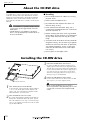 10
10
-
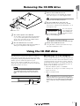 11
11
-
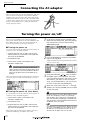 12
12
-
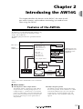 13
13
-
 14
14
-
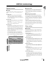 15
15
-
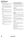 16
16
-
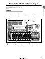 17
17
-
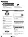 18
18
-
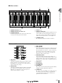 19
19
-
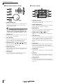 20
20
-
 21
21
-
 22
22
-
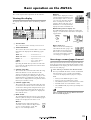 23
23
-
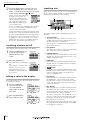 24
24
-
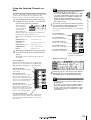 25
25
-
 26
26
-
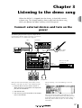 27
27
-
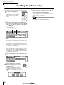 28
28
-
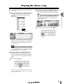 29
29
-
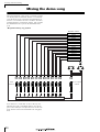 30
30
-
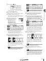 31
31
-
 32
32
-
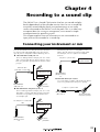 33
33
-
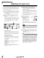 34
34
-
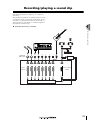 35
35
-
 36
36
-
 37
37
-
 38
38
-
 39
39
-
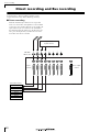 40
40
-
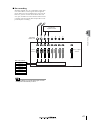 41
41
-
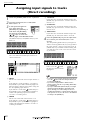 42
42
-
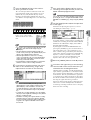 43
43
-
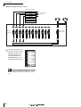 44
44
-
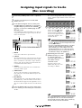 45
45
-
 46
46
-
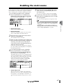 47
47
-
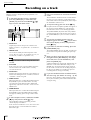 48
48
-
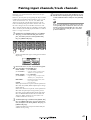 49
49
-
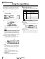 50
50
-
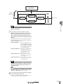 51
51
-
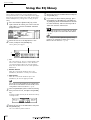 52
52
-
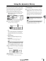 53
53
-
 54
54
-
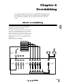 55
55
-
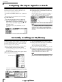 56
56
-
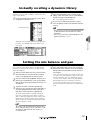 57
57
-
 58
58
-
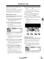 59
59
-
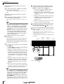 60
60
-
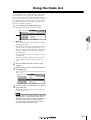 61
61
-
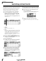 62
62
-
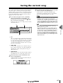 63
63
-
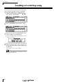 64
64
-
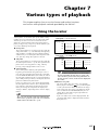 65
65
-
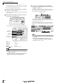 66
66
-
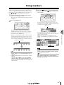 67
67
-
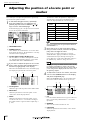 68
68
-
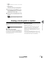 69
69
-
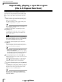 70
70
-
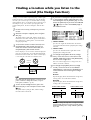 71
71
-
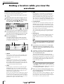 72
72
-
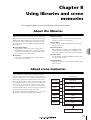 73
73
-
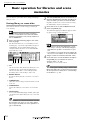 74
74
-
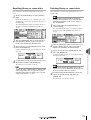 75
75
-
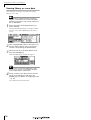 76
76
-
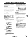 77
77
-
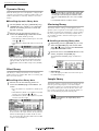 78
78
-
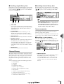 79
79
-
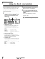 80
80
-
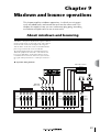 81
81
-
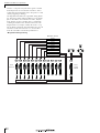 82
82
-
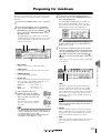 83
83
-
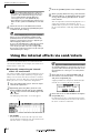 84
84
-
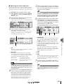 85
85
-
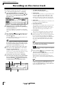 86
86
-
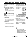 87
87
-
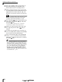 88
88
-
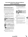 89
89
-
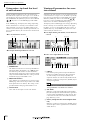 90
90
-
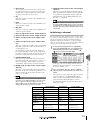 91
91
-
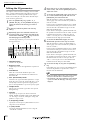 92
92
-
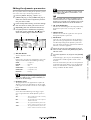 93
93
-
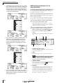 94
94
-
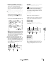 95
95
-
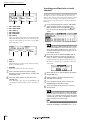 96
96
-
 97
97
-
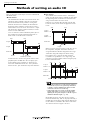 98
98
-
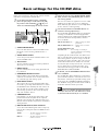 99
99
-
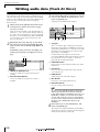 100
100
-
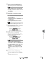 101
101
-
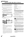 102
102
-
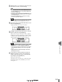 103
103
-
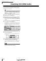 104
104
-
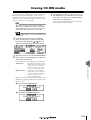 105
105
-
 106
106
-
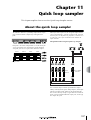 107
107
-
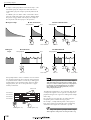 108
108
-
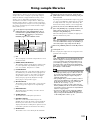 109
109
-
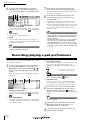 110
110
-
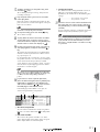 111
111
-
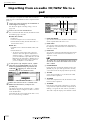 112
112
-
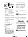 113
113
-
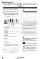 114
114
-
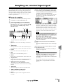 115
115
-
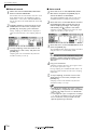 116
116
-
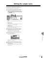 117
117
-
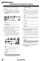 118
118
-
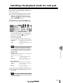 119
119
-
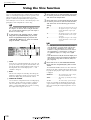 120
120
-
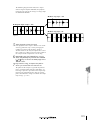 121
121
-
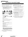 122
122
-
 123
123
-
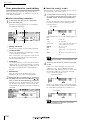 124
124
-
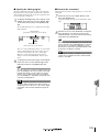 125
125
-
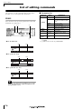 126
126
-
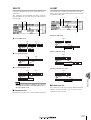 127
127
-
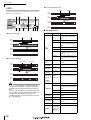 128
128
-
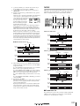 129
129
-
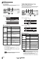 130
130
-
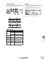 131
131
-
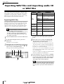 132
132
-
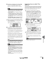 133
133
-
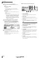 134
134
-
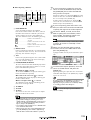 135
135
-
 136
136
-
 137
137
-
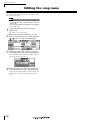 138
138
-
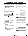 139
139
-
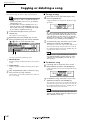 140
140
-
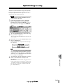 141
141
-
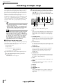 142
142
-
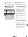 143
143
-
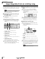 144
144
-
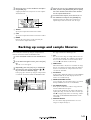 145
145
-
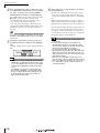 146
146
-
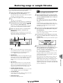 147
147
-
 148
148
-
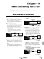 149
149
-
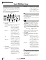 150
150
-
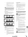 151
151
-
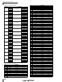 152
152
-
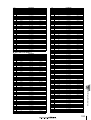 153
153
-
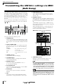 154
154
-
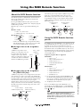 155
155
-
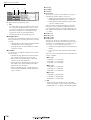 156
156
-
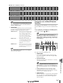 157
157
-
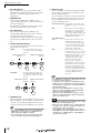 158
158
-
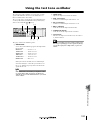 159
159
-
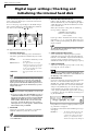 160
160
-
 161
161
-
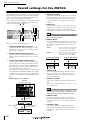 162
162
-
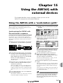 163
163
-
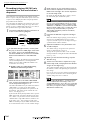 164
164
-
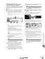 165
165
-
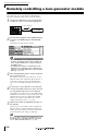 166
166
-
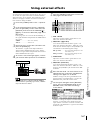 167
167
-
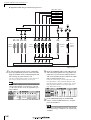 168
168
-
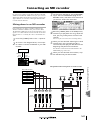 169
169
-
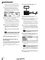 170
170
-
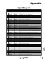 171
171
-
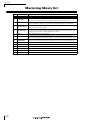 172
172
-
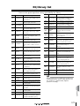 173
173
-
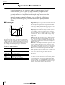 174
174
-
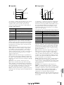 175
175
-
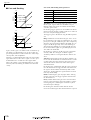 176
176
-
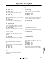 177
177
-
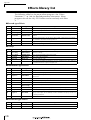 178
178
-
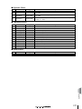 179
179
-
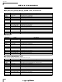 180
180
-
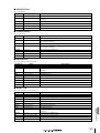 181
181
-
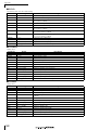 182
182
-
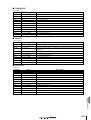 183
183
-
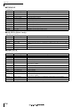 184
184
-
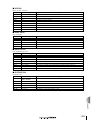 185
185
-
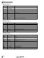 186
186
-
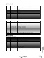 187
187
-
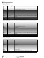 188
188
-
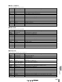 189
189
-
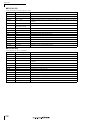 190
190
-
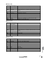 191
191
-
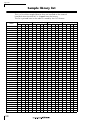 192
192
-
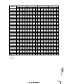 193
193
-
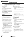 194
194
-
 195
195
-
 196
196
-
 197
197
-
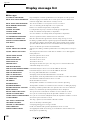 198
198
-
 199
199
-
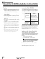 200
200
-
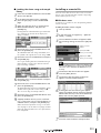 201
201
-
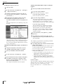 202
202
-
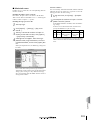 203
203
-
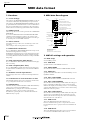 204
204
-
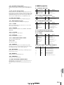 205
205
-
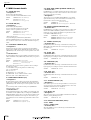 206
206
-
 207
207
-
 208
208
-
 209
209
-
 210
210
-
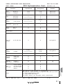 211
211
-
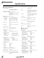 212
212
-
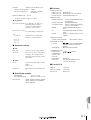 213
213
-
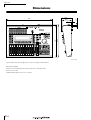 214
214
-
 215
215
-
 216
216
-
 217
217
-
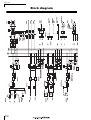 218
218
-
 219
219


Yamaha AW 16G Handleiding
- Categorie
- Muziekinstrumenten
- Type
- Handleiding
- Deze handleiding is ook geschikt voor
in andere talen
- English: Yamaha AW 16G User manual
- italiano: Yamaha AW 16G Manuale utente
- русский: Yamaha AW 16G Руководство пользователя
- français: Yamaha AW 16G Manuel utilisateur
- español: Yamaha AW 16G Manual de usuario
- Deutsch: Yamaha AW 16G Benutzerhandbuch
- português: Yamaha AW 16G Manual do usuário
- dansk: Yamaha AW 16G Brugermanual
- čeština: Yamaha AW 16G Uživatelský manuál
- svenska: Yamaha AW 16G Användarmanual
- Türkçe: Yamaha AW 16G Kullanım kılavuzu
- polski: Yamaha AW 16G Instrukcja obsługi
- română: Yamaha AW 16G Manual de utilizare