Shure SCM262 Gebruikershandleiding
- Categorie
- Audiomixers
- Type
- Gebruikershandleiding

SCM262
Stereomixer
The Shure stereo microphone mixer, SCM262, user guide.
Version: 4 (2019-G)

Shure Incorporated
2/19
Table of Contents
SCM262Stereomixer 3
BELANGRIJKE VEILIGHEIDSINSTRUCTIES 3
General Description 4
Features 4
Front Panel 4
Rear Panel 6
DIP Switches 6
Applications 8
General Application 8
Paging with Ducking Application 8
Jukebox Mute Application 8
Connections 9
Interne wijzigingen 9
Internal Modifications 9
Disassembly 10
Supplied Hardware 12
Rackmount Installation 12
Stand-Alone Installation 14
Fixed Installation 14
Productgegevens 16
Voltage Gain (typical, controls full clockwise) 18
Vervangingsonderdelen 18
Optionele accessoires 19
Serviceverklaring 19
Certificering 19

Shure Incorporated
3/19
1.
2.
3.
4.
5.
6.
7.
8.
9.
10.
11.
12.
13.
14.
15.
16.
17.
18.
19.
SCM262
Stereomixer
BELANGRIJKE VEILIGHEIDSINSTRUCTIES
LEES deze instructies.
BEWAAR deze instructies.
NEEM alle waarschuwingen in acht.
VOLG alle instructies op.
GEBRUIK dit apparaat NIET in de buurt van water.
REINIG UITSLUITEND met een droge doek.
DICHT GEEN ventilatieopeningen AF. Zorg dat er voldoende afstand wordt gehouden voor adequate ventilatie. Instal
leer het product volgens de instructies van de fabrikant.
Plaats het apparaat NIET in de buurt van warmtebronnen, zoals vuur, radiatoren, warmteroosters, kachels of andere
apparaten (waaronder versterkers) die warmte genereren. Plaats geen vuurbronnen in de buurt van het product.
ZORG ERVOOR dat de beveiliging van de gepolariseerde stekker of randaardestekker intact blijft. Een gepolariseerde
stekker heeft twee pennen waarbij er één breder is dan de andere. Een randaardestekker heeft twee pennen en een
extra aardaansluiting. De breedste pen en de aardaansluiting zijn bedoeld om uw veiligheid te garanderen. Als de mee
geleverde stekker niet in de contactdoos past, vraag een elektricien dan om de verouderde contactdoos te vervangen.
BESCHERM het netsnoer tegen erop lopen of afknelling, vooral in de buurt van stekkers en uitgangen en op de plaats
waar deze het apparaat verlaten.
GEBRUIK UITSLUITEND door de fabrikant gespecificeerde hulpstukken/accessoires.
GEBRUIK het apparaat UITSLUITEND in combinatie met een door de fabrikant gespecificeerde wagen, standaard,
driepoot, beugel of tafel of met een meegeleverde ondersteuning. Wees bij gebruik van een wagen voorzichtig tijdens
verplaatsingen van de wagen/apparaat-combinatie om letsel door omkantelen te voorkomen.
HAAL de stekker van dit apparaat uit de contactdoos tijdens onweer/bliksem of wanneer het lange tijd niet wordt ge
bruikt.
Laat onderhoud altijd UITVOEREN door bevoegd servicepersoneel. Onderhoud moet worden uitgevoerd wanneer het
apparaat op enigerlei wijze is beschadigd, bijvoorbeeld beschadiging van netsnoer of stekker, vloeistof of voorwerpen
in het apparaat zijn terechtgekomen, het apparaat is blootgesteld aan regen of vocht, niet naar behoren werkt of is ge
vallen.
STEL het apparaat NIET bloot aan druppelend en rondspattend vocht. PLAATS GEEN voorwerpen gevuld met vloei
stof, bijvoorbeeld een vaas, op het apparaat.
De NETSTEKKER of een koppelstuk van het apparaat moet klaar voor gebruik zijn.
Het door het apparaat verspreide geluid mag niet meer zijn dan 70 dB(A).
Apparaten van een KLASSE Iconstructie moeten worden aangesloten op een WANDCONTACTDOOS met bescher
mende aardaansluiting.
Stel dit apparaat niet bloot aan regen of vocht om het risico op brand of elektrische schokken te verminderen.

Shure Incorporated
4/19
20.
21.
•
•
•
•
•
•
•
•
•
•
•
•
•
Probeer dit product niet te wijzigen. Wanneer dit wel gebeurt, kan lichamelijk letsel optreden en/of het product defect
raken.
Gebruik dit product binnen de gespecificeerde bedrijfstemperaturen.
Dit symbool geeft aan dat in deze eenheid een gevaarlijk spanning aanwezig is met het risico op een elektri
sche schok.
Dit symbool geeft aan dat in de documentatie bij deze eenheid belangrijke bedienings en onderhoudsinstruc
ties zijn opgenomen.
WAARSCHUWING: De voltages in deze apparatuur zijn levensgevaarlijk. Bevat geen onderdelen die de gebruiker zelf kan re
pareren. Laat onderhoud altijd uitvoeren door bevoegd servicepersoneel. De veiligheidscertificeringen zijn niet meer geldig in
dien de fabrieksinstelling van de werkspanning wordt gewijzigd.
General Description
The Shure Model SCM262 is a stereo mixer intended for sound reinforcement applications that integrate microphones with
consumer stereo products. It incorporates two activebalanced microphone inputs with three unbalanced stereo aux level in
puts.
The SCM262 Stereo Mixer is designed for restaurants, classrooms, corporate training, aerobics classes, and other situations
where a paging/public announcement system is combined with background music or other program material.
Features
Designed to combine paging with background music
One active-balanced, XLR microphone input channel
One active-balanced XLR microphone and 1/4-in. TRS line input channel
Three STEREO INPUT channels
Stereo AUX level OUTPUTs
Stereo MIC/LINE OUTPUTs
BASS and TREBLE tone controls on the master output
1/2-rack chassis
12 V phantom power for condenser microphones
Internal power supply
Removable power cable
Ducking function (defeatable)
Jukebox mute function (defeatable)

Shure Incorporated
5/19
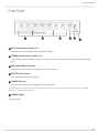
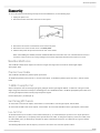
Front Panel
① MIC Channel Gain Controls, 1-2.
Control the gain levels of the MIC channels and LINE IN 2 (MIC 2).
② STEREO Channel Gain Controls, 1-3.
Control the gain levels from CD players, juke boxes, VCRs, or other consumer stereo equipment connected to the STEREO
inputs.
③ BASS and TREBLE Controls.
Control the boost/cut of the low- and high-frequency of the shelving filters.
④ MASTER Gain Control.
Allows adjustment of the overall output gain.
⑤ POWER Indicator.
Lights up to indicate when the unit is plugged in and receiving power.
The SCM262 does not have a power switch. To turn the unit off, unplug the power cord or use an external power strip with a switch. However, it can remain
plugged in as it uses very little power when idle.
⑥ POWER Switch.
Country dependent.

Shure Incorporated
6/19
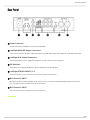
Rear Panel
① Power Connector.
Accepts 100-120 Vac (SCM262) or 220-240 Vac (SCM262E).
② Left/Right MIC/LINE Output Connectors.
These 1/4-in. connectors are stereo, balanced outputs for use with professional audio equipment. Controlled by DIP switch.
③ Left/Right AUX Output Connectors.
These phono jacks are stereo, unbalanced outputs for use with consumer stereo equipment.
④ DIP Switches.
These allow you to adjust the SCM262 for specific applications. See DIP Switches.
⑤ Left/Right STEREO INPUTS, 1-3.
These phono jacks are stereo inputs for connection to consumer stereo devices.
⑥ MIC Channel 2 INPUT.
Microphone channel 2 has two available inputs. There is a 1/4in. connector for balanced/unbalanced linelevel connecti
ons, or an XLR connector for balanced mic-level connections.
⑦ MIC Channel 1 INPUT.
This is an XLR connector for balanced mic-level connections.

Shure Incorporated
7/19
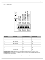
DIP Switches
DIP SWITCH FUNCTION POSITION UP (default) POSITION DOWN
1 LEFT OUTPUT MIC/LINE Line Mic
2 RIGHT OUTPUT MIC/LINE Line Mic
3 MIC 1 DUCKING Off On
4 MIC 2 DUCKING Off On
5 DUCKING LEVEL –∞ -20 dB
6
STEREO 3 JUKEBOX MU
TE
Off On
7 12 V PHANTOM Off On
LEFT/RIGHT OUTPUT MIC/LINE: DIP switches 1 and 2 adjust the left and right outputs for line- or mic-level operation.
MIC 1/MIC 2 Ducking: When ducking is on, the SCM262 will automatically lower the gain of all STEREO inputs when someo
ne is speaking into one of the microphones.
DUCKING LEVEL: Adjusts the amount of STEREO channel gain reduction when ducking is activated.

Shure Incorporated
8/19
1.
2.
3.
4.
5.
6.
1.
2.
3.
1.
2.
STEREO 3 JUKEBOX MUTE: This DIP switch turns the Juke Box Mute feature on or off. When on, any source connected to
STEREO 3 will mute STEREO 1 and 2 inputs.
PHANTOM POWER: When in the down position, this switch activates a 12 V phantom power source for condenser micropho
nes. Phantom power does not affect the operation of balanced, dynamic microphones, so one can be connected to the
SCM262 in combination with a condenser microphone.
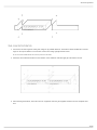
Applications
General Application
This is a general setup for most situations which require the combined use of a professional microphone and consumer stereo
equipment. Using this general setup, there are several other options available for further adjusting the SCM262 for your sound
system. See the diagram on the facing page.
Turn all gain controls counterclockwise.
Connect L/R STEREO INPUTS of the SCM262 to the L/R stereo outputs of the desired stereo audio equipment (CD
players, VCRs, televisions, juke boxes, etc.).
Connect microphone(s) to the MIC INPUTS on the SCM262.
For microphones which require phantom power, such as condenser microphones, place DIP switch 7 in the down posi
tion (phantom power on).
Connect the L/R outputs of the SCM262 to the L/R inputs of the amplifier.
Note: If you are using a consumer stereo amplifier, use the AUX OUTs. If you are using a professional audio power amplifier, use the LINE OUTs.
The MIC/LINE and AUX OUTPUTs can be used simultaneously to feed two separate amplifiers.
Apply power to the mixer by connecting the supplied power cable between the power connector on the mixer and the
appropriate AC power supply. The green POWER LED will illuminate to indicate that the mixer is powered on.
Note: The SCM262 has no power switch*. It is designed to be plugged into a power strip which supports the whole sound system. A typical power
strip will have a power switch, so that when the power strip is powered on, the SCM262 is powered on. (*Power Switch, country dependent).
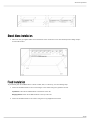
Paging with Ducking Application
With Ducking on, the SCM262 will automatically sense when someone is talking into one of the microphones and lower the vo
lume of the music so the talker can be heard more clearly. Once the talker is finished, the music resumes.
Use a microphone with an ON/OFF or pushbutton switch for the Paging with Ducking Application. A microphone without a switch will false-trigger, causing un-
wanted interruptions in the program material.
Connect the SCM262 to the sound system as described in General Application.
Set DIP switch 3 or 4 to the down position to activate ducking for microphone channel 1 or 2, respectively.
Set DIP switch 5 position. The Down position sets the ducking so that the program sound is lowered 20 dB when so
meone uses a microphone. The Up position sets the ducking so that the program sound is muted when someone uses
a microphone.
Jukebox Mute Application
In this application, designed primarily for Jukeboxes, any sound source connected to the STEREO 3 channels will automati
cally mute any sound coming over the STEREO 1 and 2 channels. This way, a CD player can be playing music, and then when
someone plays a song on the Jukebox, the SCM262 will automatically mute the CD player channels and switch to the Jukebox.
STEREO 1 and 2 channels will remain muted for about 30 seconds after program material is finished, to allow the jukebox time
to move on to the next song.
Connect the SCM262 to the sound system as described in General Application.
Connect the L/R audio outputs of the jukebox to the L/R inputs of STEREO 3.

Shure Incorporated
9/19
3.
This feature is designed especially for use with jukeboxes, but will work for any equipment connected to STEREO 3.
Set DIP Switch 6 to the down position (Jukebox Mute on).
If the ducking application is used in conjuction with the Jukebox Mute application, then activated microphones will mute
or duck the STEREO 3 input.
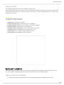
Connections
Interne wijzigingen
Internal Modifications
Voltages in this equipment are hazardous to life. No userserviceable parts inside. Refer all servicing and modifications to qua
lified service personnel.

Shure Incorporated
10/19
1.
2.
3.
4.
5.
Disassembly
To access the printed circuit board (pc board) for internal modifications, use the following steps:
Unplug the power cord.
Remove the knobs and retainer nuts from the front panel.
Remove the two screws at each bottom corner of the front panel.
Remove the four screws at each corner of the back panel.
Slide the back panel and pc board out from the rear of the chassis.
When reassembling the SCM262, DO NOT OVERTIGHTEN the knob retainer nuts. Use a minimal amount of force to
secure the nut (0.6-0.8 N-m (5-7 in-lb)). Damage to the internal components will result if too much force is used.
Mono Mixer Modification
This modification allows all the inputs to be mixed to a single mono signal sent over both the left and right outputs.
Short jumper X203.
Phantom Power Disable
This modification disables the phantom power per channel.
To disable the phantom power from mic 1, remove resistor R121. To disable the phantom power from mic 2, remove resistor
R122.
15 dB Mic Preamplifier Pad
When a microphone has an extremely high signal, getting the desired gain might be difficult - a small turn of the gain control
might change the sound from a whisper to deafeningly loud. This modification adds a 15 dB Mic preamplifier pad to allow more
accurate gain adjustment with extremely high microphone signals.
Remove R160 (mic 1) or R183 (mic 2).
Hard Panning MIC Channels
To remove MIC 1 from the left outputs, remove R912. To remove MIC 1 from the right outputs, remove R913.
To remove MIC 2/LINE 2 from the left outputs, remove R910. To remove MIC 2/LINE 2 from the right outputs, remove R911.
Low-Cut Filter
To eliminate the 80 Hz, low-cut filter, remove resistor R501 (mic 1), or resistor R519 (mic 2). Place a 10 to 33 µF capacitor in
X501 (mic 1) or R502 (mic 2). The polarity of the capacitor does not matter. To change the frequency of the low cut filter, remo
ve resistor R501 (mic 1) or R519 (mic2), and place the proper capacitor into X501 (mic 1) or X502 (mic 2) to get the desired
corner frequency.
The following tables list the low-cut frequency corners for some of the most common capacitor values:

Shure Incorporated
11/19
Capacitor Value Corner Frequency
.033 µF 803 Hz
.047 µF 564 Hz
.068 µF 390 Hz
.1 µF 265 Hz
.22 µF 120 Hz
Capacitor Value Corner Frequency
.33 µF 80 Hz
.47 µF 56 Hz
.68 µF 39 Hz
1.0 µF 26.5 Hz
2.2 µF 12 Hz
Ducking Depth
This modification adjusts the level of ducking depth attenuation of the input channels when ducking is activated.
The aux ducking depth may be changed by removing resistor R213 and inserting a resistor into jumper X202. Use the following
tables to determine the proper resistor value for the desired ducking depth.
Ducking Depth Resistor Value
6 dB 4,000 Ω
9 dB 5,000 Ω
15 dB 7,500 Ω
20 dB 10,000 Ω
24 dB 12,000 Ω
29 dB 15,000 Ω
Ducking Depth Resistor Value
36 dB 20,000 Ω
42 dB 25,000 Ω
47 dB 30,000 Ω
50 dB 33,000 Ω
55 dB 40,000 Ω

Shure Incorporated
12/19
•
•
•
•
•
•
•
•
1.
Ducking Threshold
This modification adjusts the threshold for activating the ducking circuit.
The ducking threshold can be raised or lowered by first removing resistor R333, and then placing a resistor (R) at jumper X303.
To lower the ducking threshold, use a resistor value (R) less than 2k ohms. To raise the ducking threshold, use a resistor value
(R) greater then 2k ohms.
Supplied Hardware
4 rubber feet. For stand-alone installation.
1 rackmount bracket, long. For half-rack (single unit) installations.
1 rackmount bracket, short. For half-rack (single) or dual-mount installations.
2 straddle brackets. For dual-mount or fixed installations.
12 bracket screws, 1/4-in. (6 mm). For securing the brackets to the chassis.
4 rackmount screws, 1 in. (2.5 cm). For mounting the unit in a rack.
4 plastic washers. For use with the supplied rackmount screws.
4 wood screws, 1/2 in. (1.25 cm). For fixed installations.
Rackmount Installation
The SCM262 can be mounted as a single unit or dual-mounted with either another SCM262 or another Shure half-rack unit
such as the SCM268 or DFR11EQ. Attach the rackmount brackets using one of the following methods:
Single unit (half-rack) installation:
Attach the short and long rackmount brackets to the SCM262 with eight (8) of the supplied bracket screws.

Shure Incorporated
13/19
1.
2.
3.
Dual-mounted installation:
Connect the two units together side-by-side using two (2) straddle brackets. The brackets should straddle the recessed
edges on the top and bottom of each chassis. Fasten them using eight (8) bracket screws.
Be sure to use both straddle brackets-one on the top and one on the bottom.
Attach the short rackmount brackets to the outsides of the combined units with eight (8) of the bracket screws.
After attaching the brackets, mount the unit in an equipment rack using the supplied rackmount screws and plastic was
hers.

Shure Incorporated
14/19
1.
1.
2.
Stand-Alone Installation
Adhere the four (4) supplied rubber feet to the bottom of the unit at each corner. This will keep it from sliding and pro
tect the table surface.
Fixed Installation
To permanently affix the SCM262 above or below a table, shelf, or counter top, use the following steps:
Fasten the straddle brackets to the recessed edges of the chassis using four (4) bracket screws.
Top Mount: Fasten the straddle brackets to the bottom of the unit.
Hanging Mount: Fasten the straddle brackets to the top of the unit.
Fasten the straddle brackets to the surface using the four (4) supplied wood screws.

Shure Incorporated
15/19

Shure Incorporated
16/19
Productgegevens
Frequentiekarakteristiek
bij 1 kHz
Microfoon/lijn-schakelaar 150 Hz tot 20 kHz ±2 dB
Aux-ingang 20 Hz tot 20 kHz ±2 dB
Hoogdoorlaatfilter
–6 dB/octaaf beneden 80 Hz

Shure Incorporated
17/19
Totale harmonische vervorming
1 kHz, +4 dBu uit, menguitgang (MASTER) bij +0 dB
<0,25%
Equivalente ingangsruis
150 Ω gebalanceerde bron, A-gewogen
-128 dBV
Uitgangsruis
Kanaalregeling volledig linksom, A-gewogen
Master volledig linksom -95 dBV
Master volledig rechtsom -59 dBV
Common Mode Rejection
>70 dB, bij 1 kHz
Polariteit
Alle ingangen naar alle uitgangen zijn niet-inverterend.
Bescherming tegen overbelasting en kortsluiting
Kortsluiting van uitgangen, zelfs langdurig, veroorzaakt geen schade. Microfooningangen raken niet be
schadigd door signalen van maximaal +10 dBV; line- en auxingangen niet door signalen van maximaal
+28 dBV
Niveauregeling
Bass (lage-frequentieshelving, kantelpunt bij 250 Hz) ±6 dB
Treble (hoge-frequentieshelving, kantelpunt bij 4 kHz) ±6 dB
Ducking
Mic-niveaus kanaal 1 en 2 -20 dB of ∞ dB
Activation time 10 ms, normaal
Deactivatietijd microfoon 2 seconden, normaal
Deactivatietijd Jukebox Mute 30 seconden, normaal
Fantoomvoeding
Open kring van 12 VDC via weerstanden van 680 Ω
Werkspanning
SCM262 100–200 V AC, 50/60 Hz, 60 mA
SCM262E 220–240 V AC, 50/60 Hz, 30 mA
Temperatuurbereik
Bedrijfstemperatuur -7° – 35° C (20° –95° F)

Shure Incorporated
18/19
Opslagtemperatuur -29° – 74° C (-20° –165° F)
Afmetingen
43 x 218 x 162 mm (1,72 x 8,60 x 6,37 in.)
Nettogewicht
1,1 kg (2 lbs, 5 oz.)
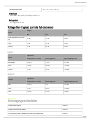
Voltage Gain (typical, controls full clockwise)
Input
Output
Mic Line Aux
Low-impedance mic (150
Ω)
32 dB 72 dB 60 dB
Line -9 dB 31 dB 19 dB
Stereo -5 dB 35 dB 23 dB
Inputs
Input
Impedance
Designed for use with Actual (typical) Input Clipping Level
Mic (XLR) <600 Ω 1.4 kΩ -16 dBV
Line <10 kΩ 155 kΩ +24 dBV
Stereo <2 kΩ 21 kΩ >28 dBV
Outputs
Output
Impedance
Designed for use with Actual (typical) Output Clipping Level
Mic >600 Ω 3 Ω -22 dBV
Line >5 kΩ 300 Ω +18 dBV
Aux ≥10 kΩ 1.5 kΩ +5 dBV
Vervangingsonderdelen
Knob, Master (blue) 95B8752
Knob, Channel Gain (white) 95A8752
Line (Power) Cords: SCM262: 100-120 Vac (US/Canada) 95B8762

Shure Incorporated
19/19
Line (Power) Cords: SCM262E: 220-240 Vac (EU) 95B8778
Fuse: SCM262 (5x20 mm, 250V, 100mA, time delay) 80Z730
SCM262E (5x20 mm, 250v, 40mA, time delay) 80M258
Hardware Kit 90AW8100
Koppelingsbalken (beugel) 53B8443
Single Mount Bracket 53A8484
Dual Mount Bracket 53E8484
Optionele accessoires
Line (Power) Cord, 230-240 Vac (UK) 95A8713
Serviceverklaring
Voor meer informatie over service of onderdelen kunt u contact opnemen met de serviceafdeling van Shure op 1-800-516-2525. Buiten de Verenigde Staten
kunt u contact opnemen met uw erkende Shure Service Center.
Certificering
Dit product voldoet aan de essentiële vereisten van alle toepasselijke Europese richtlijnen en komt in aanmerking voor CE-
markering.
De CE-conformiteitsverklaring kan worden verkregen via: www.shure.com/europe/compliance
Erkende Europese vertegenwoordiger:
Shure Europe GmbH
Hoofdkantoren in Europa, Midden-Oosten en Afrika
Afdeling: EMEA-goedkeuring
Jakob-Dieffenbacher-Str. 12
75031 Eppingen, Duitsland
Telefoon: +49-7262-92 49 0
Fax: +49-7262-92 49 11 4
E-mail: [email protected]
-
 1
1
-
 2
2
-
 3
3
-
 4
4
-
 5
5
-
 6
6
-
 7
7
-
 8
8
-
 9
9
-
 10
10
-
 11
11
-
 12
12
-
 13
13
-
 14
14
-
 15
15
-
 16
16
-
 17
17
-
 18
18
-
 19
19


Shure SCM262 Gebruikershandleiding
- Categorie
- Audiomixers
- Type
- Gebruikershandleiding
in andere talen
- English: Shure SCM262 User guide