
Yamaha Sound System Simulator Y-S
3
Owner’s Manual V3.0
1
Yamaha Sound System Simulator
~ Y-S
3
Version 3.0 ~
Owner’s Manual
© 2014 Yamaha Corporation

Yamaha Sound System Simulator Y-S
3
Owner’s Manual V3.0
2
ATTENTION
PLEASE READ THIS SOFTWARE LICENSE AGREEMENT (“AGREEMENT”) CAREFULLY BEFORE USING
THIS SOFTWARE. YOU ARE ONLY PERMITTED TO USE THIS SOFTWARE PURSUANT TO THE TERMS AND
CONDITIONS OF THIS AGREEMENT. THIS AGREEMENT IS BETWEEN YOU (AS AN INDIVIDUAL OR
LEGAL ENTITY) AND YAMAHA CORPORATION (“YAMAHA”).
BY DOWNLOADING, INSTALLING, COPYING, OR OTHERWISE USING THIS SOFTWARE YOU ARE
AGREEING TO BE BOUND BY THE TERMS OF THIS LICENSE. IF YOU DO NOT AGREE WITH THE TERMS,
DO NOT DOWNLOAD, INSTALL, COPY, OR OTHERWISE USE THIS SOFTWARE. IF YOU HAVE
DOWNLOADED OR INSTALLED THE SOFTWARE AND DO NOT AGREE TO THE TERMS, PROMPTLY
DELETE THE SOFTWARE.
SOFTWARE LICENSE AGREEMENT
1. GRANT OF LICENSE AND COPYRIGHT
Yamaha hereby grants you the right to use one copy of the software program(s) and data (“SOFTWARE”)
accompanying this AGREEMENT. The term SOFTWARE shall encompass any updates to the accompanying software
and data. The SOFTWARE is owned by Yamaha and/or Yamaha’s licensor(s), and is protected by relevant copyright
laws and all applicable treaty provisions. While you are entitled to claim ownership of the data created with the use of
SOFTWARE, the SOFTWARE will continue to be protected under relevant copyrights.
• You may use the SOFTWARE on a single computer.
• You may make one copy of the SOFTWARE in machine-readable form for backup purposes only, if the
SOFTWARE is on media where such back up copy is permitted. On the backup copy, you must reproduce
Yamaha’s copyright notice and any other proprietary legends that were on the original copy of the
SOFTWARE.
• You may permanently transfer to a third party all your rights in the SOFTWARE, provided that you do not
retain any copies and the recipient reads and agrees to the terms of this AGREEMENT.
2. RESTRICTIONS
• You may not engage in reverse engineering, disassembly, decompilation or otherwise deriving a source code
form of the SOFTWARE by any method whatsoever.
• You may not reproduce, modify, change, rent, lease, or distribute the SOFTWARE in whole or in part, or
create derivative works of the SOFTWARE.
• You may not electronically transmit the SOFTWARE from one computer to another or share the
SOFTWARE in a network with other computers.
• You may not use the SOFTWARE to distribute illegal data or data that violates public policy.
• You may not initiate services based on the use of the SOFTWARE without permission by Yamaha.
3. TERMINATION
This AGREEMENT becomes effective on the day that you receive the SOFTWARE and remains effective until
terminated. If any copyright law or provisions of this AGREEMENT is violated, the AGREEMENT shall terminate
automatically and immediately without notice from Yamaha. Upon such termination, you must immediately destroy the
licensed SOFTWARE, any accompanying written documents and all copies thereof.

Yamaha Sound System Simulator Y-S
3
Owner’s Manual V3.0
3
4. DISCLAIMER OF WARRANTY ON SOFTWARE
You expressly acknowledge and agree that use of the SOFTWARE is at your sole risk. The SOFTWARE and related
documentation are provided “AS IS” and without warranty of any kind. NOTWITHSTANDING ANY OTHER
PROVISION OF THIS AGREEMENT, YAMAHA EXPRESSLY DISCLAIMS ALL WARRANTIES AS TO THE
SOFTWARE, EXPRESS, AND IMPLIED, INCLUDING BUT NOT LIMITED TO THE IMPLIED WARRANTIES OF
MERCHANTABILITY, FITNESS FOR A PARTICULAR PURPOSE AND NON-INFRINGEMENT OF THIRD
PARTY RIGHTS. SPECIFICALLY, BUT WITHOUT LIMITING THE FOREGOING, YAMAHA DOES NOT
WARRANT THAT THE SOFTWARE WILL MEET YOUR REQUIREMENTS, THAT THE OPERATION OF THE
SOFTWARE WILL BE UNINTERRUPTED OR ERROR-FREE, OR THAT DEFECTS IN THE SOFTWARE WILL
BE CORRECTED.
5. LIMITATION OF LIABILITY
YAMAHA’S ENTIRE OBLIGATION HEREUNDER SHALL BE TO PERMIT USE OF THE SOFTWARE UNDER
THE TERMS HEREOF. IN NO EVENT SHALL YAMAHA BE LIABLE TO YOU OR ANY OTHER PERSON FOR
ANY DAMAGES, INCLUDING, WITHOUT LIMITATION, ANY DIRECT, INDIRECT, INCIDENTAL OR
CONSEQUENTIAL DAMAGES, EXPENSES, LOST PROFITS, LOST DATA OR OTHER DAMAGES ARISING
OUT OF THE USE, MISUSE OR INABILITY TO USE THE SOFTWARE, EVEN IF YAMAHA OR AN
AUTHORIZED DEALER HAS BEEN ADVISED OF THE POSSIBILITY OF SUCH DAMAGES. In no event shall
Yamaha’s total liability to you for all damages, losses and causes of action (whether in contract, tort or otherwise)
exceed the amount paid for the SOFTWARE.
6. GENERAL
This AGREEMENT shall be interpreted according to and governed by Japanese law without reference to principles of
conflict of laws. Any dispute or procedure shall be heard before the Tokyo District Court in Japan. If for any reason a
court of competent jurisdiction finds any portion of this AGREEMENT to be unenforceable, the remainder of this
AGREEMENT shall continue in full force and effect.
7. COMPLETE AGREEMENT
This AGREEMENT constitutes the entire agreement between the parties with respect to use of the SOFTWARE and
any accompanying written materials and supersedes all prior or contemporaneous understandings or agreements, written
or oral, regarding the subject matter of this AGREEMENT. No amendment or revision of this AGREEMENT will be
binding unless in writing and signed by a fully authorized representative of Yamaha.

Yamaha Sound System Simulator Y-S
3
Owner’s Manual V3.0
4
System Requirements
OS
Windows 8/8.1 (32bit, 64bit) , Windows 7 (32bit, 64bit)
*1
, Windows® XP Professional
CPU
Core 2 Duo (2 G Hz or higher)
RAM
2GB or higher
Sound Card
16-bit 44.1 kHz Stereo
Disk Space
2GB or more (may differ according to the environment the software is used)
Display
1024 x 768, 256 colors, 96 dpi (Normal)
*2
Video card: DirectX 9.0C supported
*3
, memory size 256MB or more
*1
When using Windows 7, there may be image flickering or images may not export correctly depending on the CPU, RAM, or video
card of the PC used. This symptom may improve by stopping the service of Desktop Window Manager Session Manager ([Start] –
[Control Panel] – [System and Security] – [Administrative Tools / Services] – [Desktop Window Manager Session Manager]).
*2
The images may not display properly when the screen is set at a DPI other than 96dpi. We strongly recommend that the property
for display colors is set to 32 bit.
*3
You may be able to use the feature by updating the video card driver. For details, contact your computer manufacturer, video card
manufacturer, etc.
Installation
1. Double-click on the “Y-S3” folder.
An executable file “setup.exe” is shown.
2. Double-click on “setup.exe.”
A setup window for Y-S
3
appears.
3. Execute the installation by following the onscreen instructions.
4. After installation is complete, the Y-S
3
folder appears on your computer (“Program Files\YAMAHA\Y-S3” folder, as the
default).
Installing Speaker Data
1. Download the data package for the speaker you want to use from the Yamaha Pro Audio website
(http://www.yamahaproaudio.com/japan/ja/downloads/firmware_software/speaker_simulator/).
2. Unzip the zipped folder. An executable file named “install.vbs” will appear in the folder.
3. Double-click “install.vbs”.
4. Follow the instructions on the screen to install the data.
5. When the installation is complete, the speaker data is added to the Y-S3 folder on your computer.
Uninstalling
1. Select [Start] - [Settings] - [Control Panel] - [Add/Remove Programs]. The Add/Remove Programs window appears.
2. Click [Change/Remove] of Y-S
3
Yamaha Sound System Simulator.
3. Follow the onscreen instructions to uninstall the software.
NOTE: The button names or menus may differ depending on the computer OS.
Precautions
Y-S
3
may cause an unexpected termination of the software under these circumstances:
When the computer recovers from standby or hibernation mode.
When OS users are changed using the Fast User Switching function.
If the software terminates, please restart your computer.

Yamaha Sound System Simulator Y-S
3
Owner’s Manual V3.0
5
Table of Contents
1. Y-S
3
General Operation ............................................................................................... 6
• Overview ................................................................................................................................................................. 6
• Startup ..................................................................................................................................................................... 6
• Project window: display of calculation results (Chapter 6) ................................................................................... 10
• Saving and Opening Projects ................................................................................................................................. 12
2. Constructing the Room Shape & Audience Area .................................................... 13
• Overview ............................................................................................................................................................... 13
• Starting a new project ............................................................................................................................................ 13
• Constructing the room shape and audience area .................................................................................................... 13
• Re-editing the room shapes ................................................................................................................................... 15
3. Editing Project Properties ......................................................................................... 16
• Overview ............................................................................................................................................................... 16
• Project. ................................................................................................................................................................... 16
• Calculation............................................................................................................................................................. 16
• System ................................................................................................................................................................... 18
• Others. ................................................................................................................................................................... 19
4. Placing Speakers ....................................................................................................... 20
• Overview ............................................................................................................................................................... 20
• Installing Speakers................................................................................................................................................. 20
• Adding a new speaker (Add Speakers) .................................................................................................................. 20
• Placing the speakers manually (Enclosure type - Manual layout) ......................................................................... 21
• Placing the speakers automatically (Enclosure type - Auto layout)....................................................................... 25
• Distributed ............................................................................................................................................................. 26
5. Adjusting Speaker Parameters ................................................................................. 30
• Overview ............................................................................................................................................................... 30
• Update ................................................................................................................................................................... 30
5-1. Speaker Arrays .......................................................................................................... 31
• Speaker array selection, on/off, changing names/deletion, saving/loading (Speaker List) .................................... 31
• Adjusting speaker array parameters (Speaker Property - Property) ...................................................................... 32
• Output configuration settings (Speaker Property - Config) ................................................................................... 34
• Directivity of speaker array (Speaker Property - Balloon) .................................................................................... 37
• Picture of speaker array (Speaker Property - Picture) ........................................................................................... 38
• Auto tuning ............................................................................................................................................................ 38
5-2. Distributed Speakers ................................................................................................. 41
• Distributed speakers on/off, changing names/deletion, adding speakers to an installation plane .......................... 41
• Adjusting distributed speaker parameters (Speaker Property - Property) .............................................................. 42
• Output configuration settings (Speaker Property - Config) ................................................................................... 44
6. Displaying Calculation Results ................................................................................ 46
• Overview ............................................................................................................................................................... 46
• Contour figure ....................................................................................................................................................... 46
• Sound pressure distribution ................................................................................................................................... 47
• Frequency characteristics ...................................................................................................................................... 48
7. Simulation Results Report ........................................................................................ 50
• Overview ............................................................................................................................................................... 50
• Project report ......................................................................................................................................................... 50
• Generating and saving project reports ................................................................................................................... 50
• Saving text data ..................................................................................................................................................... 51
• Saving images ........................................................................................................................................................ 51
• Saving product list ................................................................................................................................................. 51
8. Exporting Configurations in DME Designer Format ............................................... 52
9. Other Functions ......................................................................................................... 53
• Input Level Negotiation ......................................................................................................................................... 53
10. General Theory .......................................................................................................... 54

Yamaha Sound System Simulator Y-S
3
Owner’s Manual V3.0
6
1. Y-S
3
General Operation
• Overview
Y-S
3
is a software application that aids in speaker system design, using data entered by the user on room type and size, speaker
type, installation conditions, and amplifier and processor type and configuration to calculate the response from the audiences’
position. Y-S
3
then presents the results as sound pressure distribution and contour figures for use in constructing appropriate
speaker systems.
• Startup
Double-click the Y-S
3
icon on the desktop or select [Start] - [Programs] - [YAMAHA] - [Y-S3]. The program starts and the main
window appears.
Click in the main window to open a new project.
In Select Venue Geometry, set the venue type (venue shape), floor shape, number of floors, and the listener's ear height.
(See chapter 2)
Click to set the room size and slope and the floor shape of each floor above the 1st floor
(See chapter 2)

Yamaha Sound System Simulator Y-S
3
Owner’s Manual V3.0
7

Yamaha Sound System Simulator Y-S
3
Owner’s Manual V3.0
8
Select an array type, and enter the coordinates and angle of the speaker array.
You can also place the speaker array symmetrically.
After you have completed the configuration of all the floors, click . The Aspect View, Speaker Property, Speaker List,
and Graph appear, with the room you configured displayed in Aspect View. Click in Speaker List to open the
Add Speakers window and configure the speakers.
(See chapter 4)
Use the Add Speakers list box to select one of the three installation types available (Enclosure type - Manual layout, Enclosure
type - Auto layout, Distributed), and enter the installation parameters.
(See chapter 4)
Enclosure type - Manual layout
Speaker
Property
Graph
Aspect View
Speaker List

Yamaha Sound System Simulator Y-S
3
Owner’s Manual V3.0
9
Select a system type and Y-S
3
will automatically calculate the optimum array
type and coordinates for the size and shape of the room defined. Y-S
3
cannot
perform these calculations for rooms of unusual size or shape, or for circular
rooms.
Configure the parameters for the ceilings, walls, and other plane surfaces, and
then set the speaker layout. There are two methods available: “Coverage”,
where you set the coverage area of the receiving surface for each speaker and
then layout the speakers automatically, and “Grid”, where you set the location
for each speaker manually of a level plane.
Enclosure type - Auto layout
Distributed
When you have finished configuring settings, the parameters you have entered and the calculated results appear in Aspect View,
Speaker Property, Speaker List, and Graph areas on the project window.

Yamaha Sound System Simulator Y-S
3
Owner’s Manual V3.0
10
• Project window: display of calculation results (Chapter 6)
Tool Bar
Table: The name and function of each button on the main toolbar
Button Type
Button Name
Button Function
New
Create a new project (Chapter 2).
Open Project
Load a previously saved project file (.ses) (Chapter 1).
Save Project
Save a project file (.ses) (Chapter 1).
Export DME Configuration
Save a DME configuration file (.daf) (Chapter 8).
Export Project Report
Create and save a project report file (.html) (Chapter 7).
Project Properties
Open a Project Property window (Chapter 3).
Product List
Open a Product List. You can save opened Product List in CSV (.csv)
format (Chapter 7).
Top View、Front View、
Right-Side View、3D View
Change viewpoints between Aspect View, Balloon view, and Picture view.
Zoom In、Zoom Out
You can zoom in or out in Aspect View.
You can also use the mouse wheel for this purpose.
Turn Down、Turn Up、
Turn Left、Turn Right
Rotate the viewing angle. This is only available for Aspect View, Balloon
view, and Picture view when in 3D View .
In the Aspect View, you can also drag the pointer with the left mouse button
for this purpose.
Move Up、Move Down、
Move Left、Move Right
Moves the screen display when in Aspect View.
You can also drag the pointer with the right mouse button for this purpose.
Default View
Reset the viewing angle, zoom setting, and screen position to their defaults.
Link to Y-S3 Information on the web
Link button to the Y-S
3
website.
To change the disposition of project windows when multiple projects are open, select [Cascade (C)] or [Tile (T)] from the
[Window (W)] menu.
Speaker
Property
Graph
Aspect View
Speaker List

Yamaha Sound System Simulator Y-S
3
Owner’s Manual V3.0
11
Aspect View (Chapter 6)
Aspect View displays the layout of the speakers, along with a sound pressure distribution and contour figure based on calculation
results. To update calculation results, select the center frequency and bandwidth from the list box in the upper section of Aspect
View, then select the calculation mode icon. Change the calculation conditions and click to reflect the new
calculation results.
You can change the background color of Aspect View and Graph by setting [BackGround Color (B)] to [Gray (G)] or [White
(W)] in the [View (V)] menu. (The background color of the above figure is [Gray (G)].)
Table: Names and functions of each Aspect View button.
Button Type
Button Name
Button Function
Frequency, Band Width
Select the center frequency and the bandwidth (1/1, 1/3, 1/6,
FFT) .Calculation results are reflected in Aspect View, Balloon view, and
Graph.
SPL Mode
Display a sound pressure distribution in Aspect View for all speakers
selected in the Speaker List checkbox.
Array Mode
Displays a contour figure for speaker arrays displaying target points. The
contour figure is depicted in three layers, indicating -3 dB (red), -6 dB
(orange) and -9 dB (green) drops in sound pressure from the target point
that is closest to the speaker arrays or speaker.
The contour figure is not available when speakers are mounted on the floor,
or when the target point is not located on the receiving surface or is in an
area obstructed by walls (first floor only) or floors. Furthermore, you
cannot select speaker arrays that have been automatically located using the
symmetry function in “Enclosure type - Auto layout” and “Enclosure type -
Manual layout” (these speakers are depicted in orange). Y-S3 does not
display target points and contour figures for these speakers.
Single Mode
Display a contour figure for each speaker displaying target points. Since the
contour figures for each speaker are calculated relative to the respective
target points, the SPL for each speaker will be different even though for
contour lines of the same color.
SPL Range
Set the maximum and minimum sound pressure distribution values to
display sound pressure distributions using different colors.
1st Floor、2nd Floor、3rd Floor、
4th Floor、All Floor
Specify the floor to display the calculation results for. Select [All] to
display the results of all floors. If you select a specific floor, frames are
displayed for the unselected floors.
Speaker Property (Chapter 5)
You can use the Property and Config views to set installation conditions for speaker arrays and configure output parameters for
items such as processors and amplifiers. The “Auto tuning” function calculates the optimum conditions for speaker arrays within
the defined area automatically.
Speaker List (Chapter 5)
You can use the checkboxes to turn installed speakers on and off. Switching speakers on and off affects calculations, the results
of which are reflected in Aspect View and Graph. You can also add or remove speakers, and change names.
Table: Names and functions of each Speaker List button.
Button Type
Button Name
Button Function
Add New Array
Click this button to open the Add Speakers window. You can add speakers
using the “Enclosure type - Manual layout”, “Enclosure type - Auto
layout”, or “Distributed” methods.
Save Array, Load Array
You can save and load array files (.spa) for each speaker array installed.
This is useful when, for example, you want to use the same speaker array
you have been using in a different project. For large-scale projects, you can
load the same speaker array file into a single project multiple times.
Distributed speakers are treated as part of a surface, and cannot be saved or
loaded.

Yamaha Sound System Simulator Y-S
3
Owner’s Manual V3.0
12
Graph (Chapter 6)
The graph displays the current calculation results ( ) for a +Position on the receiving surface. Drag the +Position
cursor with your mouse to see the calculation results for a given point on the receiving surface. At the desired receiving point,
select a graph number (e.g. ), and click . The graph changes color and the current results
( ) are saved to the selected graph number. You can save calculation results for up to 8 points on the graph. Click
to open an Information window displaying details on the graph number selected. In this window, you can also add a dry
source to the response at the receiving points calculated and listen to the results.
• Saving and Opening Projects
In order to save the whole project, click icon on the tool bar or select [Save Project (S)] or [Save Project As… (A)] under
the [File (F)] menu. In order to open a project, click icon or select [Open Project (O)] under the [File (F)] menu.
The maximum number of projects that can be opened at once is 15. If 15 projects are already open, you can not open another
saved project.
.

Yamaha Sound System Simulator Y-S
3
Owner’s Manual V3.0
13
2. Constructing the Room Shape & Audience Area
• Overview
Construct the room shape and set the audience area for calculation.
• Starting a new project
Click in the tool bar or select [New (N)] from the [File (F)] menu to open a new project. The Select Venue Geometry (Step
1/2) setting window opens. The maximum number of projects that can be opened at once is 15. If 15 projects are already open,
you can not create a new project.
• Constructing the room shape and audience area
Select Venue Geometry (Step1/2):
Select a room shape. The selected shape appears on the 3D view for verification. You can change the zoom, angle and position
for the 3D view. Click when you have selected a shape. Immediately after the dialog box opens, "Select Venue
Geometry (Step 1/2)" appears in the title bar. However, the total number of steps will vary between 2 and 5 depending on the
number of floors.
Unit
Select “Metric” (meters) or “Imperial” (feet) for units of measurement.
Venue Type
Select a venue type from the list box (Rectangular, Fan, Cross, Polygon, or Circle), then select the room shape that most closely
matches the geometry of your project. You will see some shapes with and without a stage/performing area, which is shown in a
lighter color. Y-S
3
will not estimate the SPL on the stage, but shows a contour to check for unexpected coverage spilling over to
the stage.
Venue Size
Set the size of the selected shape with the slider.
Number of Floors
Set the number of floors in the range of 1 to 4. The total number of steps of Select Venue Geometry will vary depending on the
number of floors you set.
Listener’s Ear Height above the Floor
Select a height from the list box. The height is the distance from the floor to the ear of the listener. This can be set from 0.1 m to
2.1 m (0.3 ft to 7 ft) with a default setting of 1.2 m (3.9 ft). You can use and the mouse wheel to zoom in and out of the
screen in 3D View. You can also view the room from a specific angle by dragging the pointer with the left mouse button.

Yamaha Sound System Simulator Y-S
3
Owner’s Manual V3.0
14
Select Venue Geometry(Step2/2):
Edit the selected shape with the Top View and Right-Side View. Use your mouse to select an orange point on a view (selected
point turns black), then drag the point to the desired position. You may also select a point, and enter the desired
three-dimensional coordinates. The range of each dimension is shown below. Note that for the 2nd to the 4th floors, y is the
distance from the reference point. The reference points of the 2nd to the 4th floors can be varied between of -100.00 m to 100.00
m (-328.08 ft to 328.08 ft)..
x : width
y : depth
z : height
Stage
-45.00m~-0.01m
(-147.64~-0.03ft)
-90.00m~90.00m
(-295.28ft~295.28ft)
0.00m~2.00m
(0.00ft~6.56ft)
1st Floor
-45.00m~-0.01m
(-147.64ft~-0.03ft)
-90.00m~90.00m
(-295.28ft~295.28ft)
0.00m~45.0m
(0.00ft~147.64ft)
2
nd
~4
th
Floor
-60.00m~-0.01m
(-196.85ft~-0.03ft)
-90.00~90.00m
(-295.28ft~295.28ft)
0.00m~50.0m
(0.00ft~164.04ft)
You can change the zoom for Top View and Right-Side View by clicking
If there are multiple floors, edit the shape for each floor. Select a template from the left side, and edit the shape. If you change the
template after setting the coordinates of each point, the coordinates will be reset.
Click when you have configured the parameters. The configured room shape appears on the project window. The
project window includes Aspect View, Speaker Property, Speaker List, and Graph.

Yamaha Sound System Simulator Y-S
3
Owner’s Manual V3.0
15
• Re-editing the room shapes
Select [Edit Venue (V)] from the [Edit (E)] menu to show the Select Venue Geometry (Step 2/X) window, where you can edit the
room shapes. You cannot change the parameters (Venue Type, 1st floor template, Venue Size, Number of floors, Listener's Ear
Height above the Floor) of the Select Venue Geometry (Step 1/2) window. You can change the templates for the 2nd and higher
floors, but when you do, the coordinates of each point will be reset. After changing the room shapes, click to apply the
changes. This will delete the receiving points that are stored.
Speaker
Property
Graph
Aspect View
Speaker List

Yamaha Sound System Simulator Y-S
3
Owner’s Manual V3.0
16
3. Editing Project Properties
• Overview
You can edit parameters such as the environment and processor selection, amplifier voltage, and text in the Project Properties
window. Click in the tool bar or select [Project Properties (P)] from the [File (F)] menu, open the Project Properties window,
and edit the contents of the Project, Calculation, System, and Others views. These parameters may be saved as a user default
setting by clicking the button. When you click the button, all parameters in every tab sheet within the Project
Properties window are saved as the default setting. In order to apply the saved setting, click icon. When you create a
new project, the software default setting is applied.
• Project
Enter the details of your project. Note that when exporting the results as a Project Report, the following characters are
automatically replaced with “_” (underscore) in order to prevent false representation in HTML format.
Characters: < > & “
• Calculation
Atmospheric Condition
Enter “Humidity” and “Temperature”. These parameters affect the speed of sound and the air absorption coefficient. The default
settings are 50% for humidity and 20°C for temperature. Check the “Air Absorption” checkbox to take attenuation of high
frequency components due air absorption into account in calculations.

Yamaha Sound System Simulator Y-S
3
Owner’s Manual V3.0
17
Precision
Select the degree of precision used in the SPL calculation and contour calculation respectively. When a lower precision is
selected, Y-S3 uses an interpolation for faster processing. You may use a lower precision in the design stage for faster processing
and the highest precision in the final stage for checking the detailed results.
Phase Consideration
Check the “Interference Sum” checkbox to take phase interference into account when calculating the frequency characteristics
and sound pressure distribution. Energy summing calculations are performed if you do NOT check this box.
Sound Source for Calculation
Select “Swept Band Noise” or “Full Band Noise” for use as the sound source in the calculation. When “Swept Band Noise” is
selected, band pass noise assumed to be used. The bandwidth corresponds to the frequency selected in Aspect View. In this mode,
the overall level in Graph is the average energy of each band response. When “Full Band Noise” is selected, full band noise is
assumed to be used. The overall level in Graph is the summation of each band response. The “Swept Band Noise” mode is
convenient when you want to see the frequency characteristic while referring to the required SPL. You may easily deduce the
overall SPL by averaging the SPL results at several frequencies in this “Swept Band Noise” mode. The “Full Band Noise” mode
is more reasonable for a comparison of the calculated SPL with the value measured by using full band pink noise and real time
spectrum analysis.
Fig: Level difference between “Sound Source for Calculation” settings
Swept Band Noise Full Band Noise
Graph Overall
Select the frequency range of overall level displayed in Graph. The default range is 20 Hz to 20 kHz. For “Swept Band Nose” (cf.
previous section), the overall level denotes the average level of the response in the selected range. For “Full Band Noise”, the
overall level equals the summation of the response in the selected range. Check “A Weighted” checkbox to process the sound in a
similar manner to that of the human ear, using “A” characteristics. The Overall figures in Graph are displayed in dBA units.
Peak Factor of Source Signal
Select the source type from “Sine (Peak-to-RMS 3dB)”, “Pink (Peak-to-RMS 6dB)”, or “Music (Peak-to-RMS 10dB)”. “Sine”
has a 3 dB difference between the peak signal and RMS, “Pink” has 6 dB and “Music” has 10 dB. In this list, you select a
peak-to-RMS level in a practical sense. These levels are used by the clip level indicator and for auto tuning. “Output
configuration settings (Speaker Property - Config)” and “Auto tuning” in chapter 5.
Frequency
SPL
Average
Frequency
SPL
Summation

Yamaha Sound System Simulator Y-S
3
Owner’s Manual V3.0
18
• System
Signal Processor
Select the output processor type. The selected processor is used in [Export DME Configuration] (selected from the [File (F)]
menu) and [Product List] (selected from the [Option (O)] menu). Each processor has different processing powers and number of
outputs. The specifications are available in http://www.yamahaproaudio.com/. If you select “SP2060”, you can then select a
processor that sets EQ and Delay values for all outputs, or one which sets values for each amplifier. The configuration used in
“SP2060” is shown in the following table.
Table: Configurations applied to each speaker type in SP2060
Speaker Type
Configuration
Tri-amp (IF3115t)
2 x 3-way
Bi-amp (IF2112b, IF2115b, …)
3 x 2-way
Passive (IF2112p, IF2115p, …)
Multi Zone
Combination (IH2115 + IL1115)
2 x 2-way + 2 x Aux
AC for Amplifier
Select the amplifier voltage. This figure is used to determine how clipping is displayed. You can check on the specifications of
each amplifier at http://www.yamahaproaudio.com/. The default setting is “120 V”.

Yamaha Sound System Simulator Y-S
3
Owner’s Manual V3.0
19
• Others
Unit
Select “Imperial” (feet and Fahrenheit) or “Metric” (meter and Celsius) for units of length and temperature.
Listen
Enter the coordinates of the principal performer or person speaking. These figures should be absolute coordinates. You should
take height into account if you are using the equipment on a stage. For example, using a sound source 1.5 m for the stage floor,
when the height of the stage floor is 0.8 m from the ground gives a total height of 2.3 m. Y-S
3
refers to the origin point when
creating auralization data. The auralization data is calculated using head-related transfer functions (HRTF) by assuming that the
listener is facing the Origin Point. See chapter 6 for how to create auralization data.
Contour Display
Check the “Wall” checkbox to show the walls in Aspect View. The height of the wall is fixed at 5 m. You may check any
unnecessary radiation onto the walls by checking the contour shown on the walls. Note that Y-S
3
does not calculate the
reflections from the walls even if this option is selected.
Report Page Size
Set the size of the page to print. You can select letter size or A4 paper.

Yamaha Sound System Simulator Y-S
3
Owner’s Manual V3.0
20
4. Placing Speakers
• Overview
Place the speakers in the room. You can add positions for each speaker array on a conventional proscenium or stage, and place
speakers on flat surfaces within the room such as ceilings and walls.
• Installing Speakers
By installing the speaker data that you’ve downloaded from the Yamaha Pro Audio website, you will be able to add the speakers
you want to use to Y-S
3
. For the installation procedure, see “Installing Speaker Data” on page 4.
• Adding a new speaker (Add Speakers)
Click in Speaker List or select [Add New Array (N)] from the [Array (A)] menu to open the Add Speakers
window. You can select the installation method (Enclosure type - Manual layout, Enclosure type - Auto layout, Distributed) from
the list box. Place each speaker array for which you have entered details. Installed speakers will be appear in Aspect View, and
are available for selection in Speaker List. See chapter 6 for details on calculation results.
Speaker Arrays
This is a very flexible installation method compatible with all Installation Series speakers. You can save installation data for each
speaker array.
(See chapter 5)
Enclosure type - Manual layout:
The method allows a great deal of freedom in speaker layout, allowing the “Array Type” selection, mirroring, and direct entry of
coordinates.
Enclosure type - Auto layout:
Y-S
3
will select an appropriate speaker array for your room and arrange them automatically, based on your “System Type”
selection.
Distributed Speakers
You can arrange speakers with a fixed spacing on a level surface (e.g. wall or ceiling). For the compatible speakers, please check
the website at http://www.yamahaproaudio.com. Since the speakers will be treated as part of the flat surface, you cannot save this
arrangement.
(See chapter 5)
Distributed:
Sets the parameters for the level surface in which speakers are placed, depending on your speaker and the “Plane Type”
selections.
Coverage:
Y-S
3
automatically places speakers in the coverage area on the receiving surface, depending on your selections for placement
pattern and degree of consolidation of the receiving surface.
Grid:
You can place speakers at any intervals on a grid, based on your selections for placement pattern and the distance between
speakers.

Yamaha Sound System Simulator Y-S
3
Owner’s Manual V3.0
21
• Placing the speakers manually (Enclosure type - Manual layout)
Click in Speaker List or select [Add New Array] from the [Array] menu to open the Add Speakers window.
Select “Enclosure type - Manual layout” from the list box. Select a speaker array type and enter the coordinates and conditions
for the area to calculate the results.
Name
Input a name for the new array (e.g. Center, Left, Right, Delays, etc). Y-S
3
automatically assigns names for single speakers that
compose the array like ***sp1, ***sp2 (*** is the array name). You can change these names also in Speaker List after placing
the speaker array. To change them, select the speaker array or single speaker in Speaker List, right-click and select [Rename],
then enter the new name.
Array Type
Select the speaker array type from the list box. When you would like to use an array type which is not shown in the list box, you
need to import a speaker array template (“.ysd” file) from “ARRAY_LIBRARY” folder to the “Array Type” list. Select “Import
Array Type” from the list box and Y-S
3
imports the data to the “Array Type” list so that you may select the array type in the list
box. The imported array type will remain on the list until you delete it, even after you restart the program. To delete the imported
data from the list, delete the “.ysd” file from the “data_foldertemplate_folderSPA_DATA” folder in the program folder. Y-S
3
requires at least one template to be present in the “Array Type” list. Placing an imported array template (.ysd) in the room will
convert it to array data (.spa) containing the conditions for the speaker array, which you can save and load. (See chapter 5)
The suffixes in the speaker array template have the following meanings.
p: Passive, b: Bi-amp, t: Tri-amp, r: rotate (horn-rotated), floor: +3dB (adding reverberations from the floor)
You can check the specifications for each speaker on the website at http://www.yamahaproaudio.com/.
Fig: File types related to the speaker arrays used in Y-S
3
Speaker array data(*.spa)
Load & save with
arrangement parameters
Locate
Array type template

Yamaha Sound System Simulator Y-S
3
Owner’s Manual V3.0
22

Yamaha Sound System Simulator Y-S
3
Owner’s Manual V3.0
23
Symmetry
Check this checkbox to place a mirror image of the speaker array with respect to the y-z plane. For a stereo system, when the left
side speaker is entered, the right side “mirrored” speaker will appear automatically. Speakers will overlap if Position x in “Array
Geometry” is set to the default (0.00). Please enter an appropriate figure. Note that since speaker figures are also mirrored, the
mirrored figure is different from the actual picture in some cases for some asymmetric models like IS2112AS or IF2115AS. This
will not affect calculation results. An asterisk (*) appears beside the array names of mirrored speakers, to help distinguish them
from the original speakers.
Array Geometry
Enter positional data for the speakers such as the splay, angle and coordinates of the speaker array. The contour diagram does not
display if the target point is not located on the receiving surface in Aspect View after you have positioned the speaker. Further,
the contour figure will not display if the target point is in an area obstructed by walls (first floor only) or floors. In both cases, the
sound pressure distribution that is displayed is based on calculations made for those areas that sound can travel to unobstructed.
Placing a speaker array outside the receiving surface or stage excludes it from calculations, and its output does not appear on
contour figure and sound pressure distribution.
Position
Enter the position coordinates of the speaker array. Defaults (x, y, z) = (0.00, 0.00, 8.00), with height set to 8 meters. The
coordinates are at the center rear point of the array. Click to place a speaker on the floor automatically. Enter the angle
you want. Floor-mounted speakers not facing the receiving surface and speakers with the same z-coordinates as the height of the
receiving surface will not have target points displayed on the receiving surface, and are thus not displayed in the contour figure.
Each coordinate can be set in the range of -99.99 m to 99.99 m (-328.0 ft to 328.0 ft).
Angle
Enter the angle of the speaker. Enter the Pan (default: 00.0), Tilt (default: 30.0), Rot (default: 00.0) angles. The angle can be set
in the range of -180.0 to 180.0.
Splay Angle
Select the splay angle of the speaker array from the list box.

Yamaha Sound System Simulator Y-S
3
Owner’s Manual V3.0
24

Yamaha Sound System Simulator Y-S
3
Owner’s Manual V3.0
25
• Placing the speakers automatically (Enclosure type - Auto layout)
Y-S
3
can automatically place speakers in the room. The appropriate speaker types for the configuration of the room, such as the
surface area of the audience area, and the ratio of its width and length, can be selected automatically. Click in
Speaker List or select [Add New Array (N)] from the [Array (A)] menu to open the Add Speakers window. Select “Enclosure
type - Auto layout” from the list box. Select “System Type” and ceiling height and click to begin calculations and
configure the system composition. Note that auto layout only takes the 1st floor into consideration; 2nd and higher floors are not
taken into consideration. When calculations are complete, Y-S
3
displays a message prompting you to carry out auto tuning. Click
to begin auto tuning. Click to finish without auto tuning. See chapter 5 for details about auto tuning.
Yo u cannot use “Auto layout” in “SPL Mode” when Y-S
3
displaying a sound pressure distribution. Always switch to “Array
Mode” or “Single Mode” before using this function. Additionally, “Auto layout” deletes any existing speaker arrays that have
already been placed and places new speaker arrays. Speakers placed suing the “Distributed” function are not deleted. This is
useful in instances such as when you want to replace speakers on a stage or proscenium but retain speakers installed in the
ceiling. The “Enclosure type - Auto layout” function does not execute for circular rooms or rooms that are too large, small, wide,
or narrow. In such cases Y-S
3
displays an error message. Please use the “Enclosure type - Manual layout” function to position
speakers.
System Type
Select the speaker system type from the list box (Center, Center, LR, LCR, Side, Center + Side).
Ceiling Height
Enter the estimated ceiling height of the room. Y-S
3
decides the array height referring to this parameter. The speaker arrays are
always set below the ceiling height. Note that Y-S
3
does not estimate the reflection from the ceiling in the calculation.
Setting methods
The “Auto layout” function selects speakers that are appropriate for the shape, floor area, and proportions of the room. It also
takes the ceiling height you have entered into account when positioning speakers (Center, Center + Side, Side).The default angle
settings are; Pan and Rot: 0°, Tilt: 30, Splay Angle: minimum.

Yamaha Sound System Simulator Y-S
3
Owner’s Manual V3.0
26
• Distributed
You can arrange speakers with a fixed spacing on a level surface. Click in Speaker List or select [Add New
Array (N)] from the [Array (A)] menu to open the Add Speakers window. Select “Distributed” from the list box. Select speakers,
ceiling, walls, and plane types from the list boxes, and enter the appropriate settings. You can select “Coverage”, which
automatically calculates positioning based on the coverage area of the receiving surface, or “Grid”, which places speakers on a
plane surface at any interval you wish.
Name
Enter the names you want to use for plane surfaces (e.g.: Ceiling, Front, Back, Wall etc). Names for the individual speakers that
make up a plane are generated automatically (***sp1, ***sp2 etc, where *** is the name of the plane). You can change these
names in Speaker List. To change a name, select a flat surface or an individual speaker from Speaker List. Right-click the item
you have selected, select [Rename] from the menu that appears, and enter the new name.
Speakers Type
Select the type of speaker you want to place from the list box. Note that the suffix ‘r’ on a type name indicates a horn-rotated
speaker. Certain speakers can be chosen from either High Impedance connection (shown as “_HiZ”) or Low Impedance
connection (shown as “_LoZ”). Refer to the website at http://www.yamahaproaudio.com/ for details.
Table: Connections of speakers in Distributed layout
Name
Connection Type
Low Impedance Serial
Low Impedance Serial Connection
Low Impedance Parallel
Low Impedance Parallel Connection
Low Impedance Equal
Low Impedance Serial & Parallel Connection *
1
High Impedance 70V
70V line High Impedance Connection
High Impedance 100V
100V line High Impedance Connection
*
1
2 pairs of 2 serially connected speakers are parallel connected.
The total impedance becomes the same as 1 speaker.
Only up to 4 speakers can be connected per amplifier channel.
Plane Geometry
Enter the defining parameters for the plane you want to place. Although you can set planes to be larger than the size of the room,
be aware that speakers placed outside the room area will not be included in any calculations.
Plane Type
Select from the plane type from the list box (Ceiling, Front Wall, Back Wall, Side Wall 1, Side Wall 2).

Yamaha Sound System Simulator Y-S
3
Owner’s Manual V3.0
27
Position
Enter the coordinates of the center of the plane. Default settings are x = 0.00, y = a figure determined by room shape, z =
receiving surface + 8.00. Each coordinate can be set in the range of -99.99 m to 99.99 m (-328.0 ft to 328.0 ft).
Plane Size
Enter the size of the plane. Default settings are L = 10 m, W = 10 m. L and W can be set in the range of 1.00 m to 90.00 m (3.3 ft
to 295.3 ft).
Plane condition
Select the reflectance of the wall surface (Hard: 100%, Medium: 50%, Transparent: 0%). You can set this parameter to “Hard” or
“Medium” to take the effects of rising acoustic pressure into consideration when placing speakers close to a plane However, this
calculation will not take sound from speakers in installed on this plane into effect.
Angle
Enter the angle of the plane. There are 3 types: Pan (default: depends on plane type), Tilt (default: depends on plane type) and
Rot (default: 0.00). The angle can be set in the range of -180.0 to 180.0.

Yamaha Sound System Simulator Y-S
3
Owner’s Manual V3.0
28
Coverage (Distributed Speaker Layout Pattern)
Speakers are placed automatically based on the coverage area of the receiving surface. This function is useful when evaluating
the speaker placement necessary to obtain direct distribution of sound.
Layout Judgment
Set the defining parameters for “Pattern”, “Bandwidth” and “Center Frequency” from the list boxes and choose a density.
Pattern:
Select either “Rectangular” or “Hexagonal” as a layout pattern for speakers on a flat surface.
Band Width, Center Frequency:
Set the bandwidth and frequency used to calculate the coverage area. Although the narrower bandwidths allow closer
distributions to the desired frequencies, they are also subject to more extreme distribution changes caused by interference and
other factors. The default setting is 2 Oct. Band, 1 kHz, which should cope with most vocal bandwidths
Density:
Set the density of the coverage area on the receiving surface. Take the distance between the receiving surface and the plane
where the speakers are located (the height, for speakers installed in the ceiling) when setting this parameter. Generally, higher
ceilings mean increased distances between speakers, so you should select high density to achieve sound pressure above a
constant level.
Speaker Arrangement
Angle (Relative):
Set the angle of the speaker when seen from the plane. Default settings are Pan (0.0), Tilt (90.0), and Rot (0.0), indicating that
the speaker’s rear is flat against the plane. The available range is -180.0 to 180.0.
Offset from plane:
Set the offset of the speaker from the wall. The default setting is (0.00), indicating that the speaker’s rear is flat against the plane.
The available range is -90.00 m to 90.00 m (-295.0 ft to 295.0 ft).

Yamaha Sound System Simulator Y-S
3
Owner’s Manual V3.0
29
Grid (Distributed Speaker Layout Pattern)
You can place speakers at intervals on your choosing on a plane. This function is useful when evaluating the sound pressure
distribution resulting from a particular placement.
Layout Judgment
Select a “Pattern” from the list box, and enter a “Pitch” (the interval between speakers).
Pattern:
Select either “Rectangular” or “Hexagonal” as a layout pattern for speakers on a plane.
Pitch:
Set the intervals at which you want to place speakers. Enter a value greater than 0 m.
Speaker Arrangement
Angle (Relative):
Set the angle of the speaker when seen from the plane. Default settings are Pan (0.0), Tilt (90.0), and Rot (0.0). The available
range is -180.0 to 180.0.
Offset from plane:
Set the offset of the speaker from the wall. The default setting is (0.00), indicating that the speaker’s rear is flat against the plane.
The available range is -90.00 m to 90.00 m (-295.0 ft to 295.0 ft).

Yamaha Sound System Simulator Y-S
3
Owner’s Manual V3.0
30
5. Adjusting Speaker Parameters
• Overview
Set all the parameters for the distributed and speaker arrays you have placed, and perform calculations.
• Update
The periphery of changes to red when you change any speaker parameters. Click this button to apply your
settings.

Yamaha Sound System Simulator Y-S
3
Owner’s Manual V3.0
31
5-1. Speaker Arrays
• Speaker array selection, on/off, changing names/deletion, saving/loading (Speaker List)
Speaker array selection
To display a speaker array, click a speaker array of a speaker name in Speaker List. The background of the array now changes to
yellow, indicating that it has been selected. Speaker Property displays all the parameters for the speaker. The selected speaker
arrays and array names are displayed in blue in Aspect View. You can also click speakers in Aspect View to select them. Mirrored
speakers placed using the “Auto layout” or symmetrical layout functions appear in orange with an asterisk (*) beside their array
names. You cannot select these speakers.
Speaker array on/off
Check the checkbox for a speaker array in Speaker List so that the checked speaker arrays are estimated in the calculation.
Speaker arrays for which checkboxes have been set to “on” appear in black in Aspect View. Speaker arrays and array names for
which checkboxes have been set to “off” appear in grey. However, the speakers you select always appear in blue regardless of
their “on/off” status, while speakers placed using the symmetrical layout function will always appear in orange. Thus, you can
always tell whether speakers are targeted for calculation by looking at the checkboxes in the Speaker list. To reflect the speaker
array checkbox settings in calculation results, click .
Renaming and deleting the speaker array
To change the name of speaker arrays appearing in Speaker List, select a speaker array, right-click it, select [Rename] from the
menu that appears, and enter the new name. To delete the placed speaker array, select the speaker array in Speaker List, then
right-click and select [Delete] or select [Delete Array (D)] from the [Array (A)] menu.
Saving and loading the speaker array data
You may save the condition of the currently selected speaker array such as Array Name, Speaker Property, and Configuration.
The data is saved in a dedicated format with the “.spa” extension. This function is useful, for example, when you want to place
speaker arrays with the same condition in different project. When you load and place the same array data multiple times, Y-S
3
creates multiple speaker arrays with identical array names in Speaker List. Change these names after you have finished loading
the arrays.
Click to save speaker array data (.spa) (or select [Save Array (S)] from the [Array (A)] menu).
Click to load saved speaker array data (.spa) (or select [Load Array (L)] from the [Array (A)] menu).

Yamaha Sound System Simulator Y-S
3
Owner’s Manual V3.0
32
• Adjusting speaker array parameters (Speaker Property - Property)
Adjust the parameters for the currently selected speaker array. To reflect the settings in calculation results, click .
You can change the “Array Name” text box at the top of Speaker Property.
Array Type
You may change the type of speaker array by selecting an array type in the list box. For arrays not displayed in the list box, select
“Import Array Type” from the list box and import the necessary speaker array template (.ysd) from the “ARRAY_LIBRARY”
folder. See chapter 4 for details.
Symmetry
When the selected speaker has a mirrored speaker array, this checkbox is checked. You cannot edit the symmetry condition here
in the Property view, but only when editing the Add Speakers window. See chapter 4 for details.
Array Geometry
Enter speaker array positional parameters. You cannot create contour figures if the target points you enter coordinates for do not
appear in the receiving surface of the room. The sound pressure levels are displayed.
Position
Enter the position coordinates of the speaker array. See chapter 4 for details.
Angle
Enter the angle of the speaker. See chapter 4 for details.
Splay Angle
Select the splay angle of the speaker array from the list box. See chapter 4 for details.
Previous/Next Array Geometry
Click or select [Previous Array Geometry (P)] or [Next Array Geometry (N)] from the [Edit (E)] menu to undo/redo the
adjusting of the “Array Geometry” parameters (Position, Angle, Spray Angle) up to 20 times. However depending on the
conditions you have set, you may not be able to return the software to its previous settings.
On Axis
Displays the positional axes and the position in relation to target points.Y-S
3
does not display figures for target points outside the
receiving surface.

Yamaha Sound System Simulator Y-S
3
Owner’s Manual V3.0
33
Target Point
Displays the intersection coordinates (target points) of the axis of the speaker arrays and the receiving surface. Target points in
Aspect View are displayed as black or gray squares on the receiving surfaces. The black square indicates the target point that is
closest to the speaker arrays or speaker. In Array Mode or SPL Mode, you can drag the target points to move them. A target point
can only be moved within the same floor. In Single Mode, the target points of each speaker are displayed, but you cannot move
them. The target point is not displayed when the axis of the array speakers does not hit the receiving surface. This may be due to
the speaker not facing the receiving surface, or being placed so that its height is the same as that of the receiving surface.
Distance to Array
Displays the distance between the array speaker position and the target point. The target point is not displayed when the axis of
the array speakers does not hit the receiving surface.
Propagation Time
This parameter denotes the propagation time from the array speaker position to the target point. You can refer to this information
when deciding the delay time for each speaker. The target point is not displayed when the axis of the array speakers does not hit
the receiving surface.
Single SP Property
This parameter denotes the properties of the single speakers which construct a speaker array. You can check each individual
speaker’s information such as model number, location, angle, target point coordinates, distance between target point and speaker,
etc.

Yamaha Sound System Simulator Y-S
3
Owner’s Manual V3.0
34
• Output configuration settings (Speaker Property - Config)
Y-S
3
automatically generates the output system configuration to suit each speaker array type and displays them in the Config
view in Speaker Property You may adjust the input signal level, source type, delay, EQ, speaker processor and amp model. To
reflect the settings in calculation results, click .
Input Level
Input the input signal level in dBu. This level denotes the signal level at the input of the processor. The maximum is 24 dBu and
the minimum is -10 dBu.
Source
Display the type of sound source used. You can select “Sine (Peak-to-RMS 3dB)”, “Pink (Peak-to-RMS 6dB)”, or “Music
(Peak-to-RMS 10dB)”. To change your selection, click to open the Project Properties window, then select a type from the
“Peak Factor of Source Signal” list box. “Sine” has a 3 dB difference between the peak signal and RMS, “Pink” has 6 dB and
“Music” has 10 dB. Select the peak-to-RMS level setting you want to use in your design. These levels are used by the clip level
indicator and for auto tuning. See “Clip indicator” and “Auto tuning” in this chapter.
Help for icons
Click to open the Help for icons window, which explains the meanings of the buttons in the Config view.

Yamaha Sound System Simulator Y-S
3
Owner’s Manual V3.0
35
Delay Component
Double-click to display the delay setting window. Refer to the end of this chapter for information on the delay setting
window.
EQ Component
Double-click to display the EQ setting window. Refer to the end of this chapter for information on the EQ setting
window.
Speaker Processing Component
Click to turn phase-rotation on/off.
Click to turn the 90 Hz cut-off frequency high-pass filter on/off. Use this when combining full-range speakers with
subwoofers.

Yamaha Sound System Simulator Y-S
3
Owner’s Manual V3.0
36
Power Amplifier
Select a power amplifier from the list box. The specifications of compatible types appear, as follows.
Mode display: Stereo and bridge details for the selected amplifier are displayed.
Output channels
The value shows the maximum output power of the amplifier. The value is under the conditions of 120 V and 1% distortion
for a 20 Hz to 20 kHz input. This value is used by the clip level indicator. SPL distribution or frequency response does not
depend on the power voltage. The specifications of amplifiers are available at http://www.yamahaproaudio.com/. The level
at which the clip indicator lights depends on the power voltage of the amplifier. You can set the power voltage under System
in the Project Properties window.
Clip indicator (circle above power amplifier list box): The indicator turns red when the peak output signal exceeds the
maximum output power of the amplifier. When “Sine” is selected in the “Source” list box, the peak output signal is 3 dB
(two times) higher that the actual output value. When “Pink” is selected, the peak is 6 dB (four times) higher. When “Music”
is selected, the peak is 10 dB (10 times) higher. The peak output capacity of the amplifier is 3 dB (two times) higher than the
actual power value. Comparing these values, the indicator shows whether the output signal is within the capacity.
Input an attenuation level for the power amplifier in dB. Maximum is 0 dB and the minimum is -60 dB.
The value shows the gain of the selected amplifier with the entered attenuation value.
Amplifier - Speaker Combination
Click to open the Amplifier - Speaker Combination window.
Amplifier Setting
The amplifier gain settings appear, and you can change between stereo and bridge connection modes.
Amplifier - Speaker
Display RMS values and speaker specifications for the amplifier.

Yamaha Sound System Simulator Y-S
3
Owner’s Manual V3.0
37
Speaker
The value shows the maximum input power of the speaker with the program signal.
The value shows the current output power of the amplifier (HF/LF). This power is fed to the speaker. If the peak current
output power exceeds the amplifier's maximum output, the value is shown in red.
Speaker clip indicator: The indicator turns yellow when the peak current output power exceeds the maximum input power of
the speaker. When “Sine” is selected in the “Source” list box, the peak current output power is 3 dB (two times) higher than
the actual output value. When “Pink” is selected, the peak is 6 dB (four times) higher and the peak is 10 dB (ten times)
higher for “Music”. The peak input capacity of the speaker is 3 dB (two times) higher than the power rating program value.
Comparing these values, the indicator shows whether the current output power is within the capacity of the speaker.
• Directivity of speaker array (Speaker Property - Balloon)
You may check the directional pattern (balloon data) of the speaker array selected in Speaker List for each of the frequencies
selected. The data is displayed in the Balloon view in Speaker Property. These figures are normalized to the on-axis response.
Each of the contour figures for -3 dB, -6 dB and -9 dB for on-axis characteristics are displayed in red, yellow and green
respectively. The view angle of the Balloon view is synchronized with Aspect View.

Yamaha Sound System Simulator Y-S
3
Owner’s Manual V3.0
38
• Picture of speaker array (Speaker Property - Picture)
You may check the 3D diagram of the speaker array selected in the Speaker List in the current settings. The gray area indicates
the back of the speakers. When you open the Picture view, the view angle is synchronized with Aspect View. Click
and in Aspect View to check speaker placement visually.
• Auto tuning
Set the service area on the receiving surface for each installed speaker array, and to automatically adjust the angle, splay angle,
EQ, and other figures you have entered, while leaving the speaker arrays in the position you assigned them. This is applied to
those speakers that are selected in Speaker List and appear in Speaker Property. Although you cannot select mirrored speaker
arrays, they will be moved and their EQ settings changed to match those of their mirror originals.
Click in Speaker Property to open the Service Area Selection & Auto tuning Parameters window.
Service Area Selection

Yamaha Sound System Simulator Y-S
3
Owner’s Manual V3.0
39
Select the area to be served by the currently selected speaker array by dragging on the audience area with the mouse. You can
also type the coordinates in the boxes. The selected area turns to a lighter color even when outside of the audience area is
selected, but only the area within the audience area will be used for the calculation. Stage, wall or outside of the floor will not be
used. This diagram shows an example of a configuration which has been made taking account of the service area of mirrored
speaker arrays installed in the y-z plane. An error message appears if the area you designate is too small or does not match the
conditions of the array speakers.
Required SPL
Enter the overall sound pressure level necessary at the target point of each single speaker. The level can be set in the range of -50
to 200 dB. If the sound pressure required is too large for the system, you may not be able to meet the required sound pressure
levels.
EQ Tuning
Check this checkbox to adjust EQ.
Fixed Input Signal Level
Place a check in this checkbox to lock the input level for the selected speaker array outputs (Input Levels in the Config view),
and input a setting. The level can be set in the range of -10.0 to 24.0 dBu.
Enter the calculation conditions, and press to calculate the results and update the Property and Config views in Speaker
Property.
The following diagrams depict the differences before and after auto-tuning speaker arrays (included mirrored speaker arrays) in
area setting above.
Before Auto Tuning
After Auto Tuning

Yamaha Sound System Simulator Y-S
3
Owner’s Manual V3.0
40
Setting methods
• Y-S
3
sets speaker parameters for each speaker array.
• Y-S
3
decides the speaker angles (Pan, Tilt and Splay Angle) to minimize the standard deviation of the sound pressure level
within the area that is selected by the user as the coverage of the speaker array.
• When computing angles, the proper setting is selected from among the conditions in which all of the target points of the
speaker composing the speaker array are within the selected cover area.
• Y-S
3
decides the EQ and gain for each speaker so that the frequency responses are flat and their levels match the required
SPL set by the user at the target points of each speaker that composes the speaker array. (Note 1: In auto tuning, since sound
pressure level calculations at axis points are computed based on the summing of energy, peaks/dips from interference are not
corrected. Note 2: Delay is not tuned automatically. All the delays are set to 0 ms after auto tuning.)
• In the level adjusting, Y-S
3
first decides the necessary output power for each speaker referring to the required SPL. Then,
Y-S
3
decides the attenuation level to adjust the necessary power difference between the speakers in one speaker array. Finally,
Y-S
3
decides the input signal level from the necessary output power and amplifier gain.

Yamaha Sound System Simulator Y-S
3
Owner’s Manual V3.0
41
5-2. Distributed Speakers
• Distributed speakers on/off, changing names/deletion, adding speakers to an installation plane
Distributed speakers on/off
Click the name of a plane in Speaker List to select it. The background of the name changes to color to blue. Speakers assigned to
this speaker group on the selected plane are displayed. Planes selected in Aspect View are displayed in blue. Additionally, the
properties are displayed in Speaker Property. To designate all speakers on each plane, or individual speakers as targets for
calculation, select the desired plans in Speaker List, or select each speaker individually, place a check in the appropriate
checkbox, and turn them on. All selected speakers appear in blue regardless of the on/off status of their checkboxes. Speakers in
the same output series appear in light blue. Speaker arrays with checkboxes set to “on” appear in black in Aspect View. Speaker
arrays with checkboxes set to “off” appear in grey, and are not targeted for calculation. Click to apply your
settings.
Additionally, you can also select click individual speakers, or the central coordinates of planes in Aspect View, to select them.
Changing names/deletion, adding speakers to installation planes
Right-click a plane. This menu allows you to change names plane names (Rename), delete planes (Delete), and add speakers to
planes (Add Speaker). Alternatively, right-click on each speaker to open a menu. You can use this menu to rename or delete
speakers. You can also select [Change Amp] to open the Amplifier - Speaker Combination window. For more information, refer
to “Output Configuration Settings (Speaker Property - Config)” in this chapter.
Distributed speakers located on a plane are treated as part of a plane, and cannot be saved in the manner of speaker arrays.

Yamaha Sound System Simulator Y-S
3
Owner’s Manual V3.0
42
• Adjusting distributed speaker parameters (Speaker Property - Property)
Adjust the parameters for the currently selected distributed speaker. To reflect the settings in calculation results, click
.
You can change the name of the installation plane in the “Speaker Name” text box in the upper area of Speaker Property.
Installation plane properties
Speakers
Click to add a speaker at the center of a plane. Enter the coordinates and other parameters as necessary.
Click to display the Add Speakers window and replace all speakers and planes.
Plane Geometry
Enter the defining parameters for the plane you want to place.
Position
Enter the coordinates of the center of the plane. Default settings are x = 0.00, y = a figure determined by room shape, z =
receiving surface + 8.00. The value can be set in the range of -99.99 m to 99.99 m (-328.0 ft to 328.0 ft).
Plane Size
Enter the size of the plane. Default settings are L = 10 m, W = 10 m. The value can be set in the range of 1.00 m to 90.00 m (3.3
ft to 295.3 ft).
Plane condition
Select the reflectance of the wall surface (Hard: 100%, Medium: 50%, Transparent: 0%). You can set this parameter to “Hard” or
“Medium” to take the effects of rising acoustic pressure into consideration when placing speakers close to a plane However, this
calculation will not take sound from speakers in installed on this plane into effect.
Angle
Enter the angle of the plane. You can set Pan, Tilt and Rot. The value can be set in the range of -180.0 to 180.0.
Speaker Layout
Displays the speaker installation method and layout.

Yamaha Sound System Simulator Y-S
3
Owner’s Manual V3.0
43
Properties of individual speakers installed on a plane
Speaker Type
Displays the type of speaker installed.
Amplifier - Speaker Combination
Click to open the Amplifier - Speaker Combination window. For details please see the next section in this chapter, “Output
Configuration Settings (Speaker Property - Config)”.
Speakers Geometry
Enter data related to speaker positioning, such as speaker coordinates.
Position
Adjust the coordinates of the speaker array. See chapter 4 for details.
Angle
Enter the angle at which the speaker is installed. See chapter 4 for details.
You can select “Link All” to link all selected speakers with all speakers on the installation plane, and change the installation
angle of all speakers simultaneously. This function is not available in Aspect View when moving target points with the mouse
and changing angles
Absolute/Relative
Click the [Absolute] button to display absolute coordinates, or the [Relative] button to display coordinates relative to the
installation plane.
Absolute:
The absolute location and angle of the speaker
Relative:
The location and angle of the speaker relative to the installation plane

Yamaha Sound System Simulator Y-S
3
Owner’s Manual V3.0
44
• Output configuration settings (Speaker Property - Config)
Y-S
3
automatically generates the output system configuration to suit each speaker array type and displays them in the Config
view in Speaker Property. You may adjust the input signal level, source type, delay, EQ, speaker processor and amp model. To
reflect the settings in calculation results, click . For details, see “Output Configuration Settings (Speaker Property -
Config)” in the “5-1. Speaker Arrays” section.
Installation plane configuration Configuration of individual speakers installed on a plane
Amplifier - Speaker Combination
Click to open the Amplifier - Speaker Combination window. You can use the list boxes to select and change
amplifier type and gain, mode settings, connection method, and speakers. You can also select the amplifier number of a selected
speaker to combine it with a particular amplifier. To prevent erroneous connections, when you press , Y-S
3
checks that
speakers and amplifiers are connected appropriately. If Y-S
3
deems a configuration incorrect, it displays a warning dialog.

Yamaha Sound System Simulator Y-S
3
Owner’s Manual V3.0
45
Chapter 5 closing material: Speaker Config
Delay Component
Drag the dial or type in a number to specify the necessary delay time (ms). The delay parameter in this window is used in the
calculation. Click at the top right of the delay setting window to reflect the settings in calculation results.
EQ Component
Drag the dial or type in a number to specify the necessary Q value, frequency and gain. You can select EQ types for two of the
eight settings. The EQ parameter in this window is used in the calculation. Click at the top right of the EQ setting
window to reflect the settings in calculation results.

Yamaha Sound System Simulator Y-S
3
Owner’s Manual V3.0
46
6. Displaying Calculation Results
• Overview
Y-S
3
calculates responses on the audience area considering the arrangement of each speaker array, EQ, delay, system attenuation
and other related parameters. The results are displayed in Aspect View or Graph.
Aspect View
Aspect View displays the layout of the speakers, along with sound pressure distributions and contour figures based on calculation
results. To update calculation results, select the center frequency and bandwidth (1/1, 1/3, 1/6, FFT) from the list box in the upper
section of Aspect View, then select the calculation mode icon. If you set bandwidth to “FFT”, you can enter the bandwidth you
want in the text box between 44 – 22000Hz. Clicking after changing calculation conditions applies the new
conditions to the calculation results and updates Aspect View, Balloon view and Graph.
• Contour figure
Y-S3 displays the contour figure for -3 dB, -6 dB and -9 dB for the target point of the speaker arrays or each speaker array
selected in Aspect View. The contour figure is depicted using three lines, indicating -3 dB (red), -6 dB (orange) and -9 dB (green)
drops in sound pressure from the target point that is closest to the speaker arrays or speaker. You can show or hide these lines by
selecting [Contour (-3dB) (3)], [Contour (-6dB) (6)], or [Contour (-9dB) (9)] from the [View (V)] menu. These figures are the
bandwidth and center frequency figures selected in the list boxes in the upper area of Aspect View. When speakers are mounted
on the floor, the contour figure is not available when the target point is not located on the receiving surface or is in an area
obstructed by walls (first floor only) or floors. Additionally, Y-S
3
does not display target points or contours of speaker arrays
placed using the “Symmetry” function in “Enclosure type - Auto layout” and “Enclosure type - Manual layout”. To display
contour figures for walls, open the Project Properties window from the [File (F)] menu, and place a check in the “Contour
Display” checkbox in Others. Y-S
3
does not display a sound pressure distribution for walls. This wall is used for display the
contour figure only, and is treated as being acoustically transparent. Thus calculations do not take reflections from this wall into
account.
Array Mode
Displays a contour figure for speakers displaying target points. A speaker array made up of a single speaker will have the same
display as “Single Mode”. Speakers distributed on a plane are treated as individual speakers, and thus have the same display as
“Single Mode”.
Single Mode
Displays a contour figure for each speaker displaying target points. When you have placed multiple speakers, you can use the
checkboxes in Speaker List to turn each speaker on/off. Since the contour figures for each speaker are calculated relative to the
respective target points, the SPL for each speaker will be different even for contour lines of the same color.
Array Mode (2000Hz, 1/6Oct Band) Single Mode (2000Hz, 1/6Oct Band)
For installation on a plane

Yamaha Sound System Simulator Y-S
3
Owner’s Manual V3.0
47
• Sound pressure distribution
Displays sound pressure distribution for receiving surfaces with speaker arrays selected from the checkboxes in Speaker List,
and displays the range (dynamic range) using a Sound Pressure Level (SPL) legend. The display range for the SPL legend is
automatically applied through calculation. After display, you can select the minimum and maximum figures in the display range
from the list boxes. You can change the legend display position by setting [SPL Legend (L)] to [Left Top (T)], [Left Center (C)],
[Left Bottom (B)], [Right Top (P)], [Right Center (R)], [Right Bottom (M)], or [Hide (H)] in the [View (V)] menu.
SPL Mode
Displays a sound pressure distribution in Aspect View for all speakers selected in the Speaker List checkbox. Areas obstructed by
walls (first floor only) or floors are displayed in blue, because the sound pressure of direct sound cannot be calculated.
Sound pressure distribution for a speaker array (2000Hz, 1/6 Oct Band, Average Value: 85.0dB)
Sound pressure distribution for speakers distributed on a plane (2000Hz, 1/6 Oct Band. Average Value: 79.0dB)

Yamaha Sound System Simulator Y-S
3
Owner’s Manual V3.0
48
• Frequency characteristics
The graph displays the current calculation results ( ) for the +Position on the receiving surface. You can use the list
box to change the bandwidth of the graph displayed. In “Array Mode” and “Single Mode”, the Graph displays only the response
of the speaker selected in Speaker List. However, the “on/off” staff of the speaker (based on the “on/off” status of the checkbox)
is also displayed. In “SPL Mode”, the graph displays combined responses of all speakers set to on. To move a receiving point,
drag the black or gray point in Aspect View. The selected receiving point is indicated with a black plus cursor, and the
coordinates are shown at the bottom right of Aspect View. A receiving point cannot be moved across floors. Move the black or
gray cursors on the receiving surface of the applicable floor. Click the right mouse button to open an Information window with
detailed information related to the current position of the cursor.
Graph (1/6 Oct Band)
The graph displays the current calculation results ( ) for a +Position on the receiving point. Drag the +Position
cursor with your mouse to see the calculation results for a given point on the receiving surface. At the desired receiving point,
select a graph number (e.g. ), and click . The graph changes color and the current results
( ) are saved to the selected graph number. You cannot move the plus cursors for the receiving points that have
been saved. You can save calculation results for up to 8 points on the graph. Right clicking a graph number opens a menu from
which you can change names, save and delete data, and display and information window. Select a graph number to display the
appropriate graph in Graph. You can also use the on/off checkboxes to hide or display each graph. You can use the list boxes to
select the maximum display figure and range and change the display range of the graph.
Graph (FFT)

Yamaha Sound System Simulator Y-S
3
Owner’s Manual V3.0
49
Click to open an Information window displaying details on the graph number selected.
Information
Click a graph number in the list box to change the graph number for which information is being displayed. You cannot select
graph numbers for which no data has been saved.
Receiving Point Property
The distance display displays the distance between the location of the targeted speaker and the console. In the “Comment” box,
you can enter comments using up to 255 characters, including carriage returns and other special characters.
Listen
You can test-listen to how a dry source would sound when heard at the receiving point, based on the results of your calculations.
Click to select the dry audio source to be convolved with the calculated response. The dry source must be in 44.1
kHz, 16-bit WAV (PCM) and stereo format. The maximum data size is 5 minutes (about 50 MB) in this format.
Click to play the calculated audio sound. Click to stop playing, to pause playing. You can also set the
playback volume with the slider. You can adjust a level difference when comparing responses from different calculation
conditions.
Click to save the sound as heard at the receiving point. Y-S
3
stores audio data in 44.1 kHz, 16-bit WAV (PCM) and stereo
format.
You can set the “HRTF” checkbox to “on” to listen to the sound with HRTF (head-related transfer functions) applied. You can
apply a directional effect to so that the sound appears to be coming from a predefined direction.

Yamaha Sound System Simulator Y-S
3
Owner’s Manual V3.0
50
7. Simulation Results Report
• Overview
Y-S
3
can save calculation results as reports and data for use as reference material. Select [Export (E)] from the [File (F)] menu.
You can save data in a variety of formats. Select [Product List (P)] from the [Option (O)] menu to save a list of the equipment
used in the project.
• Project report
You can save a project report which outputs a variety of data (including the following), in HTML format.
• Project Summary: An overview of the project
• Venue Geometry: Room type and size
• Product List: A list of equipment used
• System Diagram: Signal processor, amplifiers, and speaker composition
• Frequency Responses: Coordinates for each receiving point and frequency response graphs
• Contour Map: A contour figure for the specified frequencies
• SPL Color Map: A sound pressure layer map for the specified frequencies
• Array Properties: The properties of installed speaker arrays and distributed speaker
• Generating and saving project reports
Click in the tool bar to generate and save a project report file in HTML format. Select [Export (E)] from the [File (F)] menu,
these select [Project Report (R)…(*html)] to open the Export Project Report window.
Export Project Report
Place a check in the checkboxes of those fields you want to export. Use the Frequency Selection window to change the
frequencies and bandwidths of the contour and sound pressure distributions if desired. You can click to save
these as the default settings for exporting project reports. Click and enter a file name to initiate generation and saving
of the project file report. If you perform an operation while a project report is being generated, images may not be exported
correctly. Do not perform other operations while a project report is being generated. Push the Esc key to cancel creation of the
report.
Note that the following characters and “space” cannot be used for file names.
; / ? : @ & = + $ , < > # % " } | ¥ ^ [ ] ` *
The background color of Aspect View and Graph image data that is generated in project reports is always set to [White].
If no receiving points have been saved, the Frequency Responses item is not exported

Yamaha Sound System Simulator Y-S
3
Owner’s Manual V3.0
51
• Saving text data
You may save speaker conditions and calculation results as text data in CSV format. CSV format can be imported into
spreadsheet applications such as Microsoft Excel®.
SPA Property
You may save all the information for the speaker arrays as text data (in CSV format). Select [SPA Property (S)…(*csv)] from
[Export (E)] in the [File (F)] menu to save SPA property.
SPL Data
You may save currently displayed sound pressure distribution results in Aspect View as text data (in CSV format). Select [SPL
Data (S)…(*csv)] from [Export (E)] in the [File (F)] menu to save the data.
Graph Data
You may save current and stored frequency characteristic results in Graph as text data (in CSV format). Select [Graph Data
(G)…(*csv)] from [Export (E)] in the [File (F)] menu to save the data.
• Saving images
You may save results of calculations displayed in Aspect View and Graph as image data (in JPEG format). The background color
of image data is always set to [White].
Image of Aspect View
You may save the currently displayed sound pressure distribution or contour figure in Aspect View as image data in JPEG format.
Select [Image of Aspect View (A)…(*jpg)] from [Export (E)] in the [File (F)] menu to save the data.
Image of Graph View
You may save the currently displayed frequency characteristic in Graph as image data in JPEG format. Select [ Image of Graph
View (H)…(*jpg)] from [Export (E)] in the [File (F)] menu to save the data.
• Saving product list
Y-S
3
creates a product list including all placed speaker arrays and accompanying devices such as amplifiers, DME and array
frames. Click in the tool bar or select [Product List (P)] from the [Option (O)] menu to display the product list. You may also
save the contents of this list as text data (in CSV format). To save the file, click in the “Product List” window and
enter a file name. To copy the text of the product list to the clipboard, click .

Yamaha Sound System Simulator Y-S
3
Owner’s Manual V3.0
52
8. Exporting Configurations in DME Designer Format
Y-S
3
can automatically generate an output system configuration for all placed speaker arrays and save them in DME Designer
Project format.
Saving a Configuration in DME Designer Project File (.daf) Format
To save the current configuration in DME Designer Project File (.daf) format, click on the tool bar, or select [DME
Configuration (D)… (*.daf)] from [Export (E)] in the [File (F)] menu and enter a file name. You may open a saved .daf file in
DME Designer. The .daf file includes the necessary number of processors and configurations for the placed speaker arrays.
Saving a Configuration in DME Designer Device Configuration (.ddf) Format
You can also export the DME's internal configuration as Device Configuration file. To save the configuration in Device
Configuration (.ddf) format, select [DME Configuration(M)… (*.ddf)] from [Export (E)] in the [File (F)] menu, and enter a file
name. To load a file into DME Designer, start DME Designer, and select [Create New Group] from [Import Device Configuration]
in the [File] menu on the main screen. You may also import the configuration to the DME already in the project file that has been
made with DME Designer. Select the processor from [Import Device Configuration] in the [File] menu of DME Designer, and
load the saved file.
Saving a Configuration in DME Designer Library File (.cel) Format
You may save the configuration of the output component of each placed speaker array in Library File (.cel) format. Select [DME
Configuration(E)… (*.cel)] from [Export (E)] in the [File (F)] menu, and specify the destination folder. In the specified folder, a
folder is created for each speaker array, and the library file is saved in each array folder. The file name is (the name of the speaker
array)_(the component name).cel or (the name of the speaker array)_(the name of the speaker)_(the component name).cel. If a file
with the same name already exists, the file will be overwritten. If necessary, create a new folder. The component name
corresponds to the DME Designer configuration, which is delay (Delay-Short 1 Output), peq (PEQ-Mono 8 Band), or SPProc
(Speaker Processor).
The saved library file can be opened in DME Designer and Amp Editor. For details on how to open library files, see the respective
software owner's manual. To use a Speaker Processor library file that has been saved using Y-S
3
in Amp Editor, first convert the
file to a TXn library file (*.ce2) using the Speaker Processor Library Converter. When the library file is recalled in Amp Editor,
the data in the file will be changed to limiter values that match the TXn gain structure. A 1-way library file can be loaded without
having to first convert it into a TXn library file (*.ce2). For details about Speaker Processor Library Converter, see the Amp Editor
owner's manual. Amp Editor does not support the loading of delay library files.
You may download DME Designer and Amp Editor from http://www.yamahaproaudio.com/.
.

Yamaha Sound System Simulator Y-S
3
Owner’s Manual V3.0
53
9. Other Functions
• Input Level Negotiation
Adjust input levels (Speaker Property - Config - Input Level) from all installed speaker arrays to a fixed level.
Select [Input Level Negotiation (I)] from the [Option (O)] menu to open the Y-S3: Input Level Negotiation window. The current
input level (Input Level (dBu)) for each array and the attenuator settings for each amplifier connected to the speakers in the array
are displayed in the Current column. The highest level of those displayed appears in bold. Click to standardize all
related figures to this level. Y-S
3
adjusts the amplifier attenuators at the same time so that the output to all speakers remains the
same. This is useful when working with smaller mixers that are not equipped with multiple output busses.
Before adjusting the input level After adjusting the input level

Yamaha Sound System Simulator Y-S
3
Owner’s Manual V3.0
54
10. General Theory
General calculation methods
• Y-S
3
computes the speaker array response at the receiving point or audience area.
• The responses are computed by combining the responses from each speaker based on a geometrical simulation.
• Each speaker response is computed using measured directional impulse responses. First by selecting the impulse response
for the corresponding direction based on the relationship between the receiver point and the speaker position, and then
considering the effects of attenuation by distance, air absorption, amplifier type, system attenuation, and processor settings
(EQ, delay).
• There are two methods of combining responses: a method that considers the interference and a method that is based on the
summing of energy and not taking the interference into account.
• The response is limited to direct sound. Calculations are performed as for a free sound field without any reflections.
• The sound pressure level is calculated assuming sine wave or pink noise input to the system.
• There are two types of pink noise: band-pass filtered noise for the “Swept Band Noise” option or overall noise for the “Full
Band Noise” option.
• The response for the two channels used in auralization is computed by first convolving the head-related transfer function
(HRTF) of the directions corresponding to each speaker’s response, and then combining these responses.
Auto setting methods
• There are two auto setting functions. “Auto layout” selects the appropriate speakers for the current room configuration, and
“Auto tuning” determines the parameters (Angle, EQ, Amp type, Input Level and Attenuation) for each speaker.
• The results for each function are only rough estimates, and adjustments or modifications will be necessary for either method.
Calculations are made based on the following theory.
1. Auto layout
• Y-S
3
selects the speaker type that is appropriate for the configuration of the room, its area, and the dimensions of the floor.
• Speaker positioning is conducted in accordance with the speaker arrangement methods (Center, Center + Side, Side) while
considering the ceiling height of the room.
• Angles are set to default: Pan and Rot = 0 degrees, Tilt = 30 degrees and Splay Angle = minimum.
2. Auto tuning
• Y-S
3
sets speaker parameters for each speaker array.
• Y-S
3
decides the speaker angles (Pan, Tilt and Splay Angle) to minimize the standard deviation of the sound pressure level
within the area that is selected by the user as the coverage of the speaker array.
• When computing angles, the proper setting is selected from among the conditions in which all of the target points of the
speaker composing the speaker array are within the selected cover area.
• Y-S
3
decides the EQ and gain for each speaker so that the frequency responses are flat and their levels match the required
SPL set by the user at the target points of each speaker that composes the speaker array. (Note 1: In auto tuning, since sound
pressure level calculations at axis points are computed based on the summing of energy, peaks/dips from interference are not
corrected. Note 2: Delay is not tuned automatically. All the delays are set to 0 ms after auto tuning.)
• In the level adjusting, Y-S
3
first decides the necessary output power for each speaker referring to the required SPL. Then,
Y-S
3
decides the attenuation level to adjust the necessary power difference between the speakers in one speaker array. Finally,
Y-S
3
decides the input signal level from the necessary output power and amplifier gain.
Documenttranscriptie
Yamaha Sound System Simulator Y-S3 Owner’s Manual V3.0 Yamaha Sound System Simulator ~ Y-S3 Version 3.0 ~ Owner’s Manual © 2014 Yamaha Corporation 1 Yamaha Sound System Simulator Y-S3 Owner’s Manual V3.0 ATTENTION PLEASE READ THIS SOFTWARE LICENSE AGREEMENT (“AGREEMENT”) CAREFULLY BEFORE USING THIS SOFTWARE. YOU ARE ONLY PERMITTED TO USE THIS SOFTWARE PURSUANT TO THE TERMS AND CONDITIONS OF THIS AGREEMENT. THIS AGREEMENT IS BETWEEN YOU (AS AN INDIVIDUAL OR LEGAL ENTITY) AND YAMAHA CORPORATION (“YAMAHA”). BY DOWNLOADING, INSTALLING, COPYING, OR OTHERWISE USING THIS SOFTWARE YOU ARE AGREEING TO BE BOUND BY THE TERMS OF THIS LICENSE. IF YOU DO NOT AGREE WITH THE TERMS, DO NOT DOWNLOAD, INSTALL, COPY, OR OTHERWISE USE THIS SOFTWARE. IF YOU HAVE DOWNLOADED OR INSTALLED THE SOFTWARE AND DO NOT AGREE TO THE TERMS, PROMPTLY DELETE THE SOFTWARE. SOFTWARE LICENSE AGREEMENT 1. GRANT OF LICENSE AND COPYRIGHT Yamaha hereby grants you the right to use one copy of the software program(s) and data (“SOFTWARE”) accompanying this AGREEMENT. The term SOFTWARE shall encompass any updates to the accompanying software and data. The SOFTWARE is owned by Yamaha and/or Yamaha’s licensor(s), and is protected by relevant copyright laws and all applicable treaty provisions. While you are entitled to claim ownership of the data created with the use of SOFTWARE, the SOFTWARE will continue to be protected under relevant copyrights. • You may use the SOFTWARE on a single computer. • You may make one copy of the SOFTWARE in machine-readable form for backup purposes only, if the SOFTWARE is on media where such back up copy is permitted. On the backup copy, you must reproduce Yamaha’s copyright notice and any other proprietary legends that were on the original copy of the SOFTWARE. • You may permanently transfer to a third party all your rights in the SOFTWARE, provided that you do not retain any copies and the recipient reads and agrees to the terms of this AGREEMENT. 2. RESTRICTIONS • You may not engage in reverse engineering, disassembly, decompilation or otherwise deriving a source code form of the SOFTWARE by any method whatsoever. • You may not reproduce, modify, change, rent, lease, or distribute the SOFTWARE in whole or in part, or create derivative works of the SOFTWARE. • You may not electronically transmit the SOFTWARE from one computer to another or share the SOFTWARE in a network with other computers. • You may not use the SOFTWARE to distribute illegal data or data that violates public policy. • You may not initiate services based on the use of the SOFTWARE without permission by Yamaha. 3. TERMINATION This AGREEMENT becomes effective on the day that you receive the SOFTWARE and remains effective until terminated. If any copyright law or provisions of this AGREEMENT is violated, the AGREEMENT shall terminate automatically and immediately without notice from Yamaha. Upon such termination, you must immediately destroy the licensed SOFTWARE, any accompanying written documents and all copies thereof. 2 Yamaha Sound System Simulator Y-S3 Owner’s Manual V3.0 4. DISCLAIMER OF WARRANTY ON SOFTWARE You expressly acknowledge and agree that use of the SOFTWARE is at your sole risk. The SOFTWARE and related documentation are provided “AS IS” and without warranty of any kind. NOTWITHSTANDING ANY OTHER PROVISION OF THIS AGREEMENT, YAMAHA EXPRESSLY DISCLAIMS ALL WARRANTIES AS TO THE SOFTWARE, EXPRESS, AND IMPLIED, INCLUDING BUT NOT LIMITED TO THE IMPLIED WARRANTIES OF MERCHANTABILITY, FITNESS FOR A PARTICULAR PURPOSE AND NON-INFRINGEMENT OF THIRD PARTY RIGHTS. SPECIFICALLY, BUT WITHOUT LIMITING THE FOREGOING, YAMAHA DOES NOT WARRANT THAT THE SOFTWARE WILL MEET YOUR REQUIREMENTS, THAT THE OPERATION OF THE SOFTWARE WILL BE UNINTERRUPTED OR ERROR-FREE, OR THAT DEFECTS IN THE SOFTWARE WILL BE CORRECTED. 5. LIMITATION OF LIABILITY YAMAHA’S ENTIRE OBLIGATION HEREUNDER SHALL BE TO PERMIT USE OF THE SOFTWARE UNDER THE TERMS HEREOF. IN NO EVENT SHALL YAMAHA BE LIABLE TO YOU OR ANY OTHER PERSON FOR ANY DAMAGES, INCLUDING, WITHOUT LIMITATION, ANY DIRECT, INDIRECT, INCIDENTAL OR CONSEQUENTIAL DAMAGES, EXPENSES, LOST PROFITS, LOST DATA OR OTHER DAMAGES ARISING OUT OF THE USE, MISUSE OR INABILITY TO USE THE SOFTWARE, EVEN IF YAMAHA OR AN AUTHORIZED DEALER HAS BEEN ADVISED OF THE POSSIBILITY OF SUCH DAMAGES. In no event shall Yamaha’s total liability to you for all damages, losses and causes of action (whether in contract, tort or otherwise) exceed the amount paid for the SOFTWARE. 6. GENERAL This AGREEMENT shall be interpreted according to and governed by Japanese law without reference to principles of conflict of laws. Any dispute or procedure shall be heard before the Tokyo District Court in Japan. If for any reason a court of competent jurisdiction finds any portion of this AGREEMENT to be unenforceable, the remainder of this AGREEMENT shall continue in full force and effect. 7. COMPLETE AGREEMENT This AGREEMENT constitutes the entire agreement between the parties with respect to use of the SOFTWARE and any accompanying written materials and supersedes all prior or contemporaneous understandings or agreements, written or oral, regarding the subject matter of this AGREEMENT. No amendment or revision of this AGREEMENT will be binding unless in writing and signed by a fully authorized representative of Yamaha. 3 Yamaha Sound System Simulator Y-S3 Owner’s Manual V3.0 System Requirements CPU Windows 8/8.1 (32bit, 64bit) , Windows 7 (32bit, 64bit) *1, Windows® XP Professional Core 2 Duo (2 G Hz or higher) RAM 2GB or higher Sound Card 16-bit 44.1 kHz Stereo Disk Space 2GB or more (may differ according to the environment the software is used) Display 1024 x 768, 256 colors, 96 dpi (Normal)*2 Video card: DirectX 9.0C supported*3, memory size 256MB or more OS *1 When using Windows 7, there may be image flickering or images may not export correctly depending on the CPU, RAM, or video card of the PC used. This symptom may improve by stopping the service of Desktop Window Manager Session Manager ([Start] – [Control Panel] – [System and Security] – [Administrative Tools / Services] – [Desktop Window Manager Session Manager]). *2 The images may not display properly when the screen is set at a DPI other than 96dpi. We strongly recommend that the property for display colors is set to 32 bit. *3 You may be able to use the feature by updating the video card driver. For details, contact your computer manufacturer, video card manufacturer, etc. Precautions Y-S3 may cause an unexpected termination of the software under these circumstances: When the computer recovers from standby or hibernation mode. When OS users are changed using the Fast User Switching function. If the software terminates, please restart your computer. Installation 1. Double-click on the “Y-S3” folder. An executable file “setup.exe” is shown. 2. Double-click on “setup.exe.” A setup window for Y-S3 appears. 3. Execute the installation by following the onscreen instructions. 4. After installation is complete, the Y-S3 folder appears on your computer (“Program Files\YAMAHA\Y-S3” folder, as the default). Installing Speaker Data 1. Download the data package for the speaker you want to use from the Yamaha Pro Audio website (http://www.yamahaproaudio.com/japan/ja/downloads/firmware_software/speaker_simulator/). 2. Unzip the zipped folder. An executable file named “install.vbs” will appear in the folder. 3. Double-click “install.vbs”. 4. Follow the instructions on the screen to install the data. 5. When the installation is complete, the speaker data is added to the Y-S3 folder on your computer. Uninstalling 1. Select [Start] - [Settings] - [Control Panel] - [Add/Remove Programs]. The Add/Remove Programs window appears. 2. Click [Change/Remove] of Y-S3 Yamaha Sound System Simulator. 3. Follow the onscreen instructions to uninstall the software. NOTE: The button names or menus may differ depending on the computer OS. 4 Yamaha Sound System Simulator Y-S3 Owner’s Manual V3.0 Table of Contents 1. Y-S3 General Operation ............................................................................................... 6 • • • • Overview ................................................................................................................................................................. 6 Startup ..................................................................................................................................................................... 6 Project window: display of calculation results (Chapter 6) ................................................................................... 10 Saving and Opening Projects ................................................................................................................................. 12 2. Constructing the Room Shape & Audience Area .................................................... 13 • • • • Overview ............................................................................................................................................................... 13 Starting a new project ............................................................................................................................................ 13 Constructing the room shape and audience area .................................................................................................... 13 Re-editing the room shapes ................................................................................................................................... 15 3. Editing Project Properties......................................................................................... 16 • • • • • Overview ............................................................................................................................................................... 16 Project.................................................................................................................................................................... 16 Calculation............................................................................................................................................................. 16 System ................................................................................................................................................................... 18 Others. ................................................................................................................................................................... 19 4. Placing Speakers ....................................................................................................... 20 • • • • • • Overview ............................................................................................................................................................... 20 Installing Speakers................................................................................................................................................. 20 Adding a new speaker (Add Speakers) .................................................................................................................. 20 Placing the speakers manually (Enclosure type - Manual layout) ......................................................................... 21 Placing the speakers automatically (Enclosure type - Auto layout)....................................................................... 25 Distributed ............................................................................................................................................................. 26 5. Adjusting Speaker Parameters................................................................................. 30 • • Overview ............................................................................................................................................................... 30 Update ................................................................................................................................................................... 30 5-1.Speaker Arrays .......................................................................................................... 31 • • • • • • Speaker array selection, on/off, changing names/deletion, saving/loading (Speaker List) .................................... 31 Adjusting speaker array parameters (Speaker Property - Property) ...................................................................... 32 Output configuration settings (Speaker Property - Config) ................................................................................... 34 Directivity of speaker array (Speaker Property - Balloon) .................................................................................... 37 Picture of speaker array (Speaker Property - Picture) ........................................................................................... 38 Auto tuning ............................................................................................................................................................ 38 5-2.Distributed Speakers ................................................................................................. 41 • • • Distributed speakers on/off, changing names/deletion, adding speakers to an installation plane .......................... 41 Adjusting distributed speaker parameters (Speaker Property - Property) .............................................................. 42 Output configuration settings (Speaker Property - Config) ................................................................................... 44 6. Displaying Calculation Results ................................................................................ 46 • • • • Overview ............................................................................................................................................................... 46 Contour figure ....................................................................................................................................................... 46 Sound pressure distribution ................................................................................................................................... 47 Frequency characteristics ...................................................................................................................................... 48 7. Simulation Results Report ........................................................................................ 50 • • • • • • Overview ............................................................................................................................................................... 50 Project report ......................................................................................................................................................... 50 Generating and saving project reports ................................................................................................................... 50 Saving text data ..................................................................................................................................................... 51 Saving images........................................................................................................................................................ 51 Saving product list ................................................................................................................................................. 51 8. Exporting Configurations in DME Designer Format ............................................... 52 9. Other Functions ......................................................................................................... 53 • Input Level Negotiation ......................................................................................................................................... 53 10. General Theory .......................................................................................................... 54 5 Yamaha Sound System Simulator Y-S3 Owner’s Manual V3.0 Y-S3 General Operation 1. • Overview Y-S3 is a software application that aids in speaker system design, using data entered by the user on room type and size, speaker type, installation conditions, and amplifier and processor type and configuration to calculate the response from the audiences’ position. Y-S3 then presents the results as sound pressure distribution and contour figures for use in constructing appropriate speaker systems. • Startup Double-click the Y-S3 icon on the desktop or select [Start] - [Programs] - [YAMAHA] - [Y-S3]. The program starts and the main window appears. Click in the main window to open a new project. In Select Venue Geometry, set the venue type (venue shape), floor shape, number of floors, and the listener's ear height. (See chapter 2) Click to set the room size and slope and the floor shape of each floor above the 1st floor (See chapter 2) 6 Yamaha Sound System Simulator Y-S3 Owner’s Manual V3.0 7 Yamaha Sound System Simulator Y-S3 Owner’s Manual V3.0 After you have completed the configuration of all the floors, click . The Aspect View, Speaker Property, Speaker List, and Graph appear, with the room you configured displayed in Aspect View. Click in Speaker List to open the Add Speakers window and configure the speakers. (See chapter 4) Speaker Property Aspect View Speaker List Graph Use the Add Speakers list box to select one of the three installation types available (Enclosure type - Manual layout, Enclosure type - Auto layout, Distributed), and enter the installation parameters. (See chapter 4) Enclosure type - Manual layout Select an array type, and enter the coordinates and angle of the speaker array. You can also place the speaker array symmetrically. 8 Yamaha Sound System Simulator Y-S3 Owner’s Manual V3.0 Enclosure type - Auto layout Select a system type and Y-S3 will automatically calculate the optimum array type and coordinates for the size and shape of the room defined. Y-S3 cannot perform these calculations for rooms of unusual size or shape, or for circular rooms. Distributed Configure the parameters for the ceilings, walls, and other plane surfaces, and then set the speaker layout. There are two methods available: “Coverage”, where you set the coverage area of the receiving surface for each speaker and then layout the speakers automatically, and “Grid”, where you set the location for each speaker manually of a level plane. When you have finished configuring settings, the parameters you have entered and the calculated results appear in Aspect View, Speaker Property, Speaker List, and Graph areas on the project window. 9 Yamaha Sound System Simulator Y-S3 Owner’s Manual V3.0 • Project window: display of calculation results (Chapter 6) Tool Bar Table: The name and function of each button on the main toolbar Button Type Button Name Button Function New Create a new project (Chapter 2). Open Project Load a previously saved project file (.ses) (Chapter 1). Save Project Save a project file (.ses) (Chapter 1). Export DME Configuration Save a DME configuration file (.daf) (Chapter 8). Export Project Report Create and save a project report file (.html) (Chapter 7). Project Properties Open a Project Property window (Chapter 3). Product List Open a Product List. You can save opened Product List in CSV (.csv) format (Chapter 7). Top View、Front View、 Right-Side View、3D View Change viewpoints between Aspect View, Balloon view, and Picture view. Zoom In、Zoom Out You can zoom in or out in Aspect View. You can also use the mouse wheel for this purpose. Turn Down、Turn Up、 Turn Left、Turn Right Rotate the viewing angle. This is only available for Aspect View, Balloon view, and Picture view when in 3D View . In the Aspect View, you can also drag the pointer with the left mouse button for this purpose. Move Up、Move Down、 Move Left、Move Right Moves the screen display when in Aspect View. You can also drag the pointer with the right mouse button for this purpose. Default View Reset the viewing angle, zoom setting, and screen position to their defaults. Link to Y-S3 Information on the web Link button to the Y-S3 website. To change the disposition of project windows when multiple projects are open, select [Cascade (C)] or [Tile (T)] from the [Window (W)] menu. Speaker Property Speaker List Graph Aspect View 10 Yamaha Sound System Simulator Y-S3 Owner’s Manual V3.0 Aspect View (Chapter 6) Aspect View displays the layout of the speakers, along with a sound pressure distribution and contour figure based on calculation results. To update calculation results, select the center frequency and bandwidth from the list box in the upper section of Aspect View, then select the calculation mode icon. Change the calculation conditions and click to reflect the new calculation results. You can change the background color of Aspect View and Graph by setting [BackGround Color (B)] to [Gray (G)] or [White (W)] in the [View (V)] menu. (The background color of the above figure is [Gray (G)].) Table: Names and functions of each Aspect View button. Button Type Button Name Button Function Frequency, Band Width Select the center frequency and the bandwidth (1/1, 1/3, 1/6, FFT) .Calculation results are reflected in Aspect View, Balloon view, and Graph. SPL Mode Display a sound pressure distribution in Aspect View for all speakers selected in the Speaker List checkbox. Array Mode Displays a contour figure for speaker arrays displaying target points. The contour figure is depicted in three layers, indicating -3 dB (red), -6 dB (orange) and -9 dB (green) drops in sound pressure from the target point that is closest to the speaker arrays or speaker. The contour figure is not available when speakers are mounted on the floor, or when the target point is not located on the receiving surface or is in an area obstructed by walls (first floor only) or floors. Furthermore, you cannot select speaker arrays that have been automatically located using the symmetry function in “Enclosure type - Auto layout” and “Enclosure type Manual layout” (these speakers are depicted in orange). Y-S3 does not display target points and contour figures for these speakers. Single Mode Display a contour figure for each speaker displaying target points. Since the contour figures for each speaker are calculated relative to the respective target points, the SPL for each speaker will be different even though for contour lines of the same color. SPL Range Set the maximum and minimum sound pressure distribution values to display sound pressure distributions using different colors. 1st Floor、2nd Floor、3rd Floor、 4th Floor、All Floor Specify the floor to display the calculation results for. Select [All] to display the results of all floors. If you select a specific floor, frames are displayed for the unselected floors. Speaker Property (Chapter 5) You can use the Property and Config views to set installation conditions for speaker arrays and configure output parameters for items such as processors and amplifiers. The “Auto tuning” function calculates the optimum conditions for speaker arrays within the defined area automatically. Speaker List (Chapter 5) You can use the checkboxes to turn installed speakers on and off. Switching speakers on and off affects calculations, the results of which are reflected in Aspect View and Graph. You can also add or remove speakers, and change names. Table: Names and functions of each Speaker List button. Button Type Button Name Button Function Add New Array Click this button to open the Add Speakers window. You can add speakers using the “Enclosure type - Manual layout”, “Enclosure type - Auto layout”, or “Distributed” methods. Save Array, Load Array You can save and load array files (.spa) for each speaker array installed. This is useful when, for example, you want to use the same speaker array you have been using in a different project. For large-scale projects, you can load the same speaker array file into a single project multiple times. Distributed speakers are treated as part of a surface, and cannot be saved or loaded. 11 Yamaha Sound System Simulator Y-S3 Owner’s Manual V3.0 Graph (Chapter 6) The graph displays the current calculation results ( ) for a +Position on the receiving surface. Drag the +Position cursor with your mouse to see the calculation results for a given point on the receiving surface. At the desired receiving point, select a graph number (e.g. ), and click . The graph changes color and the current results ( ) are saved to the selected graph number. You can save calculation results for up to 8 points on the graph. Click to open an Information window displaying details on the graph number selected. In this window, you can also add a dry source to the response at the receiving points calculated and listen to the results. • Saving and Opening Projects In order to save the whole project, click icon on the tool bar or select [Save Project (S)] or [Save Project As… (A)] under the [File (F)] menu. In order to open a project, click icon or select [Open Project (O)] under the [File (F)] menu. The maximum number of projects that can be opened at once is 15. If 15 projects are already open, you can not open another saved project. . 12 Yamaha Sound System Simulator Y-S3 Owner’s Manual V3.0 2. Constructing the Room Shape & Audience Area • Overview Construct the room shape and set the audience area for calculation. • Starting a new project Click in the tool bar or select [New (N)] from the [File (F)] menu to open a new project. The Select Venue Geometry (Step 1/2) setting window opens. The maximum number of projects that can be opened at once is 15. If 15 projects are already open, you can not create a new project. • Constructing the room shape and audience area Select Venue Geometry (Step1/2): Select a room shape. The selected shape appears on the 3D view for verification. You can change the zoom, angle and position for the 3D view. Click when you have selected a shape. Immediately after the dialog box opens, "Select Venue Geometry (Step 1/2)" appears in the title bar. However, the total number of steps will vary between 2 and 5 depending on the number of floors. Unit Select “Metric” (meters) or “Imperial” (feet) for units of measurement. Venue Type Select a venue type from the list box (Rectangular, Fan, Cross, Polygon, or Circle), then select the room shape that most closely matches the geometry of your project. You will see some shapes with and without a stage/performing area, which is shown in a lighter color. Y-S3 will not estimate the SPL on the stage, but shows a contour to check for unexpected coverage spilling over to the stage. Venue Size Set the size of the selected shape with the slider. Number of Floors Set the number of floors in the range of 1 to 4. The total number of steps of Select Venue Geometry will vary depending on the number of floors you set. Listener’s Ear Height above the Floor Select a height from the list box. The height is the distance from the floor to the ear of the listener. This can be set from 0.1 m to 2.1 m (0.3 ft to 7 ft) with a default setting of 1.2 m (3.9 ft). You can use and the mouse wheel to zoom in and out of the screen in 3D View. You can also view the room from a specific angle by dragging the pointer with the left mouse button. 13 Yamaha Sound System Simulator Y-S3 Owner’s Manual V3.0 Select Venue Geometry(Step2/2): Edit the selected shape with the Top View and Right-Side View. Use your mouse to select an orange point on a view (selected point turns black), then drag the point to the desired position. You may also select a point, and enter the desired three-dimensional coordinates. The range of each dimension is shown below. Note that for the 2nd to the 4th floors, y is the distance from the reference point. The reference points of the 2nd to the 4th floors can be varied between of -100.00 m to 100.00 m (-328.08 ft to 328.08 ft).. x : width y : depth z : height Stage -45.00m~-0.01m -90.00m~90.00m 0.00m~2.00m (-147.64~-0.03ft) (-295.28ft~295.28ft) (0.00ft~6.56ft) 1st Floor -45.00m~-0.01m -90.00m~90.00m 0.00m~45.0m (-147.64ft~-0.03ft) (-295.28ft~295.28ft) (0.00ft~147.64ft) 2nd ~4th Floor -60.00m~-0.01m -90.00~90.00m 0.00m~50.0m (-196.85ft~-0.03ft) (-295.28ft~295.28ft) (0.00ft~164.04ft) You can change the zoom for Top View and Right-Side View by clicking If there are multiple floors, edit the shape for each floor. Select a template from the left side, and edit the shape. If you change the template after setting the coordinates of each point, the coordinates will be reset. Click when you have configured the parameters. The configured room shape appears on the project window. The project window includes Aspect View, Speaker Property, Speaker List, and Graph. 14 Yamaha Sound System Simulator Y-S3 Owner’s Manual V3.0 Speaker Property Speaker List Graph Aspect View • Re-editing the room shapes Select [Edit Venue (V)] from the [Edit (E)] menu to show the Select Venue Geometry (Step 2/X) window, where you can edit the room shapes. You cannot change the parameters (Venue Type, 1st floor template, Venue Size, Number of floors, Listener's Ear Height above the Floor) of the Select Venue Geometry (Step 1/2) window. You can change the templates for the 2nd and higher floors, but when you do, the coordinates of each point will be reset. After changing the room shapes, click to apply the changes. This will delete the receiving points that are stored. 15 Yamaha Sound System Simulator Y-S3 Owner’s Manual V3.0 3. Editing Project Properties • Overview You can edit parameters such as the environment and processor selection, amplifier voltage, and text in the Project Properties window. Click in the tool bar or select [Project Properties (P)] from the [File (F)] menu, open the Project Properties window, and edit the contents of the Project, Calculation, System, and Others views. These parameters may be saved as a user default setting by clicking the button. When you click the button, all parameters in every tab sheet within the Project Properties window are saved as the default setting. In order to apply the saved setting, click icon. When you create a new project, the software default setting is applied. • Project Enter the details of your project. Note that when exporting the results as a Project Report, the following characters are automatically replaced with “_” (underscore) in order to prevent false representation in HTML format. Characters: < > & “ • Calculation Atmospheric Condition Enter “Humidity” and “Temperature”. These parameters affect the speed of sound and the air absorption coefficient. The default settings are 50% for humidity and 20°C for temperature. Check the “Air Absorption” checkbox to take attenuation of high frequency components due air absorption into account in calculations. 16 Yamaha Sound System Simulator Y-S3 Owner’s Manual V3.0 Precision Select the degree of precision used in the SPL calculation and contour calculation respectively. When a lower precision is selected, Y-S3 uses an interpolation for faster processing. You may use a lower precision in the design stage for faster processing and the highest precision in the final stage for checking the detailed results. Phase Consideration Check the “Interference Sum” checkbox to take phase interference into account when calculating the frequency characteristics and sound pressure distribution. Energy summing calculations are performed if you do NOT check this box. Sound Source for Calculation Select “Swept Band Noise” or “Full Band Noise” for use as the sound source in the calculation. When “Swept Band Noise” is selected, band pass noise assumed to be used. The bandwidth corresponds to the frequency selected in Aspect View. In this mode, the overall level in Graph is the average energy of each band response. When “Full Band Noise” is selected, full band noise is assumed to be used. The overall level in Graph is the summation of each band response. The “Swept Band Noise” mode is convenient when you want to see the frequency characteristic while referring to the required SPL. You may easily deduce the overall SPL by averaging the SPL results at several frequencies in this “Swept Band Noise” mode. The “Full Band Noise” mode is more reasonable for a comparison of the calculated SPL with the value measured by using full band pink noise and real time spectrum analysis. Fig: Level difference between “Sound Source for Calculation” settings Swept Band Noise Full Band Noise Average SPL SPL Summation Frequency Frequency Graph Overall Select the frequency range of overall level displayed in Graph. The default range is 20 Hz to 20 kHz. For “Swept Band Nose” (cf. previous section), the overall level denotes the average level of the response in the selected range. For “Full Band Noise”, the overall level equals the summation of the response in the selected range. Check “A Weighted” checkbox to process the sound in a similar manner to that of the human ear, using “A” characteristics. The Overall figures in Graph are displayed in dBA units. Peak Factor of Source Signal Select the source type from “Sine (Peak-to-RMS 3dB)”, “Pink (Peak-to-RMS 6dB)”, or “Music (Peak-to-RMS 10dB)”. “Sine” has a 3 dB difference between the peak signal and RMS, “Pink” has 6 dB and “Music” has 10 dB. In this list, you select a peak-to-RMS level in a practical sense. These levels are used by the clip level indicator and for auto tuning. “Output configuration settings (Speaker Property - Config)” and “Auto tuning” in chapter 5. 17 Yamaha Sound System Simulator Y-S3 Owner’s Manual V3.0 • System Signal Processor Select the output processor type. The selected processor is used in [Export DME Configuration] (selected from the [File (F)] menu) and [Product List] (selected from the [Option (O)] menu). Each processor has different processing powers and number of outputs. The specifications are available in http://www.yamahaproaudio.com/. If you select “SP2060”, you can then select a processor that sets EQ and Delay values for all outputs, or one which sets values for each amplifier. The configuration used in “SP2060” is shown in the following table. Table: Configurations applied to each speaker type in SP2060 Speaker Type Configuration Tri-amp (IF3115t) 2 x 3-way Bi-amp (IF2112b, IF2115b, …) 3 x 2-way Passive (IF2112p, IF2115p, …) Multi Zone Combination (IH2115 + IL1115) 2 x 2-way + 2 x Aux AC for Amplifier Select the amplifier voltage. This figure is used to determine how clipping is displayed. You can check on the specifications of each amplifier at http://www.yamahaproaudio.com/. The default setting is “120 V”. 18 Yamaha Sound System Simulator Y-S3 Owner’s Manual V3.0 • Others Unit Select “Imperial” (feet and Fahrenheit) or “Metric” (meter and Celsius) for units of length and temperature. Listen Enter the coordinates of the principal performer or person speaking. These figures should be absolute coordinates. You should take height into account if you are using the equipment on a stage. For example, using a sound source 1.5 m for the stage floor, when the height of the stage floor is 0.8 m from the ground gives a total height of 2.3 m. Y-S3 refers to the origin point when creating auralization data. The auralization data is calculated using head-related transfer functions (HRTF) by assuming that the listener is facing the Origin Point. See chapter 6 for how to create auralization data. Contour Display Check the “Wall” checkbox to show the walls in Aspect View. The height of the wall is fixed at 5 m. You may check any unnecessary radiation onto the walls by checking the contour shown on the walls. Note that Y-S3 does not calculate the reflections from the walls even if this option is selected. Report Page Size Set the size of the page to print. You can select letter size or A4 paper. 19 Yamaha Sound System Simulator Y-S3 Owner’s Manual V3.0 4. Placing Speakers • Overview Place the speakers in the room. You can add positions for each speaker array on a conventional proscenium or stage, and place speakers on flat surfaces within the room such as ceilings and walls. • Installing Speakers By installing the speaker data that you’ve downloaded from the Yamaha Pro Audio website, you will be able to add the speakers you want to use to Y-S3. For the installation procedure, see “Installing Speaker Data” on page 4. • Adding a new speaker (Add Speakers) Click in Speaker List or select [Add New Array (N)] from the [Array (A)] menu to open the Add Speakers window. You can select the installation method (Enclosure type - Manual layout, Enclosure type - Auto layout, Distributed) from the list box. Place each speaker array for which you have entered details. Installed speakers will be appear in Aspect View, and are available for selection in Speaker List. See chapter 6 for details on calculation results. Speaker Arrays This is a very flexible installation method compatible with all Installation Series speakers. You can save installation data for each speaker array. (See chapter 5) Enclosure type - Manual layout: The method allows a great deal of freedom in speaker layout, allowing the “Array Type” selection, mirroring, and direct entry of coordinates. Enclosure type - Auto layout: Y-S3 will select an appropriate speaker array for your room and arrange them automatically, based on your “System Type” selection. Distributed Speakers You can arrange speakers with a fixed spacing on a level surface (e.g. wall or ceiling). For the compatible speakers, please check the website at http://www.yamahaproaudio.com. Since the speakers will be treated as part of the flat surface, you cannot save this arrangement. (See chapter 5) Distributed: Sets the parameters for the level surface in which speakers are placed, depending on your speaker and the “Plane Type” selections. Coverage: Y-S3 automatically places speakers in the coverage area on the receiving surface, depending on your selections for placement pattern and degree of consolidation of the receiving surface. Grid: You can place speakers at any intervals on a grid, based on your selections for placement pattern and the distance between speakers. 20 Yamaha Sound System Simulator Y-S3 Owner’s Manual V3.0 • Placing the speakers manually (Enclosure type - Manual layout) Click in Speaker List or select [Add New Array] from the [Array] menu to open the Add Speakers window. Select “Enclosure type - Manual layout” from the list box. Select a speaker array type and enter the coordinates and conditions for the area to calculate the results. Name Input a name for the new array (e.g. Center, Left, Right, Delays, etc). Y-S3 automatically assigns names for single speakers that compose the array like ***sp1, ***sp2 (*** is the array name). You can change these names also in Speaker List after placing the speaker array. To change them, select the speaker array or single speaker in Speaker List, right-click and select [Rename], then enter the new name. Array Type Select the speaker array type from the list box. When you would like to use an array type which is not shown in the list box, you need to import a speaker array template (“.ysd” file) from “ARRAY_LIBRARY” folder to the “Array Type” list. Select “Import Array Type” from the list box and Y-S3 imports the data to the “Array Type” list so that you may select the array type in the list box. The imported array type will remain on the list until you delete it, even after you restart the program. To delete the imported data from the list, delete the “.ysd” file from the “data_foldertemplate_folderSPA_DATA” folder in the program folder. Y-S3 requires at least one template to be present in the “Array Type” list. Placing an imported array template (.ysd) in the room will convert it to array data (.spa) containing the conditions for the speaker array, which you can save and load. (See chapter 5) The suffixes in the speaker array template have the following meanings. p: Passive, b: Bi-amp, t: Tri-amp, r: rotate (horn-rotated), floor: +3dB (adding reverberations from the floor) You can check the specifications for each speaker on the website at http://www.yamahaproaudio.com/. Fig: File types related to the speaker arrays used in Y-S3 Speaker array data(*.spa) Load & save with arrangement parameters Locate Array type template 21 Yamaha Sound System Simulator Y-S3 Owner’s Manual V3.0 22 Yamaha Sound System Simulator Y-S3 Owner’s Manual V3.0 Symmetry Check this checkbox to place a mirror image of the speaker array with respect to the y-z plane. For a stereo system, when the left side speaker is entered, the right side “mirrored” speaker will appear automatically. Speakers will overlap if Position x in “Array Geometry” is set to the default (0.00). Please enter an appropriate figure. Note that since speaker figures are also mirrored, the mirrored figure is different from the actual picture in some cases for some asymmetric models like IS2112AS or IF2115AS. This will not affect calculation results. An asterisk (*) appears beside the array names of mirrored speakers, to help distinguish them from the original speakers. Array Geometry Enter positional data for the speakers such as the splay, angle and coordinates of the speaker array. The contour diagram does not display if the target point is not located on the receiving surface in Aspect View after you have positioned the speaker. Further, the contour figure will not display if the target point is in an area obstructed by walls (first floor only) or floors. In both cases, the sound pressure distribution that is displayed is based on calculations made for those areas that sound can travel to unobstructed. Placing a speaker array outside the receiving surface or stage excludes it from calculations, and its output does not appear on contour figure and sound pressure distribution. Position Enter the position coordinates of the speaker array. Defaults (x, y, z) = (0.00, 0.00, 8.00), with height set to 8 meters. The coordinates are at the center rear point of the array. Click to place a speaker on the floor automatically. Enter the angle you want. Floor-mounted speakers not facing the receiving surface and speakers with the same z-coordinates as the height of the receiving surface will not have target points displayed on the receiving surface, and are thus not displayed in the contour figure. Each coordinate can be set in the range of -99.99 m to 99.99 m (-328.0 ft to 328.0 ft). Angle Enter the angle of the speaker. Enter the Pan (default: 00.0), Tilt (default: 30.0), Rot (default: 00.0) angles. The angle can be set in the range of -180.0 to 180.0. Splay Angle Select the splay angle of the speaker array from the list box. 23 Yamaha Sound System Simulator Y-S3 Owner’s Manual V3.0 24 Yamaha Sound System Simulator Y-S3 Owner’s Manual V3.0 • Placing the speakers automatically (Enclosure type - Auto layout) Y-S3 can automatically place speakers in the room. The appropriate speaker types for the configuration of the room, such as the surface area of the audience area, and the ratio of its width and length, can be selected automatically. Click in Speaker List or select [Add New Array (N)] from the [Array (A)] menu to open the Add Speakers window. Select “Enclosure type - Auto layout” from the list box. Select “System Type” and ceiling height and click to begin calculations and configure the system composition. Note that auto layout only takes the 1st floor into consideration; 2nd and higher floors are not taken into consideration. When calculations are complete, Y-S3 displays a message prompting you to carry out auto tuning. Click to begin auto tuning. Click to finish without auto tuning. See chapter 5 for details about auto tuning. You cannot use “Auto layout” in “SPL Mode” when Y-S3 displaying a sound pressure distribution. Always switch to “Array Mode” or “Single Mode” before using this function. Additionally, “Auto layout” deletes any existing speaker arrays that have already been placed and places new speaker arrays. Speakers placed suing the “Distributed” function are not deleted. This is useful in instances such as when you want to replace speakers on a stage or proscenium but retain speakers installed in the ceiling. The “Enclosure type - Auto layout” function does not execute for circular rooms or rooms that are too large, small, wide, or narrow. In such cases Y-S3 displays an error message. Please use the “Enclosure type - Manual layout” function to position speakers. System Type Select the speaker system type from the list box (Center, Center, LR, LCR, Side, Center + Side). Ceiling Height Enter the estimated ceiling height of the room. Y-S3 decides the array height referring to this parameter. The speaker arrays are always set below the ceiling height. Note that Y-S3 does not estimate the reflection from the ceiling in the calculation. Setting methods The “Auto layout” function selects speakers that are appropriate for the shape, floor area, and proportions of the room. It also takes the ceiling height you have entered into account when positioning speakers (Center, Center + Side, Side).The default angle settings are; Pan and Rot: 0°, Tilt: 30, Splay Angle: minimum. 25 Yamaha Sound System Simulator Y-S3 Owner’s Manual V3.0 • Distributed You can arrange speakers with a fixed spacing on a level surface. Click in Speaker List or select [Add New Array (N)] from the [Array (A)] menu to open the Add Speakers window. Select “Distributed” from the list box. Select speakers, ceiling, walls, and plane types from the list boxes, and enter the appropriate settings. You can select “Coverage”, which automatically calculates positioning based on the coverage area of the receiving surface, or “Grid”, which places speakers on a plane surface at any interval you wish. Name Enter the names you want to use for plane surfaces (e.g.: Ceiling, Front, Back, Wall etc). Names for the individual speakers that make up a plane are generated automatically (***sp1, ***sp2 etc, where *** is the name of the plane). You can change these names in Speaker List. To change a name, select a flat surface or an individual speaker from Speaker List. Right-click the item you have selected, select [Rename] from the menu that appears, and enter the new name. Speakers Type Select the type of speaker you want to place from the list box. Note that the suffix ‘r’ on a type name indicates a horn-rotated speaker. Certain speakers can be chosen from either High Impedance connection (shown as “_HiZ”) or Low Impedance connection (shown as “_LoZ”). Refer to the website at http://www.yamahaproaudio.com/ for details. Table: Connections of speakers in Distributed layout Name Connection Type Low Impedance Serial Low Impedance Serial Connection Low Impedance Parallel Low Impedance Parallel Connection Low Impedance Equal Low Impedance Serial & Parallel Connection *1 High Impedance 70V 70V line High Impedance Connection High Impedance 100V 100V line High Impedance Connection *1 2 pairs of 2 serially connected speakers are parallel connected. The total impedance becomes the same as 1 speaker. Only up to 4 speakers can be connected per amplifier channel. Plane Geometry Enter the defining parameters for the plane you want to place. Although you can set planes to be larger than the size of the room, be aware that speakers placed outside the room area will not be included in any calculations. Plane Type Select from the plane type from the list box (Ceiling, Front Wall, Back Wall, Side Wall 1, Side Wall 2). 26 Yamaha Sound System Simulator Y-S3 Owner’s Manual V3.0 Position Enter the coordinates of the center of the plane. Default settings are x = 0.00, y = a figure determined by room shape, z = receiving surface + 8.00. Each coordinate can be set in the range of -99.99 m to 99.99 m (-328.0 ft to 328.0 ft). Plane Size Enter the size of the plane. Default settings are L = 10 m, W = 10 m. L and W can be set in the range of 1.00 m to 90.00 m (3.3 ft to 295.3 ft). Plane condition Select the reflectance of the wall surface (Hard: 100%, Medium: 50%, Transparent: 0%). You can set this parameter to “Hard” or “Medium” to take the effects of rising acoustic pressure into consideration when placing speakers close to a plane However, this calculation will not take sound from speakers in installed on this plane into effect. Angle Enter the angle of the plane. There are 3 types: Pan (default: depends on plane type), Tilt (default: depends on plane type) and Rot (default: 0.00). The angle can be set in the range of -180.0 to 180.0. 27 Yamaha Sound System Simulator Y-S3 Owner’s Manual V3.0 Coverage (Distributed Speaker Layout Pattern) Speakers are placed automatically based on the coverage area of the receiving surface. This function is useful when evaluating the speaker placement necessary to obtain direct distribution of sound. Layout Judgment Set the defining parameters for “Pattern”, “Bandwidth” and “Center Frequency” from the list boxes and choose a density. Pattern: Select either “Rectangular” or “Hexagonal” as a layout pattern for speakers on a flat surface. Band Width, Center Frequency: Set the bandwidth and frequency used to calculate the coverage area. Although the narrower bandwidths allow closer distributions to the desired frequencies, they are also subject to more extreme distribution changes caused by interference and other factors. The default setting is 2 Oct. Band, 1 kHz, which should cope with most vocal bandwidths Density: Set the density of the coverage area on the receiving surface. Take the distance between the receiving surface and the plane where the speakers are located (the height, for speakers installed in the ceiling) when setting this parameter. Generally, higher ceilings mean increased distances between speakers, so you should select high density to achieve sound pressure above a constant level. Speaker Arrangement Angle (Relative): Set the angle of the speaker when seen from the plane. Default settings are Pan (0.0), Tilt (90.0), and Rot (0.0), indicating that the speaker’s rear is flat against the plane. The available range is -180.0 to 180.0. Offset from plane: Set the offset of the speaker from the wall. The default setting is (0.00), indicating that the speaker’s rear is flat against the plane. The available range is -90.00 m to 90.00 m (-295.0 ft to 295.0 ft). 28 Yamaha Sound System Simulator Y-S3 Owner’s Manual V3.0 Grid (Distributed Speaker Layout Pattern) You can place speakers at intervals on your choosing on a plane. This function is useful when evaluating the sound pressure distribution resulting from a particular placement. Layout Judgment Select a “Pattern” from the list box, and enter a “Pitch” (the interval between speakers). Pattern: Select either “Rectangular” or “Hexagonal” as a layout pattern for speakers on a plane. Pitch: Set the intervals at which you want to place speakers. Enter a value greater than 0 m. Speaker Arrangement Angle (Relative): Set the angle of the speaker when seen from the plane. Default settings are Pan (0.0), Tilt (90.0), and Rot (0.0). The available range is -180.0 to 180.0. Offset from plane: Set the offset of the speaker from the wall. The default setting is (0.00), indicating that the speaker’s rear is flat against the plane. The available range is -90.00 m to 90.00 m (-295.0 ft to 295.0 ft). 29 Yamaha Sound System Simulator Y-S3 Owner’s Manual V3.0 5. Adjusting Speaker Parameters • Overview Set all the parameters for the distributed and speaker arrays you have placed, and perform calculations. • Update The periphery of settings. changes to red when you change any speaker parameters. Click this button to apply your 30 Yamaha Sound System Simulator Y-S3 Owner’s Manual V3.0 5-1. Speaker Arrays • Speaker array selection, on/off, changing names/deletion, saving/loading (Speaker List) Speaker array selection To display a speaker array, click a speaker array of a speaker name in Speaker List. The background of the array now changes to yellow, indicating that it has been selected. Speaker Property displays all the parameters for the speaker. The selected speaker arrays and array names are displayed in blue in Aspect View. You can also click speakers in Aspect View to select them. Mirrored speakers placed using the “Auto layout” or symmetrical layout functions appear in orange with an asterisk (*) beside their array names. You cannot select these speakers. Speaker array on/off Check the checkbox for a speaker array in Speaker List so that the checked speaker arrays are estimated in the calculation. Speaker arrays for which checkboxes have been set to “on” appear in black in Aspect View. Speaker arrays and array names for which checkboxes have been set to “off” appear in grey. However, the speakers you select always appear in blue regardless of their “on/off” status, while speakers placed using the symmetrical layout function will always appear in orange. Thus, you can always tell whether speakers are targeted for calculation by looking at the checkboxes in the Speaker list. To reflect the speaker array checkbox settings in calculation results, click . Renaming and deleting the speaker array To change the name of speaker arrays appearing in Speaker List, select a speaker array, right-click it, select [Rename] from the menu that appears, and enter the new name. To delete the placed speaker array, select the speaker array in Speaker List, then right-click and select [Delete] or select [Delete Array (D)] from the [Array (A)] menu. Saving and loading the speaker array data You may save the condition of the currently selected speaker array such as Array Name, Speaker Property, and Configuration. The data is saved in a dedicated format with the “.spa” extension. This function is useful, for example, when you want to place speaker arrays with the same condition in different project. When you load and place the same array data multiple times, Y-S3 creates multiple speaker arrays with identical array names in Speaker List. Change these names after you have finished loading the arrays. Click to save speaker array data (.spa) (or select [Save Array (S)] from the [Array (A)] menu). Click to load saved speaker array data (.spa) (or select [Load Array (L)] from the [Array (A)] menu). 31 Yamaha Sound System Simulator Y-S3 Owner’s Manual V3.0 • Adjusting speaker array parameters (Speaker Property - Property) Adjust the parameters for the currently selected speaker array. To reflect the settings in calculation results, click You can change the “Array Name” text box at the top of Speaker Property. . Array Type You may change the type of speaker array by selecting an array type in the list box. For arrays not displayed in the list box, select “Import Array Type” from the list box and import the necessary speaker array template (.ysd) from the “ARRAY_LIBRARY” folder. See chapter 4 for details. Symmetry When the selected speaker has a mirrored speaker array, this checkbox is checked. You cannot edit the symmetry condition here in the Property view, but only when editing the Add Speakers window. See chapter 4 for details. Array Geometry Enter speaker array positional parameters. You cannot create contour figures if the target points you enter coordinates for do not appear in the receiving surface of the room. The sound pressure levels are displayed. Position Enter the position coordinates of the speaker array. See chapter 4 for details. Angle Enter the angle of the speaker. See chapter 4 for details. Splay Angle Select the splay angle of the speaker array from the list box. See chapter 4 for details. Previous/Next Array Geometry Click or select [Previous Array Geometry (P)] or [Next Array Geometry (N)] from the [Edit (E)] menu to undo/redo the adjusting of the “Array Geometry” parameters (Position, Angle, Spray Angle) up to 20 times. However depending on the conditions you have set, you may not be able to return the software to its previous settings. On Axis Displays the positional axes and the position in relation to target points.Y-S3 does not display figures for target points outside the receiving surface. 32 Yamaha Sound System Simulator Y-S3 Owner’s Manual V3.0 Target Point Displays the intersection coordinates (target points) of the axis of the speaker arrays and the receiving surface. Target points in Aspect View are displayed as black or gray squares on the receiving surfaces. The black square indicates the target point that is closest to the speaker arrays or speaker. In Array Mode or SPL Mode, you can drag the target points to move them. A target point can only be moved within the same floor. In Single Mode, the target points of each speaker are displayed, but you cannot move them. The target point is not displayed when the axis of the array speakers does not hit the receiving surface. This may be due to the speaker not facing the receiving surface, or being placed so that its height is the same as that of the receiving surface. Distance to Array Displays the distance between the array speaker position and the target point. The target point is not displayed when the axis of the array speakers does not hit the receiving surface. Propagation Time This parameter denotes the propagation time from the array speaker position to the target point. You can refer to this information when deciding the delay time for each speaker. The target point is not displayed when the axis of the array speakers does not hit the receiving surface. Single SP Property This parameter denotes the properties of the single speakers which construct a speaker array. You can check each individual speaker’s information such as model number, location, angle, target point coordinates, distance between target point and speaker, etc. 33 Yamaha Sound System Simulator Y-S3 Owner’s Manual V3.0 • Output configuration settings (Speaker Property - Config) Y-S3 automatically generates the output system configuration to suit each speaker array type and displays them in the Config view in Speaker Property You may adjust the input signal level, source type, delay, EQ, speaker processor and amp model. To reflect the settings in calculation results, click . Input Level Input the input signal level in dBu. This level denotes the signal level at the input of the processor. The maximum is 24 dBu and the minimum is -10 dBu. Source Display the type of sound source used. You can select “Sine (Peak-to-RMS 3dB)”, “Pink (Peak-to-RMS 6dB)”, or “Music (Peak-to-RMS 10dB)”. To change your selection, click to open the Project Properties window, then select a type from the “Peak Factor of Source Signal” list box. “Sine” has a 3 dB difference between the peak signal and RMS, “Pink” has 6 dB and “Music” has 10 dB. Select the peak-to-RMS level setting you want to use in your design. These levels are used by the clip level indicator and for auto tuning. See “Clip indicator” and “Auto tuning” in this chapter. Help for icons Click to open the Help for icons window, which explains the meanings of the buttons in the Config view. 34 Yamaha Sound System Simulator Y-S3 Owner’s Manual V3.0 Delay Component Double-click window. to display the delay setting window. Refer to the end of this chapter for information on the delay setting EQ Component Double-click window. to display the EQ setting window. Refer to the end of this chapter for information on the EQ setting Speaker Processing Component Click to turn phase-rotation on/off. Click to turn the 90 Hz cut-off frequency high-pass filter on/off. Use this when combining full-range speakers with subwoofers. 35 Yamaha Sound System Simulator Y-S3 Owner’s Manual V3.0 Power Amplifier Select a power amplifier from the list box. The specifications of compatible types appear, as follows. Mode display: Stereo and bridge details for the selected amplifier are displayed. Output channels The value shows the maximum output power of the amplifier. The value is under the conditions of 120 V and 1% distortion for a 20 Hz to 20 kHz input. This value is used by the clip level indicator. SPL distribution or frequency response does not depend on the power voltage. The specifications of amplifiers are available at http://www.yamahaproaudio.com/. The level at which the clip indicator lights depends on the power voltage of the amplifier. You can set the power voltage under System in the Project Properties window. Clip indicator (circle above power amplifier list box): The indicator turns red when the peak output signal exceeds the maximum output power of the amplifier. When “Sine” is selected in the “Source” list box, the peak output signal is 3 dB (two times) higher that the actual output value. When “Pink” is selected, the peak is 6 dB (four times) higher. When “Music” is selected, the peak is 10 dB (10 times) higher. The peak output capacity of the amplifier is 3 dB (two times) higher than the actual power value. Comparing these values, the indicator shows whether the output signal is within the capacity. Input an attenuation level for the power amplifier in dB. Maximum is 0 dB and the minimum is -60 dB. The value shows the gain of the selected amplifier with the entered attenuation value. Amplifier - Speaker Combination Click to open the Amplifier - Speaker Combination window. Amplifier Setting The amplifier gain settings appear, and you can change between stereo and bridge connection modes. Amplifier - Speaker Display RMS values and speaker specifications for the amplifier. 36 Yamaha Sound System Simulator Y-S3 Owner’s Manual V3.0 Speaker The value shows the maximum input power of the speaker with the program signal. The value shows the current output power of the amplifier (HF/LF). This power is fed to the speaker. If the peak current output power exceeds the amplifier's maximum output, the value is shown in red. Speaker clip indicator: The indicator turns yellow when the peak current output power exceeds the maximum input power of the speaker. When “Sine” is selected in the “Source” list box, the peak current output power is 3 dB (two times) higher than the actual output value. When “Pink” is selected, the peak is 6 dB (four times) higher and the peak is 10 dB (ten times) higher for “Music”. The peak input capacity of the speaker is 3 dB (two times) higher than the power rating program value. Comparing these values, the indicator shows whether the current output power is within the capacity of the speaker. • Directivity of speaker array (Speaker Property - Balloon) You may check the directional pattern (balloon data) of the speaker array selected in Speaker List for each of the frequencies selected. The data is displayed in the Balloon view in Speaker Property. These figures are normalized to the on-axis response. Each of the contour figures for -3 dB, -6 dB and -9 dB for on-axis characteristics are displayed in red, yellow and green respectively. The view angle of the Balloon view is synchronized with Aspect View. 37 Yamaha Sound System Simulator Y-S3 Owner’s Manual V3.0 • Picture of speaker array (Speaker Property - Picture) You may check the 3D diagram of the speaker array selected in the Speaker List in the current settings. The gray area indicates the back of the speakers. When you open the Picture view, the view angle is synchronized with Aspect View. Click and in Aspect View to check speaker placement visually. • Auto tuning Set the service area on the receiving surface for each installed speaker array, and to automatically adjust the angle, splay angle, EQ, and other figures you have entered, while leaving the speaker arrays in the position you assigned them. This is applied to those speakers that are selected in Speaker List and appear in Speaker Property. Although you cannot select mirrored speaker arrays, they will be moved and their EQ settings changed to match those of their mirror originals. Click in Speaker Property to open the Service Area Selection & Auto tuning Parameters window. Service Area Selection 38 Yamaha Sound System Simulator Y-S3 Owner’s Manual V3.0 Select the area to be served by the currently selected speaker array by dragging on the audience area with the mouse. You can also type the coordinates in the boxes. The selected area turns to a lighter color even when outside of the audience area is selected, but only the area within the audience area will be used for the calculation. Stage, wall or outside of the floor will not be used. This diagram shows an example of a configuration which has been made taking account of the service area of mirrored speaker arrays installed in the y-z plane. An error message appears if the area you designate is too small or does not match the conditions of the array speakers. Required SPL Enter the overall sound pressure level necessary at the target point of each single speaker. The level can be set in the range of -50 to 200 dB. If the sound pressure required is too large for the system, you may not be able to meet the required sound pressure levels. EQ Tuning Check this checkbox to adjust EQ. Fixed Input Signal Level Place a check in this checkbox to lock the input level for the selected speaker array outputs (Input Levels in the Config view), and input a setting. The level can be set in the range of -10.0 to 24.0 dBu. Enter the calculation conditions, and press to calculate the results and update the Property and Config views in Speaker Property. The following diagrams depict the differences before and after auto-tuning speaker arrays (included mirrored speaker arrays) in area setting above. Before Auto Tuning After Auto Tuning 39 Yamaha Sound System Simulator Y-S3 Owner’s Manual V3.0 Setting methods • • • • • Y-S3 sets speaker parameters for each speaker array. Y-S3 decides the speaker angles (Pan, Tilt and Splay Angle) to minimize the standard deviation of the sound pressure level within the area that is selected by the user as the coverage of the speaker array. When computing angles, the proper setting is selected from among the conditions in which all of the target points of the speaker composing the speaker array are within the selected cover area. Y-S3 decides the EQ and gain for each speaker so that the frequency responses are flat and their levels match the required SPL set by the user at the target points of each speaker that composes the speaker array. (Note 1: In auto tuning, since sound pressure level calculations at axis points are computed based on the summing of energy, peaks/dips from interference are not corrected. Note 2: Delay is not tuned automatically. All the delays are set to 0 ms after auto tuning.) In the level adjusting, Y-S3 first decides the necessary output power for each speaker referring to the required SPL. Then, Y-S3 decides the attenuation level to adjust the necessary power difference between the speakers in one speaker array. Finally, Y-S3 decides the input signal level from the necessary output power and amplifier gain. 40 Yamaha Sound System Simulator Y-S3 Owner’s Manual V3.0 5-2. Distributed Speakers • Distributed speakers on/off, changing names/deletion, adding speakers to an installation plane Distributed speakers on/off Click the name of a plane in Speaker List to select it. The background of the name changes to color to blue. Speakers assigned to this speaker group on the selected plane are displayed. Planes selected in Aspect View are displayed in blue. Additionally, the properties are displayed in Speaker Property. To designate all speakers on each plane, or individual speakers as targets for calculation, select the desired plans in Speaker List, or select each speaker individually, place a check in the appropriate checkbox, and turn them on. All selected speakers appear in blue regardless of the on/off status of their checkboxes. Speakers in the same output series appear in light blue. Speaker arrays with checkboxes set to “on” appear in black in Aspect View. Speaker arrays with checkboxes set to “off” appear in grey, and are not targeted for calculation. Click to apply your settings. Additionally, you can also select click individual speakers, or the central coordinates of planes in Aspect View, to select them. Changing names/deletion, adding speakers to installation planes Right-click a plane. This menu allows you to change names plane names (Rename), delete planes (Delete), and add speakers to planes (Add Speaker). Alternatively, right-click on each speaker to open a menu. You can use this menu to rename or delete speakers. You can also select [Change Amp] to open the Amplifier - Speaker Combination window. For more information, refer to “Output Configuration Settings (Speaker Property - Config)” in this chapter. Distributed speakers located on a plane are treated as part of a plane, and cannot be saved in the manner of speaker arrays. 41 Yamaha Sound System Simulator Y-S3 Owner’s Manual V3.0 • Adjusting distributed speaker parameters (Speaker Property - Property) Adjust the parameters for the currently selected distributed speaker. To reflect the settings in calculation results, click . You can change the name of the installation plane in the “Speaker Name” text box in the upper area of Speaker Property. Installation plane properties Speakers Click Click to add a speaker at the center of a plane. Enter the coordinates and other parameters as necessary. to display the Add Speakers window and replace all speakers and planes. Plane Geometry Enter the defining parameters for the plane you want to place. Position Enter the coordinates of the center of the plane. Default settings are x = 0.00, y = a figure determined by room shape, z = receiving surface + 8.00. The value can be set in the range of -99.99 m to 99.99 m (-328.0 ft to 328.0 ft). Plane Size Enter the size of the plane. Default settings are L = 10 m, W = 10 m. The value can be set in the range of 1.00 m to 90.00 m (3.3 ft to 295.3 ft). Plane condition Select the reflectance of the wall surface (Hard: 100%, Medium: 50%, Transparent: 0%). You can set this parameter to “Hard” or “Medium” to take the effects of rising acoustic pressure into consideration when placing speakers close to a plane However, this calculation will not take sound from speakers in installed on this plane into effect. Angle Enter the angle of the plane. You can set Pan, Tilt and Rot. The value can be set in the range of -180.0 to 180.0. Speaker Layout Displays the speaker installation method and layout. 42 Yamaha Sound System Simulator Y-S3 Owner’s Manual V3.0 Properties of individual speakers installed on a plane Speaker Type Displays the type of speaker installed. Amplifier - Speaker Combination Click to open the Amplifier - Speaker Combination window. For details please see the next section in this chapter, “Output Configuration Settings (Speaker Property - Config)”. Speakers Geometry Enter data related to speaker positioning, such as speaker coordinates. Position Adjust the coordinates of the speaker array. See chapter 4 for details. Angle Enter the angle at which the speaker is installed. See chapter 4 for details. You can select “Link All” to link all selected speakers with all speakers on the installation plane, and change the installation angle of all speakers simultaneously. This function is not available in Aspect View when moving target points with the mouse and changing angles Absolute/Relative Click the [Absolute] button to display absolute coordinates, or the [Relative] button to display coordinates relative to the installation plane. Absolute: The absolute location and angle of the speaker Relative: The location and angle of the speaker relative to the installation plane 43 Yamaha Sound System Simulator Y-S3 Owner’s Manual V3.0 • Output configuration settings (Speaker Property - Config) Y-S3 automatically generates the output system configuration to suit each speaker array type and displays them in the Config view in Speaker Property. You may adjust the input signal level, source type, delay, EQ, speaker processor and amp model. To reflect the settings in calculation results, click . For details, see “Output Configuration Settings (Speaker Property Config)” in the “5-1. Speaker Arrays” section. Installation plane configuration Configuration of individual speakers installed on a plane Amplifier - Speaker Combination Click to open the Amplifier - Speaker Combination window. You can use the list boxes to select and change amplifier type and gain, mode settings, connection method, and speakers. You can also select the amplifier number of a selected speaker to combine it with a particular amplifier. To prevent erroneous connections, when you press , Y-S3 checks that 3 speakers and amplifiers are connected appropriately. If Y-S deems a configuration incorrect, it displays a warning dialog. 44 Yamaha Sound System Simulator Y-S3 Owner’s Manual V3.0 Chapter 5 closing material: Speaker Config Delay Component Drag the dial or type in a number to specify the necessary delay time (ms). The delay parameter in this window is used in the calculation. Click at the top right of the delay setting window to reflect the settings in calculation results. EQ Component Drag the dial or type in a number to specify the necessary Q value, frequency and gain. You can select EQ types for two of the eight settings. The EQ parameter in this window is used in the calculation. Click at the top right of the EQ setting window to reflect the settings in calculation results. 45 Yamaha Sound System Simulator Y-S3 Owner’s Manual V3.0 6. Displaying Calculation Results • Overview Y-S3 calculates responses on the audience area considering the arrangement of each speaker array, EQ, delay, system attenuation and other related parameters. The results are displayed in Aspect View or Graph. Aspect View Aspect View displays the layout of the speakers, along with sound pressure distributions and contour figures based on calculation results. To update calculation results, select the center frequency and bandwidth (1/1, 1/3, 1/6, FFT) from the list box in the upper section of Aspect View, then select the calculation mode icon. If you set bandwidth to “FFT”, you can enter the bandwidth you want in the text box between 44 – 22000Hz. Clicking after changing calculation conditions applies the new conditions to the calculation results and updates Aspect View, Balloon view and Graph. • Contour figure Y-S3 displays the contour figure for -3 dB, -6 dB and -9 dB for the target point of the speaker arrays or each speaker array selected in Aspect View. The contour figure is depicted using three lines, indicating -3 dB (red), -6 dB (orange) and -9 dB (green) drops in sound pressure from the target point that is closest to the speaker arrays or speaker. You can show or hide these lines by selecting [Contour (-3dB) (3)], [Contour (-6dB) (6)], or [Contour (-9dB) (9)] from the [View (V)] menu. These figures are the bandwidth and center frequency figures selected in the list boxes in the upper area of Aspect View. When speakers are mounted on the floor, the contour figure is not available when the target point is not located on the receiving surface or is in an area obstructed by walls (first floor only) or floors. Additionally, Y-S3 does not display target points or contours of speaker arrays placed using the “Symmetry” function in “Enclosure type - Auto layout” and “Enclosure type - Manual layout”. To display contour figures for walls, open the Project Properties window from the [File (F)] menu, and place a check in the “Contour Display” checkbox in Others. Y-S3 does not display a sound pressure distribution for walls. This wall is used for display the contour figure only, and is treated as being acoustically transparent. Thus calculations do not take reflections from this wall into account. Array Mode Displays a contour figure for speakers displaying target points. A speaker array made up of a single speaker will have the same display as “Single Mode”. Speakers distributed on a plane are treated as individual speakers, and thus have the same display as “Single Mode”. Single Mode Displays a contour figure for each speaker displaying target points. When you have placed multiple speakers, you can use the checkboxes in Speaker List to turn each speaker on/off. Since the contour figures for each speaker are calculated relative to the respective target points, the SPL for each speaker will be different even for contour lines of the same color. Array Mode (2000Hz, 1/6Oct Band) Single Mode (2000Hz, 1/6Oct Band) For installation on a plane 46 Yamaha Sound System Simulator Y-S3 Owner’s Manual V3.0 • Sound pressure distribution Displays sound pressure distribution for receiving surfaces with speaker arrays selected from the checkboxes in Speaker List, and displays the range (dynamic range) using a Sound Pressure Level (SPL) legend. The display range for the SPL legend is automatically applied through calculation. After display, you can select the minimum and maximum figures in the display range from the list boxes. You can change the legend display position by setting [SPL Legend (L)] to [Left Top (T)], [Left Center (C)], [Left Bottom (B)], [Right Top (P)], [Right Center (R)], [Right Bottom (M)], or [Hide (H)] in the [View (V)] menu. SPL Mode Displays a sound pressure distribution in Aspect View for all speakers selected in the Speaker List checkbox. Areas obstructed by walls (first floor only) or floors are displayed in blue, because the sound pressure of direct sound cannot be calculated. Sound pressure distribution for a speaker array (2000Hz, 1/6 Oct Band, Average Value: 85.0dB) Sound pressure distribution for speakers distributed on a plane (2000Hz, 1/6 Oct Band. Average Value: 79.0dB) 47 Yamaha Sound System Simulator Y-S3 Owner’s Manual V3.0 • Frequency characteristics The graph displays the current calculation results ( ) for the +Position on the receiving surface. You can use the list box to change the bandwidth of the graph displayed. In “Array Mode” and “Single Mode”, the Graph displays only the response of the speaker selected in Speaker List. However, the “on/off” staff of the speaker (based on the “on/off” status of the checkbox) is also displayed. In “SPL Mode”, the graph displays combined responses of all speakers set to on. To move a receiving point, drag the black or gray point in Aspect View. The selected receiving point is indicated with a black plus cursor, and the coordinates are shown at the bottom right of Aspect View. A receiving point cannot be moved across floors. Move the black or gray cursors on the receiving surface of the applicable floor. Click the right mouse button to open an Information window with detailed information related to the current position of the cursor. Graph (1/6 Oct Band) The graph displays the current calculation results ( ) for a +Position on the receiving point. Drag the +Position cursor with your mouse to see the calculation results for a given point on the receiving surface. At the desired receiving point, select a graph number (e.g. ), and click . The graph changes color and the current results ( ) are saved to the selected graph number. You cannot move the plus cursors for the receiving points that have been saved. You can save calculation results for up to 8 points on the graph. Right clicking a graph number opens a menu from which you can change names, save and delete data, and display and information window. Select a graph number to display the appropriate graph in Graph. You can also use the on/off checkboxes to hide or display each graph. You can use the list boxes to select the maximum display figure and range and change the display range of the graph. Graph (FFT) 48 Yamaha Sound System Simulator Y-S3 Owner’s Manual V3.0 to open an Information window displaying details on the graph number selected. Click Information Click a graph number in the list box to change the graph number for which information is being displayed. You cannot select graph numbers for which no data has been saved. Receiving Point Property The distance display displays the distance between the location of the targeted speaker and the console. In the “Comment” box, you can enter comments using up to 255 characters, including carriage returns and other special characters. Listen You can test-listen to how a dry source would sound when heard at the receiving point, based on the results of your calculations. Click to select the dry audio source to be convolved with the calculated response. The dry source must be in 44.1 kHz, 16-bit WAV (PCM) and stereo format. The maximum data size is 5 minutes (about 50 MB) in this format. Click to play the calculated audio sound. Click to stop playing, to pause playing. You can also set the playback volume with the slider. You can adjust a level difference when comparing responses from different calculation conditions. Click format. to save the sound as heard at the receiving point. Y-S3 stores audio data in 44.1 kHz, 16-bit WAV (PCM) and stereo You can set the “HRTF” checkbox to “on” to listen to the sound with HRTF (head-related transfer functions) applied. You can apply a directional effect to so that the sound appears to be coming from a predefined direction. 49 Yamaha Sound System Simulator Y-S3 Owner’s Manual V3.0 7. Simulation Results Report • Overview Y-S3 can save calculation results as reports and data for use as reference material. Select [Export (E)] from the [File (F)] menu. You can save data in a variety of formats. Select [Product List (P)] from the [Option (O)] menu to save a list of the equipment used in the project. • Project report You can save a project report which outputs a variety of data (including the following), in HTML format. • Project Summary: An overview of the project • Venue Geometry: Room type and size • Product List: A list of equipment used • System Diagram: Signal processor, amplifiers, and speaker composition • Frequency Responses: Coordinates for each receiving point and frequency response graphs • Contour Map: A contour figure for the specified frequencies • SPL Color Map: A sound pressure layer map for the specified frequencies • Array Properties: The properties of installed speaker arrays and distributed speaker • Generating and saving project reports Click in the tool bar to generate and save a project report file in HTML format. Select [Export (E)] from the [File (F)] menu, these select [Project Report (R)…(*html)] to open the Export Project Report window. Export Project Report Place a check in the checkboxes of those fields you want to export. Use the Frequency Selection window to change the frequencies and bandwidths of the contour and sound pressure distributions if desired. You can click to save these as the default settings for exporting project reports. Click and enter a file name to initiate generation and saving of the project file report. If you perform an operation while a project report is being generated, images may not be exported correctly. Do not perform other operations while a project report is being generated. Push the Esc key to cancel creation of the report. Note that the following characters and “space” cannot be used for file names. ;/?:@&=+$,<>#%" }|¥^[]`* The background color of Aspect View and Graph image data that is generated in project reports is always set to [White]. If no receiving points have been saved, the Frequency Responses item is not exported 50 Yamaha Sound System Simulator Y-S3 Owner’s Manual V3.0 • Saving text data You may save speaker conditions and calculation results as text data in CSV format. CSV format can be imported into spreadsheet applications such as Microsoft Excel®. SPA Property You may save all the information for the speaker arrays as text data (in CSV format). Select [SPA Property (S)…(*csv)] from [Export (E)] in the [File (F)] menu to save SPA property. SPL Data You may save currently displayed sound pressure distribution results in Aspect View as text data (in CSV format). Select [SPL Data (S)…(*csv)] from [Export (E)] in the [File (F)] menu to save the data. Graph Data You may save current and stored frequency characteristic results in Graph as text data (in CSV format). Select [Graph Data (G)…(*csv)] from [Export (E)] in the [File (F)] menu to save the data. • Saving images You may save results of calculations displayed in Aspect View and Graph as image data (in JPEG format). The background color of image data is always set to [White]. Image of Aspect View You may save the currently displayed sound pressure distribution or contour figure in Aspect View as image data in JPEG format. Select [Image of Aspect View (A)…(*jpg)] from [Export (E)] in the [File (F)] menu to save the data. Image of Graph View You may save the currently displayed frequency characteristic in Graph as image data in JPEG format. Select [ Image of Graph View (H)…(*jpg)] from [Export (E)] in the [File (F)] menu to save the data. • Saving product list Y-S3 creates a product list including all placed speaker arrays and accompanying devices such as amplifiers, DME and array frames. Click in the tool bar or select [Product List (P)] from the [Option (O)] menu to display the product list. You may also save the contents of this list as text data (in CSV format). To save the file, click in the “Product List” window and enter a file name. To copy the text of the product list to the clipboard, click . 51 Yamaha Sound System Simulator Y-S3 Owner’s Manual V3.0 8. Exporting Configurations in DME Designer Format Y-S3 can automatically generate an output system configuration for all placed speaker arrays and save them in DME Designer Project format. Saving a Configuration in DME Designer Project File (.daf) Format To save the current configuration in DME Designer Project File (.daf) format, click on the tool bar, or select [DME Configuration (D)… (*.daf)] from [Export (E)] in the [File (F)] menu and enter a file name. You may open a saved .daf file in DME Designer. The .daf file includes the necessary number of processors and configurations for the placed speaker arrays. Saving a Configuration in DME Designer Device Configuration (.ddf) Format You can also export the DME's internal configuration as Device Configuration file. To save the configuration in Device Configuration (.ddf) format, select [DME Configuration(M)… (*.ddf)] from [Export (E)] in the [File (F)] menu, and enter a file name. To load a file into DME Designer, start DME Designer, and select [Create New Group] from [Import Device Configuration] in the [File] menu on the main screen. You may also import the configuration to the DME already in the project file that has been made with DME Designer. Select the processor from [Import Device Configuration] in the [File] menu of DME Designer, and load the saved file. Saving a Configuration in DME Designer Library File (.cel) Format You may save the configuration of the output component of each placed speaker array in Library File (.cel) format. Select [DME Configuration(E)… (*.cel)] from [Export (E)] in the [File (F)] menu, and specify the destination folder. In the specified folder, a folder is created for each speaker array, and the library file is saved in each array folder. The file name is (the name of the speaker array)_(the component name).cel or (the name of the speaker array)_(the name of the speaker)_(the component name).cel. If a file with the same name already exists, the file will be overwritten. If necessary, create a new folder. The component name corresponds to the DME Designer configuration, which is delay (Delay-Short 1 Output), peq (PEQ-Mono 8 Band), or SPProc (Speaker Processor). The saved library file can be opened in DME Designer and Amp Editor. For details on how to open library files, see the respective software owner's manual. To use a Speaker Processor library file that has been saved using Y-S3 in Amp Editor, first convert the file to a TXn library file (*.ce2) using the Speaker Processor Library Converter. When the library file is recalled in Amp Editor, the data in the file will be changed to limiter values that match the TXn gain structure. A 1-way library file can be loaded without having to first convert it into a TXn library file (*.ce2). For details about Speaker Processor Library Converter, see the Amp Editor owner's manual. Amp Editor does not support the loading of delay library files. You may download DME Designer and Amp Editor from http://www.yamahaproaudio.com/. . 52 Yamaha Sound System Simulator Y-S3 Owner’s Manual V3.0 9. Other Functions • Input Level Negotiation Adjust input levels (Speaker Property - Config - Input Level) from all installed speaker arrays to a fixed level. Select [Input Level Negotiation (I)] from the [Option (O)] menu to open the Y-S3: Input Level Negotiation window. The current input level (Input Level (dBu)) for each array and the attenuator settings for each amplifier connected to the speakers in the array are displayed in the Current column. The highest level of those displayed appears in bold. Click to standardize all related figures to this level. Y-S3 adjusts the amplifier attenuators at the same time so that the output to all speakers remains the same. This is useful when working with smaller mixers that are not equipped with multiple output busses. Before adjusting the input level After adjusting the input level 53 Yamaha Sound System Simulator Y-S3 Owner’s Manual V3.0 10. General Theory General calculation methods • • • • • • • • Y-S3 computes the speaker array response at the receiving point or audience area. The responses are computed by combining the responses from each speaker based on a geometrical simulation. Each speaker response is computed using measured directional impulse responses. First by selecting the impulse response for the corresponding direction based on the relationship between the receiver point and the speaker position, and then considering the effects of attenuation by distance, air absorption, amplifier type, system attenuation, and processor settings (EQ, delay). There are two methods of combining responses: a method that considers the interference and a method that is based on the summing of energy and not taking the interference into account. The response is limited to direct sound. Calculations are performed as for a free sound field without any reflections. The sound pressure level is calculated assuming sine wave or pink noise input to the system. There are two types of pink noise: band-pass filtered noise for the “Swept Band Noise” option or overall noise for the “Full Band Noise” option. The response for the two channels used in auralization is computed by first convolving the head-related transfer function (HRTF) of the directions corresponding to each speaker’s response, and then combining these responses. Auto setting methods • • 1. • • • 2. • • • • • There are two auto setting functions. “Auto layout” selects the appropriate speakers for the current room configuration, and “Auto tuning” determines the parameters (Angle, EQ, Amp type, Input Level and Attenuation) for each speaker. The results for each function are only rough estimates, and adjustments or modifications will be necessary for either method. Calculations are made based on the following theory. Auto layout Y-S3 selects the speaker type that is appropriate for the configuration of the room, its area, and the dimensions of the floor. Speaker positioning is conducted in accordance with the speaker arrangement methods (Center, Center + Side, Side) while considering the ceiling height of the room. Angles are set to default: Pan and Rot = 0 degrees, Tilt = 30 degrees and Splay Angle = minimum. Auto tuning Y-S3 sets speaker parameters for each speaker array. Y-S3 decides the speaker angles (Pan, Tilt and Splay Angle) to minimize the standard deviation of the sound pressure level within the area that is selected by the user as the coverage of the speaker array. When computing angles, the proper setting is selected from among the conditions in which all of the target points of the speaker composing the speaker array are within the selected cover area. Y-S3 decides the EQ and gain for each speaker so that the frequency responses are flat and their levels match the required SPL set by the user at the target points of each speaker that composes the speaker array. (Note 1: In auto tuning, since sound pressure level calculations at axis points are computed based on the summing of energy, peaks/dips from interference are not corrected. Note 2: Delay is not tuned automatically. All the delays are set to 0 ms after auto tuning.) In the level adjusting, Y-S3 first decides the necessary output power for each speaker referring to the required SPL. Then, Y-S3 decides the attenuation level to adjust the necessary power difference between the speakers in one speaker array. Finally, Y-S3 decides the input signal level from the necessary output power and amplifier gain. 54-
 1
1
-
 2
2
-
 3
3
-
 4
4
-
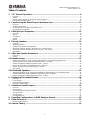 5
5
-
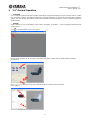 6
6
-
 7
7
-
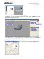 8
8
-
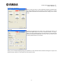 9
9
-
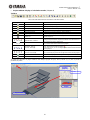 10
10
-
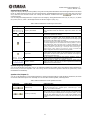 11
11
-
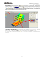 12
12
-
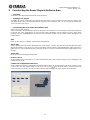 13
13
-
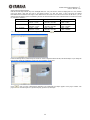 14
14
-
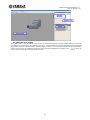 15
15
-
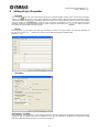 16
16
-
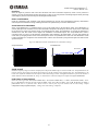 17
17
-
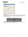 18
18
-
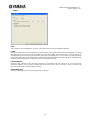 19
19
-
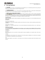 20
20
-
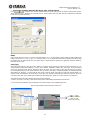 21
21
-
 22
22
-
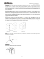 23
23
-
 24
24
-
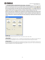 25
25
-
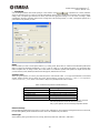 26
26
-
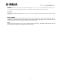 27
27
-
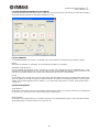 28
28
-
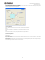 29
29
-
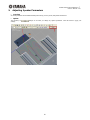 30
30
-
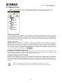 31
31
-
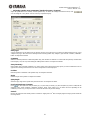 32
32
-
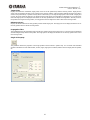 33
33
-
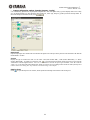 34
34
-
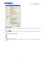 35
35
-
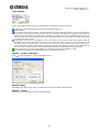 36
36
-
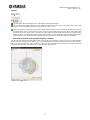 37
37
-
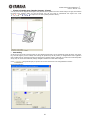 38
38
-
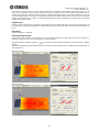 39
39
-
 40
40
-
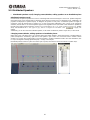 41
41
-
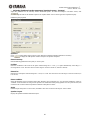 42
42
-
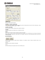 43
43
-
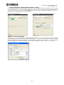 44
44
-
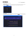 45
45
-
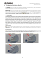 46
46
-
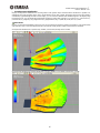 47
47
-
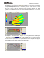 48
48
-
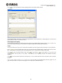 49
49
-
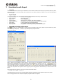 50
50
-
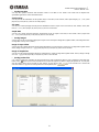 51
51
-
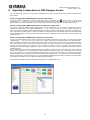 52
52
-
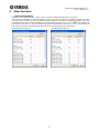 53
53
-
 54
54


Yamaha V3 Handleiding
- Type
- Handleiding
- Deze handleiding is ook geschikt voor
in andere talen
- English: Yamaha V3 User manual
- italiano: Yamaha V3 Manuale utente
- русский: Yamaha V3 Руководство пользователя
- français: Yamaha V3 Manuel utilisateur
- español: Yamaha V3 Manual de usuario
- Deutsch: Yamaha V3 Benutzerhandbuch
- português: Yamaha V3 Manual do usuário
- dansk: Yamaha V3 Brugermanual
- suomi: Yamaha V3 Ohjekirja
- čeština: Yamaha V3 Uživatelský manuál
- svenska: Yamaha V3 Användarmanual
- Türkçe: Yamaha V3 Kullanım kılavuzu
- polski: Yamaha V3 Instrukcja obsługi
- română: Yamaha V3 Manual de utilizare