
EN
Owner’s Manual
Keep This Manual For Future Reference.

(5)-1
2
SPX2000—Owner’s Manual
PRECAUTIONS
PLEASE READ CAREFULLY BEFORE PROCEEDING
* Please keep this manual in a safe place for future reference.
WARNING
Always follow the basic precautions listed below to avoid the possibility of serious injury or even death from electrical
shock, short-circuiting, damages, fire or other hazards. These precautions include, but are not limited to, the following:
• Only use the voltage specified as correct for the device. The required voltage is
printed on the name plate of the device.
• Use only the included power cord.
If you intend to use the device in an area other than in the one you purchased,
the included power cord may not be compatible. Please check with your Yamaha
dealer.
• Do not place the power cord near heat sources such as heaters or radiators, and do
not excessively bend or otherwise damage the cord, place heavy objects on it, or
place it in a position where anyone could walk on, trip over, or roll anything over it.
• Do not open the device or attempt to disassemble the internal parts or modify
them in any way. The device contains no user-serviceable parts. If it should
appear to be malfunctioning, discontinue use immediately and have it inspected
by qualified Yamaha service personnel.
• Do not expose the device to rain, use it near water or in damp or wet conditions,
or place containers on it containing liquids which might spill into any openings.
• Never insert or remove an electric plug with wet hands.
• If the power cord or plug becomes frayed or damaged, or if there is a sudden loss of
sound during use of the device, or if any unusual smells or smoke should appear to be
caused by it, immediately turn off the power switch, disconnect the electric plug from
the outlet, and have the device inspected by qualified Yamaha service personnel.
• If this device should be dropped or damaged, immediately turn off the power
switch, disconnect the electric plug from the outlet, and have the device
inspected by qualified Yamaha service personnel.
CAUTION
Always follow the basic precautions listed below to avoid the possibility of physical injury to you or others, or damage
to the device or other property. These precautions include, but are not limited to, the following:
• Remove the electric plug from the outlet when the device is not to be used for
extended periods of time, or during electrical storms.
• When removing the electric plug from the device or an outlet, always hold the
plug itself and not the cord. Pulling by the cord can damage it.
• Before moving the device, remove all connected cables.
• When setting up the product, make sure that the AC outlet you are using is
easily accessible. If some trouble or malfunction occurs, immediately turn off
the power switch and disconnect the plug from the outlet. Even when the power
switch is turned off, electricity is still flowing to the product at the minimum
level. When you are not using the product for a long time, make sure to unplug
the power cord from the wall AC outlet.
• Do not expose the device to excessive dust or vibrations, or extreme cold or heat
(such as in direct sunlight, near a heater, or in a car during the day) to prevent
the possibility of panel disfiguration or damage to the internal components.
• Do not place the device in an unstable position where it might accidentally fall over.
• Do not use the device in the vicinity of a TV, radio, stereo equipment, mobile
phone, or other electric devices. Otherwise, the device, TV, or radio may
generate noise.
• Before connecting the device to other devices, turn off the power for all devices.
Before turning the power on or off for all devices, set all volume levels to minimum.
• Be sure to connect to a properly grounded power source. A ground screw
terminal is provided on the rear panel for safely grounding the device and
preventing electrical shock.
• Do not insert your fingers or hand in any gaps or openings on the device.
•Avoid inserting or dropping foreign objects (paper, plastic, metal, etc.) into any
gaps or openings on the device. If this happens, turn off the power immediately
and unplug the power cord from the AC outlet. Then have the device inspected
by qualified Yamaha service personnel.
• Do not rest your weight on the device or place heavy objects on it, and avoid use
excessive force on the buttons, switches or connectors.
• This device has a built-in backup battery. When you unplug the power cord from
the AC outlet, the internal data is retained. However, if the backup battery fully
discharges, this data will be lost. When the backup battery is running low, the
LCD indicates “Low Battery!”. In this case, immediately save the data to a
computer or other external device, then have qualified Yamaha service
personnel replace the backup battery.
XLR-type connectors are wired as follows (IEC60268 standard): pin 1: ground, pin 2: hot (+), and pin 3: cold (-).
Yamaha cannot be held responsible for damage caused by improper use or modifications to the device, or data that is lost or destroyed.
Always turn the power off when the device is not in use.
The performance of components with moving contacts, such as switches, volume controls, and connectors, deteriorates over time. Consult qualified Yamaha service
personnel about replacing defective components.
Power supply/Power cord
Do not open
Water warning
If you notice any abnormality
Power supply/Power cord
Location
Connections
Handling caution
Backup battery

(5)-1
SPX2000—Owner’s Manual
3
1. IMPORTANT NOTICE: DO NOT MODIFY THIS UNIT!
This product, when installed as indicated in the instructions con-
tained in this manual, meets FCC requirements. Modifications not
expressly approved by Yamaha may void your authority, granted by
the FCC, to use the product.
2. IMPORTANT:
When connecting this product to accessories and/
or another product use only high quality shielded cables. Cable/s
supplied with this product MUST be used. Follow all installation
instructions. Failure to follow instructions could void your FCC
authorization to use this product in the USA.
3. NOTE:
This product has been tested and found to comply with the
requirements listed in FCC Regulations, Part 15 for Class “B” digital
devices. Compliance with these requirements provides a reason-
able level of assurance that your use of this product in a residential
environment will not result in harmful interference with other elec-
tronic devices. This equipment generates/uses radio frequencies
and, if not installed and used according to the instructions found in
the users manual, may cause interference harmful to the operation
of other electronic devices. Compliance with FCC regulations does
* This applies only to products distributed by YAMAHA CORPORATION OF AMERICA. (class B)
not guarantee that interference will not occur in all installations. If
this product is found to be the source of interference, which can be
determined by turning the unit “OFF” and “ON”, please try to elimi-
nate the problem by using one of the following measures:
Relocate either this product or the device that is being affected by
the interference.
Utilize power outlets that are on different branch (circuit breaker or
fuse) circuits or install AC line filter/s.
In the case of radio or TV interference, relocate/reorient the
antenna. If the antenna lead-in is 300 ohm ribbon lead, change the
lead-in to co-axial type cable.
If these corrective measures do not produce satisfactory results,
please contact the local retailer authorized to distribute this type of
product. If you can not locate the appropriate retailer, please con-
tact Yamaha Corporation of America, Electronic Service Division,
6600 Orangethorpe Ave, Buena Park, CA90620
The above statements apply ONLY to those products distributed by
Yamaha Corporation of America or its subsidiaries.
FCC INFORMATION (U.S.A.)
IMPORTANT NOTICE FOR THE UNITED KINGDOM
Connecting the Plug and Cord
WARNING:
THIS APPARATUS MUST BE EARTHED
IMPORTANT. The wires in this mains lead are coloured in accordance
with the following code:
GREEN-AND-YELLOW : EARTH
BLUE : NEUTRAL
BROWN : LIVE
As the colours of the wires in the mains lead of this apparatus may not
correspond with the coloured markings identifying the terminals in
your plug proceed as follows:
The wire which is coloured GREEN-and-YELLOW must be connected
to the terminal in the plug which is marked by the letter E or by the
safety earth symbol or colored GREEN or GREEN-and-YELLOW.
The wire which is coloured BLUE must be connected to the terminal
which is marked with the letter N or coloured BLACK.
The wire which is coloured BROWN must be connected to the termi-
nal which is marked with the letter L or coloured RED.
• This applies only to products distributed by Yamaha-Kemble Music (U.K.) Ltd. (3 wires)
ADVARSEL!
Lithiumbatteri—Eksplosionsfare ved fejlagtig håndtering. Udskiftning
må kun ske med batteri af samme fabrikat og type. Levér det brugte
batteri tilbage til leverandoren.
VARNING
Explosionsfara vid felaktigt batteribyte. Använd samma batterityp eller
en ekvivalent typ som rekommenderas av apparattillverkaren.
Kassera använt batteri enligt fabrikantens instruktion.
VAROITUS
Paristo voi räjähtää, jos se on virheellisesti asennettu. Vaihda paristo
ainoastaan laitevalmistajan suosittelemaan tyyppiin. Hävitä käytetty
paristo valmistajan ohjeiden mukaisesti.
(lithium caution)
NEDERLAND / THE NETHERLANDS
• Dit apparaat bevat een lithium batterij voor geheugen back-up.
• This apparatus contains a lithium battery for memory back-up.
• Raadpleeg uw leverancier over de verwijdering van de batterij op het
moment dat u het apparaat ann het einde van de levensduur of
gelieve dan contact op te nemen met de vertegenwoordiging van
Yamaha in uw land.
•For the removal of the battery at the moment of the disposal at the
end of life please consult your retailer or Yamaha representative
office in your country.
• Gooi de batterij niet weg, maar lever hem in als KCA.
• Do not throw away the battery. Instead, hand it in as small chemical
waste.
(lithium disposal)
* This applies only to products distributed by
YAMAHA CORPORATION OF AMERICA.
COMPLIANCE INFORMATION STATEMENT
(DECLARATION OF CONFORMITY PROCEDURE)
Responsible Party : Yamaha Corporation of America
Address : 6600 Orangethorpe Ave., Buena Park, Calif.
90620
Telephone : 714-522-9011
Type of Equipment : PROFESSIONAL MULTI-EFFECT PROCESSOR
Model Name : SPX2000
This device complies with Part 15 of the FCC Rules.
Operation is subject to the following two conditions:
1) this device may not cause harmful interference, and
2) this device must accept any interference received including interfer-
ence that may cause undesired operation.
See user manual instructions if interference to radio reception is sus-
pected.
(FCC DoC)

(5)-1
4
SPX2000—Owner’s Manual
The above warning is located on the top of the unit.
Explanation of Graphical Symbols
The lightning flash with arrowhead symbol
within an equilateral triangle is intended to alert
the user to the presence of uninsulated “danger-
ous voltage” within the product’s enclosure that
may be of sufficient magnitude to constitute a
risk of electric shock to persons.
The exclamation point within an equilateral trian-
gle is intended to alert the user to the presence of
important operating and maintenance (servicing)
instructions in the literature accompanying the
product.
IMPORTANT SAFETY INSTRUCTIONS
1 Read these instructions.
2Keep these instructions.
3 Heed all warnings.
4 Follow all instructions.
5 Do not use this apparatus near water.
6 Clean only with dry cloth.
7 Do not block any ventilation openings. Install in
accordance with the manufacturer’s instructions.
8 Do not install near any heat sources such as radia-
tors, heat registers, stoves, or other apparatus
(including amplifiers) that produce heat.
9 Do not defeat the safety purpose of the polarized
or grounding-type plug. A polarized plug has two
blades with one wider than the other. A grounding
type plug has two blades and a third grounding
prong. The wide blade or the third prong are pro-
vided for your safety. If the provided plug does not
fit into your outlet, consult an electrician for
replacement of the obsolete outlet.
10 Protect the power cord from being walked on or
pinched particularly at plugs, convenience recep-
tacles, and the point where they exit from the
apparatus.
11 Only use attachments/accessories specified by
the manufacturer.
12 Use only with the cart, stand,
tripod, bracket, or table speci-
fied by the manufacturer, or
sold with the apparatus. When a
cart is used, use caution when
moving the cart/apparatus com-
bination to avoid injury from tip-
over.
13 Unplug this apparatus during lightning storms or
when unused for long periods of time.
14 Refer all servicing to qualified service personnel.
Servicing is required when the apparatus has
been damaged in any way, such as power-supply
cord or plug is damaged, liquid has been spilled or
objects have fallen into the apparatus, the appara-
tus has been exposed to rain or moisture, does
not operate normally, or has been dropped.
CAUTION: TO REDUCE THE RISK OF
ELECTRIC SHOCK, DO NOT REMOVE
COVER (OR BACK). NO USER-SERVICEABLE
PARTS INSIDE. REFER SERVICING TO
QUALIFIED SERVICE PERSONNEL.
CAUTION
RISK OF ELECTRIC SHOCK
DO NOT OPEN
WARNING
TO REDUCE THE RISK OF FIRE OR ELECTRIC SHOCK,
DO NOT EXPOSE THIS APPARATUS TO RAIN OR MOISTURE.
* This applies only to products distributed
by YAMAHA CORPORATION OF AMERICA. (Perchlorate)
This product contains a battery that contains perchlorate material.
Perchlorate Material—special handling may apply,
See www.dtsc.ca.gov/hazardouswaste/perchlorate.
CAUTIONS:
• This unit is a CLASS I device. Connect the unit to a mains socket
outlet that features a protective ground terminal.
• This unit is not completely disconnected from the mains when you
turn off the POWER switch, which is a single pole switch.

SPX2000—Owner’s Manual
5
• All illustrations in this owner’s manual are for explanatory purposes; they may differ
from the actual specifications.
• Company names and product names appearing in this manual are the trademarks or
registered trademarks of their respective owners.
Table of contents
Features of the SPX2000 . . . . . . . . . . . . . . . . . . . . . . . . . . . . . . . . 6
Parts and their functions . . . . . . . . . . . . . . . . . . . . . . . . . . . . . . . . 7
Front panel . . . . . . . . . . . . . . . . . . . . . . . . . . . . . . . . . . . . . . . . . . . . . . . . . . . . . . . . . . . . . . . . . . . 7
Rear panel . . . . . . . . . . . . . . . . . . . . . . . . . . . . . . . . . . . . . . . . . . . . . . . . . . . . . . . . . . . . . . . . . . . . 9
Operation . . . . . . . . . . . . . . . . . . . . . . . . . . . . . . . . . . . . . . . . . . . 10
Basic operation . . . . . . . . . . . . . . . . . . . . . . . . . . . . . . . . . . . . . . . . . . . . . . . . . . . . . . . . . . . . . . . 10
Editing an effect . . . . . . . . . . . . . . . . . . . . . . . . . . . . . . . . . . . . . . . . . . . . . . . . . . . . . . . . . . . . . . 13
Other functions. . . . . . . . . . . . . . . . . . . . . . . . . . . . . . . . . . . . . . . . . . . . . . . . . . . . . . . . . . . . . . . 17
Effects . . . . . . . . . . . . . . . . . . . . . . . . . . . . . . . . . . . . . . . . . . . . . . 25
Reverb . . . . . . . . . . . . . . . . . . . . . . . . . . . . . . . . . . . . . . . . . . . . . . . . . . . . . . . . . . . . . . . . . . . . . . 27
Early Reflection. . . . . . . . . . . . . . . . . . . . . . . . . . . . . . . . . . . . . . . . . . . . . . . . . . . . . . . . . . . . . . . 35
Delay, Echo . . . . . . . . . . . . . . . . . . . . . . . . . . . . . . . . . . . . . . . . . . . . . . . . . . . . . . . . . . . . . . . . . . 38
Modulation . . . . . . . . . . . . . . . . . . . . . . . . . . . . . . . . . . . . . . . . . . . . . . . . . . . . . . . . . . . . . . . . . . 47
Pitch Change. . . . . . . . . . . . . . . . . . . . . . . . . . . . . . . . . . . . . . . . . . . . . . . . . . . . . . . . . . . . . . . . . 61
Composite effects . . . . . . . . . . . . . . . . . . . . . . . . . . . . . . . . . . . . . . . . . . . . . . . . . . . . . . . . . . . . . 66
Freeze. . . . . . . . . . . . . . . . . . . . . . . . . . . . . . . . . . . . . . . . . . . . . . . . . . . . . . . . . . . . . . . . . . . . . . . 77
Other effects . . . . . . . . . . . . . . . . . . . . . . . . . . . . . . . . . . . . . . . . . . . . . . . . . . . . . . . . . . . . . . . . . 82
MIDI . . . . . . . . . . . . . . . . . . . . . . . . . . . . . . . . . . . . . . . . . . . . . . . 88
Preparations for using MIDI . . . . . . . . . . . . . . . . . . . . . . . . . . . . . . . . . . . . . . . . . . . . . . . . . . . . 88
What you can do using MIDI . . . . . . . . . . . . . . . . . . . . . . . . . . . . . . . . . . . . . . . . . . . . . . . . . . . 88
MIDI data format . . . . . . . . . . . . . . . . . . . . . . . . . . . . . . . . . . . . . . . . . . . . . . . . . . . . . . . . . . . . . 89
MIDI Control Change Parameter Assignment Table . . . . . . . . . . . . . . . . . . . . . . . . . . . . . . . . 95
Error message list . . . . . . . . . . . . . . . . . . . . . . . . . . . . . . . . . . . . . 97
Troubleshooting . . . . . . . . . . . . . . . . . . . . . . . . . . . . . . . . . . . . . . 98
Specifications . . . . . . . . . . . . . . . . . . . . . . . . . . . . . . . . . . . . . . . . 99
Index . . . . . . . . . . . . . . . . . . . . . . . . . . . . . . . . . . . . . . . . . . . . . . 104

6
SPX2000—Owner’s Manual
Features of the SPX2000
●
High-quality sound
High quality is guaranteed by 96 kHz 24-bit digital processing.
●
Flexible support for a variety of situations and applications
122 different effects are provided as presets, meeting the needs of a wide variety of situations and applica-
tions. You can edit these preset effects to create your own unique sounds.
●
Control effects remotely
You can use the SPX2000 Editor
(*)
or MIDI messages to control effects remotely. You can not only switch
effects, but also modify the effect parameters to make fine adjustments, or make the effect vary in conjunc-
tion with your performance on a MIDI keyboard.
*Refer to “Controlling the SPX2000 from your computer,” below.
●
Manage effect data on your computer
You can use the SPX2000 Editor to manage or back up your original effects and data. For example you could
create a separate library for each live performance or recording project, and store effects for just that event.
Then you can simply swap the data (USER bank) for each occasion, allowing you to use effects efficiently.
★
Digital input/output
By connecting an AES/EBU format compatible device
you can input/output audio in digital form.
★
Intuitive operation
Operation is intuitive; use the [STORE] button to store
an effect, the [RECALL] button to recall an effect, and
the [
▲
INC]/[
▼
DEC] buttons to increment/decre-
ment a parameter value.
★
Instant recognition of effect types
The SPX2000’s display shows a different background
color (by default) for each type of effect. You can tell the
general effect type at a glance; e.g., cyan (light blue) for
reverb and early reflection, white for delay, magenta for
modulation, and green for effects of the Classic bank.
★
New reverb algorithms
New reverbs feature the newly-developed REV-X algo-
rithm, delivering rich, high-density reverberation with
smooth decay, spaciousness, and depth that brings out
the best in the original signal.
★
Classic SPX effects revived with new algorithms
Favorite effects such as gate reverb, freeze, and flanger
have been carried over from previous SPX-series mod-
els, with newly developed algorithms.
★
Stereo input/output
The SPX2000 provides full stereo operation; 2 IN/2
OUT.
★
Tempo synchronization
Some effects can be synchronized to a specified note
length and tempo. The tempo can be set using the front
panel [TAP] button, from a foot switch such as the FC5,
or via MIDI messages.
★
A full range of MIDI functionality
You can use MIDI to switch effects, modify parameter
values, or transmit/receive bulk data.Effects and tempo
synchronization can also be controlled via MIDI.
Hardware features
Controlling the SPX2000 from
your computer
You can use the SPX2000 Editor to remotely control
the SPX2000 from your computer. The SPX2000
Editor is expected to be available for downloading
from the following website. For the latest informa-
tion, please visit the website.
Yamaha Pro Audio Website:
http://www.yamahaproaudio.com/
For details on the SPX2000 Editor, refer to the
operating manual for the software.
Software features

SPX2000—Owner’s Manual
7
Parts and their functions
Front panel
1
[INPUT L R] control
This concentric pair of knobs adjusts the level of the
analog input signal. The inner knob controls the L
channel, and the outer knob controls the R channel.
2
Level meters
These indicate the signal level pre-effect or post-effect
(page 103).
3
[INPUT MODE] button/indicator
This button selects monaural input or stereo input.
The indicator will light to indicate the currently
selected input mode.
4
[METER] button/indicator
This button selects either pre-effect or post-effect as
the signal whose level will be shown in the level meter
(
2
). The indicator will light to indicate the currently
selected signal.
5
[INPUT SOURCE] indicator
This indicates the currently selected input source. Use
“INPUT SOURCE” (page 19) to select the input
source.
6
[CLOCK] indicator
This indicates the currently selected word clock source.
Use “CLOCK SOURCE” (page 18) to select the word
clock source.
7
[MIDI] indicator
This will light when the SPX2000 receives MIDI data.
8
[kHz] indicator
This indicates the currently-operating word clock fre-
quency.
9
Display
This displays information about the currently-recalled
effect or the selected utility function.
0
Effect number indicator
This indicates the effect number of the currently
selected effect. If the selected effect is different than the
recalled effect, the number will blink. When you store
or recall an effect, the blinking number will change to
steadily lit.
A
[BANK] button/indicator
This button selects the effect bank. The indicator for
the selected bank will light. For details on banks, refer
to “Three banks” (page 12).
B
[STORE] button
This button stores the selected effect.
C
[
▲
]/[
▼
] buttons
These buttons select an effect.
D
[RECALL] button
This button recalls the selected effect.
E
[UNDO] button/LED
Use this button when you want to undo the preceding
store/recall/erase operation (page 16). The LED will
light if the [UNDO] button is available.
F
[BACK] button
This button selects the preceding parameter.
G
[
▲
INC]/[
▼
DEC] buttons
Use these buttons to edit parameter values.
2 3 57 9 0 B E I J MFC G
H N O
DA4681 LK
P

8 SPX2000—Owner’s Manual
H [NEXT] button
This button selects the next parameter.
I [COMPARE] button/LED
Use this button to compare the effect before editing
(immediately after recall) and after editing. If you edit
a parameter after recalling an effect, this LED will light.
The LED will go dark when you store or recall an effect
(page 16).
J [PARAMETER] button/LED
This button selects the basic parameters of the effect.
This LED will light if basic parameters are selected.
K [FINE PARAM] button/LED
This button selects the FINE parameters of the effect.
The FINE parameters supplement the basic parame-
ters. This LED will light if FINE parameters are
selected.
L [UTILITY] button/LED
This button selects the SPX2000’s utility functions. For
details, refer to “Other functions” (page 17). This LED
will light if a utility function is selected.
M [BYPASS] button/LED
This button switches the effect on/off. When the
[BYPASS] button is off (LED dark), the effect will be
applied to the input signal and output from the output
jacks. When the [BYPASS] button is on (LED lit), the
input signal will be sent from the output jacks without
modification.
N [TAP] button/LED
Use this to set the tempo value of the effect. When you
press this button twice or more, the tempo value will be
calculated from the average interval at which you press
the button. If the effect SYNC parameter is on, the LED
will blink at the interval of the tempo value.
O [FOOT SW] jack
You can connect an optional foot switch (such as the
FC5) to this jack and the foot switch to input the
tempo as an alternative to using the [TAP] button (N)
(page 23).
P [POWER ON/OFF] button
This button turns the power of the SPX2000 on/off.
NOTE: The following buttons will be inoperable when the
[UTILITY] LED (
L
) is lit.
• [BANK] button (
A
)
• [STORE] button (
B
)
• [
▲
]/[
▼
] buttons (
C
)
• [RECALL] button (
D
)
• [UNDO] button (
E
)
• [COMPARE] button (
I
)
NOTE: The [BYPASS] button will turn off when you recall
an effect.

SPX2000—Owner’s Manual 9
Rear panel
Q Grounding screw
For safety, use this screw to ground the SPX2000.
The included power cable has a three-prong plug; if the
electrical outlet you use is correctly grounded, the
SPX2000 will be appropriately grounded. If the electri-
cal outlet is not grounded, use this screw to ground the
SPX2000. Correctly grounding the SPX2000 will effec-
tively reduce hum and interference.
R [AC IN] jack
Connect the power cable to this jack. First connect the
power cable to the SPX2000, and then connect the
other end to the electrical outlet.
S [MIDI OUT/THRU] connector
You can connect a MIDI device to this connector and
use MIDI messages to send SPX2000 data to it. You can
bulk-dump SPX2000 data via MIDI, or re-transmit
MIDI data received at the [MIDI IN] connector (T)
from this connector without change. Use “MIDI OUT
SETUP” (page 21) to specify whether this connector
functions as “MIDI OUT” or “MIDI THRU.”
T [MIDI IN] connector
You can connect a MIDI device to this connector and
use messages transmitted from that device to remotely
control the SPX2000 (page 88).
U [TO HOST USB] connector
You can use a USB cable to connect your computer
here. You can use SPX2000 Editor or your MIDI appli-
cation to remotely control the SPX2000 from your
computer (page 6).
V [WORD CLOCK IN] jack
Connect this jack to a device that supplies a word clock
signal. This jack is terminated with a 75-ohm resistor.
Connect this jack in a one-to-one connection with the
device supplying the word clock.
W [AES/EBU OUT] jack
Connect an AES/EBU format device to this jack. This
XLR-3-32 jack outputs an AES/EBU format digital sig-
nal.
X [AES/EBU IN] jack
Connect an AES/EBU format device to this jack. This
XLR-3-31 jack inputs an AES/EBU format digital sig-
nal.
Y [OUTPUT] jacks
Connect these jacks to the effect return of your mixer
or to the input of your power amp. These jacks output
analog signals. Use either the XLR-3-32 jacks or the
TRS phone jacks, as appropriate for the device you are
connecting.
Z [OUTPUT –10 dBu/+4 dBu] switch
Set this to either –10 dBu or +4 dBu according to the
input level of the device connected to the [OUTPUT]
jacks (Y).
[ [INPUT] jacks
Connect these jacks to the effect send of your mixer or
to the output of an electronic musical instrument.
These jacks input analog signals. Use either the XLR-3-
31 jacks or the TRS phone jacks, as appropriate for the
device you are connecting.
In order to enable these jacks, you must set the input
source setting to “ANALOG” (page 19).
\ [INPUT –10 dBu/+4 dBu] switch
Set this to either –10 dBu or +4 dBu according to the
output level of the device connected to the [INPUT]
jacks ([).
R S T W XYU V
ZQ \
[
Use only the supplied power cord.

10 SPX2000—Owner’s Manual
Operation
Basic operation
This section provides a simple explanation of how to input signals to the SPX2000,
apply effects, and output the result. The overall steps are as follows.
Make connections to external devices
↓
Turn the power on
↓
Select the input signal
↓
Select an effect
↓
Recall the effect
↓
Switch the effect on/off
The connectors you use will depend on whether the input/
output signals are analog or digital.
• Analog input:
Connect your device to the [INPUT] jacks ([).
• Digital input:
Connect your device to the [AES/EBU IN] jack (X).
• Analog output:
Connect your device to the [OUTPUT] jacks (Y).
• Digital output:
Connect your device to the [AES/EBU OUT] jack (W).
Related items
• Selecting the word clock source......................... page 18
•Using your computer to
control the SPX2000 ............................................ page 6
•Using MIDI messages to
control the SPX2000 .........................................page 88
Here’s how to turn on the power of a system that includes
the SPX2000.
1 Protect your monitor system
Before you turn on the power of the SPX2000, turn off
the power of the device that is connected to the [OUT-
PUT] jacks (Y) or [AES/EBU OUT] jack (W). Also
turn the [INPUT L R] control (1) to minimize the
L/R input signal level (the inner knob controls the L
channel, and the outer knob controls the R channel).
2 Turn on the power of the SPX2000
Press the [POWER ON/OFF] button (P) to turn the
power on.
→ The front panel display and LEDs will light.
3 Turn on your external devices
Turn on the power of devices connected to the
SPX2000.
Make connections to external
devices
NOTE: If you are inputting/outputting analog signals, you must
set the [INPUT –10 dBu/+4 dBu] switch (
\
) and the [OUTPUT
–10dBu/+4dBu] switch (
Z
) appropriately for the signal level of
the connected devices.
You must turn off the power of all devices before you
make connections.
Turn the power on
NOTE:To prevent high-volume noise from being out-
put from your speakers, turn on the power starting
with the device that is closest to the audio source.
Example: sound modules → mixer → SPX2000 →
power amp
Reverse this order when turning the power off.

SPX2000—Owner’s Manual 11
Operation
You will need to make several selections regarding the
input signal.
Select monaural or stereo input
Use the [INPUT MODE] button (3) to select either mon-
aural input or stereo input. Each time you press the
[INPUT MODE] button the indicator will alternate
between MONO and STEREO.
The signal flow will change as follows depending on
whether the input is monaural or stereo, and on the num-
ber of inputs/outputs for the effect you recall.
Select the signal for metering
Use the [METER] button (4) to select either the pre-
effect signal or the post-effect signal for display in the level
meter (2). Each time you press the [METER] button the
indicator will alternate between INPUT and OUTPUT.
Check the status of the input signal
The following indicators will light to indicate the state of
the input signal.
• INPUT SOURCE (5):
This will indicate whether the input signal is ANALOG
or DIGITAL. If you want to change input sources, use
“INPUT SOURCE” (page 19) to select the desired input
source.
• MIDI (7):
This indicator will light when MIDI data is received.
• CLOCK (6):
This indicates the word clock source. Use “CLOCK
SOURCE” (page 18) to select the word clock source.
• kHz (8)
This indicates the word clock frequency (44.1/48/88.2/96
kHz). If you are using the SPX2000’s internal clock, you
can use “CLOCK SOURCE” (page 18) to select the fre-
quency.
Use the [INPUT L R] control (1) to adjust the analog
input signal levels (L/R); the inner knob controls the L
channel, and the outer knob controls the R channel.
Select the input signal
FX
IN L
IN R OUT R
OUT L
L
R
C
–3 dB
–3 dB
FX
IN L
IN R OUT R
OUT L
L
R
L
R
FX
IN L
(MONO)
IN L
(MONO)
IN R OUT R
OUT L
L
R
C
FX
IN R OUT R
OUT L
L
R
L
R
Monaural input 1IN 2OUT
Monaural input 2IN 2OUT
Stereo input 1IN 2OUT
Stereo input 2IN 2OUT
INT
The SPX2000’s internal clock
The SPX2000 will operate as the
clock master.
You will need to set other con-
nected devices to be clock slaves.
AES/EBU
Clock data received at the [AES/EBU IN]
jack (X)
The SPX2000 will operate as a clock
slave.
WC
Clock will be received at the [WORD
CLOCK IN] jack (V)
The SPX2000 will operate as a clock
slave.
Adjust the input level

12 SPX2000—Owner’s Manual
Here’s how to select the effect that you want to apply to the
input signal.
1 Select a bank
Press the [BANK] button (A) several times to select
the bank that contains the desired effect.
→ The [BANK] indicator (A) shows the currently
selected bank.
2 Select an effect
Use the [▲]/[▼] buttons (C) to select the effect you
want to use.
→ The number of the currently-selected effect will
blink in the effect number indicator (0).
Press the [RECALL] button (D) to recall the effect.
→ The recalled effect will be applied to the output signal.
You can use the [BYPASS] button (M) to switch the effect
on/off.
→ Each time you press the button the effect will be
switched on/off. When the [BYPASS] button is on, the
effect will be off and the input signal will be output
without modification.
Three banks
The SPX2000 has three effect banks; PRESET,
USER, and CLASSIC. These banks are organized as
follows.
PRESET bank
This bank contains a total of 97 effects; 80
effects based on new algorithms and ranging
from standard to distinctive, and 17 newly-
developed reverb (REV-X) effects.
The effects in this bank are read-only.
CLASSIC bank
This bank contains 25 simple and easy-to-use
effects based on early models of the SPX series.
The effects in this bank are read-only.
USER bank
When shipped, this bank does not contain
effects. You can edit effects from the PRESET
bank or CLASSIC bank and store them as your
own original effects in the USER bank. Once
you have stored an effect, you can recall and use
it in the same way as the effects of the PRESET
bank or CLASSIC bank.
You can store 99 effects in this bank.
Select an effect
[▲] button
Press to move to the following effect.
Hold
to continue moving through
the following effects.
Hold down
[▲] and
press [▼]
to move more rapidly through
the following effects.
[▼] button
Press to move to the preceding effect.
Hold
to continue moving through
the preceding effects.
Hold down
[▼] and
press [▲]
to move more rapidly through
the preceding effects.
NOTE: The following buttons will be inoperable when the
[UTILITY] LED (
L
) is lit
• [BANK] button (
A
)
• [STORE] button (
B
)
• [
▲
]/[
▼
] buttons (
C
)
• [RECALL] button (
D
)
• [UNDO] button (
E
)
• [COMPARE] button (
I
)
NOTE: While you are selecting an effect (i.e., while the effect
number indicator is blinking), pressing any of the following
buttons will cancel the effect selection; the currently-recalled
effect will appear in the display.
• [UNDO] button (
E
)
• [BACK] button (
F
)
• [
▲
INC]/[
▼
DEC] buttons (
G
)
• [NEXT] button (
H
)
• [COMPARE] button (
I
)
• [PARAMETER] button (
J
)
• [FINE PARAM] button (
K
)
Recall the effect
NOTE: You can press the [UNDO] button (
E
) to undo the
preceding Recall operation. The [UNDO] LED will light if UNDO
is available.
Switch the effect on/off

SPX2000—Owner’s Manual 13
Operation
Editing an effect
This section explains the process of editing a selected effect and storing it. The over-
all steps are as follows.
Select an effect
↓
Select a parameter
↓
Edit the parameter
↓
Check the edited effect
↓
Store the effect
↓
(Undo the preceding Store operation)
Select the effect that you want to edit.
1 Select a bank
Use the [BANK] button (A) to select the bank con-
taining the effect you want to edit.
→ The [BANK] indicator (A) shows the currently
selected bank.
2 Select an effect (page 12)
Use the [▲]/[▼] buttons (C) to select the effect you
want to edit.
→ The number of the currently selected effect will
blink in the effect number indicator (0).
3 Recall the effect
Press the [RECALL] button (D) to recall the effect.
→ The effect number indicator (0) will change from
blinking to steadily lit.
Select an effect
NOTE: While you are selecting an effect (i.e., while the effect
number indicator is blinking), pressing any of the following
buttons will cancel the effect selection; the currently-recalled
effect will appear in the display.
• [UNDO] button (
E
)
• [BACK] button (
F
)
• [
▲
INC]/[
▼
DEC] buttons (
G
)
• [NEXT] button (
H
)
• [COMPARE] button (
I
)
• [PARAMETER] button (
J
)
• [FINE PARAM] button (
K
)
NOTE: The following buttons will be inoperable when the
[UTILITY] LED (
L
) is lit
• [BANK] button (
A
)
• [STORE] button (
B
)
• [
▲
]/[
▼
] buttons (
C
)
• [RECALL] button (
D
)
• [UNDO] button (
E
)
• [COMPARE] button (
I
)
Basic parameters and Fine
parameters
Each of the SPX2000’s effects consists of two types
of parameter: Basic parameters and Fine parame-
ters.
Since some effects have a rather large number of
parameters, the parameters that you will probably
need to edit most often are grouped as “Basic
parameters,” and supplementary parameters are
grouped as “Fine parameters.”
The number and type of Basic parameters and Fine
parameters will differ for each effect.
Effect
Basic parameter 1
Basic parameter 2
Basic parameter 3
Basic parameter n
Fine parameter 1
Fine parameter 2
Fine parameter 3
Fine parameter m

14 SPX2000—Owner’s Manual
To edit a parameter, you must first select it. The editable
parameters will differ for each effect. For details, refer to
the explanation of each parameter in the “Effects” section
(page 25 and following).
1 Select a Basic parameter or Fine parameter
Press either the [PARAMETER] button (J) or the
[FINE PARAM] button (K) to select the type of
parameter that you want to edit.
→ The LED of the button you pressed will light.
2 Select a parameter
Use the [BACK] button (F) or [NEXT] button (H) to
select the parameter that you want to edit.
→ The currently selected parameter is shown in the
display (9).
Selecting Basic parameters
Press the [BACK] button
to move to the preceding parameter.
Press and hold the [BACK] button
to continue moving through the preceding parameters.
Press the [NEXT] button or [PARAMETER] button
to move to the following parameter.
Press and hold the [NEXT] button or [PARAMETER] but-
ton
to continue moving through the following parameters.
Selecting FINE parameters
Press the [BACK] button
to move to the preceding parameter.
Press and hold the [BACK] button
to continue moving through the preceding parameters.
Press the [NEXT] button or [FINE PARAM] button
to move to the following parameter.
Press and hold the [NEXT] button or [FINE PARAM] but-
ton
to continue moving through the following parameters.
Use the [▲ INC]/[▼ DEC] button (G) to edit the value of
the parameter.
→ The parameter value shown in the display (9) will
change, and the [COMPARE] LED (I) will light.
The [COMPARE] LED (I) indicates that the currently-
recalled effect has been edited since it was recalled.
Select a parameter
NOTE: If the display indicates “NO FINE PARAMETER,” an
effect from the CLASSIC bank is recalled.
The effects of the CLASSIC bank do not have Fine parameters.
Use the [PARAMETER] button to select the Basic parameters.
REV-X LARGE HALL
REV TIME= 3.20s
Edit the parameter
[▲ INC]
button
Press
to increment the parameter
value.
Hold
to continue incrementing the
parameter value.
Hold down
[▲ INC] and
press [▼ DEC]
to continue incrementing the
parameter value faster.
[▼ DEC]
button
Press
to decrement the parameter
value.
Hold
to continue decrementing the
parameter value.
Hold down
[▼ DEC] and
press [▲ INC]
to continue decrementing the
parameter value faster.
Setting the tempo
Some effects have a Tempo parameter. You can edit
the Tempo parameter in any of the following five
ways.
• Use the [▲ INC]/[▼ DEC] button (G)
This is the same method as when editing other
parameters.
• Use the [TAP] button (N)
When you press the [TAP] button (N) two or
more times, the average interval will be calculated
and set as the Tempo value. If you want to use this
method, set “TEMPO SOURCE” (page 23) to
specify “TAP” as the synchronization source.
• Use the foot switch
When you press the foot switch (optional) two or
more times, the average interval will be calcu-
lated and set as the Tempo value. If you want to
use this method, use the following procedure.
1. Connect an optional foot switch (e.g., FC5) to
the [FOOT SW] jack (O).
2. Set the “TEMPO SOURCE” setting (page 23)
to specify “TAP” as the synchronization source.
• Use MIDI clock
The interval of MIDI Clock messages can be used
to set the Tempo value. If you want to use this
method, set “TEMPO SOURCE” (page 23) to
specify “MIDI” as the synchronization source.
• Use MIDI control changes
The value specified by a MIDI Control Change
message can be used to set the Tempo value. By
using this method you can control the SPX2000’s
Te mpo value from a connected external MIDI
device.

SPX2000—Owner’s Manual 15
Operation
Effects and tempo synchronization
Some of the SPX2000’s effects allow you to synchronize the effect with the tempo. There are two such types of effect; delay-
type effects and modulation-type effects. For delay-type effects, the delay time will change according to the tempo. For mod-
ulation-type effects, the frequency of the modulation signal will change according to the tempo.
• Parameters related to tempo synchronization
The following five parameters are related to tempo synchronization.
1) SYNC 2) NOTE 3) TEMPO 4) DELAY 5) FREQ.
SYNC: ........................................This is the on/off switch for tempo synchronization.
NOTE and TEMPO: .................These are the basic parameters for tempo synchronization.
DELAY and FREQ.:................... DELAY is the delay time, and FREQ. is the frequency of the modulation signal. These
directly affect the way in which the effect sound will change. DELAY is relevant only
for delay-type effects, and FREQ. is relevant only for modulation-type effects.
• How the parameters are related
Te mpo synchronization uses TEMPO and NOTE to calculate a value that will be the basis for the tempo, and continues
making adjustments so that this tempo basis stays essentially the same as the DELAY (or FREQ.). This means that when
TEMPO, NOTE, and DELAY (or FREQ.) are synchronized, and you change any of these values, the other parameters will
be re-set in order to maintain the correct relationship. The parameters that are re-set and the calculation method(*
a
) used
are as follows.
If you turn SYNC on
→ NOTE will be set
If you edit DELAY (or FREQ.)
→ NOTE will be set
In this case, the NOTE value is calculated as follows.
NOTE = DELAY (or FREQ.)/(4 x (60/TEMPO))
If you edit NOTE → DELAY (or FREQ.) will be set
In this case, the DELAY (or FREQ.) value is calculated as follows.
DELAY (or FREQ.) = NOTE x 4 x (60/TEMPO)
If you edit TEMPO → DELAY (or FREQ.) will be set
In this case, the DELAY (or FREQ.) value is calculated as follows.
DELAY (or FREQ.) = original DELAY (or FREQ.) x (previous TEMPO/new TEMPO)
Example 1: When SYNC=ON, DELAY=250 ms, TEMPO=120, you change NOTE from 8th note to quarter note
DELAY= new NOTE x 4 x (60/TEMPO)
= (1/4) x 4 x (60/120)
= 0.5 (sec)
= 500 ms
Thus, the DELAY will change from 250 ms to 500 ms.
Example 2: When SYNC=ON, DELAY=250 ms, NOTE=8th note, you change TEMPO from 120 to 121
DELAY= original DELAY x (previous TEMPO/new TEMPO)
= 250 x (120/121)
= 247.9 (ms)
Thus, the TEMPO will change from 250 ms to 247.9 ms.
*
a
Rounded values are used for the calculation results.
• Ranges of the NOTE and TEMPO values
The ranges of the NOTE and TEMPO values are limited by the ranges of the DELAY or FREQ. values. You cannot set
NOTE or TEMPO values that would cause DELAY or FREQ. to exceed their maximum possible values when synchronized
to tempo. This limitation also applies even when SYNC is OFF.
• Special characteristics of the TEMPO parameter
The TEMPO parameter has the following characteristics that are unlike other parameters.
•It is a common value shared by all effects
•It cannot be stored/recalled (the value is not saved)
This means that the TEMPO value may not necessarily be the same when an effect is recalled as when that effect was
stored. Here is an example.
Store the effect: TEMPO=120 → Change TEMPO to 60 → Recall the effect: TEMPO=60
Normally when you change the TEMPO, the DELAY (or FREQ.) will be re-set accordingly. However if the DELAY (or
FREQ.) were changed, the effect would sound differently when recalled than when it was stored. To prevent the effect from
changing in this way between store and recall, the SPX2000 does not update the DELAY (or FREQ.) value when an effect is
recalled, even if the TEMPO is no longer the same as when that effect was stored.
= 1/48
= 2/1
= 1/16
= 1/24
= 1/12
= 3/4
= 3/16
= 1/2
= 3/32
= 1/6
= 1/4
= 1/8
= 1/1
= 3/8

16 SPX2000—Owner’s Manual
Press the [COMPARE] button (I) to compare the origi-
nal effect with the edited version.
→ Each time you press this button, the [COMPARE] LED
will alternate between lit and blinking. The LED will
light if the edited effect is selected, and will blink if the
unedited effect is selected.
Here’s how to specify a location in the USER bank and
store the edited effect.
1 Select the USER bank
Press the [BANK] button (A) several times to select
the USER bank.
→ The [BANK] indicator (A) will indicate “USER.”
2 Select a store-destination for the effect
Use the [▲]/[▼] buttons (C) to specify the effect
number in which you will store the effect you edited.
→ The effect number indicator (0) shows the cur-
rently selected effect number.
3 Store the effect
Press the [STORE] button (B) to store the effect.
→ The [COMPARE] LED (I) will go dark, and the
[UNDO] LED (E) will light.
You can return settings to their prior state by “undoing”
the previous Store, Recall, or Clear Effect operation. You
can also “undo” the previous “undo” operation; this is
called “redo.”
Undo
When the [UNDO] LED (E) is lit, press the [UNDO] but-
ton to undo the previous Store, Recall, or Clear Effect
operation.
→ The [UNDO] LED will blink.
Redo
When the [UNDO] LED (E) is blinking, press the
[UNDO] button to cancel the previous Undo operation.
→ The [UNDO] LED will light.
Check the edited effect
NOTE:
The following buttons are inoperable while the [COMPARE]
LED is blinking.
• [
▲
INC]/[
▼
DEC] buttons (
G
)
• [UTILITY] buttons (
L
)
• [TAP] button (
N
)
Store the effect
Undoing the previous operation
NOTE: Undo/Redo will no longer be available if you switch
parameters.

SPX2000—Owner’s Manual 17
Operation
Other functions
Here’s how to edit the name of the recalled effect. You can
edit the name only for effects in the USER bank.
1 Select the USER bank
Use the [BANK] button (A) to select the USER bank.
2 Select an effect
Select the effect whose name you want to edit, and
recall it (page 12).
3 Select the “TITLE EDIT” function
Press the [UTILITY] button (L) several times to select
“TITLE EDIT.”
4 Edit the effect name
Use the following buttons to edit the effect name.
[BACK] button:
Moves the cursor toward the left.
[NEXT] button:
Moves the cursor toward the right.
[▲ INC] button:
Changes the character at the cursor location (A→B→C).
[▼ DEC] button:
Changes the character at the cursor location (C→B→A).
The effect name can be up to 16 characters long. You can
use the following characters.
You can switch the Protect setting on/off for the recalled
effect. Only effects in the USER bank can be protected. By
turning Protect ON for important effects, you can prevent
them from being overwritten accidentally.
1 Select the USER bank
Use the [BANK] button (A) to select the USER bank.
2 Select an effect
Select the effect whose Protect setting you want to
change, and recall it (page 12).
3 Select the “USER PGM PROTECT” function
Press the [UTILITY] button (L) several times to select
“USER PGM PROTECT.”
4 Turn Protect on or off
Use the [▲ INC]/[▼ DEC] buttons (G) to turn Pro-
tect on/off.
If you turn the setting ON, you will be unable to per-
form the following operations on that effect.
•Store
• Edit the effect name
•Delete
•Change the background color
If you turn the setting OFF, protect will be defeated and
you will again be able to perform Store operations, etc.
Editing the effect name
REV-X LARGE HALL
TITLE EDIT
REV-X LARGE HALL
TITLE EDIT
Cursor
A
R S T U V W X Y Z
ab cd ef g
xy z
[ ¥
!
@
./
0123456789 : ; <=>?
)
+,–
$%& ’ ("#
]
^
`
_
hi jk l m n o
pqr s t uv
w
BC D EFG H I J K L M N O
PQ
Protecting an effect
USER PGM PROTECT
*OFF ON
USER PGM PROTECT
*OFF ON

18 SPX2000—Owner’s Manual
Here’s how to change the background color for the recalled
effect. You can change the background color only for USER
bank effects.
1 Select the USER bank
Use the [BANK] button (A) to select the USER bank.
2 Select an effect
Select the effect whose background color you want to
change, and recall it (page 12).
3 Select the “LCD BACK” function
Press the [UTILITY] button (L) several times to select
“LCD BACK.”
4 Select the display background color
Use the [▲ INC]/[▼ DEC] buttons (G) to select the
display background color.
You can choose one of the following five colors.
WHITE
CYAN
MAGENTA
YELLOW
GREEN
Selecting the Utility function
Press the [BACK] button
to move to the preceding function.
Press and hold the [BACK] button
to continue moving through the preceding functions.
Press the [NEXT] button or [UTILITY] button
to move to the following function.
Press and hold the [UTILITY] button
to continue moving through the functions.
*For some functions, the [BACK] button and [NEXT] button
are used to move the cursor.
1 Select the “CLOCK SOURCE” function
Press the [UTILITY] button (L) several times to select
“CLOCK SOURCE.”
2 Select the word clock source
Use the [▲ INC]/[▼ DEC] buttons (G) to select the
word clock source.
→ The [CLOCK] indicator (6) and [kHz] indicator (8)
will light according to your selection.
You can choose one of the following six word clock
sources.
• WORD CLOCK: Clock data received from the
[WORD CLOCK IN] jack (V)
• AES/EBU: Clock data received from the [AES/
EBU IN] jack (X)
• INT44.1kHz: Internal clock (44.1 kHz)
• INT48kHz: Internal clock (48 kHz)
• INT88.2kHz: Internal clock (88.2 kHz)
• INT96kHz: Internal clock (96 kHz)
Changing the display back-
ground color
REV-X LARGE HALL
LCD BACK=YELLOW
REV-X LARGE HALL
LCD BACK=GREEN
Selecting the word clock source
NOTE: If the display indicates “WRONG WORD CLOCK!”, the
word clock signal from the external device has either been
interrupted or is a frequency to which the SPX2000 cannot
synchronize. Check whether there might be a problem with the
connection from the device supplying the word clock, or an
incorrect word clock setting.
If this occurs, the word clock source will automatically switch to
one of the SPX2000’s internal clocks until an acceptable word
clock is supplied from the external device.
NOTES:
• The SPX2000 extracts the sampling frequency from the
clock frequency. This means that the word clock frequency =
the sampling frequency.
• When INT44.1 kHz–INT 96 kHz is selected, noise may occur
or the output may be muted if the word clock and the input
signal cannot be synchronized correctly
CLOCK SOURCE
INT96kHz
CLOCK SOURCE
INT96kHz

SPX2000—Owner’s Manual 19
Operation
Here’s how to select either the signal from the [INPUT]
jacks ([) or the signal from the [AES/EBU IN] jack (X)
as the input source.
1 Select the “INPUT SOURCE” function
Press the [UTILITY] button (L) several times to select
“INPUT SOURCE.”
2 Select the input source
Press the [▲ INC] button (G) to select DIGITAL
([AES/EBU IN] jack), or press the [▼ DEC] button
(G) to select ANALOG ([INPUT] jacks).
→ The [INPUT SOURCE] indicator (5) indicates your
selection.
To prevent undesired changes from being made acciden-
tally, you can selectively disable certain operations.
1 Select the “OPERATION LOCK” function
Press the [UTILITY] button (L) several times to select
“OPERATION LOCK.”
2 Select the operation lock level
Use the [▲ INC]/[▼ DEC] buttons (G) to select the
operation lock level.
About word clock
The signal used to synchronize digital audio signal
processing is called “word clock.”
When two or more digital devices are connected in
order to send and receive digital audio signals, each
digital device must process the signal at the same
timing. Even if all connected devices are set to the
same clock frequency, the signals will not be trans-
mitted and received correctly if the processing tim-
ing does not match, or you may hear noise.
In order for digital audio signals to be synchro-
nized, one digital device must transmit the clock
(synchronization data), and the other devices must
be set to receive this clock. In such a setup, the
device that supplies the synchronization reference
clock is called the “CLOCK MASTER,” and the
receiving devices are called “CLOCK SLAVES.”
To use the SPX2000 as the clock master, set the
“CLOCK SOURCE” function (page 18) to either
INT96kHz, INT88.2kHz, INT48kHz, or INT44.1.
To use the SPX2000 as a clock slave, use either of
the following two methods.
1 Set the “CLOCK SOURCE” function
(page 18) to AES/EBU, and connect the
AES/EBU format compatible device supply-
ing the clock data to the [AES/EBU IN] jack
(X).
2 Set the “CLOCK SOURCE” function
(page 18) to WORD CLOCK, and connect
the device supplying the clock to the
[WORD CLOCK IN] jack (V). When doing
so, the device supplying the clock must be
connected one-to-one with the SPX2000.
Selecting the input source
NOTE: If the display indicates “Sync Error!” or if the DIGITAL
[INPUT SOURCE] indicator blinks, the incoming digital input
signal does not match the clock on which the SPX2000 is
operating.
Tr y changing the setting of the device that is supplying the word
clock.
Restricting operation of the
SPX2000
INPUT SOURCE
*ANALOG DIGITAL
INPUT SOURCE
*ANALOG DIGITAL
OPERATION LOCK
*OFF 1 2 3
OPERATION LOCK
*OFF 1 2 3

20 SPX2000—Owner’s Manual
Level 1: Utility functions other than Operation Lock
will be disabled
Level 2: In addition to Level 1, effect store and undo-
ing of store operations will be disabled
Level 3: In addition to Level 2, effect recall and editing
will be disabled
The following table shows the operations that are dis-
abled for each level.
O: Operable X: Inoperable
*1 Only the Operation Lock level can be changed.
*2 If the Operation Lock level is 1 or higher, Utility functions
other than Operation Lock cannot be selected.
Here’s how to erase (clear) the recalled effect. You can only
erase USER bank effects.
You cannot erase the effects in the PRESET bank or CLAS-
SIC bank.
1 Select the USER bank
Use the [BANK] button (A) to select the USER bank.
2 Select an effect
Select the effect that you want to erase (page 12).
3 Select the “U## CLEAR?” function
Press the [UTILITY] button (L) several times to select
“U## CLEAR?” (## will be an effect number).
4 Erase the effect
Press the [▲ INC] button (G) to erase the recalled
effect.
→ When the effect has been erased, the display will
indicate “Completed!”
NOTE: If you attempt to use the front panel buttons to perform
an operation that has been disabled by Operation Lock, a
message of “Operation Locked!” will appear in the display.
However, this message will not appear if such an operation is
attempted by remote control.
OPERATION LOCK
OFF
123
Button operations or equivalent remote control
[INPUT MODE] button (3)
OOOX
[METER] button (4)
OOOO
[BANK] button (A)
OOOX
[STORE] button (B)
OOX X
[▲]/[▼] buttons (C)
OOOX
[RECALL] button (D)
OOOX
[UNDO]
button (E)
Undo of Store opera-
tions
OOX X
Undo of Recall opera-
tions
OOOX
[BACK] button (F)/
[NEXT] button (H)
OOOO
[▲ INC]/
[▼ DEC]
buttons (
G)
Editing of Basic param-
eters and Fine parame-
ters
OOOX
Editing of Utility
settings
O
X
*1
X
*1
X
*1
[PARAMETER] button (J)
OOOO
[FINE PARAM] button (K)
OOOO
[UTILITY] button (L)
O
O
*2
O
*2
O
*2
[COMPARE] button (I)
OOOX
[BYPASS] button (M)
OOOX
[TAP] button (N)/foot switch
OOOX
[POWER ON/OFF] button (P)
OOOO
MIDI
Note on/off
(Start/stop recording or
playback for Freeze)
OOOO
Erasing an effect
NOTES:
• The effect will be erased when you press the [
▲
INC] button.
After the effect has been erased, you can use the [UNDO]
button (
E
) to recover the erased effect.
• If the display indicates “This Program is Protected!”, the pro-
tect setting has been turned on for that effect. Turn off the
protect setting, and then erase the effect (page 17).
U01 CLEAR?
PUSH INC

SPX2000—Owner’s Manual 21
Operation
The SPX2000 uses two ports to transmit and receive MIDI
data.
One port (“MIDI PORT GENERAL”) is used to transmit
and receive conventional MIDI data, and the other port
(“MIDI PORT EDITOR”) is used for communication
between the SPX2000 and the SPX2000 Editor. You cannot
use the same setting for both ports. A port you selected for
one setting will not appear as a selection for the other set-
ting.
1 Select either the “MIDI PORT GENERAL” func-
tion or the “MIDI PORT EDITOR” function
Press the [UTILITY] button (L) several times to select
either “MIDI PORT GENERAL” or “MIDI PORT EDI-
TOR.”
2 Select the port you will use for MIDI transmis-
sion and reception
Use the [▲ INC]/[▼ DEC] buttons (G) to select a
port.
“MIDI PORT GENERAL” setting
You can select one of nine ports: MIDI (the [MIDI IN]
(T) and [MIDI OUT/THRU] (S) connectors), or USB
1–USB 8 (ports 1–8
(*)
of the [TO HOST USB] connector
(U)). If you select OFF, it will not be possible to trans-
mit or receive MIDI data.
“MIDI PORT EDITOR” setting
You can select one of eight ports: USB 1–USB 8 (ports 1–
8
(*)
of the [TO HOST USB] connector (U)).
If you select OFF, it will not be possible to transmit or
receive MIDI data.
(*) The [TO HOST USB] connector lets you use eight separate
ports on this single connector.
You can use the [MIDI OUT/THRU] connector (S) as
either MIDI OUT or MIDI THRU.
1 Select the “MIDI OUT SETUP” function
Press the [UTILITY] button (L) several times to select
“MIDI OUT SETUP.”
2 Select either “MIDI OUT” or “MIDI THRU”
Press either the [▲ INC] button (G) to select “MIDI
THRU” or the [▼ DEC] button (G) to select “MIDI
OUT.”
• MIDI THRU:
MIDI data entering the [MIDI IN] connector (T)
will be retransmitted without change. With this set-
ting, MIDI data from the SPX2000 itself cannot be
transmitted.
• MIDI OUT:
Internal data of the SPX2000 can be bulk-dumped,
or data can be transmitted in response to a request
received from an external device.
Here’s how to select the channel that will be used to trans-
mit/receive MIDI data on the port you chose for the
“MIDI PORT GENERAL” setting (page 21).
1 Select the “MIDI CHANNEL” function
Press the [UTILITY] button (L) several times to select
“MIDI CHANNEL.”
2 Select the channel
Use the [▲ INC]/[▼ DEC] buttons (G) to select the
channel used for MIDI transmission/reception.
You can choose one of 17 choices: CH1—CH16 (chan-
nels 1—16) or OMNI (all channels).
Selecting the port for MIDI
transmission/reception
NOTE: In order to connect the SPX2000 to your computer via
USB, you will need to install the Yamaha USB-MIDI driver on
your computer.
You can download the Yamaha USB-MIDI driver from the
following website.
Yamaha Pro Audio website:
http://www.yamahaproaudio.com/
NOTE: If the display indicates “MIDI OUT is NOT Selected!”
and you are unable to select the port, the [MIDI OUT/THRU]
connector (
S
) is set to “THRU.”
In order to select a port, you must first set the “MIDI OUT
SETUP” parameter so that the [MIDI OUT/THRU] connector is
set to “OUT.”
MIDI PORT
GENERAL = MIDI
MIDI PORT
GENERAL = MIDI
Switching MIDI OUT/THRU
Selecting the MIDI transmission/
reception channel
MIDI OUT SETUP
*OUT THRU
MIDI OUT SETUP
*OUT THRU
MIDI CHANNEL
CH 1
MIDI CHANNEL
CH 1

22 SPX2000—Owner’s Manual
You can select an ID number that will identify the
SPX2000 Editor. In order to allow communication with
the SPX2000 Editor, you must set this to the same ID num-
ber as you specified in the SPX2000 Editor.
1 Select the “EDITOR ID” function
Press the [UTILITY] button (L) several times to select
“EDITOR ID.”
2
Specify the ID number for use with the SPX2000
Editor
Use the [▲ INC]/[▼ DEC] buttons (G) to specify the
ID number for identifying the SPX2000 Editor. You can
select an ID number in the range of 1—8.
You can create a MIDI program change table to specify the
effect that will be recalled when the SPX2000 receives a
program change message.
The SPX2000 provides three tables (A—C), and each table
lets you make 128 effect assignments (a total of 384 assign-
ments).
1 Select the “MIDI PGM CHANGE” function
Press the [UTILITY] button (L) several times to select
“MIDI PGM CHANGE.”
2 Edit the MIDI program change table
Use the following buttons to select the Table (TBL A—
C), Program Change Number (PGM1—128), and
Effect (---, P01—U99
(*)
).
[BACK] button:
Moves the cursor toward the left.
[NEXT] button:
Moves the cursor toward the right.
[▲ INC] button:
Changes the character at the cursor location
(e.g., A→B→C, 1→2→3).
[▼ DEC] button:
Changes the character at the cursor location
(e.g., C→B→A, 3→2→1).
(*) This abbreviation indicates the bank and effect number; e.g.,
P01 is effect number 01 of the PRESET bank, C10 is effect
number 10 of the CLASSIC bank, and U05 is effect number 5
of the USER bank.
Selecting the ID number for use
with the SPX2000 Editor
EDITOR ID
1
EDITOR ID
1
Editing the MIDI program
change table
NOTE: If you specify “---” as the effect, no effect will be recalled
when the SPX2000 receives that program change message.
For example, suppose that you made the following settings in
Ta ble A:
TABLE A: PGM107=P02
TABLE A: PGM108=---
TABLE A: PGM109=U05
When the SPX2000 receives the Table A:107 or 109 program
change messages, it will recall the corresponding effect.
However, nothing will be recalled when the Table A:108
message is received.
MIDI PGM CHANGE
TBL A:PGM 1=P01
Cursor
MIDI PGM CHANGE
TBL A:PGM 1=P01
Table Effect
Program Change Number

SPX2000—Owner’s Manual 23
Operation
You can transmit the SPX2000’s system settings, MIDI
program change tables, and effect data to another device.
This data will be transmitted from the port specified by the
“MIDI PORT GENERAL” setting (page 21).
1 Select the “BULK OUT (ALL)” function
Press the [UTILITY] button (L) several times to select
“BULK OUT (ALL).”
2 Start transmission
Press the [▲ INC] button (G) to start transmission.
While the data is being transmitted, the display will
indicate “Transmitting...”
When transmission is completed, the display will indi-
cate “Completed!” for approximately one second.
1 Select the “TEMPO SOURCE” function
Press the [UTILITY] button (L) several times to select
“TEMPO SOURCE.”
2 Select the tempo synchronization source
Use the [▲ INC]/[▼ DEC] buttons (G) to select the
tempo synchronization source.
You can select one of the following three sources for
tempo synchronization.
• TEMPO VALUE ONLY:
The TEMPO value specified using the [▲ INC]/[▼
DEC] buttons
• MIDI CLOCK:
MIDI Clock messages from the device connected to
the [MIDI IN] connector (T) or [TO HOST USB]
connector (U)
•TAP:
The TEMPO value specified using the [TAP] button
(
N
), [FOOT SW] jack (
O
), or [▲ INC]/[▼ DEC]
buttons
You can individually enable/disable reception for some
types of MIDI message. Reception can be enabled/disabled
for the following MIDI messages.
•NOTE ON/OFF (Note on/off)
• PGM CHANGE (Program change)
• CTL CHANGE (Control change)
•SYSEX BLKDMP (Bulk dump)
•SYSEX PRMCHG (Parameter change)
1 Select the “MIDI RECEIVE” function
Press the [UTILITY] button (L) several times to select
“MIDI RECEIVE.”
2 Select a type of MIDI message
Use the [BACK] button (F)/[NEXT] button (H) to
select the type of MIDI message for which you want to
enable/disable reception.
3 Enable or disable MIDI message reception
Press the [▲ INC] button (G) to select ON (enable),
or press the [▼ DEC] button (G) to select OFF (dis-
able).
Transmitting SPX2000 data to
another device
NOTE: The INPUT MODE and METER settings are not
included with the transmitted data.
Selecting the tempo synchroni-
zation source
BULK OUT(ALL)
PUSH INC
TEMPO SOURCE
TAP
TEMPO SOURCE
TAP
Enabling/disabling MIDI mes-
sage reception
MIDI RECEIVE
NOTE ON/OFF= ON
MIDI RECEIVE
NOTE ON/OFF= ON
MIDI RECEIVE
NOTE ON/OFF= ON

24 SPX2000—Owner’s Manual
Here’s how to return the SPX2000 to its factory-set condi-
tion.
1 Turn off the power
If the SPX2000 is powered-on, turn the power off.
2 Prepare for initialization
While holding down the [STORE] button (B), turn on
the power.
→ The following screen will appear.
3 Initialize
Press the [▲ INC] button (G) to initialize the
SPX2000.
If you decide not to initialize, press any button other
than [▲ INC].
Initializing the SPX2000
The following procedure will erase all effects in the
USER bank. If necessary, use the “BULK OUT (ALL)”
function to back up your data before you proceed.
Factory Preset?
PUSH INC

SPX2000—Owner’s Manual 25
Effects
Effects
PRESET bank
No.
Effect name Type Page Category Display background color
1 REV-X LARGE HALL
REV-X 27
HALL
CYAN
2 REV-X MED HALL
3 REV-X SMALL HALL
4 REV-X TINY HALL
5 REV-X WARM HALL
6 REV-X BRITE HALL
7 REV-X HUGE HALL
8 AMBIENCE Reverb 31
9 STEREO HALL
Stereo reverb 30
10 VOCAL CHAMBER
11 BRIGHT HALL
Reverb 3112 BREATHY REVERB
13 CONCERT HALL
14 REVERB FLANGE Composite effect 69
15 REVERB STAGE Reverb 31
16 REV-X VOCAL PLT
REV-X 27
PLATE
17 REV-X BRIGHT PLT
18 REV-X SNARE PLT
19 VOCAL PLATE
Reverb 31
20 ECHO ROOM 1
21 ECHO ROOM 2
22 PRESENCE REVERB
23 ARENA
24 THIN PLATE Stereo reverb 30
25 OLD PLATE
Reverb 31
26 DARK PLATE
27 REV-X CHAMBER
REV-X 27
ROOM
28 REV-X WOOD ROOM
29 REV-X WARM ROOM
30 REV-X LARGE ROOM
31 REV-X MED ROOM
32 REV-X SMALL ROOM
33 REV-X SLAP ROOM
34 FAT REFLECTIONS Early Reflection
35
35 BIG SNARE Gate reverb
36 BAMBOO ROOM Reverb 31
37 REFLECTIONS Early Reflection 35
38 STONE ROOM Reverb 31
39 CONCRETE ROOM
Gate reverb
35
40 REVERSE PURPLE
GATE REVERBS41 FULL METAL GATE
42 REVERSE GATE Reverse gate
43 DRUM MACH. AMB S Stereo reverb 30
DRUM MACHINE REVERBS44 DRUM MACH. AMB L Reverb 31
45 ELECT.SNR PLATE Reverse gate 35
46 MONO DELAY
Mono delay 38
DELAYS WHITE
47 120 BPM MONO DDL
48 120 BPM X-DDL Echo 44
49 STEREO DELAY Stereo delay 40
50 DELAY L,C,R Delay L,C,R 43
51 KARAOKE ECHO Echo 44
52 GOOD OL P.CHANGE
Dual pitch 62
PITCH EFFECTS MAGENTA
53 VOCAL SHIFT
54 STEREO PITCH
55 PITCH SLAP
56 HALO COMB
57 GRUMPY FLUTTER
58 ROGER ON THE 12 High quality pitch 61
59 BOTTOM WHACKER
Dual pitch 62
60 VOICE DOUBLER

26 SPX2000—Owner’s Manual
CLASSIC bank
61 SYMPHONIC Symphonic 52
MODULATION MAGENTA
62 REV+SYMPHONIC Composite effect 71
63 DETUNE CHORUS Chorus 51
64 CHORUS & REVERB Composite effect 68
65 BASS CHORUS Dual pitch 62
66 STEREO PHASING Modulation delay 41
67 CLASSY GLASSY Chorus 51
68 SILKY SWEEP Modulation delay 41
69 UP DOWN FLANGE Flanger 47
70 TREMOLO Tremolo 53
71 ROTARY SPEAKER Rotary Speaker 85
72 AUTO PAN Auto pan 55
73 PHASER Phaser 49
74 RING MODULATION Ring modulator 57
75 MOD FILTER Modulation filter 56
76 DYNA FLANGE Dynamic flanger 59
77 DYNA PHASER Dynamic phaser 60
78 DYNA FILTER Dynamic filter 58
FILTER
YELLOW
79 M. BAND DYNA Multi-band dynamics processor 83
80 MULTI FILTER Multi-filter 82
81 FILTERED VOICE Multi-band dynamics processor 83
82 DISTORTION Distortion 86
DISTORTION
83 AMP SIMULATOR Amp simulator 87
84 DIST->FLANGE
Composite effect
66
85 DIST->DELAY
86 REV->CHORUS 68
MULTIPLE
87 REV+FLANGE 69
88 REV->SYMPHONIC 71
89 REV->PAN 72
90 DELAY+ER 1
73
91 DELAY+ER 2
92 DELAY->ER 1
93 DELAY->ER 2
94 DELAY+REV
7595 DELAY->REV
96 RESO DRONE
97 FREEZE Freeze 77 SAMPLING
No.
Effect name
Type
Page Display background color
1 REV 1 HALL
Reverb 29
GREEN
2 REV 2 ROOM
3 REV 3 VOCAL
4 REV 4 PLATE
5 EARLY REF 1
Early reflection 37
6 EARLY REF 2
7 DELAY L,R Delay L,R
46
8 STEREO ECHO Stereo echo
9 STEREO FLANGE A
Stereo flanger 50
10 STEREO FLANGE B
11 CHORUS A
Chorus 54
12 CHORUS B
13 STEREO PHASING Stereo phasing 50
14 TREMOLO Tremolo 54
15 SYMPHONIC Symphonic 54
16 GATE REVERB Gate reverb
37
17 REVERSE GATE Reverse gate
18 REVERB & GATE Reverb & gate 33
19 PITCH CHANGE A Pitch change A, D 64
20 PITCH CHANGE B Pitch change B 65
21 PITCH CHANGE C Pitch change C 65
22 PITCH CHANGE D Pitch change A, D 64
23 FREEZE A Freeze A 78
24 FREEZE B Freeze B 79
25 PAN Pan 56
No.
Effect name Type Page Category Display background color

SPX2000—Owner’s Manual 27
Reverb
Reverb
These effects add reverberation. Reverberation varies in a complex way according to factors such as the size of the room and
the material of the walls. You can use this type of effect to simulate these changes, producing a wide range of reverberation.
Reverberation can be divided into two categories of sound; early reflections and the subsequent reverberation. Early reflec-
tions are the sounds that reach your ear after being reflected only once from the walls or ceiling. The subsequent reverbera-
tion is the “wash” of sound that reaches your ear after reflecting multiple times from the walls and ceiling. The SPX2000
provides two types of reverb; those that allow you to independently control the early reflections and the reverberation, and
those that control these two as a single unit.
The SPX2000 also provides gated reverbs. These effects pass the signal through a gate so that reverb is added only while the
gate is open. One way to use these effects is to add only reverb that exceeds a specified level, and close the gate to cut the
slowly decaying reverberation.
The differences between the various types of reverb are as follows.
REV-X (PRESET bank)
These are reverbs that use a new algorithm. You can modify the enve-
lope of the reverberation.
Each aspect of the sound is controlled by the following effect parame-
ters.
Reverberation:
REV TIME, HI.RATIO, LO.RATIO, INI.DLY, DIFF., LO.FREQ., DECAY
Overall effect sound: ROOMSIZE
Filter/equalizer: HPF, LPF
Output level: OUT LVL, MIX BAL.
Parameter details
■Basic parameters
Type Bank
No. of
INs/OUTs
Early reflections and
subsequent reverberation
Gated Controllable envelope Page
REV-X PRESET 2IN/2OUT
Unified
No
Ye s 2 7
Reverb CLASSIC 1IN/2OUT
No
29
Stereo reverb
PRESET
2IN/2OUT
Separate
30
Reverb
1IN/2OUT Yes
31
Reverb & Gate CLASSIC Unified 33
Parameter name Range Explanation
REV TIME 0.10—46.92s
Time over which the reverberation will decay and disappear.
HI.RATIO 0.1—1.0
Length of the high-frequency or low-frequency reverberation. These times are specified as a pro-
portion of the REV TIME. If this value is set to 1.0, the length will be the same as REV TIME.
You can use these values to simulate the absorptiveness of the walls and ceiling. HI.RATIO indi-
cates the decay of the high-frequency range, and LO.RATIO indicates the decay of the low-fre-
quency range.
LO.RATIO 0.1—1.4
INI.DLY 0.0—125.0 ms
Delay of the reflections relative to the original sound.
DIFF. 0—10
Density and left/right diffusion of the reverberation. Increasing this value will increase the density,
and produce a stronger sense of spaciousness.
ROOMSIZE 0—28
Size of the reverberant space. Increasing this value simulates a larger space. You can use this to sim-
ulate the absorptiveness of the walls and ceiling. Changing this value will change the REV TIME
value.
INI.DLY REV TIME
Level
Time
Reverberation
Original sound

28 SPX2000—Owner’s Manual
■Fine parameters
Effect list
The following table shows the default parameter values for the effects belonging to the REV-X type (PRESET bank).
■Basic parameters
■Fine parameters
Parameter name Range Explanation
MIX BAL. 0—100%
Balance between the original sound and effect sound. At a setting of 0% only the original sound
will be output; at a setting of 100% only the effect sound will be output.
OUT LVL 0—100%
Output level after the original sound and effect sound have been mixed. Decrease this value if you
want to lower the output. At a setting of 0% there will be no output.
HPF Thru, 22.0 Hz—8.00 kHz
A filter that cuts the low-frequency portion of the effect. Frequency components lower than the
frequency specified here will be cut. With a setting of Thru this filter will do nothing. This filter
does not affect the original sound.
LPF 1.00—18.0 kHz, Thru
A filter that cuts the high-frequency portion of the effect. Frequency components above the fre-
quency specified here will be cut. With a setting of Thru this filter will do nothing. This filter does
not affect the original sound.
LO.FREQ. 22.0 Hz—18.0 kHz
The frequency that will be the basis for the LO.RATIO (Basic parameter). Frequencies lower than
the value specified here will be affected by LO.RATIO.
DECAY 0—53
Shapes the envelope of the reverberation. This changes the way in which the reverberation decays.
No. Effect name REV TIME HI.RATIO LO.RATIO INI.DLY DIFF. ROOMSIZE
1 REV-X LARGE HALL 2.70 s 0.6 1.2 20.0 ms 10 28
2 REV-X MED HALL 2.01 s 0.6 1.2 15.0 ms 10 25
3 REV-X SMALL HALL 1.40 s 0.6 1.2 9.0 ms 9 23
4 REV-X TINY HALL 0.75 s 0.6 1.2 5.0 ms 7 22
5 REV-X WARM HALL 2.70 s 0.6 1.2 32.0 ms 10 28
6 REV-X BRITE HALL 2.79 s 0.7 1.2 25.0 ms 10 28
7 REV-X HUGE HALL 6.98 s 0.9 1.1 0.1 ms 10 28
16 REV-X VOCAL PLT 2.44 s 0.3 1.1 30.0 ms 10 18
17 REV-X BRIGHT PLT 2.44 s 0.5 1.0 30.0 ms 10 18
18 REV-X SNARE PLT 2.22 s 0.3 1.1 0.0 ms 10 18
27 REV-X CHAMBER 1.04 s 0.6 0.9 0.0 ms 10 20
28 REV-X WOOD ROOM 1.66 s 0.8 0.7 0.0 ms 10 24
29 REV-X WARM ROOM 0.70 s 0.4 1.0 5.0 ms 9 19
30 REV-X LARGE ROOM 1.66 s 0.8 0.9 0.0 ms 9 22
31 REV-X MED ROOM 1.04 s 0.7 0.9 0.0 ms 9 20
32 REV-X SMALL ROOM 0.68 s 0.7 0.8 0.0 ms 9 18
33 REV-X SLAP ROOM 1.33 s 0.5 0.9 100.0 ms 9 22
No. Effect name MIX BAL. OUT LVL HPF LPF LO.FREQ. DECAY
1 REV-X LARGE HALL 100% 80% Thru 5.60 kHz 800 Hz 50
2 REV-X MED HALL 100% 90% Thru 5.00 kHz 800 Hz 47
3 REV-X SMALL HALL 100% 100% Thru 5.60 kHz 800 Hz 10
4 REV-X TINY HALL 100% 100% Thru 5.60 kHz 800 Hz 8
5 REV-X WARM HALL 100% 80% Thru 3.20 kHz 800 Hz 50
6 REV-X BRITE HALL 100% 70% Thru Thru 800 Hz 53
7 REV-X HUGE HALL 100% 100% 160 Hz 2.80 kHz 800 Hz 53
16 REV-X VOCAL PLT 100% 80% 140 Hz 6.30 kHz 800 Hz 25
17 REV-X BRIGHT PLT 100% 75% 180 Hz 8.00 kHz 800 Hz 25
18 REV-X SNARE PLT 100% 80% 125 Hz 7.00 kHz 800 Hz 25
27 REV-X CHAMBER 100% 100% 80.0 Hz Thru 800 Hz 10
28 REV-X WOOD ROOM 100% 100% 56.0 Hz 8.00 kHz 800 Hz 30
29 REV-X WARM ROOM 100% 100% Thru 6.30 kHz 800 Hz 12
30 REV-X LARGE ROOM 100% 100% 80.0 Hz 10.0 kHz 800 Hz 53
31 REV-X MED ROOM 100% 100% Thru 10.0 kHz 800 Hz 35
32 REV-X SMALL ROOM 100% 100% Thru 10.0 kHz 800 Hz 20
33 REV-X SLAP ROOM 100% 100% Thru 5.60 kHz 800 Hz 26

SPX2000—Owner’s Manual 29
Reverb
Reverb (CLASSIC bank)
These reverbs are based on effects of earlier models in the SPX series.
There is no distinction between early reflections and subsequent
reverberation.
Each aspect of the sound is controlled by the following effect parame-
ters.
Reverberation: REV TIME. HI.RATIO, DELAY
Filter/equalizer: HPF, LPF
Output level: OUT LVL, MIX BAL.
Parameter details
■Basic parameters
Effect list
The following table show the default parameter values for the effects belonging to the Reverb type (CLASSIC bank).
Parameter name Range Explanation
REV TIME 0.3—99.0 s
Reverb time. This is expressed as the time over which reverberation at 1 kHz will decay by 60 dB.
HI.RATIO 0.1—1.0
Reverb time for the high-frequency range, expressed as a proportion of REV TIME. If this value is
0.1 the time will be 1/10th the REV TIME; if it is 1.0 the time will be the same as the REV TIME.
You can adjust these values to simulate the absorptiveness of the walls or ceiling. HI.RATIO is the
decay of the high-frequency range.
DELAY 0.0—500.0 ms
Delay of the reverberation relative to the original sound.
HPF THRU, 32 Hz—1.0 kHz
A filter that cuts the low-frequency portion of the effect. Frequency components lower than the
frequency specified here will be cut. With a setting of THRU this filter will do nothing. This filter
does not affect the original sound.
LPF 1.0—11 kHz, THRU
A filter that cuts the high-frequency portion of the effect. Frequency components above the fre-
quency specified here will be cut. With a setting of THRU this filter will do nothing. This filter does
not affect the original sound.
OUT LVL 0—100%
Output level after the original sound and effect sound have been mixed. Decrease this value if you
want to lower the output. At a setting of 0% there will be no output.
MIX BAL. 0—100%
Balance between the original sound and effect sound. At a setting of 0% only the original sound
will be output; at a setting of 100% only the effect sound will be output.
No. Effect name REV TIME HI.RATIO DELAY HPF LPF OUT LVL MIX BAL.
1 REV 1 HALL 2.6 s 0.2 0.0 ms 50 Hz 7.0 kHz 90% 100%
2 REV 2 ROOM 1.5 s 0.2 4.0 ms 90 Hz 8.0 kHz 90% 100%
3 REV 3 VOCAL 2.5 s 0.2 25.0 ms 90 Hz 8.0 kHz 100% 100%
4 REV 4 PLATE 1.8 s 0.2 10.0 ms 56 Hz 8.0 kHz 90% 100%
DELAY REV TIME
Level
Time
Reverberation
Original sound

30 SPX2000—Owner’s Manual
Stereo Reverb (PRESET bank)
These are stereo reverbs; they allow two-channel input.
Each aspect of the sound is controlled by the following effect parame-
ters.
Early reflections: INI.DLY
Reverberation: REV TIME, HI.RATIO, LO.RATIO, DIFF., DENSITY
Overall effect sound: REV TYPE, E/R BAL.
Filter/equalizer: HPF, LPF
Output level: OUT LVL, MIX BAL.
Parameter details
■Basic parameters
■Fine parameters
Effect list
The following tables show the default parameter values for the effects belonging to the Stereo Reverb type (PRESET bank).
■Basic parameters
■Fine parameters
Parameter name Range Explanation
REV TYPE Hall, Room, Stage, Plate
The pattern of reverb; this determines the basic character of the effect. The characteristics of the
reverberation will depend on the type you select here.
REV TIME 0.3—99.0 s
Reverb time. This is expressed as the time over which reverberation at 1 kHz will decay by 60 dB.
HI.RATIO 0.1—1.0
Reverb time for the high-frequency range or low-frequency range, expressed as a proportion of
REV TIME. If this value is 0.1 the time will be 1/10th the REV TIME; if it is 1.0 the time will be the
same as the REV TIME. You can adjust these values to simulate the absorptiveness of the walls or
ceiling. HI.RATIO is the decay of the high-frequency range, and LO.RATIO is the decay of the low-
frequency range.
LO.RATIO 0.1—2.4
INI.DLY 0.0—100.0 ms
Delay of the early reflections relative to the original sound. This also affects the delay until the
reverberation is heard.
DIFF. 0—10
Diffusion of the sound to left and right. Increasing this value will make the reverberation more
spaciousness.
DENSITY 0—100%
Density of the reverberation. Increasing this value will make the reverberation smoother. You can
create unique effects by lowering this value.
Parameter name Range Explanation
MIX BAL. 0—100%
Balance between the original sound and effect sound. At a setting of 0% only the original sound
will be output; at a setting of 100% only the effect sound will be output.
OUT LVL 0—100%
Output level after the original sound and effect sound have been mixed. Decrease this value if you
want to lower the output. At a setting of 0% there will be no output.
E/R BAL. 0—100%
Balance of the early reflections and subsequent reverberation. At a setting of 100% only the early
reflections will be output; at a setting of 0% only the reverberation will be output.
HPF Thru, 21.2 Hz—8.00 kHz
A filter that cuts the low-frequency portion of the effect. Frequency components lower than the
frequency specified here will be cut. With a setting of Thru this filter will do nothing. This filter
does not affect the original sound.
LPF 50.0 Hz—16.0 kHz, Thru
A filter that cuts the high-frequency portion of the effect. Frequency components above the fre-
quency specified here will be cut. With a setting of Thru this filter will do nothing. This filter does
not affect the original sound.
No. Effect name REV TYPE REV TIME HI.RATIO LO.RATIO INI.DLY DIFF. DENSITY
9 STEREO HALL Stage 2.2 s 0.3 1.1 15.5 ms 3 80%
10 VOCAL CHAMBER Stage 1.9 s 0.3 1.1 49.8 ms 3 94%
24 THIN PLATE Room 1.8 s 0.5 1.0 44.5 ms 3 96%
43 DRUM MACH. AMB S Room 1.2 s 0.3 0.8 9.1 ms 1 80%
No. Effect name MIX BAL. OUT LVL E/R BAL. HPF LPF
9 STEREO HALL 100% 100% 45% Thru 9.50 kHz
10 VOCAL CHAMBER 100% 85% 30% Thru 7.50 kHz
24 THIN PLATE 100% 100% 54% 50.0 Hz 10.6 kHz
43 DRUM MACH. AMB S 100% 100% 70% Thru 8.00 kHz
INI. DLY REV TIME
Level
Time
Early reflections
Reverberation
Original sound

SPX2000—Owner’s Manual 31
Reverb
Reverb (PRESET bank)
These are gated reverbs. The early reflections and subsequent rever-
beration can be controlled separately. By using the gate you can cause
only a portion of the reverberation to be heard.
Each aspect of the sound is controlled by the following effect parame-
ters.
Early reflections: INI.DLY
Reverberation:
REV TIME, HI.RATIO, LO.RATIO, DIFF., DENSITY, E/R DLY
Gating: GATE LVL, ATTACK, HOLD, DECAY
Overall effect sound: E/R BAL.
Filter/equalizer: HPF, LPF
Output level: OUT LVL, MIX BAL.
Parameter details
■Basic parameters
■Fine parameters
Parameter name Range Explanation
REV TIME 0.3—99.0 s
Reverb time. This is expressed as the time over which reverberation at 1 kHz will decay by 60 dB.
HI.RATIO 0.1—1.0
Reverb time for the high-frequency range or low-frequency range, expressed as a proportion of REV
TIME. If this value is 0.1 the time will be 1/10th the REV TIME; if it is 1.0 the time will be the same as the
REV TIME. You can adjust these values to simulate the absorptiveness of the walls or ceiling. HI.RATIO
is the decay of the high-frequency range, and LO.RATIO is the decay of the low-frequency range.
LO.RATIO 0.1—2.4
INI.DLY 0.0—500.0 ms
Delay of the early reflections relative to the original sound. This also affects the delay until the
reverberation is heard.
DIFF. 0—10
Diffusion of the sound to left and right. Increasing this value will make the reverberation more
spaciousness.
DENSITY 0—100%
Density of the reverberation. Increasing this value will make the reverberation smoother. You can
create unique effects by lowering this value.
Parameter name Range Explanation
MIX BAL. 0—100%
Balance between the original sound and effect sound. At a setting of 0% only the original sound
will be output; at a setting of 100% only the effect sound will be output.
OUT LVL 0—100%
Output level after the original sound and effect sound have been mixed. Decrease this value if you
want to lower the output. At a setting of 0% there will be no output.
E/R DLY 0.0—100.0 ms
Delay of the subsequent reverberation relative to the early reflections. The delay from the original
sound until the beginning of the subsequent reverberation will be INI.DLY + E/R DLY.
E/R BAL. 0—100%
Balance of the early reflections and subsequent reverberation. At a setting of 100% only the early
reflections will be output; at a setting of 0% only the reverberation will be output.
HPF Thru, 21.2 Hz—8.00 kHz
A filter that cuts the low-frequency portion of the effect. Frequency components lower than the
frequency specified here will be cut. With a setting of Thru this filter will do nothing. This filter
does not affect the original sound.
LPF 50.0 Hz—16.0 kHz, Thru
A filter that cuts the high-frequency portion of the effect. Frequency components above the fre-
quency specified here will be cut. With a setting of Thru this filter will do nothing. This filter does
not affect the original sound.
GATE LVL OFF, –60—0 dB
The level at which the gate is triggered. The gate will begin opening when the level of the original
sound exceeds this value, and will remain open as long as the level remains above this value.
ATTACK 0—120 ms
The attack time of the gate. This is the time from when the gate begins to open until it is com-
pletely open. Higher settings of this value will make the gate open more slowly; i.e., the volume that
passes through the gate will rise more slowly. With a setting of 0 ms, the gate will open completely
the moment the original sound reaches the GATE LVL.
HOLD
*a
*a. The range of this parameter depends on the sampling frequency at which the SPX2000 is operating.
44.1 kHz: 0.02 ms—2.13 s
48 kHz: 0.02 ms—1.96 s
88.2 kHz: 0.01 ms—1.06 s
96 kHz: 0.01 —981 ms
The minimum time that the gate remains open. Even when the original sound falls below the
GATE LVL, the gate will remain open for the time specified by this value.
DECAY
*a
44.1 kHz: 6 ms—46.0 s
48 kHz: 5 ms—42.3 s
88.2 kHz: 3 ms—23.0 s
96 kHz: 3 ms—21.1 s
The decay time of the gate. This is the time from when the gate begins to close until it is completely
closed. Higher settings of this value will make the gate close more slowly; i.e., the volume that
passes through the gate will decrease more slowly.
INI. DLY REV TIME
Level
Time
Early reflections
Reverberation
Original sound

32 SPX2000—Owner’s Manual
Effect list
The following tables show the default parameter values for the effects belonging to the Reverb type (PRESET bank).
■Basic parameters
■FINE parameters
No. Effect name REV TIME HI.RATIO LO.RATIO INI.DLY DIFF. DENSITY
8 AMBIENCE 2.8 s 0.2 1.2 30.0 ms 5 100%
11 BRIGHT HALL 2.6 s 0.9 1.1 42.0 ms 4 98%
12 BREATHY REVERB 2.9 s 1.0 0.9 52.0 ms 10 100%
13 CONCERT HALL 3.4 s 0.2 1.2 112.0 ms 10 100%
15 REVERB STAGE 1.8 s 0.7 1.0 16.0 ms 8 90%
19 VOCAL PLATE 2.4 s 0.3 1.2 35.0 ms 10 100%
20 ECHO ROOM 1 2.2 s 0.2 1.0 25.0 ms 7 90%
21 ECHO ROOM 2 1.0 s 0.2 1.0 0.0 ms 7 90%
22 PRESENCE REVERB 1.4 s 1.0 0.9 35.0 ms 10 100%
23 ARENA 1.8 s 0.2 1.0 10.0 ms 8 87%
25 OLD PLATE 1.8 s 0.3 1.0 26.0 ms 7 94%
26 DARK PLATE 2.2 s 0.1 1.0 28.8 ms 5 94%
36 BAMBOO ROOM 1.0 s 0.1 1.3 0.1 ms 10 96%
38 STONE ROOM 0.5 s 0.5 1.3 0.0 ms 0 92%
44 DRUM MACH. AMB L 1.0 s 0.4 1.4 13.8 ms 5 88%
No. Effect name MIX BAL. OUT LVL E/R DLY E/R BAL. HPF LPF
8 AMBIENCE 100% 75% 25.0 ms 50% Thru 10.0 kHz
11 BRIGHT HALL 100% 70% 0.1 ms 44% Thru 10.0 kHz
12 BREATHY REVERB 100% 70% 0.1 ms 29% 50.0 Hz Thru
13 CONCERT HALL 100% 80% 4.0 ms 32% Thru Thru
15 REVERB STAGE 100% 70% 8.0 ms 20% 80.0 Hz 7.10 kHz
19 VOCAL PLATE 100% 90% 22.1 ms 46% 80.0 Hz 10.6 kHz
20 ECHO ROOM 1 100% 90% 20.2 ms 40% Thru 7.10 kHz
21 ECHO ROOM 2 100% 90% 20.2 ms 40% Thru 6.70 kHz
22 PRESENCE REVERB 100% 90% 12.0 ms 40% Thru 14.0 kHz
23 ARENA 100% 90% 0.0 ms 40% Thru 9.50 kHz
25 OLD PLATE 100% 80% 17.0 ms 44% Thru 7.10 kHz
26 DARK PLATE 100% 90% 6.4 ms 62% Thru 5.60 kHz
36 BAMBOO ROOM 100% 100% 4.6 ms 45% Thru 4.25 kHz
38 STONE ROOM 100% 85% 0.0 ms 0% Thru 3.75 kHz
44 DRUM MACH. AMB L 100% 100% 9.5 ms 40% Thru 8.00 kHz
No. Effect name GATE LVL AT TACK HOLD
*a
*a. The default value of this parameter depends on the sampling frequency at which
the SPX2000 is operating. The value shown in the table is for fs = 96 kHz.
DECAY
*a
8 AMBIENCE OFF 10 ms 725 ms 83 ms
11 BRIGHT HALL OFF 0 ms 85.3 ms 3 ms
12 BREATHY REVERB OFF 5 ms 3.68 ms 3 ms
13 CONCERT HALL OFF 0 ms 82.6 ms 6 ms
15 REVERB STAGE OFF 0 ms 18.6 ms 3 ms
19 VOCAL PLATE OFF 0 ms 69.3 ms 3 ms
20 ECHO ROOM 1 OFF 48 ms 106 ms 3 ms
21 ECHO ROOM 2 OFF 48 ms 106 ms 3 ms
22 PRESENCE REVERB OFF 10 ms 1.93 ms 3 ms
23 ARENA OFF 10 ms 101 ms 3 ms
25 OLD PLATE OFF 1 ms 66.6 ms 3 ms
26 DARK PLATE OFF 0 ms 37.3 ms 8 ms
36 BAMBOO ROOM OFF 0 ms 69.3 ms 3 ms
38 STONE ROOM OFF 2 ms 53.3 ms 3 ms
44 DRUM MACH. AMB L OFF 18 ms 181 ms 3 ms

SPX2000—Owner’s Manual 33
Reverb
Reverb & Gate (CLASSIC bank)
This is a gated reverb (also called gate echo). You can use this effect to add only a portion of the reverberation.
Each aspect of the sound is controlled by the following effect parameters.
Reverberation: REV TIME, HI.RATIO, DELAY
Gating: TRG. LVL, HOLD, RELEASE, MIDI TRG
Filter/equalizer: HPF, LPF
Output level: OUT LVL, MIX BAL.
Parameter details
■Basic parameters
Effect list
The following table shows the default parameter values for the effect belonging to the Reverb & Gate type (CLASSIC bank).
Parameter name Range Explanation
REV TIME 0.3—99.0 s
Reverb time. This is expressed as the time over which reverberation at 1 kHz will decay by 60 dB.
HI.RATIO 0.1—1.0
Reverb time for the high-frequency range, expressed as a proportion of REV TIME. If this value is
0.1 the time will be 1/10th the REV TIME; if it is 1.0 the time will be the same as the REV TIME.
You can adjust these values to simulate the absorptiveness of the walls and ceiling. HI.RATIO is the
decay of the high-frequency range.
DELAY 0.0—500.0 ms
Delay of the reverberation relative to the original sound.
HPF THRU, 32 Hz—1.0 kHz
A filter that cuts the low-frequency portion of the effect. Frequency components lower than the
frequency specified here will be cut. With a setting of THRU this filter will do nothing. This filter
does not affect the original sound.
LPF 1.0 —11 kHz, THRU
A filter that cuts the high-frequency portion of the effect. Frequency components above the fre-
quency specified here will be cut. With a setting of THRU this filter will do nothing. This filter does
not affect the original sound.
TRG. LVL 1—61
The level at which the gate is triggered. Increasing this value will raise the level of original sound
required to open the gate.
HOLD
*a
*a. The range of this parameter depends on the sampling frequency at which the SPX2000 is operating.
44.1 kHz: 0.02 ms—2.13 s
48 kHz: 0.02 ms—1.96 s
88.2 kHz: 0.01 ms—1.06 s
96 kHz: 0.01—981 ms
The minimum time that the gate remains open. Even when the original sound falls below the TRG.
LVL, the gate will remain open for the time specified by this value.
RELEASE
*a
44.1 kHz: 6—32000 ms
48 kHz: 6—29400 ms
88.2 kHz: 3—16000 ms
96 kHz: 3—14700 ms
The release time of the gate. This is the time from when the gate begins to close until it is com-
pletely closed. Higher settings of this value will make the gate close more slowly; i.e., the volume
that passes through the gate will decrease more slowly.
MIDI TRG ON, OFF
Specifies whether MIDI messages will be used to trigger the gate. If this is ON, the gate will open
when a Note-on message with note number C1 or higher is received. In order to enable MIDI mes-
sage reception, you must specify the MIDI port and MIDI channel. For details, refer to “Prepara-
tions for using MIDI” on page 88.
OUT LVL 0—100%
Output level after the original sound and effect sound have been mixed. Decrease this value if you
want to lower the output. At a setting of 0% there will be no output.
MIX BAL. 0—100%
Balance between the original sound and effect sound. At a setting of 0% only the original sound
will be output; at a setting of 100% only the effect sound will be output.
No. Effect name REV TIME HI.RATIO DELAY HPF LPF TRG.LVL HOLD
*a
*a. The default value of this parameter depends on the sampling frequency at which the SPX2000 is operating. The value shown in the table is for fs =
96 kHz.
RELEASE
*a
MIDI TRG
18 REVERB & GATE
2.0 s 0.2 10.0 ms THRU 11 kHz 37 149 ms 6 ms OFF
OUT LVL MIX BAL.
100% 100%

34 SPX2000—Owner’s Manual
What is a Gate?
A “gate” is a device or circuit that passes or blocks a signal. Gates are provided on the SPX2000’s Reverb (PRE-
SET bank) and Reverb & Gate (CLASSIC bank) effects, and can be used to control the reverberation.
For example you can use a gate to apply reverberation only to signals that exceed a specified level, or to suddenly
cut the decaying “tail” of the reverberation so that the reverberation ends suddenly.
The various gate-related parameters are explained below.
• Threshold Level
This is the signal level at which the gate will open. The
gate will open when the input signal exceeds this level,
and will remain open as long as the signal remains above
this level.
On the SPX2000, this is controlled by parameters such
as GATE LVL, TRG.LVL.
• Attack Time/Release Time (Decay Time)
To prevent sudden “jumps” in the sound when the input signal exceeds or falls below the threshold level, you
can make the gate open or close gradually over a specified length of time. The time from when the gate begins
to open until it opens completely is called the Attack Time, and the time from when it begins to close until it
closes completely is called the Release Time (or Decay Time).
On the SPX2000, the Attack Time is controlled by parameters such as ATTACK, and the Release Time is con-
trolled by parameters such as DECAY, RELEASE.
• Hold Time
This is the time that the gate will remain open after the signal falls below the threshold level.
If the level of the signal changes irregularly, the gate will open and close at short intervals. This will cause the
sound to be alternately interrupted and passed, making it sound unsteady and jumpy.
In such cases, you can adjust the Hold Time so that the gate will remain open for a time even after the signal
falls below the threshold level; this will prevent the gate from opening and closing so frequently. However, be
aware that if you set the Hold Time longer than necessary, the gate will remain open all the time, and will
therefore have no effect on the sound.
On the SPX2000, the Hold Time is controlled by the HOLD parameter.
Release time
(Decay time)
Hold time
Threshold
level
Level
Time
Original sound
Effect sound

SPX2000—Owner’s Manual 35
ER
Early Reflection
These effects add early reflections. Early reflections are the sounds that reach your ear after being reflected only once from the
walls or ceiling. In contrast, the “wash” of sound that reaches your ear after reflecting multiple times from the walls and ceil-
ing is called “subsequent reverberation.” In nature, early reflections will be followed by subsequent reverberation, but the
Early Reflection effects omit this, producing a tighter sound. These effects can produce interesting results when applied to
drums, percussion, or guitar.
The differences between the effects are summarized below.
Early Reflection, Gate Reverb, Reverse Gate (PRESET bank)
Early Reflection is the basic effect of this type, and Gate Reverb is
based on the popular effect of the same name. Reverse Gate is also
known as “backwards reverb.”
Each aspect of the sound is controlled by the following effect parameters.
Early reflections: TYPE, ROOMSIZE, LIVENESS, INI.DLY, DIFF.,
DENSITY, ER NUM, FB.GAIN, HI.RATIO
Filter/equalizer: HPF, LPF
Output level: OUT LVL, MIX BAL.
Parameter details
■Basic parameters
■Fine parameters
Type Bank No. of INs/OUTs Explanation
Early Reflection, Gate Reverb, Reverse Gate PRESET
1IN/2OUT
Parameters can be controlled in detail
Early Reflection, Gate Reverb, Reverse Gate CLASSIC
Simpler operation; fewer controllable parameters
than the PRESET bank effects
Parameter name Range Explanation
TYPE
*a
*a. For Early Reflection effects, choose from S-Hall, L-Hall, Random, Revers, Plate, and Spring.
For Gate Reverb and Reverse Gate effects, choose from Type-A and Type-B.
The pattern of early reflections; this determines the basic character of the effect. The characteristics
of the early reflections will depend on the type you select here.
ROOMSIZE 0.1—20.0
Size of the reverberant space. Increasing this value simulates a larger space. You can use this to sim-
ulate the absorptiveness of the walls and ceiling.
LIVENESS 0—10
Decay characteristics of the early reflections. Increasing this value will reduce the decay, causing the
repeats to continue. You can use this to simulate the absorptiveness of the walls and ceiling.
INI.DLY 0.0—500.0 ms
Delay of the early reflections relative to the original sound.
DIFF. 0—10
Diffusion of the sound to left and right. Increasing this value will make the reverberation more
spaciousness.
DENSITY 0—100%
Density of the early reflections. Increasing this value will make the reverberation smoother. You
can create unique effects by lowering this value.
Parameter name Range Explanation
MIX BAL. 0—100%
Balance between the original sound and effect sound. At a setting of 0% only the original sound
will be output; at a setting of 100% only the effect sound will be output.
OUT LVL 0—100%
Output level after the original sound and effect sound have been mixed. Decrease this value if you
want to lower the output. At a setting of 0% there will be no output.
ER NUM. 1—19
The number of early reflections. Increasing this value will increase the number of reflections.
HPF Thru, 21.2 Hz—8.00 kHz
A filter that cuts the low-frequency portion of the effect. Frequency components lower than the
frequency specified here will be cut. With a setting of Thru this filter will do nothing. This filter
does not affect the original sound.
LPF 50.0 Hz—16.0 kHz, Thru
A filter that cuts the high-frequency portion of the effect. Frequency components above the fre-
quency specified here will be cut. With a setting of Thru this filter will do nothing. This filter does
not affect the original sound.
FB.GAIN –99%—+99%
Amount of feedback for the early reflections. This indicates the ratio by which the level is reduced for
each repetition of the effect. For example with a setting of +50, the level of the reflections will decay
to 50% → 25% → 12.5% as they are repeated. Negative (–) values invert the phase of the feedback.
HI.RATIO 0.1—1.0
Amount of feedback for the high-frequency portion of the reflections. This is specified as a propor-
tion of FB.GAIN. If this value is 0.1, the feedback amount will be 1/10th of FB.GAIN; if this value is
1.0, the feedback amount will be the same as FB.GAIN.
INI.DLY
Level
Time
Original sound

36 SPX2000—Owner’s Manual
Effect list
The following tables show the default parameter values for the effects belonging to the Early Reflection, Gate Reverb, and
Reverse Gate types (PRESET bank).
■Basic parameters
■Fine parameters
No. Effect name TYPE ROOMSIZE LIVENESS INI.DLY DIFF. DENSITY
34 FAT REFLECTIONS S-Hall 5.1 10 10.6 ms 10 100%
35 BIG SNARE Type-A 1.2 10 10.0 ms 9 80%
37 REFLECTIONS L-Hall 1.0 4 11.8 ms 10 0%
39 CONCRETE ROOM Type-A 0.4 4 5.0 ms 5 80%
40 REVERSE PURPLE Type-A 1.3 8 62.5 ms 10 100%
41 FULL METAL GATE Type-A 0.6 2 33.7 ms 7 88%
42 REVERSE GATE Type-A 0.2 6 10.0 ms 10 100%
45 ELECT.SNR PLATE Type-A 0.6 9 8.7 ms 10 88%
No. Effect name MIX BAL. OUT LVL ER NUM. HPF LPF FB.GAIN HI.RATIO
34 FAT REFLECTIONS 100% 60% 19 Thru 10.0 kHz 0% 0.6
35 BIG SNARE 100% 65% 19 Thru 9.50 kHz 0% 0.8
37 REFLECTIONS 100% 80% 10 40.0 Hz Thru 0% 1.0
39 CONCRETE ROOM 100% 80% 19 Thru 7.50 kHz 0% 0.6
40 REVERSE PURPLE 100% 80% 18 100 Hz Thru +26% 1.0
41 FULL METAL GATE 100% 100% 19 30.0 Hz 2.80 kHz +26% 0.1
42 REVERSE GATE 100% 100% 19 Thru 8.50 kHz 0% 0.7
45 ELECT.SNR PLATE 100% 70% 19 Thru 3.35 kHz 0% 1.0

SPX2000—Owner’s Manual 37
ER
Early Reflection, Gate Reverb, Reverse Gate (CLASSIC bank)
These effects are based on the effects of earlier models in the SPX
series. They have a simpler parameter structure than the identically-
named effects of the PRESET bank.
Each aspect of the sound is controlled by the following effect parame-
ters.
Early reflections: TYPE, ROOMSIZE, LIVENESS, DELAY
Filter/equalizer: LPF
Output level: OUT LVL, MIX BAL.
Parameter details
■Basic parameters
Effect list
The following table shows the default parameter values for the effects belonging to the Early Reflection, Gate Reverb, and
Reverse Gate types (CLASSIC bank).
Parameter name Range Explanation
TYPE
HALL, RANDOM,
REVERS, PLATE
The pattern of early reflections; this determines the basic character of the effect. The characteristics
of the early reflections will depend on the type you select here.
ROOMSIZE 0.1—20.0
Size of the reverberant space. Increasing this value simulates a larger space. You can use this to sim-
ulate the absorptiveness of the walls and ceiling.
LIVENESS 0—10
Decay characteristics of the early reflections. Increasing this value will reduce the decay, causing the
repeats to continue. You can use this to simulate the absorptiveness of the walls and ceiling.
DELAY 0.0—500.0 ms
Delay of the early reflections relative to the original sound.
LPF 1.0—11 kHz, THRU
A filter that cuts the high-frequency portion of the effect. Frequency components above the fre-
quency specified here will be cut. With a setting of THRU this filter will do nothing. This filter does
not affect the original sound.
OUT LVL 0—100%
Output level after the original sound and effect sound have been mixed. Decrease this value if you
want to lower the output. At a setting of 0% there will be no output.
MIX BAL. 0—100%
Balance between the original sound and effect sound. At a setting of 0% only the original sound
will be output; at a setting of 100% only the effect sound will be output.
No. Effect name TYPE ROOMSIZE LIVENESS DELAY LPF OUT LVL MIX BAL.
5 EARLY REF 1 HALL 1.1 3 3.5 ms 9.0 kHz 75% 100%
6 EARLY REF 2 HALL 1.6 6 3.5 ms 8.0 kHz 75% 100%
16 GATE REVERB HALL 0.8 6 15.0 ms 3.2 kHz 80% 100%
17 REVERSE GATE HALL 2.3 7 0.0 ms 5.6 kHz 80% 100%
DELAY
Level
Time
Original sound

38 SPX2000—Owner’s Manual
Delay, Echo
These effects add one or more delayed sound. Karaoke echo is a typical example, used to add depth to the sound. The delay
can repeat while diminishing. Some of these effects let you synchronize the delay to the tempo.
The differences between the effects are summarized below.
Mono Delay (PRESET bank)
These are basic delay effects. A monaural delayed sound will follow the original sound.
Each aspect of the sound is controlled by the following effect parameters.
Delay sound: DELAY, FB.GAIN, HI.RATIO
Tempo synchronization: SYNC, NOTE, TEMPO
Filter/equalizer: HPF, LPF
Output level: OUT LVL, MIX BAL.
Parameter details
■Basic parameters
Type Bank
No. of
INs/OUTs
Number of delay
sounds
Modulate the
delay
Feedback delay
Tempo synchro-
nized delay
Page
Mono delay
PRESET
1IN/2OUT 1
No
No
Ye s
38
Stereo delay 2IN/2OUT 2 (L, R) 40
Modulation delay
1IN/2OUT
1Yes 41
Delay L,C,R 3 (L, C, R)
No
Ye s
43
Echo
2IN/2OUT 2 (L, R)
44
Delay L,R
CLASSIC No No 46
Stereo echo
Parameter name Range Explanation
DELAY 0.0—2730.0 ms
Delay relative to the original sound.
FB.GAIN –99%—+99%
Amount of feedback for the delay sound. This indicates the ratio by which the level is reduced
when repeating the effect. For example with a setting of +50, the level of the delay sound will decay
to 50% → 25% → 12.5% as it is repeated. Negative (–) values invert the phase of the feedback.
HI.RATIO 0.1—1.0
Amount of feedback for the high-frequency portion of the delay sound. This is specified as a pro-
portion of FB.GAIN. If this value is 0.1, the feedback amount will be 1/10th of FB.GAIN; if this
value is 1.0, the feedback amount will be the same as FB.GAIN.
DELAY DELAY DELAY
Level
Time
Original sound
IN
HPF LPF
DELAY
FB.GAIN
MIX
BAL.
OUT L
OUT R

SPX2000—Owner’s Manual 39
Delay
■Fine parameters
Effect list
The following tables show the default parameter values for the effects belonging to the Mono Delay type (PRESET bank).
■Basic parameters
■Fine parameters
Parameter name Range Explanation
MIX BAL. 0—100%
Balance between the original sound and effect sound. At a setting of 0% only the original sound
will be output; at a setting of 100% only the effect sound will be output.
OUT LVL 0—100%
Output level after the original sound and effect sound have been mixed. Decrease this value if you
want to lower the output. At a setting of 0% there will be no output.
HPF Thru, 21.2 Hz—8.00 kHz
A filter that cuts the low-frequency portion of the effect. Frequency components lower than the
frequency specified here will be cut. With a setting of Thru this filter will do nothing. This filter
does not affect the original sound.
LPF 50.0 Hz—16.0 kHz, Thru
A filter that cuts the high-frequency portion of the effect. Frequency components above the fre-
quency specified here will be cut. With a setting of Thru this filter will do nothing. This filter does
not affect the original sound.
SYNC ON, OFF
Switches tempo synchronization on/off. If this is ON, the delay will synchronize to the tempo syn-
chronization source specified by “TEMPO SOURCE” (page 23). The NOTE value will be set to the
synchronized tempo value.
NOTE
*a
*a.
This parameter is used for tempo synchronization. If SYNC is ON, the DELAY value will be set
according to this value and TEMPO. If SYNC is OFF, this value is ignored.
TEMPO 25—300
This parameter is used for tempo synchronization. If SYNC is ON, the DELAY value will be set
according to this value and NOTE. If SYNC is OFF, this value is ignored.
No. Effect name DELAY FB.GAIN HI.RATIO
46 MONO DELAY 375.0 ms +42% 0.6
47 120 BPM MONO DDL 250.0 ms +32% 0.6
No. Effect name MIX BAL. OUT LVL HPF LPF SYNC NOTE TEMPO
46 MONO DELAY 100% 70% Thru 12.5 kHz OFF —
47 120 BPM MONO DDL 100% 85% Thru 12.5 kHz OFF —

40 SPX2000—Owner’s Manual
Stereo Delay (PRESET bank)
This effect adds two delayed sounds; one each for the L and R channels. You can control each delay independently.
Each aspect of the sound is controlled by the following effect parameters.
Delay sound: DELAY L, DELAY R, FB.G L, FB.G R, HI.RATIO
Tempo synchronization: SYNC, NOTE L, NOTE R, TEMPO
Filter/equalizer: HPF, LPF
Output level: OUT LVL, MIX BAL.
Parameter details
■Basic parameters
■Fine parameters
Parameter name Range Explanation
DELAY L
DELAY R
0.0—1350.0 ms
Delay relative to the original sound. DELAY L indicates the L channel delay, and DELAY R indi-
cates the R channel delay.
FB.G L
FB.G R
–99%—+99%
Amount of feedback for the delay sounds. This indicates the ratio by which the level is reduced
when repeating the effect. For example with a setting of +50, the level of the delay sound will decay
to 50% → 25% → 12.5% as it is repeated. Negative (–) values invert the phase of the feedback.
FB.G L indicates the feedback amount for the L channel, and FB.G R for the R channel.
HI.RATIO 0.1—1.0
Amount of feedback for the high-frequency portion of the delay sound. This is specified as a pro-
portion of FB.G. If this value is 0.1, the high-frequency feedback amount for the L channel will be
1/10th of FB.G L, and the high-frequency feedback amount for the R channel will be 1/10th of
FB.G R. If this value is set to 1.0, the high-frequency range feedback will be the same as the FB.G L
or FB.G R.
Parameter name Range Explanation
MIX BAL. 0—100%
Balance between the original sound and effect sound. At a setting of 0% only the original sound
will be output; at a setting of 100% only the effect sound will be output.
OUT LVL 0—100%
Output level after the original sound and effect sound have been mixed. Decrease this value if you
want to lower the output. At a setting of 0% there will be no output.
HPF Thru, 21.2 Hz—8.00 kHz
A filter that cuts the low-frequency portion of the effect. Frequency components lower than the
frequency specified here will be cut. With a setting of Thru this filter will do nothing. This filter
does not affect the original sound.
LPF 50.0 Hz—16.0 kHz, Thru
A filter that cuts the high-frequency portion of the effect. Frequency components above the fre-
quency specified here will be cut. With a setting of Thru this filter will do nothing. This filter does
not affect the original sound.
SYNC ON, OFF
Switches tempo synchronization on/off. If this is ON, the delay will synchronize to the tempo syn-
chronization source specified by “TEMPO SOURCE” (page 23). The NOTE L and the NOTE R
value will be set to the synchronized tempo value.
NOTE L
NOTE R
*a
*a.
These parameters are used for tempo synchronization. If SYNC is ON, the DELAY L value will be
set according to the NOTE L and TEMPO values, and the DELAY R value will be set according to
the NOTE R and TEMPO values. If SYNC is OFF, this value is ignored.
TEMPO 25—300
This parameter is used for tempo synchronization. If SYNC is ON, the DELAY value will be set
according to this value and NOTE. If SYNC is OFF, this value is ignored.
DELAY L
DELAY R
LR
R
R
R
R
L
DELAY L
L
Level
Time
Original sound
IN R
IN L
MIX
BAL.
OUT L
OUT R
DELAY R
DELAY L
HPF LPF
FB.G L
FB.G R

SPX2000—Owner’s Manual 41
Delay
Effect list
The following tables show the default parameter values for the effect belonging to the Stereo Delay type (PRESET bank).
■Basic parameters
■Fine parameters
Modulation Delay (PRESET bank)
These effects modulate the delay sound.
Each aspect of the sound is controlled by the following effect parameters.
Delay sound: DELAY, FB.GAIN, HI.RATIO
Modulation signal: FREQ., DEPTH, WAVE
Tempo synchronization: SYNC, DLY.NOTE, MOD.NOTE, TEMPO
Filter/equalizer: HPF, LPF
Output level: OUT LVL, MIX BAL.
Parameter details
■Basic parameters
No. Effect name DELAY L DELAY R FB.G L FB.G R HI.RATIO
49 STEREO DELAY 250.0 ms 375.0 ms +44% +28% 0.6
No. Effect name MIX BAL. OUT LVL HPF LPF SYNC NOTE L NOTE R TEMPO
49 STEREO DELAY 100% 90% Thru 12.5 kHz OFF —
Parameter name Range Explanation
DELAY 0.0—2725.0 ms
Delay relative to the original sound.
FB.GAIN –99%—+99%
Amount of feedback for the delay sound. This indicates the ratio by which the level is reduced
when repeating the effect. For example with a setting of +50, the level of the delay sound will decay
to 50% → 25% → 12.5% as it is repeated. Negative (–) values invert the phase of the feedback.
HI.RATIO 0.1—1.0
Amount of feedback for the high-frequency portion of the delay sound. This is specified as a pro-
portion of FB.GAIN. If this value is 0.1, the feedback amount will be 1/10th of FB.GAIN; if this
value is 1.0, the feedback amount will be the same as FB.GAIN.
FREQ. 0.05—40.00 Hz
Speed of modulation. Increasing this value will cause the delay sound to be modulated in a shorter
cycle.
DEPTH 0—100%
Depth of modulation. Increasing this value will make the modulation deeper.
WAVE Sine, Tri
Waveform of the modulation signal. This will affect the character of the modulation.
You can choose Sine (sine wave) or Tri (triangle wave).
IN
HPF LPF
DELAY
with
Modulation
FB.GAIN
MIX
BAL.
OUT L
OUT R

42 SPX2000—Owner’s Manual
■Fine parameters
Effect list
The following tables show the default parameter values for the effects belonging to the Modulation Delay type (PRESET
bank).
■Basic parameters
■Fine parameters
Parameter name Range Explanation
MIX BAL. 0—100%
Balance between the original sound and effect sound. At a setting of 0% only the original sound
will be output; at a setting of 100% only the effect sound will be output.
OUT LVL 0—100%
Output level after the original sound and effect sound have been mixed. Decrease this value if you
want to lower the output. At a setting of 0% there will be no output.
HPF Thru, 21.2 Hz—8.00 kHz
A filter that cuts the low-frequency portion of the effect. Frequency components lower than the
frequency specified here will be cut. With a setting of Thru this filter will do nothing. This filter
does not affect the original sound.
LPF 50.0 Hz—16.0 kHz, Thru
A filter that cuts the high-frequency portion of the effect. Frequency components above the fre-
quency specified here will be cut. With a setting of Thru this filter will do nothing. This filter does
not affect the original sound.
SYNC ON, OFF
Switches tempo synchronization on/off. If this is ON, the delay will synchronize to the tempo syn-
chronization source specified by “TEMPO SOURCE” (page 23). The DLY.NOTE and the
MOD.NOTE value will be set to the synchronized tempo value.
DLY.NOTE
*a
*a.
This parameter is used for tempo synchronization. If SYNC is ON, the DELAY value will be set
according to this value and TEMPO. If SYNC is OFF, this value is ignored.
MOD.NOTE
*b
*b.
This parameter is used for tempo synchronization. If SYNC is ON, the FREQ. value will be set
according to this value and TEMPO. If SYNC is OFF, this value is ignored.
TEMPO 25—300
This parameter is used for tempo synchronization. If SYNC is ON, the DELAY value will be set
according to the DLY.NOTE and TEMPO values, and the FREQ. value will be set according to the
MOD.NOTE and TEMPO values. If SYNC is OFF, this value is ignored.
No. Effect name DELAY FB.GAIN HI.RATIO FREQ. DEPTH WAVE
66 STEREO PHASING 2.0 ms +38% 0.9 0.90 Hz 46% Sine
68 SILKY SWEEP 0.2 ms –40% 1.0 0.30 Hz 80% Sine
No. Effect name MIX BAL. OUT LVL HPF LPF SYNC DLY.NOTE MOD.NOTE TEMPO
66 STEREO PHASING 100% 100% 45.0 Hz 9.00 kHz OFF —
68 SILKY SWEEP 100% 100% 125 Hz Thru OFF —

SPX2000—Owner’s Manual 43
Delay
Delay L,C,R (PRESET bank)
This effect adds delayed sounds to the Left, Center, and Right channels. Each delay can be controlled independently.
Each aspect of the sound is controlled by the following effect parameters.
Delay sound: DELAY L, DELAY C, DELAY R, FB.DLY, FB.GAIN, HI.RATIO
Filter/equalizer: HPF, LPF
Tempo synchronization: SYNC, NOTE L, NOTE C, NOTE R, NOTE FB, TEMPO
Output level: LEVEL L, LEVEL C, LEVEL R, MIX BAL.
Parameter details
■Basic parameters
■Fine parameters
Parameter name Range Explanation
DELAY L
DELAY C
DELAY R
0.0—2730.0 ms
Delay relative to the original sound. DELAY L indicates the L channel delay, DELAY C the center
channel delay, and DELAY R the R channel delay.
FB.DLY 0.0—2730.0 ms
Delay added to feedback. The DELAY L/DELAY C/DELAY R values are the delays from the original
sound until the first delayed sounds, but the delay of the subsequently repeated sounds will be
DELAY+FB.DLY.
LEVEL L
LEVEL C
LEVEL R
–100%—+100%
Output level of each channel. LEVEL L is the output level of the L channel, LEVEL C of the center
channel, and LEVEL R of the R channel. Negative values invert the phase.
FB.GAIN –99%—+99%
Amount of feedback for the delay sounds. This indicates the ratio by which the level is reduced
when repeating the effect. For example with a setting of +50, the level of the delay sound will decay
to 50% → 25% → 12.5% as it is repeated. Negative (–) values invert the phase of the feedback.
HI.RATIO 0.1—1.0
Amount of feedback for the high-frequency range of the delay sound. This is specified as a propor-
tion of FB.GAIN. If this value is 0.1, the amount of feedback will be 1/10th of the FB.GAIN; if this
value is 1.0, the amount of feedback will be the same as FB.GAIN.
Parameter name Range Explanation
MIX BAL. 0—100%
Balance between the original sound and effect sound. At a setting of 0% only the original sound
will be output; at a setting of 100% only the effect sound will be output.
HPF Thru, 21.2 Hz—8.00 kHz
A filter that cuts the low-frequency portion of the effect. Frequency components lower than the
frequency specified here will be cut. With a setting of Thru this filter will do nothing. This filter
does not affect the original sound.
LPF 50.0 Hz—16.0 kHz, Thru
A filter that cuts the high-frequency portion of the effect. Frequency components above the fre-
quency specified here will be cut. With a setting of Thru this filter will do nothing. This filter does
not affect the original sound.
SYNC ON, OFF
Switches tempo synchronization on/off. If this is ON, the delay will synchronize to the tempo syn-
chronization source specified by “TEMPO SOURCE” (page 23). The each NOTE value will be set
to the synchronized tempo value.
NOTE L
NOTE C
NOTE R
NOTE FB
*a
*a.
These parameters are used for tempo synchronization. If SYNC is ON, the DELAY value will be set
according to each NOTE value and the TEMPO. If SYNC is OFF, this value is ignored.
TEMPO 25—300
This parameter is used for tempo synchronization. If SYNC is ON, the DELAY value will be set
according to this value and NOTE. If SYNC is OFF, this value is ignored.
IN
HPF LPF
FB.GAIN
OUT L
OUT R
DELAY
LEVEL
MIX
BAL.

44 SPX2000—Owner’s Manual
Effect list
The following tables show the default parameter values for the effect belonging to the Delay L,C,R type (PRESET bank).
■Basic parameters
■Fine parameters
Echo (PRESET bank)
These effects add two delays; one each to the L and R channels. This is similar to Stereo Delay (page 40), but Echo mixes the
L/R channel delay sounds for feedback. You can specify the amount of feedback sent from the L channel to the R channel, and
from the R channel to the L channel.
Each aspect of the sound is controlled by the following effect parameters.
Delay sound:
DELAY L, DELAY R, FB.DLYL, FB.DLYR, FB.G L, FB.G R, L
→
R FBG, R
→
L FBG, HI.RATIO
Tempo synchronization: SYNC, NOTE L, NOTE R, NOTE.FBL, NOTE.FBR, TEMPO
Filter/equalizer: HPF, LPF
Output level: OUT LVL, MIX BAL.
Parameter details
■Basic parameters
No. Effect name DELAY L DELAY C DELAY R FB.DLY LEVEL L LEVEL C LEVEL R FB.GAIN HI.RATIO
50 DELAY L,C,R 142.8 ms 428.5 ms 285.7 ms 142.8 ms +70% +70% +70% 0% 1.0
No. Effect name MIX BAL. HPF LPF SYNC NOTE L NOTE C NOTE R NOTE FB TEMPO
50 DELAY L,C,R 100% Thru Thru OFF —
Parameter name Range Explanation
DELAY L
DELAY R
0.0—1350.0 ms
Delay relative to the original sound. DELAY L indicates the L channel delay, and DELAY R indi-
cates the R channel delay.
FB.DLYL
FB.DLYR
0.0—1350.0 ms
Delay added to the feedback. FB.DLYL indicates the L channel delay, and FB.DLYR indicates the R
channel delay. The delay from the original sound to the first delay sound is DELAY L or DELAY R;
the delay of the subsequently repeated sound will be DELAYL+FB.DLYL or DELAY R+FB.DLYR.
FB.G L
FB.G R
–99%—+99%
Amount of feedback for the delay sounds. This indicates the ratio by which the level is reduced
when repeating the effect. For example with a setting of +50, the level of the delay sound will decay
to 50% → 25% → 12.5% as it is repeated. Negative (–) values invert the phase of the feedback.
FB.G L indicates the feedback amount for the L channel, and FB.G R for the R channel.
L->R FBG –99%—+99%
Amount of feedback from the L channel to the R channel. Negative (–) values invert the phase of
the feedback.
R->L FBG –99%—+99%
Amount of feedback from the R channel to the L channel. Negative (–) values invert the phase of
the feedback.
HI.RATIO 0.1—1.0
Amount of feedback for the high-frequency portion of the delay sound. This is specified as a pro-
portion of FB.G. If this value is 0.1, the high-frequency feedback amount for the L channel will be
1/10th of FB.G L, and the high-frequency feedback amount for the R channel will be 1/10th of
FB.G R. If this value is 1.0, the feedback amount will be the same as FB.G L/FB.G R.
NOTE: If the FB.G L, FB.G R, L->R FBG, or R->L FBG values are raised excessively, oscillation will occur, and the signal will not decay.
Please use caution.
IN R
IN L
MIX
BAL.
OUT L
OUT R
DELAY R
DELAY L
HPF LPF
FB.G L, L->R FBG
FB.G R, R->L FBG

SPX2000—Owner’s Manual 45
Delay
■Fine parameters
Effect list
The following tables show the default parameter values for the effects belonging to the Echo type (PRESET bank).
■Basic parameters
■Fine parameters
Parameter name Range Explanation
MIX BAL. 0—100%
Balance between the original sound and effect sound. At a setting of 0% only the original sound
will be output; at a setting of 100% only the effect sound will be output.
OUT LVL 0—100%
Output level after the original sound and effect sound have been mixed. Decrease this value if you
want to lower the output. At a setting of 0% there will be no output.
HPF Thru, 21.2 Hz—8.00 kHz
A filter that cuts the low-frequency portion of the effect. Frequency components lower than the
frequency specified here will be cut. With a setting of Thru this filter will do nothing. This filter
does not affect the original sound.
LPF 50.0 Hz—16.0 kHz, Thru
A filter that cuts the high-frequency portion of the effect. Frequency components above the fre-
quency specified here will be cut. With a setting of Thru this filter will do nothing. This filter does
not affect the original sound.
SYNC ON, OFF
Switches tempo synchronization on/off. If this is ON, the delay will synchronize to the tempo syn-
chronization source specified by “TEMPO SOURCE” (page 23). The each NOTE value will be set
to the synchronized tempo value.
NOTE L
NOTE R
*a
*a.
This parameter is used for tempo synchronization. If SYNC is ON, the DELAY L value will be set
according to the NOTE L and TEMPO values, and the DELAY R value will be set according to the
NOTE R and TEMPO values. If SYNC is OFF, this value is ignored.
NOTE FBL
NOTE FBR
*a
This parameter is used for tempo synchronization. If SYNC is ON, the FB.DLY value will be set
according to this value and the TEMPO value. If SYNC is OFF, this value is ignored. NOTE FBL
corresponds to FB.DLY L, and NOTE FBR corresponds to FB.DLY R.
TEMPO 25—300
This parameter is used for tempo synchronization. If SYNC is ON, the various DELAY values will
be set according to this value and the corresponding NOTE values. If SYNC is OFF, this value is
ignored.
No. Effect name DELAY L DELAY R FB.DLYL FB.DLYR FB.G L FB.G R L->R FBG R->L FBG HI.RATIO
48 120 BPM X-DDL 500.0 ms 1000.0 ms 500.0 ms 1000.0 ms 0% +30% 0% +75% 1.0
51 KARAOKE ECHO 200.0 ms 200.0 ms 200.0 ms 200.0 ms +66% +66% 0% 0% 0.1
No. Effect name MIX BAL. OUT LVL HPF LPF
48 120 BPM X-DDL 100% 90% Thru Thru
51 KARAOKE ECHO 100% 100% 180 Hz 2.50 kHz
No. Effect name SYNC NOTE L NOTE R NOTE FBL NOTE FBR TEMPO
48 120 BPM X-DDL OFF —
51 KARAOKE ECHO OFF —

46 SPX2000—Owner’s Manual
Delay L,R, Stereo Echo (CLASSIC bank)
These effects are based on earlier models of the SPX series. Delay L,R is equivalent to the Echo effects of the PRESET bank,
and Stereo Echo is equivalent to the Stereo Delay effects of the PRESET bank. These effects have a simpler parameter struc-
ture than the equivalent PRESET bank effects.
Each aspect of the sound is controlled by the following effect parameters.
Delay sound: Lch DLY, Rch DLY, FB.G L, FB.G R, HI.RATIO
Output level: OUT LVL, MIX BAL.
Parameter details
■Basic parameters
Effect list
The following table shows the default parameter values for the effects belonging to the Delay L,R and Stereo Echo types
(CLASSIC bank).
■Basic parameters
Parameter name Range Explanation
Lch DLY
Rch DLY
0.0—1350.0 ms
Delay relative to the original sound. Lch DLY indicates the L channel delay, and Rch DLY indicates
the R channel delay.
FB.G L
FB.G R
–99%—+99%
Amount of feedback for the delay sounds. This indicates the ratio by which the level is reduced
when repeating the effect. For example with a setting of +50, the level of the delay sound will decay
to 50% → 25% → 12.5% as it is repeated. Negative (–) values invert the phase of the feedback.
FB.G L indicates the feedback amount for the L channel, and FB.G R for the R channel.
HI.RATIO 0.1—1.0
Amount of feedback for the high-frequency portion of the delay sound. This is specified as a pro-
portion of FB.G. If this value is 0.1, the high-frequency feedback amount for the L channel will be
1/10th of FB.G L, and the high-frequency feedback amount for the R channel will be 1/10th of
FB.G R. If this value is 1.0, the feedback amount will be the same as FB.G L/FB.G R.
OUT LVL 0—100%
Output level after the original sound and effect sound have been mixed. Decrease this value if you
want to lower the output. At a setting of 0% there will be no output.
MIX BAL. 0—100%
Balance between the original sound and effect sound. At a setting of 0% only the original sound
will be output; at a setting of 100% only the effect sound will be output.
NOTE: If the FB.G L or FB.G R values of Delay L,R are raised excessively, oscillation will occur, and the signal will not decay. Please use
caution.
No. Effect name Lch DLY FB.G L Rch DLY FB.G R HI.RATIO OUT LVL MIX BAL.
7 DELAY L,R 100.0 ms 0% 200.0 ms 0% 1.0 90% 100%
8 STEREO ECHO 170.0 ms +60% 178.0 ms +58% 0.9 90% 100%

SPX2000—Owner’s Manual 47
Modulation
Modulation
These effects modulate the input signal in various ways. Using one signal to vary another signal is called “modulation.” The
signal that is being varied is called the “carrier,” and the signal that is creating the modulation is called the “modulator.” Mod-
ulation-type effects can vary the volume, the pitch, or the delay time of the effect sound to produce “swooshing” or “twisting”
sounds (flanger, phaser) or cyclic changes in volume (tremolo) or position (auto pan). The SPX2000 can use the signal of an
oscillator as the modulator to apply cyclic change, or use the input signal itself or MIDI messages to apply change.
Flanger (PRESET bank)
These effects add a “swooshing” character that is reminiscent of a jet
airplane taking off and landing.
For delay-type effects, the delay time relative to the original sound does
not change; however for a flanger, the delay time is modulated cycli-
cally. It is this change in the delay time that produces the “swooshing”
character of a flanger.
Each aspect of the sound is controlled by the following effect parame-
ters.
Modulation signal: FREQ., DEPTH, WAVE
Effect sound: MOD.DLY, FB.GAIN
Tempo synchronization: SYNC, NOTE, TEMPO
Filter/equalizer: LSH G, LSH F, EQ G, EQ F, EQ Q, HSH G, HSH F
Output level: OUT LVL, MIX BAL.
Parameter details
■Basic parameters
Type Bank
No. of
INs/OUTs
Modulation effect Modulator signal Page
Flanger
PRESET
2IN/2OUT
Twisting
Oscillator signal
47
Phaser 49
Stereo Flanger/Stereo Phasing CLASSIC 50
Chorus
PRESET
Chorus
51
Symphonic 52
Tremolo Volume change
53
54
CLASSIC
Chorus
CLASSIC
Chorus
Symphonic Symphonic 54
Auto Pan PRESET
Positional change
55
Pan CLASSIC 56
Modulation Filter
PRESET Twisting
56
Ring Modulation 57
Dynamic Filter
Input signal or
MIDI message
58
Dynamic Flanger 59
Dynamic Phaser 60
Parameter name Range Explanation
FREQ. 0.05—40.00 Hz
Speed of modulation. Increasing this value will make the modulation repeat at a shorter interval.
DEPTH 0—100%
Modulation depth. Increasing this value will make the modulation deeper.
MOD.DLY 0.0—500.0 ms
Delay of the effect sound relative to the original sound. The delay time will be modulated around
this value. FREQ. sets the speed of this change, and DEPTH sets the depth.
FB.GAIN –99%—+99%
Amount of feedback for the modulated sound. Raising this value will increase the amount of feed-
back, emphasizing the modulation. Negative (–) settings will invert the phase of the feedback.
WAVE Sine, Tri
Waveform of the modulation signal. This will affect the character of the modulation.
You can choose Sine (sine wave) or Tri (triangle wave).
MOD. DLY
DEPTH
L(R) R(L)
Level
Time
Original sound

48 SPX2000—Owner’s Manual
■Fine parameters
Effect list
The following tables show the default parameter values for the effect belonging to the Flanger type (PRESET bank).
■Basic parameters
■Fine parameters
Parameter name Range Explanation
MIX BAL. 0—100%
Balance between the original sound and effect sound. At a setting of 0% only the original sound
will be output; at a setting of 100% only the effect sound will be output.
OUT LVL 0—100%
Output level after the original sound and effect sound have been mixed.
Decrease this value if you want to lower the output. At a setting of 0% there will be no output.
LSH G –12.0—+12.0 dB
Gain of the low shelving filter. This adjusts the volume of the low-frequency region. Positive (+)
settings will boost the low-frequency region, and negative (–) settings will attenuate it.
LSH F 21.2 Hz—8.00 kHz
Frequency of the low shelving filter. The LSH G gain applies to the frequency region below this set-
ting.
EQ G –12.0—+12.0 dB
Gain of the equalizer (peaking type). This adjusts the gain of the frequency region specified by EQ
F. Positive (+) settings will boost the region, and negative (–) settings will attenuate it.
EQ F 100 Hz—8.00 kHz
Frequency of the equalizer (peaking type). The EQ G gain setting will affect the region around this
frequency.
EQ Q 10.0—0.10
Q (sharpness) of the equalizer (peaking type). This indicates the sharpness of the equalizer fre-
quency response curve. Higher values will produce a sharper curve.
HSH G –12.0—+12.0 dB
Gain of the high shelving filter. This adjusts the volume of the high-frequency region. Positive (+)
settings will boost the high-frequency region, and negative (–) settings will attenuate it.
HSH F 50.0 Hz—16.0 kHz
Frequency of the high shelving filter. The HSH G gain applies to the frequency region above this
setting.
SYNC ON, OFF
Switches tempo synchronization on/off. If this is ON, the speed of modulation will synchronize to
the tempo synchronization source specified by “TEMPO SOURCE” (page 23). The NOTE value
will be set to the synchronized tempo value.
NOTE
*a
*a.
This parameter is used for tempo synchronization. If SYNC is ON, the FREQ. value will be set
according to this value and the TEMPO value. This value is ignored if SYNC is OFF.
TEMPO 25—300
This parameter is used for tempo synchronization. If SYNC is ON, the FREQ. value will be set
according to this value and NOTE. This value is ignored if SYNC is OFF.
No. Effect name FREQ. DEPTH
MOD.
DLY
FG.
GAIN
WAVE
69 UP DOWN FLANGE 1.00 Hz 75% 0.9 ms +60% Sine
No. Effect name MIX BAL. OUT LVL LSH G LSH F EQ G EQ F EQ Q HSH G HSH F
69 UP DOWN FLANGE
100% 100% –0.5 dB 140 Hz +12.0 dB 4.50 kHz 3.5 0.0 dB 8.00 kHz
SYNC NOTE TEMPO
OFF —

SPX2000—Owner’s Manual 49
Modulation
Phaser (PRESET bank)
By cyclically varying the frequencies whose phase is shifted, this effect creates a sense of space and movement. A phase shift circuit is
used to delay the phase of specific frequencies.
Each aspect of the sound is controlled by the following effect parameters.
Modulation signal: FREQ., DEPTH, PHASE
Phase shift: FB.GAIN, OFFSET, STAGE
Tempo synchronization: SYNC, NOTE, TEMPO
Filter/equalizer: LSH G, LSH F, HSH G, HSH F
Output level: OUT LVL, MIX BAL.
Parameter details
■Basic parameters
■Fine parameters
Effect list
The following tables show the default parameter values for the effect belonging to the Phaser type (PRESET bank).
■Basic parameters
■Fine parameters
Parameter name Range Explanation
FREQ. 0.05—40.00 Hz
Speed of modulation. Increasing this value will make the modulation repeat at a shorter interval.
DEPTH 0—100%
Modulation depth. Increasing this value will make the modulation deeper.
FB.GAIN –99%—+99%
Amount of feedback for the modulated sound. Raising this value will increase the amount of feed-
back, emphasizing the modulation. Negative (–) settings will invert the phase of the feedback.
OFFSET 0—100
Offset value for the frequency whose phase is shifted. Raising this value will move the frequency
upward, and lowering it will move the frequency downward. The frequency being phase-shifted
will change around this value. FREQ. sets the speed of change, and DEPTH sets the amount of
change.
PHASE 0.00—354.38 dg
Phase difference between the modulation signals of the L channel and R channel. This lets you con-
trol the spaciousness of the sound.
STAGE 2, 4, 6, 8, 10, 12, 14, 16
Number of stages in the phase shift circuitry. Raising this value will produce a more complex sense of modu-
lation.
Parameter name Range Explanation
MIX BAL. 0—100%
Balance between the original sound and effect sound. At a setting of 0% only the original sound
will be output; at a setting of 100% only the effect sound will be output.
OUT LVL 0—100%
Output level after the original sound and effect sound have been mixed.
Decrease this value if you want to lower the output. At a setting of 0% there will be no output.
LSH G –12.0—+12.0 dB
Gain of the low shelving filter. This adjusts the volume of the low-frequency region. Positive (+)
settings will boost the low-frequency region, and negative (–) settings will attenuate it.
LSH F 21.2 Hz—8.00 kHz
Frequency of the low shelving filter. The LSH G gain applies to the frequency region below this set-
ting.
HSH G –12.0—+12.0 dB
Gain of the high shelving filter. This adjusts the volume of the high-frequency region. Positive (+)
settings will boost the high-frequency region, and negative (–) settings will attenuate it.
HSH F 50.0 Hz—16.0 kHz
Frequency of the high shelving filter. The HSH G gain applies to the frequency region above this
setting.
SYNC ON, OFF
Switches tempo synchronization on/off. If this is ON, the speed of modulation will synchronize to
the tempo synchronization source specified by “TEMPO SOURCE” (page 23). The NOTE value
will be set to the synchronized tempo value.
NOTE
*a
*a.
This parameter is used for tempo synchronization. If SYNC is ON, the FREQ. value will be set
according to this value and the TEMPO value. This value is ignored if SYNC is OFF.
TEMPO 25—300
This parameter is used for tempo synchronization. If SYNC is ON, the FREQ. value will be set
according to this value and NOTE. This value is ignored if SYNC is OFF.
No. Effect name FREQ. DEPTH FB.GAIN OFFSET PHASE STAGE
73 PHASER 0.50 Hz 36% +70% 58 0.00 dg 6
No. Effect name MIX BAL. OUT LVL LSH G LSH F HSH G HSH F SYNC NOTE TEMPO
73 PHASER 100% 100% 0.0 dB 125 Hz 0.0 dB 10.0 kHz OFF —

50 SPX2000—Owner’s Manual
Stereo Flanger, Stereo Phasing (CLASSIC bank)
These effects are based on earlier models of the SPX series. Stereo
Flanger is equivalent to the Flanger effects of the PRESET bank, and
Stereo Phasing is equivalent to the Phaser effects of the PRESET bank.
These effects have a simpler parameter structure than the equivalent
PRESET bank effects.
Each aspect of the sound is controlled by the following effect parame-
ters.
Modulation signal: MOD. FRQ., DEPTH
Effect sound: MOD. DLY, FB.GAIN
Output level: OUT LVL, MIX BAL.
Parameter details
■Basic parameters
Effect list
The following table shows the default parameter values for the effects belonging to the Stereo Flanger and Stereo Phasing
types (CLASSIC bank).
Parameter name Range Explanation
MOD. FRQ 0.1—40.0 Hz
Speed of modulation. Increasing this value will make the modulation repeat at a shorter interval.
DEPTH 0—100%
Modulation depth. Increasing this value will make the modulation deeper.
MOD. DLY 0.0—500.0 ms
Delay of the effect sound relative to the original sound. The delay time will change around this
value. MOD.FRQ. sets the speed of this change, and DEPTH sets the depth.
F. B .GAIN 0—99%
Amount of feedback for the modulated sound. Raising this value will increase the amount of feed-
back, emphasizing the modulation. Negative (–) settings will invert the phase of the feedback.
OUT LVL 0—100%
Output level after the original sound and effect sound have been mixed.
Decrease this value if you want to lower the output. At a setting of 0% there will be no output.
MIX BAL. 0—100%
Balance between the original sound and effect sound. At a setting of 0% only the original sound
will be output; at a setting of 100% only the effect sound will be output.
No. Effect name MOD. FRQ DEPTH
MOD.
DLY
F.B.
GAIN
OUT LVL MIX BAL.
9 STEREO FLANGE A 2.5 Hz 50% 1.2 ms 35% 100% 100%
10 STEREO FLANGE B 0.5 Hz 89% 1.0 ms 40% 100% 100%
13 STEREO PHASING 1.1 Hz 100% 1.1 ms 44% 100% 100%
MOD. DLY
DEPTH
L(R) R(L)
Level
Time
Original sound

SPX2000—Owner’s Manual 51
Modulation
Chorus (PRESET bank)
This effect creates the impression that a single sound is being played by
multiple sources. It makes the original sound richer by adding three
delays whose volume and pitch are varying cyclically. This effect uses
amplitude modulation (AM) and pitch modulation (PM).
Each aspect of the sound is controlled by the following effect parameters.
Modulation signal: FREQ., AM DEPTH, PM DEPTH, WAVE
Effect sound: MOD.DLY
Tempo synchronization: SYNC, NOTE, TEMPO
Filter/equalizer: LSH G, LSH F, EQ G, EQ F, EQ Q, HSH G, HSH F
Output level: OUT LVL, MIX BAL.
Parameter details
■Basic parameters
■Fine parameters
Effect list
The following table shows the default parameter values for the effects belonging to the Chorus type (PRESET bank).
■Basic parameters
Parameter name Range Explanation
FREQ. 0.05—40.00 Hz
Speed of modulation (AM, PM). Increasing this value will make the modulation repeat at a shorter
interval.
AM DEPTH 0—100%
Amplitude modulation (AM) depth. Increasing this value will produce greater volume change.
PM DEPTH 0—100%
Pitch modulation (PM) depth. Increasing this value will produce greater pitch change.
MOD.DLY 0.0—500.0 ms
Delay of the effect sound relative to the original sound.
WAVE Sine, Tri
Waveform of the modulation signal. This will affect the character of the modulation.
You can choose Sine (sine wave) or Tri (triangle wave).
Parameter name Range Explanation
MIX BAL. 0—100%
Balance between the original sound and effect sound. At a setting of 0% only the original sound
will be output; at a setting of 100% only the effect sound will be output.
OUT LVL 0—100%
Output level after the original sound and effect sound have been mixed.
Decrease this value if you want to lower the output. At a setting of 0% there will be no output.
LSH G –12.0—+12.0 dB
Gain of the low shelving filter. This adjusts the volume of the low-frequency region. Positive (+)
settings will boost the low-frequency region, and negative (–) settings will attenuate it.
LSH F 21.2 Hz—8.00 kHz
Frequency of the low shelving filter. The LSH G gain applies to the frequency region below this set-
ting.
EQ G –12.0—+12.0 dB
Gain of the equalizer (peaking type). This adjusts the gain of the frequency region specified by EQ
F. Positive (+) settings will boost the region, and negative (–) settings will attenuate it.
EQ F 100 Hz—8.00 kHz
Frequency of the equalizer (peaking type). The EQ G gain setting will affect the region around this
frequency.
EQ Q 10.0—0.10
Q (sharpness) of the equalizer (peaking type). This indicates the sharpness of the equalizer fre-
quency response curve. Higher values will produce a sharper curve.
HSH G –12.0—+12.0 dB
Gain of the high shelving filter. This adjusts the volume of the high-frequency region. Positive (+)
settings will boost the high-frequency region, and negative (–) settings will attenuate it.
HSH F 50.0 Hz—16.0 kHz
Frequency of the high shelving filter. The HSH G gain applies to the frequency region above this
setting.
SYNC ON, OFF
Switches tempo synchronization on/off. If this is ON, the speed of modulation will synchronize to
the tempo synchronization source specified by “TEMPO SOURCE” (page 23). The NOTE value
will be set to the synchronized tempo value.
NOTE
*a
*a.
This parameter is used for tempo synchronization. If SYNC is ON, the FREQ. value will be set
according to this value and the TEMPO value. This value is ignored if SYNC is OFF.
TEMPO 25—300
This parameter is used for tempo synchronization. If SYNC is ON, the FREQ. value will be set
according to this value and NOTE. This value is ignored if SYNC is OFF.
No. Effect name FREQ.
AM
DEPTH
PM
DEPTH
MOD.
DLY
WAVE
63 DETUNE CHORUS 0.50 Hz 0% 52% 4.7 ms Sine
67 CLASSY GLASSY 2.00 Hz 89% 27% 4.4 ms Sine
AM DEPTH
MOD.DLY
Level
Time
Original sound

52 SPX2000—Owner’s Manual
■Fine parameters
Symphonic (PRESET bank)
This effect adds more stages to the chorus effect and strengthens the time-varying changes. It is especially effective when used
on string ensembles.
Each aspect of the sound is controlled by the following effect parameters.
Modulation signal: FREQ., DEPTH, WAVE
Phase shift: MOD.DLY
Tempo synchronization: SYNC, NOTE, TEMPO
Filter/equalizer: LSH G, LSH F, EQ G, EQ F, EQ Q, HSH G, HSH F
Output level: OUT LVL, MIX BAL.
Parameter details
■Basic parameters
■Fine parameters
Effect list
The following tables show the default parameter values for the effect belonging to the Symphonic type (PRESET bank).
■Basic parameters
No. Effect name MIX BAL. OUT LVL LSH G LSH F EQ G EQ F EQ Q HSH G HSH F
63
DETUNE CHORUS
100% 100% –2.0 dB 212 Hz 0.0 dB 1.00 kHz 10.0 –2.5 dB 10.0 kHz
67 CLASSY GLASSY 100% 100% 0.0 dB 125 Hz +7.0 dB 4.00 kHz 2.0 +10.0 dB 7.50 kHz
No. Effect name SYNC NOTE TEMPO
63
DETUNE CHORUS
OFF —
67 CLASSY GLASSY OFF —
Parameter name Range Explanation
FREQ. 0.05—40.00 Hz
Speed of modulation. Increasing this value will make the modulation repeat at a shorter interval.
DEPTH 0—100%
Modulation depth. Increasing this value will make the modulation deeper.
MOD.DLY 0.0—500.0 ms
Delay relative to the original sound.
WAVE Sine, Tri
Waveform of the modulation signal. This will affect the character of the modulation.
You can choose Sine (sine wave) or Tri (triangle wave).
Parameter name Range Explanation
MIX BAL. 0—100%
Balance between the original sound and effect sound. At a setting of 0% only the original sound
will be output; at a setting of 100% only the effect sound will be output.
OUT LVL 0—100%
Output level after the original sound and effect sound have been mixed.
Decrease this value if you want to lower the output. At a setting of 0% there will be no output.
LSH G –12.0—+12.0 dB
Gain of the low shelving filter. This adjusts the volume of the low-frequency region. Positive (+)
settings will boost the low-frequency region, and negative (–) settings will attenuate it.
LSH F 21.2 Hz—8.00 kHz
Frequency of the low shelving filter. The LSH G gain applies to the frequency region below this set-
ting.
EQ G –12.0—+12.0 dB
Gain of the equalizer (peaking type). This adjusts the gain of the frequency region specified by EQ
F. Positive (+) settings will boost the region, and negative (–) settings will attenuate it.
EQ F 100 Hz—8.00 kHz
Frequency of the equalizer (peaking type). The EQ G gain setting will affect the region around this
frequency.
EQ Q 10.0—0.10
Q (sharpness) of the equalizer (peaking type). This indicates the sharpness of the equalizer fre-
quency response curve. Higher values will produce a sharper curve.
HSH G –12.0—+12.0 dB
Gain of the high shelving filter. This adjusts the volume of the high-frequency region. Positive (+)
settings will boost the high-frequency region, and negative (–) settings will attenuate it.
HSH F 50.0 Hz—16.0 kHz
Frequency of the high shelving filter. The HSH G gain applies to the frequency region above this setting.
SYNC ON, OFF
Switches tempo synchronization on/off. If this is ON, the speed of modulation will synchronize to
the tempo synchronization source specified by “TEMPO SOURCE” (page 23). The NOTE value
will be set to the synchronized tempo value.
NOTE
*a
*a.
This parameter is used for tempo synchronization. If SYNC is ON, the FREQ. value will be set
according to this value and the TEMPO value. This value is ignored if SYNC is OFF.
TEMPO 25—300
This parameter is used for tempo synchronization. If SYNC is ON, the FREQ. value will be set
according to this value and NOTE. This value is ignored if SYNC is OFF.
No. Effect name FREQ. DEPTH MOD.DLY WAVE
61 SYMPHONIC 0.50 Hz 75% 7.2 ms Sine

SPX2000—Owner’s Manual 53
Modulation
■Fine parameters
Tremolo (PRESET bank)
This effect cyclically varies the volume, producing amplitude modulation (AM).
Each aspect of the sound is controlled by the following effect parameters.
Modulation signal: FREQ., DEPTH, WAVE
Tempo synchronization: SYNC, NOTE, TEMPO
Filter/equalizer: LSH G, LSH F, EQ G, EQ F, EQ Q, HSH G, HSH F
Output level: OUT LVL, MIX BAL.
Parameter details
■Basic parameters
■Fine parameters
Effect list
The following tables show the default parameter values for the effect belonging to the Tremolo type (PRESET bank).
■Basic parameters
No. Effect name MIX BAL. OUT LVL LSH G LSH F EQ G EQ F EQ Q HSH G HSH F
61 SYMPHONIC
100% 100% 0.0 dB 125 Hz 0.0 dB 1.00 kHz 2.8 0.0 dB 10.0 kHz
SYNC NOTE TEMPO
OFF —
Parameter name Range Explanation
FREQ. 0.05—40.00 Hz
Speed of modulation (AM). Increasing this value will make the volume change repeat at a shorter
interval.
DEPTH 0—100%
Modulation depth. Increasing this value will make the modulation deeper.
WAVE Sine, Tri, Square
Waveform of the modulation signal. This will affect the character of the modulation.
You can choose Sine (sine wave), Tri (triangle wave), or Square (square wave).
Parameter name Range Explanation
MIX BAL. 0—100%
Balance between the original sound and effect sound. At a setting of 0% only the original sound
will be output; at a setting of 100% only the effect sound will be output.
OUT LVL 0—100%
Output level after the original sound and effect sound have been mixed.
Decrease this value if you want to lower the output. At a setting of 0% there will be no output.
LSH G –12.0—+12.0 dB
Gain of the low shelving filter. This adjusts the volume of the low-frequency region. Positive (+)
settings will boost the low-frequency region, and negative (–) settings will attenuate it.
LSH F 21.2 Hz—8.00 kHz
Frequency of the low shelving filter. The LSH G gain applies to the frequency region below this set-
ting.
EQ G –12.0—+12.0 dB
Gain of the equalizer (peaking type). This adjusts the gain of the frequency region specified by EQ
F. Positive (+) settings will boost the region, and negative (–) settings will attenuate it.
EQ F 100 Hz—8.00 kHz
Frequency of the equalizer (peaking type). The EQ G gain setting will affect the region around this
frequency.
EQ Q 10.0—0.10
Q (sharpness) of the equalizer (peaking type). This indicates the sharpness of the equalizer fre-
quency response curve. Higher values will produce a sharper curve.
HSH G –12.0—+12.0 dB
Gain of the high shelving filter. This adjusts the volume of the high-frequency region. Positive (+)
settings will boost the high-frequency region, and negative (–) settings will attenuate it.
HSH F 50.0 Hz—16.0 kHz
Frequency of the high shelving filter. The HSH G gain applies to the frequency region above this setting.
SYNC ON, OFF
Switches tempo synchronization on/off. If this is ON, the speed of modulation will synchronize to
the tempo synchronization source specified by “TEMPO SOURCE” (page 23). The NOTE value
will be set to the synchronized tempo value.
NOTE
*a
*a.
This parameter is used for tempo synchronization. If SYNC is ON, the FREQ. value will be set
according to this value and the TEMPO value. This value is ignored if SYNC is OFF.
TEMPO 25—300
This parameter is used for tempo synchronization. If SYNC is ON, the FREQ. value will be set
according to this value and NOTE. This value is ignored if SYNC is OFF.
No. Effect name FREQ. DEPTH WAVE
70 TREMOLO 6.00 Hz 56% Sine

54 SPX2000—Owner’s Manual
■Fine parameters
Chorus, Tremolo (CLASSIC bank)
These effects are based on earlier models of the SPX series. These effects have a simpler parameter structure than the corre-
spondingly-named effects of the PRESET bank.
Each aspect of the sound is controlled by the following effect parameters.
Modulation signal: MOD.FREQ., AM DEPTH, PM DEPTH
Output level: OUT LVL, MIX BAL.
Parameter details
■Basic parameters
Effect list
The following table shows the default parameter values for the effects belonging to the Chorus and Tremolo types (CLASSIC
bank).
Symphonic (CLASSIC bank)
This effect is based on earlier models of the SPX series. This effect has a simpler parameter structure than the correspond-
ingly-named effects of the PRESET bank.
Each aspect of the sound is controlled by the following effect parameters.
Modulation signal: MOD.FREQ., DEPTH
Output level: OUT LVL, MIX BAL.
Parameter details
■Basic parameters
Effect list
The following table shows the default parameter values for the effect belonging to the Symphonic type (CLASSIC bank).
No. Effect name MIX BAL. OUT LVL LSH G LSH F EQ G EQ F EQ Q HSH G HSH F
70 TREMOLO
100% 100% 0.0 dB 125 Hz 0.0 dB 1.00 kHz 10.0 0.0 dB 10.0 kHz
SYNC NOTE TEMPO
OFF —
Parameter name Range Explanation
MOD. FRQ 0.1—40.0 Hz
Speed of modulation (AM, PM). Increasing this value will make the modulation repeat at a shorter
interval.
PM DEPTH 0—100%
Pitch modulation (PM) depth. Increasing this value will make the pitch modulation deeper.
AM DEPTH 0—100%
Amplitude modulation (AM) depth. Increasing this value will make the volume modulation
deeper.
OUT LVL 0—100%
Output level after the original sound and effect sound have been mixed.
Decrease this value if you want to lower the output. At a setting of 0% there will be no output.
MIX BAL. 0—100%
Balance between the original sound and effect sound. At a setting of 0% only the original sound
will be output; at a setting of 100% only the effect sound will be output.
No. Effect name MOD.FRQ PM DEPTH AM DEPTH OUT LVL MIX BAL.
11 CHORUS A 0.2 Hz 100% 55% 100% 100%
12 CHORUS B 0.3 Hz 96% 10% 100% 100%
14 TREMOLO 6.0 Hz 50% 50% 100% 100%
Parameter name Range Explanation
MOD. FRQ 0.1—40.0 Hz
Speed of modulation. Increasing this value will make the modulation repeat at a shorter interval.
DEPTH 0—100%
Modulation depth. Increasing this value will make the modulation deeper.
OUT LVL 0—100%
Output level after the original sound and effect sound have been mixed.
Decrease this value if you want to lower the output. At a setting of 0% there will be no output.
MIX BAL. 0—100%
Balance between the original sound and effect sound. At a setting of 0% only the original sound
will be output; at a setting of 100% only the effect sound will be output.
No. Effect name MOD.FRQ DEPTH OUT LVL MIX BAL.
15 SYMPHONIC 0.7 Hz 94% 100% 100%

SPX2000—Owner’s Manual 55
Modulation
Auto Pan (PRESET bank)
This effect cyclically moves the pan position of the sound.
Each aspect of the sound is controlled by the following effect parameters.
Modulation: FREQ., DEPTH, WAVE, DIR.
Filter/Equalizer: LSH G, LSH F, EQ G, EQ F, EQ Q, HSH G, HSH F
Tempo synchronization: SYNC, NOTE, TEMPO
Output level: OUT LVL, MIX BAL.
Parameter details
■Basic parameters
■Fine parameters
Effect list
The following tables show the default parameter values for the effect belonging to the Auto Pan type (PRESET bank).
■Basic parameters
■Fine parameters
Parameter name Range Explanation
FREQ. 0.05—40.00 Hz
Speed of modulation (panning movement). Increasing this value will make the panning movement
faster.
DEPTH 0—100%
Modulation depth. Increasing this value will produce greater movement between left and right.
WAVE Sine, Tri, Square
Waveform of the modulation signal. This will affect the character of the modulation.
You can choose Sine (sine wave), Tri (triangle wave), or Square (square wave).
DIR.
L<->R, L-->R, L<--R, Turn L,
Tur n R
Direction of panning movement. L<->R makes the sound move alternately between the L and R
channels. L-->R makes the sound move from L to R and then jump back to L; L<--R does the
opposite. Turn L or Turn R makes the sound rotate toward the left or right.
Parameter name Range Explanation
MIX BAL. 0—100%
Balance between the original sound and effect sound. At a setting of 0% only the original sound
will be output; at a setting of 100% only the effect sound will be output.
OUT LVL 0—100%
Output level after the original sound and effect sound are mixed. Decrease this value if you want to
lower the output. At a setting of 0% there will be no output.
LSH G –12.0—+12.0 dB
Gain of the low shelving filter. This adjusts the volume of the low-frequency region. Positive (+)
settings will boost the low-frequency region, and negative (–) settings will attenuate it.
LSH F 21.2 Hz—8.00 kHz
Frequency of the low shelving filter. The LSH G gain applies to the frequency region below this set-
ting.
EQ G –12.0—+12.0 dB
Gain of the equalizer (peaking type). This adjusts the gain of the frequency region specified by EQ
F. Positive (+) settings will boost the region, and negative (–) settings will attenuate it.
EQ F 100 Hz—8.00 kHz
Frequency of the equalizer (peaking type). The EQ G gain setting will affect the region around this
frequency.
EQ Q 10.0—0.10
Q (sharpness) of the equalizer (peaking type). This indicates the sharpness of the equalizer fre-
quency response curve. Higher values will produce a sharper curve.
HSH G –12.0—+12.0 dB
Gain of the high shelving filter. This adjusts the volume of the high-frequency region. Positive (+)
settings will boost the high-frequency region, and negative (–) settings will attenuate it.
HSH F 50.0 Hz—16.0 kHz
Frequency of the high shelving filter. The HSH G gain applies to the frequency region above this
setting.
SYNC ON, OFF
Switches tempo synchronization on/off. If this is ON, the modulation speed will synchronize to the
tempo synchronization source specified by “TEMPO SOURCE” (see page 23). The NOTE value
will be set to the synchronized tempo value.
NOTE
*a
*a.
This parameter is used for tempo synchronization. If SYNC is ON, the FREQ. value will be set
according to this value and the TEMPO value. This value is ignored if SYNC is OFF.
TEMPO 25—300
This parameter is used for tempo synchronization. If SYNC is ON, the FREQ. value will be set
according to this value and NOTE. This value is ignored if SYNC is OFF.
No
Effect name FREQ. DEPTH WAVE DIR.
72 AUTO PAN 1.55 Hz 100% Sine L<->R
No
Effect name MIX BAL. OUT LVL LSH G LSH F EQ G EQ F EQ Q HSH G HSH F
72 AUTO PAN
100% 100% 0.0 dB 125 Hz 0.0 dB
1.00 kHz
10.0 0.0 dB
10.0 kHz
SYNC NOTE TEMPO
OFF —

56 SPX2000—Owner’s Manual
Pan (CLASSIC bank)
This effect is based on earlier models of the SPX series. It cyclically varies the panning of the sound.
Each aspect of the sound is controlled by the following effect parameters.
Modulation signal: MOD.FREQ., DIR., DEPTH
Output level: OUT LVL, MIX BAL.
Parameter details
■Basic parameters
Effect list
The following table shows the default parameter values for the effect belonging to the Pan type (CLASSIC bank).
Modulation Filter (PRESET bank)
This effect cyclically moves the frequency band of a filter to modulate a specific frequency region.
Each aspect of the sound is controlled by the following effect parameters.
Modulation signal: FREQ., DEPTH, PHASE
Filter: TYPE, OFFSET, RESO.
Tempo synchronization: SYNC, NOTE, TEMPO
Output level: OUT LVL, MIX BAL.
Parameter details
■Basic parameters
■Fine parameters
Parameter name Range Explanation
MOD. FRQ 0.1—40.0 Hz
Speed of modulation (panning movement). Increasing this value will make the panning move more quickly.
DIR. L-->R, L<--R, L<->R
Direction of panning movement. You can specify that the panning move back and forth between
LR, or from L to R and then jump back to L (or vice versa).
DEPTH 0—100%
Modulation depth. Increasing this value will broaden the movement between L and R.
OUT LVL 0—100%
Output level after the original sound and effect sound have been mixed.
Decrease this value if you want to lower the output. At a setting of 0% there will be no output.
MIX BAL. 0—100%
Balance between the original sound and effect sound. At a setting of 0% only the original sound
will be output; at a setting of 100% only the effect sound will be output.
No. Effect name
MOD.
FRQ
DIR. DEPTH OUT LVL MIX BAL.
25 PAN 0.7 Hz L-->R 75% 100% 100%
Parameter name Range Explanation
FREQ. 0.05—40.00 Hz
Speed of modulation. Increasing this value will make the modulation repeat at a shorter interval.
DEPTH 0—100%
Modulation depth. Increasing this value will make the modulation deeper.
PHASE 0.00—354.38 dg
Phase difference between the modulation signal of the L channel and R channel. This controls the
sense of spaciousness.
TYPE LPF, HPF, BPF
Type of filter. Choose from LPF (Low Pass Filter), HPF (High Pass Filter), and BPF (Band Pass Filter).
OFFSET 0—100
Offset value for the filter frequency. Increasing this value will raise the frequency; decreasing this
value will lower the frequency. The filter frequency will change around this value. FREQ. sets the
speed of change, and DEPTH sets the amount of change.
RESO. 0—20
This is the resonance. Higher values will sharpen the frequency response curve of the filter.
Parameter name Range Explanation
MIX BAL. 0—100%
Balance between the original sound and effect sound. At a setting of 0% only the original sound
will be output; at a setting of 100% only the effect sound will be output.
OUT LVL 0—100%
Output level of the effect sound.
Decrease this value if you want to lower the output. At a setting of 0% there will be no output.
SYNC ON, OFF
Switches tempo synchronization on/off. If this is ON, the speed of modulation will synchronize to
the tempo synchronization source specified by “TEMPO SOURCE” (page 23). The NOTE value
will be set to the synchronized tempo value.
NOTE
*a
*a.
This parameter is used for tempo synchronization. If SYNC is ON, the FREQ. value will be set
according to this value and the TEMPO value. This value is ignored if SYNC is OFF.
TEMPO 25—300
This parameter is used for tempo synchronization. If SYNC is ON, the FREQ. value will be set
according to this value and NOTE. This value is ignored if SYNC is OFF.

SPX2000—Owner’s Manual 57
Modulation
Effect list
The following tables show the default parameter values for the effect belonging to the Modulation Filter type (PRESET
bank).
■Basic parameters
■Fine parameters
Ring Modulation (PRESET bank)
This effect adds a metallic bell-like resonance.
Each aspect of the sound is controlled by the following effect parameters.
Modulation signal: SOURCE, OSC FRQ, FM FREQ., FM DEPTH
Tempo synchronization: SYNC, NOTE FM, TEMPO
Output level: OUT LVL, MIX BAL.
Parameter details
■Basic parameters
■Fine parameters
Effect list
The following tables show the default parameter values for the effect belonging to the Ring Modulation type (PRESET bank).
■Basic parameters
■Fine parameters
No. Effect name FREQ. DEPTH PHASE TYPE OFFSET RESO.
75 MOD FILTER 0.25 Hz 60% 180.00 dg BPF 8 5
No. Effect name MIX BAL. OUT LVL SYNC NOTE TEMPO
75 MOD FILTER 100% 100% OFF —
Parameter name Range Explanation
SOURCE OSC, SELF
Source of the modulating signal. If you select OSC, an oscillator signal will modulate the ampli-
tude. If you set this to SELF, the input signal will modulate itself.
OSC FRQ 0.0—5000.0 Hz
Oscillator frequency. This indicates the speed of modulation. Increasing this value will make the
volume change over a shorter cycle. This value is valid if SOURCE is set to OSC.
FM FREQ. 0.05—40.00 Hz
Speed of modulation applied to the oscillator signal. This ring modulator effect lets you use the FM
FREQ. parameter to apply additional modulation to the oscillator signal.
FM DEPTH 0—100%
Depth of modulation applied to the oscillator signal. Increasing this value will increase the modu-
lation that is applied to the oscillator signal.
Parameter name Range Explanation
MIX BAL. 0—100%
Balance between the original sound and effect sound. At a setting of 0% only the original sound
will be output; at a setting of 100% only the effect sound will be output.
OUT LVL 0—100%
Output level after the original sound and effect sound have been mixed.
Decrease this value if you want to lower the output. At a setting of 0% there will be no output.
SYNC ON, OFF
Switches tempo synchronization on/off. If this is ON, the speed of modulation will synchronize to
the tempo synchronization source specified by “TEMPO SOURCE” (page 23). The NOTE FM
value will be set to the synchronized tempo value.
NOTE FM
*a
*a.
This parameter is used for tempo synchronization. If SYNC is ON, the FM FREQ. value will be set
according to this value and the TEMPO value. This value is ignored if SYNC is OFF.
TEMPO 25—300
This parameter is used for tempo synchronization. If SYNC is ON, the FM FREQ. value will be set
according to this value and NOTE FM. This value is ignored if SYNC is OFF.
No. Effect name SOURCE OSC FRQ FM FREQ. FM DEPTH
74 RING MODULATION OSC 880.0 Hz 1.30 Hz 45%
No. Effect name MIX BAL. OUT LVL SYNC NOTE FM TEMPO
74 RING MODULATION 100% 100% OFF —

58 SPX2000—Owner’s Manual
Dynamic Filter (PRESET bank)
This effect uses the input signal or MIDI messages to vary the frequency band of a filter, creating modulation in a specific fre-
quency region.
Each aspect of the sound is controlled by the following effect parameters.
Modulation signal: SOURCE
Filter: SENSE, TYPE, OFFSET, RESO., DIR., DECAY
Output level: OUT LVL, MIX BAL.
Parameter details
■Basic parameters
■Fine parameters
Effect list
The following tables show the default parameter values for the effect belonging to the Dynamic Filter type (PRESET bank).
■Basic parameters
■Fine parameters
Parameter name Range Explanation
SOURCE INPUT, MIDI
Source of the modulating signal. If you select INPUT, the effect sound will change according to the
input signal. If you select MIDI, the modulated sound will change according to the received MIDI
messages (velocity). If you want the effect to vary according to your keyboard performance, select
MIDI.
SENSE 0—100
The sensitivity to SOURCE. Higher settings of this value will cause the filter frequency to follow the
SOURCE more faithfully. With lower settings, the filter frequency will follow more loosely.
TYPE LPF, HPF, BPF
Type of filter. Choose from LPF (Low Pass Filter), HPF (High Pass Filter), and BPF (Band Pass Filter).
OFFSET 0—100
Offset value for the filter frequency. This affects the frequency of the filter when a control signal is
not being received. Lowering this value if DIR. is UP (or raising it if DIR. is DOWN) will extend
the variable range of the filter, producing a greater width of modulation.
RESO. 0—20
This is the resonance. Higher values will sharpen the frequency response curve of the filter.
Parameter name Range Explanation
MIX BAL. 0—100%
Balance between the original sound and effect sound. At a setting of 0% only the original sound
will be output; at a setting of 100% only the effect sound will be output.
OUT LVL 0—100%
Output level of the effect sound.
Decrease this value if you want to lower the output. At a setting of 0% there will be no output.
DIR. UP, DOWN
Direction in which the filter will move in response to the SOURCE signal.
DECAY
*a
*a. The range of this parameter depends on the sampling frequency at which the SPX2000 is operating.
44.1 kHz: 6 ms—46.0 s
48 kHz: 5 ms—42.3 s
88.2 kHz: 3 ms—23.0 s
96 kHz: 3 ms—21.1 s
Decay time of the filter. This indicates the time from when the SOURCE signal is received and the
filter moves until it returns to its original position. Higher settings of this parameter will make the
filter return more slowly.
No. Effect name SOURCE SENSE TYPE OFFSET RESO.
78 DYNA FILTER INPUT 48 BPF 4 5
No. Effect name MIX BAL. OUT LVL DIR. DECAY
*a
*a. The default value of this parameter depends on the sampling frequency at which
the SPX2000 is operating. The value shown in the table is for fs = 96 kHz.
78 DYNA FILTER 100% 100% UP 35 ms

SPX2000—Owner’s Manual 59
Modulation
Dynamic Flanger (PRESET bank)
This effect uses the input signal or MIDI messages to vary the delay time of the effect sound, creating modulation in a specific
frequency region.
Each aspect of the sound is controlled by the following effect parameters.
Modulation signal: SOURCE
Effect sound: SENSE, OFFSET, FB.GAIN
Filter/equalizer: LSH G, LSH F, EQ G, EQ F, EQ Q, HSH G, HSH F
Output level: OUT LVL, MIX BAL.
Parameter details
■Basic parameters
■Fine parameters
Effect list
The following tables show the default parameter values for the effect belonging to the Dynamic Flanger type (PRESET bank).
■Basic parameters
■Fine parameters
Parameter name Range Explanation
SOURCE INPUT, MIDI
Source of the modulating signal. If you select INPUT, the effect sound will change according to the input
signal. If you select MIDI, the modulated sound will change according to the received MIDI messages
(velocity). If you want the effect to vary according to your keyboard performance, select MIDI.
SENSE 0—100
The sensitivity to SOURCE. Higher settings of this value will cause the delay time to follow the
SOURCE more faithfully. With lower settings, the delay time will follow more loosely.
OFFSET 0—100
Offset value of the delay time. This affects the delay time when a control signal is not being received.
FB.GAIN –99%—+99%
Amount of feedback for the modulated sound. Raising this value will increase the amount of feed-
back, emphasizing the modulation. Negative (–) settings will invert the phase of the feedback.
Parameter name Range Explanation
MIX BAL. 0—100%
Balance between the original sound and effect sound. At a setting of 0% only the original sound
will be output; at a setting of 100% only the effect sound will be output.
OUT LVL 0—100%
Output level after the original sound and effect sound have been mixed.
Decrease this value if you want to lower the output. At a setting of 0% there will be no output.
DIR. UP, DOWN
Direction in which the delay time will move in response to the SOURCE signal.
DECAY
*a
*a. The range of this parameter depends on the sampling frequency at which the SPX2000 is operating.
44.1 kHz: 6 ms—46.0 s
48 kHz: 5 ms—42.3 s
88.2 kHz: 3 ms—23.0 s
96 kHz: 3 ms—21.1 s
Decay time of the flanger. This indicates the time from when the SOURCE signal is received and the delay
time changes until it returns to its original position. Higher settings of this parameter will make the delay
time return more slowly.
LSH G –12.0—+12.0 dB
Gain of the low shelving filter. This adjusts the volume of the low-frequency region. Positive (+)
settings will boost the low-frequency region, and negative (–) settings will attenuate it.
LSH F 21.2 Hz—8.00 kHz
Frequency of the low shelving filter. The LSH G gain applies to the frequency region below this set-
ting.
EQ G –12.0—+12.0 dB
Gain of the equalizer (peaking type). This adjusts the gain of the frequency region specified by EQ
F. Positive (+) settings will boost the region, and negative (–) settings will attenuate it.
EQ F 100 Hz—8.00 kHz
Frequency of the equalizer (peaking type). The EQ G gain setting will affect the region around this frequency.
EQ Q 10.0—0.10
Q (sharpness) of the equalizer (peaking type). This indicates the sharpness of the equalizer fre-
quency response curve. Higher values will produce a sharper curve.
HSH G –12.0—+12.0 dB
Gain of the high shelving filter. This adjusts the volume of the high-frequency region. Positive (+)
settings will boost the high-frequency region, and negative (–) settings will attenuate it.
HSH F 50.0 Hz—16.0 kHz
Frequency of the high shelving filter. The HSH G gain applies to the frequency region above this
setting.
No. Effect name SOURCE SENSE OFFSET
FB.
GAIN
76 DYNA FLANGE INPUT 85 48 –78%
No. Effect name MIX BAL. OUT LVL DIR. DECAY
*a
*a. The default value of this parameter depends on the sampling frequency at which the SPX2000 is operating. The value shown in the table is for fs = 96 kHz.
LSH G LSH F EQ G EQ F EQ Q
76 DYNA FLANGE
100% 100% UP 158 ms 0.0 dB 125 Hz 0.0 dB 1.00 kHz 2.0
HSH G HSH F
0.0 dB 10.0 kHz

60 SPX2000—Owner’s Manual
Dynamic Phaser (PRESET bank)
This effect uses the input signal or MIDI messages to vary the phase-shifted frequency, creating modulation in a specific fre-
quency region.
Each aspect of the sound is controlled by the following effect parameters.
Modulation signal: SOURCE
Phase shift: SENSE, OFFSET, FB.GAIN, STAGE, DIR., DECAY
Filter/equalizer: LSH G, LSH F, HSH G, HSH F
Output level: OUT LVL, MIX BAL.
Parameter details
■Basic parameters
■Fine parameters
Effect list
The following tables show the default parameter values for the effect belonging to the Dynamic Phaser type (PRESET bank).
■Basic parameters
■Fine parameters
Parameter name Range Explanation
SOURCE INPUT, MIDI
Source of the modulating signal. If you select INPUT, the effect sound will change according to the
input signal. If you select MIDI, the modulated sound will change according to the received MIDI mes-
sages (velocity). If you want the effect to vary according to your keyboard performance, select MIDI.
SENSE 0—100
The sensitivity to SOURCE. Higher settings of this value will cause the phase shift frequency to follow
the SOURCE more faithfully. With lower settings, the phase shift frequency will follow more loosely.
OFFSET 0—100
Offset value of the phase shift frequency. This affects the basic frequency when a control signal is
not being received.
FB.GAIN –99%—+99%
Amount of feedback for the effect sound. Raising this value will increase the amount of feedback,
emphasizing the modulation. Negative (–) settings will invert the phase of the feedback.
STAGE 2, 4, 6, 8, 10, 12, 14, 16
Number of stages in the phase shift circuitry. Raising this value will produce a more complex sense
of modulation.
Parameter name Range Explanation
MIX BAL. 0—100%
Balance between the original sound and effect sound. At a setting of 0% only the original sound
will be output; at a setting of 100% only the effect sound will be output.
OUT LVL 0—100%
Output level after the original sound and effect sound have been mixed.
Decrease this value if you want to lower the output. At a setting of 0% there will be no output.
DIR. UP, DOWN
Direction in which the phase-shifted frequency will move in response to the SOURCE signal.
DECAY
*a
*a. The range of this parameter depends on the sampling frequency at which the SPX2000 is operating.
44.1 kHz: 6 ms—46.0 s
48 kHz: 5 ms—42.3 s
88.2 kHz: 3 ms—23.0 s
96 kHz: 3 ms—21.1 s
Decay time of the phaser. This indicates the time from when the SOURCE signal is received and the
phaser moves until it returns to its original position. Higher settings of this parameter will make
the phase shift frequency return more slowly.
LSH G –12.0—+12.0 dB
Gain of the low shelving filter. This adjusts the volume of the low-frequency region. Positive (+)
settings will boost the low-frequency region, and negative (–) settings will attenuate it.
LSH F 21.2 Hz—8.00 kHz
Frequency of the low shelving filter. The LSH G gain applies to the frequency region below this set-
ting.
HSH G –12.0—+12.0 dB
Gain of the high shelving filter. This adjusts the volume of the high-frequency region. Positive (+)
settings will boost the high-frequency region, and negative (–) settings will attenuate it.
HSH F 50.0 Hz—16.0 kHz
Frequency of the high shelving filter. The HSH G gain applies to the frequency region above this
setting.
No. Effect name SOURCE SENSE OFFSET FB.GAIN STAGE
77 DYNA PHASER INPUT 50 32 +70% 8
No. Effect name MIX BAL. OUT LVL DIR. DECAY
*a
*a. The default value of this parameter depends on the sampling frequency at which the SPX2000 is operating. The value shown in the
table is for fs = 96 kHz.
LSH G LSH F HSH G HSH F
77 DYNA PHASER 100% 100% UP 184 ms 0.0 dB 125 Hz 0.0 dB 10.0 kHz

SPX2000—Owner’s Manual 61
Pitch
Pitch Change
This effect changes the pitch. When an audio signal such as music is played back at a higher speed, its pitch will be higher.
Conversely if the audio is played back at a lower speed, its pitch will be lower. This effect simulates this in a more sophisti-
cated way. Some of these effects can add two effect sounds at different pitches, or synchronize the effect sound to the tempo.
The differences between the various Pitch Change effects are as follows.
High Quality Pitch (PRESET bank)
This is a typical pitch change effect.
Each aspect of the sound is controlled by the following effect parameters.
Effect sound: PITCH, FINE, DELAY, FB.GAIN, MODE
Tempo synchronization: SYNC, NOTE, TEMPO
Output level: OUT LVL, MIX BAL.
Parameter details
■Basic parameters
■Fine parameters
Type Bank No. of INs/OUTs
Number of effect
sounds
Feedback
Effect sound tempo
synchronization
Control pitch via MIDI Page
High Quality Pitch
PRESET
1IN/2OUT 1
Ye s
Ye s N o
61
Dual Pitch 2IN/2OUT 2 62
Pitch Change A
Pitch Change D
CLASSIC
1IN/2OUT 1
No
Ye s 6 4
Pitch Change B
2IN/2OUT
2
No No
65
Pitch Change C 2 (L,R) 65
Parameter name Range Explanation
PITCH –12—+12
Amount of pitch change, set in semitone steps. Positive (+) settings make the pitch higher than the
original sound, and negative (–) settings make it lower.
FINE –50—+50
Amount of pitch change, set in cents (1/100th of a semitone). Positive (+) settings make the pitch
higher than the original sound, and negative (–) settings make it lower.
DELAY 0.0—1000.0 ms
Delay of the effect sound relative to the original sound.
FB.GAIN –99%—+99%
Amount of feedback for the effect sound. Raising this value will increase the amount of feedback,
emphasizing the pitch change. Negative (–) settings will invert the phase of the feedback.
Parameter name Range Explanation
MIX BAL. 0—100%
Balance between the original sound and effect sound. At a setting of 0% only the original sound
will be output; at a setting of 100% only the effect sound will be output.
OUT LVL 0—100%
Output level after the original sound and effect sound have been mixed.
Decrease this value if you want to lower the output. At a setting of 0% there will be no output.
MODE 1—10
Precision of the pitch change. Higher settings produce a more accurate pitch change, but the delay
error will be greater.
SYNC ON, OFF
Switches tempo synchronization on/off. If this is ON, the delay will synchronize to the tempo syn-
chronization source specified by “TEMPO SOURCE” (page 23). The NOTE value will be set to the
synchronized tempo value.
NOTE
*a
*a.
This parameter is used for tempo synchronization. If SYNC is ON, the DELAY value will be set
according to this value and the TEMPO value. This value is ignored if SYNC is OFF.
TEMPO 25—300
This parameter is used for tempo synchronization. If SYNC is ON, the DELAY value will be set
according to this value and NOTE. This value is ignored if SYNC is OFF.

62 SPX2000—Owner’s Manual
Effect list
The following tables show the default parameter values for the effect belonging to the High Quality Pitch type (PRESET
bank).
■Basic parameters
■Fine parameters
Dual Pitch (PRESET bank)
This is essentially the same as High Quality Pitch, but there are two effect sounds whose pitch can be specified independently.
Each aspect of the sound is controlled by the following effect parameters.
Effect sound 1: PITCH 1, FINE 1, DELAY 1, FB.G 1, MODE
Effect sound 2: PITCH 2, FINE 2, DELAY 2, FB.G 2, MODE
Tempo synchronization: SYNC, NOTE 1, NOTE 2, TEMPO
Output level: LEVEL 1, LEVEL 2, MIX BAL.
Parameter details
■Basic parameters
■Fine parameters
No. Effect name PITCH FINE DELAY FB.GAIN
58 ROGER ON THE 12 +12 0 0.0 ms 0%
No. Effect name MIX BAL. OUT LVL MODE SYNC NOTE TEMPO
58 ROGER ON THE 12 100% 90% 6 OFF —
Parameter name Range Explanation
PITCH 1
PITCH 2
–24—+24
Amount of pitch change, adjusted in semitone steps. Positive (+) settings make the pitch higher
than the original sound, and negative (–) settings make it lower.
FINE 1
FINE 2
–50—+50
Amount of pitch change, adjusted in steps of one cent (1/100th of a semitone). Positive (+) settings
make the pitch higher than the original sound, and negative (–) settings make it lower.
DELAY 1
DELAY 2
0.0—1000.0 ms
Delay of the effect sound relative to the original sound.
FB.G 1
FB.G 2
–99%—+99%
Amount of feedback for the effect sound. Raising this value will increase the amount of feedback,
emphasizing the pitch change. Negative (–) settings will invert the phase of the feedback.
LEVEL 1
LEVEL 2
–100%—+100%
Output levels of the effect 1 and effect 2 sounds. LEVEL 1 is the output level for effect sound 1, and
LEVEL 2 is the output level for effect sound 2.
Negative (–) settings invert the phase.
PAN 1
PAN 2
L63—R63
Position of each effect sound. L63 is far left, and R63 is far right.
Parameter name Range Explanation
MIX BAL. 0—100%
Balance between the original sound and effect sound. At a setting of 0% only the original sound
will be output; at a setting of 100% only the effect sound will be output.
MODE 1—10
Precision of the pitch change. Higher settings produce a more accurate pitch change, but the delay
error will be greater.
SYNC ON, OFF
Switches tempo synchronization on/off. If this is ON, the delay time will synchronize to the tempo
synchronization source specified by the “TEMPO SOURCE” setting (page 23). The NOTE 1 and
the NOTE 2 value will be set to the synchronized tempo value.
NOTE 1
NOTE 2
*a
*a.
These parameters are used for tempo synchronization. If SYNC is ON, the DELAY 1 value will be
set according to the NOTE 1 and TEMPO values, and the DELAY 2 value will be set according to
the NOTE 2 and TEMPO values. If SYNC is OFF, this value is ignored.
TEMPO 25—300
These parameters are used for tempo synchronization. If SYNC is ON, the DELAY 1 value will be
set according to the NOTE 1 and TEMPO values, and the DELAY 2 value will be set according to
the NOTE 2 and TEMPO values. If SYNC is OFF, this value is ignored.

SPX2000—Owner’s Manual 63
Pitch
Effect list
The following tables show the default parameter values for the effects belonging to the Dual Pitch type (PRESET bank).
■Basic parameters
■Fine parameters
No. Effect name PITCH 1 FINE 1 DELAY 1 FB.G 1 LEVEL 1 PAN 1
52 GOOD OL P.CHANGE 0 +8 10.0 ms 0% +90% R63
53 VOCAL SHIFT 0 +12 13.1 ms +18% +90% L32
54 STEREO PITCH –4 0 0.0 ms 0% +100% L63
55 PITCH SLAP 0 +9 25.0 ms 0% +90% L63
56 HALO COMB +12 0 250.0 ms +57% +90% R63
57 GRUMPY FLUTTER –12 0 500.0 ms +79% +90% CENTER
59 BOTTOM WHACKER –20 +8 25.1 ms +58% +100% CENTER
60 VOICE DOUBLER 0 +2 4.0 ms 0% +100% R63
65 BASS CHORUS 0 +9 2.0 ms 0% +100% L63
No. Effect name PITCH 2 FINE 2 DELAY 2 FB.G 2 LEVEL 2 PAN 2
52 GOOD OL P.CHANGE 0 –8 20.0 ms 0% +90% L63
53 VOCAL SHIFT 0 –12 27.2 ms +24% +90% R32
54 STEREO PITCH –4 0 0.0 ms 0% +100% R63
55 PITCH SLAP 0 –9 275.0 ms 0% +90% R63
56 HALO COMB +12 0 500.0 ms +35% +90% L63
57 GRUMPY FLUTTER 0 –10 125.0 ms +79% +90% CENTER
59 BOTTOM WHACKER –20 +8 25.1 ms +58% +100% CENTER
60 VOICE DOUBLER 0 –2 7.0 ms 0% +100% L63
65 BASS CHORUS 0 –9 0.0 ms 0% +100% R63
No. Effect name MIX BAL. MODE SYNC NOTE 1 NOTE 2 TEMPO
52 GOOD OL P.CHANGE 100% 3 OFF —
53 VOCAL SHIFT 100% 3 OFF —
54 STEREO PITCH 100% 3 OFF —
55 PITCH SLAP 100% 3 OFF —
56 HALO COMB 100% 2 OFF —
57 GRUMPY FLUTTER 100% 2 OFF —
59 BOTTOM WHACKER 100% 2 OFF —
60 VOICE DOUBLER 100% 2 OFF —
65 BASS CHORUS 100% 3 OFF —

64 SPX2000—Owner’s Manual
Pitch Change A, D (CLASSIC bank)
These are pitch change effects based on earlier models of the SPX series. They are equivalent to the High Quality Pitch effects
of the PRESET bank, but have a simpler parameter structure than the PRESET bank effects. Since MIDI note-on messages
can be used to change the pitch, you can connect a MIDI keyboard and change the pitch according to your accompaniment.
Each aspect of the sound is controlled by the following effect parameters.
Effect sound: PITCH, FINE, DELAY, F.B.GAIN
MIDI control: BASE KEY
Output level: OUT LVL, MIX BAL.
Parameter details
■Basic parameters
Effect list
The following table shows the default parameter values for the effects belonging to the Pitch Change A, D types (CLASSIC
bank).
■Basic parameters
Parameter name Range Explanation
PITCH –12—+12
Amount of pitch change, set in semitone steps. Positive (+) settings make the pitch higher than the
original sound, and negative (–) settings make it lower.
FINE –50—+50
Amount of pitch change, set in cents (1/100th of a semitone). Positive (+) settings make the pitch
higher than the original sound, and negative (–) settings make it lower.
DELAY 0.0—1000.0 ms
Delay of the effect sound relative to the original sound.
F. B .GAIN 0%—99%
Amount of feedback for the effect sound. Raising this value will increase the amount of feedback,
emphasizing the pitch change. Negative (–) settings will invert the phase of the feedback.
BASE KEY OFF, C 1—C 6
Base key for when receiving MIDI note-on messages. When a MIDI Note-on message with note
number C1 or higher is received, its distance from this setting will be used to update the PITCH
value. For example if you set this parameter as C4, a received note-on message of C3 will cause
PITCH to be set to –12, making the effect sound one octave lower than the original pitch. If you set
this parameter as C2, a received note-on message of D2 will cause PITCH to be set to +2, making
the effect sound two semitones higher than the original pitch. If this parameter is OFF, MIDI note-
on messages will not be received.
OUT LVL 0—100%
Output level after the original sound and effect sound have been mixed.
Decrease this value if you want to lower the output. At a setting of 0% there will be no output.
MIX BAL. 0—100%
Balance between the original sound and effect sound. At a setting of 0% only the original sound
will be output; at a setting of 100% only the effect sound will be output.
No. Effect name PITCH FINE DELAY F.B.GAIN BASE KEY OUT LVL MIX BAL.
19 PITCH CHANGE A 0 0 0.0 ms 0% C 3 80% 100%
22 PITCH CHANGE D 0 0 0.0 ms 0% C 3 80% 100%

SPX2000—Owner’s Manual 65
Pitch
Pitch Change B (CLASSIC bank)
This is a pitch change effect based on earlier models of the SPX series. It is equivalent to the Dual Pitch effect of the PRESET
bank. The two effect sounds will be mixed and output.
Each aspect of the sound is controlled by the following effect parameters.
Effect sound 1: 1 PITCH, 1 FINE, 1 DLY
Effect sound 2: 2 PITCH, 2 FINE, 2 DLY
Output level: OUT LVL, MIX BAL.
Parameter details
■Basic parameters
Effect list
The following table shows the default parameter values for the effect belonging to the Pitch Change B type (CLASSIC bank).
Pitch Change C (CLASSIC bank)
This is a pitch change effect based on earlier models of the SPX series. It is equivalent to the Dual Pitch effect of the PRESET
bank. The two effect sounds will be output separately from the L and R channels.
Each aspect of the sound is controlled by the following effect parameters.
L channel effect sound: L PITCH, L FINE, L DLY
R channel effect sound: R PITCH, R FINE, R DLY
Output level: OUT LVL, MIX BAL.
Parameter details
■Basic parameters
Effect list
The following table shows the default parameter values for the effect belonging to the Pitch Change C type (CLASSIC bank).
Parameter name Range Explanation
1 PITCH
2 PITCH
–12—+12
Amount of pitch change, set in semitone steps. Positive (+) settings make the pitch higher than the
original sound, and negative (–) settings make it lower.
1 FINE
2 FINE
–100—+100
Amount of pitch change, set in cents (1/100th of a semitone). Positive (+) settings make the pitch
higher than the original sound, and negative (–) settings make it lower.
1 DLY
2 DLY
0.0—1000.0 ms
Delay of the effect sound relative to the original sound.
OUT LVL 0—100%
Output level after the original sound and effect sound have been mixed. Decrease this value if you
want to lower the output. At a setting of 0% there will be no output.
MIX BAL. 0—100%
Balance between the original sound and effect sound. At a setting of 0% only the original sound
will be output; at a setting of 100% only the effect sound will be output.
No. Effect name 1 PITCH 1 FINE 1 DLY 2 PITCH 2 FINE 2 DLY OUT LVL MIX BAL.
20 PITCH CHANGE B 0 +8 0.1 ms 0 –8 20.0 ms 100% 100%
Parameter name Range Explanation
L PITCH
R PITCH
–12—+12
Amount of pitch change, set in semitone steps. Positive (+) settings make the pitch higher than the
original sound, and negative (–) settings make it lower.
L FINE
R FINE
–100—+100
Amount of pitch change, set in cents (1/100th of a semitone). Positive (+) settings make the pitch
higher than the original sound, and negative (–) settings make it lower.
L DLY
R DLY
0.0—1000.0 ms
Delay of the effect sound relative to the original sound.
OUT LVL 0—100%
Output level after the original sound and effect sound have been mixed. Decrease this value if you
want to lower the output. At a setting of 0% there will be no output.
MIX BAL. 0—100%
Balance between the original sound and effect sound. At a setting of 0% only the original sound
will be output; at a setting of 100% only the effect sound will be output.
No. Effect name L PITCH L FINE L DLY R PITCH R FINE R DLY OUT LVL MIX BAL.
21 PITCH CHANGE C 0 +8 0.1 ms 0 –8 0.1 ms 100% 100%

66 SPX2000—Owner’s Manual
Composite effects
These are combinations of two different effects. Types listed as Effect 1 + Effect 2 process the original sound separately and
then mix the result. Types listed as Effect 1 → Effect 2 process the original sound first through Effect 1 and then process the
result through Effect 2.
Distortion → Flanger (PRESET bank)
Distortion → Delay (PRESET bank)
These effects apply distortion to the original sound, and then apply flanger or delay.
Each aspect of the sound is controlled by the following effect parameters.
Distortion: DST TYPE, DRIVE, TONE
Modulation: FREQ., DEPTH
Applicable to both Distortion and Modulation: DELAY, FB.GAIN, HI.RATIO, DLY.BAL
Noise gate: N.GATE
Tempo synchronization: SYNC, DLY.NOTE, MOD.NOTE, TEMPO
Output level: MIX.BAL, MASTER
Parameter details
■Basic parameters
Type Bank
No. of
INs/OUTs
Page
Distortion → Flanger
PRESET 1 IN/2 OUT
66
Distortion → Delay
Reverb + Chorus
68
Reverb → Chorus
Reverb + Flanger
69
Reverb → Flanger
Reverb + Symphonic
71
Reverb → Symphonic
Reverb → Pan 72
Delay + Early Reflection
73
Delay → Early Reflection
Delay + Reverb
75
Delay → Reverb
Parameter name Range Explanation
DST TYPE
DST1, DST2, OVD1, OVD2,
CRUNCH
Type of distortion; this determines the basic character of the effect. The character of the distortion
will depend on the type you select.
DRIVE 0—100
Distortion depth. Raising this value will produce stronger distortion.
TONE –10—+10
Controls the level of the high-frequency range. Positive (+) settings produce a more piercing tone,
and negative (–) settings produce a more mellow tone.
DELAY 0.0—2725.0 ms
Delay of the effect sound relative to the original sound. The delay time will vary around this value.
FREQ. sets the speed of variation, and DEPTH sets the depth of variation.
FB.GAIN –99%—+99%
Amount of feedback for the effect sound. Raising this value will increase the amount of feedback,
emphasizing the modulation. Negative (–) settings will invert the phase of the feedback.
HI.RATIO 0.1—1.0
Amount of feedback for the high-frequency range. This is specified as a proportion of FB.GAIN. If
this value is 0.1, the feedback amount will be 1/10th of FB.GAIN; if this value is 1.0, the feedback
amount will be the same as FB.GAIN.
FREQ. 0.05—40.00 Hz
Speed of modulation. Increasing this value will make the modulation repeat at a shorter interval.
DEPTH 0—100%
Depth of modulation. Increasing this value will make the modulation deeper.

SPX2000—Owner’s Manual 67
Composite
■Fine parameters
Effect list
■Basic parameters
■Fine parameters
Parameter name Range Explanation
MIX BAL. 0—100%
Balance between the original sound and effect sound. At a setting of 0% only the original sound
will be output; at a setting of 100% only the effect sound will be output.
N.GATE 0—20
Noise gate depth. Raising this value will raise the level of the signals that will be allowed through
the gate. This is a useful way to remove noise.
MASTER 0—100
Output level of the effect sound. Turn down this value if you want to reduce the effect sound.
DLY.BAL 0%—100%
Amount of delay. Raising this value will strengthen the delay effect. At a setting of 0% only distor-
tion will be heard.
SYNC ON, OFF
Switches tempo synchronization on/off. If this is ON, the delay and the speed of modulation will
synchronize to the tempo synchronization source specified by “TEMPO SOURCE” (page 23). The
DLY.NOTE and the MOD.NOTE value will be set to the synchronized tempo value.
DLY.NOTE
*a
*a.
This parameter is used for tempo synchronization. If SYNC is ON, the DELAY value will be set
according to this value and TEMPO. If SYNC is OFF, this value is ignored.
MOD.NOTE
*b
*b.
This parameter is used for tempo synchronization. If SYNC is ON, the FREQ. value will be set
according to this value and TEMPO. If SYNC is OFF, this value is ignored.
TEMPO 25—300
This parameter is used for tempo synchronization. If SYNC is ON, the DELAY value will be set
according to the DLY.NOTE and TEMPO values, and the FREQ. value will be set according to the
MOD.NOTE and TEMPO values. If SYNC is OFF, this value is ignored.
No. Effect name DST TYPE DRIVE TONE DELAY FB.GAIN HI.RATIO FREQ. DEPTH
84 DIST->FLANGE DST2 80 +9 0.6 ms –78% 0.9 0.35 Hz 40%
85 DIST->DELAY OVD1 15 +6 250.0 ms –52% 0.2 2.65 Hz 18%
No. Effect name MIX BAL. N.GATE MASTER DLY.BAL SYNC DLY.NOTE MOD.NOTE TEMPO
84 DIST->FLANGE 100% 1 25 100% OFF —
85 DIST->DELAY 100% 1 75 40% OFF —

68 SPX2000—Owner’s Manual
Reverb + Chorus (PRESET bank)
Reverb → Chorus (PRESET bank)
Reverb + Chorus separately applies reverb and chorus to the original sound, and then mixes the results.
Reverb → Chorus applies reverb to the original sound and then applies chorus.
Each aspect of the sound is controlled by the following effect parameters.
Reverb: REV TIME, HI.RATIO, INI.DLY, DIFF., DENSITY
Chorus: FREQ., AM DEPTH, PM DEPTH, MOD.DLY, WAVE
Balance of reverb and chorus: REV/CHO, REV.BAL
Filter/equalizer: HPF, LPF
Tempo synchronization: SYNC, NOTE, TEMPO
Output level: OUT LVL, MIX BAL.
Parameter details
■Basic parameters
■Fine parameters
Parameter name Range Explanation
FREQ. 0.05—40.00 Hz
Speed of modulation (AM, PM). Increasing this value will make the modulation repeat at a shorter
interval.
AM DEPTH 0—100%
Amplitude modulation (AM) depth. Increasing this value will produce greater volume change.
PM DEPTH 0—100%
Pitch modulation (PM) depth. Increasing this value will produce greater pitch change.
MOD.DLY 0.0—500.0 ms
Delay of the effect sound relative to the original sound.
WAVE Sine, Tri
Waveform of the modulation signal. This will affect the character of the modulation.
You can choose Sine (sine wave) or Tri (triangle wave).
REV TIME 0.3—99.0 s
Reverb time. This is expressed as the time over which reverberation at 1 kHz will decay by 60 dB.
HI.RATIO 0.1—1.0
Reverb time for the high-frequency range, expressed as a proportion of REV TIME. If this value is
0.1 the time will be 1/10th the REV TIME; if it is 1.0 the time will be the same as the REV TIME.
You can adjust these values to simulate the absorptiveness of the walls or ceiling. HI.RATIO is the
decay of the high-frequency range.
INI.DLY 0.0—500.0 ms
Delay of the early reflections relative to the original sound. This also affects the delay until the
reverberation is heard.
DIFF. 0—10
Diffusion of the sound to left and right. Increasing this value will make the reverberation more
spaciousness.
DENSITY 0—100%
Density of the reverberation. Increasing this value will make the reverberation smoother. You can
create unique effects by lowering this value.
Parameter name Range Explanation
MIX BAL. 0—100%
Balance between the original sound and effect sound. At a setting of 0% only the original sound
will be output; at a setting of 100% only the effect sound will be output.
OUT LVL 0—100%
Output level after the original sound and effect sound have been mixed.
Decrease this value if you want to lower the output. At a setting of 0% there will be no output.
HPF Thru, 21.2 Hz—8.00 kHz
A filter that cuts the low-frequency portion of the effect. Frequency components lower than the
frequency specified here will be cut. With a setting of Thru this filter will do nothing. This filter
does not affect the original sound.
LPF 50.0 Hz—16.0 kHz, Thru
A filter that cuts the high-frequency portion of the effect. Frequency components above the fre-
quency specified here will be cut. With a setting of Thru this filter will do nothing. This filter does
not affect the original sound.
REV/CHO 0—100%
(Reverb + Chorus only) Balance between the reverb and chorus. A setting of 0% outputs only the
reverb; a setting of 100% outputs only the chorus.
REV.BAL 0—100%
(Reverb → Chorus only) Amount of chorus. Raising this value will strengthen the chorus effect. At
a setting of 0% only reverb will be heard.
SYNC ON, OFF
Switches tempo synchronization on/off. If this is ON, the speed of modulation will synchronize to
the tempo synchronization source specified by “TEMPO SOURCE” (page 23). The NOTE value
will be set to the synchronized tempo value.
NOTE
*a
*a.
This parameter is used for tempo synchronization. If SYNC is ON, the FREQ. value will be set
according to this value and TEMPO. If SYNC is OFF, this value is ignored.
TEMPO 25—300
This parameter is used for tempo synchronization. If SYNC is ON, the FREQ. value will be set
according to this value and NOTE. If SYNC is OFF, this value is ignored.

SPX2000—Owner’s Manual 69
Composite
Effect list
■Basic parameters
■Fine parameters
Reverb + Flanger (PRESET bank)
Reverb → Flanger (PRESET bank)
Reverb + Flanger separately applies reverb and flanger to the original sound, and then mixes the results.
Reverb -> Flanger applies reverb to the original sound and then applies flanger.
Each aspect of the sound is controlled by the following effect parameters.
Reverb: REV TIME, HI.RATIO, INI.DLY, DIFF., DENSITY
Flanger: FREQ., DEPTH, MOD.DLY, FB GAIN, WAVE
Balance of reverb and flanger: REV/FLG, REV.FLG
Filter/equalizer: HPF, LPF
Tempo synchronization: SYNC, NOTE, TEMPO
Output level: OUT LVL, MIX BAL.
Parameter details
■Basic parameters
No. Effect name FREQ. AM DEPTH PM DEPTH MOD.DLY WAVE REV TIME HI.RATIO INI.DLY DIFF.
64 CHORUS & REVERB 0.65 Hz 30% 58% 5.2 ms Sine 2.4 s 0.1 10.0 ms 9
86 REV->CHORUS 2.00 Hz 74% 18% 17.0 ms Tri 2.1 s 0.4 17.0 ms 7
No. Effect name DENSITY
64 CHORUS & REVERB 100%
86 REV->CHORUS 100%
No. Effect name MIX BAL. OUT LVL HPF LPF REV/CHO REV.BAL SYNC NOTE TEMPO
64 CHORUS & REVERB 100% 100% Thru 10.0 kHz 78%
OFF —
86 REV->CHORUS 100% 100% Thru 8.00 kHz
65% OFF —
Parameter name Range Explanation
FREQ. 0.05—40.00 Hz
Speed of modulation. Increasing this value will make the modulation repeat at a shorter interval.
DEPTH 0—100%
Modulation depth. Increasing this value will produce deeper modulation.
MOD.DLY 0.0—500.0 ms
Delay of the effect sound relative to the original sound. The delay time will be modulated around
this value. FREQ. sets the speed of this change, and DEPTH sets the depth.
FB.GAIN –99%—+99%
Amount of feedback for the effect sound. Raising this value will increase the amount of feedback,
emphasizing the modulation. Negative (–) settings will invert the phase of the feedback.
WAVE Sine, Tri
Waveform of the modulation signal. This will affect the character of the modulation.
You can choose Sine (sine wave) or Tri (triangle wave).
REV TIME 0.3—99.0 s
Reverb time. This is expressed as the time over which reverberation at 1 kHz will decay by 60 dB.
HI.RATIO 0.1—1.0
Reverb time for the high-frequency range, expressed as a proportion of REV TIME. If this value is
0.1 the time will be 1/10th the REV TIME; if it is 1.0 the time will be the same as the REV TIME.
You can adjust these values to simulate the absorptiveness of the walls or ceiling. HI.RATIO is the
decay of the high-frequency range.
INI.DLY 0.0—500.0 ms
Delay of the early reflections relative to the original sound. This also affects the delay until the
reverberation is heard.
DIFF. 0—10
Diffusion of the sound to left and right. Increasing this value will make the reverberation more
spaciousness.
DENSITY 0—100%
Density of the reverberation. Increasing this value will make the reverberation smoother. You can
create unique effects by lowering this value.

70 SPX2000—Owner’s Manual
■Fine parameters
Effect list
■Basic parameters
■Fine parameters
Parameter name Range Explanation
MIX BAL. 0—100%
Balance between the original sound and effect sound. At a setting of 0% only the original sound
will be output; at a setting of 100% only the effect sound will be output.
OUT LVL 0—100%
Output level after the original sound and effect sound have been mixed.
Decrease this value if you want to lower the output. At a setting of 0% there will be no output.
HPF Thru, 21.2 Hz—8.00 kHz
A filter that cuts the low-frequency portion of the effect. Frequency components lower than the
frequency specified here will be cut. With a setting of Thru this filter will do nothing. This filter
does not affect the original sound.
LPF 50.0 Hz—16.0 kHz, Thru
A filter that cuts the high-frequency portion of the effect. Frequency components above the fre-
quency specified here will be cut. With a setting of Thru this filter will do nothing. This filter does
not affect the original sound.
REV/FLG 0—100%
(Reverb + Flanger only) Balance between the reverb and flanger. A setting of 0% outputs only the
reverb; a setting of 100% outputs only the flanger.
REV.BAL 0—100%
(Reverb → Flanger only) Amount of flanger. Raising this value will strengthen the flanger effect. At
a setting of 0% only reverb will be heard.
SYNC ON, OFF
Switches tempo synchronization on/off. If this is ON, the speed of modulation will synchronize to
the tempo synchronization source specified by “TEMPO SOURCE” (page 23). The NOTE value
will be set to the synchronized tempo value.
NOTE
*a
*a.
This parameter is used for tempo synchronization. If SYNC is ON, the FREQ. value will be set
according to this value and TEMPO. If SYNC is OFF, this value is ignored.
TEMPO 25—300
This parameter is used for tempo synchronization. If SYNC is ON, the FREQ. value will be set
according to this value and NOTE. If SYNC is OFF, this value is ignored.
No. Effect name FREQ. DEPTH MOD.DLY FB.GAIN WAVE REV TIME HI.RATIO INI.DLY DIFF. DENSITY
14 REVERB FLANGE 1.10 Hz 80% 1.2 ms +10% Sine 2.4 s 0.4 0.1 ms 5 95%
87 REV+FLANGE 0.25 Hz 88% 0.3 ms –84% Tri 1.9 s 0.7 2.4 ms 10 100%
No. Effect name MIX BAL. OUT LVL HPF LPF REV/FLG REV.BAL SYNC NOTE TEMPO
14 REVERB FLANGE 76% 100% Thru 4.25 kHz
60% OFF —
87 REV+FLANGE 100% 100% Thru Thru 67%
OFF —

SPX2000—Owner’s Manual 71
Composite
Reverb + Symphonic (PRESET bank)
Reverb → Symphonic (PRESET bank)
Reverb + Symphonic separately applies reverb and symphonic to the original sound, and then mixes the results.
Reverb → Symphonic applies reverb to the original sound and then applies symphonic.
Each aspect of the sound is controlled by the following effect parameters.
Reverb: REV TIME, HI.RATIO, INI.DLY, DIFF., DENSITY
Symphonic: FREQ., DEPTH, MOD.DLY, WAVE
Balance of reverb and symphonic: REV/SYM, REV.BAL
Filter/equalizer: HPF, LPF
Tempo synchronization: SYNC, NOTE, TEMPO
Output level: OUT LVL, MIX BAL.
Parameter details
■Basic parameters
■Fine parameters
Effect list
■Basic parameters
Parameter name Range Explanation
FREQ. 0.05—40.00 Hz
Speed of modulation. Increasing this value will make the modulation repeat at a shorter interval.
DEPTH 0—100%
Modulation depth. Increasing this value will produce deeper modulation.
MOD.DLY 0.0—500.0 ms
Delay of the effect sound relative to the original sound.
WAVE Sine, Tri
Waveform of the modulation signal. This will affect the character of the modulation.
You can choose Sine (sine wave) or Tri (triangle wave).
REV TIME 0.3—99.0 s
Reverb time. This is expressed as the time over which reverberation at 1 kHz will decay by 60 dB.
HI.RATIO 0.1—1.0
Reverb time for the high-frequency range, expressed as a proportion of REV TIME. If this value is
0.1 the time will be 1/10th the REV TIME; if it is 1.0 the time will be the same as the REV TIME.
You can adjust these values to simulate the absorptiveness of the walls or ceiling. HI.RATIO is the
decay of the high-frequency range.
INI.DLY 0.0—500.0 ms
Delay of the early reflections relative to the original sound. This also affects the delay until the
reverberation is heard.
DIFF. 0—10
Diffusion of the sound to left and right. Increasing this value will make the reverberation more
spaciousness.
DENSITY 0—100%
Density of the reverberation. Increasing this value will make the reverberation smoother. You can
create unique effects by lowering this value.
Parameter name Range Explanation
MIX BAL. 0—100%
Balance between the original sound and effect sound. At a setting of 0% only the original sound
will be output; at a setting of 100% only the effect sound will be output.
OUT LVL 0—100%
Output level after the original sound and effect sound have been mixed.
Decrease this value if you want to lower the output. At a setting of 0% there will be no output.
HPF Thru, 21.2 Hz—8.00 kHz
A filter that cuts the low-frequency portion of the effect. Frequency components lower than the
frequency specified here will be cut. With a setting of Thru this filter will do nothing. This filter
does not affect the original sound.
LPF 50.0 Hz—16.0 kHz, Thru
A filter that cuts the high-frequency portion of the effect. Frequency components above the fre-
quency specified here will be cut. With a setting of Thru this filter will do nothing. This filter does
not affect the original sound.
REV/SYM 0—100%
(Reverb + Symphonic only) Balance between the reverb and symphonic. A setting of 0% outputs
only the reverb; a setting of 100% outputs only the symphonic.
REV.BAL 0—100%
(Reverb → Symphonic only) Amount of symphonic. Raising this value will strengthen the sym-
phonic effect. At a setting of 0% only reverb will be heard.
SYNC ON, OFF
Switches tempo synchronization on/off. If this is ON, the speed of modulation will synchronize to
the tempo synchronization source specified by “TEMPO SOURCE” (page 23). The NOTE value
will be set to the synchronized tempo value.
NOTE
*a
*a.
This parameter is used for tempo synchronization. If SYNC is ON, the FREQ. value will be set
according to this value and TEMPO. If SYNC is OFF, this value is ignored.
TEMPO 25—300
This parameter is used for tempo synchronization. If SYNC is ON, the FREQ. value will be set
according to this value and NOTE. If SYNC is OFF, this value is ignored.
No. Effect name FREQ. DEPTH MOD.DLY WAVE REV TIME HI.RATIO INI.DLY DIFF. DENSITY
62 REV+SYMPHONIC 0.95 Hz 63% 3.2 ms Sine 0.6 s 0.9 40.0 ms 10 100%
88 REV->SYMPHONIC 2.50 Hz 30% 14.0 ms Sine 1.6 s 1.0 7.0 ms 10 98%

72 SPX2000—Owner’s Manual
■Fine parameters
Reverb → Pan (PRESET bank)
This applies reverb to the original sound and then applies panning.
Each aspect of the sound is controlled by the following effect parameters.
Reverb: REV TIME, HI.RATIO, INI.DLY, DIFF., DENSITY
Pan: FREQ., DEPTH, WAVE, DIR.
Balance of reverb and pan: REV.BAL
Filter/equalizer: HPF, LPF
Tempo synchronization: SYNC, NOTE, TEMPO
Output level: OUT LVL, MIX BAL.
Parameter details
■Basic parameters
■Fine parameters
No. Effect name MIX BAL. OUT LVL HPF LPF REV/SYM REV.BAL SYNC NOTE TEMPO
62 REV+SYMPHONIC 100% 100% Thru Thru 78%
OFF —
88 REV->SYMPHONIC 100% 100% Thru Thru 45% OFF —
Parameter name Range Explanation
FREQ. 0.05—40.00 Hz
Speed of modulation (panning movement). Increasing this value will make the modulation repeat
at a shorter interval.
DEPTH 0—100%
Modulation depth. Increasing this value will produce deeper modulation.
WAVE Sine, Tri, Square
Waveform of the modulation signal. This affects the character of the modulation.
You can select Sine (sine wave), Tri (triangle wave), or Square (square wave).
DIR.
L<->R, L-->R, L<--R,
Tur n L, Turn R
Direction of panning movement. L<->R makes the sound move alternately between the L and R
channels. L-->R makes the sound move from L to R and then jump back to L; L<--R does the
opposite. Turn L or Turn R makes the sound rotate toward the left or right.
REV TIME 0.3—99.0 s
Reverb time. This is expressed as the time over which reverberation at 1 kHz will decay by 60 dB.
HI.RATIO 0.1—1.0
Reverb time for the high-frequency range, expressed as a proportion of REV TIME. If this value is
0.1 the time will be 1/10th the REV TIME; if it is 1.0 the time will be the same as the REV TIME.
You can adjust these values to simulate the absorptiveness of the walls or ceiling. HI.RATIO is the
decay of the high-frequency range.
INI.DLY 0.0—500.0 ms
Delay of the early reflections relative to the original sound. This also affects the delay until the
reverberation is heard.
DIFF. 0—10
Diffusion of the sound to left and right. Increasing this value will make the reverberation more
spaciousness.
DENSITY 0—100%
Density of the reverberation. Increasing this value will make the reverberation smoother. You can
create unique effects by lowering this value.
Parameter name Range Explanation
MIX BAL. 0—100%
Balance between the original sound and effect sound. At a setting of 0% only the original sound
will be output; at a setting of 100% only the effect sound will be output.
OUT LVL 0—100%
Output level after the original sound and effect sound have been mixed.
Decrease this value if you want to lower the output. At a setting of 0% there will be no output.
HPF Thru, 21.2 Hz—8.00 kHz
A filter that cuts the low-frequency portion of the effect. Frequency components lower than the
frequency specified here will be cut. With a setting of Thru this filter will do nothing. This filter
does not affect the original sound.
LPF 50.0 Hz—16.0 kHz, Thru
A filter that cuts the high-frequency portion of the effect. Frequency components above the fre-
quency specified here will be cut. With a setting of Thru this filter will do nothing. This filter does
not affect the original sound.
REV.BAL 0—100%
Amount of auto pan. Raising this value will strengthen the auto pan effect. At a setting of 0% only
reverb will be heard.
SYNC ON, OFF
Switches tempo synchronization on/off. If this is ON, the speed of modulation will synchronize to
the tempo synchronization source specified by “TEMPO SOURCE” (page 23). The NOTE value
will be set to the synchronized tempo value.
NOTE
*a
*a.
This parameter is used for tempo synchronization. If SYNC is ON, the FREQ. value will be set
according to this value and TEMPO. If SYNC is OFF, this value is ignored.
TEMPO 25—300
This parameter is used for tempo synchronization. If SYNC is ON, the FREQ. value will be set
according to this value and NOTE. If SYNC is OFF, this value is ignored.

SPX2000—Owner’s Manual 73
Composite
Effect list
■Basic parameters
■Fine parameters
Delay + Early Reflections (PRESET bank)
Delay → Early Reflections (PRESET bank)
Delay + Early Reflection separately applies delay and early reflection to the original sound, and then mixes the results.
Delay → Early Reflections applies delay to the original sound, and then applies early reflections.
Each aspect of the sound is controlled by the following effect parameters.
Delay: DELAY L, DELAY R, FB.DLY, FB.GAIN, HI.RATIO
Early reflections: TYPE, ROOMSIZE, LIVENESS, INI.DLY, DIFF., DENSITY, ER NUM.
Balance between delay and early reflections: DLY/ER, DLY.BAL
Filter/equalizer: HPF, LPF
Tempo synchronization: SYNC, NOTE L, NOTE R, NOTE FB, TEMPO
Output level: OUT LVL, MIX BAL.
Parameter details
■Basic parameters
No. Effect name FREQ. DEPTH WAVE DIR. REV TIME HI.RATIO INI.DLY DIFF. DENSITY
89 REV->PAN 1.00 Hz 100% Tri L<->R 3.8 s 1.0 18.8 ms 10 90%
No. Effect name MIX BAL. OUT LVL HPF LPF REV.BAL SYNC NOTE TEMPO
89 REV->PAN 100% 100% Thru 14.0 kHz 25% OFF —
Parameter name Range Explanation
TYPE
S-Hall, L-Hall, Random,
Revers, Plate, Spring
The pattern of early reflections; this determines the basic character of the effect. The characteristics
of the early reflections will depend on the type you select here.
ROOMSIZE 0.1—20.0
Size of the reflective space. Increasing this value simulates a larger space. You can use this to simu-
late the absorptiveness of the walls and ceiling.
LIVENESS 0—10
Decay characteristics of the early reflections. Increasing this value will reduce the decay, causing the
repeats to continue. You can use this to simulate the absorptiveness of the walls and ceiling.
INI.DLY 0.0—500.0 ms
Delay of the early reflections relative to the original sound.
DIFF. 0—10
Diffusion of the sound to left and right. Increasing this value will make the reflections more spa-
ciousness.
DENSITY 0—100%
Density of the early reflections. Increasing this value will make the sound smoother. You can create
unique effects by lowering this value.
DELAY L
DELAY R
0.0—1000.0 ms
Delay relative to the original sound. DELAY L is the L channel delay, and DELAY R is the R channel
delay.
FB.DLY 0.0—1000.0 ms
Delay added when the signal is fed back. The delay from the original sound to the first delay is set
by the DELAY L and DELAY R values, but the delay of subsequent repeats will be each DELAY +
FB.DLY.
FB.GAIN –99%—+99%
Amount of feedback for the delay sound. This indicates the ratio by which the level is reduced for
each repetition of the effect. For example with a setting of +50, the level of the delay will decay to
50% → 25% → 12.5% as it is repeated. Negative (–) values invert the phase of the feedback.
HI.RATIO 0.1—1.0
Amount of feedback for the high-frequency portion of the delay. This is specified as a proportion
of FB.GAIN. If this value is 0.1, the feedback amount will be 1/10th of FB.GAIN; if this value is 1.0,
the feedback amount will be the same as FB.GAIN.

74 SPX2000—Owner’s Manual
■Fine parameters
Effect list
■Basic parameters
■Fine parameters
Parameter name Range Explanation
MIX BAL. 0—100%
Balance between the original sound and effect sound. At a setting of 0% only the original sound
will be output; at a setting of 100% only the effect sound will be output.
OUT LVL 0—100%
Output level after the original sound and effect sound have been mixed.
Decrease this value if you want to lower the output. At a setting of 0% there will be no output.
ER NUM. 1—19
The number of early reflections. Increasing this value will increase the number of reflections.
HPF Thru, 21.2 Hz—8.00 kHz
A filter that cuts the low-frequency portion of the effect. Frequency components lower than the
frequency specified here will be cut. With a setting of Thru this filter will do nothing. This filter
does not affect the original sound.
LPF 50.0 Hz—16.0 kHz, Thru
A filter that cuts the high-frequency portion of the effect. Frequency components above the fre-
quency specified here will be cut. With a setting of Thru this filter will do nothing. This filter does
not affect the original sound.
DLY/ER 0—100%
(Delay + Early Reflection only) This is the balance between delay and early reflections. If this value
is 0% only the delay sound will be output; if this is 100% only the early reflections will be output.
DLY.BAL 0—100%
(Delay -> Early Reflection only) This specifies the amount of early reflections. Raising this value
will strengthen the early reflections. If this value is 0% only delay will be produced.
SYNC ON, OFF
Switches tempo synchronization on/off. If this is ON, the delays will synchronize to the tempo syn-
chronization source specified by “TEMPO SOURCE” (page 23). Each NOTE value will be set to the
synchronized tempo value.
NOTE L
NOTE R
NOTE FB
*a
*a.
These parameters are used for tempo synchronization. If SYNC is ON, each DELAY value will be set
according to the corresponding NOTE value and TEMPO. If SYNC is OFF, this value is ignored.
TEMPO 25—300
This parameter is used for tempo synchronization. If SYNC is ON, the various DELAY values will be set
according to this value and the corresponding NOTE values. If SYNC is OFF, this value is ignored.
No. Effect name TYPE ROOMSIZE LIVENESS INI.DLY DIFF. DENSITY DELAY L DELAY R FB.DLY
90 DELAY+ER 1 S-Hall 10.2 3 10.2 ms 8 64% 250.0 ms 500.0 ms 500.0 ms
91 DELAY+ER 2 L-Hall 1.4 3 17.0 ms 10 68% 24.5 ms 15.5 ms 77.6 ms
92 DELAY->ER 1 Spring 1.8 3 9.0 ms 8 90% 250.0 ms 375.0 ms 500.0 ms
93 DELAY->ER 2 S-Hall 1.8 3 30.4 ms 10 82% 27.3 ms 15.6 ms 12.2 ms
No. Effect name FB.GAIN HI.RATIO
90 DELAY+ER 1 +24% 0.4
91 DELAY+ER 2 –50% 0.4
92 DELAY->ER 1 –45% 0.3
93 DELAY->ER 2 –42% 0.6
No. Effect name MIX BAL. OUT LVL ER NUM. HPF LPF DLY/ER DLY.BAL
90 DELAY+ER 1 100% 100% 14 80.0 Hz 7.10 kHz 50%
91 DELAY+ER 2 100% 100% 16 Thru 12.5 kHz 37%
92 DELAY->ER 1 100% 100% 14 132 Hz 4.75 kHz 35%
93 DELAY->ER 2 100% 100% 19 Thru 11.2 kHz
30%
No. Effect name SYNC NOTE L NOTE R NOTE FB TEMPO
90 DELAY+ER 1 OFF —
91 DELAY+ER 2 OFF —
92 DELAY->ER 1 OFF —
93 DELAY->ER 2 OFF —

SPX2000—Owner’s Manual 75
Composite
Delay + Reverb (PRESET bank)
Delay → Reverb (PRESET bank)
Delay + Reverb separately applies delay and reverb to the original sound, and then mixes the results.
Delay → Reverb applies delay to the original sound, and then applies reverb.
Each aspect of the sound is controlled by the following effect parameters.
Delay: DELAY L, DELAY R, FB.DLY, FB.GAIN, DELAY HI
Reverb: REV TIME, REV HI, INI.DLY, DIFF., DENSITY
Balance between delay and reverb: DLY/REV, DLY.BAL
Filter/equalizer: HPF, LPF
Tempo synchronization: SYNC, NOTE L, NOTE R, NOTE FB, TEMPO
Output level: OUT LVL, MIX BAL.
Parameter details
■Basic parameters
■Fine parameters
Parameter name Range Explanation
REV TIME 0.3—99.0 s
Reverb time. This is expressed as the time over which reverberation at 1 kHz will decay by 60 dB.
REV HI 0.1—1.0
Reverb time for the high-frequency range, expressed as a proportion of REV TIME. If this value is
0.1 the time will be 1/10th the REV TIME; if it is 1.0 the time will be the same as the REV TIME.
You can adjust these values to simulate the absorptiveness of the walls and ceiling. REV HI is the
decay of the high-frequency range.
INI.DLY 0.0—500.0 ms
Delay of the early reflections relative to the original sound. This value also affects the delay until
reverberation is heard.
DIFF. 0—10
Diffusion of the sound to left and right. Increasing this value will make the reverberation more
spaciousness.
DENSITY 0—100%
Density of the reverberation. Increasing this value will make the reverberation smoother. You can
create unique effects by lowering this value.
DELAY L
DELAY R
0.0—1000.0 ms
Delay relative to the original sound. DELAY L is the L channel delay, and DELAY R is the R channel
delay.
FB.DLY 0.0—1000.0 ms
Delay added when the signal is fed back. The delay from the original sound to the first delay is set by
the DELAY L and DELAY R values, but the delay of subsequent repeats will be each DELAY + FB.DLY.
FB.GAIN –99%—+99%
Amount of feedback for the delay sound. This indicates the ratio by which the level is reduced for
each repetition of the effect. For example with a setting of +50, the level of the delay will decay to
50% → 25% → 12.5% as it is repeated. Negative (–) values invert the phase of the feedback.
DELAY HI 0.1—1.0
Amount of feedback for the high-frequency portion of the delay. This is specified as a proportion
of FB.GAIN. If this value is 0.1, the feedback amount will be 1/10th of FB.GAIN; if this value is 1.0,
the feedback amount will be the same as FB.GAIN.
Parameter name Range Explanation
MIX BAL. 0—100%
Balance between the original sound and effect sound. At a setting of 0% only the original sound
will be output; at a setting of 100% only the effect sound will be output.
OUT LVL 0—100%
Output level after the original sound and effect sound have been mixed.
Decrease this value if you want to lower the output. At a setting of 0% there will be no output.
HPF Thru, 21.2 Hz—8.00 kHz
A filter that cuts the low-frequency portion of the effect. Frequency components lower than the
frequency specified here will be cut. With a setting of Thru this filter will do nothing. This filter
does not affect the original sound.
LPF 50.0 Hz—16.0 kHz, Thru
A filter that cuts the high-frequency portion of the effect. Frequency components above the fre-
quency specified here will be cut. With a setting of Thru this filter will do nothing. This filter does
not affect the original sound.
DLY/REV 0—100%
(Delay + Reverb only) Balance between the delay and reverb. A setting of 0% outputs only the
delay; a setting of 100% outputs only the reverb.
DLY.BAL 0—100%
(Delay → Reverb only) Amount of reverb. Raising this value will strengthen the reverb effect. At a
setting of 0% only delay will be heard.
SYNC ON, OFF
Switches tempo synchronization on/off. If this is ON, the delays will synchronize to the tempo syn-
chronization source specified by “TEMPO SOURCE” (page 23). Each NOTE value will be set to the
synchronized tempo value.
NOTE L
NOTE R
NOTE FB
*a
*a.
These parameters are used for tempo synchronization. If SYNC is ON, each DELAY value will be
set according to the corresponding NOTE value and TEMPO. If SYNC is OFF, this value is ignored.
TEMPO 25—300
This parameter is used for tempo synchronization. If SYNC is ON, the various DELAY values will
be set according to this value and the corresponding NOTE values. If SYNC is OFF, this value is
ignored.

76 SPX2000—Owner’s Manual
Effect list
■Basic parameters
■Fine parameters
No. Effect name REV TIME REV HI INI.DLY DIFF. DENSITY DELAY L DELAY R FB.DLY FB.GAIN DELAY HI
94 DELAY+REV 3.8 s 0.7 75.2 ms 6 100% 493.0 ms 507.0 ms 500.0 ms –40% 0.2
95 DELAY->REV 1.2 s 0.4 25.0 ms 10 100% 500.0 ms 250.0 ms 500.0 ms –40% 0.4
96 RESO DRONE 55.0 s 1.0 0.0 ms 7 100% 2.0 ms 0.0 ms 0.1 ms –78% 0.7
No. Effect name MIX BAL. OUT LVL HPF LPF DLY/REV DLY.BAL
94 DELAY+REV 100% 100% Thru 3.15 kHz 40%
95 DELAY->REV 100% 100% Thru 3.35 kHz 30%
96 RESO DRONE 100% 100% Thru Thru
0%
No. Effect name SYNC NOTE L NOTE R NOTE FB TEMPO
94 DELAY+REV OFF —
95 DELAY->REV OFF —
96 RESO DRONE OFF —

SPX2000—Owner’s Manual 77
Freeze
Freeze
These are sampling effects that let you record the input signal and play it back.
Freeze (PRESET bank)
This allows up to 2970.5 ms of recording (sampling). You can freeze the recorded data, repeat it as many times as desired, or
modify the pitch.
Each aspect of the sound is controlled by the following effect parameters.
Recording: REC MODE, REC DLY, RECORD
Playback: PLAY, PLY MODE, START, END, LOOP, LOOP NUM
Playback pitch: PITCH, FINE
Recording/playback trigger: MIDI TRG, TRG LVL, TRG MASK
Output level: OUT LVL, MIX BAL.
Parameter details
■Basic parameters
Type Bank
No. of
INs/OUTs
Page
Freeze PRESET
1 IN/2 OUT
77
Freeze A
CLASSIC
78
Freeze B 79
Parameter name Range Explanation
REC MODE MANUAL, AUTO
Recording method. Choose MANUAL (manual) or AUTO (automatic).
REC DLY –1000—+1000 ms
Delay from when recording is triggered until recording actually begins.
RECORD ---
When REC MODE is MANUAL, press the [▼ DEC] button (G) to enter record-ready mode; then
press the [▲ INC] button (G) to begin recording.
PLAY ---
Press the [▲ INC]/[▼ DEC] buttons (G) to play back as specified by the PLY MODE setting.
PLY MODE MOMENT, CONTI., INPUT
This is the method by which the sampled data will be played back.
MOMENT: Playback will continue while you hold down the [▲ INC]/[▼ DEC] button (G).
CONTI.: Playback will begin when you press the [▲ INC]/[▼ DEC] button (G), and will con-
tinue for the number of times specified by LOOP NUM. If you press the [▲ INC]/[▼ DEC] button
during playback, playback will start again from the beginning.
INPUT: Playback will begin when the input signal level exceeds TRG LVL, and will continue for the
number of times specified by LOOP NUM. If a signal exceeding the TRG LVL is input again during
playback, playback will start again from the beginning.
START
*a
*a. At 44.1 kHz or 88.2 kHz, this will be 0.0—2970.5 ms. At 48 kHz or 96 kHz, this will be 0.0—2729.2 ms.
Playback start point for the sampled data.
END *a
Playback end point for the sampled data.
LOOP *a
Playback start point when loop playback is used. If you use loop playback, the first pass will play the
START—END region, and the second and subsequent passes will play the LOOP—END region.
LOOP NUM 0—100
Number of times the loop will play. Once the START—END region has played, the LOOP—END
region will play the number of times specified here.
PITCH –12—+12
Amount of pitch change for the playback, in units of one semitone. Positive (+) settings will make
the playback pitch higher than the original pitch, and negative (–) settings will lower it.
MIDI TRG OFF, C 1—C 6, ALL
MIDI trigger setting. When the SPX2000 receives a MIDI note-on message whose note number
matches this value, it will play back the sampled data. If this setting is OFF, MIDI note-on messages
will not be received. If this is ALL, any note-on message of C1 or higher will trigger playback.
TRG LVL –60—0 dB
The level that will trigger recording/playback. If REC MODE is AUTO and the SPX2000 is in
record-ready mode, recording of the input signal will begin when the input signal exceeds this
level. If PLY MODE is INPUT, playback will begin when the input signal exceeds this level.

78 SPX2000—Owner’s Manual
■Fine parameters
Effect list
The following tables show the default parameter values for the effect belonging to the Freeze type (PRESET bank).
■Basic parameters
■Fine parameters
Freeze A (CLASSIC bank)
This is a freeze effect based on earlier models of the SPX series. You can specify the start/end points of the playback. The
parameter structure is simpler than the corresponding effect of the PRESET bank.
Each aspect of the sound is controlled by the following effect parameters.
Recording: REC MODE, TRG. DLY, RECORD
Playback: PLAY, START, END
Recording trigger: INP. TRG
Output level: OUT LVL, MIX BAL.
Parameter details
■Basic parameters
Parameter name Range Explanation
MIX BAL. 0—100%
Balance between the original sound and effect sound. At a setting of 0% only the original sound
will be output; at a setting of 100% only the effect sound will be output.
OUT LVL 0—100%
Output level after the original sound and effect sound have been mixed. Decrease this value if you
want to lower the output. At a setting of 0% there will be no output.
FINE –50—+50
Amount of pitch change for the playback, in units of one cent (1/100th of a semitone). Positive (+)
settings will raise the playback pitch higher than the original, and negative (–) settings will lower it.
TRG MASK 0—1000 ms
The time from when a trigger is received until the next trigger will be allowed.
No. Effect name REC MODE REC DLY RECORD PLAY PLY MODE START END LOOP LOOP NUM
97 FREEZE
MANUAL –50 ms — — CONTI. 0.0 ms
*a
*a. At 44.1 kHz or 88.2 kHz, this will be 2970.5 ms. At 48 kHz or 96 kHz, this will be 2729.2 ms.
0.0 ms 100
PITCH MIDI TRG TRG LVL
0 OFF –14 dB
No. Effect name MIX BAL. OUT LVL FINE TRG MASK
97 FREEZE 100% 100% 0 1000 ms
Parameter name Range Explanation
REC MODE MANUAL, AUTO
Recording method. Choose MANUAL (manual) or AUTO (automatic).
TRG. DLY –1000—+1000 ms
Delay from when recording is triggered until recording actually begins.
INP. TRG ON, OFF
This setting specifies whether the input signal will trigger the playback. If this is ON, an input sig-
nal of –14 dB or higher will trigger the playback. If this is OFF, you can start playback by pressing
the [▲ INC] or [▼ DEC] button or by operating a MIDI device.
RECORD ---
When REC MODE is MANUAL, press the [▼ DEC] button (G) to enter record-ready mode; then
press the [▲ INC] button (G) to begin recording.
PLAY ---
If INP.TRG is OFF, pressing the [▲ INC] or [▼ DEC] buttons (G) will start playback.
START
*a
*a. At 44.1 kHz or 88.2 kHz, this will be 0.0—2970.5 ms. At 48 kHz or 96 kHz, this will be 0.0—2729.2 ms.
Playback start point for the sampled data.
END
*a
Playback end point for the sampled data.
OUT LVL 0—100%
Output level after the original sound and effect sound have been mixed. Decrease this value if you
want to lower the output. At a setting of 0% there will be no output.
MIX BAL. 0—100%
Balance between the original sound and effect sound. At a setting of 0% only the original sound
will be output; at a setting of 100% only the effect sound will be output.

SPX2000—Owner’s Manual 79
Freeze
Effect list
The following table shows the default parameter values for the effect belonging to the Freeze A type (CLASSIC bank).
■Basic parameters
Freeze B (CLASSIC bank)
This is a freeze effect based on earlier models of the SPX series. You can specify the pitch of the playback. The parameter
structure is simpler than the corresponding effect of the PRESET bank.
Each aspect of the sound is controlled by the following effect parameters.
Recording: REC MODE, TRG. DLY, RECORD
Playback: PLAY
Playback pitch: PITCH, FINE, BASE KEY
Output level: OUT LVL, MIX BAL.
Parameter details
■Basic parameters
Effect list
The following table shows the default parameter values for the effect belonging to the Freeze B type (CLASSIC bank).
■Basic parameters
No. Effect name REC MODE TRG. DLY INP. TRG RECORD PLAY START END OUT LVL MIX BAL.
23 FREEZE A AUTO –5 ms OFF — — 0.0 ms
*a
*a. At 44.1 kHz or 88.2 kHz, this will be 2970.5 ms. At 48 kHz or 96 kHz, this will be 2729.2 ms.
100% 100%
Parameter name Range Explanation
REC MODE MANUAL, AUTO
Recording method. Choose MANUAL (manual) or AUTO (automatic).
TRG. DLY –1000—+1000 ms
Delay from when recording is triggered until recording actually begins.
RECORD ---
When REC MODE is MANUAL, press the [▼ DEC] button (G) to enter record-ready mode; then
press the [▲ INC] button (G) to begin recording.
PLAY ---
Playback will continue while you press the [▲ INC] or [▼ DEC] button (G).
PITCH –12—+12
Amount of pitch change for the playback, in units of one semitone. Positive (+) settings will make
the playback pitch higher than the original pitch, and negative (–) settings will lower it.
FINE –50—+50
Amount of pitch change for the playback, in units of one cent (1/100th of a semitone). Positive (+)
settings will make the playback pitch higher than the original pitch, and negative (–) settings will
lower it.
BASE KEY OFF, C 1—C 6
This specifies the base key for incoming MIDI note-on messages. When a note-on message is
received, the PITCH value will be set by the difference between this setting and the value of the
note-on. For example if you set BASE KEY as C4, a received note-on message of C3 will cause
PITCH to be set to –12, making the sample play one octave lower than the original pitch. If you set
this parameter as C2, a received note-on message of D2 will cause PITCH to be set to +2, making
the sample play two semitones higher than the original pitch. If this parameter is OFF, MIDI note-
on messages will not be received.
OUT LVL 0—100%
Output level after the original sound and effect sound have been mixed. Decrease this value if you
want to lower the output. At a setting of 0% there will be no output.
MIX BAL. 0—100%
Balance between the original sound and effect sound. At a setting of 0% only the original sound
will be output; at a setting of 100% only the effect sound will be output.
No. Effect name REC MODE TRG. DLY RECORD PLAY PITCH FINE BASE KEY OUT LVL MIX BAL.
24 FREEZE B MANUAL –50 ms — — 0 0 C 3 100% 100%

80 SPX2000—Owner’s Manual
The sampled data will be erased when you perform any of the following operations.
If the SPX2000 is the clock slave, the sampled data will also be erased if the supplied word clock frequency changes.
You can use either AUTO or MANUAL recording modes.
AUTO:
—Use an input signal to trigger the recording —
1. Set REC MODE to AUTO.
2. Set TRG LVL (only for Freeze (PRESET bank)).
TRG LVL sets the signal level that will trigger recording.
3. Set REC DLY (TRG.DLY).
REC DLY (TRG.DLY) is the delay from when recording is
triggered until recording will actually begin. With a set-
ting of 0 ms, recording will begin the instant trigger
occurs. With positive (+) settings, recording will begin
the specified time after triggering. With negative (–) set-
tings, recording will begin the specified time before trig-
gering.
4. Enter record-ready mode.
Select RECORD and press the [▼ DEC] button (
G).
The display will change to “REC.READY”.
In this state, recording will begin automatically when the
input signal exceeds the trigger level.
MANUAL:
—
Record manually—
1. Set REC MODE to MANUAL.
2. Set REC DLY (TRG.DLY).
REC DLY (TRG.DLY) is the delay from when recording is
triggered until recording will actually begin. In the case of
MANUAL recording, triggering will occur when you
press the button to begin recording. With a setting of 0
ms, recording will begin the instant you press the button.
With positive (+) settings, recording will begin the speci-
fied time after you press the button. With negative (–)
settings, recording will begin the specified time before
you press the button.
3. Enter record-ready mode.
Select RECORD and press the [▼ DEC] button (
G).
The display will change to “REC.READY”.
4. Begin recording.
While the display indicates “REC. READY”, press the [▲
INC] button (
G).
The display will show a meter to indicate the recording
status, and will indicate “OK” when recording ends.
—Recording with a MIDI message as the trigger—
1 Set REC MODE to MANUAL.
2 Set REC DLY (TRG.DLY).
3 Set MIDI TRG (Freeze (PRESET bank) only).
4 Enter record-ready mode.
Select RECORD, and press the [▼ DEC] button (
G).
The display will change to “REC.READY”.
5Transmit a MIDI note-on message
If you are using Freeze (PRESET bank), transmit the
note-on message you specified for MIDI TRG. If you are
using Freeze A (CLASSIC bank) or Freeze B (CLASSIC
bank), transmit any note-on message of C1 or higher.
Recording will begin automatically.
Freeze recording
• Enter record-ready mode
•Press the [UNDO] button
•Press the [INPUT MODE] button
•Press the [RECALL] button
•Press the [COMPARE] button
•Use the “INPUT SOURCE” setting to change the input
source
•Use the “CLOCK SOURCE” setting to change the word
clock source
NOTE: The CLASSIC bank Freeze A and Freeze B
effects do not have this setting; recording will begin
when the input signal level exceeds –14 dB.
NOTES:
• The previously-sampled data will be erased when
you enter record-ready mode.
• Recording will be cancelled if you press any button
other than [
▲
INC] (
G
) during recording. In this
case, the data that had been sampled up to that
point will also be lost.
• The recorded sample will be erased when you turn
off the power of the SPX2000.
• Recording can be performed regardless of the Oper-
ation Lock level.
NOTE: The previously-recorded sample data will be
erased when you enter record-ready mode.
NOTES:
• Recording will be cancelled if you press [
▼
DEC]
button during recording. In this case, the data that
had been sampled up to that point will also be lost.
• The recorded sample will be erased when you turn
off the power of the SPX2000.
• If the Operation Lock level is set to 3, recording will
not be possible since the [
▲
INC] button is inopera-
ble.
NOTE: The previously-recorded sample data will be
erased when you enter record-ready mode.
NOTES:
• Recording will be cancelled if you press the [
▼
DEC]
button during recording. In this case, the partially-
recorded sample will also be discarded.
• The recorded sample data will be erased when the
SPX2000 is powered-off.
• You can record regardless of the Operation Lock
level.

SPX2000—Owner’s Manual 81
Freeze
You can use one of the following three methods to play
back the freeze sample.
—
Play back the sample manually
—
1. Select PLAY, and press the [▲ INC] button (G) or
[▼ DEC] button (
G).
Playback will begin.
—Use an input signal to trigger the playback—
■ Only for Freeze (PRESET bank)
1. Set PLY MODE to INPUT.
2. Set TRG LVL.
3. Input a signal.
Playback will begin when the input signal level exceeds
the TRG LVL. If the input signal exceeds TRG LVL during
playback, the sample will start playing again from the
beginning.
■ When using Freeze A (CLASSIC bank)
1Turn INP.TRG “ON.”
2 Input a signal.
Playback will start when the input signal level exceeds –
14 dB. Playback will start again from the beginning if the
input signal level exceeds –14 dB during playback.
—Use a MIDI message to trigger the playback—
■ When using Freeze (PRESET bank)
1 Set MIDI TRG.
2Transmit a MIDI note-on message.
When the note-on message specified by MIDI TRG is
received, playback will start automatically.
3 If PLY MODE is set to MOMENT, transmit a MIDI
note-off message.
When the note-off message is received, playback will end
automatically.
■
When using Freeze A (CLASSIC bank)
1Turn INP.TRG “OFF.”
2Transmit a MIDI note-on message.
When a note-on message of C1 or higher is received,
playback will start automatically.
■ When using Freeze B (CLASSIC bank)
1 Set BASE KEY to other than “OFF.”
2Transmit a MIDI note-on message.
When a note-on message of C1 or higher is received,
playback will start automatically.
Playback options
• Specify the playback start/end points (only for
Freeze (PRESET bank) or Freeze A (CLASSIC
bank))
You can use START/END to specify the playback start
and playback end points.
If you set the end point earlier than the start point, the
sample will play backward.
• Play back repeatedly (only for Freeze (PRESET
bank))
By setting LOOP and LOOP NUM you can cause the
sample to play repeatedly for the specified number of
times.
The first pass will play the START—END region, and
the second and subsequent passes will play the
LOOP—END region for the LOOP NUM number of
times.
• Change the playback pitch (only for Freeze
(PRESET bank) or Freeze B (CLASSIC bank))
By setting PITCH and FINE you can change the play-
back pitch of the sampling data (Freeze (PRESET
bank)).
By using a MIDI note-on message to trigger the sam-
pling data, you can control the playback start time and
the pitch (Freeze B (CLASSIC bank)).
Freeze Playback
NOTES:
• If the Freeze (PRESET bank) parameter PLY MODE
is set to MOMENT or the Freeze B (CLASSIC bank),
the sample will play only while you continue holding
the [
▲
INC]/[
▼
DEC] button.
• If Operation Lock is set to Level 3, playback will not
be possible since the [
▲
INC] button will be disabled.
NOTE: Recording can be performed regardless of the
Operation Lock level.
NOTE: You can play back regardless of the Operation
Lock level.
NOTES:
• For details about enabling MIDI message transmis-
sion/reception, refer to “Preparations for using MIDI”
on page 88.
• Recording can be performed regardless of the Oper-
ation Lock level.

82 SPX2000—Owner’s Manual
Other effects
The SPX2000 also provides an effect that lets you apply three different filters simultaneously, an effect that combines a com-
pressor, expander, and limiter to make your sound tighter and more finished, and guitar-type effects such as distortion and
amp simulator.
Multi Filter (PRESET bank)
This effect lets you simultaneously apply three different filters.
Filter 1: TYPE 1, FREQ. 1, RESO. 1
Filter 2: TYPE 2, FREQ. 2, RESO. 2
Filter 3: TYPE 3, FREQ. 3, RESO. 3
Output level: MIX BAL., LEVEL 1, LEVEL 2, LEVEL 3
Parameter details
■Basic parameters
■Fine parameters
Effect list
The following tables show the default parameter values for the effect belonging to the Multi Filter type (PRESET bank).
■Basic parameters
■Fine parameters
Type Bank
No. of
INs/OUTs
Page
Multi Filter
PRESET
2 IN/2 OUT
82
Multi-band Dynamics Processor 83
Rotary Speaker
1 IN/2 OUT
85
Distortion 86
Amp Simulator 87
Parameter name Range Explanation
TYPE 1
TYPE 2
TYPE 3
LPF, HPF, BPF
Filter type. Choose from LPF (Low Pass Filter), HPF (High Pass Filter), and BPF (Band Pass Filter).
FREQ.1
FREQ.2
FREQ.3
28.0 Hz—16.0 kHz
Filter frequency. The affected region will depend on the selected TYPE. If TYPE is LPF, frequency
components above this frequency will be cut. If TYPE is HPF, frequency components below this
frequency will be cut. If TYPE if BPF, frequency components in the region near this frequency will
pass through the filter more readily.
RESO.1
RESO.2
RESO.3
0—20
Resonance. This indicates the sharpness of the frequency response curve. This parameter is valid if
TYPE is set to BPF. Higher settings will sharpen the curve, narrowing the width of the filter.
Parameter name Range Explanation
MIX BAL. 0—100%
Balance between the original sound and effect sound. At a setting of 0% only the original sound
will be output; at a setting of 100% only the effect sound will be output.
LEVEL 1
LEVEL 2
LEVEL 3
0—100
Output level. LEVEL 1 is the output level of the Filter 1 region, LEVEL 2 is the output level of the
Filter 2 region, and LEVEL 3 is the output level of the Filter 3 region.
No. Effect name TYPE 1 FREQ. 1 RESO. 1 TYPE 2 FREQ. 2 RESO. 2 TYPE 3 FREQ. 3 RESO. 3
80 MULTI FILTER LPF 160 Hz 9 BPF 630 Hz 8 HPF 1.60 kHz 9
No. Effect name MIX BAL. LEVEL 1 LEVEL 2 LEVEL 3
80 MULTI FILTER 100% 100 100 65

SPX2000—Owner’s Manual 83
Others
Multi-band Dynamics Processor (PRESET bank)
This effect splits the signal into three frequency bands, and individually controls the dynamic range of each band. It lets you
use three types of processor — a compressor, expander, and limiter — in combination. The signal is sent through the
expander, compressor, and limiter in that order.
Compressor: CMP.THRE, CMP.RAT, CMP.ATK, CMP.REL, CMP.KNEE, CMP.BYP
Expander: EXP.THRE, EXP.RAT, EXP.REL, EXP.BYP
Limiter: LIM.THRE, LIM.ATK, LIM.REL, LIM.BYP, LIM.KNEE
Applicable to Compressor, Expander, and Limiter: PRESENCE, LOOKUP
Filter/equalizer: LOW GAIN, MID GAIN, HI. GAIN, L-M XOVR, M-H XOVR, SLOPE
Output level: CEILING, MIX BAL., SOLO LOW, SOLO MID, SOLO HI
Parameter details
■Basic parameters
Parameter name Range Explanation
LOW GAIN –96.0—+12.0 dB
Low range gain. Raising this value will boost the low-frequency range.
MID GAIN –96.0—+12.0 dB
Mid range gain. Raising this value will boost the mid-frequency range.
HI. GAIN –96.0—+12.0 dB
High range gain. Raising this value will boost the high-frequency range.
PRESENCE –10—+10
This setting varies the effect separately for each range. Positive (+) settings of this value will lower the
high-frequency threshold level and raise the low-frequency. Negative (–) settings will raise the high-fre-
quency and lower the low-frequency. With a setting of 0, all ranges will have the same threshold level.
CMP.THRE –24.0—0.0 dB
Compressor threshold level. When the level of the input signal (original sound) exceeds this level,
the portion above this level will be compressed by the CMP.RAT.
CMP.RAT 1:1—20:1
Compression ratio. When the input signal level exceeds CMP.THRE, the portion of the signal
above that level will be compressed by this ratio.
CMP.ATK 0—120 ms
Compressor attack time. This is the time from when the input signal level exceeds CMP.THRE
until the maximum compression is reached.
You can use this when you want to retain the attacks of the original signal.
CMP.REL
*a
*a. The range of this parameter depends on the sampling frequency at which the SPX2000 is operating.
44.1 kHz: 6 ms—46.0 s
48 kHz: 5 ms—42.3 s
88.2 kHz: 3 ms—23.0 s
96 kHz: 3 ms—21.1 s
Compressor release time. The original signal level is not resumed the instant the input signal falls
below CMP.THRE; the signal will gradually return to its original level over the duration of this
value.
CEILING –6.0—0.0 dB, OFF
Upper limit of the output level. Signals that exceed this value will be restricted to this value. If you
select OFF, this restriction will be defeated.
EXP.THRE –54.0—–24.0 dB
Expander threshold level. When the input signal falls below this level, it will be compressed by the
EXP.RATIO.
EXP.RAT 1:1—∞:1
Expander ratio. When the input signal level falls below EXP.THRE, it will be compressed by this ratio.
EXP.REL
*a
44.1 kHz: 6 ms—46.0 s
48 kHz: 5 ms—42.3 s
88.2 kHz: 3 ms—23.0 s
96 kHz: 3 ms—21.1 s
Expander release time. This is the time from when the input signal falls below EXP.THRE until the
maximum expander effect is reached.
LIM.THRE –12.0—0.0 dB
Limiter threshold level. When the input signal (original sound) exceeds this level, it will be
restricted to this value.
LIM.ATK 0—120 ms
Limiter attack time. This is the time from when the input signal exceeds LIM.THRE until maxi-
mum limiting is reached.
You can use this when you want to retain the attacks of the original signal.
LIM.REL
*a
44.1 kHz: 6 ms—46.0 s
48 kHz: 5 ms—42.3 s
88.2 kHz: 3 ms—23.0 s
96 kHz: 3 ms—21.1 s
Limiter release time. This is the time from when the input signal falls below LIM.THRE until limit-
ing is removed.
IN L
IN R
MIX
BAL.
OUT L
OUT R
same as LOW BAND
same as LOW BAND
MIX
CEIL
ING
LEVEL
LOOK UP
EXPANDER
COMPRESSOR
LIMITER
LOW
MID
HIGH

84 SPX2000—Owner’s Manual
■Fine parameters
Effect list
The following tables show the default parameter values for the effects belonging to the Multi-band Dynamics Processor type
(PRESET bank).
■Basic parameters
■Fine parameters
Parameter name Range Explanation
MIX BAL. 0—100%
Balance between the original sound and effect sound. At a setting of 0% only the original sound
will be output; at a setting of 100% only the effect sound will be output.
CMP.KNEE 0—5
Compressor knee. If this is set to 0, compression will begin immediately when the input signal
exceeds CMP.THRE; i.e., the level will begin changing suddenly. With a setting of 1 or above, com-
pression will begin before the point at which the signal exceeds CMP.THRE, so that the compres-
sion produces a smoother change in level. This will produce a less obtrusive transition for the level
change produced by the compressor.
LOOKUP 0.0—100.0 ms
Lookup delay. Normally you will leave this at 0.0 ms. If you want the input signal to be read ahead
of time so that the level can be controlled more quickly, set this to a value of 0.1 ms or greater; the
compressor, expander, and limiter will begin functioning ahead of the input signal.
CMP.BYP ON, OFF
Compressor bypass. If this is ON, the compressor will be bypassed, and will not do anything.
L-M XOVR 21.2 Hz—8.00 kHz
Crossover frequency between the low and mid ranges. This parameter specifies the frequency that
will be the boundary between the low-frequency and mid-frequency ranges.
M-H XOVR 21.2 Hz—8.00 kHz
Crossover frequency between the mid and high ranges. This parameter specifies the frequency that
will be the boundary between the mid-frequency and high-frequency ranges.
SLOPE –6 dB, –12 dB
Attenuation of the filter that divides the frequency bands. –12 dB produces greater attenuation
than –6 dB, dividing the frequency bands more sharply.
EXP.BYP ON, OFF
Expander bypass. If this is ON, the expander will be bypassed, and will not do anything.
LIM.BYP ON, OFF
Limiter bypass. If this is ON, the limiter will be bypassed, and will not do anything.
LIM.KNEE 0—5
Limiter knee. If this is set to 0, limiting will begin immediately when the input signal exceeds
LIM.THRE; i.e., the level will begin changing suddenly. With a setting of 1 or above, limiting will
begin before the point at which the signal exceeds LIM.THRE, so that the limiting produces a
smoother change in level. This will produce a less obtrusive transition for the level change pro-
duced by the limiter.
SOLO LOW
SOLO MID
SOLO HI
ON, OFF
These are Solo settings. Only the bands that are turned ON will be output. If all are ON or if all are
OFF, all bands will be output.
No. Effect name LOW GAIN MID GAIN HI. GAIN PRESENCE CMP.THRE CMP.RAT CMP.ATK CMP.REL
*a
CEILING
79 M.BAND DYNA +3.0 dB +3.0 dB +3.0 dB 0 –6.0 dB 2:1 20 ms 64 ms 0.0 dB
81 FILTERED VOICE –96.0 dB 0.0 dB –96.0 dB 0 –24.0 dB 20:1 0 ms 3 ms OFF
No. Effect name EXP.THRE EXP.RAT EXP.REL
*a
LIM.THRE LIM.ATK LIM.REL
*a
*a. The default value of this parameter depends on the sampling frequency at which the SPX2000 is operating.
The value shown in the table is for fs = 96 kHz.
79 M.BAND DYNA –54.0 dB 1:1 110 ms 0.0 dB 0 ms 14 ms
81 FILTERED VOICE –54.0 dB 1:1 110 ms –6.0 dB 0 ms 14 ms
No. Effect name MIX BAL. CMP.KNEE LOOKUP CMP.BYP L-M XOVR M-H XOVR SLOPE EXP.BYP
79 M.BAND DYNA 100% 3 0.0 ms OFF 180 Hz 2.00 kHz –12 dB OFF
81 FILTERED VOICE 100% 5 0.0 ms OFF 900 Hz 950 Hz –12 dB OFF
No. Effect name LIM.BYP LIM.KNEE SOLO LOW SOLO MID SOLO HI
79 M.BAND DYNA OFF 1 OFF OFF OFF
81 FILTERED VOICE OFF 1 OFF OFF OFF

SPX2000—Owner’s Manual 85
Others
Rotary Speaker (PRESET bank)
This effect simulates a rotary speaker. A rotary speaker physically turns its internal speaker and horn to produce a Doppler
effect, giving a distinctive character to the sound.
Each aspect of the sound is controlled by the following effect parameters.
Rotary speaker simulation: ROTATE, SPEED, SLOW, FAST, DRIVE, ACCEL
Output level: MIX BAL., LOW, HIGH
Parameter details
■Basic parameters
■Fine parameters
Effect list
The following tables show the default parameter values for the effect belonging to the Rotary Speaker type (PRESET bank).
■Basic parameters
■Fine parameters
Parameter name Range Explanation
ROTATE START, STOP
Speaker rotation start/stop control.
SPEED SLOW, FAST
Speaker rotation speed. Select either SLOW or FAST.
SLOW 0.05—10.00 Hz
Speaker rotation speed when SPEED is set to SLOW.
FAST 0.05—10.00 Hz
Speaker rotation speed when SPEED is set to FAST.
DRIVE 0—100
Overdrive depth. Raising this value will produce stronger distortion.
Parameter name Range Explanation
MIX BAL. 0—100%
Balance between the original sound and effect sound. At a setting of 0% only the original sound
will be output; at a setting of 100% only the effect sound will be output.
ACCEL 0—10
Rate of acceleration when switching between rotation speeds (SLOW, FAST). With higher settings,
the transition between speeds will occur more quickly. Since an actual rotary speaker must acceler-
ate or decelerate an object (the speaker) that has a given amount of mass, a certain length of time is
required for the change to occur. This parameter simulates this phenomenon.
LOW 0—100
Low-frequency output level. Raising this value will boost the low-frequency range.
HIGH 0—100
High-frequency output level. Raising this value will boost the high-frequency range.
No. Effect name ROTATE SPEED SLOW FAST DRIVE
71 ROTARY SPEAKER START SLOW 0.35 Hz 3.50 Hz 68
No. Effect name MIX BAL. ACCEL LOW HIGH
71 ROTARY SPEAKER 100% 3 92 92
IN
LPF
MIX
BAL.
OUT L
OUT R
ROTOR
SIMULATOR
HPF
HORN
SIMULATOR
OVER
DRIVE
LEVEL

86 SPX2000—Owner’s Manual
Distortion (PRESET bank)
This effect distorts the sound. It is used mainly on electric guitar.
Each aspect of the sound is controlled by the following effect parameters.
Effect sound: DST TYPE, DRIVE, TONE
Noise gate: N.GATE
Output level: MIX BAL., MASTER
Parameter details
■Basic parameters
■Fine parameters
Effect list
The following tables show the default parameter values for the effect belonging to the Distortion type (PRESET bank).
■Basic parameters
■Fine parameters
Parameter name Range Explanation
DST TYPE
DST1, DST2, OVD1, OVD2,
CRUNCH
Type of distortion; this determines the basic character of the effect. The character of the distortion
will depend on the type you select.
DRIVE 0—100
Distortion depth. Raising this value will produce stronger distortion.
TONE –10—+10
Controls the level of the high-frequency range. Positive (+) settings produce a more piercing tone,
and negative (–) settings produce a more mellow tone.
Parameter name Range Explanation
MIX BAL. 0—100%
Balance between the original sound and effect sound. At a setting of 0% only the original sound
will be output; at a setting of 100% only the effect sound will be output.
N.GATE 0—20
Noise gate depth. Raising this value will raise the level of the signals that will be allowed through
the gate. This is a useful way to remove noise. Excessively high settings of this parameter will
weaken the forcefulness of the sound.
MASTER 0—100
Output level. Decrease this value if you want to lower the output of the effect sound; only the orig-
inal sound will be heard.
No. Effect name DST TYPE DRIVE TONE
82 DISTORTION DST2 70 +7
No. Effect name MIX BAL. N.GATE MASTER
82 DISTORTION 100% 1 30
IN
DISTORTION
GATE
TONE
MIX
BAL.
OUT L
OUT R

SPX2000—Owner’s Manual 87
Others
Amp Simulator (PRESET bank)
This effect simulates the characteristics of a guitar amp. Previously when recording an electric guitar in a studio, it was usual
to play the guitar through an amp and then mic the amp in order to obtain the tonal character typical of the amp. This effect
simulates the result without requiring you to use an amp.
Each aspect of the sound is controlled by the following effect parameters.
Amp simulation: AMP TYPE, BASS, MIDDLE, TREBLE, DIST TYPE, DRIVE, CAB DEP
Filter/equalizer: EQ G, EQ F, EQ Q
Noise gate: N.GATE
Output level: MIX BAL., MASTER
■Basic parameters
■Fine parameters
Effect list
The following tables show the default parameter values for the effect belonging to the Amp Simulator type (PRESET) bank.
■Basic parameters
■Fine parameters
Parameter name Range Explanation
AMP TYPE
*a
*a. STK-M1, STK-M2, THRASH, MIDBST, CMB-PG, CMB-VR, CMB-DX, CMB-TW, MINI, FLAT
Type of amp to be simulated; The character of the amp will depend on the type you select.
BASS 0—100
Simulates the BASS control of the preamp, controlling the low-frequency range tone. Raising this
value will make the low range stand out.
MIDDLE 0—100
Simulates the MIDDLE control of the preamp, controlling the mid-frequency range tone. Raising
this value will make the mid range stand out.
TREBLE 0—100
Simulates the TREBLE control of the preamp, controlling the high-frequency range tone. Raising
this value will make the high range stand out.
DST TYPE
DST1, DST2, OVD1, OVD2,
CRUNCH
Type of distortion; The character of the distortion will depend on the type you select.
DRIVE 0—100
Distortion depth. Raising this value will produce stronger distortion.
Parameter name Range Explanation
MIX BAL. 0—100%
Balance between the original sound and effect sound. At a setting of 0% only the original sound
will be output; at a setting of 100% only the effect sound will be output.
CAB DEP 0—100%
Strength of the speaker cabinet simulation. Raising this value will cause the idiosyncrasies of the
speakers to be heard more strongly.
EQ G –12.0—+12.0 dB
Gain of the equalizer (peaking type). This adjusts the gain of the frequency region specified by EQ
F. Positive (+) settings will boost the region, and negative (–) settings will attenuate it.
EQ F 100 Hz—8.00 kHz
Equalizer (peaking type) frequency. The EG G gain will be applied to a region centered on this fre-
quency.
EQ Q 10.0—0.10
Equalizer (peaking type) Q. This indicates the sharpness of the frequency response curve of the
equalizer. Raising this value produces a sharper curve.
N.GATE 0—20
Noise gate depth. Raising this value will raise the level of the signals that will be allowed through
the gate. This is a useful way to remove noise. Excessively high settings of this parameter will
weaken the forcefulness of the sound.
MASTER 0—100
Output level. Decrease this value if you want to lower the output of the effect sound; only the orig-
inal sound will be heard.
No. Effect name AMP TYPE BASS MIDDLE TREBLE DST TYPE DRIVE
83 AMP SIMULATOR STK-M1 94 100 82 DST1 50
No. Effect name MIX BAL. CAB DEP EQ G EQ F EQ Q N.GATE MASTER
83 AMP SIMULATOR 100% 42% +1.5 dB 750 Hz 2.0 1 40
IN
SPEAKER
CABINET
SIMULATOR
GATE
PRE AMP
SIMULATOR
DISTORTION
MIDDLE
MIX
BAL.
OUT L
OUT R
TREBLE
BASS

88 SPX2000—Owner’s Manual
MIDI
You can use MIDI to remotely control the SPX2000. This chapter explains how to make
preparations for using MIDI, what you can do using MIDI, and the MIDI data format.
Preparations for using
MIDI
In order to use the SPX2000’s MIDI functionality, you
must make the following preparations.
1 Connect your MIDI device
Connect your device using either of the following con-
nectors.
• [MIDI IN] connector (T) and [MIDI OUT/THRU]
connector (S)
•[TO HOST USB] connector (U)
2 If you are using the [MIDI OUT/THRU] connec-
tor, set it to “MIDI OUT” (page 21)
3 Select the MIDI port that you want to use
Use the Utility setting “MIDI PORT GENERAL” to
make this selection (page 21).
4 Select the MIDI channel that you want to use
(page 21).
5 Enable MIDI message reception (page 23)
What you can do using
MIDI
On the SPX2000 you can use MIDI to do the following six
things.
• Recall effects
You can remotely select/recall effects from a MIDI device
connected to the [MIDI IN] connector (T) or [TO
HOST USB] connector (U).
In order to do this, you must first create a MIDI pro-
gram change table on the SPX2000. For details, refer to
“Editing the MIDI program change table” (page 22).
MIDI messages used:
Control change (Bank select) + Program change
• Control parameters
You can control the SPX2000’s effect parameters from a
MIDI device connected to the [MIDI IN] connector
(T) or [TO HOST USB] connector (U).
The control method and content will depend on the
MIDI messages you use.
MIDI messages used:
Note on/off, Control change, Parameter change
• Bulk dump SPX2000 internal data
You can transmit the SPX2000’s data to a MIDI device
connected to the [MIDI OUT/THRU] connector (S) or
[TO HOST USB] connector (U) (page 23). Conversely,
the SPX2000 can receive data from a MIDI device con-
nected to the [MIDI IN] connector to overwrite the
SPX2000’s internal data.
MIDI messages used: Bulk dump
• Synchronize with another MIDI device
The SPX2000 can synchronize to MIDI Clock messages
received from a MIDI device connected to the [MIDI
IN] connector (T) or [TO HOST USB] connector (U).
In order to do this, you must set the tempo synchroniza-
tion source to “MIDI CLOCK” (page 23).
MIDI messages used: MIDI clock
• Check the MIDI connection status
The SPX2000 can check whether there is a correctly
functioning connection with a MIDI device connected
to the [MIDI IN] connector (T), [MIDI OUT/THRU]
connector (S), or [TO HOST USB] connector (U).
MIDI messages used: Active sensing
• Initialize MIDI communication
You can initialize MIDI communication, for example if a
communication error has occurred.
MIDI messages used: Reset

SPX2000—Owner’s Manual 89
MIDI
MIDI data format
'tx' indicates that the SPX2000 can transmit the message. 'rx' indicates
that the SPX2000 can receive the message.
1.1 CHANNEL MESSAGE
1.2 SYSTEM REALTIME MESSAGE
1.3 EXCLUSIVE MESSAGE
■ 1.3.1 Bulk dump
The SPX2000 handles the following types of data as bulk dumps.
■ 1.3.2 Parameter Change
The SPX2000 handles the following types of data as parameter changes.
2.1 NOTE OFF (8n)
If the SPX2000 receives this message when a freeze-type effect has been
recalled, it will stop playing the sampled data.
• Reception conditions
This message is received if the following two conditions are satisfied.
1) The “MIDI RECEIVE” setting (page 23) is “NOTE ON/OFF = ON”.
2) The channel on which the MIDI message is transmitted matches the
SPX2000’s MIDI channel, or the SPX2000’s MIDI channel is set to
OMNI.
• Format
STATUS 1000nnnn 8n Note off message
DATA 0nnnnnnn nn Note number
0vvvvvvv vv Velocity (ignored)
2.2 NOTE ON (9n)
When the SPX2000 receives this message, it will control the recalled
effect.
The effects that respond to this message and the controlled content are as
follows.
• Reception conditions
This message is received if the following two conditions are satisfied.
1) The “MIDI RECEIVE” setting (page 23) is “NOTE ON/OFF = ON”.
2) The channel on which the MIDI message is transmitted matches the
SPX2000’s MIDI channel, or the SPX2000’s MIDI channel is set to
OMNI.
• Format
STATUS 1001nnnn 9n Note on message
DATA 0nnnnnnn nn Note number
0vvvvvvv vv Velocity (1-127:on, 0:off)
2.3 CONTROL CHANGE (Bn)
When the SPX2000 receives this message, it will operate in one of two
ways. The operation will depend on the content of the first two bytes of
data. If the data begins with a value of 01h-1Fh, the parameter specified
by the control change parameter list will be controlled. If the data begins
with a value of either 00h or 20h, the program change table (A/B/C) will
be switched.
• Reception conditions
This message is received if the following two conditions are satisfied.
1) The “MIDI RECEIVE” setting (page 23) is “CTL CHANGE = ON”.
2) The channel on which the MIDI message is transmitted matches the
SPX2000’s MIDI channel, or the SPX2000’s MIDI channel is set to
OMNI.
• Format
If the data begins with 01h-1Fh
STATUS 1011nnnn Bn Control change
DATA 000nnnnn nn Control number (1-31)
0vvvvvvv vv Control Value (0-127)
For details on control numbers, refer to “MIDI Control Change Parame-
ter Assignment Table” (page 95).
1. Format summary
Command rx/tx function
8n NOTE OFF rx Control internal effects
9n NOTE ON rx Control internal effects
Bn CONTROL CHANGE rx Control parameters
Cn PROGRAM CHANGE rx Change programs
Command rx/tx function
F8 TIMING CLOCK rx MIDI clock
FE ACTIVE SENSING rx Check MIDI cable connections
FF RESET rx Clear running status
Command rx/tx function
F0 43 0n 7E ...
F7 BULK DUMP DATA
rx/tx Bulk dump data
F0 43 2n 7E ...
F7 BULK DUMP REQUEST
rx Bulk dump request
Data name rx/tx function
S rx/tx System setup data and request
E rx/tx Effect program and request
P rx/tx Program change table and request
Command rx/tx function
F0 43 1n 1E 09 ...
F7 RARAMETER CHANGE
rx/tx
Parameter changes specific to the
SPX2000
F0 43 3n 1E 09 ...
F7 PARAMETER REQUEST
rx
Parameter requests specific to the
SPX2000
Type (HEX) rx/tx function
1 (01) rx/tx
Edit buffer
3 (03) rx/tx
System setup data
4 (04) rx/tx
System backup data
16 (10) rx/tx
Functions (recall, store, title, clear)
17 (11) rx/tx
Functions (undo, compare)
18 (12) rx
Functions (effect)
20 (14) rx/tx
Functions (attribute (Protect), LCD Back
Color)
33 (21) rx/tx
Remote Meter
2. Format details
DYNA.FILTER (P76)
DYNA.FLANGE (P77)
DYNA.PHASER (P78)
Modulation
FREEZE (P97)
FREEZE A (C23)
FREEZE B (C24)
Start recording, playing the sam-
pled data
PITCH CHANGE A (C19)
PITCH CHANGE D (C22)
Change pitch
REVERB & GATE (C18) Open the gate

90 SPX2000—Owner’s Manual
Equation for converting the control value into parameter
data (CurValue)
paramSteps = paramMax - paramMin;
curValue = (Control Value * paramSteps)/127;
If the data begins with 00h or 20h
STATUS 1011nnnn Bn Control change
DATA 00000000 00 Bank Select MSB
00000000 00 Bank number MSB (0); fixed
at 0
STATUS 1011nnnn Bn Control change
DATA 00100000 20 Bank Select LSB
000000vv vv
Bank number LSB (0, 1, 2); 0:
table A, 1: table B, 2: table
C
STATUS 1100nnnn Cn Program change
DATA 0vvvvvvv vv Program number (0-127)
2.4 PROGRAM CHANGE (Cn)
When the SPX2000 receives this message, it will recall the effect specified
by the content of the program change table (page 22).
• Reception conditions
This message is received if the following two conditions are satisfied.
1) The “MIDI RECEIVE” setting (page 23) is “PGM CHANGE = ON”.
2) The channel on which the MIDI message is transmitted matches the
SPX2000’s MIDI channel, or the SPX2000’s MIDI channel is set to
OMNI.
• Format
STATUS 1100nnnn Cn Program change
DATA 0nnnnnnn nn Program number (0-127)
2.5 TIMING CLOCK (F8)
This message is used for tempo synchronization of the effect. Twenty-
four of these messages are received per quarter note.
• Reception conditions
This message is received if the “TEMPO SOURCE” setting (page 23) is
set to a tempo synchronization source of “MIDI.”
• Format
STATUS 11111000 F8 Timing clock
2.6 ACTIVE SENSING (FE)
Once the SPX2000 has received this message, failure to receive a message
of any kind for an interval longer than 400 ms will cause it to initialize
MIDI communication settings such as running status.
• Format
STATUS 11111110 FE Active sensing
2.7 SYSTEM RESET (FF)
When the SPX2000 receives this message, it will initialize MIDI commu-
nication settings such as running status.
• Format
STATUS 11111111 FF System reset
2.8 SYSTEM EXCLUSIVE MESSAGE (F0)
■ 2.8.1 BULK DUMP/BULK DUMP REQUEST
Bulk Dump messages are used to bulk dump SPX2000 data to a con-
nected MIDI device (see page 23) , or to receive data from a connected
MIDI device to overwrite internal settings of the SPX2000.
Bulk Dump Request messages request a bulk dump of data from the
SPX2000.
• Reception conditions
This message is received if the following two conditions are satisfied.
1) The “MIDI RECEIVE” setting (page 23) is “SYSEX BLKDMP = ON”.
2) The device number within the MIDI message matches the
SPX2000’s MIDI channel, or the SPX2000’s MIDI channel is set to
OMNI.
•Transmission conditions
This message is transmitted when either of the following conditions
are met.
•The “BULK OUT (ALL)” function is executed to perform a bulk
dump.
•A Bulk Dump Request message is received.
• Data conversion
The data portion is handled by converting seven words of 8-bit data
into eight words of 7-bit data.
[Converting actual data into bulk data]
d[0~6]: Actual data
b[0~7]: Bulk data
b[0] = 0;
for( I=0; I<7; I++){
if( d[I]&0x80){
b[0] |= 1<<(6-I);
}
b[I+1] = d[I]&0x7F;
}
[Restoring bulk data into actual data]
d[0~6]: Actual data
b[0~7]: Bulk data
for( I=0; I<7; I++){
b[0] <<= 1;
d[I] = b[I+1]+(0x80&b[0]);
}
■ 2.8.1.1 System Setup Data Bulk Dump Format
This bulk-dumps the SPX2000’s setup memory except for the program
change table.
• Format
STATUS 11110000 F0 System exclusive message
ID No. 01000011 43 Manufacture’s ID number
(YAMAHA)
SUB STATUS 0000nnnn 0n n=0-15 (Device number=Device
No-1)
FORMAT No. 01111110 7E Universal bulk dump
COUNT HIGH 0ccccccc ch data count = ch * 128 + cl
COUNT LOW 0ccccccc cl
01001100 4C ‘L’
01001101 4D ‘M’
00100000 20 ‘ ’
00100000 20 ‘ ’
00111000 38 ‘8’
01000100 44 ‘D’
00110001 31 ‘1’
00110001 31 ‘1’
DATA NAME 01010011 53 ‘S’
00000010 02
00000000 00 No.256 = Current
BLOCK INFO. 0ttttttt tt total block number(minimum
number is 0)
0bbbbbbb bb current block number(0-total
block number)
DATA 0ddddddd ds Setup data of block[bb]
::
0ddddddd de
CHECK SUM 0eeeeeee ee ee=(Invert(‘L’+ c+de)+1)&0x7F
EOX 11110111 F7 End of exclusive
■ 2.8.1.2 System Setup Data Bulk Dump request Format
• Format
STATUS 11110000 F0 System exclusive message
ID No. 01000011 43 Manufacture’s ID number
(YAMAHA)
SUB STATUS 0010nnnn 2n n=0-15 (Device number=Device
No-1)
FORMAT No. 01111110 7E Universal bulk dump
01001100 4C ’L’
01001101 4D ‘M’
00100000 20 ‘ ’
00100000 20 ‘ ’
00111000 38 ‘8’
01000100 44 ‘D’
00110001 31 ‘1’
00110001 31 ‘1’
DATA NAME 01010011 53 ‘S’
00000010 02
00000000 00 No.256 = Current
EOX 11110111 F7 End of exclusive

SPX2000—Owner’s Manual 91
MIDI
■ 2.8.1.3 System Setup Data Bulk Dump request Format
This bulk-dumps the data of the specified effect.
• Format
STATUS 11110000 F0 System exclusive message
ID No. 01000011 43 Manufacture’s ID number
(YAMAHA)
SUB STATUS 0000nnnn 0n n=0-15 (Device number=Device
No-1)
FORMAT No. 01111110 7E Universal bulk dump
COUNT HIGH 00000000 00 data count = ch(0x00) * 128
+ cl(0x72) = 114
COUNT LOW 01110010 72
01001100 4C ‘L’
01001101 4D ‘M’
00100000 20 ‘ ’
00100000 20 ‘ ’
00111000 38 ‘8’
01000100 44 ‘D’
00110001 31 ‘1’
00110001 31 ‘1’
DATA NAME 01000101 45 ‘E’
0mmmmmmm mh 0-220(Program no.P1-97,C1-
25,U1-99),256(EDIT BUFFER)
0mmmmmmm ml
BLOCK INFO. 0ttttttt tt total block number(minimum
number is 0)
0bbbbbbb bb current block number(0-total
block number)
DATA 0ddddddd ds Effect Program data of
block[bb]
::
0ddddddd de
CHECK SUM 0eeeeeee ee ee=(Invert(‘L’+...de)
+1)&0x7F
EOX 11110111 F7 End of exclusive
The second and third byte of DATA NAME specify the program num-
ber.
0:PRESET1 – 96:PRESET97
97:CLASSIC1 – 121:CLASSIC25
122:USER1 – 220:USER99
256:EDIT BUFFER
For reception by the SPX2000, only USER 1-99 or EDIT BUFFER are
valid. (120-220, 256)
■ 2.8.1.4 Effect Program Bulk Dump request Format
The second and third byte of DATA NAME specify the program number.
• Format
STATUS 11110000 F0 System exclusive message
ID No. 01000011 43 Manufacture’s ID number
(YAMAHA)
SUB STATUS 0010nnnn 2n n=0-15 (Device number=Device
No-1)
FORMAT No. 01111110 7E Universal bulk dump
01001100 4C ‘L’
01001101 4D ‘M’
00100000 20 ‘ ’
00100000 20 ‘ ’
00111000 38 ‘8’
01000100 44 ‘D’
00110001 31 ‘1’
00110001 31 ‘1’
DATA NAME 01000101 45 ‘E’
0mmmmmmm mh 0-220(Program no.P1-97,C1-
25,U1-99),
256(EDIT BUFFER)
0mmmmmmm ml
EOX 11110111 F7 End of exclusive
The second and third byte of DATA NAME specify the program num-
ber.
122:USER1 – 220:USER99
256:EDIT BUFFER
■ 2.8.1.5 Program change table Bulk Dump Format
This bulk-dumps the program change table data.
• Format
STATUS 11110000 F0 System exclusive message
ID No. 01000011 43 Manufacture’s ID number
(YAMAHA)
SUB STATUS 0000nnnn 0n n=0-15 (Device number=Device
No-1)
FORMAT No. 01111110 7E Universal bulk dump
COUNT HIGH 0ccccccc ch data count = ch * 128 + cl
COUNT LOW 0ccccccc cl
01001100 4C ‘L’
01001101 4D ‘M’
00100000 20 ‘ ’
00100000 20 ‘ ’
00111000 38 ‘8’
01000100 44 ‘D’
00110001 31 ‘1’
00110001 31 ‘1’
DATA NAME 01010000 50 ‘P’
00000010 02
00000000 00 No.256 = Current
BLOCK INFO. 0ttttttt tt total block number
(minimum number is 0)
0bbbbbbb bb current block number
(0 - total block number)
DATA 0ddddddd ds Program change table data of
block[bb]
::
0ddddddd de
CHECK SUM 0eeeeeee ee ee=(Invert
(‘L’+...+de)+1) &0x7F
EOX 11110111 F7 End of exclusive
■ 2.8.1.6 Program change table Bulk Dump request
Format
• Format
STATUS 11110000 F0 System exclusive message
ID No. 01000011 43 Manufacture’s ID number
(YAMAHA)
SUB STATUS 0010nnnn 2n n=0-15 (Device number=Device
No-1)
FORMAT No. 01111110 7E Universal bulk dump
01001100 4C ‘L’
01001101 4D ‘M’
00100000 20 ‘ ’
00100000 20 ‘ ’
00111000 38 ‘8’
01000100 44 ‘D’
00110001 31 ‘1’
00110001 31 ‘1’
DATA NAME 01010000 50 ‘P’
00000010 02
00000000 00 No.256 = Current
EOX 11110111 F7 End of exclusive
■ 2.8.2 Program change table Bulk Dump request For-
mat
When the SPX2000 receives a Parameter Change message, the SPX2000
setting specified by the content will be controlled. When the SPX2000
receives a Parameter Change Request message, it will transmit a Parame-
ter Change message in reply.
• Reception conditions
This message is received if the following two conditions are satisfied.
1) The “MIDI RECEIVE” setting (page 23) is “SYEX PRMCHG = ON”.
2) The device number within the MIDI message matches the
SPX2000’s MIDI channel, or the SPX2000’s MIDI channel is set to
OMNI.
•Transmission conditions PARAMETER CHANGE only
This message is transmitted when either of the following conditions
are met.
•The SPX2000’s state has changed due to a received Parameter Change
•A Parameter Change Request message is received
■ 2.8.2.1 Parameter change (Edit Buffer)
This message modifies the value of a parameter in the edit buffer.
• Format
STATUS 11110000 F0 System exclusive message
ID No. 01000011 43 Manufacture’s ID number
(YAMAHA)
SUB STATUS 0001nnnn 1n n=0-15 (Device number=Device
No-1)
GROUP ID 00011110 1E MODEL ID (signal processor)
MODEL ID 00001001 09 SPX2000
ADDRESS 00000001 01 Edit Buffer
0eeeeeee ee Element no.(if 'ee' is 0,
'ee' will be expanded to two
bytes)
0ppppppp pp Parameter no.
0ccccccc cc Channel no.
DATA 0ddddddd dd data
::
EOX 11110111 F7 End of exclusive

92 SPX2000—Owner’s Manual
■ 2.8.2.2 Parameter request (Edit Buffer)
• Format
STATUS 11110000 F0 System exclusive message
ID No. 01000011 43 Manufacture’s ID number
(YAMAHA)
SUB STATUS 0011nnnn 3n n=0-15 (Device number=
Device No-1)
GROUP ID 00011110 1E MODEL ID (signal processor)
MODEL ID 00001001 09 SPX2000
ADDRESS 00000001 01 Edit Buffer
0eeeeeee ee Element no.(if 'ee' is 0,
'ee' will be expanded to two
bytes)
0ppppppp pp Parameter no.
0ccccccc cc Channel no.
EOX 11110111 F7 End of exclusive
■ 2.8.2.3 Parameter change (System Setup Memory)
This message modifies the value of a parameter in system setup memory.
• Format
STATUS 11110000 F0 System exclusive message
ID No. 01000011 43 Manufacture’s ID number
(YAMAHA)
SUB STATUS 0001nnnn 1n n=0-15 (Device number=
Device No-1)
GROUP ID 00011110 1E MODEL ID (signal processor)
MODEL ID 00001001 09 SPX2000
ADDRESS 00000011 03 System Setup data
0eeeeeee ee Element no.(if 'ee' is 0,
'ee' will be expanded to two
bytes)
0ppppppp pp Parameter no.
0ccccccc cc Channel no.
DATA 0ddddddd dd data
::
EOX 11110111 F7 End of exclusive
■ 2.8.2.4 Parameter request (System Setup Memory)
STATUS 11110000 F0 System exclusive message
ID No. 01000011 43 Manufacture’s ID number
(YAMAHA)
SUB STATUS 0011nnnn 3n n=0-15 (Device number=
Device No-1)
GROUP ID 00011110 1E MODEL ID (signal processor)
MODEL ID 00001001 09 SPX2000
ADDRESS 00000011 03 System Setup data
0eeeeeee ee Element no.(if 'ee' is 0,
'ee' will be expanded to two
bytes)
0ppppppp pp Parameter no.
0ccccccc cc Channel no.
EOX 11110111 F7 End of exclusive
■ 2.8.2.5 Parameter change (System Backup Memory)
This message modifies the value of a parameter in system backup mem-
ory.
• Format
STATUS 11110000 F0 System exclusive message
ID No. 01000011 43 Manufacture’s ID number
(YAMAHA)
SUB STATUS 0001nnnn 1n n=0-15 (Device number=
Device No-1)
GROUP ID 00011110 1E MODEL ID (signal processor)
MODEL ID 00001001 09 SPX2000
ADDRESS 00000011 04 System Backup data
0eeeeeee ee Element no.(if 'ee' is 0,
'ee' will be expanded to two
bytes)
0ppppppp pp Parameter no.
0ccccccc cc Channel no.
DATA 0ddddddd dd data
::
EOX 11110111 F7 End of exclusive
■ 2.8.2.6 Parameter request (System Backup Memory)
• Format
STATUS 11110000 F0 System exclusive message
ID No. 01000011 43 Manufacture’s ID number
(YAMAHA)
SUB STATUS 0011nnnn 3n n=0-15 (Device number=
Device No-1)
GROUP ID 00011110 1E MODEL ID (signal processor)
MODEL ID 00001001 09 SPX2000
ADDRESS 00000011 04 System Backup data
0eeeeeee ee Element no.(if 'ee' is 0,
'ee' will be expanded to two
bytes)
0ppppppp pp Parameter no.
0ccccccc cc Channel no.
EOX 11110111 F7 End of exclusive
■ 2.8.2.7 Parameter change (Function call : Program
store/recall)
When the SPX2000 receives this message, it will store or recall the speci-
fied effect, and will then use this message to transmit the state following
the change. At this time, the device number will be the MIDI channel of
the SPX2000. If the MIDI channel is OMNI, the device number will be 1.
• Format
STATUS 11110000 F0 System exclusive message
ID No. 01000011 43 Manufacture’s ID number
(YAMAHA)
SUB STATUS 0001nnnn 1n n=0-15 (Device number=
Device No-1)
GROUP ID 00011110 1E MODEL ID (signal processor)
MODEL ID 00001001 09 SPX2000
ADDRESS 00010000 10 Function call
00ffffff ff function
0mmmmmmm mh number High
0mmmmmmm ml number Low
DATA 0ccccccc ch channel High
0ccccccc cl channel Low
EOX 11110111 F7 End of exclusive
■ 2.8.2.8 Parameter change (Function call : title)
When the SPX2000 receives this message, it will edit the specified effect
name, and will then use this message to transmit the state following the
change. At this time, the device number will be the MIDI channel of the
SPX2000. If the MIDI channel is OMNI, the device number will be 1.
• Format
STATUS 11110000 F0 System exclusive message
ID No. 01000011 43 Manufacture’s ID number
(YAMAHA)
SUB STATUS 0001nnnn 1n n=0-15 (Device number=
Device No-1)
GROUP ID 00011110 1E MODEL ID (signal processor)
MODEL ID 00001001 09 SPX2000
ADDRESS 00010000 10 Function call
01000100 44 Effect Program title
0mmmmmmm mh number High
0mmmmmmm ml number Low
DATA 0ddddddd dd title 1
:::
0ddddddd dd title x(depend on the pro-
gram)
EOX 11110111 F7 End of exclusive
■ 2.8.2.9 Parameter request (Function call : title)
• Format
STATUS 11110000 F0 System exclusive message
ID No. 01000011 43 Manufacture’s ID number
(YAMAHA)
SUB STATUS 0011nnnn 3n n=0-15 (Device number=Device
No-1)
GROUP ID 00011110 1E MODEL ID (signal processor)
MODEL ID 00001001 09 SPX2000
ADDRESS 00010000 10 Function call
01000100 44 Effect Program title
0mmmmmmm mh number High
0mmmmmmm ml number Low
EOX 11110111 F7 End of exclusive
For the function and number, refer to the table in “2.8.2.8 Parameter
change (Function call: title).”
function number channel rx/tx
Effect Program Recall 0x04 1-221 0 rx/tx
Effect Program Store 0x24 123-221 0 rx/tx
function number size
Effect Program Title 0x44
1-221
(1-122:response
only)
16

SPX2000—Owner’s Manual 93
MIDI
■ 2.8.2.10 Parameter change (Function call : Program
clear)
When the SPX2000 receives this message, it will erase the specified effect
name, and will then use this message to transmit the state following the
change. At this time, the device number will be the MIDI channel of the
SPX2000. If the MIDI channel is OMNI, the device number will be 1.
• Format
STATUS 11110000 F0 System exclusive message
ID No. 01000011 43 Manufacture’s ID number
(YAMAHA)
SUB STATUS 0001nnnn 1n n=0-15 (Device number=Device
No-1)
GROUP ID 00011110 1E MODEL ID (signal processor)
MODEL ID 00001001 09 SPX2000
ADDRESS 00010000 10 Function call
01100100 64 Effect Program clear func-
tion
0mmmmmmm mh number High
0mmmmmmm ml number Low
EOX 11110111 F7 End of exclusive
■ 2.8.2.11 Parameter change (Function call : Undo)
When the SPX2000 receives this message, it will perform the same opera-
tion as if the [UNDO] button had been pressed, and will then use this
message to transmit the state following the change. At this time, the
device number will be the MIDI channel of the SPX2000. If the MIDI
channel is OMNI, the device number will be 1.
• Format
STATUS 11110000 F0 System exclusive message
ID No. 01000011 43 Manufacture’s ID number
(YAMAHA)
SUB STATUS 0001nnnn 1n n=0-15 (Device number=Device
No-1)
GROUP ID 00011110 1E MODEL ID (signal processor)
MODEL ID 00001001 09 SPX2000
ADDRESS 00010001 11 Function call
00100010 24 Undo
00000000 00
00000000 00
DATA 00000000 00
00000000 00
EOX 11110111 F7 End of exclusive
■ 2.8.2.12 Parameter change (Function call : Compare)
When the SPX2000 receives this message, it will perform the same opera-
tion as if the [COMPARE] button had been pressed, and will then use this
message to transmit the state following the change. At this time, the
device number will be the MIDI channel of the SPX2000. If the MIDI
channel is OMNI, the device number will be 1.
• Format
STATUS 11110000 F0 System exclusive message
ID No. 01000011 43 Manufacture’s ID number
(YAMAHA)
SUB STATUS 0001nnnn 1n n=0-15 (Device number=Device
No-1)
GROUP ID 00011110 1E MODEL ID (signal processor)
MODEL ID 00001001 09 SPX2000
ADDRESS 00010001 11 Function call
01000100 44 Compare
00000000 00
00000000 00
DATA 00000000 00
00000000 00
EOX 11110111 F7 End of exclusive
■ 2.8.2.13 Parameter change (Function call : Event
Effect)
When the SPX2000 receives this message while a freeze-type effect is
recalled, it will perform the same operation as if the RECORD parameter
or PLAY parameter is selected and the [▼ DEC] button pressed. The con-
tents of the function will determine whether the RECORD parameter or
the PLAY parameter is selected.
• Format
STATUS 11110000 F0 System exclusive message
ID No. 01000011 43 Manufacture’s ID number
(YAMAHA)
SUB STATUS 0001nnnn 1n n=0-15 (Device number=Device
No-1)
GROUP ID 00011110 1E MODEL ID (signal processor)
MODEL ID 00001001 09 SPX2000
ADDRESS 00010010 12 Function call Effect Event
0000ffff 0f function
00000000 00
0ppppppp pp Release:0, Press:1
DATA 00000000 00
0eeeeeee ee Effect number (0)
EOX 11110111 F7 End of exclusive
*This will not function if the effect type is wrong.
■ 2.8.2.14 Parameter change (Function call:
attribute(Protect))
When the SPX2000 receives this message, it will switch Protect on/off for
the specified effect, and will then use this message to transmit the state
following the change. At this time, the device number will be the MIDI
channel of the SPX2000. If the MIDI channel is OMNI, the device num-
ber will be 1.
• Format
STATUS 11110000 F0 System exclusive message
ID No. 01000011 43 Manufacture’s ID number
(YAMAHA)
SUB STATUS 0001nnnn 1n n=0-15 (Device number=Device
No-1)
GROUP ID 00011110 1E MODEL ID (signal processor)
MODEL ID 00001001 09 SPX2000
ADDRESS 00010100 14 Function call
00000100 04 attribute
0mmmmmmm mh number High
0mmmmmmm ml number Low
DATA 0ttttttt tt attribute(protect:0x0001,
normal:0x0000)
0ttttttt tt
EOX 11110111 F7 End of exclusive
■ 2.8.2.15 Parameter request (Function call:
attribute(Protect))
• Format
STATUS 11110000 F0 System exclusive message
ID No. 01000011 43 Manufacture’s ID number
(YAMAHA)
SUB STATUS 0011nnnn 3n n=0-15 (Device number=Device
No-1)
GROUP ID 00011110 1E MODEL ID (signal processor)
MODEL ID 00001001 09 SPX2000
ADDRESS 00010100 14 Function call
00000100 04 attribute
0mmmmmmm mh number High
0mmmmmmm ml number Low
EOX 11110111 F7 End of exclusive
For the function and number, refer to the table in “2.8.2.14 Parameter
change (Function call: attribute (Protect)).”
■ 2.8.2.16 Parameter change (Function call: LCD Back
Color)
When the SPX2000 receives this message, it will change the display
background color of the specified effect, and will then use this message
to transmit the state following the change. At this time, the device
number will be the MIDI channel of the SPX2000. If the MIDI channel
is OMNI, the device number will be 1.
• Format
STATUS 11110000 F0 System exclusive message
ID No. 01000011 43 Manufacture’s ID number
(YAMAHA)
SUB STATUS 0001nnnn 1n n=0-15 (Device number=Device
No-1)
GROUP ID 00011110 1E MODEL ID (signal processor)
MODEL ID 00001001 09 SPX2000
ADDRESS 00010100 14 Function call
01100100 64 LCD Back Color
0mmmmmmm mh number High
0mmmmmmm ml number Low
DATA 0ccccccc cc color(0:Green,1:Yellow,
2:Magenta,3:Cyan,4:White)
0ccccccc cc
function number
Effect Program Clear 0x64 123-221
function channel
Freeze Play button 0x00 0
Freeze Record button 0x01 0
function number
Effect Program Attribute
0x04
1-221(1-122:response
only)

94 SPX2000—Owner’s Manual
EOX 11110111 F7 End of exclusive
■ 2.8.2.17 Parameter request (Function call: LCD Back
Color)
• Format
STATUS 11110000 F0 System exclusive message
ID No. 01000011 43 Manufacture’s ID number
(YAMAHA)
SUB STATUS 0011nnnn 3n n=0-15 (Device number=Device
No-1)
GROUP ID 00011110 1E MODEL ID (signal processor)
MODEL ID 00001001 09 SPX2000
ADDRESS 00010100 14 Function call
01100100 64 LCD Back Color
0mmmmmmm mh number High
0mmmmmmm ml number Low
EOX 11110111 F7 End of exclusive
For the function and number, refer to the table in “2.8.2.16 Parameter
change (Function call: LCD Back Color).”
■ 2.8.2.18 Parameter change (Remote Meter)
When the SPX2000 receives a Parameter Request (Remote Meter) mes-
sage, it will transmit this message. The content is data for the specified
meter. This is transmitted at 50 msec intervals for ten seconds. If you
want meter data to continue being transmitted, you must transmit a
Request message at intervals of less than ten seconds. However if the port
is being used for other communication, transmission of meter data may
be interrupted.
The device number used when transmitting meter data will be the MIDI
channel of the SPX2000. If the MIDI channel is OMNI, the device num-
ber will be 1.
When the SPX2000 receives a Request message with an Address UL =
0x7F, transmission of all meter data will be halted immediately. Transmis-
sion will also stop if the power is turned off and on again while transmit-
ting meter data, or if the MIDI port setting is changed.
• Format
STATUS 11110000 F0 System exclusive message
ID No. 01000011 43 Manufacture’s ID number
(YAMAHA)
SUB STATUS 0001nnnn 1n n=0-15 (Device number=Device
No-1)
GROUP ID 00011110 1E MODEL ID (signal processor)
MODEL ID 00001001 09 SPX2000
ADDRESS 00100001 21 Remote meter
0mmmmmmm mm ADDRESS UL
0mmmmmmm mm ADDRESS LU
0mmmmmmm mm ADDRESS LL
DATA 0ddddddd dd Data1 H
0ddddddd dd Data1 L
::
EOX 11110111 F7 End of exclusive
■ 2.8.2.19 Parameter request (Remote Meter)
• Format
STATUS 11110000 F0 System exclusive message
ID No. 01000011 43 Manufacture’s ID number
(YAMAHA)
SUB STATUS 0011nnnn 3n n=0-15 (Device number=Device
No-1)
GROUP ID 00011110 1E MODEL ID (signal processor)
MODEL ID 00001001 09 SPX2000
ADDRESS 00100001 21 Remote meter
0mmmmmmm mm ADDRESS UL
0mmmmmmm mm ADDRESS LU
0mmmmmmm mm ADDRESS LL
0ccccccc ch Count H
0ccccccc cl Count L
EOX 11110111 F7 End of exclusive
function number
Effect Program LCD Back Color
0x64
1-221(1-
122:response only)

SPX2000—Owner’s Manual 95
MIDI
MIDI Control Change Parameter Assignment Table
PRESET bank
CC # REV-X Stereo reverb Reverb Early Reflection Mono delay Stereo delay Modulation delay Delay L,C,R
1 REV TIME REV TIME INI.DLY TYPE DELAY DELAY L DELAY DELAY L
2 INI.DLY REV TYPE REV TIME ROOMSIZE DELAY R
3 HI.RATIO INI.DLY HI.RATIO LIVENESS FB.GAIN FB.G L FB.GAIN DELAY C
4LO.RATIO HI.RATIO LO.RATIO INI.DLY HI.RATIO FB.G R HI.RATIO
5 DIFF. LO.RATIO DIFF. DIFF. HPF HI.RATIO FREQ. DELAY R
6ROOMSIZE DIFF. DENSITY DENSITY LPF HPF DEPTH
7 DECAY DENSITY HPF ER NUM. SYNC LPF WAVE FB.DLY
8LO.FREQ HPF LPF FB.GAIN NOTE SYNC HPF
9 HPF LPF E/R DLY HI.RATIO OUT LVL NOTE L LPF LEVEL L
10 LPF E/R BAL. E/R BAL. HPF NOTE R SYNC LEVEL C
11 OUT LVL OUT LVL GATE LVL LPF OUT LVL DLY.NOTE LEVEL R
12 ATTACK OUT LVL MOD.NOTE FB.GAIN
13 HOLD OUT LVL HI.RATIO
14 DECAY HPF
15 OUT LVL LPF
16 SYNC
17 NOTE L
18 NOTE C
19 NOTE R
20 NOTE FB
21
31 MIX BAL. MIX BAL. MIX BAL. MIX BAL. MIX BAL. MIX BAL. MIX BAL. MIX BAL.
CC # Echo Flanger Phaser Chorus Symphonic Tremolo Auto pan Modulation filter
1 DELAY L FREQ. FREQ. FREQ. FREQ. FREQ. FREQ. FREQ.
2 DELAY R DEPTH DEPTH AM DEPTH DEPTH DEPTH DEPTH DEPTH
3FB.DLYL MOD.DLY FB.GAIN PM DEPTH MOD.DLY WAVE DIR. PHASE
4FB.DLYR FB.GAIN OFFSET MOD.DLY WAVE LSH F WAVE TYPE
5FB.G L WAVE PHASE WAVE LSH F LSH G LSH F OFFSET
6FB.G R LSH F STAGE LSH F LSH G EQ F LSH G RESO.
7 L->R FBG LSH G LSH F LSH G EQ F EQ G EQ F OUT LVL
8 R->L FBG EQ F LSH G EQ F EQ G EQ Q EQ G SYNC
9 HI.RATIO EQ G HSH F EQ G EQ Q HSH F EQ Q NOTE
10 HPF EQ Q HSH G EQ Q HSH F HSH G HSH F
11 LPF HSH F SYNC HSH F HSH G SYNC HSH G
12 SYNC HSH G NOTE HSH G SYNC NOTE SYNC
13 NOTE L SYNC OUT LVL SYNC NOTE OUT LVL NOTE
14 NOTE R NOTE NOTE OUT LVL OUT LVL
15 NOTE FBL OUT LVL OUT LVL
16 NOTE FBR
17 OUT LVL
18
19
20
21
31 MIX BAL. MIX BAL. MIX BAL. MIX BAL. MIX BAL. MIX BAL. MIX BAL. MIX BAL.
CC # Ring modulation Dynamic filter Dynamic flanger Dynamic phaser High quality pitch Dual pitch
Distortion → Flanger
Distortion → Delay
Reverb + Chorus
1 SOURCE SOURCE SOURCE SOURCE PITCH PITCH 1 DST TYPE INI.DLY
2 OSC FRQ SENSE SENSE SENSE FINE FINE 1 DRIVE REV TIME
3 DIR. DIR. DIR. DELAY LEVEL 1 MASTER HI.RATIO
4 FM FREQ. DECAY DECAY DECAY FB.GAIN PAN 1 TONE DIFF.
5 FM DEPTH TYPE OFFSET OFFSET MODE DELAY 1 N.GATE DENSITY
6 SYNC OFFSET FB.GAIN FB.GAIN SYNC FB.G 1 DELAY HPF
7NOTE FM RESO. LSH F STAGE NOTE PITCH 2 LPF
8 OUT LVL OUT LVL LSH G LSH F OUT LVL FINE 2 FB.GAIN REV/CHO
9 EQ F LSH G LEVEL 2 HI.RATIO FREQ.
10 EQ G HSH F PAN 2 FREQ. AM DEPTH
11 EQ Q HSH G DELAY 2 DEPTH PM DEPTH
12 HSH F OUT LVL FB.G 2 DLY.BAL MOD.DLY
13 HSH G MODE SYNC WAVE
14 OUT LVL SYNC DLY.NOTE SYNC
15 NOTE 1 MOD.NOTE NOTE
16 NOTE 2 OUT LVL
17
18
19
20
21
31 MIX BAL. MIX BAL. MIX BAL. MIX BAL. MIX BAL. MIX BAL. MIX BAL. MIX BAL.

96 SPX2000—Owner’s Manual
CLASSIC bank
CC # Reverb → Chorus Reverb + Flanger Reverb → Flanger Reverb + Symphonic Reverb → Symphonic Reverb → Pan
Delay + Early Reflec-
tion
Delay → Early Reflec-
tion
1 INI.DLY INI.DLY DELAY L DELAY L INI.DLY INI.DLY DELAY L DELAY L
2 REV TIME REV TIME DELAY R DELAY R REV TIME REV TIME DELAY R DELAY R
3 HI.RATIO HI.RATIO FB.DLY FB.DLY HI.RATIO HI.RATIO FB.DLY FB.DLY
4 DIFF. DIFF. FB.GAIN FB.GAIN DIFF. DIFF. FB.GAIN FB.GAIN
5 DENSITY DENSITY HI.RATIO HI.RATIO DENSITY DENSITY HI.RATIO HI.RATIO
6 HPF HPF HPF HPF HPF HPF HPF HPF
7 LPF LPF LPF LPF LPF LPF LPF LPF
8 REV.BAL REV.BAL DLY/ER DLY.BAL REV.BAL REV.BAL DLY/ER DLY.BAL
9 FREQ. FREQ. TYPE TYPE FREQ. FREQ. TYPE TYPE
10 DEPTH DEPTH ROOMSIZE ROOMSIZE DEPTH DEPTH ROOMSIZE ROOMSIZE
11 MOD.DLY DIR. LIVENESS LIVENESS MOD.DLY DIR. LIVENESS LIVENESS
12 WAVE WAVE INI.DLY INI.DLY WAVE WAVE INI.DLY INI.DLY
13 SYNC SYNC DIFF. DIFF. SYNC SYNC DIFF. DIFF.
14 NOTE NOTE DENSITY DENSITY NOTE NOTE DENSITY DENSITY
15 OUT LVL OUT LVL ER NUM. ER NUM. OUT LVL OUT LVL ER NUM. ER NUM.
16 SYNC SYNC SYNC SYNC
17 NOTE L NOTE L NOTE L NOTE L
18 NOTE R NOTE R NOTE R NOTE R
19 NOTE FB NOTE FB NOTE FB NOTE FB
20 OUT LVL OUT LVL OUT LVL OUT LVL
21
31 MIX BAL. MIX BAL. MIX BAL. MIX BAL. MIX BAL. MIX BAL. MIX BAL. MIX BAL.
CC # Delay + Reverb Delay → Reverb Freeze Multi Filter
Multi-band Dynamics
Processor
Rotary Speaker Distortion Amp Simulator
1 DELAY L DELAY L REC MODE TYPE 1 LOW GAIN ROTATE DST TYPE AMP TYPE
2 DELAY R DELAY R REC DLY TYPE 2 MID GAIN SPEED DRIVE DST TYPE
3FB.DLY FB.DLY TRG LVL TYPE 3 HI.GAIN SLOW MASTER DRIVE
4FB.GAIN FB.GAIN TRG MASK FREQ. 1 PRESENCE FAST TONE MASTER
5 DELAY HI DELAY HI PLY MODE FREQ. 2 EXP.THRE DRIVE N.GATE BASS
6 HPF HPF START FREQ. 3 EXP.RAT ACCEL MIDDLE
7 LPF LPF LEVEL 1 EXP.REL LOW TREBLE
8DLY/REV DLY.BAL END LEVEL 2 EXP.BYP HIGH CAB DEP
9 INI.DLY INI.DLY LEVEL 3 CMP.THRE EQ F
10 REV TIME REV TIME LOOP RESO. 1 CMP.RAT EQ G
11 REV HI REV HI RESO. 2 CMP.REL EQ Q
12 DIFF. DIFF. LOOP NUM RESO. 3 CMP.ATK N.GATE
13 DENSITY DENSITY PITCH CMP.KNEE
14 SYNC SYNC FINE CMP.BYP
15 NOTE L NOTE L MIDI TRG LIM.THRE
16 NOTE R NOTE R OUT LVL LIM.REL
17 NOTE FB NOTE FB LIM.ATK
18 OUT LVL OUT LVL LIM.KNEE
19 LIM.BYP
20 LOOKUP
21 L-M XOVR
22 M-H XOVR
23 SLOPE
24 CEILING
31 MIX BAL. MIX BAL. MIX BAL. MIX BAL. MIX BAL. MIX BAL. MIX BAL. MIX BAL.
CC # Reverb Reverb & gate
Early reflection
Gate reverb
Reverse gate
Delay L,R
Stereo echo
Stereo flanger
Stereo phasing
Chorus
Tremolo
Symphonic Pan
1 REV TIME REV TIME TYPE Lch DLY MOD. FRQ MOD. FRQ MOD. FRQ MOD. FRQ
2 HI.RATIO HI.RATIO ROOMSIZE FB.G L DEPTH PM DEPTH DEPTH DIR.
3 DELAY DELAY LIVENESS Rch DLY MOD. DLY AM DEPTH OUT LVL DEPTH
4 HPF HPF DELAY FB.G R F.B.GAIN OUT LVL OUT LVL
5 LPF LPF LPF HI.RATIO OUT LVL
6 OUT LVL TRG. LVL OUT LVL OUT LVL
7 HOLD
8 RELEASE
9 MIDI TRG
10 OUT LVL
31 MIX BAL. MIX BAL. MIX BAL. MIX BAL. MIX BAL. MIX BAL. MIX BAL. MIX BAL.
CC #
Pitch Change A
Pitch Change D
Pitch Change B Pitch Change C Freeze Freeze B
1 PITCH 1 PITCH L PITCH REC MODE REC MODE
2 FINE 1 FINE L FINE TRG. DLY TRG. DLY
3 DELAY 1 DLY L DLY INP. TRG PITCH
4F.B.GAIN 2 PITCH R PITCH START FINE
5 BASE KEY 2 FINE R FINE BASE KEY
6 OUT LVL 2 DLY R DLY END OUT LVL
7 OUT LVL OUT LVL
8 OUT LVL
9
10
31 MIX BAL. MIX BAL. MIX BAL. MIX BAL. MIX BAL.

SPX2000—Owner’s Manual 97
Error message list
Error message Message content/Action
Low Battery!
The internal backup battery has run down.
If the battery goes dead, the internal data will be lost. Press any button to cancel the error message. Then immediately
use the “BULK OUT (ALL)” function (page 23) to save the internal data on your computer or on external device.
After you have saved the data, contact your Yamaha dealer to have the backup battery replaced.
MIDI Framing Error!
A MIDI framing error has occurred.
Press any button to cancel the error message. Then try transmitting the MIDI data once again.
MIDI OUT is NOT Selected!
Since the “MIDI OUT/THRU” connector (S) is set to “THRU,” MIDI messages cannot be transmitted.
If you want to transmit MIDI messages, use the “MIDI OUT SETUP” (page 21) function to set the [MIDI OUT/
THRU] connector to “OUT.”
MIDI Overrun Error!
A MIDI overrun error has occurred.
Press any button to cancel the error message. Then try transmitting the MIDI data once again.
MIDI Parity Error!
A MIDI parity error has occurred.
Press any button to cancel the error message. Then try transmitting the MIDI data once again.
MIDI Rx Buffer Full!
The MIDI reception buffer is full.
Press any button to cancel the error message. Then try transmitting the MIDI data once again. If the error occurs
again, try increasing the spacing between the MIDI data that is transmitted, or take other measures to prevent a large
amount of MIDI data from being transmitted at once.
NO FINE PARAMETER
This effect has no Fine parameters.
Effects of the CLASSIC bank have no Fine parameters; this message will appear if you press the [FINE PARAM] but-
ton for an effect of the CLASSIC bank.
Use the [PARAMETER] button to select Basic parameters.
Not Available in Compare
Mode!
You pressed an unavailable button while comparing the effect (while the [COMPARE] LED is blinking). Press the
[COMPARE] button to defeat Compare before you perform the desired operation.
Operation Locked!
The button etc. you attempted to operate has been disabled by the “OPERATION LOCK” function. Defeat the restric-
tion as necessary. For details, refer to “Restricting operation of the SPX2000” on page 19.
PORT GENERAL is
Selected OFF!
MIDI messages cannot be transmitted because the MIDI port (GENERAL) is turned OFF.
If you want to transmit MIDI messages, set the “MIDI PORT GENERAL” setting (page 21) to the port that you want
to use for MIDI message transmission and reception.
U## Program is Empty!
There is no effect to recall.
Please re-select an effect to recall.
Sync Error!
The clock of the received digital input signal differs from the SPX2000’s operating clock.
For details, refer to “About word clock” (page 19).
This BANK is Protected!
You selected the PRESET bank or CLASSIC bank as the effect store-destination.
Since the PRESET bank and CLASSIC bank are read-only, you cannot change store to these effects, or change the
effect name, protect setting, or display background color. Press any button to cancel the error message. Then select a
store-destination from the USER bank.
This Program is Protected!
The effect store-destination is protected.
Press any button to cancel the error message. Then defeat the protect setting as desired. For details, refer to “Protect-
ing an effect” on page 17.
USB Rx Buffer Full!
The USB reception buffer is full.
Press any button to cancel the error message. Then try transmitting the MIDI data once again. If the error occurs
again, try increasing the spacing between the MIDI data that is transmitted, or take other measures to prevent a large
amount of MIDI data from being transmitted at once.
WRONG WORD CLOCK!
The word clock signal from an external device has been interrupted, or is a frequency to which the SPX2000 cannot
synchronize. Check whether there are any problems with the connection from the device supplying the word clock,
and verify that the word clock settings are correct. For details, refer to “About word clock” (page 19).

98 SPX2000—Owner’s Manual
Troubleshooting
If the SPX2000 does not function as you expect, or if you suspect a problem, please check the following points.
Power does not turn on
•Is the power cable connected to an AC outlet of the correct voltage?
•Is the POWER switch turned ON?
The input sound is not sent from
the outputs
•Is your external equipment correctly connected with the SPX2000?
•Could the cables connected to/from your external equipment be broken?
•Is a signal being input from your external device?
•Is the [INPUT L R] control (1) set to an appropriate level?
•Is the INPUT SOURCE set appropriately? (For details, refer to page 19.)
•Is the CLOCK SOURCE set appropriately? (For details, refer to page 18.)
•Could output-related parameters such as OUT LVL and LEVEL be set to 0%?
•Is the signal output when you turn the [BYPASS] button (M) on? (Some
effects do not output a signal at all times.)
Noise is heard in the output • Is the CLOCK SOURCE set appropriately? (For details, refer to page 18.)
Signal level does not match the
external device
•Are the rear panel [OUTPUT –10 dBu/+4 dBu] switch and the [INPUT –10
dBu/+4 dBu] switch set correctly?
Some buttons are inoperable
•Could the [UTILITY] button be on (LED lit)? (see page 8)
•Could the [COMPARE] button be on (LED blinking)? (see page 16)
TEMPO and NOTE settings do not
produce the timing you expect
•Is the SYNC setting turned on? (For details, refer to page 15.)
Can’t transfer MIDI data
•Have you made the correct preparations for using MIDI? (see page 88)
•Is the MIDI cable (USB cable) connected correctly?
•Could the MIDI cable (USB cable) be broken?

SPX2000—Owner’s Manual 99
Specifications
General Specifications
Analog Input/Output
INPUT L,R
XLR-3-31 Balanced
Phone jack Balanced
AD converter, 24-bit linear
128-times oversampling (@Fs=44.1, 48 kHz)
64-times oversampling (@Fs=88.2, 96 kHz)
Level SW +4/–10 dBu
OUTPUT L,R
XLR-3-32 Balanced
Phone jack Balanced
DA converter, 24-bit linear
128-times oversampling (@Fs=44.1, 48 kHz)
64-times oversampling (@Fs=88.2, 96 kHz)
Level SW +4/–10 dBu
Digital Input/Output
AES/EBU IN XLR-3-31 Balanced
AES/EBU OUT XLR-3-32 Balanced
Controls
WORD CLOCK IN
MIDI IN
MIDI OUT/THRU
USB TO HOST USB 1.1
INPUT L, R for VOLUME
FOOT SW for TAP
Keys
[INPUT MODE], [METER], [BANK]
MEMORY [UNDO], [▲], [▼], [RECALL], [STORE]
EDIT
[COMPARE], [▲ INC], [▼ DEC], [NEXT], [BACK]
[PARAMETER], [FINE PARAM], [UTILITY]
[BYPASS], [TAP]
[POWER ON/OFF]
LEDs
Level Meter L, R 2 × 12 Segments LED
Effect No. 2 × 7 Segments LED
INPUT MODE [MONO]/[STEREO]
METER [INPUT]/[OUTPUT]
INPUT SOURCE [ANALOG]/[DIGITAL]
CLOCK [INT]/[AES/EBU]/[WC]
kHz [96]/[88.2]/[48]/[44.1]
MIDI [MIDI]
BANK [PRESET]/[USER]/[CLASSIC]
LCD
16 characters × 2 rows back-lit LCD
Back-lit color
Green, Yellow, Magenta, Cyan, White,
Red (Error Message only)
Effects
PRESET 97
USER 99
CLASSIC 25
Power Requirements
U.S./Canada 120V 25W 60Hz
Others 230V 25W 50Hz
Dimensions
Height 45 mm
Depth 372.5 mm
Width 480 mm
Net Weight
4kg
Operating free-air temperature
range
5—40°C
Storage temperature range
–20—60°C
Accessories
Power cable
Option
Foot Switch FC5

100 SPX2000—Owner’s Manual
Input/Output Characteristics
Analog Input Characteristics
*1 Sensitivity is the lowest level that will produce an output of +4dB(1.23V) or the nominal output level when the unit is
set to maximum gain.(level control is maximum position.)
*2 XLR-3-31 type connectors are balanced. (1=GND, 2=HOT, 3=COLD)
*3 Phone jacks are balanced. (Tip=HOT, Ring=COLD, Sleeve=GND)
*4 In these specifications, when dBu represents are specific voltage, 0 dBu is referenced to 0.775 Vrms.
*5 AD converter is 24-bit linear,128-times oversampling @Fs=44.1, 48 kHz, 64-times oversampling @Fs=88.2, 96 kHz
Analog Output Characteristics
*1 XLR-3-32 type connectors are balanced. (1=GND, 2=HOT, 3=COLD)
*2 Phone jacks are balanced. (Tip=HOT, Ring=COLD, Sleeve=GND)
*3 In these specifications, when dBu represents are specific voltage, 0 dBu is referenced to 0.775 Vrms.
*4 DA converter is 24-bit, 128-times oversampling @Fs=44.1, 48 kHz, 64-times oversampling @Fs=88.2, 96 kHz
Digital Input Characteristics
*1 XLR-3-31 type connectors are balanced. (1=GND, 2=HOT, 3=COLD)
Digital Output Characteristics
*1 channel status of AES/EBU OUT
type: 2 audio channels
emphasis: NO
sampling frequency: depends on the internal configuration
*2 dither: word length 16 - 24-bit
*3 XLR-3-32 type connector is balanced. (1=GND, 2=HOT, 3=COLD)
Control I/O Characteristics
Input Terminals Level SW
Input Level
VR.
Actual
Load
Impedance
For Use With
Nominal
Input Level
Connector
Sensitivity Nominal
Max.
before clip
INPUT L, R
+4 dBu
Max.:
+10 dB
10 k Ω
600 Ω
Lines
–6 dBu
(0.388 V)
—
+14 dBu
(3.88 V)
XLR-3-31 type
(Balanced)
Phone jack
(TRS: Balanced)
–10 dBu
Max.:
+10 dB
–20 dBu
(0.0775 V)
—
0 dBu
(0.775 V)
Input Terminals Level SW
Input Level
VR.
Actual
Load
Impedance
For Use With
Nominal
Input Level
Connector
Sensitivity Nominal
Max.
before clip
INPUT L, R
+4 dBu
Nominal:
0 dB
10 k Ω
600 Ω
Lines
—
+4 dBu
(1.23V)
+ 24 dBu
(12.28 V)
XLR-3-31 type
(Balanced)
Phone jack
(TRS: Balanced)
–10 dBu
Nominal:
0 dB
—
–10 dBu
(0.245V)
+10 dBu
(2.45 V)
Output Terminals
Actual
Source
Impedance
For Use With
Nominal
Level SW
Output Level
Connector
Nominal
Max.
before clip
OUTPUT L, R 75 Ω 600 Ω Lines
+4 dBu
+4 dBu
(1.23V)
+24 dBu
(12.28V) XLR-3-32 type (Balanced)
Phone jack (TRS: Balanced)
–10 dBu
–10 dBu
(0.245V)
+10 dBu
(2.45V)
Input Terminals Format Data Length Level Connector
AES/EBU IN AES/EBU 24-bit RS422 XLR-3-31 type (Balanced)
Output Terminals Format Data Length Level Connector
AES/EBU OUT AES/EBU Professional use 24-bit RS422 XLR-3-32 type (Balanced)
Terminals Format Level Connector
USB TO HOST USB 1.1 0 to 3.3 V B type USB Connector
MIDI
IN MIDI — DIN Connector 5P
OUT/THRU MIDI — DIN Connector 5P
WORD CLOCK IN — TTL/75 Ω BNC Connector

SPX2000—Owner’s Manual 101
Electrical Characteristics
Input Level VR is nominal when measured. Output impedance of signal generator:600ohms
Frequency Response
Fs=48 kHz: @20 Hz-20 kHz, reference to the nominal output level @1 kHz
Fs=96 kHz: @20 Hz-40 kHz, reference to the nominal output level @1 kHz
Gain Error
@1 kHz
*1 In these specifications, when dBu represents are specific voltage, 0 dBu is referenced to 0.775 Vrms.
Total Harmonic Distortion
*1 In these specifications, when dBu represents are specific voltage, 0 dBu is referenced to 0.775 Vrms.
*2 Total Harmonic Distortion is measured with a 18 dB/octave filter @80 kHz.
Hum & Noise
Fs=48/96 kHz
*1 Hum & Noise are measured with a 6 dB/octave filter @12.7 kHz;
equivalent to a 20 kHz filter with infinite dB/octave attenuation.
*2 In these specifications, when dBu represents are specific voltage, 0 dBu is referenced to 0.775 Vrms.
Dynamic Range
Fs=48/96 kHz
*1 Dynamic range are measured with a 6 dB/octave filter @12.7 kHz;
equivalent to a 20 kHz filter with infinite dB/octave attenuation.
Crosstalk
@1 kHz
Maximum voltage gain
@1 kHz
Input Output RL Conditions Min Typ Max Units
INPUT L, R OUTPUT L, R 600 Ω — –3.0 0.0 +1.0 dB
Input Output RL Conditions Min Typ Max Units
INPUT L, R OUTPUT L, R 600 Ω
INPUT LEVEL SW: +4, OUTPUT LEVEL SW: +4 +2.0 +4.0 +6.0 dBu
INPUT LEVEL SW: –10, OUTPUT LEVEL SW: –10
–12.0 –10.0 –8.0 dBu
Input Output RL Conditions Min Typ Max Units
INPUT L, R OUTPUT L, R 600Ω
Fs=48 kHz: +14 dBu @20 Hz-20 kHz,
INPUT LEVEL SW: +4,
OUTPUT LEVEL SW: +4
0.05 %
Fs=96 kHz: +14 dBu @20 Hz-40 kHz,
INPUT LEVEL SW: +4,
OUTPUT LEVEL SW: +4
0.05 %
Input Output RL Conditions Min Typ Max Units
INPUT L, R OUTPUT L, R 600 Ω
Rs=600 Ω, INPUT LEVEL VR: nominal
INPUT LEVEL SW: +4 /OUTPUT LEVEL SW: +4
–80 dBu
Input Output RL Conditions Min Typ Max Units
INPUT L, R OUTPUT L, R 600 Ω AD + DA, INPUT LEVEL VR: max 106 dB
From/To To/From Conditions Min Typ Max Units
INPUT L, R OUTPUT L, R INPUT to OUTPUT –80 dB
Input Output RL Conditions Min Typ Max Units
INPUT L, R OUTPUT L, R 600 Ω
Rs=600 Ω, INPUT LEVEL VR: max
INPUT LEVEL SW: +4 /OUTPUT LEVEL SW: +4
+10 dB

102 SPX2000—Owner’s Manual
PARAMETER CONDITIONS MIN TYP MAX UNITS
Sampling Frequency
External Clock
Frequency Range
Normal Rate 39.69 50.88 kHz
Double Rate 79.38 101.76 kHz
Jitter of PLL
DIGITAL IN Fs=44.1 kHz, Jitter 2ns 10 ns
DIGITAL IN Fs=48 kHz, Jitter 2ns 10 ns
DIGITAL IN Fs=39.69-50.88 kHz, Jitter 2ns 20 ns
DIGITAL IN Fs=88.2 kHz, Jitter 2ns 10 ns
DIGITAL IN Fs=96 kHz, Jitter 2ns 10 ns
DIGITAL IN Fs=79.38-101.76 kHz, Jitter 2ns 20 ns
Internal Clock
Frequency
word clock: int 44.1 kHz 44.1 kHz
word clock: int 48 kHz 48 kHz
word clock int 88.2 kHz 88.2 kHz
word clock: int 96 kHz 96 kHz
accuracy
word clock int 44.1 kHz 50 ppm
word clock: int 48 kHz 50 ppm
word clock: int 88.2 kHz 50 ppm
word clock: int 96 kHz 50 ppm
jitter
word clock: int 44.1 kHz 5 ns
word clock: int 48 kHz 5 ns
word clock : int 88.2 kHz 5 ns
word clock: int 96 kHz 5 ns
Signal Delay
INPUT to OUTPUT(@Delay time=0.0 ms / Fs=96 kHz)
426 µs

SPX2000—Owner’s Manual 103
Block Diagram
Dimensions
*Specifications and descriptions in this owner's manual are for information purposes only. Yamaha Corp. reserves the right to change or
modify products or specifications at any time without prior notice. Since specifications, equipment or options may not be the same in
every locale, please check with your Yamaha dealer.
European models
Purchaser/User Information specified in EN55103-1 and EN55103-2.
Inrush Current: 45 A
Conforms to Environments: E1, E2, E3 and E4
DA
AD
DA
SEL
AD
INPUT L
INPUT R
AES/EBU
IN
OUTPUT L
OUTPUT R
AES/EBU
OUT
+4dBu
-10dBu
+4dBu
-10dBu
+4dBu
-10dBu
+4dBu
-10dBu
INPUT LEVEL
EFFECT
INPUT
OUTPUT
METER
METER
1
45
44
480
350
50250
11.8
352.7
8
372.5
Unit: mm

104 SPX2000—Owner’s Manual
Index
Symbols
[▲ INC]/[▼ DEC] button .....................................................7, 14
[▲]/[▼] buttons
....................................................... 7, 12, 13, 16
A
[AC IN] jack .................................................................................. 9
Adjust
input level
............................................................................ 11
[AES/EBU IN] jack
.................................................................9, 19
[AES/EBU OUT] jack
................................................................... 9
ANALOG
..................................................................................... 19
Attack Time
................................................................................. 34
B
[BACK] button .......................................................................7, 14
[BANK] button
.......................................................................7, 12
[BANK] indicator
............................................................7, 12, 13
Basic parameter
........................................................................... 13
BULK OUT (ALL)
...................................................................... 23
[BYPASS] button
....................................................................8, 12
[BYPASS] LED
.............................................................................. 8
C
Cancel
effect selection
...............................................................12, 13
Recall operation
.................................................................. 12
carrier
.......................................................................................... 47
Characteristics of the Tempo parameter
................................... 15
CLASSIC bank
......................................................................12, 26
[CLOCK] indicator
..................................................................... 18
clock master
................................................................................ 19
clock slave
.................................................................................... 19
CLOCK SOURCE
....................................................................... 18
[COMPARE] button
...............................................................8, 16
[COMPARE] LED
..................................................................8, 16
Composite effects
........................................................................ 66
Delay + Early Reflections (PRESET bank)
Delay → Early Reflections (PRESET bank)
...... 73
Delay + Reverb (PRESET bank)
Delay → Reverb (PRESET bank)
...................... 75
Distortion → Flanger (PRESET bank)
Distortion → Delay (PRESET bank)
................ 66
Reverb + Chorus (PRESET bank)
Reverb → Chorus (PRESET bank)
................... 68
Reverb + Flanger (PRESET bank)
Reverb → Flanger (PRESET bank)
................... 69
Reverb + Symphonic (PRESET bank)
Reverb → Symphonic (PRESET bank)
............ 71
Reverb → Pan (PRESET bank)
.......................................... 72
computer
....................................................................................... 6
D
Decay Time ................................................................................. 34
Delay, Echo
.................................................................................. 38
Delay L,R, Stereo Echo (CLASSIC bank)
.......................... 46
Delay L,C,R (PRESET bank)
..............................................43
Echo (PRESET bank)
..........................................................44
Modulation Delay (PRESET bank)
....................................41
Mono Delay (PRESET bank)
..............................................38
Stereo Delay (PRESET bank)
.............................................40
DIGITAL
......................................................................................19
Display
...........................................................................................7
E
Early Reflection ............................................................................35
Early Reflection, Gate Reverb,
Reverse Gate (CLASSIC bank)
...........................37
Early Reflection, Gate Reverb,
Reverse Gate (PRESET bank)
............................35
early reflections
............................................................................27
Edit
effect
.....................................................................................13
effect name
..........................................................................17
MIDI program change table
...............................................22
parameter
.............................................................................14
EDITOR ID
..................................................................................22
Effect
............................................................................................12
Check the edited effect
........................................................16
Editing
..................................................................................13
Editing the effect name
.......................................................17
effect
.....................................................................................16
Erasing
.................................................................................20
Recall
....................................................................................13
Select
............................................................................. 12, 13
Store
.....................................................................................16
store-destination
.................................................................16
Undoing the previous operation
........................................16
effect name
...................................................................................17
Effect number indicator
................................................................7
effect on/off
..................................................................................12
Effects
...........................................................................................25
Enabling/disabling
Button operations or equivalent remote control
..............20
MIDI message reception
.....................................................23
F
Features ..........................................................................................6
[FINE PARAM] button
.......................................................... 8, 14
[FINE PARAM] LED
.............................................................. 8, 14
Fine parameter
.............................................................................13
[FOOT SW] jack
.............................................................. 8, 14, 23
foot switch
....................................................................................14
Freeze
...........................................................................................77
Freeze (PRESET bank)
........................................................77
Freeze A (CLASSIC bank)
..................................................78
Freeze B (CLASSIC bank)
...................................................79
G
Gate ..............................................................................................34
Attack Time
.........................................................................34
Decay Time
..........................................................................34
Release Time
........................................................................34

SPX2000—Owner’s Manual 105
Threshold Level ................................................................... 34
Grounding screw
........................................................................... 9
H
Hold Time ................................................................................... 34
I
[INPUT –10 dBu/+4 dBu] switch ................................................ 9
[INPUT] jacks
........................................................................ 9, 19
[INPUT L R] control
....................................................... 7, 11
[INPUT MODE] button/indicator
.............................................. 7
INPUT SOURCE
......................................................................... 19
input source
.................................................................................19
[INPUT SOURCE] indicator
.......................................... 7, 11, 19
K
[kHz] indicator ....................................................................... 7, 11
L
Level meters ................................................................................... 7
M
MIDI
MIDI message reception
..................................................... 23
MIDI port
............................................................................ 21
MIDI program change table
............................................... 22
Selecting the MIDI channel
................................................21
MIDI CHANNEL
........................................................................ 21
MIDI clock
................................................................................... 14
MIDI control changes
................................................................. 14
[MIDI IN] connector
.................................................................... 9
[MIDI] indicator
.................................................................... 7, 11
MIDI OUT
................................................................................... 21
MIDI OUT SETUP
...................................................................... 21
[MIDI OUT/THRU] connector
............................................ 9, 21
MIDI PGM CHANGE
................................................................ 22
MIDI PORT EDITOR
.................................................................21
MIDI PORT GENERAL
.............................................................. 21
MIDI RECEIVE
........................................................................... 23
MIDI THRU
................................................................................ 21
Modulation
..................................................................................47
Auto Pan (PRESET bank)
.................................................. 55
Chorus (PRESET bank)
...................................................... 51
Chorus, Tremolo (CLASSIC bank)
.................................... 54
Dynamic Filter (PRESET bank)
......................................... 58
Dynamic Flanger (PRESET bank)
...................................... 59
Dynamic Phaser (PRESET bank)
.......................................60
Flanger (PRESET bank)
...................................................... 47
Modulation Filter (PRESET bank)
.................................... 56
Pan (CLASSIC bank)
.......................................................... 56
Phaser (PRESET bank)
....................................................... 49
Ring Modulation (PRESET bank)
..................................... 57
Stereo Flanger, Stereo Phasing (CLASSIC bank)
..............50
Symphonic (CLASSIC bank)
.............................................. 54
Symphonic (PRESET bank)
............................................... 52
Tremolo
............................................................................... 53
modulation
..................................................................................47
modulator
.................................................................................... 47
N
[NEXT] button .......................................................................8, 14
O
OPERATION LOCK ................................................................... 19
Other effects
................................................................................ 82
Amp Simulator (PRESET bank)
........................................ 87
Distortion (PRESET bank)
................................................ 86
Multi Filter (PRESET bank)
............................................... 82
Multi-band Dynamics Processor (PRESET bank)
............ 83
Rotary Speaker (PRESET bank)
......................................... 85
[OUTPUT –10 dBu/+4 dBu] switch
............................................ 9
[OUTPUT] jacks
........................................................................... 9
P
Parameter
Basic parameter
.................................................................. 13
Fine parameter
.................................................................... 13
[PARAMETER] button
..........................................................8, 14
[PARAMETER] LED
..............................................................8, 14
Pitch Change
............................................................................... 61
Dual Pitch (PRESET bank)
................................................ 62
High Quality Pitch (PRESET bank)
.................................. 61
Pitch Change A, D (CLASSIC bank)
................................. 64
Pitch Change B (CLASSIC bank)
...................................... 65
Pitch Change C (CLASSIC bank)
...................................... 65
[POWER ON/OFF] button
....................................................8, 10
PRESET bank
.............................................................................. 12
Protect on or off
.......................................................................... 17
R
Recall ........................................................................................... 12
[RECALL] button
............................................................7, 12, 13
Redo
............................................................................................. 16
Release
......................................................................................... 34
Release Time
................................................................................ 34
Restricting operation of the SPX2000
........................................ 19
Reverb
.......................................................................................... 27
Reverb & Gate (CLASSIC bank)
........................................ 33
Reverb (CLASSIC bank)
.................................................... 29
Reverb (PRESET bank)
...................................................... 31
REV-X (PRESET bank)
...................................................... 27
Stereo Reverb (PRESET bank)
........................................... 30
Rotary Speaker
............................................................................ 85
S
Selecting
bank
...............................................................................12, 13
Basic parameters
................................................................. 14
effect
..............................................................................12, 13
FINE parameters
................................................................. 14
parameter
............................................................................ 14
tempo synchronization source
........................................... 23
word clock source
............................................................... 18
Setting the tempo
........................................................................ 14
Specifications
.............................................................................. 99
[STORE] button
......................................................................7, 16
subsequent reverberation
........................................................... 27
Switching MIDI OUT/THRU
.................................................... 21

106 SPX2000—Owner’s Manual
T
[TAP] button ...................................................................8, 14, 23
TEMPO SOURCE
....................................................................... 23
Threshold Level
........................................................................... 34
TITLE EDIT
................................................................................ 17
[TO HOST USB] connector
......................................................... 9
U
U## CLEAR? ............................................................................... 20
Undo
............................................................................................ 16
[UNDO] button
............................................................................ 7
[UNDO] LED
..........................................................................7, 16
USER bank
.................................................................................. 12
USER PGM PROTECT
.............................................................. 17
UTILITY
BULK OUT (ALL)
.............................................................. 23
CLOCK SOURCE
............................................................... 18
EDITOR ID
......................................................................... 22
INPUT SOURCE
................................................................ 19
MIDI CHANNEL
............................................................... 21
MIDI OUT SETUP
............................................................. 21
MIDI PGM CHANGE
........................................................ 22
MIDI PORT EDITOR
........................................................ 21
MIDI PORT GENERAL
..................................................... 21
TEMPO SOURCE
.............................................................. 23
TITLE EDIT
........................................................................ 17
U## CLEAR?
....................................................................... 20
USER PGM PROTECT
...................................................... 17
[UTILITY] button
........................................................................ 8
[UTILITY] LED
...............................................................8, 12, 13
W
Website .......................................................................................... 6
word clock
................................................................................... 19
[WORD CLOCK IN] jack
............................................................ 9
word clock source
....................................................................... 11
Y
Yamaha Website ........................................................................... 6

YAMAHA [PROFESSIONAL MULTI-EFFECT PROCESSOR] Date: 12 MAY 2003
Model: SPX2000
MIDI Implementation Chart
Version: 1.0
Function... Transmitted Recognized Remarks
Basic
Channel
Default
Changed
X
X
1–16
1–16
Memorized
Mode
Default
Messages
Altered
X
X
**************
OMNI OFF/OMNI ON
X
X
Memorized
Note
Number
True Voice
X
**************
0–127*1
X
*4
Velocity
Note On
Note Off
X
X
O 9nH, v=1-127*1
X
*4
After
Key’s
Ch’s
X
X
X
X
Pitch Bend X X
Control
Change
0-32 X O*1
0:Bank Select MSB
1-30:*4
31:Mix Balance
32:Bank Select LSB
Program
Change :True#
X
**************
O 0–127*1
Assignable
Program Change
Table
System Exclusive O*2 O*2 *3
Common
:Song Pos.
:Song Sel.
:Tune
X
X
X
X
X
X
System
Real Time
:Clock
:Commands
X
X
O
X
*4
Aux
Messages
:All Sound Off
:Reset All Cntrls
:Local ON/OFF
:All Notes OFF
:Active Sense
:Reset
X
X
X
X
X
X
X
X
X
X
O
O
Notes
*1 receive if switch is on.
*2 transmit/receive if exclusive switch is on.
*3 Bulk Dump/Request, Parameter Change/Request
*4 Effect Control(Depend On Program)
Mode 1: OMNI ON, POLY
Mode 3: OMNI OFF, POLY
Mode 2: OMNI ON, MONO
Mode 4: OMNI OFF, MONO
O: Yes
X: No

011IPTO-F0
Yamaha Manual Library
http://www.yamaha.co.jp/manual/
Yamaha Pro Audio Global Web Site
http://www.yamahaproaudio.com/
© 2003-2010 Yamaha Corporation
U.R.G., Pro Audio Division
Printed in Japan
WB42190
For details of products, please contact your nearest Yamaha
representative or the authorized distributor listed below.
Pour plus de détails sur les produits, veuillez-vous adresser à Yamaha ou
au distributeur le plus proche de vous figurant dans la liste suivante.
Die Einzelheiten zu Produkten sind bei Ihrer unten aufgeführten
Niederlassung und bei Yamaha Vertragshändlern in den jeweiligen
Bestimmungsländern erhältlich.
Para detalles sobre productos, contacte su tienda Yamaha más cercana
o el distribuidor autorizado que se lista debajo.
CANADA
Yamaha Canada Music Ltd.
135 Milner Avenue, Scarborough, Ontario,
M1S 3R1, Canada
Tel: 416-298-1311
U.S.A.
Yamaha Corporation of America
6600 Orangethorpe Ave., Buena Park, Calif. 90620,
U.S.A.
Tel: 714-522-9011
MEXICO
Yamaha de México S.A. de C.V.
Calz. Javier Rojo Gómez #1149,
Col. Guadalupe del Moral
C.P. 09300, México, D.F., México
Tel: 55-5804-0600
BRAZIL
Yamaha Musical do Brasil Ltda.
Rua Joaquim Floriano, 913 - 4' andar, Itaim Bibi,
CEP 04534-013 Sao Paulo, SP. BRAZIL
Tel: 011-3704-1377
ARGENTINA
Yamaha Music Latin America, S.A.
Sucursal de Argentina
Olga Cossettini 1553, Piso 4 Norte
Madero Este-C1107CEK
Buenos Aires, Argentina
Tel: 011-4119-7000
PANAMA AND OTHER LATIN
AMERICAN COUNTRIES/
CARIBBEAN COUNTRIES
Yamaha Music Latin America, S.A.
Torre Banco General, Piso 7, Urbanización Marbella,
Calle 47 y Aquilino de la Guardia,
Ciudad de Panamá, Panamá
Tel: +507-269-5311
THE UNITED KINGDOM
Yamaha Music U.K. Ltd.
Sherbourne Drive, Tilbrook, Milton Keynes,
MK7 8BL, England
Tel: 01908-366700
GERMANY
Yamaha Music Europe GmbH
Siemensstraße 22-34, 25462 Rellingen, Germany
Tel: 04101-3030
SWITZERLAND/LIECHTENSTEIN
Yamaha Music Europe GmbH
Branch Switzerland in Zürich
Seefeldstrasse 94, 8008 Zürich, Switzerland
Tel: 01-383 3990
AUSTRIA
Yamaha Music Europe GmbH Branch Austria
Schleiergasse 20, A-1100 Wien, Austria
Tel: 01-60203900
CZECH REPUBLIC/SLOVAKIA/
HUNGARY/SLOVENIA
Yamaha Music Europe GmbH Branch Austria
Schleiergasse 20, A-1100 Wien, Austria
Tel: 01-602039025
POLAND
Yamaha Music Europe GmbH
Branch Sp.z o.o. Oddzial w Polsce
ul. 17 Stycznia 56, PL-02-146 Warszawa, Poland
Tel: 022-500-2925
THE NETHERLANDS/
BELGIUM/LUXEMBOURG
Yamaha Music Europe Branch Benelux
Clarissenhof 5-b, 4133 AB Vianen, The Netherlands
Tel: 0347-358 040
FRANCE
Yamaha Musique France
BP 70-77312 Marne-la-Vallée Cedex 2, France
Tel: 01-64-61-4000
ITALY
Yamaha Musica Italia S.P.A.
Combo Division
Viale Italia 88, 20020 Lainate (Milano), Italy
Tel: 02-935-771
SPAIN/PORTUGAL
Yamaha Música Ibérica, S.A.
Ctra. de la Coruna km. 17, 200, 28230
Las Rozas (Madrid), Spain
Tel: 91-639-8888
SWEDEN
Yamaha Scandinavia AB
J. A. Wettergrens Gata 1, Box 30053
S-400 43 Göteborg, Sweden
Tel: 031 89 34 00
DENMARK
YS Copenhagen Liaison Office
Generatorvej 6A, DK-2730 Herlev, Denmark
Tel: 44 92 49 00
NORWAY
Norsk filial av Yamaha Scandinavia AB
Grini Næringspark 1, N-1345 Østerås, Norway
Tel: 67 16 77 70
RUSSIA
Yamaha Music (Russia)
Room 37, bld. 7, Kievskaya street, Moscow,
121059, Russia
Tel: 495 626 5005
OTHER EUROPEAN COUNTRIES
Yamaha Music Europe GmbH
Siemensstraße 22-34, 25462 Rellingen, Germany
Tel: +49-4101-3030
Yamaha Corporation,
Asia-Pacific Sales & Marketing Group
Nakazawa-cho 10-1, Naka-ku, Hamamatsu,
Japan 430-8650
Tel: +81-53-460-2303
TURKEY/CYPRUS
Yamaha Music Europe GmbH
Siemensstraße 22-34, 25462 Rellingen, Germany
Tel: 04101-3030
OTHER COUNTRIES
Yamaha Music Gulf FZE
LOB 16-513, P.O.Box 17328, Jubel Ali,
Dubai, United Arab Emirates
Tel: +971-4-881-5868
THE PEOPLE’S REPUBLIC OF CHINA
Yamaha Music & Electronics (China) Co.,Ltd.
2F, Yunhedasha, 1818 Xinzha-lu, Jingan-qu,
Shanghai, China
Tel: 021-6247-2211
INDIA
Yamaha Music India Pvt. Ltd.
5F Ambience Corporate Tower Ambience Mall Complex
Ambience Island, NH-8, Gurgaon-122001, Haryana, India
Tel: 0124-466-5551
INDONESIA
PT. Yamaha Musik Indonesia (Distributor)
PT. Nusantik
Gedung Yamaha Music Center, Jalan Jend. Gatot
Subroto Kav. 4, Jakarta 12930, Indonesia
Tel: 021-520-2577
KOREA
Yamaha Music Korea Ltd.
8F, 9F, Dongsung Bldg. 158-9 Samsung-Dong,
Kangnam-Gu, Seoul, Korea
Tel: 02-3467-3300
MALAYSIA
Yamaha Music (Malaysia) Sdn., Bhd.
Lot 8, Jalan Perbandaran, 47301 Kelana Jaya,
Petaling Jaya, Selangor, Malaysia
Tel: 03-78030900
SINGAPORE
Yamaha Music (Asia) Pte., Ltd.
#03-11 A-Z Building
140 Paya Lebor Road, Singapore 409015
Tel: 6747-4374
TAIWAN
Yamaha KHS Music Co., Ltd.
3F, #6, Sec.2, Nan Jing E. Rd. Taipei.
Taiwan 104, R.O.C.
Tel: 02-2511-8688
THAILAND
Siam Music Yamaha Co., Ltd.
4, 6, 15 and 16
th
floor, Siam Motors Building,
891/1 Rama 1 Road, Wangmai,
Pathumwan, Bangkok 10330, Thailand
Tel: 02-215-2622
OTHER ASIAN COUNTRIES
Yamaha Corporation,
Asia-Pacific Sales & Marketing Group
Nakazawa-cho 10-1, Naka-ku, Hamamatsu,
Japan 430-8650
Tel: +81-53-460-2303
AUSTRALIA
Yamaha Music Australia Pty. Ltd.
Level 1, 99 Queensbridge Street, Southbank,
Victoria 3006, Australia
Tel: 3-9693-5111
COUNTRIES AND TRUST
TERRITORIES IN PACIFIC OCEAN
Yamaha Corporation,
Asia-Pacific Sales & Marketing Group
Nakazawa-cho 10-1, Naka-ku, Hamamatsu,
Japan 430-8650
Tel: +81-53-460-2303
NORTH AMERICA
CENTRAL & SOUTH AMERICA
EUROPE
AFRICA
MIDDLE EAST
ASIA
OCEANIA
HEAD OFFICE
Yamaha Corporation, Pro Audio Division
Nakazawa-cho 10-1, Naka-ku, Hamamatsu, Japan 430-8650
Tel: +81-53-460-2441
PA28
Documenttranscriptie
Owner’s Manual Keep This Manual For Future Reference. EN PRECAUTIONS PLEASE READ CAREFULLY BEFORE PROCEEDING * Please keep this manual in a safe place for future reference. WARNING Always follow the basic precautions listed below to avoid the possibility of serious injury or even death from electrical shock, short-circuiting, damages, fire or other hazards. These precautions include, but are not limited to, the following: Power supply/Power cord Water warning • Do not expose the device to rain, use it near water or in damp or wet conditions, or place containers on it containing liquids which might spill into any openings. • Never insert or remove an electric plug with wet hands. • Only use the voltage specified as correct for the device. The required voltage is printed on the name plate of the device. • Use only the included power cord. If you intend to use the device in an area other than in the one you purchased, the included power cord may not be compatible. Please check with your Yamaha dealer. • Do not place the power cord near heat sources such as heaters or radiators, and do not excessively bend or otherwise damage the cord, place heavy objects on it, or place it in a position where anyone could walk on, trip over, or roll anything over it. If you notice any abnormality • If the power cord or plug becomes frayed or damaged, or if there is a sudden loss of sound during use of the device, or if any unusual smells or smoke should appear to be caused by it, immediately turn off the power switch, disconnect the electric plug from the outlet, and have the device inspected by qualified Yamaha service personnel. • If this device should be dropped or damaged, immediately turn off the power switch, disconnect the electric plug from the outlet, and have the device inspected by qualified Yamaha service personnel. Do not open • Do not open the device or attempt to disassemble the internal parts or modify them in any way. The device contains no user-serviceable parts. If it should appear to be malfunctioning, discontinue use immediately and have it inspected by qualified Yamaha service personnel. CAUTION Always follow the basic precautions listed below to avoid the possibility of physical injury to you or others, or damage to the device or other property. These precautions include, but are not limited to, the following: Power supply/Power cord Connections • Before connecting the device to other devices, turn off the power for all devices. Before turning the power on or off for all devices, set all volume levels to minimum. • Be sure to connect to a properly grounded power source. A ground screw terminal is provided on the rear panel for safely grounding the device and preventing electrical shock. • Remove the electric plug from the outlet when the device is not to be used for extended periods of time, or during electrical storms. • When removing the electric plug from the device or an outlet, always hold the plug itself and not the cord. Pulling by the cord can damage it. Location Handling caution • Before moving the device, remove all connected cables. • When setting up the product, make sure that the AC outlet you are using is easily accessible. If some trouble or malfunction occurs, immediately turn off the power switch and disconnect the plug from the outlet. Even when the power switch is turned off, electricity is still flowing to the product at the minimum level. When you are not using the product for a long time, make sure to unplug the power cord from the wall AC outlet. • Do not expose the device to excessive dust or vibrations, or extreme cold or heat (such as in direct sunlight, near a heater, or in a car during the day) to prevent the possibility of panel disfiguration or damage to the internal components. • Do not place the device in an unstable position where it might accidentally fall over. • Do not use the device in the vicinity of a TV, radio, stereo equipment, mobile phone, or other electric devices. Otherwise, the device, TV, or radio may generate noise. • Do not insert your fingers or hand in any gaps or openings on the device. • Avoid inserting or dropping foreign objects (paper, plastic, metal, etc.) into any gaps or openings on the device. If this happens, turn off the power immediately and unplug the power cord from the AC outlet. Then have the device inspected by qualified Yamaha service personnel. • Do not rest your weight on the device or place heavy objects on it, and avoid use excessive force on the buttons, switches or connectors. Backup battery • This device has a built-in backup battery. When you unplug the power cord from the AC outlet, the internal data is retained. However, if the backup battery fully discharges, this data will be lost. When the backup battery is running low, the LCD indicates “Low Battery!”. In this case, immediately save the data to a computer or other external device, then have qualified Yamaha service personnel replace the backup battery. XLR-type connectors are wired as follows (IEC60268 standard): pin 1: ground, pin 2: hot (+), and pin 3: cold (-). Yamaha cannot be held responsible for damage caused by improper use or modifications to the device, or data that is lost or destroyed. Always turn the power off when the device is not in use. The performance of components with moving contacts, such as switches, volume controls, and connectors, deteriorates over time. Consult qualifi ed Yamaha service personnel about replacing defective components. (5)-1 2 SPX2000—Owner’s Manual FCC INFORMATION (U.S.A.) 1. IMPORTANT NOTICE: DO NOT MODIFY THIS UNIT! not guarantee that interference will not occur in all installations. If this product is found to be the source of interference, which can be determined by turning the unit “OFF” and “ON”, please try to eliminate the problem by using one of the following measures: Relocate either this product or the device that is being affected by the interference. Utilize power outlets that are on different branch (circuit breaker or fuse) circuits or install AC line filter/s. In the case of radio or TV interference, relocate/reorient the antenna. If the antenna lead-in is 300 ohm ribbon lead, change the lead-in to co-axial type cable. If these corrective measures do not produce satisfactory results, please contact the local retailer authorized to distribute this type of product. If you can not locate the appropriate retailer, please contact Yamaha Corporation of America, Electronic Service Division, 6600 Orangethorpe Ave, Buena Park, CA90620 The above statements apply ONLY to those products distributed by Yamaha Corporation of America or its subsidiaries. This product, when installed as indicated in the instructions contained in this manual, meets FCC requirements. Modifications not expressly approved by Yamaha may void your authority, granted by the FCC, to use the product. 2. IMPORTANT: When connecting this product to accessories and/ or another product use only high quality shielded cables. Cable/s supplied with this product MUST be used. Follow all installation instructions. Failure to follow instructions could void your FCC authorization to use this product in the USA. 3. NOTE: This product has been tested and found to comply with the requirements listed in FCC Regulations, Part 15 for Class “B” digital devices. Compliance with these requirements provides a reasonable level of assurance that your use of this product in a residential environment will not result in harmful interference with other electronic devices. This equipment generates/uses radio frequencies and, if not installed and used according to the instructions found in the users manual, may cause interference harmful to the operation of other electronic devices. Compliance with FCC regulations does * This applies only to products distributed by YAMAHA CORPORATION OF AMERICA. (class B) COMPLIANCE INFORMATION STATEMENT (DECLARATION OF CONFORMITY PROCEDURE) IMPORTANT NOTICE FOR THE UNITED KINGDOM Connecting the Plug and Cord Responsible Party : Yamaha Corporation of America Address : 6600 Orangethorpe Ave., Buena Park, Calif. 90620 Telephone : 714-522-9011 Type of Equipment : PROFESSIONAL MULTI-EFFECT PROCESSOR Model Name : SPX2000 WARNING: THIS APPARATUS MUST BE EARTHED IMPORTANT. The wires in this mains lead are coloured in accordance with the following code: GREEN-AND-YELLOW : EARTH BLUE : NEUTRAL BROWN : LIVE As the colours of the wires in the mains lead of this apparatus may not correspond with the coloured markings identifying the terminals in your plug proceed as follows: The wire which is coloured GREEN-and-YELLOW must be connected to the terminal in the plug which is marked by the letter E or by the safety earth symbol or colored GREEN or GREEN-and-YELLOW. The wire which is coloured BLUE must be connected to the terminal which is marked with the letter N or coloured BLACK. The wire which is coloured BROWN must be connected to the terminal which is marked with the letter L or coloured RED. • This applies only to products distributed by Yamaha-Kemble Music (U.K.) Ltd. This device complies with Part 15 of the FCC Rules. Operation is subject to the following two conditions: 1) this device may not cause harmful interference, and 2) this device must accept any interference received including interference that may cause undesired operation. See user manual instructions if interference to radio reception is suspected. * This applies only to products distributed by YAMAHA CORPORATION OF AMERICA. (FCC DoC) (3 wires) ADVARSEL! NEDERLAND / THE NETHERLANDS Lithiumbatteri—Eksplosionsfare ved fejlagtig håndtering. Udskiftning må kun ske med batteri af samme fabrikat og type. Levér det brugte batteri tilbage til leverandoren. • Dit apparaat bevat een lithium batterij voor geheugen back-up. • This apparatus contains a lithium battery for memory back-up. • Raadpleeg uw leverancier over de verwijdering van de batterij op het moment dat u het apparaat ann het einde van de levensduur of gelieve dan contact op te nemen met de vertegenwoordiging van Yamaha in uw land. • For the removal of the battery at the moment of the disposal at the end of life please consult your retailer or Yamaha representative office in your country. • Gooi de batterij niet weg, maar lever hem in als KCA. • Do not throw away the battery. Instead, hand it in as small chemical waste. VARNING Explosionsfara vid felaktigt batteribyte. Använd samma batterityp eller en ekvivalent typ som rekommenderas av apparattillverkaren. Kassera använt batteri enligt fabrikantens instruktion. VAROITUS Paristo voi räjähtää, jos se on virheellisesti asennettu. Vaihda paristo ainoastaan laitevalmistajan suosittelemaan tyyppiin. Hävitä käytetty paristo valmistajan ohjeiden mukaisesti. (lithium caution) (lithium disposal) (5)-1 SPX2000—Owner’s Manual 3 CAUTIONS: • This unit is a CLASS I device. Connect the unit to a mains socket outlet that features a protective ground terminal. • This unit is not completely disconnected from the mains when you turn off the POWER switch, which is a single pole switch. This product contains a battery that contains perchlorate material. Perchlorate Material—special handling may apply, See www.dtsc.ca.gov/hazardouswaste/perchlorate. * This applies only to products distributed by YAMAHA CORPORATION OF AMERICA. (Perchlorate) Explanation of Graphical Symbols The lightning flash with arrowhead symbol within an equilateral triangle is intended to alert the user to the presence of uninsulated “dangerous voltage” within the product’s enclosure that may be of sufficient magnitude to constitute a risk of electric shock to persons. CAUTION RISK OF ELECTRIC SHOCK DO NOT OPEN The exclamation point within an equilateral triangle is intended to alert the user to the presence of important operating and maintenance (servicing) instructions in the literature accompanying the product. CAUTION: TO REDUCE THE RISK OF ELECTRIC SHOCK, DO NOT REMOVE COVER (OR BACK). NO USER-SERVICEABLE PARTS INSIDE. REFER SERVICING TO QUALIFIED SERVICE PERSONNEL. The above warning is located on the top of the unit. IMPORTANT SAFETY INSTRUCTIONS 1 2 3 4 5 6 7 8 9 10 Protect the power cord from being walked on or pinched particularly at plugs, convenience receptacles, and the point where they exit from the apparatus. 11 Only use attachments/accessories specified by the manufacturer. 12 Use only with the cart, stand, tripod, bracket, or table specified by the manufacturer, or sold with the apparatus. When a cart is used, use caution when moving the cart/apparatus combination to avoid injury from tipover. 13 Unplug this apparatus during lightning storms or when unused for long periods of time. 14 Refer all servicing to qualified service personnel. Servicing is required when the apparatus has been damaged in any way, such as power-supply cord or plug is damaged, liquid has been spilled or objects have fallen into the apparatus, the apparatus has been exposed to rain or moisture, does not operate normally, or has been dropped. Read these instructions. Keep these instructions. Heed all warnings. Follow all instructions. Do not use this apparatus near water. Clean only with dry cloth. Do not block any ventilation openings. Install in accordance with the manufacturer’s instructions. Do not install near any heat sources such as radiators, heat registers, stoves, or other apparatus (including amplifiers) that produce heat. Do not defeat the safety purpose of the polarized or grounding-type plug. A polarized plug has two blades with one wider than the other. A grounding type plug has two blades and a third grounding prong. The wide blade or the third prong are provided for your safety. If the provided plug does not fit into your outlet, consult an electrician for replacement of the obsolete outlet. WARNING TO REDUCE THE RISK OF FIRE OR ELECTRIC SHOCK, DO NOT EXPOSE THIS APPARATUS TO RAIN OR MOISTURE. (5)-1 4 SPX2000—Owner’s Manual Table of contents Features of the SPX2000 . . . . . . . . . . . . . . . . . . . . . . . . . . . . . . . . 6 Parts and their functions . . . . . . . . . . . . . . . . . . . . . . . . . . . . . . . . 7 Front panel . . . . . . . . . . . . . . . . . . . . . . . . . . . . . . . . . . . . . . . . . . . . . . . . . . . . . . . . . . . . . . . . . . . 7 Rear panel . . . . . . . . . . . . . . . . . . . . . . . . . . . . . . . . . . . . . . . . . . . . . . . . . . . . . . . . . . . . . . . . . . . . 9 Operation . . . . . . . . . . . . . . . . . . . . . . . . . . . . . . . . . . . . . . . . . . . 10 Basic operation . . . . . . . . . . . . . . . . . . . . . . . . . . . . . . . . . . . . . . . . . . . . . . . . . . . . . . . . . . . . . . . 10 Editing an effect . . . . . . . . . . . . . . . . . . . . . . . . . . . . . . . . . . . . . . . . . . . . . . . . . . . . . . . . . . . . . . 13 Other functions. . . . . . . . . . . . . . . . . . . . . . . . . . . . . . . . . . . . . . . . . . . . . . . . . . . . . . . . . . . . . . . 17 Effects . . . . . . . . . . . . . . . . . . . . . . . . . . . . . . . . . . . . . . . . . . . . . . 25 Reverb . . . . . . . . . . . . . . . . . . . . . . . . . . . . . . . . . . . . . . . . . . . . . . . . . . . . . . . . . . . . . . . . . . . . . . Early Reflection. . . . . . . . . . . . . . . . . . . . . . . . . . . . . . . . . . . . . . . . . . . . . . . . . . . . . . . . . . . . . . . Delay, Echo . . . . . . . . . . . . . . . . . . . . . . . . . . . . . . . . . . . . . . . . . . . . . . . . . . . . . . . . . . . . . . . . . . Modulation . . . . . . . . . . . . . . . . . . . . . . . . . . . . . . . . . . . . . . . . . . . . . . . . . . . . . . . . . . . . . . . . . . Pitch Change . . . . . . . . . . . . . . . . . . . . . . . . . . . . . . . . . . . . . . . . . . . . . . . . . . . . . . . . . . . . . . . . . Composite effects . . . . . . . . . . . . . . . . . . . . . . . . . . . . . . . . . . . . . . . . . . . . . . . . . . . . . . . . . . . . . Freeze. . . . . . . . . . . . . . . . . . . . . . . . . . . . . . . . . . . . . . . . . . . . . . . . . . . . . . . . . . . . . . . . . . . . . . . Other effects . . . . . . . . . . . . . . . . . . . . . . . . . . . . . . . . . . . . . . . . . . . . . . . . . . . . . . . . . . . . . . . . . 27 35 38 47 61 66 77 82 MIDI . . . . . . . . . . . . . . . . . . . . . . . . . . . . . . . . . . . . . . . . . . . . . . . 88 Preparations for using MIDI . . . . . . . . . . . . . . . . . . . . . . . . . . . . . . . . . . . . . . . . . . . . . . . . . . . . What you can do using MIDI . . . . . . . . . . . . . . . . . . . . . . . . . . . . . . . . . . . . . . . . . . . . . . . . . . . MIDI data format . . . . . . . . . . . . . . . . . . . . . . . . . . . . . . . . . . . . . . . . . . . . . . . . . . . . . . . . . . . . . MIDI Control Change Parameter Assignment Table . . . . . . . . . . . . . . . . . . . . . . . . . . . . . . . . 88 88 89 95 Error message list . . . . . . . . . . . . . . . . . . . . . . . . . . . . . . . . . . . . . 97 Troubleshooting . . . . . . . . . . . . . . . . . . . . . . . . . . . . . . . . . . . . . . 98 Specifications . . . . . . . . . . . . . . . . . . . . . . . . . . . . . . . . . . . . . . . . 99 Index . . . . . . . . . . . . . . . . . . . . . . . . . . . . . . . . . . . . . . . . . . . . . . 104 • All illustrations in this owner’s manual are for explanatory purposes; they may differ from the actual specifications. • Company names and product names appearing in this manual are the trademarks or registered trademarks of their respective owners. SPX2000—Owner’s Manual 5 Features of the SPX2000 ● High-quality sound High quality is guaranteed by 96 kHz 24-bit digital processing. ● Flexible support for a variety of situations and applications 122 different effects are provided as presets, meeting the needs of a wide variety of situations and applications. You can edit these preset effects to create your own unique sounds. ● Control effects remotely You can use the SPX2000 Editor(*) or MIDI messages to control effects remotely. You can not only switch effects, but also modify the effect parameters to make fine adjustments, or make the effect vary in conjunction with your performance on a MIDI keyboard. * Refer to “Controlling the SPX2000 from your computer,” below. ● Manage effect data on your computer You can use the SPX2000 Editor to manage or back up your original effects and data. For example you could create a separate library for each live performance or recording project, and store effects for just that event. Then you can simply swap the data (USER bank) for each occasion, allowing you to use effects efficiently. Hardware features ★ Digital input/output By connecting an AES/EBU format compatible device you can input/output audio in digital form. ★ Intuitive operation Operation is intuitive; use the [STORE] button to store an effect, the [RECALL] button to recall an effect, and the [▲ INC]/[▼ DEC] buttons to increment/decrement a parameter value. ★ Instant recognition of effect types The SPX2000’s display shows a different background color (by default) for each type of effect. You can tell the general effect type at a glance; e.g., cyan (light blue) for reverb and early reflection, white for delay, magenta for modulation, and green for effects of the Classic bank. Controlling the SPX2000 from your computer You can use the SPX2000 Editor to remotely control the SPX2000 from your computer. The SPX2000 Editor is expected to be available for downloading from the following website. For the latest information, please visit the website. Yamaha Pro Audio Website: http://www.yamahaproaudio.com/ For details on the SPX2000 Editor, refer to the operating manual for the software. 6 SPX2000—Owner’s Manual Software features ★ New reverb algorithms New reverbs feature the newly-developed REV-X algorithm, delivering rich, high-density reverberation with smooth decay, spaciousness, and depth that brings out the best in the original signal. ★ Classic SPX effects revived with new algorithms Favorite effects such as gate reverb, freeze, and flanger have been carried over from previous SPX-series models, with newly developed algorithms. ★ Stereo input/output The SPX2000 provides full stereo operation; 2 IN/2 OUT. ★ Tempo synchronization Some effects can be synchronized to a specified note length and tempo. The tempo can be set using the front panel [TAP] button, from a foot switch such as the FC5, or via MIDI messages. ★ A full range of MIDI functionality You can use MIDI to switch effects, modify parameter values, or transmit/receive bulk data.Effects and tempo synchronization can also be controlled via MIDI. Parts and their functions Front panel 2 3 57 1 9 0 4 68 B C E A 1 [INPUT L R] control This concentric pair of knobs adjusts the level of the analog input signal. The inner knob controls the L channel, and the outer knob controls the R channel. 2 Level meters These indicate the signal level pre-effect or post-effect (page 103). 3 [INPUT MODE] button/indicator This button selects monaural input or stereo input. The indicator will light to indicate the currently selected input mode. 4 [METER] button/indicator This button selects either pre-effect or post-effect as the signal whose level will be shown in the level meter (2). The indicator will light to indicate the currently selected signal. 5 [INPUT SOURCE] indicator This indicates the currently selected input source. Use “INPUT SOURCE” (page 19) to select the input source. 6 [CLOCK] indicator This indicates the currently selected word clock source. Use “CLOCK SOURCE” (page 18) to select the word clock source. 7 [MIDI] indicator This will light when the SPX2000 receives MIDI data. 8 [kHz] indicator This indicates the currently-operating word clock frequency. D F G I H J M LK N O P 9 Display This displays information about the currently-recalled effect or the selected utility function. 0 Effect number indicator This indicates the effect number of the currently selected effect. If the selected effect is different than the recalled effect, the number will blink. When you store or recall an effect, the blinking number will change to steadily lit. A [BANK] button/indicator This button selects the effect bank. The indicator for the selected bank will light. For details on banks, refer to “Three banks” (page 12). B [STORE] button This button stores the selected effect. C [▲]/[▼] buttons These buttons select an effect. D [RECALL] button This button recalls the selected effect. E [UNDO] button/LED Use this button when you want to undo the preceding store/recall/erase operation (page 16). The LED will light if the [UNDO] button is available. F [BACK] button This button selects the preceding parameter. G [▲ INC]/[▼ DEC] buttons Use these buttons to edit parameter values. SPX2000—Owner’s Manual 7 H [NEXT] button This button selects the next parameter. I [COMPARE] button/LED Use this button to compare the effect before editing (immediately after recall) and after editing. If you edit a parameter after recalling an effect, this LED will light. The LED will go dark when you store or recall an effect (page 16). J [PARAMETER] button/LED This button selects the basic parameters of the effect. This LED will light if basic parameters are selected. K [FINE PARAM] button/LED This button selects the FINE parameters of the effect. The FINE parameters supplement the basic parameters. This LED will light if FINE parameters are selected. L [UTILITY] button/LED This button selects the SPX2000’s utility functions. For details, refer to “Other functions” (page 17). This LED will light if a utility function is selected. NOTE: The following buttons will be inoperable when the [UTILITY] LED (L) is lit. • [BANK] button (A) • [STORE] button (B) • [▲]/[▼] buttons (C) • [RECALL] button (D) • [UNDO] button (E) • [COMPARE] button (I) 8 SPX2000—Owner’s Manual M [BYPASS] button/LED This button switches the effect on/off. When the [BYPASS] button is off (LED dark), the effect will be applied to the input signal and output from the output jacks. When the [BYPASS] button is on (LED lit), the input signal will be sent from the output jacks without modification. NOTE: The [BYPASS] button will turn off when you recall an effect. N [TAP] button/LED Use this to set the tempo value of the effect. When you press this button twice or more, the tempo value will be calculated from the average interval at which you press the button. If the effect SYNC parameter is on, the LED will blink at the interval of the tempo value. O [FOOT SW] jack You can connect an optional foot switch (such as the FC5) to this jack and the foot switch to input the tempo as an alternative to using the [TAP] button (N) (page 23). P [POWER ON/OFF] button This button turns the power of the SPX2000 on/off. Rear panel R S T U VW Q X Y Z Q Grounding screw For safety, use this screw to ground the SPX2000. The included power cable has a three-prong plug; if the electrical outlet you use is correctly grounded, the SPX2000 will be appropriately grounded. If the electrical outlet is not grounded, use this screw to ground the SPX2000. Correctly grounding the SPX2000 will effectively reduce hum and interference. R [AC IN] jack Connect the power cable to this jack. First connect the power cable to the SPX2000, and then connect the other end to the electrical outlet. Use only the supplied power cord. S [MIDI OUT/THRU] connector You can connect a MIDI device to this connector and use MIDI messages to send SPX2000 data to it. You can bulk-dump SPX2000 data via MIDI, or re-transmit MIDI data received at the [MIDI IN] connector (T) from this connector without change. Use “MIDI OUT SETUP” (page 21) to specify whether this connector functions as “MIDI OUT” or “MIDI THRU.” T [MIDI IN] connector You can connect a MIDI device to this connector and use messages transmitted from that device to remotely control the SPX2000 (page 88). U [TO HOST USB] connector You can use a USB cable to connect your computer here. You can use SPX2000 Editor or your MIDI application to remotely control the SPX2000 from your computer (page 6). [ \ V [WORD CLOCK IN] jack Connect this jack to a device that supplies a word clock signal. This jack is terminated with a 75-ohm resistor. Connect this jack in a one-to-one connection with the device supplying the word clock. W [AES/EBU OUT] jack Connect an AES/EBU format device to this jack. This XLR-3-32 jack outputs an AES/EBU format digital signal. X [AES/EBU IN] jack Connect an AES/EBU format device to this jack. This XLR-3-31 jack inputs an AES/EBU format digital signal. Y [OUTPUT] jacks Connect these jacks to the effect return of your mixer or to the input of your power amp. These jacks output analog signals. Use either the XLR-3-32 jacks or the TRS phone jacks, as appropriate for the device you are connecting. Z [OUTPUT –10 dBu/+4 dBu] switch Set this to either –10 dBu or +4 dBu according to the input level of the device connected to the [OUTPUT] jacks (Y). [ [INPUT] jacks Connect these jacks to the effect send of your mixer or to the output of an electronic musical instrument. These jacks input analog signals. Use either the XLR-331 jacks or the TRS phone jacks, as appropriate for the device you are connecting. In order to enable these jacks, you must set the input source setting to “ANALOG” (page 19). \ [INPUT –10 dBu/+4 dBu] switch Set this to either –10 dBu or +4 dBu according to the output level of the device connected to the [INPUT] jacks ([). SPX2000—Owner’s Manual 9 Operation Basic operation This section provides a simple explanation of how to input signals to the SPX2000, apply effects, and output the result. The overall steps are as follows. Make connections to external devices ↓ Turn the power on ↓ Select the input signal ↓ Select an effect ↓ Recall the effect ↓ Switch the effect on/off Make connections to external devices The connectors you use will depend on whether the input/ output signals are analog or digital. • Analog input: Connect your device to the [INPUT] jacks ([). • Digital input: Connect your device to the [AES/EBU IN] jack (X). • Analog output: Connect your device to the [OUTPUT] jacks (Y). • Digital output: Connect your device to the [AES/EBU OUT] jack (W). NOTE: If you are inputting/outputting analog signals, you must set the [INPUT –10 dBu/+4 dBu] switch (\) and the [OUTPUT –10dBu/+4dBu] switch (Z) appropriately for the signal level of the connected devices. You must turn off the power of all devices before you make connections. Related items • Selecting the word clock source......................... page 18 • Using your computer to control the SPX2000 ............................................ page 6 • Using MIDI messages to control the SPX2000 ......................................... page 88 10 SPX2000—Owner’s Manual Turn the power on Here’s how to turn on the power of a system that includes the SPX2000. 1 Protect your monitor system Before you turn on the power of the SPX2000, turn off the power of the device that is connected to the [OUTPUT] jacks (Y) or [AES/EBU OUT] jack (W). Also turn the [INPUT L R] control (1) to minimize the L/R input signal level (the inner knob controls the L channel, and the outer knob controls the R channel). 2 Turn on the power of the SPX2000 Press the [POWER ON/OFF] button (P) to turn the power on. → The front panel display and LEDs will light. 3 Turn on your external devices Turn on the power of devices connected to the SPX2000. NOTE:To prevent high-volume noise from being output from your speakers, turn on the power starting with the device that is closest to the audio source. Example: sound modules → mixer → SPX2000 → power amp Reverse this order when turning the power off. Select the signal for metering You will need to make several selections regarding the input signal. Select monaural or stereo input Use the [INPUT MODE] button (3) to select either monaural input or stereo input. Each time you press the [INPUT MODE] button the indicator will alternate between MONO and STEREO. The signal flow will change as follows depending on whether the input is monaural or stereo, and on the number of inputs/outputs for the effect you recall. Monaural input 1IN 2OUT OUT L IN L (MONO) C FX Check the status of the input signal The following indicators will light to indicate the state of the input signal. • INPUT SOURCE (5): This will indicate whether the input signal is ANALOG or DIGITAL. If you want to change input sources, use “INPUT SOURCE” (page 19) to select the desired input source. • MIDI (7): This indicator will light when MIDI data is received. • CLOCK (6): This indicates the word clock source. Use “CLOCK SOURCE” (page 18) to select the word clock source. L R IN R Use the [METER] button (4) to select either the preeffect signal or the post-effect signal for display in the level meter (2). Each time you press the [METER] button the indicator will alternate between INPUT and OUTPUT. OUT R The SPX2000’s internal clock INT Monaural input 2IN 2OUT IN L (MONO) OUT L AES/EBU L R FX L R IN R OUT R Stereo input 1IN 2OUT IN L OUT L –3 dB C FX Operation Select the input signal L WC The SPX2000 will operate as the clock master. You will need to set other connected devices to be clock slaves. Clock data received at the [AES/EBU IN] jack (X) The SPX2000 will operate as a clock slave. Clock will be received at the [WORD CLOCK IN] jack (V) The SPX2000 will operate as a clock slave. • kHz (8) This indicates the word clock frequency (44.1/48/88.2/96 kHz). If you are using the SPX2000’s internal clock, you can use “CLOCK SOURCE” (page 18) to select the frequency. R –3 dB IN R OUT R Use the [INPUT L R] control (1) to adjust the analog input signal levels (L/R); the inner knob controls the L channel, and the outer knob controls the R channel. Stereo input 2IN 2OUT IN L OUT L L R IN R Adjust the input level FX L R OUT R SPX2000—Owner’s Manual 11 Three banks The SPX2000 has three effect banks; PRESET, USER, and CLASSIC. These banks are organized as follows. PRESET bank This bank contains a total of 97 effects; 80 effects based on new algorithms and ranging from standard to distinctive, and 17 newlydeveloped reverb (REV-X) effects. The effects in this bank are read-only. CLASSIC bank This bank contains 25 simple and easy-to-use effects based on early models of the SPX series. The effects in this bank are read-only. USER bank When shipped, this bank does not contain effects. You can edit effects from the PRESET bank or CLASSIC bank and store them as your own original effects in the USER bank. Once you have stored an effect, you can recall and use it in the same way as the effects of the PRESET bank or CLASSIC bank. You can store 99 effects in this bank. NOTE: The following buttons will be inoperable when the [UTILITY] LED (L) is lit • [BANK] button (A) • [STORE] button (B) • [▲]/[▼] buttons (C) • [RECALL] button (D) • [UNDO] button (E) • [COMPARE] button (I) NOTE: While you are selecting an effect (i.e., while the effect number indicator is blinking), pressing any of the following buttons will cancel the effect selection; the currently-recalled effect will appear in the display. • [UNDO] button (E) • [BACK] button (F) • [▲ INC]/[▼ DEC] buttons (G) • [NEXT] button (H) • [COMPARE] button (I) • [PARAMETER] button (J) • [FINE PARAM] button (K) Recall the effect Press the [RECALL] button (D) to recall the effect. → The recalled effect will be applied to the output signal. NOTE: You can press the [UNDO] button (E) to undo the preceding Recall operation. The [UNDO] LED will light if UNDO is available. Select an effect Here’s how to select the effect that you want to apply to the input signal. 1 Select a bank Press the [BANK] button (A) several times to select the bank that contains the desired effect. → The [BANK] indicator (A) shows the currently selected bank. 2 Select an effect Use the [▲]/[▼] buttons (C) to select the effect you want to use. → The number of the currently-selected effect will blink in the effect number indicator (0). Press to move to the following effect. Hold to continue moving through the following effects. Hold down [▲] and press [▼] to move more rapidly through the following effects. Press to move to the preceding effect. Hold to continue moving through the preceding effects. Hold down [▼] and press [▲] to move more rapidly through the preceding effects. [▲] button [▼] button 12 SPX2000—Owner’s Manual Switch the effect on/off You can use the [BYPASS] button (M) to switch the effect on/off. → Each time you press the button the effect will be switched on/off. When the [BYPASS] button is on, the effect will be off and the input signal will be output without modification. Editing an effect This section explains the process of editing a selected effect and storing it. The overall steps are as follows. Select an effect ↓ Select a parameter ↓ Edit the parameter ↓ Check the edited effect Operation ↓ Store the effect ↓ (Undo the preceding Store operation) Select an effect Select the effect that you want to edit. 1 Select a bank Basic parameters and Fine parameters Use the [BANK] button (A) to select the bank containing the effect you want to edit. Each of the SPX2000’s effects consists of two types of parameter: Basic parameters and Fine parameters. → The [BANK] indicator (A) shows the currently selected bank. Effect 2 Select an effect (page 12) Use the [▲]/[▼] buttons (C) to select the effect you want to edit. Basic parameter 1 Fine parameter 1 Basic parameter 2 Fine parameter 2 Basic parameter 3 Fine parameter 3 → The number of the currently selected effect will blink in the effect number indicator (0). Fine parameter m Basic parameter n NOTE: While you are selecting an effect (i.e., while the effect number indicator is blinking), pressing any of the following buttons will cancel the effect selection; the currently-recalled effect will appear in the display. • [UNDO] button (E) • [BACK] button (F) • [▲ INC]/[▼ DEC] buttons (G) • [NEXT] button (H) • [COMPARE] button (I) • [PARAMETER] button (J) • [FINE PARAM] button (K) Since some effects have a rather large number of parameters, the parameters that you will probably need to edit most often are grouped as “Basic parameters,” and supplementary parameters are grouped as “Fine parameters.” The number and type of Basic parameters and Fine parameters will differ for each effect. 3 Recall the effect Press the [RECALL] button (D) to recall the effect. → The effect number indicator (0) will change from blinking to steadily lit. NOTE: The following buttons will be inoperable when the [UTILITY] LED (L) is lit • [BANK] button (A) • [STORE] button (B) • [▲]/[▼] buttons (C) • [RECALL] button (D) • [UNDO] button (E) • [COMPARE] button (I) SPX2000—Owner’s Manual 13 Select a parameter To edit a parameter, you must first select it. The editable parameters will differ for each effect. For details, refer to the explanation of each parameter in the “Effects” section (page 25 and following). 1 Select a Basic parameter or Fine parameter Press either the [PARAMETER] button (J) or the [FINE PARAM] button (K) to select the type of parameter that you want to edit. → The LED of the button you pressed will light. 2 Select a parameter Edit the parameter Use the [▲ INC]/[▼ DEC] button (G) to edit the value of the parameter. → The parameter value shown in the display (9) will change, and the [COMPARE] LED (I) will light. The [COMPARE] LED (I) indicates that the currentlyrecalled effect has been edited since it was recalled. [▲ INC] button Press to increment the parameter value. Hold to continue incrementing the parameter value. Use the [BACK] button (F) or [NEXT] button (H) to select the parameter that you want to edit. Hold down to continue incrementing the [▲ INC] and parameter value faster. press [▼ DEC] → The currently selected parameter is shown in the display (9). Press to decrement the parameter value. Hold to continue decrementing the parameter value. REV-X LARGE HALL REV TIME= 3.20s [▼ DEC] button Hold down to continue decrementing the [▼ DEC] and parameter value faster. press [▲ INC] Selecting Basic parameters Press the [BACK] button to move to the preceding parameter. Press and hold the [BACK] button to continue moving through the preceding parameters. Press the [NEXT] button or [PARAMETER] button to move to the following parameter. Press and hold the [NEXT] button or [PARAMETER] button to continue moving through the following parameters. Selecting FINE parameters Press the [BACK] button to move to the preceding parameter. Press and hold the [BACK] button to continue moving through the preceding parameters. Press the [NEXT] button or [FINE PARAM] button to move to the following parameter. Press and hold the [NEXT] button or [FINE PARAM] button to continue moving through the following parameters. NOTE: If the display indicates “NO FINE PARAMETER,” an effect from the CLASSIC bank is recalled. The effects of the CLASSIC bank do not have Fine parameters. Use the [PARAMETER] button to select the Basic parameters. Setting the tempo Some effects have a Tempo parameter. You can edit the Tempo parameter in any of the following five ways. • Use the [▲ INC]/[▼ DEC] button (G) This is the same method as when editing other parameters. • Use the [TAP] button (N) When you press the [TAP] button (N) two or more times, the average interval will be calculated and set as the Tempo value. If you want to use this method, set “TEMPO SOURCE” (page 23) to specify “TAP” as the synchronization source. • Use the foot switch When you press the foot switch (optional) two or more times, the average interval will be calculated and set as the Tempo value. If you want to use this method, use the following procedure. 1. Connect an optional foot switch (e.g., FC5) to the [FOOT SW] jack (O). 2. Set the “TEMPO SOURCE” setting (page 23) to specify “TAP” as the synchronization source. • Use MIDI clock The interval of MIDI Clock messages can be used to set the Tempo value. If you want to use this method, set “TEMPO SOURCE” (page 23) to specify “MIDI” as the synchronization source. • Use MIDI control changes The value specified by a MIDI Control Change message can be used to set the Tempo value. By using this method you can control the SPX2000’s Tempo value from a connected external MIDI device. 14 SPX2000—Owner’s Manual Effects and tempo synchronization Some of the SPX2000’s effects allow you to synchronize the effect with the tempo. There are two such types of effect; delaytype effects and modulation-type effects. For delay-type effects, the delay time will change according to the tempo. For modulation-type effects, the frequency of the modulation signal will change according to the tempo. • Parameters related to tempo synchronization The following five parameters are related to tempo synchronization. 1) SYNC 2) NOTE 3) TEMPO 4) DELAY 5) FREQ. Operation SYNC: ........................................ This is the on/off switch for tempo synchronization. NOTE and TEMPO: ................. These are the basic parameters for tempo synchronization. DELAY and FREQ.:................... DELAY is the delay time, and FREQ. is the frequency of the modulation signal. These directly affect the way in which the effect sound will change. DELAY is relevant only for delay-type effects, and FREQ. is relevant only for modulation-type effects. • How the parameters are related Tempo synchronization uses TEMPO and NOTE to calculate a value that will be the basis for the tempo, and continues making adjustments so that this tempo basis stays essentially the same as the DELAY (or FREQ.). This means that when TEMPO, NOTE, and DELAY (or FREQ.) are synchronized, and you change any of these values, the other parameters will be re-set in order to maintain the correct relationship. The parameters that are re-set and the calculation method(*a) used are as follows. If you turn SYNC on → NOTE will be set If you edit DELAY (or FREQ.) → NOTE will be set In this case, the NOTE value is calculated as follows. NOTE = DELAY (or FREQ.)/(4 x (60/TEMPO)) If you edit NOTE → DELAY (or FREQ.) will be set In this case, the DELAY (or FREQ.) value is calculated as follows. DELAY (or FREQ.) = NOTE x 4 x (60/TEMPO) If you edit TEMPO → DELAY (or FREQ.) will be set In this case, the DELAY (or FREQ.) value is calculated as follows. DELAY (or FREQ.) = original DELAY (or FREQ.) x (previous TEMPO/new TEMPO) Example 1: When SYNC=ON, DELAY=250 ms, TEMPO=120, you change NOTE from 8th note to quarter note DELAY= new NOTE x 4 x (60/TEMPO) = (1/4) x 4 x (60/120) = 0.5 (sec) = 500 ms Thus, the DELAY will change from 250 ms to 500 ms. Example 2: When SYNC=ON, DELAY=250 ms, NOTE=8th note, you change TEMPO from 120 to 121 DELAY= original DELAY x (previous TEMPO/new TEMPO) = 250 x (120/121) = 247.9 (ms) Thus, the TEMPO will change from 250 ms to 247.9 ms. *a Rounded values are used for the calculation results. • Ranges of the NOTE and TEMPO values The ranges of the NOTE and TEMPO values are limited by the ranges of the DELAY or FREQ. values. You cannot set NOTE or TEMPO values that would cause DELAY or FREQ. to exceed their maximum possible values when synchronized to tempo. This limitation also applies even when SYNC is OFF. • Special characteristics of the TEMPO parameter The TEMPO parameter has the following characteristics that are unlike other parameters. • It is a common value shared by all effects • It cannot be stored/recalled (the value is not saved) This means that the TEMPO value may not necessarily be the same when an effect is recalled as when that effect was stored. Here is an example. Store the effect: TEMPO=120 → Change TEMPO to 60 → Recall the effect: TEMPO=60 Normally when you change the TEMPO, the DELAY (or FREQ.) will be re-set accordingly. However if the DELAY (or FREQ.) were changed, the effect would sound differently when recalled than when it was stored. To prevent the effect from changing in this way between store and recall, the SPX2000 does not update the DELAY (or FREQ.) value when an effect is recalled, even if the TEMPO is no longer the same as when that effect was stored. = 1/48 = 1/24 = 1/16 = 1/12 = 3/32 = 1/8 = 1/6 = 3/16 = 1/4 = 3/8 = 1/2 = 3/4 = 1/1 = 2/1 SPX2000—Owner’s Manual 15 Check the edited effect Press the [COMPARE] button (I) to compare the original effect with the edited version. → Each time you press this button, the [COMPARE] LED will alternate between lit and blinking. The LED will light if the edited effect is selected, and will blink if the unedited effect is selected. NOTE: The following buttons are inoperable while the [COMPARE] LED is blinking. • [▲ INC]/[▼ DEC] buttons (G) • [UTILITY] buttons (L) • [TAP] button (N) Undoing the previous operation You can return settings to their prior state by “undoing” the previous Store, Recall, or Clear Effect operation. You can also “undo” the previous “undo” operation; this is called “redo.” Undo When the [UNDO] LED (E) is lit, press the [UNDO] button to undo the previous Store, Recall, or Clear Effect operation. → The [UNDO] LED will blink. Redo When the [UNDO] LED (E) is blinking, press the [UNDO] button to cancel the previous Undo operation. → The [UNDO] LED will light. Store the effect Here’s how to specify a location in the USER bank and store the edited effect. 1 Select the USER bank Press the [BANK] button (A) several times to select the USER bank. → The [BANK] indicator (A) will indicate “USER.” 2 Select a store-destination for the effect Use the [▲]/[▼] buttons (C) to specify the effect number in which you will store the effect you edited. → The effect number indicator (0) shows the currently selected effect number. 3 Store the effect Press the [STORE] button (B) to store the effect. → The [COMPARE] LED (I) will go dark, and the [UNDO] LED (E) will light. 16 SPX2000—Owner’s Manual NOTE: Undo/Redo will no longer be available if you switch parameters. Other functions Editing the effect name Protecting an effect Here’s how to edit the name of the recalled effect. You can edit the name only for effects in the USER bank. 1 Select the USER bank Use the [BANK] button (A) to select the USER bank. You can switch the Protect setting on/off for the recalled effect. Only effects in the USER bank can be protected. By turning Protect ON for important effects, you can prevent them from being overwritten accidentally. 1 Select the USER bank 2 Select an effect Use the [BANK] button (A) to select the USER bank. 2 Select an effect Select the effect whose Protect setting you want to change, and recall it (page 12). 3 Select the “TITLE EDIT” function Press the [UTILITY] button (L) several times to select “TITLE EDIT.” 3 Select the “USER PGM PROTECT” function Press the [UTILITY] button (L) several times to select “USER PGM PROTECT.” REV-X LARGE HALL TITLE EDIT USER PGM PROTECT *OFF ON 4 Edit the effect name Use the following buttons to edit the effect name. 4 Turn Protect on or off Use the [▲ INC]/[▼ DEC] buttons (G) to turn Protect on/off. REV-X LARGE HALL TITLE EDIT USER PGM PROTECT *OFF ON Cursor [BACK] button: Moves the cursor toward the left. [NEXT] button: Moves the cursor toward the right. [▲ INC] button: Changes the character at the cursor location (A→B→C). [▼ DEC] button: Changes the character at the cursor location (C→B→A). The effect name can be up to 16 characters long. You can use the following characters. ! " # $ % & ’ ( + , – . / ) 0 1 2 3 4 5 6 7 8 9 : @ A B C D E F G H I ; < = > ? J K L M N O P Q R S T U V W X Y Z [ ¥ ` a b c d e f g h i p q r s t If you turn the setting ON, you will be unable to perform the following operations on that effect. • Store • Edit the effect name • Delete • Change the background color If you turn the setting OFF, protect will be defeated and you will again be able to perform Store operations, etc. j k ] ^ _ l m n o u v w x y z SPX2000—Owner’s Manual 17 Operation Select the effect whose name you want to edit, and recall it (page 12). Changing the display background color Here’s how to change the background color for the recalled effect. You can change the background color only for USER bank effects. Selecting the word clock source 1 Select the “CLOCK SOURCE” function Press the [UTILITY] button (L) several times to select “CLOCK SOURCE.” 1 Select the USER bank CLOCK SOURCE INT96kHz Use the [BANK] button (A) to select the USER bank. 2 Select an effect Select the effect whose background color you want to change, and recall it (page 12). 3 Select the “LCD BACK” function Press the [UTILITY] button (L) several times to select “LCD BACK.” 2 Select the word clock source Use the [▲ INC]/[▼ DEC] buttons (G) to select the word clock source. CLOCK SOURCE INT96kHz REV-X LARGE HALL LCD BACK=YELLOW → The [CLOCK] indicator (6) and [kHz] indicator (8) will light according to your selection. 4 Select the display background color Use the [▲ INC]/[▼ DEC] buttons (G) to select the display background color. REV-X LARGE HALL LCD BACK=GREEN You can choose one of the following five colors. WHITE CYAN MAGENTA YELLOW GREEN Selecting the Utility function Press the [BACK] button NOTE: If the display indicates “WRONG WORD CLOCK!”, the word clock signal from the external device has either been interrupted or is a frequency to which the SPX2000 cannot synchronize. Check whether there might be a problem with the connection from the device supplying the word clock, or an incorrect word clock setting. If this occurs, the word clock source will automatically switch to one of the SPX2000’s internal clocks until an acceptable word clock is supplied from the external device. You can choose one of the following six word clock sources. • WORD CLOCK: Clock data received from the • AES/EBU: • INT44.1kHz: • INT48kHz: to move to the preceding function. • INT88.2kHz: Press and hold the [BACK] button • INT96kHz: to continue moving through the preceding functions. Press the [NEXT] button or [UTILITY] button to move to the following function. Press and hold the [UTILITY] button to continue moving through the functions. * For some functions, the [BACK] button and [NEXT] button are used to move the cursor. 18 SPX2000—Owner’s Manual [WORD CLOCK IN] jack (V) Clock data received from the [AES/ EBU IN] jack (X) Internal clock (44.1 kHz) Internal clock (48 kHz) Internal clock (88.2 kHz) Internal clock (96 kHz) NOTES: • The SPX2000 extracts the sampling frequency from the clock frequency. This means that the word clock frequency = the sampling frequency. • When INT44.1 kHz–INT 96 kHz is selected, noise may occur or the output may be muted if the word clock and the input signal cannot be synchronized correctly The signal used to synchronize digital audio signal processing is called “word clock.” When two or more digital devices are connected in order to send and receive digital audio signals, each digital device must process the signal at the same timing. Even if all connected devices are set to the same clock frequency, the signals will not be transmitted and received correctly if the processing timing does not match, or you may hear noise. In order for digital audio signals to be synchronized, one digital device must transmit the clock (synchronization data), and the other devices must be set to receive this clock. In such a setup, the device that supplies the synchronization reference clock is called the “CLOCK MASTER,” and the receiving devices are called “CLOCK SLAVES.” To use the SPX2000 as the clock master, set the “CLOCK SOURCE” function (page 18) to either INT96kHz, INT88.2kHz, INT48kHz, or INT44.1. To use the SPX2000 as a clock slave, use either of the following two methods. 1 Set the “CLOCK SOURCE” function (page 18) to AES/EBU, and connect the AES/EBU format compatible device supplying the clock data to the [AES/EBU IN] jack (X). 2 Set the “CLOCK SOURCE” function (page 18) to WORD CLOCK, and connect the device supplying the clock to the [WORD CLOCK IN] jack (V). When doing so, the device supplying the clock must be connected one-to-one with the SPX2000. Selecting the input source Here’s how to select either the signal from the [INPUT] jacks ([) or the signal from the [AES/EBU IN] jack (X) as the input source. 1 Select the “INPUT SOURCE” function Press the [UTILITY] button (L) several times to select “INPUT SOURCE.” INPUT SOURCE *ANALOG DIGITAL 2 Select the input source Press the [▲ INC] button (G) to select DIGITAL ([AES/EBU IN] jack), or press the [▼ DEC] button (G) to select ANALOG ([INPUT] jacks). INPUT SOURCE *ANALOG DIGITAL → The [INPUT SOURCE] indicator (5) indicates your selection. NOTE: If the display indicates “Sync Error!” or if the DIGITAL [INPUT SOURCE] indicator blinks, the incoming digital input signal does not match the clock on which the SPX2000 is operating. Try changing the setting of the device that is supplying the word clock. Restricting operation of the SPX2000 To prevent undesired changes from being made accidentally, you can selectively disable certain operations. 1 Select the “OPERATION LOCK” function Press the [UTILITY] button (L) several times to select “OPERATION LOCK.” OPERATION LOCK *OFF 1 2 3 2 Select the operation lock level Use the [▲ INC]/[▼ DEC] buttons (G) to select the operation lock level. OPERATION LOCK *OFF 1 2 3 SPX2000—Owner’s Manual 19 Operation About word clock Level 1: Utility functions other than Operation Lock will be disabled Level 2: In addition to Level 1, effect store and undoing of store operations will be disabled Level 3: In addition to Level 2, effect recall and editing will be disabled NOTE: If you attempt to use the front panel buttons to perform an operation that has been disabled by Operation Lock, a message of “Operation Locked!” will appear in the display. However, this message will not appear if such an operation is attempted by remote control. The following table shows the operations that are disabled for each level. O: Operable X: Inoperable OPERATION LOCK OFF 1 2 Erasing an effect Here’s how to erase (clear) the recalled effect. You can only erase USER bank effects. You cannot erase the effects in the PRESET bank or CLASSIC bank. 1 Select the USER bank Use the [BANK] button (A) to select the USER bank. 2 Select an effect Select the effect that you want to erase (page 12). 3 Select the “U## CLEAR?” function Press the [UTILITY] button (L) several times to select “U## CLEAR?” (## will be an effect number). 3 Button operations or equivalent remote control [INPUT MODE] button (3) O O O X [METER] button (4) O O O O [BANK] button (A) O O O X [STORE] button (B) O O X X [▲]/[▼] buttons (C) O O O X [RECALL] button (D) O O O X Undo of Store operations O O X X Undo of Recall operations O O O X O O O O Editing of Basic parameters and Fine parameters O O O X Editing of Utility settings O X*1 X*1 X*1 [PARAMETER] button (J) O O O O [FINE PARAM] button (K) O O O O [UTILITY] button (L) O O*2 O*2 O*2 [COMPARE] button (I) O O O X [BYPASS] button (M) O O O X [TAP] button (N)/foot switch O O O X [POWER ON/OFF] button (P) O O O O O O O O [UNDO] button (E) [BACK] button (F)/ [NEXT] button (H) [▲ INC]/ [▼ DEC] buttons (G) MIDI Note on/off (Start/stop recording or playback for Freeze) *1 Only the Operation Lock level can be changed. *2 If the Operation Lock level is 1 or higher, Utility functions other than Operation Lock cannot be selected. 20 SPX2000—Owner’s Manual U01 CLEAR? PUSH INC 4 Erase the effect Press the [▲ INC] button (G) to erase the recalled effect. → When the effect has been erased, the display will indicate “Completed!” NOTES: • The effect will be erased when you press the [▲ INC] button. After the effect has been erased, you can use the [UNDO] button (E) to recover the erased effect. • If the display indicates “This Program is Protected!”, the protect setting has been turned on for that effect. Turn off the protect setting, and then erase the effect (page 17). The SPX2000 uses two ports to transmit and receive MIDI data. One port (“MIDI PORT GENERAL”) is used to transmit and receive conventional MIDI data, and the other port (“MIDI PORT EDITOR”) is used for communication between the SPX2000 and the SPX2000 Editor. You cannot use the same setting for both ports. A port you selected for one setting will not appear as a selection for the other setting. 1 Select either the “MIDI PORT GENERAL” function or the “MIDI PORT EDITOR” function Press the [UTILITY] button (L) several times to select either “MIDI PORT GENERAL” or “MIDI PORT EDITOR.” Switching MIDI OUT/THRU You can use the [MIDI OUT/THRU] connector (S) as either MIDI OUT or MIDI THRU. 1 Select the “MIDI OUT SETUP” function Press the [UTILITY] button (L) several times to select “MIDI OUT SETUP.” MIDI OUT SETUP *OUT THRU 2 Select either “MIDI OUT” or “MIDI THRU” Press either the [▲ INC] button (G) to select “MIDI THRU” or the [▼ DEC] button (G) to select “MIDI OUT.” MIDI OUT SETUP *OUT THRU MIDI PORT GENERAL = MIDI • MIDI THRU: 2 Select the port you will use for MIDI transmission and reception Use the [▲ INC]/[▼ DEC] buttons (G) to select a port. MIDI PORT GENERAL = MIDI “MIDI PORT GENERAL” setting You can select one of nine ports: MIDI (the [MIDI IN] (T) and [MIDI OUT/THRU] (S) connectors), or USB 1–USB 8 (ports 1–8(*) of the [TO HOST USB] connector (U)). If you select OFF, it will not be possible to transmit or receive MIDI data. “MIDI PORT EDITOR” setting You can select one of eight ports: USB 1–USB 8 (ports 1– 8(*) of the [TO HOST USB] connector (U)). If you select OFF, it will not be possible to transmit or receive MIDI data. (*) The [TO HOST USB] connector lets you use eight separate MIDI data entering the [MIDI IN] connector (T) will be retransmitted without change. With this setting, MIDI data from the SPX2000 itself cannot be transmitted. • MIDI OUT: Internal data of the SPX2000 can be bulk-dumped, or data can be transmitted in response to a request received from an external device. Selecting the MIDI transmission/ reception channel Here’s how to select the channel that will be used to transmit/receive MIDI data on the port you chose for the “MIDI PORT GENERAL” setting (page 21). 1 Select the “MIDI CHANNEL” function Press the [UTILITY] button (L) several times to select “MIDI CHANNEL.” MIDI CHANNEL CH 1 ports on this single connector. NOTE: In order to connect the SPX2000 to your computer via USB, you will need to install the Yamaha USB-MIDI driver on your computer. You can download the Yamaha USB-MIDI driver from the following website. Yamaha Pro Audio website: http://www.yamahaproaudio.com/ NOTE: If the display indicates “MIDI OUT is NOT Selected!” and you are unable to select the port, the [MIDI OUT/THRU] connector (S) is set to “THRU.” In order to select a port, you must first set the “MIDI OUT SETUP” parameter so that the [MIDI OUT/THRU] connector is set to “OUT.” 2 Select the channel Use the [▲ INC]/[▼ DEC] buttons (G) to select the channel used for MIDI transmission/reception. You can choose one of 17 choices: CH1—CH16 (channels 1—16) or OMNI (all channels). MIDI CHANNEL CH 1 SPX2000—Owner’s Manual 21 Operation Selecting the port for MIDI transmission/reception Selecting the ID number for use with the SPX2000 Editor You can select an ID number that will identify the SPX2000 Editor. In order to allow communication with the SPX2000 Editor, you must set this to the same ID number as you specified in the SPX2000 Editor. 1 Select the “EDITOR ID” function Press the [UTILITY] button (L) several times to select “EDITOR ID.” EDITOR ID 1 2 Specify the ID number for use with the SPX2000 Editor Use the [▲ INC]/[▼ DEC] buttons (G) to specify the ID number for identifying the SPX2000 Editor. You can select an ID number in the range of 1—8. EDITOR ID 1 Editing the MIDI program change table You can create a MIDI program change table to specify the effect that will be recalled when the SPX2000 receives a program change message. The SPX2000 provides three tables (A—C), and each table lets you make 128 effect assignments (a total of 384 assignments). 1 Select the “MIDI PGM CHANGE” function Press the [UTILITY] button (L) several times to select “MIDI PGM CHANGE.” MIDI PGM CHANGE TBL A:PGM 1=P01 Cursor 2 Edit the MIDI program change table Use the following buttons to select the Table (TBL A— C), Program Change Number (PGM1—128), and Effect (---, P01—U99(*)). MIDI PGM CHANGE TBL A:PGM 1=P01 Table Effect Program Change Number [BACK] button: Moves the cursor toward the left. [NEXT] button: Moves the cursor toward the right. [▲ INC] button: Changes the character at the cursor location (e.g., A→B→C, 1→2→3). [▼ DEC] button: Changes the character at the cursor location (e.g., C→B→A, 3→2→1). NOTE: If you specify “---” as the effect, no effect will be recalled when the SPX2000 receives that program change message. For example, suppose that you made the following settings in Table A: TABLE A: PGM107=P02 TABLE A: PGM108=--TABLE A: PGM109=U05 When the SPX2000 receives the Table A:107 or 109 program change messages, it will recall the corresponding effect. However, nothing will be recalled when the Table A:108 message is received. (*) This abbreviation indicates the bank and effect number; e.g., P01 is effect number 01 of the PRESET bank, C10 is effect number 10 of the CLASSIC bank, and U05 is effect number 5 of the USER bank. 22 SPX2000—Owner’s Manual Transmitting SPX2000 data to another device You can transmit the SPX2000’s system settings, MIDI program change tables, and effect data to another device. This data will be transmitted from the port specified by the “MIDI PORT GENERAL” setting (page 21). 1 Select the “BULK OUT (ALL)” function Press the [UTILITY] button (L) several times to select “BULK OUT (ALL).” Enabling/disabling MIDI message reception You can individually enable/disable reception for some types of MIDI message. Reception can be enabled/disabled for the following MIDI messages. • NOTE ON/OFF (Note on/off) • PGM CHANGE (Program change) • CTL CHANGE (Control change) • SYSEX BLKDMP (Bulk dump) 2 Start transmission • SYSEX PRMCHG (Parameter change) 1 Select the “MIDI RECEIVE” function Press the [UTILITY] button (L) several times to select “MIDI RECEIVE.” Press the [▲ INC] button (G) to start transmission. While the data is being transmitted, the display will indicate “Transmitting...” When transmission is completed, the display will indicate “Completed!” for approximately one second. NOTE: The INPUT MODE and METER settings are not included with the transmitted data. Selecting the tempo synchronization source 1 Select the “TEMPO SOURCE” function Press the [UTILITY] button (L) several times to select “TEMPO SOURCE.” TEMPO SOURCE TAP MIDI RECEIVE NOTE ON/OFF= ON 2 Select a type of MIDI message Use the [BACK] button (F)/[NEXT] button (H) to select the type of MIDI message for which you want to enable/disable reception. MIDI RECEIVE NOTE ON/OFF= ON 3 Enable or disable MIDI message reception Press the [▲ INC] button (G) to select ON (enable), or press the [▼ DEC] button (G) to select OFF (disable). MIDI RECEIVE NOTE ON/OFF= ON 2 Select the tempo synchronization source Use the [▲ INC]/[▼ DEC] buttons (G) to select the tempo synchronization source. TEMPO SOURCE TAP You can select one of the following three sources for tempo synchronization. • TEMPO VALUE ONLY: The TEMPO value specified using the [▲ INC]/[▼ DEC] buttons • MIDI CLOCK: MIDI Clock messages from the device connected to the [MIDI IN] connector (T) or [TO HOST USB] connector (U) • TAP: The TEMPO value specified using the [TAP] button (N), [FOOT SW] jack (O), or [▲ INC]/[▼ DEC] buttons SPX2000—Owner’s Manual 23 Operation BULK OUT(ALL) PUSH INC Initializing the SPX2000 Here’s how to return the SPX2000 to its factory-set condition. The following procedure will erase all effects in the USER bank. If necessary, use the “BULK OUT (ALL)” function to back up your data before you proceed. 1 Turn off the power If the SPX2000 is powered-on, turn the power off. 2 Prepare for initialization While holding down the [STORE] button (B), turn on the power. → The following screen will appear. Factory Preset? PUSH INC 3 Initialize Press the [▲ INC] button (G) to initialize the SPX2000. If you decide not to initialize, press any button other than [▲ INC]. 24 SPX2000—Owner’s Manual Effects PRESET bank Effect name 1 REV-X LARGE HALL 2 REV-X MED HALL 3 REV-X SMALL HALL 4 REV-X TINY HALL 5 REV-X WARM HALL 6 REV-X BRITE HALL 7 REV-X HUGE HALL 8 AMBIENCE 9 STEREO HALL 10 VOCAL CHAMBER 11 BRIGHT HALL 12 BREATHY REVERB 13 CONCERT HALL 14 REVERB FLANGE 15 REVERB STAGE 16 REV-X VOCAL PLT 17 REV-X BRIGHT PLT 18 REV-X SNARE PLT 19 VOCAL PLATE 20 ECHO ROOM 1 21 ECHO ROOM 2 22 PRESENCE REVERB 23 ARENA 24 THIN PLATE 25 OLD PLATE 26 DARK PLATE Type Page REV-X 27 Reverb 31 Stereo reverb 30 Reverb 31 Composite effect 69 Reverb 31 REV-X 27 Reverb 31 Stereo reverb 30 Reverb 31 REV-X 27 27 REV-X CHAMBER REV-X WOOD ROOM 29 REV-X WARM ROOM 30 REV-X LARGE ROOM 31 REV-X MED ROOM 32 REV-X SMALL ROOM 33 REV-X SLAP ROOM 34 FAT REFLECTIONS 35 BIG SNARE 36 BAMBOO ROOM 37 REFLECTIONS Early Reflection 35 38 STONE ROOM Reverb 31 Gate reverb Reverb 39 CONCRETE ROOM REVERSE PURPLE 41 FULL METAL GATE 42 REVERSE GATE Reverse gate Gate reverb 31 35 43 DRUM MACH. AMB S Stereo reverb 30 DRUM MACH. AMB L Reverb 31 45 ELECT.SNR PLATE Reverse gate 35 46 MONO DELAY 47 120 BPM MONO DDL Mono delay 38 48 120 BPM X-DDL Echo 44 49 STEREO DELAY Stereo delay 40 50 DELAY L,C,R Delay L,C,R 43 51 KARAOKE ECHO Echo 44 Dual pitch 62 GOOD OL P.CHANGE 54 STEREO PITCH 55 PITCH SLAP 56 HALO COMB 57 GRUMPY FLUTTER 58 ROGER ON THE 12 59 BOTTOM WHACKER 60 VOICE DOUBLER PLATE 35 44 VOCAL SHIFT HALL ROOM Early Reflection 40 53 Display background color CYAN 28 52 Category Effects No. High quality pitch 61 Dual pitch 62 GATE REVERBS DRUM MACHINE REVERBS DELAYS WHITE PITCH EFFECTS MAGENTA SPX2000—Owner’s Manual 25 No. Effect name Type Page 61 SYMPHONIC Symphonic 52 62 REV+SYMPHONIC Composite effect 71 63 DETUNE CHORUS Chorus 51 64 CHORUS & REVERB 65 BASS CHORUS 66 STEREO PHASING 67 CLASSY GLASSY 68 SILKY SWEEP 69 UP DOWN FLANGE Flanger 47 70 TREMOLO Tremolo 53 71 ROTARY SPEAKER 72 AUTO PAN Composite effect 68 Dual pitch 62 Modulation delay 41 Chorus 51 Modulation delay 41 Rotary Speaker 85 Auto pan 55 Phaser 49 73 PHASER 74 RING MODULATION Ring modulator 57 75 MOD FILTER Modulation filter 56 76 DYNA FLANGE Dynamic flanger 59 77 DYNA PHASER Dynamic phaser 60 78 DYNA FILTER Dynamic filter 58 79 M. BAND DYNA Multi-band dynamics processor 83 80 MULTI FILTER Multi-filter 82 81 FILTERED VOICE 82 DISTORTION 83 AMP SIMULATOR 84 DIST->FLANGE 85 Multi-band dynamics processor 83 Distortion 86 Amp simulator 87 DIST->DELAY REV->CHORUS 68 87 REV+FLANGE 69 88 REV->SYMPHONIC 71 89 REV->PAN 90 DELAY+ER 1 91 DELAY+ER 2 92 DELAY->ER 1 93 DELAY->ER 2 DELAY+REV 95 DELAY->REV 96 RESO DRONE 97 FREEZE Display background color MODULATION MAGENTA FILTER DISTORTION 66 86 94 Category YELLOW 72 Composite effect 73 MULTIPLE 75 Freeze 77 Type Page Reverb 29 Early reflection 37 SAMPLING CLASSIC bank No. Effect name 1 REV 1 HALL 2 REV 2 ROOM 3 REV 3 VOCAL 4 REV 4 PLATE 5 EARLY REF 1 6 EARLY REF 2 7 DELAY L,R 8 STEREO ECHO 9 STEREO FLANGE A 10 STEREO FLANGE B 11 CHORUS A 12 CHORUS B Delay L,R Stereo echo 46 Stereo flanger 50 Chorus 54 13 STEREO PHASING 14 TREMOLO 15 16 17 REVERSE GATE 18 REVERB & GATE Reverb & gate 19 PITCH CHANGE A Pitch change A, D 64 20 PITCH CHANGE B Pitch change B 65 21 PITCH CHANGE C Pitch change C 65 22 PITCH CHANGE D Pitch change A, D 64 23 FREEZE A Freeze A 78 24 FREEZE B Freeze B 79 25 PAN Pan 56 26 Stereo phasing 50 Tremolo 54 SYMPHONIC Symphonic 54 GATE REVERB Gate reverb Reverse gate SPX2000—Owner’s Manual Display background color 37 33 GREEN Reverb These effects add reverberation. Reverberation varies in a complex way according to factors such as the size of the room and the material of the walls. You can use this type of effect to simulate these changes, producing a wide range of reverberation. Reverberation can be divided into two categories of sound; early reflections and the subsequent reverberation. Early reflections are the sounds that reach your ear after being reflected only once from the walls or ceiling. The subsequent reverberation is the “wash” of sound that reaches your ear after reflecting multiple times from the walls and ceiling. The SPX2000 provides two types of reverb; those that allow you to independently control the early reflections and the reverberation, and those that control these two as a single unit. The SPX2000 also provides gated reverbs. These effects pass the signal through a gate so that reverb is added only while the gate is open. One way to use these effects is to add only reverb that exceeds a specified level, and close the gate to cut the slowly decaying reverberation. The differences between the various types of reverb are as follows. Bank No. of INs/OUTs REV-X PRESET 2IN/2OUT Reverb CLASSIC 1IN/2OUT Type Stereo reverb Reverb Reverb & Gate PRESET CLASSIC 2IN/2OUT 1IN/2OUT Early reflections and subsequent reverberation Unified Gated Controllable envelope Page Yes 27 No 29 Separate Unified 30 No 31 Yes 33 These are reverbs that use a new algorithm. You can modify the envelope of the reverberation. Each aspect of the sound is controlled by the following effect parameters. Level Original sound Reverberation Reverberation: REV TIME, HI.RATIO, LO.RATIO, INI.DLY, DIFF., LO.FREQ., DECAY Overall effect sound: ROOMSIZE Filter/equalizer: HPF, LPF Output level: OUT LVL, MIX BAL. Reverb REV-X (PRESET bank) INI.DLY REV TIME Time Parameter details ■Basic parameters Parameter name Range REV TIME 0.10—46.92s HI.RATIO 0.1—1.0 LO.RATIO 0.1—1.4 INI.DLY 0.0—125.0 ms DIFF. 0—10 ROOMSIZE 0—28 Explanation Time over which the reverberation will decay and disappear. Length of the high-frequency or low-frequency reverberation. These times are specified as a proportion of the REV TIME. If this value is set to 1.0, the length will be the same as REV TIME. You can use these values to simulate the absorptiveness of the walls and ceiling. HI.RATIO indicates the decay of the high-frequency range, and LO.RATIO indicates the decay of the low-frequency range. Delay of the reflections relative to the original sound. Density and left/right diffusion of the reverberation. Increasing this value will increase the density, and produce a stronger sense of spaciousness. Size of the reverberant space. Increasing this value simulates a larger space. You can use this to simulate the absorptiveness of the walls and ceiling. Changing this value will change the REV TIME value. SPX2000—Owner’s Manual 27 ■Fine parameters Parameter name Range MIX BAL. 0—100% OUT LVL 0—100% HPF Thru, 22.0 Hz—8.00 kHz LPF 1.00—18.0 kHz, Thru LO.FREQ. 22.0 Hz—18.0 kHz DECAY 0—53 Explanation Balance between the original sound and effect sound. At a setting of 0% only the original sound will be output; at a setting of 100% only the effect sound will be output. Output level after the original sound and effect sound have been mixed. Decrease this value if you want to lower the output. At a setting of 0% there will be no output. A filter that cuts the low-frequency portion of the effect. Frequency components lower than the frequency specified here will be cut. With a setting of Thru this filter will do nothing. This filter does not affect the original sound. A filter that cuts the high-frequency portion of the effect. Frequency components above the frequency specified here will be cut. With a setting of Thru this filter will do nothing. This filter does not affect the original sound. The frequency that will be the basis for the LO.RATIO (Basic parameter). Frequencies lower than the value specified here will be affected by LO.RATIO. Shapes the envelope of the reverberation. This changes the way in which the reverberation decays. Effect list The following table shows the default parameter values for the effects belonging to the REV-X type (PRESET bank). ■Basic parameters No. REV TIME HI.RATIO LO.RATIO INI.DLY DIFF. ROOMSIZE 1 Effect name REV-X LARGE HALL 2.70 s 0.6 1.2 20.0 ms 10 28 2 REV-X MED HALL 2.01 s 0.6 1.2 15.0 ms 10 25 3 REV-X SMALL HALL 1.40 s 0.6 1.2 9.0 ms 9 23 4 REV-X TINY HALL 0.75 s 0.6 1.2 5.0 ms 7 22 5 REV-X WARM HALL 2.70 s 0.6 1.2 32.0 ms 10 28 6 REV-X BRITE HALL 2.79 s 0.7 1.2 25.0 ms 10 28 7 REV-X HUGE HALL 6.98 s 0.9 1.1 0.1 ms 10 28 16 REV-X VOCAL PLT 2.44 s 0.3 1.1 30.0 ms 10 18 17 REV-X BRIGHT PLT 2.44 s 0.5 1.0 30.0 ms 10 18 18 REV-X SNARE PLT 2.22 s 0.3 1.1 0.0 ms 10 18 20 27 REV-X CHAMBER 1.04 s 0.6 0.9 0.0 ms 10 28 REV-X WOOD ROOM 1.66 s 0.8 0.7 0.0 ms 10 24 29 REV-X WARM ROOM 0.70 s 0.4 1.0 5.0 ms 9 19 30 REV-X LARGE ROOM 1.66 s 0.8 0.9 0.0 ms 9 22 31 REV-X MED ROOM 1.04 s 0.7 0.9 0.0 ms 9 20 32 REV-X SMALL ROOM 0.68 s 0.7 0.8 0.0 ms 9 18 33 REV-X SLAP ROOM 1.33 s 0.5 0.9 100.0 ms 9 22 DECAY ■Fine parameters No. MIX BAL. OUT LVL HPF LPF LO.FREQ. 1 Effect name REV-X LARGE HALL 100% 80% Thru 5.60 kHz 800 Hz 50 2 REV-X MED HALL 100% 90% Thru 5.00 kHz 800 Hz 47 10 3 REV-X SMALL HALL 100% 100% Thru 5.60 kHz 800 Hz 4 REV-X TINY HALL 100% 100% Thru 5.60 kHz 800 Hz 8 5 REV-X WARM HALL 100% 80% Thru 3.20 kHz 800 Hz 50 6 REV-X BRITE HALL 100% 70% Thru Thru 800 Hz 53 7 REV-X HUGE HALL 100% 100% 160 Hz 2.80 kHz 800 Hz 53 16 REV-X VOCAL PLT 100% 80% 140 Hz 6.30 kHz 800 Hz 25 17 REV-X BRIGHT PLT 100% 75% 180 Hz 8.00 kHz 800 Hz 25 18 REV-X SNARE PLT 100% 80% 125 Hz 7.00 kHz 800 Hz 25 10 27 REV-X CHAMBER 100% 100% 80.0 Hz Thru 800 Hz 28 REV-X WOOD ROOM 100% 100% 56.0 Hz 8.00 kHz 800 Hz 30 29 REV-X WARM ROOM 100% 100% Thru 6.30 kHz 800 Hz 12 30 REV-X LARGE ROOM 100% 100% 80.0 Hz 10.0 kHz 800 Hz 53 31 REV-X MED ROOM 100% 100% Thru 10.0 kHz 800 Hz 35 32 REV-X SMALL ROOM 100% 100% Thru 10.0 kHz 800 Hz 20 33 REV-X SLAP ROOM 100% 100% Thru 5.60 kHz 800 Hz 26 28 SPX2000—Owner’s Manual Reverb (CLASSIC bank) These reverbs are based on effects of earlier models in the SPX series. There is no distinction between early reflections and subsequent reverberation. Each aspect of the sound is controlled by the following effect parameters. Reverberation: REV TIME. HI.RATIO, DELAY Filter/equalizer: HPF, LPF Output level: OUT LVL, MIX BAL. Level Original sound Reverberation DELAY REV TIME Time Parameter details Parameter name Range Explanation REV TIME 0.3—99.0 s HI.RATIO 0.1—1.0 Reverb time. This is expressed as the time over which reverberation at 1 kHz will decay by 60 dB. Reverb time for the high-frequency range, expressed as a proportion of REV TIME. If this value is 0.1 the time will be 1/10th the REV TIME; if it is 1.0 the time will be the same as the REV TIME. You can adjust these values to simulate the absorptiveness of the walls or ceiling. HI.RATIO is the decay of the high-frequency range. Delay of the reverberation relative to the original sound. A filter that cuts the low-frequency portion of the effect. Frequency components lower than the frequency specified here will be cut. With a setting of THRU this filter will do nothing. This filter does not affect the original sound. A filter that cuts the high-frequency portion of the effect. Frequency components above the frequency specified here will be cut. With a setting of THRU this filter will do nothing. This filter does not affect the original sound. Output level after the original sound and effect sound have been mixed. Decrease this value if you want to lower the output. At a setting of 0% there will be no output. Balance between the original sound and effect sound. At a setting of 0% only the original sound will be output; at a setting of 100% only the effect sound will be output. DELAY 0.0—500.0 ms HPF THRU, 32 Hz—1.0 kHz LPF 1.0—11 kHz, THRU OUT LVL 0—100% MIX BAL. 0—100% Effect list The following table show the default parameter values for the effects belonging to the Reverb type (CLASSIC bank). No. Effect name REV TIME HI.RATIO DELAY HPF LPF OUT LVL MIX BAL. 1 REV 1 HALL 2.6 s 0.2 0.0 ms 50 Hz 7.0 kHz 90% 100% 2 REV 2 ROOM 1.5 s 0.2 4.0 ms 90 Hz 8.0 kHz 90% 100% 3 REV 3 VOCAL 2.5 s 0.2 25.0 ms 90 Hz 8.0 kHz 100% 100% 4 REV 4 PLATE 1.8 s 0.2 10.0 ms 56 Hz 8.0 kHz 90% 100% SPX2000—Owner’s Manual 29 Reverb ■Basic parameters Stereo Reverb (PRESET bank) These are stereo reverbs; they allow two-channel input. Each aspect of the sound is controlled by the following effect parameters. Early reflections: INI.DLY Reverberation: REV TIME, HI.RATIO, LO.RATIO, DIFF., DENSITY Overall effect sound: REV TYPE, E/R BAL. Filter/equalizer: HPF, LPF Output level: OUT LVL, MIX BAL. Level Original sound Early reflections Reverberation INI. DLY REV TIME Time Parameter details ■Basic parameters Parameter name Range REV TYPE Hall, Room, Stage, Plate REV TIME 0.3—99.0 s HI.RATIO 0.1—1.0 LO.RATIO 0.1—2.4 INI.DLY 0.0—100.0 ms DIFF. 0—10 DENSITY 0—100% Explanation The pattern of reverb; this determines the basic character of the effect. The characteristics of the reverberation will depend on the type you select here. Reverb time. This is expressed as the time over which reverberation at 1 kHz will decay by 60 dB. Reverb time for the high-frequency range or low-frequency range, expressed as a proportion of REV TIME. If this value is 0.1 the time will be 1/10th the REV TIME; if it is 1.0 the time will be the same as the REV TIME. You can adjust these values to simulate the absorptiveness of the walls or ceiling. HI.RATIO is the decay of the high-frequency range, and LO.RATIO is the decay of the lowfrequency range. Delay of the early reflections relative to the original sound. This also affects the delay until the reverberation is heard. Diffusion of the sound to left and right. Increasing this value will make the reverberation more spaciousness. Density of the reverberation. Increasing this value will make the reverberation smoother. You can create unique effects by lowering this value. ■Fine parameters Parameter name Range MIX BAL. 0—100% OUT LVL 0—100% E/R BAL. 0—100% HPF Thru, 21.2 Hz—8.00 kHz LPF 50.0 Hz—16.0 kHz, Thru Explanation Balance between the original sound and effect sound. At a setting of 0% only the original sound will be output; at a setting of 100% only the effect sound will be output. Output level after the original sound and effect sound have been mixed. Decrease this value if you want to lower the output. At a setting of 0% there will be no output. Balance of the early reflections and subsequent reverberation. At a setting of 100% only the early reflections will be output; at a setting of 0% only the reverberation will be output. A filter that cuts the low-frequency portion of the effect. Frequency components lower than the frequency specified here will be cut. With a setting of Thru this filter will do nothing. This filter does not affect the original sound. A filter that cuts the high-frequency portion of the effect. Frequency components above the frequency specified here will be cut. With a setting of Thru this filter will do nothing. This filter does not affect the original sound. Effect list The following tables show the default parameter values for the effects belonging to the Stereo Reverb type (PRESET bank). ■Basic parameters No. REV TYPE REV TIME HI.RATIO LO.RATIO INI.DLY DIFF. DENSITY 9 Effect name STEREO HALL Stage 2.2 s 0.3 1.1 15.5 ms 3 80% 10 VOCAL CHAMBER Stage 1.9 s 0.3 1.1 49.8 ms 3 94% 24 THIN PLATE Room 1.8 s 0.5 1.0 44.5 ms 3 96% 43 DRUM MACH. AMB S Room 1.2 s 0.3 0.8 9.1 ms 1 80% MIX BAL. OUT LVL E/R BAL. HPF LPF 100% 100% 45% Thru 9.50 kHz ■Fine parameters No. Effect name 9 STEREO HALL 10 VOCAL CHAMBER 100% 85% 30% Thru 7.50 kHz 24 THIN PLATE 100% 100% 54% 50.0 Hz 10.6 kHz 43 DRUM MACH. AMB S 100% 100% 70% Thru 8.00 kHz 30 SPX2000—Owner’s Manual Reverb (PRESET bank) These are gated reverbs. The early reflections and subsequent reverberation can be controlled separately. By using the gate you can cause only a portion of the reverberation to be heard. Each aspect of the sound is controlled by the following effect parameters. Early reflections: INI.DLY Level Original sound Early reflections Reverberation Reverberation: REV TIME, HI.RATIO, LO.RATIO, DIFF., DENSITY, E/R DLY Gating: GATE LVL, ATTACK, HOLD, DECAY Overall effect sound: E/R BAL. Filter/equalizer: HPF, LPF Output level: OUT LVL, MIX BAL. INI. DLY REV TIME Time Parameter details Parameter name Range Explanation REV TIME 0.3—99.0 s HI.RATIO 0.1—1.0 LO.RATIO 0.1—2.4 Reverb time. This is expressed as the time over which reverberation at 1 kHz will decay by 60 dB. Reverb time for the high-frequency range or low-frequency range, expressed as a proportion of REV TIME. If this value is 0.1 the time will be 1/10th the REV TIME; if it is 1.0 the time will be the same as the REV TIME. You can adjust these values to simulate the absorptiveness of the walls or ceiling. HI.RATIO is the decay of the high-frequency range, and LO.RATIO is the decay of the low-frequency range. Delay of the early reflections relative to the original sound. This also affects the delay until the reverberation is heard. Diffusion of the sound to left and right. Increasing this value will make the reverberation more spaciousness. Density of the reverberation. Increasing this value will make the reverberation smoother. You can create unique effects by lowering this value. INI.DLY 0.0—500.0 ms DIFF. 0—10 DENSITY 0—100% ■Fine parameters Parameter name Range MIX BAL. 0—100% OUT LVL 0—100% E/R DLY 0.0—100.0 ms E/R BAL. 0—100% HPF Thru, 21.2 Hz—8.00 kHz LPF 50.0 Hz—16.0 kHz, Thru GATE LVL OFF, –60—0 dB ATTACK 0—120 ms HOLD*a 44.1 kHz: 0.02 ms—2.13 s 48 kHz: 0.02 ms—1.96 s 88.2 kHz: 0.01 ms—1.06 s 96 kHz: 0.01 —981 ms DECAY*a 44.1 kHz: 6 ms—46.0 s 48 kHz: 5 ms—42.3 s 88.2 kHz: 3 ms—23.0 s 96 kHz: 3 ms—21.1 s Explanation Balance between the original sound and effect sound. At a setting of 0% only the original sound will be output; at a setting of 100% only the effect sound will be output. Output level after the original sound and effect sound have been mixed. Decrease this value if you want to lower the output. At a setting of 0% there will be no output. Delay of the subsequent reverberation relative to the early reflections. The delay from the original sound until the beginning of the subsequent reverberation will be INI.DLY + E/R DLY. Balance of the early reflections and subsequent reverberation. At a setting of 100% only the early reflections will be output; at a setting of 0% only the reverberation will be output. A filter that cuts the low-frequency portion of the effect. Frequency components lower than the frequency specified here will be cut. With a setting of Thru this filter will do nothing. This filter does not affect the original sound. A filter that cuts the high-frequency portion of the effect. Frequency components above the frequency specified here will be cut. With a setting of Thru this filter will do nothing. This filter does not affect the original sound. The level at which the gate is triggered. The gate will begin opening when the level of the original sound exceeds this value, and will remain open as long as the level remains above this value. The attack time of the gate. This is the time from when the gate begins to open until it is completely open. Higher settings of this value will make the gate open more slowly; i.e., the volume that passes through the gate will rise more slowly. With a setting of 0 ms, the gate will open completely the moment the original sound reaches the GATE LVL. The minimum time that the gate remains open. Even when the original sound falls below the GATE LVL, the gate will remain open for the time specified by this value. The decay time of the gate. This is the time from when the gate begins to close until it is completely closed. Higher settings of this value will make the gate close more slowly; i.e., the volume that passes through the gate will decrease more slowly. *a. The range of this parameter depends on the sampling frequency at which the SPX2000 is operating. SPX2000—Owner’s Manual 31 Reverb ■Basic parameters Effect list The following tables show the default parameter values for the effects belonging to the Reverb type (PRESET bank). ■Basic parameters No. Effect name REV TIME HI.RATIO LO.RATIO INI.DLY DIFF. DENSITY 8 AMBIENCE 2.8 s 0.2 1.2 30.0 ms 5 100% 11 BRIGHT HALL 2.6 s 0.9 1.1 42.0 ms 4 98% 12 BREATHY REVERB 2.9 s 1.0 0.9 52.0 ms 10 100% 100% 13 CONCERT HALL 3.4 s 0.2 1.2 112.0 ms 10 15 REVERB STAGE 1.8 s 0.7 1.0 16.0 ms 8 90% 19 VOCAL PLATE 2.4 s 0.3 1.2 35.0 ms 10 100% 20 ECHO ROOM 1 2.2 s 0.2 1.0 25.0 ms 7 90% 21 ECHO ROOM 2 1.0 s 0.2 1.0 0.0 ms 7 90% 22 PRESENCE REVERB 1.4 s 1.0 0.9 35.0 ms 10 100% 87% 23 ARENA 1.8 s 0.2 1.0 10.0 ms 8 25 OLD PLATE 1.8 s 0.3 1.0 26.0 ms 7 94% 26 DARK PLATE 2.2 s 0.1 1.0 28.8 ms 5 94% 36 BAMBOO ROOM 1.0 s 0.1 1.3 0.1 ms 10 96% 38 STONE ROOM 0.5 s 0.5 1.3 0.0 ms 0 92% 44 DRUM MACH. AMB L 1.0 s 0.4 1.4 13.8 ms 5 88% ■FINE parameters No. Effect name MIX BAL. OUT LVL E/R DLY E/R BAL. HPF LPF 8 AMBIENCE 100% 75% 25.0 ms 50% Thru 10.0 kHz 11 BRIGHT HALL 100% 70% 0.1 ms 44% Thru 10.0 kHz 12 BREATHY REVERB 100% 70% 0.1 ms 29% 50.0 Hz Thru 13 CONCERT HALL 100% 80% 4.0 ms 32% Thru Thru 15 REVERB STAGE 100% 70% 8.0 ms 20% 80.0 Hz 7.10 kHz 19 VOCAL PLATE 100% 90% 22.1 ms 46% 80.0 Hz 10.6 kHz 20 ECHO ROOM 1 100% 90% 20.2 ms 40% Thru 7.10 kHz 21 ECHO ROOM 2 100% 90% 20.2 ms 40% Thru 6.70 kHz 22 PRESENCE REVERB 100% 90% 12.0 ms 40% Thru 14.0 kHz 9.50 kHz 23 ARENA 100% 90% 0.0 ms 40% Thru 25 OLD PLATE 100% 80% 17.0 ms 44% Thru 7.10 kHz 26 DARK PLATE 100% 90% 6.4 ms 62% Thru 5.60 kHz 36 BAMBOO ROOM 100% 100% 4.6 ms 45% Thru 4.25 kHz 38 STONE ROOM 100% 85% 0.0 ms 0% Thru 3.75 kHz Thru 8.00 kHz 44 DRUM MACH. AMB L 100% 100% 9.5 ms 40% No. Effect name GATE LVL ATTACK HOLD*a DECAY*a 83 ms 8 AMBIENCE OFF 10 ms 725 ms 11 BRIGHT HALL OFF 0 ms 85.3 ms 3 ms 12 BREATHY REVERB OFF 5 ms 3.68 ms 3 ms 13 CONCERT HALL OFF 0 ms 82.6 ms 6 ms 15 REVERB STAGE OFF 0 ms 18.6 ms 3 ms 19 VOCAL PLATE OFF 0 ms 69.3 ms 3 ms 20 ECHO ROOM 1 OFF 48 ms 106 ms 3 ms 21 ECHO ROOM 2 OFF 48 ms 106 ms 3 ms 22 PRESENCE REVERB OFF 10 ms 1.93 ms 3 ms 3 ms 23 ARENA OFF 10 ms 101 ms 25 OLD PLATE OFF 1 ms 66.6 ms 3 ms 26 DARK PLATE OFF 0 ms 37.3 ms 8 ms 36 BAMBOO ROOM OFF 0 ms 69.3 ms 3 ms 38 STONE ROOM OFF 2 ms 53.3 ms 3 ms 44 DRUM MACH. AMB L OFF 18 ms 181 ms 3 ms *a. The default value of this parameter depends on the sampling frequency at which the SPX2000 is operating. The value shown in the table is for fs = 96 kHz. 32 SPX2000—Owner’s Manual Reverb & Gate (CLASSIC bank) This is a gated reverb (also called gate echo). You can use this effect to add only a portion of the reverberation. Each aspect of the sound is controlled by the following effect parameters. Reverberation: REV TIME, HI.RATIO, DELAY Gating: TRG. LVL, HOLD, RELEASE, MIDI TRG Filter/equalizer: HPF, LPF Output level: OUT LVL, MIX BAL. Parameter details Parameter name Range Explanation REV TIME 0.3—99.0 s HI.RATIO 0.1—1.0 Reverb time. This is expressed as the time over which reverberation at 1 kHz will decay by 60 dB. Reverb time for the high-frequency range, expressed as a proportion of REV TIME. If this value is 0.1 the time will be 1/10th the REV TIME; if it is 1.0 the time will be the same as the REV TIME. You can adjust these values to simulate the absorptiveness of the walls and ceiling. HI.RATIO is the decay of the high-frequency range. Delay of the reverberation relative to the original sound. A filter that cuts the low-frequency portion of the effect. Frequency components lower than the frequency specified here will be cut. With a setting of THRU this filter will do nothing. This filter does not affect the original sound. A filter that cuts the high-frequency portion of the effect. Frequency components above the frequency specified here will be cut. With a setting of THRU this filter will do nothing. This filter does not affect the original sound. The level at which the gate is triggered. Increasing this value will raise the level of original sound required to open the gate. DELAY 0.0—500.0 ms HPF THRU, 32 Hz—1.0 kHz LPF 1.0 —11 kHz, THRU TRG. LVL 1—61 44.1 kHz: 0.02 ms—2.13 s 48 kHz: 0.02 ms—1.96 s 88.2 kHz: 0.01 ms—1.06 s 96 kHz: 0.01—981 ms HOLD*a RELEASE*a 44.1 kHz: 6—32000 ms 48 kHz: 6—29400 ms 88.2 kHz: 3—16000 ms 96 kHz: 3—14700 ms MIDI TRG ON, OFF OUT LVL 0—100% MIX BAL. 0—100% The minimum time that the gate remains open. Even when the original sound falls below the TRG. LVL, the gate will remain open for the time specified by this value. The release time of the gate. This is the time from when the gate begins to close until it is completely closed. Higher settings of this value will make the gate close more slowly; i.e., the volume that passes through the gate will decrease more slowly. Specifies whether MIDI messages will be used to trigger the gate. If this is ON, the gate will open when a Note-on message with note number C1 or higher is received. In order to enable MIDI message reception, you must specify the MIDI port and MIDI channel. For details, refer to “Preparations for using MIDI” on page 88. Output level after the original sound and effect sound have been mixed. Decrease this value if you want to lower the output. At a setting of 0% there will be no output. Balance between the original sound and effect sound. At a setting of 0% only the original sound will be output; at a setting of 100% only the effect sound will be output. *a. The range of this parameter depends on the sampling frequency at which the SPX2000 is operating. Effect list The following table shows the default parameter values for the effect belonging to the Reverb & Gate type (CLASSIC bank). No. 18 Effect name REVERB & GATE REV TIME HI.RATIO DELAY HPF LPF TRG.LVL HOLD*a RELEASE*a MIDI TRG 2.0 s 0.2 10.0 ms THRU 11 kHz 37 149 ms 6 ms OFF OUT LVL MIX BAL. 100% 100% *a. The default value of this parameter depends on the sampling frequency at which the SPX2000 is operating. The value shown in the table is for fs = 96 kHz. SPX2000—Owner’s Manual 33 Reverb ■Basic parameters What is a Gate? A “gate” is a device or circuit that passes or blocks a signal. Gates are provided on the SPX2000’s Reverb (PRESET bank) and Reverb & Gate (CLASSIC bank) effects, and can be used to control the reverberation. For example you can use a gate to apply reverberation only to signals that exceed a specified level, or to suddenly cut the decaying “tail” of the reverberation so that the reverberation ends suddenly. The various gate-related parameters are explained below. • Threshold Level This is the signal level at which the gate will open. The gate will open when the input signal exceeds this level, and will remain open as long as the signal remains above this level. On the SPX2000, this is controlled by parameters such as GATE LVL, TRG.LVL. Level Original sound Effect sound Threshold level Hold time Release time (Decay time) Time • Attack Time/Release Time (Decay Time) To prevent sudden “jumps” in the sound when the input signal exceeds or falls below the threshold level, you can make the gate open or close gradually over a specified length of time. The time from when the gate begins to open until it opens completely is called the Attack Time, and the time from when it begins to close until it closes completely is called the Release Time (or Decay Time). On the SPX2000, the Attack Time is controlled by parameters such as ATTACK, and the Release Time is controlled by parameters such as DECAY, RELEASE. • Hold Time This is the time that the gate will remain open after the signal falls below the threshold level. If the level of the signal changes irregularly, the gate will open and close at short intervals. This will cause the sound to be alternately interrupted and passed, making it sound unsteady and jumpy. In such cases, you can adjust the Hold Time so that the gate will remain open for a time even after the signal falls below the threshold level; this will prevent the gate from opening and closing so frequently. However, be aware that if you set the Hold Time longer than necessary, the gate will remain open all the time, and will therefore have no effect on the sound. On the SPX2000, the Hold Time is controlled by the HOLD parameter. 34 SPX2000—Owner’s Manual Early Reflection These effects add early reflections. Early reflections are the sounds that reach your ear after being reflected only once from the walls or ceiling. In contrast, the “wash” of sound that reaches your ear after reflecting multiple times from the walls and ceiling is called “subsequent reverberation.” In nature, early reflections will be followed by subsequent reverberation, but the Early Reflection effects omit this, producing a tighter sound. These effects can produce interesting results when applied to drums, percussion, or guitar. The differences between the effects are summarized below. Type Bank Early Reflection, Gate Reverb, Reverse Gate PRESET Early Reflection, Gate Reverb, Reverse Gate CLASSIC No. of INs/OUTs 1IN/2OUT Explanation Parameters can be controlled in detail Simpler operation; fewer controllable parameters than the PRESET bank effects Early Reflection, Gate Reverb, Reverse Gate (PRESET bank) Level Original sound INI.DLY Time ER Early Reflection is the basic effect of this type, and Gate Reverb is based on the popular effect of the same name. Reverse Gate is also known as “backwards reverb.” Each aspect of the sound is controlled by the following effect parameters. Early reflections: TYPE, ROOMSIZE, LIVENESS, INI.DLY, DIFF., DENSITY, ER NUM, FB.GAIN, HI.RATIO Filter/equalizer: HPF, LPF Output level: OUT LVL, MIX BAL. Parameter details ■Basic parameters Parameter name Range *a TYPE ROOMSIZE 0.1—20.0 LIVENESS 0—10 INI.DLY 0.0—500.0 ms DIFF. 0—10 DENSITY 0—100% Explanation The pattern of early reflections; this determines the basic character of the effect. The characteristics of the early reflections will depend on the type you select here. Size of the reverberant space. Increasing this value simulates a larger space. You can use this to simulate the absorptiveness of the walls and ceiling. Decay characteristics of the early reflections. Increasing this value will reduce the decay, causing the repeats to continue. You can use this to simulate the absorptiveness of the walls and ceiling. Delay of the early reflections relative to the original sound. Diffusion of the sound to left and right. Increasing this value will make the reverberation more spaciousness. Density of the early reflections. Increasing this value will make the reverberation smoother. You can create unique effects by lowering this value. *a. For Early Reflection effects, choose from S-Hall, L-Hall, Random, Revers, Plate, and Spring. For Gate Reverb and Reverse Gate effects, choose from Type-A and Type-B. ■Fine parameters Parameter name Range MIX BAL. 0—100% OUT LVL 0—100% ER NUM. 1—19 HPF Thru, 21.2 Hz—8.00 kHz LPF 50.0 Hz—16.0 kHz, Thru FB.GAIN –99%—+99% HI.RATIO 0.1—1.0 Explanation Balance between the original sound and effect sound. At a setting of 0% only the original sound will be output; at a setting of 100% only the effect sound will be output. Output level after the original sound and effect sound have been mixed. Decrease this value if you want to lower the output. At a setting of 0% there will be no output. The number of early reflections. Increasing this value will increase the number of reflections. A filter that cuts the low-frequency portion of the effect. Frequency components lower than the frequency specified here will be cut. With a setting of Thru this filter will do nothing. This filter does not affect the original sound. A filter that cuts the high-frequency portion of the effect. Frequency components above the frequency specified here will be cut. With a setting of Thru this filter will do nothing. This filter does not affect the original sound. Amount of feedback for the early reflections. This indicates the ratio by which the level is reduced for each repetition of the effect. For example with a setting of +50, the level of the reflections will decay to 50% → 25% → 12.5% as they are repeated. Negative (–) values invert the phase of the feedback. Amount of feedback for the high-frequency portion of the reflections. This is specified as a proportion of FB.GAIN. If this value is 0.1, the feedback amount will be 1/10th of FB.GAIN; if this value is 1.0, the feedback amount will be the same as FB.GAIN. SPX2000—Owner’s Manual 35 Effect list The following tables show the default parameter values for the effects belonging to the Early Reflection, Gate Reverb, and Reverse Gate types (PRESET bank). ■Basic parameters No. Effect name TYPE INI.DLY DIFF. DENSITY 34 FAT REFLECTIONS S-Hall 5.1 10 10.6 ms 10 100% 35 BIG SNARE Type-A 1.2 10 10.0 ms 9 80% 37 REFLECTIONS L-Hall 1.0 4 11.8 ms 10 0% 39 CONCRETE ROOM Type-A 0.4 4 5.0 ms 5 80% 40 REVERSE PURPLE Type-A 1.3 8 62.5 ms 10 100% 41 FULL METAL GATE Type-A 0.6 2 33.7 ms 7 88% 42 REVERSE GATE Type-A 0.2 6 10.0 ms 10 100% 45 ELECT.SNR PLATE Type-A 0.6 9 8.7 ms 10 88% ROOMSIZE LIVENESS ■Fine parameters No. Effect name MIX BAL. OUT LVL ER NUM. HPF LPF FB.GAIN 34 FAT REFLECTIONS 100% 60% 19 Thru 10.0 kHz 0% 0.6 35 BIG SNARE 100% 65% 19 Thru 9.50 kHz 0% 0.8 1.0 HI.RATIO 37 REFLECTIONS 100% 80% 10 40.0 Hz Thru 0% 39 CONCRETE ROOM 100% 80% 19 Thru 7.50 kHz 0% 0.6 40 REVERSE PURPLE 100% 80% 18 100 Hz Thru +26% 1.0 41 FULL METAL GATE 100% 100% 19 30.0 Hz 2.80 kHz +26% 0.1 42 REVERSE GATE 100% 100% 19 Thru 8.50 kHz 0% 0.7 45 ELECT.SNR PLATE 100% 70% 19 Thru 3.35 kHz 0% 1.0 36 SPX2000—Owner’s Manual Early Reflection, Gate Reverb, Reverse Gate (CLASSIC bank) These effects are based on the effects of earlier models in the SPX series. They have a simpler parameter structure than the identicallynamed effects of the PRESET bank. Each aspect of the sound is controlled by the following effect parameters. Early reflections: TYPE, ROOMSIZE, LIVENESS, DELAY Filter/equalizer: LPF Output level: OUT LVL, MIX BAL. Level Original sound Time DELAY Parameter details Parameter name TYPE Range Explanation HALL, RANDOM, REVERS, PLATE The pattern of early reflections; this determines the basic character of the effect. The characteristics of the early reflections will depend on the type you select here. Size of the reverberant space. Increasing this value simulates a larger space. You can use this to simulate the absorptiveness of the walls and ceiling. Decay characteristics of the early reflections. Increasing this value will reduce the decay, causing the repeats to continue. You can use this to simulate the absorptiveness of the walls and ceiling. Delay of the early reflections relative to the original sound. A filter that cuts the high-frequency portion of the effect. Frequency components above the frequency specified here will be cut. With a setting of THRU this filter will do nothing. This filter does not affect the original sound. Output level after the original sound and effect sound have been mixed. Decrease this value if you want to lower the output. At a setting of 0% there will be no output. Balance between the original sound and effect sound. At a setting of 0% only the original sound will be output; at a setting of 100% only the effect sound will be output. ROOMSIZE 0.1—20.0 LIVENESS 0—10 DELAY 0.0—500.0 ms LPF 1.0—11 kHz, THRU OUT LVL 0—100% MIX BAL. 0—100% Effect list The following table shows the default parameter values for the effects belonging to the Early Reflection, Gate Reverb, and Reverse Gate types (CLASSIC bank). No. Effect name TYPE DELAY LPF OUT LVL MIX BAL. 5 EARLY REF 1 HALL ROOMSIZE LIVENESS 1.1 3 3.5 ms 9.0 kHz 75% 100% 6 EARLY REF 2 HALL 1.6 6 3.5 ms 8.0 kHz 75% 100% 16 GATE REVERB HALL 0.8 6 15.0 ms 3.2 kHz 80% 100% 17 REVERSE GATE HALL 2.3 7 0.0 ms 5.6 kHz 80% 100% SPX2000—Owner’s Manual 37 ER ■Basic parameters Delay, Echo These effects add one or more delayed sound. Karaoke echo is a typical example, used to add depth to the sound. The delay can repeat while diminishing. Some of these effects let you synchronize the delay to the tempo. The differences between the effects are summarized below. Type Bank No. of INs/OUTs Number of delay sounds Mono delay 1IN/2OUT 1 Stereo delay 2IN/2OUT 2 (L, R) Modulation delay PRESET Delay L,C,R CLASSIC Stereo echo No 3 (L, C, R) 2IN/2OUT 41 43 Yes 44 No 2 (L, R) Page 40 Yes Yes Echo Delay L,R Tempo synchronized delay Feedback delay 38 No 1 1IN/2OUT Modulate the delay No No 46 Mono Delay (PRESET bank) Level OUT L IN HPF LPF DELAY Original sound MIX BAL. FB.GAIN OUT R Time DELAY DELAY DELAY These are basic delay effects. A monaural delayed sound will follow the original sound. Each aspect of the sound is controlled by the following effect parameters. Delay sound: DELAY, FB.GAIN, HI.RATIO Tempo synchronization: SYNC, NOTE, TEMPO Filter/equalizer: HPF, LPF Output level: OUT LVL, MIX BAL. Parameter details ■Basic parameters Parameter name DELAY Range Explanation 0.0—2730.0 ms Delay relative to the original sound. Amount of feedback for the delay sound. This indicates the ratio by which the level is reduced when repeating the effect. For example with a setting of +50, the level of the delay sound will decay to 50% → 25% → 12.5% as it is repeated. Negative (–) values invert the phase of the feedback. Amount of feedback for the high-frequency portion of the delay sound. This is specified as a proportion of FB.GAIN. If this value is 0.1, the feedback amount will be 1/10th of FB.GAIN; if this value is 1.0, the feedback amount will be the same as FB.GAIN. FB.GAIN –99%—+99% HI.RATIO 0.1—1.0 38 SPX2000—Owner’s Manual ■Fine parameters Parameter name Range MIX BAL. 0—100% OUT LVL 0—100% HPF Thru, 21.2 Hz—8.00 kHz LPF 50.0 Hz—16.0 kHz, Thru SYNC ON, OFF NOTE *a TEMPO 25—300 Explanation Balance between the original sound and effect sound. At a setting of 0% only the original sound will be output; at a setting of 100% only the effect sound will be output. Output level after the original sound and effect sound have been mixed. Decrease this value if you want to lower the output. At a setting of 0% there will be no output. A filter that cuts the low-frequency portion of the effect. Frequency components lower than the frequency specified here will be cut. With a setting of Thru this filter will do nothing. This filter does not affect the original sound. A filter that cuts the high-frequency portion of the effect. Frequency components above the frequency specified here will be cut. With a setting of Thru this filter will do nothing. This filter does not affect the original sound. Switches tempo synchronization on/off. If this is ON, the delay will synchronize to the tempo synchronization source specified by “TEMPO SOURCE” (page 23). The NOTE value will be set to the synchronized tempo value. This parameter is used for tempo synchronization. If SYNC is ON, the DELAY value will be set according to this value and TEMPO. If SYNC is OFF, this value is ignored. This parameter is used for tempo synchronization. If SYNC is ON, the DELAY value will be set according to this value and NOTE. If SYNC is OFF, this value is ignored. *a. Effect list The following tables show the default parameter values for the effects belonging to the Mono Delay type (PRESET bank). No. Effect name DELAY FB.GAIN HI.RATIO 46 MONO DELAY 375.0 ms +42% 0.6 47 120 BPM MONO DDL 250.0 ms +32% 0.6 Delay ■Basic parameters ■Fine parameters No. Effect name MIX BAL. OUT LVL HPF LPF SYNC 46 MONO DELAY 100% 70% Thru 12.5 kHz OFF — 47 120 BPM MONO DDL 100% 85% Thru 12.5 kHz OFF — NOTE TEMPO SPX2000—Owner’s Manual 39 Stereo Delay (PRESET bank) Level OUT L IN L Original sound R DELAY L L R R L HPF MIX BAL. FB.G L LPF FB.G R RL R DELAY L DELAY L Time DELAY R IN R DELAY R OUT R This effect adds two delayed sounds; one each for the L and R channels. You can control each delay independently. Each aspect of the sound is controlled by the following effect parameters. Delay sound: DELAY L, DELAY R, FB.G L, FB.G R, HI.RATIO Tempo synchronization: SYNC, NOTE L, NOTE R, TEMPO Filter/equalizer: HPF, LPF Output level: OUT LVL, MIX BAL. Parameter details ■Basic parameters Parameter name Range DELAY L DELAY R 0.0—1350.0 ms FB.G L FB.G R –99%—+99% HI.RATIO 0.1—1.0 Explanation Delay relative to the original sound. DELAY L indicates the L channel delay, and DELAY R indicates the R channel delay. Amount of feedback for the delay sounds. This indicates the ratio by which the level is reduced when repeating the effect. For example with a setting of +50, the level of the delay sound will decay to 50% → 25% → 12.5% as it is repeated. Negative (–) values invert the phase of the feedback. FB.G L indicates the feedback amount for the L channel, and FB.G R for the R channel. Amount of feedback for the high-frequency portion of the delay sound. This is specified as a proportion of FB.G. If this value is 0.1, the high-frequency feedback amount for the L channel will be 1/10th of FB.G L, and the high-frequency feedback amount for the R channel will be 1/10th of FB.G R. If this value is set to 1.0, the high-frequency range feedback will be the same as the FB.G L or FB.G R. ■Fine parameters Parameter name Range MIX BAL. 0—100% OUT LVL 0—100% HPF Thru, 21.2 Hz—8.00 kHz LPF 50.0 Hz—16.0 kHz, Thru SYNC ON, OFF NOTE L NOTE R *a TEMPO 25—300 *a. 40 SPX2000—Owner’s Manual Explanation Balance between the original sound and effect sound. At a setting of 0% only the original sound will be output; at a setting of 100% only the effect sound will be output. Output level after the original sound and effect sound have been mixed. Decrease this value if you want to lower the output. At a setting of 0% there will be no output. A filter that cuts the low-frequency portion of the effect. Frequency components lower than the frequency specified here will be cut. With a setting of Thru this filter will do nothing. This filter does not affect the original sound. A filter that cuts the high-frequency portion of the effect. Frequency components above the frequency specified here will be cut. With a setting of Thru this filter will do nothing. This filter does not affect the original sound. Switches tempo synchronization on/off. If this is ON, the delay will synchronize to the tempo synchronization source specified by “TEMPO SOURCE” (page 23). The NOTE L and the NOTE R value will be set to the synchronized tempo value. These parameters are used for tempo synchronization. If SYNC is ON, the DELAY L value will be set according to the NOTE L and TEMPO values, and the DELAY R value will be set according to the NOTE R and TEMPO values. If SYNC is OFF, this value is ignored. This parameter is used for tempo synchronization. If SYNC is ON, the DELAY value will be set according to this value and NOTE. If SYNC is OFF, this value is ignored. Effect list The following tables show the default parameter values for the effect belonging to the Stereo Delay type (PRESET bank). ■Basic parameters No. Effect name DELAY L DELAY R FB.G L FB.G R HI.RATIO 49 STEREO DELAY 250.0 ms 375.0 ms +44% +28% 0.6 MIX BAL. OUT LVL HPF LPF SYNC 100% 90% Thru 12.5 kHz OFF ■Fine parameters No. Effect name 49 STEREO DELAY NOTE L NOTE R TEMPO — Modulation Delay (PRESET bank) IN HPF DELAY with Modulation LPF OUT L MIX BAL. FB.GAIN OUT R Delay These effects modulate the delay sound. Each aspect of the sound is controlled by the following effect parameters. Delay sound: DELAY, FB.GAIN, HI.RATIO Modulation signal: FREQ., DEPTH, WAVE Tempo synchronization: SYNC, DLY.NOTE, MOD.NOTE, TEMPO Filter/equalizer: HPF, LPF Output level: OUT LVL, MIX BAL. Parameter details ■Basic parameters Parameter name DELAY Range Explanation 0.0—2725.0 ms Delay relative to the original sound. Amount of feedback for the delay sound. This indicates the ratio by which the level is reduced when repeating the effect. For example with a setting of +50, the level of the delay sound will decay to 50% → 25% → 12.5% as it is repeated. Negative (–) values invert the phase of the feedback. Amount of feedback for the high-frequency portion of the delay sound. This is specified as a proportion of FB.GAIN. If this value is 0.1, the feedback amount will be 1/10th of FB.GAIN; if this value is 1.0, the feedback amount will be the same as FB.GAIN. Speed of modulation. Increasing this value will cause the delay sound to be modulated in a shorter cycle. Depth of modulation. Increasing this value will make the modulation deeper. Waveform of the modulation signal. This will affect the character of the modulation. You can choose Sine (sine wave) or Tri (triangle wave). FB.GAIN –99%—+99% HI.RATIO 0.1—1.0 FREQ. 0.05—40.00 Hz DEPTH 0—100% WAVE Sine, Tri SPX2000—Owner’s Manual 41 ■Fine parameters Parameter name Range MIX BAL. 0—100% OUT LVL 0—100% HPF Thru, 21.2 Hz—8.00 kHz LPF 50.0 Hz—16.0 kHz, Thru SYNC ON, OFF DLY.NOTE *a MOD.NOTE *b TEMPO Explanation Balance between the original sound and effect sound. At a setting of 0% only the original sound will be output; at a setting of 100% only the effect sound will be output. Output level after the original sound and effect sound have been mixed. Decrease this value if you want to lower the output. At a setting of 0% there will be no output. A filter that cuts the low-frequency portion of the effect. Frequency components lower than the frequency specified here will be cut. With a setting of Thru this filter will do nothing. This filter does not affect the original sound. A filter that cuts the high-frequency portion of the effect. Frequency components above the frequency specified here will be cut. With a setting of Thru this filter will do nothing. This filter does not affect the original sound. Switches tempo synchronization on/off. If this is ON, the delay will synchronize to the tempo synchronization source specified by “TEMPO SOURCE” (page 23). The DLY.NOTE and the MOD.NOTE value will be set to the synchronized tempo value. This parameter is used for tempo synchronization. If SYNC is ON, the DELAY value will be set according to this value and TEMPO. If SYNC is OFF, this value is ignored. This parameter is used for tempo synchronization. If SYNC is ON, the FREQ. value will be set according to this value and TEMPO. If SYNC is OFF, this value is ignored. 25—300 This parameter is used for tempo synchronization. If SYNC is ON, the DELAY value will be set according to the DLY.NOTE and TEMPO values, and the FREQ. value will be set according to the MOD.NOTE and TEMPO values. If SYNC is OFF, this value is ignored. *a. *b. Effect list The following tables show the default parameter values for the effects belonging to the Modulation Delay type (PRESET bank). ■Basic parameters No. Effect name DELAY FB.GAIN HI.RATIO FREQ. DEPTH WAVE 66 STEREO PHASING 2.0 ms +38% 0.9 0.90 Hz 46% Sine 68 SILKY SWEEP 0.2 ms –40% 1.0 0.30 Hz 80% Sine DLY.NOTE ■Fine parameters No. Effect name MIX BAL. OUT LVL HPF LPF SYNC 66 STEREO PHASING 100% 100% 45.0 Hz 9.00 kHz OFF — 68 SILKY SWEEP 100% 100% 125 Hz Thru OFF — 42 SPX2000—Owner’s Manual MOD.NOTE TEMPO Delay L,C,R (PRESET bank) OUT L IN HPF LPF DELAY LEVEL MIX BAL. FB.GAIN OUT R This effect adds delayed sounds to the Left, Center, and Right channels. Each delay can be controlled independently. Each aspect of the sound is controlled by the following effect parameters. Delay sound: DELAY L, DELAY C, DELAY R, FB.DLY, FB.GAIN, HI.RATIO Filter/equalizer: HPF, LPF Tempo synchronization: SYNC, NOTE L, NOTE C, NOTE R, NOTE FB, TEMPO Output level: LEVEL L, LEVEL C, LEVEL R, MIX BAL. Parameter details ■Basic parameters Range Explanation DELAY L DELAY C DELAY R 0.0—2730.0 ms Delay relative to the original sound. DELAY L indicates the L channel delay, DELAY C the center channel delay, and DELAY R the R channel delay. FB.DLY 0.0—2730.0 ms Delay added to feedback. The DELAY L/DELAY C/DELAY R values are the delays from the original sound until the first delayed sounds, but the delay of the subsequently repeated sounds will be DELAY+FB.DLY. LEVEL L LEVEL C LEVEL R –100%—+100% Output level of each channel. LEVEL L is the output level of the L channel, LEVEL C of the center channel, and LEVEL R of the R channel. Negative values invert the phase. FB.GAIN –99%—+99% HI.RATIO 0.1—1.0 Amount of feedback for the delay sounds. This indicates the ratio by which the level is reduced when repeating the effect. For example with a setting of +50, the level of the delay sound will decay to 50% → 25% → 12.5% as it is repeated. Negative (–) values invert the phase of the feedback. Amount of feedback for the high-frequency range of the delay sound. This is specified as a proportion of FB.GAIN. If this value is 0.1, the amount of feedback will be 1/10th of the FB.GAIN; if this value is 1.0, the amount of feedback will be the same as FB.GAIN. ■Fine parameters Parameter name MIX BAL. Range 0—100% HPF Thru, 21.2 Hz—8.00 kHz LPF 50.0 Hz—16.0 kHz, Thru SYNC NOTE L NOTE C NOTE R NOTE FB TEMPO ON, OFF *a 25—300 Explanation Balance between the original sound and effect sound. At a setting of 0% only the original sound will be output; at a setting of 100% only the effect sound will be output. A filter that cuts the low-frequency portion of the effect. Frequency components lower than the frequency specified here will be cut. With a setting of Thru this filter will do nothing. This filter does not affect the original sound. A filter that cuts the high-frequency portion of the effect. Frequency components above the frequency specified here will be cut. With a setting of Thru this filter will do nothing. This filter does not affect the original sound. Switches tempo synchronization on/off. If this is ON, the delay will synchronize to the tempo synchronization source specified by “TEMPO SOURCE” (page 23). The each NOTE value will be set to the synchronized tempo value. These parameters are used for tempo synchronization. If SYNC is ON, the DELAY value will be set according to each NOTE value and the TEMPO. If SYNC is OFF, this value is ignored. This parameter is used for tempo synchronization. If SYNC is ON, the DELAY value will be set according to this value and NOTE. If SYNC is OFF, this value is ignored. *a. SPX2000—Owner’s Manual 43 Delay Parameter name Effect list The following tables show the default parameter values for the effect belonging to the Delay L,C,R type (PRESET bank). ■Basic parameters No. Effect name DELAY L DELAY C DELAY R FB.DLY LEVEL L LEVEL C LEVEL R FB.GAIN HI.RATIO 50 DELAY L,C,R 142.8 ms 428.5 ms 285.7 ms 142.8 ms +70% +70% +70% 0% 1.0 NOTE L NOTE C NOTE R NOTE FB TEMPO ■Fine parameters No. Effect name MIX BAL. HPF LPF SYNC 50 DELAY L,C,R 100% Thru Thru OFF — Echo (PRESET bank) OUT L IN L DELAY L HPF FB.G L, L->R FBG FB.G R, R->L FBG LPF IN R MIX BAL. DELAY R OUT R These effects add two delays; one each to the L and R channels. This is similar to Stereo Delay (page 40), but Echo mixes the L/R channel delay sounds for feedback. You can specify the amount of feedback sent from the L channel to the R channel, and from the R channel to the L channel. Each aspect of the sound is controlled by the following effect parameters. Delay sound: DELAY L, DELAY R, FB.DLYL, FB.DLYR, FB.G L, FB.G R, L→R FBG, R→L FBG, HI.RATIO Tempo synchronization: SYNC, NOTE L, NOTE R, NOTE.FBL, NOTE.FBR, TEMPO Filter/equalizer: HPF, LPF Output level: OUT LVL, MIX BAL. Parameter details ■Basic parameters Parameter name Range DELAY L DELAY R 0.0—1350.0 ms FB.DLYL FB.DLYR 0.0—1350.0 ms FB.G L FB.G R –99%—+99% L->R FBG –99%—+99% R->L FBG –99%—+99% HI.RATIO 0.1—1.0 Explanation Delay relative to the original sound. DELAY L indicates the L channel delay, and DELAY R indicates the R channel delay. Delay added to the feedback. FB.DLYL indicates the L channel delay, and FB.DLYR indicates the R channel delay. The delay from the original sound to the first delay sound is DELAY L or DELAY R; the delay of the subsequently repeated sound will be DELAYL+FB.DLYL or DELAY R+FB.DLYR. Amount of feedback for the delay sounds. This indicates the ratio by which the level is reduced when repeating the effect. For example with a setting of +50, the level of the delay sound will decay to 50% → 25% → 12.5% as it is repeated. Negative (–) values invert the phase of the feedback. FB.G L indicates the feedback amount for the L channel, and FB.G R for the R channel. Amount of feedback from the L channel to the R channel. Negative (–) values invert the phase of the feedback. Amount of feedback from the R channel to the L channel. Negative (–) values invert the phase of the feedback. Amount of feedback for the high-frequency portion of the delay sound. This is specified as a proportion of FB.G. If this value is 0.1, the high-frequency feedback amount for the L channel will be 1/10th of FB.G L, and the high-frequency feedback amount for the R channel will be 1/10th of FB.G R. If this value is 1.0, the feedback amount will be the same as FB.G L/FB.G R. NOTE: If the FB.G L, FB.G R, L->R FBG, or R->L FBG values are raised excessively, oscillation will occur, and the signal will not decay. Please use caution. 44 SPX2000—Owner’s Manual ■Fine parameters Parameter name Range MIX BAL. 0—100% OUT LVL 0—100% HPF Thru, 21.2 Hz—8.00 kHz LPF 50.0 Hz—16.0 kHz, Thru SYNC ON, OFF NOTE L NOTE R *a NOTE FBL NOTE FBR *a TEMPO 25—300 Explanation Balance between the original sound and effect sound. At a setting of 0% only the original sound will be output; at a setting of 100% only the effect sound will be output. Output level after the original sound and effect sound have been mixed. Decrease this value if you want to lower the output. At a setting of 0% there will be no output. A filter that cuts the low-frequency portion of the effect. Frequency components lower than the frequency specified here will be cut. With a setting of Thru this filter will do nothing. This filter does not affect the original sound. A filter that cuts the high-frequency portion of the effect. Frequency components above the frequency specified here will be cut. With a setting of Thru this filter will do nothing. This filter does not affect the original sound. Switches tempo synchronization on/off. If this is ON, the delay will synchronize to the tempo synchronization source specified by “TEMPO SOURCE” (page 23). The each NOTE value will be set to the synchronized tempo value. This parameter is used for tempo synchronization. If SYNC is ON, the DELAY L value will be set according to the NOTE L and TEMPO values, and the DELAY R value will be set according to the NOTE R and TEMPO values. If SYNC is OFF, this value is ignored. This parameter is used for tempo synchronization. If SYNC is ON, the FB.DLY value will be set according to this value and the TEMPO value. If SYNC is OFF, this value is ignored. NOTE FBL corresponds to FB.DLY L, and NOTE FBR corresponds to FB.DLY R. This parameter is used for tempo synchronization. If SYNC is ON, the various DELAY values will be set according to this value and the corresponding NOTE values. If SYNC is OFF, this value is ignored. *a. Effect list ■Basic parameters No. Effect name DELAY L DELAY R FB.DLYL FB.DLYR FB.G L FB.G R L->R FBG R->L FBG 48 120 BPM X-DDL 500.0 ms 1000.0 ms 500.0 ms 1000.0 ms 0% +30% 0% +75% 1.0 51 KARAOKE ECHO 200.0 ms 200.0 ms 200.0 ms 200.0 ms +66% +66% 0% 0% 0.1 MIX BAL. OUT LVL HPF LPF 100% 90% Thru Thru NOTE FBR TEMPO HI.RATIO ■Fine parameters No. Effect name 48 120 BPM X-DDL 51 KARAOKE ECHO 100% 100% 180 Hz 2.50 kHz No. Effect name SYNC NOTE L NOTE R NOTE FBL 48 120 BPM X-DDL OFF — 51 KARAOKE ECHO OFF — SPX2000—Owner’s Manual 45 Delay The following tables show the default parameter values for the effects belonging to the Echo type (PRESET bank). Delay L,R, Stereo Echo (CLASSIC bank) These effects are based on earlier models of the SPX series. Delay L,R is equivalent to the Echo effects of the PRESET bank, and Stereo Echo is equivalent to the Stereo Delay effects of the PRESET bank. These effects have a simpler parameter structure than the equivalent PRESET bank effects. Each aspect of the sound is controlled by the following effect parameters. Delay sound: Lch DLY, Rch DLY, FB.G L, FB.G R, HI.RATIO Output level: OUT LVL, MIX BAL. Parameter details ■Basic parameters Parameter name Range Lch DLY Rch DLY 0.0—1350.0 ms FB.G L FB.G R –99%—+99% HI.RATIO 0.1—1.0 OUT LVL 0—100% MIX BAL. 0—100% Explanation Delay relative to the original sound. Lch DLY indicates the L channel delay, and Rch DLY indicates the R channel delay. Amount of feedback for the delay sounds. This indicates the ratio by which the level is reduced when repeating the effect. For example with a setting of +50, the level of the delay sound will decay to 50% → 25% → 12.5% as it is repeated. Negative (–) values invert the phase of the feedback. FB.G L indicates the feedback amount for the L channel, and FB.G R for the R channel. Amount of feedback for the high-frequency portion of the delay sound. This is specified as a proportion of FB.G. If this value is 0.1, the high-frequency feedback amount for the L channel will be 1/10th of FB.G L, and the high-frequency feedback amount for the R channel will be 1/10th of FB.G R. If this value is 1.0, the feedback amount will be the same as FB.G L/FB.G R. Output level after the original sound and effect sound have been mixed. Decrease this value if you want to lower the output. At a setting of 0% there will be no output. Balance between the original sound and effect sound. At a setting of 0% only the original sound will be output; at a setting of 100% only the effect sound will be output. NOTE: If the FB.G L or FB.G R values of Delay L,R are raised excessively, oscillation will occur, and the signal will not decay. Please use caution. Effect list The following table shows the default parameter values for the effects belonging to the Delay L,R and Stereo Echo types (CLASSIC bank). ■Basic parameters No. Effect name Lch DLY FB.G L Rch DLY FB.G R HI.RATIO OUT LVL MIX BAL. 7 DELAY L,R 100.0 ms 0% 200.0 ms 0% 1.0 90% 100% 8 STEREO ECHO 170.0 ms +60% 178.0 ms +58% 0.9 90% 100% 46 SPX2000—Owner’s Manual Modulation These effects modulate the input signal in various ways. Using one signal to vary another signal is called “modulation.” The signal that is being varied is called the “carrier,” and the signal that is creating the modulation is called the “modulator.” Modulation-type effects can vary the volume, the pitch, or the delay time of the effect sound to produce “swooshing” or “twisting” sounds (flanger, phaser) or cyclic changes in volume (tremolo) or position (auto pan). The SPX2000 can use the signal of an oscillator as the modulator to apply cyclic change, or use the input signal itself or MIDI messages to apply change. Type Bank Flanger No. of INs/OUTs Stereo Flanger/Stereo Phasing Chorus Symphonic 49 CLASSIC 50 Chorus PRESET Volume change CLASSIC CLASSIC Auto Pan PRESET Pan CLASSIC 51 2IN/2OUT 52 53 Oscillator signal 54 Chorus Symphonic 54 55 Positional change 56 Modulation Filter 56 Ring Modulation Dynamic Filter 57 PRESET 58 Twisting Input signal or MIDI message Dynamic Flanger 59 Dynamic Phaser Modulation Tremolo Page Twisting Chorus Symphonic Modulator signal 47 PRESET Phaser Modulation effect 60 Flanger (PRESET bank) These effects add a “swooshing” character that is reminiscent of a jet airplane taking off and landing. For delay-type effects, the delay time relative to the original sound does not change; however for a flanger, the delay time is modulated cyclically. It is this change in the delay time that produces the “swooshing” character of a flanger. Each aspect of the sound is controlled by the following effect parameters. Modulation signal: FREQ., DEPTH, WAVE Effect sound: MOD.DLY, FB.GAIN Tempo synchronization: SYNC, NOTE, TEMPO Filter/equalizer: LSH G, LSH F, EQ G, EQ F, EQ Q, HSH G, HSH F Output level: OUT LVL, MIX BAL. Level DEPTH Original sound L(R) R(L) MOD. DLY Time Parameter details ■Basic parameters Parameter name Range Explanation FREQ. 0.05—40.00 Hz DEPTH 0—100% Speed of modulation. Increasing this value will make the modulation repeat at a shorter interval. Modulation depth. Increasing this value will make the modulation deeper. Delay of the effect sound relative to the original sound. The delay time will be modulated around this value. FREQ. sets the speed of this change, and DEPTH sets the depth. Amount of feedback for the modulated sound. Raising this value will increase the amount of feedback, emphasizing the modulation. Negative (–) settings will invert the phase of the feedback. Waveform of the modulation signal. This will affect the character of the modulation. You can choose Sine (sine wave) or Tri (triangle wave). MOD.DLY 0.0—500.0 ms FB.GAIN –99%—+99% WAVE Sine, Tri SPX2000—Owner’s Manual 47 ■Fine parameters Parameter name Range MIX BAL. 0—100% OUT LVL 0—100% LSH G –12.0—+12.0 dB LSH F 21.2 Hz—8.00 kHz EQ G –12.0—+12.0 dB EQ F 100 Hz—8.00 kHz EQ Q 10.0—0.10 HSH G –12.0—+12.0 dB HSH F 50.0 Hz—16.0 kHz SYNC ON, OFF NOTE *a TEMPO 25—300 Explanation Balance between the original sound and effect sound. At a setting of 0% only the original sound will be output; at a setting of 100% only the effect sound will be output. Output level after the original sound and effect sound have been mixed. Decrease this value if you want to lower the output. At a setting of 0% there will be no output. Gain of the low shelving filter. This adjusts the volume of the low-frequency region. Positive (+) settings will boost the low-frequency region, and negative (–) settings will attenuate it. Frequency of the low shelving filter. The LSH G gain applies to the frequency region below this setting. Gain of the equalizer (peaking type). This adjusts the gain of the frequency region specified by EQ F. Positive (+) settings will boost the region, and negative (–) settings will attenuate it. Frequency of the equalizer (peaking type). The EQ G gain setting will affect the region around this frequency. Q (sharpness) of the equalizer (peaking type). This indicates the sharpness of the equalizer frequency response curve. Higher values will produce a sharper curve. Gain of the high shelving filter. This adjusts the volume of the high-frequency region. Positive (+) settings will boost the high-frequency region, and negative (–) settings will attenuate it. Frequency of the high shelving filter. The HSH G gain applies to the frequency region above this setting. Switches tempo synchronization on/off. If this is ON, the speed of modulation will synchronize to the tempo synchronization source specified by “TEMPO SOURCE” (page 23). The NOTE value will be set to the synchronized tempo value. This parameter is used for tempo synchronization. If SYNC is ON, the FREQ. value will be set according to this value and the TEMPO value. This value is ignored if SYNC is OFF. This parameter is used for tempo synchronization. If SYNC is ON, the FREQ. value will be set according to this value and NOTE. This value is ignored if SYNC is OFF. *a. Effect list The following tables show the default parameter values for the effect belonging to the Flanger type (PRESET bank). ■Basic parameters No. Effect name FREQ. DEPTH MOD. DLY FG. GAIN WAVE 69 UP DOWN FLANGE 1.00 Hz 75% 0.9 ms +60% Sine MIX BAL. OUT LVL LSH G LSH F EQ G EQ F EQ Q HSH G HSH F 100% 100% –0.5 dB 140 Hz +12.0 dB 4.50 kHz 3.5 0.0 dB 8.00 kHz SYNC NOTE TEMPO ■Fine parameters No. 69 Effect name UP DOWN FLANGE OFF 48 SPX2000—Owner’s Manual — Phaser (PRESET bank) By cyclically varying the frequencies whose phase is shifted, this effect creates a sense of space and movement. A phase shift circuit is used to delay the phase of specific frequencies. Each aspect of the sound is controlled by the following effect parameters. Modulation signal: FREQ., DEPTH, PHASE Phase shift: FB.GAIN, OFFSET, STAGE Tempo synchronization: SYNC, NOTE, TEMPO Filter/equalizer: LSH G, LSH F, HSH G, HSH F Output level: OUT LVL, MIX BAL. Parameter details Parameter name Range Explanation FREQ. 0.05—40.00 Hz DEPTH 0—100% FB.GAIN –99%—+99% OFFSET 0—100 PHASE 0.00—354.38 dg Speed of modulation. Increasing this value will make the modulation repeat at a shorter interval. Modulation depth. Increasing this value will make the modulation deeper. Amount of feedback for the modulated sound. Raising this value will increase the amount of feedback, emphasizing the modulation. Negative (–) settings will invert the phase of the feedback. Offset value for the frequency whose phase is shifted. Raising this value will move the frequency upward, and lowering it will move the frequency downward. The frequency being phase-shifted will change around this value. FREQ. sets the speed of change, and DEPTH sets the amount of change. Phase difference between the modulation signals of the L channel and R channel. This lets you control the spaciousness of the sound. STAGE 2, 4, 6, 8, 10, 12, 14, 16 Number of stages in the phase shift circuitry. Raising this value will produce a more complex sense of modulation. ■Fine parameters Parameter name Range MIX BAL. 0—100% OUT LVL 0—100% LSH G –12.0—+12.0 dB LSH F 21.2 Hz—8.00 kHz HSH G –12.0—+12.0 dB HSH F 50.0 Hz—16.0 kHz SYNC ON, OFF NOTE *a TEMPO 25—300 Explanation Balance between the original sound and effect sound. At a setting of 0% only the original sound will be output; at a setting of 100% only the effect sound will be output. Output level after the original sound and effect sound have been mixed. Decrease this value if you want to lower the output. At a setting of 0% there will be no output. Gain of the low shelving filter. This adjusts the volume of the low-frequency region. Positive (+) settings will boost the low-frequency region, and negative (–) settings will attenuate it. Frequency of the low shelving filter. The LSH G gain applies to the frequency region below this setting. Gain of the high shelving filter. This adjusts the volume of the high-frequency region. Positive (+) settings will boost the high-frequency region, and negative (–) settings will attenuate it. Frequency of the high shelving filter. The HSH G gain applies to the frequency region above this setting. Switches tempo synchronization on/off. If this is ON, the speed of modulation will synchronize to the tempo synchronization source specified by “TEMPO SOURCE” (page 23). The NOTE value will be set to the synchronized tempo value. This parameter is used for tempo synchronization. If SYNC is ON, the FREQ. value will be set according to this value and the TEMPO value. This value is ignored if SYNC is OFF. This parameter is used for tempo synchronization. If SYNC is ON, the FREQ. value will be set according to this value and NOTE. This value is ignored if SYNC is OFF. *a. Effect list The following tables show the default parameter values for the effect belonging to the Phaser type (PRESET bank). ■Basic parameters No. Effect name FREQ. DEPTH FB.GAIN OFFSET PHASE STAGE 73 PHASER 0.50 Hz 36% +70% 58 0.00 dg 6 MIX BAL. OUT LVL LSH G LSH F HSH G HSH F SYNC 100% 100% 0.0 dB 125 Hz 0.0 dB 10.0 kHz OFF ■Fine parameters No. Effect name 73 PHASER NOTE TEMPO SPX2000—Owner’s Manual — 49 Modulation ■Basic parameters Stereo Flanger, Stereo Phasing (CLASSIC bank) These effects are based on earlier models of the SPX series. Stereo Flanger is equivalent to the Flanger effects of the PRESET bank, and Stereo Phasing is equivalent to the Phaser effects of the PRESET bank. These effects have a simpler parameter structure than the equivalent PRESET bank effects. Each aspect of the sound is controlled by the following effect parameters. Modulation signal: MOD. FRQ., DEPTH Effect sound: MOD. DLY, FB.GAIN Output level: OUT LVL, MIX BAL. Level DEPTH Original sound L(R) MOD. DLY R(L) Time Parameter details ■Basic parameters Parameter name MOD. FRQ DEPTH Range Explanation 0.1—40.0 Hz Speed of modulation. Increasing this value will make the modulation repeat at a shorter interval. Modulation depth. Increasing this value will make the modulation deeper. Delay of the effect sound relative to the original sound. The delay time will change around this value. MOD.FRQ. sets the speed of this change, and DEPTH sets the depth. Amount of feedback for the modulated sound. Raising this value will increase the amount of feedback, emphasizing the modulation. Negative (–) settings will invert the phase of the feedback. Output level after the original sound and effect sound have been mixed. Decrease this value if you want to lower the output. At a setting of 0% there will be no output. Balance between the original sound and effect sound. At a setting of 0% only the original sound will be output; at a setting of 100% only the effect sound will be output. 0—100% MOD. DLY 0.0—500.0 ms F.B.GAIN 0—99% OUT LVL 0—100% MIX BAL. 0—100% Effect list The following table shows the default parameter values for the effects belonging to the Stereo Flanger and Stereo Phasing types (CLASSIC bank). No. Effect name MOD. FRQ DEPTH MOD. DLY F.B. GAIN OUT LVL MIX BAL. 9 STEREO FLANGE A 2.5 Hz 50% 1.2 ms 35% 100% 100% 10 STEREO FLANGE B 0.5 Hz 89% 1.0 ms 40% 100% 100% 13 STEREO PHASING 1.1 Hz 100% 1.1 ms 44% 100% 100% 50 SPX2000—Owner’s Manual Chorus (PRESET bank) This effect creates the impression that a single sound is being played by multiple sources. It makes the original sound richer by adding three delays whose volume and pitch are varying cyclically. This effect uses amplitude modulation (AM) and pitch modulation (PM). Each aspect of the sound is controlled by the following effect parameters. Modulation signal: FREQ., AM DEPTH, PM DEPTH, WAVE Effect sound: MOD.DLY Tempo synchronization: SYNC, NOTE, TEMPO Filter/equalizer: LSH G, LSH F, EQ G, EQ F, EQ Q, HSH G, HSH F Output level: OUT LVL, MIX BAL. Level Original sound AM DEPTH MOD.DLY Time Parameter details ■Basic parameters Range FREQ. 0.05—40.00 Hz AM DEPTH 0—100% PM DEPTH 0—100% MOD.DLY 0.0—500.0 ms WAVE Sine, Tri Explanation Speed of modulation (AM, PM). Increasing this value will make the modulation repeat at a shorter interval. Amplitude modulation (AM) depth. Increasing this value will produce greater volume change. Pitch modulation (PM) depth. Increasing this value will produce greater pitch change. Delay of the effect sound relative to the original sound. Waveform of the modulation signal. This will affect the character of the modulation. You can choose Sine (sine wave) or Tri (triangle wave). ■Fine parameters Parameter name Range MIX BAL. 0—100% OUT LVL 0—100% LSH G –12.0—+12.0 dB LSH F 21.2 Hz—8.00 kHz EQ G –12.0—+12.0 dB EQ F 100 Hz—8.00 kHz EQ Q 10.0—0.10 HSH G –12.0—+12.0 dB HSH F 50.0 Hz—16.0 kHz SYNC ON, OFF NOTE *a TEMPO 25—300 Explanation Balance between the original sound and effect sound. At a setting of 0% only the original sound will be output; at a setting of 100% only the effect sound will be output. Output level after the original sound and effect sound have been mixed. Decrease this value if you want to lower the output. At a setting of 0% there will be no output. Gain of the low shelving filter. This adjusts the volume of the low-frequency region. Positive (+) settings will boost the low-frequency region, and negative (–) settings will attenuate it. Frequency of the low shelving filter. The LSH G gain applies to the frequency region below this setting. Gain of the equalizer (peaking type). This adjusts the gain of the frequency region specified by EQ F. Positive (+) settings will boost the region, and negative (–) settings will attenuate it. Frequency of the equalizer (peaking type). The EQ G gain setting will affect the region around this frequency. Q (sharpness) of the equalizer (peaking type). This indicates the sharpness of the equalizer frequency response curve. Higher values will produce a sharper curve. Gain of the high shelving filter. This adjusts the volume of the high-frequency region. Positive (+) settings will boost the high-frequency region, and negative (–) settings will attenuate it. Frequency of the high shelving filter. The HSH G gain applies to the frequency region above this setting. Switches tempo synchronization on/off. If this is ON, the speed of modulation will synchronize to the tempo synchronization source specified by “TEMPO SOURCE” (page 23). The NOTE value will be set to the synchronized tempo value. This parameter is used for tempo synchronization. If SYNC is ON, the FREQ. value will be set according to this value and the TEMPO value. This value is ignored if SYNC is OFF. This parameter is used for tempo synchronization. If SYNC is ON, the FREQ. value will be set according to this value and NOTE. This value is ignored if SYNC is OFF. *a. Effect list The following table shows the default parameter values for the effects belonging to the Chorus type (PRESET bank). ■Basic parameters AM DEPTH PM DEPTH MOD. DLY No. Effect name 63 DETUNE CHORUS 0.50 Hz 0% 52% 4.7 ms Sine 67 CLASSY GLASSY 2.00 Hz 89% 27% 4.4 ms Sine FREQ. WAVE SPX2000—Owner’s Manual 51 Modulation Parameter name ■Fine parameters No. Effect name 63 DETUNE CHORUS MIX BAL. OUT LVL LSH G LSH F EQ G EQ F EQ Q HSH G HSH F 100% 100% –2.0 dB 212 Hz 0.0 dB 1.00 kHz 10.0 –2.5 dB 10.0 kHz 125 Hz +7.0 dB 4.00 kHz 2.0 +10.0 dB 7.50 kHz 67 CLASSY GLASSY 100% 100% 0.0 dB No. Effect name SYNC NOTE TEMPO 63 DETUNE CHORUS OFF — 67 CLASSY GLASSY OFF — Symphonic (PRESET bank) This effect adds more stages to the chorus effect and strengthens the time-varying changes. It is especially effective when used on string ensembles. Each aspect of the sound is controlled by the following effect parameters. Modulation signal: FREQ., DEPTH, WAVE Phase shift: MOD.DLY Tempo synchronization: SYNC, NOTE, TEMPO Filter/equalizer: LSH G, LSH F, EQ G, EQ F, EQ Q, HSH G, HSH F Output level: OUT LVL, MIX BAL. Parameter details ■Basic parameters Parameter name FREQ. Range 0.05—40.00 Hz DEPTH 0—100% MOD.DLY WAVE 0.0—500.0 ms Sine, Tri Explanation Speed of modulation. Increasing this value will make the modulation repeat at a shorter interval. Modulation depth. Increasing this value will make the modulation deeper. Delay relative to the original sound. Waveform of the modulation signal. This will affect the character of the modulation. You can choose Sine (sine wave) or Tri (triangle wave). ■Fine parameters Parameter name Range MIX BAL. 0—100% OUT LVL 0—100% LSH G –12.0—+12.0 dB LSH F 21.2 Hz—8.00 kHz EQ G –12.0—+12.0 dB EQ F 100 Hz—8.00 kHz EQ Q 10.0—0.10 HSH G –12.0—+12.0 dB HSH F 50.0 Hz—16.0 kHz SYNC ON, OFF NOTE *a TEMPO 25—300 Explanation Balance between the original sound and effect sound. At a setting of 0% only the original sound will be output; at a setting of 100% only the effect sound will be output. Output level after the original sound and effect sound have been mixed. Decrease this value if you want to lower the output. At a setting of 0% there will be no output. Gain of the low shelving filter. This adjusts the volume of the low-frequency region. Positive (+) settings will boost the low-frequency region, and negative (–) settings will attenuate it. Frequency of the low shelving filter. The LSH G gain applies to the frequency region below this setting. Gain of the equalizer (peaking type). This adjusts the gain of the frequency region specified by EQ F. Positive (+) settings will boost the region, and negative (–) settings will attenuate it. Frequency of the equalizer (peaking type). The EQ G gain setting will affect the region around this frequency. Q (sharpness) of the equalizer (peaking type). This indicates the sharpness of the equalizer frequency response curve. Higher values will produce a sharper curve. Gain of the high shelving filter. This adjusts the volume of the high-frequency region. Positive (+) settings will boost the high-frequency region, and negative (–) settings will attenuate it. Frequency of the high shelving filter. The HSH G gain applies to the frequency region above this setting. Switches tempo synchronization on/off. If this is ON, the speed of modulation will synchronize to the tempo synchronization source specified by “TEMPO SOURCE” (page 23). The NOTE value will be set to the synchronized tempo value. This parameter is used for tempo synchronization. If SYNC is ON, the FREQ. value will be set according to this value and the TEMPO value. This value is ignored if SYNC is OFF. This parameter is used for tempo synchronization. If SYNC is ON, the FREQ. value will be set according to this value and NOTE. This value is ignored if SYNC is OFF. *a. Effect list The following tables show the default parameter values for the effect belonging to the Symphonic type (PRESET bank). ■Basic parameters No. Effect name FREQ. DEPTH MOD.DLY WAVE 61 SYMPHONIC 0.50 Hz 75% 7.2 ms Sine 52 SPX2000—Owner’s Manual ■Fine parameters No. 61 Effect name MIX BAL. OUT LVL LSH G LSH F EQ G EQ F EQ Q HSH G HSH F 100% 100% 0.0 dB 125 Hz 0.0 dB 1.00 kHz 2.8 0.0 dB 10.0 kHz SYNC NOTE TEMPO SYMPHONIC OFF — Tremolo (PRESET bank) This effect cyclically varies the volume, producing amplitude modulation (AM). Each aspect of the sound is controlled by the following effect parameters. Modulation signal: FREQ., DEPTH, WAVE Tempo synchronization: SYNC, NOTE, TEMPO Filter/equalizer: LSH G, LSH F, EQ G, EQ F, EQ Q, HSH G, HSH F Output level: OUT LVL, MIX BAL. Parameter details ■Basic parameters Range FREQ. 0.05—40.00 Hz DEPTH 0—100% WAVE Sine, Tri, Square Explanation Speed of modulation (AM). Increasing this value will make the volume change repeat at a shorter interval. Modulation depth. Increasing this value will make the modulation deeper. Waveform of the modulation signal. This will affect the character of the modulation. You can choose Sine (sine wave), Tri (triangle wave), or Square (square wave). ■Fine parameters Parameter name Range MIX BAL. 0—100% OUT LVL 0—100% LSH G –12.0—+12.0 dB LSH F 21.2 Hz—8.00 kHz EQ G –12.0—+12.0 dB EQ F 100 Hz—8.00 kHz EQ Q 10.0—0.10 HSH G –12.0—+12.0 dB HSH F 50.0 Hz—16.0 kHz SYNC ON, OFF NOTE *a TEMPO 25—300 Explanation Balance between the original sound and effect sound. At a setting of 0% only the original sound will be output; at a setting of 100% only the effect sound will be output. Output level after the original sound and effect sound have been mixed. Decrease this value if you want to lower the output. At a setting of 0% there will be no output. Gain of the low shelving filter. This adjusts the volume of the low-frequency region. Positive (+) settings will boost the low-frequency region, and negative (–) settings will attenuate it. Frequency of the low shelving filter. The LSH G gain applies to the frequency region below this setting. Gain of the equalizer (peaking type). This adjusts the gain of the frequency region specified by EQ F. Positive (+) settings will boost the region, and negative (–) settings will attenuate it. Frequency of the equalizer (peaking type). The EQ G gain setting will affect the region around this frequency. Q (sharpness) of the equalizer (peaking type). This indicates the sharpness of the equalizer frequency response curve. Higher values will produce a sharper curve. Gain of the high shelving filter. This adjusts the volume of the high-frequency region. Positive (+) settings will boost the high-frequency region, and negative (–) settings will attenuate it. Frequency of the high shelving filter. The HSH G gain applies to the frequency region above this setting. Switches tempo synchronization on/off. If this is ON, the speed of modulation will synchronize to the tempo synchronization source specified by “TEMPO SOURCE” (page 23). The NOTE value will be set to the synchronized tempo value. This parameter is used for tempo synchronization. If SYNC is ON, the FREQ. value will be set according to this value and the TEMPO value. This value is ignored if SYNC is OFF. This parameter is used for tempo synchronization. If SYNC is ON, the FREQ. value will be set according to this value and NOTE. This value is ignored if SYNC is OFF. *a. Effect list The following tables show the default parameter values for the effect belonging to the Tremolo type (PRESET bank). ■Basic parameters No. Effect name FREQ. DEPTH WAVE 70 TREMOLO 6.00 Hz 56% Sine SPX2000—Owner’s Manual 53 Modulation Parameter name ■Fine parameters No. Effect name 70 TREMOLO MIX BAL. OUT LVL LSH G LSH F EQ G EQ F EQ Q HSH G HSH F 100% 100% 0.0 dB 125 Hz 0.0 dB 1.00 kHz 10.0 0.0 dB 10.0 kHz SYNC NOTE TEMPO OFF — Chorus, Tremolo (CLASSIC bank) These effects are based on earlier models of the SPX series. These effects have a simpler parameter structure than the correspondingly-named effects of the PRESET bank. Each aspect of the sound is controlled by the following effect parameters. Modulation signal: MOD.FREQ., AM DEPTH, PM DEPTH Output level: OUT LVL, MIX BAL. Parameter details ■Basic parameters Parameter name Range MOD. FRQ 0.1—40.0 Hz PM DEPTH 0—100% AM DEPTH 0—100% OUT LVL 0—100% MIX BAL. 0—100% Explanation Speed of modulation (AM, PM). Increasing this value will make the modulation repeat at a shorter interval. Pitch modulation (PM) depth. Increasing this value will make the pitch modulation deeper. Amplitude modulation (AM) depth. Increasing this value will make the volume modulation deeper. Output level after the original sound and effect sound have been mixed. Decrease this value if you want to lower the output. At a setting of 0% there will be no output. Balance between the original sound and effect sound. At a setting of 0% only the original sound will be output; at a setting of 100% only the effect sound will be output. Effect list The following table shows the default parameter values for the effects belonging to the Chorus and Tremolo types (CLASSIC bank). No. Effect name MOD.FRQ 11 CHORUS A 0.2 Hz 100% 55% 100% 100% 12 CHORUS B 0.3 Hz 96% 10% 100% 100% 14 TREMOLO 6.0 Hz 50% 50% 100% 100% PM DEPTH AM DEPTH OUT LVL MIX BAL. Symphonic (CLASSIC bank) This effect is based on earlier models of the SPX series. This effect has a simpler parameter structure than the correspondingly-named effects of the PRESET bank. Each aspect of the sound is controlled by the following effect parameters. Modulation signal: MOD.FREQ., DEPTH Output level: OUT LVL, MIX BAL. Parameter details ■Basic parameters Parameter name MOD. FRQ Range 0.1—40.0 Hz DEPTH 0—100% OUT LVL 0—100% MIX BAL. 0—100% Explanation Speed of modulation. Increasing this value will make the modulation repeat at a shorter interval. Modulation depth. Increasing this value will make the modulation deeper. Output level after the original sound and effect sound have been mixed. Decrease this value if you want to lower the output. At a setting of 0% there will be no output. Balance between the original sound and effect sound. At a setting of 0% only the original sound will be output; at a setting of 100% only the effect sound will be output. Effect list The following table shows the default parameter values for the effect belonging to the Symphonic type (CLASSIC bank). No. Effect name MOD.FRQ DEPTH OUT LVL MIX BAL. 15 SYMPHONIC 0.7 Hz 94% 100% 100% 54 SPX2000—Owner’s Manual Auto Pan (PRESET bank) This effect cyclically moves the pan position of the sound. Each aspect of the sound is controlled by the following effect parameters. Modulation: FREQ., DEPTH, WAVE, DIR. Filter/Equalizer: LSH G, LSH F, EQ G, EQ F, EQ Q, HSH G, HSH F Tempo synchronization: SYNC, NOTE, TEMPO Output level: OUT LVL, MIX BAL. Parameter details ■Basic parameters Parameter name Range FREQ. 0.05—40.00 Hz DEPTH 0—100% WAVE Sine, Tri, Square Explanation L<->R, L-->R, L<--R, Turn L, Turn R DIR. Speed of modulation (panning movement). Increasing this value will make the panning movement faster. Modulation depth. Increasing this value will produce greater movement between left and right. Waveform of the modulation signal. This will affect the character of the modulation. You can choose Sine (sine wave), Tri (triangle wave), or Square (square wave). Direction of panning movement. L<->R makes the sound move alternately between the L and R channels. L-->R makes the sound move from L to R and then jump back to L; L<--R does the opposite. Turn L or Turn R makes the sound rotate toward the left or right. ■Fine parameters Range MIX BAL. 0—100% OUT LVL 0—100% LSH G –12.0—+12.0 dB LSH F 21.2 Hz—8.00 kHz EQ G –12.0—+12.0 dB EQ F 100 Hz—8.00 kHz EQ Q 10.0—0.10 HSH G –12.0—+12.0 dB HSH F 50.0 Hz—16.0 kHz SYNC ON, OFF NOTE *a TEMPO 25—300 Explanation Balance between the original sound and effect sound. At a setting of 0% only the original sound will be output; at a setting of 100% only the effect sound will be output. Output level after the original sound and effect sound are mixed. Decrease this value if you want to lower the output. At a setting of 0% there will be no output. Gain of the low shelving filter. This adjusts the volume of the low-frequency region. Positive (+) settings will boost the low-frequency region, and negative (–) settings will attenuate it. Frequency of the low shelving filter. The LSH G gain applies to the frequency region below this setting. Gain of the equalizer (peaking type). This adjusts the gain of the frequency region specified by EQ F. Positive (+) settings will boost the region, and negative (–) settings will attenuate it. Frequency of the equalizer (peaking type). The EQ G gain setting will affect the region around this frequency. Q (sharpness) of the equalizer (peaking type). This indicates the sharpness of the equalizer frequency response curve. Higher values will produce a sharper curve. Gain of the high shelving filter. This adjusts the volume of the high-frequency region. Positive (+) settings will boost the high-frequency region, and negative (–) settings will attenuate it. Frequency of the high shelving filter. The HSH G gain applies to the frequency region above this setting. Switches tempo synchronization on/off. If this is ON, the modulation speed will synchronize to the tempo synchronization source specified by “TEMPO SOURCE” (see page 23). The NOTE value will be set to the synchronized tempo value. This parameter is used for tempo synchronization. If SYNC is ON, the FREQ. value will be set according to this value and the TEMPO value. This value is ignored if SYNC is OFF. This parameter is used for tempo synchronization. If SYNC is ON, the FREQ. value will be set according to this value and NOTE. This value is ignored if SYNC is OFF. *a. Effect list The following tables show the default parameter values for the effect belonging to the Auto Pan type (PRESET bank). ■Basic parameters No 72 Effect name FREQ. DEPTH WAVE DIR. AUTO PAN 1.55 Hz 100% Sine L<->R MIX BAL. OUT LVL LSH G LSH F EQ G EQ F EQ Q HSH G HSH F 100% 100% 0.0 dB 125 Hz 0.0 dB 1.00 kHz 10.0 0.0 dB 10.0 kHz SYNC NOTE TEMPO ■Fine parameters No 72 Effect name AUTO PAN OFF — SPX2000—Owner’s Manual 55 Modulation Parameter name Pan (CLASSIC bank) This effect is based on earlier models of the SPX series. It cyclically varies the panning of the sound. Each aspect of the sound is controlled by the following effect parameters. Modulation signal: MOD.FREQ., DIR., DEPTH Output level: OUT LVL, MIX BAL. Parameter details ■Basic parameters Parameter name MOD. FRQ DIR. Range Explanation 0.1—40.0 Hz Speed of modulation (panning movement). Increasing this value will make the panning move more quickly. Direction of panning movement. You can specify that the panning move back and forth between LR, or from L to R and then jump back to L (or vice versa). Modulation depth. Increasing this value will broaden the movement between L and R. Output level after the original sound and effect sound have been mixed. Decrease this value if you want to lower the output. At a setting of 0% there will be no output. Balance between the original sound and effect sound. At a setting of 0% only the original sound will be output; at a setting of 100% only the effect sound will be output. L-->R, L<--R, L<->R DEPTH 0—100% OUT LVL 0—100% MIX BAL. 0—100% Effect list The following table shows the default parameter values for the effect belonging to the Pan type (CLASSIC bank). No. Effect name MOD. FRQ DIR. DEPTH OUT LVL MIX BAL. 25 PAN 0.7 Hz L-->R 75% 100% 100% Modulation Filter (PRESET bank) This effect cyclically moves the frequency band of a filter to modulate a specific frequency region. Each aspect of the sound is controlled by the following effect parameters. Modulation signal: FREQ., DEPTH, PHASE Filter: TYPE, OFFSET, RESO. Tempo synchronization: SYNC, NOTE, TEMPO Output level: OUT LVL, MIX BAL. Parameter details ■Basic parameters Parameter name Range Explanation FREQ. 0.05—40.00 Hz DEPTH 0—100% PHASE 0.00—354.38 dg Speed of modulation. Increasing this value will make the modulation repeat at a shorter interval. Modulation depth. Increasing this value will make the modulation deeper. Phase difference between the modulation signal of the L channel and R channel. This controls the sense of spaciousness. Type of filter. Choose from LPF (Low Pass Filter), HPF (High Pass Filter), and BPF (Band Pass Filter). Offset value for the filter frequency. Increasing this value will raise the frequency; decreasing this value will lower the frequency. The filter frequency will change around this value. FREQ. sets the speed of change, and DEPTH sets the amount of change. This is the resonance. Higher values will sharpen the frequency response curve of the filter. TYPE LPF, HPF, BPF OFFSET 0—100 RESO. 0—20 ■Fine parameters Parameter name Range MIX BAL. 0—100% OUT LVL 0—100% SYNC ON, OFF NOTE *a TEMPO 25—300 *a. 56 SPX2000—Owner’s Manual Explanation Balance between the original sound and effect sound. At a setting of 0% only the original sound will be output; at a setting of 100% only the effect sound will be output. Output level of the effect sound. Decrease this value if you want to lower the output. At a setting of 0% there will be no output. Switches tempo synchronization on/off. If this is ON, the speed of modulation will synchronize to the tempo synchronization source specified by “TEMPO SOURCE” (page 23). The NOTE value will be set to the synchronized tempo value. This parameter is used for tempo synchronization. If SYNC is ON, the FREQ. value will be set according to this value and the TEMPO value. This value is ignored if SYNC is OFF. This parameter is used for tempo synchronization. If SYNC is ON, the FREQ. value will be set according to this value and NOTE. This value is ignored if SYNC is OFF. Effect list The following tables show the default parameter values for the effect belonging to the Modulation Filter type (PRESET bank). ■Basic parameters No. Effect name FREQ. DEPTH PHASE TYPE OFFSET RESO. 75 MOD FILTER 0.25 Hz 60% 180.00 dg BPF 8 5 ■Fine parameters No. Effect name MIX BAL. OUT LVL SYNC 75 MOD FILTER 100% 100% OFF NOTE TEMPO — Ring Modulation (PRESET bank) This effect adds a metallic bell-like resonance. Each aspect of the sound is controlled by the following effect parameters. Modulation signal: SOURCE, OSC FRQ, FM FREQ., FM DEPTH Tempo synchronization: SYNC, NOTE FM, TEMPO Output level: OUT LVL, MIX BAL. Parameter details ■Basic parameters Range SOURCE OSC, SELF OSC FRQ 0.0—5000.0 Hz FM FREQ. 0.05—40.00 Hz FM DEPTH 0—100% Explanation Source of the modulating signal. If you select OSC, an oscillator signal will modulate the amplitude. If you set this to SELF, the input signal will modulate itself. Oscillator frequency. This indicates the speed of modulation. Increasing this value will make the volume change over a shorter cycle. This value is valid if SOURCE is set to OSC. Speed of modulation applied to the oscillator signal. This ring modulator effect lets you use the FM FREQ. parameter to apply additional modulation to the oscillator signal. Depth of modulation applied to the oscillator signal. Increasing this value will increase the modulation that is applied to the oscillator signal. ■Fine parameters Parameter name Range MIX BAL. 0—100% OUT LVL 0—100% SYNC ON, OFF NOTE FM TEMPO *a 25—300 Explanation Balance between the original sound and effect sound. At a setting of 0% only the original sound will be output; at a setting of 100% only the effect sound will be output. Output level after the original sound and effect sound have been mixed. Decrease this value if you want to lower the output. At a setting of 0% there will be no output. Switches tempo synchronization on/off. If this is ON, the speed of modulation will synchronize to the tempo synchronization source specified by “TEMPO SOURCE” (page 23). The NOTE FM value will be set to the synchronized tempo value. This parameter is used for tempo synchronization. If SYNC is ON, the FM FREQ. value will be set according to this value and the TEMPO value. This value is ignored if SYNC is OFF. This parameter is used for tempo synchronization. If SYNC is ON, the FM FREQ. value will be set according to this value and NOTE FM. This value is ignored if SYNC is OFF. *a. Effect list The following tables show the default parameter values for the effect belonging to the Ring Modulation type (PRESET bank). ■Basic parameters No. Effect name 74 RING MODULATION SOURCE OSC FRQ FM FREQ. FM DEPTH OSC 880.0 Hz 1.30 Hz 45% MIX BAL. OUT LVL SYNC NOTE FM 100% 100% OFF ■Fine parameters No. Effect name 74 RING MODULATION TEMPO — SPX2000—Owner’s Manual 57 Modulation Parameter name Dynamic Filter (PRESET bank) This effect uses the input signal or MIDI messages to vary the frequency band of a filter, creating modulation in a specific frequency region. Each aspect of the sound is controlled by the following effect parameters. Modulation signal: SOURCE Filter: SENSE, TYPE, OFFSET, RESO., DIR., DECAY Output level: OUT LVL, MIX BAL. Parameter details ■Basic parameters Parameter name Range SOURCE INPUT, MIDI SENSE 0—100 TYPE LPF, HPF, BPF OFFSET 0—100 RESO. 0—20 Explanation Source of the modulating signal. If you select INPUT, the effect sound will change according to the input signal. If you select MIDI, the modulated sound will change according to the received MIDI messages (velocity). If you want the effect to vary according to your keyboard performance, select MIDI. The sensitivity to SOURCE. Higher settings of this value will cause the filter frequency to follow the SOURCE more faithfully. With lower settings, the filter frequency will follow more loosely. Type of filter. Choose from LPF (Low Pass Filter), HPF (High Pass Filter), and BPF (Band Pass Filter). Offset value for the filter frequency. This affects the frequency of the filter when a control signal is not being received. Lowering this value if DIR. is UP (or raising it if DIR. is DOWN) will extend the variable range of the filter, producing a greater width of modulation. This is the resonance. Higher values will sharpen the frequency response curve of the filter. ■Fine parameters Parameter name Range MIX BAL. 0—100% OUT LVL 0—100% DIR. UP, DOWN DECAY*a 44.1 kHz: 6 ms—46.0 s 48 kHz: 5 ms—42.3 s 88.2 kHz: 3 ms—23.0 s 96 kHz: 3 ms—21.1 s Explanation Balance between the original sound and effect sound. At a setting of 0% only the original sound will be output; at a setting of 100% only the effect sound will be output. Output level of the effect sound. Decrease this value if you want to lower the output. At a setting of 0% there will be no output. Direction in which the filter will move in response to the SOURCE signal. Decay time of the filter. This indicates the time from when the SOURCE signal is received and the filter moves until it returns to its original position. Higher settings of this parameter will make the filter return more slowly. *a. The range of this parameter depends on the sampling frequency at which the SPX2000 is operating. Effect list The following tables show the default parameter values for the effect belonging to the Dynamic Filter type (PRESET bank). ■Basic parameters No. Effect name 78 DYNA FILTER SOURCE SENSE TYPE OFFSET RESO. INPUT 48 BPF 4 5 MIX BAL. OUT LVL DIR. DECAY*a 100% 100% UP 35 ms ■Fine parameters No. Effect name 78 DYNA FILTER *a. The default value of this parameter depends on the sampling frequency at which the SPX2000 is operating. The value shown in the table is for fs = 96 kHz. 58 SPX2000—Owner’s Manual Dynamic Flanger (PRESET bank) This effect uses the input signal or MIDI messages to vary the delay time of the effect sound, creating modulation in a specific frequency region. Each aspect of the sound is controlled by the following effect parameters. Modulation signal: SOURCE Effect sound: SENSE, OFFSET, FB.GAIN Filter/equalizer: LSH G, LSH F, EQ G, EQ F, EQ Q, HSH G, HSH F Output level: OUT LVL, MIX BAL. Parameter details ■Basic parameters Parameter name Range SOURCE INPUT, MIDI SENSE 0—100 OFFSET 0—100 FB.GAIN –99%—+99% Explanation Source of the modulating signal. If you select INPUT, the effect sound will change according to the input signal. If you select MIDI, the modulated sound will change according to the received MIDI messages (velocity). If you want the effect to vary according to your keyboard performance, select MIDI. The sensitivity to SOURCE. Higher settings of this value will cause the delay time to follow the SOURCE more faithfully. With lower settings, the delay time will follow more loosely. Offset value of the delay time. This affects the delay time when a control signal is not being received. Amount of feedback for the modulated sound. Raising this value will increase the amount of feedback, emphasizing the modulation. Negative (–) settings will invert the phase of the feedback. ■Fine parameters Range MIX BAL. 0—100% OUT LVL 0—100% DIR. UP, DOWN DECAY*a 44.1 kHz: 6 ms—46.0 s 48 kHz: 5 ms—42.3 s 88.2 kHz: 3 ms—23.0 s 96 kHz: 3 ms—21.1 s LSH G –12.0—+12.0 dB LSH F 21.2 Hz—8.00 kHz EQ G –12.0—+12.0 dB EQ F 100 Hz—8.00 kHz EQ Q 10.0—0.10 HSH G –12.0—+12.0 dB HSH F 50.0 Hz—16.0 kHz Explanation Balance between the original sound and effect sound. At a setting of 0% only the original sound will be output; at a setting of 100% only the effect sound will be output. Output level after the original sound and effect sound have been mixed. Decrease this value if you want to lower the output. At a setting of 0% there will be no output. Direction in which the delay time will move in response to the SOURCE signal. Decay time of the flanger. This indicates the time from when the SOURCE signal is received and the delay time changes until it returns to its original position. Higher settings of this parameter will make the delay time return more slowly. Gain of the low shelving filter. This adjusts the volume of the low-frequency region. Positive (+) settings will boost the low-frequency region, and negative (–) settings will attenuate it. Frequency of the low shelving filter. The LSH G gain applies to the frequency region below this setting. Gain of the equalizer (peaking type). This adjusts the gain of the frequency region specified by EQ F. Positive (+) settings will boost the region, and negative (–) settings will attenuate it. Frequency of the equalizer (peaking type). The EQ G gain setting will affect the region around this frequency. Q (sharpness) of the equalizer (peaking type). This indicates the sharpness of the equalizer frequency response curve. Higher values will produce a sharper curve. Gain of the high shelving filter. This adjusts the volume of the high-frequency region. Positive (+) settings will boost the high-frequency region, and negative (–) settings will attenuate it. Frequency of the high shelving filter. The HSH G gain applies to the frequency region above this setting. *a. The range of this parameter depends on the sampling frequency at which the SPX2000 is operating. Effect list The following tables show the default parameter values for the effect belonging to the Dynamic Flanger type (PRESET bank). ■Basic parameters No. Effect name 76 DYNA FLANGE SOURCE SENSE OFFSET FB. GAIN INPUT 85 48 –78% MIX BAL. OUT LVL DIR. DECAY*a LSH G LSH F EQ G EQ F EQ Q 100% 100% UP 158 ms 0.0 dB 125 Hz 0.0 dB 1.00 kHz 2.0 HSH G HSH F 0.0 dB 10.0 kHz ■Fine parameters No. 76 Effect name DYNA FLANGE *a. The default value of this parameter depends on the sampling frequency at which the SPX2000 is operating. The value shown in the table is for fs = 96 kHz. SPX2000—Owner’s Manual 59 Modulation Parameter name Dynamic Phaser (PRESET bank) This effect uses the input signal or MIDI messages to vary the phase-shifted frequency, creating modulation in a specific frequency region. Each aspect of the sound is controlled by the following effect parameters. Modulation signal: SOURCE Phase shift: SENSE, OFFSET, FB.GAIN, STAGE, DIR., DECAY Filter/equalizer: LSH G, LSH F, HSH G, HSH F Output level: OUT LVL, MIX BAL. Parameter details ■Basic parameters Parameter name Range SOURCE INPUT, MIDI SENSE 0—100 OFFSET 0—100 FB.GAIN –99%—+99% STAGE 2, 4, 6, 8, 10, 12, 14, 16 Explanation Source of the modulating signal. If you select INPUT, the effect sound will change according to the input signal. If you select MIDI, the modulated sound will change according to the received MIDI messages (velocity). If you want the effect to vary according to your keyboard performance, select MIDI. The sensitivity to SOURCE. Higher settings of this value will cause the phase shift frequency to follow the SOURCE more faithfully. With lower settings, the phase shift frequency will follow more loosely. Offset value of the phase shift frequency. This affects the basic frequency when a control signal is not being received. Amount of feedback for the effect sound. Raising this value will increase the amount of feedback, emphasizing the modulation. Negative (–) settings will invert the phase of the feedback. Number of stages in the phase shift circuitry. Raising this value will produce a more complex sense of modulation. ■Fine parameters Parameter name Range MIX BAL. 0—100% OUT LVL 0—100% DIR. UP, DOWN DECAY*a 44.1 kHz: 6 ms—46.0 s 48 kHz: 5 ms—42.3 s 88.2 kHz: 3 ms—23.0 s 96 kHz: 3 ms—21.1 s LSH G –12.0—+12.0 dB LSH F 21.2 Hz—8.00 kHz HSH G –12.0—+12.0 dB HSH F 50.0 Hz—16.0 kHz Explanation Balance between the original sound and effect sound. At a setting of 0% only the original sound will be output; at a setting of 100% only the effect sound will be output. Output level after the original sound and effect sound have been mixed. Decrease this value if you want to lower the output. At a setting of 0% there will be no output. Direction in which the phase-shifted frequency will move in response to the SOURCE signal. Decay time of the phaser. This indicates the time from when the SOURCE signal is received and the phaser moves until it returns to its original position. Higher settings of this parameter will make the phase shift frequency return more slowly. Gain of the low shelving filter. This adjusts the volume of the low-frequency region. Positive (+) settings will boost the low-frequency region, and negative (–) settings will attenuate it. Frequency of the low shelving filter. The LSH G gain applies to the frequency region below this setting. Gain of the high shelving filter. This adjusts the volume of the high-frequency region. Positive (+) settings will boost the high-frequency region, and negative (–) settings will attenuate it. Frequency of the high shelving filter. The HSH G gain applies to the frequency region above this setting. *a. The range of this parameter depends on the sampling frequency at which the SPX2000 is operating. Effect list The following tables show the default parameter values for the effect belonging to the Dynamic Phaser type (PRESET bank). ■Basic parameters No. Effect name 77 DYNA PHASER SOURCE SENSE OFFSET FB.GAIN STAGE INPUT 50 32 +70% 8 MIX BAL. OUT LVL DIR. DECAY*a LSH G LSH F HSH G HSH F 100% 100% UP 184 ms 0.0 dB 125 Hz 0.0 dB 10.0 kHz ■Fine parameters No. Effect name 77 DYNA PHASER *a. The default value of this parameter depends on the sampling frequency at which the SPX2000 is operating. The value shown in the table is for fs = 96 kHz. 60 SPX2000—Owner’s Manual Pitch Change This effect changes the pitch. When an audio signal such as music is played back at a higher speed, its pitch will be higher. Conversely if the audio is played back at a lower speed, its pitch will be lower. This effect simulates this in a more sophisticated way. Some of these effects can add two effect sounds at different pitches, or synchronize the effect sound to the tempo. The differences between the various Pitch Change effects are as follows. Type High Quality Pitch Dual Pitch Bank No. of INs/OUTs PRESET Pitch Change A Pitch Change D Pitch Change B 1IN/2OUT 1 2IN/2OUT 2 1IN/2OUT 1 CLASSIC 2IN/2OUT Pitch Change C Number of effect Feedback sounds 2 2 (L,R) Effect sound tempo synchronization Control pitch via MIDI Yes No Page Yes Yes No No No 61 62 64 65 65 High Quality Pitch (PRESET bank) Pitch This is a typical pitch change effect. Each aspect of the sound is controlled by the following effect parameters. Effect sound: PITCH, FINE, DELAY, FB.GAIN, MODE Tempo synchronization: SYNC, NOTE, TEMPO Output level: OUT LVL, MIX BAL. Parameter details ■Basic parameters Parameter name Range PITCH –12—+12 FINE –50—+50 DELAY FB.GAIN 0.0—1000.0 ms –99%—+99% Explanation Amount of pitch change, set in semitone steps. Positive (+) settings make the pitch higher than the original sound, and negative (–) settings make it lower. Amount of pitch change, set in cents (1/100th of a semitone). Positive (+) settings make the pitch higher than the original sound, and negative (–) settings make it lower. Delay of the effect sound relative to the original sound. Amount of feedback for the effect sound. Raising this value will increase the amount of feedback, emphasizing the pitch change. Negative (–) settings will invert the phase of the feedback. ■Fine parameters Parameter name Range MIX BAL. 0—100% OUT LVL 0—100% MODE 1—10 SYNC ON, OFF NOTE *a TEMPO 25—300 Explanation Balance between the original sound and effect sound. At a setting of 0% only the original sound will be output; at a setting of 100% only the effect sound will be output. Output level after the original sound and effect sound have been mixed. Decrease this value if you want to lower the output. At a setting of 0% there will be no output. Precision of the pitch change. Higher settings produce a more accurate pitch change, but the delay error will be greater. Switches tempo synchronization on/off. If this is ON, the delay will synchronize to the tempo synchronization source specified by “TEMPO SOURCE” (page 23). The NOTE value will be set to the synchronized tempo value. This parameter is used for tempo synchronization. If SYNC is ON, the DELAY value will be set according to this value and the TEMPO value. This value is ignored if SYNC is OFF. This parameter is used for tempo synchronization. If SYNC is ON, the DELAY value will be set according to this value and NOTE. This value is ignored if SYNC is OFF. *a. SPX2000—Owner’s Manual 61 Effect list The following tables show the default parameter values for the effect belonging to the High Quality Pitch type (PRESET bank). ■Basic parameters No. Effect name 58 ROGER ON THE 12 PITCH FINE DELAY FB.GAIN +12 0 0.0 ms 0% MIX BAL. OUT LVL MODE SYNC 100% 90% 6 OFF ■Fine parameters No. Effect name 58 ROGER ON THE 12 NOTE TEMPO — Dual Pitch (PRESET bank) This is essentially the same as High Quality Pitch, but there are two effect sounds whose pitch can be specified independently. Each aspect of the sound is controlled by the following effect parameters. Effect sound 1: PITCH 1, FINE 1, DELAY 1, FB.G 1, MODE Effect sound 2: PITCH 2, FINE 2, DELAY 2, FB.G 2, MODE Tempo synchronization: SYNC, NOTE 1, NOTE 2, TEMPO Output level: LEVEL 1, LEVEL 2, MIX BAL. Parameter details ■Basic parameters Parameter name Range PITCH 1 PITCH 2 –24—+24 FINE 1 FINE 2 –50—+50 DELAY 1 DELAY 2 FB.G 1 FB.G 2 0.0—1000.0 ms –99%—+99% LEVEL 1 LEVEL 2 PAN 1 PAN 2 –100%—+100% L63—R63 Explanation Amount of pitch change, adjusted in semitone steps. Positive (+) settings make the pitch higher than the original sound, and negative (–) settings make it lower. Amount of pitch change, adjusted in steps of one cent (1/100th of a semitone). Positive (+) settings make the pitch higher than the original sound, and negative (–) settings make it lower. Delay of the effect sound relative to the original sound. Amount of feedback for the effect sound. Raising this value will increase the amount of feedback, emphasizing the pitch change. Negative (–) settings will invert the phase of the feedback. Output levels of the effect 1 and effect 2 sounds. LEVEL 1 is the output level for effect sound 1, and LEVEL 2 is the output level for effect sound 2. Negative (–) settings invert the phase. Position of each effect sound. L63 is far left, and R63 is far right. ■Fine parameters Parameter name MIX BAL. Range 0—100% MODE 1—10 SYNC ON, OFF NOTE 1 NOTE 2 *a TEMPO 25—300 *a. 62 SPX2000—Owner’s Manual Explanation Balance between the original sound and effect sound. At a setting of 0% only the original sound will be output; at a setting of 100% only the effect sound will be output. Precision of the pitch change. Higher settings produce a more accurate pitch change, but the delay error will be greater. Switches tempo synchronization on/off. If this is ON, the delay time will synchronize to the tempo synchronization source specified by the “TEMPO SOURCE” setting (page 23). The NOTE 1 and the NOTE 2 value will be set to the synchronized tempo value. These parameters are used for tempo synchronization. If SYNC is ON, the DELAY 1 value will be set according to the NOTE 1 and TEMPO values, and the DELAY 2 value will be set according to the NOTE 2 and TEMPO values. If SYNC is OFF, this value is ignored. These parameters are used for tempo synchronization. If SYNC is ON, the DELAY 1 value will be set according to the NOTE 1 and TEMPO values, and the DELAY 2 value will be set according to the NOTE 2 and TEMPO values. If SYNC is OFF, this value is ignored. Effect list The following tables show the default parameter values for the effects belonging to the Dual Pitch type (PRESET bank). ■Basic parameters No. Effect name PITCH 1 FINE 1 DELAY 1 FB.G 1 LEVEL 1 PAN 1 52 GOOD OL P.CHANGE 0 +8 10.0 ms 0% +90% R63 53 VOCAL SHIFT 0 +12 13.1 ms +18% +90% L32 54 STEREO PITCH –4 0 0.0 ms 0% +100% L63 55 PITCH SLAP 0 +9 25.0 ms 0% +90% L63 56 HALO COMB +12 0 250.0 ms +57% +90% R63 57 GRUMPY FLUTTER –12 0 500.0 ms +79% +90% CENTER 59 BOTTOM WHACKER –20 +8 25.1 ms +58% +100% CENTER 60 VOICE DOUBLER 0 +2 4.0 ms 0% +100% R63 65 BASS CHORUS 0 +9 2.0 ms 0% +100% L63 No. Effect name PITCH 2 FINE 2 DELAY 2 FB.G 2 LEVEL 2 PAN 2 52 GOOD OL P.CHANGE 0 –8 20.0 ms 0% +90% L63 53 VOCAL SHIFT 0 –12 27.2 ms +24% +90% R32 54 STEREO PITCH –4 0 0.0 ms 0% +100% R63 55 PITCH SLAP 0 –9 275.0 ms 0% +90% R63 56 HALO COMB +12 0 500.0 ms +35% +90% L63 57 GRUMPY FLUTTER 0 –10 125.0 ms +79% +90% CENTER 59 BOTTOM WHACKER –20 +8 25.1 ms +58% +100% CENTER 60 VOICE DOUBLER 0 –2 7.0 ms 0% +100% L63 65 BASS CHORUS 0 –9 0.0 ms 0% +100% R63 NOTE 1 NOTE 2 TEMPO No. Effect name MIX BAL. MODE SYNC 52 GOOD OL P.CHANGE 100% 3 OFF — 53 VOCAL SHIFT 100% 3 OFF — 54 STEREO PITCH 100% 3 OFF — 55 PITCH SLAP 100% 3 OFF — 56 HALO COMB 100% 2 OFF — 57 GRUMPY FLUTTER 100% 2 OFF — 59 BOTTOM WHACKER 100% 2 OFF — 60 VOICE DOUBLER 100% 2 OFF — 65 BASS CHORUS 100% 3 OFF — SPX2000—Owner’s Manual Pitch ■Fine parameters 63 Pitch Change A, D (CLASSIC bank) These are pitch change effects based on earlier models of the SPX series. They are equivalent to the High Quality Pitch effects of the PRESET bank, but have a simpler parameter structure than the PRESET bank effects. Since MIDI note-on messages can be used to change the pitch, you can connect a MIDI keyboard and change the pitch according to your accompaniment. Each aspect of the sound is controlled by the following effect parameters. Effect sound: PITCH, FINE, DELAY, F.B.GAIN MIDI control: BASE KEY Output level: OUT LVL, MIX BAL. Parameter details ■Basic parameters Parameter name Range Explanation PITCH –12—+12 FINE –50—+50 DELAY 0.0—1000.0 ms F.B.GAIN BASE KEY 0%—99% OFF, C 1—C 6 OUT LVL 0—100% MIX BAL. 0—100% Amount of pitch change, set in semitone steps. Positive (+) settings make the pitch higher than the original sound, and negative (–) settings make it lower. Amount of pitch change, set in cents (1/100th of a semitone). Positive (+) settings make the pitch higher than the original sound, and negative (–) settings make it lower. Delay of the effect sound relative to the original sound. Amount of feedback for the effect sound. Raising this value will increase the amount of feedback, emphasizing the pitch change. Negative (–) settings will invert the phase of the feedback. Base key for when receiving MIDI note-on messages. When a MIDI Note-on message with note number C1 or higher is received, its distance from this setting will be used to update the PITCH value. For example if you set this parameter as C4, a received note-on message of C3 will cause PITCH to be set to –12, making the effect sound one octave lower than the original pitch. If you set this parameter as C2, a received note-on message of D2 will cause PITCH to be set to +2, making the effect sound two semitones higher than the original pitch. If this parameter is OFF, MIDI noteon messages will not be received. Output level after the original sound and effect sound have been mixed. Decrease this value if you want to lower the output. At a setting of 0% there will be no output. Balance between the original sound and effect sound. At a setting of 0% only the original sound will be output; at a setting of 100% only the effect sound will be output. Effect list The following table shows the default parameter values for the effects belonging to the Pitch Change A, D types (CLASSIC bank). ■Basic parameters No. Effect name PITCH FINE DELAY F.B.GAIN BASE KEY OUT LVL MIX BAL. 19 PITCH CHANGE A 0 0 0.0 ms 0% C3 80% 100% 22 PITCH CHANGE D 0 0 0.0 ms 0% C3 80% 100% 64 SPX2000—Owner’s Manual Pitch Change B (CLASSIC bank) This is a pitch change effect based on earlier models of the SPX series. It is equivalent to the Dual Pitch effect of the PRESET bank. The two effect sounds will be mixed and output. Each aspect of the sound is controlled by the following effect parameters. Effect sound 1: 1 PITCH, 1 FINE, 1 DLY Effect sound 2: 2 PITCH, 2 FINE, 2 DLY Output level: OUT LVL, MIX BAL. Parameter details ■Basic parameters Parameter name 1 PITCH 2 PITCH Range Explanation –12—+12 1 FINE 2 FINE –100—+100 1 DLY 2 DLY 0.0—1000.0 ms OUT LVL 0—100% MIX BAL. 0—100% Amount of pitch change, set in semitone steps. Positive (+) settings make the pitch higher than the original sound, and negative (–) settings make it lower. Amount of pitch change, set in cents (1/100th of a semitone). Positive (+) settings make the pitch higher than the original sound, and negative (–) settings make it lower. Delay of the effect sound relative to the original sound. Output level after the original sound and effect sound have been mixed. Decrease this value if you want to lower the output. At a setting of 0% there will be no output. Balance between the original sound and effect sound. At a setting of 0% only the original sound will be output; at a setting of 100% only the effect sound will be output. Effect list No. 20 Effect name 1 PITCH 1 FINE 1 DLY 2 PITCH 2 FINE 2 DLY OUT LVL MIX BAL. 0 +8 0.1 ms 0 –8 20.0 ms 100% 100% PITCH CHANGE B Pitch The following table shows the default parameter values for the effect belonging to the Pitch Change B type (CLASSIC bank). Pitch Change C (CLASSIC bank) This is a pitch change effect based on earlier models of the SPX series. It is equivalent to the Dual Pitch effect of the PRESET bank. The two effect sounds will be output separately from the L and R channels. Each aspect of the sound is controlled by the following effect parameters. L channel effect sound: L PITCH, L FINE, L DLY R channel effect sound: R PITCH, R FINE, R DLY Output level: OUT LVL, MIX BAL. Parameter details ■Basic parameters Parameter name L PITCH R PITCH Range Explanation –12—+12 L FINE R FINE –100—+100 L DLY R DLY 0.0—1000.0 ms OUT LVL 0—100% MIX BAL. 0—100% Amount of pitch change, set in semitone steps. Positive (+) settings make the pitch higher than the original sound, and negative (–) settings make it lower. Amount of pitch change, set in cents (1/100th of a semitone). Positive (+) settings make the pitch higher than the original sound, and negative (–) settings make it lower. Delay of the effect sound relative to the original sound. Output level after the original sound and effect sound have been mixed. Decrease this value if you want to lower the output. At a setting of 0% there will be no output. Balance between the original sound and effect sound. At a setting of 0% only the original sound will be output; at a setting of 100% only the effect sound will be output. Effect list The following table shows the default parameter values for the effect belonging to the Pitch Change C type (CLASSIC bank). No. Effect name 21 PITCH CHANGE C L PITCH L FINE L DLY R PITCH R FINE R DLY OUT LVL MIX BAL. 0 +8 0.1 ms 0 –8 0.1 ms 100% 100% SPX2000—Owner’s Manual 65 Composite effects These are combinations of two different effects. Types listed as Effect 1 + Effect 2 process the original sound separately and then mix the result. Types listed as Effect 1 → Effect 2 process the original sound first through Effect 1 and then process the result through Effect 2. Type Bank No. of INs/OUTs Distortion → Flanger Page 66 Distortion → Delay Reverb + Chorus 68 Reverb → Chorus Reverb + Flanger 69 Reverb → Flanger Reverb + Symphonic PRESET Reverb → Symphonic Reverb → Pan 1 IN/2 OUT 71 72 Delay + Early Reflection 73 Delay → Early Reflection Delay + Reverb 75 Delay → Reverb Distortion → Flanger (PRESET bank) Distortion → Delay (PRESET bank) These effects apply distortion to the original sound, and then apply flanger or delay. Each aspect of the sound is controlled by the following effect parameters. Distortion: DST TYPE, DRIVE, TONE Modulation: FREQ., DEPTH Applicable to both Distortion and Modulation: DELAY, FB.GAIN, HI.RATIO, DLY.BAL Noise gate: N.GATE Tempo synchronization: SYNC, DLY.NOTE, MOD.NOTE, TEMPO Output level: MIX.BAL, MASTER Parameter details ■Basic parameters Parameter name DST TYPE Range Explanation DST1, DST2, OVD1, OVD2, CRUNCH Type of distortion; this determines the basic character of the effect. The character of the distortion will depend on the type you select. Distortion depth. Raising this value will produce stronger distortion. Controls the level of the high-frequency range. Positive (+) settings produce a more piercing tone, and negative (–) settings produce a more mellow tone. DRIVE 0—100 TONE –10—+10 DELAY 0.0—2725.0 ms FB.GAIN –99%—+99% HI.RATIO 0.1—1.0 FREQ. 0.05—40.00 Hz DEPTH 0—100% 66 SPX2000—Owner’s Manual Delay of the effect sound relative to the original sound. The delay time will vary around this value. FREQ. sets the speed of variation, and DEPTH sets the depth of variation. Amount of feedback for the effect sound. Raising this value will increase the amount of feedback, emphasizing the modulation. Negative (–) settings will invert the phase of the feedback. Amount of feedback for the high-frequency range. This is specified as a proportion of FB.GAIN. If this value is 0.1, the feedback amount will be 1/10th of FB.GAIN; if this value is 1.0, the feedback amount will be the same as FB.GAIN. Speed of modulation. Increasing this value will make the modulation repeat at a shorter interval. Depth of modulation. Increasing this value will make the modulation deeper. ■Fine parameters Parameter name MIX BAL. Range 0—100% N.GATE 0—20 MASTER 0—100 DLY.BAL 0%—100% SYNC ON, OFF DLY.NOTE *a MOD.NOTE *b TEMPO Explanation Balance between the original sound and effect sound. At a setting of 0% only the original sound will be output; at a setting of 100% only the effect sound will be output. Noise gate depth. Raising this value will raise the level of the signals that will be allowed through the gate. This is a useful way to remove noise. Output level of the effect sound. Turn down this value if you want to reduce the effect sound. Amount of delay. Raising this value will strengthen the delay effect. At a setting of 0% only distortion will be heard. Switches tempo synchronization on/off. If this is ON, the delay and the speed of modulation will synchronize to the tempo synchronization source specified by “TEMPO SOURCE” (page 23). The DLY.NOTE and the MOD.NOTE value will be set to the synchronized tempo value. This parameter is used for tempo synchronization. If SYNC is ON, the DELAY value will be set according to this value and TEMPO. If SYNC is OFF, this value is ignored. This parameter is used for tempo synchronization. If SYNC is ON, the FREQ. value will be set according to this value and TEMPO. If SYNC is OFF, this value is ignored. 25—300 This parameter is used for tempo synchronization. If SYNC is ON, the DELAY value will be set according to the DLY.NOTE and TEMPO values, and the FREQ. value will be set according to the MOD.NOTE and TEMPO values. If SYNC is OFF, this value is ignored. *a. *b. Effect list ■Basic parameters No. Effect name DST TYPE DRIVE TONE DELAY FB.GAIN HI.RATIO FREQ. 84 DIST->FLANGE DST2 80 +9 0.6 ms –78% 0.9 0.35 Hz 40% 85 DIST->DELAY OVD1 15 +6 250.0 ms –52% 0.2 2.65 Hz 18% DLY.NOTE MOD.NOTE TEMPO Composite DEPTH ■Fine parameters No. Effect name MIX BAL. N.GATE MASTER DLY.BAL SYNC 84 DIST->FLANGE 100% 1 25 100% OFF — 85 DIST->DELAY 100% 1 75 40% OFF — SPX2000—Owner’s Manual 67 Reverb + Chorus (PRESET bank) Reverb → Chorus (PRESET bank) Reverb + Chorus separately applies reverb and chorus to the original sound, and then mixes the results. Reverb → Chorus applies reverb to the original sound and then applies chorus. Each aspect of the sound is controlled by the following effect parameters. Reverb: REV TIME, HI.RATIO, INI.DLY, DIFF., DENSITY Chorus: FREQ., AM DEPTH, PM DEPTH, MOD.DLY, WAVE Balance of reverb and chorus: REV/CHO, REV.BAL Filter/equalizer: HPF, LPF Tempo synchronization: SYNC, NOTE, TEMPO Output level: OUT LVL, MIX BAL. Parameter details ■Basic parameters Parameter name Range FREQ. 0.05—40.00 Hz AM DEPTH 0—100% PM DEPTH 0—100% MOD.DLY 0.0—500.0 ms WAVE Sine, Tri REV TIME 0.3—99.0 s HI.RATIO 0.1—1.0 INI.DLY 0.0—500.0 ms DIFF. 0—10 DENSITY 0—100% Explanation Speed of modulation (AM, PM). Increasing this value will make the modulation repeat at a shorter interval. Amplitude modulation (AM) depth. Increasing this value will produce greater volume change. Pitch modulation (PM) depth. Increasing this value will produce greater pitch change. Delay of the effect sound relative to the original sound. Waveform of the modulation signal. This will affect the character of the modulation. You can choose Sine (sine wave) or Tri (triangle wave). Reverb time. This is expressed as the time over which reverberation at 1 kHz will decay by 60 dB. Reverb time for the high-frequency range, expressed as a proportion of REV TIME. If this value is 0.1 the time will be 1/10th the REV TIME; if it is 1.0 the time will be the same as the REV TIME. You can adjust these values to simulate the absorptiveness of the walls or ceiling. HI.RATIO is the decay of the high-frequency range. Delay of the early reflections relative to the original sound. This also affects the delay until the reverberation is heard. Diffusion of the sound to left and right. Increasing this value will make the reverberation more spaciousness. Density of the reverberation. Increasing this value will make the reverberation smoother. You can create unique effects by lowering this value. ■Fine parameters Parameter name Range MIX BAL. 0—100% OUT LVL 0—100% HPF Thru, 21.2 Hz—8.00 kHz LPF 50.0 Hz—16.0 kHz, Thru REV/CHO 0—100% REV.BAL 0—100% SYNC ON, OFF NOTE *a TEMPO 25—300 *a. 68 SPX2000—Owner’s Manual Explanation Balance between the original sound and effect sound. At a setting of 0% only the original sound will be output; at a setting of 100% only the effect sound will be output. Output level after the original sound and effect sound have been mixed. Decrease this value if you want to lower the output. At a setting of 0% there will be no output. A filter that cuts the low-frequency portion of the effect. Frequency components lower than the frequency specified here will be cut. With a setting of Thru this filter will do nothing. This filter does not affect the original sound. A filter that cuts the high-frequency portion of the effect. Frequency components above the frequency specified here will be cut. With a setting of Thru this filter will do nothing. This filter does not affect the original sound. (Reverb + Chorus only) Balance between the reverb and chorus. A setting of 0% outputs only the reverb; a setting of 100% outputs only the chorus. (Reverb → Chorus only) Amount of chorus. Raising this value will strengthen the chorus effect. At a setting of 0% only reverb will be heard. Switches tempo synchronization on/off. If this is ON, the speed of modulation will synchronize to the tempo synchronization source specified by “TEMPO SOURCE” (page 23). The NOTE value will be set to the synchronized tempo value. This parameter is used for tempo synchronization. If SYNC is ON, the FREQ. value will be set according to this value and TEMPO. If SYNC is OFF, this value is ignored. This parameter is used for tempo synchronization. If SYNC is ON, the FREQ. value will be set according to this value and NOTE. If SYNC is OFF, this value is ignored. Effect list ■Basic parameters No. Effect name FREQ. MOD.DLY WAVE REV TIME HI.RATIO INI.DLY DIFF. 64 CHORUS & REVERB 0.65 Hz 30% 58% 5.2 ms Sine 2.4 s 0.1 10.0 ms 9 86 REV->CHORUS 2.00 Hz 74% 18% 17.0 ms Tri 2.1 s 0.4 17.0 ms 7 No. Effect name 64 CHORUS & REVERB 100% 86 REV->CHORUS 100% REV.BAL SYNC NOTE TEMPO AM DEPTH PM DEPTH DENSITY ■Fine parameters No. Effect name MIX BAL. OUT LVL HPF LPF REV/CHO 64 CHORUS & REVERB 100% 100% Thru 10.0 kHz 78% 86 REV->CHORUS 100% 100% Thru 8.00 kHz 65% OFF — OFF — Reverb + Flanger (PRESET bank) Reverb → Flanger (PRESET bank) Reverb + Flanger separately applies reverb and flanger to the original sound, and then mixes the results. Reverb -> Flanger applies reverb to the original sound and then applies flanger. Each aspect of the sound is controlled by the following effect parameters. Reverb: REV TIME, HI.RATIO, INI.DLY, DIFF., DENSITY Flanger: FREQ., DEPTH, MOD.DLY, FB GAIN, WAVE Balance of reverb and flanger: REV/FLG, REV.FLG Composite Filter/equalizer: HPF, LPF Tempo synchronization: SYNC, NOTE, TEMPO Output level: OUT LVL, MIX BAL. Parameter details ■Basic parameters Parameter name Range Explanation FREQ. 0.05—40.00 Hz DEPTH 0—100% Speed of modulation. Increasing this value will make the modulation repeat at a shorter interval. Modulation depth. Increasing this value will produce deeper modulation. Delay of the effect sound relative to the original sound. The delay time will be modulated around this value. FREQ. sets the speed of this change, and DEPTH sets the depth. Amount of feedback for the effect sound. Raising this value will increase the amount of feedback, emphasizing the modulation. Negative (–) settings will invert the phase of the feedback. Waveform of the modulation signal. This will affect the character of the modulation. You can choose Sine (sine wave) or Tri (triangle wave). Reverb time. This is expressed as the time over which reverberation at 1 kHz will decay by 60 dB. Reverb time for the high-frequency range, expressed as a proportion of REV TIME. If this value is 0.1 the time will be 1/10th the REV TIME; if it is 1.0 the time will be the same as the REV TIME. You can adjust these values to simulate the absorptiveness of the walls or ceiling. HI.RATIO is the decay of the high-frequency range. Delay of the early reflections relative to the original sound. This also affects the delay until the reverberation is heard. Diffusion of the sound to left and right. Increasing this value will make the reverberation more spaciousness. Density of the reverberation. Increasing this value will make the reverberation smoother. You can create unique effects by lowering this value. MOD.DLY 0.0—500.0 ms FB.GAIN –99%—+99% WAVE Sine, Tri REV TIME 0.3—99.0 s HI.RATIO 0.1—1.0 INI.DLY DIFF. DENSITY 0.0—500.0 ms 0—10 0—100% SPX2000—Owner’s Manual 69 ■Fine parameters Parameter name Range MIX BAL. 0—100% OUT LVL 0—100% Explanation HPF Thru, 21.2 Hz—8.00 kHz LPF 50.0 Hz—16.0 kHz, Thru REV/FLG 0—100% REV.BAL 0—100% SYNC ON, OFF NOTE *a TEMPO Balance between the original sound and effect sound. At a setting of 0% only the original sound will be output; at a setting of 100% only the effect sound will be output. Output level after the original sound and effect sound have been mixed. Decrease this value if you want to lower the output. At a setting of 0% there will be no output. A filter that cuts the low-frequency portion of the effect. Frequency components lower than the frequency specified here will be cut. With a setting of Thru this filter will do nothing. This filter does not affect the original sound. A filter that cuts the high-frequency portion of the effect. Frequency components above the frequency specified here will be cut. With a setting of Thru this filter will do nothing. This filter does not affect the original sound. (Reverb + Flanger only) Balance between the reverb and flanger. A setting of 0% outputs only the reverb; a setting of 100% outputs only the flanger. (Reverb → Flanger only) Amount of flanger. Raising this value will strengthen the flanger effect. At a setting of 0% only reverb will be heard. Switches tempo synchronization on/off. If this is ON, the speed of modulation will synchronize to the tempo synchronization source specified by “TEMPO SOURCE” (page 23). The NOTE value will be set to the synchronized tempo value. This parameter is used for tempo synchronization. If SYNC is ON, the FREQ. value will be set according to this value and TEMPO. If SYNC is OFF, this value is ignored. This parameter is used for tempo synchronization. If SYNC is ON, the FREQ. value will be set according to this value and NOTE. If SYNC is OFF, this value is ignored. 25—300 *a. Effect list ■Basic parameters No. Effect name FREQ. DEPTH MOD.DLY FB.GAIN WAVE REV TIME HI.RATIO INI.DLY DIFF. 14 REVERB FLANGE 1.10 Hz 80% 1.2 ms +10% Sine 2.4 s 0.4 0.1 ms 5 95% 87 REV+FLANGE 0.25 Hz 88% 0.3 ms –84% Tri 1.9 s 0.7 2.4 ms 10 100% REV/FLG REV.BAL SYNC NOTE TEMPO 60% OFF — OFF — ■Fine parameters No. Effect name MIX BAL. OUT LVL HPF LPF 14 REVERB FLANGE 76% 100% Thru 4.25 kHz 87 REV+FLANGE 100% 100% Thru Thru 70 SPX2000—Owner’s Manual 67% DENSITY Reverb + Symphonic (PRESET bank) Reverb → Symphonic (PRESET bank) Reverb + Symphonic separately applies reverb and symphonic to the original sound, and then mixes the results. Reverb → Symphonic applies reverb to the original sound and then applies symphonic. Each aspect of the sound is controlled by the following effect parameters. Reverb: REV TIME, HI.RATIO, INI.DLY, DIFF., DENSITY Symphonic: FREQ., DEPTH, MOD.DLY, WAVE Balance of reverb and symphonic: REV/SYM, REV.BAL Filter/equalizer: HPF, LPF Tempo synchronization: SYNC, NOTE, TEMPO Output level: OUT LVL, MIX BAL. Parameter details ■Basic parameters Range FREQ. 0.05—40.00 Hz DEPTH 0—100% MOD.DLY 0.0—500.0 ms WAVE Sine, Tri REV TIME 0.3—99.0 s HI.RATIO 0.1—1.0 INI.DLY 0.0—500.0 ms DIFF. 0—10 DENSITY 0—100% Explanation Speed of modulation. Increasing this value will make the modulation repeat at a shorter interval. Modulation depth. Increasing this value will produce deeper modulation. Delay of the effect sound relative to the original sound. Waveform of the modulation signal. This will affect the character of the modulation. You can choose Sine (sine wave) or Tri (triangle wave). Reverb time. This is expressed as the time over which reverberation at 1 kHz will decay by 60 dB. Reverb time for the high-frequency range, expressed as a proportion of REV TIME. If this value is 0.1 the time will be 1/10th the REV TIME; if it is 1.0 the time will be the same as the REV TIME. You can adjust these values to simulate the absorptiveness of the walls or ceiling. HI.RATIO is the decay of the high-frequency range. Delay of the early reflections relative to the original sound. This also affects the delay until the reverberation is heard. Diffusion of the sound to left and right. Increasing this value will make the reverberation more spaciousness. Density of the reverberation. Increasing this value will make the reverberation smoother. You can create unique effects by lowering this value. ■Fine parameters Parameter name Range MIX BAL. 0—100% OUT LVL 0—100% HPF Thru, 21.2 Hz—8.00 kHz LPF 50.0 Hz—16.0 kHz, Thru REV/SYM 0—100% REV.BAL 0—100% SYNC ON, OFF NOTE *a TEMPO 25—300 Explanation Balance between the original sound and effect sound. At a setting of 0% only the original sound will be output; at a setting of 100% only the effect sound will be output. Output level after the original sound and effect sound have been mixed. Decrease this value if you want to lower the output. At a setting of 0% there will be no output. A filter that cuts the low-frequency portion of the effect. Frequency components lower than the frequency specified here will be cut. With a setting of Thru this filter will do nothing. This filter does not affect the original sound. A filter that cuts the high-frequency portion of the effect. Frequency components above the frequency specified here will be cut. With a setting of Thru this filter will do nothing. This filter does not affect the original sound. (Reverb + Symphonic only) Balance between the reverb and symphonic. A setting of 0% outputs only the reverb; a setting of 100% outputs only the symphonic. (Reverb → Symphonic only) Amount of symphonic. Raising this value will strengthen the symphonic effect. At a setting of 0% only reverb will be heard. Switches tempo synchronization on/off. If this is ON, the speed of modulation will synchronize to the tempo synchronization source specified by “TEMPO SOURCE” (page 23). The NOTE value will be set to the synchronized tempo value. This parameter is used for tempo synchronization. If SYNC is ON, the FREQ. value will be set according to this value and TEMPO. If SYNC is OFF, this value is ignored. This parameter is used for tempo synchronization. If SYNC is ON, the FREQ. value will be set according to this value and NOTE. If SYNC is OFF, this value is ignored. *a. Effect list ■Basic parameters No. Effect name FREQ. DEPTH MOD.DLY WAVE REV TIME HI.RATIO INI.DLY DIFF. DENSITY 62 REV+SYMPHONIC 0.95 Hz 63% 3.2 ms Sine 0.6 s 0.9 40.0 ms 10 100% 88 REV->SYMPHONIC 2.50 Hz 30% 14.0 ms Sine 1.6 s 1.0 7.0 ms 10 98% SPX2000—Owner’s Manual 71 Composite Parameter name ■Fine parameters No. Effect name MIX BAL. OUT LVL HPF LPF REV/SYM 62 REV+SYMPHONIC 100% 100% Thru Thru 78% 88 REV->SYMPHONIC 100% 100% Thru Thru REV.BAL 45% SYNC NOTE TEMPO OFF — OFF — Reverb → Pan (PRESET bank) This applies reverb to the original sound and then applies panning. Each aspect of the sound is controlled by the following effect parameters. Reverb: REV TIME, HI.RATIO, INI.DLY, DIFF., DENSITY Pan: FREQ., DEPTH, WAVE, DIR. Balance of reverb and pan: REV.BAL Filter/equalizer: HPF, LPF Tempo synchronization: SYNC, NOTE, TEMPO Output level: OUT LVL, MIX BAL. Parameter details ■Basic parameters Parameter name Range FREQ. 0.05—40.00 Hz DEPTH 0—100% WAVE Sine, Tri, Square L<->R, L-->R, L<--R, Turn L, Turn R DIR. REV TIME 0.3—99.0 s HI.RATIO 0.1—1.0 INI.DLY 0.0—500.0 ms DIFF. 0—10 DENSITY 0—100% Explanation Speed of modulation (panning movement). Increasing this value will make the modulation repeat at a shorter interval. Modulation depth. Increasing this value will produce deeper modulation. Waveform of the modulation signal. This affects the character of the modulation. You can select Sine (sine wave), Tri (triangle wave), or Square (square wave). Direction of panning movement. L<->R makes the sound move alternately between the L and R channels. L-->R makes the sound move from L to R and then jump back to L; L<--R does the opposite. Turn L or Turn R makes the sound rotate toward the left or right. Reverb time. This is expressed as the time over which reverberation at 1 kHz will decay by 60 dB. Reverb time for the high-frequency range, expressed as a proportion of REV TIME. If this value is 0.1 the time will be 1/10th the REV TIME; if it is 1.0 the time will be the same as the REV TIME. You can adjust these values to simulate the absorptiveness of the walls or ceiling. HI.RATIO is the decay of the high-frequency range. Delay of the early reflections relative to the original sound. This also affects the delay until the reverberation is heard. Diffusion of the sound to left and right. Increasing this value will make the reverberation more spaciousness. Density of the reverberation. Increasing this value will make the reverberation smoother. You can create unique effects by lowering this value. ■Fine parameters Parameter name Range MIX BAL. 0—100% OUT LVL 0—100% HPF Thru, 21.2 Hz—8.00 kHz LPF 50.0 Hz—16.0 kHz, Thru REV.BAL 0—100% SYNC ON, OFF NOTE *a TEMPO 25—300 *a. 72 SPX2000—Owner’s Manual Explanation Balance between the original sound and effect sound. At a setting of 0% only the original sound will be output; at a setting of 100% only the effect sound will be output. Output level after the original sound and effect sound have been mixed. Decrease this value if you want to lower the output. At a setting of 0% there will be no output. A filter that cuts the low-frequency portion of the effect. Frequency components lower than the frequency specified here will be cut. With a setting of Thru this filter will do nothing. This filter does not affect the original sound. A filter that cuts the high-frequency portion of the effect. Frequency components above the frequency specified here will be cut. With a setting of Thru this filter will do nothing. This filter does not affect the original sound. Amount of auto pan. Raising this value will strengthen the auto pan effect. At a setting of 0% only reverb will be heard. Switches tempo synchronization on/off. If this is ON, the speed of modulation will synchronize to the tempo synchronization source specified by “TEMPO SOURCE” (page 23). The NOTE value will be set to the synchronized tempo value. This parameter is used for tempo synchronization. If SYNC is ON, the FREQ. value will be set according to this value and TEMPO. If SYNC is OFF, this value is ignored. This parameter is used for tempo synchronization. If SYNC is ON, the FREQ. value will be set according to this value and NOTE. If SYNC is OFF, this value is ignored. Effect list ■Basic parameters No. Effect name FREQ. DEPTH WAVE DIR. REV TIME HI.RATIO INI.DLY DIFF. DENSITY 89 REV->PAN 1.00 Hz 100% Tri L<->R 3.8 s 1.0 18.8 ms 10 90% MIX BAL. OUT LVL HPF LPF REV.BAL SYNC NOTE TEMPO 100% 100% Thru 14.0 kHz 25% OFF ■Fine parameters No. Effect name 89 REV->PAN — Delay + Early Reflections (PRESET bank) Delay → Early Reflections (PRESET bank) Delay + Early Reflection separately applies delay and early reflection to the original sound, and then mixes the results. Delay → Early Reflections applies delay to the original sound, and then applies early reflections. Each aspect of the sound is controlled by the following effect parameters. Delay: DELAY L, DELAY R, FB.DLY, FB.GAIN, HI.RATIO Early reflections: TYPE, ROOMSIZE, LIVENESS, INI.DLY, DIFF., DENSITY, ER NUM. Balance between delay and early reflections: DLY/ER, DLY.BAL Filter/equalizer: HPF, LPF Tempo synchronization: SYNC, NOTE L, NOTE R, NOTE FB, TEMPO Parameter details ■Basic parameters Parameter name TYPE Range Explanation S-Hall, L-Hall, Random, Revers, Plate, Spring The pattern of early reflections; this determines the basic character of the effect. The characteristics of the early reflections will depend on the type you select here. Size of the reflective space. Increasing this value simulates a larger space. You can use this to simulate the absorptiveness of the walls and ceiling. Decay characteristics of the early reflections. Increasing this value will reduce the decay, causing the repeats to continue. You can use this to simulate the absorptiveness of the walls and ceiling. Delay of the early reflections relative to the original sound. Diffusion of the sound to left and right. Increasing this value will make the reflections more spaciousness. Density of the early reflections. Increasing this value will make the sound smoother. You can create unique effects by lowering this value. Delay relative to the original sound. DELAY L is the L channel delay, and DELAY R is the R channel delay. Delay added when the signal is fed back. The delay from the original sound to the first delay is set by the DELAY L and DELAY R values, but the delay of subsequent repeats will be each DELAY + FB.DLY. Amount of feedback for the delay sound. This indicates the ratio by which the level is reduced for each repetition of the effect. For example with a setting of +50, the level of the delay will decay to 50% → 25% → 12.5% as it is repeated. Negative (–) values invert the phase of the feedback. Amount of feedback for the high-frequency portion of the delay. This is specified as a proportion of FB.GAIN. If this value is 0.1, the feedback amount will be 1/10th of FB.GAIN; if this value is 1.0, the feedback amount will be the same as FB.GAIN. ROOMSIZE 0.1—20.0 LIVENESS 0—10 INI.DLY DIFF. 0.0—500.0 ms 0—10 DENSITY 0—100% DELAY L DELAY R 0.0—1000.0 ms FB.DLY 0.0—1000.0 ms FB.GAIN –99%—+99% HI.RATIO 0.1—1.0 SPX2000—Owner’s Manual 73 Composite Output level: OUT LVL, MIX BAL. ■Fine parameters Parameter name Range MIX BAL. 0—100% OUT LVL 0—100% ER NUM. 1—19 Explanation HPF Thru, 21.2 Hz—8.00 kHz LPF 50.0 Hz—16.0 kHz, Thru DLY/ER 0—100% DLY.BAL 0—100% SYNC ON, OFF NOTE L NOTE R NOTE FB TEMPO Balance between the original sound and effect sound. At a setting of 0% only the original sound will be output; at a setting of 100% only the effect sound will be output. Output level after the original sound and effect sound have been mixed. Decrease this value if you want to lower the output. At a setting of 0% there will be no output. The number of early reflections. Increasing this value will increase the number of reflections. A filter that cuts the low-frequency portion of the effect. Frequency components lower than the frequency specified here will be cut. With a setting of Thru this filter will do nothing. This filter does not affect the original sound. A filter that cuts the high-frequency portion of the effect. Frequency components above the frequency specified here will be cut. With a setting of Thru this filter will do nothing. This filter does not affect the original sound. (Delay + Early Reflection only) This is the balance between delay and early reflections. If this value is 0% only the delay sound will be output; if this is 100% only the early reflections will be output. (Delay -> Early Reflection only) This specifies the amount of early reflections. Raising this value will strengthen the early reflections. If this value is 0% only delay will be produced. Switches tempo synchronization on/off. If this is ON, the delays will synchronize to the tempo synchronization source specified by “TEMPO SOURCE” (page 23). Each NOTE value will be set to the synchronized tempo value. *a These parameters are used for tempo synchronization. If SYNC is ON, each DELAY value will be set according to the corresponding NOTE value and TEMPO. If SYNC is OFF, this value is ignored. 25—300 This parameter is used for tempo synchronization. If SYNC is ON, the various DELAY values will be set according to this value and the corresponding NOTE values. If SYNC is OFF, this value is ignored. *a. Effect list ■Basic parameters No. Effect name TYPE INI.DLY DIFF. DENSITY DELAY L DELAY R FB.DLY 90 DELAY+ER 1 S-Hall 10.2 3 10.2 ms 8 64% 250.0 ms 500.0 ms 500.0 ms 91 DELAY+ER 2 L-Hall 1.4 3 17.0 ms 10 68% 24.5 ms 15.5 ms 77.6 ms 92 DELAY->ER 1 Spring 1.8 3 9.0 ms 8 90% 250.0 ms 375.0 ms 500.0 ms 3 30.4 ms 10 82% 27.3 ms 15.6 ms 12.2 ms DLY.BAL ROOMSIZE LIVENESS 93 DELAY->ER 2 S-Hall 1.8 No. Effect name FB.GAIN HI.RATIO 90 DELAY+ER 1 +24% 0.4 91 DELAY+ER 2 –50% 0.4 92 DELAY->ER 1 –45% 0.3 93 DELAY->ER 2 –42% 0.6 ■Fine parameters No. Effect name MIX BAL. OUT LVL ER NUM. HPF LPF DLY/ER 90 DELAY+ER 1 100% 100% 14 80.0 Hz 7.10 kHz 50% 91 DELAY+ER 2 100% 100% 16 Thru 12.5 kHz 37% 92 DELAY->ER 1 100% 100% 14 132 Hz 4.75 kHz 35% 93 DELAY->ER 2 100% 100% 19 Thru 11.2 kHz 30% No. Effect name SYNC NOTE L NOTE R NOTE FB TEMPO 90 DELAY+ER 1 OFF — 91 DELAY+ER 2 OFF — 92 DELAY->ER 1 OFF — 93 DELAY->ER 2 OFF — 74 SPX2000—Owner’s Manual Delay + Reverb (PRESET bank) Delay → Reverb (PRESET bank) Delay + Reverb separately applies delay and reverb to the original sound, and then mixes the results. Delay → Reverb applies delay to the original sound, and then applies reverb. Each aspect of the sound is controlled by the following effect parameters. Delay: DELAY L, DELAY R, FB.DLY, FB.GAIN, DELAY HI Reverb: REV TIME, REV HI, INI.DLY, DIFF., DENSITY Balance between delay and reverb: DLY/REV, DLY.BAL Filter/equalizer: HPF, LPF Tempo synchronization: SYNC, NOTE L, NOTE R, NOTE FB, TEMPO Output level: OUT LVL, MIX BAL. Parameter details Parameter name REV TIME Range Explanation 0.3—99.0 s Reverb time. This is expressed as the time over which reverberation at 1 kHz will decay by 60 dB. Reverb time for the high-frequency range, expressed as a proportion of REV TIME. If this value is 0.1 the time will be 1/10th the REV TIME; if it is 1.0 the time will be the same as the REV TIME. You can adjust these values to simulate the absorptiveness of the walls and ceiling. REV HI is the decay of the high-frequency range. Delay of the early reflections relative to the original sound. This value also affects the delay until reverberation is heard. Diffusion of the sound to left and right. Increasing this value will make the reverberation more spaciousness. Density of the reverberation. Increasing this value will make the reverberation smoother. You can create unique effects by lowering this value. Delay relative to the original sound. DELAY L is the L channel delay, and DELAY R is the R channel delay. Delay added when the signal is fed back. The delay from the original sound to the first delay is set by the DELAY L and DELAY R values, but the delay of subsequent repeats will be each DELAY + FB.DLY. Amount of feedback for the delay sound. This indicates the ratio by which the level is reduced for each repetition of the effect. For example with a setting of +50, the level of the delay will decay to 50% → 25% → 12.5% as it is repeated. Negative (–) values invert the phase of the feedback. Amount of feedback for the high-frequency portion of the delay. This is specified as a proportion of FB.GAIN. If this value is 0.1, the feedback amount will be 1/10th of FB.GAIN; if this value is 1.0, the feedback amount will be the same as FB.GAIN. REV HI 0.1—1.0 INI.DLY 0.0—500.0 ms DIFF. 0—10 DENSITY 0—100% DELAY L DELAY R 0.0—1000.0 ms FB.DLY 0.0—1000.0 ms FB.GAIN –99%—+99% DELAY HI 0.1—1.0 ■Fine parameters Parameter name Range MIX BAL. 0—100% OUT LVL 0—100% HPF Thru, 21.2 Hz—8.00 kHz LPF 50.0 Hz—16.0 kHz, Thru DLY/REV 0—100% DLY.BAL 0—100% SYNC ON, OFF NOTE L NOTE R NOTE FB TEMPO *a 25—300 Explanation Balance between the original sound and effect sound. At a setting of 0% only the original sound will be output; at a setting of 100% only the effect sound will be output. Output level after the original sound and effect sound have been mixed. Decrease this value if you want to lower the output. At a setting of 0% there will be no output. A filter that cuts the low-frequency portion of the effect. Frequency components lower than the frequency specified here will be cut. With a setting of Thru this filter will do nothing. This filter does not affect the original sound. A filter that cuts the high-frequency portion of the effect. Frequency components above the frequency specified here will be cut. With a setting of Thru this filter will do nothing. This filter does not affect the original sound. (Delay + Reverb only) Balance between the delay and reverb. A setting of 0% outputs only the delay; a setting of 100% outputs only the reverb. (Delay → Reverb only) Amount of reverb. Raising this value will strengthen the reverb effect. At a setting of 0% only delay will be heard. Switches tempo synchronization on/off. If this is ON, the delays will synchronize to the tempo synchronization source specified by “TEMPO SOURCE” (page 23). Each NOTE value will be set to the synchronized tempo value. These parameters are used for tempo synchronization. If SYNC is ON, each DELAY value will be set according to the corresponding NOTE value and TEMPO. If SYNC is OFF, this value is ignored. This parameter is used for tempo synchronization. If SYNC is ON, the various DELAY values will be set according to this value and the corresponding NOTE values. If SYNC is OFF, this value is ignored. *a. SPX2000—Owner’s Manual 75 Composite ■Basic parameters Effect list ■Basic parameters No. Effect name REV TIME REV HI INI.DLY DIFF. DENSITY DELAY L DELAY R FB.DLY FB.GAIN DELAY HI 94 DELAY+REV 3.8 s 0.7 75.2 ms 6 100% 493.0 ms 507.0 ms 500.0 ms –40% 0.2 95 DELAY->REV 1.2 s 0.4 25.0 ms 10 100% 500.0 ms 250.0 ms 500.0 ms –40% 0.4 96 RESO DRONE 55.0 s 1.0 0.0 ms 7 100% 2.0 ms 0.0 ms 0.1 ms –78% 0.7 DLY.BAL ■Fine parameters No. Effect name MIX BAL. OUT LVL HPF LPF DLY/REV 94 DELAY+REV 100% 100% Thru 3.15 kHz 40% 95 DELAY->REV 100% 100% Thru 3.35 kHz 96 RESO DRONE 100% 100% Thru Thru No. Effect name SYNC NOTE L NOTE R NOTE FB 94 DELAY+REV OFF — 95 DELAY->REV OFF — 96 RESO DRONE OFF — 76 SPX2000—Owner’s Manual 30% 0% TEMPO Freeze These are sampling effects that let you record the input signal and play it back. Type Bank Freeze No. of INs/OUTs PRESET Freeze A CLASSIC Freeze B Page 77 1 IN/2 OUT 78 79 Freeze (PRESET bank) This allows up to 2970.5 ms of recording (sampling). You can freeze the recorded data, repeat it as many times as desired, or modify the pitch. Each aspect of the sound is controlled by the following effect parameters. Recording: REC MODE, REC DLY, RECORD Playback: PLAY, PLY MODE, START, END, LOOP, LOOP NUM Playback pitch: PITCH, FINE Recording/playback trigger: MIDI TRG, TRG LVL, TRG MASK Output level: OUT LVL, MIX BAL. ■Basic parameters Parameter name REC MODE Range Explanation MANUAL, AUTO Recording method. Choose MANUAL (manual) or AUTO (automatic). Delay from when recording is triggered until recording actually begins. When REC MODE is MANUAL, press the [▼ DEC] button (G) to enter record-ready mode; then press the [▲ INC] button (G) to begin recording. Press the [▲ INC]/[▼ DEC] buttons (G) to play back as specified by the PLY MODE setting. This is the method by which the sampled data will be played back. MOMENT: Playback will continue while you hold down the [▲ INC]/[▼ DEC] button (G). CONTI.: Playback will begin when you press the [▲ INC]/[▼ DEC] button (G), and will continue for the number of times specified by LOOP NUM. If you press the [▲ INC]/[▼ DEC] button during playback, playback will start again from the beginning. INPUT: Playback will begin when the input signal level exceeds TRG LVL, and will continue for the number of times specified by LOOP NUM. If a signal exceeding the TRG LVL is input again during playback, playback will start again from the beginning. Playback start point for the sampled data. REC DLY –1000—+1000 ms RECORD --- PLAY --- PLY MODE MOMENT, CONTI., INPUT START *a END *a LOOP *a LOOP NUM PITCH 0—100 –12—+12 MIDI TRG OFF, C 1—C 6, ALL TRG LVL –60—0 dB Playback end point for the sampled data. Playback start point when loop playback is used. If you use loop playback, the first pass will play the START—END region, and the second and subsequent passes will play the LOOP—END region. Number of times the loop will play. Once the START—END region has played, the LOOP—END region will play the number of times specified here. Amount of pitch change for the playback, in units of one semitone. Positive (+) settings will make the playback pitch higher than the original pitch, and negative (–) settings will lower it. MIDI trigger setting. When the SPX2000 receives a MIDI note-on message whose note number matches this value, it will play back the sampled data. If this setting is OFF, MIDI note-on messages will not be received. If this is ALL, any note-on message of C1 or higher will trigger playback. The level that will trigger recording/playback. If REC MODE is AUTO and the SPX2000 is in record-ready mode, recording of the input signal will begin when the input signal exceeds this level. If PLY MODE is INPUT, playback will begin when the input signal exceeds this level. *a. At 44.1 kHz or 88.2 kHz, this will be 0.0—2970.5 ms. At 48 kHz or 96 kHz, this will be 0.0—2729.2 ms. SPX2000—Owner’s Manual 77 Freeze Parameter details ■Fine parameters Parameter name Range Explanation MIX BAL. 0—100% OUT LVL 0—100% FINE –50—+50 TRG MASK 0—1000 ms Balance between the original sound and effect sound. At a setting of 0% only the original sound will be output; at a setting of 100% only the effect sound will be output. Output level after the original sound and effect sound have been mixed. Decrease this value if you want to lower the output. At a setting of 0% there will be no output. Amount of pitch change for the playback, in units of one cent (1/100th of a semitone). Positive (+) settings will raise the playback pitch higher than the original, and negative (–) settings will lower it. The time from when a trigger is received until the next trigger will be allowed. Effect list The following tables show the default parameter values for the effect belonging to the Freeze type (PRESET bank). ■Basic parameters No. Effect name 97 REC MODE REC DLY RECORD PLAY PLY MODE START END LOOP LOOP NUM MANUAL –50 ms — — CONTI. 0.0 ms *a 0.0 ms 100 PITCH MIDI TRG TRG LVL 0 OFF –14 dB FREEZE *a. At 44.1 kHz or 88.2 kHz, this will be 2970.5 ms. At 48 kHz or 96 kHz, this will be 2729.2 ms. ■Fine parameters No. Effect name 97 FREEZE MIX BAL. OUT LVL FINE TRG MASK 100% 100% 0 1000 ms Freeze A (CLASSIC bank) This is a freeze effect based on earlier models of the SPX series. You can specify the start/end points of the playback. The parameter structure is simpler than the corresponding effect of the PRESET bank. Each aspect of the sound is controlled by the following effect parameters. Recording: REC MODE, TRG. DLY, RECORD Playback: PLAY, START, END Recording trigger: INP. TRG Output level: OUT LVL, MIX BAL. Parameter details ■Basic parameters Parameter name REC MODE Range Explanation MANUAL, AUTO Recording method. Choose MANUAL (manual) or AUTO (automatic). Delay from when recording is triggered until recording actually begins. This setting specifies whether the input signal will trigger the playback. If this is ON, an input signal of –14 dB or higher will trigger the playback. If this is OFF, you can start playback by pressing the [▲ INC] or [▼ DEC] button or by operating a MIDI device. When REC MODE is MANUAL, press the [▼ DEC] button (G) to enter record-ready mode; then press the [▲ INC] button (G) to begin recording. If INP.TRG is OFF, pressing the [▲ INC] or [▼ DEC] buttons (G) will start playback. Playback start point for the sampled data. TRG. DLY –1000—+1000 ms INP. TRG ON, OFF RECORD --- PLAY --- START *a END *a OUT LVL 0—100% MIX BAL. 0—100% Playback end point for the sampled data. Output level after the original sound and effect sound have been mixed. Decrease this value if you want to lower the output. At a setting of 0% there will be no output. Balance between the original sound and effect sound. At a setting of 0% only the original sound will be output; at a setting of 100% only the effect sound will be output. *a. At 44.1 kHz or 88.2 kHz, this will be 0.0—2970.5 ms. At 48 kHz or 96 kHz, this will be 0.0—2729.2 ms. 78 SPX2000—Owner’s Manual Effect list The following table shows the default parameter values for the effect belonging to the Freeze A type (CLASSIC bank). ■Basic parameters No. Effect name 23 FREEZE A REC MODE TRG. DLY INP. TRG RECORD PLAY START END OUT LVL MIX BAL. AUTO –5 ms OFF — — 0.0 ms *a 100% 100% *a. At 44.1 kHz or 88.2 kHz, this will be 2970.5 ms. At 48 kHz or 96 kHz, this will be 2729.2 ms. Freeze B (CLASSIC bank) This is a freeze effect based on earlier models of the SPX series. You can specify the pitch of the playback. The parameter structure is simpler than the corresponding effect of the PRESET bank. Each aspect of the sound is controlled by the following effect parameters. Recording: REC MODE, TRG. DLY, RECORD Playback: PLAY Playback pitch: PITCH, FINE, BASE KEY Output level: OUT LVL, MIX BAL. Parameter details Parameter name REC MODE Range Explanation MANUAL, AUTO Recording method. Choose MANUAL (manual) or AUTO (automatic). Delay from when recording is triggered until recording actually begins. When REC MODE is MANUAL, press the [▼ DEC] button (G) to enter record-ready mode; then press the [▲ INC] button (G) to begin recording. Playback will continue while you press the [▲ INC] or [▼ DEC] button (G). Amount of pitch change for the playback, in units of one semitone. Positive (+) settings will make the playback pitch higher than the original pitch, and negative (–) settings will lower it. Amount of pitch change for the playback, in units of one cent (1/100th of a semitone). Positive (+) settings will make the playback pitch higher than the original pitch, and negative (–) settings will lower it. This specifies the base key for incoming MIDI note-on messages. When a note-on message is received, the PITCH value will be set by the difference between this setting and the value of the note-on. For example if you set BASE KEY as C4, a received note-on message of C3 will cause PITCH to be set to –12, making the sample play one octave lower than the original pitch. If you set this parameter as C2, a received note-on message of D2 will cause PITCH to be set to +2, making the sample play two semitones higher than the original pitch. If this parameter is OFF, MIDI noteon messages will not be received. Output level after the original sound and effect sound have been mixed. Decrease this value if you want to lower the output. At a setting of 0% there will be no output. Balance between the original sound and effect sound. At a setting of 0% only the original sound will be output; at a setting of 100% only the effect sound will be output. TRG. DLY –1000—+1000 ms RECORD --- PLAY --- PITCH –12—+12 FINE –50—+50 BASE KEY OFF, C 1—C 6 OUT LVL 0—100% MIX BAL. 0—100% Effect list The following table shows the default parameter values for the effect belonging to the Freeze B type (CLASSIC bank). ■Basic parameters No. Effect name 24 FREEZE B REC MODE TRG. DLY RECORD PLAY PITCH FINE BASE KEY OUT LVL MIX BAL. MANUAL –50 ms — — 0 0 C3 100% 100% SPX2000—Owner’s Manual 79 Freeze ■Basic parameters Freeze recording The sampled data will be erased when you perform any of the following operations. • • • • Enter record-ready mode Press the [UNDO] button Press the [INPUT MODE] button Press the [RECALL] button • Press the [COMPARE] button • Use the “INPUT SOURCE” setting to change the input source • Use the “CLOCK SOURCE” setting to change the word clock source If the SPX2000 is the clock slave, the sampled data will also be erased if the supplied word clock frequency changes. You can use either AUTO or MANUAL recording modes. AUTO: —Use an input signal to trigger the recording — 1. Set REC MODE to AUTO. settings, recording will begin the specified time before you press the button. 3. Enter record-ready mode. Select RECORD and press the [▼ DEC] button (G). The display will change to “REC.READY”. 2. Set TRG LVL (only for Freeze (PRESET bank)). TRG LVL sets the signal level that will trigger recording. 3. Set REC DLY (TRG.DLY). REC DLY (TRG.DLY) is the delay from when recording is triggered until recording will actually begin. With a setting of 0 ms, recording will begin the instant trigger occurs. With positive (+) settings, recording will begin the specified time after triggering. With negative (–) settings, recording will begin the specified time before triggering. NOTE: The previously-recorded sample data will be erased when you enter record-ready mode. 4. Begin recording. While the display indicates “REC. READY”, press the [▲ INC] button (G). The display will show a meter to indicate the recording status, and will indicate “OK” when recording ends. NOTES: • Recording will be cancelled if you press [▼ DEC] button during recording. In this case, the data that had been sampled up to that point will also be lost. • The recorded sample will be erased when you turn off the power of the SPX2000. • If the Operation Lock level is set to 3, recording will not be possible since the [▲ INC] button is inoperable. NOTE: The CLASSIC bank Freeze A and Freeze B effects do not have this setting; recording will begin when the input signal level exceeds –14 dB. 4. Enter record-ready mode. Select RECORD and press the [▼ DEC] button (G). The display will change to “REC.READY”. In this state, recording will begin automatically when the input signal exceeds the trigger level. NOTES: • The previously-sampled data will be erased when you enter record-ready mode. • Recording will be cancelled if you press any button other than [▲ INC] (G) during recording. In this case, the data that had been sampled up to that point will also be lost. • The recorded sample will be erased when you turn off the power of the SPX2000. • Recording can be performed regardless of the Operation Lock level. —Recording with a MIDI message as the trigger— 1 Set REC MODE to MANUAL. 2 Set REC DLY (TRG.DLY). 3 Set MIDI TRG (Freeze (PRESET bank) only). 4 Enter record-ready mode. Select RECORD, and press the [▼ DEC] button (G). The display will change to “REC.READY”. NOTE: The previously-recorded sample data will be erased when you enter record-ready mode. 5 MANUAL: —Record manually— 1. Set REC MODE to MANUAL. 2. Set REC DLY (TRG.DLY). REC DLY (TRG.DLY) is the delay from when recording is triggered until recording will actually begin. In the case of MANUAL recording, triggering will occur when you press the button to begin recording. With a setting of 0 ms, recording will begin the instant you press the button. With positive (+) settings, recording will begin the specified time after you press the button. With negative (–) 80 SPX2000—Owner’s Manual Transmit a MIDI note-on message If you are using Freeze (PRESET bank), transmit the note-on message you specified for MIDI TRG. If you are using Freeze A (CLASSIC bank) or Freeze B (CLASSIC bank), transmit any note-on message of C1 or higher. Recording will begin automatically. NOTES: • Recording will be cancelled if you press the [▼ DEC] button during recording. In this case, the partiallyrecorded sample will also be discarded. • The recorded sample data will be erased when the SPX2000 is powered-off. • You can record regardless of the Operation Lock level. Freeze Playback You can use one of the following three methods to play back the freeze sample. ■ When using Freeze B (CLASSIC bank) 1 Set BASE KEY to other than “OFF.” —Play back the sample manually— 2 Transmit a MIDI note-on message. When a note-on message of C1 or higher is received, playback will start automatically. 1. Select PLAY, and press the [▲ INC] button (G) or [▼ DEC] button (G). Playback will begin. NOTES: • If the Freeze (PRESET bank) parameter PLY MODE is set to MOMENT or the Freeze B (CLASSIC bank), the sample will play only while you continue holding the [▲ INC]/[▼ DEC] button. • If Operation Lock is set to Level 3, playback will not be possible since the [▲ INC] button will be disabled. NOTES: • For details about enabling MIDI message transmission/reception, refer to “Preparations for using MIDI” on page 88. • Recording can be performed regardless of the Operation Lock level. Playback options ■ Only for Freeze (PRESET bank) 1. Set PLY MODE to INPUT. 2. Set TRG LVL. 3. Input a signal. Playback will begin when the input signal level exceeds the TRG LVL. If the input signal exceeds TRG LVL during playback, the sample will start playing again from the beginning. NOTE: Recording can be performed regardless of the Operation Lock level. ■ When using Freeze A (CLASSIC bank) 1 Turn INP.TRG “ON.” 2 Input a signal. Playback will start when the input signal level exceeds – 14 dB. Playback will start again from the beginning if the input signal level exceeds –14 dB during playback. NOTE: You can play back regardless of the Operation Lock level. —Use a MIDI message to trigger the playback— ■ When using Freeze (PRESET bank) 1 Set MIDI TRG. 2 Transmit a MIDI note-on message. When the note-on message specified by MIDI TRG is received, playback will start automatically. 3 If PLY MODE is set to MOMENT, transmit a MIDI note-off message. When the note-off message is received, playback will end automatically. • Specify the playback start/end points (only for Freeze (PRESET bank) or Freeze A (CLASSIC bank)) You can use START/END to specify the playback start and playback end points. If you set the end point earlier than the start point, the sample will play backward. • Play back repeatedly (only for Freeze (PRESET bank)) By setting LOOP and LOOP NUM you can cause the sample to play repeatedly for the specified number of times. The first pass will play the START—END region, and the second and subsequent passes will play the LOOP—END region for the LOOP NUM number of times. • Change the playback pitch (only for Freeze (PRESET bank) or Freeze B (CLASSIC bank)) By setting PITCH and FINE you can change the playback pitch of the sampling data (Freeze (PRESET bank)). By using a MIDI note-on message to trigger the sampling data, you can control the playback start time and the pitch (Freeze B (CLASSIC bank)). ■ When using Freeze A (CLASSIC bank) 1 Turn INP.TRG “OFF.” 2 Transmit a MIDI note-on message. When a note-on message of C1 or higher is received, playback will start automatically. SPX2000—Owner’s Manual 81 Freeze —Use an input signal to trigger the playback— Other effects The SPX2000 also provides an effect that lets you apply three different filters simultaneously, an effect that combines a compressor, expander, and limiter to make your sound tighter and more finished, and guitar-type effects such as distortion and amp simulator. Type No. of INs/OUTs Bank Multi Filter 2 IN/2 OUT Multi-band Dynamics Processor Rotary Speaker PRESET Page 82 83 85 Distortion 1 IN/2 OUT Amp Simulator 86 87 Multi Filter (PRESET bank) This effect lets you simultaneously apply three different filters. Filter 1: TYPE 1, FREQ. 1, RESO. 1 Filter 2: TYPE 2, FREQ. 2, RESO. 2 Filter 3: TYPE 3, FREQ. 3, RESO. 3 Output level: MIX BAL., LEVEL 1, LEVEL 2, LEVEL 3 Parameter details ■Basic parameters Parameter name Range Explanation TYPE 1 TYPE 2 TYPE 3 LPF, HPF, BPF Filter type. Choose from LPF (Low Pass Filter), HPF (High Pass Filter), and BPF (Band Pass Filter). FREQ.1 FREQ.2 FREQ.3 28.0 Hz—16.0 kHz Filter frequency. The affected region will depend on the selected TYPE. If TYPE is LPF, frequency components above this frequency will be cut. If TYPE is HPF, frequency components below this frequency will be cut. If TYPE if BPF, frequency components in the region near this frequency will pass through the filter more readily. RESO.1 RESO.2 RESO.3 0—20 Resonance. This indicates the sharpness of the frequency response curve. This parameter is valid if TYPE is set to BPF. Higher settings will sharpen the curve, narrowing the width of the filter. ■Fine parameters Parameter name Range Explanation MIX BAL. 0—100% Balance between the original sound and effect sound. At a setting of 0% only the original sound will be output; at a setting of 100% only the effect sound will be output. LEVEL 1 LEVEL 2 LEVEL 3 0—100 Output level. LEVEL 1 is the output level of the Filter 1 region, LEVEL 2 is the output level of the Filter 2 region, and LEVEL 3 is the output level of the Filter 3 region. Effect list The following tables show the default parameter values for the effect belonging to the Multi Filter type (PRESET bank). ■Basic parameters No. Effect name 80 MULTI FILTER TYPE 1 FREQ. 1 RESO. 1 TYPE 2 FREQ. 2 RESO. 2 TYPE 3 FREQ. 3 RESO. 3 LPF 160 Hz 9 BPF 630 Hz 8 HPF 1.60 kHz 9 MIX BAL. LEVEL 1 LEVEL 2 LEVEL 3 100% 100 100 65 ■Fine parameters No. Effect name 80 MULTI FILTER 82 SPX2000—Owner’s Manual Multi-band Dynamics Processor (PRESET bank) IN L OUT L IN R LIMITER COMPRESSOR MIX BAL. EXPANDER LEVEL LOOK UP LOW same as LOW BAND MIX MID CEIL ING OUT R same as LOW BAND This effect splits the signal into three frequency bands, and individually controls the dynamic range of each band. It lets you use three types of processor — a compressor, expander, and limiter — in combination. The signal is sent through the expander, compressor, and limiter in that order. Compressor: CMP.THRE, CMP.RAT, CMP.ATK, CMP.REL, CMP.KNEE, CMP.BYP Expander: EXP.THRE, EXP.RAT, EXP.REL, EXP.BYP Limiter: LIM.THRE, LIM.ATK, LIM.REL, LIM.BYP, LIM.KNEE Applicable to Compressor, Expander, and Limiter: PRESENCE, LOOKUP Filter/equalizer: LOW GAIN, MID GAIN, HI. GAIN, L-M XOVR, M-H XOVR, SLOPE Output level: CEILING, MIX BAL., SOLO LOW, SOLO MID, SOLO HI Parameter details ■Basic parameters Parameter name Range Explanation LOW GAIN –96.0—+12.0 dB MID GAIN –96.0—+12.0 dB HI. GAIN –96.0—+12.0 dB Low range gain. Raising this value will boost the low-frequency range. Mid range gain. Raising this value will boost the mid-frequency range. High range gain. Raising this value will boost the high-frequency range. This setting varies the effect separately for each range. Positive (+) settings of this value will lower the high-frequency threshold level and raise the low-frequency. Negative (–) settings will raise the high-frequency and lower the low-frequency. With a setting of 0, all ranges will have the same threshold level. Compressor threshold level. When the level of the input signal (original sound) exceeds this level, the portion above this level will be compressed by the CMP.RAT. Compression ratio. When the input signal level exceeds CMP.THRE, the portion of the signal above that level will be compressed by this ratio. Compressor attack time. This is the time from when the input signal level exceeds CMP.THRE until the maximum compression is reached. You can use this when you want to retain the attacks of the original signal. PRESENCE –10—+10 CMP.THRE –24.0—0.0 dB CMP.RAT 1:1—20:1 CMP.ATK 0—120 ms CMP.REL*a CEILING EXP.THRE EXP.RAT 44.1 kHz: 6 ms—46.0 s 48 kHz: 5 ms—42.3 s 88.2 kHz: 3 ms—23.0 s 96 kHz: 3 ms—21.1 s –6.0—0.0 dB, OFF –54.0—–24.0 dB 1:1—∞:1 EXP.REL*a 44.1 kHz: 6 ms—46.0 s 48 kHz: 5 ms—42.3 s 88.2 kHz: 3 ms—23.0 s 96 kHz: 3 ms—21.1 s LIM.THRE –12.0—0.0 dB LIM.ATK LIM.REL*a 0—120 ms 44.1 kHz: 6 ms—46.0 s 48 kHz: 5 ms—42.3 s 88.2 kHz: 3 ms—23.0 s 96 kHz: 3 ms—21.1 s Compressor release time. The original signal level is not resumed the instant the input signal falls below CMP.THRE; the signal will gradually return to its original level over the duration of this value. Upper limit of the output level. Signals that exceed this value will be restricted to this value. If you select OFF, this restriction will be defeated. Expander threshold level. When the input signal falls below this level, it will be compressed by the EXP.RATIO. Expander ratio. When the input signal level falls below EXP.THRE, it will be compressed by this ratio. Expander release time. This is the time from when the input signal falls below EXP.THRE until the maximum expander effect is reached. Limiter threshold level. When the input signal (original sound) exceeds this level, it will be restricted to this value. Limiter attack time. This is the time from when the input signal exceeds LIM.THRE until maximum limiting is reached. You can use this when you want to retain the attacks of the original signal. Limiter release time. This is the time from when the input signal falls below LIM.THRE until limiting is removed. *a. The range of this parameter depends on the sampling frequency at which the SPX2000 is operating. SPX2000—Owner’s Manual 83 Others HIGH ■Fine parameters Parameter name MIX BAL. CMP.KNEE Range 0—100% 0—5 LOOKUP 0.0—100.0 ms CMP.BYP ON, OFF L-M XOVR 21.2 Hz—8.00 kHz M-H XOVR 21.2 Hz—8.00 kHz SLOPE –6 dB, –12 dB EXP.BYP ON, OFF LIM.BYP ON, OFF LIM.KNEE SOLO LOW SOLO MID SOLO HI 0—5 ON, OFF Explanation Balance between the original sound and effect sound. At a setting of 0% only the original sound will be output; at a setting of 100% only the effect sound will be output. Compressor knee. If this is set to 0, compression will begin immediately when the input signal exceeds CMP.THRE; i.e., the level will begin changing suddenly. With a setting of 1 or above, compression will begin before the point at which the signal exceeds CMP.THRE, so that the compression produces a smoother change in level. This will produce a less obtrusive transition for the level change produced by the compressor. Lookup delay. Normally you will leave this at 0.0 ms. If you want the input signal to be read ahead of time so that the level can be controlled more quickly, set this to a value of 0.1 ms or greater; the compressor, expander, and limiter will begin functioning ahead of the input signal. Compressor bypass. If this is ON, the compressor will be bypassed, and will not do anything. Crossover frequency between the low and mid ranges. This parameter specifies the frequency that will be the boundary between the low-frequency and mid-frequency ranges. Crossover frequency between the mid and high ranges. This parameter specifies the frequency that will be the boundary between the mid-frequency and high-frequency ranges. Attenuation of the filter that divides the frequency bands. –12 dB produces greater attenuation than –6 dB, dividing the frequency bands more sharply. Expander bypass. If this is ON, the expander will be bypassed, and will not do anything. Limiter bypass. If this is ON, the limiter will be bypassed, and will not do anything. Limiter knee. If this is set to 0, limiting will begin immediately when the input signal exceeds LIM.THRE; i.e., the level will begin changing suddenly. With a setting of 1 or above, limiting will begin before the point at which the signal exceeds LIM.THRE, so that the limiting produces a smoother change in level. This will produce a less obtrusive transition for the level change produced by the limiter. These are Solo settings. Only the bands that are turned ON will be output. If all are ON or if all are OFF, all bands will be output. Effect list The following tables show the default parameter values for the effects belonging to the Multi-band Dynamics Processor type (PRESET bank). ■Basic parameters No. Effect name LOW GAIN MID GAIN HI. GAIN CMP.RAT CMP.ATK CMP.REL*a CEILING 79 M.BAND DYNA +3.0 dB +3.0 dB +3.0 dB 0 –6.0 dB 2:1 20 ms 64 ms 0.0 dB 81 FILTERED VOICE –96.0 dB 0.0 dB –96.0 dB 0 –24.0 dB 20:1 0 ms 3 ms OFF No. Effect name EXP.THRE EXP.RAT EXP.REL*a LIM.THRE LIM.ATK LIM.REL*a 79 M.BAND DYNA –54.0 dB 1:1 110 ms 0.0 dB 0 ms 14 ms 81 FILTERED VOICE –54.0 dB 1:1 110 ms –6.0 dB 0 ms 14 ms PRESENCE CMP.THRE *a. The default value of this parameter depends on the sampling frequency at which the SPX2000 is operating. The value shown in the table is for fs = 96 kHz. ■Fine parameters No. Effect name MIX BAL. CMP.KNEE LOOKUP CMP.BYP L-M XOVR M-H XOVR SLOPE EXP.BYP 79 M.BAND DYNA 100% 3 0.0 ms OFF 180 Hz 2.00 kHz –12 dB OFF 81 FILTERED VOICE 100% 5 0.0 ms OFF 900 Hz 950 Hz –12 dB OFF No. Effect name 79 M.BAND DYNA OFF 1 OFF OFF OFF 81 FILTERED VOICE OFF 1 OFF OFF OFF 84 LIM.BYP SPX2000—Owner’s Manual LIM.KNEE SOLO LOW SOLO MID SOLO HI Rotary Speaker (PRESET bank) LPF ROTOR SIMULATOR HPF HORN SIMULATOR OUT L OVER DRIVE IN LEVEL MIX BAL. OUT R This effect simulates a rotary speaker. A rotary speaker physically turns its internal speaker and horn to produce a Doppler effect, giving a distinctive character to the sound. Each aspect of the sound is controlled by the following effect parameters. Rotary speaker simulation: ROTATE, SPEED, SLOW, FAST, DRIVE, ACCEL Output level: MIX BAL., LOW, HIGH Parameter details ■Basic parameters Range ROTATE START, STOP SPEED SLOW, FAST SLOW 0.05—10.00 Hz FAST 0.05—10.00 Hz DRIVE 0—100 Explanation Speaker rotation start/stop control. Speaker rotation speed. Select either SLOW or FAST. Speaker rotation speed when SPEED is set to SLOW. Speaker rotation speed when SPEED is set to FAST. Overdrive depth. Raising this value will produce stronger distortion. Others Parameter name ■Fine parameters Parameter name MIX BAL. ACCEL Range 0—100% 0—10 LOW 0—100 HIGH 0—100 Explanation Balance between the original sound and effect sound. At a setting of 0% only the original sound will be output; at a setting of 100% only the effect sound will be output. Rate of acceleration when switching between rotation speeds (SLOW, FAST). With higher settings, the transition between speeds will occur more quickly. Since an actual rotary speaker must accelerate or decelerate an object (the speaker) that has a given amount of mass, a certain length of time is required for the change to occur. This parameter simulates this phenomenon. Low-frequency output level. Raising this value will boost the low-frequency range. High-frequency output level. Raising this value will boost the high-frequency range. Effect list The following tables show the default parameter values for the effect belonging to the Rotary Speaker type (PRESET bank). ■Basic parameters No. Effect name 71 ROTARY SPEAKER ROTATE SPEED SLOW FAST DRIVE START SLOW 0.35 Hz 3.50 Hz 68 MIX BAL. ACCEL LOW HIGH 100% 3 92 92 ■Fine parameters No. Effect name 71 ROTARY SPEAKER SPX2000—Owner’s Manual 85 Distortion (PRESET bank) OUT L IN DISTORTION TONE GATE MIX BAL. OUT R This effect distorts the sound. It is used mainly on electric guitar. Each aspect of the sound is controlled by the following effect parameters. Effect sound: DST TYPE, DRIVE, TONE Noise gate: N.GATE Output level: MIX BAL., MASTER Parameter details ■Basic parameters Parameter name DST TYPE Range Explanation DST1, DST2, OVD1, OVD2, CRUNCH Type of distortion; this determines the basic character of the effect. The character of the distortion will depend on the type you select. Distortion depth. Raising this value will produce stronger distortion. Controls the level of the high-frequency range. Positive (+) settings produce a more piercing tone, and negative (–) settings produce a more mellow tone. DRIVE 0—100 TONE –10—+10 ■Fine parameters Parameter name MIX BAL. Range 0—100% N.GATE 0—20 MASTER 0—100 Explanation Balance between the original sound and effect sound. At a setting of 0% only the original sound will be output; at a setting of 100% only the effect sound will be output. Noise gate depth. Raising this value will raise the level of the signals that will be allowed through the gate. This is a useful way to remove noise. Excessively high settings of this parameter will weaken the forcefulness of the sound. Output level. Decrease this value if you want to lower the output of the effect sound; only the original sound will be heard. Effect list The following tables show the default parameter values for the effect belonging to the Distortion type (PRESET bank). ■Basic parameters No. Effect name DST TYPE DRIVE TONE 82 DISTORTION DST2 70 +7 ■Fine parameters No. Effect name MIX BAL. N.GATE MASTER 82 DISTORTION 100% 1 30 86 SPX2000—Owner’s Manual Amp Simulator (PRESET bank) BASS DISTORTION IN OUT L PRE AMP SIMULATOR MIDDLE SPEAKER CABINET SIMULATOR GATE MIX BAL. TREBLE OUT R This effect simulates the characteristics of a guitar amp. Previously when recording an electric guitar in a studio, it was usual to play the guitar through an amp and then mic the amp in order to obtain the tonal character typical of the amp. This effect simulates the result without requiring you to use an amp. Each aspect of the sound is controlled by the following effect parameters. Amp simulation: AMP TYPE, BASS, MIDDLE, TREBLE, DIST TYPE, DRIVE, CAB DEP Filter/equalizer: EQ G, EQ F, EQ Q Noise gate: N.GATE Output level: MIX BAL., MASTER ■Basic parameters Range BASS 0—100 MIDDLE 0—100 TREBLE 0—100 DST TYPE Explanation *a AMP TYPE Type of amp to be simulated; The character of the amp will depend on the type you select. Simulates the BASS control of the preamp, controlling the low-frequency range tone. Raising this value will make the low range stand out. Simulates the MIDDLE control of the preamp, controlling the mid-frequency range tone. Raising this value will make the mid range stand out. Simulates the TREBLE control of the preamp, controlling the high-frequency range tone. Raising this value will make the high range stand out. DST1, DST2, OVD1, OVD2, CRUNCH DRIVE 0—100 Type of distortion; The character of the distortion will depend on the type you select. Distortion depth. Raising this value will produce stronger distortion. *a. STK-M1, STK-M2, THRASH, MIDBST, CMB-PG, CMB-VR, CMB-DX, CMB-TW, MINI, FLAT ■Fine parameters Parameter name Range MIX BAL. 0—100% CAB DEP 0—100% EQ G –12.0—+12.0 dB EQ F 100 Hz—8.00 kHz EQ Q 10.0—0.10 N.GATE 0—20 MASTER 0—100 Explanation Balance between the original sound and effect sound. At a setting of 0% only the original sound will be output; at a setting of 100% only the effect sound will be output. Strength of the speaker cabinet simulation. Raising this value will cause the idiosyncrasies of the speakers to be heard more strongly. Gain of the equalizer (peaking type). This adjusts the gain of the frequency region specified by EQ F. Positive (+) settings will boost the region, and negative (–) settings will attenuate it. Equalizer (peaking type) frequency. The EG G gain will be applied to a region centered on this frequency. Equalizer (peaking type) Q. This indicates the sharpness of the frequency response curve of the equalizer. Raising this value produces a sharper curve. Noise gate depth. Raising this value will raise the level of the signals that will be allowed through the gate. This is a useful way to remove noise. Excessively high settings of this parameter will weaken the forcefulness of the sound. Output level. Decrease this value if you want to lower the output of the effect sound; only the original sound will be heard. Effect list The following tables show the default parameter values for the effect belonging to the Amp Simulator type (PRESET) bank. ■Basic parameters No. Effect name 83 AMP SIMULATOR AMP TYPE BASS MIDDLE TREBLE DST TYPE DRIVE STK-M1 94 100 82 DST1 50 MIX BAL. CAB DEP EQ G EQ F EQ Q N.GATE MASTER 100% 42% +1.5 dB 750 Hz 2.0 1 40 ■Fine parameters No. Effect name 83 AMP SIMULATOR SPX2000—Owner’s Manual 87 Others Parameter name MIDI You can use MIDI to remotely control the SPX2000. This chapter explains how to make preparations for using MIDI, what you can do using MIDI, and the MIDI data format. Preparations for using MIDI What you can do using MIDI In order to use the SPX2000’s MIDI functionality, you must make the following preparations. On the SPX2000 you can use MIDI to do the following six things. 1 Connect your MIDI device • Recall effects You can remotely select/recall effects from a MIDI device connected to the [MIDI IN] connector (T) or [TO HOST USB] connector (U). In order to do this, you must first create a MIDI program change table on the SPX2000. For details, refer to “Editing the MIDI program change table” (page 22). Connect your device using either of the following connectors. • [MIDI IN] connector (T) and [MIDI OUT/THRU] connector (S) • [TO HOST USB] connector (U) 2 If you are using the [MIDI OUT/THRU] connector, set it to “MIDI OUT” (page 21) 3 Select the MIDI port that you want to use Use the Utility setting “MIDI PORT GENERAL” to make this selection (page 21). 4 Select the MIDI channel that you want to use (page 21). 5 Enable MIDI message reception (page 23) MIDI messages used: Control change (Bank select) + Program change • Control parameters You can control the SPX2000’s effect parameters from a MIDI device connected to the [MIDI IN] connector (T) or [TO HOST USB] connector (U). The control method and content will depend on the MIDI messages you use. MIDI messages used: Note on/off, Control change, Parameter change • Bulk dump SPX2000 internal data You can transmit the SPX2000’s data to a MIDI device connected to the [MIDI OUT/THRU] connector (S) or [TO HOST USB] connector (U) (page 23). Conversely, the SPX2000 can receive data from a MIDI device connected to the [MIDI IN] connector to overwrite the SPX2000’s internal data. MIDI messages used: Bulk dump • Synchronize with another MIDI device The SPX2000 can synchronize to MIDI Clock messages received from a MIDI device connected to the [MIDI IN] connector (T) or [TO HOST USB] connector (U). In order to do this, you must set the tempo synchronization source to “MIDI CLOCK” (page 23). MIDI messages used: MIDI clock • Check the MIDI connection status The SPX2000 can check whether there is a correctly functioning connection with a MIDI device connected to the [MIDI IN] connector (T), [MIDI OUT/THRU] connector (S), or [TO HOST USB] connector (U). MIDI messages used: Active sensing • Initialize MIDI communication You can initialize MIDI communication, for example if a communication error has occurred. MIDI messages used: Reset 88 SPX2000—Owner’s Manual MIDI data format 1. Format summary 2. Format details 'tx' indicates that the SPX2000 can transmit the message. 'rx' indicates that the SPX2000 can receive the message. 2.1 NOTE OFF (8n) 1.1 CHANNEL MESSAGE If the SPX2000 receives this message when a freeze-type effect has been recalled, it will stop playing the sampled data. Command rx/tx function 8n NOTE OFF rx Control internal effects 9n NOTE ON rx Control internal effects Bn CONTROL CHANGE rx Control parameters Cn PROGRAM CHANGE rx Change programs • Reception conditions This message is received if the following two conditions are satisfied. 1) The “MIDI RECEIVE” setting (page 23) is “NOTE ON/OFF = ON”. 2) The channel on which the MIDI message is transmitted matches the SPX2000’s MIDI channel, or the SPX2000’s MIDI channel is set to OMNI. • Format STATUS DATA 1.2 SYSTEM REALTIME MESSAGE rx/tx rx MIDI clock FE ACTIVE SENSING rx Check MIDI cable connections FF RESET rx Clear running status ■ 1.3.1 Bulk dump rx/tx F0 43 0n 7E ... F7 BULK DUMP DATA rx/tx F0 43 2n 7E ... F7 BULK DUMP REQUEST rx function Bulk dump data Bulk dump request The SPX2000 handles the following types of data as bulk dumps. rx/tx function S rx/tx System setup data and request E rx/tx Effect program and request P rx/tx Program change table and request ■ 1.3.2 Parameter Change Command rx/tx F0 43 1n 1E 09 ... F7 RARAMETER CHANGE F0 43 3n 1E 09 ... F7 PARAMETER REQUEST function rx/tx Parameter changes specific to the SPX2000 rx Parameter requests specific to the SPX2000 The SPX2000 handles the following types of data as parameter changes. Type (HEX) rx/tx 2.2 NOTE ON (9n) When the SPX2000 receives this message, it will control the recalled effect. The effects that respond to this message and the controlled content are as follows. 1.3 EXCLUSIVE MESSAGE Data name Note off message Note number Velocity (ignored) function F8 TIMING CLOCK Command 8n nn vv DYNA.FILTER (P76) DYNA.FLANGE (P77) DYNA.PHASER (P78) Modulation FREEZE (P97) FREEZE A (C23) FREEZE B (C24) Start recording, playing the sampled data PITCH CHANGE A (C19) PITCH CHANGE D (C22) Change pitch REVERB & GATE (C18) Open the gate • Reception conditions This message is received if the following two conditions are satisfied. 1) The “MIDI RECEIVE” setting (page 23) is “NOTE ON/OFF = ON”. 2) The channel on which the MIDI message is transmitted matches the SPX2000’s MIDI channel, or the SPX2000’s MIDI channel is set to OMNI. • Format STATUS DATA 1001nnnn 0nnnnnnn 0vvvvvvv 9n nn vv Note on message Note number Velocity (1-127:on, 0:off) 2.3 CONTROL CHANGE (Bn) function 1 (01) rx/tx Edit buffer 3 (03) rx/tx System setup data 4 (04) rx/tx System backup data 16 (10) rx/tx Functions (recall, store, title, clear) 17 (11) rx/tx Functions (undo, compare) 18 (12) rx Functions (effect) 20 (14) rx/tx Functions (attribute (Protect), LCD Back Color) 33 (21) rx/tx Remote Meter When the SPX2000 receives this message, it will operate in one of two ways. The operation will depend on the content of the first two bytes of data. If the data begins with a value of 01h-1Fh, the parameter specified by the control change parameter list will be controlled. If the data begins with a value of either 00h or 20h, the program change table (A/B/C) will be switched. • Reception conditions This message is received if the following two conditions are satisfied. 1) The “MIDI RECEIVE” setting (page 23) is “CTL CHANGE = ON”. 2) The channel on which the MIDI message is transmitted matches the SPX2000’s MIDI channel, or the SPX2000’s MIDI channel is set to OMNI. • Format If the data begins with 01h-1Fh STATUS DATA 1011nnnn 000nnnnn 0vvvvvvv Bn nn vv Control change Control number (1-31) Control Value (0-127) For details on control numbers, refer to “MIDI Control Change Parameter Assignment Table” (page 95). SPX2000—Owner’s Manual 89 MIDI Command 1000nnnn 0nnnnnnn 0vvvvvvv Equation for converting the control value into parameter data (CurValue) paramSteps = paramMax - paramMin; curValue = (Control Value * paramSteps)/127; If the data begins with 00h or 20h STATUS DATA 1011nnnn 00000000 00000000 Bn 00 00 STATUS DATA 1011nnnn 00100000 000000vv Bn 20 vv STATUS DATA 1100nnnn 0vvvvvvv Cn vv Control change Bank Select MSB Bank number MSB (0); fixed at 0 Control change Bank Select LSB Bank number LSB (0, 1, 2); 0: table A, 1: table B, 2: table C Program change Program number (0-127) 2.4 PROGRAM CHANGE (Cn) When the SPX2000 receives this message, it will recall the effect specified by the content of the program change table (page 22). • Reception conditions This message is received if the following two conditions are satisfied. 1) The “MIDI RECEIVE” setting (page 23) is “PGM CHANGE = ON”. 2) The channel on which the MIDI message is transmitted matches the SPX2000’s MIDI channel, or the SPX2000’s MIDI channel is set to OMNI. • Format STATUS DATA 1100nnnn 0nnnnnnn Cn nn Program change Program number (0-127) • Transmission conditions This message is transmitted when either of the following conditions are met. • The “BULK OUT (ALL)” function is executed to perform a bulk dump. • A Bulk Dump Request message is received. • Data conversion The data portion is handled by converting seven words of 8-bit data into eight words of 7-bit data. [Converting actual data into bulk data] d[0~6]: Actual data b[0~7]: Bulk data b[0] = 0; for( I=0; I<7; I++){ if( d[I]&0x80){ b[0] |= 1<<(6-I); } b[I+1] = d[I]&0x7F; } [Restoring bulk data into actual data] d[0~6]: Actual data b[0~7]: Bulk data for( I=0; I<7; I++){ b[0] <<= 1; d[I] = b[I+1]+(0x80&b[0]); } ■ 2.8.1.1 System Setup Data Bulk Dump Format This bulk-dumps the SPX2000’s setup memory except for the program change table. 2.5 TIMING CLOCK (F8) • Format This message is used for tempo synchronization of the effect. Twentyfour of these messages are received per quarter note. STATUS ID No. 11110000 01000011 F0 43 • Reception conditions This message is received if the “TEMPO SOURCE” setting (page 23) is set to a tempo synchronization source of “MIDI.” SUB STATUS 0000nnnn 0n FORMAT No. COUNT HIGH COUNT LOW 01111110 0ccccccc 0ccccccc 01001100 01001101 00100000 00100000 00111000 01000100 00110001 00110001 01010011 00000010 00000000 0ttttttt 7E ch cl 4C 4D 20 20 38 44 31 31 53 02 00 tt 0bbbbbbb bb 0ddddddd : 0ddddddd 0eeeeeee 11110111 ds : de ee F7 • Format STATUS 11111000 F8 Timing clock 2.6 ACTIVE SENSING (FE) Once the SPX2000 has received this message, failure to receive a message of any kind for an interval longer than 400 ms will cause it to initialize MIDI communication settings such as running status. • Format STATUS DATA NAME BLOCK INFO. 11111110 FE Active sensing 2.7 SYSTEM RESET (FF) DATA When the SPX2000 receives this message, it will initialize MIDI communication settings such as running status. CHECK SUM EOX • Format STATUS 11111111 FF System reset System exclusive message Manufacture’s ID number (YAMAHA) n=0-15 (Device number=Device No-1) Universal bulk dump data count = ch * 128 + cl ‘L’ ‘M’ ‘ ’ ‘ ’ ‘8’ ‘D’ ‘1’ ‘1’ ‘S’ No.256 = Current total block number(minimum number is 0) current block number(0-total block number) Setup data of block[bb] ee=(Invert(‘L’+ c+de)+1)&0x7F End of exclusive ■ 2.8.1.2 System Setup Data Bulk Dump request Format • Format STATUS ID No. 11110000 01000011 F0 43 ■ 2.8.1 BULK DUMP/BULK DUMP REQUEST SUB STATUS 0010nnnn 2n Bulk Dump messages are used to bulk dump SPX2000 data to a connected MIDI device (see page 23) , or to receive data from a connected MIDI device to overwrite internal settings of the SPX2000. Bulk Dump Request messages request a bulk dump of data from the SPX2000. FORMAT No. 01111110 01001100 01001101 00100000 00100000 00111000 01000100 00110001 00110001 01010011 00000010 00000000 11110111 7E 4C 4D 20 20 38 44 31 31 53 02 00 F7 2.8 SYSTEM EXCLUSIVE MESSAGE (F0) • Reception conditions This message is received if the following two conditions are satisfied. 1) The “MIDI RECEIVE” setting (page 23) is “SYSEX BLKDMP = ON”. 2) The device number within the MIDI message matches the SPX2000’s MIDI channel, or the SPX2000’s MIDI channel is set to OMNI. 90 SPX2000—Owner’s Manual DATA NAME EOX System exclusive message Manufacture’s ID number (YAMAHA) n=0-15 (Device number=Device No-1) Universal bulk dump ’L’ ‘M’ ‘ ’ ‘ ’ ‘8’ ‘D’ ‘1’ ‘1’ ‘S’ No.256 = Current End of exclusive ■ 2.8.1.3 System Setup Data Bulk Dump request Format 01001100 01001101 00100000 00100000 00111000 01000100 00110001 00110001 01010000 00000010 00000000 0ttttttt 4C 4D 20 20 38 44 31 31 50 02 00 tt 0bbbbbbb bb DATA 0ddddddd ds CHECK SUM : 0ddddddd 0eeeeeee : de ee EOX 11110111 F7 This bulk-dumps the data of the specified effect. • Format 11110000 01000011 SUB STATUS 0000nnnn FORMAT No. COUNT HIGH 01111110 00000000 COUNT LOW 01110010 01001100 01001101 00100000 00100000 00111000 01000100 00110001 00110001 01000101 0mmmmmmm DATA NAME BLOCK INFO. 0mmmmmmm 0ttttttt 0bbbbbbb DATA 0ddddddd CHECK SUM : 0ddddddd 0eeeeeee EOX 11110111 F0 System exclusive message 43 Manufacture’s ID number (YAMAHA) 0n n=0-15 (Device number=Device No-1) 7E Universal bulk dump 00 data count = ch(0x00) * 128 + cl(0x72) = 114 72 4C ‘L’ 4D ‘M’ 20 ‘ ’ 20 ‘ ’ 38 ‘8’ 44 ‘D’ 31 ‘1’ 31 ‘1’ 45 ‘E’ mh 0-220(Program no.P1-97,C125,U1-99),256(EDIT BUFFER) ml tt total block number(minimum number is 0) bb current block number(0-total block number) ds Effect Program data of block[bb] : de ee ee=(Invert(‘L’+...de) +1)&0x7F F7 End of exclusive DATA NAME BLOCK INFO. • Format STATUS ID No. 11110000 01000011 F0 43 SUB STATUS 0010nnnn 2n FORMAT No. 01111110 01001100 01001101 00100000 00100000 00111000 01000100 00110001 00110001 01010000 00000010 00000000 11110111 7E 4C 4D 20 20 38 44 31 31 50 02 00 F7 0:PRESET1 – 96:PRESET97 97:CLASSIC1 – 121:CLASSIC25 122:USER1 – 220:USER99 256:EDIT BUFFER DATA NAME For reception by the SPX2000, only USER 1-99 or EDIT BUFFER are valid. (120-220, 256) EOX The second and third byte of DATA NAME specify the program number. • Format STATUS ID No. 11110000 01000011 F0 43 SUB STATUS 0010nnnn 2n FORMAT No. 01111110 01001100 01001101 00100000 00100000 00111000 01000100 00110001 00110001 01000101 0mmmmmmm 7E 4C 4D 20 20 38 44 31 31 45 mh 0mmmmmmm 11110111 ml F7 DATA NAME EOX System exclusive message Manufacture’s ID number (YAMAHA) n=0-15 (Device number=Device No-1) Universal bulk dump ‘L’ ‘M’ ‘ ’ ‘ ’ ‘8’ ‘D’ ‘1’ ‘1’ ‘E’ 0-220(Program no.P1-97,C125,U1-99), 256(EDIT BUFFER) End of exclusive The second and third byte of DATA NAME specify the program number. 122:USER1 – 220:USER99 256:EDIT BUFFER ■ 2.8.1.5 Program change table Bulk Dump Format This bulk-dumps the program change table data. • Format STATUS ID No. 11110000 01000011 F0 43 SUB STATUS 0000nnnn 0n FORMAT No. COUNT HIGH COUNT LOW 01111110 0ccccccc 0ccccccc 7E ch cl System exclusive message Manufacture’s ID number (YAMAHA) n=0-15 (Device number=Device No-1) Universal bulk dump data count = ch * 128 + cl ee=(Invert (‘L’+...+de)+1) &0x7F End of exclusive ■ 2.8.1.6 Program change table Bulk Dump request Format The second and third byte of DATA NAME specify the program number. ■ 2.8.1.4 Effect Program Bulk Dump request Format No.256 = Current total block number (minimum number is 0) current block number (0 - total block number) Program change table data of block[bb] System exclusive message Manufacture’s ID number (YAMAHA) n=0-15 (Device number=Device No-1) Universal bulk dump ‘L’ ‘M’ ‘ ’ ‘ ’ ‘8’ ‘D’ ‘1’ ‘1’ ‘P’ No.256 = Current End of exclusive ■ 2.8.2 Program change table Bulk Dump request Format When the SPX2000 receives a Parameter Change message, the SPX2000 setting specified by the content will be controlled. When the SPX2000 receives a Parameter Change Request message, it will transmit a Parameter Change message in reply. • Reception conditions This message is received if the following two conditions are satisfied. 1) The “MIDI RECEIVE” setting (page 23) is “SYEX PRMCHG = ON”. 2) The device number within the MIDI message matches the SPX2000’s MIDI channel, or the SPX2000’s MIDI channel is set to OMNI. • Transmission conditions PARAMETER CHANGE only This message is transmitted when either of the following conditions are met. • The SPX2000’s state has changed due to a received Parameter Change • A Parameter Change Request message is received ■ 2.8.2.1 Parameter change (Edit Buffer) This message modifies the value of a parameter in the edit buffer. • Format STATUS ID No. 11110000 01000011 F0 43 SUB STATUS 0001nnnn 1n GROUP ID MODEL ID ADDRESS 00011110 00001001 00000001 0eeeeeee 1E 09 01 ee 0ppppppp 0ccccccc 0ddddddd : 11110111 pp cc dd : F7 DATA EOX System exclusive message Manufacture’s ID number (YAMAHA) n=0-15 (Device number=Device No-1) MODEL ID (signal processor) SPX2000 Edit Buffer Element no.(if 'ee' is 0, 'ee' will be expanded to two bytes) Parameter no. Channel no. data End of exclusive SPX2000—Owner’s Manual 91 MIDI STATUS ID No. ‘L’ ‘M’ ‘ ’ ‘ ’ ‘8’ ‘D’ ‘1’ ‘1’ ‘P’ ■ 2.8.2.2 Parameter request (Edit Buffer) 0eeeeeee ee 0ppppppp 0ccccccc 11110111 pp cc F7 • Format STATUS ID No. 11110000 01000011 F0 43 SUB STATUS 0011nnnn 3n GROUP ID MODEL ID ADDRESS 00011110 00001001 00000001 0eeeeeee 1E 09 01 ee 0ppppppp 0ccccccc 11110111 pp cc F7 EOX System exclusive message Manufacture’s ID number (YAMAHA) n=0-15 (Device number= Device No-1) MODEL ID (signal processor) SPX2000 Edit Buffer Element no.(if 'ee' is 0, 'ee' will be expanded to two bytes) Parameter no. Channel no. End of exclusive ■ 2.8.2.3 Parameter change (System Setup Memory) This message modifies the value of a parameter in system setup memory. • Format STATUS ID No. 11110000 01000011 F0 43 SUB STATUS 0001nnnn 1n GROUP ID MODEL ID ADDRESS 00011110 00001001 00000011 0eeeeeee 1E 09 03 ee 0ppppppp 0ccccccc 0ddddddd : 11110111 pp cc dd : F7 DATA EOX System exclusive message Manufacture’s ID number (YAMAHA) n=0-15 (Device number= Device No-1) MODEL ID (signal processor) SPX2000 System Setup data Element no.(if 'ee' is 0, 'ee' will be expanded to two bytes) Parameter no. Channel no. data End of exclusive ■ 2.8.2.4 Parameter request (System Setup Memory) STATUS ID No. 11110000 01000011 F0 43 SUB STATUS 0011nnnn 3n GROUP ID MODEL ID ADDRESS 00011110 00001001 00000011 0eeeeeee 1E 09 03 ee 0ppppppp 0ccccccc 11110111 pp cc F7 EOX System exclusive message Manufacture’s ID number (YAMAHA) n=0-15 (Device number= Device No-1) MODEL ID (signal processor) SPX2000 System Setup data Element no.(if 'ee' is 0, 'ee' will be expanded to two bytes) Parameter no. Channel no. End of exclusive ■ 2.8.2.5 Parameter change (System Backup Memory) This message modifies the value of a parameter in system backup memory. • Format STATUS ID No. 11110000 01000011 F0 43 SUB STATUS 0001nnnn 1n GROUP ID MODEL ID ADDRESS 00011110 00001001 00000011 0eeeeeee 1E 09 04 ee 0ppppppp 0ccccccc 0ddddddd : 11110111 pp cc dd : F7 DATA EOX System exclusive message Manufacture’s ID number (YAMAHA) n=0-15 (Device number= Device No-1) MODEL ID (signal processor) SPX2000 System Backup data Element no.(if 'ee' is 0, 'ee' will be expanded to two bytes) Parameter no. Channel no. data End of exclusive EOX ■ 2.8.2.7 Parameter change (Function call : Program store/recall) When the SPX2000 receives this message, it will store or recall the specified effect, and will then use this message to transmit the state following the change. At this time, the device number will be the MIDI channel of the SPX2000. If the MIDI channel is OMNI, the device number will be 1. • Format STATUS ID No. 11110000 01000011 F0 43 SUB STATUS 0001nnnn 1n GROUP ID MODEL ID ADDRESS 00011110 00001001 00010000 00ffffff 0mmmmmmm 0mmmmmmm 0ccccccc 0ccccccc 11110111 1E 09 10 ff mh ml ch cl F7 DATA EOX F0 43 SUB STATUS 0011nnnn 3n GROUP ID MODEL ID ADDRESS 00011110 00001001 00000011 1E 09 04 92 System exclusive message Manufacture’s ID number (YAMAHA) n=0-15 (Device number= Device No-1) MODEL ID (signal processor) SPX2000 System Backup data SPX2000—Owner’s Manual number channel rx/tx Effect Program Recall 0x04 1-221 0 rx/tx Effect Program Store 0x24 123-221 0 rx/tx ■ 2.8.2.8 Parameter change (Function call : title) When the SPX2000 receives this message, it will edit the specified effect name, and will then use this message to transmit the state following the change. At this time, the device number will be the MIDI channel of the SPX2000. If the MIDI channel is OMNI, the device number will be 1. • Format STATUS ID No. 11110000 01000011 F0 43 SUB STATUS 0001nnnn 1n GROUP ID MODEL ID ADDRESS 00011110 00001001 00010000 01000100 0mmmmmmm 0mmmmmmm 0ddddddd : 0ddddddd 1E 09 10 44 mh ml dd : dd 11110111 F7 DATA EOX System exclusive message Manufacture’s ID number (YAMAHA) n=0-15 (Device number= Device No-1) MODEL ID (signal processor) SPX2000 Function call Effect Program title number High number Low title 1 : title x(depend on the program) End of exclusive function number size Effect Program Title 1-221 (1-122:response only) 16 0x44 ■ 2.8.2.9 Parameter request (Function call : title) • Format STATUS ID No. 11110000 01000011 F0 43 SUB STATUS 0011nnnn 3n GROUP ID MODEL ID ADDRESS 00011110 00001001 00010000 01000100 0mmmmmmm 0mmmmmmm 11110111 1E 09 10 44 mh ml F7 • Format 11110000 01000011 System exclusive message Manufacture’s ID number (YAMAHA) n=0-15 (Device number= Device No-1) MODEL ID (signal processor) SPX2000 Function call function number High number Low channel High channel Low End of exclusive function ■ 2.8.2.6 Parameter request (System Backup Memory) STATUS ID No. Element no.(if 'ee' is 0, 'ee' will be expanded to two bytes) Parameter no. Channel no. End of exclusive EOX System exclusive message Manufacture’s ID number (YAMAHA) n=0-15 (Device number=Device No-1) MODEL ID (signal processor) SPX2000 Function call Effect Program title number High number Low End of exclusive For the function and number, refer to the table in “2.8.2.8 Parameter change (Function call: title).” ■ 2.8.2.10 Parameter change (Function call : Program clear) MODEL ID ADDRESS When the SPX2000 receives this message, it will erase the specified effect name, and will then use this message to transmit the state following the change. At this time, the device number will be the MIDI channel of the SPX2000. If the MIDI channel is OMNI, the device number will be 1. DATA • Format STATUS ID No. F0 43 0001nnnn 1n GROUP ID MODEL ID ADDRESS 00011110 00001001 00010000 01100100 1E 09 10 64 0mmmmmmm 0mmmmmmm 11110111 mh ml F7 System exclusive message Manufacture’s ID number (YAMAHA) n=0-15 (Device number=Device No-1) MODEL ID (signal processor) SPX2000 Function call Effect Program clear function number High number Low End of exclusive function number Effect Program Clear 0x64 123-221 ■ 2.8.2.11 Parameter change (Function call : Undo) When the SPX2000 receives this message, it will perform the same operation as if the [UNDO] button had been pressed, and will then use this message to transmit the state following the change. At this time, the device number will be the MIDI channel of the SPX2000. If the MIDI channel is OMNI, the device number will be 1. STATUS ID No. 11110000 01000011 F0 43 SUB STATUS 0001nnnn 1n GROUP ID MODEL ID ADDRESS 00011110 00001001 00010001 00100010 00000000 00000000 00000000 00000000 11110111 1E 09 11 24 00 00 00 00 F7 End of exclusive EOX SPX2000 Function call Effect Event function Release:0, Press:1 Effect number (0) End of exclusive System exclusive message Manufacture’s ID number (YAMAHA) n=0-15 (Device number=Device No-1) MODEL ID (signal processor) SPX2000 Function call Undo channel Freeze Play button 0x00 0 Freeze Record button 0x01 0 *This will not function if the effect type is wrong. ■ 2.8.2.14 Parameter change (Function call: attribute(Protect)) When the SPX2000 receives this message, it will switch Protect on/off for the specified effect, and will then use this message to transmit the state following the change. At this time, the device number will be the MIDI channel of the SPX2000. If the MIDI channel is OMNI, the device number will be 1. • Format STATUS ID No. 11110000 01000011 F0 43 SUB STATUS 0001nnnn 1n GROUP ID MODEL ID ADDRESS DATA 00011110 00001001 00010100 00000100 0mmmmmmm 0mmmmmmm 0ttttttt 1E 09 14 04 mh ml tt EOX 0ttttttt 11110111 tt F7 • Format DATA 09 12 0f 00 pp 00 ee F7 function 11110000 01000011 SUB STATUS EOX EOX 00001001 00010010 0000ffff 00000000 0ppppppp 00000000 0eeeeeee 11110111 System exclusive message Manufacture’s ID number (YAMAHA) n=0-15 (Device number=Device No-1) MODEL ID (signal processor) SPX2000 Function call attribute number High number Low attribute(protect:0x0001, normal:0x0000) End of exclusive function number Effect Program Attribute 1-221(1-122:response only) 0x04 ■ 2.8.2.15 Parameter request (Function call: attribute(Protect)) ■ 2.8.2.12 Parameter change (Function call : Compare) When the SPX2000 receives this message, it will perform the same operation as if the [COMPARE] button had been pressed, and will then use this message to transmit the state following the change. At this time, the device number will be the MIDI channel of the SPX2000. If the MIDI channel is OMNI, the device number will be 1. STATUS ID No. 11110000 01000011 F0 43 SUB STATUS 0011nnnn 3n GROUP ID MODEL ID ADDRESS 00011110 00001001 00010100 00000100 0mmmmmmm 0mmmmmmm 11110111 1E 09 14 04 mh ml F7 • Format STATUS ID No. 11110000 01000011 F0 43 SUB STATUS 0001nnnn 1n GROUP ID MODEL ID ADDRESS 00011110 00001001 00010001 01000100 00000000 00000000 00000000 00000000 11110111 1E 09 11 44 00 00 00 00 F7 DATA EOX System exclusive message Manufacture’s ID number (YAMAHA) n=0-15 (Device number=Device No-1) MODEL ID (signal processor) SPX2000 Function call Compare End of exclusive ■ 2.8.2.13 Parameter change (Function call : Event Effect) When the SPX2000 receives this message while a freeze-type effect is recalled, it will perform the same operation as if the RECORD parameter or PLAY parameter is selected and the [▼ DEC] button pressed. The contents of the function will determine whether the RECORD parameter or the PLAY parameter is selected. EOX For the function and number, refer to the table in “2.8.2.14 Parameter change (Function call: attribute (Protect)).” ■ 2.8.2.16 Parameter change (Function call: LCD Back Color) When the SPX2000 receives this message, it will change the display background color of the specified effect, and will then use this message to transmit the state following the change. At this time, the device number will be the MIDI channel of the SPX2000. If the MIDI channel is OMNI, the device number will be 1. • Format STATUS ID No. 11110000 01000011 F0 43 SUB STATUS 0001nnnn 1n GROUP ID MODEL ID ADDRESS 00011110 00001001 00010100 01100100 0mmmmmmm 0mmmmmmm 0ccccccc 1E 09 14 64 mh ml cc 0ccccccc cc • Format STATUS ID No. 11110000 01000011 F0 43 SUB STATUS 0001nnnn 1n GROUP ID 00011110 1E System exclusive message Manufacture’s ID number (YAMAHA) n=0-15 (Device number=Device No-1) MODEL ID (signal processor) System exclusive message Manufacture’s ID number (YAMAHA) n=0-15 (Device number=Device No-1) MODEL ID (signal processor) SPX2000 Function call attribute number High number Low End of exclusive DATA System exclusive message Manufacture’s ID number (YAMAHA) n=0-15 (Device number=Device No-1) MODEL ID (signal processor) SPX2000 Function call LCD Back Color number High number Low color(0:Green,1:Yellow, 2:Magenta,3:Cyan,4:White) SPX2000—Owner’s Manual 93 MIDI • Format EOX 11110111 F7 End of exclusive function number Effect Program LCD Back Color 1-221(1122:response only) 0x64 ■ 2.8.2.17 Parameter request (Function call: LCD Back Color) • Format STATUS ID No. 11110000 01000011 F0 43 SUB STATUS 0011nnnn 3n GROUP ID MODEL ID ADDRESS 00011110 00001001 00010100 01100100 0mmmmmmm 0mmmmmmm 11110111 1E 09 14 64 mh ml F7 EOX System exclusive message Manufacture’s ID number (YAMAHA) n=0-15 (Device number=Device No-1) MODEL ID (signal processor) SPX2000 Function call LCD Back Color number High number Low End of exclusive For the function and number, refer to the table in “2.8.2.16 Parameter change (Function call: LCD Back Color).” ■ 2.8.2.18 Parameter change (Remote Meter) When the SPX2000 receives a Parameter Request (Remote Meter) message, it will transmit this message. The content is data for the specified meter. This is transmitted at 50 msec intervals for ten seconds. If you want meter data to continue being transmitted, you must transmit a Request message at intervals of less than ten seconds. However if the port is being used for other communication, transmission of meter data may be interrupted. The device number used when transmitting meter data will be the MIDI channel of the SPX2000. If the MIDI channel is OMNI, the device number will be 1. When the SPX2000 receives a Request message with an Address UL = 0x7F, transmission of all meter data will be halted immediately. Transmission will also stop if the power is turned off and on again while transmitting meter data, or if the MIDI port setting is changed. • Format STATUS ID No. 11110000 01000011 SUB STATUS 0001nnnn GROUP ID MODEL ID ADDRESS 00011110 00001001 00100001 0mmmmmmm 0mmmmmmm 0mmmmmmm 0ddddddd 0ddddddd : 11110111 DATA EOX F0 43 mm mm mm dd dd F7 System exclusive message Manufacture’s ID number (YAMAHA) 1n n=0-15 (Device number=Device No-1) 1E MODEL ID (signal processor) 09 SPX2000 21 Remote meter ADDRESS UL ADDRESS LU ADDRESS LL Data1 H Data1 L : End of exclusive ■ 2.8.2.19 Parameter request (Remote Meter) • Format STATUS ID No. 11110000 01000011 SUB STATUS 0011nnnn GROUP ID MODEL ID ADDRESS 00011110 00001001 00100001 0mmmmmmm 0mmmmmmm 0mmmmmmm 0ccccccc 0ccccccc 11110111 EOX 94 F0 43 1E 09 21 mm mm mm ch cl F7 System exclusive message Manufacture’s ID number (YAMAHA) 3n n=0-15 (Device number=Device No-1) MODEL ID (signal processor) SPX2000 Remote meter ADDRESS UL ADDRESS LU ADDRESS LL Count H Count L End of exclusive SPX2000—Owner’s Manual MIDI Control Change Parameter Assignment Table PRESET bank CC # REV-X Stereo reverb Reverb Early Reflection Mono delay Stereo delay Modulation delay Delay L,C,R 1 REV TIME REV TIME INI.DLY TYPE DELAY DELAY L DELAY DELAY L 2 INI.DLY REV TYPE REV TIME ROOMSIZE DELAY C DELAY R 3 HI.RATIO INI.DLY HI.RATIO LIVENESS FB.GAIN FB.G L FB.GAIN 4 LO.RATIO HI.RATIO LO.RATIO INI.DLY HI.RATIO FB.G R HI.RATIO 5 DIFF. LO.RATIO DIFF. DIFF. HPF HI.RATIO FREQ. 6 ROOMSIZE DIFF. DENSITY DENSITY LPF HPF DEPTH 7 DECAY DENSITY HPF ER NUM. SYNC LPF WAVE 8 LO.FREQ HPF LPF FB.GAIN NOTE SYNC HPF OUT LVL DELAY R FB.DLY 9 HPF LPF E/R DLY HI.RATIO NOTE L LPF LEVEL L 10 LPF E/R BAL. E/R BAL. HPF NOTE R SYNC LEVEL C 11 OUT LVL OUT LVL OUT LVL DLY.NOTE LEVEL R GATE LVL LPF 12 ATTACK OUT LVL 13 HOLD 14 DECAY 15 OUT LVL MOD.NOTE FB.GAIN OUT LVL HI.RATIO HPF LPF 16 SYNC 17 NOTE L 18 NOTE C 19 NOTE R 20 NOTE FB 21 31 MIX BAL. MIX BAL. MIX BAL. MIX BAL. MIX BAL. MIX BAL. MIX BAL. MIX BAL. CC # Echo Flanger Phaser Chorus Symphonic Tremolo Auto pan Modulation filter 1 DELAY L FREQ. FREQ. FREQ. FREQ. FREQ. FREQ. FREQ. 2 DELAY R DEPTH DEPTH AM DEPTH DEPTH DEPTH DEPTH DEPTH 3 FB.DLYL MOD.DLY FB.GAIN PM DEPTH MOD.DLY WAVE DIR. PHASE 4 FB.DLYR FB.GAIN OFFSET MOD.DLY WAVE LSH F WAVE TYPE 5 FB.G L WAVE PHASE WAVE LSH F LSH G LSH F OFFSET 6 FB.G R LSH F STAGE LSH F LSH G EQ F LSH G RESO. 7 L->R FBG LSH G LSH F LSH G EQ F EQ G EQ F OUT LVL 8 R->L FBG EQ F LSH G EQ F EQ G EQ Q EQ G SYNC 9 HI.RATIO EQ G HSH F EQ G EQ Q HSH F EQ Q NOTE 10 HPF EQ Q HSH G EQ Q HSH F HSH G HSH F 11 LPF HSH F SYNC HSH F HSH G SYNC HSH G 12 SYNC HSH G NOTE HSH G SYNC NOTE SYNC 13 NOTE L SYNC OUT LVL SYNC NOTE OUT LVL 14 NOTE R NOTE NOTE OUT LVL 15 NOTE FBL OUT LVL OUT LVL 16 NOTE FBR 17 OUT LVL NOTE OUT LVL 18 19 21 31 MIX BAL. MIX BAL. MIX BAL. MIX BAL. MIX BAL. MIX BAL. MIX BAL. MIX BAL. CC # Ring modulation Dynamic filter Dynamic flanger Dynamic phaser High quality pitch Dual pitch Distortion → Flanger Distortion → Delay Reverb + Chorus 1 SOURCE SOURCE SOURCE SOURCE PITCH PITCH 1 DST TYPE INI.DLY 2 OSC FRQ SENSE SENSE SENSE FINE FINE 1 DRIVE REV TIME DIR. DIR. DIR. DELAY LEVEL 1 MASTER HI.RATIO 4 FM FREQ. DECAY DECAY DECAY FB.GAIN PAN 1 TONE DIFF. 5 FM DEPTH TYPE OFFSET OFFSET MODE DELAY 1 N.GATE DENSITY 6 SYNC OFFSET FB.GAIN FB.GAIN SYNC FB.G 1 DELAY HPF 7 NOTE FM RESO. LSH F STAGE NOTE PITCH 2 8 OUT LVL OUT LVL LSH G LSH F OUT LVL FINE 2 FB.GAIN REV/CHO 9 EQ F LSH G LEVEL 2 HI.RATIO FREQ. 10 EQ G HSH F PAN 2 FREQ. AM DEPTH 3 LPF 11 EQ Q HSH G DELAY 2 DEPTH PM DEPTH 12 HSH F OUT LVL FB.G 2 DLY.BAL MOD.DLY 13 HSH G MODE SYNC WAVE 14 OUT LVL SYNC DLY.NOTE SYNC 15 NOTE 1 MOD.NOTE 16 NOTE 2 NOTE OUT LVL 17 18 19 20 21 31 MIX BAL. MIX BAL. MIX BAL. MIX BAL. MIX BAL. MIX BAL. MIX BAL. MIX BAL. SPX2000—Owner’s Manual 95 MIDI 20 CC # Reverb → Chorus Reverb + Flanger Reverb → Flanger Reverb + Symphonic Reverb → Symphonic Reverb → Pan Delay + Early Reflection Delay → Early Reflection 1 INI.DLY INI.DLY DELAY L DELAY L INI.DLY INI.DLY DELAY L DELAY L 2 REV TIME REV TIME DELAY R DELAY R REV TIME REV TIME DELAY R DELAY R 3 HI.RATIO HI.RATIO FB.DLY FB.DLY HI.RATIO HI.RATIO FB.DLY FB.DLY 4 DIFF. DIFF. FB.GAIN FB.GAIN DIFF. DIFF. FB.GAIN FB.GAIN 5 DENSITY DENSITY HI.RATIO HI.RATIO DENSITY DENSITY HI.RATIO HI.RATIO 6 HPF HPF HPF HPF HPF HPF HPF HPF 7 LPF LPF LPF LPF LPF LPF LPF LPF 8 REV.BAL REV.BAL DLY/ER DLY.BAL REV.BAL REV.BAL DLY/ER DLY.BAL 9 FREQ. FREQ. TYPE TYPE FREQ. FREQ. TYPE TYPE 10 DEPTH DEPTH ROOMSIZE ROOMSIZE DEPTH DEPTH ROOMSIZE ROOMSIZE 11 MOD.DLY DIR. LIVENESS LIVENESS MOD.DLY DIR. LIVENESS LIVENESS 12 WAVE WAVE INI.DLY INI.DLY WAVE WAVE INI.DLY INI.DLY 13 SYNC SYNC DIFF. DIFF. SYNC SYNC DIFF. DIFF. 14 NOTE NOTE DENSITY DENSITY NOTE NOTE DENSITY DENSITY 15 OUT LVL OUT LVL OUT LVL OUT LVL ER NUM. ER NUM. ER NUM. ER NUM. 16 SYNC SYNC SYNC SYNC 17 NOTE L NOTE L NOTE L NOTE L 18 NOTE R NOTE R NOTE R NOTE R 19 NOTE FB NOTE FB NOTE FB NOTE FB 20 OUT LVL OUT LVL OUT LVL OUT LVL MIX BAL. MIX BAL. 21 31 MIX BAL. MIX BAL. MIX BAL. MIX BAL. MIX BAL. MIX BAL. CC # Delay + Reverb Delay → Reverb Freeze Multi Filter Multi-band Dynamics Processor Rotary Speaker Distortion Amp Simulator 1 DELAY L DELAY L REC MODE TYPE 1 LOW GAIN ROTATE DST TYPE AMP TYPE 2 DELAY R DELAY R REC DLY TYPE 2 MID GAIN SPEED DRIVE DST TYPE 3 FB.DLY FB.DLY TRG LVL TYPE 3 HI.GAIN SLOW MASTER DRIVE 4 FB.GAIN FB.GAIN TRG MASK FREQ. 1 PRESENCE FAST TONE MASTER 5 DELAY HI DELAY HI PLY MODE FREQ. 2 EXP.THRE DRIVE N.GATE 6 HPF HPF START FREQ. 3 EXP.RAT ACCEL 7 LPF LPF 8 DLY/REV DLY.BAL 9 INI.DLY INI.DLY 10 REV TIME REV TIME 11 REV HI REV HI 12 DIFF. 13 14 15 END LEVEL 1 EXP.REL LOW TREBLE LEVEL 2 EXP.BYP HIGH CAB DEP LEVEL 3 CMP.THRE EQ F LOOP RESO. 1 CMP.RAT EQ G RESO. 2 CMP.REL EQ Q DIFF. LOOP NUM RESO. 3 CMP.ATK N.GATE DENSITY DENSITY PITCH SYNC SYNC FINE CMP.BYP NOTE L NOTE L MIDI TRG LIM.THRE OUT LVL LIM.REL CMP.KNEE 16 NOTE R NOTE R 17 NOTE FB NOTE FB LIM.ATK 18 OUT LVL OUT LVL LIM.KNEE 19 LIM.BYP 20 LOOKUP 21 L-M XOVR 22 M-H XOVR 23 SLOPE 24 CEILING 31 BASS MIDDLE MIX BAL. MIX BAL. MIX BAL. MIX BAL. MIX BAL. MIX BAL. MIX BAL. MIX BAL. CLASSIC bank CC # Reverb Reverb & gate Early reflection Gate reverb Reverse gate Delay L,R Stereo echo Stereo flanger Stereo phasing Chorus Tremolo Symphonic Pan 1 REV TIME REV TIME TYPE Lch DLY MOD. FRQ MOD. FRQ MOD. FRQ MOD. FRQ 2 HI.RATIO HI.RATIO ROOMSIZE FB.G L DEPTH PM DEPTH DEPTH DIR. 3 DELAY DELAY LIVENESS Rch DLY MOD. DLY AM DEPTH OUT LVL DEPTH 4 HPF HPF DELAY FB.G R F.B.GAIN OUT LVL 5 LPF LPF LPF HI.RATIO OUT LVL 6 OUT LVL TRG. LVL OUT LVL OUT LVL MIX BAL. 7 HOLD 8 RELEASE 9 MIDI TRG 10 OUT LVL 31 MIX BAL. MIX BAL. MIX BAL. CC # Pitch Change A Pitch Change D Pitch Change B Pitch Change C Freeze Freeze B 1 PITCH 1 PITCH L PITCH REC MODE REC MODE 2 FINE 1 FINE L FINE TRG. DLY TRG. DLY 3 DELAY 1 DLY L DLY INP. TRG PITCH 4 F.B.GAIN 2 PITCH R PITCH START 5 BASE KEY 2 FINE R FINE 6 OUT LVL 7 2 DLY R DLY OUT LVL OUT LVL 8 MIX BAL. FINE BASE KEY END OUT LVL OUT LVL 9 10 31 96 OUT LVL MIX BAL. MIX BAL. SPX2000—Owner’s Manual MIX BAL. MIX BAL. MIX BAL. MIX BAL. MIX BAL. MIX BAL. Error message list Error message Message content/Action Low Battery! The internal backup battery has run down. If the battery goes dead, the internal data will be lost. Press any button to cancel the error message. Then immediately use the “BULK OUT (ALL)” function (page 23) to save the internal data on your computer or on external device. After you have saved the data, contact your Yamaha dealer to have the backup battery replaced. MIDI Framing Error! A MIDI framing error has occurred. Press any button to cancel the error message. Then try transmitting the MIDI data once again. MIDI OUT is NOT Selected! Since the “MIDI OUT/THRU” connector (S) is set to “THRU,” MIDI messages cannot be transmitted. If you want to transmit MIDI messages, use the “MIDI OUT SETUP” (page 21) function to set the [MIDI OUT/ THRU] connector to “OUT.” MIDI Overrun Error! A MIDI overrun error has occurred. Press any button to cancel the error message. Then try transmitting the MIDI data once again. MIDI Parity Error! A MIDI parity error has occurred. Press any button to cancel the error message. Then try transmitting the MIDI data once again. MIDI Rx Buffer Full! The MIDI reception buffer is full. Press any button to cancel the error message. Then try transmitting the MIDI data once again. If the error occurs again, try increasing the spacing between the MIDI data that is transmitted, or take other measures to prevent a large amount of MIDI data from being transmitted at once. NO FINE PARAMETER This effect has no Fine parameters. Effects of the CLASSIC bank have no Fine parameters; this message will appear if you press the [FINE PARAM] button for an effect of the CLASSIC bank. Use the [PARAMETER] button to select Basic parameters. Not Available in Compare Mode! You pressed an unavailable button while comparing the effect (while the [COMPARE] LED is blinking). Press the [COMPARE] button to defeat Compare before you perform the desired operation. Operation Locked! The button etc. you attempted to operate has been disabled by the “OPERATION LOCK” function. Defeat the restriction as necessary. For details, refer to “Restricting operation of the SPX2000” on page 19. PORT GENERAL is Selected OFF! MIDI messages cannot be transmitted because the MIDI port (GENERAL) is turned OFF. If you want to transmit MIDI messages, set the “MIDI PORT GENERAL” setting (page 21) to the port that you want to use for MIDI message transmission and reception. U## Program is Empty! There is no effect to recall. Please re-select an effect to recall. Sync Error! The clock of the received digital input signal differs from the SPX2000’s operating clock. For details, refer to “About word clock” (page 19). This BANK is Protected! You selected the PRESET bank or CLASSIC bank as the effect store-destination. Since the PRESET bank and CLASSIC bank are read-only, you cannot change store to these effects, or change the effect name, protect setting, or display background color. Press any button to cancel the error message. Then select a store-destination from the USER bank. This Program is Protected! The effect store-destination is protected. Press any button to cancel the error message. Then defeat the protect setting as desired. For details, refer to “Protecting an effect” on page 17. USB Rx Buffer Full! The USB reception buffer is full. Press any button to cancel the error message. Then try transmitting the MIDI data once again. If the error occurs again, try increasing the spacing between the MIDI data that is transmitted, or take other measures to prevent a large amount of MIDI data from being transmitted at once. WRONG WORD CLOCK! The word clock signal from an external device has been interrupted, or is a frequency to which the SPX2000 cannot synchronize. Check whether there are any problems with the connection from the device supplying the word clock, and verify that the word clock settings are correct. For details, refer to “About word clock” (page 19). SPX2000—Owner’s Manual 97 Troubleshooting If the SPX2000 does not function as you expect, or if you suspect a problem, please check the following points. Power does not turn on The input sound is not sent from the outputs • Is the power cable connected to an AC outlet of the correct voltage? • Is the POWER switch turned ON? • • • • • • • • Is your external equipment correctly connected with the SPX2000? Could the cables connected to/from your external equipment be broken? Is a signal being input from your external device? Is the [INPUT L R] control (1) set to an appropriate level? Is the INPUT SOURCE set appropriately? (For details, refer to page 19.) Is the CLOCK SOURCE set appropriately? (For details, refer to page 18.) Could output-related parameters such as OUT LVL and LEVEL be set to 0%? Is the signal output when you turn the [BYPASS] button (M) on? (Some effects do not output a signal at all times.) Noise is heard in the output • Is the CLOCK SOURCE set appropriately? (For details, refer to page 18.) Signal level does not match the external device • Are the rear panel [OUTPUT –10 dBu/+4 dBu] switch and the [INPUT –10 dBu/+4 dBu] switch set correctly? Some buttons are inoperable • Could the [UTILITY] button be on (LED lit)? (see page 8) • Could the [COMPARE] button be on (LED blinking)? (see page 16) TEMPO and NOTE settings do not produce the timing you expect Can’t transfer MIDI data 98 SPX2000—Owner’s Manual • Is the SYNC setting turned on? (For details, refer to page 15.) • Have you made the correct preparations for using MIDI? (see page 88) • Is the MIDI cable (USB cable) connected correctly? • Could the MIDI cable (USB cable) be broken? Specifications General Specifications INPUT L,R Analog Input/Output OUTPUT L,R Digital Input/Output XLR-3-31 Balanced Phone jack Balanced AD converter, 24-bit linear 128-times oversampling (@Fs=44.1, 48 kHz) 64-times oversampling (@Fs=88.2, 96 kHz) Level SW +4/–10 dBu XLR-3-32 Balanced Phone jack Balanced DA converter, 24-bit linear 128-times oversampling (@Fs=44.1, 48 kHz) 64-times oversampling (@Fs=88.2, 96 kHz) Level SW +4/–10 dBu AES/EBU IN XLR-3-31 Balanced AES/EBU OUT XLR-3-32 Balanced WORD CLOCK IN MIDI IN Controls MIDI OUT/THRU USB TO HOST USB 1.1 INPUT L, R for VOLUME FOOT SW for TAP [INPUT MODE], [METER], [BANK] MEMORY Keys EDIT [UNDO], [▲], [▼], [RECALL], [STORE] [COMPARE], [▲ INC], [▼ DEC], [NEXT], [BACK] [PARAMETER], [FINE PARAM], [UTILITY] [BYPASS], [TAP] [POWER ON/OFF] Level Meter L, R LEDs 2 × 12 Segments LED Effect No. 2 × 7 Segments LED INPUT MODE [MONO]/[STEREO] METER [INPUT]/[OUTPUT] INPUT SOURCE [ANALOG]/[DIGITAL] CLOCK [INT]/[AES/EBU]/[WC] kHz [96]/[88.2]/[48]/[44.1] MIDI [MIDI] BANK [PRESET]/[USER]/[CLASSIC] 16 characters × 2 rows back-lit LCD LCD Effects Power Requirements Dimensions Green, Yellow, Magenta, Cyan, White, Red (Error Message only) Back-lit color PRESET 97 USER 99 CLASSIC 25 U.S./Canada 120V 25W 60Hz Others 230V 25W 50Hz Height 45 mm Depth 372.5 mm Width 480 mm Net Weight 4kg Operating free-air temperature range 5—40°C Storage temperature range –20—60°C Accessories Power cable Option Foot Switch FC5 SPX2000—Owner’s Manual 99 Input/Output Characteristics Analog Input Characteristics Input Terminals Level SW Input Level VR. +4 dBu Max.: +10 dB –10 dBu Max.: +10 dB Level SW Input Level VR. +4 dBu Nominal: 0 dB –10 dBu Nominal: 0 dB INPUT L, R Input Terminals INPUT L, R Actual Load Impedance For Use With Nominal 10 k Ω 600 Ω Lines Actual Load Impedance For Use With Nominal 10 k Ω 600 Ω Lines Input Level Connector Sensitivity Nominal Max. before clip –6 dBu (0.388 V) — +14 dBu (3.88 V) XLR-3-31 type (Balanced) –20 dBu (0.0775 V) — 0 dBu (0.775 V) Phone jack (TRS: Balanced) Connector Input Level Sensitivity Nominal Max. before clip — +4 dBu (1.23V) + 24 dBu (12.28 V) XLR-3-31 type (Balanced) — –10 dBu (0.245V) +10 dBu (2.45 V) Phone jack (TRS: Balanced) *1 Sensitivity is the lowest level that will produce an output of +4dB(1.23V) or the nominal output level when the unit is set to maximum gain.(level control is maximum position.) *2 XLR-3-31 type connectors are balanced. (1=GND, 2=HOT, 3=COLD) *3 Phone jacks are balanced. (Tip=HOT, Ring=COLD, Sleeve=GND) *4 In these specifications, when dBu represents are specific voltage, 0 dBu is referenced to 0.775 Vrms. *5 AD converter is 24-bit linear,128-times oversampling @Fs=44.1, 48 kHz, 64-times oversampling @Fs=88.2, 96 kHz Analog Output Characteristics Output Terminals Actual Source Impedance For Use With Nominal 75 Ω 600 Ω Lines OUTPUT L, R *1 *2 *3 *4 Output Level Level SW Nominal Max. before clip +4 dBu +4 dBu (1.23V) +24 dBu (12.28V) –10 dBu –10 dBu (0.245V) +10 dBu (2.45V) Connector XLR-3-32 type (Balanced) Phone jack (TRS: Balanced) XLR-3-32 type connectors are balanced. (1=GND, 2=HOT, 3=COLD) Phone jacks are balanced. (Tip=HOT, Ring=COLD, Sleeve=GND) In these specifications, when dBu represents are specific voltage, 0 dBu is referenced to 0.775 Vrms. DA converter is 24-bit, 128-times oversampling @Fs=44.1, 48 kHz, 64-times oversampling @Fs=88.2, 96 kHz Digital Input Characteristics Input Terminals AES/EBU IN Format Data Length Level Connector AES/EBU 24-bit RS422 XLR-3-31 type (Balanced) *1 XLR-3-31 type connectors are balanced. (1=GND, 2=HOT, 3=COLD) Digital Output Characteristics Output Terminals AES/EBU OUT Format Data Length Level Connector AES/EBU Professional use 24-bit RS422 XLR-3-32 type (Balanced) *1 channel status of AES/EBU OUT type: 2 audio channels emphasis: NO sampling frequency: depends on the internal configuration *2 dither: word length 16 - 24-bit *3 XLR-3-32 type connector is balanced. (1=GND, 2=HOT, 3=COLD) Control I/O Characteristics Terminals USB MIDI WORD CLOCK 100 Format Level Connector USB 1.1 0 to 3.3 V B type USB Connector IN MIDI — DIN Connector 5P OUT/THRU MIDI — DIN Connector 5P — TTL/75 Ω BNC Connector TO HOST IN SPX2000—Owner’s Manual Electrical Characteristics Input Level VR is nominal when measured. Output impedance of signal generator:600ohms Frequency Response Fs=48 kHz: @20 Hz-20 kHz, reference to the nominal output level @1 kHz Fs=96 kHz: @20 Hz-40 kHz, reference to the nominal output level @1 kHz Input INPUT L, R Output RL Conditions Min Typ Max Units OUTPUT L, R 600 Ω — –3.0 0.0 +1.0 dB Output RL Units Gain Error @1 kHz Input INPUT L, R OUTPUT L, R 600 Ω Conditions Min Typ Max INPUT LEVEL SW: +4, OUTPUT LEVEL SW: +4 +2.0 +4.0 +6.0 dBu INPUT LEVEL SW: –10, OUTPUT LEVEL SW: –10 –12.0 –10.0 –8.0 dBu Min Typ *1 In these specifications, when dBu represents are specific voltage, 0 dBu is referenced to 0.775 Vrms. Total Harmonic Distortion Input INPUT L, R Output RL OUTPUT L, R 600Ω Max Units Fs=48 kHz: +14 dBu @20 Hz-20 kHz, INPUT LEVEL SW: +4, OUTPUT LEVEL SW: +4 Conditions 0.05 % Fs=96 kHz: +14 dBu @20 Hz-40 kHz, INPUT LEVEL SW: +4, OUTPUT LEVEL SW: +4 0.05 % Max Units –80 dBu Max Units *1 In these specifications, when dBu represents are specific voltage, 0 dBu is referenced to 0.775 Vrms. *2 Total Harmonic Distortion is measured with a 18 dB/octave filter @80 kHz. Hum & Noise Fs=48/96 kHz Input INPUT L, R Output OUTPUT L, R RL Conditions 600 Ω Rs=600 Ω, INPUT LEVEL VR: nominal INPUT LEVEL SW: +4 /OUTPUT LEVEL SW: +4 Min Typ *1 Hum & Noise are measured with a 6 dB/octave filter @12.7 kHz; equivalent to a 20 kHz filter with infinite dB/octave attenuation. *2 In these specifications, when dBu represents are specific voltage, 0 dBu is referenced to 0.775 Vrms. Dynamic Range Fs=48/96 kHz Input INPUT L, R Output RL OUTPUT L, R 600 Ω Conditions Min AD + DA, INPUT LEVEL VR: max Typ 106 dB *1 Dynamic range are measured with a 6 dB/octave filter @12.7 kHz; equivalent to a 20 kHz filter with infinite dB/octave attenuation. Crosstalk @1 kHz From/To To/From INPUT L, R Conditions OUTPUT L, R Min Typ INPUT to OUTPUT Max Units –80 dB Max Units Maximum voltage gain @1 kHz Input INPUT L, R Output RL Conditions OUTPUT L, R 600 Ω Rs=600 Ω, INPUT LEVEL VR: max INPUT LEVEL SW: +4 /OUTPUT LEVEL SW: +4 Min Typ +10 SPX2000—Owner’s Manual dB 101 PARAMETER CONDITIONS MIN TYP MAX UNITS Sampling Frequency Frequency Range Normal Rate 39.69 50.88 kHz Double Rate 79.38 101.76 kHz DIGITAL IN Fs=44.1 kHz, Jitter DIGITAL IN Fs=48 kHz, Jitter External Clock Jitter of PLL 2ns 2ns DIGITAL IN Fs=39.69-50.88 kHz, Jitter DIGITAL IN Fs=88.2 kHz, Jitter DIGITAL IN Fs=96 kHz, Jitter 2ns 2ns 2ns DIGITAL IN Fs=79.38-101.76 kHz, Jitter 2ns word clock: int 44.1 kHz Frequency word clock: int 48 kHz word clock int 88.2 kHz word clock: int 96 kHz Internal Clock accuracy jitter Signal Delay 102 SPX2000—Owner’s Manual 10 ns 10 ns 20 ns 10 ns 10 ns 20 ns 44.1 kHz 48 kHz 88.2 kHz 96 kHz word clock int 44.1 kHz 50 ppm word clock: int 48 kHz 50 ppm word clock: int 88.2 kHz 50 ppm word clock: int 96 kHz 50 ppm word clock: int 44.1 kHz 5 ns word clock: int 48 kHz 5 ns word clock : int 88.2 kHz 5 ns word clock: int 96 kHz 5 ns 426 µs INPUT to OUTPUT(@Delay time=0.0 ms / Fs=96 kHz) Block Diagram INPUT METER OUTPUT METER OUTPUT L DA AD INPUT L +4dBu -10dBu +4dBu -10dBu INPUT LEVEL OUTPUT R SEL EFFECT DA AD +4dBu -10dBu INPUT R +4dBu -10dBu AES/EBU OUT AES/EBU IN Dimensions 8 372.5 352.7 250 50 11.8 350 45 44 480 1 Unit: mm * Specifications and descriptions in this owner's manual are for information purposes only. Yamaha Corp. reserves the right to change or modify products or specifications at any time without prior notice. Since specifications, equipment or options may not be the same in every locale, please check with your Yamaha dealer. European models Purchaser/User Information specified in EN55103-1 and EN55103-2. Inrush Current: 45 A Conforms to Environments: E1, E2, E3 and E4 SPX2000—Owner’s Manual 103 Index Symbols [▲ INC]/[▼ DEC] button .....................................................7, 14 [▲]/[▼] buttons ....................................................... 7, 12, 13, 16 A [AC IN] jack .................................................................................. 9 Adjust input level ............................................................................ 11 [AES/EBU IN] jack .................................................................9, 19 [AES/EBU OUT] jack ................................................................... 9 ANALOG ..................................................................................... 19 Attack Time ................................................................................. 34 B [BACK] button .......................................................................7, 14 [BANK] button .......................................................................7, 12 [BANK] indicator ............................................................7, 12, 13 Basic parameter ........................................................................... 13 BULK OUT (ALL) ...................................................................... 23 [BYPASS] button ....................................................................8, 12 [BYPASS] LED .............................................................................. 8 C Cancel effect selection ...............................................................12, 13 Recall operation .................................................................. 12 carrier .......................................................................................... 47 Characteristics of the Tempo parameter ................................... 15 CLASSIC bank ......................................................................12, 26 [CLOCK] indicator ..................................................................... 18 clock master ................................................................................ 19 clock slave .................................................................................... 19 CLOCK SOURCE ....................................................................... 18 [COMPARE] button ...............................................................8, 16 [COMPARE] LED ..................................................................8, 16 Composite effects ........................................................................ 66 Delay + Early Reflections (PRESET bank) Delay → Early Reflections (PRESET bank) ...... 73 Delay + Reverb (PRESET bank) Delay → Reverb (PRESET bank) ...................... 75 Distortion → Flanger (PRESET bank) Distortion → Delay (PRESET bank) ................ 66 Reverb + Chorus (PRESET bank) Reverb → Chorus (PRESET bank) ................... 68 Reverb + Flanger (PRESET bank) Reverb → Flanger (PRESET bank) ................... 69 Reverb + Symphonic (PRESET bank) Reverb → Symphonic (PRESET bank) ............ 71 Reverb → Pan (PRESET bank) .......................................... 72 computer ....................................................................................... 6 Delay L,C,R (PRESET bank) ..............................................43 Echo (PRESET bank) ..........................................................44 Modulation Delay (PRESET bank) ....................................41 Mono Delay (PRESET bank) ..............................................38 Stereo Delay (PRESET bank) .............................................40 DIGITAL ......................................................................................19 Display ...........................................................................................7 E Early Reflection ............................................................................35 Early Reflection, Gate Reverb, Reverse Gate (CLASSIC bank) ...........................37 Early Reflection, Gate Reverb, Reverse Gate (PRESET bank) ............................35 early reflections ............................................................................27 Edit effect .....................................................................................13 effect name ..........................................................................17 MIDI program change table ...............................................22 parameter .............................................................................14 EDITOR ID ..................................................................................22 Effect ............................................................................................12 Check the edited effect ........................................................16 Editing ..................................................................................13 Editing the effect name .......................................................17 effect .....................................................................................16 Erasing .................................................................................20 Recall ....................................................................................13 Select ............................................................................. 12, 13 Store .....................................................................................16 store-destination .................................................................16 Undoing the previous operation ........................................16 effect name ...................................................................................17 Effect number indicator ................................................................7 effect on/off ..................................................................................12 Effects ...........................................................................................25 Enabling/disabling Button operations or equivalent remote control ..............20 MIDI message reception .....................................................23 F Features ..........................................................................................6 [FINE PARAM] button .......................................................... 8, 14 [FINE PARAM] LED .............................................................. 8, 14 Fine parameter .............................................................................13 [FOOT SW] jack .............................................................. 8, 14, 23 foot switch ....................................................................................14 Freeze ...........................................................................................77 Freeze (PRESET bank) ........................................................77 Freeze A (CLASSIC bank) ..................................................78 Freeze B (CLASSIC bank) ...................................................79 G D Decay Time ................................................................................. 34 Delay, Echo .................................................................................. 38 Delay L,R, Stereo Echo (CLASSIC bank) .......................... 46 104 SPX2000—Owner’s Manual Gate ..............................................................................................34 Attack Time .........................................................................34 Decay Time ..........................................................................34 Release Time ........................................................................34 Threshold Level ................................................................... 34 Grounding screw ........................................................................... 9 N [NEXT] button .......................................................................8, 14 H Hold Time ................................................................................... 34 I [INPUT –10 dBu/+4 dBu] switch ................................................ 9 [INPUT] jacks ........................................................................ 9, 19 [INPUT L R] control ....................................................... 7, 11 [INPUT MODE] button/indicator .............................................. 7 INPUT SOURCE ......................................................................... 19 input source ................................................................................. 19 [INPUT SOURCE] indicator .......................................... 7, 11, 19 O OPERATION LOCK ................................................................... 19 Other effects ................................................................................ 82 Amp Simulator (PRESET bank) ........................................ 87 Distortion (PRESET bank) ................................................ 86 Multi Filter (PRESET bank) ............................................... 82 Multi-band Dynamics Processor (PRESET bank) ............ 83 Rotary Speaker (PRESET bank) ......................................... 85 [OUTPUT –10 dBu/+4 dBu] switch ............................................ 9 [OUTPUT] jacks ........................................................................... 9 P K [kHz] indicator ....................................................................... 7, 11 L Level meters ................................................................................... 7 M MIDI MIDI message reception ..................................................... 23 MIDI port ............................................................................ 21 MIDI program change table ............................................... 22 Selecting the MIDI channel ................................................ 21 MIDI CHANNEL ........................................................................ 21 MIDI clock ................................................................................... 14 MIDI control changes ................................................................. 14 [MIDI IN] connector .................................................................... 9 [MIDI] indicator .................................................................... 7, 11 MIDI OUT ................................................................................... 21 MIDI OUT SETUP ...................................................................... 21 [MIDI OUT/THRU] connector ............................................ 9, 21 MIDI PGM CHANGE ................................................................ 22 MIDI PORT EDITOR ................................................................. 21 MIDI PORT GENERAL .............................................................. 21 MIDI RECEIVE ........................................................................... 23 MIDI THRU ................................................................................ 21 Modulation .................................................................................. 47 Auto Pan (PRESET bank) .................................................. 55 Chorus (PRESET bank) ...................................................... 51 Chorus, Tremolo (CLASSIC bank) .................................... 54 Dynamic Filter (PRESET bank) ......................................... 58 Dynamic Flanger (PRESET bank) ...................................... 59 Dynamic Phaser (PRESET bank) ....................................... 60 Flanger (PRESET bank) ...................................................... 47 Modulation Filter (PRESET bank) .................................... 56 Pan (CLASSIC bank) .......................................................... 56 Phaser (PRESET bank) ....................................................... 49 Ring Modulation (PRESET bank) ..................................... 57 Stereo Flanger, Stereo Phasing (CLASSIC bank) .............. 50 Symphonic (CLASSIC bank) .............................................. 54 Symphonic (PRESET bank) ............................................... 52 Tremolo ............................................................................... 53 modulation .................................................................................. 47 modulator .................................................................................... 47 Parameter Basic parameter .................................................................. 13 Fine parameter .................................................................... 13 [PARAMETER] button ..........................................................8, 14 [PARAMETER] LED ..............................................................8, 14 Pitch Change ............................................................................... 61 Dual Pitch (PRESET bank) ................................................ 62 High Quality Pitch (PRESET bank) .................................. 61 Pitch Change A, D (CLASSIC bank) ................................. 64 Pitch Change B (CLASSIC bank) ...................................... 65 Pitch Change C (CLASSIC bank) ...................................... 65 [POWER ON/OFF] button ....................................................8, 10 PRESET bank .............................................................................. 12 Protect on or off .......................................................................... 17 R Recall ........................................................................................... 12 [RECALL] button ............................................................7, 12, 13 Redo ............................................................................................. 16 Release ......................................................................................... 34 Release Time ................................................................................ 34 Restricting operation of the SPX2000 ........................................ 19 Reverb .......................................................................................... 27 Reverb & Gate (CLASSIC bank) ........................................ 33 Reverb (CLASSIC bank) .................................................... 29 Reverb (PRESET bank) ...................................................... 31 REV-X (PRESET bank) ...................................................... 27 Stereo Reverb (PRESET bank) ........................................... 30 Rotary Speaker ............................................................................ 85 S Selecting bank ...............................................................................12, 13 Basic parameters ................................................................. 14 effect ..............................................................................12, 13 FINE parameters ................................................................. 14 parameter ............................................................................ 14 tempo synchronization source ........................................... 23 word clock source ............................................................... 18 Setting the tempo ........................................................................ 14 Specifications .............................................................................. 99 [STORE] button ......................................................................7, 16 subsequent reverberation ........................................................... 27 Switching MIDI OUT/THRU .................................................... 21 SPX2000—Owner’s Manual 105 T [TAP] button ...................................................................8, 14, 23 TEMPO SOURCE ....................................................................... 23 Threshold Level ........................................................................... 34 TITLE EDIT ................................................................................ 17 [TO HOST USB] connector ......................................................... 9 U U## CLEAR? ............................................................................... 20 Undo ............................................................................................ 16 [UNDO] button ............................................................................ 7 [UNDO] LED ..........................................................................7, 16 USER bank .................................................................................. 12 USER PGM PROTECT .............................................................. 17 UTILITY BULK OUT (ALL) .............................................................. 23 CLOCK SOURCE ............................................................... 18 EDITOR ID ......................................................................... 22 INPUT SOURCE ................................................................ 19 MIDI CHANNEL ............................................................... 21 MIDI OUT SETUP ............................................................. 21 MIDI PGM CHANGE ........................................................ 22 MIDI PORT EDITOR ........................................................ 21 MIDI PORT GENERAL ..................................................... 21 TEMPO SOURCE .............................................................. 23 TITLE EDIT ........................................................................ 17 U## CLEAR? ....................................................................... 20 USER PGM PROTECT ...................................................... 17 [UTILITY] button ........................................................................ 8 [UTILITY] LED ...............................................................8, 12, 13 W Website .......................................................................................... 6 word clock ................................................................................... 19 [WORD CLOCK IN] jack ............................................................ 9 word clock source ....................................................................... 11 Y Yamaha Website ........................................................................... 6 106 SPX2000—Owner’s Manual YAMAHA [PROFESSIONAL MULTI-EFFECT PROCESSOR] Model: SPX2000 Date: 12 MAY 2003 MIDI Implementation Chart Function... Version: 1.0 Transmitted Recognized Remarks Basic Channel Default Changed X X 1–16 1–16 Memorized Default Messages Altered X X ************** OMNI OFF/OMNI ON X X Memorized Mode Note Number True Voice X ************** 0–127*1 X *4 Velocity Note On Note Off X X O 9nH, v=1-127*1 X *4 After Key’s Ch’s X X X X X X Pitch Bend Control Change Program Change 0-32 :True# X O*1 X ************** O 0–127*1 O*2 O*2 System Exclusive Common :Song Pos. :Song Sel. :Tune X X X X X X System Real Time :Clock :Commands X X O X Aux Messages :All Sound Off :Reset All Cntrls :Local ON/OFF :All Notes OFF :Active Sense :Reset X X X X X X X X X X O O Notes *1 *2 *3 *4 Mode 1: OMNI ON, POLY Mode 3: OMNI OFF, POLY Mode 2: OMNI ON, MONO Mode 4: OMNI OFF, MONO 0:Bank Select MSB 1-30:*4 31:Mix Balance 32:Bank Select LSB Assignable Program Change Table *3 *4 receive if switch is on. transmit/receive if exclusive switch is on. Bulk Dump/Request, Parameter Change/Request Effect Control(Depend On Program) O: Yes X: No For details of products, please contact your nearest Yamaha representative or the authorized distributor listed below. Pour plus de détails sur les produits, veuillez-vous adresser à Yamaha ou au distributeur le plus proche de vous figurant dans la liste suivante. NORTH AMERICA CANADA Yamaha Canada Music Ltd. 135 Milner Avenue, Scarborough, Ontario, M1S 3R1, Canada Tel: 416-298-1311 U.S.A. Yamaha Corporation of America 6600 Orangethorpe Ave., Buena Park, Calif. 90620, U.S.A. Tel: 714-522-9011 CENTRAL & SOUTH AMERICA MEXICO Yamaha de México S.A. de C.V. Calz. Javier Rojo Gómez #1149, Col. Guadalupe del Moral C.P. 09300, México, D.F., México Tel: 55-5804-0600 Die Einzelheiten zu Produkten sind bei Ihrer unten aufgeführten Niederlassung und bei Yamaha Vertragshändlern in den jeweiligen Bestimmungsländern erhältlich. Para detalles sobre productos, contacte su tienda Yamaha más cercana o el distribuidor autorizado que se lista debajo. ASIA POLAND Yamaha Music Europe GmbH Branch Sp.z o.o. Oddzial w Polsce ul. 17 Stycznia 56, PL-02-146 Warszawa, Poland Tel: 022-500-2925 THE NETHERLANDS/ BELGIUM/LUXEMBOURG Yamaha Music Europe Branch Benelux Clarissenhof 5-b, 4133 AB Vianen, The Netherlands Tel: 0347-358 040 FRANCE Yamaha Musique France BP 70-77312 Marne-la-Vallée Cedex 2, France Tel: 01-64-61-4000 ITALY Yamaha Musica Italia S.P.A. Combo Division Viale Italia 88, 20020 Lainate (Milano), Italy Tel: 02-935-771 SPAIN/PORTUGAL BRAZIL Yamaha Musical do Brasil Ltda. Rua Joaquim Floriano, 913 - 4' andar, Itaim Bibi, CEP 04534-013 Sao Paulo, SP. BRAZIL Tel: 011-3704-1377 Yamaha Música Ibérica, S.A. Ctra. de la Coruna km. 17, 200, 28230 Las Rozas (Madrid), Spain Tel: 91-639-8888 SWEDEN ARGENTINA Yamaha Music Latin America, S.A. Sucursal de Argentina Olga Cossettini 1553, Piso 4 Norte Madero Este-C1107CEK Buenos Aires, Argentina Tel: 011-4119-7000 PANAMA AND OTHER LATIN AMERICAN COUNTRIES/ CARIBBEAN COUNTRIES Yamaha Music Latin America, S.A. Torre Banco General, Piso 7, Urbanización Marbella, Calle 47 y Aquilino de la Guardia, Ciudad de Panamá, Panamá Tel: +507-269-5311 EUROPE THE UNITED KINGDOM Yamaha Music U.K. Ltd. Sherbourne Drive, Tilbrook, Milton Keynes, MK7 8BL, England Tel: 01908-366700 Yamaha Scandinavia AB J. A. Wettergrens Gata 1, Box 30053 S-400 43 Göteborg, Sweden Tel: 031 89 34 00 DENMARK YS Copenhagen Liaison Office Generatorvej 6A, DK-2730 Herlev, Denmark Tel: 44 92 49 00 NORWAY Norsk filial av Yamaha Scandinavia AB Grini Næringspark 1, N-1345 Østerås, Norway Tel: 67 16 77 70 SWITZERLAND/LIECHTENSTEIN Yamaha Music Europe GmbH Branch Switzerland in Zürich Seefeldstrasse 94, 8008 Zürich, Switzerland Tel: 01-383 3990 AUSTRIA Yamaha Music Europe GmbH Branch Austria Schleiergasse 20, A-1100 Wien, Austria Tel: 01-60203900 CZECH REPUBLIC/SLOVAKIA/ HUNGARY/SLOVENIA Yamaha Music Europe GmbH Branch Austria Schleiergasse 20, A-1100 Wien, Austria Tel: 01-602039025 Yamaha Music & Electronics (China) Co.,Ltd. 2F, Yunhedasha, 1818 Xinzha-lu, Jingan-qu, Shanghai, China Tel: 021-6247-2211 INDIA Yamaha Music India Pvt. Ltd. 5F Ambience Corporate Tower Ambience Mall Complex Ambience Island, NH-8, Gurgaon-122001, Haryana, India Tel: 0124-466-5551 INDONESIA PT. Yamaha Musik Indonesia (Distributor) PT. Nusantik Gedung Yamaha Music Center, Jalan Jend. Gatot Subroto Kav. 4, Jakarta 12930, Indonesia Tel: 021-520-2577 KOREA Yamaha Music Korea Ltd. 8F, 9F, Dongsung Bldg. 158-9 Samsung-Dong, Kangnam-Gu, Seoul, Korea Tel: 02-3467-3300 MALAYSIA Yamaha Music (Malaysia) Sdn., Bhd. Lot 8, Jalan Perbandaran, 47301 Kelana Jaya, Petaling Jaya, Selangor, Malaysia Tel: 03-78030900 SINGAPORE Yamaha Music (Asia) Pte., Ltd. #03-11 A-Z Building 140 Paya Lebor Road, Singapore 409015 Tel: 6747-4374 TAIWAN Yamaha KHS Music Co., Ltd. 3F, #6, Sec.2, Nan Jing E. Rd. Taipei. Taiwan 104, R.O.C. Tel: 02-2511-8688 THAILAND RUSSIA Yamaha Music (Russia) Room 37, bld. 7, Kievskaya street, Moscow, 121059, Russia Tel: 495 626 5005 OTHER EUROPEAN COUNTRIES Yamaha Music Europe GmbH Siemensstraße 22-34, 25462 Rellingen, Germany Tel: +49-4101-3030 GERMANY Yamaha Music Europe GmbH Siemensstraße 22-34, 25462 Rellingen, Germany Tel: 04101-3030 THE PEOPLE’S REPUBLIC OF CHINA AFRICA Yamaha Corporation, Asia-Pacific Sales & Marketing Group Nakazawa-cho 10-1, Naka-ku, Hamamatsu, Japan 430-8650 Tel: +81-53-460-2303 MIDDLE EAST TURKEY/CYPRUS Yamaha Music Europe GmbH Siemensstraße 22-34, 25462 Rellingen, Germany Tel: 04101-3030 OTHER COUNTRIES Yamaha Music Gulf FZE LOB 16-513, P.O.Box 17328, Jubel Ali, Dubai, United Arab Emirates Tel: +971-4-881-5868 Siam Music Yamaha Co., Ltd. 4, 6, 15 and 16th floor, Siam Motors Building, 891/1 Rama 1 Road, Wangmai, Pathumwan, Bangkok 10330, Thailand Tel: 02-215-2622 OTHER ASIAN COUNTRIES Yamaha Corporation, Asia-Pacific Sales & Marketing Group Nakazawa-cho 10-1, Naka-ku, Hamamatsu, Japan 430-8650 Tel: +81-53-460-2303 OCEANIA AUSTRALIA Yamaha Music Australia Pty. Ltd. Level 1, 99 Queensbridge Street, Southbank, Victoria 3006, Australia Tel: 3-9693-5111 COUNTRIES AND TRUST TERRITORIES IN PACIFIC OCEAN Yamaha Corporation, Asia-Pacific Sales & Marketing Group Nakazawa-cho 10-1, Naka-ku, Hamamatsu, Japan 430-8650 Tel: +81-53-460-2303 HEAD OFFICE Yamaha Corporation, Pro Audio Division Nakazawa-cho 10-1, Naka-ku, Hamamatsu, Japan 430-8650 Tel: +81-53-460-2441 PA28 Yamaha Pro Audio Global Web Site http://www.yamahaproaudio.com/ Yamaha Manual Library http://www.yamaha.co.jp/manual/ U.R.G., Pro Audio Division © 2003-2010 Yamaha Corporation 011IPTO-F0 Printed in Japan WB42190-
 1
1
-
 2
2
-
 3
3
-
 4
4
-
 5
5
-
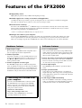 6
6
-
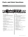 7
7
-
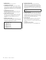 8
8
-
 9
9
-
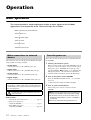 10
10
-
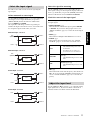 11
11
-
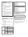 12
12
-
 13
13
-
 14
14
-
 15
15
-
 16
16
-
 17
17
-
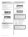 18
18
-
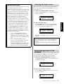 19
19
-
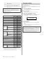 20
20
-
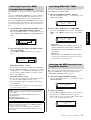 21
21
-
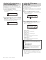 22
22
-
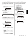 23
23
-
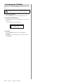 24
24
-
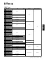 25
25
-
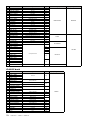 26
26
-
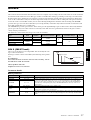 27
27
-
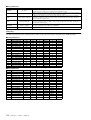 28
28
-
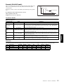 29
29
-
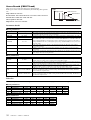 30
30
-
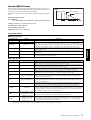 31
31
-
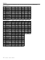 32
32
-
 33
33
-
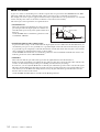 34
34
-
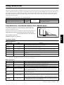 35
35
-
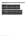 36
36
-
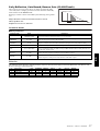 37
37
-
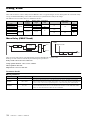 38
38
-
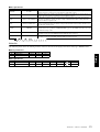 39
39
-
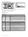 40
40
-
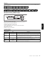 41
41
-
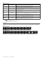 42
42
-
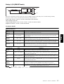 43
43
-
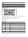 44
44
-
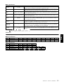 45
45
-
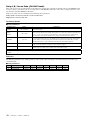 46
46
-
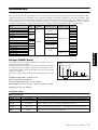 47
47
-
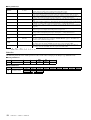 48
48
-
 49
49
-
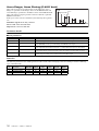 50
50
-
 51
51
-
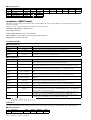 52
52
-
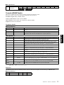 53
53
-
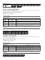 54
54
-
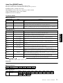 55
55
-
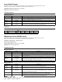 56
56
-
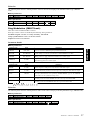 57
57
-
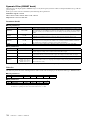 58
58
-
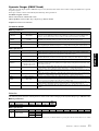 59
59
-
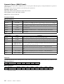 60
60
-
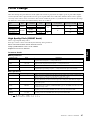 61
61
-
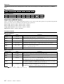 62
62
-
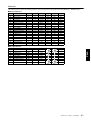 63
63
-
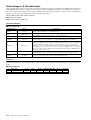 64
64
-
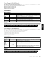 65
65
-
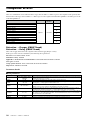 66
66
-
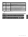 67
67
-
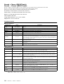 68
68
-
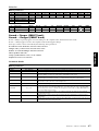 69
69
-
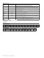 70
70
-
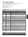 71
71
-
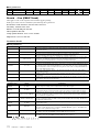 72
72
-
 73
73
-
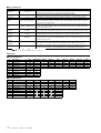 74
74
-
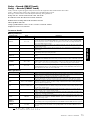 75
75
-
 76
76
-
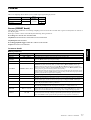 77
77
-
 78
78
-
 79
79
-
 80
80
-
 81
81
-
 82
82
-
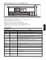 83
83
-
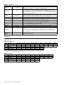 84
84
-
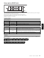 85
85
-
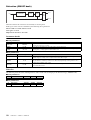 86
86
-
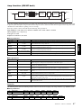 87
87
-
 88
88
-
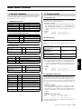 89
89
-
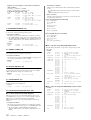 90
90
-
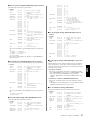 91
91
-
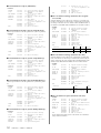 92
92
-
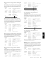 93
93
-
 94
94
-
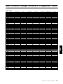 95
95
-
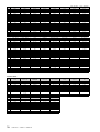 96
96
-
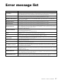 97
97
-
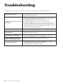 98
98
-
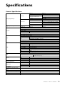 99
99
-
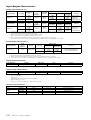 100
100
-
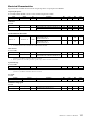 101
101
-
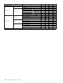 102
102
-
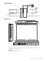 103
103
-
 104
104
-
 105
105
-
 106
106
-
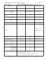 107
107
-
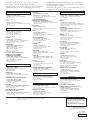 108
108


in andere talen
- English: Yamaha SPX2000 User manual
- italiano: Yamaha SPX2000 Manuale utente
- русский: Yamaha SPX2000 Руководство пользователя
- français: Yamaha SPX2000 Manuel utilisateur
- español: Yamaha SPX2000 Manual de usuario
- Deutsch: Yamaha SPX2000 Benutzerhandbuch
- português: Yamaha SPX2000 Manual do usuário
- dansk: Yamaha SPX2000 Brugermanual
- suomi: Yamaha SPX2000 Ohjekirja
- čeština: Yamaha SPX2000 Uživatelský manuál
- svenska: Yamaha SPX2000 Användarmanual
- Türkçe: Yamaha SPX2000 Kullanım kılavuzu
- polski: Yamaha SPX2000 Instrukcja obsługi
- română: Yamaha SPX2000 Manual de utilizare