
Victron Energy bv / De Paal 35 / 1351 JG ALMERE / The Netherlands
Phone: (+31) (0)36 535 97 00 / Fax: (+31) (0)36 535 97 40 / www.victronenergy.com / e-mail: sales@victronenergy.com
ARGO FET Battery Isolator with alternator energize input
ENGLISH
Warning: hot surface, mount the Argo Diode on non-flammable
surface only!
No voltage loss
In contrast with diode battery isolators, FET isolators have virtually no
voltage loss. Voltage drop is less than 0,02 Volt at low current and
averages 0,1 Volt at higher currents.
When using ARGO FET Battery Isolators, there is no need to also
increase the output voltage of the alternator. Care should taken however
to keep cable lengths short and of sufficient cross section.
Example:
When a current of 100 A flows through a cable of 50 mm² cross section (AWG 0)
and 10 m length (30 ft), the voltage drop over the cable will be 0,26 Volt. Similarly a
current of 50 A through a cable of 10 mm² cross section (AWG 7) and 5 m length
(15 ft) will result in a voltage drop of 0,35 Volt!
12/24 Volt auto ranging
The Argofet will automatically adjust to a 12V or 24V system.
Alternator energize input
Some alternators need DC voltage on the B+ output to start charging.
Obviously, DC will be present when the alternator is directly connected to
a battery. Inserting a Diode or FET splitter will however prevent any
return voltage/current from the batteries to the B+, and the alternator will
not start.
The new Argofet isolators have a special current limited energize input
that will power the B+ when the engine run/stop switch is closed.
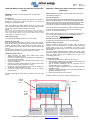
Installation (see figure below)
1. Always disconnect the battery minus cables before making
alterations to the electrical system.
2. Connect the positive output of the supplying source (alternator) to
the input of the battery isolator.
3. Connect the positive connection of the battery sets to output 1, 2 and
(optional) 3 respectively.
4. Connect the ‘Energize’ blade terminal to the engine run/stop switch
(optional). Minimum cable cross section: 2,5 mm².
5. Connect the ‘Ground’ blade terminal to the common negative bus
bar. Minimum cable cross section: 2,5 mm².
6. Connect the negative poles of the battery sets to the common
negative bus bar.
The blue LED will light up when voltage is present on the input of the
Argofet.
ARGO FET Laadstroomverdelers met dynamo ‘energizer’
NEDERLANDS
Waarschuwing: Heet oppervlak, monteer de Argo Diode alleen op een
niet-brandbare ondergrond!
Geen spanningsverlies
Net zoals de bekende Argo Diode laadstroomverdelers, zijn de Argofet
laadstroomverdelers bedoeld om meerdere accusets gelijktijdig te laden
met één dynamo of acculader. Tijdens het ontladen worden de accusets
van elkaar gescheiden door de Argofet. Wanneer bijvoorbeeld de
accessoire accu ontladen wordt zal de startaccu volledig geladen blijven.
Het grote voordeel van FET (Field Effect Transistor) laadstroomverdelers
is het zeer geringe spanningsverlies: minder dan 0,02 Volt bij weinig
stroom en 0,1 Volt bij maximale stroom.
Meer informatie over het laden van accu’s en laadstroom verdelers vindt
u in ons boek “Elektriciteit aan Boord”. Gratis verkrijgbaar bij Victron
Energy en beschikbaar op www.victronenergy.com.
Geschikt voor 12V en 24V accuspanning
De Argofet past zich automatisch aan aan de systeemspanning.
Dynamo ‘energize’ aansluiting
Sommige dynamo’s beginnen alleen met laden indien er spanning
aanwezig is op de B+ aansluiting. Dit is altijd het geval wanneer de
dynamo direct op een accu is aangesloten. Een diode of FET
laadstroomverdeler isoleert echter de accu’s van de dynamo zodat deze
niet zal starten.
De nieuwe Argofet laadstroomverdelers hebben een aparte stroom
begrensde ‘Energize’ aansluiting waarmee spanning op de B+ aansluiting
gezet kan worden wanneer het contactslot van de motor in de
contactstand gezet wordt.
Installatie (zie schema)
1. Maak voor de montage de min kabels van de accu’s los.
2. Sluit de positieve uitgang van de voedingsbron (dynamo) aan op de
‘Input’ aansluiting van de laadstroomverdeler.
3. Sluit de positieve aansluitingen van de accugroepen aan op
respectievelijk output 1, 2 en eventueel 3.
4. Verbind de ‘Energize’ aansluiting met het contactslot (optioneel).
Draaddikte: 2,5 mm².
5. Verbind de ‘Ground’ aansluiting met de gemeenschappelijke min
aansluiting. Draaddikte: 2,5 mm².
6. Sluit de min kabels van de accu’s weer aan.
De blauwe LED licht op wanneer er spanning staat op de ‘input’.
Optional
energize
input
Engine
run/stop
switch
Alternator
Starter battery
Revision : Rev13
Date : 30-03-2017
Pagina wordt geladen...
Pagina wordt geladen...
Pagina wordt geladen...
Documenttranscriptie
Revision : Rev13 Date : 30-03-2017 ARGO FET Battery Isolator with alternator energize input ENGLISH ARGO FET Laadstroomverdelers met dynamo ‘energizer’ NEDERLANDS Warning: hot surface, mount the Argo Diode on non-flammable Waarschuwing: Heet oppervlak, monteer de Argo Diode alleen op een niet-brandbare ondergrond! No voltage loss In contrast with diode battery isolators, FET isolators have virtually no voltage loss. Voltage drop is less than 0,02 Volt at low current and averages 0,1 Volt at higher currents. Geen spanningsverlies Net zoals de bekende Argo Diode laadstroomverdelers, zijn de Argofet laadstroomverdelers bedoeld om meerdere accusets gelijktijdig te laden met één dynamo of acculader. Tijdens het ontladen worden de accusets van elkaar gescheiden door de Argofet. Wanneer bijvoorbeeld de accessoire accu ontladen wordt zal de startaccu volledig geladen blijven. surface only! When using ARGO FET Battery Isolators, there is no need to also increase the output voltage of the alternator. Care should taken however to keep cable lengths short and of sufficient cross section. Example: When a current of 100 A flows through a cable of 50 mm² cross section (AWG 0) and 10 m length (30 ft), the voltage drop over the cable will be 0,26 Volt. Similarly a current of 50 A through a cable of 10 mm² cross section (AWG 7) and 5 m length (15 ft) will result in a voltage drop of 0,35 Volt! 12/24 Volt auto ranging The Argofet will automatically adjust to a 12V or 24V system. Alternator energize input Some alternators need DC voltage on the B+ output to start charging. Obviously, DC will be present when the alternator is directly connected to a battery. Inserting a Diode or FET splitter will however prevent any return voltage/current from the batteries to the B+, and the alternator will not start. The new Argofet isolators have a special current limited energize input that will power the B+ when the engine run/stop switch is closed. Installation (see figure below) 1. Always disconnect the battery minus cables before making alterations to the electrical system. 2. Connect the positive output of the supplying source (alternator) to the input of the battery isolator. 3. Connect the positive connection of the battery sets to output 1, 2 and (optional) 3 respectively. 4. Connect the ‘Energize’ blade terminal to the engine run/stop switch (optional). Minimum cable cross section: 2,5 mm². 5. Connect the ‘Ground’ blade terminal to the common negative bus bar. Minimum cable cross section: 2,5 mm². 6. Connect the negative poles of the battery sets to the common negative bus bar. The blue LED will light up when voltage is present on the input of the Argofet. Optional energize input Het grote voordeel van FET (Field Effect Transistor) laadstroomverdelers is het zeer geringe spanningsverlies: minder dan 0,02 Volt bij weinig stroom en 0,1 Volt bij maximale stroom. Meer informatie over het laden van accu’s en laadstroom verdelers vindt u in ons boek “Elektriciteit aan Boord”. Gratis verkrijgbaar bij Victron Energy en beschikbaar op www.victronenergy.com. Geschikt voor 12V en 24V accuspanning De Argofet past zich automatisch aan aan de systeemspanning. Dynamo ‘energize’ aansluiting Sommige dynamo’s beginnen alleen met laden indien er spanning aanwezig is op de B+ aansluiting. Dit is altijd het geval wanneer de dynamo direct op een accu is aangesloten. Een diode of FET laadstroomverdeler isoleert echter de accu’s van de dynamo zodat deze niet zal starten. De nieuwe Argofet laadstroomverdelers hebben een aparte stroom begrensde ‘Energize’ aansluiting waarmee spanning op de B+ aansluiting gezet kan worden wanneer het contactslot van de motor in de contactstand gezet wordt. Installatie (zie schema) 1. Maak voor de montage de min kabels van de accu’s los. 2. Sluit de positieve uitgang van de voedingsbron (dynamo) aan op de ‘Input’ aansluiting van de laadstroomverdeler. 3. Sluit de positieve aansluitingen van de accugroepen aan op respectievelijk output 1, 2 en eventueel 3. 4. Verbind de ‘Energize’ aansluiting met het contactslot (optioneel). Draaddikte: 2,5 mm². 5. Verbind de ‘Ground’ aansluiting met de gemeenschappelijke min aansluiting. Draaddikte: 2,5 mm². 6. Sluit de min kabels van de accu’s weer aan. De blauwe LED licht op wanneer er spanning staat op de ‘input’. Alternator Engine run/stop switch Starter battery Victron Energy bv / De Paal 35 / 1351 JG ALMERE / The Netherlands Phone: (+31) (0)36 535 97 00 / Fax: (+31) (0)36 535 97 40 / www.victronenergy.com / e-mail: [email protected]-
 1
1
-
 2
2
-
 3
3
-
 4
4


Victron energy Argo Fet Battery Isolator de handleiding
- Type
- de handleiding
- Deze handleiding is ook geschikt voor
in andere talen
- English: Victron energy Argo Fet Battery Isolator Owner's manual
- italiano: Victron energy Argo Fet Battery Isolator Manuale del proprietario
- français: Victron energy Argo Fet Battery Isolator Le manuel du propriétaire
- español: Victron energy Argo Fet Battery Isolator El manual del propietario
- Deutsch: Victron energy Argo Fet Battery Isolator Bedienungsanleitung
- svenska: Victron energy Argo Fet Battery Isolator Bruksanvisning
- Türkçe: Victron energy Argo Fet Battery Isolator El kitabı
Gerelateerde papieren
-
Victron energy Argo Diode Battery Isolator de handleiding
-
-
-
-
-
-
-
-
Victron Energie Phoenix Smart IP43 Charger de handleiding