
RX-V657
AV Receiver
OWNER’S MANUAL
U

IMPORTANT SAFETY INSTRUCTIONS
i
• Explanation of Graphical Symbols
The lightning flash with arrowhead symbol, within an
equilateral triangle, is intended to alert you to the
presence of uninsulated “dangerous voltage” within
the product’s enclosure that may be of sufficient
magnitude to constitute a risk of electric shock to
persons.
The exclamation point within an equilateral triangle
is intended to alert you to the presence of important
operating and maintenance (servicing) instructions in
the literature accompanying the appliance.
1 Read Instructions – All the safety and operating instructions
should be read before the product is operated.
2 Retain Instructions – The safety and operating instructions
should be retained for future reference.
3 Heed Warnings – All warnings on the product and in the
operating instructions should be adhered to.
4 Follow Instructions – All operating and use instructions
should be followed.
5 Cleaning – Unplug this product from the wall outlet before
cleaning. Do not use liquid cleaners or aerosol cleaners. Use
a damp cloth for cleaning.
6 Attachments – Do not use attachments not recommended by
the product manufacturer as they may cause hazards.
7 Water and Moisture – Do not use this product near water –
for example, near a bath tub, wash bowl, kitchen sink, or
laundry tub; in a wet basement; or near a swimming pool;
and the like.
8 Accessories – Do not place this product on an unstable cart,
stand, tripod, bracket, or table. The product may fall,
causing serious injury to a child or adult, and serious
damage to the product. Use only with a cart, stand, tripod,
bracket, or table recommended by the manufacturer, or sold
with the product. Any mounting of the product should
follow the manufacturer’s instructions, and should use a
mounting accessory recommended by the manufacturer.
9 A product and cart combination should be moved with care.
Quick stops, excessive force, and uneven
surfaces may cause the product and cart
combination to overturn.
10 Ventilation – Slots and openings in the cabinet are provided
for ventilation and to ensure reliable operation of the
product and to protect it from overheating, and these
openings must not be blocked or covered. The openings
should never be blocked by placing the product on a bed,
sofa, rug, or other similar surface. This product should not
be placed in a built-in installation such as a bookcase or rack
unless proper ventilation is provided or the manufacturer’s
instructions have been adhered to.
11 Power Sources – This product should be operated only from
the type of power source indicated on the marking label. If
you are not sure of the type of power supply to your home,
consult your product dealer or local power company. For
products intended to operate from battery power, or other
sources, refer to the operating instructions.
12 Grounding or Polarization – This product may be equipped
with a polarized alternating current line plug (a plug having
one blade wider than the other). This plug will fit into the
power outlet only one way. This is a safety feature. If you
are unable to insert the plug fully into the outlet, try
reversing the plug. If the plug should still fail to fit, contact
your electrician to replace your obsolete outlet. Do not
defeat the safety purpose of the polarized plug.
13 Power-Cord Protection – Power-supply cords should be
routed so that they are not likely to be walked on or pinched
by items placed upon or against them, paying particular
attention to cords at plugs, convenience receptacles, and the
point where they exit from the product.
14 Lightning – For added protection for this product during a
lightning storm, or when it is left unattended and unused for
long periods of time, unplug it from the wall outlet and
disconnect the antenna or cable system. This will prevent
damage to the product due to lightning and power-line
surges.
15 Power Lines – An outside antenna system should not be
located in the vicinity of overhead power lines or other
electric light or power circuits, or where it can fall into such
power lines or circuits. When installing an outside antenna
system, extreme care should be taken to keep from touching
such power lines or circuits as contact with them might be
fatal.
16 Overloading – Do not overload wall outlets, extension
cords, or integral convenience receptacles as this can result
in a risk of fire or electric shock.
17 Object and Liquid Entry – Never push objects of any kind
into this product through openings as they may touch
dangerous voltage points or short-out parts that could result
in a fire or electric shock. Never spill liquid of any kind on
the product.
18 Servicing – Do not attempt to service this product yourself
as opening or removing covers may expose you to
dangerous voltage or other hazards. Refer all servicing to
qualified service personnel.
19 Damage Requiring Service – Unplug this product from the
wall outlet and refer servicing to qualified service personnel
under the following conditions:
a) When the power-supply cord or plug is damaged,
b) If liquid has been spilled, or objects have fallen into the
product,
c) If the product has been exposed to rain or water,
IMPORTANT SAFETY INSTRUCTIONS
CAUTION
CAUTION: TO REDUCE THE RISK OF
ELECTRIC SHOCK, DO NOT REMOVE
COVER (OR BACK). NO USER-SERVICEABLE
PARTS INSIDE. REFER SERVICING TO
QUALIFIED SERVICE PERSONNEL.
RISK OF ELECTRIC SHOCK
DO NOT OPEN

IMPORTANT SAFETY INSTRUCTIONS
ii
EXAMPLE OF ANTENNA GROUNDING
MAST
GROUND
CLAMP
ANTENNA
LEAD IN
WIRE
ANTENNA
DISCHARGE UNIT
(NEC SECTION 810–20)
GROUNDING CONDUCTORS
(NEC SECTION 810–21)
GROUND CLAMPS
POWER SERVICE GROUNDING
ELECTRODE SYSTEM
(NEC ART 250. PART H)
ELECTRIC
SERVICE
EQUIPMENT
NEC – NATIONAL ELECTRICAL CODE
d) If the product does not operate normally by following
the operating instructions. Adjust only those controls
that are covered by the operating instructions as an
improper adjustment of other controls may result in
damage and will often require extensive work by a
qualified technician to restore the product to its normal
operation,
e) If the product has been dropped or damaged in any
way, and
f) When the product exhibits a distinct change in perfor-
mance - this indicates a need for service.
20 Replacement Parts – When replacement parts are required,
be sure the service technician has used replacement parts
specified by the manufacturer or have the same
characteristics as the original part. Unauthorized
substitutions may result in fire, electric shock, or other
hazards.
21 Safety Check – Upon completion of any service or repairs to
this product, ask the service technician to perform safety
checks to determine that the product is in proper operating
condition.
22 Wall or Ceiling Mounting – The unit should be mounted
to a wall or ceiling only as recommended by the
manufacturer.
23 Heat – The product should be situated away from heat
sources such as radiators, heat registers, stoves, or other
products (including amplifiers) that produce heat.
24 Outdoor Antenna Grounding – If an outside antenna or
cable system is connected to the product, be sure the antenna
or cable system is grounded so as to provide some
protection against voltage surges and built-up static charges.
Article 810 of the National Electrical Code, ANSI/NFPA 70,
provides information with regard to proper grounding of the
mast and supporting structure, grounding of the lead-in wire
to an antenna discharge unit, size of grounding conductors,
location of antenna discharge unit, connection to grounding
electrodes, and requirements for the grounding electrode.
Note to CATV system installer:
This reminder is provided to call the CATV system installer’s
attention to Article 820-40 of the NEC that provides
guidelines for proper grounding and, in particular, specifies
that the cable ground shall be connected to the grounding
system of the building, as close to the point of cable entry as
practical.
FCC INFORMATION (for US customers)
1 IMPORTANT NOTICE: DO NOT MODIFY THIS
UNIT!
This product, when installed as indicated in the
instructions contained in this manual, meets FCC
requirements. Modifications not expressly approved by
Yamaha may void your authority, granted by the FCC, to
use the product.
2 IMPORTANT: When connecting this product to
accessories and/or another product use only high quality
shielded cables. Cable/s supplied with this product MUST
be used. Follow all installation instructions. Failure to
follow instructions could void your FCC authorization to
use this product in the USA.
3 NOTE: This product has been tested and found to comply
with the requirements listed in FCC Regulations, Part 15
for Class “B” digital devices. Compliance with these
requirements provides a reasonable level of assurance that
your use of this product in a residential environment will
not result in harmful interference with other electronic
devices.
This equipment generates/uses radio frequencies and, if
not installed and used according to the instructions found
in the users manual, may cause interference harmful to the
operation of other electronic devices.
Compliance with FCC regulations does not guarantee that
interference will not occur in all installations. If this
product is found to be the source of interference, which
can be determined by turning the unit “OFF” and “ON”,
please try to eliminate the problem by using one of the
following measures:
Relocate either this product or the device that is being
affected by the interference.
Utilize power outlets that are on different branch (circuit
breaker or fuse) circuits or install AC line filter/s.
In the case of radio or TV interference, relocate/reorient
the antenna. If the antenna lead-in is 300 ohm ribbon lead,
change the lead-in to coaxial type cable.
If these corrective measures do not produce satisfactory
results, please contact the local retailer authorized to
distribute this type of product. If you can not locate the
appropriate retailer, please contact Yamaha Electronics
Corp., U.S.A. 6660 Orangethorpe Ave, Buena Park, CA
90620.
The above statements apply ONLY to those products
distributed by Yamaha Corporation of America or its
subsidiaries.

CAUTION: READ THIS BEFORE OPERATING YOUR UNIT.
iii
1 To assure the finest performance, please read this
manual carefully. Keep it in a safe place for future
reference.
2 Install this sound system in a well ventilated, cool,
dry, clean place – away from direct sunlight, heat
sources, vibration, dust, moisture, and/or cold.
Allow ventilation space of at least 30 cm on the top,
20 cm on the left and right, and 20 cm on the back of
this unit.
3 Locate this unit away from other electrical
appliances, motors, or transformers to avoid
humming sounds.
4 Do not expose this unit to sudden temperature
changes from cold to hot, and do not locate this unit
in a environment with high humidity (i.e. a room with
a humidifier) to prevent condensation inside this
unit, which may cause an electrical shock, fire,
damage to this unit, and/or personal injury.
5 Avoid installing this unit where foreign object may
fall onto this unit and/or this unit may be exposed to
liquid dripping or splashing. On the top of this unit,
do not place:
– Other components, as they may cause damage
and/or discoloration on the surface of this unit.
– Burning objects (i.e. candles), as they may cause
fire, damage to this unit, and/or personal injury.
– Containers with liquid in them, as they may fall
and liquid may cause electrical shock to the user
and/or damage to this unit.
6 Do not cover this unit with a newspaper, tablecloth,
curtain, etc. in order not to obstruct heat radiation. If
the temperature inside this unit rises, it may cause
fire, damage to this unit, and/or personal injury.
7 Do not plug in this unit to a wall outlet until all
connections are complete.
8 Do not operate this unit upside-down. It may
overheat, possibly causing damage.
9 Do not use force on switches, knobs and/or cords.
10 When disconnecting the power cord from the wall
outlet, grasp the plug; do not pull the cord.
11 Do not clean this unit with chemical solvents; this
might damage the finish. Use a clean, dry cloth.
12 Only voltage specified on this unit must be used.
Using this unit with a higher voltage than specified
is dangerous and may cause fire, damage to this
unit, and/or personal injury. YAMAHA will not be
held responsible for any damage resulting from use
of this unit with a voltage other than specified.
13 To prevent damage by lightning, disconnect the
power cord and outdoor antenna from the wall outlet
during an electrical storm.
14 Do not attempt to modify or fix this unit. Contact
qualified YAMAHA service personnel when any
service is needed. The cabinet should never be
opened for any reasons.
15 When not planning to use this unit for long periods
of time (i.e. vacation), disconnect the AC power plug
from the wall outlet.
16 Be sure to read the “TROUBLESHOOTING” section
on common operating errors before concluding that
this unit is faulty.
17 Before moving this unit, press STANDBY/ON to set
this unit in the standby mode, and disconnect the
AC power plug from the wall outlet.
18 VOLTAGE SELECTOR (Asia and General models
only)
The VOLTAGE SELECTOR on the rear panel of this
unit must be set for your local main voltage BEFORE
plugging into the AC main supply. Voltages are:
Asia model ..................... 220/230–240 V AC, 50/60 Hz
General model
........................... 110/120/220/230–240 V AC, 50/60 Hz
We Want You Listening For A Lifetime
YAMAHA and the Electronic Industries Association’s Consumer
Electronics Group want you to get the most out of your equipment
by playing it at a safe level. One that lets the sound come through
loud and clear without annoying blaring or distortion – and, most
importantly, without affecting your sensitive hearing.
Since hearing damage from loud sounds is often
undetectable until it is too late, YAMAHA and the
Electronic Industries Association’s Consumer
Electronics Group recommend you to avoid
prolonged exposure from excessive volume levels.
CAUTION: READ THIS BEFORE OPERATING YOUR UNIT.
WARNING
TO REDUCE THE RISK OF FIRE OR ELECTRIC
SHOCK, DO NOT EXPOSE THIS UNIT TO RAIN
OR MOISTURE.
This unit is not disconnected from the AC power
source as long as it is connected to the wall outlet, even
if this unit itself is turned off. This state is called the
standby mode. In this state, this unit is designed to
consume a very small quantity of power.
FOR CANADIAN CUSTOMERS
To prevent electric shock, match wide blade of plug to
wide slot and fully insert.
This Class B digital apparatus complies with Canadian
ICES-003.
IMPORTANT
Please record the serial number of this unit in the space
below.
MODEL:
Serial No.:
The serial number is located on the rear of the unit.
Retain this Owner’s Manual in a safe place for future
reference.

1
PREPARATIONINTRODUCTION
BASIC
OPERATION
SOUND FIELD
PROGRAMS
ADVANCED
OPERATION
ADDITIONAL
INFORMATION
FEATURES.............................................................2
GETTING STARTED............................................3
Supplied accessories..................................................3
Installing batteries in the remote control................... 3
CONTROLS AND FUNCTIONS ......................... 4
Front panel.................................................................4
Remote control........................................................... 6
Using the remote control ........................................... 7
Front panel display .................................................... 8
Rear panel................................................................ 10
SPEAKER SETUP ...............................................11
Speaker placement................................................... 11
Speaker connections ................................................ 12
CONNECTIONS .................................................. 15
Before connecting components................................ 15
Connecting video components................................. 16
Connecting audio components................................. 19
Connecting the FM and AM antennas..................... 21
Connecting the power supply cord ..........................22
Speaker impedance setting ...................................... 23
Turning on the power............................................... 23
AUTO SETUP....................................................... 24
Introduction.............................................................. 24
Optimizer microphone setup.................................... 24
Starting the setup .....................................................25
PLAYBACK..........................................................30
Basic operations.......................................................30
Selecting sound field programs ............................... 32
Selecting input modes.............................................. 36
FM/AM TUNING................................................. 38
Automatic and manual tuning.................................. 38
Presetting stations.................................................... 39
Selecting preset stations........................................... 41
Exchanging preset stations ...................................... 42
XM Satellite Radio TUNING .............................. 44
What is XM Satellite Radio?...................................44
XM Satellite Radio connections..............................44
XM Satellite Radio functions .................................. 45
Activating XM Satellite Radio ................................46
Basic XM Satellite Radio operations.......................47
XM Satellite Radio search modes............................48
Setting XM Satellite Radio preset channels ............51
RECORDING.......................................................54
SOUND FIELD PROGRAM
DESCRIPTIONS...............................................55
For movie/video sources.......................................... 55
For music sources....................................................57
ADVANCED OPERATIONS ..............................58
Selecting the OSD mode.......................................... 58
Using the sleep timer............................................... 58
Manually adjusting speaker levels........................... 59
SET MENU............................................................60
Using SET MENU................................................... 62
1 SOUND MENU....................................................63
2 INPUT MENU...................................................... 68
3 OPTION MENU................................................... 70
ADVANCED SETUP MENU...............................72
REMOTE CONTROL FEATURES ...................74
Control area ............................................................. 74
Setting remote control codes ................................... 75
Controlling other components .................................76
Switching library codes ........................................... 77
Clearing set up remote control codes....................... 77
ZONE 2 (U.S.A., CANADA, AUSTRALIA,
U.K. AND EUROPE MODELS ONLY).........78
Zone 2 connections.................................................. 78
Remote controlling Zone 2...................................... 79
EDITING SOUND FIELD PARAMETERS ......81
What is a sound field ............................................... 81
Changing parameter settings ................................... 81
SOUND FIELD PARAMETER
DESCRIPTIONS...............................................83
TROUBLESHOOTING .......................................88
RESETTING THE FACTORY PRESETS ........93
GLOSSARY...........................................................94
Audio formats.......................................................... 94
Sound field programs............................................... 95
Audio information ................................................... 95
Video signal information......................................... 96
SPECIFICATIONS...............................................97
CONTENTS
INTRODUCTION
PREPARATION
BASIC OPERATION
SOUND FIELD PROGRAMS
ADVANCED OPERATION
ADDITIONAL INFORMATION

FEATURES
2
Built-in 7-channel power amplifier
◆ Minimum RMS output power
(0.06% THD, 20 Hz to 20 kHz, 8 Ω)
Front: 95 W + 95 W
Center: 95 W
Surround: 95 W + 95 W
Surround back: 95 W + 95 W
Sound field features
◆ Proprietary YAMAHA technology for the creation of
sound fields
◆ Dolby Digital/Dolby Digital EX decoder
◆ DTS/DTS-ES Matrix 6.1, Discrete 6.1, DTS Neo:6,
DTS 96/24 decoder
◆ Dolby Pro Logic/Dolby Pro Logic II/
Dolby Pro Logic IIx decoder
◆ Virtual CINEMA DSP
◆ SILENT CINEMA
™
Sophisticated AM/FM tuner
◆ 40-station random and direct preset tuning
◆ Automatic preset tuning
◆ Preset station shifting capability (preset editing)
XM Satellite Radio
◆ XM Satellite Radio programming (using the “XM
Connect and Play digital antenna accessory”, sold
separately)
Other features
◆ YPAO: YAMAHA Parametric Room Acoustic
Optimizer for automatic speaker setup
◆ 192-kHz/24-bit D/A converter
◆ A SET MENU that provides you with items for
optimizing this unit for your audio/video system
◆ 8 additional input jacks for discrete multi-channel input
◆ PURE DIRECT for pure fidelity sound with analog and
PCM sources
◆ On-screen display function helpful in controlling this
unit
◆ S-video signal input/output capability
◆ Component video input/output capability
◆ Video signal conversion (Composite video ↔ S-video
→ Component video) capability for monitor out
◆ Optical and coaxial digital audio signal jacks
◆ Sleep timer
◆ Cinema and music night listening modes
◆ Remote control with preset remote control codes
◆ Zone 2 custom installation facility (U.S.A., Canada,
Australia, U.K. and Europe models only)
• y indicates a tip for your operation.
• Some operations can be performed by using either the buttons on the main unit or on the remote control. In cases when the button
names differ between the main unit and the remote control, the button name on the remote control is given in parentheses.
• This manual is printed prior to production. Design and specifications are subject to change in part as a result of improvements, etc. In
case of differences between the manual and product, the product has priority.
Manufactured under license from Dolby Laboratories.
“Dolby”, “Pro Logic”, “Surround EX”, and the double-D symbol
are trademarks of Dolby Laboratories.
“SILENT CINEMA” is a trademark of YAMAHA
CORPORATION.
“DTS”, “DTS-ES”, “Neo:6” and “DTS 96/24” are trademarks of
Digital Theater Systems, Inc.
The XM name and related logos are registered trademarks of XM
Satellite Radio Inc.
FEATURES

GETTING STARTED
3
INTRODUCTION
Please check that you received all of the following parts.
1 Press the part and slide the battery
compartment cover off.
2
Insert four supplied batteries (AAA, R03,
UM-4) according to the polarity markings
(+ / –) on the inside of the battery
compartment.
3 Slide the cover back until it snaps into place.
Notes on batteries
• Change all of the batteries if you notice the following
conditions; the operation range of the remote control decreases,
the indicator does not flash or its light becomes dim.
• Do not use old batteries together with new ones.
• Do not use different types of batteries (such as alkaline and
manganese batteries) together. Read the packaging carefully as
these different types of batteries may have the same shape and
color.
• If the batteries have leaked, dispose of them immediately. Avoid
touching the leaked material or letting it come into contact with
clothing, etc. Clean the battery compartment thoroughly before
installing new batteries.
• Do not throw away batteries with general house waste; dispose
of them correctly in accordance with your local regulations.
GETTING STARTED
Supplied accessories
TRANSMITCODE SET
STANDBY
SYSTEM
POWER
CD MD/CD-R
TUNER
V-AU XDVD
AMP
POWERPOWER
REC
AUDIO
MUTE
MENUTITLE
VOLUME
DISC SKIP
SET MENU
BAND SRCH MODE
FAVOR.
MEMORY ON SCREEN
LEVEL
A-E/CAT. A-E/CAT.
STRAIGHT
MOVIE
ENTERTAIN
MUSICSTEREO
4321
8
10
7
09
65
ENT.
PURE DIRECT
EXTD SUR.
STANDARD
SELECT
NIGHT
AB
SPEAKERS
EFFECT
DISPLAYRETURN
TV MUTE TV INPUT
TV VOL TV CH
AVTV
ENTER
VCR 1 DVR/VCR2
DTV/CBL
MULTI CH IN
SLEEP
PRESET/CH
Remote control
Batteries (4)
(AAA, R03, UM-4)
Indoor FM antenna
(U.S.A., Canada, China,
Asia and General models)
AM loop antenna
Indoor FM antenna
(U.K., Europe, Australia
and Korea models)
Optimizer microphone
Installing batteries in the remote
control
1
3
2
If the remote control is without batteries for more than
2 minutes, or if exhausted batteries remain in the
remote control, the contents of the memory may be
cleared. When the memory is cleared, insert new
batteries, set up the remote control code and program
any acquired functions that may have been cleared.

CONTROLS AND FUNCTIONS
4
1 STANDBY/ON
Turns on this unit or sets it to the standby mode. When you
turn on this unit, you will hear a click and there will be a 4
to 5-second delay before this unit can reproduce sound.
In standby mode, this unit consumes a small amount of power in
order to receive infrared-signals from the remote control.
2 OPTIMIZER MIC jack
Use to connect and input audio signals from the supplied
microphone for use with the AUTO SETUP function (see
page 24).
3 Remote control sensor
Receives signals from the remote control.
4 Front panel display
Shows information about the operational status of this
unit.
5 A/B/C/D/E, NEXT, CATEGORY
*
Selects one of the 5 preset station groups (A to E) when
the unit is in tuner mode.
Selects the speaker channel to be adjusted when the unit is
not in tuner mode.
6 PRESET/TUNING/ CH
*
l / h, LEVEL –/+
Selects preset station number 1 to 8 when the colon (:) is
displayed next to the band indication in the front panel
display when the unit is in tuner mode. Selects the tuning
frequency when the colon (:) is not displayed.
Adjusts the level of the speaker channel selected using
A/B/C/D/E (NEXT) when the unit is not in tuner mode.
7 MEMORY (MAN’L/AUTO FM)
Stores a station in the memory. Hold down this button for
more than 3 seconds to start automatic preset tuning.
8 TUNING MODE (AUTO/MAN’L MONO),
DISPLAY
*
Switches the tuning mode between automatic (AUTO
indicator on) and manual (AUTO indicator off).
9 VIDEO AUX jacks
Input audio and video signals from a portable external
source such as a game console. To reproduce source
signals from these jacks, select V-AUX as the input
source.
CONTROLS AND FUNCTIONS
Front panel
MAIN
ZONE ON/OFF
ZONE 2
DISPLAY
S VIDEO VIDEO OPTICALL AUDIO R
LEVEL
CATEGORY
NEXT
SEARCH MODE
EFFECT
MEMORY
MAN'L/AUTO FM
FM/AM
XM
PRESET/TUNING
EDIT
OPTIMIZER MIC A/B/C/D/E
PROGRAM
l PRESET/TUNING/CH h
TUNING MODE
AUTO/MAN'L MONO
PURE DIRECTINPUT MODETONE CONTROLSTRAIGHT
SPEAKERSPHONES
SILENT CINEMA
STANDBY
/ON
BA
MULTI CH
INPUT
VOLUME
VIDEO AUX
INPUT
31452609
J
KHGEBACDF I
L
78
(U.S.A. model)
(U.S.A., Canada,
Australia, U.K. and
Europe models only)
Note

CONTROLS AND FUNCTIONS
5
INTRODUCTION
0 VOLUME
Controls the output level of all audio channels.
This does not affect the REC OUT level.
A PHONES (SILENT CINEMA) jack
Outputs audio signals for private listening with
headphones. When you connect headphones, no signals
are output to the PRE OUT jacks or to the speakers.
All Dolby Digital and DTS audio signals are mixed down
to the left and right headphone channels.
B SPEAKERS A/B
Turns on or off the set of front speakers connected to the A
and/or B terminals on the rear panel each time the
corresponding button is pressed.
C PRESET/TUNING (EDIT), SEARCH MODE
*
Switches the function of PRESET/TUNING/CH l / h
(LEVEL –/+) between selecting preset station numbers
and tuning.
D STRAIGHT (EFFECT)
Switches the sound fields off or on. When STRAIGHT is
selected, input signals (2-channel or multi-channel) are
output directly from their respective speakers without
effect processing.
E FM/AM, XM
*
Switches the reception band when the unit is in tuner
mode.
F PROGRAM
Use to select sound field programs or adjust the bass/treble
balance (in conjunction with TONE CONTROL).
G TONE CONTROL
Use to adjust the bass/treble balance for the front left and
right, center, presence and subwoofer channels (see
pages 31).
H INPUT MODE
Sets the priority (AUTO, DTS, ANALOG) for the type of
signals received when one component is connected to two
or more of this unit’s input jacks (see page 36).
I INPUT selector
Selects the input source you want to listen to or watch.
J MULTI CH INPUT
Selects the source connected to the MULTI CH INPUT
jacks. When selected, the MULTI CH INPUT source takes
priority over the source selected with INPUT (or the input
selector buttons on the remote control).
K PURE DIRECT
Turns on or off PURE DIRECT mode (see page 35).
■ U.S.A., Canada, Australia, U.K. and
Europe models only
L ZONE ON/OFF buttons
MAIN
Switches this unit’s operation to control the component in
the main room (see page 79).
ZONE 2
Switches this unit’s operation to control the component in
the second room (Zone 2) (see page 79).
*
Available only when the unit is in the XM Satellite Radio mode
(see page 45).

CONTROLS AND FUNCTIONS
6
This section describes the function of each control on the
remote control used to control this unit. To operate other
components, see “REMOTE CONTROL FEATURES” on
page 74.
1 Infrared window
Outputs infrared control signals. Aim this window at the
component you want to operate.
2 CODE SET
Use to set up remote control codes (see page 75).
3 Input selector buttons
Select the input source and change the control area.
4 Sound field program/numeric buttons
Use to select sound field programs.
Use numbers 1 through 8 to select preset stations when the
unit is in tuner mode.
Use SELECT to playback 2-channel sources in multiple
channel format (see page 34).
Use EXTD SUR. to switch between 5.1 or 6.1/7.1-channel
playback of multi-channel software (see page 33).
Use PURE DIRECT to turn on or off PURE DIRECT
mode (see page 35).
5 SPEAKERS A/B
Use to turn on or off the set of front speakers connected to
the A and/or B terminal on the rear panel each time the
corresponding button is pressed.
6 LEVEL, BAND
Selects the speaker channel to be adjusted and sets the
level.
Switches the reception band when the unit is in tuner
mode.
7 Cursor buttons u / d / j / i /ENTER
Use to select and adjust sound field program parameters or
SET MENU items.
Press j / i to select a preset station group (A to E) when
the unit is in tuner mode.
Press u / d to select a preset station number (1 to 8)
when the unit is in tuner mode.
8 RETURN, MEMORY
*
Returns to the previous menu level when adjusting the
SET MENU parameters.
9 TRANSMIT indicator
Flashes while the remote control is sending signals.
0 STANDBY
Sets this unit in the standby mode.
A SYSTEM POWER
Turns on the power of this unit.
Remote control
TRANSMITCODE SET
STANDBY
SYSTEM
POWER
CD MD/CD-R
TUNER
V-AUXDVD
AMP
POWERPOWER
REC
AUDIO
MUTE
MENUTITLE
VOLUME
DISC SKIP
SET MENU
BAND SRCH MODE
MEMORY ON SCREEN
LEVEL
A-E/CAT. A-E/CAT.
STRAIGHT
MOVIE
ENTERTAIN
MUSICSTEREO
4321
8
10
7
09
65
ENT.
PURE DIRECT
EXTD SUR.
STANDARD
SELECT
NIGHT
AB
SPEAKERS
EFFECT
DISPLAYRETURN
TV MUTE TV INPUT
TV VOL TV CH
AVTV
ENTER
VCR 1 DVR/VCR2
DTV/CBL
MULTI CH IN
SLEEP
PRESET/CH
9
0
A
B
C
D
E
F
H
I
1
2
3
4
5
7
8
6
G

CONTROLS AND FUNCTIONS
7
INTRODUCTION
B SLEEP
Sets the sleep timer.
C MULTI CH IN
Selects multi-channel input when using an external
decoder (etc.).
D AMP
Selects the AMP mode. You must select the AMP mode to
control the main unit.
E VOLUME +/–
Increases or decreases the volume level.
F MUTE
Mutes the sound. Press again to restore the audio output to
the previous volume level.
G NIGHT
Turns on or off the night listening modes (see page 35).
H STRAIGHT (EFFECT), ENT.
*
Switches the sound fields off or on. When STRAIGHT is
selected, input signals (2-channel or multi-channel) are
output directly from their respective speakers without
effect processing.
I SET MENU, SRCH MODE
*
Activates the SET MENU function.
*
Available only when the unit is in the XM Satellite Radio mode
(see page 45).
The remote control transmits a directional infrared beam.
Be sure to aim the remote control directly at the remote
control sensor on the main unit during operation.
■ Handling the remote control
• Do not spill water or other liquids on the remote
control.
• Do not drop the remote control.
• Do not leave or store the remote control in the
following types of conditions:
– places of high humidity, such as near a bath
– high temperature, such as near a heater or stove
– extremely low temperatures
– dusty places
Using the remote control
DISPLAY
S VIDEO VIDEO OPTICALL AUDIO R
LEVEL
CATEGORY
NEXT
SEARCH MODE
EFFECT
MEMORY
MAN'L/AUTO FM
FM/AM
XIM
PRESET/TUNING
EDIT
OPTIMIZER MIC A/B/C/D/E
PROGRAM
l PRESET/TUNING/CH h
TUNING MODE
AUTO/MAN'L MONO
PURE DIRECTINPUT MODETONE CONTROLSTRAIGHT
SPEAKERSPHONES
SILENT CINEMA
STANDBY
/ON
BA
MULTI CH
INPUT
VOLUME
VIDEO AUX
INPUT
30 30
TRANSMITCODE SET
STANDBY
SYSTEM
POWER
CD
MD/CD-R
TUNER
V-AUX
DVD
AMP
POWERPOWER
REC
AUDIO
MUTE
MENUTITLE
VOLUME
DISC SKIP
SET MENU
LEVEL
4321
8
10
7
09
65
EFFECT
DISPLAYRETURN
TV MUTE TV INPUT
TV VOL TV CH
AVTV
VCR 1 DVR/VCR2
DTV/CBL
MULTI CH IN
SLEEP
PRESET/CH
BAND
SRCH MODE
MEMORY ON SCREEN
A-E/CAT. A-E/CAT.
STRAIGHT
MOVIE
ENTERTAIN
MUSIC
STEREO
ENT.
PURE DIRECT
EXTD SUR.STANDARD
SELECT
NIGHT
AB
SPEAKERS
ENTER
Approximately 6 m (20 ft)

CONTROLS AND FUNCTIONS
8
1 Decoder indicators
When any of this unit’s decoders function, the respective
indicator lights up.
2 VIRTUAL indicator
Lights up when Virtual CINEMA DSP is active (see
page 36).
3 SILENT CINEMA indicator
Lights up when headphones are connected and a sound
field program is selected (see page 31).
4 Input source indicators
A cursor lights to show the current input source.
5 Sound field indicators
Light to indicate the active DSP sound fields.
6 CINEMA DSP indicator
Lights up when you select a CINEMA DSP sound field
program.
7 YPAO indicator
Lights up during the auto setup procedure and when the
auto setup speaker settings are used without any
modifications.
8 AUTO indicator
Lights up when this unit is in automatic tuning mode.
9 TUNED indicator
Lights up when this unit is tuned into a station.
0 STEREO indicator
Lights up when this unit is receiving a strong signal for an
FM stereo broadcast while the AUTO indicator is lit.
A MEMORY indicator
Flashes to show that a station can be stored.
B MUTE indicator
Flashes while the MUTE function is on.
C VOLUME level indication
Indicates the current volume level.
D PCM indicator
Lights up when this unit is reproducing PCM (Pulse Code
Modulation) digital audio signals.
E STANDARD
Lights up when Surround Standard or Surround Enhanced
is selected (see page 34).
F NIGHT indicator
Lights up when you select night listening mode.
G SP A B indicators
Light up according to the set of front speakers selected.
Both indicators light up when both sets of speakers are
selected.
H Headphones indicator
Lights up when headphones are connected.
I HiFi DSP indicator
Lights up when you select a HiFi DSP sound field
program.
J Multi-information display
Shows the current sound field program name and other
information when adjusting or changing settings.
Front panel display
PHONOCDTUNER
MD/CD-R
DVD
DTV/CBL
V-AUX
VCR1
DVR/VCR2
96
24
q
PL
q
EX
q
PL
MATRIX DISCRETE
SILENT CINEMA
NIGHT
ZONE2STANDARD
AUTO
YPAO
PS
PS
HOLD
HOLD
RT CT
RT CT
EON
EON
PTY
PTY
PTY
PTY
TUNED STEREO MUTE
VOLUME
MEMORY
SLEEP
VIRTUAL
PCM
q
PL x
A B
SP
mS
dB
ft
dB
96/24
HiFi DSP
LFE
LCR
SL SB SR
q
DIGITAL
t
123456789 A B C0
O
IJ M
KNLED
FH
G
(U.S.A., Canada, Australia, U.K.
and Europe models only)
Presence DSP sound field
Listening position
Left surround
DSP sound field
Right surround
DSP sound field
Surround back DSP sound field

CONTROLS AND FUNCTIONS
9
INTRODUCTION
K SLEEP indicator
Lights up while the sleep timer is on.
L 96/24 indicator
Lights up when a DTS 96/24 signal is input to this unit.
M LFE indicator
Lights up when the input signal contains the LFE signal.
N Input channel indicators
Indicate the channel components of the current digital
input signal.
■ U.S.A., Canada, Australia, U.K. and
Europe models only
O ZONE 2 indicator
Lights up when Zone 2 power is on.

CONTROLS AND FUNCTIONS
10
1 DIGITAL OUTPUT jacks
See page 19 for details.
2 Audio component jacks
See page 19 for connection information.
3 Video component jacks
See pages 16 and 18 for connection information.
4 Antenna terminals
See page 21 for connection information.
5 PRESENCE/ZONE 2 speaker terminals
(U.S.A., Canada, Australia, U.K. and Europe
models)
PRESENCE speaker terminals
(other models)
See page 13 for connection information.
6 REMOTE IN/OUT jacks
(U.S.A., Canada, Australia, U.K. and Europe
models only)
See page 78 for details.
7 XM jack
See page 44 for connection information.
8 CONTROL OUT jack
(U.S.A., Canada, Australia, U.K. and Europe
models only)
This is a control expansion terminal for commercial use.
9 AC OUTLET(S)
Use to supply power to your other A/V components (see
page 22).
0 DIGITAL INPUT jacks
See pages 16, 18 and 19 for details.
A MULTI CH INPUT jacks
See page 17 for connection information.
B ZONE 2 OUTPUT jacks
(U.S.A., Canada, Australia, U.K. and Europe
models only)
These jacks output analog signals only. See page 78 for
details.
C PRE OUT jacks
See page 20 for connection information.
D Speaker terminals
See page 13 for connection information.
■ Asia and General models only
VOLTAGE SELECTOR
See page 22 for details.
Rear panel
AUDIO AUDIO
DIGITAL
INPUT
DVD
DVD
CD
COAXIAL
DTV/CBL
MD/CD-R
MD/CD-R
SUB
WOOFER
SURROUND
BACK
SURROUND
FRONT
OUT
(REC)
IN
(PLAY)
MD/
CD-R
CD
DVD
VIDEO
MONITOR
OUT
DTV/
CBL
DVD
COMPONENT VIDEO
PR PB Y
75Ω UNBAL.
FM
ANT
AM
ANT
GND
TUNER
DTV/
CBL
IN
VCR 1
OUT
IN
DVR/
VCR 2
OUT
CENTER
DIGITAL
OUTPUT
MULTI CH INPUT
ZONE 2
OUTPUT
VIDEO S VIDEO
VIDEO S VIDEO
MONITOR OUT
FRONT
SUB
WOOFER
FRONT
A
B
CENTER SINGLE
PRE OUT
SURROUND
SURROUND
BACK
PRESENCE/
ZONE 2
OUT
IN
REMOTE
CONTROL
OUT
AC OUTLETS
SWITCHED
+12V
15mA MAX.
SPEAKERS
SURROUND
CENTER
SURROUND BACK
OPTICAL
12 3 48965
0A B C D
XM
7
(U.S.A. model)

SPEAKER SETUP
11
PREPARATION
The speaker layout below shows the standard ITU-R
*
speaker setting. You can use it to enjoy CINEMA DSP and
multi-channel audio sources.
*
ITU-R is the radio communication sector of the ITU
(International Telecommunication Union).
Front speakers (FR and FL)
The front speakers are used for the main source sound plus
effect sounds. Place these speakers an equal distance from
the ideal listening position. The distance of each speaker
from each side of the video monitor should be the same.
Center speaker (C)
The center speaker is for the center channel sounds
(dialog, vocals, etc.). If for some reason it is not practical
to use a center speaker, you can do without it. Best results,
however, are obtained with the full system. Align the front
face of the center speaker with the front face of your video
monitor. Place the speaker centrally between the front
speakers and as close to the monitor as possible, such as
directly over or under it.
Surround speakers (SR and SL)
The surround speakers are used for effect and surround
sounds. Place these speakers behind your listening
position, facing slightly inwards, about 1.8 m (6 ft) above
the floor.
Surround back speakers (SBR and SBL)
The surround back speakers supplement the surround
speakers and provide for more realistic front-to-back
transitions. Place these speakers directly behind the
listening position and at the same height as the surround
speakers. They should be positioned at least 30 cm (12 in)
apart. Ideally, they should be positioned at the same width
as the front speakers.
Subwoofer
The use of a subwoofer, such as the YAMAHA Active
Servo Processing Subwoofer System, is effective not only
for reinforcing bass frequencies from any or all channels,
but also for high fidelity reproduction of the LFE (low-
frequency effect) channel included in Dolby Digital and
DTS software. The position of the subwoofer is not so
critical, because low bass sounds are not highly
directional. But it is better to place the subwoofer near the
front speakers. Turn it slightly toward the center of the
room to reduce wall reflections.
Presence speakers (PR and PL)
Presence speakers supplement the sound from the front
speakers with extra ambient effects produced by CINEMA
DSP (see page 55). These effects include sounds that
filmmakers intend to locate a little farther back behind the
screen in order to create more theater-like ambience. Place
these speakers at the front of the room about 0.5 - 1 m
(1 - 3 ft) outside the front speakers, facing slightly
inwards, and about 1.8 m (6 ft) above the floor.
SPEAKER SETUP
Speaker placement
60˚
30˚
PL
PR
SBR
SBL
FL
FR
C
SL
SR
SR
80˚
SL
30 cm (12 in) or more
1.8 m (6 ft)
1.8 m (6 ft)

12
SPEAKER SETUP
Be sure to connect the left channel (L), right channel (R),
“+” (red) and “–” (black) properly. If the connections are
faulty, no sound will be heard from the speakers, and if the
polarity of the speaker connections is incorrect, the sound
will be unnatural and lack bass.
• If you will use 4 or 6 ohm speakers, be sure to
set this unit’s speaker impedance setting to
4 ohms before using (see page 23).
• Before connecting the speakers, make sure that the
power of this unit is off.
• Do not let the bare speaker wires touch each other or do
not let them touch any metal part of this unit. This
could damage this unit and/or speakers.
• Use magnetically shielded speakers. If this type of
speakers still creates the interference with the monitor,
place the speakers away from the monitor.
A speaker cord is actually a pair of insulated cables
running side by side. One cable is colored or shaped
differently, perhaps with a stripe, groove or ridges.
Connect the striped (grooved, etc.) cable to the “+” (red)
terminals on this unit and your speaker. Connect the plain
cable to the “–” (black) terminals.
1 Remove approximately 10 mm (3/8") of
insulation from the end of each speaker
cable.
2 Twist the exposed wires of the cable together
to prevent short circuits.
3 Unscrew the knob.
4 Insert one bare wire into the hole in the side
of each terminal.
5 Tighten the knob to secure the wire.
■ Connecting to PRESENCE/ZONE 2 or
PRESENCE speaker terminals
1 Open the tab.
2 Insert one bare wire into the hole of each
terminal.
3 Return the tab to secure the wire.
■ Banana plug connections
(With the exception of U.K., Europe and Asia models)
First, tighten the knob and then insert the banana plug
connector into the end of the corresponding terminal.
y
You can also use banana plugs with the PRESENCE/ZONE 2 and
PRESENCE speaker terminals. Open the tab, then insert one
banana plug connector into the hole of each terminal. Do not
attempt to close the tabs after connecting the banana plugs.
Speaker connections
CAUTION
10 mm (3/8")
1
2
Red: positive (+)
Black: negative (–)
3
4
5
2
1
3
Banana plug
(With the exception of U.K., Europe
and Asia models)

13
SPEAKER SETUP
PREPARATION
FRONT
SUB
WOOFER
FRONT
A
B
CENTER SINGLE
PRE OUT
SURROUND
SURROUND
BACK
PRESENCE/
ZONE 2
SPEAKERS
SURROUND
CENTER
SURROUND BACK
231
6 7 10
98
4 5
Subwoofer
system
Center
speaker
Front speakers (A)
Surround back
speakers
LeftRight
LeftRight
Surround speakers
Front
speakers
(B)
(U.S.A. model)
LeftRight
LeftRight
Presence speakers
You can connect both surround back and presence speakers to this unit, but they do not output sound simultaneously.
• The surround back speakers output the surround back channel included in Dolby Digital EX and DTS-ES software and only
operate when the Dolby Digital EX, DTS-ES or Dolby Pro Logic IIx decoder is turned on.
• The presence speakers output ambient effects created by the DSP sound fields. They do not output sound when other sound fields
are selected.

14
SPEAKER SETUP
■ FRONT terminals
Connect one or two speaker systems (6, 7) to these
terminals. If you use only one speaker system, connect it
to the FRONT A or B terminals.
■ CENTER terminals
Connect a center speaker (8) to these terminals.
■ SURROUND terminals
Connect surround speakers (4, 5) to these terminals.
■ SUBWOOFER jack
Connect a subwoofer with built-in amplifier (1), such as
the YAMAHA Active Servo Processing Subwoofer
System, to this jack.
■ SURROUND BACK terminals
Connect surround back speakers (9, 10) to these terminals.
If you only connect one surround back speaker, connect it
to the left (L) terminals.
■ PRESENCE terminals
Connect presence speakers (2, 3) to these terminals.
*
If you are using either the U.S.A., Canada, Australia, U.K. or
Europe model, you can also use these speakers as Zone 2
speakers (see page 78).
1
6
7
8
9
2
3
5
4
10
Speaker layout

CONNECTIONS
15
PREPARATION
Do not connect this unit or other components to the mains
power until all connections between components are
complete.
■ Cable indications
■ Analog jacks
You can input analog signals from audio components by
connecting audio pin cable to the analog jacks on this unit.
Connect red plugs to the right jacks and white plugs to the
left jacks.
■ Digital jacks
This unit has digital jacks for direct transmission of digital
signals through either coaxial or fiber optic cables. You
can use the digital jacks to input PCM, Dolby Digital and
DTS bitstreams. When you connect components to both
the COAXIAL and OPTICAL jacks, priority is given to
the input signals from the COAXIAL jack. All digital
input jacks are compatible with 96-kHz sampling digital
signals.
This unit handles digital and analog signals independently. Thus
audio signals input to the analog jacks are only output to the
analog OUT (REC) jacks. Likewise audio signals input to the
digital (OPTICAL or COAXIAL) jacks are only output to the
DIGITAL OUTPUT jack.
Dust protection cap
Pull out the cap from the optical jack before you connect
the fiber optic cable. Do not discard the cap. When you are
not using the optical jack, be sure to put the cap back in
place. This cap protects the jack from dust.
■ Video jacks
This unit has three types of video jacks. Connection
depends on the availability of input jacks on your monitor.
The signals input through the S VIDEO jacks on this unit
are automatically converted for output through the VIDEO
jacks. When VIDEO CONV. is set to ON (see page 70),
signals input through the VIDEO jacks can be output
through the S VIDEO and COMPONENT VIDEO jacks.
Likewise, signals input through the S VIDEO jacks can
also be output through the COMPONENT VIDEO jacks.
VIDEO jacks
For conventional composite video signals.
S VIDEO jacks
For S-Video signals, separated into luminance (Y) and
color (C) video signals to achieve high-quality color
reproduction.
COMPONENT VIDEO jacks
For component signals, separated into luminance (Y) and
color difference (P
B, PR) to provide the best quality in
picture reproduction.
When signals are input through both the S VIDEO and VIDEO
jacks, signals input through the S VIDEO jack have priority.
CONNECTIONS
Before connecting components
Note
CAUTION
S
V
O
Y
P
B
PR
L
R
C
left analog cables
right analog cables
optical cables
coaxial cables
video cables
S-video cables
For analog signals
For digital signals
For video signals
component video cables
Note
VIDEO
S VIDEO
COMPONENT VIDEO
P
R
P
B
Y
S VIDEO
VIDEO
COMPONENT
VIDEO
Signal flow inside this unit
Only when VIDEO CONV. is set to ON
(see page 70).
Output
(MONITOR OUT)
Input

16
CONNECTIONS
■ Connections for DVD playback
Be sure to connect your video source components in the same way you connect your video monitor to this unit if VIDEO CONV. (see
page 70) is set to OFF. For example, if you connect your video monitor to this unit using a VIDEO connection, connect your video
source components to this unit using the VIDEO connections. (Even when VIDEO CONV. is set to OFF, S-video signals input from
your video source component are automatically converted to composite signals in this unit.)
Connecting video components
Note
AUDIO
DIGITAL
INPUT
DVD
DVD
COAXIAL
DVD
VIDEO
MONITOR
OUT
DVD
COMPONENT VIDEO
PR PB Y
VIDEO S VIDEO
VIDEO S VIDEO
MONITOR OUT
LRC
O
S
P
R PB Y
V
DVD player
Video
monitor
(U.S.A. model)
Optical out
Video out
Audio out
Video in
Coaxial out

17
CONNECTIONS
PREPARATION
■ Connecting to the MULTI CH INPUT jacks
This unit is equipped with 8 additional input jacks (left and right FRONT, CENTER, left and right SURROUND, left and
right SURROUND BACK and SUBWOOFER) for discrete multi-channel input from a multi-format player, external
decoder, sound processor or pre-amplifier.
Connect the output jacks on your multi-format player or external decoder to the MULTI CH INPUT jacks. Be sure to
match the left and right outputs to the left and right input jacks for the front and surround channels.
• When you select MULTI CH INPUT as the input source, this unit automatically turns off the digital sound field processor, and you
cannot select sound field programs.
• This unit does not redirect signals input to the MULTI CH INPUT jacks to accommodate for missing speakers. We recommend that
you connect at least a 5.1-channel speaker system before using this feature.
• When headphones are used, only front left and right channels are output.
Notes
SUB
WOOFER
SURROUND
FRONT
CENTER
MULTI CH INPUT
LRLR
SUB
WOOFER
SURROUND
BACK
SURROUND
FRONT
CENTER
MULTI CH INPUT
LR LRLR
Multi-format player/
External decoder
For 6-channel input
Front
out
Surround
out
Subwoofer
out
Center
out
Multi-format player/
External decoder
Front
out
Surround
out
Subwoofer
out
Center
out
Surround
back out
For 8-channel input
(U.S.A. model)
(U.S.A. model)

18
CONNECTIONS
■ Connections for other video components
• Be sure to connect your video source components in the same way you connect your video monitor to this unit if VIDEO CONV. (see
page 70) is set to OFF. For example, if you connect your video monitor to this unit using a VIDEO connection, connect your video
source components to this unit using the VIDEO connections. (Even when VIDEO CONV. is set to OFF, S-video signals input from
your video source component are automatically converted to composite signals in this unit.)
• Converted video signals are only output to the MONITOR OUT jacks. When recording you must make the same type of video
connections (i.e., S-video) between each component.
■ VIDEO AUX jacks (on the front panel)
Use these jacks to connect any video source, such as a
game console or video camera, to this unit.
Notes
AUDIO
DIGITAL
INPUT
COAXIAL
DTV/CBL
VIDEO
DTV/
CBL
COMPONENT VIDEO
P
R
P
B
Y
DTV/
CBL
IN
VCR 1
OUT
VIDEO S VIDEO
VIDEO S VIDEO
MONITOR OUT
MONITOR
OUT
O
LR
LR LR
S
V
S
V
V
S
P
R PB Y
Cable TV or
satellite tuner
DVD recorder
or VCR
Audio out
Video out
Optical out
Audio out Video out
Video inAudio in
(U.S.A.
model)
Video
monitor
Video in
or or
VIDEOS VIDEO OPTICALL AUDIO R
VIDEO AUX
O
V
S
L
R
Game
console or
video
camera
Video out
Audio out L
Audio out R
Optical out
S-video out

19
CONNECTIONS
PREPARATION
■ Connections for audio components
Connecting audio components
AUDIO
DIGITAL
INPUT
CD
COAXIAL
MD/CD-R
MD/CD-R
OUT
(REC)
IN
(PLAY)
MD/
CD-R
CD
DIGITAL
OUTPUT
OPTICAL
L
R
L
R
O
L
R
O
C
CD player
MD recorder or
tape deck
(U.S.A. model)
Coaxial out
Audio out
Audio in
Optical in
Audio out
Optical out

20
CONNECTIONS
■ Connecting to an external amplifier
If you want to increase the power output to the speakers,
or want to use another amplifier, connect an external
amplifier to the PRE OUT jacks as follows.
• When audio pin plugs are connected to the PRE OUT jacks for
output to an external amplifier, do not make connections to the
corresponding SPEAKERS terminals. Set the volume of the
amplifier connected to this unit to the maximum.
• The signals output through the FRONT PRE OUT and
CENTER PRE OUT jacks are affected by the TONE
CONTROL settings.
• If SPEAKERS A is turned off and SP B is set to ZONE B (see
page 71), signals will only be output from the FRONT PRE
OUT jacks.
1 FRONT PRE OUT jacks
Front channel line output jacks.
2 SURROUND PRE OUT jacks
Surround channel line output jacks.
3 CENTER PRE OUT jack
Center channel line output jack.
4 SURROUND BACK PRE OUT jacks
Surround back or presence channel line output jacks.
5 SUBWOOFER PRE OUT jack
Connect a subwoofer with built-in amplifier, such as the
YAMAHA Active Servo Processing Subwoofer System,
to this jack.
• Each PRE OUT jack outputs the same channel signals as the
corresponding speaker terminals.
• Adjust the volume level of the subwoofer with the control on
the subwoofer. It is also possible to adjust the volume level
using the remote control (see “Manually adjusting speaker
levels” on page 59).
• Some signals may not be output from the SUBWOOFER PRE
OUT jack depending on the SPEAKER SET (see page 63) and
LFE/BASS OUT (see page 64) settings.
Notes
Notes
FRONT
SUB
WOOFER
CENTER SINGLE
PRE OUT
SURROUND
SURROUND
BACK
123
5
4

21
CONNECTIONS
PREPARATION
Both FM and AM indoor antennas are included with this
unit. In general, these antennas should provide sufficient
signal strength. Connect each antenna correctly to the
designated terminals.
■ Connecting the AM loop antenna
1 Set up the AM loop antenna, then connect it
to the terminals on this unit.
2 Press and hold the tab to
insert the AM loop antenna
lead wires into the AM ANT
and GND terminals.
3 Orient the AM loop antenna
for the best reception.
■ FREQUENCY STEP
(Asia and General models only)
Be sure to set the frequency step according to the
frequency spacing in your area (see page 73).
• The AM loop antenna should be placed away from this unit.
• The AM loop antenna should always be connected, even if an
outdoor AM antenna is connected to this unit.
• A properly installed outdoor antenna provides clearer reception
than an indoor one. If you experience poor reception quality, an
outdoor antenna may improve the quality. Consult the nearest
authorized YAMAHA dealer or service center about outdoor
antennas.
Connecting the FM and AM antennas
75
Ω
UNBAL.
FM
ANT
AM
ANT
GND
TUNER
AM loop antenna
(included)
Ground (GND terminal)
For maximum safety and minimum
interference, connect the antenna
GND
terminal to a good earth ground. A good
earth ground is a metal stake driven into
moist earth.
Indoor FM antenna
(included)
Notes

22
CONNECTIONS
■ Connecting the AC power cord
Plug the power cord into an AC wall outlet.
■ AC OUTLET(S) (SWITCHED)
U.K. and Australia models ................................... 1 outlet
Korea model ..............................................................None
Other models ........................................................2 outlets
Use these outlets to connect the power cords from your
other components to this unit. Power to the AC
OUTLET(S) is controlled by this unit’s STANDBY/ON
(or SYSTEM POWER and STANDBY). The outlet(s)
supply power to any connected component whenever this
unit is turned on. For information on the maximum power
(total power consumption of components), see
“SPECIFICATIONS” on page 97.
■ VOLTAGE SELECTOR
(Asia and General models only)
The VOLTAGE SELECTOR on the rear panel of this unit
must be set for your local main voltage BEFORE plugging
into the AC main supply. Voltages are:
Asia model .........................220/230–240 V AC, 50/60 Hz
General model .....110/120/220/230–240 V AC, 50/60 Hz
■ Memory back-up
The memory back-up circuit prevents the stored data from
being lost even if this unit is in the standby mode.
However if the power cord is disconnected from the AC
wall outlet, or the power supply is cut for more than one
week, the stored data will be lost.
Connecting the power supply cord
VOLTAGE
SELECTOR
VOLTAGE SELECTOR
(Asia and General models)

23
CONNECTIONS
PREPARATION
If you are using 4 or 6 ohm speakers, set the impedance to
4 or 6 ohms as follows before turning on the power.
Be sure this unit is in the standby mode.
1 Turn off the power to this unit, and while
holding down STRAIGHT (EFFECT), press
STANDBY/ON.
This unit turns on, and the ADVANCED SETUP
menu appears in the front panel display.
2 Rotate PROGRAM to move through the menu
and select “SP IMP.”.
3 Press STRAIGHT (EFFECT) repeatedly to
select “4 Ω MIN”.
4 Press STANDBY/ON to turn off the power.
The setting you made is reflected the next time this
unit’s power is turned on.
When all connections are complete, turn on the power of
this unit.
1 Press STANDBY/ON (or SYSTEM POWER on
the remote control) to turn on the power of
this unit.
2 Turn on the video monitor connected to this
unit.
Speaker impedance setting
CAUTION
EFFECT
STRAIGHT
STANDBY
/ON
While holding
down, press
PROGRAM
EFFECT
STRAIGHT
STANDBY
/ON
Turning on the power
DISPLAY
S VIDEO VIDEO OPTICALL AUDIO R
LEVEL
CATEGORY
NEXT
SEARCH MODE
EFFECT
MEMORY
MAN'L/AUTO FM
FM/AM
XIM
PRESET/TUNING
EDIT
OPTIMIZER MIC A/B/C/D/E
PROGRAM
l PRESET/TUNING/CH h
TUNING MODE
AUTO/MAN'L MONO
PURE DIRECTINPUT MODETONE CONTROLSTRAIGHT
SPEAKERSPHONES
SILENT CINEMA
STANDBY
/ON
BA
MULTI CH
INPUT
VOLUME
VIDEO AUX
INPUT
1
TRANSMITCODE SET
STANDBY
SYSTEM
POWER
CD MD/CD-R
TUNER
V-AU XDVD
AMP
POWERPOWER
VOLUME
TV MUTE TV INPUT
TV VOL TV CH
AVTV
VCR 1 DVR/VCR2
DTV/CBL
MULTI CH IN
SLEEP
1
(U.S.A. model)
STANDBY
/ON
SYSTEM
POWER
or
Front panel
Remote control

AUTO SETUP
24
This receiver employs YAMAHA Parametric Room
Acoustic Optimizer (YPAO) technology which lets you
avoid troublesome listening-based speaker setup and
achieves highly accurate sound adjustments. The supplied
optimizer microphone collects and analyzes the sound
your speakers produce in your actual listening
environment.
• Please be advised that it is normal for loud test tones to be
output during the auto setup procedure.
• If auto setup stops and error messages appear on the screen,
follow the troubleshooting on page 28.
YPAO performs the following checks and makes
appropriate adjustments to give you the best possible
sound from your system.
WIRING:
Checks which speakers are connected and the polarity of
each speaker.
SIZE:
Checks the speakers frequency response and sets the
crossover/high cut frequency for the subwoofer to improve
the sound relationship between the speakers and the
subwoofer.
DISTANCE:
Checks the distance of each speaker from the listening
position and adjusts the delay of each channel so that the
sound from each speaker reaches the listening position at
the same time.
EQUALIZING:
Adjusts frequency and levels of each channel’s parametric
equalizer to reduce coloration across the channels and
create a cohesive sound field. This is particularly
important if you use different brands or sizes of speakers
for some channels or have a room with unique sonic
characteristics.
YPAO equalizing calibration incorporates three
parameters (frequency, level and Q factor) for each of the
seven bands in its parametric equalizer to provide highly
precise automatic adjustment of frequency characteristics.
LEVEL:
Checks and adjusts the sound level (volume) of each
speaker.
1 Connect the supplied optimizer microphone
to the OPTIMIZER MIC jack on the front
panel.
• After you have completed the auto setup procedure, be sure to
disconnect the optimizer microphone.
• The optimizer microphone is sensitive to heat.
– Keep it away from direct sunlight.
– Do not place it on top of this unit.
2 Place the optimizer microphone on a flat
level surface with the omni-directional
microphone head upward, at your normal
listening position.
If possible, use a tripod (etc.) to affix the optimizer
mic at the same height as your ears would be when
you are seated in your listening position.
AUTO SETUP
Introduction
Notes
Optimizer microphone setup
Notes
LEVEL
CATEGORY
NEXT
SEARCH MODE
EFFECT
FM/AM
XIM
PRESET/TUNING
EDIT
OPTIMIZER MIC A/B/C/D/E
PROGRAM
l PRESET/TUNING/CH
h
INPUT MODETONE CONTROLSTRAIGHT
SPEAKERSPHONES
SILENT CINEMA
STANDBY
/ON
BA
(U.S.A. model)
Optimizer microphone position

25
AUTO SETUP
PREPARATION
For best results, make sure the room is as quiet as possible
during the auto setup procedure (YPAO). If there is too
much ambient noise, the results may not be satisfactory.
y
If your subwoofer has adjustable volume and crossover/high cut
frequency controls, set the volume between 9 and 11 o’clock (as
viewed on a conventional clockface) and set the crossover/high
cut frequency to the maximum.
1 Switch on this unit and your video monitor.
Make sure the OSD is displayed.
2 Press AMP.
3 Press SET MENU.
y
When MEMORY GUARD is set to ON, you cannot select
any other SET MENU items (see page 60).
4 Press u / d to select AUTO SETUP, then
press ENTER.
5 Press u / d to select SETUP, then press j / i
to select the desired setting.
AUTO To perform the auto setup procedure
(YPAO).
RELOAD To reload the last auto setup (YPAO)
settings to override any manual
changes.
UNDO To undo the last auto setup (YPAO) and
restore the previous settings.
DEFAULT To restore the factory preset (default)
setup parameters.
y
You can choose RELOAD or UNDO only if you have
already performed the auto setup procedure.
6 Press d to select “START”, then press
ENTER to start the setup procedure.
The screen changes as follows.
Starting the setup
VOLUME
MIN
MAX
CROSSOVER/
HIGH CUT
50Hz
150Hz
Subwoofer
AMP
MENU
SET MENU
SRCH MODE
A-E/CAT. A-E/CAT.
ENTER
PRESET/CH
SET MENU
.;AUTOSETUP
;MANUALSETUP
;SIGNAL INFO.
[ ]/[ ]:Up/Down
[ENTER]:Enter
p
p
A-E/CAT. A-E/CAT.
ENTER
PRESET/CH
1 AUTO:MENU
. SETUP;;;;;;;AUTO
START
Automatic
processing
of all items
[ ]/[ ]:Up/Down
[<]/[>]:Select
p
p
2 AUTO:CHECK
WIRING
INITIALZING
.
SIZE/DISTANCE.
EQUALIZING.
LEVEL.
CHECK CH=CENTER
|||||;;;;;;;;
[]:Exit
p
.WARNING (3)
RESULT
SP : 5/4/0.1
DIST: 10.0/ 12.0ft
LVL : -9.0/ +6.5dB
.>SET CANCEL
[]/[]:Up/Down
[ENTER]:Enter
p
p
RESULT:EXIT
1 AUTO:MENU
SETUP;;;;;;;AUTO
.START
Automatic
processing
of all items
[]/[]:Up/Down
[ENTER]:Start
p
p

26
AUTO SETUP
The results displayed in the RESULT:EXIT screen
are as follows:
SP The number of connected speakers
displayed in the order:
Front/Back/Subwoofer
DIST The distance of the speakers from this
unit displayed in the order:
Closest speaker distance/Farthest
speaker distance
LVL The speaker output level displayed in
the order:
Lowest output level/Highest output
level
• If you selected AUTO in step 5, “WAITING”
appears when the auto setup procedure is started,
then loud test tones are output from each speaker in
turn.
• If you selected DEFAULT, RELOAD or UNDO in
step 5, no test tones are output.
• If an ERROR screen appears, see “If an error
screen appears” on page 26.
• If a WARNING screen appears, see “If a warning
screen appears” on page 27.
y
You can display the detailed result information by using d and
ENTER to select “RESULT”. In the detailed result information
screen, you can switch information by pressing u / d / j / i.
7 Press j / i to select SET or CANCEL, then
press ENTER to return to the SET MENU
screen.
SET To apply the auto setup (YPAO)
settings.
CANCEL To cancel the auto setup (YPAO)
without making any changes.
y
If you are not satisfied with the result or want to manually adjust
each setup parameter, use the manual setup parameters (see
page 59).
• If E-10 appears during testing, restart the procedure from step 3.
• To cancel the auto setup procedure before completion, press u.
■ If an error screen appears
Use u / d / j / i to select RETRY or EXIT, then
press ENTER.
RETRY To retry the auto setup procedure.
EXIT To exit auto setup.
Notes
WARNING (3)
RESULT
SP : 5/4/0.1
DIST: 10.0/ 12.0ft
LVL : -9.0/ +6.5dB
.>SET CANCEL
[]/[]:Up/Down
[ENTER]:Enter
p
p
RESULT:EXIT
ERROR
.E-9:USER CANCEL
.
.Don't operate
.any function.
.>RETRYEXIT
[]/[]:Up/Down
[ENTER]:Enter
p
p

27
AUTO SETUP
PREPARATION
■ If a warning screen appears
1 Press ENTER to display detailed information
about the warning.
Press j / i to switch between warning messages.
For details about each message, see page 29.
y
• Warnings let you know about potential problems detected
during auto setup. Warnings will not cancel the auto setup.
• The number of warnings is displayed to the right of
“WARNING”.
• When the warning is not applicable to a speaker, “– –” is
displayed.
2 When you are finished, press ENTER to
return to the RESULT:EXIT screen.
Continue from step 7 on page 26.
• If you change speakers, speaker positions, or the layout of your
listening environment, perform auto setup again to re-calibrate
your system.
• Depending on listening environments, SWFR PHASE:REV
appears in AUTO:CHECK and SUBWOOFER PHASE
parameter in the SETMENU (see page 65) is automatically set
to REVERSE. To select the desired setting, change the
SUBWOOFER PHASE parameter in the SETMENU.
• In the DISTANCE results, the distance displayed may be longer
than the actual distance depending on the characteristics of your
subwoofer.
Notes
.WARNING (3)
RESULT
SP : 5/4/0.1
DIST: 10.0/ 12.0ft
LVL : -9.0/ +6.5dB
.>SET CANCEL
[]/[]:Up/Down
[ENTER]:Enter
p
p
RESULT:EXIT
WARNING:W-1
.<OUT OF PHASE>
.Reverse Channel
.FL __
.CENTER
.PL PR
.SL SR
.SBL SBR
[<]/[>]:Select
[ENTER]:Return
W-1 warning screen

28
AUTO SETUP
■ Troubleshooting for auto setup procedure
Before auto setup
Errors during auto setup
Error message Cause Remedy
Connect MIC
Optimizer microphone is not connected. • Connect the supplied optimizer microphone to the
OPTIMIZER MIC jack on the front panel.
Unplug HP
Headphones are connected. • Unplug the headphones.
Error message Cause Remedy
E-1:NO FRONT SP
Front L/R channel signal(s) is (are) not
detected.
• Select the front speakers with SPEAKERS A/B.
• Check the front left and right speaker connections.
• Turn on the power to the external amplifier (when the
front speaker signals are output from an external
amplifier).
E-2:NO SURR. SP
Only one surround channel signal is detected. • Check the surround speaker connections.
E-3:NO PRES. SP
Only one presence channel signal is detected. • Check the presence speaker connections.
E-4:SBR->SBL
Only right surround back channel signal is
detected.
• Connect the surround back speaker to the LEFT
SURROUND BACK SPEAKERS terminal if you
only have one surround back speaker.
E-5:NOISY
Background noise is too loud. • Try the auto setup procedure in a quiet environment.
• Turn off noisy electric equipment like air conditioners
(etc.) or move them away from the optimizer
microphone.
E-6:CHECK SUR.
Surround back speaker(s) is (are) connected,
though surround L/R speakers are not.
• Connect surround speakers when you use (a)
surround back speaker(s).
• Check the surround speaker connections.
E-7:NO MIC
The optimizer microphone was unplugged
during the auto setup procedure.
• Do not touch the optimizer microphone during the
auto setup procedure.
E-8:NO SIGNAL
The optimizer microphone does not detect test
tones.
• Check the microphone setting.
• Check the speaker connections and placement.
E-9:USER CANCEL
The auto setup procedure was cancelled due to
user activity.
• Perform the auto setup procedure again. Do not adjust
VOLUME (etc.) during the auto setup procedure.
E-10:INTERNAL
ERROR
A DSP communication error or hangup
occurred.
• Perform the auto setup procedure again.

29
AUTO SETUP
PREPARATION
Warnings after auto setup
Press j / i to display detailed information about individual warnings.
• If the ERROR or WARNING screens appears, check the cause of the problem, then perform the auto setup procedure again.
• If warning W-1 appears, corrections are made, but they may not be optimal.
• If warning W-2 or W-3 appears, no corrections are made.
• If error E-10 occurs repeatedly, please contact a qualified YAMAHA service center.
Warning message Cause Remedy
W-1:OUT OF PHASE
Speaker polarity is not correct. This message
may appear depending on the speakers even
when the speakers are connected correctly.
• Check the speaker connections for proper polarity
(+ / –).
W-2:OVER 24m
The distance between the speaker and the
listening position is 24 m (80 ft) or more.
• Move the speaker closer to the listening position.
• Check the speaker connections for proper polarity
(+ / –).
W-3:LEVEL ERROR
The difference of volume level among speakers
is excessive. (No level correction is made.)
• Readjust the speaker installation so that all speakers
are set in locations with similar conditions.
• Check the speaker connections for proper polarity
(+ / –).
• Use speakers of similar quality and efficiency.

PLAYBACK
30
1 Press STANDBY/ON (or SYSTEM POWER on
the remote control) to turn on the power.
2 Turn on the video monitor connected to this
unit.
3 Press SPEAKERS A or B (or press AMP to
select the AMP mode, then press SPEAKERS
A or B on the remote control).
Each press turns the respective speakers on or off.
4 Select the input source.
Rotate INPUT (or press one of the input selector
buttons on the remote control) to select the input you
desire.
The current input source name and input mode appear
in the front panel display and video monitor for a few
seconds.
5 Start playback or select a broadcast station
on the source component.
Refer to the operating instructions for the component.
6 Adjust the volume to the desired output level.
PLAYBACK
Basic operations
DISPLAY
S VIDEO VIDEO OPTICALL AUDIO R
LEVEL
CATEGORY
NEXT
SEARCH MODE
EFFECT
MEMORY
MAN'L/AUTO FM
FM/AM
XIM
PRESET/TUNING
EDIT
OPTIMIZER MIC A/B/C/D/E
PROGRAM
l PRESET/TUNING/CH h
TUNING MODE
AUTO/MAN'L MONO
PURE DIRECTINPUT MODETONE CONTROLSTRAIGHT
SPEAKERSPHONES
SILENT CINEMA
STANDBY
/ON
BA
MULTI CH
INPUT
VOLUME
VIDEO AUX
INPUT
1 7 43
6
TRANSMITCODE SET
STANDBY
SYSTEM
POWER
CD MD/CD-R
TUNER
V-AU XDVD
AMP
POWERPOWER
VOLUME
TV VOL TV CH
AVTV
VCR 1 DVR/VCR2
DTV/CBL
MULTI CH IN
SLEEP
MUTE
VOLUME
STRAIGHT
MOVIE
ENTERTAIN
MUSICSTEREO
4321
8
10
7
09
65
ENT.
PURE DIRECT
EXTD SUR.
STANDARD
SELECT
NIGHT
AB
SPEAKERS
EFFECT
TV MUTE TV INPUT
TV VOL TV CH
PRESET/CH
7
3
6
1
4
3
(U.S.A. model)
STANDBY
/ON
SYSTEM
POWER
Front panel Remote control
or
SPEAKERS
B
A
09
AB
SPEAKERS
or
Front panel
Remote control
AMP
INPUT
CD MD/CD-R
TUNER
V-AUXDVD
AMP
VCR 1 DVR/VCR2
DTV/CBL
MULTI CH IN
SLEEP
Front panel
Remote control
or
CD PHONOTUNER
MD/CD-R
DVD
DTV/CBL
V-AUX
VCR1
DVR/VCR2
VOLUME
A
SP
dB
LR
Selected input source
Input mode
VOLUME
VOLUME
or
Remote control
Front panel

31
PLAYBACK
BASIC
OPERATION
7 Select a sound field program if desired.
Use PROGRAM (or press AMP to select the AMP
mode, then press one of the sound field program
buttons) to select a sound field program. See page 55
for details about sound field programs.
■ To listen with headphones (“SILENT
CINEMA”)
“SILENT CINEMA” allows you to enjoy multi-channel
music or movie sound, including Dolby Digital and DTS
surround, through ordinary headphones. “SILENT
CINEMA” activates automatically whenever you connect
headphones to the PHONES jack while listening to
CINEMA DSP or HiFi DSP sound field programs. When
activated, the “SILENT CINEMA” indicator lights up in
the front panel display.
• This unit will not be set to “SILENT CINEMA” when MULTI
CH INPUT is selected as the input source.
• “SILENT CINEMA” is not effective when PURE DIRECT or
the 2ch Stereo program is selected, or in STRAIGHT mode.
■ To adjust the tone
You can adjust the tonal quality
of your front left and right,
center, and subwoofer speakers or
headphones (when connected).
Press TONE CONTROL on the
front panel repeatedly to select
TREBLE or BASS, then rotate
PROGRAM to the right or left to
increase or decrease.
• Select TREBLE to adjust the
high frequency response.
• Select BASS to adjust the low
frequency response.
y
Speaker and headphone adjustments are stored independently.
• TONE CONTROL is not effective during playback in the PURE
DIRECT mode, or when MULTI CH INPUT is selected
(page 32).
• When TONE BYPASS is set to “AUTO” (page 67), and BASS
and TREBLE are set to 0 dB, audio output automatically
bypasses this unit’s tone control circuitry.
■ To mute the sound
Press MUTE on the remote control.
The MUTE indicator flashes in the
front panel display.
To resume the audio output, press
MUTE again (or press VOLUME –/+).
The MUTE indicator disappears from
the display.
y
You can adjust the muting level (see page 67).
Notes
PROGRAM
STRAIGHT
MOVIE
ENTERTAIN
MUSICSTEREO
4321
8
10
7
09
65
ENT.
PURE DIRECT
EXTD SUR.
STANDARD
SELECT
NIGHT
AB
SPEAKERS
EFFECT
Remote control
Front panel
or
AMP
Notes
TONE CONTROL
PROGRAM
MUTE

32
PLAYBACK
■ Selecting MULTI CH INPUT
Press MULTI CH INPUT (or MULTI CH IN on the
remote control) so that “MULTI CH INPUT” appears in
the front panel display and video monitor.
MULTI CH INPUT
When “MULTI CH INPUT” is shown in the front panel display,
no other source can be played. To select another input source with
INPUT (or one of the input selector buttons), press MULTI CH
INPUT (or MULTI CH IN on the remote control) to turn off
“MULTI CH INPUT” in the front panel display.
■ Playing video sources in the
background
You can combine a video image from a video source with
sound from an audio source. For example, you can enjoy
listening to classical music while viewing beautiful
scenery from the video source on the video monitor.
Use the input selector buttons on the remote
control to select a video source, then select an
audio source.
If you want to enjoy audio from the MULTI CH INPUT jacks
together with a video source, first select the video source, then
press MULTI CH INPUT (or MULTI CH IN on the remote
control).
■ Front panel operation
Rotate PROGRAM to select the desired program.
The name of the selected program appears in the front
panel display and video monitor.
Note
Note
MULTI CH
INPUT
MULTI CH IN
Front panel
Remote control
or
CD MD/CD-R
TUNER
V-AUXDVD
AMP
VCR 1 DVR/VCR2
DTV/CBL
MULTI CH IN
SLEEP
Audio sources
Video sources
Selecting sound field programs
DISPLAY
S VIDEO VIDEO OPTICALL AUDIO R
LEVEL
CATEGORY
NEXT
SEARCH MODE
EFFECT
MEMORY
MAN'L/AUTO FM
FM/AM
XIM
PRESET/TUNING
EDIT
OPTIMIZER MIC A/B/C/D/E
PROGRAM
l
PRESET/TUNING/CH
h
TUNING MODE
AUTO/MAN'L MONO
PURE DIRECTINPUT MODETONE CONTROLSTRAIGHT
SPEAKERSPHONES
SILENT CINEMA
STANDBY
/ON
BA
MULTI CH
INPUT
VOLUME
VIDEO AUX
INPUT
PROGRAM
(U.S.A. model)
CD PHONOTUNER
MD/CD-R
DVD
DTV/CBL
V-AUX
VCR1
DVR/VCR2
VOLUME
A
SP
dB
HiFi DSP
L R
TV Sports
Program name
PROGRAM

33
PLAYBACK
BASIC
OPERATION
■ Remote control operation
Press AMP to select the AMP mode, then press
one of the sound field program buttons to select
the desired program.
The name of the selected program appears in the front
panel display.
y
Choose a sound field program based on your listening preference,
and not on the name of the program.
• When you select an input source, this unit automatically selects
the last sound field program used with that source.
• Sound field programs cannot be selected when MULTI CH
INPUT is selected.
• Sampling frequencies higher than 48 kHz (except for DTS 96/
24 signals) will be sampled down to 48 kHz, then sound field
programs will be applied.
■ Enjoying multi-channel software
If you connected a surround back speaker, use this feature
to enjoy 6.1/7.1-channel playback for multi-channel
sources using the Dolby Pro Logic IIx, Dolby Digital EX
or DTS-ES decoders.
Press AMP to select the AMP mode, then press
EXTD SUR. on the remote control to switch
between 5.1 and 6.1/7.1-channel playback.
To select a decoder, press j / i repeatedly when
PLIIxMusic (etc.) is displayed.
Auto (AUTO)
When a signal (flag) that can be recognized by the unit is
input, the unit selects the optimum decoder for playing
back the signal in 6.1/7.1 channels.
If the unit cannot recognize the flag or no flag is present in
the input signal, it cannot automatically be played in 6.1/
7.1 channels.
Decoders (select with j / i)
You can select from the following decoders depending on
the format of the software you are playing.
PLIIxMovie
For playing back Dolby Digital or DTS signals in 7.1
channels using the Pro Logic IIx movie decoder.
PLIIxMusic
For playing back Dolby Digital or DTS signals in 6.1/7.1
channels using the Pro Logic IIx music decoder.
EX/ES
For playing back Dolby Digital signals in 6.1/7.1 channels
using the Dolby Digital EX decoder.
DTS signals are played back in 6.1/7.1 channels using the
DTS-ES decoder.
EX
For playing back Dolby Digital or DTS signals in 6.1/7.1
channels using the Dolby Digital EX decoder.
Off (OFF)
Decoders are not used to create 6.1/7.1 channels.
y
When “SUR. B L/R SP” is set to SMLx1 or LRGx1 (see
page 64), the surround back channel will be output from the left
SURROUND BACK speaker terminals.
Notes
TRANSMITCODE SET
STANDBY
SYSTEM
POWER
CD MD/CD-R
TUNER
V-AU XDVD
AMP
POWERPOWER
VOLUME
TV MUTE TV INPUT
TV VOL TV CH
AVTV
VCR 1 DVR/VCR2
DTV/CBL
MULTI CH IN
SLEEP
MUTE
MENUTITLE
VOLUME
SET MENU
BAND SRCH MODE
LEVEL
STRAIGHT
MOVIE
ENTERTAIN
MUSICSTEREO
4321
8
10
7
09
65
ENT.
PURE DIRECT
EXTD SUR.
STANDARD
SELECT
NIGHT
AB
SPEAKERS
EFFECT
TV MUTE TV INPUT
TV VOL TV CH
ENTER
PRESET/CH
Sound field
program
buttons
AMP
CD PHONOTUNER
MD/CD-R
DVD
DTV/CBL
V-AUX
VCR1
DVR/VCR2
VOLUME
A
SP
dB
HiFi DSP
L R
TV Sports
STRAIGHT
MOVIE
ENTERTAIN
MUSICSTEREO
4321
8
10
7
09
65
ENT.
PURE DIRECT
EXTD SUR.
STANDARD
SELECT
NIGHT
AB
SPEAKERS
EFFECT
AMP
Program name
7
EXTD SUR.
AMP
A-E/CAT. A-E/CAT.
ENTER
PRESET/CH

34
PLAYBACK
• Some 6.1-channel compatible discs do not have a signal (flag)
which this unit can automatically detect. When playing these
kinds of discs with 6.1-channel, select a decoder (PLIIx Movie,
PLIIx Music, EX/ES or EX) manually.
• 6.1-channel playback is not possible even if EXTD SUR. is
pressed in the following cases:
– When “SUR. L/R SP” (see page 63) or “SUR. B L/R SP” (see
page 64) is set to NONE.
– When the source connected to the MULTI CH INPUT jack is
being played.
– When the source being played does not contain surround left
and right channel signals.
– When a Dolby Digital KARAOKE source is being played.
– When “2ch Stereo” or PURE DIRECT is selected.
• When the power of this unit is turned off, this setting will be
reset to AUTO.
• The Pro Logic IIx decoder is not available when “SUR. B L/R
SP” is set to NONE (see page 64).
• PLIIxMovie cannot be selected when “SUR. B L/R SP” is set to
SMLx1 or LRGx1 (see page 64).
■ Enjoying 2-channel software in surround
Signals input from 2-channel sources can also be played
back on multiple channels.
Press AMP to select the AMP mode, then press
STANDARD on the remote control to switch
between the SUR. STANDARD and SUR.
ENHANCED programs.
Or press MOVIE to select the MOVIE THEATER
program.
Press SELECT on the remote control to select
the decoder.
You can select from the following modes depending on the
type of software you are playing and your personal
preference.
When you select the SUR. STANDARD program:
PRO LOGIC
Dolby Pro Logic processing for any sources.
PLII Movie
Dolby Pro Logic II processing for movie software.
PLII Music
Dolby Pro Logic II processing for music software.
PLII Game
Dolby Pro Logic II processing for game software.
PLIIx Movie
Dolby Pro Logic IIx processing for movie software.
PLIIx Music
Dolby Pro Logic IIx processing for music software.
PLIIx Game
Dolby Pro Logic IIx processing for game software.
Neo:6 Cinema
DTS processing for movie software.
Neo:6 Music
DTS processing for music software.
When you select the SUR. ENHANCED or MOVIE
THEATER program:
PRO LOGIC
Dolby Pro Logic processing for any sources.
PLII Movie
Dolby Pro Logic II processing for movie software.
PLIIx Movie
Dolby Pro Logic IIx processing for movie software.
Neo:6 Cinema
DTS processing for movie software.
y
You can also select a decoder by pressing j / i on the remote
control when the decoder type is displayed in the short message
display.
The Pro Logic IIx decoder is not available when “SUR. B L/R
SP” is set to NONE (see pages 64).
Notes
AMP
5
STANDARD
4
MOVIE
6
SELECT
Note

35
PLAYBACK
BASIC
OPERATION
■ Listening to high fidelity stereo sound
(PURE DIRECT)
PURE DIRECT allows you to bypass this unit’s decoders
and DSP processors, and turn off the video circuitry and
front panel display to enjoy pure high fidelity sound from
analog and PCM sources.
Press PURE DIRECT (or press AMP to select the
AMP mode, then press PURE DIRECT on the
remote control) to activate pure direct.
The indicator around the front panel button lights up.
y
The front panel display switches on momentarily when an
operation is performed.
To cancel, press PURE DIRECT again.
The indicator around the front panel button goes out and
the previous settings are restored.
• To avoid unexpected noise, do not play DTS-encoded CDs in
this mode.
• When a multi-channel signal (Dolby Digital or DTS) is input,
this unit automatically switches to the corresponding analog
input.
• No sound will be output from the subwoofer.
• The following operations are not possible during PURE
DIRECT operation:
– switching the sound field program
– displaying the OSD
– adjusting SET MENU parameters
– all video functions (video conversion etc.)
• PURE DIRECT is automatically cancelled whenever this unit is
set to the standby mode.
■ Night listening modes
The night listening modes are designed to improve
listenability at lower volumes or at night. Choose either
NIGHT:CINEMA or NIGHT:MUSIC depending on the
type of material you are playing.
Press AMP to select the AMP mode, then press
NIGHT repeatedly on the remote control to select
cinema or music.
When night listening is selected, the NIGHT indicator in
the front panel display lights up.
• Select NIGHT:CINEMA when watching films to
reduce the dynamic range of film soundtracks and
make dialog easier to hear at lower volumes.
• Select NIGHT:MUSIC when listening to music sources
to preserve ease-of-listening for all sounds.
• Select OFF if you do not want to use this function.
Press j / i to adjust the effect level while
NIGHT:CINEMA or NIGHT:MUSIC is displayed.
This adjusts the level of compression.
• Select MIN for minimum compression.
• Select MID for standard compression.
• Select MAX for maximum compression.
y
NIGHT:CINEMA and NIGHT:MUSIC adjustments are stored
independently.
• You cannot use the night listening modes with PURE DIRECT
or MULTI CH INPUT (even though the NIGHT indicator lights
up when PURE DIRECT is selected).
• The night listening modes may vary in effectiveness depending
on the input source and surround sound settings you use.
Notes
PURE DIRECT
8
PURE DIRECT
Front panel Remote control
or
AMP
Notes
10
NIGHT
AMP
A-E/CAT. A-E/CAT.
ENTER
PRESET/CH
Remote control
Effect.Lvl:MID

36
PLAYBACK
■ Downmixing to 2 channels
You can enjoy 2-channel stereo playback even from multi-
channel sources.
Rotate PROGRAM (or press AMP to select the
AMP mode, then press STEREO on the remote
control) to select 2ch Stereo.
2ch Stereo
y
You can use a subwoofer with this program when SWFR or
BOTH is selected in “BASS OUT”.
■ Listening to unprocessed input signals
In STRAIGHT mode, two channel stereo sources are
output from only the front left and right speakers. Multi-
channel sources are decoded straight into the appropriate
channels without any additional effect processing.
Press STRAIGHT (or press AMP to select the
AMP mode, then press STRAIGHT on the remote
control) to select STRAIGHT.
STRAIGHT
Press STRAIGHT (EFFECT) again so that “STRAIGHT”
disappears from the display when you want to turn the
sound effect back on.
■ Virtual CINEMA DSP
Virtual CINEMA DSP allows you to enjoy the CINEMA
DSP programs without surround speakers. It creates
virtual speakers to reproduce the natural sound field.
If you set “SUR. L/R SP” to NONE (see page 63), Virtual
CINEMA DSP activates automatically whenever you
select a CINEMA DSP sound field program.
Virtual CINEMA DSP will not activate, even when “SUR. L/R
SP” is set to NONE (see page 63) in the following cases:
– When MULTI CH INPUT is selected as the input source.
– When headphones are connected to the PHONES jack.
This unit comes with a variety of input jacks. Do the
following to select the type of input signals you want to
use.
1 Rotate INPUT to select the input source.
2 Press INPUT MODE to select an input mode.
In most cases, use AUTO.
AUTO Automatically selects input signals in
the following order:
1) Digital signals
*
2) Analog signals
DTS Selects only digital signals encoded in
DTS. If no DTS signals are input, no
sound is output.
ANALOG Selects only analog signals. If no
analog signals are input, no sound is
output.
* If this unit detects a Dolby Digital or DTS signal, the
decoder automatically switches to the appropriate
decoder.
y
You can adjust the default input mode of this unit (see page 69).
Note
1
STEREO
Front panel
or
PROGRAM
Remote control
AMP
EFFECT
STRAIGHT
STRAIGHT
ENT.
EFFECT
Front panel
Remote control
or
AMP
Selecting input modes
INPUT
Front panel
INPUT MODE
CD PHONOTUNER
MD/CD-R
DVD
DTV/CBL
V-AUX
VCR1
DVR/VCR2
VOLUME
A
SP
dB
LR
Input modeInput source
Front panel

37
PLAYBACK
BASIC
OPERATION
• When playing a DTS-CD/LD, be sure to set the INPUT MODE
to DTS.
• If the digital output data of the player has been processed in any
way, you may not be able to perform DTS decoding even if you
make a digital connection between this unit and the player
depending on the player.
■ Displaying information about the input
source
You can display the type, format and sampling frequency
of the current input signal.
1 Select the input source.
2 Press AMP to select the AMP mode, then
press STRAIGHT so that “STRAIGHT”
appears in the display.
STRAIGHT
3 Press u / d to display the following
information about the input signal.
(Format) Signal format display. When the unit
cannot detect a digital signal it
automatically switches to analog input.
in Number of source channels in the input
signal. For example, a multi-channel
soundtrack with 3 front channels, 2
surround channels and LFE, is
displayed as “3/2/LFE”.
fs Sampling frequency. When the unit is
unable to detect the sampling
frequency “Unknown” appears.
rate Bit rate. When the unit is unable to
detect the bit rate “Unknown” appears.
flg Flag data encoded with DTS or Dolby
Digital signals that cue this unit to
automatically switch decoders.
Notes
CD MD/CD-R
TUNER
V-AUXDVD
AMP
VCR 1 DVR/VCR2
DTV/CBL
MULTI CH IN
SLEEP
STRAIGHT
ENT.
EFFECT
AMP
then
A-E/CAT. A-E/CAT.
ENTER
PRESET/CH

FM/AM TUNING
38
There are 2 tuning methods; automatic and manual.
Automatic tuning is effective when station signals are
strong and there is no interference.
■ Automatic tuning
1 Rotate INPUT to select TUNER as the input
source.
2 Press FM/AM to select the reception band.
“FM” or “AM” appears in the front panel display.
3 Press TUNING MODE (AUTO/MAN’L MONO)
so that the AUTO indicator lights up in the
front panel display.
If a colon (:) appears in the front panel display, tuning
is not possible. Press PRESET/TUNING (EDIT) to
turn the colon (:) off.
4 Press PRESET/TUNING/CH l / h once to
begin automatic tuning.
Press h to tune into a higher frequency, or press l
to tune into a lower frequency.
When tuned into a station, the TUNED indicator
lights up and the frequency of the received station is
shown in the front panel display.
FM/AM TUNING
Automatic and manual tuning
DISPLAY
S VIDEO VIDEO OPTICALL AUDIO R
LEVEL
CATEGORY
NEXT
SEARCH MODE
EFFECT
MEMORY
MAN'L/AUTO FM
FM/AM
XIM
PRESET/TUNING
EDIT
OPTIMIZER MIC A/B/C/D/E
PROGRAM
l PRESET/TUNING/CH h
TUNING MODE
AUTO/MAN'L MONO
PURE DIRECTINPUT MODETONE CONTROLSTRAIGHT
SPEAKERSPHONES
SILENT CINEMA
STANDBY
/ON
BA
MULTI CH
INPUT
VOLUME
VIDEO AUX
INPUT
3 312 4
(U.S.A. model)
INPUT
FM/AM
or
AM
FM
DISPLAY
TUNING MODE
AUTO/MAN'L MONO
AUTO
Lights up
SEARCH MODE
PRESET/TUNING
EDIT
TUNER
MD/CD-R
DVD
DTV/CBL
V-AUX
VCR1
R
/VCR2
AUTO
TUNED
A
SP
TUNER
MD/CD-R
DVD
DTV/CBL
V-AUX
VCR1
R
/VCR2
AUTO
TUNED
A
SP
LEVEL
l PRESET/TUNING/CH h

39
FM/AM TUNING
BASIC
OPERATION
■ Manual tuning
If the signal from the station you want to select is weak,
tune into it manually. Manually tuning into an FM station
will automatically switch the tuner to monaural reception
to increase the signal quality.
1 Select TUNER and the reception band
following steps 1 and 2 as described in
“Automatic tuning”.
2 Press TUNING MODE (AUTO/MAN’L MONO)
so that the AUTO indicator disappears from
the front panel display.
If a colon (:) appears in the front panel display, tuning
is not possible. Press PRESET/TUNING (EDIT) to
turn the colon (:) off.
3 Press PRESET/TUNING/CH l / h to tune
into the desired station manually.
Hold down the button to
continue searching.
■ Automatically presetting FM stations
You can use the automatic preset tuning feature to store
FM stations. This function enables this unit to
automatically tune into FM stations with strong signals,
and to store up to 40 (8 stations in 5 groups, A1 through
E8) of those stations in order. You can then recall any
preset station easily by selecting the preset station number.
1 Press FM/AM to select the FM band.
2 Press TUNING MODE (AUTO/MAN’L MONO)
so that the AUTO indicator lights up in the
front panel display.
If a colon (:) appears in the front panel display, tuning
is not possible. Press PRESET/TUNING (EDIT) to
turn the colon (:) off.
DISPLAY
TUNING MODE
AUTO/MAN'L MONO
AUTO
Disappears
SEARCH MODE
PRESET/TUNING
EDIT
TUNER
MD/CD-R
DVD
DTV/CBL
V-AUX
VCR1
R
/VCR2
AUTO
TUNED
A
SP
LEVEL
l PRESET/TUNING/CH h
Presetting stations
DISPLAY
S VIDEO VIDEO OPTICALL AUDIO R
LEVEL
CATEGORY
NEXT
SEARCH MODE
EFFECT
MEMORY
MAN'L/AUTO FM
FM/AM
XIM
PRESET/TUNING
EDIT
OPTIMIZER MIC A/B/C/D/E
PROGRAM
l PRESET/TUNING/CH h
TUNING MODE
AUTO/MAN'L MONO
PURE DIRECTINPUT MODETONE CONTROLSTRAIGHT
SPEAKERSPHONES
SILENT CINEMA
STANDBY
/ON
BA
MULTI CH
INPUT
VOLUME
VIDEO AUX
INPUT
231
(U.S.A. model)
FM/AM
FM
DISPLAY
TUNING MODE
AUTO/MAN'L MONO
AUTO
Lights up
SEARCH MODE
PRESET/TUNING
EDIT
TUNER
MD/CD-R
DVD
DTV/CBL
V-AUX
VCR1
R
/VCR2
AUTO
TUNED
A
SP

40
FM/AM TUNING
3 Press and hold MEMORY (MAN’L/AUTO FM)
for more than 3 seconds.
The preset number, the MEMORY and AUTO
indicators flash. After about 5 seconds, automatic
presetting starts from the frequency currently
displayed and proceeds toward the higher
frequencies.
When automatic preset tuning is completed, the front
panel display shows the frequency of the last preset
station.
• Any stored station data existing under a preset number is
cleared when you store a new station under that preset number.
• If the number of received stations does not reach 40 (E8),
automatic preset tuning has automatically stopped after
searching all stations.
• Only FM stations with sufficient signal strength are stored
automatically by automatic preset tuning. If the station you
want to store is weak in signal strength, tune into it manually,
and store it by following the procedure in “Manually presetting
stations”.
Automatic preset tuning options:
You can select the preset number from which this unit will
store FM stations and/or begin tuning toward lower
frequencies.
After pressing MEMORY in step 3:
1 Press A/B/C/D/E, then PRESET/TUNING/CH l / h
to select the preset number under which the first station
will be stored. Automatic preset tuning will stop when
stations have all been stored up to E8.
2 Press PRESET/TUNING (EDIT) to turn off the colon
(:) and then press PRESET/TUNING/CH l to begin
tuning toward the lower frequencies.
■ Manually presetting stations
You can also store up to 40 stations (8 stations in 5 groups,
A1 through E8) manually.
1 Tune into a station.
See page 38 for tuning instructions.
When tuned into a station, the front panel display
shows the frequency of the station received.
2 Press MEMORY (MAN’L/AUTO FM).
The MEMORY indicator flashes for about 5 seconds.
3 Press A/B/C/D/E (NEXT) repeatedly to select
a preset station group (A to E) while the
MEMORY indicator is flashing.
The group letter appears. Check that the colon (:)
appears in the front panel display.
Notes
Memory back-up
The memory back-up circuit prevents the stored data
from being lost even if this unit is set in the standby
mode, the power cord is disconnected from the AC
outlet, or the power supply is temporarily cut due to
power failure. However, if the power is cut for more
than one week, the preset stations may be cleared. If
so, store the stations again by using the presetting
station methods.
MEMORY
MAN'L/AUTO FM
CD PHONOTUNER
MD/CD-R
DVD
DTV/CBL
V-AUX
VCR1
DVR/VCR2
AUTO
TUNED
VOLUME
MEMORY
A
SP
dB
LR
DISPLAY
S VIDEO VIDEO OPTICALL AUDIO R
LEVEL
CATEGORY
NEXT
SEARCH MODE
EFFECT
MEMORY
MAN'L/AUTO FM
FM/AM
XIM
PRESET/TUNING
EDIT
OPTIMIZER MIC A/B/C/D/E
PROGRAM
l PRESET/TUNING/CH h
TUNING MODE
AUTO/MAN'L MONO
PURE DIRECTINPUT MODETONE CONTROLSTRAIGHT
SPEAKERSPHONES
SILENT CINEMA
STANDBY
/ON
BA
MULTI CH
INPUT
VOLUME
VIDEO AUX
INPUT
43 2,5
(U.S.A. model)
CD PHONOTUNER
MD/CD-R
DVD
DTV/CBL
V-AUX
VCR1
DVR/VCR2
TUNED
VOLUME
A
SP
dB
LR
MEMORY
MAN'L/AUTO FM
MEMORY
Flashes
CATEGORY
NEXT
A/B/C/D/E
CD PHONOTUNER
MD/CD-R
DVD
DTV/CBL
V-AUX
VCR1
DVR/VCR2
TUNED
VOLUME
MEMORY
A
SP
dB
LR
Preset group

41
FM/AM TUNING
BASIC
OPERATION
4 Press PRESET/TUNING/CH l / h to select a
preset station number (1 to 8) while the
MEMORY indicator is flashing.
Press h to select a higher preset station number.
Press l to select a lower preset station number.
5 Press MEMORY (MAN’L/AUTO FM) on the
front panel while the MEMORY indicator is
flashing.
The station band and
frequency appear in the front
panel display with the preset
group and number you have
selected.
6 Repeat steps 1 to 5 to store other stations.
• Any stored station data existing under a preset number is
cleared when you store a new station under that preset number.
• The reception mode (stereo or monaural) is stored along with
the station frequency.
You can tune any desired station simply by selecting the
preset station number under which it was stored.
y
When performing this operation with the remote control, first
press TUNER to set the remote to tuner mode.
1 Press A/B/C/D/E (NEXT) (or A–E/CAT. j / i on
the remote control) to select the preset
station group.
The preset group letter appears in the front panel
display and changes each time you press the button.
Notes
LEVEL
l PRESET/TUNING/CH h
CD PHONOTUNER
MD/CD-R
DVD
DTV/CBL
V-AUX
VCR1
DVR/VCR2
TUNED
VOLUME
MEMORY
A
SP
dB
LR
Preset number
MEMORY
MAN'L/AUTO FM
CD PHONOTUNER
MD/CD-R
DVD
DTV/CBL
V-AUX
VCR1
DVR/VCR2
TUNED
VOLUME
MEMORY
A
SP
dB
LR
Shows the displayed station has been stored as C3.
Selecting preset stations
DISPLAY
S VIDEO VIDEO OPTICALL AUDIO R
LEVEL
CATEGORY
NEXT
SEARCH MODE
EFFECT
MEMORY
MAN'L/AUTO FM
FM/AM
XIM
PRESET/TUNING
EDIT
OPTIMIZER MIC A/B/C/D/E
PROGRAM
l PRESET/TUNING/CH h
TUNING MODE
AUTO/MAN'L MONO
PURE DIRECTINPUT MODETONE CONTROLSTRAIGHT
SPEAKERSPHONES
SILENT CINEMA
STANDBY
/ON
BA
MULTI CH
INPUT
VOLUME
VIDEO AUX
INPUT
2
1
REC
AUDI O
MENUTITLE
SET MENU
BAND SRCH MODE
MEMORY ON SCREEN
LEVEL
A-E/CAT. A-E/CAT.
STRAIGHT
1009
ENT.
NIGHT
AB
SPEAKERS
EFFECT
DISPLAYRETURN
ENTER
PRESET/CH
2
1
(U.S.A. model)
CATEGORY
NEXT
A/B/C/D/E
or
Front panel
Remote control
A-E/CAT. A-E/CAT.
ENTER
PRESET/CH

42
FM/AM TUNING
2 Press PRESET/TUNING/CH l / h (or
PRESET/CH u / d on the remote control) to
select a preset station number (1 to 8).
The preset group and number appear on the front
panel display along with the station band, frequency
and the TUNED indicator lights up.
You can exchange the assignment of two preset stations
with each other. The example below describes the
procedure for exchanging preset station “E1” with “A5”.
1 Select preset station “E1”.
See “Selecting preset stations”.
2 Press and hold PRESET/TUNING (EDIT) for
more than 3 seconds.
“E1” and the MEMORY indicator flash in the front
panel display.
LEVEL
l PRESET/TUNING/CH h
CDTUNER
MD/CD-R
DVD
DTV/CBL
V-AUX
VCR1
DVR/VCR2
TUNED
A
SP
or
Front panel
Remote control
A-E/CAT. A-E/CAT.
ENTER
PRESET/CH
Exchanging preset stations
DISPLAY
S VIDEO VIDEO OPTICALL AUDIO R
LEVEL
CATEGORY
NEXT
SEARCH MODE
EFFECT
MEMORY
MAN'L/AUTO FM
FM/AM
XIM
PRESET/TUNING
EDIT
OPTIMIZER MIC A/B/C/D/E
PROGRAM
l PRESET/TUNING/CH h
TUNING MODE
AUTO/MAN'L MONO
PURE DIRECTINPUT MODETONE CONTROLSTRAIGHT
SPEAKERSPHONES
SILENT CINEMA
STANDBY
/ON
BA
MULTI CH
INPUT
VOLUME
VIDEO AUX
INPUT
2,4 1,31,3
(U.S.A. model)
SEARCH MODE
PRESET/TUNING
EDIT
CDTUNER
MD/CD-R
DVD
DTV/CBL
V-AUX
VCR1
DVR/VCR2
TUNED MEMORY
A
SP

43
FM/AM TUNING
BASIC
OPERATION
3 Select preset station “A5” using A/B/C/D/E
and PRESET/TUNING/CH l / h.
“A5” and the MEMORY indicator flash in the front
panel display.
4 Press PRESET/TUNING (EDIT) again.
The stations stored at the two preset assignments are
exchanged.
CDTUNER
MD/CD-R
DVD
DTV/CBL
V-AUX
VCR1
DVR/VCR2
TUNED MEMORY
A
SP
LEVEL
l PRESET/TUNING/CH h
CATEGORY
NEXT
A/B/C/D/E
CDTUNER
MD/CD-R
DVD
DTV/CBL
V-AUX
VCR1
DVR/VCR2
TUNED
A
SP
SEARCH MODE
PRESET/TUNING
EDIT

XM SATELLITE RADIO TUNING
44
XM Satellite Radio is the satellite radio service with
millions of listeners across the U.S., broadcasting live
daily. XM’s channel lineup includes more than 130 digital
channels of choice from coast to coast: 68 commercial-
free music channels, featuring hip hop to opera, classical
to country, bluegrass to blues; 33 channels of premier
sports, talk, comedy, children’s and entertainment
programming; and more than 20 channels of the traffic
and weather information for major metropolitan areas
nationwide.
Because XM Satellite Radio is a subscription service, you
will need to set up an account and activate service with
XM using your XM Satellite Radio ID number. To check
your ID number, follow “Activating XM Satellite Radio”
on page 46. For further information on XM Satellite Radio
services, see the XM Satellite Radio website at “http://
www.xmradio.com”.
• The XM Satellite Radio service is only available in the 48
contiguous United States (not available in Alaska and Hawaii).
• XM Connect and Play digital antenna accessory and monthly
subscription are sold separately. For details, see the XM
Satellite Radio website at “http://www.xmradio.com”.
■ Connecting the XM Connect and Play
digital antenna accessory
Connect the XM Connect and Play digital antenna
accessory (sold separately) to the XM jack on the rear of
this unit. (For details, see the operating instructions
provided with the XM Connect and Play digital antenna
accessory).
• For information on obtaining the XM Connect and Play digital
antenna accessory, see the website at
“http://www.xmradio.com” or visit your local retailer that sells
XM Ready products.
• To ensure optimal reception of XM’s satellite signal, the XM
Connect and Play digital antenna accessory should be placed at
or near a southerly facing window with nothing obstructing its
path to the sky. You can mount it indoors or outdoors.
XM SATELLITE RADIO TUNING
What is XM Satellite Radio?
Notes
XM Satellite Radio connections
Notes
XM/DT
XM
XM jack

45
XM SATELLITE RADIO TUNING
BASIC
OPERATION
This section describes the functions of each control used
for XM Satellite Radio tuning.
■ Front panel functions
The following controls are only available when the unit is in the
TUNER mode and the XM Connect and Play digital antenna
accessory is connected to the XM jack on the rear of this unit.
(For details, see “XM Satellite Radio connections”.)
1 SEARCH MODE
Switches between the All Channel Search, Category
Search, and Preset Search modes. (For details, see “XM
Satellite Radio search modes” on page 48.)
2 XM
Switches the reception band between AM, FM and XM.
3 CATEGORY
(All Channel Search mode)
Changes the channel category to next one (while staying
in the All Channel Search mode).
(Category Search mode)
Changes the channel category to next one.
(Preset Search mode)
Switches between five preset groups (A to E).
4 PRESET/TUNING/CH l / h
(All Channel Search mode)
Searches a radio channel within all channels. Press and
hold for quick search.
(Category Search mode)
Searches a radio channel within the selected category.
Press and hold for quick search.
(Preset Search mode)
Changes the preset number (1 to 8).
5 MEMORY
Switches the unit to the preset memory mode.
6 DISPLAY
Switches XM information such as channel number/name,
category, or artist name/song title displayed in the front
panel display and on-screen display. (For details, see
“Switching XM information in the front panel display” on
page 47.)
■ Remote control functions
The following controls are only available when the unit is in the
TUNER mode. To switch to the TUNER mode, press TUNER to
select TUNER as input source.
1 Numeric buttons
(All Channel Search or Category Search mode)
Use 1 to 9 and 0 to enter a channel number directly.
(Preset Search mode)
Use 1 to 8 to enter a preset channel number directly.
2 BAND
Switches the reception band between the currently
selected band (AM or FM) and XM.
3 Cursor buttons u / d / j / i
(All Channel Search mode)
Press A-E/CAT. j / i to change the channel category.
Press PRESET/CH u / d to search a radio channel
within all channels. Press and hold for quick search.
(Category Search mode)
Press A-E/CAT.
j
/
i
to change the channel category.
Press PRESET/CH
u
/ d
to search a radio channel within
the selected category. Press and hold for quick search.
(Preset Search mode)
Press A-E/CAT.
j
/
i
to change the preset group (A to E).
Press PRESET/CH
u
/
d
to change the preset number (1 to 8).
4 MEMORY
Switches the unit to the preset memory mode.
5 ENT.
Confirms an entered channel number during the Direct
Number Access mode (see page 50).
6 SRCH MODE
Switches between the All Channel Search, Category
Search, and Preset Search modes. (For details, see “XM
Satellite Radio search modes” on page 48.)
7 DISPLAY
Switches XM information such as channel number/name,
category, or artist name/song title displayed in the front panel
display and on-screen display. (For details, see “Switching XM
information in the front panel display” on page 47.)
XM Satellite Radio functions
Note
AUTO/MAN'L MONOMAN'L/AUTO FM
LEVEL
NEXT
SEARCH MODE
MEMORYFM/AMPRESET/TUNING
EDIT
A/B/C/D/E
l PRESET/TUNING/CH h
TUNING MODE
XM
CATEGORY
DISPLAY
1
2
3
4
5
6
Note
REC
AUDIO
MUTE
MENUTITLE
DISC SKIP
SET MENU
BAND SRCH MODE
MEMORY ON SCREEN
LEVEL
A-E/CAT. A-E/CAT.
STRAIGHT
MOVIE
ENTERTAIN
MUSICSTEREO
4321
8
10
7
09
65
ENT.
PURE DIRECT
EXTD SUR.
STANDARD
SELECT
NIGHT
AB
SPEAKERS
EFFECT
DISPLAYRETURN
TV MUTE TV INPUT
ENTER
PRESET/CH
1
2
3
4
7
6
5

46
XM SATELLITE RADIO TUNING
To sign up for an account with the XM Satellite Radio
service, an XM Satellite Radio ID number is required.
Follow the procedure below to check your ID number, and
then access the website at “http://activate.xmradio.com”
or call “1-800-XM-RADIO (1-800-967-2346)” with a
major credit card for signing up.
1 Rotate INPUT (or press TUNER on the remote
control) to select TUNER as the input source.
2 Press XM (or BAND on the remote control) to
select “XM” as the reception band.
If “CHECK ANTENNA” appears in the front panel
display, the XM Connect and Play digital antenna
accessory may not be connected to the XM jack on
the rear of this unit properly. See “XM Satellite Radio
connections” on page 44 and check the connection.
3 Press PRESET/TUNING/CH l / h (or
PRESET/CH u / d on the remote control) to
select channel “0”.
You cannot select channel “0” if the All Channel Search mode
(see page 48) is not selected.
4 Check the XM Satellite Radio ID number
displayed in the front panel display and write
it down.
ID:_____________________________________
Activating XM Satellite Radio
DISPLAY
S VIDEO VIDEO OPTICALL AUDIO R
LEVEL
CATEGORY
NEXT
SEARCH MODE
EFFECT
MEMORY
MAN'L/AUTO FM
FM/AM
XM
PRESET/TUNING
EDIT
OPTIMIZER MIC A/B/C/D/E
PROGRAM
l PRESET/TUNING/CH h
TUNING MODE
AUTO/MAN'L MONO
PURE DIRECTINPUT MODETONE CONTROLSTRAIGHT
SPEAKERSPHONES
SILENT CINEMA
STANDBY
/ON
BA
MULTI CH
INPUT
VOLUME
VIDEO AUX
INPUT
1
2
3
INPUT
TUNER
or
Front panel
Remote control
FM/AM
XM
TITLE
BAND
LEVEL
or
Front panel
CDTUNER
MD/CD-R
DVD
DTV/CBL
V-AUXVCR1
DVR/VCR2
XM
A
SP
XM RADIO
Lights
Remote control
Note
LEVEL
l PRESET/TUNING/CH h
A-E/CAT. A-E/CAT.
ENTER
PRESET/CH
or
Front panel
Remote control

47
XM SATELLITE RADIO TUNING
BASIC
OPERATION
■ Selecting the XM Satellite Radio mode
1 Rotate INPUT (or press TUNER on the remote
control) to select TUNER as the input source.
2 Press XM (or BAND on the remote control) to
select “XM” as the reception band.
Information (such as channel number/name, category,
or artist name/song title) for the channel currently
selected appears in the front panel display and the
XM indicator lights up.
y
• Selecting the “XM” band automatically recalls the channel
previously selected.
• You can change the kind of XM information by pressing
DISPLAY repeatedly. (For details, see “Switching XM
information in the front panel display” on page 47.)
XM Satellite Radio signals cannot be output from the AUDIO
OUT (REC) jacks.
■ Switching XM information in the front
panel display
You can display XM information (such as channel
number/name, category, or artist name/song title) for the
channel currently selected in the front panel display.
Press DISPLAY on the unit (or remote control
during the TUNER mode) repeatedly to toggle
between the following XM information display
modes.
When the channel number/name is displayed:
When the channel category is displayed:
When the artist name/song title is displayed:
y
• The front panel display can indicate up to 14 alphanumeric
characters at once. If the information contains more than 14
characters, the information scrolls from right to left.
• If the information contains a character that cannot be
recognized by the unit, the character will be displayed with an
underbar “_”.
If a status message or an error message appears in the display, see
“Status and error messages” on page 53.
Basic XM Satellite Radio
operations
Note
AUTO/MAN'L MONOMAN'L/AUTO FM
LEVEL
NEXT
SEARCH MODE
MEMORYFM/AMPRESET/TUNING
EDIT
A/B/C/D/E
PROGRAM
l
PRESET/TUNING/CH
h
TUNING MODE
INPUT MODETONE CONTROLSTRAIGHTSPEAKERS
BA
INPUT
XM
CATEGORY
DISPLAY
2
1
INPUT
TUNER
or
Front panel
Remote control
CDTUNER
MD/CD-R
DVD
DTV/CBL
V-AUXVCR1
DVR/VCR2
XM
A
SP
[001] Preview
Lights
FM/AM
XM
TITLE
BAND
LEVEL
or
Front panel
Remote control
Note
DISPLAY
ON SCREEN
DISPLAY
Channel name/number
Channel category
Artist name/Song title
Front panel
Remote control
or
CDTUNER
MD/CD-R
DVD
DTV/CBL
V-AUXVCR1
DVR/VCR2
XM
A
SP
[040] Deep Tra
CDTUNER
MD/CD-R
DVD
DTV/CBL
V-AUXVCR1
DVR/VCR2
XM
A
SP
<CAT>Rock
CDTUNER
MD/CD-R
DVD
DTV/CBL
V-AUXVCR1
DVR/VCR2
XM
A
SP
Coldplay / Clo

48
XM SATELLITE RADIO TUNING
■ Displaying XM information in the on-
screen display
You can display XM information on a video monitor by
pressing DISPLAY. It is much easier to see the available
information than reading it on the front panel display.
y
• In the SET MENU (see page 71), you can set the time for
displaying XM information in the on-screen display.
• When “XM DISPLAY” in the SET MENU is set to “OFF”, you
cannot display XM information in the on-screen display.
• If the information contains a character that cannot be
recognized by the unit (on-screen display program), the
character will be displayed with an underbar “_”.
You can search for the channel you want to listen to using
one of three search modes. You can also enter the number
directly to select the desired channel. (For details, see
“Direct Number Access mode” on page 50.)
■ All Channel Search mode
1 Carry out “Selecting the XM Satellite Radio
mode” on page 47.
2 Press SEARCH MODE (or SRCH MODE on
the remote control) repeatedly to select “ALL
CH SEARCH”.
XM INFORMATION
ALL CH SEARCH
XM:040
CHAN:Deep Tracks
CAT:Rock
NAME:Coldplay
TITLE:Clocks
.(Coldplay/Clo)
[]/[]:CHANNEL
[<]/[>]:CATEGORY
p
p
XM Satellite Radio search modes
AUTO/MAN'L MONOMAN'L/AUTO FM
LEVEL
NEXT
SEARCH MODE
MEMORYFM/AMPRESET/TUNING
EDIT
A/B/C/D/E
PROGRAM
l
PRESET/TUNING/CH
h
TUNING MODE
INPUT MODETONE CONTROLSTRAIGHTSPEAKERS
BA
INPUT
XM
CATEGORY
DISPLAY
32
SEARCH MODE
PRESET/TUNING
EDIT
CDTUNER
MD/CD-R
DVD
DTV/CBL
V-AUXVCR1
DVR/VCR2
XM
A
SP
ALL CH SEARCH
MENU
SET MENU
SRCH MODE
or
Front panel
Remote control

49
XM SATELLITE RADIO TUNING
BASIC
OPERATION
3 To change the channel category, press
CATEGORY (or A-E/CAT. j / i on the remote
control) repeatedly.
To search a channel within all channels,
press PRESET/TUNING/CH l / h (or
PRESET/CH u / d on the remote control)
repeatedly.
y
You can search a channel with the quick search by pressing and
holding PRESET/TUNING/CH l / h (or PRESET/CH u / d
on the remote control).
■ Category Search mode
1 Carry out “Selecting the XM Satellite Radio
mode” on page 47.
2 Press SEARCH MODE (or SRCH MODE on
the remote control) repeatedly to select “CAT
SEARCH”.
3 To change the channel category, press
CATEGORY (or A-E/CAT. j / i on the remote
control) repeatedly.
To search a channel within the selected
channel category, press PRESET/TUNING/CH
l / h (or PRESET/CH u / d on the remote
control) repeatedly.
y
You can search a channel with the quick search by pressing and
holding PRESET/TUNING/CH l / h (or PRESET/CH u / d
on the remote control).
CATEGORY
NEXT
A/B/C/D/E
A-E/CAT. A-E/CAT.
ENTER
PRESET/CH
or
Front panel
Remote control
LEVEL
l PRESET/TUNING/CH h
A-E/CAT. A-E/CAT.
ENTER
PRESET/CH
or
Front panel
Remote control
AUTO/MAN'L MONOMAN'L/AUTO FM
LEVEL
NEXT
SEARCH MODE
MEMORYFM/AMPRESET/TUNING
EDIT
A/B/C/D/E
PROGRAM
l
PRESET/TUNING/CH
h
TUNING MODE
INPUT MODETONE CONTROLSTRAIGHTSPEAKERS
BA
INPUT
XM
CATEGORY
DISPLAY
32
CDTUNER
MD/CD-R
DVD
DTV/CBL
V-AUXVCR1
DVR/VCR2
XM
A
SP
CAT SEARCH
SEARCH MODE
PRESET/TUNING
EDIT
MENU
SET MENU
SRCH MODE
or
Front panel
Remote control
CATEGORY
NEXT
A/B/C/D/E
A-E/CAT. A-E/CAT.
ENTER
PRESET/CH
or
Front panel
Remote control
LEVEL
l PRESET/TUNING/CH h
A-E/CAT. A-E/CAT.
ENTER
PRESET/CH
or
Front panel
Remote control

50
XM SATELLITE RADIO TUNING
■ Preset Search mode
Prior to selecting a preset channel in the Preset Search
mode, you should preset XM Satellite Radio channels. For
details, see “Setting XM Satellite Radio preset channels”
on page 51. All preset channels (A1 to E8) recalls “001
Preview” by the factory setting.
1 Carry out “Selecting the XM Satellite Radio
mode” on page 47.
2 Press SEARCH MODE (or SRCH MODE on
the remote control) repeatedly to select
“PRESET SEARCH”.
3 To change the preset group (A to E), press
CATEGORY (or A-E/CAT. j / i on the remote
control) repeatedly.
To change the preset number (1 to 8), press
PRESET/TUNING/CH l / h (or PRESET/CH
u / d on the remote control) repeatedly.
y
You can also select the preset number directly by pressing the
numeric buttons (1 to 8) on the remote control.
■ Direct Number Access mode
1 Carry out “Selecting the XM Satellite Radio
mode” on page 47.
2 Press SEARCH MODE (or SRCH MODE on
the remote control) repeatedly to select “ALL
CH SEARCH” or “CAT SEARCH”.
AUTO/MAN'L MONOMAN'L/AUTO FM
LEVEL
NEXT
SEARCH MODE
MEMORYFM/AMPRESET/TUNING
EDIT
A/B/C/D/E
PROGRAM
l
PRESET/TUNING/CH
h
TUNING MODE
INPUT MODETONE CONTROLSTRAIGHTSPEAKERS
BA
INPUT
XM
CATEGORY
DISPLAY
32
CDTUNER
MD/CD-R
DVD
DTV/CBL
V-AUXVCR1
DVR/VCR2
XM
A
SP
PRESET SEARCH
SEARCH MODE
PRESET/TUNING
EDIT
MENU
SET MENU
SRCH MODE
or
Front panel
Remote control
CATEGORY
NEXT
A/B/C/D/E
A-E/CAT. A-E/CAT.
ENTER
PRESET/CH
or
Front panel
Remote control
LEVEL
l PRESET/TUNING/CH h
A-E/CAT. A-E/CAT.
ENTER
PRESET/CH
or
Front panel
Remote control
REC
AUDIO
MUTE
MENUTITLE
DISC SKIP
SET MENU
BAND SRCH MODE
MEMORY ON SCREEN
LEVEL
A-E/CAT. A-E/CAT.
STRAIGHT
MOVIE
ENTERTAIN
MUSICSTEREO
4321
8
10
7
09
65
ENT.
PURE DIRECT
EXTD SUR.
STANDARD
SELECT
NIGHT
AB
SPEAKERS
EFFECT
DISPLAYRETURN
TV MUTE TV INPUT
ENTER
PRESET/CH
3
2
4
CDTUNER
MD/CD-R
DVD
DTV/CBL
V-AUXVCR1
DVR/VCR2
XM
A
SP
ALL CH SEARCH
CDTUNER
MD/CD-R
DVD
DTV/CBL
V-AUXVCR1
DVR/VCR2
XM
A
SP
CAT SEARCH
or
SEARCH MODE
PRESET/TUNING
EDIT
MENU
SET MENU
SRCH MODE
or
Front panel
Remote control

51
XM SATELLITE RADIO TUNING
BASIC
OPERATION
3 Press the numeric buttons to enter the
desired channel number.
For example, to enter the number 123, press the
numeric buttons as shown below.
The display changes as follows.
4 If you enter fewer than three numbers, you
may press ENT. to tune to the channel
immediately or wait a few seconds to confirm
the entered channel number.
y
• If no button is pressed within a few seconds after entering one-
digit or two-digit number, the unit automatically confirms the
entered channel number.
• Pressing a button other than numeric buttons or ENT. cancels
the direct number access procedure.
You can use this feature to store up to 40 XM Satellite
Radio channels (eight preset numbers in five preset
groups, A1 to E8). You can then recall any preset channel
easily by selecting the preset group and number as
described in “Preset Search mode” on page 50.
1 Search the XM Satellite Radio channel you
want to set as a preset channel.
To search the desired channel, carry out “All Channel
Search mode” on page 48, “Category Search mode”
on page 49, or “Direct Number Access mode” on
page 50.
2 Press MEMORY on the unit (or remote
control during the TUNER mode).
The MEMORY indicator flashes for about five
seconds.
3
ENTERTAIN
2
MUSIC
1
STEREO
CDTUNER
MD/CD-R
DVD
DTV/CBL
V-AUXVCR1
DVR/VCR2
XM
A
SP
<XM> -12
CDTUNER
MD/CD-R
DVD
DTV/CBL
V-AUXVCR1
DVR/VCR2
XM
A
SP
<XM>123
CDTUNER
MD/CD-R
DVD
DTV/CBL
V-AUXVCR1
DVR/VCR2
XM
A
SP
<XM> --1
STRAIGHT
ENT.
EFFECT
Setting XM Satellite Radio preset
channels
AUTO/MAN'L MONOMAN'L/AUTO FM
LEVEL
NEXT
SEARCH MODE
MEMORYFM/AMPRESET/TUNING
EDIT
A/B/C/D/E
PROGRAM
l
PRESET/TUNING/CH
h
TUNING MODE
INPUT MODETONE CONTROLSTRAIGHTSPEAKERS
BA
INPUT
XM
CATEGORY
DISPLAY
2,5
4
3
CDTUNER
MD/CD-R
DVD
DTV/CBL
V-AUXVCR1
DVR/VCR2
XM
A
SP
[040] Deep Tra
When the channel number “040” is selected
MEMORY
MAN'L/AUTO FM
MEMORY
MEMORY
RETURN
Flashes
or
Front panel
Remote control

52
XM SATELLITE RADIO TUNING
3
While the MEMORY indicator is flashing, press
CATEGORY (or A-E/CAT.
j
/
i
on the remote
control) to select a preset group (A to E).
The group letter appears.
4 While the MEMORY indicator is flashing,
press PRESET/TUNING/CH l / h (or
PRESET/CH u / d on the remote control) to
select a preset number (1 to 8).
5 While the MEMORY indicator is flashing,
press MEMORY on the unit (or the remote
control) to preset the selected XM Satellite
Radio channel.
A colon appears next to the preset number for
confirmation, and the MEMORY indicator turns off.
Presetting a new channel clears the former preset channel stored
in the same preset group and number.
CDTUNER
MD/CD-R
DVD
DTV/CBL
V-AUXVCR1
DVR/VCR2
XM
MEMORY
A
SP
C [040] Deep
Preset group
CATEGORY
NEXT
A/B/C/D/E
A-E/CAT. A-E/CAT.
ENTER
PRESET/CH
or
Front panel
Remote control
CDTUNER
MD/CD-R
DVD
DTV/CBL
V-AUXVCR1
DVR/VCR2
XM
TUNED MEMORY
A
SP
C5 [040] Deep
Preset number
LEVEL
l PRESET/TUNING/CH h
A-E/CAT. A-E/CAT.
ENTER
PRESET/CH
or
Front panel
Remote control
Note
CDTUNER
MD/CD-R
DVD
DTV/CBL
V-AUXVCR1
DVR/VCR2
XM
A
SP
C5:[040] Deep
MEMORY
MAN'L/AUTO FM
Colon appears
MEMORY
RETURN
or
Front panel
Remote control

53
XM SATELLITE RADIO TUNING
BASIC
OPERATION
■ Status and error messages
If an operation takes longer than usual or an error occurs, one of the following messages may appear in the front panel
display. In this case, read the cause and follow the corresponding remedies.
Message Cause Remedy
CHECK ANTENNA
The XM Connect and Play digital antenna
accessory is not connected, or does not work
properly.
• Check the XM Connect and Play digital antenna
accessory connections.
UPDATING
The XM user encryption code is being updated. • Wait until the encryption code is updated.
NO SIGNAL
The signal is too weak. • Check the XM Connect and Play digital antenna
accessory connections and orient it for the best
reception.
LOADING
It takes longer than four seconds for audio or
text data to be decoded.
• Wait until the decoding process has finished.
OFF AIR
The XM Satellite Radio channel you selected is
not currently broadcasting any signal.
• Check the channel number again or select another
XM Satellite Radio channel.
<XM> - - -
The channel station ID (SID) is no longer
available.
- - - / - - -
No artist name/feature or song/program title is
available.
<CAT> - - -
No channels are available for the selected
category.
• Select another channel category by pressing
CATEGORY (or A-E/CAT. j / i on the remote
control) repeatedly.

RECORDING
54
Recording adjustments and other operations are
performed from the recording components. Refer to the
operating instructions for those components.
1 Turn on the power of this unit and all
connected components.
2 Select the source component you want to
record from.
3 Start playback (or select a broadcast station)
on the source component.
4 Start recording on the recording component.
y
Do a test recording before you start an actual recording.
• When this unit is set in the standby mode, you cannot record
between other components connected to this unit.
• The setting of TONE CONTROL, VOLUME, “SPEAKER
LEVEL” (page 65) and programs does not affect recorded
material.
• A source connected to the MULTI CH INPUT jacks of this unit
cannot be recorded.
• S-video and composite video signals pass independently
through this unit’s video circuits. Therefore, when recording or
dubbing video signals, if your video source component is
connected to provide only an S-video (or only a composite
video) signal, you can record only an S-video (or only a
composite video) signal to your VCR.
• Digital signals input to the DIGITAL INPUT jacks are not
output to the analog AUDIO OUT (L/R) jacks for recording.
Likewise, analog signals input to the AUDIO IN (L/R) jacks are
not output to the DIGITAL OUTPUT jack. Therefore, if your
source component is connected to provide only digital (or
analog) signals, you can only record digital (or analog) signals.
• A given input source is not output on the same REC OUT
channel. (For example, the signal input from VCR 1 IN is not
output on VCR 1 OUT.)
• Check the copyright laws in your country to record from
records, CDs, radio, etc. Recording of copyrighted material may
infringe copyright laws.
■ Special considerations when recording
DTS software
The DTS signal is a digital bitstream. Attempting to
digitally record the DTS bitstream will result in noise
being recorded. Therefore, if you want to use this unit to
record sources that have DTS signals recorded on them,
the following considerations and adjustments need to be
made.
For DVDs and CDs encoded with DTS, when your player
is compatible with the DTS format, follow its operating
instructions to make a setting so that the analog signal will
be output from the player.
RECORDING
DISPLAY
S VIDEO VIDEO OPTICALL AUDIO R
LEVEL
CATEGORY
NEXT
SEARCH MODE
EFFECT
MEMORY
MAN'L/AUTO FM
FM/AM
XIM
PRESET/TUNING
EDIT
OPTIMIZER MIC A/B/C/D/E
PROGRAM
l PRESET/TUNING/CH h
TUNING MODE
AUTO/MAN'L MONO
PURE DIRECTINPUT MODETONE CONTROLSTRAIGHT
SPEAKERSPHONES
SILENT CINEMA
STANDBY
/ON
BA
MULTI CH
INPUT
VOLUME
VIDEO AUX
INPUT
12
TRANSMITCODE SET
STANDBY
SYSTEM
POWER
CD MD/CD-R
TUNER
V-AU XDVD
AMP
POWERPOWER
VOLUME
TV MUTE TV INPUT
TV VOL TV CH
AVTV
VCR 1 DVR/VCR2
DTV/CBL
MULTI CH IN
SLEEP
1
2
(U.S.A. model)
INPUT
CD MD/CD-R
TUNER
V-AUXDVD
AMP
VCR 1 DVR/VCR2
DTV/CBL
MULTI CH IN
SLEEP
or
Front panel Remote control
Notes
If you playback a video source that uses scrambled or
encoded signals to prevent it from being dubbed, the
picture itself may be disturbed due to those signals.

SOUND FIELD PROGRAM DESCRIPTIONS
55
SOUND FIELD
PROGRAMS
This unit is equipped with a variety of precise digital decoders that allow you to enjoy multi-channel playback from
almost any sound source (stereo or multi-channel). This unit is also equipped with a YAMAHA digital sound field
processing (DSP) chip containing several sound field programs which you can use to enhance your playback experience.
Most of these sound field programs are precise digital recreations of actual acoustic environments found in famous
concert halls, music venues, and movie theaters.
y
The YAMAHA CINEMA DSP modes are compatible with all Dolby Digital, DTS, and Dolby Surround sources. Set the input mode to
AUTO (see page 36) to enable this unit to automatically switch to the appropriate digital decoder according to the input signal.
• This unit’s DSP sound field programs are recreations of real-world acoustic environments made from precise measurements taken in
the actual hall, etc. Thus you may notice variations in the strength of the reflections coming from the front, back, left and right.
• Feel free to choose a sound field program based on your listening preference, and not purely on the name of the program itself.
You can select from the following sound fields when playing movie or video sources. The sound fields marked “MULTI”
can be used with multi-channel sources, like DVD, digital TV, etc. Those marked “2-CH” can be used with 2-channel
(stereo) sources like TV programs, video tapes, etc.
Program selection methods vary depending on sound field program types. For details on how to
select sound field programs, see “Selecting sound field programs” on pages 32 to 36.
SOUND FIELD PROGRAM DESCRIPTIONS
Notes
For movie/video sources
Remote
control
button
Program Features Sources
1
STEREO:
2ch Stereo
Downmixes multi-channel sources to 2 channel (left and right) or plays back 2-channel
sources as is.
MULTI
2-CH
2
MUSIC:
POP/ROCK
This program lends an enthusiastic atmosphere to the sound, giving you the feeling you are at
an actual jazz or rock concert.
3
ENTERTAINMENT:
TV Sports
Though the presence sound field is relatively narrow, the surround sound field employs the
sound environment of a large concert hall. This effect enhances the experience of watching
various TV programs such as news, variety shows, music programs or sports programs.
ENTERTAINMENT:
Mono Movie
This program is provided for reproducing monaural video sources (such as old movies). The
program produces the optimum reverberation to create sound depth using only the presence
sound field.
ENTERTAINMENT:
Game
This program adds a deep and spatial feeling to video game sounds.

56
SOUND FIELD PROGRAM DESCRIPTIONS
4
MOVIE THEATER:
Spectacle
CINEMA DSP processing. This program creates the extremely wide sound field of a 70-mm
movie theater. It precisely reproduces the source sound in detail, making both the video and
the sound field incredibly real. This is ideal for any kind of video source encoded with Dolby
Surround, Dolby Digital or DTS (especially large-scale movie productions).
MULTI
2-CH
MOVIE THEATER:
Sci-Fi
CINEMA DSP processing. This program clearly reproduces dialog and sound effects in the
latest sound form for science fiction films, thus creating a broad and expansive cinematic
space amid silence. You can enjoy science fiction films in a virtual-space sound field that
includes Dolby Surround, Dolby Digital and DTS-encoded software employing the most
advanced techniques.
MOVIE THEATER:
Adventure
CINEMA DSP processing. This program is ideal for precisely reproducing the sound design
of the newest 70-mm and multi-channel soundtrack films. The sound field is made to be
similar to that of the newest movie theaters, so the reverberations of the sound field itself are
restrained as much as possible.
MOVIE THEATER:
General
CINEMA DSP processing. This program is for reproducing sounds from 70-mm and multi-
channel soundtrack films, and is characterized by soft and extensive sound field.
5
SUR. STANDARD
Standard processing for the selected decoder.
SUR. ENHANCED
Enhanced processing for the selected decoder.
Remote
control
button
Program Features Sources

57
SOUND FIELD PROGRAM DESCRIPTIONS
SOUND FIELD
PROGRAMS
You can select from the following sound fields when playing music sources, like CD, FM/AM broadcasting, tapes, etc.
Program selection methods vary depending on sound field program types. For details on how to
select sound field programs, see “Selecting sound field programs” on pages 32 to 36.
For music sources
Remote
control
button
Program Features Sources
1
STEREO:
2ch Stereo
2-channel (left and right) playback.
2-CH
STEREO:
7ch Stereo
Use to increase the output stereo sources (in stereo) from all speakers. This provides a
larger sound field and is ideal for background music at parties, etc.
2
MUSIC:
Hall in Vienna
HiFi DSP processing. A classic shoe-box type concert hall with approximately 1700
seats. Pillars and ornate carvings create extremely complex reflections which produce
a very full, rich sound.
MULTI
2-CH
MUSIC:
The Bttm Line
HiFi DSP processing. This is the sound field at stage front in “The Bottom Line”, a
famous New York jazz club. The floor can seat 300 people to the left and right in a
sound field offering a real and vibrant sound.
MUSIC:
The Roxy Thtr
HiFi DSP processing. The ideal program for lively, dynamic rock music. The data for
this program was recorded at LA’s “hottest” rock club. The listener’s virtual seat is at
the center-left of the hall.
3
ENTERTAINMENT:
Disco
HiFi DSP processing. This program recreates the acoustic environment of a lively
disco in the heart of a big city. The sound is dense and highly concentrated. It is also
characterized by high-energy, “immediate” sound.
5
SUR. STANDARD
Standard processing for the selected decoder.
SUR. ENHANCED
Enhanced processing for the selected decoder.

ADVANCED OPERATIONS
58
You can display this unit’s operating information on a
video monitor. If you display the SET MENU and sound
field program parameter settings on a monitor, it is much
easier to see the available options and parameters than it is
by reading this information on the front panel display.
1 Turn on the video monitor connected to this
unit.
2 Press ON SCREEN repeatedly to change the
OSD mode.
The OSD mode changes in the
following order: full display, short
display, and display off.
Full display
Always shows the sound field program parameter settings
as well as the contents of the front panel display.
Short display
Briefly shows the contents of the front panel display at the
bottom of the screen each time you operate this unit.
Display off
Only operations performed using ON SCREEN are
displayed. The OSD is displayed when using SET MENU
or the test tone feature, even if the OSD mode is set to
“Display off”.
• The OSD signal is not output to the REC OUT jack, and will
not be recorded.
• You can set the OSD to turn on (gray background) or off when a
video source is not being reproduced (or the source component
is turned off) by using “DISPLAY SET” (see page 70).
• When using component video signals, the “Short display” is not
output to the COMPONENT VIDEO MONITOR OUT jacks.
To display the OSD with component video signal input, set the
OSD mode to “Full display” while GRAY BACK in DISPLAY
SET (see page 70) is set to AUTO.
Use this feature to automatically set this unit in the
standby mode after a certain amount of time. The sleep
timer is useful when you are going to sleep while this unit
is playing or recording a source. The sleep timer also
automatically turns off any external components
connected to AC OUTLET(S).
■ Setting the sleep timer
1 Select a source and start playback on the
source component.
2 Press SLEEP repeatedly to set
the amount of time.
Each time you press SLEEP, the front
panel display changes as shown
below. The SLEEP indicator flashes
while switching the amount of time
for the sleep timer.
The SLEEP indicator lights up in the front panel
display, and the display returns to the selected sound
field program.
ADVANCED OPERATIONS
Selecting the OSD mode
Notes
ON SCREEN
DISPLAY
P04
MOVIE THEATER
.General
DSPLEVEL;;;;0dB
P.INIT.DLY;;15ms
P.ROOMSIZE;;1.0
S.INIT.DLY;;20ms
S.ROOMSIZE;;1.0
P04MOVIETHEATER
General
Full display Short display
Using the sleep timer
TRANSMITCODE SET
STANDBY
SYSTEM
POWER
CD MD/CD-R
TUNER
V-AU XDVD
AMP
POWERPOWER
VOLUME
TV MUTE TV INPUT
TV VOL TV CH
AVTV
VCR 1 DVR/VCR2
DTV/CBL
MULTI CH IN
SLEEP
2
SLEEP
SLEEP 90min
SLEEP 60minSLEEP 30minSLEEP OFF
SLEEP 120min
CD PHONOTUNER
MD/CD-R
DVD
DTV/CBL
V-AUX
VCR1
DVR/VCR2
TUNED
VOLUME
SLEEP
A
SP
dB
HiFi DSP
LR
CD PHONOTUNER
MD/CD-R
DVD
DTV/CBL
V-AUX
VCR1
DVR/VCR2
TUNED
VOLUME
SLEEP
A
SP
dB
LR
TV Sports
SLEEP indicator

59
ADVANCED OPERATIONS
ADVANCED
OPERATION
■ Canceling the sleep timer
Press SLEEP repeatedly until “SLEEP OFF” appears in
the front panel display.
After a few seconds, “SLEEP OFF” disappears, and the
SLEEP indicator goes off.
y
The sleep timer setting can also be canceled by pressing
STANDBY on the remote control (or STANDBY/ON on the front
panel) to set this unit to the standby mode.
You can adjust the output level of each speaker while
listening to a music source. This is also possible when
playing sources through the MULTI CH INPUT jacks.
Please note that this operation will override the level
adjustments made in “AUTO SETUP” (page 24),
“SPEAKER LEVEL” (page 65).
1 Press AMP.
2 Press LEVEL repeatedly to select the
speaker you want to adjust.
FRONT L Front left speaker level
CENTER Center speaker level
FRONT R Front right speaker level
SUR.R Surround right speaker level
SUR.L Surround left speaker level
SUR.B.R Surround back right speaker level
SUR.B.L Surround back left speaker level
SWFR Subwoofer level
PRES.L Presence left speaker level
PRES.R Presence right speaker level
y
Once you press LEVEL, you can also select the speaker by
pressing u / d.
3 Press j / i to adjust the speaker output level.
The control range is from +10 dB to –10 dB.
4 Press ENTER when you have completed your
adjustment.
y
This operation can also be performed using the controls on the
front panel. Press NEXT repeatedly to select the speaker you
want to adjust, then press LEVEL –/+ to adjust the output level.
SLEEP
SLEEP OFF
Manually adjusting speaker levels
AMP
REC
MUTE
MENUTITLE
VOLUME
SET MENU
BAND SRCH MODE
MEMORY ON SCREEN
LEVEL
A-E/CAT. A-E/CAT.
STRAIGHT
MOVIE
ENTERTAIN
MUSICSTEREO
4321
8
10
7
09
65
ENT.
PURE DIRECT
EXTD SUR.
STANDARD
SELECT
NIGHT
AB
SPEAKERS
EFFECT
DISPLAYRETURN
TV MUTE TV INPUT
TV VOL TV CH
ENTER
VCR 1 DVR/VCR2
PRESET/CH
3
4
2
1

SET MENU
60
You can use the following parameters in SET MENU to adjust a variety of system settings and customize the way this
unit operates. Change the initial settings (indicated in bold under each parameter) to reflect the needs of your listening
environment.
■ AUTO SETUP
Use to specify which speaker parameters auto setup will adjust, and to activate the auto setup procedure (see page 24).
■ MANUAL SETUP
Use to manually adjust speaker and system parameters manually.
1 SOUND MENU
Use to manually adjust any speaker setting, alter the quality and tone of the sound output by the system or compensate for
video signal processing delays when using LCD monitors or projectors.
y
Most of the parameters described in SOUND MENU are set automatically when you run auto setup (see page 24). You can use SOUND
MENU to make further adjustments, but we recommend running auto setup first
.
2 INPUT MENU
Use to reassign digital input/outputs, select the input mode or rename your inputs.
SET MENU
Item Features Page
A)SPEAKER SET
Selects the size of each speaker, the speakers for low-frequency signal output, and the cross over
frequency.
63
B)SPEAKER LEVEL
Adjusts the output level of each speaker.
65
C)SP DISTANCE
Adjusts the delay time of each speaker.
66
D)EQUALIZER
Adjusts the tonal quality of the center speaker.
66
E)LFE LEVEL
Adjusts the output level of the LFE channel for Dolby Digital or DTS signals.
67
F)DYNAMIC RANGE
Adjusts the dynamic range for Dolby Digital or DTS signals.
67
G)AUDIO SET
Customizes the muting level, audio delay and tone bypass settings.
67
Item Features Page
A)I/O ASSIGNMENT
Assigns jacks according to the component to be used.
68
B)INPUT MODE
Selects the initial input mode of the source.
69
C)INPUT RENAME
Changes the name of the inputs.
69
D)VOLUME TRIM
Adjusts the output volume of each jack.
69

61
SET MENU
ADVANCED
OPERATION
3 OPTION MENU
Use to adjust the optional system parameters.
■ SIGNAL INFO
Use to check audio Signal information (see page 37).
Item Features Page
A)DISPLAY SET
Adjusts the brightness of the display and converts video signals.
70
B)MEMORY GUARD
Locks sound field program parameters and other SET MENU settings.
70
C)PARAM. INI
Initializes the parameters of a group of sound field programs.
71
D)MULTI ZONE SET
Specifies the location of the speakers connected to the SPEAKERS B terminals or selects how
the ZONE 2 speakers will be amplified.
71
E)XM RADIO SET
Displays the current reception level for the XM Connect and Play digital antenna accessory.
71

62
SET MENU
Use the remote control to access and adjust each
parameter.
y
• You can change SET MENU parameters while the unit is
reproducing sound.
• If you press a sound field program button during SET MENU
operation, the SET MENU is canceled.
You cannot change some SET MENU parameters while the unit
is in either cinema or music night listening mode.
1 Press AMP.
2 Press SET MENU.
3 Press u / d to select MANUAL SETUP.
4 Press ENTER to enter MANUAL SETUP.
1 SOUND MENU appears on the front panel display.
5 Press u / d to select the desired menu.
6 Press ENTER to enter the selected menu.
7 Press u / d and ENTER to select the
submenu, then press u / d to select the item
and j / i to change the parameter.
• Repeat this operation to select and adjust each
setting.
• To return to the previous menu level, press
RETURN.
8 To exit, press SET MENU when finished.
Using SET MENU
Note
AMP
REC
AUDIO
MUTE
MENUTITLE
VOLUME
SET MENU
BAND SRCH MODE
MEMORY ON SCREEN
LEVEL
A-E/CAT. A-E/CAT.
STRAIGHT
MOVIE
ENTERTAIN
MUSICSTEREO
4321
8
10
7
09
65
ENT.
PURE DIRECT
EXTD SUR.
STANDARD
SELECT
NIGHT
AB
SPEAKERS
EFFECT
DISPLAYRETURN
TV MUTE TV INPUT
TV VOL TV CH
ENTER
VCR 1 DVR/VCR2
PRESET/CH
3-7
1
2,8
AMP
MENU
SET MENU
SRCH MODE
A-E/CAT. A-E/CAT.
ENTER
PRESET/CH
SET MENU
;AUTOSETUP
.;MANUALSETUP
.;SIGNAL INFO.
[]/[]:Up/Down
[ENTER]:Enter
p
p
Memory back-up
The memory back-up circuit prevents the stored data
from being lost even if this unit is in the standby mode.
However, if the power cord is disconnected from the
AC outlet, or the power supply is cut for more than one
week, the stored data will be lost. If so, adjust the
items again.
A-E/CAT. A-E/CAT.
ENTER
PRESET/CH
;MANUAL SETUP
.1SOUNDMENU
2INPUTMENU
3OPTIONMENU
[]/[]:Up/Down
[ENTER]:Enter
p
p
A-E/CAT. A-E/CAT.
ENTER
PRESET/CH
.A)SPEAKERSET
B)SPEAKERLEVEL
C)SPDISTANCE
D)EQUALIZER
[]/[]:Up/Down
[ENTER]:Enter
p
p
1 SOUND
MENU 1/2
-+
.FL
FR
C
B)SPEAKER
LEVEL
MENU
SET MENU
SRCH MODE

63
SET MENU
ADVANCED
OPERATION
Use to manually adjust any speaker setting or compensate for
video signal processing delays when using LCD monitors or
projectors. Most of the SOUND MENU parameters are set
automatically when you run auto setup (see page 24)
.
■ Speaker settings A)SPEAKER SET
Use to manually adjust any speaker setting.
y
If you are not satisfied with the bass sounds from your speakers,
you can change these settings according to your preference.
Front speakers FRONT SP
Choices: LARGE, SMALL
• Select SMALL if you have small front speakers. The
unit directs the low-frequency signals of the front
channel to the speakers selected with “LFE/BASS
OUT”.
• Select LARGE if you have large front speakers. The
unit directs the entire range of the front left and right
channel signals to the front left and right speakers.
Center speaker CENTER SP
Choices: LRG, SML, NONE
• Select LRG if you have a large center speaker. The unit
directs the entire range of the center channel signal to
the center speaker.
• Select SML if you have a small center speaker. The unit
directs the low-frequency signals of the center channel to
the speakers selected with “LFE/BASS OUT”.
• Select NONE if you do not have a center speaker. The
unit directs all of the center channel signal to the front
left and right speakers.
Surround left/right speakers SUR. L/R SP
Choices: LRG, SML, NONE
• Select LRG if you have large surround left and right
speakers. The entire range of the surround channel
signal is directed to the surround left and right
speakers.
• Select SML if you have small surround left and right
speakers. The low-frequency signals of the surround
channel are directed to the speakers selected with
“LFE/BASS OUT”.
• Select NONE if you do not have surround speakers.
This will set the unit to the Virtual CINEMA DSP
mode (see page 36) and automatically set the surround
back speaker setting (SUR. B L/R SP) to NONE.
1 SOUND MENU
.A)SPEAKERSET
B)SPEAKERLEVEL
C)SPDISTANCE
D)EQUALIZER
[]/[]:Up/Down
[ENTER]:Enter
p
p
1 SOUND
MENU 1/2
SMALL)LARGE
FRONT SP
NONE)SMLLRG
CENTER SP
NONE)SMLLRG
SUR. L/R SP

64
SET MENU
Surround back speakers SUR. B L/R SP
Choices: LRGx2, LRGx1, SMLx2, SMLx1, NONE
• Select LRGx1 if you have a large surround back
speaker. The unit directs the entire range of the
surround back channel signal to the left surround back
speaker.
• Select LRGx2 if you have 2 large surround back
speakers. The unit directs the entire range of the
surround back channel signal to the surround back
speakers.
• Select SMLx2 if you have 2 small surround back
speakers. The low-frequency signals of the surround
back channels are directed to the speakers selected with
“LFE/BASS OUT”.
• Select SMLx1 if you have a small surround back
speaker. The low-frequency signals of the surround
back channel are directed to the speakers selected with
“LFE/BASS OUT”, and the rest of the frequency
signals are directed to the left surround back speaker.
• Select NONE if you do not have a surround back
speaker. The unit directs all of the surround back
channel signal to the surround left and right speakers.
If you select SMLx1 or LRGx1, connect the speaker to the left
SURROUND BACK speaker terminals.
Presence speakers PRESENCE SP
Choices: YES, NONE
• Select YES if you have presence speakers.
• Select NONE if you do not have presence speakers.
y
When YES is selected, the unit automatically adjusts the dialog
lift parameter. To adjust it manually, see page 86.
Bass out LFE/BASS OUT
Low-frequency (bass) signals can be directed to the
subwoofer and/or the front left and right speakers
according to the characteristics of your system. This
setting also determines the routing of the LFE (low-
frequency effect) signals found in Dolby Digital or DTS
sources.
Choices: SWFR, FRNT, BOTH
• Select SWFR if you connect a subwoofer. LFE and
low-frequency signals from other channels are directed
to the subwoofer according to the speaker settings.
• Select FRNT if you do not use a subwoofer. LFE and
low frequency signals from other channels are directed
to the front speakers according to the speaker settings
(even if you have previously set front speakers to
SML).
• Select BOTH if you connect a subwoofer and you want
to output low-frequency signals from front channels to
both the front speakers and subwoofer. LFE and low-
frequency signals from other channels are also directed
to the subwoofer according to the speaker settings. Use
this function to reinforce low-frequency signals using
the subwoofer when playing back sources such as CDs.
Cross over CROSS OVER
Use this feature to select a cross-over (cut-off) frequency
for all low-frequency signals. All frequencies below the
selected frequency will be sent to the subwoofer.
Choices: 40Hz, 60Hz, 80Hz, 90Hz, 100Hz, 110Hz,
120Hz, 160Hz, 200Hz
Note
SMLx1)SMLx2
SUR. B L/R SP
)NONEYES
PRESENCE SP
SWFRFRNT)BOTH
LFE/BASS OUT
FREQ;;;80Hz
CROSS OVER

65
SET MENU
ADVANCED
OPERATION
Subwoofer phase SUBWOOFER PHASE
If bass sounds are lacking or unclear, use this feature to
switch the phase of your subwoofer.
Choices: NORMAL, REVERSE
• Select NORMAL if you do not want to reverse the
phase of your subwoofer.
• Select REVERSE to reverse the phase of your
subwoofer.
Presence/Surround back channel priority
PRIORITY
You can select to prioritize either the surround back or
presence speakers when playing sources that contain
surround back channel signals using CINEMA DSP sound
field programs.
Choices: PRch, SBch
• Select PRch to use presence speakers even when
surround back channel signals are input. The signals
for the surround back channel will be output from
surround speakers.
• Select SBch to use surround back speakers when a
surround back channel signal is detected in a CINEMA
DSP program. Presence channel signals will be output
from front speakers.
■ Speaker level B)SPEAKER LEVEL
Use these settings to manually balance the speaker levels
between the front left or surround left speakers and each
speaker selected in SPEAKER SET (page 63).
Choices: –10.0 dB to +10.0 dB
Initial Setting: 0 dB
• FL adjusts the balance of the front left speaker.
• FR adjusts the balance of the front right speaker.
• C adjusts the balance of the center speaker.
• SL adjusts the balance of the surround left speaker.
• SR adjusts the balance of the surround right speaker.
• SBL
*
adjusts the balance of the surround back left
speaker.
• SBR
*
adjusts the balance of the surround back right
speaker.
• SWFR adjusts the balance of the subwoofer.
• PL adjusts the balance of the presence left speaker.
• PR adjusts the balance of the presence right speaker.
*
Instead of SBL and SBR, SB will be displayed if you selected
only one surround back speaker in SUR. B L/R SP (page 64).
)NORMALREVERSE
02ASUBWOOFER PHASE
PRch )SBch
p
p
PRIORITY
-+
.FL
FR
C
B)SPEAKER
LEVEL

66
SET MENU
■ Speaker distance C)SP DISTANCE
Use this feature to manually input the distance of each
speaker and adjust the delay applied to respective channel.
Ideally, each speaker should be the same distance from the
main listening position. However, this is not possible in
most home situations. Thus, a certain amount of delay
must be applied to the sound from each speaker so that all
sound will arrive at the listening position at the same time.
Unit UNIT
Choices: meters (m), feet (ft)
Initial setting:
U.S.A. and Canada models: feet (ft)
Other models: meters (m)
• Select meters to input speaker distances in meters.
• Select feet to input speaker distances in feet.
Speaker distances
Choices: 0.3 to 24.00 m (1 to 80 ft)
• FRONT L adjusts the distance of the front left speaker.
Initial setting: 3.0 m (10.0 ft)
• FRONT R adjusts the distance of the front right
speaker. Initial setting: 3.0 m (10.0 ft)
• CENTER adjusts the distance of the center speaker.
Initial setting: 3.0 m (10.0 ft)
• SUR. L adjusts the distance of the surround left
speaker. Initial setting: 3.0 m (10.0 ft)
• SUR. R adjusts the distance of the surround right
speaker. Initial setting: 3.0 m (10.0 ft)
• SB L
*
adjusts the distance of the surround back left
speaker. Initial setting: 2.10 m (7.0 ft)
• SB R
*
adjusts the distance of the surround back right
speaker. Initial setting: 2.10 m (7.0 ft)
• SWFR adjusts the distance of the subwoofer. Initial
setting: 3.0 m (10.0 ft)
• PRES L adjusts the distance of the presence left
speaker. Initial setting: 3.0 m (10.0 ft)
• PRES R adjusts the distance of the presence right
speaker. Initial setting: 3.0 m (10.0 ft)
*
Instead of SB L and SB R, SUR. B will be displayed if you
selected only one surround back speaker in SUR. B L/R SP
(page 64).
■ Center graphic equalizer D)EQUALIZER
Use this feature to select the parametric (AUTO PEQ) or
graphic equalizer (CNTR GEQ).
Equalizer EQ TYPE SELECT
Select to change the type of equalizer used by this unit.
Choices: AUTO PEQ, CNTR GEQ, EQ OFF
• Select AUTO PEQ to use the equalizer adjusted in auto
setup.
• Select CNTR GEQ to adjust the built-in 5-band graphic
equalizer so that the tonal quality of the center speaker
matches that of the front left and right speakers.
• Select EQ OFF to cancel equalizing.
Center graphic equalizer CENTER GEQ
When CNTR GEQ is selected, use this feature to output a
test tone and adjust the tonal quality so that it matches that
of the front left speaker.
You can adjust 5 frequency bands:
100Hz, 300Hz, 1kHz, 3kHz, 10kHz
Choices: –6 to +6 dB
Initial setting: 0 dB
• Select ON to output test tones from the front left and
center speakers, and adjust the tonal quality of the
center speaker.
• Select OFF to stop the test tone and output the
currently selected source component.
•Press u / d to select a frequency band.
•Press j / i to adjust the selected frequency band.
. UNIT;;;;;;meters
FRONTL;;;;3.00m
FRONTR;;;;3.00m
CENTER;;;;;3.00m
[]/[]:Up/Down
[<]/[>]:Adjust
p
p
C)SP
DISTANCE
.TEST)OFFON
-+
100Hz0dB
300Hz0dB
1kHz0dB
3kHz0dB
10kHz0dB
[]/[]:Up/Down
[<]/[>]:Adjust
D)EQUALIZER
p
p

67
SET MENU
ADVANCED
OPERATION
■ Low-frequency effect level E)LFE LEVEL
Use to adjust the output level of the LFE (low-frequency
effect) channel according to the capacity of your
subwoofer or headphones. The LFE channel carries low-
frequency special effects which are only added to certain
scenes. This setting is effective only when this unit
decodes Dolby Digital or DTS signals.
Choices: –20 to 0 dB
Speaker SPEAKER
Select to adjust the speaker LFE level.
Headphone HEADPHONE
Select to adjust the headphone LFE level.
Depending on the settings of “LFE LEVEL”, some signals may
not be output from the SUBWOOFER OUTPUT jack.
■ Dynamic range F)DYNAMIC RANGE
Use to select the amount of dynamic range compression to
be applied to your speakers or headphones. This setting is
effective only when the unit is decoding Dolby Digital and
DTS signals.
Choices: MIN (minimum), STD (standard), MAX
(maximum)
Speaker SP
Select to adjust the speaker compression.
Headphone HP
Select to adjust the headphone compression.
• Select MIN if you regularly listen at low volume levels.
• Select STD for general use.
• Select MAX to preserve the greatest amount of
dynamic range.
■ Audio settings G)AUDIO SET
Use to customize this units overall audio settings.
Muting type MUTING TYPE
Use to adjust how much the mute function reduces the
output volume.
Choices: FULL, –20dB
• Select FULL to completely halt all output of sound.
• Select –20dB to reduce the current volume by 20 dB.
Audio delay AUDIO DELAY
Use to delay the sound output and synchronize it with the
video image. This may be necessary when using certain
LCD monitors or projectors.
Choices: 0 to 160 ms
Tone bypass TONE BYPASS
Use to select whether audio output bypasses tone control
circuitry when TREBLE and BASS are set to 0 dB (see
page 31).
Choices: AUTO, OFF
• Select AUTO if you want signals to bypass tone control
circuitry to provide the purest signal possible.
• Select OFF if you do not want signals to bypass tone
control circuitry.
Note
.SPEAKER;;;;;;0dB
HEADPHONE;;;;0dB
[]/[]:Up/Down
[<]/[>]:Adjust
p
p
E)LFE
LEVEL
.SP:MINSTD)MAX
HP:MINSTD)MAX
[]/[]:Up/Down
[<]/[>]:Select
p
p
F)DYNAMIC RANGE
.MUTING TYPE;;FULL
AUDIODELAY;;0ms
TONE BYPASS;;AUTO
[]/[]:Up/Down
[<]/[>]:Select
p
p
G)AUDIO SET

68
SET MENU
Use to reassign digital input/outputs, select the input mode
or rename your inputs.
■ Input/output assignment
A)I/O ASSIGNMENT
You can assign jacks according to the component to be
used if this unit’s initial settings do not correspond to your
needs. Change the following parameters to reassign the
respective jacks and effectively connect more components.
Once the inputs have been reassigned, you can select the
corresponding component by using INPUT on the front
panel or the input selector buttons on the remote control.
For COMPONENT VIDEO jacks A (CMPNT-V
INPUT [A]
) and B (CMPNT-V INPUT [B])
Choices: [A] DVD, DTV/CBL, V-AUX, VCR1,
DVR/VCR2
[B] DVD, DTV/CBL, V-AUX, VCR1,
DVR/VCR2
For OPTICAL OUTPUT jack 1 (OPTICAL OUT (1))
Choices: CD, MD/CD-R, DVD, DTV/CBL,
V-AUX, VCR1, DVR/VCR2
For OPTICAL INPUT jack 2 (OPTICAL IN (2)
),
3
(OPTICAL IN (3)) and 4 (OPTICAL IN (4))
Choices: (2) CD, MD/CD-R, DVD, DTV/CBL, VCR1,
DVR/VCR2
(3) CD, MD/CD-R, DVD, DTV/CBL, VCR1,
DVR/VCR2
(4) CD, MD/CD-R, DVD, DTV/CBL, VCR1,
DVR/VCR2
For COAXIAL INPUT jacks 5 (COAXIAL IN (5)
)
and 6
(COAXIAL IN (6))
Choices: (5) CD, MD/CD-R, DVD, DTV/CBL, V-AUX,
VCR1, DVR/VCR2
(6) CD, MD/CD-R, DVD, DTV/CBL, V-AUX,
VCR1, DVR/VCR2
• You cannot select a specific item more than once for the same
type of jack.
• When you connect a component to both the COAXIAL and
OPTICAL jacks, priority is given to the input signals from the
COAXIAL jack.
2 INPUT MENU
.A)I/OASSIGNMENT
B)INPUTMODE
C)INPUTRENAME
D)VOLUME TRIM
[]/[]:Up/Down
[ENTER]:Enter
2
INPUT
MENU
p
p
.[A];;;;;DVD
(DVD)
[B];;;;;DTV/CBL
(DTV/CBL)
CMPNT-V
INPUT
.(1);;;;;MD/CD-R
(MD/CD-R )
OPTICAL
OUT
Notes
.(2);;;;;MD/CD-R
(MD/CD-R)
(3);;;;; DVD
(DVD )
(4);;;;;DTV/CBL
(DTV/CBL )
OPTICAL
IN
.(5);;;;; CD
(CD)
(6);;;;; DVD
(DVD )
COAXIAL
IN

69
SET MENU
ADVANCED
OPERATION
■ Input mode B)INPUT MODE
Use this feature to designate the input mode for sources
connected to the DIGITAL INPUT jacks when you turn on
this unit (see page 36 for details about the input mode).
Choices: AUTO, LAST
• Select AUTO to allow this unit to automatically detect
the type of input signal and select the appropriate input
mode.
• Select LAST to set this unit to automatically select the
last input mode used for that source.
Even if LAST is selected, the last setting for the EX/ES button
will not be recalled.
■ Input rename C)INPUT RENAME
Use this feature to change the name of the inputs on the
OSD and front panel display.
1 Press an input selector button to select the
input you want to change the name of.
2 Press AMP.
3 Press j / i to place the _ (under-bar) under
the space or the character you want to edit.
4 Press u / d to select the character you want,
then use j / i to move to the next space.
• You can use up to 8 characters for each input.
• Press d to change the character in the following
order, or press u to go in the reverse order:
A to Z, a space, 0 to 9, a space, a to z, a space,
symbols (#, *, –, +, etc.).
5 Repeat steps 1 through 4 to rename each
input.
6 To exit, press SET MENU when finished.
■ Volume Trim D)VOLUME TRIM
Use this feature to adjust the level of the signal input to
each jack. This is useful if you want to balance the level of
each input source to avoid sudden changes in volume
when switching between input sources.
Choices: CD, MD/CD-R, TUNER, DVD, DTV/CBL,
V-AUX, VCR1, DVR/VCR2
Note
)AUTOLAST
[<]/[>]:Select
[ENTER]:Return
B)INPUT
MODE
DVD->DVD
[<]/[>]:Position
[]/[]:Chara.
C)INPUT
RENAME
p
p

70
SET MENU
Use to adjust the optional system parameters.
■ Display settings A)DISPLAY SET
Dimmer DIMMER
Use to adjust the brightness of the front panel display.
Choices: –4 to 0
Video conversion VIDEO CONV.
Use this feature to turn on/off conversion of composite
(VIDEO) signals to both S-video and component signals.
This allows you to output converted video signals from the
S VIDEO or COMPONENT VIDEO jacks when no
S-video or component signals are input. This feature also
converts S-Video signals to component signals when no
component signals are input.
Choices: ON, OFF
• Select OFF not to convert any signals (except S-video
signals to composite signals).
• Select ON to convert composite signals to S-video and
component signals, and to convert S-video signals to
component signals.
• Regardless of the setting, S-video signals are always
converted to composite signals.
• Converted video signals are only output to the MONITOR OUT
jacks. When recording you must make the same type of video
connections (i.e., S-video) between each component.
• When converting composite video or S-Video signals from a
VCR to component video signals, the picture quality may suffer
depending on your VCR.
OSD shift OSD SHIFT
Use to adjust the vertical position of the OSD.
Choices: +5 (downward) to –5 (upward)
• Press + to lower the position of the OSD.
• Press – to raise the position of the OSD.
Gray back GRAY BACK
Selecting AUTO for the on-screen display setting displays
a gray background when there’s no video signal input.
Nothing is displayed if OFF is selected.
Choices: AUTO, OFF
• When only the component video signals are input, the OSD is
not displayed if GRAY BACK is set to OFF. To display the
OSD with component video signal input, set GRAY BACK to
AUTO while the OSD mode (see page 58) is set to “Full
display”.
• When video signals are not being input, set GRAY BACK to
AUTO to display the OSD.
Component OSD CMPNT OSD
Use this feature to turn on/off OSD output to the
COMPONENT VIDEO MONITOR OUT jacks when
using the SET MENU.
Choices: ON, OFF
• Select ON to output the OSD signals from
COMPONENT VIDEO MONITOR OUT jacks.
• Select OFF if you do not want to output the OSD
signals from COMPONENT VIDEO MONITOR OUT
jacks.
SET MENU functions even when OFF is selected.
■ Memory guard B)MEMORY GUARD
Use this feature to prevent accidental changes to DSP
program parameter values and other system settings.
Choices: ON, OFF
Select ON to protect:
• DSP program parameters
• All SET MENU items
• All speaker levels
• The on-screen display (OSD) mode
When MEMORY GUARD is set to ON, you cannot select any
other SET MENU items.
3 OPTION MENU
Notes
.A)DISPLAYSET
B)MEMORYGUARD
C)PARAM.INI
D)MULTI ZONESET
[]/[]:Up/Down
[ENTER]:Enter
3
OPTION
MENU
p
p
.DIMMER;;;;;;;;;0
VIDEOCONV.;;;ON
OSD SHIFT;;;;;;0
GRAY BACK;;;AUTO
CMPNTOSD;;;;;ON
[]/[]:Up/Down
[<]/[>]:sELECT
A)DISPLAY
SET
p
p
Notes
Note
Note
)OFFON
[<]/[>]:Select
[ENTER]:Return
B)MEMORY
GUARD

71
SET MENU
ADVANCED
OPERATION
■ Parameter initialization C)PARAM. INI
Use this feature to initialize the parameters for each sound
field program within a sound field program group. When
you initialize a sound field program group, all of the
parameter values within that group revert to their initial
settings.
Press the corresponding numeric button for the sound
field
program that you want to initialize.
Choices:
An asterisk (*) appears to the left of program names that
have been changed from their initial settings.
Choices: STEREO, MUSIC, ENTERTAINMENT,
MOVIE, STANDAND
• You cannot automatically revert to the previous parameter
settings once you initialize a
sound field program group.
• You cannot separately initialize individual
sound field
programs.
• You cannot initialize any program groups when “MEMORY
GUARD” is set to ON.
■ Zone set D)MULTI ZONE SET
Use to specify the location of speakers connected to the
SPEAKERS B terminals.
Speaker B setting SP B
Use this feature to select the location of the front speakers
connected to the SPEAKERS B terminals.
Choices: FRONT, ZONE B
• Select FRONT to turn on/off SPEAKERS A and B
when the speakers connected to the SPEAKERS B
terminals are set in the main room.
• Select ZONE B if the speakers connected to the
SPEAKERS B terminals are set in another room. If
SPEAKERS A is turned OFF and SPEAKERS B is
turned ON, all the speakers including the subwoofer in
the main room are muted and the unit outputs sound
from SPEAKERS B only.
• If you connect headphones to the PHONES jack on the unit
when “SP B” is set to ZONE B, the sound is output from both
headphones and SPEAKERS B.
• If a DSP program is selected when “SP B” is set to ZONE B,
the unit automatically enters the Virtual CINEMA DSP mode.
Zone 2 amplifier ZONE2 AMP
(U.S.A., Canada, Australia, U.K. and Europe models
only)
Use to select how the ZONE 2 speakers will be amplified.
Choices: INT, EXT
• Select EXT if you do not use Zone 2 speakers or if you
connect your Zone 2 speakers through an external amplifiers
connected to this unit’s ZONE 2 OUTPUT jacks.
• Select INT to use this unit’s internal amplifier if you
connect your Zone 2 speakers directly to this unit’s
PRESENCE/ZONE 2 speaker terminals.
■ XM Radio setting E)XM RADIO SET
XM information display time XM DISPLAY
Use to set the time for displaying XM information in the
on-screen display. If “10s” or “30s” is selected, XM
information is displayed for 10 or 30 seconds after
pressing DISPLAY.
Choices: OFF, 10s, 30s, ON
y
When “XM DISPLAY” in the SET MENU is set to “ON”,
pressing DISPLAY shows XM information until you select
another input source (see page 30).
XM Radio antenna XM ANT.
Use to check the current reception level for the XM
Connect and Play digital antenna accessory connected to
this unit. For the best reception, orient the XM Connect
and Play digital antenna accessory so that a value of XX%
or more is displayed here.
Range: NONE, 0 to 100%
“NONE” is displayed if the XM Connect and Play digital antenna
accessory is not connected to this unit. If this happens, check the
antenna connections (see page 44).
Notes
STEREO
*MUSIC
ENTERTAINMENT
MOVIE THEATER
*STANDARD
Press DSP key
C)PARAM.
INI
.SPB;;;;;;;;FRONT
ZONE2 AMP;;;;;EXT
[<]/[>]:Select
[ENTER]:Return
D)MULTI ZONE
SET
Notes
Note
.SPB;;;;;;;;FRONT
.ZONE2 AMP;;;;;EXT
D)MULTI ZONE SET
[<]/[>]:Select
[ENTER]:Return
E)XM RADIO SET
XM DISPLAY;;;10S
XM ANTENNA;;;75%
[<]/[>]:Select
[ENTER]:Return

ADVANCED SETUP MENU
72
The ADVANCED SETUP menu is displayed in the front
panel display.
y
• During the advanced setup procedure, audio output is muted.
• During the advanced setup procedure, only the STANDBY/ON
and STRAIGHT (EFFECT) buttons, and PROGRAM selector
buttons on the front panel are available for operation.
Be sure to set the speaker impedance before using this unit
to play back audio or video signals.
1 Turn off the power to this unit, and while
holding down STRAIGHT (EFFECT), press
STANDBY/ON.
This unit turns on, and the ADVANCED SETUP
menu appears in the front panel display.
2 Rotate PROGRAM to move through the menu
and select the item you want to set up.
See the end of this section for a complete list of
available parameters.
3 Press STRAIGHT (EFFECT) repeatedly to
toggle between the available parameters.
4 Press STANDBY/ON to confirm your
selection.
This completes the advanced setup procedure.
The settings you made are reflected the next time this
unit’s power is turned on.
ADVANCED SETUP MENU
CAUTION
DISPLAY
S VIDEO VIDEO OPTICALL AUDIO R
LEVEL
CATEGORY
NEXT
SEARCH MODE
EFFECT
MEMORY
MAN'L/AUTO FM
FM/AM
XIM
PRESET/TUNING
EDIT
OPTIMIZER MIC A/B/C/D/E
PROGRAM
l PRESET/TUNING/CH h
TUNING MODE
AUTO/MAN'L MONO
PURE DIRECTINPUT MODETONE CONTROLSTRAIGHT
SPEAKERSPHONES
SILENT CINEMA
STANDBY
/ON
BA
MULTI CH
INPUT
VOLUME
VIDEO AUX
INPUT
1,4 2
1,3
(U.S.A. model)
EFFECT
STRAIGHT
STANDBY
/ON
While holding
down, press
PROGRAM
EFFECT
STRAIGHT
STANDBY
/ON

73
ADVANCED SETUP MENU
ADVANCED
OPERATION
■ ADVANCED SETUP menu items
Change the initial settings (indicated in bold under each
parameter) to reflect the needs of your listening
environment.
Speaker impedance SP IMP.
Use to switch the speaker impedance for this unit.
Choices: 8 Ω MIN, 4 Ω MIN
•Select 8 Ω MIN to set the speaker impedance to 8 Ω .
•Select 4 Ω MIN to set the speaker impedance to 4 Ω .
*
The Canada model cannot use two separate speaker systems
(A and B) simultaneously when SP IMP. is set to the 8 Ω MIN
position.
Factory presets PRESET
Use to reset all parameters to the factory presets
(see page 93).
Choices: CANCEL, RESET
• Select CANCEL if you do not want this unit’s
parameters to be initialized when you reset the factory
presets.
• Select RESET if you want all of this unit’s parameters
to be initialized when you reset the factory presets.
This setting does not affect ADVANCED SETUP menu item
parameters.
Remote REMOTE
Use to switch the ID for the remote control of this unit.
Choices: ID1, ID2
• Select ID1 to operate this unit using the default code.
• Select ID2 to operate this unit using an alternative
code.
You must also make settings for the remote control (see page 77).
< Asia and General models only >
Tuner TU
Use to switch the frequency step selection according to the
frequency spacing in your area.
Choices: AM10/FM100, AM9/FM50
• North, Central and South America:
AM10/FM100 (kHz)
• Other areas: AM9/FM50 (kHz)
SP IMP. Speaker Impedance level
4 Ω ΜΙΝ
Front
If you use one set (A or B),
the impedance of each
speaker must be 4 Ω or
higher.
If you use two sets (A and
B), the impedance of each
speaker must be 8 Ω or
higher.
Center
The impedance of each
speaker must be 6 Ω or
higher.
Surround
Surround back
8 Ω ΜΙΝ
Front
If you use one set (A or B),
the impedance of each
speaker must be 8 Ω or
higher.
If you use two sets (A and
B), the impedance of each
speaker must be 16 Ω or
higher.
*
Center
The impedance of each
speaker must be 8 Ω or
higher.
Surround
Surround back
Note
Note

REMOTE CONTROL FEATURES
74
In addition to controlling this unit, the remote control can also operate other A/V components made by YAMAHA and
other manufacturers. To control other components, you must set up remote control with the appropriate remote control
codes.
■ Controlling this unit
The shaded areas below can be used to control this unit
after pressing AMP to activate the AMP mode.
■ Controlling other components
The shaded areas below can be used to control other
components. Each button has a different function
depending on the selected component. Select the
component you want to control by pressing an input
selector button.
REMOTE CONTROL FEATURES
Control area
TRANSMITCODE SET
STANDBY
SYSTEM
POWER
CD MD/CD-R
TUNER
V-A UXDVD
AMP
POWERPOWER
REC
AUDIO
MUTE
MENUTITLE
VOLUME
DISC SKIP
SET MENU
BAND SRCH MODE
MEMORY ON SCREEN
LEVEL
A-E/CAT. A-E/CAT.
STRAIGHT
MOVIE
ENTERTAIN
MUSICSTEREO
4321
8
10
7
09
65
ENT.
PURE DIRECT
EXTD SUR.
STANDARD
SELECT
NIGHT
AB
SPEAKERS
EFFECT
DISPLAYRETURN
TV MUTE TV INPUT
TV VOL TV CH
AVTV
ENTER
VCR 1 DVR/VCR2
DTV/CBL
MULTI CH IN
SLEEP
PRESET/CH
The buttons in the
dotted lines control
this unit in any
mode (SYSTEM
POWER,
STANDBY,
SLEEP, MULTI CH
IN, VOLUME +/–,
MUTE and input
selector buttons)
function in any
mode.
Press AMP
to control
this unit.
TRANSMITCODE SET
STANDBY
SYSTEM
POWER
CD MD/CD-R
TUNER
V-A UXDVD
AMP
POWERPOWER
REC
AUDIO
MUTE
MENUTITLE
VOLUME
DISC SKIP
SET MENU
BAND SRCH MODE
MEMORY ON SCREEN
LEVEL
A-E/CAT. A-E/CAT.
STRAIGHT
MOVIE
ENTERTAIN
MUSICSTEREO
4321
8
10
7
09
65
ENT.
PURE DIRECT
EXTD SUR.
STANDARD
SELECT
NIGHT
AB
SPEAKERS
EFFECT
DISPLAYRETURN
TV MUTE TV INPUT
TV VOL TV CH
AVTV
ENTER
VCR 1 DVR/VCR2
DTV/CBL
MULTI CH IN
SLEEP
PRESET/CH
REC
AUDIO
MENUTITLE
DISC SKIP
SET MENU
BAND SRCH MODE
MEMORY ON SCREEN
LEVEL
A-E/CAT. A-E/CAT.
STRAIGHT
MOVIE
ENTERTAIN
MUSICSTEREO
4321
8
10
7
09
65
ENT.
PURE DIRECT
EXTD SUR.
STANDARD
SELECT
NIGHT
AB
SPEAKERS
EFFECT
DISPLAYRETURN
TV MUTE TV INPUT
TV VOL TV CH
ENTER
PRESET/CH
POWERPOWER
AVTV
The button and the
input selector buttons switch
the function of the
component control area
below.
*
Use the buttons to
control other components
regardless of whether they
are connected to this unit.
Component control
area
You can control up to 9
different components by
setting appropriate remote
control codes (see
page 75).

75
REMOTE CONTROL FEATURES
ADVANCED
OPERATION
You can control other components by setting the
appropriate remote control codes. Codes can be set up for
each input area. For a complete list of available remote
control codes, refer to “LIST OF REMOTE CONTROL
CODES” at the end of this manual.
The following table shows the default component
(Library: component category) and the remote control
code for each area.
Remote Control Code Default Settings
*1
U.K. and Europe models
*2
Other models
You may not be able to operate your YAMAHA component even
if a YAMAHA remote control code is initially set as listed above.
In this case, try to set other YAMAHA remote control code(s).
1 Press an input selector button or to
select the component you want to set up.
2 Press CODE SET using a ballpoint pen or
similar object.
The TRANSMIT indicator on the remote control
flashes twice.
3 Press the numeric buttons (0 to 9) to enter
the four-digit remote control code for the
component to be used.
Refer to “LIST OF REMOTE CONTROL CODES”
at the end of this manual.
The TRANSMIT indicator on the remote control
flashes twice, and the remote control code for the
selected component is set.
• If the manufacturer of your component has more than one code,
try each of them until you find the correct one.
• If you wait for more than 30 seconds during step 3, the setup
process is canceled. If this happens, start over from step 2.
Setting remote control codes
Input
area
Library
(component
category)
Manufacturer
Default
YAMAHA
code
CD CD YAMAHA 0005
MD/CD-R MD YAMAHA 0024
TUNER TUNER YAMAHA
0023
*1
0033
*2
DVD DVD YAMAHA 0098
DTV/CBL – – –
V-AUX – – –
VCR 1 – – –
DVR/VCR2
DVR YAMAHA 0208
–––
Note
Notes
CD MD/CD-R
TUNER
V-AUXDVD
AMP
VCR 1 DVR/VCR2
DTV/CBL
MULTI CH IN
SLEEP
TRANSMIT
CODE SET
STRAIGHT
MOVIE
ENTERTAIN
MUSICSTEREO
4321
8
10
7
09
65
ENT.
PURE DIRECT
EXTD SUR.
STANDARD
SELECT
NIGHT
AB
SPEAKERS
EFFECT

76
REMOTE CONTROL FEATURES
Once you set the appropriate remote control codes, you
can use this remote to control your other components.
Note that some buttons may not correctly operate the
selected component. Use the input selector buttons to
select the component you want to operate. The remote
control automatically switches to the appropriate control
mode for that component.
*1
This button functions only when the original remote control of the component has a POWER button.
*2
These buttons can operate your TV without switching the input if the remote control code is set in DTV/CBL or . When the
remote control code for your TV is set up in both the DTV/CBL and areas, priority is given to the signal in the DTV/CBL area.
*3
These buttons can operate your VCR without switching the input to VCR 1 if the remote control code is set in VCR 1.
Controlling other components
TRANSMITCODE SET
STANDBY
SYSTEM
POWER
CD MD/CD-R
TUNER
V-A UXDVD
AMP
POWERPOWER
MUTE
VOLUME
MOVIE
ENTERTAIN
MUSICSTEREO
4321
TV MUTE TV INPUT
TV VOL TV CH
AVTV
VCR 1 DVR/VCR2
DTV/CBL
MULTI CH IN
SLEEP
REC
AUDIO
MENUTITLE
DISC SKIP
SET MENU
BAND SRCH MODE
MEMORY ON SCREEN
LEVEL
A-E/CAT. A-E/CAT.
STRAIGHT
MOVIE
ENTERTAIN
MUSICSTEREO
4321
8
10
7
09
65
ENT.
PURE DIRECT
EXTD SUR.
STANDARD
SELECT
NIGHT
AB
SPEAKERS
EFFECT
DISPLAYRETURN
ENTER
PRESET/CH
4
3
2
5
6
7
8
9
B
D
0
1
A
C
DVD player VCR
Digital TV/
Cable TV
LD player CD player
MD/CD
recorder
Tuner
1 AV POWER
Power *1 Power *1 VCR power *3 Power *1 Power *1 Power *1 Power *1
2 TV POWER
TV power *2 TV power *2 TV power TV power *2 TV power *2 TV power *2 TV power *2
3 TV CH +
TV channel up *2 TV channel up *2 TV channel up TV channel up *2 TV channel up *2 TV channel up *2 TV channel up *2
TV CH –
TV channel down
*2
TV channel down *2 TV channel down TV channel down *2 TV channel down *2 TV channel down *2
TV channel down
*2
4 TV VOL +
TV volume up *2 TV volume up *2 TV volume up TV volume up *2 TV volume up *2 TV volume up *2 TV volume up *2
TV VOL –
TV volume down
*2
TV volume down *2 TV volume down TV volume down *2 TV volume down *2 TV volume down *2
TV volume down
*2
5 TV MUTE
TV mute *2 TV mute *2 TV mute TV mute *2 TV mute *2 TV mute *2 TV mute *2
6 TV INPUT
TV input * TV input *2 TV input TV input *2 TV input *2 TV input *2 TV input *2
7 1-9, 0, +10
Numeric buttons Numeric buttons Numeric buttons Numeric buttons Numeric buttons Numeric buttons Preset stations (1-8)
8 TITLE
Title
9 PRESET/CH u
Up VCR channel up Preset up (1-8)
PRESET/CH d Down VCR channel down Preset down (1-8)
j Left Preset down (A-E)
i Right Preset up (A-E)
0 RETURN
Return
A REC/
DISC SKIP
Disc skip (player) Rec VCR rec *3 Disc skip Rec (MD)
h Play Play VCR play *3 Play Play Play
ll Search backward Search backward
VCR search
backward *3
Search backward Search backward Search backward
hh Search forward Search forward
VCR search
forward *3
Search forward Search forward Search forward
AUDIO Audio Sound
e Pause Pause VCR pause *3 Pause Pause Pause
b Skip backward Skip backward Skip backward Skip backward
a Skip forward Skip forward Skip forward Skip forward
s Stop Stop VCR stop *3 Stop Stop Stop
B ENT.
Title/Index Enter Enter Chapter/Time Index Index
C MENU
Menu
D DISPLAY
Display Display Display Display Display

77
REMOTE CONTROL FEATURES
ADVANCED
OPERATION
You can select the unit you want to operate with the
remote control by entering the library code.
1 Press CODE SET using a ballpoint pen or
similar object.
The TRANSMIT indicator on the remote control
flashes twice.
2 Enter the code number “9991” or “9992” (see
the table below).
The TRANSMIT indicator on the remote control
flashes twice, and the library code is changed.
When using multiple YAMAHA receivers/amplifiers, you
may be able to operate the other components simultaneously
with the default code setting. In this case, set one of the
alternative codes to operate this unit separately.
You must also make settings for the receiver/amplifier.
1 Press an input selector button or to
select the component control for which you
want to clear the remote control code.
2 Press CODE SET using a ballpoint pen or
similar object.
The TRANSMIT indicator on the remote control
flashes twice.
3 Enter the code number “0000”.
The TRANSMIT indicator on the remote control
flashes twice, and the remote control code for the
selected component is cleared.
y
• If you do not press any button within 30 seconds after step 2,
the clearing process is canceled. If this happens, start over from
step 1.
• You can clear all setup remote control codes at once by entering
the code number “9990”.
Switching library codes
AMP library
code
(remote
control
setting)
Function
Remote
control ID (unit
setting: see
page 73)
9991
To operate this unit
using the default code.
ID1
(initial setting)
9992
To operate this unit
using an alternative
code.
ID2
Note
TRANSMIT
CODE SET
Clearing set up remote control
codes
CD MD/CD-R
TUNER
V-AUXDVD
AMP
VCR 1 DVR/VCR2
DTV/CBL
MULTI CH IN
SLEEP
TRANSMIT
CODE SET

ZONE 2 (U.S.A., CANADA, AUSTRALIA, U.K. AND EUROPE MODELS ONLY)
78
This unit allows you to configure a multi-room audio system. You can control this unit from the second room using the
supplied remote control.
You need the following additional equipment to use the multi-room functions of this unit:
• An infrared signal receiver in the second room.
• An infrared emitter in the main room. This emitter transmits the infrared signals from the remote control in the second
room to the main room (to a CD player, for example).
• An amplifier and speakers for the second room.
y
• Since there are many possible ways to connect and use this unit in a multi-room installation, we recommend that you consult with your
nearest authorized YAMAHA dealer or service center about the Zone 2 connections that best meet your requirements.
• Some YAMAHA models are able to connect directly to the REMOTE CONTROL OUT jack of this unit. If you own these products,
you may not need to use an infrared emitter. Up to 6 YAMAHA components can be connected as shown.
•
■ System configuration and connections example
• When not using the main room, turn down the volume of this unit in the main room. Adjust the volume control on the amplifier in the
second room.
• To avoid unexpected noise, DO NOT USE the Zone 2 feature with CDs encoded in DTS.
ZONE 2 (U.S.A., CANADA, AUSTRALIA, U.K. AND EUROPE
MODELS ONLY)
Only analog signals are sent to the second room. Any source you want to listen to in the second room must be
connected using the analog (AUDIO L/R) input jacks on this unit.
Zone 2 connections
OUT
IN
OUT
IN
REMOTE
CONTROL OUT
This unit
Notes
REMOTE CONTROL OUT
DVD INPUT
ZONE 2 REMOTE IN
ZONE 2 OUTPUT
This unit
Infrared emitter
DVD player
(or other component)
Amplifier
Remote control
Infrared signal
receiver
Second room
Main room

79
ZONE 2 (U.S.A., CANADA, AUSTRALIA, U.K. AND EUROPE MODELS ONLY)
ADVANCED
OPERATION
Using this unit’s internal amplifier
To use this unit’s internal amplifier, set “ZONE2 AMP” to INT in the SET MENU (see pages 71).
The supplied remote control can be used to control Zone
2. You can even select the input source and control
components located in the main room directly from the
second room regardless of the listening condition in the
main room.
y
You can also turn on/off the main or Zone 2 mode by pressing
MAIN or ZONE 2 on the front panel.
■ To enable Zone 2 mode on the remote
control
1 Press .
2 Press CODE SET using a ballpoint pen or
similar object.
The TRANSMIT indicator on the remote control
flashes twice.
3 Enter the code number “2999”.
Immediately after you have configured the remote
control for Zone 2, the remote will enter main mode.
When the remote is in main mode, you can turn the
main unit on, or set it in standby mode independently
of Zone 2 by pressing SYSTEM POWER or
STANDBY.
• If you enable Zone 2, the Zone function is applied to the current
remote control ID (ID1: default code, ID2: alternative code).
However, because the remote control codes for Zone 2 are
common to ID1 and ID2, the remote control ID does not change
even if it is switched.
• To release Zone 2, clear the remote control code set for , or
set a remote control code other than a TV code for
.
■ To control Zone 2
1 Press to set the remote control to Zone 2.
The TRANSMIT indicator on the remote control
lights up while the remote control is in Zone 2 mode.
2 Press SYSTEM POWER to turn Zone 2 power
on.
3 Press an input selector button to select the
input source you want to listen to in the
second room.
4 You can control Zone 2 using the input
selector buttons, STANDBY, SYSTEM
POWER, MUTE and VOLUME +/–.
y
If “ZONE2 AMP” in OPTION MENU is set to INT, you can use
VOLUME –/+ to adjust sound output from speakers connected to
the PRESENCE/ZONE 2 speaker terminals. However, VOLUME
–/+ cannot be used to adjust sound output from the ZONE2
OUTPUT jacks.
R
L
+
–
PRESENCE
/ZONE 2
Second room
This unit
Remote controlling Zone 2
Notes
TRANSMIT
CODE SET
CD MD/CD-R
TUNER
V-AUXDVD
AMP
VCR 1 DVR/VCR2
DTV/CBL
MULTI CH IN
SLEEP
TV MUTE TV INPUT
TV VOL TV CH
TRANSMITCODE SET
STANDBY
SYSTEM
POWER
CD
MD/CD-R
TUNER
V-A UX
DVD
AMP
POWERPOWER
MUTE
VOLUME
TV MUTE TV INPUT
TV VOL TV CH
AVTV
VCR 1 DVR/VCR2
DTV/CBL
MULTI CH IN
SLEEP

80
ZONE 2 (U.S.A., CANADA, AUSTRALIA, U.K. AND EUROPE MODELS ONLY)
The remote control returns to the main mode 10 seconds after you
press , or if you press any button other than SYSTEM
POWER, STANDBY, MUTE, VOLUME +/– or the input
selector buttons. If the TRANSMIT indicator is turned off, press
to set the remote control to Zone 2 mode before turning Zone
2 power on or off, changing the input source, or muting the sound.
■ To control the power of the main unit
and Zone 2 unit
To turn all units (the main unit and Zone 2 unit) to
standby:
While holding down AMP, press STANDBY.
To turn on all units (the main unit and Zone 2
unit):
While holding down AMP, press SYSTEM POWER.
y
STANDBY and SYSTEM POWER work differently depending
on the selected mode.
■ Special considerations for DTS software
The DTS signal is a digital bitstream. If you attempt to
send the DTS signal to the second room you will only hear
digital noise (that may damage your speakers). Thus, the
following considerations and adjustments need to be made
when playing DTS-encoded discs.
For DVDs encoded in DTS
Only 2 channel analog audio signals may be sent to the
second room.
Use the disc menu to set the DVD player’s mixed
2-channel left and right audio outputs to the PCM or
Dolby Digital soundtrack.
For CDs encoded in DTS
To avoid unexpected noise, DO NOT USE the Zone 2
feature with CDs encoded in DTS.
Note
Mode
TRANSMIT
indicator
STANDBY/
SYSTEM POWER
Main mode Off
Press STANDBY to turn
the main unit to standby.
Press SYSTEM POWER
to turn on the main unit.
Zone 2 mode On
Press STANDBY to turn
the Zone 2 component to
standby.
Press SYSTEM POWER
to turn on the Zone 2
component.

EDITING SOUND FIELD PARAMETERS
81
ADDITIONAL
INFORMATION
What really creates the rich, full tones of a live instrument
are the multiple reflections from the walls of the room. In
addition to making the sound “live”, these reflections
enable us to tell where the player is situated, and the size
and shape of the room in which we are sitting.
■ Elements of a sound field
In any environment, in addition to the direct sound coming
straight to our ears from the player’s instrument, there are
two distinct types of sound reflections that combine to
make up the sound field:
Early reflections
Reflected sounds reach our ears extremely rapidly (50 ms
– 100 ms after the direct sound), after reflecting from one
surface only – for example, from the ceiling or a wall.
Early reflections actually add clarity to the direct sound.
Reverberations
These are caused by reflections from more than one
surface – walls, ceiling, the back of the room – so
numerous that they merge together to form a continuous
sonic “afterglow”. They are non-directional, and lessen
the clarity of the direct sound.
Direct sound, early reflections and subsequent
reverberation taken together help us to determine the
subjective size and shape of the room, and it is this
information that the digital sound field processor
reproduces in order to create sound fields.
If you could create the appropriate early reflections and
subsequent reverberations in your listening room, you
would be able to create your own listening environment.
The acoustics in your room could be changed to those of a
concert hall, a dance floor, or virtually any size room at
all. This ability to create sound fields at will is exactly
what YAMAHA has done with the digital sound field
processor.
You can enjoy good quality sound with the factory preset
parameters. Although you do not have to change the initial
settings, you can change some of the parameters to better
suit the input source or your listening room.
1 Press AMP.
2 Turn on the video monitor and
press ON SCREEN repeatedly
to select the full display
mode.
3 Select the sound field program you want to
adjust.
EDITING SOUND FIELD PARAMETERS
What is a sound field Changing parameter settings
REC
AUDI O
MUTE
MENUTITLE
DISC SKIP
SET MENU
BAND SRCH MODE
MEMORY ON SCREEN
LEVEL
A-E/CAT. A-E/CAT.
STRAIGHT
MOVIE
ENTERTAIN
MUSICSTEREO
4321
8
10
7
09
65
ENT.
PURE DIRECT
EXTD SUR.
STANDARD
SELECT
NIGHT
AB
SPEAKERS
EFFECT
DISPLAYRETURN
ENTER
PRESET/CH
TRANSMITCODE SET
STANDBY
SYSTEM
POWER
CD MD/CD-R
TUNER
V-AU XDVD
AMP
POWERPOWER
VOLUME
TV MUTE TV INPUT
TV VOL TV CH
AVTV
VCR 1 DVR/VCR2
DTV/CBL
MULTI CH IN
SLEEP
1
3
2
4
5
AMP
ON SCREEN
DISPLAY
P04
MOVIE THEATER
.General
DSPLEVEL;;;;0dB
P.INIT.DLY;;15ms
P.ROOMSIZE;;1.0
S.INIT.DLY;;20ms
S.ROOMSIZE;;1.0
Program No. Program name
Parameters Parameter values
Cursor
STRAIGHT
MOVIE
ENTERTAIN
MUSICSTEREO
4321
8
10
7
09
65
ENT.
PURE DIRECT
EXTD SUR.
STANDARD
SELECT
NIGHT
AB
SPEAKERS
EFFECT

82
EDITING SOUND FIELD PARAMETERS
4 Press u / d to select
the parameters.
5 Press j / i to change
the parameter value.
When you set a parameter
to a value other than the
factory-set value, an
asterisk mark (*) appears
by the parameter name on
the on-screen display.
y
If you press and hold j / i to change the parameter value, the
front panel display automatically stops at the factory preset
parameter momently.
6 Repeat steps 3 through 5 as necessary to
change other program parameters.
You cannot change parameter values when “MEMORY GUARD”
is set to ON. If you want to change the parameter values, set
“MEMORY GUARD” to OFF (see page 70).
■ Resetting parameters to the factory
presets
Use PARAM. INI (see page 71).
Note
Memory back-up
The memory back-up circuit prevents the stored data
from being lost even if this unit is set in the standby
mode, the power cord is disconnected from the AC
outlet, or the power supply is temporarily cut due to
power failure. However, if the power is cut for more
than one week, the parameter values will return to the
factory settings. If this happens, edit the parameter
value again.
A-E/CAT. A-E/CAT.
ENTER
PRESET/CH
A-E/CAT. A-E/CAT.
ENTER
PRESET/CH

SOUND FIELD PARAMETER DESCRIPTIONS
83
ADDITIONAL
INFORMATION
You can adjust the values of certain digital sound field parameters so the sound fields are recreated accurately in your
listening room. Not all of the following parameters are found in every program.
■ DSP LEVEL (DSP level)
Function: Adjusts the level of all the DSP effect sounds within a narrow range.
Description: Depending on the acoustics of your listening room, you may want to increase or decrease the DSP
effect level relative to the level of the direct sound.
Control range: –6 dB to +3 dB
■ INIT. DLY/P. INIT. DLY (Initial delay)
Function: Changes the apparent distance from the source sound by adjusting the delay between the direct sound
and the first reflection heard by the listener.
Description: The smaller the value, the closer the sound source seems to the listener. The larger the value, the farther
it seems. For a small room, set to a small value. For a large room, set to a large value.
Control range: 1
to 99 msec
■ ROOM SIZE/P. ROOM SIZE (Room size)
Function: Adjusts the apparent size of the surround sound field. The larger the value, the larger the surround
sound field becomes.
Description: As the sound is repeatedly reflected around a room, the larger the hall is, the longer the time between
the original reflected sound and the subsequent reflections. By controlling the time between the
reflected sounds, you can change the apparent size of the virtual venue. Changing this parameter from
one to two, doubles the apparent length of the room.
Control range: 0.1 to 2.0
SOUND FIELD PARAMETER DESCRIPTIONS
Source Sound
Early
Reflections
Time
Time
Time
Delay
Delay
Delay
Sound Source
Reflection Face
Level
Small value = 1 ms Large value = 99 ms
Level
Level
Level
Level
Level
Time
Time
Time
Source Sound
Early
Reflections
Small value = 0.1
Large value = 2.0
Sound Source

84
SOUND FIELD PARAMETER DESCRIPTIONS
■ LIVENESS (Liveness)
Function: Adjusts the reflectivity of the virtual walls in the hall by changing the rate at which the early reflections
decay.
Description: The early reflections of a sound source decay much faster in a room with acoustically absorbent wall
surfaces than in one which has highly reflective surfaces. A room with acoustically absorbent surfaces
is referred to as “dead”, while a room with highly reflective surfaces is referred to as “live”. The
LIVENESS parameter lets you adjust the early reflection decay rate, and thus the “liveness” of the
room.
Control range: 0 to 10
■ S. INIT. DLY (Surround initial delay)
Function: Adjusts the delay between the direct sound and the first reflection on the surround side of the sound
field. You can only adjust this parameter when at least two front channels and two surround channels
are used.
Control Range: 1 to 49 msec
■ S. ROOM SIZE (Surround room size)
Function: Adjusts the apparent size of the surround sound field.
Control Range: 0.1 to 2.0
■ S. LIVENESS (Surround liveness)
Function: Adjusts the apparent reflectivity of the virtual walls in the surround sound field.
Control Range: 0 to 10
■ SB INI. DLY (Surround back initial delay)
Function: Adjusts the delay between the direct sound and the first reflection in the surround back sound field.
Control Range: 1 to 49 msec
■ SB ROOM SIZE (Surround back room size)
Function: Adjusts the apparent size of the surround back sound field.
Control Range: 0.1 to 2.0
■ SB LIVENESS (Surround back liveness)
Function: Adjusts the apparent reflectivity of the virtual wall in the surround back sound field.
Control Range: 0 to 10
Source Sound
Level
Level
Level
Dead
Live
Time
Time Time
Small Reflected
Sound
Large
Reflected Sound
Small value = 0
Large value = 10

85
SOUND FIELD PARAMETER DESCRIPTIONS
ADDITIONAL
INFORMATION
■ REV.TIME (Reverberation time)
Function: Adjusts the amount of time it takes for the dense, subsequent reverberation sound to decay by 60 dB (at
1 kHz). This changes the apparent size of the acoustic environment over an extremely wide range.
Description: Set a longer reverberation time for “dead” sources and listening room environments, and a shorter time
for “live” sources and listening room environments.
Control Range: 1.0 to 5.0 sec
■ REV.DELAY (Reverberation delay)
Function: Adjusts the time difference between the beginning of the direct sound and the beginning of the
reverberation sound.
Description: The larger the value, the later the reverberation sound begins. A later reverberation sound makes you
feel like you are in a larger acoustic environment.
Control Range: 0 to 250 msec
■ REV. LEVEL (Reverberation level)
Function: Adjusts the volume of the reverberation sound.
Description: The larger the value, the stronger the reverberation becomes.
Control Range: 0 to 100%
Reverberation Reverberation
60 dB 60 dB 60 dB
Source Sound
Reverberation time
Early Reflections
Sound Source
Short
Reverberation
Long
Reverberation
Small value = 1.0 s Large value = 5.0 s
Reverberation time
Reverberation time
(dB)
60 dB
Level
Source Sound
Reverberation
Reverberation time
Reverberation
delay
Time
Source Sound
Level
Reverberation level
Time

86
SOUND FIELD PARAMETER DESCRIPTIONS
■ DIALG.LIFT (Dialog lift)
Function: Adjusts the height of the front and center channel sounds by assigning some of the front and center
channel elements to the presence speakers.
Description: The larger the parameter, the higher the position of the front and center channel sound.
Choices: 0/1/2/3/4/5, initial setting is 0.
For 2ch Stereo:
■ DIRECT (Direct)
Function: Bypasses this unit’s decoders and DSP processors for pure high fidelity sound when playing 2-channel
analog sources. The AUTO setting is effective only when BASS and TREBLE are set to 0 dB.
Choices: AUTO, OFF
• When multi-channel signals (Dolby Digital and DTS) are input, they are downmixed to 2 channels and output from the front left and
right speakers.
• When “BASS OUT” is set to BOTH, or “FRONT SP” set to SMALL and “BASS OUT” set to SWFR, front left and right speaker low-
frequency signals are redirected to the subwoofer.
For 7ch Stereo:
Function: These parameters adjust the volume level for each channel in 7-channel stereo mode.
Control Range: 0 – 100%
■ CT LEVEL (Center level)
■ SL LEVEL (Surround left level)
■ SR LEVEL (Surround right level)
■ SB LEVEL (Surround back level)
■ PL LEVEL (Presence left level)
■ PR LEVEL (Presence right level)
For PRO LOGIC IIx Music and PRO LOGIC II Music:
■ PANORAMA (Panorama)
Function: Sends stereo signals to the surround speakers as well as the front speakers for a wraparound effect.
Choices: OFF, ON
■ DIMENSION (Dimension)
Function: Gradually adjusts the sound field either towards the front or towards the rear.
Control range: –3 (towards the rear) to +3 (towards the front), initial setting is STD (standard).
■ CENTER WIDTH (Center width)
Function: Adjusts the center image from all three front speakers to varying degrees. A larger value adjusts the
center image towards the front left and right speakers.
Control range: 0 (center channel sound is output only from center speaker) to 7 (center channel sound is output only
from front left and right speakers)
Initial setting: 3
This parameter can be set only when SUR. STANDARD is selected.
Notes
Note

87
SOUND FIELD PARAMETER DESCRIPTIONS
ADDITIONAL
INFORMATION
For DTS Neo:6 Music:
■ C. IMAGE (Center image)
Function: Adjusts the center image from all three front speakers to varying degrees.
Control range: 0 to 1.0
Initial setting: 0.3
This parameter can be set only when SUR. STANDARD is selected.
Note

TROUBLESHOOTING
88
Refer to the chart below when this unit does not function properly. If the problem you are experiencing is not listed below
or if the instruction below does not help, set this unit to the standby mode, disconnect the power cord, and contact the
nearest authorized YAMAHA dealer or service center.
■ General
TROUBLESHOOTING
Problem Cause Remedy
Refer to
page
This unit fails to turn
on when STANDBY/
ON (or SYSTEM
POWER) is pressed,
or enters the standby
mode soon after the
power has been
turned on.
The power cord is not connected or the
plug is not completely inserted.
Connect the power cord firmly.
—
The impedance setting is incorrect. Set the impedance to match your speakers.
73
The protection circuitry has been
activated.
Make sure all speaker wire connections on this unit
and on all speakers are secure and that the wire for
each connection does not touch anything other than
its respective connection.
11-14
This unit has been exposed to a strong
external electric shock (such as lightning
or strong static electricity).
Set this unit in the standby mode, disconnect the
power cord, plug it back in after 30 seconds, then use
it normally.
—
On-screen display
does not appear.
The setting for the on-screen display is set
to “DISPLAY OFF”.
Select the full display or short display mode.
58
“GRAY BACK” in SET MENU is set to
OFF, and no video signal is currently
being received.
Set “GRAY BACK” to AUTO to always show the
OSD.
70
No sound Incorrect input or output cable
connections.
Connect the cables properly. If the problem persists,
the cables may be defective.
15-20
The optimizer microphone is connected. Disconnect the optimizer microphone.
24
The input mode is set to DTS or
ANALOG.
Select AUTO.
36
No appropriate input source has been
selected.
Select an appropriate input source with INPUT,
MULTI CH INPUT (or MULTI CH IN on the remote
control) or the input selector buttons.
30
Speaker connections are not secure. Secure the connections.
12
The front speakers to be used have not
been selected properly.
Select the front speakers with SPEAKERS A and/or
B.
30
The volume is turned down. Turn up the volume.
—
The sound is muted. Press MUTE or any operation button of this unit to
resume audio output, then adjust the volume.
31
The input mode is set to ANALOG while
playing a source encoded with a DTS
signal.
Set the input mode to AUTO or DTS.
36
Signals this unit cannot reproduce are
being received from a source component,
such as a CD-ROM.
Play a source whose signals can be reproduced by this
unit.
—
No picture The output and input for the picture are
connected to different types of video
jacks.
Turn on the video conversion function.
70

89
TROUBLESHOOTING
ADDITIONAL
INFORMATION
Problem Cause Remedy
Refer to
page
The sound suddenly
goes off.
The protection circuitry has been activated
because of a short circuit, etc.
Check that the impedance selector setting is correct.
73
Check that the speaker wires are not touching each
other and then turn this unit back on.
—
The sleep timer has turned the unit off. Turn on the power, and play the source again.
—
The sound is muted. Press MUTE to cancel a mute.
31
Only the speaker on
one side can be
heard.
Incorrect cable connections. Connect the cables properly. If the problem persists,
the cables may be defective.
12
Incorrect balance settings in SET MENU. Adjust the SPEAKER LEVEL settings.
65
Only the center
speaker outputs
substantial sound.
When playing a monaural source with a
CINEMA DSP program, the source signal
is directed to the center channel, and the
front and surround speakers output effect
sounds.
No sound from the
effect speakers.
The sound field programs are turned off. Press STRAIGHT (EFFECT) to turn them on.
36
You are using a source or program
combination that does not output sound
from all channels.
Try another sound field program.
55
No sound from the
center speaker.
The output level of the center speaker is
set to minimum.
Raise the level of the center speaker.
65
“CENTER SP” in SET MENU is set to
NONE.
Select the appropriate setting for the center speaker.
63
One of the HiFi DSP programs (except for
7ch Stereo) has been selected.
Try another sound field program.
55
No sound from the
surround speakers.
The output level of the surround speakers
is set to minimum.
Raise the output level of the surround speakers.
65
“SUR. L/R SP” in SET MENU is set to
NONE.
Select the appropriate setting for the surround left and
right speakers.
63
A monaural source is being played with
STRAIGHT.
Press STRAIGHT (EFFECT) to turn on the sound
fields.
—
No sound from the
surround back
speakers.
Surround back speakers are not selected. Select surround back speakers in SUR. B L/R SP.
64
“SUR. L/R SP” in SET MENU is set to
NONE.
If the surround left and right speakers are set to
NONE, the surround back speaker setting is
automatically set to NONE. Select the appropriate
setting for the surround speakers.
63
“SUR. B L/R SP” in SET MENU is set to
NONE.
Select LRGx1 or SMLx1.
64
No sound from the
subwoofer.
“LFE/BASS OUT” in SET MENU is set
to FRNT when a Dolby Digital or DTS
signal is being played.
Select SWFR or BOTH.
64
“LFE/BASS OUT” in SET MENU is set
to SWFR or FRNT when a 2-channel
source is being played.
Select BOTH.
64
The source does not contain low bass
signals.

90
TROUBLESHOOTING
Problem Cause Remedy
Refer to
page
Dolby Digital or DTS
sources cannot be
played. (Dolby Digital
or DTS indicator on
the front panel
display does not light
up.)
The connected component is not set to
output Dolby Digital or DTS digital
signals.
Make an appropriate setting following the operating
instructions for your component.
—
The input mode is set to ANALOG. Set the input mode to AUTO or DTS.
36
A “humming” sound
can be heard.
Incorrect cable connections. Firmly connect the audio plugs. If the problem
persists, the cables may be defective.
—
The volume level
cannot be increased,
or the sound is
distorted.
The component connected to the OUT
(REC) jacks of this unit is turned off.
Turn on the power to the component.
—
The sound effect
cannot be recorded.
It is not possible to record the sound effect
with a recording component.
A source cannot be
recorded by a digital
recording component
connected to this
DIGITAL OUTPUT
jack.
The source component is not connected to
this unit’s DIGITAL INPUT jacks.
Connect the source component to the DIGITAL
INPUT jacks.
15-19
Some components cannot record the
Dolby Digital or DTS sources.
A source cannot be
recorded by an
analog component
connected to the
AUDIO OUT jacks.
The source component is not connected to
this unit’s analog AUDIO IN jacks.
Connect the source component to the analog AUDIO
IN jacks.
15-19
The sound field
parameters and some
other settings on this
unit cannot be
changed.
“MEMORY GUARD” in SET MENU is
set to ON.
Select OFF.
70
This unit does not
operate properly.
The internal microcomputer has been
frozen by an external electric shock (such
as lightning or excessive static electricity)
or by a power supply with low voltage.
Disconnect the AC power cord from the outlet and
then plug it in again after about 30 seconds.
—
“CHECK SP WIRES”
appears in the front
panel display.
Speaker cables are short circuited. Make sure all speaker cables are connected correctly.
12

91
TROUBLESHOOTING
ADDITIONAL
INFORMATION
■ Tuner
Problem Cause Remedy
Refer to
page
There is noise
interference from
digital or radio
frequency equipment,
or this unit.
This unit is too close to the digital or high-
frequency equipment.
Move this unit further away from such equipment.
—
The picture is
disturbed.
The video source uses scrambled or
encoded signals to prevent dubbing.
There is noise when
the OSD is displayed.
The OSD may be disturbed when
displaying OSD through component video
connections.
Select OFF in CMPNT OSD.
70
This unit suddenly
turns into the standby
mode.
The internal temperature becomes too
high and the overheat protection circuitry
has been activated.
Wait about 1 hour for this unit to cool down and then
turn it back on.
—
Problem Cause Remedy
Refer
to page
FM
FM stereo reception is
noisy.
The characteristics of FM stereo
broadcasts may cause this problem
when the transmitter is too far away or
the antenna input is poor.
Check the antenna connections.
Try using a high-quality directional FM
antenna.
21
Use the manual tuning method.
39
There is distortion, and
clear reception cannot
be obtained even with a
good FM antenna.
There is multipath interference. Adjust the antenna position to eliminate
multipath interference.
—
The desired station
cannot be tuned in with
the automatic tuning
method.
The signal is too weak. Use a high-quality directional FM antenna.
21
Use the manual tuning method.
39
Previously preset
stations can no longer
be tuned in.
This unit has been disconnected for a
long period.
Preset the stations again.
39
AM
The desired station
cannot be tuned in with
the automatic tuning
method.
The signal is weak or the antenna
connections are loose.
Tighten the AM loop antenna connections
and orient it for the best reception.
—
Use the manual tuning method.
39
There are continuous
crackling and hissing
noises.
Noises result from lightning,
fluorescent lamps, motors, thermostats
and other electrical equipment.
Use an outdoor antenna and a ground wire.
This will help somewhat, but it is difficult to
eliminate all noise.
—
There are buzzing and
whining noises.
A TV set is being used nearby. Move this unit away from the TV.
—

92
TROUBLESHOOTING
■ Remote control
Problem Cause Remedy
Refer to
page
The remote control
does not work nor
function properly.
Wrong distance or angle. The remote control will function within a maximum
range of 6 m (20 ft) and no more than 30 degrees off-
axis from the front panel.
7
Direct sunlight or lighting (from an
inverter type of fluorescent lamp, etc.) is
striking the remote control sensor of this
unit.
Reposition this unit.
—
The batteries are weak. Replace all batteries.
3
The remote control code was not correctly
set.
Set the remote control code correctly using “LIST OF
REMOTE CONTROL CODES” at the end of this
manual.
75
Try to set another code for the same manufacturer
using “LIST OF REMOTE CONTROL CODES” at
the end of this manual.
75
The remote control ID and this unit’s ID
do not match.
Switch the library code.
77
Even if the remote control code is
correctly set, there are some models that
do not respond to the remote control.

RESETTING THE FACTORY PRESETS
93
ADDITIONAL
INFORMATION
If you want to reset all of your unit’s parameters for any
reason, do the following. This procedure completely resets
ALL parameters, including the SET MENU, level, assign
and tuner presets.
Be sure this unit is in standby mode.
1 With the unit in standby mode, hold down
STRAIGHT (EFFECT) on the front panel and
press STANDBY/ON.
The ADVANCED SETUP menu appears in the front
panel display.
y
To cancel the initialization procedure without making any
changes, press STANDBY/ON.
2 Rotate PROGRAM to move through the menu
and select “PRESET”.
3 Press STRAIGHT (EFFECT) to select the
desired setting.
RESET To reset the unit to its factory presets.
CANCEL To cancel without making any changes.
4 Press STANDBY/ON to confirm your
selection.
If you selected “RESET”, the unit is reset to its
factory presets and switches to standby mode.
If you selected “CANCEL”, the unit switches to
standby mode and nothing is reset.
RESETTING THE FACTORY PRESETS
DISPLAY
S VIDEO VIDEO OPTICALL AUDIO R
LEVEL
CATEGORY
NEXT
SEARCH MODE
EFFECT
MEMORY
MAN'L/AUTO FM
FM/AM
XIM
PRESET/TUNING
EDIT
OPTIMIZER MIC A/B/C/D/E
PROGRAM
l
PRESET/TUNING/CH
h
TUNING MODE
AUTO/MAN'L MONO
PURE DIRECTINPUT MODETONE CONTROLSTRAIGHT
SPEAKERSPHONES
SILENT CINEMA
STANDBY
/ON
BA
MULTI CH
INPUT
VOLUME
VIDEO AUX
INPUT
1,4
2
1,3
(U.S.A. model)
EFFECT
STRAIGHT
STANDBY
/ON
While holding
down, press
PROGRAM
EFFECT
STRAIGHT
STANDBY
/ON

GLOSSARY
94
■ Dolby Digital
Dolby Digital is a digital surround sound system that gives
you completely independent multi-channel audio. With 3
front channels (left, center, and right), and 2 surround
stereo channels, Dolby Digital provides 5 full-range audio
channels. With an additional channel especially for bass
effects, called LFE (low frequency effect), the system has
a total of 5.1-channels (LFE is counted as 0.1 channel). By
using 2-channel stereo for the surround speakers, more
accurate moving sound effects and surround sound
environment are possible than with Dolby Surround. The
wide dynamic range (from maximum to minimum
volume) reproduced by the 5 full-range channels and the
precise sound orientation generated using digital sound
processing provide listeners with previously unheard of
excitement and realism.
With this unit, any sound environment from monaural up
to a 5.1-channel configuration can be freely selected for
your enjoyment.
■ Dolby Digital EX
Dolby Digital EX creates 6 full-bandwidth output
channels from 5.1-channel sources. This is done using a
matrix decoder that derives 3 surround channels from the
2 in the original recording. For the best results, Dolby
Digital EX should be used with movie sound tracks
recorded with Dolby Digital Surround EX. With this
additional channel, you can experience more dynamic and
realistic moving sound especially with scenes with
“flyover” and “fly-around” effects.
■ Dolby Pro Logic II
Dolby Pro Logic II is an improved technique used to
decode vast numbers of existing Dolby Surround software.
This new technology enables a discrete 5-channel
playback with 2 front left and right channels, 1 center
channel, and 2 surround left and right channels (instead of
only 1 surround channel for conventional Pro Logic
technology). Music and Game modes are also available for
2-channel sources in addition to the Movie mode.
■ Dolby Pro Logic IIx
Dolby Pro Logic IIx is a new technology enabling discrete
multi-channel playback from 2-channel or multi-channel
sources. There is a Music mode for music, a Movie mode
for movies and a Game mode for games.
■ Dolby Surround
Dolby Surround uses a 4 channel analog recording system
to reproduce realistic and dynamic sound effects: 2 front
left and right channels (stereo), a center channel for dialog
(monaural), and a surround channel for special sound
effects (monaural). The surround channel reproduces
sound within a narrow frequency range.
Dolby Surround is widely used with nearly all video tapes
and laser discs, and in many TV and cable broadcasts as
well. The Dolby Pro Logic decoder built into this unit
employs a digital signal processing system that
automatically stabilizes the volume on each channel to
enhance moving sound effects and directionality.
■ DTS 96/24
DTS 96/24 offers an unprecedented level of audio quality
for multi-channel sound on DVD-Video, and is fully
backward-compatible with all DTS decoders. “96” refers
to a 96 kHz sampling rate (compared to the typical 48 kHz
sampling rate). “24” refers to 24-bit word length. DTS 96/
24 offers sound quality transparent to the original 96/24
master, and 96/24 5.1-channel sound with full-quality full-
motion video for music programs and motion picture
soundtracks on DVD-video.
■ DTS (Digital Theater Systems)
Digital Surround
DTS digital surround was developed to replace the analog
soundtracks of movies with a 6-channel digital sound
track, and is now rapidly gaining popularity in movie
theaters around the world. Digital Theater Systems Inc.
has developed a home theater system so that you can enjoy
the depth of sound and natural spatial representation of
DTS digital surround in your home. This system produces
practically distortion-free 6-channel sound (technically, a
left, right and center channels, 2 surround channels, plus
an LFE 0.1 channel as a subwoofer, for a total of 5.1-
channels). The unit incorporates DTS-ES decoder that
enables 6.1- channel reproduction by adding the surround
back channel to existing 5.1-channel format.
■ Neo:6
Neo:6 decodes the conventional 2-channel sources for 6
channel playback by the specific decoder. It enables
playback with the full-range channels with higher
separation just like digital discrete signal playback. Two
modes are available; “Music mode” for playing music
sources and “Cinema mode” for movies.
GLOSSARY
Audio formats

95
GLOSSARY
ADDITIONAL
INFORMATION
■ CINEMA DSP
Since the Dolby Surround and DTS systems were
originally designed for use in movie theaters, their effect
is best felt in a theater having many speakers and designed
for acoustic effects. Since home conditions, such as room
size, wall material, number of speakers, and so on, can
differ so widely, it’s inevitable that there are differences in
the sound heard as well. Based on a wealth of actually
measured data, YAMAHA CINEMA DSP uses
YAMAHA original sound field technology to combine
Dolby Pro Logic, Dolby Digital and DTS systems to
provide the visual and audio experience of movie theater
in the listening room of your own home.
■ SILENT CINEMA
YAMAHA has developed a natural, realistic sound effect
DSP algorithm for headphones.
Parameters for headphones have been set for each sound
field so that accurate representations of all the sound field
programs can be enjoyed on headphones.
■ Virtual CINEMA DSP
YAMAHA has developed a Virtual CINEMA DSP
algorithm that allows you to enjoy DSP sound field
surround effects even without any surround speakers by
using virtual surround speakers.
It is even possible to enjoy Virtual CINEMA DSP using a
minimal two-speaker system that does not include a center
speaker.
■ ITU-R
ITU-R is the radio communication sector of the ITU
(International Telecommunication Union). ITU-R
recommends a standard speaker placement which is used
in many critical listening rooms, especially for mastering
purposes.
■ LFE 0.1 channel
This channel is for the reproduction of low bass signals.
The frequency range for this channel is 20 Hz to 120 Hz.
This channel is counted as 0.1 because it only enforces a
low frequency range compared to the full-range
reproduced by the other 5/6 channels in Dolby Digital or
DTS 5.1/6.1-channel systems.
■ PCM (Linear PCM)
Linear PCM is a signal format under which an analog
audio signal is digitized, recorded and transmitted without
using any compression. This is used as a method of
recording CDs and DVD audio. The PCM system uses a
technique for sampling the size of the analog signal per
very small unit of time. Standing for “pulse code
modulation”, the analog signal is encoded as pulses and
then modulated for recording.
■ Sampling frequency and number of
quantized bits
When digitizing an analog audio signal, the number of
times the signal is sampled per second is called the
sampling frequency, while the degree of fineness when
converting the sound level into a numeric value is called
the number of quantized bits.
The range of rates that can be played back is determined
based on the sampling rate, while the dynamic range
representing the sound level difference is determined by
the number of quantized bits. In principle, the higher the
sampling frequency, the wider the range of frequencies
that can be played back, and the higher the number of
quantized bits, the more finely the sound level can be
reproduced.
Sound field programs Audio information

96
GLOSSARY
■ Component video signal
With the component video signal system, the video signal
is separated into the Y signal for the luminance and the P
B
and PR signals for the chrominance. Color can be
reproduced more faithfully with this system because each
of these signals is independent. The component signal is
also called the “color difference signal” because the
luminance signal is subtracted from the color signal.
A monitor with component input jacks is required in order
to use the component signal for output.
■ Composite video signal
With the composite video signal system, the video signal
is composed of three basic elements of a video picture;
color, brightness and synchronization data. A composite
video jack on a video component transmits these three
elements combined.
■ S-video signal
With the S-video signal system, the video signal normally
transmitted using a pin cable is separated and transmitted
as the Y signal for the luminance and the C signal for the
chrominance through the S-video cable. Using the
S VIDEO jack eliminates video signal transmission loss
and allows recording and playback of even more beautiful
images.
Video signal information

SPECIFICATIONS
97
ADDITIONAL
INFORMATION
AUDIO SECTION
• Minimum RMS Output Power for Front, Center, Surround,
Surround back
20 Hz to 20 kHz, 0.06% THD, 8 Ω ..................................... 95 W
• Maximum Power (EIAJ)
[China, Korea and General models]
1 kHz, 10% THD, 8 Ω ....................................................... 135 W
• Dynamic Power (IHF)
8/6/4/2 Ω .......................................................130/165/195/240 W
• DIN Standard Output Power [U.K., Europe and Asia models]
1 kHz, 0.7% THD, 4 Ω ...................................................... 145 W
• IEC Output Power [U.K., Asia and Europe models]
1 kHz, 0.06% THD, 8 Ω .................................................... 105 W
• Damping Factor (IHF)
20 Hz to 20 kHz, 8 Ω .................................................120 or more
• Frequency Response
CD terminal to Front L/R .................... 10 Hz to 100 kHz, –3 dB
• Total Harmonic Distortion
CD, etc. to Front L/R (20 Hz to 20 kHz, 50 W, 8 Ω)
............................................................................. 0.06% or less
• Signal to Noise Ratio (IHF-A Network)
CD (250 mV) to Front L/R, Effect Off ................100 dB or more
• Residual Noise (IHF-A Network)
Front L/R .............................................................. 150 µV or less
• Channel Separation (1 kHz/10 kHz)
CD (5.1 kΩ terminated) to Front L/R ........ 60 dB/45 dB or more
• Tone Control (Front L/R)
BASS Boost/Cut ..................................................... ±6 dB/50 Hz
BASS Turnover Frequency ............................................... 350 Hz
TREBLE Boost/Cut .............................................. ±6 dB/20 kHz
TREBLE Turnover Frequency ......................................... 3.5 kHz
• Phones Output ......................................................... 150 mV/100 Ω
• Input Sensitivity/Input Impedance
CD, etc. ................................................................ 200 mV/47 kΩ
MULTI CH INPUT .............................................. 200 mV/47 kΩ
• Output Level/Output Impedance
REC OUT ........................................................... 200 mV/1.2 kΩ
PRE OUT ....................................................................2 V/1.2 kΩ
SUBWOOFER ........................................................... 4 V/1.7 kΩ
ZONE 2 OUTPUT
[U.S.A., Canada and Australia models] ........... 200 mV/1.2 kΩ
VIDEO SECTION
• Video Signal Type ........................................................ PAL/NTSC
• Signal to Noise Ratio .............................................. 50 dB or more
• Frequency Response (MONITOR OUT)
Composite, S-video ................................ 5 Hz to 10 MHz, –3 dB
Component ............................................. 5 Hz to 60 MHz, –3 dB
FM SECTION
• Tuning Range
[U.S.A. and Canada models] ......................... 87.5 to 107.9 MHz
[Asia and General models] ...... 87.5/87.50 to 108.0/108.00 MHz
[Other models] .......................................... 87.50 to 108.00 MHz
• Usable Sensitivity (IHF)...................................... 1.0 µV (11.2 dBf)
• Signal to Noise Ratio (IHF)
Mono/Stereo ............................................................ 76 dB/70 dB
• Harmonic Distortion (1 kHz)
Mono/Stereo ............................................................... 0.2%/0.3%
• Stereo Separation (1 kHz) ..................................................... 42 dB
• Frequency Response ........................ 20 Hz to 15 kHz, +0.5, –2 dB
AM SECTION
• Tuning Range
[U.S.A. and Canada models] ............................. 530 to 1710 kHz
[Asia and General models] ................ 530/531 to 1710/1611 kHz
[Other models] .................................................. 531 to 1611 kHz
• Usable Sensitivity ............................................................ 300 µV/m
GENERAL
• Power Supply
[U.S.A. and Canada models] ............................ AC 120 V, 60 Hz
[Australia model] ............................................. AC 240 V, 50 Hz
[China model] ................................................... AC 220 V, 50 Hz
[Korea model] .................................................. AC 220 V, 60 Hz
[U.K. and Europe models] ............................... AC 230 V, 50 Hz
[General model] ............. AC 110/120/220/230–240 V, 50/60 Hz
[Asia model] ................................. AC 220/230–240 V, 50/60 Hz
• Power Consumption
[U.S.A. and Canada models] ................................ 400 W/500 VA
[Other models] .................................................................. 440 W
• Standby Power Consumption ..................................... 0.1 W or less
•AC Outlets
[U.K. and Australia models] ............. 1 (Total 100 W maximum)
[U.S.A., Canada and China models]
......................................................... 2 (Total 100 W maximum)
[Europe, Asia and General models]
........................................................... 2 (Total 50 W maximum)
• Dimensions (W x H x D) .............................. 435 x 171 x 420 mm
(17-1/8” x 6-3/4” x 16-1/2”)
• Weight ............................................................ 12.5 kg (27 lbs 9 oz)
SPECIFICATIONS

APPENDIX-i
LIST OF REMOTE CONTROL CODES
TV
A TANDY 0941
ABEX 1151
ADMIRA 1141
ADVENTURA 1131
AIKO 1121
AIWA 1481
AKAI 0331, 1101, 1111
ALBA 0431
ALLERON 1091
AMBASSADOR 1081
AMSTRAD 0481, 1081
ANAM 0251, 1041, 1051,
1061, 1071
ANAM NATIONAL 1041
AOC 0361, 1021, 1031,
1111, 1161
ARCHER 1161
AUDIOSONIC 1001
AUDIOVOX 1051, 1161
BAUER 0441
BAUR 1001
BEIJING 1511, 1551, 1561
BELCOR 1031
BELL & HOWELL 0981, 0991
BEON 1001
BRADFORD 1051
BROCKWOOD 1031
BROKSONIC 1161
BUSH 1001
CANDLE 0351, 0361, 0961,
0971, 1111, 1131
CAPEHART 1021
CARVER 0101
CATHAY 1001
CELEBRITY 0951
CENTURION 0411
CHANGHONG 1541, 1551, 1561,
1621
CITIZEN 0351, 0361, 0921,
0931, 0941, 0961,
0971, 1111, 1121,
1131
CLAIRTONE 1011
CLARIVOX 1001
CONCERTO 0351, 0971
CONROWA 1751
CONTEC 0901, 0911, 1011,
1051
CORANDO 0941
CRAIG 0251, 1051
CROWN 0941, 1051
CURTIS MATHES 0161, 0361,
0931, 0941,
0981, 1111
CXC 1051
DAEWOO 0291, 0301, 0331,
0721, 0941, 1001,
1031, 1121, 1191,
1531, 1581, 1591,
1601
DANSAI 1001
DAYTRON 0941, 1031
DECCA 0271, 1001
DIXI 0331, 1001, 1071
DUMONT 0891, 1031
DYNATECH 0881
ELECTROBAND 0951, 1011
ELECTROHOME 0941
ELECTRON 0941
ELIN 1001
ELTA 0331
EMERSON 0001, 0021, 0061,
0071, 0081, 0091,
0111, 0811, 0821,
0831, 0841, 0851,
0861, 0871, 0901,
0921, 0941, 0981,
1011, 1031, 1051,
1081, 1091
ENVISION 0361, 1111
ERRES 1001
ETRON 0331
FERGUSON 1001
FINLUX 1001
FISHER 0171, 0801, 0981
FORMENTI 0441
FORMONTI 1001
FORTRESS 1141
FUJITSU 1091
FUNAI 1051, 1091, 1501,
1521
FUTURETECH 1051
GE 0131, 0161, 0201,
0751, 0761, 0771,
0781, 0791, 0811,
0861, 1041
GEC 0271, 1001
GEMINI 0391
GENEXXA 0431
GIBRALTER 0891, 1031, 1111
GOODMANS/TASHIKO
0271, 0661, 1001
GRANADA 1001
GRUNDIG 1781, 1791, 1801,
1811, 1821, 1831,
1841, 1851, 1861,
1871, 1881
GUNPY 1051, 1091
H/K 0721
HALLMARK 0861
HANSEATIC 1001
HARVARD 1051, 1061
HINARI 1001, 1091
HITACHI 0181, 0351, 0671,
0681, 0691, 0701,
0711, 0871, 0941,
0971, 1351
HYPSON 1001
IMA 1051
INDIANA 1001
INFINITY REFERENCE
0101
INTERFUNK 1001
ITT 0611
JANEIL 1131
JBL 0101
JCB 0951
JENSEN 0311
JINXING 1531, 1541, 1551,
1561, 1571, 1621,
1631, 1641, 1651,
1691, 1731
JVC 0261, 0281, 0641,
0651, 0661, 0841
KAWASHO 0901
KAYPANI 1021
KENWOOD 0361, 1031, 1111
KLOSS 0631, 0721, 1131
KTV 0921, 0941, 1011,
1051, 1111
LEYCO 1001
LG (GOLDSTAR) 0031, 0121,
0351, 0411, 0731,
0741, 0861, 0941,
0971, 1001, 1031,
1111, 1151
LIESENK & TTER 1001
LLOYTRON 0941
LOEWE 1001
LOGIK 0991, 1771
LUXMAN 0351, 0971
LXI 0101, 0621, 0761,
0861, 0981
MAGNAVOX 0101, 0341, 0391,
0401, 0411, 0421,
0581, 0591, 0601,
0611, 0631, 0661,
0961, 1111
MAJESTIC 0991
MARANTZ 0101, 0221, 0361,
1001, 1111
MARK 1001
MATSUI 0271, 0331, 1001
MEDIATOR 1001
MEGATRON 0691, 0861, 1161
MEI 1011
M-ELECTRONIC 1001
MEMOREX 0331, 0571, 0861,
0971, 0981, 0991,
1771
METZ 1791, 1831, 1891,
1901, 1911, 1921,
1931, 1941
MGA 0361, 0561, 0571,
0861, 1031, 1111
MIDLAND 0751, 0761, 0891,
0941, 1151
MITSUBISHI 0221, 0321, 0561,
0571, 0661, 0861,
1031, 1101, 1381
MONTGOMERY 1091
MOTOROLA 1041, 1141
MTC 0351, 0361, 0881,
0931, 0971, 1011,
1031, 1111
MULTITECH 0881, 1051
NAD 0551, 0621, 0861
NEC 0241, 0351, 0361,
0661, 0971, 1031,
1111, 1321, 1711
NECKERMANN 1001
NEI 1001
NIKKAI 0271, 0431, 1001,
1151
NIKKO 0861, 1111, 1121
NOVABEAM 0721
NTC 1121
ONWA 1051
OPTIMUS 0551
OPTONICA 0541, 1141
ORION 0831, 1001
OSAKI 0271, 1151
OTTO VERSAND 1001
PANASONIC 0101, 0191, 0251,
0751, 1041, 1311,
1371, 1431
PANDA 1541, 1721
PENNY 0161, 0361, 0521,
0531, 0621, 0731,
0751, 0761, 0781,
0791, 0861, 0931,
0941, 1031, 1041,
1111, 1151, 1161
PEONY 1561, 1621
PHILCO 0361, 0581, 0591,
0601, 0611, 0631,
0961, 1031, 1111
PHILIPS 0101, 0401, 1001
PHONOLA 1001
PILOT 0941, 1031, 1111
PIONEER 0511, 0551, 0871
PORTLAND 0941, 1031, 1121
PRICECLUB 0931
PRISM 0751
PROSCAN 0761
PROTECH 1001
PROTON 0501, 0861, 0941,
1021, 1161
PULSAR 0891
PULSER 1031
QUASAR 0251, 0751, 1041
QUELLE 1001
RADIO SHACK 0541, 0941,
1031, 1051,
1151
RADIOLA 1001
RCA 0051, 0141, 0151,
0181, 0411, 0491,
0531, 0761, 0771,
0871, 1031
REALISTIC 0541, 0861, 0941,
0971, 0981, 1031,
1051, 1111, 1151
RHAPSODY 1011
R-LINE 1001
RUNCO 0891, 1111
SAISHO 0331, 1081
SAMPO 0361, 0941, 1021,
1111, 1151
SAMSUNG 0331, 0341, 0351,
0361, 0861, 0931,
0941, 0971, 1001,
1031, 1111, 1151
SAMSUX 0941
SANYO 0171, 0231, 0271,
0661, 0801, 0911,
0981, 1231, 1251,
1261
SBR 1001
SCHEIDER 1001
SCIMITSU 1031
SCOTCH 0861
SCOTT 0831, 0861, 0941,
1031, 1051, 1091
SEARS 0101, 0161, 0171,
0351, 0481, 0521,
0621, 0761, 0801,
0861, 0971, 0981,
1091
SHANGHAI 1561, 1681
SHARP 0461, 0471, 0541,
0661, 0911, 0941,
1141
SHOGUN 1031
SIGNATURE 0991, 1771
SIMPSON 0581, 0961
SOLAVOX 1151
SONOKO 1001

APPENDIX-ii
SONTEC 1001
SONY 0371, 0451, 0661,
0841, 0951, 1281,
1441
SOUNDESIGN 0861, 0961, 1051,
1091
SOUNDWAVE 1001
SPECTRICON 1161
SQUAREVIEW 0481
SSS 1031, 1051
STAR-LITE 1051
SUPREM 0951
SUPRE-MACY 1131
SURPA 0351, 0971
SYLVANIA 0101, 0361, 0441,
0581, 0591, 0601,
0611, 0631, 0961,
1111
SYMPHONIC 0481
SYSLINE 1001
TANDY 0271, 0431, 1141
TATUNG 0271, 0881, 1001,
1041, 1161
TCL 1561, 1631, 1701
TECHNICS 0751
TECHWOOD 0351, 0751, 0971
TEKNIKA 0101, 0351, 0571,
0931, 0941, 0961,
0971, 0991, 1031,
1051, 1091, 1121,
1131, 1771
TELETECH 0331
TERA 0501
THAKRAL 1671
THORM 1001
TMK 0351, 0861, 0971,
1081
TOSHIBA 0381, 0521, 0621,
0661, 0931, 0981,
1301
TOSONIC 1011
TOTEVISION 0941
TRICAL 0911
UNIVERSAL 0781, 0791
UNIVERSUM 1001
VECTOR RESEARCH
0361, 1111
VESTEL 1001
VICTOR 0651
VIDEO CONCEPT 1101
VIDIKRON 0101, 0211
VIDTECH 0861, 1031
VIKING 1131
WARDS 0101, 0361, 0451,
0541, 0581, 0591,
0601, 0611, 0771,
0781, 0791, 0861,
0971, 0991, 1031,
1091, 1111, 1771
WATSON 1001
XOGEGO 1611, 1621, 1661,
1741, 1761
YAMAHA 0361, 1031, 1111,
1951, 1961, 1971,
1981
YOKO 1001
ZENITH 0011, 0041, 0891,
0991, 1771
ZONDA 1161
CABLE TV
ABC 0256, 0376
ANTRONIX 0136
ARCHER 0136, 0286
BBT 0076
CABLETIME 0166
CABLEVISION 0196
COLOUR VOICE 0306, 0346
COMTRONICS 0216, 0276
EAGLE COMTRONICS
0276
EASTERN 0066
ELECTRICORD 0206
ELECTUS 0266
GE 0116, 0126
GEC CABLE SYSTEM
0196
GENERAL INSTRUMENT
0926, 0936, 0946
HAMLIN H5 0676
HAMLIN H6 0666
HAMLIN H6S 0656
HAMLIN H8 0646
HAMLIN H9 0636
JERROLD 0256
JERROLD 400L 0626
JERROLD 450L 0616
JERROLD 550 0606
JERROLD OSD CATV
0596
JERROLD SPRUCER
0436
MAGNAVOX/PHILIPS
0416, 0426
MAMM 0296
MEMOREX 0386
MOTOROLA 0956, 0966
MOVIE TIME 0146, 0206
NORTHCOAST 0016
NSC 0146
OAK 0106
OAK SIGMA 450 0546
OAK SIGMA 550 0536
PANASONIC TZ 120/130
0476
PANASONIC TZ 170/180
0446
PANASONIC TZ140 0466
PANASONIC TZ150/160
0456
PARAGON 0386
PHILIPS 0036, 0216, 0306,
0316, 0326, 0336,
0346
PIONEER 0006, 0086
PIONEER BR50 0846
PIONEER BR60/70/80/81/82
0696
PIONEER BR90 0556
PULSAR 0386
RCA DIGITAL SATELLITE
SYSTEM 0396, 0406, 0986,
0996, 1006
REALISTIC 0136
REGENCY/EASTERN0686
RUNCO 0386
SAMSUNG 0276
SCIENTIFIC ATLANTA
0976
SCIENTIFIC ATLANTA 175/475
0576
SCIENTIFIC ATLANTA 75
0366, 0586
SCIENTIFIC ATLANTA 8650
0566
SIGNAL 0276
SL MARX 0276
SPECTAVISION 0236
STANDARD COMPONENTS
0186
STARCOM V 0256
STARGATE 0276
SYLVANIA/TEXSCAN
0376, 0496
TEKNIKA 0176
TELESERVICE 0056
TELEVIEW 0276
TEXSCAN 0186, 0376
TFC 0026
TOCOM 0226, 0356
TOCOM 5503A0526
TOCOM 5503VIP/5507
0516
TOCOM TC56 0506
TOSHIBA 0386
TUDI 0046
UNIKA 0136
UNIVERSAL 0136, 0156, 0206,
0286
VIDEOWAY 0096
VIEWSTAR 0216
ZENITH 0246, 0386, 0486
SATELLITE TUNER
ALPHA STAR 0826
CHAPARRAL 0756
ECHOSTAR 0836
GENERAL INSTRUMENT
0776, 0876
HTS 0836
HUGHES NETWORK SYSTEMS
0816
JERROLD 0776, 0786
PANASONIC 0806
PRIMESTAR 0776, 0786
RCA 0766
SONY 0796
(DBS)
HITACHI 0856
MAGNAVOX 0886
MEMOREX 0886
PANASONIC 0896
PHILIPS 0886
SONY 0906
STAR CHOICE 0876
TOSHIBA 0866, 0916
UNIDEN 0886
VCR
A TANDY 0902
ADVENTURA 0992
AIKO 0982
AIWA 0992
AKAI 0262, 0942, 0952,
0962, 0972
AMERICAN HIGH 0932
AMSTRAD 0992
ASA 0002, 0912
ASHA 0922
AUDIO DYNAMICS 0202
AUDIOVOX 0912
BEAUMARK 0922
BELL & HOWELL 0902
BLAUPUNKT 0412
BROKSONIC 0872, 0882, 0892
BUSH 0852
CALIX 0912
CANON 0862, 0932
CCE 0852, 0982
CITIZEN 0912, 0982
COLT 0852
CRAIG 0832, 0842, 0852,
0912, 0922
CURTIS MATHES 0662, 0822,
0932
CYBERNEX 0922
DAEWOO 0802, 0812, 0982
DBX 0202
DYNATECH 0472, 0992
ELECTROHOME 0912
ELECTROPHONIC 0912
EMEREX 0792
EMERSON 0072, 0132, 0142,
0152, 0162, 0172,
0182, 0192, 0212,
0702, 0712, 0722,
0732, 0742, 0752,
0762, 0772, 0782,
0872, 0882, 0892,
0912, 0952, 0992,
1072
FINLUX 0002, 0992
FISHER 0682, 0692, 0842,
0902
FUJI 0672, 0932
FUNAI 0992
GARRARD 0992
GE 0662, 0822, 0932
GO VIDEO 0642, 0652
GOODMANS 0402
GRADIENTE 0992
GRANDA 0612, 0902
GRUNDIG 0002
H/K 1082
HARLEY DAVIDSON
0992
HARMAN/KARDON
0632, 1082
HARWOOD 0752, 0852
HEADQUARTER 0612
HI-Q 0842
HINARI 0852
HITACHI 0102, 0562, 0572,
0582, 0592, 0602,
0992
ITT 0942
JVC (VICTOR) 0202, 0522, 0532,
0542, 0552
KENWOOD 0202, 0542, 0612,
0632, 0902
KLH 0852
KODAK 0912, 0932
LG (GOLDSTAR) 0082, 0632,
0912
LLOYD 0992
LOGIK 0852
LUXOR 0942
LXI 0022, 0912
MAGNAVOX 0002, 0482, 0492,
0502, 0512, 0932
MAGNIN 0922
MARANTZ 0002, 0202, 0402,
0632, 0932
MARTA 0912
MATSUSHITA 0932
MATSUI 0722
MEI 0222, 0932
MEMOREX 0232, 0242, 0472,
0512, 0612, 0842,
0902, 0912, 0922,
0932, 0992
MGA 0762, 0952
MGA TECHNOLOGY
0922
MINOLTA 0592, 0602

APPENDIX-iii
MITSUBISHI 0452, 0462, 0542,
0762, 0952, 1082
MOTOROLA 0472, 0932
MTC 0922, 0992
MULTITECH 0852, 0992
NAD 0442
NEC 0122, 0202, 0292,
0422, 0432, 0542,
0632
NIKKO 0912
NOBLEX 0922
OLYMPUS 0412, 0932
OPTIMUS 0442, 0472, 0912
OPTONICA 0402
ORION 0212, 0722, 0742,
0772
OSAKI 0912
PANASONIC 0012, 0052, 0092,
0222, 0372, 0382,
0392, 0412, 0932
PENNY 0202, 0432, 0602,
0632, 0692, 0912,
0922, 0932
PENTAX 0592, 0602
PERDIO 0992
PHILCO 0002, 0932
PHILIPS 0002, 0282, 0402,
0492, 0932
PILOT 0912
PIONEER 0442, 0542
PROSCAN 1002, 1012, 1022,
1032, 1042, 1052,
1062
PULSAR 0512
QUARTER 0612
QUARTZ 0272, 0612
QUASAR 0382, 0392, 0932
RADIO SHACK 0912, 0992
RADIX 0912
RANDEX 0912
RCA 0112, 0382, 0392,
0482, 0592, 0602,
0662, 0822, 0942
REALISTIC 0402, 0472, 0612,
0682, 0842, 0902,
0912, 0922, 0932,
0992
RICOH 0352, 0362
SAISHO 0212, 0582, 0722,
0732, 0742, 0772
SALORA 0612, 0762
SAMSUNG 0212, 0312, 0922,
0962
SANKY 0472, 0512
SANSUI 0292, 0542, 0832
SANYO 0242, 0612, 0842,
0902, 0922
SBR 0002, 0282
SCHEIDER 0852
SCOTT 0342, 0712, 0762,
0872, 0882, 0892
SEARS 0302, 0592, 0602,
0612, 0682, 0692,
0842, 0902, 0912,
0932
SHARP 0402, 0472
SHINTOM 0852
SHOGUN 0922
SINGER 0852
SONY 0032, 0332, 0352,
0362, 0672, 0792,
0932
STS 0602
SUNPAK 0352
SYLVANIA 0002, 0492, 0502,
0762, 0932, 0992
SYMPHONIC 0992
TANDY 0992
TASHIKO 0712, 0992
TEAC 0992
TECHNICS 0932
TEKNIKA 0322, 0912, 0932,
0992
TELEFUNKEN 0252
TMK 0212, 0732, 0772,
0922
TOSHIBA 0062, 0302, 0342,
0622, 0682, 0712,
0762
TOTEVISION 0912, 0922
UNITECH 0922
VECTOR RESEARCH
0202, 0432, 0632
VIDEO CONCEPTS
0202, 0432, 0632,
0952
WARDS 0322, 0402, 0472,
0482, 0602, 0712,
0842, 0852, 0922,
0932, 0992
YAMAHA 0202, 0632
ZENITH 0042, 0362, 0512,
0672
DVD PLAYER
AKAI 0058
AIWA 0218
DENON 0188
HITACHI 0198
JVC 0088, 0178
KENWOOD 0148
LG 0228
MAGNAVOX 0128
MITSUBISHI 0138
ONKYO 0068, 0128
PANASONIC 0028
PHILIPS 0098, 0128
PIONEER 0108, 0118
PROSCAN 0158
RCA 0158
SAMSUNG 0078
SHARP 0038
SONY 0018
TECHNICS 0028
THOMSON 0168
TOSHIBA 0048, 0128
YAMAHA 0008, 0028, 0098
ZENITH 0128
DVD RECORDER
PANASONIC 0238, 0248, 0258
PHILIPS 0208
PIONEER 0278, 0288, 0298
SHARP 0338, 0348
SONY 0308, 0318, 0328
TOSHIBA 0268
YAMAHA 0208
LD PLAYER
AIWA 0157
DENON 0147
DISCO VISION0017
FUNAI 0157
HITACHI (E) 0017
KENWOOD 0087, 0107
MAGNAVOX 0027
MARANTZ 0027
MITSUBISHI 0137
NAD 0137
PANASONIC 0077, 0177
PHILIPS 0027
PIONEER 0017, 0037, 0137
RCA 0167
REALISTIC 0157
SHARP 0127
SONY 0047, 0057, 0117
VICTOR 0097
YAMAHA 0007, 0067
CD PLAYER
ACOUSTIC RESEARCH
1295
ADC 0025, 0065
ADCOM 0205, 0255, 1015
ADS 0265
AIWA 0295, 0945, 1035,
1055
AKAI 0175, 0485, 0535
ALPINE 1215, 1305
AUDIO-TECHNICA 0545
BSR 0245, 0655, 0775
CALIFORNIA AUDIO LAB
0055
CAPETRONIC 1205
CARRERA 0245
CARVER 0285, 1135
CASIO 0345
CROWN 0185
CURTIS MATHES 0345
DENON 0275, 0875, 0885
DEUAL (E) 0505
DYNAMIC BASS (H)
0555
EMERSON 0205, 0325, 1105
EROICA 1275
FISHER 0095, 0555, 0925,
1005
GARRARD 0365
GENEXXA 0305, 0325, 1105
H/K 0105, 0175, 0465,
0995
HITACHI 0195, 0205, 0505,
0815
INKEL 0115, 0395
JVC 0315
KENWOOD 0045, 0095, 0405,
0585, 0725, 0735,
0745, 0755, 0895
KYOCERA 0025
LG (GOLDSTAR) 1135, 1225,
1265, 1335
LUXMAN 0075, 0425, 0675,
0705, 0715, 0985
MAGNAVOX 0165, 0215, 0645,
0955
MARANTZ 0215, 0235, 0375,
0785, 1345
MCINTOSH 0355, 1085
MCS 0905, 1315
MEMOREX 0205, 0225, 0235,
0305, 0325, 1105
MGA 0135
MISSION 0215
MITSUBISHI 0135, 0445
MTC 1255
NAD 0035, 0615, 0685,
0695
NAKAMICHI 0125, 0435, 0515
NEC 0255, 0905, 0965
NIKKO 0545, 1005
ONKYO 0155, 0455, 0495,
0805, 1155
OPTIMUS 0225, 0245, 0555,
0595, 0845, 0855,
0865, 0895, 0935
PANASONIC 0055, 0825, 1095,
1125
PENNY 0905
PHILIPS 0165, 0215
PIONEER 0305, 0935, 1045
PROTON 0215, 1185
QUASAR 0055
RCA 0205, 0915, 1115
REALISTIC 0205, 0225, 0235,
0325, 0555, 0845
REVOX 1175
ROTEL 0215
SABA TELECOMMANDER (E)
0505
SAE 0215
SAMSUNG 1285
SANSUI 0215, 0625, 0975,
1025, 1105
SANYO 0145, 0555, 0635,
0765
SCOTT 0325, 1105
SEARS 0345
SHARP 0235, 0665, 0895,
1065, 1075
SHERWOOD 0115, 0235, 0395,
0475
SIEMENTS GARRARD
1245
SIGNATURE 0175
SONTEC 1165
SONY 0065, 0565, 0865,
1145
STARON 1235
STS 0025
SYLVANIA 0215
SYMPHONIC 0335
TANDY 0305
TANGBERG 1195
TEAC 0235, 0335, 0385,
0525, 0795, 0835,
1355
TECHNICS 0055, 0605, 1095
TECHWOOD 1325
TELEFUNKEN (E) 0505
THOMSON (E) 0505
TOSHIBA 0035, 0685
VECTOR RESEARCH
0065, 1135
VICTOR 0315
WA R DS 0 1 75
YAMAHA 0005, 0015, 0085,
0415, 0545, 0575,
1065
CD RECORDER
HITACHI 0474
JVC 0504
MARANTZ 0484, 0494
PHILIPS 0444
PIONEER 0454, 0464
YAMAHA 0414
MD RECORDER
KENWOOD 0384
PIONEER 0424
SHARP 0434
SONY 0394

APPENDIX-iv
YAMAHA 0024, 0394, 0404,
0514
TAPE DECK
AIWA 0094, 0214, 0224
AKAI 0184
CARVER 0094
DENON 0304
FISHER 0144
GARRARD 0194, 0204
JVC 0274, 0284, 0294
KENWOOD 0124, 0134, 0154,
0234, 0244, 0264
MAGNAVOX 0094
MARANTZ 0094, 0344
MITSUBISHI 0184
OPTIMUS 0034, 0064, 0204,
0334
ONKYO 0364, 0374
PHILIPS 0094
PIONEER 0034, 0044, 0064
REVOX 0354
SANSUI 0094, 0344
SHARP 0264
SHERWOOD 0334
SONY 0054, 0084, 0324
TEAC 0194, 0254
TECHNICS 0074, 0314
VICTOR 0294
WARDS 0034
YAMAHA 0004, 0014, 0104,
0114, 0164, 0174,
0264

YAMAHA ELECTRONICS CORPORATION, USA
6660 ORANGETHORPE AVE., BUENA PARK, CALIF. 90620, U.S.A.
YAMAHA CANADA MUSIC LTD.
135 MILNER AVE., SCARBOROUGH, ONTARIO M1S 3R1, CANADA
YAMAHA ELECTRONIK EUROPA G.m.b.H.
SIEMENSSTR. 22-34, 25462 RELLINGEN BEI HAMBURG, GERMANY
YAMAHA ELECTRONIQUE FRANCE S.A.
RUE AMBROISE CROIZAT BP70 CROISSY-BEAUBOURG 77312 MARNE-LA-VALLEE CEDEX02, FRANCE
YAMAHA ELECTRONICS (UK) LTD.
YAMAHA HOUSE, 200 RICKMANSWORTH ROAD WATFORD, HERTS WD18 7GQ, ENGLAND
YAMAHA SCANDINAVIA A.B.
J A WETTERGRENS GATA 1, BOX 30053, 400 43 VÄSTRA FRÖLUNDA, SWEDEN
YAMAHA MUSIC AUSTRALIA PTY, LTD.
17-33 MARKET ST., SOUTH MELBOURNE, 3205 VIC., AUSTRALIA
©
2005 All rights reserved.
Printed in Malaysia WE59990
-
 1
1
-
 2
2
-
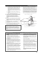 3
3
-
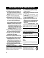 4
4
-
 5
5
-
 6
6
-
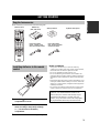 7
7
-
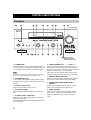 8
8
-
 9
9
-
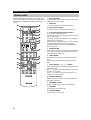 10
10
-
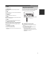 11
11
-
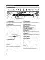 12
12
-
 13
13
-
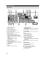 14
14
-
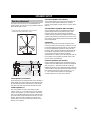 15
15
-
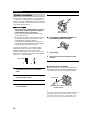 16
16
-
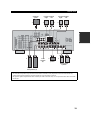 17
17
-
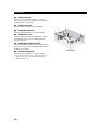 18
18
-
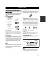 19
19
-
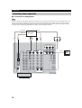 20
20
-
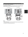 21
21
-
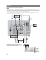 22
22
-
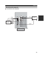 23
23
-
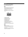 24
24
-
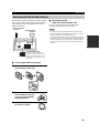 25
25
-
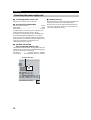 26
26
-
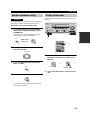 27
27
-
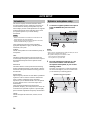 28
28
-
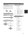 29
29
-
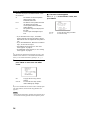 30
30
-
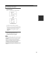 31
31
-
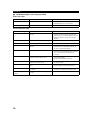 32
32
-
 33
33
-
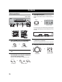 34
34
-
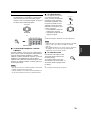 35
35
-
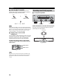 36
36
-
 37
37
-
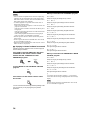 38
38
-
 39
39
-
 40
40
-
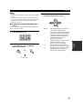 41
41
-
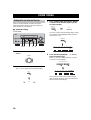 42
42
-
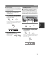 43
43
-
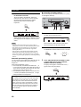 44
44
-
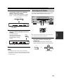 45
45
-
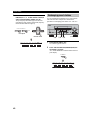 46
46
-
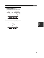 47
47
-
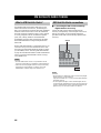 48
48
-
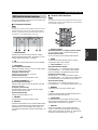 49
49
-
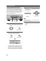 50
50
-
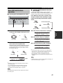 51
51
-
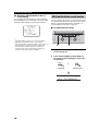 52
52
-
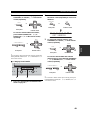 53
53
-
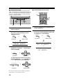 54
54
-
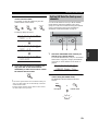 55
55
-
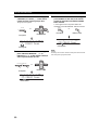 56
56
-
 57
57
-
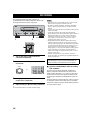 58
58
-
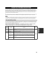 59
59
-
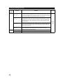 60
60
-
 61
61
-
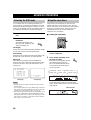 62
62
-
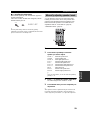 63
63
-
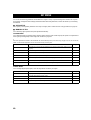 64
64
-
 65
65
-
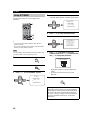 66
66
-
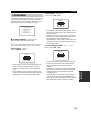 67
67
-
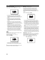 68
68
-
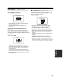 69
69
-
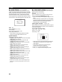 70
70
-
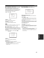 71
71
-
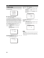 72
72
-
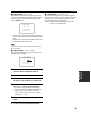 73
73
-
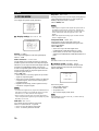 74
74
-
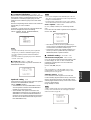 75
75
-
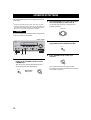 76
76
-
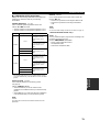 77
77
-
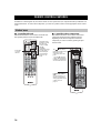 78
78
-
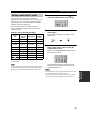 79
79
-
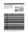 80
80
-
 81
81
-
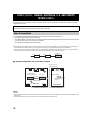 82
82
-
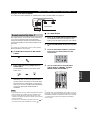 83
83
-
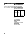 84
84
-
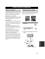 85
85
-
 86
86
-
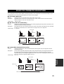 87
87
-
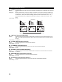 88
88
-
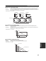 89
89
-
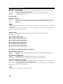 90
90
-
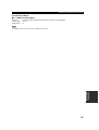 91
91
-
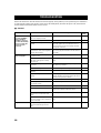 92
92
-
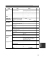 93
93
-
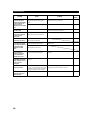 94
94
-
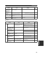 95
95
-
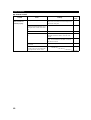 96
96
-
 97
97
-
 98
98
-
 99
99
-
 100
100
-
 101
101
-
 102
102
-
 103
103
-
 104
104
-
 105
105
-
 106
106


in andere talen
- English: Yamaha RX-V657 Owner's manual
- italiano: Yamaha RX-V657 Manuale del proprietario
- русский: Yamaha RX-V657 Инструкция по применению
- français: Yamaha RX-V657 Le manuel du propriétaire
- español: Yamaha RX-V657 El manual del propietario
- Deutsch: Yamaha RX-V657 Bedienungsanleitung
- português: Yamaha RX-V657 Manual do proprietário
- dansk: Yamaha RX-V657 Brugervejledning
- suomi: Yamaha RX-V657 Omistajan opas
- čeština: Yamaha RX-V657 Návod k obsluze
- svenska: Yamaha RX-V657 Bruksanvisning
- Türkçe: Yamaha RX-V657 El kitabı
- polski: Yamaha RX-V657 Instrukcja obsługi
- română: Yamaha RX-V657 Manualul proprietarului
Gerelateerde artikelen
-
Yamaha RX-V757 Handleiding
-
Yamaha RX-V461 - AV Receiver Handleiding
-
Yamaha RX-V557 de handleiding
-
-
Yamaha RX V661 - AV Receiver Handleiding
-
-
Yamaha RX-V563 Handleiding
-
-
-
Yamaha RX-V861 Handleiding