Yamaha DSP5D Handleiding
- Categorie
- Audiomixers
- Type
- Handleiding
Deze handleiding is ook geschikt voor

EN
PM5D/PM5D-RH V2
DSP5D
Owner’s Manual
Owner’s Manual
Owner’s Manual
PM5D/PM5D-RH V2 / DSP5D
This document is printed on recycled
chlorine free (ECF) paper with soy ink.
U.R.G., Pro Audio & Digital Musical Instrument Division, Yamaha Corporation
© 2004 Yamaha Corporation
Printed in Japan
WJ45370 704IPAP1.2-01D0
Yamaha Manual Library
http://www.yamaha.co.jp/manual/
Yamaha Pro Audio global web site:
http://www.yamahaproaudio.com/

The above warning is located on the rear/top of the unit.
Explanation of Graphical Symbols
The lightning flash with arrowhead symbol
within an equilateral triangle is intended to alert
the user to the presence of uninsulated
“dangerous voltage” within the product’s
enclosure that may be of sufficient magnitude to
constitute a risk of electric shock to persons.
The exclamation point within an equilateral
triangle is intended to alert the user to the
presence of important operating and
maintenance (servicing) instructions in the
literature accompanying the product.
IMPORTANT SAFETY INSTRUCTIONS
1 Read these instructions.
2Keep these instructions.
3 Heed all warnings.
4 Follow all instructions.
5 Do not use this apparatus near water.
6 Clean only with dry cloth.
7 Do not block any ventilation openings. Install in
accordance with the manufacturer’s instructions.
8 Do not install near any heat sources such as radiators,
heat registers, stoves, or other apparatus (including
amplifiers) that produce heat.
9 Do not defeat the safety purpose of the polarized or
grounding-type plug. A polarized plug has two blades
with one wider than the other. A grounding type plug
has two blades and a third grounding prong. The wide
blade or the third prong are provided for your safety. If
the provided plug does not fit into your outlet, consult
an electrician for replacement of the obsolete outlet.
10 Protect the power cord from being walked on or pinched
particularly at plugs, convenience receptacles, and the
point where they exit from the apparatus.
11 Only use attachments/accessories specified by the
manufacturer.
12 Use only with the cart, stand,
tripod, bracket, or table specified
by the manufacturer, or sold with
the apparatus. When a cart is
used, use caution when moving
the cart/apparatus combination
to avoid injury from tip-over.
13 Unplug this apparatus during
lightning storms or when unused for long periods of
time.
14 Refer all servicing to qualified service personnel.
Servicing is required when the apparatus has been
damaged in any way, such as power-supply cord or plug
is damaged, liquid has been spilled or objects have
fallen into the apparatus, the apparatus has been
exposed to rain or moisture, does not operate normally,
or has been dropped.
(98-6500)
CAUTION: TO REDUCE THE RISK OF
ELECTRIC SHOCK, DO NOT REMOVE
COVER (OR BACK). NO USER-SERVICEABLE
PARTS INSIDE. REFER SERVICING TO
QUALIFIED SERVICE PERSONNEL.
CAUTION
RISK OF ELECTRIC SHOCK
DO NOT OPEN
WARNING
TO REDUCE THE RISK OF FIRE OR ELECTRIC SHOCK, DO NOT EXPOSE THIS APPARATUS TO RAIN OR MOISTURE.
1. IMPORTANT NOTICE: DO NOT MODIFY THIS UNIT!
This product, when installed as indicated in the instructions con-
tained in this manual, meets FCC requirements. Modifications not
expressly approved by Yamaha may void your authority, granted by
the FCC, to use the product.
2. IMPORTANT:
When connecting this product to accessories and/
or another product use only high quality shielded cables. Cable/s
supplied with this product MUST be used. Follow all installation
instructions. Failure to follow instructions could void your FCC
authorization to use this product in the USA.
3. NOTE:
This product has been tested and found to comply with the
requirements listed in FCC Regulations, Part 15 for Class “B” digital
devices. Compliance with these requirements provides a reason-
able level of assurance that your use of this product in a residential
environment will not result in harmful interference with other elec-
tronic devices. This equipment generates/uses radio frequencies
and, if not installed and used according to the instructions found in
the users manual, may cause interference harmful to the operation
of other electronic devices. Compliance with FCC regulations does
* This applies only to products distributed by YAMAHA CORPORATION OF AMERICA. (class B)
not guarantee that interference will not occur in all installations. If
this product is found to be the source of interference, which can be
determined by turning the unit “OFF” and “ON”, please try to elimi-
nate the problem by using one of the following measures:
Relocate either this product or the device that is being affected by
the interference.
Utilize power outlets that are on different branch (circuit breaker or
fuse) circuits or install AC line filter/s.
In the case of radio or TV interference, relocate/reorient the
antenna. If the antenna lead-in is 300 ohm ribbon lead, change the
lead-in to co-axial type cable.
If these corrective measures do not produce satisfactory results,
please contact the local retailer authorized to distribute this type of
product. If you can not locate the appropriate retailer, please con-
tact Yamaha Corporation of America, Electronic Service Division,
6600 Orangethorpe Ave, Buena Park, CA90620
The above statements apply ONLY to those products distributed by
Yamaha Corporation of America or its subsidiaries.
FCC INFORMATION (U.S.A.)

* This applies only to the DSP5D distributed by
YAMAHA CORPORATION OF AMERICA.
COMPLIANCE INFORMATION STATEMENT
(DECLARATION OF CONFORMITY PROCEDURE)
Responsible Party : Yamaha Corporation of America
Address : 6600 Orangethorpe Ave., Buena Park, Calif. 90620
Telephone : 714-522-9011
Type of Equipment : Digital Mixing System
Model Name : DSP5D
This device complies with Part 15 of the FCC Rules.
Operation is subject to the following two conditions:
1) this device may not cause harmful interference, and
2) this device must accept any interference received including interference
that may cause undesired operation.
See user manual instructions if interference to radio reception is sus-
pected.
(FCC DoC)
* This applies only to products distributed by YAMAHA CORPORATION OF AMERICA. (Perchlorate)
This product contains a battery that contains perchlorate material.
Perchlorate Material—special handling may apply,
See www.dtsc.ca.gov/hazardouswaste/perchlorate.
ADVARSEL!
Lithiumbatteri—Eksplosionsfare ved fejlagtig håndtering. Udskiftning
må kun ske med batteri af samme fabrikat og type. Levér det brugte
batteri tilbage til leverandoren.
VARNING
Explosionsfara vid felaktigt batteribyte. Använd samma batterityp eller
en ekvivalent typ som rekommenderas av apparattillverkaren.
Kassera använt batteri enligt fabrikantens instruktion.
VAROITUS
Paristo voi räjähtää, jos se on virheellisesti asennettu. Vaihda paristo
ainoastaan laitevalmistajan suosittelemaan tyyppiin. Hävitä käytetty
paristo valmistajan ohjeiden mukaisesti.
(lithium caution)
NEDERLAND / THE NETHERLANDS
• Dit apparaat bevat een lithium batterij voor geheugen back-up.
• This apparatus contains a lithium battery for memory back-up.
• Raadpleeg uw leverancier over de verwijdering van de batterij op het
moment dat u het apparaat ann het einde van de levensduur of
gelieve dan contact op te nemen met de vertegenwoordiging van
Yamaha in uw land.
•For the removal of the battery at the moment of the disposal at the
end of life please consult your retailer or Yamaha representative
office in your country.
• Gooi de batterij niet weg, maar lever hem in als KCA.
• Do not throw away the battery. Instead, hand it in as small chemical
waste.
(lithium disposal)
This product contains a high intensity lamp that contains
a small amount of mercury. Disposal of this material
may be regulated due to environmental considerations.
For disposal information in the United States, refer to
the Electronic Industries Alliance web site:
www.eiae.org
(mercury)* This applies only to the PM5D (PM5D-RH) distributed by
YAMAHA CORPORATION OF AMERICA.
IMPORTANT NOTICE FOR THE UNITED KINGDOM
Connecting the Plug and Cord
WARNING:
THIS APPARATUS MUST BE EARTHED
IMPORTANT. The wires in this mains lead are coloured in accordance
with the following code:
GREEN-AND-YELLOW : EARTH
BLUE : NEUTRAL
BROWN : LIVE
As the colours of the wires in the mains lead of this apparatus may not
correspond with the coloured markings identifying the terminals in
your plug proceed as follows:
The wire which is coloured GREEN-and-YELLOW must be connected
to the terminal in the plug which is marked by the letter E or by the
safety earth symbol or colored GREEN or GREEN-and-YELLOW.
The wire which is coloured BLUE must be connected to the terminal
which is marked with the letter N or coloured BLACK.
The wire which is coloured BROWN must be connected to the termi-
nal which is marked with the letter L or coloured RED.
(3 wires)• This applies only to the DSP5D distributed by
Yamaha-Kemble Music (U.K.) Ltd.

4
PM5D/PM5D-RH V2 / DSP5D Owner’s Manual
PRECAUTIONS
PLEASE READ CAREFULLY BEFORE PROCEEDING
* Please keep this manual in a safe place for future reference.
WARNING
Always follow the basic precautions listed below to avoid the possibility of serious injury or even death from electrical
shock, short-circuiting, damages, fire or other hazards. These precautions include, but are not limited to, the following:
• Only use the voltage specified as correct for the device. The required voltage is
printed on the name plate of the device.
• Use only the specified power supply (PW800W or an equivalent recommended
by Yamaha).
• (DSP5D only) Use only the included power cord.
If you intend to use the device in an area other than in the one you purchased,
the included power cord may not be compatible. Please check with your Yamaha
dealer.
• Do not place the power cord near heat sources such as heaters or radiators, and
do not excessively bend or otherwise damage the cord, place heavy objects on
it, or place it in a position where anyone could walk on, trip over, or roll anything
over it.
• (DSP5D only) Be sure to connect to an appropriate outlet with a protective
grounding connection. Improper grounding can result in electrical shock.
• Do not open the device or attempt to disassemble the internal parts or modify
them in any way. The device contains no user-serviceable parts. If it should
appear to be malfunctioning, discontinue use immediately and have it inspected
by qualified Yamaha service personnel.
• Do not expose the device to rain, use it near water or in damp or wet conditions,
or place containers on it containing liquids which might spill into any openings.
• Never insert or remove an electric plug with wet hands.
• If the power cord or plug becomes frayed or damaged, or if there is a sudden
loss of sound during use of the device, or if any unusual smells or smoke
should appear to be caused by it, immediately turn off the power switch,
disconnect the electric plug from the outlet, and have the device inspected by
qualified Yamaha service personnel.
• If this device or power supply should be dropped or damaged, immediately turn
off the power switch, disconnect the electric plug from the outlet, and have the
device inspected by qualified Yamaha service personnel.
CAUTION
Always follow the basic precautions listed below to avoid the possibility of physical injury to you or others, or damage
to the device or other property. These precautions include, but are not limited to, the following:
• Remove the electric plug from the outlet when the device is not to be used for
extended periods of time, or during electrical storms.
• When removing the electric plug from the device or an outlet, always hold the
plug itself and not the cord. Pulling by the cord can damage it.
•Turn the PM5D ON/OFF using only the power supply PW800W POWER switch.
Turning the PM5D ON/OFF by plugging or unplugging the power cord, using a
switch on a power tap, a breaker switch, or similar external means can result in
damage.
• When transporting or moving the device, always use four or more people
(PM5D), two or more people (DSP5D). Attempting to lift the device by yourself
may damage your back, result in other injury, or cause damage to the device
itself.
• Before moving the device, remove all connected cables.
• When setting up the DSP5D, make sure that the front-panel power switch can be
easily turned ON/OFF. If some trouble or malfunction occurs, immediately turn
off the power switch and disconnect the plug from the outlet.
• If the DSP5D is to be mounted in an EIA-standard rack, leave the back of the
rack open and make sure that it is at least 10 cm away from walls or surfaces.
Also, if the DSP5D is to be mounted with devices that tend to generate heat,
such as power amplifiers, be sure to keep an adequate gap between the DSP5D
and the heat-generating devices or install ventilation panels to prevent high
temperatures from developing inside the DSP5D.
Inadequate ventilation can result in overheating, possibly causing damage to the
device(s), or even fire.
• Do not use the DSP5D in a confined, poorly-ventilated location. If the DSP5D is
to be used in a small space other than an EIA-standard rack, make sure that
there is adequate space between the DSP5D and surrounding walls or other
devices: at least 10 cm behind and 10 cm above. Inadequate ventilation can
result in overheating, possibly causing damage to the device(s), or even fire.
Power supply/Power cord
Do not open
Water warning
If you notice any abnormality
Power supply/Power cord
Location
(5)-4
1/2

PM5D/PM5D-RH V2 / DSP5D Owner’s Manual
5
•Avoid setting all equalizer controls and faders to their maximum. Depending on
the condition of the connected devices, doing so may cause feedback and may
damage the speakers.
• Do not expose the device to excessive dust or vibrations, or extreme cold or heat
(such as in direct sunlight, near a heater, or in a car during the day) to prevent
the possibility of panel disfiguration or damage to the internal components.
• Do not place the device in an unstable position where it might accidentally fall
over.
• Do not block the vents. This device has ventilation holes at the front and rear to
prevent the internal temperature from becoming too high. In particular, do not
place the device on its side or upside down. Inadequate ventilation can result in
overheating, possibly causing damage to the device(s), or even fire.
• Do not use the device in the vicinity of a TV, radio, stereo equipment, mobile
phone, or other electric devices. Doing so may result in noise, both in the device
itself and in the TV or radio next to it.
• Before connecting the device to other devices, turn off the power for all devices.
Before turning the power on or off for all devices, set all volume levels to
minimum.
• When turning on the AC power in your audio system, always turn on the power
amplifier LAST, to avoid speaker damage. When turning the power off, the power
amplifier should be turned off FIRST for the same reason.
• Do not insert your fingers or hands in any gaps or openings on the device
(vents, etc.).
•Avoid inserting or dropping foreign objects (paper, plastic, metal, etc.) into any
gaps or openings on the device (vents, etc.) If this happens, turn off the power
immediately and unplug the power cord from the AC outlet. Then have the
device inspected by qualified Yamaha service personnel.
• (PM5D only) Do not apply oil, grease, or contact cleaner to the faders. Doing so
may cause problems with electrical contact or fader motion.
• Do not use the headphones for a long period of time at a high or uncomfortable
volume level, since this can cause permanent hearing loss. If you experience
any hearing loss or ringing in the ears, consult a physician.
• Do not rest your weight on the device or place heavy objects on it, and avoid use
excessive force on the buttons, switches or connectors.
• This device has a built-in backup battery. When you unplug the power cord from
the AC outlet, the internal data of current scene is retained. However, if the
backup battery fully discharges, this data will be lost. When the backup battery
is running low in the system using PM5D or PM5D/DSP5D Editor, each LCD
display indicates “Low Battery!” during operation or “NO BATTERY!” when
starting up the system (the BATTERY field also indicates “LOW” or “NO
BATTERY” in the PREFERENCE2 screen).
When using only the DSP5D, the message such as “Low Battery!” cannot be
displayed because the DSP5D itself has no LCD display. When the DSP5D is
cascade-connected to the PM5D or online with the DSP5D Editor, these
messages will be displayed. In this case, have qualified Yamaha service
personnel replace the backup battery.
Always turn the power off when the device is not in use.
The performance of components with moving contacts, such as switches, volume controls, and connectors, deteriorates over time. Consult qualified Yamaha service
personnel about replacing defective components.
Connections
Handling caution
Backup battery
XLR-type connectors are wired as follows (IEC60268 standard): pin 1: ground, pin 2: hot (+), and pin 3: cold (-).
Yamaha cannot be held responsible for damage caused by improper use or modifications to the device, or data that is lost or destroyed.
Included Accessories
PM5D/PM5D-RH
• Owner's Manual (this document)
• Gooseneck Lamps x 3
• Power Supply PW800W Connection Cable
DSP5D
• Owner's Manual (this document)
• AC Power Cord
• D-SUB 68-pin Cable 10 m x 2
(5)-4
2/2

6
PM5D/PM5D-RH V2 / DSP5D Owner’s Manual
Table of Contents
Table of Contents — Operating section
1
Introduction.......................................... 10
Thank you ....................................................................... 10
An overview of the PM5D system .................................... 10
Differences between the PM5D model and
the PM5D-RH model ........................................... 11
About the channel structure of the PM5D ................................12
About the DSP5D ............................................................ 12
Differences with the PM5D.........................................................12
Regarding cascade connections between the PM5D and
DSP5D ................................................................................13
About PM5D Editor and DSP5D Editor ............................ 13
Firmware versions ............................................................ 14
Major new functionality in PM5D firmware V2.0 ............. 14
Regarding word clock synchronization ............................ 15
How this manual is organized.......................................... 15
Conventions in this manual........................................................15
2
Top, front, and rear panels.................. 16
Top panel ........................................................................ 16
Rear panel........................................................................ 18
Front panel ...................................................................... 20
DSP5D front panel........................................................... 21
DSP5D rear panel ............................................................ 22
3
Basic operation on the PM5D.............. 23
About the various types of user interface ......................... 23
User interface in the display........................................................23
DISPLAY ACCESS section..........................................................24
Data Entry section........................................................................24
External user interface .................................................................25
Basic operation ................................................................ 26
Click ..............................................................................................26
Drag...............................................................................................26
Drag and drop ..............................................................................26
Accessing a desired screen ...........................................................27
Moving the cursor........................................................................27
Scrolling the screen ......................................................................28
Operating the buttons .................................................................29
Adjusting the setting of a knob or fader.....................................29
Assigning a name .........................................................................30
4
Connections and setup ........................ 31
Examples of systems expanded with the DSP5D ............. 31
Example of simple input expansion
(PM5D + one DSP5D unit)..............................................31
PM5D + remotely connected input expansion
(PM5D + DCU5D + two DSP5D units)..........................31
Control from DSP5D Editor (one DSP5D unit + PC) .............32
Audio connections........................................................... 33
Analog audio connections...........................................................33
Analog output connections.........................................................34
Digital input/output connections...............................................36
Installing an option card .............................................................37
Word clock connections and settings .............................. 38
About word clock.........................................................................38
Selecting the word clock master..................................................38
Restoring the current scene to the default state............... 40
Switching the target of panel operations
(when cascade-connected with the DSP5D)........ 40
5
Input channel operations .....................41
About the input channels ................................................ 41
AD IN section .................................................................. 43
Items in the AD IN section......................................................... 43
Controlling the input sensitivity and phantom power
(+48V) of the head amp ................................................... 44
INPUT channel strip......................................................... 45
Items in the INPUT channel strip.............................................. 45
ST IN/FX RTN channel strip ............................................. 47
Items in the ST IN/FX RTN channel strip ................................ 47
FADER FLIP/ENCODER MODE section ............................. 48
Items in the FADER FLIP/ENCODER MODE section ........... 48
Various operations for input channels.............................. 49
Selecting the function of the encoders....................................... 49
Exchanging the fader and encoder functions............................ 49
Sending a signal from an input channel to the STEREO
bus ...................................................................................... 50
Sending the signal from the input channel to a MIX bus ........ 51
Enabling/disabling pairing.......................................................... 53
6
Output channel operations ..................55
About the output channels.............................................. 55
MIX section ..................................................................... 57
Items in the MIX section ............................................................ 57
Operations in the MIX section................................................... 57
STEREO A/B channel strip ................................................ 61
Items in the STEREO A/B channel strip ................................... 61
Operations in the STEREO A/B channel strip .......................... 62
MATRIX section ............................................................... 63
Items in the MATRIX section .................................................... 63
Operations in the MATRIX section........................................... 63
7
Using the Selected Channel section.....65
About the SELECTED CHANNEL section .......................... 65
Items in the SELECTED CHANNEL section ....................... 65
GROUP ........................................................................................ 65
CHANNEL SELECT ................................................................... 66
DELAY ......................................................................................... 66
GAIN/ATTENUATION/ø (Gain / Attenuation / Phase) ........ 67
NOISE GATE............................................................................... 67
STEREO ....................................................................................... 68
COMPRESSOR ........................................................................... 68
HPF (High Pass Filter)................................................................ 69
EQUALIZER................................................................................ 69
Operations in the SELECTED CHANNEL section .............. 70
Selecting a channel and editing its parameters ......................... 70
Compressor operations............................................................... 71
Gate operations ........................................................................... 72
EQ/HPF operations..................................................................... 73
8
Input Patch / Output Patch operations .74
Changing the input patch settings .................................. 74
Changing the output patch settings................................ 75
Inserting an external device into a channel...................... 77
Connecting an external device for insertion ............................. 77
Patching the insert-out and insert-in ........................................ 78
Directly outputting the signal of an input channel .......... 80

PM5D/PM5D-RH V2 / DSP5D Owner’s Manual
Table of Contents
7
9
Grouping and linking............................81
About DCA Groups and Mute Groups ............................. 81
Items in the ASSIGN MODE section ................................. 81
Items in the DCA strip...................................................... 81
Using DCA Groups........................................................... 82
Assigning channels to DCA groups............................................82
Controlling DCA groups.............................................................83
Using mute groups .......................................................... 83
Assigning channels to mute groups............................................83
Controlling mute groups.............................................................84
Using the Mute Safe function .....................................................84
Using EQ Link and Compressor Link ................................ 85
10
Scene memory....................................87
About scenes ................................................................... 87
Items in the SCENE MEMORY section .............................. 88
Using scene memories ..................................................... 89
Storing a scene..............................................................................89
Recalling a scene...........................................................................90
Using PREVIEW mode ...................................................... 90
Using the Auto Store function.......................................... 91
Using the Direct Recall function ....................................... 91
Using the Selective Recall function................................... 92
Using the Recall Safe function.......................................... 94
Using the Fade function................................................... 95
Using the Tracking Recall function ................................... 96
Using the Global Paste function ....................................... 97
11
Monitor and Cue................................99
About the MONITOR and CUE sections........................... 99
Using the Monitor function ........................................... 100
Items in the MONITOR section...............................................100
Monitoring a signal....................................................................101
Using the Cue/Solo functions ........................................ 102
Items in the CUE section...........................................................102
About CUE mode and SOLO mode.........................................102
Cue and Solo groups..................................................................103
Using the Cue function .............................................................104
Using the Solo function.............................................................104
12
Talkback and Oscillator....................105
About the TALKBACK/OSCILLATOR sections.................. 105
Items in the TALKBACK/OSCILLATOR sections..................105
Using talkback ............................................................... 106
Using the oscillator ........................................................ 107
13
Meters...............................................108
Items in the meter section ............................................. 108
Switching the meter display........................................... 108
Switching the metering point ........................................ 109
Specifying the metering point for input channels...................109
Specifying the metering point for output channels ................109
Viewing the gain reduction of the internal gates and
compressors....................................................... 110
Viewing the gain reduction for input channels .......................110
Viewing the gain reduction for output channels.....................110
14
Effects ...............................................111
About the internal effects............................................... 111
Using an internal effect via a MIX bus ............................ 112
Inserting an internal effect into a channel ...................... 113
Basic operations in the effect screen .............................. 114
Recalling settings from the effect library..................................114
Editing the effect parameters ....................................................115
Storing settings in the effect library ..........................................115
Using the Tap Tempo function ...................................... 116
Using the Freeze effect................................................... 117
15
Graphic EQ and Parametric EQ .......118
Patching the GEQ modules............................................ 118
Expanding the GEQ modules......................................... 119
Basic graphic EQ operations .......................................... 119
Controlling the graphic EQ from the display ......................... 119
Controlling the graphic EQ from the DCA section................ 120
Basic parametric EQ operations ..................................... 121
Controlling the parametric EQ from the display.................... 121
Controlling the parametric EQ from the SELECTED
CHANNEL section.......................................................... 122
16
Remote control ................................123
MIDI on the PM5D ........................................................ 123
Using program changes to control events ..................... 123
Using control changes to control events........................ 125
Using the MIDI Remote function ................................... 127
Assigning MIDI messages to controllers ................................. 127
Using MIDI remote channels................................................... 131
Transmitting MIDI events when you switch scenes........ 132
Using GPI (General Purpose Interface) ........................... 133
Using GPI IN ............................................................................. 133
Calibrating the GPI IN ports .................................................... 135
Using GPI OUT......................................................................... 136
17
Using memory cards........................138
Using memory cards with the PM5D............................. 138
Saving files to a memory card........................................ 138
Loading files from a memory card ................................. 140
18
Surround pan ...................................142
About surround pan ...................................................... 142
Bus configuration and operation in surround mode ...... 143
About the surround buses ........................................................ 143
How the MIX section will operate ........................................... 143
Basic settings for surround buses ................................... 144
Controlling surround pan .............................................. 145
Notes regarding surround pan ...................................... 147
19
Other functions................................148
Using the user defined keys ........................................... 148
Items in the USER DEFINED section ..................................... 148
Assigning functions to the User Defined keys ........................ 148
Executing functions assigned to the User Defined keys......... 149
Using the FADER MODE section .................................... 149
Items in the FADER MODE section........................................ 149
Assigning the FADER MODE section layer ............................ 149
Switching the FADER MODE section layer............................ 150
Locking the PM5D (Security functions).......................... 151
Setting the System Password or Console Password................ 151
Using Parameter Lock or Console Lock.................................. 152
Using cascade connections ............................................ 153
Example of cascade connections between the PM5D and
DSP5D.............................................................................. 153
Example of cascade connections between PM5D units ......... 153
Specifying the DSP5D’s machine ID number......................... 153
Basic settings for cascade connection ...................................... 154
Selecting the buses used for cascade connection .................... 156
Connecting the PM5D to your computer via USB ......... 158
Caution when using the USB TO HOST connector .............. 158
Connecting the DSP5D to your computer via Ethernet . 159
Initializing the PM5D’s internal memory........................ 160
Initializing the DSP5D’s internal memory....................... 160
Adjusting the faders and input/output gain
(Calibration) ...................................................... 161
Calibrating the faders................................................................ 161
Adjusting the analog input gain (PM5D-RH model only).... 162
Adjusting the output gain......................................................... 162

8
PM5D/PM5D-RH V2 / DSP5D Owner’s Manual
Table of Contents
Table of Contents — Reference section
Information shown in the display.......... 163
Upper part of the display (always visible)....................... 163
Main area of the display ................................................ 164
Lower part of the display (always visible) ....................... 164
Function menu........................................ 165
Global functions...................................... 166
EFFECT functions ........................................................... 166
EFFECT PARAM (Effect parameter) screen ...........................166
EFFECT ASSIGN screen............................................................168
EFFECT LIBRARY screen .........................................................169
PLUG-IN screen.........................................................................170
GEQ function................................................................. 170
GEQ PARAM (GEQ parameter) screen ..................................170
GEQ ASSIGN screen .................................................................173
GEQ LIBRARY screen ...............................................................174
SCENE function ............................................................. 175
SCENE screen.............................................................................175
EVENT LIST screen...................................................................177
SELECTIVE RECALL screen ....................................................180
RECALL SAFE screen ................................................................182
FADE TIME screen....................................................................184
TRACKING RECALL screen ....................................................186
GLOBAL PASTE screen ............................................................187
MIDI REMOTE function ................................................. 188
MIDI SETUP screen ..................................................................188
MIDI PGM CHANGE (MIDI program change) screen ........190
MIDI CTRL CHANGE (MIDI control change) screen..........191
MIDI REMOTE screen..............................................................192
GPI screen...................................................................................194
FADER START screen...............................................................196
TRANSPORT screen .................................................................198
DME CONTROL screen ...........................................................199
UTILITY function ............................................................ 204
PREFERENCE 1/2 screens ........................................................204
USER DEFINE screen................................................................208
SAVE screen ...............................................................................211
LOAD screen ..............................................................................215
FADER ASSIGN screen .............................................................217
SECURITY screen......................................................................218
SYS/W.CLOCK function ................................................. 219
WORD CLOCK screen..............................................................219
MIXER SETUP screen...............................................................221
CASCADE screen.......................................................................226
HA (Head Amp) screen.............................................................228
OUTPUT PORT ATT (Output port attenuation) screen ......229
DITHER screen ..........................................................................229
HA LIBRARY screen..................................................................230
METER function ............................................................. 231
INPUT METER screen ..............................................................231
OUTPUT METER screen..........................................................232
INPUT GR (Input Gain Reduction) screen.............................233
OUTPUT GR (Output Gain Reduction) screen .....................234
MON/CUE function ....................................................... 234
TALKBACK screen ....................................................................234
OSCILLATOR screen ................................................................236
2TR I/O screen ...........................................................................237
MONITOR screen .....................................................................238
CUE/SOLO screen .....................................................................240
Output functions .................................... 243
OUTPUT PATCH function .............................................. 243
OUTPUT PATCH screen ......................................................... 243
INSERT PATCH screen............................................................ 244
INSERT POINT screen............................................................. 246
NAME screen............................................................................. 247
OUTPUT PATCH LIBRARY screen ....................................... 247
OUTPUT INSERT function.............................................. 248
INSERT IN MIX 1-24 screen ................................................... 248
INSERT IN MATRIX/STEREO/MONITOR screen .............. 248
HA LIBRARY screen ................................................................. 249
OUTPUT EQ function .................................................... 250
EQ PARAM (EQ Parameter) screen........................................ 250
MIX 1-24 screen ........................................................................ 251
MATRIX/STEREO screen ........................................................ 251
OUTPUT EQ LIBRARY screen................................................ 252
OUTPUT COMP function............................................... 253
COMP PARAM (Compressor parameter) screen.................. 253
MIX 1-24 screen ........................................................................ 255
MATRIX/STEREO screen ........................................................ 255
COMP LIBRARY (Compressor library) screen...................... 256
OUTPUT DELAY function ............................................... 257
MIX 1-24 screen ........................................................................ 257
MATRIX/STEREO screen ........................................................ 257
OUTPUT DCA/GROUP function..................................... 258
DCA GROUP ASSIGN screen ................................................. 258
MUTE GROUP ASSIGN screen .............................................. 259
EQ LINK ASSIGN screen ......................................................... 260
COMP LINK ASSIGN (Compressor link assign) screen ....... 261
MATRIX/ST function...................................................... 262
MATRIX/ST ROUTING screen............................................... 262
MIX to MATRIX VIEW screen................................................ 264
LCR screen ................................................................................. 267
SURR SETUP screen................................................................. 268
OUTPUT VIEW function ................................................. 270
CH VIEW (Channel view) screen............................................ 270
SIGNAL FLOW screen ............................................................. 272
FADER VIEW screen ................................................................ 273
CH JOB (Channel job) screen.................................................. 274
OUTPUT CH LIBRARY screen ............................................... 275

PM5D/PM5D-RH V2 / DSP5D Owner’s Manual Table of Contents 9
Input functions ........................................277
INPUT PATCH function .................................................. 277
INPUT PATCH screen..............................................................277
DIRECT OUT PATCH screen..................................................278
INSERT PATCH screen ............................................................279
INSERT/DIRECT OUT POINT screen ...................................281
NAME screen .............................................................................282
INPUT PATCH LIBRARY screen ............................................283
INPUT HA/INSERT function............................................ 283
CH 1-24 (Input channel 1-24) screen ......................................283
CH 25-48 (Input channel 25-48) screen ..................................283
STIN/FXRTN (ST IN/FXRTN channel) screen ......................283
INSERT 1-24 screen...................................................................284
INSERT 25-48 screen.................................................................284
INSERT STIN screen .................................................................284
HA LIBRARY screen..................................................................285
INPUT ø/EQ function ..................................................... 286
EQ PARAM (EQ parameter) screen ........................................286
EQ 1-24 screen ...........................................................................287
EQ 25-48 switch .........................................................................287
EQ STIN/FXRTN screen...........................................................287
ø/ATT 1-48 (Phase/Attenuation 1-48) screen.........................288
ø/ATT STIN/FXRTN (Phase/Attenuation STIN/FXRTN)
screen ................................................................................288
INPUT EQ LIBRARY screen ....................................................289
INPUT GATE/COMP function......................................... 289
GATE PARAM (Gate parameter) screen.................................289
COMP PARAM (Compressor parameter) screen ..................291
CH 1-12 (Input channel 1–12) screen .....................................293
CH 13-24 (Input channel 13–24) screen .................................293
CH 25-36 (Input channel 25–36) screen .................................293
CH 37-48 (Input channel 37–48) screen .................................293
ST IN (ST IN channel) screen...................................................293
GATE LIBRARY screen.............................................................294
COMP LIBRARY (Compressor library) screen ......................295
INPUT DELAY function................................................... 295
CH 1-24 (Input channel 1–24) screen .....................................295
CH 25-48 (Input channel 25–48) screen .................................295
ST IN (ST IN channel) screen...................................................295
INPUT DCA/GROUP function......................................... 296
DCA GROUP ASSIGN screen ..................................................296
MUTE GROUP ASSIGN screen...............................................297
EQ LINK ASSIGN screen..........................................................298
COMP LINK ASSIGN (Compressor link assign) screen .......299
PAN/ROUTING function ................................................ 299
CH to MIX (Channel to mix) screen .......................................299
MIX SEND VIEW screen ..........................................................305
FIX ASSIGN VIEW screen ........................................................307
LCR screen..................................................................................308
SURR PARAM (Surround parameter) screen.........................309
SURR VIEW (Surround view) screen ......................................310
M/S screen ..................................................................................311
INPUT VIEW function ..................................................... 311
CH VIEW (Channel view) screen ............................................311
SIGNAL FLOW screen ..............................................................313
FADER VIEW screen.................................................................314
CH JOB screen ...........................................................................314
INPUT CH LIBRARY (Input channel library) screen............316
Appendices..............................................317
EQ Library List................................................................ 317
GATE Library List............................................................ 318
Compressor Library List ................................................. 319
Dynamics Parameters .................................................... 321
GATE section............................................................................. 321
COMP section ........................................................................... 322
Effect Library List............................................................ 324
Effects Parameters.......................................................... 325
Effects and tempo synchronization ......................................... 336
Scene Memory/Effect Library to Program Change Table
.. 337
Parameters that can be assigned to control changes ..... 341
Control change parameter assignments ........................ 343
NRPN parameter assignments ....................................... 360
Channel Library List ....................................................... 364
List of parameters available for Pair, Recall Safe or
OUTPUT ISOLATION operation ......................... 365
MIDI Data Format.......................................................... 368
Warning Messages......................................................... 377
Error Messages............................................................... 379
Troubleshooting ............................................................ 380
General Specifications.................................................... 381
PM5D/PM5D-RH..................................................................... 381
DSP5D........................................................................................ 383
Input/output characteristics........................................... 384
Electrical characteristics ................................................. 389
PM5D/PM5D-RH..................................................................... 389
DSP5D........................................................................................ 391
Other Functions............................................................. 393
Pin Assignment.............................................................. 394
Dimensions.................................................................... 395
MIDI Implementation Chart .......................................... 396
Index ............................................................................. 397
PM5D/PM5D-RH Block Diagram ...................End of Manual
DSP5D Block Diagram ...................................End of Manual
PM5D Level Diagram.....................................End of Manual
PM5D-RH Level Diagram ...............................End of Manual
DSP5D Level Diagram ...................................End of Manual
• The illustrations and screen displays as shown in this
Owner’s Manual are for instructional purposes only,
and may be different from the ones on your device.
• The company names and product names in this
Owner’s Manual are the trademarks or registered
trademarks of their respective companies.

10 PM5D/PM5D-RH V2 / DSP5D Owner’s Manual Operating section
Operating section
Thank you
Thank you for purchasing the Yamaha PM5D digital mixing console and/or Yamaha DSP5D digital mixing system. In order
to take full advantage of the PM5D/DSP5D’s superior functionality and enjoy years of trouble-free use, please read this man-
ual before you begin using the product. After you have read the manual, keep it in a safe place.
An overview of the PM5D system
The PM5D is an expandable digital mixing console with the following features.
❏ Full digital SR mixing system
The PM5D is a full-digital SR mixing console that takes
advantage of cutting-edge digital audio processing technol-
ogy. 24-bit linear AD/DA converters are used to deliver up
to 110 dB of dynamic range and amazing sound quality. As
input channels, it provides 48 monaural channels, four ste-
reo channels, and four stereo channels for effect return. As
output channels, it provides 24 MIX channels, eight
MATRIX channels, and two STEREO channels. The PM5D
can be used in a wide range of applications. You can assign
desired channels to be controlled by the eight DCA faders
on the panel, and use them as group faders.
❏ PM5D model and PM5D-RH model
In addition to the standard PM5D model that provides
manual control of the head amp for each input, the
PM5D-RH model is also available, providing programma-
ble control of head amp input sensitivity and phantom
power settings. You can choose the model appropriate for
your situation and budget.
❏ Cutting-edge user interface
For the input channels and STEREO A/B channels, dedi-
cated channel strips are provided where you can operate
the fader, pan, cue, and on/off controls. For MIX channels
and MATRIX channels, encoders allow you to control the
send level and master level. The PM5D allows quick and
intuitive operation just as on an analog mixer. In addition,
you can use the SELECTED CHANNEL section to manu-
ally control the principal parameters (delay, EQ, gate,
compressor) of the desired channel.
❏ Eight effect modules / Twelve graphic
EQ modules
Eight high-quality multi-effect modules are built in. Effects
such as reverb, delay, multiband compressor, and various
modulation effects can be routed via internal buses or
inserted into the desired channel. 31-band graphic EQ
(alternatively, 8-band parametric EQ) can also be inserted
into any channel or any output.
❏ Add-On effects provided as standard
As effect types, the channel strip package (COMP276/276S,
COMP260/260S, EQ601), master strip package (OPEN
DECK), and reverb package (REV-X) are provided as
standard.
❏ Scene memories and libraries
Mix parameters and internal effect settings can be stored in
memory as up to 500 scenes for immediate recall. Effects,
input/output patching, input channel/output channel set-
tings, internal head amp (PM5D-RH model only) or
external head amp settings can be stored in various librar-
ies, independently of scenes.
❏ Digital cascade connection
Up to four PM5D units, or one PM5D and one Yamaha
DM2000/02R96 unit, can be cascade-connected to share
buses in the digital domain. In particular when PM5D
units are cascaded together, operations such as scene sav-
ing and recall can also be linked. DME64N can also be used
as inserts or as extended signal processors via a cascade
connection.
❏ Surround panning
Surround pan functionality allows multi-channel playback
systems to be used, letting you place the signal of an input
channel in two-dimensional space, or move the sound
image forward/backward and left/right. 3-1ch, 5.1ch, and
6.1ch surround modes are available.
❏ I/O card expansion
The rear panel provides four slots in which separately sold
mini-YGDAI cards can be installed. AD cards, DA cards, or
digital I/O cards can be installed in these slots to add inputs
and outputs.
❏ Expansion via the DSP5D
A maximum of two DSP5D digital mixing systems can be
cascade-connected to a PM5D to expand the inputs and
outputs. You can also connect a Yamaha DCU5D digital
cabling unit between the PM5D and DSP5D, and locate the
DSP5D remotely.
1 Introduction

PM5D/PM5D-RH V2 / DSP5D Owner’s Manual Operating section 11
1
Introduction
Differences between the PM5D model and the PM5D-RH
model
The PM5D is available as the standard PM5D model or as the PM5D-RH model which allows internal head amp settings to be
programmed. These models differ as follows.
❏ PM5D model
• Head amp adjustments (input sensitivity settings,
phantom power (+48V) on/off) for the analog inputs
(INPUT jacks 1–48, ST IN jacks 1–4) are performed
manually, using the controls of the top panel.
• Insert jacks (INSERT IN/OUT jacks) for the monaural
analog inputs (INPUT jacks 1–48) are provided on the
rear panel, allowing external effect processors to be
inserted in the analog domain.
• ST IN jacks 1–4 are only for line level.
• There is no +48V MASTER switch.
❏ PM5D-RH model
• Head amp adjustments (input sensitivity settings,
phantom power (+48V) on/off) for the analog inputs
are controlled from within the screen via software. For
this reason, the top panel does not have head amp con-
trols; instead, LEDs showing the presence or absence of
a signal are provided. Head amp settings can be saved
in a library and recalled at any time.
• Insert jacks for the analog inputs are not provided.
• ST IN jacks 1–4 support mic levels through line levels.
Phantom power can also be supplied to ST IN jacks 1–
4.
• The +48V MASTER switch turns all phantom power
(+48V) on/off.
INPUT jacks 1–48ST IN jacks 1–4
INSERT IN/OUT jacks 1–48
INPUT jacks 1–48
ST IN jacks 1–4

1 Introduction
12 PM5D/PM5D-RH V2 / DSP5D Owner’s Manual Operating section
The PM5D provides the following input channels and out-
put channels.
❏ Input channels
This section processes input signals and sends them to the
STEREO bus or MIX buses. There are three types of input
channel, as follows.
• Input channels 1–48
These channels are used to process monaural signals.
By default, the input signals from the monaural analog
input jacks (INPUT jacks 1–48) are assigned to these
channels.
• ST IN channels 1–4
These channels are used to process stereo signals. By
default, the input signals from the stereo analog input
jacks (ST IN jacks 1–4) are assigned to these channels.
• FX RTN channels 1–4
These channels are used mainly to process the return
signals (stereo) from the internal effects. By default, the
left/right output channels of internal effects 1 through
4 are assigned to these channels.
Hint
Signal assignments to the input channels can be changed as
desired.
❏ Output channels
This section mixes the signals sent from input channels
etc., and sends them to the corresponding output jacks or
output buses. There are three types of output channel, as
follows.
• MIX channels 1–24
These channels process signals sent from input chan-
nels to MIX buses. In the initial state, output signals are
assigned to MIX OUT jacks 1–24. These channels are
used mainly for foldback or as sends to external effects.
The signals of MIX channels 1–24 can also be sent to
the STEREO bus or MATRIX buses.
• MATRIX channels 1–8
These process the signals sent from MIX channels or
STEREO A/B channels to MATRIX buses, and output
them from the MATRIX OUT jacks. This allows MIX
channels or STEREO A/B channels to be mixed at the
desired balance for output.
• STEREO A/B channels
These process the signals sent from input channels or
MIX channels, and output them to STEREO OUT
jacks A/B. These channels are used as the main stereo
outputs. Normally, the same signal is sent from the
STEREO A and B channels. However, it is also possible
to use the STEREO B channel as the center channel for
three-channel L/C/R playback.
About the DSP5D
The DSP5D is a digital signal processing (DSP) system
expanding the inputs and outputs of the PM5D.
• Its audio processing capability is equivalent to that of
the PM5D-RH. As analog audio input/output jacks, it
provides INPUT jacks 1–48, ST IN jacks 1–4, and
OMNI OUT jacks 1–24.
• Up to two DSP5D units can be cascade-connected to
one PM5D. By connecting it with DSP5D units, the
PM5D system can be expanded to a maximum of 168
channels of input (144 channels + 12 ST).
• By switching the control target on the PM5D, the
DSP5D can be seamlessly controlled in the same way as
the PM5D itself.
• You can use DSP5D Editor application software to
remotely control and edit the parameters of the
DSP5D. Only Windows computers are supported.
• The DSP5D can be connected to a Yamaha DCU5D
digital cabling unit and placed on stage, and operated
remotely from the PM5D.
• The front panel provides two slots in which you can
install separately sold mini-YGDAI cards to add inputs
and outputs in a variety of digital formats.
❏ Connectors and interfaces not found on
the DSP5D
• INSERT IN/OUT jacks, MIX OUT jacks, LAMP jacks,
MONITOR OUT jacks, CUE OUT jacks, STEREO
OUT A/B jacks, MATRIX OUT jacks, 2TR IN ANA-
LOG jacks, TIME CODE INPUT jack, USB TO HOST
connector, GPI connector, RS422 REMOTE connec-
tor, HA REMOTE connector, MIDI IN/THRU/OUT
connectors, 2TR OUT DIGITAL jack, 2TR IN DIGI-
TAL jack, SLOT 3–4, MEMORY CARD slot, MOUSE
connector, KEYBOARD connector, PHONES jack
• Controllers such as faders, display devices such as
meters. LCD display, +48V MASTER switch (PM5D-
RH), 75Ω ON/OFF switch
❏ Connectors and interfaces found only
the DSP5D
• OMNI OUT jacks, CASCADE IN/OUT RJ-45 connec-
tors, NETWORK connector, AC IN connector
• POWER switch, mode switch, FAN switch
About the connectors: Since the DSP5D does not have
the functionality for the connectors with which DSP5D
is not equipped, these functions and connectors are not
shown in the screen of the PM5D or DSP5D Editor.
About the channel structure of the
PM5D
Differences with the PM5D

PM5D/PM5D-RH V2 / DSP5D Owner’s Manual Operating section 13
1
Introduction
About the interface: Since the DSP5D does not have
controllers such as faders or the LCD display, it is oper-
ated from the PM5D or DSP5D Editor.
Note
• The explanations in chapter 5 and following of this Owner’s
Manual are based on the functionality and operating proce-
dures of the PM5D. Supplementary explanations regarding
the DSP5D are added only in cases where there is a signifi-
cant difference in functionality or operating procedure.
However, in cases where it is obvious that the above-
described differences would make clear differences in oper-
ation or in the on-screen display, explanations for the
DSP5D will be omitted.
• There are some differences between the PM5D and DSP5D
in the I/O cards that are supported. For the most recent
information regarding I/O cards, refer to the following
Yamaha website.
http://www.yamahaproaudio.com/
❏ Connection to a computer
The PM5D can be connected to a computer via a USB
cable from its USB TO HOST connector, but the DSP5D
can be connected to a computer via an Ethernet CAT5
cable from its NETWORK connector.
By bi-directionally cascade-connecting the PM5D and
DSP5D, you can share MIX buses 1–24, STEREO A/B
buses, and CUE buses.
For details on cascade connections, refer to p.153.
Note
• Cascade connection with the DSP5D is possible only for
PM5D V2.0 or later. If you’re using earlier version than V2.0,
you will need to upgrade to PM5D V2.0 or later. You can
download the most recent firmware from the following
Yamaha website.
http://www.yamahaproaudio.com/
• Connectors and interfaces not found on the DSP5D cannot
be controlled from the PM5D. For example, the MONITOR
[LEVEL] and MONITOR [PHONES] knobs found on the
PM5D’s top panel are always operated at the level of the
PM5D.
❏ Controlling the DSP5D
• As the target of control from the PM5D’s panel and
screen, you can recall machine #1 (PM5D), machine #2
(first DSP5D), or machine #3 (second DSP5D) as
desired. For details on operation, refer to p.153.
• Functions assigned to the user-defined keys or the
FADER MODE section can be used to select the
DSP5D as the target machine to be operated (➥ p.148,
149). Operations can be performed from the panel of
the PM5D itself or from DSP5D Editor connected to
the DSP5D.
❏ Operation when cascade-connected
• Output channels
In general, operations for the output channels of cas-
cade-connected buses will be linked between machines.
(You can also specify that they not be linked.) This
means that you can operate the system as if it were a
single console with an expanded number of inputs.
However, since the inserts to output channels will also
be duplicated, inserted GEQ modules and effects may
also be consumed in duplicate or triplicate. (Separate
GEQ modules or effects are inserted into the linked
buses on each machine.)
• Scene memories and libraries
Scene memory and library data is stored on each
machine. When a scene or a library associated with a
scene is stored or recalled, the same scene/library num-
ber will be stored/recalled on all machines. When the
cascade-connection becomes active, the PM5D’s
library data not associated with a scene will be sent to
each DSP5D to synchronize the libraries. The data on
cascade-connected machines can also be saved together
to a memory card.
• Effects
The DSP5D provides GEQ modules and effects that are
equivalent to those on the PM5D, but since the con-
nections between machines are bus cascade
connections, inserts into input channels are limited to
being within each machine.
• DCA groups / Mute groups
These will operate in tandem for cascade-connected
PM5D/DSP5D machines. (➥ p.156)
• CH JOB function
Channel copy operations between the PM5D/DSP5D
can be performed from the PM5D front panel. How-
ever, channels can be moved using the INPUT VIEW
function only within each machine. (➥ p.274, 314)
About PM5D Editor and DSP5D Editor
These programs are application software for operating the
PM5D/DSP5D’s functionality from a computer. You can
use this software to remotely control and edit the parame-
ters of the PM5D/DSP5D.
The USB-MIDI driver (for the PM5D) or DME-N Net-
work driver (for the DSP5D) required for connection with
a computer, as well as the PM5D/DSP5D editor, can be
downloaded from the following Yamaha website.
http://www.yamahaproaudio.com/
Note
DSP5D Editor supports only Windows computers.
Regarding cascade connections
between the PM5D and DSP5D

1 Introduction
14 PM5D/PM5D-RH V2 / DSP5D Owner’s Manual Operating section
Firmware versions
You can download the most recent firmware from the following Yamaha website.
http://www.yamahaproaudio.com/
For either the PM5D or the DSP5D, you can check the firmware version in the UTILITY function PREFERENCE 2 screen
(➥ p.207).
Major new functionality in PM5D firmware V2.0
The major new functionality and improvements that were added in conjunction with the upgrade to firmware V2.0 are as
follows.
❏ Basic functionality and panel operations
• You can now control the DSP5D from the PM5D’s
panel. (➥ p.153)
• On/off operations of the channel selected in the
FADER MODE section can now be operated from the
DCA [MUTE] key.
• Even if the FADER [FLIP] key is on, you can now use
the encoders to control the panning of the signal sent
to the MIX buses, the head amp gain, or the attenua-
tors. (➥ p.49)
• If there is no vacant library number when you store the
selected scene as NEW, it will now be impossible to
save the scene; this prevents an existing library item
from being overwritten.
• Remote control of the DME64N/24N (firmware V2.0
and later) is now faster. In particular, operation is
faster when connected via an MY16-C or MY16-CII
card (supported from V1.2).
• As parameters that can be operated in the screen,
MONITOR LEVEL and CUE LEVEL have been added.
You can now assign these to the faders of the DCA strip
so that the monitor or cue levels can be adjusted.
(➥ p.149)
❏ EFFECT functions
• Add-On Effects (COMP276/276S, COMP260/260S,
EQ601, OPEN DECK) and DE-ESSER have been
added.
•A DSP CONFIGURATION option has been added to
the EFFECT ASSIGN screen and to the GEQ function
GEQ ASSIGN screen, allowing internal effects 1–8 to
be used as graphic EQ or parametric EQ.
(➥ p.168, 173)
• When the panel [SEL] key is pressed in the EFFECT
PARAM screen, or when a [SEL] key is turned on via a
linking setting, the effect module inserted in that chan-
nel will automatically be selected.
• If you’ve used the tap tempo function to specify the
tempo in the EFFECT PARAM screen and then edited
the DELAY parameter, the tempo will now stay
unchanged.
❏ GEQ functions
• Options have been added to the GEQ PARAM screen,
allowing you to switch a graphic EQ to a parametric
EQ. (➥ p.170)
• Not only when the panel [SEL] key is pressed in the
GEQ PARAM screen but also when a [SEL] key is
turned on via a linking setting, the GEQ module
inserted in that channel will automatically be selected.
• When you insert a GEQ in the GEQ PARAM screen,
insert-in will automatically be turned on for that chan-
nel, and will be automatically turned off when you
remove the GEQ.
❏ SCENE functions
• In the SCENE screen, you can now specify “read-only”
scenes that will not be overwritten when you load
scenes from a memory card. (➥ p.175)
• In the SCENE screen, a DELAY field has been added,
allowing you to specify the timing of the program
change or MIDI events that are transmitted when the
scene is recalled. (➥ p.175)
• In the SELECTIVE RECALL screen and the RECALL
SAFE screen, the ON parameter has been added as a
channel parameter that can be included in or excluded
from recall operations. (➥ p.180, 182)
• In the SELECTIVE RECALL screen and RECALL SAFE
screen, separately from the conventional Recall Safe
functionality, an OUTPUT ISOLATION field has been
added, so that output channels and parameters to be
excluded from recall operations can be stored in
SETUP memory (which is not affected by memory
card load operations). (➥ p.180, 182)
❏ SYS/W.CLOCK functions
• In the MIXER SETUP screen, a VIRTUAL SOUND-
CHECK button has been added, allowing you to
temporarily switch the input signals without affecting
the scene memory (input patching). For example, this
allows you to perform a sound check using pre-
recorded material played back by a DAW connected to
a slot, instead of the analog input material received via
the INPUT jacks. (➥ p.221)
• In the OUTPUT ATT PORT screen, a ø (phase) but-
ton has been added, allowing you to switch the phase
between normal and reverse for each output channel or
I/O channel output port.
❏ UTILITY functions
• In the PREFERENCE 1 screen, a DCA MUTE TAR-
GET option has been added, allowing you to specify
that the DCA [MUTE] key will mute the send to the
MIX bus. (➥ p.205)
• In the PREFERENCE 1 screen, an ATT OPERATION
ON PANEL option has been added, allowing you to
prevent the panel encoders from operating the attenua-
tors. (➥ p.206)
• In the PREFERENCE 1 screen, a MIX SEL/ENCODER
MODE LINK option has been added, allowing you to

PM5D/PM5D-RH V2 / DSP5D Owner’s Manual Operating section 15
1
Introduction
link selection of MIX channels with selection of MIX
SEND SELECT keys. (➥ p.206)
• In the USER DEFINE screen, functions such as DSP5D
CONTROL and ENCODER MODE KEY have been
added to the functions that can be assigned to user-
defined keys. (➥ p.208)
• In the FADER ASSIGN screen, options have been
added, allowing you to use the STEREO/DCA strip sec-
tion to control the monitor/cue level and on/off status.
(➥ p.217)
• In the FADER ASSIGN screen, you can now assign the
desired channels of the DSP5D as well. (➥ p.217)
• In the SECURITY screen, a LOAD LOCK function has
been added, allowing you to disable loading for each
type of file. (➥ p.218)
• In the SECURITY screen, a RECALL LOCK option has
been added, allowing you to lock parameters so that
they will not be changed when a scene or library is
recalled. (➥ p.218)
❏ Input/output functions
• In the OUTPUT PATCH function OUTPUT PATCH
screen, you can now change the patching of output
channels to MIX OUT jacks 1–24. (➥ p.243)
• In the OUTPUT PATCH function INSERT POINT
screen and the INPUT PATCH function INSERT/
DIRECT OUT POINT screen, a SET ALL button and
CLEAR ALL button have been added, allowing you to
turn all channels on/off in a single operation.
(➥ p.246, 281)
• In the OUTPUT PATCH function, a NAME screen has
been added, allowing you to assign names to output
channels for display in various screens (supported from
V1.2). (➥ p.247)
• In the INPUT VIEW function CH JOB screen, channel
settings can now be moved as well as copied. (➥ p.314)
• In the INPUT PATCH function INSERT/DIRECT
OUT POINT screen, PRE ATT has been added as a
direct output transmit location. (➥ p.282)
• In the PAN/ROUTING function MIX SEND VIEW
screen, the send position (PRE/POST) of the signal
sent to the MIX bus is now indicated by the color of the
bar graph. (➥ p.306)
• You can now set a Q of up to 16 for the parametric EQ
in the input channels, output channels, and GEQ
modules.
• You can now set a threshold level of down to –72 dB
for an input channel GATE.
Regarding word clock synchronization
The signal used to synchronize digital audio signal process-
ing is called “word clock.” Normally, one device transmits
a reference word clock signal, and the other devices receive
this word clock signal and synchronize to it.
In order to transmit or receive digital audio signals to or
from an external device via the PM5D/DSP5D’s digital
input/output jacks or via a digital I/O card installed in a
slot, the word clock must be synchronized between the
devices. Be aware that if the word clock is not synchro-
nized, the signals will not be transmitted correctly, and
unpleasant noise will occur.
Hint
• For details on synchronizing the word clock of the PM5D/
DSP5D and external devices, refer to the explanation of
word clock in Operating section “Chapter 4. Connections
and setup” (
➥
p.38), and to the Reference Section “WORD
CLOCK screen” (
➥
p.219).
• As an exception, digital signals that are not synchronized
with the PM5D/DSP5D can be input via a digital I/O card
that contains a sampling rate converter, or via the 2TR IN/
OUT DIGITAL jacks.
How this manual is organized
This owner’s manual is divided into the following three
sections.
❏ Operating section
This section explains the items on the front and rear pan-
els, connections and setup, and how to operate the PM5D’s
basic functionality. In particular if you have not operated a
digital console before, we recommend that you read chap-
ters 2 through 7 first.
❏ Reference section
This section explains the functionality and operation for all
of the PM5D’s screens. Refer to this section when you want
to learn about the items in the screens.
❏ Appendices
This contains various information such as library lists,
parameter lists for the internal effects, the MIDI data for-
mat, and lists of warning messages and error messages.
In this manual, non-locking panel switches that you press
are called “keys,” and those that change their on/off status
when you push them in (locking types) are called
“switches.” Of the control knobs on the panel, those that
turn from a minimum value to a maximum value are
called “knobs,” while those that turn endlessly are called
“encoders.”
Controls located on the panel are enclosed in square brack-
ets [ ] (e.g., [CUE] key, [PAD] switch) in order to
distinguish them from the buttons and knobs displayed in
the screen. For some controls, the section name is listed
before the [ ] (e.g., CH [ON] key, EQ [FREQUENCY]
encoder).
Unless otherwise specified, references to the PM5D apply
to both the PM5D model and the PM5D-RH model. If
specifications differ between the PM5D model and the
PM5D-RH model, such differences will be noted each time
they occur.
Conventions in this manual

2 Top, front, and rear panels
16 PM5D/PM5D-RH V2 / DSP5D Owner’s Manual Operating section
This chapter explains the names and functions of each part of the PM5D/DSP5D. Details for each
section of the top panel are explained in subsequent chapters of this operating section; refer to the
appropriate chapter for more information.
Top panel
A AD IN section (PM5D model)
In this section you can adjust the sensitivity of the ana-
log signals being input from the rear panel INPUT
jacks 1–48 and ST IN jacks 1–4, and switch pad, insert,
and phantom power (+48 V) on/off (➥ p.43).
B AD IN section (PM5D-RH model)
This area indicates the presence, peak level, and phan-
tom power (+48V) on/off status of the input signal
from rear panel INPUT jacks 1–48 and ST IN jacks 1–
4.
Hint
For the PM5D-RH model, input sensitivity and phantom power
on/off are controlled by operations in the display (
➥
p.44).
C INPUT channel strip section
This section controls the principal parameters for input
channels 1–48 (➥ p.45).
D FADER FLIP/ENCODER MODE section
Here you can select the parameters controlled by the
faders/encoders of the INPUT channel strip (
3)
(➥ p.48).
E MIX section
This section controls the on/off status and send level of
the signals sent from input channels to MIX buses, and
adjusts the master level of the MIX channels (➥ p.57).
F MATRIX section
This section controls the send level of the signals sent
from MIX channels to MATRIX buses, and adjusts the
master level of the MATRIX channels (➥ p.63).
G SELECTED CHANNEL section
In this section you can view and control the mix
parameters for the currently selected input channel or
output channel (➥ p.65).
H Meter section
This section contains peak level meters that indicate
the input levels of input channels and the output levels
of output channels and cue monitoring, as selected by
key operations (➥ p.108).
2 Top, front, and rear panels
1
(PM5D model)
2
(PM5D-RH model)
4 5
3
6 8
7

PM5D/PM5D-RH V2 / DSP5D Owner’s Manual Operating section 17
2
Top, front, and rear panels
I Display
This display shows the information you need to oper-
ate the PM5D, and lets you make system-wide settings
and control mix parameters for input and output
channels (➥ p.23).
Hint
You can adjust the angle of the display by moving the upper
part of the display frame forward or backward.
Note
Before moving the PM5D, you must lower the display all the
way back until it is fastened in place.
J FADER MODE section
Here you can select the combination of channels or
DCA groups that will be controlled by the faders of the
DCA strip section (
K) (➥ p.149).
K DCA strip section
From this section you can control the channels
assigned to DCA groups 1–8 (➥ p.81).
L ST IN/FX RTN (Stereo in / Effect return)
channel strip section
This section controls the principal parameters of ST IN
channels 1–4 or FX RTN channels 1–4 (➥ p.47).
M STEREO strip section
This section controls the principal parameters of the
STEREO A/B channels (➥ p.61).
N SCENE MEMORY section
This section stores/recalls mix parameters as scene
memories (➥ p.88). Mute operations for mute groups
1–8 are also performed in this section (➥ p.83).
O CUE/MONITOR section
This section selects the monitor source that is output
from the MONITOR OUT jacks, and adjusts the lev-
els. This section also determines the cue point and
monitoring method that will be used when you press a
[CUE] key for a channel (➥ p.99).
P OSCILLATOR/TALKBACK section
This section switches the oscillator or talkback on/off,
and adjusts the talkback level (➥ p.105).
Q DISPLAY ACCESS section
This section selects the functions or screen shown in
the display (➥ p.24).
R USER DEFINED KEYS sections
This section executes the functions that have been
assigned to the User Defined keys [1]–[25] (➥ p.148).
S Data entry section
This section lets you move the pointer (the arrow dis-
played in the screen) or cursor (the red frame
indicating a selection) in the display and edit the
parameter value (➥ p.24).
T ASSIGN MODE section
This section lets you assign mute groups and DCA
groups for control from the panel (➥ p.81).
R
9
Q
R
ST
N O P
8
J
K M L

2 Top, front, and rear panels
18 PM5D/PM5D-RH V2 / DSP5D Owner’s Manual Operating section
Rear panel
A INPUT jacks 1–48 (PM5D model)
These are balanced XLR-3-31 type input jacks for
inputting analog audio signals from line level devices
or microphones. Nominal input level is
–60 dBu to +10 dBu.
B INSERT IN/OUT jacks 1–48 (PM5D model
only)
These are balanced TRS phone type input/output jacks
for inserting external effects or dynamics processors
etc. into INPUT jacks 1–48. Nominal input/output
level is +4 dBu.
C ST IN (Stereo input) jacks 1–4 (PM5D
model)
These are balanced XLR-3-31 type input jacks for
inputting analog audio signals from line level devices.
Nominal input level is –34 dBu to +10 dBu.
D +48V MASTER switch (PM5D-RH model
only)
This is the master phantom power (+48V) switch for
INPUT jacks 1–48 and ST IN jacks 1–4. If this switch is
off, the +48V buttons shown in the display are
unavailable.
E INPUT jacks 1–48 (PM5D-RH model)
These are balanced XLR-3-31 type input jacks for
inputting analog audio signals from line level devices
or microphones. Nominal input level is
–62 dBu to +10 dBu.
F ST IN (Stereo input) jacks 1–4 (PM5D-RH
model)
These are balanced XLR-3-31 type input jacks for
inputting analog audio signals from line level devices
or microphones. Nominal input level is
–62 dBu to +10 dBu.
3 1
2
(PM5D model)
Male XLR plug
1 (ground)
2 (hot)
3 (cold)
1/4" TRS
phone plug
Tip (hot)
Ring (cold)
Sleeve (ground)
Male XLR plug
1 (ground)
2 (hot)
3 (cold)
46
5
(PM5D-RH model)
Male XLR plug
1 (ground)
2 (hot)
3 (cold)
Male XLR plug
1 (ground)
2 (hot)
3 (cold)

PM5D/PM5D-RH V2 / DSP5D Owner’s Manual Operating section 19
2
Top, front, and rear panels
G MIX OUT jacks
These are XLR-3-32 (balanced) jacks that output ana-
log signals such as those that are patched from MIX
channels 1–24. Nominal output level is +4 dBu.
H LAMP connector
This is a four-pin female XLR output jack for supply-
ing power to a gooseneck lamp. (These jacks are
provided at three locations). The location of these jacks
differs between the PM5D model and the PM5D-RH
model.
I MONITOR OUT jacks
These are XLR-3-32 (balanced) jacks that output the
monitor signal selected in the MONITOR section of
the top panel. Nominal output level is +4 dBu.
Note
Although the various output jacks and 2TR IN ANALOG jacks
have a nominal input/output level of +4 dBu (maximum level is
+24 dBu), an internal switch allows this to be changed to
–2 dBu (maximum level +18 dBu) if necessary. For details,
contact your Yamaha dealer.
J CUE OUT jacks
These are XLR-3-32 (balanced) jacks that output the
cue monitor signal from the channel selected by its
[CUE] key. Nominal output level is +4 dBu.
K STEREO OUT A/B jacks
These are XLR-3-32 (balanced) jacks that output the
analog signals of the STEREO A/B channels. Nominal
output level is +4 dBu.
L MATRIX OUT jacks
These are XLR-3-32 (balanced) jacks that output the
analog signals of MATRIX channels 1–8. Nominal out-
put level is +4 dBu.
M DC POWER INPUT connector
This is a connector for connecting the PW800W power
supply. Use the dedicated cable included with the
PM5D to make the connection.
N 2TR IN ANALOG jacks 1/2
These are XLR-3-31 (balanced) jacks that input stereo
analog signals from an external source. Nominal input
level is +4 dBu.
O TIME CODE INPUT jack
This is an XLR-3-31 (balanced) jack that receives
SMPTE time code (LTC) from an external source.
P TO HOST connector
This is a USB (type B) connector that allows communi-
cation with a computer.
Note
PM5D Editor and the USB-MIDI driver required for connection
with your computer can be downloaded from the Yamaha
website listed below.
http://www.yamahaproaudio.com/
7
8
Female XLR plug
2 (hot)
1 (ground)
3 (cold)
C
RLRL
RLRL
87654321
MJ9KL
Female XLR plug
2 (hot)
1 (ground)
3 (cold)
Female XLR plug
2 (hot)
1 (ground)
3 (cold)
Female XLR plug
2 (hot)
1 (ground)
3 (cold)
Female XLR plug
2 (hot)
1 (ground)
3 (cold)
IN
R
L
R
L
SMPTE
USB
OUT IN
75
ON OFF
21
COAXIAL COAXIALAES/EBU AES/EBU AES/EBU AES/EBU
3
21
3
THRU OUT IN
N X YVUT
Q R S Z aWPO
Male XLR plug
1 (ground)
2 (hot)
3 (cold)
Male XLR plug
1 (ground)
2 (hot)
3 (cold)

2 Top, front, and rear panels
20 PM5D/PM5D-RH V2 / DSP5D Owner’s Manual Operating section
Q GPI connector
This is a D-sub 25-pin female connector that allows
communication with a GPI-equipped external device.
R RS422 REMOTE connector
This is a D-sub 9-pin female connector for remotely
controlling an external device that supports the RS422
protocol.
S HA REMOTE connector
This is a D-sub 9-pin male connector for remotely con-
trolling an external head amp device (e.g., Yamaha
AD8HR or AD824) that supports a special protocol.
T WORD CLOCK IN connector
This is a BNC connector for supplying a word clock
from an external device to the PM5D.
U 75Ω ON/OFF switch
This switch terminates the word clock connection.
Normally you will leave this ON. If a device made by
another manufacturer is connected and word clock
cannot be received correctly, try turning this OFF.
V WORD CLOCK OUT connector
This is a BNC connector for supplying a word clock
from the PM5D to an external device.
W MIDI IN/THRU/OUT connectors
These connectors are used to transmit and receive
MIDI messages to and from external MIDI devices.
The MIDI IN connector receives messages from an
external device, and the MIDI OUT connector trans-
mits messages from the PM5D. Messages received at
the MIDI IN connector are retransmitted without
change from the MIDI THRU connector.
X 2TR OUT DIGITAL (2 track out digital) jacks
1–3
These jacks digitally output the signals of the STEREO
A/B channels. Two types are provided; AES/EBU
(XLR-3-32) jacks (1/2) which output AES/EBU format
signals, and a COAXIAL (RCA phono) jack (3) which
outputs consumer format signals (IEC60958).
Y 2TR IN DIGITAL (2 track in digital) jacks 1–3
These jacks input digital audio from external devices
such as CD players. Two types are provided; AES/EBU
(XLR-3-31) jacks (1/2) which receive AES/EBU format
signals, and a COAXIAL (RCA phono) jack (3) which
receives consumer format signals (IEC60958).
Z CASCADE OUT connector
This is a D-sub half-pitch 68-pin female connector that
can be connected to another PM5D, DSP5D, DCU5D
or DME64N for transmission/reception of control sig-
nals and transmission of audio signals.
a CASCADE IN connector
This is a D-sub half-pitch 68-pin female connector that
can be connected to another PM5D, DSP5D or
DCU5D for transmission/reception of control signals
and reception of audio signals.
b Cooling fan vent
This is the vent for the cooling fans inside the console
(two locations). When placing the unit, take care that
this vent is not obstructed.
c SLOT 1–4
These slots allow separately sold mini-YGDAI I/O
cards to be installed to expand the input/output ports.
Front panel
A MEMORY CARD slot
A memory card inserted in this slot can be used to
save/load scene memories or library data. You can use
PCMCIA Type II flash ATA cards, or CompactFlash
cards inserted into a PC card adaptor.
B MOUSE connector
A PS/2 mouse can be connected to this connector and
used to perform operations in the display.
C KEYBOARD connector
A PS/2 keyboard can be connected to this connector
and used to input text or perform operations in the
display.
D PHONES (Headphone) jack
This headphone jack lets you monitor the MONITOR
OUT or CUE signals.
cb
PHONES
KEYBOARD
MOUSE
MEMORY CARD
PHONES
KEYBOARD
MOUSE
MEMORY CARD
12
43
56
12
43
56
1 2 3 4

PM5D/PM5D-RH V2 / DSP5D Owner’s Manual
Operating section
21
2
Top, front, and rear panels
DSP5D front panel
A
INPUT jacks 1–48 / ST IN (stereo input)
jacks 1–4
These are balanced XLR-3-31 type input jacks for
inputting analog audio signals from line level devices
or microphones. The nominal input level is –62 dBu to
+10 dBu. A resettable head amp is provided on all
jacks, and head amp settings can be stored in scene
memory.
B
OMNI OUT jacks 1–24
These are XLR-3-32 (balanced) jacks for outputting
analog audio signals. These are used mainly for output-
ting the MIX/MATRIX/STEREO A/B channel signals.
The nominal output level is +4 dBu.
Note
The nominal output level of OMNI OUT jacks 1–24 is +4 dBu
(maximum level is +24 dBu), but if necessary, this can be
changed to –2 dBu (maximum level +18 dBu) by setting an
internal switch (a fee will be charged). For details, please con-
tact your Yamaha dealer.
C
CASCADE IN/OUT connectors
These are D-sub half-pitch 68-pin female connectors to
allow connection of the DSP5D, PM5D, DCU5D, and
DME64N so that audio signals and control signals can
be transmitted and received.
D
NETWORK connector
This connector allows the DSP5D to be connected to a
Windows computer via a CAT5 Ethernet cable.
This is used mainly when remotely controlling or edit-
ing the DSP5D from the dedicated “DSP5D Editor”
application software.
Note
• You should use a CAT5 STP (Shielded Twisted Pair) cable
to prevent electromagnetic interference.
• DSP5D Editor and the DME-N Network driver required for
connection with your computer can be downloaded from the
Yamaha website listed below.
http://www.yamahaproaudio.com/
E
WORD CLOCK IN/OUT connectors
These are BNC connectors used to input and output
word clock signals from and to an external device. The
input connector is terminated with 75 ohms.
F
CASCADE IN/OUT connectors
These are RJ-45 connectors that can be connected via a
CAT5 Ethernet cable to a DSP5D or DCU5D so that
audio signals and control signals can be transmitted
and received.
Note
• As connectors, use RJ-45 connectors that are compatible
with Neutrik’s EtherCon
®
.
• As cables, you should use CAT5 STP cables (shielded
twisted pair cables) to prevent electromagnetic interference.
• To prevent electromagnetic interference, use conductive
tape etc. to firmly fasten the metal portion of the connector to
the shield of the cable.
• These connectors use EtherSound technology, but are only
for use with the PM5D system; they cannot be connected to
other EtherSound equipment. For details on the length of
cables that can be used, refer to the following website.
http://www.ethersound.com/technology/compatibility.php
G
IN/OUT [TX]/[RX] LED
When signals are transmitted (TX) or received (RX) via
the [CASCADE IN]/[CASCADE OUT] connectors, the
corresponding LED will light.
When you use the rear panel mode switch to set the
machine ID, the number of LEDs corresponding to the
machine ID number will light for five seconds
(
➥
p.153).
H
SLOT 1–2
The input/output ports can be expanded by installing
separately sold mini-YGDAI I/O cards in these slots.
I
DC POWER INPUT connector
A separately sold PW800W power supply can be con-
nected here as an external backup power supply. Use a
power supply link cable (PSL360) to make this
connection.
J
POWER LED
This will light if power is being supplied to the DSP5D.
K
POWER switch
This switch turns the power on/off.
L
AC IN connector
Use the included power cable to supply power to this
connector.
M
Grounding screw
For safe operation, be sure that the DSP5D is correctly
grounded. The included power cable has a three-pin
plug, and if the AC outlet is grounded, the DSP5D will
be grounded appropriately. If the AC outlet you’re
using is not grounded, you must be sure to connect
this screw to a valid electrical ground. Correct ground-
ing will effectively eliminate noises such as hum and
interference.
CASCADE IN
OUT OUT
OUT
TX RX TX RX
IN
ININ
75Ω
TERMINATED
OUT OUT
OUT
TX RX TX RX
IN
ININ
75Ω
TERMINATED
1 2
5 64
8 9 L M
7 KJ
3

2 Top, front, and rear panels
22 PM5D/PM5D-RH V2 / DSP5D Owner’s Manual Operating section
DSP5D rear panel
A Cooling fan vents
These are the vents for the DSP5D’s internal cooling
fans (two locations). When placing the unit, take care
that these vents are not obstructed.
B FAN switch
This switches the rotational speed of the DSP5D’s
internal cooling fans between HIGH and LOW.
For normal use, set this to LOW. However if the
DSP5D is in a location of high temperature or is out-
side in direct sunlight, set this to HIGH. You should
also set this to HIGH if you feel that the panel is
warmer than usual.
C Mode switch
This switch is used when initializing the settings of
internal memory, when updating the firmware in the
future, and when setting the machine ID number.
D POWER LED
This will light if power is being supplied to the DSP5D.
E Grounding screw
For safe operation, be sure that the DSP5D is correctly
grounded. The included power cable has a three-pin
plug, and if the AC outlet is grounded, the DSP5D will
be grounded appropriately. If the AC outlet you’re
using is not grounded, you must be sure to connect
this screw to a valid electrical ground. Correct ground-
ing will effectively eliminate noises such as hum and
interference.
FAN
HIGH LOW
POWER
FAN
HIGH LOW
POWER
1
2 3 4
5

PM5D/PM5D-RH V2 / DSP5D Owner’s Manual Operating section 23
3
Basic operation on the PM5D
This chapter explains the various types of user interface used to operate the PM5D.
About the various types of user interface
Basic parameters such as mixing and editing the sound of each channel can be controlled by the faders and encoders of the top
panel. However to make more detailed settings, you will need to access the appropriate “function” and edit the parameter val-
ues in the display. The section below explains the various user interface components shown in the display, and how to use
them.
The user interface in the PM5D’s display uses the follow-
ing components.
❏ Pointer
The arrow shown in the display is called the “pointer.” Use
the pointer to select the parameter you want to control
next.
❏ Cursor
The red frame shown in the display is called
the “cursor.” If the cursor encloses a parame-
ter on the screen, that parameter is selected
for operation.
❏ Tabs
The screen names shown in
the upper left of the display
are called “tabs.” Tabs are
used to switch between
screens within the same
function.
❏ Buttons
Buttons in the display are
used to switch parameters
on/off or to select one of
multiple choices. Buttons
that are currently on are dis-
played in green (some
buttons are displayed in red
or blue); buttons that are
turned off are displayed in
gray.
❏ Knobs/Faders/Boxes
Knobs/faders in the display are used to edit parameter val-
ues. The current value is shown in the box. Boxes for which
/ buttons are displayed at left and right allow you to
edit the parameter by using these buttons. (If editing is not
possible, the buttons will be gray.)
If you want to assign a name to a channel or scene, input
characters, numerals, and symbols into the box.
❏ Character palette
This is a “virtual” keyboard used to input characters,
numerals, and symbols into a text input box.
3 Basic operation on the PM5D
User interface in the display
Cursor
Ta b
Buttons turned
off (gray)
Buttons turned
on (green)
Fader
Box
Box
Knob
/ buttons for
editing the value

3 Basic operation on the PM5D
24 PM5D/PM5D-RH V2 / DSP5D Owner’s Manual Operating section
❏ Scroll bar
If the displayed items are too numerous to fit into a single
screen, you can use the scroll bar to view the portion that is
not currently displayed.
The DISPLAY ACCESS section contains keys that access
the desired function or screen in the display.
A Global functions
These keys access functions that affect the entire
PM5D.
B Output functions
These keys access functions that are related to output
channels.
C Input functions
These keys access functions that are related to input
channels.
When you press the key for the desired function, the screen
for that function will appear in the display. By repeatedly
pressing a key you can cycle through the screens included
in that function.
Hint
If you hold down the [SHIFT] key and press a key in the DIS-
PLAY ACCESS section, the screens included in that function
will appear in the reverse order (Page Back function). You can
also use the Page Back function by holding down a key in the
DISPLAY ACCESS section. If you rapidly press a key twice,
you will return to the first screen in that function.
Controllers used to edit settings and values in the display
are gathered into the data entry section.
A [DEC/CANCEL]/[INC/OK] keys
Use these keys to increase or decrease the value of the
parameter where the cursor is located. If the PM5D has
displayed a window asking you to confirm an opera-
tion such as recall or store, these buttons can be used
instead of the CANCEL button and OK button shown
in the window.
B CURSOR [√]/[®]/[π]/[†] keys
These keys are used to move the cursor to the desired
parameter.
C [SHIFT] key
This key can be used in conjunction with the CUR-
SOR [√]/[®]/[π]/[†] keys to move the cursor
rapidly, or in conjunction with the [DATA] encoder or
[DEC]/[INC] keys to change the parameter value
rapidly.
If you hold down the [SHIFT] key and press the
[ENTER] key, the JOB SELECT window will appear,
allowing you to set multiple parameters in a single
operation. (When you move the cursor to a parameter
for which there is a JOB SELECT window, an indica-
tion of “Job Select = [SHIFT] + [ENTER]” will
appear.)
D [ENTER] key
Use this key to switch a button at the cursor location
on/off, or to open a window.
E [DATA] encoder
Use this to increase or decrease the value of the param-
eter where the cursor is located. The parameter value
will change more rapidly if you turn the [DATA]
encoder while holding down the [SHIFT] key.
Scroll bar
DISPLAY ACCESS section
1
2
3
Data Entry section
2
1
6
3
7
4
5

PM5D/PM5D-RH V2 / DSP5D Owner’s Manual Operating section 25
3
Basic operation on the PM5D
F Track pad and left/right buttons
These are used to move the pointer or select the desired
parameter. To adjust a knob-type parameter in the dis-
play, hold down the left button or right track pad
button while you operate the track pad.
G PHONES (Headphone) jack
This is a stereo phone jack for connecting a set of
headphones.
If desired, you can add the following external user inter-
face components.
❏ Mouse
A PS/2 compatible mouse can be connected to the MOUSE
connector located on the front panel of the PM5D and
used in the same way as the track pad.
❏ Keyboard
A PS/2 compatible keyboard can be connected to the KEY-
BOARD connector located on the front panel of the PM5D
and used in the same way as the character palette in the
display to input characters, numerals, and symbols. The
numeric key pad of the keyboard can be used to input
numerical values or to recall scenes.
Each key (or combination of keys) has the following
function.
Full keyboard
Numeric key pad
External user interface
Key Function
<PageUp>
Same function as the [INS/OK] key of the Data
Entry section
<PageDown>
Same function as the [DEC/CANCEL] key of
the Data Entry section
<←>, <→>,
<↑>, <↓>
Same function as the CURSOR [√]/[®]/[π]/
[†] keys
<Alt> +
<PageUp>
Same function as moving the [DATA] encoder
clockwise
<Alt> +
<PageDown>
Same function as moving the [DATA] encoder
counterclockwise
<Enter> Same function as the [ENTER] key
<Shift> Same function as the [SHIFT] key
<Ctrl> + <←>,
<Ctrl> + <→>
Same function as the buttons of the
character palette
<Ctrl> + <x>
Copies the text string in the box and clears the
copy-source character string (Cut)
<Ctrl> + <c>
Same function as the COPY button of the
character palette
<Ctrl> + <v>
Same function as the PASTE button of the
character palette
<Insert>
Same function as the INS button of the char-
acter palette
<Delete>
Same function as the DEL button of the char-
acter palette
<Home>
Moves the input location in the box to the
beginning
<End>
Moves the input location in the box to after the
last-input character
<BackSpace>
Deletes the preceding character that was
input in the box (Backspace)
<Tab>
Switches to the next screen within the same
function
<Shift> + <Tab>
Switches to the previous screen within the
same function
<Esc>
Accesses the function menu (if the function
menu is already displayed, recalls the last-dis-
played screen)
<Alt> +
<0>–<9>
Switch screens within the same function
Key Function
<0>–<9>
Input a scene number (if the PREFERENCE 1
screen item USE NUMERIC-KEYPAD is on),
input numerical values (if off)
<.>
Returns the scene selection number to the
number of the scene that was last recalled or
stored
<+>
Same function as the [π] key of the SCENE
MEMORY section
<->
Same function as the [†] key of the SCENE
MEMORY section
</>, <*> Not used
<Enter>
Same function as the [RECALL] key of the
SCENE MEMORY section (if the PREFER-
ENCE 1 screen item USE NUMERIC-KEY-
PAD is on), same function as the [ENTER] key
(when off)
Key Function

3 Basic operation on the PM5D
26 PM5D/PM5D-RH V2 / DSP5D Owner’s Manual Operating section
Basic operation
This section explains the basic procedures you can perform in the PM5D’s display. In general, you will perform operations in
the PM5D’s display by combining the operations described here.
Moving the pointer to a specific parameter in the screen
and pressing the left/right track pad button (or the left/
right mouse button) is called “clicking.” Clicking is mainly
used to turn an on-screen button on/off, to move the cur-
sor, or to make fine adjustments to a value.
Using the CURSOR [√]/[®]/[π]/[†] keys of the data
entry section to move the cursor to a desired parameter
and then pressing the [ENTER] key is equivalent to click-
ing. If you are using a PS/2 keyboard, you can perform the
same action using the arrow keys and the <Enter> key.
Subsequently in this manual, this operation will simply be
called “clicking.”
Hint
When using the track pad, you can
move the pointer to the desired param-
eter and then tap the track pad to
obtain the same result as if you
pressed the left button. (This is called
the Tapping function.) If you want to
use the tapping function, you must
enable it in the PREFERENCE 2
screen (UTILITY function) (
➥
p.206).
Moving the pointer to a specific parameter in the screen
and then holding down the left/right track pad (or mouse)
button while moving up/down/left/right is called “drag-
ging.” Dragging is used mainly to adjust the value of a
knob or fader.
Using the CURSOR [√]/[®]/[π]/[†] keys of the data
entry section to move the cursor to a desired parameter
and then turning the [DATA ] encoder (or pressing the
[DEC/CANCEL]/[INC/OK] keys) is equivalent to drag-
ging. If you are using a PS/2 keyboard, you can perform the
same action using the arrow keys and the <PageUp>/
<PageDown> keys (or keys that have the same function).
Subsequently in this manual, this operation will simply be
called “dragging.”
Moving the mouse pointer to a specific parameter in the
screen, dragging to another location in the screen, and then
releasing your finger is called “dragging and dropping.”
Dragging and dropping is used to copy EQ or compressor
settings to another channel. Dragging and dropping can-
not be performed using the CURSOR keys or keyboard.
Subsequently in this manual, this operation will be called
“dragging and dropping.”
Click
Click
Click
• Track pad • Mouse
• Track pad
Tapping
Drag
Drag
Drag
While pressing
• Track pad • Mouse
Drag and drop

PM5D/PM5D-RH V2 / DSP5D Owner’s Manual Operating section 27
3
Basic operation on the PM5D
A desired function/screen can be accessed in the display
using either of the following two methods.
❏ Using the keys of the DISPLAY ACCESS
section
1
From the keys of the DISPLAY ACCESS section,
press the key corresponding to the desired
function.
The most recently operated screen for that function
will appear.
2
If you want to switch to another screen within
that function, press the same key you pressed
in step 1.
If you repeatedly press a key in the DISPLAY ACCESS
section, or hold down the [SHIFT] key of the data
entry section and press the same key as in step 1, you
will return to the preceding screen of the same
function.
❏ Using buttons within the display
1
In any screen, click the function name area
located in the upper left of the screen.
When you click the function name area, the function
menu screen will appear. This screen is the starting
point from which you can access the desired screen via
operations in the display.
2
In the function menu screen, click the button
corresponding to the desired function.
The most recently operated screen for that function
will appear.
3
Click a tab in the screen to select the desired
screen.
Hint
By clicking the buttons located below
the function name area you can switch backward through the
screens that had been previously displayed for at least two
seconds (not including the function menu). Up to the eight
most recent screens are remembered.
To select a parameter, use the data entry section’s control-
lers or a PS/2 keyboard to move the cursor (the red frame).
Hint
If you are using a mouse or the track pad, the cursor will move
when you click on the button or knob of the desired
parameter.
1
Use the CURSOR [√]/[®]/[π]/[†] keys to
move the cursor.
The cursor in the display will move in the direction of
the key you pressed. However, it will not move if there
is no parameter in the direction of that key.
Accessing a desired screen
Click the function name area
Click a tab
Moving the cursor
Move to the adjacent grid

3 Basic operation on the PM5D
28 PM5D/PM5D-RH V2 / DSP5D Owner’s Manual Operating section
2
To move quickly to the outer edge of the cur-
rent window or to a different window, hold
down the [SHIFT] key and use the CURSOR
[√]/[®]/[π]/[†] keys.
You will move from the scroll window in which the
cursor is currently located, in the direction of the key
you pressed.
Hint
If the cursor is located on a grid such as in a PATCH screen,
turning the [DATA] encoder clockwise will move the cursor
toward the right, and turning it counterclockwise will move the
cursor toward the left. If you are holding down the [SHIFT]
key, turning the [DATA] encoder clockwise will move the cur-
sor downward, and turning it counterclockwise will move the
cursor upward.
A scroll bar is displayed if there are more items than can be
shown in a single screen. To scroll the screen, drag the box
shown in the bar.
You can also scroll the screen by clicking the vacant por-
tion of the scroll bar or the / buttons or /
buttons located at the ends of the scroll bar.
If you move the cursor to the scroll bar
and press the [DEC/CANCEL] key or
turn the [DATA] encoder counterclock-
wise, the screen will scroll toward the left
(or upward, in the case of vertical scroll-
ing). If you press the [INC/OK] key or
turn the [DATA] encoder clockwise, the screen will scroll
toward the right (or downward, in the case of vertical
scrolling).
Hint
If the cursor is located at the scroll bar box, holding down the
[SHIFT] key and turning the [DATA] encoder will have the
same result as clicking the button or button, depend-
ing on the direction in which you turn the encoder.
[SHIFT] key
+
CURSOR [®] key
Scrolling the screen
➠
Drag
Click these buttons to move the
scroll bar box step-wise in the
direction indicated. Clicking the
/ buttons will move in larger
steps than clicking the /
buttons.
Click in these areas to
make the scroll bar box
move by a large step in the
corresponding direction;
the screen will scroll
accordingly.

PM5D/PM5D-RH V2 / DSP5D Owner’s Manual Operating section 29
3
Basic operation on the PM5D
Buttons in the display are used to switch parameters on/off
or to select one of multiple choices.
1
Move the pointer to the desired button, and
use the left/right buttons of the track pad (or
mouse) to click the button.
The button will be switched on/off (or the correspond-
ing button will be selected).
Hint
You can use the CURSOR [
√
]/[
®
]/[
π
]/[
†
] keys and the
[ENTER] key (or the arrow keys and <Enter> key of a PS/2
keyboard) to perform the equivalent operation.
Hint
When using the track pad, you can also click by tapping the
track pad if you have enabled tapping in the PREFERENCE 2
screen (UTILITY function
➥
p.206). In this case, the result will
be the same as if you pressed the left button of the track pad
(or mouse).
Knobs and faders in the display are used to adjust the value
of specific parameters.
1
Move the pointer to the desired knob/fader,
and use the left/right buttons of the track pad
(or mouse) to click the knob/fader.
The cursor will move to that location.
2
To increase or decrease the value in steps of 1,
click the right button or left button of the
track pad (or mouse).
Clicking the right button will raise the value by one
step, and clicking the left button will lower the value by
one step.
3
To raise or lower the value continuously, use
the track pad (or mouse) to drag the knob/
fader.
The value will change as you drag the knob or fader
left/right or up/down. For a parameter whose knob has
a wide range of adjustment, holding down the right
button of the track pad (or mouse) as you drag will
produce a larger range of change than when using the
left button.
Hint
You can also adjust the value by using the [DEC/CANCEL]/
[INC/OK] keys, the [DATA] encoder, or the <PageUp>/<Page-
Down> keys of a PS/2 keyboard. When adjusting a parameter
that has a wide range of adjustment, you can increase the rate
of change by holding down the [SHIFT] key while you press
the [DEC/CANCEL]/[INC/OK] keys (or turn the [DATA]
encoder).
Operating the buttons
➠
Click
Off On
Adjusting the setting of a knob or
fader
Adjust the
knob value
Adjust the
fader value

3 Basic operation on the PM5D
30 PM5D/PM5D-RH V2 / DSP5D Owner’s Manual Operating section
On the PM5D you can assign a four-character name to
each input channel or DCA group, and assign a title to
scene and library data when saving it.
For example, the screen shown below is the LIBRARY
STORE window that appears when you assign a name to
the INPUT EQ library. To input characters in this screen,
use the following procedure.
1
Use the character palette (or a PS/2 key-
board) to input a character.
When you click the character palette, a character will
be input in the box, and the highlighted area will move
to the right.
2
Input the subsequent characters in the same
way.
When inputting characters, you can use the following
buttons in the character palette.
Note
Copy/paste operations are not possible in some screens.
There are also cases in which the paste operation cannot be
performed due to the type of character string copied to the
buffer memory.
3
When you have finished inputting the name,
click the STORE button.
The name you input will be stored.
Hint
• In general, the same procedure applies in screens where
you enter names for scenes or other library items.
• If a PS/2 keyboard is connected, you can use it to enter
characters.
• If you move the cursor to the text input box and press the
[ENTER] key (or click), the input position will move to that
point. If the cursor is located at the text input box, you can
step through the available characters by turning the [DATA]
encoder. If the cursor is located elsewhere, turning the
[DATA] encoder will move the selected position. The [INC]/
[DEC] keys move the selected position regardless of where
the cursor is located.
Note
The number of characters that can be input will depend on the
type of data (scene/library) you are saving. You cannot input
more than the specified number of characters, or move the
highlighted area beyond that range.
INS button
Inserts a space (blank) at the high-
lighted position. Pressing the
<Insert> key of a PS/2 keyboard will
produce the same result.
DEL button
Deletes the character at the high-
lighted position. Pressing the
<Delete> key of a PS/2 keyboard will
produce the same result.
CLEAR button
Deletes all characters that have been
input in the text input box.
buttons
Move the highlighted area to left or
right.
PASTE button
Pastes the character string that was
copied to buffer memory by the
COPY button. Holding down the
<Ctrl> key and pressing the <V> key
of a PS/2 keyboard will produce the
same result.
COPY button
Copies the character string in the box
to a temporary buffer memory. Hold-
ing down the <Ctrl> key and pressing
the <C> key of a PS/2 keyboard will
produce the same result.
CAPS LOCK button
Switches between uppercase and
lowercase alphabetical characters.
Uppercase characters can be input
while this button is on.
Assigning a name

PM5D/PM5D-RH V2 / DSP5D Owner’s Manual Operating section 31
4
Connections and setup
This chapter describes examples of expanded systems using the DSP5D, audio input/output con-
nections, and the setup that will be necessary when starting up the PM5D/DSP5D for the first time.
Examples of systems expanded with the DSP5D
• In order to use “cascade connections” for expansion, you must first specify the machine ID (➥ p.153) and make cascade
connection settings (➥ p.154). If the PM5D and DSP5D are cascade-connected, you’ll be able to select the PM5D/DSP5D
that will be the target of control from the PM5D’s panel (➥ p.40).
• This system expands the number of input channels to
96 monaural + 8 stereo.
• To make cascade connections, use a D-sub half-pitch
68-pin cable to connect the CASCADE IN connector to
the OUT connector of each respective PM5D and
DSP5D unit.
• The connection between the PM5D located at FoH and
the DSP5D located on the stage is routed through the
DCU5D, via Ethernet CAT5 cable and the CASCADE
IN and OUT connectors.
• By using two DSP5D units, the number of input chan-
nels is expanded to 144 monaural + 12 stereo.
• To make cascade connections between the PM5D and
DCU5D, use D-sub half-pitch 68-pin cables to con-
nect the CASCADE IN connectors to the OUT
connectors of each respective unit.
• Connections between the two DSP5D units are made
using an Ethernet CAT5 cable and a D-sub half-pitch
68-pin cable, each connected from CASCADE IN to
OUT of the two units.
Note
If the PM5D and DSP5D are cascade-connected via the
DCU5D and you’re not synchronizing to an external word
clock being input to the PM5D, you should set the PM5D as
the word clock master and the DSP5D as the slave.
4 Connections and setup
Example of simple input expansion
(PM5D + one DSP5D unit)
FoH
CASCADE
PM5D
OUTINOUTIN
DSP5D
CASCADE IN
PM5D + remotely connected input
expansion
(PM5D + DCU5D + two DSP5D units)
Stage
FoH
DSP5D DSP5D
DCU5D
POWER
CASCADE
CASCADE
OUT
OUT
OUT
IN
IN
IN
IN
OUT
IN
CASCADE IN CASCADE IN
Ethernet CAT5
Ethernet
CAT5
OUT
PM5D

4
Connections and setup
32
PM5D/PM5D-RH V2 / DSP5D Owner’s Manual
Operating section
• One DSP5D unit is connected to a PC via an Ethernet
CAT5 cable, allowing the DSP5D to be controlled from
DSP5D Editor.
Control from DSP5D Editor
(one DSP5D unit + PC)
DSP5D PC
CASCADE IN
Ethernet CAT5

PM5D/PM5D-RH V2 / DSP5D Owner’s Manual Operating section 33
4
Connections and setup
Audio connections
PM5D model
INPUT jacks 1–48 are used mainly to connect micro-
phones or monaural line-level devices. ST IN jacks 1–4 are
used mainly to connect stereo line-level devices.
Input signal sensitivity, pad on/off, and phantom power
(+48V) on/off are controlled from the top panel AD IN
section (➥ p.44).
PM5D-RH model
INPUT jacks 1–48 and ST IN jacks 1–4 can both be used to
connect microphones or line-level devices.
Input signal sensitivity and phantom power (+48V) on/off
are controlled from within the display (➥ p.44). However,
all phantom power can be switched on/off as a whole by
the rear panel [+48V MASTER] switch.
DSP5D
INPUT jacks 1–48 and ST IN jacks 1–4 will accommodate
connections ranging from microphones to line level
devices.
Each connector is provided with phantom power (+48V),
and the input signal sensitivity and phantom power on/off
can be operated from the display as on the PM5D-RH
(➥ p.44). The +48V master switch is turned on/off in the
SYS/W.CLOCK function MIXER SETUP screen
(➥ p.221).
Analog audio connections
Synthesizer Microphone
Effect processor
Synthesizer
MicrophoneMicrophone
When the PM5D, PM5D-RH, or DSP5D are in the
default state, the input signal from INPUT jacks 1–48 is
patched to input channels 1–48, and the input signal
from ST IN jacks 1–4 is patched to the ST IN channels.
However, you may change this if desired (for details on
restoring the default patching ➥ p.40).
SynthesizerMicrophone

4 Connections and setup
34 PM5D/PM5D-RH V2 / DSP5D Owner’s Manual Operating section
PM5D/PM5D-RH
MIX OUT jacks 1–24, MATRIX OUT jacks 1–8, and STEREO OUT A/B jacks respectively output the signal from MIX chan-
nels 1–24, MATRIX channels 1–8, and the STEREO A/B channels.
The MONITOR OUT jacks output the monitor signal that is selected in the top panel MONITOR section.
The CUE OUT jacks output the cue monitor signal of the channel that is currently selected by its [CUE] key.
Analog output connections
L
A
C
RLRL
RLRL
87654321
MIX OUT MATRIX OUT
MONITOR OUT DC POWER INPUTCUE OUT
STEREO OUT
Monitor speakers Monitor speakers
PW800W power supply
Monitor speakers
(foldback)
Main speakers
Recorder, relay
vehicle, etc.

PM5D/PM5D-RH V2 / DSP5D Owner’s Manual Operating section 35
4
Connections and setup
DSP5D
With the default settings, the signals of MIX channels 1–22 are output from OMNI OUT jacks 1–22, and the signals of the
STEREO A channel are output from OMNI OUT jacks 23–24. The desired output signal can be patched to each jack; the sig-
nals of MIX channels 1–24, MATRIX channels 1–8, STEREO A/B channels, or cue signals can be output from OMNI OUT
jacks 1–24.
CASCADE IN
OUT OUT
OUT
TX RX TX RX
IN
ININ
75Ω
TERMINATED
Main speakers
Monitor speakers
(foldback)
PW800W power supply
(for backup external power supply)

4 Connections and setup
36 PM5D/PM5D-RH V2 / DSP5D Owner’s Manual Operating section
PM5D/PM5D-RH
Use 2TR IN DIGITAL jacks 1–3 to connect digital sources
such as CD players or DAT recorders. (To input analog
output signals from a CD player or DAT recorder, use 2TR
IN ANALOG jacks 1/2.)
Use 2TR OUT DIGITAL jacks 1–3 to send the STEREO A/
B channel signals to a DAT recorder or other digital device.
By installing separately sold mini-YGDAI I/O cards in slots
1–4 (1–2 on the DSP5D) you can add analog input/output
jacks to the PM5D/DSP5D or allow connection of digital
devices such as digital MTR or HDR units.
The following types of I/O card can be used.
For the most recent information regarding I/O cards, refer
to the following Yamaha website.
http://www.yamahaproaudio.com/
Note
• In order to send or receive digital audio via the 2TR IN DIGI-
TAL jacks, 2TR OUT DIGITAL jacks, or slots 1–4, the word
clock data of the respective signals must be synchronized
(
➥
p.38).
• In order to assign input signals from the 2TR IN DIGITAL
jacks, 2TR IN ANALOG jacks, or slots 1–4 to input channels
or ST IN channels, you will need to change the input patch-
ing (
➥
p.74).
Digital input/output connections
N
R
L
R
L
SMPTE
USB
OUT IN
75
ON OFF
21
COAXIAL COAXIALAES/EBU AES/EBU AES/EBU AES/EBU
3
21
3
THRU OUT IN
DAT
00.00.00.00
2TR IN
ANALOG
2TR OUT
DIGITAL
2TR IN
DIGITAL
SLOT
CD player DAT recorder
Digital MTR/HDR
Digital I/O card
Card type Model
Number of
channels
Digital
format
Bit
depth
AD card
MY4-AD 4
— 24 bit
MY8-AD*
8MY8-AD24
MY8-AD96
DA card
MY4-DA 4
—
20 bit
MY8-DA96 8 24 bit
AD/DA card MY8-ADDA96 8 — 24 bit
Digital I/O card
MY8-AE
8
AES/EBU
24 bit
MY8-AEB
MY8-AE96
MY8-AE96S
MY16-AE 16
MY8-AT 8
ADAT
MY16-AT 16
MY8-TD 8
TASCAM
MY16-TD 16
CobraNet card
MY16-C*
16 CobraNet 24 bit
MY16-CII
AVIOM
Yamaha output
card
AVIOM16/o-Y1 16 A-NET 24 bit
AudioService
MADI card
MY16MADI64 16 MADI 24 bit
AuviTran
EtherSound
card
AVY16-ES 16 EtherSound 24 bit
Waves plug-in
DSP card
Y96K* 8 ADAT 24bit
* is supported only by the PM5D.
Card type Model
Number of
channels
Digital
format
Bit
depth

PM5D/PM5D-RH V2 / DSP5D Owner’s Manual Operating section 37
4
Connections and setup
Before installing a card, you must check the Yamaha web-
site to make sure that this device is compatible with this
card, and to verify the number of cards that can be
installed in conjunction with other Yamaha or third-party
cards.
Yamaha website: http:www.yamahaproaudio.com
To install an optional mini-YGDAI card, proceed as
follows.
1
Make sure that the power is turned off.
2
Loosen the screws that hold the slot cover in
place, and remove the slot cover.
Keep the removed slot cover in a safe place.
3
Align the edges of the card with the guard
rails inside the slot, and insert the card into
the slot.
Push the card all the way into the slot so that the con-
nector at the end of the card is correctly mated with the
connector inside the slot.
4
Use the screws included with the card to fas-
ten the card in place.
Malfunctions or incorrect operation may occur if the
card is not fastened.
Installing an option card
21
COAXIAL
U
AES/EBU
AES/EBU AES/EBU
21
3
2
1
COAXIAL
U
AES/EBU
AES/EBU
AES/EBU
21
3

4 Connections and setup
38 PM5D/PM5D-RH V2 / DSP5D Owner’s Manual Operating section
Word clock connections and settings
This section explains the word clock settings required in order to send or receive digital audio between the PM5D/DSP5D and
an external digital device.
When digital audio signals are being sent or received
between multiple devices, the devices must process the
audio signals at the matching timing. For example if the
audio signal processing is not synchronized, the signals will
not be transmitted correctly and unpleasant noise will
occur even if both devices are set to the same sampling
frequency.
The signal used to synchronize digital audio signal process-
ing is called “word clock.” Normally, one device transmits
a reference word clock signal, and the other devices receive
this word clock signal and synchronize to it. (The transmit-
ting device is called the “word clock master” and the
receiving devices are called “word clock slaves.”)
The word clock can be synchronized between the PM5D/
DSP5D and external devices in either of two ways; you can
send/receive a word clock signal by itself, or use the clock
data that is included in a digital audio signal.
The WORD CLOCK IN/OUT connectors on the rear
panel of the PM5D (front panel for the DSP5D) are used to
send/receive a word clock signal by itself. In general, word
clock connections can be made in either of the following
two ways.
Using daisy-chain connections
In this method, the signal is distributed sequentially; the
WORD CLOCK OUT connector of the first device is con-
nected to the WORD CLOCK IN connector of the second
device, and so on. Turn all of the PM5D’s 75Ω ON/OFF
switches ON. On the DSP5D, this is fixed at 75Ω ON. This
method is not recommended for large systems.
Using a word clock distribution box
In this method, a special word clock distribution box is
used to distribute the signal from the word clock master to
multiple word clock slaves. Turn ON all of the 75Ω ON/
OFF switches.
If an external device does not have WORD CLOCK IN/
OUT connectors, the clock data included in the digital
audio signal is used. In this case, both the digital audio sig-
nal and the clock data are sent from the DIGITAL OUT
jack of the word clock master to the DIGITAL IN jack of
the word clock slave.
When digitally connecting the PM5D/DSP5D to an exter-
nal device, you must select the source that will be the word
clock master for the system.
1
Repeatedly press the [SYS/W.CLOCK] key of
the DISPLAY ACCESS section until the WORD
CLOCK screen appears.
In this screen you can select the master clock, and
check the input signal synchronization status for each
slot or jack.
Note
When you switch the word clock source, noise may occur due
to loss of synchronization. You must lower the level of your
monitoring equipment before you perform the following
operation.
Use the MASTER CLOCK SELECT area located in the
upper part of the screen to select the master clock
source. You can choose one of the following sources.
About word clock
WC IN
(BNC)
WC OUT
(BNC)
WC OUT (BNC)
WC IN
(BNC)
WC IN
(BNC)
WC OUT
(BNC)
75Ω ON/OFF= ON
75Ω ON/OFF= ON 75Ω ON/OFF= ON 75Ω ON/OFF= ON
Word clock
master
Device A
Word clock
slave
Device B
Word clock
slave
Device C
Word clock
slave
WC OUT
(BNC)
WC IN (BNC) WC IN (BNC) WC IN (BNC) WC IN (BNC)
75Ω ON/OFF= ON
75Ω ON/OFF= ON 75Ω ON/OFF= ON75Ω ON/OFF= ON 75Ω ON/OFF= ON
Word clock
master
Device A
Word clock
slave
Word clock
distribution box
Device B
Word clock
slave
Device C
Word clock
slave
Device D
Word clock
slave
DIGITAL
OUT
DIGITAL
IN
Digital audio signal
+
Clock data
Device A
Word clock
master
Device B
Word clock
slave
Selecting the word clock master
WORD CLOCK MASTER CLOCK SELECT area

PM5D/PM5D-RH V2 / DSP5D Owner’s Manual Operating section 39
4
Connections and setup
PM5D
DSP5D
Note
• Sources for which the symbol at the left of the button is
red (UNLOCK) or yellow (UNKNOWN) cannot be selected,
since a valid clock is not being input or the clock cannot be
detected.
• If the PM5D and DSP5D are cascade-connected via the
DCU5D and you’re not synchronizing to an external word
clock being input to the PM5D, you should set the PM5D as
the word clock master and the DSP5D as the slave. This
means that in this case, you’ll select INT for the PM5D, and
CASCADE IN for the DSP5D.
2
In the MASTER CLOCK SELECT area located in
the upper part of the screen, click a button to
select the desired master clock source.
A window will appear, asking you to confirm that you
want to switch the master clock.
3
Click the OK button.
The selected word clock master will be enabled. The
selected word clock master is remembered even if you
turn off the power. As long as the connections have not
been changed, you don’t have to make this setting
again.
Note
• If a digital I/O card (such as the MY8-AE96S) that contains a
built-in SRC (Sampling Rate Converter) is installed in slots,
you can switch the SRC on/off in groups of two channels.
The input signals from channels for which the SRC is turned
on do not need to be synchronized with the PM5D/DSP5D’s
word clock.
• If transferring high sampling rate (88.2 kHz/96 kHz) signals
between the PM5D/DSP5D and an external device, you will
need to select the transmission method. (For details, refer to
p.220)
INT 96, INT 88.2,
INT 48, INT 44.1
These settings select the PM5D’s inter-
nal clock. If you select one of these set-
tings, the PM5D will operate as the
word clock master. As necessary,
make settings within your external
devices so that they will operate as
word clock slaves.
W.CLOCK IN
The PM5D will follow the word clock
signal being input from the rear panel
WORD CLOCK IN connector.
CASCADE IN
The PM5D will follow the clock data
being sent from another PM5D con-
nected to the CASCADE IN connector.
2TR IN D1–D3
The PM5D will follow the clock data
included in the input signal from 2TR
IN DIGITAL jacks 1–3.
SLOT 1–4
The PM5D will follow the clock data
included in the input signal from a digi-
tal I/O card installed in slots 1–4. (You
can select a specific pair of adjacent
odd-numbered/even-numbered chan-
nels.)
INT 96, INT 88.2,
INT 48, INT 44.1
These settings select the DSP5D’s
internal clock. If you select one of these
settings, the DSP5D will operate as the
word clock master. As necessary,
make settings within your external
devices so that they will operate as
word clock slaves.
W.CLOCK IN
The DSP5D will follow the word clock
signal being input from the front panel
WORD CLOCK IN connector.
CASCADE IN
(D-sub half-pitch
68-pin connector)
The DSP5D will follow the clock data
sent from the other DSP5D, the PM5D,
or the DME64N.
CASCADE IN
(RJ-45 connector)
The DSP5D will follow the clock data
sent from the other DSP5D or the
DCU5D.
SLOT 1–2
The DSP5D will follow the clock data
included in the input signal from a digi-
tal I/O card installed in slots 1–2. (You
can select a specific pair of adjacent
odd-numbered/even-numbered chan-
nels.)

4 Connections and setup
40 PM5D/PM5D-RH V2 / DSP5D Owner’s Manual Operating section
Restoring the current scene to the default state
When the PM5D/DSP5D is in its default state, the input
signals from INPUT jacks 1–48 are patched to input chan-
nels 1–48 and the input signals from ST IN jacks 1–4 are
patched to the ST IN channels, and can then be output via
the STEREO bus or MIX buses.
However, if the PM5D/DSP5D’s internal mix parameter
settings (referred to as the “current scene”) have been
modified, the signal of a specific input may not be sent to
an input channel, or the EQ or dynamics processors may
be set to produce extreme effects.
To initialize the mix parameters from such a state, proceed
as follows.
1
Use the SCENE [π]/[†] keys of the SCENE
MEMORY section to make the scene number
indicator show “000”.
Scene number “000” is a scene memory containing the
default settings.
Hint
If the PM5D and DSP5D are cascade-connected, scene data
is stored in both the PM5D and the DSP5D.
When a scene is recalled, the same scene number is recalled
on all PM5D/DSP5D units.
2
Press the [RECALL] key of the SCENE MEM-
ORY section.
Scene number “000” will be loaded, and the current
scene will return to the default state.
Note
Be aware that when scene number “000” is loaded, the input
patch, output patch, internal effect, and HA (Head Amp) set-
tings will also return to their default state. (However, the word
clock master selection is not affected.)
Switching the target of panel operations (when cascade-con-
nected with the DSP5D)
When the DSP5D is cascade-connected, you can switch the
target of operations performed from the PM5D’s panel,
and operate these units while seamlessly switching between
the PM5D and DSP5D.
To switch the target of panel operations, use the following
procedure. For details, refer to the page reference given for
each step.
1
Set the machine ID number of the PM5D and
DSP5D (➥ p.153).
2
In the SYS/W.CLOCK function MIXER SETUP
screen, make settings for cascade connections
(➥ p.154).
3
Use one of the following three methods to
switch the target of panel operations.
• Using the constantly-displayed screen
In the constantly displayed screen, select the machine
ID and change it (➥ p.164).
• Using a user-defined key
In the UTILITY function USER DEFINE screen, assign
the DSP5D CONTROL function (➥ p.148), and use
the user-defined key to switch the target of control
(➥ p.149).
• Using the FADER MODE key
In the UTILITY function FADER ASSIGN screen,
assign a DSP5D layer (➥ p.149), and use the FADER
MODE key to switch the target of control (➥ p.150).
Scene number
indicator
SCENE [π]/[†]
keys

PM5D/PM5D-RH V2 / DSP5D Owner’s Manual Operating section 41
5
Input channel operations
This chapter explains the functions and operation of each section related to input channels.
About the input channels
The input channel section processes the signals that are input via the input patch section, and outputs them to the STEREO
buses or MIX buses. There are three types of input channel, as follows.
Input channels 1–48
These channels are used to process monaural signals. When the input patching is in the default state, the input signals from
INPUT jacks 1–48 are assigned to these channels.
ST IN channels 1–4
These channels are used to process stereo signals. When the input patching is in the default state, the input signals from ST IN
jacks 1–4 are assigned to these channels.
5 Input channel operations

5 Input channel operations
42 PM5D/PM5D-RH V2 / DSP5D Owner’s Manual Operating section
FX RTN channels 1–4
These channels are used mainly to process the return signals (stereo) from the internal effects. When the input patching is in
the default state, the left/right channels of internal effects 1–4 are assigned to these channels.
• INPUT PATCH
This assigns an input signal to the input channel.
•ø (Phase)
Switches the phase of the input signal.
• MS DECODE (Input channels / ST IN channels
only)
Switches MS decode processing on/off when an MS
mic is connected.
• ATT (Attenuator)
Attenuates/boosts the level of the input signal.
• HPF (High Pass Filter)
This is a high pass filter that cuts the region below the
specified frequency.
•4 BAND EQ (4 band equalizer)
A parametric EQ with four bands; HIGH, HIGH MID,
LOW MID, and LOW.
• GATE (Input channels and ST IN channels only)
This is a dynamics processor that can be used for gat-
ing or ducking.
• COMP (Compressor) (Input channels and ST IN
channels only)
This is a dynamics processor that can be used as a com-
pressor, expander, or limiter.
• INPUT DELAY (Input channels and ST IN channels
only)
This delays the input signal. It can be used to make fine
adjustments in the relative timing between channels.
• LEVEL/DCA 1-8
Adjusts the input level of the effect.
• ON (On/off)
Turns the input channel on/off. If off, that channel is
muted.
• PAN
Adjusts the panning of the signal sent from the input
channel to the STEREO bus. If necessary, this pan set-
ting can also be applied to signals sent to two paired
MIX buses.
• LCR (Left/Center/Right)
Sends the three-channel signal (left/right channels and
a center channel) to the STEREO bus.
• MIX 1-24 (Mix send level 1–24)
Adjusts the send level of the signal sent from the input
channel to MIX buses 1–24. As the position from
which the signal is sent to the MIX bus, you can choose
from the following; immediately before the 4-band EQ,
pre-fader, or post-fader.
• INSERT (Input channels and ST IN channels only)
Here you can patch the desired output port and input
port to insert-out/insert-in, allowing an external effect
processor or other device to be inserted. You can
switch the insert-out and insert-in locations.
• DIRECT OUT (Input channel and ST IN channels
only)
This can be patched to an output port, and the input
signal sent directly from that output port.
• METER
This meters the level of the input channel. The level
detection point can be switched.
Note
The signal assignments from input patch to input channel can
be edited in the INPUT PATCH function INPUT PATCH
screen.
To edit the parameters of an input channel, you can either
use the panel controllers (e.g., INPUT channel strip, ST
IN/FX RTN channel strip, SELECTED CHANNEL sec-
tion), or access the appropriate screen in the display and
edit the parameters in the screen.

PM5D/PM5D-RH V2 / DSP5D Owner’s Manual Operating section 43
5
Input channel operations
AD IN section
The AD IN section AD-converts the signals that are input from the rear panel INPUT jacks 1–48 and ST IN jacks 1–4, and
sends them to the input patch section. The structure of this section differs between the PM5D model and the PM5D-RH
model.
PM5D model
A [+48V ON/OFF] switch
If this switch is on, +48V is supplied to the condenser
mic or direct box connected to the INPUT jack 1–48.
B [PAD] switch
If this switch is on, the input level is attenuated by
26 dB.
C [GAIN] knob
Adjusts the input sensitivity of the input channel. The
range of adjustment is –34 dBu to +10 dBu (when the
PAD switch is on) or –60 dBu to –16 dBu (when the
PAD switch is off).
D [PEAK]/[SIGNAL] LED
The [SIGNAL] LED will light when the input level
reaches 14 dB below nominal level (i.e., 34 dB below
clipping level). The [PEAK] indicator will light when
the signal reaches 3 dB below clipping level.
E [INSERT ON/OFF] switch
This switch enables/disables the INSERT IN/OUT jack
located on the rear panel.
F ST IN [GAIN] knob
Adjusts the input sensitivity of the ST IN channel. The
range of adjustment is –34 dBu to +10 dBu.
G ST IN [PEAK]/ST IN [SIGNAL] LED
The ST IN [SIGNAL] LED will light when the input
level of the ST IN channel reaches 14 dB below nomi-
nal level (34 dB below clipping level). The ST IN
[PEAK] indicator will light when the signal reaches
3 dB below clipping level.
H [LAMP DIMMER] knob
This adjusts the brightness of the lamp connected to
the LAMP connector.
PM5D model
PM5D-RH model
DSP5D
Items in the AD IN section
5
3
2
1
4
7
8
6

5 Input channel operations
44 PM5D/PM5D-RH V2 / DSP5D Owner’s Manual Operating section
PM5D-RH model
A [+48V ON/OFF] LED
This LED will light if phantom power (+48V) is being
supplied to the corresponding INPUT jacks 1–48 or ST
IN jacks 1–4. However, +48V will not be supplied
unless the rear panel [+48V MASTER] switch is on.
B [PEAK]/[SIGNAL] LED
The [SIGNAL] LED will light when the input level
reaches 14 dB below nominal level (i.e., 34 dB below
clipping level). The [PEAK] indicator will light when
the signal reaches 3 dB below clipping level.
C [LAMP DIMMER] knob
This adjusts the brightness of the lamp connected to
the LAMP connector.
On the PM5D-RH model, the AD IN input signal sensitiv-
ity and phantom power (+48V) on/off setting for each
channel are controlled from within the display. However,
the rear panel [+48V MASTER] switch is the phantom
power master switch.
You can adjust the input sensitivity and switch phantom
power (+48V) on/off for the signals being input from
INPUT jacks 1–48 and ST IN jacks 1–4. These operations
are performed differently on the PM5D model and PM5D-
RH model.
Hint
Even if input channels are paired, head amp settings must be
made individually.
PM5D model
For the PM5D model, head amp settings are made using
the controls of the AD IN section of the panel (➥ p.43).
• The input sensitivity is adjusted by the combination of
the [GAIN] knob setting and [PAN] switch on/off set-
ting for that jack.
• To supply phantom power (+48V) to an INPUT jack
1–48, turn on the [+48V] switch corresponding to that
jack.
• To enable an external device that is inserted into the
INSERT IN/OUT jacks, turn on the [INSERT] switch
corresponding to that jack.
PM5D-RH model/DSP5D
On the PM5D-RH model/DSP5D, head amp settings are
made by operations within the display.
1
Repeatedly press the [SYS/W.CLOCK] key of
the DISPLAY ACCESS section until the HA
screen appears.
2
In the screen, click the INTERNAL HA button.
The internal head amp settings for INPUT jacks 1–48
and ST IN jacks 1–4 will be displayed.
3
Use the buttons and knobs in the screen to
edit the head amp settings.
A +48V button
Click this button to switch phantom power (+48V) on/
off for that jack.
B GAIN knob
Drag this knob to adjust the input sensitivity of that
jack in a range of +10 dB to –62 dB.
Note
The PAD will be switched on or off internally when the gain of
the PM5D-RH internal head amp is adjusted between –14 dB
and –13 dB. Keep in mind that noise may be generated if
there is a difference between the Hot and Cold output imped-
ance of the external device connected to the INPUT
connector/ST IN connector when using phantom power.
C GANG button
If this button is on, the input sensitivity of two adja-
cent odd-numbered/even-numbered channels will
change in tandem, maintaining the current offset value.
When making these settings, the LEDs of the AD IN
section of the panel will indicate the input signal level
and the phantom power (+48V) on/off status.
Note
• On the PM5D-RH model and DSP5D, head amp settings can
also be made from the HA/INSERT function CH 1-24 screen,
CH 25-48 screen, or ST IN/FX RTN screen (
➥
p.283).
• Settings for an external head amp device (AD8HR) can also
be made from the screen in the same way as for the inter-
nal head amps.
1
2
3
Controlling the input sensitivity and
phantom power (+48V) of the head amp
HA
1
2
3

PM5D/PM5D-RH V2 / DSP5D Owner’s Manual Operating section 45
5
Input channel operations
INPUT channel strip
The INPUT channel strip is the section where you can control the principal parameters of the input channels.
This section is layered as shown in the following diagram; choose the CH 1-24 layer when you want to control input channels
1–24, or the CH 25-48 layer when you want to control input channels 25–48.
Note
If the console is cascade-connected to a DSP5D, you can use user-defined keys (
➥
p.148) or the FADER MODE key (
➥
p.149) to select a
DSP5D layer.
A [CH 1-24]/[CH 25-48] keys
These keys select the layer (CH 1-24 or CH 25-48) con-
trolled by the INPUT channel strip. The LED of the
currently selected layer will light.
B [PRE] key
This selects the output location of the signal when send
level to MIX bus 1–24 is selected as the encoder func-
tion. The pre-fader signal is sent to the corresponding
MIX bus if this key is on, and the post-fader signal is
sent if this key is off.
C ENCODER [ON] key
This switches the function currently assigned to the
encoder on/off. By default, this switches the signal sent
from the input channel to MIX buses 1–24 on/off.
D Encoder
According to the selection in the ENCODER MODE
section / FADER FLIP section (➥ p.48), this encoder
adjusts the send level from the input channel to MIX
buses 1–24, the panning of the input channel, or the
level of the input channel in the layer that is not cur-
rently selected. By default, this adjusts the send level to
MIX buses 1–24.
E [SEL] key
This selects the input channel that you will control
from the SELECTED CHANNEL section or from
within the display.
F Name indicator
This displays the name that has been assigned to the
input channel.
G CH [ON] key
Switches the input channel on/off. If this key is off
(LED dark), no signal will be sent from that input
channel to the STEREO bus or MIX buses.
H Fader
This 100 mm fader adjusts the input level of the input
channel.
CH 1-24 layer
CH 25-48 layer
Items in the INPUT channel strip
4
3
2
5
6
7
8
9
1
J
K
L
M
P
N
O

5 Input channel operations
46 PM5D/PM5D-RH V2 / DSP5D Owner’s Manual Operating section
I [CUE] key
This key lets you cue-monitor the signal of the input
channel.
J [TO ST] LED
This LED will light when the signal sent from the input
channel to the STEREO bus is on.
K [COMP] LED
This indicates the operational status of the compressor
for the input channel. This will be dark when the gain
reduction amount is 0 dB, dimly lit when it is 0–10 dB,
and lit when it is greater than 10 dB.
L [GATE] LED
This indicates the operational status of the gate for the
input channel. This will be dark when the gain reduc-
tion amount is 0 dB, dimly lit when it is 0–30 dB (or 0–
10 dB when ducking), and lit when greater than this.
M Meter LEDs
This is a six-point LED meter that indicates the input
level of the input channel. OVER indicates clipping
level, and –6 to –60 indicate the level of the signal rela-
tive to clipping level (0 dB). The level detection point
can be switched.
N DCA assign LEDs
The LED of the DCA group to which that input chan-
nel is assigned will light.
O MUTE assign LEDs
The LED of the mute group to which that input chan-
nel is assigned will light.
P [RCL SAFE]/[MUTE SAFE] LEDs
The corresponding LED will light when recall safe or
mute safe is enabled for the input channel.

PM5D/PM5D-RH V2 / DSP5D Owner’s Manual Operating section 47
5
Input channel operations
ST IN/FX RTN channel strip
In this section you can control the ST IN channels and FX RTN channels.
This section is layered as shown in the diagram below; choose the ST IN layer when you want to control the ST IN channels,
or the FX RTN layer when you want to control the FX RTN channels.
Note
If the console is cascade-connected to a DSP5D, you can use
user-defined keys (
➥
p.148) or the FADER MODE key
(
➥
p.149) to select a DSP5D layer.
A [ST IN 1-4]/[FX RTN 1-4] keys
These keys select the layer that will be controlled by the
ST IN/FX RTN channel strip. Press the [ST IN 1-4] key
to control ST IN channels 1–4, or press the [FX RTN 1-
4] key to control FX RTN channels 1–4.
Items
2–P below are the same as in the INPUT channel
strip (➥ p.45). However since FX RTN channels do not
have a gate or compressor, the [GATE] LED (
L) and
[COMP] LED (
K) are not used.
B [PRE] key
C ENCODER [ON] key
D Encoder
E [SEL] key
F Name indicator
G CH [ON] key
H Fader
I [CUE] key
J [TO ST] LED
K [COMP] LED
L [GATE] LED
M Meter LEDs
N DCA assign LEDs
O MUTE assign LEDs
P [RCL SAFE]/[MUTE SAFE] LEDs
FX RTN 1-4 layer
ST IN 1-4 layer
Items in the ST IN/FX RTN channel
strip
8
7
6
5
1
9
4
2
3
M
P
O
N
J
K
L

5 Input channel operations
48 PM5D/PM5D-RH V2 / DSP5D Owner’s Manual Operating section
FADER FLIP/ENCODER MODE section
In the FADER FLIP/ENCODER MODE section you can change the parameter that is assigned to the encoders, and exchange
the parameters assigned to the faders and encoders.
A FADER [FLIP] key
If this key is on, the parameters controlled by the fad-
ers and encoders will be exchanged.
B Encoder mode indicator
This indicates the number of the MIX bus (1–24)
selected by the MIX SEND SELECT keys (
6) or the
encoder function selected by keys
3–5.
C [PAN] key
This key selects pan (balance) as the parameter con-
trolled by the encoders. The encoder mode indicator
will indicate “Pn” while this key is on.
D [GAIN/ATT] key
This key selects input sensitivity to the internal head
amp (PM5D-RH model only) or external head amp
device (AD8HR or AD824) or attenuation immedi-
ately after AD conversion as the parameter controlled
by the encoders. The encoder mode indicator will indi-
cate “HA” (if input sensitivity to the head amp is
selected) or “At” (if attenuator is selected) while this
key is on.
Note
If you don’t want it to be possible to select the attenuators,
access the UTILITY function PREFERENCE 1 screen, and
turn ATT OPERATION ON PANEL off (
➥
p.206).
E [ALT LAYER] key
This key selects “input level of the channel not
included in the currently selected layer” as the parame-
ter controlled by the encoders. The encoder mode
indicator will indicate “AL” while this key is on.
F MIX SEND SELECT [1]–[24] keys
These keys select the MIX bus (1–24) whose send level
will be controlled by the encoders. When you press one
of these keys, the LED of that key will light, and the
encoder mode indicator will show the number of the
MIX bus.
Hint
If you turn on any key
3
–
6
, the remaining keys will automati-
cally turn off.
Items in the FADER FLIP/ENCODER
MODE section
6
1
5432

PM5D/PM5D-RH V2 / DSP5D Owner’s Manual Operating section 49
5
Input channel operations
Various operations for input channels
When the PM5D is in the default state, the encoders of the
INPUT channel strip and ST IN/FX RTN channel strip are
assigned to control send levels to MIX buses 1–24. How-
ever you can use the various ENCODER MODE keys to
select one of the following as the function of the encoders.
The currently selected function is shown by the key that is
lit and by the encoder mode indicator.
Repeatedly pressing the [PAN] key or [ALT LAYER] key
will alternate between the function selected by that key and
the MIX bus send level. Repeatedly pressing the [GAIN/
ATT] key will alternate between the following three
choices; input sensitivity to the internal head amp → atten-
uator → MIX bus send level.
Hint
If the FADER section [FLIP] key is on, the functions controlled
by the encoders and faders will be exchanged.
You can use the FADER [FLIP] key to exchange the func-
tions assigned to the faders and encoders of the channel
strip.
For example with the default setting (FADER [FLIP] key
off), the faders control the input channel input levels, and
the encoders control the send levels to the MIX buses. If
you then press the FADER [FLIP] key to make the LED
light, the faders will control the send levels to the MIX
buses and the encoders will control the input channel
input levels.
The function assigned to the controls when the [FLIP] key is on (LED lit) will depend on the current encoder mode as follows.
Note
The DCA channel strip and STEREO A/B channel strip are not affected by the on/off status of the [FLIP] key.
Key Encoder function Display
MIX SEND SELECT
[1]–[24] keys
Send levels to MIX buses 1–24 1–24
[PAN] key Pan (balance) Pn
[GAIN/ATT] key Head amp input sensitivity HA
[GAIN/ATT] key Attenuator At
[ALT LAYER] key
Input level for the currently un-
selected layer
*1
*1. In the INPUT channel strip, the CH 1-24 layer and the CH
25-48 layer are in a “front/rear” relation. In the ST IN/FX
RTN channel strip, the ST IN 1-4 layer and the FX RTN 1-4
layer are in a “front/rear” relation.
AL
Selecting the function of the encoders
Exchanging the fader and encoder
functions
➠
Control the channel input
level and on/off status
Control the channel input
level and on/off status
Control the send level and on/off
status of the signal sent from the
channel to the MIX buses
Control the send level and on/off
status of the signal sent from the
channel to the MIX buses
[FLIP]
key
Encoder
mode
Function of each control
Encoder ENCODER [ON] key Fader CH [ON] key
Off
MIX
SEND
Send level from channel to
MIX bus
On/off status of signal sent
from channel to MIX bus
Channel (currently
selected layer) input level
Channel (currently
selected layer) on/off
PA NPan (balance)
On/off status of signal sent
from channel to STEREO
bus
GAIN/ATT
Head amp input sensitivity
/ attenuator
No function
ALT
LAYER
Channel (currently un-
selected layer) input level
Channel (currently un-
selected layer) on/off
On
MIX
SEND
Channel (currently
selected layer) input level
Channel (currently
selected layer) on/off
Send level from channel
(currently selected layer) to
MIX bus
On/off status of signal sent
from channel (currently
selected layer) to MIX bus
PA N
Pan of the signal sent from
channels (of the currently
selected layer) to paired
MIX buses (invalid if MIX
channels are not paired)
Channel (currently
selected layer) on/off
GAIN/ATT
Head amp input sensitivity
/ attenuator
No function
ALT
LAYER
Send level from channel
(currently un-selected
layer) to MIX bus
On/off status of signal sent
from channel (currently un-
selected layer) to MIX bus

5 Input channel operations
50 PM5D/PM5D-RH V2 / DSP5D Owner’s Manual Operating section
Here’s how to use the INPUT channel strip or ST IN/FX
RTN channel strip to send an input channel signal to the
STEREO bus. The explanation here uses the example of an
input channel, but the procedure is essentially identical
when using a ST IN channel or FX RTN channel.
1
Make sure that an input source is correctly
assigned to the input channel, and that the
head amp gain is set appropriately.
2
Make sure that the appropriate CH [ON] key is
turned on in the INPUT channel strip, and
press the [SEL] key for that channel to make it
light.
The [SEL] keys are used to select the channel you want
to control.
3
In the SELECTED CHANNEL section, press the
[TO STEREO] key to make it light.
In the SELECTED CHANNEL section you can make
detailed parameters settings for the channel currently
selected by its [SEL] key. (For details on the
SELECTED CHANNEL section ➥ p.65.)
When you turn on the [TO STEREO] key, the signal
sent from that input channel to the STEREO bus will
be turned on. At this time, the [TO ST] LED of the
INPUT channel strip will light.
4
Raise the corresponding fader of the INPUT
channel strip.
The level of the input signal is shown by the level meter
located at the right of the CH [ON] key.
5
Turn on the [PAN] key in the ENCODER MODE
section.
6
Use the encoder in the INPUT channel strip to
adjust the pan of the input channel.
Note
If you are sending the signal from a ST IN channel / FX RTN
channel to the STEREO bus, you can repeatedly press the
[SEL] key to switch between L/R channels, and make pan set-
tings for each channel.
7
In the STEREO A/B channel strip, turn the STE-
REO A [ON] key and STEREO B [ON] key on
(LED lit).
8
In the STEREO A/B channel strip, raise the
[STEREO A]/[STEREO B] faders.
The signal sent to the stereo bus will be routed through
the STEREO A/B channels and output from the STE-
REO OUT A/B jacks.
Sending a signal from an input chan-
nel to the STEREO bus
CH [ON] key
[SEL] key
Level meter
STEREO [PAN] encoder
[TO STEREO] key
STEREO B
[ON] key
STEREO A
[ON] key
STEREO A
fader
STEREO B
fader

PM5D/PM5D-RH V2 / DSP5D Owner’s Manual Operating section 51
5
Input channel operations
Signals from input channels or ST IN/FX RTN channels
can be sent to the desired MIX bus. This can be done either
by specifying the send level sent from all input channels to
a specific MIX bus, or by specifying the send level sent
from a specific input channel to all MIX buses.
The explanation here uses an input channel as the send-
source, but the procedure is the same when using a ST IN
channel or FX RTN channel.
To send signals from all input channels to
a specific MIX bus
1
Use MIX SEND SELECT [1]–[24] keys of the
ENCODER MODE section to select the destina-
tion MIX bus.
The selected key will light, and the encoder mode indi-
cator will show the number of the destination MIX
bus. In this state, the encoders of the channel strip
adjust the send level to the MIX bus. Make sure that
the FADER [FLIP] key is dark.
2
Turn the encoders of the INPUT channel strip.
When MIX SEND is selected as the encoder mode, you
can use the encoders of the INPUT channel strip to
adjust the level of the signal that is sent to the currently
selected MIX bus from the corresponding input
channel.
The LEDs around the periphery of the encoder indi-
cate the approximate send level.
3
To turn off the signal sent from a specific
channel to the MIX bus, press the ENCODER
[ON] key for that channel to turn it off.
Press the same key once again to turn it back on.
Note
If the send-destination MIX bus is set to FIXED mode
(
➥
p.299), the encoders have no effect; the signal can only be
switched on/off by the ENCODER [ON] key.
4
In the same way, select a different send-desti-
nation MIX bus, and use the encoders of the
INPUT channel strip to adjust the send levels
to it.
To send signals from a specific input chan-
nel to all MIX buses
1
Press a [SEL] key of the INPUT channel strip to
select the send-source channel.
2
In the MIX section, press the [MIX SEND] key
to make it light.
The MIX section lets you control the signals sent to
MIX buses 1–24 and the signals output from MIX
channels 1–24. (For details, refer to ➥ p.57)
When the [MIX SEND] key is lit, you can use the
encoders of the MIX section to control the send levels
from the currently selected input channel to MIX buses
1–24.
Hint
When the [MIX MASTER] key of the MIX section is lit, you can
hold down the [SEL] key of an input channel to make the [MIX
SEND] key light (the [MIX MASTER] key will go dark). In this
state, you can use the encoders of the MIX section to adjust
the send levels from the selected channel to MIX buses 1–24.
3
Turn the MIX encoders to adjust the send lev-
els to the MIX buses.
The LEDs around the periphery of the encoder indi-
cate the approximate send level.
Sending the signal from the input
channel to a MIX bus
Switches the sig-
nal sent from the
input channel to
the MIX bus on/
off.
Adjusts the send
level of the signal
sent from the
input channel to
the MIX bus.
MIX bus
Input channels
[MIX SEND] key [MIX MASTER] key
MIX [ON] key
MIX encoder

5 Input channel operations
52 PM5D/PM5D-RH V2 / DSP5D Owner’s Manual Operating section
4
To turn off the signal sent from that channel
to a MIX bus, press the MIX [ON] key to turn it
off.
Press the MIX [ON] key once again to turn it back on.
Note
MIX buses can be switched (in units of two adjacent odd-num-
bered/even-numbered MIX buses) between VARI type (send
levels are variable) and FIXED type (send levels are fixed).
(For details on switching the type
➥
p.299)
If the send-destination MIX bus is set to FIXED mode, the MIX
encoders have no effect; the signal can only be switched on/
off by the MIX [ON] key.
MIX bus
Input channels
Switches the sig-
nal sent from the
input channel to
the MIX bus on/
off.
Adjusts the send
level of the signal
sent from the
input channel to
the MIX bus.
MIX1
MIX2
STEREO L
STEREO R
……
……
FADER
INPUT CHANNEL 1
ON
ON
ON
PAN
MIX1 (VARI)
LEVEL
MIX2 (VARI)
LEVEL
FADER
INPUT CHANNEL 2
ON
ON
ON
PAN
MIX1 (VARI)
LEVEL
MIX2 (VARI)
LEVEL
❏ When sending a signal from an input channel to
a VARI type MIX bus
MIX1
MIX2
STEREO L
STEREO R
……
……
FADER
INPUT CHANNEL 1
ON
ON
ON
PAN
MIX1 (FIX)
MIX2 (FIX)
FADER
INPUT CHANNEL 2
ON
ON
ON
PAN
MIX1 (FIX)
MIX2 (FIX)
❏ When sending a signal from an input channel to
a FIXED type MIX bus

PM5D/PM5D-RH V2 / DSP5D Owner’s Manual Operating section 53
5
Input channel operations
Monaural input channels can be paired to link their princi-
pal parameters. There are two types of pairing; you can use
only one type.
• Horizontal pair mode
This mode pairs adjacent odd-numbered/even-num-
bered channels (default setting).
• Vertical pair mode
This mode pairs channels of different layers that share
the same fader.
Hint
Input channels that are paired will have their parameters
linked except for head amp, delay, pan, attenuation, and
phase.
Note
If the PM5D is cascade-connected to the DSP5D, pairing can
be specified only within each individual machine.
❏ Using horizontal pairing
Here’s how to enable or defeat pairing for adjacent odd-
numbered/even-numbered channels.
1
To enable pairing, hold down the [SEL] key of
one of the adjacent odd-numbered/even-num-
bered channels, and press the [SEL] key of the
other channel.
The parameters of the channel you pressed first will be
copied to the subsequently-pressed channel.
Hint
The copy-source channel is determined by the order in which
you press the [SEL] keys. For example if you hold down the
channel 1 [SEL] key and press the channel 2 [SEL] key, the
channel 1 parameters will be copied to channel 2.
2
To defeat pairing, hold down the [SEL] key of
one of the paired channels and press the [SEL]
key of the other channel.
Note
If you are unable to enable/defeat pairing by using the above
procedure, make sure that MAKE PAIR ON PANEL is turned
on in the UTILITY function PREFERENCE 1 screen
(
➥
p.206).
❏ Using vertical pairing
Here’s how to enable or disable pairing for channels of dif-
ferent layers that share the same fader.
1
Repeatedly press the [SYS/W.CLOCK] key of
the DISPLAY ACCESS section until the MIXER
SETUP screen appears.
2
Click the VERTICAL PAIR button in the PAIR
MODE area to turn it on.
A window will appear, asking you to confirm that you
want to change the pair mode.
3
Click the OK button.
Now you can use “vertical pair” mode.
When you switch to “vertical pair” mode, new num-
bers will be assigned to the input channels. For details,
refer to p.221.
You can return to “horizontal pair mode” by clicking
the HORIZONTAL PAIR button to turn it on.
Enabling/disabling pairing
Horizontal pair
Vertical pair
PAIR MODE area
VERTICAL PAIR button
MIXER SETUP

5 Input channel operations
54 PM5D/PM5D-RH V2 / DSP5D Owner’s Manual Operating section
Hint
When you switch between vertical pair mode and horizontal
pair mode, the input channel numbers will change, but the
channel names and parameter values will not change.
4
Hold down the [SHIFT] key of the data entry
section, and press the [SEL] key of one of the
channels you want to pair.
A window will appear, allowing you to select how pair-
ing will be handled.
5
Click the appropriate button to choose the
source/destination for the parameters that will
be copied.
The channels will be paired as you specify.
Hint
If you click the RESET BOTH button, the parameters of both
channels will be reset to their default value.
6
To defeat pairing, hold down the [SHIFT] key
and press the [SEL] key of one of the channels.
A window will ask you to confirm that you want to
defeat pairing. Click the OK button to defeat pairing.

PM5D/PM5D-RH V2 / DSP5D Owner’s Manual Operating section 55
6
Output channel operations
This chapter explains the functions and operation of each section related to output channels.
About the output channels
Output channels mix the signals sent from input channels etc., and send them to the corresponding output jacks or output
buses.
There are three types of output channel, as follows.
Note
The DSP5D does not have MIX OUT jacks, MATRIX OUT jacks, or STEREO OUT jacks. Output channels are assigned to OMNI OUT
jacks for use.
MIX channels 1–24
Signals sent from input channels to MIX buses are sent via these channels to the MIX OUT jacks 1–24 or the STEREO/
MATRIX buses. If the output patching is in its default state, the PM5D assigns MIX channels 1–24 to MIX OUT jacks 1–24,
and the DSP5D assigns MIX channels 1–22 to OMNI OUT jacks 1–22.
STEREO A/B channels
The signals sent from input channels or MIX channels are sent via these channels to STEREO OUT jacks A/B.
If the DSP5D’s output patching is in its default state, the STEREO A channel is assigned to OMNI OUT jacks 23–24.
6 Output channel operations

6 Output channel operations
56 PM5D/PM5D-RH V2 / DSP5D Owner’s Manual Operating section
MATRIX channels 1–8
The signals sent from MIX channels or STEREO A/B channels to MATRIX buses are sent via these channels to the MATRIX
OUT jacks.
•8 BAND EQ (8 band equalizer) (MIX channels and
STEREO A/B channels)
This is an eight-band (four upper bands + four lower
bands) parametric EQ.
•4 BAND EQ (4 band equalizer) (MATRIX channels)
This is a four-band (HIGH, HIGH MID, LOW MID,
LOW) parametric EQ.
• COMP (Compressor)
This is a dynamics processor that can be used as a com-
pressor, expander, or limiter.
• LEVEL
This adjusts the output level of the channel.
• ON (On/off)
This switches the channel on/off. If this is off, that
channel will be muted.
• OUTPUT DELAY
This delays the output signal. It can be used to make
fine adjustments in the relative timing between
channels.
• OUT ATT. (Output attenuator)
This attenuates or boosts the level of the channel’s out-
put signal.
• METER
This meter indicates the output level of the output
channel. The level detection point can be switched.
• MIX to STEREO (MIX channels)
This is an on/off switch for the signal sent from the
MIX channel to the STEREO bus.
• to MATRIX (MIX channels and STEREO A/B
channels)
This is an on/off switch for the signal sent from the
MIX channel to the MATRIX bus.
• PAN (MIX channels)
This adjusts the panning of the signal sent from the
MIX channel to the STEREO bus.
• BAL (Balance) (STEREO channels)
This adjusts the L/R volume balance of the STEREO
channel.
• LCR (Left/Center/Right) (MIX channels)
This sends the three-channel signal (left/right channels
and a center channel) to the STEREO bus.
• INSERT
Here you can patch the desired output port and input
port to insert-out/insert-in, allowing an external effect
processor or other device to be inserted. You can
switch the insert-out and insert-in locations.
• OUTPUT PATCH
Here, output channels can be assigned to output jacks.
Hint
STEREO A/B channels, and MATRIX channels 1–8 are
always connected to STEREO OUT jacks A/B, and MATRIX
OUT jacks 1–8 respectively. However, you can also make out-
put patch settings to send the signals of these output channels
and MIX channels 1–24 to slots 1–4, the 2TR OUT DIGITAL
jacks or the MIX OUT jacks.

PM5D/PM5D-RH V2 / DSP5D Owner’s Manual Operating section 57
6
Output channel operations
MIX section
The MIX section adjusts the send level of the signals sent from input channels to MIX buses, and adjusts the output level of
the MIX channels.
A [TO ST] LED
This LED will light when the signal sent from the MIX
channel to the STEREO bus is on.
B [TO MTRX] LED
This LED will light when the signal sent from the MIX
channel to the MATRIX bus is on.
C DCA group LEDs
The LED of the DCA group to which this MIX channel
is assigned will light.
D MIX [PAIR] LED
This LED will light if adjacent odd-numbered/even-
numbered MIX channels are paired.
E MIX [ON] key
If the [MIX SEND] key (9) is on, this switches the sig-
nal sent from the input channel to the MIX bus on/off.
If the [MIX MASTER] key (
J) is on, this switches the
MIX channel on/off.
F MIX encoder
If the [MIX SEND] key (9) is on, this adjusts the send
level to the MIX bus. If the [MIX MASTER] key (
J) is
on, this adjusts the output level of the MIX channel.
G MIX [CUE] key
This is used to monitor a MIX channel via the Cue
Monitor/Solo function.
H MIX [SEL] key
This selects the MIX channel to which operations in
the SELECTED CHANNEL section or in the display
will apply.
I [MIX SEND] key
J [MIX MASTER] key
These keys switch the operation of the MIX section.
When the [MIX SEND] key is on, you can use the con-
trols of the MIX section to edit the send level and on/
off status of the signal being sent from the currently
selected input channel to the MIX buses. Controls
other than
4–6 will have no effect.
When the [MIX MASTER] key is on, you can use the
controls of the MIX section to edit the output level and
on/off status of the MIX channels.
❏ Sending signals from MIX channels to
output jacks
Here’s how a signal sent from an input channel to a MIX
bus can be sent from the corresponding MIX OUT jack.
1
Make sure that an appropriate signal is being
sent from an input channel to the MIX bus.
2
Press the [MIX MASTER] key in the MIX
section.
When this key is on, you can use the MIX section to
control the signals being sent from the MIX channels
to the MIX OUT jacks.
3
Turn on the MIX [ON] key for the MIX chan-
nel whose signal you want to output.
4
Turn the MIX encoder to adjust the output
level of the corresponding MIX channel.
The signal of the corresponding MIX channel will be
sent from the corresponding MIX OUT jack.
5
If you want the meters of the panel to indi-
cate the output level of the MIX channels,
press the [MIX/MATRIX] key of the meter
section.
The output level of the MIX channels will be shown by
the [INPUT/MIX] meters.
Items in the MIX section
9
124
J
7
5
8
6
3
Operations in the MIX section
MIX
PEAK
HOLD
CH 1 -24
24
OVER
-3
-6
-9
-12
-15
-18
-24
-30
-40
-50
-60
OVER
-3
-6
-9
-12
-15
-18
-24
-30
-40
-50
-60
2322212019181716151413121110987654321
ST IN/
/ST IN
MATRIX
INPUT/MIX meters
[MIX/MATRIX] key

6 Output channel operations
58 PM5D/PM5D-RH V2 / DSP5D Owner’s Manual Operating section
Hint
The detection point (metering point) of the signal levels shown
in the meters can be changed if desired. For details, refer to
p.109.
❏ Sending signals from MIX channels to
MATRIX buses
Here’s how a signal sent from an input channel to a MIX
bus can be output to a MATRIX bus. This can be done
either by specifying the send level sent from all MIX chan-
nels to a specific MATRIX bus, or by specifying the send
level sent from a specific MIX channel to all MATRIX
buses.
To send signals from all MIX channels to a
specific MATRIX bus
1
Make sure that appropriate signals are being
sent from input channels to the MIX buses.
2
Repeatedly press the [MATRIX/ST] key of the
DISPLAY ACCESS section to access the
MATRIX/ST ROUTING screen shown below.
3
Use the left/right scroll bar to display the MIX
channel that you want to send to the MATRIX
bus, and click the MIX TO MATRIX ON/OFF
button to turn it on.
The signal of the corresponding MIX channel is now
sent to the MATRIX bus.
Hint
You can use the PRE FADER/POST FADER buttons in the
MIX TO MATRIX area to change the send point (pre-fader/
post-fader) of the signal sent from the MIX channel to the
MATRIX bus.
4
Press the [MIX MASTER] key in the MIX
section.
5
Press and hold the MATRIX [SEL] key for the
send-destination MATRIX bus.
All MIX [SEL] keys will blink. As long as you hold
down the MATRIX [SEL] key, the MIX encoders 1–24
will respectively adjust the send levels from the MIX
channels to the currently selected MATRIX bus.
6
Continuing to hold down the MATRIX [SEL]
key, turn MIX encoders 1–24 to adjust the level
of the signal sent from each MIX channel to
the currently selected MATRIX bus.
The LEDs around the periphery of the MIX encoder
indicate the approximate level. When you take your
hand off the MATRIX [SEL] key, the encoders will
revert to their previous function.
Hint
You can fix the encoders in the above state by rapidly press-
ing the MATRIX [SEL] key twice. To return to the previous
state, press any MIX [SEL] key or MATRIX [SEL] key.
To send from a specific MIX channel to all
MATRIX buses
1
Make settings so that a signal is sent from the
desired MIX channel to a MATRIX bus, as
described in steps 1–3 of “To send signals from
all MIX channels to a specific MATRIX bus.”
2
Press the [MIX MASTER] key in the MIX
section.
3
Press and hold the MIX [SEL] key for the send-
source MIX channel.
All MATRIX [SEL] keys will blink. As long as you con-
tinue to hold down the MIX [SEL] key, MATRIX
encoders 1–8 will adjust the send levels sent from the
selected MIX channel to each MATRIX bus.
4
Continuing to hold down the MIX [SEL] key,
turn MATRIX encoders 1–8 to adjust the level
of the signal sent from the currently selected
MIX channel to the MATRIX buses.
The LEDs around the periphery of the MATRIX
encoder indicate the approximate send level. When
you take your hand off the MIX [SEL] key, the encod-
ers will revert to their previous function.
MIX channelsMIX TO MATRIX
ON/OFF buttons
MATRIX/ST ROUTING
Use the encoders of the MIX section to
adjust the send levels

PM5D/PM5D-RH V2 / DSP5D Owner’s Manual Operating section 59
6
Output channel operations
Hint
You can fix the encoders in the above state by rapidly press-
ing the MIX [SEL] key twice. To return to the previous state,
press any MIX [SEL] key or MATRIX [SEL] key.
5
If you want the meters of the panel to indi-
cate the output level of the MIX channels,
press the [MIX/MATRIX] key of the meter
section.
Hint
The send levels from MIX channels to MATRIX buses can
also be edited in the display. For details, refer to p.262.
❏ Sending signals from MIX channels to
the STEREO bus
Here’s how signals sent from input channels to MIX buses
can be output to the STEREO bus.
1
Make sure that appropriate signals are being
sent from input channels to the MIX buses.
2
Press the [MIX MASTER] key in the MIX
section.
3
Turn on the MIX [ON] key for the MIX chan-
nels whose signals you want to send to the
STEREO bus.
4
Press the MIX [SEL] key of the channel whose
signal you want to send to the STEREO bus,
and turn on the [TO STEREO] key of the
SELECTED CHANNEL section.
5
To adjust the pan of the signal sent from the
MIX channel to the STEREO bus, press the MIX
[SEL] key of the desired MIX channel and turn
the STEREO [PAN] encoder of the SELECTED
CHANNEL section.
6
Turn the MIX encoder to adjust the signal level
that is sent to the STEREO bus.
Hint
You can also switch the output to the STEREO bus on/off and
adjust the pan from within the MATRIX/ST ROUTING screen
(MATRIX/ST function). If desired, the send position (post fader
or post ON key) for the signal sent from the MIX channel to
the STEREO bus can also be changed in this screen
(
➥
p.264).
7
In the STEREO A/B channel strip, turn the STE-
REO A [ON] key and STEREO B [ON] key on
(LED lit).
8
In the STEREO A/B channel strip, raise the
[STEREO A]/[STEREO B] faders.
The signal sent from the MIX channel to the STEREO
bus will be sent from STEREO OUT jacks A/B.
The level of the signal output from the STEREO A/B
channels is shown by the [MASTER] meters in the
meter section.
❏ Pairing MIX channels
Adjacent odd-numbered/even-numbered MIX channels
can be paired. If two MIX channels are paired, their
parameters (with the exception of pan and delay) will be
linked.
1
Turn on the [MIX MASTER] key in the MIX
section.
2
Of the desired two adjacent odd-numbered/
even-numbered MIX channels, hold down the
MIX [SEL] key of one, and press the MIX [SEL]
key of the other.
The [PAIR] LED will light, and the MIX channels will
be paired. At this time, the parameters of the channel
whose MIX [SEL] key you pressed first will be copied
to the channel whose MIX [SEL] key you pressed later.
For example if you pressed the keys in the order of
MIX channel 1 → MIX channel 2, the parameters of
MIX channel 1 will be copied to MIX channel 2.
3
To defeat pairing, hold down the MIX [SEL]
key of one of the paired MIX channels and
press the MIX [SEL] key of the other channel.
When MIX channels are paired, the signal flow will
change as follows.
Use the encoders of the MATRIX section to
adjust the send level
STEREO [PAN] encoder
[TO STEREO] key

6 Output channel operations
60 PM5D/PM5D-RH V2 / DSP5D Owner’s Manual Operating section
Signals sent from an input channel to a
VARI type MIX bus
• If the VARI type MIX bus is not paired
When the [MIX SEND] key is on, the MIX encoders
will adjust the send level of the signals sent to the corre-
sponding MIX bus from the currently selected input
channel.
• If the VARI type MIX bus is paired
When the [MIX SEND] key is on, MIX encoders of
odd-numbered channels will adjust the pan of the sig-
nal sent to the two MIX buses. MIX encoders of even-
numbered channels will adjust the shared send level for
the two MIX buses.
MIX channel output signals
• If MIX channels are not paired
When the [MIX MASTER] key is on, the MIX encod-
ers will adjust the output level of the corresponding
MIX channels.
• If MIX channels are paired
When the [MIX MASTER] key is on, the MIX encod-
ers of odd-numbered channels will adjust the volume
balance between paired MIX channels. The MIX
encoders of even-numbered channels will adjust the
shared level of the two paired channels.
Hint
MIX channel pairing status and output level/balance settings
can also be edited in the CH to MIX screen (
➥
p.299) or
MATRIX/ST screen (
➥
p.262).
MIX bus 1
SEND LEVEL
MIX bus 2
SEND LEVEL
MIX1
MIX2
STEREO L
STEREO R
……
……
FADER
INPUT CHANNEL
ON
ON
ON
PAN
MIX1 (VARI)
LEVEL
MIX2 (VARI)
LEVEL
LEVEL
MIX bus 1/2
SEND PAN
MIX bus 1/2
SEND LEVEL
MIX1
MIX2
STEREO L
STEREO R
……
……
FADER
INPUT CHANNEL
ON
ON
PAN
PAN
MIX1/2 (VARI)
LEVEL
MIX channel 1
OUTPUT
LEVEL
MIX channel 2
OUTPUT
LEVEL
OUTPUT LEVEL
MIX OUT 1
MIX 1
MIX CHANNEL
ON
OUTPUT LEVEL
MIX OUT 2
MIX 2
ON
MIX channel
1/2 BALANCE
MIX channel
1/2 OUTPUT
LEVEL
OUTPUT LEVEL
MIX OUT 1BALANCE
MIX 1
MIX CHANNEL
ON
MIX OUT 2
MIX 2

PM5D/PM5D-RH V2 / DSP5D Owner’s Manual Operating section 61
6
Output channel operations
STEREO A/B channel strip
The STEREO A/B channel strip lets you send the signal of the STEREO A/B channels to the MATRIX bus, and adjust the out-
put level of the STEREO A/B channels.
A [TO MATRIX] LED
This LED will light when the signal sent from the STE-
REO channel to the MATRIX bus is on.
B [COMP] LED
This indicates the operating status of the compressor
for the STEREO channel. This will be dark when the
gain reduction amount is 0 dB, dimly lit when it is 0–
10 dB, and lit when it is greater than 10 dB.
C STEREO A/B [SEL] key
This selects the STEREO A or STEREO B L/R channels
for editing in the SELECTED CHANNEL section or
display. The L/R channels will alternate each time you
press the key.
D STEREO [MONO] key
This switches the STEREO B channel to monaural. The
status will alternate between monaural and stereo each
time you press the key.
E STEREO [ON] key
This switches the STEREO channel on/off. If this key is
off (LED dark), no signal will be output from that STE-
REO channel.
F STEREO fader
This 100 mm fader adjusts the output level of the STE-
REO channel.
G STEREO [CUE] key
This is used to monitor the STEREO A/B channel via
the Cue Monitor/Solo function.
Items in the STEREO A/B channel
strip
7
4
6
5
3
2
1

6 Output channel operations
62 PM5D/PM5D-RH V2 / DSP5D Owner’s Manual Operating section
❏ Sending signals from the STEREO A/B
channels to output jacks
Here’s how the signals sent from input channels or MIX
channels to the STEREO bus can be output from STEREO
OUT jacks A/B.
1
Make sure that appropriate signals are being
sent from the desired channels to the STEREO
bus.
2
Turn on the STEREO [ON] key of the STEREO
A/B channel strip.
3
Raise the [STEREO A]/[STEREO B] faders.
The signal of the STEREO A/B channels will be output
from STEREO OUT jacks A/B. The output level of the
STEREO A/B channels is shown by the [MASTER]
meters in the meter section.
Hint
Normally, the same signal is output from the STEREO A and
B channels. However you can also use the STEREO B chan-
nel as a Center channel for L/C/R three-channel playback
(
➥
p.222, 267).
❏ Sending signals from the STEREO A/B
channels to MATRIX buses
Here’s how the signal of the STEREO A/B channels can be
sent to the MATRIX buses.
1
Make sure that an appropriate signal is being
input to the STEREO bus.
2
Repeatedly press the [MATRIX/ST] key of the
DISPLAY ACCESS section to access the
MATRIX/ST ROUTING screen.
3
Use the left/right scroll bar to display the STE-
REO A/B channels, and click the MIX TO
MATRIX ON/OFF button to turn it on.
With these settings, the signal of the STEREO A/B
channels will be sent to the MATRIX channels.
4
Make sure that the STEREO A/B [ON] keys are
turned on in the STEREO A/B channel strip;
then hold down the STEREO A [SEL] key or
STEREO B [SEL] key.
While you continue holding down the key, all
MATRIX [SEL] keys will blink. In this condition, you
can use the MATRIX encoders to adjust the signal lev-
els sent from the STEREO A or B channel to the
MATRIX buses.
5
While continuing to hold down the STEREO A
[SEL] key or STEREO B [SEL] key, turn MATRIX
encoders 1–8 to adjust the signal level sent to
the MATRIX buses.
The LEDs around the periphery of the MATRIX
encoder indicate the approximate send level. When
you take your hand off the STEREO A [SEL] key or
STEREO B [SEL] key, the MATRIX encoders will
revert to their previous function.
Hint
• You can also switch to the above state by rapidly pressing
the STEREO A [SEL] key or STEREO B [SEL] key twice. To
return to the previous state, press any [SEL] key.
• Send levels from the STEREO A/B channels to the MATRIX
buses can also be adjusted from within the display
(
➥
p.262).
Operations in the STEREO A/B chan-
nel strip
MASTER meters
MIX TO MATRIX
ON/OFF buttons
MATRIX/ST ROUTING

PM5D/PM5D-RH V2 / DSP5D Owner’s Manual Operating section 63
6
Output channel operations
MATRIX section
In the MATRIX section you can adjust the send levels from MIX channels to MATRIX buses, and adjust the output level of
the MATRIX channels.
A DCA group LEDs
The LED of the DCA group to which this MATRIX
channel is assigned will light.
B MATRIX [PAIR] LED
This LED will light if adjacent odd-numbered/even-
numbered MATRIX channels are paired.
C MATRIX [ON] key
This switches the MATRIX channel on/off.
D MATRIX encoder
This adjusts the output level of the MATRIX channel.
E MATRIX [CUE] key
This is used to monitor a MATRIX channel via the Cue
Monitor/Solo function.
F MATRIX [SEL] key
This selects the MATRIX channel to which operations
in the SELECTED CHANNEL section or in the display
will apply.
❏ Sending signals from the MATRIX sec-
tion to output jacks
Here’s how the signals sent from MIX channels or STE-
REO A/B channels to MATRIX buses can be sent to the
MATRIX OUT jacks.
1
Make sure that appropriate signals are being
sent from the MIX channels or STEREO A/B
channels to the MATRIX buses.
2
In the MATRIX section, press the MATRIX [ON]
buttons to turn the desired MATRIX chan-
nel(s) on.
3
Turn the encoders of the MATRIX section to
adjust the output level of the MATRIX
channels.
The signals sent to the MATRIX bus(es) will be sent
from the corresponding MATRIX OUT jack(s).
4
To check the output level of the MATRIX chan-
nels, press the [MIX/MATRIX] key in the meter
section.
The [ST IN/MATRIX] meters will show the output
levels.
Hint
The detection point (metering point) of the signal levels shown
in the meters can be changed if desired (
➥
p.109).
❏ Pairing the MATRIX section
Adjacent odd-numbered/even-numbered MATRIX chan-
nels can be paired if desired. If two channels are paired,
their parameters (with the exception of pan and delay) will
be linked.
1
In the MATRIX section, hold down the MATRIX
[SEL] key for one of two adjacent odd-num-
bered/even-numbered channels, and press the
MATRIX [SEL] key of the other channel.
The [PAIR] LED will light, and the MATRIX channels
will be paired. At this time, the parameters of the chan-
nel whose MATRIX [SEL] key you pressed first will be
copied to the channel whose MATRIX [SEL] key you
pressed later.
For example if you pressed the keys in the order of
MATRIX channel 1 → MATRIX channel 2, the param-
eters of MATRIX channel 1 will be copied to MATRIX
channel 2.
2
To defeat pairing, hold down the [SEL] key of
one of the paired MATRIX channels and press
the [SEL] key of the other MATRIX channel.
When MATRIX channels are paired, the signal flow
will change as follows.
Items in the MATRIX section
5
3
6
4
12
Operations in the MATRIX section
OVER
-3
-6
-9
-12
-15
-18
-24
-30
-40
-50
-60
OVER
-3
-6
-9
-12
-15
-18
-24
-30
-40
-50
-60
1L 1R 2L 2R 3L 3R 4L 4R
MATRIX
ST IN / /
1 2 3 4 5 6 7 8
MIX
PEAK
HOLD
CH 1-24
ST IN/
/ST IN
MATRIX
ST/IN MATRIX meters
[MIX/MATRIX] key

6 Output channel operations
64 PM5D/PM5D-RH V2 / DSP5D Owner’s Manual Operating section
Signals sent from MIX channels and STE-
REO A/B channels to MATRIX buses
• If MATRIX channels are not paired
When you are holding down the [SEL] key of a spe-
cific MIX channel or STEREO A/B channel in order to
adjust the send levels from that channel to all MATRIX
buses, the MATRIX encoders will adjust the send level
to the corresponding MATRIX bus.
• If MATRIX channels are paired
When you are holding down the [SEL] key of a spe-
cific MIX channel or STEREO A/B channel in order to
adjust the send levels from that channel to all MATRIX
buses, the MATRIX encoder of the odd-numbered
channel will adjust the pan of the signal sent to the two
MATRIX buses. The MATRIX encoder of the even-
numbered channel will adjust the send level shared by
the two MATRIX buses.
Hint
For details on how to send the signal of a specific MIX chan-
nel to all MATRIX buses, refer to p.58. For details on how to
send the signal from either the STEREO A or B channel to all
MATRIX buses, refer to p.62.
Output signals from MATRIX channels
• If MATRIX channels are not paired
The MATRIX encoders adjust the output level of the
corresponding MATRIX channel.
• If MATRIX channels are paired
MIX encoders of odd-numbered channels adjust the
volume balance between paired MATRIX channels.
MATRIX encoders of even-numbered channels will
adjust the shared level of the two paired channels.
Hint
You can access the MATRIX/ST ROUTING screen (MATRIX/
ST function) to see a list of the MATRIX channels in the dis-
play, and edit the pairing and other parameters. For details,
refer to p.262 of the Reference section.
……
MATRIX1
MATRIX2
FADER
MIX CHANNEL
ON
ON
ON
to
MATRIX1
LEVEL
to
MATRIX2
LEVEL
MATRIX 1
LEVEL
encoder
MATRIX 2
LEVEL
encoder
ON
ON
ON
PAN
to MATRIX 1/2
LEVEL
……
MATRIX1
MATRIX2
FADER
MIX CHANNEL
MATRIX 1/2
PA N encoder
MATRIX1/2
LEVEL
encoder
MATRIX chan-
nel 1 OUTPUT
LEVEL
encoder
MATRIX chan-
nel 2 OUTPUT
LEVEL
encoder
OUTPUT LEVEL
OUTPUT PATCH
MATRIX 1
MATRIX CHANNEL
ON
OUTPUT LEVEL
MATRIX 2
ON
MATRIX
channel 1/2
BALANCE
encoder
MATRIX
channel 1/2
OUTPUT
LEVEL
encoder
OUTPUT PATCH
MATRIX 1
MATRIX CHANNEL
MATRIX 2
OUTPUT LEVEL
BALANCE ON

PM5D/PM5D-RH V2 / DSP5D Owner’s Manual Operating section 65
7
Using the Selected Channel section
This chapter explains how you can use the SELECTED CHANNEL section to control input chan-
nels and output channels.
About the SELECTED CHANNEL section
The SELECTED CHANNEL section lets you edit the mix parameters of the currently selected input channel or output chan-
nel; it corresponds to a channel module of a conventional analog mixer.
This section controls the channel that was last selected by pressing its [SEL] key. (In the case of an ST IN channel, FX TRN
channel, or STEREO A/B channel, you will select either the L or the R channel.) However, you will be able to edit essentially all
of the mix parameters (head amp settings, EQ/compressor/gate settings, output to the STEREO bus, DCA group and mute
group assignments, etc.) using panel controls.
Items in the SELECTED CHANNEL section
Here you can assign the currently selected channel to DCA
groups and mute groups. (For details on DCA groups and
mute groups ➥ p.82, 83)
A DCA [1]–[8] keys
These keys assign the selected channel to DCA groups
1–8. The key LED for the assigned DCA group(s) will
light.
Input channels can use DCA groups 1–8, and output
channels can use DCA groups 7/8. For DCA groups 7/
8, input channels and output channels can both exist in
the same-numbered group.
B MUTE [1]–[8] keys
These keys assign the selected channel to mute groups
1–8. The key LED for the assigned mute group(s) will
light.
Mute groups 1–8 allow you to mix input channels and
output channels.
C [RECALL SAFE] key
This key switches Recall Safe on/off for the selected
channel. If this key is on, the parameters of the corre-
sponding channel will not be affected when a scene is
recalled. The applicable parameters can be specified in
the RECALL SAFE screen (SCENE function)
(➥ p.182).
D [MUTE SAFE] key
This key switches Mute Safe on/off for the selected
channel. If this key is on, the corresponding channel
will be temporarily excluded from mute groups.
E Level meter
This indicates the input/output level of the selected
channel.
7
Using the Selected Channel section
GROUP
3
4
5
1 2

7 Using the Selected Channel section
66 PM5D/PM5D-RH V2 / DSP5D Owner’s Manual Operating section
Here you can select or copy channels.
A INPUT/OUTPUT indicators
These indicators show whether an input channel or
output channel is selected.
B Name indicator
This indicates the name of the selected channel.
C Number indicator
This is the number of the selected channel. For stereo
channels (ST IN, FX TRN, STEREO A/B), the number
and a character of “L” or “r” will appear, depending on
whether the L or R channel is selected. If a channel is
paired, the decimal point for the lowest place will light.
For a FX RTN channel, the LED for the highest place
will light.
D [PASTE] key
E [COPY] key
These keys are used to copy and paste channel data.
When you press the [COPY] key, the data of the cur-
rently selected channel will be copied into a memory
buffer; when you press the [PASTE] key, the data in the
memory buffer will be pasted into the currently
selected channel. You can specify the parameters that
will be copied in the INPUT VIEW function CH JOB
screen (for input channels) or the OUTPUT VIEW
function CH JOB screen (for output channels).
Note
• If the buffer memory contains no data, or if the data in the
buffer memory is of a different type than the selected chan-
nel, a warning message will appear and the Paste operation
cannot be executed.
• The data in the buffer memory is lost when the power is
turned off.
F CH [DEC] key
G CH [INC] key
The CH [DEC] key decrements the currently selected
channel number, and the CH [INC] key increments it.
• Input channels 1–48
• ST IN channels 1L/1R–4L/4R
• FX RTN channels 1L/1R–4L/4R
• MIX channels 1–24
• MATRIX channels 1–8
• STEREO A channel L/R
• STEREO B channel L/R
Here you can edit delay-related parameters for the cur-
rently selected channel.
A DELAY [TIME] indicator
This indicates the currently specified delay time in
msec units. However in the case of one second, the
indicator will be “1...”.
B DELAY [TIME] encoder
This controls the delay time of the selected channel.
C DELAY [ON] key
This key switches delay on/off for the selected channel.
Channel Display
ST IN channel 1L./1r. – 4L./4r.
FX RTN channel 1.L./1.r. – 4.L./4.r.
STEREO A channel AL./Ar.
STEREO B channel BL./Br.
CHANNEL SELECT
4
5
7
6
1
2
3
DELAY
2
3
1

PM5D/PM5D-RH V2 / DSP5D Owner’s Manual Operating section 67
7
Using the Selected Channel section
Here you can edit the head amp, post AD conversion
attenuator, and phase parameters for the currently selected
channel. This section is available only if an input channel is
selected.
A A[GAIN/ATT] key
This key selects the parameter that is controlled by the
[GAIN/ATT] encoder (
2).
• [GAIN/ATT] key lit (Gain)
The encoder adjusts the input sensitivity of the inter-
nal head amp patched to the input channel (PM5D-
RH and DSP5D only) or of an external head amp that
supports the dedicated protocol (Yamaha AD8HR,
AD824, etc.). The range of adjustment is +10 to –62.
• [GAIN/ATT] key dark (Attenuator)
The encoder controls the post AD conversion attenua-
tor of the input channel. The range of adjustment is
–96 to +24.
Note
• Gain cannot be selected for channels to which an internal/
external head amp is not patched.
• The PAD will be switched on or off internally when the gain
of the PM5D-RH internal head amp is adjusted between –
14 dB and –13 dB. Keep in mind that noise may be gener-
ated if there is a difference between the Hot and Cold output
impedance of the external device connected to the INPUT
connector/ST IN connector when using phantom power.
• If you don’t want it to be possible to select the attenuators,
access the UTILITY function PREFERENCE 1 screen, and
turn ATT OPERATION ON PANEL off (
➥
p.206).
B [GAIN/ATT] encoder
According to the setting of the [GAIN/ATT] key (1),
this encoder controls either the input sensitivity of the
internal/external head amp patched to the input chan-
nel, or the attenuator following AD conversion.
The LEDs around the periphery will change as follows.
• [GAIN/ATT] key lit (Gain)
• [GAIN/ATT] key dark (Attenuator)
C [ø] key
This switches the phase of the selected input channel. If
this key is on, the phase will be reversed.
Here you can edit noise gate parameters for the selected
channel. This section is valid only if an input channel or ST
IN channel is selected.
A GATE GR meter
This meter indicates the amount of reduction pro-
duced by the gate of the selected channel.
B GATE [ON] key
Switches the gate on/off for the selected channel.
C GATE [ATTACK] indicator
Indicates the attack time of the gate in msec units.
D GATE [ATTACK] encoder
Specifies the attack time of the gate (the time from
when the signal exceeds the threshold until the gate
opens).
E GATE [HOLD] indicator
Indicates the hold time of the gate in msec units or sec
units (the indicator for the displayed unit will light).
F GATE [HOLD] encoder
Specifies the hold time of the gate (the time from when
the signal falls below the threshold until the gate
closes).
G GATE [DECAY] indicator
Indicates the decay time of the gate in msec units or sec
units.
GAIN/ATTENUATION/ø (Gain /
Attenuation / Phase)
1
2
3
➠
➠
➠
–
(attenuation)
+
(boost)
0
NOISE GATE
9
2
J
8
6
4
3
5
7
1

7 Using the Selected Channel section
68 PM5D/PM5D-RH V2 / DSP5D Owner’s Manual Operating section
H GATE [DECAY] encoder
Specifies the hold time of the gate (the time over which
the gate will close after the hold time has elapsed).
I GATE [THRESHOLD] encoder
Specifies the threshold level of the gate (the level at
which the gate will open or close). The gate will open
when the signal exceeds this level, and will close when
the signal falls below this level.
J GATE [RANGE] encoder
Specifies the amount of attenuation while the gate is
closed.
Here you can switch the on/off status of the signal sent
from the selected channel to the STEREO bus, and adjust
the pan.
A STEREO [PAN] encoder
The function of this encoder depends on the currently
selected channel, as follows.
B [TO STEREO] key
The function of this key depends on the currently
selected channel, as follows.
Here you can edit compressor parameters for the selected
channel. This section is available only if a channel other
than an FX RTN channel is selected.
A COMP GR meter
This meter indicates the amount of reduction pro-
duced by the compressor of the selected channel.
B COMP [ON] key
Switches the compressor on/off for the selected
channel.
C COMP [ATTACK] indicator
Indicates the attack time of the compressor in msec
units.
D COMP [ATTACK] encoder
Specifies the attack time of the compressor (the time
from when the signal exceeds the threshold level until
compression begins).
E COMP [RELEASE] indicator
Indicates the release time of the compressor in msec
units or sec units (the indicator for the displayed unit
will light).
F COMP [RELEASE] encoder
Specifies the release time of the compressor (the time
from when the signal falls below the threshold level
until compression is removed).
G COMP [RATIO] indicator
Indicates the compression ratio setting.
H COMP [RATIO] encoder
Specifies the compression ratio (the ratio at which the
input signal will be compressed when the signal
exceeds the threshold level).
I COMP [THRESHOLD] encoder
Specifies the threshold level of the compressor (the
level at which the compressor will operate). The input
signal will start being compressed when the signal
exceeds this level; compression will be removed when
the signal falls below this level.
Selected channel Function
Input channel
Adjusts the panning of the signal
sent from that channel to the STE-
REO bus.
ST IN channel
FX RTN channel
MIX channel
STEREO A/B channels
Adjusts the left/right balance of the
signal sent from the STEREO A/B
channels.
MATRIX channel No function.
Selected channel Function
Input channel
Functions as an on/off switch for
the signal sent from that channel
to the STEREO bus.
ST IN channel
FX RTN channel
MIX channel
STEREO A/B channels
No function.
MATRIX channel
STEREO
1
2
COMPRESSOR
9
2
J
8
6
4
3
5
7
1

PM5D/PM5D-RH V2 / DSP5D Owner’s Manual Operating section 69
7
Using the Selected Channel section
J COMP [GAIN] encoder
Specifies the gain of the signal that has passed through
the compressor.
Here you can edit high pass filter parameters for the
selected channel. This section is available only if an input
channel is selected.
A HPF [FREQUENCY] encoder
Specifies the cutoff frequency of the high pass filter.
B HPF [FREQUENCY] indicator
Indicates the currently specified high pass filter cutoff
frequency, in units of Hz.
C HPF [ON] key
Switches the high pass filter on/off.
Here you can edit equalizer parameters for the selected
channel. The equalizer structure differs as follows between
input channels and output channels.
❏ Input channels
You can use a four-band peak/dip type EQ (HIGH, HIGH
MID, LOW MID, LOW). The HIGH band can be switched
to an LPF or shelving type; the LOW band can be switched
to a shelving type.
❏ Output channels
If a MIX channel or STEREO A/B is selected, you can use
an eight-band peak/dip type EQ. (Operation is divided into
UPPER and LOWER groups of four bands each.) For
MATRIX channels, you can use a four-band peak/dip type
EQ.
For any output channel, the HIGH band can be switched
to shelving or LPF. The LOW band can be switched to
shelving or HPF. For MIX channels and STEREO A/B
channels, this can be specified for UPPER and LOWER,
allowing you to apply shelving or filtering twice.
Hint
• Input channels also provide an HPF that is independent of
the four-band EQ.
• Output channels do not have an independent HPF, but
instead allow you to switch the LOW band type to HPF.
• Switching the equalizer type to HPF or LPF can be done in
the EQ PARAM screen (
➥
p.250)
A EQ [ON] key
Switches the equalizer on/off for the selected channel.
B EQ [UPPER] key
C EQ [LOWER] key
If a MIX channel or STEREO A/B channel is selected,
these keys select the four-band group (UPPER or
LOWER) that you will edit. (The LED of the currently
selected key will light.)
If any other channel is selected, the LEDs of both keys
will be dark.
Hint
By simultaneously holding down the EQ [UPPER] key and EQ
[LOWER] key, you can return the EQ GAIN settings of the
selected channel to a flat state.
D EQ [ ] key
If this key is on, the corresponding HIGH band EQ
type will be switched to shelving. In this case, the
HIGH band EQ [Q] knob will have no function.
HPF (High Pass Filter)
1
3
2
EQUALIZER
2
1
3
9
8
7
45 6

7 Using the Selected Channel section
70 PM5D/PM5D-RH V2 / DSP5D Owner’s Manual Operating section
E EQ [Q] encoder
Adjusts the Q (steepness) of each band. This encoder
does nothing for bands whose EQ type is set to shelv-
ing, LPF, or HPF.
F EQ [FREQUENCY] encoder
Adjusts the center frequency (or cutoff frequency) at
which each band will be boosted or cut.
G EQ [FREQUENCY] indicator
Indicates the center frequency (or cutoff frequency) at
which boost/cut will occur, in units of kHz or Hz. (The
indicator for the displayed unit will light.)
H EQ [GAIN] encoder
Adjusts the amount of cut/boost for each band.
I [] key
If this key is on, the corresponding LOW band EQ will
be switched to shelving type. In this case, the LOW
band EQ [Q] knob will have no function.
Operations in the SELECTED CHANNEL section
The SELECTED CHANNEL section always controls the
channel that was last selected by its [SEL] key.
To select an input channel, press a [SEL] key in the INPUT
channel strip or ST IN/FX RTN channel strip. (If neces-
sary, switch the layer before pressing a [SEL] key.) To select
an output channel, press a [SEL] key in the MIX section,
MATRIX section, or STEREO A/B channel strip.
1
Press a [SEL] key to select the channel you
want to control.
The number and name of the currently selected chan-
nel is shown in the SELECTED CH area at the lower
left of the display, and by the name indicator and num-
ber indicator in the SELECTED CHANNEL section.
Note
If the console is cascade-connected to the DSP5D, the
MACHINE ID field will show the machine ID number.
The number shown in the number indicator is as fol-
lows. If a channel is paired, the decimal point for the
lowest place will light. For a FX RTN channel, the deci-
mal point for the highest place will light.
Hint
• In the case of stereo channels (ST IN/FX RTN channels,
STEREO A/B channels), you can switch between L/R by
pressing the same [SEL] key.
• You can also switch the channel by using the CH [DEC] key
/ CH [INC] key of the SELECTED CHANNEL section.
2
Use the controls of the SELECTED CHANNEL
section to edit the parameters of the selected
channel.
When you select a channel in step 1, the parameter val-
ues of that channel will be shown by the LEDs and
indicators of the SELECTED CHANNEL section.
These parameters can be edited using the controls of
the SELECTED CHANNEL section.
Hint
• Gate, compressor, and EQ/HPF operations are explained in
the second half of this chapter; refer to the appropriate sec-
tion for details.
• For details on DCA group and mute group operations, refer
to p.82, 83.
• If you operate a parameter that is selected for AUTO DIS-
PLAY in the PREFERENCE 1 screen, the screen associated
with that parameter will appear automatically.
3
In the same way, select other channels and
edit their parameters.
Selecting a channel and editing its
parameters
CH 1
Number of the selected channel
Name of the selected channel
Name
indicator
The name of
the selected
channel
Number
indicator
The number
of the
selected
channel
Selected channel Number indicator
Input channels 1–48 1–48
ST IN/FX RTN channels 1–4 (L/R) 1L./1r. – 4L./4r.
MIX channels 1–24 1–24
MATRIX channels 1–8 1–8
STEREO A/B channels (L/R) AL., Ar., BL., Br.

PM5D/PM5D-RH V2 / DSP5D Owner’s Manual Operating section 71
7
Using the Selected Channel section
Here’s how you can use the SELECTED CHANNEL sec-
tion to operate the internal compressor.
Note
The PM5D provides four types of built-in compressor; COMP
(compressor), EXPANDER (expander), COMPANDER H
(hard compander), and COMPANDER S (soft compander).
These four operate in different ways. This means that if you
want to use a compressor, you must load compressor set-
tings of the desired type from the compressor library, and then
edit the parameters as desired.
1
Press a [SEL] key to select the channel you
want to control.
A compressor is available for all channels except for FX
RTN channels.
2
In the DISPLAY ACCESS section, press the
INPUT [GATE/COMP] key (for an input chan-
nel) or OUTPUT [COMP] key (for an output
channel) several times to access the COMP
LIBRARY screen.
In the COMP LIBRARY screen you can store compres-
sor settings in the library, or recall existing data from
the library. The operations described below are the
same for the COMP LIBRARY screen of both output
channels and input channels.
3
Move the cursor to the scroll bar of the library
list in the lower right of the screen, and turn
the [DATA] encoder to select the library item
that you want to load. (The library item
selected in the list is highlighted.)
Numbers 001–036 for which an “R” is shown at the
right of the list contain read-only preset library items.
Numbers 001–004 contain preset library items of dif-
ferent types. It is convenient to use these library items
when you want to select a specific type. Preset library
items 001–004 are respectively of the following types.
Hint
• The type of the currently selected compressor is shown in
the COMP PARAM screen (
➥
p.253, 291).
• The COMP LIBRARY screen also provides other library set-
tings suitable for a wide variety of instruments or purposes.
Settings you edit can also be stored in the library.
• For a detailed explanation of each type of compressor, refer
to the Appendices (
➥
p.322).
4
After selecting a library item, click the RECALL
button located at the lower left of the library
list.
The library item you selected in step 3 will be recalled
to the channel you selected in step 1.
5
In the SELECTED CHANNEL section, press the
COMP [ON] key to make the LED light.
The compressor of the selected channel will be
activated.
6
You can use the compressor controls of the
SELECTED CHANNEL section to edit the com-
pressor parameters.
The amount of gain reduction produced by the com-
pressor is shown by the COMP GR meter in the
SELECTED CHANNEL section.
Hint
• For details on the function of the compressor controls, refer
to p.68.
• More detailed parameters for the compressor (selection of
the key-in signal, stereo link on/off, assignment to a com-
pressor link group) can be edited in the COMP PARAM
screen of the INPUT GATE/COMP function or the OUTPUT
COMP function (
➥
p.253, 291).
• You can also cause the COMP PARAM screen to appear
automatically when you operate a compressor-related con-
trol. This setting is made in the UTILITY function
PREFERENCE 1 screen (
➥
p.204).
Number Name Type
001 Comp COMP (Compressor)
002 Expand EXPANDER
003 Compander (H)
COMPANDER H (Hard com-
pander)
004 Compander (S)
COMPANDER S (Soft com-
pander)
Compressor operations
COMP LIBRARY
Scroll barRECALL button
COMP [ON] key
COMP GR meter

7 Using the Selected Channel section
72 PM5D/PM5D-RH V2 / DSP5D Owner’s Manual Operating section
Here’s how you can use the SELECTED CHANNEL sec-
tion to operate the internal gate.
Note
The PM5D provides two types of built-in gating; GATE and
DUCKING. These operate in different ways. This means that if
you want to use a gate, you must load gate settings of the
desired type from the gate library, and then edit the parame-
ters as desired.
1
Press a [SEL] key to select the channel you
want to control.
Gate is available only for input channels or ST IN
channels.
2
In the DISPLAY ACCESS section, press the
INPUT [GATE/COMP] key several times to
access the GATE LIBRARY screen.
In the GATE LIBRARY screen you can store gate set-
tings in the library, or recall existing data from the
library.
3
Move the cursor to the scroll bar of the library
list in the lower right of the screen, and turn
the [DATA] encoder to select the library item
that you want to load. (The library item
selected in the list is highlighted.)
Numbers 001–004 for which an “R” is shown at the
right of the list contain read-only preset library items.
Numbers 001–002 contain preset library items of dif-
ferent types. It is convenient to use these library items
when you want to select a specific type. These numbers
correspond to the different types as follows.
Hint
• The type of the currently selected gate is shown in the
GATE PARAM screen (
➥
p.289).
• The GATE LIBRARY screen also provides other library set-
tings suitable for a wide variety of instruments or purposes.
You can also save your own settings in the library.
• For a detailed explanation of each type of gate, refer to the
Appendices (
➥
p.321).
4
After selecting a library item, click the RECALL
button located at the lower left of the library
list.
The library item you selected in step 3 will be recalled
to the channel you selected in step 1.
5
In the SELECTED CHANNEL section, press the
GATE [ON] key to make the LED light.
The gate of the selected channel will be activated.
6
You can use the gate controls of the SELECTED
CHANNEL section to edit the gate parameters.
The amount of gain reduction produced by the gate is
shown by the GATE GR meter in the SELECTED
CHANNEL section.
Note
The THRESHOLD LED will not light if the threshold level is
between –55 dB and –72 dB.
Hint
• For details on the function of the gate controls, refer to p.67.
• More detailed parameters for the gate (selection of key-in
signal, stereo link on/off) can be edited in the INPUT GATE/
COMP function GATE PARAM screen (
➥
p.289).
• You can also cause the GATE PARAM screen to appear
automatically when you operate a gate control. This setting
is made in the UTILITY function PREFERENCE 1 screen
(
➥
p.204).
Number Name Type
001 Gate GATE
002 Ducking DUCKING
Gate operations
GATE LIBRARY
Scroll barRECALL button
GATE [ON] key
GATE GR meter

PM5D/PM5D-RH V2 / DSP5D Owner’s Manual Operating section 73
7
Using the Selected Channel section
Here’s how you can use the SELECTED CHANNEL sec-
tion to edit the EQ (equalizer) and HPF (High Pass Filter).
EQ can be used on all input channels and all output chan-
nels. An HPF that is independent of the EQ is provided
only for input channels. However even on output chan-
nels, you can switch the LOW band type to HPF.
1
Press a [SEL] key to select the channel you
want to control.
Four-band EQ (HIGH, HIGH MID, LOW MID,
LOW) is provided on all input channels and on
MATRIX channels.
Eight-band EQ is provided on MIX channels and STE-
REO A/B channels. (Control is divided into UPPER
and LOWER sections of four bands each.)
2
In the SELECTED
CHANNEL section,
make sure that the
EQ [ON] key is on.
If you selected a MIX
channel or STEREO A/
B channel in step 1,
use the SELECTED
CHANNEL section EQ
[UPPER] key or EQ
[LOWER] key to select the UPPER or LOWER group
of four bands.
3
For each band, use the EQ [Q] encoder, EQ
[FREQUENCY] encoder, and [GAIN] encoder to
edit the steepness, center frequency, and gain
respectively.
Hint
If the input signal of an input channel clips because of EQ
boost, make the SELECTED CHANNEL section [GAIN/ATT]
key go dark and use the [GAIN/ATT] encoder to lower the
level.
4
If you want to restore the EQ of the currently
operated channel to a flat state, simulta-
neously hold down the EQ [UPPER] and EQ
[LOWER] keys of the SELECTED CHANNEL
section.
When you hold down these two keys simultaneously,
the boost/cut amount of all bands will be reset to 0 dB.
5
If you want to use the HIGH band or LOW
band as a shelving-type EQ, turn on the [ ]
key or [ ] key for the corresponding band.
6
If you want to use HPF on an input channel,
turn on the HPF [ON] key in the SELECTED
CHANNEL section.
Input channels provide an HPF that is independent of
the four-band EQ. Use the HPF [ON] key to switch the
HPF on/off, and use the HPF [FREQUENCY] encoder
to specify the cutoff frequency.
Hint
• Output channels do not provide an HPF that is independent
of the EQ, but you can switch the LOW band type to HPF, or
the HIGH band type to LPF. This change is made in the
OUTPUT EQ function EQ PARAM screen (
➥
p.250).
• For input channels you can switch the HIGH band type to
LPF. This change is made in the INPUT ø/EQ function EQ
PARAM screen (
➥
p.286).
Hint
• You can cause the associated screen to appear automati-
cally when you operate equalizer or HPF parameters in the
SELECTED CHANNEL section. This setting is made in the
UTILITY function PREFERENCE 1 screen (
➥
p.204).
• In the same way as for compressor or noise gate settings,
EQ settings can also be stored to or recalled from a dedi-
cated EQ library. Preset library items suitable for a variety of
instruments or situations are also provided.
EQ/HPF operations
EQ [UPPER]
key
EQ [LOWER]
key
EQ [ON] key
EQ [FREQUENCY]
encoder
EQ [ ] key
EQ [Q] encoder
E
Q [GAIN] encoder
EQ [ ] key
HPF [FREQUENCY]
encoder
HPF [ON]
key

8 Input Patch / Output Patch operations
74 PM5D/PM5D-RH V2 / DSP5D Owner’s Manual Operating section
This chapter explains how to edit the input patch and output patch settings, and how to use insert
connections and direct output.
Changing the input patch settings
The input patch section lets you assign input ports to input
channels. In the PM5D’s default state, the input patch set-
tings assign the following signals to input channels.
However, you will need to edit the input patch settings if
you want input signals from an I/O card installed in slots
1–4 or input signals from a 2TR IN DIGITAL jack to be
assigned to an input channel. Here’s how to do this.
1
In the DISPLAY ACCESS section, press the
INPUT [PATCH] key several times to access the
INPUT PATCH screen.
The INPUT PATCH screen is where you can patch
(assign) input ports (rear panel input jacks or input
channels of I/O cards) to input channels.
The horizontal direction of the screen shows the input
ports (i.e., patch sources), and the vertical direction of
the screen shows the input channels (i.e., patch
destinations).
If an input port is patched to an input channel, a
symbol is displayed at the intersecting grid.
2
Use the left/right scroll bar to display the
patch-source input port.
The horizontal direction of the screen shows the patch
source’s input port type, ID number, port number, and
the number of input channels that are assigned to it. To
view input ports that are not currently visible, use the
horizontal scroll bar or the [DATA] encoder.
You can select the following input ports.
3
Use the vertical scroll bar to display the patch-
destination input channel.
The vertical direction of the screen shows the patch-
destination input channels. To see channels that are
not currently visible, use the vertical scroll bar. Alterna-
tively, you can hold down the [SHIFT] key and turn
the [DATA] encoder.
The following input channels can be selected.
8 Input Patch / Output Patch
operations
Input channels 1–48 Input signals from INPUT jacks 1–48
ST IN channels 1–4
Input signals from ST IN jacks 1–4
(L/R)
FX RTN channels 1–4
Output signals of internal effects 1–4
(L/R)
INPUT PATCH
AD IN 1–48 INPUT jacks 1–48
AD ST IN 1–4 ST IN jacks 1–4 (L/R)
SLOT IN 1–4 Input channels (1–16) of slots 1–4
FX OUT 1–8 Outputs (L/R) of internal effects 1–8
2TR IN D1–D3 2TR IN DIGITAL jacks 1–3 (L/R)
2TR IN A1/A2 2TR IN ANALOG jacks 1/2
CH 1–48 Input channels 1–48
STIN1L/1R–STIN4L/4R ST IN channels 1–4 (L/R)
FXRTN1L/1R–FXRTN4L/4R FX RTN channels 1–4 (L/R)
Indicates the number of the input channel.
Indicates the name of the input channel.
Indicates the number of input ports
assigned to the input channel.
To patch an input port to an input
channel, click this grid to display a “ ”
symbol.
From the top, this shows the input port type
and ID number, the port number, and the
number of input channels currently assigned.

PM5D/PM5D-RH V2 / DSP5D Owner’s Manual Operating section 75
8
Input Patch / Output Patch operations
4
Click the grid where the desired patch-source
and patch-destination intersect.
The vertical and horizontal red lines indicate the grid
position where the cursor is located. The SELECTED
PATCH area in the upper left of the screen shows the
input port and input channel for the grid at which the
cursor is located.
When you click a grid, a window will ask you to con-
firm that you want to change the patch setting.
5
Click the OK button in the window.
The new patch will be finalized, and a “ ” symbol will
appear at the corresponding grid.
To cancel the patch, click the “ ” symbol once again.
Hint
• If you want to change the patch directly without having to
respond to the confirmation window, go to the UTILITY func-
tion PREFERENCE 1 screen and turn PATCH
CONFIRMATION off (
➥
p.204).
• To move the cursor location rapidly in or out of the grid, hold
down the [SHIFT] key and press the CURSOR [
√
]/[
®
]/[
π
]/
[
†
] keys.
Note
You can patch a single input port to multiple input channels,
but you cannot patch multiple input ports to a single input
channel.
Changing the output patch settings
In the output patch section you can assign output chan-
nels to output ports. When the PM5D is in its initial state,
MIX channels 1–24 are assigned to MIX OUT jacks 1–24.
Other output channels are always connected to the follow-
ing output jacks.
However you can edit the output patch settings so that the
signals of these output channels are also sent from other
output ports in parallel. Here’s how to do this.
1
In the DISPLAY ACCESS section, press the
OUTPUT [PATCH] key several times to access
the OUTPUT PATCH screen.
In the OUTPUT PATCH screen you can patch (assign)
output channels to output ports. The horizontal direc-
tion of the screen shows the output ports (i.e., patch
destinations), and the vertical direction of the screen
shows the output channels (i.e., patch sources).
When the PM5D is in its default state, MIX channels
1–24, MATRIX channels 1–8, and the STEREO A
channel are patched to the output channels of slots 1–4
and the 2TR OUT DIGITAL jacks in addition to the
output jacks that are always connected. However, you
are free to change this patching.
2
Use the horizontal scroll bar to display the
patch-destination output port.
The horizontal direction of the screen shows the patch
destination’s output port type, ID number, port num-
ber, and the number of output channels that are
assigned to it.
You can select the following output ports.
Input port
Input channel
number
Input channel
name
MIX channels 1–24 MIX OUT jacks 1–24
STEREO A/B channels STEREO OUT jacks A/B
MATRIX channels 1–8 MATRIX OUT jacks 1–8
Monitor output L/R/C MONITOR OUT jacks L/R/C
OUTPUT PATCH
MIX OUT MIX OUT jacks 1–24
SLOT OUT 1–4
Output channels (1–16) of an I/O
card installed in slots 1–4
FX IN 1–8 Inputs (L/R) of internal effects 1–8
2TR OUT D1/D2 2TR OUT DIGITAL jacks 1–2 (L/R)
Indicates the output channel number.
Indicates the number of output ports
assigned to the output channel.
To patch an output port to an output
channel, click this grid to display a “ ”
symbol.
From the top, this area shows the output
port type, ID number, port number, and
number of assigned output channels.

8 Input Patch / Output Patch operations
76 PM5D/PM5D-RH V2 / DSP5D Owner’s Manual Operating section
3
Use the vertical scroll bar to display the patch-
source output channel.
The vertical direction of the screen shows the patch-
source output channels.
The following output channels can be selected.
Note
For the PM5D, the CUE L/R channels are unavailable; for the
DSP5D, the MONITOR L/R/C channels are unavailable.
4
Click the grid where the desired patch-source
and patch-destination intersect.
The SELECTED PATCH area in the upper left of the
screen shows the output port and output channel for
the grid at which the cursor is located.
When you click a grid, a window will ask you to con-
firm that you want to change the patch setting.
Hint
If you want to change the patch directly without having to
respond to the confirmation window, go to the UTILITY func-
tion PREFERENCE 1 screen and turn PATCH
CONFIRMATION off (
➥
p.204).
5
Click the OK button in the window.
The new patch will be finalized, and a “ ” symbol will
appear at the corresponding grid. To cancel the patch,
click the “ ” symbol once again.
Note
You can patch an output channel to more than one output
port, but you cannot patch multiple output channels to a sin-
gle output port.
MIX 1–24 MIX channels 1–24
MATRIX 1–8 MATRIX channels 1–8
ST AL/AR STEREO A channel (L/R)
ST BL/BR STEREO B channel (L/R)
MONITOR L/R/C
(PM5D)
Monitor output (L/C/R)
CUE L/R (DSP5D) Cue output (L/R)
TALKBACK OUT Talkback output
OSC OUT Oscillator output
Output port
Output channel
number
Output channel
name

PM5D/PM5D-RH V2 / DSP5D Owner’s Manual Operating section 77
8
Input Patch / Output Patch operations
Inserting an external device into a channel
You can insert an effect processor or other external device into the signal route of an input channel or output channel. When
doing so, you can specify for each channel the input/output port and insert I/O point that you want to use for insertion.
When inserting an external device into a desired channel,
you can use the rear panel input/output jacks or the input/
output jacks of an I/O card installed in a slot as insert-out/
insert-in jacks.
The following diagrams show typical examples of insert
connections.
Insert connection example 1
Insert connection example 2
Insert connection example 3
If you are inserting an external digital device via a digital I/
O card as shown in “Insert connection example
3,” you
will need to synchronize the word clock of the PM5D and
the external device. Normally, we recommend that you set
the external device as a word clock slave, and make it fol-
low the PM5D’s word clock. (For details on how to set
your device as a word clock slave, refer to its manual.)
Hint
For the PM5D model, you can also use the rear panel
INSERT IN/OUT jacks to insert an external device into an
input signal, as an alternative to the method described above.
In this case, the insert I/O point is fixed at immediately before
AD conversion. Also, the steps described p.78 will not be
necessary.
Connecting an external device for
insertion
21
COAXIAL COAXIALAES/EBU AES/EBU AES/EBU AES/EBU
3
21
3
DIGITAL IN
(AES/EBU)
DIGITAL OUT
(AES/EBU)
Effect processor
MY8-DA96MY8-AD96
ANALOG OUT ANALOG IN
Effect processor
AES/EBU
MY8-AE
DIGITAL OUT
(AES/EBU)
INPUT 1/2 OUTPUT 1/2
DIGITAL IN
(AES/EBU)
Effect processor
(female) (male)
Special AES/EBU
cable for MY8-AE

8 Input Patch / Output Patch operations
78 PM5D/PM5D-RH V2 / DSP5D Owner’s Manual Operating section
Here we will explain how to make insert connections,
using an example in which an external device connected to
an AD/DA card in a slot is inserted into an input channel.
However, the procedure is the same when inserting into an
output channel, the only difference being that you will be
working in a screen for output channels.
1
In the DISPLAY ACCESS section, press the
INPUT [PATCH] key several times to access the
INSERT PATCH screen (INPUT PATCH func-
tion) shown below.
In the left side of this screen you can select an output
port to use as insert-out, and in the right side of the
screen you can select an input port to use as insert-in.
If you want to insert into an output channel, press the
OUTPUT [PATCH] key several times to access the
OUTPUT PATCH function INSERT PATCH screen.
2
In the left side of the screen, click the grid at
which the output port connected to your
external device intersects the desired channel.
The procedure is the same as in the INPUT PATCH
screen or OUTPUT PATCH screen. You can select the
following output ports.
Hint
If you select GEQ IN at the left side of the screen, the identi-
cally-numbered GEQ OUT will be automatically selected at
the right side of the screen, inserting the correspondingly-
numbered GEQ module into that channel. (For details on
using the graphic EQ
➥
p.118)
3
In the right side of the screen, click the grid at
which the input port connected to your exter-
nal device intersects the desired channel.
You can select the following input ports.
The SELECTED PATCH area shows the channel corre-
sponding to the grid at which the cursor is located. To
the right of this are shown the input/output ports
patched to insert-out/insert-in for this channel.
Hint
To move the cursor rapidly between the grids in the left and
right sides of the screen, you can hold down the [SHIFT] key
and press the CURSOR [
√
]/[
®
] keys.
Note
With the steps you have taken so far, the external device has
been patched to the insert-out/insert-in of the selected chan-
nel. However, please note that the insert connection is not
actually enabled until you turn on the INSERT I/O ON/OFF
button in the INSERT/DIRECT OUT screen as described
below. As an exception to this, the INSERT I/O ON/OFF but-
ton is automatically turned on if you patch a GEQ.
4
Press the INPUT [PATCH] key several times to
access the INSERT/DIRECT OUT POINT screen
(INPUT PATCH function) shown below.
In the INSERT/DIRECT OUT POINT screen (INPUT
PATCH function) you can switch insert on/off for each
input channel. In this screen you can also select the
insert I/O point (the location at which the external
device will be inserted).
If you want to insert into an output channel, press the
OUTPUT [PATCH] key several times to access the
OUTPUT PATCH function INSERT PATCH screen.
MIX OUT 1–24 MIX OUT jacks 1–24
SLOT OUT 1–4
Output channels of an I/O card
installed in slots 1–4
FX IN 1–8 L/R inputs of internal effects 1–8
GEQ IN 1–12 Inputs of GEQ modules 1–12
2TR OUT 1–3 2TR OUT DIGITAL jacks 1–3 (L/R)
Patching the insert-out and insert-in
INSERT PATCH
AD IN 1–48 INPUT jacks 1–48
AD ST IN 1–4 ST IN jacks 1–4 (L/R)
SLOT IN 1–4
Input channels of an I/O card
installed in slots 1–4
FX OUT 1–8 Outputs (L/R) of internal effects 1–8
GEQ OUT 1–12 Outputs of GEQ modules 1–12
2TR IN D1–D3 2TR IN DIGITAL jacks 1–3 (L/R)
2TR IN A1/A2 2TR IN ANALOG jacks 1/2 (L/R)
Channel at which
the cursor is located
Port patched to
insert-out
Port patched to
insert-in
INSERT/DIRECT OUT POINT

PM5D/PM5D-RH V2 / DSP5D Owner’s Manual Operating section 79
8
Input Patch / Output Patch operations
5
Select one of the following as the insert I/O
point for each channel, and turn on the corre-
sponding button.
The selected point is indicated by the graphic in the
upper part of the screen.
6
Click the INSERT I/O ON/OFF button for the
desired channel to turn it on.
This enables the insert connection for the correspond-
ing channel.
If you selected AD IN as the insert-in, or if you selected
a slot to which an external head amp supporting the
special protocol (Yamaha AD8HR, AD824) is con-
nected, make head amp settings as necessary (➥ p.44).
PRE EQ Immediately before the EQ
POST EQ Immediately after the EQ
PRE DELAY Immediately before the delay
POST FADER Immediately after the fader
Select the insert I/O point for
each channel.
The INS symbol indicates the insert I/O point
for the channel at which the cursor is located.
These are the INSERT I/O ON/OFF buttons
that switch insert on/off for each channel.
These indicate the channel numbers.
These indicate the names of the input channels.

8 Input Patch / Output Patch operations
80 PM5D/PM5D-RH V2 / DSP5D Owner’s Manual Operating section
Directly outputting the signal of an input channel
Here’s how the signal being input to an input channel or ST IN channel can be output directly from the desired output jack.
1
In the DISPLAY ACCESS section, press the
INPUT [PATCH] key several times to access the
DIRECT OUT PATCH screen (INPUT PATCH
function) shown below.
In this screen you can select the output port that will
directly output the input signal of an input channel or
ST IN channel. You can select the following output
ports.
2
Click the grid at which the desired channel
and output port intersect.
The procedure is the same as in the INPUT PATCH
screen or OUTPUT PATCH screen. The SELECTED
PATCH area at the upper left of the screen shows the
channel and output port corresponding to the grid at
which the cursor is located.
Note
With the procedure up to this point, the selected channel and
output port are now patched. However, please note that direct
output is not actually enabled until you turn on the DIRECT
OUT ON/OFF button in the INSERT/DIRECT OUT screen
described below.
3
Press the INPUT [PATCH] key several times to
access the INSERT/DIRECT OUT POINT screen
(INPUT PATCH function) shown below.
In the INSERT/DIRECT OUT POINT screen (INPUT
PATCH function) you can switch direct output on/off,
and select the direct out point (the location from which
the signal is taken for direct output).
4
Choose the direct out point for each channel
from the following choices, and turn on the
appropriate button.
The selected point is indicated by the graphic in the
upper part of the screen.
5
Click the DIRECT OUT ON/OFF button for the
desired channel to turn it on.
This enables direct output for the corresponding
channel.
SLOT OUT 1–4
Output channels of an I/O card
installed in slots 1–4
2TR OUT D1–D3 2TR OUT DIGITAL jacks 1–3 (L/R)
DIRECT OUT PATCH
PRE ATT Immediately before the attenuator
PRE HPF Immediately before the HPF
PRE EQ
Immediately before the EQ (immedi-
ately after the PRE EQ of the
INSERT I/O)
PRE FADER Immediately before the fader
POST ON Immediately after the [ON] key
INSERT/DIRECT OUT POINT
Select the direct out point
for each channel.
The “D” symbol indicates the direct out point
for the channel at which the cursor is located
Switch direct out on/off
for each channel.
These indicate the number of the input channels.
These indicate the name of the input channels.

PM5D/PM5D-RH V2 / DSP5D Owner’s Manual Operating section 81
9
Grouping and linking
This chapter explains DCA Groups and Mute Groups which let you control the level or muting of
multiple channels simultaneously, and EQ Link and Compressor Link which let you link EQ or
compressor parameters of multiple channels.
About DCA Groups and Mute
Groups
You can use eight DCA groups and eight mute groups to
control multiple channels simultaneously.
DCA groups allow the level of multiple channels to be con-
trolled together by the DCA faders 1–8 of the top panel
DCA strip. A single DCA fader will control the level of
channels belonging to the same DCA group while main-
taining the level difference between the channels. This
provides a convenient way in which drum mics can be
grouped.
DCA groups 1–6 are for input channels only, but DCA
groups 7/8 can be used with both input channels and out-
put channels. Both types of channel can exist in an
identically-numbered group.
Mute groups allow multiple channels to be switched on/off
simultaneously by the SCENE MEMORY [1]–[8] keys in
the SCENE MEMORY section of the top panel. You can
use this to cut out multiple channels simultaneously.
Mute groups 1–8 can be used with both input channels
and output channels. Both types of channel can exist in an
identically-numbered group.
Items in the ASSIGN MODE
section
The ASSIGN MODE section lets you use the panel to
assign channels to DCA groups or mute groups.
A ASSIGN MODE [DCA] key
This key lets you assign channels to DCA groups 1–8.
While this key is blinking, you can use the [CUE] key
of each channel to assign that channel to the currently
selected DCA group.
B ASSIGN MODE [MUTE] key
This key lets you assign channels to mute groups 1–8.
While this key is blinking, you can use the [CUE] key
of each channel to assign that channel to the currently
selected mute group.
Items in the DCA strip
The DCA strip is where you control DCA groups 1–8.
A Name indicator
This indicates the name assigned to each DCA group.
B DCA [MUTE] key
This switches DCA group muting on/off. If you turn
this key on (LED lit), channels assigned to that DCA
group will be muted.
C DCA [NOMINAL] LED
This LED will light when the corresponding DCA fader
is at the 0 dB position.
D DCA fader
This fader adjusts the level of the DCA group.
E DCA [RCL SAFE] LED
If Recall Safe is enabled for a DCA group, the corre-
sponding LED will light.
9 Grouping and linking
1
2
1
2
4
6
5
3

9 Items in the DCA strip
82 PM5D/PM5D-RH V2 / DSP5D Owner’s Manual Operating section
F DCA [CUE] key
This key is used to cue-monitor all channels assigned to
that DCA group.
Using DCA Groups
Here we explain how to assign channels to DCA groups and use the DCA faders to control them.
From the panel, you can assign channels to DCA groups
either by selecting a specific channel and specifying the
DCA group to which it will belong, or by selecting a spe-
cific DCA group and specifying the channels that will
belong to that DCA group.
❏ To select the DCA groups to which a
specific channel will belong
1
Press a [SEL] key to select the channel for
which you want to make assignments.
2
In the SELECTED CHANNEL section, press a
DCA [1]–[8] key to select the DCA group to
which the channel will be assigned (you may
select more than one DCA group).
The LEDs will light for DCA [1]–[8] key(s) that are
turned on. If an input channel is selected, its corre-
sponding DCA assign LED(s) in the channel strip will
also light.
3
Select the DCA group(s) for other channels in
the same way.
❏ To select the channels that will belong
to a specific DCA group
1
In the ASSIGN MODE section, press the
ASSIGN MODE [DCA] key.
The ASSIGN MODE [DCA] key will blink. The [DCA]
key of the FADER MODE section will also blink. While
this key is blinking, you can use the [CUE] key of each
channel to assign that channel to a DCA group.
2
Press a DCA [CUE] key in the DCA strip to
select the DCA group (1–8) to which you want
to assign channels.
3
Press the [CUE] key of input channels / output
channels (you may select more than one) to
assign them to the selected DCA group.
If a DCA group 1–6 is selected, you can select only
input channels. If a DCA group 7/8 is selected, you can
select input channels and output channels. If an input
channel is selected, its corresponding DCA assign
LED(s) in the channel strip will also light.
4
Assign channels to other DCA groups in the
same way.
5
When you have finished making assignments,
press the ASSIGN MODE section ASSIGN
MODE [DCA] key to make its LED go dark.
The FADER MODE section [DCA] key will also stop
blinking, and return to its previous state.
Hint
• You can also assign channels to DCA groups from within the
display. Input channel DCA assignments are made in the
INPUT DCA/GROUP function DCA GROUP ASSIGN
screen (
➥
p.296), and output channel DCA assignments are
made in the OUTPUT DCA/GROUP function DCA GROUP
ASSIGN screen (
➥
p.258).
• DCA group settings are saved as part of the scene.
Assigning channels to DCA groups
DCA [1]–[8] keys
DCA assign LEDs

PM5D/PM5D-RH V2 / DSP5D Owner’s Manual Operating section 83
9
Grouping and linking
Here’s how you can use the DCA strip to control DCA
groups.
1
In the FADER MODE section, make sure that
the FADER MODE [DCA] key LED is lit.
The FADER MODE section selects the function of the
DCA strip faders. When the FADER MODE [DCA]
key LED is lit, you can use the faders of the DCA strip
to control DCA groups 1–8.
2
Use the faders of the channel strip to adjust
the relative levels between the channels
belonging to the DCA group you want to use.
3
Operate the DCA fader for the DCA group you
want to use.
The level of the channels assigned to that DCA fader
will change while preserving the level differences you
established in step 2.
4
If you want to mute a DCA group, press the
[MUTE] key for that DCA group in the DCA
strip.
The [MUTE] key will light, and muting will be turned
on for channels belonging to that DCA group (the
same state as if the faders were lowered to –∞ dB). At
this time, the name indicator for that DCA group will
be dimmed.
Hint
If desired, you can cause the DCA assign LEDs of the corre-
sponding input channels to blink while the DCA group is
muted. To do so, turn on the DCA/MUTE FLASH INDICATE
setting in the PREFERENCE 1 screen (UTILITY screen).
5
To un-mute a DCA group, press the lit [MUTE]
key in the DCA strip.
Using mute groups
This section explains how to assign channels to mute groups and use the panel keys to control them.
From the panel, you can assign channels to mute groups
either by selecting a specific channel and specifying the
mute groups to which that channel will belong, or by
selecting a specific mute group and specifying the channels
that will belong to that mute group.
❏ To select the mute groups to which a
specific channel will belong
1
Press a [SEL] key to select the channel for
which you want to make assignments.
2
In the SELECTED CHANNEL section, use the
MUTE [1]–[8] keys to select the mute group to
which the channel will be assigned (you may
select more than one mute group).
The LEDs will light for MUTE [1]–[8] key(s) that are
turned on. If an input channel is selected, its corre-
sponding mute assign LED(s) in the channel strip will
also light.
3
Select the mute group(s) for other channels in
the same way.
Controlling DCA groups
FADER MODE [DCA] key
Assigning channels to mute groups
MUTE [1]–[8] keys
Mute assign LEDs

9 Items in the DCA strip
84 PM5D/PM5D-RH V2 / DSP5D Owner’s Manual Operating section
❏ To select the channels that will belong
to a specific mute group
1
In the ASSIGN MODE section, press the
ASSIGN MODE [MUTE] key.
The ASSIGN MODE [MUTE] key will blink. In the
SCENE MEMORY section, the MUTE MASTER LED
will also blink. While this key is blinking, you can use
the [CUE] key of each channel to assign that channel to
a mute group.
2
In the SCENE MEMORY section, use the SCENE
MEMORY [1]–[8] keys to select the mute group
(1–8) for which you want to make
assignments.
While the ASSIGN MODE [MUTE] key is blinking,
you can use the SCENE MEMORY [1]–[8] keys to
select the mute group for which you will make assign-
ments. Press one of these keys; the LED of that key will
blink.
3
Press the [CUE] key of input channels / output
channels (you may select more than one) to
assign them to the selected mute group.
The [CUE] key will light, and that channel will be
assigned to the selected mute group.
Both input channels and output channels can be
assigned to mute groups 1–8.
4
Assign channels to other mute groups in the
same way.
5
When you have finished making assignments,
press the ASSIGN MODE section ASSIGN
MODE [MUTE] key to make its LED go dark.
The SCENE MEMORY section MUTE MASTER/
DIRECT RECALL LED will also return to its previous
state.
Hint
• You can also assign channels to mute groups from within
the display. Input channel assignments are made in the
INPUT DCA/GROUP function MUTE GROUP ASSIGN
screen (
➥
p.297), and output channel assignments are
made in the OUTPUT DCA/GROUP function MUTE
GROUP ASSIGN screen (
➥
p.259).
• Mute group assignments are saved as part of the scene.
Here’s how you can use the SCENE MEMORY [1]–[8]
keys of the SCENE MEMORY section to switch muting
on/off for mute groups 1–8.
1
Turn on the MUTE MASTER button located in
the lower right of the display.
The DIRECT RECALL button and MUTE MASTER
button located in the lower right of the display select
the function of the SCENE MEMORY [1]–[8] keys.
• When the DIRECT RECALL button is on
The SCENE MEMORY [1]–[8] keys will directly recall
the scene that is assigned to each key.
• When the MUTE MASTER button is on
The SCENE MEMORY [1]–[8] keys will switch mut-
ing on/off for mute groups 1–8.
2
Press the SCENE MEMORY [1]–[8] key for the
mute group you want to mute.
The key LED will light, and all channels belonging to
the selected mute group will be muted (the same state
as when the [ON] key is turned off). You can turn on
more than one key to mute multiple mute groups.
3
To un-mute a mute group, press a lit SCENE
MEMORY [1]–[8] key.
Hint
• The mute group mute on/off status is saved in the scene.
However, you can also use the Recall Safe function to
exclude the mute group status from scene recall.
• If desired, you can cause the MUTE assign LEDs of the cor-
responding input channels to blink while the mute group is
muted. To do so, turn on the DCA/MUTE FLASH INDICATE
setting in the PREFERENCE 1 screen (UTILITY screen).
If necessary, channels belonging to a mute group can be
temporarily excluded from mute group operations (Mute
Safe).
1
Press a [SEL] key to select the channel you
want to exclude from mute groups.
2
In the SELECTED CHANNEL section, press the
[MUTE SAFE] key to make the LED light.
Mute Safe will be enabled for the corresponding chan-
nel. (In the case of an input channel, the [MUTE
SAFE] LED in the channel strip will light.) In this state,
muting an applicable mute group will not affect that
channel.
3
To defeat Mute Safe, press the SELECTED
CHANNEL section [MUTE SAFE] key once again
to make the LED go dark.
Hint
Mute Safe settings are not saved in the scene. They will
remain effective until you manually defeat them.
Controlling mute groups
DIRECT RECALL button
MUTE MASTER button
Using the Mute Safe function

PM5D/PM5D-RH V2 / DSP5D Owner’s Manual Operating section 85
9
Grouping and linking
Using EQ Link and Compressor Link
EQ Link and Compressor Link are functions that respectively link the EQ parameters or compressor parameters of multiple
channels. Editing the EQ or compressor parameters of any channel belonging to a link group will similarly edit the other
channels in that link group.
1
In the DISPLAY ACCESS section, press the
INPUT [DCA/GROUP] key (for an input chan-
nel) or OUTPUT [GROUP] key (for an output
channel) to access one of the following
screens.
• INPUT DCA/GROUP function EQ LINK ASSIGN
screen
Assign EQ link groups (1–8) for input channels
• INPUT DCA/GROUP function COMP LINK
ASSIGN screen
Assign compressor link groups (1–8) for input
channels
• OUTPUT DCA/GROUP function EQ LINK ASSIGN
screen
Assign EQ link groups (A–F) for output channels
• OUTPUT DCA/GROUP function COMP LINK
ASSIGN screen
Assign compressor link groups (A–F) for output
channels
In each screen, the channels (assignment source) are
listed horizontally, and the link group number or
alphabetical character (assignment destination) are
listed vertically.
Hint
The EQ link groups and compressor link groups are indepen-
dent for input channels and output channels.
EQ LINK ASSIGN
COMP LINK ASSIGN
EQ LINK ASSIGN
COMP LINK ASSIGN

9 Items in the DCA strip
86 PM5D/PM5D-RH V2 / DSP5D Owner’s Manual Operating section
2
Click the grid at which the desired channel
(assignment source) intersects the desired link
group (assignment destination).
A “ ” symbol will appear at the corresponding grid.
To cancel the assignment, click the “ ” symbol once
again.
In the case of output channel EQ link groups, MIX
channels and STEREO A/B channels can be assigned
only to groups A–F, and MATRIX channels can be
assigned only to groups G/H. (Unavailable grids are
grayed-out.)
If another channel is already assigned to the assign-
ment-destination group, the EQ and compressor
parameters of the previously-assigned channel will be
copied to the channel that is added later, causing the
settings to be the same.
3
If you want to use the [CUE] key of each chan-
nel to assign it to a link group, click the SET BY
CUE button for the corresponding link group
in the screen to turn it on.
While the SET BY CUE button is on, you can use the
channel [CUE] keys to set or cancel link group
assignments.
Note
• The SET BY CUE button can be turned on for only one link
group.
• When you switch to a different screen, the SET BY CUE but-
ton that was turned on will automatically be defeated.
4
When you have finished making link group
assignments, operate the EQ or compressor
parameters of a channel belonging to a link
group.
The EQ or compressor parameters of channels belong-
ing to the same link group will follow your editing.
Hint
Link group settings are saved as part of the scene.
Note
The STEREO LINK button and KEY IN SOURCE settings are
not linked even for channels belonging to the same compres-
sor link group.
SET BY CUE button

PM5D/PM5D-RH V2 / DSP5D Owner’s Manual Operating section 87
10
Scene memory
This chapter explains how to store and recall the PM5D’s mix parameters as “scenes.”
About scenes
The PM5D can store and recall the current state of its mix parameters as a “scene.” Scenes are assigned a scene number of
000–500. Scene 000 is read-only, and cannot be overwritten. Other scene numbers may be rewritten freely.
A scene contains the settings of the panel controls (except
for the TALKBACK section, CUE/MONITOR section, and
the AD IN section of the PM5D model) as well as the set-
tings of the functions and screens listed below.
• INPUT function settings
• OUTPUT function settings
• EFFECT PARAM screen settings
• GEQ PARAM screen settings
• SELECTIVE RECALL screen (SCENE function)
settings
• FADE TIME screen (SCENE function) settings
• MIXER SETUP screen (SYS/W.CLOCK function)
settings
• HA screen (SYS/W.CLOCK function) settings
However, input patch, output patch, and HA (head amp)
settings are saved in the corresponding library, and the
scene contains only a library number that links to these
saved settings.
For example if the input patch, output patch, and HA
(head amp) settings have been edited when you store a
scene, the changes will be stored in the corresponding
library, and the library number of these stored library
items will be stored in the scene.
Hint
You can choose how the changes will be stored in the library;
they can either be stored in a new unused library number, or
overwritten onto the existing library number (
➥
p.89).
When you recall a scene, the input patch, output patch,
and HA (head amp) library numbers linked to that scene
will be recalled simultaneously.
For each scene, you can specify whether to enable linking
to these libraries (➥ p.175). For example if you turn off
linking to the HA library for a certain scene, recalling that
scene will not update the HA settings.
Note
By “head amp settings” we mean settings for the internal head
amps of the PM5D-RH model and for an external head amp
device that supports the special protocol (e.g., Yamaha
AD8HR or AD824). The settings of the AD IN section of the
PM5D model are not included.
Hint
If the PM5D and DSP5D are cascade-connected, storing a
scene will cause the scene data to be stored in each the
PM5D and in the DSP5D.
When a scene is recalled, the same scene number is recalled
on all PM5D/DSP5D units.
10 Scene memory
00 Initial Data
10 InPatch #1
00 Initial Data
10 OutPatch #1
00 Initial Data
10 HA #1
000 Initial Data
010 Music #1
Current scene
Scene memory
Input patch
settings
Output patch
settings
Internal/external
head amp settings
Input patch library
Output patch library
HA library
• Storing a scene
000 Initial Data
010 Music #1
00 Initial Data
10 InPatch #1
00 Initial Data
10 OutPatch #1
00 Initial Data
10 HA #1
• Recalling a scene
Current scene
Scene memory
Input patch
settings
Output patch
settings
Internal/external
head amp settings
Input patch library
Output patch library
HA library

10 Scene memory
88 PM5D/PM5D-RH V2 / DSP5D Owner’s Manual Operating section
Items in the SCENE MEMORY section
The SCENE MEMORY section lets you store and recall mix parameters as scene memories. Mute operations for mute groups
1–8 are also performed in this section.
A SCENE MEMORY [1]–[8] keys
The function of these keys will depend on the selection
of the DIRECT RECALL button and MUTE MASTER
button in the lower right of the display.
• When the DIRECT RECALL button is on
SCENE MEMORY [1]–[8] keys operate as Direct
Recall keys that directly recall the eight scenes assigned
to these keys.
• When the MUTE MASTER button is on
SCENE MEMORY [1]–[8] keys operate as Mute Mas-
ter keys that switch muting on/off for mute groups 1–8.
B [DIRECT RECALL]/[MUTE MASTER]
indicators
These indicators indicate the currently selected func-
tion of the SCENE MEMORY [1]–[8] keys (
1).
C SCENE MEMORY [PREVIEW] key
This key selects either NORMAL mode or PREVIEW
mode as the operation when you recall a scene. PRE-
VIEW mode is selected if this key LED is lit; NORMAL
mode is selected if it is dark. Operation will differ as
follows according to the selected mode.
• NORMAL mode
This mode lets you store and recall scenes as usual.
When you recall a scene in this mode, the current scene
will be overwritten by the settings of the newly recalled
scene.
• PREVIEW mode
This mode lets you preview the settings of a scene
stored in memory without affecting the signal process-
ing of the current scene. When you recall a scene in this
mode, the mix parameter values of that scene will be
shown in the PM5D’s panel, but the internal signal
processing will remain as it was before the recall.
When you operate the panel keys or encoders at this
time, the panel display will change but internal signal
processing will not be affected. If desired, you can save
the edited content in the desired scene number or
library number.
D Scene number indicator
This indicate shows the number (000–500) of the scene
that is selected for store or recall.
E SCENE MEMORY [UNDO] key
This key cancels the most recently-executed scene recall
operation. If you have accidentally recalled an
unwanted scene, you can press this key to return to the
state prior to recalling the scene.
F SCENE MEMORY [RECALL] key
This key recalls the scene whose number is shown in
the scene number indicator (
4).
G SCENE MEMORY [π]/[†] keys
These keys increment or decrement the number dis-
played in the scene number indicator (
4). However if
the SCENE screen BLANK SKIP button is turned on,
you will only be able to select numbers in which a scene
is actually stored.
H SCENE MEMORY [STORE] key
This key stores the current scene into the number
shown by the scene number indicator (
4).
4
5
6
3
1
2
8
7
DIRECT RECALL button
MUTE MASTER button

PM5D/PM5D-RH V2 / DSP5D Owner’s Manual Operating section 89
10
Scene memory
Using scene memories
Here’s how to store the current mix settings (the current
scene) into a scene memory.
Note
Before you continue with the following procedure, make sure
that the SCENE MEMORY section SCENE MEMORY [PRE-
VIEW] key is off (dark). (If it is on, turn it off.)
1
Use the PM5D’s panel controls to set the mix
parameters as desired.
2
Use the SCENE MEMORY [π]/[†] keys to
select the store-destination scene number.
When you select a new scene number, the scene num-
ber and name shown at the top of the display and the
scene number shown in the scene number indicator of
the SCENE MEMORY section will blink. This blinking
indicates that the settings of the indicated scene differ
from the currently-set mix parameters.
3
Press the SCENE MEMORY [STORE] key.
The SCENE STORE window will appear, allowing you
to assign a title to the scene and store it. This window
shows the following information.
4
Use the SCENE TITLE area to assign a name to
the scene. (For details on how to input text
➥ p.30)
5
As desired, specify the library numbers in
which the input patch, output patch, and HA
settings will be stored.
To specify a store-destination library number, scroll
the input patch, output patch, or HA library list, and
click the desired number. (The number currently
selected as the store-destination is highlighted.) The
library number you select here is saved as part of the
scene.
The default selection of store-destination will depend
on the setting in the DEFAULT EDIT LIBRARY NO.
area.
• If the NEW button is on
The lowest of the unused library numbers will be
selected.
• If the OVERWRITE button is on
The number from which the library was originally
recalled will be selected. (If this was a read-only library
item, the lowest-numbered unused library number will
be selected.)
6
Click the STORE button in the window.
A message will ask you to confirm the store operation.
7
Click the OK button.
The current settings will be stored to the scene number
you selected in step 2, and the upper part of the screen
and the scene number indicators will stop blinking. If
any changes have been made to the input patch, out-
put patch, and HA settings used by this scene, they will
be stored in the corresponding library number.
Storing a scene
Scene number and name will blink
Scene number
will blink
An “EDIT” indicator appears here if the library settings have
been modified from the state in which they were last stored.
SCENE TITLE area, where you can rename the scene.
As the default choice in which edited library
settings will be stored when you store a scene,
choose either NEW (select an unused library)
or OVERWRITE (select the original library).
HA library
list
Input Patch
library list
Output Patch
library list

10 Scene memory
90 PM5D/PM5D-RH V2 / DSP5D Owner’s Manual Operating section
Here’s how to recall a stored scene from memory.
Note
Before you continue with the following procedure, make sure
that the SCENE MEMORY section SCENE MEMORY [PRE-
VIEW] key is off (dark). (If it is on, turn it off.)
1
Use the SCENE MEMORY [π]/[†] keys to
select the scene number that you want to
recall.
When you select a new scene number, the scene num-
ber and name shown at the top of the display and the
scene number shown in the scene number indicator of
the SCENE MEMORY section will blink.
2
Press the SCENE MEMORY [RECALL] key.
A message in the display will ask you to confirm the
recall operation. When you click the OK button, the
scene number you selected in step 1 will be recalled.
If input patch, output patch, and HA libraries are
linked to that scene, the correspondingly numbered
libraries will also be recalled.
Hint
If desired, you can disable the link between the scene and
these libraries, so that specific libraries will not be updated
when you recall that scene.
Using PREVIEW mode
Preview mode lets you check or edit the settings of a scene stored in memory without affecting the signal processing of the
current scene. When you recall a scene in this mode, the settings of the newly recalled scene will appear on the PM5D’s panel,
but the internal signal processing will remain as it was prior to the recall.
During an actual performance, it can be convenient to use this to check the content of the scene you intend to recall next, or to
make minor changes to a scene and then store it.
1
In the SCENE MEMORY section, turn on the
SCENE MEMORY [PREVIEW] key.
The key LED will light, and the SCENE MEMORY sec-
tion will operate in PREVIEW mode. At this time, the
scene indicator at the top of the display will turn red,
and the “PREVIEW” indicator will appear.
While in PREVIEW mode, operating the knobs,
encoders, and other controls (except for the TALK-
BACK section, CUE/MONITOR section, and the AD
IN section of the PM5D model) will not affect the
audio signal processing.
2
Use the SCENE MEMORY [π]/[†] keys to
select the scene number that you want to
recall.
The scene number will light in the scene number
indicator.
3
Press the SCENE MEMORY [RECALL] key.
Only the setting values of the scene you selected in step
2 will be loaded and shown in the PM5D’s panel LEDs
and display. However, the internal signal processing of
the system will remain unchanged as it was prior to the
Recall operation.
If desired, you can access a specific channel in the
SELECTED CHANNEL section, or access a specific
screen in the display to examine the values in detail.
4
If desired, use the controls of the console to
edit the settings.
Operating a panel control in PREVIEW mode will edit
the settings of the scene you recalled in step 3, but will
not affect the PM5D’s internal signal processing.
5
If you want to store the changes you made in
step 4, select the scene number in which you
want to store the scene, and press the SCENE
MEMORY [STORE] key.
The settings you edited in step 4 will be stored into
memory.
6
To return the SCENE MEMORY section to
NORMAL mode operation, press the SCENE
MEMORY [PREVIEW] key to make the key LED
go dark.
Note
• PREVIEW mode applies to all parameters included in scene
memory, all parameters included in the INPUT PATCH and
OUTPUT PATCH functions, and HA parameters. PREVIEW
mode does not apply to parameters other than these.
• Even while you are in PREVIEW mode, recall operations in
the EVENT LIST screen or via MIDI messages will apply to
the current scene. While in PREVIEW mode, operations of
parameters that can be edited in the USER DEFINED
screen will generally apply to PREVIEW mode, not to the
current scene.
Recalling a scene
“PREVIEW” indicator

PM5D/PM5D-RH V2 / DSP5D Owner’s Manual Operating section 91
10
Scene memory
Using the Auto Store function
With the PM5D’s default settings, pressing the SCENE MEMORY [STORE] key will open the SCENE STORE window where
you can name the scene and store it. If you enable the Auto Store function, you can execute the Store operation simply by
pressing the SCENE MEMORY [STORE] key twice. Here’s the procedure.
1
In the DISPLAY ACCESS section, press the
[UTILITY] key several times to access the PREF-
ERENCE 1 screen shown below.
The PREFERENCE 1 screen is where you can make
various default settings for the PM5D.
2
In the STORE/RECALL area at the upper left of
the screen, turn on the AUTO STORE button.
The Auto Store function is now enabled. When you
press the SCENE MEMORY [STORE] key once, the
SCENE STORE window will appear as usual; press the
key once again to execute the Store operation. If you
rapidly press the key twice, the Store operation will be
executed before the SCENE STORE window appears.
Note
Note that if the STORE CONFIRMATION button is turned on
in the STORE/RECALL area of this PREFERENCE 1 screen,
a window will ask you to confirm the Store operation even if
Auto Store is enabled. If you don’t want any windows to
appear, turn off the STORE CONFIRMATION button as well.
Using the Direct Recall function
If you assign frequently-used scenes to the SCENE MEMORY [1]–[8] keys of the SCENE MEMORY section, you will be able
to recall these scenes with a single keystroke.
1
In the DISPLAY ACCESS section, press the
[SCENE] key several times to access the SCENE
screen shown below.
In the SCENE screen you can use the DIRECT
RECALL ASSIGN list shown in the lower middle of the
screen to assign scene numbers to the SCENE MEM-
ORY [1]–[8] keys.
2
Use the DIRECT RECALL ASSIGN list to assign a
scene number to a SCENE MEMORY [1]–[8]
key.
Move the cursor to the left-hand field of the DIRECT
RECALL ASSIGN list and turn the [DATA] encoder or
click the / buttons to select a scene number; the
scene name will appear in the field at right.
3
Assign scene numbers to other keys in the
same way.
4
In the KEY MODE area at the right side (or
lower right) of the screen, make sure that the
DIRECT RECALL button is turned on. (If it is
off, click the DIRECT RECALL button.)
When the DIRECT RECALL button is on, the SCENE
MEMORY section [DIRECT RECALL] LED will light,
and the SCENE MEMORY [1]–[8] keys will operate as
Direct Recall keys.
PREFERENCE 1 AUTO STORE button
SCENE
DIRECT RECALL
button
DIRECT RECALL ASSIGN list
Scene name is
displayed

10 Scene memory
92 PM5D/PM5D-RH V2 / DSP5D Owner’s Manual Operating section
5
In the SCENE MEMORY section of the console,
press one of the SCENE MEMORY [1]–[8] keys.
The LED of the corresponding key will light, and the
scene assigned to that key will be recalled.
Using the Selective Recall function
“Selective Recall” is a function that lets you restrict the parameters or channels that will be updated when you recall a specific
scene, or, conversely, specify for each scene parameters or channels that will be excluded from recall operations.
Hint
As a function similar to Selective Recall, there is also a “Recall
Safe” function that lets you select channels and parameters to
be excluded from recall operations (
➥
p.94). However it dif-
fers from Selective Recall in that Recall Safe settings apply to
all scenes.
1
In the DISPLAY ACCESS section, press the
[SCENE] key several times to access the SELEC-
TIVE RECALL screen shown below.
2
In the SELECTION MODE area in the upper
middle of the screen, choose one of the fol-
lowing two selection modes to specify how the
SELECTIVE RECALL screen will operate.
• SAFE PARAMETER mode
Specify channels/parameters that will be excluded from
Recall operations.
• RECALL PARAMETER mode
Specify channels/parameters that will be affected by
Recall operations.
When you click a button to change the mode, a confir-
mation window will appear. Immediately after you
switch modes, all channels/parameters will be subject
to recall.
3
Use the buttons in the screen to select the
parameters/channels that will be subject to
recall (or excluded from recall).
The SELECTIVE RECALL screen is divided into three
areas. From the left, these areas let you make settings
for input channels, output channels, and other param-
eters. The buttons in the screen correspond to
parameters and channels as follows.
❏ Input channels / Output channels
A SAFE ON/OFF
RECALL ON/OFF
The functions and names of these buttons will depend
on the currently-chosen SELECTION MODE.
• SAFE PARAMETER mode
The buttons will function as SAFE ON/OFF buttons to
select the channels that will be excluded from Recall.
• RECALL PARAMETER mode
The buttons will function as RECALL ON/OFF but-
tons to select the channels that will be subject to Recall.
B Parameter matrix grid
Here you can select the parameters that will be
excluded from (or subject to) Recall. If the ALL button
is on, all parameters will be excluded from (or subject
to) Recall.
C SET ALL
Turns on all buttons for all input channels/output
channels or for the corresponding parameter.
D CLEAR ALL
Turns off all buttons for all input channels/output
channels or for the corresponding parameter.
SELECTIVE RECALL SELECTION MODE area
3
4
12

PM5D/PM5D-RH V2 / DSP5D Owner’s Manual Operating section 93
10
Scene memory
❏ Other parameters
A DCA/GEQ/EFFECT
These buttons specify whether DCA groups, GEQ
modules, and internal effects will be excluded from (or
subject to) Recall.
Note
DCA groups provide a WITH NAME button. This button
excludes the DCA group name from the recall operation (or
selects it as the object of recall).
B MUTE MASTER
This button specifies whether the Mute Master key on/
off status will be excluded from (or subject to) Recall.
C MIDI REMOTE (PM5D only)
These buttons specify whether MIDI remote layers A–
D will be excluded from (or subject to) Recall.
D PLUG-IN (PM5D only)
These buttons specify whether the Waves plug-in DSP
cards Y96K installed in slots 1–4 will be excluded from
(or subject to) Recall.
E SET ALL
This button turns on all buttons for parameters 1–4.
F CLEAR ALL
This button turns off all buttons for parameters 1–4.
4
In the upper left of the screen, switch the
SELECTIVE RECALL ENABLED/DISABLED but-
ton to ENABLED.
When this button is set to ENABLED, the Selective
Recall function will apply to subsequently-stored
scenes.
5
Store the current scene.
The settings of the SELECTIVE RECALL screen will be
saved as part of the scene. When you recall this scene,
only the selected channels/parameters will be excluded
from (or subject to) Recall.
Note
• If you edit the settings of the SELECTIVE RECALL screen,
you must store that scene in order to make your changes
effective.
• Recall Safe and Selective Recall can be used together.
Channels/parameters excluded from recall operations by
either Recall Safe or Selective Recall (or both) will not be
recalled.
5
6
2
3
4
1

10 Scene memory
94 PM5D/PM5D-RH V2 / DSP5D Owner’s Manual Operating section
Using the Recall Safe function
“Recall Safe” is a function that excludes only specific parameters/channels from Recall operations. This differs from the Selec-
tive Recall settings (➥ p.92) made for individual scenes in that Recall Safe settings are common to all scenes.
1
In the DISPLAY ACCESS section, press the
[SCENE] key several times to access the
RECALL SAFE screen shown below.
2
Use the buttons in the screen to select the
parameters/channels that will be excluded
from Recall operations.
The function of the buttons in the screen and the pro-
cedures are the same as in the SELECTIVE RECALL
screen (when SAFE PARAMETER mode is selected),
except for the fact that HA (Head Amp) SAFE ON/
OFF button is added as a parameter in the INPUT
SAFE PARAMETER area.
The [RCL SAFE] indicator of the channel strip will
light for input channels, STEREO A/B channels, and
DCA groups for which Recall Safe is turned on.
Hint
• In the RECALL SAFE screen, clicking the parameter matrix
grid will display a “ ” symbol with a “G” character in the
center. This “G” indicates that the setting is global, and
applies to all scenes.
• If desired, you can copy and paste Selective Recall settings
from the currently selected scene into the RECALL SAFE
screen (
➥
p.183).
• If you scroll the scroll bar downward, you will see that the
CH column of the SAFE PARAMETERS area shows not
only input channels but also input ports. If you set the HA of
a certain input port to Recall Safe, the HA of the correspond-
ing channel will also be set to Recall Safe. Even if they are
assigned to multiple channels, the HA Recall Safe settings
for corresponding input ports/channels will be linked.
• If necessary, you can turn on the HA+CH button in the
SAFE KEY MODE SELECT area, so that when recall safe is
turned on/off using the panel [RECALL SAFE] key or the
RECALL SAFE button in the CH VIEW screen (INPUT
VIEW function), recall safe will be also be turned on/off for
the HA patched to the corresponding channel.
• Separately from the conventional Recall Safe functionality,
the OUTPUT ISOLATION field allows you to specify output
channels and parameters excluded from recall to be memo-
rized in SETUP memory (which is not subject to memory
card load operations) (
➥
p.182).
3
If you want to use the panel to switch Recall
Safe on/off for a channel, use the [SEL] key to
select a channel and then press the SELECTED
CHANNEL section [RECALL SAFE] key to make
the key LED light.
Recall Safe will be turned on for the corresponding
channel.
Note
By default, ALL is selected as the parameters that will be
excluded from recall. This means that if you turn on Recall
Safe from the panel, the Recall Safe setting will affect all
parameters of the channel(s) for which it is turned on.
After you have finished making Recall Safe settings and
you recall a scene, only the selected channels/parame-
ters will be excluded from the Recall operation.
Note
Recall Safe and Selective Recall can be used together. Chan-
nels/parameters excluded from recall operations by either
Recall Safe or Selective Recall (or both) will not be recalled.
RECALL SAFE
[RECALL SAFE] key

PM5D/PM5D-RH V2 / DSP5D Owner’s Manual Operating section 95
10
Scene memory
Using the Fade function
“Fade” is a function that smoothly changes fader and pan to their new values over a specified duration when you recall a
scene. The settings of the Fade function are made independently for each scene.
1
In the DISPLAY ACCESS section, press the
[SCENE] key several times to access the FADE
TIME screen shown below.
In this screen you can select the channels that will use
the Fade function, and specify the fade time and start
offset time.
2
In the upper left of the screen, click the FAD-
ING ENABLED/DISABLED button to select
ENABLED.
When the FADING ENABLED/DISABLED button is
set to ENABLED, the Fade function will be enabled for
the faders in the current scene.
3
In the upper right of the screen, make sure
that the FADE TIME button is on.
The FADE TIME/START OFFSET buttons in the
upper right of the screen select the parameter that will
be edited in the lower part of the FADE TIME screen.
When this button is on, you can specify the fade time
(the time over which fader and pan parameters will
reach their new value) for each channel.
4
In the rows of buttons at the bottom of the
screen, click to turn on the buttons of the
channels for which you want to enable the
Fade function.
By clicking the SET ALL buttons located at the right of
the screen, you can turn on the buttons of all input
channels and all DCA groups, or the buttons of all out-
put channels.
By clicking the CLEAR ALL buttons located at the right
of the screen, you can turn off the buttons of all input
channels and all DCA groups, or the buttons of all out-
put channels.
5
Move the cursor to the box located immedi-
ately below each button, and turn the [DATA]
encoder to specify the fade time for that chan-
nel. (Alternatively, click the / buttons at
the left and right of the box.)
Hint
If the numerical value is displayed in light blue when you per-
form the above actions, this indicates that an offset time has
been specified for the corresponding channel.
6
In the same way, specify the fade time for
other channels as well.
If desired, you can easily copy the fade time setting of a
channel to another channel (➥ p.185).
7
In the upper right of the screen, click the
START OFFSET button to turn it on.
When the START OFFSET button is on, you can spec-
ify an offset time for each channel (the time from when
the scene is recalled until the fader or pan parameter
begins to change).
8
As you did in steps 4–6, specify an offset time
for each channel.
9
If you want to enable the Fade function not
only for faders but also for the PAN (BAL-
ANCE) parameters of input channels, set the
INPUT CH PANNING ENABLED/DISABLED but-
ton (located in the upper middle of the
screen) to ENABLED.
The FADING ENABLED/DISABLED button and
INPUT CH PANNING ENABLED/DISABLED button
can be set independently. Use the following two but-
tons to select the input channels to which this will
apply.
• When the ALL INPUT button is on
The Fade function will apply to the pan (balance)
parameter of all input channels.
• When the SAME AS FADING button is on
The Fade function will apply to the pan (balance)
parameters of only the input channels selected in step
4.
10
When you have finished making settings,
store the scene.
The settings in the FADE TIME screen are saved
independently for each scene. The Fade function will
apply when you recall a scene for which this button
is set to ENABLED. After recall, the fader and pan
(balance) parameter values will begin changing when
the specified Start Offset Time has elapsed, and will
reach their new values over the specified Fade Time.
FADE TIME
FADING ENABLED/
DISABLED button
FADE TIME button
Fade time

10 Scene memory
96 PM5D/PM5D-RH V2 / DSP5D Owner’s Manual Operating section
Using the Tracking Recall function
“Tracking Recall” is a function that adds a specified offset value to each fader or level value when a scene is recalled. Tracking
Recall settings are common to all scenes. For example if the original level of a certain sound source has changed, or if an actor
was replaced by an understudy, this function provides a convenient way to adjust the level of that specific channel for all
scenes.
1
In the DISPLAY ACCESS section, press the
[SCENE] key several times to access the
TRACKING RECALL screen shown below.
In this screen you can select the channels that will use
the Tracking Recall function, and specify the offset
value for each channel.
2
In the upper left of the screen, click the
TRACKING RECALL ENABLED/DISABLED but-
ton to make it indicate ENABLED.
When the TRACKING RECALL ENABLED/DIS-
ABLED button is set to ENABLED, the Tracking Recall
function will be enabled for all scenes.
3
Using the buttons of the DISPLAY SELECT area
in the upper middle of the screen, select the
type of channels for which you want to make
settings.
• If the INPUT button is on
The screen will show the faders of input channels 1–48,
ST IN channels 1–4, FX RTN channels 1–4, DCA
groups 1–8, and STEREO A/B channels.
• If the OUTPUT button is on
The screen will show the faders of MIX channels 1–24,
MATRIX channels 1–8, DCA groups 7/8, and STE-
REO A/B channels.
4
In the row of buttons above the faders in the
screen, click to turn on the buttons of the
channels for which you want to enable the
Tracking Recall function.
Clicking the SET ALL button located in the upper right
of the screen will turn on the buttons of all channels
and DCA groups.
Clicking the CLEAR ALL button located in the upper
right of the screen will turn off the buttons of all chan-
nels and DCA groups.
5
To set the offset value for each channel, drag
the fader upward or downward for a channel
whose button you have turned on.
When you turn on the setting for a channel in step 4,
the offset value is set to 0. The offset value can be
adjusted in a range of –15 dB to +15 dB. The current
value is shown in the box immediately below the fader.
6
In the same way, specify the offset value for
other channels as well.
7
When you have finished making settings, turn
on the OFFSET LOCK button located in the
upper right of the screen.
When this button is on, the offset values currently
specified for the channels will be fixed; this prevents the
offset values from being unintentionally changed.
When you recall a new scene in this state, the offset val-
ues will be added to the level of each channel when the
scene is loaded. (However, the upper and lower level
limits will not be exceeded.)
Note
Channels that are excluded from Recall operations by the
Recall Safe or Selective Recall functions will not change even
if Tracking Recall is turned on.
TRACKING RECALLTRACKING RECALL
ENABLED/DISABLED button
DISPLAY SELECT area OFFSET LOCK button
Offset value

PM5D/PM5D-RH V2 / DSP5D Owner’s Manual Operating section 97
10
Scene memory
Using the Global Paste function
“Global Paste” is a function that lets you copy and paste settings of the desired channel or parameter from the current scene to
scene data in memory (multiple selections are allowed). This is a convenient way in which changes to the current scene can be
applied to scenes that have already been stored.
1
In the DISPLAY ACCESS section, press the
[SCENE] key several times to access the GLO-
BAL PASTE screen shown below.
In this screen you can select the copy-source channels/
parameters and specify the paste-destination scene
data.
2
Use the buttons in the PASTE MODE area to
select one of the following as the type of item
you want to paste.
3
In the CURRENT SCENE area, select the copy-
source channels or parameters.
The contents shown in the CURRENT SCENE area
will depend on what you select in the PASTE MODE
area.
• When PASTE MODE = INPUT
Select input channels in the left area, and select param-
eters in the right area. (For details on the parameters
➥ p.187).
• When PASTE MODE = OUTPUT
Select output channels in the left area, and select
parameters in the right area. (For details on the param-
eters ➥ p.187).
INPUT Input channel parameters
OUTPUT Output channel parameters
DCA, GEQ, EFFECT
DCA level or mute on/off status,
GEQ settings, internal effect settings
GLOBAL PASTEPASTE MODE area
CURRENT SCENE area
DESTINATION SCENE area
PASTE button

10 Scene memory
98 PM5D/PM5D-RH V2 / DSP5D Owner’s Manual Operating section
• When PASTE MODE = DCA, GEQ, EFFECT
Select DCA groups, GEQ modules, and internal effects.
Hint
In either of these modes, you can click the SET ALL button to
turn on all channels, or click the CLEAR ALL button to turn off
all channels.
4
In the DESTINATION SCENE area, select the
paste-destination scene(s).
To select a single scene, click the desired line in the
upper half of the list.
To select multiple consecutive scenes, use the upper
half of the list to click the scene number at which you
want to begin pasting, and use the lower half of the list
to click the scene number at which you want to stop
pasting.
The order in which the scenes are listed can be changed
by clicking one of the buttons at the top of the list; the
button (sort by number), SCENE TITLE button
(sort by scene title), or TIME STAMP button (sort by
the date on which the scene was saved).
5
Click the PASTE button.
The selected items of the current scene will be pasted to
the scene(s) in memory.
Note
• If the parameter settings differ between the copy-source and
paste-destination, exception handling may be applied when
the data is pasted (
➥
p.188).
• Only the parameters selected by PASTE MODE will be
pasted. Note that even if you selected parameters in the
CURRENT SCENE area, they will be excluded from the
paste operation if you switch the PASTE MODE.

PM5D/PM5D-RH V2 / DSP5D Owner’s Manual Operating section 99
11
Monitor and Cue
This chapter explains the PM5D’s Monitor and Cue functions.
About the MONITOR and CUE sections
The MONITOR section sends the signal selected as the
monitor source to the MONITOR OUT jacks. You can
select the following signals as the monitor source.
• The input signal from 2TR IN ANALOG jacks 1/2
• The input signal from 2TR IN DIGITAL jacks 1–3
• The output signal of the STEREO A/B channels
• The output signal of the LCR channels
• The output signal of a pre-selected MIX channel 1–24
or MATRIX channel 1–8
Note
If the PM5D is cascade-connected to the DSP5D, the
DSP5D’s cue operations will occur in tandem.
The CUE section sends the cue signal of the channel/group
selected by a panel [CUE] key to the CUE OUT jacks.
Hint
If the CUE INTERRUPTION button is turned on in the MONI-
TOR screen (MON/CUE function), the Cue/Solo signal will
also be sent from the MONITOR OUT jacks when Cue/Solo is
active.
Note
Since the DSP5D does not have monitor functionality, the
keys and knobs of the MONITOR section will always operate
the settings of machine #1 (PM5D).
Similarly, the CUE [LEVEL] knob will always operate the set-
tings of machine #1 (PM5D).
11 Monitor and Cue
DSP5D
ON
PM5D

11 Monitor and Cue
100 PM5D/PM5D-RH V2 / DSP5D Owner’s Manual Operating section
• MONITOR SELECT
Selects the monitor source.
• MONITOR DELAY
Delays the monitor signal.
• CUE OUT DELAY
Delays the cue signal.
• METER
Switches the signal that is shown in the meter section
or in the display.
• DIM (Dimmer)
Attenuates the monitor/cue signal by a fixed amount.
• OUT ATT. (Output attenuator)
Attenuates/boosts the monitor/cue signal.
• ON (On/off)
Switches the monitor signal on/off.
• PHONES LEVEL
Adjusts the output level of the top panel and front
panel PHONES jacks.
• MONITOR LEVEL
Adjusts the monitor level.
• CUE OUT LEVEL
Adjusts the output level of the cue signal.
Using the Monitor function
A [2TR IN A1] key
B [2TR IN A2] key
These keys select the input signals of 2TR IN ANA-
LOG jacks 1/2 as the monitor source.
C [2TR IN D1] key
D [2TR IN D2] key
E [2TR IN D3] key
These keys select the input signals of 2TR IN DIGITAL
jacks 1–3 as the monitor source.
F [STEREO A] key
G [STEREO B] key
These keys select the output signals of STEREO A/B
channels as the monitor source. By simultaneously
pressing the [STEREO A] key and [STEREO B] key
you can select the LCR channels as the monitor source.
H [DEFINE] key
This key selects the output signal of the pre-selected
MIX channel 1–24 or MATRIX channel 1–8 as the
monitor source. This monitor source selected by this
key can be specified in the MONITOR screen (MON/
CUE function).
Hint
The currently selected source is shown by the lit/dark state of
keys
1
–
8
.
I MONITOR [LEVEL] knob
This knob adjusts the output level of the signal being
output from the MONITOR OUT L/R/C jacks.
J MONITOR [ON] key
This key turns the monitor output on/off.
K MONITOR [PHONES] knob
This analog volume adjusts the output level of the
PHONES jacks.
L [MONO] key
If this key is on, the monitor output L/R channels will
be mixed and output as a monaural signal. The signal
will return to stereo when you turn this key off.
Items in the MONITOR section
1
3
4
5
9
J L
2
6
7
8
K

PM5D/PM5D-RH V2 / DSP5D Owner’s Manual Operating section 101
11
Monitor and Cue
Here we explain how you can use the MONITOR section
to monitor the desired source.
1
Make sure that your monitor system is con-
nected to the rear panel MONITOR OUT jacks
L/R/C.
If you want to monitor through headphones, make
sure they are connected to the top panel or front panel
PHONES jack.
Note
• Since the DSP5D does not have monitor functionality, the
PM5D’s MONITOR section will always operate the monitor
settings of machine #1 (PM5D).
• MONITOR OUT jack C is a special jack used to monitor the
center channel when LCR mode is active. Note that the
appropriate signal will not be output from MONITOR OUT
jack C unless the LCR channel is selected as the monitor
source and the USE AS CENTER BUS button is turned on
in the MIXER SETUP screen (SYS/W.CLOCK function)
(
➥
p.222).
• Turning on the [CUE] key of even one input channel, output
channel, or DCA group will override the settings of the MON-
ITOR section and cause the Cue signal to be output from
the MONITOR OUT jacks. Make sure that the CUE section
[INPUT]/[DCA]/[OUTPUT] LEDs are not lit.
2
To specify the channel that will be selected by
the [DEFINE] key, press the DISPLAY ACCESS
section [MON/CUE] key repeatedly to access
the MONITOR screen shown below.
3
Click a button in the DEFINE area to select the
channel that will be monitored when you
press the [DEFINE] key.
You can assign more than one channel to the
[DEFINE] key. You can choose from the following
sources.
Hint
The MONITOR screen also lets you make settings for monitor
signal delay, insert-out/in, and dimmer (
➥
p.238).
4
Use the keys of the MONITOR section to select
the monitor source from the following.
Hint
• You can simultaneously select one from 2TR A1–2TR D3 or
DEFINE, and one from STEREO A/STEREO B (including
LCR) (a maximum of two). To select this from the panel,
simultaneously press the two corresponding keys on the
panel.
• The monitor source can also be selected in the MONITOR
screen (MON/CUE function).
5
Press the MONITOR [ON] key to turn it on.
Hint
A signal is always output from the PHONES jacks regardless
of the on/off state of the MONITOR [ON] key.
6
Turn the MONITOR [LEVEL] knob to adjust the
monitor level. If you are monitoring through
headphones, turn the PHONES [LEVEL] knob
to adjust the monitor level.
Hint
Monitor level and monitor on/off status can also be operated
from the STEREO/DCA strip section (
➥
p.149).
7
If you want to monitor the signal in monaural,
turn the MONITOR section’s [MONO] key on.
MIX 1–MIX 24 Output signals of MIX channels 1–24
MATRIX 1–
MATRIX 8
Output signals of MATRIX buses 1–8
Monitoring a signal
MONITOR
DEFINE area
[2TR IN A1]/[2TR IN
A2] keys
The input signal from 2TR IN ANA-
LOG jacks 1/2
[2TR IN D1]/[2TR IN
D2]/[2TR IN D3] keys
The input signal from 2TR IN DIGI-
TAL jacks 1–3
[STEREO A]/[STE-
REO B] keys
The output signal of the STEREO A/
B channels
[STEREO A] key +
[STEREO B] key
The LCR channel output
[DEFINE] key
The signal pre-selected in the MON-
ITOR screen (MON/CUE function)

11 Monitor and Cue
102 PM5D/PM5D-RH V2 / DSP5D Owner’s Manual Operating section
Using the Cue/Solo functions
A [INPUT]/[DCA]/[OUTPUT] LEDs
These LEDs indicate the monitoring status. If even one
[CUE] key is on, the LED of the group to which that
key belongs will light. If a special Cue signal such as
KEY IN CUE or EFFECT CUE is active, all three LEDs
will light.
B [SOLO] key
This selects how monitoring will occur when you use
the [CUE] keys. If this key is on, monitoring will oper-
ate in SOLO mode. If this key is off, monitoring will
operate in CUE mode.
C [LAST CUE] key
This selects the mode of operation when more than
one [CUE] key is on. Turning the key on selects LAST
CUE mode; turning the key off selects MIX CUE
mode. When you switch this mode, Cue will be turned
off for all channels.
D CUE [LEVEL] knob
This adjusts the signal level that is sent from the CUE
OUT jacks.
E [OUTPUT PFL] key
This switches the location from which the signal is sent
to the CUE bus when you turn on the [CUE] key of an
output channel (MIX channel, MATRIX channel, STE-
REO A/B channel). If this key is on, the PFL (pre-
fader) signal will be sent. If this key is off, the POST
ON (immediately after the [ON] key) signal will be
sent.
The PM5D lets you select either SOLO mode or CUE
mode when using the [CUE] key to monitor signals. Use
the [SOLO] key in the CUE section of the panel to switch
the mode.
In CUE mode, holding down the [SOLO] key will switch
to SOLO mode; the [CUE] keys of all channels will go
dark. Conversely in SOLO mode, pressing the [SOLO] key
will immediately switch to CUE mode.
These modes differ as follows.
• CUE mode
The cue signals of channels / DCA groups whose
[CUE] key is on will be sent via the CUE bus and out-
put from the CUE OUT jacks (Cue function). Choose
this method when you want to monitor a signal with-
out affecting other channels. When the PM5D is in the
default state, the cue signal can also be monitored from
the MONITOR OUT jacks.
• SOLO mode
Only the channels / DCA groups whose [CUE] key is
on will be output from the MIX/MATRIX/STEREO
buses, and other channels / DCA groups will be muted
(Solo function). The MONITOR OUT jacks also will
output only the signal from these same channels / DCA
groups.
Note
• If an input channel is soloed, the on/off setting of the output
channels will remain unchanged; only the signal of the corre-
sponding input channel will be sent to the buses. If an output
channel is soloed, the on/off setting of the input channels will
remain unchanged; the signal will be sent only to the corre-
sponding bus.
• If a DCA group is soloed, only the signals of input channels
belonging to that DCA group will be output to the corre-
sponding buses. However if output channels are assigned to
DCA groups 7/8, signals will be sent only to buses belong-
ing to that DCA group.
Hint
If desired, you can exclude specific channels from Solo opera-
tions (
➥
p.241).
Items in the CUE section
2
3
4
5
1
About CUE mode and SOLO mode

PM5D/PM5D-RH V2 / DSP5D Owner’s Manual Operating section 103
11
Monitor and Cue
The PM5D’s cue and solo signals can be categorized into
the following four groups.
• INPUT CUE group
The cue/solo signals of input channels make up this
group. This group becomes active when a [CUE] key of
an input channel, ST IN channel, or FX RTN channel
is pressed to turn it on.
• DCA CUE group
The cue/solo signals of DCA groups make up this
group. This group becomes active when a [CUE] key in
the DCA strip is pressed to turn it on.
• OUTPUT CUE group
The cue/solo signals of output channels make up this
group. This group becomes active when a [CUE] key of
a MIX channel, MATRIX channel, or STEREO A/B
channel is pressed to turn it on.
• Other CUE group
This group consists of the cue/solo signals operated by
the CUE buttons in the display. This group becomes
active when you click to turn on a CUE button in the
EFFECT PARAM screen (EFFECT function) or GATE
PARAM screen (INPUT GATE/COMP function).
It is not possible to simultaneously turn on Cue
between different groups. Normally, the group to
which the most recently pressed [CUE] key (CUE but-
ton) belongs will take priority, and the [CUE] keys of
the previously selected group will be defeated.
However if you have switched cue/solo signal groups in
a certain order, the [CUE] key status of the previously
selected group will be recovered when you turn off the
[CUE] key (CUE button) to defeat the current cue/solo
selection.
The [CUE] key status can be recovered for the follow-
ing combinations of groups.
• OUTPUT CUE group → DCA CUE group
• OUTPUT CUE group → INPUT CUE group
• DCA CUE group → INPUT CUE group
• INPUT CUE / OUTPUT CUE / DCA CUE group →
Other CUE group
For example if you switch groups in the order of OUT-
PUT CUE group → DCA CUE group → INPUT CUE
group → Other CUE group, you can then successively
defeat the [CUE] keys (CUE buttons) to recover the
[CUE] key status of the previously selected group.
Cue and Solo groups
Input channel [CUE] key
ST IN/FX RTN channel
[CUE] key
DCA strip [CUE] key
MIX/MATRIX channel
[CUE] key
STEREO A/B channel
[CUE] key
CUE button in the display

11 Monitor and Cue
104 PM5D/PM5D-RH V2 / DSP5D Owner’s Manual Operating section
This section explains how you can use the [CUE] key of a
desired channel or DCA group to monitor the Cue signal.
Note
If you want the cue/solo signal to be output from the MONI-
TOR OUT jacks as well, access the MONITOR screen (MON/
CUE function) and make sure that the CUE INTERRUPTION
ON/OFF button is on before you continue with the following
procedure (
➥
p.239).
1
Using the [OUTPUT PFL] key of the CUE sec-
tion, select one of the following as the output
position of the signal sent to the CUE bus
when an output channel [CUE] key is pressed.
• PFL ([OUTPUT PFL] key is on)
The signal from immediately before the fader will be
sent to the CUE bus.
• POST ON ([OUTPUT PFL] key is off)
The signal from immediately after the [ON] key will be
sent to the CUE bus.
Hint
The above setting can also be made in the CUE screen
(MON/CUE function) (
➥
p.240). In this screen you can also
specify the output position of the signal sent from input chan-
nels and DCA groups to the CUE bus.
2
In the CUE section, use the [LAST CUE] key to
specify the mode of operation when more
than one [CUE] key within the same group is
turned on.
• LAST CUE mode ([LAST CUE] key is on)
Only the channel/group whose [CUE] key was last
turned on will be monitored.
• MIX CUE mode ([LAST CUE] key is off)
Channels/groups within the same group whose [CUE]
key is turned on will be monitored.
Note
• [CUE] keys belonging to different groups cannot be turned
on simultaneously. The group to which the last-pressed
[CUE] key belongs will be turned on, allowing the signals of
that group to be monitored.
• If you press the [CUE] key of a paired channel, both chan-
nels will be turned on.
3
Make sure that the [SOLO] key in the CUE sec-
tion is turned off.
4
Press the [CUE] key of a desired channel or
DCA group to turn it on.
The cue signal of the corresponding channel will be
output from the CUE OUT jacks and the MONITOR
OUT jacks.
5
To defeat Cue, press the currently-on [CUE]
key once again.
Hint
If you press the [LAST CUE] key to switch from LAST CUE
mode to MIX CUE mode (or vice versa), all previously-
enabled Cue (Solo) signals will be defeated. For example if
you have turned on multiple [CUE] keys in MIX CUE mode,
you can quickly turn them all off by pressing the [LAST CUE]
key twice.
This section explains how to use the Solo function.
1
Use the [LAST CUE] key of the CUE section to
specify the mode of operation when a [CUE]
key is turned on (LAST CUE mode or MIX CUE
mode).
2
In the CUE section, press and hold the [SOLO]
key.
When you press and hold the [SOLO] key, the key LED
will blink and SOLO mode will be enabled. In SOLO
mode, only the signal of the channel or DCA group
whose [CUE] key is turned on will be sent to the MIX,
MATRIX, and STEREO buses. The same signal can
also be monitored from the MONITOR OUT jacks and
CUE OUT jacks.
Hint
If desired, you can exclude specific channels or groups from
Solo operations (for details, refer to
➥
p.241).
3
Turn on the [CUE] key of a desired channel or
DCA group.
Only the corresponding channel or DCA group will be
output to the buses and output jacks; the remaining
channels and DCA groups will be muted. The same sig-
nal will also be output from the CUE OUT jacks and
the MONITOR OUT jacks.
Note
If you turn on the [CUE] key of an output channel, the signal
will be sent only to the corresponding bus.
4
To defeat Solo, press the [SOLO] key.
If you press the [SOLO] key while in SOLO mode, you
will immediately return to CUE mode.
Hint
Normally, the Cue/Solo functions can be operated indepen-
dently of scene memories.
Using the Cue function
MONITOR CUE INTERRUPTION
Using the Solo function

PM5D/PM5D-RH V2 / DSP5D Owner’s Manual Operating section 105
12
Talkback and Oscillator
This chapter explains how to use talkback and oscillator.
About the TALKBACK/OSCILLATOR sections
The TALKBACK and OSCILLATOR sections let you send the signal of a mic connected to the TALKBACK jack or the signal
of a test oscillator to the desired output jacks.
Signal flow in the TALKBACK/OSCILLATOR sections is as follows.
A TALKBACK jack
This is a balanced XLR-3-31 jack to which a talkback
mic can be connected. You can make settings in the
display to supply +48V phantom power to this jack.
B TALKBACK [LEVEL] knob
This adjusts the input level of the mic connected to the
TALKBACK jack.
C TALKBACK [ON] key
This switches the talkback signal on/off. When you
press and hold the key, talkback will be on as long as
you hold down the key. If you press and immediately
release the key, talkback will remain on until you press
the key once again.
However if the NEVER LATCH button is turned on in
the TALKBACK screen, talkback will be on only while
you hold down the key, and will turn off when you
release the key; i.e., talkback will not “latch” even if you
press and immediately release the key.
D OSCILLATOR [ON] key
This is an on/off switch for the signal sent from the
internal oscillator to the specified bus(es).
Note
If the OSCILLATOR [ON] key is off, and a screen other than
the OSCILLATOR screen (TALKBACK function) is displayed,
pressing this key will only display the OSCILLATOR screen;
the key will not turn on. When you press the key once again, it
will turn on. If the key is on, pressing it once again will turn it
off regardless of the screen that is displayed.
12 Talkback and Oscillator
PM5D
DSP5D
Items in the TALKBACK/OSCILLATOR
sections
2
4
1
3

12 Talkback and Oscillator
106 PM5D/PM5D-RH V2 / DSP5D Owner’s Manual Operating section
Using talkback
Here’s how the talkback signal input from the TALKBACK jack can be sent to the desired bus(es).
1
Repeatedly press the [MON/CUE] key of the
DISPLAY ACCESS section until the TALKBACK
screen appears.
Note
If you select the DSP5D when cascade-connected to the
DSP5D, the TALKBACK IN field will not be displayed.
2
Turn the TALKBACK [LEVEL] knob to adjust the
input sensitivity of the talkback mic.
The meter in the TALKBACK IN area indicates the
input level of the mic connected to the TALKBACK
jack. If you want phantom power (+48V) to be sup-
plied to the TALKBACK jack, turn on the +48V button
located in the TALKBACK IN area.
Hint
The INPUT TO TALKBACK area also lets you use any INPUT
jack 1–48 as a supplementary input for talkback.
3
Click a button in the BUS ASSIGN area to spec-
ify the bus(es) to which the talkback signal will
be sent (multiple selections are allowed).
These buttons correspond to the following buses.
Hint
If desired, the talkback signal can also be output directly from
an output channel of slot 1–4 or from 2TR OUT DIGITAL jacks
1–3. To do so, click the PATCH button in the TALKBACK
OUT area to access the OUTPUT PATCH screen, and patch
talkback to the jack you want to use for direct output.
4
To enable talkback, press the TALKBACK [ON]
key in the TALKBACK section of the panel to
turn it on.
The TALKBACK [ON] key can operate in either of the
following two ways, depending on the setting of the
NEVER LATCH button in the TALKBACK area.
• If the NEVER LATCH button is off
Talkback will be switched on/off each time you press
the TALKBACK [ON] key (Latched). However if you
press and hold down the TALKBACK [ON] key, talk-
back will remain on only while you continue holding
down the key, and will turn off when you release the
key (Unlatched).
• If the NEVER LATCH button is on
Talkback will be on only while you continue holding
down the TALKBACK [ON] key, and will turn off
when you release the key (Unlatched).
Hint
• The TALKBACK [ON] key of the panel and the TALKBACK
ON/OFF button in the screen are linked. The setting of the
NEVER LATCH button also affects both of these. However if
the NEVER LATCH button is off, holding down the on-
screen TALKBACK ON/OFF button will cause Latched
operation.
• When talkback is on, you can use the talkback dimmer to
lower the monitor levels other than talkback (
➥
p.239).
• You can also assign the talkback function to a user-defined
key (
➥
p.208).
MIX 1–24 buttons MIX buses 1–24
MATRIX 1–8 buttons MATRIX buses 1–8
STEREO AL/R STEREO A bus L/R channels
STEREO BL/R STEREO B bus L/R channels
TALKBACK BUS ASSIGN areaTALKBACK area
INPUT TO TALKBACK area TALKBACK OUT area

PM5D/PM5D-RH V2 / DSP5D Owner’s Manual Operating section 107
12
Talkback and Oscillator
Using the oscillator
The PM5D contains a test oscillator. By outputting the oscillator signal to the desired bus you can check the operation of con-
nected devices or test the acoustics of a hall.
1
Repeatedly press the [MON/CUE] key of the
DISPLAY ACCESS section until the OSCILLA-
TOR screen appears.
2
Click a button in the OSC MODE section to
select the type of oscillator to output, from the
following choices.
3
Use the knobs and buttons of the PARAME-
TERS area to adjust the oscillator parameters.
The parameters that can be adjusted will depend on the
type of oscillator you selected in step 2. For example if
you selected SINE WAVE 1CH as the oscillator type,
the PARAMETERS area will contain the following
parameters.
4
Click a button in the BUS ASSIGN area to
select the oscillator signal output destination
from the following choices.
Hint
• If you selected SINE WAVE 2CH as the oscillator type, the
L-channel signal of the oscillator will be sent to odd-num-
bered buses (or the L output jack) and the R-channel signal
of the oscillator will be sent to even-numbered buses (or the
R output jack).
• You can use the OSC OUT area to directly output the oscil-
lator signal from an output jack or slot (
➥
p.237).
5
Press the OSCILLATOR [ON] key of the OSCIL-
LATOR section.
The oscillator signal will be sent to the bus you selected
in step 4. When you press the key again, the oscillator
will turn off.
Hint
The OSCILLATOR [ON] key of the panel and the OSC ON/
OFF button in the screen are linked.
Note
If the OSCILLATOR [ON] key is off, and a screen other than
the OSCILLATOR screen (TALKBACK function) is displayed,
pressing this key will only display the OSCILLATOR screen;
the key will not turn on. When you press the key once again, it
will turn on.
SINE WAVE 1CH button Sine wave x 1 channel
SINE WAVE 2CH button Sine wave x 2 channels
PINK NOISE button Pink noise
BURST NOISE button
Burst noise (repeated output
of pink noise)
OSCILLATOR BUS ASSIGN areaOSC MODE area
PARAMETERS areaOSC OUT area
FREQ knob
Adjusts the frequency of
the sine wave output from
the oscillator. You can
choose preset frequen-
cies by clicking the but-
tons below.
LEVEL knob
Adjusts the output level of
the oscillator.
MIX 1–24 MIX buses 1–24
MATRIX 1–8 MATRIX buses 1–8
STEREO AL/R STEREO A bus L/R channels
STEREO BL/R STEREO B bus L/R channels

13 Meters
108 PM5D/PM5D-RH V2 / DSP5D Owner’s Manual Operating section
This chapter explains meter-related operations.
Items in the meter section
The meter section shows the input levels of the input channels and the output levels of the output channels.
A INPUT/MIX meters
Depending on the key you press, these meters indicate
the input levels of input channels 1–24 or 25–48, or the
output levels of MIX channels 1–24.
B [CH 1-24/ST IN/FX RTN] key
When this key is on, the INPUT/MIX meters indicate
the input levels of input channels 1–24 and the ST IN/
FX RTN/MATRIX meters indicate the output level of
ST IN channels (or FX RTN channels, depending on
the FOLLOW INPUT LAYER setting) 1–4.
C [CH 25-48/FX RTN/ST IN] key
When this key is on, the INPUT/MIX meters indicate
the input levels of input channels 25–48 and the ST IN/
FX RTN/MATRIX meters indicate the output level of
FX RTN channels (or ST IN channels, depending on
the FOLLOW INPUT LAYER setting) 1–4.
D [MIX/MASTER] key
When this key is on, the INPUT/MIX meters indicate
the output levels of MIX channels 1–24 and the ST IN/
FX RTN/MATRIX meters indicate the output levels of
MATRIX channels 1–8.
E [PEAK HOLD] key
Switches the peak hold function on/off for the meter
display.
F ST IN/FX RTN/MATRIX meters
Depending on the key you press, these meters indicate
the output levels of ST IN channels 1–4 or MATRIX
channels 1–8.
G MASTER meters
These meters always indicate the output levels of the
STEREO A/B channels and CUE bus.
Switching the meter display
You can use the keys of the meter section to specify the
channels whose levels will be shown in the INPUT/MIX
meters and ST IN/MATRIX meters. The following chan-
nels correspond to each key.
Hint
• The type of channels shown in the meter section is also
shown in the METER SECTION area in the upper right of
the display.
• The MASTER meters always indicate the output levels of
the STEREO A/B channels and CUE bus.
13 Meters
MIX
PEAK
HOLD
CH 1 -24
24
OVER
-3
-6
-9
-12
-15
-18
-24
-30
-40
-50
-60
OVER
-3
-6
-9
-12
-15
-18
-24
-30
-40
-50
-60
2322212019181716151413121110987654321
ST IN/
/ST IN
MATRIX
OVER
-3
-6
-9
-12
-15
-18
-24
-30
-40
-50
-60
OVER
-3
-6
-9
-12
-15
-18
-24
-30
-40
-50
-60
OVER
-3
-6
-9
-12
-15
-18
-24
-30
-40
-50
-60
OVER
-3
-6
-9
-12
-15
-18
-24
-30
-40
-50
-60
STEREO
A
STEREO
B CUE
LR LR LR
1L 1R 2L 2R 3L 3R 4L 4R
MATRIX
ST IN / /
1 2 3 4 5 6 7 8
1
32 54
6 7
Key
[INPUT/MIX]
meters
[ST IN/MATRIX]
meters
[CH 1-24/ST IN/FX
RTN] key
Input channels
1–24
ST channels
(or FX RTN channels)
1–4
[CH 25-48/FX RTN/
ST IN] key
Input channels
25–48
FX RTN channels
(or ST IN channels)
1–4
[MIX/MATRIX] key
MIX channels
1–24
MATRIX channels
1–8

PM5D/PM5D-RH V2 / DSP5D Owner’s Manual Operating section 109
13
Meters
Switching the metering point
The metering point for the level meters (i.e., the position at which the level is detected) can be specified separately for input
channels and output channels.
Here’s how to specify the metering point for input chan-
nels and ST IN/FX RTN channels.
1
In the DISPLAY ACCESS section, repeatedly
press the [METER] key to access the INPUT
METER screen.
2
Click the / buttons at the left and right of
the METERING POINT box to choose one of
the following metering points.
Here’s how to specify the metering point for output chan-
nels, MONITOR channels, and the CUE bus.
Hint
The metering point setting for the CUE bus is independent
from the other output channels.
1
In the DISPLAY ACCESS section, repeatedly
press the [METER] key to access the OUTPUT
METER screen.
2
To specify the metering point for output chan-
nels and MONITOR channels, click the /
buttons at the left and right of the METERING
POINT box to choose one of the following.
3
To specify the metering point for the CUE bus,
click the / buttons at the left and right of
the CUE METERING POINT box to choose one
of the following.
PRE ATT Immediately before the attenuator
PRE GATE Immediately before the internal gate
PRE FADER Immediately before the fader
POST FADER Immediately after the fader
POST ON Immediately after the [ON] key
Specifying the metering point for
input channels
INPUT METER METERING POINT box
PRE EQ Immediately before the EQ
PRE FADER Immediately before the fader
POST FADER Immediately after the fader
POST ON Immediately after the [ON] key
POST DELAY Immediately after the internal delay
PRE DELAY Immediately before the internal delay
POST DELAY Immediately after the internal delay
Specifying the metering point for
output channels
OUTPUT METER
METERING POINT
box
CUE METERING POINT
box

13 Meters
110 PM5D/PM5D-RH V2 / DSP5D Owner’s Manual Operating section
Viewing the gain reduction of the internal gates and compres-
sors
The amount of gain reduction produced by the gates/compressors of the input channels and the amount of gain reduction
produced by the compressors of the output channels can be viewed in the display.
Here’s how to view the amount of gain reduction pro-
duced by the gates/compressors provided on input
channels 1–48 and ST IN channels 1–4.
1
In the DISPLAY ACCESS section, repeatedly
press the [METER] key to access the INPUT GR
screen.
2
Click the GATE button or COMP button to
select the parameter that will be displayed.
For an explanation of the items shown in the screen,
refer to the explanation of the INPUT GR screen
(➥ p.233) in the Reference section.
To view the amount of gain reduction produced by the
compressors provided on the output channels, repeatedly
press the [METER] key of the DISPLAY ACCESS section
to access the OUTPUT GR screen.
For an explanation of the items shown in the screen, refer
to the explanation of the OUTPUT GR screen (➥ p.234)
in the Reference section.
Viewing the gain reduction for input
channels
INPUT GR
GATE button COMP button
Viewing the gain reduction for out-
put channels
OUTPUT GR

PM5D/PM5D-RH V2 / DSP5D Owner’s Manual Operating section 111
14
Effects
This chapter explains the functionality and operation of the PM5D’s internal effects.
About the internal effects
The PM5D contains eight internal effect modules. For each module, you can choose one of 55 effect types for the module to
use.
Note
The eight effects can also be used as GEQ modules
(
➥
p.119).
To use an internal effect via send/return, assign the output
of a MIX channel to the input of the effect, and assign the
output of the effect to an input channel. In this case, the
corresponding MIX bus is used as an effect send AUX bus,
and the input channel is used as an effect return channel.
By default, the L/R outputs of effects 1–4 are assigned to L/
R of FX RTN channels 1–4.
Alternatively, you can insert an internal effect into a chan-
nel by assigning the input/output of the internal effect to
the insert-out/insert-in of the desired channel.
The PM5D’s effect types fall into two categories; “stereo
effect types” which process the L/R channel input signals
independently, and “mix effect types” which mix the two
channels before processing the signal.
If signals are assigned to both the L and R inputs of an
effect, the way in which the L/R channels are processed will
depend on whether a Stereo effect type or a Mix effect type
is selected, as follows.
If a signal is assigned to only one input of an effect, it will
be processed as mono-in/stereo-out regardless of whether a
Stereo effect type or Mix effect type is selected.
14 Effects
OUTPUT PATCH
INPUT PATCH
EFFECT 1
EFFECT 2
EFFECT 3
EFFECT 8
Input channel 1–48
inputs
ST IN channel 1–4
inputs
FX RTN channel
1–4 inputs
MIX chan-
nel 1–24
outputs
EFFECT
Insert-out of the
desired channel
Insert-in of the
desired channel
INPUT L EFFECT L L RETURN
INPUT R EFFECT R R RETURN
INPUT L L RETURN
INPUT R
EFFECT
R RETURN
• Stereo effect types
• Mix effect types
L RETURN
EFFECT
R RETURN
INPUT L
or R

14 Effects
112 PM5D/PM5D-RH V2 / DSP5D Owner’s Manual Operating section
Using an internal effect via a MIX bus
This section explains how to use an internal effect via a
MIX bus. As an example, we will choose effect 1 for our
operations, assign MIX bus 1 to the effect input, and assign
the effect output to FX RTN channels 1/2.
1
In the DISPLAY ACCESS section, repeatedly
press the INPUT [PAN/ROUTING] key to access
the CH to MIX screen.
2
Make sure that the MIX bus 1 type selection
box indicates “VARI.”
If the box indicates “FIXED,” click the / buttons
at left and right to change the indication to “VARI”;
then press the [ENTER] key (or click inside the box) to
finalize the change.
This box selects the operation of the MIX bus (VARI or
FIXED). If VARI is selected, the bus send levels will be
adjustable.
Hint
The VARI/FIXED selection is made for two adjacent odd-num-
bered/even-numbered MIX buses. If the effect input is stereo,
it is convenient to pair these two MIX buses.
3
In the DISPLAY ACCESS section, repeatedly
press the [EFFECT] key to access the EFFECT
PARAM screen.
4
Make sure that the box in the upper left of the
screen indicates EFFECT 1.
This box lets you select the effect module that you want
to control. If a different effect module is selected, click
the / buttons at left and right to select EFFECT 1.
Hint
You can access the EFFECT ASSIGN screen (EFFECT func-
tion) to see all eight effect modules at once while you assign
signal routes to the effect inputs and outputs, or operate
Bypass and Cue (
➥
p.168).
5
In the INPUT area, click the / buttons at
the left and right of the L CH box to select
MIX 1 (MIX channel 1); then press the [ENTER]
key (or click within the box).
This assigns the output of MIX channel 1 to the L input
of the effect.
If a signal route is already assigned, a window will
appear when you press the [ENTER] key, asking you to
confirm the assignment. Click the OK button to con-
firm the assignment.
If you want to use the effect input in stereo, assign MIX
channel 2 to the R CH box in the same way.
6
In the OUTPUT area, make sure that the L CH
box indicates FX RTN1L and the R CH box indi-
cates FX RTN1R.
The L CH/R CH boxes in the OUTPUT area select the
input channels that are assigned to the L/R outputs of
the effect.
By default, the L/R outputs of effect 1 are assigned to
FX RTN channel 1 (L/R). If different channels are
selected, use the / buttons at the left and right of
the boxes to select FX RTN1L and FX RTN1R
respectively.
7
Set the MIX BALANCE knob to about 100.
The MIX BALANCE knob adjusts the balance between
the original sound and effect sound included in the
output signal from the effect. If this knob is at the 100
(%) position, only the effect sound will be output.
8
In the ENCODER MODE section, press the MIX
SEND SELECT [1] key to make the encoder
mode indicator show “1”.
In this state you can use the input channel encoders to
adjust the send level from each channel to MIX bus 1.
9
Turn the encoders of the INPUT channel strip
and ST IN channel strip to adjust the send
level of the signal sent from each channel to
MIX bus 1.
Don’t raise the encoder of the FX RTN channel you are using
as the effect return. Doing so will send the output of the effect
back to the input, possibly causing oscillation.
Hint
• The send position of the signals sent from input channels to
the MIX bus can be specified for each channel (
➥
p.51).
• As an alternate way to adjust the send level, you can turn on
the [MIX SEND] key of the MIX section, then use a [SEL]
key to select an input channel and turn the corresponding
MIX encoder (
➥
p.51).
CH to MIX Type selection box
EFFECT PARAM
OUTPUT area
INPUT area MIX BALANCE knob
The effect module you are using

PM5D/PM5D-RH V2 / DSP5D Owner’s Manual Operating section 113
14
Effects
10
In the MIX section, press the [MIX MASTER]
key to turn it on (LED lit).
When the [MIX MASTER] key is on, you can use the
controls of the MIX section to control MIX channels
1–24.
11
Press the MIX channel 1 MIX [ON] key to
turn it on. Use the MIX encoder of that MIX
channel to adjust the master send level of
the signal sent to the effect.
12
In the FX RTN channel strip, press the FX
RTN channel 1 [ON] key to turn it on.
13
Use the FX RTN channel 1 fader to adjust the
effect return level.
Hint
The input/output levels of the effect can be viewed in the
meters shown in the EFFECT PARAM screen or EFFECT
ASSIGN screen.
Inserting an internal effect into a channel
You can insert an internal effect into a channel by assigning the input/output of the internal effect to the insert-out/insert-in of
the desired channel. As an example, here’s how to insert an effect into an input channel.
1
In the DISPLAY ACCESS section, repeatedly
press the [EFFECT] key to access the EFFECT
PARAM screen.
2
To select the effect module you want to use,
click the / buttons at the left and right of
the box in the upper left of the screen.
3
In the INPUT area, use the / buttons at
the left and right of the L CH box to select the
insert-out of the channel into which you want
to insert the effect, and press the [ENTER] key.
(If a signal route has already been assigned, a
window will ask you to confirm the assign-
ment change.)
If you are inserting the effect into a stereo channel (or
two paired channels), use the R CH box to assign the
insert-out for the other channel in the same way.
4
In the OUTPUT area, use the / buttons at
the left and right of the L CH box to select the
insert-in assigned to the L output of the effect.
If you are inserting the effect into a stereo channel (or
two paired channels), use the R CH box to assign the
insert-in for the other channel in the same way.
5
In the DISPLAY ACCESS section, repeatedly
press the INPUT [PATCH] key to access the
INSERT/DIRECT OUT POINT screen.
6
Turn on the INSERT ON/OFF button for the
channel into which you inserted the effect.
This enables the effect insertion for the corresponding
channel.
7
Use the buttons of the INSERT I/O area to
specify the insert-out/in point.
Hint
For details on the INSERT I/O area, refer to INSERT/DIRECT
OUT POINT screen (
➥
p.281) in the Reference section.
8
Turn on the [ON] key for the channel into
which you inserted the effect, and use the
fader to adjust the input level.
9
Access the EFFECT PARAM screen, and drag
the MIX BALANCE knob to adjust the balance
of the effect sound and original sound.
The input/output levels of the effect can be viewed in
the meters shown in the EFFECT PARAM screen or
EFFECT ASSIGN screen.
EFFECT PARAM
OUTPUT area
INPUT area MIX BALANCE knob
The effect module you are using
INSERT I/O area INSERT/DIRECT OUT POINT
INSERT ON/OFF button

14 Effects
114 PM5D/PM5D-RH V2 / DSP5D Owner’s Manual Operating section
Basic operations in the effect screen
This section explains how to store or recall effect library data, and how to edit effect parameters.
Note
Data created by versions earlier than PM5D V2.0 can be
loaded into the PM5D V2.0 or the DSP5D. However, you must
move library number 55 to number 56 or later before loading.
On PM5D version 2.0 or later, library number 55 will be
deleted.
Here’s how to recall existing settings from the effect library.
1
In the DISPLAY ACCESS section, repeatedly
press the [EFFECT] key to access the EFFECT
PARAM screen.
Note
You cannot change the currently selected effect type in the
EFFECT PARAM screen. To change the effect type, you must
recall (load) a library item that uses the desired effect type.
2
Click the / buttons at the left and right of
the box in the left side of the screen to select
the effect module you want to use, and then
click the LIBRARY button.
The EFFECT LIBRARY screen will appear, allowing
you to recall or store settings in the effect library.
Hint
You can also access this screen by repeatedly pressing the
[EFFECT] key. The effect module you are controlling can also
be selected in this screen.
3
In the library list at the right of the screen,
click to select the library item you want to
recall
When you click a library item in the library list, that
line will be highlighted and move to the center of the
list. The effect type of the currently selected library item
will be shown above the library list.
4
Click the RECALL button.
The selected library item will be loaded into the effect
module you chose.
Hint
You can click the EDIT button in the upper right of the screen
to access the EFFECT PARAM screen for the currently
selected effect.
Recalling settings from the effect
library
EFFECT PARAM
The effect module you are controlling
LIBRARY button
EFFECT LIBRARY RECALL button
Library listCurrent effect type

PM5D/PM5D-RH V2 / DSP5D Owner’s Manual Operating section 115
14
Effects
Here’s how to edit the parameters of an internal effect.
1
In the DISPLAY ACCESS section, repeatedly
press the [EFFECT] key to access the EFFECT
PARAM screen.
The lower part of the screen will show knobs and but-
tons for editing the parameters of the currently selected
effect. The content of the parameters will depend on
the type of the currently selected effect.
2
Use the box in the upper left of the screen to
select the effect module you want to control.
3
Use the knobs and buttons in the lower part of
the screen to edit the effect parameters.
For details on the effect parameters, refer to the Appen-
dices at the end of this manual.
Hint
The parameter settings for internal effect modules 1–8 are
saved in the scene. The settings of individual effects can also
be stored in the effect library independently of scene memory.
Here’s how to store effect parameter settings in the effect
library.
1
In the DISPLAY ACCESS section, repeatedly
press the [EFFECT] key to access the EFFECT
PARAM screen.
2
Use the box in the upper left of the screen to
select the effect module whose settings you
want to store, and click the LIBRARY button.
The EFFECT LIBRARY screen will appear, allowing
you to recall or store settings in the effect library.
3
In the library list, choose the store-destination
number and click that line.
Note
Library items for which an “R” (read-only) appears in the right
column of the list are factory preset library items. These num-
bers cannot be overwritten.
Editing the effect parameters
EFFECT PARAM
The effect module you are controlling
Effect parameters
Storing settings in the effect library
EFFECT PARAM
The effect module whose data you want to store
LIBRARY button
EFFECT LIBRARY
“R” (read-only)

14 Effects
116 PM5D/PM5D-RH V2 / DSP5D Owner’s Manual Operating section
4
Click the STORE button.
The EFFECT LIBRARY STORE window will appear,
allowing you to name the library item you are saving.
5
Use the character palette to assign a name to
the library item.
For details on using the character palette, refer to p.30.
6
Click the STORE button.
A window will ask you to confirm the Store operation.
7
To execute the Store operation, click the OK
button.
The data will be stored, and you will return to the pre-
vious screen.
If you click the CANCEL button instead of the OK but-
ton, the Store operation will be aborted and you will
return to the previous screen.
Using the Tap Tempo function
This section explains how to use the Tap Tempo function. “Tap tempo” is a function that lets you specify the delay time of a
delay effect or the modulation speed of a modulation effect by striking a key at the desired interval.
1
From the effect library, recall a library item
whose effect type uses a TEMPO parameter
(e.g., Delay+ER., Echo, Chorus).
TEMPO is a parameter that specifies a time-related
effect parameter (the DELAY parameter of Delay+ER.
or Echo, or the FREQ. parameter of Chorus, etc.) in
terms of a BPM value or a manual setting. The TEMPO
parameter is included in delay-type effects or modula-
tion-type effects, and is shown in the lower left of the
EFFECT PARAM screen.
Hint
For details on the parameters of each effect type, refer to the
Appendices at the end of this manual (
➥
p.325).
2
In the DISPLAY ACCESS section, repeatedly
press the [EFFECT] key to access the EFFECT
PARAM screen.
The following illustration shows the screen when the
“Delay
→ER.” effect type is selected.
3
Move the cursor to the TAP TEMPO button,
and repeatedly press the [ENTER] key at the
desired tempo. (Alternatively, repeatedly click
the TAP TEMPO button.)
The average interval (BPM) at which you press the key
will be calculated, and that value will be input for the
TEMPO parameter.
Hint
• The Tap Tempo function is valid only for the currently dis-
played internal effect. However, it is ignored if the selected
effect type does not include a TEMPO parameter.
• If the average value is outside the range of 20–300 BPM, it
will be ignored.
• If desired, an external switch connected to the GPI connec-
tor can be used to operate the Tap Tempo function of the
current page (
➥
p.133).
EFFECT PARAM
TAP TEMPO button
ab c
First tap Second tap Third tap Fourth tap
The average interval will be input
(the average of a, b, and c)

PM5D/PM5D-RH V2 / DSP5D Owner’s Manual Operating section 117
14
Effects
Using the Freeze effect
Here’s how to use the “FREEZE” effect type, which provides the functionality of a simple sampler. When this effect type is
selected, you can perform operations in the screen to record (sample) and play back a sound.
1
In the EFFECT LIBRARY screen, recall a library
item that uses the FREEZE effect type.
2
In the DISPLAY ACCESS section, repeatedly
press the [EFFECT] key to access the EFFECT
PARAM screen.
If the FREEZE effect type is selected, the lower left of
the EFFECT PARAM screen will show a REC button, a
PLAY button, and a progress bar.
3
To begin recording (sampling), click the REC
button and then click the PLAY button.
The signal being input to the effect will be recorded.
The progress bar shows the current recording location.
When a fixed time has elapsed, the buttons will auto-
matically turn off.
Hint
You can adjust the parameters in the screen to make detailed
settings for recording time, the way in which recording will
begin, and the way in which the sample will play back. For
more about the parameters, refer to the Appendices at the
end of this manual (
➥
p.332).
4
To play back the recorded sample, click the
PLAY button.
Note
Once you stop, the sampled content will be erased.
EFFECT PARAM
Progress bar
PLAY button
REC button

15 Graphic EQ and Parametric EQ
118 PM5D/PM5D-RH V2 / DSP5D Owner’s Manual Operating section
The PM5D provides twelve units of 31-band graphic EQ or 8-band parametric EQ (expandable to a
maximum of twenty units). This chapter explains how to use the graphic EQ and parametric EQ.
Patching the GEQ modules
The GEQ module built into the PM5D can be inserted into the insert-out/in of the desired channel. As an example, here’s how
to insert GEQ module into the STEREO A channel.
1
In the DISPLAY ACCESS section, repeatedly
press the [GEQ] key to access the GEQ PARAM
screen.
In this screen you can select a GEQ module, specify the
channel into which it will be inserted, and edit its
parameters.
2
Click the / buttons at the left and right of
the MODULE box in the upper left of the
screen to select the GEQ module you want to
operate.
3
Click the GEQ/PEQ button located in the
upper middle of the screen, to switch between
31-band graphic EQ and 8-band parametric
EQ.
4
Click the / buttons at the left and right of
the INSERT box to select ST AL [INS] (STEREO
A L channel insert-in/out) as the channel into
which the GEQ module will be inserted, and
press the [ENTER] key (or click within the box).
You can choose one of the following insert
destinations.
If an insert destination is already assigned, a window
will appear when you click within the box, asking you
to confirm the change. Click the OK button to execute.
5
In the upper left of the screen, click the /
buttons at the left and right of the MODULE
box to select another GEQ module, and assign
it to ST AR [INS] (STEREO A R channel insert-
in) in the same way.
6
Click the GEQ ON/OFF button to turn it on.
Note
When you insert a GEQ module, the insert-in for the channel
will be enabled automatically.
7
In the DISPLAY ACCESS section, repeatedly
press the OUTPUT [PATCH] key to access the
INSERT POINT screen.
8
If desired, change the insert point for the STE-
REO A channel into which you inserted the
GEQ module.
When you insert a GEQ module, the insert-in point for
that channel will be enabled automatically.
Note
• If you inserted a GEQ module into an input channel, repeat-
edly press the INPUT [PATCH] key to access the INSERT/
DIRECT OUT POINT screen (INPUT PATCH function), and
edit the settings in the same way.
• You can also insert a GEQ module into the desired chan-
nel’s insert-in/out by using the INSERT PATCH screen
(INPUT PATCH function and OUTPUT PATCH function).
15 Graphic EQ and Parametric EQ
INS CH 1–INS CH 48 Input channel 1–48 insert in/out
INS STIN1L–INS
STIN4R
ST IN channel 1–4 (L/R) insert in/
out
INS MIX 1–INS MIX 24 MIX channel 1–24 insert in/out
INS MTRX1–INS
MTRX8
MATRIX channel 1–8 insert in/out
INS ST AL/INS ST AR
STEREO A channel (L/R) insert
in/out
INS ST BL–INS ST BR STEREO B channel insert in/out
MODULE box GEQ/PEQ button
GEQ PARAM
INSERT box
INS MON L–INS MON C
(PM5D only)
MONITOR channel (L/R/C) insert
in/out
INSERT POINT
ON/OFF button Insert point

PM5D/PM5D-RH V2 / DSP5D Owner’s Manual Operating section 119
15
Graphic EQ and Parametric
Expanding the GEQ modules
The GEQ modules provided by the PM5D can be expanded to a maximum of 20 modules by re-purposing the eight internal
effects.
1
In the DISPLAY ACCESS section, repeatedly
press the [GEQ] key to access the GEQ ASSIGN
screen.
In this screen, you can view the overall settings and
input/output levels for the GEQ modules, specify the
signal routing, and turn the module on/off.
2
In the DSP CONFIGURATION box located in
the lower right of the screen, click the left/
right / buttons to change the number of
internal effects and GEQ modules that will be
assigned.
If twelve GEQ modules are used, there will be eight
internal effects. If twenty GEQ modules are used, no
internal effects will be available.
Basic graphic EQ operations
There are two ways to control a graphic EQ; using the virtual faders and buttons within the display, or using the DCA faders of
the panel.
Here’s how to control the desired graphic EQ by using the
faders and buttons shown in the GEQ PARAM screen
(GEQ function).
1
In the DISPLAY ACCESS section, repeatedly
press the [GEQ] key to access the GEQ PARAM
screen.
GEQ ASSIGN
DSP CONFIGURATION box
Controlling the graphic EQ from the
display
MODULE box Spectrum analyzer
GEQ PARAM
Faders LIMIT area
GEQ/PEQ button

15 Graphic EQ and Parametric EQ
120 PM5D/PM5D-RH V2 / DSP5D Owner’s Manual Operating section
2
Click the / buttons at the left and right of
the MODULE box to select the GEQ module
you want to operate.
At this time make sure that the GEQ ON/OFF button
is on. Also make sure that the corresponding module is
inserted into an appropriate channel, and that insert-
in/out is enabled for that channel.
Hint
• The upper part of the GEQ PARAM screen functions as a
spectrum analyzer. If a signal is being input to the corre-
sponding channel, the level of each frequency band is
displayed in realtime.
• As an alternate way to select the desired GEQ module, you
can use the GEQ ASSIGN screen (GEQ function) (
➥
p.173).
3
Click the GEQ button located in the upper
middle of the screen to select the 31-band
graphic EQ.
4
If desired, use the buttons of the LIMIT area to
specify the variable range of the faders.
The LIMIT area lets you select the maximum amount
and direction of the change controlled by the faders.
You can select ±15 dB/±12 dB/±6 dB (both boost and
cut directions) or –24 dB (cut only).
5
Drag the faders in the lower part of the screen
to adjust the amount of boost/cut.
The value of each fader is shown by the box below it.
Hint
Clicking the EQ FLAT button below the LIMIT area will reset
all faders to 0 dB.
Here’s how to control the graphic EQ using the keys and
faders of the panel DCA strip. In this case, the correspond-
ing graphic EQ is divided into six regions for control.
1
In the DISPLAY ACCESS section, repeatedly
press the [GEQ] key to access the GEQ PARAM
screen.
2
Click the / buttons at the left and right of
the MODULE box to select the GEQ module
you want to operate.
At this time, make sure that the GEQ ON/OFF button
is turned on. Also make sure that the corresponding
module is inserted into an appropriate channel, and
that insert is enabled for that channel.
Hint
When the GEQ PARAM screen is displayed, pressing the
[SEL] key of a channel in which a GEQ module is inserted will
recall the corresponding GEQ module in the screen.
3
Click the GEQ button located in the upper
middle of the screen to select the 31-band
graphic EQ.
4
Use the buttons of the LIMIT area to select the
maximum amount and direction of the change
controlled by the faders.
5
In the lower part of the screen, click a button
in the ASSIGN TO FADERS area to select the
region you will control from the DCA faders.
The buttons in the ASSIGN TO FADERS area corre-
spond to the following frequency regions.
When a button is clicked, you can use the DCA faders
to control the faders of that frequency region. The fad-
ers of the selected region are indicated by a red line in
the center of the fader.
While any of the buttons in the ASSIGN TO FADERS
area is on, you can use the FADER MODE section
FADER MODE [A]–[F] keys to select the frequency
region corresponding to these buttons.
Even if all of the buttons in the ASSIGN TO FADERS
area are off, you can hold down the [SHIFT] key and
press one of the FADER MODE [A]–[F] keys to select
the region to be controlled by the DCA faders.
Controlling the graphic EQ from the
DCA section
MODULE box EQ ON/OFFbutton
GEQ PARAM
LIMIT areaASSIGN TO FADERS area
GEQ/PEQ button
A 20.0-100 button The eight bands 20.0 Hz–100 Hz
B 63.0-315 button The eight bands 63.0 Hz–315 Hz
C 200-1.00k button The eight bands 200 Hz–1.00 kHz
D 630-3.15k button The eight bands 630 Hz–3.15 kHz
E
2.00k-10.0k button
The eight bands 2.00 kHz–10.0 kHz
F
4.00k-20.0k button
The eight bands 4.00 kHz–20.0 kHz
20.0Hz–100Hz 630Hz–3.15kHz
63.0Hz–315Hz 200Hz–1.00kHz
2.00kHz–10.0kHz
4.00kHz–20.0kHz

PM5D/PM5D-RH V2 / DSP5D Owner’s Manual Operating section 121
15
Graphic EQ and Parametric
6
Operate DCA faders 1–8.
The corresponding frequency region will be boosted or
cut.
Hint
If the fader of a graphic EQ is at the 0 dB position, the [NOMI-
NAL] LED of the DCA fader will light. If it is at other than the 0
dB position, the DCA [MUTE] key will light. While the DCA
[MUTE] key is lit, pressing the DCA [MUTE] key will reset the
corresponding band to 0 dB.
7
If you want to use the DCA faders to control a
different region, repeat steps 5–6.
8
When you have finished using the DCA faders
to control the graphic EQ, either press the
FADER MODE [DCA] key or click the OFF but-
ton in the ASSIGN TO FADERS area.
When the [DCA] button is on, the FADER MODE
keys and the DCA faders will return to their normal
state. If you once again want to assign the graphic EQ
to the DCA faders, either click a button in the ASSIGN
TO FADERS area or hold down the [SHIFT] key and
press a FADER MODE [A]–[F] key.
Hint
• GEQ module settings are saved as part of the scene. The
settings of a GEQ module can also be saved in the GEQ
library. For details, refer to GEQ LIBRARY screen (
➥
p.174)
in the Reference section.
• When you switch the display to a different screen, the DCA
fader assignments will be forcibly defeated, and will no
longer function even if you return to the GEQ screen. How-
ever if you turn on the AUTO ASSIGN button in the GEQ
PARAM screen, the DCA faders will automatically be
assigned to the most recently operated region when you
access the GEQ PARAM screen.
Basic parametric EQ operations
There are two ways to operate the parametric EQ: using the knobs and buttons in the display, or using the SELECTED
CHANNEL section of the panel.
Here’s how to use the knobs and buttons of the GEQ
PARAM screen (GEQ function) to operate the desired
parametric EQ.
1
In the DISPLAY ACCESS section, repeatedly
press the [GEQ] keys to access the GEQ
PARAM screen.
2
In the MODULE box, click the left/right /
buttons to select the GEQ module that you
want to operate.
Make sure that the EQ ON/OFF button is on. Also
make sure that the corresponding module is inserted
into the appropriate channel, and that insert in/out is
enabled for that channel.
Hint
An alternate way to select the desired GEQ module is to use
the GEQ ASSIGN screen (GEQ function) (
➥
p.173).
3
Click the PEQ button located in the upper mid-
dle of the screen to select the 8-band
parametric EQ.
4
If you want to use the LOW band or HIGH
band as a shelving-type EQ or as a high-pass or
low-pass filter, click the / button of that
band, or the HPF/LPF button to turn it on.
If you switch to a shelving type, the Q knob will disap-
pear. When you switch to a high-pass or low-pass filter,
the Q knob will disappear, and the GAIN knob will
change to the HPF/LPF on/off switch.
5
Using the Q knob, GAIN knob, and FREQ knob
of each band, specify the steepness, gain, and
center frequency for each band.
The value of each setting is shown in the box below.
Hint
If you click the EQ FLAT button, the boost/cut amount of all
bands will be reset to 0 dB.
Controlling the parametric EQ from
the display
MODULE box EQ ON/OFF button
GEQ PARAM
GEQ/PEQ button

15 Graphic EQ and Parametric EQ
122 PM5D/PM5D-RH V2 / DSP5D Owner’s Manual Operating section
You can use the keys and encoders in the SELECTED
CHANNEL section of the panel to operate the parametric
EQ.
1
In the DISPLAY ACCESS section, repeatedly
press the [GEQ] keys to access the GEQ
PARAM screen.
2
In the MODULE box, click the left/right /
buttons to select the GEQ module that you
want to operate.
Make sure that the EQ ON/OFF button is on. Also
make sure that the corresponding module is inserted
into the appropriate channel, and that insert in/out is
enabled for that channel.
Hint
If the GEQ PARAM screen is displayed, pressing the [SEL]
key of the channel in which the GEQ module is inserted will
recall the corresponding GEQ module to the screen.
3
Click the PEQ button located in the upper mid-
dle of the screen to select the 8-band
parametric EQ.
4
Click the ASSIGN TO SELECTED CH field ON
button to turn it on.
5
Use the SELECTED CHANNEL section EQUAL-
IZER controls to control the parametric EQ.
At this time you won’t be able to operate the
SELECTED CHANNEL section other than EQUAL-
IZER. For details on using the SELECTED CHANNEL
section, refer to p.65.
Hint
• GEQ module settings are saved as part of the scene. You
can also save desired GEQ module settings in a library. For
details, refer to the Reference section GEQ LIBRARY
screen
(
➥
p.174)
.
• When the display switches to another screen, the UPPER or
LOWER assignments are forcibly defeated, and you won’t
be able to operate this even if you once again access the
GEQ PARAM screen. However if you leave the ASSIGN TO
SELECTED CH field’s AUTO ASSIGN button on, the previ-
ously-operated band will automatically be assigned to the
SELECTED CHANNEL section when you access the GEQ
PARAM screen.
Controlling the parametric EQ from
the SELECTED CHANNEL section
MODULE box EQ ON/OFF button
GEQ PARAM
GEQ/PEQ button
SELECTED CHANNEL section

PM5D/PM5D-RH V2 / DSP5D Owner’s Manual Operating section 123
16
Remote control
This chapter explains how you can use MIDI or GPI to control the PM5D’s parameters from an
external device, or conversely how you can use the PM5D to control external devices.
MIDI on the PM5D
The PM5D can use MIDI to perform the following operations.
• Program Change transmission and reception
When you execute a specific event (scene/effect library
recall) on the PM5D, a program change message of the
corresponding number can be transmitted to an exter-
nal device. Conversely, the corresponding events can be
executed when program change messages are received
from an external device.
• Control Change transmission and reception
When you execute a specific event (fader/encoder or
key operation) on the PM5D, a control change mes-
sage of the corresponding number can be transmitted
to an external device. Conversely, events can be exe-
cuted when control change messages are received from
an external device. This capability can be used to
record fader and key operations on a MIDI sequencer
or other external device, and play back this data later.
System exclusive messages can also be used to transmit
or receive bulk data (scene or library content) or
parameters.
• MIDI Remote function
You can assign MIDI messages to the controls of the
INPUT/ST IN channel strip, and transmit those MIDI
messages by operating the controls. This capability can
be used for remote control of external MIDI devices
such as synthesizers, or to control the parameters of
DAW software or a HDR unit.
• MIDI Event transmission
MIDI messages can be registered independently for
each scene in scene memory, and transmitted when
that scene is recalled.
Note
For each of the above functions, the MIDI port used to trans-
mit/receive MIDI messages can be selected from the rear
panel MIDI IN/OUT connectors, the rear panel USB connec-
tor, and an I/O card installed in slots 1 through 4. (If the USB
connector or an I/O card is selected, you can additionally
choose from ports 1 through 8.) However, MIDI Event trans-
mission is fixed at the MIDI OUT connector.
Using program changes to control events
The PM5D lets you assign specific events (scene recall / effect library recall) to each MIDI program number, so that the corre-
spondingly-numbered program change message will be transmitted to an external device when you execute that event on the
PM5D. Conversely, the corresponding event can be executed when a program change message is received from an external
device.
1
Connect the MIDI OUT connector of the exter-
nal device to the PM5D’s MIDI IN connector.
Connect the MIDI OUT connector of the PM5D
to the MIDI IN connector of the external
device.
2
In the DISPLAY ACCESS section, press the
[MIDI/REMOTE] key several times to access the
MIDI PGM CHANGE screen shown below.
In the MIDI PGM CHANGE screen you can assign
events to each program number, select the port at
which MIDI messages will be transmitted and received,
and select how program changes will be transmitted
and received.
16 Remote control
MIDI IN MIDI OUT MIDI OUTMIDI IN
PM5D
External
device
MIDI PGM CHANGE

16 Remote control
124 PM5D/PM5D-RH V2 / DSP5D Owner’s Manual Operating section
3
In the PROGRAM CHANGE SETUP area at the
left of the screen, you can select the way in
which program changes will be transmitted
and received, and switch reception and trans-
mission on/off.
The MODE area of PROGRAM CHANGE SETUP lets
you choose one of the following as the way in which
program changes will be transmitted and received.
• SINGLE
If this button is on, program changes will be transmit-
ted/received on a single MIDI channel (Single mode).
• OMNI ON/OFF
If this button is on, program changes of all MIDI chan-
nels will be received in Single mode (this is unavailable
in Multi mode).
• BANK ON/OFF
If this button is on, bank select messages will be trans-
mitted and received in Single mode (this is unavailable
in Multi mode).
• MULTI
If this button is on, program changes will be transmit-
ted/received on multiple MIDI channels (Multi mode).
You can use the Tx (transmission) and Rx (reception)
buttons to turn program change transmission and
reception on/off separately.
4
In the MIDI SETUP area at the upper left of the
screen, select the port at which program
changes will be transmitted/received, and the
MIDI channel that will be used for transmis-
sion and reception. You have the following
choices.
Click the / buttons at the left and right of the Tx
box (transmission) or Rx box (reception) to change the
setting, and press the [ENTER] key (or click within the
box) to finalize the setting. If you select USB or SLOT
1–4, use the box at the right to specify the port number
(1–8) as well.
If SINGLE (single mode) is selected as the program
change transmission/reception mode, use the MIDI
CH field to select the MIDI transmit channel and MIDI
receive channel.
Hint
The MIDI port and MIDI channel used for program change
transmission/reception can also be specified from the MIDI
SETUP screen (
➥
p.188).
5
In the list at the right side of the screen, dis-
play the MIDI channel (bank) and program
number to which you want to assign an event,
and click that line.
This list lets you select the event (scene recall / effect
library recall) assigned to each program number.
The list contains the following columns.
• CH/BANK (Channel/Bank)
In Multi mode, or in Single mode when the BANK
ON/OFF button is off, the value in this column indi-
cates the MIDI channel on which program changes are
transmitted and received.
In Single mode when the BANK ON/OFF button is on,
the value in this column indicates the bank number.
• PGM No. (Program number)
Indicates the program number 1–128.
• LIBRARY NAME
In this column you can view/select the type and the
number of the event assigned to each channel (bank)/
program number.
Use the scroll bar at the right to display the desired
channel (bank) and program number, and click that
line; the line you click will move to the center and will
be highlighted.
6
Click the button in the LIBRARY NAME col-
umn of the currently selected line to open the
MIDI PGM CHANGE window.
MIDI The rear panel MIDI IN/OUT connectors
USB The rear panel USB connector
SLOT 1–4 An I/O card installed in rear panel slot 1–4

PM5D/PM5D-RH V2 / DSP5D Owner’s Manual Operating section 125
16
Remote control
In this window you can select the type of event (a
scene, or a library item for effect 1–8) and its number.
In the list at the left, select the type of event. In the list
at the right, select the scene/library number that will be
recalled. The following types of event can be selected in
the list at the left.
7
When you have finished making settings, click
the OK button in the MIDI PGM CHANGE
window.
8
Assign events to other program numbers in
the same way.
With these settings, executing the specified event on
the PM5D will cause a program change (or bank select
+ program change) message to be transmitted to the
external device.
When an external device transmits a program change
(or bank select + program change) message on the
appropriate channel, the event assigned to that pro-
gram number will be executed.
Hint
• You can use the CLEAR button above the list to erase all
assignments to program numbers. The PRESET button will
return all program number assignments to their default state.
• The contents of the program change table are not saved in
the scene. If desired, you can save this data on a memory
card as a MIDI PGM TABLE.
Note
If more than one program number is assigned to a single
scene, only the lowest-numbered program change will be
transmitted in Single mode, and in Multi mode the lowest-
numbered program change for each channel will be
transmitted.
Using control changes to control events
You can use MIDI control change messages to control specified events (fader/encoder operations, key on/off operations etc.)
on the PM5D. This capability can be used to record fader and key operations on a MIDI sequencer or other external device,
and play back this data later.
You can use control changes to control events in either of
the following two ways.
• Using control change numbers 1–119
This method uses the common variety of control
change messages. You can freely assign an event to each
control number.
• Using NRPN (Non Registered Parameter Number)
This method uses a special type of control change mes-
sages called NRPN. NRPN uses control change
numbers 99 and 98 to specify the MSB (Most Signifi-
cant Byte) and LSB (Least Significant Byte) of the
parameter number, and subsequently-transmitted con-
trol change messages of control change number 6 (or 6
and 38) to specify the value of that parameter.
The event specified by each combination of MSB and
LSB is fixed.
1
Connect the MIDI OUT connector of the exter-
nal device to the PM5D’s MIDI IN connector.
Connect the MIDI OUT connector of the PM5D
to the MIDI IN connector of the external
device.
2
In the DISPLAY ACCESS section, press the
[MIDI/REMOTE] key several times to access the
MIDI CTRL CHANGE screen shown below.
In the MIDI CTRL CHANGE screen you can select the
port used to transmit/receive MIDI messages, and how
control changes will be transmitted and received. If
control change 1–119 is selected as the transmission/
reception method, you can assign the desired event to
each control number.
NO ASSIGN No event is assigned
SCENE Scene memory recall
EFFECT 1–8
Recall an effect library item into an internal
effect module 1–8
Event type Scene/library number
MIDI CTRL CHANGE

16 Remote control
126 PM5D/PM5D-RH V2 / DSP5D Owner’s Manual Operating section
3
In the CONTROL CHANGE SETUP area at the
left of the screen, you can select the way in
which control changes will be transmitted and
received, and switch reception and transmis-
sion on/off.
The MODE area of CONTROL CHANGE SETUP lets
you choose one of the following as the way in which
control changes will be transmitted and received.
You can use the buttons in the Tx (transmission) area
and Rx (reception) area to turn control change trans-
mission/reception on/off.
4
In the MIDI SETUP area at the upper left of the
screen, select the port used to transmit/
receive control changes, and the MIDI chan-
nel used for transmission and reception.
In MIDI SETUP, the MIDI PORT settings let you select
the port used for MIDI control change transmission/
reception; you have the following choices.
Click the / buttons at the left and right of the Tx
box (transmission) or Rx box (reception) to change the
setting, and press the [ENTER] key to finalize the set-
ting. If you select USB or SLOT 1–4, use the box at the
right to specify the port number (1–8) as well.
If TABLE [SINGLE] or NRPN are selected as the con-
trol change transmission/reception method, use MIDI
CH field to choose the MIDI channel used for trans-
mission and reception.
Hint
The MIDI port and MIDI channel used for control change
transmission/reception can also be specified from the MIDI
SETUP screen (
➥
p.188).
5
If TABLE [SINGLE] or TABLE [MULTI] are
selected as the control change transmission/
reception method, use the list in the right of
the screen to display the MIDI channel and
control number to which you want to assign
an event, and click that line.
In this list you can select the event (fader/encoder oper-
ation, key operation, etc.) that will be assigned to each
control number. The list contains the following
columns.
• CH (Channel)
Indicates the MIDI channel on which the control
change is transmitted/received.
Note
You can use this column to specify multiple MIDI channels
even if TABLE [SINGLE] is selected as the transmission/
reception method. However in actuality, only the MIDI trans-
mit/receive channel selected in the MIDI SETUP field will be
valid.
• CTRL No. (Control number)
Indicates the control number 1–119. You cannot make
settings for numbers 0, 32, or 96–101.
• CTRL CHANGE EVENT (Library name)
Indicates/selects the type of event assigned to the corre-
sponding channel / control number.
Use the scroll bar at the right to display the desired
channel and control number, and click that line; the
line you click will move to the center and will be
highlighted.
6
Click the button in the CTRL CHANGE
EVENT column of the currently selected line to
open the MIDI CTRL CHANGE window, and
specify the parameter that you want to assign.
In this window you can specify the parameter in three
levels (mode, parameters 1/2).
7
When you have finished making settings, click
the OK button in the MIDI CTRL CHANGE
window.
8
Assign events to other control numbers in the
same way.
When you operate the parameters you assigned on the
PM5D, control change messages will be transmitted to
external devices.
Similarly, if the corresponding control change mes-
sages are sent from an external device on the
appropriate channel, the parameters assigned to those
control numbers will change.
NRPN
If this button is on, PM5D parameters
will be transmitted/received as NRPN
messages.
TABLE [SINGLE]
If this button is on, PM5D parameters
will be transmitted/received as control
change messages on a single MIDI
channel according to the assignments
in the list at the right side of the screen.
TABLE [MULTI]
If this button is on, PM5D parameters
will be transmitted/received as control
change messages on multiple MIDI
channels according to the assignments
in the list at the right side of the screen.
MIDI The rear panel MIDI IN/OUT connectors
USB The rear panel USB connector
SLOT 1–4 An I/O card installed in rear panel slot 1–4

PM5D/PM5D-RH V2 / DSP5D Owner’s Manual Operating section 127
16
Remote control
Hint
• You can use the CLEAR button above the list to erase all
assignments to control numbers. The PRESET button will
return all control number assignments to their default state.
• The contents of the control change table are not saved in
the scene. If desired, you can save this data on a memory
card as a MIDI CTRL TABLE.
Using the MIDI Remote function
“MIDI Remote” allows you to assign MIDI messages to the controllers (faders, encoders, CH [ON] keys, ENCODER [ON]
keys) of the INPUT/ST IN channel strips so that these MIDI messages will be transmitted when you operate these controllers.
This capability can be used for remote control of external MIDI devices such as synthesizers, or to control the parameters of
DAW software or a HDR unit.
While the MIDI Remote function is active, INPUT chan-
nel strip 1–24 functions as MIDI remote channels 1–24,
and ST IN channel strip 1–4 functions as MIDI remote
channels 25–28.
To each controller you can assign a MIDI message consist-
ing of up to sixteen bytes of hexadecimal data. If desired,
you can specify that a value within the message varies
according to the movement of the controller.
Here’s how to specify the MIDI port used by the MIDI
Remote function, and assign a MIDI message to the
desired MIDI remote channel.
1
In the DISPLAY ACCESS section, press the
[MIDI/REMOTE] key several times to access the
MIDI SETUP screen shown below.
2
In the MIDI REMOTE area at the right of the
screen, select one of the following as the port
from which MIDI messages will be output for
each of the four MIDI Remote banks (BANK A–
D).
Click the / buttons at the left and right of each
box to change the setting, and press the [ENTER] key
(or click within the box) to finalize the setting. If you
select USB or SLOT 1–4, use the box at the right to
specify the port number (1–8) as well.
MIDI remote channels 1–24 MIDI remote channels 25–28
MIDI The rear panel MIDI OUT connector
USB The rear panel USB connector
SLOT 1–4 An I/O card installed in rear panel slot 1–4
Assigning MIDI messages to controllers
MIDI SETUP

16 Remote control
128 PM5D/PM5D-RH V2 / DSP5D Owner’s Manual Operating section
3
In the DISPLAY ACCESS section, press the
[MIDI/REMOTE] key several times to access the
MIDI REMOTE screen shown below.
4
In the BANK SELECT area at the upper right of
the screen, use the A–D buttons to select the
bank you want to use.
The bank name is displayed above buttons A–D. You
can change the name by clicking the button at the
left of the bank name.
5
In the upper left of the screen, set the TRANS-
MIT ENABLED/DISABLED button to ENABLED.
Transmission will be enabled for the selected bank.
(You can enable/disable transmission for each of the
four banks.)
6
Use the channel select area at the left of the
screen to select the MIDI remote channel to
which you want to assign a MIDI message.
These buttons correspond to the following channel
strips.
When you click the / buttons at the left and right
of the box, the corresponding name is displayed in the
box at the right. You can change the name of the MIDI
remote channel by clicking the button of the box at
right.
7
Use the MIDI message boxes in the lower part
of the screen to specify a MIDI message for
each controller of the channel.
The lower part of the MIDI REMOTE screen contains
MIDI message boxes that let you assign a MIDI mes-
sage to the ENCODER [ON] key, encoder, CH [ON]
key, and fader.
You can assign a MIDI message to a controller in any
of the following three ways.
A Directly inputting hexadecimal values
In this method you directly input the message as hexa-
decimal values. To use this method, click the button
at the left edge of the desired MIDI message box to
open the MIDI REMOTE SETUP window.
In this window you can input a message by clicking the
desired input box to select it (the box will be high-
lighted) and turning the [DATA] encoder. You can use
the [INC]/[DEC] keys to move the selected position.
You can input the following values.
REMOTE CH 1–24 INPUT channel strip 1–24
REMOTE CH 25–28 ST IN channel strip 1–4
MIDI REMOTE
BANK SELECT area
Channel select area
TRANSMIT
ENABLED/DISABLED button
Value
Available
assign-
ments
Content
00(H)–
FF(H)
All
The MIDI message that is transmitted
(hexadecimal).
END All
Indicates the end of the MIDI mes-
sage. When you operate the corre-
sponding controller, the MIDI
message from the beginning until
immediately before END will be
transmitted.
SW All
Indicates the on/off status of the
encoder [ON] key or the channel
[ON] key. A value of 7F(H) is transmit-
ted when the key turns on, and a
value of 00(H) is transmitted when
the key turns off. If this is assigned to
an encoder or fader, the current value
of the key will be transmitted when
the encoder or fader is operated.
ENC
ENCODER
ON/
ENCODER
Indicates the current position of the
encoder. If assigned to an encoder, a
value of 00–7F(H) is transmitted
when the encoder is operated. If
assigned to an encoder [ON] key, the
current value of the encoder is trans-
mitted when the key is switched on.
FAD
CH ON/
FADER
Indicates the current position of the
fader. If the message is assigned to a
fader, this value is transmitted as a
value of 00–7F(H) when the fader is
operated. If assigned to a CH [ON]
key, the current value of the fader is
transmitted when the key is switched
on.
LEARN buttonLATCH button MIDI message box

PM5D/PM5D-RH V2 / DSP5D Owner’s Manual Operating section 129
16
Remote control
If you set a value to SW, ENC, or FAD, that value will
be linked to the state of the controller. For example if
you have made settings as shown in the following
screen, the last value will be linked with the fader posi-
tion, and will change in the range of 0–127.
When you click a box in which a hexadecimal value has
been input, the range of values that can be interpreted
as a valid MIDI message (including that box) will turn
red. The lower part of the screen shows the MIDI chan-
nel (MIDI CH), message type (TYPE), and data values
(DATA 1, DATA 2) for this MIDI message, letting you
verify that the appropriate MIDI message has been
input.
You can use the following buttons to input or edit the
message in this window.
When you have finished inputting data in the MIDI
REMOTE SETUP window, click the OK button. The
hexadecimal values will be input in the MIDI message
box of the MIDI REMOTE screen.
B Specifying the type of message
In this method you specify the desired MIDI channel,
type of message, and data value; these will be con-
verted into the appropriate hexadecimal values. Access
the MIDI REMOTE SETUP window in the same way
as for method
1, and click the first box into which
you want to input data.
Next, click the / buttons at the left and right of the
TYPE box to select the type of message.
Then use the MIDI CH, DATA 1, and DATA 2 boxes
to specify the MIDI channel and various values. The
values that can be selected in the MIDI CH, DATA 1,
and DATA 2 boxes will depend on the type of message
you selected first.
If you set the DATA 1 or DATA 2 value to SWITCH,
ENCODER (available only for encoders), or FADER
(available only for faders), that value will be linked with
the state of the controller.
buttons Move the highlighted area to left or right.
INS button
Inserts a space (blank) at the highlighted
position. Pressing the <Insert> key of a
PS/2 keyboard will produce the same
result.
DEL button
Deletes the character at the highlighted
position. Pressing the <Delete> key of a
PS/2 keyboard will produce the same
result.
CLEAR button
Erases the entire message that was input
in the MIDI message input boxes.
PASTE button
Pastes the message that was copied to
buffer memory by the COPY button.
COPY button
Copies the message from the MIDI mes-
sage input box to temporary buffer mem-
ory. Use this in conjunction with the PASTE
button to copy a message from one con-
troller to another bank or controller.
TYPE MIDI CH DATA 1 DATA 2
NOTE OFF
1–16
Note number
(0–127)
Note-off velocity
(0–127)
NOTE ON
Note-on velocity
(0–127)
KEY PRES-
SURE
Pressure value
(0–127)
CONTROL
CHANGE
Control num-
ber (0–127)
Controller value
(0–127)
PROGRAM
CHANGE
Program
number
—
CHANNEL
PRESSURE
Pressure
value (0–127)
PITCH BEND
Pitch bend
MSB (0–127)
Pitch bend LSB
(0–127)
EXCLUSIVE
MESSAGE
—
Hexadecimal values that were input
Type of message

16 Remote control
130 PM5D/PM5D-RH V2 / DSP5D Owner’s Manual Operating section
When you have specified all of the values, click the
“” button in the screen; the hexadecimal val-
ues for that message will be input in the input box of
the MIDI REMOTE SETUP window. As necessary, you
can edit the message by clicking an input box and turn-
ing the [DATA] encoder.
C Using the LEARN button
The LEARN button lets you assign a MIDI message to
a controller by receiving that message from an external
device. To use the Learn function, go to the MIDI
REMOTE screen and click the LEARN button in for
the controller to which you want to assign a message.
Note
• Only one LEARN button can be turned on simultaneously.
• The LEARN button is valid only for the MIDI remote channel
that is currently selected. Also, you cannot change the MIDI
remote channel while this button is on.
• The LEARN button is turned off automatically when you
switch to a different screen.
If a MIDI message is received at a MIDI port available
for the current bank while the LEARN button is on, the
received message will be input to the MIDI input box.
The following screen shows an example of when the
modulation wheel (control change #1) of a synthesizer
is operated.
Hint
• MIDI messages assigned using the LEARN button can be a
maximum of 16 bytes long (the 17th and subsequent bytes
are discarded). If the message is less than 16 bytes long,
END will be placed immediately after the last data value.
• If a control change is received, the third byte will automati-
cally be replaced by FAD (if the assignment destination is a
fader), ENC (if the assignment destination is an encoder), or
SW (if the assignment destination is an encoder [ON] or CH
[ON] key).
• If multiple messages are received while the LEARN button is
on, the last-received message will be used. If the status byte
is omitted from the last message, the appropriate status byte
will be supplied.
8
Assign messages to other MIDI remote chan-
nels or other banks in the same way.
If a specific byte is set to “SW” for the ENCODER
[ON] key or CH [ON] key, use the LATCH button to
select one of the following behaviors.
• If the LATCH button is on
The on/off status will change each time you press the
key (Latched). If you press the key from the Off state, a
MIDI message with 7F(H) as the SW value will be
transmitted, and when you press the same key once
again a MIDI message with 00(H) as the SW value will
be transmitted.
• If the LATCH button is off
The switch will be on only while you are holding it
down, and will turn off when you release it
(Unlatched). The moment you press the key, a MIDI
message with 7F(H) as the SW value will be transmit-
ted; the moment you release the key, a MIDI message
with a SW value of 00(H) will be transmitted.
If a specific byte is set to “ENC” (or “FAD”) for the
ENCODER [ON] key or CH [ON] key, use the
LATCH button to select one of the following
behaviors.
• If the LATCH button is on
If you press the key from the Off state, a MIDI message
with the current value of the encoder (or fader) as the
ENC (or FAD) value will be transmitted, and when you
press the same key once again a MIDI message with
00(H) as the ENC (or FAD) value will be transmitted.
• If the LATCH button is off
The moment you press the key, a MIDI message with
the current value of the encoder (or fader) as the ENC
(or FAD) value will be transmitted, and the moment
you release the key a MIDI message with 00(H) as the
ENC (or FAD) value will be transmitted.
Note
If SW/ENC/FAD are not specified as the last byte of the MIDI
message, the same MIDI message will be transmitted when
the key is turned on or off. (The same message will be trans-
mitted when the key is turned off.)
Hexadecimal values that were input

PM5D/PM5D-RH V2 / DSP5D Owner’s Manual Operating section 131
16
Remote control
Here’s how to recall banks A–D to which you assigned
MIDI messages, and operate MIDI remote channels.
1
In the DISPLAY ACCESS section, press the
[MIDI/REMOTE] key several times to access the
following MIDI REMOTE screen.
2
In the BANK SELECT area at the upper right of
the screen, use the A–D buttons to select the
bank you want to use.
3
In the upper middle of the screen, use the
ASSIGN TO CH STRIP SECTION buttons to
select the MIDI remote channel you want to
control. (Multiple simultaneous selections are
allowed.)
This setting applies to all four banks.
Turning on a button will enable the MIDI Remote
function; the corresponding channel strip will func-
tion as MIDI remote channels. (The usual function of
the controllers will be disabled.)
At this time, the lower part of the display will indicate
“REMOTE” in the encoder/fader mode area. The
INPUT CH layer and ST IN/FX RTN layer indications
will change to the corresponding MIDI remote
channel.
4
Operate the appropriate channel strip.
MIDI messages will be transmitted from the corre-
sponding MIDI port.
5
To disable the MIDI Remote function, turn off
the ASSIGN TO CH STRIP SECTION buttons.
Note
• When the MIDI Remote function is enabled, the controllers
will return to their normal state if you switch to another
screen. However when you come back to the MIDI
REMOTE screen, the remote function of the controllers will
be enabled.
• The controller values during MIDI Remote operation are
included in the scene data. This means that when you recall
a scene, the controller values will change and MIDI mes-
sages will be transmitted. Recall Safe settings can also be
applied to the MIDI Remote function.
INPUT CH INPUT channel strip 1–24
STIN/FXRTN ST IN/FX RTN channel strip 1–4
Using MIDI remote channels
MIDI REMOTE BANK SELECT area
ST IN/FX RTN
layer
INPUT CH
layer
Encoder/fader
mode area

16 Remote control
132 PM5D/PM5D-RH V2 / DSP5D Owner’s Manual Operating section
Transmitting MIDI events when you switch scenes
You can register a desired MIDI message for each scene in scene memory so that this message will be transmitted from the
MIDI OUT connector when you recall the scene. For example you can use this to switch programs on an external MIDI-com-
patible effect processor when the scene changes.
1
Connect the MIDI OUT connector of the PM5D
to the MIDI IN connector of the external
device.
2
In the DISPLAY ACCESS section, press the
[SCENE] key several times to access the SCENE
screen shown below.
3
Scroll the scene list upward or downward to
select the scene number for which you want to
assign a MIDI event.
4
Scroll the scene list toward the right to dis-
play the MIDI EVENT column.
In the MIDI EVENT column you will input the MIDI
message that will be transmitted when you recall that
scene.
5
Click the button at the left edge of the MIDI
EVENT column to open the MIDI EVENT SETUP
window.
6
Use the MIDI EVENT SETUP window to specify
the MIDI message that will be linked with that
scene.
The procedure for specifying a MIDI message in the
MIDI EVENT SETUP window is the same as in the
MIDI REMOTE screen MIDI REMOTE SETUP win-
dow, with the exceptions that you cannot select FAD,
ENC, or SW for the DATA 1/DATA 2 boxes, and that
there is no LEARN button. (For details, refer to p.128)
When you have finished making settings, click the OK
button in the MIDI EVENT SETUP window.
7
Click the Tx ON/OFF
column located at the
right of the MIDI EVENT
column to turn it on.
The MIDI event linked to
the corresponding scene is
now enabled.
Note
If necessary, you can adjust the
timing at which the MIDI events
linked to the scene are trans-
mitted (
➥
p.176).
8
In the same way, specify MIDI events for other
scene numbers.
9
Recall a scene to which a MIDI event is linked.
The MIDI message will be transmitted from the speci-
fied MIDI port.
SCENE
MIDI EVENT column

PM5D/PM5D-RH V2 / DSP5D Owner’s Manual Operating section 133
16
Remote control
Using GPI (General Purpose Interface)
The GPI connector on the rear panel can be used as a GPI (General Purpose Interface) input/output connector. This connec-
tor provides four GPI IN ports and twelve GPI OUT ports. For example you can use an external switch or joystick to control
the PM5D’s parameters, or conversely use the PM5D’s keys and faders to send control signals to an external device.
The following diagram is an example of an external circuit
that can operate GPI via the GPI connector. (For specifica-
tions of the GPI connector pins, refer to the Appendices
p.388 and p.394 at the end of the manual.)
This circuit uses four switches (GPI 1–GPI 4) to switch the
GPI IN ports between active and inactive. If the polarity of
a GPI OUT port is set to Low Active, and you operate the
PM5D to make the GPI OUT port Active, the correspond-
ing LED in the above circuit (GPO 1–GPO 12) will light.
(If the polarity of the GPI OUT port is High Active, the
LED will go dark.)
You can use the GPI IN ports of the GPI connector to con-
trol PM5D parameters from an external device. For
example you can use an external switch to turn the
PM5D’s talkback on/off or to operate its Tap Tempo func-
tion, or you can use a joystick to control surround
panning.
1
Connect an external device to the PM5D’s GPI
connector.
2
In the DISPLAY ACCESS section, press the
[MIDI/REMOTE] key several times to access the
GPI screen shown below.
In this screen, the upper list is used to make GPI IN
settings and the lower list is used to make GPI OUT
settings.
3
In the POLARITY column of the GPI IN list,
select the polarity of each GPI IN port.
You can select one of the following as the polarity for a
GPI IN port.
• (Low active)
When controlling an on/off switch-type parameter, the
port will become active when the switch is grounded.
When controlling a continuously-variable parameter,
that parameter will be at its maximum value when the
voltage is at low level (by default, 0V), and at its mini-
mum value when the voltage is at high level (by default,
approximately 5V).
• (High active)
When controlling an on/off switch-type parameter, the
port will be active when the switch is opened or when a
high-level voltage is input.
9 1 21 14 9 2 21 15
GPO 1 GPO 2 GPO 3 GPO 4
9 3 21 16 9 4 21 17
GPO 5 GPO 6 GPO 7 GPO 8
21 24 9 12 21 25 9 13
GPO 9 GPO 10 GPO 11 GPO 12
14
15
16
17
18
19
20
21
22
23
24
25
2
3
4
5
6
7
8
9
10
11
12
13
1
GPI 1 GPI 2
GPI 3 GPI 4
22 18 10 6 23 19 11 7
Using GPI IN
GPIGPI IN list
GPI OUT list

16 Remote control
134 PM5D/PM5D-RH V2 / DSP5D Owner’s Manual Operating section
When controlling a continuously-variable parameter,
that parameter will be at its minimum value when the
voltage is at low level, and at its maximum value when
the voltage is at high level.
While the GPI screen is displayed, the GPI IN status
column of the GPI IN area will show a yellow bar
graph to indicate the approximate value of the voltage
being input to each port. (If the bar is not shown, the
voltage is grounded; if the bar is displayed all the way
to the right edge, the voltage is at high level.)
Hint
The voltage value at which the PM5D detects High or Low
level can be adjusted to suit the external controller (except for
external switches) you are using (
➥
p.135).
4
At the left edge of the FUNCTION column,
click the button to open the GPI IN PORT
ASSIGN window.
In the GPI IN PORT ASSIGN window you can select
the PM5D function that will be controlled by each GPI
IN port.
Use the FUNCTION column to select the type of func-
tion, and use the PARAMETER column to select the
optional parameters. You can select the following func-
tions and parameters.
After you have specified the function and parameter,
click the OK button.
Note
• If latched operation is selected, the port will change between
active/inactive each time a trigger is input from an external
switch. In this case, we recommend that you use a non-lock-
ing type of external switch.
• If unlatched operation is selected, the port will be active only
while the signal from the external switch stays at high level
or low level. In this case, we recommend that you use either
a non-locking or a locking type of external switch as appro-
priate for your situation.
FUNCTION PARAMETER PM5D operation
NO
ASSIGN
— No assignment
MONITOR
DIMMER ON
Switches the Dimmer func-
tion on/off
SOURCE =
[monitor
source name]
Switches the monitor source
MONO ON
Switches the Monitor section
[MONO] key on
PARAMETER
column
FUNCTION columnGPI IN
status
POLARITY column
TALK-
BACK ON
LATCH
Switches the Talkback func-
tion on/off (latched operation)
UNLATCH
Switches the Talkback func-
tion on/off (unlatched opera-
tion)
CH ON-
LATCH
[channel
name]
Switches the channel on/off
(latched operation)
CH ON-
UNLATCH
[channel
name]
Switches the channel on/off
(unlatched operation)
FADER
LEVEL
[channel
name]
Modifies the fader value
(LEVEL parameter) accord-
ing to the voltage
SUR-
ROUND
PA N
FRONT-REAR
PAN [SEL]
Modifies the surround pan-
ning (front/rear) of the
selected channel according
to the voltage
LEFT-RIGHT
PAN [SEL]
Modifies the surround pan-
ning (left/right) of the selected
channel according to the volt-
age
FRONT-REAR
PAN [ODD]
Modifies the surround pan-
ning (front/rear) of the
selected odd-numbered
channel according to the volt-
age
LEFT-RIGHT
PAN [ODD]
Modifies the surround pan-
ning (left/right) of the selected
odd-numbered channel
according to the voltage
FRONT-REAR
PAN [EVEN]
Modifies the surround pan-
ning (front/rear) of the
selected even-numbered
channel according to the volt-
age
LEFT-RIGHT
PAN [EVEN]
Modifies the surround pan-
ning (left/right) of the selected
even-numbered channel
according to the voltage
USER
DEFINED
KEY
FUNCTION
[User Defined
key bank / key
number]
While the external input is
active, executes the same
operation as when the
selected User Defined key is
pressed
USER
DEFINED
KEY LED
[User Defined
key bank / key
number]
While the external input is
active, lights the LED of the
selected User Defined key
PEAK
HOLD ON
—
Switches the Peak Hold func-
tion on/off
OSCILLA-
TOR ON
Switches the Oscillator on/off
SOLO ON
Switches the Solo function
on/off
FUNCTION PARAMETER PM5D operation

PM5D/PM5D-RH V2 / DSP5D Owner’s Manual Operating section 135
16
Remote control
5
Specify the function and parameter for other
GPI IN ports in the same way.
With these settings when you operate an external
device to make the GPI IN port active, the correspond-
ing PM5D function will be executed. (If a
continuously-variable parameter is assigned, the
parameter value will vary according to the change in
voltage.)
Hint
The settings in the GPI screen apply to all scenes. These set-
tings can also be saved on a memory card as SETUP data.
If necessary, the voltage values at which the PM5D detects
Low and High levels can be adjusted appropriately for the
voltage of the signals being input from the GPI IN port.
You can use this to set the variable range of a PM5D
parameter to match the range of voltage change produced
by a continuously-variable controller (such as a joystick).
1
Connect an external device to the PM5D’s GPI
connector.
2
In the DISPLAY ACCESS section, press the
[MIDI/REMOTE] key several times to access the
GPI screen.
3
In the GPI IN MONITOR area at the upper
right of the screen, select the GPI IN port that
you want to calibrate.
If you are calibrating a two-dimensional controller
such as a joystick, click the / buttons at the left
and right of the X-AXIS and Y-AXIS fields to specify
the two GPI IN ports.
If you are calibrating only one GPI IN port, set one of
them to “----” (no assignment).
When you specify a GPI IN port, the voltage from that
GPI IN port is indicated by a yellow symbol in the
GPI IN monitor area. In this case, the horizontal posi-
tion (X-axis) corresponds to the voltage of the GPI IN
port selected in the X-AXIS field, and the vertical posi-
tion (Y-axis) corresponds to the voltage of the GPI IN
port selected in the Y-AXIS field.
The red line (or red square) displayed in the GPI IN
monitor area indicates the range between High level
and Low level for the GPI IN ports corresponding to
the Y-axis and X-axis.
Hint
If necessary, you can click the REVERSE button to invert the
Low level and High level of the input signal. (The result is the
same as switching the POLARITY setting of the GPI IN port.)
4
Turn on the CALIBRATION button.
The red line (or red square) in the GPI IN monitor
area will temporarily disappear, and only the yellow
symbol will remain.
5
If you are calibrating only one GPI IN port,
vary the voltage of the signal being input to
the GPI IN port specified in step 3 from the
maximum value to the minimum value.
The yellow symbol will move up/down or left/right
as the voltage changes. The red line will extend accord-
ing to this change, and the maximum and minimum
voltage values for the corresponding GPI IN port will
be stored.
6
If you are calibrating a joystick, move the joy-
stick through a 360-degree path.
The yellow symbol will rotate. The red square will
broaden accordingly, and the maximum and mini-
mum voltage values of the GPI IN ports corresponding
to the X-axis and Y-axis will be stored.
7
Turn off the CALIBRATION button.
The maximum and minimum voltage values detected
will be remembered as the reference values for the
High and Low levels. (When controlling a continu-
ously variable parameter, the maximum value and
minimum value of that parameter will be aligned with
these reference values.)
Hint
The results of calibration apply to all scenes. They are also
preserved even when the PM5D is powered-off.
Calibrating the GPI IN ports

16 Remote control
136 PM5D/PM5D-RH V2 / DSP5D Owner’s Manual Operating section
Here’s how you can use the GPI OUT ports of the GPI
connector to control an external device from the PM5D’s
faders or keys.
1
To the PM5D’s GPI connector, connect the
external device that you want to control from
the PM5D.
2
In the DISPLAY ACCESS section, press the
[MIDI/REMOTE] key several times to access the
GPI screen.
3
In the POLARITY column of the GPI OUT area,
select the polarity of the signal that is output
from each GPI OUT port.
The POLARITY column of the GPI OUT area selects
one of the following two settings as the polarity of the
signal that is output when the GPI OUT port becomes
active.
• (Low active)
Grounded when the GPI OUT port is active.
• (High active)
Open when the GPI OUT port is active.
4
In the GPI OUT area, use the FADER START,
USER DEFINED KEYS, and TALLY columns to
select the PM5D function for GPI OUT ports 1
through 12.
When an operation selected here is executed on the
PM5D, the corresponding GPI OUT port will become
active, and a control signal will be output.
For each GPI OUT port you can select the following
three functions (multiple selections are allowed).
❏ FADER START
A fader operation on the PM5D will be the trigger for out-
putting a signal from the GPI OUT port.
To edit the setting, click the button at the left to open
the GPI OUT PORT ASSIGN window, and select the fader
mode (trigger detection method) and channel. You can
select the following fader modes.
• FADER START
A control signal (trigger signal) 250 msec long will be
output when the fader of the selected channel moves
from –60 dB or below to above –60 dB.
• FADER STOP
A control signal (trigger signal) 250 msec long will be
output when the fader of the selected channel reaches
–∞ dB.
• FADER TALLY
A control signal will be output when the fader of the
selected channel moves from –60 dB or below to above
–60 dB. This control signal will be held until the fader
reaches –∞ dB (or until that GPI OUT port receives a
different trigger).
The following illustration shows how the output signal
from the GPI OUT port changes when you operate a
fader in each of the fader modes. (This illustration
shows operation when is selected as the POLAR-
ITY of the GPI OUT port. If POLARITY is , the
polarity of the output signal will be the opposite.)
Note
When the voltage is at High level, the output signal of the port
will be open. If the receiving device requires High level, it can
be taken from the +5 power supply pin. However in this case
there is a limitation on the current flow; for details, refer to the
Appendices at the end of this manual.
Using GPI OUT
TALLY columnFADER START column
GPI OUT
status
POLARITY column
TEST button
USER DEFINED KEYS
column
FADER
START
FADER
STOP
FADER
TALLY
➪
➠
➠
➠
➠
➪➪➪➪
250 msec
250 msec

PM5D/PM5D-RH V2 / DSP5D Owner’s Manual Operating section 137
16
Remote control
❏ USER DEFINED KEYS
Operation of a User Defined key on the PM5D will be the
trigger for outputting a signal from the GPI OUT port.
To edit the setting, click the button at the left to open
the GPI OUT PORT ASSIGN window; from the list, select
the User Defined key bank (A–D) and number (1–25), and
choose the trigger mode (how the trigger will operate when
the key is pressed). You can choose one of the following
trigger modes.
• LATCH
Alternate between active and inactive each time the key
is pressed.
• UNLATCH
Active only while the key remains pressed.
The following illustration shows how the output signal
from the GPI OUT port changes when you operate a
User Defined key in each of the trigger modes. (This
illustration shows operation when is selected as the
POLARITY of the GPI OUT port. If POLARITY is ,
the polarity of the output signal will be the opposite.)
❏ TALLY (other)
Other operations on the PM5D will be the trigger for out-
putting a signal from the GPI OUT port. When the
corresponding operation is executed on the PM5D, a con-
trol signal will be output. This control signal will be held
until you defeat the above operation (or until that GPI
OUT port receives a different trigger).
To edit the settings, click the button at the left to open
the GPI OUT PORT ASSIGN window, and select one of
the following functions.
5
Make settings for other GPI OUT ports in the
same way.
With these settings, executing an operation assigned to
the GPI OUT port will output a control signal accord-
ing to the POLARITY setting.
You can use the TEST buttons in the GPI OUT area to
check the operation of the GPI OUT ports. When a
TEST button is on, the corresponding GPI OUT port
will become active, and a control signal will be output.
The GPI OUT status column indicates the status of the
output signal of the corresponding port. The charac-
ters L/H indicate the Low or High level of the signal.
The background color is yellow when active, and gray
when inactive.
LATCH
UNLATCH
Function PM5D operation
NO ASSIGN No assignment
POWER ON The PM5D’s power is turned on
SOLO ON [SOLO] key is turned on
GPI IN 1
FUNCTION
The function assigned to GPI IN port 1
becomes active
GPI IN 2
FUNCTION
The function assigned to GPI IN port 2
becomes active
GPI IN 3
FUNCTION
The function assigned to GPI IN port 3
becomes active
GPI IN 4
FUNCTION
The function assigned to GPI IN port 4
becomes active
PREVIEW ON
SCENE MEMORY section [PREVIEW] key is
turned on
CUE ON
[INPUT ONLY]
Input channel [CUE] key is turned on
CUE ON
[DCA ONLY]
DCA [CUE] key is turned on
CUE ON
[OUTPUT
ONLY]
Output channel [CUE] key is turned on
CUE ON Any [CUE] key is turned on

17 Using memory cards
138 PM5D/PM5D-RH V2 / DSP5D Owner’s Manual Operating section
This chapter explains how to save/load PM5D/DSP5D internal data using a memory card.
Using memory cards with the PM5D
You can insert a commercially available memory card into
the memory card slot located on the front panel of the
PM5D, and use it to save or load various types of data.
You can use PCMCIA Type II PC flash ATA cards, or
CompactFlash media inserted in a PC card adaptor. (In
either case, media with a power supply voltage of 3.3V or
5V is supported.) Normally, these cards are sold in an
already-formatted state. This means that you won’t need to
format them before using them with the PM5D. If you do
need to format a card, use a computer or other external
device to format the card in FAT16 format.
Note
Operation is not guaranteed for any type of media other than
described above.
Saving files to a memory card
Here’s how to save individual items of data (or all data) from the PM5D/DSP5D onto a memory card. If the PM5D and
DSP5D are cascade-connected, the settings of each machine can be consecutively saved by a single operation.
1
Insert the memory card into the memory card
slot located on the front panel of the PM5D.
You may insert or remove cards while the PM5D is
powered-on.
2
In the DISPLAY ACCESS section, repeatedly
press the [UTILITY] key to access the SAVE
screen.
In the left side of the SAVE screen you can select the
save mode and the item(s) that will be saved. The file
list in the right side of the screen contains four col-
umns; FILE NAME, TYPE, DATE/SIZE, and
COMMENT. This list shows the files and directories
on the memory card. (To see the COMMENT col-
umn, scroll the list toward the right.)
3
In the MODE area, click the BASIC button to
select BASIC as the save mode.
If BASIC mode is selected, you can choose the desired
item (or all items) and save them to a memory card.
Hint
The other save modes provided are ADVANCED mode which
lets you save scene memories or libraries under different
numbers, and CSV EXPORT mode which lets you save the
names of scene memories or libraries as a CSV format file.
For details, refer to the Reference section (
➥
p.212).
Note
If a DSP5D (machine #2 or #3) is selected, you can’t save
CSV format files. Please use DSP5D Editor.
4
Use the buttons below the MODE area to
select the item you want to save.
The item whose button is turned on is selected for sav-
ing. (You can turn on only one button.) By clicking the
ALL DATA button you can select all items at once.
These buttons correspond to the following items.
17 Using memory cards
PHONES
KEYBOARD
MOUSE
MEMORY CARD
MEMORY CARD
SAVE
SAVE button
MODE area
File list
Button Content
ALL DATA
All items, and the contents of the cur-
rent scene
SCENE MEMORY Contents of scene memory
LINKED LIBRARY
Libraries linked to the scene (available
only if the SCENE MEMORY button is
on)
HA Contents of the HA library
INPUT PATCH Contents of the input patch library
OUTPUT PATCH Contents of the output patch library
INPUT CH Contents of the input channel library
OUTPUT CH Contents of the output channel library
INPUT EQ Contents of the input EQ library

PM5D/PM5D-RH V2 / DSP5D Owner’s Manual Operating section 139
17
Using memory cards
If you select the SCENE MEMORY, HA, INPUT
PATCH, or OUTPUT PATCH items, you can specify
the starting number and ending number so that only
the desired range of scenes or library items will be
saved. The LINKED LIBRARY button is available only
if the SCENE MEMORY button is on.
Hint
The TOTAL SIZE field at the bottom of the MODE area indi-
cates the file size for the selected item(s). The available
capacity of the inserted memory card is shown below the file
list.
5
If you selected scenes or libraries for saving,
use the boxes at the right of the button to
specify the starting number and ending
number.
6
As necessary, use the file list to select the
directory (folder) in which you will save the
data.
If the file list contains a directory below the current
level, the TYPE column will indicate “[DIR].”
To move to a lower directory, click the directory line to
select it (that line will move to the center of the list),
and click the directory name shown in the FILE NAME
column.
If the file list contains a directory above the current
level, it will be shown as “. .” in the FILE NAME col-
umn and “[DIR]” in the TYPE column.
To move to a higher directory, click the directory line
to select it (that line will move to the center of the list),
and click the “. .” shown in the FILE NAME column.
Hint
• The directory currently selected as the save destination is
also shown in the FILE PATH field above the list
• If you want to create a new directory in the current location,
click the MAKE DIR button below the file list.
Note
• The file list can display only up to one hundred items.
• Saving is not possible if the FILE PATH field exceeds 60
characters (including the filename extension).
7
After specifying the item to be saved and the
save-destination directory, click the SAVE
button.
The FILE SAVE window will appear, allowing you to
assign a name to the data that will be saved.
8
Use the character palette to input a filename,
and click the OK button.
A window will ask you to confirm the Save operation.
Note
• When assigning a name to a file on a memory card, lower-
case alphabetical characters and some symbols in the
character palette cannot be used.
• If you paste text copied from another character palette when
inputting the file name, all lowercase alphabetical charac-
ters will be converted to uppercase.
OUTPUT EQ Contents of the output EQ library
GATE Contents of the gate library
COMP Contents of the compressor library
EFFECT Contents of the effect library
GEQ Contents of the GEQ library
SETUP Various settings not saved in a scene
USER DEFINED
KEY
User Defined key settings
DCA FADER
MODE
DCA fader mode settings
MIDI REMOTE MIDI remote settings
MIDI PGM TABLE
Contents of the list in the MIDI PGM
CHANGE screen
MIDI CTRL TABLE
Contents of the list in the MIDI CTRL
CHANGE screen
EVENT LIST
Contents of the list in the EVENT LIST
screen
Button Content
Starting number Ending number
Scene/library name
A directory below the current level
A directory above the current level

17 Using memory cards
140 PM5D/PM5D-RH V2 / DSP5D Owner’s Manual Operating section
9
To execute the Save operation, click the OK
button.
A window will appear, indicating the progress of the
Save operation. If you click the CANCEL button
instead of the OK button, the Save operation will be
aborted.
Do not insert or remove the memory card while it is being
accessed. A BUSY indicator at the upper right of the display
will light while the card is being accessed.
10
If the PM5D and DSP5D are cascade-con-
nected, a window will appear in which you
can save the settings of the second and sub-
sequent machines (DSP5D).
As necessary, repeat steps 7–9 to save the settings for
each machine individually. If you don’t need the set-
tings for the second and subsequent machine, click
the CANCEL button to abort the save operation.
When the save operation is finished, you will return
to the previous screen.
Hint
To avoid loading the data into the wrong machine, in the FILE
SAVE window that appears, the machine ID number (2 or 3)
will automatically be appended to the end of the file name for
the second and subsequent units.
Loading files from a memory card
Here’s how to load data from a memory card into the PM5D/PM5D.
1
Insert the memory card containing the data
you want to load into the memory card slot
located on the front panel of the PM5D.
2
If the PM5D and DSP5D are cascade-con-
nected, switch to the machine into which you
want to load the settings.
For details on how to switch the machine that is the
target of panel control, refer to p.40.
3
In the DISPLAY ACCESS section, repeatedly
press the [UTILITY] key to access the LOAD
screen.
4
As necessary, use the file list to specify the
load-source directory.
Navigation between directories is the same as in the file
list of the SAVE screen (➥ p.139). The currently
selected directory is also shown in the FILE PATH field
above the list.
5
In the file list, click the line showing the file
you want to load.
That file will move to the center of the list, and will be
highlighted.
The file list shows the following information.
• FILE NAME column
This column shows the names of the files saved on the
memory card. If a directory is selected, the directory
name is shown.
• TYPE column
This column shows the content that was saved. The
indication in the TYPE column will be one of the
following.
Hint
For scene memory data, the type can be either “SCENE” in
which only scene memory data is saved, and “SCENE+LIB” in
which linked libraries are included.
• DATE/SIZE column
This shows the date on which the file was last saved,
and its size. If a directory is selected, only the date is
shown.
LOAD
LOAD button
MODE area
File list
ALL A file in which all items were saved
[DIR] A directory
UNKNOWN A file that cannot be loaded by the PM5D
Other A file in which a specific item was saved
FILE NAME
column
DATE/SIZE columnTYPE column

PM5D/PM5D-RH V2 / DSP5D Owner’s Manual Operating section 141
17
Using memory cards
• COMMENT column
This shows the comment assigned when the file was
saved. To input a comment, scroll the file list horizon-
tally and click the COMMENT column for the
currently selected file.
Hint
By clicking the headings at the top of the list, you can sort the
list in ascending or descending order of that item. The text of
the currently selected button will turn red, and an arrow indi-
cating ascending (
↑
) or descending (
↓
) order will appear.
6
In the MODE area, click the BASIC button to
select BASIC as the loading mode.
Similarly to the Save mode in the SAVE screen, you can
choose either BASIC, ADVANCED, or CSV IMPORT
as the Load mode. If BASIC mode is selected, the item
buttons appropriate for the currently selected file will
turn on.
Hint
• If ADVANCED mode is selected, you can specify the range
of scenes or library numbers that will be loaded from a
scene memory and/or library file saved in BASIC mode or
ADVANCED mode.
• If CSV IMPORT is selected, you can load CSV files that
were saved in CSV EXPORT mode. For details on each
mode, refer to the Reference section (
➥
p.212).
Note
• If you select a directory in the file list, the Load mode will
automatically switch to CSV IMPORT, and the screen will
indicate whether that directory contains any CSV files. If you
subsequently select any file readable by the PM5D other
than a CSV file, the mode will automatically switch to
BASIC.
• If the type of file to be loaded is ALL DATA, the entire con-
tents of the PM5D/DSP5D’s scene memories and libraries
will be rewritten. Before loading, make sure you are not acci-
dentally overwriting important scenes or library data.
• If a DSP5D (machine #2 or #3) is selected as the target of
control, CSV files can’t be loaded. If you need to load a CSV
file, please use DSP5D Editor.
7
When loading scenes or libraries, you can click
the / buttons at the left and right of the
boxes beside each button to select the scene
or library numbers that will be loaded.
8
Click the LOAD button.
A window will ask you to confirm the Load operation.
9
To execute the Load operation, click the OK
button.
Note
Loading cannot be executed if cascade connection is enabled.
A window will appear, indicating the progress of the
Load operation. When loading is completed, the previ-
ous screen will reappear.
If you click the CANCEL button instead of the OK but-
ton, the Load operation will be aborted and you will
return to the previous screen.
Do not insert or remove the memory card while it is being
accessed. A BUSY indicator at the upper right of the display
will light while the card is being accessed.
Note
• If the SECURITY screen LOAD LOCK button is on, parame-
ters selected in the LOCK PARAMETER SELECT field will
not be loaded.
• Be aware that scene memories for which “R” (read only) is
indicated in the SCENE function SCENE screen will not be
loaded, but the linked libraries will be loaded.

18 Surround pan
142 PM5D/PM5D-RH V2 / DSP5D Owner’s Manual Operating section
This chapter explains how to use the surround pan functionality.
About surround pan
“Surround pan” is functionality that, when used with a multi-channel playback system, lets you place the signal of an input
channel in two-dimensional space or move the sound image between front/back and left/right. (To move the surround pan
image, you can use the mouse, the CURSOR [√]/[®]/[π]/[†] keys, or the MIX encoders etc.)
The PM5D lets you choose from the following three surround modes, depending on the number of channels in your sur-
round environment.
• 3-1ch
This mode uses four channels; left and right front,
front center, and rear (surround).
• 5.1ch
This mode uses six channels; left and right front, left
and right rear, front center, and subwoofer.
• 6.1ch
This mode uses seven channels; 5.1ch with the addi-
tion of rear center.
Hint
The surround mode can be selected in the MIXER SETUP
screen (SYS/W.CLOCK function) or SURR SETUP screen
(MATRIX/ST function).
18 Surround pan
Front L Center Front R
Rear (surround)
Subwoofer
Rear L Rear R
Front L Center Front R
Subwoofer
Rear L Rear R
Front L Center Front R
Rear center

PM5D/PM5D-RH V2 / DSP5D Owner’s Manual Operating section 143
18
Surround pan
Bus configuration and operation in surround mode
When any of the three surround modes (3-1ch, 5.1ch, 6.1ch) are selected, the PM5D’s bus configuration and operation will
change as follows.
While a surround mode is selected, MIX buses 1–8 or MIX
buses 9–16 can be used as surround buses. (The choice of
whether to use MIX buses 1–8 or MIX buses 9–16 is made
in the MATRIX/ST function SURR SETUP screen.)
When you switch the surround mode, the following sur-
round channels will be assigned by default to each of the
MIX buses. (You are free to change these assignments
subsequently.)
Note
MIX buses shaded in gray in this table can be used as con-
ventional MIX buses. However in 6.1ch mode, the MIX 8/16
bus will operate only as FIXED type.
For example when the surround mode is 6.1ch and you
have chosen MIX 1–8 to use as the surround buses, the
surround pan signal flow will be as follows.
When a surround mode is selected, the MIX encoders allo-
cated to surround buses will operate differently than
normal. For example if MIX buses 1–8 are being used as
surround buses, you can use MIX encoders 1–8 of the MIX
section to edit the following parameters.
❏ If the MIX section [MIX SEND] key is on
A L ↔ R
Moves the surround pan of the selected channel
between left and right.
B F ↔ R
Moves the surround pan of the selected channel
between front and rear.
C Front divergence (5.1ch and 6.1ch modes
only)
Adjusts the front divergence (the proportion at which a
signal panned to the center will be sent to the front
center bus and to the front LR buses) of the selected
channel. Front divergence (the DIV F parameter) can
be adjusted if 6.1ch mode is being used.
D Rear divergence (6.1ch mode only)
Adjusts the rear divergence (the proportion at which a
signal panned to the rear will be sent to the rear center
bus and to the rear LR buses) of the selected channel.
E LFE (5.1ch and 6.1ch modes only)
Adjusts the send level of the signal sent from the
selected channel to the LFE (Low Frequency Effects)
bus.
Hint
• For details on each of the surround pan parameters, refer to
SURR PARAM screen (
➥
p.309) in the Reference section.
• If MIX buses 9–16 are being used as surround buses, you
can use MIX encoders 9–16 to perform the above
operations.
Surround
mode
MIX bus
3-1ch 5.1ch 6.1ch
MIX bus 1/9
L
(Front L)
MIX bus 2/10
R
(Front R)
MIX bus 3/11
C
(Center)
Ls
(Rear L)
MIX bus 4/12
S
(Surround)
Rs
(Rear R)
MIX bus 5/13
C
(Center)
MIX bus 6/14
LFE
(Subwoofer)
Bs
(Rear center)
MIX bus 7/15
LFE
(Subwoofer)
MIX bus 8/16
About the surround buses
Input channel 1
Input channel 2
How the MIX section will operate
1 2 3 4 5

18 Surround pan
144 PM5D/PM5D-RH V2 / DSP5D Owner’s Manual Operating section
❏ If the MIX section [MIX MASTER] key is on
A Output level
The encoders adjust the output level of each surround
channel.
Basic settings for surround buses
Here’s how to choose either 3-1ch, 5.1ch, or 6.1ch as the surround mode, and make settings for the MIX buses you will use as
surround buses.
1
According to the surround mode you intend to
use, connect an appropriate playback system
to MIX OUT jacks 1–8 or MIX OUT jacks 9–16.
2
In the DISPLAY ACCESS section, repeatedly
press the [MATRIX/ST] key to access the SURR
SETUP screen.
In order to use a surround mode, you will first choose
a surround mode, and then specify the MIX buses that
will be the surround output destinations.
3
Click a button in the SURROUND MODE area
to select the desired surround mode.
When you click a button a window will appear, asking
you to confirm that you want to switch the surround
mode.
Click the OK button to enable the surround mode you
selected. For example if you switch to 6.1ch mode, the
screen display will change as follows.
4
In the SURROUND BUS ALLOCATION area,
press the MIX 1-8 button or the MIX 9-16 but-
ton to select the MIX buses you want to use as
surround buses.
You can select either MIX buses 1–8 or MIX buses 9–
16. When you click a button a window will appear, ask-
ing you to confirm that you want to change the MIX
bus allocation.
When you click the OK button, the selected MIX buses
will be allocated as surround buses, and will be
assigned to surround channels according to the cur-
rent surround mode.
5
If you want to change the surround channel
assignments, click the / buttons at the left
and right of each field in the bus assign area,
and press the [ENTER] key (or click within the
box) to confirm the setting.
When the setting is confirmed, the previously-selected
bus and the newly-assigned bus will be exchanged.
Hint
You can initialize the surround channel assignments by click-
ing the INIT button located at the right of the bus assign area.
1
SURR SETUP
SURROUND MODE area
SURROUND BUS
ALLOCATION area
Bus assign area
SURR SETUP

PM5D/PM5D-RH V2 / DSP5D Owner’s Manual Operating section 145
18
Surround pan
6
Use the knobs and buttons in the lower part of
the screen to adjust the volume, delay, on/off
status, and cue for each surround channel.
For details on these knobs and buttons, refer to SURR
PARAM screen (➥ p.309) in the Reference section.
7
In the MIX section, make the [MIX MASTER]
key light, and turn on the MIX [ON] keys of all
MIX buses that will be used as surround buses.
The signal of each surround bus is now sent from the
corresponding MIX OUT jack.
Controlling surround pan
Here’s how to control surround pan for two adjacent input channels (or ST IN/FX RTN channels L and R).
Note
• Before you continue with the following procedure, you must
select the desired surround mode and connect MIX OUT
jacks 1–8 or MIX OUT jacks 9–16 to an appropriate play-
back system, as described in “Basic settings for surround
buses” (
➥
p.144).
• If you use 5.1ch or 6.1ch surround mode, connect the LFE
(Low Frequency Effects) channel signal to a dedicated sub-
woofer for the low frequencies. However, simply switching
the surround mode does not change the EQ (filter) settings.
As necessary, use the EQ (LPF) of the MIX channel
assigned to the LFE channel to cut the high-frequency por-
tion of the signal according to the frequency response of the
subwoofer you are using.
1
In the DISPLAY ACCESS section, repeatedly
press the [PAN/ROUTING] key to access the
SURR PARAM screen (PAN/ROUTING
function).
The SURR PARAM screen always shows surround pan
settings for two channels.
2
Use the channel selection area to select the
input channels whose surround pan settings
you want to edit.
Two adjacent odd-numbered/even-numbered chan-
nels (or ST IN/FX RTN channels L and R) will be
displayed.
3
Use the SURROUND BUS ON/OFF buttons
located around the surround pan grid to select
the surround buses to which the input chan-
nel will be sent.
The SURROUND BUS ON/OFF buttons are on/off
switches for the signal sent from the input channel to
each surround bus.
Hint
You can do the same thing by pressing a [SEL] key to select
an input channel, making the MIX section [MIX SEND] key
light, and then turning on the MIX [ON] key for the desired sur-
round buses.
4
Use any of the following methods to adjust the
surround pan of the selected channel.
• Using the mouse or track pad
Move the pointer into the surround pan grid of the
channel you want to control, and drag the yellow O
symbol forward/backward/left/right. (The symbol will
turn red while you are dragging it.) Alternatively, you
can click a desired location within the surround pan
grid to move the surround pan to that location.
• Using the pan buttons around the surround pan
area
If you want to quickly move the channel signal to the
location of a speaker, click one of the pan buttons (e.g.,
L, R, C) shown around the edge of the surround pan
grid.
• Using the CURSOR [√]/[®]/[π]/[†] keys
Move the cursor to the surround pan grid and press the
[ENTER] key; the O symbol will turn red.
In this condition, you can use the CURSOR [√]/[®]
keys to move surround pan left/right, or the CURSOR
[π]/[†] keys to move it forward/backward, in a range
of eight steps. By performing this operation while hold-
ing down the [SHIFT] key, you can quickly move
surround pan in a range of 32 steps. To finalize the sur-
round pan adjustment, press the [ENTER] key once
again.
SURR PARAM
Pan buttons SURROUND BUS
ON/OFF buttons
Channel selection
STEREO LINK button
Surround pan grid

18 Surround pan
146 PM5D/PM5D-RH V2 / DSP5D Owner’s Manual Operating section
• Using the MIX encoders
If you turn on the [MIX SEND] key of the MIX sec-
tion, you can use MIX encoders 1 or 9 to adjust the
left/right position of the input channel, and MIX
encoders 2 or 10 to adjust the front/rear position. The
SURR PARAM screen MIX SECTION ASSIGNMENT
area shows the parameters assigned to each MIX
encoder.
• Using MIDI control changes or GPI
If you assign surround pan parameters to MIDI con-
trol changes or GPI, you can use an external device to
control surround pan. For details, refer to MIDI CTRL
CHANGE screen (➥ p.191) and GPI screen (➥ p.194)
in the Reference section.
5
If you want surround pan operations to be
linked for two adjacent channels, turn on the
STEREO LINK button, and use the box at right
to select the link pattern.
When you turn on the STEREO LINK button, sur-
round pan will be linked for the two channels shown in
the SURR PARAM screen. To specify how they will be
linked, select one of the following link patterns by
clicking the / buttons at the left and right of the box
located to the right of the STEREO LINK button.
6
Edit other parameters as desired.
In the SURR PARAM screen you can also edit the fol-
lowing parameters.
• Divergence
These controls specify the proportion at which the sig-
nals are sent to each surround bus when the input
channel is positioned in the center. The parameters
that are displayed will depend on the surround mode
that is currently selected. (For details, refer to p.309)
•LFE
This adjusts the output level of the signal sent from the
input channel to the LFE (Low Frequency Effect) bus
for a subwoofer. You can also use the ON/OFF button
to switch the signal sent from the input channel to the
LFE bus on/off.
Hint
• The master level of each surround bus is shown in the upper
right of the screen.
• You can use the SURR VIEW screen to see the surround
pan settings of all channels at a glance.
Pattern 1
The channels will move in the same
direction for both the front/rear axis
and the left/right axis.
Pattern 2
The channels will move in opposite
directions for the front/rear axis, and in
the same direction for the left/right
axis.
Pattern 3
The channels will move in the same
direction for the front/rear axis, and in
opposite directions for the left/right
axis.
Pattern 4
Left↔right movement of the odd-num-
bered channel will be linked with
rear↔front movement of the even-
numbered channel. Front↔rear move-
ment of the odd-numbered channel
will be linked with left↔right move-
ment of the even-numbered channel.
Pattern 5
Left↔right movement of the odd-num-
bered channel will be linked with
front↔rear movement of the even-
numbered channel. Front↔rear move-
ment of the odd-numbered channel
will be linked with left↔right move-
ment of the even-numbered channel.
Pattern 6
Front/rear and left/right movement will
both be linked in the opposite direc-
tion.
Pattern 7
Left↔right movement of the odd-num-
bered channel will be linked with
front↔rear movement of the even-
numbered channel. Front↔rear move-
ment of the odd-numbered channel
will be linked with right↔left move-
ment of the even-numbered channel.
Pattern 8
Left↔right movement of the odd-num-
bered channel will be linked with
rear↔front movement of the even-
numbered channel. Front↔rear move-
ment of the odd-numbered channel
will be linked with left↔right move-
ment of the even-numbered channel.

PM5D/PM5D-RH V2 / DSP5D Owner’s Manual Operating section 147
18
Surround pan
Notes regarding surround pan
Here are some notes and limitations that you should be aware of when using surround pan.
❏ Scene recall operations
• The surround mode selection and the surround pan
settings of each channel are stored as part of the scene.
• If you recall a scene whose surround mode differs from
the current scene, the screen and panel display will
change accordingly. The surround mode is recalled
regardless of Selective Recall or Recall Safe settings.
• If one channel (of a pair of channels) is excluded from
recall, and you recall a scene in which the STEREO
LINK button is on, the STEREO LINK button will
remain on but only the other channel (of the pair) will
be recalled.
• SURROUND BUS SETUP settings (MIX bus 1-8/9-16
selection, and assignments to each surround channel)
are not included in the scene data.
❏ Channel library recall operations
• Surround pan related parameters for inputs are stored
in the input channel library.
• If the STEREO LINK button is on, and you recall input
channel library settings, the STEREO LINK button will
remain on, but only one channel will be recalled. Sub-
sequent operation will be according to STEREO LINK.
❏ Channel copy
• When you copy an input channel using panel opera-
tions, surround-related parameters will also be copied.
• In order to copy surround-related parameters using the
CH JOB screen (INPUT VIEW function), the ALL but-
ton must be turned on in the DESTINATION area.
❏ Global paste
• In order to paste surround-related parameters, the ALL
button must be turned on in the CURRENT SCENE
area of the GLOBAL PASTE screen (SCENE function).
In addition, the settings of the STEREO LINK area will
also be pasted if two adjacent channels are selected.

19 Other functions
148 PM5D/PM5D-RH V2 / DSP5D Owner’s Manual Operating section
This chapter explains other functionality of the PM5D not covered elsewhere.
Using the user defined keys
You can assign the desired functions to the User Defined keys in the USER DEFINED section of the top panel, and press these
keys to execute the defined function.
A USER DEFINED [1]–[24] keys
B USER DEFINED [25] key
These are User Defined keys that execute the assigned
function.
Here’s how to assign the functions that will be executed
when the USER DEFINED [1]–[25] keys are pressed.
1
In the DISPLAY ACCESS section, press the
[UTILITY] key repeatedly to access the USER
DEFINE screen shown below.
In this screen you can make User Defined key assign-
ments for each of four banks; A–D.
2
In the BANK SELECT area at the upper left of
the screen, use the A–D buttons to select the
bank you want to use.
To clear the assignments of the current bank, click the
CLEAR BANK button located at the bottom of the
BANK SELECT area.
3
Click the button located on the line of the
User Defined key you want to assign.
The USER DEFINED KEY ASSIGN window will
appear. In this window you can select a function to
assign to the User Defined key, and select option
parameters.
4
Select the desired function in the FUNCTION
column, select parameters in the PARAMETER
1/2 columns, and click the OK button.
For details on the available functions and parameters,
refer to the Reference section (➥ p.208).
19 Other functions
Items in the USER DEFINED section
1
2
Assigning functions to the User
Defined keys
USER DEFINE
BANK SELECT area

PM5D/PM5D-RH V2 / DSP5D Owner’s Manual Operating section 149
19
Other functions
5
Assign functions to other keys and banks in
the same way.
Hint
The User Defined key assignments are not saved in the
scene. If desired, you can save the assignments on a mem-
ory card as USER DEFINED KEY data.
Here’s how to use the USER DEFINED [1]–[25] keys to
execute the functions that have been assigned to them.
1
In the DISPLAY ACCESS section, repeatedly
press the [UTILITY] key to access the USER
DEFINE screen.
2
In the BANK SELECT area at the upper left of
the screen, use the A–D buttons to select the
bank (A–D) you want to use.
3
Press a USER DEFINED [1]–[25] key.
The function assigned to that key will be executed.
Using the FADER MODE section
In the FADER MODE section you can switch the channels that are assigned to DCA faders 1–8 of the panel DCA strip. For
each of six layers A–F, you can specify the channel that is assigned to each fader. For example, you might use this to simulta-
neously control the send level and return level of an internal effect, or to use a fader as the master fader of a MIX bus or
MATRIX bus.
In tandem with switching the FADER MODE section layer, you can also switch the machine being controlled by panel opera-
tions, the INPUT channel strip, the ST IN/FX RTN channel strip, and the STEREO A/B channel strip layer.
For each layer you can specify the channel/machine/layer that is assigned to each fader, and use the FADER MODE section to
switch between layers while you operate the faders.
In the FADER MODE section you can select the layers or
DCA groups that will be controlled.
A FADER MODE [A]–[F] keys
These switch the layer for DCA faders 1–8, the machine
affected by panel operations, the INPUT channel strip,
the ST IN/FX RTN channel strip, and STEREO A/B
channel strip.
B FADER MODE [DCA] key
If this button is on, DCA faders 1–8 will control DCA
groups 1–8.
Here’s how to assign the desired channel/machine/layer to
the FADER MODE section layers.
1
In the DISPLAY ACCESS section, repeatedly
press the [UTILITY] key to access the FADER
ASSIGN screen.
In this screen, you can select the desired channel/
machine/layer for each layer A–F.
Executing functions assigned to the
User Defined keys
Items in the FADER MODE section
21
Assigning the FADER MODE section
layer
FADER ASSIGN

19 Other functions
150 PM5D/PM5D-RH V2 / DSP5D Owner’s Manual Operating section
2
Use the channel selection boxes for the
desired layer (A–F) to select the channel
assigned to each fader 1–8.
To select a channel, move the cursor to the box and
turn the dial. The channel will blink; press the
[ENTER] key to confirm. You can choose from the fol-
lowing channels.
Hint
• If an input channel or a DCA fader 1–8 is selected, the chan-
nel name is displayed immediately below the channel
selection box.
• Input channels and output channels can coexist in the same
layer.
• Channels of each machine cascade-connected with the
DSP5D are assigned to the channels that show the corre-
sponding machine ID (#1–#3). Channels of the currently
selected machine are assigned to the channels for which a
machine ID is not shown. However, MONITOR and CUE are
fixed at PM5D (#1).
3
As desired, use the MACHINE ID
box corresponding to the layer (A–
F) you want to operate to select the
machine that will be controlled
from the panel.
To select a machine, move the cursor and
turn the [DATA] encoder and press the
[ENTER] key to confirm. The machines
that can be selected are “#1” (PM5D),
“#2” (DSP5D), “#3” (DSP5D), or
“STAY” (no change).
4
As desired, use the INPUT box and ST IN/FX
RTN box for the layer (A–F) you want to oper-
ate to select the INPUT channel strip and ST
IN/FX RTN channel strip layers.
To select a layer, move the cursor and turn the [DATA]
encoder and press the [ENTER] key to confirm.
5
As desired, change the assign-
ment of the STEREO A/B
channel strip (fader and [ON]
key).
To change the assignment, move the
cursor and turn the [DATA] encoder
and press the [ENTER] key to confirm. You can select
the following assignments.
• ST A/B
STEREO A/B channels
• MONITOR
Output level from the MONITOR OUT L/R/C jacks
• CUE
Output level from the MONITOR OUT L/R/C jacks
6
In the same way, assign the channel/machine/
layer for other layers.
Hint
The settings of the FADER MODE section are not saved in
the scene. If desired, you can save these settings on a mem-
ory card as DCA FADER MODE data.
1
In the FADER MODE section, use the FADER
MODE [A]–[F] keys to select the layer you want
to use.
The key LED will light, and the corresponding layer
will become active. If input channels are assigned to the
DCA faders, the channel names will appear in the
name indicators of the DCA strip.
Hint
You can also switch layers from within the FADER ASSIGN
screen. This screen also shows the values of the DCA faders
and their approximate positions.
2
Operate the faders of the DCA strip.
The level of the corresponding channels will change. If
a channel assigned to a DCA fader is paired (or if one
side of a stereo channel is assigned), the level of the
other paired channel (or the other side of the stereo
channel) will follow.
Note
If a FADER MODE [A]–[F] key is on, the DCA channel strip
[MUTE] keys can be used as [ON] keys of the corresponding
channels. The [CUE] keys can also be used as [CUE] keys for
the corresponding channels.
Item Selected channel
CH 1–CH 48 Input channel 1–48
STIN1L/STIN1R–STIN4L/
STIN4R
ST IN channel 1–4 L or R
FXRTN1L/FXRTN1R–
FXRTN4L/FXRTN4R
FX RTN channel 1–4 L or R
MIX 1–MIX 24 MIX channel 1–24
MTRX1–MTRX8 MATRIX channel 1–8
DCA1–8 DCA fader 1–8
MONITOR
Output level from the MONI-
TOR OUT L/R/C jacks
CUE
Output level from the CUE
OUT jacks
---- Fader disabled
STAY No change
Channel selection box
Switching the FADER MODE section
layer

PM5D/PM5D-RH V2 / DSP5D Owner’s Manual Operating section 151
19
Other functions
Locking the PM5D (Security functions)
The PM5D lets you prohibit changes to certain parameters (Parameter Lock), disabling file loading (Load Lock), or prohibit
operation of the console (Console Lock). For example, this lets you prevent an unauthorized person from operating the con-
sole while the engineer is taking a break.
You can also apply password protection to the lock function using a “system password” which is remembered even after
power-off, or a “console password” which is cleared when the power is turned off. You will be able to use Parameter Lock,
Load Lock, and Console Lock if you’ve specified a system password; you will only be able to use Console Lock if you’ve speci-
fied a console password.
Here’s how to set the password used for Parameter Lock
and Console Lock. However, it is possible to apply the lock
function even if a password has not been specified.
1
In the DISPLAY ACCESS section, repeatedly
press the [UTILITY] key to access the SECU-
RITY screen.
In this screen you can use the SYSTEM PASSWORD
and CONSOLE PASSWORD fields located at the left to
specify the passwords. (If no password has been speci-
fied, the corresponding box will indicate “--FREE--”.)
2
To set the system password, click the but-
ton for the SYSTEM PASSWORD field. To set
the console password, click the button for
the CONSOLE PASSWORD field.
A window will appear, and you will be asked to input
the new password. (The upper left of the window indi-
cates “NEW PASSWORD.”)
As an example, the illustration below shows the SYS-
TEM PASSWORD CHANGE window where you
specify the system password.
Note
• If a password has already been input, you will be requested
to input the old password. (The upper left of the window indi-
cates “OLD PASSWORD”.) In this case, input the existing
password and click the OK button before you continue to
step 3.
• If you want to return the system to a condition in which a
password has not been specified, input the existing pass-
word, click the OK button, and then leave the new password
field blank when you execute steps 3–5.
3
Use the character palette to input a password
of up to eight characters in the NEW PASS-
WORD text box.
The characters you input are displayed as “ * ”
(asterisks).
Any character of the character palette except for
SPACE can be used in a password. (The password is
case-sensitive; i.e., uppercase and lowercase alphabeti-
cal characters are distinguished.) When inputting a
password, the COPY, PASTE, SPACE, INS,
←, and →
keys of the character palette cannot be used.
4
Click the OK button.
The indication in the upper left of the window will
change to “RE-ENTER PASSWORD”.
5
Input the same password once again, and click
the OK button.
The password will be applied, and you will return to
the SECURITY screen.
Note
The console password will be cleared when the PM5D is pow-
ered-off. In contrast, the system password is remembered
even after the power is turned off. This means that if you for-
get the system password, you will be unable to defeat
Parameter Lock or Console Lock except by initializing the
entire memory of the PM5D (
➥
p.160). Please be careful not
to lose the system password.
Setting the System Password or Con-
sole Password
SECURITY
SYSTEM PASSWORD area
CONSOLE PASSWORD area

19 Other functions
152 PM5D/PM5D-RH V2 / DSP5D Owner’s Manual Operating section
Here’s how to lock parameters or the console. You can also
lock using the password you specified.
1
In the DISPLAY ACCESS section, repeatedly
press the [UTILITY] key to access the SECU-
RITY screen.
2
If you want to lock
only specific parame-
ters, use the buttons
of the LOCK PARAME-
TER SELECT area to
select the parameters
for which you want to
prohibit editing.
When you click a button,
a check mark will appear
for the selected item. You
can select the following
items (multiple selections are allowed).
Note
• As long as the PARAMETER LOCK button is on, the above
settings cannot be edited. You will need to defeat the lock
function before editing them.
• If you turn on the RECALL LOCK button, the specified
parameters will also be unaffected by scene or library recall
operations.
3
Depending on the items you want to lock, click
either the PARAMETER LOCK button, LOAD
LOCK button or CONSOLE LOCK button.
If a password has been specified, a window will ask you
to input the password. If you click the CANCEL but-
ton without inputting a password in this window, you
will return to the previous screen.
Note
If the LOAD LOCK button is on, synchronization can occur
only from this unit to PM5D Editor/DSP5D Editor (not the
reverse) when synchronizing with PM5D Editor/DSP5D Editor.
4
Input the password you assigned beforehand,
and click the OK button.
If you clicked the PARAMETER LOCK button in step
3, a message of “Parameter Locked” will appear briefly,
and then editing will be disabled for the selected
parameters.
If you clicked the CONSOLE LOCK button in step 3,
an indication of “CONSOLE LOCKED” will appear on
the screen, and all operations other than pressing the
UNLOCK button will be disabled.
5
To defeat Parameter Lock, click the PARAME-
TER LOCK button. To defeat Console Lock,
click the UNLOCK button.
If a password has been specified, a window will ask you
to input the password. Input the password and click
the OK button to defeat the lock function. You will
return to the screen in which you were prior to apply-
ing the security setting.
Note
The console password will be cleared when the PM5D is pow-
ered-off. In contrast, the system password is remembered
even after the power is turned off. This means that if you for-
get the system password, you will be unable to defeat
Parameter Lock or Console Lock except by initializing the
entire memory of the PM5D (
➥
p.160). Please be careful not
to lose the system password.
Item Content
SYSTEM CONFIG-
URATION
Changes to the settings of the MIXER
SETUP screen and CASCADE screen
WORD CLOCK
SETUP
Changes to the word clock setting
DITHER Changes to dither-related settings
INPUT PATCH
Changes to the input patch settings
(and names)
OUTPUT PATCH Changes to the output patch settings
INPUT CH ON/OFF Input channel on/off operations
OUTPUT CH ON/
OFF
Output channel on/off operations
MIX TO ST ON/OFF
MIX TO STEREO button on/off opera-
tions
DCA MUTE ON
DCA [MUTE] key On operations
(Off operations are not included)
Using Parameter Lock or Console Lock
SECURITY
LOCK PARAMETER SELECT area

PM5D/PM5D-RH V2 / DSP5D Owner’s Manual Operating section 153
19
Other functions
Using cascade connections
You can share buses by cascade-connecting a PM5D and DSP5D, multiple PM5D units (maximum of four units), or a PM5D
with an external mixer (Yamaha DM2000/02R96, etc.). When multiple PM5D/DSP5D units are cascade-connected, opera-
tions such as scene store/recall, cue/solo, and dimmer can also be linked.
Up to two DSP5D units can be cascade-connected to one
PM5D unit. By going through a DCU5D digital cabling
unit, you can also utilize long-distance routing via Ether-
net cable. For details, refer to p.31.
Here we will explain cascade connections and operation,
using an example in which two PM5D units are cascade-
connected.
To cascade-connect two PM5D units, connect the CAS-
CADE IN connectors and CASCADE OUT connectors of
the two units to each other. This allows the MIX bus, STE-
REO bus, and CUE bus output signals to be transmitted
and received between the two units.
If you want operations such as scene store/recall and cue/
solo to be linked between the two PM5D units, specify one
unit as the cascade master and the other as the cascade
slave. (This setting is made in the SYS/W.CLOCK function
MIXER SETUP screen.) The PM5D assigned as the cas-
cade master will output control signals (operational
signals) via its CASCADE IN connector, and the PM5D
assigned as the cascade slave will receive these signals via its
CASCADE OUT connector.
Hint
• If you want to daisy-chain two to four PM5D units (i.e., con-
nect the first unit’s CASCADE OUT
→
second unit’s
CASCADE IN, and the second unit’s CASCADE OUT
→
third unit’s CASCADE IN. Up to four units can be con-
nected.), you should assign the PM5D located last in the
chain (the PM5D connected only via its CASCADE IN con-
nector) as the cascade master, and the remaining PM5D
units as cascade slaves (
➥
p.226).
• If you want to cascade-connect a PM5D with a Yamaha
DM2000 or 02R96, connect the CASCADE OUT connector
of the DM2000/02R96 to the CASCADE IN connector of the
PM5D. However in this case, it is not possible to link
operations.
• If you want to cascade-connect the PM5D with any other
external mixer, use I/O cards installed in slots 1–4 to send
and receive the audio signals (
➥
p.224).
When cascade-connecting the PM5D and DSP5D, you
must specify a unique ID number for each machine
(PM5D and DSP5D). Specify the machine ID number as
#1 (PM5D), #2 (first DSP5D unit), and #3 (second DSP5D
unit).
Note
• The PM5D’s machine ID number is fixed at #1, so you don’t
need to set it.
• For a system in which only DSP5Ds are connected in cas-
cade, set the machine ID number of the first DSP5D to #1,
and set the second DSP5D to #2.
❏ Making settings on the DSP5D itself
1
Power-on the DSP5D, and press the mode
switch located on the rear panel.
2
Between one and three of the front panel IN/
OUT [TX]/[RX] LEDs will light, corresponding
to the machine ID number (1–3).
One LED (OUT [TX]) is lit to indicate machine #1 (a
system consisting of only the DSP5D), two LEDs (OUT
[TX]/[RX]) are lit to indicate machine #2 (the first
DSP5D unit), and three LEDs (OUT [TX][RX]
IN[TX]) are lit to indicate machine #3 (the second
DSP5D unit) is selected.
Example of cascade connections
between the PM5D and DSP5D
Stage
FoH
DSP5D DSP5D
DCU5D
POWER
CASCADE
CASCADE
OUT
OUT
OUT
IN
IN
IN
IN
OUT
IN
CASCADE IN CASCADE IN
Ethernet CAT5
Ethernet
CAT5
OUT
PM5D
Example of cascade connections
between PM5D units
PM5D A
CASCADE
IN
CASCADE
OUT
CASCADE
IN
CASCADE
OUT
PM5D B
Audio
signals of
units A+B
Audio
signals of
units A+B
(cascade master) (cascade slave)
Specifying the DSP5D’s machine ID
number
FAN
HIGH LOW
POWER
FAN
HIGH LOW
POWER
Mode switch

19 Other functions
154 PM5D/PM5D-RH V2 / DSP5D Owner’s Manual Operating section
• For machine ID #1
• For machine ID #2
• For machine ID #3
3
While the machine ID number LEDs are lit
(within five seconds), you can repeatedly press
the mode switch to cycle through machine ID
#1 → #2 → #3 → #1 → #2 → #3.
Note
The machine ID number LED indication will return to the nor-
mal display when you have not pressed the mode switch for
five seconds or more.
❏ Making settings from DSP5D Editor
1
Synchronize DSP5D Editor with the DSP5D
itself.
2
In the Mixer Setup window, use Cascade Con-
nection to specify the machine ID number.
Note
For details, refer to the DSP5D Editor Owner’s Manual.
Here we will explain the basic settings needed when cas-
cade-connecting the PM5D and DSP5D, and when
cascade-connecting two PM5D units bi-directionally.
❏ Cascade-connecting the PM5D and
DSP5D
1
In the DISPLAY ACCESS section, repeatedly
press the [SYS/W.CLOCK] key until the MIXER
SETUP screen appears.
2
In the CASCADE CONNECTION area located at
the bottom of the screen, click the TYPE
SELECT button to access the CASCADE TYPE
SELECT window.
3
According to the DSP5D or DCU5D that is con-
nected, select the appropriate connection
type, and click the OK button to close the
window.
According to the type you selected, a connection dia-
gram is shown in the CASCADE CONNECTION field,
and cascade settings such as ports will be made
automatically.
Hint
For details on each connection type, refer to p.223.
OUT
OUT
TX RX TX RX
IN
IN
OUT
OUT
TX RX TX RX
IN
IN
OUT
OUT
TX RX TX RX
IN
IN
Basic settings for cascade connection
MIXER SETUP
CASCADE CONNECTION areaTYPE SELECT

PM5D/PM5D-RH V2 / DSP5D Owner’s Manual Operating section 155
19
Other functions
❏ Cascade master (bi-directional cascade
connections between PM5D units)
1
In the DISPLAY ACCESS section, repeatedly
press the [SYS/W.CLOCK] key until the MIXER
SETUP screen appears.
2
In the CASCADE CONNECTION area located at
the bottom of the screen, click the TYPE
SELECT button to access the CASCADE TYPE
SELECT window.
3
Select “PM5D - PM5D” as the connection type,
and click the OK button to close the window.
4
In the CASCADE MODE area at the lower part
of the screen, select “MASTER”. In addition,
turn on the BI-DIRECTION button located
immediately below it.
When multiple PM5D units are cascaded, the settings
of the CASCADE MODE area specify whether the unit
will operate as a cascade master (when “MASTER” is
selected) or as a cascade slave (when “SLAVE” is
selected).
If you turn the BI-DIRECTION button on, the mixed
audio signals of both cascade-connected PM5D units
will be output from both units.
5
Select “PM5D” in the CASCADE FROM field
and in the CASCADE TO field.
In the CASCADE FROM field, select one of the follow-
ing as the type of the external device that is sending
signals to the PM5D via the cascade connection.
In the CASCADE TO field, select either “PM5D” or “--
--” (transmission disabled) as the external device to
which the signal will be sent from the PM5D via the
cascade connection.
6
Make sure that “CASCADE IN” is selected for
the CASCADE IN PORT SELECT field, and “CAS-
CADE OUT” is selected for the CASCADE OUT
PORT SOURCE SELECT field.
The CASCADE IN PORT SELECT and CASCADE
OUT PORT SOURCE SELECT fields select the ports
MIXER SETUP
CASCADE CONNECTION area
CASCADE MODE area BI-DIRECTION button
Display
Source
device
Selectable cas-
cade input port
Parameter
linkage
—
Cascade dis-
abled
CASCADE IN,
SLOT 4, SLOT 3/4,
SLOT1-4 [CH1-8],
SLOT 1-4 [CH9-16]
Not
possible
PM5D another PM5D CASCADE IN Possible
*1
*1. Linked parameters are specified in the CASCADE
screen.
DM2000
/02R96
Yamaha
DM2000 or
02R96
CASCADE IN
Not
possible
MIXER
[30BUS]
A mixer other
than the above
(maximum 30
bus)
SLOT 3/4,
SLOT 1-4 [CH1-8],
SLOT 1-4 [CH9-16]
MIXER
[16BUS]
A mixer other
than the above
(maximum 16
bus)
SLOT 4
CASCADE FROM
field
CASCADE TO field
CASCADE IN PORT
SELECT field
CASCADE OUT PORT
SOURCE SELECT field

19 Other functions
156 PM5D/PM5D-RH V2 / DSP5D Owner’s Manual Operating section
through which audio signals will be transmitted to and
received from the cascade-connected external device.
If “PM5D” or “DM2000/02R96” are selected as the
other cascade-connected device, only “CASCADE IN”
can be selected for the CASCADE IN PORT SELECT
field. In the CASCADE OUT PORT SOURCE SELECT
field, you can choose from the output channels of slots
1–4 as well as “CASCADE OUT” (➥ p.225).
Hint
If you choose a setting other than “CASCADE OUT” in the
CASCADE OUT PORT SOURCE SELECT field, the same
signal will be output from both the specified slot/channel and
from the CASCADE OUT connector.
❏ Cascade slave (bi-directional cascade
connections between PM5D units)
1
In the DISPLAY ACCESS section, repeatedly
press the [SYS/W.CLOCK] key to access the
MIXER SETUP screen.
2
In the CASCADE CONNECTION area located at
the bottom of the screen, click the TYPE
SELECT button to access the CASCADE TYPE
SELECT window.
3
Select “PM5D - PM5D” as the connection type,
and click the OK button to close the window.
4
In the CASCADE MODE area at the lower part
of the screen, select “SLAVE”. In addition, turn
on the BI-DIRECTION button located immedi-
ately below it.
5
Select “PM5D” in the CASCADE FROM field
and in the CASCADE TO field.
6
Make sure that “CASCADE IN” is selected in
the CASCADE IN PORT SELECT field, and “CAS-
CADE OUT” is selected in the CASCADE OUT
PORT SOURCE SELECT field.
Here we will explain how to select the buses used for the
cascade connection, specify the items that will be linked,
and enable the cascade connection. Perform the following
steps on both the cascade master and cascade slave units.
1
In the DISPLAY ACCESS section, repeatedly
press the [SYS/W.CLOCK] key until the CAS-
CADE screen shown below appears.
In this combination you can enable/disable buses used
for transmission/reception in the cascade connection,
and select the operations that will be linked when mul-
tiple PM5D units are cascade-connected.
Note
In the case of a system that is cascade-connected to the
DSP5D, the system will always operate as though the CAS-
CADE LINK area’s LINK button is on; this setting cannot be
changed.
2
In the CASCADE LINK area at the left of the
screen, turn on the buttons for the operations
that you want to be linked.
The settings of the CASCADE LINK area select the
operations that will be linked when multiple PM5D
units are cascade-connected. You can select the follow-
ing items.
• SCENE RECALL
Scene recall operations / Recall undo operations
Selecting the buses used for cascade
connection
CASCADE

PM5D/PM5D-RH V2 / DSP5D Owner’s Manual Operating section 157
19
Other functions
• SCENE STORE/EDIT
Scene store operations, store undo operations, title
editing, sorting
• CUE/SOLO LOGIC
Cue/Solo operations
• DIMMER ON/OFF
Dimmer effect (including talkback dimmer)
• PAGE CHANGE
Switching the display screen
• DCA FADER MODE
Switching the mode of the top panel FADER MODE
section
• ENCODER MODE
Switching the mode of the top panel ENCODER
MODE section
• PANEL/LCD BRIGHTNESS
BRIGHTNESS settings in the PREFERENCE 2 screen
(UTILITY function)
• INPUT METER POINT/OUTPUT METER POINT/
PEAK HOLD
Input channel / output channel metering point selec-
tion, and peak hold on/off
• DCA LEVEL/MUTE
DCA group 1–8 level, name, [CUE] key on/off opera-
tions, and [MUTE] key on/off operations
• MUTE MASTER
Mute group 1–8 on/off
Note
• Note that linking is enabled only if the LINK buttons for the
same item are turned on for both the cascade master unit
and the cascade slave unit.
• If you have cascade-connected three or more PM5D units in
a daisy-chain, you can also turn linking off for the cascade
master but on between the cascade slaves.
Hint
DCA and MUTE parameter values will be linked as soon as
linking is turned on. CUE/SOLO will be initialized as soon as
linking is turned on. Other parameters will be linked only when
that parameter is first operated after Link is turned on.
3
In the CASCADE I/O ASSIGN VIEW area, use
the CASCADE IN and CASCADE OUT ON/OFF
buttons to specify whether each bus will trans-
mit or receive audio signals to or from the
external cascade-connected device.
The CASCADE IN and CASCADE OUT ON/OFF but-
tons specify whether signals of each bus will be
transmitted to or received from the cascade-connected
external device. These settings are made independently
for each bus; MIX buses 1–24, STEREO A bus L/R,
STEREO B bus L/R, and CUE bus L/R.
Buses whose CASCADE IN button is on will receive
signals from the external device; buses whose CAS-
CADE OUT button is on will send signals to the
external device.
The CASCADE IN SOURCE fields indicate each of the
source buses. If the other cascade-connected device is a
PM5D or DSP5D, these assignments are fixed and can-
not be modified.
Note
• When two PM5D units are cascade-connected, signal trans-
mission and reception is enabled if the CASCADE OUT
button of the transmitting unit and the CASCADE IN button
of the receiving unit are both turned on for the same bus.
• If a device other than the PM5D/DSP5D is selected as the
other cascade-connected device, the transmission source
indication shown in the CASCADE IN SOURCE field will
change (
➥
p.227).
4
Using the PARAM LINK ON/OFF button
located in the CASCADE I/O ASSIGN VIEW
area, specify whether channel parameters will
be linked between machines.
You can specify this for every two adjacent odd-num-
bered/even-numbered channels. Turn this on if you
want each machine to output the same signal.
5
Set the CASCADE ENABLED/DISABLED button
to ENABLED.
When you click the DISABLED button, it may take up
to 10 minutes for cascade connection to be enabled.
The cascade connection will be enabled when the CAS-
CADE ENABLED/DISABLED button is set to
ENABLED on both the cascade master and the cascade
slave.
Note
If the word clock becomes unlocked while the machines are
synchronized (before cascade connection is enabled), the
operation of each machine may become unstable. If this
occurs, please power-cycle each machine.
CASCADE IN SOURCE area
CASCADE IN ON/OFF buttons
PARAM LINK buttons
CASCADE OUT ON/OFF buttons

19 Other functions
158 PM5D/PM5D-RH V2 / DSP5D Owner’s Manual Operating section
Connecting the PM5D to your computer via USB
The PM5D Editor application can be installed in a computer and used to control the PM5D’s parameters or to backup and
restore the contents of the PM5D’s memory.
Here we will explain the operations required in order to establish a USB connection between the PM5D and a computer.
Note
The following procedure assumes that the PM5D Editor pro-
gram and USB-MIDI driver have already been correctly
installed in the computer. Before you continue, download the
program and driver from the Yamaha website and install them.
http://www.yamahaproaudio.com/
1
In the DISPLAY ACCESS section, repeatedly
press the [MIDI/REMOTE] key until the MIDI
SETUP screen appears.
2
In the PM5D EDITOR area at the lower right of
the screen, select the port to which the com-
puter is connected, and select the PM5D’s ID
number.
First use the PORT field to select the port that will be
used to communicate with the computer. Click the /
buttons located at the left and right of the left box to
select the type of port, and press the [ENTER] key (or
click inside the box) to finalize your selection. If you
select USB or SLOT 1–4, use the box at the right to
select a port number 1–8.
Next, use the ID field to select an ID number in the
range of 1–8 for the PM5D that you want to control.
(This number is used to distinguish individual PM5D
units when multiple units are being used together.)
Note
Set the USB port number and PM5D ID number to match the
settings in the PM5D Editor. For details, refer to the PM5D
Editor owner’s manual.
3
Start up PM5D Editor on the computer, and
use a USB cable to connect the computer to
the PM5D.
This enables communication between the computer
and the PM5D. For details on operation, refer to the
PM5D Editor owner’s manual.
Note
• If you disconnect or reconnect the USB cable, or power-
cycle the PM5D, you must close the PM5D Editor and shut
down the computer. In some cases, it may not be possible to
reconnect with the PM5D until the computer is restarted.
• Use a USB cable no longer than 3 meters. Also, connect the
PM5D directly to the USB connector of the computer; do not
use a USB hub.
You must observe the following points when connecting
the PM5D to your computer via the USB TO HOST con-
nector. If you fail to observe these points, your computer
or the PM5D may stop operating (“hang up”), causing
data to be corrupted or lost. If the computer or the PM5D
stops working, turn the power off and then on again, and
restart the computer.
• Before connecting the computer via the USB TO
HOST connector, disable the power management
mode (suspend/sleep/standby/hibernate) on your
computer.
• Connect the USB TO HOST connector to the com-
puter before you power-on the PM5D.
• Close all application programs (such as PM5D Edi-
tor) before turning the PM5D’s power on or off, or
connecting or disconnecting the USB cable.
• Leave an interval of at least three seconds between
powering the PM5D on and off, or between discon-
necting and connecting the USB cable.
MIDI SETUP
PM5D EDITOR area
Caution when using the USB TO
HOST connector

PM5D/PM5D-RH V2 / DSP5D Owner’s Manual Operating section 159
19
Other functions
Connecting the DSP5D to your computer via Ethernet
You can use the DSP5D Editor program installed in your computer to control the DSP5D’s parameters and to back up and
restore the contents of its memory.
Here we will explain the necessary steps for using an Ethernet cable to connect the DSP5D to your computer.
Note
• The following steps assume that the DSP5D Editor program
and DME-N Network driver have been correctly installed in
your computer. Before you continue, download the program
and driver from the Yamaha website and install them.
http://www.yamahaproaudio.com/
• For details on settings when using the DSP5D by itself, refer
to the DSP5D Editor Owner’s Manual. If you do not know the
network settings, you can initialize the internal memory
(
➥
p.160) to return the settings to the default values listed in
step 3.
1
In the DISPLAY ACCESS section, repeatedly
press the [UTILITY] key to access the PREFER-
ENCE 2 screen.
2
In the NETWORK area at the lower right of the
screen, click the SET button to access the NET-
WORK window.
A IP ADDRESS
This specifies the number (IP address) that is assigned
in order to distinguish individual devices within the
Internet or LAN (Local Area Network). Set this so that
it does not conflict with other devices on the network.
B GATEWAY ADDRESS
This specifies a number (gateway address) that distin-
guishes devices (gateways) that convert data between
different media or protocols to allow communication
within the network. Set this so that it does not conflict
with the IP address of other devices on the network.
C SUBNET MASK
Within the IP address used in the network, this defines
the bits that are used for the network address that dis-
tinguishes the network.
3
Specify the IP address, gateway address, and
subnet mask by clicking the / buttons
located at the left and right of each box.
If you’re connecting the DSP5D and your computer in
a one-to-one connection, we recommend that you use
the following default values.
• IP address
192.168.0.129
• Gateway address
192.168.0.1
• Subnet mask
255.255.255.0
4
Click OK to close the NETWORK window.
5
Make network settings on your computer.
For the case of the example shown above, set the IP
address in the range 192.168.0.2–127, and set the gate-
way address and subnet mask to the same value as the
DSP5D.
6
Use an Ethernet cable to connect the com-
puter and the DSP5D, and start up DSP5D
Editor on your computer.
This will allow communication between your com-
puter and the DSP5D. For specific operating
procedures, refer to the DSP5D Editor Owner’s
Manual.
PREFERENCE 2
SET button
1
2
3

19 Other functions
160 PM5D/PM5D-RH V2 / DSP5D Owner’s Manual Operating section
Initializing the PM5D’s internal memory
If an error occurs in the PM5D’s internal memory, or if you are unable to return to normal operation because you have for-
gotten the system password, use the following procedure to initialize the internal memory.
When you initialize the internal memory, the content that had
been previously been saved in memory (including read-only
scene memories) will be lost. You must use extreme caution
when performing this operation.
1
While holding down the SCENE MEMORY
[STORE] key of the panel, turn on the power of
the PW800W power supply.
After the opening screen, the following initialization
menu screen will appear.
2
Click one of the following buttons to select the
desired type of initialization.
• INITIALIZE ALL MEMORIES
All memories including scene memories and libraries
will return to their factory-set condition.
• INITIALIZE CURRENT MEMORIES
Memories other than scene memories and libraries will
return to their factory-set condition.
• CANCEL
The initialization procedure will be aborted, and the
PM5D will start up in normal operating mode.
Note
Note
If the voltage of the backup battery runs low, or if an error
occurs in the internal memory, a warning message will appear
at the bottom of the screen, and the initialization menu will
appear “by force.” Please note that if the warning message is
displayed, and you click the CANCEL button to start in normal
operating mode, we cannot guarantee that the system will
operate correctly.
3
A message will ask you to confirm that you
really want to initialize; click the OK button.
When the internal memory has been initialized, the
PM5D will start up in normal operating mode.
Initializing the DSP5D’s internal memory
If an error occurs in the DSP5D’s internal memory, or if
you are unable to connect from your computer because
you’ve forgotten the network settings, you can use the fol-
lowing procedure to initialize all of the DSP5D’s memory
(including scene memories, libraries, and network set-
tings) to the factory-set condition.
When you initialize the internal memory, the content that had
been previously been saved in memory (including read-only
scene memories) will be lost. You must use extreme caution
when performing this operation.
1
While holding down the rear panel Mode
switch, turn on the power.
The four front panel IN/OUT [TX]/[RX] LEDs will light.
2
When the four LEDs light, release the Mode
switch, and then press and hold the Mode
switch once again for about five seconds.
The four LEDs will return to their normal lit state.
3
After the LEDs return to their normal lit state,
release the Mode switch and wait for about
twenty (20) seconds to three (3) minutes.
The four LEDs will light up consecutively starting from
the left.
4
Verify that the OUT [TX] LED at left is blinking
and that the other three LEDs light up steadily.
5
Turn the power off, and then on again.
The entire contents of memory (including the scene
memories, libraries, and network settings) were reset to
the factory state in step 4, but you must be sure to
power-cycle the unit in order to return it to normal
operation.
FAN
HIGH LOW
POWER
FAN
HIGH LOW
POWER
Mode switch
CASCADE IN
OUT OUT
OUT
TX RX TX RX
IN
ININ
75Ω
TERMINATED
OUT OUT
OUT
TX RX TX RX
IN
ININ
75Ω
TERMINATED
IN/OUT [TX]/[RX] LEDs

PM5D/PM5D-RH V2 / DSP5D Owner’s Manual Operating section 161
19
Other functions
Adjusting the faders and input/output gain (Calibration)
Depending on the conditions of use, discrepancies may occur in the behavior of the motor faders. you can use the Calibration
function to correct such discrepancies. If necessary, you can also make fine adjustments to the analog input/output gain.
1
While holding down the [ENTER] key of the
panel, turn on the power of the PW800W
power supply.
After the opening screen, the following calibration
menu screen will appear.
2
Click one of the following buttons to choose
what you want to calibrate.
A window for the calibration item you selected will
appear.
3
Make calibration settings as directed by the
instructions that appear in the window.
4
Click the OK button in the window.
The calibration settings will be applied, and the PM5D
will start up in normal mode.
Here you can execute a semi-automatic procedure for cali-
brating the faders of the specified channel strip (INPUT,
DCA, STEREO A/B, ST IN/FX RTN). This window will
also appear if a problem with the fader settings is detected
when the PM5D is started up.
1
Click a fader select button to add a check mark
to the faders you want to calibrate.
If problems with certain faders were detected during
start-up, those buttons will be on (green), and check
marks will already be shown for them.
2
Click the START CALIBRATION button; calibra-
tion will begin automatically.
A progress bar will indicate the state of the process.
3
The automatic processing will end when the
progress bar reaches 60%. Manually move all
faders you specified for calibration to the posi-
tions listed below in the following order:
1 –∞
2 –20 dB
3 0 dB
4 +10 dB
4
After you have set the faders to the correct
position, press the [ENTER] key.
Processing will proceed to the next fader position.
5
Repeat steps 3–4 for each fader position 1–4.
6
Verify that calibration has been completed and
that all fader select buttons are now off. Then
click the OK button.
The calibration settings will be stored in internal mem-
ory. If a fader select button remains on (green),
calibration has failed. Try executing calibration once
again.
Note
The progress bar will indicate “Writing...” while the settings are
being written to internal memory; do not turn off the power
while this indication is visible.
CALIBRATE FADER
POSITION
The FADER CALIBRATION win-
dow will appear, allowing you to
calibrate the specified faders.
CALIBRATE AD INPUT
GAIN (make fine adjust-
ments to the analog
input gain; PM5D-RH
model only)
The AD INPUT TRIM window
will appear, allowing you to
make fine adjustments to the
gain of the specified analog
input port.
CALIBRATE OUTPUT
GAIN (make fine adjust-
ments to the output
ports)
The OUTPUT TRIM window will
appear, allowing you to make
fine adjustments to the gain of
the specified output port.
Calibrating the faders

19 Other functions
162 PM5D/PM5D-RH V2 / DSP5D Owner’s Manual Operating section
If necessary, you can make fine adjustments in steps of
0.1 dB to the gain of the specified analog input port. Since
the input levels of all ports are set to match each other
when the PM5D is shipped from the factory, you will nor-
mally not need to change these settings.
Note
• Since these are set to optimal values at the factory, the
default values will differ between input ports. Initializing the
internal memory will return these settings to their factory-set
values.
• Fine adjustments of the DSP5D’s input/output gain should
be made from DSP5D Editor.
To adjust the gain, click the / buttons located at the
left and right of each box to specify the gain of each input
port in 0.1 dB units. If you want to restore all input ports
to their factory settings, click the FACTORY PRESET but-
ton. Click the OK button to apply the settings.
If necessary, you can make fine adjustments in steps of 0.01
dB to the gain of the specified output port. The factory set-
ting is 0.00 dB.
To adjust the gain, click the / buttons located at the
left and right of each box to specify the gain of each output
port in 0.01 dB units. If you want to reset all output ports
to 0.00 dB, click the FACTORY PRESET button. Click the
OK button to apply the settings.
Adjusting the analog input gain
(PM5D-RH model only)
Adjusting the output gain

PM5D/PM5D-RH V2 / DSP5D Owner’s Manual Reference section 163
Reference section
The Reference section explains the functionality and operations for every screen of the PM5D,
organized into four main areas; function menu, global functions, output functions, and input
functions.
The following illustration is a typical screen on the PM5D.
This screen shows the following information.
Upper part of the display
(always visible)
A Function Name Indication
Displays the name of the function currently selected in
the screen. By clicking the BACK/FORWARD buttons
you can move through the eight most recent screens
that were displayed for at least two seconds (with the
exception of function menus). You can also access the
Function menu by clicking this function name indica-
tion. When the Function menu is displayed, click once
again to return to the previously-displayed screen.
B SCENE MEMORY
Indicates the number and title of the last-stored or
recalled scene memory. If you select a different scene,
the number and title will blink. If you edit the contents
of a scene after storing it, the EDIT indicator in the
upper right will light. If the scene is write-protected, a
lock icon is displayed at the right of the title, and read-
only scenes are indicated as “R.”
Note
• You can move the cursor to the scene number and turn the
[DATA] encoder to select a scene.
• If you click here while the number and title are blinking, the
most recently stored or recalled scene will be displayed.
C NEXT SCENE/NEXT EVENT
Indicates the scene/event that will be recalled next by
the User Defined keys or the Event List function. The
information shown here will differ as follows, depend-
ing on the settings in the EVENT LIST screen of the
SCENE function.
• If the DISABLE button is turned on in the EVENT
LIST screen
Indicates the number and name of the next scene (the
scene that will be recalled when you press a User
Defined key assigned to the “INC RECALL” function).
Normally, this will be the scene of the number follow-
ing the most recently recalled or stored scene.
• If the ENABLE [ALL MANUAL] button or the
[ENABLE] button is turned on in the EVENT LIST
screen
Indicates the number and name of the next event (the
scene that will be recalled next by the Event List func-
tion). At the right is displayed the time until the next
event will be recalled (or the condition upon which the
event will be recalled).
Note
• The “MANUAL” indication means that the user must exe-
cute the Next Event operation in order to recall the next
event. (Press a User Defined key assigned to the “NEXT
EVENT RECALL” function, or click the NEXT button in the
EVENT LIST screen.)
• If a time is displayed, this indicates the remaining time until
the next event is recalled automatically.
• The “--------” indication means that there is no event to be
recalled next.
D PRESENT TIME, TIME CODE, CASCADE/Fs
Click this area to cycle through the following three
items of information. This is linked with the UPPER
PART DISPLAY setting in the PREFERENCE 2 screen
(UTILITY function).
Information shown in the display
2
3
1
6 7 8 9 J K
4 5
Information shown
in the display
Function
menu
Global
functions
Output
functions
Input
functions
Appendices

Main area of the display
164 PM5D/PM5D-RH V2 / DSP5D Owner’s Manual Reference section
• PRESENT TIME
Indicates the present time. The time can be specified in
the UTILITY function PREFERENCE 1 screen.
• TIME CODE
Indicates the internal time code being generated by the
PM5D (machine #1), or the time code being received
from an external device. This is the same as the time
code shown in the SCENE function EVENT LIST
screen.
• CASCADE/Fs
Indicates the master/slave status when using a cascade
connection, and the sampling frequency at which the
PM5D system is currently operating.
E METER SECTION
Indicates the type of channels that are currently shown
by the meters in the upper left and right of the panel.
You can also click the / buttons to switch this
directly.
F EVENT indicator
The EVENT indicator is displayed here if the ENABLE
[ALL MANUAL] or ENABLE button is turned on in
the SCENE function EVENT LIST screen.
G FADING/TRACKING indicator
This area shows the FADING indicator while fade time
is being executed, or the TRACKING indicator if
Tracking Recall is available. If both are enabled, FAD-
ING takes priority.
H LCR/LCR [B] indicator
If there is at least one channel for which LCR is turned
on, the LCR indicator is displayed here.
If in the SYS/W.CLOCK function MIXER SETUP
screen the BUS SETUP setting STEREO B is set to USE
AS CENTER BUS, the LCR [B] indicator is displayed
here.
I TB/OSC/DIMM indicator
If talkback, oscillator, or dimmer are on, the respective
TB/OSC/DIMM indicator is displayed here. If more
than one of these are enabled, the display priority is
TB>OSC>DIMM.
J SOLO/INPUT CUE/DCA CUE/OUTPUT CUE/
KEY IN CUE/EFFECT CUE/EXTERNAL CUE
indicator
If Solo or Cue Monitor is enabled, the corresponding
indicator is shown here. If more than one Cue is
selected, only the indicator for the currently-valid Cue
is shown.
K BUSY/RS422/HA/GPI/MIDI indicator
The BUSY indicator is shown here while internal mem-
ory or a PC card in the card slot is being accessed.
When RS422/HA/GPI/MIDI signals are received (in
the case of RS422, when Status is received to indicate a
status change on a connected device), the appropriate
indicator will appear briefly. If more than one of these
conditions occur simultaneously, the display priority is
BUSY>RS422>HA>GPI>MIDI.
Note
In the case of MIDI signals, the indicator will light if signals are
received at the MIDI connector, USB connector, or slots 1–4.
However, active sensing, MIDI clock, and quarter time code
messages will not cause the indicator to light.
Main area of the display
A Tabs
Click this area to switch between screens within the
selected function.
B Function parameters
This area shows parameters for the currently selected
function or screen.
Lower part of the display
(always visible)
A SELECTED CH (Selected channel)
Indicates the type and name of the channel currently
selected by the [SEL] key. You can also move the cur-
sor and turn the [DATA] encoder to change this
directly.
B MACHINE ID
If the DSP5 is cascade-connected, this indicates the
machine (PM5D or DSP5D) #1–#3 that is being con-
trolled from the panel. You can also move the cursor
and turn the [DATA] encoder to change this directly.
When you switch machines, the screen background
color and the constantly displayed screen (except for
time code) will also change to the settings of the
machine that is now being controlled. The screen back-
ground color can be specified for each machine in the
UTILITY function PREFERENCE 2 screen. The indica-
tor above will light only for the machine ID number
that is cascade-connected.
C MIX SECTION
Indicates the encoder mode currently selected in the
MIX section. In MIX SEND mode this indicates
“SEND,” in MIX MASTER mode this indicates “MAS-
TER,” and if a shortcut operation has been used to
select TO MATRIX mode this indicates “TO
MATRIX.” You can also move the cursor and turn the
1
2
5 6 7 9
1 32 4
8

PM5D/PM5D-RH V2 / DSP5D Owner’s Manual Reference section 165
[DATA] encoder to directly switch between “SEND”
and “MASTER.”
D Encoder/Fader mode
Indicates the parameters that are assigned to the
encoders/faders of the input channel strip.
The encoders can be assigned to MIX SEND 1–24,
GAIN, ATT, PAN/BAL, LEVEL, or REMOTE. The fad-
ers can be assigned to LEVEL, MIX SEND 1–24, or
REMOTE. For both the encoders and the faders, for
parameters other than REMOTE, you can move the
cursor and turn the [DATA] encoder to switch them
directly.
If you select LEVEL for the encoders, the faders will be
flipped; the most recently selected of the MIX SEND 1–
24 parameters will be assigned to the faders. Similarly,
the faders will also be flipped if you select MIX SEND
1–24 for the faders; the LEVEL parameter will be
assigned to the encoders.
E INPUT CH (Input channel) layer
This shows the layer that is selected for the input chan-
nel strip in tandem with the [CH 1-24]/[CH 25-48]
keys located in the input channel strip of the panel or
the FADER MODE [A]–[F] keys of the FADER MODE
section. (If the MIDI REMOTE layer is selected, this
will indicate REMOTE 1-24.) For layers other than
MIDI REMOTE, you can move the cursor and turn the
[DATA] encoder to select them directly.
F FADER MODE
This is linked with the FADER MODE section on the
panel, and indicates the function that is assigned to the
faders of the DCA strip. You can also move the cursor
and turn the [DATA] encoder to change this directly.
G ST IN/FX RTN (ST IN channel / Effect
return) layer
This shows the layer that is selected for the ST IN chan-
nel strip in tandem with the [ST IN] key / [FX RTN 1-
4] key located in the ST IN channel strip of the panel or
the FADER MODE [A]–[F] keys of the FADER MODE
section. (If the MIDI REMOTE layer is selected, this
will indicate REMOTE 25-28. If a layer of a machine
other than the input channel layer is selected, the
machine ID number is also shown.) For layers other
than MIDI REMOTE, you can move the cursor and
turn the [DATA] encoder to select them directly.
H DIRECT RECALL/MUTE MASTER
This switches between the following two choices as the
function of the [1]–[8] keys in the SCENE MEMORY
section of the panel.
• DIRECT RECALL
Keys [1]–[8] of the SCENE MEMORY section will
directly recall the scene that was assigned in the SCENE
screen.
• MUTE MASTER
Keys [1]–[8] of the SCENE MEMORY section will
switch mute groups 1–8 on/off.
I USER DEFINED KEY BANK
Indicates the currently selected bank of User Defined
keys. You can also move the cursor and turn the
[DATA] encoder to change this directly.
Here you can select the function that you want to view in
the display. These operate in the same way as the keys of
the DISPLAY ACCESS section.
Hint
To access this screen from another function, click the Func-
tion Name area at the top of the display.
A Global functions
These buttons access functions that affect the entire
PM5D.
B Output-related functions
These buttons access functions related to output chan-
nels (MIX channels, MATRIX channels, STEREO A/B
channels).
C Input-related functions
These buttons access functions related to input chan-
nels (input channels, ST IN channels, FX RTN
channels).
Function menu
1
2
3
Information shown
in the display
Function
menu
Global
functions
Output
functions
Input
functions
Appendices

Global functions
166 PM5D/PM5D-RH V2 / DSP5D Owner’s Manual Reference section
EFFECT functions
Here you can select the type of internal effect, edit its
parameters, and perform input/output patching.
A Effect selection
Of the internal effects 1–8, select the effect for which
you want to make settings. To switch between effects,
place the cursor here and turn the [DATA] encoder, or
click the / buttons at left or right.
B Effect type
Indicates the currently selected effect type, both by
name and as a graphic. The number of input/output
channels (1 IN/2 OUT or 2 IN/2 OUT) of this effect is
also shown at the bottom of this area.
Note
You can’t switch the effect type in this screen. If you want to
switch to a different effect type, recall an effect that uses the
desired effect type from the effect library.
C Input patch
This box lets you select the signal path that will be
patched to the L/R input channels of the internal effect.
Move the cursor to this box and turn the [DATA]
encoder or click the / buttons at left or right to dis-
play the desired signal path, and then press the
[ENTER] key to finalize the change.
You can choose the following signal paths.
Note
• If you move the cursor away without pressing the [ENTER]
key, the setting will revert to its original state.
• If you assign a signal to both input channels for a 1 IN/2
OUT effect type, the two will be mixed to monaural and then
input.
• If you assign a signal to only one input channel for a 2 IN/2
OUT effect type, the same signal will be sent to both chan-
nels of the effect.
• If STEAL PATCH CONFIRMATION is turned on in the
PREFERENCE 1 screen (UTILITY function), and you
attempt to make patch settings that would cause an existing
patch to be modified, a confirmation message will appear.
D Input meter
Indicates the level of the signal being input to the effect.
Global functions
EFFECT PARAM (Effect parameter)
screen
EFFECT PARAM
1
2 3 4
MIX1–MIX24 MIX channel 1–24 output
INS CH1–INS CH48 Input channel 1–48 insert out
INS STIN1 (L/R)–INS STIN4
(L/R)
ST IN channel 1–4 (L/R)
insert out
INS MIX1–INS MIX24 MIX channel 1–24 insert out
INS MTRX1–INS MTRX8
MATRIX channel 1–8 insert
out
INS ST A (L/R)
STEREO A channel (L/R)
insert out
INS ST B (L/R)
STEREO B channel (L/R)
insert out
INS MON (L/R/C)
(PM5D only)
MONITOR channel (L/R/C)
insert out

PM5D/PM5D-RH V2 / DSP5D Owner’s Manual Reference section 167
Information shown
in the display
Function
menu
Global
functions
Output
functions
Input
functions
Appendices
E MIX BALANCE
Adjusts the balance of the effect sound relative to the
original sound.
0 (%) outputs only the original sound, and 100 (%)
outputs only the effect sound.
F BYPASS
This button temporarily bypasses the effect.
G CUE
This button cue-monitors the output of the effect
shown in the screen. Cue is automatically defeated
when you switch to a different screen. (However, cue
will be held if you switch to the EFFECT ASSIGN
screen.)
H Output meter
Indicates the level of the signal being output from the
effect.
I Output patch
This box lets you select the signal path that will be
patched to the L/R output channels of the internal
effect. The selection method is the same as for Input
Patch. You can choose the following signal paths.
Note
Even if you’ve patched multiple channels in the INPUT
PATCH/OUTPUT PATCH function INSERT PATCH screen,
changing the input/output patch in this screen will turn off
patching to other channels.
J LIBRARY
This button accesses the EFFECT LIBRARY screen for
the currently selected effect.
K TEMPO parameter
If a delay-type or modulation-type effect type is
selected, the tempo parameter will be displayed here.
The TEMPO parameter specifies time-related parame-
ters in units of BPM (Beats Per Minute). For a delay-
type effect it sets the DELAY (delay time), and for a
modulation-type effect it sets the FREQ. (modulation
frequency).
Note
For some effect types, a parameter unique to the effect may
be shown instead of the TEMPO parameter. For example if
FREEZE is selected as the effect type, a button for recording/
playing the input signal is shown.
The BPM value can be edited using the on-screen
knob, or by repeatedly clicking the TAP TEMPO but-
ton. (In this case, the average interval between clicks is
detected. If the average value is outside the range of 20–
300 BPM, it will be ignored.)
If the MIDI CLK button is on, the TEMPO parameter
will synchronize to the MIDI timing clock being
received from the MIDI port.
L Effect parameters
This area shows parameters for the currently selected
effect type.
CH1–CH48 Input channel 1–48 input
STIN1–STIN4 (L/R) ST IN channel 1–4 (L/R) input
FXRTN1–FXRTN4 (L/R) FX RTN channel 1–4 input
INS CH1–INS CH48 Input channel 1–48 insert in
INS ST1 (L/R)–INS ST4 (L/
R)
ST IN channel 1–4 (L/R) insert
in
INS MIX1–INS MIX24 MIX channel 1–24 insert in
INS MTRX1–INS MTRX8 MATRIX channel 1–8 insert in
INS ST A (L/R)
STEREO A channel (L/R)
insert in
INS ST B (L/R)
STEREO B channel (L/R)
insert in
INS MON (L/R/C)
(PM5D only)
MONITOR channel (L/R/C)
insert in
J8 9
5
6
7
K L
ab c
First tap Second tap Third tap Fourth tap
The average of the intervals is input as the parameter
value (average of a, b, and c)

EFFECT functions
168 PM5D/PM5D-RH V2 / DSP5D Owner’s Manual Reference section
This screen lists the effect types used by internal effects 1–8,
and shows their input levels.. Here you can also assign sig-
nals to input/output channels, and make settings for
bypass and cue.
A Level meter
Indicates the input level to the effect.
B Effect type
Indicates the selected effect type, both by name and as a
graphic. When you click this area, the EFFECT
PARAM screen will appear. You can also drag and
drop this area onto another effect in this screen to copy
the effect settings.
C BYPASS
This button temporarily bypasses the effect.
D CUE
This button cue-monitors the effect output. Cue is
automatically defeated when you switch to a different
screen. (However, cue will be held if you switch to the
EFFECT PARAM screen of the corresponding effect.)
E Input patch
This box indicates the signal path that is patched to the
L/R input channels of the internal effect. You can also
directly assign the signal path in this box.
F Output patch
This box indicates the signal path that is patched to the
L/R output channels of the internal effect. You can also
directly assign the signal path in this box.
Note
Even if you’ve patched multiple channels in the INPUT
PATCH/OUTPUT PATCH function INSERT PATCH screen,
changing the input/output patch in this screen will turn off
patching to other channels.
G DSP CONFIGURATION
This box lets you change the number of assignments
for the internal effects and GEQ modules. If you
decrease the number of internal effects, the number of
available GEQ modules will increase by one. The num-
ber of internal effects can be changed between eight
units (twelve GEQ modules) to zero available internal
effects (twenty GEQ modules).
Note
If you change the DSP CONFIGURATION setting, the inter-
nal effects or GEQ modules may be muted briefly.
EFFECT ASSIGN screen
EFFECT ASSIGN
1
3
5
4
6
2
7

PM5D/PM5D-RH V2 / DSP5D Owner’s Manual Reference section 169
Information shown
in the display
Function
menu
Global
functions
Output
functions
Input
functions
Appendices
Here you can recall, store, rename, or delete items in the
effect library.
A EDIT
When you click this button, the EFFECT PARAM
screen for the currently selected effect will appear.
B Effect selection
Of the internal effects 1–8, select the effect for which
you want to make settings.
C Input meter
Indicates the input level of the effect.
D Current effect type
Indicates the effect type of the currently selected effect.
E Output meter
Indicates the output level of the effect.
F Library effect type
Indicates the effect type of the library item selected in
the list.
G RECALL
Recalls the library item shown in the list into the cur-
rently selected effect.
Note
When you recall an Add-On effect, other effects may be
muted briefly.
H STORE
Stores the currently selected effect into the selected
location of the list. When you click this button a win-
dow will appear, allowing you to name and save the
effect.
I TITLE EDIT
Edits the title of the library item selected in the list.
When you click this button a window will appear,
allowing you to edit the title.
J CLEAR
Deletes the library item selected in the list. When you
click this button, a confirmation message will appear.
Note
Library items with an “R” displayed in the right column of the
list are read-only. Read-only items cannot be stored,
renamed, or deleted.
K Library list
Use the scroll bar to select the library item on which
you want to perform an operation. The selected library
item will move to the center, and will be highlighted.
Note
If the library item selected for operations is different than the
last-stored/recalled library item, the last-stored/recalled library
item will be shown with a blue background.
EFFECT LIBRARY screen
EFFECT LIBRARY
3 54
1 2
7
8
9
J
K
6

GEQ function
170 PM5D/PM5D-RH V2 / DSP5D Owner’s Manual Reference section
In this screen you can make settings for Waves Y96K plug-
in DSP cards installed in slots 1–4. For details on opera-
tion, refer to the Y96K operating manual.
Please note that Y96K cards will operate as follows.
• Settings will be stored/recalled as scene data, but the
Undo function is not supported.
• If you power the PM5D off and then on again, the con-
ventional scene data will be in the state of when the
power was turned off, but the Y96K will be in the state
that was last stored or recalled.
• If you recall a scene that produces a major change in
the Y96K’s settings, the Y96K’s settings will change sev-
eral seconds after recall occurs on the PM5D. If you
want to match this timing, set the appropriate START
OFFSET in the FADE TIME screen.
• Do not execute scene store or recall operations while
the screen indicates that the Y96K is waiting to update.
If you do so, the screen will become inoperable for up
to 30 seconds.
• The Y96K’s settings will be saved in the PM5D when
you store the scene. If in the past you had stored a
scene with a Y96K installed, and you then once again
store that scene without the Y96K installed, the previ-
ous Y96K settings will remain. If there is a scene for
which a Y96K has never been installed, and you install
a Y96K and then recall that scene, nothing will be
reflected in the Y96K.
• In PREVIEW mode, the PLUG-IN screen will not show
the state of the Y96K.
Note
The DSP5D does not support the Y96K.
GEQ function
Here you can adjust the boost/cut for a 31-band graphic
EQ or 8-band parametric EQ, specify the input/output
patching, and assign a GEQ to faders.
A Module select
This selects the GEQ module to operate. To switch
between modules, place the cursor here and turn the
[DATA] encoder, or click the / buttons at left or
right.
B LINK button
This button links adjacent odd-numbered → even-
numbered graphic EQ modules. When you turn this
button on, a window will appear, allowing you to select
whether the parameters will be copied from one mod-
ule to the other, or whether both modules will be
initialized.
PLUG-IN screen
PLUG-IN
GEQ PARAM (GEQ parameter) screen
GEQ PARAM
GEQ PARAM
1 5 6 72 43

PM5D/PM5D-RH V2 / DSP5D Owner’s Manual Reference section 171
Information shown
in the display
Function
menu
Global
functions
Output
functions
Input
functions
Appendices
C INSERT (Insert destination)
Selects the location at which the GEQ module will be
inserted. Move the cursor to this box and turn the
[DATA] encoder or click the / buttons at left or
right to display the desired insertion destination, and
then press the [ENTER] key to finalize the change.
You can choose the following insertion destinations.
• INS CH1–INS CH48
Input channel 1–48 insert in/out
• INS STIN1 (L/R)–INS STIN4 (L/R)
ST IN channel 1–4 (L/R) insert in/out
• INS MIX1–INS MIX24
MIX channel 1–24 insert in/out
• INS MTRX1–INS MTRX8
MATRIX channel 1–8 insert in/out
• INS ST A (L/R)
STEREO A channel (L/R) insert in/out
• INS ST B (L/R)
STEREO B channel (L/R) insert in/out
• INS MON (L/R/C) (PM5D only)
MONITOR channel (L/R/C) insert in/out
Note
• When you select the insertion destination here, insert in/out
will be patched simultaneously, and insertion will automati-
cally be turned on for the channel into which the graphic EQ
module was inserted.
• If you move the cursor away without pressing the [ENTER]
key, the setting will revert to its original state.
D GEQ/PEQ button
This switches between the 31-band graphic EQ (GEQ)
and 8-band parametric EQ (PEQ).
Note
Even if you switch between GEQ and PEQ, the graphic EQ
and parametric EQ parameters will remember their settings
from before the change.
E EQ ON/OFF button
Switches the currently selected GEQ module on/off.
F LIBRARY
This button accesses the GEQ LIBRARY screen.
G Level meter
This meter indicates the peak level before and after the
GEQ module.
❏ When graphic EQ is selected
H SLOW/FAST
Switches the fall speed of the spectrum analyzer
between slow or fast. This setting does not affect the
meters in other screens or the meters on the panel.
I PEAK HOLD
Switches the peak hold function on/off for the spec-
trum analyzer. The peak level for each band is held
while this button is on. (To reset the peak level display,
turn this button off and then on again). This setting
does not affect the meters in other screens or the
meters on the panel.
J Spectrum analyzer
This is an analyzer that shows a realtime level display
for each band of the input signal.
K EQ graph
Indicates the current frequency response of the graphic
EQ.
L Faders
These faders cut/boost the frequency bands of the
graphic EQ. The actual values are shown in the numer-
ical boxes below.
M ASSIGN TO FADERS
These buttons divide the 31 bands of the graphic EQ
into six groups so that you can use the DCA faders to
adjust the boost/cut amount of each band. Click one of
the six buttons A (20.0-100), B (63.0-315), C (200-
1.00k), D (630-3.15k), E (2.00k-10.0k), F (4.00k-
20.0k). DCA faders 1–8 will be assigned to the corre-
sponding region of frequency bands, allowing you to
control them with the DCA faders. At this time, the
divisions of the corresponding faders and the value in
the numerical box screen will turn red in the screen. To
return to the original state, press the DCA (OFF) but-
ton in the screen or the [DCA] button on the panel.
Note
• If the ASSIGN TO FADERS buttons A–F are off, you can
hold down the [SHIFT] button on the panel and press a
FADER MODE section button [A]–[F], and then use the DCA
faders to control the corresponding region of the graphic EQ
in the same way as if you had pressed a button A–F in the
screen.
• The currently selected DCA fader mode (DCA, A–F) is dis-
abled while one of the ASSIGN TO FADERS buttons A–F is
on. At this time, you can also use the FADER MODE sec-
tion buttons [A]–[F] to switch between regions of the graphic
EQ; the button for the selected region will blink, and the
remaining buttons will light.
• If the AUTO ASSIGN button is off, the setting in the ASSIGN
TO FADERS field is cleared automatically when you switch
screens, and the currently selected DCA fader mode will
once again be enabled.
8 9
J
K
L
M
NOP

GEQ function
172 PM5D/PM5D-RH V2 / DSP5D Owner’s Manual Reference section
N LIMIT
The range and direction of adjustment controlled by
the faders can be selected from the following: ±15 dB,
±12 dB, ±6 dB (these are valid in both the boost and
cut directions), or –24 dB (valid only in the cut
direction).
O EQ FLAT
Resets all faders to the 0 dB position. When you click
this button, a confirmation message will appear.
P AUTO ASSIGN
This button automates assignments to the DCA faders.
If this button is on, the most recently selected region of
GEQ bands will be assigned to the DCA faders when
you access the GEQ PARAM screen.
❏ When parametric EQ is selected
Q ASSIGN TO SELECTED CH ON/OFF button
This switches the assignment to the SELECTED
CHANNEL section on/off.
Note
If the AUTO ASSIGN button is off, switching the screen will
make the ASSIGN TO SELECTED CH ON/OFF button turn
off, and you’ll be able to use the SELECTED CHANNEL sec-
tion to operate the parameters of the currently selected
channel.
R AUTO ASSIGN
This button automates assignment to the SELECTED
CHANNEL section. If you leave this button turned on,
the selected frequency band will be assigned to the
SELECTED CHANNEL section when you access the
GEQ PARAM screen if the ASSIGN TO SELECTED
CH ON/OFF button is on.
S EQ TYPE
This selects the EQ type. Turn the TYPE I button on to
choose the algorithm used in conventional Yamaha
digital mixers, or turn the TYPE II button on to choose
a newly-developed algorithm. Using TYPE II will
decrease the interference between bands.
T EQ graph
This graph shows the approximate response of the EQ
parameters. The colored vertical line shows the FREQ
(center frequency) of the band at which the cursor is
located. (The color of each line is the same as the mark-
ings around the knob of each band.) When you edit the
Q or GAIN (gain) of each band, the response curve will
change accordingly.
U EQ FLAT
This resets the GAIN parameter of all bands to the ini-
tial value (±0.0 dB). When you click this button, a
confirmation message will appear.
V LOWER/UPPER
These indicators show which four bands (LOWER or
UPPER) are selected in the SELECTED CHANNEL
section of the panel. The text is shown in yellow to
indicate the set of bands that is selected.
W Knobs
For each band, these knobs adjust the Q, the FREQ
(center frequency), and GAIN (amount of boost/cut).
X BYPASS
This button bypasses each band of the EQ.
Y (LOW shelving)
If this button is on, the LOW EQ will be switched to a
shelving-type. The Q knob will disappear.
Z HPF (High Pass Filter)
If this button is on, the LOW EQ will operate as a high
pass filter. The Q knob will disappear, and the GAIN
knob will be used to turn the HPF on/off.
a LPF (Low Pass Filter)
If this button is on, the HIGH EQ will operate as a low
pass filter. The Q knob will disappear, and the GAIN
knob will be used to turn the LPF on/off.
b (HIGH shelving)
If this button is on, the HIGH EQ will be switched to a
shelving-type. The Q knob will disappear.
UT
V
W
Q
R
S
Y
Z
a
b
X

PM5D/PM5D-RH V2 / DSP5D Owner’s Manual Reference section 173
Information shown
in the display
Function
menu
Global
functions
Output
functions
Input
functions
Appendices
This screen lists the approximate values of the GEQ mod-
ule settings, and shows the input/output levels. The signal
path assignments and on/off status can also be edited in
this screen.
A Level meter
This meter indicates the peak level before and after the
GEQ module.
B Fader graph
This indicates the approximate fader position for each
band. When you click this area, the GEQ PARAM
screen for the corresponding GEQ module will appear.
You can also drag and drop this area onto another
GEQ module to copy the GEQ settings.
C GEQ ON/OFF button
Switches the GEQ module on/off.
D Insert destination
Indicates the location at which the GEQ module is
inserted. You can also specify the insert location from
within this screen.
E LINK button
This button indicates the link status of adjacent odd-
numbered → even-numbered GEQ modules. When
you turn this button on, a window will appear, allow-
ing you to select whether the parameters will be copied
from one module to the other, or whether both mod-
ules will be initialized.
F DSP CONFIGURATION
This box lets you change the number of assignments
for the internal effects and GEQ modules. If you
decrease the number of internal effects, the number of
available GEQ modules will increase by one. The num-
ber of internal effects can be changed between eight
units (twelve GEQ modules) to zero available internal
effects (twenty GEQ modules).
Note
If you change the DSP CONFIGURATION setting, the inter-
nal effects or GEQ modules may be muted briefly.
GEQ ASSIGN screen
GEQ ASSIGN
5
1 2 3
4
6

GEQ function
174 PM5D/PM5D-RH V2 / DSP5D Owner’s Manual Reference section
Here you can recall, store, rename, or delete items in the
GEQ library.
A EDIT
When you click this button, the GEQ PARAM screen
for the currently selected GEQ module will appear.
B GEQ module select
Select the GEQ module for which you want to make
settings.
C GEQ/PEQ
This indicates the type of the selected GEQ. The library
list will indicate either GEQ LIBRARY or OUTPUT EQ
LIBRARY, depending on the current type.
D Current EQ graph
Indicates the approximate response of the currently
selected GEQ module.
E Level meter
This meter indicates the peak level before and after the
GEQ module.
F RECALL
Recalls the library item selected in the list into the cur-
rently selected GEQ module.
G STORE
Stores the settings of the currently selected GEQ mod-
ule into the selected location in the list. When you click
this button a window will appear, allowing you to
name and save the GEQ module settings.
H TITLE EDIT
Edits the title of the library item selected in the list.
When you click this button a window will appear,
allowing you to edit the title.
I CLEAR
Deletes the library item selected in the list. When you
click this button, a confirmation message will appear.
Note
Library items with an “R” displayed in the right column of the
list are read-only. Read-only items cannot be stored,
renamed, or deleted.
J Library EQ graph
Shows the response curve of the library selected in the
list.
K Library list
Use the scroll bar to select the library item on which
you want to perform an operation. The selected library
item will move to the center, and will be highlighted.
GEQ LIBRARY screen
GEQ LIBRARY
1 2 43
5
J
6
7
8
9
K

PM5D/PM5D-RH V2 / DSP5D Owner’s Manual Reference section 175
Information shown
in the display
Function
menu
Global
functions
Output
functions
Input
functions
Appendices
SCENE function
Here you can store/recall scenes.
A Scene list
This is a list of the stored scenes. For each scene, the fol-
lowing items are displayed. (To view
7
COMMENT
and subsequent items, scroll the list to the right.)
B (Scene number)
This is the scene number 0–500. You can click this icon
to reverse the order in which the scenes are sorted.
C TITLE
This is the name assigned to each scene. You can click
the TITLE button to sort the scenes in order of their
titles. When you click the button at the left, a win-
dow will appear, allowing you to edit the title.
D (Protect)
For each scene, this button specifies whether the scene
will be protected and read-only.
• Protect (lock) symbol
The scene cannot be overwritten.
•R (read only) symbol
In addition to the above Protect setting, it will be
impossible to overwrite the scene by loading a file, etc.
This setting can be made only for consecutive scene
numbers starting at scene number 000.
Note
• If LINKED LIBRARY PROTECTION is turned on in the
UTILITY function PREFERENCE 1 screen, libraries that are
linked to READ ONLY scenes will also be protected, but
they will be overwritten when a file is loaded.
• Read Only settings will not be loaded. If you load after initializ-
ing the memory, you’ll have to re-make the Read Only settings.
• No symbol
The scene is not protected in any way.
E SEL.RECALL (Selective recall)
For each scene, you can specify whether the Selective
Recall function will be used when recalling the scene. If
the Selective Recall function is enabled (➥ p.180),
scenes for which this button is turned on can recall
only specific parameters. (Alternatively, you can
exclude only specific parameters from the recall.)
If the scenes are sorted in order of TITLE, a check mark
is displayed for scenes for which this is turned on. If the
scenes are sorted in numerical order, a downward or
upward arrow is displayed for scenes for which this is
turned on; this makes it easy to see which was the origi-
nal scene prior to selective recall.
F Library link
This area shows the number and title of the INPUT
PATCH library, OUTPUT PATCH library, and HA
library used by each scene. You can click the button
at the left to access a window that lets you change the
library number that is linked. The LINK button for
each library determines whether library recall opera-
tions will be linked to scene recall operations.
If the LINK button is on (this column indicates
“LINK”), the library of the corresponding number will
also be recalled when you recall that scene. A library
whose LINK button is off will not change when you
recall that scene.
G COMMENT
In this column you can enter or view a comment for the
scene. A text input window will appear when you move
the cursor to the COMMENT field and press the
[ENTER] key, or when you click the button at the left.
H TIME STAMP
Indicates the time at which the scene was last stored, in
the format of month/day/year/hours/minutes/seconds.
I MIDI EVENT
Specifies a MIDI message that will be transmitted from
the MIDI OUT connector when the scene is recalled.
When you click the button at left a window will
appear, allowing you to input a MIDI event in hexa-
decimal form (➥ p.128).
SCENE screen
SCENE
1
2 3 45 6
7 8
9 K
J

SCENE function
176 PM5D/PM5D-RH V2 / DSP5D Owner’s Manual Reference section
J TX ON/OFF (MIDI event transmission on/
off)
Specifies whether the assigned MIDI event will be
transmitted.
K DELAY
This specifies the timing of the program change or
MIDI event that will be transmitted when the scene is
recalled. When you click the button at the left, the
following MIDI EVENT DELAY window will appear.
• POST
The program change or MIDI event will be transmit-
ted when scene recall processing is completed (the
same operation as before V1.2).
• INTERVAL
The program change or MIDI event will be transmit-
ted following the specified time interval after scene
recall processing began. The transmission start time
can be specified in a range from 0.0 seconds to 9.9
seconds.
L GPI OUT CONTROL 1–12
Specifies the polarity and transmission method (tally/
trigger) of the signal that is sent from GPI OUT ports
1–12 when the scene is recalled. When you click a but-
ton corresponding to a port 1–12, the setting will
change in the following order.
Note
• GPI OUT CONTROL settings are independent of the set-
tings in the MIDI/REMOTE function GPI screen.
• In the case of a Trigger type setting, the time interval
between becoming active and returning to the inactive state
is 250 msec.
M REMOTE TRANSPORT
Selects the transport command (MMC or RS422 pro-
tocol) that will be transmitted when you recall the
scene. If you click the button at the left a window
will appear, allowing you to select the output destina-
tion and the type of command.
N SCENE FUNCTION (Recall function)
Here you can store/recall scenes.
• RECALL
Loads the scene currently selected in the scene list into
the PM5D.
• STORE
Saves the current settings of the PM5D in the scene
currently selected in the scene list. (This button is inop-
erable if the selected scene is read-only or protected.)
• UNDO
Cancels the preceding Recall or Store operation. You
can click this once again (Redo) to return to the state
prior to Undoing.
• PREVIEW
If this button is on, the PM5D will be in PREVIEW
mode; this allows you to view or edit the settings of a
scene stored in memory or the settings of a library item
without affecting the internal signal processing. This is
linked with the [PREVIEW] key in the SCENE MEM-
ORY section of the panel (➥ p.88).
Note
• Monitor settings will apply to internal signal processing even
during Preview mode. You can perform cue/monitor opera-
tions while Previewing.
• EVENT LIST, MIDI, and GPI operations will apply to internal
signal processing, but not to Preview.
• Memory card save/load operations cannot be performed
during Preview.
• During Preview, user defined operations that affect internal
signal processing are disabled; such operations include
EVENT LIST, TALKBACK ASSIGN, MONITOR, MIDI
DIRECT OUT, MACHINE CONTROL, and GPI OUT
CONTROL.
L M
Display Polarity
Transmission
method
None Disabled
High active Tally
Low active Tally
High active Trigger
Low active Trigger
N P Q
O
R

PM5D/PM5D-RH V2 / DSP5D Owner’s Manual Reference section 177
Information shown
in the display
Function
menu
Global
functions
Output
functions
Input
functions
Appendices
O BLANK SKIP
Specifies how scene numbers can be selected. If the
BLANK SKIP button is off, all scene numbers can be
selected consecutively regardless of whether they con-
tain scene data. In contrast if the BLANK SKIP button
is on, only numbers in which a scene is actually stored
can be selected. This setting applies when you switch
scenes using the SCENE MEMORY [π]/[†] keys in
the SCENE MEMORY section of the panel, the
[DATA] encoder, or the / buttons in the screen.
P EDIT
These buttons let you rearrange the order of the scenes
in memory.
• CUT
Cuts the scene selected in the list, and holds it in a tem-
porary memory buffer. Subsequent scenes will be
moved forward by one.
• COPY
Copies the scene selected in the list into the memory
buffer. The copy-source and other scenes will not be
affected.
• INSERT
Inserts the scene from the memory buffer at the num-
ber selected in the list. Scenes that follow the number at
which you inserted will be moved backward by one.
• PASTE
Overwrites the scene from the memory buffer onto the
blank number selected in the list. Other scenes will not
be affected.
• CLEAR
Deletes the scene selected in the list.
• UNDO
Cancels the operation that was last performed in the
EDIT area.
Note
•A confirmation message will appear when you click one of
these buttons.
• If a read-only or protected scene is selected in the list, the
CUT, INSERT, and CLEAR buttons are grayed-out, and
cannot be used.
• If an existing scene is selected in the list, the PASTE button
is grayed-out, and cannot be used.
• If the list is sorted by title, the CUT, INSERT, and UNDO
buttons are displayed in gray.
• If you modify the contents of a scene by operations in other
than the EDIT section, the UNDO button is displayed in gray.
Q DIRECT RECALL ASSIGN
This lets you select the scenes that will be directly
recalled by the SCENE MEMORY [1]–[8] keys on the
panel. This function is available if the DIRECT
RECALL button is on.
When you move the cursor to the field on the left and
turn the [DATA] encoder, or when you click the /
buttons to select a scene number, the scene name will
appear in the field on the right.
R DIRECT RECALL/MUTE MASTER
These are linked with the DIRECT RECALL/MUTE
MASTER buttons shown at the bottom of the display.
(➥ p.165)
The Event List function lets you register scenes in the order
of use, so that these scenes can be recalled either manually
or automatically according to the specified time code or
interval.
Note
The setting screen for the PM5D is always shown, even if the
DSP5D is cascade-connected.
A EVENT LIST ENABLE/DISABLE
Use the following three buttons to enable/disable the
Event List function.
• DISABLE
The Event List function will not recall scenes registered
in the event list.
• ENABLE [ALL MANUAL]
Scenes registered in the event list will be recalled only
by manual operation. If the list contains events for
which a time code has been specified, the candidate
event for recall will change as time code progresses, but
events will not actually be recalled unless the recall
operation is performed manually.
• ENABLE
Scenes registered in the event list will be recalled
according to the specified condition (time code, inter-
val, or manual operation).
EVENT LIST screen
EVENT LIST
1
3
2

SCENE function
178 PM5D/PM5D-RH V2 / DSP5D Owner’s Manual Reference section
B Event list
In this list you can register the scenes to be recalled,
and the conditions under which the scenes will be
recalled. Click a line to select the event of that line for
editing; it will be highlighted in the center of the list.
• No.
Indicates the event number.
• EVENT TRIGGER
This column specifies the condition that will recall each
event. Click the button, and in the window that
appears, use the following three buttons to select the
condition.
MANUAL . . . . . The event can be recalled by the
DIRECT button in the EVENT
RECALL area (
3) or by a User
Defined key. The EVENT TRIG-
GER field will indicate
“[MANUAL]”.
INTERVAL . . . . The scene will be recalled when a
specified time has elapsed after the
preceding scene was recalled. If you
select this button, specify the wait
time in the lower part of the win-
dow. The EVENT TRIGGER field
in the list shows a “ ” symbol and
the wait time.
TIME CODE . . . The scene will be recalled when the
time code (LTC, MTC, internal
time code) reaches the specified
time. If you select this button, spec-
ify the time code location (hours/
minutes/seconds/frames) in the
lower part of the window. The
EVENT TRIGGER field in the list
shows the time code.
Hint
• As long as an event for which MANUAL is specified is
selected in the list, the scene will not change until you manu-
ally execute a recall.
• However, if a event for which TIME CODE is specified is
registered later in the list, events set to MANUAL will be
skipped when that time code arrives, and the corresponding
scene will be recalled.
• The condition for recalling the scene that will be recalled
next is shown in the NEXT SCENE/NEXT EVENT fields in
the upper part of the display.
Note
• If time code source is OFF, events whose EVENT TRIG-
GER is set to TIME CODE will not be recalled unless you
perform a manual recall.
• In contrast, events whose EVENT TRIGGER is set to
INTERVAL will be recalled automatically after the specified
interval elapses from the previous recall operation, even if
the time code source is OFF.
• In the two-second interval after time code starts, events may
not be executed because synchronization is being estab-
lished. You must start time code at least two seconds earlier
than an event you want to execute.
• SCENE TITLE
This is the number and title of the scene to be recalled.
Click the button, and in the window that appears,
click the number of a scene to select it.
C EVENT RECALL
Here you can recall events. The following three but-
tons are provided.
• PREV
When you click this button, the event of the line pre-
ceding the last-recalled event will be recalled and
selected.
• DIRECT
When you click this button, the event currently
selected in the event list will be recalled. This is used
mainly to recall an event whose EVENT TRIGGER
field is set to “[MANUAL]”.
• NEXT
When you click this button, the event of the line fol-
lowing the last-recalled event will be recalled and
selected.
D AUTO CAPTURE
This button lets you automatically register events in
realtime while time code runs. If time code is running
and this button is on, using the buttons of the panel
SCENE MEMORY to recall a scene will cause the cor-
responding scene number and time code location to be
captured, and this will be added as a new event.
Note
• If the list contains previously-recorded events, they will be
sorted in descending order of their time code.
• If an event already exists at the identical time code location,
it will be overwritten by the new event.
• Even if time code source is “OFF,” performing a recall oper-
ation while this button is on will register a new event in the
list. In this case, the EVENT TRIGGER field will be regis-
tered as “[MANUAL]”.
• If an offset value is specified, the sum of the offset value and
the displayed time code is captured as the time code.
Event that will be recalled manually
Event that will be recalled when time code reaches the
specified location
Event that will be recalled when the specified interval elapses
after the previous recall operation
4
9
J
Q
5
6
7
8
K
L
M
N
O
P

PM5D/PM5D-RH V2 / DSP5D Owner’s Manual Reference section 179
Information shown
in the display
Function
menu
Global
functions
Output
functions
Input
functions
Appendices
E MOVE UP
This button moves the currently selected event one
position earlier in the event list.
F MOVE DOWN
This button moves the currently selected event one
position later in the event list.
Note
• The MOVE UP/DOWN buttons are available only for events
whose EVENT TRIGGER field is shown as “[MANUAL]” or
the “ ” symbol.
• If the EVENT TRIGGER field of the selected event shows a
time code, these buttons will be grayed-out and unavailable.
G MANUAL INSERT
This button inserts a new event at the location selected
in the event list. The EVENT TRIGGER field of the
new event will be “[MANUAL],” and its SCENE TITLE
field will be “no assignment.” You can change these as
desired.
H MANUAL OVERWRITE
This button overwrites a new event onto the location
currently selected in the event list. (If the line at the
current location is blank, this button will be grayed-out
and unavailable.) The EVENT TRIGGER field of the
new event will be “[MANUAL].”
I TIME CODE SETUP
Here you can make settings for the time code received
by the PM5D.
• TC SOURCE (Time code source)
Select one of the following as the time code source that
will be used.
OFF . . . . . . . . . . Time code will not be received.
INTERNAL . . . . The time code generated within the
PM5D will be used.
TIME CODE . . . The time code (LTC) received via
the rear panel TIME CODE connec-
tor will be used.
MIDI . . . . . . . . . The MIDI time code (MTC)
received via the rear panel MIDI IN
connector will be used.
USB . . . . . . . . . . The MIDI time code received from
the specified port via the rear panel
USB connector will be used.
SLOT 1–4 . . . . . If a card that supports MIDI input
is installed in one of the rear panel
slots, the MIDI time code received
from the specified port will be used.
Note
• This setting does not affect the MIDI REMOTE function MIDI
SETUP screen.
• If you select USB or SLOT 1–4, you will need to specify the
port number (1–8) in the field on the right (Depending on the
card that is installed, some slots may have only one port.)
• If you switch to INTERNAL, the time code will be set to the
Start Time value.
• FRAME RATE
Select one of the following as the frame rate for the
time code (LTC, MTC, internal time code) you are
using.
30 . . . . . . . . . . 30 frames/second (non-drop)
30D . . . . . . . . . 30 frames/second (drop frame)
29.97 . . . . . . . . 29.97 frames/second (non-drop)
29.97D . . . . . . 29.97 frames/second (drop frame)
25 . . . . . . . . . . 25 frames/second
24 . . . . . . . . . . 24 frames/second
• OFFSET TIME/START TIME
If INTERNAL is selected as the time code source, use
this field to specify the time at which internal time code
will begin (START TIME).
If any other time code source is selected, use this field
to specify the offset (OFFSET TIME). The offset is the
interval by which the timing at which scenes are
recalled is adjusted backward or forward relative to the
incoming time code (LTC or MTC).
In either case, you can edit the value by clicking the
button and specifying the value in hours/minutes/sec-
onds/frames units in the window that appears.
J Time code display area
This displays the value of the incoming time code (LTC
or MTC) or the internal time code. If INTERNAL is
selected as the time code source, transport buttons are
shown immediately below the time code value; you can
use these buttons to rewind, stop, or start the internal
time code.
In addition, if INTERNAL is selected you can click the
button to access the TIME CODE window, and
specify the time code directly.
Note
An offset value is not added to the displayed time code.
K TIME CODE INSERT
This button registers the time code data in the list in
realtime. When the time code source is running, click-
ing this button will capture the time code value and
add it as a new event. The captured time code is input
in the EVENT TRIGGER field of the new event, and
the SCENE TITLE field will be “no assignment.” At this
time, the events within the list are sorted in descending
order of time code. (If an event exists at the same time
location, it will be overwritten by the new event.)
Note
If the time code source is OFF, the EVENT TRIGGER column
will be “[MANUAL].” If the time code source is TIME CODE,
MIDI, USB, or SLOT 1–4, the offset value has been added to
the time code value of the newly added event.
L TIME CODE OVERWRITE
This button replaces the time code of the event selected
in the list in realtime. When the time code source is
running, clicking this button will write the current time
location as the time code value of the currently selected
event. (The SCENE TITLE field will not change.) At
this time, the events within the list are sorted in
descending order of time code.
If a blank line is selected, this button is grayed-out.
RETURN TO START TIME
(rewind the time code to
the start time)
START
(start the time code
from the current
location)
STOP
(stop the time code)

SCENE function
180 PM5D/PM5D-RH V2 / DSP5D Owner’s Manual Reference section
Note
If the time code source is OFF, the EVENT TRIGGER column
will be “[MANUAL].” If the time code source is TIME CODE,
MIDI, USB, or SLOT 1–4, the offset value has been added to
the rewritten time code value.
M SCENE INSERT
This button inserts one or more consecutive scenes
from scene memory into the event list. Use the FROM/
TO fields located at right to specify the starting and
ending scene numbers, and click this button; the speci-
fied scenes will be inserted as new events for recall
immediately before the currently selected event. The
EVENT TRIGGER field is set to “[MANUAL]” for all
of the new events.
N SCENE OVERWRITE
This button overwrites the scene assignments of con-
secutive events in the event list with multiple
consecutive scenes from scene memory. Use the
FROM/TO fields located at right to specify the starting
and ending scene numbers, and click this button; start-
ing at the currently selected line of the event list, the
SCENE TITLE field of the corresponding number of
subsequent events will be rewritten to the scenes you
specified. (The EVENT TRIGGER field will not
change.) If a blank line is selected, this button is
grayed-out.
O DELETE
This button deletes the event selected in the event list.
If a blank line is selected, this button is grayed-out.
P UNDO
This button returns the event list to its state prior to the
most recent editing operation. If undo cannot be exe-
cuted, this button is grayed-out.
Q ALL DELETE
This button deletes all events from the event list. When
you click this button, a confirmation message will
appear.
Note
If you edit the list (
4
–
8
,
K
–
Q
) or change the time code, the
NEXT EVENT button in the constantly-displayed area will
search from the current time code. However if the time code
source is OFF, or if there is no time code setting in the EVENT
TRIGGER field (only for [MANUAL] and [INTERVAL]), the
NEXT EVENT will be the beginning of the list.
In this screen you can make settings for the Selective Recall
function, which, independently for each scene, lets you
exclude specific parameters/channels from recall, or con-
versely recall only specific parameters/channels.
A SELECTIVE RECALL ENABLED/DISABLED
Enables/disables Selective Recall for the currently
selected scene. If this button is set to DISABLED, the
Selective Recall function is disabled.
Note
• Unlike the RECALL SAFE screen (
➥
p.182) which is com-
mon to all scenes, the settings in the SELECTIVE RECALL
screen are independent for each scene.
• If you edit the settings of the SELECTIVE RECALL screen,
you must store that scene in order to make your changes
effective.
B SELECTION MODE
Use the following two buttons to choose how you want
to use the SELECTIVE RECALL screen.
• SAFE PARAMETER button
If this button is on, you can specify the channels/
parameters that will be excluded from recall
operations.
• RECALL PARAMETER button
If this button is on, you can specify the channels/
parameters that will be recalled.
Immediately after you switch buttons, all channels/
parameters will be subject to recall.
C OUTPUT ISOLATION
If the ON button is on, output channels and parame-
ters to be excluded from recall operations can be
memorized in SETUP memory (not included in mem-
ory card load operations) separately from the Recall
Safe function. To specify the output channels and
parameters that will be excluded from recall, make set-
tings in the OUTPUT ISOLATION SETUP window
that appears when you click the button.
SELECTIVE RECALL screen
SELECTIVE RECALL
1 32

PM5D/PM5D-RH V2 / DSP5D Owner’s Manual Reference section 181
Information shown
in the display
Function
menu
Global
functions
Output
functions
Input
functions
Appendices
D SAFE ON/OFF buttons
RECALL ON/OFF buttons
The function of these buttons will depend on the
SELECTION MODE (
2) setting.
If the SAFE PARAMETER button is on
These buttons function as SAFE ON/OFF buttons that
specify the channels excluded from recall operations.
If the RECALL PARAMETER button is on
These buttons function as RECALL ON/OFF buttons
that specify the channels that will be recalled.
E Parameter matrix grid
Here you can select the parameters that will be recalled
(or excluded from recall). SAFE PARAMETER selec-
tions are shown in green, and RECALL PARAMETER
selections are shown in blue. If the ALL button is on, all
parameters other than CH to MIX will be recalled (or
excluded from recall).
Note
• Matrix grids corresponding to combinations that cannot be
selected are grayed-out.
• Settings in the parameter matrix grid are ignored for chan-
nels whose SAFE ON/OFF button or RECALL ON/OFF
button is switched off.
F ASSIGN
This area indicates the number of assigned channels for
each parameter.
G SET ALL
These buttons turn on the buttons of all channels or all
buttons of the corresponding parameter.
H CLEAR ALL
These buttons turn off the buttons of all channels or all
buttons of the corresponding parameter.
I OTHER SAFE/RECALL PARAMETERS
By using these buttons, parameters other than those
described above can be excluded from recall
operations.
If the SAFE PARAMETER button is turned on in the
SELECTION MODE (
2) area, these buttons specify
the parameters that will be excluded from recall. If the
RECALL PARAMETER button is turned on, these but-
tons specify the parameters that will be recalled.
The DCA area contains a WITH NAME button. This
lets you specify whether the DCA group name will be
subject to recall operations.
J SET ALL
This button turns on all buttons of the OTHER SAFE
PARAMETERS area.
K CLEAR ALL
This button turns off all buttons of the OTHER SAFE
PARAMETERS area.
4 5
7
6
8
9
J
K

SCENE function
182 PM5D/PM5D-RH V2 / DSP5D Owner’s Manual Reference section
When using Selective Recall, parameters of which only one
instance for every two adjacent odd-numbered/even-num-
bered channels/modules will be handled as follows if only
one of the channels/modules is set to Selective Recall.
• PAIR
These parameters will not be recalled.
• GATE STEREO LINK
• COMP STEREO LINK
• GEQ LINK
The LINK parameter will be forcibly turned off (link-
ing will be disabled).
• DELAY GANG
• ATT GANG
The GANG parameter will be recalled. If GANG is
turned on because of the recall, operation will main-
tain the difference in the DELAY/ATT parameter
values following the recall.
• MS DECODE
• FIXED/VARI
These parameters will not be recalled.
• PAN MODE
The PAN MODE parameter will be recalled. However
if the PAN MODE would be changed by the recall from
BALANCE to any other setting, or if it would be
changed to BALANCE from any other setting, the PAN
MODE and PAN parameters will not be recalled. If the
recall causes PAN MODE to be set to GANG PAN, the
difference in PAN parameter values will be maintained
for operation following the recall.
Note
• Recall Safe and Selective Recall can be used together.
Channels/parameters excluded from recall operations by
either Recall Safe or Selective Recall (or both) will not be
recalled.
• Selective Recall applies when a scene is recalled in PRE-
VIEW mode.
• When you recall a scene, there may be cases in which a
conflict in pairing settings between Recall Safe and Selec-
tive Recall causes the settings of a parameter to differ
between L and R channels. In such cases, the parameter
will be linked when it is next operated.
Here you can specify parameters/channels that will be
excluded from recall operations for all scenes.
A SAFE KEY MODE SELECT (Safe Key Mode
selection)
If the HA+CH button is on, Recall Safe will also turn
on/off for the HA patched to the corresponding chan-
nel when you operate the panel [RECALL SAFE] key or
the RECALL SAFE button (INPUT VIEW function CH
VIEW screen) to turn Recall Safe on/off. If the CH but-
ton is on, this will not be linked.
B OUTPUT ISOLATION
If the ON button is on, output channels and parame-
ters to be excluded from recall operations can be
memorized in SETUP memory (not included in mem-
ory card load operations) separately from the Recall
Safe function (➥ p.180).
RECALL SAFE screen
RECALL SAFE
1 2

PM5D/PM5D-RH V2 / DSP5D Owner’s Manual Reference section 183
Information shown
in the display
Function
menu
Global
functions
Output
functions
Input
functions
Appendices
C HA SAFE ON/OFF (Head Amp safe on/off)
buttons
These buttons select the channels whose assigned HA
(Head Amp) will be excluded from recall operations.
Note
If you scroll the scroll bar downward, you will see that the CH
column of the SAFE PARAMETERS area shows not only
input channels but also the following input ports.
AD1-AD48 . . . .INPUT jacks 1-48
AD1L-AD4R . . .L/R channels of ST IN jacks 1-4
ExHA1-1–ExHA8-8. . . . . Channels 1-8 of external head amps
1-8 (AD8HR or AD824)
D CH SAFE ON/OFF (Channel safe on/off)
buttons
These buttons select the channels that will be excluded
from recall operations. These are linked with the
[RECALL SAFE] key of the panel.
E Parameter matrix grid
Here you can select the channel parameters that will be
excluded from recall operations. If the ALL button is
on, all parameters except for CH to MIX will be
excluded.
Recall Safe and Selective Recall can be used together.
Channels/parameters excluded from recall operations
by either Recall Safe or Selective Recall (or both) will
not be recalled.
Note
Settings in the parameter matrix grid are ignored for channels
whose CH SAFE ON/OFF button is OFF.
F ASSIGN
This area indicates the number of assigned channels for
each parameter.
G SET ALL
These buttons turn on the buttons of all channels or all
buttons of the corresponding parameter.
H CLEAR ALL
These buttons turn off the buttons of all channels or all
buttons of the corresponding parameter.
I SELECTIVE RECALL PARAMETERS PASTE
This button copies parameter settings from the SELEC-
TIVE RECALL screen, and pastes them into the
RECALL SAFE screen. When you click the button, a
confirmation message will appear.
J OTHER SAFE PARAMETERS
By using these buttons, parameters other than those
described above can be excluded from recall
operations.
The DCA area contains a WITH NAME button. If this
button is on, Recall Safe will apply to the DCA group
name of DCA groups that are on. If the WITH NAME
button is off, the DCA group name is excluded from
Recall Safe.
K SET ALL
This button turns on all buttons of the OTHER SAFE
PARAMETERS area.
L CLEAR ALL
This button turns off all buttons of the OTHER SAFE
PARAMETERS area.
3 4 5
7
6
8
J
K
9
L

SCENE function
184 PM5D/PM5D-RH V2 / DSP5D Owner’s Manual Reference section
When using Recall Safe, parameters of which only one
instance for every two adjacent odd-numbered/even-num-
bered channels/modules will be handled as follows if only
one of the channels/modules is set to Recall Safe.
• PAIR
The setting will be forcibly turned off (pairing will be
disabled).
• GATE STEREO LINK
• COMP STEREO LINK
• GEQ LINK
The LINK parameter will be forcibly turned off (link-
ing will be disabled).
• DELAY GANG
• ATT GANG
The GANG parameter will be recalled. If GANG is
turned on because of the recall, operation will main-
tain the difference in the DELAY/ATT parameter
values following the recall.
• MS DECODE
• FIXED/VARI
These parameters will not be recalled.
• PAN MODE
The PAN MODE parameter will be recalled. However
if the PAN MODE would be changed by the recall from
BALANCE to any other setting, or if it would be
changed to BALANCE from any other setting, the PAN
MODE and PAN parameters will not be recalled. If the
recall causes PAN MODE to be set to GANG PAN, the
difference in PAN parameter values will be maintained
for operation following the recall.
Hint
• Selective Recall applies when a scene is recalled in PRE-
VIEW mode.
• When you recall a scene, there may be cases in which a
conflict in pairing settings between Recall Safe and Selec-
tive Recall causes the settings of a parameter to differ
between L and R channels. In such cases, the parameter
will be linked when it is next operated.
Here you can specify how fader and pan will change
smoothly to their new values over a specified duration
when the scene is recalled.
A FADING ENABLED/DISABLED
Enables/disables the Fade function for fader levels.
Note
• The settings in the FADE TIME screen are independent for
each scene. If you edit these settings, you must store that
scene in order to make your changes effective.
• The Fade function will apply when you recall a scene for
which the ENABLED button is selected.
B INPUT CH PANNING ENABLED/DISABLED
(Input channel panning enable/disable)
If the ENABLED button is selected, the Fade function
will also apply to the PAN (BALANCE) parameter of
input channels. This button is independent from the
FADING ENABLED/DISABLED (
1) setting. Use the
following two buttons to select the input channels to
which this will apply.
• When the ALL INPUT button is on
The Fade function will apply to the PAN (BALANCE)
parameter of all input channels.
• When the SAME AS FADING button is on
The Fade function will apply to the PAN (BALANCE)
parameter of only the input channels you select in
4.
C FADE TIME/START OFFSET
Use the following two buttons to select the parameters
that can be viewed/edited in the FADE TIME screen.
The indication at the right shows which button is cur-
rently selected.
• When the FADE TIME button is on
Edit the time (fade time) over which the fader or pan
parameter of the corresponding channel will reach the
new value when you recall a scene for which the Fade
function is enabled.
FADE TIME screen
FADE TIME
1 2 3

PM5D/PM5D-RH V2 / DSP5D Owner’s Manual Reference section 185
Information shown
in the display
Function
menu
Global
functions
Output
functions
Input
functions
Appendices
• When the START OFFSET button is on
Edit the time (start offset time) after which the fader or
pan parameter of the corresponding channel will begin
changing when you recall a scene for which the Fade
function is enabled.
D Channel settings
Here you can turn the Fade function on/off and spec-
ify the fade time (or the start offset time) for each input
channel / output channel.
Use the channel name buttons to switch the Fade func-
tion on/off. The box below each button lets you specify
the fade time or start offset time. Move the cursor to a
box, and turn the [DATA] encoder or click the /
buttons at the left and right to edit the value.
The color of the numerical value shown in the box will
change as follows.
• When the FADE TIME button is on
The value is displayed in white for channels whose start
offset time is “----” (unset), and in light blue for chan-
nels that are set to 0.1 or above.
• When the START OFFSET button is on
The value is displayed in red for channels whose start
offset time is “----” (unset), and in yellow for channels
that are set to 0.1 or above.
If desired, you can copy the fade time / offset time
value from one channel to another as follows. Move
the cursor to the box that displays the value you want
to copy; then hold down the [SHIFT] key and press the
[ENTER] key to access the JOB SELECT window.
In this window, select the copy-destination item and
click the OK button; the value of the selected channel
will be copied.
E SET ALL
This button enables the Fade function for all input
channels or output channels.
F CLEAR ALL
This button disables the Fade function for all input
channels or output channels.
4 65

SCENE function
186 PM5D/PM5D-RH V2 / DSP5D Owner’s Manual Reference section
Here you can make settings for the Tracking Recall func-
tion, which adds a specified offset value to the value of each
fader when you recall a scene.
A TRACKING RECALL ENABLED/DISABLED
Enables/disables the Tracking Recall function.
Hint
The settings in the TRACKING RECALL screen apply to all
scenes.
B DISPLAY SELECT
These buttons select the type of channels that are
shown in the TRACKING RECALL screen; either
INPUT (input channels) or OUTPUT (output
channels).
C SET ALL
This button enables Tracking Recall for all channels
(including channels not currently shown in the screen).
D CLEAR ALL
This button disables Tracking Recall for all channels
(including channels not currently shown in the screen).
E OFFSET LOCK
If this button is on, the sliders of all channels (includ-
ing channels not currently shown in the screen) will be
grayed-out, and you will be unable to edit the offset
value.
F ON (Tracking On)
These buttons enable/disable tracking for each chan-
nel. If the TRACKING RECALL ENABLED/
DISABLED button is set to ENABLED, tracking is
enabled on channels for which this button is ON.
Note
If OFFSET LOCK (
5
) is off, turning this button on will reset
the tracking offset of the corresponding channel to 0 dB. If in
this state you operate the fader of the corresponding channel,
the relative amount of fader movement from the point at which
this button was turned on will be memorized as the tracking
offset. You can then turn OFFSET LOCK on to lock the offset.
This offset value will be added whenever you subsequently
recall a scene.
G Tracking offset
Here you can specify the offset value applied to each
channel if tracking is enabled. The range is ±15 dB.
While OFFSET LOCK (
5) is off, operating the panel
faders will cause these values to change as well; how-
ever, adjusting the offset values in the screen will not
cause the panel faders to move.
TRACKING RECALL screen
TRACKING RECALL
34
21 5
7
6

PM5D/PM5D-RH V2 / DSP5D Owner’s Manual Reference section 187
Information shown
in the display
Function
menu
Global
functions
Output
functions
Input
functions
Appendices
This screen lets you copy parameter settings of any desired
channel or parameter in the current scene, and paste them
into one or more scenes in scene memory.
A PASTE MODE
Select the type of copy-source parameter from the fol-
lowing choices. You cannot select more than one type
simultaneously.
INPUT . . . . . . Input channel parameters
OUTPUT . . . . Output channel parameters
DCA, GEQ, EFFECT . . . .DCA level or mute on/off
status, GEQ settings, inter-
nal effect settings
B CURRENT SCENE
Here you can select the channels and parameters that
will be copied from the currently selected scene. The
contents shown in this area will depend on the paste
mode (
1) you choose.
• If Paste Mode= INPUT
Select input channels in the left area, and select param-
eters in the right area. You can select the following
parameters.
• If Paste Mode= OUTPUT
Select output channels in the left area, and select
parameters in the right area. You can select the follow-
ing parameters.
Note
• If Paste Mode= INPUT, and the parameter being pasted is
NAME, the name library linked to the selected scene will be
searched automatically and pasted.
• Be aware that if other scenes link to this library, the paste
operation will overwrite the library, meaning that other
scenes may be affected.
GLOBAL PASTE screen
GLOBAL PASTE
1
2
ALL
All parameters except for HA, PATCH, and
NAME
ATT Attenuator
EQ EQ function settings
GATE GATE function settings
COMP COMP function settings
DELAY DELAY function settings
FADER Fader level
ON CH [ON] key on/off status
PAN/BAL Pan/balance settings
INSERT Insert on/off status and insert point
SEND
*1
*1. If the SEND button is on, use the MIX buttons (1–24) to
select the applicable MIX bus. If the MIX bus is paired,
SEND PAN is included in PAN/BAL if FOLLOW PAN
“VARI” is on, or included in SEND if it is off.
Send level to the desired MIX bus(es)
DCA Associated DCA group
MUTE Associated mute group
LCR LCR screen settings
HA
Settings for the head amp assigned to the
corresponding input channel
PATCH
Settings for the input patch assigned to the
corresponding input channel
NAME
Name assigned to the corresponding input
channel
EQ EQ function settings
COMP COMP function settings
DELAY DELAY function settings
FADER Fader level
ON CH [ON] key on/off status
BAL Balance settings
INSERT Insert on/off status and insert point
TO MTRX
*1
*1. If the TO MTRX button is on, use the MATRIX buttons
(1–8) to select the applicable MATRIX bus.
Send level to the desired MATRIX bus(es)
DCA Associated DCA group
MUTE Associated mute group
LCR LCR screen settings
WITHOUT
MIX SEND/
WITH MIX
SEND
Selects whether the send level sent from
input channels to the selected MIX bus will
be included (WITH...) or will not be included
(WITHOUT...) in the pasted data.

MIDI REMOTE function
188 PM5D/PM5D-RH V2 / DSP5D Owner’s Manual Reference section
C DESTINATION SCENE (Paste-destination
scene)
This list lets you select the scenes to which the data will
be pasted. If you want to select multiple consecutive
scenes as the paste-destination, select the starting num-
ber in the upper list and the ending number in the
lower list. (If you’re pasting to only one scene, select
the same scene in the upper and lower lists.)
You can change the order in which the list is sorted by
clicking the buttons shown at the top of the scene
number, SCENE TITLE, TIME STAMP, or COM-
MENT columns.
D PASTE
This button executes the Global Paste operation. When
you click this button, a confirmation message will
appear.
In the case of parameters such as those listed below, of
which only one exists for each two adjacent odd-num-
bered/even-numbered channels or modules, the
parameter will be pasted only if both channels/mod-
ules are specified for pasting.
• GATE STEREO LINK
• COMP STEREO LINK
• DELAY GANG
• PAN MODE
• GEQ LINK
• ATT GANG
• MS DECODE
• FIXED/VARI
Note
• Paste is valid even in PREVIEW mode.
• When you paste to a scene, there may be cases in which a
conflict in pairing settings causes the settings of a parame-
ter to differ between L and R channels. In such cases, the
parameter will be recalled with those settings, and will be
linked when it is next operated.
MIDI REMOTE function
Note
The various MIDI REMOTE function screens other than the
DME CONTROL screen are invalid if the DSP5D is selected.
Here you can select the types of MIDI message transmitted
and received by the PM5D, and select the MIDI port that
will be used.
A MODE
Here you can select the way in which program changes
and control changes will be transmitted/received.
• PROGRAM CHANGE MODE
In this area you can select the program change trans-
mission/reception method.
SINGLE
If this button is on, program changes will be trans-
mitted/received on a single MIDI channel (Single
mode).
OMNI ON/OFF
If this button is on, program changes of all MIDI
channels will be received in Single mode (this is
unavailable in Multi mode).
3
4
MIDI SETUP screen
MIDI SETUP
1 2 3 4

PM5D/PM5D-RH V2 / DSP5D Owner’s Manual Reference section 189
Information shown
in the display
Function
menu
Global
functions
Output
functions
Input
functions
Appendices
BANK ON/OFF
If this button is on, bank select messages will be trans-
mitted and received in Single mode (this is
unavailable in Multi mode).
MULTI
If this button is on, program changes will be trans-
mitted/received on multiple MIDI channels (Multi
mode).
Hint
• If program change reception is on, the PM5D’s scenes or
effects will switch when the appropriate program change is
received from an external device. Additionally, if transmis-
sion is on, program changes will be transmitted to an
external device when scenes or effects are switched on the
PM5D.
• The scene/effect assignment for each program change num-
ber is made in the MIDI PGM CHANGE screen (
➥
p.190).
• CONTROL CHANGE MODE
In this area you can select the control change transmis-
sion/reception method.
NRPN
If this button is on, PM5D mix parameters will be
transmitted/received as NRPN messages.
TABLE [SINGLE]
If this button is on, PM5D mix parameters will be
transmitted/received as control change messages on a
single MIDI channel.
TABLE [MULTI]
If this button is on, PM5D mix parameters will be
transmitted/received as control change messages on
multiple MIDI channels.
Hint
• If control change reception is on, the PM5D’s parameters
will change when the appropriate control change is received
from an external device. If transmission is on, a control
change will be transmitted to an external device when you
edit a parameter on the PM5D.
• If NRPN is selected as the control change mode, the assign-
ment of parameters to NRPN is pre-defined and cannot be
changed.
• If TABLE [SINGLE] or TABLE [MULTI] is selected as the
control change mode, the parameter assignment for each
control number can be edited in the MIDI CTRL CHANGE
screen (
➥
p.191).
B Tx (MIDI transmission)
Here you can make various settings for transmission of
MIDI messages.
• MIDI PORT Tx (MIDI transmission port)
Select the port at which the PM5D will transmit MIDI
messages. You have the following choices.
MIDI . . . . . . . The rear panel MIDI IN connector
USB . . . . . . . . The rear panel USB connector
SLOT 1–4 . . . A card that supports serial transmis-
sion and is installed in rear panel slot
1–4
Move the cursor to this box and turn the [DATA]
encoder or click the / buttons at left or right to
change the setting; then press the [ENTER] key to
finalize the change.
If you select USB or SLOT 1–4, you will need to spec-
ify the port number (1–8) in the field on the right
(Depending on the card that is installed, some slots
may have only one port.)
• SINGLE MODE MIDI CH Tx (MIDI transmission
channel for Single mode)
Select the MIDI channel on which the PM5D will
transmit program changes, control changes, parameter
changes, and bulk data. (This setting is valid only in
Single mode.) Move the cursor to this box and turn the
[DATA] encoder or click the / buttons at left or
right to change the setting; then press the [ENTER] key
to finalize the change.
• PROGRAM CHANGE Tx (Program change
transmission)
• CONTROL CHANGE Tx (Control change
transmission)
• PARAMETER CHANGE Tx (Parameter change
transmission)
These buttons turn transmission on/off for program
changes, control changes, and parameter changes
respectively.
Hint
Parameter changes are a method by which PM5D parame-
ters are transmitted in the form of system exclusive
messages.
• MIDI THRU Tx (Thru output)
Select the port from which messages input to MIDI
THRU Rx will be output. The selection method is the
same as for MIDI PORT Tx.
C Rx (MIDI reception)
Here you can make various settings for reception of
MIDI messages.
• MIDI PORT Rx (MIDI reception port)
Select the port from which the PM5D will receive
MIDI messages.
• SINGLE MODE MIDI CH Rx (MIDI reception chan-
nel for Single mode)
Select the MIDI channel on which the PM5D will
receive program changes, control changes, parameter
changes, and bulk data. (This setting is valid only in
Single mode.)
• PROGRAM CHANGE Rx (Program change
reception)
• CONTROL CHANGE Rx (Control change
reception)
• PARAMETER CHANGE Rx (Parameter change
reception)
These buttons turn transmission on/off for program
changes, control changes, and parameter changes
respectively.
• MIDI THRU Rx (Thru input)
Here you can select the port that will “thru input” the
received MIDI messages.
D ECHO (MIDI message echo output)
Here you can select whether received program changes,
control changes, parameter changes, and other MIDI
messages will be echoed out from the MIDI transmis-
sion port.

MIDI REMOTE function
190 PM5D/PM5D-RH V2 / DSP5D Owner’s Manual Reference section
E MMC OUTPUT PORT
This selects the port that will transmit MMC (MIDI
Machine Control).
F MIDI REMOTE OUTPUT PORT (MIDI remote
output port)
Here you can select the port from which MIDI mes-
sages will be transmitted by the MIDI Remote
function, for each of the four banks. Incoming mes-
sages used by the LEARN function of the MIDI
REMOTE screen are also received at this port.
G PM5D EDITOR (PM5D EDITOR connection
port)
Here you can select the port and ID number (1–8) used
to communicate with the PM5D Editor application,
which controls the PM5D from a computer.
In this screen you can select the scene or effect library
assigned to each MIDI program number.
A MIDI SETUP
Select the ports that the PM5D will use to transmit and
receive MIDI messages, and the MIDI channels. This
item is linked with the settings in the MIDI SETUP
screen.
B PROGRAM CHANGE SETUP
Here you can specify how program changes will be
transmitted and received, and turn transmission and
reception on/off. This item is linked with the settings in
the MIDI SETUP screen.
C ECHO ON/OFF
This selects whether program changes received from an
external device are echoed-out from the MIDI trans-
mission port. This item is linked with the settings in the
MIDI SETUP screen.
5
6
7
MIDI PGM CHANGE (MIDI program
change) screen
MIDI PGM CHANGE
1
2
3

PM5D/PM5D-RH V2 / DSP5D Owner’s Manual Reference section 191
Information shown
in the display
Function
menu
Global
functions
Output
functions
Input
functions
Appendices
D List
In this list you can view and select the event (scene
recall / effect library recall) assigned to each program
number.
• CH/BANK (Channel/Bank)
Indicates the MIDI channel on which the program
change is transmitted/received. In Single mode when
the BANK ON/OFF button is on, this column is dis-
played as BANK, and the value shown corresponds to
the bank number.
• PGM No. (Program number)
Indicates the program number 1–128.
• LIBRARY NAME
Here you can view/select the type and the number of
the event (scene or effect) assigned to each channel/
program number.
To make an assignment, click the desired line to select
it. (That line will be highlighted in the center of the
list.) Click the button shown at the left of the
LIBRARY NAME field; the MIDI PGM CHANGE
SETUP window will appear. In this window you can
select the type of event (a scene, or a library item for
effect 1–8) and its number.
When a program change on the corresponding MIDI
channel is received, the event assigned to that program
number will be recalled. In addition, the correspond-
ing program change will be transmitted when this
event is recalled on the PM5D.
E PRESET
Clicking this button will restore all event assignments
in the list to their default state.
F CLEAR ALL
Clicking this button will delete all event assignments in
the list.
Here you can select the PM5D parameter (fader operation,
[ON] key operation, etc.) assigned to each control number.
A MIDI SETUP
Select the ports that the PM5D will use to transmit and
receive MIDI messages, and the MIDI channels. This
item is linked with the settings in the MIDI SETUP
screen.
B CONTROL CHANGE SETUP
Here you can specify how control changes will be
transmitted and received, and turn transmission and
reception on/off. This item is linked with the settings in
the MIDI SETUP screen. You have the following
choices of transmission/reception method.
• NRPN
If this button is on, PM5D mix parameters will be
transmitted/received as NRPN messages.
• TABLE [SINGLE]
If this button is on, PM5D mix parameters will be
transmitted/received as control change messages on a
single MIDI channel according to the assignments in
the list (
4).
• TABLE [MULTI]
If this button is on, PM5D mix parameters will be
transmitted/received as control change messages on
5 64
MIDI CTRL CHANGE (MIDI control
change) screen
MIDI CTRL CHANGE
1
2
3

MIDI REMOTE function
192 PM5D/PM5D-RH V2 / DSP5D Owner’s Manual Reference section
multiple MIDI channels according to the assignments
in the list (
4).
C ECHO ON/OFF
This selects whether control changes received from an
external device are echoed-out from the MIDI trans-
mission port. This item is linked with the settings in the
MIDI SETUP screen.
D List
In this list you can view/select the events assigned to
each control number.
• CH (Channel)
Indicates the MIDI channel on which the control
change is transmitted/received.
• CTRL No. (Control number)
Indicates the control number 0–119. Control numbers
0, 32, and 96–110 cannot be specified.
• CTRL CHANGE EVENT (Control change event)
Indicates/selects the type of event assigned to the corre-
sponding channel / control number.
To make an assignment, click the desired line (that line
will be highlighted in the center of the list); then click
the button at the left of the CTRL CHANGE
EVENT field to open the MIDI CTRL CHANGE
SETUP window. In this window you can specify the
parameter in three levels (mode, parameters 1/2).
When a control change on the corresponding MIDI
channel is received, the event assigned to that control
number will be edited. In addition, the corresponding
control change will be transmitted when this event is
edited on the PM5D.
Note
This list is ignored if the control change mode is set to NRPN.
E PRESET
Clicking this button will restore all event assignments
in the list to their default state.
F CLEAR ALL
Clicking this button will delete all event assignments in
the list.
Here you can assign MIDI messages to panel faders, CH
[ON] keys, encoders, and ENCODER [ON] keys, and
make settings for the MIDI Remote function used to con-
trol external devices.
A TRANSMIT ENABLED/DISABLED (Enable/
disable transmission)
Enables/disables the MIDI Remote function. You can
enable/disable this function for each of the four banks
(memories in which MIDI Remote settings are stored).
B ASSIGN TO CH STRIP SECTION (Assign to
channel strip)
You can choose the following two as the channel strip
to which the MIDI Remote function is assigned (both
can be selected simultaneously if desired).
INPUT CH . . . . . . . INPUT channel strip 1–24
STIN/FXRTN . . . . . ST IN/FX RTN channel strip 1–
4
This setting applies to all four banks.
C Channel selection
Select the MIDI Remote channel for which you want to
make settings. When you click the / buttons at the
left and right of the box, the corresponding name is
displayed in the box at the right. You can change the
name by clicking the button of the right box.
Note
You cannot change the MIDI Remote channel you’re editing
while any of the LEARN buttons (
7
) are on. You will have to
turn off the LEARN button first.
4
5 6
MIDI REMOTE screen
MIDI REMOTE
1 2
3

PM5D/PM5D-RH V2 / DSP5D Owner’s Manual Reference section 193
Information shown
in the display
Function
menu
Global
functions
Output
functions
Input
functions
Appendices
D BANK SELECT
Of the four banks, select the bank for which you want
to make settings. When you use the A–D buttons to
select a bank, the name of that bank will be displayed in
the field immediately above. You can click the but-
ton at the left to edit the name of the bank.
E CLEAR BANK
This button erases the currently selected bank (all
MIDI messages will be deleted).
F MIDI message
From the top, these fields assign MIDI messages to the
ENCODER [ON] keys, encoders, CH [ON] keys, and
faders. Click the to open the MIDI REMOTE
SETUP window, and input the message as hexadeci-
mal values. You can input the following values.
Hint
When you click a hexadecimal value, the region interpreted as
a MIDI message that includes that value will be displayed in
red.
G LEARN
Use this button to assign a received MIDI message to a
controller. When you turn on one of the four LEARN
buttons, the MIDI message received by the PM5D will
be assigned to the corresponding controller. The
LEARN function uses the MIDI messages received at
the input port specified by the MIDI REMOTE OUT-
PUT PORT in the MIDI SETUP screen.
Hint
• MIDI messages assigned using the LEARN button can be a
maximum of 16 bytes long (the 17th and subsequent bytes
are discarded). If the message is less than 16 bytes long,
END will be immediately after the last data value.
• If a control change is received, the third byte will automati-
cally be replaced by FAD (if the assignment destination is
FADER), ENC (if the assignment destination is ENCODER),
or SW (if the assignment destination is ENCODER ON or
CH ON).
• If more than one message is received while a LEARN but-
ton is on, the last message will be used. (If the status byte
was omitted from the last message, the appropriate status
byte will be added.)
H LATCH
If a specific byte is set to “SW” in a message assigned to
an ENCODER [ON] key or CH [ON] key, use the
LATCH button to select one of the following
behaviors.
• If the LATCH button is on
The on/off status will change each time you press the
key (Latched). If you press the key from the Off state, a
MIDI message with 7F(H) as the SW value will be
transmitted, and when you press the same key once
again a MIDI message with 00(H) as the SW value will
be transmitted.
• If the LATCH button is off
The switch will be on only while you are holding it
down, and will turn off when you release it
(Unlatched). Immediately after you press the key, a
MIDI message with 7F(H) as the SW value will be
transmitted; immediately after you release the key, a
MIDI message with a SW value of 00(H) will be
transmitted.
If a specific byte is set to “ENC” (or “FAD”) in a mes-
sage assigned to an ENCODER [ON] key or a CH
[ON] key, use the LATCH button to select one of the
following behaviors.
• If the LATCH button is on
If you press the key from the Off state, a MIDI message
with the current setting of the encoder (or fader) as the
ENC (or FAD) value will be transmitted, and when you
press the same key once again a MIDI message with a
value of 00(H) as the ENC (or FAD) value will be
transmitted.
• If the LATCH button is off
The moment you press the key, a MIDI message with
the current setting of the encoder (or fader) as the ENC
(or FAD) value will be transmitted; the moment you
release the key, a MIDI message with 00(H) as the ENC
(or FAD) value will be transmitted.
Note
If SW/ENC/FAD is not specified as the last byte of the MIDI
message, turning the key on or off will transmit the same MIDI
message; i.e., the same message is transmitted when the key
goes off.
Value
Available
Assignments
Content
00(H)–
FF(H)
All
The MIDI message that is trans-
mitted (hexadecimal).
END All
Indicates the end of the MIDI
message. When you operate the
corresponding controller, the
MIDI message from the begin-
ning until immediately before
END will be transmitted.
SW All
Indicates the on/off status of the
encoder [ON] key or the channel
[ON] key. A value of 7F(H) is
transmitted when the key turns
on, and a value of 00(H) is trans-
mitted when the key turns off. If
this is assigned to an ENCODER
or FADER, the current value of
the key will be transmitted when
the encoder or fader is operated.
ENC
ENCODER
ON/
ENCODER
Indicates the current position of
the encoder. If assigned to an
ENCODER, a value of 00–7F(H)
is transmitted when the encoder
is operated. If assigned to an
ENCODER [ON] key, the current
value of the encoder is transmit-
ted when the key is switched on.
FAD
CH ON/
FADER
Indicates the current position of
the fader. If assigned to a
FADER, a value of 00–7F(H) is
transmitted when the fader is
operated. If assigned to a CH
[ON] key, the current value of the
fader is transmitted when the key
is switched on.
45
8
6 7

MIDI REMOTE function
194 PM5D/PM5D-RH V2 / DSP5D Owner’s Manual Reference section
Here you can make settings for GPI (General Purpose
Interface) input/output, used to transfer control signals
between the PM5D and an external device.
A GPI IN port
These are the numbers of the GPI IN ports for which
you can make settings.
B GPI IN status
The yellow bar indicates the input signal voltage state
of the corresponding port. If the bar is not shown, the
signal is in the grounded state; if the bar is displayed to
the right edge, the signal is at the high level state. Use
the POLARITY (
3) field to select whether the signal is
active when low or high.
C POLARITY
This selects how GPI IN on/off will be detected. You
can choose Low Active (active when the key is
grounded) or High Active (active when key is open, or
when a high level signal is input).
D FUNCTION
E PARAMETER
These fields indicate the function that is executed when
the corresponding GPI IN port becomes active (or the
function that is controlled by the voltage value being
input from the GPI IN port), and option parameters
for that function.
To edit the settings, click the button at the left to
open the GPI IN PORT ASSIGN window, and select
the function and parameter from the following table.
GPI screen
GPI
1 2
3 4 5
FUNCTION PARAMETER PM5D operation
NO ASSIGN — No assignment
MONITOR
DIMMER ON
Switches the Dimmer
function on/off
SOURCE=
[monitor source
name]
Switches the monitor
source
MONO ON
Switches the monitor sec-
tion [MONO] key on
TALKBACK
ON
LATCH
Switches the Talkback
function on/off (latched
operation)
UNLATCH
Switches the Talkback
function on/off (unlatched
operation)
CH ON-
LATCH
[channel name]
Switches the channel on/
off (latched operation)
CH ON-
UNLATCH
[channel name]
Switches the channel on/
off (unlatched operation)
FADER
LEVEL
[channel name]
Modifies the fader value
(LEVEL parameter)
according to the voltage
SUR-
ROUND PAN
FRONT-REAR
PAN [SEL]
according to the voltage.
LEFT-RIGHT
PAN [SEL]
Modifies the surround pan-
ning (left/right) of the
selected channel accord-
ing to the voltage.
FRONT-REAR
PAN [ODD]
Modifies the surround pan-
ning (front/rear) of the
selected odd-numbered
channel according to the
voltage.
LEFT-RIGHT
PAN [ODD]
Modifies the surround pan-
ning (left/right) of the
selected odd-numbered
channel according to the
voltage.
FRONT-REAR
PAN [EVEN]
Modifies the surround pan-
ning (front/rear) of the
selected even-numbered
channel according to the
voltage.
LEFT-RIGHT
PAN [EVEN]
Modifies the surround pan-
ning (left/right) of the
selected even-numbered
channel according to the
voltage.
USER
DEFINED
KEY FUNC-
TION
[User Defined
key bank / key
number]
While the external input is
active, executes the same
operation as when the
selected User Defined key
is pressed
USER
DEFINED
KEY LED
[User Defined
key bank / key
number]
While the external input is
active, lights the LED of
the selected User Defined
key
PEAK HOLD
ON
—
Switches the Peak Hold
function on/off
OSCILLA-
TOR ON
Switches the Oscillator on/
off
SOLO ON
Switches the Solo func-
tion on/off

PM5D/PM5D-RH V2 / DSP5D Owner’s Manual Reference section 195
Information shown
in the display
Function
menu
Global
functions
Output
functions
Input
functions
Appendices
❏ GPI IN MONITOR
F GPI IN monitor
The voltage from the GPI IN port selected by the X-
AXIS field (
8) and Y-AXIS field (9) is respectively
indicated by a yellow in the X-axis (horizontal) and
Y-axis (vertical) dimensions of the graph.
The range of voltage variation used to determine the
active/inactive status is shown as a red rectangle.
G CALIBRATION
This button calibrates the range of voltage variation
used by the PM5D to determine active/inactive status,
so that the range will be appropriate for the voltages
being input from the GPI PORT. (For details on using
calibration ➥ p.135)
When you turn this button on, the range of voltage
variation will be temporarily cleared; the range will be
updated every time the GPI IN voltage changes. When
you turn this button off, the range of variation will be
memorized, and this range of variation will subse-
quently be used to determine the active/inactive state.
H X-AXIS
I Y-AXIS
These fields select the GPI IN port for which calibra-
tion will be performed. You can click the /
buttons at left and right to change the port.
If you are using a two-dimensional controller such as a
joystick, specify a port for both the X-axis and Y-axis. If
you want to perform calibration for only one direc-
tion, set one of the ports to “-----.”
J REVERSE
This button inverts the low/high level of the input,
changing the displayed direction of the graph. This is
equivalent to switching the POLARITY (3) of the
selected GPI IN port.
❏ GPI OUT
K GPI OUT port
These are the numbers of the GPI OUT ports for which
you can make settings.
L GPI OUT status
This indicates the state of the output signal for the cor-
responding port. The L/H character indicates whether
the signal level is Low (the output level is grounded) or
High (the output level is high). The background color
is yellow when active, and gray when inactive. Use the
POLARITY (
M) field to select whether the signal is
active when low or high.
M POLARITY
Selects the polarity of the signal that is output when the
GPI OUT port becomes active. You can select either
Low Active (grounded when active) or High Active
(high level when active).
N TEST
This button tests the operation of each GPI OUT port.
While this button is on, the corresponding GPI OUT
port will temporarily become active, and a signal will
be output according to the POLARITY (
M) setting.
O FADER START
Indicates the channel of the fader assigned as a trigger
to each GPI OUT port, and the fader mode (trigger
detection method) of that fader.
To edit the settings, click the button at the left to
open the GPI OUT PORT ASSIGN window, and select
the fader mode and channel. You can select the follow-
ing fader modes.
• FADER START
A control signal (trigger signal) 250 msec long will be
output when the fader of the selected channel moves
from –60 dB or below to exceed –60 dB.
• FADER STOP
A control signal (trigger signal) 250 msec long will be
output when the fader of the selected channel reaches
–∞ dB.
• FADER TALLY
A control signal will be output when the fader of the
selected channel moves from –60 dB or below to
exceed –60 dB. This control signal will be held until the
fader reaches –∞ dB (or until that GPI OUT port
receives a different trigger).
The setting of the GPI screen’s FADER START field is
linked with the GPI-related settings of the FADER
START screen (➥ p.196).
8
9
J
7
6
K L
M N O P Q

MIDI REMOTE function
196 PM5D/PM5D-RH V2 / DSP5D Owner’s Manual Reference section
P USER DEFINED KEYS
This area indicates the User Defined keys that are
assigned as triggers to each GPI OUT port, and their
operations.
To edit the setting, click the button at the left to
open the GPI OUT PORT ASSIGN window; from the
list, select the User Defined key bank (A–D) and num-
ber (1–25), and how the trigger signal will be
transmitted. As the transmission method for the trig-
ger signal, you can select either Latch (switch between
active/inactive each time the key is pressed) or Unlatch
(active only while the key is pressed).
Q TALLY
This area indicates the state of other Tally output func-
tions assigned as triggers to each port. When you
execute the corresponding operation on the PM5D, a
control signal will be output from the corresponding
GPI OUT port. This control signal will be held until
you defeat the above operation (or until that GPI OUT
port receives a different trigger).
To edit the settings, click the button at the left to
open the GPI OUT PORT ASSIGN window, and select
one of the following functions.
Here you can make settings for the Fader Start function
which lets you use input channel faders to control GPI
OUT ports or external devices.
A INPUT CH (Input channel)
This area shows the number and name of the channels
(input channels, ST IN channels) for which you can
make settings. When you click a line to select it, that
line will be highlighted in the center of the list.
B OUTPUT TYPE
C PARAMETER
Indicates the type of signal that will be output when
you operate the corresponding fader, and option
parameters for it. To edit the setting, click the but-
ton at the left of the OUTPUT TYPE field to open the
FADER START ASSIGN window. You can select the
following output types and parameters.
• NO ASSIGN
No assignment.
• GPI
A trigger will be sent to the specified GPI OUT port
according to the fader operation of the corresponding
channel, and a control signal will be output. (The
polarity of the control signal will be as specified by the
settings in the GPI screen.) If this output type is
selected, you can choose from the following two option
parameters.
FADER START . . . GPI OUT port from which the
trigger is sent when the fader
changes from below –60 dB to
exceed –60 dB.
Function PM5D operation
NO ASSIGN No assignment
POWER ON The PM5D’s power is turned on
SOLO ON [SOLO] key is turned on
GPI IN 1 FUNC-
TION
The function assigned to GPI IN port 1
becomes active
GPI IN 2 FUNC-
TION
The function assigned to GPI IN port 2
becomes active
GPI IN 3 FUNC-
TION
The function assigned to GPI IN port 3
becomes active
GPI IN 4 FUNC-
TION
The function assigned to GPI IN port 4
becomes active
PREVIEW ON
SCENE MEMORY section [PREVIEW]
key is turned on
CUE ON [INPUT
ONLY]
Input channel [CUE] key is turned on
CUE ON [DCA
ONLY]
DCA [CUE] key is turned on
CUE ON [OUT-
PUT ONLY]
Output channel [CUE] key is turned on
CUE ON Any [CUE] key is turned on
FADER START screen
FADER START
1 2 3 4

PM5D/PM5D-RH V2 / DSP5D Owner’s Manual Reference section 197
Information shown
in the display
Function
menu
Global
functions
Output
functions
Input
functions
Appendices
FADER STOP . . . . . GPI OUT port from which the
trigger is sent when the fader
reaches –∞ dB.
Note that the GPI-related settings you make in the
FADER START screen are linked with the FADER
START field of the GPI screen.
For example, if in the FADER START screen you spec-
ify different ports for the FADER START parameter
and FADER STOP parameter of a certain channel, the
FADER START field of the GPI screen will be assigned
to the corresponding channel (Fader Mode= FADER
START/FADER STOP) of those ports. (The opposite
also applies.)
If the same port is specified for the FADER START
parameter and the FADER STOP parameter, the GPI
screen FADER START field will be assigned to the
channel corresponding to that port (Fader Mode=
FADER TALLY). (The opposite is also true.)
•MMC
An MMC command will be sent from the currently-
enabled MIDI port according to the fader operation of
the corresponding channel. (The MIDI transmit port is
selected in the MIDI SETUP screen.)
An MMC PLAY command is transmitted when the
fader changes from below –60 dB to –60 dB or higher,
and an MMC STOP command is transmitted when the
fader reaches –∞ dB.
If this output type is selected, you can use an option
parameter to specify the MMC device ID number (1–
127 or ALL).
•RS422
An RS422 protocol command will be sent from the
RS422 REMOTE connector according to the fader
operation of the corresponding channel.
An RS422 protocol PLAY command is transmitted
when the fader changes from below –60 dB to –60 dB
or higher, and an RS422 protocol STOP command is
transmitted when the fader reaches –∞ dB.
D CLEAR ALL
Clears the Output Type field assignments of all
channels.
⇔
⇔

MIDI REMOTE function
198 PM5D/PM5D-RH V2 / DSP5D Owner’s Manual Reference section
Here you can use MMC/RS422 protocol commands to
remotely control transport/locate operations on a recorder
or other external device from the PM5D.
A MMC DEVICE No.
Indicates the device ID number
of the external device to be con-
trolled via MMC. To change
this setting, click the / but-
tons at left and right to choose
from the range 1–127 or ALL
(applies to all device ID
numbers).
B RS422 DATA FORMAT
Select the format (P2 or
DENON) of the RS422 com-
mands sent from the RS422
REMOTE connector. When you
click this button, a confirma-
tion message will appear.
Note
The RS422 command format you
specify in this screen also applies to
the RS422 commands issued by
the Fader Start function or the User
Defined keys.
Note
DENON format is a set of commands used in devices such as
Denon’s professional CD (DN-C680) and MD (DN-M1050R)
players. On the CD or MD player, set the settings to 9600 bps
and RS422. If you are using DENON format, clicking the
button during Play will enter Pause mode; clicking the
button during Standby will Stop. While stopped, click the
button once again if you want to Standby. Clicking the
button will return to the previous track, and clicking the
button will advance to the next track. Use a D-Sub 9-pin
straight cable to connect the REMOTE RS422 connector to
the device you wish to control using P2 or DENON format.
C Transport
These buttons operate the transport of an external
device. When you click a button, the corresponding
MMC/RS422 command (from the left, REWIND,
FAST FORWARD, STOP, PLAY, REC) will be
transmitted.
There is an indicator above each RS422 transport but-
ton; the indicator will light as follows according to the
status of the external device being controlled.
•P2
• DENON
TRANSPORT screen
TRANSPORT
1
2
Playing lit
Fast-forwarding lit
Rewinding lit
Stopped lit
Recording and lit
Playing lit
Paused blinking
Standby lit
Stopped All dark
Recording and lit
Recording paused lit, blinking
5 64
3

PM5D/PM5D-RH V2 / DSP5D Owner’s Manual Reference section 199
Information shown
in the display
Function
menu
Global
functions
Output
functions
Input
functions
Appendices
D LOCATE POINT
These buttons correspond to each locate point. Twenty
locate points can be specified for MMC-compatible
devices, and another twenty locate points can be sepa-
rately specified for RS422-compatible devices. When
you click buttons 1–20, an MMC command or RS422
command for moving to that locate point will be
transmitted.
E Time code
This field indicates the time code that is specified for
each locate point. To edit the time code, click the
button located at the left to open the MMC/RS422
LOCATE POINT window, and specify the new time
code in hours/minutes/seconds/frames. (In the case of
DENON format, use track/minute/second/frame units
to specify the value.) You can also use the CAPTURE
button located at the right to capture the time code
being received by the PM5D.
F CAPTURE
This button captures the time code currently being
received by the PM5D, and inputs it in the time code
field. In the case of MMC, the time code source, frame
rate, and offset time can be specified in the EVENT
LIST screen (SCENE function). (➥ p.177) In the case
of RS422, the time data at that moment for the exter-
nal device being controlled will be captured.
Here you can remotely control various functions of a
Yamaha DME series digital mixing engine.
Hint
As of this writing (April 2007), this function can be used with
the DME series models DME64N, DME24N, DME8i-C,
DME8o-C, DME4io-C, DME8i-ES, DME8o-ES and DME4io-
ES. (This function cannot be used with the DME32.)
A Component type selection area
Here you can select the type of DME series component
that you want to control from the PM5D. When you
click the / buttons at the left and right to select the
type of component, the display in the central area of
the screen will change accordingly. The following types
of component can be selected.
• SETUP
Select the port connecting the PM5D and the DME
series unit, and initiate or terminate communication.
• GEQ
Control the DME series unit’s graphic EQ from the
PM5D.
• PEQ
Control the DME series unit’s parametric EQ from the
PM5D.
• CROSS OVER
An internal signal within the DME series unit is divided
into six bands, and the output level, filter slope and
type, and cutoff frequency etc. can be controlled for
each band. This screen also lets you specify the cross-
over frequency at which the bands are divided.
• LONG DELAY
• SHORT DELAY
Control the long delay and short delay functions of the
DME series unit from the PM5D.
• MATRIX
Specify the level of the signals sent from a specific input
of the DME series unit to all outputs, or from all inputs
to a specific output.
• SLOT OUTPUT
For each slot of the DME series unit, specify the out-
put level, delay time, and phase setting of each port.
B Component selection area
From the type of component you selected in 1, select
the component that you want to control.
DME CONTROL screen
6
7
541 2 3

MIDI REMOTE function
200 PM5D/PM5D-RH V2 / DSP5D Owner’s Manual Reference section
C MONITOR
When you click the monitor source select button (@),
the MONITOR POINT SELECT window will appear,
allowing you to select the monitor source for the DME
series. When you turn the MONITOR button on, the
EXTERNAL CUE indicator in the upper part of the
display will turn on, and the monitor signal of the
DME series will be sent to the PM5D’s CUE bus.
Note
If you want to turn the MONITOR button on, you must first
select the same port for the DME series’ monitor output and
the PM5D monitor input. The monitor output of the DME
series unit can be specified in the “Monitor Out” dialog box
accessed from DME Designer via the [Tools] menu
→
[Moni-
tor]. The monitor input of the PM5D unit is specified by
MONITOR PORT in the SETUP area of the DME CONTROL
screen.
D SCENE
This area indicates/selects the scene that will be stored/
recalled on the DME series unit. When you click the /
buttons located at left and right to select a number,
the name of that scene is shown in the field at right.
E STORE/RECALL
These buttons save (overwrite) the settings of the DME
series unit edited in the PM5D’s screen into the scene
selected in the SCENE area, or recall the scene selected
in the SCENE area into the DME.
Note
• When storing a DME scene from the PM5D’s screen, you
can only store by overwriting an existing scene on the DME;
you cannot store the settings as a new scene or edit the
scene name.
• If SETUP is selected, items
3
,
4
, and
6
are not shown.
F Parameter display area
This area displays the parameters of the currently
selected component. The displayed contents will
depend on the component.
G ASSIGN TO FADERS (DCA fader
assignments)
You can use DCA faders 1–8 to control the parameters
of the component currently shown in the screen.
Note
The parameters that can be assigned to DCA faders will
depend on the component. This function may not be available
for some components.
❏ Connecting the PM5D with a DME
series unit
Various methods for connecting the PM5D with a DME
series unit to transmit and receive audio signals and con-
trol signals are shown below.
Note
If characters other than alphabetical characters and symbols
(e.g., double-byte characters such as Japanese) are used on
the DME series unit in a component name or scene name,
such characters may not be displayed correctly.
1 Bi-directional connection via CobraNet
This connection method uses CobraNet (a format for
transmitting multi-channel audio signals and control sig-
nals over Ethernet). Install a MY-16CII CobraNet card in
the PM5D’s slot, and use an Ethernet cable to connect it to
the DME series. This method allows bi-directional transfer
of audio signals over a single cable. For example, signals
can be sent via the PM5D’s MIX bus to the DME for pro-
cessing, and then returned to a PM5D input channel.
Note
You cannot use AuviTran’s AVY16-ES EtherSound card to
control the DME series from the PM5D.
2 Bi-directional connection using the CASCADE IN/
OUT connectors (DME64N only)
In this connection method, the CASCADE IN connector
and CASCADE OUT connector of the PM5D and the
DME64N are connected to each other, allowing bi-direc-
tional transfer of audio signals.
PM5D
CobraNet
connector
DME series
CobraNet
card
Slot
DME64N
PM5D
CASCADE
OUT connector
CASCADE
OUT connector
CASCADE
IN connector
CASCADE
IN connector

PM5D/PM5D-RH V2 / DSP5D Owner’s Manual Reference section 201
Information shown
in the display
Function
menu
Global
functions
Output
functions
Input
functions
Appendices
3 Uni-directional connection using the CASCADE IN/
OUT connectors — 1 (DME64N only)
This method is a uni-directional connection that sends
audio signals from the DME64N to the PM5D via its CAS-
CADE IN connector.
4 Uni-directional connection using the CASCADE IN/
OUT connectors — 2 (DME64N only)
This method is a uni-directional connection that sends
audio signals from the PM5D via its CASCADE OUT con-
nector to the DME64N.
Note
When using the CASCADE IN/OUT connectors to make con-
nections, the CASCADE IN/OUT connectors are used as the
connectors, but the settings will be the same as when using
slot input/output. In the CASCADE CONNECTION area of the
MIXER SETUP screen (SYS/W.CLOCK function), you will
need to make settings so that the CASCADE IN connector is
assigned to the SLOT IN port (if using the CASCADE IN con-
nector) or the SLOT OUT port is assigned to the CASCADE
OUT connector (if using the CASCADE OUT connector).
Hint
If desired, you can control the DME series unit from the PM5D
without transmitting or received audio signals. In this case,
simply make one of the connections shown in examples
2
–
4
; control signals will be sent from the PM5D to the DME.
5 Connections using the DSP5D
If the PM5D and DSP5D are cascade-connected, install a
MY-16CII CobraNet card in a slot of the DSP5D (machine
#2), and use an Ethernet cable to connect it to the DME
series.
Note
You cannot use AuviTran’s AVY16-ES EtherSound card to
control the DME series from the PM5D.
❏ Procedure for connecting the DSP5D
and DME series
1 Bi-directional connection via the CASCADE IN/
OUT connectors (DME64N only)
This is an example of connecting the CASCADE IN and
CASCADE OUT connectors of the DSP5D and DME64N
respectively, so that audio signals be transferred bi-
directionally.
DME64N
PM5D
CASCADE
IN connector
CASCADE
OUT connector
DME64N
PM5D
CASCADE
OUT connector
CASCADE
IN connector
PM5D
DSP5D
CASCADE IN
DME series
CobraNet connector
CASCADE
OUT connector
CASCADE
OUT connector
CASCADE
IN connector
to CASCADE IN connector
DME64N
DSP5D
CASCADE IN
HUB
CASCADE
OUT connect
o
CASCADE
IN connector
to CASCADE IN (D-SUB)
connector
CASCADE OUT
(D-SUB) connector

MIDI REMOTE function
202 PM5D/PM5D-RH V2 / DSP5D Owner’s Manual Reference section
2 Connection using a DCU5D unit
You can use an Ethernet cable to connect the DSP5D and
DME series via a DCU5D digital cabling unit.
Note
The DSP5D must be connected via the CASCADE OUT (RJ-
45) connector.
❏ Initiating communication between the
PM5D and the DME series unit
To select the port used for audio signal transmission/recep-
tion between the PM5D and the DME series unit, and to
initiate communication, proceed as follows.
1
Connect the PM5D and the DME series unit.
2
In the DISPLAY ACCESS section, press the
[MIDI/REMOTE] key several times to access the
DME CONTROL screen.
3
In the component selection area at the upper
left of the screen, select SETUP.
A screen like the following will appear.
The SETUP screen contains the following items.
A CONNECT
This button initiates or terminates the connection
between the PM5D and the DME series unit.
B MIDI PGM CHANGE (MIDI program
change)
If this button is on, a program change message will be
transmitted to the DME via the I/O card or via the
CASCADE IN/OUT connectors when a scene is
recalled on the PM5D. This allows scenes to be recalled
on the DME in tandem with scene recall operations on
the PM5D.
C INPUT PORT
Here you can select the PM5D port that will receive
audio signals from the DME.
D MONITOR PORT
Here you can select the PM5D port that will receive
monitor signals from the DME. Since this monitor sig-
nal is sent to the PM5D’s CUE bus, the DME’s monitor
function can be controlled from the PM5D just like the
PM5D’s own cue function (EXTERNAL CUE
function).
E MIXER SETUP (show the MIXER SETUP
screen)
This button displays the SYS/W.CLOCK function
MIXER SETUP screen.
F OUTPUT PORT
Here you can select the PM5D port that will output
audio signals to the DME.
4
In the INPUT PORT area
located at the lower left
of the screen, select the
PM5D port that will
receive audio signals from
the DME series unit.
The types of port that can be
selected here will depend on
the port that is currently selected for cascade input
(MIXER SETUP screen CASCADE IN PORT SELECT
field), as follows.
Note
• You cannot switch the cascade input port setting from the
DME CONTROL screen. If necessary, click the MIXER
SETUP button to access the MIXER SETUP screen (SYS/
W.CLOCK function), and change the port you will use for
cascade input.
• Depending on the type of cascade connection, the DSP5D
port will indicate only the items that can be selected: ---,
SLOT1-2, CASCADE IN (D-SUB), or CASCADE OUT (RJ-
45).
5
In the MONITOR PORT field, select the PM5D
port that will receive monitor signals from the
DME series unit.
The following ports can be selected.
---- . . . . . . . . . . . . . . . . . .No assignment
SLOT1-1–SLOT4-16 . . .The desired port of slot 1–4
CASCADE 1–32 . . . . . . .CASCADE IN ports 1–32
DSP5D
CASCADE IN
HUB
DCU5D
POWER
DME series
CASCADE
OUT connector
CASCADE
IN connector
to CASCADE IN (D-SUB)
connector
CASCADE OUT
(D-SUB) connector
CASCADE OUT
(RJ-45) connector
CASCADE
IN (RJ-45)
connector
1 5
4 6
2
3
Setting in the CAS-
CADE IN PORT
SELECT field (MIXER
SETUP screen)
Items available in the INPUT
PORT field
CASCADE IN ----, SLOT1–SLOT4
SLOT4 ----, CASCADE IN, SLOT1–SLOT3
SLOT3/4 ----, CASCADE IN, SLOT1–SLOT2
SLOT1-4 [CH1-8] ----, CASCADE IN
SLOT1-4 [CH9-16] ----, CASCADE IN

PM5D/PM5D-RH V2 / DSP5D Owner’s Manual Reference section 203
Information shown
in the display
Function
menu
Global
functions
Output
functions
Input
functions
Appendices
6
In the OUTPUT PORT field
located in the lower right
of the screen, select the
PM5D port that will trans-
mit audio signals to the
DME.
The types of port that can be
selected here will depend on
the port that is currently selected for cascade output
(MIXER SETUP screen CASCADE OUT PORT
SELECT field), as follows.
Note
• You cannot switch the cascade output port setting from the
DME CONTROL screen. If necessary, click the MIXER
SETUP button to access the MIXER SETUP screen (SYS/
W.CLOCK function), and change the port you will use for
cascade output.
• Depending on the type of cascade connection, the DSP5D
port will indicate only the items that can be selected: ---,
SLOT1-2, CASCADE OUT (D-SUB), or CASCADE OUT
(RJ-45).
7
If you want scene changes on the PM5D to be
linked with scene changes on the DME series
unit, turn on the MIDI PGM CHANGE button
in the center of the screen.
If the MIDI PGM CHANGE button is on, switching
the scene on the PM5D will cause a program change
message of a number corresponding to that scene to be
sent to the DME.
Hint
• The above program change message is always transmitted
via the I/O card or the CASCADE IN/OUT connector. This is
not affected by MIDI PGM CHANGE or by the MIDI pro-
gram change transmission port or transmission on/off setting
selected in the MIDI SETUP screen.
• The program number assignment for each scene can be
specified in the MIDI PGM CHANGE screen.
8
To initiate communication between the PM5D
and the DME series unit, click the CONNECT
button to turn it on.
While the CONNECT button is on, parameter opera-
tions and scene store/recall operations on the DME can
be remotely controlled from the PM5D. To terminate
communication, click the CONNECT button once
again to turn it off.
❏ Controlling DME parameters
Here’s how the parameters of the DME series unit can be
controlled from the PM5D. If desired, the changes you
make can be saved in the scene of the DME series unit.
1
In the DME CONTROL screen, choose SETUP,
and turn on the CONNECT button to initiate
communication.
2
In the upper left of the screen, use the compo-
nent type / component selection areas to
select the component you want to control.
If a component other than SETUP is selected, internal
parameters of the DME can be controlled from the
PM5D screen. The following illustration is an example
of when the SLOT OUTPUT component is selected.
3
Use the knobs, sliders, and buttons in the
screen to control the parameters of the DME
series unit.
Knob, slider, and button operation methods are the
same as for the PM5D’s internal parameters. For details
on the parameters that can be operated for each com-
ponent, refer to the owner’s manual of the DME series
unit.
4
If you want to use DCA faders 1–8 to control
the parameters of the component, click an A–F
button in the ASSIGN TO FADERS area.
When you click a button A–F, the corresponding
parameters will be assigned to DCA faders 1–8, and can
be controlled by the faders. To return to the previous
state, click the DCA button.
Hint
As an alternative to clicking the A–F buttons, you can obtain
the same result by holding down the top panel [SHIFT] key
and pressing the [A]–[F] keys of the FADER MODE section.
5
If you want to store your changes in a scene of
the DME series unit, use the SCENE field in the
upper right of the screen to select the store-
destination, and click the STORE button.
The edited settings will be stored as a scene in the
DME. To recall this scene, use the SCENE field in the
upper right of the screen to select the scene, and click
the RECALL button.
Note
When storing a DME scene from the PM5D’s screen, you can
only store by overwriting an existing scene on the DME; you
cannot store the settings as a new scene or edit the scene
name.
Hint
For a system in which only the DSP5D and DME are con-
nected, use DSP5D Editor to specify the DSP5D port that will
be connected to the DME.
You can select the following connectors/slots for each port.
• INPUT PORT
CASCADE IN (D-SUB), SLOT1, SLOT2, CASCADE OUT
(RJ-45)
• OUTPUT PORT
CASCADE OUT (D-SUB), SLOT1, SLOT2, CASCADE OUT
(RJ-45)
Setting in the CAS-
CADE OUT PORT
SELECT field (MIXER
SETUP screen)
Items available in the OUTPUT
PORT field
CASCADE OUT ----, SLOT1–SLOT4
SLOT3/4
----, SLOT1–SLOT4, CASCADE
OUT
SLOT1-4 [CH1-8]
SLOT1-4 [CH9-16]

UTILITY function
204 PM5D/PM5D-RH V2 / DSP5D Owner’s Manual Reference section
UTILITY function
Preference settings for the PM5D are divided into two
screens.
For the DSP5D
A STORE/RECALL
These buttons let you turn on/off options related to
scene store/recall operations. You can select the follow-
ing options.
• AUTO STORE
Turns the Auto Store function on/off. If this button is
on, pressing the [STORE] button (SCENE MEMORY
section) of the panel twice in succession will store the
current scene in the currently selected scene number.
• LINKED LIBRARY PROTECTION
If this button is on, you will be unable to overwrite or
delete library items that are linked to a protected scene.
This option prevents a protected scene from being
modified by having an associated library item edited.
• USE NUMERIC-KEYPAD
If this button is on, the numeric keypad of a PS/2 key-
board connected to the KEYBOARD connector (or a
numeric keypad connected to the KEYBOARD con-
nector) can be used to specify the scene number
directly.
• STORE CONFIRMATION
• RECALL CONFIRMATION
If these buttons are on, a confirmation message will
appear when you perform a Store or Recall operation
respectively.
B PATCH
These buttons let you turn on/off options related to
patch operations. You can select the following options.
• PATCH CONFIRMATION
If this button is on, a confirmation message will appear
when you edit an input patch or output patch.
• STEAL PATCH CONFIRMATION
If this button is on, a confirmation message will appear
when you edit an input patch or output patch item that
is already patched.
C GATE/COMP (Gate / Compressor)
These buttons let you turn on/off options related to
gating and compression.
• GR METER ON/OFF LINK
If this button is on, the GR meter will not show the
reduction amount for gates/compressors that are cur-
rently off.
PREFERENCE 1/2 screens
P
REFERENCE 1
PREFERENCE 2
PREFERENCE 2
1
2
5
3
4

PM5D/PM5D-RH V2 / DSP5D Owner’s Manual Reference section 205
Information shown
in the display
Function
menu
Global
functions
Output
functions
Input
functions
Appendices
D DCA MUTE TARGET
This specifies whether the DCA [MUTE] key will mute
the send to the MIX bus when the send-source to the
MIX bus is PRE FADER. If you specify “POST ONLY,”
the PRE FADER signal will not be muted. If you spec-
ify “PRE & POST,” it will be muted regardless of the
send-source position.
E METER SECTION
Here you can set the following meter-related options.
• FOLLOW INPUT LAYER
This option lets you specify how the [CH 1-24]/[CH
25-48] keys (INPUT channel strip) and [STIN 1-4]/
[FXRTN 1-4] keys will select the layer that is shown by
the meters in the center of the panel and the meters in
the upper right of the panel. Click the / buttons at
left and right to make your choice.
OFF . . . . . . . . Operating the [CH 1-24]/[CH 25-48]
keys will not affect the content shown
by the meters in the center of the
panel. Pressing the [STIN 1-4]/
[FXRTN 1-4] keys will not affect the
content shown by the meters in the
upper right of the panel.
SAME . . . . . . . When you press the [CH 1-24] or
[CH 25-48] key, the corresponding
layer will be shown by the meters in
the center of the panel (if an input
channel is selected in the meter sec-
tion). When you press the [STIN 1-4]
or [FXRTN 1-4] key, the correspond-
ing layer will be shown by the meters
in the upper right of the panel.
ALTERNATIVE . . . When you press the [CH 1-24]
or [CH 25-48] key, the opposite
layer will be shown by the
meters in the center of the panel
(if an input channel is selected
in the meter section). When you
press the [STIN 1-4] or
[FXRTN 1-4] key, the opposite
layer will be shown by the
meters in the upper right of the
panel.
Note
• If this is set to SAME or ALTERNATIVE, the meters in the
center of the panel and the meters in the upper right can be
switched independently.
• If the selected layer is switched from the panel, the layer
shown by the meters will also change. However if you switch
the METER SECTION field in the constantly-displayed area
in the upper part of the screen, the layer selected on the
panel will not change.
• FOLLOW MIX MASTER MODE
If this button is on, pressing the MIX section [MIX
MASTER] key will cause the meters in the center of the
panel and the meters in the upper right of the panel to
show the MIX/MATRIX channel levels. Press the MIX
section [MIX SEND] key to return to the original input
channel level display.
F PANEL OPERATION
Here you can set the following options for panel
operation.
• AUTO CHANNEL SELECT
This specifies whether the corresponding channel will
be selected when you operate a channel’s [ON] key,
fader, or encoder. INPUT CH (input channels) and
OUTPUT CH (output channels) can be turned on/off
separately.
• AUTO DISPLAY
For each of the following items, you can individually
specify whether the related screen will automatically
appear when you use the SELECTED CHANNEL sec-
tion to operate a specific parameter. The following
table shows the parameters corresponding to each but-
ton and the screen that will appear.
Button name
Corresponding
parameters
Screen that appears
HA
Input channel head
amp gain
INPUT HA/INSERT
function screens
PHASE/ATT
Input channel
phase/attenuator
INPUT EQ function ø/
ATT screen
EQUALIZER
EQ-related param-
eters
INPUT EQ/OUTPUT
EQ function EQ
PARAM screen
DYNAMICS
Gate/compressor-
related parameters
INPUT GATE/COMP
function or OUTPUT
COMP function GATE
PARAM or COMP
PARAM screen
DELAY
Delay-related
parameters
INPUT DELAY/OUT-
PUT DELAY function
screens
DCA/MUTE/
SAFE
DCA group / Mute
group / Recall safe-
related parameters
INPUT DCA/GROUP
function or OUTPUT
DCA/GROUP func-
tion DCA GROUP
ASSIGN, MUTE
GROUP ASSIGN or
RECALL SAFE
screen
TO MIX/STE-
REO
TO MIX/TO STE-
REO-related
parameters
PAN/ROUTING func-
tion CH to MIX screen
or SURR PARAM
screen, or MATRIX/ST
function MATRIX/ST
ROUTING screen
TO MATRIX
Send level to
MATRIX bus
MATRIX/ST function
MATRIX/ST ROUT-
ING screen
6

UTILITY function
206 PM5D/PM5D-RH V2 / DSP5D Owner’s Manual Reference section
• MAKE PAIR ON PANEL
If this button is on, you can use the [SEL] keys to set/
defeat pairing. In Horizontal Pair mode, you can set/
defeat pairing by simultaneously pressing the [SEL]
keys of two pairable channels. In Vertical Pair mode,
you can set/defeat pairing by holding down the
[SHIFT] key and pressing the [SEL] key of one of the
channels. (For more about pair modes ➥ p.53)
• USE ENCODER-ON AS +48V
If this button is on, the ENCODER [ON] key located
above the encoder will turn the phantom power
(+48V) on/off when HA (head amp input sensitivity) is
selected as the encoder mode.
• DCA/MUTE FLASH INDICATE
If this button is on, the DCA [MUTE] key LED and the
DCA assign LED for channels belonging to that DCA
group will blink when you turn on a DCA [MUTE] key
(DCA section).
• MIX MINUS CONFIRMATION
If this button is on, a confirmation message will appear
when you execute the Mix Minus setting (hold down
the [SEL] key of an input channel and press the [SEL]
key of a MIX channel) from the panel.
• SCENE UP/DOWN KEY
This specifies what the SCENE MEMORY [π]/[†]
keys will do when pressed in the SCENE screen. You
can choose one of the following two operations.
SCENE +1/–1 . . . . . Pressing the SCENE MEMORY
[π] key will select the next
highest-numbered scene, and
pressing the SCENE MEMORY
[†] key will select the next low-
est-numbered scene. (Key
presses will increment/decre-
ment the scene number.)
LIST UP/DOWN . . Pressing the SCENE MEMORY
[π] key will scroll the list
upward, and pressing the
SCENE MEMORY [†] key will
scroll the list downward.
(Key presses will scroll the list
upward/downward.)
• LIST ORDER
This specifies the order in which scene memories and
library items will appear in the screen.
NORMAL . . . . . . . . Show the list in ascending
numerical order.
REVERSE . . . . . . . . Show the list in descending
numerical order.
• ATT OPERATION ON PANEL
If this button is on, you will be unable to use the panel
encoders to operate the attenuator.
• MIX SEL/ENCODER MODE LINK
If this button is on, using the panel [SEL] keys or on-
screen operations to select MIX channels 1–24 will
select the MIX SEND SELECT [1]–[24] keys of the
FADER FLIP ENCODER MODE section in tandem. In
the same way, pressing MIX SEND SELECT [1]–[24]
keys will select MIX channels 1–24.
❏ PREFERENCE screen 2
G BRIGHTNESS
Here you can make settings for the brightness of the
panel LED and LCD displays.
• PANEL UNITY POINT
If this button is on, LEDs corresponding to a specific
reference value (e.g., 0 dB or CENTER) will light more
brightly than usual. However, this is valid only if
PANEL BRIGHTNESS is set to 5 or less.
• PANEL ASSISTANCE
If this button is on, even LEDs that should be off will
stay dimly lit so that you can tell their location even in
a dark environment. However, this is valid only if
PANEL BRIGHTNESS is set to 5 or less.
• PANEL BRIGHTNESS
This adjusts the brightness of all panel LEDs in a range
of 1–8.
• LCD BRIGHTNESS
You can adjust the brightness of the LCD display in a
three-step range: HIGH, MID, or LOW.
• LCD BACK LIGHT
You can adjust the brightness of the LCD display back-
light in a two-step range: HIGH or LOW.
H TRACK PAD/MOUSE
Here you can make settings for the built-in track pad
or a PS/2 mouse connected to the MOUSE connector.
• TRACK PAD TAPPING
This enables/disables the Tapping function (a function
that lets you perform the track pad left-click operation
by tapping quickly on the track pad).
• MOVING SPEED
This selects the speed at which the cursor in the screen
will move when you operate the built-in track pad or a
PS/2 mouse connected to the MOUSE connector.
Choose one of three speeds; FAST, MID, or SLOW.
I SCREEN TIPS
• SHOW SCREEN TIPS
If this button is on, moving the cursor onto an item in
the screen and waiting for a short time will (in some
cases) display a “screen tip” reminding you of the oper-
ation. The screen tip is displayed when you open the
JOB SELECT window by holding down the [SHIFT]
key and pressing the [ENTER] key, or when you need
to press the [ENTER] key to finalize an edited value.
OUTPUT
MASTER
MIX/MATRIX chan-
nel output level
OUTPUT VIEW func-
tion FADER VIEW
screen
Button name
Corresponding
parameters
Screen that appears
7
8
9

PM5D/PM5D-RH V2 / DSP5D Owner’s Manual Reference section 207
Information shown
in the display
Function
menu
Global
functions
Output
functions
Input
functions
Appendices
J UPPER PART DISPLAY
These buttons select the item that is shown in the cen-
ter right (to the right of the scene memory indication)
of the upper part of the display (the constantly dis-
played area).
• PRESENT TIME
Indicates the present time.
• TIME CODE
Indicates the internal time code being generated by the
PM5D, or the time code being received from an exter-
nal device. This is the same as the time code shown in
the SCENE function EVENT LIST screen.
• CASCADE/Fs
Indicates the master/slave status when using a cascade
connection, and the sampling frequency at which the
PM5D system is currently operating.
Hint
You can also cycle through these choices by clicking in this
display section.
K NAME DISPLAY ([NAME] indicator display)
Choose one of the following as the content that will be
shown by the [NAME] indicators of the INPUT chan-
nel strip and DCA strip.
• NAME
The indicators will show the names assigned to the
input channels / DCA groups in the NAME screen
(INPUT PATCH function). (➥ p.282)
• PORT
For input channels, the indicators will show the name
of the currently assigned port. For DCA groups, the
indicators will show the ID number.
•ID
For both input channels and DCA groups, the indica-
tors will show the fixed ID number.
L WARNING DISPLAY
Here you can select whether a warning will be dis-
played when the following problems occur.
• TIME CODE DROP
When time code (LTC, MTC) being received from an
external device is dropped.
• DIGITAL I/O ERROR
When a DIO error is detected.
• MIDI I/O ERROR
When a MIDI error is detected.
M CHANNEL NAME NUMERIC DISPLAY
• ENCODER VALUE
When you operate an encoder (pan setting), the name
display will switch to indicating that value.
• FADER VALUE
When you operate a fader, the name display will switch
to indicating that value.
N SOFTWARE VERSION
This indicates the version of the unit’s operating soft-
ware (firmware).
O BATTERY
This indicates the voltage of the internal battery.
P POWER SUPPLY (DSP5D only)
This indicates the status of the DSP5D’s power supply.
This will indicate “INTERNAL” if the DSP5D is oper-
ating on its internal power supply, or “EXTERNAL” if
it is operating on the PW800W external power supply.
Q INTERNAL CLOCK
This indicates the year/month/day (DATE) and time
(TIME) of the internal clock.
If you want to change the setting, click the SET button.
R BACKGROUND COLOR
This specifies the screen background color for each
machine. If the PM5D and DSP5D are cascade-con-
nected, having a different background color will make
it easier to distinguish the machines when you switch
between them for control.
S NETWORK (DSP5D only)
Here you can make network settings used when the
DSP5D’s [NETWORK] connector is connected to your
computer via an Ethernet cable (➥ p.159).
J
K
L
M
N
O
P
Q R S

UTILITY function
208 PM5D/PM5D-RH V2 / DSP5D Owner’s Manual Reference section
Here you can assign functions to the User Defined keys
(USER DEFINED [1]–[25] keys).
A BANK
Select a bank A–D (groups of functions assigned to the
User Defined keys).
B CLEAR BANK
Clears the currently selected bank.
C List
This area lists the functions and option parameters
assigned to the User Defined keys in the currently
selected bank.
To edit the settings, click the button at the left to
open the USER DEFINED KEY ASSIGN window, and
select the function and parameter from the following
table.
USER DEFINE screen
USER DEFINE
2
31
FUNCTION PARAMETER 1 PARAMETER 2 Explanation
NO ASSIGN — — No assignment
SCENE
INC RECALL — Recall the scene of the next existing number.
DEC RECALL — Recall the scene of the previous existing number.
DIRECT RECALL SCENE #000–#500 Directly recall the scene of the specified number
EVENT LIST
TIME CODE [RTN TO START]
—
The same functions as the RETURN TO START TIME,
STOP, and PLAY buttons displayed when INTERNAL is
selected as the time code source in the EVENT LIST screen
TIME CODE [STOP]
TIME CODE [PLAY]
TIME CODE [INSERT]
The same function as the TIME CODE INSERT button in the
EVENT LIST screen
AUTO CAPTURE ON
The same function as the AUTO CAPTURE button in the
EVENT LIST screen
DIRECT EVENT RECALL EVENT #000–#999
Recall the specified event registered in the EVENT LIST
screen
NEXT EVENT RECALL
—
Recall the next-numbered event
PREV EVENT RECALL Recall the previous-numbered event
ENABLE/DISABLE
Switch the ENABLE button and DISABLE button in the
EVENT LIST screen
ENABLE [ALL MANUAL]/DIS-
ABLE
Switch the ENABLE [ALL MANUAL] button and DISABLE
button in the EVENT LIST screen
EFFECT LIBRARY
DIRECT RECALL → EFFECT
1–8
INC RECALL Recall the next-numbered library item into effect 1–8
DEC RECALL Recall the previous-numbered library item into effect 1–8
LIBRARY #001–#199 Recall the library item of the specified number into effect 1–8
EFFECT BYPASS EFFECT 1–EFFECT 8 BYPASS ON Bypass the specified effect
INPUT CH LIBRARY
DIRECT RECALL
LIBRARY #000–#199
Recall the library item of the specified number into the
selected channel/GEQ module
OUTPUT CH
LIBRARY
GATE LIBRARY
LIBRARY #001–#199
COMP LIBRARY
INPUT EQ LIBRARY
OUTPUT EQ
LIBRARY
INPUT PATCH
LIBRARY
LIBRARY #00–#99
OUTPUT PATCH
LIBRARY
HA LIBRARY
LIBRARY #000–#199
GEQ LIBRARY DIRECT RECALL → GEQ 1–20
TRACKING RECALL
ENABLE/DISABLE
—
The same function as the ENABLED/DISABLED button in
the TRACKING RECALL screen
OFFSET LOCK
The same function as the OFFSET LOCK button in the
TRACKING RECALL screen
SELECTED CH ON
Switch the Tracking Recall function on/off for the currently
selected channel

PM5D/PM5D-RH V2 / DSP5D Owner’s Manual Reference section 209
Information shown
in the display
Function
menu
Global
functions
Output
functions
Input
functions
Appendices
TALKBACK ASSIGN
SELECTED CH ASSIGN —
When an output channel is selected, turn talkback transmis-
sion on/off for that channel
DIRECT ASSIGN
MIX 1–24, MATRIX 1–8,
STEREO A L/R, STE-
REO B L/R
Send the talkback signal to the specified output channel
MONITOR
DIRECT ASSIGN MIX 1–24, MATRIX 1–8 Monitor the desired MIX/MATRIX channel
*1
DIMMER ON — Switch on the monitor dimmer function
TAP TEMPO
CURRENT PAGE
—
Control the Tap Tempo function in the displayed screen
EFFECT 1–EFFECT 8 Control the Tap Tempo function of the specified effect
ALL EFFECTS
Control the Tap Tempo function of all effects that have a
TEMPO parameter
SURROUND PAN GRAB
SELECTED CH, ODD
CH, EVEN CH
Use a joystick assigned to GPI to begin controlling the sur-
round pan of the corresponding channel
NAME DISPLAY
NAME → PORT → ID —
Each time you press the key, the [NAME] indicator for each
fader will cycle through the channel name → port name → ID
(channel number)
ID
UNLATCH
The [NAME] indicator for each fader will show the ID (chan-
nel number) only while you hold down the key
PORT
The [NAME] indicator for each fader will show the port name
only while you hold down the key
NAME
The [NAME] indicator for each fader will show the channel
name only while you hold down the key
PAGE CHANGE
PAGE BACK
—
Display the screen that you used immediately prior to the
current screen
PAGE FORWARD
Display the screen that you used immediately after the cur-
rent screen
PAGE BOOKMARK
Memorize the currently selected screen (hold down the key
for two seconds or longer), or display the last-memorized
screen (press and release the key within two seconds)
*2
GEQ PARAM PAGE GEQ 1–20 Display the GEQ PARAM screen
EFFECT PARAM PAGE EFFECT 1–8 Display the EFFECT PARAM screen
NEXT TAB
—
Display the next screen within the currently selected function
PREVIOUS TAB
Display the previous screen within the currently selected
function
LAYER SNAPSHOT — —
Memorize the state of the layer assigned to the panel (hold
down the key for two seconds or longer), or display the last-
memorized layer (press and release the key within two sec-
onds)
*3
DIRECT RECALL/
MUTE MASTER
MODE CHANGE
LATCH
Switch the function of the SCENE MEMORY [1]–[8] keys
(DIRECT RECALL / MUTE MASTER) each time you press
the User Defined key
UNLATCH
The SCENE MEMORY [1]–[8] keys will function as DIRECT
RECALL while you hold down the User Defined key
USER DEFINED KEY
BANK
NEXT BANK
—
Switch to the next bank of User Defined key assignments
PREVIOUS BANK
Switch to the previous bank of User Defined key assign-
ments
DIRECT SELECT BANK A–D Switch to the desired bank of User Defined key assignments
MIDI DIRECT OUT
MIDI NOTE C-2–G 8
When you press the key, transmit a note-on message with
the specified note number and a velocity of 127 When you
release the key, transmit a note-on message of the same
note number with a velocity of 0 (= note-off)
*4
MIDI PGM CHANGE 1–128
When you press the key, transmit a program change mes-
sage with the specified number
*4
MIDI CTRL CHANGE 0–119
When you press the key, transmit a control change message
with the specified control number and a value of 127 When
you release the key, transmit a control change message of
the same control number with a value of 0
*4
MACHINE CONTROL
SET LOCATION, RS-422 REC,
RS-422 PLAY, RS-422 STOP,
RS-422 FF, RS-422 REW, RS-
422 LOCATE 1–20
—
Transmit the specified RS422/MMC command from the
RS422 REMOTE connector or the currently-valid MIDI port
(the SET LOCATION command is common to RS422 and
MMC)
MMC REC, MMC PLAY, MMC
STOP, MMC FF, MMC REW,
MMC LOCATE 1–20
MMC ID= 1–127, ALL
GPI OUT CONTROL PORT 1–12
LATCH
Switch the specified GPI OUT port between active/inactive
each time you press the key
UNLATCH
Switch the specified GPI OUT port to inactive while you hold
down the key
PM5D EDITOR CON-
TROL
*5 *5
Switch windows in PM5D Editor on a PC
FUNCTION PARAMETER 1 PARAMETER 2 Explanation

UTILITY function
210 PM5D/PM5D-RH V2 / DSP5D Owner’s Manual Reference section
Note
During PREVIEW mode, the following USER DEFINE functions that affect internal signal processing are disabled;
EVENT LIST, TALKBACK ASSIGN, MONITOR, MIDI DIRECT OUT, MACHINE CONTROL, and GPI OUT CONTROL.
SET NOMINAL
LEVEL
——
If you hold down this key and press the [SEL] key, the fader
of that channel will be set to nominal level. (While you hold
down this key, only the [SEL] keys of channels not at nominal
level will light.) Alternatively, you can set the level to nominal
level by moving the cursor to an on-screen knob (level, EQ
gain) or fader, and then pressing the [ENTER] key while
holding down this key.
SET DEFAULT
VALUE
——
If you move the cursor to an on-screen knob or fader, and
then press the [ENTER] key while holding down this key, the
control will return to its default value
ENCODER MODE
KEY
PA N
—
Same function as the [PAN] key in the top panel ENCODER
MODE section
GAIN/ATT
Same function as the [GAIN/ATT] key in the top panel
ENCODER MODE section
ALT LAYER
Same function as the [ALT LAYER] key in the top panel
ENCODER MODE section
MIX SEND 1–24
Same function as the MIX SEND SELECT [1]--[24] keys in
the top panel ENCODER MODE section
FADER FLIP —
Same function as the [FLIP] key in the top panel FADER
FLIP section
SELECTED CH INSERT ON/OFF — Turns insert on/off for the selected channel
STEREO STRIP
SECTION
STEREO A, STEREO B MONITOR, CUE
Select either STEREO A/B channels, Monitor, or Cue as the
function controlled by the STEREO A/B channel strip's STE-
REO fader and [ON] key
Dark: Monitor or CUE is enabled
Lit: STEREO A/B channels are enabled
DSP5D CONTROL
MACHINE SELECT
#1(PM5D), #2(DSP5D),
#3(DSP5D)
Select the PM5D or DSP5D (#2 or #3) as the machine that
will be controlled by panel operations (Lit if the specified
machine is selected)
CH STRIP LAYER DIRECT
#1(PM5D) CH1-24,
#1(PM5D) CH25-48,
#2(DSP5D) CH1-24,
#2(DSP5D) CH25-48,
#3(DSP5D) CH1-24,
#3(DSP5D) CH24-48,
#1(PM5D) STIN1-4,
#1(PM5D) FX RTN1-4,
#2(DSP5D) STIN1-4,
#2(DSP5D) FX RTN1-4,
#3(DSP5D) STIN1-4,
#3(DSP5D) FX RTN1-4
Switch the INPUT channel strip or ST IN/FX RTN channel
strip to a layer of the desired machine (Lit if the specified
layer is selected)
*1. The corresponding channel will be selected in the DEFINE field of the MONITOR screen, and the monitor source will switch to
DEFINE.
*2. The LED will light for User Defined keys for which a screen has been memorized. The column in the right of the list in the USER
DEFINE screen shows the name of the memorized screen.
*3. Layers that can be memorized include the following items.
- The layer selected in the INPUT channel strip (CH 1-24, CH 25-48, MIDI REMOTE)
- The layer selected in the ST IN/FX RTN channel strip (ST IN 1-4, FX RTN 1-4, MIDI REMOTE)
- The layer shown by the DCA channel strip (DCA, A–F, GEQ)
- If the DCA channel strip is controlling GEQ, the GEQ module number and band
- The encoder mode selected by ENCODER MODE (SEND, PAN, HA, ATT, ALT)
- The FADER FLIP status
- The currently selected MIX send
- The mode selected in the MIX section (MIX SEND, MIX MASTER)
- The source selected in the METER section (CH 1-24 ST IN, CH 25-48 ST IN, MIX/MATRIX)
*4. The output port and MIDI channel can be specified in the MIDI SETUP screen.
*5. This parameter specifies the PM5D Editor window that you want to control. If the specified window is closed or inactive, the window
will be opened and made active. If the specified window is already open and active, the window will be closed.
FUNCTION PARAMETER 1 PARAMETER 2 Explanation

PM5D/PM5D-RH V2 / DSP5D Owner’s Manual Reference section 211
Information shown
in the display
Function
menu
Global
functions
Output
functions
Input
functions
Appendices
Here you can save PM5D scenes and library data on a
memory card inserted in the MEMORY CARD slot. This
cannot be used while in PREVIEW mode.
Hint
If the PM5D and DSP5D are cascade-connected, the settings
of each machine can be consecutively saved by a single
operation.
A MODE
Choose one of the following as the mode in which files
will be saved: BASIC, ADVANCED, CSV EXPORT.
The left side of the screen will change according to the
mode you select.
❏ BASIC mode
In BASIC mode you can save all scene memory and library
data (or just a selected portion of data) to a card. If BASIC
is selected, the left side of the screen will show the items
listed in the following table.
B Select the items to save
Choose one of the following to specify the data that will
be saved.
SAVE screen
SAVE
1
Button Content
ALL DATA
All items of each type, and the con-
tents of the current scene
SCENE MEMORY Contents of scene memory
LINKED LIBRARY
Libraries linked to the scene (avail-
able only if the SCENE MEMORY
button is on)
HA Contents of the HA library
INPUT PATCH Contents of the input patch library
OUTPUT PATCH Contents of the output patch library
INPUT CH Contents of the input channel library
OUTPUT CH Contents of the output channel library
INPUT EQ Contents of the input EQ library
OUTPUT EQ Contents of the output EQ library
GATE Contents of the gate library
COMP Contents of the compressor library
EFFECT Contents of the effect library
GEQ Contents of the GEQ library
SETUP Various settings not saved in a scene
USER DEFINED
KEY
User Defined key settings
DCA FADER MODE Fader mode settings
MIDI REMOTE MIDI remote settings
MIDI PGM TABLE
Contents of the list in the MIDI PGM
CHANGE screen
MIDI CTRL TABLE
Contents of the list in the MIDI CTRL
CHANGE screen
EVENT LIST
Contents of the list in the EVENT
LIST screen
2
3
BASIC button

UTILITY function
212 PM5D/PM5D-RH V2 / DSP5D Owner’s Manual Reference section
If the SCENE MEMORY, HA, INPUT PATCH, or
OUTPUT PATCH button is on, you can use the box at
the right to specify the starting number and ending
number of the scenes or library items that will be saved.
Hint
If the specified range of numbers includes empty scenes or
library items, the correspondingly-numbered scenes or library
items will be empty when that data is loaded.
C TOTAL SIZE
Indicates the file size of the currently selected item(s)
(common to all modes).
❏ ADVANCED mode
In this mode you can select either scene memory or a
library, specify a starting number and ending number, and
save the specified range of data on a card. If desired, you
can also specify that the starting number be shifted for-
ward or backward when the data is saved. If ADVANCED
is selected, the left side of the screen will show the follow-
ing items.
D CATEGORY
Indicates the category of data that is selected for sav-
ing; scene memories or library data. Click the /
buttons at left and right to change the category.
E SOURCE (save-source numbers)
This area shows the starting and ending number (and
the corresponding scene names or library titles) of the
scene memories or library items that will be saved on
the card. Click the / buttons at the left and right of
each box to change the number.
F DESTINATION (save-destination number)
This area shows the starting and ending number (and
the corresponding scene names or library titles) with
which the data will be saved on the card. If you want to
save the data to the card with a different range of num-
bers, click the / buttons at the left and right of the
starting number box. (The value in the ending number
box will change automatically as the starting number is
edited.)
❏ CSV EXPORT mode
In this mode you can select items such as scene memory or
library titles, or channel names, and write them to a card as
a separate CSV format file for each item. If CSV EXPORT
is selected, the left side of the screen will show the items
listed in the following table.
Note
If a DSP5D (machine #2 or #3) is selected as the target of
control, CSV files can’t be written. If you need to write a CSV
file, please use DSP5D Editor.
Starting number Ending number
4
5
6
ADVANCED button
PM
5
D
011
012
013
014
015
AAA
BBB
CCC
DDD
EEE
001
002
003
004
005
006
AAA
BBB
CCC
DDD
EEE
FFF
➠
Memory card
Starting
number
Ending
number
8
9
J
7
CSV EXPORT button

PM5D/PM5D-RH V2 / DSP5D Owner’s Manual Reference section 213
Information shown
in the display
Function
menu
Global
functions
Output
functions
Input
functions
Appendices
G LIBRARY TITLE
H CHANNEL NAME
From the following table, select the parameters that will
be written (e.g., library title, channel name).
Hint
Files saved in CSV format can be edited using a word proces-
sor or spreadsheet software on a computer, and loaded back
into the PM5D. However be aware that it will not be possible
to reload the file back into the PM5D if you change the syn-
tax, file format, or file name.
If you use Microsoft Excel to edit these files, use the Data
menu to import the CSV file, and use the Text File Wizard to
delete the character string quotation ("). (If you fail to do so,
symbols such as “–” and “+” will not be displayed correctly.)
I SET ALL
Selects all LIBRARY TITLE / CHANNEL NAME items.
J CLEAR ALL
De-selects all items.
K FILE PATH
Indicates the directory (folder) that is currently selected
on the memory card inserted in the MEMORY CARD
slot, and the location of the file. (The directory name is
delineated by “\” characters.)
L SCAN
This scans the directory that is currently selected on the
memory card, and displays the contents in the file list
(
M).
M File list
This area shows the files/directories contained in the
current directory. The currently selected file/directory
is always shown in the middle line. (The TYPE and
DATE SIZE fields will be highlighted.)
The list is divided into four columns; FILE NAME,
TYPE, DATE/SIZE, and COMMENT. (To see the
COMMENT field, use the scroll bar to scroll the list
toward the right.)
The headings at the top of each column of the list also
function as buttons to sort the list. When you click
these buttons, the list will be sorted in ascending or
descending order for that item. The text of the cur-
rently selected button will change to red, and an arrow
indicating ascending (↑) or descending (↓) order will
appear.
These columns display the following content.
• FILE NAME
These are the names of the files/directories saved in the
currently selected directory. If a lower directory is
selected, you can move to that directory by clicking the
directory name shown in this column.
Button Content
LIBRARY
TITLE
SCENE MEMORY Scene memory names
HA HA library titles
INPUT PATCH Input patch library titles
OUTPUT PATCH Output patch library titles
INPUT CH
Input channel library
titles
OUTPUT CH
Output channel library
titles
INPUT EQ Input EQ library titles
OUTPUT EQ Output EQ library titles
GATE Gate library titles
COMP Compressor library titles
EFFECT Effect library titles
GEQ GEQ library titles
CHANNEL
NAME
INPUT 1-48 Input channel names
ST IN ST IN channel names
FX RTN FX RTN channel names
DCA DCA names
PATCH
INPUT PATCH
Input patch connection
status
OUTPUT PATCH
Output patch connection
status
O
M
LK
P Q R N

UTILITY function
214 PM5D/PM5D-RH V2 / DSP5D Owner’s Manual Reference section
If a higher directory is selected, this column will show a
“. .” symbol. You can click this symbol to return to that
directory.
• TYPE
This indicates the type of data that is saved. In the case
of a directory, this column will indicate [DIR]. Data
that cannot be used by the PM5D is indicated as
UNKNOWN.
• DATE / SIZE
This shows the date on which the file was last saved,
and its size. In the case of a directory, only the date of
creation is displayed.
• COMMENT
This displays comments (up to 32 characters) stored
for the files on the memory card. To create or edit a
comment, click the COMMENT field of the file
selected in the list to open the FILE COMMENT EDIT
window.
N Number of files / Free area
This displays the number of files and directories in the
current directory, and the free area on the memory
card.
Note
A maximum of 99 files and directories can be displayed in the
file list. If there are more than 99, a blinking message of “Too
Many Files” will be displayed. In this case, please delete
unneeded files or move files to another directory.
O SAVE
This saves the data selected in the left side of the screen
to the currently selected directory. When you click this
button, the FILE NAME EDIT window will appear,
allowing you to assign a filename of up to eight charac-
ters and save the file.
Note
• If an identically-named file exists in that directory, a mes-
sage will warn you that you will be overwriting the file. If you
don’t want to overwrite the existing file, you can either
change the filename or select a different directory in which to
save the file.
• When you execute the Save operation in CSV EXPORT
mode, a new directory will be created within the current
directory of the memory card, and a CSV file for each
selected item will be created in the new directory.
• The name of the CSV file is fixed for each type of data, and
cannot be changed. The newly created directory will have
the name you specified when saving.
P RENAME
This button lets you rename the currently selected file
or directory. When you click this button, the FILE
NAME EDIT window will appear, allowing you to edit
the name.
Q MAKE DIR (Make directory)
This button creates a new sub-directory within the cur-
rently selected directory. When you click this button,
the DIR NAME EDIT popup window will appear,
allowing you to specify a name for the new directory.
R DELETE
This button deletes the currently selected file or direc-
tory. When you click this button, the FILE DELETE
window will appear, asking you to confirm the
deletion.
Note
•A deleted file cannot be recovered.
• If you attempt to delete a directory that contains files, a
warning message will appear, and the operation cannot be
executed. Before deleting a directory, you must first delete
any files it contains.
Note
• As memory cards, the PM5D can use either PCMCIA
Type II flash ATA cards or CompactFlash media inserted in
a PC card adaptor (power supply voltage of 3.3V/5V in
either case). Operation is not guaranteed for any other type
of media.
• Normally, the above cards are sold in an already-formatted
state, so formatting will not be necessary. If you need to for-
mat a card, use a computer or other external device to
format the card in FAT16 format.
➠ ➠

PM5D/PM5D-RH V2 / DSP5D Owner’s Manual Reference section 215
Information shown
in the display
Function
menu
Global
functions
Output
functions
Input
functions
Appendices
In this screen, scene or library data from a memory card
inserted in the MEMORY CARD can be loaded into the
PM5D. This cannot be used while in PREVIEW mode.
A FILE PATH
Indicates the location of the directory (folder) or file
that is currently selected on the memory card. (The
directory name is delineated by “\” characters.)
B SCAN
This scans the directory that is currently selected on the
memory card, and displays the contents in the file list
(
3).
C File list
This area shows the files/directories contained in the
current directory. The currently selected file/directory
is always shown in the middle line. (The TYPE and
DATE SIZE fields will be highlighted.)
The list is divided into four columns; FILE NAME,
TYPE, DATE/SIZE, and COMMENT. (To see the
COMMENT field, use the scroll bar to scroll the list
toward the right.) The contents of each column are the
same as in the SAVE screen (➥ p.213).
D Mode
Here you can select the mode in which files will be
loaded. If a file other than CSV is selected in the file list,
you will be able to select BASIC mode or ADVANCED
mode. (The CSV button will be grayed-out and
unavailable.)
If a CSV file or directory is selected in the file list, CSV
IMPORT mode will be selected automatically. (The
BASIC and ADVANCED buttons will be grayed-out
and unavailable.)
The right side of the screen will change as follows
according to the currently selected mode.
❏ BASIC mode
In BASIC mode you can load all scene memory and
library data (or just a selected portion of data) from a
card. If BASIC is selected, the right side of the screen
will show the following items.
E Select the data to be loaded
Here you can select the data that will be loaded. The
contents of each item are the same as in BASIC mode
of the SAVE screen (➥ p.211). However, the items that
can be selected will depend on the currently selected
file. Buttons for items that cannot be loaded will be
grayed-out and unavailable.
If the SCENE MEMORY, HA, INPUT PATCH, or
OUTPUT PATCH button is on, you restrict the scenes
or library items that will be loaded by using the box at
the right to specify the starting number and ending
number.
Hint
If the data saved on the card includes empty scenes or library
items, the corresponding scenes or library items will be empty
when the data is loaded.
LOAD screen
LOAD
3
1 2
4
6
5
BASIC button

UTILITY function
216 PM5D/PM5D-RH V2 / DSP5D Owner’s Manual Reference section
F LOAD
This button loads the data selected in the left side of the
screen into the parameters you specify. When you click
this button, a message will ask you to confirm the Load
operation. (This is common to all modes.)
Note
If cascade connection is enabled, you can’t execute the load
operation.
❏ ADVANCED mode
In this mode you can select either scene memory or a
library, specify a starting number and ending number, and
load the specified range of data from the card.
G CATEGORY
This indicates the type of data (scene memory or
library) saved in the currently selected file.
H SOURCE (load-source)
This area shows the starting and ending number (and
the corresponding scene names or library titles) of the
scene memories or library items that will be loaded
from the card. Click the / buttons at the left and
right of each box to change the number.
I DESTINATION (load-destination)
If you’ve changed the starting number of the load-des-
tination, this area shows the starting and ending
number (and the corresponding scene names or library
titles) of the PM5D’s internal scene memories or
library items into which the data selected in the
SOURCE area will be loaded. To edit the setting, click
the / buttons located at the left and right of the
starting number box. (The ending number value will
change automatically as you edit the starting number.)
Hint
• Even if you’ve selected data that was saved in BASIC mode,
you can switch to ADVANCED mode and load only specific
numbers.
• However, an exception is that if the selected data was saved
as ALL DATA or SCENE MEMORY+LINKED LIBRARY in
BASIC mode, the ADVANCED button will be grayed-out,
and you will not be able to switch to ADVANCED mode.
Note
You cannot load from a memory card if LOAD LOCK is turned
on in the UTILITY function SECURITY screen.
❏ CSV IMPORT mode
If a CSV file or directory is selected, CSV IMPORT
mode will be selected automatically. The selected CSV
file (or CSV files in the selected directory) will be
searched, and the following items will appear in the
right of the screen.
Note
If a DSP5D (machine #2 or #3) is selected as the target of
control, CSV files can’t be loaded. If you need to load a CSV
file, please use DSP5D Editor.
J LIBRARY TITLE
K CHANNEL NAME
Use these buttons to select the data you want to load
(e.g., library titles or channel names). (The contents of
each item are the same as in the SAVE screen.)
However, you will only be able to select items that
match the CSV file (or the CSV files in the directory)
selected in the list for loading. The buttons for other
items will be grayed-out and unavailable.
L SET ALL
This button selects all available items for loading.
M CLEAR ALL
De-selects all items.
Note
Note that the screen will automatically switch to CSV IMPORT
mode even if the directory selected in the list does not contain
an appropriate CSV file. (In this case, all buttons will be
grayed-out.)
7
8
9
ADVANCED button
PM
5
D
002
003
004
005
006
BBB
CCC
DDD
EEE
FFF
011
012
013
014
BBB
CCC
DDD
EEE
➠
Memory card
Starting
number
Ending
number
L
M
K
J

PM5D/PM5D-RH V2 / DSP5D Owner’s Manual Reference section 217
Information shown
in the display
Function
menu
Global
functions
Output
functions
Input
functions
Appendices
Here you can assign the desired input channels / output
channels to the eight faders in the DCA section of the
panel. Here you can also assign the machine, INPUT chan-
nel layer, and ST IN/FX RTN layer that will be switched in
tandem with the FADER MODE.
A MACHINE ID
This assigns a machine ID number (#1–#3) that will be
the target of panel operations. If you select “STAY” the
machine will not change.
B INPUT
This assigns the layer that will be operated by the
INPUT channel strip. You can select 1–24 or 25–48. If
you select “STAY” the layer will not change.
C 1–8 (DCA faders 1–8)
Here you can assign the channel that will be operated
by each fader. You can select CH 1–48, STIN1L–
STIN4R, FXRTN1L–FXRTN4R, MIX1–24,
MATRIX1–8, DCA1–8, MONITOR LEVEL, or CUE
LEVEL of each machine. If you select “STAY” the fad-
ers will not change. If you select “----,” the faders will
be disabled.
D ST IN/FX RTN
This assigns the layer that will be operated by the ST
IN/FX RTN channel strip. You can select either ST IN
or FX RTN of each machine. If you select “STAY” the
machine will not change.
E FADER MODE
Indicates the currently selected fader mode (layer A–F,
DCA). You can also click the buttons to switch the
fader mode directly. The machine, INPUT channel
strip, DCA faders, and ST IN/FX RTN channel strip
will change.
F Faders 1–8
The parameter assigned to each fader of the DCA fader
section is shown here. This will depend on the cur-
rently selected fader mode. You can also operate the
fader directly by dragging it upward or downward.
G STEREO A/STEREO B
This selects the function that will be operated by the
STEREO faders and STEREO [ON] keys of the STE-
REO A/B channel strip. You can select ST A/B,
MONITOR, or CUE.
Hint
Settings
1
–
4
and
7
will not change until you press the
ENTER key to confirm.
FADER ASSIGN screen
FADER ASSIGN
1 2 4 53
6
7

UTILITY function
218 PM5D/PM5D-RH V2 / DSP5D Owner’s Manual Reference section
In this screen you can prohibit console operation (Console
Lock), prohibit editing for specific parameters (Parameter
Lock) or disabling file loading (Load Lock). Two pass-
words of differing levels can be specified to allow locking
and unlocking.
A SYSTEM PASSWORD
This is a permanent password (maximum of eight
characters) for the entire system. The password you
specify here is valid for the PARAMETER LOCK but-
ton (
2) and for the CONSOLE LOCK button (4).
However, you can perform the Lock operation even
without specifying a password.
If no password has been specified, this box will indi-
cate “--FREE--”. If a password has been specified,
asterisks (*) will be displayed to represent the charac-
ters of the password.
To set or change the password, click the button to
open the SYSTEM PASSWORD CHANGE window.
When setting the password for the first time, you will
input the same password twice for confirmation. To
change the password, you will input both the old pass-
word and the new password. By specifying a blank
entry as the new password, you can restore the state to
a condition in which no password has been set.
Note
The system password is remembered even when the power is
turned off. This means that if you forget the password, you will
be unable to defeat Parameter Lock or Console Lock except
by initializing the entire memory of the PM5D (
➥
p.160).
Please be careful not to lose the system password.
B PARAMETER LOCK
This button sets/defeats Parameter Lock for the param-
eters selected in the LOCK PARAMETER SELECT area
(
5). If not even one parameter is selected, these but-
tons will be grayed-out and cannot be turned on. If the
system password has been set, clicking this button will
open the SYSTEM PASSWORD CHECK window,
where you will need to input the system password.
C LOAD LOCK
This button disables file load operations. If the system
password has been set, clicking this button will open
the SYSTEM PASSWORD CHECK window, where
you will need to input the system password. If this but-
ton is on, synchronization with PM5D Editor/DSP5D
Editor can occur only from this unit to PM5D Editor/
DSP5D Editor (not in the opposite direction).
D CONSOLE LOCK
This button locks the console operations. If the system
password has been set, clicking this button will open
the SYSTEM PASSWORD CHECK window, where
you will need to input the system password.
E LOCK PARAMETER SELECT
If the PARAMETER LOCK button (2) is on, parame-
ters for which editing will be disabled can be selected
from the following table. As long as the PARAMETER
LOCK button (
2) is on, these parameters cannot be
edited.
Note
If you turn on the RECALL LOCK button, the specified param-
eters will also be unaffected by scene or library recall
operations.
SECURITY screen
SECURITY
1
3
4
2
SYSTEM CONFIGU-
RATION
Changes to the settings of the
MIXER SETUP screen and the CAS-
CADE screen
WORD CLOCK
SETUP
Changes in the word clock setting
DITHER Changes in dither-related settings
INPUT PATCH
Changes to the input patch (and
NAME) settings
OUTPUT PATCH Changes to the output patch settings
INPUT CH ON/OFF Input channel on/off operations
OUTPUT CH ON/
OFF
Output channel on/off operations
MIX TO ST ON/OFF
MIX channel [TO STEREO] key
operations
DCA MUTE ON
DCA [MUTE] key On operations
(Off operations are not included)
5

PM5D/PM5D-RH V2 / DSP5D Owner’s Manual Reference section 219
Information shown
in the display
Function
menu
Global
functions
Output
functions
Input
functions
Appendices
F CONSOLE PASSWORD
This is a temporary password (maximum of eight char-
acters) that is separate from the system password. The
password you specify here is valid for the CONSOLE
LOCK button (
7). The method for setting or chang-
ing the password is the same as for the system
password.
Hint
The Console Password is cleared when the PM5D’s power is
turned off, and will return to the unset state (the box will indi-
cate “--FREE--”).
G CONSOLE LOCK
This button locks the console operations. If the con-
sole password has been set, clicking this button will
open the CONSOLE PASSWORD CHECK window,
where you will need to input the console password.
SYS/W.CLOCK function
Here you can select the word clock on which the PM5D
will operate. You can also view and edit settings for cards
installed in slots 1–4.
A MASTER CLOCK SELECT
As the master clock to use, you can select the internal
clock or an external clock input from a connector or
slot. This setting determines the sampling frequency at
which the PM5D will operate. You can select the fol-
lowing items.
6 7
Display Content
INT 96k
The PM5D’s internal clock
(sampling rate= 96 kHz)
INT 88.2k
The PM5D’s internal clock
(sampling rate= 88.2 kHz)
INT 48 k
The PM5D’s internal clock
(sampling rate= 48 kHz)
INT 44.1 k
The PM5D’s internal clock
(sampling rate= 44.1 kHz)
W.CLOCK IN
The word clock supplied from the rear panel
WORD CLOCK IN connector
CASCADE IN
The word clock supplied via the CASCADE
IN connector from another cascade-con-
nected PM5D
2TR IN D1
The clock data of the digital audio signal
supplied from 2TR IN DIGITAL connector 1
2TR IN D2
The clock data of the digital audio signal
supplied from 2TR IN DIGITAL connector 2
2TR IN D3
The clock data of the digital audio signal
supplied from 2TR IN DIGITAL connector 3
SLOT 1–4
The clock data of the digital audio signal
supplied via a digital I/O card in slot 1–4
(selectable in two-channel units)
WORD CLOCK screen
WORD CLOCK
2
1

SYS/W.CLOCK function
220 PM5D/PM5D-RH V2 / DSP5D Owner’s Manual Reference section
Note
• For the DSP5D, you cannot select 2TR IN D1–D3 or SLOT
3–4. For CASCADE IN, you can choose either the D-sub 68-
pin connector or the RJ-45 connector.
• If you make cascade or other connections using the
DCU5D’s CASCADE OUT (RJ-45) connector, it will not be
possible to synchronize to the word clock from the DCU5D’s
CASCADE OUT (D-sub) connector. In this case, you’ll need
to provide a separate connection for the word clock.
The operational status of each clock is shown by the
color of the symbol at the left of each button. Each
color has the following significance.
• LOCK (blue)
This indicates that a clock synchronized with the
source selected in (
2) is being input. If an external
device is connected to the corresponding connector or
slot, input/output is occurring normally between that
device and the PM5D. If the sampling frequency is
close, this status may be displayed even if not
synchronized.
• UNLOCK (red)
A valid clock is not being input. If an external device is
connected to the corresponding connector, input/out-
put cannot occur correctly between that device and the
PM5D.
• LOCK, BUT NOT SYNC’ED (orange)
A valid clock is being input, but is not synchronized
with the clock source selected in (
2). If an external
device is connected to the corresponding connector,
input/output cannot occur correctly between that
device and the PM5D.
• UNKNOWN (yellow)
This indicates that the clock status cannot be detected
because no external device is connected or because
there is no valid clock input. You will be able to select
this connector/slot, but successful synchronization can-
not occur until a valid connection is established.
• SRC ON (green)
This is a special status only for SLOT 1–4 and 2TR IN
2TR IN D1–3, indicating that the corresponding chan-
nel’s SRC (Sampling Rate Converter) is enabled. This
means that even if the signal is not synchronized, nor-
mal input/output with the PM5D is occurring.
Note
• Noise may occur at the output jacks when the word clock
setting is changed. In order to protect your speaker system,
be sure to turn down the power amp output before changing
the word clock setting.
• If you attempt to select a channel whose SRC is on as the
word clock master, a message will appear, warning you that
the sampling rate converter will be disabled.
B Fs (Sampling frequency)
This indicates the sampling frequency at which the
PM5D is operating. This will indicate “UNLOCKED”
while synchronization is lost (such as immediately after
switching the master clock).
C Slot number / Card type
This area shows the type of digital I/O card installed in
slots 1–4.
D INPUT FORMAT (Input signal format)
E OUTPUT FORMAT (Output signal format)
Select one of the following as the method by which sig-
nals will be exchanged with a digital I/O card installed
in the slot when the PM5D is operating at a high sam-
pling rate (88.2/96 kHz).
• SINGLE
This setting allows transmission/reception of the nor-
mal number of channels when existing equipment that
operates at 44.1/48 kHz is connected. The sampling
rate will be converted for each channel of the digital I/
O card, and transmitted/received at half the sampling
frequency (44.1/48 kHz) of the PM5D. (This setting
can be selected only for slots in which a digital I/O card
that does not support 96 kHz is installed.)
• DOUBLE SPEED
This setting allows high sampling rate audio signals to
be transmitted/received without change when equip-
ment that operates at a high sampling rate (88.2/96
kHz) is connected. (This setting can be connected only
for slots in which a digital I/O card that supports 96
kHz is installed.)
• DOUBLE CHANNEL
This setting allows high sampling rate (88.2/96 kHz)
audio signals to be handled when existing equipment
that operates at 44.1/48 kHz is connected. Two chan-
nels of signals at half the PM5D’s sampling frequency
(44.1/48 kHz) are transmitted/received together as a
high sampling rate monaural signal. (The number of
usable channels will be half.)
F FREQUENCY (Sampling frequency)
This indicates the sampling frequency of the signal
being input to each channel of the digital I/O card, in
sets of two channels.
G SRC (Sampling Rate Converter)
This button switches the Sampling Rate Converter on/
off, in sets of two channels. This is available only for
slots in which a digital I/O card with a built-in sam-
pling rate converter is installed.
H EMPHASIS STATUS
This indicates whether emphasis is applied to the input
signal, in sets of two channels. This is available only for
slots in which a digital I/O card is installed.
4
8
53
76

PM5D/PM5D-RH V2 / DSP5D Owner’s Manual Reference section 221
Information shown
in the display
Function
menu
Global
functions
Output
functions
Input
functions
Appendices
Here you can make settings that apply to the entire PM5D
system.
A +48V MASTER (DSP5D only)
This is the master phantom power (+48V) switch for
INPUT jacks 1–48 and ST IN jacks 1–4. If this switch is
off, the +48V button shown in the display will be
disabled.
B VIRTUAL SOUNDCHECK
This temporarily switches the input signals without
affecting the scene memory (input patching). For
example, this allows you to perform a sound check
using pre-recorded material played back by a DAW
connected to a slot, instead of the analog input mate-
rial received via the INPUT jacks. When you click the
button located at the left, the VIRTUAL SOUND-
CHECK SETUP window will appear, allowing you to
assign a replacement port for each port. To enable
these settings, click the ON/OFF button located at the
right.
For each port, you can specify a port that will be substi-
tuted virtually. You cannot assign the same port to more
than one port. If you assign a previously-assigned port
to a different port, the patch will be turned off (shown in
gray) for the port whose assignment was taken away. If a
slot is exchanged with the CASCADE IN connector, the
cascade bus number will be displayed in black on a yel-
low background in the slot port number display area. In
the example shown above, slots 1 and 2 are assigned to
AD IN 1–32, so you’ll be able to perform a sound check
using pre-recorded audio received at slots 1 and 2
instead of the analog inputs to the INPUT jacks.
By clicking the PRESET button, you can return the set-
tings of the VIRTUAL SOUNDCHECK SETUP
window to their factory-set state.
C PAIR MODE
Select one of the following two methods by which
input channels will be paired.
• HORIZONTAL PAIR
If this button is on, input channels of adjacent num-
bers (1/2, 3/4 ...) will be paired.
• VERTICAL PAIR
If this button is on, input channels of different layers
that share the same fader (1/25, 2/26 ...) will be paired.
This setting lets you use the faders of the INPUT chan-
nel strip to control up to 24 pairs (48 channels).
Hint
The graphic below the buttons will change according to the
pair mode you select.
When you switch from horizontal pair mode to verti-
cal pair mode, new numbers will be assigned to the
input channels as follows.
Channel 1 → no change
Channel 2 → Channel 25
Channel 3 → Channel 2
Channel 4 → Channel 26
:
Channel 47 → Channel 24
Channel 48 → no change
(If you again switch back to horizontal pair mode, the
channels will return to their previous number.) How-
ever, please note that this simply means the input
channel that was previously called “channel 2” is now
called “channel 25”; the name and parameter settings
of that channel have not changed.
In the various screens of the display (except for the
TRACKING RECALL screen and the FADER VIEW
screen), switching the pair mode will only change the
displayed numbers; the arrangement of the input chan-
nels will not change.
D PAN NOMINAL POSITION
Here you can specify whether a signal will be at nomi-
nal level when panned to center, or at nominal level
when panned far left or far right. Choose one of the fol-
lowing two settings. You can choose independently for
monaural channels and paired channels.
• CENTER
The signal will be at nominal level (+0 dB) when
panned to the center, and will rise +3 dB when panned
to far left or far right.
•L ↔ R
The signal will be at nominal level (+0 dB) when
panned to far left or far right, and will decrease
–3 dB when panned to the center.
Hint
The current setting is also shown by the graph below the
buttons.
MIXER SETUP screen
MIXER SETUP
1
3
2
4

SYS/W.CLOCK function
222 PM5D/PM5D-RH V2 / DSP5D Owner’s Manual Reference section
E BUS SETUP
This area indicates the MIX bus mode (VARI/FIXED)
for every two adjacent odd-numbered/even-numbered
MIX buses. You can edit the setting by clicking the /
buttons at the left and right.
F STEREO B
Select one of the following two choices to specify how
the STEREO B bus will function.
• USE AS STEREO BUS
If this button is on, the STEREO B bus will function as
a conventional stereo bus; the same signal as the STE-
REO A bus will be sent to it.
• USE AS CENTER BUS
If this button is on, the STEREO B bus will function as
the CENTER bus of LCR mode. When you turn this
on, the CENTER bus output signal will be added to the
L/R channels of the STEREO A bus, allowing LCR
playback (three-channel playback). (The monitor sig-
nal will also be played back from the three MONITOR
OUT connectors L/C/R.
Note
If the USE AS STEREO BUS button is on, LCR mode is
disabled.
G SURROUND BUS ALLOCATION
Choose which of the following two ranges of MIX bus
will be used as surround buses.
MIX 1-8 . . . . . MIX bus 1–8
MIX 9-16 . . . . MIX bus 9–16
H SURROUND MODE
Choose one of the following as the surround mode
when using the Surround Pan function (➥ p.142).
• STEREO
This is conventional stereo mode.
• 3-1ch
This mode uses four channels: L (front left), C (front
center), R (front right), and S (surround).
• 5.1ch
This mode uses six channels: L (front left), C (front
center), R (front right), Ls (rear left), Rs (rear right),
and LFE (subwoofer).
• 6.1ch
This mode uses seven channels: 5.1ch with the addi-
tion of Bs (rear center).
Hint
The graphic below the buttons will change according to the
mode you select.
6
587
L
(front left)
C
(front center)
R
(front right)
S
(surround)
LFE
(subwoofer)
Ls
(rear left)
Rs
(rear right)
L
(front left)
C
(front center)
R
(front right)
LFE
(subwoofer)
Ls
(rear left)
Rs
(rear right)
L
(front left)
C
(front center)
R
(front right)
Bs
(rear center)

PM5D/PM5D-RH V2 / DSP5D Owner’s Manual Reference section 223
Information shown
in the display
Function
menu
Global
functions
Output
functions
Input
functions
Appendices
I TYPE SELECT
Click this window to access the CASCADE TYPE
SELECT window, where you can select the type of cas-
cade connection.
Note
• Set the cascade connection type to match the actual con-
nection. If it does not match, the system will not operate
correctly.
• The head margin of the buses that can be cascaded may
change according to the type of cascade connection.
In the CASCADE CONNECTION area of the MIXER
SETUP screen, the color of the route (heavy arrow)
between machines indicate the type or status of the
route as follows.
Blue: A route that sums the buses of each
machine
Yellow: A route that returns the final signal of the
cascaded buses
Red: A route that is not connected correctly
Gray: A route for which it cannot be determined
whether the connection is correct
This means that in order for the cascade connection to
work properly, you must make connections and set-
tings so that no routes are displayed in red or gray. The
numbers shown above or below each route indicate the
number of each machine included in the signals that
flow through each route.
• PM5D-PM5D
This system directly cascade-connects PM5D units. A
maximum of four PM5D units can be connected. Use
L–Q to specify the details of the cascade connection.
• PM5D-DCU5D — DCU5D-PM5D
This system cascade-connects two DCU5D units
between the PM5D units in order to extend the dis-
tance of the cascade connection. A maximum of two
PM5D units can be connected. Use
L–Q to specify
the details of the cascade connection.
• PM5D-DSP5D
This system cascade-connects one DSP5D unit to the
PM5D, expanding the number of input channels to 96
monaural input channels.
• PM5D-DCU5D — DSP5D
This system cascade-connects one DCU5D and one
DSP5D to the PM5D, adding 48 remotely located
monaural inputs.
• PM5D-DSP5D-DSP5D
This system cascade-connects two DSP5D units to the
PM5D, expanding the number of input channels to
144 monaural input channels.
• PM5D-DCU5D — DSP5D-DSP5D
This system cascade-connects one DCU5D and two
DSP5D units to the PM5D, adding 96 remotely located
monaural inputs.
9

SYS/W.CLOCK function
224 PM5D/PM5D-RH V2 / DSP5D Owner’s Manual Reference section
• PM5D-DCU5D — DSP5D-DCU5D — DSP5D
This system cascade-connects two DCU5D units and
two DSP5D units to the PM5D, adding two sets of 48
remotely located monaural inputs.
J CASCADE ENABLED/DISABLED
Turns the Cascade function on/off.
Note
• If you edit the parameters (
9
–
Q
) included in CASCADE
CONNECTION or power-cycle the unit, the cascade func-
tion will return to the Off state.
• If word clock becomes unlocked while machines are syn-
chronized (before cascade connection is enabled), the
operation of each machine may become unstable. If this
occurs, please power-cycle each machine.
• This setting will not be loaded for PM5D firmware V2.0 and
later.
K DME CONTROL
This button accesses the DME CONTROL screen
(➥ p.199).
The following items
L–Q are shown only if you select
“PM5D-PM5D” or “PM5D-DCU5D — DCU5D-
PM5D”as the cascade-connection type. If you select a cas-
cade-connection that includes a DSP5D, the same settings
are made automatically, and the settings will be only for
viewing.
L CASCADE FROM (Source when cascade-
connected)
Select one of the following as the external device that is
sending audio signals to the PM5D via a cascade
connection.
M CASCADE IN PORT SELECT
Select one of the following as the port that will receive
the audio signals from the cascade-connected device.
Hint
• If you select a choice other than CASCADE IN, the signal
from the slot will be assigned to the cascade input, and the
signal from the CASCADE IN connector will be assigned to
the corresponding slot input.
• The signal assigned from the CASCADE IN connector to the
slot input can be used as a patch source in the IN PATCH
screen.
• CASCADE IN
Up to 30 channels of audio signals can be received
from another PM5D via the rear panel CASCADE IN
connector. If PM5D is selected as the cascade source
(
L), control signals for parameter linkage will also be
transmitted and received.
• SLOT 4
Up to 16 channels of audio signals can be received via
input channels 1–16 of an I/O card installed in slot 4 of
the rear panel. If you choose this setting, the signals
from the CASCADE IN connector (channels 1–16) will
be assigned to channels 1–16 of the SLOT IN 4 port
instead.
Display Source device
Available cas-
cade input port
Parame-
ter linkage
— Cascade disabled
CASCADE IN,
SLOT 3/4,
SLOT 1-4
[CH1-8], SLOT
1-4 [CH9-16]
Not
possible
PM5D or
PM5D+
DCU5D
another PM5D CASCADE IN Possible
*1
J
NL QP
M O K
DM2000
/02R96
Yamaha DM2000
or 02R96
CASCADE IN
Not
possible
MIXER
[30BUS]
A mixer other than
the above (maxi-
mum 30 bus)
SLOT 3/4,
SLOT 1-4
[CH1-8], SLOT
1-4 [CH9-16]
MIXER
[16BUS]
A mixer other than
the above (maxi-
mum 16 bus)
SLOT 4
*1. Linked parameters are specified in the CASCADE
screen.
Display Source device
Available cas-
cade input port
Parame-
ter linkage
CASCADE IN
CH 1-16
SLOT 4
SLOT IN 1 (CH 1–16)
SLOT IN 2 (CH 1–16)
SLOT IN 3 (CH 1–16)
CH 1-16
SLOT 1-3
SLOT IN 4 (CH 1–16)
CASCADE IN
CH 1-16
16 channels
16 channels

PM5D/PM5D-RH V2 / DSP5D Owner’s Manual Reference section 225
Information shown
in the display
Function
menu
Global
functions
Output
functions
Input
functions
Appendices
• SLOT 3/4
Up to 30 channels of audio signals can be received via
input channels 1–16 of I/O cards installed in slots 3 and
4. (Since channels 15/16 of SLOT 4 are not used, only
30 channels are actually available.) If you choose this
setting, the signals from the CASCADE IN connector
(channels 1–32) will be assigned to channels 1–16 of
the SLOT IN 3/4 ports instead.
• SLOT 1-4 [CH1-8]
Up to 30 channels of audio signals can be received via
input channels 1–8 of I/O cards installed in slots 1–4.
(Since channels 7/8 of SLOT 4 are not used, only 30
channels are actually available.) If you choose this set-
ting, the signals from the CASCADE IN connector
(channels 1–32) will be assigned to channels 1–8 of the
SLOT IN 1–4 ports instead.
• SLOT 1-4 [CH9-16]
Up to 30 channels of audio signals can be received via
input channels 9–16 of I/O cards installed in slots 1–4.
(Since channels 15/16 of SLOT 4 are not used, only 30
channels are actually available.) If you choose this set-
ting, the signals from the CASCADE IN connector
(channels 1–32) will be assigned to channels 9–16 of
the SLOT IN 1–4 ports instead.
N CASCADE TO (Transmission destination
when cascade-connected)
As the external device to which audio signals will be
transmitted and control signals exchanged over the cas-
cade connection, you can select either PM5D/
PM5D+DCU5D (i.e., a different PM5D unit) or “----”
(transmission disabled).
O CASCADE OUT PORT SOURCE SELECT
Select one of the following as the signal source that will
be output from the CASCADE OUT connector.
Hint
If you select a setting other than CASCADE OUT, the same
signals will be output both to the corresponding slots and to
the CASCADE OUT connector.
• CASCADE OUT
The audio signals sent by the cascade function will be
output from the CASCADE OUT connector. If PM5D
is selected as the transmission destination (
N), con-
trol signals for parameter linkage will also be
transmitted and received. The type of signals that are
output can be selected in the CASCADE screen.
• SLOT 3/4
The same audio signals (up to 32 channels) as are out-
put from output channels 1–16 of slots 3/4 will be
output in parallel from the CASCADE OUT connector.
• SLOT 1-4 [CH1-8]
The same audio signals (up to 32 channels) that are
output from output channels 1–8 of slots 1–4 will also
be output in parallel from the CASCADE OUT
connector.
• SLOT 1-4 [CH9-16]
The same audio signals (up to 32 channels) that are
output from output channels 9–16 of slots 1–4 will also
be output in parallel from the CASCADE OUT
connector.
P CASCADE MODE
Choose one of the following two modes of operation
when multiple PM5D units are cascade-connected.
• MASTER
If the Cascade function is enabled, control signals will
be sent to an external PM5D.
• SLAVE
If the Cascade function is enabled, control signals will
be received from an external PM5D.
Q BI-DIRECTION (Bi-directional
communication)
When multiple PM5D units are connected, this button
selects whether they will mix each other’s audio signals.
Set the Cascade mode and the BI-DIRECTION button
according to the type of cascade connection, as dis-
cussed below.
If you cascade-connect two PM5D units in a “ring”
topology (i.e., connect the CASCADE IN connector of
each unit to the OUT connector of the other unit), set
the cascade mode to MASTER on one unit and SLAVE
on the other unit. Turn the BI-DIRECTION button
On for both units.
CASCADE IN
CH 1-16
SLOT 3/4
CH 1-16
SLOT 1/2
CASCADE IN
CH 1-32
SLOT IN 1 (CH 1–16)
SLOT IN 2 (CH 1–16)
SLOT IN 3 (CH 1–16)
SLOT IN 4 (CH 1–16)
30 channels
32 channels
CASCADE IN
CH 1-8
SLOT 1-4
CH 9-16
SLOT 1-4
SLOT IN 1–4 (CH 9–16)
SLOT IN 1–4 (CH 1–8)
CASCADE IN
CH 1-32
30 channels
32 channels
CASCADE IN
CH 9-16
SLOT 1-4
CH 1-8
SLOT 1-4
SLOT IN 1–4 (CH 1–8)
SLOT IN 1–4 (CH 9–16)
CASCADE IN
CH 1-32
30 channels
32 channels
PM5D A
CASCADE
IN
CASCADE
OUT
CASCADE
IN
CASCADE
OUT
PM5D B
CASCADE MODE= MASTER
BI-DIRECTION= ON
CASCADE MODE= SLAVE
BI-DIRECTION= ON
Audio signals of
A+B
Audio signals of
A+B
(Cascade master) (Cascade slave)

SYS/W.CLOCK function
226 PM5D/PM5D-RH V2 / DSP5D Owner’s Manual Reference section
In this state, the SLAVE unit will follow when you
operate the MASTER unit. The same mix will be out-
put from both PM5D units.
If you daisy-chain two to four PM5D units (i.e., con-
nect the first unit’s CASCADE OUT → second unit’s
CASCADE IN, and the second unit’s CASCADE OUT
→ third unit’s CASCADE IN. Up to four units can be
connected.), set the PM5D located last in the chain to
MASTER, and the remaining PM5D units to SLAVE.
Turn the BI-DIRECTION button Off for all units.
In this state, the SLAVE units will follow when you
operate the MASTER unit. The final mix of all signals
will be output from the PM5D that is connected last in
the chain.
Here you can make various settings related to cascade
connection.
A CASCADE ENABLED/DISABLED
Enables/disables cascade connection.
B CASCADE LINK
Here you can select the operations and parameters that
will be linked when multiple PM5D units are cascade-
connected. You can select the following items.
• SCENE RECALL
Scene recall operations / Recall undo operations
• SCENE STORE/EDIT
Scene store operations, store undo operations, title
editing, sorting
• CUE/SOLO LOGIC
Cue/Solo operations (however, all Cue settings are
cleared when linking occurs)
• DIMMER ON/OFF
Dimmer effect (including talkback dimmer)
• PAGE CHANGE
Switching the display screen
CASCADE MODE= SLAVE
BI-DIRECTION= OFF
PM5D C
CASCADE MODE= MASTER
BI-DIRECTION= OFF
PM5D D
CASCADE MODE= SLAVE
BI-DIRECTION= OFF
PM5D A
CASCADE
IN
CASCADE
OUT
CASCADE
IN
CASCADE
OUT
CASCADE
IN
CASCADE
OUT
CASCADE
IN
CASCADE
OUT
CASCADE MODE= SLAVE
BI-DIRECTION= OFF
PM5D B
(Cascade slave)
(Cascade slave)
Audio signals of
A+B+C+D
(Cascade slave)
(Cascade master)
Audio signals of
A+B+C
Audio signals of
A+B
Audio signals of A
CASCADE screen
CASCADE
1
2

PM5D/PM5D-RH V2 / DSP5D Owner’s Manual Reference section 227
Information shown
in the display
Function
menu
Global
functions
Output
functions
Input
functions
Appendices
• DCA FADER MODE
Switching the mode of the top panel FADER MODE
section
• ENCODER MODE
Switching the mode of the top panel ENCODER
MODE section
• PANEL/LCD BRIGHTNESS
BRIGHTNESS settings in the PREFERENCE 2 screen
(UTILITY function)
• INPUT METER POINT/OUTPUT METER POINT/
PEAK HOLD
Input channel / output channel metering point selec-
tion, and peak hold on/off
• DCA LEVEL/MUTE
DCA group 1–8 level, name, [CUE] key on/off opera-
tions, and [MUTE] key on/off operations
Hint
DCA and MUTE parameter values will be linked the instant
Link is turned on. Other parameters will be linked for the first
time only when that parameter is operated after Link is turned
on.
• MUTE MASTER
Mute group 1–8 on/off
Hint
• For details on the actual procedure of cascade-connecting
multiple PM5D/DSP5D units, refer to p.153.
• In the case of a system that is cascade-connected to the
DSP5D, the system will always operate as though the CAS-
CADE LINK area’s LINK button is on; this setting cannot be
changed. Other operations may also be linked.
• To enable cascade link, you must turn on linking for the cor-
responding parameters on the other cascade-connected
PM5D units as well.
• You can also turn linking off for the master PM5D. For
example if you’ve cascade-connected multiple PM5D units,
you can (for example) make settings so that DCA 1 is linked
only between the master and the second unit, DCA 2 is
linked for all PM5D units, and DCA 3 is linked only between
the second unit and third unit.
C CASCADE IN SOURCE (Cascade IN source I/
O assignment view)
Here you can view and select the signals that are sent to
the PM5D/DSP5D’s internal buses from the cascade-
connected external device. The type of signals received
will depend on the selection in the CASCADE FROM
field of the MIXER SETUP screen (SYS/W.CLOCK
function.)
D CASCADE IN ON/OFF
For each of the PM5D/DSP5D’s internal buses, you can
specify whether signals from the cascade master will be
input.
E PARAM LINK (parameter link)
For each pair of adjacent odd-numbered/even-num-
bered channels, this specifies whether the PM5D/
DSP5D’s channel parameters will be linked to output
the identical signal.
F CASCADE OUT ON/OFF
For each of the PM5D/DSP5D’s internal buses, you can
specify whether signals will be output to the cascade
slave.
43 5 6
External device selected in the
CASCADE FROM field
Destina-
tion bus
PM5D/
DSP5D
*1
DM2000/
02R96
*1
MIXER
[30BUS]
MIXER
[16BUS]
*2
MIX 1 BUS 1
*3
SLOT4- 1 MIX 1
MIX 2 BUS 2 SLOT4-2 MIX 2
MIX 3 BUS 3 SLOT4-3 MIX 3
MIX 4 BUS 4 SLOT4-4 MIX 4
MIX 5 BUS 5 SLOT4-5 MIX 5
MIX 6 BUS 6 SLOT4-6 MIX 6
MIX 7 BUS 7 SLOT4-7 MIX 7
MIX 8 BUS 8 SLOT4-8 MIX 8
MIX 9 AUX 1 SLOT4-9 MIX 9
MIX10 AUX 2 SLOT4-10 MIX10
MIX11 AUX 3 SLOT4-11 MIX11
MIX12 AUX 4 SLOT4-12 MIX12
MIX13 AUX 5 SLOT4- 1 MIX13
MIX14 AUX 6 SLOT4- 2 MIX14
MIX15 AUX 7 SLOT4- 3 MIX15
MIX16 AUX 8 SLOT4- 4 MIX16
MIX17 AUX 9 SLOT4- 5 MIX17
MIX18 AUX10 SLOT4- 6 MIX18
MIX19 AUX11 SLOT4- 7 MIX19
MIX20 AUX12 SLOT4- 8 MIX20
MIX21 — SLOT4- 9 MIX21
MIX22 — SLOT4-10 MIX22
MIX23 — SLOT4-11 MIX23
MIX24 — SLOT4-12 MIX24
ST AL ST L SLOT4-13 ST AL
ST AR ST R SLOT4-14 ST AR
ST BL — SLOT4- 9 ST BL
ST BR — SLOT4-10 ST BR
CUE L CUE L SLOT4-15 CUE L
CUE R CUE R SLOT4-16 CUE R
*1. The signal assigned to each bus is fixed; it cannot be
changed.
*2. You can enable/disable the assignment for each bus.
However, you cannot send the signal of the same slot
or same input channel to multiple buses. If a signal
already assigned to a bus is selected for a different bus,
the previous assignment will be cancelled.
*3. Assigned from the top in ascending numerical order of
slot number / channel number, according to the settings
of the CASCADE IN PORT SELECT area of the
MIXER SETUP screen (SYS/W.CLOCK function). (this
cannot be changed.)

SYS/W.CLOCK function
228 PM5D/PM5D-RH V2 / DSP5D Owner’s Manual Reference section
In this screen you can make settings such as phantom
power (+48V), gain, and HPF for each of the internal head
amps (PM5D-RH model and DSP5D only), or for each
channel of an external head amp device that supports
remote control via the dedicated protocol (e.g., Yamaha
AD8HR or AD824).
A DISPLAY MODE
Select one of the following as the type of head amp dis-
played in the screen.
• INTERNAL HA (PM5D-RH/DSP5D)
The internal head amp channels (AD IN 1–48, AD
STIN 1–4) will be displayed.
• EXTERNAL HA 1-4
• EXTERNAL HA 5-8
The channels of an external head amp device (ID num-
ber= 1–4, or ID number= 5–8) connected via the [HA
REMOTE] connector will be displayed.
Hint
Up to eight external devices can be daisy-chained to the
PM5D’s [HA REMOTE] connector. In this case, an ID number
(1–8) is automatically assigned to each device, starting from
the device that is connected directly to the PM5D’s [HA
REMOTE] connector.
B Model name
For each ID number, this indicates the model name of
the external head amp device that is connected. If no
device is connected this will indicate “-----”. However
even in this case, you will be able to make the same set-
tings as when a Yamaha AD8HR is connected.
C Slot/Channel
Here you can view/select the slot and channels to
which the audio output of the external head amp
device is connected.
Note
If an external head amp device is connected to a PM5D slot,
you must specify the appropriate slot/channels manually.
Please note that if you specify an incorrect setting, the input
channel HA indication in screens such as the IN HA screen
may differ from the actual state.
D +48V MASTER
If an AD8HR is connected via the [HA REMOTE] con-
nector, this indicates the master phantom power on/off
status. (Otherwise, this indicates “---”.)
E +48V
Switches phantom power (+48V) on/off for each
channel.
F HPF (High Pass Filter)
Turns the HPF on/off for each channel.
G Cutoff frequency
Specifies the HPF cutoff frequency for each channel of
the AD8HR. Move the cursor to the box, and turn the
[DATA] encoder to adjust the cutoff frequency in a
range of 20–600 Hz.
H GAIN
Adjusts the gain for each channel. Move the cursor to
the knob, and turn the [DATA] encoder to adjust the
gain in a range of –62 dB to +10 dB. The current value
is shown in the box below.
Note
The PAD will be switched on or off internally when the gain of
the PM5D-RH internal head amp is adjusted between –14 dB
and –13 dB. Keep in mind that noise may be generated if
there is a difference between the Hot and Cold output imped-
ance of the external device connected to the INPUT
connector/ST IN connector when using phantom power.
I GANG
If this button is on, the gain settings of two adjacent
odd-numbered/even-numbered channels will change
in tandem, maintaining the current offset value.
J LIBRARY
This button displays the HA LIBRARY screen
(➥ p.230).
Note
When an external head amp device is connected for the first
time, the settings on the external head amp device are used. If
you subsequently recall a HA library item, the HA library set-
tings are used.
HA (Head Amp) screen
HA
1
2
5
6
9
7
8
3
4
J

PM5D/PM5D-RH V2 / DSP5D Owner’s Manual Reference section 229
Information shown
in the display
Function
menu
Global
functions
Output
functions
Input
functions
Appendices
In this screen you can specify the amount of attenuation
for each output channel and for each output channel of an
I/O card.
A DISPLAY MODE
Select the channels that will appear in the display, from
the following choices.
• OUTPUT
The screen will show the amount of attenuation for
output channels (MIX channels 1–24, MATRIX chan-
nels 1–8, STEREO A L/R channels, STEREO B L/R
channels), CUE L/R channels, MONITOR L/R/C chan-
nels, and 2TR OUT DIGITAL 1–3 L/R channels.
• SLOT 1-4
The screen will show the amount of attenuation for
each output channel of the I/O cards installed in slots
1–4.
B ø (phase)
If this button is on, the phase of the output port will be
reversed.
C ATT (Attenuation)
Adjusts the amount of attenuation for each channel.
Move the cursor to the box, and turn the [DATA]
encoder to adjust the value in a range of –9 to 0 dB.
In this screen you can turn dithering on/off and specify the
bit depth for dithering. These settings are made individu-
ally for each digital output jack and each output channel of
the digital I/O cards.
A Digital output jack dither
settings
Specify the number of bits (16,
20, 24 bits) used when dither-
ing the output signals from 2TR
DIGITAL OUT jacks 1–3. If you
select OFF, dithering will not be
performed.
B Slots 1–4
This area shows the type of digital I/O card installed in
each slot.
C Digital I/O card dither settings
For each output channel of the digital I/O cards
installed in the slots, specify the number of bits used
when dithering.
OUTPUT PORT ATT (Output port
attenuation) screen
OUTPUT PORT ATT
1 2 3
DITHER screen
DITHER
1
2 3

SYS/W.CLOCK function
230 PM5D/PM5D-RH V2 / DSP5D Owner’s Manual Reference section
In this screen you can recall, store, rename, or delete items
in the HA library.
A EDIT
When you click this button, the HA screen will appear.
B DATA FORMAT
Indicates the model name (PM5D or PM5D-RH).
Note
In the case of the DSP5D, it will be indicated as “PM5D-RH.”
C EXTERNAL HA TYPE INFORMATION
This area shows the model names (AD8HR/AD824) of
the external head amp devices (ID numbers= 1–8)
connected to the PM5D’s [HA REMOTE] connector.
D RECALL
Recalls the HA library item selected in the list into
memory.
E STORE
Stores the current settings of the HA screen into the
location selected in the list. When you click this button
a window will appear, allowing you to name and save
the settings.
F TITLE EDIT
Edits the title of the library item selected in the list.
When you click this button a window will appear,
allowing you to edit the title.
G CLEAR
Deletes the library item selected in the list. When you
click this button, a confirmation message will appear.
Note
Library items with an “R” displayed in the right column of the
list are read-only. Read-only items cannot be stored,
renamed, or deleted.
H DATA FORMAT
Indicates the data format (PM5D-RH or PM5D) of the
library item selected in the list.
Note
Data stored by the DSP5D will be indicated as “PM5D-RH.”
I EXTERNAL HA TYPE INFORMATION
This area indicates the model name (AD8HR/AD824)
of the external head amps (ID numbers= 1–8) for
which data is stored in the library.
Note
If a DSP5D (machine #2 or #3) is selected as the target of
control, this information will not be displayed.
J Library list
Use the scroll bar to select the library item on which
you want to perform an operation. The selected library
item will move to the center, and will be highlighted.
Note
• If PM5D format data is recalled to the PM5D-RH, the inter-
nal head amp settings will not change. If PM5D-RH format
data is recalled to the PM5D, the internal head amp settings
will be ignored.
HA LIBRARY screen
HA LIBRARY
3
1
2
9
J
8
4
5
6
7

PM5D/PM5D-RH V2 / DSP5D Owner’s Manual Reference section 231
Information shown
in the display
Function
menu
Global
functions
Output
functions
Input
functions
Appendices
• If the recall-source and recall-destination head amp devices
have the same ID number but are assigned to different slots/
channels, the data will not be recalled to head amps of those
ID numbers.
• AD8HR data can be recalled into an AD824, and AD824
data can be recalled into an AD8HR. However when AD8HR
data is recalled to an AD824, the gain settings of each chan-
nel will be converted into 6 dB units in order to match the
specifications of the AD824.
METER function
This screen contains meters that show the input level of the
input channels (input channels 1–48, ST IN channels 1–4,
FXTRN channels 1–4).
A METERING POINT
Select one of the following as the point at which the
input level will be detected. This setting also applies to
the meters on the panel.
PRE ATT . . . . . . . . . Immediately before the
attenuator
PRE GATE . . . . . . . Immediately before the internal
gate
PRE FADER . . . . . . Immediately before the fader
POST FADER . . . . . Immediately after the fader
POST ON . . . . . . . . Immediately after the [ON] key
B CH METER ALWAYS PRE ATT
If this button is on, the input channel meters of the
panel will always show the pre-attenuator levels.
C PEAK HOLD
If this button is on, the peak level of each meter will be
held. When you turn this button off, the peak level
indication that had been held will be cleared. Peak hold
will be cleared when you change the metering point
(
1). This button is linked with the [PEAK HOLD] key
in the METER section of the top panel.
INPUT METER screen
INPUT METER
1 2 3

METER function
232 PM5D/PM5D-RH V2 / DSP5D Owner’s Manual Reference section
D Meters
These peak level meters indicate the input level of each
channel. The current fader value is shown in the box
below.
If clipping occurs at any point PRE ATT, POST EQ,
POST GATE, POST COMP, INSERT IN, or POST
FADER, the ∑ segment will light.
E Pair icon
This indicates the pairing status of two adjacent odd-
numbered/even-numbered channels.
This screen contains meters that show the output level of
output channels (MIX channels 1–24, MATRIX channels
1–8, STEREO A/B channels), MONITOR (L/R/C), and
CUE (L/R).
A METERING POINT
Select one of the following as the point at which the
output level will be detected.
PRE EQ . . . . . . . . . . Immediately before the EQ
PRE FADER . . . . . . Immediately before the fader
POST FADER . . . . . Immediately after the fader
POST ON . . . . . . . . Immediately after the [ON] key
POST DELAY . . . . . Immediately after the internal
delay (of an output channel)
B CUE METERING POINT
Select one of the following as the point at which the
output level of the cue signal will be detected.
PRE DELAY . . . . . . Immediately before the internal
delay (of a monitor/cue
channel)
POST DELAY . . . . . Immediately after the internal
delay (of a monitor/cue
channel)
C PEAK HOLD
If this button is on, the peak level of each meter will be
held. When you turn this button off, the peak level
indication that had been held will be cleared. Peak hold
will be cleared when you change the metering point
(
1). This button is linked with the [PEAK HOLD] key
in the METER section of the top panel.
4
5
OUTPUT METER screen
OUTPUT METER
1 2 3

PM5D/PM5D-RH V2 / DSP5D Owner’s Manual Reference section 233
Information shown
in the display
Function
menu
Global
functions
Output
functions
Input
functions
Appendices
D Meters
These peak level meters indicate the output level of
each channel. The current master level value is shown
in the box below.
If clipping occurs at any point POST EQ, POST
COMP, POST ON, POST FADER, or INSERT IN, the
∑ segment will light.
E Pair icon
This indicates the pairing status of two adjacent odd-
numbered/even-numbered channels.
This screen contains meters that show the amount of gain
reduction produced by the gate/compressor for each input
channel (input channels 1–48, ST IN channels 1–4).
A GATE/COMP (Gate / Compressor)
These buttons select either Gate or Compressor as the
processor whose gain reduction amount is shown by
the meters. The display at the left will change accord-
ing to your selection.
B Meters
These peak level meters indicate the amount of gain
reduction for each channel. The current fader value is
shown in the box below.
C Pair icon
This indicates the pairing status of two adjacent odd-
numbered/even-numbered channels.
4
5
INPUT GR (Input Gain Reduction)
screen
INPUT GR
1
2
3

MON/CUE function
234 PM5D/PM5D-RH V2 / DSP5D Owner’s Manual Reference section
This screen contains meters that show the amount of gain
reduction produced by the compressor for each output
channel (MIX channels 1–24, MATRIX channels 1–8, STE-
REO A/B channels).
A Meters
These peak level meters indicate the amount of gain
reduction for each channel. The current master level
value is shown in the box below.
B Pair icon
This indicates the pairing status of two adjacent odd-
numbered/even-numbered channels.
MON/CUE function
In this screen you can switch talkback on/off, and select the
talkback destination.
A Level meter (TALKBACK jack level meter)
This level meter indicates the peak level of the signal
being input from the TALKBACK jack of the top panel.
B +48V (TALKBACK jack phantom power)
This button switches phantom power on/off for the
TALKBACK jack.
Note
• The WITH ANALOG VOLUME icon below the button indi-
cates that the LEVEL volume in the TALKBACK section of
the panel will affect only the signal being input from the
TALKBACK jack.
• If the DSP5D is selected, the TALKBACK IN field is not
displayed.
OUTPUT GR (Output Gain Reduction)
screen
OUTPUT GR
1
2
TALKBACK screen
TALKBACK
1
2

PM5D/PM5D-RH V2 / DSP5D Owner’s Manual Reference section 235
Information shown
in the display
Function
menu
Global
functions
Output
functions
Input
functions
Appendices
C Talkback input selection
If you want to use an input jack other than the TALK-
BACK jack for purposes of talkback, you can choose it
here from analog inputs AD IN 1–48. The talkback
input selection is not included in the input patch
library.
D HA (PM5D-RH model only)
Here you can switch phantom power on/off and adjust
the gain for the analog input selected in (
3). The
LEVEL volume in the TALKBACK section of the panel
does not affect the talkback input from the analog
input channel. The HA setting is included in the HA
library.
E Level meter (Analog input level meter)
This level meter indicates the peak level of the signal
being input from the analog input selected in (
3).
F ON/OFF (Analog input on/off)
This button switches the talkback input selected in (3)
on/off.
G ON/OFF (Talkback on/off)
This button switches Talkback on/off. This is linked
with the TALKBACK [ON] key in the TALKBACK sec-
tion of the panel.
H NEVER LATCH
This button selects one of the following as the mode in
which the TALKBACK ON/OFF button and the panel
TALKBACK [ON] key will behave.
• If the NEVER LATCH button is off
Talkback will be switched on/off (Latched operation)
each time you click the ON/OFF button or press the
TALKBACK [ON] key. However if you press and hold
down the TALKBACK [ON] key, talkback will stay on
only while you continue holding down the key; talk-
back will turn off when you release the key (Unlatched
operation).
• If the NEVER LATCH button is on
Talkback will be on only while you click and hold
down the ON/OFF button or press and hold down the
TALKBACK [ON] button; talkback will turn off when
you release the button or key (Unlatched operation).
I BUS ASSIGN
Here you can select the bus(es) or output jack(s) from
which the talkback signal will be sent. (Multiple selec-
tions are allowed.)
MIX 1–24 . . . . . . . . MIX bus 1–24
MATRIX 1–8 . . . . . MATRIX bus 1–8
ST A L/R . . . . . . . . . STEREO A bus L/R channels
ST B L/R . . . . . . . . . STEREO B bus L/R channels
J TALKBACK OUT (Talkback direct output)
This indicates the channel of the output jack / slot that
is selected as the output destination for direct output of
the talkback signal. If more than one output destina-
tion is patched, “...” will be displayed following the
name of the output destination that was found first. If
you want to change the output destination, click the
PATCH button to access the OUTPUT PATCH screen.
6
5
3
4
7
8
9
J

MON/CUE function
236 PM5D/PM5D-RH V2 / DSP5D Owner’s Manual Reference section
’Here you can make settings and perform operations
related to the internal oscillator.
A OSC ON/OFF (Oscillator on/off)
Turns the Oscillator on/off. This is linked with the
OSCILLATOR [ON] switch of the top panel.
B OSC MODE (Oscillator mode)
These buttons select the waveform or type of noise pro-
duced by the oscillator.
SINE WAVE 1CH . Sine wave x 1 channel
SINE WAVE 2CH . Sine wave x 2 channels
PINK NOISE . . . . . Pink noise
BURST NOISE . . . . Burst noise (repeated output of
pink noise)
C PARAMETERS
Here you can set various items according to the selec-
tion in (
2).
• If SINE WAVE 1CH is selected
• If SINE WAVE 2CH is selected
• If PINK NOISE is selected
• If BURST NOISE is selected
D LEVEL
This knob adjusts the output level of the oscillator. The
range is –96 dB to 0 dB. The level meter beside the
knob indicates the output level.
E FREQ (Frequency)
This knob specifies the frequency of the sine wave pro-
duced by the oscillator. The range is 20 Hz–20 kHz (the
current setting is shown in the numerical box below).
You can use the 10 kHz /1 kHz / 100 Hz buttons to
select a preset frequency.
Hint
If SINE WAVE 2CH is selected, you can specify the level and
frequency of each channel independently.
F HPF (High Pass Filter)
G LPF (Low Pass Filter)
Here you can make settings for the HPF/LPF through
which the pink noise or burst noise is sent. The knob
above sets the cutoff frequency (20 Hz–20 kHz), and
the button below switches the filter on/off.
OSCILLATOR screen
OSCILLATOR
1
3
2
54
54 54
6 74
6 74 98

PM5D/PM5D-RH V2 / DSP5D Owner’s Manual Reference section 237
Information shown
in the display
Function
menu
Global
functions
Output
functions
Input
functions
Appendices
H WIDTH
I INTERVAL
If burst noise is selected, these knobs select the dura-
tion of the noise itself (WIDTH) and the duration of
silence between noise bursts (INTERVAL).
The range is 0.1–10 sec for WIDTH, and 1–30 sec for
INTERVAL. (The current setting is shown in the box
below each knob.)
J OSC OUT (Oscillator direct output)
This indicates the channel of the output jack / slot that
directly outputs the oscillator signal. If you want to
change the output destination, click the PATCH but-
ton to access the OUTPUT PATCH screen.
If SINE WAVE 2CH is selected, the L channel of the
oscillator is sent to the oscillator direct output.
K BUS ASSIGN
Here you can select the bus(es) or output jack(s) from
which the sine wave or noise will be sent. (Multiple
selections are allowed.)
MIX 1–24 . . . . . . . . MIX bus 1–24
MATRIX 1–8. . . . . . MATRIX bus 1–8
AL/AR . . . . . . . . . . . STEREO A bus L/R channels
BL/BR . . . . . . . . . . . STEREO B bus L/R channels
If SINE WAVE 2CH is selected, the L channel of the
oscillator is output to the odd-numbered bus or the L
jack, and the R channel of the oscillator is output to the
even-numbered bus or the R jack.
This screen contains various settings and indications for
2TR IN / 2TR OUT.
Note
The 2TR I/O screen is disabled if the DSP5D is selected.
A Input level meters
These indicate the input level of 2TR IN DIGITAL
jacks 1–3 and 2TR IN ANALOG jacks 1–2.
B FREQUENCY (Sampling frequency)
Indicates the sampling frequency of the input signal
from 2TR IN DIGITAL jacks 1–3.
C SRC (Sampling Rate Converter)
These are on/off switches for the sampling rate con-
verters built into 2TR IN DIGITAL jacks 1–3.
(If turned off, this indicates “THROUGH.”)
D EMPHASIS STATUS
Indicates whether emphasis processing is being applied
to the input signal from 2TR IN DIGITAL jacks 1–3.
INTERVAL
WIDTH
Level
Time
Pink noise output
The BURST NOISE button is on
J
K
2TR I/O screen
2TR I/O
1
2
3
4

MON/CUE function
238 PM5D/PM5D-RH V2 / DSP5D Owner’s Manual Reference section
E Output level meter
Indicates the output level of 2TR OUT DIGITAL jacks
1–3.
F SRC (Sampling Rate Converter)
These are on/off and output frequency select switches
for the sampling rate converters built into 2TR OUT
DIGITAL jacks 1–3. As the output frequency you can
select either 44.1 kHz or 48 kHz. The on/off button
selects either ON or THROUGH (off).
G Fs (Sampling frequency)
This indicates the sampling frequency at which the
PM5D is operating.
Here you can make settings and perform operations
related to monitoring.
A MONITOR SOURCE
Selects the source that will be monitored from the L/R/
C MONITOR OUT jacks. You can select one from 2TR
IN A1/A2, 2TR IN D1–D3, or DEFINE, and also simul-
taneously select one from STEREO A/B or LCR. These
buttons are linked with the various keys of the MONI-
TOR section in the top panel.
If a monitor source indicated by (*) is selected, the sig-
nal that is output will change depending on whether
5
6
7
2TR IN A1 2TR IN ANALOG jack 1 input signal
2TR IN A2 2TR IN ANALOG jack 2 input signal
2TR IN D1 2TR IN DIGITAL jack 1 input signal
2TR IN D2 2TR IN DIGITAL jack 2 input signal
2TR IN D3 2TR IN DIGITAL jack 3 input signal
STEREO A STEREO A channel output signal (*)
STEREO B STEREO B channel output signal (*)
LCR LCR channel output signal (*)
DEFINE
The signal selected in the DEFINE section
(
2) of this screen
MONITOR screen
MONITOR
1
2

PM5D/PM5D-RH V2 / DSP5D Owner’s Manual Reference section 239
Information shown
in the display
Function
menu
Global
functions
Output
functions
Input
functions
Appendices
the USE AS STEREO BUS button or the USE AS CEN-
TER BUS button is turned on in the STEREO B section
of the MIXER SETUP screen (➥ p.222).
❏ If the USE AS STEREO BUS button is on
❏ If the USE AS CENTER BUS button is on
B DEFINE
If “DEFINE” is selected in the MONITOR SOURCE
section, you can choose the signal that will be moni-
tored from the following.
MIX 1–24 . . . . . . . . MIX bus 1–24 output signal
MATRIX 1–8. . . . . . MATRIX bus 1–8 output signal
C DIMMER
When you turn this button on, the level of the signal
being monitored will be temporarily attenuated. The
knob adjusts the amount of attenuation that will occur
when the button is on. The range of adjustment is
–96 dB to 0 dB. While this button is on, the DIMM
indicator will appear in the upper right of the display.
Hint
You can also use an external switch connected to the GPI IN
connector to switch the dimmer on/off. To do so, assign the
MONITOR DIMMER ON function to the GPI IN port to which
the switch is connected. (
➥
p.194).
D TALKBACK DIMMER
This adjusts the amount by which the monitor signal
will be attenuated when talkback is on. The range of
adjustment is –96 dB to 0 dB. The talkback on/off sta-
tus is shown in the box below.
E CUE INTERRUPTION
If this button is on, the cue/solo signal will also be out-
put from the MONITOR OUT jacks while the Cue/
Solo function is active. During this time, the monitor
source selected in the MONITOR SOURCE section
will be disabled.
If this button is off, the cue/solo signal will never be
output from the MONITOR OUT jacks.
F MONITOR MODE
Here you can select one of the following two ways in
which the signal will be output from the MONITOR
OUT jacks.
STEREO . . . . The L/R channels will be output in
stereo.
MONO . . . . . The L/R channels will be mixed, and
output in monaural.
The status of these two buttons is linked with on/off
operations of the [MONO] key in the MONITOR sec-
tion of the panel.
G MONITOR INSERT
This area shows the input jacks (and input channels of
the digital I/O card) that are inserted into the MONI-
TOR OUT L/C/R channels. The input level of the
inserted signal is shown by the level meter at the right.
If GEQ or EFFECT is inserted, the corresponding
information is shown here.
H INSERT ON/OFF
This button enables/disables insertion.
I PATCH
Displays the INSERT PATCH screen.
Monitor
source
LRC
ST A STEREO A L STEREO A R
—ST B STEREO B L STEREO B R
LCR — —
Monitor
source
LRC
ST A STEREO A L STEREO A R —
ST B — —
STEREO B L
LCR STEREO A L STEREO A R
3 4
5
6
7
8
9

MON/CUE function
240 PM5D/PM5D-RH V2 / DSP5D Owner’s Manual Reference section
J Level meter
These peak level meters indicate the level of the output
signal from the MONITOR OUT jacks. You can select
the level detection point to be immediately before the
delay that is provided on the MONITOR/CUE bus
output (when the PRE DELAY button is on) or imme-
diately after the delay (when the POST DELAY button
is on).
K MONITOR / CUE DELAY
Here you can make settings for the delay function pro-
vided on the MONITOR/CUE bus output. Use the
knob to specify the delay time (0–1000 msec), and use
the ON/OFF button to switch the delay on/off. If the
ON/OFF button is on, the monitor signal and cue sig-
nal will be delayed by the specified time. The delay time
units can be changed in the DELAY SCALE field found
in each screen of the INPUT DELAY/OUTPUT
DELAY function.
L MONITOR LEVEL
The level of the signal sent from the MONITOR OUT
jacks is set by the level (digital) you adjust here together
with the level (analog) adjusted by the MONITOR
[LEVEL] knob on the top panel of the PM5D.
M MONITOR OUT
Switches the signal sent from the MONITOR OUT
jacks on/off.
Here you can make settings and perform operations
related to the Cue/Solo function.
A SOLO ON/OFF
This button selects either
CUE mode or SOLO mode
as the type of monitoring
performed by the [CUE] key.
When you turn this button
on, a confirmation message
will appear. Each mode
operates as follows.
• CUE mode (SOLO ON/OFF
button is off)
The signal of the channel
whose [CUE] key is pressed
will be sent to the dedicated
CUE bus, and monitored via
the CUE bus from the CUE
OUT jacks, MONITOR
OUT jacks (if CUE INTERRUPTION is on), and
PHONE jack. This mode lets you monitor the signal of
a specific channel without affecting other buses.
• SOLO mode (SOLO ON/OFF button is on)
When using Input Solo, the familiar “solo” function is
enabled; only the signal of the channel whose [CUE]
key is pressed will be sent to the MIX, MATRIX, and
STEREO A/B buses, and other channels will be muted.
When using Output Solo, only that channel will be on.
The signal of a channel whose [CUE] key is pressed can
also be monitored from the CUE OUT jacks, MONI-
TOR OUT jacks, and PHONES jack.
B CUE MODE
This button selects one of the following two possibili-
ties for when the [CUE] key of more than one channel
is pressed.
• MIX CUE mode
All channels / DCA groups whose [CUE] key is on will
be mixed for monitoring.
K
J
L
M
CUE/SOLO screen
CUE/SOLO
1
2
3

PM5D/PM5D-RH V2 / DSP5D Owner’s Manual Reference section 241
Information shown
in the display
Function
menu
Global
functions
Output
functions
Input
functions
Appendices
Note
As an exception to MIX CUE, turning on a CUE button in the
EFFECT PARAM screen or GATE PARAM screen or turning
on a CUE button in the DME CONTROL screen (EXTERNAL
CUE) will give priority to monitoring only the corresponding
signal. (Any [CUE] keys that had been on until then will be
forcibly defeated.)
• LAST CUE mode
Only the channel / DCA group whose [CUE] key was
pressed last will be monitored.
C CUE FUNCTION
These buttons let you turn on/off various functions
related to Cue. You can select the following functions.
• MIX CUE LINK
Specifies whether cue operations will be linked to MIX
channel selection. If this button is on, pressing the mix
key selected in the ENCODER MODE section of the
panel once again will simultaneously switch on the
[CUE] key of that channel.
• CUE/SEL LINK
Specifies whether channel selection will be linked with
cue operations. If this button is on, pressing the [CUE]
key of a channel will simultaneously select that chan-
nel and light its [SEL] key.
• FADER/CUE RELEASE
This specifies whether cue operations will be restricted
according to the fader position. If this button is on, cue
will be defeated if you raise the fader from the –∞ dB
position for a channel whose [CUE] key is lit. For a
channel whose fader is above the
–∞ dB position, cue operation will not be possible.
(Pressing the [CUE] key will do nothing.) This means
that cue can be turned on only when the fader is at the
–∞ dB position.
D INPUT
Here you can select the position from which an input
channel will be cued.
PFL (Pre-Fader Listen)
. . . . . . . Immediately before the fader
AFL (After-Fader Listen)
. . . . . . . Immediately after the fader
POST PAN . . . . . . . Immediately after pan
If you select PFL, you can also use the knob located at
the left to adjust the output level in a range of
–20 dB to +10 dB.
E DCA
Here you can make cue output settings for DCA
groups.
• DCA TRIM
Adjusts the level of cue output from a DCA group in a
range of –20 dB to +10 dB.
• DCA UNITY
If this button is on, pressing a DCA [CUE] key will
always monitor the corresponding DCA group at unity
gain (the same level at when the DCA fader is at 0 dB).
Hint
• If you leave the DCA UNITY button on, you will be able to
monitor the desired DCA group even if that DCA group is
muted or its fader is lowered.
• Even when the DCA UNITY button is on, the value specified
by the DCA TRIM knob is still valid. (In this case, the DCA
TRIM knob specifies an offset value relative to unity gain.)
• PRE PAN/POST PAN
This selects whether the pre-pan signal (PRE PAN but-
ton on) or the post-pan signal (POST PAN button is
on) will be monitored when the DCA [CUE] button is
turned on.
F OUTPUT
Here you can select the position from which an output
channel will be cued.
PFL (Pre-Fader Listen)
. . . . . . . . Immediately before the fader
POST ON . . . Immediately after the [ON] key
If you select PFL, you can also use the knob located at
the left to adjust the output level in a range of
–20 dB to +10 dB.
G INPUT SOLO SAFE
Here you can specify input channels that will be
excluded from Solo operations. (You can specify more
than one.) The buttons correspond to the following
input channels.
4 5 6
INPUT 1–48 Input channels 1–48
ST IN 1–4 ST IN channels 1–4
FX RTN 1–4 FX RTN channels 1–4
SET ALL
Sets all input channels to the Solo
Safe condition
CLEAR ALL
Defeats the Solo Safe setting for
all input channels
7

MON/CUE function
242 PM5D/PM5D-RH V2 / DSP5D Owner’s Manual Reference section
H OUTPUT SOLO SAFE
Here you can specify output channels that will be
excluded from Solo operations. (You can specify more
than one.) The buttons correspond to the following
output channels.
Hint
Solo Safe settings and Cue on/off operations are linked for
paired channels. Solo Safe operations can be performed inde-
pendently of the scene memory.
I Level meter
This is a peak level meter that indicates the level of the
signals output from the CUE OUT jacks. You can select
the level detection point to be immediately befor the
delay that is provided on the MONITOR/CUE bus
output (when the PRE DELAY button is on), or imme-
diately after the delay (when the POST DELAY button
is on).
J MONITOR / CUE DELAY
Here you can make settings for the delay function pro-
vided on the MONITOR/CUE bus output. Use the
knob to specify the delay time (0–1000 msec), and use
the DELAY button to switch the delay on/off. In gen-
eral, this is linked with the MONITOR/CUE DELAY
setting in the MONITOR screen. However, the differ-
ence is that in this screen, turning the AUTO BYPASS
button on lets you automatically bypass the delay when
you perform the Cue any input channels.
K CUE LEVEL
The level of the signal sent from the CUE OUT jacks is
set by the level (digital) you adjust here together with
the level (analog) adjusted by the CUE [LEVEL] knob
on the top panel of the PM5D.
L CUE OUT
Switches the cue output on/off.
MIX 1–24 MIX channels 1–24
MATRIX 1–8 MATRIX channels 1–8
STEREO A/B STEREO A/B channels
SET ALL
Sets all output channels to the
Solo Safe condition
CLEAR ALL
Defeats the Solo Safe setting for
all output channels
8
J
9
K
L

PM5D/PM5D-RH V2 / DSP5D Owner’s Manual Reference section 243
Information shown
in the display
Function
menu
Global
functions
Output
functions
Input
functions
Appendices
OUTPUT PATCH function
Here you can make patch settings to send output channel
signals to the outputs of I/O cards installed in the MIX
OUT jacks and slots, to the input of internal effects, and to
the 2TR OUT DIGITAL jacks.
A SELECTED PATCH
This indicates the output channel number, name and
output port of the grid at which the cursor is located.
B CH (Output channel)
This is the number and name of the output channel
(MIX channel, MATRIX channel, STEREO A/B chan-
nel, MONITOR L/R/C channel, CUE L/R channel,
TALKBACK OUT channel, OSC OUT channel) whose
output destination will be patched. The channel num-
ber at which the cursor is located will be highlighted.
When you click the name area, a window will appear,
allowing you to assign a name to the channel.
Note
On the PM5D, this is unavailable for the CUE L/R channels;
on the DSP5D, this is unavailable for the MONITOR L/R/C
channels.
C ASSIGN
For each output channel, this indicates the number of
output ports that are currently assigned.
D Grid
This grid lets you patch output ports (horizontal rows)
to output channels (vertical columns). Currently-
patched grids are indicated by a symbol. By clicking
a grid location you can set/cancel patching.
The red lines at the left and top indicate the grid loca-
tion to which you move the cursor.
Hint
• If PATCH CONFIRMATION is turned on in the PREFER-
ENCE 1 screen (UTILITY function), a confirmation message
will appear each time you attempt to change a patch set-
ting. If STEAL PATCH CONFIRMATION is turned on, a
confirmation message will also appear when you attempt to
make patch settings that would cause an existing patch to
be modified.
• To move the cursor location rapidly in or out of the grid, hold
down the [SHIFT] key and press the CURSOR [
√
]/[
®
]/[
π
]/
[
†
] keys.
• To move rapidly to left or right inside the grid, turn the
[DATA] encoder. To move up or down, hold down the
[SHIFT] key and turn the [DATA] encoder.
Note
You can patch an output channel to more than one output
port, but you cannot patch multiple output channels to a sin-
gle output port.
E Output port
From the top, this area indicates the type of output
port, the ID number, the output channel number, and
the number of output channels assigned. The follow-
ing types of output port can be selected.
Note
On the DSP5D, you can choose from OMNI OUT 1-24, SLOT
OUT 1-4 (SLOT OUT 3-4 is the CASCADE OUT connector),
and FX IN 1-8.
Output functions
OUTPUT PATCH screen
OUTPUT PATCH
5
1
2
34
MIX OUT MIX OUT jacks 1–24
SLOT OUT
Output channels of an I/O card installed in slots
1–4
FX IN
L/R inputs of internal effects 1–8 (MIX chan-
nels are the only output channels that can be
selected)
2TR OUT L/R channels of 2TR OUT DIGITAL jacks 1–3

OUTPUT PATCH function
244 PM5D/PM5D-RH V2 / DSP5D Owner’s Manual Reference section
F LIBRARY button
This button accesses the OUTPUT PATCH LIBRARY
screen (➥ p.247), where you can store/recall patch
library settings for output channels.
Hint
• The signal from immediately after the delay and immedi-
ately before the output port attenuation will be sent to output
ports you patch in this screen. Subsequently, in the case of
SLOT OUT and 2TR OUT, the specified output port attenua-
tion will be applied respectively.
• The rear panel MATRIX OUT jacks 1–8, and STEREO OUT
jacks A/B always output the signal of the corresponding out-
put channel. They are not affected by the settings in this
screen.
In this screen you can patch the input/output ports into
which external devices will be inserted. Select the output
port in the left side of the screen, and the input port in the
right side of the screen.
A SELECTED PATCH
This indicates the number and name of the output
channel at which the cursor is located in the grid.
B Insert in/out
This indicates the input/output ports that are patched
as insert in/out for the output channel at which the
cursor is located. If multiple ports are assigned for
insert-out, only the first port is displayed.
C CH (Output channel)
This area shows the numbers and names of the output
channels (MIX channels, MATRIX channels, STEREO
A/B channels, MONITOR L/R/C channels). The chan-
nel number at which the cursor is located will be
highlighted. When you click the name area, a window
will appear, allowing you to assign a name to the
channel.
Note
On the DSP5D, this is unavailable for the MONITOR L/R/C
channels.
6
INSERT PATCH screen
INSERT PATCH
21
6
3
45

PM5D/PM5D-RH V2 / DSP5D Owner’s Manual Reference section 245
Information shown
in the display
Function
menu
Global
functions
Output
functions
Input
functions
Appendices
D ASSIGN
For each output channel, this indicates the number of
output ports that are currently assigned as insert-out.
E Grid
For each output channel (vertical column), this grid
lets you can patch one or more output ports (horizon-
tal row) to be used as insert-outs. Currently-patched
grids are indicated by a symbol.
By clicking a grid location you can set/cancel patching.
The red lines at the left and top indicate the grid loca-
tion to which you move the cursor.
Hint
Operations in the grid are the same for all of the patching
screens. For details, refer to the Hint on p.243.
F Output port
From the top, this area indicates the type of output
port, the ID number, the output channel number, and
the number of output channels assigned. The follow-
ing types of output port can be patched as insert-out.
Note
On the DSP5D, you can choose from OMNI OUT 1-24, SLOT
OUT 1-4 (SLOT OUT 3-4 is the CASCADE OUT connector),
FX IN 1-8, and GEQ IN 1-20.
Hint
If you select FX IN as an insert-out, the output of the same
internal effect will automatically be selected as the insert-in. If
you select GEQ IN, the output of the same GEQ module will
automatically be selected as the insert-in.
G ASSIGN
For each input channel, this indicates the number of
input ports that are currently assigned as insert-in.
H Input port
From the top, this area indicates the type of input port,
the ID number, the input channel number, and the
number of input channels assigned. The following
types of input port can be selected.
Note
On the DSP5D, you can choose from OMNI OUT 1-24, SLOT
OUT 1-4 (SLOT OUT 3-4 is the CASCADE OUT connector),
FX IN 1-8, and GEQ IN 1-20.
I LIBRARY button
This button accesses the OUTPUT PATCH LIBRARY
screen (➥ p.247), where you can store/recall patch
library settings for output channels.
❏ Using the [SHIFT] key + CURSOR [√]/
[®] to move the cursor
When operating from the panel, you can move the cur-
sor from the right side of the screen to the left side (or
vice versa) by holding down the [SHIFT] key and using
the CURSOR [√]/[®] keys.
To quickly move the cursor in or out of the grid, hold
down the [SHIFT] key and press the CURSOR [√]/
[®]/[π]/[†] keys.
Note
To enable an insert-in assigned to an output channel in this
screen, you must turn on the ON/OFF button for the corre-
sponding output channel in the INSERT POINT screen
(OUTPUT PATCH function). (
➥
p.246) However, the insert-
out is always on, regardless of the state of the ON/OFF but-
ton. An exception to the above is that if you insert GEQ, its
insert-in will automatically be on.
MIX OUT MIX OUT jacks 1–24
SLOT OUT
Output channels of an I/O card installed in slots
1–4
FX IN L/R inputs of internal effects 1–8
GEQ IN Inputs of internal GEQ modules 1–20
2TR OUT L/R channels of 2TR OUT DIGITAL jacks 1–3
AD IN INPUT jacks 1–48
AD ST IN ST IN jacks 1–4 L/R
SLOT IN
Input channels of an I/O card installed in slots
1–4
FX OUT L/R outputs of internal effects 1–8
8
7
GEQ OUT Outputs of GEQ modules 1–20
2TR IN
L/R channels of 2TR IN DIGITAL jacks 1–3 and
2TR IN ANALOG jacks 1/2
9
➠
[SHIFT] key
+
CURSOR [®] key
Cursor
Cursor will move

OUTPUT PATCH function
246 PM5D/PM5D-RH V2 / DSP5D Owner’s Manual Reference section
In this screen you can select the position at which the
insert-in/out of each output channel will be patched. Here
you can also switch insert-in on/off.
A Insert view
When you move the cursor to the insert I/O point
(
4), the insert point for that output channel will be
shown graphically.
B OUTPUT CH (Output channel)
This is the number and name of the output channel
you are editing. Two paired channels are indicated by a
heart symbol shown at the left; settings
3–4 will be
linked for these channels. You can click this symbol to
enable/disable pairing.
C ON/OFF (Insert on/off)
This button switches insert on/off for each channel.
This is linked for paired channels.
Note
Be aware that if you turn on this button when either insert-in or
insert-out are unpatched, the signal will no longer be output
from the corresponding output channel.
D INSERT I/O (Insert I/O point)
Here you can select one of the following as the insert-
in/out location for each output channel.
E SET ALL
Turns on the corresponding item (insert or the insert
point) for all channels (including channels not cur-
rently shown in the screen).
F CLEAR ALL
Turns insert off for all channels (including channels
not currently shown in the screen).
INSERT POINT screen
INSERT POINT
1
PRE EQ Immediately before the EQ
POST EQ Immediately after the EQ
PRE FADER Immediately before the fader
POST ON Immediately after the [ON] key
2
56
3 4

PM5D/PM5D-RH V2 / DSP5D Owner’s Manual Reference section 247
Information shown
in the display
Function
menu
Global
functions
Output
functions
Input
functions
Appendices
Here you can assign names to the output channels. How-
ever, display in the CH COPY, GLOBAL PASTE, and CSV
IMPORT/EXPORT functions is not supported.
A Channel
This is the number of the output channel (MIX chan-
nel, MATRIX channel, or STEREO A/B channel).
B Name
This is the name currently assigned to the output chan-
nel. When you click the name area, a window will
appear, allowing you to assign a name to the channel.
C LIBRARY
This button displays the OUTPUT PATCH LIBRARY
screen (➥ p.247) where you can store or recall the state
of the output channel patching (and names) as library
data.
Here you can recall, store, rename, or delete items in the
output patch library.
A EDIT
When you click this button, the OUTPUT PATCH
screen will appear.
B Patch information for the current scene
This area shows the output patch settings for the cur-
rent scene.
Note
If a DSP5D (machine #2 or #3) is selected as the target of
control, this information will not be displayed.
NAME screen
NAME
1 2 3
OUTPUT PATCH LIBRARY screen
OUTPUT PATCH LIBRARY
1
2

OUTPUT INSERT function
248 PM5D/PM5D-RH V2 / DSP5D Owner’s Manual Reference section
C RECALL
Recalls the output patch library item selected in the list
into memory.
D STORE
Stores the current settings of the OUTPUT PATCH
screen into the location selected in the list. When you
click this button a window will appear, allowing you to
name and save the settings.
E TITLE EDIT
Edits the title of the library item selected in the list.
When you click this button a window will appear,
allowing you to edit the title.
F CLEAR
Deletes the library item selected in the list. When you
click this button, a confirmation message will appear.
Note
Library items with an “R” displayed in the right column of the
list are read-only. Read-only items cannot be stored,
renamed, or deleted.
G Patch settings of the library item
Displays the settings of the library item selected in the
list.
H Library list
Use the scroll bar to select the library item on which
you want to perform an operation. The selected library
item will move to the center, and will be highlighted.
OUTPUT INSERT function
Here you can make settings for the internal HA (PM5D-
RH model only) or external HA assigned to the insert-in of
an output channel or MONITOR L/C/R channel.
3
4
5
6
8
7
INSERT IN MIX 1-24 screen
INSERT IN MATRIX/STEREO/MONI-
TOR screen
INSERT IN MIX1-24
INSERT IN MATRIX/STEREO/MONITOR

PM5D/PM5D-RH V2 / DSP5D Owner’s Manual Reference section 249
Information shown
in the display
Function
menu
Global
functions
Output
functions
Input
functions
Appendices
A +48V
Switches phantom power (+48V) on/off for each
channel.
B HPF (High Pass Filter)
Turns the HPF on/off for each channel.
C Cutoff frequency
Specifies the HPF cutoff frequency for each channel.
Move the cursor to the box, and turn the [DATA]
encoder to adjust the cutoff frequency in a range of 20–
600 Hz.
D GAIN
Adjusts the gain for each channel. Move the cursor to
the knob, and turn the [DATA] encoder to adjust the
attenuation in a range of +10 dB to –62 dB. The cur-
rent value is shown in the box below each knob.
Note
Since settings
1
–
4
are for the patched input port, they are
linked for channels that are patched to the same port.
E Input port
This indicates the type and number of the input port
assigned to the insert-in of that channel.
Note
• Items
1
–
4
are not shown for channels to whose insert-in
nothing is patched, or for channels patched to an input port
that does not have a HA. Items
2
and
3
are not shown for
channels patched to a port that has no high pass filter.
• Use the INSERT PATCH screen (OUTPUT PATCH func-
tion) to patch an input port to an insert-in.
F Channel
This is the number and name of the channel you are
editing. Two paired channels are indicated by a heart
symbol displayed between them.
Note
HA settings are not linked even if two channels are paired.
However, the GAIN knob setting is linked for HAs whose
GANG button is turned on in the HA screen (SYS/W.CLOCK
function).
Hint
The HA settings you edit in this screen are also reflected in
the HA screen (SYS/W.CLOCK function).
This screen is shared with HA LIBRARY in the SYS/
W.CLOCK function (➥ p.230).
1
2
3
5
4
6
HA LIBRARY screen
HA LIBRARY

OUTPUT EQ function
250 PM5D/PM5D-RH V2 / DSP5D Owner’s Manual Reference section
OUTPUT EQ function
Here you can edit the EQ parameters of the selected out-
put channel.
(If a MIX channel or STEREO A/B channel is selected)
(If a MATRIX channel is selected)
A Channel selection
Select the output channel that you want to edit. You
can use eight-band EQ (four UPPER bands + four
LOWER bands) for MIX channels and STEREO A/B
channels, and four-band EQ for MATRIX channels.
If a channel is paired (or if a STEREO A/B channel is
selected), a heart symbol is displayed at the right. For
MIX channels or MATRIX channels, you can click this
symbol to enable/disable pairing.
B EQ ON/OFF (EQ on/off)
Turns the EQ on/off for that channel.
C EQ LINK GROUP
Selects the EQ link group (A–H) to which the EQ of
that channel belongs. EQ parameters are linked for
output channels belonging to the same group.
Note
The EQ of MIX channels and STEREO A/B channels can be
assigned only to groups A–F, and the EQ of MATRIX chan-
nels can be assigned only to groups G/H.
D LIBRARY
This button accesses the OUTPUT EQ LIBRARY
screen (➥ p.252), where you can store/recall EQ
library settings for output channels.
E EQ TYPE
Selects the type of EQ. Turning the TYPE I button on
selects the algorithm used in the 02R series. Turning
the TYPE II button on selects a newly developed algo-
rithm. TYPE II reduces the interference between bands.
F EQ graph
This graph shows the approximate response of the EQ
parameters. The colored vertical lines indicate the
FREQ (center frequency) of the band for the parame-
ter at which the cursor is located. (The color of each
line matches the knob markings for each band.) The
response curve will change when you edit the Q or
GAIN of each band.
G Level meter
These meters indicate the peak levels before EQ and
after EQ. If the signal clips before EQ, the OVER seg-
ment will light.
H EQ FLAT
This button resets the GAIN parameters of all bands to
the default value (±0.0 dB). When you click this but-
ton, a confirmation message will appear.
I LOWER/UPPER (only for MIX channels and
STEREO A/B channels)
This indicator shows which four bands (LOWER or
UPPER) are selected in the SELECTED CHANNEL
section of the panel. The text label of the selected group
is displayed in yellow.
EQ PARAM (EQ Parameter) screen
EQ PARAM
EQ PARAM
5
1 2 4
8 7
36
9

PM5D/PM5D-RH V2 / DSP5D Owner’s Manual Reference section 251
Information shown
in the display
Function
menu
Global
functions
Output
functions
Input
functions
Appendices
J Knobs
These knobs adjust the Q, FREQ (center frequency),
and GAIN (amount of boost/cut) for each band.
K BYPASS
These buttons bypass each band of the EQ.
L (LOW shelving)
If this button is on, the LOW EQ will function as a
shelving-type EQ. The Q knob will disappear.
M HPF (High Pass Filter)
If this button is on, the LOW EQ will function as a
high-pass filter. The Q knob will disappear, and the
GAIN knob is used to switch the HPF on/off.
N (HIGH shelving)
If this button is on, the HIGH EQ will function as a
shelving-type EQ. The Q knob will disappear.
O LPF (Low Pass Filter)
If this button is on, the HIGH EQ will function as a
low-pass filter. The Q knob will disappear, and the
GAIN knob is used to switch the LPF on/off.
These screens list the EQ settings for all output channels.
Here you can also copy EQ settings between output
channels.
K
J
L M N O
MIX 1-24 screen
MATRIX/STEREO screen
MIX 1-24
MATRIX/STEREO

OUTPUT EQ function
252 PM5D/PM5D-RH V2 / DSP5D Owner’s Manual Reference section
A EQ graph
This mini-graph shows the approximate EQ response
for each output channel.
When you click the graph at which the cursor is cur-
rently located, the EQ PARAM screen for that channel
will appear.
In this screen you can drag and drop the mini-graph
from the desired channel to copy its EQ settings.
(When you drag and drop the mini-graph, a message
will ask you to confirm the copy operation.)
You can also copy EQ settings between the MIX 1-24
screen and the MATRIX/STEREO screen. First drag the
mini-graph over the MIX 1-24 tab or MATRIX/STE-
REO tab in the screen (the screen will switch). Then
drag and drop the mini-graph onto the desired chan-
nel, and a message will ask you to confirm the copy
operation.
You can also copy settings between the eight-band EQ
of a MIX channel or STEREO A/B channel and the
four-band EQ of a MATRIX channel. In this case, only
the LOWER four bands will be copied for MIX chan-
nels or STEREO A/B channels.
B EQ ON/OFF (EQ on/off)
Turns the EQ on/off for that channel. This is linked for
paired channels.
C Channel
This is the number and name of the channel you are
editing. Two paired channels are indicated by a heart
symbol displayed between them.
D Level meter
This meter indicates the peak level after EQ. If the sig-
nal clips, the OVER segment will light.
Here you can recall, store, rename, or delete items in the
output EQ library.
A EDIT
When you click this button, the EQ PARAM screen for
the currently selected output channel will appear.
B Channel selection
Select the channel that you want to edit.
C EQ graph for the selected channel
This graph shows the approximate response of the EQ
for the currently selected channel.
D Level meter
These meters indicate the peak levels before EQ and
after EQ. If the signal clips before EQ, the OVER seg-
ment will light.
4 1 2
3
OUTPUT EQ LIBRARY screen
OUTPUT EQ LIBRARY
1
2
3
4

PM5D/PM5D-RH V2 / DSP5D Owner’s Manual Reference section 253
Information shown
in the display
Function
menu
Global
functions
Output
functions
Input
functions
Appendices
E RECALL
Recalls the EQ library item selected in the list into
memory.
F STORE
Stores the EQ settings of the currently selected channel
into the location selected in the list. When you click
this button a window will appear, allowing you to
name and save the settings.
G TITLE EDIT
Edits the title of the library item selected in the list.
When you click this button a window will appear,
allowing you to edit the title.
H CLEAR
Deletes the library item selected in the list. When you
click this button, a confirmation message will appear.
Note
Library items with an “R” displayed in the right column of the
list are read-only. Read-only items cannot be stored,
renamed, or deleted.
I Library EQ graph
This graph indicates the approximate response of the
EQ library item selected in the list. The LIBRARY
TYPE indication shows whether the item contains
eight-band EQ settings (MIX, STEREO A/B or GEQ)
or four-band EQ settings (MATRIX).
J Library list
Use the scroll bar to select the library item on which
you want to perform an operation. The selected library
item will move to the center, and will be highlighted.
OUTPUT COMP function
Here you can edit the compressor parameters of the
selected output channel.
A Channel selection
Select the channel that you want to edit. If the corre-
sponding MIX channel or MATRIX channel is paired
(or if a STEREO A/B channel is selected), a heart sym-
bol is displayed at the right. For MIX channels or
MATRIX channels, you can click this symbol to
enable/disable pairing.
B COMP ON/OFF (Compressor on/off)
Turns the compressor on/off for that channel.
C COMP LINK GROUP (Compressor link
group)
Selects the compressor link group (A–H) to which that
channel belongs. Compressor parameters are linked for
output channels belonging to the same group.
D LIBRARY
This button accesses the COMP LIBRARY screen
(➥ p.256), where you can store/recall compressor
library settings for output channels.
5
6
7
8
J
9
COMP PARAM (Compressor parame-
ter) screen
COMP PARAM
1 2 43

OUTPUT COMP function
254 PM5D/PM5D-RH V2 / DSP5D Owner’s Manual Reference section
E Level meters
These meters indicate the amount of gain reduction
(GR), the peak level before (PRE) and after (POST) the
compressor, and the peak level of the key-in signal
(KEY IN) that causes the compressor to operate. If the
signal clips, the OVER segment will light.
If stereo link is turned on for the corresponding MIX
channel or MATRIX channel (or if a STEREO A/B
channel is selected), level meters for two channels are
displayed.
Hint
If GR METER ON/OFF LINK is turned on in the PREFER-
ENCE 1 screen (UTILITY function), the gain reduction meter
will not be displayed when the compressor is off.
F Type
Indicates the type of the currently selected compressor.
Hint
To change the compressor type, use the OUTPUT COMP
LIBRARY screen to recall a library item that has a different
type. You cannot change the compressor type in this screen.
G STEREO LINK
This specifies whether parameter settings and compres-
sor operation by a key-in signal will be linked
(STEREO LINK button on) for adjacent odd-num-
bered/even-numbered MIX/MATRIX channels or the
L/R channels of the STEREO A/B channels, or not
(STEREO LINK button off).
❏ Key-in signal flow when Link= On
❏ Key-in signal flow when Link= Off
Note
Stereo Link is fixed at On for paired channels and for STE-
REO A/B channels.
H Compressor graph
This graph displays the approximate response of the
compressor.
I KEY IN SOURCE
Select the desired key-in signal from the following
choices.
5
6 97 8
SELF PRE EQ
The pre-EQ signal of the currently
selected output channel
SELF POST EQ
The post-EQ signal of the currently
selected output channel
MIX1–24 POST EQ The post-EQ signal of the corre-
sponding output channel (however,
you can only select from the group
to which that channel belongs,
from the three groups MIX 1–12,
MIX 13–24, and MATRIX/ST)
MATRIX1–8 POST EQ
ST AL/AR POST EQ
ST BL/BR POST EQ
MIX21–24
The output signal of the corre-
sponding MIX channel immedi-
ately before the output patch
GR
THR
THR
LINK= ON
GR
Key-in signal of odd-
numbered channel
Key-in signal of even-
numbered channel
AT TACK
processing
AT TACK
processing
Detect the
maximum
level
GR
THR
THR
LINK= OFF
GR
Key-in signal of odd-
numbered channel
Key-in signal of even-
numbered channel
AT TACK
processing
AT TACK
processing
Detect the
maximum level
Detect the
maximum level

PM5D/PM5D-RH V2 / DSP5D Owner’s Manual Reference section 255
Information shown
in the display
Function
menu
Global
functions
Output
functions
Input
functions
Appendices
J THRESHOLD (Threshold level)
Specifies the threshold level at which the compressor
will operate. The input signal will start being com-
pressed when the key-in signal exceeds this level;
compression will be removed when the signal falls
below this level.
K RATIO
Specifies the ratio at which the input signal will be
compressed when the key-in signal exceeds the thresh-
old level.
L ATTACK (Attack time)
Specifies the time from when the key-in signal exceeds
the threshold level until compression begins.
M RELEASE (Release time)
Specifies the time from when the key-in signal falls
below the threshold level until compression is
removed.
N GAIN
Specifies the output level gain.
O KNEE
Select the sharpness at which the output level changes;
the range is HARD or 1–5. HARD produces the sharp-
est change, and 5 produces the most gradual change.
These screens show the compressor settings for all output
channels. Here you can also copy compressor settings
between output channels.
A Compressor graph
This mini-graph shows the approximate compressor
response for each output channel.
When you click the graph at which the cursor is cur-
rently located, the COMP PARAM screen for that
channel will appear.
In this screen you can drag and drop the mini-graph
from the desired channel to copy its compressor set-
tings. (When you drag and drop the mini-graph, a
J K L M N O
MIX 1-24 screen
MATRIX/STEREO screen
MIX 1-24
MATRIX/STEREO
2 1 3
4

OUTPUT COMP function
256 PM5D/PM5D-RH V2 / DSP5D Owner’s Manual Reference section
popup window will ask you to confirm the copy
operation.)
You can also copy compressor settings between the
MIX 1-24 screen and the MATRIX/STEREO screen.
First drag the mini-graph over the MIX 1-24 tab or
MATRIX/STEREO tab in the screen (the screen will
switch). Then drag and drop the mini-graph onto the
desired channel, and a message will ask you to confirm
the copy operation.
B Level meters
These meters show the amount of gain reduction pro-
duced by the compressor (at left), and the peak level of
the signal after passing through the compressor (at
right). If the signal clips, the OVER segment will light.
C COMP ON/OFF (Compressor on/off)
Turns the compressor on/off for that channel.
D Channel
This is the number and name of the channel you are
editing. Two paired channels are indicated by a heart
symbol displayed between them.
Here you can recall, store, rename, or delete items in the
compressor library. The contents of this screen are in com-
mon with the COMP LIBRARY screen of the INPUT
GATE/COMP function.
A EDIT
When you click this button, the COMP PARAM screen
for the currently selected channel will appear.
B Channel selection
Select the channel that you want to edit.
C Compressor graph of the selected channel
This graph shows the approximate response of the
compressor for the currently selected channel.
D Level meters
These meters show the amount of gain reduction (GR),
and the peak levels before the compressor (PRE) and
after the compressor (POST). If the signal clips, the
OVER segment will light.
COMP LIBRARY (Compressor library)
screen
COMP LIBRARY
1
2
3
4

PM5D/PM5D-RH V2 / DSP5D Owner’s Manual Reference section 257
Information shown
in the display
Function
menu
Global
functions
Output
functions
Input
functions
Appendices
E RECALL
Recalls the compressor library item selected in the list
into memory.
F STORE
Stores the compressor settings of the currently selected
channel into the location selected in the list. When you
click this button a window will appear, allowing you to
name and save the settings.
G TITLE EDIT
Edits the title of the library item selected in the list.
When you click this button a window will appear,
allowing you to edit the title.
H CLEAR
Deletes the library item selected in the list. When you
click this button, a confirmation message will appear.
Note
Library items with an “R” displayed in the right column of the
list are read-only. Read-only items cannot be stored,
renamed, or deleted.
I Compressor graph of the library item
This graph indicates the approximate response of the
compressor library item selected in the list.
J Library list
Use the scroll bar to select the library item on which
you want to perform an operation. The selected library
item will move to the center, and will be highlighted.
OUTPUT DELAY function
Here you can edit the delay parameters of the selected out-
put channel.
A DELAY SCALE
The unit you select here is used to indicate the delay
time in the box below the delay time knob (
3) and in
other screens. You can choose one of the following
units.
• METER
The distance in meters, calculated as the speed of
sound at an air temperature of 20°C (343.59 m/s) x the
delay time (seconds).
• FEET
The distance in feet, calculated as the speed of sound at
an air temperature of 20°C (68°F) (1127.26 feet/s) x
the delay time (seconds).
5
6
7
8
J
9
MIX 1-24 screen
MATRIX/STEREO screen
MIX1-24
MATRIX/STEREO
1

OUTPUT DCA/GROUP function
258 PM5D/PM5D-RH V2 / DSP5D Owner’s Manual Reference section
• SAMPLE
The delay time is shown as a number of samples. If you
change the sampling frequency at which the PM5D
operates, the number of samples will change
accordingly.
• msec (milliseconds)
The delay time is shown in units of milliseconds. If this
button is on, the boxes above and below the delay time
knob (
3) will show the same values.
• BEAT
The delay time is shown in units relative to the note
length (considered as 1.0) specified by the tempo
(BPM) and note value (NOTE).
To specify the tempo, you can either use the /
buttons located immediately below the BEAT button,
or repeatedly tap (click) the TAP button, or repeatedly
click a User Defined key that is assigned to [TAP
TEMPO]-[CURRENT PAGE].
• FRAME
The delay time is shown in units of frames.
Use the six buttons located below the FRAME button
to select the number of frames per second.
Hint
• If you change the DELAY SCALE setting of the OUTPUT
DELAY function screen, the DELAY SCALE setting of the
INPUT DELAY function screen will change in tandem.
• The TAP button of the OUTPUT DELAY function is indepen-
dent from the TAP TEMPO button of the internal effect.
• The number of frames per second is linked with the TIME
CODE SETUP field in the EVENT LIST screen (SCENE
function).
B GANG
This button specifies whether the delay parameters will
be linked for adjacent odd-numbered/even-numbered
channels. This can be specified independently of pair-
ing. If the GANG button is turned on for channels of
differing delay times, turning the delay time knob (
3)
will change the delay times of both channels while
maintaining the difference in their delay time.
C Delay time knob
This knob sets the delay time of each channel. The box
below the knob shows the delay time in the units you
selected in (
1). The box above the knob always shows
the delay time in millisecond units.
D DELAY ON/OFF
This button switches delay on/off. This is linked for
paired channels.
E Channel
This is the number and name of the channel you are
editing. Two paired channels are indicated by a heart
symbol displayed between them. You can click this
symbol to enable/disable pairing.
OUTPUT DCA/GROUP func-
tion
Here you can specify the output channels that will be
assigned to DCA groups 7/8. You can use DCA faders 7/8
to uniformly adjust the levels of output channels belong-
ing to the same DCA group.
A DCA group
This is the number of the DCA group. The number
corresponding to the grid where the cursor is located is
highlighted.
B Name
This is the name of the DCA group. You can also click
this area to edit the name.
C Grid
This grid lets you assign output channels (horizontal
rows) to DCA groups (vertical columns). Currently-
patched grids are indicated by a symbol. Move the
cursor to the desired grid and press the [ENTER] key
(or click) to set/disable the assignment.
Hint
• You can also assign an output channel to both DCA groups
for multiple DCA control.
• DCA groups 1–6 are for input channels only, but DCA
groups 7/8 can be used with both input channels and output
channels. DCA groups 7/8 allow you to use both types of
channel in the identically-numbered group.
2
3
4
5
DCA GROUP ASSIGN screen
DCA GROUP ASSIGN
213

PM5D/PM5D-RH V2 / DSP5D Owner’s Manual Reference section 259
Information shown
in the display
Function
menu
Global
functions
Output
functions
Input
functions
Appendices
D SET BY CUE (Assign by [CUE] key)
This specifies whether the [CUE] key will be used to
make/cancel DCA group assignments. While the DCA
group SET BY CUE button is on, pressing the [CUE]
key of a channel that can be assigned to the corre-
sponding group will assign the channel to the group.
(Press the [CUE] key once again to cancel the
assignment.)
Hint
• The SET BY CUE button can be turned on for only one DCA
group. This is automatically turned off when you change
screens or turn off the power.
• To turn on SET BY CUE from the panel, press the ASSIGN
MODE [DCA] key and then turn on the DCA group 7/8
[CUE] key.
E CLEAR
This button clears all output channels assigned to that
DCA group.
F MUTE
These buttons switch muting on/off for DCA groups 7/
8. They are linked with DCA [MUTE] keys 7/8 in the
DCA strip of the panel.
G DCA faders
These faders adjust the levels of DCA groups 7/8. They
are linked with DCA faders 7/8 in the DCA strip.
H CUE
These buttons cue-monitor DCA groups 7/8. They are
linked with DCA [CUE] keys 7/8 in the DCA strip of
the panel.
I DCA LEVEL SET
Use the following two buttons to operate DCA groups
7/8 together.
• ALL NOMINAL
Clicking this button will move DCA faders 7/8 to nom-
inal level (0 dB).
• ALL MINIMUM
Clicking this button will move DCA faders 7/8 to the
–∞ dB position.
Here you can specify the output channels that will be
assigned to mute groups 1–8. Muting can be switched on/
off together for channels assigned to the same mute group.
A Mute group
This area shows the mute group number. The number
corresponding to the grid where the cursor is located is
highlighted.
B MUTE (Mute master)
These buttons switch muting on/off for each mute
group. These buttons are linked with the SCENE
MEMORY [1]–[8] keys of the panel (if the MUTE
MASTER button is On in the constantly-shown area at
the bottom of the display).
Hint
When you turn muting on, channels belonging to that mute
group will behave just as though their panel [ON] key had
been turned off; no signal will be output. During this time, the
panel [ON] key LED will blink.
C Grid
This grid lets you assign output channels (horizontal
rows) to mute groups (vertical columns). Currently-
patched grids are indicated by a symbol. Move the
cursor to the desired grid and press the [ENTER] key
(or click) to set/cancel the assignment.
54
6
8
7
9
MUTE GROUP ASSIGN screen
MUTE GROUP ASSIGN
321
4

OUTPUT DCA/GROUP function
260 PM5D/PM5D-RH V2 / DSP5D Owner’s Manual Reference section
D MUTE SAFE
These buttons temporarily defeat the muted state of a
channel. When a button is displayed as “–”, clicking it
will change its display to “ON,” and the corresponding
output channel will be excluded from mute groups.
Clicking the button once again restores the original
state.
Note
Normally, Mute Safe operations can be performed indepen-
dently of the scene memory.
Hint
Mute groups 1–8 can be used with both input channels and
output channels. Both types of channel can exist in the identi-
cally-numbered mute group.
E SET BY CUE (Assign by [CUE] key)
This specifies whether the [CUE] key will be used to
make/cancel mute group assignments. While the mute
group SET BY CUE button is on, pressing the [CUE]
key of a channel that can be assigned to the corre-
sponding group will assign the channel to the group.
(Press the [CUE] key once again to cancel the
assignment.)
Hint
The SET BY CUE button can be turned on for only one mute
group. This is automatically turned off when you change
screens or turn off the power.
F CLEAR
This button clears all output channels assigned to that
mute group.
G DIRECT RECALL/MUTE MASTER
This is the same function as the DIRECT RECALL/
MUTE MASTER buttons located at the bottom of the
display (➥ p.165).
Here you can specify the output channels that will be
assigned to EQ link groups A–H. EQ parameters are linked
for channels belonging to the same group.
A EQ link group
These are the EQ link group numbers. The number
corresponding to the grid where the cursor is located is
highlighted.
B Grid
This grid lets you assign output channels (horizontal
rows) to EQ link groups (vertical columns). Currently-
patched grids are indicated by a symbol. Move the
cursor to the desired grid and press the [ENTER] key
(or click) to set/cancel the assignment.
Hint
• The MIX channels and STEREO A/B channels can be
assigned only to EQ link groups A–F, and MATRIX chan-
nels can be assigned only to EQ link groups G/H.
• Grey areas in the grid indicate combinations that cannot be
assigned.
• Input channels and output channels use separate EQ link
groups. Output channels use groups A–H, and input chan-
nels use groups 1–8.
65
7
EQ LINK ASSIGN screen
EQ LINK ASSIGN
12

PM5D/PM5D-RH V2 / DSP5D Owner’s Manual Reference section 261
Information shown
in the display
Function
menu
Global
functions
Output
functions
Input
functions
Appendices
C SET BY CUE (Assign by [CUE] key)
This specifies whether the [CUE] key will be used to
make/cancel EQ link group assignments. While the EQ
link group SET BY CUE button is on, pressing the
[CUE] key of a channel that can be assigned to the cor-
responding group will assign the channel to the group.
(Press the [CUE] key once again to cancel the
assignment.)
Hint
The SET BY CUE button can be turned on for only one EQ
link group. This is automatically turned off when you change
screens or turn off the power.
D CLEAR
This button clears all output channels assigned to that
EQ link group.
Here you can specify the output channels that will be
assigned to compressor link groups A–H. Compressor
parameters are linked for channels belonging to the same
group.
A Compressor link group
This area shows the compressor link group number.
The number corresponding to the grid where the cur-
sor is located is highlighted.
B Grid
This grid lets you assign output channels (horizontal
rows) to compressor link groups (vertical columns).
Currently-patched grids are indicated by a symbol.
Move the cursor to the desired grid and press the
[ENTER] key (or click) to set/cancel the assignment.
Hint
Input channels and output channels use separate compres-
sor link groups. Output channels use groups A–H, and input
channels use groups 1–8.
43
COMP LINK ASSIGN (Compressor link
assign) screen
COMP LINK ASSIGN
12

MATRIX/ST function
262 PM5D/PM5D-RH V2 / DSP5D Owner’s Manual Reference section
C SET BY CUE (Assign by [CUE] key)
This specifies whether the [CUE] key will be used to
make/cancel compressor link group assignments.
While the compressor link group SET BY CUE button
is on, pressing the [CUE] key of a channel that can be
assigned to the corresponding group will assign the
channel to the group. (Press the [CUE] key once again
to cancel the assignment.)
Hint
The SET BY CUE button can be turned on for only one com-
pressor link group. This is automatically turned off when you
change screens or turn off the power.
D CLEAR
This button clears all output channels assigned to that
compressor link group.
MATRIX/ST function
Here you can send the signal from MIX channels and STE-
REO A/B channels to the STEREO bus or the desired
MATRIX bus.
A MATRIX bus
This is the number of the MATRIX bus to which the
signal is sent. Paired MATRIX channels are indicated
by a heart symbol displayed between them. You can
click this symbol to enable/disable pairing.
B Send level
These knobs specify the send level of each signal that is
sent from the MIX channel or STEREO A/B channel
(vertical column) to the MATRIX buses (horizontal
row).
The knobs shown in this area will depend on how the
MATRIX channels are paired.
43
MATRIX/ST ROUTING screen
MATRIX/ST ROUTING
21
MIX channel
STEREO A/B channel

PM5D/PM5D-RH V2 / DSP5D Owner’s Manual Reference section 263
Information shown
in the display
Function
menu
Global
functions
Output
functions
Input
functions
Appendices
❏ If the MATRIX channels are used individually ❏ If the MATRIX channels are paired
LEVEL knobs
Adjust the send level of the signals sent
from the MIX channels and STEREO A/B
channels to each MATRIX bus.
MIX channel 2
↓
MATRIX bus 2
MIX channel 2
↓
MATRIX bus 1
MIX channel 1
↓
MATRIX bus 1
MIX channel 1
↓
MATRIX bus 2
……
MATRIX 1
MATRIX 2
FADER
MIX CHANNEL 1
ON
ON
ON
to
MATRIX1
LEVEL
to
MATRIX2
LEVEL
FADER
MIX CHANNEL 2
ON
ON
ON
to
MATRIX1
LEVEL
to
MATRIX2
LEVEL
PAN knobs
Adjust the panning of the signals
sent from the MIX channels and
STEREO A/B channels to each
pair of adjacent odd-numbered/
even-numbered MATRIX buses.
MIX channel 2
↓
MATRIX buses 1/2
MIX channel 1
↓
MATRIX buses 1/2
LEVEL knobs
Adjust the send level of
the signals sent from
the MIX channels and
STEREO A/B channels
to each MATRIX bus.
ON
ON
ON
ON
PAN
to MATRIX 1/2
LEVEL
……
MATRIX 1
MATRIX 2
FADER
MIX CHANNEL 1
ON
PAN
to MATRIX 1/2
LEVEL
FADER
MIX CHANNEL 2
ON

MATRIX/ST function
264 PM5D/PM5D-RH V2 / DSP5D Owner’s Manual Reference section
C MIX TO MATRIX ON/OFF
This button is an on/off switch for the signal sent from
each MIX channel or STEREO A/B channel to the
MATRIX buses. If this button is off, no signal will be
sent from that channel to the MATRIX buses.
D PRE FADER/POST FADER/POST ON
These buttons select the position from which the sig-
nal is sent from the MIX channel or STEREO A/B
channel to the MATRIX buses, from the following
choices.
This parameter applies to the signal sent from the cor-
responding channel to all MATRIX buses.
E MIX TO STEREO ON/OFF
This button is an on/off switch for the signal sent from
each MIX channel to the STEREO bus. If this button is
off, no signal will be sent from that channel to the STE-
REO bus.
F PRE/POST (Pre-on/Post-on)
This button selects the position from which the signal
is sent from the MIX channel to the STEREO bus, from
the following choices.
G PAN (MIX→STEREO pan)
This knob specifies the panning of the signal sent from
the MIX channel to the STEREO bus. If a MIX chan-
nel is selected in the SELECTED CHANNEL section,
the STEREO [PAN] encoder is linked with this knob.
Hint
If the source is a STEREO A/B channel, parameters
5
–
7
are not displayed.
H MIX channel, STEREO A/B channel
This area indicates the MIX channel or STEREO A/B
channel from which the signal is being sent. Paired
MIX channels are indicated by a heart symbol dis-
played between them. You can click this symbol to
enable/disable pairing.
This screen lists the signals sent from the MIX channels to
the MATRIX buses. You can also edit the settings from
within this screen.
A MIX to MTRX/MTRX from MIX
Select one of the following two types of screen display.
❏ When the MIX to MTRX button is on
You can view the status of the signals sent from a spe-
cific MIX channel or STEREO A/B channel to all
MATRIX buses.
PRE FADER Immediately before the fader
POST FADER Immediately after the fader
POST ON
Immediately after the MIX [ON] key / STE-
REO [ON] key
PRE
Immediately before the MIX [ON] key
(immediately after the fader)
POST Immediately after the MIX [ON] key
4
8
3
7
5
6
MIX to MATRIX VIEW screen
MIX to MATRIX VIEW
1 2

PM5D/PM5D-RH V2 / DSP5D Owner’s Manual Reference section 265
Information shown
in the display
Function
menu
Global
functions
Output
functions
Input
functions
Appendices
❏ When the MTRX from MIX button is on
You can view the status of the signals sent from all MIX
channels or STEREO A/B channels to a specific
MATRIX bus.
B SEND LEVEL/SEND POINT
Select one of the following two parameters to view in
the grid.
❏ When the SEND LEVEL button is on
The send levels sent from the MIX channels or STE-
REO A/B channels to the MATRIX buses will be shown
as a bar graph in each grid. Channels for which the sig-
nal sent to the MATRIX bus is turned off are shown by
gray bars, and channels for which the signal is turned
on are shown by blue bars.
To edit the send level, move the cursor to the grid
where the MIX or STEREO A/B channel (vertical col-
umn) intersects the MATRIX bus (horizontal row),
and turn the [DATA] encoder.
To switch the signal sent from a specific MIX or STE-
REO A/B channel to the MATRIX buses on/off, move
the cursor to the vertical column for that channel, and
press the [ENTER] key.
Hint
• If the send level is set above nominal (0 dB), a red line indi-
cating nominal level is displayed.
• If the send-destination MATRIX channel is paired, the grid
for the odd-numbered MATRIX bus will show an orange line
indicating the pan value instead of a bar graph. (In MTRX
from MIX mode, upward indicates R, and downward indi-
cates L.)
If the SEND LEVEL button is on, you can select a
desired grid and copy its send level (pan) value to other
channels (horizontal direction) or to other MATRIX
buses (vertical direction), or switch all grids on/off
simultaneously.
To do so, move the cursor to the desired grid; then
hold down the [SHIFT] key and press the [ENTER]
key. (Alternatively, hold down the [SHIFT] key and
click the desired grid.) When the JOB SELECT win-
dow appears, select one of the following choices to
copy, and click the OK button.
LEVEL COPY [ALL MATRIX ]
Copy the send level (pan) value of the selected grid to
all send level (pan) settings of the corresponding MIX
(or STEREO A/B) channel in the vertical direction of
the grid.
Note
If the selected grid is a send level, only the send levels will be
copied. If the selected grid is a pan value, only the pan values
will be copied.
LEVEL COPY [ALL MIX ]
Copy the send level (pan) value of the selected grid to
all send level (pan) settings of the corresponding
MATRIX bus in the horizontal direction of the grid.
LEVEL COPY [ALL MIX x ALL MATRIX]
Copy the send level (pan) value of the selected grid to
the send level (pan) settings of all MIX (and STEREO
A/B) channels and MATRIX buses.
ALL ON [ALL MIX ]
Turn on the signals sent from all channels (MIX,
STEREO A/B) to the corresponding MATRIX bus.
ALL OFF [ALL MIX ]
Turn off the signals sent from all channels (MIX,
STEREO A/B) to the corresponding MATRIX bus.
❏ When the SEND POINT button is on
The grid will show the position from which the signal is
sent from the MIX channels or STEREO A/B channels
to the MATRIX buses.
Each indication has the following significance.
(yellow) . . PRE FADER (immediately
before the fader)
(gray) . . . . POST FADER (immediately
after the fader)
(red) . . . . . POST ON (immediately after
the [ON] key)
Channels for which the
signal sent to the MATRIX
bus is turned on (blue bar
graph)
Channels for which the
signal sent to the MATRIX
bus is turned off (gray bar
graph)
Pan value (orange line)
PRE FADER POST FADER POST ON

MATRIX/ST function
266 PM5D/PM5D-RH V2 / DSP5D Owner’s Manual Reference section
To change the position from which the signal is sent,
move the cursor to the vertical column for the desired
channel, and press the [ENTER] key, click, or turn the
[DATA] encoder. (The position of all signals sent from
that channel to all MATRIX buses will change
simultaneously.)
If the SEND POINT button is on, the send position for
all grid locations can be changed simultaneously. To do
so, hold down the [SHIFT] key and click the desired
grid. (Alternatively, move the cursor to the desired
grid; then hold down the [SHIFT] key and press the
[ENTER] key.) When the JOB SELECT window
appears, select one of the following choices, and click
the OK button.
ALL PRE FADER [ALL MIX ]
All grids will be set to PRE FADER.
ALL POST FADER [ALL MIX ]
All grids will be set to POST FADER.
ALL POST ON [ALL MIX ]
All grids will be set to POST ON.
C Grid
The grid shows various settings for the signals sent
from the MIX or STEREO A/B channels (vertical col-
umns) to the MATRIX buses (horizontal rows). The
red lines shown in the upward, downward, left, and
right directions indicate the channel (MIX or STEREO
A/B) and MATRIX bus corresponding to the grid
where the cursor is located.
D SELECTED PARAMETER (currently selected
parameter)
This area indicates the channel (MIX or STEREO A/B)
and MATRIX bus corresponding to the grid where the
cursor is currently located. The four boxes at right
indicate the values for the grid where the cursor is cur-
rently located.
3
4
Send level
Pan (displayed if the
destination MATRIX
channel is paired)
Position from which
the signal is sent
On/off switch for the signal
sent to the MATRIX bus

PM5D/PM5D-RH V2 / DSP5D Owner’s Manual Reference section 267
Information shown
in the display
Function
menu
Global
functions
Output
functions
Input
functions
Appendices
Here you can make settings for LCR mode, which allows
three-channel playback by adding a CENTER channel to
the L/R channels of the STEREO bus. This function can be
used only with MIX channels.
A Response graph
These graphs indicate the approximate LCR response
for each MIX channel. The graph will change as the
CSR knob (
2) is edited.
B CSR (Center Side Ratio)
This knob adjusts the proportional level of the CEN-
TER channel relative to the L/R channels. The range is
0–100%.
If the CSR knob is set to 0%, turning the PAN knob in
the MIX TO STEREO area of the MATRIX/ST ROUT-
ING screen (or the [PAN] encoder in the SELECTED
CHANNEL section) will change the signal levels of the
L/R channels as shown below.
In this case, MIX TO STEREO PAN will operate as a
conventional PAN control, and no signal will be sent to
the CENTER channel.
If CSR is set to 100%, turning the PAN knob ([PAN]
encoder) will change the signal levels of the L/R chan-
nels as shown below.
When the PAN knob ([PAN] encoder) is in the center
position, the signal level of the CENTER channel will
be at maximum, and no signal will be sent to the L/R
channels.
C LCR (LCR mode on/off)
For each MIX channel, this turns LCR mode on/off.
For channels where LCR mode is turned on, the PAN
knob in the MIX TO STEREO area of the MATRIX/ST
ROUTING screen can be used to simultaneously con-
trol the levels of the L/R channels and the CENTER
channel.
If you have selected a MIX channel for which LCR is
on, you can also use the [PAN] encoder in the
SELECTED CHANNEL section of the top panel. In
this case, the peripheral LEDs will change as follows
when you operate the [PAN] encoder.
• When LCR = off
• When LCR = on
Note
In order to use the LCR function, the USE AS CENTER BUS
button must be turned On in the MIXER SETUP screen (SYS/
W.CLOCK function) (
➥
p.222). Be aware that when this but-
ton is on, the CENTER channel signal is not sent to the
STEREO B bus, and will not play back appropriately. (In this
case, the STEREO B bus is sent the same signal as the STE-
REO A bus.)
LCR screen
LCR
3
1
2
4
CRL
Signal sent to the
R channel
[PAN] encoder
Signal sent to the
L channel
Signal level
CRL
[PAN] encoder
Signal sent to the
R channel
Signal sent to the
C channel
Signal sent to the
L channel
Signal level
RLRL RL
RLRL RL

MATRIX/ST function
268 PM5D/PM5D-RH V2 / DSP5D Owner’s Manual Reference section
D MIX channel
This is the number and name of the MIX channel you
are editing. Paired MIX channels are indicated by a
heart symbol displayed at the right. You can click this
symbol to enable/disable pairing. The values of param-
eters
2–3 are linked for paired channels.
Hint
• The master level of the CENTER channel is controlled by
the STEREO B channel fader. You can also use the STE-
REO B channel EQ and compressor to process the signal.
• Use either one of the output jacks patched to the STEREO B
channel as the output jack for the CENTER channel. (When
the USE AS CENTER BUS button is On in the MIXER
SETUP screen, the L/R channels of the STEREO B bus out-
put the same signal.)
• By selecting LCR as the monitor source, you can monitor
the LCR signal from the MONITOR OUT jacks L/C/R.
Here you can make various settings related to surround
functionality, such as selecting the surround mode, and
assigning MIX buses to surround channels.
A SURROUND MODE
Choose one of the follow-
ing as the surround mode
when using the Surround
Pan function (➥ p.142).
This is the same as the
SURROUND MODE in
the MIXER SETUP screen
(SYS/W.CLOCK func-
tion). The graphic below
the buttons will change
according to the mode you
select.
• STEREO
This is conventional stereo
mode.
• 3-1ch
This mode uses four chan-
nels: L (front left), C (front
center), R (front right),
and S (surround).
• 5.1ch
This mode uses six channels: L (front left), C (front
center), R (front right), Ls (rear left), Rs (rear right),
and LFE (subwoofer).
• 6.1ch
This mode uses seven channels: 5.1ch with the addi-
tion of Bs (rear center).
Hint
If 3-1ch, 5.1ch, or 6.1 ch is selected as the surround mode,
MIX buses 1–8 or 9–16 are used as surround buses, starting
with the earlier-numbered buses. (Buses not used as sur-
round buses can be used as conventional buses.) These MIX
buses cannot be used as conventional bus outputs until you
return to stereo mode.
SURR SETUP screen
SURR SETUP
1

PM5D/PM5D-RH V2 / DSP5D Owner’s Manual Reference section 269
Information shown
in the display
Function
menu
Global
functions
Output
functions
Input
functions
Appendices
B Bus assignments
This area indicates the surround channels assigned to
the MIX buses that are being used as surround buses.
You can edit these settings by clicking the / but-
tons at the left and right.
When you change the surround channel assignment,
the MIX bus whose channel assignment you changed
will be exchanged with the MIX bus that had been pre-
viously assigned to that channel.
Note
The MIX buses used are fixed for each surround mode.
For surround mode 3-1, MIX buses 1–4 or 9–13 can be used.
For surround mode 5.1, MIX buses 1–6 or 9–14 can be used.
For surround mode 6.1, MIX buses 1–7 or 9–15 can be used.
Other MIX buses can be used as conventional MIX buses.
However in the case of 6.1, MIX bus 8 or MIX bus 16 are
always handled as FIXED buses.
C INIT (Initialize)
For each surround mode, this restores the surround
channel assignments to the MIX buses to their initial
state.
D SURROUND BUS ALLOCATION
Select either MIX buses 1–8 or 9–16 as the range of
MIX buses used as surround buses.
E DELAY
This specifies the delay time for each surround channel
in a range of 0–1000 msec. The current value is shown
by the two boxes below the knob. (The upper box
shows the delay time in millisecond units, and the
lower box shows the delay time in the units selected in
the MIX 1-24 screen of the OUT DELAY function.)
F DELAY ON/OFF
Turns the delay on/off for each surround channel.
G FADER (Fader level)
Adjusts the level of the signal sent from the surround
channel to the corresponding MIX bus in a range of
–∞ to +10 dB. The current value is shown in the box
below.
H CUE
This button lets you cue-monitor the surround chan-
nel. This is linked with the [CUE] key of the
corresponding MIX channel.
I ON/OFF (Channel on/off)
Turns the surround channel on/off. This is linked with
the MIX [ON] key of the corresponding MIX channel.
J Level meter
Indicates the output level of the surround channel.
K Surround channel
This is the name of the surround channel.
2 3 4
5 7 8 J
K
6
9

OUTPUT VIEW function
270 PM5D/PM5D-RH V2 / DSP5D Owner’s Manual Reference section
OUTPUT VIEW function
This screen displays the mix parameters of the currently
selected MIX channel, MATRIX channel, or STEREO A/B
channel. In this screen you can also edit the principal
parameters and access other screens.
A Channel
This is the number of the channel you are editing. If
the corresponding MIX/MATRIX channel is paired (or
if a STEREO A/B channel is selected), a heart symbol is
displayed at the right. You can click this symbol to
enable/disable pairing for the MIX/MATRIX channel.
Note
The screen shown above is for when a paired channel is
selected. If the selected channel is not paired, the parameters
for only one channel are displayed, and pairing-related set-
tings are not displayed.
B EQ
This area shows the post-EQ level, the approximate EQ
response, and the EQ on/off status. You can click the
EQ ON/OFF button to switch EQ on/off in this screen.
If you click the mini-graph, the EQ PARAM screen for
that channel will appear.
C Compressor
This area shows the amount of gain reduction and the
output level of the compressor, a mini-graph showing
the approximate response of the compressor, and the
compressor on/off status. You can click the COMP
ON/OFF button to switch the compressor on/off in
this screen. If you click the mini-graph, the COMP
PARAM screen for that channel will appear.
D Insert in
This area indicates the insert point, the insert on/off
status, and the type and input level of the port that is
patched to insert-in. You can click the INSERT ON/
OFF button to switch insertion on/off in this screen.
If an internal effect is patched, the effect type and
BYPASS button are displayed. If a GEQ module is
patched, the GEQ ON/OFF button and a mini-graph
showing the GEQ response are displayed.
E DELAY
In this area you can view and edit the delay time of the
internal delay and its on/off status.
F TO MATRIX (only for MIX channels and
STEREO A/B channels)
This area shows the send level, send position, and on/
off status of the signals sent from the corresponding
MIX channel or STEREO A/B channel to MATRIX
buses 1–8. You can also edit the send level, send posi-
tion, and on/off status in this screen. Here’s how to do
this.
• To edit the send level of signals sent to the MATRIX
bus
Move the cursor to the desired bar graph in the list,
and turn the [DATA] encoder.
• To edit the send position of signals sent to the
MATRIX bus
Click either the PRE FADER, the POST FADER, or the
POST ON button located below.
Alternatively, you can edit the setting by moving the
cursor to the PRE or POST indication in the list and
pressing the [ENTER] key or turning the [DATA]
encoder.
CH VIEW (Channel view) screen
CH VIEW
1
2
3
4
5
6

PM5D/PM5D-RH V2 / DSP5D Owner’s Manual Reference section 271
Information shown
in the display
Function
menu
Global
functions
Output
functions
Input
functions
Appendices
• To switch the signal sent to the MATRIX bus on/off
Click the ON/OFF button located below.
You can also switch this on/off by moving the cursor to
a bar graph in the list and pressing the [ENTER] key.
The bar graph is colored blue when on, and gray when
off.
G DCA group / Mute group
Here you can assign or cancel DCA group and MUTE
group assignments.
H RECALL SAFE / MUTE SAFE
Here you can enable or disable Recall Safe and Mute
Safe settings.
I TO STEREO (MIX channels only)
Here you can switch the signal sent from a MIX chan-
nel to the STEREO bus on/off, and edit its panning and
send position (pre-on / post-on) (➥ p.264).
J BALANCE (only for paired MIX/MATRIX
channels and STEREO A/B channels)
This adjusts the left/right volume balance of the signals
output from paired MIX channels or STEREO A/B
channels.
K LCR (MIX channels only)
Here you can switch LCR mode on/off, and adjust CSR
(the level of the CENTER channel relative to the L/R
channels) (➥ p.267).
L LIBRARY
This button accesses the OUTPUT CH LIBRARY
screen (➥ p.275), where you can store/recall library
settings for output channels.
M Level meter
This level meter indicates the output level of the
channel.
N Signal detection point
This is the point at which the signal level shown in the
level meter (
M) is detected (PRE EQ, PRE FADER,
POST FADER, POST DELAY, or POST ON). You can
edit this setting by clicking the / buttons at the left
and right.
O Fader
This controls the output level of the channel.
P CUE
This button cue-monitors the signal of the channel.
This is linked with the [CUE] key of the corresponding
channel.
Q ON/OFF (Channel on/off)
This is an on/off switch for the signal that is output
from the channel. This is linked with the [ON] key of
that channel.
7
L
M
O
N
P
Q
8
9
J
K

OUTPUT VIEW function
272 PM5D/PM5D-RH V2 / DSP5D Owner’s Manual Reference section
This screen shows the signal flow for adjacent odd-num-
bered/even-numbered MIX/MATRIX channels or for
STEREO A/B channels. In this screen you can also edit
some of the parameters, and access other screens. You can
also determine the location within the signal flow at which
clipping occurred.
A Channels
These are the numbers and names of the channels you
are editing. By clicking the / buttons at left and
right, you can switch the display in units of two
channels.
If the corresponding MIX/MATRIX channels are
paired (or if a STEREO A/B channel is selected), a heart
symbol is displayed at the right. You can click this sym-
bol to enable/disable pairing for the MIX/MATRIX
channels.
B Insert
This area displays insert-related information for the
two selected channels (insert point, the ports patched
to insert in/out, and insert on/off status).
Here you can also select the insert point (use the /
buttons at left and right), or switch insertion on/off
(use the ON/OFF button).
C Level meters
These meters indicate the levels within the signal flow.
Levels are detected at the following locations.
• EQ (immediately before and after the EQ)
• COMP (immediately before and after the
compressor)
• FADER (immediately before and after the fader)
• DELAY (immediately before and after the delay)
• INSERT IN (immediately after the insert point)
D Signal flow
This area indicates the signal flow of the selected chan-
nel. The following parameters are displayed.
• EQ (Equalizer)
This indicates the EQ on/off status and the approxi-
mate response curve. You can click the EQ button to
switch EQ on/off, or click the mini-graph to access the
EQ PARAM screen for the corresponding channel.
• COMP (Compressor)
This indicates the compressor on/off status and the
approximate response curve. You can click the COMP
button to switch the compressor on/off, or click the
mini-graph to access the COMP PARAM screen for the
corresponding channel.
• FADER
This indicates the output level of the channel. This is
linked with the encoder or fader of the corresponding
channel.
• ON/OFF (On/off)
Turns the channel on/off. This is linked with the [ON]
key of the corresponding channel.
• DELAY
Here you can switch the internal delay on/off and edit
the delay time.
Hint
• If insert is enabled, the currently selected insert point is
shown in this signal flow.
• If the signal clips, the signal flow (horizontal line) after clip-
ping is displayed in red. If an output is turned off so that the
signal does not flow any further, the subsequent flow is dis-
played in gray. If PEAK HOLD is on, the flow indication will
stay red if clipping occurs even once, making it easier to see
that clipping has occurred.
SIGNAL FLOW screen
SIGNAL FLOW
1 2
3
4

PM5D/PM5D-RH V2 / DSP5D Owner’s Manual Reference section 273
Information shown
in the display
Function
menu
Global
functions
Output
functions
Input
functions
Appendices
E TO MATRIX (only for MIX channels and
STEREO A/B channels)
This area shows the on/off status of the signal sent
from the MIX channel or STEREO A/B channel to the
MATRIX buses, and the point from which the signal is
sent.
F TO STEREO (MIX channels only)
This area shows the pan, the send position, and the on/
off status of the signal sent from the MIX channel to
the STEREO bus.
This screen shows the on/off status, level, and cue monitor
status of the output channels and DCA groups.
A ON/OFF (On/off)
Here you can switch output channels on/off, and
switch DCA group muting on/off. These settings are
linked with the [ON] keys of the corresponding chan-
nels and the [MUTE] keys of the DCA groups.
B Level
Here you can adjust the level of the output channels
and DCA groups. The current value is shown in the
box immediately below. These are linked with the
encoder or fader of the corresponding channel or DCA
group.
C Cue
Here you can switch cue monitoring on/off for output
channels and DCA groups. These are linked with the
[CUE] key of the corresponding channel or DCA
group.
65
FADER VIEW screen
FADER VIEW
1
3
2

OUTPUT VIEW function
274 PM5D/PM5D-RH V2 / DSP5D Owner’s Manual Reference section
In this screen you can copy the desired parameter(s) from
the selected output channel into a memory buffer, and
paste the same type of channel (you may select more than
one paste-destination).
A JOB SELECT
• COPY
The copy-source channel will remain; its parameters
will be copied to another channel.
Note
You cannot turn off the COPY button.
B CAPTURE
When you click this button, the settings of the cur-
rently selected channel will be copied to a temporary
memory buffer.
If the corresponding MIX/MATRIX channel is paired
(or if a STEREO A/B channel is selected), a heart sym-
bol is displayed at the right.
C BUFFERED CH (Channel in the buffer)
This shows the channel that is currently copied into
buffer memory.
Note
• The same buffer memory is used to copy channel settings
for both input channels and output channels.
• If input channel settings have been copied to the buffer
memory, a message of “TYPE CONFLICT!” is displayed
below, and you cannot paste to an output channel.
• The contents of the buffer memory are erased when the
PM5D is powered-off.
D EXECUTE
When you click this button, the specified parameters
will be copied from buffer memory to the specified
paste-destination channel.
If an input channel is copied to buffer memory, or if no
paste-destination has been specified, this is grayed-out
and the Paste operation is unavailable.
E PARAMETER SELECT
Here you can select the parameter(s) that will be
pasted. You can select the following parameters.
If the TO MTRX button is on, you can use the
MATRIX buttons (1–8) to select the applicable
MATRIX buses.
CH JOB (Channel job) screen
CH JOB
1
3
2
ALL All parameters
EQ EQ function settings
COMP COMP function settings
DELAY DELAY function settings
FADER Fader level
ON CH [ON] key on/off status
BAL Balance settings
INSERT Insert on/off status and insert point
TO MTRX Send level to the desired MATRIX bus(es)
DCA Associated DCA group
MUTE Associated mute group
LCR LCR screen settings
WITHOUT
MIX SEND/
WITH MIX
SEND
Selects whether the send level sent from
input channels to the selected MIX bus will
be included (WITH...) or will not be included
(WITHOUT...) in the pasted data.
6
5
4
7
8

PM5D/PM5D-RH V2 / DSP5D Owner’s Manual Reference section 275
Information shown
in the display
Function
menu
Global
functions
Output
functions
Input
functions
Appendices
F CH SELECT (Channel selection)
Here you can select the paste-destination channel(s).
You can only select channels of the same type as the
copy-source.
Hint
If the copy-source MIX/MATRIX channel is paired, the odd-
numbered channel is copied to the odd-numbered channel(s),
and the even-numbered channel is copied to the even-num-
bered channel(s).
G SET ALL
Specifies the paste-destination as all channels of the
same type as the copy-source.
H CLEAR ALL
De-selects all channels.
Here you can recall, store, rename, or delete items in the
output channel library.
A EDIT
When you click this button, the CH VIEW screen
(OUTPUT CH VIEW screen) for the currently selected
output channel will appear.
B Channel
This is the number and name of the channel you will
store or recall.
Note
• Channel library store/recall operations are performed in units
of one channel.
• If the channel selected by the [SEL] key is paired (or if a
STEREO A/B channel is selected), the operation will apply
to only one of the currently selected channels (in the case of
STEREO A/B, only the L or the R channel).
• When you recall a channel library item into one of a pair of
MIX/MATRIX channels (or into L or R of the STEREO A/B
channel), any linked parameters will be copied to the other
channel.
C LIBRARY TYPE (Channel type)
Indicates the type of the currently selected channel. If a
MIX or STEREO A/B channel is selected, the pairing
configuration of MATRIX buses 1–8 is shown immedi-
ately below.
OUTPUT CH LIBRARY screen
OUTPUT CH LIBRARY
1
2
3

OUTPUT VIEW function
276 PM5D/PM5D-RH V2 / DSP5D Owner’s Manual Reference section
D RECALL
Recalls the channel library item selected in the list into
memory.
If the channel selected in (
1) is of a different type than
the channel selected in the list, this button is grayed-
out and the Recall operation is unavailable. (However,
Initial Data can be recalled to any output channel.)
E STORE
Stores the settings of the currently selected output
channel into the location selected in the list. When you
click this button a window will appear, allowing you to
name and save the settings.
F TITLE EDIT
Edits the title of the library item selected in the list.
When you click this button a window will appear,
allowing you to edit the title.
G CLEAR
Deletes the library item selected in the list. When you
click this button, a confirmation message will appear.
Note
Library items with an “R” displayed in the right column of the
list are read-only. Read-only items cannot be stored,
renamed, or deleted.
H LIBRARY TYPE
Displays the type of channel for the library item
selected in the list. If the channel selected in (
1) is of a
different type than the channel selected in the list, a
message of “CONFLICT!” is displayed at the right and
the Recall operation is unavailable.
If a MIX or STEREO A/B channel is selected, the pair-
ing configuration of MATRIX buses 1–8 is shown
immediately below.
I Library list
Use the scroll bar to select the library item on which
you want to perform an operation. The selected library
item will move to the center, and will be highlighted.
4
5
6
7
9
8

PM5D/PM5D-RH V2 / DSP5D Owner’s Manual Reference section 277
Information shown
in the display
Function
menu
Global
functions
Output
functions
Input
functions
Appendices
INPUT PATCH function
Here you can assign input ports (INPUT jacks, ST IN
jacks, 2TR IN DIGITAL/ANALOG jacks, input channels of
slots, outputs of internal effects) to input channels.
A SELECTED PATCH
This indicates the name and number of the input chan-
nel at which the cursor is located, and the input port.
B CH (Input channel)
This is the number and name of the input channel
(input channel, ST IN channel, FX RTN channel)
assigned to the input port. The channel number at
which the cursor is located will be highlighted. If you
click the name, a window will open allowing you to
assign a name to the channel.
C ASSIGN
For each channel, this indicates the number (1 or 0) of
input ports currently assigned.
D Grid
This grid lets you patch input ports (horizontal rows)
to input channels (vertical columns). Currently-
patched grids are indicated by a symbol. By clicking
a grid location you can set/cancel patching.
The red lines at the left and top indicate the grid loca-
tion to which you move the cursor.
Hint
• If PATCH CONFIRMATION is turned on in the PREFER-
ENCE 1 screen (UTILITY function), a confirmation message
will appear each time you attempt to change a patch set-
ting. If STEAL PATCH CONFIRMATION is turned on, a
confirmation message will also appear when you attempt to
make patch settings that would cause an existing patch to
be modified.
• To move the cursor location rapidly in or out of the grid, hold
down the [SHIFT] key and press the CURSOR [
√
]/[
®
]/[
π
]/
[
†
] keys.
• To move rapidly to left or right inside the grid, turn the
[DATA] encoder. To move up or down, hold down the
[SHIFT] key and turn the [DATA] encoder.
Note
You can patch multiple input channels to a single input port,
but you cannot patch multiple input ports to a single input
channel.
E Input port
From the top, this area indicates the type of input port,
the ID number, the input channel number, and the
number of input channels assigned. The following
types of input port can be selected.
Hint
• The port number is grayed-out for ports that are currently
unavailable.
• If the CASCADE connector is being used as a SLOT IN port,
the port number of the CASCADE connector is displayed in
yellow instead of the SLOT IN port number.
Input functions
INPUT PATCH screen
INPUT PATCH
5
1
2
3 4
AD IN INPUT jacks 1–48
AD STIN L/R channels of ST IN jacks 1–4
SLOT IN
Input channels of an I/O card installed in
slots 1–4
FX OUT L/R outputs of internal effects 1–8
2TR IN
L/R channels of 2TR IN DIGITAL jacks 1–3
and 2TR IN ANALOG jacks 1/2

INPUT PATCH function
278 PM5D/PM5D-RH V2 / DSP5D Owner’s Manual Reference section
F PRESET
This button resets the input port → input channel
assignments to the following default settings.
G CLEAR ALL
This button clears all assignments of input ports to
input channels.
H VIRTUAL SOUNDCHECK
Here you can make settings for the virtual soundcheck
function, which temporarily switches the input patch-
ing. For details, refer to the explanation of the SYS/
W.CLOCK function MIXER SETUP screen (➥ p.221).
I LIBRARY
This button accesses the INPUT PATCH LIBRARY
screen (➥ p.283), where you can store/recall input
channel patch library settings.
Here you can patch an input channel to an output port so
that the input signal will be output directly from that port.
A SELECTED PATCH
This indicates the name and number of the input chan-
nel at which the cursor is located, and the output port.
B CH (Input channel)
This is the number and name of the input channel
(input channel, ST IN channel) for assignment to an
output port. The channel number at which the cursor
is located will be highlighted. If you click the name, a
window will open allowing you to assign a name to the
channel.
C ASSIGN
For each channel, this indicates the number of output
ports that are currently assigned.
D Grid
This grid lets you patch input channels (vertical col-
umns) to output ports (horizontal rows). Currently-
patched grids are indicated by a symbol. By clicking
a grid location you can set/cancel patching.
The red lines at the left and top indicate the grid loca-
tion to which you move the cursor.
Hint
Operations in the grid are the same for all of the patching
screens. For details, refer to the Hint on p.277.
Channel Input port
Input channels 1–48 AD IN 1–48
ST IN channels 1–4 L/R AD STIN L/R
FX RTN channels 1–4 L/R FX OUT 1–4 L/R
6 7 98
DIRECT OUT PATCH screen
DIRECT OUT PATCH
5
1
2
3 4

PM5D/PM5D-RH V2 / DSP5D Owner’s Manual Reference section 279
Information shown
in the display
Function
menu
Global
functions
Output
functions
Input
functions
Appendices
E Output port
From the top, this area indicates the type of output
port, the ID number, the output channel number, and
the number of input channels assigned. The following
types of output port can be selected.
Hint
• The port number is grayed-out for ports that are currently
unavailable.
• For SLOT OUT ports that are also being output to the CAS-
CADE connector, the port number of the CASCADE
connector is displayed in yellow instead of the SLOT OUT
port number.
F LIBRARY button
This button accesses the INPUT PATCH LIBRARY
screen (➥ p.283), where you can store/recall input
channel patch library settings.
Note
To enable direct output from the selected port, you will need to
make settings in the INSERT/DIRECT OUT POINT screen
(INPUT PATCH function) to turn on direct output for the corre-
sponding input channel (
➥
p.281).
In this screen you can patch the input/output ports by
which external devices will be inserted into each input
channel. Select the output port in the left side of the screen,
and the input port in the right side of the screen.
A SELECTED PATCH
This indicates the number and name of the input chan-
nel at which the cursor is located in the grid.
B Insert in/out
This indicates the input/output ports that are patched
as insert in/out for the input channel at which the cur-
sor is located.
C CH (Input channel)
This area shows the number and name of each input
channel (input channel, ST IN channel L/R). The
channel number at which the cursor is located will be
highlighted. If you click the name, a window will open
allowing you to assign a name to the channel.
D ASSIGN
For each input channel, this indicates the number of
output ports that are currently assigned as insert-out.
SLOT OUT
Output channels of an I/O card installed in
slots 1–4
2TR OUT
L/R channels of 2TR OUT DIGITAL jacks
1–3
6
INSERT PATCH screen
INSERT PATCH
21
6
3
4 5

INPUT PATCH function
280 PM5D/PM5D-RH V2 / DSP5D Owner’s Manual Reference section
E Grid
For each input channel (vertical column), this grid lets
you can patch one or more output ports (horizontal
row) to be used as insert-outs. Currently-patched grids
are indicated by a symbol.
By clicking a grid location you can set/cancel patching.
The red lines at the left and top indicate the grid loca-
tion to which you move the cursor.
Hint
Operations in the grid are the same for all of the patching
screens. For details, refer to the Hint on p.277.
F Output port
From the top, this area indicates the type of output
port, the ID number, the output channel number, and
the number of input channels assigned. The following
types of output port can be patched as insert-out.
Hint
• The port number is grayed-out for ports that are currently
unavailable.
• For SLOT OUT ports that are also being output to the CAS-
CADE connector, the port number of the CASCADE
connector is displayed in yellow instead of the SLOT OUT
port number.
• If you select GEQ IN as an insert-out, the output of the same
GEQ module will automatically be selected as the insert-in.
G Input port
From the top, this area indicates the type of input port,
the ID number, L/R, the input channel number, and
the total number of input channels (including insert-
in) that are patched to each input port. You can select
the following input ports.
H LIBRARY button
This button accesses the INPUT PATCH LIBRARY
screen (➥ p.283), where you can store/recall input
channel patch library settings.
Note
To enable the insert ins/outs that you assigned to input chan-
nels in this screen, you need to turn Insert on for the
corresponding input channel in the INSERT/DIRECT OUT
POINT screen (INPUT PATCH function) (
➥
p.281). However,
insertion is automatically enabled if you assigned insert in/out
to a GEQ.
Hint
When operating from the panel, you can move the cursor from
the right side of the screen to the left side (or vice versa) by
holding down the [SHIFT] key and using the CURSOR [
√
]/
[
®
] keys.
MIX OUT MIX OUT jacks 1–24
SLOT OUT
Output channels of an I/O card installed in
slots 1–4
FX IN L/R inputs of internal effects 1–8
GEQ IN Inputs of GEQ modules 1–20
2TR OUT
L/R channels of 2TR OUT DIGITAL jacks
1–3
AD IN INPUT jacks 1–48
AD ST IN ST IN jacks 1–4 L/R
SLOT IN
Input channels of an I/O card installed in
slots 1–4
FX OUT L/R outputs of internal effects 1–8
GEQ OUT Outputs of GEQ modules 1–20
2TR IN
L/R channels of 2TR IN DIGITAL jacks 1–3
or 2TR IN ANALOG jacks 1/2
7
8

PM5D/PM5D-RH V2 / DSP5D Owner’s Manual Reference section 281
Information shown
in the display
Function
menu
Global
functions
Output
functions
Input
functions
Appendices
For each input channel, you can specify the point at which
insert in/out will be patched, and the point from which
direct output will be taken. Here you can also switch Insert
or Direct Output on/off.
A Insert view
When you move the cursor to an insert I/O point (4),
the insert and direct output locations for that input
channel will be shown graphically.
B INPUT CH (Input channel)
This is the number of the input channel you are edit-
ing. Two paired channels are indicated by a heart
symbol shown at the left; settings
3–6 will be linked
for these channels. You can click this symbol to enable/
disable pairing.
C INSERT ON/OFF
This button switches insert on/off for each channel.
This is linked for two paired channels.
Note
Be aware that if you turn on this button when either insert-in or
insert-out are unpatched, the signal will no longer be output
from the corresponding input channel.
D INSERT I/O (Insert I/O point)
Here you can select one of the following as the insert-
in/out location for each channel.
E SET ALL
Turns on the corresponding item (insert or the insert
point) for all channels (including channels not cur-
rently shown in the screen).
F CLEAR ALL
Turns insert off for all channels (including channels
not currently shown in the screen).
INSERT/DIRECT OUT POINT screen
INSERT/DIRECT OUT POINT
1
PRE EQ Immediately before the EQ
POST EQ Immediately after the EQ
PRE DELAY Immediately before the delay
POST FADER Immediately after the fader
2
56
43

INPUT PATCH function
282 PM5D/PM5D-RH V2 / DSP5D Owner’s Manual Reference section
G DIRECT OUT ON/OFF
These buttons switch direct output on/off for each
channel.
H DIRECT OUT
Here you can select one of the following as the direct
output location for each channel.
I SET ALL
Turns on the corresponding item (direct out or the
direct out point) for all channels (including channels
not currently shown in the screen).
J CLEAR ALL
Turns direct out off for all channels (including chan-
nels not currently shown in the screen).
Here you can assign a name to each input channel and
DCA group.
A Channel
This area indicates the input channel (input channel,
ST IN channel) and DCA group numbers.
B Name
This area indicates the names currently assigned to
each input channel and DCA group. If you click the
name, a window will open allowing you to assign a
name to the channel.
C LIBRARY
This button accesses the INPUT PATCH LIBRARY
screen (➥ p.283), where you can store/recall input
channel patch (and name) library settings.
PRE ATT Immediately before the attenuator
PRE HPF Immediately before the high-pass filter
PRE EQ
Immediately before the EQ (immediately
after the PRE EQ of the INSERT I/O)
PRE FADER Immediately before the fader
POST ON Immediately after the CH [ON] key
87
9
J
NAME screen
NAME
1 2 3

PM5D/PM5D-RH V2 / DSP5D Owner’s Manual Reference section 283
Information shown
in the display
Function
menu
Global
functions
Output
functions
Input
functions
Appendices
Here you can recall, store, rename, or delete items in the
input patch library.
Except for the fact that these are patch settings for input
channels, display and operations are the same as in the
OUTPUT PATCH function OUTPUT PATCH LIBRARY
screen. Refer to p.247.
INPUT HA/INSERT function
Here you can make settings for internal HAs (PM5D-RH
model only) or external HAs assigned to input channels.
INPUT PATCH LIBRARY screen
INPUT PATCH LIBRARY
CH 1-24 (Input channel 1-24) screen
CH 25-48 (Input channel 25-48)
screen
STIN/FXRTN (ST IN/FXRTN channel)
screen
CH 1-24
STIN/FXRTN

INPUT HA/INSERT function
284 PM5D/PM5D-RH V2 / DSP5D Owner’s Manual Reference section
A +48V
B HPF (High Pass Filter)
C Cutoff frequency
D GAIN
E Input port
These items are the same as in the OUTPUT INSERT
function INSERT IN MIX1-24 screen and INSERT IN
MATRIX/STEREO/MONITOR screen (➥ p.248).
F Channel
This area shows the number and name of the channel
you are editing. Two paired channels are indicated by a
heart symbol displayed between them.
Note
• Items
1
–
4
are not shown for channels to which nothing is
patched, or for channels patched to an input port that does
not have a HA. Items
2
and
3
are not shown for channels
patched to a port that has no high pass filter.
• To assign input ports to input channels, use the INPUT
PATCH screen (INPUT PATCH function).
• HA settings are not linked even if two channels are paired.
However, the GAIN knob setting is linked for HAs whose
GANG button is turned on in the HA screen (SYS/W.CLOCK
function).
G LIBRARY button
This button displays the HA LIBRARY screen
(➥ p.230), where you can store/recall internal HA or
external HA settings as library items.
Hint
The HA settings you edit in this screen are also reflected in
the HA screen (SYS/W.CLOCK function).
Here you can make settings for internal HAs (PM5D-RH
model only) or external HAs assigned to the insert-in of
input channels.
1
2
3
5
6
4
7
INSERT 1-24 screen
INSERT 25-48 screen
INSERT STIN screen
INSERT 1-24
INSERT STIN

PM5D/PM5D-RH V2 / DSP5D Owner’s Manual Reference section 285
Information shown
in the display
Function
menu
Global
functions
Output
functions
Input
functions
Appendices
A +48V
B HPF (High Pass Filter)
C Cutoff frequency
D GAIN
E Input port
These items are the same as in the OUTPUT INSERT
function INSERT IN MIX1-24 screen and INSERT IN
MATRIX/STEREO/MONITOR screen (➥ p.248).
F Channel
This area shows the number and name of the channel
you are editing. Two paired channels are indicated by a
heart symbol displayed between them.
Note
• Items
1
–
4
are not shown for channels to whose insert-in
nothing is patched, or for channels patched to an input port
whose insert-in does not have a HA. Items
2
and
3
are not
shown for channels patched to a port that has no high pass
filter.
• To assign an input port to an insert-in, use the INPUT
PATCH screen (INPUT PATCH function).
• HA settings are not linked even if two channels are paired.
However, the GAIN knob setting is linked for HAs whose
GANG button is turned on in the HA screen (SYS/W.CLOCK
function).
G LIBRARY button
This button displays the HA LIBRARY screen
(➥ p.230), where you can store/recall internal HA or
external HA settings as library items.
Hint
The HA settings you edit in this screen are also reflected in
the HA screen (SYS/W.CLOCK function).
This screen is the same as HA LIBRARY in the SYS/
W.CLOCK function (➥ p.230).
1
2
3
5
6
4
7
HA LIBRARY screen
HA LIBRARY

INPUT ø/EQ function
286 PM5D/PM5D-RH V2 / DSP5D Owner’s Manual Reference section
INPUT ø/EQ function
Here you can edit the EQ parameters of the selected input
channel.
A Channel selection
Selects the input channel (input channel 1–48, STIN
channel 1–4 L/R, FXRTN channel 1–4 L/R).
B Name
This is the name of the currently selected input chan-
nel. If the input channel is paired (or if a ST IN channel
or FX RTN channel is selected), a heart symbol is dis-
played at the right. For an input channel, you can click
this symbol to enable/disable pairing.
C EQ ON/OFF
Turns the EQ on/off for that channel.
D EQ LINK GROUP
Selects the EQ link group (1–8) to which the EQ of that
channel belongs. EQ parameters are linked for input
channels belonging to the same group.
Note
The input channel EQ link groups are independent from the
output channel EQ link groups.
E LIBRARY
This button accesses the INPUT EQ LIBRARY screen
(➥ p.289), where you can store/recall input channel
EQ library settings.
F ATT (Attenuation)
This knob adjusts the amount of attenuation/gain
immediately following AD conversion in a range of
–96 dB to +24 dB. This is linked with the ATT knob in
the ø/ATT 1-48 screen and ø/ATT STIN/FXRTN
screen. The current value is displayed in the box
located below the knob.
G EQ TYPE
Selects the type of EQ. Turning the TYPE I button on
selects the algorithm used in the 02R series. Turning
the TYPE II button on selects a newly developed algo-
rithm. TYPE II reduces the interference between bands.
H EQ graph
This graph shows the approximate response of the EQ
parameters. The colored vertical lines indicate the
FREQ (center frequency) of the band for the parame-
ter at which the cursor is located. (The color of each
line matches the knob markings for each band.) The
response curve will change when you edit the Q or
GAIN of each band.
I Level meters
These meters indicate the peak levels before EQ and
after EQ. If the signal clips before or after EQ, the
OVER segment will light.
J EQ FLAT
This button resets the GAIN parameters of all bands to
the default value (±0.0 dB). When you click this but-
ton, a confirmation message will appear.
K HPF (High Pass Filter)
The high pass filter located after attenuation and before
EQ can be switched on/off, and you can adjust its cut-
off frequency. The cutoff frequency can be adjusted in
a range of 20–600 Hz.
L Knobs
These knobs adjust the Q, FREQ (center frequency),
and GAIN (amount of boost/cut) for each band.
M (LOW shelving)
If this button is on, the LOW EQ will function as a
shelving-type EQ. The Q knob will disappear.
N (HIGH shelving)
If this button is on, the HIGH EQ will function as a
shelving-type EQ. The Q knob will disappear.
O LPF (Low Pass Filter)
If this button is on, the HIGH EQ will function as a
low-pass filter. The Q knob will disappear, and the
GAIN knob is used to switch the LPF on/off.
EQ PARAM (EQ parameter) screen
EQ PARAM
1 2 3 54
987 6 J
MK NOL

PM5D/PM5D-RH V2 / DSP5D Owner’s Manual Reference section 287
Information shown
in the display
Function
menu
Global
functions
Output
functions
Input
functions
Appendices
These screens list the EQ settings for the input channels.
Here you can also copy EQ settings between input
channels.
Note
In some screens that include channel numbers as part of the
screen name, changing the Pair Mode to Vertical Pairing in
the MIXER SETUP screen will change the name of the
screen.
Example: EQ 1-24 screen → EQ 1,25- screen
A EQ graph
This mini-graph shows the approximate EQ response
for each input channel.
When you click the graph at which the cursor is cur-
rently located, the EQ PARAM screen for that channel
will appear.
In this screen you can drag and drop the mini-graph
from the desired channel to copy its EQ settings.
(When you drag and drop the mini-graph, a window
will appear, asking you to confirm the copy operation.)
You can also copy EQ settings between the three
screens EQ 1-24, EQ 25-48, and EQ STIN/FXRTN.
First drag the mini-graph over the EQ 1-24, EQ 25-48,
or EQ STIN/FXRTN tabs in the screen (the screen will
switch). Then drag and drop the mini-graph onto the
desired channel, and a window will appear, asking you
to confirm the copy operation.
B EQ ON/OFF
Turns the EQ on/off for that channel. This is linked for
two paired channels.
C Channel
This is the number of the channel you are editing. Two
paired channels are indicated by a heart symbol dis-
played between them.
D Level meter
This meter indicates the peak level after EQ. If the sig-
nal clips, the OVER segment will light.
EQ 1-24 screen
EQ 25-48 switch
EQ STIN/FXRTN screen
EQ 1-24
EQ STIN/FXRTN
4 1 2
3

INPUT ø/EQ function
288 PM5D/PM5D-RH V2 / DSP5D Owner’s Manual Reference section
Here you can adjust the amount of attenuation/gain
immediately following AD conversion, and reverse the
phase.
A GANG
When you turn this button on, attenuation/gain set-
tings will be linked for adjacent odd-numbered/even-
numbered channels (or the L/R sides of an STIN/
FXRTN channel).
If the settings are different when you turned the but-
ton on, they will maintain their relative difference
while linked.
B ø (Phase)
This button inverts the phase of each channel’s signal
following AD conversion.
C Attenuation/gain
For each channel, you can adjust the amount of attenu-
ation/gain immediately following AD conversion over
a range of –96 dB to +24 dB. This is linked with the
ATT knob of the EQ PARAM screen. The current value
is displayed in the box located below the knob.
D Channel
This is the number and name of the channel. If two
adjacent odd-numbered/even-numbered channels are
paired (or if a STIN channel or FXRTN channel is dis-
played), a heart symbol is displayed between the two
channels.
ø/ATT 1-48 (Phase/Attenuation
1-48) screen
ø/ATT STIN/FXRTN (Phase/Attenua-
tion STIN/FXRTN) screen
ø /ATT 1-48
ø /ATT STIN/FXRTN
1
2
3
4

PM5D/PM5D-RH V2 / DSP5D Owner’s Manual Reference section 289
Information shown
in the display
Function
menu
Global
functions
Output
functions
Input
functions
Appendices
Here you can recall, store, rename, or delete items in the
input EQ library.
Except for the fact that these are EQ settings for the input
channels, display and operations are the same as in the
OUTPUT EQ function OUTPUT EQ LIBRARY screen.
Refer to p.252.
INPUT GATE/COMP function
Here you can edit the gate parameters of the selected input
channel.
A Channel selection
Select the input channel (input channel, ST IN chan-
nel) that you want to edit.
B Name
This is the name of the currently selected input chan-
nel. If the input channel is paired (or if a ST IN channel
is selected), a heart symbol is displayed at the right. For
an input channel, you can click this symbol to enable/
disable pairing.
C GATE ON/OFF
Turns the gate for that channel on/off.
D LIBRARY
This button accesses the GATE LIBRARY screen
(➥ p.294), where you can store/recall gate library set-
tings for input channels.
INPUT EQ LIBRARY screen
INPUT EQ LIBRARY
GATE PARAM (Gate parameter)
screen
GATE PARAM
1 2 3 4

INPUT GATE/COMP function
290 PM5D/PM5D-RH V2 / DSP5D Owner’s Manual Reference section
E Level meters
These meters indicate the
amount of gain reduction
(GR), the peak level before
(PRE) and after (POST)
the gate, and the peak level
of the key-in signal (KEY
IN) that causes the gate to
operate. If the signal clips,
the OVER segment will
light.
If stereo link is turned on
for the input channel (or if
a ST IN channel is
selected), level meters for
two channels are
displayed.
Hint
If GR METER ON/OFF LINK is turned on in the PREFER-
ENCE 1 screen (UTILITY function), the gain reduction meter
will not be displayed when the gate is off.
F Type
Indicates the type of the currently selected gate.
Hint
To change the gate type, use the INPUT GATE LIBRARY
screen to recall a library item that has a different type. You
cannot change only the gate type in this screen.
G STEREO LINK
This specifies whether parameter settings and gate
operation by a key-in signal will be linked (STEREO
LINK button on) for adjacent odd-numbered/even-
numbered input channels and the L/R channels of ST
IN channels, or not (STEREO LINK button off).
❏ Key-in signal flow when Link= On
❏ Key-in signal flow when Link= Off
Note
Stereo Link is fixed at On for paired channels.
H Gate graph
This graph displays the approximate response of the
gate.
I KEY IN SOURCE
Here you can select one of the following as the key-in
signal that will be used. (If an input channel is selected,
its name will be displayed at the right.)
J FILTER
Select the type of filter to be applied to the selected key-
in signal, from the following types.
• HPF (High Pass Filter)
Passes the portion of the signal above the specified fre-
quency (the cutoff frequency), and cuts the portion
below. If you select this filter, use the knob at the right
to adjust the cutoff frequency (20 Hz–20 kHz).
• BPF (Band Pass Filter)
Passes only the specified frequency region (the band
pass frequency), and cuts the rest of the signal. If you
select this filter, use the knobs at the right to adjust the
band pass frequency (20 Hz–20 kHz) and Q (10.0–
0.10).
• LPF (Low Pass Filter)
Passes the portion of the signal below the specified fre-
quency (the cutoff frequency), and cuts the portion
above. If you select this filter, use the knob at the right
to adjust the cutoff frequency (20 Hz–20 kHz).
5
76
8
GR
THR
THR
LINK= ON
GR
Odd-numbered
channel key-in signal
Even-numbered
channel key-in signal
ATTACK
processing
ATTACK
processing
Detect
maximum
level
SELF PRE EQ
The pre-EQ signal of the currently
selected input channel
SELF POST EQ
The post-EQ signal of the currently
selected input channel
CH 1–48 POST EQ The post-EQ signal of the corre-
sponding input channel (however,
you can only choose channels
belonging to the same group,
within the seven groups CH1–8,
CH9–16, CH17–24, CH25–32,
CH33–40, CH41–48, and ST IN
1L/1R–4L/4R)
ST IN 1L/1R–4L/4R
POST EQ
MIX 21–24
The output signal of the corre-
sponding MIX channel immedi-
ately before the output patch
GR
THR
THR
LINK= OFF
GR
Odd-numbered
channel key-in signal
Even-numbered
channel key-in signal
ATTACK
processing
ATTACK
processing
Detect max-
imum level
Detect max-
imum level
L
J
9
K

PM5D/PM5D-RH V2 / DSP5D Owner’s Manual Reference section 291
Information shown
in the display
Function
menu
Global
functions
Output
functions
Input
functions
Appendices
K FILTER ON/OFF
This is an on/off switch for the filter applied to the key-
in signal.
L CUE
This button cue-monitors the currently selected key-in
signal.
Note
Even if the cue mode is set to MIX CUE (which lets you moni-
tor the mix of all channels whose [CUE] key is on), only the
corresponding signal will take priority for monitoring when you
turn on the CUE button in the GATE PARAM screen. (Any
[CUE] keys that had been on at that time will be forcibly turned
off.)
M THRESHOLD (Threshold level)
Specifies the level at which the gate will open and close.
The gate will open when the key-in signal exceeds this
level, and will close when the signal falls below this
level.
N ATTACK (Attack time)
Specifies the time from when the key-in signal exceeds
the threshold level until the gate opens.
O HOLD (Hold time)
Specifies the time that the gate will remain open after
the key-in signal falls below the threshold.
P DECAY (Decay time)
Specifies the time over which the gate will close after
the hold time has elapsed.
Q RANGE
Specifies the amount of attenuation while the gate is
closed.
Here you can edit the compressor parameters of the
selected input channel.
A Channel selection
Select the input channel (input channel, ST IN chan-
nel) that you want to edit.
B Name
This is the name of the currently selected input chan-
nel. If the input channel is paired (or if a ST IN channel
is selected), a heart symbol is displayed at the right. For
an input channel, you can click this symbol to enable/
disable pairing.
C COMP ON/OFF (Compressor on/off)
Turns the compressor on/off for that channel.
D COMP LINK GROUP (Compressor link
group)
Selects the compressor link group (1–8) to which that
channel belongs. Compressor parameters are linked for
input channels belonging to the same group.
Note
Input channel compressor link groups are independent from
output channel compressor link groups.
E LIBRARY
This button accesses the COMP LIBRARY screen
(➥ p.256), where you can store/recall compressor
library settings for input channels.
M N O P Q
COMP PARAM (Compressor parame-
ter) screen
COMP PARAM
1 2 3 54

INPUT GATE/COMP function
292 PM5D/PM5D-RH V2 / DSP5D Owner’s Manual Reference section
F Level meters
These meters indicate the
amount of gain reduction
(GR), the peak level before
(PRE) and after (POST)
the compressor, and the
peak level of the key-in
signal (KEY IN) that
causes the compressor to
operate. If the signal clips,
the OVER segment will
light.
G Type
Indicates the type of the currently selected compressor.
H STEREO LINK
This specifies whether compressor parameter settings
and key-in signal operation will be linked for adjacent
odd-numbered/even-numbered input channels (STE-
REO LINK button on), or will be independent
(STEREO LINK button off). (For details on compres-
sor stereo link ➥ p.254)
I Compressor graph
This graph displays the approximate response of the
compressor.
J KEY IN SOURCE
Select the desired key-in signal from the following
choices.
K THRESHOLD (Threshold level)
L RATIO
M ATTACK (Attack time)
N RELEASE (Release time)
O GAIN
P KNEE
These parameters are the same as in the OUTPUT
COMP function COMP PARAM screen (➥ p.255).
6
87
9
SELF PRE EQ
The pre-EQ signal of the currently
selected input channel
SELF POST EQ
The post-EQ signal of the currently
selected input channel
CH 1–48 POST EQ The post-EQ signal of the corre-
sponding input channel (however,
you can only choose channels
belonging to the same group,
within the seven groups CH1–8,
CH9–16, CH17–24, CH25–32,
CH33–40, CH41–48, and ST IN
1L/1R–4L/4R)
ST IN 1L/1R–4L/4R
POST EQ
MIX 21–24
The output signal of the corre-
sponding MIX channel immedi-
ately before the output patch
J
K L M N O P

PM5D/PM5D-RH V2 / DSP5D Owner’s Manual Reference section 293
Information shown
in the display
Function
menu
Global
functions
Output
functions
Input
functions
Appendices
These screens list the gate/compressor settings for the input
channels. Here you can also copy gate/compressor settings
between input channels.
A Gate graph
This mini-graph shows the approximate gate response
for each input channel. If you click the mini-graph, the
GATE PARAM screen for that channel will appear.
B Level meters
These meters show the amount of gain reduction pro-
duced by the gate (at left), and the peak level of the
signal after passing through the gate (at right). If the
signal clips, the OVER segment will light.
C GATE ON/OFF
Turns the gate for that channel on/off.
D Compressor graph
This mini-graph shows the approximate compressor
response for each input channel. If you click the mini-
graph, the COMP PARAM screen for that channel will
appear.
E Level meters
These meters show the amount of gain reduction pro-
duced by the compressor (at left), and the peak level of
the signal after passing through the compressor (at
right). If the signal clips, the OVER segment will light.
F COMP ON/OFF (Compressor on/off)
Turns the compressor on/off for that channel.
G Channel
This area shows the number and name of the channel
you are editing. Two paired channels are indicated by a
heart symbol displayed between them.
In this screen, you can copy gate/compressor settings
by dragging and dropping the mini-graph of a desired
channel onto another channel. You can also copy gate/
compressor settings between different screens (for the
procedure ➥ p.255).
CH 1-12 (Input channel 1–12) screen
CH 13-24 (Input channel 13–24)
screen
CH 25-36 (Input channel 25–36)
screen
CH 37-48 (Input channel 37–48)
screen
ST IN (ST IN channel) screen
CH 1-12
ST IN
3
6
5
7
2 1 4

INPUT GATE/COMP function
294 PM5D/PM5D-RH V2 / DSP5D Owner’s Manual Reference section
Here you can recall, store, rename, or delete items in the
gate library.
A EDIT
When you click this button, the GATE PARAM screen
for the currently selected input channel will appear.
B Channel selection
Select the input channel that you want to edit. The
name of the channel is displayed at the right.
C Gate graph of the selected channel
This graph shows the approximate response of the gate
for the currently selected channel.
D Level meters
These meters show the amount of gain reduction (GR),
and the peak levels before the gate (PRE) and after the
gate (POST). If the signal clips, the OVER segment will
light.
E RECALL
Recalls the gate library item selected in the list into
memory.
F STORE
Stores the gate settings of the currently selected chan-
nel into the location selected in the list. When you click
this button a window will appear, allowing you to
name and save the settings.
G TITLE EDIT
Edits the title of the library item selected in the list.
When you click this button a window will appear,
allowing you to edit the title.
H CLEAR
Deletes the library item selected in the list. When you
click this button, a confirmation message will appear.
Note
Library items with an “R” displayed in the right column of the
list are read-only. Read-only items cannot be stored,
renamed, or deleted.
I Library gate graph
This graph indicates the approximate response of the
gate library item selected in the list.
J Library list
Use the scroll bar to select the library item on which
you want to perform an operation. The selected library
item will move to the center, and will be highlighted.
GATE LIBRARY screen
GATE LIBRARY
1
2
3
4
5
6
7
8
J
9

PM5D/PM5D-RH V2 / DSP5D Owner’s Manual Reference section 295
Information shown
in the display
Function
menu
Global
functions
Output
functions
Input
functions
Appendices
Here you can recall, store, rename, or delete items in the
compressor library.
Except for the fact that these settings are for input chan-
nels, this is the same as the OUTPUT COMP function
COMP LIBRARY screen. Refer to p.256.
INPUT DELAY function
Here you can edit the delay parameters of the selected
input channel.
A DELAY SCALE
Here you can select the units in which the delay time is
displayed. The units that can be selected are the same
as in OUTPUT DELAY function DELAY SCALE
(➥ p.257). When you change the delay scale in the
INPUT DELAY function, the delay scale of the OUT-
PUT DELAY function will also change accordingly.
COMP LIBRARY (Compressor library)
screen
COMP LIBRARY
CH 1-24 (Input channel 1–24) screen
CH 25-48 (Input channel 25–48)
screen
ST IN (ST IN channel) screen
CH 1-24
ST IN
1

INPUT DCA/GROUP function
296 PM5D/PM5D-RH V2 / DSP5D Owner’s Manual Reference section
B GANG
C Delay time knob
D DELAY ON/OFF
These are the same as in the OUTPUT DELAY func-
tion (➥ p.258).
E Channel
This area shows the number and name of the input
channel you are editing. Two paired channels (or a ST
IN channel) are indicated by a heart symbol displayed
between them. You can click this symbol to enable/dis-
able pairing.
INPUT DCA/GROUP function
Here you can specify the input channels that will be
assigned to DCA groups 1–8. The level of input channels
belonging to the same DCA group can be adjusted as a
whole using DCA faders 1–8.
A DCA group
This is the number of the DCA group. The number
corresponding to the grid where the cursor is located is
highlighted.
B Name
This is the name of the DCA group. You can also click
this area to edit the name.
C Grid
This grid lets you assign input channels (horizontal
rows) to DCA groups (vertical columns). Currently-
patched grids are indicated by a symbol. Move the
cursor to the desired grid and press the [ENTER] key
(or click) to set/disable the assignment.
Hint
You can also assign a single input channel to multiple DCA
groups for multiple DCA control.
Hint
DCA groups 1–6 are for input channels only, but DCA groups
7/8 can be used with both input channels and output chan-
nels. Both types of channel can exist in an identically-
numbered group.
2
4
3
5
DCA GROUP ASSIGN screen
DCA GROUP ASSIGN
21 3

PM5D/PM5D-RH V2 / DSP5D Owner’s Manual Reference section 297
Information shown
in the display
Function
menu
Global
functions
Output
functions
Input
functions
Appendices
D SET BY CUE (Assign by [CUE] key)
This specifies whether the [CUE] key will be used to
make/cancel DCA group assignments. While the DCA
group SET BY CUE button is on, pressing the [CUE]
key of an input channel that can be assigned to the cor-
responding group will assign the channel to the group.
(Press the [CUE] key once again to cancel the
assignment.)
Hint
The SET BY CUE button can be turned on for only one DCA
group. This is automatically turned off when you change
screens or turn off the power.
E CLEAR
This button clears all input channels assigned to that
DCA group.
F MUTE
These buttons switch muting on/off for DCA groups
1–8. They are linked with DCA [MUTE] keys 1–8 in
the DCA strip of the panel.
G DCA faders
These faders adjust the levels of DCA groups 1–8. They
are linked with DCA faders 1–8 in the DCA strip.
H CUE
These buttons cue-monitor DCA groups 1–8. They are
linked with DCA [CUE] keys 1–8 in the DCA strip of
the panel.
I DCA LEVEL SET
Use the following two buttons to operate DCA groups
1–8 together.
• ALL NOMINAL
Clicking this button will move DCA faders 1–8 to
nominal level (0 dB).
• ALL MINIMUM
Clicking this button will move DCA faders 1–8 to the
–∞ dB position.
Here you can specify the input channels that will be
assigned to mute groups 1–8. Muting can be switched on/
off together for channels assigned to the same mute group.
Except for the fact that these settings apply to input chan-
nels, the display and operations are the same as in the
OUTPUT DCA/GROUP function MUTE GROUP
ASSIGN screen. Refer to p.259.
Hint
Mute groups 1–8 can be used with both input channels and
output channels. Both types of channel can exist in the identi-
cally-numbered mute group.
54
8
6
7
9
MUTE GROUP ASSIGN screen
MUTE GROUP ASSIGN

INPUT DCA/GROUP function
298 PM5D/PM5D-RH V2 / DSP5D Owner’s Manual Reference section
Here you can specify the input channels that will be
assigned to EQ link groups 1–8. EQ parameters are linked
for channels belonging to the same group.
A EQ link group
These are the EQ link group numbers. The number
corresponding to the grid where the cursor is located is
highlighted.
B Grid
This grid lets you assign input channels (horizontal
rows) to EQ link groups (vertical columns). Currently-
patched grids are indicated by a symbol. Move the
cursor to the desired grid and press the [ENTER] key
(or click) to set/disable the assignment.
Hint
Input channels and output channels use separate EQ link
groups. Input channels use groups A–H, and output channels
use groups 1–8.
C SET BY CUE (Assign by [CUE] key)
This specifies whether the [CUE] key will be used to
make/cancel EQ link group assignments. While the EQ
link group SET BY CUE button is on, pressing the
[CUE] key of a channel that can be assigned to the cor-
responding group will assign the channel to the group.
(Press the [CUE] key once again to cancel the
assignment.)
Hint
The SET BY CUE button can be turned on for only one EQ
link group. This is automatically turned off when you change
screens or turn off the power.
D CLEAR
This button clears all input channels assigned to that
EQ link group.
EQ LINK ASSIGN screen
EQ LINK ASSIGN
1 2
43

PM5D/PM5D-RH V2 / DSP5D Owner’s Manual Reference section 299
Information shown
in the display
Function
menu
Global
functions
Output
functions
Input
functions
Appendices
Here you can specify the input channels that will be
assigned to compressor link groups 1–8. Compressor
parameters are linked for channels belonging to the same
group.
Except for the fact that these settings apply to input chan-
nels, the display and operations are the same as in the
OUTPUT DCA/GROUP function COMP LINK ASSIGN
screen. Refer to p.261.
Hint
Input channels and output channels use separate compres-
sor link groups. Input channels use groups A–H, and output
channels use groups 1–8.
PAN/ROUTING function
Here you can send signals from input channels to the
desired MIX bus. In this screen you can also switch the
type (VARI or FIXED) of each MIX bus, and specify the
location from which the signal will be sent.
A Type selection
Here you can select the mix bus type for every two
adjacent odd-numbered/even-numbered MIX buses.
You can choose one of the following types.
• FIXED
The send level of the MIX bus is fixed at nominal level
(0.0 dB). Choose this if you want to use the MIX bus as
a group output or as a bus output for recording on a
multitrack recorder.
• VARI (Variable)
The send level of the MIX bus is adjustable. Choose
this if you want to use the MIX bus as an external effect
send or as a foldback output.
Hint
If surround mode is enabled, the type indication will change to
“SURROUND” for MIX buses used as surround buses. You
cannot change the mix bus type during this time.
B MIX bus
This is the number and name of the MIX bus to which
the signal is sent. Paired MIX buses are indicated by a
heart symbol displayed between them. You can click
this symbol to enable/disable pairing.
C POST ON/POST TO ST (Post on / Post to
stereo)
This button lets you specify in greater detail the loca-
tion from which post-fader signals will be sent from
input channels to this MIX bus. You can choose one of
the following two send locations.
COMP LINK ASSIGN (Compressor link
assign) screen
COMP LINK ASSIGN
CH to MIX (Channel to mix) screen
CH to MIX
43
1 2

PAN/ROUTING function
300 PM5D/PM5D-RH V2 / DSP5D Owner’s Manual Reference section
❏ POST ON
The signal will be sent from immediately after the
[ON] key.
POST ON/POST TO ST=
❏ POST TO ST
The signal will be sent from immediately after the [TO
STEREO] key.
POST ON/POST TO ST=
Hint
This setting applies to the signals sent from all input channels
to the corresponding MIX bus.
D CH to MIX (Channel to mix)
In this area, the signals sent from input channels / ST
IN channels (vertical columns) to MIX buses (horizon-
tal rows) can be switched on/off and their level
adjusted.
The buttons and knobs displayed here will differ
depending on the type (FIXED or VARI) of the send-
destination MIX bus, and on whether the MIX buses
are paired.
❏ Type = FIXED, Pairing = disabled
MIX1
MIX2
STEREO L
STEREO R
……
……
FADER
INPUT CHANNEL 1
ON TO ST
ON
ON
PAN
MIX1 (VARI)
LEVEL
MIX2 (VARI)
LEVEL
MIX1
MIX2
STEREO L
STEREO R
……
……
FADER
INPUT CHANNEL 1
ON TO ST
ON
ON
PAN
MIX1 (VARI)
LEVEL
MIX2 (VARI)
LEVEL
Input channel 1
↓
MIX bus 1
Input channel 1
↓
MIX bus 2
Input channel 2
↓
MIX bus 1
Input channel 2
↓
MIX bus 2
SEND ON/OFF button
On/off switch for the signal sent from
input channels to each MIX bus.
MIX1
MIX2
STEREO L
STEREO R
……
……
FADER
INPUT CHANNEL 1
ON
ON
ON
PAN
MIX1 (FIX)
MIX2 (FIX)
FADER
INPUT CHANNEL 2
ON
ON
ON
PAN
MIX1 (FIX)
MIX2 (FIX)

PM5D/PM5D-RH V2 / DSP5D Owner’s Manual Reference section 301
Information shown
in the display
Function
menu
Global
functions
Output
functions
Input
functions
Appendices
❏ Type = FIXED, Pairing = enabled ❏ Type = VARI, Pairing = disabled
Input channel 1
↓
MIX buses 1/2
Input channel 2
↓
MIX buses 1/2
SEND ON/OFF button
On/off switch for the signal sent from
input channels to the two MIX buses.
MIX1
MIX2
STEREO L
STEREO R
……
……
FADER
INPUT CHANNEL 1
ON
ON
PAN
MIX1/2 (FIX)
FADER
INPUT CHANNEL 2
ON
ON
PAN
MIX1/2 (FIX)
SEND ON/OFF button
On/off switch for the signal sent from input
channels to each MIX bus.
PRE/POST button
Selects either PRE (pre-EQ or pre-fader) or
POST (post ON or post TO ST) as the loca-
tion from which the signal will be sent from
input channels to each MIX bus.
SEND LEVEL knob
Adjusts the level of the signal sent from
input channels to each MIX bus.
Input channel 1
↓
MIX bus 1
Input channel 1
↓
MIX bus 2
Input channel 2
↓
MIX bus 1
Input channel 2
↓
MIX bus 2
MIX1
MIX2
STEREO L
STEREO R
……
……
ON
ON
ON
PAN
MIX1 (VARI)
LEVEL
MIX2 (VARI)
LEVEL
MIX1
MIX2
STEREO L
STEREO R
……
……
FADER
ON
ON
ON
PAN
MIX1 (VARI)
LEVEL
MIX2 (VARI)
LEVEL
FADER
INPUT CHANNEL 1
INPUT CHANNEL 1
• PRE/POST button= PRE
• PRE/POST button= POST

PAN/ROUTING function
302 PM5D/PM5D-RH V2 / DSP5D Owner’s Manual Reference section
❏ Type = VARI, Pairing = enabled
E PRE EQ/PRE FADER
These buttons let you specify in greater detail the loca-
tion from which the pre-fader signal will be sent from
an input channel to the MIX buses. You can choose
one of the following two send locations.
Hint
This setting applies to the signal sent from the corresponding
input channel to all MIX buses.
F FOLLOW PAN
These buttons specify how the TO ST PAN knob (8)
will affect the signal sent from the input channel to
MIX buses.
• VARI
If this button is on, the PAN knob displayed in the CH
to MIX area (
4) will be linked with the TO ST PAN
knob (
8) if VARI-type MIX buses are paired.
• FIXED
If this button is on, the signal from after the TO ST
PAN (
8) knob will be sent to FIXED-type MIX buses.
G TO ST (To stereo)
This button specifies whether the input channel / ST
IN channel will send its signal to the STEREO bus. This
is linked with the [TO STEREO] switch in the
SELECTED CHANNEL section.
H TO ST PAN (To stereo pan)
Here you can adjust the panning of the signal sent from
the input channel / ST IN channel to the STEREO bus.
(The current value is shown in the boxes immediately
below.) This is linked with the encoder if PAN is
selected as the encoder mode, and with the [PAN]
encoder of the SELECTED CHANNEL section.
I PAN MODE
Here you can select one of the following ways in which
pan settings will be linked between adjacent odd-num-
bered/even-numbered input channels (or the left/right
channels of a ST IN channel).
• INDIVIDUAL
The two pan settings will be independent.
• GANG PAN
The two pan settings will be linked in the same direc-
tion. If the two pan values are different when you turn
on this button, pan will be linked while preserving the
existing difference in values.
• INV. GANG (Inverted gang)
The two pan settings will operate in opposite
directions.
Input channel 1
↓
MIX buses 1/2
Input channel 2
↓
MIX buses 1/2
SEND ON/OFF
button
On/off switch for
the signal sent
from input chan-
nels to the two
MIX buses.
PRE/POST button
Selects either PRE (pre-EQ or pre-fader) or POST
(post ON or post TO ST) as the location from which the
signal will be sent from input channels to each MIX bus.
MIX PAN/BALANCE knob
Specifies the panning of the signal sent
from input channels to the two MIX
buses. If the PAN MODE (
9) of the
input channel is set to BALANCE, this
functions as a BALANCE knob that
adjusts the volume balance between
the two channels.
SEND LEVEL knob
Adjusts the level of the signal
sent from input channels to the
two MIX buses.
MIX1
MIX2
STEREO L
STEREO R
……
……
MIX1
MIX2
STEREO L
STEREO R
……
……
INPUT CHANNEL 1
FADER
INPUT CHANNEL 1
ON
ON
PAN
PAN
MIX1/2 (VARI)
LEVEL
FADER
ON
ON
PAN
PAN
MIX1/2 (VARI)
LEVEL
• PRE/POST button= PRE
• PRE/POST button= POST
PRE FADER Immediately before the fader
PRE EQ Immediately before the EQ
59
J7 K
86

PM5D/PM5D-RH V2 / DSP5D Owner’s Manual Reference section 303
Information shown
in the display
Function
menu
Global
functions
Output
functions
Input
functions
Appendices
• BALANCE
The two PAN knobs will function as BALANCE knobs
that adjust the balance of the signal sent from the odd-
numbered/even-numbered channels (or the L/R chan-
nels of the ST IN channel) to the STEREO bus L/R. If
you choose this setting, the two knobs will be reset to
the center position, and will be linked in the same
direction. Also, the knob markings will change from
red to white.
Note
• Pan mode is always valid, even if the send-source input
channels are not paired.
• You will be unable to operate the TO ST PAN knobs if you
select GANG PAN mode when the two pan knobs are set to
far left and right, or if you select INV.GANG when both pan
knobs are turned all the way in the same direction.
J MIX MINUS
This function sends the same mix as the STEREO bus
— but with a specific input channel removed — to the
desired MIX bus. If you need to send a monitor mix to
a performer or announcer, this is a quick way to give
them the same mix as the STEREO bus but without
their own voice.
Access the desired source input channel in the screen,
and click the MIX MINUS button for that channel; a
window will appear, allowing you to select the MIX bus
for which to make Mix Minus settings.
Hint
As a shortcut to access the above window, you can simulta-
neously press the [SEL] key of the INPUT/ST IN channel strip
and the [SEL] key of the MIX section. However, be aware that
holding down either one of these keys by itself will access a
different shortcut.
In the above window, select the send-destination MIX
bus and click the OK button; the following parameters
will change in the CH to MIX screen.
• In the CH to MIX area of the send-destination MIX
bus, all ON/OFF buttons will turn on.
• In the CH to MIX area of the send-destination MIX
bus, all PRE/POST buttons will be set to POST.
• The send level of signals sent from the source input
channel to the destination MIX bus will be lowered
to –∞ dB.
• The send level of signals sent from all input chan-
nels other than the above to the destination MIX
bus will be set to nominal level (0.0 dB).
• The POST ON/POST TO ST button will be set to
POST TO ST for the destination MIX bus.
Note
• Mix Minus does not switch a “mode”; rather, it is a quick way
to make certain settings. This means that even after execut-
ing Mix Minus, you can freely edit the parameters of the CH
to MIX screen.
• When you execute the Mix Minus operation, only the input
channel you selected as the source will be removed from the
mix. If you want to remove more than one input channel
from the signal sent to a specific MIX bus, execute the Mix
Minus operation and then manually change the settings of
other channels.
• If the input channel is paired (or if a ST IN channel is
selected), the send level of the signal sent from both chan-
nels to the target MIX bus will be set to –∞.
• The Mix Minus operation is valid even if the destination MIX
bus is paired. In this case, the PAN setting of the input chan-
nel will be reflected by the PAN settings of the paired MIX
buses.
K Input channel
This is the source input channel (or channels). Paired
input channels (or a ST IN channel) are indicated by a
heart symbol displayed between them. For an input
channel, you can click this symbol to enable/disable
pairing.
You can move the cursor to a parameter in the CH to
COPY area, and then hold down the [SHIFT] key and
click (or press the [SHIFT] key + [ENTER] key) to
copy the value of that parameter to another channel (in
the horizontal direction) or to another MIX bus (in the
vertical direction), or to switch all parameters on/off.
You can use this method to set the following
parameters.
• Mix send on/off
Move the cursor to the SEND ON/OFF button of the
CH to COPY area; then hold down the [SHIFT] key
and click (or press the [SHIFT] key + [ENTER] key) to
access the following window.
To set multiple parameters at once, use the [DATA]
encoder to select one of the following items, and click
the OK button.
ALL OFF [ALL MIX ]
ALL ON [ALL MIX ]
Switch the signals sent from the selected input chan-
nel to all MIX buses on or off together.

PAN/ROUTING function
304 PM5D/PM5D-RH V2 / DSP5D Owner’s Manual Reference section
ALL OFF [ALL CH ]
ALL ON [ALL CH ]
Switch the signals sent from all input channels to the
selected MIX bus on or off together.
ALL OFF [ALL CH x ALL MIX]
ALL ON [ALL CH x ALL MIX]
Switch the signals sent from all input channels to all
MIX buses on or off together.
• Mix send position
Move the cursor to a PRE/POST button in the CH to
COPY area; then hold down the [SHIFT] key and click
(or press the [SHIFT] key + [ENTER] key) to access
the following window.
To set multiple parameters at once, use the [DATA]
encoder to select one of the following items, and click
the OK button.
ALL POST [ALL MIX ]
ALL PRE [ALL MIX ]
Switch the send position of the signal sent from the
selected input channel to all MIX buses to either post-
fader or pre-fader.
ALL POST [ALL CH ]
ALL PRE [ALL CH ]
Switch the send position of the signal sent from all
input channels to the selected MIX bus to either post-
fader or pre-fader.
ALL POST [ALL CH x ALL MIX]
ALL PRE [ALL CH x ALL MIX]
Switch the send position of the signal sent from all
input channels to all MIX buses to either post-fader
or pre-fader.
Note
These “all-at-once” operations are ignored by FIXED-type MIX
buses.
• Mix send level
Move the cursor to a SEND LEVEL knob in the CH to
COPY area; then hold down the [SHIFT] key and click
(or press the [SHIFT] key + [ENTER] key) to access
the following window.
To set multiple parameters at once, use the [DATA]
encoder to select one of the following items, and click
the OK button.
LEVEL COPY [ALL MIX ]
The value of the selected SEND LEVEL knob will be
copied to the send level of the signals sent from that
input channel to all MIX buses.
LEVEL COPY [ALL MIX ]
The value of the selected SEND LEVEL knob will be
copied to the send level of the signals sent from all
input channels to that MIX bus.
LEVEL COPY [ALL CH x ALL MIX]
The value of the selected SEND LEVEL knob will be
copied to the send level of the signals sent from all
input channels to all MIX buses.
Note
These “all-at-once” operations are ignored by FIXED-type MIX
buses.

PM5D/PM5D-RH V2 / DSP5D Owner’s Manual Reference section 305
Information shown
in the display
Function
menu
Global
functions
Output
functions
Input
functions
Appendices
• Mix pan/balance
When the destination MIX bus is paired, move the cur-
sor to a MIX PAN/BALANCE knob displayed in the
CH to COPY area; then hold down the [SHIFT] key
and click (or press the [SHIFT] key + [ENTER] key) to
access the following window.
To set multiple parameters at once, use the [DATA]
encoder to select one of the following items, and click
the OK button.
PAN (BAL) COPY [ALL MIX ]
The value of the selected MIX PAN/BALANCE knob
will be copied to the pan (balance) of signals sent
from that channel to all paired MIX buses.
PAN (BAL) COPY [ALL MIX ]
The value of the selected MIX PAN/BALANCE knob
will be copied to the pan (balance) of signals sent
from all channels to that MIX bus.
PAN (BAL) COPY [ALL CH x ALL MIX]
The value of the selected parameter will be copied to
the pan (balance) of signals sent from all channels to
all paired MIX buses.
Note
• This operation is ignored by unpaired MIX buses and
FIXED-type MIX buses.
• You cannot copy PAN parameters to BALANCE parameters
(or vice versa).
• Copying is invalid for channels whose VARI button (in the
FOLLOW PAN area) is on.
This screen lists the signals sent from the input channels to
the MIX buses. You can also edit the settings from within
this screen.
A CH to MIX/MIX from CH
Select one of the following two types of screen display.
❏ When the CH to MIX button is on
The screen shows the status of the signals sent from a
specific input channel (input channel / ST IN channel)
to all MIX buses. (Use the scroll bar to see input chan-
nels that are not currently shown.)
❏ When the MIX from CH button is on
The screen shows the status of the signals sent from all
input channels to a specific MIX bus.
MIX SEND VIEW screen
MIX SEND VIEW
1 2
3

PAN/ROUTING function
306 PM5D/PM5D-RH V2 / DSP5D Owner’s Manual Reference section
B SEND LEVEL, PRE/POST (Send level / Send
point)
Select one of the following two parameters to view in
the grid.
❏ When the SEND LEVEL button is on
The send levels of the signals sent from input channels
to MIX buses are shown in the grid as bar graphs.
Except for the fact that the send-sources are input
channels and the send-destinations are MIX buses, the
bar graph display is the same as in the MIX to
MATRIX VIEW screen (MATRIX/ST function)
(➥ p.264).
Depending on the send location of the signal being sent
to the MIX bus, the color of the bar graph will differ as
follows.
(green) . . . . PRE EQ (immediately before
the EQ)
(yellow) . . . PRE FADER (immediately
before the fader)
(blue) . . . . . POST ON (immediately after
the [ON] key) or POST TO ST
(immediately after the [TO ST]
key)
To edit the send level of a signal, move the cursor to
the grid where the desired channel and MIX bus inter-
sect, and turn the [DATA] encoder. To switch a MIX
send on/off, click the grid where the desired channel
and MIX bus intersect.
If the SEND LEVEL button is on, you can select a
desired grid and copy its send level (pan) value to other
channels (horizontal direction) or to other MIX buses
(vertical direction), or switch all grids on/off
simultaneously.
To do so, move the cursor to the desired grid; then
hold down the [SHIFT] key and press the [ENTER]
key. (Alternatively, hold down the [SHIFT] key and
click the desired grid.) When the following window
appears, select one of the following choices to copy,
and click the OK button.
LEVEL COPY [ALL MIX ]
Copy the send level (pan) value of the selected grid to
all MIX buses.
LEVEL COPY [ALL CH ]
Copy the send level (pan) value of the selected grid to
all input channels.
LEVEL COPY [ALL CH x ALL MIX]
Copy the send level (pan) value of the selected grid to
all input channels / all MIX buses.
ALL OFF [ALL MIX ]
Turn off the signals sent from the specified input
channel to all MIX buses.
ALL ON [ALL MIX ]
Turn on the signals sent from the specified input
channel to all MIX buses.
ALL OFF [ALL CH ]
Turn off the signals sent from all input channels to
the specified MIX bus.
ALL ON [ALL CH ]
Turn on the signals sent from all input channels to
the specified MIX bus.
ALL OFF [ALL CH x ALL MIX]
Turn off the signals sent from all input channels to all
MIX buses.
ALL ON [ALL CH x ALL MIX]
Turn on the signals sent from all input channels to all
MIX buses.
❏ When the PRE/POST button is on
This screen shows the send positions of the signals sent
from the input channels to the MIX buses.
Each indication has the following significance.
(green) . . . PRE EQ (immediately before
the EQ)
(yellow) . . PRE FADER (immediately
before the fader)
(gray) . . . . POST ON (immediately after
the [ON] key)
(red) . . . . . POST TO ST (immediately after
the [TO ST] key)
To change the send position of a signal, move the cur-
sor to the grid where the desired channel and MIX bus
intersect, and press the [ENTER] key, or click, or turn
the [DATA] encoder.
If the PRE/POST button is on, the send position for all
grid locations can be changed simultaneously. To do
so, hold down the [SHIFT] key and click the desired
grid. (Alternatively, move the cursor to the desired
grid; then hold down the [SHIFT] key and press the
[ENTER] key.) When the following window appears,
select one of the following choices and click the OK
button.

PM5D/PM5D-RH V2 / DSP5D Owner’s Manual Reference section 307
Information shown
in the display
Function
menu
Global
functions
Output
functions
Input
functions
Appendices
ALL PRE [ALL MIX ]
Specify pre-fader as the send position for signals sent
from the specified input channel to all MIX buses.
ALL POST [ALL MIX ]
Specify post-fader as the send position for signals sent
from the specified input channel to all MIX buses.
ALL PRE [ALL CH ]
Specify pre-fader as the send position for signals sent
from all input channels to the specified MIX bus.
ALL POST [ALL CH ]
Specify post-fader as the send position for signals sent
from all input channels to the specified MIX bus.
ALL PRE [ALL CH x ALL MIX]
Specify pre-fader as the send position for signals sent
from all input channels to all MIX buses.
ALL POST [ALL CH x ALL MIX]
Specify post-fader as the send position for signals sent
from all input channels to all MIX buses.
C Grid
This area shows various settings for the signals sent
from the input channels (horizontal rows) to the MIX
buses (vertical columns). The red lines extending
toward the left and upward indicate the corresponding
input channel and MIX bus for the grid at which the
cursor is now located.
D SELECTED PARAMETER (currently selected
parameter)
This indicates the input channel and MIX bus for the
grid where the cursor is currently located. The four
boxes at right indicate the values for the grid where the
cursor is currently located.
This screen lists the signals sent from the input channels to
the buses and direct outputs. You can also set or cancel
these assignments from within this screen.
A Input channel
This area indicates the number and name of the input
channel you are editing.
B PAN
If this button is on, the input channel’s TO STEREO
PAN knob setting will also apply to the signal sent to
FIXED-type MIX buses. This is linked with the FOL-
LOW PAN FIXED button of the CH to MIX screen
(PAN/ROUTING function).
C Bus assignments
These buttons assign the corresponding input channel
to FIXED-type MIX buses. These are linked with the
SEND ON/OFF buttons of the CH to MIX screen
(PAN/ROUTING function). For VARI-type MIX
buses, the buttons are grayed-out and inoperable.
Note
If a surround mode other than STEREO is selected, the but-
tons for MIX buses used as surround buses will be named by
their surround channel (e.g., L, C, R) rather than by number.
4
FIX ASSIGN VIEW screen
FIX ASSIGN VIEW
2
4
5
6
3
1

PAN/ROUTING function
308 PM5D/PM5D-RH V2 / DSP5D Owner’s Manual Reference section
D TO ST (To stereo)
If this button is on, the corresponding input channel is
assigned to the STEREO bus. This is linked with the
TO ST button of the CH to MIX screen (PAN/ROUT-
ING function).
E DIRECT
If this button is on, the signal of the corresponding
input channel will be sent to the output port selected as
the direct output. This is linked with the DIRECT OUT
ON/OFF button in the INSERT/DIRECT OUT POINT
screen (IN PATCH function).
F Output port
This area indicates the output port that is patched in
the DIRECT OUT PATCH screen (INPUT PATCH
function) to the direct output of this input channel
G ALL STEREO
Clicking this button enables the assignment of all input
channels to the STEREO bus.
H ALL BUS
Clicking this button enables the assignment of all input
channels to FIXED-type MIX buses.
I ALL CLEAR
Clicking this button cancels all assignments in the FIX
ASSIGN VIEW screen.
J SURROUND MODE
This indicates the currently selected surround mode.
Here you can make settings for LCR mode, which allows
three-channel playback by adding a CENTER channel to
the L/R channels of the STEREO bus.
Except for the fact that the send-sources are input chan-
nels, the display and operations are the same as in the
MATRIX/ST function LCR screen. Refer to p.267.
8 9
J
7
LCR screen
LCR

PM5D/PM5D-RH V2 / DSP5D Owner’s Manual Reference section 309
Information shown
in the display
Function
menu
Global
functions
Output
functions
Input
functions
Appendices
Here you can perform realtime control of surround pan-
ning for the two currently selected input channels.
A Channel selection
Select the two adjacent odd-numbered/even-num-
bered input channels (or ST IN channel L/R) that you
want to control. The names of these channels are dis-
played at the right.
B DIVERGENCE
These controls specify the proportion at which the sig-
nals are sent to each surround bus when the input
channel is positioned in the center. Depending on the
currently selected surround mode, the displayed
parameters will differ as follows.
❏ If Surround Mode = 3-1ch/5.1ch
A knob for controlling the front
divergence is displayed. Use this
knob to specify the proportion (0–
100) at which a signal positioned
in the center will be sent to the
center bus (C) and the left/right
buses (L, R). With a setting of 0
the signal will be sent only to the
left/right buses, and with a setting
of 100 it will be sent only to the center bus. With a set-
ting of 50, the signal will be sent at the same level to the
left/right and center buses.
❏ If Surround Mode = 6.1ch
An F knob for controlling the front divergence and an
R knob for controlling the rear divergence are dis-
played. Use these two knobs to specify the proportion
(0–100) at which a signal positioned in the center will
be sent to the center buses (C, S, Bs) and the left/right
buses (L, R, Ls, Rs).
In 6.1ch mode, a LINK button
that links the front and rear diver-
gence is displayed between the F
knob and R knob. When you turn
the LINK button on, the F knob
value will be copied to the R knob,
and the F knob and R knob values
will be linked.
C LFE (Low Frequency Effect)
This adjusts the output level of the signal sent from the
input channel to the LFE (Low Frequency Effect) bus
for a subwoofer. You can use the ON/OFF button to
switch the signal sent from the input channel to the
LFE bus on/off.
The LFE knob and ON/OFF button are displayed only
when the surround mode is 5.1ch or 6.1ch.
D Surround pan grid
This grid lets you control the surround panning, with
the listening point at the center. The current setting is
indicated by a O symbol.
E Position buttons
These buttons correspond to each surround bus. When
you click a button, the surround panning will move to
that position.
F SURROUND BUS ON/OFF buttons
These buttons are on/off switches for the signal sent
from the input channel to the corresponding surround
bus.
G Surround pan position
This indicates the coordinate locations of the O sym-
bol in the left/right direction and the front/rear
direction.
SURR PARAM (Surround parameter)
screen
SURR PARAM
1
2
3
4
5 6 7

PAN/ROUTING function
310 PM5D/PM5D-RH V2 / DSP5D Owner’s Manual Reference section
H STEREO LINK
This specifies whether sound image movement will be
linked between the two channels shown in the screen.
To link the movement of the two channels, use the /
buttons at left and right to select one of the eight link
patterns. (For details on how each pattern will operate,
refer to p.146)
I SURROUND MODE
This indicates the currently selected surround mode.
J Level meters
These meters show the master levels of the surround
buses.
K MIX SEND ASSIGNMENT
If MIX SEND is selected as the operation of the MIX
section, this area indicates the surround parameters
that can be operated by the MIX [ON] key and MIX
encoder of the corresponding surround bus.
This screen shows the surround settings for each input
channel. From this screen you can also jump to the SURR
PARAM screen for the desired channel.
A Surround pan grid
For each input channel, the approximate surround pan
position is shown by the O symbol. If you click this
area, the SURR PARAM screen for that channel will
appear.
B Surround pan position
This indicates the surround pan coordinate positions
in the left/right direction (L/R) and the front/rear
direction (F/R).
C Channel
This is the number and name of the input channel.
8 9 J
K
SURR VIEW (Surround view) screen
SURR VIEW
1
2
3

PM5D/PM5D-RH V2 / DSP5D Owner’s Manual Reference section 311
Information shown
in the display
Function
menu
Global
functions
Output
functions
Input
functions
Appendices
For two adjacent odd-numbered/even-numbered input
channels (or ST IN channel L/R), these settings convert the
two-channel signal from an MS mic into L/R signals.
A S-GAIN knob
This knob sets the proportionate level of the S mic rela-
tive to the level of the M mic. The current value is
shown in the numerical box at the right.
At the MONO position, the S mic level will be at –∞, at
the STEREO position the M mic and S mic will be at
the same level, and at the EXP.ST position the S mic
level will be +10 dB.
B M/S DECODE ON/OFF
This button switches M/S decoding on/off for two
adjacent odd-numbered/even-numbered input chan-
nels (or ST IN channel L/R). M/S decoding can be
switched on even for channels that are not assigned as a
stereo pair.
C Channel
This is the number and name of the input channel.
Hint
M/S is a stereo recording technique in which two micro-
phones are used; a uni-directional M (Middle) mic and a bi-
directional S (Side) mic. The M mic captures the main signal
and the S mic captures the directional signal, and the sum
(M+S) and difference (M-S) of the two signals (this procedure
is known as “decoding”) is recorded on the L and R channels
respectively.
INPUT VIEW function
This screen lists the mix parameters of the currently
selected input channel. In this screen you can also edit the
principal parameters and access other screens.
A Channel
This is the number of the input channel you are edit-
ing. If the input channel is paired (or if a ST IN channel
is selected), a heart symbol is displayed at the right.
You can click this symbol to enable/disable pairing for
the input channel.
B HA (Head Amp)
This area indicates the input port that is patched to the
input channel, the setting of the internal head amp
(PM5D-RH model only) or external head amp, and the
input level. In this screen you can also adjust the head
amp gain and switch phantom power (+48V) on/off.
C ATT (Attenuation)
This area shows the attenuation and ø (phase) settings.
You can also adjust the attenuation and switch the
phase from this screen.
M/S screen
M/S
1
2
3
CH VIEW (Channel view) screen
CH VIEW
2
3
4
5
6
1

INPUT VIEW function
312 PM5D/PM5D-RH V2 / DSP5D Owner’s Manual Reference section
D EQ
Refer to the explanation of the OUTPUT VIEW func-
tion CH VIEW screen (➥ p.270).
E GATE
This area shows the amount of gain reduction and the
output level of the gate, a mini-graph showing the
approximate response of the gate, and the gate on/off
status. You can also switch the gate on/off from this
screen. If you click the mini-graph, the GATE PARAM
screen for that channel will appear.
F COMP (Compressor)
Refer to the explanation of the OUTPUT VIEW func-
tion CH VIEW screen (➥ p.270).
G DELAY
In this area you can view and edit the delay time of the
internal delay and its on/off status.
H TO MIX
In this area you can specify the send level, output posi-
tion, and on/off status of the signals sent from the
corresponding input channel to MIX buses 1–24.
(Operation is the same as in the TO MATRIX area of
the OUTPUT VIEW function CH VIEW screen.) Refer
to p.270.
I TO STEREO
Here you can specify the on/off status, pan, and FOL-
LOW PAN settings of the signal sent from the
corresponding input channel to the STEREO bus.
J DCA group / Mute group
K Recall safe / Mute safe
Refer to the explanation of the OUTPUT VIEW func-
tion CH VIEW screen (➥ p.271).
L DIRECT
Turns direct output on/off for the corresponding input
channel.
M INSERT
Turns insert on/off for the corresponding input
channel.
N SURROUND (Surround pan)
If surround mode is enabled, the surround pan posi-
tion of the corresponding input channel is indicated by
the O symbol in the surround pan grid and also as a
front/rear/left/right coordinate position. If you click
the surround pan grid, the SURR PARAM screen for
that channel will appear.
O LCR
Here you can switch LCR mode on/off, and adjust CSR
(the level of the CENTER channel relative to the L/R
channels) (➥ p.267).
P LIBRARY
This button accesses the INPUT CH LIBRARY screen
(➥ p.316), where you can store/recall input channel
library settings.
Q Level meter
This level meter indicates the input level of the channel.
R Signal detection point
This is the point at which the signal level shown in the
level meter (
Q) is detected (PRE ATT, PRE GATE,
PRE FADER, POST FADER, or POST ON). You can
edit this setting by clicking the / buttons at the left
and right.
S Fader
This controls the input level of the channel.
T CUE
U ON/OFF (Channel on/off)
Refer to the explanation of the OUTPUT VIEW func-
tion CH VIEW screen (➥ p.271).
7
9
8
K
J
L
M
N
O
P
Q
R
S
T
U

PM5D/PM5D-RH V2 / DSP5D Owner’s Manual Reference section 313
Information shown
in the display
Function
menu
Global
functions
Output
functions
Input
functions
Appendices
This screen shows the signal flow for two adjacent odd-
numbered/even-numbered input channels or ST IN chan-
nels. In this screen you can also edit some of the
parameters, and access other screens. You can also deter-
mine the location within the signal flow at which clipping
occurred.
A Channel
B Insert
Except for the fact that this screen depicts input chan-
nels, the contents are the same as the OUTPUT VIEW
function SIGNAL FLOW screen. Refer to p.272.
C Direct out
This area displays information about the direct output
of the two selected channels (the signal output posi-
tion, the port patched to direct out, and the direct
output on/off status).
Here you can also select the signal output position (use
the / buttons at left and right), and switch direct
output on/off (use the ON/OFF button).
D Level meters
These meters indicate the levels at various points in the
signal flow. Levels are detected at the following
locations.
• PRE ATT (immediately before the attenuator)
• EQ (immediately before and after the EQ)
• GATE (immediately before and after the gate)
• COMP (immediately before and after the
compressor)
• FADER (immediately before and after the fader)
• POST ON (immediately after the CH [ON] key)
• INSERT IN (immediately after the insert point)
E Signal flow
This area indicates the signal flow of the selected chan-
nel. The following parameters are displayed.
• ATT (Attenuation)
Specifies the amount of attenuation immediately after
AD conversion for the corresponding channel.
• HPF (High Pass Filter)
Specifies the high pass filter on/off and cutoff fre-
quency for the corresponding channel.
• EQ (Equalizer)
• GATE
• COMP (Compressor)
These areas show the approximate response of the
equalizer, gate, and compressor for the corresponding
channel. You can also switch these on/off in this screen,
or click a mini-graph to access the individual parame-
ter screen.
• DELAY
Here you can switch the internal delay on/off and edit
the delay time.
• FADER
This indicates the input level of the channel. This is
linked with the encoder or fader of the corresponding
channel.
• ON/OFF (On/off)
Turns the channel on/off. This is linked with the [ON]
key of the corresponding channel.
• TO STEREO
Here you can specify the on/off status and pan settings
of the signal sent from the corresponding channel to
the STEREO bus. These are linked with the [TO STE-
REO] key and STEREO [PAN] encoder of the
corresponding channel.
Hint
• If insert or direct out is turned on, the current insert point or
direct out point within the signal flow is shown.
• If the signal clips, the signal flow (horizontal line) after clip-
ping is displayed in red. If an output is turned off so that the
signal does not flow any further, the subsequent flow is dis-
played in gray. If PEAK HOLD is on, the flow indication will
stay red if clipping occurs even once, making it easier to see
that clipping has occurred.
SIGNAL FLOW screen
SIGNAL FLOW
1 32
4
5

INPUT VIEW function
314 PM5D/PM5D-RH V2 / DSP5D Owner’s Manual Reference section
This screen shows the on/off status, level, and cue monitor
status of the input channels and DCA groups.
Except for the fact that this screen is for input channels,
DCA groups, and STEREO A/B channels, this is the same
as the OUTPUT VIEW function FADER VIEW screen.
Refer to p.273.
In this screen you can copy the desired parameter(s) from
the selected input channel into a memory buffer, and paste
or move them to the same type of channel (you may select
more than one paste-destination).
A JOB SELECT
Here you can select either Copy or Move as the
operation.
• COPY
The copy-source channel will remain; its parameters
will be copied to another channel.
• MOVE
The parameters will be moved to another channel.
Note
When you execute the channel move operation, the channels
between the selected channel and the move-destination chan-
nel will also move forward or backward.
FADER VIEW screen
FADER VIEW
CH JOB screen
CH JOB
CH JOB
1

PM5D/PM5D-RH V2 / DSP5D Owner’s Manual Reference section 315
Information shown
in the display
Function
menu
Global
functions
Output
functions
Input
functions
Appendices
B CAPTURE
When you click this button, the settings of the cur-
rently selected channel will be copied to a temporary
memory buffer. If you selected the MOVE operation,
this will be grayed, and copying will not be possible.
If the corresponding INPUT channel is paired (or if a
ST IN/FX RTN channel is selected), a heart symbol is
shown at the right.
C BUFFERED CH (Channel in the buffer)
This shows the channel that is currently copied into
buffer memory. If you selected the MOVE operation,
this will be grayed.
Note
• The same buffer memory is used to copy channel settings
for both input channels and output channels.
• If output channel settings have been copied to the buffer
memory, a message of “TYPE CONFLICT!” is displayed
below, and you cannot paste to an input channel.
• The contents of the buffer memory are erased when the
PM5D is powered-off.
D EXECUTE
When you click this button, the specified parameters
will be copied from buffer memory to the specified
paste-destination channel. If you click this button
when performing a MOVE operation, the parameters
of the selected channel will be moved to the specified
move-destination channel.
If an output channel is copied to buffer memory, or if
no paste-destination has been specified, this is grayed-
out and the Paste operation is unavailable.
Note
•A single channel can be moved only if the following two con-
ditions are satisfied.
- There are no paired channels between the move-source
and move-destination.
- You have not selected a parameter of which only one
exists for every two adjacent odd-numbered/even-num-
bered channels, such as DELAY GANG.
• Channels can be moved only within the following channel
sections (on each machine)
- INPUT channels 1–48
- ST IN channels 1–4
- FX RTN channels1–4
E PARAMETER SELECT
Here you can select the parameter(s) that will be
pasted. You can’t select this for the MOVE operation.
You can select the following parameters.
If the SEND button is on, use the MIX buttons (1–24)
to select the target MIX bus.
F CH SELECT (Channel selection)
Here you can select the paste/move-destination chan-
nel(s). You can only select channels of the same type as
the copy/move-source.
Hint
If the copy/move-source INPUT channel is paired, the odd-
numbered channel is copied to the odd-numbered channel(s),
and the even-numbered channel is copied to the even-num-
bered channel(s).
G SET ALL
Specifies the paste-destination as all channels of the
same type as the copy-source. You can’t select this for
the MOVE operation.
H CLEAR ALL
De-selects all channels. You can’t select this for the
MOVE operation.
2
3
6
5
4
7
8
ALL All parameters
ATT Attenuator settings
EQ EQ function settings
COMP COMP function settings
DELAY DELAY function settings
FADER Fader level
ON CH [ON] key on/off status
PAN/BAL Pan/balance settings
INSERT Insert on/off status and insert point
SEND Send level to the desired MIX bus(es)
DCA Associated DCA group
MUTE Associated mute group
LCR LCR screen settings
HA HA library settings
PATCH Input patch settings
NAME Channel name

INPUT VIEW function
316 PM5D/PM5D-RH V2 / DSP5D Owner’s Manual Reference section
Here you can recall, store, rename, or delete items in the
input channel library.
Except for the fact that these settings are for input chan-
nels, this is the same as the OUTPUT VIEW function CH
LIBRARY screen. Refer to p.275.
INPUT CH LIBRARY (Input channel
library) screen
INPUT CH LIBRARY

PM5D/PM5D-RH V2 / DSP5D Owner’s Manual Reference section 317
Information shown
in the display
Function
menu
Global
functions
Output
functions
Input
functions
Appendices
EQ Library List
Appendices
#Title
Parameter
LOW L-MID H-MID HIGH
01
Bass Drum
1
PEAKING PEAKING PEAKING H.SHELF
G +3.5 dB –3.5 dB 0.0 dB +4.0 dB
F 100 Hz 265 Hz 1.06 kHz 5.30 kHz
Q 1.25 10.0 0.90 —
02
Bass Drum
2
PEAKING PEAKING PEAKING LPF
G +8.0 dB –7.0 dB +6.0 dB ON
F 80.0 Hz 400 Hz 2.50 kHz 12.5 kHz
Q 1.4 4.5 2.2 —
03
Snare
Drum 1
PEAKING PEAKING PEAKING H.SHELF
G –0.5 dB 0.0 dB +3.0 dB +4.5 dB
F 132 Hz 1.00 kHz 3.15 kHz 5.00 kHz
Q 1.25 4.5 0.11 —
04
Snare
Drum 2
L.SHELF PEAKING PEAKING PEAKING
G +1.5 dB –8.5 dB +2.5 dB +4.0 dB
F 180 Hz 335 Hz 2.36 kHz 4.00 kHz
Q — 10.0 0.70 0.10
05 Tom-tom 1
PEAKING PEAKING PEAKING PEAKING
G +2.0 dB –7.5 dB +2.0 dB +1.0 dB
F 212 Hz 670 Hz 4.50 kHz 6.30 kHz
Q 1.4 10.0 1.25 0.28
06 Cymbal
L.SHELF PEAKING PEAKING H.SHELF
G –2.0 dB 0.0 dB 0.0 dB +3.0 dB
F 106 Hz 425 Hz 1.06 kHz 13.2 kHz
Q — 8.0 0.90 —
07 High Hat
L.SHELF PEAKING PEAKING H.SHELF
G –4.0 dB –2.5 dB +1.0 dB +0.5 dB
F 95 Hz 425 Hz 2.80 kHz 7.50 kHz
Q — 0.50 1.0 —
08 Percussion
L.SHELF PEAKING PEAKING H.SHELF
G –4.5 dB 0.0 dB +2.0 dB 0.0 dB
F 100 Hz 400 Hz 2.80 kHz 17.0 kHz
Q — 4.5 0.56 —
09 E. Bass 1
L.SHELF PEAKING PEAKING H.SHELF
G –7.5 dB +4.5 dB +2.5 dB 0.0 dB
F 35.5 Hz 112 Hz 2.00 kHz 4.00 kHz
Q — 5.0 4.5 —
10 E. Bass 2
PEAKING PEAKING PEAKING H.SHELF
G +3.0 dB 0.0 dB +2.5 dB +0.5 dB
F 112 Hz 112 Hz 2.24 kHz 4.00 kHz
Q 0.10 5.0 6.3 —
11 Syn. Bass 1
PEAKING PEAKING PEAKING H.SHELF
G +3.5 dB +8.5 dB 0.0 dB 0.0 dB
F 85 Hz 950 Hz 4.00 kHz 12.5 kHz
Q 0.10 8.0 4.5 —
12 Syn. Bass 2
PEAKING PEAKING PEAKING H.SHELF
G +2.5 dB 0.0 dB +1.5 dB 0.0 dB
F 125 Hz 180 Hz 1.12 kHz 12.5 kHz
Q 1.6 8.0 2.2 —
13 Piano 1
L.SHELF PEAKING PEAKING H.SHELF
G –6.0 dB 0.0 dB +2.0 dB +4.0 dB
F 95 Hz 950 Hz 3.15 kHz 7.50 kHz
Q — 8.0 0.90 —
14 Piano 2
PEAKING PEAKING PEAKING H.SHELF
G +3.5 dB –8.5 dB +1.5 dB +3.0 dB
F 224 Hz 600 Hz 3.15 kHz 5.30 kHz
Q 5.6 10.0 0.70 —
15 E. G. Clean
PEAKING PEAKING PEAKING H.SHELF
G +2.0 dB –5.5 dB +0.5 dB +2.5 dB
F 265 Hz 400 Hz 1.32 kHz 4.50 kHz
Q 0.18 10.0 6.3 —
16
E. G.
Crunch 1
PEAKING PEAKING PEAKING PEAKING
G +4.5 dB 0.0 dB +4.0 dB +2.0 dB
F 140 Hz 1.00 kHz 1.90 kHz 5.60 kHz
Q 8.0 4.5 0.63 9.0
17
E. G.
Crunch 2
PEAKING PEAKING PEAKING H.SHELF
G +2.5 dB +1.5 dB +2.5 dB 0.0 dB
F 125 Hz 450 Hz 3.35 kHz 19.0 kHz
Q 8.0 0.40 0.16 —
18 E. G. Dist. 1
L.SHELF PEAKING PEAKING H.SHELF
G +5.0 dB 0.0 dB +3.5 dB 0.0 dB
F 355 Hz 950 Hz 3.35 kHz 12.5 kHz
Q — 9.0 10.0 —
19 E. G. Dist. 2
L.SHELF PEAKING PEAKING H.SHELF
G +6.0 dB –8.5 dB +4.5 dB +4.0 dB
F 315 Hz 1.06 kHz 4.25 kHz 12.5 kHz
Q — 10.0 4.0 —
20
A. G.
Stroke 1
PEAKING PEAKING PEAKING H.SHELF
G –2.0 dB 0.0 dB +1.0 dB +4.0 dB
F 106 Hz 1.00 kHz 1.90 kHz 5.30 kHz
Q 0.9 4.5 3.5 —
21
A. G.
Stroke 2
L.SHELF PEAKING PEAKING H.SHELF
G –3.5 dB –2.0 dB 0.0 dB +2.0 dB
F 300 Hz 750 Hz 2.00 kHz 3.55 kHz
Q — 9.0 4.5 —
22
A. G.
Arpeg. 1
L.SHELF PEAKING PEAKING PEAKING
G –0.5 dB 0.0 dB 0.0 dB +2.0 dB
F 224 Hz 1.00 kHz 4.00 kHz 6.70 kHz
Q — 4.5 4.5 0.125
23
A. G.
Arpeg. 2
L.SHELF PEAKING PEAKING H.SHELF
G 0.0 dB –5.5 dB 0.0 dB +4.0 dB
F 180 Hz 355 Hz 4.00 kHz 4.25 kHz
Q — 7.0 4.5 —
24 Brass Sec.
PEAKING PEAKING PEAKING PEAKING
G –2.0 dB –1.0 dB +1.5 dB +3.0 dB
F 90 Hz 850 Hz 2.12 kHz 4.50 kHz
Q 2.8 2.0 0.70 7.0
25
Male Vocal
1
PEAKING PEAKING PEAKING PEAKING
G –0.5 dB 0.0 dB +2.0 dB +3.5 dB
F 190 Hz 1.00 kHz 2.00 kHz 6.70 kHz
Q 0.11 4.5 0.56 0.11
26
Male Vocal
2
PEAKING PEAKING PEAKING H.SHELF
G +2.0 dB –5.0 dB –2.5 dB +4.0 dB
F 170 Hz 236 Hz 2.65 kHz 6.70 kHz
Q 0.11 10.0 5.6 —
#Title
Parameter
LOW L-MID H-MID HIGH

GATE Library List
318 PM5D/PM5D-RH V2 / DSP5D Owner’s Manual Reference section
GATE Library List
27
Female Vo.
1
PEAKING PEAKING PEAKING PEAKING
G –1.0 dB +1.0 dB +1.5 dB +2.0 dB
F 118 Hz 400 Hz 2.65 kHz 6.00 kHz
Q 0.18 0.45 0.56 0.14
28
Female Vo.
2
L.SHELF PEAKING PEAKING H.SHELF
G –7.0 dB +1.5 dB +1.5 dB +2.5 dB
F 112 Hz 335 Hz 2.00 kHz 6.70 kHz
Q — 0.16 0.20 —
29
Chorus &
Harmo
PEAKING PEAKING PEAKING PEAKING
G –2.0 dB –1.0 dB +1.5 dB +3.0 dB
F 90.0 Hz 850 Hz 2.12 kHz 4.50 kHz
Q 2.8 2.0 0.70 7.0
30 Total EQ 1
PEAKING PEAKING PEAKING H.SHELF
G –0.5 dB 0.0 dB +3.0 dB +6.5 dB
F 95.0 Hz 950 Hz 2.12 kHz 16.0 kHz
Q 7.0 2.2 5.6 —
31 Total EQ 2
PEAKING PEAKING PEAKING H.SHELF
G +4.0 dB +1.5 dB +2.0 dB +6.0 dB
F 95 Hz 750 Hz 1.80 kHz 18.0 kHz
Q 7.0 2.8 5.6 —
32 Total EQ 3
L.SHELF PEAKING PEAKING H.SHELF
G +1.5 dB +0.5 dB +2.0 dB +4.0 dB
F 67.0 Hz 850 Hz 1.90 kHz 15.0 kHz
Q — 0.28 0.70 —
33
Bass Drum
3
PEAKING PEAKING PEAKING PEAKING
G +3.5 dB –10.0 dB +3.5 dB 0.0 dB
F 118 Hz 315 Hz 4.25 kHz 20.0 kHz
Q 2.0 10.0 0.40 0.40
34
Snare
Drum 3
L.SHELF PEAKING PEAKING PEAKING
G 0.0 dB +2.0 dB +3.5 dB 0.0 dB
F 224 Hz 560 Hz 4.25 kHz 4.00 kHz
Q — 4.5 2.8 0.10
35 Tom-tom 2
L.SHELF PEAKING PEAKING H.SHELF
G –9.0 dB +1.5 dB +2.0 dB 0.0 dB
F 90.0 Hz 212 Hz 5.30 kHz 17.0 kHz
Q — 4.5 1.25 —
36 Piano 3
PEAKING PEAKING PEAKING H.SHELF
G +4.5 dB –13.0 dB +4.5 dB +2.5 dB
F 100 Hz 475 Hz 2.36 kHz 10.0 kHz
Q 8.0 10.0 9.0 —
37 Piano Low
PEAKING PEAKING PEAKING H.SHELF
G –5.5 dB +1.5 dB +6.0 dB 0.0 dB
F 190 Hz 400 Hz 6.70 kHz 12.5 kHz
Q 10.0 6.3 2.2 —
38 Piano High
PEAKING PEAKING PEAKING PEAKING
G –5.5 dB +1.5 dB +5.0 dB +3.0 dB
F 190 Hz 400 Hz 6.70 kHz 5.60 kHz
Q 10.0 6.3 2.2 0.10
39
Fine-EQ
Cass
L.SHELF PEAKING PEAKING H.SHELF
G –1.5 dB 0.0 dB +1.0 dB +3.0 dB
F 75.0 Hz 1.00 kHz 4.00 kHz 12.5 kHz
Q — 4.5 1.8 —
40 Narrator
PEAKING PEAKING PEAKING H.SHELF
G –4.0 dB –1.0 dB +2.0 dB 0.0 dB
F 106 Hz 710 Hz 2.50 kHz 10.0 kHz
Q 4.0 7.0 0.63 —
#Title
Parameter
LOW L-MID H-MID HIGH
#Title Type Parameter Value
1 Gate GATE
Threshold (dB) –26
Range (dB) –56
Attack (ms) 0
Hold (ms) 2.56
Decay (ms) 331
2 Ducking DUCKING
Threshold (dB) –19
Range (dB) –22
Attack (ms) 93
Hold (ms) 1.20 S
Decay (ms) 6.32 S
3 A. Dr. BD GATE
Threshold (dB) –11
Range (dB) –53
Attack (ms) 0
Hold (ms) 1.93
Decay (ms) 400
4 A. Dr. SN GATE
Threshold (dB) –8
Range (dB) –23
Attack (ms) 1
Hold (ms) 0.63
Decay (ms) 238

PM5D/PM5D-RH V2 / DSP5D Owner’s Manual Reference section 319
Information shown
in the display
Function
menu
Global
functions
Output
functions
Input
functions
Appendices
Compressor Library List
#Title Type Parameter Value
1 Comp COMP
Threshold (dB) –8
Ratio ( :1) 2.5
Attack (ms) 30
Out gain (dB) 0.0
Knee 2
Release (ms) 250
2 Expand EXPAND
Threshold (dB) –23
Ratio ( :1) 1.7
Attack (ms) 1
Out gain (dB) 3.5
Knee 2
Release (ms) 70
3
Compander
(H)
COMPAND-H
Threshold (dB) –10
Ratio ( :1) 3.5
Attack (ms) 1
Out gain (dB) 0.0
Width (dB) 6
Release (ms) 250
4
Compander
(S)
COMPAND-S
Threshold (dB) –8
Ratio ( :1) 4
Attack (ms) 25
Out gain (dB) 0.0
Width (dB) 24
Release (ms) 180
5 A. Dr. BD COMP
Threshold (dB) –24
Ratio ( :1) 3
Attack (ms) 9
Out gain (dB) 5.5
Knee 2
Release (ms) 58
6 A. Dr. BD COMPAND-H
Threshold (dB) –11
Ratio ( :1) 3.5
Attack (ms) 1
Out gain (dB) –1.5
Width (dB) 7
Release (ms) 192
7 A. Dr. SN COMP
Threshold (dB) –17
Ratio ( :1) 2.5
Attack (ms) 8
Out gain (dB) 3.5
Knee 2
Release (ms) 12
8 A. Dr. SN EXPAND
Threshold (dB) –23
Ratio ( :1) 2
Attack (ms) 0
Out gain (dB) 0.5
Knee 2
Release (ms) 151
9 A. Dr. SN COMPAND-S
Threshold (dB) –8
Ratio ( :1) 1.7
Attack (ms) 11
Out gain (dB) 0.0
Width (dB) 10
Release (ms) 128
10 A. Dr. Tom EXPAND
Threshold (dB) –20
Ratio ( :1) 2
Attack (ms) 2
Out gain (dB) 5.0
Knee 2
Release (ms) 749
11
A. Dr.
OverTop
COMPAND-S
Threshold (dB) –24
Ratio ( :1) 2
Attack (ms) 38
Out gain (dB) –3.5
Width (dB) 54
Release (ms) 842
12 E. B. Finger COMP
Threshold (dB) –12
Ratio ( :1) 2
Attack (ms) 15
Out gain (dB) 4.5
Knee 2
Release (ms) 470
13 E. B. Slap COMP
Threshold (dB) –12
Ratio ( :1) 1.7
Attack (ms) 6
Out gain (dB) 4.0
Knee hard
Release (ms) 133
14 Syn. Bass COMP
Threshold (dB) –10
Ratio ( :1) 3.5
Attack (ms) 9
Out gain (dB) 3.0
Knee hard
Release (ms) 250
15 Piano1 COMP
Threshold (dB) –9
Ratio ( :1) 2.5
Attack (ms) 17
Out gain (dB) 1.0
Knee hard
Release (ms) 238
16 Piano2 COMP
Threshold (dB) –18
Ratio ( :1) 3.5
Attack (ms) 7
Out gain (dB) 6.0
Knee 2
Release (ms) 174
17 E. Guitar COMP
Threshold (dB) –8
Ratio ( :1) 3.5
Attack (ms) 7
Out gain (dB) 2.5
Knee 4
Release (ms) 261
18 A. Guitar COMP
Threshold (dB) –10
Ratio ( :1) 2.5
Attack (ms) 5
Out gain (dB) 1.5
Knee 2
Release (ms) 238
19 Strings1 COMP
Threshold (dB) –11
Ratio ( :1) 2
Attack (ms) 33
Out gain (dB) 1.5
Knee 2
Release (ms) 749
20 Strings2 COMP
Threshold (dB) –12
Ratio ( :1) 1.5
Attack (ms) 93
Out gain (dB) 1.5
Knee 4
Release (ms) 1.35 S
#Title Type Parameter Value

Compressor Library List
320 PM5D/PM5D-RH V2 / DSP5D Owner’s Manual Reference section
* When fs=44.1 kHz
21 Strings3 COMP
Threshold (dB) –17
Ratio ( :1) 1.5
Attack (ms) 76
Out gain (dB) 2.5
Knee 2
Release (ms) 186
22 BrassSection COMP
Threshold (dB) –18
Ratio ( :1) 1.7
Attack (ms) 18
Out gain (dB) 4.0
Knee 1
Release (ms) 226
23 Syn. Pad COMP
Threshold (dB) –13
Ratio ( :1) 2
Attack (ms) 58
Out gain (dB) 2.0
Knee 1
Release (ms) 238
24 SamplingPerc COMPAND-S
Threshold (dB) –18
Ratio ( :1) 1.7
Attack (ms) 8
Out gain (dB) –2.5
Width (dB) 18
Release (ms) 238
25 Sampling BD COMP
Threshold (dB) –14
Ratio ( :1) 2
Attack (ms) 2
Out gain (dB) 3.5
Knee 4
Release (ms) 35
26 Sampling SN COMP
Threshold (dB) –18
Ratio ( :1) 4
Attack (ms) 8
Out gain (dB) 8.0
Knee hard
Release (ms) 354
27 Hip Comp COMPAND-S
Threshold (dB) –23
Ratio ( :1) 20
Attack (ms) 15
Out gain (dB) 0.0
Width (dB) 15
Release (ms) 163
28 Solo Vocal1 COMP
Threshold (dB) –20
Ratio ( :1) 2.5
Attack (ms) 31
Out gain (dB) 2.0
Knee 1
Release (ms) 342
29 Solo Vocal2 COMP
Threshold (dB) –8
Ratio ( :1) 2.5
Attack (ms) 26
Out gain (dB) 1.5
Knee 3
Release (ms) 331
30 Chorus COMP
Threshold (dB) –9
Ratio ( :1) 1.7
Attack (ms) 39
Out gain (dB) 2.5
Knee 2
Release (ms) 226
#Title Type Parameter Value
31 Click Erase EXPAND
Threshold (dB) –33
Ratio ( :1) 2
Attack (ms) 1
Out gain (dB) 2.0
Knee 2
Release (ms) 284
32 Announcer COMPAND-H
Threshold (dB) –14
Ratio ( :1) 2.5
Attack (ms) 1
Out gain (dB) –2.5
Width (dB) 18
Release (ms) 180
33 Limiter1 COMPAND-S
Threshold (dB) –9
Ratio ( :1) 3
Attack (ms) 20
Out gain (dB) –3.0
Width (dB) 90
Release (ms) 3.91 s
34 Limiter2 COMP
Threshold (dB) 0
Ratio ( :1) ∞
Attack (ms) 0
Out gain (dB) 0.0
Knee hard
Release (ms) 319
35 Total Comp1 COMP
Threshold (dB) –18
Ratio ( :1) 3.5
Attack (ms) 94
Out gain (dB) 2.5
Knee hard
Release (ms) 447
36 Total Comp2 COMP
Threshold (dB) –16
Ratio ( :1) 6
Attack (ms) 11
Out gain (dB) 6.0
Knee 1
Release (ms) 180
#Title Type Parameter Value

PM5D/PM5D-RH V2 / DSP5D Owner’s Manual Reference section 321
Information shown
in the display
Function
menu
Global
functions
Output
functions
Input
functions
Appendices
Dynamics Parameters
Each channel has a GATE section (input channels and ST IN channels only) and a COMP section. The Gate section includes
Gate and Ducking types. The Comp section includes Compressor, Expander, Compander Hard (COMP. (H)), and Com-
pander Soft (COMP. (S)) types.
❏ GATE
A gate attenuates signals below a set THRESHOLD level by a specified amount (RANGE).
❏ DUCKING
Ducking is commonly used for voice-over applications in which the background music level is reduced automatically when an
announcer speaks. When the KEY IN source signal level exceeds the specified THRESHOLD, the output level is attenuated by
a specified amount (RANGE).
GATE section
Parameter Range Description
THRESHOLD (dB) –72 to 0 (73 points) This determines the level at which the gate effect is applied.
RANGE (dB) –∞, –69 to 0 (71 points) This determines the amount of attenuation when the gate closes.
ATTACK (ms) 0–120 (121 points) This determines how fast the gate opens when the signal exceeds the threshold level.
HOLD (ms)
44.1kHz: 0.02 ms – 2.13 sec
48kHz: 0.02 ms – 1.96 sec
88.2kHz: 0.01 ms – 1.06 sec
96kHz: 0.01 ms – 981 ms (160 points)
This determines how long the gate stays open once the trigger signal has fallen
below the threshold.
DECAY (ms)
44.1kHz: 6 ms – 46.0 sec
48kHz: 5 ms – 42.3 sec
88.2kHz: 3 ms – 23.0 sec
96kHz: 3 ms – 21.1 sec (160 points)
This determines how fast the gate closes once the hold time has expired. The value is
expressed as the duration required for the level to change by 6 dB.
Parameter Range Description
THRESHOLD (dB) –54 to 0 (55 points) This determines the level of trigger signal (KEY IN) required to activate ducking.
RANGE (dB) –70 to 0 (71 points) This determines the amount of attenuation when ducking is activated.
ATTACK (ms) 0–120 (121 points) This determines how soon the signal is ducked once the ducker has been triggered.
HOLD (ms)
44.1kHz: 0.02 ms – 2.13 sec
48kHz: 0.02 ms – 1.96 sec
88.2kHz: 0.01 ms – 1.06 sec
96kHz: 0.01 ms – 981 ms (160 points)
This determines how long ducking remains active once the trigger signal has fallen
below the THRESHOLD level.
DECAY (ms)
44.1kHz: 6 ms – 46.0 sec
48kHz: 5 ms – 42.3 sec
88.2kHz: 3 ms – 23.0 sec
96kHz: 3 ms – 21.1 sec (160 points)
This determines how soon the ducker returns to its normal gain once the trigger sig-
nal level drops below the threshold. The value is expressed as the duration required
for the level to change by 6 dB.
Input Level Time Time
Output Level
Input Level
Output Level
• I/O Characteristics • Time Series Analysis
RANGE
THRESHOLD
THRESHOLD
RANGE
Input Signal Output Signal
ATTACK DECAY
HOLD
Input Level Time Time
Output Level
Input Level
Output Level
• I/O Characteristics • Time Series Analysis
RANGE
THRESHOLD
THRESHOLD
RANGE
Input Signal Output Signal
ATTACK DECAY
HOLD

Dynamics Parameters
322 PM5D/PM5D-RH V2 / DSP5D Owner’s Manual Reference section
❏ Compressor (COMP)
The COMP processor attenuates signals above a specified THRESHOLD by a specified RATIO. The COMP processor can also
be used as a limiter, which, with a RATIO of ∞:1, reduces the level to the threshold. This means that the limiter’s output level
never actually exceeds the threshold.
❏ Expander (EXPAND)
An expander attenuates signals below a specified THRESHOLD by a specified RATIO.
COMP section
Parameter Range Description
THRESHOLD (dB) –54 to 0 (55 points) This determines the level of input signal required to trigger the compressor.
RATIO
1.0:1, 1.1:1, 1.3:1, 1.5:1, 1.7:1, 2.0:1,
2.5:1, 3.0:1, 3.5:1, 4.0:1, 5.0:1, 6.0:1,
8.0:1, 10:1, 20:1, ∞:1 (16 points)
This determines the amount of compression, that is, the change in output signal level
relative to change in input signal level.
ATTACK (ms) 0–120 (121 points)
This determines how soon the signal will be compressed once the compressor has
been triggered.
RELEASE (ms)
44.1kHz: 6 ms – 46.0 sec
48kHz: 5 ms – 42.3 sec
88.2kHz: 3 ms – 23.0 sec
96kHz: 3 ms – 21.1 sec (160 points)
This determines how soon the compressor returns to its normal gain once the trigger
signal level drops below the threshold. The value is expressed as the duration
required for the level to change by 6 dB.
OUT GAIN (dB) 0.0 to +18.0 (181 points) This sets the compressor’s output signal level.
KNEE Hard, 1–5 (6 points)
This determines how compression is applied at the threshold. For higher knee set-
tings, compression is applied gradually as the signal exceeds the specified threshold,
creating a more natural sound.
Input Level Time Time
Output Level
Input Level
Output Level
• Time Series Analysis (RATIO= ∞:1)
RATIO
THRESHOLD
THRESHOLD
Input signal Output Signal
ATTACK RELEASE
• I/O Characteristics
(KNEE= hard, OUT GAIN=0.0dB)
Parameter Range Description
THRESHOLD (dB) –54 to 0 (55 points) This determines the level of input signal required to trigger the expander.
RATIO
1.0:1, 1.1:1, 1.3:1, 1.5:1, 1.7:1, 2.0:1,
2.5:1, 3.0:1, 3.5:1, 4.0:1, 5.0:1, 6.0:1,
8.0:1, 10:1, 20:1, ∞:1 (16 points)
This determines the amount of expansion.
ATTACK (ms) 0–120 (121 points)
This determines how soon the expander returns to its normal gain once the trigger
signal level exceeds the threshold.
RELEASE (ms)
44.1kHz: 6 ms – 46.0 sec
48kHz: 5 ms – 42.3 sec
88.2kHz: 3 ms – 23.0 sec
96kHz: 3 ms – 21.1 sec (160 points)
This determines how soon the signal is expanded once the signal level drops below
the threshold. The value is expressed as the duration required for the level to change
by 6 dB.
OUT GAIN (dB) 0.0 to +18.0 (181 points) This sets the expander’s output signal level.
KNEE Hard, 1–5 (6 points)
This determines how expansion is applied at the threshold. For higher knee settings,
expansion is applied gradually as the signal falls below the specified threshold, creat-
ing a more natural sound.
Input Level Time Time
Output Level
Input Level
Output Level
• I/O Characteristics
(KNEE= hard, OUT GAIN= 0.0dB)
• Time Series Analysis (RATIO= ∞:1)
RATIO
THRESHOLD
THRESHOLD
Input Signal Output Signal
ATTACK RELEASE

PM5D/PM5D-RH V2 / DSP5D Owner’s Manual Reference section 323
Information shown
in the display
Function
menu
Global
functions
Output
functions
Input
functions
Appendices
❏ COMPANDER HARD (COMP.(H))
❏ COMPANDER SOFT (COMP.(S))
The hard and soft companders combine the effects of the compressor, expander and limiter.
The companders function differently at the following levels:
1 0 dB and higher . . . . . . . . . . . . . . . . . . Functions as a limiter.
2 Exceeding the threshold . . . . . . . . . . Functions as a compressor.
3 Below the threshold and width . . . . Functions as an expander.
The hard compander has an expansion ratio of 5:1, while the soft compander has an expansion ratio of 1.5:1. The expander is
essentially turned off when the width is set to maximum. The compressor has a fixed knee setting of 2.
* The gain is automatically adjusted according to the ratio and threshold values, and can be increased by up to 18 dB.
* The OUT GAIN parameter enables you to compensate for the overall level change caused by the compression and expan-
sion processes.
Parameter Range Description
THRESHOLD (dB) –54 to 0 (55 points) This determines the level at which compression is applied.
RATIO
1.0:1, 1.1:1, 1.3:1, 1.5:1, 1.7:1, 2.0:1,
2.5:1, 3.0:1, 3.5:1, 4.0:1, 5.0:1, 6.0:1,
8.0:1, 10:1, 20:1, (15 points)
This determines the amount of compression.
ATTACK (ms) 0–120 (121 points)
This determines how soon the signal is compressed or expanded once the com-
pander has been triggered.
RELEASE (ms)
44.1kHz: 6 ms – 46.0 sec
48kHz: 5 ms – 42.3 sec
88.2kHz: 3 ms – 23.0 sec
96kHz: 3 ms – 21.1 sec (160 points)
This determines how soon the compressor or expander returns to the normal gain
once the trigger signal level drops below or exceeds the threshold respectively. The
value is expressed as the duration required for the level to change by 6 dB.
OUT GAIN (dB) –18.0 to 0.0 (181 points) This sets the compander’s output signal level.
WIDTH (dB) 1–90 (90 points)
This determines how far below the threshold expansion will be applied. The expander
is activated when the level drops below the threshold and width.
0dB
Input Level
Output Level
THRESHOLD
WIDTH

Effect Library List
324 PM5D/PM5D-RH V2 / DSP5D Owner’s Manual Reference section
Effect Library List
This is a list of the built-in effects.
No. Title Type Description
001 Reverb Hall REVERB HALL
Concert hall reverberation
simulation with gate
002 Reverb Room REVERB ROOM
Room reverberation simula-
tion with gate
003 Reverb Stage REVERB STAGE
Reverb designed for vocals,
with gate
004 Reverb Plate REVERB PLATE
Plate reverb simulation with
gate
005 Early Ref. EARLY REF.
Early reflections without the
subsequent reverb
006 Gate Reverb GATE REVERB Gated early reflections
007 Reverse Gate REVERSE GATE
Gated reverse early reflec-
tions
008 Mono Delay MONO DELAY Simple mono delay
009 Stereo Delay STEREO DELAY Simple stereo delay
010 Mod.Delay MOD.DELAY
Simple repeat delay with
modulation
011 Delay LCR DELAY LCR
3-tap (left, center, right)
delay
012 Echo ECHO
Stereo delay with crossed
left/right feedback
013 Chorus CHORUS Chorus
014 Flange FLANGE Flanger
015 Symphonic SYMPHONIC
Proprietary Yamaha effect
that produces a richer and
more complex modulation
than normal chorus
016 Phaser PHASER
16-stage stereo phase
shifter
017 Auto Pan AUTO PAN Auto-panner
018 Tremolo TREMOLO Tremolo
019 HQ. Pitch HQ.PITCH
Mono pitch shifter, produc-
ing stable results
020 Dual Pitch DUAL PITCH Stereo pitch shifter
021 Rotary ROTARY Rotary speaker simulation
022 Ring Mod. RING MOD. Ring modulator
023 Mod.Filter MOD.FILTER Modulated filter
024 Distortion DISTORTION Distortion
025 Amp Simulate AMP SIMULATE Guitar amp simulation
026 Dyna.Filter DYNA.FILTER Dynamically controlled filter
027 Dyna.Flange DYNA.FLANGE
Dynamically controlled
flanger
028 Dyna.Phaser DYNA.PHASER
Dynamically controlled
phase shifter
029 Rev+Chorus REV+CHORUS
Reverb and chorus in paral-
lel
030 Rev→Chorus REV→CHORUS Reverb and chorus in series
031 Rev+Flange REV+FLANGE
Reverb and flanger in paral-
lel
032 Rev→Flange REV→FLANGE Reverb and flanger in series
033 Rev+Sympho. REV+SYMPHO.
Reverb and symphonic in
parallel
034 Rev→Sympho. REV→SYMPHO.
Reverb and symphonic in
series
035 Rev→Pan REV→PAN
Reverb and auto-pan in
series
036 Delay+Er. DELAY+ER.
Delay and early reflections
in parallel
037 Delay+Er. DELAY→ER.
Delay and early reflections
in series
038 Delay+Rev DELAY+REV Delay and reverb in parallel
039 Delay→Rev DELAY→REV Delay and reverb in series
040 Dist→Delay DIST→DELAY
Distortion and delay in
series
041 Multi.Filter MULTI.FILTER
3-band parallel filter (24 dB/
octave)
042 Freeze FREEZE Simple sampler
043 Stereo Reverb ST REVERB Stereo reverb
044 M.Band Dyna. M.BAND DYNA.
Multi-band dynamics pro-
cessor
045 M.Band Comp M.BAND COMP Multi-band compressor
046 REV-X Hall
REV-X HALL
New reverb algorithm that
delivers dense and rich
reverberation, smooth
decay, and provides a spa-
ciousness and depth that
enhances the original
sound. Choose from three
types depending on your
location and needs; REV-X
HALL, REV-X ROOM, and
REV-X PLATE.
047 REV-X Room
REV-X ROOM
048 REV-X Plate
REV-X PLATE
049 Comp276 COMP276
This compressor emulates
the characteristics of an
analog compressor that has
become a sought-after clas-
sic in recording studios.
050 Comp276S COMP276S
This is a stereo model of
COMP276.
051 Comp260 COMP260
This compressor emulates
the characteristics of a com-
pressor/limiter of the latter
1970s that has become a
sought-after classic for live
SR.
052 Comp260S COMP260S
This is a stereo model of the
COMP260.
053 Equalizer601 EQUALIZER601
This equalizer emulates the
characteristics of an analog
equalizer of the 1970s. It
can be used to obtain a
sense of drive.
054 OpenDeck OPENDECK
This is a tape saturation
effect that emulates the
tape compression pro-
duced by two open-reel
tape recorders: a recording
deck and a reproduction
deck.
055 De-Esser DE-ESSER
This detects and compresses
only the high-frequency
consonant portions such as
the sibilance of a vocal.
No. Title Type Description

PM5D/PM5D-RH V2 / DSP5D Owner’s Manual Reference section 325
Information shown
in the display
Function
menu
Global
functions
Output
functions
Input
functions
Appendices
Effects Parameters
❏ REVERB HALL, REVERB ROOM, REVERB
STAGE, REVERB PLATE
One input, two output hall, room, stage, and plate reverb
simulations, all with gates.
❏ EARLY REF.
One input, two output early reflections.
❏ GATE REVERB, REVERSE GATE
One input, two output early reflections with gate, and early
reflections with reverse gate.
❏ MONO DELAY
One input, one output basic repeat delay.
❏ STEREO DELAY
Two input, two output basic stereo delay.
Parameter Range Description
REV TIME 0.3–99.0 s Reverb time
INI. DLY 0.0–500.0 ms
Initial delay before reverb
begins
HI. RATIO 0.1–1.0
High-frequency reverb time
ratio
LO. RATIO 0.1–2.4
Low-frequency reverb time
ratio
DIFF. 0–10
Reverb diffusion (left–right
reverb spread)
DENSITY 0–100% Reverb density
E/R DLY 0.0–100.0 ms
Delay between early reflec-
tions and reverb
E/R BAL. 0–100%
Balance of early reflections
and reverb
(0% = all reverb, 100% = all
early reflections)
HPF THRU, 21.2 Hz–8.00 kHz
High-pass filter cutoff fre-
quency
LPF 50.0 Hz–16.0 kHz, THRU
Low-pass filter cutoff fre-
quency
GATE LVL OFF, –60 to 0 dB Level at which gate kicks in
ATTACK 0–120 ms Gate opening speed
HOLD
*1
*1. 0.02 ms–2.13 s (fs=44.1 kHz), 0.02 ms–1.96 s (fs=48 kHz),
0.01 ms–1.06 s (fs=88.2 kHz), 0.01 ms–981 ms (fs=96 kHz)
Gate open time
DECAY
*2
*2. 6.0 ms–46.0 s (fs=44.1 kHz), 5.0 ms–42.3 s (fs=48 kHz),
3 ms–23.0 s (fs=88.2 kHz), 3 ms–21.1 s (fs=96 kHz)
Gate closing speed
Parameter Range Description
TYPE
S-Hall, L-Hall, Random,
Revers, Plate, Spring
Type of early reflection sim-
ulation
ROOMSIZE 0.1–20.0 Reflection spacing
LIVENESS 0–10
Early reflections decay char-
acteristics (0 = dead, 10 =
live)
INI. DLY 0.0–500.0 ms
Initial delay before reverb
begins
DIFF. 0–10
Reflection diffusion (left–
right reflection spread)
DENSITY 0–100% Reflection density
ER NUM. 1–19 Number of early reflections
FB GAIN –99 to +99% Feedback gain
HI. RATIO 0.1–1.0
High-frequency feedback
ratio
HPF THRU, 21.2 Hz–8.00 kHz
High-pass filter cutoff fre-
quency
LPF 50.0 Hz–16.0 kHz, THRU
Low-pass filter cutoff fre-
quency
Parameter Range Description
TYPE Type-A, Type-B Type of early reflection simulation
ROOMSIZE 0.1–20.0 Reflection spacing
LIVENESS 0–10
Early reflections decay characteris-
tics (0 = dead, 10 = live)
INI. DLY 0.0–500.0 ms Initial delay before reverb begins
DIFF. 0–10
Reflection diffusion (left–right
reflection spread)
DENSITY 0–100% Reflection density
HI. RATIO 0.1–1.0 High-frequency feedback ratio
ER NUM. 1–19 Number of early reflections
FB GAIN –99 to +99% Feedback gain
HPF
THRU, 21.2 Hz–
8.00 kHz
High-pass filter cutoff frequency
LPF
50.0 Hz–16.0 kHz,
THRU
Low-pass filter cutoff frequency
Parameter Range Description
DELAY 0.0–2730.0 ms Delay time
FB. GAIN –99 to +99%
Feedback gain (plus values for
normal-phase feedback, minus
values for reverse-phase feedback)
HI. RATIO 0.1–1.0 High-frequency feedback ratio
HPF
THRU, 21.2 Hz–
8.00 kHz
High-pass filter cutoff frequency
LPF
50.0 Hz–16.0 kHz,
THRU
Low-pass filter cutoff frequency
SYNC OFF/ON Tempo parameter sync on/off
NOTE
*1
*1.
(Max. value depends on tempo setting)
Used in conjunction with TEMPO
to determine DELAY
Parameter Range Description
DELAY L 0.0–1350.0 ms Left channel delay time
DELAY R 0.0–1350.0 ms Right channel delay time
FB. G L –99 to +99%
Left channel feedback (plus values
for normal-phase feedback, minus
values for reverse-phase feedback)
FB. G R –99 to +99%
Right channel feedback (plus val-
ues for normal-phase feedback,
minus values for reverse-phase
feedback)
HI. RATIO 0.1–1.0 High-frequency feedback ratio
HPF
THRU, 21.2 Hz–
8.00 kHz
High-pass filter cutoff frequency
LPF
50.0 Hz–16.0 kHz,
THRU
Low-pass filter cutoff frequency
SYNC OFF/ON Tempo parameter sync on/off
NOTE L
*1
*1.
(Maximum value depends on the tempo setting)
Used in conjunction with TEMPO
to determine left channel DELAY
NOTE R 1
Used in conjunction with TEMPO
to determine right channel DELAY

Effects Parameters
326 PM5D/PM5D-RH V2 / DSP5D Owner’s Manual Reference section
❏ MOD. DELAY
One input, two output basic repeat delay with modulation.
❏ DELAY LCR
One input, two output 3-tap delay (left, center, right).
❏ ECHO
Two input, two output stereo delay with crossed feedback
loop.
❏ CHORUS
Two input, two output chorus effect.
Parameter Range Description
DELAY 0.0–2725.0 ms Delay time
FB. GAIN –99 to +99%
Feedback gain (plus values for
normal-phase feedback, minus
values for reverse-phase feedback)
HI. RATIO 0.1–1.0 High-frequency feedback ratio
FREQ. 0.05–40.00 Hz Modulation speed
DEPTH 0–100% Modulation depth
WAVE Sine/Tri Modulation waveform
HPF
THRU, 21.2 Hz–
8.00 kHz
High-pass filter cutoff frequency
LPF
50.0 Hz–16.0 kHz,
THRU
Low-pass filter cutoff frequency
SYNC OFF/ON Tempo parameter sync on/off
DLY.NOTE
*1
*1.
(Maximum value depends on the tempo setting)
Used in conjunction with TEMPO
to determine DELAY
MOD.NOTE
*2
*2.
Used in conjunction with TEMPO
to determine FREQ
Parameter Range Description
DELAY L 0.0–2730.0 ms Left channel delay time
DELAY C 0.0–2730.0 ms Center channel delay time
DELAY R 0.0–2730.0 ms Right channel delay time
FB. DLY 0.0–2730.0 ms Feedback delay time
LEVEL L –100 to +100% Left channel delay level
LEVEL C –100 to +100% Center channel delay level
LEVEL R –100 to +100% Right channel delay level
FB. GAIN –99 to +99%
Feedback gain (plus values for
normal-phase feedback, minus
values for reverse-phase feedback)
HI. RATIO 0.1–1.0 High-frequency feedback ratio
HPF
THRU, 21.2 Hz–
8.00 kHz
High-pass filter cutoff frequency
LPF
50.0 Hz–16.0 kHz,
THRU
Low-pass filter cutoff frequency
SYNC OFF/ON Tempo parameter sync on/off
NOTE L
*1
*1.
(Maximum value depends on the tempo setting)
Used in conjunction with TEMPO
to determine DELAY L
NOTE C 1
Used in conjunction with TEMPO
to determine DELAY C
NOTE R 1
Used in conjunction with TEMPO
to determine DELAY R
NOTE FB 1
Used in conjunction with TEMPO
to determine FB. DLY
Parameter Range Description
DELAY L 0.0–1350.0 ms Left channel delay time
DELAY R 0.0–1350.0 ms Right channel delay time
FB.DLY L 0.0–1350.0 ms Left channel feedback delay time
FB.DLY R 0.0–1350.0 ms Right channel feedback delay time
FB. G L –99 to +99%
Left channel feedback gain (plus
values for normal-phase feedback,
minus values for reverse-phase
feedback)
FB. G R –99 to +99%
Right channel feedback gain (plus
values for normal-phase feedback,
minus values for reverse-phase
feedback)
L→R FBG –99 to +99%
Left to right channel feedback
gain (plus values for normal-phase
feedback, minus values for
reverse-phase feedback)
R→L FBG –99 to +99%
Right to left channel feedback
gain (plus values for normal-phase
feedback, minus values for
reverse-phase feedback)
HI. RATIO 0.1–1.0 High-frequency feedback ratio
HPF
THRU, 21.2 Hz–
8.00 kHz
High-pass filter cutoff frequency
LPF
50.0 Hz–16.0 kHz,
THRU
Low-pass filter cutoff frequency
SYNC OFF/ON Tempo parameter sync on/off
NOTE L
*1
*1.
(Maximum value depends on the tempo setting)
Used in conjunction with TEMPO
to determine DELAY L
NOTE R 1
Used in conjunction with TEMPO
to determine DELAY R
NOTE FBL 1
Used in conjunction with TEMPO
to determine FB. D L
NOTE FBR 1
Used in conjunction with TEMPO
to determine FB. D R
Parameter Range Description
FREQ. 0.05–40.00 Hz Modulation speed
AM DEPTH 0–100% Amplitude modulation depth
PM DEPTH 0–100% Pitch modulation depth
MOD. DLY 0.0–500.0 ms Modulation delay time
WAVE Sine, Tri Modulation waveform
LSH F 21.2 Hz–8.00 kHz Low shelving filter frequency
LSH G –12.0 to +12.0 dB Low shelving filter gain
EQ F 100 Hz–8.00 kHz EQ (peaking type) frequency
EQ G –12.0 to +12.0 dB EQ (peaking type) gain
EQ Q 10.0–0.10 EQ (peaking type) bandwidth
HSH F 50.0 Hz–16.0 kHz High shelving filter frequency
HSH G –12.0 to +12.0 dB High shelving filter gain
SYNC OFF/ON Tempo parameter sync on/off
NOTE
*1
*1.
Used in conjunction with TEMPO
to determine FREQ.

PM5D/PM5D-RH V2 / DSP5D Owner’s Manual Reference section 327
Information shown
in the display
Function
menu
Global
functions
Output
functions
Input
functions
Appendices
❏ FLANGE
Two input, two output flange effect.
❏ SYMPHONIC
Two input, two output symphonic effect.
❏ PHASER
Two input, two output 16-stage phaser.
❏ AUTOPAN
Two input, two output autopanner.
❏ TREMOLO
Two input, two output tremolo effect.
❏ HQ. PITCH
One input, two output high-quality pitch shifter.
Parameter Range Description
FREQ. 0.05–40.00 Hz Modulation speed
DEPTH 0–100% Modulation depth
MOD. DLY 0.0–500.0 ms Modulation delay time
FB. GAIN –99 to +99%
Feedback gain (plus values for
normal-phase feedback, minus
values for reverse-phase feedback)
WAVE Sine, Tri Modulation waveform
LSH F 21.2 Hz–8.00 kHz Low shelving filter frequency
LSH G –12.0 to +12.0 dB Low shelving filter gain
EQ F 100 Hz–8.00 kHz EQ (peaking type) frequency
EQ G –12.0 to +12.0 dB EQ (peaking type) gain
EQ Q 10.0–0.10 EQ (peaking type) bandwidth
HSH F 50.0 Hz–16.0 kHz High shelving filter frequency
HSH G –12.0 to +12.0 dB High shelving filter gain
SYNC OFF/ON Tempo parameter sync on/off
NOTE
*1
*1.
Used in conjunction with TEMPO
to determine FREQ.
Parameter Range Description
FREQ. 0.05–40.00 Hz Modulation speed
DEPTH 0–100% Modulation depth
MOD. DLY 0.0–500.0 ms Modulation delay time
WAVE Sine, Tri Modulation waveform
LSH F 21.2 Hz–8.00 kHz Low shelving filter frequency
LSH G –12.0 to +12.0 dB Low shelving filter gain
EQ F 100 Hz–8.00 kHz EQ (peaking type) frequency
EQ G –12.0 to +12.0 dB EQ (peaking type) gain
EQ Q 10.0–0.10 EQ (peaking type) bandwidth
HSH F 50.0 Hz–16.0 kHz High shelving filter frequency
HSH G –12.0 to +12.0 dB High shelving filter gain
SYNC OFF/ON Tempo parameter sync on/off
NOTE
*1
*1.
Used in conjunction with TEMPO
to determine FREQ.
Parameter Range Description
FREQ. 0.05–40.00 Hz Modulation speed
DEPTH 0–100% Modulation depth
FB. GAIN –99 to +99%
Feedback gain (plus values for
normal-phase feedback, minus
values for reverse-phase feedback)
OFFSET 0–100
Lowest phase-shifted frequency
offset
PHASE
0.00–354.38
degrees
Left and right modulation phase
balance
STAGE
2, 4, 6, 8, 10, 12,
14, 16
Number of phase shift stages
LSH F 21.2 Hz–8.00 kHz Low shelving filter frequency
LSH G –12.0 to +12.0 dB Low shelving filter gain
HSH F 50.0 Hz–16.0 kHz High shelving filter frequency
HSH G –12.0 to +12.0 dB High shelving filter gain
SYNC OFF/ON Tempo parameter sync on/off
NOTE
*1
*1.
Used in conjunction with TEMPO
to determine FREQ.
Parameter Range Description
FREQ. 0.05–40.00 Hz Modulation speed
DEPTH 0–100% Modulation depth
DIR.
*1
*1. L↔R, L→R, L←R, Turn L, Turn R
Panning direction
WAVE Sine, Tri, Square Modulation waveform
LSH F 21.2 Hz–8.00 kHz Low shelving filter frequency
LSH G –12.0 to +12.0 dB Low shelving filter gain
EQ F 100 Hz–8.00 kHz EQ (peaking type) frequency
EQ G –12.0 to +12.0 dB EQ (peaking type) gain
EQ Q 10.0–0.10 EQ (peaking type) bandwidth
HSH F 50.0 Hz–16.0 kHz High shelving filter frequency
HSH G –12.0 to +12.0 dB High shelving filter gain
SYNC OFF/ON Tempo parameter sync on/off
NOTE
*2
*2.
Used in conjunction with TEMPO
to determine FREQ.
Parameter Range Description
FREQ. 0.05–40.00 Hz Modulation speed
DEPTH 0–100% Modulation depth
WAVE Sine, Tri, Square Modulation waveform
LSH F 21.2 Hz–8.00 kHz Low shelving filter frequency
LSH G –12.0 to +12.0 dB Low shelving filter gain
EQ F 100 Hz–8.00 kHz EQ (peaking type) frequency
EQ G –12.0 to +12.0 dB EQ (peaking type) gain
EQ Q 10.0–0.10 EQ (peaking type) bandwidth
HSH F 50.0 Hz–16.0 kHz High shelving filter frequency
HSH G –12.0 to +12.0 dB High shelving filter gain
SYNC OFF/ON Tempo parameter sync on/off
NOTE
*1
*1.
Used in conjunction with TEMPO
to determine FREQ.
Parameter Range Description
PITCH –12 to +12 semitones Pitch shift
FINE –50 to +50 cents Pitch shift fine
DELAY 0.0–1000.0 ms Delay time
FB. GAIN –99 to +99%
Feedback gain (plus values for
normal-phase feedback, minus
values for reverse-phase feed-
back)
MODE 1–10 Pitch shift precision
SYNC OFF/ON Tempo parameter sync on/off
NOTE
*1
*1.
(Maximum value depends on the tempo setting)
Used in conjunction with
TEMPO to determine DELAY

Effects Parameters
328 PM5D/PM5D-RH V2 / DSP5D Owner’s Manual Reference section
❏ DUAL PITCH
Two input, two output pitch shifter.
❏ ROTARY
One input, two output rotary speaker simulator.
❏ RING MOD.
Two input, two output ring modulator.
❏ MOD. FILTER
Two input, two output modulation filter.
❏ DISTORTION
One input, two output distortion effect.
❏ AMP SIMULATE
One input, two output guitar amp simulator.
❏ DYNA. FILTER
Two input, two output dynamically controlled filter.
Parameter Range Description
PITCH 1 –24 to +24 semitones Channel #1 pitch shift
FINE 1 –50 to +50 cents Channel #1 pitch shift fine
LEVEL 1 –100 to +100%
Channel #1 level (plus values
for normal phase, minus values
for reverse phase)
PAN 1 L63 to R63 Channel #1 pan
DELAY 1 0.0–1000.0 ms Channel #1 delay time
FB. G 1 –99 to +99%
Channel #1 feedback gain (plus
values for normal-phase feed-
back, minus values for
reverse-phase feedback)
PITCH 2 –24 to +24 semitones Channel #2 pitch shift
FINE 2 –50 to +50 cents Channel #2 pitch shift fine
LEVEL 2 –100 to +100%
Channel #2 level (plus values
for normal phase, minus values
for reverse phase)
PAN 2 L63 to R63 Channel #2 pan
DELAY 2 0.0–1000.0 ms Channel #2 delay time
FB. G 2 –99 to +99%
Channel #2 feedback gain (plus
values for normal-phase feed-
back, minus values for
reverse-phase feedback)
MODE 1–10 Pitch shift precision
SYNC OFF/ON Tempo parameter sync on/off
NOTE 1
*1
*1.
(Maximum value depends on the tempo setting)
Used in conjunction with
TEMPO to determine Channel
#1 delay
NOTE 2 1
Used in conjunction with
TEMPO to determine Channel
#2 delay
Parameter Range Description
ROTATE STOP, START Rotation stop, start
SPEED SLOW, FAST
Rotation speed (see SLOW and
FAST parameters)
SLOW 0.05–10.00 Hz SLOW rotation speed
FAST 0.05–10.00 Hz FAST rotation speed
DRIVE 0–100 Overdrive level
ACCEL 0–10 Acceleration at speed changes
LOW 0–100 Low-frequency filter
HIGH 0–100 High-frequency filter
Parameter Range Description
SOURCE OSC, SELF
Modulation source: oscillator or
input signal
OSC FREQ 0.0–5000.0 Hz Oscillator frequency
FM FREQ. 0.05–40.00 Hz
Oscillator frequency modulation
speed
FM DEPTH 0–100%
Oscillator frequency modulation
depth
SYNC OFF/ON Tempo parameter sync on/off
NOTE FM
*1
*1.
Used in conjunction with TEMPO
to determine FM FREQ
Parameter Range Description
FREQ. 0.05–40.00 Hz Modulation speed
DEPTH 0–100% Modulation depth
PHASE 0.00–354.38 degrees
Left-channel modulation and
right-channel modulation
phase difference
TYPE LPF, HPF, BPF
Filter type: low pass, high pass,
band pass
OFFSET 0–100 Filter frequency offset
RESO. 0–20 Filter resonance
LEVEL 0–100 Output level
SYNC OFF/ON Tempo parameter sync on/off
NOTE
*1
*1.
Used in conjunction with
TEMPO to determine FREQ
Parameter Range Description
DST TYPE
DST1, DST2, OVD1,
OVD2, CRUNCH
Distortion type (DST = distortion,
OVD = overdrive)
DRIVE 0–100 Distortion drive
MASTER 0–100 Master volume
TONE –10 to +10 Tone
N. GATE 0–20 Noise reduction
Parameter Range Description
AMP TYPE
*1
*1. STK-M1, STK-M2, THRASH, MIDBST, CMB-PG, CMB-VR, CMB-
DX, CMB-TW, MINI, FLAT
Guitar amp simulation type
DST TYPE
DST1, DST2, OVD1,
OVD2, CRUNCH
Distortion type (DST = distortion,
OVD = overdrive)
DRIVE 0–100 Distortion drive
MASTER 0–100 Master volume
BASS 0–100 Bass tone control
MIDDLE 0–100 Middle tone control
TREBLE 0–100 High tone control
CAB DEP 0–100% Speaker cabinet simulation depth
EQ F 100–8.00 kHz EQ (peaking type) frequency
EQ G –12.0 to +12.0 dB EQ (peaking type) gain
EQ Q 10.0–0.10 EQ (peaking type) bandwidth
N. GATE 0–20 Noise reduction
Parameter Range Description
SOURCE INPUT, MIDI
Control source: input signal or
MIDI Note On velocity
SENSE 0–100 Sensitivity
DIR. UP, DOWN
Upward or downward frequency
change
DECAY
*1
*1. 6.0 ms–46.0 s (fs=44.1 kHz), 5.0 ms–42.3 s (fs=48 kHz),
3 ms–23.0 s (fs=88.2 kHz), 3 ms–21.1 s (fs=96 kHz)
Filter frequency change decay
speed
TYPE LPF, HPF, BPF Filter type
OFFSET 0–100 Filter frequency offset
RESO. 0–20 Filter resonance
LEVEL 0–100 Output Level

PM5D/PM5D-RH V2 / DSP5D Owner’s Manual Reference section 329
Information shown
in the display
Function
menu
Global
functions
Output
functions
Input
functions
Appendices
❏ DYNA. FLANGE
Two input, two output dynamically controlled flanger.
❏ DYNA. PHASER
Two input, two output dynamically controlled phaser.
❏ REV+CHORUS
One input, two output reverb and chorus effects in parallel.
❏ REV→CHORUS
One input, two output reverb and chorus effects in series.
Parameter Range Description
SOURCE INPUT, MIDI
Control source: input signal or
MIDI Note On velocity
SENSE 0–100 Sensitivity
DIR. UP, DOWN
Upward or downward frequency
change
DECAY
*1
*1. 6.0 ms–46.0 s (fs=44.1 kHz), 5.0 ms–42.3 s (fs=48 kHz),
3 ms–23.0 s (fs=88.2 kHz), 3 ms–21.1 s (fs=96 kHz)
Decay speed
OFFSET 0–100 Delay time offset
FB.GAIN –99 to +99%
Feedback gain (plus values for
normal-phase feedback, minus
values for reverse-phase feedback)
LSH F 21.2 Hz–8.00 kHz Low shelving filter frequency
LSH G –12.0 to +12.0 dB Low shelving filter gain
EQ F 100 Hz–8.00 kHz EQ (peaking type) frequency
EQ G –12.0 to +12.0 dB EQ (peaking type) gain
EQ Q 10.0–0.10 EQ (peaking type) bandwidth
HSH F 50.0 Hz–16.0 kHz High shelving filter frequency
HSH G –12.0 to +12.0 dB High shelving filter gain
Parameter Range Description
SOURCE INPUT, MIDI
Control source: input signal or
MIDI Note On velocity
SENSE 0–100 Sensitivity
DIR. UP, DOWN
Upward or downward frequency
change
DECAY
*1
*1. 6.0 ms–46.0 s (fs=44.1 kHz), 5.0 ms–42.3 s (fs=48 kHz),
3 ms–23.0 s (fs=88.2 kHz), 3 ms–21.1 s (fs=96 kHz)
Decay speed
OFFSET 0–100
Lowest phase-shifted frequency
offset
FB.GAIN –99 to +99%
Feedback gain (plus values for
normal-phase feedback, minus
values for reverse-phase feedback)
STAGE
2, 4, 6, 8, 10, 12,
14, 16
Number of phase shift stages
LSH F 21.2 Hz–8.00 kHz Low shelving filter frequency
LSH G –12.0 to +12.0 dB Low shelving filter gain
HSH F 50.0 Hz–16.0 kHz High shelving filter frequency
HSH G –12.0 to +12.0 dB High shelving filter gain
Parameter Range Description
REV TIME 0.3–99.0 s Reverb time
INI. DLY 0.0–500.0 ms Initial delay before reverb begins
HI. RATIO 0.1–1.0 High-frequency reverb time ratio
DIFF. 0–10 Spread
DENSITY 0–100% Reverb density
HPF
THRU, 21.2 Hz–
8.00 kHz
High-pass filter cutoff frequency
LPF
50.0 Hz–16.0 kHz,
THRU
Low-pass filter cutoff frequency
REV/CHO 0–100%
Reverb and chorus balance (0% =
all reverb, 100% = all chorus)
FREQ. 0.05–40.00 Hz Modulation speed
AM DEPTH 0–100% Amplitude modulation depth
PM DEPTH 0–100% Pitch modulation depth
MOD. DLY 0.0–500.0 ms Modulation delay time
WAVE Sine, Tri Modulation waveform
SYNC OFF/ON Tempo parameter sync on/off
NOTE
*1
*1.
Used in conjunction with TEMPO
to determine FREQ.
Parameter Range Description
REV TIME 0.3–99.0 s Reverb time
INI. DLY 0.0–500.0 ms Initial delay before reverb begins
HI. RATIO 0.1–1.0 High-frequency reverb time ratio
DIFF. 0–10 Spread
DENSITY 0–100% Reverb density
HPF
THRU, 21.2 Hz–
8.00 kHz
High-pass filter cutoff frequency
LPF
50.0 Hz–16.0 kHz,
THRU
Low-pass filter cutoff frequency
REV.BAL 0–100%
Reverb and chorused reverb bal-
ance (0% = all chorused reverb,
100% = all reverb)
FREQ. 0.05–40.00 Hz Modulation speed
AM DEPTH 0–100% Amplitude modulation depth
PM DEPTH 0–100% Pitch modulation depth
MOD. DLY 0.0–500.0 ms Modulation delay time
WAVE Sine, Tri Modulation waveform
SYNC OFF/ON Tempo parameter sync on/off
NOTE
*1
*1.
Used in conjunction with TEMPO
to determine FREQ.

Effects Parameters
330 PM5D/PM5D-RH V2 / DSP5D Owner’s Manual Reference section
❏ REV+FLANGE
One input, two output reverb and flanger effects in
parallel.
❏ REV→FLANGE
One input, two output reverb and flanger effects in series.
❏ REV+SYMPHO.
One input, two output reverb and symphonic effects in
parallel.
❏ REV→SYMPHO.
One input, two output reverb and symphonic effects in
series.
Parameter Range Description
REV TIME 0.3–99.0 s Reverb time
INI. DLY 0.0–500.0 ms Initial delay before reverb begins
HI. RATIO 0.1–1.0 High-frequency reverb time ratio
DIFF. 0–10 Spread
DENSITY 0–100% Reverb density
HPF
THRU, 21.2 Hz–
8.00 kHz
High-pass filter cutoff frequency
LPF
50.0 Hz–16.0 kHz,
THRU
Low-pass filter cutoff frequency
REV/FLG 0–100%
Reverb and flange balance (0% =
all reverb, 100% = all flange)
FREQ. 0.05–40.00 Hz Modulation speed
DEPTH 0–100% Modulation depth
MOD. DLY 0.0–500.0 ms Modulation delay time
FB. GAIN –99 to +99%
Feedback gain (plus values for
normal-phase feedback, minus
values for reverse-phase feedback)
WAVE Sine, Tri Modulation waveform
SYNC OFF/ON Tempo parameter sync on/off
NOTE
*1
*1.
Used in conjunction with TEMPO
to determine FREQ.
Parameter Range Description
REV TIME 0.3–99.0 s Reverb time
INI. DLY 0.0–500.0 ms Initial delay before reverb begins
HI. RATIO 0.1–1.0 High-frequency reverb time ratio
DIFF. 0–10 Spread
DENSITY 0–100% Reverb density
HPF
THRU, 21.2 Hz–
8.00 kHz
High-pass filter cutoff frequency
LPF
50.0 Hz–16.0 kHz,
THRU
Low-pass filter cutoff frequency
REV.BAL 0–100%
Reverb and flanged reverb bal-
ance (0% = all flanged reverb,
100% = all reverb)
FREQ. 0.05–40.00 Hz Modulation speed
DEPTH 0–100% Modulation depth
MOD. DLY 0.0–500.0 ms Modulation delay time
FB. GAIN –99 to +99%
Feedback gain (plus values for
normal-phase feedback, minus
values for reverse-phase feedback)
WAVE Sine, Tri Modulation waveform
SYNC OFF/ON Tempo parameter sync on/off
NOTE
*1
*1.
Used in conjunction with TEMPO
to determine FREQ.
Parameter Range Description
REV TIME 0.3–99.0 s Reverb time
INI. DLY 0.0–500.0 ms Initial delay before reverb begins
HI. RATIO 0.1–1.0 High-frequency reverb time ratio
DIFF. 0–10 Spread
DENSITY 0–100% Reverb density
HPF
THRU, 21.2 Hz–
8.00 kHz
High-pass filter cutoff frequency
LPF
50.0 Hz–16.0 kHz,
THRU
Low-pass filter cutoff frequency
REV/SYM 0–100%
Reverb and symphonic balance
(0% = all reverb, 100% = all sym-
phonic)
FREQ. 0.05–40.00 Hz Modulation speed
DEPTH 0–100% Modulation depth
MOD. DLY 0.0–500.0 ms Modulation delay time
WAVE Sine, Tri Modulation waveform
SYNC OFF/ON Tempo parameter sync on/off
NOTE
*1
*1.
Used in conjunction with TEMPO
to determine FREQ.
Parameter Range Description
REV TIME 0.3–99.0 s Reverb time
INI. DLY 0.0–500.0 ms Initial delay before reverb begins
HI. RATIO 0.1–1.0 High-frequency reverb time ratio
DIFF. 0–10 Spread
DENSITY 0–100% Reverb density
HPF
THRU, 21.2 Hz–
8.00 kHz
High-pass filter cutoff frequency
LPF
50.0 Hz–16.0 kHz,
THRU
Low-pass filter cutoff frequency
REV.BAL 0–100%
Reverb and symphonic reverb bal-
ance (0% = all symphonic reverb,
100% = all reverb)
FREQ. 0.05–40.00 Hz Modulation speed
DEPTH 0–100% Modulation depth
MOD. DLY 0.0–500.0 ms Modulation delay time
WAVE Sine, Tri Modulation waveform
SYNC OFF/ON Tempo parameter sync on/off
NOTE
*1
*1.
Used in conjunction with TEMPO
to determine FREQ.

PM5D/PM5D-RH V2 / DSP5D Owner’s Manual Reference section 331
Information shown
in the display
Function
menu
Global
functions
Output
functions
Input
functions
Appendices
❏ REV→PAN
One input, two output reverb and autopan effects in
parallel.
❏ DELAY+ER.
One input, two output delay and early reflections effects in
parallel.
❏ DELAY→ER.
One input, two output delay and early reflections effects in
series.
❏ DELAY+REV
One input, two output delay and reverb effects in parallel.
Parameter Range Description
REV TIME 0.3–99.0 s Reverb time
INI. DLY 0.0–500.0 ms Initial delay before reverb begins
HI. RATIO 0.1–1.0 High-frequency reverb time ratio
DIFF. 0–10 Spread
DENSITY 0–100% Reverb density
HPF
THRU, 21.2 Hz–
8.00 kHz
High-pass filter cutoff frequency
LPF
50.0 Hz–16.0 kHz,
THRU
Low-pass filter cutoff frequency
REV.BAL 0–100%
Reverb and panned reverb bal-
ance (0% = all panned reverb,
100% = all reverb)
FREQ. 0.05–40.00 Hz Modulation speed
DEPTH 0–100% Modulation depth
DIR.
*1
*1. L↔R, L→R, L←R, Turn L, Turn R
Panning direction
WAVE Sine, Tri, Square Modulation waveform
SYNC OFF/ON Tempo parameter sync on/off
NOTE
*2
*2.
Used in conjunction with TEMPO
to determine FREQ.
Parameter Range Description
DELAY L 0.0–1000.0 ms Left channel delay time
DELAY R 0.0–1000.0 ms Right channel delay time
FB. DLY 0.0–1000.0 ms Feedback delay time
FB. GAIN –99 to +99%
Feedback gain (plus values for
normal-phase feedback, minus
values for reverse-phase feedback)
HI. RATIO 0.1–1.0 High-frequency feedback ratio
HPF
THRU, 21.2 Hz–
8.00 kHz
High-pass filter cutoff frequency
LPF
50.0 Hz–16.0 kHz,
THRU
Low-pass filter cutoff frequency
DLY/ER 0–100%
Delay and early reflections bal-
ance (0% = all delay, 100% = all
early reflections)
TYPE
S-Hall, L-Hall, Ran-
dom, Revers, Plate,
Spring
Type of early reflection simulation
ROOMSIZE 0.1–20.0 Reflection spacing
LIVENESS 0–10
Early reflections decay characteris-
tics (0 = dead, 10 = live)
INI. DLY 0.0–500.0 ms Initial delay before reverb begins
DIFF. 0–10 Spread
DENSITY 0–100% Reverb density
ER NUM. 1–19 Number of early reflections
SYNC OFF/ON Tempo parameter sync on/off
NOTE L
*1
*1.
(Maximum value depends on the tempo setting)
Used in conjunction with TEMPO
to determine left channel DELAY L
NOTE R 1
Used in conjunction with TEMPO
to determine right channel DELAY
R
NOTE FB 1
Used in conjunction with TEMPO
to determine FB. DLY
Parameter Range Description
DELAY L 0.0–1000.0 ms Left channel delay time
DELAY R 0.0–1000.0 ms Right channel delay time
FB. DLY 0.0–1000.0 ms Feedback delay time
FB. GAIN –99 to +99%
Feedback gain (plus values for
normal-phase feedback, minus
values for reverse-phase feedback)
HI. RATIO 0.1–1.0 High-frequency feedback ratio
HPF
THRU, 21.2 Hz–
8.00 kHz
High-pass filter cutoff frequency
LPF
50.0 Hz–16.0 kHz,
THRU
Low-pass filter cutoff frequency
DLY.BAL 0–100%
Delay and early reflected delay
balance (0% = all early reflected
delay, 100% = all delay)
TYPE
S-Hall, L-Hall, Ran-
dom, Revers, Plate,
Spring
Type of early reflection simulation
ROOMSIZE 0.1–20.0 Reflection spacing
LIVENESS 0–10
Early reflections decay characteris-
tics (0 = dead, 10 = live)
INI. DLY 0.0–500.0 ms Initial delay before reverb begins
DIFF. 0–10 Spread
DENSITY 0–100% Reverb density
ER NUM. 1–19 Number of early reflections
SYNC OFF/ON Tempo parameter sync on/off
NOTE L
*1
*1.
(Maximum value depends on the tempo setting)
Used in conjunction with TEMPO
to determine left channel DELAY L
NOTE R 1
Used in conjunction with TEMPO
to determine right channel DELAY
R
NOTE FB 1
Used in conjunction with TEMPO
to determine FB. DLY
Parameter Range Description
DELAY L 0.0–1000.0 ms Left channel delay time
DELAY R 0.0–1000.0 ms Right channel delay time
FB. DLY 0.0–1000.0 ms Feedback delay time
FB. GAIN –99 to +99%
Feedback gain (plus values for
normal-phase feedback, minus
values for reverse-phase feedback)
DELAY HI 0.1–1.0
Delay high-frequency feedback
ratio
HPF
THRU, 21.2 Hz–
8.00 kHz
High-pass filter cutoff frequency
LPF
50.0 Hz–16.0 kHz,
THRU
Low-pass filter cutoff frequency
DLY/REV 0–100%
Delay and reverb balance (0% =
all delay, 100% = all reverb)
REV TIME 0.3–99.0 s Reverb time
INI. DLY 0.0–500.0 ms Initial delay before reverb begins
REV HI 0.1–1.0 High-frequency reverb time ratio
DIFF. 0–10 Spread
DENSITY 0–100% Reverb density
SYNC OFF/ON Tempo parameter sync on/off
NOTE L
*1
*1.
(Maximum value depends on the tempo setting)
Used in conjunction with TEMPO
to determine left channel DELAY L
NOTE R 1
Used in conjunction with TEMPO
to determine right channel DELAY
R
NOTE FB 1
Used in conjunction with TEMPO
to determine FB. DLY

Effects Parameters
332 PM5D/PM5D-RH V2 / DSP5D Owner’s Manual Reference section
❏ DELAY→REV
One input, two output delay and reverb effects in series.
❏ DIST→DELAY
One input, two output distortion and delay effects in
series.
❏ MULTI FILTER
Two input, two output 3-band multi-filter (24 dB/octave).
❏ FREEZE
One input, one output basic sampler.
Parameter Range Description
DELAY L 0.0–1000.0 ms Left channel delay time
DELAY R 0.0–1000.0 ms Right channel delay time
FB. DLY 0.0–1000.0 ms Feedback delay time
FB. GAIN –99 to +99%
Feedback gain (plus values for
normal-phase feedback, minus
values for reverse-phase feedback)
DELAY HI 0.1–1.0
Delay high-frequency feedback
ratio
HPF
THRU, 21.2 Hz–
8.00 kHz
High-pass filter cutoff frequency
LPF
50.0 Hz–16.0 kHz,
THRU
Low-pass filter cutoff frequency
DLY.BAL 0–100%
Delay and delayed reverb balance
(0% = all delayed reverb, 100% =
all delay)
REV TIME 0.3–99.0 s Reverb time
INI. DLY 0.0–500.0 ms Initial delay before reverb begins
REV HI 0.1–1.0 High-frequency reverb time ratio
DIFF. 0–10 Spread
DENSITY 0–100% Reverb density
SYNC OFF/ON Tempo parameter sync on/off
NOTE L
*1
*1.
(Maximum value depends on the tempo setting)
Used in conjunction with TEMPO
to determine left channel DELAY L
NOTE R *1
Used in conjunction with TEMPO
to determine right channel DELAY
R
NOTE FB *1
Used in conjunction with TEMPO
to determine FB. DLY
Parameter Range Description
DST TYPE
DST1, DST2, OVD1,
OVD2, CRUNCH
Distortion type (DST = distortion,
OVD = overdrive)
DRIVE 0–100 Distortion drive
MASTER 0–100 Master volume
TONE –10 to +10 Tone control
N. GATE 0–20 Noise reduction
DELAY 0.0–2725.0 ms Delay time
FB. GAIN –99 to +99%
Feedback gain (plus values for
normal-phase feedback, minus
values for reverse-phase feed-
back)
HI. RATIO 0.1–1.0 High-frequency feedback ratio
FREQ. 0.05–40.00 Hz Modulation speed
DEPTH 0–100% Modulation depth
DLY.BAL 0–100%
Distortion and delay balance (0%
= all distortion, 100% = all
delayed distortion)
SYNC OFF/ON Tempo parameter sync on/off
DLY.NOTE
*1
*1.
(Maximum value depends on the tempo setting)
Used in conjunction with TEMPO
to determine DELAY
MOD.NOT
E
*2
*2.
Used in conjunction with TEMPO
to determine FREQ.
Parameter Range Description
TYPE 1 HPF, LPF, BPF
Filter 1 type: high pass, low pass,
band pass
TYPE 2 HPF, LPF, BPF
Filter 2 type: high pass, low pass,
band pass
TYPE 3 HPF, LPF, BPF
Filter 3 type: high pass, low pass,
band pass
FREQ. 1 28.0 Hz–16.0 kHz Filter 1 frequency
FREQ. 2 28.0 Hz–16.0 kHz Filter 2 frequency
FREQ. 3 28.0 Hz–16.0 kHz Filter 3 frequency
LEVEL 1 0–100 Filter 1 level
LEVEL 2 0–100 Filter 2 level
LEVEL 3 0–100 Filter 3 level
RESO. 1 0–20 Filter 1 resonance
RESO. 2 0–20 Filter 2 resonance
RESO. 3 0–20 Filter 3 resonance
Parameter Range Description
REC MODE MANUAL, INPUT
In MANUAL mode, recording is
started by pressing the REC and
PLAY buttons. In INPUT mode,
Record-Ready mode is engaged by
pressing the REC button, and
actual recording is triggered by the
input signal.
REC DLY
–1000 to +1000
ms
Recording delay. For plus values,
recording starts after the trigger is
received. For minus values, record-
ing starts before the trigger is
received.
TRG LVL –60 to 0 dB
Input trigger level (i.e., the signal
level required to trigger recording
or playback)
TRG MASK 0–1000 ms
Once playback has been triggered,
subsequent triggers are ignored for
the duration of the TRG MASK
time.
PLY MODE
MOMENT,
CONTI., INPUT
In MOMENT mode, the sample
plays only while the that the PLAY
button is pressed. In CONT mode,
playback continues once the PLAY
button has been pressed. The
number of times the sample plays
is set using the LOOP NUM param-
eter. In INPUT mode, playback is
triggered by the input signal.
START
*1
*1. 0.0–5941.0 ms (fs=44.1 kHz), 0.0 ms–5458.3 ms (fs=48 kHz), 0.0–
2970.5 ms (fs=88.2 kHz), 0.0 ms–2729.2 ms (fs=96 kHz)
Playback start point in milliseconds
END 1 Playback end point in milliseconds
LOOP 1 Loop start point in milliseconds
LOOP
NUM
0–100 Number of times the sample plays
START
[SAMPLE]
0–262000 Playback start point in samples
END
[SAMPLE]
0–262000 Playback end point in samples
LOOP
[SAMPLE]
0–262000 Loop start point in samples
PITCH
–12 to +12 semi-
tones
Playback pitch shift
FINE –50 to +50 cents Playback pitch shift fine
MIDI TRG OFF, C1–C6, ALL
PLAY button can be triggered by
using MIDI Note on/off messages.

PM5D/PM5D-RH V2 / DSP5D Owner’s Manual Reference section 333
Information shown
in the display
Function
menu
Global
functions
Output
functions
Input
functions
Appendices
❏ ST REVERB
Two input, two output stereo reverb.
❏ M. BAND DYNA.
Two input, two output 3-band dynamics processor, with
individual solo and gain reduction metering for each band.
❏ M.BAND COMP
Two input, two output 3-band compressor, with individ-
ual solo and gain reduction metering for each band.
❏ REV-X HALL, REV-X ROOM, REV-X PLATE
Newly-developed two input, two output reverb algo-
rithm. Delivers dense and rich reverberation, smooth
decay, and provides a spaciousness and depth that
enhances the original sound. Choose from three types
depending on your location and needs; REV-X HALL,
REV-X ROOM, and REV-X PLATE.
Parameter Range Description
REV TIME 0.3–99.0 s Reverb time
REV TYPE
Hall, Room, Stage,
Plate
Reverb type
INI. DLY 0.0–100.0 ms Initial delay before reverb begins
HI. RATIO 0.1–1.0 High-frequency reverb time ratio
LO. RATIO 0.1–2.4 Low-frequency reverb time ratio
DIFF. 0–10
Reverb diffusion (left–right reverb
spread)
DENSITY 0–100% Reverb density
E/R BAL. 0–100%
Balance of early reflections and
reverb (0% = all reverb, 100% =
all early reflections)
HPF
THRU, 21.2 Hz–
8.00 kHz
High-pass filter cutoff frequency
LPF
50.0 Hz–16.0 kHz,
THRU
Low-pass filter cutoff frequency
Parameter Range Description
LOW GAIN –96.0 to +12.0 dB Low band level
MID GAIN –96.0 to +12.0 dB Mid band level
HI. GAIN –96.0 to +12.0 dB High band level
PRESENCE –10 to +10
For positive values, the thresh-
old of the high band is low-
ered and the threshold of the
low band is increased. For
negative values, the opposite
will occur. When set to 0, all
three bands are affected the
same.
CMP. THRE –24.0 dB to 0.0 dB Compressor threshold
CMP. RAT 1:1 to 20:1 Compressor ratio
CMP. ATK 0–120 ms Compressor attack
CMP. REL 1 Compressor release time
CMP. KNEE 0–5 Compressor knee
LOOKUP 0.0–100.0 ms Lookup delay
CMP. BYP ON/OFF Compressor bypass
L–M XOVR 21.2 Hz–8.00 kHz Low/mid crossover frequency
M–H XOVR 21.2 Hz–8.00 kHz Mid/high crossover frequency
SLOPE –6 dB, –12 dB Filter slope
CEILING –6.0 dB to 0.0 dB, OFF
Specifies the maximum output
level
EXP. THRE –54.0 dB to –24.0 dB Expander threshold
EXP. RAT 1:1 to ∞:1 Expander ratio
EXP. REL
*1
*1. 6.0 ms–46.0 s (fs=44.1 kHz), 5.0 ms–42.3 s (fs=48 kHz),
3 ms–23.0 s (fs=88.2 kHz), 3 ms–21.1 s (fs=96 kHz)
Expander release time
EXP. BYP ON/OFF Expander bypass
LIM. THRE –12.0 dB to 0.0 dB Limiter threshold
LIM. ATK 0–120 ms Limiter attack
LIM. REL 1 Limiter release time
LIM. BYP ON/OFF Limiter bypass
LIM. KNEE 0–5 Limiter knee
Parameter Range Description
LOW GAIN –96.0 to +12.0 dB Low band level
MID GAIN –96.0 to +12.0 dB Mid band level
HI. GAIN –96.0 to +12.0 dB High band level
L-M XOVR 21.2 Hz–8.00 kHz Low/mid crossover frequency
M-H XOVR 21.2 Hz–8.00 kHz Mid/high crossover frequency
SLOPE –6 dB, –12 dB Filter slope
CEILING –6.0 dB to 0.0 dB, OFF
Specifies the maximum output
level
LOOKUP 0.0–100.0 ms Lookup delay
LOW THRE –54.0 dB to 0.0 dB Low band threshold level
MID THRE –54.0 dB to 0.0 dB Mid band threshold level
HI. THRE –54.0 dB to 0.0 dB High band threshold level
RATIO 1:1 to 20:1 Compression ratio
ATTACK 0–120 ms Compressor attack time
CMP. REL
*1
*1. 6.0 ms–46.0 s (fs=44.1 kHz), 5.0 ms–42.3 s (fs=48 kHz),
3 ms–23.0 s (fs=88.2 kHz), 3 ms–21.1 s (fs=96 kHz)
Compressor release time
KNEE 0–5 Compressor knee
BYPASS ON/OFF Bypasses the compressor
Parameter Range Description
REV TIME
0.47–46.92 s
*1
*1. These values are for when the effect type is REV-X HALL and the
ROOM SIZE=28. The range will differ depending on the effect type
and ROOM SIZE setting.
Reverb time
INI. DLY 0.0–120.0 ms Initial delay before reverb begins
HI. RATIO 0.1–1.0 High-frequency reverb time ratio
LO. RATIO 0.1–2.4 Low-frequency reverb time ratio
LO.FREQ 22.0 Hz–18.0 kHz
Frequency point for LO.RATIO
setting
DIFF. 0–10
Reverb diffusion (left–right reverb
spread)
ROOM
SIZE
0–28
Size of room
DECAY 0–53 Gate closing speed
HPF
THRU, 22.0 Hz–
8.00 kHz
High-pass filter cutoff frequency
LPF
1.00 kHz–18.0 kHz,
THRU
Low-pass filter cutoff frequency

Effects Parameters
334 PM5D/PM5D-RH V2 / DSP5D Owner’s Manual Reference section
❏ COMP276
This effect emulates the characteristics of analog compres-
sors that are widely used in recording studios. It will
produce a thick, strong frame sound suitable for drums
and bass. You can control two monaural channels
independently.
❏ COMP276S
This effect emulates the characteristics of analog compres-
sors that are widely used in recording studios. It produces a
thick, strong frame sound suitable for drums and bass. You
can link and control the L and R channel parameters.
❏ COMP260
This effect emulates the characteristics of mid 70’s com-
pressors/limiters that are the standard for live SR. You can
control two monaural channels independently. You can
also link several parameters via stereo links.
❏ COMP260S
This effect emulates the characteristics of mid 70’s com-
pressors/limiters that are the standard for live SR. You can
link and control the L and R channel parameters.
Parameter Range Description
INPUT 1 –180.0 to 0 dB Adjusts the CH1 input level
OUTPUT 1 –180.0 to 0 dB Adjusts the CH1 output gain
RATIO 1
2:1, 4:1, 8:1, 12:1,
20:1
Ratio for CH1 compressor
ATTACK 1 0.022–50.4 ms Attack time for CH1 compressor
RELEASE1 10.88–544.22 ms Release time for CH1 compressor
MAKE UP1 OFF, ON
Automatically corrects output
gain reduction when CH1 com-
pressor is applied
SIDEHPF1 OFF, ON
When the HPF in the side chain of
the CH1 compressor is turned on,
the compression applied to the
low range will be weakened, thus
emphasizing the low range.
INPUT 2 –180.0 to 0 dB Adjusts the CH2 input level
OUTPUT 2 –180.0 to 0 dB Adjusts the CH2 output gain
RATIO 2
2:1, 4:1, 8:1, 12:1,
20:1
Ratio of CH2 compressor
ATTACK 2 0.022–50.40 ms Attack time of CH2 compressor
RELEASE2 10.88–544.22 ms Release time of CH2 compressor
MAKE UP2 OFF, ON
Automatically corrects output
gain reduction when the CH2
compressor is applied
SIDEHPF2 OFF, ON
When the HPF in the side chain of
the CH2 compressor is turned on,
the compression applied to the
low range will be weakened, thus
emphasizing the low range.
Parameter Range Description
INPUT –180.0 to 0 dB Adjusts the input level
OUTPUT –180.0 to 0 dB Adjusts the output gain
RATIO
1:2, 4:1, 8:1, 12:1,
20:1
Ratio of the compressor
ATTACK 0.022–50.40 ms Attack time of the compressor
RELEASE 10.88–544.22 ms Release time of the compressor
MAKE UP OFF, ON
Automatically corrects output
gain reduction when the com-
pressor is applied
SIDE HPF OFF, ON
When the HPF in the side chain of
the compressor is turned on, the
compression applied to the low
range will be weakened, thus
emphasizing the low range.
Parameter Range Description
THRE.1 –60.0 to 0.0 dB Threshold of CH1 compressor
KNEE1
SOFT, MEDIUM,
HARD
Knee of CH1 compressor
ATTACK1 0.010–80.0 ms Attack time of CH1 compressor
RELEASE1 6.2–999.0 ms Release time of CH1 compressor
RATIO1 1.00–500, ∞ Ratio of CH1 compressor
OUTPUT1 –20.0 to 40.0 dB Adjusts the CH1 output gain
THRE.2 –60.0 to 0.0 dB Threshold of CH2 compressor
KNEE2
SOFT, MEDIUM,
HARD
Knee of CH2 compressor
ATTACK2 0.010–80.0 ms Attack time of CH2 compressor
RELEASE2 6.2–999.0 ms Release time of CH2 compressor
RATIO2
1.00–500,
∞
Ratio of CH2 compressor
OUTPUT2 –20.0 to 40.0 dB Adjusts the CH2 output gain
ST LINK OFF, ON
Links CH1 and CH2 as a stereo
pair. THRE., KNEE, ATTACK,
RELEASE, and RATIO parameters
are linked; OUTPUT parameter is
not linked
Parameter Range Description
THRE. –60.0 to 0.0 dB Threshold of the compressor
KNEE
SOFT, MEDIUM,
HARD
Knee of the compressor
ATTACK 0.010–80.0 ms Attack time of the compressor
RELEASE 6.2–999.0 ms Release time of the compressor
RATIO 1.00–500, ∞ Ratio of the compressor
OUTPUT –20.0 to 40.0 dB Adjusts the output gain

PM5D/PM5D-RH V2 / DSP5D Owner’s Manual Reference section 335
Information shown
in the display
Function
menu
Global
functions
Output
functions
Input
functions
Appendices
❏ EQUALIZER601
This effect emulates the characteristics of 70’s analog
equalizers. Re-creating the distortion of typical analog cir-
cuits will add drive to the sound.
❏ OPENDECK
It emulates the tape compression created by two open reel
tape recorders (a recording deck and a playback deck.) You
can change the sound quality by adjusting various ele-
ments, such as the deck type, tape quality, playback speed,
etc.
❏ DE-ESSER
This detects and compresses only the high-frequency con-
sonantal components (e.g., sibilants) of a vocal sound. Two
monaural channels can be controlled independently.
Parameter Range Description
LO TYPE HPF-2/1, LSH-1/2 Type of EQ1
LO F 16.0 Hz to 20.0 kHz Cut-off frequency of EQ1
LO G –18.0 to +18.0 dB Gain of EQ1
MID1 Q 0.50–16.00 Q of EQ2
MID1 F 16.0 Hz to 20.0 kHz Center frequency of EQ2
MID1 G –18.0 to +18.0 dB Gain of EQ2
MID2 Q 0.50–16.00 Q of EQ3
MID2 F 16.0 Hz to 20.0 kHz Center frequency of EQ3
MID2 G –18.0 to +18.0 dB Gain of EQ3
INPUT –18.0 to +18.0 dB Input gain
OUTPUT –18.0 to +18.0 dB Output gain
MID3 Q 0.50–16.00 Q of EQ4
MID3 F 16.0 Hz to 20.0 kHz Center frequency of EQ4
MID3 G –18.0 to +18.0 dB Gain of EQ4
MID4 Q 0.50–16.00 Q of EQ5
MID4 F 16.0 Hz to 20.0 kHz Center frequency of EQ5
MID4 G –18.0 to +18.0 dB Gain of EQ5
HI TYPE LPF-2/1, HSH-1/2 Type of EQ6
HI F
16.0 Hz to 20.0 kHz
*1
*1. 16.0 Hz to 20.0 kHz (LPF-1, LPF-2), 1.0 kHz to 20.0 kHz (HSH-1,
HSH-2)
Cut-off frequency of EQ6
HI G –18.0 to +18.0 dB Gain of EQ6
LO SW OFF, ON Switches EQ1 on/off
MID1 SW OFF, ON Switches EQ2 on/off
MID2 SW OFF, ON Switches EQ3 on/off
MID3 SW OFF, ON Switches EQ4 on/off
MID4 SW OFF, ON Switches EQ5 on/off
HI SW OFF, ON Switches EQ6 on/off
TYPE CLEAN, DRIVE
Selects the equalizer type. The
CLEAN equalizer provides
non-distorted, clear, typical
digital sound, emulating varia-
tions in frequency response in
the analog circuits. The DRIVE
equalizer provides distorted,
driven sound that enhances
analog flavor, emulating
changes in frequency
response in the analog cir-
cuits.
Parameter Range Description
REC DEC
Swss70, Swss78,
Swss85, Amer70
Selects the recording deck type
REC LVL –96.0 to +18.0 dB
Adjusts the input level of the
recording deck. As you raise the
level, tape compression is gener-
ated, which narrows the dynamic
range and distorts the sound
REC HI –6.0 to +6.0 dB
Adjusts the high range gain of the
recording deck
REC BIAS –1.00 to +1.00
Adjusts the bias of the recording
deck
REPR DEC
Swss70, Swss78,
Swss85, Amer70
Selects the playback deck type
REPR LVL –96.0 to +18.0 dB
Adjusts the output level of the
playback deck
REPR HI –6.0 to +6.0 dB
Adjusts the high range gain of the
playback deck
REPR LO –6.0 to +6.0 dB
Adjusts the low range gain of the
playback deck
MAKE UP Off, On
When you adjust the REC LVL, the
REPR LVL reflects the change,
maintaining the relative output
level. You can change the amount
of distortion without changing
the output level.
TP SPEED 15ips, 30ips Selects the tape speed
TP KIND Old, New Selects the tape type
Parameter Range Description
THRE. 1
–54.0 to 0.0 dB
(541 points)
Threshold level above which the
CH1 de-esser effect will apply.
FREQ. 1
1.00 kHz to 12.5 kHz
(45 points)
Cutoff frequency of the HPF
used to detect the high frequen-
cies for CH1.
THRE. 2
–54.0 to 0.0 dB
(541 points)
Threshold level above which the
CH2 de-esser effect will apply.
FREQ. 2
1.00 kHz to 12.5 kHz
(45 points)
Cutoff frequency of the HPF
used to detect the high frequen-
cies for CH2.

Effects Parameters
336 PM5D/PM5D-RH V2 / DSP5D Owner’s Manual Reference section
Some of the PM5D’s effects allow you to synchronize the effect with the tempo. There are two such types of effect; delay-type
effects and modulation-type effects. For delay-type effects, the delay time will change according to the tempo. For modula-
tion-type effects, the frequency of the modulation signal will change according to the tempo.
• Parameters related to tempo synchronization
The following five parameters are related to tempo synchronization.
1) SYNC 2) NOTE 3) TEMPO 4) DELAY 5) FREQ.
SYNC:.............................This is the on/off switch for tempo synchronization.
NOTE and TEMPO: .....These are the basic parameters for tempo synchronization.
DELAY and FREQ.:.......DELAY is the delay time, and FREQ. is the frequency of the modulation signal. These directly affect the
way in which the effect sound will change. DELAY is relevant only for delay-type effects, and FREQ. is
relevant only for modulation-type effects.
• How the parameters are related
Te mpo synchronization calculates the DELAY (or FREQ.) value*a from the TEMPO and NOTE.
If you turn SYNC on
If you edit NOTE → DELAY (or FREQ.) will be set
In this case, the DELAY (or FREQ.) value is calculated as follows.
DELAY (or FREQ.) = NOTE x 4 x (60/TEMPO)
If you edit TEMPO → DELAY (or FREQ.) will be set
In this case, the DELAY (or FREQ.) value is calculated as follows.
DELAY = NOTE x 4 x (60 / TEMPO) sec
FREQ. = (TEMPO / 60) / (NOTE x 4) Hz
Example 1: When SYNC=ON, DELAY=250 ms, TEMPO=120, you change NOTE from 8th note to quarter note
DELAY= new NOTE x 4 x (60/TEMPO)
= (1/4) x 4 x (60/120)
= 0.5 (sec)
= 500 ms
Thus, the DELAY will change from 250 ms to 500 ms.
Example 2: When SYNC=ON, DELAY=250 ms, NOTE=8th note, you change TEMPO from 120 to 121
DELAY = NOTE x 4 x (60 / new TEMPO)
= (1 / 8) x 4 x (60 / 121)
= 0.2479(sec)
= 247.9 (ms)
Thus, the TEMPO will change from 250 ms to 247.9 ms.
*a Rounded values are used for the calculation results.
• Special characteristics of the TEMPO parameter
The TEMPO parameter has the following characteristics that are unlike other parameters.
•It is a common value shared by all effects
•You cannot stored it to or recall it from the Effects Library. (You can store it to and recall it from a Scene.)
This means that the TEMPO value may not necessarily be the same when an effect is recalled as when that effect was stored. Here is
an example.
Store the effect: TEMPO=120 → Change TEMPO to 60 → Recall the effect: TEMPO=60
Normally when you change the TEMPO, the DELAY (or FREQ.) will be re-set accordingly. However if the DELAY (or FREQ.) were
changed, the effect would sound differently when recalled than when it was stored. To prevent the effect from changing in this way
between store and recall, the PM5D does not update the DELAY (or FREQ.) value when an effect is recalled, even if the TEMPO is
no longer the same as when that effect was stored.
* The NOTE parameter is calculated based on the following values.
Effects and tempo synchronization
= 1/48
= 2/1
= 1/16= 1/24 = 1/12
= 3/4= 3/16 = 1/2
= 3/32 = 1/6
= 1/4
= 1/8
= 1/1= 3/8

PM5D/PM5D-RH V2 / DSP5D Owner’s Manual Reference section 337
Information shown
in the display
Function
menu
Global
functions
Output
functions
Input
functions
Appendices
Scene Memory/Effect Library to Program Change Table
❏ Preset Bank/Ch# 1 ❏ Preset Bank/Ch# 2
Program
Change#
Scene/
Effect
Preset#
Program
Change#
Scene/
Effect
Preset#
001
Scene
001 065
Scene
065
002 002 066 066
003 003 067 067
004 004 068 068
005 005 069 069
006 006 070 070
007 007 071 071
008 008 072 072
009 009 073 073
010 010 074 074
011 011 075 075
012 012 076 076
013 013 077 077
014 014 078 078
015 015 079 079
016 016 080 080
017 017 081 081
018 018 082 082
019 019 083 083
020 020 084 084
021 021 085 085
022 022 086 086
023 023 087 087
024 024 088 088
025 025 089 089
026 026 090 090
027 027 091 091
028 028 092 092
029 029 093 093
030 030 094 094
031 031 095 095
032 032 096 096
033 033 097 097
034 034 098 098
035 035 099 099
036 036 100 100
037 037 101 101
038 038 102 102
039 039 103 103
040 040 104 104
041 041 105 105
042 042 106 106
043 043 107 107
044 044 108 108
045 045 109 109
046 046 110 110
047 047 111 111
048 048 112 112
049 049 113 113
050 050 114 114
051 051 115 115
052 052 116 116
053 053 117 117
054 054 118 118
055 055 119 119
056 056 120 120
057 057 121 121
058 058 122 122
059 059 123 123
060 060 124 124
061 061 125 125
062 062 126 126
063 063 127 127
064 064 128 128
Program
Change#
Scene/
Effect
Preset#
Program
Change#
Scene/
Effect
Preset#
001
Scene
129 065
Scene
193
002 130 066 194
003 131 067 195
004 132 068 196
005 133 069 197
006 134 070 198
007 135 071 199
008 136 072 200
009 137 073 201
010 138 074 202
011 139 075 203
012 140 076 204
013 141 077 205
014 142 078 206
015 143 079 207
016 144 080 208
017 145 081 209
018 146 082 210
019 147 083 211
020 148 084 212
021 149 085 213
022 150 086 214
023 151 087 215
024 152 088 216
025 153 089 217
026 154 090 218
027 155 091 219
028 156 092 220
029 157 093 221
030 158 094 222
031 159 095 223
032 160 096 224
033 161 097 225
034 162 098 226
035 163 099 227
036 164 100 228
037 165 101 229
038 166 102 230
039 167 103 231
040 168 104 232
041 169 105 233
042 170 106 234
043 171 107 235
044 172 108 236
045 173 109 237
046 174 110 238
047 175 111 239
048 176 112 240
049 177 113 241
050 178 114 242
051 179 115 243
052 180 116 244
053 181 117 245
054 182 118 246
055 183 119 247
056 184 120 248
057 185 121 249
058 186 122 250
059 187 123 251
060 188 124 252
061 189 125 253
062 190 126 254
063 191 127 255
064 192 128 256

Scene Memory/Effect Library to Program Change Table
338 PM5D/PM5D-RH V2 / DSP5D Owner’s Manual Reference section
❏ Preset Bank/Ch# 3 ❏ Preset Bank/Ch# 4
Program
Change#
Scene/
Effect
Preset#
Program
Change#
Scene/
Effect
Preset#
001
Scene
257 065
Scene
321
002 258 066 322
003 259 067 323
004 260 068 324
005 261 069 325
006 262 070 326
007 263 071 327
008 264 072 328
009 265 073 329
010 266 074 330
011 267 075 331
012 268 076 332
013 269 077 333
014 270 078 334
015 271 079 335
016 272 080 336
017 273 081 337
018 274 082 338
019 275 083 339
020 276 084 340
021 277 085 341
022 278 086 342
023 279 087 343
024 280 088 344
025 281 089 345
026 282 090 346
027 283 091 347
028 284 092 348
029 285 093 349
030 286 094 350
031 287 095 351
032 288 096 352
033 289 097 353
034 290 098 354
035 291 099 355
036 292 100 356
037 293 101 357
038 294 102 358
039 295 103 359
040 296 104 360
041 297 105 361
042 298 106 362
043 299 107 363
044 300 108 364
045 301 109 365
046 302 110 366
047 303 111 367
048 304 112 368
049 305 113 369
050 306 114 370
051 307 115 371
052 308 116 372
053 309 117 373
054 310 118 374
055 311 119 375
056 312 120 376
057 313 121 377
058 314 122 378
059 315 123 379
060 316 124 380
061 317 125 381
062 318 126 382
063 319 127 383
064 320 128 384
Program
Change#
Scene/
Effect
Preset#
Program
Change#
Scene/
Effect
Preset#
001
Scene
385 065
Scene
449
002 386 066 450
003 387 067 451
004 388 068 452
005 389 069 453
006 390 070 454
007 391 071 455
008 392 072 456
009 393 073 457
010 394 074 458
011 395 075 459
012 396 076 460
013 397 077 461
014 398 078 462
015 399 079 463
016 400 080 464
017 401 081 465
018 402 082 466
019 403 083 467
020 404 084 468
021 405 085 469
022 406 086 470
023 407 087 471
024 408 088 472
025 409 089 473
026 410 090 474
027 411 091 475
028 412 092 476
029 413 093 477
030 414 094 478
031 415 095 479
032 416 096 480
033 417 097 481
034 418 098 482
035 419 099 483
036 420 100 484
037 421 101 485
038 422 102 486
039 423 103 487
040 424 104 488
041 425 105 489
042 426 106 490
043 427 107 491
044 428 108 492
045 429 109 493
046 430 110 494
047 431 111 495
048 432 112 496
049 433 113 497
050 434 114 498
051 435 115 499
052 436 116 500
053 437 117 000
054 438 118
No Assign
055 439 119
056 440 120
057 441 121
058 442 122
059 443 123
060 444 124
061 445 125
062 446 126
063 447 127
064 448 128

PM5D/PM5D-RH V2 / DSP5D Owner’s Manual Reference section 339
Information shown
in the display
Function
menu
Global
functions
Output
functions
Input
functions
Appendices
❏ Preset Bank/Ch# 5
❏ Preset Bank/Ch# 6
❏ Preset Bank/Ch# 7
❏ Preset Bank/Ch# 8
❏ Preset Bank/Ch# 9
❏ Preset Bank/Ch# 10
❏ Preset Bank/Ch# 11
❏ Preset Bank/Ch# 12
❏ Preset Bank/Ch# 13
❏ Preset Bank/Ch# 14
❏ Preset Bank/Ch# 15
❏ Preset Bank/Ch# 16
Program Change# Scene/Effect Preset#
001
No Assign
002
003
:
128
Program Change# Scene/Effect Preset#
001
No Assign
002
003
:
128
Program Change# Scene/Effect Preset#
001
No Assign
002
003
:
128
Program Change# Scene/Effect Preset#
001
No Assign
002
003
:
128
Program Change# Scene/Effect Preset#
001
Effect1
001
002 002
003 003
::
128 128
Program Change# Scene/Effect Preset#
001
Effect2
001
002 002
003 003
::
128 128
Program Change# Scene/Effect Preset#
001
Effect3
001
002 002
003 003
::
128 128
Program Change# Scene/Effect Preset#
001
Effect4
001
002 002
003 003
::
128 128
Program Change# Scene/Effect Preset#
001
Effect5
001
002 002
003 003
::
128 128
Program Change# Scene/Effect Preset#
001
Effect6
001
002 002
003 003
::
128 128
Program Change# Scene/Effect Preset#
001
Effect7
001
002 002
003 003
::
128 128
Program Change# Scene/Effect Preset#
001
Effect8
001
002 002
003 003
::
128 128

Scene Memory/Effect Library to Program Change Table
340 PM5D/PM5D-RH V2 / DSP5D Owner’s Manual Reference section
❏ Bank/Ch# _
Program
Change#
Scene/
Effect
User#
Program
Change#
Scene/
Effect
User#
Program
Change#
Scene/
Effect
User#
001 044 087
002 045 088
003 046 089
004 047 090
005 048 091
006 049 092
007 050 093
008 051 094
009 052 095
010 053 096
011 054 097
012 055 098
013 056 099
014 057 100
015 058 101
016 059 102
017 060 103
018 061 104
019 062 105
020 063 106
021 064 107
022 065 108
023 066 109
024 067 110
025 068 111
026 069 112
027 070 113
028 071 114
029 072 115
030 073 116
031 074 117
032 075 118
033 076 119
034 077 120
035 078 121
036 079 122
037 080 123
038 081 124
039 082 125
040 083 126
041 084 127
042 085 128
043 086

PM5D/PM5D-RH V2 / DSP5D Owner’s Manual Reference section 341
Information shown
in the display
Function
menu
Global
functions
Output
functions
Input
functions
Appendices
Parameters that can be assigned to control changes
MODE PARAMETER 1 PARAMETER 2
NO ASSIGN — —
FADER H
INPUT
CH 1–CH48
STIN1L–STIN4R
FXRTN1L–FXRTN4R
OUTPUT
MIX 1–MIX24
MATRIX 1–MATRIX 8
STEREO AL–STEREO BR
FADER L
INPUT
CH 1–CH48
STIN1L–STIN4R
FXRTN1L–FXRTN4R
OUTPUT
MIX 1–MIX24
MATRIX 1–MATRIX 8
STEREO AL–STEREO BR
CH ON
INPUT
CH 1–CH48
STIN1L–STIN4R
FXRTN1L–FXRTN4R
OUTPUT
MIX 1–MIX24
MATRIX 1–MATRIX 8
STEREO AL–STEREO BR
PHASE INPUT
CH 1–CH48
STIN1L–STIN4R
FXRTN1L–FXRTN4R
INSERT
INPUT
CH 1–CH48
STIN1L–STIN4R
OUTPUT
MIX 1–MIX24
MATRIX 1–MATRIX 8
STEREO AL–STEREO BR
DIRECT OUT ON
CH 1–CH48
STIN1L–STIN4R
FXRTN1L–FXRTN4R
PAN/BALANCE INPUT
CH 1–CH48
STIN1L–STIN4R
FXRTN1L–FXRTN4R
BALANCE OUTPUT
MIX 1–MIX24
MATRIX 1–MATRIX 8
STEREO AL–STEREO BR
TO STEREO ON
CH 1–CH48
STIN1L–STIN4R
FXRTN1L–FXRTN4R
LCR
ON CH 1–CH48
STIN1L–STIN4R
FXRTN1L–FXRTN4R
MIX 1–MIX24
CSR
MIX SEND
PRE POINT
CH 1–CH48
STIN1L–STIN4R
FXRTN1L–FXRTN4R
MIX 1 ON–
MIX24 ON
MIX 1 PRE/POST–
MIX24 PRE/POST
MIX 1 LEVEL H–
MIX24 LEVEL H
MIX 1 LEVEL L–
MIX24 LEVEL L
MIX 1/ 2 PAN–
MIX23/24 PAN
FOLLOW PAN VARI
FOLLOW PAN FIXED
POST POINT MIX 1–MIX24
MIX TO STEREO
POINT
MIX 1–MIX24ON
PAN
MIX TO MATRIX
MATRIX 1 POINT–
MATRIX 8 POINT
MIX 1–MIX24
MATRIX 1 ON–
MATRIX 8 ON
MATRIX 1 LEVEL H–
MATRIX 8 LEVEL H
MATRIX 1 LEVEL L–
MATRIX 8 LEVEL L
MATRIX 1/2 PAN–
MATRIX 7/8 PAN
ST TO MATRIX
MATRIX 1 POINT–
MATRIX 8 POINT
STEREO AL–STEREO BR
MATRIX 1 ON–
MATRIX 8 ON
MATRIX 1 LEVEL H–
MATRIX 8 LEVEL H
MATRIX 1 LEVEL L–
MATRIX 8 LEVEL L
MATRIX 1/2 PAN–
MATRIX 7/8 PAN
IN DELAY
ON
CH 1–CH48
STIN1L–STIN4R
TIME HIGH
TIME MID
TIME LOW
OUT DELAY
ON
MIX 1–MIX24
MATRIX 1–MATRIX 8
STEREO AL–STEREO BR
TIME HIGH
TIME MID
TIME LOW
INPUT EQ
ON
CH 1–CH48
STIN1L–STIN4R
FXRTN1L–FXRTN4R
LOW Q
LOW FREQ
LOW GAIN
LOW MID Q
LOW MID FREQ
LOW MID GAIN
HIGH MID Q
HIGH MID FREQ
HIGH MID GAIN
HIGH Q
HIGH FREQ
HIGH GAIN
LPF ON
LOW TYPE
HIGH TYPE
INPUT ATT INPUT
CH 1–CH48
STIN1L–STIN4R
FXRTN1L–FXRTN4R
INPUT HPF
ON CH 1–CH48
STIN1L–STIN4R
FXRTN1L–FXRTN4R
FREQ
MODE PARAMETER 1 PARAMETER 2

Parameters that can be assigned to control changes
342 PM5D/PM5D-RH V2 / DSP5D Owner’s Manual Reference section
OUTPUT EQ
ON
MIX 1–MIX24
MATRIX 1–MATRIX 8
STEREO AL–STEREO BR
GEQ1–GEQ20
L LOW BYPASS
L LOW Q
L LOW FREQ
L LOW GAIN
L LOW MID BYPASS
L LOW MID Q
L LOW MID FREQ
L LOW MID GAIN
L HIGH MID BYPASS
L HIGH MID Q
L HIGH MID FREQ
L HIGH MID GAIN
L HIGH BYPASS
L HIGH Q
L HIGH FREQ
L HIGH GAIN
U LOW BYPASS
MIX 1–MIX24
STEREO AL–STEREO BR
GEQ1–GEQ20
U LOW Q
U LOW FREQ
U LOW GAIN
U LOW MID BYPASS
U LOW MID Q
U LOW MID FREQ
U LOW MID GAIN
U HIGH MID BYPASS
U HIGH MID Q
U HIGH MID FREQ
U HIGH MID GAIN
U HIGH BYPASS
U HIGH Q
U HIGH FREQ
U HIGH GAIN
L LOW TYPE MIX 1–MIX24
MATRIX 1–MATRIX 8
STEREO AL–STEREO BR
GEQ1–GEQ20
L HIGH TYPE
U LOW TYPE MIX 1–MIX24
STEREO AL–STEREO BR
GEQ1–GEQ20
U HIGH TYPE
L LOW HPF ON MIX 1–MIX24
MATRIX 1–MATRIX 8
STEREO AL–STEREO BR
GEQ1–GEQ20
L HIGH HPF ON
U LOW HPF ON MIX 1–MIX24
STEREO AL–STEREO BR
GEQ1–GEQ20
U HIGH HPF ON
INPUT GATE
ON
CH 1–CH48
STIN1L–STIN4R
ATTACK
THRESHOLD
RANGE
HOLD H
HOLD L
DECAY H
DECAY L
INPUT COMP
ON
CH 1–CH48
STIN1L–STIN4R
ATTACK
THRESHOLD
RELEASE H
RELEASE L
RATIO
GAIN
KNEE/WIDTH
MODE PARAMETER 1 PARAMETER 2
OUTPUT COMP
ON
MIX 1–MIX24
MATRIX 1–MATRIX 8
STEREO AL–STEREO BR
ATTACK
THRESHOLD
RELEASE H
RELEASE L
RATIO
GAIN
KNEE/WIDTH
SURROUND
LFE H
CH 1–CH48
STIN1L–STIN4R
FXRTN1L–FXRTN4R
LFE L
DIVERGENCE F
DIVERGENCE R
LEFT-RIGHT PAN CH 1–CH48
STIN1L–STIN4R
FXRTN1L–FXRTN4R
ALT SEL CH
FRONT-REAR PAN
EFFECT
BYPASS
EFFECT 1–EFFECT 8
MIX BALANCE
PARAM 1 H–
PARAM32 L
GEQ
ON
GEQ 1–GEQ20
GAIN 1–GAIN31
DCA
ON
DCA 1–DCA 8FADER H
FADER L
MUTE MASTER ON MASTER 1–MASTER 8
RECALL SAFE ON
CH 1–CH48
STIN1L–STIN4R
FXRTN1L–FXRTN4R
MIX 1–MIX24
MATRIX 1–MATRIX 8
STEREO AL–STEREO BR
EFFECT 1–EFFECT 8
GEQ 1–GEQ 20
DCA 1–DCA 8
MUTE MASTER
CUE DELAY
ON
L
R
TIME HIGH
TIME MID
TIME LOW
MONITOR
DELAY
ON
L
R
C
TIME HIGH
TIME MID
TIME LOW
MODE PARAMETER 1 PARAMETER 2

PM5D/PM5D-RH V2 / DSP5D Owner’s Manual Reference section 343
Information shown
in the display
Function
menu
Global
functions
Output
functions
Input
functions
Appendices
Control change parameter assignments
❏ PRESET CHANNEL1
Control
Change#
MODE PARAMETER 1 PARAMETER 2
1
FADER H
INPUT
CH 1
2 CH 2
3 CH 3
4 CH 4
5 CH 5
6 CH 6
7 CH 7
8 CH 8
9 CH 9
10 CH10
11 CH11
12 CH12
13 CH13
14 CH14
15 CH15
16 CH16
17 CH17
18 CH18
19 CH19
20 CH20
21 CH21
22 CH22
23 CH23
24 CH24
25
OUTPUT
MIX 1
26 MIX 2
27 MIX 3
28 MIX 4
29 NO ASSIGN —
30
FADER H OUTPUT
STEREO AL
31 STEREO BL
33
FADER L
INPUT
CH 1
34 CH 2
35 CH 3
36 CH 4
37 CH 5
38 CH 6
39 CH 7
40 CH 8
41 CH 9
42 CH10
43 CH11
44 CH12
45 CH13
46 CH14
47 CH15
48 CH16
49 CH17
50 CH18
51 CH19
52 CH20
53 CH21
54 CH22
55 CH23
56 CH24
57
OUTPUT
MIX 1
58 MIX 2
59 MIX 3
60 MIX 4
61 NO ASSIGN —
62
FADER L OUTPUT
STEREO AL
63 STEREO BL
64
CH ON INPUT
CH 1
65 CH 2
66 CH 3
67 CH 4
68 CH 5
69 CH 6
70 CH 7
71 CH 8
72 CH 9
73 CH10
74 CH11
75 CH12
76 CH13
77 CH14
78 CH15
79 CH16
80 CH17
81 CH18
82 CH19
83 CH20
84 CH21
85 CH22
86 CH23
87 CH24
88 NO ASSIGN —
89
PAN/BALANCE INPUT
CH 1
90 CH 2
91 CH 3
92 CH 4
93 CH 5
94 CH 6
95 CH 7
102 CH 8
103 CH 9
104 CH10
105 CH11
106 CH12
107 CH13
108 CH14
109 CH15
110 CH16
111 CH17
112 CH18
113 CH19
114 CH20
115 CH21
116 CH22
117 CH23
118 CH24
119 NO ASSIGN —
Control
Change#
MODE PARAMETER 1 PARAMETER 2

Control change parameter assignments
344 PM5D/PM5D-RH V2 / DSP5D Owner’s Manual Reference section
❏ PRESET CHANNEL2
Control
Change#
MODE PARAMETER 1 PARAMETER 2
1
FADER H
INPUT
CH25
2 CH26
3 CH27
4 CH28
5 CH29
6 CH30
7 CH31
8 CH32
9 CH33
10 CH34
11 CH35
12 CH36
13 CH37
14 CH38
15 CH39
16 CH40
17 CH41
18 CH42
19 CH43
20 CH44
21 CH45
22 CH46
23 CH47
24 CH48
25
OUTPUT
MIX 5
26 MIX 6
27 MIX 7
28 MIX 8
29 NO ASSIGN —
30
CH ON OUTPUT
STEREO AL
31 STEREO BL
33
FADER L
INPUT
CH25
34 CH26
35 CH27
36 CH28
37 CH29
38 CH30
39 CH31
40 CH32
41 CH33
42 CH34
43 CH35
44 CH36
45 CH37
46 CH38
47 CH39
48 CH40
49 CH41
50 CH42
51 CH43
52 CH44
53 CH45
54 CH46
55 CH47
56 CH48
57
OUTPUT
MIX 5
58 MIX 6
59 MIX 7
60 MIX 8
61 NO ASSIGN —
62
BALANCE OUTPUT
STEREO AL
63 STEREO BL
64
CH ON INPUT
CH25
65 CH26
66 CH27
67 CH28
68 CH29
69 CH30
70 CH31
71 CH32
72 CH33
73 CH34
74 CH35
75 CH36
76 CH37
77 CH38
78 CH39
79 CH40
80 CH41
81 CH42
82 CH43
83 CH44
84 CH45
85 CH46
86 CH47
87 CH48
88 NO ASSIGN —
89
PAN/BALANCE INPUT
CH25
90 CH26
91 CH27
92 CH28
93 CH29
94 CH30
95 CH31
102 CH32
103 CH33
104 CH34
105 CH35
106 CH36
107 CH37
108 CH38
109 CH39
110 CH40
111 CH41
112 CH42
113 CH43
114 CH44
115 CH45
116 CH46
117 CH47
118 CH48
119 NO ASSIGN —
Control
Change#
MODE PARAMETER 1 PARAMETER 2

PM5D/PM5D-RH V2 / DSP5D Owner’s Manual Reference section 345
Information shown
in the display
Function
menu
Global
functions
Output
functions
Input
functions
Appendices
❏ PRESET CHANNEL3
Control
Change#
MODE PARAMETER 1 PARAMETER 2
1
INPUT EQ LOW GAIN
CH 1
2 CH 2
3 CH 3
4 CH 4
5 CH 5
6 CH 6
7 CH 7
8 CH 8
9 CH 9
10 CH10
11 CH11
12 CH12
13 CH13
14 CH14
15 CH15
16 CH16
17 CH17
18 CH18
19 CH19
20 CH20
21 CH21
22 CH22
23 CH23
24 CH24
25
FADER H OUTPUT
MIX 9
26 MIX10
27 MIX11
28 MIX12
29 NO ASSIGN —
30
BALANCE OUTPUT
MIX 1
31 MIX 3
33
NO ASSIGN —
34
35
36
37
38
39
40
41
42
43
44
45
46
47
48
49
50
51
52
53
54
55
56
57
FADER L OUTPUT
MIX 9
58 MIX10
59 MIX11
60 MIX12
61 NO ASSIGN —
62
BALANCE OUTPUT
MIX 5
63 MIX 7
64
INPUT EQ LOW FREQ
CH 1
65 CH 2
66 CH 3
67 CH 4
68 CH 5
69 CH 6
70 CH 7
71 CH 8
72 CH 9
73 CH10
74 CH11
75 CH12
76 CH13
77 CH14
78 CH15
79 CH16
80 CH17
81 CH18
82 CH19
83 CH20
84 CH21
85 CH22
86 CH23
87 CH24
88 NO ASSIGN —
89
INPUT EQ LOW Q
CH 1
90 CH 2
91 CH 3
92 CH 4
93 CH 5
94 CH 6
95 CH 7
102 CH 8
103 CH 9
104 CH10
105 CH11
106 CH12
107 CH13
108 CH14
109 CH15
110 CH16
111 CH17
112 CH18
113 CH19
114 CH20
115 CH21
116 CH22
117 CH23
118 CH24
119 NO ASSIGN —
Control
Change#
MODE PARAMETER 1 PARAMETER 2

Control change parameter assignments
346 PM5D/PM5D-RH V2 / DSP5D Owner’s Manual Reference section
❏ PRESET CHANNEL4
Control
Change#
MODE PARAMETER 1 PARAMETER 2
1
INPUT EQ LOW GAIN
CH25
2 CH26
3 CH27
4 CH28
5 CH29
6 CH30
7 CH31
8 CH32
9 CH33
10 CH34
11 CH35
12 CH36
13 CH37
14 CH38
15 CH39
16 CH40
17 CH41
18 CH42
19 CH43
20 CH44
21 CH45
22 CH46
23 CH47
24 CH48
25
FADER H OUTPUT
MIX13
26 MIX14
27 MIX15
28 MIX16
29 NO ASSIGN —
30
BALANCE OUTPUT
MIX 9
31 MIX11
33
NO ASSIGN —
34
35
36
37
38
39
40
41
42
43
44
45
46
47
48
49
50
51
52
53
54
55
56
57
FADER L OUTPUT
MIX13
58 MIX14
59 MIX15
60 MIX16
61 NO ASSIGN —
62
BALANCE OUTPUT
MIX13
63 MIX15
64
INPUT EQ LOW FREQ
CH25
65 CH26
66 CH27
67 CH28
68 CH29
69 CH30
70 CH31
71 CH32
72 CH33
73 CH34
74 CH35
75 CH36
76 CH37
77 CH38
78 CH39
79 CH40
80 CH41
81 CH42
82 CH43
83 CH44
84 CH45
85 CH46
86 CH47
87 CH48
88 NO ASSIGN —
89
INPUT EQ LOW Q
CH25
90 CH26
91 CH27
92 CH28
93 CH29
94 CH30
95 CH31
102 CH32
103 CH33
104 CH34
105 CH35
106 CH36
107 CH37
108 CH38
109 CH39
110 CH40
111 CH41
112 CH42
113 CH43
114 CH44
115 CH45
116 CH46
117 CH47
118 CH48
119 NO ASSIGN —
Control
Change#
MODE PARAMETER 1 PARAMETER 2

PM5D/PM5D-RH V2 / DSP5D Owner’s Manual Reference section 347
Information shown
in the display
Function
menu
Global
functions
Output
functions
Input
functions
Appendices
❏ PRESET CHANNEL5
Control
Change#
MODE PARAMETER 1 PARAMETER 2
1
INPUT EQ
LOW MID
GAIN
CH 1
2 CH 2
3 CH 3
4 CH 4
5 CH 5
6 CH 6
7 CH 7
8 CH 8
9 CH 9
10 CH10
11 CH11
12 CH12
13 CH13
14 CH14
15 CH15
16 CH16
17 CH17
18 CH18
19 CH19
20 CH20
21 CH21
22 CH22
23 CH23
24 CH24
25
CH ON OUTPUT
MIX 1
26 MIX 2
27 MIX 3
28 MIX 4
29 NO ASSIGN —
30
CH ON OUTPUT
MIX17
31 MIX18
33
NO ASSIGN —
34
35
36
37
38
39
40
41
42
43
44
45
46
47
48
49
50
51
52
53
54
55
56
57
CH ON OUTPUT
MIX 5
58 MIX 6
59 MIX 7
60 MIX 8
61 NO ASSIGN —
62
CH ON OUTPUT
MIX19
63 MIX20
64
INPUT EQ LOW MID FREQ
CH 1
65 CH 2
66 CH 3
67 CH 4
68 CH 5
69 CH 6
70 CH 7
71 CH 8
72 CH 9
73 CH10
74 CH11
75 CH12
76 CH13
77 CH14
78 CH15
79 CH16
80 CH17
81 CH18
82 CH19
83 CH20
84 CH21
85 CH22
86 CH23
87 CH24
88 NO ASSIGN —
89
INPUT EQ LOW MID Q
CH 1
90 CH 2
91 CH 3
92 CH 4
93 CH 5
94 CH 6
95 CH 7
102 CH 8
103 CH 9
104 CH10
105 CH11
106 CH12
107 CH13
108 CH14
109 CH15
110 CH16
111 CH17
112 CH18
113 CH19
114 CH20
115 CH21
116 CH22
117 CH23
118 CH24
119 NO ASSIGN —
Control
Change#
MODE PARAMETER 1 PARAMETER 2

Control change parameter assignments
348 PM5D/PM5D-RH V2 / DSP5D Owner’s Manual Reference section
❏ PRESET CHANNEL6
Control
Change#
MODE PARAMETER 1 PARAMETER 2
1
INPUT EQ
LOW MID
GAIN
CH25
2 CH26
3 CH27
4 CH28
5 CH29
6 CH30
7 CH31
8 CH32
9 CH33
10 CH34
11 CH35
12 CH36
13 CH37
14 CH38
15 CH39
16 CH40
17 CH41
18 CH42
19 CH43
20 CH44
21 CH45
22 CH46
23 CH47
24 CH48
25
CH ON OUTPUT
MIX 9
26 MIX10
27 MIX11
28 MIX12
29 NO ASSIGN —
30
CH ON OUTPUT
MIX21
31 MIX22
33
NO ASSIGN —
34
35
36
37
38
39
40
41
42
43
44
45
46
47
48
49
50
51
52
53
54
55
56
57
CH ON OUTPUT
MIX13
58 MIX14
59 MIX15
60 MIX16
61 NO ASSIGN —
62
CH ON OUTPUT
MIX23
63 MIX24
64
INPUT EQ LOW MID FREQ
CH25
65 CH26
66 CH27
67 CH28
68 CH29
69 CH30
70 CH31
71 CH32
72 CH33
73 CH34
74 CH35
75 CH36
76 CH37
77 CH38
78 CH39
79 CH40
80 CH41
81 CH42
82 CH43
83 CH44
84 CH45
85 CH46
86 CH47
87 CH48
88 NO ASSIGN —
89
INPUT EQ LOW MID Q
CH25
90 CH26
91 CH27
92 CH28
93 CH29
94 CH30
95 CH31
102 CH32
103 CH33
104 CH34
105 CH35
106 CH36
107 CH37
108 CH38
109 CH39
110 CH40
111 CH41
112 CH42
113 CH43
114 CH44
115 CH45
116 CH46
117 CH47
118 CH48
119 NO ASSIGN —
Control
Change#
MODE PARAMETER 1 PARAMETER 2

PM5D/PM5D-RH V2 / DSP5D Owner’s Manual Reference section 349
Information shown
in the display
Function
menu
Global
functions
Output
functions
Input
functions
Appendices
❏ PRESET CHANNEL7
Control
Change#
MODE PARAMETER 1 PARAMETER 2
1
INPUT EQ
HIGH MID
GAIN
CH 1
2 CH 2
3 CH 3
4 CH 4
5 CH 5
6 CH 6
7 CH 7
8 CH 8
9 CH 9
10 CH10
11 CH11
12 CH12
13 CH13
14 CH14
15 CH15
16 CH16
17 CH17
18 CH18
19 CH19
20 CH20
21 CH21
22 CH22
23 CH23
24 CH24
25
FADER H OUTPUT
MIX17
26 MIX18
27 MIX19
28 MIX20
29 NO ASSIGN —
30
BALANCE OUTPUT
MIX17
31 MIX19
33
NO ASSIGN —
34
35
36
37
38
39
40
41
42
43
44
45
46
47
48
49
50
51
52
53
54
55
56
57
FADER L OUTPUT
MIX17
58 MIX18
59 MIX19
60 MIX20
61 NO ASSIGN —
62
BALANCE OUTPUT
MIX21
63 MIX23
64
INPUT EQ
HIGH MID
FREQ
CH 1
65 CH 2
66 CH 3
67 CH 4
68 CH 5
69 CH 6
70 CH 7
71 CH 8
72 CH 9
73 CH10
74 CH11
75 CH12
76 CH13
77 CH14
78 CH15
79 CH16
80 CH17
81 CH18
82 CH19
83 CH20
84 CH21
85 CH22
86 CH23
87 CH24
88 NO ASSIGN —
89
INPUT EQ HIGH MID Q
CH 1
90 CH 2
91 CH 3
92 CH 4
93 CH 5
94 CH 6
95 CH 7
102 CH 8
103 CH 9
104 CH10
105 CH11
106 CH12
107 CH13
108 CH14
109 CH15
110 CH16
111 CH17
112 CH18
113 CH19
114 CH20
115 CH21
116 CH22
117 CH23
118 CH24
119 NO ASSIGN —
Control
Change#
MODE PARAMETER 1 PARAMETER 2

Control change parameter assignments
350 PM5D/PM5D-RH V2 / DSP5D Owner’s Manual Reference section
❏ PRESET CHANNEL8
Control
Change#
MODE PARAMETER 1 PARAMETER 2
1
INPUT EQ
HIGH MID
GAIN
CH25
2 CH26
3 CH27
4 CH28
5 CH29
6 CH30
7 CH31
8 CH32
9 CH33
10 CH34
11 CH35
12 CH36
13 CH37
14 CH38
15 CH39
16 CH40
17 CH41
18 CH42
19 CH43
20 CH44
21 CH45
22 CH46
23 CH47
24 CH48
25
FADER H OUTPUT
MIX21
26 MIX22
27 MIX23
28 MIX24
29 NO ASSIGN —
30
BALANCE OUTPUT
MATRIX 1
31 MATRIX 3
33
NO ASSIGN —
34
35
36
37
38
39
40
41
42
43
44
45
46
47
48
49
50
51
52
53
54
55
56
57
FADER L OUTPUT
MIX21
58 MIX22
59 MIX23
60 MIX24
61 NO ASSIGN —
62
BALANCE OUTPUT
MATRIX 5
63 MATRIX 7
64
INPUT EQ
HIGH MID
FREQ
CH25
65 CH26
66 CH27
67 CH28
68 CH29
69 CH30
70 CH31
71 CH32
72 CH33
73 CH34
74 CH35
75 CH36
76 CH37
77 CH38
78 CH39
79 CH40
80 CH41
81 CH42
82 CH43
83 CH44
84 CH45
85 CH46
86 CH47
87 CH48
88 NO ASSIGN —
89
INPUT EQ HIGH MID Q
CH25
90 CH26
91 CH27
92 CH28
93 CH29
94 CH30
95 CH31
102 CH32
103 CH33
104 CH34
105 CH35
106 CH36
107 CH37
108 CH38
109 CH39
110 CH40
111 CH41
112 CH42
113 CH43
114 CH44
115 CH45
116 CH46
117 CH47
118 CH48
119 NO ASSIGN —
Control
Change#
MODE PARAMETER 1 PARAMETER 2

PM5D/PM5D-RH V2 / DSP5D Owner’s Manual Reference section 351
Information shown
in the display
Function
menu
Global
functions
Output
functions
Input
functions
Appendices
❏ PRESET CHANNEL9
Control
Change#
MODE PARAMETER 1 PARAMETER 2
1
INPUT EQ HIGH GAIN
CH 1
2 CH 2
3 CH 3
4 CH 4
5 CH 5
6 CH 6
7 CH 7
8 CH 8
9 CH 9
10 CH10
11 CH11
12 CH12
13 CH13
14 CH14
15 CH15
16 CH16
17 CH17
18 CH18
19 CH19
20 CH20
21 CH21
22 CH22
23 CH23
24 CH24
25
FADER H OUTPUT
MATRIX 1
26 MATRIX 2
27 MATRIX 3
28 MATRIX 4
29 NO ASSIGN —
30
CH ON OUTPUT
MATRIX 1
31 MATRIX 2
33
NO ASSIGN —
34
35
36
37
38
39
40
41
42
43
44
45
46
47
48
49
50
51
52
53
54
55
56
57
FADER L OUTPUT
MATRIX 1
58 MATRIX 2
59 MATRIX 3
60 MATRIX 4
61 NO ASSIGN —
62
CH ON OUTPUT
MATRIX 3
63 MATRIX 4
64
INPUT EQ HIGH FREQ
CH 1
65 CH 2
66 CH 3
67 CH 4
68 CH 5
69 CH 6
70 CH 7
71 CH 8
72 CH 9
73 CH10
74 CH11
75 CH12
76 CH13
77 CH14
78 CH15
79 CH16
80 CH17
81 CH18
82 CH19
83 CH20
84 CH21
85 CH22
86 CH23
87 CH24
88 NO ASSIGN —
89
INPUT EQ HIGH Q
CH 1
90 CH 2
91 CH 3
92 CH 4
93 CH 5
94 CH 6
95 CH 7
102 CH 8
103 CH 9
104 CH10
105 CH11
106 CH12
107 CH13
108 CH14
109 CH15
110 CH16
111 CH17
112 CH18
113 CH19
114 CH20
115 CH21
116 CH22
117 CH23
118 CH24
119 NO ASSIGN —
Control
Change#
MODE PARAMETER 1 PARAMETER 2

Control change parameter assignments
352 PM5D/PM5D-RH V2 / DSP5D Owner’s Manual Reference section
❏ PRESET CHANNEL10
Control
Change#
MODE PARAMETER 1 PARAMETER 2
1
INPUT EQ HIGH GAIN
CH25
2 CH26
3 CH27
4 CH28
5 CH29
6 CH30
7 CH31
8 CH32
9 CH33
10 CH34
11 CH35
12 CH36
13 CH37
14 CH38
15 CH39
16 CH40
17 CH41
18 CH42
19 CH43
20 CH44
21 CH45
22 CH46
23 CH47
24 CH48
25
FADER H OUTPUT
MATRIX 5
26 MATRIX 6
27 MATRIX 7
28 MATRIX 8
29 NO ASSIGN —
30
CH ON OUTPUT
MATRIX 5
31 MATRIX 6
33
NO ASSIGN —
34
35
36
37
38
39
40
41
42
43
44
45
46
47
48
49
50
51
52
53
54
55
56
57
FADER L OUTPUT
MATRIX 5
58 MATRIX 6
59 MATRIX 7
60 MATRIX 8
61 NO ASSIGN —
62
CH ON OUTPUT
MATRIX 7
63 MATRIX 8
64
INPUT EQ HIGH FREQ
CH25
65 CH26
66 CH27
67 CH28
68 CH29
69 CH30
70 CH31
71 CH32
72 CH33
73 CH34
74 CH35
75 CH36
76 CH37
77 CH38
78 CH39
79 CH40
80 CH41
81 CH42
82 CH43
83 CH44
84 CH45
85 CH46
86 CH47
87 CH48
88 NO ASSIGN —
89
INPUT EQ HIGH Q
CH25
90 CH26
91 CH27
92 CH28
93 CH29
94 CH30
95 CH31
102 CH32
103 CH33
104 CH34
105 CH35
106 CH36
107 CH37
108 CH38
109 CH39
110 CH40
111 CH41
112 CH42
113 CH43
114 CH44
115 CH45
116 CH46
117 CH47
118 CH48
119 NO ASSIGN —
Control
Change#
MODE PARAMETER 1 PARAMETER 2

PM5D/PM5D-RH V2 / DSP5D Owner’s Manual Reference section 353
Information shown
in the display
Function
menu
Global
functions
Output
functions
Input
functions
Appendices
❏ PRESET CHANNEL11
Control
Change#
MODE PARAMETER 1 PARAMETER 2
1
INPUT ATT INPUT
CH 1
2 CH 2
3 CH 3
4 CH 4
5 CH 5
6 CH 6
7 CH 7
8 CH 8
9 CH 9
10 CH10
11 CH11
12 CH12
13 CH13
14 CH14
15 CH15
16 CH16
17 CH17
18 CH18
19 CH19
20 CH20
21 CH21
22 CH22
23 CH23
24 CH24
25
INPUT HPF FREQ
CH 1
26 CH 2
27 CH 3
28 CH 4
29 NO ASSIGN —
30
INPUT HPF FREQ
CH 5
31 CH 6
33
NO ASSIGN —
34
35
36
37
38
39
40
41
42
43
44
45
46
47
48
49
50
51
52
53
54
55
56
57
INPUT HPF FREQ
CH 7
58 CH 8
59 CH 9
60 CH10
61 NO ASSIGN —
62
INPUT HPF FREQ
CH11
63 CH12
64
INPUT HPF ON
CH 1
65 CH 2
66 CH 3
67 CH 4
68 CH 5
69 CH 6
70 CH 7
71 CH 8
72 CH 9
73 CH10
74 CH11
75 CH12
76 CH13
77 CH14
78 CH15
79 CH16
80 CH17
81 CH18
82 CH19
83 CH20
84 CH21
85 CH22
86 CH23
87 CH24
88 NO ASSIGN —
89
INPUT EQ LPF ON
CH 1
90 CH 2
91 CH 3
92 CH 4
93 CH 5
94 CH 6
95 CH 7
102 CH 8
103 CH 9
104 CH10
105 CH11
106 CH12
107 CH13
108 CH14
109 CH15
110 CH16
111 CH17
112 CH18
113 CH19
114 CH20
115 CH21
116 CH22
117 CH23
118 CH24
119 NO ASSIGN —
Control
Change#
MODE PARAMETER 1 PARAMETER 2

Control change parameter assignments
354 PM5D/PM5D-RH V2 / DSP5D Owner’s Manual Reference section
❏ PRESET CHANNEL12
Control
Change#
MODE PARAMETER 1 PARAMETER 2
1
INPUT ATT INPUT
CH25
2 CH26
3 CH27
4 CH28
5 CH29
6 CH30
7 CH31
8 CH32
9 CH33
10 CH34
11 CH35
12 CH36
13 CH37
14 CH38
15 CH39
16 CH40
17 CH41
18 CH42
19 CH43
20 CH44
21 CH45
22 CH46
23 CH47
24 CH48
25
INPUT HPF FREQ
CH13
26 CH14
27 CH15
28 CH16
29 NO ASSIGN —
30
INPUT HPF FREQ
CH17
31 CH18
33
NO ASSIGN —
34
35
36
37
38
39
40
41
42
43
44
45
46
47
48
49
50
51
52
53
54
55
56
57
INPUT HPF FREQ
CH19
58 CH20
59 CH21
60 CH22
61 NO ASSIGN —
62
INPUT HPF FREQ
CH23
63 CH24
64
INPUT HPF ON
CH25
65 CH26
66 CH27
67 CH28
68 CH29
69 CH30
70 CH31
71 CH32
72 CH33
73 CH34
74 CH35
75 CH36
76 CH37
77 CH38
78 CH39
79 CH40
80 CH41
81 CH42
82 CH43
83 CH44
84 CH45
85 CH46
86 CH47
87 CH48
88 NO ASSIGN —
89
INPUT EQ LPF ON
CH25
90 CH26
91 CH27
92 CH28
93 CH29
94 CH30
95 CH31
102 CH32
103 CH33
104 CH34
105 CH35
106 CH36
107 CH37
108 CH38
109 CH39
110 CH40
111 CH41
112 CH42
113 CH43
114 CH44
115 CH45
116 CH46
117 CH47
118 CH48
119 NO ASSIGN —
Control
Change#
MODE PARAMETER 1 PARAMETER 2

PM5D/PM5D-RH V2 / DSP5D Owner’s Manual Reference section 355
Information shown
in the display
Function
menu
Global
functions
Output
functions
Input
functions
Appendices
❏ PRESET CHANNEL13
Control
Change#
MODE PARAMETER 1 PARAMETER 2
1
SURROUND LFE H
CH 1
2 CH 2
3 CH 3
4 CH 4
5 CH 5
6 CH 6
7 CH 7
8 CH 8
9 CH 9
10 CH10
11 CH11
12 CH12
13 CH13
14 CH14
15 CH15
16 CH16
17 CH17
18 CH18
19 CH19
20 CH20
21 CH21
22 CH22
23 CH23
24 CH24
25
INPUT HPF FREQ
CH25
26 CH26
27 CH27
28 CH28
29 NO ASSIGN —
30
INPUT HPF FREQ
CH29
31 CH30
33
SURROUND LFE L
CH 1
34 CH 2
35 CH 3
36 CH 4
37 CH 5
38 CH 6
39 CH 7
40 CH 8
41 CH 9
42 CH10
43 CH11
44 CH12
45 CH13
46 CH14
47 CH15
48 CH16
49 CH17
50 CH18
51 CH19
52 CH20
53 CH21
54 CH22
55 CH23
56 CH24
57
INPUT HPF FREQ
CH31
58 CH32
59 CH33
60 CH34
61 NO ASSIGN —
62
INPUT HPF FREQ
CH35
63 CH36
64
SURROUND DIVERGENCE F
CH 1
65 CH 2
66 CH 3
67 CH 4
68 CH 5
69 CH 6
70 CH 7
71 CH 8
72 CH 9
73 CH10
74 CH11
75 CH12
76 CH13
77 CH14
78 CH15
79 CH16
80 CH17
81 CH18
82 CH19
83 CH20
84 CH21
85 CH22
86 CH23
87 CH24
88 NO ASSIGN —
89
INPUT EQ ON
CH 1
90 CH 2
91 CH 3
92 CH 4
93 CH 5
94 CH 6
95 CH 7
102 CH 8
103 CH 9
104 CH10
105 CH11
106 CH12
107 CH13
108 CH14
109 CH15
110 CH16
111 CH17
112 CH18
113 CH19
114 CH20
115 CH21
116 CH22
117 CH23
118 CH24
119 NO ASSIGN —
Control
Change#
MODE PARAMETER 1 PARAMETER 2

Control change parameter assignments
356 PM5D/PM5D-RH V2 / DSP5D Owner’s Manual Reference section
❏ PRESET CHANNEL14
Control
Change#
MODE PARAMETER 1 PARAMETER 2
1
SURROUND LFE H
CH25
2 CH26
3 CH27
4 CH28
5 CH29
6 CH30
7 CH31
8 CH32
9 CH33
10 CH34
11 CH35
12 CH36
13 CH37
14 CH38
15 CH39
16 CH40
17 CH41
18 CH42
19 CH43
20 CH44
21 CH45
22 CH46
23 CH47
24 CH48
25
INPUT HPF FREQ
CH37
26 CH38
27 CH39
28 CH40
29 NO ASSIGN —
30
INPUT HPF FREQ
CH41
31 CH42
33
SURROUND LFE L
CH25
34 CH26
35 CH27
36 CH28
37 CH29
38 CH30
39 CH31
40 CH32
41 CH33
42 CH34
43 CH35
44 CH36
45 CH37
46 CH38
47 CH39
48 CH40
49 CH41
50 CH42
51 CH43
52 CH44
53 CH45
54 CH46
55 CH47
56 CH48
57
INPUT HPF FREQ
CH43
58 CH44
59 CH45
60 CH46
61 NO ASSIGN —
62
INPUT HPF FREQ
CH47
63 CH48
64
SURROUND DIVERGENCE F
CH25
65 CH26
66 CH27
67 CH28
68 CH29
69 CH30
70 CH31
71 CH32
72 CH33
73 CH34
74 CH35
75 CH36
76 CH37
77 CH38
78 CH39
79 CH40
80 CH41
81 CH42
82 CH43
83 CH44
84 CH45
85 CH46
86 CH47
87 CH48
88 NO ASSIGN —
89
INPUT EQ ON
CH25
90 CH26
91 CH27
92 CH28
93 CH29
94 CH30
95 CH31
102 CH32
103 CH33
104 CH34
105 CH35
106 CH36
107 CH37
108 CH38
109 CH39
110 CH40
111 CH41
112 CH42
113 CH43
114 CH44
115 CH45
116 CH46
117 CH47
118 CH48
119 NO ASSIGN —
Control
Change#
MODE PARAMETER 1 PARAMETER 2

PM5D/PM5D-RH V2 / DSP5D Owner’s Manual Reference section 357
Information shown
in the display
Function
menu
Global
functions
Output
functions
Input
functions
Appendices
❏ PRESET CHANNEL15
Control
Change#
MODE PARAMETER 1 PARAMETER 2
1
SURROUND
LEFT-RIGHT
PAN
CH 1
2 CH 2
3 CH 3
4 CH 4
5 CH 5
6 CH 6
7 CH 7
8 CH 8
9 CH 9
10 CH10
11 CH11
12 CH12
13 CH13
14 CH14
15 CH15
16 CH16
17 CH17
18 CH18
19 CH19
20 CH20
21 CH21
22 CH22
23 CH23
24 CH24
25
DCA FADER H
DCA 1
26 DCA 2
27 DCA 3
28 DCA 4
29 NO ASSIGN —
30
MUTE MASTER ON
MASTER 1
31 MASTER 2
33
SURROUND
FRONT-REAR
PAN
CH 1
34 CH 2
35 CH 3
36 CH 4
37 CH 5
38 CH 6
39 CH 7
40 CH 8
41 CH 9
42 CH10
43 CH11
44 CH12
45 CH13
46 CH14
47 CH15
48 CH16
49 CH17
50 CH18
51 CH19
52 CH20
53 CH21
54 CH22
55 CH23
56 CH24
57
DCA FADER L
DCA 1
58 DCA 2
59 DCA 3
60 DCA 4
61 NO ASSIGN —
62
MUTE MASTER ON
MASTER 3
63 MASTER 4
64
NO ASSIGN —
65
66
67
68
69
70
71
72
73
74
75
76
77
78
79
80
81
82
83
84
85
86
87
88
89
90
91
92
93
94
95
102
103
104
105
106
107
108
109
110
111
112
113
114
115
116
117
118
119
Control
Change#
MODE PARAMETER 1 PARAMETER 2

Control change parameter assignments
358 PM5D/PM5D-RH V2 / DSP5D Owner’s Manual Reference section
❏ PRESET CHANNEL16
Control
Change#
MODE PARAMETER 1 PARAMETER 2
1
SURROUND
LEFT-RIGHT
PAN
CH25
2 CH26
3 CH27
4 CH28
5 CH29
6 CH30
7 CH31
8 CH32
9 CH33
10 CH34
11 CH35
12 CH36
13 CH37
14 CH38
15 CH39
16 CH40
17 CH41
18 CH42
19 CH43
20 CH44
21 CH45
22 CH46
23 CH47
24 CH48
25
DCA FADER H
DCA5
26 DCA6
27 DCA7
28 DCA8
29 NO ASSIGN —
30
MUTE MASTER ON
MASTER5
31 MASTER6
33
SURROUND
FRONT-REAR
PAN
CH25
34 CH26
35 CH27
36 CH28
37 CH29
38 CH30
39 CH31
40 CH32
41 CH33
42 CH34
43 CH35
44 CH36
45 CH37
46 CH38
47 CH39
48 CH40
49 CH41
50 CH42
51 CH43
52 CH44
53 CH45
54 CH46
55 CH47
56 CH48
57
DCA FADER L
DCA 5
58 DCA 6
59 DCA 7
60 DCA 8
61 NO ASSIGN —
62
MUTE MASTER ON
MASTER 7
63 MASTER 8
64
NO ASSIGN —
65
66
67
68
69
70
71
72
73
74
75
76
77
78
79
80
81
82
83
84
85
86
87
88
89
90
91
92
93
94
95
102
103
104
105
106
107
108
109
110
111
112
113
114
115
116
117
118
119
Control
Change#
MODE PARAMETER 1 PARAMETER 2

PM5D/PM5D-RH V2 / DSP5D Owner’s Manual Reference section 359
Information shown
in the display
Function
menu
Global
functions
Output
functions
Input
functions
Appendices
❏ CHANNEL _
Control
Change#
MODE PARAMETER 1 PARAMETER 2
1
2
3
4
5
6
7
8
9
10
11
12
13
14
15
16
17
18
19
20
21
22
23
24
25
26
27
28
29
30
31
33
34
35
36
37
38
39
40
41
42
43
44
45
46
47
48
49
50
51
52
53
54
55
56
57
58
59
60
61
62
63
64
65
66
67
68
69
70
71
72
73
74
75
76
77
78
79
80
81
82
83
84
85
86
87
88
89
90
91
92
93
94
95
102
103
104
105
106
107
108
109
110
111
112
113
114
115
116
117
118
119
Control
Change#
MODE PARAMETER 1 PARAMETER 2

NRPN parameter assignments
360 PM5D/PM5D-RH V2 / DSP5D Owner’s Manual Reference section
NRPN parameter assignments
PARAMETER
FROM
(HEX)
TO
(HEX)
FADER
CHANNEL 0000 003F
MIX1-20,MATRIX1-8,ST A LR 0060 007D
CH to Mix LEVEL
MIX9 SEND 007E 00BD
MIX10 SEND 00DE 011D
MIX11 SEND 013E 017D
MIX12 SEND 019E 01DD
MIX13 SEND 01FE 023D
MIX14 SEND 025E 029D
MIX15 SEND 02BE 02FD
MIX16 SEND 031E 035D
MIX17 SEND 037E 03BD
MIX18 SEND 03DE 041D
MIX19 SEND 043E 047D
MIX20 SEND 049E 04DD
MIX1-20, MATRIX1-
8, ST A LR to Matrix
LEVEL
MATRIX1 SEND 04FE 0513
MATRIX2 SEND 0514 0529
MATRIX3 SEND 052A 053F
MATRIX4 SEND 0540 0555
MATRIX5 SEND 0556 056B
MATRIX6 SEND 056C 0581
MATRIX7 SEND 0582 0597
MATRIX8 SEND 0598 05AD
MIX1-8 to ST LEVEL MIX TO ST 05AE 05B5
ON
CHANNEL 05B6 05F5
MIX1-20,MATRIX1-8,ST A LR 0616 0633
CH to Mix ON
MIX9 SEND 0634 0673
MIX10 SEND 0694 06D3
MIX11 SEND 06F4 0733
MIX12 SEND 0754 0793
MIX13 SEND 07B4 07F3
MIX14 SEND 0814 0853
MIX15 SEND 0874 08B3
MIX16 SEND 08D4 0913
MIX17 SEND 0934 0973
MIX18 SEND 0994 09D3
MIX19 SEND 09F4 0A33
MIX20 SEND 0A54 0A93
MIX1-20, MATRIX1-
8, ST A LR to Matrix
LEVEL
MATRIX1 SEND 0AB4 0AC9
MATRIX2 SEND 0ACA 0AC9
MATRIX3 SEND 0AE0 0ADF
MATRIX4 SEND 0AF6 0AF5
MATRIX5 SEND 0B0C 0B0B
MATRIX6 SEND 0B22 0B21
MATRIX7 SEND 0B38 0B37
MATRIX8 SEND 0B4E 0B4D
MIX1-8 to ST ON MIX TO ST 0B64 0B6B
PHASE CHANNEL 0B6C 0BAB
INSERT ON
CHANNEL 0BCC 0C03
MIX1-20,MATRIX1-8,ST A LR 0C2C 0C49
CH to Mix PRE/
POST
MIX9 SEND 0C4A 0C89
MIX10 SEND 0CAA 0CE9
MIX11 SEND 0D0A 0D49
MIX12 SEND 0D6A 0DA9
MIX13 SEND 0DCA 0E09
MIX14 SEND 0E2A 0E69
MIX15 SEND 0E8A 0EC9
MIX16 SEND 0EEA 0F29
MIX17 SEND 0F4A 0F89
MIX18 SEND 0FAA 0FE9
MIX19 SEND 100A 1049
MIX20 SEND 106A 10A9
INPUT DELAY
ON 10CA 1101
TIME HIGH 112A 1161
TIME LOW 118A 11C1
MIX1-20,MATRIX1-
8,ST A LR OUTPUT
DELAY
ON 12AA 12C7
TIME HIGH 12C8 12E5
TIME LOW 12E6 1303
EQ CH & MIX1-20,
MATRIX1-8, ST A LR
OUTPUT(LOWER)
*1
ON 1304 1381
Q LOW 1382 13FF
F LOW 1400 147D
G LOW 147E 14FB
Q LO-MID 14FC 1579
F LO-MID 157A 15F7
G LO-MID 15F8 1675
Q HI-MID 1676 16F3
F HI-MID 16F4 1771
G HI-MID 1772 17EF
Q HIGH 17F0 186D
F HIGH 186E 18EB
G HIGH 18EC 1969
ATT 196A 19A9
HPF ON 19E8 1A65
LPF ON 1A66 1AE3
GATE
ON 1AE4 1B1B
ATTACK 1B44 1B7B
THRESH 1BA4 1BDB
RANGE 1C04 1C3B
HOLD 1C64 1C9B
DECAY 1CC4 1CFB
COMP CH & MIX1-
20, MATRIX1-8, ST
A LR OUTPUT
*1
ON 1D24 1DA1
ATTACK 1DA2 1E1F
THRESH 1E20 1E9D
RELEASE 1E9E 1F1B
RATIO 1F1C 1F99
GAIN 1F9A 2017
KNEE 2018 2095
PAN CHANNEL 2096 20D5
CH to MIX PAN
MIX9-10 20F6 2135
MIX11-12 2156 2195
MIX13-14 21B6 21F5
MIX15-16 2216 2255
MIX17-18 2276 22B5
MIX19-20 22D6 2315
MIX1-20, ST A LR to
Matrix PAN
MATRIX1,2 2336 234B
MATRIX3,4 234C 2361
MATRIX5,6 2362 2377
MATRIX7,8 2378 238D
MIX1-8 to ST PAN MIX TO ST 238E 2395
BALANCE MIX1-20,MATRIX1-8,ST A LR 2396 23B3
SURROUND
LFE 23B4 23F3
DIV (F) 2414 2453
LR 2474 24B3
FR 24D4 2513
PARAMETER
FROM
(HEX)
TO
(HEX)

PM5D/PM5D-RH V2 / DSP5D Owner’s Manual Reference section 361
Information shown
in the display
Function
menu
Global
functions
Output
functions
Input
functions
Appendices
GEQ13-20
ON 2534 253B
GAIN1 253C 2543
GAIN2 2544 254B
GAIN3 254C 2553
GAIN4 2554 255B
GAIN5 255C 2563
GAIN6 2564 256B
GAIN7 256C 2573
GAIN8 2574 257B
GAIN9 257C 2583
GAIN10 2584 258B
GAIN11 258C 2593
GAIN12 2594 259B
GAIN13 259C 25A3
GAIN14 25A4 25AB
GAIN15 25AC 25B3
GAIN16 25B4 25BB
GAIN17 25BC 25C3
GAIN18 25C4 25CB
GAIN19 25CC 25D3
GAIN20 25D4 25DB
GAIN21 25DC 25E3
GAIN22 25E4 25EB
GAIN23 25EC 25F3
GAIN24 25F4 25FB
GAIN25 25FC 2603
GAIN26 2604 260B
GAIN27 260C 2613
GAIN28 2614 261B
GAIN29 261C 2623
GAIN30 2624 262B
GAIN31 262C 2633
EFFECT 1-8
BYPASS 26B4 26BB
MIX 26BC 26C3
PARAM1 26C4 26CB
PARAM2 26CC 26D3
PARAM3 26D4 26DB
PARAM4 26DC 26E3
PARAM5 26E4 26EB
PARAM6 26EC 26F3
PARAM7 26F4 26FB
PARAM8 26FC 2703
PARAM9 2704 270B
PARAM10 270C 2713
PARAM11 2714 271B
PARAM12 271C 2723
PARAM13 2724 272B
PARAM14 272C 2733
PARAM15 2734 273B
PARAM16 273C 2743
PARAM17 2744 274B
PARAM18 274C 2753
PARAM19 2754 275B
PARAM20 275C 2763
PARAM21 2764 276B
PARAM22 276C 2773
PARAM23 2774 277B
PARAM24 277C 2783
PARAM25 2784 278B
PARAM26 278C 2793
PARAM27 2794 279B
PARAM28 279C 27A3
PARAM29 27A4 27AB
PARAM30 27AC 27B3
PARAM31 27B4 27BB
PARAM32 27BC 27C3
PARAMETER
FROM
(HEX)
TO
(HEX)
GEQ 1-6
ON 27C4 27C9
GAIN1 27CA 27CF
GAIN2 27D0 27D5
GAIN3 27D6 27DB
GAIN4 27DC 27E1
GAIN5 27E2 27E7
GAIN6 27E8 27ED
GAIN7 27EE 27F3
GAIN8 27F4 27F9
GAIN9 27FA 27FF
GAIN10 2800 2805
GAIN11 2806 280B
GAIN12 280C 2811
GAIN13 2812 2817
GAIN14 2818 281D
GAIN15 281E 2823
GAIN16 2824 2829
GAIN17 282A 282F
GAIN18 2830 2835
GAIN19 2836 283B
GAIN20 283C 2841
GAIN21 2842 2847
GAIN22 2848 284D
GAIN23 284E 2853
GAIN24 2854 2859
GAIN25 285A 285F
GAIN26 2860 2865
GAIN27 2866 286B
GAIN28 286C 2871
GAIN29 2872 2877
GAIN30 2878 287D
GAIN31 287E 2883
SURROUND DIV R 2884 28C3
FADER MIX21-24,ST B LR 28E4 28E9
CH to Mix LEVEL
MIX1 SEND 28EA 2929
MIX2 SEND 292A 2969
MIX3 SEND 296A 29A9
MIX4 SEND 29AA 29E9
MIX5 SEND 29EA 2A29
MIX6 SEND 2A2A 2A69
MIX7 SEND 2A6A 2AA9
MIX8 SEND 2AAA 2AE9
MIX21 SEND 2AEA 2B29
MIX22 SEND 2B2A 2B69
MIX23 SEND 2B6A 2BA9
MIX24 SEND 2BAA 2BE9
MIX21-24, ST B LR
to Matrix LEVEL
MATRIX1 SEND 2BEA 2BEF
MATRIX2 SEND 2BF0 2BF5
MATRIX3 SEND 2BF6 2BFB
MATRIX4 SEND 2BFC 2C01
MATRIX5 SEND 2C02 2C07
MATRIX6 SEND 2C08 2C0D
MATRIX7 SEND 2C0E 2C13
MATRIX8 SEND 2C14 2C19
MIX21-24 to ST
LEVEL
MIX TO ST 2C1A 2C29
ON MIX21-24,ST B LR 2C2A 2C2F
PARAMETER
FROM
(HEX)
TO
(HEX)

NRPN parameter assignments
362 PM5D/PM5D-RH V2 / DSP5D Owner’s Manual Reference section
CH to Mix ON
MIX1 SEND 2C30 2C6F
MIX2 SEND 2C70 2CAF
MIX3 SEND 2CB0 2CEF
MIX4 SEND 2CF0 2D2F
MIX5 SEND 2D30 2D6F
MIX6 SEND 2D70 2DAF
MIX7 SEND 2DB0 2DEF
MIX8 SEND 2DF0 2E2F
MIX21 SEND 2E30 2E6F
MIX22 SEND 2E70 2EAF
MIX23 SEND 2EB0 2EEF
MIX24 SEND 2EF0 2F2F
MATRIX SEND 2F30 2F35
MIX TO ST 2F36 2F45
INSERT ON MIX21-24,ST B LR 2F46 2F4B
CH to Mix PRE/
POST
MIX1 SEND 2F4C 2F8B
MIX2 SEND 2F8C 2FCB
MIX3 SEND 2FCC 300B
MIX4 SEND 300C 304B
MIX5 SEND 304C 308B
MIX6 SEND 308C 30CB
MIX7 SEND 30CC 310B
MIX8 SEND 310C 314B
MIX21 SEND 314C 318B
MIX22 SEND 318C 31CB
MIX23 SEND 31CC 320B
MIX24 SEND 320C 324B
MIX1-20, ST B LR
OUTPUT DELAY
ON 324C 3251
TIME HIGH 3252 3257
TIME LOW 3258 325D
EQ MIX21-24, ST A
LR OUT-
PUT(LOWER)
ON 325E 3263
Q LOW 3264 3269
F LOW 326A 326F
G LOW 3270 3275
Q LO-MID 3276 327B
F LO-MID 327C 3281
G LO-MID 3282 3287
Q HI-MID 3288 328D
F HI-MID 328E 3293
G HI-MID 3294 3299
Q HIGH 329A 329F
F HIGH 32A0 32A5
G HIGH 32A6 32AB
HPF ON 32AC 32B1
LPF ON 32B2 32B7
EQ OUTPUT
(HIGHER)
E Q 32B8 32D3
E F 32D4 32EF
E G 32F0 330B
F Q 330C 3327
F F 3328 3343
F G 3344 335F
G Q 3360 337B
G F 337C 3397
G G 3398 33B3
H Q 33B4 33CF
H F 33D0 33EB
H G 33EC 3407
E HPF ON/OFF 3408 3423
H LPF ON/OFF 3424 343F
INPUT EQ LOW TYPE(P/S/F) 3440 347F
INPUT EQ HIGH TYPE(P/S/F) 3480 34BF
OUTPUT EQ
A TYPE(P/S/F) 34C0 34E3
D TYPE(P/S/F) 34E4 3507
E TYPE(P/S/F) 3508 3523
H TYPE(P/S/F) 3524 353F
PARAMETER
FROM
(HEX)
TO
(HEX)
OUTPUT EQ
A BYPASS 3540 3563
B BYPASS 3564 3587
C BYPASS 3588 35AB
D BYPASS 35AC 35CF
E BYPASS 35D0 35EB
F BYPASS 35EC 3607
G BYPASS 3608 3623
H BYPASS 3624 363F
IN HPF F 3640 367F
COMP MIX21-24,
ST A LR OUTPUT
ON 3680 3685
ATTACK 3686 368B
THRESH 368C 3691
RELEASE 3692 3697
RATIO 3698 369D
GAIN 369E 36A3
KNEE 36A4 36A9
PAN MIX1-2 36AA 36E9
CH to MIX PAN
MIX3-4 36EA 3729
MIX5-6 372A 3769
MIX7-8 376A 37A9
MIX21-22 37AA 37E9
MIX23-24 37EA 3829
MIX21-24, ST B LR
to Matrix PAN
MATRIX1,2 382A 382F
MATRIX3,4 3830 3835
MATRIX5,6 3836 383B
MATRIX7,8 383C 3841
MIX9-24 to ST PAN MIX TO ST 3842 3851
GEQ7-12
ON 3852 3857
GAIN1 3858 385D
GAIN2 385E 3863
GAIN3 3864 3869
GAIN4 386A 386F
GAIN5 3870 3875
GAIN6 3876 387B
GAIN7 387C 3881
GAIN8 3882 3887
GAIN9 3888 388D
GAIN10 388E 3893
GAIN11 3894 3899
GAIN12 389A 389F
GAIN13 38A0 38A5
GAIN14 38A6 38AB
GAIN15 38AC 38B1
GAIN16 38B2 38B7
GAIN17 38B8 38BD
GAIN18 38BE 38C3
GAIN19 38C4 38C9
GAIN20 38CA 38CF
GAIN21 38D0 38D5
GAIN22 38D6 38DB
GAIN23 38DC 38E1
GAIN24 38E2 38E7
GAIN25 38E8 38ED
GAIN26 38EE 38F3
GAIN27 38F4 38F9
GAIN28 38FA 38FF
GAIN29 3900 3905
GAIN30 3906 390B
GAIN31 390C 3911
LCR IN, MIX
ON/OFF 3912 3969
CSR 396A 39C1
DIRECT OUT ON/OFF 39C2 39F9
CH TO STEREO ON/OFF 3A02 3A41
DCA
ON/OFF 3A42 3A49
LEVEL 3A4E 3A55
MUTE MASTER ON/OFF 3A5A 3A61
RECALL SAFE ON/OFF 3A66 3AE6
PARAMETER
FROM
(HEX)
TO
(HEX)

PM5D/PM5D-RH V2 / DSP5D Owner’s Manual Reference section 363
Information shown
in the display
Function
menu
Global
functions
Output
functions
Input
functions
Appendices
HA
GAIN1 3B06 3B14
GAIN2 3B16 3B24
GAIN3 3B26 3B34
GAIN4 3B36 3B44
GAIN5 3B46 3B54
GAIN6 3B56 3B64
GAIN7 3B66 3B74
GAIN8 3B76 3B84
+48v 1 3B86 3B94
+48v 2 3B96 3BA4
+48v 3 3BA6 3BB4
+48v 4 3BB6 3BC4
+48v 5 3BC6 3BD4
+48v 6 3BD6 3BE4
+48v 7 3BE6 3BF4
+48v 8 3BF6 3C04
HPF1 3C06 3C14
HPF2 3C16 3C24
HPF3 3C26 3C34
HPF4 3C36 3C44
HPF5 3C46 3C54
HPF6 3C56 3C64
HPF7 3C66 3C74
HPF8 3C76 3C84
GEQ
ON 3C86 3C99
L LOW BYPASS 3C9A 3CAD
L LOW Q 3CAE 3CC1
L LOW FREQ 3CC2 3CD5
L LOW GAIN 3CD6 3CE9
L LOW MID BYPASS 3CEA 3CFD
L LOW MID Q 3CFE 3D11
L LOW MID FREQ 3D12 3D25
L LOW MID GAIN 3D26 3D39
L HIGH MID BYPASS 3D3A 3D4D
L HIGH MID Q 3D4E 3D61
L HIGH MID FREQ 3D62 3D75
L HIGH MID GAIN 3D76 3D89
L HIGH BYPASS 3D8A 3D9D
L HIGH Q 3D9E 3DB1
L HIGH FREQ 3DB2 3DC5
L HIGH GAIN 3DC6 3DD9
U LOW BYPASS 3DDA 3DED
U LOW Q 3DEE 3E01
U LOW FREQ 3E02 3E15
U LOW GAIN 3E16 3E29
U LOW MID BYPASS 3E2A 3E3D
U LOW MID Q 3E3E 3E51
U LOW MID FREQ 3E52 3E65
U LOW MID GAIN 3E66 3E79
U HIGH MID BYPASS 3E7A 3E8D
U HIGH MID Q 3E8E 3EA1
U HIGH MID FREQ 3EA2 3EB5
U HIGH MID GAIN 3EB6 3EC9
U HIGH BYPASS 3ECA 3EDD
U HIGH Q 3EDE 3EF1
U HIGH FREQ 3EF2 3F05
U HIGH GAIN 3F06 3F19
L LOW TYPE 3F1A 3F2D
L HIGH TYPE 3F2E 3F41
U LOW TYPE 3F42 3F55
U HIGH TYPE 3F56 3F69
L HPF ON 3F6A 3F7D
L LPF ON 3F7E 3F91
U HPF ON 3F92 3FA5
U LPF ON 3FA6 3FB9
PARAMETER
FROM
(HEX)
TO
(HEX)
*1. For EQ or COMP parameters that include INPUT CH and OUTPUT,
the OUTPUT is assigned starting at 96 (60h) after the first number.
Thus, the numbers from immediately after INPUT CH until immedi-
ately before OUTPUT are unassigned.

Channel Library List
364 PM5D/PM5D-RH V2 / DSP5D Owner’s Manual Reference section
Channel Library List
This table lists the parameters that are saved in the channel library for INPUT/ST IN channels, MIX channels, MATRIX chan-
nels, and STEREO A/B channels.
INPUT/ST IN MIX MATRIX STEREO A/B
LCR On/Off
LCR Center-Side Ratio
Fade Time On/Off
Fade Time Start Offset
Fade Time Fading Time
Insert In On/Off
Insert Point
Direct Out On/Off
Direct Out Point
Phase
On/Off
To Stereo Pan
Master Balance
Level Master Level
Attenuator
GATE On/Off
GATE Key In Filter
On
GATE Filter Type
GATE Filter Freq.
GATE Filter Q
GATE Type
GATE Attack
GATE Range
GATE Hold
GATE Decay
GATE Threshold
COMP LINK 1-8 COMP LINK A-H
COMP On/Off
COMP Key In Type
COMP Attack
COMP Release
COMP Ratio
COMP OutGain
COMP Knee/Width
COMP Threshold
EQ LINK 1-8 EQ LINK A-F EQ LINK G,H EQ LINK A-F
HPF On/Off
EQ HPF On/
Off x2
EQ HPF On/
Off
EQ HPF On/
Off x2
HPF Freq
EQ Type 1,2
EQ On/Off
EQ Filter Type x2
EQ Filter Type
x4
EQ Filter Type
x2
EQ Filter Type
x4
EQ LPF On/Off
EQ LPF On/Off
x2
EQ LPF On/Off
EQ LPF On/Off
x2
EQ Q x4 EQ Q x8 EQ Q x4 EQ Q x8
EQ Freq x4 EQ Freq x8 EQ Freq x4 EQ Freq x8
EQ Gain x4 EQ Gain x8 EQ Gain x4 EQ Gain x8
EQ Bypass x8 EQ Bypass x4 EQ Bypass x8
Delay On/Off
Delay Time
Surround LFE
Surround Div.
Surround Div.Rear
Surround LR Pan
Surround FR Pan
Surround Div.Link
Mute Group 1-8 On/Off
DCA Group 1-8
On/Off
DCA Group
7,8 On/Off
DCA Group
7,8 On/Off
DCA Group
7,8 On/Off
To Stereo On/Off
To Stereo
Point
Mix Send Pre
Point
Mix Send Post
Point
Mix Send Follow
Pan Vari
Mix Send Follow
Pan Fixed
Mix Send 1-24
On/Off
Mix Send 1-24
Pre/Post
Mix Send 1-24
Level
Mix Send 1-24
Pan
To Matrix On/
Off
To Matrix On/
Off
To Matrix
Point
To Matrix
Point
To Matrix 1-8
Level
To Matrix 1-8
Level
To Matrix 1-8
Pan
To Matrix 1-8
Pan
Selective Recall On
Selective Recall Parameter
INPUT/ST IN MIX MATRIX STEREO A/B

PM5D/PM5D-RH V2 / DSP5D Owner’s Manual Reference section 365
Information shown
in the display
Function
menu
Global
functions
Output
functions
Input
functions
Appendices
List of parameters available for Pair, Recall Safe or OUTPUT
ISOLATION operation
The following table illustrates which parameters for the paired channels can be linked and which settings for each parameter
can be selected for Recall Safe or OUTPUT ISOLATION operation.
: Parameters of paired channels are linked.
–:Not subject to Pairing / Recall Safe / Output Isolation
❏ Input channels ❏ MIX channels
Parameter Pair Recall Safe
Recall Safe —
HA
GANG pos-
sible on HA
HA (not ALL)
NAME
—
PHASE — INPUT ALL
MS DECODE — INPUT ALL
LCR INPUT ALL
Fade Time INPUT FADER, ALL
Insert INPUT ALL
Direct Out INPUT ALL
On INPUT ALL
Fader INPUT FADER, ALL
PAN GANG INPUT ALL
Att GANG INPUT ATT, ALL
Gate INPUT GATE, ALL
Comp INPUT COMP, ALL
HPF INPUT EQ, ALL
EQ INPUT EQ, ALL
Delay On INPUT DELAY, ALL
Delay TIME GANG INPUT DELAY, ALL
Surround LFE INPUT ALL
Surround Div INPUT ALL
Surround Div Rear INPUT ALL
Surround Div Link INPUT ALL
Mute Assign INPUT ALL
DCA Assign INPUT ALL
To Stereo On INPUT ALL
To Mix Follow Pan INPUT MIX SEND, ALL
To Mix ON INPUT MIX SEND, ALL
To Mix LEVEL INPUT MIX SEND, ALL
To Mix PAN INPUT MIX SEND, ALL
To Mix PRE/POST INPUT MIX SEND, ALL
PAIR INPUT ALL
Global Paste —
Solo Safe —
Cue —
Key In Cue —
Mute Safe —
Selective Recall —
Tracking Recall —
Parameter Pair Recall Safe ISOLATION
Recall Safe —
LCR MIX ALL
Fade Time MIX FADER, ALL
Insert MIX ALL
MIX INSERT,
MIX ALL
On MIX ALL
Fader MIX FADER, ALL
BALANCE — MIX ALL
Comp MIX COMP, ALL
EQ MIX EQ, ALL
Delay On MIX DELAY, ALL
Delay TIME GANG MIX DELAY, ALL
Mute Assign MIX ALL
DCA Assign MIX ALL
To Mix ON CH to MIX (not ALL)
To Mix LEVEL CH to MIX (not ALL)
To Mix Pan — CH to MIX (not ALL)
To Mix PRE/POST CH to MIX (not ALL)
To Matrix ON MIX TO MTRX, ALL
To Matrix LEVEL MIX TO MTRX, ALL
To Matrix POINT MIX TO MTRX, ALL
To Matrix PAN — MIX ALL
To Stereo On MIX ALL
To Stereo Point MIX ALL
Post To ST MIX ALL
Mute Assign MIX ALL
DCA Assign MIX ALL
PAIR MIX ALL
VARI/FIX MIX ALL
Global Paste —
Solo Safe —
Cue —
Mute Safe —
Selective Recall —
Tracking Recall —
Patch — —
MIX PATCH,
MIX ALL
OUTPUT ISOLA-
TION
—

List of parameters available for Pair, Recall Safe or OUTPUT ISOLATION operation
366 PM5D/PM5D-RH V2 / DSP5D Owner’s Manual Reference section
❏ MATRIX channels ❏ STEREO channels
❏ Other
* The parameter becomes eligible for Recall Safe if the library link is
turned off in the SCENE screen.
** If you set this to OUTPUT ISOLATION, it may also become impossi-
ble to change the DSP CONFIGURATION setting.
Parameter Pair Recall Safe ISOLATION
Recall Safe —
Fade Time MATRIX FADER, ALL
Insert MATRIX ALL
MATRIX INSERT,
MATRIX ALL
On MATRIX ALL
Fader MATRIX FADER, ALL
BALANCE — MATRIX ALL
Comp MATRIX COMP, ALL
EQ MATRIX EQ, ALL
Delay On MATRIX DELAY, ALL
Delay TIME GANG MATRIX DELAY, ALL
Mute Assign MATRIX ALL
DCA Assign MATRIX ALL
PAIR MATRIX ALL
Global Paste —
Solo Safe —
Cue —
Mute Safe —
Selective Recall —
Tracking Recall —
Patch — —
MIX PATCH,
MIX ALL
OUTPUT ISOLA-
TION
—
Parameter Pair Recall Safe ISOLATION
Recall Safe —
Fade Time ST FADER, ALL
Insert ST ALL ST INSERT, ST ALL
On ST ALL
Fader ST FADER, ALL
BALANCE — ST ALL
Comp ST COMP, ALL
EQ ST EQ ALL
Delay On ST DELAY, ALL
Delay TIME GANG ST DELAY, ALL
Mute Assign ST ALL
DCA Assign ST ALL
MONO — ST ALL
To Matrix On ST TO MTRX, ALL
To Matrix LEVEL ST TO MTRX, ALL
To Matrix POINT ST TO MTRX, ALL
To Matrix PAN — ST ALL
Global Paste —
Solo Safe —
Cue —
Mute Safe —
Selective Recall —
Tracking Recall —
Patch — —
MIX PATCH,
MIX ALL
OUTPUT ISOLA-
TION
—
Parameter Pair Recall Safe ISOLATION
INPUT PATCH
Turn off the library link.* —
OUTPUT PATCH
Turn off the library link.* —
EFF1-8
EFF 1-8 **
GEQ 1-20 LINK GEQ 1-20 **
DCA FADER,MUTE
DCA1-8 —
DCA FADE TIME
DCA1-8 —
DCA NAME
DCA1-8 (WITH NAME) —
MUTE MASTER
MUTE MASTER —
MIDI REMOTE
MIDI REMOTE A-D —
PLUG-IN
PLUG-IN 1-4 —

PM5D/PM5D-RH V2 / DSP5D Owner’s Manual Reference section 367
Information shown
in the display
Function
menu
Global
functions
Output
functions
Input
functions
Appendices
The following table lists the behavior of channel parameters when INPUT/ST IN channels, MIX channels, or MATRIX chan-
nels are paired.
❏ Parameters that are copied when pair-
ing is enabled
❏ Parameters that are turned on when
pairing is enabled
❏ Parameters that are not modified when
pairing is enabled (reset if RESET BOTH
is selected)
❏ Parameters that are not modified when
pairing is enabled (not reset even if
RESET BOTH is selected)
INPUT/ST IN MIX MATRIX
LCR On/Off
LCR Center-Side Ratio
Fade Time On/Off
Fade Time Start Offset
Fade Time Fading Time
Insert In On/Off
Insert Point
Direct Out On/Off
Direct Out Point
On/Off
Level Master Level
GATE On/Off
GATE Key In Source
GATE Key In Filter On
GATE Filter Type
GATE Filter Freq.
GATE Filter Q
GATE Type
GATE Attack
GATE Range
GATE Hold
GATE Decay
GATE Threshold
COMP LINK 1-8 COMP LINK A-H
COMP On/Off
COMP Key In Source
COMP Key In Type
COMP Attack
COMP Release
COMP Ratio
COMP OutGain
COMP Knee/Width
COMP Threshold
EQ LINK 1-8 EQ LINK A-F EQ LINK G,H
HPF On/Off EQ HPF On/Off x2 EQ HPF On/Off
HPF Freq
EQ Type 1,2
EQ On/Off
EQ Filter Type x2 EQ Filter Type x4 EQ Filter Type x2
EQ LPF On/Off EQ LPF On/Off x2 EQ LPF On/Off
EQ Q x4 EQ Q x8 EQ Q x4
EQ Freq x4 EQ Freq x8 EQ Freq x4
EQ Gain x4 EQ Gain x8 EQ Gain x4
EQ Bypass x8 EQ Bypass x4
Delay On/Off
Surround LFE
Surround Div.
Surround Div.Rear
Surround Div.Link
Mute Group 1-8 On/Off
DCA Group 1-8 On/Off DCA Group 7,8 On/Off
To Stereo On/Off
To Stereo Point
Mix Send Pre Point Mix Send Post Point
Mix Send Follow Pan Vari
Mix Send Follow Pan
Fixed
Mix Send 1-24 On/Off
Mix Send 1-24 Pre/Post
Mix Send 1-24 Level
To Matrix On/Off
To Matrix Point
Selective Recall On
Selective Recall Parameter
Recall Safe On
Recall Safe Parameter
Mute Safe On
Tracking On/Off
Tracking Level
Solo Safe On/Off
Cue/Solo On/Off
CH COPY CH SELECT
GLOBAL PASTE CH SELECT
OUTPUT ISOLATION PARAMETER
INPUT/ST IN MIX MATRIX
Attenuator Gang
Gate Stereo Link
Comp Stereo Link
Delay Gang
INPUT/ST IN MIX MATRIX
Phase
To Stereo Pan
Master Balance
Attenuator
Delay Time
Surround LR Pan
Surround FR Pan
Mix Send 1-24 Pan
To Matrix 1-8 Level
To Matrix 1-8 Pan
Input Pan Mode
Surround Link On/Off
Surround Link Pattern
M-S Encode On/Off
M-S Encode S-Gain
INPUT/ST IN MIX MATRIX
Mix Type
(VARI,FIX,SURR)
TB On/Off
OSC On/Off
MONITOR DEFINE On/Off
INPUT/ST IN MIX MATRIX

MIDI Data Format
368 PM5D/PM5D-RH V2 / DSP5D Owner’s Manual Reference section
MIDI Data Format
This section explains the format of the data that the PM5D is able to understand, send, and receive.
In addition to the messages described here, you can use the MIDI REMOTE function or the MIDI EVENT settings of the
SCENE function to transmit any type of command.
1 CHANNEL MESSAGE
1.1 NOTE OFF (8n)
Reception
These messages are echoed to MIDI OUT if [OTHER ECHO] is ON.
They are received if [Rx CH] matches, and used to control effects.
1.2 NOTE ON (9n)
Reception
These messages are echoed to MIDI OUT if [OTHER ECHO] is ON.
They are received if [Rx CH] matches, and used to control effects.
1.3 CONTROL CHANGE (Bn)
Tw o types of control change can be transmitted and received; [NRPN] (Non-
Registered Parameter Numbers) and freely-assigned [TABLE] (16CH x 110)
messages. Select either [TABLE] or [NRPN].
Reception
These messages are echoed to MIDI OUT if [Control Change ECHO] is ON.
If [TABLE MULTI] is selected, these messages are received when [Control
Change Rx] is ON, and will control parameters according to the settings of the
[Control assign table]. If [TABLE SINGLE] is selected, these messages are
received when [Control Change Rx] is ON and [Rx CH] matches, and will
control parameters according to the settings of the [Control assign table]. For
the parameters that can be assigned, refer to p.341.
If [NRPN] is selected, these messages are received when [Control Change Rx] is
ON and the [Rx CH] matches; the four messages NRPN control number (62h,
63h) and DATA ENTRY control number (06h, 26h) are used to control the
specified parameter.
Transmission
If [TABLE MULTI] is selected, and if [Control Change Tx] is ON when you
operate a parameter that is assigned in the [Control assign table], these
messages will be transmitted. If [TABLE SINGLE] is selected, and if [Control
Change Tx] is ON when you operate a parameter that is assigned in the [Control
assign table], these messages are transmitted on the [Tx CH] channel. For the
parameters that can be assigned, refer to p.341.
If [NRPN] is selected, and if [Control Change Tx] is ON when you operate a
specified parameter, the four messages NRPN control number (62h, 63h) and
DATA ENTRY control number (06h, 26h) are transmitted on the [Tx CH]
channel.
Control Change messages are not used for transmission to PM5D Editor
because there is no guarantee that the contents of the assignment tables will
match. (Parameter Change messages are always used.)
Control Change numbers 0 and 32 are for selecting banks.
If [TABLE] is selected
Equation for converting a Control Value to parameter data
paramSteps = paramMax - paramMin + 1;
add = paramWidth / paramSteps;
mod = paramWidth - add * paramSteps;
curValue = parm * add + mod / 2;
(1) If the assigned parameter has fewer than 128 steps
paramWidth = 128; rxValue = Control value;
(2) If the assigned parameter has 128 or more but less than
16,384 steps
paramWidth = 16384;
(2-1) When High and Low data is received
rxValue = Control value(High) * 128 + Control value(Low);
(2-2) When Low data is received
rxValue = (curValue & 16256) + Control value(Low);
(2-3) When High data is received
rxValue = Control value(High) * 128 + (curValue & 127);
(3) If the assigned parameter has 16,384 or more but less than
2,097,152 steps
paramWidth = 2097152;
(3-1) When High, Middle, and Low data is received
rxValue = Control value(High) * 16384 + Control value(Middle) * 128 + Control
value(Low);
(3-2) When only Low data is received
rxValue = (curValue & 2097024) + Control value(Low);
(3-3) When only Middle data is received
rxValue = (curValue & 2080895) + Control value(Middle) * 128;
(3-4) When only High data is received
rxValue = (curValue & 16383) + Control value(High) * 16384;
(3-5) When only Middle and Low data is received
rxValue = (curValue & 2080768) + Control value(Middle) * 128 + Control
value(Low);
(3-6) When only High and Low data is received
rxValue = (curValue & 16256) + Control value(High) * 16384 + Control value(Low);
(3-7) When only High and Middle data is received
rxValue = (curValue & 127) + Control value(High) * 16384 + Control value(Middle)
* 128;
if ( rxValue > paramWidth)
rxValue = paramWidth;
param = ( rxValue - mod / 2) / add;
If [NRPN] is selected
STATUS 1000nnnn 8n
Note off message
DATA 0nnnnnnn nn
Note number
0vvvvvvv vv
Velocity(ignored)
STATUS 1001nnnn 9n
Note on message
DATA 0nnnnnnn nn
Note number
0vvvvvvv vv
Velocity (1-127:on, 0:off)
STATUS 1011nnnn Bn
Control change
DATA 00
Control number (00)
0vvvvvvv vv
Control Value (0-127)
STATUS 1011nnnn Bn
Control change
DATA 20
Control number (32)
0vvvvvvv vv
Control Value (0-127)
STATUS 1011nnnn Bn
Control change
DATA 0nnnnnnn nn
Control number (1-31,33-95,102-119) *
0vvvvvvv vv
Control Value (0-127)
* Numbers 0, 32, and 96–101 cannot be used.
STATUS 1011nnnn Bn
Control change
DATA 01100010 62
NRPN LSB
0vvvvvvv vv
Parameter number LSB
STATUS 1011nnnn Bn
Control change *
DATA 01100011 63
NRPN MSB
0vvvvvvv vv
Parameter number MSB
STATUS 1011nnnn Bn
Control change *
DATA 00000110 06
Data entry MSB
0vvvvvvv vv
Parameter data MSB
STATUS 1011nnnn Bn
Control change *
DATA 00100110 26
Data entry LSB
0vvvvvvv vv
Parameter data LSB
* The STATUS byte of the second and subsequent messages need not
be added during transmission. Reception must occur correctly
whether or not the status byte is omitted.

PM5D/PM5D-RH V2 / DSP5D Owner’s Manual Reference section 369
Information shown
in the display
Function
menu
Global
functions
Output
functions
Input
functions
Appendices
1.4 PROGRAM CHANGE (Cn)
Reception
If [Program Change ECHO] is ON, bank select messages will also be echoed
from MIDI OUT.
If SINGLE CH is selected, these messages are received if [Program Change RX]
is ON and the [Rx CH] matches. However if [OMNI] is ON, these messages are
received regardless of the channel. When these messages are received, scene
memories are recalled according to the settings of the [Program Change Table].
Transmission
If [Program Change] is ON, these messages are transmitted according to the
[Program Change Table] settings when a scene memory is recalled.
If SINGLE CH is selected, these messages are transmitted on the [Tx CH]
channel.
If the recalled scene has been assigned to more than one program number, the
lowest-numbered program number for each MIDI channel will be transmitted.
Program Change messages are not used for transmission to PM5D Editor
because there is no guarantee that the contents of the assignment tables will
match. (Parameter Change messages are always used.)
You can choose either MULTI MIDI CH or SINGLE CH.
If SINGLE is selected
You can choose the RX CH, OMNI CH, and TX CH.
You can choose whether a bank select message will be added.
A bank of up to 16 can be specified.
If MULTI is selected
The RX and TX channels will be the same.
The assignment table will use the settings for each MIDI channel. Bank select
messages will not be added.
You can make settings for up to sixteen MIDI channels.
2 SYSTEM REALTIME MESSAGE
2.1 TIMING CLOCK (F8)
Reception
This message is used to control effects. This message is transmitted twenty-four
times per quarter note.
Echoing of this message depends on the OTHER item in the ECHO settings.
2.2 ACTIVE SENSING (FE)
Reception
Once this message has been received, MIDI communication will be initialized
(e.g., Running Status will be cleared) if no message is received for an interval of
400 ms.
This message is not subject to echoing.
2.3 SYSTEM RESET (FF)
Reception
When this message is received, MIDI communication will be initialized (e.g.,
Running Status will be cleared).
This message is not subject to echoing.
3 System Exclusive Message
3.1 Real Time System Exclusive
3.2 Bulk Dump
This message is used to send or receive the contents of various memories stored
within the PM5D.
The basic format is as follows.
The PM5D uses the following data types for a bulk dump.
The unique header (Model ID) identifies whether the device is a PM5D.
To calculate the check sum, add the bytes starting with the byte after BYTE
COUNT (LOW) and ending with the byte before CHECK SUM, take the binary
complement, and set bit 7 to 0.
CHECK SUM = (-sum)&0x7F
Bulk Dumps can be received at any time, and can be transmitted at any time
when a Bulk Dump Request is received.
A Bulk Dump is transmitted on the [Rx CH] channel in response to a Bulk
Dump Request.
In the data portion, seven words of 8-bit data are converted into eight words of
7-bit data.
[Conversion from actual data to bulk data]
d[0. 6]: actual data
b[0. 7]: bulk data
b[0] = 0;
for( I=0; I<7; I++){
if( d[I]&0x80){
b[0] |= 1<<(6-I);
}
b[I+1] = d[I]&0x7F;
}
STATUS 1100nnnn Cn
Program change
DATA 0nnnnnnn nn
Program number (0-127)
STATUS 11111000 F8
Timing clock
STATUS 11111110 FE
Active sensing
STATUS 11111111 FF
System reset
Command rx/tx function
F0 7F dd 06 … F7 MMC COMMAND tx
MMC
command
F0 7F dd 01 … F7 MIDI TIME CODE rx
Full message
Command rx/tx function
F0 43 0n 3E BB BB 0F D0 D1 D2 …
EE F7 BULK DUMP DATA
rx/tx
BULK DUMP
DATA
F0 43 2n 3E 0F D0 D1 D2 … EE F7
BULK DUMP REQUEST
rx
BULK DUMP
REQUEST
Data name
(D0)
Data Number
(D1,2)
tx/rx function
‘M’ 0-500
512 (current data)
tx/rx
Scene Memory & Request
‘S’ 512 (current data)
tx/rx
Setup Memory & Request
(current setup)
‘R’ 0–99
512 (current data)
tx/rx
Input patch library & Request
‘O’ 0–99
512 (current data)
tx/rx
Output patch library & Request
‘H’ 1–199
512– (channel
current data)
tx/rx
Input Channel library & Request
‘h’ 1–199
768– (channel
current data)
tx/rx
Output Channel library &
Request
‘G’ 1–199
512– (channel
current data)
tx/rx
Gate library & Request
‘Y’ 1–199
512– (channel
current data)
tx/rx
Compressor library & Request
‘Q’ 1–199
512– (channel
current data)
tx/rx
Input Equalizer library & Request
‘q’ 1–199
768 - (channel
current data)
tx/rx
Output Equalizer library &
Request
‘F’ 1–199
512– (GEQ 1-20
current data)
tx/rx
GEQ Equalizer library & Request
‘E’ 1–199
512– (Effect 1-8
current data)
tx/rx
Effect library & Request
‘W’ 1–199
512 (current data)
tx/rx
HA library & Request
‘P’ 512 (current data)
tx/rx
Program change table & Request
‘C’ 512 (current data)
tx/rx
Control change table & Request
‘N’ 512 (current data)
tx/rx
Plug-in Effect Card Data &
Request
‘A’ 512 (current data)
tx/rx
Event List & Request

MIDI Data Format
370 PM5D/PM5D-RH V2 / DSP5D Owner’s Manual Reference section
[Recovery from bulk data to actual data]
d[0. 6]: actual data
b[0. 7]: bulk data
for( I=0; I<7; I++){
b[0] <<= 1;
d[I] = b[I+1]+(0x80&b[0]);
}
3.3 PARAMTER CHANGE
Reception
This message is echoed if [Parameter change ECHO] is ON.
This message is received if [Parameter change RX] is ON and [Rx CH] matches
the Device number included in the SUB STATUS. When a parameter change is
received, the specified parameter will be controlled. When a parameter request
is received, the current value of the specified parameter will be transmitted as a
parameter change with its Device Number as the [Rx CH].
Transmission
If [Parameter change TX] is ON, and you edit a parameter for which control
change transmission has not been enabled, a parameter change will be
transmitted with the [Tx CH] as its device number.
In response to a parameter request, a parameter change will be transmitted with
[Rx CH] as its device number.
4. PARAMETER CHANGE details
4.1 Current Scene, Setup, Backup, Input Patch,
Output Patch, HA Data
– Parameter change –
4.1.1 Format
Reception
This message is received if [Parameter change RX] is ON and [Rx CH] matches
the Device number included in the SUB STATUS.
This message is echoed if [Parameter change ECHO] is ON.
When the message is received, the specified parameter will be edited.
Transmission
If [Parameter change Tx] is ON, this message is transmitted with the [Device
Number] specified by the [Tx CH] when you edit a parameter that is not
assigned in the [Control change assign table].
4.1.2 Data categories
4.2 Current Scene, Setup, Backup, Input Patch,
Output Patch, HA Data
– Parameter request –
4.2.1 Format
Reception
This message is received if [Parameter change RX] is ON and [Rx CH] matches
the Device number included in the SUB STATUS.
This message is echoed if [Parameter change ECHO] is ON.
When this is received, the value of the specified parameter is transmitted as a
Parameter Change.
4.2.2 Data categories
4.3 Function Call – Library Store/Recall –
(Parameter change)
4.3.1 Format
Reception
This message is received if [Parameter change RX] is ON and [Rx CH] matches
the Device number included in the SUB STATUS.
This message is echoed if [Parameter change ECHO] is ON.
When the message is received, the specified parameter will be edited.
Transmission
If [Parameter change Tx] is ON, this message is transmitted with a [Device
Number] of the [Tx CH].
Command rx/tx function
F0 43 1n 3E 0F … F7
RARAMETER CHANGE
rx/tx
PM5D native parameter change
F0 43 3n 3E 0F … F7
PARAMETER REQUEST
rx/tx
PM5D native parameter request
STATUS 11110000 F0
System exclusive message
ID No. 01000011 43
Manufacture’s ID number (YAMAHA)
SUB STATUS 0001nnnn 1n
n=0-15 (Device number=MIDI Channel)
GROUP ID 00111110 3E
Digital mixer
MODEL ID 00001111 0F
PM5D
DATA
Category
0ccccccc cc
DATA 0eeeeeee ee
Element No *1
0iiiiiii ii
Index No *2
0ccccccc cc
Channel No *3
0ddddddd dd
data
::
EOX 11110111 F7
End of exclusive
*1 If ee is 0, the Element No. is extended by two bytes.
*2 If ii is 0, the Index No. is extended by two bytes.
*3 If cc is 0, the Channel No. is extended by two bytes.
DATA CATEGORY NAME
0x01 00000001
Current Scene Data
0x03 00000011
Setup Data
0x04 00000100
Backup Data
0x06 00000110
Input patch Data
0x07 00000111
Output patch Data
0x08 00001000
HA Data
STATUS 11110000 F0
System exclusive message
ID No. 01000011 43
Manufacture’s ID number (YAMAHA)
SUB STATUS 0001nnnn 3n
n=0-15 (Device number=MIDI Channel)
GROUP ID 00111110 3E
Digital mixer
MODEL ID 00001111 0F
PM5D
DATA Category 0ccccccc cc
DATA 0eeeeeee ee
Element No *1
0iiiiiii ii
Index No *1
0ccccccc cc
Channel No *1
EOX 11110111 F7
End of exclusive
*1 See 4.1.1
DATA CATEGORY NAME
0x01 00000001
Current Scene Data
0x03 00000011
Setup Data
0x04 00000100
Backup Data
0x06 00000110
Input patch Data
0x07 00000111
Output patch Data
0x08 00001000
HA Data
STATUS 11110000 F0
System exclusive message
ID No. 01000011 43
Manufacture’s ID number (YAMAHA)
SUB STATUS 0001nnnn 1n
n=0-15 (Device number=MIDI Channel)
GROUP ID 00111110 3E
Digital mixer
MODEL ID 00001111 0F
PM5D
DATA CATEGORY 00000000 00
OTHER DATA
FUNCTION NAME 01001100 "L"
(ASCII CODE) See 4.3.2
01101001 "i"
(ASCII CODE)
01100010 "b"
(ASCII CODE)
0fffffff ff
(ASCII CODE)
0fffffff ff
(ASCII CODE)
0fffffff ff
(ASCII CODE)
0fffffff ff
(ASCII CODE)
0fffffff ff
(ASCII CODE)
MODULE NAME 0mmmmmmm mm
(ASCII CODE) See 4.3.3
0mmmmmmm mm
(ASCII CODE)
0mmmmmmm mm
(ASCII CODE)
0mmmmmmm mm
(ASCII CODE)
0mmmmmmm mm
(ASCII CODE)
0mmmmmmm mm
(ASCII CODE)
0mmmmmmm mm
(ASCII CODE)
0mmmmmmm mm
(ASCII CODE)
DATA 0mmmmmmm mh
number High
0mmmmmmm ml
number Low
0ccccccc ch
channel High
0ccccccc cl
channel Low
EOX 11110111 F7
End of exclusive

PM5D/PM5D-RH V2 / DSP5D Owner’s Manual Reference section 371
Information shown
in the display
Function
menu
Global
functions
Output
functions
Input
functions
Appendices
4.3.2 Function names
4.3.3 Module names
4.4 Function Call – Library Edit –
(Parameter change)
4.4.1 Format
Reception
This message is received if [Parameter change RX] is ON and [Rx CH] matches
the Device number included in the SUB STATUS.
This message is echoed if [Parameter change ECHO] is ON.
When the message is received, the specified memory/library will be edited.
Transmission
In response to a request, a Parameter Change message is transmitted on the [Rx
CH].
If [Parameter change ECHO] is ON, the message is transmitted without change.
4.4.2 Function names
FUNCTION NAME
Store “LibStr__”
Recall “LibRcl__”
Unknown Factor Store *1 “LibUnStr”
Unknown Factor Recall “LibUnRcl”
Store Undo (only Scene) “LibStrUd”
Recall Undo (only Scene) “LibRclUd”
*1 This indicates that the library data has been
updated due to an external cause (such as
LOAD).
MODULE NAME
Scene “SCENE___”
Input Patch “INPATCH_”
Output Patch “OUTPATCH”
Input Channel “INCHNNL_”
Output Channel “OUTCHNNL”
Input EQ “INEQ____”
Output EQ “OUTEQ___”
Gate “GATE____”
Comp “COMP____”
GEQ “GEQ_____”
Effect “EFFECT__”
HA “HA______”
Plug-in Effect Library “PLUG-IN”
Function Number Channel tx/rx
“LibStr__ ” SCENE 1- 500 *5
tx/rx
INPATCH 1- 99 *5
tx/rx
OUTPATCH LIB 1- 99 *5
tx/rx
INPUT CHANNEL LIB 1- 199 *1
tx/rx
OUTPUT CHANNEL
LIB
1- 199 *2 *3 *4
tx/rx
INPUT EQ LIB 41- 199 *1
tx/rx
OUTPUT EQ LIB 4- 199 *2 *3 *4
tx/rx
GATE LIB 5- 199 *1
tx/rx
COMP LIB 37- 199 *1 *2 *3 *4
tx/rx
GEQ LIB 1- 199 *6
tx/rx
EFFECT LIB 48- 199 *7
tx/rx
HA LIB 1- 199 *5
tx/rx
PLUG-IN EFFECT LIB *8 *5
tx
“LibUnStr” SCENE 1- 500
tx
INPATCH 1- 99
tx
OUTPATCH LIB 1- 99
tx
INPUT CHANNEL LIB 1- 199
tx
OUTPUT CHANNEL
LIB
1- 199
tx
INPUT EQ LIB 41- 199
tx
OUTPUT EQ LIB 4- 199
tx
GATE LIB 5- 199
tx
COMP LIB 37- 199
tx
GEQ LIB 1- 199
tx
EFFECT LIB 48- 199
tx
HA LIB 1- 199
tx
PLUG-IN EFFECT LIB *8
tx
“LibRcl__” SCENE 0- 500 *5
tx/rx
INPATCH 0- 99 *5
Tx/rx
OUTPATCH LIB 0- 99 *5
Tx/rx
INPUT CHANNEL LIB 0- 199 *1
Tx/rx
OUTPUT CHANNEL
LIB
0- 199 *2 *3 *4
Tx/rx
INPUT EQ LIB 1- 199 *1
tx/rx
OUTPUT EQ LIB 1- 199 *2 *3 *4 *9
tx/rx
GATE LIB 1- 199 *1
tx/rx
COMP LIB 1- 199 *1 *2 *3 *4
tx/rx
GEQ LIB 0- 199 *6
tx/rx
EFFECT LIB 1- 199 *7
tx/rx
HA LIB 0- 199 *5
tx/rx
“LibUnRcl” SCENE *5
tx
INPATCH *5
tx
OUTPATCH LIB *5
tx
INPUT CHANNEL LIB *1
tx
OUTPUT CHANNEL
LIB
*2 *3 *4
tx
INPUT EQ LIB *1
tx
OUTPUT EQ LIB *2 *3 *4 *9
tx
GATE LIB *1
tx
COMP LIB *1 *2 *3 *4
tx
GEQ LIB *6
tx
EFFECT LIB *7
tx
HA LIB *5
tx
“LibStrUd” SCENE
tx/rx
“LibRclUd” SCENE
tx/rx
*1 0:CH1–47:CH48, 48:STIN1L–55:STIN4R, 56:FXRTN 1L–63:FXRTN
4R
*2 256:MIX1–279:MIX24
*3 512:MATRIX1–519:MATRIX8
*4 1024:STEREO1L–1027:STEREO2R
*5 Use 512 if the recall-destination or store-source data is single
*6 0:GEQ1–19:GEQ20
*7 0:Effect1–7:Effect8
*8 0-500:Slot1 0-500, 512-1012:Slot2 0-500, 1024-1524:Slot3 0-
500, 1536-2036:Slot4 0-500
*9 1280:GEQ1 – 1299:GEQ20
STATUS 11110000 F0
System exclusive message
ID No. 01000011 43
Manufacture’s ID number (YAMAHA)
SUB STATUS 0001nnnn 1n
n=0-15 (Device number=MIDI Channel)
GROUP ID 00111110 3E
Digital mixer
MODEL ID 00001111 0F
PM5D
DATA
CATEGORY
00000000 00
OTHER DATA
FUNCTION
NAME
01001100 "L"
(ASCII CODE) See 4.4.2
01101001 "i"
(ASCII CODE)
01100010 "b"
(ASCII CODE)
0fffffff ff
(ASCII CODE)
0fffffff ff
(ASCII CODE)
0fffffff ff
(ASCII CODE)
0fffffff ff
(ASCII CODE)
0fffffff ff
(ASCII CODE)
MODULE NAME 0mmmmmmm mm
(ASCII CODE) See 4.4.3
0mmmmmmm mm
(ASCII CODE)
0mmmmmmm mm
(ASCII CODE)
0mmmmmmm mm
(ASCII CODE)
0mmmmmmm mm
(ASCII CODE)
0mmmmmmm mm
(ASCII CODE)
0mmmmmmm mm
(ASCII CODE)
0mmmmmmm mm
(ASCII CODE)
DATA 0mmmmmmm mh
number -source start High
0mmmmmmm ml
number -source start Low
0mmmmmmm mh
number -source end High
0mmmmmmm ml
number -source end Low
0mmmmmmm mh
number -destination start High
0mmmmmmm ml
number -destination to start Low
EOX 11110111 F7
End of exclusive
FUNCTION NAME
Copy “LibCpy__”
Paste “LibPst__”
Clear “LibClr__”
Cut “LibCut__”
Insert “LibIns__”
Edit undo “LibEdtUd”
Function Number Channel tx/rx

MIDI Data Format
372 PM5D/PM5D-RH V2 / DSP5D Owner’s Manual Reference section
4.4.3 Module names
4.5 Function Call – Library Attribute –
4.5.1 Title (Parameter change) format
Reception
This message is received if [Parameter change RX] is ON and [Rx CH] matches
the Device number included in the SUB STATUS.
This message is echoed if [Parameter change ECHO] is ON.
When the message is received, the title of the specified memory/library will be
edited.
Transmission
In response to a request, a Parameter Change message is transmitted on the [Rx
CH].
If [Parameter change ECHO] is ON, the message is transmitted without change.
4.5.2 Title (Parameter request) format
Reception
When this is received, a parameter change is transmitted with [Rx CH] as the
device number.
4.5.3 Title module names
4.5.4 Protect (Parameter change) format
4.5.5 Protect (Parameter request) format
Reception
When this is received, a parameter change is transmitted with [Rx CH] as the
device number.
MODULE NAME
SCENE LIB “SCENE___” Copy, Paste, Clear, Cut, Insert,
EditUndo
INPATCH LIB “INPATCH_” Only Clear
OUTPATCH LIB “OUTPATCH” Only Clear
INPUT CHANNEL LIB “INCHNNL_” Only Clear
OUTPUT CHANNEL LIB “OUTCHNNL” Only Clear
INPUT EQ LIB “INEQ____” Only Clear
OUTPUT EQ LIB “OUTEQ___” Only Clear
GATE LIB “GATE____” Only Clear
COMP LIB “COMP____” Only Clear
GEQ LIB “GEQ_____” Only Clear
EFFECT LIB “EFFECT__” Only Clear
HA LIB “HA______” Only Clear
STATUS 11110000 F0
System exclusive message
ID No. 01000011 43
Manufacture’s ID number (YAMAHA)
SUB STATUS 0001nnnn 1n
n=0-15 (Device number=MIDI Channel)
GROUP ID 00111110 3E
Digital mixer
MODEL ID 00001111 0F
PM5D
DATA
CATEGORY
00000000 00
OTHER DATA
FUNCTION
NAME
01001100 "L"
(ASCII CODE)
01101001 "i"
(ASCII CODE)
01100010 "b"
(ASCII CODE)
01010100 "T"
(ASCII CODE)
01101001 "i"
(ASCII CODE)
01110100 "t"
(ASCII CODE)
01101100 "l"
(ASCII CODE)
01011111 "_"
(ASCII CODE)
MODULE NAME 0mmmmmmm mm
(ASCII CODE) See 4.5.3
0mmmmmmm mm
(ASCII CODE)
0mmmmmmm mm
(ASCII CODE)
0mmmmmmm mm
(ASCII CODE)
0mmmmmmm mm
(ASCII CODE)
0mmmmmmm mm
(ASCII CODE)
0mmmmmmm mm
(ASCII CODE)
0mmmmmmm mm
(ASCII CODE)
DATA 0mmmmmmm mh
number High
0mmmmmmm ml
number Low
0ddddddd dd
title 1
0ddddddd dd
title x
EOX 11110111 F7
End of exclusive
STATUS 11110000 F0
System exclusive message
ID No. 01000011 43
Manufacture’s ID number (YAMAHA)
SUB STATUS 0011nnnn 3n
n=0-15 (Device number=MIDI Channel)
GROUP ID 00111110 3E
Digital mixer
MODEL ID 00001111 0F
PM5D
DATA
CATEGORY
00000000 00
OTHER DATA
FUNCTION
NAME
01001100 "L"
(ASCII CODE)
01101001 "i"
(ASCII CODE)
01100010 "b"
(ASCII CODE)
01010100 "T"
(ASCII CODE)
01101001 "i"
(ASCII CODE)
01110100 "t"
(ASCII CODE)
01101100 "l"
(ASCII CODE)
01011111 "_"
(ASCII CODE)
MODULE NAME 0mmmmmmm mm
(ASCII CODE) See 4.5.3
0mmmmmmm mm
(ASCII CODE)
0mmmmmmm mm
(ASCII CODE)
0mmmmmmm mm
(ASCII CODE)
0mmmmmmm mm
(ASCII CODE)
0mmmmmmm mm
(ASCII CODE)
0mmmmmmm mm
(ASCII CODE)
0mmmmmmm mm
(ASCII CODE)
DATA 0mmmmmmm mh
number High
0mmmmmmm ml
number Low
EOX 11110111 F7
End of exclusive
MODULE NAME number size
SCENE LIB “SCENE___” 0-500,512 (0: response only) 16
INPATCH LIB “INPATCH_” 0-99 (0: response only) 16
OUTPATCH LIB “OUTPATCH” 0-99 (0: response only) 16
INPUT CHANNEL LIB “INCHNNL_” 0-199 (0-1: response only) 16
OUTPUT CHANNEL
LIB
“OUTCHNNL” 0-199 (0-1: response only) 16
INPUT EQ LIB “INEQ____” 1-199 (1-40: response only) 16
OUTPUT EQ LIB “OUTEQ___” 1-199 (1-3: response only) 16
GATE LIB “GATE____” 1-199 (1-4: response only) 16
COMP LIB “COMP____” 1-199 (1-36: response only) 16
GEQ LIB “GEQ_____” 1-199 (1-52: response only) 16
EFFECT LIB “EFFECT__” 0-199 (0: response only) 16
HA LIB “HA______” 0-199 (0: response only) 16
STATUS 11110000 F0
System exclusive message
ID No. 01000011 43
Manufacture’s ID number (YAMAHA)
SUB STATUS 0001nnnn 1n
n=0-15 (Device number=MIDI Channel)
GROUP ID 00111110 3E
Digital mixer
MODEL ID 00001111 0F
PM5D
DATA
CATEGORY
00000000 00
OTHER DATA
FUNCTION
NAME
01001100 "L"
(ASCII CODE)
01101001 "i"
(ASCII CODE)
01100010 "b"
(ASCII CODE)
01010000 "P"
(ASCII CODE)
01110010 "r"
(ASCII CODE)
01110100 "t"
(ASCII CODE)
01100011 "c"
(ASCII CODE)
01011111 "_"
(ASCII CODE)
MODULE NAME 0mmmmmmm mm
(ASCII CODE) See 4.5.6
0mmmmmmm mm
(ASCII CODE)
0mmmmmmm mm
(ASCII CODE)
0mmmmmmm mm
(ASCII CODE)
0mmmmmmm mm
(ASCII CODE)
0mmmmmmm mm
(ASCII CODE)
0mmmmmmm mm
(ASCII CODE)
0mmmmmmm mm
(ASCII CODE)
DATA 0mmmmmmm mh
number High
0mmmmmmm ml
number Low
0ddddddd dd
data (unprotected:0, protected:1, read
only:2 )
EOX 11110111 F7
End of exclusive
STATUS 11110000 F0
System exclusive message
ID No. 01000011 43
Manufacture’s ID number (YAMAHA)
SUB STATUS 0011nnnn 3n
n=0-15 (Device number=MIDI Channel)
GROUP ID 00111110 3E
Digital mixer
MODEL ID 00001111 0F
PM5D
DATA
CATEGORY
00000000 00
OTHER DATA

PM5D/PM5D-RH V2 / DSP5D Owner’s Manual Reference section 373
Information shown
in the display
Function
menu
Global
functions
Output
functions
Input
functions
Appendices
4.5.6 Protect module names
4.5.7 Link format (Parameter change)
Reception
This message is received if [Parameter change RX] is ON and [Rx CH] matches
the Device number included in the SUB STATUS.
This message is echoed if [Parameter change ECHO] is ON.
When the message is received, the link settings of the specified memory/library
will be edited.
Transmission
In response to a request, a Parameter Change message is transmitted on the [Rx
CH].
If [Parameter change ECHO] is ON, the message is transmitted without change.
4.5.8 Link format (Parameter request)
Reception
When this is received, a parameter change is transmitted with [Rx CH] as the
device number.
For the function and number, refer to the table in 4.5.7.
4.5.9 Library module names
4.5.10 Linked library module names
FUNCTION
NAME
01001100 "L"
(ASCII CODE)
01101001 "i"
(ASCII CODE)
01100010 "b"
(ASCII CODE)
01010000 "P"
(ASCII CODE)
01110010 "r"
(ASCII CODE)
01110100 "t"
(ASCII CODE)
01100011 "c"
(ASCII CODE)
01011111 "_"
(ASCII CODE)
MODULE NAME 0mmmmmmm mm
(ASCII CODE) See 4.5.6
0mmmmmmm mm
(ASCII CODE)
0mmmmmmm mm
(ASCII CODE)
0mmmmmmm mm
(ASCII CODE)
0mmmmmmm mm
(ASCII CODE)
0mmmmmmm mm
(ASCII CODE)
0mmmmmmm mm
(ASCII CODE)
0mmmmmmm mm
(ASCII CODE)
DATA 0mmmmmmm mh
number High
0mmmmmmm ml
number Low
EOX 11110111 F7
End of exclusive
MODULE NAME number size
SCENE LIB “SCENE___” 0-500,512 (0:response only) 16
STATUS 11110000 F0
System exclusive message
ID No. 01000011 43
Manufacture’s ID number (YAMAHA)
SUB STATUS 0001nnnn 1n
n=0-15 (Device number=MIDI Channel)
GROUP ID 00111110 3E
Digital mixer
MODEL ID 00001111 0F
PM5D
DATA
CATEGORY
00000000 00
OTHER DATA
FUNCTION
NAME
01001100 "L"
(ASCII CODE)
01101001 "i"
(ASCII CODE)
01100010 "b"
(ASCII CODE)
01010000 "L"
(ASCII CODE)
01101001 "i"
(ASCII CODE)
01101110 "n"
(ASCII CODE)
01101011 "k"
(ASCII CODE)
01011111 "_"
(ASCII CODE)
MODULE NAME 0mmmmmmm mm
(ASCII CODE) See 4.5.9
0mmmmmmm mm
(ASCII CODE)
0mmmmmmm mm
(ASCII CODE)
0mmmmmmm mm
(ASCII CODE)
0mmmmmmm mm
(ASCII CODE)
0mmmmmmm mm
(ASCII CODE)
0mmmmmmm mm
(ASCII CODE)
0mmmmmmm mm
(ASCII CODE)
DATA 0sssssss mh
library number High
0sssssss ml
library number Low
0mmmmmmm mm
linked library (ASCII CODE) *1 See 4.5.10
0mmmmmmm mm
linked library (ASCII CODE) *1
0mmmmmmm mm
linked library (ASCII CODE) *1
0mmmmmmm mm
linked library (ASCII CODE) *1
0mmmmmmm mm
linked library (ASCII CODE) *1
0mmmmmmm mm
linked library (ASCII CODE) *1
0mmmmmmm mm
linked library (ASCII CODE) *1
0mmmmmmm mm
linked library (ASCII CODE) *1
0mmmmmmm mh
linked library number High *1
0mmmmmmm ml
linked library number Low *1
0ddddddd dd
data (unlinked:0, linked:1) *1
EOX 11110111 F7
End of exclusive
*1 If this portion is repeated multiple times, this means that a single
packet contains link data for multiple libraries.
STATUS 11110000 F0
System exclusive message
ID No. 01000011 43
Manufacture’s ID number (YAMAHA)
SUB STATUS 0011nnnn 3n
n=0-15 (Device number=MIDI Channel)
GROUP ID 00111110 3E
Digital mixer
MODEL ID 00001111 0F
PM5D
DATA
CATEGORY
00000000 00
OTHER DATA
FUNCTION
NAME
01001100 "L"
(ASCII CODE)
01101001 "i"
(ASCII CODE)
01100010 "b"
(ASCII CODE)
01010000 "L"
(ASCII CODE)
01101001 "i"
(ASCII CODE)
01101110 "n"
(ASCII CODE)
01101011 "k"
(ASCII CODE)
01011111 "_"
(ASCII CODE)
MODULE NAME 0mmmmmmm mm
(ASCII CODE) See 4.5.9
0mmmmmmm mm
(ASCII CODE)
0mmmmmmm mm
(ASCII CODE)
0mmmmmmm mm
(ASCII CODE)
0mmmmmmm mm
(ASCII CODE)
0mmmmmmm mm
(ASCII CODE)
0mmmmmmm mm
(ASCII CODE)
0mmmmmmm mm
(ASCII CODE)
DATA 0sssssss mh
library number High
0sssssss ml
library number Low
0mmmmmmm mm
linked library (ASCII CODE) *1 See 4.5.10
0mmmmmmm mm
linked library (ASCII CODE) *1
0mmmmmmm mm
linked library (ASCII CODE) *1
0mmmmmmm mm
linked library (ASCII CODE) *1
0mmmmmmm mm
linked library (ASCII CODE) *1
0mmmmmmm mm
linked library (ASCII CODE) *1
0mmmmmmm mm
linked library (ASCII CODE) *1
0mmmmmmm mm
linked library (ASCII CODE) *1
EOX 11110111 F7
End of exclusive
*1 If this portion does not exist, it is assumed that all information for the
specified library and number is being requested.
MODULE NAME number
SCENE LIB "SCENE___" 0-500,512 (0:response only)
MODULE NAME number
INPATCH LIB "INPATCH_" 0- 99
OUTPATCH LIB "OUTPATCH" 0- 99
HA LIB "HA______" 0-199

MIDI Data Format
374 PM5D/PM5D-RH V2 / DSP5D Owner’s Manual Reference section
4.6 Exist Library Range
4.6.1 Format (Parameter change)
Transmission
When PM5D receives Library Exist request command from outside, the answer
will be sent back with the following Parameter change.
This packet shows smallest library number range that exists and not read only.
To p number is requested number or more.
-Example-
SCENE is stored 5,6,7,10,100 and 101
Request Number: 0
Data : Valid, Top Number : 5, End Number 7
Request Number: 8
Data : Valid, Top Number : 10, End Number 10
Request Number: 11
Data : Valid, Top Number : 100, End Number 101
Request Number: 102
Data : Invalid, Top Number : 0, End Number 0
4.6.2 Format (Parameter request)
Reception
The Parameter change will be sent with Device number [Rx CH] immediately
the data is received.
4.6.3 Module name
4.7 Function Call – Collection Store –
4.7.1 Format (Parameter change)
Transmission
Data will be transmitted with the [Device Number] in [Tx CH] when
[Parameter change Tx] is on.
4.7.2 Function name
STATUS 11110000 F0
System exclusive message
ID No. 01000011 43
Manufacture’s ID number (YAMAHA)
SUB STATUS 0001nnnn 1n
n=0-15 (Device number=MIDI Channel)
GROUP ID 00111110 3E
Digital mixer
MODEL ID 00001111 0F
PM5D
DATA
CATEGORY
00000000 00
OTHER DATA
FUNCTION
NAME
01001100 "L"
(ASCII CODE)
01101001 "i"
(ASCII CODE)
01100010 "b"
(ASCII CODE)
01000101 "E"
(ASCII CODE)
01111000 "x"
(ASCII CODE)
01101001 "i"
(ASCII CODE)
01110011 "s"
(ASCII CODE)
01110100 "t"
(ASCII CODE)
MODULE NAME 0mmmmmmm mm
(ASCII CODE)
0mmmmmmm mm
(ASCII CODE)
0mmmmmmm mm
(ASCII CODE)
0mmmmmmm mm
(ASCII CODE)
0mmmmmmm mm
(ASCII CODE)
0mmmmmmm mm
(ASCII CODE)
0mmmmmmm mm
(ASCII CODE)
0mmmmmmm mm
(ASCII CODE)
DATA 0mmmmmmm nn
Data Status ( 0:Invalid data,1:Valid Data )
0nnnnnnn nh
Request Number High
0nnnnnnn nl
Request Number Low
0nnnnnnn nh
Top Number High
0nnnnnnn nl
Top Number Low
0nnnnnnn nh
End Number High
0nnnnnnn nl
End Number Low
EOX 11110111 F7
End of exclusive
STATUS 11110000 F0
System exclusive message
ID No. 01000011 43
Manufacture’s ID number (YAMAHA)
SUB STATUS 0011nnnn 3n
n=0-15 (Device number=MIDI Channel)
GROUP ID 00111110 3E
Digital mixer
MODEL ID 00001111 0F
PM5D
DATA
CATEGORY
00000000 00
OTHER DATA
FUNCTION
NAME
01001100 "L"
(ASCII CODE)
01101001 "i"
(ASCII CODE)
01100010 "b"
(ASCII CODE)
01000101 "E"
(ASCII CODE)
01111000 "x"
(ASCII CODE)
01101001 "i"
(ASCII CODE)
01110011 "s"
(ASCII CODE)
01110100 "t"
(ASCII CODE)
MODULE NAME 0mmmmmmm mm
(ASCII CODE)
0mmmmmmm mm
(ASCII CODE)
0mmmmmmm mm
(ASCII CODE)
0mmmmmmm mm
(ASCII CODE)
0mmmmmmm mm
(ASCII CODE)
0mmmmmmm mm
(ASCII CODE)
0mmmmmmm mm
(ASCII CODE)
0mmmmmmm mm
(ASCII CODE)
DATA 0nnnnnnn nh
Request Number High
0nnnnnnn nl
Request Number Low
EOX 11110111 F7
End of exclusive
MODULE NAME number
SCENE LIB “SCENE___” 1-500
INPATCH LIB “INPATCH_” 1-99
OUTPATCH LIB “OUTPATCH” 1-99
INPUT CHANNEL LIB “INCHNNL_” 2-199
OUTPUT CHANNEL
LIB
“OUTCHNNL” 2-199
INPUT EQ LIB “INEQ____” 41-199
OUTPUT EQ LIB “OUTEQ___” 4-199
GATE LIB “GATE____” 5-199
COMP LIB “COMP____” 37-199
GEQ LIB “GEQ_____” 53-199
EFFECT LIB “EFFECT__” 1-199
HA LIB “HA______” 1-199
Plug-in Effect Library “PLUGIN__” 1-500
STATUS 11110000 F0
System exclusive message
ID No. 01000011 43
Manufacture’s ID number (YAMAHA)
SUB STATUS 0001nnnn 1n
n=0-15 (Device number=MIDI Channel)
GROUP ID 00111110 3E
Digital mixer
MODEL ID 00001111 0F
PM5D/DSP5D
DATA
CATEGORY
00000000 00
OTHER DATA
FUNCTION
NAME
01001100 "C"
(ASCII CODE)
01101001 "o"
(ASCII CODE)
01100010 "l"
(ASCII CODE)
01010101 "U"
(ASCII CODE)
01101110 "n"
(ASCII CODE)
01010011 "S"
(ASCII CODE)
01110100 "t"
(ASCII CODE)
01110010 "r"
(ASCII CODE)
MODULE NAME 0mmmmmmm mm
(ASCII CODE)
0mmmmmmm mm
(ASCII CODE)
0mmmmmmm mm
(ASCII CODE)
0mmmmmmm mm
(ASCII CODE)
0mmmmmmm mm
(ASCII CODE)
0mmmmmmm mm
(ASCII CODE)
0mmmmmmm mm
(ASCII CODE)
0mmmmmmm mm
(ASCII CODE)
DATA 0mmmmmmm mh
number High
0mmmmmmm ml
number Low
0ccccccc ch
channel High
0ccccccc cl
channel Low
EOX 11110111 F7
End of exclusive
Function Number tx/rx
“ColUnStr” Setup 0
tx
User Defined Key 0-3
tx
MIDI Remote 0-3
tx
Fader Mode 0-5
tx
Program Change 0
tx
Control Change 0
tx
Event List 0
tx
In EQ 0-63 *1
tx
Mix EQ 256-279 *2
tx

PM5D/PM5D-RH V2 / DSP5D Owner’s Manual Reference section 375
Information shown
in the display
Function
menu
Global
functions
Output
functions
Input
functions
Appendices
4.7.3 Module name
4.8 Function Call – Module –
4.8.1 Effect Trigger (Parameter change) format
Reception
This message is received if [Parameter change RX] is ON and [Rx CH] matches
the Device number included in the SUB STATUS. This message is echoed if
[Parameter change ECHO] is ON.
When this message is received, the corresponding effect function will operate
(depends on the effect type).
4.8.2 Effect module names
Nothing will happen if the Effect Type is different.
4.9 Function Call – Channel –
4.9.1 Pair ON/OFF Trigger format (Parameter change)
Reception
Data will be received when [Parameter change Rx] is on and the Device number
of both [Rx CH] and SUB STATUS are matched. The data will be echoed when
[Parameter change ECHO] is on.
4.9.2 Module name – Trigger Type –
Matrix EQ 512-519 *3
tx
Stereo EQ 1024-1027 *4
1280-1299 *8
tx
Gate 0-55 *1
tx
In Comp 0-55 *1
tx
Mix Comp 256- 279 *2
tx
Matrix Comp 512- 519 *3
tx
Stereo Comp 1024-1027 *4
tx
GEQ 0-19 *6
tx
Effect 0-7 *7
tx
Surround 0
tx
*1 0:CH1–47:CH48, 48:STIN1L–55:STIN4R, 56:FXRTN 1L–
63:FXRTN 4R
*2 256:MIX1–279:MIX24
*3 512:MATRIX1–519:MATRIX8
*4 1024:STEREO1L–1027:STEREO2R
*5 Use 512 if the recall-destination or store-source data is
single
*6 0:GEQ1–19:GEQ20
*7 0:Effect1–7:Effect8
*8 1280:GEQ1 – 1299:GEQ20
MODULE NAME
Setup “SETUP___”
User Defined Key “USERDEF_”
MIDI Remote “MIDIRMT_”
Fader Mode “FADMODE_”
Program Change “PRGMCHG_”
Control Change “CTRLCHG_”
Event List “EVNTLIST”
In EQ “IN_EQ___”
Mix EQ “MIX_EQ__”
Matrix EQ “MTRX_EQ_”
Stereo EQ “ST_EQ___”
Gate “GATE____”
In Comp “IN_CMP__”
Mix Comp “MIX_CMP_”
Matrix Comp “MTRX_CMP”
Stereo Comp “ST_CMP__”
GEQ “GEQ_____”
Effect “EFFECT__”
Surround “SURROUND”
STATUS 11110000 F0
System exclusive message
ID No. 01000011 43
Manufacture’s ID number (YAMAHA)
SUB STATUS 0001nnnn 1n
n=0-15 (Device number=MIDI Channel)
GROUP ID 00111110 3E
Digital mixer
MODEL ID 00001111 0F
PM5D
DATA
CATEGORY
00000000 00
OTHER DATA
FUNCTION
NAME
01001101 "M"
01101111 "o"
01100100 "d"
01000110 "F"
01111000 "x"
01010100 "T"
01110010 "r"
01100111 "g"
MODULE NAME 0mmmmmmm mm
(ASCII CODE) See 4.6.2
0mmmmmmm mm
(ASCII CODE)
0mmmmmmm mm
(ASCII CODE)
0mmmmmmm mm
(ASCII CODE)
0mmmmmmm mm
(ASCII CODE)
0mmmmmmm mm
(ASCII CODE)
0mmmmmmm mm
(ASCII CODE)
Function Number tx/rx
0mmmmmmm mm
(ASCII CODE)
DATA 0eeeeeee ee
Effect number (0:Effect1 - 7:Effect8)
0ppppppp pp
Release:0, Press:1
EOX 11110111 F7
End of exclusive
MODULE NAME channel
Freeze Play button "FRZPLAY_" 0:Effect1 - 7:Effect8
Freeze Record button "FRZREC__" 0:Effect1 - 7:Effect8
STATUS 11110000 F0
System exclusive message
ID No. 01000011 43
Manufacture’s ID number (YAMAHA)
SUB STATUS 0001nnnn 1n
n=0-15 (Device number=MIDI Channel)
GROUP ID 00111110 3E
Digital mixer
MODEL ID 00001111 0F
PM5D/DSP5D
DATA
CATEGORY
00000000 00
OTHER DATA
FUNCTION
NAME
01000011 "C"
01101000 "h"
01101100 "l"
01010000 "P"
01101001 "i"
01110010 "r"
01000011 "C"
01110000 "p"
MODULE NAME 0mmmmmmm mm
(ASCII CODE)
0mmmmmmm mm
(ASCII CODE)
0mmmmmmm mm
(ASCII CODE)
0mmmmmmm mm
(ASCII CODE)
0mmmmmmm mm
(ASCII CODE)
0mmmmmmm mm
(ASCII CODE)
0mmmmmmm mm
(ASCII CODE)
0mmmmmmm mm
(ASCII CODE)
DATA 0sssssss ss
Source Channel Number H *1
0sssssss ss
Source Channel Number L *1
0ddddddd dd
Destination Channel Number H *1
0ddddddd dd
Destination Channel Number L *1
EOX 11110111 F7
End of exclusive
MODULE NAME
Pair On (with Copy) “PAIRONCP”
Pair On (with Reset Both) “PAIRONRS”
Pair Off “PAIROFF_”
*1 0:CH1–47:CH48
256:MIX1–279:MIX24
512:MATRIX1–519:MATRIX8

MIDI Data Format
376 PM5D/PM5D-RH V2 / DSP5D Owner’s Manual Reference section
4.10 Level Meter Data – Parameter change –
4.10.1 Format (Parameter change)
Once a Level Meter Request is received to enable transmission, the specified
meter data will be transmitted at 50 msec intervals for a duration of ten seconds.
If you want meter data to be transmitted continuously, you must transmit a
Request at intervals of no longer than ten seconds.
Reception
This message is echoed if [Parameter change ECHO] is ON.
Transmission
Once transmission is enabled by a Request, the meter data specified in the
Address will be transmitted on the [Rx CH] channel at a specific interval for a
specific duration. (The transmission interval and the duration of transmission
will differ between models of device.)
Tr ansmission is disabled when the power is cycled, or when PORT settings are
changed.
If [Parameter change ECHO] is ON, the message is transmitted without change.
4.10.2 Format (Parameter request)
Reception
This message is received if [Parameter change RX] is ON and [Rx CH] matches
the Device number included in the SUB STATUS. This message is echoed if
[Parameter change ECHO] is ON.
When this is received, the meter data specified in the Address is transmitted on
the [Rx CH] channel at a specific interval for a specific duration.
If this is received with an Address UL = 0x7F, transmission of all meter data will
stop (will be disabled) immediately.
Transmission
If [Parameter change ECHO] is ON, the message is transmitted without change.
4.11 Time Counter Data – Time Code –
4.11.1 Format (Parameter change)
When transmission is enabled by receiving a Remote Time Counter request,
Time Counter data is transmitted at 50 ms intervals for a duration of ten
seconds. If you want counter data to be transmitted continuously, you must
transmit a Request at intervals of no longer than ten seconds.
Reception
This message is echoed if [Parameter change ECHO] is ON.
Transmission
When transmission is enabled by a request, Time Counter data is transmitted
for a specific duration.
Tr ansmission is disabled when the power is cycled, or when PORT settings are
changed.
If [Parameter change ECHO] is ON, the message is transmitted without change.
4.11.2 Format (Parameter request)
Reception
This message is received if [Parameter change RX] is ON and [Rx CH] matches
the Device number included in the SUB STATUS. This message is echoed if
[Parameter change ECHO] is ON.
When this message is received, Time Counter data is transmitted on the [Rx
CH] channel for a specific duration.
If a message is received with 0x7F as the second byte of the Address, data
transmission will be stopped (disabled) immediately.
Transmission
If [Parameter change ECHO] is ON, the message is transmitted without change.
STATUS 11110000 F0
System exclusive message
ID No. 01000011 43
Manufacture’s ID number (YAMAHA)
SUB STATUS 0001nnnn 1n
n=0-15 (Device number=MIDI Channel)
GROUP ID 00111110 3E
Digital mixer
MODEL ID 00001111 0F
PM5D
DATA
CATEGORY
00100001 21
REMOTE LEVEL METER
DATA 0mmmmmmm mm
ADDRESS UL
0mmmmmmm mm
ADDRESS LU
0mmmmmmm mm
ADDRESS LL
0ddddddd dd
Data1 H
0ddddddd dd
Data1 L
::
EOX 11110111 F7
End of exclusive
STATUS 11110000 F0
System exclusive message
ID No. 01000011 43
Manufacture’s ID number (YAMAHA)
SUB STATUS 0011nnnn 3n
n=0-15 (Device number=MIDI Channel)
GROUP ID 00111110 3E
Digital mixer
MODEL ID 00001111 0F
PM5D
DATA
CATEGORY
00100001 21
REMOTE LEVEL METER
DATA 0mmmmmmm mm
ADDRESS UL
0mmmmmmm mm
ADDRESS LU
0mmmmmmm mm
ADDRESS LL
0ccccccc ch
Request Ch Total Number H
0ccccccc cl
Request Ch Total Number L
EOX 11110111 F7
End of exclusive
STATUS 11110000 F0
System exclusive message
ID No. 01000011 43
Manufacture’s ID number (YAMAHA)
SUB STATUS 0001nnnn 1n
n=0-15 (Device number=MIDI Channel)
GROUP ID 00111110 3E
Digital mixer
MODEL ID 00001111 0F
PM5D
DATA
CATEGORY
00101011 2b
Time Counter TC
DATA 0ddddddd dd
Hour
0ddddddd dd
Minute
0ddddddd dd
Second
0ddddddd dd
Frame
EOX 11110111 F7
End of exclusive
STATUS 11110000 F0
System exclusive message
ID No. 01000011 43
Manufacture’s ID number (YAMAHA)
SUB STATUS 0011nnnn 3n
n=0-15 (Device number=MIDI Channel)
GROUP ID 00111110 3E
Digital mixer
MODEL ID 00001111 0F
PM5D
DATA
CATEGORY
00101011 2b
Time Counter TC
DATA 0ddddddd dd
0: Request transmission
0x7F: Request stop transmission
EOX 11110111 F7
End of exclusive

PM5D/PM5D-RH V2 / DSP5D Owner’s Manual Reference section 377
Information shown
in the display
Function
menu
Global
functions
Output
functions
Input
functions
Appendices
Warning Messages
These are messages displayed in the lower part of the screen. They will disappear after a certain duration has elapsed.
Message Meaning
#xxx of Scene is Empty!
No data has been stored in the scene you attempted to recall, or the data has been damaged so that it
cannot be recalled.
#xxx of Scene is Read Only! You attempted to overwrite (store) a read-only scene.
#xxx of Scene is Protected! You attempted to overwrite (store) a protected scene.
Cannot Undo! You pressed the SCENE MEMORY [UNDO] key when Undo was not available.
Cannot Assign!
You clicked an unavailable (grayed-out) grid in the patch screen, or pressed an invalid key on the panel
(e.g., a DCA/MUTE assign key that is unavailable due to the selected channel).
Cannot Drop! You attempted to drop a EQ/compressor/gate/EQ/effect mini-graph onto a location of a different type.
Pair Made. You used a panel operation to assign channel pairing.
Pair Broken. You used a panel operation to cancel channel pairing.
EFFECT CUE: Turned Off.
CUE was defeated because you switched to another screen from the EQ PARAM or EFFECT ASSIGN
screen, or because you switched the selected effect.
KEY IN CUE: Turned Off.
KEY IN CUE was defeated because you switched from the GATE PRM/COMP PRM screen to a different
screen.
Overwrite Existing Event.
In the EVENT LIST screen you input an event at the same time as a previously-input event, so the exist-
ing event was overwritten.
Event List Full! Last Event cancelled.
In the EVENT LIST screen, the event list is full; the last event in the event list was pushed out and deleted
when you added a new event.
Interval from Previous Event is Too Short!
The event you are attempting to input in the EVENT LIST screen is too close to an existing event earlier
than that location, so it is possible that it may not be recalled at the time you intend.
TIME CODE: Frame Jump!
The time code that was input in the EVENT LIST screen has experienced a frame jump or is running
backward.
TIME CODE: Frame Mismatch!
The incoming time code has a frame rate that is different than the time code specified in the EVENT LIST
screen.
MIDI: Data Framing Error! Invalid signals are being input to the MIDI IN connector.
MIDI: Data Overrun! Invalid signals are being input to the MIDI IN connector.
MIDI: Rx Buffer Full! Too much data is being received at the MIDI IN connector.
MIDI: Tx Buffer Full! Too much data is being sent from the MIDI OUT connector.
USB: Data Framing Error! Invalid signals are being input from the USB connector input port.
USB: Data Overrun! Invalid signals are being input from the USB connector input port.
USB: Rx Buffer Full! Too much data is being received at the USB connector input port.
USB: Tx Buffer Full! Too much data is being sent from the USB connector output port.
SLOT x: Data Framing Error! Invalid signals are being input from the SLOT x input port.
SLOT x: Data Overrun! Invalid signals are being input from the SLOT x input port.
SLOT x: Rx Buffer Full! Too much data is being received at the SLOT x input port.
SLOT x: Tx Buffer Full! Too much data is being sent from the SLOT x output port.
RS422: Data Framing Error! Invalid signals are being received at the HA REMOTE connector or RS422 REMOTE connector.
RS422: Data Overrun! Invalid signals are being received at the HA REMOTE connector or RS422 REMOTE connector.
RS422: Rx Buffer Full! Too much data is being received at the HA REMOTE connector or RS422 REMOTE connector.
RS422: Tx Buffer Full! Too much data is being transmitted from the HA REMOTE connector or RS422 REMOTE connector.
CASCADE: Data Framing Error! Invalid signals are being input to the CASCADE IN/OUT connector.
CASCADE: Data Overrun! Invalid signals are being input to the CASCADE IN/OUT connector.
CASCADE: Rx Buffer Full! Too much data is being received at the CASCADE IN/OUT connector.
CASCADE: Tx Buffer Full! Too much data is being transmitted from the CASCADE IN/OUT connector.
DME Control: Data Framing Error! Invalid signals are being input during communication with the DME.
DME Control: Data Overrun! Invalid signals are being input during communication with the DME.
DME Control: Rx Buffer Full! Too much data is being received during communication with the DME.
DME Control: Tx Buffer Full! Too much data is being transmitted during communication with the DME.
Wrong Word Clock!
The PM5D cannot synchronize because the source selected by MASTER CLOCK SELECT in the WORD
CLOCK screen is not appropriate.
Sync Error! [xxxx] The xxxx signal is not synchronized with the PM5D.
xxxx No Signal Present! The xxxx signal is not being input.
Data Type Conflict! Canceled. You attempted to execute a library recall or channel copy operation on a different type of channel.
HA Type Conflict! Data Ignored. You attempted to recall a HA library of a different model (PM5D model or PM5D-RH model).
Conflicting GPI OUT Cancelled.
The parameter you assigned to the FADER START function or to a User Defined key is the same as an
existing GPI OUT assignment, so the GPI OUT assignment was cancelled.
Conflicting USER DEFINED KEY
Cancelled.
The parameter you assigned to GPI OUT is the same as an existing User Defined key assignment, so the
User Defined key assignment was cancelled.
Conflicting FADER START Cancelled.
The parameter you assigned to GPI OUT is the same as an existing FADER START function, so the FADER
START assignment was cancelled.
Wrong Password! The system password or console password you input was incorrect.
System Password Changed. The system password has been changed.
Console Password Changed. The console password has been changed.

Warning Messages
378 PM5D/PM5D-RH V2 / DSP5D Owner’s Manual Reference section
Parameter Locked. Parameter Lock has been enabled.
Parameter Unlocked. Parameter Lock has been defeated.
This Parameter is Locked. The parameter you attempted to control is locked.
Channel Copied. The selected channel settings were copied to the memory buffer.
Channel Pasted. The channel settings in the memory buffer were pasted to the selected channel.
Nothing to Paste! Paste cannot be performed because there is no data in the memory buffer.
Cannot Paste to Different Channel Type. Paste cannot be performed because you are attempting to paste channel settings of a different type.
No Card in Slot! No memory card is inserted in the MEMORY CARD slot.
File Already Exist!
The memory card already contain a file/directory with the same name as the one you are attempting to
save, rename, or create.
Saving Aborted. Saving to memory card was aborted.
Loading Aborted. Loading from memory card was aborted.
No Controllable Gain. You attempted to operate a gain knob that is currently disabled on the panel.
Tap Operation Ignored. Tap operation was ignored because the TAP TEMPO button is not displayed in the screen.
Cascade Unit Disconnected. The connection with a cascade-connected external device was broken.
Additional Cascade Unit Detected. A cascade-connected external device was newly detected.
Incorrect Cascade Connection! The connection is not appropriate for the cascade settings.
Couldn’t Store Scene on Slave Console!
The cascade-connected slave console was unable to store the scene because the scene was protected on
the slave console, or for some other reason.
Couldn’t Edit Scene on Slave Console!
The cascade-connected slave console was unable to edit the scene because the scene was protected on
the slave console, or for some other reason.
DME Disconnected. The connection with an external DME was broken.
No Response from External HA. No response from an external AD8HR or AD824.
Processing Aborted. A process was aborted.
Internal Power Supply is Turned On. (DSP5D only) The internal power supply started up normally.
Illegal Address! (DSP5D only) The IP address or gateway address setting is invalid.
Load Locked. LOAD LOCK is on, and file loading from memory card is prohibited.
Load Unlocked. LOAD LOCK is off, and file loading from memory card is possible.
DME Unsupported Firmware Version. A DME operating with an unsupported firmware version was connected.
DME Unsupported Component Version. A DME containing a component of an unsupported version was connected.
DME DSP Power Shortage. The DSP resources of the DME are insufficient.
Corrupted data fixed!
Illegal parameter values that exceeded the valid range have been correct to stay within the allowable
range.
Parameter out of range! While reading from a memory card, there was a parameter value that exceeded the allowable range.
Channel Moved. Channel settings have been moved between the selected channels.
Message Meaning

PM5D/PM5D-RH V2 / DSP5D Owner’s Manual Reference section 379
Information shown
in the display
Function
menu
Global
functions
Output
functions
Input
functions
Appendices
Error Messages
These are messages displayed as popup windows in the center of the screen. After noting the content of the message, click the
OK button in the screen to close the popup window.
Message Meaning
Cannot Store! Failed to store a scene memory or library.
Cannot Recall! Failed to recall a scene memory or library.
Memory Card Full! You attempted to save a file that was larger than the available capacity of the memory card.
File Not Found! The file/directory does not exist on the memory card.
Couldn’t Read File. Failed to read the file from the memory card.
Couldn’t Write File. Failed to write the file to the memory card.
Couldn’t Delete File. Failed to delete the memory card file.
Couldn’t Open File. Failed to open the file from the memory card.
Couldn’t Close File. Failed to close the file on the memory card.
Unsupported File Format! The file you attempted to load from the memory card is of an unsupported format.
No Files to Upload! Internal memory does not contain files to upload.
Low Battery! The backup battery voltage is low.
Power Supply has Malfunctioned!
A problem has occurred with the PW800W power supply connected to the PM5D. Please contact your
Yamaha dealer.
Total Slot Power Capability Exceeded! The I/O cards installed in the slots exceed the rated power capacity.
Internal Power Supply is Cut Off!
(DSP5D only) Power has stopped being supplied from the internal power supply. Alternatively, some
type of problem has occurred. If a problem has occurred, please contact your Yamaha dealer.
External Power Supply is Cut Off!
(DSP5D only) Power has stopped being supplied from the PW800W power supply connected to the
DSP5D. Alternatively, some type of problem has occurred. If a problem has occurred, please contact
your Yamaha dealer.
Illegal MAC Address! Cannot Use
Ethernet.
(DSP5D only) Because the MAC address setting was damaged for some reason, communication via the
NETWORK connector (RJ-45 connector) is not possible. Please contact your Yamaha dealer.
Power Supply Fan has Malfunctioned!
(DSP5D only) The cooling fan for the internal power supply has stopped. Please contact your Yamaha
dealer.
Right Fan has Malfunctioned! (DSP5D only) The cooling fan on the right side has malfunctioned. Please contact your Yamaha dealer.
Left Fan has Malfunctioned! (DSP5D only) The cooling fan on the left side has malfunctioned. Please contact your Yamaha dealer.

Troubleshooting
380 PM5D/PM5D-RH V2 / DSP5D Owner’s Manual Reference section
Troubleshooting
Power does not turn on, panel LEDs
and the LCD display do not light
❍ Are the PM5D/DSP5D and PW800W correctly connected by the special power cable?
❍ Is the PW800W’s POWER switch turned on?
❍ In the UTILITY function PREFERENCE 2 screen, could the LED brightness have been turned down?
(➥ p.206)
❍ If the power still does not turn on, contact your Yamaha dealer.
Sound is not input
❍ Is the optional I/O card installed correctly? (➥ p.37)
❍ Is a signal being input from the external device?
❍ Is the input port patched to an input channel? (➥ p.74)
❍ Is the GAIN of the internal head amp or external head amp set to an appropriate level? (➥ p.44, 228)
❍ Is the EQ attenuator raised? (➥ p.286)
❍ Could insert be turned on even though it has not been specified correctly? (➥ p.78)
❍ Is the [ON] key indicator of the input channel lit?
❍ Is the fader of the input channel raised?
❍ In SOLO mode, could the [CUE] key be on for a channel that has no signal? (➥ p.104)
❍ Is the DCA fader assigned to that channel raised? Could MUTE be turned on? (➥ p.83)
Sound is not output
❍ Is the optional I/O card installed correctly? (➥ p.37)
❍ Is the [ON] key indicator of the STEREO A/B channel lit?
❍ Is an output port patched to the output channel? (➥ p.75)
❍ Could LCR be on, and the CSR value be set to 1.0? (➥ p.267)
Sound is not output from
headphones or the MONITOR OUT
jacks
❍ Is the MONITOR section [PHONES] knob or [LEVEL] knob set to an appropriate volume?
❍ Are on-screen settings such as MONITOR LEVEL and CUE LEVEL set to an appropriate volume?
Sound is not loud enough
❍ Is the GAIN of the internal head amp or external head amp set to an appropriate level? (➥ p.44, 228)
❍ Is the fader of the input channel raised?
❍ Could the EQ gain be set to an extremely low setting? (➥ p.73)
❍ Could the GATE/COMP threshold or ratio be set to an extreme setting? (➥ p.71, 72)
❍ Is the EQ attenuator raised? (➥ p.286)
❍ Is the fader of the output channel raised?
❍ Try using the various screens of the METER function to check the levels. (➥ p.231, 232)
❍ Is the DCA fader assigned to that channel raised?
Sound is distorted
❍ Is the word clock set correctly? (➥ p.38)
❍ Is the GAIN of the internal head amp or external head amp set to an appropriate level? (➥ p.44, 228)
❍ Could the fader of the input channel be raised too high?
❍ Could the fader of the STEREO A/B channel be raised too high?
❍ Could the EQ gain be set to an extremely high setting? (➥ p.73)
Sound is output even though it is not
patched to an output channel
❍ Could you have assigned an input channel to direct out? (➥ p.80)
❍ Could you have assigned an output channel as the insert out? (➥ p.78)
Paired channels are not heard in
stereo
❍ Are the pan mode setting and pan value correct? (➥ p.302)
The volume of a specific channel
rises and falls
❍ Could GATE/COMP be set to ducking? (➥ p.72)
Operating a fader does not control
the level as you expect
❍ Have you used the layer keys ([CH 1-24]/[CH 25-48] keys or [ST IN 1-4]/[FX RTN 1-4] keys) to select the
appropriate layer?
❍ Is the FADER [FLIP] key turned off?
Only the sound of a specific channel
is heard from the MONITOR OUT or
PHONES jack
❍ Could a [CUE] key be on?
Noise occurs from an externally
connected recorder or other device
❍ Is the word clock set correctly? (➥ p.38)
❍ Could the input signal be unsynchronized?
❍ Is the dither setting appropriate? (➥ p.229)
❍ Could oscillator or talkback be turned on? (➥ p.106, 107)
High frequency range is attenuated
❍ Could emphasis be applied? This problem will occur if the input signal status does not match the empha-
sis data. (➥ p.220, 237)
❍ Could EQ be applied? (➥ p.73)
An input signal is being input, but
there’s no monitor output
❍ Could the CUE INTERRUPTION button be on? If this button is on, the cue/solo signal will also be output
from the MONITOR OUT jacks while the Cue/Solo function is active. (➥ p.239)
Some channels are always heard
even in SOLO mode
❍ Could those channels be set to SOLO SAFE? (➥ p.241, 242)
Not enough headroom, especially
when EQ boost is applied
❍ Use the EQ attenuator function to lower the level. (➥ p.286)
Sound recorded via a 2TR OUT
DIGITAL jack or a digital I/O card is
gritty
❍ Check that the dither function matches the word length of the recording device. (➥ p.229)
Signal is delayed ❍ Check whether the delay setting for each channel is set correctly. (➥ p.66)
Turning a MIX encoder does not
change the send level to the MIX bus
❍ Is the [MIX SEND] key turned on?
❍ Is the MIX [ON] key turned on?
❍ Is the MIX bus set to VARI type? (➥ p.222)
❍ If the send point is set to POST, could the fader have been lowered?
Can’t save scene memory or library
data
❍ Are you attempting to save the data to a read-only scene/library or a protected scene? (➥ p.175)
Can’t save to a memory card
❍ Is the memory card protected?
❍ Does the memory card have enough free capacity to save the data?
❍ When formatting a memory card, format it in FAT16 format.
Can’t transmit/receive MIDI data
❍ Is the MIDI PORT selected correctly? (➥ p.123, 125, 127)
❍ Are the mode and channel selected correctly on the transmitting and receiving devices? (➥ p.123, 125)
❍ Has an event been assigned for the program change? (➥ p.123)
The [ON] keys or [SEL] keys select
the wrong channels
❍ Have you used the layer keys ([CH 1-24]/[CH 25-48] keys or [ST IN 1-4]/[FX RTN 1-4] keys) to select the
appropriate layer?

PM5D/PM5D-RH V2 / DSP5D Owner’s Manual Reference section 381
Information shown
in the display
Function
menu
Global
functions
Output
functions
Input
functions
Appendices
General Specifications
PM5D/PM5D-RH
You paired input channels, but the
signal phase is incorrect
❍ Set the paired input channels to the same phase setting. Even when channels are paired, the phase set-
tings are not linked. (➥ p.53)
When you recall a scene, some
channels/parameters are not
updated
❍ Could those channels/parameters be set to Recall Safe or Selective Recall? (➥ p.92, 94)
You turn on a CUE button in the
EFFECT PARAM screen, but it is
automatically defeated
❍ This is defeated automatically when you switch screens in the display. (➥ p.167)
Can’t make boost settings with the
GEQ
❍ In the GEQ PARAM screen, could LIMIT be set to –24 dB? (➥ p.119)
When you recall a scene, it takes a
certain amount of time for the faders
to stop
❍ Could you have specified a fade time? (➥ p.95)
The panel LEDs or LCD display are
too dark / too bright
❍ In the UTILITY function PREFERENCE 2 screen, use the BRIGHTNESS setting to adjust the brightness.
(➥ p.206)
Can’t control the DSP5D that’s
cascade-connected to the PM5D
❍ Are the PM5D and DSP5D correctly cascade-connected?
❍ In the SYS/W.CLOCK function MIXER SETUP screen, is CASCADE CONNECTION set to the correct type?
❍ If the units are cascade-connected via the DCU5D, could two Ethernet cables be connected? To allow bi-
directional communication, connect one Ethernet cable between the DCU5D and DSP5D.
❍ Is the DSP5D’s machine ID number set correctly?
❍ In the SYS/W.CLOCK function MIXER SETUP screen, is the setting CASCADE ENABLED?
❍ Have you used a user-defined key or FADER MODE key to select the machine that you want to control
from the PM5D?
MIX channel signal is not sent from
MIX OUT connector
❍ For the output channel, is a MIX channel patched to the MIX OUT jack?
Can’t load from memory card
❍ Is the memory card formatted as FAT16?
❍ In the UTILITY function SECURITY screen, is the LOAD LOCK button turned off?
Sampling Frequency
Internal: 44.1 kHz, 48 kHz, 88.2 kHz, 96 kHz
External: 44.1 kHz (–10%) to 48 kHz (+6%)
88.2 kHz (–10%) to 96 kHz (+6%)
Signal Delay
PM5D: Less than 2.3 ms INPUT to STEREO A,B (@Fs = 48 kHz)
Less than 1.15 ms INPUT to STEREO A,B (@Fs = 96 kHz)
PM5D-RH: Less than 2.5 ms INPUT to STEREO A,B (@Fs = 48 kHz)
Less than 1.25 ms INPUT to STEREO A,B (@Fs = 96 kHz)
Fader 100mm motorized x38
Fader Resolution +10 to –138, –∞ dB (1024 steps/100 mm)
Maximum Voltage Gain
PM5D: 84 dB INPUT1-48 to Each Output
PM5D-RH: 86 dB INPUT1-48 to Each Output
Crosstalk (@1kHz) –80 dB Adjacent Input Channels (INPUT1-48), GAIN: Min.
Dimensions 1551 x 950 x 283 mm (W x D x H)
Net Weight
PM5D: 98 kg
PM5D-RH: 97 kg
Power Requirements
PM5D: 480W, DC 24V, 20A (Use PW800W Only)
PM5D-RH: 528W, DC 24V, 22A (Use PW800W Only)
Operation free-air Temperature Range +10 °C to +35 °C
Storage Temperature Range –20 °C to +60 °C
Included Accessories
Owner’s Manual
Gooseneck Lamps x 3
Power Supply PW800W Connection Cable
Optional Accessories
mini YGDAI cards
Power Supply PW800W
Power Supply Link Cable PSL120

General Specifications
382 PM5D/PM5D-RH V2 / DSP5D Owner’s Manual Reference section
❏ Analog Input (1-48)
❏ Analog Input (ST IN1-4 [L,R])
❏ Analog Input (2TR IN ANALOG1,2 [L,R])
❏ Digital Input (2TR IN DIGITAL1-3)
❏ Talkback Input
❏ Oscillator
❏ STEREO A,B [L,R], MIX1-24, MATRIX1-8
❏ MONITOR OUT [L,C,R], CUE OUT
❏ PHONES (x2)
❏ Digital Output (2TR OUT DIGITAL1-3)
Connector XLR-3-31 Type (Balanced) x48
Phantom Power
PM5D: +48V DC is supplied to Input by individual mechanical switch
PM5D-RH: +48V DC is supplied to Input by individual software control
Pad Switch PM5D: 0/26 dB attenuation
Gain Control
PM5D: 44 dB detented
–60 dB to –16 dB (PAD=OFF), –34 to +10 dB (PAD=ON)
PM5D-RH: 72 dB by software control
–62 dB to 10 dB (1 dB step)
Peak Indicator Red LED is lit when post HA level reaches 3 dB below clipping
Signal Indicator Green LED is lit when post HA level reaches 14 dB below nominal
Insert (Pre AD converter) PM5D: Out, In (TRS Balanced)
Insert Switch PM5D: On/Off
AD Converter 24bit linear, 128 times oversampling
Connector XLR-3-31 Type (Balanced) x8
Phantom Power PM5D-RH: +48V DC is supplied to Input by individual software control
Gain Control
PM5D: 44 dB detented
–34 dB to +10 dB
PM5D-RH: 72 dB by software control
–62 dB to +10 dB (1 dB step)
Peak Indicator Red LED is lit when post HA level reaches 3 dB below clipping
Signal Indicator Green LED is lit when post HA level reaches 14 dB below nominal
AD Converter 24bit linear, 128 times oversampling
Connector XLR-3-31 Type (Balanced) x4
Gain Switch +24 dBu (default) / +18 dBu
AD Converter 24bit linear, 128 times oversampling
Connector
AES/EBU XLR-3-31 Type (Balanced) x2 (DIGITAL
IN 1,2)
SPDIF RCA PIN (DIGITAL IN 3)
Sampling Rate
Converter
On/Off by software control (1:3 and 3:1 maxi-
mum input to output sample rate ratio)
Connector XLR-3-31 Type (Balanced)
Phantom Power +48V DC is supplied by software control
Gain 50 dB fixed (pre level control)
AD Converter 24bit linear, 128 times oversampling
Talkback Select
TALKBACK IN and selected INPUT1-48 can be
used simultaneously
Level 0 to –96dB (1dB step)
On/Off Dedicated switch and software control
Waveform
MODE: Sine Wave 1ch, Sine Wave 2ch, Pink
Noise, Burst Noise
Sine Waveform: 100Hz, 1kHz, 10kHz
Routing MIX1-24, MATRIX1-8, STEREO A,B (L,R)
Connector XLR-3-32 Type (Balanced)
DA Converter 24bit linear, 128 times oversampling
Connector XLR-3-32 Type (Balanced)
DA Converter 24bit linear, 128 times oversampling
Level Control Analog potentiometer
Connector TRS
Level Control Analog potentiometer
Connector
AES/EBU XLR-3-32 Type (Balanced) x2 (DIGITAL
OUT 1,2)
SPDIF RCA PIN (DIGITAL OUT 3)
Sampling Rate
Converter
On/Off by software control (1:3 and 3:1 maxi-
mum input to output sample rate ratio)

PM5D/PM5D-RH V2 / DSP5D Owner’s Manual Reference section 383
Information shown
in the display
Function
menu
Global
functions
Output
functions
Input
functions
Appendices
DSP5D
Sampling Frequency
Internal: 44.1 kHz, 48 kHz, 88.2 kHz, 96 kHz
External: 42.9975 kHz to 49.200 kHz (Normal Rate)
85.995 kHz to 98.400 kHz (Double Rate)
Signal Delay
Less than 2.5 ms INPUT to OMNI OUT (@Fs=48kHz)
Less than 1.25 ms INPUT to OMNI OUT (@Fs=96kHz)
Maximum Voltage Gain 86 dB INPUT1-48/ST IN1-4 to OMNI OUT1-24
Crosstalk (@1kHz) –80 dB Adjacent Input Channels (INPUT1-48/ST IN1-4), GAIN: Min.
Dimensions 480 x 460 x 440 mm (W x D x H)
Net Weight 38 kg
Power Requirements 300W
AC Power Cord Length 250cm
Operation free-air Temperature Range +10 °C to +35 °C
Storage Temperature Range –20 °C to +60 °C
Included Accessories
Owner’s Manual
AC Power Cord
D-Sub 68-pin Cable 10 m x 2
Optional Accessories
mini YGDAI cards
Power Supply PW800W
Power Supply Link Cable PSL360

Input/output characteristics
384 PM5D/PM5D-RH V2 / DSP5D Owner’s Manual Reference section
Input/output characteristics
❏ Analog Input Characteristics (PM5D)
❏ Analog Input Characteristics (PM5D-RH)
*1. Sensitivity is the lowest level that will produce an output of +4 dBu (1.23 V) or the nominal output level when the unit is set to maximum gain. (All faders
and level controls are maximum position.)
*2. XLR-3-31 type connectors are balanced. (1=GND, 2=HOT, 3=COLD)
*3. Phone jacks are balanced. (Tip=HOT, Ring=COLD, Sleeve=GND)
*4. There are switches inside the body to preset the maximum input level.
* In these specifications, 0 dBu = 0.775 Vrms.
* All input AD converters are 24bit linear, 128 times (@48 kHz) oversampling.
* PM5D: +48V DC (phantom power) is supplied to INPUT (1-48) XLR type connectors via each individual switch, and TALKBACK XLR type connectors
via software switch.
PM5D-RH: +48V DC (phantom power) is supplied to INPUT (1-48) and TALKBACK XLR type connectors via master mechanical switch and each individ-
ual software switch.
Input Terminals PAD GAIN
Actual Load
Impedance
For Use With
Nominal
GAIN SW
*4
Input Level
Connector
Sensitivity
*1
Nominal
Max. Before
Clip
INPUT 1-48
0
–60dB
3kΩ
50-600Ω Mics
&
600Ω Lines
—
–80 dBu
(0.0775 mV)
–60 dBu
(0.775 mV)
–40 dBu
(7.75 mV)
XLR-3-31 Type
(Balanced)
*2
–16dB
–36 dBu
(12.3 mV)
–16 dBu
(123 mV)
+4 dBu
(1.23 V)
26
–10 dBu
(245 mV)
+10 dBu
(2.45 V)
+30 dBu
(24.51 V)
ST IN1-4 [L,R] —
–34dB
4kΩ 600Ω Lines —
–54 dBu
(1.55 mV)
–34 dBu
(15.5 mV)
–14 dBu
(155 mV)
XLR-3-31 Type
(Balanced)
*2
10dB
–10 dBu
(245 mV)
+10 dBu
(2.54 V)
+30 dBu
(24.51 V)
INSERT IN 1-48 — 10kΩ 600Ω Lines —
–16 dBu
(123 mV)
+4 dBu
(1.23 V)
+24 dBu
(12.28 V)
Phone Jack (TRS)
(Balanced)
*3
2TR IN ANALOG
1,2 [L,R]
— 10kΩ 600Ω Lines
+24 dB
(default)
–6 dBu
(388 mV)
+4 dBu
(1.23 V)
+24 dBu
(12.28 V)
XLR-3-31 Type
(Balanced)
*2
+18 dB
–12 dBu
(195 mV)
–2 dBu
(0.616 V)
+18 dBu
(6.16 V)
TALKBACK — 3kΩ
50-600Ω Mics
&
600Ω Lines
—
–60 dBu
(0.775 mV)
–50 dBu
(2.45 mV)
–30 dBu
(24.5 mV)
XLR-3-31 Type
(Balanced)
*2
Input Terminals GAIN
Actual Load
Impedance
For Use With
Nominal
GAIN SW *4
Input Level
Connector
Sensitivity *1 Nominal
Max. Before
Clip
INPUT 1-48
–62dB
3kΩ
50-600Ω Mics
&
600Ω Lines
—
–82 dBu
(61.6 µV)
–62 dBu
(0.616 mV)
–42 dBu
(6.16 mV)
XLR-3-31 Type
(Balanced)
*2
+10dB
–10 dBu
(245 mV)
+10 dBu
(2.45 V)
+30 dBu
(24.5 V)
ST IN1-4 [L,R]
–62dB
3kΩ
50-600Ω Mics
&
600Ω Lines
—
–82dBu
(61.6 µV)
–62 dBu
(0.616 mV)
–42 dBu
(6.16 mV)
XLR-3-31 Type
(Balanced)
*2
+10dB
–10 dBu
(245 mV)
+10 dBu
(2.45 V)
+30 dBu
(24.5 V)
2TR IN ANALOG
1,2 [L,R]
— 10kΩ 600Ω Lines
+24 dB
(default)
–6 dBu
(388 mV)
+4 dBu
(1.23 V)
+24 dBu
(12.28 V)
XLR-3-31 Type
(Balanced)
*2
+18 dB
–12 dBu
(195 mV)
–2 dBu
(0.616 V)
+18 dBu
(6.16 V)
TALKBACK — 3kΩ
50-600Ω Mics
&
600Ω Lines
—
–60 dBu
(0.775 mV)
–50 dBu
(2.45 mV)
–30 dBu
(24.5 mV)
XLR-3-31 Type
(Balanced)
*2

PM5D/PM5D-RH V2 / DSP5D Owner’s Manual Reference section 385
Information shown
in the display
Function
menu
Global
functions
Output
functions
Input
functions
Appendices
❏ Analog Input Characteristics (DSP5D)
*1. Sensitivity is the lowest level that will produce an output of +4 dBu (1.23 V) or the nominal output level when the unit is set to maximum gain. (all faders
and level controls are maximum position.)
*2. XLR-3-31 type connectors are balanced. (1=GND, 2=HOT, 3=COLD)
* In these specifications, 0 dBu = 0.775 Vrms.
* All input AD converters are 24bit linear, 128 times (@48 kHz) oversampling.
* +48V DC (phantom power) is supplied to INPUT (1-48) XLR type connectors via one master and each individual software switches.
❏ Analog Output Characteristics (PM5D, PM5D-RH)
*1. XLR-3-32 type connectors are balanced. (1=GND, 2=HOT, 3=COLD)
*2. Phone jacks are balanced. (Tip=HOT, Ring=COLD, Sleeve=GND)
*3. PHONES stereo phone jacks are unbalanced. (Tip=LEFT, Ring=RIGHT, Sleeve=GND)
*4. There are switches inside the body to preset the maximum output level.
*5. INSERT OUTs are only provided for PM5D.
*6. The position of the level control is 10 dB lowered from Max.
* In these specifications, 0 dBu = 0.775 Vrms.
* All output DA converters are 24bit, 128 times (@48 kHz) oversampling.
❏ Analog Output Characteristics (DSP5D)
*1. XLR-3-32 type connectors are balanced. (1=GND, 2=HOT, 3=COLD)
*2. There are switches inside the body to preset the maximum output level.
* In these specifications, 0 dBu = 0.775 Vrms.
* All output DA converters are 24bit, 128 times (@48 kHz) oversampling.
Input Terminals GAIN
Actual Load
Impedance
For Use With
Nominal
Input Level
Connector
Sensitivity
*1
Nominal
Max. before
clip
INPUT 1-48
–62 dB
3kΩ
50-600Ω Mics
&
600Ω Lines
–82 dBu
(61.6 µV)
–62 dBu
(0.616 mV)
–42 dBu
(6.16 mV)
XLR-3-31 type
(Balanced)
*2
+10 dB
–10 dBu
(245 mV)
+10 dBu
(2.45 V)
+30 dBu
(24.5 V)
ST IN 1-4 [L,R]
–62 dB
3kΩ
50-600Ω Mics
&
600Ω Lines
–82 dBu
(61.6 µV)
–62 dBu
(0.616 mV)
–42 dBu
(6.16 mV)
XLR-3-31 type
(Balanced)
*2
+10 dB
–10 dBu
(245 mV)
+10 dBu
(2.45V)
+30 dBu
(24.5 V)
Output
Terminals
Actual Source
Impedance
For Use With
Nominal
GAIN SW
*4
Output Level
Connector
Nominal Max. Before Clip
STEREO A,B [L,R] 150Ω 600Ω Lines
+24 dB (default) +4 dBu (1.23 V) +24 dBu (12.28 V)
XLR-3-32 Type
(Balanced)
*1
+18 dB –2 dBu (616 mV) +18 dBu (6.16 V)
MONITOR OUT
[L,R,C]
150Ω 600Ω Lines
+24 dB (default) +4 dBu (1.23 V) +24 dBu (12.28 V)
XLR-3-32 Type
(Balanced)
*1
+18 dB –2 dBu (616 mV) +18 dBu (6.16 V)
CUE OUT [L,R] 150Ω 600Ω Lines
+24 dB (default) +4 dBu (1.23 V) +24 dBu (12.28 V)
XLR-3-32 Type
(Balanced)
*1
+18 dB –2 dBu (616 mV) +18 dBu (6.16 V)
MATRIX OUT 1-8 150Ω 600Ω Lines
+24 dB (default) +4 dBu (1.23 V) +24 dBu (12.28 V)
XLR-3-32 Type
(Balanced)
*1
+18 dB –2 dBu (616 mV) +18 dBu (6.16 V)
MIX OUT 1-24 150Ω 600Ω Lines
+24 dB (default) +4 dBu (1.23 V) +24 dBu (12.28 V)
XLR-3-32 Type
(Balanced)
*1
+18 dB –2 dBu (616 mV) +18 dBu (6.16 V)
INSERT OUT 1-48 150Ω 10kΩ Lines — +4 dBu (1.23 V) +24 dBu (12.28 V)
Phone Jack (TRS)
(Balanced)
*2 *5
PHONES (x 2) 15Ω
8Ω Phones
—
75 mW
*6
150 mW
Stereo Phone Jack
(TRS) (Unbalanced)
*3
40Ω Phones
65 mW
*6
150 mW
Output Terminals
Actual Source
Impedance
For Use With
Nominal
GAIN SW
*2
Output Level
Connector
Nominal Max. before clip
OMNI OUT 1-24 150Ω 600Ω Lines
+24 dB
(default)
+4 dBu
(1.23 V)
+24 dBu
(12.28 V)
XLR-3-32 type (Balanced)
*1
+18 dB
–2 dBu
(616 mV)
+18 dBu
(6.16 V)

Input/output characteristics
386 PM5D/PM5D-RH V2 / DSP5D Owner’s Manual Reference section
❏ Digital Input Characteristics (PM5D, PM5D-RH)
❏ Digital Input Characteristics (DSP5D)
*1. CASCADE (D-Sub 68pin) Max. Cable length: 200 m@48 kHz, 50 m@96 kHz
*2. CASCADE (RJ-45) Max. Cable length is based on EtherSound standard.
❏ Digital Output Characteristics (PM5D, PM5D-RH)
*1. The channel status of 2TR OUT DIGITAL 1,2 is described on page 387.
*2. The channel status of 2TR OUT DIGITAL 3 is described on page 387.
*3. Dither: word length 16/20/24 bit
*4. XLR-3-32 type connectors are balanced. (1=GND, 2=HOT, 3=COLD)
Terminal Format Data Length Level Connector
2TR IN DIGITAL
1 AES/EBU AES/EBU 24bit RS422
XLR-3-31 Type (Balanced)
*1
*1. XLR-3-31 type connectors are balanced. (1=GND, 2=HOT, 3=COLD)
2 AES/EBU AES/EBU 24bit RS422
XLR-3-31 Type (Balanced)
*1
3 COAXIAL IEC-60958 24bit 0.5Vpp/75Ω RCA Pin Jack
CASCADE IN — RS422 D-Sub Half Pitch Connector 68P (Female)
Terminal Format Data Length Level Connector
CASCADE IN
*1
——RS422 D-Sub Half Pitch Connector 68P (Female)
CASCADE IN
*2
——100Base-TX RJ-45
Terminal Format Data Length Level Connector
2TR OUT DIGITAL
1 AES/EBU
AES/EBU
*1
Professional Use
24bit
*3
RS422
XLR-3-32 Type (Balanced)
*4
2 AES/EBU
AES/EBU
*1
Professional Use
24bit
*3
RS422
XLR-3-32 Type (Balanced)
*4
3 COAXIAL
IEC-60958
*2
Consumer Use
24bit
*3
0.5Vpp/75Ω RCA Pin Jack
CASCADE OUT — RS422 D-Sub Half Pitch Connector 68P (Female)

PM5D/PM5D-RH V2 / DSP5D Owner’s Manual Reference section 387
Information shown
in the display
Function
menu
Global
functions
Output
functions
Input
functions
Appendices
• Channel Status of 2TR OUT DIGITAL 1,2
• Channel Status of 2TR OUT DIGITAL 3
❏ Digital Output Characteristics (DSP5D)
*1. CASCADE (D-Sub 68pin) Max. Cable length: 200 m@48 KHz, 50 m@96 KHz
*2. CASCADE (RJ-45) Max. Cable length is based on EtherSound standard.
byte bit field name fixed/variable data description
0
0 Block Format
fixed
1 professional use
1 Mode 0 audio
2-4 Emphasis 0x4 off
5 Fs Lock 0 lock
6-7 Sampling Frequency variable
0x0 others
0x3 32kHz
0x2 44.1kHz
0x1 48kHz
1
0-3 Channel Mode
fixed
0x1 2ch mode
4-7 Users Bit Management 0x0 —
2
0-2 Use of AUX
fixed
0x1 24bits Audio Data
3-7 Source 0x00 —
3 0-7 Multi Channel fixed 0x00 —
4
0-1 Digital Audio Reference Signal
fixed
0x0
—
2— 0
3-6 Sampling Frequency variable
0x0 others
0x5 88.2kHz
0x4 96kHz
7 Sampling Frequency Scan Flag fixed 0 —
byte bit field name fixed/variable data description
0
0 Block Format
fixed
0
consumer use
1 Mode audio
2 Copy 1 enabled
3 Emphasis
0
off
4
——
5
6
7
1 0-7 Category Code fixed 0x49 Digital Mixer (L=1:original)
2
0-3 Source Number
fixed 0x0
4-7 Channel Number
3
0-3 Sampling Frequency variable
0xC 32kHz
0x0 44.1kHz
0x4 48kHz
0x8 —
0x1 88.2kHz
0x5 96kHz
4-5 Fs Accuracy
fixed
0x0 Level II
6
—0—
7
40Maximum Audio Sample word length fixed 1 24bits
1-3 Sample Word Length fixed 0x5 24bits
4-7 Original Sampling Frequency variable
0x3 32kHz
0xF 44.1kHz
0xB 48kHz
0x0 —
0xE 88.2kHz
0xA 96kHz
Terminal Format Data Length Level Connector
CASCADE OUT
*1
——RS422 D-Sub Half Pitch Connector 68P (Female)
CASCADE OUT
*2
——100Base-TX RJ-45

Input/output characteristics
388 PM5D/PM5D-RH V2 / DSP5D Owner’s Manual Reference section
❏ Control I/O Characteristics (PM5D, PM5D-RH)
*1. XLR-3-31 type connectors are balanced. (1/Sleeve=GND, 2/Tip=HOT, 3/Ring=COLD)
*2. 4pin=HOT, 3pin=COLD, Lamp rating 5 W, Voltage control by variable volume
*3. Inputs: 4 channels, Outputs: 12 channels
Input Pin: AD Converter (7bit, 128steps, Voltage Detection Range: 0-5V, Maximum Rating: 5V)
Output Pin: Open Collector (Vmax=12V, Imax/pin=75 mA, GPO1-8: Total Imax=300 mA, GPO9-12: Total Imax=300 mA)
Power Pin: Power Supply (Vp=5V, Imax/2 pin=500 mA)
❏ Control I/O Characteristics (DSP5D)
❏ SLOT 1-4 (PM5D, PM5D-RH)/SLOT 1-2 (DSP5D) Characteristics
Terminal Format Level Connector
TO HOST USB USB 1.1
—
B Type USB Connector
MIDI
IN
MIDI DIN Connector 5PTHRU
OUT
TIME CODE IN SMPTE SMPTE 0.3Vpp(Min)/10.0Vpp(Max), 10kΩ
XLR-3-31 Type (Balanced)
*1
WORD CLOCK
IN
—
TTL/75Ω (ON/OFF)
BNC Connector
OUT TTL/75Ω
GPI
—
—
D-Sub Connector 25P (Female)
*3
HA REMOTE
RS422
D-Sub Connector 9P (Male)
RS422 REMOTE D-Sub Connector 9P (Female)
KEYBOARD
PS/2 — DIN Connector 6P
MOUSE
LAMP 1,2,3
—
2.5V - 11.5V
XLR-4-31 Type
*2
MEMORY CARD — PCMCIA (Compact Flash)
Terminal Format Level Connector
WORD CLOCK
IN — TTL/75Ω BNC Connector
OUT — TTL/75Ω BNC Connector
Ethernet 10base-T /100Base-TX 10base-T /100Base-TX RJ-45
Card Name Function Input Output
The Number Of Usable Cards
PM5D/PM5D-RH DSP5D
MY4-AD
ANALOG IN
4IN
—
4
2
MY8-AD
8IN
—
MY8-AD24
2
MY8-AD96
MY4-DA
ANALOG OUT —
4OUT
MY8-DA96 8OUT
MY8-ADDA96 ANALOG IN/OUT 8IN 8OUT
MY8-AE
AES/EBU
8IN 8OUT
MY8-AEB
MY8-AE96
MY8-AE96S
MY16-AE 16IN 16OUT
MY8-AT
ADAT
8IN 8OUT
MY16-AT 16IN 16OUT
MY8-TD
TASCAM
8IN 8OUT
MY16-TD 16IN 16OUT
MY16-C
CobraNet 16IN 16OUT
—
MY16-CII
2
AVIOM16/o-Y1 A-NET 16IN 16OUT
MY16MADI64 MADI 16IN 16OUT
AVY16-ES EtherSound 16IN 16OUT
Waves Y96K Effect & I/O 8IN 8OUT —

PM5D/PM5D-RH V2 / DSP5D Owner’s Manual Reference section 389
Information shown
in the display
Function
menu
Global
functions
Output
functions
Input
functions
Appendices
Electrical characteristics
PM5D/PM5D-RH
All faders are nominal when measured. Output impedance of signal generator:150ohms
❏ Frequency Response Fs= 44.1 kHz or 48 kHz @20 Hz–20 kHz, referenced to the nominal output level @1 kHz
Fs= 88.2 kHz or 96 kHz @20 Hz–40 kHz, referenced to the nominal output level @1 kHz
❏ Gain Error @1 kHz
❏ Total Harmonic Distortion Fs= 44.1 kHz or 48 kHz
* Total Harmonic Distortion is measured with a 18 dB/octave filter @80 kHz
❏ Total Harmonic Distortion Fs=88.2 kHz or 96 kHz
* Total Harmonic Distortion is measured with a 18 dB/octave filter @80 kHz
* GAIN Max. = –60 dBu (PM5D), –62 dBu (PM5D-RH)
Input Output RL Conditions Min. Typ. Max. Unit
INPUT 1-48
STEREO A,B
600Ω
PM5D: GAIN: Max., PAD: Off
PM5D-RH: GAIN: Max.
–1.5
0.0 0.5 dB
MIX OUT
MATRIX OUT
MONITOR OUT
CUE OUT
PHONES 8Ω –3.0
2TR IN ANALOG 1,2
STEREO A,B
600Ω –1.5
MONITOR OUT
Input Output RL Conditions Min. Typ. Max. Unit
INPUT 1-48 STEREO A,B 600Ω
PM5D: Input Level: –60 dBu, GAIN: Max., PAD: Off
PM5D-RH: Input Level: –62 dBu, GAIN: Max.
2.0 4.0 6.0
dBu
PM5D: Input Level: +10 dBu, GAIN: Min., PAD: On
PM5D-RH: Input Level: +10 dBu, GAIN: Min.
2TR IN ANALOG 1,2 STEREO A,B 600Ω Input Level: +4 dBu 2.0 4.0 6.0
Internal OSC
STEREO A,B
600Ω
Full Scale Output
23.5 24.0 24.5
MIX OUT
MATRIX OUT
MONITOR OUT Full Scale Output, MONITOR Level Control: Max.
CUE OUT Full Scale Output, CUE Level Control: Max.
PHONES 8Ω –30 dBFs, PHONES Level Control: Max. –0.5 0 0.5
Input Output RL Conditions Min. Typ. Max. Unit
INPUT 1-48 STEREO A,B 600Ω
PM5D: +4 dBu @20 Hz–20 kHz, GAIN: Max., PAD: Off
PM5D-RH: +4 dBu @20 Hz–20 kHz, GAIN: Max.
0.1
%
PM5D: +4 dBu @20 Hz–20 kHz, GAIN: Min., PAD: On
PM5D-RH: +4 dBu @20 Hz–20 kHz, GAIN: Min.
0.05
2TR IN ANALOG 1,2 STEREO A,B 600Ω +4 dBu @20 Hz–20 kHz 0.05
Internal OSC
STEREO A,B
600Ω
Full Scale Output @1 kHz
0.02
MIX OUT
MATRIX OUT
MONITOR OUT Full Scale Output @1 kHz, MONITOR Level Control : Max.
CUE OUT Full Scale Output @1 kHz, CUE Level Control: Max.
PHONES 8Ω Full Scale Output @1kHz, PHONES Level Control: Max. 0.2
Input Output RL Conditions Min. Typ. Max. Unit
INPUT 1-48 STEREO A,B 600Ω
PM5D: +4 dBu @20 Hz–40 kHz, GAIN: Max., PAD: Off 0.1
%
PM5D-RH: +4 dBu @20 Hz–40 kHz, GAIN: Max. 0.12
PM5D: +4 dBu @20 Hz–40 kHz, GAIN: Min., PAD: On
PM5D-RH: +4 dBu @20 Hz–40 kHz, GAIN: Min.
0.05
2TR IN ANALOG 1,2 STEREO A,B 600Ω +4 dBu @20 Hz–40 kHz 0.05
Internal OSC
STEREO A,B
600Ω
Full Scale Output @1 kHz
0.02
MIX OUT
MATRIX OUT
MONITOR OUT Full Scale Output @1 kHz, MONITOR Level Control : Max.
CUE OUT Full Scale Output @1 kHz, CUE Level Control: Max.
PHONES 8Ω Full Scale Output @1kHz, PHONES Level Control: Max. 0.2

Electrical characteristics
390 PM5D/PM5D-RH V2 / DSP5D Owner’s Manual Reference section
❏ Hum & Noise EIN= Equivalent Input Noise
* Hum & Noise is measured with a 6 dB/octave filter @12.7 kHz; equivalent to a 20 kHz filter with infinite dB/octave attenuation.
❏ Dynamic Range
* Dynamic range is measured with a 6 dB/octave filter @12.7 kHz; equivalent to a 20 kHz filter with infinite dB/octave attenuation.
❏ Input Indicator Level
❏ Sampling Frequency
Input Output RL Conditions Min. Typ. Max. Unit
INPUT 1-48
STEREO A,B 600Ω
Master fader at nominal level and one INPUT fader at nomi-
nal level.
–128
EIN
dBu
PM5D: Rs= 150Ω, GAIN: Max., PAD: Off –64
PM5D-RH: Rs= 150Ω, GAIN: Max. –62
Master fader at nominal level and one INPUT fader at nomi-
nal level.
PM5D: Rs= 150Ω, GAIN: Min., PAD: On
PM5D-RH: Rs= 150Ω, GAIN: Min.
–81 –76
All INPUT
Master fader at nominal level and all INPUT1-48 faders at
nominal level.
PM5D: Rs= 150Ω, GAIN: Min., PAD: On
PM5D-RH: Rs= 150Ω, GAIN: Min.
–64
2TR IN ANALOG 1,2 STEREO A,B 600Ω
Master fader at nominal level.
Rs= 150Ω
–81 –76
—
STEREO A,B
600Ω
Residual Output Noise, ST Master Off
–86
MIX OUT Residual Output Noise, MIX Master Off
MATRIX OUT Residual Output Noise, MATRIX Master Off
MONITOR OUT Residual Output Noise, MONITOR Level Control Min.
CUE OUT Residual Output Noise, CUE Level Control Min.
PHONES 8Ω Residual Output Noise, PHONES Level Control Min.
Input Output RL Conditions Min. Typ. Max. Unit
INPUT 1-48 STEREO A,B
600Ω
PM5D: AD + DA, GAIN: Min.,
PAD: On
Fs= 44.1/48 kHz 108
dB
PM5D-RH: AD + DA, GAIN: Min. Fs= 88.2/96 kHz 106
—
STEREO A,B
DA Converter 110
MIX OUT
MATRIX OUT
MONITOR OUT
CUE OUT
Input Output Condition Min. Typ. Max. Unit
INPUT 1-48
INSERT OUT
PEAK Red LED: ON 19 21 23
dBu
SIGNAL Green LED: ON –12 –10 –8
ST IN 1-4
PEAK Red LED: ON 19 21 23
SIGNAL Green LED: ON –12 –10 –8
Parameter Conditions Min. Typ. Max. Unit
External Clock Frequency Range
Normal Rate 39.69 50.88
kHz
Double Rate 79.39 101.76
Internal Clock
Frequency
Word Clock : Int 44.1kHz 44.1
Word Clock : Int 48kHz 48
Word Clock : Int 88.2kHz 88.2
Word Clock : Int 96kHz 96
Accuracy
Word Clock : Int 44.1kHz
50 ppm
Word Clock : Int 48kHz
Word Clock : Int 88.2kHz
Word Clock : Int 96kHz
Jitter
Word Clock : Int 44.1kHz
5ns
Word Clock : Int 48kHz
Word Clock : Int 88.2kHz
Word Clock : Int 96kHz

PM5D/PM5D-RH V2 / DSP5D Owner’s Manual Reference section 391
Information shown
in the display
Function
menu
Global
functions
Output
functions
Input
functions
Appendices
DSP5D
❏ Frequency Response
Fs= 44.1kHz or 48 kHz @20 Hz-20 kHz, referenced to the nominal output level @1 kHz
Fs= 88.2 kHz or 96 kHz @20 Hz-40 kHz, referenced to the nominal output level @1 kHz
❏ Gain Error Fs= 44.1 kHz, 48 kHz, 88.2 kHz or 96 kHz@1 kHz
❏ Total Harmonic Distortion Fs= 44.1 kHz or 48 kHz
* Total Harmonic Distortion is measured with a 18 dB/octave filter @80 kHz
❏ Total Harmonic Distortion Fs= 88.2 kHz or 96 kHz
* Total Harmonic Distortion is measured with a 18 dB/octave filter @80 kHz
❏ Hum & Noise Fs= 44.1 kHz, 48 kHz, 88.2 kHz or 96 kHz, EIN=Equivalent Input Noise
* Hum & Noise are measured with a 6 dB/octave filter @12.7 kHz; equivalent to a 20 kHz filter with infinite dB/octave attenuation.
Input Output RL Conditions Min. Typ. Max. Unit
INPUT 1-48
OMNI OUT 1-24 600Ω GAIN: Max. –1.5 0.0 0.5 dB
ST IN 1-4
Input Output RL Conditions Min. Typ. Max. Unit
INPUT 1-48
OMNI OUT 1-24 600Ω
Input level: –62 dBu, GAIN: Max. → Output level: +4.0 dBu (Typ.) –2.0 0 +2.0
dB
Input level: +10 dBu, GAIN: Min. → Output level: +4.0 dBu (Typ.) –2.0 0 +2.0
ST IN 1-4
Input level: –62 dBu, GAIN: Max. → Output level: +4.0 dBu (Typ.) –2.0 0 +2.0
Input level: +10 dBu, GAIN: Min. → Output level: +4.0 dBu (Typ.) –2.0 0 +2.0
Internal OSC Full scale output, Output level: +24.0 dBu (Typ.) –0.5 0 +0.5
Input Output RL Conditions Min. Typ. Max. Unit
INPUT 1-48
OMNI OUT 1-24 600Ω
+4 dBu @20 Hz–20 kHz, GAIN: Max 0.1
%
+4 dBu @20 Hz–20 kHz, GAIN: Min 0.05
ST IN 1-4
+4 dBu @20 Hz–20 kHz, GAIN: Max 0.1
+4 dBu @20 Hz–20 kHz, GAIN: Min 0.05
Internal OSC Full scale output @1 kHz 0.02
Input Output RL Conditions Min. Typ. Max. Units
INPUT 1-48
OMNI OUT 1-24 600Ω
+4 dBu @20 Hz–40 kHz, GAIN: Max 0.12
%
+4 dBu @20 Hz–40 kHz, GAIN: Min 0.05
ST IN 1-4
+4 dBu @20 Hz–40 kHz, GAIN: Max 0.12
+4 dBu @20 Hz–40 kHz, GAIN: Min 0.05
Internal OSC Full scale output @1 kHz 0.02
Input Output RL Conditions Min. Typ. Max. Unit
INPUT 1-48
OMNI OUT 1-24 600Ω
Rs= 150Ω, GAIN: Max
Master fader at nominal level and one Ch fader at nominal level.
–128
EIN
dBu
(When controlled by PM5D or PM5D Editor) –62
Rs= 150Ω, GAIN: Min
Master fader at nominal level and one Ch fader at nominal level.
(When controlled by PM5D or PM5D Editor)
–81 –76
ST IN 1-4
Rs= 150Ω, GAIN: Max
Master fader at nominal level and one Ch fader at nominal level.
–128
EIN
(When controlled by PM5D or PM5D Editor) –62
Rs= 150Ω, GAIN: Min
Master fader at nominal level and one Ch fader at nominal level.
(When controlled by PM5D or PM5D Editor)
–81 –76
All INPUT
Rs= 150Ω, GAINs: Min
Master fader at nominal level and all ch1-48 in faders at nominal level.
(When controlled by PM5D or PM5D Editor)
–62
— Residual output noise, ST master off. –86

Electrical characteristics
392 PM5D/PM5D-RH V2 / DSP5D Owner’s Manual Reference section
❏ Dynamic Range
* Dynamic range are measured with a 6 dB/octave filter @12.7 kHz; equivalent to a 20 kHz filter with infinite dB/octave attenuation.
❏ Sampling Frequency
Input Output RL Conditions Min. Typ. Max. Unit
INPUT 1-48
OMNI OUT 1-24 600Ω
AD + DA, GAIN: Min
Fs=44.1/48 kHz 108
dBST IN 1-4 Fs=88.2/96 kHz 106
— DA Converter 110
Parameter Conditions Min Typ Max Units
External Clock Frequency Range
Normal Rate 42.9975 49.200
kHz
Double Rate 85.995 98.400
Internal Clock
Frequency
Word Clock: Int 44.1 kHz 44.1
kHz
Word Clock: Int 48 kHz 48
Word Clock: Int 88.2 kHz 88.2
Word Clock: Int 96 kHz 96
Accuracy
Word Clock: Int 44.1 kHz
50 ppm
Word Clock: Int 48 kHz
Word Clock: Int 88.2 kHz
Word Clock: Int 96 kHz
Jitter
Word Clock: Int 44.1 kHz
5ns
Word Clock: Int 48 kHz
Word Clock: Int 88.2 kHz
Word Clock: Int 96 kHz

PM5D/PM5D-RH V2 / DSP5D Owner’s Manual Reference section 393
Information shown
in the display
Function
menu
Global
functions
Output
functions
Input
functions
Appendices
Other Functions
❏ Libraries
❏ Input Function
❏ Output Function
❏ Processor
Name Number Total
Scene Memory Preset 1 + User 500 501
Input Patch Library Preset 1 + User 99 100
Output Patch Library Preset 1 + User 99 100
Input Channel Library Preset 1 + User 199 200
Output Channel Library Preset 1 + User 199 200
Input EQ Library Preset 40 + User 159 199
Output EQ Library Preset 3 + User 196 199
GATE Library Preset 4 + User 195 199
COMP Library Preset 36 + User 163 199
Effect Library Preset 55 + User 144 199
GEQ Library Preset 1 + User 199 200
HA Library Preset 1 + User 199 200
Function Parameter
Phase Normal/Reverse
MS Decode On, S-Gain
Attenuator –96 to +24 dB
HPF
Slope= 12 dB/Oct
Frequency= 20 Hz to 600 Hz
4Band Equalizer
Frequency= 20 Hz to 20 kHz
Gain= –18 dB to +18 dB
Q= 0.10 to 16.0
Low Shelving (Low Band)
High Shelving, LPF (High Band)
Type I/Type II
Insert Insert Point: Pre EQ/Post EQ/Pre Delay/Post Fader
Direct Out
Direct Out Point: Pre HPF/Pre EQ/Pre Fader/Post
On
Noise Gate
Type: Gate/Ducking
Threshold= –72 (Gate)/–54 (Ducking) dB to 0 dB
Attack= 0 msec to 120 msec
Hold= 0.02 msec to 1.96 sec
Decay= 5 msec to 42.3 sec
Range= –∞dB, –69 dB to 0 dB
Key In: Self Pre EQ/Self Post EQ/Mix21-24/
Ch1-STIN4R (8ch block)
Key In Filter: HPF/LPF/BPF
Compressor
Type: Comp/Expander/Compander H/
Compander S
Threshold= –54 dB to 0 dB
Ratio= 1:1 to ∞:1
Attack= 0 msec to 120 msec
Release= 5 msec to 42.3 sec
Gain= 0 dB to +18 dB
Knee= Hard to 5 (soft)
Input Delay Time= 0.0 msec to 1000 msec
Fader Level: 1024 steps, ∞, –138 dB to +10 dB
On On/Off
DCA Group 8 Groups
Mute Group 8 Groups
Mix Send
24 sends
Fix/Variable can be set each two mixes
Mix Send Point: Pre EQ/Pre Fader/Post On/Post
TO ST
Level: 1024 steps, ∞, –138 dB to +10 dB
LCR Pan CSR= 0% to 100%
Surround Pan 3-1, 5.1, 6.1 panning support
Function Parameter
8Band Equalizer
(Matrix: 4band)
Frequency= 20 Hz to 20 kHz
Gain= –18 dB to +18 dB
Q= 0.10 to 16.0
Low Shelving (Low Band)
High Shelving, LPF (High Band)
Type I/Type II
Insert Insert Point: Pre EQ/Post EQ/Pre Fader/Post On
Compressor
Type: Comp/Expander/Compander H/Com-
pander S
Threshold= –54 dB to 0 dB
Ratio= 1:1 to ∞:1
Attack= 0 msec to 120 msec
Release= 5 msec to 42.3 sec
Gain= 0 dB to +18 dB
Knee= Hard to 5 (soft)
Input Delay Time = 0.0 msec to 1000 msec
Fader Level: 1024 steps, ∞, –138 dB to +10 dB
On On/Off
DCA Group 2 Groups
Mute Group 8 Groups
Mix to Matrix
Stereo to Matrix
Matrix Send Point: Pre Fader/Post Fader/Post On
Level: 1024 steps, ∞, –138 dB to +10 dB
Output Port Att 0 dB to –9 dB
Function Parameter
GEQ 31 bands x 12 systems
Effects Stereo In/Stereo Out multi effector x 8 systems

Pin Assignment
394 PM5D/PM5D-RH V2 / DSP5D Owner’s Manual Reference section
Pin Assignment
❏ CASCADE IN ❏ CASCADE OUT
❏ HA REMOTE ❏ RS422 REMOTE
2 1334
68 3537 36
Pin Signal Pin Signal
1 GND 35 GND
2 Input 1-2(+) 36 Input 1-2(–)
3 Input 3-4(+) 37 Input 3-4(–)
4 Input 5-6(+) 38 Input 5-6(–)
5 Input 7-8(+) 39 Input 7-8(–)
6 Input 9-10(+) 40 Input 9-10(–)
7 Input 11-12(+) 41 Input 11-12(–)
8 Input 13-14(+) 42 Input 13-14(–)
9 Input 15-16(+) 43 Input 15-16(–)
10 DTR In(+) 44 DTR In(–)
11 RTS Out(+) 45 RTS Out(–)
12 GND 46 GND
13 Word Clock In(+) 47 Word Clock In(–)
14 Word Clock Out(+) 48 Word Clock Out(–)
15 Control In(+) 49 Control In(–)
16 Control Out(+) 50 Control Out(–)
17 GND 51 ID6 In
18 GND 52 ID6 Out
19 Input 17-18(+) 53 Input 17-18(–)
20 Input 19-20(+) 54 Input 19-20(–)
21 Input 21-22(+) 55 Input 21-22(–)
22 Input 23-24(+) 56 Input 23-24(–)
23 Input 25-26(+) 57 Input 25-26(–)
24 Input 27-28(+) 58 Input 27-28(–)
25 Input 29-30(+) 59 Input 29-30(–)
26 Input 31-32(+) 60 Input 31-32(–)
27 ID0 In 61 ID1 In
28 ID2 In 62 ID3 In
29 ID4 In 63 ID5 In
30 ID0 Out 64 ID1 Out
31 ID2 Out 65 ID3 Out
32 ID4 Out 66 ID5 Out
33 MSB In 67 2Ch/Line In
34 FG 68 FG
Pin Signal Pin Signal
1 GND 35 GND
2 Output 1-2(+) 36 Output 1-2(–)
3 Output 3-4(+) 37 Output 3-4(–)
4 Output 5-6(+) 38 Output 5-6(–)
5 Output 7-8(+) 39 Output 7-8(–)
6 Output 9-10(+) 40 Output 9-10(–)
7 Output 11-12(+) 41 Output 11-12(–)
8 Output 13-14(+) 42 Output 13-14(–)
9 Output 15-16(+) 43 Output 15-16(–)
10 DTR Out(+) 44 DTR Out(–)
11 RTS In(+) 45 RTS In(–)
12 GND 46 GND
13 Word Clock Out(+) 47 Word Clock Out(–)
14 Word Clock In(+) 48 Word Clock In(–)
15 Control Out(+) 49 Control Out(–)
16 Control In(+) 50 Control In(–)
17 GND 51 ID6 Out
18 GND 52 ID6 In
19 Output 17-18(+) 53 Output 17-18(–)
20 Output 19-20(+) 54 Output 19-20(–)
21 Output 21-22(+) 55 Output 21-22(–)
22 Output 23-24(+) 56 Output 23-24(–)
23 Output 25-26(+) 57 Output 25-26(–)
24 Output 27-28(+) 58 Output 27-28(–)
25 Output 29-30(+) 59 Output 29-30(–)
26 Output 31-32(+) 60 Output 31-32(–)
27 ID0 Out 61 ID1 Out
28 ID2 Out 62 ID3 Out
29 ID4 Out 63 ID5 Out
30 ID0 In 64 ID1 In
31 ID2 In 65 ID3 In
32 ID4 In 66 ID5 in
33 MSB Out 67 2Ch/Line Out
34 FG 68 FG
5
9
1
6
1
6
5
9
Pin Signal Name Pin Signal Name
1 GND 6 RX+
2 RX– 7 Reserved
3 TX– 8 Reserved
4 TX+ 9 GND
5 N.C
Pin Signal Name Pin Signal Name
1 GND 6 GND
2 RX– 7 RX+
3 TX+ 8 TX–
4 GND 9 GND
5 N.C

PM5D/PM5D-RH V2 / DSP5D Owner’s Manual Reference section 395
Information shown
in the display
Function
menu
Global
functions
Output
functions
Input
functions
Appendices
❏ GPI
*For information on maximum permissible current, refer to the page 388.
❏ DC POWER INPUT
Dimensions
* Specifications and descriptions in this owner’s manual are for information purposes only. Yamaha Corp. reserves the right
to change or modify products or specifications at any time without prior notice. Since specifications, equipment or options
may not be the same in every locale, please check with your Yamaha dealer.
European models
Purchaser/User Information specified in EN55103-1 and EN55103-2.
Inrush Current: 21A (DSP5D only)
Conforms to Environments: E1, E2, E3 and E4
Pin Signal Name Pin Signal Name
1 GPO1 14 GPO2
2 GPO3 15 GPO4
3 GPO5 16 GPO6
4 GPO7 17 GPO8
5 GND 18 GND
6 GND 19 GND
7 GND 20 GND
8 GND 21 +5V
9 +5V 22 GPI1
10 GPI2 23 GPI3
11 GPI4 24 GPO9
12 GPO10 25 GPO11
13 GPO12
12313
25 1416 15
Pin Signal Name Pin Signal Name
1 +24V 13 GND
2 +24V 14 GND
3 +24V 15 GND
4 +24V 16 GND
5 +24V 17 GND
6 +24V 18 GND
7 +24V 19 CAUTION(+)
8 +24V 20 CAUTION(–)
9 +24V 21 DETECT A
10 GND 22 DETECT B
11 GND 23 DETECT GND
12 GND Frame GND
1
2
3
4
5
6789
10111213
14
15
16
17181920
21
22
23
Unit: mm
283
271
260
283
271
260
1551
1450
950
865
1551
1450
950
865
PM5D-RHPM5D
430
340 35070
50
480
2 6.4
460
21.6
DSP5D
13 440

MIDI Implementation Chart
YAMAHA [Digital Mixing Console] Date: 30-Apr-2004
Model: PM5D/PM5D-RH
MIDI Implementation Chart
Version: 1.0
Function... Transmitted Recognized Remarks
Basic
Channel
Default
Changed
1–16
1–16
1–16
1–16
Memorized
Mode
Default
Messages
Altered
X
X
**************
1, 3
X
X
Memorized
Note
Number
:True Voice
X
**************
0–127
X
Velocity
Note On
Note Off
X
X
O
O
Effect Control
After
Touch
Key’s
Ch’s
X
X
X
X
Pitch Bend X X
Control
Change
0,32
6,38
98,99
1-31,33-98,
102-119
O
O
O
O
O
O
O
O
Bank Select
Data Entry
NRPN LSB,MSB
Assignable Cntrl
Prog
Change :True#
O 0–127
**************
O 0–127
0–500
Assignable
System Exclusive O *1 O *1
System
Common
:Song Pos
:Song Sel
:Tune
X
X
X
X
X
X
System
Real Time
:Clock
:Commands
X
X
O
X
Effect Control
Aux
Messages
:All Sound Off
:Reset All Cntrls
:Local ON/OFF
:All Notes OFF
:Active Sense
:Reset
X
X
X
X
X
X
X
X
X
X
O
O
Notes
*1: Bulk Dump/Request, Parameter Change/Request, and MMC.
For MIDI remote and event, all messages can be
transmitted.
MTC quarter frame message is recognized.
Mode 1: OMNI ON, POLY
Mode 3: OMNI OFF, POLY
Mode 2: OMNI ON, MONO
Mode 4: OMNI OFF, MONO
O: Yes
X: No

PM5D/PM5D-RH V2 / DSP5D Owner’s Manual Reference section 397
Information shown
in the display
Function
menu
Global
functions
Output
functions
Input
functions
Appendices
Index
Symbols
ø ................................................... 67
ø/ATT 1-48
................................. 288
ø/ATT STIN/FXRTN
.................. 288
Numerics
2TR I/O ...................................... 237
A
Accessing a screen ......................... 27
AD IN section
............................... 43
Adjusting the input gain
(PM5D-RH)
............. 162
Adjusting the output gain
............ 162
ADVANCED mode
.............. 212, 216
Analog audio connections
............. 33
Analog output connections
............ 34
Appendices
................................. 317
Assign
ASSIGN MODE section
............ 81
Assigning a name
..................... 30
Assigning MIDI messages
....... 127
GEQ ASSIGN
......................... 173
ATTENUATION
.......................... 67
AUTO CAPTURE
....................... 178
Auto Store function
....................... 91
B
BASIC mode ........................ 211, 215
Basic operation
.............................. 23
BLANK SKIP
.............................. 176
Block Diagram
........... End of Manual
Boxes
............................................ 23
BPM
........................................... 167
BUSY indicator
........................... 164
Buttons
.................................... 23, 29
C
Calibrating the GPI IN ports........ 135
Calibration
.................................. 161
Cascade
....................................... 226
BI-DIRECTION
..................... 225
Cascade connections
.............. 153
CASCADE IN PORT SELECT
224
CASCADE MODE
................. 225
CASCADE OUT PORT
SOURCE SELECT
.... 225
Source when cascade connected
................................. 224
CASCADE FROM
....................... 227
CASCADE/Fs
.............................. 163
CH 1-12
...................................... 293
CH 1-24
............................... 283, 295
CH 1-24 layer
................................ 45
CH 13-24
.................................... 293
CH 25-36
.................................... 293
CH 25-48
............................. 283, 295
CH 25-48 layer
.............................. 45
CH 37-48
.................................... 293
CH JOB
................................ 274, 314
CH to MIX
........................... 112, 299
CH VIEW
............................ 270, 311
Channel Library List
.................... 364
CHANNEL SELECT
...................... 66
Channel strip
...................... 45, 47, 61
INPUT channel
........................ 45
ST IN/FX RTN channel
............ 47
STEREO A/B channel
............... 61
Channel structure
.......................... 12
Character palette
........................... 23
COMP LIBRARY
........... 71, 256, 295
COMP LINK ASSIGN
.... 85, 261, 299
COMP PARAM
................... 253, 291
Compressor
............................ 68, 110
Operations
............................... 71
Compressor Library List
.............. 319
Compressor Link
........................... 85
Connecting to a computer
........... 158
Connections
.................................. 31
Analog audio connections
........ 33
Analog output connections
....... 34
Digital input/output connections
................................... 36
Console Lock
.............................. 152
Control change parameter assign-
ments
....................... 343
Control changes
.......................... 125
CSV EXPORT mode
.................... 212
CSV IMPORT mode
................... 216
Cue
............................................... 99
Cue function
.......................... 104
CUE mode
............................. 102
CUE section
...................... 99, 102
Cue/Solo functions
................. 102
Solo function
.......................... 104
CUE FUNCTION
....................... 241
CUE/SOLO
................................. 240
CUE FUNCTION
................... 241
INPUT SOLO SAFE
............... 241
OUTPUT SOLO SAFE
........... 242
SOLO ON/OFF
...................... 240
Cursor
..................................... 23, 27
D
Daisy-chain connections................ 38
Data Entry
..................................... 24
DCA
............................................. 81
DCA CUE indicator
.................... 164
DCA GROUP ASSIGN
......... 258, 296
DCA Groups
........................... 81, 82
DELAY
.......................................... 66
Digital input/output connections
... 36
Dimensions
................................. 395
DIMM indicator
.......................... 164
DIRECT OUT PATCH
........... 80, 278
DIRECT RECALL
....................... 165
DIRECT RECALL ASSIGN
.......... 177
Direct Recall function
.................... 91
Directly outputting
........................ 80
DISPLAY ACCESS
.................. 24, 27
DISPLAY ACCESS section
........... 165
Distribution box
............................ 38
DITHER
...................................... 229
Divergence
.................................. 146
DME CONTROL
........................ 199
Drag and drop
............................... 26
DSP5D
About the DSP5D
..................... 12
Cascade connections with the
PM5D
......................... 13
Difference with the PM5D
........ 12
Front panel
............................... 21
Initializing
.............................. 160
Rear panel
................................ 22
Specifying the machine ID num-
ber
............................ 153
DSP5D Editor
............................... 13
Dynamics Parameters
.................. 321
E
Effect Library
Program Change Table
........... 337
Effects
......................................... 111
Basic operations
...................... 114
Editing
................................... 115
EFFECT ASSIGN
.................... 168
EFFECT CUE indicator
.......... 164
EFFECT functions
.................. 166
EFFECT LIBRARY
................. 169
Effect Library List
................... 324
EFFECT PARAM
.......... 112, 113, 115, 166
Effects Parameters
.................. 325
Freeze effect
............................ 117
Inserting into a channel
.......... 113
PLUG-IN
............................... 170
Recalling
................................. 114
Storing
................................... 115
Tap Tempo function
.............. 116
Using via a MIX bus
............... 112
Effects and tempo synchronization
................................. 336
Electrical characteristics
............... 389
Encoder function
........................... 49
Encoder mode
............................. 165
EQ (Equalizer)
...................... 69, 287
Operations
............................... 73
EQ Library List
............................ 317
EQ Link
......................................... 85
EQ LINK ASSIGN
.......... 85, 260, 298
EQ PARAM
.......................... 250, 286
EQ STIN/FXRTN
........................ 287
Error Messages
............................ 379
EVENT indicator
......................... 164

Index
398 PM5D/PM5D-RH V2 / DSP5D Owner’s Manual Reference section
EVENT LIST............................... 177
AUTO CAPTURE
.................. 178
DISABLE
......................... 163, 177
ENABLE
......................... 163, 177
EVENT RECALL
.................... 178
EVENT TRIGGER
.................. 178
MOVE DOWN
...................... 179
MOVE UP
.............................. 179
Events
.................................. 123, 125
Examples of systems
................ 31, 32
Exchanging the fader and encoder
functions
.................... 49
EXTERNAL CUE indicator
......... 164
External user interface
................... 25
F
Fade function ................................ 95
FADE TIME
........................... 95, 184
FADER ASSIGN
.......................... 217
Fader calibration
......................... 161
FADER FLIP/ENCODER MODE
section
........................ 48
FADER MODE
........................... 165
FADER MODE section
................ 149
FADER START
........................... 196
FADER VIEW
...................... 273, 314
Faders
..................................... 23, 29
FADING indicator
...................... 164
Features
........................................ 10
Firmware versions
......................... 14
FIX ASSIGN VIEW
..................... 307
FIXED type MIX bus
..................... 52
FRAME RATE
............................. 179
Freeze effect
................................. 117
Front panel
................................... 20
Front panel (DSP5D)
.................... 21
Function Name
........................... 163
Function parameters
................... 164
FX RTN channels 1–4
.................... 42
FX RTN layer
......................... 47, 165
G
Gain.............................................. 67
Adjusting
............................... 162
Gain reduction
....................... 110
Gate
............................................ 110
Operations
............................... 72
GATE LIBRARY
..................... 72, 294
GATE Library List
....................... 318
GATE PARAM
............................ 289
GEQ
GEQ ASSIGN
......................... 173
GEQ function
......................... 170
GEQ LIBRARY
....................... 174
GEQ PARAM
.................. 118, 170
GEQ module
Expanding
.............................. 119
Patching
................................. 118
Global
............................ 24, 165, 166
EFFECT functions
.................. 166
GEQ function
......................... 170
METER function
.................... 231
MIDI REMOTE function
........ 188
MON/CUE function
............... 234
SCENE function
..................... 175
SYS/W.CLOCK function
........ 219
UTILITY function
.................. 204
GLOBAL PASTE
................... 97, 187
Global Paste function
.................... 97
GPI
............................................. 194
Calibrating
............................. 135
General Purpose Interface
....... 133
GPI IN
................................... 133
GPI IN MONITOR
................ 195
GPI indicator
.......................... 164
GPI OUT
........................ 136, 195
TALLY
............................ 137, 196
USER DEFINED KEYS
........... 137
Graphic EQ
................................. 118
Basic Operations
..................... 119
Group
........................................... 65
Cue and Solo
.......................... 103
Grouping
...................................... 81
ASSIGN MODE section
............ 81
DCA
......................................... 81
H
HA (Head Amp) ................... 44, 228
HA indicator
............................... 164
HA LIBRARY
............... 230, 249, 285
HORIZONTAL PAIR
............ 53, 221
HPF (High Pass Filter)
................... 69
Operations
............................... 73
I
I/O card......................................... 36
Indicator
..................................... 164
Initializing
................................... 160
Initializing (DSP5D)
.................... 160
Input
.............................. 24, 165, 277
ø/ATT 1-48
............................ 288
ø/ATT STIN/FXRTN
.............. 288
ø/EQ function
........................ 286
CH 1-12
................................. 293
CH 1-24
.......................... 283, 295
CH 13-24
............................... 293
CH 25-36
............................... 293
CH 25-48
........................ 283, 295
CH 37-48
............................... 293
CH JOB
.................................. 314
CH LIBRARY
......................... 316
CH to MIX
............................. 299
CH VIEW
.............................. 311
COMP LIBRARY
................... 295
COMP LINK ASSIGN
............ 299
COMP PARAM
...................... 291
DCA GROUP ASSIGN
........... 296
DCA/GROUP function
........... 296
DELAY function
..................... 295
DIRECT OUT PATCH
........... 278
EQ
......................................... 287
EQ LIBRARY
......................... 289
EQ LINK ASSIGN
.................. 298
EQ PARAM
............................ 286
EQ STIN/FXRTN
................... 287
FADER VIEW
........................ 314
FIX ASSIGN VIEW
................. 307
GATE LIBRARY
..................... 294
GATE PARAM
....................... 289
GATE/COMP function
........... 289
HA LIBRARY
......................... 285
HA/INSERT function
............. 283
INSERT
.................................. 284
INSERT PATCH
.................... 279
INSERT STIN
......................... 284
INSERT/DIRECT OUT POINT
................................. 281
LCR
........................................ 308
M/S
........................................ 311
MIX SEND VIEW
.................. 305
MUTE GROUP ASSIGN
........ 297
NAME
.................................... 282
PAN/ROUTING function
....... 299
PATCH
.................................. 277
PATCH function
.................... 277
PATCH LIBRARY
.................. 283
SIGNAL FLOW
...................... 313
ST IN
............................. 293, 295
STIN/FXRTN
......................... 283
SURR PARAM
....................... 309
SURR VIEW
........................... 310
VIEW function
....................... 311
Input a character
........................... 30
Assigning a name
...................... 30
INPUT CH layer
.......................... 165
Input channel
....... 12, 41, 283, 293, 295
AD IN section
........................... 43
Channel strip
...................... 45, 47
FADER FLIP/ENCODER MODE
section
........................ 48
FX RTN channels 1–4
............... 42
Input channels 1–48
................. 41
ST IN channels 1–4
................... 41
INPUT CUE indicator
................. 164
INPUT DCA/GROUP function
... 296
COMP LINK ASSIGN
............ 299
DCA GROUP ASSIGN
........... 296
EQ LINK ASSIGN
.................. 298
MUTE GROUP ASSIGN
........ 297
INPUT DELAY function
............. 295
Input Gain Reduction
.................. 233
INPUT GATE/COMP function
... 289
COMP LIBRARY
.................... 295
COMP PARAM
...................... 291
GATE LIBRARY
..................... 294
GATE PARAM
....................... 289
Input channel
......................... 293
ST IN
..................................... 293
INPUT GR
.......................... 110, 233
INPUT HA/INSERT function
...... 283
CH 1-24
................................. 283
CH 25-48
............................... 283
HA LIBRARY
......................... 285
Input channel
......................... 283
INSERT
.................................. 284
STIN/FXRTN
......................... 283
INPUT METER
........................... 231
INPUT ø/EQ function
................. 286
ø/ATT 1-48
............................ 288
ø/ATT STIN/FXRTN
.............. 288
EQ
.......................................... 287

PM5D/PM5D-RH V2 / DSP5D Owner’s Manual Reference section 399
Information shown
in the display
Function
menu
Global
functions
Output
functions
Input
functions
Appendices
EQ PARAM ........................... 286
EQ STIN/FXRTN
................... 287
INPUT EQ LIBRARY
............. 289
Input patch
................................... 74
INPUT PATCH function
............ 277
DIRECT OUT PATCH
........... 278
INPUT PATCH LIBRARY
...... 283
INSERT PATCH
.................... 279
INSERT/DIRECT OUT POINT
................................. 281
NAME
................................... 282
INPUT SOLO SAFE
.................... 241
INPUT VIEW function
............... 311
CH JOB
.................................. 314
CH VIEW
.............................. 311
FADER VIEW
........................ 314
INPUT CH LIBRARY
............. 316
SIGNAL FLOW
...................... 313
Input/output characteristics
........ 384
INSERT
...................................... 284
INSERT IN MIX 1-24
.................. 248
INSERT PATCH
............ 78, 244, 279
INSERT POINT
.......................... 246
INSERT STIN
............................. 284
INSERT/DIRECT OUT POINT
.............. 78, 80, 113, 281
Inserting
External device
......................... 77
Internal effect into a channel
.. 113
Insert-out and insert-in
Patching
................................... 78
Internal memory
Initializing
.............................. 160
K
KEY IN CUE indicator ................ 164
Keyboard
...................................... 25
Knobs
...................................... 23, 29
L
LATCH....................................... 193
Layer
........................................ 45, 47
[CH 1-24]/[CH 25-48] keys
...... 45
[ST IN 1-4]/[FX RTN 1-4] keys
47
INPUT CH
............................. 165
ST IN/FX RTN
....................... 165
LCR
..................................... 267, 308
LCR [B] indicator
........................ 164
LCR indicator
............................. 164
LEARN
....................................... 193
Level Diagram
............ End of Manual
LFE
............................................. 146
Library
COMP LIBRARY
................... 295
EFFECT LIBRARY
................. 169
GATE LIBRARY
..................... 294
GEQ LIBRARY
....................... 174
HA LIBRARY
.................. 249, 285
INPUT CH LIBRARY
............. 316
INPUT EQ LIBRARY
............. 289
INPUT PATCH LIBRARY
...... 283
OUTPUT CH LIBRARY
......... 275
OUTPUT PATCH LIBRARY
.. 247
Linking
......................................... 81
ASSIGN MODE section
............ 81
Compressor Link
...................... 85
EQ Link
.................................... 85
LOAD
......................................... 215
ADVANCED mode
................ 216
BASIC mode
.......................... 215
CSV IMPORT mode
.............. 216
Loading
....................................... 140
M
M/S............................................. 311
Major new functionality in PM5D
V2.0
............................ 14
Manual organize
............................ 15
MATRIX channels 1–8
.................. 56
MATRIX section
........................... 63
MATRIX/ST function
.................. 262
LCR
....................................... 267
MATRIX/ST ROUTING
........ 262
MIX to MATRIX VIEW
......... 264
SURR SETUP
......................... 268
MATRIX/STEREO
....... 251, 255, 257
Memory cards
............................. 138
METER function
......................... 231
INPUT GR
............................. 233
INPUT METER
...................... 231
OUTPUT GR
......................... 234
OUTPUT METER
.................. 232
Meter section
....................... 108, 164
Meters
......................................... 108
Metering point
....................... 109
MIDI
........................................... 123
Assigning MIDI messages
....... 127
MIDI events
........................... 132
MIDI remote channels
............ 131
MIDI CTRL CHANGE
......... 125, 191
MIDI Data Format
...................... 368
MIDI EVENT
.............................. 175
MIDI Implementation Chart
....... 396
MIDI indicator
............................ 164
MIDI PGM CHANGE
.......... 123, 190
MIDI REMOTE
................... 127, 192
MIDI REMOTE function
............ 188
DME CONTROL
................... 199
FADER START
...................... 196
GPI
........................................ 194
LATCH
.................................. 193
LEARN
.................................. 193
MMC
.............................. 197, 198
RS422
.............................. 197, 198
TALLY
................................... 196
TRANSPORT
......................... 198
MIDI SETUP
.............................. 188
mini-YGDAI I/O cards
.................. 36
MIX 1-24
..................... 251, 255, 257
MIX channel output signals
........... 60
MIX channels 1–24
........................ 55
MIX section
........................... 57, 164
MIX SEND VIEW
....................... 305
MIX to MATRIX VIEW
.............. 264
MIXER SETUP
...................... 53, 221
PAIR MODE
.......................... 221
MMC
................................... 197, 198
MON/CUE function
.................... 234
2TR I/O
.................................. 237
CUE/SOLO
............................ 240
MONITOR
............................ 238
OSCILLATOR
........................ 236
TALKBACK
........................... 234
Monitor
......................... 99, 101, 238
CUE mode
............................. 102
SOLO mode
........................... 102
MONITOR sections
...................... 99
Mouse
........................................... 25
MOVE DOWN
........................... 179
MOVE UP
................................... 179
MUTE GROUP ASSIGN
...... 259, 297
Mute Groups
........................... 81, 83
MUTE MASTER
......................... 165
N
NAME.................................. 247, 282
NEXT SCENE/NEXT EVENT
..... 163
NOISE GATE
................................ 67
NRPN parameter assignments
..... 360
O
OFFSET TIME ............................ 179
Operating section
.......................... 10
Option card
................................... 37
types of I/O card
....................... 36
OSC indicator
............................. 164
OSCILLATOR
.............. 105, 107, 236
Output
........................... 24, 165, 243
CH JOB
.................................. 274
CH LIBRARY
......................... 275
CH VIEW
............................... 270
COMP function
...................... 253
COMP LIBRARY
.................... 256
COMP LINK ASSIGN
............ 261
COMP PARAM
...................... 253
DCA GROUP ASSIGN
........... 258
DCA/GROUP function
........... 258
DELAY function
..................... 257
EQ function
............................ 250
EQ LIBRARY
.......................... 252
EQ LINK ASSIGN
.................. 260
EQ PARAM
............................ 250
FADER VIEW
........................ 273
HA LIBRARY
......................... 249
INSERT function
.................... 248
INSERT IN MATRIX/STE-
REO/MONITOR
...... 248
INSERT IN MIX 1-24
............. 248
INSERT PATCH
.................... 244
INSERT POINT
..................... 246
LCR
........................................ 267
MATRIX/ST function
............. 262
MATRIX/ST ROUTING
......... 262
MATRIX/STEREO
.................. 251, 255, 257
MIX 1-24
................. 251, 255, 257
MIX to MATRIX VIEW
......... 264
MUTE GROUP ASSIGN
........ 259
NAME
.................................... 247

Index
400 PM5D/PM5D-RH V2 / DSP5D Owner’s Manual Reference section
PATCH.................................. 243
PATCH function
.................... 243
PATCH LIBRARY
.................. 247
SIGNAL FLOW
...................... 272
SURR SETUP
......................... 268
VIEW function
....................... 270
Output channel
....................... 12, 55
Channel strip
............................ 61
MATRIX channels 1–8
............. 56
MATRIX section
...................... 63
MIX channels 1–24
................... 55
MIX section
.............................. 57
STEREO A/B channels
.............. 55
OUTPUT COMP function
.......... 253
COMP LIBRARY
................... 256
COMP PARAM
...................... 253
MATRIX/STEREO
................. 255
MIX 1-24
............................... 255
OUTPUT CUE indicator
............. 164
OUTPUT DCA/GROUP function
................................. 258
COMP LINK ASSIGN
............ 261
DCA GROUP ASSIGN
........... 258
EQ LINK ASSIGN
.................. 260
MUTE GROUP ASSIGN
........ 259
OUTPUT DELAY function
......... 257
OUTPUT EQ function
................ 250
EQ PARAM
............................ 250
MATRIX/STEREO
................. 251
MIX 1-24
............................... 251
OUTPUT EQ LIBRARY
......... 252
Output Gain Reduction
............... 234
OUTPUT GR
....................... 110, 234
OUTPUT INSERT function
........ 248
HA LIBRARY
......................... 249
INSERT IN MIX 1-24
............. 248
OUTPUT METER
....................... 232
Output patch
................................. 75
OUTPUT PATCH function
......... 243
INSERT PATCH
.................... 244
INSERT POINT
..................... 246
NAME
................................... 247
OUTPUT PATCH LIBRARY
.. 247
OUTPUT PORT ATT
................. 229
Output signals from MATRIX
channels
..................... 64
OUTPUT SOLO SAFE
................ 242
OUTPUT VIEW function
............ 270
CH JOB
.................................. 274
CH VIEW
.............................. 270
FADER VIEW
........................ 273
OUTPUT CH LIBRARY
......... 275
SIGNAL FLOW
...................... 272
Overview of the PM5D system
....... 10
P
PAIR MODE.......................... 53, 221
Pairing
Enabling/disabling
.................... 53
Pairing MIX channels
............... 59
PAN/ROUTING function
........... 299
CH to MIX
............................. 299
FIX ASSIGN VIEW
................ 307
LCR
....................................... 308
M/S
........................................ 311
MIX SEND VIEW
.................. 305
SURR PARAM
....................... 309
SURR VIEW
........................... 310
Panels
............................................ 16
Parameter Lock
........................... 152
Parameters that can be assigned to
control changes
......... 341
Parametric EQ
Basic Operations
..................... 121
PASTE MODE
.............................. 97
Patch
............................................. 74
Patching
Insert-out and insert-in
............ 78
Pattern
........................................ 146
Phantom power
............................. 44
Phase
............................................. 67
Pin Assignment
........................... 394
PM5D Editor
................................. 13
PM5D, PM5D-RH model
.............. 11
Pointer
.......................................... 23
PREFERENCE 1/2
....................... 204
PRESENT TIME
.......................... 163
PREVIEW indicator
...................... 90
PREVIEW mode
........................... 90
Program changes
......................... 123
R
Rear panel ..................................... 18
Rear panel (DSP5D)
...................... 22
RECALL SAFE
....................... 94, 182
Recall Safe function
....................... 94
Reference section
......................... 163
Remote control
........................... 123
Control changes
..................... 125
MIDI
...................................... 123
MIDI Remote
......................... 127
MIDI remote channels
............ 131
Program changes
.................... 123
Restoring to the default state
.......... 40
RS422
................................... 197, 198
RS422 indicator
........................... 164
S
SAVE ................................... 138, 211
ADVANCED mode
................ 212
BASIC mode
.......................... 211
CSV EXPORT mode
............... 212
Scene
..................................... 87, 175
Restoring to the default state
..... 40
Scene memory
....................... 87, 163
Auto Store function
.................. 91
Basic operation
......................... 89
BLANK SKIP
.......................... 176
DIRECT RECALL ASSIGN
..... 177
Direct Recall function
............... 91
EVENT LIST
.......................... 177
Fade function
........................... 95
FADE TIME
........................... 184
GLOBAL PASTE
.................... 187
Global Paste function
............... 97
GPI OUT CONTROL
............. 176
MIDI EVENT
......................... 175
PREVIEW mode
....................... 90
Program Change Table
........... 337
RECALL SAFE
........................ 182
Recall Safe function
.................. 94
Recalling
................................... 90
REMOTE TRANSPORT
......... 176
SCENE
................................... 175
SCENE FUNCTION
............... 176
SCENE function
..................... 175
SCENE MEMORY section
........ 88
SELECTIVE RECALL
............. 180
Selective Recall function
............ 92
Storing
..................................... 89
TRACKING RECALL
............. 186
Tracking Recall function
........... 96
Scroll
............................................. 28
Scroll bar
....................................... 24
SECURITY
.................................. 218
Security functions
........................ 151
Console Lock
.......................... 152
Parameter Lock
...................... 152
Selected channel
.................... 65, 164
Editing parameters
.................... 70
SELECTED CHANNEL section
65
Selecting the word clock master
..... 38
SELECTIVE RECALL
............ 92, 180
Selective Recall function
................ 92
Sending signals
from the MATRIX section to
output jacks
................ 63
from the STEREO A/B chan-
nels to MATRIX buses
. 62
from the STEREO A/B chan-
nels to output jacks
..... 62
to a MIX bus
............................. 51
to MATRIX buses
..................... 58
to the STEREO bus
............. 50, 59
Setup
............................................. 31
Word clock
............................... 38
Shown in the display
.................... 163
SIGNAL FLOW
................... 272, 313
Signals sent
to a VARI type MIX bus
............ 60
to MATRIX buses
..................... 64
Solo function
............................... 104
SOLO indicator
........................... 164
SOLO mode
................................ 102
SOLO ON/OFF
........................... 240
Specifications
............................... 381
Specifying the machine ID number
................................. 153
ST IN
.................................. 293, 295
ST IN channels 1–4
........................ 41
ST IN layer
............................ 47, 165
START OFFSET button
............... 185
START TIME
.............................. 179
STEREO
........................................ 68
STEREO A/B channels
................... 55
STEREO B
................................... 222
STIN/FXRTN
.............................. 283
Surround
SURR PARAM
....................... 309
SURR SETUP
......................... 268

PM5D/PM5D-RH V2 / DSP5D Owner’s Manual Reference section 401
Information shown
in the display
Function
menu
Global
functions
Output
functions
Input
functions
Appendices
SURR VIEW .......................... 310
Surround mode
............ 142, 143, 222
Surround pan
....................... 142, 222
Divergence
............................. 146
LFE
........................................ 146
Notes
..................................... 147
Pattern
................................... 146
Surround buses
...................... 143
Synchronization
............................ 15
SYS/W.CLOCK function
............. 219
CASCADE
............................. 226
DITHER
................................ 229
HA (Head Amp)
.................... 228
HA LIBRARY
......................... 230
MIXER SETUP
...................... 221
OUTPUT PORT ATT
............ 229
WORD CLOCK
..................... 219
T
Tabs....................................... 23, 164
TALKBACK
................. 105, 106, 234
TALKBACK/OSCILLATOR sections
................................. 105
TALLY
........................................ 196
TAP TEMPO
BPM
...................................... 167
Tap Tempo function
................... 116
Tapping
........................................ 26
TB indicator
................................ 164
TIME CODE
........................ 163, 179
TIME CODE SETUP
................... 179
Top panel
...................................... 16
TRACKING indicator
................. 164
TRACKING RECALL
............. 96, 186
Tracking Recall function
................ 96
TRANSPORT
.............................. 198
Troubleshooting
.......................... 380
U
USB
USB TO HOST connector
...... 158
USE AS CENTER BUS
......... 222, 239
USE AS STEREO BUS
.......... 222, 239
USER DEFINE
............................ 208
USER DEFINED KEY BANK
...... 165
USER DEFINED KEYS
......... 148, 196
USER DEFINED section
.............. 148
User interface
................................ 23
Using an internal effect via a MIX
bus
........................... 112
UTILITY function
....................... 204
FADER ASSIGN
..................... 217
LOAD
.................................... 215
PREFERENCE 1/2
.................. 204
SAVE
..................................... 211
SECURITY
............................. 218
USER DEFINE
....................... 208
V
VARI type MIX bus....................... 52
VERTICAL PAIR
................... 53, 221
W
Warning Messages....................... 377
Word clock
...................... 15, 38, 219

Index
402 PM5D/PM5D-RH V2 / DSP5D Owner’s Manual Reference section
MEMO

PM5D/PM5D-RH Block Diagram

DSP5D Block Diagram
CH 1(...48)
ATT
INPUT
DELAY
CUE
PreEQ/
PreFader/
PostON
DIRECT OUT
Keyin
Self Pre EQ/
Self Post EQ/
Mix21-24 /
CH1-8 Post EQ/
CH9-16 Post EQ/
...
CH41-48 Post EQ
LINK ON/OFF
PAN
HPF
ON
TO ST
MIX1-24
ST A
LEVEL/
DCA1-8
ON
MIX1
MIX24
FIX
VARI
MIX2
Keyin
Self Pre EQ/
Self Post EQ/
Mix21-24/
CH1-8 Post EQ/
CH9-16 Post EQ/
...
CH41-48 Post EQ
LINK ON/OFF
MIX PAIR
FIXED MIX PAN
PFL/
AFL/
Post PAN
KEYIN CUE
INSERT
INSERT
INSERT IN
INSERT OUT
PreEQ/
PostEQ/
PreDelay/
PostFader
CUE R
CUE L
CASCADE OUT D-SUB
To CASCADE IN/OUT RJ-45
INPUT/
OUTPUT/
DCA
TRIM
GEQ 1(...12)
INSERT OUT
INSERT IN
31BAND
GEQ
METERMETER
ST IN 1-4
Pair configuration of Mono channel
METER
LEVEL/
DCA7-8
ON
BAL
INSERT INSERT
INSERT
OUTPUT
DELAY
INSERT
to MATRIX
To OUTPUT PATCH
MONO
To OUTPUT PATCH
INSERT
PAN
MIX to STEREO
ON
LEVEL/
DCA7-8
ON
PreFader/
PostFader/
PostON
INSERT INSERT
OUTPUT
DELAY
INSERT
Same as the mix master 1
to MATRIX
To OUTPUT PATCH
METER
CUE
PAN
ON
TO ST
LEVEL/D
CA1-8
ON
MIX1
MIX24
FIX
VARI
MIX2
MIX PAIR
FIXED MIX PAN
PFL/
AFL/
POST PAN
MATRIX3
MATRIX4
MATRIX5
MATRIX6
MATRIX7
MATRIX8
MATRIX2
MATRIX1
INSERT
ON
INSERT
INSERT
INSERT
OUTPUT
DELAY
Same as the above
STEREO B-L
STEREO B-R
STEREO A-L
STEREO A-R
LEVEL
MIX1
MIX24
Same as the matrix master 1
To OUTPUT PATCH
Pre EQ/
PreFader/
PostON
SLOT1
DITHER
SLOT2
DITHER
OUTPUT PATCH
SLOT1 16
SLOT2
16
Same as the monaural input
Same as the stereo master A
TALKBACK
ON
To OUTPUT PATCH
LEVEL
ON
To OUTPUT PATCH
Same as the above
Same as the above
IN 1-48
CUE OUT
DELAY
CUE OUT
DELAY
CUE
Same as the stereo master L
To OUTPUT PATCH
MONO
METER
32
BYPASS
OSC(L)
OSC(R)
Pink Noise
MS-
DECODE
POST
TO ST
ON
ST B
(C)
CUE
CUE
To OUTPUT PATCH
To OUTPUT PATCH
FOLLOW
PAN
POST
TO ST
CUE
LCR
CSR
ON
LCR
CSR
ON
Keyin
Self Pre EQ/
Self Post EQ/
Mix21-24 /
Stereo A,B,Matrix1-8 Post EQ
LINK ON/OFF
Keyin
Self Pre EQ/Self Post EQ/Mix21-24 /
Mix1-12 Post EQ/Mix13-24 Post EQ
LINK ON/OFF
Keyin
Self Pre EQ/
Self Post EQ/
Mix21-24 /
Stereo A,B,Matrix1-8 Post EQ
LINK ON/OFF
FOLLOW
PAN
32
BI DIRECTION
From
CASCADE IN
SELECT
ON
BI DIRECTION
ON
BI DIRECTION
ON
From
CASCADE IN
SELECT
PreFader/
PostFader/
PostON
LCR
CSR
ON
ATT
METER
METER
HPF
OUT ATT.
PreATT
METER
InsertIn
METER
4BAND
EQ
IN
OUT
METERMETER
GATE COMP
Keyin Filter
OUT
IN
METER
GR
METER
METER
METER
METER
GR
METER
OUT
METER
KEYIN
KEYIN
INSERT
METER
PostFader
PostON
4BAND
EQ
IN
OUT
METERMETER
PreATT
METER
METER
PostFader
PostON
TALKBACK
SELECT
SELECT
SPECTRUM
ANALYZER
12
8BAND
EQ
IN
OUT
METERMETER
METER
KEYIN
IN
METER
METER
GR
METER
OUT
COMP
8BAND
EQ
IN
OUT
METERMETER
METER
KEYIN
IN
METER
METER
GR
METER
OUT
COMP
4BAND
EQ
IN
OUT
METERMETER
KEYIN
IN
METER
METER
GR
METER
OUT
COMP
METER
PostFader
PostON
PostDelay
PostFader
PostON
PostDelay
METER
PostFader
PostON
PostDelay
CASCADE
OUT
ON/OFF
Lch
METER
Rch
METER
1
INPUT
+48V
TO TALKBACK SELECT
GAIN
OFF
ON
AD
+48V MASTER
ON
OFF
INPUT 1-48
FX7 OUT L/R
FX8 OUT L/R
FX1 OUT L/R
FX4 OUT L/R
FX6 OUT L/R
FX2 OUT L/R
FX3 OUT L/R
FX5 OUT L/R
INPUT PATCH
SLOT1
SLOT2
16
16
FX7 IN L/R
FX8 IN L/R
FX1 IN L/R
FX4 IN L/R
FX6 IN L/R
FX2 IN L/R
FX3 IN L/R
FX5 IN L/R
EFFECT
1-8
EFFECT
MIX 1~24
INSERT OUT
24
92
SELECT
METER
SLOT1 1-16
SLOT2 1-16
To BUS SUMMING
CASCADE IN D-SUB
32
32
CASCADE IN SELECT
GAIN
OFF
ON
AD
GAIN
OFF
ON
AD
ST IN L
ST IN R
ST IN 1-4 L
ST IN 1-4 R
[INPUT]
(1-48)
x 48
[ST IN]
(1-4)
x 4
PreFader
PreFader
PreFader
PreFader
LEVEL/
DCA7-8
PreFader
To METER
To METER
PreATT
PreGate
PreATT
To METER
To METER
PreEQ
To METER
PreEQ
To METER
PreEQ
INSERT OUT
PreEQ/
PostEQ/
PreFader/
PostOn
INSERT OUT
PreEQ/
PostEQ/
PreFader/
PostOn
INSERT OUT
PreEQ/
PostEQ/
PreFader/
PostOn
ON
ON
PreGate
TB OUT
OSC OUT
To OUTPUT PATCH
PreEQ
PreHPF
PreFader
PostON
To OUTPUT PATCH
To OUTPUT PATCH
To OUTPUT PATCH
To OUTPUT PATCH
Burst Noise
HPF LPF
INSERT
PFL/
PostON
PFL/
PostON
PreON/
PostON
PFL/
PostON
CASCADE
IN
ON/OFF
FX RTN 1-4
Pair configuration of Mono channel
External CUE
SELECT
SLOT1-2(1-16)
+48V
TO TAL KBACK
PreATT
2
8
24
STEREO B
MATRIX1-8
MIX1-24
DIRECT OUT 1-STIN-4R
INSERT OUT
2
STEREO A
1
OSC OUT(Lch)
1
TB OUT
56
92
2
CUE L,R
OMNIOUT
24
DA
2
8
24
STEREO B
MATRIX1-8
MIX1-24
INSERT OUT
2
STEREO A
1
OSC OUT(Lch)
1
TB OUT
92
2
CUE L,R
CASCADE IN RJ-45
32
To External
CUE SELECT
SLOT3 1-16
SLOT4 1-16
16
16
16
16
16
DITHER
DITHER
SLOT3 16
SLOT4
16
32
CASCADE OUT RJ-45
16
From CASCADE OUT
32
32
From CASCADE IN SELECT
STEREO A-L
STEREO A-R
STEREO B-L
STEREO B-R
MIX 1
MIX 24
MATRIX 1
MAT
CUE
RIX 8
[OMNI OUT](1-24)
DIM
DI
L
R
GITA L
CUE
LEV EL
To OUTPUT PATCH
ON

PM5D Level Diagram
DA
Max. DSP Noise Floor
PHASE
GATE
AD
Digital Clipping Level
Max. Output
0
1
2
3
4
5
6
7
8
9
10
11
12
13
14
15
16
17
18
19
20
21
22
23
24
25
26
27
28
29
30
31
32
33
Digital
Bit
34
35
36
0
-10
-20
-30
-40
-50
-60
-70
-80
-90
-100
-110
-120
-130
-140
-150
-160
-170
-190
-200
-210
dBu
Analog
dBFS
-180
[0dBu = 0.775Vrms]
[0dBFS = Full Scale]
+20
+10
0
-10
-20
-30
-40
-50
-60
-70
-80
-90
-100
-110
-120
-130
-140
-150
-160
+24
+4
-170
-180
-190
[+10dBu]
Nominal
Input
DigitalAnalog Digital Analog
ATT. INSERT
ON
COMP DELAY
PAN
DELAY
BUS
Adder
EQ
COMP
MASTER
LEVEL ON
MASTER
INSERT INSERT INSERT
INSERT INSERT BAL
OUTPUT
PATCH
INPUT
PATCH
[+4dBu]
HPF
DECDE
MS-
LEVEL
DCA
EQ
INSERT INSERT
dBu
Analog
+20
+10
0
-10
-20
-30
-40
-50
-60
-70
-80
-90
-100
-110
-120
-130
-140
-150
-160
+24
+4
-170
-180
-190
Nominal Output
[+24dBu]
[+4dBu]
OUT
IN
OUT
IN
OUT
IN
DCA
OUT
IN
(x2)(x8/4)(x8)(x4)
INSERT IN
INININ
OUT OUT OUT
IN
+30
+30
Nominal Output
(75mW@8 )
(150mW@8 )
Max Output
[The position of the level
control is 10dB lowered
from Max]
PHONES
MONITOR OUT[L,R,C]
STEREO A,B[L,R]
CUE OUT[L,R]
MATRIX OUT1-8
MIX OUT1-24
default setting
INSERT OUT 1-48
GAIN
PAD
INPUT 1-48 (GAIN MIN.,PAD ON)
ST IN (GAIN MIN.)
InputMax. [+30dBu]
InputMax. [+24dBu]
Nominal
Input
InputMax. [-14dBu]
[-34dBu]
Nominal Input
InputMax.
[-40dBu]
[-60dBu]
Nominal
Input
INSERT IN 1-48
2TR IN ANALOG 1,2 [L,R] (default setting)
ST IN (GAIN MAX.)
INPUT 1-48 (GAIN MAX.,PAD OFF)
TALKBACK
InputMax.
[-30dBu]
[-50dBu]
Nominal Input
CASCADE OUT*1CASCADE IN*1
*1 CASCADE TYPE = PM5D - PM5D,
PM5D - DSP5D
*2 CASCADE TYPE = PM5D - DCU5D --- DCU5D - PM5D,
PM5D - DCU5D --- DSP5D,
PM5D - DSP5D - DSP5D,
PM5D - DCU5D --- DSP5D - DSP5D,
PM5D - DCU5D --- DSP5D - DCU5D --- DSP5D
CASCADE OUT*2
CASCADE IN*2

PM5D-RH Level Diagram
DA
Max. DSP Noise Floor
PHASE
GATEAD
Digital Clipping Level
Max. Output
0
1
2
3
4
5
6
7
8
9
10
11
12
13
14
15
16
17
18
19
20
21
22
23
24
25
26
27
28
29
30
31
32
33
Digital
Bit
34
35
36
0
-10
-20
-30
-40
-50
-60
-70
-80
-90
-100
-110
-120
-130
-140
-150
-160
-170
-190
-200
-210
GAIN
dBu
Analog
dBFS
-180
[0dBu = 0.775Vrms]
[0dBFS = Full Scale]
+20
+10
0
-10
-20
-30
-40
-50
-60
-70
-80
-90
-100
-110
-120
-130
-140
-150
-160
+24
+4
-170
-180
-190
Input
Max.
[+30dBu]
[+10dBu]
[-62dBu]
[-42dBu]
Nominal
Input
Nominal
Input
DigitalAnalog
InputMax.
Digital Analog
ATT. INSERT
ON
COMP DELAY
PAN
DELAY
BUS
Adder
EQ
COMP
MASTER
LEVEL ON
MASTER
INSERT INSERT INSERT
INSERT INSERT BAL
OUTPUT
PATCH
INPUT
PATCH
HPF
DECDE
MS-
LEVEL
DCA
EQ
INSERT INSERT
dBu
Analog
+20
+10
0
-10
-20
-30
-40
-50
-60
-70
-80
-90
-100
-110
-120
-130
-140
-150
-160
+24
+4
-170
-180
-190
Nominal Output
[+24dBu]
[+4dBu]
STEREO A,B[L,R]
MONITOR OUT[L,R,C]
CUE OUT[L,R]
OUT
IN
OUT
IN
OUT
IN
DCA
OUT
IN
(x2)(x8/4)(x8)(x4)
INSERT IN
INININ
OUT OUT OUT
IN
+30
+30
MATRIX OUT1-8
MIX OUT1-24
default setting
Nominal Output
(75mW@8 )
(150mW@8 )
Max Output
[The position of the level
control is 10dB lowered
from Max]
PHONES
INPUT 1-48 (GAIN MIN.)
ST IN (GAIN MIN.)
2TR IN ANALOG 1,2 [L,R] (default setting)
INPUT 1-48 (GAIN MAX.)
ST IN (GAIN MAX.)
TALKBACK
InputMax. [+24dBu]
[+4dBu]
Nominal
Input
[-50dBu]
Nominal
Input
[-30dBu]InputMax.
CASCADE OUT*1CASCADE IN*1
*1 CASCADE TYPE = PM5D - PM5D,
PM5D - DSP5D
*2 CASCADE TYPE = PM5D - DCU5D --- DCU5D - PM5D,
PM5D - DCU5D --- DSP5D,
PM5D - DSP5D - DSP5D,
PM5D - DCU5D --- DSP5D - DSP5D,
PM5D - DCU5D --- DSP5D - DCU5D --- DSP5D
CASCADE OUT*2
CASCADE IN*2

DSP5D Level Diagram
DA
Max. DSP Noise Floor
PHASE
GATEAD
Digital Clipping Level
Max. Output
0
1
2
3
4
5
6
7
8
9
10
11
12
13
14
15
16
17
18
19
20
21
22
23
24
25
26
27
28
29
30
31
32
33
Digital
Bit
34
35
36
0
-10
-20
-30
-40
-50
-60
-70
-80
-90
-100
-110
-120
-130
-140
-150
-160
-170
-190
-200
-210
GAIN
dBu
Analog
dBFS
-180
[0dBu = 0.775Vrms]
[0dBFS = Full Scale]
+20
+10
0
-10
-20
-30
-40
-50
-60
-70
-80
-90
-100
-110
-120
-130
-140
-150
-160
+24
+4
-170
-180
-190
Input
Max.
[+30dBu]
[+10dBu]
[-62dBu]
[-42dBu]
Nominal
Input
Nominal
Input
DigitalAnalog
InputMax.
Digital Analog
ATT. INSERT
ONCOMP DELAY
PAN
DELAY
BUS
Adder
EQ
COMP
MASTER
LEVEL ON
MASTER
INSERT INSERT INSERT
INSERT INSERT BAL
OUTPUT
PATCH
INPUT
PATCH
HPF
DECDE
MS-
LEVEL
DCA
EQ
INSERT INSERT
dBu
Analog
+20
+10
0
-10
-20
-30
-40
-50
-60
-70
-80
-90
-100
-110
-120
-130
-140
-150
-160
+24
+4
-170
-180
-190
OUT
IN
OUT
IN
OUT
IN
DCA
OUT
IN
(x2)(x8/4)(x8)(x4)
INSERT IN
INININ
OUT OUT OUT
IN
+30
+30
OMNI OUT1-24
default setting
INPUT 1-48 (GAIN MIN.)
ST IN (GAIN MIN.)
INPUT 1-48 (GAIN MAX.)
ST IN (GAIN MAX.)
CASCADE OUT*1CASCADE IN*1
*1 CASCADE TYPE = PM5D - PM5D,
PM5D - DSP5D
*2 CASCADE TYPE = PM5D - DCU5D --- DCU5D - PM5D,
PM5D - DCU5D --- DSP5D,
PM5D - DSP5D - DSP5D,
PM5D - DCU5D --- DSP5D - DSP5D,
PM5D - DCU5D --- DSP5D - DCU5D --- DSP5D
CASCADE OUT*2
CASCADE IN*2
Nominal Output
[+24dBu]
[+4dBu]

For details of products, please contact your nearest Yamaha
representative or the authorized distributor listed below.
Pour plus de détails sur les produits, veuillez-vous adresser à Yamaha ou
au distributeur le plus proche de vous figurant dans la liste suivante.
Die Einzelheiten zu Produkten sind bei Ihrer unten aufgeführten
Niederlassung und bei Yamaha Vertragshändlern in den jeweiligen
Bestimmungsländern erhältlich.
Para detalles sobre productos, contacte su tienda Yamaha más cercana
o el distribuidor autorizado que se lista debajo.
CANADA
Yamaha Canada Music Ltd.
135 Milner Avenue, Scarborough, Ontario,
M1S 3R1, Canada
Tel: 416-298-1311
U.S.A.
Yamaha Corporation of America
6600 Orangethorpe Ave., Buena Park, Calif. 90620,
U.S.A.
Tel: 714-522-9011
MEXICO
Yamaha de México S.A. de C.V.
Calz. Javier Rojo Gómez #1149,
Col. Guadalupe del Moral
C.P. 09300, México, D.F., México
Tel: 55-5804-0600
BRAZIL
Yamaha Musical do Brasil Ltda.
Rua Joaquim Floriano, 913 - 4' andar, Itaim Bibi,
CEP 04534-013 Sao Paulo, SP. BRAZIL
Tel: 011-3704-1377
ARGENTINA
Yamaha Music Latin America, S.A.
Sucursal de Argentina
Olga Cossettini 1553, Piso 4 Norte
Madero Este-C1107CEK
Buenos Aires, Argentina
Tel: 011-4119-7000
PANAMA AND OTHER LATIN
AMERICAN COUNTRIES/
CARIBBEAN COUNTRIES
Yamaha Music Latin America, S.A.
Torre Banco General, Piso 7, Urbanización Marbella,
Calle 47 y Aquilino de la Guardia,
Ciudad de Panamá, Panamá
Tel: +507-269-5311
THE UNITED KINGDOM
Yamaha Music U.K. Ltd.
Sherbourne Drive, Tilbrook, Milton Keynes,
MK7 8BL, England
Tel: 01908-366700
GERMANY
Yamaha Music Central Europe GmbH
Siemensstraße 22-34, 25462 Rellingen, Germany
Tel: 04101-3030
SWITZERLAND/LIECHTENSTEIN
Yamaha Music Central Europe GmbH,
Branch Switzerland
Seefeldstrasse 94, 8008 Zürich, Switzerland
Tel: 01-383 3990
AUSTRIA
Yamaha Music Central Europe GmbH,
Branch Austria
Schleiergasse 20, A-1100 Wien, Austria
Tel: 01-60203900
CZECH REPUBLIC/SLOVAKIA/
HUNGARY/SLOVENIA
Yamaha Music Central Europe GmbH,
Branch Austria, CEE Department
Schleiergasse 20, A-1100 Wien, Austria
Tel: 01-602039025
POLAND
Yamaha Music Central Europe GmbH
Sp.z. o.o. Oddzial w Polsce
ul. 17 Stycznia 56, PL-02-146 Warszawa, Poland
Tel: 022-868-07-57
THE NETHERLANDS/
BELGIUM/LUXEMBOURG
Yamaha Music Central Europe GmbH,
Branch Benelux
Clarissenhof 5-b, 4133 AB Vianen, The Netherlands
Tel: 0347-358 040
FRANCE
Yamaha Musique France
BP 70-77312 Marne-la-Vallée Cedex 2, France
Tel: 01-64-61-4000
ITALY
Yamaha Musica Italia S.P.A.
Combo Division
Viale Italia 88, 20020 Lainate (Milano), Italy
Tel: 02-935-771
SPAIN/PORTUGAL
Yamaha Música Ibérica, S.A.
Ctra. de la Coruna km. 17, 200, 28230
Las Rozas (Madrid), Spain
Tel: 91-639-8888
SWEDEN
Yamaha Scandinavia AB
J. A. Wettergrens Gata 1, Box 30053
S-400 43 Göteborg, Sweden
Tel: 031 89 34 00
DENMARK
YS Copenhagen Liaison Office
Generatorvej 6A, DK-2730 Herlev, Denmark
Tel: 44 92 49 00
NORWAY
Norsk filial av Yamaha Scandinavia AB
Grini Næringspark 1, N-1345 Østerås, Norway
Tel: 67 16 77 70
RUSSIA
Yamaha Music (Russia)
Office 4015, entrance 2, 21/5 Kuznetskii
Most street, Moscow, 107996, Russia
Tel: 495 626 0660
OTHER EUROPEAN COUNTRIES
Yamaha Music Central Europe GmbH
Siemensstraße 22-34, 25462 Rellingen, Germany
Tel: +49-4101-3030
Yamaha Corporation,
Asia-Pacific Music Marketing Group
Nakazawa-cho 10-1, Naka-ku, Hamamatsu,
Japan 430-8650
Tel: +81-53-460-2313
TURKEY/CYPRUS
Yamaha Music Central Europe GmbH
Siemensstraße 22-34, 25462 Rellingen, Germany
Tel: 04101-3030
OTHER COUNTRIES
Yamaha Music Gulf FZE
LOB 16-513, P.O.Box 17328, Jubel Ali,
Dubai, United Arab Emirates
Tel: +971-4-881-5868
THE PEOPLE’S REPUBLIC OF CHINA
Yamaha Music & Electronics (China) Co.,Ltd.
25/F., United Plaza, 1468 Nanjing Road (West),
Jingan, Shanghai, China
Tel: 021-6247-2211
INDONESIA
PT. Yamaha Music Indonesia (Distributor)
PT. Nusantik
Gedung Yamaha Music Center, Jalan Jend. Gatot
Subroto Kav. 4, Jakarta 12930, Indonesia
Tel: 21-520-2577
KOREA
Yamaha Music Korea Ltd.
8F, 9F, Dongsung Bldg. 158-9 Samsung-Dong,
Kangnam-Gu, Seoul, Korea
Tel: 080-004-0022
MALAYSIA
Yamaha Music Malaysia, Sdn., Bhd.
Lot 8, Jalan Perbandaran, 47301 Kelana Jaya,
Petaling Jaya, Selangor, Malaysia
Tel: 3-78030900
SINGAPORE
Yamaha Music Asia Pte., Ltd.
#03-11 A-Z Building
140 Paya Lebor Road, Singapore 409015
Tel: 747-4374
TAIWAN
Yamaha KHS Music Co., Ltd.
3F, #6, Sec.2, Nan Jing E. Rd. Taipei.
Taiwan 104, R.O.C.
Tel: 02-2511-8688
THAILAND
Siam Music Yamaha Co., Ltd.
891/1 Siam Motors Building, 15-16 floor
Rama 1 road, Wangmai, Pathumwan
Bangkok 10330, Thailand
Tel: 02-215-2626
OTHER ASIAN COUNTRIES
Yamaha Corporation,
Asia-Pacific Music Marketing Group
Nakazawa-cho 10-1, Naka-ku, Hamamatsu,
Japan 430-8650
Tel: +81-53-460-2317
AUSTRALIA
Yamaha Music Australia Pty. Ltd.
Level 1, 99 Queensbridge Street, Southbank,
Victoria 3006, Australia
Tel: 3-9693-5111
COUNTRIES AND TRUST
TERRITORIES IN PACIFIC OCEAN
Yamaha Corporation,
Asia-Pacific Music Marketing Group
Nakazawa-cho 10-1, Naka-ku, Hamamatsu,
Japan 430-8650
Tel: +81-53-460-2313
NORTH AMERICA
CENTRAL & SOUTH AMERICA
EUROPE
AFRICA
MIDDLE EAST
ASIA
OCEANIA
HEAD OFFICE Yamaha Corporation, Pro Audio & Digital Musical Instrument Division
Nakazawa-cho 10-1, Naka-ku, Hamamatsu, Japan 430-8650
Tel: +81-53-460-2441
PA20

PM5D/PM5D-RH V2
DSP5D
This document is printed on
chlorine free (ECF) paper with soy ink.
U.R.G., Pro Audio & Digital Musical Instrument Division, Yamaha Corporation
© 2004 Yamaha Corporation
Printed in Japan
WN71340 803IPAPx.x-0xG0
Yamaha Manual Library
http://www.yamaha.co.jp/manual/
Yamaha Pro Audio global web site:
http://www.yamahaproaudio.com/
-
 1
1
-
 2
2
-
 3
3
-
 4
4
-
 5
5
-
 6
6
-
 7
7
-
 8
8
-
 9
9
-
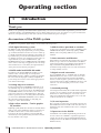 10
10
-
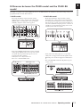 11
11
-
 12
12
-
 13
13
-
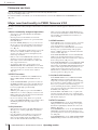 14
14
-
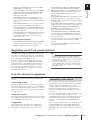 15
15
-
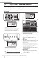 16
16
-
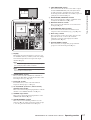 17
17
-
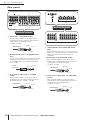 18
18
-
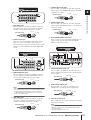 19
19
-
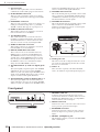 20
20
-
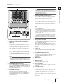 21
21
-
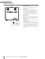 22
22
-
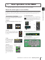 23
23
-
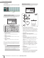 24
24
-
 25
25
-
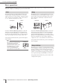 26
26
-
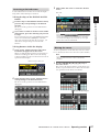 27
27
-
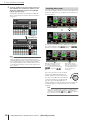 28
28
-
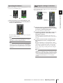 29
29
-
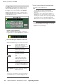 30
30
-
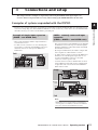 31
31
-
 32
32
-
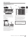 33
33
-
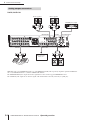 34
34
-
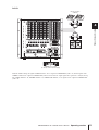 35
35
-
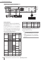 36
36
-
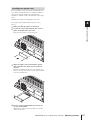 37
37
-
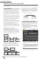 38
38
-
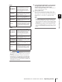 39
39
-
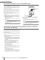 40
40
-
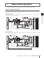 41
41
-
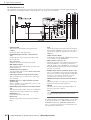 42
42
-
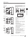 43
43
-
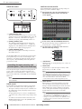 44
44
-
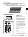 45
45
-
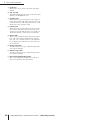 46
46
-
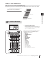 47
47
-
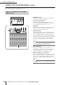 48
48
-
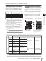 49
49
-
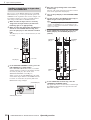 50
50
-
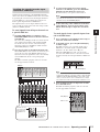 51
51
-
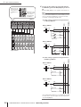 52
52
-
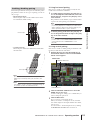 53
53
-
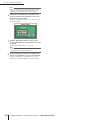 54
54
-
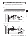 55
55
-
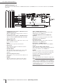 56
56
-
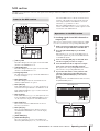 57
57
-
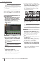 58
58
-
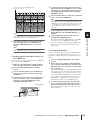 59
59
-
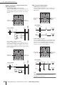 60
60
-
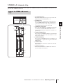 61
61
-
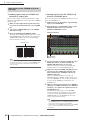 62
62
-
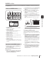 63
63
-
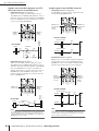 64
64
-
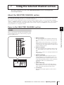 65
65
-
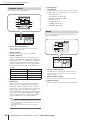 66
66
-
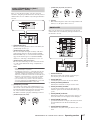 67
67
-
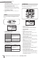 68
68
-
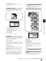 69
69
-
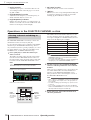 70
70
-
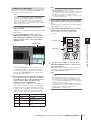 71
71
-
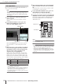 72
72
-
 73
73
-
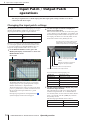 74
74
-
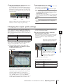 75
75
-
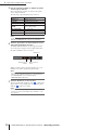 76
76
-
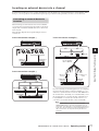 77
77
-
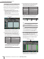 78
78
-
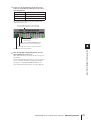 79
79
-
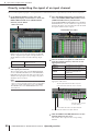 80
80
-
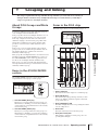 81
81
-
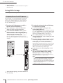 82
82
-
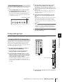 83
83
-
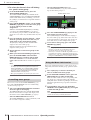 84
84
-
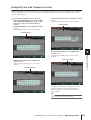 85
85
-
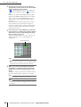 86
86
-
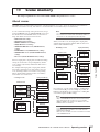 87
87
-
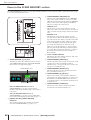 88
88
-
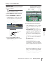 89
89
-
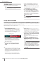 90
90
-
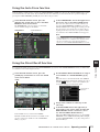 91
91
-
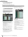 92
92
-
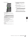 93
93
-
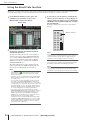 94
94
-
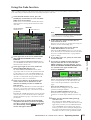 95
95
-
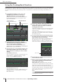 96
96
-
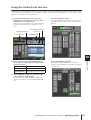 97
97
-
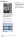 98
98
-
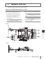 99
99
-
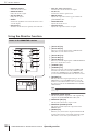 100
100
-
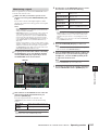 101
101
-
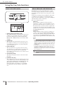 102
102
-
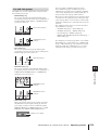 103
103
-
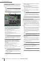 104
104
-
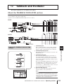 105
105
-
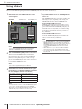 106
106
-
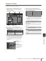 107
107
-
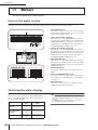 108
108
-
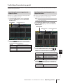 109
109
-
 110
110
-
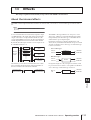 111
111
-
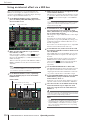 112
112
-
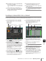 113
113
-
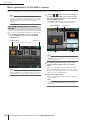 114
114
-
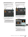 115
115
-
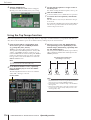 116
116
-
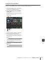 117
117
-
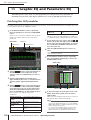 118
118
-
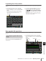 119
119
-
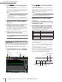 120
120
-
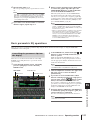 121
121
-
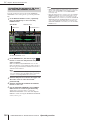 122
122
-
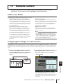 123
123
-
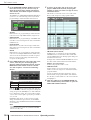 124
124
-
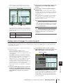 125
125
-
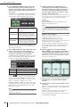 126
126
-
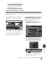 127
127
-
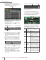 128
128
-
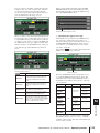 129
129
-
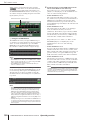 130
130
-
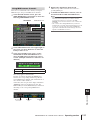 131
131
-
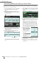 132
132
-
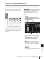 133
133
-
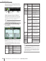 134
134
-
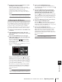 135
135
-
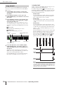 136
136
-
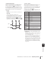 137
137
-
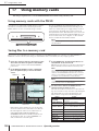 138
138
-
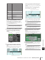 139
139
-
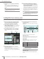 140
140
-
 141
141
-
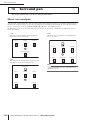 142
142
-
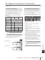 143
143
-
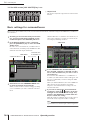 144
144
-
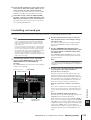 145
145
-
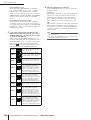 146
146
-
 147
147
-
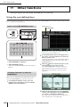 148
148
-
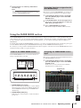 149
149
-
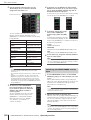 150
150
-
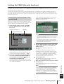 151
151
-
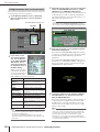 152
152
-
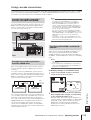 153
153
-
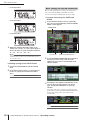 154
154
-
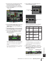 155
155
-
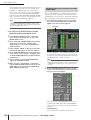 156
156
-
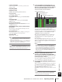 157
157
-
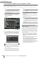 158
158
-
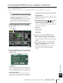 159
159
-
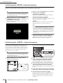 160
160
-
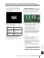 161
161
-
 162
162
-
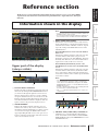 163
163
-
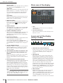 164
164
-
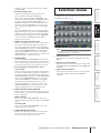 165
165
-
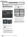 166
166
-
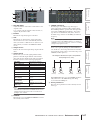 167
167
-
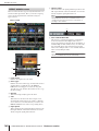 168
168
-
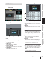 169
169
-
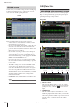 170
170
-
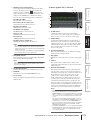 171
171
-
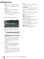 172
172
-
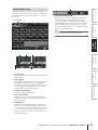 173
173
-
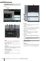 174
174
-
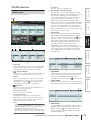 175
175
-
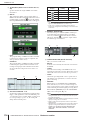 176
176
-
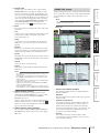 177
177
-
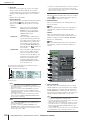 178
178
-
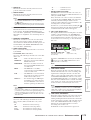 179
179
-
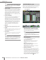 180
180
-
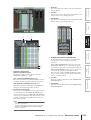 181
181
-
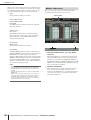 182
182
-
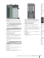 183
183
-
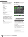 184
184
-
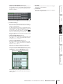 185
185
-
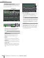 186
186
-
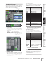 187
187
-
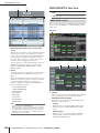 188
188
-
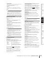 189
189
-
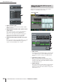 190
190
-
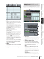 191
191
-
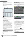 192
192
-
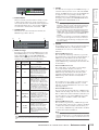 193
193
-
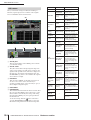 194
194
-
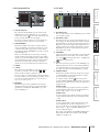 195
195
-
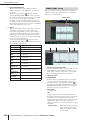 196
196
-
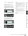 197
197
-
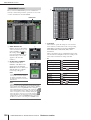 198
198
-
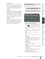 199
199
-
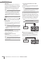 200
200
-
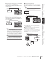 201
201
-
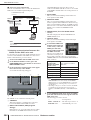 202
202
-
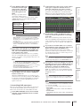 203
203
-
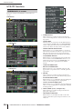 204
204
-
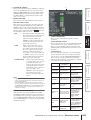 205
205
-
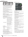 206
206
-
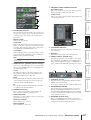 207
207
-
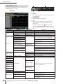 208
208
-
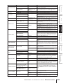 209
209
-
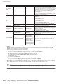 210
210
-
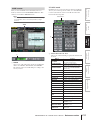 211
211
-
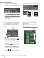 212
212
-
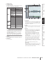 213
213
-
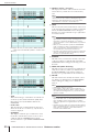 214
214
-
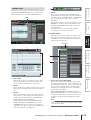 215
215
-
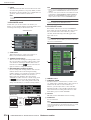 216
216
-
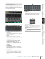 217
217
-
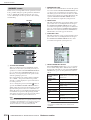 218
218
-
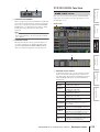 219
219
-
 220
220
-
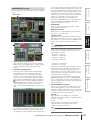 221
221
-
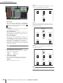 222
222
-
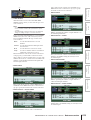 223
223
-
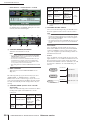 224
224
-
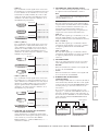 225
225
-
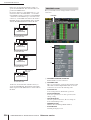 226
226
-
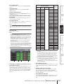 227
227
-
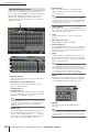 228
228
-
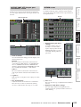 229
229
-
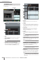 230
230
-
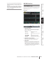 231
231
-
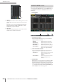 232
232
-
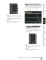 233
233
-
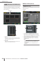 234
234
-
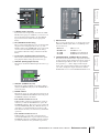 235
235
-
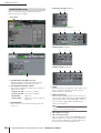 236
236
-
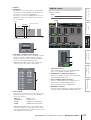 237
237
-
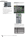 238
238
-
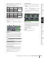 239
239
-
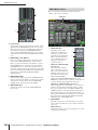 240
240
-
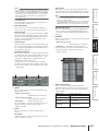 241
241
-
 242
242
-
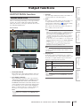 243
243
-
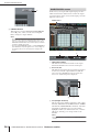 244
244
-
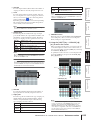 245
245
-
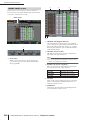 246
246
-
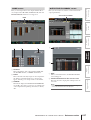 247
247
-
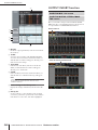 248
248
-
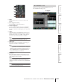 249
249
-
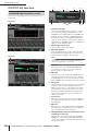 250
250
-
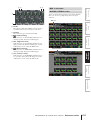 251
251
-
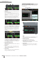 252
252
-
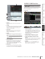 253
253
-
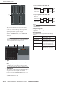 254
254
-
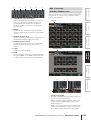 255
255
-
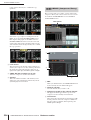 256
256
-
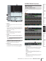 257
257
-
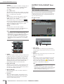 258
258
-
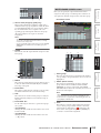 259
259
-
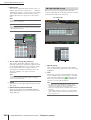 260
260
-
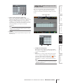 261
261
-
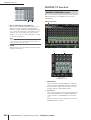 262
262
-
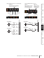 263
263
-
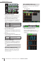 264
264
-
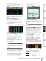 265
265
-
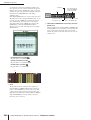 266
266
-
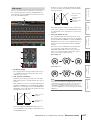 267
267
-
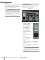 268
268
-
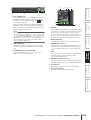 269
269
-
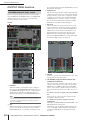 270
270
-
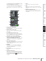 271
271
-
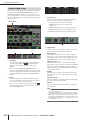 272
272
-
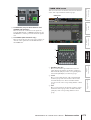 273
273
-
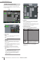 274
274
-
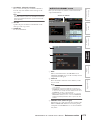 275
275
-
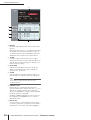 276
276
-
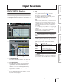 277
277
-
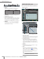 278
278
-
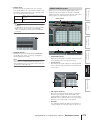 279
279
-
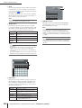 280
280
-
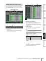 281
281
-
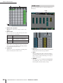 282
282
-
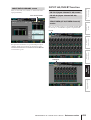 283
283
-
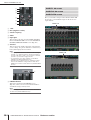 284
284
-
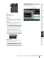 285
285
-
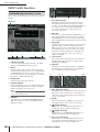 286
286
-
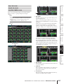 287
287
-
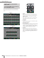 288
288
-
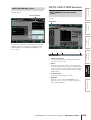 289
289
-
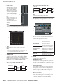 290
290
-
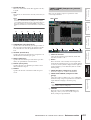 291
291
-
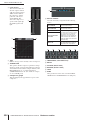 292
292
-
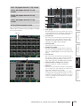 293
293
-
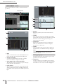 294
294
-
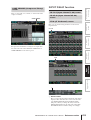 295
295
-
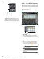 296
296
-
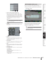 297
297
-
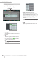 298
298
-
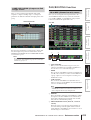 299
299
-
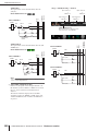 300
300
-
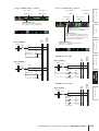 301
301
-
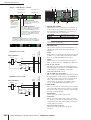 302
302
-
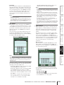 303
303
-
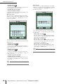 304
304
-
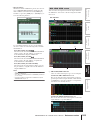 305
305
-
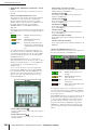 306
306
-
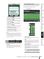 307
307
-
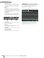 308
308
-
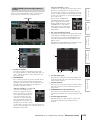 309
309
-
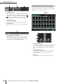 310
310
-
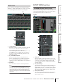 311
311
-
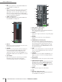 312
312
-
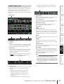 313
313
-
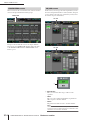 314
314
-
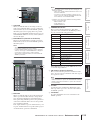 315
315
-
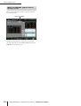 316
316
-
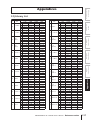 317
317
-
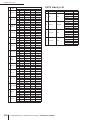 318
318
-
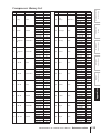 319
319
-
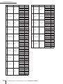 320
320
-
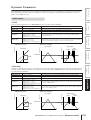 321
321
-
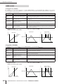 322
322
-
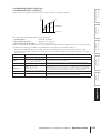 323
323
-
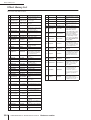 324
324
-
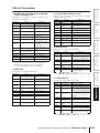 325
325
-
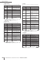 326
326
-
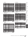 327
327
-
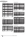 328
328
-
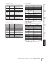 329
329
-
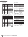 330
330
-
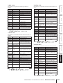 331
331
-
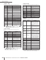 332
332
-
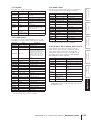 333
333
-
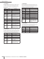 334
334
-
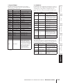 335
335
-
 336
336
-
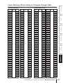 337
337
-
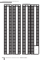 338
338
-
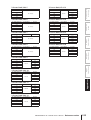 339
339
-
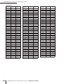 340
340
-
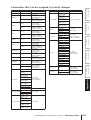 341
341
-
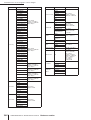 342
342
-
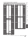 343
343
-
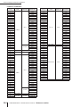 344
344
-
 345
345
-
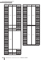 346
346
-
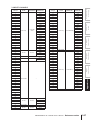 347
347
-
 348
348
-
 349
349
-
 350
350
-
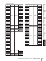 351
351
-
 352
352
-
 353
353
-
 354
354
-
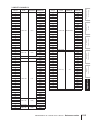 355
355
-
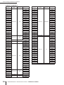 356
356
-
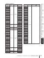 357
357
-
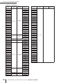 358
358
-
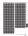 359
359
-
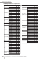 360
360
-
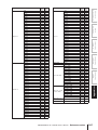 361
361
-
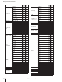 362
362
-
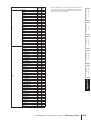 363
363
-
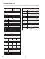 364
364
-
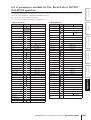 365
365
-
 366
366
-
 367
367
-
 368
368
-
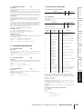 369
369
-
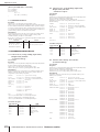 370
370
-
 371
371
-
 372
372
-
 373
373
-
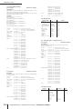 374
374
-
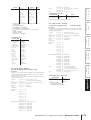 375
375
-
 376
376
-
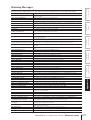 377
377
-
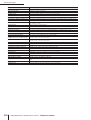 378
378
-
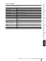 379
379
-
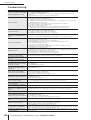 380
380
-
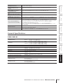 381
381
-
 382
382
-
 383
383
-
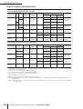 384
384
-
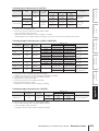 385
385
-
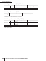 386
386
-
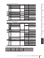 387
387
-
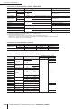 388
388
-
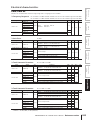 389
389
-
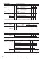 390
390
-
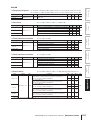 391
391
-
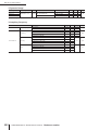 392
392
-
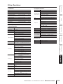 393
393
-
 394
394
-
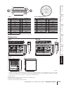 395
395
-
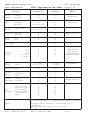 396
396
-
 397
397
-
 398
398
-
 399
399
-
 400
400
-
 401
401
-
 402
402
-
 403
403
-
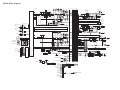 404
404
-
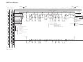 405
405
-
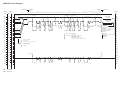 406
406
-
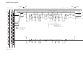 407
407
-
 408
408
-
 409
409


Yamaha DSP5D Handleiding
- Categorie
- Audiomixers
- Type
- Handleiding
- Deze handleiding is ook geschikt voor
in andere talen
- English: Yamaha DSP5D User manual
- italiano: Yamaha DSP5D Manuale utente
- русский: Yamaha DSP5D Руководство пользователя
- français: Yamaha DSP5D Manuel utilisateur
- español: Yamaha DSP5D Manual de usuario
- Deutsch: Yamaha DSP5D Benutzerhandbuch
- português: Yamaha DSP5D Manual do usuário
- dansk: Yamaha DSP5D Brugermanual
- suomi: Yamaha DSP5D Ohjekirja
- čeština: Yamaha DSP5D Uživatelský manuál
- svenska: Yamaha DSP5D Användarmanual
- Türkçe: Yamaha DSP5D Kullanım kılavuzu
- polski: Yamaha DSP5D Instrukcja obsługi
- română: Yamaha DSP5D Manual de utilizare
Gerelateerde papieren
-
Yamaha V2 de handleiding
-
-
-
-
Yamaha V1 Handleiding
-
-
-
-
-