
WHI
WALL HUGGER INVISIFLAME® GAS BURNER
TABLE OF CONTENTS
Subject Page
A. General Information ……………………………………………………….…..….……. 2
B. Receiving and Inspection ………………………………………….…….…...…….….. 2
C. Capacities ………….……………………………………………………………………. 3
D. Dimensions …………….………………………………………………………………... 7
E. Installation ……………………………………………………………………………….. 7
F. Ignition…………………………………………………………………………………….. 10
G. Initial SetUp………………………………………………………………………………. 11
H. Operation…………………………………………………………………………………. 14
I. Maintenance……………………………………………………………………………… 14
J. Recommended Spare Parts……………………………………………………………. 16
Attachments: ZMI Ionization Pilot
IC20 Butterfly Valve Actuator
INSTRUCTIONS
WARNING
These instructions are intended for use only by experienced, qualified
combustion start-up personnel. Adjustment of this equipment and its
components, by unqualified personnel, can result in fire, explosion, severe
personal injury, or even death.
These instructions are intended to serve as
guidelines covering the installation, operation, and maintenance of Hauck equipment. While
every attempt has been made to ensure completeness, unforeseen or unspecified applications, details, and variations may preclude
covering every possible contingency.
WARNING: TO PREVENT THE POSSIBILITY OF SERIOUS BODILY INJURY, DO NOT USE OR
OPERATE ANY EQUIPMENT OR COMPONENT WITH ANY PARTS REMOVED OR ANY PARTS NOT APPROVED BY THE
MANUFACTURER. Should further information be required or desired or should particular pr
oblems arise which are not covered
sufficiently for the purchaser’s purpose, contact Hauck Mfg. Co.
WHI-9
HAUCK MANUFACTURING CO.,
P.O. Box 90 Lebanon, PA 17042-0090 717-272-3051
6/11 www.hauckburner.com Fax: 717-273-9882

Page 2
WHI-9
A. GENERAL INFORMATION
The WHI burner utilizes an air-staged design for ultra low NOx emissions and low CO when firing
with low excess air in furnace environments with temperatures up to 2500°F (1,370°C). The
burner has two modes of operation, ‘firing’ mode required for low temperature startup or operation
below 1600°F (870°C), and Invisiflame® mode for ultra low NOx operation above 1600°F
(870°C). Transitioning between modes is accomplished via a switching valve which is sold
separately. The burner operates with cold or preheated air up to 900°F (480°C).
The WHI burners fire any clean industrial fuel gas. Capacities range from 2 to 6 MM Btu/Hr (580 –
1,760 kW) at 20.9"wc (5200 Pa) static air pressure. The burner is designed for applications
requiring even heat distribution with no flame impingement at all firing rates.
Turndown is approximately 10:1 on natural gas. Consult Hauck for mounting options and field
installation recommendations.
B. RECEIVING & INSPECTION
Upon receipt, check each item on the bill of lading and/or invoice to determine that all equipment
has been received. A careful examination of all parts should be made to ascertain if there has
been any damage in shipment.
WARNING
This equipment is potentially dangerous with the possibility of serious personal injury
and property damage. Hauck Manufacturing Company recommends the use of flame
supervisory equipment and fuel safety shutoff valves. Furthermore, Hauck urges rigid
adherence to National Fire Protection Association (NFPA) standards and insurance
underwriter’s requirements. Operation and regular preventative maintenance of this
equipment should be performed only by properly trained and qualified personnel.
Annual review and upgrading of safety equipment is recommended.
IMPORTANT
If the installation is delayed and the equipment is stored outside,
provide adequate protection as dictated by climate and period of
exposure. Special care should be given to all motors and bearings, if
applicable, to protect them from rain or excessive moisture.
WARNING
The WHI burner MUST be equipped with the Invisiflame control valve and actuator for
operation in furnaces < 1,600°F. Refer to the burner capacity sheets for operating air
pressure required, Stage 1 & 2 Static Air Pressure, when using the Invisiflame control
valve. If equipped without the Invisiflame control valve, the burner can only be fired >
1,600°F furnace temperature.

Page 3
WHI-9
C. CAPACITIES
BURNER MODEL
140 240
BURNER SPECIFICATIONS – HIGH FIRE BURNER STATIC INLET AIR PRESSURE OF 20.9"WC
Combustion Air Temp. (°F) 60 900
Operating Mode
Firing Invisi-
Flame
Firing Invisi-
Flame
Max. Input @ 5% Excess Air (MMBtu/hr) 2.4
2.0
1.5
1.2
Max. Air Flow @ 20.9"wc (scfh) 24,000
19,500
14,840
11,760
Min. Input @ Max. Air Flow (Btu/hr) 191,000
N/A
Max. Excess Air (%) 1,230
N/A
Air Press. @ Burner Inlet ("wc) 22.5
22.5
22.5
22.5
Burner Gas Inlet Press. ("wc) 7.9
7.0
4.2
2.5
Flame Length @ Max. Input (ft) 0.75
N/A
.5
N/A
Flame Dia. @ Max. Input (ft) 3.5
N/A
2.75
N/A
Stage 1 & 2 Air Static Press. ("wc) 1.7
0.2
1.7
0.2
Stage 3 Air Static Press. ("wc) 7.6
7.7
7.6
7.7
BURNER SPECIFICATIONS – LOW FIRE
Input @ 5% Excess Air (Btu/hr)
151,600
151,600
151,600
151,600
Air Flow – Low Fire (scfh) 1,500
1,500
1,500
1,500
Min. Input @ Low Fire Air Flow (Btu/hr)
80,000
N/A
Max. Excess Air (%) 100
N/A
Min. Gas for Ignition (scfh) 80
80
80
80
Min. Gas for UV Signal (scfh) 80
N/A
80
N/A
Notes:
1. “Firing” Operating Mode is required for furnace temperature below 1600°F; Invisiflame® operating
mode is suitable for furnace temperature above 1600°F.
2. Capacities based on natural gas with HHV of 134 Btu/ft3, 0.59 S.G., and stoichiometric air:gas ratio
of 9.74:1 with burner firing into chamber under no pressure @ 5% excess air.
3. Air and gas flows based on 60°F @ sea level.
4. Static air pressure measured at designated locations.
5. Flame lengths measured from the end of the burner tile.
6. Flame length and diameter is not applicable in Invisiflame® operating mode..
7. All data based on industry standard air and gas piping practices.
8. Flame detection via UV scanner in Firing Mode only.
9. Burners can be operated up to a static inlet air pressure of 16 osig; consult Hauck.
Table 1. 140 through 240 Series Capacities

Page 4
WHI-9
C. CAPACITIES (Continued)
BURNER MODEL
140 240
BURNER SPECIFICATIONS – HIGH FIRE BURNER STATIC INLET AIR PRESSURE OF 5,200 Pa
Combustion Air Temp. (°C) 15.5°C 482°C
Operating Mode
Firing Invisi-
Flame
Firing Invisi-
Flame
Max. Input @ 5% Excess Air (kW) 650
545
410
325
Max. Air Flow @ 5,200 Pa (nm3/hr) 640
520
400
315
Min. Input @ Max. Air Flow (kW) 56
N/A
Max. Excess Air (%) 1,230
N/A
Air Press. @ Burner Inlet (Pa) 5,600
5,600
5,600
5,600
Burner Gas Inlet Press. (Pa) 1,965
1,740
1,045
620
Flame Length @ Max. Input (mm) 230
N/A
150
N/A
Flame Dia. @ Max. Input (mm) 1,070
N/A
840
N/A
Stage 1 & 2 Air Static Press. (Pa) 420
50
420
50
Stage 3 Air Static Press. (Pa) 1,890
1,915
1,890
1,915
BURNER SPECIFICATIONS – LOW FIRE
Input @ 5% Excess Air (kW) 60
60
60
60
Air Flow – Low Fire (nm3/hr) 55
55
55
55
Min. Input @ Low Fire Air Flow (kW)
55
N/A
Max. Excess Air (%) 15
N/A
Min. Gas for Ignition (nm3/hr) 4.7
4.7
4.7
4.7
Min. Gas for UV Signal (nm3/hr) 4.7
N/A
4.7
N/A
Notes:
1. “Firing” Operating Mode is required for furnace temperatures below 870°C; Invisiflame® operating
mode is suitable for furnace temperatures above 870°C.
2. Capacities based on natural gas with LHV of 36.74 MJ/nm3, 0.59 S.G., and stoichiometric air:gas ratio
of 9.74:1 with burner firing into chamber under no pressure @ 5% excess air.
3. Air and gas flows based on 0°C @ sea level.
4. Static air pressure measured at designated locations.
5. Flame lengths measured from the end of the burner tile.
6. Flame length and diameter is not applicable in Invisiflame® operating mode.
7. All data based on industry standard air and gas piping practices.
8. Flame detection via UV scanner in Firing Mode only.
9. Burners can be operated up to a static inlet air pressure of 3450 Pa; consult Hauck.
Table 2. 140 through 240 Series Metric Capacities

Page 5
WHI-9
C. CAPACITIES (Continued)
BURNER MODEL
160 260
BURNER SPECIFICATIONS – HIGH FIRE BURNER STATIC INLET AIR PRESSURE OF 20.9"WC
Combustion Air Temp. (°F) 60 900
Operating Mode
Firing Invisi-
Flame
Firing Invisi-
Flame
Max. Input @ 5% Excess Air (MMBtu/hr) 4.9
4.5
3.0
2.8
Max. Air Flow @ 20.9"wc (scfh) 48,430
44,590
29,950
27,570
Min. Input @ Max. Air Flow (Btu/hr) 300,000
N/A
Max. Excess Air (%) 1,600
N/A
Air Press. @ Burner Inlet ("wc) 22.5
22.5
22.5
22.5
Burner Gas Inlet Press. ("wc) 28.6
23.3
13.6
10
Flame Length @ Max. Input (ft) 1
N/A
0.75
N/A
Flame Dia. @ Max. Input (ft) 6
N/A
4.75
N/A
Stage 1 & 2 Air Static Press. ("wc) 2.0
0.1
2.0
0.1
Stage 3 Air Static Press. ("wc) 20.9
20.9
20.9
20.9
BURNER SPECIFICATIONS – LOW FIRE
Input @ 5% Excess Air (Btu/hr)
300,000
300,000
300,000
300,000
Air Flow – Low Fire (scfh) 3,100
3,100
3,100
3,100
Min. Input @ Low Fire Air Flow (Btu/hr)
150,000
N/A
Max. Excess Air (%) 120
N/A
Min. Gas for Ignition (scfh) 145
145
145
145
Min. Gas for UV Signal (scfh) 145
N/A
145
N/A
Notes:
1. “Firing” Operating Mode is required for furnace temperatures below 1600°F; Invisiflame® operating
mode is suitable for furnace temperatures above 1600°F.
2. Capacities based on natural gas with HHV of 1034 Btu/ft3, 0.59 S.G., and stoichiometric air:gas ratio of
9.74:1 with burner firing into chamber under no pressure @ 5% excess air.
3. Air and gas flows based on 60°F @ sea level.
4. Static air pressure measured at designated locations.
5. Flame lengths measured from the end of the burner tile.
6. Flame length and diameter is not applicable in Invisiflame® operating mode.
7. All data based on industry standard air and gas piping practices.
8. Flame detection via UV scanner in Firing Mode only.
9. Burners can be operated up to a static inlet air pressure of 16 osig; consult Hauck.
Table 3. 160 through 260 Series Capacities

Page 6
WHI-9
C. CAPACITIES (Continued)
BURNER MODEL
160 260
BURNER SPECIFICATIONS – HIGH FIRE BURNER STATIC INLET AIR PRESSURE OF 5,200 Pa
Combustion Air Temp. (°C) 15.5°C 482°C
Operating Mode
Firing Invisi-
Flame
Firing Invisi-
Flame
Max. Input @ 5% Excess Air (kW) 1,275
1,170
780
730
Max. Air Flow @ 5,200 Pa (nm3/hr) 1,275
1,170
780
730
Min. Input @ Max. Air Flow (kW) 80
N/A
Max. Excess Air (%) 1,600
N/A
Air Press. @ Burner Inlet (Pa) 5,600
5,600
5,600
5,600
Burner Gas Inlet Press. (Pa) 7,115
5,800
3,380
2,490
Flame Length @ Max. Input (mm) 305
N/A
230
N/A
Flame Dia. @ Max. Input (mm) 1,830
N/A
1,450
N/A
Stage 1 & 2 Air Static Press. (Pa) 500
25
500
25
Stage 3 Air Static Press. (Pa) 5,200
5,200
5,200
5,200
BURNER SPECIFICATIONS – LOW FIRE
Input @ 5% Excess Air (kW) 80
80
80
80
Air Flow – Low Fire (nm3/hr) 80
80
80
80
Min. Input @ Low Fire Air Flow (kW)
40
N/A
Max. Excess Air (%) 120
N/A
Min. Gas for Ignition (nm3/hr) 4
4
4
4
Min. Gas for UV Signal (nm3/hr) 4
N/A
4
N/A
Notes:
1. “Firing” Operating Mode is required for furnace temperatures below 870°C; Invisiflame® operating
mode is suitable for furnace temperatures above 870°C.
2. Capacities based on natural gas with LHV of 36.74 MJ/nm3, 0.59 S.G., and stoichiometric air:gas ratio
of 9.74:1 with burner firing into chamber under no pressure @ 5% excess air.
3. Air and gas flows based on 0°C @ sea level.
4. Static air pressure measured at designated locations.
5. Flame lengths measured from the end of the burner tile.
6. Flame length and diameter is not applicable in Invisiflame® operating mode.
7. All data based on industry standard air and gas piping practices.
8. Flame detection via UV scanner in Firing Mode only.
9. Burners can be operated up to a static inlet air pressure of 3450 Pa; consult Hauck.
Table 4. 160 through 260 Series Metric Capacities

Page 7
WHI-9
D. DIMENSIONS
See appropriate Dimension sheet for detailed dimensional information.
E. INSTALLATION
Burner Mounting
1. Since WHI burners can fire in any position, they can be installed through the roof, walls, or
bottom of the furnace. Irregardless of position, the outlet end of the tile must be flush
with the inner wall surface. The inside furnace wall surface should be flat in the vicinity of
the WHI tile outlet to permit free expansion of the hot combustible gases.
2. The furnace shell plate must be provided with studs to match the tile mounting plate as shown
in Section D. Hauck WHI burners must be mounted on properly braced, rigid furnace
structures capable of supporting the burner and tile weight (see Table 5).
Table 5. WHI Burner and Tile Weights
3. Furnish an opening in the furnace shell 1/2" (13 mm) larger than the burner tile outside
dimension.
4. For installation in an existing refractory wall, refer to Figure 1. From inside the furnace,
remove rammed, cast or brick refractory as required to furnish an opening 1/2" (13 mm) larger
than the tile dimensions.
Figure 1. Burner Installation – Hard Wall
Burner Model Approx. Burner
Net Wt. (lbs.) Approx. Tile
Net Wt. (lbs.)
WHI-140/240 200 310
WHI-160/260 200 440
Y8111
(NOT TO SCALE)

Page 8
WHI-9
5. Wrap the outside of the tile with one or more layers of ceramic fiber rated for a higher
temperature than the furnace. Secure ceramic fiber with tape to retain the fiber during
installation of the tile.
6. Mount the self-supporting burner tile/burner assembly to the furnace shell plate using 5/8" (16
mm) studs positioned as shown on in Section D. Place the tile mounting flange gasket over
the studs followed by the burner tile assembly. Secure with lock washers and hex nuts.
Air & Fuel Connections
1. The burner air inlet connection can be located in any orientation, this is most easily achieved
by simply installing the entire tile/burner assembly in the desired position without dis-
assembling the burner from the tile.
2. Connect the air line to the burner inlet flange, install a matching gasket to minimize air
leakage. For the WHI__40 a gasket and flange are provided.
3. Provide power to the motorized Invisiflame valve actuator (see attached IC20 butterfly valve
actuator sheet) and verify the valve position is in the ‘open’ position as shown in Figure 2 for
low temperature furnace operation (< 1,600°F) of the burner, i.e. ‘firing’ mode. With the valve
open, air is allowed to flow to stages 1 and 2 of the burner, refer to the burner capacity tables
for the correct stage 1 and 2 air pressure in relation to stage 3 air pressure, check pressures
with a suitable manometer, and adjust the opening of the Invisiflame valve as required to
achieve the necessary pressure. Provide air to the burner and verify the flow prior to
attempting to light burners.
CAUTION
Be careful not to damage the Invisiflame control valve and actuator during
burner mounting. Do not attempt to lift the burner by the Invisiflame control
valve or associated piping.
CAUTION
The burner mounted Invisiflame control valve and motorized actuator
must be installed/wired in the correct orientation to insure proper/safe
burner startup for low temperature operation. The Invisiflame valve can
NOT be closed (0°) for low temperature (< 1,600°F) operation.

Page 9
WHI-9
Figure 2. Invisiflame Valve Actuator Shown in ‘Open’ or Low
Temperature (< 1,600°F) Furnace Startup Position
4. If using preheated air, insulate the outside of all air pipes leading to the burner main air inlet
and insulate the outside of the main air inlet pipe up to the main burner body. Though not
required, to minimize contact surface temperature, the outside of the Invisiflame control valve
piping may also be insulated.
5. If necessary, the gas inlet Tee can be rotated to the desired orientation as follows:
a. Use a pipe wrench to hold the gas tube in between the gas inlet tee and the gas tube
packing gland which screws into the burner backplate. Note the gas tube itself can
NOT be rotated and must be held firmly in place to prevent possible damage to
internal parts.
b. Using a second pipe wrench on the tee itself, rotate the tee to the desired inlet
orientation, re-seal with pipe dope if required.
IMPORTANT
All piping must be properly supported and aligned to
avoid stresses on the burner and associated
equipment. Hauck recommends that unions and
flexible connections be used on all air and fuel lines.
The unions will allow the burner to be more easily
serviced when required, and the flexible connections
will help isolate the burner from piping movement due
to expansion, contraction and vibration.
X8148
(NOT TO SCALE)

Page 10
WHI-9
6. Install and connect the gas line.
7. Install the spark igniter if applicable, down the center of the gas tee via the bushing provided.
Pipe ambient cooling air to the 1/2 NPT (DN 15) connection for continuous spark igniter
cooling flow. The cooling air connection should be supplied with minimum 20.9 "wc (5200 Pa)
of dry ambient purge air. If not using an ignition source, cooling air must be provided, at a
rate of approximately 1 cfm (0.027 nm3/m).
8. If applicable, install the pilot down the center of the gas tee via the bushing provided. Consult
the appropriate dimensional sheet and instructions that accompany the pilot for additional
information (ZMI-9).
9. If a UV scanner is used, install it in the correct accessory port located on the burner
backplate. Provide a minimum 20.9 "wc (5200 Pa) ambient dry air source for the UV scanner
air purge by connecting a cold air supply line to the 1/4 NPT (DN 6) bushing on the scanner
adapter using minimum 1/4" (6.3 mm) OD tubing or pipe and a suitable isolating valve.
10. Complete the mounting of pilot components and connection of air, gas, and air purge lines.
11. Inspect all bolted joints on the burner. Be sure all fasteners are tight.
F. IGNITION
WHI burners can be equipped with an air cooled spark igniter, IPE 50, or a Kromschroder ZMI
pilot. A 5000/6000 volt standard coil type ignition transformer can be utilized.
CAUTION
In order to ensure an adequate seal, it is important that the burner backplate
bolts be sufficiently tight. Before any attempt is made to start the burner,
check to ensure that the bolts are sufficiently tight and conduct a gas leak
test. Failure to check and ensure that a satisfactory seal exists by
conducting a leak test could result in the formation of a hazardous gas
leakage condition. Whenever burner internals are removed for cleaning or
replacement, be sure to tighten the backplate bolts and conduct a gas leak
test.
WARNING
Adjustment of this equipment, and its components, by unqualified
personnel, can result in fire, explosion, severe personal injury, or
even death.
NOTE
Manual ignition or torch lighting is not
recommended.

Page 11
WHI-9
For air cooled spark igniter set-up, perform the following:
1. Disconnect cooling air from spark igniter and remove spark igniter from burner.
2. Connect ignition wire to spark igniter electrode connection.
3. Energize the ignition transformer and verify that an adequate spark is produced between
the electrode tip and the outer tube.
4. De-energize ignition transformer.
5. If the spark is adequate, re-install spark igniter into burner. If the spark is weak or absent,
check integrity of spark wire insulators and possibility of short circuit behind electrode tip.
6. If spark is still absent, consult Hauck.
For gas pilot ignition see attached instructions.
G. INITIAL SETUP
WHI burners typically operate with automatic control systems. The burners are capable of
proportional control over their entire capacity range. In a typical system, ignition will be preceded
by a series of steps.
WARNING
When using a standard coil ignition transformer, provisions must
be made to eliminate the ignition spark falsely satisfying the
“flame on” UV scanner. Hauck designed flame supervisory panels
accomplish this by “timing out” the spark transformer after a short
(10 seconds for most applications) trial for ignition.
CAUTION
Initial adjustment and burner start-up should be
undertaken only by trained and experienced
personnel familiar with combustion systems,
control and safety circuitry and overall installation
procedures.
CAUTION
Ensure that all safety equipment and limits are
working properly before proceeding.
CAUTION
The ignition transformer can cause an electric shock. Use care
around the ignition cable. The igniter should be electrically
grounded and should NOT be handled while the transformer is
energized.

Page 12
WHI-9
1. Once installed, the burner is ready for initial set-up. The specific operation of the burner will
depend on the individual system components in the entire combustion system. Refer to the
instruction sheets that accompany the individual components.
2. Combustion air pressure should be set at the combustion air control valve. Typical
combustion air pressure range from a minimum of approximately 0.1"wc (25 Pa) to a
maximum of 22.5"wc (5600 Pa) static pressure at the inlet to the burner. Hauck recommends
that the combustion air setting remain at minimum until the burner has been ignited (refer to
the appropriate capacity sheet for burner air flow at low fire conditions).
3. Gas pressure should be set at the gas control valve (typically limiting gas valve for ambient
combustion air, or automatic butterfly valve for preheated combustion air). Actual gas
pressure required may vary (refer to the appropriate capacity sheet for burner gas flow at low
fire conditions).
4. If not previously completed, refer to Section F for air-cooled spark igniter.
5. Once the igniter is set and the initial gas and air adjustments are made, the burner can be
ignited as follows:
a. BE SURE THAT ALL FUEL SHUTOFF VALVES ARE CLOSED AND ALL CONTROL
VALVES ARE IN THE LOW FIRE POSITION.
b. Position the burner switching valve to the ‘open’ or ‘firing’ operating position,
see Section E Installation.
c. Start the combustion air blower.
CAUTION
Failure to achieve ignition of pilot or main flame within a
safe period (10 seconds) could result in a build-up of a
combustible gas mixture which could lead to an explosion.
In the event that the pilot or main flame does not light within
the above time period, shut off fuel valves and re-purge the
chamber before attempting further adjustment.
CAUTION
All cast refractory burner components are porous and therefore
subject to moisture absorption. Refractory components should not be
stored or exposed to damp conditions potentially reducing their normal
expected life. Care must be taken at initial startups and after extended
idle times to assure refractory components have been sufficiently dried
prior to normal firing conditions. It is highly recommended that low fire
drying for at least 6-8 hours at 50 to 100% excess air occur at initial
startups prior to exposing refractory components to normal firing
operation. Thereafter, if the refractory components are exposed to
excessive moisture, condensation, or high humidity for extended
periods, allow at least 30 minutes of low fire drying before beginning
normal operation. Failure to do so may cause any moisture present to
expand rapidly resulting in refractory spalling and/or premature failure.

Page 13
WHI-9
AIR-COOLED SPARK IGNITION
d. Energize the ignition transformer.
e. Open (energize) the main automatic gas safety shutoff valves.
f. Once flame has been established de-energize the ignition transformer, proceed to
step n.
GAS PILOT IGNITION
g. Ensure that the pilot automatic safety solenoid valves and the pilot manual gas valve
are closed.
h. Turn the pilot manual air valve to the full open position.
i. Energize the ignition transformer.
j. Open the pilot gas automatic safety shutoff solenoid valves and the pilot manual gas
valve.
k. Once the pilot flame has been established (confirm using observation port or UV flame
supervision), de-energize the ignition transformer.
l. Open (energize) the main automatic gas safety shutoff valves.
m. Once flame has been established, de-energize the ignition transformer, close the pilot
manual valve, and leave the manual pilot air valve open.
n. Proceed to ignite all burners (if applicable) per the above procedure.
6. When all burners are ignited, increase the combustion air to the high fire position (refer to
appropriate capacity sheet for burner air flow at high fire conditions).
7. Verify that the air pressure at the burner inlet, stage 1 and 2 static air pressure, and stage 3
static air pressures are as indicated in the capacity tables (Tables 1-4). If necessary, adjust
the position of the Invisiflame Valve Actuator (Figure 2) to achieve the needed static air
pressures at stage 1, 2 and stage 3. For detailed instructions, see attachment on the IC20
Butterfly Valve Actuator.
8. When high fire combustion air is set, adjust the gas control valve (limiting gas valve or
automatic butterfly valve) to achieve the desired gas flow at high fire (refer to appropriate
capacity sheet for burner gas flow at high fire conditions).
9. Verify air/fuel ratio using orifice meters in the air and gas lines. Static air pressure at the
burner air inlet can be related to air flows if an air orifice meter is not available.
10. Drive the burner to the low fire position and verify that the settings are consistent. Repeat
steps 6 through 9 as necessary until high and low fire settings remain constant.
11. Lock all control motor linkage or direct-couplings in place and return all control system
functions to normal, if changed during initial adjustments.
12. To shut down the burner system:
a. Return the burner to the low fire position.
b. Close all fuel shutoff valves.
c. Allow the furnace to cool to 800°F or less before shutting off the combustion air
blower.

Page 14
WHI-9
H. OPERATION
Once properly installed, ignited and fired, the burner is ready for operation. The operation of the
burner will depend on the specific items in the combustion control system and the application of
the burners. Refer to the instruction sheet that accompanies each item. The burner should always
be ignited under low fire conditions. When the burner is firing, the spark igniter should be shut off.
I. MAINTENANCE
Hauck WHI burners have been engineered to provide dependable performance while requiring
low maintenance. As with any product, it is very important to follow operating instructions and all
procedures carefully to obtain optimum performance. Please refer to the applicable WHI Parts
List to become familiar with the various burner components and assemblies.
1. Burner components which should be checked periodically and cleaned, if necessary, include:
Gas Body Assembly (All Models).
a. Disconnect the gas line.
b. Remove the IPE spark igniter or pilot from the center of burner (if applicable).
c. Remove the gas nozzle by screwing it counterclockwise from inside the furnace.
d. Remove the inner most set of eight hex nuts from the air body backplate.
e. Remove the outer most set of hex bolts holding the backplate to the main burner body
flange; pull away the backplate and gas tube assembly as one unit being careful not to
damage burner internal insulation.
f. Inspect internal parts. Clean the interior walls of gas body assembly and gas tube
assembly of any residue. Check the 4 radial holes located in the end of the gas tube
and clean if necessary.
g. If necessary, loosen the gas tube packing nut at the backplate and remove the gas
inlet tee to pull the gas tube out of the backplate assembly.
h. Inspect the four air holes located in the short pipe nipples attached to the plate on the
front of the gas tube, and clean of any residue or debri if necessary.
i. Check condition of internal refractory baffle and stage 1 and 2 air openings, semi
circles in refractory baffle, and clean if necessary.
IMPORTANT
If the refractory in the burner is exposed to excessive
moisture or extended periods of dampness, allow at least
30 minutes of low fire drying before beginning normal
operation. Failure to do so can cause moisture present
to expand rapidly, causing damage to the refractory.
CAUTION
Be sure burner internals have cooled sufficiently before
attempting to disassemble any components. Use care
when separating gasket surfaces to avoid damage to the
gaskets.

Page 15
WHI-9
j. Install a new burner backplate gasket if necessary, and reinsert gas tube and burner
backplate assembly. Ensure that the four stage 1 air holes located on the flat
plate attached to the end of the gas tube line up with the stage 1 air openings
(four innermost holes refractory baffle). The packing gland located on the rear of
the gas tube should be loosened slightly to ensure the gas tube assembly flat plate
located near the downstream end of the tube is firmly pressed into the back of the
burner refractory baffle, and also to rotate the gas tube slightly to correctly align the
stage 1 air holes (air holes in the gas tube plate match up to the air holes in the
refractory baffle). Retighten packing nut after correct alignment is attained and after
the burner backplate has already been securely tightened.
k. Reconnect the gas line.
Bypass Valve Seat (If applicable – WHI 260 Only).
a. Disconnect the bypass air valve from the bypass air line by removing the 4 bolts at the
bypass valve flanged connection.
b. Inspect the valve and valve seat, clean of any debris. Ensure that the valve disc
makes contact with the seat located in the valve body when in the ‘closed’ or
Invisiflame mode.
c. Install new fiberfrax gaskets between the valve body and flanges.
d. Tighten the 4 bolts with the valve centered in the bypass air line.
2. Replacement of Internal refractory Baffle
In certain situations, it may become necessary or desired to replace the internal baffle of the
burner. The baffle on the WHI burner is made of high temperature refractory. In order to
replace the internal baffle, use the following procedure:
a. Repeat step 1. a through e. above.
b. Pull the internal refractory baffle out through the burner internal air sleeve. To loosen
the baffle it may be necessary to push the baffle from inside the furnace.
c. Apply a thin layer (1/16 to 1/8”) of high temperature cement (Hauck recommends
Fiberfrax QF-150 or equivalent) to the baffle at each of the 3 rectangular shaped slots
and around the outside diameter of the baffle at the point of the angle change. Do not
put cement in or near the stage 2 air holes (semicircular shaped holes) of the baffle.
The cement will ensure a tight seal between the baffle and the cast alloy air sleeve
located in the front of the burner.
d. Slide the new baffle through the air tube being sure to align the 3 rectangular shaped
slots on the front side of the baffle with the 3 receiving tabs located on the burner
mounting flange. Be sure the baffle is properly aligned via the tabs and fully seats into
the locating tabs to insure a proper seal is made. Wipe any excess bonding cement
out of the stage 2 air holes if necessary.
e. Reinsert the burner gas tube assembly and burner backplate per step 1. j. above.
f. Reinstall all gas piping and check for gas leaks before restarting burner.
CAUTION
Failure to check and ensure that a satisfactory seal exists by
conducting a gas leak test could result in a hazardous condition.

Page 16
WHI-9
3. Replacement of Self-Supporting Refractory Tile
Refractory tiles should be checked for damage. Should it ever become necessary to replace
the burner refractory tile, use the following procedure:
a. Disconnect the main air and gas connections from the burner.
b. Remove flame scanning equipment and pilot or spark igniter from accessory ports to
prevent damage.
c. Support the burner weight before loosening burner mounting nuts.
d. Locate the burner to tile mounting nuts, the innermost nuts on the round tile or the 8
nuts located on a common bolt circle on the square tile version. Carefully support the
burner weight and remove the nuts and entire burner assembly.
e. Unbolt the tile mounting flange and remove the burner tile.
f. Remove the existing burner tile from the furnace wall and clean the tile port opening.
g. Inspect the refractory in the area surrounding the tile and repair any damage.
h. Replace the burner tile mounting gasket, if necessary.
i. Mount the new burner refractory tile per Section E ‘burner mounting’ steps 1 through 6
of these instructions.
j. Install a new burner mounting gasket and re-attach the burner assembly to the tile.
k. Reinstall air and gas lines and leak check per section E ‘air and fuel connections’
steps 2 through 11 of these Instructions.
J. RECOMMENDED SPARE PARTS LIST
Item Qty. Part Number Description
1 1 See Parts List Spark Igniter Assembly (If Applicable)
2 1 See Parts List UV Scanner
3 1 74105712 Actuator, Burner Switching Valve
Table 6. Recommended Spare Parts

- 1 -
D
GB
F
NL
I
E
D
GB
F
NL
I
E
D
GB
F
NL
I
E
D
GB
F
NL
I
E
D
GB
F
NL
I
E
D
GB
F
NL
I
E
Ionisationszündbrenner
ZAI, ZMI, ZKIH
Betriebsanleitung
Bitte lesen und aufbewahren
Zeichenerklärung
, , , ... = Tätigkeit
= Hinweis
Alle in dieser Betriebsanleitung
aufgeführten Tätigkeiten dürfen
nur von autorisiertem Fach per-
sonal ausgeführt werden!
WARNING! Incorrect installation,
adjustment, modification, operation
or maintenance may cause injury or
material damage.
Read the instructions before use.
This unit must be installed in accord-
ance with the regulations in force.
Toutes les actions mentionnées
dans les présentes instructions
de service doivent être exécutées
par des spécialistes formés et au-
torisés uniquement !
ATTENTION ! Un montage, un ré-
glage, une modi fication, une utilisa-
tion ou un entretien in adaptés ris-
quent d’engendrer des dom mages
matériels ou corporels.
Lire les instructions avant utilisation.
Cet appareil doit être installé en res-
pectant les règlements en vigueur.
Alle in deze bedrijfshandleiding
vermelde werkzaamheden mo-
gen alleen door technici worden
uitgevoerd!
WAARSCHUWING! Ondeskundi-
ge inbouw, instelling, wijziging,
bediening of onder houds werk zaam-
heden kunnen per soonlijk letsel of
materiële schade veroor zaken.
Aanwijzingen voor het gebruik lezen.
Dit apparaat moet overeenkom-
stig de geldende regels worden
geïnstalleerd.
Tutte le operazioni indicate nelle
presenti istruzioni d’uso devono
essere eseguite soltanto dal pre-
posto esperto autorizzato.
ATTENZIONE! Se montaggio,
re go lazione, modifica, utilizzo o
manu tenzione non vengono ese guiti
correttamente, possono veri ficarsi
infortuni o danni.
Si prega di leggere le istruzioni prima
di utilizzare il prodotto che dovrà ve-
nire installato in base alle normative
vigenti.
¡Todas las actividades indicadas
en estas Instrucciones de utiliza-
ción, sólo deben realizarse por
una persona formada y autorizada!
¡ADVERTENCIA! La instalación,
ajuste, modificación, manejo o man-
tenimiento incorrecto puede ocasio-
nar daños personales o mate riales.
Leer las instrucciones antes de usar.
Este dispositivo debe ser instalado
observando las normativas en vigor.
03250560 01.06 Fx/ivd
7.1.1.2 Edition 11.10
Elster GmbH
Postfach 28 09
D-49018 Osnabrück
Ionisatie-aansteek-
branders
ZAI, ZMI, ZKIH
Bedieningsvoorschrift
Lezen en goed bewaren a.u.b.
Legenda
, , , ... = werkzaamheden
= aanwijzing
Brûleurs d’allumage à
ionisation
ZAI, ZMI, ZKIH
Instructions de service
À lire attentivement et à
conserver
Légendes
, , , ... = action
= remarque
Ionization pilot
burners
ZAI, ZMI, ZKIH
Operating instructions
Please read and keep in a safe
place
Explanation of symbols
, , , ... = Action
= Instruction
All the work set out in these
operating instructions may only
be completed by authorized
trained personnel!
Bruciatori pilota
a ionizzazione
ZAI, ZMI, ZKIH
Istruzioni d’uso
Si prega di leggere e conser-
vare
Spiegazione dei simboli
, , , ... = Operazione
= Avvertenza
Quemadores de encen-
dido controlados por
io nización ZAI, ZMI,
ZKIH
Instrucciones de
utilización
Se ruega que las lean y conser-
ven
Explicación de símbolos
, , , ... = Actividad
= Indicación
WARNUNG! Unsachgemäßer
Ein bau, Einstellung, Verän de rung,
Be die nung oder War tung kann
Ver letzungen oder Sachschäden
verursachen.
Anleitung vor dem Gebrauch lesen.
Dieses Gerät muss nach den gelten-
den Vorschriften installiert werden.
Inhaltsverzeichnis
Prüfen 2
Vorbereiten 3
Einbauen 4
Verdrahten 6
Dichtheit prüfen 7
In Betrieb nehmen 8
Wartung 9
Zubehör 10
Contents
Testing 2
Preparation 3
Installation 4
Wiring 6
Tightness test 7
Commissioning 8
Maintenance 9
Accessories 10
Sommaire
Vérifier 2
Préparation 3
Montage 4
Câblage 6
Vérifier l’étanchéité 7
Mise en service 8
Maintenance 9
Accessoires 10
Inhoudsopgave
Controleren 2
Voorbereiden 3
Inbouwen 4
Bedraden 6
Controle op lekkage 7
In bedrijf stellen 8
Onderhoud 9
Toebehoren 10
Indice
Verifica 2
Predisposizione 3
Montaggio 4
Cablaggio 6
Controllo della tenuta 7
Messa in servizio 8
Manutenzione 9
Accessori 10
Índice
Comprobar 2
Preparar 3
Montaje 4
Cableado 6
Comprobar la estanquidad 7
Puesta en funcionamiento 8
Mantenimiento 9
Accesorios 10

- 2 -
Prüfen
ZAI, ZMI, ZKIH
Ionisch überwachte Zündbrenner zum
sicheren Zünden von Gasbrennern in
Verbindung mit den Gasfeuerungs-
automaten BCU, IFS, IFD, PFD oder
PFS. Die Leistung des Zündbrenners
soll 2 bis 5 % des Hauptbrenners be-
tragen.
Auch als eigenständig betriebene
Brenner einsetzbar.
Für Erdgas, Stadtgas und Flüssiggas.
Andere Gase auf Anfrage.
ZAI
ZAI Atmosphärischer Ionisa-
tionszündbrenner mit zwei
Elektroden
D-Osnabrück
Germany
84228010
ZAI R 3.03
R Rp-Innengewinde
TN NPT-Innengewinde
Leistung ca. 1,8 – 3 kW.
Lieferumfang
A Brenner mit Düse 1,3 mm
(0,051") für Erdgas
B Düse 0,7 mm (0,028") für Flüs-
siggas
C Kegelring
D Überwurfmutter
BD
C
A
ZMI
ZMI Ionisationszündbrenner mit
einer Elektrode D-49018 Osnabrück Germany
84230010
ZMI 16 B150R
Pmax. 1,5 kW
Gas N
.0535
16 – 25 Brennergröße
T T-Produkt
B
Gfür Erdgas
für Flüssiggas
150 – 600
Flammrohrlänge
R Rp-Innengewinde
N NPT-Innengewinde
Leistung:
ZMI 16: ca. 0,8 – 1,5 kW
ZMI 25: ca. 0,9 – 3,4 kW
Nennleistung P
max
, Gasart – siehe
Typenschild.
ZKIH
ZKIH Ionisationszündbrenner mit
zwangsweiser Luftzufuhr D-49018 Osnabrück Germany
84214010
ZKIH 150/100R
Pmax. 7 kW
Gas N, F, S
.0535
150 – 600
Brennerrohrlänge
/100 Flammrohrlänge
R Rp-Innengewinde
Nennleistung P
max
, Gasart – siehe
Typenschild.
Testing
ZAI, ZMI, ZKIH
Ionization-controlled pilot burners for
the safe ignition of gas burners in con-
junction with automatic burner control
units BCU, IFS, IFD, PFD or PFS. The
capacity of the pilot burner should be
2 to 5% of that of the main burner.
Can also be used as independently
operated burners.
For natural gas, town gas and LPG.
Other types of gas on request.
ZAI
ZAI
Thermo ionization pilot
burner with two electrodes
R Rp internal thread
TN NPT internal thread
Capacity approx. 1.8 – 3 kW.
Scope of delivery
A Burner with 1.3 mm (0.051")
nozzle for natural gas
B 0.7 mm (0.028") nozzle for LPG
C Cone olive
D Union nut
ZMI
ZMI
Ionization pilot burner with
one electrode
16 – 25 Burner size
T T-product
B
GFor natural gas
For LPG
150 – 600
Flame tube length
R Rp internal thread
N NPT internal thread
Capacity:
ZMI 16: approx. 0.8 – 1.5 kW.
ZMI 25: approx. 0.9 – 3.4 kW.
Rated capacity Pmax, gas type –
see type label.
ZKIH
ZKIH Ionization pilot burner with
forced air supply
150 – 600
Burner tube length
/100 Flame tube length
R Rp internal thread
Rated capacity Pmax, gas type –
see type label.
Vérifier
ZAI, ZMI, ZKIH
Brûleurs d’allumage à contrôle par
ionisation pour un allumage sûr des
brûleurs gaz en combinaison avec les
boîtiers de sécurité BCU, IFS, IFD,
PFD ou PFS. La puissance du brûleur
d’allumage doit être entre 2 et 5 %
de la puissance du brûleur principal.
Peuvent également être utilisés
comme brûleurs autonomes.
Pour gaz naturel, gaz de ville et GPL.
Autres types de gaz sur demande.
ZAI
ZAI
Brûleur pilote atmosphé-
rique à ionisation avec deux
électrodes
R Taraudage Rp
TN Taraudage NPT
Puissance env. 1,8 – 3 kW.
Programme de livraison
A Brûleur avec buse 1,3 mm (0,051")
pour gaz naturel
B Buse 0,7 mm (0,028") pour GPL
C Bague conique
D Écrou de raccord
ZMI
ZMI
Brûleur pilote à ionisation
avec une électrode
16 – 25 Taille du brûleur
T Produit T
B
GPour gaz naturel
Pour GPL
150 – 600
Longueur du tube de
flamme
R Taraudage Rp
N Taraudage NPT
Puissance :
ZMI 16 : env. 0,8 – 1,5 kW
ZMI 25 : env. 0,9 – 3,4 kW
Puissance nominale P
max
, type de
gaz – voir la plaque signalétique.
ZKIH
ZKIH Brûleur pilote à ionisation
avec alimentation en air
forcée
150 – 600
Longueur du tube de
flamme
/100 Longueur du tube de
flamme
R Taraudage Rp
Puissance nominale P
max
, type de
gaz – voir la plaque signalétique.
Controleren
ZAI, ZMI, ZKIH
Aansteekbranders met ionisatiebe-
waking voor het veilig ontsteken van
gasbranders in combinatie met de
branderautomaten BCU, IFS, IFD,
PFD of PFS. Het vermogen van de
aansteekbrander moet 2 tot 5% van
het vermogen van de hoofdbrander
bedragen.
Ook als zelfstandig gebruikte bran-
ders inzetbaar.
Voor aardgas, stadsgas en LPG. An-
dere gassen op aanvraag.
ZAI
ZAI
Atmosferische ionisatie-
aansteekbrander met twee
elektroden
R Binnendraad Rp
TN Binnendraad NPT
Vermogen: ca. 1,8 – 3 kW.
Leveringsomvang
A Brander met 1,3 mm (0,051") pijp-
stuk voor aardgas
B 0,7 mm (0,028") pijpstuk voor LPG
C Conische ring
D Wartelmoer
ZMI
ZMI
Ionisatie-aansteekbrander
met een elektrode
16 – 25 Brandergrootte
T T product
B
GVoor aardgas
Voor LPG
150 – 600
Lengte van de vlambuis
R Binnendraad Rp
N Binnendraad NPT
Vermogen:
ZMI 16: ca. 0,8 – 1,5 kW
ZMI 25: ca. 0,9 – 3,4 kW
Nominaal vermogen Pmax, gas-
soort – zie typeplaatje.
ZKIH
ZKIH Ionisatie-aansteekbrander
met geforceerde luchttoe-
voer
150 – 600
Lengte van de brander-
buis
/100 Lengte van de vlambuis
R Binnendraad Rp
Nominaal vermogen Pmax, gas-
soort – zie typeplaatje.
Verifica
ZAI, ZMI, ZKIH
Bruciatori pilota con controllo a io-
nizzazione per l’accensione sicura di
bruciatori a gas con apparecchiature
di controllo fiamma BCU, IFS, IFD,
PFD o PFS. La potenza del bruciatore
pilota deve essere tra il 2 e il 5 % del
bruciatore principale.
Utilizzabili anche come bruciatori
autonomi.
Per gas metano, gas di città e gas
liquido. Altri tipi di gas su richiesta.
ZAI
ZAI Bruciatore pilota atmosferi-
co a ionizzazione con due
elettrodi
R Filettatura femmina Rp
TN Filettatura femmina NPT
Potenza ca. 1,8 – 3 kW.
Corredo di fornitura
A Bruciatore con ugello 1,3 mm
(0,051") per metano
B Ugello 0,7 mm (0,028") per gas
liquido
C Giunto conico
D Dado ad ogiva
ZMI
ZMI
Bruciatore pilota a ionizza-
zione monoelettrodo
16 – 25 Dimensioni bruciatore
T Prodotto T
B
GPer metano
Per gas liquido
150 – 600
Lunghezza tubo guida-
fiamma
R Filettatura femmina Rp
N Filettatura femmina NPT
Potenza:
ZMI 16: ca. 0,8 – 1,5 kW
ZMI 25: ca. 0,9 – 3,4 kW
Portata nominale Pmax, tipo di
gas – vedi targhetta dati.
ZKIH
ZKIH Bruciatore pilota a ionizza-
zione ad aria soffiata
150 – 600
Lunghezza tubo bruciatore
/100 Lunghezza tubo guida-
fiamma
R Filettatura femmina Rp
Portata nominale Pmax, tipo di
gas – vedi targhetta dati.
Comprobar
ZAI, ZMI, ZKIH
Quemadores de encendido contro-
lados por ionización, para el encen-
dido seguro de quemadores de gas
en combinación con los controles de
quemador BCU, IFS, IFD, PFD o PFS.
La potencia del quemador de encen-
dido debe ser del 2 hasta el 5 % de
la del quemador principal.
También se pueden utilizar como
quemadores operados indepen-
dientemente.
Para gas natural, gas ciudad y GLP.
Otros tipos de gas bajo demanda.
ZAI
ZAI
Quemador atmosférico de
encendido por ionización
con dos electrodos
R Rosca interior Rp
TN Rosca interior NPT
Potencia aprox. 1,8 – 3 kW.
Componentes del suministro
A Quemador con tobera de 1,3 mm
(0,051") para gas natural
B Tobera de 0,7 mm (0,028") para
GLP
C Anillo cónico
D Tuerca de racor
ZMI
ZMI
Quemador de encendido
por ionización con un elec-
trodo
16 – 25 Tamaño del quemador
T Producto T
B
GPara gas natural
Para GLP
150 – 600
Longitud del tubo de llama
R Rosca interior Rp
N Rosca interior NPT
Potencia:
ZMI 16: aprox. 0,8 – 1,5 kW
ZMI 25: aprox. 0,9 – 3,4 kW
Potencia nominal Pmax, tipo de
gas – ver placa de características.
ZKIH
ZKIH Quemador de encendido
por ionización con alimen-
tación de aire forzada
150 – 600
Longitud del tubo del
quemador
/100 Longitud del tubo de
llama
R Rosca interior Rp
Potencia nominal Pmax, tipo de
gas – ver placa de características.

- 3 -
Vorbereiten
Gasarten:
Erdgas = N
Flüssiggas = F
Stadtgas = S
Alle Zündbrenner sind bei Liefe-
rung auf Erdgas N eingestellt.
Falls der Zündbrenner mit einer an-
deren Gasart als Erdgas betrieben
wird, Brenner für Gasart vorberei-
ten.
2
ZAI 34
0.7
7
65
B
B
Gasdüse ∅ 0,7 mm (0,028") für Flüssiggas.
Gas nozzle Ø 0.7 mm (0.028") for LPG.
Injecteur gaz Ø 0,7 mm (0,028") pour GPL.
Gaspijpstuk Ø 0,7 mm (0,028") voor LPG.
Ugello del gas Ø 0,7 mm (0,028") per gas
liquido.
Tobera de gas Ø 0,7 mm (0,028") para GLP.
Nach der Umstellung auf Flüssig-
gas die Luft neu einstellen (siehe
„In Betrieb nehmen“).
ZMI
Düsen-∅ prüfen, ob passend für
gewünschte Gasart. Passende
Düsen (siehe „Zubehör“).
2
ZMI 3
Gasart/Gas type/
Type de gaz/Gas-
soort/Tipo di gas/
Tipo de gas
Düse/Nozzle/Buse/Pijpstuk/Ugello/Tobera
∅ [mm (inch)]
ZMI 16 ZMI 25
N0,94 (0,037) 1,40 (0,055)
F0,76 (0,029) 1,05 (0,041)
S1,30 (0,051) 1,78 (0,070)
2
ZKIH 3
IZ
45
+= N
+= F
= S
6789
Bei Betrieb mit Stadtgas S die
Halteschraube ohne den Düsen-
einsatz wieder einschrauben – den
Düseneinsatz nicht im Anschluss-
kasten aufbewahren.
Nach der Umstellung auf eine an-
dere Gasart die Luft neu einstellen
(siehe „In Betrieb nehmen“).
Voorbereiden
Gassoorten:
Aardgas = N
LPG = F
Stadsgas = S
Bij levering zijn alle aansteekbran-
ders op aardgas N ingesteld.
Indien de aansteekbrander met
een andere gassoort dan aardgas
wordt gebruikt, de brander op de
gassoort voorbereiden.
Na de omstelling op LPG de hoe-
veelheid lucht opnieuw instellen
(zie “In bedrijf stellen”).
ZMI
Pijpstukken-Ø controleren of dit
past voor de gewenste gassoort.
Passende pijpstukken (zie “Toebe-
horen”).
Bij gebruik met stadsgas S de
borgschroef er zonder het in-
zetstuk weer inschroeven – het
inzetstuk niet in de aansluitkast
bewaren.
Na de omstelling op een andere
gassoort de hoeveelheid lucht
opnieuw instellen (zie “In bedrijf
stellen”).
Préparation
Types de gaz :
Gaz naturel = N
GPL = F
Gaz de ville = S
À la livraison, tous les brûleurs
pilotes sont réglés pour le gaz
naturel N.
Si le brûleur pilote est utilisé avec
un autre type de gaz que du gaz
naturel, préparer le brûleur pour ce
type de gaz.
Après adaptation au GPL, procé-
der au réglage du débit d’air (voir
«Mise en service»).
ZMI
Vérifier que le Ø de la buse est
adapté au type de gaz souhaité.
Buses adéquates (voir « Acces-
soires »).
En cas d’emploi de gaz de ville S,
revisser la vis de fixation sans la
garniture de buse – ne pas conser-
ver la garniture de buse dans le
boîtier de jonction.
Après adaptation à un autre type
de gaz, procéder au réglage du
débit d’air (voir « Mise en ser-
vice»).
Preparation
Types of gas:
Natural gas = N
LPG = F
Town gas = S
All pilot burners are set for natural
gas N on delivery.
If the pilot burner is to be used with
a different type of gas, prepare the
burner for its use.
After conversion to LPG, adjust the
air volume (see “Commissioning”).
ZMI
Check if nozzle diameter is suitable
for the required gas type. Suitable
nozzles (see “Accessories”).
For operation with town gas S
screw the retaining screw back in
without the nozzle insert – do not
store the nozzle insert in the con-
nection box.
After conversion to another type
of gas, adjust the air volume (see
“Commissioning”).
Predisposizione
Tipi di gas:
Metano = N
Gas liquido = F
Gas di città = S
Alla consegna tutti i bruciatori pilo-
ta sono impostati su gas metano
N.
Se il bruciatore pilota funziona con
un tipo di gas diverso dal metano,
predisporlo per il tipo di gas spe-
cifico.
Dopo la conversione su gas liqui-
do, impostare di nuovo la quantità
di aria (vedi “Messa in servizio”).
ZMI
Controllare se il Ø dell’ugello è
adatto al tipo di gas scelto. Ugelli
adatti (vedi “Accessori”).
In caso di funzionamento con gas
di città S stringere di nuovo la vite
di fissaggio senza l’adattatore per
l’ugello – non conservare l’adatta-
tore nella scatola di raccordo.
Dopo la conversione su un altro
tipo di gas, impostare di nuovo
la quantità di aria (vedi “Messa in
servizio”).
Preparar
Tipos de gas:
Gas natural = N
GLP = F
Gas ciudad = S
Todos los quemadores de encen-
dido están ajustados para gas
natural N en el momento del su-
ministro.
Si el quemador de encendido tiene que
funcionar con un tipo de gas diferente
al gas natural, se deberá preparar el
quemador para ese tipo de gas.
Después de cambiar a GLP, ajus-
tar de nuevo la cantidad de aire
(ver “Puesta en funcionamiento”).
ZMI
Comprobar que el Ø de la tobera
es el adecuado para el tipo de gas
deseado. Toberas adecuadas (ver
“Accesorios”).
En caso de funcionar con gas ciu-
dad S, volver a atornillar el tornillo
de sujeción sin el suplemento de la
tobera – no guardar el suplemento
de la tobera en la caja de conexio-
nes.
Después de cambiar a otro tipo de
gas, ajustar de nuevo la cantidad
de aire (ver “Puesta en funciona-
miento”).

- 4 -
Einbauen
Zündbrenner so einbauen, dass
ein sicheres Zünden des Haupt-
brenners gewährleistet ist.
Wir empfehlen in die Gas- und
Luftzuleitung je einen Filter einzu-
bauen.
ZAI
Eingangsdruck:
Erdgas: 12 – 30 mbar
(4,8 – 12"WC),
Stadtgas: 6 – 20 mbar,
(2,4 – 8 "WC),
Flüssiggas: 30 – 50 mbar
(12 – 20 "WC).
Bei höherem Eingangsdruck Gas-
vordrossel einsetzen.
ZAI 1
Brenner an den zwei Löchern der Befestigungslasche
befestigen.
Attach the burner to the two holes on the fastening lug.
Fixer le brûleur au niveau des deux orifices de la patte de fixation.
De brander bevestigen aan de twee gaten van de bevestigingsstrip.
Fissare il bruciatore ai due fori della linguetta di fissaggio.
Fijar el quemador en los dos agujeros de la lengüeta de fijación.
Zündgasleitung mit 8×1 Kupferrohr
anschließen:
Beim Festschrauben der Über-
wurfmutter D auf die richtige Lage
des Kegelrings C achten – Kegel-
ring einfetten.
DC
≈ 2 mm
ZMI
Eingangsdruck:
Gas: 20 – 50 mbar (8 – 20 "WC),
Luft: 20 – 50 mbar (8 – 20 "WC).
Vor den Brenner Druckregler in die
Luft- und Gaszuleitung einbauen,
um den Luft- und Gasdruck ein-
stellen zu können.
Bei Betrieb mit Erdgas L, Stadtgas
und Flüssiggas sollte der einge-
stellte Luftdruck 20 – 30 % über
dem Gasdruck liegen.
Bei Betrieb mit anderen Gasarten
den Gasdruck entsprechend an-
passen.
ACHTUNG! Bei Einsatz als Zünd-
brenner müssen Gas- und Luftdruck
höher sein als die Anschlussdrücke
des Hauptbrenners.
Inbouwen
Aansteekbrander zo inbouwen
dat een veilige ontsteking van
de hoofdbrander gegarandeerd
wordt.
Wij raden u aan, in de gas- en
luchttoevoerleiding een filter in te
bouwen.
ZAI
Inlaatdruk:
Aardgas: 12 – 30 mbar,
(4,8 – 12"WC),
Stadsgas: 6 – 20 mbar,
(2,4 – 8 "WC),
LPG: 30 – 50 mbar
(12 – 20 "WC).
Bij hogere inlaatdrukken een gas-
restrictie-element voor de brander
inzetten.
De gasontstekingsleiding met 8×1
koperen buis aansluiten:
Bij het vastschroeven van de war-
telmoer D op de juiste positie van
de conische ring C letten – de co-
nische ring invetten.
ZMI
Inlaatdruk:
Gas: 20 – 50 mbar (8 – 20 "WC),
Lucht: 20 – 50 mbar (8 – 20 "WC).
Voor de brander drukregelaars in
de lucht- en gastoevoerleiding in-
bouwen om de lucht- en gasdruk
te kunnen instellen.
Bij gebruik met aardgas L, stads-
gas en LPG moet de ingestelde
luchtdruk 20 – 30% boven de
gasdruk liggen.
Bij gebruik met andere gassoorten
de gasdruk evenredig aanpassen.
ATTENTIE! Bij toepassing als aan-
steekbrander moeten de gas- en
luchtdruk hoger zijn dan de aan-
sluitdrukken van de hoofdbrander.
Montage
Procéder au montage du brûleur
pilote de façon à garantir un allu-
mage sûr du brûleur principal.
Nous recommandons l’installa-
tion d’un filtre dans la conduite
d’alimentation en gaz et dans la
conduite d’alimentation en air.
ZAI
Pression amont :
Gaz naturel : 12 – 30 mbar
(4,8 – 12 pouces CE),
Gaz de ville : 6 – 20 mbar
(2,4 – 8
pouces CE
),
GPL : 30 – 50 mbar
(12 – 20
pouces CE
).
En cas de pression amont plus éle-
vée, installer un obturateur primaire
de gaz.
Raccorder la conduite de gaz d’al-
lumage à l’aide d’un tube en cuivre
8×1 :
Lors du vissage de l’écrou de
raccord D, veiller à positionner
correctement la bague conique
C – graisser la bague conique.
ZMI
Pression amont :
Gaz : 20 – 50 mbar
(8 – 20 pouces CE),
Air : 20 – 50 mbar
(8 – 20 pouces CE).
Installer des régulateurs de pres-
sion dans les conduites d’alimen-
tation en gaz et air en amont du
brûleur afin de pouvoir régler la
pression d’air et de gaz.
En cas d’emploi de gaz naturel
L, de gaz de ville et de GPL, la
pression d’air réglée doit se situer
entre 20 et 30 % au-dessus de la
pression de gaz.
En cas d’emploi d’autres types de
gaz, adapter la pression de gaz en
conséquence.
ATTENTION ! En cas d’utilisation
comme brûleur pilote, les pres-
sions de gaz et d’air doivent être
plus élevées que les pressions de
raccordement du brûleur principal.
Installation
Install the pilot burner so that reli-
able ignition of the main burner is
guaranteed.
We recommend that a filter be
installed in the gas and air supply
line respectively.
ZAI
Inlet pressure:
Natural gas: 12 – 30 mbar
(4.8 – 12"WC),
Town gas: 6 – 20 mbar,
(2.4 – 8 "WC),
LPG: 30 – 50 mbar
(12 – 20 "WC).
In the case of higher inlet pres-
sures, insert a gas restrictor orifice.
Connect the pilot gas line with 8×1
copper tube:
When tightening union nut D, en-
sure that cone olive C is correctly
positioned – lubricate the cone
olive.
ZMI
Inlet pressure:
Gas: 20 – 50 mbar (8 – 20 "WC),
Air: 20 – 50 mbar (8 – 20 "WC).
Install pressure regulators in the
air and gas supply lines upstream
the burner so that the air and gas
pressures can be adjusted.
For operation with natural gas L,
town gas and LPG, the set air
pressure should be 20 – 30%
higher than the gas pressure.
For operation with other types of
gas, adjust the gas pressure cor-
respondingly.
IMPORTANT! If used as pilot burn-
er, the gas and air pressure must be
higher that the connection pressures
of the main burner.
Montaje
Montar el quemador de encendido
de manera que esté garantizado el
encendido seguro del quemador
principal.
Recomendamos instalar un filtro
en cada una de las líneas de ali-
mentación de gas y de aire.
ZAI
Presión de entrada:
Gas natural: 12 – 30 mbar
(4,8 – 12pulg. CA),
Gas ciudad: 6 – 20 mbar
(2,4 – 8 pulg. CA),
GLP: 30 – 50 mbar
(12 – 20 pulg. CA).
En caso de presión de entrada
más elevada, utilizar una estran-
gulación previa para gas.
Conectar la tubería de gas de en-
cendido con tubo de cobre 8×1:
Al apretar la tuerca de racor D
prestar atención a la correcta posi-
ción del anillo cónico C – engrasar
el anillo cónico.
ZMI
Presión de entrada:
Gas: 20 – 50 mbar (8 – 20 pulg. CA),
Aire: 20 – 50 mbar (8 – 20 pulg. CA).
Instalar reguladores de presión en
las líneas de alimentación de aire y
de gas, aguas arriba del quema-
dor, para poder ajustar la presión
del aire y del gas.
Si se opera con gas natural L, gas
ciudad o GLP, la presión de aire
ajustada deberá ser 20 – 30 %
mayor que la presión del gas.
Si se opera con otros tipos de ga-
ses, se deberá ajustar correspon-
dientemente la presión del gas.
¡ATENCIÓN! Cuando se utilice
como quemador de encendido, las
presiones del gas y del aire deben
ser mayores que las presiones de
conexión del quemador principal.
Montaggio
Montare il bruciatore pilota in mo-
do da garantire un’accensione
sicura del bruciatore principale.
Si consiglia di installare un filtro
sia nella conduttura del gas che
in quella dell’aria.
ZAI
Pressione di entrata:
metano: 12 – 30 mbar,
(4,8 – 12"WC),
gas di città: 6 – 20 mbar,
(2,4 – 8 "WC),
gas liquido: 30 – 50 mbar
(12 – 20 "WC).
In caso di pressione di entrata
elevata inserire un regolatore di
portata gas in entrata.
Collegare la conduttura del gas
pilota con tubo in rame 8×1:
Nel serrare il dado ad ogiva D,
prestare attenzione al corretto
posizionamento del giunto conico
C – ingrassare il giunto conico.
ZMI
Pressione di entrata:
gas: 20 – 50 mbar (8 – 20 "WC),
aria: 20 – 50 mbar (8 – 20 "WC).
Montare degli stabilizzatori di pres-
sione nella conduttura dell’aria e
del gas, a monte del bruciatore,
per poter regolare la pressione
dell’aria e del gas.
In caso di funzionamento con me-
tano L, gas di città e gas liquido,
la pressione dell’aria impostata
dovrebbe essere superiore del
20 – 30 % rispetto alla pressione
del gas.
In caso di funzionamento con altri
tipi di gas adeguare, di conse-
guenza, la pressione del gas.
ATTENZIONE! In caso di utilizzo
come bruciatore pilota, la pressione
del gas e dell’aria devono essere su-
periori alle pressioni di collegamento
del bruciatore principale.

- 5 -
ZMI 1 2 3
4 5
Rp ½
Transportsicherung entfernen.
Remove transport safety device.
Retirer la sécurité de transport.
Transportbescherming verwijderen.
Togliere il dispositivo di sicurezza per il
trasporto.
Retirar el seguro de transporte.
Vor Festziehen Brenner positionieren.
Position the burner before tightening.
Positionner le brûleur avant de procéder
au serrage.
Brander voor het vastschroeven juist po-
sitioneren.
Prima del serraggio del dado, posizionare
il bruciatore.
Antes de apretar, posicionar el quemador.
6 Zündgasleitung mit Rp ¼ und Luft-
leitung mit Rp ½ anschließen.
ZKIH
Eingangsdruck:Gas
[mbar
("WC)]
Luft
[mbar
("WC)]
Erdgas 20
(8) 18
(7,2)
Stadtgas 17
(6,8) 30
(12)
Flüssiggas 30
(12) 20
(8)
Brennerdiagramm – siehe
www.docuthek.com, Dokumen-
tart „Arbeitskennfelder“.
Bei höherem Gasdruck Gasvor-
drossel einbauen.
ZKIH 123
4 Zündgasleitung mit Rp ¼ und Luft-
leitung mit Rp ½ anschließen.
Zum Anschluss von Zündgas- und
Luftleitung mit NPT-Gewinde das
Adapterset bestellen (siehe „Zube-
hör“).
6 Connect pilot gas line with Rp ¼
and air line with Rp ½.
ZKIH
Inlet pressure: Gas
[mbar
("WC)]
Air
[mbar
("WC)]
Natural gas 20
(8) 18
(7.2)
Town gas 17
(6.8) 30
(12)
LPG 30
(12) 20
(8)
Burner diagram – see
www.docuthek.com, kind of doc-
ument “Operating characteristic
diagrams”.
In the case of higher gas pres-
sures, insert a gas restrictor orifice.
4 Connect pilot gas line with Rp ¼
and air line with Rp ½.
For connecting pilot gas and air
lines with NPT thread, order the
adapter set (see “Accessories”).
6 Raccorder la conduite de gaz d’al-
lumage avec Rp ¼ et la conduite
d’air avec Rp ½.
ZKIH
Pression amont :
Gaz
[mbar
(pouces
CE)]
Air
[mbar
(pouces
CE)]
Gaz naturel 20
(8) 18
(7,2)
Gaz de ville 17
(6,8) 30
(12)
GPL 30
(12) 20
(8)
Diagramme brûleur –
voir www.docuthek.com, type
de document «Diagrammes de
travail».
En cas de pression de gaz plus
élevée, installer un obturateur pri-
maire de gaz.
4 Raccorder la conduite de gaz d’al-
lumage avec Rp ¼ et la conduite
d’air avec Rp ½.
Pour raccorder les conduites de
gaz d’allumage et d’air avec ta-
raudage NPT, commander le kit
d’adaptation (voir « Accessoires »).
6
De gasontstekingsleiding Rp ¼ en
de luchtleiding Rp ½ aansluiten.
ZKIH
Inlaatdruk: Gas
[mbar
("WC)]
Lucht
[mbar
("WC)]
Aardgas 20
(8) 18
(7,2)
Stadsgas 17
(6,8) 30
(12)
LPG 30
(12) 20
(8)
Branderdiagram – zie
www.docuthek.com, document-
soort (Kind of document) “Werk-
karakteristieken (Operating cha-
racteristic diagrams)”.
Bij hogere gasdrukken een gas-
restrictie-element voor de brander
inbouwen.
4 Gasontstekingsleiding Rp ¼ en
luchtleiding Rp ½ aansluiten.
Voor het aansluiten van gasontste-
kings- en luchtleidingen met NPT-
schroefdraad moet de adapterset
worden besteld (zie “Toebehoren”).
6 Collegare la conduttura del gas
pilota con Rp ¼ e la conduttura
dell’aria con Rp ½.
ZKIH
Pressione di entrata:
Gas
[mbar
("WC)]
Aria
[mbar
("WC)]
Metano 20
(8) 18
(7,2)
Gas di città 17
(6,8) 30
(12)
Gas liquido 30
(12) 20
(8)
Diagramma di bruciatore – vedi
www.docuthek.com, tipo di docu-
mento (Kind of document) “Campi
di lavoro (Operating characteristic
diagrams)”.
In caso di pressione del gas eleva-
ta inserire un regolatore di portata
gas in entrata.
4 Collegare la conduttura del gas
pilota con Rp ¼ e la conduttura
dell’aria con Rp ½.
Per collegare la conduttura del gas
pilota e dell’aria con filettatura NPT,
ordinare il set adattatore (vedi “Ac-
cessori”).
6
Conectar la tubería del gas de en-
cendido con Rp ¼ y la tubería del
aire con Rp ½.
ZKIH
Presión de entrada:
Gas
[mbar
(pulg.
CA)]
Aire
[mbar
(pulg.
CA)]
Gas natural 20
(8) 18
(7,2)
Gas ciudad 17
(6,8) 30
(12)
GLP 30
(12) 20
(8)
Diagrama del quemador – ver
www.docuthek.com, tipo de
documento (Kind of document)
“Diagramas característicos de
trabajo (Operating characteristic
diagrams)”.
En caso de presión de gas más
elevada, instalar una estrangula-
ción previa para gas.
4
Conectar la tubería del gas de en-
cendido con Rp ¼ y la tubería del
aire con Rp ½.
Para la conexión de la tubería del
gas de encendido y la tubería del
aire con rosca NPT se ha de pe-
dir el set adaptador (ver “Acceso-
rios”).
Zum Festschrauben Schmierstoff verwenden.
When tightening, use a lubricant.
Utiliser du lubrifiant pour le vissage.
Voor het vastschroeven smeermiddel gebruiken.
Per avvitare, utilizzare un lubrificante.
Para atornillarlo, usar un lubricante.
Anzugsmoment/Tightening torque/Couple de
serrage/Aanhaalkoppel/Coppia di avvitamento/
Par de apriete: ZMI 16: 30–40 Nm (22–29 lbf ft),
ZMI 25: 70–100Nm (51–73 lbf ft).

- 6 -
Verdrahten
Für die Ionisations- und Zündlei-
tung nicht abgeschirmtes Hoch-
spannungskabel verwenden:
FZLSi 1/7 -50 bis 180 °C
(-58 bis 356 °F),
Best.-Nr. 04250410, oder
FZLK 1/7 -5 bis 80 °C
(23 bis 176 °F),
Best.-Nr. 04250409.
Brenner nach den Anschlussplä-
nen des Gasfeuerungsautomaten/
Zündtrafos verdrahten.
1
ZAI 23
I
Z
I = Ionisationselektrode/Ionization elec-
trode/Électrode d’ionisation/Ionisatie-
pen/Elettrodo di ionizzazione/Électrodo
de ionización
Z = Zündelektrode/Ignition electrode/Élec-
trode d’allumage/Ontstekingselektrode/
Elettrodo di accensione/Electrodo de
encendido
4 Schutzleiter für die Erdung am
Brennereinsatz anschließen.
ZMI
Flammenüberwachung durch Ein-
elektrodenbetrieb oder UV-Sonde.
ZMI 123
4 Direkte Schutzleiterverbindung
vom Brennereinsatz zum Gasfeu-
erungsautomaten herstellen.
1
ZKIH 2
IZ
5
3 4 PG-Verschraubung festschrauben.
Tighten PG cable gland.
Visser le presse-étoupe PG.
PG-wartel vastschroeven.
Serrare il pressacavo PG
Apretar el pasacables PG.
I = Ionisationselektrode/Ionization elec-
trode/Électrode d’ionisation/Ionisatie-
pen/Elettrodo di ionizzazione/Electrodo
de ionización
Z = Zündelektrode/Ignition electrode/Élec-
trode d’allumage/Ontstekingselektrode/
Elettrodo di accensione/Electrodo de
encendido
6 Ionisations- und Zündleitung gut
festschrauben.
7 Dichtung und Deckel wieder auf-
setzen und festschrauben.
Schutzleiter für die Erdung am
Brennereinsatz anschließen.
Wiring
For the ionization and ignition ca-
bles, use unscreened high-voltage
cable:
FZLSi 1/7 -50 to 180°C
(-58 to 356°F),
Order No. 04250410, or
FZLK 1/7 -5 to 80°C
(23 to 176°F),
Order No. 04250409.
Wire the burner as shown in the
connection diagrams of the auto-
matic burner control unit/ignition
transformer.
4 Connect the PE wire for burner
ground to the burner insert.
ZMI
Flame control with single-electrode
operation or UV sensor.
4
Route the PE wire from the burner
insert directly to the automatic
burner control unit.
6 Tighten ionization and ignition ca-
bles securely.
7 Replace seal and cover and screw
into place.
Connect the PE wire for burner
ground to the burner insert.
Câblage
Pour les câbles d’ionisation et d’al-
lumage, utiliser des câbles haute
tension non blindés :
FZLSi 1/7 -50 à 180 °C
(-58 à 356 °F),
N° réf. 04250410, ou
FZLK 1/7 -5 à 80 °C
(23 à 176 °F),
N° réf. 04250409.
Câbler le brûleur selon les plans
de raccordement du boîtier de
sécurité / du transformateur d’al-
lumage.
4 Raccorder le conducteur de pro-
tection au corps du brûleur pour
la mise à terre.
ZMI
Contrôle de la flamme par contrôle
monoélectrode ou cellule UV.
4 Établir une liaison de terre directe
entre le corps du brûleur et le boî-
tier de sécurité.
6 Serrer les câbles d’ionisation et
d’allumage.
7 Remettre et revisser le joint et le
couvercle.
Raccorder le conducteur de pro-
tection au corps du brûleur pour
la mise à terre.
Bedraden
Voor de ionisatie- en ontstekings-
kabel niet afgeschermd hoogspan-
ningskabel gebruiken:
FZLSi 1/7 -50 tot 180°C
(-58 tot 356°F),
Bestelnr. 04250410, of
FZLK 1/7 -5 tot 80°C
(23 tot 176°F),
Bestelnr. 04250409.
Brander bedraden volgens de aan-
sluitschema’s van de branderauto-
maat/ontstekingstransformator.
4
Aardleiding op het branderelement
aansluiten.
ZMI
Vlambewaking door een elektrode
of UV-sonde.
4 Directe aardleiding van het
brander element naar de brander-
automaat aanleggen.
6
Ionisatiekabel en ontstekingskabel
goed vastschroeven.
7 Dichting en deksel weer aanbren-
gen en vastschroeven.
Aardleiding op het branderelement
aansluiten.
Cablaggio
Per i conduttori di ionizzazione e di
accensione utilizzare cavi ad alta
tensione non schermati:
FZLSi 1/7 da -50 a 180 °C
(da -58 a 356 °F),
n° d’ordine 04250410, oppure
FZLK 1/7 da -5 a 80 °C
(da 23 a 176 °F),
n° d’ordine 04250409.
Cablare il bruciatore in base agli
schemi di collegamento dell’ap-
parecchiatura di controllo fiamma
/ del trasformatore di accensione.
4 Collegare il conduttore di prote-
zione per il collegamento a terra
sull’inserto del bruciatore.
ZMI
Controllo fiamma mediante funzio-
namento monoelettrodo o sonda
UV.
4 Eseguire un collegamento diret-
to del conduttore di protezione
dall’inserto del bruciatore all’ap-
parecchiatura di controllo fiamma.
6 Serrare bene il conduttore di ioniz-
zazione e di accensione.
7
Rimettere la guarnizione e il coper-
chio e avvitare.
Collegare il conduttore di prote-
zione per il collegamento a terra
sull’inserto del bruciatore.
Cableado
Utilizar cables de alta tensión no
blindados para los cables de ioni-
zación y de encendido.
FZLSi 1/7 -50 hasta 180 °C
(-58 hasta 356 °F),
Nº de referencia 04250410, ó
FZLK 1/7 -5 hasta 80 °C
(23 hasta 176 °F),
Nº de referencia 04250409.
Cablear el quemador según los es-
quemas de conexiones del control
de quemador o del transformador
de encendido.
4 Conectar el cable de tierra en el
suplemento del quemador.
ZMI
Control de llama mediante fun-
cionamiento con un electrodo o
mediante sonda UV.
4 Establecer la conexión directa del
conductor de protección, desde el
suplemento del quemador hasta el
control de quemador.
6 Apretar bien los cables de ioniza-
ción y de encendido.
7 Colocar de nuevo la junta y la tapa
y atornillar firmemente.
Conectar el cable de tierra en el
suplemento del quemador.

- 7 -
Dichtheit prüfen
Achtung! Damit keine Gefährdung
durch eine Leckage entsteht, unmit-
telbar nach der Inbetriebnahme des
Brenners die gasführenden Verbin-
dungen am Brenner auf Dichtheit
prüfen!
ZAI 1
N2 = 1,5 x pe max
2
ZMI 1
N2 = 1,5 x pe max
2
ZKIH 1
N2 = 1,5 x pe max
2
Tightness test
Important! To ensure that there is no
danger resulting from a leak, check
the gas connections on the burner
for leaks immediately after the burner
has been put into operation.
Vérifier l’étanchéité
Attention ! Afin qu’aucun danger lié à
une fuite ne survienne, vérifier l’étan-
chéité des raccords gaz au niveau du
brûleur directement après la mise en
service de celui-ci !
Lektest
Attentie! Opdat er geen risico door
lekkage ontstaat, direct na de inbe-
drijfstelling van de brander de gasvoe-
rende verbindingen op de brander op
lekkage controleren!
Controllo della tenuta
Attenzione! Affinché non si abbiano
rischi dovuti a perdite, controllare la
tenuta dei collegamenti di alimenta-
zione del gas sul bruciatore immedia-
tamente dopo la messa in servizio del
bruciatore stesso.
Comprobar la
estanquidad
¡Atención! Para que no se produz-
ca ningún peligro a causa de una
fuga, comprobar la estanquidad de
las conexiones que llevan gas en el
quemador inmediatamente después
de la puesta en servicio del quemador.

- 8 -
In Betrieb nehmen
Einstellung und Inbetriebnahme des
Brenners mit dem Betreiber oder
Ersteller der Anlage absprechen!
Gesamte Anlage, vorgeschaltete
Geräte und elektrische Anschlüsse
überprüfen.
Achtung! Vorsichtsmaßnahmen
beim Zünden des Brenners und
beim Öffnen der Gas- und Luft-
zufuhr beachten! Inbetriebnahme
des Brenners nur von autorisiertem
Fach per sonal durchführen lassen!
Vor jedem Zündversuch den Ofen-
raum mit Luft (5 x Brennraumvolu-
men) vorspülen!
Gasleitung zum Brenner vorsichtig
und sachgerecht mit Gas befüllen
und gefahrlos ins Freie entlüften –
Prüfvolumen nicht in den Ofen-
raum leiten! Explosionsgefahr!
Wenn der Brenner nach mehrma-
ligem Einschalten des Gasfeue-
rungsautomaten nicht zündet:
gesamte Anlage überprüfen.
Gas- und Luftzufuhr so öffnen,
dass der Brenner immer mit Luftü-
berschuss betrieben wird – sonst
CO-Bildung im Ofenraum! Explo-
sionsgefahr!
Nach dem Zünden gas- und luft-
seitige Druckanzeige am Brenner
und die Flamme beobachten und
Ionisationsstrom messen! Ab-
schaltschwelle – siehe Betriebs-
anleitung Gasfeuerungsautomat.
Anlage einschalten.
Kugelhahn öffnen.
Brenner über Gasfeuerungsauto-
maten zünden.
4 Ionisationsstrom durch Luftverstel-
lung einstellen.
Commissioning
Arrange the adjustment and com-
missioning of the burner with the
system operator or manufacturer.
Check the entire system, upstream
devices and electrical connections.
Important! Please observe the fol-
lowing precautions when igniting
the burner and when opening the
gas and air supply. The burner must
only be commissioned by authorized
trained personnel!
Pre-purge the furnace chamber
with air (5 x combustion chamber
volume) before every ignition at-
tempt!
Fill the gas line to the burner care-
fully and correctly with gas and
vent it safely into the open air –
do not discharge the test volume
into the furnace chamber. Risk of
explosion!
If the burner does not ignite al-
though the automatic burner con-
trol unit has been switched on and
off several times: check the entire
system.
Open the gas and air supply so
that the burner is always operated
with excess air – otherwise CO will
form in the furnace chamber! Risk
of explosion!
After ignition, monitor the gas- and
air-side pressure display on the
burner and the flame. Measure
the ionization current. Switch-off
threshold – see automatic burner
control unit operating instructions.
Switch on the system.
Open the manual valve.
Ignite the burner via the automatic
burner control unit.
4 Set the ionization current by ad-
justing the air volume.
Mise en service
Consulter l’exploitant ou le fabri-
cant de l’installation concernant
le réglage et la mise en service du
brûleur !
Vérifier l’installation complète, les
appareils montés en amont et les
raccordements électriques.
Attention ! Respecter les mesures
de précaution lors de l’allumage
du brûleur et lors de l’ouverture de
l’alimentation gaz et air ! La mise en
service du brûleur ne peut être effec-
tuée que par un personnel spécialisé
autorisé !
Pré-ventiler le four ou la chambre
de combustion avec de l’air (5 x
le volume du four / de la chambre
de combustion) avant tout essai
d’allumage !
Remplir la conduite de gaz allant
au brûleur avec précaution et
dans les règles de l’art. Purger
sans risque vers l’extérieur, ne pas
diriger le volume d’essai dans la
chambre de combustion ! Risque
d’explosion !
Si le brûleur ne s’allume pas après
plusieurs tentatives du boîtier de
sécurité : vérifier toute l’installation.
Ouvrir l’alimentation gaz et air de
sorte que le brûleur fonctionne
toujours en excès d’air – sinon, du
CO est susceptible de se former
dans la chambre de combustion !
Risque d’explosion !
Après l’allumage, observer les
pressions d’air et de gaz au niveau
du brûleur ainsi que la flamme et
mesurer le courant d’ionisation !
Seuil de mise à l’arrêt – voir les
instructions de service du boîtier
de sécurité.
Mettre l’installation sous tension.
Ouvrir le robinet à boisseau sphé-
rique.
Allumer le brûleur via le boîtier de
sécurité.
4 Régler le courant d’ionisation en
ajustant le débit d’air.
In bedrijf stellen
Instelling en inbedrijfstelling van
de brander met de exploitant of
constructeur van de installatie be-
spreken!
De complete installatie inclusief
ervoor geschakelde apparaten en
elektrische aansluitingen controle-
ren.
Attentie! Voorzorgsmaatregelen bij
het ontsteken van de brander en bij
het openen van gas- en luchttoevoer
in acht nemen! De brander mag al-
leen door geautoriseerd vakperso-
neel in bedrijf worden gesteld!
Voor elke ontstekingspoging de
branderkamer met lucht (5 x bran-
derkamervolume) voorspoelen!
Gasleiding voor de brander voor-
zichtig en op oordeelkundige wijze
met gas vullen en veilig naar buiten
ontluchten – testvolume niet in de
branderkamer leiden! Ontploffings-
gevaar!
Als de brander na het herhaalde-
lijke inschakelen van de brander-
automaat niet ontsteekt: de gehele
installatie controleren.
Gas- en luchttoevoer zo instellen
dat de brander altijd met lucht-
overmaat wordt gebruikt – anders
CO-vorming in de branderkamer!
Ontploffingsgevaar!
Na het ontsteken de gas- en lucht-
zijdige drukaanduiding op de bran-
der en de vlam observeren en de
ionisatiestroom meten! Uitschakel-
drempel – zie bedrijfshandleiding
branderautomaat.
Installatie inschakelen.
Kogelkraan openen.
Brander via de branderautomaat
ontsteken.
4
Ionisatiestroom door verandering
van de hoeveelheid lucht instellen.
Messa in servizio
Per la regolazione e la messa in
servizio del bruciatore accordarsi
con il gestore o l’esecutore dell’im-
pianto!
Controllare l’intero impianto, gli
apparecchi inseriti a monte e i
collegamenti elettrici.
Attenzione! Al momento dell’ac-
censione del bruciatore e dell’aper-
tura dell’alimentazione del gas e
dell’aria attenersi alle misure pre-
cauzionali! La messa in servizio del
bruciatore va eseguita esclusiva-
mente da personale specializzato
autorizzato!
Prima di ogni tentativo di accen-
sione effettuare il prelavaggio del
forno con aria (5 x il volume della
camera di combustione)!
Riempire di gas la conduttura del
bruciatore, usando la dovuta cau-
tela, e farlo sfiatare all’aperto, dove
non ci siano pericoli di sorta – non
convogliare il volume di prova nel
forno! Pericolo d’esplosione!
Se dopo ripetute accensioni
dell’apparecchiatura di controllo
fiamma il bruciatore non si accen-
de: controllare l’intero impianto.
Aprire l’alimentazione del gas e
dell’aria in modo che il bruciatore
funzioni sempre con un eccesso
d’aria – altrimenti si ha formazione
di CO nel forno! Pericolo d’esplo-
sione!
In seguito all’accensione osser-
vare l’indicazione di pressione per
il gas e per l’aria sul bruciatore e
la fiamma e misurare la corrente
di ionizzazione! Soglia di disinse-
rimento – vedi istruzioni per l’uso
dell’apparecchiatura di controllo
fiamma.
Mettere in funzione l’impianto.
Aprire la valvola a sfera.
Accendere il bruciatore tramite
l’apparecchiatura di controllo
fiamma.
4
Impostare la corrente di ionizzazio-
ne mediante la regolazione della
quantità di aria.
Puesta en
funcionamiento
¡Ponerse de acuerdo sobre el
ajuste y la puesta en servicio del
quemador con el propietario o el
diseñador/realizador de la instala-
ción!
Comprobar toda la instalación, los
equipos conectados aguas arriba
y las conexiones eléctricas.
¡Atención! ¡Observar las medidas
de seguridad al encender el quema-
dor y al abrir el suministro de gas y
de aire! ¡Realizar la puesta en servi-
cio del quemador sólo con personal
especializado!
Antes de cada intento de encendi-
do barrer previamente con aire la
cámara del horno (5 veces el volu-
men de la cámara de combustión).
Llenar la tubería de gas al quema-
dor cuidadosa y correctamente
con gas y ventilarla sin peligro al
exterior – ¡no conducir el volumen
de ensayo a la cámara del horno!
¡Peligro de explosión!
Si el quemador no se enciende
después de varias conexiones del
control de quemador: comprobar
toda la instalación.
Abrir el suministro de gas y de aire
de manera que el quemador siem-
pre funcione con exceso de aire –
¡de lo contrario se formará CO en
la cámara del horno! ¡Peligro de
explosión!
Después del encendido, observar
la indicación de la presión del gas
y del aire en el quemador y la llama
y medir la corriente de ionización.
Umbral de desconexión – ver las
instrucciones de utilización del
control de quemador.
Conectar la instalación.
Abrir la válvula de bola.
Encender el quemador a través del
control de quemador.
4Ajustar la corriente de ionización
mediante la regulación de la can-
tidad del aire.

- 9 -
Luft einstellen
5
ZAI
5
ZMI
0
pGas
0
pAir
pAir ≈ pGas + 20…30%
pGas und pAir über Druckregler einstellen.
Set pGas and pAir using the pressure regulators.
Régler pGas et pAir via les régulateurs de pression.
pGas en pAir d.m.v. drukregelaars instellen.
Impostare pGas e pAir tramite gli stabilizzatori di pressione.
Ajustar pGas y pAir a través de reguladores de presión.
Eingangsdruck:
Gas: 20 – 50 mbar (8 – 20 "WC),
Luft: 20 – 50 mbar (8 – 20 "WC).
Bei Betrieb mit Erdgas L, Stadtgas
und Flüssiggas sollte der einge-
stellte Luftdruck 20 – 30 % über
dem Gasdruck liegen.
5
ZKIH 6
IZ
7Lufteinstellschraube verdrehen.
Turn air adjustment screw.
Tourner la vis de réglage de l’air.
Luchtstelschroef verdraaien.
Girare la vite di regolazione dell’aria.
Girar el tornillo de ajuste del aire.
Eingangsdruck:Gas
[mbar
("WC)]
Luft
[mbar
("WC)]
Erdgas 20 (8) 18 (7,2)
Stadtgas 17 (6,8) 30 (12)
Flüssiggas 30 (12) 20 (8)
Auf guten Kontakt der Flammen-
wurzel am Brennermund achten –
die Flamme darf nicht abheben
und muss bei deutlichem Flam-
menmantel scharf brennen – der
Flammenkern muss nicht scharf
begrenzt sein.
Dichtung und Deckel wieder auf-
setzen und festschrauben.
Wartung
Zu empfehlen ist eine jährliche
Funktions prüfung.
Setting the air flow
Inlet pressure:
Gas: 20 – 50 mbar (8 – 20 "WC),
Air: 20 – 50 mbar (8 – 20 "WC).
For operation with natural gas L,
town gas and LPG, the set air
pressure should be 20 – 30%
higher than the gas pressure.
Inlet pressure: Gas
[mbar
("WC)]
Air
[mbar
("WC)]
Natural gas 20 (8) 18 (7,2)
Town gas 17 (6,8) 30 (12)
LPG 30 (12) 20 (8)
Ensure that there is good contact
between the root of the flame and
the burner nozzle – the flame must
not lift up and must burn with a
clearly defined flame envelope –
the core of the flame must not
necessarily be clearly defined.
Replace seal and cover and screw
into place.
Maintenance
We recommend an annual function
check.
Réglage du débit d’air
Pression amont :
Gaz : 20 – 50 mbar
(8 – 20 pouces CE),
Air : 20 – 50 mbar
(8 – 20 pouces CE).
En cas d’emploi de gaz naturel
L, de gaz de ville et de GPL, la
pression d’air réglée doit se situer
entre 20 et 30 % au-dessus de la
pression de gaz.
Pression amont :
Gaz
[mbar
(pouces
CE)]
Air
[mbar
(pouces
CE)]
Gaz naturel 20 (8) 18 (7,2)
Gaz de ville 17 (6,8) 30 (12)
GPL 30 (12) 20 (8)
Veiller à un accrochage correct de
la flamme au nez du brûleur – la
flamme ne doit pas décrocher.
Remettre et revisser le joint et le
couvercle.
Maintenance
Nous recommandons de procéder
à une vérification du fonctionnement
une fois par an.
Hoeveelheid lucht instellen
Inlaatdruk:
Gas: 20 – 50 mbar (8 – 20 "WC),
Lucht: 20 – 50 mbar (8 – 20 "WC).
Bij gebruik met aardgas L, stads-
gas en LPG moet de ingestelde
luchtdruk 20 – 30% boven de
gasdruk liggen.
Inlaatdruk: Gas
[mbar
("WC)]
Lucht
[mbar
("WC)]
Aardgas 20 (8) 18 (7,2)
Stadsgas 17 (6,8) 30 (12)
LPG 30 (12) 20 (8)
Op een goed contact van het be-
gin van de vlam met de brander-
mond letten – de vlam mag niet
loskomen en moet bij een duide-
lijke vlambeeld helder branden –
de vlamkern moet niet scherp
begrensd zijn.
Dichting en deksel weer aanbren-
gen en vastschroeven.
Onderhoud
Aanbevolen wordt, de goede werking
1 x per jaar te controleren.
Regolazione della quantità di aria
Pressione di entrata:
gas: 20 – 50 mbar (8 – 20 "WC),
aria: 20 – 50 mbar (8 – 20 "WC).
In caso di funzionamento con me-
tano L, gas di città e gas liquido,
la pressione dell’aria impostata
dovrebbe essere superiore del
20 – 30 % rispetto alla pressione
del gas.
Pressione di entrata:
Gas
[mbar
("WC)]
Aria
[mbar
("WC)]
Metano 20 (8) 18 (7,2)
Gas di città 17 (6,8) 30 (12)
Gas liquido 30 (12) 20 (8)
Assicurare un buon contatto della
base della fiamma sull’imboccatu-
ra del bruciatore – la fiamma non
deve staccarsi e deve ardere con
un mantello slanciato – il nucleo
della fiamma non deve essere li-
mitato in modo preciso.
Rimettere la guarnizione e il coper-
chio e avvitare.
Manutenzione
Si raccomanda una verifica annuale
del funzionamento.
Ajustar la cantidad del aire
Presión de entrada:
Gas: 20 – 50 mbar
(8 – 20 pulg. CA),
Aire: 20 – 50 mbar
(8 – 20 pulg. CA).
Si se opera con gas natural L, gas
ciudad o GLP, la presión de aire
ajustada deberá ser 20 – 30 %
superior que la presión del gas.
Presión de entrada:
Gas
[mbar
(pulg.
CA)]
Aire
[mbar
(pulg.
CA)]
Gas natural 20 (8) 18 (7,2)
Gas ciudad 17 (6,8) 30 (12)
GLP 30 (12) 20 (8)
Observar que haga buen contacto
la base de la llama con la boca del
quemador – la llama no debe ele-
varse y debe arder con intensidad
mostrando claramente una zona
exterior – el núcleo de la llama no
tiene que estar nítidamente delimi-
tado.
Colocar de nuevo la junta y la tapa
y atornillar firmemente.
Mantenimiento
Se recomienda un ensayo del funcio-
namiento una vez al año.

- 10 -
1
74923430
Se reserva el derecho a realizar modi-
ficaciones técnicas sin previo aviso.
Puede recibir soporte técnico en la
sucursal/representación que a Ud. le
corresponda. La dirección la puede
obtener en Internet o a través de la
empresa
Elster GmbH
.
Technische wijzigingen ter verbetering
van onze producten voorbehouden.
Voor technische vragen wendt u zich
a.u.b. tot de plaatselijke vestiging/ver-
tegenwoordiging. Het adres is op het
internet te vinden of u wendt zich tot
Elster GmbH
.
Sous réserve de modifications
techniques visant à améliorer nos
produits.
Pour toute assistance technique,
vous pouvez également contacter
votre agence/représentation la plus
proche dont l’adresse est disponible
sur Internet ou auprès de la société
Elster GmbH
.
Zubehör
Schutzrohr
Für ZAI zum Schutz der Isolatoren
und Elektroden vor hohen Tempe-
raturen.
1
75437010
2
Gasdüse
Für ZMI, ZMI..T
Brenner
Burner
Brûleur
Brander
Bruciatore
Quemador
Gasart
Gas type
Type de gaz
Gassoort
Tipo di gas
Tipo de gas
Bestell-Nr.
Order No.
Référence
Bestelnr.
N° d’ordine
Nº referencia
[mm (inch)] ZMI ZMI..T
ZMI 16
N*0,94 (0,037) 75455010 75442157
F*0,76 (0,029) 75455147 75448032
S*1,30 (0,051) 75455146 –
ZMI 25
N*1,40 (0,055) 75455012 75443157
F*1.05 (0,041) 75455149 75448031
S*1,78 (0,070) 75455148 –
*N = Erdgas/Natural gas/Gaz naturel/Aardgas/Metano/Gas natural
*F = Flüssiggas/LPG/GPL/LPG/Gas liquido/GLP
*S = Stadtgas/Town gas/Gaz de ville/Stadsgas/Gas di città/Gas
ciudad
Adapterset
Zum Anschluss des Zündbrenners
ZKIH an Zündgas- und Luftleitung.
Bestehend aus einem Adapter mit
mit 1/4-18NPT-Innengewinde und
einem Adapter mit 1/2-14NPT-
Innengewinde.
Technische Änderungen, die dem
Fortschritt dienen, vorbehalten.
Bei technischen Fragen wenden Sie
sich bitte an die für Sie zuständige
Nieder lassung/Vertretung. Die Adres-
se erfahren Sie im Internet oder bei der
Elster GmbH.
Zentrale Kundendienst-Einsatz-
Leitung weltweit:
Elster GmbH
Tel. +49 (0)541 1214-365
Tel. +49 (0)541 1214-499
Fax +49 (0)541 1214-547
Salvo modifiche tecniche per
migliorie.
Per problemi tecnici rivolgersi alla
filiale/rappresentanza competente.
L’indirizzo è disponibile su Internet o
può essere richiesto alla
Elster GmbH
.
We reserve the right to make technical
modifications in the interests of pro-
gress.
If you have any technical questions
please contact your local branch
office/agent. The addresses are
available on the Internet or from
ElsterGmbH
.
Accessories
Protective tube
For ZAI to protect the insulators
and electrodes from high tempera-
tures.
Gas nozzle
For ZMI, ZMI..T
Adapter set
For connecting the pilot burner
ZKIH to pilot gas and air lines.
Comprising one adapter with
1/4-18NPT internal thread and
one adapter with 1/2-14 NPT
internal thread.
Accessoires
Tube de protection
Pour ZAI, pour protéger les isola-
teurs et les électrodes contre les
températures élevées.
Injecteur gaz
Pour ZMI, ZMI..T
Kit d’adaptation
Pour raccorder le brûleur pilote
ZKIH aux conduites de gaz d’allu-
mage et d’air. Comprend un adap-
tateur avec taraudage NPT1/4-18
et un adaptateur avec taraudage
NPT1/2-14.
Toebehoren
Beschermingsbuis
Voor ZAI om de isolatoren en de
elektroden tegen hoge temperatu-
ren te beschermen.
Gaspijpstuk
Voor ZMI, ZMI..T
Adapterset
Voor het aansluiten van de aan-
steekbrander ZKIH aan de gas-
ontstekings- en luchtleiding.
Bestaande uit een adapter met
1/4-18NPT binnendraad en een
adapter met 1/2-14NPT binnen-
draad.
Elster GmbH
Postfach 28 09
D-49018 Osnabrück
Strotheweg 1
D-49504 Lotte (Büren)
Tel. +49 (0)541 1214-0
Fax +49 (0)541 1214-370
info@kromschroeder.com
www.kromschroeder.de
Accessori
Tubo di protezione
Per ZAI al fine di proteggere iso-
latori ed elettrodi da alte tempera-
ture.
Ugello del gas
Per ZMI, ZMI..T
Set adattatore
Per collegare il bruciatore pilota
ZKIH alla conduttura del gas pilota
e dell’aria. Costituito da un adatta-
tore con filetto femmina NPT1/4-
18 e da un adattatore con filetto
femmina NPT1/2-14.
Accesorios
Tubo protector
Para ZAI, para proteger los aislan-
tes y los electrodos de las altas
temperaturas.
Tobera de gas
Para ZMI, ZMI..T
Set adaptador
Para conectar el quemador de
encendido ZKIH a la tubería del
gas de encendido y la tubería del
aire. Compuesto por un adaptador
con rosca interior 1/4-18NPT y un
adaptador con rosca interior 1/2-
14NPT.

- 1 -
D
GB
F
NL
I
E
D
GB
F
NL
I
E
All the work set out in these
operating instructions may only
be completed by authorised
trained personnel!
3.1.6.2 Edition 11.08
03250237 07.07 Fx/ivd
Actuators
IC 20, IC 40, IC 40S
Butterfly valves
BVG, BVA, BVH, BVHS
Operating instructions
Please read and keep in a safe
place
Explanation of symbols
, , , ... = Action
= Instruction
TR CZ PL RUS H
DK S N P GR
�
www.docuthek.com
WARNING! Incorrect installation,
adjustment, modification, operation
or maintenance may cause injury or
material damage.
Read the instructions before use.
This unit must be installed in accord-
ance with the regulations in force.
WARNUNG! Unsachgemäßer
Ein bau, Einstellung, Verän de rung,
Be die nung oder War tung kann
Ver letzungen oder Sachschäden
verursachen.
Anleitung vor dem Gebrauch lesen.
Dieses Gerät muss nach den gelten-
den Vorschriften installiert werden.
Stellantrieb
IC 20, IC 40, IC 40S
Drosselklappe
BVG, BVA, BVH, BVHS
Betriebsanleitung
Bitte lesen und aufbewahren
Zeichenerklärung
, , , ... = Tätigkeit
= Hinweis
Actuators
IC 20, IC 40, IC 40S
Butterfly valves
BVG, BVA, BVH, BVHS
Operating instructions
Please read and keep in a safe
place
Explanation of symbols
, , , ... = Action
= Instruction
Servomoteur
IC 20, IC 40, IC 40S
Vanne papillon BVG,
BVA, BVH, BVHS
Instructions de service
A lire attentivement et à
conserver
Légendes
, , , ... = action
= remarque
Stelaandrijving
IC 20, IC 40, IC 40S
Gasklep BVG, BVA,
BVH, BVHS
Bedieningsvoorschrift
Lezen en goed bewaren a.u.b.
Legenda
, , , ... = werkzaamheden
= aanwijzing
Servomotori IC 20,
IC 40, IC 40S
Valvole a farfalla BVG,
BVA, BVH, BVHS
Istruzioni d’uso
Si prega di leggere e conser-
vare
Spiegazione dei simboli
, , , ... = Operazione
. = Avvertenza
Servomotor IC 20,
IC 40, IC 40S
Válvula de mariposa
BVG, BVA, BVH, BVHS
Instrucciones de
utilización
Se ruega que las lean y conser-
ven
Explicación de símbolos
, , , ... = Actividad
= Indicación
WARNING! Incorrect installation,
adjustment, modification, operation
or maintenance may cause injury or
material damage.
Read the instructions before use.
This unit must be installed in accord-
ance with the regulations in force.
WAARSCHUWING! Ondeskundi-
ge inbouw, instelling, wijziging,
bediening of onder houds werk zaam-
heden kunnen per soonlijk letsel of
materiële schade veroor zaken.
Aanwijzingen voor het gebruik lezen.
Dit apparaat moet overeenkom-
stig de geldende regels worden
geïnstalleerd.
Toutes les actions mentionnées
dans les présentes instructions de
service doivent être exécutées par
des spécialistes formés et autori-
sés uniquement !
Alle in deze bedrijfshandleiding
vermelde werkzaamheden mo-
gen alleen door technici worden
uitgevoerd!
Tutte le operazioni indicate nelle
presenti istruzioni d’uso devono
essere eseguite soltanto dal pre-
posto esperto autorizzato.
¡Todas las actividades indicadas
en estas Instrucciones de utiliza-
ción, sólo deben realizarse por
una persona formada y autorizada!
¡ADVERTENCIA! La instalación,
ajuste, modificación, manejo o
mantenimiento incorrecto puede
ocasionar daños personales o
mate riales.
Leer las instrucciones antes de usar.
Este dispositivo debe ser instalado
observando las normativas en
vigor.
ATTENZIONE! Se montaggio,
re go lazione, modifica, utilizzo o
manu tenzione non vengono ese guiti
correttamente, possono veri ficarsi
infortuni o danni.
Si prega di leggere le istruzioni prima
di utilizzare il prodotto che dovrà ve-
nire installato in base alle normative
vigenti.
ATTENTION ! Un montage, un ré-
glage, une modi fication, une utilisa-
tion ou un entretien in adaptés ris-
quent d’engendrer des dom mages
matériels ou corporels.
Lire les instructions avant utilisation.
Cet appareil doit être installé en res-
pectant les règlements en vigueur.
D
GB
F
NL
I
E
D
GB
F
NL
I
E
D
GB
F
NL
I
E
D
GB
F
NL
I
E
D
GB
F
NL
I
E
Alle in dieser Betriebsanleitung
aufgeführten Tätigkeiten dürfen
nur von autorisiertem Fach per-
sonal ausgeführt werden!
Inhaltsverzeichnis
Konformitätserklärung 2
Prüfen 3
Einbauen 4
Dichtheitsprüfung 5
Verdrahten 5
In Betrieb nehmen 9
IC 20: Schaltnocken einstellen/
Stellantrieb im Handbetrieb 9
IC 20: Einstellen 9
IC 20: Automatikbetrieb 11
IC 40: Verbindung mit
PC herstellen 11
IC 40: Kalibrierung/Geschlos-
senstellung einstellen 12
Wartung 12
Störung 13
IC 20 13
IC 40 15
Zubehör 19
Technische Daten 22
BVG, BVA 22
IC 20 22
IC 20..E 23
IC 40 23
Contents
Declaration of conformity 2
Testing 3
Installation 4
Tightness test 5
Wiring 5
Commissioning 9
IC 20: Adjusting the switching
cams/actuator in manual mode 9
IC 20: Adjustment 9
IC 20: Automatic mode 11
IC 40: PC connection 11
IC 40: Calibration/Setting
the closed position 12
Maintenance 12
Faults 13
IC 20 13
IC 40 15
Accessories 19
Technical data 22
BVG, BVA 22
IC 20 22
IC 20..E 23
IC 40 23
Sommaire
Déclaration de conformité 2
Vérifier 3
Montage 4
Vérifier l’étanchéité 5
Câblage 5
Mise en service 9
IC 20 : réglage des cames de
commutation / servomoteur
en mode manuel 9
IC 20 : réglage 9
IC 20 : mode automatique 11
IC 40 : raccordement au PC 11
IC 40 : étalonnage / réglage
de position fermeture 12
Maintenance 12
Défaut 13
IC 20 13
IC 40 15
Accessoires 19
Caractéristiques techniques 22
BVG, BVA 22
IC 20 22
IC 20..E 23
IC 40 23
Inhoudsopgave
Verklaring van overeenstem-
ming 2
Controleren 3
Inbouwen 4
Lektest 5
Bedraden 5
In bedrijf stellen 9
IC 20: Schakelnokken instellen/
stelaandrijving in handbediening 9
IC 20: Instellen 9
IC 20: Automatisch bedrijf 11
IC 40: Verbinding met PC
maken 11
IC 40: Kalibratie/gesloten
stand instellen 12
Onderhoud 12
Storing 13
IC 20 13
IC 40 15
Toebehoren 19
Technische gegevens 22
BVG, BVA 22
IC 20 22
IC 20..E 23
IC 40 23
Indice
Dichiarazione di conformità 2
Verificare 3
Montaggio 4
Controllo della tenuta 5
Cablaggio 5
Messa in servizio 9
IC 20: regolazione delle camme
di commutazione/servomotore
in funzionamento manuale 9
IC 20: regolazione 9
IC 20: funzionamento
automatico 11
IC 40: creare collegamento
con PC 11
IC 40: calibratura/impostazione
della posizione “chiuso” 12
Manutenzione 12
Guasti 13
IC 20 13
IC 40 15
Accessori 19
Dati tecnici 22
BVG, BVA 22
IC 20 22
IC 20..E 23
IC 40 23
Índice
Declaración de conformidad 2
Comprobar 3
Instalación 4
Prueba de estanquidad 5
Cableado 5
Puesta en servicio 9
IC 20: Ajustar las levas de
conmutación/servomotor en
fun cionamiento manual 9
IC 20: Ajustar 9
IC 20: Funcionamiento
automático 11
IC 40: Establecer la conexión
con el PC 11
IC 40: Calibración/ajustar
posición cerrado 12
Mantenimiento 12
Fallo 13
IC 20 13
IC 40 15
Accesorios 19
Datos técnicos 22
BVG, BVA 22
IC 20 22
IC 20..E 23
IC 40 23

- 2 -
Konformitätserklärung
Wir erklären als Hersteller, dass die
Produkte IC 20 und IC 40 die grund-
legenden Anforderungen folgender
Richtlinien erfüllen:
– 2006/95/EC,
– 2004/108/EC.
Die entsprechend gekennzeichneten
Produkte erfüllen die Anforderungen
der aufgeführten Richtlinien und Nor-
men.
Die Herstellung unterliegt dem Quali-
tätsmanagementsystem nach DIN EN
ISO 9001.
Elster GmbH
Wir erklären als Hersteller, dass das
Produkt BVG, gekennzeichnet mit der
Produkt-ID-Nr. CE-0063BM1154, die
grundlegenden Anforderungen fol-
gender Richtlinien erfüllt:
– 90/396/EWG auf Basis der rele-
vanten Anforderungen aus EN 161,
prEN 161 und EN 126.
Die entsprechend gekennzeichneten
Produkte stimmen überein mit dem
bei der zugelassenen Stelle 0063
geprüften Baumuster.
Eine umfassende Qualitätssicherung
ist gewährleistet durch ein zertifiziertes
Qualitätsmanagementsystem nach
DIN EN ISO 9001 gemäß Anhang
II Absatz 3 der Richtlinie 90/396/
EWG.
Elster GmbH
Declaration of
conformity
We, the manufacturer, hereby declare
that the products IC 20 and IC 40
comply with the essential require-
ments of the following Directives:
– 2006/95/EC,
– 2004/108/EC.
Products labelled accordingly meet
the requirements of the listed direc-
tives and standards.
The production is subject to a Qual-
ity System pursuant to DIN EN
ISO 9001.
Elster GmbH
We, the manufacturer, hereby declare
that the product BVG, marked with
product ID No. CE-0063BM1154,
complies with the essential require-
ments of the following Directives:
– 90/396/EEC on the basis of the
relevant requirements of EN 161,
prEN 161 and EN 126.
The relevant products correspond to
the type tested by the notified body
0063.
Comprehensive quality assurance
is guaranteed by a certified Quality
System pursuant to DIN EN ISO 9001
according to annex II, paragraph 3 of
Directive 90/396/EEC.
Elster GmbH
Déclaration de
conformité
En tant que fabricant, nous déclarons
que les produits IC 20 et IC 40 répon-
dent aux exigences essentielles des
directives suivantes :
– 2006/95/CE,
– 2004/108/CE.
Les produits désignés en consé-
quence satisfont aux exigences des
Directives et Normes citées.
La fabrication est soumise au sys-
tème qualité conforme à DIN EN ISO
9001.
Elster GmbH
En tant que fabricant, nous déclarons
que le produit BVG, identifié par le
numéro de produit CE-0063BM1154,
répond aux exigences essentielles
des directives suivantes :
– 90/396/CEE sur la base des
exigences correspondantes de
EN 161, prEN 161 et EN 126.
Les produits désignés en con-
séquence sont conformes au type
éprouvé à l’organisme notifié 0063.
Une assurance de la qualité est ga-
rantie par un système qualité certifié
selon DIN EN ISO 9001, conformé-
ment à l’annexe II, paragraphe 3 de
la directive 90/396/CEE.
Elster GmbH
Verklaring van
overeenstemming
Wij verklaren als fabrikant dat de
producten IC 20 en IC 40 aan de
fundamentele voorschriften van de
volgende richtlijnen voldoen:
– 2006/95/EG,
– 2004/108/EG.
De overeenkomstig gekenmerkte pro-
ducten voldoen aan het gestelde in de
vermelde richtlijnen en normen.
De fabricage is onderworpen aan een
kwaliteitsborgingsysteem conform
DIN EN ISO 9001.
Elster GmbH
Wij verklaren als fabrikant dat het pro-
duct BVG, gemerkt met het product-
identificatienummer CE-0063BM1154,
aan de fundamentele voorschriften
van de volgende richtlijnen voldoet:
– 90/396/EEG op basis van de rele-
vante eisen uit EN 161, prEN 161
en EN 126.
De overeenkomstig gekenmerkte
producten stemmen overeen met het
door de aangewezen instantie 0063
gecontroleerde type.
Een uitgebreide kwaliteitsborging
wordt gegarandeerd door een ge-
certificeerd kwaliteitsborgingsysteem
conform DIN EN ISO 9001 overeen-
komstig bijlage II, lid 3 van de richtlijn
90/396/EEG.
Elster GmbH
Dichiarazione di
conformità
Dichiariamo in qualità di produttori
che i prodotti IC 20 e IC 40 rispon-
dono ai requisiti essenziali posti dalle
direttive seguenti:
– 2006/95/CE,
– 2004/108/CE.
I prodotti opportunamente marcati
rispondono ai requisiti delle norme e
delle direttive indicate.
La produzione è sottoposta al sistema
di management della qualità ai sensi
della DIN EN ISO 9001.
Elster GmbH
Dichiariamo in qualità di produttori
che il prodotto BVG, contrassegna-
to con il numero di identificazione del
prodotto CE-0063BM1154, risponde
ai requisiti essenziali posti dalle diret-
tive seguenti:
– 90/396/CEE in base ai requisiti
pertinenti della EN 161, della prEN
161 e della EN 126.
I prodotti con tale contrassegno cor-
rispondono al tipo esaminato dall’or-
ganismo notificato 0063.
La totale sicurezza della qualità è
garantita da un sistema certificato
di management della qualità ai sensi
della DIN EN ISO 9001, in base all’ap-
pendice II, comma 3 della direttiva
90/396/CEE.
Elster GmbH
Declaración de
conformidad
Nosotros, el fabricante, declaramos
que los productos IC 20 e IC 40 cum-
plen con los requisitos básicos de las
siguientes Directivas:
– 2006/95/CE,
– 2004/108/CE.
Los productos, marcados adecuada-
mente, cumplen con los requisitos de
las Directivas y Normas indicadas.
La fabricación está sometida al Sis-
tema de Gestión de la Calidad según
DIN EN ISO 9001.
Elster GmbH
Nosotros, el fabricante, declaramos
que el producto BVG identificado por
el Nº ID de producto CE-0063BM1154
cumple con los requisitos básicos de
las siguientes Directivas:
– 90/396/CEE en base a los requi-
sitos pertinentes de las normas
EN 161, prEN 161 y EN 126.
Los productos correspondientemente
marcados coinciden con el modelo
constructivo ensayado en el Orga-
nismo Notificado 0063.
El exhaustivo control de calidad está
garantizado por un sistema de ges-
tión de calidad, certificado conforme
a la norma DIN EN ISO 9001 según
el Anexo II, Párrafo 3 de la Directiva
90/396/CEE.
Elster GmbH

- 3 -
Testing
Actuators IC 20, IC 40, IC 40S
The actuators IC are designed for
all applications that require precise,
controlled rotary movement between
0° and 90°. They can be mounted
directly onto the butterfly valves BVG,
BVA or BVH in order to control the
gas and air flow rates on gas using
installations.
Safety class: I pursuant to
EN 60335.
Duty cycle: 100%.
Mains voltage, electrical power
rating, enclosure, ambient tem-
perature, torque and installation
position – see type label.
No condensation permitted.
IC 20: Running times are reduced
by a factor of 0.83 at 60 Hz com-
pared to 50 Hz.
Butterfly valves BVG, BVA, BVH,
BVHS
The butterfly valves are designed to
adjust volumes of gas, cold and hot
air and flue gas on gas using instal-
lations.
Ambient temperature:
-20 to +60°C.
No condensation permitted.
Max. differential pressure Δp:
150 mbar.
Max. inlet pressure pe –
see type label.
BVG
For natural gas, town gas and
LPG.
BVA
For air.
BVG, BVA
Medium temperature:
-20 to +60°C.
BVH, BVHS
For (hot) air and flue gas.
Medium temperature:
-20 to +250°C,
-20 to +450°C using heat deflec-
tors – see section entitled “Acces-
sories”.
IC 40S + BVHS
Safety closing function
The safety closing function is only
possible when the actuator and
the butterfly valve are ordered in
the same version.
Prüfen
Stellantrieb IC 20, IC 40, IC 40S
Die Stellantriebe IC sind für jeden
Anwendungsfall geeignet, der eine
exakte und geregelte Drehbewegung
zwischen 0° und 90° erfordert. Sie
können direkt an die Drosselklappen
BVG, BVA oder BVH montiert werden,
um den Gas- und Luftvolumenstrom
an Gasverbrauchseinrichtungen ein-
zustellen.
Schutzklasse: I nach EN 60335.
Einschaltdauer: 100 %.
Netzspannung, elektrische Lei-
stung, Schutzart, Umgebungs-
temperatur, Drehmoment und
Einbaulage – siehe Typenschild.
Keine Betauung zulässig.
IC 20: Die Laufzeiten verkürzen
sich bei 60 Hz gegenüber 50 Hz
um den Faktor 0,83.
Drosselklappe BVG, BVA, BVH,
BVHS
Die Drosselklappen dienen zur Men-
geneinstellung von Gas, Kalt-/Warm-
luft und Rauchgas an Gasverbrauch-
seinrichtungen.
Umgebungstemperatur:
-20…+60 °C.
Keine Betauung zulässig.
Max. Differenzdruck Δp:
150 mbar.
Max. Eingangsdruck pe –
siehe Typenschild.
BVG
Für Erd-, Stadt- und Flüssiggas.
BVA
Für Luft.
BVG, BVA
Mediumtemperatur:
-20…+60 °C.
BVH, BVHS
Für Luft (Warmluft) und Rauch-
gas.
Mediumtemperatur:
-20…+250 °C,
-20…+450 °C unter Einsatz von
Wärmeableitblechen – siehe Kapi-
tel „Zubehör“.
IC 40S + BVHS
Sicherheitsschließfunktion
Die Sicherheitsschließfunktion ist
nur möglich, wenn Stellantrieb und
Drosselklappe in gleicher Ausfüh-
rung bestellt wurden.
D-49018 Osnabrück, Germany
BVG
CE-0063 BM 1154
p
e max
D-49018 Osnabrück, Germany
IC
Vérifier
Servomoteur IC 20, IC 40, IC 40S
Les servomoteurs IC sont conçus
pour toute application exigeant un
temps de rotation précis et entre
0° et 90°. Ils peuvent être montés
directement sur les vannes papillon
BVG, BVA ou BVH pour le réglage
des débits de gaz et d’air sur les
équipements thermiques.
Classe de protection : I selon
EN 60335.
Temps d’ouverture : 100 %.
Tension secteur, puissance élec-
trique, type de protection, tempé-
rature ambiante, couple moteur
et position de montage – voir la
plaque signalétique.
Condensation non admise.
IC 20 : les temps de course sont
plus courts à 60 Hz qu’à 50 Hz
d’un facteur de 0,83.
Vanne papillon BVG, BVA, BVH,
BVHS
Les vannes papillons permettent
l’ajustement des débits de gaz, air
froid/chaud et fumées sur les équi-
pements thermiques.
Température ambiante :
de -20 à +60 °C.
Condensation non admise.
Pression différentielle maxi. Δp :
150 mbar.
Pression amont maxi. pe –
voir la plaque signalétique.
BVG
Pour gaz naturel, gaz de ville et
GPL.
BVA
Pour air.
BVG, BVA
Température du fluide :
de -20 à +60 °C.
BVH, BVHS
Pour air (chaud) et fumées.
Température du fluide :
de -20 à +250 °C,
de -20 à + 450 °C avec montage
supplémentaire de tôles dissipa-
trices de chaleur – voir le chapitre
“Accessoires”.
IC 40S + BVHS
Fonction fermeture de sécurité
La fonction fermeture de sécu-
rité est uniquement possible si le
servomoteur et la vanne papillon
ont été commandés dans la même
version.
Controleren
Stelaandrijving IC 20, IC 40,
IC 40S
De stelaandrijvingen IC zijn voor
alle toepassingen geschikt, die een
exacte en geregelde draaibeweging
tussen 0° en 90° vereisen. De aan-
drijvingen kunnen rechtstreeks op de
gaskleppen BVG, BVA of BVH wor-
den gemonteerd teneinde de gas- en
luchtstroom van gastoestellen in te
stellen.
Beschermingsklasse: I conform
EN 60335.
Inschakelduur: 100 %.
Netspanning, elektrisch vermogen,
beschermingswijze, omgevings-
temperatuur, draaimoment en
inbouwpositie – zie typeplaatje.
Geen condensatie toegestaan.
IC 20: De looptijden bij 60 Hz zijn
t.o.v. de bij 50 Hz 0,83 korter.
Gasklep BVG, BVA, BVH, BVHS
De gaskleppen dienen voor de kwa-
litatieve instelling van gas, koude/
warme lucht en rookgas bij gastoe-
stellen.
Omgevingstemperatuur:
-20…+60°C.
Geen condensatie toegestaan.
Max. drukverschil Δp:
150 mbar.
Max. inlaatdruk pe –
zie typeplaatje.
BVG
Voor aardgas, stadsgas en LPG.
BVA
Voor lucht.
BVG, BVA
Temperatuur van het medium:
-20…+60°C.
BVH, BVHS
Voor lucht (warme lucht) en rook-
gas.
Temperatuur van het medium:
-20…+250°C,
-20…+450°C onder toepassing
van warmtegeleidingsplaten – zie
hoofdstuk “Toebehoren”.
IC 40S + BVHS
Veiligheidssluitfunctie
De veiligheidssluitfunctie is alleen
mogelijk indien stelaandrijving en
gasklep in dezelfde uitvoering be-
steld zijn.
Verificare
Servomotori IC 20, IC 40, IC 40S
I servomotori IC sono adatti a qual-
siasi utilizzo che richieda moti rota-
tori precisi e regolati tra 0° e 90°. Si
possono montare direttamente sulle
valvole a farfalla BVG, BVA o BVH per
regolare la portata di gas e aria su
impianti di gas combustibile.
Classe di protezione: I secondo
EN 60335.
Rapporto d’inserzione: 100 %.
Per tensione di rete, potenza elet-
trica, tipo di protezione, tempera-
tura ambiente, coppia e posizione
di montaggio si rimanda alla tar-
ghetta dati.
Non è ammessa la formazione di
condensa.
IC 20: a 60 Hz, rispetto a 50 Hz, i
tempi ciclo si riducono di un fattore
pari a 0,83.
Valvole a farfalla BVG, BVA, BVH,
BVHS
Le valvole a farfalla servono per la
regolazione della portata di gas, aria
fredda/calda e gas combusti su im-
pianti di gas combustibile.
Temperatura ambiente:
-20…+60 °C.
Non è ammessa la formazione di
condensa.
Pressione differenziale max. Δp:
150 mbar.
Per la pressione di entrata max. p
e
vedere la targhetta dati
BVG
Per gas metano, gas di città e gas
liquido.
BVA
Per aria.
BVG, BVA
Temperatura del media:
-20…+60 °C.
BVH, BVHS
Per aria (calda) e gas combusti.
Temperatura del media:
-20…+250 °C,
-20…+450 °C con impiego di
lamiere dissipatrici – vedi capitolo
“Accessori”.
IC 40S + BVHS
Funzione di arresto di sicurezza
La funzione di arresto di sicurezza
è possibile solo se il servomotore
e la valvola a farfalla sono ordinati
nella stessa versione.
Comprobar
Servomotor IC 20, IC 40, IC 40S
Los servomotores IC son adecuados
para cualquier aplicación que requiera
un movimiento rotativo exacto y regu-
lado entre 0° y 90°. Pueden ser mon-
tados directamente sobre las válvulas
de mariposa BVG, BVA o BVH, para
ajustar el caudal de gas y de aire en
los dispositivos de consumo de gas.
Clase de protección: I según
EN 60335.
Duración de la conexión: 100 %.
Para la tensión de red, conexión
eléctrica, grado de protección,
temperatura ambiente, par de gi-
ro y posición de montaje – véase
placa de características.
No es permisible la condensa-
ción.
IC 20: en caso de 60 Hz, los tiem-
pos de apertura se acortan con
respecto a los de 50 Hz en un
factor de 0,83.
Válvula de mariposa BVG, BVA,
BVH, BVHS
Las válvulas de mariposa sirven
para ajustar caudales de gas, aire
frío/caliente y gases producto de la
combustión en los dispositivos de
consumo de gas.
Temperatura ambiente:
-20 hasta +60°C.
No es permisible la condensa-
ción.
Presión diferencial máxima Δp:
150 mbar.
Presión de entrada máxima pe –
véase placa de características.
BVG
Para gas natural, gas ciudad y
GLP.
BVA
Para aire.
BVG, BVA
Temperatura del fluido:
-20 hasta +60°C.
BVH, BVHS
Para aire (caliente) y gases produc-
to de la combustión.
Temperatura del fluido:
-20 hasta +250°C,
-20 hasta +450°C si se utilizan
chapas disipadoras del calor –
véase capítulo “Accesorios”.
IC 40S + BVHS
Función de cierre de seguridad
La función de cierre de seguridad
sólo es posible si el servomotor y
la válvula de mariposa se han so-
licitado de la versión adecuada.

Einbauen
Stellantrieb senkrecht stehend bis
waagerecht liegend, nicht über
Kopf. Bei senkrechter Einbaulage
empfehlen wir die Durchflussrich-
tung von unten nach oben.
Wir empfehlen vor jede Anlage
einen Filter einzubauen.
Die Drosselklappe zentriert in ei-
ne gerade Rohrleitung einbauen.
Die Länge einer Ein- und Auslauf-
strecke sollte jeweils 2 x DN betra-
gen.
Rohrleitung mit gleicher Nennweite
verwenden.
Stellantrieb und Drosselklappe
montieren und einbauen
Anlage spannungsfrei schalten.
Gas-/Luftzufuhr absperren.
Der IC 20, IC 40 kann um 180° ver-
setzt eingebaut werden.
Warmluft als Medium
Bei isolierter Rohrleitung auf ge-
nügend Montagefreiraum für die
Schraubverbindungen im Bereich
der Klappe achten.
Achtung!
IC und BVH nicht isolieren!
Bei einer Mediumtemperatur
> 250 °C Wärmeableitbleche
einsetzen – Bestellnummer unter
„Zubehör“.
Installation
Actuator in the vertical upright po-
sition or tilted up to the horizontal,
not upside down. For a vertical in-
stallation position we recommend
that the direction of flow be from
bottom to top.
We recommend that a filter be in-
stalled upstream of every system.
Install the butterfly valve centred in
a straight pipeline. The length of an
inlet and outlet section should be
2 x DN.
Use a pipeline with the same nomi-
nal dimensions.
Assembling and fitting the actua-
tor and butterfly valve
Disconnect the system from the
electrical power supply.
Shut off the gas/air supply.
The IC 20, IC 40 may be installed
offset by 180°.
Hot air as a medium
If you are using an insulated pipe-
line ensure that there is sufficient
installation space to access the
screw connectors near the valve.
Caution!
Do not insulate IC and BVH.
Use heat deflectors for a medium
temperature > 250°C – see un-
der “Accessories” for the order
number.
IC 20/IC 40
BVG/BVA/BVH
3 4 5
BVH für Warmluft: Auf die Temperaturbeständigkeit der Dichtungen achten!
BVH for hot air: Check the temperature resistance of the seals.
BVH pour air chaud : vérifier la résistance thermique des joints !
BVH voor warme lucht: Op de temperatuurbestendigheid van de dichtingen letten!
BVH per aria calda: verificare la resistenza termica delle guarnizioni!
BVH para aire caliente: tener en cuenta la resistencia de las juntas a las altas tempera-
turas.
87
6
IC 20/IC 40
BVG/BVA
IC 20/IC 40
BVH
7 8 9
6
- 4 -
Montage
Servomoteur placé à la verticale ou
couché à l’horizontale, pas à l’envers.
En cas de position de montage verti-
cale, nous recommandons un sens
de circulation du fluide de bas en
haut.
Nous recommandons de monter
un filtre en amont de chaque ins-
tallation.
Monter la vanne papillon au cen-
tre dans une conduite droite de
2 x DN en amont et en aval.
Utiliser une conduite ayant un dia-
mètre nominal identique.
Monter et installer le servomoteur
et la vanne papillon
Mettre l’installation hors tension.
Fermer l’alimentation gaz/air.
L’IC 20 et l’IC 40 peuvent être montés
en déport ou décalé à 180°.
L’air chaud comme fluide
En cas de conduite isolée, veiller à
ce qu’il y ait un espace libre suffi-
sant à l’emplacement de montage
pour les raccords à vis au niveau
de la vanne.
Attention !
Ne pas isoler l’IC 20 et la BVH !
Installer les tôles dissipatrices de
chaleur pour une température du
fluide > 250 °C – pour le numéro
de référence, voir “Accessoires”.
Instalación
Servomotor en posición vertical o
en posición horizontal, no cabeza
abajo. En caso de posición de
montaje vertical recomendamos
que el flujo pase de abajo hacia
arriba.
Recomendamos instalar un filtro
delante de cada instalación.
Montar la válvula de mariposa cen-
trada en una tubería recta. La longi-
tud de un tramo recto de entrada y
de salida deberá ser en cada caso
de 2 x DN (2 diámetros nominales).
Utilizar tubería del mismo diámetro
nominal.
Montar e instalar el servomotor y
la válvula de mariposa
Desconectar y dejar sin tensión la
instalación.
Cortar el suministro de gas y de aire.
El IC 20, IC 40 se puede montar des-
plazado 180°.
Aire caliente como fluido
En las tuberías aisladas, prestar
atención a que haya suficiente
espacio libre de montaje para las
conexiones atornilladas en la zona
de la válvula de mariposa.
¡Atención!
¡No aislar IC y BVH!
En caso de temperatura del fluido
> 250°C utilizar chapas disipado-
ras de calor – véase el número de
referencia en “Accesorios”.
Montaggio
Servomotore in posizione verticale
o appoggiato in orizzontale, non
capovolto. In caso di montaggio
su tubazione verticale si consiglia
la direzione di flusso dal basso
verso l’alto.
Consigliamo di montare un filtro a
monte di ogni impianto.
Centrare la valvola a farfalla e
montarla in una tubazione diritta.
Il tratto di entrata e quello di usci-
ta dovrebbero avere ognuno una
lunghezza pari a 2 x DN.
Utilizzare tubazioni con lo stesso
diametro nominale.
Montare e installare il servomo-
tore e la valvola a farfalla
Togliere la tensione dall’impianto.
Interrompere l’alimentazione del
gas/dell’aria.
I servomotori IC 20, IC 40 possono
essere montati ruotati di 180°.
Mezzo: aria calda
Nelle tubazioni isolate controllare
che ci sia spazio sufficiente per
montare i raccordi a vite nell’area
della valvola.
Attenzione!
Non isolare IC e BVH!
Inserire le lamiere dissipatrici in
caso di temperatura del media
> 250 °C – numero di riferimento
sotto “Accessori”.
Inbouwen
Stelaandrijving verticaal staand tot
horizontaal liggend, niet onderste-
boven. Bij verticale inbouwpositie
adviseren wij de doorstroomrich-
ting van beneden naar boven.
Wij raden u aan, voor elke instal-
latie een filter in te bouwen.
De gasklep gecentreerd in een
rechte leiding inbouwen. De lengte
van het in- en uitlooptraject moet
elk 2 x DN bedragen.
Leiding met dezelfde nominale
diameter gebruiken.
Stelaandrijving en gasklep mon-
teren en inbouwen.
Installatie spanningsvrij maken.
Gas-/luchttoevoer afsluiten.
De IC 20, IC 40 kan 180° gedraaid
worden ingebouwd.
Warme lucht als medium
Bij geïsoleerde leiding op voldoen-
de vrije ruimte voor de montage
van de schroefverbindingen in de
omgeving van de klep letten.
Attentie!
IC en BVH niet isoleren!
Bij een temperatuur van het me-
dium > 250°C warmtegeleidings-
platen inzetten – bestelnummer
onder “Toebehoren”.

- 5 -
Dichtheitsprüfung
Ausgang der Drosselklappe mit
Steckscheibe schließen oder das
Gas-Magnetventil hinter der Dros-
selklappe schließen.
6
Steckscheibe entfernen oder das
Gas-Magnetventil hinter der Dros-
selklappe öffnen.
Verdrahten
Versorgungs- und Signalleitungen
getrennt verlegen.
Leitungen weit entfernt von Hoch-
spannungsleitungen anderer Ge-
räte verlegen.
Auf EMV-gerechte Verlegung der
Signalleitungen achten.
Leitungen mit Aderendhülsen ver-
wenden.
Leitungsquerschnitt:
max. 2,5 mm².
Bei häufigen Spannungsspitzen
im Netz empfehlen wir einen elek-
trischen Filter einzusetzen.
Tightness test
Close off the outlet of the butterfly
valve with a blanking plate or close
the gas solenoid valve downstream
of the butterfly valve.
6 Remove the blanking plate or open
the gas solenoid valve downstream
of the butterfly valve.
Wiring
Install supply and signal lines sepa-
rately.
Cables should be installed well
away from high-voltage lines of
other devices.
Observe EMC Directive for instal-
lation of signal lines.
Use cables with wire end ferrules.
Cable cross-section:
max. 2.5 mm².
If the power supply is susceptible
to frequent voltage peaks we re-
c ommend that an electric filter be
used.
2 4 5
N2
1,5 x pe max
IC 20/IC 40
BVG
3
D-49018 Osnabrück, Germany
IC
P:
U:
Klappe öffnen.
Open the valve.
Ouvrir la vanne.
Klep openen.
Aprire la valvola.
Abrir la válvula.
Vérifier l’étanchéité
Fermer la sortie de la vanne pa-
pillon avec une plaque d’obtura-
tion ou fermer l’électrovanne de
gaz située en aval de la vanne
papillon.
6 Retirer la plaque d’obturation ou
ouvrir l’électrovanne de gaz en
aval de la vanne papillon.
Câblage
Poser les câbles d’alimentation
séparément des câbles de signal.
Poser les câbles loin des câbles
haute-tension d’autres appareils.
Veiller à poser les câbles de signal
selon la directive sur la compatibi-
lité électromagnétique.
Utiliser des câbles avec embouts.
Section de câble :
2,5 mm² maxi.
En cas de pics de tension fré-
quents dans le secteur, nous re-
commandons l’installation d’un
filtre électrique.
Lektest
Uitgang van de gasklep met steek-
schijf afsluiten of de gasmagneet-
klep achter de gasklep sluiten.
6 Steekschijf verwijderen of de gas-
magneetklep achter de gasklep
openen.
Bedraden
Voedings- en signaalkabels ge-
scheiden installeren.
Bekabeling ver verwijderd van
hoogspanningsleidingen voor an-
dere apparatuur installeren.
Op EMC-conforme montage van
de signaalleidingen letten.
Leidingen met ader-eindhulzen
gebruiken.
Draaddoorsnede:
max. 2,5 mm².
Bij frequente netspanningspieken
raden wij u aan om een elektrisch
filter toe te passen.
Controllo della tenuta
Chiudere l’uscita della valvola a
farfalla con un tappo a innesto
oppure chiudere la valvola elet-
tromagnetica per gas a valle della
valvola a farfalla.
6 Rimuovere il tappo a innesto op-
pure aprire la valvola elettromagne-
tica per gas a valle della valvola a
farfalla.
Cablaggio
Posare le linee di alimentazione e
di segnalazione separate tra loro.
Posare le linee lontano dai cavi ad
alta tensione di altri apparecchi.
Verificare che la posa delle linee
di segnalazione sia conforme
all’EMC.
Utilizzare conduttori con capicorda
ad anello.
Sezione del cavo:
max. 2,5 mm².
Nel caso in cui nella rete si verifi-
chino frequenti picchi di tensione,
si consiglia di inserire un filtro elet-
trico.
Prueba de estanquidad
Cerrar la salida de la válvula de
mariposa con una brida ciega o
cerrar la válvula electromagnética
para gas aguas abajo de la válvula
de mariposa.
6 Retirar la brida ciega o abrir la
válvula electromagnética para
gas aguas abajo de la válvula de
mariposa.
Cableado
Tender por separado las líneas de
señales y las líneas de alimenta-
ción.
Instalar las líneas alejadas de las
líneas de alta tensión de otros
equipos.
Realizar una instalación de las
líneas de señales que cumpla la
norma de compatibilidad electro-
magnética.
Utilizar líneas mediante cable man-
guera.
Sección de los cables:
máx. 2,5 mm².
En caso de que se produzcan
puntas frecuentes de tensión en
la red, recomendamos instalar un
filtro eléctrico.

- 6 -
Anlage spannungsfrei schalten.
Gaszufuhr absperren.
Disconnect the system from the
electrical power supply.
Shut off the gas supply.
5 4 3
IC 20/IC 40
BVG/BVA/BVH
IC 20..E
IC 20
L1 L1 L1 N
0° � 90°
0°
90°
90° � 0°
R..
20 1 9 1 8
1 7
max. 0,5 W
3 2 1 6 7 4 8 1 2 1 1
S3 S4
M
IC 20
S1 S2
5
PE 1 3 1 5 1 6
S11
S10
20
1 9 1 8
3 2 1 6 7 4 8 1 2 1 1
S3 S4
S10
L1 L1 L1 N OUT
0° � 90°
0°
90°
90° � 0°
M
IC 20..E
S1 S2
5
L1
1 7
+ +
IN
4–20 mA
0(4)–20 mA
0–10 V
OK
R
R
PE
A D
A D
R
1 2 3 4 5 6
ON
µC
1 3 1 5 1 6
IC 40
6
IC 40
PE
Potentiometer
IN Analog
22 21 20 19 18 16 15 14 12 11 10 8 7 5 4 2 1
Power
NL1– +
D A
DC
AC
R..
M
DI 1 / DI 2 RO 1 / RO 2
– + – +
100..230 VAC
24 VDC
max. 230 VAC
max. 2 A
100..230 VAC
50..60 Hz 4..20 mA
IC 40
IC 40T
UL listed
max. 0,25 W
120 VAC
60 Hz
120 VAC
24 VDC
max. 120 VAC
max. 2 A
4..20 mA
Class 2
max. 0,25 W
Class 2
Verdrahten gemäß Anschlussplan.
Wire as shown on the connection
diagram.
Câbler selon le plan de
raccordement.
Bedraden volgens het aansluit-
schema.
Cablaggio secondo lo schema di
collegamento.
Cablear según el esquema de
conexiones.
Mettre l’installation hors tension.
Fermer l’alimentation gaz.
Desconectar y dejar sin tensión la
instalación.
Cortar el suministro de gas.
Togliere la tensione dall’impianto.
Interrompere l’alimentazione del
gas.
Installatie spanningsvrij maken.
Gastoevoer afsluiten.

- 7 -
IC 20
Ausgangsstellung „Zu“.
Der Antrieb dreht „Auf“:
Spannung an Klemme 2 legen. Die
Drosselklappe fährt auf.
Der Antrieb dreht „Zu“:
Spannung an Klemme 1 legen. Die
Drosselklappe fährt zu.
Positionsschalter
Die Positionsschalter für die No-
cken S1 und S2 sind potenzialfrei.
Die Klemmen 6 bis 13 müssen mit
gleichem Spannungspotenzial be-
trieben werden.
Schaltleistung der Positionsschal-
ter – siehe Technische Daten.
IC 20..E
Über den DIP-Schalter die Ein-
gangssignale für den Stellmotor
anpassen.
DIP-Schalterpositionen, die nicht
eingezeichnet sind, sind frei wählbar.
Eingangssignal auswählen
4 – 20 mA
4 – 20 mA
ON
OFF
1234
0 – 20 mA
ON
OFF
1234
0 – 10 V
ON
OFF
1234
50 Ω
ON
OFF
1234
56
56
56
56
250 Ω
ON
OFF
123456
ON
OFF
123456
ON
OFF
123456
ON
OFF
123456
ON
OFF
123456
0 – 20 mA
4 – 20 mA
ON
OFF
1234
0 – 20 mA
ON
OFF
1234
0 – 10 V
ON
OFF
1234
50 Ω
ON
OFF
1234
56
56
56
56
250 Ω
ON
OFF
123456
ON
OFF
123456
ON
OFF
123456
ON
OFF
123456
ON
OFF
123456
0 – 10 V
4 – 20 mA
ON
OFF
1234
0 – 20 mA
ON
OFF
1234
0 – 10 V
ON
OFF
1234
50 Ω
ON
OFF
1234
56
56
56
56
250 Ω
ON
OFF
123456
ON
OFF
123456
ON
OFF
123456
ON
OFF
123456
ON
OFF
123456
Verhalten bei Leitungsbruch
Nur einstellbar bei Eingangssignal
„4 – 20 mA“.
Die Klappe wird in Zu-Position
gefahren.
4 – 20 mA
ON
OFF
1234
0 – 20 mA
ON
OFF
1234
0 – 10 V
ON
OFF
1234
50 Ω
ON
OFF
1234
56
56
56
56
250 Ω
ON
OFF
123456
ON
OFF
123456
ON
OFF
123456
ON
OFF
123456
ON
OFF
123456
Die Klappe wird in Auf-Position
gefahren.
4 – 20 mA
ON
OFF
1234
0 – 20 mA
ON
OFF
1234
0 – 10 V
ON
OFF
1234
50 Ω
ON
OFF
1234
56
56
56
56
250 Ω
ON
OFF
123456
ON
OFF
123456
ON
OFF
123456
ON
OFF
123456
ON
OFF
123456
Der Stellantrieb wird gestoppt.
4 – 20 mA
ON
OFF
1234
0 – 20 mA
ON
OFF
1234
0 – 10 V
ON
OFF
1234
50 Ω
ON
OFF
1234
56
56
56
56
250 Ω
ON
OFF
123456
ON
OFF
123456
ON
OFF
123456
ON
OFF
123456
ON
OFF
123456
IC 20
Default setting “Closed”.
The actuator turns “Open”:
Apply voltage to terminal 2. The
butterfly valve opens.
The actuator turns “Closed”:
Apply voltage to terminal 1. The
butterfly valve closes.
Position switches
The position switches for the cams
S1 and S2 are floating. Terminals
6 to 13 must be operated with the
same voltage potential.
Switching capacity of the position
switches – see Technical data.
IC 20..E
Adjust the input signal for the ac-
tuator using the DIP switch.
DIP switch positions that are not
indicated can be freely selected.
Selecting the input signal
4 – 20 mA
0 – 20 mA
0 – 10 V
Behaviour in the event of a cable
break
Can only be adjusted with
4 – 20 mA input signal.
The valve is moved to the closed
position.
The valve is moved to the open
position.
The actuator is stopped.
IC 20
Position de sortie “fermeture”.
Le servomoteur tourne pour “ouvrir” :
Mettre sous tension la borne 2. La
vanne papillon s’ouvre.
Le servomoteur tourne pour “fer-
mer” :
Mettre sous tension la borne 1. La
vanne papillon se ferme.
Indicateurs de position
Les indicateurs de position des
cames S1 et S2 sont libres de po-
tentiel. La même tension doit être
appliquée aux bornes 6 à 13.
Pouvoir de coupure des indica-
teurs de position – voir Caracté-
ristiques techniques.
IC 20..E
Adapter les signaux d’entrée pour le
servomoteur via le commutateur DIP.
Les positions du commutateur DIP
non indiquées peuvent être choi-
sies librement.
Sélectionner le signal d’entrée
4 à 20 mA
0 à 20 mA
0 à 10 V
Comportement en cas de rupture
de câbles
Réglable uniquement pour le signal
d’entrée “4 à 20 mA”.
La vanne est amenée en position
fermeture.
La vanne est amenée en position
ouverture.
Le servomoteur est mis à l’arrêt.
IC 20
Posición de salida “cerrado”.
El servomotor gira a “abierto”:
Aplicar tensión al borne 2. La vál-
vula de mariposa gira abriendo.
El servomotor gira a “cerrado”:
Aplicar tensión al borne 1. La vál-
vula de mariposa gira cerrando.
Contactos de posicionamiento
Los contactos de posicionamiento
para las levas S1 y S2 están libres
de potencial. Los bornes del 6 al
13 deben hacerse funcionar con
el mismo potencial de tensión.
Potencia de ruptura de los con-
tac tos de posicionamiento – véase
Datos técnicos.
IC 20..E
Usar el interruptor DIP para adaptar las
señales de entrada del servomotor.
Las posiciones del interruptor DIP
que no han sido ilustradas pueden
elegirse libremente.
Selección de la señal de entrada
4 – 20 mA
0 – 20 mA
0 – 10 V
Comportamiento en caso de ro-
tura de cable
Sólo ajustable con la señal de en-
trada “4 – 20 mA”.
La válvula de mariposa se sitúa en
posición Cerrado.
La válvula de mariposa se sitúa en
posición Abierto.
Se para el servomotor.
IC 20
Posizione di partenza “chiuso”.
Il servomotore commuta su “aper-
to”:
Dare tensione al morsetto 2. La
valvola a farfalla si apre.
Il servomotore commuta su “chiu-
so”:
Dare tensione al morsetto 1. La
valvola a farfalla si chiude.
Indicatori di posizione
Gli indicatori di posizione per le
camme S1 e S2 sono a potenziale
zero. I morsetti da 6 a 13 devono
funzionare con lo stesso potenzia-
le di tensione.
Portata contatti degli indicatori
di posizione – vedi Dati tecnici.
IC 20..E
Adattare i segnali di entrata per il
servomotore mediante l’interrutto-
re DIP.
Posizioni dell’interruttore DIP non
contrassegnati sono di scelta libera.
Selezione del segnale di entrata
4 – 20 mA
0 – 20 mA
0 – 10 V
Comportamento in caso di rottura
dei cavi
Regolabile solo con segnale di
entrata “4 – 20 mA”.
La valvola viene messa in posizio-
ne “off”.
La valvola viene messa in posizio-
ne “on”.
Si arresta il servomotore.
IC 20
Uitgangsstand “dicht”.
De aandrijving gaat “open”:
Spanning op klem 2 aansluiten. De
gasklep gaat open.
De aandrijving draait “dicht”:
Spanning op klem 1 aansluiten. De
gasklep gaat dicht.
Positieschakelaars
De positieschakelaars voor nokken S1
en S2 zijn potentiaalvrij. De klemmen
6 tot 13 moeten met hetzelfde span-
ningspotentiaal worden gebruikt.
Schakelvermogen van de posi-
tieschakelaars – zie Technische
gegevens.
IC 20..E
Via de DIP-schakelaar de in-
gangssignalen voor de stelaan-
drijving aanpassen.
DIP-schakelposities die niet zijn
ingetekend, zijn vrij selecteerbaar.
Ingangssignaal kiezen
4 – 20 mA
0 – 20 mA
0 – 10 V
Gedrag bij breuk van een leiding
Alleen instelbaar bij ingangssignaal
“4 – 20 mA”.
De klep wordt in positie Dicht ge-
bracht.
De klep wordt in positie Open ge-
bracht.
De stelaandrijving wordt gestopt.

- 8 -
Zwei-Punkt-Schritt Ansteuerung
Brennerregelung Klein/Groß bzw.
Ein/Aus.
4 – 20 mA
ON
OFF
1234
0 – 20 mA
ON
OFF
1234
0 – 10 V
ON
OFF
1234
50 Ω
ON
OFF
1234
56
56
56
56
250 Ω
ON
OFF
123456
ON
OFF
123456
ON
OFF
123456
ON
OFF
123456
ON
OFF
123456
Brücke zwischen Klemme 1 und
3 anschließen.
Wird an Klemme 5 (OK) ein Ein-
gangssignal angelegt, fährt der
Antrieb auf. Ohne Eingangssignal
an Klemme 5 fährt der Antrieb
zu.
20
1918
32167481211
S3S4
S10
NOUT
0°
90°
M
IC 20..E
S1 S2
5
L1
17
++
IN
4–20 mA
0(4)–20 mA
0–10 V
OK
R
R
PE
AD
AD
RµC
13 1516
123456
ON
L1
Bürde des Stromeingangs
50 Ω
4 – 20 mA
ON
OFF
1234
0 – 20 mA
ON
OFF
1234
0 – 10 V
ON
OFF
1234
50 Ω
ON
OFF
1234
56
56
56
56
250 Ω
ON
OFF
123456
ON
OFF
123456
ON
OFF
123456
ON
OFF
123456
ON
OFF
123456
250 Ω
4 – 20 mA
ON
OFF
1234
0 – 20 mA
ON
OFF
1234
0 – 10 V
ON
OFF
1234
50 Ω
ON
OFF
1234
56
56
56
56
250 Ω
ON
OFF
123456
ON
OFF
123456
ON
OFF
123456
ON
OFF
123456
ON
OFF
123456
IC 40
Spannung an Klemmen 1 und 2
als Dauerversorgung legen.
Klemmenbelegung – siehe An-
schlussplan IC 40.
Eingänge entsprechend der An-
wendung belegen.
Digitaleingang „DI 1“ und
„DI 2“ für 100 bis 230 V~ oder 24 V=.
Bei 24 V= Polarität beachten!
Analogeingang „AI“:
4...20 mA, Polarität beachten.
Ausgänge entsprechend der An-
wendung belegen.
Digitalausgänge „RO 1“ und „RO 2“:
Meldekontakte als Relais-Wechs-
ler. Kontaktstrom der Digitalaus-
gänge min. 5 mA (ohmsch) und
max. 2 A.
Die Relaiskontakte können
mit 100 – 230 V~ oder 24 V=
(IC 40..T 120 V oder 24 V) ge-
schaltet werden. Werden die Kon-
takte einmal mit einer Spannung
> 24 V und einem Strom > 0,1 A
geschaltet, ist die Goldschicht
an den Kontakten weggebrannt.
Danach kann mit dem Kontakt
nur noch diese oder eine höhere
Leistung geschaltet werden.
Two-point step control
Burner control: High/Low or
On/Off.
Connect bridge between terminals
1 and 3.
If an input signal is applied to ter-
minal 5 (OK), the actuator opens.
If no input signal is applied to ter-
minal 5, the actuator closes.
Load impedance of the current
input
50 Ω
250 Ω
IC 40
Supply terminals 1 and 2 with per-
manent voltage.
Terminal assignment – see IC 40
connection diagram.
Assign inputs according to appli-
cation.
Digital inputs “DI 1” and “DI 2” for
100 – 230 V AC or 24 V DC.
Check the polarity when using
24 V DC!
Analogue input “AI”:
4 – 20 mA, check the polarity.
Assign outputs according to ap-
plication.
Digital outputs “RO 1” and
“RO 2”:
Signalling contacts designed as
relay change-over contacts. Con-
tact current of digital outputs: min.
5 mA (resistive) and max. 2 A.
The relay contacts can be con-
nected with 100 – 230 V AC or
24 V DC (IC 40..T: 120 V or 24 V).
If the contacts have been con-
nected with a voltage > 24 V and
a current > 0.1 A once, the gold
plating on the contacts will have
been burnt through. This contact
can then only be connected with
this power rating or higher power
rating.
Activation par signal progressif
deux points
Régulation du brûleur Tout/Peu ou
Marche/Arrêt.
Raccorder le pont entre les bornes
1 et 3.
En présence d’un signal d’entrée
sur la borne 5 (OK), le servomoteur
s’ouvre. En l’absence d’un signal
d’entrée sur la borne 5, le servo-
moteur se ferme.
Charge de l’entrée électrique
50 Ω
250 Ω
IC 40
Appliquer une tension permanente
aux bornes 1 et 2.
Occupation des bornes – voir
le plan de raccordement pour
IC 40.
Assigner les entrées selon l’appli-
cation.
Entrée numérique “DI 1” et
“DI 2” pour 100 – 230 V CA ou
24 V CC.
En cas d’une alimentation à
24 V CC respecter la polarité !
Entrée analogique “AI” : 4 à 20 mA,
respecter la polarité.
Assigner les sorties selon l’appli-
cation.
Sorties numériques “RO 1” et
“RO 2” :
contacts à signaux comme inver-
seur à relais. Courant de contact
des sorties numériques : min.
5 mA (résistif) et max. 2 A.
Les contacts de relais peuvent
être soumis à une tension de
100 à 230 V CA ou 24 V CC
(IC 40..T : 120 V ou 24 V). Si les
contacts sont soumis une fois à
une tension > à 24 V et à un cou-
rant > à 0,1 A, la couche d’or sur
les contacts est détruite. Ensuite,
ce contact ne peut fonctionner
qu’avec cette valeur de tension ou
une valeur de tension supérieure.
Tweepunts stappenaansturing
Branderregeling Klein/Groot of
Aan/Uit.
Brug tussen klem 1 en 3 aanslui-
ten.
Wordt aan klem 5 (OK) een in-
gangssignaal aangebracht, gaat
de aandrijving open. Zonder in-
gangssignaal aan klem 5 gaat de
aandrijving dicht.
Belasting van de stroomingang
50 Ω
250 Ω
IC 40
Spanning continu op klemmen 1
en 2 aansluiten.
Aansluitingen van de klemmen –
zie aansluitschema IC 40.
Ingangen overeenkomstig de toe-
passing aansluiten.
Digitale ingang “DI 1” en “DI 2”
voor 100 tot 230 V~ of 24 V=.
Bij 24 V= op de polariteit letten!
Analoge ingang “AI”: 4...20 mA, op
de polariteit letten.
Uitgangen overeenkomstig de
toepassing aansluiten.
Digitale uitgangen “RO 1” en
“RO 2”:
signaalcontacten als relais-om-
schakelcontacten. Contactstroom
van de digitale uitgangen min.
5 mA (resistief) en max. 2 A.
De relaiscontacten kunnen met
100 – 230 V~ of 24 V= (IC 40..T:
120 V of 24 V) worden geschakeld.
Als de contacten ooit met een
spanning > 24 V en een stroom
> 0,1 A geschakeld zijn, is de
gouden laag op de contacten
weggebrand. Daarna kan met het
contact alleen nog dit of een hoger
vermogen worden geschakeld.
Comando a due punti
Regolazione del bruciatore alto/
basso oppure on/off.
Creare un ponticello tra i morsetti
1 e 3.
Se si applica un segnale di entrata
al morsetto 5 (OK), il servomotore
si apre. In assenza di segnale di
entrata sul morsetto 5, il servomo-
tore si chiude.
Carico dell’entrata dell’ali men-
tazione
50 Ω
250 Ω
IC 40
Dare tensione permanente ai mor-
setti 1 e 2.
Per la disposizione dei morsetti ve-
dere lo schema di collegamento
per l’IC 40.
Collegare le entrate conformemen-
te all’utilizzo.
Entrate digitali “DI 1” e “DI 2” per
100 – 230 V~ oppure 24 V=.
Con 24 V= controllare la polarità!
Entrata analogica “AI”: 4...20 mA,
controllare la polarità.
Collegare le uscite conformemente
all’utilizzo.
Uscite digitali “RO 1” e “RO 2”:
con contatti di commutazione per
segnalazione. Corrente di contatto
delle uscite digitali min. 5 mA (oh-
mico) e max. 2 A.
I contatti del relè si possono attiva-
re con 100 – 230 V~ oppure 24 V=
(IC 40..T: 120 V o 24 V). Se i con-
tatti sono attivati con una tensione
> 24 V e una corrente > 0,1 A, lo
strato dorato si deteriora. Succes-
sivamente con il contatto si può
attivare solo questa potenza o una
superiore.
Control mediante señal progresi-
va de dos puntos
Regulación del quemador Poco/
Todo o Todo/Nada.
Conectar el puente entre los bor-
nes 1 y 3.
Si se aplica en el borne 5 una se-
ñal de entrada (OK), el servomotor
se abre. Sin señal de entrada en el
borne 5 el servomotor se cierra.
Carga de la entrada de corriente
50 Ω
250 Ω
IC 40
Aplicar tensión a los bornes 1 y 2
como alimentación continua.
Asignación de los bornes – véa-
se esquema de conexiones de
IC 40.
Asignar las entradas de acuerdo
con la aplicación.
Entrada digital “DI 1” y “DI 2” para
100 hasta 230 V ca ó 24 V cc.
En caso de 24 V cc tener en cuen-
ta la polaridad.
Entrada analógica “AI”: 4 – 20 mA,
tener en cuenta la polaridad.
Asignar las salidas de acuerdo con
la aplicación.
Salidas digitales “RO 1” y “RO 2”:
contactos de aviso como inversor
de relé. Corriente de contacto de
las salidas digitales mín. 5 mA (óh-
mica) y máx. 2 A.
Los contactos de relé se pueden
conmutar con 100 – 230 V ca ó
24 V cc (IC 40..T: 120 V ó 24 V).
Si los contactos se conmutan una
vez con una tensión > 24 V y una
corriente > 0,1 A, se habrá que-
mado la capa dorada en los con-
tactos. A continuación, con este
contacto sólo se podrá conmutar
esta tensión o una superior.

- 9 -
Potenziometer zur unabhängigen
Stellungsrückmeldung:
max. Leistung = 0,25 W,
max. Spannung = 15 V.
Zusammenbau in umgekehrter
Reihenfolge.
Achtung! Lichtleiter innerhalb des
Deckelfensters ausrichten.
Deckelschrauben wieder fest an-
ziehen, um die Erdung des Deckels
sicherzustellen.
In Betrieb nehmen
IC 20: Schaltnocken einstellen/
Stellantrieb im Handbetrieb
Spannung an Klemme 3 legen.
Schalter S10 auf Handbetrieb stel-
len.
IC 20..E: Die blaue LED leuchtet.
Der Stellantrieb dreht „Auf“:
Tippschalter S11 nach oben drü-
cken. Die Klappe fährt auf.
Die Schaltnocke S3 begrenzt den
maximalen Öffnungswinkel der
Klappe.
Der Stellantrieb dreht „Zu“:
Tippschalter S11 nach unten drü-
cken. Die Klappe fährt zu.
Die Schaltnocke S4 begrenzt den
minimalen Öffnungswinkel für den
geschlossenen Zustand der Klap-
pe.
IC 20: Einstellen
Zum Einstellen der Schaltno-
cken den Schraubendreher in die
Schlitzschraube der einzustel-
lenden Nocke stecken und dre-
hen.
Achtung: Vor dem Verfahren der
Nocken den Schraubendreher
abziehen.
Schaltnocke S3/Großlast ein-
stellen:
Schaltnocke S3 schaltet den Stel-
lantrieb im maximalen Öffnungs-
winkel ab.
Rückmeldung erfolgt an Klemme 15.
Die Einstellschraube für S3 ist
nach hinten versetzt.
S3 ist nur bei geöffneter Klappe
zugänglich.
Stellantrieb in maximalen Öffnungs-
winkel fahren und Schaltnocke S3
einstellen.
Mit dem Schraubendreher den
Schaltpunkt der Nocke S3 ein-
stellen.
Gegen Uhrzeigersinn = kleinerer
Öffnungswinkel.
Im Uhrzeigersinn = größerer Öff-
nungswinkel.
Achtung: Die Großlast, Schalt-
nocke S3, nur zwischen 40° und
90° einstellen. Andere Einstellungen
können zu Beschädigungen füh-
ren.
Potentiometer for independent
position feedback:
max. power = 0.25 W,
max. voltage = 15 V.
Follow the reverse procedure when
reassembling.
Caution! Align optical wave guide
within cover window.
Re-tighten the cover screws, in
order to ensure that the cover is
grounded.
Commissioning
IC 20: Adjusting the switching
cams/actuator in manual mode
Apply voltage to terminal 3.
Set switch S10 to manual mode.
IC 20..E: The blue LED lights up.
The actuator turns “Open”:
Press the toggle switch S11 up-
wards. The valve opens.
The switching cam S3 limits the
maximum opening angle of the
valve.
The actuator turns “Closed”:
Press the toggle switch S11 down-
wards. The valve closes.
The switching cam S4 limits the
minimum opening angle for the
closed position of the valve.
IC 20: Adjustment
To adjust the switching cams in-
sert a screwdriver into the slotted
screw for the appropriate cam and
turn it.
Caution: Remove the screwdriver
before attempting to actuate the
cams.
Adjusting switching cam S3/
high-fire rate:
Switching cam S3 switches off the
actuator in the maximum opening
angle.
Response at terminal 15.
The adjusting screw for S3 is po-
sitioned to the rear.
S3 can only be accessed when
the valve is in an open position.
Move the actuator to its maximum
opening angle and adjust switch-
ing cam S3.
Adjust the trip point of cam S3 us-
ing the screwdriver.
Anti-clockwise = Smaller opening
angle.
Clockwise = Higher opening
angle.
Caution: Only adjust the high-fire
rate, switching cam S3, between
40° and 90°. Other settings can
lead to damage.
0 � 90°
90° � 0
S11S10
S1
S2
S3
S4
Potentiomètre pour recopie de
position indépendante :
puissance maxi. = 0,25 W,
tension maxi. = 15 V.
Assemblage dans l’ordre inverse.
Attention ! Cadrer le guide d’on-
des optiques à l’intérieur de la
fenêtre du couvercle.
Resserrer fermement les vis du
couvercle pour assurer la mise à
la terre du couvercle.
Mise en service
IC 20 : réglage des cames de
commutation / servomoteur en
mode manuel
Mettre sous tension la borne 3.
Mettre l’interrupteur S10 sur mode
manuel.
IC 20..E : la DEL bleue s’allume.
Le servomoteur tourne pour
“ouvrir” :
Pousser l’interrupteur à impul-
sion S11 vers le haut. La vanne
s’ouvre.
La came de commutation S3 limite
l’angle d’ouverture maximal de la
vanne.
Le servomoteur tourne pour “fer-
mer” :
Pousser l’interrupteur à impulsion
S11 vers le bas. La vanne se
ferme.
La came de commutation S4 limite
l’angle d’ouverture minimal de la
vanne en état fermé.
IC 20 : réglage
Pour régler les cames de commu-
tation, insérer le tournevis dans la
vis à tête fendue de la came à
régler et tourner.
Attention : avant de déplacer les
cames, retirer le tournevis.
Réglage de la came S3 / débit
maximum :
La came de commutation S3 dé-
connecte le servomoteur à l’angle
d’ouverture maximal.
Réaction sur la borne 15.
La vis de réglage pour S3 est dé-
placée vers l’arrière.
S3 est accessible uniquement
lorsque la vanne est ouverte.
Positionner le servomoteur à
l’angle d’ouverture maximal et ré-
gler la came de commutation S3.
A l’aide du tournevis, régler le point
de consigne de la came S3.
Sens anti horaire = angle d’ouver-
ture plus petit.
Sens horaire = angle d’ouverture
plus grand.
Attention : régler la came S3, débit
maximum, uniquement entre 40° et
90°. Tout autre réglage peut provo-
quer des dommages.
Potentiometer voor de onafhanke-
lijke standaanwijzer:
Max. vermogen = 0,25 W,
Max. spanning = 15 V.
Montage in omgekeerde volg-
orde.
Attentie! Lichtgeleider binnen het
venster van de afsluitkap uitlijnen.
De dekselschroeven opnieuw vast
aanhalen om de aarding van het
deksel te verzekeren.
In bedrijf stellen
IC 20: Schakelnokken instellen/
stelaandrijving in handbediening
Spanning op klem 3 aansluiten.
Schakelaar S10 op handbediening
zetten.
IC 20..E: De blauwe LED gaat
aan.
De stelaandrijving draait “open”:
Tipschakelaar S11 naar boven
duwen. De klep gaat open.
De schakelnok S3 beperkt de
maximale openingshoek van de
klep.
De stelaandrijving draait “dicht”:
Tipschakelaar S11 naar beneden
duwen. De klep gaat dicht.
De schakelnok S4 beperkt de
minimale openingshoek voor de
gesloten toestand van de klep.
IC 20: Instellen
Voor het instellen van de schakel-
nokken een schroevendraaier in
de sleufschroef van de in te stel-
len nok steken en draaien.
Attentie: Alvorens de nokken te
verzetten de schroevendraaier
verwijderen.
Schakelnok S3/max. capaciteit
instellen:
Schakelnok S3 schakelt de stel-
aandrijving bij de maximale ope-
ningshoek uit.
Feedback gebeurt op klem 15.
De stelschroef voor S3 is naar
achteren verschoven.
S3 is alleen bij geopende klep
toegankelijk.
Stelaandrijving op de maximale
openingshoek zetten en schakel-
nok S3 instellen.
Met de schroevendraaier het scha-
kelpunt van nok S3 instellen.
Tegen de wijzers van de klok in =
kleinere openingshoek.
In de richting van de wijzers van
de klok = grotere openingshoek.
Attentie: Voor maximale capaciteit
schakelnok S3 tussen 40° en 90°
instellen. Andere instellingen kun-
nen tot schade leiden.
Potenziometro per la conferma di
posizione indipendente:
potenza max. = 0,25 W,
tensione max. = 15 V.
Assemblaggio in sequenza inver-
sa.
Attenzione! Orientare l’accoppia-
tore ottico all’interno della finestrel-
la posta sul coperchio.
Serrare bene le viti del coperchio
per assicurarne la messa a terra.
Messa in servizio
IC 20: regolazione delle camme
di commutazione/servomotore
in funzionamento manuale
Dare tensione al morsetto 3.
Porre l’interruttore S10 su funzio-
namento manuale.
IC 20..E: si accende il LED blu.
Il servomotore commuta su “aper-
to”:
Spingere verso l’alto il pulsante
S11. La valvola si apre.
La camma di commutazione S3
limita l’angolo di apertura massimo
della valvola.
Il servomotore commuta su “chiu-
so”:
Spingere verso il basso il pulsante
S11. La valvola si chiude.
La camma di commutazione S4
limita l’angolo di apertura minimo
della valvola in condizione di chiu-
sura.
IC 20: regolazione
Per regolare le camme di commu-
tazione inserire il cacciavite nella
vite con intaglio della camma da
regolare e girare.
Attenzione: prima di spostare le
camme, togliere il cacciavite.
Camma di commutazione S3/ rego-
lazione della portata massima:
La camma di commutazione S3
disattiva il servomotore nell’angolo
di apertura massimo.
Segnale di retroazione al morsetto 15.
La vite di regolazione per S3 è
spostata indietro.
S3 è accessibile solo con la val-
vola aperta.
Posizionare il servomotore nell’ango-
lo di apertura massimo e regolare la
camma di commutazione S3.
Regolare con il cacciavite il punto
di contatto della camma S3.
In senso antiorario = minore ango-
lo di apertura.
In senso orario = maggiore angolo
di apertura.
Attenzione: regolare la portata
massima, camma di commutazione
S3, solo tra 40° e 90°. Impostazioni
diverse possono causare eventuali
danni.
Potenciómetro para la confirma-
ción independiente de la posi-
ción:
Potencia máx. = 0,25 W,
Tensión máx. = 15 V.
Montaje en orden inverso.
¡Atención! Alinear el tubo de plás-
tico transparente conductor de luz
con la ventana de la tapa.
Apretar los tornillos para garantizar
la puesta a tierra de la tapa.
Puesta en servicio
IC 20: Ajustar las levas de con-
mutación/servomotor en fun-
cionamiento manual
Aplicar tensión al borne 3.
Poner en funcionamiento manual
el interruptor S10.
IC 20..E: se enciende el LED
azul.
El servomotor gira a “abierto”:
Presionar hacia arriba el interruptor
de pulsación S11. La válvula de
mariposa se abre.
La leva de conmutación S3 limita
el ángulo de apertura máximo de
la válvula de mariposa.
El servomotor gira a “cerrado”:
Presionar hacia abajo el interruptor
de pulsación S11. La válvula de
mariposa se cierra.
La leva de conmutación S4 limita
el ángulo mínimo para el estado
cerrado de la válvula de maripo-
sa.
IC 20: Ajustar
Para ajustar las levas de conmu-
tación, introducir el destornillador
en la ranura del tornillo de la leva
a ajustar y girarlo.
Atención: retirar el destornillador
de las levas antes de moverlas.
Leva de conmutación S3/ajustar
el caudal máximo:
La leva de conmutación S3 desco-
necta el servomotor en el ángulo
de apertura máximo.
El control de ejecución se realiza
por el borne 15.
El tornillo de ajuste para S3 está
desplazado en la parte trasera.
S3 sólo está accesible si la válvula
de mariposa está abierta.
Llevar el servomotor al ángulo de
apertura máximo y ajustar la leva
de conmutación S3.
Ajustar con el destornillador el punto
de conmutación de la leva S3.
En sentido contrario a las mane-
cillas del reloj = menor ángulo de
apertura.
En el sentido de las manecillas del
reloj = mayor ángulo de apertura.
Atención: ajustar el caudal máxi-
mo, leva de conmutación S3, sólo
entre 40° y 90°. Otros ajustes pue-
den provocar daños.

- 10 -
Schaltnocke S4/Kleinlast ein-
stellen:
Schaltnocke S4 schaltet den Stell-
antrieb im minimalen Öffnungswin-
kel für den geschlossenen Zustand
ab.
Rückmeldung erfolgt an Klemme 16.
Stellantrieb in minimalen Öffnungs-
winkel fahren und Schaltnocke S4
einstellen.
Mit dem Schraubendreher den
Schaltpunkt der Nocke S4 ein-
stellen.
Gegen Uhrzeigersinn = kleinerer
Öffnungswinkel.
Im Uhrzeigersinn = größerer Öff-
nungswinkel.
Achtung: Die Kleinlast, Schaltno-
cke S4, nur zwischen 0° und 30°
einstellen. Andere Einstellungen
können zu Beschädigungen füh-
ren.
Schaltnocken S1/S2 einstellen:
Die Positionsschalter für die No-
cken S1/S2 können wahlweise
verwendet werden.
Mit dem Schraubendreher den
Schaltpunkt der Nocken S1/S2
einstellen.
Gegen Uhrzeigersinn = kleinerer
Öffnungswinkel.
Im Uhrzeigersinn = größerer Öff-
nungswinkel.
Die Einstellung der Nocken S1 und
S2 ist über den gesamten Dreh-
bereich (0 – 90°) des Stellantriebes
möglich.
IC 20..E kalibrieren:
Wenn die Schaltnocken eingestellt
sind, den IC 20..E kalibrieren, um
die Schrittweite der Klappenstel-
lung an den Regelbereich anzu-
passen.
Der IC 20..E ist im Handbetrieb,
die blaue LED leuchtet.
Automatisch:
min- und max-Taste gleichzeitig
(ca. 3 s) drücken, bis die blaue und
rote LED blinken.
Manuell:
Über den Tippschalter S11 die
Klappe bis zur gewünschten Min-
Position fahren lassen.
Die min-Taste drücken (ca. 3 s),
bis die blaue LED kurz (ca. 0,5 s)
erlischt.
Über den Tippschalter S11 die
Klappe bis zur gewünschten Max-
Position fahren lassen.
Die max-Taste drücken (ca. 3 s),
bis die blaue LED kurz (ca. 0,5 s)
erlischt.
Wenn der Min-Wert ≥ Max-Wert
sein soll, die min- oder max-Taste
drücken, bis die rote LED kurz (ca.
0,5 s) leuchtet und weiter für ca.
3 s gedrückt halten, bis die blaue
LED kurz (ca. 0,5 s) erlischt.
Adjusting switching cam S4/
low-fire rate:
Switching cam S4 switches off the
actuator in the minimum opening
angle for the closed position.
Response at terminal 16.
Move the actuator to its minimum
opening angle and adjust switch-
ing cam S4.
Adjust the trip point of cam S4 us-
ing the screwdriver.
Anti-clockwise = Smaller opening
angle.
Clockwise = Higher opening an-
gle.
Caution: Only adjust the low-fire
rate, switching cam S4, between
0° and 30°. Other settings can lead
to damage.
Adjusting switching cams S1/
S2:
The position switches for the cams
S1 and S2 may be used as alter-
natives.
Adjust the trip point of cams S1/
S2 using the screwdriver.
Anti-clockwise = Smaller opening
angle.
Clockwise = Higher opening an-
gle.
Cams S1 and S2 can be adjusted
over the full turning angle (0 – 90°)
of the actuator.
Calibrating the IC 20..E:
Once the switching cams have
been set, calibrate the IC 20..E in
order to adjust the increment of
the butterfly valve to the control
range.
The IC 20..E is in manual mode
and the blue LED is lit.
Automatic:
Press min and max buttons simul-
taneously (approx. 3 seconds) until
the blue and red LEDs flash.
Manual:
Move the valve to the required Min.
position by pressing toggle switch
S11.
Press the min button (approx.
3 seconds) until the blue LED goes
out briefly (approx. 0.5 seconds).
Move the valve to the required
Max. position by pressing toggle
switch S11.
Press the max button (approx.
3 seconds) until the blue LED goes
out briefly (approx. 0.5 seconds).
If the min. value is to be ≥ the max.
value, press the min or max but-
tons until the red LED lights up
briefly (approx. 0.5 seconds) and
hold it in for approx. 3 seconds
more until the blue LED goes out
briefly (approx. 0.5 seconds).
0 � 90°
90° � 0
S11S10
ON
123456
SET
min max
B
R
17 18 19 20
Réglage de la came S4 / débit
minimum :
La came de commutation S4 dé-
connecte le servomoteur à l’an-
gle d’ouverture minimal à l’état
fermé.
Réaction sur la borne 16.
Positionner le servomoteur à l’an-
gle d’ouverture minimal et régler la
came de commutation S4.
A l’aide du tournevis, régler le point
de consigne de la came S4.
Sens anti horaire = angle d’ouver-
ture plus petit.
Sens horaire = angle d’ouverture
plus grand.
Attention : régler la came S4, débit
minimum, uniquement entre 0° et
30°. Tout autre réglage peut provo-
quer des dommages.
Réglage des cames S1/S2 :
Les indicateurs de position des ca-
mes S1/S2 peuvent être utilisés au
choix.
A l’aide du tournevis, régler le point
de consigne des cames S1/S2.
Sens anti horaire = angle d’ouver-
ture plus petit.
Sens horaire = angle d’ouverture
plus grand.
Le réglage des cames S1 et S2
est possible sur toute la plage de
rotation (0 à 90°) du servomoteur.
Etalonnage IC 20..E :
Après le réglage des cames de
commutation, étalonner l’IC 20..E
pour adapter le pas de la position
de vanne à la plage de régulation.
L’IC 20..E est en mode manuel, la
DEL bleue s’allume.
Automatique :
Appuyer simultanément sur les
touches min et max (3 s env.)
jusqu’à ce que les DEL bleue et
rouge clignotent.
Manuel :
Amener la vanne jusqu’à la posi-
tion mini. souhaitée via l’interrup-
teur à impulsion S11.
Appuyer sur la touche min (3 s
env.) jusqu’à ce que la DEL bleue
s’éteigne brièvement (0,5 s env.).
Amener la vanne jusqu’à la posi-
tion maxi. souhaitée via l’interrup-
teur à impulsion S11.
Appuyer sur la touche max (3 s
env.) jusqu’à ce que la DEL bleue
s’éteigne brièvement (0,5 s env.).
Si la valeur mini. doit être supé-
rieure ou égale à la valeur maxi.,
appuyer sur la touche min ou
max jusqu’à ce que la DEL rouge
s’allume brièvement (0,5 s env.)
et appuyer de nouveau pendant
3 secondes jusqu’à ce que la DEL
bleue s’éteigne brièvement (0,5 s
env.).
Camma di commutazione S4/
regolazione della portata mini-
ma:
La camma di commutazione S4
disattiva il servomotore nell’angolo
di apertura minimo in condizione
di chiusura.
Segnale di retroazione al morsetto
16.
Posizionare il servomotore nell’an-
golo di apertura minimo e regolare
la camma di commutazione S4.
Regolare con il cacciavite il punto
di contatto della camma S4.
In senso antiorario = minore ango-
lo di apertura.
In senso orario = maggiore angolo
di apertura.
Attenzione: regolare la portata
minima, camma di commutazione
S4, solo tra 0° e 30°. Impostazioni
diverse possono causare eventuali
danni.
Regolazione delle camme di com-
mutazione S1/S2:
Gli indicatori di posizione per le
camme S1/S2 possono essere
utilizzati a scelta.
Regolare con il cacciavite il punto
di contatto delle camme S1/S2.
In senso antiorario = minore ango-
lo di apertura.
In senso orario = maggiore angolo
di apertura.
E’ possibile regolare le camme S1
e S2 per l’intero campo di rotazio-
ne (0 – 90°) del servomotore.
Calibratura dell’IC 20..E:
Se le camme di commutazio-
ne sono impostate, calibrare
l’IC 20..E per adattare l’ampiezza
del passo della posizione della
valvola al campo di regolazione.
L’IC 20..E è in funzionamento ma-
nuale, il LED blu si accende.
In automatico:
Premere contemporaneamente il
tasto min e max (ca. 3 s), finché
i LED blu e rosso lampeggiano.
In manuale:
Portare la valvola fino alla posi-
zione min desiderata mediante il
pulsante S11.
Premere il tasto min (ca. 3 s),
finché il LED blu si spegne breve-
mente (ca. 0,5 s).
Portare la valvola fino alla posi-
zione max desiderata mediante il
pulsante S11.
Premere il tasto max (ca. 3 s),
finché il LED blu si spegne breve-
mente (ca. 0,5 s).
Per ottenere valore min ≥ valore
max, premere il tasto min o max,
finché il LED rosso si accende bre-
vemente (ca. 0,5 s) e poi tenere
premuto ancora per ca. 3 s, finché
il LED blu si spegne brevemente
(ca. 0,5 s).
.
Leva de conmutación S4/ajustar
el caudal mínimo:
La leva de conmutación S4 desco-
necta el servomotor en el ángulo
de apertura mínimo para el estado
cerrado.
El control de ejecución se realiza
por el borne 16.
Llevar el servomotor al ángulo de
apertura mínimo y ajustar la leva
de conmutación S4.
Ajustar con el destornillador el
punto de conmutación de la leva
S4.
En sentido contrario a las mane-
cillas del reloj = menor ángulo de
apertura.
En el sentido de las manecillas del
reloj = mayor ángulo de apertura.
Atención: ajustar el caudal mínimo,
leva de conmutación S4, sólo en-
tre 0° y 30°. Otros ajustes pueden
provocar daños.
Ajustar las levas de conmutación
S1/S2:
Los contactos de posicionamiento
para las levas S1/S2 se pueden
utilizar a elección.
Ajustar con el destornillador el
punto de conmutación de las le-
vas S1/S2.
En sentido contrario a las mane-
cillas del reloj = menor ángulo de
apertura.
En el sentido de las manecillas del
reloj = mayor ángulo de apertura.
El ajuste de las levas S1 y S2 se
puede realizar en todo el campo
de giro (0 – 90°) del servomotor.
Calibración del IC 20..E:
Si las levas de conmutación están
ajustadas, calibrar el IC 20..E para
adaptar los pasos del movimiento
de la válvula de mariposa al rango
de regulación.
El IC 20..E se encuentra en funcio-
namiento manual, el LED azul brilla.
Automática:
Pulsar las teclas min y max simul-
táneamente (aprox. 3 s) hasta que
los LED azul y rojo parpadeen.
Manual:
Situar la válvula de mariposa en la
posición mín. deseada utilizando
el interruptor de pulsación S11.
Pulsar la tecla min (aprox. 3 s)
hasta que el LED azul se apague
brevemente (aprox. 0,5 s).
Situar la válvula de mariposa en la
posición máx. deseada utilizando
el interruptor de pulsación S11.
Pulsar la tecla max (aprox. 3 s)
hasta que el LED azul se apague
brevemente (aprox. 0,5 s).
Si el valor mínimo debe ser ≥ que el
valor máximo, pulsar la tecla min o
max hasta que el LED rojo se en-
cienda brevemente (aprox. 0,5 s) y
mantener la tecla pulsada aprox.
3 s más, hasta que el LED azul se
apague brevemente (aprox. 0,5 s).
Schakelnok S4/min. capaciteit
instellen:
Schakelnok S4 schakelt de stel-
aandrijving bij de minimale ope-
ningshoek voor de gesloten toe-
stand uit.
Feedback gebeurt op klem 16.
Stelaandrijving op de minimale
openingshoek zetten en schakel-
nok S4 instellen.
Met de schroevendraaier het scha-
kelpunt van nok S4 instellen.
Tegen de wijzers van de klok in =
kleinere openingshoek.
In de richting van de wijzers van
de klok = grotere openingshoek.
Attentie: Voor minimale capaciteit
de schakelnok S4 altijd tussen 0°
en 30° instellen. Andere instellingen
kunnen tot schade leiden.
Schakelnokken S1/S2 instellen:
De positieschakelaars voor de
nokken S1/S2 kunnen zo nodig
worden gebruikt.
Met de schroevendraaier het
schakelpunt van de nokken S1/
S2 instellen.
Tegen de wijzers van de klok in =
kleinere openingshoek.
In de richting van de wijzers van
de klok = grotere openingshoek.
Het instellen van de nokken S1
en S2 is over de gehele draaicir-
kel (0 – 90°) van de stelaandrijving
mogelijk.
IC 20..E kalibreren:
Als de schakelnokken zijn inge-
steld, moet de IC 20..E worden
gekalibreerd om de stapwijdte van
de kleppositie aan het regelbereik
aan te passen.
De IC 20..E is in handbediening,
de blauwe LED schijnt.
Automatisch:
min- en max-toets gelijktijdig (ca.
3 s) indrukken tot de blauwe en de
rode LED knipperen.
Manueel:
Via de tipschakelaar S11 de klep
tot de gewenste Min-positie laten
bewegen.
De min-toets indrukken (ca. 3 s)
tot de blauwe LED kort (ca. 0,5 s)
uitgaat.
Via de tipschakelaar S11 de klep
tot aan de gewenste Max-positie
laten bewegen.
De max-toets indrukken (ca. 3 s)
tot de blauwe LED kort (ca. 0,5 s)
uitgaat.
Als de min-waarde ≥ max-waarde
dient te zijn, op de min- of max-
toets drukken tot de rode LED kort
(ca. 0,5 s) schijnt en verder gedu-
rende ca. 3 s ingedrukt houden
tot de blauwe LED kort (ca. 0,5 s)
uitgaat.

- 11 -
IC 20: Automatikbetrieb
Schalter S10 auf Automatikbetrieb
stellen.
Spannung an Klemme 2 und
Klemme 4 legen, Drosselklappe
fährt auf – oder Spannung an
Klemme 1 und Klemme 4 legen,
Drosselklappe fährt zu.
IC 20..E:
Bei Schwankungen des Eingangs-
signals die Hysterese entspre-
chend durch Drehen der Schraube
nach rechts erhöhen.
IC 40: Verbindung mit PC
herstellen
Zur Inbetriebnahme PC-Opto-
Adapter und Software BCSoft
benutzen – siehe „Zubehör“ .
Der Stellantrieb steht unter Span-
nungs-Dauerversorgung.
Stecker vom PC-Opto-Adapter am
PC oder Notebook an die serielle
Schnittstelle RS 232 anschließen.
Die BCSoft fordert Sie nur beim
ersten Start automatisch auf,
die Schnittstelle zu konfigurieren!
Schnittstellen-Port: COM 1, 2, 3
oder 4.
Sollte keine serielle Schnittstelle
vorliegen, empfehlen wir einen
USB-RS232-Konverter über den
Computerhandel zu beziehen.
Einzelheiten zur Installation den
Herstellerinformationen des Kon-
verters entnehmen.
In der BCSoft unter den Schnitt-
stelleneinstellungen „USB“ anwäh-
len.
Sensor des PC-Opto-Adapters
auf der dafür vorgesehenen Mar-
kierung (Kreis) am Gehäusedeckel
platzieren.
Sensor muss genau zentriert im
Kreis liegen – die Folie im Kreis
muss sauber und unbeschädigt
sein!
Nach dem Programmstart identi-
fiziert sich das Gerät selbststän-
dig.
IC 20: Automatic mode
Set switch S10 to automatic
mode.
Apply voltage to terminal 2 and
terminal 4, the butterfly valve
opens – or apply voltage to termi-
nal 1 and terminal 4, the butterfly
valve closes.
IC 20..E:
If there are fluctuations in the input
signal, increase the hysteresis cor-
respondingly by turning the screw
to the right.
IC 40: PC connection
Use a PC opto-adapter and the
BCSoft software for commission-
ing – see “Accessories”.
The actuator is permanently sup-
plied with voltage.
Connect the plug of the PC op-
to-adapter to the RS 232 serial
interface on the PC or notebook
computer.
BCSoft automatically asks you to
configure the interface when you
start it. Interface port: COM 1, 2,
3 or 4.
Should no serial interface be avail-
able, we recommend purchasing
a USB-RS232 converter from a
computer dealer. For installation
details please refer to the manu-
facturer information on the con-
verter.
Select “USB” in the interface set-
tings in BCSoft.
Place the sensor of the PC opto-
adapter on the marking provided
(circle) on the housing cover.
The sensor must be centred ex-
actly on the circle – the foil in the
circle must be clean and undam-
aged!
When the program has been start-
ed the device will identify itself.
0 � 90
90 � 0
S11S10
ON
123456
SET
min max
B
R
17 18 19 20
IC 20 : mode automatique
Mettre l’interrupteur S10 sur mode
automatique.
Mettre sous tension les bornes 2
et 4, la vanne papillon s’ouvre, ou
mettre sous tension les bornes 1
et 4, la vanne papillon se ferme.
IC 20..E :
En cas de variations du signal
d’entrée, augmenter le différentiel
en conséquence en tournant la vis
vers la droite.
IC 40 : raccordement au PC
Pour la mise en service utiliser
l’adaptateur optique et le logiciel
BCSoft – voir “Accessoires”.
Le servomoteur est alimenté en
tension permanente.
Raccorder le connecteur de
l’adaptateur optique sur l’inter-
face sérielle RS 232 du PC ou du
portable.
Le logiciel BCSoft vous demande
automatiquement de configurer
l’interface au premier démarrage !
Port de l’interface : COM 1, 2, 3
ou 4.
Dans le cas où il n’y aurait aucun
port de communication sériel,
nous vous recommandons de
vous procurer un convertisseur
USB-RS232 dans un magasin
d’informatique. Pour l’installation,
suivre les consignes fournies par
le fabricant du convertisseur.
Dans le logiciel BCSoft, dans “Ré-
glage des interfaces”, sélectionner
“USB”.
Placer le capteur de l’adaptateur
optique à l’emplacement prévu à
cet effet (cercle) sur le couvercle
du boîtier.
Le capteur doit être placé très
exactement au centre du cer-
cle – la feuille en forme de cercle
doit être propre et intact !
Après le démarrage du programme,
l’appareil est détecté automatique-
ment.
IC 20: Automatisch bedrijf
Schakelaar S10 op automatisch
bedrijf zetten.
Spanning op klem 2 en klem 4
aansluiten, de gasklep gaat open –
of spanning op klem 1 en klem 4
aansluiten, de gasklep gaat dicht.
IC 20..E:
Bij schommelingen van het in-
gangssignaal de hysterese over-
eenkomstig verhogen door de
schroef naar rechts te draaien.
IC 40: Verbinding met PC maken
Voor de inbedrijfstelling PC opto-
adapter en software BCSoft ge-
bruiken – zie “Toebehoren”.
De stelaandrijving staat continu
onder spanning.
Stekker van de PC opto-adapter
op PC of notebook op de seriële
interface RS 232 aansluiten.
De BCSoft zal u alleen bij de eerste
start automatisch vragen om de
interface te configureren! Interface-
port: COM 1, 2, 3 of 4.
Mocht er geen seriële interface
aanwezig zijn, adviseren wij een
USB-RS232-omvormer via de
computerhandel te betrekken.
Voor details m.b.t. de installatie
de gebruiksaanwijzing van de
omvormer raadplegen.
In de BCSoft, onder de interface
instellingen, “USB” kiezen.
Sensor van de PC opto-adapter op
het daartoe bestemde merkteken
(cirkel) op de afsluitkap plaatsen.
De sensor moet precies gecen-
treerd in de cirkel liggen – de folie
in de cirkel moet schoon en onbe-
schadigd zijn!
Na de programmastart zal het ap-
paraat zichzelf identificeren.
IC 20: funzionamento automa-
tico
Porre l’interruttore S10 su funzio-
namento automatico.
Dare tensione al morsetto 2 e al
morsetto 4, la valvola a farfalla si
apre – oppure al morsetto 1 e al
morsetto 4, la valvola a farfalla si
chiude.
IC 20..E:
In caso di oscillazioni del segnale
di entrata aumentare l’isteresi, ruo-
tando la vite a destra.
IC 40: creare collegamento con
PC
Per la messa in funzione, utilizzare
un adattatore ottico da interfaccia-
re con un PC e il software BCSoft –
vedi “Accessori”.
Il servomotore si trova sotto ten-
sione.
Collegare la spina dell’adattatore
ottico per PC all’interfaccia seriale
RS 232 del PC o del notebook.
Il BCSoft richiede automaticamen-
te la configurazione dell’interfaccia
solo al primo avvio! Porta interfac-
cia: COM 1, 2, 3 o 4.
Se non è disponibile un’interfaccia
seriale, si consiglia di acquistare
un convertitore USB-RS232 pres-
so un rivenditore di computer. Per
i dettagli relativi all’installazione
consultare le istruzioni del con-
vertitore.
Nel BCSoft selezionare “USB” nelle
impostazioni dell’interfaccia.
Collocare il sensore dell’adattatore
ottico per PC sull’apposito segno
(cerchio) posto sul coperchio della
scatola.
Il sensore deve trovarsi esatta-
mente al centro del cerchio – la
pelllicola nel cerchio deve essere
pulita e intatta!
Dopo l’avvio del programma l’ap-
parecchio si identifica da sé.
IC 20: Funcionamiento auto-
mático
Situar el interruptor S10 en funcio-
namiento automático.
Aplicar tensión al borne 2 y al
borne 4: la válvula de mariposa
se abre – o aplicar tensión al bor-
ne 1 y al borne 4: la válvula de
mariposa se cierra.
IC 20..E:
En caso de oscilaciones en la señal
de entrada, subir la histéresis gi-
rando el tornillo hacia la derecha.
IC 40: Establecer la conexión
con el PC
Utilizar el adaptador optoaco-
plado para PC y el software
BCSoft – véase “Accesorios” –
para la puesta en servicio.
El servomotor está con alimenta-
ción continua de tensión.
Conectar el enchufe del adapta-
dor optoacoplado para PC al PC
o al Notebook en el interfaz serie
RS 232.
El BCSoft sólo le pide automáti-
camente al primer arranque que
configure el interfaz. Puerto de
interfaz: COM 1, 2, 3 ó 4.
Si no existiera ningún interfaz serie,
recomendamos adquirir en el co-
mercio informático un convertidor
USB-RS232. Los detalles sobre
su instalación se indican en las
informaciones del fabricante del
convertidor.
En el BCSoft, seleccionar “USB”
en los ajustes de interfaz.
Situar el sensor del adaptador op-
toacoplado para PC en la marca
(círculo) prevista para él en la tapa
de la carcasa.
El sensor debe estar exactamente
centrado en el círculo – la lámina
en el círculo debe estar limpia y sin
daños.
Después de arrancar el programa,
el equipo se identifica por sí mis-
mo.

- 12 -
IC 40: Kalibrierung/Geschlos-
senstellung einstellen
BCSoft:
Nach der Identifizierung die An-
zeige „Geräte..“ auswählen, um
die einzelnen Programmpunkte
aufzurufen.
Den Programmpunkt „Inbetrieb-
nahme“ auswählen.
Drosselklappentyp in der Abfrage
angeben.
BVH, BVHS:
Nach Auswahl „Kalibration“ läuft
die Einstellung der Klappe für die
Nullpunkt-/Geschlossenstellung
au tomatisch.
Kalibrierung abgeschlossen.
BVA, BVG, Antrieb solo:
Die Klappe manuell für die Null-
punkt-/Geschlossenstellung an-
fahren:
Nach Auswahl „Kalibration“ den
Stellantrieb über die Schaltflächen
„AUF fahren“ und „ZU fahren“ ma-
nuell bewegen.
Über die Schaltfläche „Nullposition
übernehmen“ wird die angefahrene
Stellung als Geschlossenstellung
übernommen.
Kalibrierung abgeschlossen.
Nach Ablauf der Kalibrierung die
angewählte Betriebsart kontrol-
lieren oder entsprechend dem
Anwendungsfall die Betriebsart
neu auswählen – siehe BCSoft-
Beschreibung.
Parametrierung und Belegung der
Ein- und Ausgänge müssen aufei-
nander abgestimmt sein.
Achtung: Die ausgewählte Be-
triebsart ist verantwortlich für das
Stellverhalten des Gerätes!
Der Stellbereich liegt zwischen
0° und 90°. Positionen außerhalb
dieses Winkelbereiches können zu
Schäden führen.
Wartung
Die Stellantriebe IC 20, IC 40 und
die Drosselklappen BVG, BVA,
BVH sind verschleiß- und war-
tungsarm.
Empfohlen wird ein Funktionstest
1x pro Jahr.
BVG: 1x pro Jahr auf äußere Dicht-
heit prüfen.
IC 40: Calibration/Setting the
closed position
BCSoft:
After the identification select the
“Devices..” display to open the in-
dividual program points.
Select the “Commissioning” pro-
gram point.
Enter the butterfly valve type in the
query.
BVH, BVHS:
After selecting “Calibration” the
setting process for the valve’s zero
point/closed position takes place
automatically.
Calibration complete.
BVA, BVG, drive solo:
Move the valve manually to the
zero point/closed position:
Select “Calibration” and move
the actuator manually using the
“OPEN” and “CLOSE” buttons.
The current position can be en-
tered as the closed position by
clicking on “Accept zero posi-
tion”.
Calibration complete.
After the calibration process has
been completed check the se-
lected operating mode or select a
new operating mode for the ap-
plication – see BCSoft.
The setting up of the parameters
and assignment of the inputs and
outputs must be co-ordinated.
Important: The selected operating
mode is responsible for the setting
properties of the device!
The adjustment range is between
0° and 90°. Positions outside this
angle range may result in dam-
age.
Maintenance
The actuators IC 20, IC 40 and the
butterfly valves BVG, BVA, BVH
suffer little wear and require little
servicing.
We recommend a function check
once a year.
BVG: Check for external tightness
once a year.
100%
90°0°
50%
IC 40 : étalonnage / réglage de
position fermeture
BCSoft :
Après détection de l’appareil, sé-
lectionner “Appareils..” pour faire
apparaître les différentes fonctions
du programme.
Sélectionner la fonction du pro-
gramme “Mise en service”.
Insérer le type de vanne papillon
dans la boîte de dialogue.
BVH, BVHS :
Après avoir sélectionné “Etalon-
nage”, le réglage de la vanne se
fait automatiquement pour le point
zéro / position fermeture.
Etalonnage terminé.
BVA, BVG, servomoteur unique :
Mettre la vanne manuellement au
point zéro / position fermeture :
Après avoir sélectionné “Etalon-
nage”, positionner manuellement
le servomoteur via le bouton de
commande sur “OUVRIR” et sur
“FERMER”.
Via le bouton de commande “Re-
prise point zéro”, la position rete-
nue est la position fermeture.
Etalonnage terminé.
Après avoir procédé à l’étalonnage,
contrôler le mode de fonctionne-
ment sélectionné ou sélectionner
un nouveau mode de fonctionne-
ment en fonction du cas d’utilisa-
tion – voir la description du logiciel
BCSoft.
Le paramétrage et l’assignation
des entrées et des sorties doivent
être réglés l’un en fonction de
l’autre.
Attention : le mode de fonction-
nement sélectionné commande la
plage de réglage de l’appareil !
La plage de réglage est située en-
tre 0° et 90°. Tout réglage sur des
positions non comprises dans ce
champ angulaire peut provoquer
des dommages.
Maintenance
Les servomoteurs IC 20, IC 40 et
les vannes papillons BVG, BVA,
BVH s’usent peu et demandent
peu d’entretien.
Il est recommandé d’effectuer un
essai de fonctionnement 1 fois par
an.
BVG : vérifier l’étanchéité externe
1 fois par an.
IC 40: Kalibratie/gesloten stand
instellen
BCSoft:
Na de identificatie de aanduiding
“Apparaten..” kiezen om de afzon-
derlijke programmapunten op te
roepen.
Het programmapunt “Inbedrijfstel-
ling” kiezen.
Het type gasklep zoals gevraagd
opgeven.
BVH, BVHS:
Na selectie van “Kalibratie” ver-
loopt het instellen van de klep
voor het nulpunt-/gesloten stand
automatisch.
Kalibratie voltooid.
BVA, BVG, aandrijving solo:
De klep manueel op het nulpunt-/
gesloten stand zetten:
Na selectie van “Kalibratie” de stel-
aandrijving via de knoppen “OPEN
draaien” en “DICHT draaien” ma-
nueel bewegen.
Via de knop “Nulstand overnemen”
wordt de ingestelde stand als ge-
sloten stand overgenomen.
Kalibratie voltooid.
Na afloop van de kalibratie de ge-
kozen gebruiksmodus controleren
of overeenkomstig de toepassing
van de gebruiksmodus opnieuw
kiezen – zie beschrijving BCSoft.
Parametratie en bezetting van de
in- en uitgangen moeten op elkaar
afgestemd zijn.
Attentie: De geselecteerde ge-
bruiksmodus is verantwoordelijk voor
het stelgedrag van het apparaat!
Het stelbereik ligt tussen 0° en
90°. Standen buiten dit hoekbe-
reik kunnen tot schade leiden.
Onderhoud
De stelaandrijvingen IC 20, IC 40
en de gaskleppen BVG, BVA, BHV
verslijten niet snel en zijn onder-
houdsvriendelijk.
Aanbevolen wordt een functietest
1 x per jaar.
BVG: 1 x per jaar extern op lek-
kage controleren.
IC 40: calibratura/impostazione
della posizione “chiuso”
BCSoft:
Dopo l’identificazione selezionare
l’indicazione “Strumenti..”, per
richiamare le singole voci del pro-
gramma.
Selezionare la voce “Messa in fun-
zione”.
Nell’interrogazione indicare il tipo
di valvola a farfalla.
BVH, BVHS:
Dopo aver selezionato “Calibra-
tura”, la valvola si posiziona au-
tomaticamente su “punto zero/
chiuso”.
Calibratura terminata.
BVA, BVG, servomotore isolato:
Mettere manualmente la valvola
sulla posizione punto zero/chiu-
so:
Dopo aver selezionato “Calibratu-
ra”, muovere manualmente il ser-
vomotore mediante i commutatori
“APERTO” e “CHIUSO”.
Mediante il commutatore “Imposta
posizione zero”, la posizione in at-
to viene assunta come posizione
“chiuso”.
Calibratura terminata.
Dopo aver effettuato la calibratura,
controllare il tipo di funzionamento
già selezionato oppure selezionare
di nuovo il tipo di funzionamento
in base all’utilizzo specifico – vedi
descrizione del BCSoft.
La parametrizzazione e il collega-
mento delle entrate e delle uscite
devono essere coordinate tra lo-
ro.
Attenzione: il tipo di funzionamento
selezionato è responsabile delle po-
sizioni assunte dall’apparecchio!
Il campo di regolazione è compre-
so tra 0° e 90°. Le posizioni che
esulano da questo campo ango-
lare possono causare danni.
Manutenzione
I servomotori IC 20, IC 40 e le
valvole a farfalla BVG, BVA, BVH
sono di poca usura e richiedono
poca manutenzione.
Si raccomanda un test funzionale
1 volta all’anno.
BVG: controllare la tenuta esterna
1 volta all’anno.
IC 40: Calibración/ajustar
posición cerrado
BCSoft:
Después de la identificación, selec-
cionar la indicación “Dispositivos..”,
para llamar los diferentes puntos
del programa.
Seleccionar el punto del programa
“Puesta en servicio”.
En la consulta indicar el tipo de
válvula de mariposa.
BVH, BVHS:
Después de seleccionar “Calibra-
ción” se ejecuta automáticamente
el ajuste de la válvula de mariposa
para la posición punto cero/cerra-
do.
Calibración finalizada.
BVA, BVG, sólo actuador:
Desplazar manualmente la válvula
de mariposa para la posición pun-
to cero/cerrado:
Después de seleccionar “Calibra-
ción”, mover el servomotor ma-
nualmente a través de los botones
“ABRIR” y “CERRAR”.
A través del botón “Aceptar posición
cero” se acepta como posición de
cerrado la posición alcanzada.
Calibración finalizada.
Una vez ejecutada la calibración,
controlar el modo operativo selec-
cionado o seleccionar un nuevo
modo operativo de acuerdo con
el caso de aplicación – véase des-
cripción de BCSoft.
La parametrización y la asignación
de las entradas y las salidas deben
estar de acuerdo entre sí.
Atención: el modo operativo ele-
gido es responsable del comporta-
miento de ajuste del dispositivo.
El intervalo de ajuste va de 0° a
90°. Posiciones fuera de este in-
tervalo pueden provocar daños.
Mantenimiento
Los servomotores IC 20, IC 40
y las válvulas de mariposa BVG,
BVA, BVH son de poco desgaste y
necesitan muy poco mantenimien-
to.
Se recomienda realizar una prue-
ba de funcionamiento una vez al
año.
BVG: Comprobar la estanquidad
externa 1 vez al año.

- 13 -
Störung
Warnung!
Lebensgefahr durch Strom-
schlag! Vor Arbeiten an strom-
führenden Teilen elektrische
Leitungen spannungsfrei schal-
ten!
Störungsbeseitigung nur durch
autorisiertes Fachpersonal!
Leiterplatte niemals demontie-
ren, die Gewährleistung erlischt
sonst! Unsachgemäße Repa-
raturen und falsche elektrische
Anschlüsse können die Dros-
selklappe öffnen und zu Zerstö-
rungen führen!
Nach Öffnen des Stellantriebes
die Deckelschrauben fest anzie-
hen, um die Erdung des Deckels
sicherzustellen.
IC 20
? Störung
! Ursache
Abhilfe
? Das Klappenblatt bewegt sich
nicht – die Anzeige steht.
! Der Stellantrieb befindet sich im
Handbetrieb (IC 20..E: Die blaue
LED leuchtet).
Schaltung auf Automatik stellen.
! Keine Spannung an Klemme 5.
Spannung an Klemme 5 überprü-
fen.
! Motorwicklung oder Elektronik
aufgrund zu hoher Umgebungs-
temperatur und/oder zu hoher
Betriebsspannung defekt.
Umgebungstemperatur und/oder
Betriebsspannung beachten – si-
ehe Typenschild.
! Schaltpunkte der Nocken falsch
eingestellt. S4 ist auf einen grö-
ßeren Winkel als S3 eingestellt
(IC 20..E: Rote LED leuchtet, die
blaue LED blinkt 1×, wenn auto-
matisch kalibriert worden ist).
Schaltpunkte anpassen – siehe
Kapitel „Schaltnocken einstellen“
(IC 20..E: anschließend kalibrie-
ren).
! Elektrischer Fehler!
Mindestabstand zu den Zündlei-
tungen berücksichtigen.
IC 20..E:
! DIP-Schalterposition ist falsch.
Richtiges Eingangssignal über den
DIP-Schalter einstellen.
! Der Stellbereich ist beim manuellen
Kalibrieren zu klein eingestellt (Rote
LED blinkt 3×).
Stellbereich über min- und max-
Taster vergrößern.
! Das Eingangssignal am 4…20 mA-
Sollwerteingang ist < 3 mA (rote
LED blinkt 1×).
Eingangssignal prüfen, Leitungs-
bruch beseitigen.
Faults
Warning!
Electric shocks can be fatal!
Before working on possible live
components ensure the control
is disconnected from the power
supply!
Fault-clearance must only be un-
dertaken by authorised, trained
personnel!
Never remove the circuit board
as this will cancel our guarantee!
Unauthorised repairs or incor-
rect electrical connections may
cause defects which can cause
the butterfly valve to open.
After the actuator has been
opened, re-tighten the cover
screws, in order to ensure that
the cover is grounded.
IC 20
? Fault
! Cause
Remedy
? The valve disc does not
move – the indicator stops.
! The actuator is in manual mode
(IC 20..E: blue LED lights up).
Switch to automatic mode.
! No voltage at terminal 5.
Check voltage at terminal 5.
! Motor coil or electronics defective
as a result of excessive ambient
temperature and/or excessive
operating voltage.
Check the ambient temperature
and/or operating voltage – see
type label.
! Cam trip points maladjusted. S4
is set to a greater angle than S3
(IC 20..E: red LED lights up, blue
LED flashes 1×, if the unit has
been automatically calibrated).
Adjust the trip points – see section
entitled “Adjusting the switching
cams” (IC 20..E: calibrate after-
wards).
! Electrical fault!
Remember the minimum distance
from ignition cables.
IC 20..E:
! Position of DIP switch is incor-
rect.
Set correct input signal using DIP
switch.
! The adjustment range has been
set too small during manual cali-
bration (red LED flashes 3×).
Increase adjustment range using
min and max buttons.
! The input signal on the 4 – 20 mA
setpoint input is < 3 mA (red LED
flashes 1×).
Check input signal, remedy cable
break.
Défaut
Attention !
Danger de mort par électrocu-
tion ! Avant de travailler sur des
pièces conductrices, mettre
hors tension les conducteurs
électriques !
Dépannage uniquement par
personnel spécialisé autorisé !
Ne jamais démonter le circuit
imprimé, sinon la garantie sera
annulée ! Des réparations inap-
propriées et des raccordements
électriques incorrects peuvent
entraîner l’ouverture de la vanne
papillon et des dommages !
Après ouverture du servomoteur,
resserrer fermement les vis du
couvercle pour assurer la mise
à la terre du couvercle.
IC 20
? Défaut
! Cause
Remède
? Le papillon ne bouge pas – l’af-
fichage est immobile.
! Le servomoteur est en mode
manuel (IC 20..E : la DEL bleue
s’allume).
Le mettre sur mode automatique.
! Pas de tension à la borne 5.
Vérifier la tension à la borne 5.
! Enroulement du moteur ou électro-
nique défectueux en raison d’une
température ambiante trop élevée
et/ou d’une tension de service trop
élevée.
Observer la température ambiante
et/ou la tension de service – voir la
plaque signalétique.
! Les points de consigne des ca-
mes sont mal réglés. S4 est réglée
sur un angle plus grand que S3
(IC 20..E : la DEL rouge s’allume,
la DEL bleue clignote 1× en cas
d’étalonnage automatique).
Corriger les points de consigne –
voir le chapitre “Réglage des ca-
mes de commutation” (IC 20..E :
étalonnage ultérieur).
! Défaut électrique !
Tenir compte de l’écart minimal
des câbles d’allumage.
IC 20..E :
! La position du commutateur DIP
est incorrecte.
Régler le signal d’entrée correct via
le commutateur DIP.
! La plage de réglage choisie lors de
l’étalonnage manuel n’est pas assez
large (la DEL rouge clignote 3×).
Augmenter la plage de réglage via
les touches min et max.
! Le signal d’entrée à l’entrée de valeur
de consigne 4 à 20 mA est inférieur
à 3 mA (la DEL rouge clignote 1×).
Vérifier le signal d’entrée, réparer
la rupture de câbles.
Storing
Waarschuwing!
Levensgevaar door elektrische
schok! Alvorens aan stroomvoe-
rende onderdelen te werken de
elektrische leidingen spannings-
vrij maken!
Verhelpen van storingen alleen
door technici!
Printkaart nooit demonteren, de
garantie komt anders te verval-
len! Ondeskundige reparaties en
verkeerde elektrische aansluitin-
gen kunnen de gasklep openen
en tot beschadiging leiden.
Na het openen van de stelaan-
drijving de dekselschroeven vast
aanhalen om de aarding van het
deksel te verzekeren.
IC 20
? Storing
! Oorzaak
Remedie
? Het klepblad beweegt niet – de
aanduiding verandert niet.
! De stelaandrijving is in handbedie-
ning (IC 20..E: de blauwe LED gaat
aan).
De schakeling op automaat zet-
ten.
! Geen spanning op klem 5.
Spanning op klem 5 controleren.
! Motorwikkeling of elektronica we-
gens te hoge omgevingstempera-
tuur en/of te hoge werkspanning
defect.
Met omgevingstemperatuur en/of
werkspanning rekening houden –
zie typeplaatje.
! Schakelpunten van de nokken
verkeerd ingesteld. S4 is op een
grotere hoek dan S3 ingesteld
(IC 20..E: de rode LED schijnt, de
blauwe LED knippert 1× als auto-
matisch is gekalibreerd).
Schakelpunten aanpassen – zie
hoofdstuk “Schakelnokken instel-
len” (IC 20..E: vervolgens kalibre-
ren).
! Elektrische fout!
Met de minimumafstand t.o.v. de
ontstekingskabels rekening hou-
den.
IC 20..E:
! DIP-schakelpositie is verkeerd.
Juist ingangssignaal via de DIP-
schakelaar instellen.
! Het stelbereik is bij het manueel
kalibreren te klein ingesteld (rode
LED knippert 3×).
Stelbereik via min- en max-toets
vergroten.
! Het ingangssignaal aan de 4...20
mA-instelwaarde-ingang is < 3 mA
(rode LED knippert 1×).
Het ingangssignaal controleren, de
leidingbreuk elimineren.
Guasti
Attenzione!
Corrente: pericolo di morte! Toglie-
re la tensione dalle linee elettriche
prima di intervenire sulle parti col-
legate alla corrente!
In caso di guasti deve intervenire
soltanto personale specializzato
e autorizzato!
Non smontare mai la piastra a
circuito stampato, altrimenti de-
cade la garanzia! Riparazioni non
appropriate e collegamenti elet-
trici sbagliati possono provocare
l’apertura della valvola a farfalla
e distruggere i componenti!
Dopo aver aperto il servomotore,
serrare bene le viti del coper-
chio per assicurarne la messa
a terra.
IC 20
? Guasto
! Causa
Rimedio
? La valvola non si muove – l’in-
dicatore è bloccato.
! Il servomotore è in modalità di fun-
zionamento manuale (IC 20..E: si
accende il LED blu).
Impostare il comando in automatico.
!
Assenza di tensione sul morsetto 5.
Controllare la tensione al morsetto 5.
! L’avvolgimento motore o il sistema
elettronico sono difettosi a causa
della temperatura ambiente troppo
elevata e/o della tensione di eser-
cizio troppo elevata.
Verificare la temperatura ambiente
e/o la tensione di esercizio – vedi
targhetta dati.
!
Punti di contatto delle camme regolati
in modo non corretto. S4 è impostata
su un angolo maggiore rispetto a S3
(IC 20..E: in caso di calibratura auto-
matica, il LED rosso si accende, il LED
blu lampeggia 1 volta).
Adattare i punti di contatto – vedi
capitolo “Regolazione delle cam-
me di commutazione” (IC 20..E:
poi procedere alla calibratura).
! Guasto elettrico!
Mantenere una distanza minima
dai conduttori di accensione.
IC 20..E:
! La posizione dell’interruttore DIP
non è corretta.
Regolare il segnale di entrata cor-
retto mediante l’interruttore DIP.
! Con la calibratura manuale si è im-
postato un campo di regolazione
troppo ristretto (il LED rosso lam-
peggia 3 volte).
Ampliare il campo di regolazione
con il tasto min e max.
! Segnale di entrata sull’entrata del
valore nominale 4...20 mA < 3 mA
(il LED rosso lampeggia 1 volta).
Controllare il segnale di entrata,
riparare la rottura del cavo.
Fallo
¡Aviso!
¡Peligro de muerte por electro-
cución! ¡Antes de comenzar los
trabajos en las partes eléctricas,
desconectar las líneas eléctricas
y dejarlas sin tensión!
¡Resolución de las anomalías só-
lo por personal especializado!
No desmontar nunca la placa de
circuitos impresos, de lo contrario
se extingue la garantía. Las repa-
raciones erróneas y los errores de
conexión eléctrica pueden producir
la apertura de la válvula de maripo-
sa y causar destrucciones.
Después de abrir el servomo-
tor, apretar los tornillos para
garantizar la puesta a tierra de
la tapa.
IC 20
? Fallo
! Causa
Remedio
? El disco de la válvula de mari-
posa no se mueve – el indica-
dor está parado.
! El servomotor se encuentra en
funcionamiento manual (IC 20..E:
se enciende el LED azul).
Conmutar a funcionamiento auto-
mático.
! No hay tensión en el borne 5.
Comprobar la tensión en el borne 5.
! Bobinado del motor o electrónica
averiado por temperatura ambiente
demasiado elevada y/o por tensión
de servicio demasiado elevada.
Observar la temperatura ambiente
y/o la tensión de servicio – véase
placa de características.
! Ajuste incorrecto de los puntos de
conmutación de las levas. S4 está
ajustada a un ángulo mayor que S3
(IC 20..E: el LED rojo se enciende y
el azul parpadea una vez si se ha
calibrado automáticamente).
Adaptar los puntos de conmu-
tación – ver capítulo “Ajustar las
levas de conmutación” (IC 20..E:
calibrar posteriormente).
! Fallo de tipo eléctrico.
Tener en cuenta la distancia mínima
hasta los cables de encendido.
IC 20..E:
! La posición del interruptor DIP es
incorrecta.
Ajustar la señal de entrada ade-
cuada con el interruptor DIP.
! El intervalo de ajuste se ha ajus-
tado demasiado pequeño durante
la calibración manual (el LED rojo
parpadea 3 veces).
Aumentar el intervalo de ajuste con
las teclas min y max.
! La señal de entrada en la entrada del
valor teórico “4 – 20 mA” es < 3 mA
(el LED rojo parpadea una vez).
Comprobar la señal de entrada,
reparar las roturas de cables.

- 14 -
? Die Synchronwelle des Motors
im Stellantrieb dreht sich – die
Anzeige steht.
! Das Getriebe ist defekt.
Gerät ausbauen und an den Her-
steller schicken.
! Getriebebelastung ist zu groß.
Drehmoment beachten – siehe
Typenschild.
? Positionsschalter S3 oder S4
schaltet nicht ab.
! Elektrische Bauteile defekt.
Staub im Gerät durch sachgemäße
Installation vermeiden.
! Material der Schaltnocken vorzeitig
verschlissen.
Vorgegebene max. Umgebungs-
temperatur beachten – siehe Ty-
penschild.
! Schalthebel hat sich gelöst.
Schalthebel wieder montieren.
? Rückmeldepotenziometer gibt
falsche Werte an.
! Potenziometer läuft gegen seinen
mechanischen Anschlag.
Potenziometer vorschriftsmäßig
einbauen – siehe Betriebsanleitung
Potenziometer.
! Anschlüsse an der Klemmleiste
vertauscht.
Kontaktbelegung der Klemmleiste
überprüfen.
! Falsche Potenziometer-Auswer-
tung.
Potenziometer als Spannungsteiler
auswerten.
! Leitmaterial des Potenziometers
defekt.
Potenziometer tauschen – siehe
Betriebsanleitung Potenziometer.
? Klappenblatt/Anzeige ist stän-
dig in Bewegung.
! Stromsignal schwankt (IC 20..E:
Die rote LED blinkt 2×).
Regelkreis überprüfen, wenn mög-
lich dämpfen.
IC 20..E: Hysterese über die Hy-
stereseschraube erhöhen.
! 3-Punkt-Schritt-Signal schwankt.
IC 20: 3-Punkt-Schritt-Regler
überprüfen/einstellen.
? Lässt sich der Fehler mit den
hier beschriebenen Maß nah-
men nicht beseitigen?
! Interner Fehler (IC 20..E: Rote LED
leuchtet, die blaue LED blinkt 2×).
Gerät ausbauen und zum Überprü-
fen an den Hersteller schicken.
? The synchronous shaft of the
actuator motor rotates – the
indicator stops.
! The gear is defective.
Remove the unit and return it to
the manufacturer.
! Gear load is too great.
Check the torque – see type la-
bel.
? Position switch S3 or S4 does
not trip.
! Electrical components defective.
Avoid dust in the unit by means of
proper installation.
! Switching cam material prema-
turely worn.
Check maximum ambient tem-
perature – see type label.
! Switching lever has become
loose.
Fit the switching lever again.
? Feedback potentiometer indi-
cates incorrect values.
! Potentiometer is moving against its
mechanical stop.
Install the potentiometer correct-
ly – see potentiometer operating
instructions.
! Connections on the terminal strip
mixed up.
Check the contact assignment on
the terminal strip.
! Incorrect potentiometer utilisa-
tion.
Utilise the potentiometer as a volt-
age divider.
! The windings in the potentiometer
are defective.
Replace the potentiometer – see
potentiometer operating instruc-
tions.
? Valve disc/Indicator moves
constantly.
! Current signal fluctuates (IC 20..E:
red LED flashes 2×).
Check control loop, if possible at-
tenuate it.
IC 20..E: Increase hystereris using
hysteresis screw.
! 3-point step signal fluctuates.
IC 20: Check/Adjust the 3-point
step controller.
? Is it not possible for the fault to
be eliminated with the meas-
ures described above?
! Internal fault (IC 20..E: red LED
lights up, blue LED flashes 2×).
Remove the unit and return it to
the manufacturer for inspection.
? L’arbre synchronisé du moteur
du servomoteur tourne, l’affi-
chage est immobile.
! L’engrenage est défectueux.
Démonter l’appareil et l’expédier
chez le fabricant.
! La charge de l’engrenage est trop
importante.
Respecter le couple moteur – voir
la plaque signalétique.
? L’indicateur de position S3 ou
S4 ne met pas hors circuit.
! Composants électriques défec-
tueux.
Eviter que la poussière pénètre
dans l’appareil en assurant une
installation conforme.
! Matière des cames de commuta-
tion prématurément usée.
Respecter la température am-
biante maximale indiquée – voir la
plaque signalétique.
! Le levier de commande est des-
serré.
Remonter le levier de commande.
? Le potentiomètre de recopie
indique des valeurs erronées.
! Le potentiomètre touche sa butée
mécanique.
Monter le potentiomètre conformé-
ment aux prescriptions – voir les
instructions de service du poten-
tiomètre.
! Les raccordements sur la barrette
de bornes sont intervertis.
Vérifier l’occupation des contacts
sur la barrette de bornes.
! Exploitation incorrecte du poten-
tiomètre.
Exploiter le potentiomètre comme
diviseur de tension.
! Matériau conducteur du potentio-
mètre défectueux.
Remplacer le potentiomètre – voir
les instructions de service du po-
tentiomètre.
? Le papillon / l’affichage sont
constamment en marche.
! Le courant électrique varie
(IC 20..E : la DEL rouge clignote
2×).
Vérifier le circuit de régulation et
l’atténuer si possible.
IC 20..E : augmenter le différentiel
via la vis de différentiel.
! Le signal progressif trois points
varie.
IC 20 : vérifier / régler le régulateur
progressif trois points.
? Si le défaut ne peut pas être
corrigé à l’aide des mesures
décrites plus haut
! Erreur interne (IC 20..E : la DEL
rouge s’allume, la DEL bleue cli-
gnote 2×).
Démonter l’appareil et l’expédier
chez le fabricant pour contrôle.
? De synchroonas van de motor
in de stelaandrijving draait – de
aanduiding verandert niet.
! De tandwielkast is defect.
Apparaat demonteren en in de
fabriek laten nakijken.
! De belasting van de tandwielkast
is te groot.
Draaimoment controleren – zie
typeplaatje.
? Positieschakelaar S3 of S4
schakelt niet.
! Elektrische bouwcomponenten
defect.
Stof in het apparaat door oordeel-
kundige installatie voorkomen.
! Materiaal van de schakelnokken
voortijdig versleten.
Vastgelegde max. omgevings-
temperatuur in acht nemen – zie
typeplaatje.
! Schakelhefboom is los komen te
zitten.
Schakelhefboom weer monteren.
? Feedback potentiometer geeft
verkeerde waarden aan.
! Potentiometer loopt tegen zijn me-
chanische aanslag aan.
Potentiometer overeenkomstig
de voorschriften inbouwen – zie
bedieningsvoorschrift potentiome-
ter.
! Aansluitingen op de klemstrook
onderling verwisseld.
Aansluitingen van de klemstrook
controleren.
! Foutieve potentiometerevaluatie.
De potentiometer als spannings-
deler evalueren.
! Geleidend materiaal van de poten-
tiometer defect.
Potentiometer vervangen – zie be-
dieningsvoorschrift potentiometer.
? Klepblad/aanduiding is voort-
durend in beweging.
! Stroomsignaal fluctueert (IC 20..E:
de rode LED knippert 2×).
Regelkring controleren, indien mo-
gelijk dempen.
IC 20..E: Hysterese via de hyste-
reseschroef verhogen.
! 3-punts stappensignaal fluc-
tueert.
IC 20: 3-punts stappenregelaar
controleren/instellen.
? Kan de fout met de hier be-
schreven maatregelen niet
worden opgeheven?
! Interne fout (IC 20..E: de rode LED
schijnt, de blauwe LED knippert
2×).
Apparaat demonteren en in de
fabriek laten nakijken.
? L’albero sincrono del servo-
motore ruota – l’indicatore è
bloccato.
! L’ingranaggio è difettoso.
Smontare l’apparecchio e inviarlo
al costruttore.
! Il carico dell’ingranaggio è ecces-
sivo.
Verificare la coppia – vedi targhetta
dati.
? L’interruttore di posizione S3 o
S4 non si disattiva.
! Componenti elettrici difettosi.
Evitare che penetri polvere nell’ap-
parecchio con un’installazione a
regola d’arte.
! L’usura del materiale delle camme
di commutazione è stata eccessi-
vamente rapida.
Verificare la temperatura ambien-
te max. prescritta – vedi targhetta
dati.
! La leva del cambio si è disinseri-
ta.
Reinserire la leva del cambio.
? Il potenziometro di retroazione
indica valori errati.
! Il potenziometro procede verso il
rispettivo fine corsa meccanico.
Montare il potenziometro secon-
do le prescrizioni; allo scopo si
rimanda alle istruzioni d’uso per il
potenziometro.
! Collegamenti invertiti sulla morset-
tiera.
Verificare la disposizione dei con-
tatti sulla morsettiera.
! Analisi errata del potenziometro.
Analizzare il potenziomentro come
divisore di tensione.
! Il materiale conduttore del poten-
ziometro è difettoso.
Sostituire il potenziometro; allo
scopo si rimanda alle istruzioni
d’uso per il potenziometro.
? La valvola/l’indicatore è sem-
pre in movimento.
! Il segnale di corrente oscilla
(IC 20..E: il LED rosso lampeggia
2 volte).
Verificare il circuito di regolazione,
se possibile attenuarlo.
IC 20..E: aumentare l’isteresi me-
diante l’apposita vite.
! Il segnale di passo a 3 punti oscil-
la.
IC 20: controllare/reimpostare il
regolatore di passo a 3 punti.
? Non è possibile eliminare il
guasto con le misure qui de-
scritte?
! Guasto interno (IC 20..E: il LED ros-
so si accende, il LED blu lampeggia
2 volte).
Smontare l’apparecchio e inviarlo
al costruttore per una verifica.
? El eje sincrónico del motor del
servomotor se gira – el indica-
dor está parado.
! El engranaje está averiado.
Desmontar el dispositivo y enviarlo
al fabricante.
! La carga del engranaje es dema-
siado elevada.
Observar el par de giro – véase
placa de características.
? El contacto de posicionamien-
to S3 ó el S4 no desconecta.
! Componentes eléctricos averia-
dos.
Evitar el polvo en el dispositivo me-
diante una correcta instalación.
! El material de las levas de conmu-
tación se ha desgastado prematu-
ramente.
Tener en cuenta la temperatura
ambiente prefijada – véase placa
de características.
! Se ha desprendido la palanca de
conmutación.
Montar de nuevo la palanca de
conmutación.
? El potenciómetro de confirma-
ción indica valores falsos.
! El potenciómetro choca contra su
tope mecánico.
Montar el potenciómetro de acuer-
do con las prescripciones – véase
las instrucciones de utilización del
potenciómetro.
! Están intercambiadas las conexio-
nes en la regleta de bornes.
Comprobar la asignación de los
contactos en la regleta de bor-
nes.
! Evaluación del potenciómetro in-
correcta.
Evaluar el potenciómetro como
divisor de tensión.
! Se ha averiado el material conduc-
tor del potenciómetro.
Cambiar el potenciómetro – véase
las instrucciones de utilización del
potenciómetro.
? El disco de la válvula de mari-
posa/el indicador están conti-
nuamente en movimiento.
! La señal de corriente oscila
(IC 20..E: el LED rojo parpadea
dos veces).
Comprobar el circuito de regulaci-
ón, a ser posible amortiguarlo.
IC 20..E: Aumentar la histéresis uti-
lizando el tornillo de la histéresis.
! La señal progresiva de 3 puntos
oscila.
IC 20: Comprobar/ajustar el regu-
lador progresivo de 3 puntos.
? ¿No se puede solucionar el fa-
llo con las medidas aquí des-
critas?
! Fallo interno (IC 20..E: el LED rojo
se enciende, el azul parpadea 2 ve-
ces).
Desmontar el dispositivo y enviarlo al
fabricante para su comprobación.

- 15 -
IC 40
? Störung
! Ursache
Abhilfe
Warn-, Fehler- und Störmeldungen
in der Diagnostik der BCSoft aus-
lesen.
? Blaue LED leuchtet entspre-
chend Betriebszustand, rote
LED mit Blinklicht = Warnung.
! 1× blinken: Innere Gehäusetempe-
ratur > 90 °C.
Reset.
Umgebungs-/Mediumtemperatur
reduzieren.
! 2× blinken: Interne Warnung (Drift
> 5 %, Klappe läuft gegen An-
schlag).
! 3× blinken: Interne Warnung (Drift
> 10 %, Klappe läuft gegen An-
schlag).
Neu kalibrieren/Geschlossenstel-
lung einstellen.
! 4× blinken: Klappe blockiert, groß-
er mechanischer Versatz, interner
Fehler, Antrieb verdreht – Refe-
renzschalter öffnet nicht.
! 5× blinken: Klappe blockiert, groß-
er mechanischer Versatz, interner
Fehler, Antrieb verdreht – Refe-
renzschalter schließt nicht.
Referenzschalter überprüfen.
!
6× blinken: Analogeingang < 4 mA.
Analogeingangssignal überprü-
fen.
! 7× blinken: Anzahl Zyklen Auf/Zu
überschritten.
! 8× blinken: Anzahl Drehrichtungs-
änderung überschritten.
! 9× blinken: Relaisausgänge RO 1
oder RO 2 zu häufig geschaltet.
Gerät warten – Verschleißteile aus-
tauschen.
Reset über BCSoft ausführen.
? Rote LED mit Dauerlicht =
Störung, blaue LED mit Blink-
licht.
! 1× blinken: Interne Störung.
Gerät und Software neu starten.
Parametrierung überprüfen/neu
einstellen.
! 2× blinken: Klappe blockiert, inter-
ner Fehler, Antrieb verdreht, BVHS:
Klappe nicht zugefallen – Nullab-
gleich: Referenzschalter schließt
nicht.
! 3× blinken: Klappe blockiert, inter-
ner Fehler, Antrieb verdreht – Null-
abgleich: Referenzschalter öffnet
nicht.
! 4× blinken: Feder defekt/zu
schwach, Klappe nicht richtig ge-
schlossen, Nocke verstellt – Null-
abgleich: Referenzschalter öffnet
zu früh (BVHS).
IC 40
? Fault
! Cause
Remedy
Read the warning, error and fault
messages in the BCSoft diagnos-
tic system.
? Blue LED lights up in accord-
ance with operating status, red
LED with flashing light = warn-
ing.
! Flashing 1×: Internal housing tem-
perature > 90°C.
Reset.
Reduce ambient/medium tem-
perature.
! Flashing 2×: Internal warning (drift
> 5%, valve moving against its
stop).
! Flashing 3×: Internal warning (drift
> 10%, valve moving against its
stop).
Recalibrate/Adjust the closed posi-
tion.
! Flashing 4×: Valve blocked, large
mechanical offset, internal fault,
actuator offset – reference switch
does not open.
! Flashing 5×: Valve blocked, large
mechanical offset, internal fault,
actuator offset – reference switch
does not close.
Check reference switch.
! Flashing 6×: Analogue input
< 4 mA.
Check analogue input signal.
! Flashing 7×: Number of Open/
Close cycles exceeded.
! Flashing 8×: Number of changes
in direction of rotation exceeded.
! Flashing 9×: Relay outputs RO 1
or RO 2 switched too often.
Service the unit – replace worn
parts.
Carry out reset using BCSoft.
? Red LED with permanent light =
fault, blue LED with flashing
light.
! Flashing 1×: Internal fault.
Restart unit and software.
Check/Adjust the parameterisa-
tion.
! Flashing 2×: Valve blocked, inter-
nal fault, actuator offset, BVHS:
valve not closed – zero position:
reference switch does not close.
! Flashing 3×: Valve blocked, in-
ternal fault, actuator offset – zero
position: reference switch does not
open.
! Flashing 4×: Spring defective/
too weak, valve not closed tightly,
cam maladjusted – zero position:
reference switch opens too early
(BVHS).
IC 40
? Défaut
! Cause
Remède
Consulter les messages d’anomalie,
d’avertissement et de défaut dans
le diagnostic du logiciel BCSoft.
? La DEL bleue s’allume selon
l’état de fonctionnement, la
DEL rouge clignote = avertis-
sement.
! Clignote 1× : température à l’inté-
rieur du boîtier > à 90 °C.
Réinitialisation.
Réduire la température ambiante
et du fluide.
!
Clignote 2× : avertissement interne (dé-
rive > 5 %, la vanne touche la butée).
!
Clignote 3× : avertissement interne (dé-
rive > 10 %, la vanne touche la butée).
Procéder à un réétalonnage / régler
la position fermeture.
! Clignote 4× : vanne bloquée,
grand décalage mécanique, er-
reur interne, servomoteur décalé –
l’interrupteur référence ne s’ouvre
pas.
! Clignote 5× : vanne bloquée, grand
décalage mécanique, erreur interne,
servomoteur décalé – l’interrupteur
référence ne se ferme pas.
Vérifier l’interrupteur référence.
! Clignote 6× : entrée analogique
< à 4 mA.
Vérifier le signal d’entrée analogi-
que.
! Clignote 7× : nombre de cycles
Ouverture / Fermeture dépassé.
! Clignote 8× : nombre de chan-
gements du sens de rotation dé-
passé.
! Clignote 9× : commutation trop
fréquente des sorties de relais
RO 1 ou RO 2.
Procéder à un entretien de l’ap-
pareil – remplacer les pièces
d’usure.
Effectuer la réinitialisation via
BCSoft.
? DEL rouge allumée en continu =
défaut, DEL bleue clignotante.
! Clignote 1× : défaut interne.
Redémarrer l’appareil et le logiciel.
Vérifier / modifier le paramétrage.
! Clignote 2× : vanne bloquée, er-
reur interne, servomoteur décalé,
BVHS : vanne non fermée – ajus-
tage point zéro : l’interrupteur ré-
férence ne se ferme pas.
! Clignote 3× : vanne bloquée, er-
reur interne, servomoteur décalé –
ajustage point zéro : l’interrupteur
référence ne s’ouvre pas.
! Clignote 4× : ressort défectueux /
trop faible, fermeture incorrecte de
la vanne, came modifiée – ajustage
point zéro : l’interrupteur référence
s’ouvre trop tôt (BVHS).
IC 40
? Fallo
! Causa
Remedio
Leer los mensajes de advertencia,
de fallo y de avería en el diagnós-
tico del BCSoft.
? El LED azul se enciende con
respecto al estado de funcio-
namiento, el LED rojo parpa-
dea = aviso.
! Parpadea 1 vez: temperatura inte-
rior de la carcasa > 90 °C.
Reset.
Reducir la temperatura ambiente/
del fluido.
! Parpadea 2 veces: aviso interno
(desplazamiento > 5 %, la válvula de
mariposa choca contra su tope).
!
Parpadea 3 veces: aviso interno
(desplazamiento > 10 %, la válvula
de mariposa choca contra su tope).
Nueva calibración/ajustar posición
cerrado.
!
Parpadea 4 veces: válvula de mari-
posa bloqueada, elemento mecánico
malposicionado, fallo interno, servo-
motor malposicionado – el interruptor
de referencia no se abre.
!
Parpadea 5 veces: válvula de mari-
posa bloqueada, elemento mecánico
malposicionado, fallo interno, servo-
motor malposicionado – el interruptor
de referencia no se cierra.
Comprobar el interruptor de referencia.
! Parpadea 6 veces: entrada analó-
gica < 4 mA.
Comprobar la señal de entrada
analógica.
!
Parpadea 7 veces: Se ha sobrepasa-
do el número de ciclos abrir/cerrar.
! Parpadea 8 veces: Se ha sobre-
pasado el número de cambios en
la dirección de giro.
! Parpadea 9 veces: Las salidas de
relé RO 1 o RO 2 están conecta-
das demasiado a menudo.
Hacer mantenimiento del dispositivo –
cambiar las piezas de desgaste.
Reinicializar usando BCSoft.
?
El LED rojo se mantiene encendida
= avería, el LED azul parpadea.
! Parpadea 1 vez: avería interna.
Arrancar de nuevo el dispositivo y
el software.
Comprobar/ajustar de nuevo la
parametrización.
!
Parpadea 2 veces: válvula de maripo-
sa bloqueada, fallo interno, servomo-
tor malposicionado, BVHS: la válvula
de mariposa no está cerrada – alinea-
miento de posición cero: el interruptor
de referencia no se cierra.
!
Parpadea 3 veces: válvula de mari-
posa bloqueada, fallo interno, servo-
motor malposicionado – alineamiento
de posición cero: el interruptor de re-
ferencia no se abre.
! Parpadea 4 veces: muelle defectuo-
so/demasiado débil, válvula de ma-
riposa no cerrada adecuadamente,
leva mal ajustada – alineamiento de
posición cero: el interruptor de refe-
rencia se abre demasiado temprano
(BVHS).
IC 40
? Guasto
! Causa
Rimedio
Selezionare i messaggi di allarme,
di errore e di anomalia nella dia-
gnostica del BCSoft.
? Il LED blu si accende confor-
memente allo stato di funzio-
namento, LED rosso lampeg-
giante = avviso.
! Lampeggia 1 volta: temperatura
interna > 90 °C.
Reset.
Ridurre la temperatura ambiente/
del media.
! Lampeggia 2 volte: avviso interno
(deviazione > 5 %, la valvola avan-
za verso il finecorsa).
! Lampeggia 3 volte: avviso inter-
no (deviazione > 10 %, la valvola
avanza verso il finecorsa).
Ricalibrare/impostare di nuovo la
posizione “chiuso”.
!
Lampeggia 4 volte: valvola bloccata,
ampio spostamento meccanico, guasto
interno, servomotore spostato – l’inter-
ruttore di riferimento non si apre.
!
Lampeggia 5 volte: valvola bloccata,
ampio spostamento meccanico, gua-
sto interno, servomotore spostato – l’in-
terruttore di riferimento non si chiude.
Controllare l’interruttore di riferi-
mento.
! Lampeggia 6 volte: entrata analo-
gica < 4 mA.
Controllare il segnale dell’entrata
analogica.
! Lampeggia 7 volte: superato il
numero di cicli aperto/chiuso.
!
Lampeggia 8 volte: superato il numero
di variazioni del senso di rotazione.
! Lampeggia 9 volte: uscite relè
RO 1 o RO 2 attivate troppo fre-
quentemente.
Provvedere alla manutenzione
dell’apparecchio – sostituire le
parti usurate.
Effettuare un reset mediante BCSoft.
? LED rosso a luce fissa = guasto,
LED blu lampeggiante.
! Lampeggia 1 volta: guasto interno.
Riavviare l’apparecchio e il software.
Verificare/reimpostare i valori dei
parametri.
! Lampeggia 2 volte: valvola bloccata,
guasto interno, servomotore sposta-
to, BVHS: la valvola non si è chiusa –
allineamento a zero: l’interruttore di
riferimento non si chiude.
! Lampeggia 3 volte: valvola bloccata,
guasto interno, servomotore sposta-
to – allineamento a zero: l’interrutto-
re di riferimento non si apre.
! Lampeggia 4 volte: molla gua-
sta/troppo allentata, valvola non
chiusa correttamente, camma
spostata – allineamento a zero:
l’interruttore di riferimento si apre
in anticipo (BVHS).
IC 40
? Storing
! Oorzaak
Remedie
Waarschuwings-, fout- en sto-
ringsmeldingen in de diagnostiek
van de BCSoft uitlezen.
? De blauwe LED schijnt overeen-
komstig de bedrijfstoestand,
de rode LED met knipperlicht
= waarschuwing.
! 1× knipperen: Temperatuur in de
behuizing > 90°C.
Reset.
Omgevingstemperatuur/tempera-
tuur van het medium reduceren.
! 2× knipperen: interne waarschu-
wing (drift > 5%, klep loopt tegen
zijn aanslag).
! 3× knipperen: interne waarschu-
wing (drift > 10%, klep loopt tegen
zijn aanslag).
Opnieuw kalibreren/gesloten stand
instellen.
! 4× knipperen: klep geblokkeerd,
grote mechanische verplaatsing,
interne fout, aandrijving verdraaid –
referentieschakelaar gaat niet
open.
! 5× knipperen: klep geblokkeerd,
grote mechanische verplaatsing,
interne fout, aandrijving verdraaid –
referentieschakelaar sluit niet.
Referentieschakelaar controleren.
! 6× knipperen: analoge ingang
< 4 mA.
Analoog ingangssignaal controle-
ren.
! 7× knipperen: aantal cycli open/
dicht overschreden.
! 8× knipperen: aantal draairichtings-
veranderingen overschreden.
! 9× knipperen: relaisuitgangen RO 1
of RO 2 te vaak geschakeld.
Apparaat onderhouden – aan
slijtage onderhevige onderdelen
vervangen.
Reset via BCSoft uitvoeren.
? Rode LED met ononderbroken
licht = storing, blauwe LED met
knipperlicht.
! 1× knipperen: interne storing.
Apparaat en software opnieuw
starten.
Parametratie controleren/herplaat-
sing.
! 2× knipperen: klep geblokkeerd,
interne fout, aandrijving verdraaid,
BVHS: klep niet dichtgevallen –
nulafstelling: referentieschakelaar
sluit niet.
! 3× knipperen: klep geblokkeerd,
interne fout, aandrijving verdraaid –
nulafstelling: referentieschakelaar
gaat niet open.
! 4× knipperen: veer defect/te zwak,
klep niet goed gesloten, nok ver-
steld – nulafstelling: referentie-
schakelaar gaat te vroeg open
(BVHS).

- 16 -
! 5× blinken: Feder defekt/zu
schwach, Klappe nicht richtig ge-
schlossen, Nocke verstellt – Null-
abgleich: Referenzschalter öffnet
zu spät (BVHS).
Referenzschalter überprüfen.
! 6×, 7×, 8×, 9× blinken: Speicher-
fehler.
Gerät ausbauen und an den Her-
steller schicken.
? Das Klappenblatt bewegt sich
nicht – die Anzeige steht.
! Keine Dauerspannung am Gerät.
Versorgungsspannung prüfen.
! Kein Signal am Gerät.
Signal prüfen.
! Signal am falschen Eingang.
Auf richtige Belegung achten:
„DI 1“/„DI 2“.
! Signalhöhe oder Qualität falsch.
Signale müssen den technischen
Daten entsprechen.
! Angewählte Betriebsart passt nicht
zu den Signalvorgaben.
Gerät oder Signal anpassen.
? Blaue LED leuchtet nicht – aber
die Drosselklappe öffnet.
! LED defekt.
Gerät ausbauen und zum Überprü-
fen an den Hersteller schicken.
? Keine LED leuchtet – Gerät hat
keine Funktion.
! Keine Spannung am Gerät.
Versorgungsspannung prüfen.
! Gerät defekt.
Gerät ausbauen und an den Her-
steller schicken.
? Rote und blaue LED mit Blink-
licht.
! Kalibration der Geschlossenstel-
lung ist aktiv.
Kalibrationsende abwarten.
Kalibration abbrechen.
Funktionsweg von Klappenblatt bis
Stellantrieb prüfen.
? Keine Reaktion trotz Eingangs-
signal.
! Angewählte Betriebsart be-
rücksichtigt diesen Eingang
nicht – falsch parametriert.
In der BCSoft Betriebsart/Eingang
entsprechend der Anforderung pa-
rametrieren.
! Flashing 5×: Spring defective/
too weak, valve not closed tightly,
cam maladjusted – zero position:
reference switch opens too late
(BVHS).
Check reference switch.
! Flashing 6×, 7×, 8×, 9×: Saving
error.
Remove the unit and return it to
the manufacturer.
? The valve disc does not move –
the indicator stops.
! No permanent voltage supply to
the unit.
Check supply voltage.
! No signal at the unit.
Check signal.
! Signal at incorrect input.
Check correct assignment:
“DI 1”/”DI 2”.
! Incorrect signal level or quality.
Signals must comply with technical
data.
! Selected operating mode does not
correspond with signal specifica-
tions.
Adjust the unit or signal.
? Blue LED does not light – but
the butterfly valve opens.
! LED defective.
Remove the unit and return it to
the manufacturer for inspection.
? No LED lights – unit is not func-
tioning.
! No voltage supply to the unit.
Check supply voltage.
! Unit defective.
Remove the unit and return it to
the manufacturer.
? Red and blue LED’s flash.
! Calibration of the closed position
is active.
Wait for the calibration process to
finish.
Cancel the calibration.
Check the distance from the valve
disc to the actuator.
? No reaction despite input sig-
nal.
! The selected operating mode is
not reading this input – incorrectly
parameterised.
Set the parameters for the operat-
ing mode/input in BCSoft to suit
your requirements.
! Clignote 5× : ressort défectueux /
trop faible, fermeture incorrecte de
la vanne, came modifiée – ajustage
point zéro : l’interrupteur référence
s’ouvre trop tard (BVHS).
Vérifier l’interrupteur référence.
! Clignote 6×, 7×, 8×, 9× : erreur de
sauvegarde.
Démonter l’appareil et l’expédier
chez le fabricant.
? Le papillon ne bouge pas – l’af-
fichage est immobile.
! Pas de tension permanente à l’ap-
pareil.
Vérifier la tension d’alimentation.
! Pas de signal à l’appareil.
Vérifier le signal.
! Signal à la mauvaise entrée.
Respecter l’assignation correcte :
“DI 1” / “DI 2”.
! Amplitude ou qualité de signal in-
correcte.
Les signaux doivent correspondre
aux caractéristiques techniques in-
diquées.
! Le mode de fonctionnement n’est
pas conforme aux consignes de
signal.
Adapter l’appareil ou le signal.
? La DEL bleue ne s’allume pas
pendant que la vanne papillon
s’ouvre.
! DEL défectueuse.
Démonter l’appareil et l’expédier
chez le fabricant pour contrôle.
? Pas de DEL allumée – appareil
sans fonction.
! Pas de tension sur l’appareil.
Vérifier la tension d’alimentation.
! Appareil défectueux.
Démonter l’appareil et l’expédier
chez le fabricant.
? Les DEL rouge et bleue cligno-
tent.
! La procédure d’étalonnage de la
position fermeture est activée.
Attendre la fin d’étalonnage.
Interrompre l’étalonnage.
Vérifier le parcours fonctionnel du
papillon jusqu’au servomoteur.
? Pas de réaction malgré le si-
gnal d’entrée.
! Le mode de fonctionnement choisi
ne prend pas en compte cette en-
trée – paramétrage erroné.
Programmer le mode de fonction-
nement / l’entrée dans BCSoft se-
lon l’application.
! Parpadea 5 veces: muelle defec-
tuoso/demasiado débil, válvula
de mariposa no cerrada adecua-
damente, leva mal ajustada – ali-
neamiento de posición cero: el
interruptor de referencia se abre
demasiado tarde (BVHS).
Comprobar el interruptor de refe-
rencia.
! Parpadea 6, 7, 8, 9 veces: fallo de
la memoria.
Desmontar el dispositivo y enviarlo
al fabricante.
? El disco de la válvula de mari-
posa no se mueve – el indica-
dor está parado.
! No hay tensión continua en el dis-
positivo.
Comprobar la tensión de alimen-
tación.
! Ninguna señal en el dispositivo.
Comprobar la señal.
! Señal en la entrada equivocada.
Observar la correcta asignación:
“DI 1”/“DI 2”.
! Altura o calidad de la señal equi-
vocadas.
Las señales deben corresponder
a los datos técnicos.
! El modo operativo elegido no es
adecuado para las especificacio-
nes de la señal.
Adaptar el dispositivo o la señal.
? LED azul no brilla – pero la vál-
vula de mariposa abre.
! LED averiado.
Desmontar el dispositivo y enviarlo
al fabricante para su comproba-
ción.
? No brilla ningún LED – el dis-
positivo no tiene ninguna fun-
ción.
! No hay tensión en el dispositivo.
Comprobar la tensión de alimen-
tación.
! Dispositivo defectuoso.
Desmontar el dispositivo y enviarlo
al fabricante.
? LED rojo y azul con luz intermi-
tente.
! Está activa la calibración de la po-
sición de cerrado.
Esperar a que finalice la calibra-
ción.
Cancelar la calibración.
Comprobar el camino de la fun-
ción desde el disco de la válvula
de mariposa hasta el servomotor.
? Ninguna reacción a pesar de
señal de entrada.
! El modo operativo seleccionado
no tiene en cuenta esta entrada –
parametrización errónea.
Parametrizar en el BCSoft el modo
operativo/entrada de acuerdo con
el requerimiento.
! Lampeggia 5 volte: molla gua-
sta/troppo allentata, valvola non
chiusa correttamente, camma
spostata – allineamento a zero:
l’interruttore di riferimento si apre
in ritardo (BVHS).
Controllare l’interruttore di riferi-
mento.
! Lampeggia 6, 7, 8, 9 volte: errore
di memoria.
Smontare l’apparecchio e inviarlo
al costruttore.
? La valvola non si muove – l’in-
dicatore è bloccato.
! Assenza di tensione nell’apparec-
chio.
Controllare la tensione di alimen-
tazione.
! Assenza di segnale nell’apparec-
chio.
Controllare il segnale.
! Segnale sull’entrata sbagliata.
Verificare l’esattezza del collega-
mento “DI 1”/“DI 2”.
! Ampiezza di segnale errata o tipo
di segnale errato.
I segnali devono corrispondere ai
dati tecnici.
! Il tipo di funzionamento seleziona-
to non si addice agli standard del
segnale.
Adeguare l’apparecchio o il segna-
le.
? LED blu spento – ma la valvola
a farfalla si apre.
! LED difettoso.
Smontare l’apparecchio e inviarlo
al costruttore per una verifica.
? LED spenti – l’apparecchio non
risponde ad alcuna funzione.
! Assenza di tensione nell’apparec-
chio.
Verificare la tensione di alimenta-
zione.
! Apparecchio guasto.
Smontare l’apparecchio e inviarlo
al costruttore.
? LED rosso e blu con luce inter-
mittente.
! Calibratura della posizione “chiuso”
attivata.
Aspettare la fine della calibratura.
Interrompere la calibratura.
Controllare il percorso di funziona-
mento dalla valvola al servomoto-
re.
? Nessuna reazione nonostante
il segnale in entrata.
! Il tipo di funzionamento seleziona-
to non prende in considerazione
questa entrata – parametrizzazio-
ne errata.
Fissare i parametri Tipo di funzio-
namento/Entrata nel BCSoft con-
formemente alla richiesta.
! 5× knipperen: veer defect/te zwak,
klep niet goed gesloten, nok ver-
steld – nulafstelling: referentiescha-
kelaar gaat te laat open (BVHS).
Referentieschakelaar controleren.
! 6×, 7×, 8×, 9× knipperen: geheu-
genfout.
Apparaat demonteren en in de
fabriek laten nakijken.
? Het klepblad beweegt niet – de
aanduiding verandert niet.
! Geen continue spanning op het
apparaat.
Voedingsspanning controleren.
! Geen signaal op het apparaat.
Signaal controleren.
! Signaal op verkeerde ingang.
Op juiste aansluiting letten:
“DI 1”/“DI 2”.
! Signaalhoogte of kwaliteit ver-
keerd.
Signalen moeten aan de techni-
sche gegevens voldoen.
! Gekozen gebruiksmodus past niet
bij de signaalcriteria.
Apparaat of signaal aanpassen.
? Blauwe LED brandt niet – maar
de gasklep gaat open.
! LED defect.
Apparaat demonteren en in de
fabriek laten nakijken.
? Geen LED brandt – apparaat
werkt niet.
! Geen spanning op het apparaat.
Voedingsspanning controleren.
! Apparaat defect.
Apparaat demonteren en in de
fabriek laten nakijken.
? Rode en blauwe LED met knip-
perlicht.
! Kalibratie van de gesloten stand is
actief.
Einde van de kalibratie afwach-
ten.
Kalibratie afbreken.
Functie van klepblad tot stelaan-
drijving controleren.
? Geen reactie ondanks ingangs-
signaal.
! Gekozen gebruiksmodus houdt
geen rekening met deze ingang –
verkeerd geparametreerd.
In de BCSoft gebruiksmodus/
ingang overeenkomstig de eis
parametreren.

- 17 -
? Kein Ausgangssignal.
! Mindest- und Maximalstromhöhe
nicht eingehalten.
Stromhöhe prüfen/anpassen.
! Funktion ist in der Software nicht
aktiviert.
Software entsprechend der Anfor-
derung parametrieren.
! Wechselrelais-Klemmen falsch
belegt.
Elektrische Verdrahtung kontrollie-
ren.
! Ausgang ist passiv – gibt keine
Spannung heraus.
Relaiswechselkontakte können nur
Stromkreise öffnen oder schlie-
ßen.
? Klappenblatt/Anzeige bewegt
sich nicht entsprechend der
Anforderung.
! Angewählte Betriebsart berück-
sichtigt die Eingänge anders als
erwartet.
Betriebsart in der BCSoft entspre-
chend der Anforderung parame-
trieren.
? Klappenblatt/Anzeige ist stän-
dig in Bewegung.
! Stromsignal schwankt.
Regelkreis überprüfen, wenn mög-
lich dämpfen.
Filterung und Hysterese in der
Software erhöhen.
! 3-Punkt-Schritt-Signal gibt zu viele
Richtungswechsel vor.
3-Punkt-Schritt-Regler überprüfen/
einstellen.
? Keine Kommunikation zwi-
schen PC und IC 40 möglich.
! Falsche Schnittstelle am PC be-
legt.
Schnittstelle per BCSoft auf rich-
rige Konfigurationen einstellen – si-
ehe „In Betrieb nehmen“.
! PC-Opto-Adapter nicht richtig
platziert.
Magnetkopf des PC-Opto-Adap-
ters in dem vorgesehenen Kreis
platzieren.
! Lichtleiter verbogen.
Lichtleiter innerhalb des Deckelfen-
sters ausrichten.
! IC 40 Gehäusedeckel nicht richtig
festgeschraubt.
Gehäuse schließen, alle Schrauben
festziehen.
! Transparentes Übertragungsfens-
ter im Gehäusedeckel verschmutzt
oder beschädigt.
Fenster reinigen, bei Beschädigung
Deckel austauschen.
! PC-Opto-Adapter defekt.
Adapter über die Testfunktion der
BCSoft überprüfen.
Anderen PC-Opto-Adapter einset-
zen.
? No output signal.
! Minimum and maximum current
values not observed.
Check/Adjust current level.
! The function is not activated in the
software.
Set the parameters on the soft-
ware to suit your requirements.
! Change-over relay terminals incor-
rectly assigned.
Check electrical wiring.
! Output is passive – not outputting
any voltage.
Relay change-over contacts can
only open or close circuits.
? Valve disc/Indicator does not
move as required.
! The selected operating mode
reads the inputs differently to ex-
pectations.
Set the parameters for the operat-
ing mode in BCSoft to suit your
requirements.
? Valve disc/Indicator moves
constantly.
! Current signal fluctuates.
Check control loop, if possible at-
tenuate it.
Increase the hysteresis and filtra-
tion in the software.
! 3-point step signal commands too
many changes of direction.
Check/Adjust the 3-point step
controller.
? No communication possible
between PC and IC 40.
! Incorrect interface used on the
PC.
Set the interface to the correct
configuration using BCSoft – see
“Commissioning”.
! PC opto-adapter not positioned
correctly.
Position the magnetic head in the
PC opto-adapter in the circle pro-
vided.
! Optical waveguide non-aligned.
Re-align optical waveguide within
cover window.
! IC 40 housing cover not correctly
secured.
Close the housing and tighten all
the screws.
! Transparent transfer window in
housing cover dirty or damaged.
Clean the window, replace the
cover if it is damaged.
! PC opto-adapter defective.
Check the adapter using the
BCSoft test function.
Replace the PC opto-adapter.
? Pas de signal de sortie.
! Courant minimum et maximum
non respectés.
Vérifier / corriger l’intensité du cou-
rant.
! La fonction n’est pas activée dans
le logiciel.
Programmer l’appareil selon l’ap-
plication.
! Les bornes du relais inverseur sont
mal assignées.
Vérifier le câblage électrique.
! La sortie est passive – n’émet pas
de tension.
Les inverseurs du relais ouvrent
ou ferment des circuits électriques
uniquement.
? Le papillon / l’affichage ne
bouge pas selon l’application.
! Le mode de fonctionnement choisi
prend en compte les entrées diffé-
remment.
Programmer le mode de fonction-
nement dans BCSoft selon l’appli-
cation.
? Le papillon / l’affichage sont
constamment en marche.
! Le courant électrique varie.
Vérifier le circuit de régulation et
l’atténuer si possible.
Augmenter le degré de filtrage et
le différentiel dans le logiciel.
! Le signal progressif 3 points im-
pose trop de changements de
direction.
Vérifier / régler le régulateur pro-
gressif trois points.
? La communication entre le PC
et l’IC 40 n’est pas possible.
! L’interface PC choisi n’est pas
correcte.
Régler l’interface à la configuration
correcte via BCSoft – voir “Mise en
service”.
! L’adaptateur optique n’est pas
positionné correctement.
Positionner la tête magnétique de
l’adaptateur optique dans le cercle
prévu à cet effet.
! Guide d’ondes optiques déformé.
Cadrer le guide d’ondes optiques
à l’intérieur de la fenêtre du cou-
vercle.
! Le couvercle du boîtier de l’IC 40
n’est pas serré à fond.
Fermer le boîtier, serrer toutes les
vis.
! La fenêtre de transmission transpa-
rente dans le couvercle du boîtier
est encrassée ou endommagée.
Nettoyer la fenêtre, remplacer le
couvercle si la fenêtre est endom-
magée.
! Adaptateur optique défectueux.
Vérifier l’adaptateur via la fonction
test du BCSoft.
Installer un autre adaptateur op-
tique.
? Geen uitgangssignaal.
! Minimale en maximale stroom-
hoogte niet aangehouden.
Stroomhoogte controleren/aan-
passen.
! Functie is in de software niet ge-
activeerd.
Software overeenkomstig de eis
parametreren.
! Klemmen omschakelrelais ver-
keerd aangesloten.
Elektrische bedrading controle-
ren.
! Uitgang is passief – geeft geen
spanning af.
Relaiscontacten kunnen alleen
stroomcircuits openen of sluiten.
? Klepblad/aanduiding beweegt
niet overeenkomstig de eis.
! Gekozen gebruiksmodus be-
schouwt de ingangen anders dan
verwacht.
Gebruiksmodus in de BCSoft over-
eenkomstig de eis parametreren.
? Klepblad/aanduiding is voort-
durend in beweging.
! Stroomsignaal fluctueert.
Regelkring controleren, indien mo-
gelijk dempen.
Filtering en hysteresis in de soft-
ware verhogen.
! 3-punts stappensignaal geeft te
vele richtingsveranderingen op.
3-punts stappenregelaar controle-
ren/instellen.
? Geen communicatie tussen PC
en IC 40 mogelijk.
! Verkeerde interface op PC aange-
sloten.
Interface met BCSoft op juiste
configuratie instellen – zie “In be-
drijf stellen”.
! PC opto-adapter niet goed aan-
gesloten.
Magneetkop van de PC opto-
adapter in de daarvoor bestemde
cirkel plaatsen.
! Lichtgeleider verbogen.
Lichtgeleider binnen het venster
van de afsluitkap uitlijnen.
! IC 40 afsluitkap niet goed vastge-
schroefd.
Behuizing sluiten, alle schroeven
vastdraaien.
! Transparante transfervenster in
afsluitkap vuil of beschadigd.
Venster reinigen, bij beschadiging
afsluitkap vervangen.
! PC opto-adapter defect.
Adapter via de testfunctie van de
BCSoft controleren.
Andere PC opto-adapter inzet-
ten.
? Nessun segnale in uscita.
! Mancata osservanza dei valori di
corrente minima e massima.
Controllare/adeguare l’intensità di
corrente.
! Nel software la funzione non è at-
tivata.
Fissare i parametri del software
conformemente alla richiesta.
! Relè di commutazione – morsetti
collegati in modo errato.
Controllare il cablaggio elettrico.
! Uscita non attiva – assenza di ten-
sione.
I contatti di commutazione del re-
lè possono aprire o chiudere solo
circuiti elettrici.
? La valvola/l’indicatore non
funziona conformememte alla
richiesta.
! Il tipo di funzionamento selezionato
considera le entrate in modo diver-
so da come previsto.
Fissare i parametri del tipo di fun-
zionamento nel BCSoft conforme-
mente alla richiesta.
? La valvola/l’indicatore è sem-
pre in movimento.
! Il segnale di corrente oscilla.
Verificare il circuito di regolazione,
se possibile attenuarlo.
Aumentare il filtraggio e l’isteresi
nel software.
! Il segnale di passo a 3 punti indica
troppi cambi di direzione.
Controllare/reimpostare il regola-
tore di passo a 3 punti.
? Il PC e l’IC 40 non possono co-
municare tra loro.
!
Si usa un’interfaccia sbagliata sul PC.
Impostare l’interfaccia sulle con-
figurazioni corrette mediante
BCSoft – vedi “Messa in funzio-
ne”.
! Adattatore ottico per PC non po-
sizionato correttamente.
Collocare la testina magnetica
dell’adattatore ottico per PC
nell’apposito cerchio.
! Accoppiatore ottico deviato.
Orientare l’accoppiatore ottico
all’interno della finestrella posta
sul coperchio.
! Coperchio della scatola di allog-
giamento dell’IC 40 non avvitato
correttamente.
Chiudere la scatola, serrare tutte
le viti.
! Finestra trasparente di trasmis-
sione, posta sul coperchio della
scatola di alloggiamento, sporca
o danneggiata.
Pulire la finestra, in caso di finestra
danneggiata, sostituire il coperchio.
! Adattatore ottico per PC difettoso.
Controllare l’adattatore con la fun-
zione di controllo del BCSoft.
Installare un altro adattatore ottico
per PC.
? Ninguna señal de salida.
! No se ha mantenido la altura mí-
nima y máxima de la corriente.
Comprobar/adaptar la altura de la
corriente.
! No está activada la función en el
software.
Parametrizar el software de acuer-
do con el requerimiento.
! Los bornes del relé conmutador
están erróneamente asignados.
Controlar el cableado eléctrico.
! La salida está pasiva – no da nin-
guna tensión.
Los contactos de conmutación
del relé sólo pueden abrir o cerrar
circuitos de corriente.
? El disco de la válvula de maripo-
sa/el indicador no se mueven de
acuerdo con el requerimiento.
! El modo operativo seleccionado
tiene en cuenta las entradas de
forma diferente a la esperada.
Parametrizar el modo operativo
en el BCSoft de acuerdo con el
requerimiento.
? El disco de la válvula de mari-
posa/el indicador están conti-
nuamente en movimiento.
! La señal de la corriente oscila.
Comprobar el circuito de regula-
ción, a ser posible amortiguarlo.
Aumentar el filtrado y la histéresis
en el software.
! La señal progresiva de 3 puntos ha
provocado demasiados cambios
de dirección.
Comprobar/ajustar el regulador
progresivo de 3 puntos.
? No es posible ninguna comu-
nicación entre el PC y el IC 40.
! Se ha asignado el interfaz equivo-
cado en el PC.
Ajustar el interfaz a las configura-
ciones correctas mediante el BC-
Soft – véase “Puesta en servicio”.
! El adaptador optoacoplado para PC
no está correctamente situado.
Situar el cabezal magnético del
adaptador optoacoplado para
PC dentro del círculo previsto.
! Conductor de luz doblado.
Alinear el tubo de plástico trans-
parente conductor de luz con la
ventana de la tapa.
! La tapa de la carcasa del IC 40 no
está firmemente atornillada.
Cerrar la carcasa, apretar todos
los tornillos.
! La ventana transparente de trans-
misión de la tapa de la carcasa
está sucia o dañada.
Limpiar la ventana sucia, si la ven-
tana está dañada, cambiar la tapa.
! Adaptador optoacoplado para PC
defectuoso.
Comprobar el adaptador usando
la función de prueba de BCSoft.
Instalar otro adaptador optoaco-
plado para PC.

- 18 -
? Gerät lässt sich nicht parame-
trieren.
! Keine Schreibrechte.
Kennwort für Schreibrechte ein-
geben (siehe Dokumentation BC-
Soft).
? Gerät reagiert nicht auf Signal-
wechsel – blaue LED blinkt
schnell.
! Gerät befindet sich im Handbe-
trieb.
Handbetrieb in der BCSoft deak-
tivieren.
? Die Synchronwelle des Motors
im Stellantrieb dreht sich – die
Anzeige steht.
! Das Getriebe ist defekt.
Gerät ausbauen und an den Her-
steller schicken.
! Eine zu groß ausgewählte Klap-
pennennweite hat die Lebens-
dauer der mechanischen Bauteile
durch die Dauerbeanspruchung
verkürzt.
Auslegung der Anlage überprüfen.
Klappengröße und/oder Stellan-
trieb anpassen.
! Getriebebelastung ist zu groß.
Drehmoment beachten – siehe
Typenschild.
? Rückmeldepotenziometer gibt
falsche Werte an.
! Anschlüsse an der Klemmleiste
vertauscht.
Kontaktbelegung der Klemmleiste
überprüfen.
! Falsche Potenziometer-Auswer-
tung.
Potenziometer als Spannungsteiler
auswerten.
! Leitmaterial des Potenziometers
defekt.
Gerät ausbauen und zum Überprü-
fen an den Hersteller schicken.
? Lässt sich der Fehler mit den
hier beschriebenen Maß nah-
men nicht beseitigen?
Gerät ausbauen und zum Überprü-
fen an den Hersteller schicken.
Bei sonstigen Software- und Ein-
stellungsproblemen:
Die aktuelle Software und Doku-
mentation kann im Internet unter
www.docuthek.com heruntergela-
den werden. Dazu müssen Sie sich
in der DOCUTHEK anmelden.
? The parameters cannot be set
on the software.
! Unable to access the program.
Enter password to access the
program (see BCSoft documen-
tation).
? Unit does not react to signal
change – the blue LED flashes
quickly.
! The unit is in manual mode.
Deactivate manual mode in
BCSoft.
? The synchronous shaft of the
actuator motor rotates – the
indicator stops.
! The gear is defective.
Remove the unit and return it to
the manufacturer.
! The selected nominal valve size is
too big and has reduced the serv-
ice life of the mechanical compo-
nents due to excessive stress.
Check the system design. Adjust
the valve size and/or actuator.
! Gear load is too great.
Check the torque – see type la-
bel.
? Feedback potentiometer indi-
cates incorrect values.
! Connections on the terminal strip
mixed up.
Check the contact assignment on
the terminal strip.
! Incorrect potentiometer utilisa-
tion.
Utilise the potentiometer as a volt-
age divider.
! The windings in the potentiometer
are defective.
Remove the unit and return it to
the manufacturer for inspection.
? Is it not possible for the fault to
be eliminated with the meas-
ures described above?
Remove the unit and return it to
the manufacturer for inspection.
For other software and settings
problems:
The current software and
documentation can be down-
loaded from our Internet site
at www.docuthek.com. To do
so, you need to register in the
DOCUTHEK.
? L’appareil ne peut pas être pro-
grammé.
! Pas de droits d’écrire.
Entrer le mot de passe pour les
droits d’écrire (voir la documenta-
tion BCSoft).
? L’appareil ne réagit pas à un
changement du signal – DEL
bleue clignote rapidement.
! L’appareil est en mode manuel.
Désactiver le mode manuel dans
le BCSoft.
? L’arbre synchronisé du moteur
du servomoteur tourne, l’affi-
chage est immobile.
! L’engrenage est défectueux.
Démonter l’appareil et l’expédier
chez le fabricant.
! Un diamètre nominal de vanne trop
grand a réduit la durée de service
des composants mécaniques due
à la charge permanente.
Vérifier le dimensionnement de
l’installation. Adapter la taille de la
vanne et/ou le servomoteur.
! La charge de l’engrenage est trop
importante.
Respecter le couple moteur – voir
la plaque signalétique.
? Le potentiomètre de recopie
indique des valeurs erronées.
! Les raccordements sur la barrette
de bornes sont intervertis.
Vérifier l’occupation des contacts
sur la barrette de bornes.
! Exploitation incorrecte du poten-
tiomètre.
Exploiter le potentiomètre comme
diviseur de tension.
! Matériau conducteur du potentio-
mètre défectueux.
Démonter l’appareil et l’expédier
chez le fabricant pour contrôle.
? Si le défaut ne peut pas être
corrigé à l’aide des mesures
décrites plus haut
Démonter l’appareil et l’expédier
chez le fabricant pour contrôle.
Pour les autres problèmes de lo-
giciel et de réglage :
la version actuelle du logiciel et la
documentation peuvent être télé-
chargées sur Internet à l’adresse
www.docuthek.com. Vous devez
pour cela vous inscrire dans la
DOCUTHEK.
? No se puede parametrizar el
dispositivo.
! No se tiene derecho de escritura.
Introducir la contraseña para dere-
cho de escritura (véase documen-
tación de BCSoft).
? El dispositivo no reacciona al
cambio de señal – el LED azul
parpadea rápidamente.
! El dispositivo se encuentra en fun-
cionamiento manual.
Desactivar el funcionamiento ma-
nual en el BCSoft.
? El eje sincrónico del motor del
servomotor se gira – el indica-
dor está parado.
! El engranaje está averiado.
Desmontar el dispositivo y enviarlo
al fabricante.
! La elección de un diámetro nomi-
nal de válvula de mariposa dema-
siado grande ha acortado la vida
útil de los componentes mecáni-
cos debido a la carga continua.
Comprobar cómo está dimen-
sionada la instalación. Adaptar el
tamaño de la válvula y/o el servo-
motor.
! La carga del engranaje es dema-
siado elevada.
Observar el par de giro – véase
placa de características.
? El potenciómetro de confirma-
ción indica valores falsos.
! Están intercambiadas las conexio-
nes en la regleta de bornes.
Comprobar la asignación de los
contactos en la regleta de bor-
nes.
! Evaluación del potenciómetro in-
correcta.
Evaluar el potenciómetro como
divisor de tensión.
! Se ha averiado el material conduc-
tor del potenciómetro.
Desmontar el dispositivo y enviarlo
al fabricante para su comproba-
ción.
? ¿No se puede solucionar el fa-
llo con las medidas aquí des-
critas?
Desmontar el dispositivo y enviarlo
al fabricante para su comproba-
ción.
En caso de aparecer otros proble-
mas de software y de ajuste:
El software y la documentación
actual pueden descargarse
en Internet en la página web
www.docuthek.com. Para ello de-
ben registrarse en DOCUTHEK.
? Impossibile fissare i parametri
dell’apparecchio.
! Accesso alla scrittura negato.
Inserire la password per l’accesso
alla scrittura (vedi documentazione
BCSoft).
? L’apparecchio non reagisce al-
la commutazione di segnale – il
LED blu lampeggia velocemen-
te.
! L’apparecchio è in modalità di fun-
zionamento manuale.
Disattivare il funzionamento ma-
nuale nel BCSoft.
? L’albero sincrono del servo-
motore ruota – l’indicatore è
bloccato.
! L’ingranaggio è difettoso.
Smontare l’apparecchio e inviarlo
al costruttore.
! La selezione di un diametro nomi-
nale della valvola troppo grande ha
ridotto la durata dei componenti
meccanici a causa della sollecita-
zione continua.
Verificare il dimensionamento
dell’impianto. Adattare il diametro
della valvola e/o il servomotore.
! Il carico dell’ingranaggio è ecces-
sivo.
Verificare la coppia – vedi targhetta
dati.
? Il potenziometro di retroazione
indica valori errati.
! Collegamenti invertiti sulla morset-
tiera.
Verificare la disposizione dei con-
tatti sulla morsettiera.
! Analisi errata del potenziometro.
Analizzare il potenziomentro come
divisore di tensione.
! Il materiale conduttore del poten-
ziometro è difettoso.
Smontare l’apparecchio e inviarlo
al costruttore per una verifica.
? Non è possibile eliminare il
guasto con le misure qui de-
scritte?
Smontare l’apparecchio e inviarlo
al costruttore per una verifica.
Se si verificano altri problemi di
software e di impostazione:
il software in uso e la documen-
tazione si possono scaricare
da Internet al seguente indiriz-
zo: www.docuthek.com. A tal
fine occorre registrarsi nella
DOCUTHEK.
? Apparaat kan men niet para-
metreren.
! Geen schrijfrechten.
Code voor schrijfrechten invoeren
(zie documentatie BCSoft).
? Apparaat reageert niet op sig-
naalwissel – blauwe LED knip-
pert snel.
! Apparaat bevindt zich in handbe-
diening.
Handbediening in de BCSoft de-
activeren.
? De synchroonas van de motor
in de stelaandrijving draait – de
aanduiding verandert niet.
! De tandwielkast is defect.
Apparaat demonteren en in de
fabriek laten nakijken.
! Een te groot gekozen nominale
klepwijdte heeft de levensduur
van de mechanische bouwcompo-
nenten door de continue belasting
verkort.
Het ontwerp van de installatie con-
troleren. Grootte van de klep en/of
stelaandrijving aanpassen.
! De belasting van de tandwielkast
is te groot.
Draaimoment controleren – zie
typeplaatje.
? Feedback potentiometer geeft
verkeerde waarden aan.
! Aansluitingen op de klemstrook
onderling verwisseld.
Aansluitingen van de klemstrook
controleren.
! Foutieve potentiometerevaluatie.
De potentiometer als spannings-
deler evalueren.
! Geleidend materiaal van de poten-
tiometer defect.
Apparaat demonteren en in de
fabriek laten nakijken.
? Kan de fout met de hier be-
schreven maatregelen niet
worden opgeheven?
Apparaat demonteren en in de
fabriek laten nakijken.
Bij andere software- en instellings-
problemen:
De desbetreffende software en
documentatie kunnen op internet
onder www.docuthek.com worden
gedownload. Daartoe moet u zich
in de DOCUTHEEK aanmelden.

- 19 -
Zubehör
Einbausatz Potenziometer für
IC 20
Nicht für IC 20..E lieferbar.
Das Potenziometer ist als Option
lieferbar.
Die Leistungsaufnahme für das
Potenziometer beträgt maximal
0,5 Watt.
Widerstandswert des Potenziome-
ters – siehe Typenschild.
Der verfügbare Bereich hängt von
der Einstellung der Schaltnocken
S3 und S4 ab.
Achtung: Die Einstellung der Nocke
S4 unter 0° sowie die Einstellung
der Nocke S3 über 90° führt zur Be-
schädigung des Potenziometers.
Potenziometer im IC 40
Das Potenziometer beim IC 40
kann nicht nachgerüstet werden.
Der Potenziometer ist eingebaut
im Stellantrieb als Option liefer-
bar – siehe Typenschild.
Der verfügbare Bereich hängt von
der Parametrierung des Stellbe-
reiches ab.
Max. Leistung = 0,25 W,
max. Spannung = 15 V.
Potenziometer IC 20/IC 40
Das Potenziometer muss als
Spannungsteiler ausgewertet
werden. Andere Schaltungen
führen zu ungenauen und nicht
langzeitstabilen oder reprodu-
zierbaren Messergebnissen und
beeinträchtigen die Lebensdauer
des Rückmeldepotenziometers.
PC-Opto-Adapter inklusive
CD-ROM BCSoft für Stellantrieb
IC 40
Bestell-Nummer: 74960437
Software BCSoft:
Die aktuelle Software und Doku-
mentation kann im Internet unter
www.docuthek.com herunterge-
laden werden. Dazu müssen Sie
sich in der DOCUTHEK anmel-
den.
Accessories
Installation set Potentiometer
for IC 20
Not available for IC 20..E.
The potentiometer is available as
an option.
The power consumption of the
potentiometer is max. 0.5 W.
Resistance value of the potenti-
ometer – see type label.
The available range depends on
the adjustment of switching cams
S3 and S4.
Caution: Adjusting cam S4 to an
angle of less than 0° or cam S3 to
an angle of over 90° will damage
the potentiometer.
Potentiometer in IC 40
IC 40 cannot be retrofitted with a
potentiometer.
As an option, the actuator is avail-
able with fitted potenti ometer –
see type label.
The available range depends on
the parameterisation of the setting
range.
Max. power = 0.25 W,
max. voltage = 15 V.
Potentiometer IC 20/IC 40
The potentiometer must be utilised
as a voltage divider. Other circuit
layouts produce measurement re-
sults that are inaccurate and do not
remain stable over a long pe riod of
time or are non-reproducible. They
also reduce the service life of the
feedback potentiometer.
PC opto-adapter including BCSoft
CD-ROM for actuator IC 40
Order number: 74960437
Software BCSoft:
The current software and
documentation can be down-
loaded from our Internet site
at www.docuthek.com. To do
so, you need to register in the
DOCUTHEK.
Ohm
100%
90°0°
50%
74921144
20 19 18
Ω
R..
M
D-49018 Osnabrück, Germany
R.. Ω
U+
U-
UM
22
21
20
(20)*
(19)*
(18)*
( )* = IC 20
Accessoires
Kit d’installation potentiomètre
pour IC 20
Non disponible pour l’IC 20..E.
Le potentiomètre est fourni en
option.
La puissance absorbée du poten-
tiomètre est de 0,5 watts maxi-
mum.
Valeur de résistance du potentio-
mètre – voir la plaque signaléti-
que.
La plage disponible dépend du
réglage des cames S3 et S4.
Attention : le réglage de la came
S4 au-dessous de 0° et le réglage
de la came S3 au-dessus de 90°
causent un endommagement du
potentiomètre.
Potentiomètre dans l’IC 40
L’IC 40 ne peut pas être équipé
d’un potentiomètre par la suite.
Le potentiomètre peut être fourni
en option intégré dans le servo-
moteur – voir la plaque signaléti-
que.
La plage disponible dépend du
réglage de la plage de réglage.
Puissance maxi. = 0,25 W,
tension maxi. = 15 V.
Potentiomètre IC 20/IC 40
Le potentiomètre doit être exploité
comme diviseur de tension. Les
autres types de circuit conduisent
à des résultats de mesure inexacts
et instables à long terme ou non
reproductibles et ont des réper-
cussions négatives sur la durée de
vie du potentiomètre de recopie.
Adaptateur optique et BCSoft
sur CD-ROM pour servomoteur
IC 40
Numéro de référence : 74960437
Logiciel BCSoft:
la version actuelle du logiciel
et la documentation peuvent
être téléchargées sur Internet à
l’adresse www.docuthek.com.
Vous devez pour cela vous
inscrire dans la DOCUTHEK.
Toebehoren
Montagemateriaal potentiome-
ter voor IC 20
Niet leverbaar voor IC 20..E.
De potentiometer is optioneel le-
verbaar.
Het door de potentiometer opge-
nomen vermogen bedraagt maxi-
maal 0,5 watt.
Weerstandswaarde van de poten-
tiometer – zie typeplaatje.
Het beschikbare bereik is van de
instelling van schakelnokken S3 en
S4 afhankelijk.
Attentie: Het instellen van nok S4
beneden 0° en ook het instellen van
nok S3 boven 90° leidt tot de be-
schadiging van de potentiometer.
Potentiometer in IC 40
De potentiometer bij de IC 40 kan
niet achteraf worden ingebouwd.
De potentiometer is ingebouwd
in de stelaandrijving optioneel
leverbaar – zie typeplaatje.
Het beschikbare bereik hangt af
van de parametratie van het stel-
bereik.
Max. vermogen = 0,25 W,
Max. spanning = 15 V.
Potentiometer IC 20/IC 40
De potentiometer moet als span-
ningsdeler worden geëvalueerd.
Andere schakelingen leiden tot
onnauwkeurige en niet langdurig
stabiele of reproduceerbare meet-
resultaten en hebben een nadelige
invloed op de levensduur van de
feedback potentiometer.
PC opto-adapter inclusief CD-
ROM BCSoft voor stelaandrijving
IC 40
Bestelnummer: 74960437
Software BCSoft:
De desbetreffende software en
documentatie kunnen op internet
onder www.docuthek.com wor-
den gedownload. Daartoe moet
u zich in de DOCUTHEEK aan-
melden.
Accessori
Kit di installazione potenziome-
tro per IC 20
Non disponibile per IC 20..E.
Il potenziometro è disponibile co-
me optional.
La potenza massima assorbita dal
potenziometro è 0,5 watt.
Per il valore ohmico del poten-
ziometro si rimanda alla targhetta
dati.
Il campo disponibile dipende dalla
regolazione delle camme di com-
mutazione S3 e S4.
Attenzione: la regolazione della
camma S4 ad un valore inferiore
a 0° e la regolazione della camma
S3 ad un valore superiore ai 90°
danneggia il potenziometro.
Potenziometro nell’IC 40
Nell’IC 40 il potenziometro non
può essere montato successiva-
mente.
Il potenziometro è disponibile co-
me optional montato sul servo-
motore – vedi targhetta dati.
Il campo disponibile dipende dai
parametri impostati per definire il
posizionamento.
Potenza max. = 0,25 W,
Tensione max. = 15 V.
Potenziometro IC 20/IC 40
Il potenziometro deve essere ana-
lizzato come divisore di tensione.
Gli altri collegamenti determinano
dei valori di misura imprecisi e non
stabili nel tempo o non riproducibili
e limitano la durata del potenzio-
metro di retroazione.
Adattatore ottico per PC con CD-
ROM BCSoft per il servomotore
IC 40
n° rif.: 74960437
Software BCSoft:
il software in uso e la document-
azione si possono scaricare
da Internet al seguente indiriz-
zo: www.docuthek.com. A tal
fine occorre registrarsi nella
DOCUTHEK.
Accesorios
Juego de montaje del potenció-
metro para IC 20
No suministrable para el IC 20..E.
El potenciómetro se suministra
como opción.
La potencia que consume el po-
tenciómetro es como máximo de
0,5 watios.
Valor de resistencia del potenció-
metro – véase placa de caracte-
rísticas.
El rango disponible depende del
ajuste de las levas de conmuta-
ción S3 y S4.
Atención: el ajuste de la leva S4
por debajo de 0° y de la leva S3
por encima de 90° produce daños
en el potenciómetro.
Potenciómetro en el IC 40
El potenciómetro no puede ser
equipado posteriormente en el
IC 40.
El potenciómetro se puede sumi-
nistrar como opción montado en
el servomotor – véase placa de
características.
El intervalo disponible depende de
la parametrización del intervalo de
ajuste.
Potencia máx. = 0,25 W,
Tensión máx. = 15 V.
Potenciómetro IC 20/IC 40
El potenciómetro se debe evaluar
como divisor de tensión. Otros
tipos de circuito conducen a re-
sultados de medición inexactos
y no estables a largo plazo o no
reproducibles, y afectan de forma
negativa sobre la duración de la
vida útil del potenciómetro de con-
firmación.
Adaptador optoacoplado para PC
inclusive CD-ROM BCSoft para el
servomotor IC 40
Nº referencia: 74960437
Software BCSoft:
El software y la documentaci-
ón actual pueden descargarse
en Internet en la página web
www.docuthek.com. Para ello de-
ben registrarse en DOCUTHEK.

- 20 -
Wärmeableitbleche zum Anbau an
Drosselklappen BVH/BVHS
Der Stellantrieb IC 20/IC 40 ist in
Verbindung mit den Drosselklap-
pen BVH, BVHS für Warmluft bis
250 °C, beim zusätzlichen An-
bau von Wärmeableitblechen bis
450 °C einsetzbar.
Für eine bessere Wärmeableitung
den Antrieb waagerecht in die
Rohrleitung bauen.
Bei isolierter Rohrleitung auf Mon-
tagefreiraum für die Wärmeableit-
bleche und für die Schraubver-
bindungen im Bereich der Klappe
achten.
Adaptersatz mit Vierkant zum An-
bau an Drosselklappe BVG/BVA
Adaptersatz mit freiem Wellen-
ende zum Anbau an Drosselklap-
pe BVG/BVA
Heat deflectors for mounting on
butterfly valves BVH/BVHS
In conjunction with butterfly valves
BVH, BVHS for hot air, actuators
IC 20/IC 40 can be used in tem-
peratures of up to 250°C, with ad-
ditional heat deflectors they can
be used in temperatures of up to
450°C.
For a better dissipation of heat, fit
the actuator in the horizontal posi-
tion in the pipeline.
If you are using an insulated pipe-
line ensure that there is sufficient
installation space to access the
heat deflectors and the screw
connectors near the valve.
Adapter set with square shaft for
mounting onto a butterfly valve
BVG/BVA
Adapter set with free shaft end for
mounting onto a butterfly valve
BVG/BVA
74921674
74921676
74921670 243
1
220 mm
ø 5,5 mm
110 mm
Tôles dissipatrices de chaleur
pour montage sur vannes
papillon BVH/BVHS
En combinaison avec les vannes
papillon BVH, BVHS pour
air chaud, les servomoteurs
IC 20 / IC 40 peuvent être utilisés
jusqu’à 250 °C et jusqu’à 450 °C
avec montage supplémentaire de
tôles dissipatrices de chaleur.
Pour une meilleure dissipation ther-
mique, monter le servomoteur à
l’horizontale dans la conduite.
En cas de conduite isolée, veiller
à ce qu’il y ait de l’espace libre à
l’emplacement de montage pour
les tôles dissipatrices de chaleur
et les raccords à vis au niveau de
la vanne.
Kit d’adaptation avec carré d’en-
traînement pour le montage sur
vannes papillon BVG / BVA
Kit d’adaptation avec bout d’ar-
bre d’entraînement libre pour
le montage sur vannes papillon
BVG / BVA
Chapas disipadoras de calor para
montar en las válvulas de maripo-
sa BVH/BVHS
Los servomotores IC 20/IC 40 en
combinación con las válvulas de
mariposa BVH, BVHS para aire
caliente se pueden utilizar hasta
250°C y, montándoles adicio-
nalmente chapas disipadoras de
calor, hasta 450°C.
Para una mejor disipación del calor
montar el servomotor en posición
horizontal en la tubería.
En las tuberías aisladas, prestar
atención a que haya espacio libre
de montaje para las chapas disi-
padoras de calor y las conexiones
atornilladas en la zona de la válvula
de mariposa.
Set adaptador con base para el
montaje sobre las válvulas de
mariposa BVG/BVA
Set adaptador con extremo de eje
libre para el montaje sobre las vál-
vulas de mariposa BVG/BVA
Lamiere dissipatrici da montare
su valvole a farfalla BVH/BVHS
Il servomotore IC 20/IC 40 si può
utilizzare unitamente alle valvole a
farfalla BVH, BVHS per aria cal-
da fino a 250 °C, oppure fino a
450 °C se si montano delle lamiere
dissipatrici.
Per migliorare la dissipazione del
calore, montare il servomotore
nella tubatura in orizzontale.
Nelle tubazioni isolate controllare
che ci sia spazio per montare le
lamiere dissipatrici e i raccordi a
vite nell’area della valvola.
Set adattatore con quadro per il
montaggio su valvole a farfalla
BVG/BVA
Set adattatore con albero libero
per il montaggio su valvole a far-
falla BVG/BVA
Warmtegeleidingsplaten voor
aanbouw aan gaskleppen BVH/
BVHS
De stelaandrijving IC 20/IC 40 is
in combinatie met de gaskleppen
BVH, BVHS voor warme lucht tot
250°C en als er bovendien warm-
tegeleidingsplaten aangebracht
zijn tot 450°C te gebruiken.
Voor een betere warmteafleiding
de aandrijving horizontaal in de
buisleiding monteren.
Bij geïsoleerde leiding op vrije
ruimte voor de montage van de
warmtegeleidingsplaten en de
schroefverbindingen in de omge-
ving van de klep letten.
Adapterset met vierkant voor aan-
bouw aan gasklep BVG/BVA
Adapterset met vrije asstomp voor
aanbouw aan gasklep BVG/BVA

- 21 -
Adaptersatz mit Handhebel zum
Anbau an Drosselklappe BVG/
BVA
Adaptersatz zum Anbau an
Drosselklappe DKL/DKG
Anbausatz für Einzelanwendung
Der Anbausatz wird benötigt,
wenn der Stellantrieb an eine an-
dere Drosselklappe als DKL, DKG,
BVA, BVG, BVH montiert wird.
O-Ring dient als Transportsiche-
rung.
O-Ring bei Bedarf entfernen.
Adapter set with lever for mount-
ing onto a butterfly valve BVG/
BVA
Adapter set for mounting onto a
butterfly valve DKL/DKG
Attachment set for single ap-
plication
This attachment set is required if
the actuator is mounted onto but-
terfly valves other than DKL, DKG,
BVA, BVG, BVH.
O-ring used as transport security.
Remove O-ring if required.
74921671
74921672
74921678
Kit d’adaptation avec levier pour
le montage sur vannes papillon
BVG/BVA
Kit d’adaptation pour le montage
sur vannes papillon DKL / DKG
Kit d’accouplement pour appli-
cation individuelle
Ce kit d’accouplement est néces-
saire si le servomoteur doit être
monté sur une vanne papillon
autre qu’une vanne DKL, DKG,
BVA, BVG ou BVH.
Le joint torique sert de sécurité en
cours de transport.
Retirer le joint torique en cas de
besoin.
Adapterset met handhendel voor
aanbouw aan gasklep BVG/BVA
Adapterset voor aanbouw aan
gasklep DKL/DKG
Voorzetaggregaat voor afzonder-
lijke toepassing
Het voorzetaggregaat is nodza-
kelijk wanneer de stelaandrijving
aan een andere gasklep dan DKL,
DKG, BVA, BVG, BVH gemonteerd
wordt.
O-ring dient als uitvalbeveiliging.
O-ring zo nodig verwijderen.
Set adattatore con leva manuale
per il montaggio su valvole a far-
falla BVG/BVA
Set adattatore per il montaggio
su valvole a farfalla DKL/DKG
Kit di installazione per utilizzo
isolato
Il kit di installazione è necessario,
qualora il servomotore sia montato
su una valvola a farfalla diversa da
DKL, DKG, BVA, BVG, BVH.
L’O-ring serve come dispositivo di
sicurezza per il trasporto.
All’occorrenza togliere l’O-ring.
Set adaptador con palanca ma-
nual para el montaje sobre las
válvulas de mariposa BVG/BVA
Set adaptador para el montaje
sobre las válvulas de mariposa
DKL/DKG
Juego de montaje para aplica-
ción individual
El juego de montaje se necesita
cuando el servomotor se monta
sobre una válvula de mariposa
diferente de las DKL, DKG, BVA,
BVG, BVH.
La junta tórica sirve de seguro de
transporte.
Quitar la junta tórica cuando sea
necesario.

- 22 -
Technische Daten
BVG, BVA
Gasart:
BVG: Erdgas, Stadtgas, Flüssiggas
und andere nichtaggressive Brenn-
gase,
BVA: Luft.
Gehäusewerkstoff: AlSi,
Klappenscheibe: Aluminium,
Antriebswelle: Edelstahl,
Dichtungen: NBR.
DN: 40…150.
Eingangsdruck pe: max. 500 mbar.
Differenzdruck zwischen Eingangs-
druck pe und Ausgangsdruck pa:
max. 150 mbar.
Mediumtemperatur: -20…+60 °C,
Umgebungstemperatur:
-20…+60 °C.
BVH, BVHS
Gasart: Luft und Rauchgas.
DN: 40…100.
Gehäusewerkstoff: GGG,
Klappenscheibe: Edelstahl,
Antriebswelle: Edelstahl.
Eingangsdruck pe: max. 150 mbar.
Mediumtemperatur: -20…+450 °C,
Umgebungstemperatur:
-20…+60 °C.
IC 20
Netzspannung:
120 V~, -15/+10 %, 50/60 Hz,
230 V~, -15/+10 %, 50/60 Hz.
Leistungsaufnahme:
4,9 VA bei 50 Hz, 5,4 VA bei 60 Hz.
Schraubklemmen für Leitungen
bis 4 mm2 (eindrähtig) und für Lei-
tungen bis 2,5 mm2 mit Aderend-
hülsen.
Drehwinkel: 0…90° einstellbar.
Haltemoment = Drehmoment.
Schaltleistung der Positionsschalter:
Span-
nung Wider-
stands-
last
Glüh-
lampen-
last
Induk-
tive
Last
125 V~
2 A 0,5 A 2 A
250 V~
2 A 0,5 A 2 A
<30 V=
2 A 2 A 2 A
<50 V=
1 A 0,4 A 1 A
<75 V=
0,75 A 0,3 A 0,75 A
<125 V=
0,5 A 0,2 A 0,03 A
<250 V=
0,25 A 0,1 A 0,03 A
12–30 V~/=
10…100
mA
–
10…100
mA
Technical data
BVG, BVA
Gas type:
BVG: natural gas, town gas, LPG
and other non-aggressive fuel gas,
BVA: air.
Housing material: AlSi,
Valve disc: aluminium,
Drive shaft: stainless steel,
Seals: NBR.
DN: 40 to 150.
Inlet pressure pe: max. 500 mbar.
Pressure differential between inlet
pressure pe and outlet pressure pa:
max. 150 mbar.
Medium temperature: -20 to +60°C,
Ambient temperature:
-20 to +60°C.
BVH, BVHS
Gas type: air and flue gas.
DN: 40 to 100.
Housing material: GGG,
Valve disc: stainless steel,
Drive shaft: stainless steel.
Inlet pressure pe: max. 150 mbar.
Medium temperature:
-20 to +450°C,
Ambient temperature:
-20 to +60°C.
IC 20
Mains voltage:
120 V AC, -15/+10%, 50/60 Hz,
230 V AC, -15/+10%, 50/60 Hz.
Power consumption:
4.9 VA at 50 Hz, 5.4 VA at 60 Hz.
Screw terminals for cables up to
4 mm2 (single core cables) and for
cables up to 2.5 mm2 with wire end
ferrules.
Angle of rotation: 0 – 90°, adjustable.
Holding torque = Torque.
Switching capacity of the position
switches:
Volt age Re-
sistive
load
Incand.
lamp
load
Induc-
tive
load
125 V AC
2 A 0.5 A 2 A
250 V AC
2 A 0.5 A 2 A
<30 V DC
2 A 2 A 2 A
<50 V DC
1 A 0.4 A 1 A
<75 V DC
0.75 A 0.3 A 0.75 A
<125 V DC
0.5 A 0.2 A 0.03 A
<250 V DC
0.25 A 0.1 A 0.03 A
12–30 V AC/DC
10 – 100
mA
–
10 – 100
mA
Caractéristiques
techniques
BVG, BVA
Type de gaz :
BVG : gaz naturel, gaz de ville, GPL
et autres gaz combustibles non
agressifs,
BVA : air.
Matériau du boîtier : AlSi.
Disque papillon : aluminium.
Arbre d’entraînement : acier inox.
Joints : NBR.
DN : 40 à 150.
Pression amont pe : max. 500 mbar.
Différence entre pression amont pe
et pression aval pa :
max. 150 mbar.
Température du fluide :
-20 à +60 °C.
Température ambiante :
-20 à +60 °C.
BVH, BVHS
Type de gaz : air et fumées.
DN : 40 à 100.
Matériau du boîtier : GGG.
Disque papillon : acier inox.
Arbre d’entraînement : acier inox.
Pression amont pe :
max. 150 mbar.
Température du fluide :
-20 à +450 °C.
Température ambiante :
-20 à +60 °C.
IC 20
Tension du secteur :
120 V CA, -15/+10 %, 50/60 Hz,
230 V CA, -15/+10 %, 50/60 Hz.
Consommation :
4,9 VA à 50 Hz, 5,4 VA à 60 Hz.
Bornes à vis pour câbles jusqu’à
4 mm2 (unifilaire) et pour câbles
jusqu’à 2,5 mm2 avec embouts.
Angle de rotation : réglable de 0° à 90°.
Couple de maintien = couple moteur.
Pouvoir de coupure des indicateurs
de position
:
Tension Charge
résistive Charge
de
lampe
à in-
cand.
Charge
induc-
tive
125 V CA
2 A 0,5 A 2 A
250 V CA
2 A 0,5 A 2 A
<30 V CC
2 A 2 A 2 A
<50 V CC
1 A 0,4 A 1 A
<75 V CC
0,75 A 0,3 A 0,75 A
<125 V CC
0,5 A 0,2 A 0,03 A
<250 V CC
0,25 A 0,1 A 0,03 A
12–30 V CA/CC
10 à 100
mA – 10 à 100
mA
Technische gegevens
BVG, BVA
Gassoort:
BVG: aardgas, stadsgas, LPG en
andere niet-agressieve stookgassen,
BVA: lucht.
Behuizingsmateriaal: AlSi,
Klepschijf: aluminium,
Drijfas: roestvaststaal,
Dichtingen: NBR.
DN: 40…150.
Inlaatdruk pe: max. 500 mbar.
Verschildruk tussen inlaatdruk pe en
uitlaatdruk pa:
max. 150 mbar.
Temperatuur van het medium:
-20…+60°C,
Omgevingstemperatuur:
-20…+60°C.
BVH, BVHS
Gassoort: lucht en rookgas.
DN: 40…100.
Behuizingsmateriaal: GGG,
Klepschijf: roestvaststaal,
Drijfas: roestvaststaal.
Inlaatdruk pe: max. 150 mbar.
Temperatuur van het medium:
-20…+450°C,
Omgevingstemperatuur:
-20…+60°C.
IC 20
Netspanning:
120 V~, -15/+10 %, 50/60 Hz,
230 V~, -15/+10 %, 50/60 Hz.
Opgenomen vermogen:
4,9 VA bij 50 Hz, 5,4 VA bij 60 Hz.
Schroefklemmen voor leidingen
tot 4 mm2 (eendraads) en voor
leidingen tot 2,5 mm2 met ader-
eindhulzen.
Draaihoek: 0…90° instelbaar.
Vasthoudmoment = draaimoment.
Schakelvermogen van de positie-
schakelaars:
Span-
ning Resistie-
ve
bela-
sting
Belasting
met
gloei-
lampen
Induc-
tieve
bela-
sting
125 V~
2 A 0,5 A 2 A
250 V~
2 A 0,5 A 2 A
<30 V=
2 A 2 A 2 A
<50 V=
1 A 0,4 A 1 A
<75 V=
0,75 A 0,3 A 0,75 A
<125 V=
0,5 A 0,2 A 0,03 A
<250 V=
0,25 A 0,1 A 0,03 A
12–30 V~/=
10…100
mA
–
10…100
mA
Dati tecnici
BVG, BVA
Tipi di gas:
BVG: metano, gas di città, gas
liquido e altri gas combustibili non
aggressivi,
BVA: aria.
Materiale del corpo: AlSi,
Disco: alluminio,
Albero motore: acciaio inox,
Guarnizioni: NBR.
DN: 40…150.
Pressione di entrata pe:
max. 500 mbar.
Pressione differenziale tra pressione
di entrata pe e pressione di uscita pa:
max. 150 mbar.
Temperatura del media:
-20…+60 °C,
Temperatura ambiente:
-20…+60 °C.
BVH, BVHS
Tipi di gas: aria e gas combusti.
DN: 40…100.
Materiale del corpo: GGG,
Disco: acciaio inox,
Albero motore: acciaio inox.
Pressione di entrata pe:
max. 150 mbar.
Temperatura del media:
-20…+450 °C,
Temperatura ambiente:
-20…+60 °C.
IC 20
Tensione di rete:
120 V~, -15/+10 %, 50/60 Hz,
230 V~, -15/+10 %, 50/60 Hz.
Potenza assorbita:
4,9 VA a 50 Hz, 5,4 VA a 60 Hz.
Morsetti a vite per cavi fino a 4 mm2
(unifilari) e per cavi fino a 2,5 mm2
con capicorda ad anello.
Angolo di rotazione: regolabile da
0 a 90°.
Coppia di arresto = coppia.
Portata contatti degli indicatori di
posizione:
Ten-
sione Carico
resi stivo Carico
lampada
a incand.
Carico
induttivo
125 V~ 2 A 0,5 A 2 A
250 V~ 2 A 0,5 A 2 A
<30 V= 2 A 2 A 2 A
<50 V= 1 A 0,4 A 1 A
<75 V= 0,75 A 0,3 A 0,75 A
<125 V=
0,5 A 0,2 A 0,03 A
<250 V=
0,25 A 0,1 A 0,03 A
12–30 V~/=
10…100
mA
–
10…100
mA
Datos técnicos
BVG, BVA
Tipo de gas:
BVG: gas natural, gas ciudad, ga-
ses licuados y otros gases combus-
tibles no agresivos,
BVA: aire.
Material del cuerpo: AlSi,
Disco de válvula: aluminio,
Eje de accionamiento: acero inoxi-
dable,
Juntas: NBR.
DN: 40 hasta 150.
Presión de entrada pe:
máx. 500 mbar.
Presión diferencial entre la presión de
entrada pe y la presión de salida pa:
máx. 150 mbar.
Temperatura del fluido:
-20 hasta +60 °C,
Temperatura ambiente:
-20 hasta +60 °C.
BVH, BVHS
Tipo de gas: aire y gases producto
de la combustión.
DN: 40 hasta 100.
Material del cuerpo: GGG,
Disco de válvula: acero inoxidable,
Eje de accionamiento: acero inoxi-
dable.
Presión de entrada pe:
máx. 150 mbar.
Temperatura del fluido:
-20 hasta +450 °C,
Temperatura ambiente:
-20 hasta +60 °C.
IC 20
Tensión de red:
120 V ca, -15/+10 %, 50/60 Hz,
230 V ca, -15/+10 %, 50/60 Hz.
Consumo de potencia:
4,9 VA a 50 Hz, 5,4 VA a 60 Hz.
Bornes roscados para conductores
hasta 4 mm2 (monofilares) y para
conductores hasta 2,5 mm2 me-
diante cable manguera.
Ángulo de giro: regulable entre 0 y 90°.
Par de retención = par de giro.
Potencia de ruptura de los contac-
tos de posicionamiento:
Tensión Carga
resistiva Carga
de
lámp.
incand.
Carga
induc-
tiva
125 V ca
2 A 0,5 A 2 A
250 V ca
2 A 0,5 A 2 A
<30 V cc
2 A 2 A 2 A
<50 V cc
1 A 0,4 A 1 A
<75 V cc
0,75 A 0,3 A 0,75 A
<125 V cc
0,5 A 0,2 A 0,03 A
<250 V cc
0,25 A 0,1 A 0,03 A
12–30 V ca/cc
10 a 100
mA – 10 a 100
mA

- 23 -
IC 20..E
Leistungsaufnahme:
Klemme 1, 2 und 5:
4,9 VA bei 50 Hz, 5,8 VA bei 60 Hz,
Klemme 3:
8,4 VA bei 50 Hz, 9,5 VA bei 60 Hz,
in Summe nicht über:
8,4 VA bei 50 Hz, 9,5 VA bei 60 Hz.
Ausgang Rückmeldung:
galvanisch getrennt, Bürde max.
500 Ω.
Eingang:
galvanisch getrennt,
4 (0)…20 mA: Bürde umschaltbar
50 Ω oder 250 Ω,
0…10 V: Eingangswiderstand 100 kΩ.
Max. Last Klemme 15 und 16:
100 mA,
Einschaltstrom max. 2 A für max.
0,1 ms (keine kapazitive Last).
IC 40
Netzspannung:
100 – 230 V~, ±10 %, 50/60 Hz,
der Stellantrieb passt sich selbst-
ständig an die jeweilige Netzspan-
nung an.
Leistungsaufnahme: 8,4 W.
Einschaltspitzenstrom max. 8 A für
max. 10 ms.
Schraubklemmen nach dem Fahr-
stuhlprinzip für Leitungen bis 4 mm2
(eindrähtig) und für Leitungen bis
2,5 mm2 mit Aderendhülsen.
Drehwinkel: 0
…
90° einstellbar mit
einer Genauigkeit < 0,05°.
Haltemoment = Drehmoment, so-
lange Netzspannung anliegt.
2 Digitaleingänge:
IC 40: Je 24 V= oder 100…230 V~,
IC 40T: Je 24 V= oder 120 V~.
Benötigter Strom der Digitaleingän-
ge: 3 mA ± 1,5 mA.
1 Analogeingang (optional):
4…20 mA (IC 40T class 2) (interne
Bürde max. 500 Ω bei 20 mA).
Potenziometer (optional):
1.000 Ω ± 20 %,
Linearitätstoleranz ± 2 %,
max. Belastbarkeit 0,25 W (IC 40T
class 2),
Leitplastik.
Achtung: Schleifer hochohmig
abgreifen.
IC 20..E
Power consumption:
Terminals 1, 2 and 5:
4.9 VA at 50 Hz, 5.8 VA at 60 Hz,
Terminal 3:
8.4 VA at 50 Hz, 9.5 VA at 60 Hz,
in total not exceeding:
8.4 VA at 50 Hz, 9.5 VA at 60 Hz.
Feedback output:
galvanically isolated, load impedance
max. 500 Ω.
Input:
galvanically isolated,
4 (0) – 20 mA: load impedance switch-
able from 50 Ω to 250 Ω,
0 – 10 V: 100 kΩ input resistance.
Max. load on terminals 15 and 16:
100 mA,
switch-on current: max. 2 A for max.
0.1 ms (no capacitive load).
IC 40
Mains voltage:
100 – 230 V AC, ±10%, 50/60 Hz,
the actuator automatically adjusts
to the respective mains voltage.
Power consumption: 8.4 W.
Switch-on peak current: Max. 8 A
for max. 10 ms.
Screw terminals using the elevator
principles for cables up to 4 mm2
(single core cables) and for cables
up to 2.5 mm2 with wire end ferrules.
Angle of rotation: 0 – 90°, setting
accuracy <0.05°.
Holding torque = Torque as long as
mains voltage is applied.
2 digital inputs:
IC 40: 24 V DC or 100 – 230 V AC
each,
IC 40T: 24 V DC or 120 V AC each.
Current requirement of digital inputs:
3 mA ± 1.5 mA.
1 analogue input (optional):
4 – 20 mA (IC 40T: Class 2) (internal
load impedance max. 500 Ω at
20 mA).
Potentiometer (optional):
1000 Ω ± 20%,
linearity tolerance ± 2%,
max. capacity 0.25 W (IC 40T:
Class 2),
conductive plastic element.
Important: Tap wiper at high resistance.
IC 20..E
Consommation :
bornes 1, 2 et 5 :
4,9 VA à 50 Hz, 5,8 VA à 60 Hz,
borne 3 :
8,4 VA à 50 Hz, 9,5 VA à 60 Hz,
total ne dépassant pas :
8,4 VA à 50 Hz, 9,5 VA à 60 Hz.
Sortie rétrosignal :
isolée galvaniquement, résistance
maxi. 500 Ω.
Entrée :
isolée galvaniquement,
4 (0) à 20 mA : résistance commu-
table à 50 Ω ou 250 Ω,
0 à 10 V : résistance d’entrée
100 kΩ.
Charge maxi. sur bornes 15 et 16 :
100 mA,
courant de démarrage : 2 A maxi.
pour 0,1 ms maxi. (aucune charge
capacitive).
IC 40
Tension du secteur :
100 – 230 V CA, ±10 %, 50/60 Hz,
le servomoteur s’adapte automati-
quement à la tension.
Consommation : 8,4 W.
Contact de pointe au démarrage :
8 A maxi. pour 10 ms maxi.
Bornes : selon le principe de l’as-
censeur pour câbles jusqu’à 4 mm2
(unifilaire) et pour câbles jusqu’à
2,5 mm2 avec embouts.
Angle de rotation : 0 à 90° réglable
avec une précision < à 0,05°.
Couple de maintien = couple mo-
teur, s’il y a du courant.
2 entrées numériques :
IC 40 : 24 V CC ou 100 à 230 V CA
chacune,
IC 40T : 24 V CC ou 120 V CA chacune.
Consommation de courant des en-
trées numériques : 3 mA ± 1,5 mA.
1 entrée analogique (en option) :
4 à 20 mA (IC 40T : classe 2) (char-
ge interne max. 500 Ω pour 20 mA).
Potentiomètre (en option) :
1000 Ω ± 20 %,
tolérance de linéarité ± 2 %,
charge maxi. 0,25 W (IC 40T :
classe 2),
plastique électroconducteur.
Attention : mesurer la tension au
niveau du contact frottant à valeur
ohmique élevée.
IC 20..E
Consumo de potencia:
bornes 1, 2 y 5:
4,9 VA a 50 Hz, 5,8 VA a 60 Hz,
borne 3:
8,4 VA a 50 Hz, 9,5 VA a 60 Hz,
sumados no deben dar más de:
8,4 VA a 50 Hz, 9,5 VA a 60 Hz.
Salida de la confirmación:
separada galvánicamente, carga
máx. 500
Ω
.
Entrada:
separada galvánicamente,
4 (0) – 20 mA: carga conmutable
50
Ω
ó 250
Ω
,
0 – 0 V: resistencia de entrada 100 kΩ.
Carga máx. en los bornes 15 y 16:
100 mA,
corriente de conexión: máx. 2 A du-
rante 0,1 ms máx. (ninguna carga
capacitiva).
IC 40
Tensión de red:
100 – 230 V ca, ±10 %, 50/60 Hz,
el servomotor se adapta automáticamen-
te a la correspondiente tensión de la red.
Consumo de potencia: 8,4 W.
Pico de corriente en la conexión:
máx. 8 A durante 10 ms máx.
Bornes roscados para conductores
hasta 4 mm² (monofilares) y para con-
ductores hasta 2,5 mm
2
mediante
cable manguera.
Ángulo de giro: regulable entre 0 y 90°
con una precisión < 0,05°.
Par de retención = par de giro, mien-
tras existe la tensión de la red.
2 entradas digitales:
IC 40: cada uno para 24 V cc o
para 100 – 230 V ca,
IC 40T: cada uno para 24 V cc o
para 120 V ca.
Corriente necesaria para las entra-
das digitales: 3 mA ± 1,5 mA.
1 entrada analógica (opcional):
4 hasta 20 mA (IC 40T: clase 2) (carga
interna máx. 500 Ω a 20 mA).
Potenciómetro (opcional):
1000 Ω ± 20 %,
Tolerancia de la linealidad ± 2 %,
Capacidad de carga máx. 0,25 W
(IC 40T: clase 2),
Plástico conductor.
¡Atención: medir el contacto desli-
zante a resistencia elevada!
IC 20..E
Potenza assorbita:
morsetto 1, 2 e 5:
4,9 VA a 50 Hz, 5,8 VA a 60 Hz,
morsetto 3:
8,4 VA a 50 Hz, 9,5 VA a 60 Hz,
in totale non oltre:
8,4 VA a 50 Hz, 9,5 VA a 60 Hz.
Uscita segnale di retroazione:
separata galvanicamente, carico
max. 500 Ω.
Entrata:
separata galvanicamente,
4 (0)...20 mA: carico commutabile a
50 Ω o a 250 Ω,
0...10 V: resistenza entrata
100 kΩ.
Carico max. su morsetti 15 e 16:
100 mA,
corrente di inserzione max. 2 A
per max. 0,1 ms (nessun carico
capacitivo).
IC 40
Tensione di rete:
100 – 230 V~, ±10 %, 50/60 Hz,
il servomotore si adegua automatica-
mente alla tensione di rete del momento.
Potenza assorbita: 8,4 W.
Corrente di picco in accensione
max. 8 A per max. 10 ms.
Morsetti a vite, con dado che si
solleva, per cavi fino a 4 mm2 (uni-
filari) e per cavi fino a 2,5 mm2 con
capicorda ad anello.
Angolo di rotazione: regolabile da 0
a 90° con una precisione < 0,05°.
Coppia di arresto = coppia; finché
c’è tensione di rete.2 entrate digitali:
IC 40: ognuno 24 V= oppure
100...230 V~,
IC 40T: ognuno 24 V= oppure 120 V~.
Corrente richiesta dalle entrate digi-
tali: 3 mA ± 1,5 mA.
1 entrata analogica (optional):
4…20 mA (IC 40T class 2) (carico
interno max. 500 Ω con 20 mA).
Potenziometro (optional):
1000 Ω ± 20 %,
tolleranza di linearità ± 2 %,
portata max. 0,25 W (IC 40T
class 2),
plastica conduttrice.
Attenzione: misurare il contatto stri-
sciante ad alta impedenza.
IC 20..E
Opgenomen vermogen:
Klemmen 1, 2 en 5:
4,9 VA bij 50 Hz, 5,8 VA bij 60 Hz,
Klem 3:
8,4 VA bij 50 Hz, 9,5 VA bij 60 Hz,
in som niet hoger dan:
8,4 VA bij 50 Hz, 9,5 VA bij 60 Hz.
Terugmeldingsuitgang:
galvanisch gescheiden, belasting
max. 500 Ω.
Ingang:
galvanisch gescheiden,
4 (0)...20 mA: belasting omschakel-
baar tussen 50 Ω en 250 Ω,
0...10 V: ingangsweerstand
100 kΩ.
Max. belasting op de klemmen 15
en 16: 100 mA,
inschakelstroom max. 2 A geduren-
de max. 0,1 ms (geen capacitieve
belasting).
IC 40
Netspanning:
100 – 230 V~, ±10 %, 50/60 Hz,
de stelaandrijving past zich zelfstan-
dig op de desbetreffende netspan-
ning aan.
Opgenomen vermogen: 8,4 W.
Piekstroom bij het inschakelen max.
8 A gedurende max. 10 ms.
Schroefklemmen volgens het lift-
principe voor leidingen tot 4 mm2
(eendraads) en voor leidingen tot
2,5 mm2 met ader-eindhulzen.
Draaihoek: 0…90° instelbaar met
een nauwkeurigheid < 0,05°.
Vasthoudmoment = draaimoment
zolang er netspanning aanwezig is.
2 digitale ingangen:
IC 40: elk 24 V= of 100...230 V~,
IC 40T: elk 24 V= of 120 V~.
Benodigde stroom van de digitale
ingangen: 3 mA ± 1,5 mA.
1 analoge ingang (optioneel):
4…20 mA (IC 40T: klasse 2) (interne
belasting max. 500 Ω bij 20 mA).
Potentiometer (optioneel):
1000 Ω ± 20 %,
lineariteitstolerantie ± 2 %,
max. belastbaarheid 0,25 W
(IC 40T: klasse 2),
elektrisch geleidend plastic.
Attentie: potentiometerarm hoog-
ohmig belasten.

- 24 -
2 Digitalausgänge:
Meldekontakte als Relais-Wechsler.
Kontaktstrom der Digitalausgänge
min. 5 mA (ohmsch) und max. 2 A.
Die Relaiskontakte können mit
100…230 V~ oder 24 V= (IC 40T
120 V oder 24 V) geschaltet wer-
den. Werden die Kontakte einmal
mit einer Spannung > 24 V und
einem Strom > 0,1 A geschaltet,
ist die Goldschicht weggebrannt.
Danach kann mit dem Kontakt nur
noch diese oder eine höhere Lei-
stung geschaltet werden.
2 LED-Statusanzeigen:
– blaue LED für Betrieb „EIN“,
Antrieb in Bewegung = lang-
sames Blinklicht;
Handbetrieb = schnelles Blink-
licht;
Antrieb steht = Dauerlicht.
– rote LED
Warnung = Dauerlicht,
Störung = Blinklicht.
– rote und blaue LED gleichzeitig
Kalibration in Arbeit = Blinklicht.
IC 20, IC 40
IC 20, IC 40: Schutzart: IP 65 nach
IEC 529,
IC 40T: NEMA 4 (Indoor Use Only).
Schutzklasse: I nach EN 60335.
Elektrischer Anschluss:
Leitungseinführungen: 3 x M20
Kunststoffverschraubungen.
Umgebungstemperatur:
-20…+60 °C, keine Betauung
zulässig.
2 digital outputs:
Signalling contacts designed as re-
lay change-over contacts. Contact
current of digital outputs: min. 5 mA
(resistive) and max. 2 A.
The relay contacts can be con-
nected to 100 – 230 V AC or 24 V
DC (IC 40T: 120 V or 24 V). If the
contacts have been connected
with a voltage > 24 V and a current
> 0.1 A once, the gold plating will
have been burnt through. This con-
tact can then only be connected
with this power rating or higher
power rating.
2 LED status displays:
– Blue LED for operation “ON”,
Drive in motion = Slow flashing
light;
Manual operation = Fast flashing
light;
Drive stopped = Permanent light.
– Red LED
Warning = Permanent light,
Fault = Flashing light.
– Red and blue LED simultaneously
Calibration in progress = Flashing
light.
IC 20, IC 40
IC 20, IC 40: Enclosure: IP 65 pur-
suant to IEC 529,
IC 40T: NEMA 4 (Indoor Use Only).
Safety class: I pursuant to EN 60335.
Electrical connection:
Line entrance: 3 x M20 plastic
screw connectors.
Ambient temperature:
-20 to +60°C, no condensation
permitted.
We reserve the right to make technical
modifications in the interests of pro-
gress.
If you have any technical questions
please contact your local branch
office/agent. The addresses are
available on the Internet or from
Elster GmbH
.
Technische Änderungen, die dem
Fortschritt dienen, vorbehalten.
Bei technischen Fragen wenden Sie
sich bitte an die für Sie zuständige
Nieder lassung/Vertretung. Die Adres-
se erfahren Sie im Internet oder bei der
Elster GmbH.
Zentrale Kundendienst-Einsatz-
Leitung weltweit:
Elster GmbH
Tel. +49 (0)541 1214-365
Tel. +49 (0)541 1214-499
Fax +49 (0)541 1214-547
Elster GmbH
Postfach 28 09
D-49018 Osnabrück
Strotheweg 1
D-49504 Lotte (Büren)
Tel. +49 (0)541 1214-0
Fax +49 (0)541 1214-370
info@kromschroeder.com
www.kromschroeder.de
2 sorties numériques :
contacts à signaux comme inver-
seur à relais. Courant de contact
des sorties numériques : min. 5 mA
(résistif) et max. 2 A
Les contacts de relais peuvent être
soumis à une tension de 100 à 230 V CA
ou 24 V CC (IC 40T : 120 V ou 24 V). Si
les contacts sont soumis une fois à une
tension > à 24 V et à un courant > à 0,1 A,
la couche d’or est détruite. Ensuite, ils ne
peuvent fonctionner qu’à cette valeur de
tension ou à une valeur de tension supé-
rieure.
2 affichages par DEL de l’état :
– DEL de couleur bleue indique le
fonctionnement en “MARCHE”
commande en mouvement =
voyant clignotant lentement ;
fonctionnement manuel = voyant
clignotant rapidement ;
commande à l’arrêt = voyant
allumé en continu.
– DEL de couleur rouge
avertissement = voyant allumé
en continu,
défaut = voyant clignotant.
– DEL rouge et bleue en même
temps
calibrage en cours = voyants
clignotants.
IC 20, IC 40
IC 20, IC 40 : type de protection :
IP 65 selon IEC 529,
IC 40T : NEMA 4 (pour utilisation
intérieure exclusivement).
Classe de protection : I selon
EN 60335.
Raccordement électrique :
passe-câbles : 3 x raccords en
plastique M20.
Température ambiante :
-20 à +60 °C, condensation non
admise.
2 digitale uitgangen:
signaalcontacten als relais-omscha-
kelcontacten. Contactstroom van
de digitale uitgangen min. 5 mA
(resistief) en max. 2 A.
De relaiscontacten kunnen met
100...230 V~ of 24 V= (IC 40T:
120 V of 24 V) worden geschakeld.
Als de contacten ooit met een
spanning > 24 V en een stroom
> 0,1 A geschakeld zijn, is de
gouden laag weggebrand. Daarna
kan met het contact alleen nog dit
of een hoger vermogen worden
geschakeld.
2 LED statusindicators:
– Blauwe LED voor apparaat “AAN”,
Aandrijving in beweging = lang-
zaam knipperlicht;
Handbediening = snel knipperlicht;
Aandrijving staat stil = ononder-
broken licht.
– Rode LED
Waarschuwing = ononderbroken
licht,
Storing = knipperlicht.
– Rode en blauwe LED tegelijkertijd
Kalibratie loopt = knipperlicht.
IC 20, IC 40
IC 20, IC 40: beschermingswijze:
IP 65 volgens IEC 529,
IC 40T: NEMA 4 (Indoor Use Only).
Beschermingsklasse: I volgens
EN 60335.
Elektrische aansluiting:
Kabelinvoeren: 3 x M20 plastic
wartels.
Omgevingstemperatuur:
-20…+60°C, geen condensatie
toegestaan.
2 uscite digitali con contatti di com-
mutazione per segnalazione. Cor-
rente di contatto delle uscite digitali
min. 5 mA (ohmico) e max. 2 A.
I contatti del relè si possono at-
tivare con 100... 230 V~ oppure
24 V= (IC 40T: 120 V o 24 V). Se
i contatti sono attivati con una
tensione > 24 V e una corrente
> 0,1 A, lo strato dorato si deteriora.
Successivamente con il contatto si
può attivare solo questa potenza o
una superiore.
2 LED indicatori dello stato:
– LED blu per funzionamento “ON”,
motore in movimento = luce in-
termittente lenta;
funzionamento manuale = luce
intermittente veloce;
motore fermo = luce fissa.
– LED rosso
avviso = luce fissa,
guasto = luce intermittente.
– LED rosso e blu contemporanea-
mente
calibratura in atto = luce intermit-
tente.
IC 20, IC 40
IC 20, IC 40: tipo di protezione:
IP 65 secondo IEC 529,
IC 40T: NEMA 4 (Indoor Use Only –
solo per uso in interni).
Classe di protezione: I secondo
EN 60335.
Collegamento elettrico:
pressacavi: 3 x collegamenti a vite
in plastica M20.
Temperatura ambiente:
-20…+60 °C, non è ammessa la
formazione di condensa.
2 salidas digitales:
Contactos de aviso como inversor
de relé. Corriente de contacto de
las salidas digitales mín. 5 mA (óh-
mica) y máx. 2 A.
Los contactos de relé se pueden
conmutar con 100 – 230 V ca ó
24 V cc (IC 40T: 120 V ó 24 V). Si los
contactos se conmutan una vez con
una tensión > 24 V y una corriente
> 0,1 A, la capa dorada se quemará.
Como consecuencia, con este con-
tacto sólo se podrá conmutar esta
tensión o una superior.
2 LED indicadores de estado:
– LED azul para funcionamiento
“CONECTADO”,
accionamiento en movimiento =
luz intermitente lenta;
funcionamiento manual = luz inter-
mitente rápida;
accionamiento parado = luz continua.
– LED rojo
aviso = luz continua,
avería = luz intermitente.
– LED rojo y azul al mismo tiempo
calibración trabajando = luz inter-
mitente.
IC 20, IC 40
IC 20, IC 40: grado de protección:
IP 65 según IEC 529,
IC 40T: NEMA 4 (uso en interiores).
Clase de protección: I según
EN 60335.
Conexión eléctrica:
Entradas de cables: 3 x racores
roscados de plástico M20.
Temperatura ambiente:
-20 hasta +60°C, no es permisible
la condensación.
Se reserva el derecho a realizar modi-
ficaciones técnicas sin previo aviso.
Puede recibir soporte técnico en la
sucursal/representación que a Ud. le
corresponda. La dirección la puede
obtener en Internet o a través de la
empresa Elster GmbH.
Sous réserve de modifications
techniques visant à améliorer nos
produits.
Pour toute assistance technique,
vous pouvez également contacter
votre agence/représentation la plus
proche dont l’adresse est disponible
sur Internet ou auprès de la société
Elster GmbH
.
Technische wijzigingen ter verbetering
van onze producten voorbehouden.
Voor technische vragen wendt u zich
a.u.b. tot de plaatselijke vestiging/ver-
tegenwoordiging. Het adres is op het
internet te vinden of u wendt zich tot
Elster GmbH.
Salvo modifiche tecniche per
migliorie.
Per problemi tecnici rivolgersi alla filia-
le/rappresentanza competente. L’in-
dirizzo è disponibile su Internet o può
essere richiesto alla
Elster GmbH
.
-
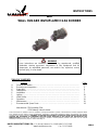 1
1
-
 2
2
-
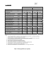 3
3
-
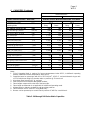 4
4
-
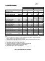 5
5
-
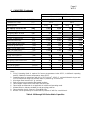 6
6
-
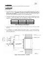 7
7
-
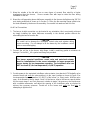 8
8
-
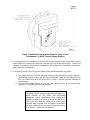 9
9
-
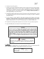 10
10
-
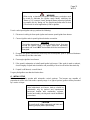 11
11
-
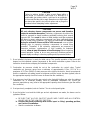 12
12
-
 13
13
-
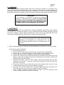 14
14
-
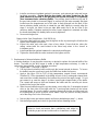 15
15
-
 16
16
-
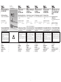 17
17
-
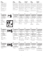 18
18
-
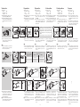 19
19
-
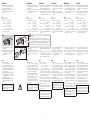 20
20
-
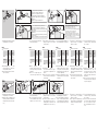 21
21
-
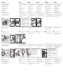 22
22
-
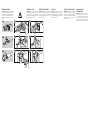 23
23
-
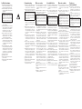 24
24
-
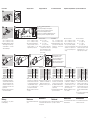 25
25
-
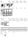 26
26
-
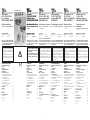 27
27
-
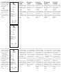 28
28
-
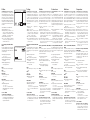 29
29
-
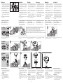 30
30
-
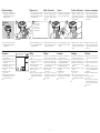 31
31
-
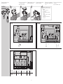 32
32
-
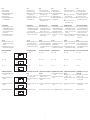 33
33
-
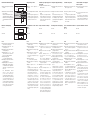 34
34
-
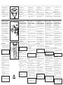 35
35
-
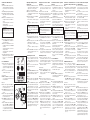 36
36
-
 37
37
-
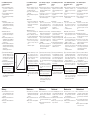 38
38
-
 39
39
-
 40
40
-
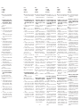 41
41
-
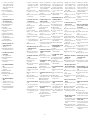 42
42
-
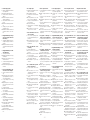 43
43
-
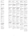 44
44
-
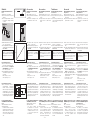 45
45
-
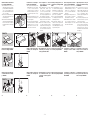 46
46
-
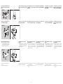 47
47
-
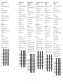 48
48
-
 49
49
-
 50
50


in andere talen
- English: Hauck WHI Operating instructions
- italiano: Hauck WHI Istruzioni per l'uso
- français: Hauck WHI Mode d'emploi
- español: Hauck WHI Instrucciones de operación
Andere documenten
-
 Kenmore Elite 153332620 de handleiding
-
Roberts Gordon Vantage GTH Handleiding
-
State GS630YOCT de handleiding
-
Napoleon Grills 308 Handleiding
-
-
-
-
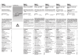 Kromschroder BICR Handleiding
-
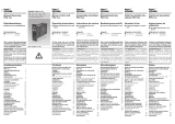 Kromschroder PFU 7xx Handleiding
-
 Kromschroder BCU 4xx Handleiding


