HOERMANN H3G Single-leaf and double-leaf steel doors Handleiding
- Type
- Handleiding

480939 M2.4 RE / 04.2022
DE Anleitung für Planung, Montage, Betrieb und Wartung
Ein- und zweiflüglige Stahltüren (OD-Türen, H3G, H3VM, H16G, HS75, H16S1)
EN Instructions for planning, fitting, operating and maintenance
Single-leaf and double-leaf steel doors (OD-doors, H3G, H3VM, H16G, HS75, H16S1)
FR
Instructions pour la conception, le montage, le fonctionnement et la
maintenance
Portes en acier à 1 et 2 vantaux (OD-portes, H3G, H3VM, H16G, HS75, H16S1)
NL Handleiding voor planning, montage, bediening en onderhoud
Eén- en tweevleugelige stalen deuren (OD-deuren, H3G, H3VM, H16G, HS75, H16S1)
IT
Istruzioni per la pianificazione, il montaggio, il funzionamento e la
manutenzione
Porte d’acciaio ad uno e a due battenti (Porte OD, H3G, H3VM, H16G, HS75, H16S1)
+PL HU CS SL RO
M2.4
M1.1 ➞ M1.3

DEUTSCH .................................3
ENGLISH ..................................9
FRANÇAIS ................................15
NEDERLANDS.............................21
ITALIANO.................................27
POLSKI ..................................33
MAGYAR .................................39
ČESKY ...................................45
SLOVENSKO ..............................51
ROMÂNĂ .................................57

Inhaltsverzeichnis
Sehr geehrte Kundin, sehr geehrter Kunde,
wir freuen uns darüber, dass Sie sich für ein Qulitätsprodukt
aus unserem Hause entschieden haben.
1 Zu dieser Anleitung
Bitte lesen und beachten Sie diese Anleitung. Sie gibt Ihnen
wichtige Informationen zu Einbau, Wartung und Pflege Ihrer
Stahltür und ist ein wichtiges Dokument für die Bauakte.
Sprechen Sie mit unserem Kundendienst, wenn Sie nach dem
Durcharbeiten dieser Anleitung noch Fragen haben.
Beachten Sie die folgenden Anleitungen für Planung,
Montage, Betrieb und Wartung entsprechend Ihrer
Zargenform.
• M1.1 Modul Eckzarge
• M1.2 Modul Dryfix, U- Zargen und Blockzargen
• M1.3 Modul Eck- und Ergänzungszargen, Dryfix und
Ergänzungszargen
1.1 Verwendete Warnhinweise
Das allgemeine Warnsymbol kennzeichnet eine Gefahr, die zu
Verletzungen oder zum Tod führen kann. Im Textteil wird das allge-
meine Warnsymbol in Verbindung mit den nachfolgend beschriebenen
Warnstufen verwendet. Im Bildteil verweist eine zusätzlich Angabe auf
die Erläuterungen im Textteil.
GEFAHR
Kennzeichnet eine Gefahr, die unmittelbar zum Tod oder zu schweren
Verletzungen führt.
1.2 Verwendete Symbole
Feuerschutz Rauchschutz Sicherheitstür
Schallschutz Funktionstür Wichtiger Hinweis
Siehe Textteil Siehe Bildteil Siehe Einbauanleitung
im Zubehörpaket
Als Zubehör zu
bestellen
Korrektes Vorgehen Unzulässiges Vorgehen
(Vorgehensweise)
Schweißen Bohren Elektrischer Türöffner
Einbruchgefahr auf
Öffnungsseite
Einbruchgefahr auf
Schließseite
Fluchtweg
Holz Mauerwerk / Beton Porenbeton
Gips Beton Mörtel
Zargendichtung DämmstoffA
(EN13501-1)
1 Zu dieser Anleitung ................................................. 3
1.1 Verwendete Warnhinweise ........................................ 3
1.2 Verwendete Symbole ................................................ 3
2 Sicherheitshinweise ....................................... 4
3 Informationen zu den Türeigenschaften ............... 4
3.1 Feuerschutz- und Rauchschutztüren ........................ 4
3.2 Schallschutztüren ..................................................... 6
3.3 Einbruchschutztüren ................................................. 6
3.4 Funktionstüren .......................................................... 6
3.5 Außenanwendung ..................................................... 6
4 Montage ................................................................... 6
4.1 Vor der Montage ....................................................... 6
4.2 Maße nach EN12519 ............................................... 6
4.3 Bei der Montage ....................................................... 6
4.4 Hinweise zum Bildteil ................................................ 7
5 Wartung und Pflege ................................................ 7
5.1 Jährliche Wartungsarbeiten ...................................... 7
5.2 Inbetriebnahme und Wartung
von Panikverschlüssen ............................................. 7
5.3 Erforderliche Oberflächenbehandlung
fürElemente mit Standardgrundierung ..................... 7
5.4 Reinigung .................................................................. 7
5.5 Pflege von Edelstahlbauteilen ................................... 7
6 Etikettierung und Kennzeichnung ......................... 8
7 Allgemeines ............................................................. 8
8 Demontage und Entsorgung .................................. 8
9 Leistungserklärung ................................................. 8
Weitergabe sowie Vervielfältigung dieses Dokuments, Verwertung und Mitteilung
seines Inhalts sind verboten, soweit nicht ausdrücklich gestattet. Zuwiderhandlungen
verpflichten zu Schadenersatz. Alle Rechte für den Fall der Patent-, Gebrauchsmuster-
oder Geschmacksmustereintragung vorbehalten. Änderungen vorbehalten.
480939 M2.4 RE / 04.2022 3
DEUTSCH

2 Sicherheitshinweise
GEFAHR
Lebensgefahr beim Einbau der Stahltür
Beim Einbau kann die Tür oder der Türrahmen umfallen und
dabei Personen erschlagen.
▶ Sichern Sie Tür und Zarge vor und während der
Montagearbeit gegen Umfallen.
• Setzen Sie nur qualifiziertes und unterwiesenes Personal
für Montage und Wartung ein.
• Lassen Sie Elektroarbeiten nur von ausgebildeten
Fachkräften durchführen.
• Führen Sie keine Veränderungen durch An- und Umbauten
durch, die die Sicherheit beeinträchtigen können.
• Schließen Sie die Gefahr durch Feuer, Gas, Staub,
Dampf, Rauch, Brand und Explosion bei Schweiß, Brenn-
und Schleifarbeiten aus.
• Vermeiden Sie, dass bei Schweißarbeiten aufschäu-
mende Baustoffe durch Wärmeeintrag reagieren und
dadurch ihre Wirkung verlieren.
3 Informationen zu den
Türeigenschaften
Beachten Sie, dass die Tür einzelne Eigenschaften, eine
Kombination aus den Eigenschaften Feuerschutz,
Rauchschutz, Schallschutz und Einbruchschutz erfüllen kann
oder eine Funktionstür sein kann.
3.1 Feuerschutz- und Rauchschutztüren
• Die jeweilige Zulassung können Sie unter
www.hoermann.de/dokumentation/
zulassungsbescheide-fuer-feuerschutzabschluesse/
einsehen. Die Zulassung muss an der Verwendungsstelle
vorliegen.
• Die angegeben Informationen sind Mindestanforderungen
für den Einbau in Deutschland. Bei Einbau in anderen
Ländern gelten die jeweiligen nationalen Zulassungen,
wobei die Materialkennwerte mindestens der
DINzugrunde gelegt werden müssen.
• Beachten Sie die DIN18093 (Einbau von Feuerschutz-
türen) und die DIN18100 (Wandöffnungen für Türen)
bzw.die länderspezifischen Vorschriften.
• Der Hersteller kann in Einzelfällen nach §22 und §23 der
Musterbauordnung eine Übereinstimmungserklärung
ausstellen.
• Der Betreiber ist für den einwandfreien Zustand der
Tür verantwortlich.
• In Deutschland dürfen Federbänder an Türen und
Klappen mit folgenden Eigenschaften nicht verwendet
werden:
– Flügelgewicht > 80kg
– Verglasung
– Einbau in Montagewände
(Ausnahme: Maße< 1000 × 1000mm)
– Kombination als Rauchschutztüren nach DIN18095
– 2 - flügelig
Außerhalb Deutschlands können andere Vorschriften
gelten, allerdings empfehlen wir die Einhaltung der deut-
schen Vorgaben.
• Verwenden Sie Beschläge, Schlösser, Schließmittel und
Elektroanbauteile nur, wenn sie Bestandteil der Türzulas-
sung sind oder eine Freigabe des Herstellers vorliegt.
• Bauen Sie 3 - seitig gefälzte Türen ohne unteren Schacht-
abschluss, in Schächten auf unterstem Bodenniveau ein.
• Gipskartonwände und Wanddicken: siehe Tab.1:
• Zulässige Wände und Wanddicken: siehe Tab.2:
• Hinterfüllen Sie die Zarge mit mineralischem Mörtel auf
Zementbasis, z.B. LM21 von Sakret, wenn es in der
Einbausituation nicht anders beschrieben wird. Bei
T30 / EI230 muss der Zargenspiegel nicht zwingend mit
Mörtel verfüllt werden. Spreizen Sie U-Zargen und
Eckzargen (mit und ohne Gegenzargen) vor dem
Hinterfüllen ab, damit sie sich durch den Druck des
Mörtels nicht verbiegen.
• Verwenden Sie bei Feuerschutz einen Drücker mit
Fallverdeck oder einen Schließzylinder und bei
Rauchschutz einen Schließzylinder.
• Rauchschutz:
– RS 65 - 1: AbPNr. P - 14 - 001829 - PR01-ift
– RS 65 - 2: AbPNr. P - 14 - 001829 - PR02-ift
– Verwenden Sie Bodendichtungen und Dichtungskeile
(siehe Bildteil Punkt3.5 und 4).
– Wenn die Zarge nicht komplett mit Mörtel hinterfüllt
ist, müssen Sie den Zargenanschluss an die
angrenzenden Bauteile versiegeln. Versiegeln Sie
beide Seiten und den Fußbereich lückenlos mit
dauerelastischem Material.
• Setzen Sie Verglasungen von Feuerschutztüren keiner
direkten Sonnenstrahlung aus.
Tab. 1: Zulässige F90A Montagewände mit Mindestwanddicken für Feuerschutz- und Rauchschutztüren, Höhe ≤5000mm
Prüfzeugnis-Nr. Wand H3OD
H_30OD
H3-1G
H_30D1
1) H3-2VM
H_30D2
P-3310/563/07-MPABS Knauf W112 ≥100mm ≥100mm ≥100mm
P-3391/170/08-MPABS Knauf W131 ≥116mm –– ––
P-3310/563/07-MPABS Knauf W132 ≥100mm –– ––
P-3202/2028-MPABS Knauf W352 / W353 ≥100mm ≥100mm ≥100mm
P-3956/1013-MPABS RiGips MW12RF, MW12RFI, MW12HA,
MW12DH, MW12BF, MW12RFWF, MW12GX ≥100mm ≥100mm ≥100mm
P-3014/1393-MPABS RiGips MW11DD ≥100mm ≥100mm ≥100mm
P-3020/0109-MPABS RiGips BW13DDRF ≥165mm –– ––
P-SAC-02/III-681 SW11 – SW14 ≥100mm ≥100mm ≥100mm
P-3391/0890-MPABS SW18 –– –– ––
P-2100/100/17-MPABS Promat 450.81 ≥140mm –– ––
P-11-003478-PR01 B + M W50 / 100 – W100 / 150 ≥100mm –– ––
P-3854/1372-MPABS Fermacell 1S31/3.1 ≥95mm ≥95mm ≥95mm
1) max. 2750 × 2750mm
4480939 M2.4 RE / 04.2022
DEUTSCH

Tab. 2: Zulässige Wände und Mindestwanddicken für Feuerschutz- und Rauchschutztüren (mm) siehe 4.2
Stahltür
Wand
H3-1OD
H_30-1OD
H3-2OD
H_30-2OD
H3-1G
H_30D1
H3-2VM
H_30D2 H6-1OD H6-2OD H16-1G
H_90D1
H16-2G
H_90F-2
H16-S1
H_90E-1
H16-1OD
H_90-1OD
H16-2OD
H_90-2OD
Beton DIN1045-1, Festigkeit≥C12/15 1) k≤ 2500 2) k> 2500 1) k≤ 2500 2) k> 2500 e≤ 1320
100 140 100 140 140 140 140 140 140 120 140 140
Mauerwerk DIN1053-1,
Steinfestigkeit≥12, Mörtelgruppe ≥2 1) k≤ 2500 k> 2500 1) k≤ 2500 2) k> 2500
e≤ 1250
und
k≤ 1750
e≤ 1500
und
k≤ 2500
e≤ 1250
k≤ 2500
e≤ 1500
k≤ 2500
115 175 115 175 175 175 115 175 175 240 175 115 7) 175 175
Porenbeton-Block oder Plan steine,
DIN4165-3, Festigkeitsklasse ≥4,
Porenbetonplatten nach allgemeiner
bauaufsichtlicher Zulassung,
Festigkeitsklasse≥4.4
k≤ 2500 k≤ 2500 6) e≤ 1320 6)
e≤ 2500
e≤ 1320
k≤ 2500
e≤ 2500
k≤ 2500
150 150 175 175 6) 150 6) 200 200 175 6) 200 6) 200
Montagewand F90-A
nach ABP, Bild1.12 beachten,
max.Höhe 5000mm
3) 3) 3) 3)
Montagewand F90-A
DIN4102-4 / Tab.10.2, Bild1.12
beachten, max.Höhe5000mm
e≤ 1320 e≤ 2500
e≤2750
und
k≤2750
e≤ 1250 e≤ 2500 e≤ 1320
k≤ 2500
e≤ 2500
k≤ 2500
100 100 100 100 100 125 125 100 150
Montagewand F30-A
Bild2D / 2.3 beachten,
max.Höhe5000mm
e≤ 1250 e≤ 2500
100 100
Montagewand F90-B
DIN4102-4 / Tab.10.3,
max.Höhe5000mm
e≤ 1250 und k≤ 2500 e≤ 2500 und k≤ 2500
4) 125 / 5) 130 4) 125 / 5) 130
Montagewand F30-B
AbPNr.: P – SAC-02 / III-668
e≤ 1125 und k≤ 2125
185
Gips-Wandbauplatten
VGOrth, P – SAC02 / III-468,
Bild9/A17 beachten
e≤ 1250 und k≤ 2500
100
Mindestwanddicken 1) ohne Oberteil 2) mit Oberteil 3) siehe Tab. 1: 4) zweischalige Zarge 5) Dryfix 6) Rauchschutz: keine Zulassung in Deutschland 7) Rauchschutz, e≤ 1320
480939 M2.4 RE / 04.2022 5
DEUTSCH

3.2 Schallschutztüren
• Die gesamte Schalldämmung ist von den umgebenden
Bauteilen abhängig. Die resultierende Schalldämmung
von Wand und Tür müssen Sie gesondert nachweisen,
da sie nicht aus dem bewerteten Schalldämmmaß Rw
bzw. R der Tür allein abgeleitet werden kann.
• Achten Sie auf vollständig anliegende Dichtung(en).
• Der Boden muss glatt sein, damit die vollständige
Dichtfunktion der Bodendichtung gewährleistet ist.
• Trennen Sie den Estrich im Schwellenbereich.
• Verwenden Sie Dichtungskeile und Bodendichtung
(sieheBildteil Punkt3.5 und 4).
• Verwenden Sie einen Schließzylinder.
• Hinterfüllen Sie die Zarge vollständig mit Mörtel.
• Verkleben Sie die auf Gehrung geschnittenen Ecken der
Zargendichtung z.B. mit Köratan UC41.
3.3 Einbruchschutztüren
• Die Tür erfüllt ihre Einbrucheigenschaften nur, wenn der
Riegel komplett vorgeschlossen und der Schlüssel
abgezogen ist.
• Sichern Sie die Türblätter an allen RC3 und RC4 Türen an
den Bändern mit je zwei Schrauben
(sieheBildteilPunkt3.3)
• Verwenden Sie bei RC3 nur Eckzargen, Eckzargen mit
Gegenzargen, U-Zargen und Blockzargen, ausgenommen
Einbausituation H1.
• Verwenden Sie bei RC4 nur Eckzargen, Eckzargen mit
Gegenzargen und U-Zargen.
• Hinterfüttern Sie die Zarge bei RC2 mindestens im
Bereich der Verriegelungspunkte, Bänder,
Sicherungsbolzen und Falzluftbegrenzer dauerhaft
druckfest. Druckfestigkeit ca.10N/mm².
• Hinterfüllen Sie die Zarge bei RC3 und RC4 Türen
umlaufend druckfest. Druckfestigkeit ca.10N/mm².
• Stützen Sie die Zarge bei RC2 mindestens im Bereich der
Verriegelungspunkte, Bänder, Sicherungsbolzen und
Falzluftbegrenzer dauerhaft und bei RC3 umlaufend mit
druckfestem Material der nachfolgenden Tabelle ab.
Material zur
Zargenabstützung RC2 RC3 Brand-
schutz
Beton ja ja ja
Mörtel (M10 nach
DINV20000-412) ja ja ja
Nadel- oder Laubholz
(Coder D nach EN338) ja ja nein
Promaboard, Firma Promat ja nein ja
PromatectH, Firma Promat ja ja ja
ROKU V2, Firma Rolf Kuhn ja ja ja
Stahlblech ja nein ja
• Montieren Sie an Türen mit Gläsern den Glashalterahmen
mit Sicherungslaschen oder Sicherungswinkeln auf der
Angriffsseite.
• Messen Sie bei 2 - flügeligen Türen die unteren
Spaltmaße von der Bodenbuchse.
• Verwenden Sie bei Antipaniktüren mit Drücker oder
Stangengriff unseren L- Winkel mit Höckerschwelle,
siehe3.15.
• Stellen Sie sicher, dass sichtbare Zargen-
Befestigungspunkte und Hinterfütterungsteile von der
Angriffsseite aus nicht demontierbar sind (z.B. sichtbare
Schraubenantriebe nach der Zargen-Montage
unbrauchbar machen oder dauerhaft überdecken).
3.3.1 Mindestanforderungen an einbruchhemmende
Türen
Widerstandsklasse
nach DINEN1627 RC2 RC3 RC4
Mauerwerk DIN1053, Teil1 [mm]
Steinfestigkeit ≥12 115 115 240
Stahlbeton, mind. C12 / 15 [mm] 100 120 140
Porenbetonsteine Klasse4 [mm] 175, 115 1) 240 –
Porenbetonplatten Klasse4[mm] 150 – –
Montagewand Knauf W118.de,
WK2 [mm] 101 – –
Holzständerwand nach
DINEN1627 ✓– –
Schließzylinder nach
DIN18252:2006-12 2) 3) 21-, 31-, 71-BZ 42-, 82-BZ
Schutzbeschlag nach
DIN18257:2022-02 2) ES1 (ZA) ES2 (ZA) ES3 (ZA)
Gläser EN356 (Feuerschutz) P5A 4)
P7B 5) P5A 4) –
1) nur 1-Flügler, wir empfehlen Wanddicken ab 150mm
2) Schutzbeschlag oder Schließzylinder muss mit Ziehschutz (ZA) ausgeführt
sein.
3) nicht zwingend im Lieferumfang enthalten
4) nicht in Flucht- und Rettungswegen
5) in Flucht- und Rettungswegen
3.4 Funktionstüren
Die Zargen müssen nicht zwingend hinterfüllt werden.
3.5 Außenanwendung
Beachten Sie die separate Anleitung Art.-Nr.: 5 04 855
beimEinbau im Außenbereich. Sie finden die Anleitung
unter www.hoermann.de.
4 Montage
4.1 Vor der Montage
Klären Sie vor der Montage folgende Fragen:
• Welche Eigenschaften hat die Tür?
• Ist die Wandbauart zum Einbau der Tür geeignet?
• Ist die Höhenlage des Bodens bekannt (Meterriss?)
• In welche Richtung soll die Tür öffnen?
• Sind Bauvorschriften zu beachten?
• Muss die Wand im Bereich der Mauerschutzkästen
ausgestemmt werden?
4.2 Maße nach EN12519
Abb. 1:
a
c
d
e
f
gij k l
- 42
- 19
+ 31
- 82
- 36
+ 64
+ 20
0
+ 15
0
Maße
a / g lichte Öffnungsbreite / -höhe
c / i lichte Falzbreite / -höhe
6480939 M2.4 RE / 04.2022
DEUTSCH

d / j Zargenaußenmaßbreite / -höhe
e / k Baurichtmaßbreite / -höhe
f / l lichte Rohbaumaßbreite / -höhe (DIN18100)
4.3 Bei der Montage
• Beachten Sie die Einbauhinweise in den Zubehörpaketen.
• Verwenden Sie Montageteile, wenn sie mitgeliefert
werden, z.B. Dübellaschen, Dübel oder Schrauben.
• Verwenden Sie im Punkt2 die angegebenen Dübel.
• Verwenden Sie in Verbindung mit Eckzarge und
Hochlochziegel bzw. Gipssteinen den Dübel
FUR10 × 80 / 100mm und beachten Sie Punkt2 der
Einbauanleitung.
• Bohren Sie Hochlochziegel und Hohlkammersteine ohne
Schlag.
• Beachten Sie den Mindestrandabstand von 50mm bei
horizontalen bzw. vertikalen Bohrungen und die
Spreizrichtung der Dübel.
• Beachten Sie, dass bei Zargen ohne Bodeneinstand der
untere Montagewinkel vor der Montage entfernt werden
muss.
• Türblattkürzungen sind nicht möglich.
4.4 Hinweise zum Bildteil
siehe Punkt Beschreibung
1a Dünnfalz
1b Dickfalz
1.2a / 1.2b Anzahl der Befestigungspunkte
1.2c Einbauablauf
1.3a Ausbau der Standardtür
1.3b Ausbau der Sicherheitstür
1.4 Zusammenbau der Eckzarge
1.5 Bodenmulde und Montagewinkel
1.6 Befestigungsteile
1.7 Minimaler Randabstand und Spreizrichtung Dübel
1.8 Einbau Schattennutprofile
1.9 Leerrohre in der Zarge
1.10 Einsetzbare E – Öffner
1.11 Mauerschutzkästen in GKF – Wände
1.12 Aufbau GKF-Wände
2.0 Einbausituationen und Zargenformen
3.1a Einbau mit Standardbändern
3.1b Einbau mit 3D-Bändern
3.2 Einstellen der Luftspalte
3.3 Einbau der Sicherheitstür
3.4 Entfernen der Bodenwinkel bei Zargen
ohneBodeneinstand
3.5 Dichtungskeile mit Silikon befestigen
3.6 Einbau der Zargendichtung
3.7 Anheben der Tür
3.8 Spannen des Federbandes Umbau Glasrahmen
3.9 Überprüfung Falleneingriff
3.10 Umbau des Lüftungsgitters
3.11 Umbau Glasrahmen
3.12 Dämmschichtbildner bei Feuer- und Rauchschutz
3.13 Dämmschichtbildner an Sicherungsbolzen
3.14 Kennzeichnung großer Glasflächen
3.15 Paniktüren und RC
siehe Punkt Beschreibung
3.16 Einbau Blockschloss bei Mehrfachverriegelung
3.17 Einbau Ankerplatte für Türhaftmagnet
4Bodendichtungen
5Türschließer
6Bohrungen für Montage Sensoren Drehflügelantriebe
7a Schlüssel bei Paniktüren abziehen
7b Fehlbedienung des Schlosses vermeiden
5 Wartung und Pflege
5.1 Jährliche Wartungsarbeiten
▶ Kontrollieren Sie Türblatt Zarge und alle Anbauteile wie
z.B. Drücker, Schloss, Türschließer und Bänder auf
Funktion und korrosive Schäden.
▶ Fetten Sie Falle, Bandbolzen und Lagerringe mit
Mehrzweckfett.
▶ Schmieren Sie Bolzenschlösser mit Teflonspray.
▶ Kontrollieren Sie die Spaltmaße.
▶ Achten Sie auf die Sichtbarkeit der Kennzeichnung.
▶ Tauschen Sie defekte Teile aus und verwenden Sie nur
Original Ersatzteile des Herstellers.
GEFAHR
Lebensgefahr durch abgelöste Dämmschichtbildner
Durch abgelöste Dämmschichtbildner verliert der
Feuerschutzabschluss seine Funktion.
▶ Ersetzen Sie abgelöste Dämmschichtbildner,
sieheBildteil Punkt3.12.
▶ Tauschen Sie defekte Teile aus.
▶ Verwenden Sie nur Orginal-Ersatzteile des Herstellers.
Wenn Sie Mängel feststellen, die Sie nicht selbst beheben
können, beauftragen Sie eine Fachfirma.
5.2 Inbetriebnahme und Wartung von
Panikverschlüssen
www.hoermann.de/dokumentation/zulassungsbescheide-
fuer-feuerschutzabschluesse/
(siehe Punkt10)
5.3 Erforderliche Oberflächenbehandlung
fürElemente mit Standardgrundierung
Die Oberfläche von Türblatt und Zarge besteht aus einer
Pulvergrundbeschichtung auf Epoxidharz Polyester Basis.
1. Entfernen Sie die Dichtung(en).
2. Schleifen Sie, bis auf die Dämmschichtbildner alle zu
lackierenden Oberflächen an.
3. Reinigen Sie die Oberflächen gründlich.
4. Kleben Sie das Kennzeichnungsschild ab.
5. Verwenden Sie für die Grund- und Endbeschichtung
Lacke, die geeignet und vom Lackhersteller für
pulverlackierte Untergründe freigegeben sind.
Beachten Sie das BFS Merkblatt Nr.24 sowie die
Verarbeitungshinweise der Lackhersteller und fertigen Sie
eine Haftprobe an. Nehmen Sie die Endbehandlung
innerhalb von drei Monaten nach Montage vor, um
Korrosionsschäden zu vermeiden.
Witterungseinflüsse wie z.B. Sonneneinstrahlung können
zu vorübergehender Verformung des Türblattes führen.
Dunkle Anstriche verstärken diesen Effekt, der keinen
Grund zur Beanstandung darstellt. Wir empfehlen helle
und / oder reflektierende Anstriche.
480939 M2.4 RE / 04.2022 7
DEUTSCH

6. Bringen Sie die Dichtung(en) nach dem Trocknen der
Farbe wieder an.
5.4 Reinigung
▶ Reinigen Sie die Oberflächen mit klarem Wasser oder
handelsüblichem Lackreiniger.
5.5 Pflege von Edelstahlbauteilen
▶ Reinigen und pflegen Sie regelmäßig Bauteile aus Edel-
stahl mit der bei Hörmann erhältlichen Edel Glanz Edel-
stahlpflege und tragen Sie diese mit einem weichen Tuch
auf.
6 Etikettierung und Kennzeichnung
Das Etikett der Türtypen D65-1, D65-2, D65-1OD, D65-2OD
ist auf Grundlage der Verordnung (EU) Nr. 305 / 2011 mit dem
CE-Konformitätskennzeichen versehen. Die herangezogene
und angewandte harmonisierte europäische Produktnorm ist
EN14351-1:2006 + A1:2010 „Fenster und Türen –
Produktnorm, Leistungseigenschaften – Teil 1: Fenster und
Außentüren ohne Eigenschaften bezüglich Feuerschutz
und / oder Rauchdichtheit.“ Die Nummer der zugehörigen
CE-Kennzeichnung bzw. Leistungserklärung ist im Falzbereich
der Tür auf dem oben genannten Etikett zwischen dem
Herstellerlogo und dem CE-Konformitätskennzeichen
angegeben.
Türen, auf deren Etikett kein CE-Konformitätskennzeichen
abgebildet ist, fallen nicht in den Anwendungsbereich der
oben genannten harmonisierten europäischen Produktnorm
und dürfen daher nicht über eine CE-Kennzeichnung bzw.
Leistungserklärung verfügen.
7 Allgemeines
Die Inbetriebnahme der Tür ist so lange untersagt, bis
festgestellt wurde, dass sie nach unseren Vorgaben montiert
und auf ihre ordnungsgemäße Funktion überprüft wurde. Bei
einer Veränderung des Produkts verliert die
Leistungserklärung ihre Gültigkeit.
8 Demontage und Entsorgung
Die Demontage erfolgt analog der Montage in umgekehrter
Reihenfolge. Entsorgen Sie das Bauelement nach den
örtlichen Vorgaben.
9 Leistungserklärung
Leistungserklärung siehe Bild1.3: www.hoermann.com/dop
8480939 M2.4 RE / 04.2022
DEUTSCH

Table of Contents
Dear Customer,
We are delighted that you have decided to choose a product
from our company.
1 About These Instructions
Please read and follow these instructions carefully.
Theyprovide you with important information on the fitting,
maintenance and care of your steel door and are an important
document for the construction file.
Should you have any questions after working through these
instructions, please contact our After-Sales Service.
Observe the following instructions for planning, fitting,
operating and maintenance according to your frame type.
• M1.1 Corner frame module
• M1.2 Dryfix, profile frame and block frame module
• M1.3 Corner and counter frame, DryFix and counter
frame module
1.1 Warnings used
The general warning symbol indicates a danger that can lead
to injury or death. In the text section, the general warning symbol will
be used in connection with the caution levels described below. In the
illustrated section, an additional instruction refers back to the
explanation in the text.
DANGER
Indicates a danger that leads directly to death or serious injuries.
1.2 Symbols used
Fire protection Smoke protection Security door
Acoustic rating Function door Important note
See text section See illustrated
section
See installation
instructions in
accessory pack
To be ordered as
an accessory
Correct
procedure
Non-permissible
procedure
Welding Drilling Electric door strike
Possible burglar
attack from
opening side
Possible burglar
attack from
closing side
Escape route
Timber Concrete / brickwork Gas concrete
Plaster Concrete Mortar
1 About These Instructions ....................................... 9
1.1 Warnings used .......................................................... 9
1.2 Symbols used ........................................................... 9
2 Safety Instructions ....................................... 10
3 Information on the Door Features ....................... 10
3.1 Fire doors and smoke-tight doors .......................... 10
3.2 Acoustic-rated doors .............................................. 12
3.3 Burglar protection doors ......................................... 12
3.4 Function doors ........................................................ 12
3.5 Outside application ................................................. 12
4 Fitting ..................................................................... 12
4.1 Before fitting ........................................................... 12
4.2 Dimensions acc. to EN12519 ................................ 12
4.3 When fitting ............................................................. 13
4.4 Information on illustrated section ........................... 13
5 Care and Maintenance ......................................... 13
5.1 Annual maintenance work ...................................... 13
5.2 Initial start-up and maintenance
of anti-panic locks ................................................. 13
5.3 Required surface treatment forelements
withstandard priming ............................................. 13
5.4 Cleaning .................................................................. 14
5.5 Cleaning stainless steel components ..................... 14
6 Labelling and marking .......................................... 14
7 General ................................................................... 14
8 Dismantling and disposal ..................................... 14
9 Declaration of performance ................................. 14
Dissemination as well as duplication of this document and the use and communication
of its content are prohibited unless explicitly permitted. Noncompliance will result in
damage compensation obligations. All rights reserved in the event of patent, utility
model or design model registration. Subject to changes.
480939 M2.4 RE / 04.2022 9
ENGLISH

Frame seal Insulation materialA
(EN13501-1)
2 Safety Instructions
DANGER
Danger to life while fitting the steel door
During fitting, the door or door frame can fall and kill persons.
▶ Prior to and during fitting, secure the door and frame
against falling over.
• Only qualified and instructed personnel may perform
fitting and maintenance.
• Electrical work may only be carried out by qualified
electricians.
• Do not make any alterations through attachments or
conversions which could impair safety.
• Exclude hazards caused by gas, dust, vapour, smoke, fire
and explosion during welding, burning and grinding work.
• When welding, ensure that intumescent materials do not
react as a result of heat input, as this would render the
materials ineffective!
3 Information on the Door Features
Please observe that the door may have single features, a
combination of fire protection, smoke protection, acoustic
rating and burglar protection features, or may be a function
door.
3.1 Fire doors and smoke-tight doors
• The respective approval can be found in the Internet at
www.hoermann.de/dokumentation/
zulassungsbescheide-fuer-feuerschutzabschluesse/.
The approval must be present at the place of use.
• The information given represents the minimum
requirements for installation in Germany. For installation
in other countries, the corresponding national allowances
are valid. However, these must be based on material
parameters equal to or exceeding DIN standard.
• Observe the standards DIN18093 (Installation of Fire
Doors) and DIN18100 (Wall Openings for Doors) or the
country-specific regulations.
• In individual cases, in accordance with §22 and §23 of
the German building code, the manufacturer can issue a
declaration of conformity.
• The operator / owner is responsible for the flawless
condition of the door.
• In Germany, spring hinges must not be used on doors
and hatches having the following characteristics:
– Leaf weight > 80kg
– Glazing
– Fitting in prefabricated walls (exception:
dimensions< 1000 × 1000mm)
– Combination as smoke-tight doors acc. to DIN18095
– Double leaf
Different regulations may apply outside Germany,
however, we recommend compliance with the German
regulations.
• Use only those fittings, locks, closing devices and
electric attached parts that are part of the door approval
or are approved by the manufacturer.
• Doors rebated on 3 sides, without a bottom seal for the
shaft, should be installed at the lowest floor level.
• Gypsum plasterboard walls and wall thicknesses:
seeTab. 1:
• Permissible walls and wall thicknesses: seeTab. 2:
• Backfill the frame with cement-based mineral mortar (e.g.
LM21 from Sakret) provided it is not described differently
in the corresponding installation situation. With
T30 / EI230 the frame face does not necessarily have to
be filled with mortar. Profile frames and corner frames
(with and without counter frames) must be splayed prior
to backfilling to ensure that they do not buckle under the
pressure of the mortar.
• Use a lever handle with catch cover or a lock cylinder for
fire protection, and a lock cylinder for smoke protection.
• Smoke protection:
– RS 65 - 1: AbPNr. P - 14 - 001829 - PR01-ift
– RS 65 - 2: AbPNr. P - 14 - 001829 - PR02-ift
– Use bottom seals and sealing wedges (see illustrated
section, section3.5 and section4).
– If the frame is not completely backfilled with mortar,
seal the frame connection to the adjacent structural
components to provide an unbroken flexible seal on
both sides.
– Use locking cylinders.
Tab. 1: Permissible F90A prefabricated walls with minimum wall thicknesses for fire-rated and smoke-tight doors, height ≤5000mm
Test certificate no. Wall H3OD
H_30OD
H3-1G
H_30D1
1) H3-2VM
H_30D2
P-3310/563/07-MPABS Knauf W112 ≥100mm ≥100mm ≥100mm
P-3391/170/08-MPABS Knauf W131 ≥116mm –– ––
P-3310/563/07-MPABS Knauf W132 ≥100mm –– ––
P-3202/2028-MPABS Knauf W352 / W353 ≥100mm ≥100mm ≥100mm
P-3956/1013-MPABS RiGips MW12RF, MW12RFI, MW12HA,
MW12DH, MW12BF, MW12RFWF, MW12GX ≥100mm ≥100mm ≥100mm
P-3014/1393-MPABS RiGips MW11DD ≥100mm ≥100mm ≥100mm
P-3020/0109-MPABS RiGips BW13DDRF ≥165mm –– ––
P-SAC-02/III-681 SW11 – SW14 ≥100mm ≥100mm ≥100mm
P-3391/0890-MPABS SW18 –– –– ––
P-2100/100/17-MPABS Promat 450.81 ≥140mm –– ––
P-11-003478-PR01 B + M W50 / 100 – W100 / 150 ≥100mm –– ––
P-3854/1372-MPABS Fermacell 1S31/3.1 ≥95mm ≥95mm ≥95mm
1) Max 2750 × 2750mm
10 480939 M2.4 RE / 04.2022
ENGLISH

Tab. 2: Permissible walls and minimum wall thicknesses for fire-rated and smoke-tight doors (mm) see 4.2
Steel door
Wall
H3-1OD
H_30-1OD
H3-2OD
H_30-2OD
H3-1G
H_30D1
H3-2VM
H_30D2 H6-1OD H6-2OD H16-1G
H_90D1
H16-2G
H_90F-2
H16-S1
H_90E-1
H16-1OD
H_90-1OD
H16-2OD
H_90-2OD
Concrete DIN1045-1,
strength≥C12/15
1) k≤ 2500 2) k> 2500 1) k≤ 2500 2) k> 2500 e≤ 1320
100 140 100 140 140 140 140 140 140 120 140 140
Brickwork DIN1053-1,
strength ≥12, mortargroup≥ 2 1) k≤ 2500 k> 2500 1) k≤ 2500 2) k> 2500
e≤ 1250
and
k≤ 1750
e≤ 1500
and
k≤ 2500
e≤ 1250
k≤ 2500
e≤ 1500
k≤ 2500
115 175 115 175 175 175 115 175 175 240 175 115 7) 175 175
Gas concrete stone slabs or concrete
precision blocks DIN4165-3, strength
class≥ 4, Gasconcrete slabs acc. to
general official approval
strengthclass≥ 4.4
k≤ 2500 k≤ 2500 6) e≤ 1320 6)
e≤ 2500
e≤ 1320
k≤ 2500
e≤ 2500
k≤ 2500
150 150 175 175 6) 150 6) 200 200 175 6) 200 6) 200
Prefabricated wall F90-A
acc. toABP, ObserveFigure1.12,
max.height5000mm
3) 3) 3) 3)
Prefabricated wall F90-A
DIN4102-4 / Tab.10.2, Observe
Figure1.12, max.height5000mm
e≤ 1320 e≤ 2500
e≤ 2750
and
k≤ 2750
e≤ 1250 e≤ 2500 e≤ 1320
k≤ 2500
e≤ 2500
k≤ 2500
100 100 100 100 100 125 125 100 150
Prefabricated wall F30-A
Figure2D / 2.3 Observe,
max.height5000mm
e≤ 1250 e≤ 2500
100 100
Prefabricated wall F90-B
DIN4102-4 / Tab.10.3
max.height 5000mm
e≤ 1250 and k≤ 2500 e≤ 2500 and k≤ 2500
4) 125 / 5) 130 4) 125 / 5) 130
Prefabricated wall F30-B
AbPNr.: P – SAC-02 / III-668
e≤ 1125 and k≤ 2125
185
Plaster wallboards
VGOrth, P–SAC02 / III-468
ObserveFigure9/A17
e≤ 1250 and k≤ 2500
100
Minimum wall thicknesses 1) Without top part 2) With top part 3) see.Tab. 1: 3) Double-shell frame 5) Dryfix 6) Smoke protection: no approval in Germany 7) Smoke protection e≤ 1320
480939 M2.4 RE / 04.2022 11
ENGLISH

• Do not expose glazings on fire-rated doors to direct
sunlight.
3.2 Acoustic-rated doors
• The overall acoustic rating is dependent on the
surrounding structural components. The resulting
acoustic rating of wall and door must be verified
separately, as it cannot be derived from the evaluated
acoustic value Rw or R of the door alone.
• Ensure that any seal(s) make full contact.
• The floor must be smooth to ensure the sealing function
of the bottom seal.
• Split the screed in the threshold area.
• Use sealing wedges and a bottom seal (see illustrated
section, section3.5 and section4).
• Use locking cylinders.
• Backfill the frame completely with mortar.
• Glue the mitre-cut corners of the frame seal with, for
example, Köratan UC°41.
3.3 Burglar protection doors
• The door fulfils its burglar-proof characteristics only if the
bolt is completely closed and the key is removed.
• Use two screws each to secure the door leaves of all
RC3 and RC4 doors on the hinges (see illustrated section
point 3.3)
• Only use corner frames, corner frames with counter
frames, profile frames and block frames for RC3, except
for fitting situation H1.
• Only use corner frames, corner frames with counter
frames and profile frames for RC4.
• Backfill the frame with RC2 at least in the area of the
locking points, hinges, security bolts and rebate space
limiters to make it permanently pressure-resistant.
Pressure resistance approx.10N/mm².
• Backfill the frame of RC3 and RC4 doors all-round with
pressure-resistant material. Pressure resistance
approx.10N/mm².
• Permanently support the frame with RC2 at least in the
area of the locking points, hinges, security bolts and
rebate space limiters and with RC3 all-around with
pressure-resistant material per the following table.
Material for frame support RC2 RC3 Fire pro-
tection
Concrete Yes Ye s Yes
Mortar (M10 acc. to
DINV20000-412) Yes Yes Yes
Softwood or hardwood
(CorDaccording to EN338) Yes Yes No
Promaboard by Promat Yes No Yes
PromatectH by Promat Yes Yes Yes
ROKU V2 by Rolf Kuhn Yes Yes Yes
Sheet steel Yes No Yes
• Fit the glazing frame to doors with glass using securing
lugs or securing brackets on the attack side.
• For double-leaf doors, measure the lower gap
dimensions from the bottom bush.
• For anti-panic doors with lever handle or push bar, use
our L-bracket with protruding threshold, see 3.15.
• Make sure that visible frame fixing points and backfill
parts cannot be dismantled from the attack side
(e.g.make visible screw drives unusable or permanently
cover them after fitting the frame).
3.3.1 Minimum requirements for security doors
Resistance class
acc.toDINENV1627 RC2 RC3 RC4
Brickwork DIN1053 part1 [mm]
strength ≥12 115 115 240
Reinforced concrete, at least
C12 / 15[mm] 100 120 140
Gas concrete blocks
class4[mm] 175, 115 1) 240 –
Gas concrete slabs class4 [mm] 150 – –
Prefabricated wall Knauf W118.
de, WK2 [mm] 101 – –
Timber partition wall acc. to
DINEN1627 ✓– –
Profile cylinder acc. to
DIN18252:2006-12 2) 3) 21-, 31-, 71-BZ 42-, 82-BZ
Protective fittings acc. to
DIN18257:2022-02 2) ES1 (ZA) ES2 (ZA) ES3 (ZA)
EN356 glazing (fire protection) P5A 4) /
P7B 5) P5A 4) –
1) Only single-leaf doors, we recommend wall thicknesses of 150mm or more
2) Protective fitting or profile cylinder must be equipped with pull-off
protection (ZA).
3) Not necessarily included in scope of delivery
4) not in escape and rescue routes
5) in escape and rescue routes
3.4 Function doors
The frames need not be backfilled.
3.5 Outside application
Please observe the separate instructions art. no.: 504 855
when fitting outdoors. You will find these instructions
at www.hoermann.de.
4 Fitting
4.1 Before fitting
Before fitting, please clarify the following questions:
• What characteristics does the door have?
• Is the wall structure suitable for installing the door?
• Is the floor height known (metre line)?
• In which direction should the door open?
• Do any building regulations need to be considered?
• Does the wall need to be chiseled out in the area of the
wall protective boxes?
4.2 Dimensions acc. to EN12519
Fig. 2:
a
c
d
e
f
gij k l
- 42
- 19
+ 31
- 82
- 36
+ 64
+ 20
0
+ 15
0
Dimensions
a / g Clear opening width / height
12 480939 M2.4 RE / 04.2022
ENGLISH

c / i Clear rebate width / height
d / j Overall frame dimension width / height
e / k Ordering width / height
f / l Clear unfinished structure dimension
width / heightacc.to (DIN18100)
4.3 When fitting
• Observe the fitting instructions in the accessory packs.
• Use fitting material if it is supplied, e.g. dowel brackets,
plugs or screws.
• Use the plugs indicated in section 2.
• In combination with corner frame and vertically
perforated brick or plaster, use the dowel
FUR10×80 / 100mm and follow item 2 in the fitting
instructions.
• Drill the vertically perforated brick and hollow bricks
without impact.
• Note a minimum edge distance of 50mm for horizontal/
vertical holes as well as the expansion direction of the
dowel.
• Please note that, for frames for finished floors, the
bottom fitting bracket must be removed before fitting.
• Door leaves cannot be shortened.
4.4 Information on illustrated section
See section Description
1a Thin rebate
1b Thick rebate
1.2a / 1.2b Number of fixing points
1.2c Fitting situations
1.3a Removing the standard door
1.3b Removing the security door
1.4 Assembling the corner frame
1.5 Floor trough and fitting bracket
1.6 Fastenings
1.7 Minimum edge spacing and expansion direction of
the dowel
1.8 Fitting the edge recess profiles
1.9 Tubes in the frame
1.10 Suitable electric strikes
1.11 Wall protective cap in gypsum board walls
1.12 Design of GKF walls
2.0 Fitting situations and frame shapes
3.1a Fitting with standard hinges
3.1b Fitting with 3-way adjustable hinges
3.3 Adjusting the air gaps
3.4 Removing the bottom angles for frames without
bottom recesses
3.5 Fastening the sealing wedges with silicone
3.6 Fitting the frame seal
3.7 Raising the door
3.8 Tensioning the spring hinge
3.9 Latch engagement verification
3.10 Alteration of ventilation grille
3.11 Alteration of glazing frame
3.12 Intumescent coating on fire doors and smoke-tight
doors
3.13 Intumescent coatings at security bolts
3.14 Marking of large glass surfaces
3.15 Anti-panic doors and RC
3.16 Block lock fitting for multiple-point locking
3.17 Anchor plate fitting for door holding magnet
See section Description
4Bottom seals
5Door closer
6Holes for fitting hinged door operator sensors
7a Removing the key in anti-panic doors
7b Avoiding incorrect operation of the lock
5 Care and Maintenance
5.1 Annual maintenance work
▶ Check the door leaf, frame and all add-on parts such as
lever handles, locks, door closers and hinges for function
and corrosive damage.
▶ Grease the latch, hinge bolts and bearing rings with
multi-purpose grease.
▶ Lubricate bolt locks with Teflon spray.
▶ Check the gap dimensions.
▶ Make sure that the marking is visible.
▶ Replace defective parts and use only original spare parts
from the manufacturer.
DANGER
Danger to life due to detached intumescent coatings
The fire door loses its function if the intumescent coatings
are detached.
▶ Replace intumescent coatings that have detached,
seeillustrated section3.12.
▶ Replace defective parts.
▶ Only use original spare parts from the manufacturer.
If you discover defects that you yourself cannot remedy, call
in a specialist company.
5.2 Initial start-up and maintenance of anti-panic
locks
www.hoermann.de/dokumentation/zulassungsbescheide-
fuer-feuerschutzabschluesse/
(See section10)
5.3 Required surface treatment forelements
withstandard priming
The surface of door leaf and frame consists of a primer
powder coating on epoxy resin polyester basis.
1. Remove the seal(s).
2. With the exception of the intumescent coatings, sand all
of the surfaces to be painted.
3. Clean the surfaces thoroughly.
4. Tape off the ID plate.
5. For the primer and final coating, use paints that are
suitable and approved by the paint manufacturer for
powder-coated subsurfaces.
We recommend light and / or reflective paints. Please
note BFSinformationsheetno.24, follow thedirections
of the paint manufacturer and test asample surface.
Finish the products within three months of fitting to avoid
corrosion damage.
We recommend light and / or reflective paints. Please
note BFSinformationsheetno.24, follow thedirections
of the paint manufacturer and test asample surface.
Finish the products within three months of fitting to avoid
corrosion damage.
6. After the paint has dried, reattach the seal(s).
480939 M2.4 RE / 04.2022 13
ENGLISH

5.4 Cleaning
▶ Clean the surfaces with clear water or conventional paint
cleaner.
5.5 Cleaning stainless steel components
▶ Regularly clean stainless steel components by applying
“Edel Glanz” stainless steel cleaner (available from
Hörmann) with a soft cloth.
6 Labelling and marking
The label for door types D65-1, D65-2, D65-1OD, D65-2OD
bears the CE conformity mark based on the (EU) Directive no.
305/2011. The European product standard used and applied
is EN14351-1:2006 + A1:2010 “Windows and doors – Pro-
ductstandard, performance characteristics – Part1: Windows
and external pedestrian doorsets without resistance to fire
and/or smoke leakage characteristics.” The number of the
corresponding CE mark or declaration of performance is indi-
cated in the rebate area of the door on the above-mentioned
label between the manufacturer logo and the CE conformity
mark.
The above-mentioned harmonised European product
standard does not apply for doors that do not bear a CE
conformity mark on their labels; thus those doors must not
have a CE mark and a declaration of performance.
7 General
Putting the door into operation is prohibited until it has been
established that the door has been installed in accordance
with our specifications and its function has been properly
tested. A product‘s declaration of performance becomes
invalid if an alteration to the product is carried out.
8 Dismantling and disposal
Dismantling is done in the reverse order of fitting. Dispose of
the construction component in accordance with local
regulations.
9 Declaration of performance
Declaration of performance see section 1.3:
www.hoermann.com/do
14 480939 M2.4 RE / 04.2022
ENGLISH

Table des matières
Cher client,
Nous vous remercions d’avoir opté pour un produit de notre
société.
1 A propos de ce mode d’emploi
Lisez attentivement et suivez les présentes instructions.
Ellesvous fournissent des informations importantes pour
l’installation, la maintenance et l’entretien de votre porte en
acier et représentent un document essentiel pour le dossier
de construction.
Si vous avez encore des questions après avoir parcouru les
présentes instructions, veuillez vous mettre en relation avec
notre service clientèle.
Respectez les instructions suivantes pour la planification, le
montage, le fonctionnement et la maintenance correspondant
à votre forme d’huisserie.
• M1.1 Module huisserie d’angle
• M1.2 Module Dryfix, huisseries enveloppantes et
huisseries tubulaires
• M1.3 Module huisseries complémentaires et huisseries
d’angle, Dryfix et huisseries complémentaires
1.1 Consignes de sécurité utilisées
Ce symbole général d’avertissement désigne un danger
susceptible de causer des blessures graves ou la mort. Dans la partie
texte, le symbole général d’avertissement est utilisé en association
avec les degrés de danger décrits ci-dessous. Dans la partie illustrée,
une indication supplémentaire renvoie aux explications du texte.
DANGER
Désigne un danger provoquant immanquablement la mort ou des
blessures graves.
1.2 Symboles utilisés
Coupe-feu Anti-fumée Porte de sécurité
Insonorisation Porte de fonction Remarque
importante
Voir partie texte Voir partie illustrée Voir instructions de
montage du paquet
d’accessoires
A commander
comme accessoire
Procédure
correcte
Procédure
interdite
Soudure Perçage Gâche électrique
Risque d’intrusion
sur le côté
d’ouverture
Risque d’intrusion
sur le côté de
fermeture
Issue de secours
Bois Maçonnerie / béton Béton cellulaire
Plâtre Béton Mortier
1 A propos de ce mode d’emploi ............................ 15
1.1 Consignes de sécurité utilisées .............................. 15
1.2 Symboles utilisés .................................................... 15
2 Consignes de sécurité ................................. 16
3 Informations sur les propriétés de porte ............ 16
3.1 Portes coupe-feu et anti-fumée .............................. 16
3.2 Portes antibruit ....................................................... 18
3.3 Portes anti-intrusion ............................................... 18
3.4 Portes de fonction .................................................. 18
3.5 Utilisation en extérieur ............................................ 18
4 Montage ................................................................. 18
4.1 Avant le montage .................................................... 18
4.2 Dimensions selon la norme EN12519 .................... 19
4.3 Lors du montage ..................................................... 19
4.4 Remarques concernant la partie illustrée ............... 19
5 Maintenance et entretien ..................................... 19
5.1 Travaux de maintenance annuels ........................... 19
5.2 Mise en service et maintenance
de fermetures antipanique ...................................... 20
5.3 Traitement de surface nécessaire pour
blocs-portes avec couche d’apprêt standard ........ 20
5.4 Nettoyage ............................................................... 20
5.5 Entretien des composants en acier inoxydable ...... 20
6 Etiquetage et marquage ....................................... 20
7 Généralités ............................................................ 20
8 Démontage et élimination .................................... 20
9 Déclaration de performance ................................ 20
Toute transmission ou reproduction de ce document, toute exploitation ou
communication de son contenu sont interdites, sauf autorisation expresse. Tout
manquement à cette règle est illicite et expose son auteur au versement de dommages
et intérêts. Tous droits réservés en cas de dépôt d’un brevet, d’un modèle d’utilité ou
d’agrément. Sous réserve de modifications.
480939 M2.4 RE / 04.2022 15
FRANÇAIS

Joint d’huisserie Matériau isolantA
(EN13501-1)
2 Consignes de sécurité
DANGER
Danger mortel lors du montage de la porte en acier
Durant le montage, la porte ou l’encadrement de porte sont
susceptibles de choir sur une personne.
▶ Avant et pendant les travaux de montage, protégez la
porte et l’huisserie de toute chute.
• Ne confiez le montage et l’entretien qu’à un personnel
qualifié et formé.
• Ne confiez les travaux électriques qu’aux seuls
professionnels formés.
• Ne procédez à aucune extension ou modification
susceptible d’affecter la sécurité de la porte.
• Lors des travaux de soudure, de brasage ou de meulage,
assurez-vous que tout danger d’incendie et d’explosion
ou autres dangers provoqués par des éléments tels que
feu, gaz, poussière, vapeur ou fumée sont exclus.
• Lors de travaux de soudure, évitez que les matériaux de
construction moussants ne réagissent sous l’influence de
la chaleur et ne perdent par là leur effet.
3 Informations sur les propriétés de
porte
Veuillez noter que la porte peut posséder des propriétés
individuelles, une combinaison de propriétés coupe-feu, anti-
fumée, insonorisantes et anti-intrusion ou être une porte de
fonction.
3.1 Portes coupe-feu et anti-fumée
• Vous pouvez consulter l’agréation correspondante sur le
site www.hoermann.de/dokumentation/
zulassungsbescheide-fuer-feuerschutzabschluesse/.
L’agréation doit être présente sur le site d’utilisation.
• Les informations indiquées correspondent aux exigences
minimales pour une installation en Allemagne. En cas
d’installation dans d’autres pays, les agréations
nationales respectives s’appliquent. Toutefois, les valeurs
caractéristiques des matériaux doivent au minimum
correspondre aux normes DIN.
• Observe the standards DIN18093 (Installation of Fire
Doors) and DIN18100 (Wall Openings for Doors) or the
country-specific regulations.
• Dans certains cas, le fabricant peut établir une
déclaration de conformité selon les §22 et 23 du code
modèle de la construction.
• L’exploitant est responsable de l’état correct de la
porte.
• En Allemagne, les paumelles à ressort ne doivent pas
être utilisées sur les portes et les trappes possédant les
caractéristiques suivantes:
– Poids de vantail > 80kg
– Vitrage
– Pose sur parois préfabriquées
(exception:dimensions< 1000 × 1000mm)
– Combinaison comme portes coupe-feu selon la
norme DIN18095
– A 2 vantaux
D’autres prescriptions sont applicables en dehors de
l’Allemagne, toutefois nous vous recommandons de
respecter les directives allemandes.
• Parois en carton-plâtre et épaisseurs de paroi (en mm):
voir Tab. 1:
• Parois et épaisseurs de paroi autorisées: voir Tab. 2:
• Utilisez uniquement les ferrures, serrures, moyens de
fermeture et pièces électriques compris dans l’agréation
de la porte ou disposant d’une autorisation expresse du
fabricant.
• Montez les portes à recouvrement de ferrure sur 3 côtés
sans fermeture de regard inférieure dans des regards au
niveau de sol le plus bas.
• Procédez à un remplissage arrière de l’huisserie à l’aide
de mortier minéral à base de ciment (par exemple LM 21
de Sakret), si cela ne va toutefois pas à l’encontre de la
situation de montage. Pour les modèles T30 / EI230, l’aile
de recouvrement ne doit pas obligatoirement être remplie
de mortier. Avant le remplissage arrière, étançonnez les
huisseries enveloppantes et huisseries d’angle (avec ou
sans contre-huisserie) afin d’éviter qu’elles ne fléchissent
sous la pression du mortier.
Tab. 1: Cloisons sèches F90A homologuées avec épaisseurs mur minimales pour portes coupe-feu et anti-fumée, hauteur ≤ 5000mm
Rapport de test n° Paroi H3OD
H_30OD
H3-1G
H_30D1
1) H3-2VM
H_30D2
P-3310/563/07-MPABS Knauf W112 ≥100mm ≥100mm ≥100mm
P-3391/170/08-MPABS Knauf W131 ≥116mm –– ––
P-3310/563/07-MPABS Knauf W132 ≥100mm –– ––
P-3202/2028-MPABS Knauf W352 / W353 ≥100mm ≥100mm ≥100mm
P-3956/1013-MPABS RiGips MW12RF, MW12RFI, MW12HA,
MW12DH, MW12BF, MW12RFWF, MW12GX ≥100mm ≥100mm ≥100mm
P-3014/1393-MPABS RiGips MW11DD ≥100mm ≥100mm ≥100mm
P-3020/0109-MPABS RiGips BW13DDRF ≥165mm –– ––
P-SAC-02/III-681 SW11 – SW14 ≥100mm ≥100mm ≥100mm
P-3391/0890-MPABS SW18 –– –– ––
P-2100/100/17-MPABS Promat 450.81 ≥140mm –– ––
P-11-003478-PR01 B + M W50 / 100 – W100 / 150 ≥100mm –– ––
P-3854/1372-MPABS Fermacell 1S31/3.1 ≥95mm ≥95mm ≥95mm
1) Max. 2750 × 2750mm
16 480939 M2.4 RE / 04.2022
FRANÇAIS

Tab. 2: Parois homologuées et épaisseurs mur minimales pour portes coupe-feu et anti-fumée (mm) voir 4.2
Porte en acier
Paroi
H3-1OD
H_30-1OD
H3-2OD
H_30-2OD
H3-1G
H_30D1
H3-2VM
H_30D2 H6-1OD H6-2OD H16-1G
H_90D1
H16-2G
H_90F-2
H16-S1
H_90E-1
H16-1OD
H_90-1OD
H16-2OD
H_90-2OD
Béton selon la norme DIN1045-1,
stabilité≥C12/15
1) k≤ 2500 2) k> 2500 1) k≤ 2500 2) k> 2500 e≤ 1320
100 140 100 140 140 140 140 140 140 120 140 140
Maçonnerie selon la norme
DIN1053-1, résistanceà la pierre ≥12,
groupe de mortier ≥2
1) k≤ 2500 k> 2500 1) k≤ 2500 2) k> 2500
e≤ 1250
ou
k≤ 1750
e≤ 1500
ou
k≤ 2500
e≤ 1250
k≤ 2500
e≤ 1500
k≤ 2500
115 175 115 175 175 175 115 175 175 240 175 115 7) 175 175
Bloc en béton cellulaire ou parpaings
DIN4165-3, classe de résistance≥4,
Plaques de béton cellulaire selon
par.=autorisation générale de l’office
de construction, cl.derésistance≥4.4
k≤ 2500 k≤ 2500 6) e≤ 1320 6)
e≤ 2500
e≤ 1320
k≤ 2500
e≤ 2500
k≤ 2500
150 150 175 175 6) 150 6) 200 200 175 6) 200 6) 200
Paroi préfabriquée F90A
selon ABP, Fig.1.12, respectez la
hauteur max.de5000mm
3) 3) 3) 3)
Paroi préfabriquée F90A
DIN4102-4/Tab.10.2, Fig.1.12,
respectez la hauteur max.de5000mm
e≤ 1320 e≤ 2500
e≤ 2750
ou
k≤ 2750
e≤ 1250 e≤ 2500 e≤ 1320
k≤ 2500
e≤ 2500
k≤ 2500
100 100 100 100 100 125 125 100 150
Paroi préfabriquée F30-A
Fig. 2D / 2.3 respectez la hauteur
max.de5000mm
e≤ 1250 e≤ 2500
100 100
Paroi préfabriquée F90B
DIN4102-4/Tab.10.3
max.de5000mm
e≤ 1250 ou k≤ 2500 e≤ 2500 ou k≤ 2500
4) 125 / 5) 130 4) 125 / 5) 130
Paroi préfabriquée F30-B
ABPNr.: P – SAC-02 / III-668
e≤ 1125 ou k≤ 2125
185
Carreaux à parois en plâtre
VGOrth, P–SAC02 / III-468, Fig.9/A17
e≤ 1250 ou k≤ 2500
100
Epaisseurs mur minimales 1) Sans imposte 2) Avec imposte 3) voir Tab. 1: 4) Huisserie à double tôle 5) Dryfix 6) Protection anti-fumée: pas 7) Protection anti-fumée, e≤ 1320
d‘homologation en Allemagne
480939 M2.4 RE / 04.2022 17
FRANÇAIS

• Pour la protection coupe-feu, utilisez un béquillage avec
pêne masqué ou un cylindre de fermeture, et pour la
protection anti-fumée, un cylindre de fermeture.
• Protection anti-fumée:
– RS 65 - 1: AbPNr. P - 14 - 001829 - PR01-ift
– RS 65 - 2: AbPNr. P - 14 - 001829 - PR02-ift
– Utilisez des joints de sol et des cales d’étanchéité
(voir partie illustrée, points3.5 et 4).
– Si l’huisserie n’est pas complètement remplie de
mortier à l’arrière, scellez le raccord entre l’huisserie
et les éléments de construction attenant sur les deux
faces avec un produit à élasticité durable, sans laisser
d’interstices.
– Utilisez des cylindres de fermeture.
• Les vitrages des portes coupe-feu ne doivent pas être
soumis à un rayonnement solaire direct.
3.2 Portes antibruit
• L’intégralité de l’isolation acoustique dépend des
éléments de construction attenants. Vous devez procéder
à une détermination spécifique de l’isolation acoustique
de la paroi et de la porte en résultant puisqu’elle ne peut
être déduite au seul moyen de l’isolation acoustique
Rwou R évaluée de la porte.
• Assurez-vous que le(s) joint(s) est/sont complet(s).
• Le sol doit être lisse afin d’assurer parfaitement la
fonction d’étanchéité du joint de sol.
• Séparez la chape de béton dans la zone de seuil.
• Utilisez des joints de sol et des cales d’étanchéité
(voirpartie illustrée, points3.5 et 4).
• Utilisez des cylindres de fermeture.
• Procédez à un remplissage arrière complet de l’huisserie.
• Collez les angles coupés en onglet du joint d’huisserie
par exemple avec Köratan UC41.
3.3 Portes anti-intrusion
• La porte ne remplit ses propriétés anti-effraction que si le
verrou est entièrement fermé et que la clé est retirée.
• Fixez les panneaux de porte sur toutes les portes CR 3 et
CR 4 au niveau des paumelles avec deux vis pour chaque
panneau (voir partie illustrée point 3.3).
• N’utilisez pour les portes CR 3 que des huisseries
d’angle, des huisseries d’angle avec contre-huisseries,
des huisseries enveloppantes et des huisseries
tubulaires, excepté pour la situation de montage H1.
• N’utilisez pour les portes CR 4 que des huisseries
d’angle, des huisseries d’angle avec contre-huisseries et
des huisseries enveloppantes.
• Stabilisez l’huisserie CR 2 au moins au niveau des points
de verrouillage, des paumelles, des points d’anti-
dégondage et du limiteur de jeu de feuillure. Résistance à
la pression env.10N/mm².
• Remplissez l’huisserie des portes CR 3 et CR 4 sur tout le
pourtour pour assurer une résistance à la pression.
Résistance à la pression env.10N/mm².
• Etayez durablement l’huisserie CR 2 au moins au niveau
des points de verrouillage, des paumelles, des points
d’anti-dégondage et des limiteurs de jeu de feuillure et,
en cas d’huisserie CR 3, de manière périphérique à l’aide
d’un matériau résistant à la pression selon le tableau
suivant.
Matériau pour étayer
l’huisserie RC2 RC3 Sécurité
coupe-feu
Béton Oui Oui Oui
Mortier (M10 selon
DINV20000-412) Oui Oui Oui
Matériau pour étayer
l’huisserie RC2 RC3 Sécurité
coupe-feu
Résineux ou feuillus
(CouDselon EN338) Oui Oui Non
Promaboard, société Promat Oui Non Oui
PromatectH, société Promat Oui Oui Oui
ROKU V2, société Rolf Kuhn Oui Oui Oui
Tôle d’acier Oui Non Oui
• Montez le châssis à parcloses sur les portes avec vitrage
à l’aide d’étriers de fixation ou d’équerres de fixation du
côté d’attaque.
• Pour les portes à 2vantaux, mesurez l’espace inférieur
de la douille de sol.
• Pour les portes antipanique avec béquillage ou barre de
poussée, utilisez nos équerres en L à seuil bombé,
voir3.15.
• Assurez-vous que les points de fixation visibles de
l’huisserie et les parties du calage ne sont pas
démontables du côté d’attaque (p. ex.: rendez les
entraînements de vis visibles inutilisables ou
recouvrez-les à long terme après le montage de
l’huisserie).
3.3.1 Exigences minimales des portes anti-intrusion
Classe de résistance selon
DINENV1627 RC2 RC3 RC4
Maçonnerie DIN 1053 partie
1[mm], résistanceà la pierre
≥12
115 115 240
Béton armé, min. C12 / 15 [mm] 100 120 140
Briques en béton
cellulaireclasse4[mm] 175, 115 1) 240 –
Plaques en béton
cellulaireclasse4[mm] 150 – –
Bouton cloison sèche W118.de,
CR 2 [mm] 101 – –
Cloison sèche en bois selon la
norme DINEN1627 ✓– –
Cylindre profilé selon
DIN18252:2006-12 2) 3) 21-, 31-, 71-BZ 42-, 82-BZ
Ferrure de protection selon
DIN18257:2022-02 2) ES1 (ZA) ES2 (ZA) ES3 (ZA)
Vitrages EN356 (coupe-feu) P5A 4) /
P7B 5) P5A 4) –
1) Uniquement pour les portes à 1vantail, nous recommandons une
épaisseur de paroi supérieure à 150mm
2) La ferrure de protection ou le cylindre profilé doit être équipé(e) d’une
protection contre l’arrachement (ZA).
3) Ne fait pas nécessairement partie du matériel livré
4) Non réalisable pour les issues de secours
5) Dans les issues de secours
3.4 Portes de fonction
Les huisseries ne doivent pas obligatoirement faire l’objet
d’un remplissage arrière.
3.5 Utilisation en extérieur
Veuillez observer les instructions séparées, n° d’art. 504 855,
lors de la pose en extérieur. Vous trouverez les instructions
àl’adresse www.hoermann.de.
4 Montage
4.1 Avant le montage
Avant le montage, veuillez éclaircir les points suivants:
• Quelles sont les propriétés de la porte?
• Le type de paroi est-il adapté au montage de la porte?
18 480939 M2.4 RE / 04.2022
FRANÇAIS

• Le niveau du sol est-il connu (repère à un mètre)?
• Dans quelle direction la porte doit-elle ouvrir?
• Des prescriptions de construction doivent-elles être
respectées?
• La paroi doit-elle être mortaisée au niveau de l’huisserie?
4.2 Dimensions selon la norme EN12519
Abb. 3:
a
c
d
e
f
gij k l
- 42
- 19
+ 31
- 82
- 36
+ 64
+ 20
0
+ 15
0
Dimensions
a / g Largeur / hauteur d’ouverture libre
c / i Largeur / hauteur de feuillure libre
d / j Largeur / hauteur hors-tout cadre
e / k Largeur / hauteur jour
f / l Largeur / hauteur jour de gros-œuvre (DIN18100)
4.3 Lors du montage
• Respectez les consignes de montage fournies dans les
paquets d’accessoires.
• Utilisez le matériel de montage fourni, par exemple pattes
de fixation à cheviller, chevilles ou vis.
• Utilisez les chevilles indiquées au point 2.
• Avec une huisserie d’angle et une brique creuse ou du
gypse, utilisez la cheville FUR10 × 80 / 100mm et
observez le point 2 de la notice de montage.
• Forez la brique creuse et les parpaings sans à-coups.
• Respectez la distance minimale de 50mm pour les
forages horizontaux ou verticaux et la direction
d’écartement de la cheville.
• Pour les huisseries sans encastrement, notez que
l’équerre de montage inférieure doit être retirée avant le
montage.
• Il est impossible de raccourcir le panneau de porte.
4.4 Remarques concernant la partie illustrée
Voir point Description
1a Feuillure mince
1b Feuillure épaisse
1.2a / 1.2b Nombre de points de fixation
1.2c Situations de montage
1.3a Démontage de la porte standard
1.3b Démontage de la porte de sécurité
1.4 Assemblage de l’huisserie d’angle
1.5 Rainure de sol et équerres de montage
1.6 Matériel de fixation
1.7 Distance minimale au bord et direction d’écartement de
la cheville
Voir point Description
1.8 Montage des profils à rainure
1.9 Tubes vides dans l’huisserie
1.10 Suitable electric strikes
1.11 Boîtiers de protection muraux pour murs en plaques de
carton-plâtre coupe-feu
1.12 En applique pour parois de placo-plâtre coupe-feu
2.0 Situations de montage et formes d’huisserie
3.1a Pose avec paumelles standards
3.1b Pose avec paumelles 3D
3.2 Réglage du jeu
3.3 Montage de la porte de sécurité
3.4 Retrait des équerres de transport en cas d’huisseries
sans encastrement au sol
3.5 Fixer les cales d’étanchéité avec du silicone
3.6 Pose du joint d’huisserie
3.7 Relevage de la porte
3.8 Mise sous tension des paumelles à ressort
3.9 Vérification engagement
3.10 Réadapter la grille d’aération
3.11 Réadapter le châssis vitré
3.12 Composants de la couche isolante pour protection
coupe-feu et anti-fumée
3.13 Créateur de couche isolante sur pointsd’anti-dégondage
3.14 Marking of large glass surfaces
3.15 Portes antipanique et RC
3.16 Pose d’une serrure monobloc en cas de verrouillage
multiple
3.17 Pose d’une plaque d’ancrage pour ventouse
électromagnétique de porte
4Joints de sol
5Ferme-porte
6Perçages pour montage des capteurs des motorisations
pour portes battantes
7a Removing the key in anti-panic doors
7b Avoiding incorrect operation of the lock
5 Maintenance et entretien
5.1 Travaux de maintenance annuels
▶ Contrôlez si le panneau de porte, l’huisserie et tous les
composants (p. ex. béquille, serrure, ferme-porte et
paumelles) fonctionnent bien et s’ils présentent
d’éventuels dommages dus à la corrosion.
▶ Graissez les pêne, axes de paumelle et bagues de
roulement avec de la graisse universelle.
▶ Lubrifiez les serrures à pêne avec un spray PTFE.
▶ Contrôlez les jeux.
▶ Veillez à ce que le marquage soit bien visible.
▶ Remplacez les pièces défectueuses et utilisez
uniquement des pièces détachées originales du
fabricant.
480939 M2.4 RE / 04.2022 19
FRANÇAIS

DANGER
Danger mortel dû à des créateurs de couche isolante
défaits
En raison de créateurs de couche isolante défaits, la
fermeture coupe-feu perd de sa fonction.
▶ Remplacez les créateurs de couche isolante défaits,
voirpartieillustrée, point3.12.
▶ Remplacez les pièces défectueuses.
▶ N’utilisez que les pièces détachées originales du
fabricant.
Si vous identifiez certaines défaillances auxquelles vous
n’êtes pas en mesure de remédier, confiez la réparation à une
entreprise spécialisée.
5.2 Mise en service et maintenance de fermetures
antipanique
www.hoermann.de/dokumentation/zulassungsbescheide-
fuer-feuerschutzabschluesse/
(Voir point10)
5.3 Traitement de surface nécessaire pour
blocs-portes avec couche d’apprêt standard
La surface du panneau de porte et de l’huisserie est
constituée d’un revêtement d’apprêt à base de poudre de
résine polyester époxydique.
1. Retirez le(s) joint(s).
2. Poncez toutes les surfaces à laquer jusqu’aux
composants de la couche isolante.
3. Nettoyez minutieusement les surfaces.
4. Décollez la plaque signalétique.
5. Pour les revêtements d’apprêt et de finition, utilisez une
laque appropriée et homologuée par le fabricant de
laques pour supports avec laquage à base de poudre.
Respectez la fiche technique BFSn°24 ainsi que les
consignes d’utilisation du fabricant de peinture et
effectuez un test d’adhérence. Afin d’éviter tout dégât
dûà la corrosion, procédez à la couche de finition dans
les trois mois suivants le montage.
Les influences climatiques telles que le rayonnement
solaire peuvent entraîner une déformation temporaire du
panneau de porte. Les peintures foncées renforcent cet
effet, ce qui n‘est pas un motif de réclamation. Nous
recommandons des revêtements de couleur claire et/ou
réfléchissants.
6. Après séchage de la peinture, replacez le(s) joint(s).
5.4 Nettoyage
▶ Nettoyez les surfaces à l’eau claire ou à l’aide de produits
de nettoyage pour surfaces laquées du commerce.
5.5 Entretien des composants en acier inoxydable
▶ Nettoyez et entretenez régulièrement les composants en
acier inoxydable en appliquant le produit d’entretien pour
acier inoxydable Edel Glanz (disponible chez Hörmann) à
l’aide d’un chiffon doux.
6 Etiquetage et marquage
L’étiquette des types de porte D65-1, D65-2, D65-1OD,
D65-2OD est pourvue du sigle de conformité CE selon le
décret européen n° 305/2011. La norme de produit
européenne apparentée et connexe est EN14351-1:2006 +
A1:2010 «Fenêtres et portes–Norme produit,
caractéristiques de performance – Partie1: Fenêtres et
blocs-portes extérieurs pour piétons sans caractéristiques de
résistance au feu et/ou dégagement de fumée». Le numéro
du sigle CE ou de la déclaration de performance respectif/
respective figure au niveau de la feuillure de la porte, sur
l’étiquette mentionnée ci-dessus, entre le logo du fabricant et
le sigle de conformitéCE.
Les portes munies d’étiquettes sans sigle de conformité CE
ne sont pas concernées par le domaine d’application de la
norme produits européenne harmonisée ci-dessus et ne
peuvent par conséquent disposer d’un marquage CE et/ou
d’une déclaration de performance.
7 Généralités
La mise en service de la porte est interdite jusqu’à
constatation de sa conformité avec nos prescriptions
d’installation et de son fonctionnement irréprochable. Toute
modification du produit annule la validité de la présente la
déclaration de performance.
8 Démontage et élimination
Le démontage se déroule dans l’ordre inverse des étapes de
montage. Eliminez la menuiserie conformément aux
prescriptions locales.
9 Déclaration de performance
Déclaration de performance voir point 1.3:
www.hoermann.com/dop
20 480939 M2.4 RE / 04.2022
FRANÇAIS

Inhoud
Geachte klant,
Het verheugt ons dat u gekozen hebt voor een product van
onze firma.
1 Bij deze handleiding
Lees deze handleiding aandachtig en neem ze in acht.
Zijgeeft u belangrijke informatie m.b.t. de montage, het
onderhoud en de instandhouding van uw stalen deur en is
een belangrijk document bij de bouwakte.
Contacteer onze klantendienst indien u na het bestuderen van
deze handleiding nog vragen hebt.
Neem de volgende instructies in acht voor planning, montage,
bediening en onderhoud overeenkomstig de kozijnvorm.
• M1.1 Module hoekkozijn
• M1.2 Module Dryfix, muuromvattend kozijn en blokkozijn
• M1.3 Module hoek- en aanvullende kozijnen, Dryfix en
aanvullende kozijnen
1.1 Gebruikte waarschuwingen
Het algemene waarschuwingssymbool kentekent een gevaar
dat kan leiden tot lichamelijke letsels of tot de dood. In de tekst
wordt het algemene waarschuwingssymbool gebruikt met betrekking
tot de volgende beschreven waarschuwingsstappen. In de illustraties
verwijst een bijkomende aanduiding naar de verklaringen in de tekst.
GEVAAR
Kentekent een gevaar dat onmiddellijk leidt tot de dood of tot zware
letsels.
1.2 Gebruikte symbolen
Brandbeveiliging Rookbeveiliging Veiligheidsdeur
Geluiddempend Functiedeur Belangrijke opmerking
Zie tekstgedeelte Zie illustraties Zie montage-
handleiding in het
toebehorenpakket
Als toebehoren
te bestellen
Correcte
werkwijze
Ontoelaatbare
werkwijze
Lassen Boren Elektrische
deuropener
Inbraakgevaar aan
openingszijde
Inbraakgevaar aan
sluitzijde
Nooduitgang
Hout Metselwerk / beton Gasbeton
Gips Beton Mortel
Kozijnafdichting IsolatiemateriaalA (EN13501-1)
1 Bij deze handleiding ............................................. 21
1.1 Gebruikte waarschuwingen .................................... 21
1.2 Gebruikte symbolen ................................................ 21
2 Veiligheidsrichtlijnen .................................... 22
3 Informatie over de eigenschappen
van de deur ............................................................ 22
3.1 Brandwerende en rookdichte deuren ..................... 22
3.2 Geluidsisolerende deuren ....................................... 24
3.3 Inbraakwerende deuren .......................................... 24
3.4 Functiedeur ............................................................. 24
3.5 Buitentoepassing .................................................... 24
4 Montage ................................................................. 24
4.1 Vóór de montage .................................................... 24
4.2 Afmetingen conform EN12519 .............................. 24
4.3 Bij de montage ........................................................ 24
4.4 Aanwijzingen bij de illustraties ................................ 25
5 Onderhoud en instandhouding ............................ 25
5.1 Jaarlijkse onderhoudswerkzaamheden .................. 25
5.2 Ingebruikname, onderhoud
van anti-panieksluitingen ........................................ 25
5.3 Vereiste oppervlaktebehandeling
voorelementen met een standaard grondlaag ....... 25
5.4 Reiniging ................................................................. 25
5.5 Verzorging van roestvrijstalen onderdelen .............. 26
6 Etiketten en kenmerken ....................................... 26
7 Algemeen ............................................................... 26
8 Demontage en verwijdering ................................. 26
9 Prestatieverklaring ................................................ 26
Doorgeven of kopiëren van dit document, gebruik en mededeling vandeinhoud ervan
zijn verboden indien niet uitdrukkelijk toegestaan. Overtredingen verplichten tot
schadevergoeding. Alle rechten voor hetinschrijven van een patent, een
gebruiksmodel of een monster voorbehouden. Wijzigingen onder voorbehoud.
480939 M2.4 RE / 04.2022 21
NEDERLANDS

2 Veiligheidsrichtlijnen
GEVAAR
Levensgevaar bij de montage van de stalen deur
Tijdens de montage kan de deur of het deurkozijn omvallen
en daarmee levensgevaarlijke letsels toebrengen aan
personen.
▶ Beveilig de deur en het kozijn voor en tijdens de
montage tegen het omvallen.
• Laat de montage en het onderhoud alleen uitvoeren door
gekwalificeerd en opgeleid personeel.
• Laat werkzaamheden aan elektrische onderdelen alleen
uitvoeren door een vakkundige.
• Voer geen wijzigingen aan de deur uit door
aanpassingswerken, die de veiligheid zouden kunnen
benadelen.
• Sluit het gevaar door vuur, gas, stof, damp, rook, brand
en explosie uit tijdens las-, brandsnij- en
slijpwerkzaamheden.
• Vermijd tijdens laswerkzaamheden dat schuimende
bouwmaterialen reageren door de warmtetoevoer en
daardoor hun werking verliezen.
3 Informatie over de eigenschappen
van de deur
Houd er rekening mee dat de deur afzonderlijke eigenschappen
kan bezitten, een combinatie kan zijn van de eigenschappen
brandweerstand, rookdichtheid, geluiddemping en
inbraakwering, of een functiedeur kan zijn.
3.1 Brandwerende en rookdichte deuren
• De desbetreffende toelating kunt u op de website
www.hoermann.de/dokumentation/
zulassungsbescheide-fuer-feuerschutzabschluesse/
bekijken. De toelating moet aanwezig zijn op de plaats
van gebruik.
• De genoemde informatie heeft betrekking op de
minimumeisen voor de montage in Duitsland. Bij de
montage in andere landen gelden de desbetreffende
nationale richtlijnen, waarbij de materiaalwaarden ten
minste moeten voldoen aan de DIN-normen.
• Neem de norm DIN18093 (montage van brandwerende
deuren) en de norm DIN18100 (muuropeningen voor
deuren), en de desbetreffende nationale voorschriften in
acht.
• In afzonderlijke gevallen kan de fabrikant een verklaring
van overeenstemming opstellen volgens § 22 en 23 van
de model-bouwverordening.
• De gebruiker is verantwoordelijk voor de
onberispelijke toestand van de deur.
• Veerscharnieren mogen in Duitsland niet gebruikt worden
bij deuren en luiken met volgende eigenschappen:
– Vleugelgewicht >80kg
– Beglazing
– Inbouw in montagewanden (uitzondering: maten
<1000 × 1000mm)
– In combinatie als rookdichte deuren volgens DIN18095
– 2-vleugelig
Buiten Duitsland kunnen andere voorschriften van kracht
zijn, in elk geval raden we aan de Duitse bepalingen te
volgen.
• Gebruik enkel deurbeslag, sloten, sluit- en elektrische
componenten die een integraal deel vormen van de
desbetreffende toelating of wanneer de fabrikant deze
componenten heeft vrijgegeven.
• Bouw deuren met 3-zijdig opdek, zonder onderste
schachtafsluiting, in schachten op onderste vloerniveau
in.
• Gipskartonwanden en wanddikten: zie Tab. 1:
• Toegelaten wanden en wanddikten: zie Tab. 2:
• Vul de ruimte achter het kozijn op met mineraalmortel op
cementbasis, bijv. LM21 van Sakret, als dit in de
inbouwsituatie niet anders beschreven wordt. Bij
T30 / EI230 hoeft de kozijnspiegel niet per se met mortel
te worden gevuld. De U- en hoekkozijnen (met of zonder
tegenkozijn) stutten vóór het opvullen, zodat ze niet
vervormen door de druk van de mortel.
• Gebruik een kruk met vallend afdekplaatje of een
sluitcilinder voor brandbeveiliging en een sluitcilinder
voor rookbeveiliging.
• Rookbeveiliging:
– RS 65 - 1: AbPNr. P - 14 - 001829 - PR01-ift
– RS 65 - 2: AbPNr. P - 14 - 001829 - PR02-ift
– Gebruik vloerafdichtingen en afdichtingswiggen
(zieillustraties punten 3.5 en 4).
– Als het kozijn niet volledig met mortel is opgevuld,
moet u de kozijnverbinding met de aangrenzende
onderdelen afdichten. Dicht beide zijden en de
onderkant naadloos af met blijvend elastisch
materiaal.
Tab. 1: Goedgekeurde F90A-montagewanden met minimale wanddiktes voor brandwerende en rookdichte deuren, hoogte ≤ 5000mm
Certificaat nr. Wand H3OD
H_30OD
H3-1G
H_30D1
1) H3-2VM
H_30D2
P-3310/563/07-MPABS Knauf W112 ≥100mm ≥100mm ≥100mm
P-3391/170/08-MPABS Knauf W131 ≥116mm –– ––
P-3310/563/07-MPABS Knauf W132 ≥100mm –– ––
P-3202/2028-MPABS Knauf W352 / W353 ≥100mm ≥100mm ≥100mm
P-3956/1013-MPABS RiGips MW12RF, MW12RFI, MW12HA,
MW12DH, MW12BF, MW12RFWF, MW12GX ≥100mm ≥100mm ≥100mm
P-3014/1393-MPABS RiGips MW11DD ≥100mm ≥100mm ≥100mm
P-3020/0109-MPABS RiGips BW13DDRF ≥165mm –– ––
P-SAC-02/III-681 SW11 – SW14 ≥100mm ≥100mm ≥100mm
P-3391/0890-MPABS SW18 –– –– ––
P-2100/100/17-MPABS Promat 450.81 ≥140mm –– ––
P-11-003478-PR01 B + M W50 / 100 – W100 / 150 ≥100mm –– ––
P-3854/1372-MPABS Fermacell 1S31/3.1 ≥95mm ≥95mm ≥95mm
1) Max. 2750 × 2750mm
22 480939 M2.4 RE / 04.2022
NEDERLANDS

Tab. 2: Goedgekeurde wanden en minimale wanddiktes voor brandwerende en rookdichte deuren (mm) zie 4.2
Stalen deur
Wand
H3-1OD
H_30-1OD
H3-2OD
H_30-2OD
H3-1G
H_30D1
H3-2VM
H_30D2 H6-1OD H6-2OD H16-1G
H_90D1
H16-2G
H_90F-2
H16-S1
H_90E-1
H16-1OD
H_90-1OD
H16-2OD
H_90-2OD
Beton DIN1045-1, stabiliteit≥C12/15 1) k≤ 2500 2) k> 2500 1) k≤ 2500 2) k> 2500 e≤ 1320
100 140 100 140 140 140 140 140 140 120 140 140
Metselwerk DIN1053-1,
steenstabiliteit≥12, mortelgroep ≥2 1) k≤ 2500 k> 2500 1) k≤ 2500 2) k> 2500
e≤ 1250
en
k≤ 1750
e≤ 1500
en
k≤ 2500
e≤ 1250
k≤ 2500
e≤ 1500
k≤ 2500
115 175 115 175 175 175 115 175 175 240 175 115 7) 175 175
Gasbetonblokken of platte stenen uit
gasbeton, DIN4165-3, stabiliteitsklasse
≥4, Gasbetonplaten volgens =
algemene toelating van het
bouwtoezicht, stabiliteitskl.≥4.4
k≤ 2500 k≤ 2500 6) e≤ 1320 6)
e≤ 2500
e≤ 1320
k≤ 2500
e≤ 2500
k≤ 2500
150 150 175 175 6) 150 6) 200 200 175 6) 200 6) 200
Montagewand F90-A
volgens ABP, illustratie1.12 in acht
nemen, max.hoogte 5000mm
3) 3) 3) 3)
Montagewand F90-A
DIN4102-4 / tab.10.2, illustratie1.12
inacht nemen, max. hoogte 5000mm
e≤ 1320 e≤ 2500
e≤ 2750
en
k≤ 2750
e≤ 1250 e≤ 2500 e≤ 1320
k≤ 2500
e≤ 2500
k≤ 2500
100 100 100 100 100 125 125 100 150
Montagewand F30-A
illustratie 2D / 2.3 inacht nemen,
max.hoogte 5000mm
e≤ 1250 e≤ 2500
100 100
Montagewand F90-B
DIN4102-4 / tab.10.3
max. hoogte 5000mm
e≤ 1250 en k≤ 2500 e≤ 2500 en k≤ 2500
4) 125 / 5) 130 4) 125 / 5) 130
Montagewand F30-B
AbPNr.:P – SAC-02 / III-668
e≤ 1125 en k≤ 2125
185
Gipsblokken
VGOrth, P–SAC02 / III-468,
illustratie9/A17
e≤ 1250 en k≤ 2500
100
Minimale wanddiktes 1) Zonder bovendeel 2) Met bovendeel 3) zie Tab. 1: 4) tweedelig kozijn 5) Dryfix 6) Rookbeveiliging: geen 7) Rookbeveiliging, e≤ 1320
goedkeuring in Duitsland
480939 M2.4 RE / 04.2022 23
NEDERLANDS

• Stel de beglazing van brandwerende deuren niet bloot
aan directe zonnestraling.
3.2 Geluidsisolerende deuren
• De totale geluiddemping is afhankelijk van de omgevende
bouwelementen. De resulterende geluiddemping van de
muur en de deur moet u afzonderlijk nagaan, aangezien
deze niet kan afgeleid worden uit de vooropgestelde
geluiddemping Rw of R van de deur alleen.
• Let op volledig aansluitende afdichting(en).
• De vloer moet vlak zijn, zodat de volledige afdichtings-
functie van de vloerafdichting gegarandeerd wordt.
• De vloerlaag moet onderbroken worden in de drempelzone.
• Gebruik afdichtingswiggen en vloerafdichting (zie
illustraties punten 3.5 en 4).
• Gebruik slotcilinders.
• Vul de ruimte achter het kozijn volledig met mortel.
• Verlijm de in verstek gezaagde hoeken van de
kozijnafdichting bijv. met Köratan UC 41.
3.3 Inbraakwerende deuren
• De deur voldoet pas aan de eigenschappen voor
inbraakbeveiliging als de grendel volledig is vergrendeld
en de sleutel is verwijderd.
• Beveilig de deurbladen bij alle RC3- en RC4-deuren bij
de scharnieren met telkens twee schroeven
(zieillustratiespunt3.3)
• Gebruik bij RC3 alleen hoekkozijnen, hoekkozijnen met
tegenkozijnen, muuromvattende kozijnen en
blokkozijnen, met uitzondering van inbouwsituatie H1.
• Gebruik bij RC4 alleen hoekkozijnen, hoekkozijnen met
tegenkozijnen en muuromvattende kozijnen.
• De ruimte achter het kozijn bij RC2 moet ten minste bij
de vergrendelingspunten, scharnieren, veiligheidspennen
en sponning spelingbegrenzing duurzaam drukvast
worden opgevuld. Drukvastheid ca.10N/mm².
• Vul de ruimte achter het kozijn bij RC3- en RC4-deuren
omlopend drukvast. Drukvastheid ca.10N/mm².
• Monteer bij deuren met glas de glasomraming met
veiligheidsstrips of veiligheidshoeken aan de
gevarenzijde.
• Meet bij 2-vleugelige deuren de onderste spleetmaten
van de vloerbus.
• Gebruik bij anti-paniekdeuren met kruk of anti-paniekbaar
onze L-hoek met gewelfde drempel, zie3.15.
• Zorg ervoor dat de zichtbare bevestigingspunten van het
kozijn en de delen die van achteren gevuld zijn niet van
de gevarenzijde kunnen worden verwijderd (maak
bijvoorbeeld zichtbare schroefkoppen onbruikbaar of dek
ze na de montage van het kozijn permanent af).
3.3.1 Minimale eisen voor inbraakwerende deuren
Weerstandsklasse volgens
DINENV1627 RC2 RC3 RC4
Metselwerk DIN1053 deel 1
[mm] steenstabiliteit ≥12 115 115 240
Staalbeton, min. C12 / 15 [mm] 100 120 140
Gasbetonblokken klasse 4 [mm] 175, 115 1) 240 –
Gasbetonplaten klasse 4 [mm] 150 – –
Montagewand Knauf W118.de,
WK2 [mm] 101 – –
Houten scheidingswand
conform DINEN1627 ✓– –
Profielcilinder volgens
DIN18252:2006-12 2) 3) 21-, 31-, 71-BZ 42-, 82-BZ
Veiligheidsbeslag
volgensDIN18257:2022-02 2) ES1 (ZA) ES2 (ZA) ES3 (ZA)
Weerstandsklasse volgens
DINENV1627 RC2 RC3 RC4
Glas EN 356 (brandwerend) P5A 4) /
P7B 5) P5A 4) –
1) enkel 1-vleugelige deuren, wij bevelen muurdikten vanaf 150mm aan
2) Veiligheidsbeslag of profielcilinder moet uitgevoerd zijn met
uittrekbeveiliging (ZA).
3) maakt niet noodzakelijk deel uit van de leveringsomvang
4) niet in vluchtwegen en reddingsuitgangen
5) in vluchtwegen en reddingsuitgangen
3.4 Functiedeur
De ruimte achter de kozijnen moet niet noodzakelijk opgevuld
worden.
3.5 Buitentoepassing
Neem de aparte handleiding art.nr.: 504855 in acht bij inbouw
buiten. U vindt de handleiding op www.hoermann.de.
4 Montage
4.1 Vóór de montage
Vóór de montage moeten de volgende punten duidelijk zijn:
• Welke eigenschappen heeft de deur?
• Is de wand geschikt voor de montage van de deur?
• Is het niveau van de vloer bekend (meterpas)?
• In welke richting moet de deur opengaan?
• Moeten er bouwvoorschriften in acht worden genomen?
• Moet de wand in het bereik van de
muurbeschermingskastjes worden uitgespaard?
4.2 Afmetingen conform EN12519
Abb. 4:
a
c
d
e
f
gij k l
- 42
- 19
+ 31
- 82
- 36
+ 64
+ 20
0
+ 15
0
Maten
a/g Vrije openingsbreedte / -hoogte
c/i Vrije sponningbreedte / -hoogte
d/j Kozijnbuitenmaatbreedte / -hoogte
e/k Dagmaatbreedte / -hoogte
f/l Vrije breedte / hoogte van het metselwerk (DIN18100)
4.3 Bij de montage
• Let op de montagerichtlijnen in het toebehorenpakket.
• Gebruik de montagedelen als deze meegeleverd worden,
bv. plugankers, pluggen of schroeven.
• Gebruik de onder punt 2 vermelde pluggen.
• Gebruik in combinatie met hoekkozijn en hoge
geperforeerde baksteen resp. gips de plug
FUR10 × 80 / 100mm en neem punt 2 van de
montagehandleiding in acht.
• Boor in hoge geperforeerde baksteen en in holle
baksteen zonder kloppen.
24 480939 M2.4 RE / 04.2022
NEDERLANDS

• Neem de minimale afstand tot de rand van 50 mm bij
horizontale of verticale boorgaten en de spreidrichting
van de pluggen in acht.
• Bij kozijnen zonder invloering moet u er rekening mee
houden dat het onderste montagehoekstuk vóór de
montage moet worden weggenomen.
• Inkorten van het deurblad is niet mogelijk.
4.4 Aanwijzingen bij de illustraties
Zie punt Productbeschrijving
1a Dunne opdek
1b Dikke opdek
1.2a / 1.2b Aantal bevestigingspunten
1.2c Inbouwsituaties
1.3a Demontage van de standaard deur
1.3b Demontage van de veiligheidsdeur
1.4 Samenbouw van het hoekkozijn
1.5 Vloergoot en montageprofiel
1.6 Bevestigingsdelen
1.7 Minimale randafstand en spreidrichting plug
1.8 Inbouw van sierlijsten
1.9 Lege kokers in het kozijn
1.10 Elektrische deuropener
1.11 Muurbeschermingskastje in GKF-muren
1.12 Opbouw wanden uit glasvezelversterkte kunststof
2.0 Inbouwsituaties en kozijnvormen
3.1a Montage met standaardbanden
3.1b Montage met 3D-banden
3.2 Instellen van de speling
3.3 Inbouw van de veiligheidsdeur
3.4 Verwijderen van instortprofielen bij kozijnen
zonderinvloering.
3.5 Afdichtingselementen met silicone bevestigen
3.6 Montage van de kozijnafdichting
3.7 Opheffen van de deur
3.8 Spannen van de veerscharnier
3.9 Controle dagschoot
3.10 Ombouw van het verluchtingsrooster
3.11 Ombouw glasomraming
3.12 Isolatiemateriaal bij brand- en rookwering
3.13 Isolatiemateriaal aan veiligheidspennen
3.14 Kenmerking van grote beglazingoppervlakken
3.15 Paniekdeuren en RC
3.16 Inbouw blokslot bij meervoudige vergrendeling
3.17 Installatie van ankerplaat voor deurkleefmagneet
4Vloerafdichtingen
5Deurdranger
6Boorgaten voor montage sensoren
draaivleugelaandrijvingen
7a Sleutels bij paniekdeuren aftrekken
7b Verkeerde bediening van het slot vermijden
5 Onderhoud en instandhouding
5.1 Jaarlijkse onderhoudswerkzaamheden
▶ Controleer het deurblad, het kozijn en alle
aanbouwonderdelen zoals bijv. krukken, sloten,
deurdrangers en scharnieren op werking en corrosieve
schade.
▶ Smeer de schoot, scharnierbouten en lagerringen in met
universeel vet.
▶ Smeer de boutsloten met Teflon spray.
▶ Controleer de spleetmaten.
▶ Let op de zichtbaarheid van de markering.
▶ Vervang defecte onderdelen en gebruik alleen originele
reserveonderdelen van de fabrikant.
GEVAAR
Er kunnen levensgevaarlijke situaties ontstaan door
loszittend isolatiemateriaal
Loszittend isolatiemateriaal kan er de oorzaak van zijn dat
de deur zijn brandwerende eigenschappen verliest.
▶ Vervang loszittend isolatiemateriaal, zie de illustraties
bij punt3.12.
▶ Vervang defecte onderdelen.
▶ Gebruik enkel originele vervangdelen van de fabrikant.
Geef opdracht aan een vakkundig bedrijf als u gebreken
vaststelt die u niet zelf kunt verhelpen.
5.2 Ingebruikname, onderhoud van anti-
panieksluitingen
www.hoermann.de/dokumentation/zulassungsbescheide-
fuer-feuerschutzabschluesse/
(Zie punt10)
5.3 Vereiste oppervlaktebehandeling
voorelementen met een standaard grondlaag
Het oppervlak van het deurblad en het kozijn is behandeld
met een poedergrondverf op basis van epoxyhars en polyester.
1. Verwijder de afdichting(en).
2. Schuur alle te lakken oppervlakken, behalve het
isolatiemateriaal.
3. Reinig de oppervlakken grondig.
4. Plak het typeplaatje af.
5. Gebruik voor de grond- en eindlaag lakken die geschikt
zijn en door de lakfabrikant zijn goedgekeurd voor met
poeder beklede substraten.
Neem het BFS datablad nr. 24 en de
verwerkingsinstructies van de lakfabrikant in acht en
probeer of de lak goed houdt. Voer de eindbehandeling
binnen drie maanden na de montage uit om
corrosieschade te voorkomen.
Weersinvloeden zoals bijvoorbeeld zonlicht kunnen leiden
tot tijdelijke vervorming van het deurblad. Donkere
kleuren versterken dit effect, maar het vormt geen reden
om een klacht in te dienen. We raden lichte of
reflecterende kleuren aan.
6. Breng de afdichting(en) terug aan als de laklaag helemaal
droog is.
5.4 Reiniging
▶ Reinig de oppervlakken met helder water of een in de
handel verkrijgbare lakreiniger.
480939 M2.4 RE / 04.2022 25
NEDERLANDS

5.5 Verzorging van roestvrijstalen onderdelen
▶ Reinig en verzorg regelmatig onderdelen van roestvrij staal
met Hörmann Edel Glanz roestvrij staal verzorgingsmiddel
en breng dit middel met een zachte doek aan.
6 Etiketten en kenmerken
Het etiket van de deurtypes D65-1, D65-2, D65-1OD,
D65-2OD isop basis van het voorschrift (EU) nr. 305/2011
van het CE-conformiteitskenmerk voorzien. De ingeschakelde
entoegepaste geharmoniseerde Europese productnorm
isEN14351-1:2006 + A1:2010 „Ramen en deuren –
Productnorm, prestatie-eigenschappen – Deel1: Ramen
enbuitendeuren zonder brand- en/of rookwerende
eigenschappen.“ Het nummer van het bijbehorende
CE-kenmerk resp. de prestatieverklaring is aangegegeven
inde sponning van de deur op het bovengenoemde etiket
tussen het logo van de fabrikant en het
CE-conformiteitsteken.
Deuren waarbij op het etiket geen CE-conformiteitskenmerk
isafgebeeld, vallen niet onder het toepassingsbereik van de
hierboven genoemde geharmoniseerde Europese
productnorm. Ze mogen daarom niet over een CE-kenmerk
resp. prestatieverklaring beschikken.
7 Algemeen
De ingebruikname van de deur is verboden totdat het moment
waarop werd vastgesteld dat de deur volgens onze instructies
is gemonteerd en werd gecontroleerd of deze correct
functioneert. Bij een verandering aan het product verliest de
prestatieverklaring haar geldigheid.
8 Demontage en verwijdering
De demontage vindt in omgekeerde volgorde van de montage
plaats. Verwijder het bouwelement volgens de plaatselijke
richtlijnen.
9 Prestatieverklaring
Prestatieverklaring zie punt 1.3: www.hoermann.com/dop
26 480939 M2.4 RE / 04.2022
NEDERLANDS

Indice
Gentile cliente,
siamo lieti che Lei abbia scelto un prodotto di nostra
produzione.
1 Su queste istruzioni
Legga attentamente le seguenti istruzioni, che Le forniranno
importanti informazioni sull‘installazione, sull‘uso e la
manutenzione della Sua porta d‘acciaio e che
rappresenteranno anche un documento importante per gli atti
di carattere edile.
La preghiamo di rivolgersi al nostro Servizio Assistenza
Clienti, se dopo aver letto le presenti istruzioni desiderasse
ulteriori chiarimenti.
Rispettare le seguenti istruzioni per la progettazione, il
montaggio, il funzionamento e la manutenzione secondo la
forma del telaio.
• Modulo M1.1 telaio ad angolo
• Modulo Dryfix M1.2, telaio avvolgente e telaio tubolare
• Modulo angolo e telaio complementare M1.3, Dryfix e
telaio complementare
1.1 Avvertenze utilizzate
Il simbolo di avvertimento generale indica il rischio di lesioni
fisiche o addirittura di morte. Nel testo il simbolo di avvertimento
generale viene utilizzato unitamente ai livelli di avvertenza descritti nel
paragrafo seguente. Nella sezione illustrata un'ulteriore indicazione
rinvia alle spiegazioni nel testo.
PERICOLO
Indica un rischio sicuro di lesioni gravi o di morte.
1.2 Simboli utilizzati
Protezione
antincendio
Protezione
antifumo
Porta di
sicurezza
Isolamento
acustico
Porta Avvertenza
importante
Vedere la parte
istruzioni
Vedere la parte
illustrata
Consultare le istruzioni
per il montaggio nel
pacco di accessori
Da ordinare come
accessorio
Procedimento
corretto
Procedimento non
corretto (procedura)
Saldatura Praticare fori Apriporta elettrico
Rischio di scasso
sul lato apertura
Rischio di scasso
sul lato chiusura
Via di fuga
Legno Muratura /
calcestruzzo
Calcestruzzo
cellulare
Gesso Calcestruzzo Malta
1 Su queste istruzioni .............................................. 27
1.1 Avvertenze utilizzate ............................................... 27
1.2 Simboli utilizzati ...................................................... 27
2 Indicazioni di sicurezza ................................ 28
3 Informazioni sulle caratteristiche della porta .... 28
3.1 Porte antincendio e tagliafumo ............................... 28
3.2 Porte insonorizzanti ................................................ 30
3.3 Porte antieffrazione ................................................. 30
3.4 Porte funzionali ....................................................... 30
3.5 Per uso esterno....................................................... 30
4 Montaggio.............................................................. 30
4.1 Prima del montaggio ............................................... 30
4.2 Dimensioni secondo EN 12519 .............................. 30
4.3 Durante il montaggio .............................................. 31
4.4 Note relativa alla parte illustrata ............................. 31
5 Manutenzione e cura ............................................ 31
5.1 Lavori di manutenzione annuali .............................. 31
5.2 Messa in funzione e manutenzione
delle serrature antipanico ....................................... 31
5.3 Necessario trattamento superfici
per elementi con mano di fondo ............................. 31
5.4 Pulizia ...................................................................... 32
5.5 Pulizia di componenti in acciaio ............................. 32
6 Etichette e contrassegno ..................................... 32
7 Generalità .............................................................. 32
8 Smontaggio e smaltimento .................................. 32
9 Dichiarazione di prestazione ............................... 32
Il trasferimento di dati a terzi e la copia del documento stesso, utilizzando il contenuto
per scopi diversi da quelli preposti, è vietato, salvo diversamente accordato per iscritto
dalla società. La mancanza di piena adesione a queste condizioni farà scaturire azione
legale contro la persona o la società recante l‘offesa. Tutti i diritti, riferiti a Certificazioni,
già esistenti o in via di applicazione, sono riservati. La Ditta si riserva la facoltà di
apportare modifiche al prodotto.
480939 M2.4 RE / 04.2022 27
ITALIANO

Guarnizione per telaio Materiale isolanteA
(EN13501-1)
2 Indicazioni di sicurezza
PERICOLO
Pericolo di morte durante il montaggio della porta in
acciaio
Durante il montaggio la porta o il suo telaio possono cadere
e uccidere persone.
▶ Assicurare la porta ed il telaio contro incidenti prima e
durante il montaggio.
• Per il montaggio e la manutenzione impiegare solo
personale specializzato e appositamente istruito.
• Fare eseguire i lavori sull‘impianto elettrico solo da
specialisti qualificati.
• Non effettuare modifiche sulla porta che potrebbero
pregiudicare la sicurezza.
• Escludere qualsiasi pericolo dovuto a fuoco, gas, polvere,
fumo, incendio ed esplosione durante i lavori di
saldatura, cottura e molatura.
• Evitare che durante l‘operazione di saldatura i materiali
da costruzione ad espansione reagiscano a causa di
diffusione del calore e perdano quindi il loro effetto!
3 Informazioni sulle caratteristiche
della porta
Osservare che la porta fornita soddisfi sia singoli requisiti che
una combinazione di requisiti, quali protezione antincendio,
protezione antifumo, isolamento acustico e protezione
antieffrazione o che possa essere una porta funzionale.
3.1 Porte antincendio e tagliafumo
• Per la relativa omologazione consultare la pagina internet
www.hoermann.de/dokumentation/
zulassungsbescheide-fuer-feuerschutzabschluesse/.
L’omologazione deve essere presente sul luogo di utilizzo.
• Le informazioni riportate sono requisiti minimi per il
montaggio in Germania. Per il montaggio in altri paesi
valgono le rispettive autorizzazioni nazionali e i valori di
riferimento dei materiali devono essere stabiliti
rispettando minimo i requisiti DIN.
• Osservare le norme DIN18093 (montaggio di porte
antincendio) e DIN18100 (aperture nel muro per porte)
oppure le norme nazionali.
• Il produttore può, in casi singoli, esporre una
dichiarazione di conformità secondo gli §22 e §23 del
regolamento edilizio.
• L’utilizzatore è responsabile del perfetto stato della
porta.
• Le cerniere a molla in Germania non devono essere
utilizzate in porte e sportelli con le seguenti caratteristiche:
– Peso del battente >80kg
– Finestratura
– Montaggio in pareti prefabbricate
(eccezione:dimensioni<1000 × 1000mm)
– Combinazione con porte tagliafumo ai sensi della
DIN18095
– A due battenti
Al di fuori della Germania possono avere validità altre
disposizioni, ad ogni modo consigliamo l‘osservanza
delle norme tedesche.
• Utilizzare applicazioni, serrature, strumenti di chiusura e
componenti elettrici montati esclusivamente se sono
parte integrante dell‘omologazione della porta o se è
presente l‘autorizzazione del produttore.
• Pareti in cartongesso e spessori delle pareti: vedereTab. 1:
• Pareti e spessori delle pareti ammessi: vedereTab. 2:
• Montare le porte con battuta su 3 lati, senza vano di
chiusura inferiore, a livello più basso del pavimento.
• Riempire il telaio con malta minerale a base di cemento,
p. es. LM21 di Sakret, se non descritto diversamente
nella situazione di montaggio. Per T30 / EI230 la mostrina
non va necessariamente riempita di malta. Puntellare i
telai ad U ed itelai ad angolo (con o senza controtelai)
prima del riempimento, in modo che non si deformino
con la pressione della malta.
• Come protezione antincendio utilizzare una maniglia con
copertura dello scrocco o un cilindro della serratura, e
come protezione antifumo un cilindro della serratura.
Tab. 1: Pareti prefabbricate F90A consentite per porte antincendio e tagliafumo, altezza ≤5000mm
Attestato di prova no. Parete H3OD
H_30OD
H3-1G
H_30D1
1) H3-2VM
H_30D2
P-3310/563/07-MPABS Knauf W112 ≥100mm ≥100mm ≥100mm
P-3391/170/08-MPABS Knauf W131 ≥116mm –– ––
P-3310/563/07-MPABS Knauf W132 ≥100mm –– ––
P-3202/2028-MPABS Knauf W352 / W353 ≥100mm ≥100mm ≥100mm
P-3956/1013-MPABS RiGips MW12RF, MW12RFI, MW12HA,
MW12DH, MW12BF, MW12RFWF, MW12GX ≥100mm ≥100mm ≥100mm
P-3014/1393-MPABS RiGips MW11DD ≥100mm ≥100mm ≥100mm
P-3020/0109-MPABS RiGips BW13DDRF ≥165mm –– ––
P-SAC-02/III-681 SW11 – SW14 ≥100mm ≥100mm ≥100mm
P-3391/0890-MPABS SW18 –– –– ––
P-2100/100/17-MPABS Promat 450.81 ≥140mm –– ––
P-11-003478-PR01 B + M W50 / 100 – W100 / 150 ≥100mm –– ––
P-3854/1372-MPABS Fermacell 1S31/3.1 ≥95mm ≥95mm ≥95mm
1) max. 2750 × 2750mm
28 480939 M2.4 RE / 04.2022
ITALIANO

Tab. 2: Pareti consentite e spessori minimi delle pareti per porte antincendio e tagliafumo (mm) vedere 4.2
Porte in lamierad‘acciaio
Parete
H3-1OD
H_30-1OD
H3-2OD
H_30-2OD
H3-1G
H_30D1
H3-2VM
H_30D2 H6-1OD H6-2OD H16-1G
H_90D1
H16-2G
H_90F-2
H16-S1
H_90E-1
H16-1OD
H_90-1OD
H16-2OD
H_90-2OD
Calcestruzzo DIN1045-1,
solidità≥C12/15
1) k≤ 2500 2) k> 2500 1) k≤ 2500 2) k> 2500 e≤ 1320
100 140 100 140 140 140 140 140 140 120 140 140
Muratura DIN1053-1,
resistenzadelmattone alla
pressione≥12, categoria malta ≥2
1) k≤ 2500 k> 2500 1) k≤ 2500 2) k> 2500
e≤ 1250
e
k≤ 1750
e≤ 1500
e
k≤ 2500
e≤ 1250
k≤ 2500
e≤ 1500
k≤ 2500
115 175 115 175 175 175 115 175 175 240 175 115 7) 175 175
Blocco in calcestruzzo cellulare
opiastre in pietra, DIN4165-3,
classedi resistenza ≥4,
Lastreincalcestruzzo cellulare secondo
autorizzazione generale dell’ispettorato
edile, classediresistenza ≥4.4
k≤ 2500 k≤ 2500 6) e≤ 1320 6)
e≤ 2500
e≤ 1320
k≤ 2500
e≤ 2500
k≤ 2500
150 150 175 175 6) 150 6) 200 200 175 6) 200 6) 200
Parete prefabbricata F90-A
secondo ABP Osservare laFig.1.12,
altezzamax.5000mm
3) 3) 3) 3)
Parete prefabbricata F90-A
DIN4102-4/Tab.10.2
OsservarelaFig.1.12,
altezzamax.5000mm
e≤ 1320 e≤ 2500 e≤ 2750 e
k≤ 2750 e≤ 1250 e≤ 2500 e≤ 1320
k≤ 2500
e≤ 2500
k≤ 2500
100 100 100 100 100 125 125 100 150
Parete prefabbricata F30-A
OsservarelaFig.2D / 2.3,
altezzamax.5000mm
e≤ 1250 e≤ 2500
100 100
Parete prefabbricata F90-B
DIN4102-4/Tab. 10.3
altezzamax.5000mm
e≤ 1250 e k≤ 2500 e≤ 2500 e k≤ 2500
4) 125 / 5) 130 4) 125 / 5) 130
Parete prefabbricata F30-A
ABPNr.: P – SAC-02 / III-668
e≤ 1125 e k≤ 2125
185
Controsoffitti di gesso
VGOrth, P–SAC02 / III-468, Fig.9/A17
e≤ 1250 e k≤ 2500
100
Spessori minimi delle pareti 1) Senza elemento superiore 2) Con elemento superiore 3) VedereTab. 1: 4) Telaio a due strati 5) Dryfix 6) Protezione antifumo: nessuna 7) Protezione antifumo
mologazione in Germania e≤ 1320
480939 M2.4 RE / 04.2022 29
ITALIANO

• Protezione antifumo:
– RS 65 - 1: AbPNr. P - 14 - 001829 - PR01-ift
– RS 65 - 2: AbPNr. P - 14 - 001829 - PR02-ift
– Utilizzare guarnizioni a pavimento e dispositivi
cuneiformi (vedere la parte illustrata, punto3.5 e 4).
– Se il telaio non viene riempito completamente di
malta, è necessario isolare il collegamento del telaio
con i componenti adiacenti. Sigillare interamente
entrambi i lati e la zona del piede con materiale
elastico duraturo.
– Utilizzare cilindri di chiusura.
• Non esporre le finestrature delle porte antincendio
direttamente ai raggi del sole.
3.2 Porte insonorizzanti
• L‘insonorizzazione completa dipende dai componenti
circostanti. L‘abbattimento acustico di parete e porta
deve essere specificatamente certificato, poiché non si
può dedurre solo dall‘indice di isolamento acustico
RwoR della porta valutato.
• Controllare che la / le guarnizione / i aderiscano
completamente.
• Il pavimento deve essere liscio per poter garantire la
funzione ermetica della guarnizione a pavimento.
• Separare il livello del pavimento nell‘area soglia.
• Utilizzare i cunei e la guarnizione a pavimento (vedere la
parte illustrata, punto3.5 e 4).
• Utilizzare cilindri di chiusura.
• Riempire completamente il telaio con malta.
• Incollare gli angoli della guarnizione telaio tagliati
obliquamente p. es. con Köratan UC41.
3.3 Porte antieffrazione
• Il portone soddisfa i requisiti antieffrazione solo se il
chiavistello è completamente chiuso e la chiave viene
rimossa.
• Fissare i manti di tutte le porte RC3 ed RC4 alle cerniere
con due viti ciascuno (vedere parte illustrata al punto 3.3)
• Per RC3 utilizzare solo telai ad angolo, telai ad angolo
con controtelai, telai avvolgenti e telai tubolari, a
eccezione della situazione di montaggio H1.
• Per RC4 utilizzare solo telai ad angolo, telai ad angolo
con controtelai e telai avvolgenti.
• Posare il telaio per RC2 nella malta a prova di pressione
permanente almeno nell‘area dei punti di bloccaggio,
delle cerniere, dei perni di sicurezza e del limitatore
d‘aria. Resistenza alla compressione di ca.10N/mm².
• Posare il telaio nella malta per le porte RC3 ed RC4 a
prova di pressione permanente. Resistenza alla
compressione di ca.10N/mm².
• Sostenere il telaio per RC2 nella malta a prova di
pressione permanente almeno nell‘area dei punti di
bloccaggio, delle cerniere, dei perni di sicurezza e del
limitatore d‘aria e per RC3 attorno con materiale
resistente alla pressione della seguente tabella.
Materiale per il supporto
deltelaio RC2 RC3 Protezione
antincendio
Calcestruzzo sì sì sì
Malta (M10 secondo
DINV20000-412) sì sì sì
Legno dolce o duro (C o D
secondo EN 338) sì sì no
Promaboard, azienda Promat sì no sì
PromatectH, azienda Promat sì sì sì
ROKU V2, azienza Rolf Kuhn sì sì sì
Lamiera d'acciaio sì no sì
• Sulle porte a vetri montare il telaio fermavetro utilizzando
dime o angolari di protezione sul lato maniglia.
• Per le porte a 2 ante, misurare la misura distanziatrice
inferiore dalla boccola a pavimento.
• Per le porte antipanico con maniglia o maniglione,
utilizzare il nostro angolare L con soglia bombata; vedere
3.15.
• Assicurarsi che i punti di fissaggio del telaio visibili e le
parti fissate nella malta sul lato maniglia non siano
smontabili (ad es. rendere inutilizzabili gli ingranaggi a
vite visibili dopo il montaggio del telaio o ricoprirli in
modalità permanente).
3.3.1 Requisiti minimi per porte antieffrazione
Classe di resistenza secondo
DINENV1627 RC2 RC3 RC4
Muratura DIN1053 parte 1 [mm]
resistenzadelmattone alla
pressione≥12
115 115 240
Calcestruzzo armato,
min.C12 / 15[mm] 100 120 140
Pietre in calcestruzzo cellulare
classe4[mm] 175, 115 1) 240 –
Lastre in calcestruzzo cellulare
classe4[mm] 150 – –
Parete prefabbricata Knauf
W118.de, WK2 [mm] 101 – –
Parete divisoria in legno
secondo DINEN1627 ✓– –
Cilindro profilato secondo
DIN18252:2006-12 2) 3) 21-, 31-, 71-BZ 42-, 82-BZ
Bandella protettiva secondo
DIN18257:2022-02 2) ES1 (ZA) ES2 (ZA) ES3 (ZA)
Vetri EN356 (tagliafuoco) P5A 4) /
P7B 5) P5A 4) –
1) Solo per porte ad un battente, consigliamo spessori di parete a partire da
150mm
2) Bandella protettiva o cilindro profilato devono essere dotate di protezione
antiestrazione (ZA).
3) Non compresa necessariamente nella fornitura
4) Non in vie di fuga e di soccorso
5) In vie di fuga e di soccorso
3.4 Porte funzionali
I telai non devono essere necessariamente riempiti.
3.5 Per uso esterno
Si prega di rispettare le istruzioni separate Art. n.: 504 855 per
l‘installazione all‘esterno. Le istruzioni sono disponibili
all‘indirizzo www.hoermann.de.
4 Montaggio
4.1 Prima del montaggio
Prima del montaggio chiarire le seguenti domande:
• Quali caratteristiche ha la porta?
• Il tipo di parete è adatto per il montaggio della porta?
• Il livello del pavimento è noto (tracciato metrico)?
• In quale direzione si deve aprire la porta?
• Ci sono norme edilizie da rispettare?
• Nella parete deve essere praticato un foro nella zona
della cassetta di protezione muro?
30 480939 M2.4 RE / 04.2022
ITALIANO

4.2 Dimensioni secondo EN 12519
Abb. 5:
a
c
d
e
f
gij k l
- 42
- 19
+ 31
- 82
- 36
+ 64
+ 20
0
+ 15
0
Dimensioni
a/g larghezza / altezza foro muratura
c/i larghezza / altezza foro battente
d/j larghezza / altezza esterna telaio
e/k altezza / larghezza nominale
f/l larghezza / altezza netta costruzione (EN18100)
4.3 Durante il montaggio
• Seguire le istruzioni di montaggio allegate nei pacchi
accessori.
• Se il materiale di fissaggio è in dotazione, come ad es.
patte per tassellaggio, tasselli ad espansione o viti,
utilizzare solo questo.
• Utilizzare i tasselli indicati al punto 2.
• In combinazione con telaio ad angolo e mattoni forati o
pietre da gesso utilizzare il tassello FUR10 × 80 / 100mm
e osservare il punto 2 delle istruzioni per il montaggio.
• Trapanare mattoni forati e cavi senza percussione.
• Rispettare la distanza minima dai bordi di 50mm in
presenza di fori orizzontali e verticali e la direzione di
espansione dei tasselli.
• Osservare che nei telai senza incasso l‘angolare di
montaggio inferiore deve essere rimosso prima del
montaggio.
• Non sono possibili rifilature del battente.
4.4 Note relativa alla parte illustrata
Vedere il
punto
Descrizione
1a Battuta sottile
1b Battuta prominente
1.2a / 1.2b Quantità punti di fissaggio
1.2c Possibilità di montaggio
1.3a Smontaggio della porta standard
1.3b Smontaggio della porta di sicurezza
1.4 Montaggio del telaio ad angolo
1.5 Incavo nel pavimento e angolare di montaggio
1.6 Elementi di fissaggio
1.7 Distanza minima dal bordo e direzione di espansione del
tassello
1.8 Montaggio profili con scanalatura
1.9 Canaline vuote nel telaio
1.10 Apriporta elettrico
1.11 Cassetta di protezione muratura nelle pareti in GKF
1.12 Montaggio pareti con ignilastre GKF
Vedere il
punto
Descrizione
2.0 Possibilità di montaggio e forme dei telai
3.1a Montaggio con cerniere standard
3.1b Montaggio con cerniere 3D
3.2 Regolazione dell‘interstizio
3.3 Montaggio della porta di sicurezza
3.4 Rimozione degli angolari a pavimento in presenza di telai
senza incasso a pavimento
3.5 Fissare le guarnizioni cuneiformi con il silicone
3.6 Montaggio della guarnizione per telaio
3.7 Sollevare la porta
3.8 Mettere sotto carico la cerniera a molla
3.9 Verifica aggancio dello scrocco
3.10 Trasformazione telaio portavetro
3.11 Trasformazione della griglia di aerazione
3.12 Rivestimento di materiale isolante per protezione
antincendio e antifumo
3.13 Rivestimento di materiale isolante sui perni di sicurezza
3.14 Contrassegno grandi superfici vetrate
3.15 Porte antipanico e RC
3.16 Montaggio serratura con antifurto con bloccaggio
multipunto
3.17 Montaggio piastra di ancoraggio per magnete di
ritegnoporta
4Guarnizioni a pavimento
5Chiudiporta
6Fori per il montaggio di sensori delle motorizzazioni per
battenti girevoli
7a Togliere la chiave nelle porte antipanico
7b Evitare un uso errato della serratura
5 Manutenzione e cura
5.1 Lavori di manutenzione annuali
▶ Controllare il funzionamento e l‘eventuale presenza di
danni nel manto del telaio e in tutti i componenti
aggiuntivi come ad es. le maniglie, i chiudiporta e le
cerniere.
▶ Lubrificare con grasso multiuso gli scrocchi, i perni delle
cerniera e gli anelli dei cuscinetti.
▶ Lubrificare con spray Teflon le serrature.
▶ Controllare le misure della fessura.
▶ Accertarsi che la marcatura sia visibile.
▶ Sostituire i pezzi difettosi e utilizzare solo ricambi originali
del costruttore.
PERICOLO
Pericolo di morte dovuto al rivestimento di materiale
isolante staccato
La chiusura antincendio perde la sua funzione a causa del
rivestimento di materiale isolante staccato.
▶ Sostituire il rivestimento di materiale isolante staccato,
vedere la parte illustrata, punto 3.12.
▶ Sostituire le parti difettose.
▶ Utilizzare esclusivamente ricambi originali del costruttore.
Se si riscontrano difetti che non possono essere corretti di
propria iniziativa, incaricare una ditta specializzata.
480939 M2.4 RE / 04.2022 31
ITALIANO

5.2 Messa in funzione e manutenzione delle
serrature antipanico
www.hoermann.de/dokumentation/zulassungsbescheide-
fuer-feuerschutzabschluesse/
(Vedere il punto10)
5.3 Necessario trattamento superfici per elementi
con mano di fondo
La superficie dello sportello e del telaio è già trattata con
mano di fondo a polveri a resina epossidica a base di
polistere.
1. Rimuovere la / le guarnizione / i.
2. Levigare tutte le superfici da verniciare, tranne il
rivestimento di materiale isolante.
3. Pulire a fondo le superfici.
4. Applicare il nastro adesivo sull‘etichetta di identificazione.
5. Per la verniciatura di base nonché finale, utilizzare una
vernice adatta e approvata dal relativo produttore per
superfici verniciate a polvere.
Attenersi alla scheda tecnica n. 24 BFS (della
Commissione federale pitture e protezione dei beni),
seguire le istruzioni del produttore della vernice
edeseguire una prova di aderenza. Provvedereal
trattamento finale entro tre mesi dal montaggio per
evitare danni causati dalla corrosione.
Agenti atmosferici come la radiazione solare possono
portare a deformazioni temporanee del battente. Le tinte
scure rafforzano questo effetto che non costituisce però
motivo di reclamo. Consigliamo tinte chiare e / o
riflettenti.
6. Applicare di nuovo la / le guarnizione / i dopo che il colore
è asciutto.
5.4 Pulizia
▶ Pulire le superfici con acqua pulita o un detergente per
superfici laccate reperibile in commercio.
5.5 Pulizia di componenti in acciaio
▶ Pulire regolarmente i componenti in acciaio con
l‘apposito prodotto Edel Glanz di Hörmann, servendosi di
un panno morbido.
6 Etichette e contrassegno
L‘etichetta dei tipi di portone D65-1, D65-2, D65-1OD,
D65-2OD èdotata del contrassegno di conformità CE sulla
base della disposizione (UE) n° 305/2011. La norma prodotto
europea armonizzata applicata e consultata è la EN14351-
1:2006 + A1:2010 “Finestre e porte – Norma di prodotto,
caratteristiche prestazionali – Parte 1: Finestre e porte esterne
pedonali senza caratteristiche di resistenza al fuoco e/o di
tenuta al fumo”. Il numero del contrassegno CE corrispondente
e della dichiarazione di prestazione è riportato nella zona della
battuta della porta sull‘etichetta sopra citata, tra il logo del
produttore ed il contrassegno di conformità CE.
Porte sulla cui etichetta non è riportato alcun contrassegno
diconformità CE non rientrano nel campo d‘impiego della
norma prodotto europea armonizzata sopra citata e quindi
non presentano un contrassegno CE né dichiarazione
diprestazione.
7 Generalità
La messa in funzione della porta è vietata fino a quando
nonsia stato accertato che questa è stata montata secondo
le nostre direttive e verificato il corretto funzionamento della
stessa. Modifiche apportate al prodotto invalidano la
dichiarazione di prestazione.
8 Smontaggio e smaltimento
Lo smontaggio avviene analogamente al montaggio ma in
sequenza inversa. Smaltire il componente per l‘edilizia in base
alle prescrizioni locali.
9 Dichiarazione di prestazione
Dichiarazione di prestazione Vedere il punto 1.3:
www.hoermann.com/dop
32 480939 M2.4 RE / 04.2022
ITALIANO

Spis treści
Szanowni Klienci,
cieszymy się, że zdecydowaliście się Państwo na zakup
wyrobu naszej firmy.
1 Informacje dotyczące niniejszej
instrukcji
Prosimy o przeczytanie istosowanie się do niniejszej
instrukcji. Zawiera ona istotne informacje na temat montażu,
pielęgnacji ikonserwacji Państwa drzwi stalowych, a ponadto
jest ważnym elementem całej dokumentacji budowlanej.
W razie dalszych pytań po zapoznaniu się zinstrukcją
prosimy skontaktować się znaszym działem obsługi klienta.
Prosimy stosować się do poniższych instrukcji projektowania,
montażu, eksploatacji i konserwacji w zakresie, jaki
odpowiada danej ościeżnicy.
• M1.1 Moduł dotyczący ościeżnicy kątowej
• M1.2 Moduł dotyczący ościeżnic obejmujących
iblokowych oraz ościeżnic Dryfix
• M1.3 Moduł dotyczący ościeżnic kątowych
iuzupełniających oraz ościeżnic Dryfix i uzupełniających
1.1 Stosowane wskazówki ostrzegawcze
Ogólny symbol ostrzegawczy oznacza niebezpieczeństwo,
które może prowadzić do urazów lub śmierci. W części opisowej
ogólny symbol ostrzegawczy stosowany jest w połączeniu z niżej
określonymi stopniami zagrożenia. W części ilustrowanej dodatkowy
odnośnik wskazuje na wyjaśnienia zawarte w części opisowej.
NIEBEZPIECZEŃSTWO
Oznacza niebezpieczeństwo, które prowadzi bezpośrednio do ciężkich
urazów lub śmierci.
1.2 Stosowane symbole
Drzwi
przeciwpożarowe
Drzwi
dymoszczelne
Drzwi
przeciwwłamaniowe
Izolacyjność
akustyczna
Drzwi funkcyjne Ważna
wskazówka
Patrz część
opisowa
Patrz część
ilustrowana
Patrz instrukcja
montażu wpaczce
zwyposażeniem
dodatkowym
Wyposażenie
dodatkowe - podlega
odrębnemu
zamówieniu
Prawidłowe
postępowanie
Niedopuszczalny
sposób
postępowania
Spawanie Wiercenie Elektrozaczep
drzwiowy
Niebezpieczeństwo
włamania po
stronie otwierania
Niebezpieczeństwo
włamania po
stronie zamykania
Wyjście ewakuacyjne
drewno ściana
murowana / beton
beton komórkowy
1 Informacje dotyczące niniejszej instrukcji ......... 33
1.1 Stosowane wskazówki ostrzegawcze .................... 33
1.2 Stosowane symbole ............................................... 33
2 Wskazówki dotyczące bezpieczeństwa ..... 34
3 Informacje dotyczące właściwości drzwi ........... 34
3.1 Drzwi przeciwpożarowe idymoszczelne ................ 34
3.2 Drzwi dźwiękoszczelne ........................................... 36
3.3 Drzwi przeciwwłamaniowe ...................................... 36
3.4 Drzwi funkcyjne ....................................................... 37
3.5 Zastosowanie na zewnątrz ..................................... 37
4 Montaż ................................................................... 37
4.1 Przed montażem ..................................................... 37
4.2 Wymiary zgodnie z EN12519 ................................. 37
4.3 Podczas montażu ................................................... 37
4.4 Wskazówki do części ilustrowanej ......................... 37
5 Konserwacja ipielęgnacja ................................... 38
5.1 Czynności konserwacyjne wykonywane
raz wroku ............................................................... 38
5.2 Uruchomienie, konserwacja zamknięć
przeciwpanicznych ................................................. 38
5.3 Wymagane wykończenie powierzchni
welementach ze standardową
powłokągruntującą ................................................ 38
5.4 Czyszczenie ............................................................ 38
5.5 Konserwacja elementów ze stali nierdzewnej ........ 38
6 Umieszczenie etykiety i oznakowania ................ 38
7 Uwagi ogólne ........................................................ 38
8 Demontaż i utylizacja ........................................... 38
9 Deklaracja właściwości użytkowych .................. 38
Zabrania się przekazywania lub powielania niniejszego dokumentu, wykorzystywania
lub informowania o jego treści bez wyraźnego zezwolenia. Niestosowanie się do
powyższego postanowienia zobowiązuje do odszkodowania. Wszystkie prawa z
rejestracji patentu, wzoru użytkowego lub zdobniczego zastrzeżone. Zmiany
zastrzeżone.
480939 M2.4 RE / 04.2022 33
POLSKI

gips beton zaprawa murarska
Uszczelka materiał izolacyjnyA
(EN13501-1)
2 Wskazówki dotyczące
bezpieczeństwa
NIEBEZPIECZEŃSTWO
Niebezpieczeństwo dla życia podczas montażu
stalowych drzwi
Drzwi irama drzwiowa mogą przewrócić się wtrakcie
montażu ispowodować przygniecenie ludzi.
▶ Podczas wykonywania montażu należy zabezpieczyć
drzwi iościeżnicę przed przewróceniem.
• Montaż ikonserwację powinien wykonywać tylko
wykwalifikowany iprzeszkolony personel.
• Wykonanie prac elektrycznych należy zlecić
wykwalifikowynym elektromonterom.
• Zabrania się dokonywania zmian poprzez montaż
dodatkowych elementów lub przemontowanie
istniejących, gdyż działania takie mogą powodować
obniżenie bezpieczeństwa.
• Podczas spawania, wypalania iszlifowania należy
zapobiegać powstawaniu gazów, pyłu, pary idymu, które
grożą eksplozją ipowstaniem pożaru.
• Podczas spawania należy uważać, aby uszczelki
pęczniejące nie uległy reakcji wskutek działania wysokiej
temperatury, gdyż spowoduje to utratę ich skuteczności.
3 Informacje dotyczące właściwości
drzwi
Drzwi mogą wykazywać określone właściwości, pełnić jedną
funkcję lub łączyć właściwości przeciwpożarowe,
dymoszczelne, dźwiękoszczelne iprzeciwwłamaniowe.
3.1 Drzwi przeciwpożarowe idymoszczelne
• Na stronie www.hoermann.de/dokumentation/
zulassungsbescheide-fuer-feuerschutzabschluesse/
istnieje możliwość zapoznania się zdanym dokumentem
aprobaty. Dokument potwierdzający dopuszczenie
wyrobu należy przechowywać wmiejscu jego instalacji.
• Podane informacje stanowią minimalne wymagania
zezwalające na montaż wyrobu na terenie Niemiec.
Wodniesieniu do montażu wykonywanego winnych
krajach obowiązują stosowne dokumenty krajowe
dopuszczające wyrób do obrotu istosowania, przy czym
własności materiałowe takiego wyrobu muszą być
zgodne co najmniej zniemiecką normą DIN.
• Należy stosować się do wymogów normy DIN18093
(Montaż drzwi przeciwpożarowych) i DIN18100 (Otwory
w ścianach na drzwi) wzgl. do przepisów krajowych.
• Zgodnie zprzepisami §22 i§ 23 niemieckiej Wzorcowej
Ustawy Budowlanej (niem. Musterbauordnung) producent
może wjednostkowych przypadkach wystawić
deklarację zgodności.
• Użytkownik ponosi odpowiedzialność za nienaganny
stan drzwi.
• Ściany gipsowo-kartonowe igrubości ścian: patrz Tab. 1:
• Dopuszczalne rodzaje igrubości ścian: patrz Tab. 2:
• Zabrania się stosowania zawiasów sprężynowych
wnastępujących drzwiach iklapach
(dotyczyobszaruNiemiec):
– ciężar skrzydła >80kg
– z przeszkleniem
– zabudowa wścianach montażowych
(wyjątek:wymiary<1000 × 1000mm)
– w zestawieniu zfunkcją dymoszczelną według
DIN18095
– w wersjach 2-skrzydłowych
Zalecamy stosowanie się do niemieckich wytycznych
nawet wprzypadku obowiązywania wdanym kraju
odmiennych przepisów niż wNiemczech.
• Należy stosować wyłącznie okucia, zamki, zamykacze
ielementy elektryczne objęte dokumentem
dopuszczającym drzwi do obrotu lub posiadające atest
producenta.
Tab. 1: Dopuszczalne ściany montażowe F90A o minimalnych grubościach dla drzwi przeciwpożarowych i dymoszczelnych, wysokość ≤ 5000mm
Świadectwo badania nr Ściana H3OD
H_30OD
H3-1G
H_30D1
1) H3-2VM
H_30D2
P-3310/563/07-MPABS Knauf W112 ≥100mm ≥100mm ≥100mm
P-3391/170/08-MPABS Knauf W131 ≥116mm –– ––
P-3310/563/07-MPABS Knauf W132 ≥100mm –– ––
P-3202/2028-MPABS Knauf W352 / W353 ≥100mm ≥100mm ≥100mm
P-3956/1013-MPABS RiGips MW12RF, MW12RFI, MW12HA,
MW12DH, MW12BF, MW12RFWF, MW12GX ≥100mm ≥100mm ≥100mm
P-3014/1393-MPABS RiGips MW11DD ≥100mm ≥100mm ≥100mm
P-3020/0109-MPABS RiGips BW13DDRF ≥165mm –– ––
P-SAC-02/III-681 SW11 – SW14 ≥100mm ≥100mm ≥100mm
P-3391/0890-MPABS SW18 –– –– ––
P-2100/100/17-MPABS Promat 450.81 ≥140mm –– ––
P-11-003478-PR01 B + M W50 / 100 – W100 / 150 ≥100mm –– ––
P-3854/1372-MPABS Fermacell 1S31/3.1 ≥95mm ≥95mm ≥95mm
1) maks. 2750 × 2750mm
34 480939 M2.4 RE / 04.2022
POLSKI

Tab. 2: Dopuszczalne rodzaje ścian oraz minimalne grubości ścian dla drzwi przeciwpożarowych i dymoszczelnych (mm) por. 4.2
Drzwi stalowe
Ściana
H3-1OD
H_30-1OD
H3-2OD
H_30-2OD
H3-1G
H_30D1
H3-2VM
H_30D2 H6-1OD H6-2OD H16-1G
H_90D1
H16-2G
H_90F-2
H16-S1
H_90E-1
H16-1OD
H_90-1OD
H16-2OD
H_90-2OD
Beton DIN1045-1,
wytrzymałość≥C12/15
1) k≤ 2500 2) k> 2500 1) k≤ 2500 2) k> 2500 e≤ 1320
100 140 100 140 140 140 140 140 140 120 140 140
Ściana murowana DIN1053-1,
klasawytrzymałościcegieł ≥12,
grupazapraw ≥2
1) k≤ 2500 k> 2500 1) k≤ 2500 2) k> 2500
e≤ 1250
e
k≤ 1750
e≤ 1500
e
k≤ 2500
e≤ 1250
k≤ 2500
e≤ 1500
k≤ 2500
115 175 115 175 175 175 115 175 175 240 175 115 7) 175 175
Bloczki lub pustaki zbetonu
komórkowego, DIN4165-3,
klasawytrzymałości ≥4, Płytyzbetonu
komórkowego zgodniez=ogólna
aprobata nadzoru budowlanego,
kl.wytrzymałości≥4.4
k≤ 2500 k≤ 2500 6) e≤ 1320 6)
e≤ 2500
e≤ 1320
k≤ 2500
e≤ 2500
k≤ 2500
150 150 175 175 6) 150 6) 200 200 175 6) 200 6) 200
Ściana montażowa F90-A
zgodnie ze świadectwem badania,
uwzględnić rys.1.12,
maks.wysokość5000mm
3) 3) 3) 3)
Ściana montażowa F90-A
DIN4102-4 / tab.10.2, uwzględnić
rys.1.12 maks.wysokość 5000mm
e≤ 1320 e≤ 2500 e≤ 2750 e
k≤ 2750 e≤ 1250 e≤ 2500 e≤ 1320
k≤ 2500
e≤ 2500
k≤ 2500
100 100 100 100 100 125 125 100 150
Ściana montażowa F30-A
uwzględnić rys.2D / 2.3
maks.wysokość 5000mm
e≤ 1250 e≤ 2500
100 100
Ściana montażowa F90-B
DIN4102-4 / tab.10.3
maks.wysokość 5000mm
e≤ 1250 e k≤ 2500 e≤ 2500 e k≤ 2500
4) 125 / 5) 130 4) 125 / 5) 130
Ściana montażowa F30-B
AbPNr.:P – SAC-02 / III-668
e≤ 1125 e k≤ 2125
185
Gipsowe płyty ścienne
VGOrth, P–SAC02 / III-468, rys.9/A17
e≤ 1250 e k≤ 2500
100
Minimalne grubości ścian 1) bez naświetla górnego 2) z naświetlem górnym 3) patrz Tab. 1: 4) ościeżnica dwuczęściowa 5) Dryfix 6) dymoszczelność: brak 7) dymoszczelność, e≤ 1320
dopuszczenia w Niemczech
480939 M2.4 RE / 04.2022 35
POLSKI

• Drzwi z trójstronną przylgą, bez zakończenia szybowego,
należy montować w szybach wyłącznie na najniższym
poziomie posadzki.
• Ościeżnicę należy wypełnić zaprawą mineralną na bazie
cementu, np. LM21 Sakret, chyba że w danej sytuacji
przewidziano inny sposób montażu. W przypadku
T30 / EI230 nie jest konieczne wypełnianie lica ościeżnicy
zaprawą. Ościeżnice obejmujące ikątowe (z ościeżnicą
uzupełniającą lub bez) należy rozeprzeć przed ich
wypełnieniem, by zapobiec ugięciu ościeżnicy pod
ciężarem zaprawy.
• W drzwiach przeciwpożarowych należy stosować klamkę
z opadającą osłoną otworu na klucz lub wkładkę
patentową, a w drzwiach dymoszczelnych – wkładkę
patentową.
• Drzwi dymoszczelne:
– RS 65 - 1: AbPNr. P - 14 - 001829 - PR01-ift
– RS 65 - 2: AbPNr. P - 14 - 001829 - PR02-ift
– Stosować uszczelki progowe iuszczelki klinowe
(por.część ilustrowana punkt 3.5 i4).
– Jeżeli ościeżnica nie jest całkowicie wypełniona
zaprawą, należy uszczelnić miejsce mocowania
ościeżnicy do przyległych elementów
konstrukcyjnych. Szczelinę wypełnić bez przerw
materiałem trwale elastycznym z obu stron
iwobszarze stopy ościeżnicy.
• Przeszklenia w drzwiach przeciwpożarowych należy
chronić przed bezpośrednim nasłonecznieniem.
3.2 Drzwi dźwiękoszczelne
• Izolacyjność akustyczna drzwi jest uzależniona od
przylegających elementów konstrukcyjnych. Izolacyjność
akustyczną drzwi iścian budynku należy
udokumentować oddzielnie, gdyż nie wynika ona
wyłącznie zważonego współczynnika izolacyjności
akustycznej Rw wzgl. R drzwi.
• Prosimy zwrócić uwagę na dokładne przyleganie
uszczelki (uszczelek).
• Tylko gładka posadzka umożliwia zachowanie
prawidłowej funkcji uszczelki progowej.
• Należy wykonać oddzielenie gotowej posadzki
wobszarze progu.
• Stosować uszczelki klinowe iuszczelki progowe
(por.część ilustrowana punkt 3.5 i41).
• Należy stosować wkładki patentowe.
• Ościeżnicę całkowicie wypełnić zaprawą.
• Klejenie dociętych na skos narożników uszczelki
ościeżnicy należy wykonać np. przy pomocy Köratan
UC41.
3.3 Drzwi przeciwwłamaniowe
• Drzwi spełniają właściwości przeciwwłamaniowe pod
warunkiem, że rygiel jest całkowicie wysunięty, a klucz
jest wyjęty z zamka.
• We wszystkich drzwiach w klasie RC3 i RC4 płytę
drzwiową należy zabezpieczyć przy zawiasach
każdorazowo przy pomocy dwóch śrub (patrz część
ilustrowanapunkt3.3)
• W klasie RC3 należy stosować tylko ościeżnice kątowe,
ościeżnice kątowe zprzeciwościeżnicą, ościeżnice
obejmujące i ościeżnice blokowe, z wyjątkiem sytuacji
montażowej H1.
• W klasie RC4 należy stosować tylko ościeżnice kątowe,
ościeżnice kątowe zprzeciwościeżnicą i ościeżnice
obejmujące.
• W klasie RC2 należy wykonać odporne na ściskanie
podparcie ościeżnicy przynajmniej w obszarze punktów
mocowania, zawiasów, czopów przeciwwyważeniowych
iograniczników luzu wrębowego. Odporność na
ściskanie ok.10N/mm².
• Ościeżnicę w drzwiach klasy RC3 i RC4 należy wypełnić
na obwodzie materiałem odpornym na ściskanie.
Odporność na ściskanie ok.10N/mm².
• W klasie RC2 należy wykonać trwałe podparcie
ościeżnicy przynajmniej w obszarze punktów ryglowania,
zawiasów, czopów przeciwwyważeniowych
iograniczników luzu wrębowego, a w klasie RC3
podparcie na całym obwodzie z materiałów odpornych
na ściskanie określonych w poniższej tabeli.
Materiały do podparcia
ościeżnicy RC2 RC3 Ochrona
przeciwpożarowa
Beton tak tak tak
Zaprawa (M10 zgodnie
zDINV20000-412) tak tak tak
Drewno iglaste lub liściaste
(ClubD zgodnie z EN338) tak tak nie
Promaboard, firmy Promat tak nie tak
PromatectH, firmy Promat tak tak tak
ROKU V2, firmy Rolf Kuhn tak tak tak
Blacha stalowa tak nie tak
• Ramę przyszybową w drzwiach z przeszkleniem
wyposażoną w łączniki zabezpieczające lub kątowniki
zabezpieczające należy montować po stronie narażonej
na atak.
• Wymiary dolnej szczeliny w drzwiach 2-skrzydłowych
należy mierzyć od tulei podłogowej.
• W drzwiach przeciwpanicznych zklamką lub dźwignią
przeciwpaniczną należy stosować nasz kątownik L
znabiegowym progiem półokrągłym, patrz3.15.
• Należy wykluczyć możliwość demontażu widocznych
punktów mocowania ościeżnicy oraz części podparcia
od strony narażonej na atak (np. po zamontowaniu
ościeżnicy wyłączyć z użytku lub trwale zakryć widoczne
napędy śrubowe).
3.3.1 Minimalne wymagania dotyczące drzwi
przeciwwłamaniowych
Klasa odporności wg
DINENV1627 RC2 RC3 RC4
Ściana murowana DIN1053
część 1[mm]
klasawytrzymałości cegieł ≥12
115 115 240
Żelbeton, min. C12 / 15 [mm] 100 120 140
Bloczki zbetonu komórkowego
klasa4[mm] 175, 115 1) 240 –
Płyty zbetonu komórkowego
klasa4[mm] 150 – –
Ściana montażowa Knauf W118.
de, WK2 [mm] 101 – –
Ściana gipsowo-kartonowa na
ruszcie drewnianym zgodnie z
DINEN1627
✓– –
Wkładka patentowa profilowana
zgodnie z
DIN18252:2006-12 2) 3)
21-, 31-, 71-BZ 42-, 82-BZ
Okucie przeciwwłamaniowe
zgodniezDIN18257:2022-02 2) ES1 (ZA) ES2 (ZA) ES3 (ZA)
Przeszklenia EN356
(przeciwpożarowe)
P5A 4) /
P7B 5) P5A 4) –
1) Tylko drzwi 1-skrzydłowe, zalecana grubość ściany od 150mm
2) Okucie przeciwwłamaniowe lub wkładka patentowa profilowana muszą
posiadać zabezpieczenie przed wyciągnięciem (wersja ZA)
3) Nie wchodzi wobowiązkowy zakres dostawy
36 480939 M2.4 RE / 04.2022
POLSKI

4) Nie można stosować na drogach ewakuacyjnych i ratunkowych
5) Na drogach ewakuacyjnych i ratunkowych
3.4 Drzwi funkcyjne
Nie wymagają bezwzględnego wypełnienia ościeżnic.
3.5 Zastosowanie na zewnątrz
W przypadku montażu drzwi w obszarze zewnętrznym
prosimy stosować się do odrębnej instrukcji nr art.: 504 855.
Instrukcja jest dostępna na stronie www.hormann.pl.
4 Montaż
4.1 Przed montażem
Przed przystąpieniem do montażu należy wyjaśnić
następujące kwestie:
• Jakie właściwości mają dane drzwi?
• Czy konstrukcja ściany nadaje się do montażu drzwi?
• Czy znana jest wysokość posadzki (znak orientacyjny
jednego metra)?
• W jakim kierunku mają się otwierać drzwi?
• Czy należy przestrzegać przepisów budowlanych?
• Czy ścianę należy wydłutować wobszarze skrzynki
ściennej?
4.2 Wymiary zgodnie z EN12519
Abb. 6:
a
c
d
e
f
gij k l
- 42
- 19
+ 31
- 82
- 36
+ 64
+ 20
0
+ 15
0
Wymiary
a / g szerokość / wysokość otworu wświetle
c / i szerokość / wysokość przylgi wświetle
d / j szerokość / wysokość zewnętrzna ościeżnicy
e / k szerokość / wysokość zestawcza
f / l szerokość / wysokość światła otworu wstanie surowym
(DIN18100)
4.3 Podczas montażu
• Należy przestrzegać wskazówek montażowych
załączonych do paczek zwyposażeniem dodatkowym.
• Stosować dostarczony materiał montażowy, np. płytki
pod kołki rozporowe, kołki rozporowe lub śruby.
• Stosować kołki rozporowe wymienione w punkcie 2.
• W połączeniu z ościeżnicą kątową i cegłą kratówką lub
cegłą gipsową stosować kołki rozporowe
FUR10 × 80 / 100mm oraz przestrzegać wskazówek
opisanych w punkcie 2 instrukcji montażu.
• W cegłach kratówkach i dziurawkach należy wiercić bez
użycia udaru.
• Podczas wiercenia otworów poziomych lub pionowych
należy zachować 50mm minimalnego odstępu od
krawędzi oraz uwzględnić kierunek rozprężania kołków
rozporowych.
• Przed przystąpieniem do montażu ościeżnic bez profilu
wpuszczanego wposadzkę należy usunąć dolny
kątownik montażowy.
• Płyty drzwiowej nie można skracać.
4.4 Wskazówki do części ilustrowanej
Patrz punkt Opis
1a Cienka przylga
1b Gruba przylga
1.2a / 1.2b Liczba punktów mocowania
1.2c Sytuacje montażowe
1.3a Rozbudowa drzwi standardowych
1.3b Rozbudowa drzwi przeciwwłamaniowych
1.4 Zmontowanie ościeżnicy kątowej
1.5 Zagłębienie wposadzce ikątownik montażowy
1.6 Elementy mocujące
1.7 Minimalna odległość od krawędzi i kierunek rozprężania
kołków rozporowych
1.8 Montaż profili zrowkiem
1.9 Rurki instalacyjne w ościeżnicy
1.10 Elektrozaczep drzwiowy
1.11 Ochronne skrzynki ścienne w ścianach GKF
1.12 Konstrukcja ścian GKF
2.0 Sytuacje montażowe i kształty ościeżnic
3.1a Montaż z zastosowaniem zawiasów standardowych
3.1b Montaż z zastosowaniem zawiasów 3D
3.2 Ustawianie szczeliny
3.3 Montaż drzwi przeciwwłamaniowych
3.4 Demontaż kątowników progowych w przypadku
ościeżnic bez profilu wpuszczanego w posadzkę
3.5 Mocowanie klinów uszczelniających silikonem
3.6 Montaż uszczelki ościeżnicy
3.7 Unoszenie drzwi
3.8 Napinanie zawiasów sprężynowych
3.9 Sprawdzenie zagłębienia zapadki w zaczepie
3.10 Przemontowanie kratki wentylacyjnej
3.11 Przemontowanie ramy przeszklenia
3.12 Materiały izolacyjne wdrzwiach
przeciwpożarowychidymoszczelnych
3.13 Materiał izolacyjny na trzpieniu przeciwwyważeniowym
3.14 Oznaczenie dużych szklanych powierzchni
3.15 Drzwi przeciwpaniczne i klasa RC
3.16 Montaż zamka blokowego w przypadku ryglowania
wielopunktowego
3.17 Montaż płyty kotwiącej dla chwytaka
elektromagnetycznego do drzwi
4Uszczelki podłogowe
5Samozamykacz
6Otwory na montaż czujników napędów skrzydeł
rozwiernych
7a Wyjmowanie klucza z drzwi przeciwpanicznych
7b Zapobieganie nieprawidłowej obsłudze zamka
480939 M2.4 RE / 04.2022 37
POLSKI

5 Konserwacja ipielęgnacja
5.1 Czynności konserwacyjne wykonywane raz
wroku
▶ Należy sprawdzić działanie płyty drzwiowej, ościeżnicy
iwszystkich elementów domontowanych, takich jak
klamka, zamek, samozamykacz i zawiasy. Skontrolować
je pod kątem uszkodzeń wskutek korozji.
▶ Nasmarować zapadkę, sworznie zawiasów i pierścienie
łożysk smarem uniwersalnym.
▶ Zamki czopowe nasmarować teflonem w aerozolu.
▶ Skontrolować wymiary szczelin.
▶ Zwrócić uwagę na widoczność oznakowania.
▶ Uszkodzone elementy należy wymienić, stosując
wyłącznie oryginalne części zamienne producenta.
NIEBEZPIECZEŃSTWO
Zagrożenie życia ze strony poluzowanych materiałów
izolacyjnych
W przypadku poluzowanych materiałów izolacyjnych
zamknięcie przeciwpożarowe nie spełnia swojej funkcji.
▶ Należy wymienić poluzowane materiały izolacyjne,
patrz część ilustrowana punkt3.12.
▶ Wymiana uszkodzonych części.
▶ Należy stosować tylko oryginalne części producenta.
W razie stwierdzenia wad, których nie można usunąć we
własnym zakresie, należy zwrócić się o pomoc do
specjalistycznej firmy.
5.2 Uruchomienie, konserwacja zamknięć
przeciwpanicznych
www.hoermann.de/dokumentation/zulassungsbescheide-
fuer-feuerschutzabschluesse/
(Patrz punkt10)
5.3 Wymagane wykończenie powierzchni
welementach ze standardową
powłokągruntującą
Powierzchnia płyty drzwiowej iościeżnicy jest zagruntowana
poliestrową farbą proszkową na bazie żywicy epoksydowej.
1. Zdjąć uszczelkę (uszczelki).
2. Przeszlifować wszystkie powierzchnie wymagające
lakierowania, łącznie zmateriałem izolacyjnym.
3. Dokładnie oczyścić powierzchnie.
4. Przykleić tabliczkę identyfikacyjną.
5. Do wykonania powłoki gruntującej i końcowej należy
stosować odpowiednie lakiery dopuszczone przez
producenta lakierów do podłoży malowanych proszkowo.
Należy stosować się do Instrukcji nr 24 wydanej przez
Biesausschuss Farbe i Sachwertschutz oraz
dowskazówek producenta lakieru, ocenić przyczepność
powłok. Wykończenie powierzchni należy przeprowadzić
w ciągu trzech miesięcy od zakończenia montażu,
abyzapobiec uszkodzeniom wskutek korozji.
Wpływ warunków atmosferycznych, np. nasłonecznienie,
może prowadzić do przejściowej deformacji płyty
drzwiowej. Ciemne kolory powłok malarskich wzmacniają
ten efekt, który nie stanowi podstawy do reklamacji.
Zalecamy stosowanie jasnych powłok malarskich i/lub
odbijających światło.
6. Uszczelkę (uszczelki) ponownie zamontować po
wyschnięciu farby.
5.4 Czyszczenie
▶ Powierzchnie myć czystą wodą lub środkami do
czyszczenia lakieru dostępnymi wsprzedaży.
5.5 Konserwacja elementów ze stali nierdzewnej
▶ Elementy wykonane ze stali nierdzewnej należy czyścić
ikonserwować w regularnych odstępach czasu
nabłyszczającym środkiem pielęgnacyjnym firmy
Hörmann. Środek należy nanosić na powierzchnię przy
pomocy miękkiej ściereczki.
6 Umieszczenie etykiety i oznakowania
Etykieta drzwi typu D65-1, D65-2, D65-1OD, D65-2OD jest
opatrzona znakiem zgodności CE zgodnie
zRozporządzeniem (UE) nr 305/2011. Powoływaną
istosowaną zharmonizowaną normą wyrobu jest
EN14351-1:2006+A1:2010 „Okna i drzwi – Norma wyrobu
– Właściwości eksploatacyjne – Część1: Okna i drzwi
zewnętrzne bez właściwości dotyczących odporności
ogniowej i/lub dymoszczelności.“ Numer odpowiedniego
oznakowania CE lub numer deklaracji właściwości
użytkowych jest podany w części przylgowej drzwi na wyżej
wymienionej etykiecie między logo producenta a znakiem
zgodności CE.
Drzwi, na których etykiecie nie podano znaku zgodności CE,
nie są objęte zakresem obowiązywania powyższej
europejskiej zharmonizowanej normy wyrobu, dlatego
nieposiadają oznakowania CE ani deklaracji właściwości
użytkowych.
7 Uwagi ogólne
Zabrania się uruchamiania drzwi do czasu stwierdzenia,
żeprodukt zainstalowano zgodnie z naszymi wytycznymi oraz
przeprowadzono kontrolę prawidłowego działania. Deklaracja
właściwości użytkowych traci swoją ważność w przypadku
dokonania zmiany wyrobu.
8 Demontaż i utylizacja
Demontaż wykonuje się w odwrotnej kolejności niż czynności
montażowe. Element stolarki budowlanej należy poddać
utylizacji zgodnie z miejscowymi przepisami.
9 Deklaracja właściwości użytkowych
Deklaracja właściwości użytkowych patrz punkt 1.3:
www.hoermann.com/dop
38 480939 M2.4 RE / 04.2022
POLSKI

Tartalomjegyzék
Tisztelt Vásárló!
Örömünkre szolgál, hogy cégünk terméke mellett döntött.
1 Néhány szó ezen utasításhoz
Kérjük olvassa el, és tartsa be ezen utasítást. Fontos
információkat tartalmaz az acélajtó beépítésével,
karbantartásával és ápolásával kapcsolatban, valamint fontos
része az építési dokumentációnak.
Kérjük, vegye fel a kapcsolatot ügyfélszolgálatunkkal,
amennyiben ezen utasítás átolvasása után is kérdései
lennének.
Kérjük, vegye figyelembe az adott toktípushoz való, alábbi
tervezési, szerelési, üzemeltetési és karbantartási
utasításokat.
• M1.1 Modul saroktok
• M1.2 Modul Dryfix, befoglaló- és blokktok
• M1.3 Modul sarok- és kiegészítőtok, Dryfix és
kiegészítőtok
1.1 Használt figyelmeztetések
Általános figyelmeztető szimbólum jelzi azt a veszélyt, ami
sérüléseket vagy halált okozhat. A szöveges részben az általános
figyelmeztető szimbólum az azt követő figyelmeztetési fokozatok
leírásával együtt használatos. Az ábrás részben kiegészítő adat vagy
jelölés utal a szöveges részben található magyarázatra.
VESZÉLY
Olyan veszély jelölése, amely azonnali halált vagy súlyos sérüléseket
okoz.
1.2 Alkalmazott szimbólumok
Tűzgátló Füstgátlás Biztonsági ajtó
Hanggátlás Speciális ajtó Fontos megjegyzés
Lásd a szöveges
részt
Lásd az
ábrás részt
Lásd a beépítési
utasítást a
tartozékcsomagban
Tartozékként
rendelhető
Korrekt eljárás Nem engedélyezett
eljárás
Hegesztés Fúrás Elektromos ajtónyitó
(„elektromos zár”)
Betörésveszély a
nyitási oldalon
Betörésveszély
a zárt oldalon
Menekülőút
Fa Téglafal / Beton Gázbeton
Gipsz Beton Habarcs
1 Néhány szó ezen utasításhoz .............................. 39
1.1 Használt figyelmeztetések ...................................... 39
1.2 Alkalmazott szimbólumok ....................................... 39
2 Biztonsági utasítások ................................... 40
3 Az ajtók tulajdonságai .......................................... 40
3.1 Tűz- és füstgátló ajtók ............................................. 40
3.2 Hanggátló ajtók ....................................................... 42
3.3 Betörésgátló ajtók ................................................... 42
3.4 Funkciós ajtók ......................................................... 42
3.5 Kültéri felhasználás ................................................. 42
4 Szerelés ................................................................. 42
4.1 A szerelés előtt........................................................ 42
4.2 Méret EN12519 szerint .......................................... 43
4.3 Szerelés közben ...................................................... 43
4.4 Megjegyzés az ábrás részekhez ............................. 43
5 Karbantartás és ápolás ........................................ 43
5.1 Éves karbantartási munkálatok ............................... 43
5.2 Üzembe helyezés, pánikreteszelések
karbantartása .......................................................... 44
5.3 Szükséges felületkezelés
standard alapozású ajtóelemek esetén .................. 44
5.4 Tisztítás ................................................................... 44
5.5 A nemesacél alkatrészek ápolása ........................... 44
6 Címkézés és jelölés .............................................. 44
7 Általános információk ........................................... 44
8 Kiszerelés és megsemmisítés ............................. 44
9 Teljesítménynyilatkozat ........................................ 44
Tilos ezen dokumentum továbbadása, sokszorosítása, valamint tartalmának felhasználása
és közlése. A tilalmat megszegők kártérítésre kötelezettek. Az összes szabadalmi-,
használati minta- és ipari jogfenntartva. Aváltoztatások jogát fenntartjuk.
480939 M2.4 RE / 04.2022 39
MAGYAR

CR toktömítés Ajelű szigetelőanyag
(EN13501-1)
2 Biztonsági utasítások
VESZÉLY
Életveszély az acélajtó beépítésekor
A beépítés során az ajtó vagy az ajtókeret eldőlhet, és
eközben személyek sérülhetnek meg.
▶ Biztosítsa az ajtót és a tokot a szerelési munkák előtt
és közben az eldőlés ellen.
• Csak kvalifikált és kioktatott személy végezheti a
szerelést és a karbantartást.
• Az elektromos munkálatokat csak képzett szakemberrel
végeztesse.
• Rá- és átépítésekkel ne végezzen változtatásokat, amik a
biztonságot korlátozhatják.
• A hegesztési és a csiszolási munkák során zárja ki a tűz,
gáz, por, gőz, füst, égés és robbanás okozta veszélyeket.
• Kerülje, hogy a hegesztési munkák közben a kihabosodó
anyagok a hőhatásra reagáljanak, és ezáltal elveszítsék
hatékonyságukat.
3 Az ajtók tulajdonságai
Figyeljen arra, hogy az ajtó funkciója vagy egyes
tulajdonságainak, mint pl. tűz-, füst-, hang- és betörésgátlás
kombinációja teljesüljön!
3.1 Tűz- és füstgátló ajtók
• A mindenkor érvényes engedélyeket, megtalálhatja a
www.hoermann.de/dokumentation/
zulassungsbescheide-fuer-feuerschutzabschluesse/
oldalon. Azengedélyt a felhasználási helyen kell tartani.
• A megadott információk a Németországban érvényes
minimális követelményeket jelentik. Más országokban
történő beépítéskor a mindenkori országos engedélyek
érvényesek, amikor is az anyagok jellemzőit illetően
legalább a DIN szabványt kell alapul venni.
• Vegye figyelembe a DIN18093 (tűzgátló ajtók beépítése)
és a DIN18100 (ajtók falnyílásai) szabvány ill. az
országspecifikus rendelkezések előírásait.
• A gyártó egyedi esetekben a22 és 23 § értelmében a
német általános építési előírásokkal való egyezőségről
nyilatkozatot állíthat ki.
• Az üzemeltető az ajtó kifogástalan állapotáért
felelősséggel tartozik.
• Rugós pántokat Németországban a következő
tulajdonságokkal rendelkező búvóajtókon és ajtókon
nem szabad használni:
– Szárnysúly > 80kg
– Üvegezett ajtó
– Szerelt falba épített ajtó
(kivétel, ha a méret<1000 × 1000mm)
– Füstgátló ajtó (DIN 18095 szerint) kombinált ajtóknál
– 2-szárnyú
Németországon kívül más előírások lehetnek érvényben,
azonban mindenképpen ajánlott legalább a német
előírások betartása.
• Csak akkor használjon kilincseket, zárakat,
csukószerkezeteket és elektromos alkatrészeket, ha azok
szerepelnek az ajtó engedélyének alkatrészjegyzékében
vagy azokat a gyártó előzetesen engedélyezte.
• A 3-oldalon falcolt, alsó tokösszekötő nélküli ajtókat az
akna legalsó padlószintjére építse be.
• Gipszkarton falakés falvastagságok: lásd az Tábl. 1. :
• Engedélyezett falak és falvastagságok: lásd az Tábl. 2. :
• A tok mögötti üregeket cementbázisú, pl. Sakret LM21,
ásványi habarccsal töltse ki, ha a beépítési szituációhoz
nincs más előírva. T30 / EI230 követelménynél a tokok
nem kötelező habarccsal kitölteni. Támassza ki az
U-tokot és a saroktokot (ellentokos vagy anélküli) a
kivakolás előtt, ezáltal a habarcs nyomására az nem fog
meghajlani.
• Tűzgátlási követelmény esetén hengerzárbetéttel vagy
takarólappal, füstgátlási követelmény esetén
hengerzárbetéttel ellátott kilincset használjon.
• Füstgátlás:
– RS 65 - 1: AbPNr. P - 14 - 001829 - PR01-ift
– RS 65 - 2: AbPNr. P - 14 - 001829 - PR02-ift
– Használjon aljzattömítést és éktömítést (lásd az ábrás
rész3.5 és 4. pontját).
Tab. 1: Engedélyezett F90A szerelt falak, a tűz- és füstgátló ajtókhoz való minimális falvastagsággal, falmagasság ≤ 5000mm
Vizsg. bizonyítvány Nr. Fal H3OD
H_30OD
H3-1G
H_30D1
1) H3-2VM
H_30D2
P-3310/563/07-MPABS Knauf W112 ≥100mm ≥100mm ≥100mm
P-3391/170/08-MPABS Knauf W131 ≥116mm –– ––
P-3310/563/07-MPABS Knauf W132 ≥100mm –– ––
P-3202/2028-MPABS Knauf W352 / W353 ≥100mm ≥100mm ≥100mm
P-3956/1013-MPABS RiGips MW12RF, MW12RFI, MW12HA,
MW12DH, MW12BF, MW12RFWF, MW12GX ≥100mm ≥100mm ≥100mm
P-3014/1393-MPABS RiGips MW11DD ≥100mm ≥100mm ≥100mm
P-3020/0109-MPABS RiGips BW13DDRF ≥165mm –– ––
P-SAC-02/III-681 SW11 – SW14 ≥100mm ≥100mm ≥100mm
P-3391/0890-MPABS SW18 –– –– ––
P-2100/100/17-MPABS Promat 450.81 ≥140mm –– ––
P-11-003478-PR01 B + M W50 / 100 – W100 / 150 ≥100mm –– ––
P-3854/1372-MPABS Fermacell 1S31 / 3.1 ≥95mm ≥95mm ≥95mm
1) max. 2750 × 2750mm
40 480939 M2.4 RE / 04.2022
MAGYAR

Tab. 2: Engedélyezett falak és minimális falvastagságok tűz- és füstgátló ajtókhoz (mm) lásd az 4.2
Acélajtók
Fal
H3-1OD
H_30-1OD
H3-2OD
H_30-2OD
H3-1G
H_30D1
H3-2VM
H_30D2 H6-1OD H6-2OD H16-1G
H_90D1
H16-2G
H_90F-2
H16-S1
H_90E-1
H16-1OD
H_90-1OD
H16-2OD
H_90-2OD
Beton DIN1045-1, szilárdság≥C12/15 1) k≤ 2500 2) k> 2500 1) k≤ 2500 2) k> 2500 e≤ 1320
100 140 100 140 140 140 140 140 140 120 140 140
Téglafal DIN1053-1 szerint, szilárdság
≥12, habarcscsoport ≥2 1) k≤ 2500 k> 2500 1) k≤ 2500 2) k> 2500
e≤ 1250
és
k≤ 1750
e≤ 1500
és
k≤ 2500
e≤ 1250
k≤ 2500
e≤ 1500
k≤ 2500
115 175 115 175 175 175 115 175 175 240 175 115 7) 175 175
Pórusbeton falazóelemek vagy
válaszfalelemek, DIN4165-3,
szilárdságiosztály ≥4,
Gázbeton lapok = Általános
Építésfelügyeleti Engedély, szerint,
szilárdság≥4.4
k≤ 2500 k≤ 2500 6) e≤ 1320 6)
e≤ 2500
e≤ 1320
k≤ 2500
e≤ 2500
k≤ 2500
150 150 175 175 6) 150 6) 200 200 175 6) 200 6) 200
F90-A szerelt fal
ABP szerint, 1.12 ábrára figyelni,
max.magasság5000mm
3) 3) 3) 3)
F90-A szerelt fal
DIN4102-4 / Tábl10.2, 1.12 ábrára
figyelni, max.magasság5000mm
e≤ 1320 e≤ 2500
e≤ 2750
és
k≤ 2750
e≤ 1250 e≤ 2500 e≤ 1320
k≤ 2500
e≤ 2500
k≤ 2500
100 100 100 100 100 125 125 100 150
F30-A szerelt fal
2D / 2.3 ábrára figyelni,
max.magasság5000mm
e≤ 1250 e≤ 2500
100 100
F90-B szerelt fal
DIN4102-4 / Tábl10.3
max.magasság5000mm
e≤ 1250 és k≤ 2500 e≤ 2500 és k≤ 2500
4) 125 / 5) 130 4) 125 / 5) 130
F30-B szerelt fal
AbPNr.:P – SAC-02 / III-668
e≤ 1125 és k≤ 2125
185
Gipsz falazóelemek
VGOrth, P–SAC02 / III-468,
9/A17ábrára figyelni
e≤ 1250 és k≤ 2500
100
Minimális falvastagságok 1) Felsőelem nélkül 2) Felsőelemmel 3) lásd az Tábl. 1. : 4) Kéthéjú tok 5) Dryfix 6) Füstgátlás: nincs engedély 7) Füstgátlás, e≤ 1320
480939 M2.4 RE / 04.2022 41
MAGYAR

– Ha a tok nincs teljesen habarccsal kitöltve, akkor le
kell tömíteni a tok és az azzal szomszédos
épületrészek közötti csatlakozást. Mindkét oldalt és
alábrészt is résmentesen tömítse le tartósan
elasztikus anyaggal.
• A tűzgátló ajtók üvegezéseit ne tegye ki közvetlen
napsugárzásnak.
3.2 Hanggátló ajtók
• A teljes hanggátlás a környező építőelemektől függ. A fal
és az ajtó eredő hanggátlását külön kell igazolni, mert az
pusztán az ajtó Rw ill. R súlyozott hanggátlási értékéből
nem vezethető le.
• Figyeljen a tömítés(ek)re való teljes mértékű felfekvésekre.
• Az aljzatnak síknak kell lennie, mert az aljzattömítés teljes
mértékű tömítettsége így garantálható.
• Szakítsa meg az estrichet a küszöbnél.
• Használjon éktömítést és aljzattömítést
(lásdazábrásrész3.5 és 4. ábráit).
• Használjon hengerzár-betétet.
• Teljesen töltse ki a tok mögötti üreget habarccsal.
• A toktömítés gérbe vágott sarkait pl. Köratan UC 41
ragasztóval ragassza meg.
3.3 Betörésgátló ajtók
• Az ajtó akkor teljesíti a betörésgátlási tulajdonságait, ha
aretesz teljesen be van zárva és a kulcs ki van húzva.
• Az összes RC3 és RC4 ajtónál az ajtólapokat a pántoknál
mindig két csavarral biztosítsa (lásd az ábrás rész
3.3pontját)
• RC3 esetén csak saroktokot, ellentokkal ellátott
saroktokot, befoglalótokot és blokktokot használjon,
kivéve a H1 beépítési szituációt.
• RC4 esetén csak saroktokot, ellentokkal ellátott
saroktokot és befoglalótokot használjon.
• RC2 esetén nyomásálló módon töltse ki a tokot legalább
a reteszelési pontok, a pántok, a biztonsági csapok és a
légréshatároló környezetében. Nyomószilárdság
kb.10N/mm².
• Rc3 és RC4 ajtóknál körben töltse ki a tokot nyomásálló
módon. Nyomószilárdság kb.10N/mm².
• RC2 esetén a tokot legalább a reteszelési pontok, a
pántok, a biztonsági csapok és a falcrés-határoló
környezetében tartósan támassza meg, RC3 esetén
pedig mindenhol az alábbi táblázat szerinti nyomásálló
anyaggal.
Anyag a tok
megtámasztásához RC2 RC3 Éghetőség
Beton igen igen igen
Habarcs (M10 DIN V 20000-
412 szerint) igen igen igen
Puhafa vagy keményfa
(C vagy D az EN 338 szerint) igen igen nem
Promaboard, Promat vállalat igen nem igen
PromatectH, Promat vállalat igen igen igen
ROKU V2, Rolf Kuhn vállalat igen igen igen
Acéllemez igen nem igen
• Az üvegezett ajtókra az üvegező keretet biztonsági
fülekkel vagy biztonsági vinklikkel szerelje fel a támadási
oldalon.
• 2-szárny ajtóknál mérje meg az alsó rés méretét az aljzati
hüvelytől.
• Kilinccsel vagy pánikrúddal ellátott pánikajtóknál
használja ráfutó küszöbös L-profilunkat, lásd3.15.
• Biztosítsa, hogy a tok látható rögzítési pontjai és a
kitöltött részei a támadási oldal felől ne lehessen
megbontani (pl. láthatóan, csavarozógéppel a tok
szerelését követően használhatatlanná tenni vagy tartós
módon elfedni).
3.3.1 A betörésgátló ajtókkal szemben támasztott
minimális követelmények
Ellenállási osztály
DINENV1627 RC2 RC3 RC4
Téglafal DIN1053 1.rész
szerint[mm] szilárdság≥12 115 115 240
Vasbeton, min. C12 / 15 [mm] 100 120 140
Gázbetonpanel 4. oszt. [mm] 175, 115 1) 240 –
Gázbetonelem 4. oszt.[mm] 150 – –
Knauf W118.de szerelt fal, WK2
[mm] 101 – –
Favázas szerelt fal EN1627
szerint ✓– –
Hengerzárbetét
DIN18252:2006-12 szerint 2) 3) 21-, 31-, 71-BZ 42-, 82-BZ
Biztonsági vasalat
DIN18257:2022-02 szerint 2) ES1 (ZA) ES2 (ZA) ES3 (ZA)
Üvegek EN356 szerint (tűzgátló) P5A 4) /
P7B 5) P5A 4) –
1) Csak 1-szárnyú, ajánlott falvastagság 150mm-től
2) A biztonsági vasalat vagy a hengerzár kihúzás ellen védett (ZA) kivitelű
legyen.
3) A szállított tartalom nem mindig tartalmazza
4) Menekülési és mentési utakon nem lehetséges
5) Menekülési és mentési utakon
3.4 Funkciós ajtók
A tokokat nem kötelező mindig kivakolni.
3.5 Kültéri felhasználás
Kültéri felhasználás esetén az 504 855 sz., külön utasítást is
vegye figyelembe. Az utasítások megtalálhatók
a www.hoermann.de oldalon.
4 Szerelés
4.1 A szerelés előtt
A szerelés előtt tisztázza a következő kérdéseket:
• Melyik tulajdonságokkal bír az ajtó?
• A fal építési módja az ajtó beépítéshez engedélyezett?
• Ismert az aljzat magassága (méterjel)?
• Melyik irányba kell az ajtónak nyílnia?
• Az építési előírások betartásra kerültek?
• Ki kell vésni a falat a zár- és pánttáska környékén?
42 480939 M2.4 RE / 04.2022
MAGYAR

4.2 Méret EN12519 szerint
Abb. 7:
a
c
d
e
f
gij k l
- 42
- 19
+ 31
- 82
- 36
+ 64
+ 20
0
+ 15
0
Méret
a / g szabad nyílásszélesség / -magasság
c / i szabad falcszélesség / -magasság
d / j tokkülméret-szélesség / -magasság
e / k névleges szélességi / -magassági méret
f / l szabad falnyílásszélesség / -magasság (DIN18100)
4.3 Szerelés közben
• A tartozékcsomagok beépítési utasítását vegye figyelembe.
• Csak olyan szerelési egységeket használjon, amik az
ajtóval együtt lettek szállítva, pl. tiplis fülek, tiplik vagy
csavarok.
• A 2. pont alatt megadott tipliket használja.
• Saroktok lyukacsos téglára ill. gipsz falazóelemekre való
rögzítéséhez használjon FUR10 × 80 / 100mm-es tipliket
és vegye figyelembe a beépítési utasítás 2. pontját.
• Ne ütve fúrjon lyukacsos téglába és üreges
falazóelemekbe.
• Tartson minimum 50mm távolságot a vízszintes ill. a
függőleges furatok között és figyeljen a tiplik terpesztési
irányára.
• Vegye figyelembe, hogy a padlóbeállás nélküli tokoknál
az alsó szerelővasat a szerelés előtt el kell távolítani.
• Az ajtólap rövidítése nem lehetséges.
4.4 Megjegyzés az ábrás részekhez
lásd a köv.
pontot Leírás
1a Vékonyfalcos
1b Vastagfalcos
1.2a / 1.2b A rögzítési pontok száma
1.2c Beépítési szituációk
1.3a A standard ajtó beépítése
1.3b A biztonsági ajtó kiépítése
1.4 A saroktok összeépítése
1.5 Aljzati fogadó és szerelővas
1.6 Rögzítőegységek
1.7 Minimális peremtávolság és a tipli terpesztésiiránya
1.8 Az árnyékolóhorony beépítése
1.9 Védőcsövezés a tokban
1.10 Elektromos ajtónyitó („elektromos zár”)
1.11 Habarcsvédő burkolat GK-falaknál
1.12 GK-falak felépítése
lásd a köv.
pontot Leírás
2.0 Beépítési szituációk és tokformák
3.1a Beépítés standard pántokkal
3.1b Beépítés 3D-pántokkal
3.2 A légrések beállítása
3.3 A biztonsági ajtó beépítése
3.4 Az aljzati távtartó eltávolítása padlóbeállás nélküli
szereléskor
3.5 A tömítést szilikonnal rögzíteni
3.6 Toktömítés beépítése
3.7 Az ajtó megemelése
3.8 A rugós pántok fehúzása
3.9 Nyelv-benyúlás ellenőrzése ajtónál
3.10 A szellőzőrács átépítése
3.11 Üvegező keret átépítése
3.12 Hőre duzzadó anyag tűz- és füstgátlásnál
3.13 Hőre duzzadó anyag a biztonsági csapoknál
3.14 Nagy üvegfelületek jelölése
3.15 Pánikajtók és RC
3.16 Blokkzár beépítése több pontos reteszelés esetén
3.17 Horgonylap beépítése ajtó tartómágneshez
4Aljzattömítések
5Ajtócsukó
6Furatok ajtószárny-meghajtás szenzorjainak szereléséhez
7a Kulcs kihúzása a zárból pánikajtóknál
7b A zár hibás működtetésének elkerülése
5 Karbantartás és ápolás
5.1 Éves karbantartási munkálatok
▶ Működés és korróziós károsodások szempontjából
ellenőrizze az ajtólapot, a tokot és az összes olyan
rászerelt komponenst, mint pl. a kilincs, zár, ajtócsukó és
pántok.
▶ Kenje meg többcélú zsírral a nyelvet, a pántcsapokat és
a csapágygyűrűket.
▶ Kenje meg teflonspray-jel a csapzárakat.
▶ Ellenőrizze a résméreteket.
▶ Ügyeljen a jelölés láthatóságára.
▶ Cserélje ki a meghibásodott alkatrészeket és csak a
gyártó eredeti pótalkatrészeit használja.
VESZÉLY
Asérült duzzadó tömítés okozta életveszély
Az sérült duzzadó tömítés hatására a nyílászáró elveszíti
tűzgátló funkcióját.
▶ Cserélje ki a sérült hőre duzzadó tömítést, lásd az
ábrás rész 3.12 pontját.
▶ Cserélje ki a meghibásodott alkatrészeket.
▶ Csak a gyártó eredeti pótalkatrészeit használja.
Ha olyan hiányosságokat talál, amelyeket önmaga nem tud
elhárítani, bízzon meg szakembert a javítással.
480939 M2.4 RE / 04.2022 43
MAGYAR

5.2 Üzembe helyezés, pánikreteszelések
karbantartása
www.hoermann.de/dokumentation/zulassungsbescheide-
fuer-feuerschutzabschluesse/
(lásd a köv. pontot10)
5.3 Szükséges felületkezelés standard alapozású
ajtóelemek esetén
Az ajtólap és a tok felülete poliészterbázisú epoxigyantával
porszórt.
1. Távolítsa el a tömítés(eke)t.
2. Enyhén csiszolja meg a duzzadó anyagig az összes
lakkozandó felületet.
3. Tisztítsa meg a felületet alaposan.
4. Ragassza le a típustáblát.
5. Az alapozó- és fedőréteghez olyan festékeket használjon,
amelyek arra alkalmasak és a festék gyártója által
porszórt alapfelületekhez jóváhagyottak.
Vegye figyelembe a porszórt alapozóbevonattal ellátott
szerkezeti elemek folyékony festékkel való átfestésének
szabályait (pl. a német BFS24. sz. tájékoztatóját),
valamint a festék gyártójának felhasználási utasítását
ésvégezzen tapadási tesztet. Aszerelést követő három
hónapon belül végezze el a végső felületkezelést,
hogyelkerülhesse a korróziós károsodásokat.
Az időjárás hatásai, mint pl. a napsugárzás az ajtólap
átmeneti deformálódásához vezethet. A sötét festék még
erősebbé teszi ezt a hatást, mely nem lehet ok
reklamációra. Javasoljuk a világos és/vagy
fényvisszaverő festékeket.
6. Tegye vissza a tömítés(eke)t a festék megszáradását
követően.
5.4 Tisztítás
▶ A felületeket tiszta vízzel vagy a kereskedelemben
kapható lakktisztító szerrel tisztítsa.
5.5 A nemesacél alkatrészek ápolása
▶ Tisztítsa és ápolja rendszeresen a nemesacél
alkatrészeket a Hörmann-nál kapható Edel Glanz
nemesacél-ápolóval, melyet puha kendővel hordjon fel.
6 Címkézés és jelölés
A D65-1, D65-2, D65-1OD, D65-2OD ajtótípusok címkéje
a305/2011(EU) rendeletnek megfelelően CE megfelelőségi
jelzéssel van ellátva. A vonatkozó és alkalmazott harmonizált
európai termékszabvány az EN14351-1:2006 + A1:2010
„Ablakok és ajtók – Termék szabvány,
Teljesítménytulajdonságok – 1. rész: Ablakok és kültéri ajtók
tűz- és/vagy füstgátló tulajdonság nélkül.” A vonatkozó
CE-jelölés ill. teljesítménynyilatkozat száma az ajtó falcában,
afent nevezett címkén, a gyártói logó és a CE megfelelőségi
jelzés között szerepel.
Az olyan ajtók, melyek címkéjén nincs ábrázolva
aCEmegfelelőségi jelzés, nem esnek a fent nevezett
európaiharmonizált termékszabvány alkalmazási területébe,
így azokhoz a CE-jelölés ill. a teljesítménynyilatkozat nem
használható.
7 Általános információk
Az ajtó üzembe helyezése mindaddig tilos, amíg
megállapítástnem nyert, hogy az az előírásunknak
megfelelően lett beszerelve és rendeltetésszerű funkciója
ellenőrizve lett. A terméken végzett, változtatás esetén a
teljesítménynyilatkozat érvényét veszti.
8 Kiszerelés és megsemmisítés
A kiszerelés, lebontás a szerelési lépések fordított
sorrendjében történik. Az építőelem megsemmisítését a helyi
előírásoknak megfelelően végezze el.
9 Teljesítménynyilatkozat
Teljesítménynyilatkozat lásd a köv. pontot 1.3:
www.hoermann.com/dop
44 480939 M2.4 RE / 04.2022
MAGYAR

Obsah
Vážená zákaznice, vážený zákazníku,
těší nás, že jste se rozhodli pro výrobek z našeho podniku.
1 Ktomuto návodu
Přečtěte si prosím tento návod a dodržujte ho. Poskytuje vám
důležité informace ovestavbě, údržbě apéči oocelové dveře
aje důležitým dokumentem pro stavební úkony.
Pokud po přečtení tohoto návodu budete mít ještě nějaké
dotazy, obraťte se na naši zákaznickou službu.
Dodržujte následující návody k navrhování, montáži, provozu
a údržbě podle konkrétního tvaru zárubně.
• M1.1 Modul rohové zárubně
• M1.2 Modul DryFix, obvodových zárubní a blokových
zárubní
• M1.3 Modul rohových a přídavných zárubní, DryFix a
přídavných zárubní
1.1 Použité výstražné pokyny
Obecný výstražný symbol označuje nebezpečí, které může vést
ke zranění osob nebo smrti. Vtextové části je obecný výstražný
symbol používán ve spojení snásledně popsanými výstražnými stupni.
Vobrazové části odkazuje doplňkový údaj na vysvětlení vtextové
části.
NEBEZPEČÍ
Označuje nebezpečí, které bezprostředně vede ke smrti nebo těžkému
zranění.
1.2 Použité symboly
Požární ochrana Protikouřová ochrana Bezpečnostní dveře
Protihluková ochrana Funkční dveře Důležité upozornění
Viz textová část Viz obrazová část Viz montážní návod
vodpovídajícím
balení příslušenství
Lze objednat jako
příslušenství
Korektní
postup
Nepřípustný
postup
Svařování Vrtání Elektrický
otevírač dveří
Nebezpečí vloupání
ze strany pantů
Nebezpečí vloupání
ze strany protipantů
Úniková cesta
Dřevo Zdivo / beton Porobeton
Sádra Beton Malta
1 Ktomuto návodu .................................................. 45
1.1 Použité výstražné pokyny ....................................... 45
1.2 Použité symboly...................................................... 45
2 Bezpečnostní pokyny ................................... 46
3 Informace o vlastnostech dveří ........................... 46
3.1 Požární ochrana a protikouřová ochrana ................ 46
3.2 Protihlukové dveře .................................................. 48
3.3 Dveře chránící proti vloupání .................................. 48
3.4 Funkční dveře ......................................................... 48
3.5 Venkovní použití ...................................................... 48
4 Montáž ................................................................... 48
4.1 Před montáží ........................................................... 48
4.2 Rozměry podle EN12519 ....................................... 48
4.3 Při montáži .............................................................. 49
4.4 Pokynykobrazové části ......................................... 49
5 Údržba apéče ....................................................... 49
5.1 Roční údržbářské práce .......................................... 49
5.2 Potřebné ošetření povrchu prvků
sestandardním základním nátěrem ........................ 49
5.3 Uvedení do provozu, údržba
panikových uzávěrů ................................................ 49
5.4 Čištění ..................................................................... 50
5.5 Péče o konstrukční díly z ušlechtilé oceli ............... 50
6 Etiketování a označení ......................................... 50
7 Všeobecně ............................................................. 50
8 Demontáž a likvidace ........................................... 50
9 Prohlášení o vlastnostech .................................... 50
Šíření arozmnožování tohoto dokumentu, zužitkování asdělování jeho obsahu je
zakázáno, pokud není výslovně povoleno. Jednání vrozporu stímto ustanovením
zavazuje knáhradě škody. Všechna práva pro případ zápisu patentu, užitného vzoru
nebo průmyslového vzoru vyhrazena. Změny vyhrazeny.
480939 M2.4 RE / 04.2022 45
ČESKY

Zárubňové těsnění Izolační hmotaA
(EN13501-1)
2 Bezpečnostní pokyny
NEBEZPEČÍ
Nebezpečí ohrožení života při vestavbě ocelových dveří
Při vestavbě se mohou dveře nebo rám dveří převrhnout
azabít osoby.
▶ Zajistěte dveře azárubeň před aběhem montážních
prací proti převrhnutí.
• Montáží a údržbou pověřujte jen kvalifikovaný apoučený
personál.
• Elektrotechnické práce nechte provádět jen školenými
odborníky.
• Neprovádějte žádné změny nástavbami apřestavbami,
které by mohly ovlivnit bezpečnost.
• Vylučte nebezpečí vyvolané ohněm, plynem, prachem,
párou, kouřem, požárem aexplozí při svařování, pálení
abroušení.
• Zabraňte tepelné reakci atím ztrátě účinku vypěňovacích
konstrukčních materiálů při sváření.
3 Informace o vlastnostech dveří
Dbejte na to, aby dodané dveře mohly splňovat jednotlivé
vlastnosti nebo kombinaci vlastností požární ochrany,
protikouřové ochrany, hlukové ochrany nebo ochrany proti
vloupání, nebo mohly být funkčními dveřmi.
3.1 Požární ochrana a protikouřová ochrana
• Příslušné schválení je vynecháno naleznete na webové
stránce www.hoermann.de/dokumentation/
zulassungsbescheide-fuer-feuerschutzabschluesse/
Schválení musí být kdispozici na místě použití.
• Uvedené informace jsou minimálními požadavky pro
montáž vNěmecku. Při montáži vjiných zemích platí
příslušné národní homologace, přičemž základem musí
být parametry materiálu minimálně vyhovující DIN.
• Dodržujte normy DIN18093 (Montáž protipožárních dveří)
a DIN18100 (Otvory stěn pro dveře), popřípadě místní
předpisy.
• Výrobce může vjednotlivých případech podle §22 a §23
Vzorového uspořádání staveb vystavit prohlášení
oshodě.
• Provozovatel odpovídá za bezvadný stav dveří.
• Pružinové závěsy nesmí být vNěmecku použity na
dveřích aklapkách snásledujícími vlastnostmi:
– hmotnost křídla >80kg
– prosklení
– vestavba do předmontované stěny
(výjimka:rozměry< 1000 × 1000mm)
– kombinace jako kouřotěsné dveře podle DIN 18095
– dvoukřídlé
Mimo území Německa mohou platit jiné předpisy,
doporučujeme ovšem dodržování německých zadání.
• Kování, zámky, uzavírací prostředky a elektrické přídavné
díly používejte, jen když jsou součástí osvědčení dveří
nebo jsou schváleny výrobcem.
• V šachtách na úrovni nejspodnější podlahy vestavte dveře
s třístrannou polodrážkou bez spodního uzávěru šachty.
• Sádrokartonové stěny atloušťky: stěn viz Tab. 1:
• Přípustné stěny a tloušťky: stěn viz Tab. 2:
• Zaplňte zárubeň minerální maltou na bázi cementu, např.
LM21 od firmy Sakret, není-li v montážní situaci popsáno
jinak. U T30 / EI230 není bezpodmínečně nutné vyplnit
čelo zárubně maltou. Zárubně U arohové zárubně
(sprotizárubní nebo bez ní) před vyplněním podepřete,
aby se tlakem malty neprohnuly.
• U protipožárního provedení používejte kliku s krytem
západky nebo válcovou vložku, u protikouřového
provedení válcovou vložku.
• Protikouřová ochrana:
– RS 65 - 1: AbPNr. P - 14 - 001829 - PR01-ift
– RS 65 - 2: AbPNr. P - 14 - 001829 - PR02-ift
– Použijte podlahová těsnění atěsnicí klíny
(vizobrazová část, body 3.5 a 4).
– Pokud zárubeň není kompletně vyplněná maltou,
musíte napojení zárubně utěsnit se sousedními
součástmi. Oba boky a spodek zárubně utěsněte bez
přerušení trvale elastickým materiálem.
– Použijte válcové vložky zámku.
• Prosklení protipožárních dveří nevystavujte přímému
slunečnímu záření.
Tab. 1: Schválené předmontované stěny F90A s minimální tloušťkou pro protipožární a kouřotěsné dveře, výška ≤ 5000mm
Záznam ozkoušce č. Stěna H3OD
H_30OD
H3-1G
H_30D1
1) H3-2VM
H_30D2
P-3310/563/07-MPABS Knauf W112 ≥100mm ≥100mm ≥100mm
P-3391/170/08-MPABS Knauf W131 ≥116mm –– ––
P-3310/563/07-MPABS Knauf W132 ≥100mm –– ––
P-3202/2028-MPABS Knauf W352 / W353 ≥100mm ≥100mm ≥100mm
P-3956/1013-MPABS RiGips MW12RF, MW12RFI, MW12HA,
MW12DH, MW12BF, MW12RFWF, MW12GX ≥100mm ≥100mm ≥100mm
P-3014/1393-MPABS RiGips MW11DD ≥100mm ≥100mm ≥100mm
P-3020/0109-MPABS RiGips BW13DDRF ≥165mm –– ––
P-SAC-02/III-681 SW11 – SW14 ≥100mm ≥100mm ≥100mm
P-3391/0890-MPABS SW18 –– –– ––
P-2100/100/17-MPABS Promat 450.81 ≥140mm –– ––
P-11-003478-PR01 B + M W50 / 100 – W100 / 150 ≥100mm –– ––
P-3854 / 1372-MPABS Fermacell 1S31/3.1 ≥95mm ≥95mm ≥95mm
1) max. 2750 × 2750mm
46 480939 M2.4 RE / 04.2022
ČESKY

Tab. 2: Přípustné stěny a minimální tloušťky stěn pro protipožární a kouřotěsné dveře (mm) viz 4.2
Ocelové dveře
Stěna
H3-1OD
H_30-1OD
H3-2OD
H_30-2OD
H3-1G
H_30D1
H3-2VM
H_30D2 H6-1OD H6-2OD H16-1G
H_90D1
H16-2G
H_90F-2
H16-S1
H_90E-1
H16-1OD
H_90-1OD
H16-2OD
H_90-2OD
Beton DIN1045-1, pevnost≥C12/15 1) k≤ 2500 2) k> 2500 1) k≤ 2500 2) k> 2500 e≤ 1320
100 140 100 140 140 140 140 140 140 120 140 140
Zdivo DIN1053-1, pevnost cihel ≥12,
skupina malty ≥2 1) k≤ 2500 k> 2500 1) k≤ 2500 2) k> 2500
e≤ 1250
a
k≤ 1750
e≤ 1500
a
k≤ 2500
e≤ 1250
k≤ 2500
e≤ 1500
k≤ 2500
115 175 115 175 175 175 115 175 175 240 175 115 7) 175 175
Pórobetonový blok nebo ploché
tvárnice, DIN4165-3, třída pevnosti
≥4, Pórobetonové desky podle =
všeobecného schválení stavebního
dozoru, třída pevnosti ≥4.4
k≤ 2500 k≤ 2500 6) e≤ 1320 6)
e≤ 2500
e≤ 1320
k≤ 2500
e≤ 2500
k≤ 2500
150 150 175 175 6) 150 6) 200 200 175 6) 200 6) 200
Předmontovaná stěna F90-A
podle ABP, mějte na zřeteli obr.8.12,
max.výška5000mm
3) 3) 3) 3)
Předmontovaná stěna F90-A
DIN4102-4 / tab.10.2,
mějte na zřeteli obr.8.12,
max.výška 5000mm
e≤ 1320 e≤ 2500 e≤ 2750 a
k≤ 2750 e≤ 1250 e≤ 2500 e≤ 1320
k≤ 2500
e≤ 2500
k≤ 2500
100 100 100 100 100 125 125 100 150
Předmontovaná stěna F30-A
mějte na zřeteli obr.2D / 2.3,
max.výška 5000mm
e≤ 1250 e≤ 2500
100 100
Předmontovaná stěna F90-B
DIN4102-4 / tab.10.3
max.výška 5000mm
e≤ 1250 a k≤ 2500 e≤ 2500 a k≤ 2500
4) 125 / 5) 130 4) 125 / 5) 130
Předmontovaná stěna F30-B
AbPNr.:P – SAC-02 / III-668
e≤ 1125 a k≤ 2125
185
Sádrové příčkovky
VGOrth, P–SAC02 / III-468,
mějte na zřeteliobr.9/A17
e≤ 1250 a k≤ 2500
100
Minimální tloušťky stěny 1) bez horního dílu 2) s horním dílem 3) stěn viz Tab. 1: 4) dvourámová zárubeň 5) Dryfix 6) Protikouřová ochrana: nemá 7) Protikouřová ochrana, e≤ 1320
schválenívNěmecku
480939 M2.4 RE / 04.2022 47
ČESKY

3.2 Protihlukové dveře
• Celkové tlumení hluku závisí na okolních stavebních
dílech. Výsledné tlumení hluku stěny adveří musíte
prokazovat odděleně, protože je nelze odvodit
zvyhodnocené míry útlumu hluku Rw nebo R samotných
dveří.
• Dbejte na to, aby těsnění zcela přiléhalo.
• Podlaha musí být hladká, aby byla zaručena dokonalá
těsnicí funkce podlahového těsnění.
• Přerušte potěr voblasti prahu.
• Použijte těsnicí klíny apodlahové těsnění
(vizobrazováčást, body 3.5 a 4).
• Použijte válcové vložky zámku.
• Vyplňte zárubeň zcela maltou.
• Rohy těsnění zárubně seříznuté na pokos slepte např.
lepidlem Köratan UC 41.
3.3 Dveře chránící proti vloupání
• Dveře splňují požadavky na ochranu proti vloupání pouze
tehdy, pokud je kompletně uzavřená závora a vytažený
klíč.
• U všech dveří RC3 a RC4 zajistěte závěsy dveřních křídel
vždy dvěma šrouby (vizobrazová část, bod3.3).
• U RC3 použijte pouze rohové zárubně, rohové zárubně
sprotizárubněmi, obvodové zárubně a blokové zárubně,
s výjimkou montážní situace H1.
• U RC4 použijte pouze rohové zárubně, rohové zárubně
sprotizárubněmi a obvodové zárubně.
• U RC2 zárubeň zezadu trvale vyplňte tak, aby byla
splněna pevnost v tlaku, a to minimálně v oblasti
utěsňovacích bodů, závěsů, zajišťovacích čepů a
omezovačů vůle falcu. Pevnost v tlaku je cca10N/mm².
• U RC3 a RC4 zárubeň zezadu vyplňte po celém obvodu
tak, aby byla splněna pevnost v tlaku. Pevnost v tlaku je
cca10N/mm².
• Podepřete trvale zárubeň u RC2 minimálně v oblasti
utěsňovacích bodů, závěsů, zajišťovacích čepů a
omezovačů vůle falcu a u RC3 po obvodu materiálem
odolným v tlaku podle následující tabulky.
Materiál k podpěře
zárubně RC2 RC3 Protipožární
ochrana
Beton Ano Ano Ano
Zdivo
(M10 dle DIN V 20000-412) Ano Ano Ano
Jehličnaté nebo listnaté
dřevo (C nebo D dle EN 338) Ano Ano Ne
Promaboard, firma Promat Ano Ne Ano
PromatectH, firma Promat Ano Ano Ano
ROKU V2, firma Rolf Kuhn Ano Ano Ano
Ocelový plech Ano Ne Ano
• Na dveře se skly namontujte na stranu zásahu přidržovací
rám skla se zajišťovacími sponami nebo zajišťovacími
úhelníky.
• U dvoukřídlých dveří změřte spodní rozměry mezery
podlahového pouzdra.
• U protipanikových dveří s klikou nebo tyčovým madlem
použijte náš L-úhelník s oblým prahem, viz3.15.
• Zajistěte, aby viditelné upevňovací body zárubně a díly
zadní výplně nebylo možné ze strany zásahu demontovat
(např. zajistěte, aby viditelné pohony šroubů nebyly již po
montáži zárubně použitelné, případně je trvale zakryjte).
3.3.1 Minimální požadavky na dveře zamezující vloupání
Třída odporu dle
DINENV1627 RC2 RC3 RC4
Zdivo DIN1053 díl 1 (mm) 115 115 240
Železobeton, min. C12 / 15 (mm) 100 120 140
Pórobetonové cihly třídy 4 (mm) 175, 115 1) 240 –
Pórobetonové desky
třídy4(mm) 150 – –
Montážní stěna Knauf W118.de,
WK2[mm] 101 – –
Dřevěná lehká příčka dle
DINEN1627 ✓– –
Profilová cylindr. vložka podle
DIN18252:2006-12 2) 3) 21-, 31-, 71-BZ 42-, 82-BZ
Bezpečnostní kování podle
DIN18257:2022-02 2) ES1 (ZA) ES2 (ZA) ES3 (ZA)
Skla EN356 (požární ochrana) P5A 4) /
P7B 5) P5A 4) –
1) jen jednokřídlé, doporučujeme tloušťku stěny od 150mm
2) ochranné kování nebo profilová cylindrická vložka musí být vprovedení
sochranou proti vytažení (ZA)
3) nemusí být nutně součástí dodávky
4) nikoliv na únikových a záchranných cestách
5) na únikových a záchranných cestách
3.4 Funkční dveře
Zárubně nemusí být nutně vyplněny.
3.5 Venkovní použití
Při montáži ve venkovním prostředí věnujte pozornost
samostatnému návodu pro č. artiklu 504 855. Návod
naleznete na internetové adrese www.hoermann.de.
4 Montáž
4.1 Před montáží
Před montáží si objasněte následující otázky:
• Jaké vlastnosti mají dveře?
• Je druh stěny vhodný k montáži dveří?
• Je známa výška čisté podlahy (metrový rys)?
• Kterým směrem se mají dveře otvírat?
• Je nutno dodržet stavební předpisy?
• Je nutno v oblasti ochranné skříňky zdi vysekat zeď?
4.2 Rozměry podle EN12519
Abb. 8:
a
c
d
e
f
gij k l
- 42
- 19
+ 31
- 82
- 36
+ 64
+ 20
0
+ 15
0
Rozměry
a/g světlá šířka / výška otvoru
c/i světlá šířka / výška drážky
d/j šířka/výška vnějšího rozměru zárubně
e/k šířka/výška směrného rozměru stavby
48 480939 M2.4 RE / 04.2022
ČESKY

f/l světlá šířka / výška rozměru hrubé stavby (DIN18100)
4.3 Při montáži
• Dodržujte montážní pokyny vbaleních spříslušenstvím.
• Pokud jsou přiloženy montážní díly, například
hmoždinkové příložky, hmoždinky nebo šrouby, je nutno
je použít.
• Použijte hmoždinky uvedené pod bodem 2.
• V kombinaci s rohovou zárubní a příčně děrovanými
cihlami, resp. sádrovými tvárnicemi použijte hmoždinku
FUR 10 × 80 / 100 mm a dodržujte bod 2 návodu
kmontáži.
• Příčně děrované cihly a dutinové tvárnice vrtejte bez
příklepu.
• Dodržujte minimální vzdálenost od okraje 50 mm
uhorizontálního, resp. vertikálního vrtání a respektujte
směr rozpínání hmoždinek.
• Dbejte na to, aby uzárubní bez zápustné části do
podlahy byl před montáží odstraněn spodní montážní
úhelník.
• Zkrácení dveřního křídla není přípustné.
4.4 Pokynykobrazové části
Viz bod Popis
1a Tenká polodrážka
1b Tlustá polodrážka
1.2a / 1.2b Počet upevňovacích bodů
1.2c Montážní situace
1.3a Demontáž standardních dveří
1.3b Demontáž bezpečnostních dveří
1.4 Smontování rohové zárubně
1.5 Zvýšení podlahy a montážní úhelník
1.6 Upevňovací díly
1.7 Minimální vzdálenost od okraje a směr rozpínání
hmoždinky
1.8 Montáž stínových drážkových profilů
1.9 Trubka v zárubni
1.10 Elektrický otevírač dveří
1.11 Ochranná skříňka zdi do sádrokartonových stěn GKF
1.12 Konstrukce stěn z protipožárních sádrokartonových desek
2.0 Montážní situace a tvary zárubně
3.1a Montáž se standardními závěsy
3.1b Montáž s 3D závěsy
3.2 Nastavení vzduchové mezery
3.3 Montáž bezpečnostních dveří
3.4 Odstranění podlahového úhelníku u zárubní bezzápustné
části do podlahy
3.5 Těsnicí klíny upevněte silikonem
3.6 Montáž zárubňového těsnění
3.7 Zvednutí dveří
3.8 Napnutí pružinového závěsu
3.9 Kontrola zapadnutí západky
3.10 Přemontování větracích mřížek
3.11 Přestavba zasklívacího rámu
3.12 Intumescenční nátěr uprotipožární aprotikouřové ochrany
3.13 Intumescentní nátěr u pojistných čepů
3.14 Označení velkých skleněných ploch
3.15 Panikové dveře aRC
Viz bod Popis
3.16 Montáž blokového zámku u vícenásobného uzamknutí
3.17 Montáž kotevní desky pro dveřní přídržný magnet
4Podlahová těsnění
5Zavírač dveří
6Vývrty pro montáž senzorů, pohony otočného křídla
7a Vytažení klíče u panikových dveří
7b Zabránění chybné obsluze zámku
5 Údržba apéče
5.1 Roční údržbářské práce
▶ Zkontrolujte funkci a poškození korozí u zárubně
dveřního křídla a všech přídavných dílů, jako je např.
klika, zámek, dveřní zavírač a dveřní závěsy.
▶ Střelku, čepy závěsů a kroužky ložisek naolejujte
víceúčelovým mazivem.
▶ Západky a závory zámku namažte teflonovým sprejem.
▶ Zkontrolujte rozměry spár.
▶ Zajistěte viditelnost označení.
▶ Vadné díly vyměňte a používejte výhradně náhradní díly
výrobce.
NEBEZPEČÍ
Nebezpečí ohrožení života v důsledku odloupaného
intumescentního nátěru
V důsledku odloupání intumescentního nátěru ztrácí
protipožární uzávěry svou funkci.
▶ Nahraďte odloupaný intumescentní nátěr, viz3.12.
▶ Vyměňte vadné díly.
▶ Používejte jen originální náhradní díly výrobce.
Zjistíte-li nedostatky, které nemůžete sami odstranit, pověřte
odstraněním odbornou firmu.
5.2 Potřebné ošetření povrchu prvků
sestandardním základním nátěrem
Povrch dveřního křídla azárubně sestává ze základové
práškové vrstvy na bázi polyesterové epoxidové pryskyřice.
1. Odstraňte těsnění.
2. Vybruste až na intumescenční vrstvu všechny povrchy
určené klakování.
3. Povrchy důkladně očistěte.
4. Nalepte štítek s označením.
5. Používejte pro základní a konečný povrchový nástřik laky,
které jsou vhodné a schválené výrobcem laků pro
podklady s práškovým nástřikem.
Sledujte prospekt BFS č. 24a pokyny pro zpracování
výrobce laků a proveďte zkoušku přilnavosti. Konečné
zpracování proveďte do tří měsíců po montáži, aby
nedošlo k poškození korozí.
Povětrnostní vlivy, jako např. přímé sluneční záření,
mohou vést k přechodné deformaci dveřního křídla.
Tmavé nátěry podporují tento efekt, který ovšem není
důvodem k reklamaci. Doporučujeme světlé nebo reflexní
nátěry.
6. Po zaschnutí barvy znovu nasaďte těsnění.
5.3 Uvedení do provozu, údržba panikových
uzávěrů
www.hoermann.de/dokumentation/zulassungsbescheide-
fuer-feuerschutzabschluesse/
(Viz bod10)
480939 M2.4 RE / 04.2022 49
ČESKY

5.4 Čištění
▶ Čistěte povrchy čistou vodou nebo běžným čistidlem na
lak.
5.5 Péče o konstrukční díly z ušlechtilé oceli
▶ Čistěte a ošetřujte pravidelně konstrukční díly z ušlechtilé
oceli prostředkem pro čištění ušlechtilé oceli „Edel Glanz“
dostupným u firmy Hörmann; nanášejte jej měkkou
tkaninou.
6 Etiketování a označení
Etiketa dveří typu D65-1, D65-2, D65-1OD, D65-2OD je na
základě vyhlášky (EU) č. 305/2011 opatřena označením o
shodě CE. Příslušná a použitá harmonizovaná evropská
norma výrobku je EN14351-1:2006 + A1:2010 „Okna a dveře
– norma výrobku, funkční vlastnosti – Část1: Okna a vnější
dveře bezvlastností požární odolnosti a/nebo kouřotěsnosti.“
Číslopříslušného označení CE, popř. prohlášení o funkčních
vlastnostech je uvedeno na výše uvedené etiketě mezi logem
výrobce a označením o shodě CE.
Dveře, na jejichž etiketě není vyobrazeno označení o shodě
CE, nespadají do oblasti použití výše uvedené harmonizované
evropské normy výrobku a nesmějí být tudíž opatřeny
označením CE, popř. prohlášením o funkčních vlastnostech.
7 Všeobecně
Uvedení dveří do provozu je zakázáno, dokud není zjištěno,
že byly montovány podle našich zadání a byla přezkoušena
jejich řádná funkce. Při změně výrobku, ztrácí prohlášení o
funkčních vlastnostech svou platnost.
8 Demontáž a likvidace
Demontáž se provádí v opačném pořadí než montáž. Stavební
prvek zlikvidujte podle místních předpisů.
9 Prohlášení o vlastnostech
Prohlášení o vlastnostech viz bod 1.3:
www.hoermann.com/dop
50 480939 M2.4 RE / 04.2022
ČESKY

Kazalo
Spoštovana stranka,
veseli nas, da ste se odločili za kakovosten izdelek iz našega
programa.
1 O navodilih
Preberite in upoštevajte ta navodila. V njih boste našli
pomembne informacije za vgradnjo, servisiranje in
vzdrževanje vaših jeklenih vrat; navodila so tudi pomemben
dokument gradbene mape.
Če boste potem, ko boste prebrali ta navodila, imeli še
dodatna vprašanja, se obrnite na našo servisno službo.
Upoštevajte naslednja navodila za načrtovanje, montažo,
obratovanje in vzdrževanje glede na obliko vašega okvirja.
• M1.1 Modul kotni vratni okvir
• M1.2 Modul Dryfix, objemni vratni okvirji in fiksni vratni
okvirji
• M1.3 Modul kotni in dopolnilni vratni okvirji, Dryfix in
dopolnilni vratni okvirji
1.1 Uporabljena opozorila
Splošni opozorilni znak opozarja na nevarnost, ki lahko
povzroči telesne poškodbe ali smrt. V tekstovnem delu se splošni
opozorilni znak uporablja v zvezi s spodaj opisanimi opozorilnimi
stopnjami. V slikovnem delu opozarja dodatni podatek na razlage v
tekstovnem delu.
NEVARNOST
Opozarja na nevarnost, ki neposredno povzroči smrt ali težke telesne
poškodbe.
1.2 Uporabljeni simboli
Ognjevarna zaščita Protidimna zaščita Varnostna vrata
Zvočna izolacija Vrata za posebne
namene
Pomembno
navodilo
Glej tekstovni del Glej slikovni del Glej navodila za
vgradnjo, priložena
paketu dodatne
opreme
Naročiti kot dodatno
opremo
Pravilno ravnanje Nedopustno
ravnanje (postopanje)
Varjenje Vrtanje Električno
odpiralo vrat
Nevarnost vloma
nastrani odpiranja
Nevarnost vloma
nastrani zapiranja
Evakuacijska pot
Les Zid / beton Porozni beton
Mavec Beton Malta
1 O navodilih ............................................................. 51
1.1 Uporabljena opozorila ............................................. 51
1.2 Uporabljeni simboli ................................................. 51
2 Varnostna navodila ....................................... 52
3 Informacije o lastnostih vrat ................................ 52
3.1 Ognjevarna in dimotesna vrata ............................... 52
3.2 Vrata s protihrupno zaščito ..................................... 54
3.3 Protivlomna vrata .................................................... 54
3.4 Vrata za posebne namene ...................................... 54
3.5 Zunanja izvedba ...................................................... 54
4 Montaža ................................................................. 54
4.1 Pred montažo ......................................................... 54
4.2 Mere po EN12519 .................................................. 54
4.3 Pri montaži .............................................................. 55
4.4 Navodila glede slikovnega dela .............................. 55
5 Servisiranje in vzdrževanje .................................. 55
5.1 Letna servisna dela ................................................. 55
5.2 Zagon, Vzdrževanje antipaničnih zapiral ................ 55
5.3 Potrebna obdelava površine za elemente
sstandardnim osnovnim premazom ...................... 55
5.4 Čiščenje .................................................................. 56
5.5 Čiščenje nerjavnih sestavnih delov ......................... 56
6 Etiketiranje in označevanje .................................. 56
7 Splošno .................................................................. 56
8 Demontaža in odstranitev .................................... 56
9 Izjava o zmogljivosti ............................................. 56
Posredovanje kakor tudi razmnoževanje tega dokumenta, izkoriščanje inprenašanje
njegove vsebine je prepovedano, v kolikor ni izrecno dovoljeno. Kršitve zavezujejo k
poravnavi škode. Pridržane so vse pravice za primer registracije patentnih in uporabnih
vzorcev. Pridržanajepravica do sprememb.
480939 M2.4 RE / 04.2022 51
SLOVENSKO

Tesnilo podboja Izolacijsko sredstvoA
(EN13501-1)
2 Varnostna navodila
NEVARNOST
Smrtna nevarnost pri vgradnji jeklenih vrat
Pri vgradnji lahko pride do padca vrat ali okvirja vrat, kar
lahko povzroči smrtne poškodbe oseb.
▶ Zato pred in v času montaže zavarujte vrata in podboj
pred padcem.
• Montažo in servisiranje lahko izvajajo samo za to
usposobljene in poučene osebe.
• Električna dela naj izvajajo samo za to strokovno
usposobljene osebe.
• Ne izvajajte sprememb z razširitvijo in predelavo, ki bi
lahko vplivale na varnost naprave.
• Preprečite nevarnosti, ki bi lahko nastale pri izvajanju
varjenja, brušenja in del z gorilniki zaradi ognja, plina,
prahu, pare, dima, požara in eksplozije.
• Preprečite, da bi penasti materiali zaradi delovanja
toplotnega učinka pri varjenju izgubili svojo funkcijo.
3 Informacije o lastnostih vrat
Upoštevajte, da lahko vrata izpolnjujejo posamezne zahtevane
lastnosti, kombinacijo lastnosti zaščite pred požarom, dimom,
hrupom in vlomom ali pa se uporabljajo kot vrata za posebne
namene.
3.1 Ognjevarna in dimotesna vrata
• Posamezno dovoljenje si lahko ogledate na naslovu
www.hoermann.de/dokumentation/
zulassungsbescheide-fuer-feuerschutzabschluesse/
Dovoljenje mora biti na voljo na samem mestu uporabe.
• Navedene informacije so minimalne zahteve za vgradnjo
v Nemčiji. Pri vgradnji v drugih državah veljajo ustrezne
državne izdaje dovoljenja, pri čemer se zahteva, da
ustrezajo značilne vrednosti materialov najmanj DIN
vrednostim.
• Upoštevajte standard DIN18093 (vgradnja ognjevarnih
vrat) in DIN18100 (stenske odprtine za vrata) oz.
nacionalne predpise.
• Proizvajalec lahko v posameznih primerih skladno
s§22in § 23 Pravilnika o gradbenih predpisih izda
izjavooskladnosti.
• Uporabnik je odgovoren za brezhibno stanje vrat.
• Vzmetnih tečajev v Nemčiji ni dovoljeno uporabljati na
vratih in loputah z naslednjimi lastnostmi:
– Teža krila > 80kg
– Zasteklitev
– Vgradnja v montažne stene (izjema:
mere< 1000 × 1000mm)
– V kombinaciji z dimotesnimi vrati po standardu
DIN18095
– 2-krilna vrata
Izven Nemčije lahko veljajo drugi predpisi, vsekakor pa
priporočamo, da se upoštevajo nemška določila.
• Uporabite okovje, ključavnice, zapirala in električne
priključne dele samo, če so sestavni del dovoljenja za
vrata ali če jih dovoljuje proizvajalec.
• Vrata s 3-stranskim utorom, brez spodnjega zaključka,
vgradite v stene jaškov na najnižjem nivoju tal.
• Stene iz mavčnih plošč in debeline sten: glej Tab. 1:
• Dopustne stene in debeline sten: glej Tab. 2:
• Zapolnite vodilo z mineralno malto na osnovi cementa,
n.pr. LM21 znamke Sakret, če v navodilih glede vgradne
situacije ni drugače opisano. Ni nujno, da se pri
T30 / EI230 prazen prostor okrog okvirja zapolni z malto.
Podprite objemne in kotne podboje (z in brez nasprotnih
podbojev) preden jih zapolnite z malto, da ne pride do
upogiba zaradi pritiska malte.
• Uporabite pri ognjevarnih vratih kljuko s pokrovom
jezička ali zapiralni cilinder in pri dimotesnih vratih
zapiralni cilinder.
• Protidimna zaščita:
– RS 65 - 1: AbPNr. P - 14 - 001829 - PR01-ift
– RS 65 - 2: AbPNr. P - 14 - 001829 - PR02-ift
– Uporabite talna tesnila in tesnilne zagozde
(glejslikovni del, točka3.5 in 4).
– Če okvirja ne zapolnite v celoti z malto, morate stik
okvirja s konstrukcijskimi deli zatesniti. Dosledno
zatesnite obe strani in podnožje s trajnoelastičnim
materialom.
• Zasteklitve ognjevarnih vrat ne izpostavljajte direktnim
sončnim žarkom.
Tab. 1: Dopustne F90A montažne stene z minimalno debelino stene za požarna in dimotesna vrata, višina ≤ 5000mm
Št. dovoljenja Stena H3OD
H_30OD
H3-1G
H_30D1
1) H3-2VM
H_30D2
P-3310/563/07-MPABS Knauf W112 ≥100mm ≥100mm ≥100mm
P-3391/170/08-MPABS Knauf W131 ≥116mm –– ––
P-3310/563/07-MPABS Knauf W132 ≥100mm –– ––
P-3202/2028-MPABS Knauf W352 / W353 ≥100mm ≥100mm ≥100mm
P-3956/1013-MPABS RiGips MW12RF, MW12RFI, MW12HA,
MW12DH, MW12BF, MW12RFWF, MW12GX ≥100mm ≥100mm ≥100mm
P-3014/1393-MPABS RiGips MW11DD ≥100mm ≥100mm ≥100mm
P-3020/0109-MPABS RiGips BW13DDRF ≥165mm –– ––
P-SAC-02/III-681 SW11 – SW14 ≥100mm ≥100mm ≥100mm
P-3391/0890-MPABS SW18 –– –– ––
P-2100/100/17-MPABS Promat 450.81 ≥140mm –– ––
P-11-003478-PR01 B + M W50 / 100 – W100 / 150 ≥100mm –– ––
P-3854/1372-MPABS Fermacell 1S31/3.1 ≥95mm ≥95mm ≥95mm
1) maks.2750 × 2750mm
52 480939 M2.4 RE / 04.2022
SLOVENSKO

Tab. 2: Dovoljene stene in minimalne debeline sten za vrata za požarno in protidimno zaščito (mm) glej 4.2
Jeklena vrata
Stena
H3-1OD
H_30-1OD
H3-2OD
H_30-2OD
H3-1G
H_30D1
H3-2VM
H_30D2 H6-1OD H6-2OD H16-1G
H_90D1
H16-2G
H_90F-2
H16-S1
H_90E-1
H16-1OD
H_90-1OD
H16-2OD
H_90-2OD
Beton DIN1045-1, trdnost ≥C12/15 1) k≤ 2500 2) k> 2500 1) k≤ 2500 2) k> 2500 e≤ 1320
100 140 100 140 140 140 140 140 140 120 140 140
Zid DIN1053-1, odpornost ≥12,
maltna skupina≥2 1) k≤ 2500 k> 2500 1) k≤ 2500 2) k> 2500
e≤ 1250
in
k≤ 1750
e≤ 1500
in
k≤ 2500
e≤ 1250
k≤ 2500
e≤ 1500
k≤ 2500
115 175 115 175 175 175 115 175 175 240 175 115 7) 175 175
Blok ali plošče iz poroznega betona,
DIN4165-3, razred trdnosti ≥4, Plošče
iz poroznega betona po=splošno
gradbeno nadzorno dovoljenje, razred
trdnosti ≥4.4
k≤ 2500 k≤ 2500 6) e≤ 1320 6)
e≤ 2500
e≤ 1320
k≤ 2500
e≤ 2500
k≤ 2500
150 150 175 175 6) 150 6) 200 200 175 6) 200 6) 200
Montažna stena F90-A
po ABP, Upoštevajte sliko1.12,
maks.višina5000mm
3) 3) 3) 3)
Montažna stena F90-A
DIN4102-4 / tab.10.2, Upoštevajte
sliko1.12, maks.višina 5000mm
e≤ 1320 e≤ 2500
e≤ 2750
in
k≤ 2750
e≤ 1250 e≤ 2500 e≤ 1320
k≤ 2500
e≤ 2500
k≤ 2500
100 100 100 100 100 125 125 100 150
Montažna stena F30-A
Upoštevajte sliko2D / 2.3,
maks.višina 5000mm
e≤ 1250 e≤ 2500
100 100
Montažna stena F90-B
DIN4102-4 / tab.10.3,
maks.višina 5000mm
e≤ 1250 in k≤ 2500 e≤ 2500 in k≤ 2500
4) 125 / 5) 130 4) 125 / 5) 130
Montažna stena F30-B
AbPNr.:P – SAC-02 / III-668
e≤ 1125 in ≤ 2125
185
Mavčne stenske plošče
VGOrth, P–SAC02 / III-468,
Upoštevajte sliko9/A17
e≤ 1250 in k≤ 2500
100
Minimalne debeline sten 1) brez nadsvetlobe 2) z nadsvetlobo 3) glej Tab. 1: 4) dvodelni podboj 5) Dryfix 6) Rauchschutz: keine Zulassung in Deutschland 7) Rauchschutz, e≤ 1320
480939 M2.4 RE / 04.2022 53
SLOVENSKO

3.2 Vrata s protihrupno zaščito
• Celotna zvočna izolacija je odvisna od ostalih
konstrukcijskih delov. Obstoječo zvočno izolacijo stene in
vrat morate posebej določiti, ker vrednosti ni mogoče
izpeljati samo iz ocenjene vrednosti zvočne izolacije
Rw oz. R vrat.
• Pazite, da se tesnilo (tesnila) popolnoma prilega (prilegajo).
• Tla morajo biti gladka, samo tako je lahko zagotovljena
popolna funkcija talnega tesnila.
• Ločite estrih na področju praga.
• Uporabite tesnilne zagozde in talno tesnilo (glej slikovni
del, točka3.5 in 4).
• Uporabite zapiralne cilindre.
• Podboj v celoti zapolnite z malto.
• Zalepite na zajero odrezane vogale tesnila podboja,
npr.zlepilom Köratan UC41.
3.3 Protivlomna vrata
• Vrata izpolnjujejo svoje protivlomne lastnosti le, če je
ključavnica zaklenjena in je ključ odstranjen.
• Zavarujte vratna krila na vseh vratih z razredom
odpornosti RC3 in RC4 na tečajih s po dvema vijakoma
(glejslikovni deltočka3.3)
• Uporabite pri razredu odpornosti RC3 samo kotne
okvirje, kotne okvirje z nasprotnim okvirjem, U-okvirje in
slepe okvirje, razen pri vgradni situaciji H1.
• Uporabite pri razredu odpornosti RC4 samo kotne
okvirje, kotne okvirje z nasprotnim okvirjem in U-okvirje.
• Zapolnite okvir v primeru razreda odpornosti RC2 vsaj v
območju točk zapahnitve, tečajev, varnostnih zatičev in
omejevalcev zraka na pripiri trajno odporno. Odpornost
na pritisk ca.10N/mm².
• Zapolnite okvir pri vratih z razredom odpornosti RC3 in
RC4 na vseh straneh trajno odporno. Odpornost na
pritisk ca.10N/mm².
• Podprite okvir v primeru razreda odpornosti RC2 vsaj v
območju točk zapahnitve, tečajev, varnostnih zatičev in
omejevalcev zraka z RC3 povsod s tlačno odpornim
materialom iz spodnje tabele.
Material za podpiranje
okvirja RC2 RC3 Protipožarna
zaščita
Beton da da da
Malta (M10 skladno z
DINV20000-412) da da da
Mehki ali trdi les (C ali D
skladno z EN 338) da da ne
Promaboard, podjetje Promat da ne da
PromatectH, podjetje Promat da da da
ROKU V2, podjetje Rolf Kuhn da da da
Jeklena pločevina da ne da
• Namestite na vratih s stekli okvir za steklo z varnostnimi
sponami ali varnostnimi kotniki na zunanji strani.
• Izmerite pri 2-krilnih vratih spodnje mere reže od talne
puše.
• Uporabite pri protipaničnih vratih s kljuko ali paličnim
držalom naš L-kotnik z izbočenim pragom, glej3.15.
• Preverite, da vidnih pritrdilnih točk okvirja in dele za
zapolnitev okvirja, gledano z zunanje strani, ni mogoče
demontirati (npr. vidne vijačne pogone je treba po
izvedeni montaži okvirja narediti neuporabne ali jih trajno
prekriti).
3.3.1 Minimalne zahteve za protivlomna vrata
Razred odpornosti proti
obremenitvam z vetrom
DINENV1627
RC2 RC3 RC4
Zid DIN1053 Del 1 [mm]
odpornost≥12 115 115 240
Stahlbeton, mind. C12 / 15 [mm] 100 120 140
Armirani beton, zidaki,
razred4[mm] 175, 115 1) 240 –
Porozni beton, plošče,
razred4[mm] 150 – –
Montažna stena Knauf W118.de,
WK2 [mm] 101 – –
Lesena vmesna stena skladno z
DINEN1627 ✓– –
Profilni cilinder po
DIN18252:2006-12 2) 3) 21-, 31-, 71-BZ 42-, 82-BZ
Zaščitno okovje po
DIN18257:2022-02 2) ES1 (ZA) ES2 (ZA) ES3 (ZA)
Stekla EN356 (požarna zaščita) P5A 4) /
P7B 5) P5A 4) –
1) Samo 1-krilna vrata, priporočamo debelino stene nad 150mm
2) Zaščitno okovje ali profilni cilinder mora biti izvedeno z zaščito pred
odstranitvijo (ZA).
3) Ni obvezno zajeto v dobavi
4) Vrata niso primerna za evakuacijske poti
5) Vrata so primerna za evakuacijske poti
3.4 Vrata za posebne namene
Ni obvezno, da bi bili podboji zapolnjeni.
3.5 Zunanja izvedba
Upoštevajte dodatna navodila za št. proizvoda: 504 855 pri
vgradnji na zunanjem območju. Navodila najdete na naslovu
www.hoermann.de.
4 Montaža
4.1 Pred montažo
Razjasnite pred montažo naslednja vprašanja:
• Katere lastnosti imajo vrata?
• Je vrsta stene primerna za vgradnjo vrat?
• Je poznana višina tal (metrska oznaka)?
• V katero smer naj se vrata odpirajo?
• Je potrebno upoštevati gradbene predpise?
• Je potrebno steno izbiti za stenske zaščitne omarice?
4.2 Mere po EN12519
Abb. 9:
a
c
d
e
f
gij k l
- 42
- 19
+ 31
- 82
- 36
+ 64
+ 20
0
+ 15
0
Mere
a/g sveta širina / višina odprtine
54 480939 M2.4 RE / 04.2022
SLOVENSKO

c/i svetla širina / višina utora
d/j zunanja mera podboja, širina / višina
e/k gradbeni standard, širina / višina
f/l svetla širina / višina surovega stanja (DIN18100)
4.3 Pri montaži
• Upoštevajte vgradna navodila, ki so v paketih z opremo.
• Uporabite montažni material, ki je dobavljen, n.pr. spone
z vložki, vložke ali vijake.
• Uporabite vložke, ki so navedeni pod točko 2.
• V povezavi s kotnim podbojem in navpično perforiranimi
zidaki oz. mavcem uporabite vložke
FUR10 × 80 / 100mm in upoštevajte točko 2 navodil za
vgradnjo.
• V navpično perforirane zidake in zidake z votlim
prostorom vrtajte brez udarcev.
• Upoštevajte najmanjši odmik od roba 50 mm pri
vodoravnih oz. navpičnih izvrtinah in smer razširanja
vložkov.
• Upoštevajte, da morate pri podbojih brez elementa talne
utrditve podboja pred montažo odstraniti spodnji
montažni kotnik.
• Krajšanje vratnega krila ni možno.
4.4 Navodila glede slikovnega dela
Glej točko Opis
1a Vgradne situacije in oblike podbojev
1b Ozka pripira
1.2a / 1.2b Široka pripira
1.2c Število pritrdilnih mest
1.3a Vgradne situacije
1.3b Priprava standardnih vrat
1.4 Priprava varnostnih vrat
1.5 Sestavljanje kotnega podboja
1.6 Talna vdolbina in montažni kotnik
1.7 Pritrdilni elementi
1.8 Minimalni odmik od roba in smer razcepa vložka
1.9 Vgradnja senčnih profilov z utori
1.10 Cevi za inštalacijo v podboju
1.11 Električno odpiralo vrat
1.12 Zidna zaščitna omarica v steni iz styrofoama (GKF)
2.0 Postavitev sten iz ognjeodpornih mavčnih plošč
3.1a Vgradne situacije in oblike podbojev
3.1b Vgradnja s standardnimi tečaji
3.2 Vgradnja s 3-dimenzionalnimi tečaji
3.3 Nastavitev zračne reže
3.4 Vgradnja varnostnih vrat
3.4 Odstranitev talnih kotnikov pri podboju brez talne utrditve
3.5 Pritrditev tesnilnih zagozd s silikonom
3.6 Vgradnja tesnila podboja
3.7 Dvigovanje vrat
3.8 Napenjanje vzmetnega tečaja
3.9 Preverjanje Zaskočni zapah
3.10 Prenova prezračevalne rešetke
3.11 Okvir zasteklitve za prenovo
3.12 Izolacijska plast pri ognjevarni in protidimni zaščiti
3.13 Izolacijski protipožarni premaz na varnostnih zatičih
3.14 Označevanje večjih steklenih površin
Glej točko Opis
3.15 Protipanična vrata in RC
3.16 Vgradnja blok-ključavnice pri večkratni zapahnitvi
3.17 Vgradnja sidrne plošče za prijemalni magnet za vrata
4Talna tesnila
5Zapiralo vrat
6Bohrungen für Montage Sensoren Drehflügelantriebe
7a Izvlecite ključ pri protipaničnih vratih
7b Izogibajte se napačni uporabi ključavnice
5 Servisiranje in vzdrževanje
5.1 Letna servisna dela
▶ Preverite okvir vratnih kril in vse sestavne dele, kot npr.
kljuka vrat, ključavnica, zapiralo vrat in tečaji, glede
delovanja in korozivnih poškodb.
▶ Zapah, tečajne zatiče in ležajne obroče namažite z
večnamensko mastjo.
▶ Ključavnice z zatičem namažite s teflonskim razpršilom.
▶ Preverite dimenzije reže.
▶ Bodite pozorni na vidnost oznake.
▶ Zamenjajte poškodovane dele in uporabite samo
originalne nadomestne dele proizvajalca.
NEVARNOST
Smrtna nevarnost zaradi izolacijskega protipožarnega
premaza, ki se je odluščil
Zaradi odluščenega izolacijskega protipožarnega premaza
ognjevarna vrata izgubijo svojo funkcijo.
▶ Obnovite izolacijski protipožarni premaz, ki se je
odluščil, glej 3.12.
▶ Zamenjajte poškodovane dele.
▶ Uporabite samo originalne rezervne dele proizvajalca.
Če ugotovite pomanjkljivosti, ki jih ne morete sami odpraviti,
pokličite strokovno usposobljeno podjetje.
5.2 Zagon, Vzdrževanje antipaničnih zapiral
www.hoermann.de/dokumentation/zulassungsbescheide-
fuer-feuerschutzabschluesse/
(Glej točko10)
5.3 Potrebna obdelava površine za elemente
sstandardnim osnovnim premazom
Površina krila vrat in podboja je obdelana s prašnim osnovnim
premazom, katerega osnova je poliestrska epoksidna smola.
1. Odstranite tesnilo (tesnila).
2. Vse površine, ki se morajo lakirati, zbrusite do izolacijske
plasti.
3. Temeljito očistite površino.
4. Prelepite ploščo z oznakami.
5. Za osnovni in zaključni premaz uporabite barve, ki so
primerne ter odobrene s strani proizvajalca barv za
prašno lakirane podlage.
Upoštevajte navodila BFS št. 24 kakor tudi navodila
zauporabo od proizvajalca laka in naredite preizkusni
premaz. Končni premaz naredite v času treh mesecev
poizvedeni montaži, da preprečite poškodbe zaradi
korozije.
Vremenski vplivi, kot je npr. sončno sevanje, lahko
povzročijo začasno deformacijo vratnega krila. Temni
premazi še povečajo ta učinek, ki pa ni razlog za
reklamacijo. Priporočamo svetle in/ali odbojne premaze.
480939 M2.4 RE / 04.2022 55
SLOVENSKO

6. Ko se barva posuši, ponovno namestite tesnilo (tesnila).
5.4 Čiščenje
▶ Površine čistite s čisto vodo ali običajnim čistilom za
lakirane površine.
5.5 Čiščenje nerjavnih sestavnih delov
▶ Sestavne dele iz nerjavnega jekla čistite redno s čistilnim
sredstvom za čiščenje nerjavnih površin, ki je na voljo pri
Hormannu (Edel Glanz); čistilno sredstvo nanašajte
zmehko krpo.
6 Etiketiranje in označevanje
Etiketa za tipe vrat D65-1, D65-2, D65-1OD, D65-2OD je na
osnovi Odredbe (EU) št. 305/2011 opremljena s CE znakom
oskladnosti. Upoštevani in uporabljeni harmonizirani evropski
standard za proizvod je EN14351-1:2006 + A1:2010 „Okna in
vrata – Standard za proizvod, Lastnosti zmogljivosti – Del1:
Okna in zunanja vrata brez lastnosti glede zaščite pred
požarom in/ali dimotesnosti.“ Številka pripadajočega CE
znaka oz. Izjave o zmogljivosti je navedena na predelu utora
vrat na zgoraj navedeni etiketi med logotipom proizvajalca in
CE znakom o skladnosti.
Vrata, na katerih etiketi ni CE znaka o skladnosti, ne sodijo
vpodročje uporabe zgoraj navedenega harmoniziranega
evropskega standarda za proizvod in torej ne smejo biti
opremljena s CE znakom oz. Izjavo o zmogljivosti.
7 Splošno
Zagon vrat je prepovedan, dokler ni potrjeno, da so vrata
montirana v skladu z našimi navodili in preverjeno njihovo
pravilno delovanje. V primeru spreminjanja proizvoda, izjava
ozmogljivosti ne velja.
8 Demontaža in odstranitev
Demontaža poteka na enak način kot montaža, le v obratnem
vrstnem redu. Odstranite komponento v skladu z lokalnimi
predpisi.
9 Izjava o zmogljivosti
Izjava o zmogljivosti glej točko 1.3:
www.hoermann.com/dop
56 480939 M2.4 RE / 04.2022
SLOVENSKO

Cuprins
Stimată clientă, stimate client,
ne bucurăm că aţi ales un produs al firmei noastre.
1 Referitor la această introducere
Vă rugăm să citiţi şi să daţi atenţie acestor instrucţiuni. Ele vă
oferă informaţii importante pentru montajul lipsit de pericole şi
o întreţinere și îngrijire a ușii dumneavoastră din oțel și
constituie și un document important pentru dosarul de
construcție.
Adresaţi-vă servciului nostru pentru clienţi dacă mai aveţi
probleme după citirea acestor instrucţiuni.
Respectați următoarele instrucțiuni pentru planificarea
montajului, funcționarea și lucrările de mentenanță în funcție
de forma tocului.
• M1.1 Modul toc de colț
• M1.2 Modul Dryfix, toc de îmbrăcare a zidului și tocuri
bloc
• M1.3 Modul tocuri de colț și complementare, Dryfix și
tocuri complementare
1.1 Avertismente folosite
Simbolul general de avertizare indică un pericol care poate
implica vătămări corporale sau chiar moartea persoanei. În text
simbolul general de avertizare este utilizat în legătură cu treptele de
avertizare descrise în cele ce urmează. În fotografie mai există o
informaţie suplimentară referitoare la explicaţiile din text.
PERICOL
Indică un pericol care provoacă nemijlocit decesul, sau răniri grave.
1.2 Simboluri folosite
Protecţie ignifugă Protecţia împotriva
fumului
Uşă de siguranţă
Protecţia antifonică Uşă funcţională Indicații importante
Vezi textul Vezi partea ilustrată Vezi instrucţiunile
de montaj în pachetul
de accesorii
Se comandă ca
accesorii
Procedură corectă Procedură
necorespunzătoare
(mod de procedare)
Sudarea Perforarea Clanţa electrică
Pericol de efracţie
când zona expusă
efracţiei este pe
partea balamalelor
Pericol de efracţie
când zona expusă
efracţiei este pe
partea opusă
balamalelor
Cale pentru ieşire
de urgenţă
Lemn Zidărie / beton Beton poros
Gips Beton Mortar
1 Referitor la această introducere .......................... 57
1.1 Avertismente folosite .............................................. 57
1.2 Simboluri folosite .................................................... 57
2 Măsuri de siguranţă ..................................... 58
3 Informaţii despre proprietăţile uşilor .................. 58
3.1 Uşile cu protecţie la foc şi fum ............................... 58
3.2 Uşi cu izolare acustică ............................................ 60
3.3 Uși de protecție împotriva intrărilor prin efracție .... 60
3.4 Uşi cu funcţie specială ............................................ 60
3.5 Utilizare la exterior .................................................. 60
4 Montaj .................................................................... 60
4.1 Înainte de montare .................................................. 60
4.2 Dimensiuni conform standardului EN 12519 .......... 61
4.3 În timpul montajului................................................. 61
4.4 Explicaţiile figurilor .................................................. 61
5 Îngrijire şi întreţinere ............................................. 61
5.1 Lucrări anuale de întreținere ................................... 61
5.2 Punerea în funcțiune, întreținerea
încuietorilor anti-panică .......................................... 62
5.3 Tratament de suprafaţă necesar
pentru elemente cu grunduire standard ................. 62
5.4 Curăţirea ................................................................. 62
5.5 Întreţinerea componentelor din oţel inoxidabil ....... 62
6 Etichetarea şi marcarea ....................................... 62
7 Generalităţi ............................................................ 62
8 Demontare și eliminare ca deșeu ........................ 62
9 Declaraţie de performanţă ................................... 62
Transferul către terţi a prezentului document cât şi multiplicarea acestuia,
comercializarea cât şi dezvăluirea conţinutului acestuia sunt interzise atât timp cât nu
aţi obţinut o aprobare expresă în acest sens. Contravenţiile vă vor obliga la plata de
despăgubiri. Toate drepturile referitoare laînregistrarea brevetului, a modelului de
utilitate sau a modelului industrial sunt rezervate. Ne rezervăm dreptul de a efectua
modificări.
480939 M2.4 RE / 04.2022 57
ROMÂNĂ

Garnitura tocului Material izolant A
(EN13501-1)
2 Măsuri de siguranţă
PERICOL
Pericol de moarte în cazul montării ușii din oțel
În timpul montării, ușa sau rama acesteia pot să se
răstoarne și să provoace decesul unor persoane.
▶ Asigurați ușa și tocul înaintea și în timpul lucrărilor de
montaj împotriva răsturnării.
• Montajul și întreținerea pot fi efectuate numai de către
personal calificat și instruit.
• Lucrările electrice pot fi efectuate numai de către
personal de specialitate.
• Nu efectuați modificări prin transformări şi adausuri care
pot periclita siguranţa.
• Eliminați pericolele provocate de foc, gaz, praf, abur, fum,
incendiu și explozii în timpul efectuării operațiunilor de
sudare, ardere sau șlefuire.
• Evitaţi lucrările de sudură dacă vor reacţiona materialele
spumante datorită încălzirii și își vor pierde astfel efectul.
3 Informaţii despre proprietăţile uşilor
Aveți în vedere faptul că ușa poate să îndeplinească roluri
unice, ombinații ale rolurilor protecţie contra incendiilor,
protecţie împotriva fumului, protecţie fonică și protecţie
împotriva efracţiei sau poate avea rolul de uşă cu funcţie
specială.
3.1 Uşile cu protecţie la foc şi fum
• Aprobarea respectivă se poate vedea pe pagina
www.hoermann.de/dokumentation/
zulassungsbescheide-fuer-feuerschutzabschluesse/.
Aceasta trebuie să se găsească la locul de utilizare.
• Informaţiile indicate reprezintă cerinţe minime pentru
efectuarea montajului în Germania. În cazul efectuării
montajului în alte ţări se vor respecta aprobările naţionale,
având la bază indicele de materiale minim
corespunzătoare DIN.
• Respectaţi DIN18093 (montajul uşilor cu protecţie anti-
incendiu) şi DIN18100 (goluri de zidărie pentru uşi),
respectiv normele specifice ţării dumneavoastră.
• Producătorul poate în cazuri individuale să emită o
declarație de conformitate conform articolelor22 și 23
ale Regulamentului cu privie la construcțiile de
prototipuri.
• Utilizatorul este răspunzător pentru starea de
integritate a uşii.
• Balamalele cu arc nu pot fi utilizate în Germania în cazul
ușilor și a clapetelor având următoarele carecteristici:
– Greutatea canatului > 80kg
– Vitrare
– Montaj în pereţi prefabricaţi
(excepţie: dimensiuni < 1000 × 1000 mm)
– Combinaţie ca uşi de protecţie contra fumului
conform DIN 18095
– cu două canaturi
În afara teritoriului german, pot să fie valabile alte
prevederi, cu toate acestea, vă recomandăm respectarea
prevederilor germane.
• Utilizaţi şine de culisare, încuietori, dispozitive de
închidere şi componente electronice doar dacă sunt
parte integrantă a omologării uşii sau dacă există vreo
aprobare în acest sens din partea producătorului.
• Montaţi uşile fălţuite pe 3 laturi fără închiderea inferioară
a golului în perete, în golul din perete la nivelul cel mai jos
al podelei.
• Pereţi din gips-carton şi grosimi de pereţi: vezi Tab. 1:
• Pereţi acceptaţi şi grosimi de pereţi admise: vezi Tab. 2:
• Umpleți tocul în spate cu mortar mineral pe bază de
ciment, de exemplu LM21 de la Sakret, dacă în situaţia
constructivă nu este altfel menţionat. Cu T30 / EI230,
suprafața cadrului nu trebuie neapărat să fie umplută cu
mortar. Sprijiniți tocurile care îmbracă zidul și cele de colț
(cu sau fără contratocuri) înainte de umplere, pentru ca
acestea să nu se îndoaie sub povara mortarului.
• Utilizați un mâner cu pârghie sau un cilindru de blocare
pentru protecția împotriva incendiilor și un cilindru de
blocare pentru protecția împotriva fumului.
Tab. 1: Pereţi prefabricaţi F90A aprobaţi cu grosimi minime ale peretelui prefabricat pentru uşi de protecţie împotriva incendiilor şi uşi cu protecţie
împotriva fumului, înălţimea ≤ 5000mm
Certificat verificare Nr. Perete H3OD
H_30OD
H3-1G
H_30D1
1) H3-2VM
H_30D2
P-3310/563/07-MPABS Knauf W112 ≥100mm ≥100mm ≥100mm
P-3391/170/08-MPABS Knauf W131 ≥116mm –– ––
P-3310/563/07-MPABS Knauf W132 ≥100mm –– ––
P-3202/2028-MPABS Knauf W352 / W353 ≥100mm ≥100mm ≥100mm
P-3956/1013-MPABS RiGips MW12RF, MW12RFI, MW12HA,
MW12DH, MW12BF, MW12RFWF, MW12GX ≥100mm ≥100mm ≥100mm
P-3014/1393-MPABS RiGips MW11DD ≥100mm ≥100mm ≥100mm
P-3020/0109-MPABS RiGips BW13DDRF ≥165mm –– ––
P-SAC-02/III-681 SW11 – SW14 ≥100mm ≥100mm ≥100mm
P-3391/0890-MPABS SW18 –– –– ––
P-2100/100/17-MPABS Promat 450.81 ≥140mm –– ––
P-11-003478-PR01 B + M W50 / 100 – W100 / 150 ≥100mm –– ––
P-3854/1372-MPABS Fermacell 1S31/3.1 ≥95mm ≥95mm ≥95mm
1) maximă 2750 × 2750mm
58 480939 M2.4 RE / 04.2022
ROMÂNĂ

Tab. 2: Pereţi admisibili şi grosimi minime pereţi pentru uşi de protecţie contra incendiilor şi contra fumului (mm) vezi 4.2
Uşi din oţel
Perete
H3-1OD
H_30-1OD
H3-2OD
H_30-2OD
H3-1G
H_30D1
H3-2VM
H_30D2 H6-1OD H6-2OD H16-1G
H_90D1
H16-2G
H_90F-2
H16-S1
H_90E-1
H16-1OD
H_90-1OD
H16-2OD
H_90-2OD
Beton DIN1045-1, rezistenţă≥C12/15 1) k≤ 2500 2) k> 2500 1) k≤ 2500 2) k> 2500 e≤ 1320
100 140 100 140 140 140 140 140 140 120 140 140
Zidărie DIN1053-1,
clasărezistențăpiatră ≥12,
grupămortar ≥2
1) k≤ 2500 k> 2500 1) k≤ 2500 2) k> 2500
e≤ 1250
şi
k≤ 1750
e≤ 1500
şi
k≤ 2500
e≤ 1250
k≤ 2500
e≤ 1500
k≤ 2500
115 175 115 175 175 175 115 175 175 240 175 115 7) 175 175
Bloc beton poros sau pietre plane,
DIN4165-3, clasă rezistență ≥4,
Plăcidin beton poros autorizaţie
generală de construcţie,
clasaderezistenţă ≥4.4
k≤ 2500 k≤ 2500 6) e≤ 1320 6)
e≤ 2500
e≤ 1320
k≤ 2500
e≤ 2500
k≤ 2500
150 150 175 175 6) 150 6) 200 200 175 6) 200 6) 200
Perete prefabricat F90-A
conform ABP, Ţineţi cont de imaginea
1.12, înălţimemaximă5000mm
3) 3) 3) 3)
Perete prefabricat F90-A
DIN4102-4 / Tabelul10.2,
Ţineţi cont de imaginea1.12,
înălţimemaximă5000mm
e≤ 1320 e≤ 2500
e≤ 2750
şi
k≤ 2750
e≤ 1250 e≤ 2500 e≤ 1320
k≤ 2500
e≤ 2500
k≤ 2500
100 100 100 100 100 125 125 100 150
Perete prefabricat F30-A
Ţineţi cont de imaginea2D / 2.3,
înălţimemaximă5000mm
e≤ 1250 e≤ 2500
100 100
Perete prefabricat F90-B
DIN4102-4 / Tabelul10.3,
înălţimemaximă5000mm
e≤ 1250 şi k≤ 2500 e≤ 2500 şi k≤ 2500
4) 125 / 5) 130 4) 125 / 5) 130
Perete prefabricat F30-B
AbPNr.:P – SAC-02 / III-668
e≤ 1125 şi k≤ 2125
185
Blocuri de gips
VGOrth, P–SAC02 / III-468,
Ţineţi cont de imaginea9/A17
e≤ 1250 şi k≤ 2500
100
Grosimi minime pereţi 1) fără element superior 2) cu element superior 3) vezi Tab. 1: 4) Toc dublu 5) Dryfix 6) Protecție anti-fum: Fără aprobare în Germania 7) Protecție anti-fum, e≤ 1320
480939 M2.4 RE / 04.2022 59
ROMÂNĂ

• Protecţia împotriva fumului:
– RS 65 - 1: AbPNr. P - 14 - 001829 - PR01-ift
– RS 65 - 2: AbPNr. P - 14 - 001829 - PR02-ift
– Utilizați garniturile de etanșare la pardoseală și penele
de etanșare (vezi imaginea punct3.5 și 4).
– Dacă rama nu este umplută complet cu mortar,
trebuie să sigilați conexiunea cadrului la
componentele adiacente. Sigilați complet ambele
părți și zona piciorului cu material permanent elastic.
– Utilizați cilindri de închidere.
• Nu expuneţi vitrările uşilor de protecţie împotriva
incendiilor la radiaţii directe ale soarelui.
3.2 Uşi cu izolare acustică
• Izolaţia fonică totală depinde de piesele de asamblare
dimprejur. Izolația fonică care rezultă din perete și ușă
trebuie indicată în mod special, deoarece aceasta nu
poate fi dedusă din valoarea de izolare fonică Rw
respectiv R a ușii.
• Acordați atenția tuturor etanșărilor asamblate complet.
• Pardoseala trebuie să fie netedă, pantru a se putea
obține o funcție de izolare completă a garniturii
pardoselei.
• Desprindeți șapa în zona pragului.
• Utilizați garniturile de etanșare la pardoseală și penele de
etanșare (vezi imaginea punct3.5 și 4).
• Utilizați cilindri de închidere.
• Umpleți tocul complet cu mortar.
• Lipiţi colţurile etanşării tocului de pe tăietura dublă cu
Köratan UC 41, de exemplu.
3.3 Uși de protecție împotriva intrărilor prin efracție
• Ușa își îndeplinește proprietățile de spargere numai dacă
șurubul este complet blocat și cheia este scoasă.
• Asigurați blaturile ușilor la balamale, cu câte două
șuruburi, la toate ușile de tip RC3 și RC4 (a se vedea
partea ilustrată punctul 3.3)
• Utilizați la RC3 doar tocuri de colț, tocuri de colț cu
contratoc, tocuri care îmbracă zidul și tocuri bloc, cu
excepția situației de instalare H1.
• Utilizați la RC4 doar tocuri de colț, tocuri de colț cu
contratoc și tocuri care îmbracă zidul.
• Cu RC2, căptușiți înapoi tocul cel puțin în zona punctelor
de blocare, balamalelor, șuruburilor de fixare și
limitatoarelor de aer rabatate, astfel încât să fie
permanent rezistent la presiune. Rezistența la compresie
de aprox10N/mm².
• Umpleți din nou tocul pe ușile RC3 și RC4 etanșe la
presiune. Rezistența la compresie de aprox10N/mm².
• Cu RC2, rezemați tocul cel puțin în zona punctelor de
blocare, balamalelor, șuruburilor de fixare și limitatoarelor
de interstițiu falț și cu RC3 de jur împrejur cu material
rezistent la presiune din tabelul de mai jos.
Material suport pentru toc
RC2 RC3
Protecție
împotriva
incendiului
Beton da da da
Mortar (M10 conform
DINV20000-412) da da da
Lemn de esență moale sau
tare (CsauD conform EN338) da da nu
Promaboard, Firma Promat da nu da
PromatectH, Firma Promat da da da
ROKU V2, Firma Rolf Kuhn da da da
Tablă de oțel da nu da
• Pe ușile cu geamuri, montați rama de fixare a sticlei cu
chingi de fixare sau suporturi de fixare pe partea de atac.
• În cazul ușilor cu 2 canaturi, măsurați dimensiunile
inferioare ale decalajului de la priza de podea.
• La ușile antipanică cu clanță sau bară de deschidere,
utilizați cornier L cu prag curbat, a se vedea 3.15.
• Asigurați-vă că punctele vizibile de fixare a tocului și
piesele din spate nu pot fi demontate din partea de atac
(de exemplu, faceți acționabile șuruburile vizibile
inutilizabile după asamblarea tocului sau acoperiți-le
permanent).
3.3.1 Condiţii minime pentru uşile anti-efracţie
clasă de rezistenţă conform
DINENV1627 RC2 RC3 RC4
Zidărie DIN1053 Partea1 [mm]
clasărezistențăpiatră ≥12 115 115 240
Beton armat, min. C12 / 15 [mm] 100 120 140
Dale de beton poros Kl.4 [mm] 175, 115 1) 240 –
Plăci de beton poros Kl.4 [mm] 150 – –
Mâner perete prefabricat W118.
de, WK2[mm] 101 – –
Perete cu structură de lemn
conform DINEN1627 ✓– –
Cilindru profilat conform
DIN18252:2006-12 2) 3) 21-, 31-, 71-BZ 42-, 82-BZ
Strat de protecţie conform
DIN18257:2022-02 2) ES1 (ZA) ES2 (ZA) ES3 (ZA)
Geamuri EN356
(termorezistente)
P5A 4) /
P7B 5)
P5A 4) –
1) numai în cazul celor cu un canat, vă recomandăm o grosime a peretelui de
la 150 mm în sus
2) Stratul de protecţie sau butucul trebuie prevăzute cu protecţie la ridicare (ZA).
3) nu este cuprins neapărat în volumul de livrare
4) nu pentru căi de evacuare de urgenţă
5) pentru căi de evacuare de urgenţă
3.4 Uşi cu funcţie specială
Tocurile nu trebuie umplute până la refuz.
3.5 Utilizare la exterior
Respectați instrucțiunile separate, art. nr.: 504 855 pentru
instalarea la exterior. Puteți găsi instrucțiunile la www.
hoermann.de.
4 Montaj
4.1 Înainte de montare
Clarificați următoarele întrebări înainte de montaj:
• Ce fel de calităţi are uşa?
• Este potrivit felul de construcţie al peretelui pentru uşă?
• Se cunoaşte cota de nivel a pardoselii (fisură de un
metru)?
• În ce direcție trebuie să se deschidă ușa?
• Se vor respecta normele de montaj?
• Trebuie scobit peretele în dreptul bridelor de montaj?
60 480939 M2.4 RE / 04.2022
ROMÂNĂ

4.2 Dimensiuni conform standardului EN 12519
Img. 10:
a
c
d
e
f
gij k l
- 42
- 19
+ 31
- 82
- 36
+ 64
+ 20
0
+ 15
0
Dimensiuni
a/g Lăţimea / Înălţimea liberă de trecere
c/i Lăţimea / Înălţimea falţului de toc
d/j Lăţimea / Înălţimea exterioară a tocului
e/k Lăţimea / înălţimea de comandă
f/l Lăţimea / Înălţimea liberă a construcţiei la roşu
(DIN18100)
4.3 În timpul montajului
• Țineți seama de indicaţiile de montaj din pachetele de
accesorii.
• Utilizați piese de montaj, dacă sunt livrate cu poarta,
deexemplu eclise pentru dibluri, dibluri sau șuruburi.
• Utilizaţi diblurile indicate la punctul 2.
• Împreună cu tocul de colţ şi cărămida cu goluri verticale,
respectiv pietre din gips să utilizaţi dibluri
FUR10 × 80 / 100mm şi respectaţi punctul 2 din
instrucţiunile de construcţie.
• Găuriţi cărămida cu găurile verticale şi blocurile cu găuri
fără percuţie.
• Respectaţi distanţa minimă până la margine de 50mm
lagăurile orizontale, respectiv verticale şi sensul de
expansiune al diblurilor.
• În cazul tocurilor fără prag de pardoseală va trebui să
îndepărtați cornierul de montare înainte de efectuarea
montajului.
• Nu este posibilă scurtarea blatului de ușă.
4.4 Explicaţiile figurilor
Vezi punctul Descriere
1a Falţ subţire
1b Falţ gros
1.2a / 1.2b Numărul de puncte de fixare
1.2c Situaţiii de montaj
1.3a Succesiunea operaţiunilor de montaj
1.3b Demontarea uşii de siguranţiă
1.4 Ansamblarea tocului de colţ
1.5 Pragul şi colţarul de montaj
1.6 Piese de fixare
1.7 Distanţa minimă până la margine şi direcţia
şpraiţului de la dibluri
1.8 Montajul profilelor canelate
1.9 Tuburi goale în interiorul tocului
1.10 Clanţa electrică
Vezi punctul Descriere
1.11 Cutie de protecţie a zidului în
pereţii din gips-carton GKF
1.12 Montare pereţi GFK
2.0 Situaţii de instalare şi forme de tocuri
3.1a Montaj cu balamale standard
3.1b Montaj cu balamale 3D
3.2 Reglajul luftului
3.3 Montajul uşii de siguranţă
3.4 La tocurile fără încastrare în pardoseală
îndepărtaţi cornierul pentru pardoseală
3.5 Fixaţi pana de etanşare cu silicon
3.6 Montarea garniturii tocului
3.7 Ridicarea uşii
3.8 Tensionarea balamalei cu arc
3.9 Verificarea angrenării limbii zăvorului
3.10 Inversarea grilei de ventilaţie
3.11 Montarea ramei de geam
3.12 Vopsea intumescentă în cazul
focului și a protecţiei împotriva fumului
3.13 Vopseaua intumescentă pe bolțurile de siguranță
3.14 Marcarea suprafeţelor mari de sticlă
3.15 Uşi anti-panică şi RC
3.16 Montare lacăt de blocare la încuietoarea multipunct
3.17 Instalarea plăcii de ancorare pentru magnetul ușii
4Garnitura de etanşare la pardoseală
5Închizătorul uşii
6Găuri pentru montarea senzorilor, sistemului de
acționare a canatului batant
7a Scoaterea cheii la ieşirea de urgenţă
7b Evitarea manipulării greşite a încuietorii
5 Îngrijire şi întreţinere
5.1 Lucrări anuale de întreținere
▶ Verificați tocul blatului de ușă și toate elementele
atașabile, cum ar fi clanța, broasca, închizătorul de ușă și
balamalele pentru funcționare și deteriorări provocate de
coroziune.
▶ Ungeți zăvorul, bolțurile balamalei și inelele distanțierelor
cu unsoare multifuncțională.
▶ Lubrifiați încuietorile bolțurilor cu spray de teflon.
▶ Verificați dimensiunile golului de deschidere.
▶ Acordați atenție vizibilității marcajului.
▶ Înlocuiți piesele defecte și utilizați numai piese de schimb
originale de la producător.
PERICOL
Pericol de moarte din cauza vopselei intumescente
Ca urmare a desprinderii vopselei intumescente sistemul de
protecţie antifoc îşi pierde funcţionalitatea.
▶ Înlocuiţi vopseaua intumescentă desprinsă, vezi
ilustraţiile, punctul 3.12.
▶ Înlocuiți piesele defecte.
▶ Utilizați numai piese de schimb originale din fabricația
producătorului.
480939 M2.4 RE / 04.2022 61
ROMÂNĂ

În cazul în care constatați defecțiuni pe care nu le puteți
rectifica, angajați o firmă de specialitate.
5.2 Punerea în funcțiune, întreținerea încuietorilor
anti-panică
www.hoermann.de/dokumentation/zulassungsbescheide-
fuer-feuerschutzabschluesse/
(Vezi punctul10)
5.3 Tratament de suprafaţă necesar pentru
elemente cu grunduire standard
Suprafaţa blatului şi a tocului uşii este acoperită cu un strat
de pulbere de grund pe bază de poliester.
1. Îndepărtați etanțările
2. Șlefuiți suprafața pe care doriți să o lăcuiți până ajungeți
la vopseaua intumescentă.
3. Curățați bine suprafețele.
4. Mascați plăcuța de marcare.
5. Pentru vopsirea de bază și cea finală utilizați vopseluri
adecvate și aprobate de producătorul de vopseluri pentru
straturi de bază vopsite prin pulverizare.
Respectaţi instrucţiunile din fişa BFS (Comisia Federală
pentru Vopsele şi Protecţie a Valorii Obiectelor) nr.24
şiinstrucţiunile de prelucrare de la producătorul
devopsele şi efectuaţi o probă de aderenţă. Efectuaţi
finisarea în timp de trei luni după montare, pentru
apreveni deteriorarea prin coroziune.
Efectele intemperiilor, cum ar fi razele solare, pot duce la
deformarea temporară a blatului de ușă. Vopselurile de
culoare închisă amplifică acest efect, care nu constituie
motiv pentru reclamații. Vă recomandăm vopseluri de
culoare deschisă și/sau reflectante.
6. După uscarea vopselei, aplicați încă o dată etanșările.
5.4 Curăţirea
▶ Curățați suprafețele cu apă limpede sau cu substanță
pentru curățarea lacurilor din comerț.
5.5 Întreţinerea componentelor din oţel inoxidabil
▶ Curăţaţi şi întreţineţi periodic componentele din oţel
inoxidabil cu soluţie cu luciu pentru întreţinerea oţelului
inoxidabil de la Hormann şi aplicaţi soluţia cu o lavetă
moale.
6 Etichetarea şi marcarea
Etichetarea uşilor din tipurile D65-1, D65-2, D65-1OD,
D65-2OD este prevăzută în conformitate cu Regulamentul
(UE) nr.305 / 2011 cu marcajul de conformitate CE.
Standardul european de produs armonizat, invocat şi aplicat
este EN14351-1:2006 + A1:2010 „Ferestre şi uşi. Standard
de produs, caracteristici de performanţă. Partea 1: Ferestre şi
uşi exterioare pentru pietoni, fără caracteristici de rezistenţă la
foc şi / sau etanşeitate la fum.“ Numărul marcajului aferent CE,
respectiv al declaraţiei de performanţă sunt indicate în zona
falţului uşii, pe eticheta menţionată mai sus, între logo-ul
producătorului şi marcajul de conformitate CE.
Uşile pe a căror etichetă nu este reprezentat marcajul
deconformitate CE nu se încadrează în domeniul de aplicare
a standardului de produs european, armonizat, menţionat mai
sus şi de aceea nu trebuie să dispună de un marcaj de
conformitate CE, respectiv de o declaraţie de performanţă.
7 Generalităţi
Punerea în funcţiune a uşii este interzisă până în momentul
constatării că uşa a fost montată în conformitate
cuinstrucţiunile noastre şi că a fost verificată funcţionarea
corespunzătoare a acesteia. În cazul unei modificări a
produsului declaraţia de performanţă îşi pierde valabilitatea.
8 Demontare și eliminare ca deșeu
Demontarea are loc în succesiunea inversă a etapelor de
montare. Eliminați componenta conform reglementărilor
locale.
9 Declaraţie de performanţă
Declaraţie de performanţă vezi punctul 1.3:
www.hoermann.com/dop
62 480939 M2.4 RE / 04.2022
ROMÂNĂ
-
 1
1
-
 2
2
-
 3
3
-
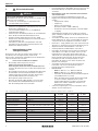 4
4
-
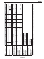 5
5
-
 6
6
-
 7
7
-
 8
8
-
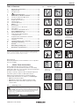 9
9
-
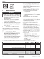 10
10
-
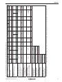 11
11
-
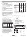 12
12
-
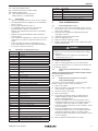 13
13
-
 14
14
-
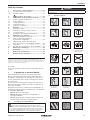 15
15
-
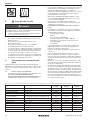 16
16
-
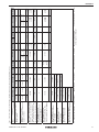 17
17
-
 18
18
-
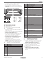 19
19
-
 20
20
-
 21
21
-
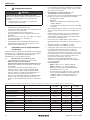 22
22
-
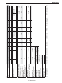 23
23
-
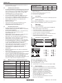 24
24
-
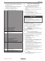 25
25
-
 26
26
-
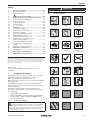 27
27
-
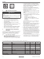 28
28
-
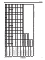 29
29
-
 30
30
-
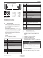 31
31
-
 32
32
-
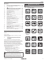 33
33
-
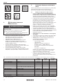 34
34
-
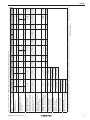 35
35
-
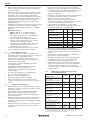 36
36
-
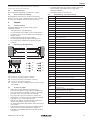 37
37
-
 38
38
-
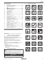 39
39
-
 40
40
-
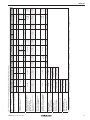 41
41
-
 42
42
-
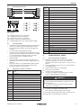 43
43
-
 44
44
-
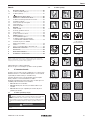 45
45
-
 46
46
-
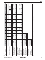 47
47
-
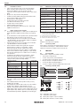 48
48
-
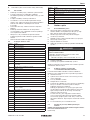 49
49
-
 50
50
-
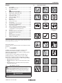 51
51
-
 52
52
-
 53
53
-
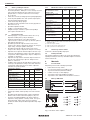 54
54
-
 55
55
-
 56
56
-
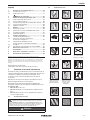 57
57
-
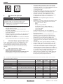 58
58
-
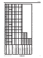 59
59
-
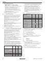 60
60
-
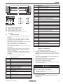 61
61
-
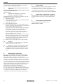 62
62


HOERMANN H3G Single-leaf and double-leaf steel doors Handleiding
- Type
- Handleiding
in andere talen
- italiano: HOERMANN H3G Single-leaf and double-leaf steel doors Istruzioni per l'uso
- français: HOERMANN H3G Single-leaf and double-leaf steel doors Mode d'emploi
- slovenčina: HOERMANN H3G Single-leaf and double-leaf steel doors Návod na používanie
- polski: HOERMANN H3G Single-leaf and double-leaf steel doors Instrukcja obsługi
- română: HOERMANN H3G Single-leaf and double-leaf steel doors Instrucțiuni de utilizare