
English
/ Español
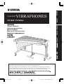
CONCERT
YV1605 YV1605J
Owner’s Manual
Bedienungsanleitung
Mode d’emploi
Manual de instrucciones
Français / Deutsch
/
Make sure to read “Safety Precautions” and “Cautions when using the instrument”.
Lesen Sie unbedingt die „Vorsichtsmaßregeln“ und die „Vorsichtshinweise zum Gebrauch des Instruments“.
Ne manquez pas de lire les sections « Précautions à observer » et « Précautions d’utilisation de l’instrument ».
Lea sin falta las “Precauciones de seguridad” y las “Precauciones para la utilización del instrumento”.
09.11.12, 3:46 PMPage 1
VIBRAPHONES

This product utilizes an external power supply (adapter). DO
NOT connect this product to any power supply or adapter other
than one described in the manual, on the name plate, or
specifically recommended by Yamaha.
WARNING: Do not place this product in a position where
anyone could walk on, trip over, or roll anything over power or
connecting cords of any kind. The use of an extension cord is not
recommended! If you must use an extension cord, the minimum
wire size for a 25" cord (or less) is 18 AWG. NOTE: The smaller
the AWG number, the larger the current handling capacity. For
longer extension cords, consult a local electrician.
This Product should be used only with the components supplied
or; a cart, rack, or stand that is recommended by Yamaha. If a
cart, etc., is used, please observe all safety markings and
instructions that accompany the accessory product.
SPECIFICATIONS SUBJECT TO CHANGE: The informa-
tion contained in this manual is believed to be correct at the time
of printing. However, Yamaha reserves the right to change or
modify any of the specifications without notice or obligation to
update existing units.
NOTICE: Service charges incurred due to lack of knowledge
relating to how a function or effect works (when the unit is
operating as designed) are not covered by the manufacturer’s
warranty; and are therefore the owners responsibility. Please
study this manual carefully and consult your dealer before re-
questing service.
ENVIRONMENTAL ISSUES: Yamaha strives to produce
products that are both user safe and environmentally friendly.
We sincerely believe that our products and the production
methods used to produce them, meet these goals. In keeping with
both the letter and the spirit of the law, we want you to be aware
of the following:
Disposal Notice: Should this Product become damaged beyond
repair, or for some reason its useful life is considered to be at an
end, please observe all local, state, and federal regulations that
relate to the disposal of products that contain lead, batteries,
plastics, etc. If your dealer is unable to assist you, Please contact
Yamaha directly.
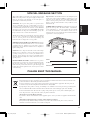
NAME PLATE LOCATION: The name Plate is located on the
player side of the product. The model number, serial number,
power requirements, etc., are located on this plate. You should
record the model number, serial number, and the date of
purchase in the spaces provided below and retain this manual as
a permanent record of your purchase.
SPECIAL MESSAGE SECTION
PLEASE KEEP THIS MANUAL
English
17
Model
Serial No.
Purchase Date
Information for Users on Collection and Disposal of Old Equipment
This symbol on the products, packaging, and/or accompanying documents means that used electrical and electronic
products should not be mixed with general household waste.
For proper treatment, recovery and recycling of old products, please take them to applicable collection points, in
accordance with your national legislation and the Directives 2002/96/EC.
By disposing of these products correctly, you will help to save valuable resources and prevent any potential negative
effects on human health and the environment which could otherwise arise from inappropriate waste handling.
For more information about collection and recycling of old products, please contact your local municipality, your
waste disposal service or the point of sale where you purchased the items.
[For business users in the European Union]
If you wish to discard electrical and electronic equipment, please contact your dealer or supplier for further informa-
tion.
[Information on Disposal in other Countries outside the European Union]
This symbol is only valid in the European Union. If you wish to discard these items, please contact your local
authorities or dealer and ask for the correct method of disposal.
EN
09.11.12, 3:47 PMPage 17

18
Safety Precautions
Please obey the following instructions in order to use your vibraphone in a safe manner.
Particularly in the case of children, a responsible adult should provide proper instruction
on how to properly use and treat the instrument before use.
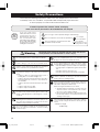
Icons are used in this
“Safety Precautions” section
to promote the safe use of
this instrument, and to pro-
tect you and others from
harm and property damage.
Please fully understand the
meaning of the icons before
reading the instructions.
In order to prevent fire, electric shock, and injury,
make sure that all precautions described below are obeyed.
About
the
icons
This icon urges caution (includes dangers and warnings).
This icon indicates actions that are prohibited.
This icon indicates special instructions that
should be strictly followed.
For example:
Do not dismantle.
For example:
Unplug the electric
plug from the outlet.
Warning
Disregard of the warnings denoted with this mark and misuse
of the product can lead to death or serious injury.
Before using the vibraphone, please thoroughly read
the following instructions and the Owner’s Manual.
Do not dismantle or modify the vibraphone’s controller
or driver. Doing so can cause fire or electrical shock.
Repairs or part replacement should not be attempted
unless instructions are provided in the manual.
Do not use or store the instrument in any of the follow-
ing locations. Doing so can cause fire or electrical
shock.
• In places subject to high temperatures (near a
heating device or in direct sunlight, etc.).
• In places where the instrument may be exposed to
moisture (bathroom, on wet floors, etc.) and exces-
sive humidity.
• In places where the instrument may be exposed to
rain.
• In places with excessive dust.
• In places subject to vibrations.
When using the AC adapter, do not excessively bend
the power cord, or place heavy objects on the cord.
Doing so may damage the cord causing fire or electri-
cal shock.
Do not play or roughhouse around the instrument.
Bumping into the instrument can cause injury. It can
also cause the instrument to overturn. Do not allow
children to play around the instrument.
Do not lean against or climb onto the instrument. Do-
ing so can cause the instrument to overturn resulting
in serious injury.
Never put foreign objects (combustible objects, coins,
wire, etc.) or liquids (water, juice, etc.) in the drive unit.
Doing so can cause fire and electric shock.
If one of the following occurs, turn off the power, unplug
the AC adapter and request repair as soon as possible.
• If the AC adapter or power cord becomes damaged.
• If foreign objects or liquids have gotten into the drive
unit.
• If the drive unit gets wet (rain, etc.).
• If the drive unit operates abnormally or is broken.
Never place the instrument on a sloping or unstable
surface or platform, etc. Doing so can cause the instru-
ment to fall over resulting in injury.
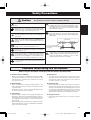
When moving the instrument on its casters, only move
across smooth, flat surfaces. Hold the instrument by its
side frames and push forward slowly.
When moving the instrument on its casters,
1. Avoid moving the instrument on surfaces that are
sloped or uneven. The instrument can overturn,
run out of control, and be a danger.
2. Never run with the instrument. The instrument may
become impossible to control and crash into a wall
causing serious injury.
If the instrument must be lifted or carried, do so with two
or more people using both hands to lift it by the side
frames.
* Vibraphone weight
YV1605: 38kg
09.11.12, 3:47 PMPage 18

19
Safety Precautions
Caution
Disregard of the warnings denoted with this mark, or misuse of
the product can result in injury or property damage.
Do not use the instrument in locations with poor venti-
lation.
Never pull on the cord when disconnecting the AC
adapter from the outlet. Always hold the AC adapter
when connecting or disconnecting the power.
Always disconnect the AC adapter from the outlet
when the instrument is not used for any extended pe-
riod of time.
Always use an AC adapter that meets YAMAHA speci-
fications. The use of any other AC adapter may cause
damage.
Never place your hands or feet underneath the pedal.
Doing so can result in pinched hands or feet.
Never touch the rotating fans. Doing so can result in
pinched fingers, etc.
Never use the mallets for anything other than playing
the instrument. Doing so can result in injury or acci-
dents. Do not allow children to use the mallets in any
way that may pose a danger to themselves or others.
Lock the stoppers on the casters when the instrument
is not in use.
When adjusting the playing surface height (described
on page 29), make sure that the procedure is per-
formed by at least two persons. Attempting to adjust
the height alone can result in the instrument overturn-
ing and create a danger.
Never touch the areas shown below when adjusting
the height. Doing so can result in pinched hands.
Make sure to hold the side frame when making height
adjustments.
Cautions when using the instrument
Before using the vibraphone, thoroughly read the cautions described below.
◆
Cautions when assembling
• Whenever assembling or dismantling the instrument, make
sure that all procedures are carried out as described in this
manual. Improper assembly of the instrument can result in
poor function or noise.
◆
When handling
•Never strike the tone bars with glockenspiel mallets or any
other solid objects. Doing so can dent or scratch the tone bars
or alter their pitch.
•Treating the controller or driver roughly can damage the inter-
nal circuit board, etc. Please use caution.
◆
Transporting
• When moving the instrument, move it gently avoiding shocks
and impacts. Also make sure that the AC adapter is discon-
nected and the caster stoppers are unlocked. Lift the instru-
ment slightly whenever moving it over surfaces that are not
smooth or flat.
• When transporting the instrument by car, dismantle the entire
instrument and pack it securely. To dismantle the instrument,
reverse the order of assembly.
◆
Maintenance
•Tone bars can be cleaned using a soft, dry cloth or silicon
cloth. Stains that are still visible may be wiped using off with a
small amount of ethyl alcohol applied to a soft cloth. Never
use thinner, benzine, or a wet cloth.
◆
Replacing parts
• Parts such as switches, volume control, jacks, are called con-
sumable parts and their function will deteriorate over time.
The level of deterioration will vary depending upon the condi-
tions under which the instrument is used however it cannot be
avoided. When replacing consumable parts, please consult
with the dealer from whom you purchased the instrument.
◆
Keep this manual
•
After reading this manual, keep it in a safe place for future
reference.
Do not touch these
areas when adjusting
the height.
Tighten bolts securely after determining the desired
height. Using the instrument with loose bolts can re-
sult in the instrument collapsing, noise, or other
troubles. Tighten the bolts occasionally.
Side Frame
09.11.12, 3:47 PMPage 19

20
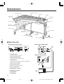
Nomenclature
■ Vibes Drive Unit
● Controller (Player Side)
Pedal Stay
Rail No. 1
q POWER Switch
Turns the power on and off.
w MOTOR SPEED Slider
Controls the fan rotation speed.
e LED Indicator
Lights when the power is turned on and flashes
while the fan is rotating.
r START/STOP Button
Starts and stops fan rotation.
t DC 12-15V IN Jack
y MOTOR OUT Terminal
u MOTOR IN Terminal
i 8P DIN Cable
o AC Adapter
Frame End
(Large)
Resonators
(Natural Tone Side)
Leg (Large)
Natural Tone Bars
Accidental Tone Bars
Controller
Fan Belt
Frame End
(Small)
Pedal
● Controller (Right Side)
● Driver (Player Side)
Caster
AC Adapter
Leg (Small)
Driver
Slide Leg
Resonators
(Accidental Tone Side)
START
/
STOP
SLOW
MOTOR
SPEED
FAST
POWER
ON OFF
r e w q
09.11.12, 3:47 PMPage 20

21
Confirmation of Packing Contents
q Vibes Main Unit x 1
t Resonators (Natural Tone Side) x 1
y Resonators (Accidental Tone Side) x 1
w Leg (Large) x 1 e Leg (Small) x 1
Slide Legs
Slide Legs
r Pedal Stay x 1
u AC Adapter x 1
i Round Belt
(Fan Belt) x 2
Vibes Drive Unit: YVM-200
* May not be included depending
on your particular area.
!0 Controller x 1
o Driver x 1
!1 8P DIN Cable x 1
The shipping carton of your YV1605 should contain the parts shown below.
Before assembling the instrument, confirm that all parts are included as listed.
* In the event that a part is missing, please contact the shop where the instrument was purchased.
09.11.12, 3:47 PMPage 21

22
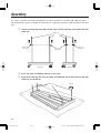
For safety, assembly should be performed by at least 2 persons in a location with sufficient space.
We recommend to you to assemble the instrument on a soft rug or carpet to avoid scratches in the tone
bars.
Assembly
Slide Legs
Slide Legs
Slide Leg
Fixing Bolt
Slide Leg
Fixing Bolt
Slide Leg
Fixing Bolt
z Loosen the slide leg fixing bolts of the large and the small leg, and remove the four
slide legs.
x Place the main unit bottom side up on the floor.
c Screw each slide leg into the screw hole at the bottom side of the main unit. (All four
slide legs are identical.)
Leg (Large)
Leg (Small)
Tighten
09.11.12, 3:47 PMPage 22

23
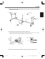
Assembly
v
Place the large leg, small leg and pedal stay so that after assembly each part will be
positioned as illustrated.
b Connect the large leg and small leg with the pedal stay.
Insert the pedal stay with its notch facing up into the lower joint of the large leg as far as it will go
(aligning the notch with the fixing bolt) and tighten the fixing bolt securely.
Tighten
Pedal Stay
Notch
Notch
Pedal Stay
Fixing
Bolt
Low Sound Side
High Sound
Side
Audience Side
Pedal
Pedal Stay
Player Side
Leg (Large)
Leg (Small)
Leg
(Large)
Leg (Large)
n Connect the other end of the pedal stay with the small leg in the same way.
09.11.12, 3:47 PMPage 23

24
Rod Connector
Tighten
Center Rod
Pedal Rod
Groove
m Connect the slide legs with the legs.
Align the legs from above so that the slide legs slide into the corresponding leg holes. Adjust to the
desired height and then securely tighten each slide leg fixing bolt, aligning it with the corresponding
notch of the slide leg. Fixing bolt and notch are aligned when the next lower notch is flush with the
upper leg flange.
, After fixing the legs, connect the
pedal with the sustain damper.
Loosen the center rod fixing bolts to
extend the center rod, and insert the
center rod into the fitting of the rod
connector. Align the groove in the cen-
ter rod with the tip of the fixing bolt, and
then securely tighten the fixing bolt.
When a slide leg fixing bolt is tightened in between two notches,
there is a danger of the slide leg slipping. Always make sure
that the slide legs are held securely.
Assembly
* The fourth notch from the tone bar side
corresponds to the standard height
setting.
High
Sound
Side
Low
Sound
Side
Do not touch the notched
part during height adjust-
ment to avoid injury.
Align notch
with upper
flange.
09.11.12, 3:47 PMPage 24

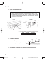
25
1
First, place the high sound side onto the corre-
sponding resonator holders.
Resonator
Holders
Assembly
.
Attach the resonators.
Insert the resonators from underneath the frame and rest the high sound side and then the low
sound side onto the resonator holders (rubber).
* Make sure not to confuse the natural tone side and accidental tone side resonators.
* Take care not to bump the resonators against the legs etc.
2
To engage the low sound side, lift it over the
resonator holders and then insert it into the gap
between the two holders, as shown in the
illustration.
Resonator
Holders
x
z
Low Sound
Side
High Sound
Side
Accidental Tone
Side Resonators
09.11.12, 3:47 PMPage 25

26
Bottom View
Insert mount
until it stops
Driver
Support Fitting
Bottom View
Fitting
Pulley
Fittings
Fixing Bolts
Motor Unit
Loosen the
fixing bolts.
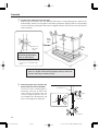
⁄0 Attach the driver.
10-1 Loosen the fixing bolts at the bottom of rails (2) and (3) on the high sound side, and slide both
fittings in the direction of the low sound side.
10-2 Fully insert the driver mount into the support fitting.
Slide the fittings.
Rail (3)
Rail (2)
Support Fitting
Fixing Bolts
Tighten
fixing bolts.
Fitting
Fitting
10-3 Slide the fittings moved in step 10-1 back in the direction of the high sound side. Engage the two
side mounts on the driver securely with the fittings, and then tighten the fixing bolts to fasten the
driver.
* Set the driver so that the pulleys on either side are positioned directly below the fan side pulleys.
Assembly
10-1 10-2
09.11.12, 3:47 PMPage 26

27
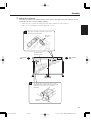
⁄1 Attach the controller.
There are two controller mounting pins on the high sound side of rail (1). Align the two holes in the
controller mounts with these pins and hook the controller onto the pins one side at a time.
* In case the 8P DIN cable is misplaced, the following spare part may be ordered:
Part No. Part Name Specification
W5 172200
Controller
Driver
Arrow Mark
Screw
Screw
Arrow Mark
8P DIN Cable
⁄2 Connect the driver with the controller.
Connect the MOTOR IN terminal of the driver with the MOTOR OUT terminal of the controller using
the supplied 8P DIN cable*.
To connect align the arrow mark (
) on the plug with the screw next to the jack.
High Sound Side
Controller mounting pins
Controller
Assembly
Rail (1)
09.11.12, 3:47 PMPage 27
8P DIN Cable
L=220

28
Assembly
Pulley
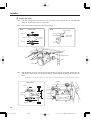
⁄3 Attach the round belt (fan belt)*.
Slip the round belt (fan belt) over the fan side pulley first, and then pull it over the flange of the driver
pulley.
* Note For Service Personnel
If the belt cannot be mounted because the distance between the pulleys is too wide, or
the belt slips due to a too narrow pulley distance, loosen the two driver positioning
screws (see illustration below) to adjust the pulley distance (belt tension). Tighten the
screws securely after adjustment.
Round Belt
(Fan Belt)
Pulley
Driver Side
Fan Side
Round Belt
(Fan Belt)
Driver Positioning
Screws
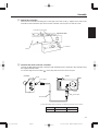
⁄4 Pedal Stroke Adjustment
Loosen the center rod fixing bolts to adjust the
protruding length of the center rod to the desired
pedal stroke, and retighten the bolts. The recom-
mended stroke (distance between pedal and floor)
is 9/16" to 13/16" (1.5 to 2 cm).
Pedal
Floor
9/16" ~ 13/16"
(1.5 ~ 2 cm)
* In case the belt is misplaced or worn, the following spare part may be ordered:
Part No. Part Name Specification
W5128070 Fan
Be
lt 3ØL236
⁄5 After assembly, confirm that each bolt and screw is tightened securely.
09.11.12, 3:47 PMPage 28

29
⁄6 Height Adjustment
Height adjustment should always be performed by at least 2 persons.
To adjust the height of the tone bars, first remove the round belt (fan belt), driver, controller and tone
bars*, and loosen the center rod fixing bolts. (* To remove the tone bars, disengage the springs on
the low sound side, and then unhook the string from the post.)
Support both frame ends by hand (do not touch the metal parts shown in the illustration), and loosen
the slide leg fixing bolts.
Assembly
For height adjustment, make
sure to support the instrument
by the wooden frame. Do not
touch the metal parts.
Frame
Do not touch !
⁄7 This completes the assembly of the instrument.
To play, connect the supplied AC adapter to the DC 12-15V IN jack of the controller.
Lift the frame ends to the desired height and then securely tighten each slide leg fixing bolt, aligning
it with the corresponding notch of the slide leg. Bolt and notch are aligned when the next higher notch
is flush with the upper leg flange. (Refer to step
m on page 24.)
When a slide leg fixing bolt is tightened in between two notches,
there is a danger of the slide leg slipping. Always make sure
that the slide legs are held securely.
09.11.12, 3:47 PMPage 29

30
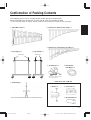
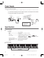
SPECIFICATIONS
YV1605
Range ....................................... f–f3, 3 Octaves
Bars .......................................... Aluminum Alloy, 1-1/2" wide, 1/2" thick
Pitch ......................................... A = 442 Hz
Drive Unit ................................. YVM-200 (Pause Controller), 25–145 rpm
Power Supply ........................... YAMAHA AC Adapter PA-130 (D.C. 12 V, 1 A
North
America), PA-D015 (D.C. 15 V, 1 A
Europe), or other adapter
recommended by YAMAHA.
Dimensions
(Length x Width) .....
124 x 74 cm (48-7/8" x 29-1/8")
Power Consumption
..................
2.9 W (PA-130), 3.6 W (PA-D015)
Height Adjustment.................... 80–88 cm (31-1/2" x 34-5/8")
Weight ...................................... 38 kg (83.8 lbs)
* Specifications subject to change without notice.
27 28 30 32 33 35 37 39 40 42 44 45 47 49 51 52 54 56 57 59 61 63 64 66 68 69 71 73 75 76 78 80 81 83 85 87 88
Middle C
SCALE RANGE
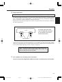
z Connect the small plug of the AC adapter to the DC 12-15V IN jack on the controller.
x Plug the AC adapter into a power outlet.
DC 12-15V IN
AC
AC Adapter
Controller
* Wrapping the AC adapter
cord once around one of
the legs will prevent
accidental disconnection of
the adapter plug.
Power Supply
Specifications
Prepare the supplied AC adapter.
* Make sure to use the supplied AC adapter. Use of different adapters may cause damage not covered by the warranty.
Scale Range
09.11.12, 3:47 PMPage 30

Page 84
Manual Development Group
© 2014 Yamaha Corporation
Published 08/2020
20208
POTO-T1
WQ84190
10-1 Nakazawa-cho, Naka-ku, Hamamatsu, 430-8650 Japan
-
 1
1
-
 2
2
-
 3
3
-
 4
4
-
 5
5
-
 6
6
-
 7
7
-
 8
8
-
 9
9
-
 10
10
-
 11
11
-
 12
12
-
 13
13
-
 14
14
-
 15
15
-
 16
16


Yamaha YV-1605 de handleiding
- Type
- de handleiding
- Deze handleiding is ook geschikt voor
in andere talen
- English: Yamaha YV-1605 Owner's manual
- italiano: Yamaha YV-1605 Manuale del proprietario
- русский: Yamaha YV-1605 Инструкция по применению
- français: Yamaha YV-1605 Le manuel du propriétaire
- español: Yamaha YV-1605 El manual del propietario
- Deutsch: Yamaha YV-1605 Bedienungsanleitung
- português: Yamaha YV-1605 Manual do proprietário
- dansk: Yamaha YV-1605 Brugervejledning
- čeština: Yamaha YV-1605 Návod k obsluze
- polski: Yamaha YV-1605 Instrukcja obsługi
- română: Yamaha YV-1605 Manualul proprietarului