
EnglishDeutschFrançaisEspañolPortuguêsItalianoРусский
JA
RU
IT
PT
ES
FR
DE
EN
WALL-MOUNT CONTROLLER
MCP1
Installation Manual
Installationshandbuch
Manuel d’installation
Manual de instalación
Manual de instalação
Manuale all’installazione
Руководство по установке

2 MCP1 Installation Manual
(can_b_02)
(class b korea)
This device complies with Part 15 of the FCC Rules. Operation is subject to the following two conditions:
(1) this device may not cause harmful interference, and (2) this device must accept any interference
received, including interference that may cause undesired operation.
CAN ICES-3 (B)/NMB-3(B)
이 기기는 가정용(B급) 전자파적합기기로서 주로 가정에서 사용하는 것을 목적으로 하며, 모든 지역에
서 사용할 수 있습니다.
1. IMPORTANT NOTICE: DO NOT MODIFY
THIS UNIT!
This product, when installed as indicated in
the instructions contained in this manual,
meets FCC requirements. Modifications not
expressly approved by Yamaha may void your
authority, granted by the FCC, to use the prod-
uct.
2. IMPORTANT: When connecting this product
to accessories and/or another product use
only high quality shielded cables. Cable/s sup-
plied with this product MUST be used. Follow
all installation instructions. Failure to follow
instructions could void your FCC authorization
to use this product in the USA.
3. NOTE: This product has been tested and
found to comply with the requirements listed in
FCC Regulations, Part 15 for Class “B” digital
devices. Compliance with these requirements
provides a reasonable level of assurance that
your use of this product in a residential envi-
ronment will not result in harmful interference
with other electronic devices. This equipment
generates/uses radio frequencies and, if not
installed and used according to the instruc-
tions found in the users manual, may cause
interference harmful to the operation of other
electronic devices. Compliance with FCC reg-
ulations does not guarantee that interference
will not occur in all installations. If this product
is found to be the source of interference, which
can be determined by tur
ning the u
nit “OFF”
and “ON”, please try to eliminate the problem
by using one of the following measures:
Relocate either this product or the device that
is being affected by the interference.
Utilize power outlets that are on different
branch (circuit breaker or fuse) circuits or
install AC line filter/s.
In the case of radio or TV interference, relo-
cate/reorient the antenna. If the antenna lead-
in is 300 ohm ribbon lead, change the lead-in
to co-axial type cable.
If these corrective measures do not produce
satisfactory results, please contact the local
retailer authorized to distribute this type of
product. If you can not locate the appropriate
retailer, please contact Yamaha Corporation of
America, Electronic Service Division, 6600
Orangethorpe Ave, Buena Park, CA90620
The above statements apply ONLY to those
products distributed by Yamaha Corporation of
America or its subsidiaries.
(class B)
FCC INFORMATION (U.S.A.)

3MCP1 Installation Manual
PRECAUTIONS
PLEASE READ CAREFULLY
BEFORE PROCEEDING
Please keep this manual in a safe
place for future reference.
WARNING
Always follow the basic precautions
listed below to avoid the possibility of
serious injury or even death from
electrical shock, short-circuiting,
damages, fire or other hazards. These
precautions include, but are not limited
to, the following:
Do not open
• This device contains no user-serviceable
parts. Do not open the device or attempt to
disassemble the internal parts or modify
them in any way. If it should appear to be
malfunctioning, discontinue use
immediately and have it inspected by
qualified Yamaha service personnel.
Water warning
• Do not expose the device to rain, use it
near water or in damp or wet conditions, or
place on it any containers (such as vases,
bottles or glasses) containing liquids which
might spill into any openings. If any liquid
such as water seeps into the device, turn
off the power of the PoE injector or the PoE
network switch immediately and unplug
the cable. Then have the device inspected
by qualified Yamaha service personnel.
• Never insert or remove a cable with wet
hands.
Fire warning
• Do not place any burning items or open
flames near the device, since they may
cause a fire.
If you notice any abnormality
• If any of the following problems occur,
immediately turn off the PoE injector or the
PoE network switch and disconnect the
cable.
- Unusual smells or smoke are emitted.
- Some object has been dropped into the
device.
- Cracks or other visible damage appear
on the device.
Then have the device inspected or
repaired by qualified Yamaha service
personnel.
CAUTION
Always follow the basic precautions
listed below to avoid the possibility of
physical injury to you or others, or
damage to the device or other property.
These precautions include, but are not
limited to, the following:
Location
• Do not place the device in a location where
it may come into contact with corrosive
gases or salt air. Doing so may result in
malfunction.
• Always consult qualified Yamaha service
personnel if the device installation requires
construction work, and make sure to
observe the following precautions.
- Choose mounting hardware and an
installation location that can support the
weight of the device.
- Avoid locations that are exposed to
constant vibration.
- Use the required tools to install the
device.
- Inspect the device periodically.
PA_en_8 1/2

4 MCP1 Installation Manual
Handling caution
• Avoid inserting or dropping foreign objects
(paper, plastic, metal, etc.) into any gaps
or openings on the device (panel, etc.). If
this happens, immediately turn off the
power of the PoE injector or the PoE
network switch, unplug the cable, and
have the device inspected by qualified
Yamaha service personnel.
• Do not rest your weight on the device or
place heavy objects on it. Avoid applying
excessive force to the buttons, switches or
connectors to prevent injuries.
NOTICE
To avoid the possibility of malfunction/ damage to the product, damage to data, or damage to
other property, follow the notices below.
Handling and maintenance
• Do not use the device in the v icinity of a TV, radio, AV equipment, mobile phone, or other electric
devices. Otherwise, the device, TV, or radio may generate noise.
• Do not expose the device to excessive dust or vibration, or extreme cold or heat (such as in
direct sunlight, near a heater, or in a car during the day), in order to prevent the possibility of
panel disfiguration, unstable operation, or damage to the internal components.
• Do not place vinyl, plastic or rubber objects on the device, since this might discolor the panel.
• When cleaning the device, use a dry and soft cloth. Do not use paint thinners, solvents, cleaning
fluids, or chemical-impregnated wiping cloths.
• Condensation can occur in the device due to rapid, drastic changes in ambient tempera-
ture—when the device is moved from one location to another, or air conditioning is turned on or
off, for example. Using the device while condensation is present can cause damag
e. If there is
reas
on to believe that condensation might have occurred, leave the device for several hours
without turning on the power until the condensation has completely dried out.
•Be sure to operate the switch with bare hands. The switch will not work properly if operated with
gloved hands.
Information
About functions/data bundled with the device
• Use STP (Shielded Twisted Pair) cable to prevent electromagnetic interference.
About disposal
• This product contains recyclable components. When disposing of this product, please contact
the appropriate local authorities.
About this manual
• The illustrations and screens as shown in this manual are for instructional purposes only.
• The company names and product names in this manual are the trademarks or registered trade-
marks of their respective companies.
•Software may be revised and updated without prior notice.
Yamaha cannot be held responsible for
damage caused by improper use or
modifications to the device.
PA_en_8 2/2

5MCP1 Installation Manual
Contents
PRECAUTIONS .....................................................................3
Introduction .......................................................................6
Controls and Connectors ........................................................7
Front Panel................................................................................................. 7
Rear Panel.................................................................................................. 8
Connections with an MTX/MRX system .......................................9
Function tree.................................................................... 10
Installation ...................................................................... 11
Setting the UNIT ID ............................................................. 13
Removal.......................................................................... 14
Initializing the MCP1 .......................................................... 14
Alert list.......................................................................... 15
Specifications .................................................................. 17
Dimensions ...................................................................... 18
Included items
•Mounting plate
•Surface mount box
• Side panel × 2
•Main unit — mounting plate screws × 4 (with washers)
•Mounting plate — surface mount box screws × 4 (without washers)
• MCP1 installation manual (this document)
Firmware update
MTX-MRX Editor is used to update the firmware of the MCP1 and to check the version.
For details on how to perform these operations, refer to “MTX-MRX Editor User Guide.”
The latest firmware can be downloaded from the download page of the following website.
http://www.yamahaproaudio.com/

6 MCP1 Installation Manual
Introduction
Thank you for purchasing the Yamaha MCP1 wall-mount controller. This product is a
wall-mount controller for controlling the MTX/MRX system. This installation manual
explains how to mount the unit when the installing technician or the designer installs or
sets-up the system. In order to take full advantage of this product’s many functions, be
sure to read this installation manual before installation.
After reading this manual, keep it for future reference.
The MCP1 lets you set up a home page and six pages, and assign up to 36 parameters.
What you’ll need to provide
When attaching the MCP1 to a wall, you’ll need to provide several items.
• PoE injector or PoE network switch that supports IEEE802.3af
This is used between the MTX/MRX system and the MCP1 in order to supply power to the
MCP1.
PoE injector units and PoE network switches are collectively referred to as “PSE (Power
Sourcing Equipment).”
• Ethernet cables (CAT5e or better)
These are used between the MTX/MRX and the PSE, and between the PSE and the MCP1.
• (If embedding the unit in the wall)
2-gang box (without separator; 20 mm or greater depth)
Yo u’ll also need screws for attaching the gang box to the wall.
• (If using a surface mount box)
Screws for attaching the surface mount box to the wall × 4
Provide M4.0 flat head screws of a length appropriate for the thickness of the wall.
• Phillips screwdriver / electric screwdriver
This is used for installation.

7MCP1 Installation Manual
Controls and Connectors
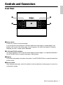
Front Panel
q Home switch
Touch this to return to the home page.
If you long-touch (more than two seconds) when the home page or another page is dis-
played, you’ll move to the utility page. If you long-press this while the display is locked or
sleeping, the lock or sleep state is defeated.
w L1/2/3 and R1/2/3 switches
Use these switches to move from the home page to another page, or to operate parameters.
Use MTX-MRX Editor to specify the pages or parameters.
e Display
This shows parameters and other information. Use MTX-MRX Editor to create the data that
will be shown.
r Return switch
After setting a parameter, touch this switch to confirm and return to the page or to move to a
confirmation screen.
r
e
w
q
w

Controls and Connectors
8 MCP1 Installation Manual
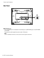
Rear Panel
t NETWORK port
This is an RJ-45 port for connection to the Dante port or [NETWORK] port of the MTX/MRX
via the PSE.
The maximum cable length that can be used is 100 meters.
NOTE
Use STP (Shielded Twisted Pair) cable to prevent electromagnetic interference.
t
t

9MCP1 Installation Manual
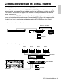
Connections with an MTX/MRX system
Up to 16 MCP1 units can be connected to an MTX/MRX system.
Use an Ethernet cable to connect the MTX/MRX’s [NETWORK] port or Dante port to a PoE
network switch, and use an Ethernet cable to connect the PoE network switch to the MCP1.
If the network switch does not support PoE, connect a PoE injector between the network
switch and the MCP1.
In some cases, the PSE (PoE network switch or PoE injector) might have ports that supply
power and ports that do not supply power. Connect the MCP1 to a port that supplies power.
For details on how to synchronize each device, refer to “MTX-MRX Editor User Guide.”
Connections for a small system
Connections for a large system
Computer
MTX3
SWR2100P-5G
MCP1
Maximum 100 meters
Computer
MRX7-D
SWR2100P-10G
MCP1
Maximum
100 meters
XMV8280-D
SWP1-16MMF
MCP1 MCP1 MCP1

10 MCP1 Installation Manual
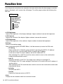
Function tree
If you long-touch (more than two seconds) the home switch when the home page or another
page is displayed, you’ll move to the utility page. The utility page contains the following func-
tion tree.
• LCD Brightness
Adjusts the brightness of the display backlight. Higher numbers increase the brightness.
• LCD Contrast
Adjusts the contrast of the display. Higher numbers increase the contrast.
• LED Brightness
Adjusts the brightness of the switches. Higher numbers increase the brightness.
•Settings
Moves to the settings page.
After synchronizing with MTX-MRX Editor, it will be necessary to enter the PIN code.
• IP Setting
Selects either PC or UNIT ID as the method of specifying the MCP1’s IP address.
In the case of PC, use MTX-MRX Editor to specify the IP address.
In the case of UNIT ID, the IP address will be 192.168.0.UNIT ID.
After selecting PC or UNIT ID, touch the return switch to move to the confirmation
screen and automatically restart.
•Unit ID
Specifies the MCP1’s UNIT ID. The range of this setting is 01 through FE.
If IP Setting is UNIT ID, make settings so that there is no conflict wit
h the IP address of
anoth
er device.
After specifying UNIT ID, touch the return switch to move to the confirmation screen and
automatically restart.
• Initialize
Initializes the MCP1.
• Version
Display the firmware version of MCP1.
•Alert
Display the alert number which has occurred current.
LCD Brightness
LCD Contrast
LED Brightness
Settings
IP Setting
Unit ID
Initialize
Version
Alert
Utility page

11MCP1 Installation Manual
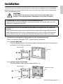
Installation
The MCP1 can be installed on a wall in either of two ways: in a gang box that is embedded
behind the wall, or in the included surface mount box which you attach to the surface of the
wall in an exposed position.
1. Attach the mounting plate to the gang box or the surface mount box.
Orient it so that the side printed “TOP” is toward yourself and above.
1- a.
If using a gang box
Align the elongated holes of the mounting place with the screw holes of the gang box,
and secure it in at least two locations.
1- b.
If using a surface mount box
Use the included screws without washers (M3.0 × 12).
CAUTION
Install the MCP1 no more than 2 meters above the floor. When MCP1 falls, it
becomes a cause by which MCP1 is damaged or you or others are injured.
If embedding the unit in a gang box installed behind the wall
Orient the gang box behind the wall in a horizontal position; into the gang box, pass the
cable that is connected to the PSE.
If installing the unit in the included surface mount box exposed on the surface of
the wall
The surface mount box has a cut-out that allows you to open a hole through which to pass the
cable. Open the hole in the cutout as necessary with a tool (such as a plier), pass the cable
into the surface mount box, and secure it using M4.0 flat head screws which you provide.
Mounting plate
Gang box
Mounting plate
Cable
Surface mount box

Installation
12 MCP1 Installation Manual
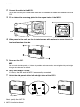
2. Connect the cable to the MCP1.
To the NETWORK port on the back of the MCP1, connect the cable that extends from the
PSE.
3. Fit the tabs of the mounting plate into the square holes of the MCP1.
4. While pressing the unit, use the included screws with washers to secure the unit in
four locations from the side.
5. Power-on the PSE.
6. Verify that the MCP1 starts.
If it starts, the PSE and the MCP1 are correctly connected.
7. Attach the side panels to the left and right sides of the MCP1.
Attach them so that they click into place.
Next, specify the UNIT ID.
NOTE
Do not attach the side panel yet. If there is a problem with connections, removing the side panel might
damage the side panel or the wall.
MCP1
Side panels

13MCP1 Installation Manual
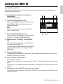
Setting the UNIT ID
Set the MCP1’s UNIT ID.
Operate the switches with bare hands. If you attempt to operate them while wearing gloves,
they will not work correctly.
1. Long-touch (two seconds or longer) the
home switch.
Move to the utility page.
2. Touch the [Settings] switch (R1).
Move to the settings page. After synchronizing
with MTX-MRX Editor, it will be necessary to
enter the PIN code.
3. Touch the [IP Setting] switch (L1).
Specify whether the IP address is determined by
the UNIT ID or by MTX-MRX Editor (PC).
4. Make sure that “IP Setting” is set to [UNIT
ID].
If it is set to [PC], touch the L1/2/3 switches at
the left to set it to [UNIT ID].
If you are using a subnet other than 192.168.0.x,
set this to [PC] and make the setting in MTX-
MRX Editor.
5. Touch the return switch.
A confirmation screen appears; select Yes. The setting is confirmed as the UNIT ID, and
the MCP1 automatically restarts.
6. Touch the [Unit ID] switch (L2).
Set the MCP1’s UNIT ID.
Set the ID so that it does not conflict with the UNIT ID of another unit within the same net-
work.
To uching an L1/2/3 switch decreases the number; touching an R1/2/3 switch increases the
number.
7. When you’ve set the UNIT ID, touch the return switch.
A confirmation screen appears; select Yes. The UNIT ID is confirmed, and the MCP1 auto-
matically restarts.
NOTE
If you have forgotten the PIN code, use MTX-MRX
Editor to specify it again.
3 2
6 5, 7
1 5, 7

14 MCP1 Installation Manual
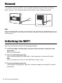
Removal
If you need to remove the MCP1, insert a slotted screwdriver into the notches of the side
panel, and twist. The subsequent steps are the reverse of the installation procedure.
Initializing the MCP1
With the unit powered on, perform the following procedure.
1. In the home page or another page, long-touch (two seconds or longer) the home
page switch.
Move to the utility page.
2. Touch the [Settings] switch (R1).
After synchronizing with MTX-MRX Editor, it will be necessary to enter the PIN code.
3. Touch the [Initialize] switch (L3).
A confirmation screen appears; select Yes. Initialization begins, and the MCP1 automati-
cally restarts.
NOTE
When re-installing the MCP1, portions of the screw holes in the mount plate may be deformed and may not
properly fit into the MCP1. If this is the case, use a tool to adjust parts of the screw holes as necessary and
re-install the unit.
NOTE
If you have forgotten the PIN code, use MTX-MRX Editor to specify it again.

15MCP1 Installation Manual
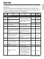
Alert list
The following table lists the alerts generated by the MCP1, their meaning, and the appropriate
action to take.
When a Fault type alert occurs, it will immediately be displayed. Other alert types can be
checked by touching [Alert] in the Settings page. A single occurrence is shown when the situa-
tion occurs. A continuous occurrence is shown when the situation occurs and when it ends.
If the problem cannot be solved, contact your Yamaha dealer.
Number Content Action Type
Single /
Continuing
Device abnormality
001
The unit did not start up nor-
mally.
Turn off the power supply of the
PSE, wait at least six seconds,
and then turn on the power. If
this does not solve the problem,
initialize the MCP1.
Fault Continuing
003
Failed writing to internal flash
ROM.
Fault Continuing
005 MAC address was lost. Fault Continuing
017
Settings saved in internal
memory were lost.
Perform synchronization again
using MTX-MRX Editor.
Fault Continuing
040 The IP address conflicts.
Make settings so that the IP
address does not conflict.
Error Continuing
041
The IP address was not estab-
lished within 60 seconds after
startup.
If the IP Setting is set to “PC,”
use MTX-MRX Editor or the
DHCP server to specify the IP
address.
Warning Continuing
042
The devices making up the
MTX/MRX system were not
found on the network.
Power-on all devices making up
the system, and make sure that
they are correctly connected to
the network.
Error Continuing
043
Too m a ny d evices are con-
nected to the network.
Reduce the number of devices
connected to the network.
Error Single
051
A device with the same UNIT
ID was found among the
devices connected to the same
network.
Make settings so that the UNIT
ID does not conflict.
Error Continuing
060 Failed to recall a preset. Initialize the MCP1. Error Continuing
064
The preset could not be
recalled.
The Preset selected for recall
cannot be recalled as no data
has been stored to it, or another
device may have been added
after presets were stored.
Please synchronize and check
all presets using MTX-MRX
Editor, and store again.
Warning Continuing

Alert list
16 MCP1 Installation Manual
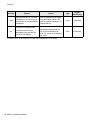
For other alerts, refer to “Alert list” in the “MTX-MRX Editor User Guide.”
070
Synchronization has not been
completed. It may be that syn-
chronization was halted before
completion.
Perform synchronization again
using MTX-MRX Editor. If this
does not solve the problem, ini-
tialize the MCP1.
Error Continuing
071
The UNIT ID settings when
synchronization was per-
formed do not match the cur-
rent UNIT ID settings.
Do not change any UNIT ID’s
after performing synchroniza-
tion. If you’ve changed any
UNIT ID’s, perform synchroniza-
tion again.
Error Continuing
Number Content Action Type
Single /
Continuing

17MCP1 Installation Manual
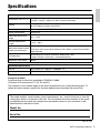
Specifications
European models
Purchaser/User Information specified in EN55103-2:2009.
Conforms to Environments: E1, E2, E3 and E4
The contents of this manual apply to the latest specifications as of the pub lishing date. To
obtain the latest manual, access the Yamaha website then download the manual file.
(rear_en_01)
Product specifications
Dimensions (W × H × D)
149(W) × 125(H) × 18(D) mm (when embedded in the wall)
152(W) × 128(H) × 46(D) mm (with a surface mount box)
Weight
0.6 kg (with a surface mount box)
0.5 kg (without a surface mount box)
Power supply voltage Power supplied via PoE (IEEE802.3af)
Power consumption 4.8 W max.
Operating temperature
range
0°C – 40°C
Storage temperature
range
-20°C – 60°C
Maximum number of units
usable simultaneously
Up to 16 MCP1 units can be installed per system
(There are limits on the total number of units within a system that includes
other devices)
Included items
Mounting plate, Surface mount box, Side panels (Two),
screws (2 kinds / Each 4 pcs.), Installation Manual
Separately sold option None
Connector specifications
Format NETWORK port: 10BASE-T/100BASE-TX
Cable specifications NETWORK port: CAT5e or better Ethernet STP cable
The model number, serial number, power requirements, etc., may be found on or near the
name plate, which is at the rear of the unit. You should note this serial number in the space
provided below and retain this manual as a permanent record of your purchase to aid
identification in the event of theft.
Model No.
Serial No.

18 MCP1 Installation Manual
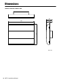
Dimensions
149
125
(20)(18)
38
Without surface mount box
Unit: mm

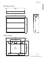
Dimensions
19MCP1 Installation Manual
(28)(18)
46
152
128
128
80
4×
Ø
4.6
152
80
With surface mount box
Surface mount box
Unit: mm

20 MCP1 Installation Manual
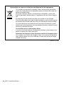
(weee_eu_en_02)
Information for users on collection and disposal of old equipment:
This symbol on the products, packaging, and/or accompanying documents
means that used electrical and electronic products should not be mixed with
general household waste.
For proper treatment, recovery and recycling of old products, please take
them to applicable collection points, in accordance with your national legisla-
tion.
By disposing of these products correctly, you will help to save valuable
resources and prevent any potential negative effects on human health and the
environment which could otherwise arise from inappropriate waste handling.
For more information about collection and recycling of old products, please
contact your local municipality, your waste disposal service or the point of sale
where you purchased the items.
For business users in the European Union:
If you wish to discard electrical and electronic equipment, please
contact y
our
dealer or supplier for further information.
Information on Disposal in other Countries outside the European Union:
This symbol is only valid in the European Union. If you wish to discard these
items, please contact your local authorities or dealer and ask for the correct
method of disposal.

149MCP1 Installation Manual

ADDRESS LIST
Head Office/Manufacturer: Yamaha Corporation 10-1, Nakazawa-cho, Naka-ku, Hamamatsu, 430-8650, Japan
(For European Countries) Importer: Yamaha Music Europe GmbH Siemensstrasse 22-34, 25462 Rellingen, Germany
CANADA
Yamaha Canada Music Ltd.
135 Milner Avenue, Toronto, Ontario,
M1S 3R1, Canada
Tel: +1-416-298-1311
U.S.A.
Yamaha Corporation of America
6600 Orangethorpe Avenue, Buena Park, CA
90620, U.S.A.
Tel: +1-714-522-9011
MEXICO
Yamaha de México, S.A. de C.V.
Av. Insurgentes Sur 1647 Piso 9, Col. San José
Insurgentes, Delegación Benito Juárez, México,
D.F., C.P. 03900, México
Tel: +52-55-5804-0600
BRAZIL
Yamaha Musical do Brasil Ltda.
Rua Fidêncio Ramos, 302 – Cj 52 e 54 – Torre B –
Vila Olímpia – CEP 04551-010 – São Paulo/SP, Brazil
Tel: +55-11-3704-1377
ARGENTINA
Yamaha Music Latin America, S.A.,
Sucursal Argentina
Olga Cossettini 1553, Piso 4 Norte,
Madero Este-C1107CEK,
Buenos Aires, Argentina
Tel: +54-11-4119-7000
PANAMA AND OTHER LATIN
AMERICAN COUNTRIES/
CARIBBEAN COUNTRIES
Yamaha Music Latin America, S.A.
Edif. Torre Banco General, Piso 7, Urbanización
Marbella, Calle 47 y Aquilino de la Guardia,
Ciudad de Panamá, República de Panamá
Tel: +507-269-5311
THE UNITED KINGDOM/IRELAND
Yamaha Music Europe GmbH (UK)
Sherbourne Drive, Tilbrook, Milton Keynes,
MK7 8BL, U.K.
Tel: +44-1908-366700
GERMANY
Yamaha Music Europe GmbH
Siemensstrasse 22-34, 25462 Rellingen, Germany
Tel: +49-4101-303-0
SWITZERLAND/LIECHTENSTEIN
Yamaha Music Europe GmbH, Branch
Switzerland in Thalwil
Seestrasse 18a, 8800 Thalwil, Switzerland
Tel: +41-44-3878080
AUSTRIA/BULGARIA/
CZECH REPUBLIC/HUNGARY/
ROMANIA/SLOVAKIA/SLOVENIA
Yamaha Music Europe GmbH
Branch Austria
Schleiergasse 20, 1100 Wien, Austria
Tel: +43-1-60203900
POLAND
Yamaha Music Europe GmbH
Sp.z o.o. Oddział w Polsce
ul. Wielicka 52, 02-657 Warszawa, Poland
Tel: +48-22-880-08-88
MALTA
Olimpus Music Ltd.
Valletta Road, Mosta MST9010, Malta
Tel: +356-2133-2093
NETHERLANDS/BELGIUM/
LUXEMBOURG
Yamaha Music Europe Branch Benelux
Clarissenhof 5b, 4133 AB Vianen, The Netherlands
Tel: +31-347-358040
FRANCE
Yamaha M u s i c E u rope
7 rue Ambroise Croizat, Zone d'activités de Pariest,
77183 Croissy-Beaubourg, France
Tel: +33-1-6461-4000
ITALY
Yamaha Music Europe GmbH, Branch Italy
Via Tinelli N.67/69 20855 Gerno di Lesmo (MB),
Italy
Tel: +39-039-9065-1
SPAIN/PORTUGAL
Yamaha Music Europe GmbH Ibérica, Sucursal
en España
Ctra. de la Coruña km. 17,200, 28231
Las Rozas de Madrid, Spain
Tel: +34-91-639-88-88
GREECE
Philippos Nakas S.A. The Music House
19th klm. Leof. Lavriou 190 02 Peania – Attiki,
Greece
Tel: +30-210-6686168
SWEDEN/FINLAND/ICELAND
Yamaha Music Europe GmbH Germany filial
Scandinavia
JA Wettergrensgata 1, 400 43 Göteborg, Sweden
Tel: +46-31-89-34-00
DENMARK
Yamaha Music Denmark,
Fillial of Yamaha Music Europe GmbH,
Tyskland
Generatorvej 8C, ST. TH. , 2860 Søborg, Denmark
Tel: +45-44-92-49-00
NORWAY
Yamaha Music Europe GmbH Germany -
Norwegian Branch
Grini Næringspark 1, 1332 Østerås, Norway
Tel: +47-6716-7800
CYPRUS
Yamaha Music Europe GmbH
Siemensstrasse 22-34, 25462 Rellingen, Germany
Tel: +49-4101-303-0
RUSSIA
Yamaha Music (Russia) LLC.
Room 37, entrance 7, bld. 7, Kievskaya street,
Moscow, 121059, Russia
Tel: +7-495-626-5005
OTHER EUROPEAN COUNTRIES
Yamaha Music Europe GmbH
Siemensstrasse 22-34, 25462 Rellingen, Germany
Tel: +49-4101-3030
Yamaha M u s i c G u l f F Z E
JAFZA-16, Office 512, P.O.Box 17328,
Jebel Ali FZE, Dubai, UAE
Tel: +971-4-801-1500
TURKEY
Yamaha Music Europe GmbH
Merkezi Almanya Türkiye İstanbul Şubesi
Mor Sumbul Sokak Varyap Meridian Business
1.Blok No:1 113-114-115
Bati Atasehir Istanbul, Turkey
Tel: +90-216-275-7960
OTHER COUNTRIES
Yamaha M u s i c G u l f F Z E
JAFZA-16, Office 512, P.O.Box 17328,
Jebel Ali FZE, Dubai, UAE
Tel: +971-4-801-1500
THE PEOPLE’S REPUBLIC OF CHINA
Yamaha Music & Electronics (China) Co.,Ltd.
2F, Yunhedasha, 1818 Xinzha-lu, Jingan-qu,
Shanghai, China
Tel: +86-400-051-7700
INDIA
Yamaha Music India Private Limited
P-401, JMD Megapolis, Sector-48, Sohna Road,
Gurgaon-122018, Haryana, India
Tel: +91-124-485-3300
INDONESIA
PT. Yamaha Musik Indonesia (Distributor)
Yamaha Music Center Bldg. Jalan Jend. Gatot
Subroto Kav. 4, Jakarta 12930, Indonesia
Tel: +62-21-520-2577
KOREA
Yamaha Music Korea Ltd.
11F, Prudential Tower, 298, Gangnam-daero,
Gangnam-gu, Seoul, 06253, Korea
Tel: +82-2-3467-3300
MALAYSIA
Yamaha Music (Malaysia) Sdn. Bhd.
No.8, Jalan Perbandaran, Kelana Jaya, 47301
Petaling Jaya, Selangor, Malaysia
Tel: +60-3-78030900
SINGAPORE
Yamaha Music (Asia) Private Limited
Block 202 Hougang Street 21, #02-00,
Singapore 530202, Singapore
Tel: +65-6740-9200
TAIWAN
Yamaha Music & Electronics Taiwan Co.,Ltd.
2F., No.1, Yuandong Rd., Banqiao Dist.,
New Taipei City 22063, Taiwan (R.O.C.)
Tel: +886-2-7741-8888
THAILAND
Siam Music Yamaha Co., Ltd.
3, 4, 15, 16th Fl., Siam Motors Building,
891/1 Rama 1 Road, Wangmai,
Pathumwan, Bangkok 10330, Thailand
Tel: +66-2215-2622
VIETNAM
Yamaha Music Vietnam Company Limited
15th Floor, Nam A Bank Tower, 201-203 Cach
Mang Thang Tam St., Ward 4, Dist.3,
Ho Chi Minh City, Vietnam
Tel: +84-8-3818-1122
OTHER ASIAN COUNTRIES
http://asia.yamaha.com/
AUSTRALIA
Yamaha Music Australia Pty. Ltd.
Level 1, 80 Market Street, South Melbourne,
VIC 3205, Australia
Tel: +61-3-9693-5111
COUNTRIES AND TRUST
TERRITORIES IN PACIFIC OCEAN
http://asia.yamaha.com/
NORTH AMERICA
CENTRAL & SOUTH AMERICA
EUROPE
AFRICA
MIDDLE EAST
ASIA
OCEANIA
PA 52


VAM5060
Manual Development Group
© 2017 Yamaha Corporation
Published 05/2018 POES-C0
Yamaha Pro Audio global website
https://www.yamaha.com/proaudio/
Yamaha Downloads
https://download.yamaha.com/
-
 1
1
-
 2
2
-
 3
3
-
 4
4
-
 5
5
-
 6
6
-
 7
7
-
 8
8
-
 9
9
-
 10
10
-
 11
11
-
 12
12
-
 13
13
-
 14
14
-
 15
15
-
 16
16
-
 17
17
-
 18
18
-
 19
19
-
 20
20
-
 21
21
-
 22
22
-
 23
23
-
 24
24


in andere talen
- English: Yamaha MCP1 User manual
- italiano: Yamaha MCP1 Manuale utente
- русский: Yamaha MCP1 Руководство пользователя
- français: Yamaha MCP1 Manuel utilisateur
- español: Yamaha MCP1 Manual de usuario
- Deutsch: Yamaha MCP1 Benutzerhandbuch
- português: Yamaha MCP1 Manual do usuário
- dansk: Yamaha MCP1 Brugermanual
- suomi: Yamaha MCP1 Ohjekirja
- čeština: Yamaha MCP1 Uživatelský manuál
- svenska: Yamaha MCP1 Användarmanual
- Türkçe: Yamaha MCP1 Kullanım kılavuzu
- polski: Yamaha MCP1 Instrukcja obsługi
- română: Yamaha MCP1 Manual de utilizare