Yamaha PSR-8000 Handleiding
- Categorie
- Synthesizer
- Type
- Handleiding
Deze handleiding is ook geschikt voor


92-469- ➀
ENVIRONMENTAL ISSUES: Yamaha strives to pro-
duce products that are both user safe and environmentally
friendly. We sincerely believe that our products and the
production methods used to produce them, meet these
goals. In keeping with both the letter and the spirit of the
law, we want you to be aware of the following:
Battery Notice: This product MAY contain a small non-
rechargable battery which (if applicable) is soldered in
place. The average life span of this type of battery is ap-
proximately five years. When replacement becomes nec-
essary, contact a qualified service representative to per-
form the replacement.
Warning: Do not attempt to recharge, disassemble, or
incinerate this type of battery. Keep all batteries away
from children. Dispose of used batteries promptly and as
regulated by applicable laws. Note: In some areas, the
servicer is required by law to return the defective parts.
However, you do have the option of having the servicer
dispose of these parts for you.
Disposal Notice: Should this product become damaged
beyond repair, or for some reason its useful life is consid-
ered to be at an end, please observe all local, state, and
federal regulations that relate to the disposal of products
that contain lead, batteries, plastics, etc.
NOTICE: Service charges incurred due to lack of knowl-
edge relating to how a function or effect works (when the
unit is operating as designed) are not covered by the
manufacturer’s warranty, and are therefore the owners
responsibility. Please study this manual carefully and con-
sult your dealer before requesting service.
NAME PLATE LOCATION: The graphic below indi-
cates the location of the name plate. The model number,
serial number, power requirements, etc., are located on
this plate. You should record the model number, serial
number, and the date of purchase in the spaces provided
below and retain this manual as a permanent record of
your purchase.
CAUTION
RISK OF ELECTRIC SHOCK
DO NOT OPEN
CAUTION: TO REDUCE THE RISK OF ELECTRIC SHOCK.
DO NOT REMOVE COVER (OR BACK).
NO USER-SERVICEABLE PARTS INSIDE.
REFER SERVICING TO QUALIFIED SERVICE PERSONNEL.
PRODUCT SAFETY MARKINGS: Yamaha electronic
products may have either labels similar to the graphics
shown below or molded/stamped facsimiles of these
graphics on the enclosure. The explanation of these graph-
ics appears on this page. Please observe all cautions indi-
cated on this page and those indicated in the safety in-
struction section.
The exclamation point within the equi-
lateral triangle is intended to alert the
user to the presence of important oper-
ating and maintenance (servicing) in-
structions in the literature accompany-
ing the product.
The lightning flash with arrowhead
symbol, within the equilateral triangle,
is intended to alert the user to the pres-
ence of uninsulated “dangerous volt-
age” within the product’s enclosure that
may be of sufficient magnitude to con-
stitute a risk of electrical shock.
IMPORTANT NOTICE: All Yamaha electronic prod-
ucts are tested and approved by an independent safety
testing laboratory in order that you may be sure that when
it is properly installed and used in its normal and custom-
ary manner, all foreseeable risks have been eliminated.
DO NOT modify this unit or commission others to do so
unless specifically authorized by Yamaha. Product per-
formance and/or safety standards may be diminished.
Claims filed under the expressed warranty may be denied
if the unit is/has been modified. Implied warranties may
also be affected.
SPECIFICATIONS SUBJECT TO CHANGE: The
information contained in this manual is believed to be
correct at the time of printing. However, Yamaha reserves
the right to change or modify any of the specifications
without notice or obligation to update existing units.
SPECIAL MESSAGE SECTION
Model _____________________________________
Serial No. __________________________________
Purchase Date ______________________________
CAUTION
RISK OF ELECTRIC SHOCK
DO NOT OPEN
AVIS :
RISQUE DE CHOC ÉLECTRIQUE–NE PAS OUVRIR.
WARNING :
TO REDUCE THE RISK OF FIRE OR ELECTRIC SHOCK,
DO NOT EXPOSE THIS PRODUCT TO RAIN OR MOISTURE.
TO HOST MIDI FOOT PEDAL
AC INLET
IN OUT THRU SWITCH 1 SWITCH 2 VOLUMEPC-1PC-2
MIDIMac
LOOP SEND AUX IN/LOOP RETURN AUX OUT
R L/L+R R L/L+R
MIN MAX
TRIM
L/L+RR

WARNING- When using any electrical or electronic prod-
uct, basic precautions should always be followed. These pre-
cautions include, but are not limited to, the following:
1. Read all Safety Instructions, Installation Instructions,
Special Message Section items, and any Assembly Instructions
found in this manual BEFORE making any connections, in-
cluding connection to the main supply.
2. Main Power Supply Verification: Yamaha products are
manufactured specifically for the supply voltage in the area
where they are to be sold. If you should move, or if any doubt
exists about the supply voltage in your area, please contact
your dealer for supply voltage verification and (if applicable)
instructions. The required supply voltage is printed on the
name plate. For name plate location, please refer to the graphic
found in the Special Message Section of this manual.
3. This product may be equipped with a polarized plug
(one blade wider than the other). If you are unable to insert the
plug into the outlet, turn the plug over and try again. If the
problem persists, contact an electrician to have the obsolete
outlet replaced. Do NOT defeat the safety purpose of the plug.
4. Some electronic products utilize external power sup-
plies or adapters. Do NOT connect this type of product to any
power supply or adapter other than one described in the owners
manual, on the name plate, or specifically recommended by
Yamaha.
5. WARNING: Do not place this product or any other
objects on the power cord or place it in a position where any-
one could walk on, trip over, or roll anything over power or
connecting cords of any kind. The use of an extension cord is
not recommended! If you must use an extension cord, the
minimum wire size for a 25' cord (or less) is 18 AWG. NOTE:
The smaller the AWG number, the larger the current handling
capacity. For longer extension cords, consult a local electri-
cian.
6. Ventilation: Electronic products, unless specifically
designed for enclosed installations, should be placed in loca-
tions that do not interfere with proper ventilation. If instruc-
tions for enclosed installations are not provided, it must be
assumed that unobstructed ventilation is required.
7. Temperature considerations: Electronic products
should be installed in locations that do not significantly con-
tribute to their operating temperature. Placement of this prod-
uct close to heat sources such as; radiators, heat registers and
other devices that produce heat should be avoided.
8. This product was NOT designed for use in wet/damp loca-
tions and should not be used near water or exposed to rain. Exam-
ples of wet/damp locations are; near a swimming pool, spa, tub,
sink, or wet basement.
9. This product should be used only with the components
supplied or; a cart, rack, or stand that is recommended by the
manufacturer. If a cart, rack, or stand is used, please observe all
safety markings and instructions that accompany the accessory
product.
10. The power supply cord (plug) should be disconnected from
the outlet when electronic products are to be left unused for ex-
tended periods of time. Cords should also be disconnected when
there is a high probability of lightening and/or electrical storm
activity.
11. Care should be taken that objects do not fall and liquids are
not spilled into the enclosure through any openings that may exist.
12. Electrical/electronic products should be serviced by a
qualified service person when:
a. The power supply cord has been damaged; or
b. Objects have fallen, been inserted, or liquids have been
spilled into the enclosure through openings; or
c. The product has been exposed to rain: or
d. The product dose not operate, exhibits a marked change
in performance; or
e. The product has been dropped, or the enclosure of the
product has been damaged.
13. Do not attempt to service this product beyond that de-
scribed in the user-maintenance instructions. All other servicing
should be referred to qualified service personnel.
14. This product, either alone or in combination with an ampli-
fier and headphones or speaker/s, may be capable of producing
sound levels that could cause permanent hearing loss. DO NOT
operate for a long period of time at a high volume level or at a
level that is uncomfortable. If you experience any hearing loss or
ringing in the ears, you should consult an audiologist.
IMPORTANT: The louder the sound, the shorter the time period
before damage occurs.
15. Some Yamaha products may have benches and/or acces-
sory mounting fixtures that are either supplied as a part of the
product or as optional accessories. Some of these items are de-
signed to be dealer assembled or installed. Please make sure that
benches are stable and any optional fixtures (where applicable) are
well secured BEFORE using. Benches supplied by Yamaha are
designed for seating only. No other uses are recommended.
INFORMATION RELATING TO PERSONAL INJURY, ELECTRICAL SHOCK,
AND FIRE HAZARD POSSIBILITIES HAS BEEN INCLUDED IN THIS LIST.
IMPORTANT SAFETY INSTRUCTIONS
PLEASE KEEP THIS MANUAL
92-469-2

PRECAUTIONS
PLEASE READ CAREFULLY BEFORE PROCEEDING
* Please keep these precautions in a safe place for future reference.
• Do not open the instrument or attempt to disassemble the internal parts
or modify them in any way. The instrument contains no user-serviceable
parts. If it should appear to be malfunctioning, discontinue use immedi-
ately and have it inspected by qualified Yamaha service personnel.
• Do not expose the instrument to rain, use it near water or in damp or wet
conditions, or place containers on it containing liquids which might spill
into any openings.
• If the power cord or plug becomes frayed or damaged, or if there is a
sudden loss of sound during use of the instrument, or if any unusual smells
• Do not place the power cord near heat sources such as heaters or radia-
tors, and do not excessively bend or otherwise damage the cord, place
heavy objects on it, or place it in a position where anyone could walk on,
trip over, or roll anything over it.
• When removing the electric plug from the instrument or an outlet, always
hold the plug itself and not the cord. Pulling by the cord can damage it.
• Do not connect the instrument to an electrical outlet using a multiple-
connector. Doing so can result in lower sound quality, or possibly cause
overheating in the outlet.
• Remove the electric plug from the outlet when the instrument is not to be
used for a long time, or during electrical storms.
• Before connecting the instrument to other electronic components, turn off
the power for all components. Before turning the power on or off for all
components, set all volume levels to minimum.
• Do not expose the instrument to excessive dust or vibrations, or extreme
cold or heat (such as in direct sunlight, near a heater, or in a car during the
day) to prevent the possibility of panel disfiguration or damage to the
internal components.
• Do not use the instrument near other electrical products such as televi-
sions, radios, or speakers, since this might cause interference which can
affect proper operation of the other products.
• Do not place the instrument in an unstable position where it might acci-
dentally fall over.
• Before moving the instrument, remove all connected cables.
• When cleaning the instrument, use a soft, dry cloth. Do not use paint
thinners, solvents, cleaning fluids, or chemical-impregnated wiping cloths.
Also, do not place vinyl or plastic objects on the instrument, since this
might discolor the panel or keyboard.
• Do not rest your weight on, or place heavy objects on the instrument, and
do not use excessive force on the buttons, switches or connectors.
• Use only the stand specified for the instrument. When attaching the stand
or rack, use the provided screws only. Failure to do so could cause dam-
age to the internal components or result in the instrument falling over.
• Do not place objects in front of the instrument’s air vents on the top and
rear panels, since this may prevent adequate ventilation of the internal
components, and possibly result in the instrument overheating.
Also, be careful to place the instrument on a flat, level surface to prevent
blockage of the air vents on the bottom panel.
• Do not operate the instrument for a long period of time at a high or uncom-
fortable volume level, since this can cause permanent hearing loss. If you
experience any hearing loss or ringing in the ears, consult a physician.
■REPLACING THE BACKUP BATTERY
The PSR-8000 requires four 1.5 V C size (LR14) batteries for memory backup
power. If no backup batteries are installed, the memory contents will be lost
when the instrument is unplugged from the AC mains supply. Please use
or smoke should appear to be caused by it, immediately turn off the power
switch, disconnect the electric plug from the outlet, and have the instru-
ment inspected by qualified Yamaha service personnel.
• Only use the voltage specified as correct for the instrument. The required
voltage is printed on the name plate of the instrument.
• Before cleaning the instrument, always remove the electric plug from the
outlet. Never insert or remove an electric plug with wet hands.
• Check the electric plug periodically and remove any dirt or dust which
may have accumulated on it.
CAUTION
Always follow the basic precautions listed below to avoid the possibility of physical injury to you or others, or damage to the
instrument or other property. These precautions include, but are not limited to, the following:
alkaline batteries.
1.Before changing the battery be sure to save any important data to disk
by using the SAVE TO DISK function described on page 141.
2.Turn the PSR-8000 power OFF and unplug the power cord from both the
AC wall socket and the instrument’s rear panel. Turn the instrument up-
side down and rest it on a blanket or other soft surface.
3.Open Battery Compartment Cover
Open the battery compartment cover — located on the instrument’s
bottom panel — by pressing on the two latches on the cover and pulling
outward, as shown in the illustration.
4.Remove the old batteries (if installed).
Remove the old batteries and wait at least one minute to ensure that all
data is fully cleared.
5.Insert Batteries
Insert the four batteries, being careful to follow the polarity markings on
the bottom panel.
6.Replace Cover
Replace the compartment cover, making sure that it locks firmly in place.
• Always make sure all batteries are inserted in conformity with the +/– polar-
ity markings. Failure to do so might result in overheating, fire, or battery fluid
leakage.
• Always replace all batteries at the same time. Do not use new batteries
together with old ones. Also, do not mix battery types, such as alkaline
batteries with manganese batteries, or batteries from different makers, or
different types of batteries from the same maker, since this can cause
overheating, fire, or battery fluid leakage.
• Do not dispose of batteries in fire.
• Do not attempt to recharge batteries that are not intended to be charged.
• If the instrument is not to be in use for a long time, remove the batteries
from it (after saving any important data to disk), in order to prevent pos-
sible fluid leakage from the battery.
• Keep batteries away from children.
■SAVING USER DATA
• Always save data to a floppy disk frequently, in order to help prevent the
loss of important data due to a malfunction or user operating error.
Yamaha cannot be held responsible for damage caused by improper use or modi-
fications to the instrument, or data that is lost or destroyed.
Always turn the power off when the instrument is not in use.
Make sure to discard used batteries according to local regulations.
4
(1)
WARNING
Always follow the basic precautions listed below to avoid the possibility of serious injury or even death from electrical shock,
short-circuiting, damages, fire or other hazards. These precautions include, but are not limited to, the following:

will pick up a layer of magnetic particles from the disks used that will
eventually cause read and write errors.
• To maintain the disk drive in optimum working order Yamaha recom-
mends that you use a commercially-available dry-type head cleaning
disk to clean the head about once a month. Ask your Yamaha dealer
about the availability of proper head-cleaning disks.
Never insert anything but floppy disks into the disk drive. Other objects
may cause damage to the disk drive or floppy disks.
■ About the Floppy Disks
To handle floppy disks with care:
• Do not place heavy objects on a disk or bend or apply pressure to the
disk in any way. Always keep floppy disks in their protective cases
when they are not in use.
• Do not expose the disk to direct sunlight, extremely high or low tem-
peratures, or excessive humidity, dust or liquids.
• Do not open the sliding shutter and touch the exposed surface of the
floppy disk inside.
• Do not expose the disk to magnetic fields, such as those produced by
televisions, speakers, motors, etc., since magnetic fields can partially or
completely erase data on the disk, rendering it unreadable.
• Never use a floppy disk with a deformed shutter or housing.
• Do not attach anything other than the provided labels to a floppy disk.
Also make sure that labels are attached in the proper location.
To protect your data (Write-protect Tab):
• To prevent accidental erasure of important data, slide the disk’s write-
protect tab to the “protect” position (tab open).
WARNING
• Before beginning installation, switch off the power to the PSR-8000 and
connected peripherals, and unplug them from the power outlet. Then
remove all cables connecting the PSR-8000 to other devices. (Leaving
the power cord connected while working can result in electric shock.
Leaving other cables connected can interfere with work.)
• Do not disassemble, modify, or apply excessive force to board areas and
connectors on hard disk, and SIMMs. Bending or tampering with boards
and connectors may lead to electric shock, fire, or equipment failures.
CAUTION
• Before handling the internal hard disk or SIMMs, you should briefly touch
the metal surface to which the hard-disk or SIMM cover is attached (or
Precautions
• Be sure to handle floppy disks and treat the disk drive with care. Follow
the important precautions below.
Compatible Disk Type
• 3.5” 2DD and 2HD type floppy disks can be used.
■ Inserting/Ejecting Floppy Disks
To insert a floppy disk into the disk drive:
• Hold the disk so that the label of the
disk is facing upward and the sliding
shutter is facing forward, towards
the disk slot. Carefully insert the disk
into the slot, slowly pushing it all the
way in until it clicks into place and
the eject button pops out.
To eject a floppy disk:
• Before ejecting a floppy disk make
sure that the floppy disk drive is not
in operation (the DISK IN USE indi-
cator should be off, except when the
internal hard disk is being accessed).
Press the eject button slowly as far as it will go; the disk will automati-
cally pop out. When the disk is fully ejected, carefully remove it by hand.
• Never attempt to remove the disk or turn the power off during recording,
reading and playing back. Doing so can damage the disk and possibly
the disk drive.
• If the eject button is pressed too quickly, or if it is not pressed in as far as
it will go, the disk may not eject properly. The eject button may become
stuck in a half-pressed position with the disk extending from the drive
slot by only a few millimeters. If this happens, do not attempt to pull out
the partially ejected disk, since using force in this situation can damage
the disk drive mechanism or the floppy disk. To remove a partially ejected
disk, try pressing the eject button once again, or push the disk back into
the slot and then repeat the eject procedure.
• Be sure to remove the floppy disk from the disk drive before turning off
the power. A floppy disk left in the drive for extended periods can easily
pick up dust and dirt that can cause data read and write errors.
Cleaning the Disk Drive Read/Write Head
• Clean the read/write head regularly. This instrument employs a preci-
sion magnetic read/write head which, after an extended period of use,
other such metallic area — be careful of any sharp edges) with your
bare hand so as to drain off any static charge from your body. Note that
even a slight amount of electrostatic discharge may cause damage to
these components.
• It is recommended that you wear gloves to protect your hands from
metallic projections on the PSR-8000 hard disk, SMMs, and other com-
ponents. Touching leads or connectors with bare hands may cause fin-
ger cuts, and may also result in poor electrical contact or electrostatic
damage.
• Take care to avoid dropping screws into the PSR-8000 unit. If a screw
does fall in, be sure to remove it before replacing the cover and powering
up the unit. Starting the unit with a loose screw inside may lead to im-
proper operation or equipment failure. (If you are unable to retrieve a
dropped screw, consult your Yamaha dealer for advice.)
Handling the Floppy Disk Drive(FDD) and Floppy Disk
Handling and Installation of Options
Data backup
• For maximum data security Yamaha recommends that you keep two
copies of important data on separate floppy disks. This gives you a backup
if one disk is lost or damaged. To make a backup disk use the COPY
FILE/FD function on page 143.
Write protected Write enabled
YAMAHA is not responsible for damage caused by improper handling or operation.
YAMAHA provides no guarantee against disk damage.
* If SIMM memory, or hard disk fails to work properly, consult the item’s dealer or manufacturer for advice.
* Yamaha will not be held responsible for any damage or injury resuting from improper installation.
5
This lamp is always on
while the power is on.
DISK IN USE

Congratulations!
You are the proud owner of an extraordinary electronic keyboard. The Yamaha PSR-8000
PortaTone combines the most advanced tone generation technology with state-of-the-art digital
electronics and features to give you stunning sound quality with maximum musical versatility. The
advanced Auto Accompaniment, Vocal Harmony, and Sampler features, in particular, are brilliant
examples of how Yamaha technology can significantly expand your musical horizons. A large-size
graphic display and easy-to-use interface also greatly enhance the operability of this advanced
instrument.
In order to make the most of your PortaTone’s features and vast performance potential, we urge
you to read the manuals thoroughly while trying out the various features described. Keep the manuals
in a safe place for later reference.
Packing List
Your PSR-8000 includes the following items:
• PSR-8000 PortaTone x 1
• AC Power Cord x 1
• AC Plug Adaptor x 1 (in applicable areas only)
• Music Stand x 1
• Audio CD x 1 (includes sound sources for sampling: page 88)
• Floppy Disk x 1 (includes accompaniment style files: page 28)
• Owner’s Manual
• Unauthorized copying of copyrighted software for purposes other than the purchaser’s personal use is prohib-
ited.
• The Vocal Harmony feature included in this product is manufactured under license from IVL Technologies Ltd.,
U.S. Patent numbers 5231671, 5301259, and 5428708.
● Trademarks:
• Apple and Macintosh are trademarks of Apple Computer, Inc.
• IBM-PC/AT is a trademark of International Business MachinesCorporation.
• Windows is the registered trademark of Microsoft
®
Corporation.
• All other trademarks are the property of their respective holders.
6
• The illustrations and LCD screens as shown in this owner’s manual are for instructional purposes only, and may
appear somewhat different from those on your instrument.
GM System Level 1
“GM System Level 1” is an addition to the MIDI standard which
guarantees that any data conforming to the standard will play
accurately on any GM-compatible tone generator or synthe-
sizer from any manufacturer.
XG
XG is a new Yamaha MIDI specification which significantly
expands and improves on the “GM System Level 1” standard
with greater voice handling capacity, expressive control, and
effect capability while retaining full compatibility with GM. By
using the PSR-8000’s XG voices, it is possible to record XG-
compatible song files.
XF
The Yamaha XF format enhances the SMF (Standard MIDI
File) strandard with greater functionality and open-ended
expandability for the future. The PSR-8000 is capable of
displaying lyrics when an XF file containing lyric data is
played.
• SMF (Standard MIDI File) is the most common format used for
MIDI sequence files. The PSR-8000 is compatible with SMF
Formats 0 and 1, and records “song” data using SMF Format
0.
The Panel Logos
The logos printed on the PSR-8000 panel indicate standards/formats it supports and special features it includes.

7
Main Features
Main Features
The PSR-8000 is a sophisticated electronic keyboard which offers a comprehensive range of
features for extensive musical versatility and expressive control: a touch-sensitive 61-key
keyboard, an outstanding range of voices (including XG voices), top quality auto-accompani-
ment with an extensive range of styles, song recording and playback capability, registration
memory, and a built-in floppy disk for convenient data storage and retrieval, and more.
The following features, in particular, give the PSR-8000 extraordinary musical production
and performance power.
● High-quality sampling capability — with expandable
wave memory — lets you sample and edit sounds
via microphone or from line sources, and then use
the sampled waveforms in original voices.
● Unique Vocal Harmony feature incorporates ad-
vanced voice-processing technology to automati-
cally produce vocal harmony based on a lead vocal,
making a single singer sound like a vocal group.
● An advanced effect system incorporating 8 sepa-
rate DSPs (Digital Signal Processors) and 5-band
master equalization adds depth, ambience, and
animation to your sound.
● Comprehensive Mixing Console displays provide
professional sound control and production capabil-
ity.
● Large multi-function LCD display panel with display-
based buttons and dials, plus comprehensive dis-
play prompts and messages, makes operation easy
and intuitive.
● Create original voices using the Voice Creator fea-
ture for a totally original sound.
● Style Creator feature lets you create “groove style”
variations on existing styles, or create entirely new
styles that are a perfect match for your performing
requirements.
● One Touch Setting feature automatically selects
appropriate voice, effect, and other settings for the
selected accompaniment style — all you have to do
is select a style, press the ONE TOUCH SETTING
button and play.
● Multi Pads record and play short rhythmic and me-
lodic sequences that can be used to add impact
and variety to your performances.
● Voice/Style List Customize feature lets you rear-
range the list contents for fast, efficient access in
performance situations.
● Unique “Talk” function instantly makes the settings
you need for mid-performance announcements and
interludes.
● Loop Send and Return jacks allow extra system
flexibility: connect external signal-processing equip-
ment for enhanced effect capability, or feed a mixer
for improved sound and on-stage monitoring quality.
● Optional internal hard disk provides high-volume,
high-speed data storage and retrieval.
● A selection of MIDI Templates eliminates tedious
setup procedures by providing instantly selectable
MIDI setups for a range of situations.
● To Host interface plus a range of MIDI functions for
expanded musical performance (General MIDI Sys-
tem Level 1 and Yamaha XG/XF compatible).
DOC
The DOC voice allocation format provides data playback
compatibility with a wide range of Yamaha instruments and
MIDI devices, including the Clavinova series.
Style File Format
The Style File Format — SFF — is Yamaha’s original style file
format which uses a unique conversion system to provide
high-quality automatic accompaniment based on a wide range
of chord types. The PSR-8000 uses the SFF internally, reads
optional SFF style disks, and creates SFF styles using the
STYLE CREATOR feature.
Vocal Harmony
Vocal Harmony employs state-of-the-art digital signal process-
ing technology to automatically add appropriate vocal
harmony to a lead vocal line sung by the user. Vocal Harmony
can even change the character and gender of the lead voice
as well as the added voices to produce a wide range of vocal
harmony effects.

8
Contents
Contents
Panel Controls 10
Connections & Music Stand 12
The Demonstration 17
The PSR-8000 Display &
Display-based Controls 19
■ The MIXING CONSOLE Buttons ....19
■ The [EXIT] Button............................ 20
■ The [DIRECT ACCESS] Button ......20
■ The [LCD CONTRAST] Control ...... 20
■ The 5-language Help Function........20
■ Display Messages ........................... 21
■ Name Entry ..................................... 21
Playing the PSR-8000 22
■ Before You Begin ............................22
The PSR-8000 Parts & Voices......... 22
■ Part Poly/Mono Modes & Mono
Note Priority ....................................22
■ The XG Voices ................................ 23
■ The Organ Flute Voice ....................23
■ Keyboard Percussion and Special
Effects ............................................. 24
Procedure:
Part Selection and Voice
Assignment
..........................................24
Voice Effects........................................ 26
Other Play Mode Functions............. 26
■ Master Transpose ........................... 26
■ Octave Change ............................... 27
■ Left Hold..........................................27
■ Pitch Bend & Modulation Wheels....27
Using the Accompaniment
Section 28
Procedure:
Auto Accompaniment......... 28
■ Auto Accompaniment Fingering
Modes .............................................30
■ Auto Accompaniment Start Modes.. 33
■ The MAIN A and MAIN B Sections
and Fill-ins.......................................34
■ Tempo Control ................................35
■ Fade-ins and Fade-outs .................. 35
■ Synchronized Stop .......................... 35
■ Accompaniment Volume ................. 36
■ Accompaniment Part Switching ......36
■ Virtual Arranger ............................... 36
■ Harmony/Echo ................................37
■ One Touch Setting .......................... 38
The Mixing Console 39
Mixing Console Parameters ............ 39
VOLUME/PAN/EQ..............................40
■ VOLUME ......................................... 40
■ PANPOT .........................................40
■ EQ LOW..........................................40
■ EQ HIGH ......................................... 40
■ HPF1 ............................................... 40
■ HPF2 ............................................... 40
FILTER ............................................... 41
■ HARMONIC CONTENT .................. 41
■ BRIGHTNESS.................................41
EFFECT DEPTH................................. 41
■ REVERB (DSP1)............................. 41
■ CHORUS (DSP2) ............................ 41
■ DSP3............................................... 42
■ DSP4-7............................................ 42
EFFECT TYPE.................................... 42
■ Type Page....................................... 42
● EFFECT BLOCK & TYPE ........... 42
● TYPE LIST .................................. 42
■ Parameter Page ..............................42
● BLOCK ........................................ 42
● TYPE ........................................... 42
● PARAMETER ..............................43
● VALUE ........................................ 43
● LEVEL ......................................... 43
● USER SET .................................. 43
TUNING .............................................. 44
■ TRANSPOSE ..................................44
■ TUNING ..........................................44
■ OCTAVE ......................................... 44
■ PITCH BEND RANGE..................... 44
■ PORTAMENTO TIME ..................... 44
MASTER EQ....................................... 45
■ EQ1 … EQ5 ....................................45
■ Q & FREQ .......................................45
■ TOTAL GAIN ADJUST.................... 45
■ STORE............................................ 45
Registration Memory 46
Registering the Panel Settings.......46
Recalling the Registered Panel
Settings
.................................................47
The Freeze Function..........................47
Organ Flute Voice Editing 48
■ ORGAN TYPE................................. 48
■ ROTARY SP SPEED ......................48
■ VIBRATO ON/OFF .......................... 48
■ VIBRATO DEPTH ........................... 48
■ FOOTAGE....................................... 48
■ VOLUME & ATTACK ...................... 49
■ EFFECT & EQ SETTINGS.............. 49
Custom Voice Creator 51
Procedure:
Engaging the Easy/
Full Edit Mode
..................................... 51
The Easy Edit Parameters ............... 52
EDIT .................................................... 52
■ FILTER............................................ 52
■ EG ...................................................52
■ VIBRATO ........................................53
■ VOLUME .........................................53
STORE/CLEAR .................................. 53
■ NAME.............................................. 53
■ STORE............................................ 53
■ CLEAR CUSTOM VOICE ...............54
The Full Edit Parameters.................. 54
■ ELEMENT SELECTION
(not available for the Drum Kits) .................. 54
VOICE ................................................. 55
■ MASTER VOLUME .........................55
■ INITIAL TOUCH CURVE................. 55
■ SCALE CURVE............................... 55
■ MODULATION ................................55
■ AFTER TOUCH............................... 55
E1:WAVEFORM .................................56
■ WAVEFORM
(INSTRUMENT for the Drum Kits) ................ 56
■ COARSE TUNE/FINE TUNE ..........56
■ VOLUME .........................................56
■ KEY ON DELAY.............................. 56
■ PAN ................................................. 56
■ NOTE LIMIT
(not available for the Drum Kits) .................. 56
■ VELOCITY LIMIT
(not available for the Drum Kits) .................. 56
E2:EG ................................................. 57
■ AMP RATE
(Amplitude Envelope Rate) ............. 57
■ AMP LEVEL
(Amplitude Envelope Level) ............ 57
■ PITCH RATE (Pitch Envelope Rate)58
■ PITCH LEVEL .................................58
■ FILTER RATE .................................58
■ FILTER LEVEL................................ 58
E3:FILTER .......................................... 59
■ FILTER1 & FILTER2 .......................59
■ RESONANCE ................................. 59
■ TOUCH TO FILTER ........................59
E4:LFO ............................................... 59
■ LFO (Low Frequency Oscillator) .....59
■ DELAY (Delay Vibrato) ................... 60
VOICE SET ......................................... 60
■ REVERB, CHORUS, and DSP
DEPTH ............................................ 60
■ DSP TYPE and VARIATION ...........60
■ EQ LOW and HIGH ......................... 60
STORE/CLEAR .................................. 61
■ NAME.............................................. 61
■ STORE............................................ 61
■ CLEAR CUSTOM VOICE ...............61
The Custom Style Creator 62
Procedure:
Custom Style Recording.... 62
CUSTOM STYLE CREATOR Param-
eters ....................................................... 66
■ Exiting ............................................. 66
BASIC ................................................. 66
■ SECTION/PATTERN LENGTH/
BEAT/TEMPO ................................. 66
■ PART COPY ................................... 67
SETUP ................................................67
■ VOICE .............................................67
■ SETUP COPY .................................68
EDIT .................................................... 68
■ QUANTIZE ......................................68
■ VELOCITY CHANGE ......................69
■ MEASURE COPY ........................... 69
■ MEASURE CLEAR .........................69
■ REMOVE CONTROL EVENT .........69
■ REMOVE DUPLICATE NOTES ......70
STORE/CLEAR .................................. 70
■ NAME.............................................. 70
■ STORE............................................ 70
■ CLEAR CUSTOM STYLE ...............70
PARAMETER EDIT ............................71
■ PART/SOURCE ROOT/SOURCE
CHORD ...........................................71
■ NTR/NTT ......................................... 71
■ HIGH KEY/NOTE LIMIT.................. 72
■ RTR ................................................. 72

9
Contents
Custom Style Recording via an
External Sequence Recorder
.......... 73
■ Connections .................................... 73
■ Creating the Data ............................ 73
■ Saving and Loading the Sequence
Data................................................. 75
■ Refining the Style ............................ 75
The Groove Style Creator 76
Procedure:
Creating a Groove Style..... 76
GROOVE STYLE CREATOR
Parameters
...........................................77
■ Exiting .............................................77
SETUP ................................................78
■ PART ON/OFF/TEMPO .................. 78
■ VOICE ............................................. 78
■ SETUP COPY ................................. 78
GROOVE ............................................79
■ GROOVE ........................................79
■ SETUP COPY ................................. 79
DYNAMICS ......................................... 80
■ DYNAMICS ..................................... 80
■ SETUP COPY ................................. 80
STORE/CLEAR .................................. 80
■ NAME..............................................80
■ STORE............................................81
■ GROOVE STYLE CLEAR ............... 81
■ STORE AS CUSTOM STYLE ......... 81
■ CUSTOM STYLE CLEAR ............... 81
DRUM EXCHANGE ............................ 82
■ DRUM EXCHANGE ........................ 82
■ SETUP COPY ................................. 82
Vocal Harmony 83
Using Vocal Harmony....................... 83
■ Setting Up .......................................83
■ The VOCAL/SAMPLING Buttons .... 83
■ Selecting a VOCAL HARMONY
Type ................................................ 84
■ Producing the VOCAL HARMONY
Effect ............................................... 84
Editing the Vocal Harmony
Parameters ........................................ 84
■ The Vocal Harmony Modes............. 85
Sampling 88
PSR-8000 Waves & Waveforms .......88
Setting Up for Sampling ...................89
■ Connecting the Source.................... 89
■ Setting Levels.................................. 89
Sampling & File Import..................... 90
■ Sampling New Material ................... 90
■ NAME/CLEAR................................. 92
Wave Edit ........................................... 93
■ EDIT ................................................ 93
■ NAME/CLEAR/DISK .......................96
Waveform Edit................................... 97
■ EDIT ................................................ 97
■ NAME/CLEAR/DISK .......................98
■ STORE AS CUSTOM VOICE ......... 99
Song Playback 100
Procedure:
Song Playback.................... 100
Enter Next Song ..............................101
Pause, Fast Forward & Reverse .... 102
Lyric Display.................................... 102
The CHORD DETECT and VOCAL
HARM. Parameters.......................... 102
■ CHORD DETECT.......................... 102
■ VOCAL HARM. .............................102
Setting the Song Playback Order ..103
MIXING CONSOLE Operation During
Song Playback ................................ 103
■ FADER .......................................... 103
■ FULL .............................................104
Song Recording 105
Procedure:
Song Recording ................. 105
Procedure:
Quick Record ......................106
■ THE TRACK INDICATORS........... 108
■ TRACK DELETE ........................... 108
■ PLAYBACK ................................... 108
■ EXITING........................................108
Procedure:
Chord Step Recording...... 109
■ DELETING EVENTS.....................110
■ INSERTING OR DELETING
MEASURES ..................................110
■ SAVING THE CHORD STEP
DATA............................................. 110
Quick Record Mode Edit Functions111
■ RENAME SONG ........................... 111
■ SONG DELETE............................. 111
Procedure:
Multi Track Record ............111
■ THE TRACK INDICATORS........... 113
■ TRACK DELETE ........................... 114
■ PLAYBACK ................................... 114
■ EXITING........................................114
Procedure:
Punch-In & Replace
Recording
...........................................114
Multi Track Record Mode Edit
Functions .........................................116
■ RENAME SONG ........................... 116
■ QUANTIZE .................................... 116
■ TRACK MIX................................... 117
■ NOTE SHIFT.................................117
■ SONG DELETE............................. 117
Multi Track Record Set Up ............. 118
■ VOICE ...........................................118
■ OTHER SET UP PARAMETERS..118
The Multi Pads 119
MULTI PAD Playback ......................119
Procedure:
MULTI PAD Recording .....119
■ MULTI PAD NAME........................121
■ MULTI PAD CLEAR ......................121
The Repeat & Chord Match Modes 121
■ REPEAT........................................121
■ CHORD MATCH ........................... 121
The PSR-8000 “Functions” 122
The FUNCTION Parameters........... 122
■ The [EXIT] Button.......................... 122
F1: MASTER TUNE/SCALE ............ 123
■ MASTER TUNE ............................123
■ SCALE (ARABIC).......................... 123
F2: SPLIT POINT/FINGERING ........ 123
■ SPLIT POINT ................................ 123
■ FINGERING .................................. 124
F3: CONTROLLER...........................124
■ FOOT CONTROLLER................... 124
■ PANEL CONTROLLER.................126
F4: REGISTRATION/ONE TOUCH
SETTING/VOICE SET ...................... 127
■ REGISTRATION ........................... 127
■ ONE TOUCH SETTING ................ 127
■ VOICE SET ...................................128
F5: HARMONY/ECHO......................129
F6: CUSTOMIZE LIST......................129
F7: TALK SETTING ......................... 130
F8: UTILITY ...................................... 131
F9: MIDI ............................................132
■ TEMPLATE ................................... 132
■ SYSTEM .......................................134
■ TRANSMIT....................................135
■ RECEIVE ......................................136
■ PANEL CONTROL........................138
Disk Operations 139
The DISK Parameters ......................139
■ Exiting ...........................................140
LOAD FROM DISK...........................140
SAVE TO DISK.................................141
COPY FILE/FD ................................. 143
■ Copying Files ................................143
■ Copying Floppy Disks ...................144
CHANGE SONG ORDER................. 144
RENAME FILE/SONG ......................145
DELETE FILE/SONG ....................... 145
FORMAT FD .....................................146
EDIT DIRECTORY............................ 146
■ NEW DIR....................................... 146
■ RENAME.......................................146
■ DELETE ........................................ 146
FORMAT HARD DISK......................147
CHECK HARD DISK ........................ 147
Troubleshooting 148
Index 150
Installing Options............................. 152
Optional SIMM Installation ............. 152
Optional Hard Disk Installation...... 156
Voice List ............................................ 159
Keyboard Drum Assignments ......166
Style List .............................................168
Direct Access Chart.........................170
Parameter Chart................................171
Effect Signal Flow Chart ................176
MIDI Data Format..............................177
MIDI Implementation Chart............196
Audio Sampling Library CD
Contents.............................................. 200
Specifications....................................203

10
SONG
REW FF
PAUSE
DEMO/HELP
MASTER VOLUME
MIN MAX
SONG SELECT
SONG
STYLE
SYNC
STOP
SYNC
START
START/
STOP
INTRO A/B MAIN/AUTO FILL
ENDING A/B
/rit.
FADE
IN/OUT
M.PAD BANK 1~60 STOP
VOICE
CREATOR
STYLE
CREATOR
FUNCTION
SONG/M.PAD
RECORDING
SAMPLING DISK
BEAT
12
34
ACCOMPANIMENT CONTROL MULTI PAD
STAND BY
ON
MODULATION
MAX
MIN
PITCH BEND
MIC/LINE INPHONES
A B
OVERALL/UTILITY
AUTO
ACCOMPANIMENT
DIRECT ACCESS
MASTER
TRANSPOSE
RESET
RESET
TEMPO
A
B
C
D
E
8BEAT 1
8BEAT 2
16BEAT
BALLAD
ROCK
DANCEFLOOR
DISCO
SWING &
JAZZ
R & B
COUNTRY
LATIN
BALLROOM
MARCH &
WALTZ
GROOVE
STYLE
CUSTOM
STYLE
PART
PART
UP
DOWN
1
y u
0 !
6
7
8
9
#
$
@
%
3
2
4
5
Panel Controls
Panel Controls
1 STAND BY/ON Button.............................. page 17
2 DEMO/HELP Button .........................pages 17, 20
3 MASTER VOLUME Control...................... page 17
4 SONG Buttons ....................................... page 100
REW, FF, PAUSE, SONG SELECT, SONG
5 STYLE Buttons .................................pages 28, 36
8BEAT1, 8BEAT2, 16BEAT, BALLAD, ROCK,
DANCEFLOOR, DISCO, SWING & JAZZ, R & B,
COUNTRY, LATIN, BALLROOM, MARCH &
WALTZ, GROOVE STYLE, CUSTOM STYLE,
AUTO ACCOMPANIMENT, VIRTUAL AR-
RANGER
6 OVERALL/UTILITY Buttons
....................pages 51, 62, 88, 105, 119, 122, 139
VOICE CREATOR, STYLE CREATOR,
FUCTION, SONG/M.PAD RECORDING, SAM-
PLING, DISK
7 DIRECT ACCESS Button................pages 20, 170
8 MASTER TRANSPOSE <, > Buttons .... page 26
9 TEMPO <, > Buttons.............................. page 35
0 ACCOMPANIMENT CONTROL Buttons.. page 33
SYNCHRO STOP, SYNCHRO START, START/
STOP, INTRO A/B, MAIN/AUTO FILL A/B, END-
ING A/B/rit., FADE IN/OUT
! MULTI PAD Buttons ............................... page 119
M.PAD BANK 1~60, STOP, 1—4
@ Liquid Crystal Display (LCD).................... page 19
# LCD (A—J) Buttons ................................. page 19
$ MIXING CONSOLE Buttons .................... page 19
FADER, FULL

11
VOICE EFFECT
REVERB(1) CHORUS(2)
HARMONY/
ECHO
DSP(4-6)
DSP
VARIATION
POLY/
LCD CONTRAST
ONE TOUCH SETTING
FREEZE
REGIST BANK 1~16
LEFT HOLD
PART ON/OFF
PART SELECT
VOICE
VOCAL/SAMPLING
REVERB(1) CHORUS (2)
DSP (7)
VOCAL
HARMONY(8)
HARMONY
VARIATION
TALK
OVER
SIGNAL
MIC/LINE
INPUT VOLUME
DISK IN USE
MEMORY
MIN
MAX
PIANO GUITAR
SAXOPHONE PERCUSSION
E.PIANO STRINGS
FLUTE XG
ORGAN
FLUTE
CHOIR&PAD
TRUMPETORGAN
ACCORDION
BRASS
SYNTHESIZER
CUSTOM
VOICE
LEFT RIGHT 1 RIGHT 2 LEAD
12
345678
REGISTRATION MEMORY
43
21
F
G
H
I
J
LEFT RIGHT 1 RIGHT 2 LEAD
^
&
)
q
w
t
r
*
(
e
Panel Controls
% LCD dials ................................................. page 19
^ EXIT Button.............................................. page 20
& VOICE EFFECT Buttons.......................... page 26
REVERB (1), CHORUS (2), HARMONY/ECHO,
DSP (4—6), DSP VARIATION, POLY/MONO
* LCD CONTRAST Control ........................ page 20
( ONE TOUCH SETTING (1—4) Buttons... page 38
) VOICE Buttons......................................... page 25
PIANO, E.PIANO, ORGAN, ACCORDION, GUI-
TAR, STRINGS, TRUMPET, BRASS, SAXO-
PHONE, FLUTE, CHOIR&PAD, SYNTHESIZER,
PERCUSSION, XG, ORGAN FLUTE, CUSTOM
VOICE
q PART SELECT Buttons............................ page 22
LEFT, RIGHT 1, RIGHT 2, LEAD
w PART ON/OFF Buttons ............................ page 25
LEFT HOLD, LEFT, RIGHT 1, RIGHT 2, LEAD
e REGISTRATION MEMORY Buttons ........ page 46
FREEZE, REGIST BANK 1~16, 1—8, MEMORY
r VOCAL/SAMPLING Buttons & Controls
..........................................................pages 83, 88
REVERB(1), CHORUS(2), DSP(7), VOCAL
HARMONY(8), HARMONY VARIATION, TALK
OVER Indicator, SIGNAL Indicator, MIC/LINE
Switch, INPUT VOLUME Control
t Disk Drive............................................... page 139
y PITCH BEND Wheel ................................ page 27
u MODULATION Wheel .............................. page 27

12
A standard pair of stereo headphones can be plugged in here for
private practice or late-night playing. The internal stereo speaker
system is automatically shut off when a pair of headphones is plugged
into the PHONES jack.
■ The PHONES Jack...............................................................................
■ The MIC/LINE IN Jack ......................................................................
The PSR-8000 includes a microphone/line input jack into which
just about any standard microphone or line-level source with a 1/4"
phone plug can be plugged (a dynamic microphone with an imped-
ance of 250 ohms is recommended). The microphone or line input can
be used with the PSR-8000’s vocal harmony and sampling functions
(pages 83 and 88, respectively). The panel MIC/LINE switch should
be set according to the type of source used, and the INPUT VOLUME
control can be used to adjust the level of the microphone or line input
signal. The SIGNAL and OVER indicators on the panel aid in setting
the ideal input level: the green SIGNAL indicator should light when
an input signal is present, but if the red OVER indicator lights the level
should be reduced by using the INPUT VOLUME control, and if this
is not sufficient, by reducing the level of the source signal itself.
• The Yamaha MZ106s microphone is recommended for use with the PSR-
8000.
• The level of the microphone sound may vary considerably according to the
type of microphone used.
• Turn the INPUT VOLUME control all the way down when connecting or
disconnecting a microphone.
• Placing a microphone which is connected to the PSR-8000 too close to the
PSR-8000 speakers (or those of an external sound system connected to the
PSR-8000) can cause feedback. Adjust the microphone position, and the
MIXING CONSOLE MIC volume level or MASTER VOLUME control level if
necessary, so that feedback does not occur.
1 The AUX OUT L/L+R and R Jacks......................................
The rear-panel AUX OUT L/L+R and R jacks deliver the output
of the PSR-8000 for connection to a keyboard amplifier, stereo sound
system, a mixing console, or tape recorder. If you will be connecting
the PSR-8000 to a monaural sound system, use only the L/L+R jack.
When a plug is inserted into the L/L+R jack only, the left- and right-
channel signals are combined and delivered via the L/L+R jack so you
don’t lose any of the PSR-8000 sound.
CAUTION
RISK OF ELECTRIC SHOCK
DO NOT OPEN
AVIS :
RISQUE DE CHOC ÉLECTRIQUE–NE PAS OUVRIR.
WARNING :
TO REDUCE THE RISK OF FIRE OR ELECTRIC SHOCK,
DO NOT EXPOSE THIS PRODUCT TO RAIN OR MOISTURE.
TO HOST MIDI FOOT PEDAL
AC INLET
IN OUT THRU SWITCH 1 SWITCH 2 VOLUMEPC-1 PC-2
MIDIMac
LOOP SEND AUX IN/LOOP RETURN AUX OUT
R L/L+R R L/L+R
MIN MAX
TRIM
L/L+RR
3 2 1
7 4 5
6
PHONES MIC/LINE IN
PHONES MIC/LINE IN
AUX OUT
L/L+RR
Stereo System
Connections & Music Stand
Connections & Music Stand
INPUT VOLUME
MIN
MAX
OVER
SIGNAL
MIC/LINE

13
The rear-panel AUX IN L/L+R and R jacks accept input
from an external instrument or audio source, or the processed
signal returned from an external effect unit fed by the PSR-8000
LOOP SEND jacks, below. The signal received at the AUX IN/
LOOP RETURN jacks is mixed with PSR-8000 sound and
delivered via the speaker system. Use the L/L+R jack only for
monaural input.
The TRIM control allows the input sensitivity of the AUX
IN L/L+R and R (LOOP RETURN) jacks to be adjusted for
optimum level matching with the connected equipment.
2 The AUX IN L/L+R and R (LOOP RETURN)
Jacks with TRIM Control..................................................
3 LOOP SEND L/L+R and R Jacks.............................
These jacks deliver the output of the PSR-8000 for connec-
tion to external signal processing devices such as reverb or
equalizer units. The output from the signal processor can be
returned to the AUX IN/LOOP RETURN jacks, described
above. When feeding a monaural device connect only the L/
L+R jack. When a plug is inserted into the L/L+R jack only, the
left- and right-channel signals are combined and delivered via
the L/L+R jack.
When a plug is inserted into the LOOP SEND L/L+ R jack
the internal signal flow is interrupted and only the signal
returned to the AUX IN (LOOP RETURN) jacks — see above
— will appear at the PSR-8000 speakers, headphones, and AUX
OUT jacks. No sound will be produced if the return signal is not
fed to the AUX IN (LOOP RETURN) jacks.
LOOP SEND/LOOP RETURN
Connection Examples
1. Stereo Effect Processor
2. Mixer and Additional Sources
L/L+R R L/L+R R
LOOP SEND LOOP RETURN
Effector
L/L+R R L/L+R R
LOOP SEND
IN PUT
IN PUT STEREO OUT
MONITOR
OUT
LOOP RETURN
PA
Sound Source
Mixer
Sound Source
MASTER EQ
LOOP SEND
AUX IN / LOOP RETURN
TRIM
MASTER VOLUME
AUX OUT
POWER AMP
SP
L / R L / R
Loop Signal Flow Diagram
Connections & Music Stand
• Never return the output from the AUX OUT jacks to the AUX IN
jacks. Also never return the output from an external device fed by
the AUX OUT jacks to the AUX IN jacks. Doing so can result in a
feedback loop which damage the PSR-8000 and connected equip-
ment.
In this setup the sound of the PSR-8000 itself
as well as the external sources will be
reproduced via the PSR-8000 amplifier and
speakers, allowing the PSR-8000 to function
as a convenient stage monitor system.
AUX IN/LOOP RETURN
R L/L+R
MIN MAX
TRIM
LOOP SEND
R L/L+R

14
4 FOOT PEDAL SWITCH 1 and 2 Jacks ...................................................................................................................
One or two optional Yamaha FC5 footswitches connected to
these jacks can be used to control sustain and a range of other
important functions. Refer to the “FOOT SWITCH 1” and
“FOOT SWITCH 2” functions described on page 124.
5 FOOT PEDAL VOLUME Jack...........................................................................................................................................
An optional Yamaha FC7 Foot Controller can be connected
to this jack to allow foot volume (expression) control. The foot
controller can be assigned to control overall volume or the
volume of individual accompaniment and/or voices via the
“FOOT VOLUME” function — page 124.
6 MIDI IN, THRU and OUT Connectors ......................................................................................................................
The MIDI IN connector receives MIDI data from an exter-
nal MIDI device (such as a MIDI sequencer) which can be used
to control the PSR-8000. The MIDI THRU connector re-
transmits any data received at the MIDI IN connector, allowing
“chaining” of several MIDI instruments or other devices. The
MIDI OUT connector transmits MIDI data generated by the
PSR-8000 (e.g. note and velocity data produced by playing the
keyboard). More details on MIDI are provided on pages 132,
177. The PSR-8000 can also be connected directly to a personal
computer via the TO HOST connector, described below, with-
out the need for a MIDI interface.
• Be sure to set the HOST SELECT switch to MIDI when using the MIDI
connectors. The MIDI connectors do not function when the HOST
SELECT switch is in any other position.
• No MIDI transmission or reception occurs in the SAMPLING mode.
FOOT PEDAL
SWITCH 1 SWITCH 2 VOLUME
FOOT PEDAL
SWITCH 1 SWITCH 2 VOLUME
MIDI
IN OUT THRU
Tone Generator
Music
Computer
Connections & Music Stand

15
Although the PSR-8000 can be connected to a personal computer via the MIDI IN/OUT connectors and a MIDI
interface, the TO HOST connector and HOST SELECT switch allow direct connection to Apple Macintosh or IBM
PC/AT personal computers for sequencing and other music applications without the need for a separate MIDI
interface.
• When using the [TO HOST] terminal of the PSR-8000, first turn the power off on both the PSR-8000 and the computer before
connecting the cable. After connecting the cable, turn the power of the computer on first, then the PSR-8000.
• When not using the [TO HOST] terminal of the PSR-8000, make sure the cable is disconnected from the [TO HOST] terminal. If
the cable is left connected, the PSR-8000 may not function properly.
• When the HOST SELECT switch is set to “Mac”, “PC-1”, or “PC-2, no data transfer occurs via the MIDI connectors. To use the MIDI
connectors for connection via a standard MIDI interface, set the HOST SELECT switch to “MIDI”.
• No MIDI or TO HOST transmission or reception occurs in the SAMPLING mode.
7 TO HOST Connector & HOST SELECT Switch ...........................................................................................
● Connecting to an Apple Macintosh Series Computer ..................................................................
Connect the TO HOST connector of the PSR-8000 to the modem or printer port on your Macintosh, depending
on which port your MIDI software is using for MIDI data communication, using a standard Macintosh 8-pin system
peripheral cable. Set the HOST SELECT switch to the “Mac” position.
You may also have to make other MIDI interface settings on the computer side, depending on the type of software
you use (refer to your software owner’s manual). In any case the clock speed should be set to 1 MHz.
● Connecting to an IBM-PC/AT Series Computer...................................................................................
Connect the TO HOST connector of the PSR-8000 to the RS-232C port on your IBM computer, using a standard
8-pin MINI DIN → 9-pin D-SUB cross cable. Set the HOST SELECT switch to the “PC-2” position.
Refer to your software owner’s manual for information on any settings you might have to make on the computer
side.
2 (HSK i)1
1 (HSK 0)2
5 (RxD-)3
MINI DIN
8-PIN
4 GND4
3 (TxD-)5
8 (RxD+)6
7 (GP i)7
6 (TxD+)8
MINI DIN
8-PIN
“Mac” Cable Connections
• 8-pin system peripheral cable.
• Data transfer rate: 31,250 bps.
Apple Macintosh
Series Computer
Set to the “Mac”
position.
TO HOST
PC-1 PC-2
MIDIMac
8 (CTS)1
7 (RST)2
2 (RxD)3
4 5 (GND)
8
3 (TxD) 5
MINI DIN
8-PIN
D-SUB
9-PIN
“PC-2” Cable Connections
• 8-pin mini DIN → 9-pin D-SUB cable.
• Data transfer rate: 38,400 bps.
IBM-PC/AT
Series Computer
Set to the “PC-2”
position.
TO HOST
PC-1 PC-2
MIDIMac
Connections & Music Stand

16
Connector Pin Numbers
■ The Music Stand ..........................................................................................................................................................................
The PSR-8000 is supplied with a music stand that can be
attached to the instrument by inserting it into the holes at the
rear of the speaker panel.
D-SUB 9-PIN
MINI DIN 8-PIN
1
34
678
5
2
Connections & Music Stand
• If your system doesn’t work properly with the connections and settings listed above, your software may require different settings.
Check your software operation manual and if it requires a 31,250 bps. data transfer rate, set the HOST SELECT switch to “PC-1”.
• When using the TO HOST terminal to connect to a personal computer using Windows, a Yamaha MIDI driver must be installed in
the personal computer. The Yamaha MIDI driver can be obtained at Yamaha’s home page on the World Wide Web, <http://
www.yamaha.co.jp/english/xg/>.
5
9
4
8
3
7
2
6
1

17
Plug the AC power cord into the AC INLET on the rear panel
of the PSR-8000, and a convenient AC outlet, then press the
[STANDBY] button to turn the PSR-8000 ON.
• Pressing the [STANDBY] button a second time turns the power off.
• Even when the power is “off”, the PSR-8000 consumes a minute
amount of power in order to maintain some internal memory contents.
Be sure to unplug the AC power cord from the AC outlet if you will not
be using the PSR-8000 for a long time.
To give you an idea of the PSR-8000’s sophisticated capabilities, it is
programmed with a number of demonstration sequences which can be
played in a number of ways.
Z Switch ON............................................................................................................................................................................................
X Set an Initial Volume Level................................................................................................................................................
Set the [MASTER VOLUME] control to a position about a
quarter of the way toward the highest setting. You can re-adjust
the [MASTER VOLUME] control for the most comfortable
overall volume level after playback begins.
C Press the [DEMO/HELP] Button..................................................................................................................................
Press the [DEMO/HELP] button and the PSR-8000 demo
display will appear.
V Select a Play Mode ....................................................................................................................................................................
Use either of the LCD dials under MODE on the display to
select one of the available play modes.
ALL All demo songs are played back in sequence.
RANDOM All demo songs are played back in random order.
SINGLE Only the selected song is played.
STAND B
Y
ON
MASTER VOLUME
MIN MAX
DEMO/HELP
The Demonstration
The Demonstration

18
B Select a Song ..................................................................................................................................................................................
Press the LCD button corresponding to the
category containing of demo song you want to
play, then use the same LCD button to select a
demo song in that group. You can also use either
of the LCD dials under SONG SELECT on the
display to select any of the demo songs.
N Turn the Repeat Mode ON or OFF
Use the REPEAT LCD dial to turn repeat
playback ON or OFF as required (when ON, the
selected song or sequence of songs will be re-
peated until the STOP LCD button is pressed)
M Start & Stop Playback as Re-
quired.........................................................................
Press the START LCD button to start playback
of the selected demo song(s). Press the STOP
LCD button when you want to stop playback.
< Exit When Done.............................................................................................................................................................................
Press either the [DEMO/HELP] button or the
[EXIT] button to exit from the demo mode and
return to the normal play-mode display when
you’ve finished playing the demo songs.
A
B
C
D
E
F
G
H
I
J
NB
B
M
DEMO/HELP
The Demonstration

19
The PSR-8000 makes general operation and programming easier than ever with
a large backlit LCD display panel and multi-function controls. The 10 LCD (A—J)
buttons — five on either side of the display panel — and 8 LCD dials below the
display perform the function indicated by the adjacent section of the display.
In the example display shown here, for example, the LCD dial immediately
below LEAD on the display can be used to adjust the volume of the LEAD voice.
Rotate the dial upward to increase the volume, or rotate the dial downward to
decrease the volume.
In the same way, the LCD button immediately to the right of LEAD voice
window on the display is used to set the normal octave for the lead voice (“0”),
shift it one octave up (“+1”), or one octave down (“–1”).
■ The MIXING CONSOLE Buttons..............................
The lower section of the normal play mode display, shown
to the right, provides individual volume controls for the PSR-
8000’s song, accompaniment, multi pad, left, right 1, right 2,
lead, and microphone sound. Pressing the [FADER] button
alternately switches between this display and the individual
auto-accompaniment part volume controls: rhythm 1, rhythm 2,
bass, chord 1, chord 2, pad, phrase 1, and phrase 2. This is
essentially a “mixer” that you will use to achieve the best overall
balance for your musical needs.
PART
PART
The PSR-8000 Display & Display-based Controls
The PSR-8000 Display & Display-based Controls
A
B
C
D
E
F
G
H
I
J
A full-screen mixing console which provides access to a
wide range of controls for each part can be selected by pressing
the [FULL] button. Full details are provided in the “The Mixing
Console” section on page 39.

20
■ The [DIRECT ACCESS] Button.....................................................................................................................................
Pressing a function button while holding the [DI-
RECT ACCESS] button will take you directly to a
parameter display related to that function. See page 170
for a list of the applicable panel buttons and parameter
displays accessed.
■ The [LCD CONTRAST] Control ....................................................................................................................................
The PSR-8000 display panel is a liquid-crystal type
which features a [LCD CONTRAST] control. Use the
[LCD CONTRAST] control to set the display for opti-
mum legibility.
■ The 5-language Help Function .....................................................................................................................................
The PSR-8000 provides “on-line help” for its main
features and functions.
Press the [DEMO/HELP] button and then the HELP
LCD button to go to the main help display. Either select
an item from the HELP MENU by using one of the
corresponding LCD dials and then press the “ENTER”
LCD button, or simply press a panel button to see
corresponding help text. If more than one page of help
text is available for the selected topic, use the LCD
buttons to the right of the display to switch pages as
necessary. Press the RETURN TO HELP MENU LCD
button for more help, or the [EXIT] or [DEMO/HELP]
button when you’re ready to exit from the help mode.
DIRECT ACCESS
LCD CONTRAST
The PSR-8000 Display & Display-based Controls
DEMO/HELP
■ The [EXIT] Button .......................................................................................................................................................................
No matter where you are in the PSR-8000 display
hierarchy, the [EXIT] button will return you to the next
highest level, or to the normal play mode display.
F
G
H
I
J
The mixing console controls will disappear when functions
which have different displays are selected, but can be instantly
recalled without exiting from the current display mode by
pressing the [FADER] or [FULL] button. Pressing the [EXIT]
button causes the mixer controls to disappear.
• In the DEMO mode the mixer SONG parameters
become DEMO parameters.

21
■ Display Messages.......................................................................................................................................................................
The large PSR-8000 display panel facilitates operation by
making it possible to display comprehensive message and
prompts that will guide you through certain operations. When
such messages appear, simply follow the instructions as shown.
■ Name Entry ........................................................................................................................................................................................
A number of PSR-8000 functions allow you to enter a name
for, for example, a file you will be saving to disk, a custom voice
or style, etc. The name entry procedure is essentially the same
in all cases (only the maximum number of characters which can
be entered will vary). An example display which includes
NAME entry parameters is shown below (the display shown
below can be accessed by pressing one of the REGISTRA-
TION MEMORY buttons — [1] … [8] — while holding the
[DIRECT ACCESS] button):
Use the < > LCD dial to move the name cursor to the
various character positions, then use the A~Z, a~z, or 0~9…
LCD dial to select the required character for each position. The
A~Z LCD dial selects capital letters, the a~z LCD dial selects
lower-case letters, and the 0~9… LCD dial selects numbers
and special characters.
The PSR-8000 Display & Display-based Controls
F
G
H
I
J
Help text and screen messages are available in five
languages: English, German, French, Spanish, and Ital-
ian. Use the LANGUAGE LCD dials in the help display
to select the desired language.

22
Before You Begin
Before playing your PSR-8000 for the first time, it might be
a good idea to re-initialize it to the original factory settings just
in case these have been changed at some point before you
receive the instrument. To do this, turn the [STANDBY] switch
ON while holding the rightmost key on the keyboard (C6).
• When the above initialization procedure is carried out, all internal
data (e.g. REGISTRATION, CUSTOM OTS (One Touch Setting),
CUSTOM STYLE, GROOVE STYLE, CUSTOM VOICE, MULTI PAD)
will also be initialized and therefore lost!
The PSR-8000 Parts & Voices
The PSR-8000 allows you to individually select and play up to four “parts” at the same time in a number of ways.
A range of voices can be assigned to each part.
RIGHT 1, The RIGHT 1, RIGHT 2, and LEAD voices can be played over the entire keyboard or to the right of a
specified split point (see “NOTE”, below). These voices can be played individually or in any combination.
The RIGHT 1, RIGHT 2, and LEAD voices can be selected from a range of voices organized in 15 groups.
LEFT The LEFT can be played to the left of a specified split point while the RIGHT 1, RIGHT 2, and/or LEAD
voices are played to the right of the split point. The LEFT voice can be selected from the same range of
voices as the RIGHT and LEAD parts.
RIGHT 2,
& LEAD
• The split point can be set via the SPLIT POINT/FINGERING FUNCTION display described on page 123.
• The SPLIT POINT/FINGERING FUNCTION display can be accessed directly by pressing the [AUTO ACCOMPANIMENT] button
while holding the [DIRECT ACCESS] button.
Each of the PSR-8000 voice “parts” can be switched to the
polyphonic or monophonic mode as required via the PART
SWITCH display accessed by pressing the PART LCD button
in the normal play mode while the FADER mixer MAIN PART
display is selected (page 19).
Use the LEFT, RIGHT 1, RIGHT 2, and LEAD LCD dials to
set the corresponding parts to POLY (polyphonic) or any of the
three MONO (monophonic) note priority modes:
■ Part Poly/Mono Modes & Mono Note Priority...............................................................................................
Playing the PSR-8000
Playing the PSR-8000

23
AUTO When all other parts as set to MONO, last-note
priority is automatically selectd. When at least one
other part is set to POLY, high-note priority is
automatically selected.
HIGH High-note priority. I.e. the highest note played on
the keyboard sounds.
LAST Last-note priority. I.e. the last note played sounds.
Poly/mono switching for each individual part can also be
carried out via the panel VOICE EFFECT [POLY/MONO]
button. Use the PART SELECT buttons to select the part you
want to switch, then use the [POLY/MONO] button to switch
selected part to the POLY (button indicator out) or MONO
(button indicator lit) mode. When the MONO mode is selected
via the [POLY/MONO] button, the last selected MONO note
priority mode will be selected.
■ The XG Voices.................................................................................................................................................................................
Yamaha’s XG format is a major new enhancement to the GM
(General MIDI) System Level 1 format. It provides a larger
number of voices as well as greater expressive control and a
wide range of effects. XG also ensures continued compatibility
with future instruments and software.
■ The Organ Flute Voice............................................................................................................................................................
The PSR-8000 has an ORGAN FLUTE voice which can be
assigned to the RIGHT, LEAD and LEFT voices in the same
way as the other voices. The main difference between the
ORGAN FLUTE voice and others is that the ORGAN FLUTE
voice can be directly edited via the display accessed by pressing
the [ORGAN FLUTE] VOICE button. Details on editing the
ORGAN FLUTE voice are provided on page 48.
PART SELECT
LEFT RIGHT 1 RIGHT 2 LEAD
VOICE EFFECT
REVERB(1) CHORUS(2)
HARMONY/
ECHO
DSP(4-6)
DSP
VARIATION
POLY/
VOICE
XG
PIANO GUITAR
SAXOPHONE PERCUSSION
E.PIANO STRINGS
FLUTE
ORGAN
FLUTE
CHOIR&PAD
TRUMPETORGAN
ACCORDION
BRASS
SYNTHESIZER
CUSTOM
VOICE
VOICE
XG
PIANO GUITAR
SAXOPHONE PERCUSSION
E.PIANO STRINGS
FLUTE
ORGAN
FLUTE
CHOIR&PAD
TRUMPETORGAN
ACCORDION
BRASS
SYNTHESIZER
CUSTOM
VOICE
Playing the PSR-8000

24
■ Keyboard Percussion and Special Effects......................................................................................................
When one of the Drum Kit or SFX Kit voices in the [PERCUS-
SION] group is selected, you can play 61 different drums and
percussion instruments or SFX (special effects) sounds on the
keyboard. The drum and percussion instruments played by the
various keys are marked by symbols above the keys. Some of the
instruments in the different drum kit voices sound different even
though they have the same name, while others are essentially
the same.
Procedure: Part Selection and Voice Assignment
Z Set Initial Volume Levels .....................................................................................................................................................
Set the [MASTER VOLUME] control to an appropriate
level, and make sure that the LEFT, R1, R2, and LEAD volume
levels in the MIXING CONSOLE MAIN VOLUME display
are set to their maximum “127” levels (use the corresponding
LCD dials to set these volume levels if necessary). You can set
the [MASTER VOLUME] control for the most comfortable
overall volume level after beginning to play.
• No sound will be produced if all volume levels other than the [MASTER
VOLUME] control are set to their minimum values.
• The instrument symbols above the keyboard correspond to the actual
instrument sounds only when the default MIXER and normal play mode
OCTAVE settings apply. If the OCTAVE settings are altered the
instruments will shift position accordingly.
• See page 166 for a complete listing of the Drum Kit and SFX Kit
assignments.
• The Transpose, Tune, Sustain, Harmony, Left Hold, and Modulation
functions do not affect the Drum Kit or SFX Kit voices.
• The pitch bend wheel can be used to bend the pitch of the keyboard
percussion and SFX voices to create unique musical effects, but it has
little effect on some percussion sounds.
VOICE
XG
PIANO GUITAR
SAXOPHONE PERCUSSION
E.PIANO STRINGS
FLUTE
ORGAN
FLUTE
CHOIR&PAD
TRUMPETORGAN
ACCORDION
BRASS
SYNTHESIZER
CUSTOM
VOICE
Playing the PSR-8000
MASTER VOLUME
MIN MAX

25
X Select the Parts You Want To Play .............................................................................................................................
Press the [RIGHT 1], [RIGHT 2], [LEAD], and/or [LEFT]
PART ON/OFF button(s), turning on the indicators corre-
sponding to the parts you want to play. When a part is turned on
the corresponding voice in the main play mode display will be
highlighted (i.e. inverted — white characters against a dark
background).
• The more parts you play simultaneously, the fewer the total number of
notes that can be played on the keyboard at the same time.
• When the LEFT part is on, the left voice will automatically be transposed
up one octave.
C Select the Part You Want to Assign a Voice To.............................................................................................
The PART SELECT buttons above the PART ON/OFF
buttons determine which part is selected for voice assignments.
If you want to change the voice assigned to the RIGHT 1 part,
for example, the [RIGHT 1] PART SELECT indicator must be
lit. Each time you turn a part on using the PART ON/OFF
buttons, the corresponding PART SELECT button indicator
will light automatically. You can also directly press any of the
PART SELECT buttons. Only one PART SELECT button can
be active at a time.
V Select a Voice ..............................................................................
Use the VOICE group buttons to select the group from
which you want to select a voice. The corresponding voice
display will appear.
• Custom voices which can be selected via the [CUSTOM VOICE] button
can be created via the CUSTOM VOICE CREATOR mode described
on page 51, or loaded from disk.
Use the page-number LCD dials to select the page contain-
ing the voice you want if more than one page is available, then
press the LCD button corresponding to the desired voice. You
can also use either of the SELECT LCD dials to select any of the
voices within the selected group.
B Play & Adjust Volume .............................................................................................................................................................
You can now play the selected voice or voices on the
keyboard. Use the [MASTER VOLUME] control to adjust the
overall volume level, and the MIXING CONSOLE MAIN
VOLUME LCD dials to set the desired balance between the
parts.
PART ON/OFF
LEFT RIGHT 1 RIGHT 2 LEAD
PART SELECT
LEFT RIGHT 1 RIGHT 2 LEAD
VOICE
XG
PIANO GUITAR
SAXOPHONE PERCUSSION
E.PIANO STRINGS
FLUTE
ORGAN
FLUTE
CHOIR&PAD
TRUMPETORGAN
ACCORDION
BRASS
SYNTHESIZER
CUSTOM
VOICE
Playing the PSR-8000

26
Other Play Mode Functions
The Master Transpose and Octave Change functions described here allow you to change the overall pitch of the PSR-
8000, or the octave of individual parts as required. The Left Hold function can be used to provide extra LEFT part
sustain.
This functions allow the overall pitch of the PSR-8000 to be
transposed up or down over a range of ±2 octaves in semitone
steps.
Use the MASTER TRANSPOSE [<] and [>] buttons to
set the transposition value as required. The current amount of
transposition appears in the transpose section of the normal play
mode display: from “–24” through “0” to “+24”.
Normal pitch (transpose value “0”) can be recalled at any
time by pressing both the MASTER TRANSPOSE [<] and
[>] buttons simultaneously.
■ Master Transpose........................................................................................................................................................................
MASTER
TRANSPOSE
RESET
Playing the PSR-8000
The PSR-8000 features a sophisticated multi-processor effect system which can add extraordinary depth and
expression to your sound. 7 independent digital signal processing (DSP) blocks are provided for effects, plus the
Vocal Harmony processor and 5-band Master EQ. Each DSP block applies to a specific part or portion of the PSR-
8000 sound. Some DSP block numbers appear next to the panel VOICE EFFECT buttons:
Voice Effects
There’s also a DSP VARIATION effect which can be applied to DSP(4-6) when the DSP(4-6) effect is on. The
VOICE EFFECT buttons turn the corresponding effects on (indicator lit) or off (indicator out) for the part currently
selected via the PART SELECT buttons. Independent VOICE EFFECT settings can be made for each part. You can
use the default effects, or reprogram them as required via the FULL MIXING CONSOLE, EFFECT DEPTH and
EFFECT TYPE displays (pages 41, 42).
The HARMONY/ECHO effect is described on page 37, and the operation of the POLY/MONO button is
described on page 22.
REVERB(1) Overall reverb
CHORUS(2) Overall chorus.
DSP(4-6) Independent effects for the RIGHT 1, RIGHT 2,
and LEAD parts.
VOICE EFFECT
REVERB(1) CHORUS(2)
HARMONY/
ECHO
DSP(4-6)
DSP
VARIATION
POLY/

27
■ Octave Change ..............................................................................................................................................................................
This function allows the LEFT, RIGHT 1, RIGHT2, and LEAD
parts to be independently transposed up or down by one octave.
The LEFT, RIGHT1, RIGHT2, LEAD LCD buttons (with
the small keyboard icons) directly set the octave of the corre-
sponding part to “+1”, “–1”, and then “0”, in sequence.
• These parameters are separate from the OCTAVE parameters ac-
cessed via the FULL mixing console display (page 44). The values of
these octave parameters are
added to those of the mixer’s OCTAVE
parameters.
• Some voices may suddenly shift octaves when played at the extreme
ends of the keyboard if they are set to a lower or higher octave and/or
transpose value than normal. This can also occur when the PITCH
BEND wheel is used on extremely low or high notes.
• If you change the transpose or octave change settings while playing
one or more notes on the keyboard, the new settings will take effect
from the next notes played.
■ Left Hold ...............................................................................................................................................................................................
This function causes the LEFT part voice to be held even when
the keys are released. Non-decaying voices such as strings are
held continuously, while decay-type voices such as piano decay
more slowly (as if the sustain pedal has been pressed). Press the
[LEFT HOLD] button so that its indicator lights to engage the
LEFT HOLD function. Press the [LEFT HOLD] button a
second time so that the indicator goes out to turn LEFT HOLD
off.
LEFT HOLD
■ Pitch Bend & Modulation Wheels..............................................................................................................................
The PITCH BEND and MODULATION wheels to the left of
the PSR-8000 keyboard can be used to add expressive variation
to your sound.
The range of the PITCH BEND wheel can be indpendently
set for the LEFT, RIGHT 1, RIGHT 2, and LEAD parts via the
FULL MIXING CONSOLE TUNING display (page 44).
The type of modulation applied by the MODULATION
wheel is preset for each of the PSR-8000’s preset voices. You
can assign your own modulation effects when creating CUS-
TOM VOICE (page 51). The MODULATION wheel can be
independently turned on or off for the LEFT, RIGHT 1, RIGHT
2, and LEAD parts via the F3: CONTROLLER, PANEL CON-
TROLLER display (page 126).
MODULATION
MAX
MIN
PITCH BEND
UP
DOWN
Playing the PSR-8000

28
The PSR-8000 has 214 different preset accompaniment “styles” that can be used
to provide fully-orchestrated or rhythm-only accompaniment. You can also create
your own “custom” and “groove” styles, as described on pages 62 and 76, respec-
tively. Up to 16 custom styles and 20 groove styles can be retained in the PSR-
8000 memory — more can be saved to disk for later loading and use.
The PSR-8000’s sophisticated auto-accompaniment system can provide
automated bass and chord backing that is perfectly matched to the selected
accompaniment style.
• The supplied floppy disk includes additional style files which can be used after being loaded into the PSR-
8000 (see page 140 for loading instructions).
Procedure: Auto Accompaniment
Z Turn AUTO ACCOMPANIMENT ON...........................................................................................................................
Press the [AUTO ACCOMPANIMENT] button so that its
indicator lights, thereby turning the AUTO ACCOMPANI-
MENT mode on.
• Rhythm-only accompaniment will be produced if you don’t turn the
[AUTO ACCOMPANIMENT] button on.
• The maximum number of notes that can be played simultaneously on
the PSR-8000 keyboard is reduced when the AUTO ACCOMPANI-
MENT feature is used.
X Select the Desired Fingering Mode.....................
Select the desired auto accompaniment fingering mode via
the SPLIT POINT/FINGERING FUNCTION display de-
scribed on page 123. The operation of each mode is described
in “Auto Accompaniment Fingering Modes”, page 30.
• Press the [AUTO ACCOMPANIMENT] button while holding
the [DIRECT ACCESS] button to jump directly to the SPLIT
POINT/FINGERING display (page 123).
C Select a Style...................................................................................................................................................................................
The PSR-8000 has 214 preset styles organized in 13 groups
(see the “Style List” on page 168).
Use the STYLE group buttons to select the group from
which you want to select a style. The corresponding style
display will appear.
Use the page-number LCD dials to select the page contain-
ing the style you want if more than one page is available, then
press the LCD button corresponding to the desired style. You
can also use either of the SELECT LCD dials to select any of the
styles within the selected group.
AUTO
ACCOMPANIMENT
STYLE
8BEAT 1
8BEAT 2
16BEAT
BALLAD
ROCK
DANCEFLOOR
DISCO
SWING &
JAZZ
R & B
COUNTRY
LATIN
BALLROOM
MARCH &
WALTZ
GROOVE
STYLE
CUSTOM
STYLE
Using the Accompaniment Section
Using the Accompaniment Section

29
The PSR-8000 automatically determines the voices to be
used for the accompaniment bass and chords according to the
accompaniment style you select.
• Custom and groove styles which can be selected via the [CUSTOM
STYLE] and [GROOVE STYLE] buttons can be created as described
on pages 62 and 76, respectively, or loaded from disk.
• Styles loaded from the floppy disk provided with the PSR-8000 or
optional SFF (Style File Format) disks can also be used as CUSTOM
STYLES.
V Set the Tempo .................................................................................................................................................................................
If necessary, set the playback tempo as required (see “Tempo
Control, page 35).
B Start the Accompaniment..................................................................................................................................................
Use one of the start modes described in “Auto Accompani-
ment Start Modes”, below, to start the accompaniment.
N Play On the AUTO ACCOMPANIMENT Section Of the Keyboard............................................
As soon as you play any chord that the PSR-8000 can
“recognize” on the AUTO ACCOMPANIMENT section of the
keyboard (to the left of the auto accompaniment split point —
F#2 by default), the PSR-8000 will automatically begin to play
the chord along with the rhythm and an appropriate bass line.
The accompaniment will continue playing even if you release
the left-hand keys. See “Auto Accompaniment Fingering Modes”,
below, for information on the individual fingering modes.
If the MANUAL BASS mode is selected only the rhythm
accompaniment will play automatically, and the bass voice set
for the style can be played on the AUTO ACCOMPANIMENT
section of the keyboard.
• The AUTO ACCOMPANIMENT section split point can be changed via
the SPLIT POINT/FINGERING FUNCTION display, described on page
123.
• The appropriate chord and bass note will sound if you play in the AUTO
ACCOMPANIMENT section of the keyboard while the AUTO ACCOM-
PANIMENT function is on but the accompaniment is stopped (but not
in the FULL KEYBOARD and MANUAL BASS modes).
• The four LED dots of the TEMPO display provide a visual indication of
the selected tempo.
• The SPLIT POINT/FINGERING display can be accessed
directly by pressing the [AUTO ACCOMPANIMENT] button
while holding the [DIRECT ACCESS] button.
C
3
▼
Split Point
Melody Section
Auto Accompani-
ment Section
Using the Accompaniment Section

30
M Select the MAIN A and B Sections as Required........................................................................................
Select the MAIN A and MAIN B sections as required. Appropriate fill-ins will be generated automatically (see “The
MAIN A and MAIN B Sections and Fill-ins”, page 34).
< Stop the Accompaniment ..................................................................................................................................................
The accompaniment can be stopped at any time by pressing the [START/STOP] button. Press the [ENDING A/
B /rit.] button if you want to go to the ending section and then stop. A different ending will play depending on whether
you go to the ending from the MAIN A or MAIN B section. Press the [ENDING A/B /rit.] button while the ending
section is playing to produce a “ritardando” ending — i.e. the tempo gradually slows down during the ending.
■ Auto Accompaniment Fingering Modes............................................................................................................
The PSR-8000 AUTO ACCOMPANIMENT feature has six
different fingering modes which can be selected via the SPLIT
POINT/FINGERING FUNCTION display described on page
123. Operation of each mode is described below.
● SINGLE FINGER
Single-finger accompaniment makes it simple to produce beau-
tifully orchestrated accompaniment using major, seventh, mi-
nor and minor-seventh chords by pressing a minimum number
of keys on the AUTO ACCOMPANIMENT section of the
keyboard. The abbreviated chord fingerings described below
are used:
• To use SINGLE FINGER minor, minor-seventh, or
seventh fingerings in the MULTI FINGER mode, be
sure to play the closest white/black key(s) to the root
of the chord.
● MULTI FINGER
The MULTI-FINGER mode automatically detects SINGLE
FINGER or FINGERED 1 chord fingerings, so you can use
either type of fingering without having to switch fingering
modes.
SYNC
STOP
SYNC
START
START/
STOP
INTRO A/B MAIN/AUTO FILL
ENDING A/B
/rit.
FADE
IN/OUT
ACCOMPANIMENT CONTROL
A B
●
For a major chord, press the
root key only.
●
For a minor chord, simulta-
neously press the root key and
a black key to its left.
Cm
C
Cm
7
C
7
●
For a seventh chord, simultaneously
press the root key and a white key to
its left.
●
For a minor-seventh chord, simulta-
neously press the root key and both a
white and black key to its left.
Using the Accompaniment Section

31
Using the Accompaniment Section
● FINGERED 1
The FINGERED 1 mode lets you finger your own chords on the AUTO ACCOMPANIMENT section of the keyboard,
while the PSR-8000 supplies appropriately orchestrated rhythm, bass, and chord accompaniment in the selected
style.
The FINGERED 1 mode will accept the following chord types:
• Notes in parentheses can
be omitted.
• If you play any three
adjacent keys (including
black keys), the chord
sound will be canceled
and only the rhythm in-
struments will continue
playing (CHORD CAN-
CEL function).
• Playing a single key or
two same root keys in the
adjacent octaves pro-
duces accompaniment
based only on the root.
• A perfect fifth (1 + 5)
produces accompaniment
based only on the root
and fifth which can be
used with both major and
minor chords.
• The chord fingerings
listed are all in “root”
position, but other inver-
sions can be used — with
the following exceptions:
m7, m7
b
5, 6, m6, sus4,
aug, dim7, 7
b
5, 6(9),
m7_11, 1+2+5.
• Inversion of the 7sus4
chord is not recognized if
the 5th is omitted.
• The AUTO ACCOMPANI-
MENT will sometimes not
change when related
chords are played in
sequence (e.g. some
minor chords followed by
the minor seventh).
• Two-note fingerings will
produce a chord based
on the previously played
chord.
Chord Name [Abbreviation] Normal Voicing
Major [M] 1 - 3 - 5
Add ninth [(9)] 1 - 2 - 3 - 5
Sixth [6] 1 - (3) - 5 - 6
Sixth ninth [6(9)] 1 - 2 - 3 - (5) - 6
Major seventh [M7] 1 - 3 - (5) - 7 or
1 - (3) - 5 - 7
Major seventh ninth [M7(9)] 1 - 2 - 3 - (5) - 7
Major seventh add sharp eleventh [M7(#11)] 1 - (2) - 3 - #4 - 5 - 7 or
1 - 2 - 3 - #4 - (5) - 7
Flatted fifth [(b5)] 1 - 3 - b5
Major seventh flatted fifth [M7b5] 1 - 3 - b5 - 7
Suspended fourth [sus4] 1 - 4 - 5
Augmented [aug] 1 - 3 - #5
Major seventh augmented [M7aug] 1 - (3) - #5 - 7
Minor [m] 1 - b3 - 5
Minor add ninth [m(9)] 1 - 2 - b3 - 5
Minor sixth [m6] 1 - b3 - 5 - 6
Minor seventh [m7] 1 - b3 - (5) - b7
Minor seventh ninth [m7(9)] 1 - 2 - b3 - (5) - b7
Minor seventh eleventh [m7(11)] 1 - (2) - b3 - 4 - 5 - (b7)
Minor major seventh [mM7] 1 - b3 - (5) - 7
Minor major seventh ninth [mM7(9)] 1 - 2 - b3 - (5) - 7
Minor seventh flatted fifth [m7b5] 1 - b3 - b5 - b7
Minor major seventh flatted fifth [mM7b5] 1 - b3 - b5 - 7
Diminished [dim] 1 - b3 - b5
Diminished seventh [dim7] 1 - b3 - b5 - 6
Seventh [7] 1 - 3 - (5) - b7 or
1 - (3) - 5 - b7
Seventh flatted ninth [7(b9)] 1 - b2 - 3 - (5) - b7
Seventh add flatted thirteenth [7(b13)] 1 - 3 - 5 - b6 - b7
Seventh ninth [7(9)] 1 - 2 - 3 - (5) - b7
Seventh add sharp eleventh [7(#11)] 1 - (2) - 3 - #4 - 5 - b7 or
1 - 2 - 3 - #4 - (5) - b7
Seventh add thirteenth [7(13)] 1 - 3 - (5) - 6 - b7
Seventh sharp ninth [7(#9)] 1 - #2 - 3 - (5) - b7
Seventh flatted fifth [7b5] 1 - 3 - b5 - b7
Seventh augmented [7aug] 1 - 3 - #5 - b7
Seventh suspended fourth [7sus4] 1 - 4 - (5) - b7
One plus two plus five [1+2+5] 1 - 2 - 5
Display for root “C”
C
C(9)
C6
C6(9)
CM7
CM7(9)
CM7#11
C(b5)
CM7b5
Csus4
Caug
CM7aug
Cm
Cm(9)
Cm6
Cm7
Cm7(9)
Cm7_11
CmM7
CmM7_9
Cm7b5
CmM7b5
Cdim
Cdim7
C7
C7(b9)
C7b13
C7(9)
C7#11
C7(13)
C7(#9)
C7b5
C7aug
C7sus4
C1+2+5

32
● FINGERED 2
This mode accepts the same fingerings as the FINGERED 1
mode, but the lowest note played in the AUTO ACCOMPANI-
MENT section of the keyboard is used as the bass root, allowing
you to play “on bass” or “fraction” chords (in the FINGERED
1 mode the root of the chord is always used as the bass root).
● FULL KEYBOARD
When this advanced auto-accompaniment mode is engaged the
PSR-8000 will automatically create appropriate accompani-
ment while you play just about anything, anywhere on the
keyboard using both hands. You don’t have to worry about
specifying the accompaniment chords. Although the FULL
KEYBOARD mode is designed to work with many songs, some
arrangements may not be suitable for use with this feature. Try
playing a few simple songs in the FULL KEYBOARD mode to
get a feel for its capabilities.
● MANUAL BASS
In this mode only the rhythm accompaniment will play auto-
matically, and the bass voice set for the style can be played on
the AUTO ACCOMPANIMENT section of the keyboard. No
chord detection occurs.
C
Cm
7
C
( )
CM
( )
7
C
(9)
C
( )
(9)
6
Caug
Cm
6
Cm
7
( )
Cm
b5
7
CmM
b5
7
Cm
( )
(9)
7
Cm
(9)
CmM
7
( )
CmM
_9
7
( )
Cdim
Cdim
7
C
(9)
7
( )
C
(13)
7
( )
C
(b9)
7
( )
C
b13
7
Csus
4
C
1+2+5
C
b5
7
C
6
( )
( )
CM
7
(9)
7
CM
#11
( )
7
CM
b5
C
(b5)
( )
C
#11
7
C
(#9)
7
( )
C aug
7
Cm
7
_11
( )
( )
CM aug
7
( )
C sus
4
7
( )
Example for “C” chords
• Chord detection occurs at approximately 8th-note
intervals. Extremely short chords — less than an 8th
note in length — may therefore not be detected.
• In all fingering modes except MANUAL BASS the
name of the detected chord will appear on the display.
Using the Accompaniment Section

33
Using the Accompaniment Section
Add variety and interest to your accompaniment taking advan-
tage of the many start variations described below.
■ Auto Accompaniment Start Modes .........................................................................................................................
● Straight Start
Press the [START/STOP] button. If you press the [START/
STOP] button, the rhythm will begin playing immediately
without bass and chord accompaniment.
• It is also possible to select the MAIN A or MAIN B section prior to a
straight start (MAIN A is the basic style pattern, MAIN B is a variation).
● Synchronized Start
Any of the start types can be synchronized to the first note or
chord played on the AUTO ACCOMPANIMENT section of the
keyboard by first pressing the [SYNC START] button. Pressing
the [SYNC START] button alone causes a straight start to occur
when the first note or chord is played. Press [SYNC START]
and the appropriate MAIN and/or INTRO buttons, as described
below, for a synchronized introduction start.
The first dot of the BEAT display above the TEMPO
buttons will flash at the current tempo when a synchronized
start mode has been selected.
• The Synchronized Start function can be cancelled before the accompa-
niment is actually started by pressing the [SYNC START] button a
second time so that its indicator goes out.
• If you press the [SYNC START] button while the accompaniment is
playing, the accompaniment will stop and the synchronized start mode
will be engaged.
• A Yamaha FC5 footswitch plugged into a rear panel FOOT PEDAL
SWITCH 1 or SWITCH 2 jack can also be used to start the accompa-
niment or control other style playback functions if the appropriate
function is assigned to the footswitch using the FOOT CONTROLLER
functions described on page 124.
● Start with an introduction followed by the MAIN A or MAIN B variation
In addition to two MAIN variations, “A” and “B”, each PSR-8000 style has two intro variations which can be
followed by either the MAIN A or MAIN B variation.
START/
STOP
SYNC
START
BEAT
RESET
TEMPO
BEAT
BEAT
BEAT
BEAT
BEAT
BEAT
BEAT
1st Beat
2nd Beat
3rd Beat
4th Beat
4/4 Time 3/4 Time
SYNC
STOP
SYNC
START
START/
STOP
INTRO A/B MAIN/AUTO FILL
ENDING A/B
/rit.
FADE
IN/OUT
A B
To start with INTRO A and go to MAIN A, press the MAIN/AUTO FILL [A] button
so that its indicator lights (if it is not already lit), then press the [INTRO A/B] button, then
use a straight or synchronized start.

34
■ The MAIN A and MAIN B Sections and Fill-ins...........................................................................................
The MAIN A and MAIN B sections can be selected at any
time during accompaniment playback by pressing the corre-
sponding button. Whenever you press the MAIN/AUTO FILL
[A] or [B] button during playback, the PSR-8000 will generate
an appropriate “fill-in” (one of four types: AA, AB, BA, and
BB) which will smoothly connect the current section to the
selected section — even if it is the same section. For example,
if you press the MAIN/AUTO FILL [A] button while the
MAIN A section is playing, a fill-in will be produced, then the
MAIN A section will continue playing. When you select a
different section, the fill-in will begin immediately and the new
section will actually begin playing from the top of the next
measure unless the MAIN/AUTO FILL [A] or [B] button is
pressed during the last half-beat of the measure, in which case
the fill-in will begin from the first beat of the next measure.
To start with INTRO B and go to MAIN B, press the MAIN/AUTO FILL [B] button so
that its indicator lights (if it is not already lit), then press the [INTRO A/B] button, then use
a straight or synchronized start.
To start with INTRO A and go to MAIN B, press the MAIN/AUTO FILL [A] button
so that its indicator lights (if it is not already lit), then press the [INTRO A/B] button, then
press the MAIN/AUTO FILL [B] button. Use a straight or synchronized start.
To start with INTRO B and go to MAIN A, press the MAIN/AUTO FILL [B] button so
that its indicator lights (if it is not already lit), then press the [INTRO A/B] button, then
press the MAIN/AUTO FILL [A] button. Use a straight or synchronized start.
• The introduction can be cancelled before the accompaniment is actually started by pressing the [INTRO
A/B] button a second time so that its indicator goes out.
SYNC
STOP
SYNC
START
START/
STOP
INTRO A/B MAIN/AUTO FILL
ENDING A/B
/rit.
FADE
IN/OUT
A B
SYNC
STOP
SYNC
START
START/
STOP
INTRO A/B MAIN/AUTO FILL
ENDING A/B
/rit.
FADE
IN/OUT
A B
SYNC
STOP
SYNC
START
START/
STOP
INTRO A/B MAIN/AUTO FILL
ENDING A/B
/rit.
FADE
IN/OUT
A B
MAIN/AUTO FILL
A B
Using the Accompaniment Section

35
Using the Accompaniment Section
■ Tempo Control................................................................................................................................................................................
When you select a different style while the accompaniment
is not playing, the “default” tempo for that style is also selected,
and the tempo is displayed on the display in beats per minute.
If the accompaniment is playing, the same tempo is maintained
even if you select a different style.
You can change the tempo to any value between 32 and 280
beats per minute, however, by using the TEMPO [<] and [>]
buttons. This can be done either before the accompaniment is
started or while it is playing. To use the [<] and [>] buttons,
press either button briefly to decrement or increment the tempo
value by one, or hold the button for continuous decrementing or
incrementing.
The default tempo for the selected style can be recalled at
any time by pressing both the TEMPO [<] and [>] buttons
simultaneously.
■ Fade-ins and Fade-outs .......................................................................................................................................................
The [FADE IN/OUT] button can be used to produce smooth
fade-ins and fade-outs when starting and stopping the accompa-
niment.
To produce a fade-in, press the [FADE IN/OUT] button so
that its indicator lights before starting the accompaniment (the
fade-in can be cancelled by pressing the button a second time).
Then when the accompaniment is started the sound will gradu-
ally fade in. The [FADE IN/OUT] indicator will flash during
the fade-in, and then go out when full volume has been reached.
To produce a fade-out press the [FADE IN/OUT] button
while the accompaniment is playing. The indicator will flash
during the fade out, then the accompaniment will stop when the
fade-out is complete. The [FADE IN/OUT] button indicator
will remain lit for a few seconds after the fade-out, indicating
that the fade-in mode is engaged. Press the [FADE IN/OUT]
button so that its indicator goes out if you want to disengage the
fade-in mode.
■ Synchronized Stop....................................................................................................................................................................
When the Sync Stop function is engaged, accompaniment
playback will stop completely when all keys in the auto accom-
paniment section of the keyboard are released. Accompaniment
playback will start again when a chord is played. The BEAT
indicators will flash while the accompaniment is stopped.
The Sync Stop function is engaged by pressing the [SYNC
STOP] button so that its indicator lights. Press the [SYNC
STOP] button again so that its indicator goes out to turn the
Sync Stop function off.
• The Sync Stop function can only be used when AUTO
ACCOMPANIMENT is ON and the FULL KEYBOARD
fingering mode is
not selected.
RESET
TEMPO
FADE
IN/OUT
SYNC
STOP

36
■ Accompaniment Volume......................................................................................................................................................
Use the various LCD dials in the MIXING CONSOLE [FADER]
ACMP VOLUME display to set the best balance between the
corresponding accompaniment parts. The MAIN VOLUME
and ACMP VOLUME displays can be used to set the balance
between the keyboard and accompaniment sound (use the
[FADER] button to toggle between the MAIN VOLUME and
ACMP VOLUME displays).
■ Accompaniment Part Switching.................................................................................................................................
The PART SWITCH buttons accessible via the MIXING
CONSOLE [FADER] ACMP VOLUME display make it pos-
sible to individually mute accompaniment parts to create the
blend and accompaniment “size” you want. With the MIXING
CONSOLE [FADER] ACMP VOLUME display showing,
press the LCD “SW.” button to bring the PART SWITCH
display to the front.
Use the LCD dials to turn the corresponding accompaniment
parts ON or OFF, as required.
The PART SWITCH display accessed from the MIXING
CONSOLE [FADER] MAIN VOLUME display additionally
includes an ACMP parameter with LARGE and SMALL set-
tings (use the [FADER] button to toggle between the ACMP
and MAIN displays). These select different arrangement “sizes”
(i.e. more or less parts turned on or off).
■ Virtual Arranger............................................................................................................................................................................
When the Virtual Arranger function is turned on, the AUTO
ACCOMPANIMENT feature will play a more complex “ar-
rangement” which provides livelier, more melodic accompani-
ment.
Turn the Virtual Arranger on by pressing the [VIRTUAL
ARRANGER] button so that its indicator lights. Press the
[VIRTUAL ARRANGER] button again so that its indicator
goes out to turn the function off.
• The Virtual Arranger is only effective when AUTO ACCOMPANIMENT
is ON and the FULL KEYBOARD or MANUAL BASS fingering mode is
not selected.
• The Virtual Arranger will not work with custom styles.
Using the Accompaniment Section
PART
AUTO
ACCOMPANIMENT

37
Using the Accompaniment Section
■ Harmony/Echo................................................................................................................................................................................
This feature adds harmony or embellishment notes to a melody
you play using the RIGHT 1, LEAD, or RIGHT 2 parts.
The PSR-8000 includes the following Harmony/Echo ef-
fects (these are independent from the DSP effects controlled via
the mixing console — page 42):
The effect to be applied, the volume of the effect in relation
to the keyboard sound, the speed of the repeat-based effects, and
the part(s) to which the effect will apply, can all be set via the
F5: HARMONY/ECHO function page described on page 129.
The PSR-8000 Harmony/Echo effect is engaged by pressing
the VOICE EFFECT [HARMONY/ECHO] button so that its
indicator lights. To turn Harmony/Echo off press the [HAR-
MONY/ECHO] button a second time so that the indicator goes
out.
• Press the [HARMONY/ECHO] button while holding the
[DIRECT ACCESS] button to jump directly to the F5:
HARMONY/ECHO function page.
• When multiple right-hand notes are played, Harmony/Echo is applied
to the last-played note (last-note priority).
• Harmony/Echo effects do not work with the Drum Kit or SFX Kit voices.
• In the AUTO ASSIGN mode, harmony is applied to the highest-priority
part among those currently turned on. The part priorities are, from
highest to lowest: R1
→
LEAD
→
R2. It is also possible to specify the
part to which harmony will be applied via the F5 HARMONY/ECHO
function page.
● Harmony-based Effects
Types 1 through 8 and 10 are harmony effects which produce
harmony based on the current AUTO ACCOMPANIMENT
chord (see “NOTES” below for conditions).
• Harmony types 1 through 8 and 10 will function only when AUTO
ACCOMPANIMENT is ON and a fingering mode other than FULL
KEYBOARD or MANUAL BASS is selected.
• No harmony is produced when no chord is detected.
• Harmony types 1 through 8 and 10 produce unison harmony during
auto-accompaniment intros and endings.
● Repeat-based Effects & Multi Assign
Effects 9 and 12 through 14 are repeat-based effects which do
not depend on AUTO ACCOMPANIMENT chord detection.
These effects will function at any time (even when AUTO
ACCOMPANIMENT is off), except when the FULL KEY-
BOARD fingering mode is active.
The MULTI ASSIGN effect (number 11) is a little different,
and may need some explanation. MULTI ASSIGN automati-
The Harmony/Echo Types
1 DUET
2 1+5
3 COUNTRY
4 TRIO
5 BLOCK
6 4WAY CLOSE 1
7 4WAY CLOSE 2
8 4WAY OPEN
9 OCTAVE
10 STRUM
11 MULTI ASSIGN
12 ECHO
13 TREMOLO
14 TRILL
VOICE EFFECT
REVERB(1) CHORUS(2)
HARMONY/
ECHO
DSP(4-6)
DSP
VARIATION
POLY/

38
The PSR-8000 One Touch Setting function provides 4 preset
“setups” (i.e. sets of panel settings, including voices, effects,
etc.) for each of the 214 preset accompaniment styles. You can
also create your own One Touch Setting setups for up to 8 styles
(4 setups per style). See page 127 for a complete list of the
parameters set by the One Touch Setting function.
To select a One Touch Setting setup for the current style,
simply press one of the panel ONE TOUCH SETTING but-
tons: [1] … [4]. The corresponding panel settings will be
recalled and the name of the selected setup will appear in the
upper left-hand corner of the display.
To create a custom setup, set the panel controls as required
then press one of the ONE TOUCH SETTING buttons while
holding the [MEMORY] button. Up to four custom setups can
be created for up to 8 styles. If the number of customizable
setups is exceeded, a message will appear asking if you want to
go to the F4: ONE TOUCH SETTING function display (page
127) to overwrite a previous custom setup.
The OVERWRITE function is only available when the F4:
ONE TOUCH SETTING function display is entered via the
message mentioned above. To overwrite a previous custom
setup, first use the OTS dial to select the number of the setup you
want to overwrite, then press the OVERWRITE LCD button.
• Press any ONE TOUCH SETTING button while holding the
[DIRECT ACCESS] button to jump directly to the F4: ONE
TOUCH SETTING function page.
■ One Touch Setting ......................................................................................................................................................................
Using the Accompaniment Section
ONE TOUCH SETTING
43
21
ONE TOUCH SETTING
43
21
MEMORY
cally assigns notes played simultaneously on the right-hand
section of the keyboard to separate parts (voices). The number
of parts which can be assigned depends on the number of parts
turned ON via the PART ON/OFF buttons. If three parts are
turned on, then up to three voices can be assigned. if two parts
are turned on, then only two voices can be assigned. For
example, if the R1, R2, and LEAD parts are turned on and you
play a C-major triad on the right-hand section of the keyboard
(C-E-G), then “C” will be played by the R1 voice, “E” by the R2
voice, and “G” by the LEAD voice.
• The TRILL effect applies when two right-hand notes
are played.
• OTS can not be recalled during the song play or song record edit mode.
• If OTS is recalled when TALK is on, parameters which are also affected by the TALK function will only take effect when TALK is turned
off.
• The PARAMETER LOCK function (F8: UITLITY functions) affects the One Touch Setting function (page 132).
• The REGISTRATION FREEZE function also affects the One Touch Setting function (page 47).
• One Touch Setting does not work with groove styles or custom styles.
• A “pencil” edit symbol will appear next to the One Touch Setting name on the display if any panel settings are changed after a One
Touch Setting setup has been recalled.

39
A full-screen mixing console which provides access to a wide range of controls
for each main and accompaniment part can be selected by pressing the MIXING
CONSOLE [FULL] button (the simpler FADER mixing console is described in
appropriate sections of this manual).
Mixing Console Parameters
The FULL mixing console has the following display pages:
VOLUME/PAN/EQ ............................................................................... 40
FILTER .................................................................................................. 41
EFFECT DEPTH ...................................................................................... 41
EFFECT TYPE ........................................................................................ 42
TUNING ................................................................................................. 44
MASTER EQ........................................................................................... 45
The Mixing Console
The Mixing Console
For the VOLUME/PAN/EQ, FILTER, EFFECT DEPTH, and
EFFECT TYPE display pages, the MIXING CONSOLE [FULL]
button alternately selects controls for the main and accompani-
ment parts.
Use the upper two LCD buttons (“A” and “F”) to select the
display page containing the parameters you want to adjust (the
selected control group name will be highlighted), press the LCD
selector corresponding to the row of controls you want to adjust
(the title of the selected row will be highlighted), then use the
LCD dial to adjust the desired part as required. Use the dials
while holding an LCD selector to simultaneously adjust the
corresponding parameter for all parts.
The FULL mixing console controls will disappear when
functions which have different displays are selected, but can be
instantly recalled without exiting from the current display mode
by pressing the [FULL] button. Pressing the [EXIT] button
causes the mixer controls to disappear.
• When a new voice is selected, mixing console settings for the corre-
sponding part may change automatically if the VOICE SET function
parameters for that part are turned ON (page 128).
• Some mixing console display pages are different during SONG record-
ing and playback. These variations will be described in the appropriate
sections of this manual.
PART
PART
A
B
C
D
E
F
G
H
I
J
Accompaniment part display
Main part display

40
The Mixing Console
VOLUME/PAN/EQ
The [FULL] button alternately switches between the [MAIN
PART] and [ACMP PART] displays.
When the [MAIN PART] display is selected, the controls in
this display page affect the PSR-8000’s main parts: SONG,
ACMP, M.PAD, LEFT, R1, R2, LEAD, and MIC.
When the [ACMP PART] display is selected, the controls in
this display page affect the PSR-8000’s AUTO ACCOMPANI-
MENT parts: RHY1, RHY2, BASS, CHD1, CHD2, PAD,
PHR1, and PHR2.
■ VOLUME............................................................................................
Each part has a graphic volume “fader” that can be set to
produce the best “mix” (balance) between the various parts. Use
the LCD dials to set the volume levels of the corresponding
parts as required. The graphic fader will move to the corre-
sponding position (higher for higher volume, and lower for
lower volume).
■ PANPOT.................................................................................................................................................................................................
Like the pan pots on a mixing console, the PANPOT controls can be used to position the sound of the corresponding
part anywhere from left to right in the stereo sound field. Use the LCD dials to set the pan positions of the
corresponding parts as required.
■ EQ LOW .................................................................................................................................................................................................
■ EQ HIGH................................................................................................................................................................................................
The EQ HIGH and EQ LOW controls function in the same way as the treble and bass controls on a sound system,
boosting or cutting the high or low frequency ranges by the specified amount. Use the LCD dials to set the EQ of
the corresponding parts as required.
Note that when the [MAIN PART] display is selected, the MIC part does not have the standard EQ HIGH and
EQ LOW controls (see HPF1 and HPF2, below).
■ HPF1..........................................................................................................................................................................................................
■ HPF2..........................................................................................................................................................................................................
These controls appear only when the [MAIN PART] display is selected. Instead of EQ controls the MIC channel
has two HPF (High Pass Filter) switches which turn cascaded high-pass filters ON or OFF. Both of these filters affect
the microphone input.
Accompaniment part display
Main part display

41
The Mixing Console
FILTER
The [FULL] button alternately switches between the [MAIN
PART] and [ACMP PART] displays.
When the [MAIN PART] display is selected, the controls in
this display page affect the LEFT, R1, R2, and LEAD parts.
When the [ACMP PART] display is selected, the controls in
this display page affect the PSR-8000’s AUTO ACCOMPANI-
MENT parts: RHY1, RHY2, BASS, CHD1, CHD2, PAD,
PHR1, and PHR2.
■ HARMONIC CONTENT.......................................................
These controls increase or decrease the harmonic content,
giving the sound more or less “punch”. Use the LCD dials to set
the harmonic content of the corresponding parts as required.
■ BRIGHTNESS ..................................................................................................................................................................................
These controls increase or decrease the brightness of the sound. Use the LCD dials to set the brightness of the
corresponding parts as required.
EFFECT DEPTH
The PSR-8000 has 7 independent digital signal processing
(DSP) blocks for effects, plus the Vocal Harmony processor.
Each DSP block applies to a specific part or portion of the PSR-
8000 sound, as listed below. The DSP block numbers appear in
several locations on the PSR-8000 panel and in some of the
display screen for easy reference: e.g. REVERB(1), CHO-
RUS(2), DSP(3), DSP(4), etc.
The individual effect types and parameters for each DSP
block are accessed via the EFFECT TYPE display, below.
■ REVERB (DSP1)........................................................................
The REVERB(1) block applies to the overall PSR-8000 sound.
The REVERB controls set the reverb depth for the correspond-
ing parts.
■ CHORUS (DSP2)...........................................................................................................................................................................
The CHORUS(2) block applies to the overall PSR-8000 sound. The CHORUS controls set the chorus depth for the
corresponding parts.
Accompaniment part display
Main part display
Accompaniment part display
Main part display

42
The Mixing Console
EFFECT TYPE
The EFFECT TYPE display page includes two “sub pages” — the TYPE page and the PARAMETER page. Use the
TYPE or PARAMETER LCD button to switch between these sub-pages.
■ TYPE LIST ...........................................................................................................................................................................................
■ EFFECT BLOCK & TYPE .................................................
This window lists all 8 DSP processors (including Vocal Har-
mony) and the effect type currently assigned to each. Use the
corresponding LCD dials to select an effect block to which you
want to assign an effect type.
Use the TYPE LIST dials to assign a specific effect to the currently selected EFFECT BLOCK (above). Note that
the contents of the TYPE LIST may be different according to the selected EFFECT BLOCK. The “User” effects in
the TYPE LIST can be programmed as described in “USER SET”, below.
Parameter Page
To access the individual parameters for each effect, go to the
PARAMETER page by pressing the PARAMETER LCD but-
ton.
■ BLOCK................................................................................................
■ TYPE......................................................................................................
These parameters duplicate the EFFECT BLOCK and TYPE
parameters in the TYPE page, above. The currently selected
EFFECT BLOCK and EFFECT TYPE appear near the top of the
display.
■ DSP3..........................................................................................................................................................................................................
The DSP(3) block applies only to the AUTO ACCOMPANIMENT and SONG playback sound. Use the DSP(3)
controls to set the effect depth for the corresponding parts.
■ DSP4-7 ....................................................................................................................................................................................................
These controls only appear when the [MAIN PART] display is selected DSP blocks (4) through (7) apply to the R1,
R2, LEAD, and MIC parts, respectively. Use the R1, R2, LEAD, and MIC part controls to set the DSP depth as
required.
Type Page
The TYPE page allows you to assign individual effects to the
any of the PSR-8000’s effect (DSP) blocks.

43
The Mixing Console
■ VALUE .....................................................................................................................................................................................................
■ PARAMETER ....................................................................................................................................................................................
Use the PARAMETER LCD dials to select the effect parameter you want to edit. The selected parameter will be
highlighted.
When the DSP(LEAD), DSP(R1), DSP(R2), or VOCAL HARMONY block is selected a second parameter will
appear below the main window. This window contains a parameter value which will apply only when the panel [DSP
VARIATION] or [HARMONY VARIATION] button is engaged. Use the [C] and [D] LCD buttons to switch back
and forth between the main and variation parameter windows.
The VALUE dials are used to adjust the value of the selected parameter as required.
■ LEVEL....................................................................................................................................................
The LEVEL parameter appears only when the REVERB(1) or CHORUS(2) effect block
is selected, or when the DSP(3) effect block is selected and its “Connection” parameter
is set to “system”. This is an EFFECT RETURN level control.
■ USER SET............................................................................................................................................................................................
The effect USER SET function makes it possible to save up to 3 effect setups individually for the REVERB, CHORUS,
and VOCAL HARMONY DSPs, and up to 10 effect setups which are shared by the LEAD, R1, R2, and MIC DSPs.
The USER SET effects appear in the EFFECT TYPE “TYPE LIST”.
After editing the effect parameters as required, select a USER SET number via the USER LCD dial, then press
the USER SET LCD button to memorize the edited settings in that USER SET number. The USER SET settings will
be retained in memory even when the power is turned off if the F8: UTILITY MEMORY BACKUP function (page
131) is turned ON.
The USER SET data can be saved to and loaded from disk as described on pages 140, 141.
● THE TEMPO-DELAY EFFECTS
• The delay time of the tempo-delay effects (DelayLCR@T, DelayLR@T,
Echo@T, CrossDly@T) is linked to the TEMPO setting. The Delay
parameter determines to which beats the delay time will be synchro-
nized: 4th (quarter notes), 4th/3 (quarter note triplets), 4th. (dotted
quarter notes), and the same variations for 8th and 16th notes.
• A small amount of noise may be produced if one of the tempo-delay
effects is selected and the tempo is changed during playback.
• The upper delay-time limit of the tempo-delay effects is as follows.
Once the limit is reached decreasing the tempo will not result in a
corresponding increase in delay time.
DSP(3), DSP(LEAD), DSP(R1), DSP(R2)
• DelayLCR@T, DelayLR@T: 1484 msec (eg: Tempo less than 40 bpm
@ 4th)
• Echo@T, CrossDly@T: 742 msec (eg: Tempo less than 40 bpm @
8th)
DSP(MIC)
• DelayLCR@T, DelayLR@T: 742 msec (eg: Tempo less than 80 bpm
@ 4th)
• Echo@T, CrossDly@T: 371 msec (eg: Tempo less than 80 bpm @
8th)
• DSP(3) has a “Connection” parameter which can be
set to “system” or “insertion”. When set to “system” the
effect applies to the overall accompaniment or song
sound. When set to “insertion” a “part” parameter
becomes available, allowing the effect to be applied to
a specific part.
• See the PSR-8000 EFFECT PARAMETER LIST on
page 191 in the appendix for details on the parameters
available for each effect, value ranges, etc. The Vocal
Harmony effect types and parameters are described
in the “Vocal Harmony” section, page 84.
• Also refer to the “Effect Signal Flow Chart” on page
176 for more imformation.
• The following abbreviations are used in the effect
parameters displays:
“cent”
→
“c”.
“degree”
→
“d”.
• A small amount of noise may be produced when some
parameters are edited.
• Extreme effect or EQ settings can result in distorted
sound. In such a case use the part volume parameters
to reduce the volume of the appropriate part(s).

44
TUNING
■ TRANSPOSE ................................................................................
The MASTER TRANSPOSE parameter duplicates the function
of the MASTER TRANSPOSE [<] and [>] buttons on the
PSR-8000 panel. Use the MASTER TRANSPOSE dial to set
overall PSR-8000 transposition in semitone increments over a
±24 semitone range. “0” is standard pitch. Adjusting the MAS-
TER TRANSPOSE parameter automatically adjusts the SONG
TRANSPOSE parameter by the same amount.
Use the SONG TRANSPOSE dial to set SONG playback
transposition in semitone increments over a ±24 semitone
range. “0” is standard pitch.
■ TUNING ..................................................................................................................................................................................................
These parameters fine-tune the corresponding parts from “–64” (down a semitone) to “+63” (up a semitone). “0” is
standard pitch.
■ OCTAVE .................................................................................................................................................................................................
These OCTAVE parameters are separate from the octave parameters accessed via the normal play mode display (page
27), and have a –2 … +2 range as opposed to the –1 … +1 range of the play-mode octave parameters. The values
of the mixer’s OCTAVE parameters are
added to those of the corresponding play-mode octave parameters.
■ PITCH BEND RANGE ..............................................................................................................................................................
Set the range of the PITCH BEND wheel for the corresponding part. The range is from “0” to “12” with each step
corresponding to one semitone.
■ PORTAMENTO TIME.................................................................................................................................................................
Set the portamento time for the corresponding parts only when the parts are set to “MONO” (page 22). The higher
the value the longer the portamento time. The portamento effect (a smooth slide between notes) is produced when
the notes are played legato: i.e. a note is held while the next note is played.
The Mixing Console

45
MASTER EQ
The PSR-8000 features a digital 5-band equalizer that can be
used to “shape” the overall frequency characteristics of the
instrument to create a wide range of tonal variations. Two preset
equalizer curves and two programmable “USER” curves are
provided. The bandwidth and center frequency of each USER
curve band can be adjusted as required for maximum equaliza-
tion versatility. The various curves can be selected by pressing
the corresponding LCD button.
■ EQ1 … EQ5 ........................................................................................................................................................................................
The PRESET and USER curves can be edited as required via the corresponding LCD dials — EQ1 through EQ5.
Each of the 5 bands can be boosted (“+” values) or cut (“–” values) by up to 12 dB. Any changes are shown graphically
via both the controls and the markers in the selected PRESET or USER curve.
■ Q & FREQ.............................................................................................................................................................................................
Whenever an EQ band is edited the corresponding EQ value is highlighted and the number of the edited band appears
above the Q and FREQ controls. The Q and FREQ controls can then be used to adjust the Q (bandwidth) and center
frequency of the selected band. The higher the “Q”, the narrower the bandwidth. The available FREQ range is
different for each band.
■ TOTAL GAIN ADJUST.............................................................................................................................................................
This dial adjusts the overall gain of all EQ bands simultaneously.
■ STORE.....................................................................................................................................................................................................
An edited PRESET or USER curve can be stored to USER 1 or USER 2 by pressing the STORE 1 or STORE 2 LCD
button, respectively.
• Extreme digital equalizer settings may result in distorted sound with some voices.
• The USER curves are retained in memory even when the power is off if the F8: UTILITY BACKUP function is ON.
The Mixing Console

46
In a sophisticated instrument with as many controls and functions as the PSR-
8000, the Registration Memory is a vital feature. It can be used to memorize 128
complete control-panel setups (16 banks, 8 setups each) that you can recall
whenever needed simply by pressing a single button.
• Registration data can be saved to and loaded from floppy disk as required (pages 140, 141).
• See page 171 for a complete listing of the data stored by the Registration Memory.
Registering the Panel Settings
To register a panel setup first make the desired control settings, then press one of the REGISTRATION MEMORY
buttons ([1] … [8]) while holding the [MEMORY] button.
FREEZE
REGIST BANK 1~16
MEMORY
REGISTRATION MEMORY
12
345678
FREEZE
REGIST BANK 1~16
If you want to select a different registration bank prior to
registering a setup, use the REGIST BANK 1-16 [–] or [+]
button to select the desired memory bank — the bank number
is shown next to REG. BANK in the upper right corner of the
display.
When a setup is registered, the current bank, registration
number and name for that setup will appear in the upper left
corner of the display. You can enter original names for each
registration setup via the F4: REGISTRATION NAME func-
tion display described on page 127.
• Any previous data in the specified registration memory will be erased
and replaced by the registered panel settings.
• You can jump directly to the F4: REGIS-
TRATION NAME function display by press-
ing a REGISTRATION MEMORY button
([1] … [8]) while holding the [DIRECT
ACCESS] button.
Registration Memory
Registration Memory

47
Recalling the Registered Panel Settings
Simply select the appropriate bank using the REGIST BANK 1-16 [–] or [+] button and press the desired
REGISTRATION MEMORY button ([1] … [8]) at any time to recall the memorized settings. The memorized
settings are actually recalled only when a REGISTRATION button ([1] … [8]) is pressed — selecting a different
bank does not change the settings.
FREEZE
REGIST BANK 1~16
MEMORY
REGISTRATION MEMORY
12
345678
The selected bank, registration number, and name appear in
the top left corner of the display.
If any change is made to a setting memorized by the REG-
ISTRATION MEMORY feature, a pencil (“edited”) icon will
appear to the right of the registration name.
• REGISTRATION MEMORY settings cannot be recalled when the
SONG RECORD EDIT display is showing.
• STYLE data will not be recalled with the REGISTRATION MEMORY
settings while the SONG PLAY mode is engaged or after STYLE data
has been recorded in the SONG RECORD mode.
• SONG data will not be recalled with the REGISTRATION MEMORY
settings during AUTO ACCOMPANIMENT or SONG playback, or when
the SONG RECORD mode is engaged.
• If a REGISTRATION MEMORY is recalled while the TALK function is
ON, mixer parameters duplicated in the TALK settings will only become
effective after TALK has been turned OFF.
The Freeze Function
If you press the [FREEZE] button so that its LED lights,
selecting a different registration setup will not change the
settings specified in the F4: REGISTRATION FREEZE GROUP
SETTING function display (page 127).
FREEZE
REGIST BANK 1~16
• You can jump directly to the F4: REGISTRATION FREEZE
GROUP SETTING function display by pressing the
[FREEZE] button while holding the [DIRECT ACCESS]
button.
Registration Memory

48
In addition to the many organ voices in the [ORGAN] voice category, the PSR-
8000 has an ORGAN FLUTE voice which can be assigned to the currenty se-
lected part and edited by pressing the VOICE [ORGAN FLUTE] button. The main
ORGAN FLUTE editing display will appear when the [ORGAN FLUTE] button is
pressed. (If the RETURN LCD button is showing, press it to return to the main
display.)
Organ Flute Voice Editing
Organ Flute Voice Editing
■ ORGAN TYPE...............................................................................
This parameter specifies the type of organ tone generation to
be simulated: Sine or Vintage. Press the ORGAN TYPE LCD
button to alternately select Sine or Vintage.
■ ROTARY SP SPEED ..............................................................
The Rotary SP Speed LCD button alternately switches
between the slow and fast rotary speaker speeds when a rotary
speaker effect is selected for the ORGAN FLUTE voice (see
“EFFECT & EQ SETTINGS”, below), and the VOICE EF-
FECT [DSP(4-6)] button is turned on (the Rotary SP Speed
LCD button has the same effect as the VOICE EFFECT [DSP
VARIATION] button).
■ VIBRATO ON/OFF........................................................................................................................................................................
This LCD button alternately turns the vibrato effect for the ORGAN FLUTE voice ON or OFF.
• If an effect other than a rotary speaker effect is selected for the ORGAN FLUTE voice, the Rotary SP Speed LCD button has the same
effect as the VOICE EFFECT [DSP VARIATION] button.
• The Rotary SP Speed LCD button may not have the expected effect if the rotary speaker effect “LFO Freq” parameter has been
edited.
■ VIBRATO DEPTH..........................................................................................................................................................................
The ORGAN FLUTE vibrato depth can be set to any of three levels via the Vibrato Depth LCD button. The
button sequentially selects a depth of “1”, “2”, or “3”.
• Vibrato speed can be adjusted via the SETTING display — see “EFFECT & EQ SETTINGS”, below.
■ FOOTAGE.............................................................................................................................................................................................
The basic sound of the ORGAN FLUTE voice is edited via FOOTAGE bars corresponding to the LCD dials. If the
FOOTAGE display is not showing, press the FOOTAGE LCD button on the left side of the display. The term
“FOOTAGE” is a reference to the fact that the sound of pipe organs is adjusted via “stops” which turn on or off pipes
of different lengths (in feet). The longer the pipe, the lower the pitch of the sound, thus the 16' (16-foot) FOOTAGE
bar adjusts the volume of the lowest pitched component of the voice while the 1' bar adjusts the highest-pitched

49
Organ Flute Voice Editing
component of the voice. Use the LCD dials to increase or reduce the amount of the corresponding footages to create
the desired overall sound. The longer a graphic footage bar, the greater the amount of the corresponding footage
added to the sound.
■ VOLUME & ATTACK..................................................................................................................................................................
To access the VOLUME and ATTACK parameters for the
ORGAN FLUTE voice, press the VOLUME/ATTACK LCD
button from the FOOTAGE display.
The VOLUME control adjusts the overall volume of the
ORGAN FLUTE voice. The longer the graphic bar, the greater
the volume.
The MODE control selects the FIRST or EACH attack
mode: in the FIRST mode attack will only be applied to the first
note in a chord or group of notes played and held simulta-
neously; in the EACH mode attack will be applied equally to all
notes.
■ EFFECT & EQ SETTINGS ...................................................................................................................................................
Press the SETTING LCD button on the right side of the display to access the ORGAN FLUTE voice effect and EQ
settings. When the SETTING display is showing, press the RETURN LCD button to return to the main ORGAN
FLUTE editing display.
The ATTACK controls adjust the attack sound of the ORGAN FLUTE voice. The 4', 2
2/3
' and 2' controls
increase or reduce the amount of attack sound at the corresponding footages. The longer the graphic bar the greater
the attack sound.
The LENGTH control affects the attack portion of the sound producing a longer or shorter decay immediately
after the initial attack. The longer the graphic bar the longer the decay.
The RESP. control affects the sustain portion of the sound, increasing or decreasing the response time of the
initial swell and release, based on the FOOTAGE controls. The higher the value the slower the swell and release.
● 1: EFFECT DEPTH & VIBRATO SPEED
This group of parameters inlcudes ON/OFF and DEPTH set-
tings for REVERB, CHORUS, and the DSP effect selected
below. VIBRATO SPEED specifies the speed of the vibrato
effect controlled by the Vibrato On/Off and Vibrato Depth LCD
dials in the main ORGAN FLUTE editing display.

50
● 2: DSP EFFECT
The DSP TYPE dials specify the DSP effect type to be applied
to the ORGAN FLUTE voice. Normally this will be one of the
six available Rotary Speaker effects. If any other type of effect
is selected the Rotary SP Speed LCD button in the main
ORGAN VOICE editing display will not control rotary speaker
speed. Instead, it will have the same effect as the VOICE
EFFECT [DSP VARIATION] button.
The VARIATION ON/OFF parameter determines whether
the DSP VARIATION will be ON or OFF when the ORGAN
FLUTE voice is selected (when the VOICE SET function is ON
— page 60).
The VARIATION PARAMETER and VALUE set the VARIA-
TION parameter value (e.g. “LFO Freq” for a Rotary Speaker
effect) when the DSP VARIATION is turned on.
● 3: EQ
The EQ parameters specify the FREQUENCY and GAIN of the
LOW and HIGH EQ bands.
• The ORGAN FLUTE voice settings are retained in memory even when
the power is off if the MEMORY BACKUP function is turned ON (page
131).
• If the VOICE SET function DSP and EQ parameters are turned ON
(page 60), The effect and EQ settings made in the SETTING display will
be automatically recalled when the ORGAN FLUTE voice is selected.
Organ Flute Voice Editing

51
This mode makes it possible to create new voices by editing some parameters of
the preset voices. Waveform data created using the PSR-8000’s SAMPLING
feature (page 88) can also be edited to create original voices.* A simple EASY
EDIT mode and full-parameter FULL EDIT mode are available. Up to 32 custom
voices can be retained in memory and assigned to the RIGHT 1, RIGHT 2, LEFT,
and LEAD voices via the [CUSTOM VOICE] button.
* Waveform data created using the SAMPLING feature is not actually stored with the CUSTOM VOICE data,
but is retained in the wave RAM memory. When the FUNCTION mode AUTO LOAD function (page 131)
is ON and a disk containing the appropriate waveform data is loaded, the waveform data for the custom
voices will automatically be loaded into the wave RAM memory when the PSR-8000 is turned on. If the
AUTO LOAD function is off or the appropriate waveform data is not found when the PSR-8000 is turned
on, the corresponding custom voices will automatically be erased.
• Custom voices can be saved to disk using the SAVE TO DISK function (page 141) and reloaded later.
Procedure: Engaging the Easy/Full Edit Mode
Z Engage the CUSTOM VOICE CREATOR Mode.............................................................................................
Press the [VOICE CREATOR] button to engage the CUS-
TOM VOICE CREATOR mode. The CUSTOM VOICE CRE-
ATOR MENU display will appear.
X Select a Preset Voice...........................................................
Select the preset voice on which the custom voice will be
based by using the VOICE buttons in the normal way.
• Previously created CUSTOM VOICEs can also be selected for editing.
• ORGAN FLUTE and SFX voices cannot be selected.
C Select Easy or Full Edit....................................................
Press the EASY EDIT or FULL EDIT LCD button to go to
the corresponding mode. The EASY EDIT mode cannot be
selected when a drum kit voice is selected for editing.
■ EXITING....................................................................................................................................................................................................
Exit from the CUSTOM VOICE CREATOR mode when
done by pressing either the [VOICE CREATOR] or [EXIT]
button.
VOICE
CREATOR
STYLE
CREATOR
FUNCTION
SONG/M.PAD
RECORDING SAMPLING DISK
OVERALL/UTILITY
VOICE
CREATOR
STYLE
CREATOR
FUNCTION
SONG/M.PAD
RECORDING SAMPLING DISK
OVERALL/UTILITY
Custom Voice Creator
Custom Voice Creator

52
Custom Voice Creator
The EASY EDIT Mode has the following display pages:
EDIT....................................................................................................... 52
STORE/CLEAR ...................................................................................... 53
Use the
and LCD buttons to the right of the display to select the EDIT and STORE/CLEAR display pages.
Use the ▲ and ▼ buttons to the left of the display to select the various parameters within each page.
The COMPARE LCD button can be used during editing to compare the sound of the original voice with the edited
voice.
The Easy Edit Parameters
EDIT
The timbre of the voice can be varied via the FREQ. and
RESONANCE LCD dials. “0” is the preset value for both
parameters. “+” FREQ. settings produce a brighter sound,
while “+” RESONANCE settings produce a more “peaky”
sound.
■ EG ............................................................................................................
The EG (Envelope Generator) parameters affect the volume
envelope of the voice.
The ATTACK LCD dial sets the time it takes for maximum
level to be reached after a key is pressed. “0” is the preset value.
“+” settings produce a faster attack.
The DECAY LCD dial sets the time it takes to reach the
sustain level after the maximum attack level has been reached.
“0” is the preset value. “+” settings produce a faster decay.
The RELEASE LCD dial sets the time it takes for the sound
to diminish to zero after a key is released. “0” is the preset value.
“+” settings produce a faster release.
• These parameters may have different effects on different voices.
■ FILTER.....................................................................................................................................................................................................
TIME
KEY ON KEY OFF
LEVEL

53
STORE/CLEAR
■ NAME........................................................................................................................................................................................................
An original name can be entered for each custom voice. Name
entry is described on page 21.
■ STORE.....................................................................................................................................................................................................
Stores the edited custom voice data in the specified custom
voice memory location. When this function is selected the size
of the current voice and the remaining memory capacity avail-
able for voice storage are displayed to the right of the display.
The names and sizes of all other voices currently in memory are
shown in the lower section of the display.
Use the STORE LCD dials to select the custom voice number
to which you want to store the newly created custom voice.
Press the EXECUTE button, then press YES to store the
voice when the confirmation display appears (or NO to cancel).
■ VIBRATO ...............................................................................................................................................................................................
Use the DEPTH, SPEED and DELAY LCD dials to set up the
vibrato effect. DELAY produces a delay between the time a key
is pressed and the beginning of the vibrato effect. “0” is the
preset value for all parameters. “+” settings increase while “–”
settings decrease the range of the effect.
■ VOLUME............................................................................................
The VOLUME LCD dial adjusts the volume of the voice.
TIME
Custom Voice Creator

54
Custom Voice Creator
■ CLEAR CUSTOM VOICE...................................................
Clears unwanted custom voices from memory, making more
memory available for custom voice storage.
Use the CLEAR LCD dials to select the custom voice you
want to clear.
Press the EXECUTE button, then press YES to clear the
voice when the confirmation display appears (or NO to cancel).
• The custom voice currently being edited cannot be cleared.
PSR-8000 voice can have up to four “elements”. An element is a “layer” of sound which can have an independent
waveform, envelope generator settings, and other parameters. When editing in the E1:WAVEFORM, E2:EG,
E3:FILTER, or E4:LFO pages you can select the element to be edited, set the maximum number of elements to be
used by the voice, and mute individual elements via the ELEMENT page accessed by the upper right LCD button
(“
”).
In the ELEMENT page the MAX NUMBER parameters sets the maximum number of elements to be used by the
voice, the EDIT parameter sets the element to be edited when you return to the editing pages, and the MUTE
parameters individually turn the corresponding elements ON or OFF. The circular indicators next to the element
numbers in the upper section of the display indicate the mute status for each element.
Press the RETURN LCD button to return to the editing pages.
The Full Edit Parameters
The FULL EDIT mode can be entered as described on page 51. The following display pages are available:
VOICE ................................................................................................... 55
E1: WAVEFORM ................................................................................... 56
E2: EG ................................................................................................... 57
E3: FILTER ........................................................................................... 59
E4: LFO ................................................................................................. 59
VOICE SET ............................................................................................ 60
STORE/CLEAR ...................................................................................... 61
Use the and LCD buttons to the right of the display to select the desired display page. Use the ▲ and
▼ buttons to the left of the display to select the various parameters within each page.
The COMPARE LCD button can be used during editing to compare the sound of the original voice with the edited
voice.
■ ELEMENT SELECTION (not available for the Drum Kits) ....................................................................................

55
VOICE
■ MASTER VOLUME ......................................................................................................................................................................
Sets the overall volume of the voice.
■ INITIAL TOUCH CURVE .....................................................
The CURVE LCD dial provides a choice of four keyboard initial
touch sensitivity curves, and the SENS LCD dial adjust initial
touch sensitivity.
■ SCALE CURVE ...........................................................................
Use the SCALE CURVE LCD dials to select the desired scale
(pitch) curve for the PSR-8000 keyboard: FLAT, PIANO 1, or
PIANO 2.
■ MODULATION..................................................................................................................................................................................
The FILTER and AMPLITUDE LCD dials set the amount of
filter and volume control applied via the PSR-8000 MODULA-
TION wheel, respectively. The LFO PMOD (pitch modula-
tion), FMOD (frequency modulation), and AMOD (amplitude
modulation) LCD dials set the amount of the corresponding
LFO modulation type applied via the PSR-8000 MODULA-
TION wheel.
■ AFTER TOUCH............................................................................
The same parameters as for MODULATION, above, but ap-
plied via keyboard after-touch response.
Custom Voice Creator

56
Custom Voice Creator
E1:WAVEFORM
■ WAVEFORM (INSTRUMENT for the Drum Kits)...............................................................................................................
Use the CATEGORY, VOICE, and WAVEFORM LCD dials
to select a waveform for the custom voice: the raw sound on
which the voice is based. Waveforms created by the SAM-
PLING feature (page 88) are also available for selection in the
“SAMPLING” CATEGORY. When a waveform which has EG
data is selected, the EG COPY LCD button will become avail-
able, and pressing it will cause the corresponding EG data to be
loaded.
When a Drum Kit is selected the WAVEFORM parameter is
replaced by the INSTRUMENT parameter, and individual
instruments can be selected rather than waveforms.
■ COARSE TUNE/FINE TUNE ...............................................................................................................................................
These parameters adjust the pitch of the voice. COARSE tunes
in semitone steps and FINE tunes in 1-cent steps (a cent is 1/
100th of a semitone).
Sets the waveform volume.
■ VOLUME............................................................................................
■ KEY ON DELAY..........................................................................
Sets the time before the envelope begins after a key is pressed.
The higher the value the longer the delay.
■ PAN .........................................................................................................
The PAN LCD dial can be used to position the voice in the
center of the stereo sound field, or to the left or right.
■ NOTE LIMIT (not available for the Drum Kits) ..................................................................................................................
Specifies the note range over which the voice will sound. The
LOW dials set the lowest note in the range and the HIGH dials
set the highest note in the range.
• When the voice OCTAVE is set to a value other than “0”, the range
specified by the NOTE LIMIT parameters is shifted by the correspond-
ing amount and some notes may not sound. If this happens check the
R1 OCTAVE setting in the FULL MIXING CONSOLE TUNING display.
■ VELOCITY LIMIT (not available for the Drum Kits) .
Sets the maximum velocity range for the voice. The LOW dials
set the minumum velocity value and the HIGH dials set the
maximum velocity value at which the voice will sound. No
sound is produced for velocity values outside the specified
range.

57
E2:EG
■ AMP RATE (Amplitude Envelope Rate) ................................................................................................................................
These parameters set the rate of output level variation. Higher
values produce faster variation.
These parameters set the amplitude envelope output level.
■ AMP LEVEL (Amplitude Envelope Level) ...........................................................................................................................
INITIAL Sets the initial level of the envelope.
DECAY1, Set the levels after DECAY1 and DECAY2
variation.
DECAY2
ATTACK Sets the rate of variation from key-on to the
maximum attack level.
DECAY1 Set the rate of variation between the maximum
attack level and the levels set by the AMP LEVEL
DECAY1 and DECAY2 parameters and the final
level, respectively.
RELEASE Sets the rate of variation from the level at key-
release to level 0 when SUSTAIN is off.
SUSTAIN Sets the rate of variation from the level at key-
release to level 0 when SUSTAIN is on.
DECAY2,
DECAY3
• The RESET LCD button resets the currently selected EG parameters to their most basic settings.
Custom Voice Creator
* Higher rate values produce faster variation.
ATTACK
RATE
DECAY1 RATE
DECAY1 LEVEL
LEVEL
DECAY2
LEVEL
RELEASE
LEVEL
SUSTAIN
LEVEL
KEY ON KEY OFF
DECAY2 RATE DECAY3 RATE RELEASE RATE
SUSTAIN RATE
TIME
INITIAL
LEVEL

58
Custom Voice Creator
■
FILTER RATE....................................................................................................................................................................................
Set the rate of cutoff frequency variation. Higher values pro-
duce faster variation.
■ FILTER LEVEL ............................................................................
These parameters set the amount of variation from the preset
cutoff frequency. Level “0” is the preset value.
■ PITCH LEVEL...............................................................................
These parameters sets the pitch envelope level offset value.
• Some parameter settings may have minimal or no
effect with some voices.
INITIAL Sets the initial offset of the envelope.
DECAY1, Set the offsets after DECAY1, DECAY2, and
DECAY3 variation.
RELEASE Sets the offset after PITCH RATE RELEASE
variation after key-release.
DECAY2,
DECAY3
INITIAL Sets the length of time the initial filter envelope
level will be maintained. Higher values correspond
to shorter time.
DECAY1, Set the rate of variation between the initial filter
envelope level and the levels set by the FILTER
LEVEL DECAY1, DECAY2, and DECAY3 param-
eters, respectively.
RELEASE Sets the rate of variation from the offset at key-
release to the offset set by the FILTER LEVEL
RELEASE parameter when SUSTAIN is off.
SUSTAIN Sets the rate of variation from the offset at key-
release to the offset set by the FILTER LEVEL
SUSTAIN parameter when SUSTAIN is on.
DECAY2,
DECAY3
INITIAL Sets the initial level of the envelope.
DECAY1, Set the levels after DECAY1, DECAY2, and
DECAY3 variation.
RELEASE Sets the level after FILTER RATE RELEASE
variation after key-release when SUSTAIN is off.
SUSTAIN Sets the level after FILTER RATE SUSTAIN
variation after key-release when SUSTAIN is on.
DECAY2,
DECAY3
■ PITCH RATE (Pitch Envelope Rate).......................................................................................................................................
These parameters set the rate of pitch variation. Higher values
produce faster variation.
DECAY1, Set the rate of variation between the initial pitch
envelope level and the levels set by the PITCH
LEVEL DECAY1, DECAY2, and DECAY3 param-
eters, respectively.
RELEASE Sets the rate of variation from the level at key-
release to the level set by the PITCH LEVEL
RELEASE parameter.
DECAY2,
DECAY3

59
E3:FILTER
■ FILTER1 & FILTER2...................................................................................................................................................................
These parameters allow you to specify two separate touch-
sensitive (dynamic) filter types. The available types are LPF
(Low Pass Filters — LPF1 and LPF2 for FILTER1), BPF
(Band Pass Filter), HPF (High Pass Filter), and BEF (Band
Elimination Filter). The FREQ. parameters set the initial fre-
quency of the corresponding filters.
■ RESONANCE ...................................................................................................................................................................................
Sets the amount of peak resonance applied to FILTER 1.
Higher values produce more resonant emphasis.
■ TOUCH TO FILTER..................................................................
The TYPE parameters specifies the touch-sensitivity curve to
be applied to the dynamic filters, and the SENS parameters sets
the sensitivity of the filters to touch control. Higher values
produce higher sensitivity.
E4:LFO
■ LFO (Low Frequency Oscillator)..................................................................................................................................................
The LFO parameters set the LFO (Low Frequency Oscillator) to
produce cyclic pitch, timbre, and amplitude modulation.
PMOD Sets the pitch modulation depth. Higher values
produce deeper modulation.
FMOD Sets the frequency modulation depth. Higher
values produce deeper modulation.
AMOD Sets the amplitude modulation depth. Higher
values produce deeper modulation.
SPEED Sets the speed of LFO variation.
TYPE Sets the waveform of the LFO: TRI (triangular) or
SAW (sawtooth).
• The RESET LCD button resets the currently selected FILTER parameters so that no filter effect is applied.
Custom Voice Creator

60
Custom Voice Creator
■ DELAY (Delay Vibrato).....................................................................................................................................................................
Delay Vibrato is a vibrato effect based on LFO modulation which has a variable delay between the time a key is played
and the beginning of the vibrato effect.
VOICE SET
■ REVERB, CHORUS, and DSP DEPTH................
The DEPTH parameters set the depth of the corresponding
effect. The ON/OFF parameters turn the corresponding effect
on or off.
■ DSP TYPE and VARIATION ............................................
The DSP TYPE parameter selects the type of DSP effect,
while the VARIATION ON/OFF parameter turns effect VARIA-
TION on or off. The VARIATION PARAMETER and VALUE
parameters determine the variation parameter value when the
effect VARIATION is turned ON.
■ EQ LOW and HIGH.................................................................
These parameters apply low (bass) and high (treble) EQ to
the voice. The FREQUENCY parameters set the rolloff fre-
quency of the LOW or HIGH bands.
TIME Sets the delay between key-on and the beginning of LFO PMOD (pitch) modulation. No delay is produced
when TIME is set to its minimum value. In this case, only normal vibrato is produced regardless of the
RATE value.
RATE Sets the rate at which LFO PMOD (pitch) modulation is applied after the delay time — i.e. how long it
takes to reach maximum modulation level after modulation begins.
VOICE SET data are automatically recalled and displayed in the appropriate FULL MIXING CONSOLE displays
(page 39) whenever a voice is selected when the VOICE SET DSP and EQ parameters in the F4: REGISTRATION/
ONE TOUCH SETTING/VOICE SET display page is ON.

61
STORE/CLEAR
■ NAME........................................................................................................................................................................................................
An original name can be entered for each custom voice.
Name entry is described on page 21.
■ STORE.....................................................................................................................................................................................................
Stores the edited custom voice data in the specified custom
voice memory location. When this function is selected the size
of the current voice and the remaining memory capacity avail-
able for voice storage are displayed to the right of the display.
The names and sizes of all other voices currently in memory are
shown in the lower section of the display.
Use the STORE LCD dials to select the custom voice number
to which you want to store the newly created custom voice.
Press the EXECUTE button, then press YES to store the
voice when the confirmation display appears (or NO to cancel).
• Custom voices can be saved to or loaded from disk all at once or
individually (see pages 140, 141).
■ CLEAR CUSTOM VOICE.......................................................................................................................................................
Clears unwanted custom voices from memory, making more
memory available for custom voice storage.
Use the CLEAR LCD dials to select the custom voice you
want to clear.
Press the EXECUTE button, then press YES to clear the
voice when the confirmation display appears (or NO to cancel).
• The custom voice currently being edited or a custom voice which is
currently being used in an element in the E1:WAVEFORM display
cannot be cleared.
Custom Voice Creator

62
VOICE
CREATOR
STYLE
CREATOR
FUNCTION
SONG/M.PAD
RECORDING SAMPLING DISK
OVERALL/UTILITY
The Custom Style Creator
The Custom Style Creator
The STYLE CREATOR mode allows you to create original accompaniment styles
that can be later recalled and played at any time, just like the presets. PSR-8000
accompaniment styles comply with Yamaha SFF (Style File Format) specifica-
tions. Up to 16 custom accompaniment styles can be maintained in internal
memory at the same time, and any number can be saved to disk for later reload-
ing and use. 10 sections can be created for each custom style: MAIN A, MAIN B,
INTRO A, INTRO B, FILL IN AA, FILL IN BB, FILL IN AB, FILL IN BA, ENDING A
and ENDING B.
Procedure: Custom Style Recording
The basic CUSTOM STYLE CREATOR recording procedure is as follows. Refer to the individual display page
descriptions for details.
Z Engage the STYLE CREATOR mode. ................
Press the [STYLE CREATOR] button. The currently se-
lected accompaniment style will appear in the ORIGINAL
STYLE window on the display.
X Select a style, if necessary...........................................
Select a preset style or one of the [CUSTOM STYLE] or
[GROOVE STYLE] styles that is close to the style you want to
create. Style selection is carried out in the normal way (page
28).
C Engage the CUSTOM STYLE CREATOR........
Press the CUSTOM STYLE CREATOR LCD button to go to
the CUSTOM STYLE CREATOR display.
STYLE
8BEAT 1
8BEAT 2
16BEAT
BALLAD
ROCK
DANCEFLOOR
DISCO
SWING &
JAZZ
R & B
COUNTRY
LATIN
BALLROOM
MARCH &
WALTZ
GROOVE
STYLE
CUSTOM
STYLE

63
V Select the section you want to record, and
change the pattern length, time signature,
& tempo, as required.
..........................................................
Perform these operations in the BASIC parameter display
(page 66). Press the SETTING LCD button to access the
SECTION, PATTERN LENGTH, BEAT and TEMPO param-
eters if the PART RECORD parameters are showing.
B Go to the PART RECORD display and set up
the parts.
...........................................................................................
Press the PART RECORD LCD button to go to the PART
RECORD display and use the LCD dials to set the REC mode
for the part you want to record. Other parts can be play-enabled
or muted as required. Parts which contain no data are automati-
cally set to MUTE.
Parts other than RHY1 and RHY2 which contain preset data
must be deleted before they can be set to the REC mode (you can
overdub over data you’ve recorded yourself). When the DEL.
LCD button is pressed DELETE will appear for parts which
contain data. Select DELETE via the part LCD dials while
holding the DEL. button to delete all data in the corresponding
parts. The data is actually deleted when the DEL. button is
released.
When a part is set to the REC mode the default voice for that
part is automatically selected. A different voice may be selected
prior to recording by using the usual voice selection method
(see “NOTE”, to the right)
• Only DRUM KIT/SFX KIT and DRUM KIT custom
voices can be selected for the RHY 1 part.
• All voices except the ORGAN FLUTE voice can be
selected for the RHY2 part.
• The ORGAN FLUTE, DRUM KIT/SFX KIT, and DRUM
KIT custom voices
cannot be selected for the BASS
through PHR2 parts.
N Start the record loop...........................................................
Press the [START/STOP] button to start recording. The
selected section of the current style will begin playing in the key
of C major 7 (only the metronome will sound if the entire style
has been cleared). The style will loop (play) continuously to
allow convenient recording and “overdubbing”.
The Custom Style Creator
SYNC
START
START/
STOP
INTRO A/B
ACCOMPANIME
N

64
M Record the selected part. ...............................................
You can now add new notes to the selected part by playing
the keyboard at the appropriate timing. The default chord for
data entry is C major 7. A different chord can be specified as
required via the PARA. EDIT display page, described on page
71. If both the RHY1 and RHY2 parts are deleted the metro-
nome will sound to provide a timing guide (the metronome
sound is not recorded). A single drum instrument can be cleared
from the RHY1 or RHY2 part which is currently set to the REC
mode by pressing the key corresponding to the instrument to be
cleared while holding the RHY. CLEAR LCD button.
● MAIN and FILL Section Rules
Observe the following rules when recording the MAIN and
FILL sections:
• Use only the CM7 (or chord specified by the PARA. EDIT page
parameters) scale notes when recording the BASS and PHRASE parts.
• Use only the chord notes when recording the CHORD and PAD tracks.
• Refer to the “ Source Chord Type List” on page 65 for the scale and
chord notes for each source chord type.
• Any appropriate chord or chord progression can be used for the INTRO
and ENDING sections.
< Repeat until all parts have been recorded. .
Continue selecting the REC mode for the various parts in the
PART RECORD display and recording them as required until
all parts have been recorded.
• Key On/Off, Volume, Pitch Bend and Modulation data,
etc., can be recorded.
• Playback can be started and stopped via the [START/
STOP] button as required while in the STYLE CRE-
ATOR mode — data cannot be recorded while play-
back is stopped. It is a good idea, however, to use
[SYNC START] if you want to record from the top of
the first measure.
• The volume, effects, and other parameters related to
the voice being used can be adjusted via the FADER
or FULL MIXING CONSOLE display R1 part LCD
dials. “- - -” will appear in the value location of param-
eters which are not available.
• A “KEY OFF” event will automatically be recorded at
the end of the loop.
• Try to keep the maximum number of simultaneous
notes below 20. Use the POLY COUNTER function
(UTILITY F8, page 131) to keep track of the total
number of notes being played.
> Go on to SETUP, EDIT, PARA. EDIT, and
STORE.
................................................................................................
You can now stop the accompaniment by pressing the
[START/STOP] button (or leave it running, as required), and
go on to the SETUP display (page 67), the EDIT display (page
68) and/or the PARA. EDIT display (page 71). When your
custom accompaniment is complete, be sure to use the STORE
function (page 70), to store the style to one of the CUSTOM
STYLE memory locations.
? Exit when done. ........................................................................
When your custom accompaniment is stored, press the
[STYLE CREATOR] or [EXIT] button to exit from the STYLE
CREATOR mode.
• It is also possible to create custom styles using an external sequencer,
as described on page 73.
The Custom Style Creator
VOICE
CREATOR
STYLE
CREATOR
FUNCTION
SONG/M.PAD
RECORDING SAMPLING DISK
OVERALL/UTILITY
SYNC
START
START/
STOP
INTRO A/B
ACCOMPANIME
N

65
● Source Chord Type List
The source chord types which can be used for Custom Style recording are listed below. A “C” on a key indicates a
chord/scale note, while an “S” on a key indicates a scale note.
CSC CS CSC C SC CSC C CS CSC C CS
C
CCC CS
CCC C CS CCC C SC CSC
SCS
CS CS
C
CS CCS
C
CCS
CC
CS
SSCCC
CC SC
C
CC SC
CC
CS CC
CC
CS C CS
C
CC SC C
C
CS
CCS
CS S SC
CCS
CCC
C
CCC
C
CSC
CC
CCC C
C
CSC CS
CC
CSC CC
C
CCC
CC
CCCS
SCC
CCC
SCC
CSC CSS
C
CSC
SCC
C
CCCS CC CCS CS
CM
Cm
7
C
CM
7
7
C
(9)
C
(9)
6
Caug Cm
6
Cm
7 77
Cm
b5
7
Cm
(9)
Cm
(11)
CmM
77
CmM
(9)
Cdim
Cdim
7
C
(9)
7
C
(13)
7
C
(b9)
7
Csus
4
C
1+2+5
C
1+8
C
1+5
C
b5
7
CM
6
Cm
(9)
7
CM
(#11)
C
(
#11)
7
C
(#9)
7
C aug
7
CM aug
7
C sus
4
7
CM
add9
C
(
b13)
7
[Maj]
[M7(9)] [6(9)] [aug] [min] [min6]
[min7] [m7b5] [m(9)] [m7(9)]
[mM7]
[7sus4]
[7(b9)]
[1+8] [1+5] [1+2+5][sus4]
[7b13] [7(#9)] [M7aug] [7aug]
[7b5] [7(9)] [7#11] [7(13)]
[dim] [dim7] [7th][mM7_9]
[m7_11]
[Maj6]
[Maj7] [(9)][M7#11]
The Custom Style Creator

66
The CUSTOM STYLE CREATOR has the following display pages:
BASIC ................................................................................................... 66
SETUP .................................................................................................... 67
EDIT....................................................................................................... 68
STORE/CLEAR ...................................................................................... 70
PARAMETER EDIT................................................................................ 71
These pages are selected via the
and LCD buttons to the right of the display, and the various parameters
in each display page can be accessed via the ▲ and ▼ LCD buttons. In all cases the selected parameter can be edited
via the appropriately labeled or positioned LCD dials.
Please note that in the CUSTOM STYLE creator the PART RECORD parameters can be accessed from any
display page by pressing the PART RECORD LCD button. The SETTINGS LCD button returns you to the standard
parameters for the current page.
CUSTOM STYLE CREATOR Parameters
■ Exiting .....................................................................................................................................................................................................
The [EXIT] or [STYLE CREATOR] button can be used at
any time to exit from a parameter display and return to the
STYLE CREATOR MENU. Pressing the [EXIT] or [STYLE
CREATOR] button while the STYLE CREATOR MENU is
showing will return you to the normal play mode.
BASIC
■ SECTION/PATTERN LENGTH/BEAT/TEMPO..................................................................................................
Use the SECTION LCD dials to select the section you want to
program: MAIN A, MAIN B, INTRO A, INTRO B, FILL IN
AA, FILL IN BB, FILL IN AB, FILL IN BA, ENDING A and
ENDING B.
Use the PATTERN LENGTH LCD dials to select a different
number of measures for the selected section (except for FILL IN
sections, which are fixed at 1 measure). Please note that the
number of measures can only be changed if all parts of the
current section have been cleared. If any data remains in any
part “All parts must be cleared to set measures.
Clear all Parts?” will appear. Once the parts have been
cleared you can select a new number of measures as required:
1 through 32.
Use the BEAT LCD dials to select a different time signature:
2/4, 3/4, 4/4, or 5/4. Please note that the time signature can only
be changed if all sections of the current custom style have been
• If you change styles or exit from the CUSTOM STYLE
CREATOR mode before storing an edited style, a
store confirmation display will appear. Press YES to
store the data, NO to exit without storing, or CANCEL
to continue editing. The YES button returns you to the
STORE/CLEAR display.
The Custom Style Creator

67
cleared. If any data remains in any section “All sections
must be cleared to set beat. Clear all sections?”
will appear. A new time signature can be selected after pressing
the YES LCD button.
Use the TEMPO LCD dials to set the default tempo for the
new style.
■ PART COPY .......................................................................................................................................................................................
Instead of starting with all the sections and/or parts from the
selected original style, you can copy specific parts from other
sections/parts of the same style, or from other styles as required.
Use the ▼ LCD button to the left of the display to select the
PART COPY parameters. Then use the CATEGORY/STYLE
LCD dials to select the style from which you want to copy a part,
the SECTION LCD dials to select the section you want to copy
from, the PART LCD dials to select the part you want to copy
(“ALL” to copy all parts of the selected section at once), and the
DESTINATION LCD dials to select the part in the currently
selected section to which you want to copy the selected part
(only “ALL” will be available when the PART parameters is set
to “ALL”). Once the source part(s) and destination have been
specified, press the EXECUTE LCD button to actually copy the
part(s).
• In addition to the SECTION LCD dials, the current
section can be switched via the panel section buttons
— INTRO A/B, MAIN/AUTO FILL, ENDING/rit. This
applies to all other CUSTOM STYLE displays, so it is
not necessary to return to this display page whenever
you want to switch sections.
• Parts can not always be copied from styles which have
a different time signature. Also, in some cases it may
not be possible to copy from other parts. In such a
case the EXECUTE LCD button will appear in gray
and will not be available.
SETUP
■ VOICE.......................................................................................................................................................................................................
These parameters assign voices to the parts available in the
currently selected section.
Use the PART LCD dials to select a part you want to assign
a different voice to. “*” will appear for parts which contain no
data and cannot be selected.
Use the CATEGORY LCD dials to select a voice category,
and the VOICE dials to select the specific voice to be assigned
to the selected PART. Voices which cannot be used will not be
displayed.
● Editing Other SETUP Parameters
Other SETUP parameters (volume, effects, etc.) can be edited
via the FULL MIXING CONSOLE [ACMP PART] displays
(page 40).
The Custom Style Creator

68
■ SETUP COPY...................................................................................................................................................................................
Copies all SETUP parameter settings (VOICE and FULL MIX-
ING CONSOLE ACMP PART settings, etc.) from the SOURCE
PART in the currently selected section to the specified DESTI-
NATION SECTION and PART.
The SOURCE PART LCD dials select ALL to copy from all
parts in the currently selected section to all corresponding parts
in the destination section, or CURRENT to copy from the
current record part in the currently selected section to the
specified destination section/part.
The DESTINATION SECTION LCD dials specify the sec-
tion to which the SETUP settings will be copied, and the
DESTINATION PART LCD dials specify the part to which the
SETUP settings will be copied if the CURRENT source part is
selected.
Press the EXECUTE button.
• Copying may not be possible with some source and
destination combinations. In such a case the EX-
ECUTE LCD button will appear in gray and will not be
available.
EDIT
For all EDIT functions use the PART LCD dials to select the part (in the currently selected section) to be edited. The
part name for parts which are being used unedited from a preset style will appear in gray letters. “*” will appear for
parts which contain no data. Neither can be selected for editing. And when all parameters (if any) have been set up
as required, press the EXECUTE button to execute the corresponding edit operation. “Executing” will appear on the
display while the data is being processed. After processing the EXECUTE button changes to an UNDO button which
can be used to undo the operation if the results are not satisfactory. UNDO is only effective until the next operation
is performed.
■ QUANTIZE ...........................................................................................................................................................................................
The QUANTIZE function aligns recorded notes to the speci-
fied beats to “tighten up” the timing of a performance.
Use the SIZE LCD dials to select the beats to which the
notes will be aligned.
The STRENGTH dials determine how “strongly” the notes
will be quantized. If a value less than “100%” is selected, notes
will be moved toward the specified quantization beats only by
the specified amount.
The Custom Style Creator
1/4 note
1/4 note triplet
The quantize sizes are:
1/8 note
1/8 note triplet
1/16 note
1/16 note triplet
1/32 note
1/8 note +
1/8 note triplet
1/16 note +
1/8 note triplet
1/16 note +
1/16 note triplet
“Laid back” 1/8 note
“Laid back” 1/16 note

69
■ VELOCITY CHANGE.............................................................
Boosts or cuts the velocity of all notes in the specified part by
the specified percentage.
Use the BOOST/CUT LCD dials to specify the percentage
by which you want the note velocities to be boosted or cut.
■ MEASURE COPY .....................................................................
This function allows data to be copied from one measure or
group of measures to another location within the same part.
Use the TOP and LAST LCD dials to specify the first and last
measures in the region to be copied. Use the DEST LCD dial to
specify the top of the measure to which the data is to be copied.
• If the copy destination falls outside the number of measures actually in
the part, the corresponding source measures will not be copied.
■ MEASURE CLEAR..................................................................
This function clears all data from the specified range of
measures within the specified part.
Use the TOP and LAST LCD dials to specify the first and last
measures in the range to be cleared.
■ REMOVE CONTROL EVENT........................................
This function can be used to remove all occurrences of a
specified type of control event from a specified part.
Use the EVENT LCD dials to select the type of event to be
removed.
The Custom Style Creator

70
■ REMOVE DUPLICATE NOTES....................................
Removes all duplicate notes from a specified part.
STORE/CLEAR
■ NAME....................................................................................................
A name can be entered for each custom style, as described
on page 21.
■ STORE.................................................................................................
Stores the recorded custom accompaniment data for use
with the PSR-8000 accompaniment feature. When this function
is selected the size of the current style and the remaining
memory capacity available for style storage are displayed to the
right of the display. The names and sizes of all other styles
currently in memory are shown in the lower section of the
display.
Use the STORE LCD dials to select the custom style number
to which you want to store the newly created custom style.
Press the EXECUTE button.
■ CLEAR CUSTOM STYLE .................................................
Clears unwanted custom styles from memory, making more
memory available for custom style storage.
Use the CLEAR LCD dials to select the custom style you
want to clear.
Press the EXECUTE button.
• The style currently being recorded or edited cannot be cleared.
The Custom Style Creator

71
PARAMETER EDIT
The AUTO ACCOMPANIMENT feature works by automatically re-harmonizing the “source pattern” to match the
specified chords. This is done on the basis of NTR (Note Transposition Rule) and NTT (Note Transposition Table)
settings that, in the PSR-8000, can be individually set for each part and each section.
■ PART/SOURCE ROOT/SOURCE CHORD.......
These settings determine the original key of the source pattern
(i.e. the key used when recording the pattern). The default, CM7
(the source root is “C” and the source chord type is “M7”), is
automatically selected whenever the preset data is deleted prior
to recording a new style, regardless of the source root and chord
included in the preset data.
Use the PART dials to select a part in the currently selected
section, then use the SOURCE ROOT and SOURCE CHORD
dials to specify the desired root and chord (these parameters
may appear as “PLAY ROOT” and “PLAY CHORD”. See
“NOTE”, below).
■ NTR/NTT............................................................................................
The NTR dials specify the transposition rule to be used by
the transposition table. Two settings are available:
The NTT dials specify the note transposition table to be used for
source pattern transposition. 6 table types are available:
The Custom Style Creator
ROOT TRANS. When transposed the pitch relationship
between notes is maintained. For example,
the notes C3, E3, and G3 in the key of C will
become F3, A3, and C4 when transposed to
F. Use this setting for parts that contain
melodic lines.
ROOT FIXED The note is kept as close as possible to the
previous note range. For example, the notes
C3, E3, and G3 in the key of C will become
C3, F3, and A3 when transposed to F. Use
this setting for chordal parts.
BYPASS No transposition.
MELODY Suitable for melody line transposition. Use for melody parts such as PHRASE 1 and PHRASE 2.
CHORD Suitable for chord transposition. Use for the CHORD 1 and CHORD 2 parts when they contain piano
or guitar-like chordal parts.
BASS Suitable for bass line transposition. This table is basically similar to the MELODY table, but recognizes
“on-bass” chords allowed in the FINGERED 2 fingering mode. Use primarily for bass lines.

72
• When NTR (above) is set to ROOT FIXED and NTT (also above) is set to BYPASS, the SOURCE ROOT and SOURCE CHORD
parameter names change to PLAY ROOT and PLAY CHORD. In this case it is possible to change chords and hear how the results
sound for all parts.
• If “P” or “PRESET” appears for the SOURCE ROOT, SOURCE CHORD, NTR, or NTT parameter, the preset data uses special
settings.
■ HIGH KEY/NOTE LIMIT..........................................................................................................................................................
The HIGH KEY dials specify the upper root limit. Chords
with a root higher than the specified limit will be played in the
octave immediately below the high-key limit. This setting is
effective only when the NTR parameter (above) is set to ROOT
TRANS..
Example: When HIGH KEY = F.
Root Motion C C# D…FF#
Notes Produced C3-E3-G3 C#3-F3-G#3 D3-F#3-A3 … F3-A3-C4 F#2-A#2-C#3
NOTE LIMIT LOW and HIGH dials specify the low and
high note limits for all notes in the specified part. Notes outside
this range are transposed to the nearest octave within the range.
Example: When LOW = C3 and HIGH = D4
Root Motion C C# …D#
Notes Produced E3-G3-C4 F3-G#3-C#4…D#3-G3-A#3
■ RTR.............................................................................................................................................................................................................
The RTR (Retrigger Rule) dials specify how notes held
through chord changes will be handled. 6 settings are available:
The Custom Style Creator
MELODIC This table lowers the third scale degree by a semitone when changing from a major to a minor chord,
or raises the minor third scale degree a semitone when changing from a minor to a major chord. Other
notes are not changed.
HARMONIC This table lowers the third and sixth scale degrees by a semitone when changing from a major to a
minor chord, or raises the minor third and flatted sixth scale degrees a semitone when changing from
a minor to a major chord. Other notes are not changed.
MINOR
MINOR
Stop The note is stopped, and resumes sounding from
the next note data.
Pitch Shift The pitch of the note will bend without attack to
match the type of the new chord.
Pitch Shift The pitch of the note will bend without attack to
match the root of the new chord.
Retrigger The note is retriggered with attack at a new pitch
matching the new chord type.
Retrigger The note is retriggered with attack at a new pitch
matching the new chord root.
Note This setting will only be available if programmed in
the original style. A designated note is produced
with designated pitch, length, and velocity
matching the new chord.
To Root
To Root
Generator

73
Custom Style Recording via an External Sequence Recorder
It is possible to create custom styles for the PSR-8000 using an external sequencer (or personal computer with
sequencing software) rather than the PSR-8000’s STYLE CREATOR function.
■ Connections .....................................................................................................................................................................................
●
Connect the PSR-8000 MIDI OUT to the sequencer
MIDI IN, and the sequencer MIDI OUT to the PSR-8000
MIDI IN.
■ Creating the Data ........................................................................................................................................................................
●
Record all sections and parts using a CM7 (C major
seventh) chord.
●
Record the parts on the MIDI channels listed below,
using the PSR-8000’s internal tone generator. Optimum
compatibility with other instruments which are both XG
and SFF (Style File Format) compatible can be
achieved by using only the XG voices (compatible
instruments include the PSR-730/630, and the CVP-98/
96/94/92).
●
Make sure that the sequencer “ECHO” function is ON,
and the PSR-8000 LOCAL ON/OFF (page 134) is
turned OFF.
●
Record the sections in the order listed below, with a
Marker Meta-event at the top of each section. Enter the
Marker Meta-events exactly as shown (including upper/
lower case characters and spaces).
●
Also include an “SFF1” Marker Meta-event, “SInt”
Marker Meta-event and style name Meta-event at
1|1|000 (the top of the sequence track), and the GM on
Sys/Ex message (F0, 7E, 7F, 09, 01, F7). (“Timing” in
the chart is based on 480 clocks per quarter note.
“1|1|000” is clock “0” of the first beat of the first mea-
sure).
●
The data from 1|1|000 through 1|4|479 is the “Initial
Setup”, and 2|1|000 through the end of Ending B is the
“Source Pattern”.
●
The timing of the Fill In AA and subsequent Marker
Meta-events will depend on the length of each section.
The Custom Style Creator
Part MIDI Ch.
Rhythm1 9
Rhythm2 10
Bass 11
Chord1 12
Chord2 13
Pad 14
Phrase1 15
Phrase2 16
Timing
Marker
Contents
Meta-Event
1|1|000 SFF1
1|1|000 Style Name (Sequence/Track
Name Meta-Event)
1|1|000 Slnt
1|1|000 GM on Sys/Ex
1|2|000
: Initial Setup Events
1|4|479
2|1|000 Main A
: 2 bars Main pattern
3|4|479 (up to 255 bars)
4|1|000 Fill In AA
: 1 bar Fill In pattern
4|4|479
5|1|000 Fill In AB
: 1 bar Fill In pattern
5|4|479
6|1|000 Intro A
: 2 bars Intro pattern
7|4|479 (up to 255 bars)
8|1|000 Ending A
: 2 bars Ending pattern
9|4|479 (up to 255 bars)
10|1|000 Main B
: 2 bars Main pattern
11|4|479 (up to 255 bars)
12|1|000 Fill In BA
: 1 bar Fill In pattern
12|4|479
13|1|000 Fill In BB
: 1 bar Fill In pattern
13|4|479
14|1|000 Intro B
: 2 bars Intro pattern
15|4|479 (up to 255 bars)
16|1|000 Ending B
: 2 bars Ending pattern
17|4|479 (up to 255 bars)
Initial Setup
Source Pattern
▼
▲
▲
▼

74
A template which is handy for creating style data is
included on the supplied floppy disk (TEMPLATE.MID).
●
The Initial Setup area from 1|2|000 through 1|4|479 is
used for voice and effect settings. Do not include note
event data.
●
The Main A data begins at 2|1|000. Any number of
measures from 1 to 255 can be used. All measures
must have one of the following time signatures: 2/4, 3/4,
4/4, or 5/4.
●
Fill In AA begins from the top of the measure following
the last measure of the Main A pattern. In the chart this
is 4|1|00, but this is only an example and the actual
timing will depend on the length of Main A. Please note
that all Fill Ins can be only 1 measure in length (refer to
the Section Length chart, below).
RPN & NRPN
Event
Initial Source
Setup Pattern
RPN (Pitch Bend Sensitivity) OK
RPN (Fine Tuning) OK
RPN (Null) OK
NRPN (Vibrato Rate) OK
NRPN (Vibrato Delay) OK
NRPN (EG Decay Time) OK
NRPN (Drum Filter Cut Off Frequency) OK
NRPN (Drum Filter Resonance) OK
NRPN (Drum EG Attack Time) OK
NRPN (Drum EG Decay Time) OK
NRPN (Drum Instrument Pitch Coarse) OK
NRPN (Drum Instrument Pitch Fine) OK
NRPN (Drum Instrument Level) OK
NRPN (Drum Instrument Panpot) OK
NRPN (Drum Instrument Reverb Send Level) OK
NRPN (Drum Instrument Chorus Send Level) OK
NRPN (Drum Instrument Variation Send Level) OK
The Custom Style Creator
Section Length
Intro 255 measures max.
Main 255 measures max.
Fill In 1 measure
Ending 255 measures max.
●
The following MIDI events can be included in the Initial
Setup and Source Pattern. Do not include any events
which are not marked “OK”, or events not listed in the
chart.
Channel Message
Event
Initial Source
Setup Pattern
Note Off OK
Note On OK
Program Change OK OK
Pitch Bend OK OK
Control#0 (Bank Select MSB) OK OK
Control#1 (Modulation) OK OK
Control#6 (Data Entry MSB) OK
Control#7 (Master Volume) OK OK
Control#10 (Panpot) OK OK
Control#11 (Expression) OK OK
Control#32 (Bank Select LSB) OK OK
Control#38 (Data Entry LSB) OK
Control#71 (Harmonic Content) OK OK
Control#72 (Release Time) OK
Control#73 (Attack Time) OK
Control#74 (Brightness) OK OK
Control#84 (Portamento Control) OK
Control#91 (Reverb Send Level) OK OK
Control#93 (Chorus Send Level) OK OK
Control#94 (Variation Send Level) OK OK
Control#98 (NRPN LSB) OK
Control#99 (NRPN MSB) OK
Control#100 (RPN LSB) OK
Control#101 (RPN MSB) OK
System Exclusive
Event
Initial Source
Setup Pattern
Sys/Ex GM on OK
Sys/Ex XG on OK
Sys Ex XG Parameter Change (Effect1) OK
Sys Ex XG Parameter Change (Multi Part)
PART MODE OK
DRY LEVEL OK OK
Sys Ex XG Parameter Change (Drum Setup)
PITCH COARSE OK
PITCH FINE OK
LEVEL OK
PAN OK
REVERB SEND OK
CHORUS SEND OK
VARIATION SEND OK
FILTER CUTOFF FREQUENCY OK
FILTER RESONANCE OK
EG ATTACK OK
EG DECAY1 OK
EG DECAY2 OK

75
●
Save the completed sequence data to a 2DD or 2HD
DOS format floppy disk (or use a disk formatted by the
PSR-8000).
●
Use a file name consisting of no more than 8 charac-
ters, and add a “.STY” suffix.
●
Save the file using Standard MIDI File Format 0.
■ Saving and Loading the Sequence Data ...........................................................................................................
●
Insert the disk into the PSR-8000 floppy drive, and load
the file as a custom style (page 140).
●
If the file won’t load properly, check the following:
→ Is the file name correct (up to 8 characters + .STY)?
→ Is “SFF1” properly recorded at 1|1|000?
→ Is the GM on Sys/Ex properly recorded at 1|1|000?
■ Refining the Style .......................................................................................................................................................................
The Custom Style Creator
●
Once the new style has been loaded, use the PSR-8000
STYLE CREATOR to refine it as required.
●
Set up the NOTE LIMIT, NTT, and NTR parameters to
ensure that the style plays properly with the widest
possible range of chords.
●
Set the RTR parameter for the smoothest chord
changes.
If any changes need to be made to the sequence data
itself, use the sequencer to make the changes then
reload the data into the PSR-8000.

76
VOICE
CREATOR
STYLE
CREATOR
FUNCTION
SONG/M.PAD
RECORDING SAMPLING DISK
OVERALL/UTILITY
STYLE
8BEAT 1
8BEAT 2
16BEAT
BALLAD
ROCK
DANCEFLOOR
DISCO
SWING &
JAZZ
R & B
COUNTRY
LATIN
BALLROOM
MARCH &
WALTZ
GROOVE
STYLE
CUSTOM
STYLE
The Groove Style Creator
The Groove Style Creator
The GROOVE STYLE CREATOR mode allows you to modify the timing, velocity,
and other parameters of the preset styles to create original “groove” styles that
can be later recalled and played at any time, just like the presets. Up to 20 groove
styles can be maintained in internal memory at the same time, and any number
can be saved to disk for later reloading and use.
Procedure: Creating a Groove Style
The basic GROOVE STYLE CREATOR recording procedure is as follows. Refer to the individual display page
descriptions for details.
Z Engage the STYLE CREATOR mode. ................
Press the [STYLE CREATOR] button. The currently se-
lected accompaniment style will appear in the ORIGINAL
STYLE window on the display.
X Select a style, if necessary...........................................
Select a preset style or one of the [CUSTOM STYLE] or
[GROOVE STYLE] styles that you want to modify. Style
selection is carried out in the normal way (page 28).
C Engage the GROOVE STYLE CREATOR........
Press the GROOVE STYLE CREATOR LCD button to go to
the GROOVE STYLE CREATOR display.

77
The Groove Style Creator
SYNC
START
START/
STOP
INTRO A/B
ACCOMPANIME
N
V Start playback.................................................................................................................................................................................
Press the [START/STOP] button to start playback of the
selected style (be sure to use AUTO ACCOMPANIMENT and
play a chord in the auto accompaniment section of the keyboard
in order to hear all parts of the style). The style will loop (play)
continuously.
B Modify the style as required...........................................................................................................................................
Use the parameters in the SETUP, GROOVE, DYNAMICS, and DRUM EXCHANGE display pages to modify
the style as required (see the “GROOVE STYLE CREATOR Parameters” section, below).
N Store the style................................................................................................................................................................................
When your groove style is complete, be sure to use the STORE function (page 80), to store the style to one of
the GROOVE STYLE memory locations.
M Exit when done. ........................................................................
When your groove style is complete, press the [STYLE
CREATOR] or [EXIT] button to exit from the STYLE CRE-
ATOR mode.
GROOVE STYLE CREATOR Parameters
The GROOVE STYLE CREATOR has the following display pages:
SETUP .................................................................................................... 78
GROOVE ................................................................................................ 79
DYNAMICS ........................................................................................... 80
STORE/CLEAR ...................................................................................... 80
DRUM EXCHANGE ................................................................................ 82
These pages are selected via the
and LCD buttons to the right of the display, and the various parameters
in each display page can be accessed via the ▲ and ▼ LCD buttons. In all cases the selected parameter can be edited
via the appropriately labeled or positioned LCD dials.
■ Exiting .....................................................................................................................................................................................................
The [EXIT] or [STYLE CREATOR] button can be used at
any time to exit from a parameter display and return to the
STYLE CREATOR MENU. Pressing the [EXIT] or [STYLE
CREATOR] button while the STYLE CREATOR MENU is
showing will return you to the normal play mode.
• If you change styles or exit from the GROOVE STYLE
CREATOR mode before storing an edited style, a
store confirmation display will appear. Press YES to
store the data, NO to exit without storing, or CANCEL
to continue editing. The YES button returns you to the
STORE/CLEAR display.
VOICE
CREATOR
STYLE
CREATOR
FUNCTION
SONG/M.PAD
RECORDING SAMPLING DISK
OVERALL/UTILITY

78
SETUP
■ PART ON/OFF/TEMPO ...........................................................................................................................................................
Turns the specified part in the specified section ON or OFF. Use
the SECTION LCD dials to select the section: MAIN A, MAIN
B, INTRO A, INTRO B, FILL IN AA, FILL IN BB, FILL IN
AB, FILL IN BA, ENDING A and ENDING B. Then use the
PART LCD dials to select the part and turn the selected part ON
or OFF.
Use the TEMPO LCD dials to set the default tempo for the
new style.
• In addition to the SECTION LCD dials, the current section can be
switched via the panel section buttons — INTRO A/B, MAIN/AUTO
FILL, ENDING/rit. This applies to all other GROOVE STYLE displays.
■ VOICE.......................................................................................................................................................................................................
These parameters assign voices to the specified section/part.
Use the SECTION and PART LCD dials to select a section/
part you want to assign a different voice to.
Use the CATEGORY LCD dials to select a voice category,
and the VOICE dials to select the specific voice to be assigned
to the selected PART. Voices which can not be used are not
displayed.
● Editing Other SETUP Parameters
Other SETUP parameters (volume, effects, etc.) can be edited
via the FULL MIXING CONSOLE [ACMP PART] displays
(page 40).
■ SETUP COPY...................................................................................................................................................................................
Copies all SETUP parameter settings (VOICE and FULL MIX-
ING CONSOLE ACMP PART settings, etc.) from the SOURCE
SECTION and PART to the specified DESTINATION SEC-
TION and PART.
Use the SOURCE SECTION, SOURCE PART, DESTINA-
TION SECTION, and DESTINATION PART LCD dials to
specify the source and destination sections and parts as re-
quired.
Press the EXECUTE button.
• Copying may not be possible with some source and destination part
combinations. In such a case the EXECUTE LCD button will appear in
gray and will not be available.
The Groove Style Creator

79
GROOVE
■ GROOVE................................................................................................................................................................................................
The parameters in this display are used to change the timing of
the style to create the required “groove”.
Use the SECTION LCD dials to select the section you want
to apply groove timing to.
The BEAT dial specifies the beats to which groove timing is
to be applied (i.e. if “8” is selected groove timing is applied to
8th notes in the selected section, or if “12” is selected groove
timing is applied to 8th-note triplets).
The BEAT CONVERTER dials actually change the timing of
the beats specified by the BEAT dial to the specified value. The
available BEAT CONVERTER settings change according to
the selected BEAT. With a BEAT setting of “8” and a BEAT
CONVERTER setting of “12”, for example, all 8th notes in the
section are shifted to 8th-note triplet timing. The “16A” and
“16B” BEAT CONVERTER settings which appear when BEAT
is set to “12” are variations of the “16” setting.
The SWING dial produces a “swing” feel by shifting the
timing of “back beats”, as specified by the BEAT parameter. For
example, if the specified BEAT value is 8th notes, then the
swing parameter will delay the 2nd, 4th, 6th, and 8th beats of
each measure to create a swing feel. The “A” through “E”
settings produce different degrees of swing feel, with “A” being
the most subtle and “E” being the strongest.
The FINE dials select a range of “groove templates” to be
applied to the current section. “PUSH” settings cause certain
beats to be played early, while “HEAVY” settings delay the
timing of certain beats. The number — “2”, “3”, “4”, or “5” —
determines which beats are to be affected. All beats up to the
specified beat, but not including the first beat, will be played
early or delayed: e.g. the 2nd and 3rd beats if “3” is selected. In
all cases “A” types produce minimum effect, “B” types produce
medium effect, and “C” types produce the maximum effect.
Press the PRESET LCD button to restore the default settings
for the current style.
• When a groove setting is changed while the style is
playing, the changes will take effect from the top of the
next measure.
■ SETUP COPY ...............................................................................
Copies all GROOVE parameter settings from the SOURCE
SECTION to the specified DESTINATION SECTION.
The SOURCE SECTION LCD dials select the section you
want to copy from.
The DESTINATION SECTION LCD dials specify the sec-
tion to which the GROOVE settings will be copied.
Press the EXECUTE button.
The Groove Style Creator

80
DYNAMICS
■ DYNAMICS..........................................................................................................................................................................................
The parameters in this display are used to change the velocity
of certain notes to complement the required “groove” feel.
Use the SECTION LCD dials to select the section contain-
ing the part you want to apply groove dynamics to, and the
PART dial to select the specific part.
The ACCENT TYPE LCD dials select the type of accent
template to be applied to the selected section/part.
The STRENGTH dial determines how “strongly” the se-
lected ACCENT TYPE will be applied. Higher values produce
a stronger effect.
The EXPAND/COMP. dial expands or compresses the
range of velocity values in the selected section, based on a
“central” velocity value of “64”. Values higher than 100%
expand the dynamic range, and values lower than 100% com-
press the dynamic range.
The BOOST/CUT dial boosts or cuts all velocity values in
the selected section/part. Values above 100% boost the overall
velocity and values below 100% reduce the overall velocity.
Press the PRESET LCD button to restore the default settings
for the current style.
■ SETUP COPY...............................................................................
Copies all DYNAMICS parameter settings from the SOURCE
SECTION and PART to the specified DESTINATION SEC-
TION and PART.
Use the SOURCE SECTION, SOURCE PART, DESTINA-
TION SECTION, and DESTINATION PART LCD dials to
specify the source and destination sections and parts as re-
quired.
Press the EXECUTE button.
STORE/CLEAR
■ NAME....................................................................................................
A name can be entered for each groove style as described on
page 21.
The Groove Style Creator

81
■ STORE.................................................................................................
Stores the recorded groove style data for use with the PSR-
8000 accompaniment feature. When this function is selected the
size of the current groove style (groove data only) and the
remaining memory capacity available for style storage are
displayed to the right of the display. The names and sizes of all
other groove styles currently in memory are shown in the lower
section of the display.
Use the STORE LCD dials to select the groove style number
to which you want to store the newly created groove style.
Press the EXECUTE button.
■ GROOVE STYLE CLEAR .................................................
Clears unwanted groove styles from memory, making more
memory available for groove style storage.
Use the GROOVE STYLE CLEAR LCD dials to select the
groove style you want to clear.
Press the EXECUTE button.
• The style currently being edited can be cleared unless it was originally
a custom style.
■ STORE AS CUSTOM STYLE........................................
This function stores the recorded groove style data as a
CUSTOM STYLE rather than a GROOVE STYLE. When this
function is selected the total size of the current style and the
remaining memory capacity available for style storage are
displayed to the right of the display. The names and sizes of all
other styles currently in memory are shown in the lower section
of the display.
Use the STORE AS CUSTOM STYLE LCD dials to select
the custom style number to which you want to store the newly
created groove style.
Press the EXECUTE button.
■ CUSTOM STYLE CLEAR .................................................
Clears unwanted custom styles from memory, making more
memory available for custom style storage.
Use the CUSTOM STYLE CLEAR LCD dials to select the
custom style you want to clear.
Press the EXECUTE button.
The Groove Style Creator

82
DRUM EXCHANGE
■ DRUM EXCHANGE.................................................................
Changes the specified original drum instrument in the RHY1 or
RHY2 part to the specified exchange instrument.
Use the PART dial to select the RHY1 or RHY2 part for
drum exchange. This applies to all sections.
The ORIGINAL INSTRUMENT dials specify the drum
instrument you want to change, and the EXCHANGE to dials
specify the drum instrument that will be used in place of the
original instrument.
The BOOST/CUT dial boosts or cuts all velocity values for
the original drum instrument. Values above 100% boost the
velocity and values below 100% reduce the velocity.
Press the PRESET LCD button to restore the default settings
for the current style.
The SOLO LCD button lets you “solo monitor” the selected
instrument in the selected rhythm part. Press SOLO a second
time to disengage solo monitoring.
■ SETUP COPY...............................................................................
Copies all DRUM EXCHANGE settings from the RHY1 part to
the RHY2 part, or vice versa.
Use the SOURCE to DESTINATION dials to specify copy-
ing from RHY1 to RHY2, or from RHY2 to RHY1.
Press the EXECUTE button.
The Groove Style Creator

83
Vocal Harmony
Vocal Harmony
This unique feature incorporates advanced voice-processing technology to
automatically produce vocal harmony based on a single lead vocal. An extensive
selection of preset VOCAL HARMONY “types” are provided, each functioning in
one of four main “modes” which determine how the harmony notes are applied. In
addition to straightforward harmony, the PSR-8000 VOCAL HARMONY feature
can change the pitch and timbre of the harmony and/or lead vocal sound to
effectively change the apparent gender of the voice. So, for example, if you are a
male singer you can have a two-part female vocal backup (the VOCAL HAR-
MONY feature can add up to two harmony notes to the main lead voice). A full
range of parameters is provided to allow detailed editing to produce precisely the
type of vocal harmony sound you need.
• Sources other than a single human voice may not produce the expected effect.
Using Vocal Harmony
■ Setting Up........................................................................................
In order to use the VOCAL HARMONY feature, a microphone
must be plugged into the PSR-8000 MIC/LINE IN jack and the
MIC/LINE and INPUT VOLUME controls set appropriately.
This procedure is the same as for connecting and setting up a
microphone for sampling — see “Setting Up for Sampling” on
page 89.
• Turn the INPUT VOLUME control all the way down when connecting or
disconnecting a microphone.
• Placing a microphone which is connected to the PSR-8000 too close to
the PSR-8000 speakers (or those of an external sound system con-
nected to the PSR-8000) can cause feedback. Adjust the microphone
position, and the MIXING CONSOLE MIC volume level or MASTER
VOLUME control level if necessary, so that feedback does not occur.
■ The VOCAL/SAMPLING Buttons.............................
The VOCAL/SAMPLING buttons all affect the microphone
(or line) sound. The [VOCAL HARMONY(8)] button is used
to turn the VOCAL HARMONY feature on or off. The [HAR-
MONY VARIATION] button turns the VOCAL HARMONY
variation parameter specified in the FULL MIXING CON-
SOLE EFFECT PARAMETER display on or off.
REVERB(1) Turns the REVERB effect (DSP 1) on or off for the microphone sound.
CHORUS(2) Turns the CHORUS effect (DSP 2) on or off for the microphone sound.
DSP(7) Turns the DSP effect (DSP 7) on or off for the microphone sound.
VOCAL Turns the VOCAL HARMONY effect on or off.
HARMONY Turns the VOCAL HARMONY effect variation on or off.
TALK Engages or disengages the FUNCTION mode F7: TALK SETTINGs for the microphone sound (page 130).
The TALK settings only take effect while the TALK button is on.
PHONES MIC/LINE IN
INPUT VOLUME
MIN
MAX
OVER
SIGNAL
MIC/LINE
VOCAL/SAMPLING
REVERB(1) CHORUS (2)
DSP (7)
VOCAL
HARMONY(8)
HARMONY
VARIATION
TALK
HARMONY(8)
VARIATION

84
Vocal Harmony
■ Selecting a VOCAL HARMONY Type ..................
The VOCAL HARMONY types are selected via the FULL
MIXING CONSOLE EFFECT TYPE display in the same way
as the other PSR-8000 effects — see page 42 for details.
■ Producing the VOCAL HARMONY Effect...........................................................................................................
The vocal harmony effect will be added to your voice. Depending on the selected VOCAL HARMONY type, you
may also have to use the AUTO ACCOMPANIMENT feature and/or play the PSR-8000 keyboard to produce
appropriate harmony (see “The Vocal Harmony Modes”, page 85).
● Using Music Software With a Vocal Harmony Track
When using commercially available software which includes a Vocal HarmonyL track, press the [SONG
SELECT] button to go to the SONG SELECT display and use the VOCAL HARM. LCD dial to specify the
Vocal Harmony track. Then go to the FULL MIXING CONSOLE EFFECT TYPE display by pressing the
[VOCAL HARMONY (8)] button while holding the [DIRECT ACCESS] button, and select one of the
“Karaok****” VOCAL HARMONY types. (When using an XG song which includes a Vocal Harmony
track, the appropriate settings will be made automatically when the song is selected.)
Editing the Vocal Harmony Parameters
The VOCAL HARMONY effect has a range of parameters
which can be edited to customize the sound to suit your
individual needs. The parameters are accessed via the FULL
MIXING CONSOLE EFFECT PARAMETER display as de-
scribed on page 42.
The effect USER SET function makes it possible to save up
to 3 effect setups for the VOCAL HARMONY feature — details
on page 43.
The Vocal Harmony Parameters
Type Determines how the harmony notes are applied. The Types are divided into four categories or “modes”:
Chordal, Vocoder, Detune, and Chromatic — see “The Vocal Harmony Modes”, below, for details. The
available values will depend on the mode to which the selected Type belongs.
Harmony Gender Can be set to “Off” or “Auto”. When “Auto”, the gender of the harmony sound is changed automatically.
Lead Gender Type Determines whether and how the gender of the lead vocal sound (i.e. the direct microphone sound) will
be changed. When “Off” no gender change occurs. When ”Unison”, “Male” or “Female” is selected the
corresponding gender change is applied to the lead vocal (in this case the number of harmony notes
which can be produced in addition to the lead vocal is reduced to one).
Type

85
Lead Gender Adjusts the degree of lead vocal gender change produced when one of the Lead Gender Types (above)
is selected.
Lead Pitch When “Correct” is selected the pitch of the lead vocal is shifted in precise semitone increments. This
parameter is only effective when one of the Lead Gender Types is selected.
Auto Upper Gender change will occur when the harmony pitch reaches or exceeds the specified number of
semitones above the lead vocal pitch.
Auto Lower Gender change will occur when the harmony pitch reaches or exceeds the specified number of
semitones below the lead vocal pitch.
Upper Gender Adjusts the degree of gender change applied to harmony notes higher than the Auto Upper Gender
Threshold.
Lower Gender Adjusts the degree of gender change applied to harmony notes lower than the Auto Lower Gender
Threshold.
Lead/Harmony Sets the balance between the lead vocal and harmony.
Vibrato Depth Sets the depth of vibrato applied to the harmony sound. Also affects the lead vocal sound if a Lead
Gender Type is selected.
Vibrato Rate Sets the speed of the vibrato effect.
Vibrato Delay Specifies the length of the delay before the vibrato effect begins when a note is produced.
Harmony1 Volume Sets the volume of the first harmony note.
Harmony2 Volume Sets the volume of the second harmony note.
Harmony1 Pan Specifies the stereo (pan) position of the first harmony note. When “Random” is selected the stereo
position of the sound will change randomly whenever the keyboard is played.
Harmony2 Pan Specifies the stereo (pan) position of the second harmony note. When “Random” is selected the stereo
position of the sound will change randomly whenever the keyboard is played.
Harmony1 Detune Detunes the first harmony note by the specified number of cents.
Harmony2 Detune Detunes the second harmony note by the specified number of cents.
Harmony Part This parameter only appears when a Vocoder Type is selected. When “Upper” or “Lower” is selected,
notes played on the corresponding section of the keyboard specify the Vocoder harmony notes.
Pitch to Note When “ON” the lead vocal sound “plays” the PSR-8000 tone generator system (dynamics, however, are
not applied).
Pitch to Note Part Determines which of the PSR-8000 parts will be controlled by the lead vocal when the Pitch to Note
parameter is “ON”.
Harmony Reverb Sets the depth of the reverb effect for the harmony sound.
Harmony Chorus Sets the depth of the chorus effect for the harmony sound.
■ The Vocal Harmony Modes...............................................................................................................................................
All of the VOCAL HARMONY Types fall into one of four basic categories — “modes” — which produce harmony
in different ways. The mode of the selected Type also determines the values available for the Type parameter in the
EFFECT TYPE PARAMETER display. Depending on the mode of the selected Type, the Type parameter name will
appear on the display as “Chordal Type”, “VocoderType”, “DetuneType”, or “ChromaticType”.
Vocal Harmony
Depth
Correction
Gender Threshold
Gender Threshold
Depth
Depth
Balance
Depth
Depth

86
Vocal Harmony
● Vocoder
When a Vocoder Type is selected, the pitch of the harmony notes
is directly controlled via the PSR-8000 keyboard or a Vocal
Harmony Track included in a song.
• The VOCAL HARM. LCD dials in the SONG mode SONG SELECT display (page 102) specify the song track from which the VOCAL
HARMONY Vocoder type note data is to be derived. The specified track’s volume, pan, detune, modulation, and pitch bend settings
will also affect the harmony notes for any VOCAL HARMONY type.
● Chordal
The pitch of the harmony notes is automatically determined on
the basis of the Auto Accompaniment chords.
“ChordalType” Parameter Settings
Type Name
LCD Harmony 1
Harmony2
abbrevi-
(none when
ation
Lead Gender on)
DuetAbove DuetAb Above lead - -
DuetBelow DuetBl Below Lead - -
DuetAbove+Bass DuetAB Bass Above lead
TrioAbove TrioAb Above lead Above lead
TrioAbove&Below TrioAB Below lead Above lead
TrioBelow TrioBl Below lead Below lead
DuetAbove+OctaveAbove DuetAO Above lead Above lead
DuetBelow+Bass DuetBB Bass Below lead
DuetBelow+OctaveBelow DuetBO Below lead Below lead
DiatonicAbove DiaAbv Above lead Above lead
DiatonicAbove&Below DiaAB Below lead Above lead
DiatonicBelow DiaBlw Below lead Below lead
JazzAbove JazzAb Above lead Above lead
JazzAbove&Below JazzAB Below lead Above lead
JazzBelow JazzBl Below lead Below lead
Unison Unison Unison - -
3Unison 3Unsn Unison Unison
Unison+OctaveAbove UnsnOA Unison Above lead
Unison+OctaveBelow UnsnOB Below lead Unison
“VocoderType” Parameter Settings
Type Name LCD Harmony 1, 2 Shift
abbrevi- (no harmony 2 when Lead
ation Gender is on)
No transpose 0trns Harmony notes used as is.
Auto transpose Auto Harmony notes shifted within an
octave of the lead vocal pitch.
–3 … +3 octave -3trns Harmony shifted by the specified
number of octaves.
• The CHORD DETECT LCD dial in the SONG
SELECT display (page 102) specifies the song
track which will be used for chord detection by the
VOCAL HARMONY Chordal type effects. When
set to “OFF” the Chordal effects will not function
during the song mode. When “XF” is selected
chord data is derived from chord meta-events in an
XF song file.
transpose … +3trns

87
“DetuneType” Parameter Settings
Type Name LCD Harmony 1 Harmony 2
abbrevi- Pitch Shift Pitch Shift
ation
(none when
Lead Gender on)
TrioLow TrioLo –7 cents +7 cents
TrioMid-Low TrioML –11 cents +11 cents
TrioMid-High TrioMH –15 cents +15 cents
TrioHigh TrioHi –20 cents +20 cents
DuetLow DuetLo –7 cents - -
DuetMid-Low DuetML –11 cents - -
DuetMid-High DuetMH –15 cents - -
DuetHigh DuetHi –20 cents - -
● Detune
Detune Types add vocal notes which are detuned by a specific
amount, thus adding a chorus effect to the lead voice.
● Chromatic
In this mode the harmony notes are always produced at the
specified interval from the lead vocal.
“ChromaticType” Parameter Settings
Type Name LCD Harmony 1 Harmony 2
abbrevi- Pitch Pitch
ation
(none when
Lead Gender on)
OctaveBelow OctBlw 1 octave down - -
3rdBelow 3rdBlw Minor 6th down - -
5thBelow 5thBlw
Perfect 4th down
- -
Unison Unison Unison - -
3rdAbove 3rdAbv Major 3rd up - -
5thAbove 5thAbv Perfect 5th up - -
OctaveAbove OctAbv 1 octave up - -
GregorianI GregI 1 octave down Perfect 4th down
GregorianII GregII 1 octave down Perfect 4th up
Unison+OctaveAbove UnsnOA Unison 1 octave up
Unison+OctaveBelow UnsnOB 1 octave down Unison
Vocal Harmony
• Received MIDI note data can also be used to specify the Vocoder mode harmony notes when the MIDI receive mode is set to “VOCAL
HARMONY” (page 136). The volume, pan, detune, modulation, and pitch bend of any Vocal Harmony type can be adjusted via
control change or pitch bend data.
• The Vocal Harmony song track and the Vocal Harmony MIDI channel, described above, are always linked: e.g. if the song track is
changed to 3, MIDI receive channel 3 will automatically be set to the VOCAL HARMONY mode, and vice versa.
• With a Vocoder mode type it is possible to produce an “a capella” vocal chorus effect by turning the volume of the panel voices all
the way down.

88
Sampling
Sampling
The PSR-8000 SAMPLING feature lets you “sample” sounds via a microphone or
line source which can be saved as “waves” within “waveforms” to be used in
original custom voices (see “PSR-8000 Waves & Waveforms”, below). The SAM-
PLING mode also includes a range of wave and waveform editing features which
can be used to “fine tune” your samples for optimum sound.
During use sampled sounds are kept in the internal wave RAM memory. The
PSR-8000 comes with a 1-megabyte wave memory which can be expanded up
to a maximum of 33 megabytes by installing optional SIMM memory modules —
see page 152 for details. Sampled waveforms can be saved to floppy or hard
disk. Wave files in standard WAV or AIFF format produced using other equipment
can also be used by the PSR-8000.
• The supplied audio CD includes sound sources for sampling.
• No MIDI or TO HOST transmission or reception occurs in the SAMPLING mode.
PSR-8000 Waves & Waveforms
The terms “wave” and “waveform” have distinct meanings in PSR-8000 sampling terminology, as follows:
● WAVE
A “wave” is the raw audio data created whenever you sample
a new sound or import a WAV or AIFF format wave file. The
PSR-8000 WAVE EDIT mode includes functions which allow
you to edit this basic data: e.g. resampling to change the
sampling frequency, trimming and looping, normalization for
maximum level and minimum noise, etc.
● WAVEFORM
All PSR-8000 waves are contained in a “waveform”, which
is basically a set of parameters which define the keyboard range
over which the wave or waves it contains will play. A waveform
can contain one or more waves, and waves can be shared by
more than one waveform. Waves in a waveform can be assigned
to different ranges of the keyboard, but they cannot be layered
(i.e. they will not sound simultaneously when a single key is
played). The PSR-8000 WAVEFORM EDIT mode lets you add
or delete waves from a waveform, and assign the waves to
different keyboard ranges.
• When you sample a new sound or import a WAV or AIFF format wave,
a new waveform which contains the new sampled or imported wave is
automatically created. The PSR-8000 saves your edited data as a
waveform file.
● WAVEFORMS & VOICES
Waveforms created by the PSR-8000 SAMPLING feature
can be used in voices in two different ways:
WAVE EDIT
Sampling
Sound
WAV AIFF
WAVE WAVE WAVE
WAVEFORM
WAVE1 WAVE2 WAVE3
WAVEFORM
CUSTOM VOICE
CREATOR
CUSTOM VOICE
1
2
2

89
Sampling
1.
You can save the waveform directly as a CUSTOM VOICE (via the WAVEFORM EDIT SAVE AS CUSTOM
VOICE function). The CUSTOM VOICE can then be edited via the CUSTOM VOICE CREATOR (page 51)
allowing you to layer waveforms with other waveforms as voice “elements”, and apply envelope generators,
filtering, modulation, and other voice parameters as required.
2.
You can select and use sampled waveforms within the CUSTOM VOICE CREATOR (page 56) with full editing
control.
Setting Up for Sampling
■ Connecting the Source.........................................................................................................................................................
The first step in setting up for sampling is to connect your source
— microphone or line — to the PSR-8000.
If you will be using a microphone, set the panel MIC/LINE
selector to MIC, and plug your microphone into the MIC/
LINE IN jack. A standard dynamic microphone with an imped-
ance of about 250 ohms is recommended (the PSR-8000 does
not support phantom-powered condenser microphones).
If you will be sampling from a CD player or other line source
set the panel MIC/LINE selector to LINE. You may have to use
a stereo-to-mono cable or a “Y” cable to combine the left- and
right-channel output signals from the source device for input to
the PSR-8000’s mono MIC/LINE IN jack.
■ Setting Levels .................................................................................................................................................................................
Once your source is connected and the MIC/LINE selector is
set to the appropriate position, you can use the INPUT VOL-
UME control in conjunction with the SIGNAL and OVER
indicators to set the optimum input level.
Begin with the INPUT VOLUME control set all the way to
the MIN position, and play your source at the highest expected
volume. Gradually rotate the INPUT VOLUME control clock-
wise until the SIGNAL indicator lights whenever an input
signal is present and the OVER indicator just begins to light,
then reduce the INPUT VOLUME level to the point at which the
OVER indicator ceases to light (the SIGNAL indicator should
still be lit whenever a signal is present). This should be the optimum level setting for your source.
If the OVER indicator lights regardless of the setting of the INPUT VOLUME control, the output level of your
source is probably too high. Compensate by reducing the output level of the source device.
• Turn the INPUT VOLUME control all the way down when connecting or disconnecting a microphone.
• Placing a microphone which is connected to the PSR-8000 too close to the PSR-8000 speakers (or those of an external sound
system connected to the PSR-8000) can cause feedback. Adjust the microphone position, and the MIXING CONSOLE MIC volume
level or MASTER VOLUME control level if necessary, so that feedback does not occur.
PHONES MIC/LINE IN
Line Source
OVER
SIGNAL
MIC/LINE
INPUT VOLUME
MIN
MAX

90
Sampling
Sampling & File Import
To sample new material or import waves from disk, go to the
SAMPLING/FILE IMPORT display by first pressing the
panel [SAMPLING] button, and then the SAMPLING/FILE
IMPORT LCD button which appears in the SAMPLING MENU.
■ Sampling New Material .....................................................
After making sure that your source is properly connected and
the input level is set (see “Setting Up for Sampling”, above), set
the AUTO TRIGGER LEVEL if necessary (below), set up any
PRE EFFECTs you want to use (below), and press the START
LCD button. “WAITING” will appear above the AUTO TRIG-
GER LEVEL parameter, and the START LCD button will
change to “STOP”.
Play your source and sampling will begin automatically as
soon as a signal which exceeds the AUTO TRIGGER LEVEL
is detected. Press the STOP LCD button to stop sample record-
ing (sampling will continue, using up sample memory as it goes,
until the STOP LCD button is pressed). Sampling will stop
automatically when the available wave memory is full, so be
sure to press STOP as soon as the sound you want to sample is
recorded, otherwise you’ll end up sampling unwanted silence
(which can be edited out later).
The amount of remaining sampling time will appear in the
upper right corner of the display (this will depend on the total
size of the samples currently in the wave memory, and the
amount of wave memory available).
• Prior to actually starting sample recording, the AUTO TRIGGER
LEVEL display can be used as a “level meter” to check that the source
level is higher than the set trigger level.
• The PSR-8000 records at a sample rate of 44.1 kHz.
• Although the wave memory of the PSR-8000 can be expanded to 33
megabytes (page 152), the maximum size of a single sample recording
is 32 megabytes.
VOICE
CREATOR
STYLE
CREATOR
FUNCTION
SONG/M.PAD
RECORDING SAMPLING DISK
OVERALL/UTILITY

91
● AUTO TRIGGER LEVEL
For most applications the default AUTO TRIGGER LEVEL
setting of “–21.0dB” will provide satisfactory results. If you
want to trigger sampling at a lower or higher level, however, use
the AUTO TRIGGER LEVEL LCD dials to set the level any-
where from –47.6 to –0.3 dB. Below the “–47.6dB” setting is a
“MANUAL” mode in which automatic triggering does not
occur. In the MANUAL mode sampling begins immediately the
START LCD button is pressed.
● PRE EFFECT
Press the PRE EFFECT LCD button to go to the PRE EFFECT
display. This display page allows you to set up a maximum of
three DSP effects to be applied to the source sound as it is
sampled. The actual DSPs used and the default settings are:
Please note that the DSP blocks are connected in series: i.e.
DSP1 → DSP2 → DSP3.
To change a PRE EFFECT DSP setup, select the desired
DSP via the ▲ and ▼ LCD buttons to the left of the display. Use
the TYPE LCD dials to select an effect type, the PARAMETER
LCD dials to select any of the parameters available for the
selected effect type, and the VALUE LCD dials to change the
value of the selected parameter as required. For some effects the
WET/DRY parameter can be used to change the balance be-
tween the direct (“dry”) and effect (“wet”) sound as required.
Press the EXIT LCD button to return to the SAMPLING/
FILE IMPORT display when done.
● Importing Waves From Disk
To import previously-saved waveform files or standard WAV or
AIFF format files from disk, insert the appropriate disk into the
PSR-8000 floppy disk drive (not necessary if the file to be
loaded is on the optional internal hard disk), then press the FILE
IMPORT LCD button in the SAMPLING/FILE IMPORT
display.
If the optional hard disk is present, use the DIRECTORY
LCD dials to select the floppy disk or hard disk directory
containing the file(s) to be loaded. All loadable files within the
selected directory will be displayed in the FILE LIST. Use the
FILE LIST LCD dials to select the file you want to load, then
press the EXECUTE LCD button to load the file.
Press the EXIT LCD button to return to the SAMPLING/
FILE IMPORT display when done. After loading the amount
of remaining sampling time will be reduced by the size of the
loaded data.
• Since all PSR-8000 samples are monaural, stereo
DSP effects may not produce the expected sound.
• If the sample memory is full, or the selected file is
larger than the available sample memory, an alert
message will appear and loading will not be possible.
•A
icon between the FILE LIST number and file
name indicates a WAV or AIFF format wave file, while
a
icon indicates a waveform file.
Sampling
Sample DSP PSR-8000 DSP Block Default Settings
DSP1 DSP (MIC) NoiseGate
DSP2 DSP (LEAD) Thru
DSP3 DSP (RIGHT2) Thru
DSP1 DSP2 DSP3

92
● Monitor Selection
Use the LCD button to switch between the currently
selected wave and the currently selected panel voice. The
LCD button is only available when at least one wave is in the
sample memory.
● Defragmenting the Sample Memory
If you’ve been sampling for a while, and/or loading and manipu-
lating a number of waves, the wave RAM memory can become
“fragmented” (normally contiguous files become broken up
into several fragments) limiting the amount of memory avail-
able for continuous sampling.
To defragment the sample memory press the defragment
( ) LCD button, and then press the OK LCD button in the
confirmation display.
■ NAME/CLEAR..................................................................................................................................................................................
Use the LCD button to the right of the display to go to
the NAME/CLEAR display. Use the ▲ and ▼ LCD buttons to
the left of the display to select the WAVE NAME or CLEAR
function.
1: WAVE NAME
Enter an original name for the selected wave as described on
page 21.
2: CLEAR
Use the WAVEFORM and WAVE LCD dials to select a
waveform and wave.
The WAVEFORM CLEAR LCD button clears the waveform
and the waves it contains. Waves which are actually included in
other waveforms but are shared by the selected waveform will
not be cleared.
The WAVE CLEAR LCD button clears only the selected
wave. If the selected waveform only has one wave, you will be
asked to confirm whether it is OK to clear the waveform. You
will also be alerted if the selected wave is shared by other
waveforms.
Press the [SAMPLING] or [EXIT] button to return to the
SAMPLING MENU display.
Sampling
● Direct Access To the WAVE EDIT and WAVEFORM EDIT Displays
The WAVE EDIT and WAVEFORM EDIT displays — also accessible via the SAMPLING MENU when at least
one wave is in the wave memory — can be directly accessed from the SAMPLING/FILE IMPORT display by
pressing the appropriate LCD button:
WAVE EDIT . . . . . . . . . .
WAVEFORM EDIT . . . .

93
Wave Edit
The WAVE EDIT display is accessible from the SAMPLING MENU when at least one wave is in the wave
memory.
The WAVE EDIT mode includes the following functions:
EDIT
1: SELECT WAVE ................................................................................. 93
2: RESAMPLING................................................................................... 93
3: LOOP POINT .................................................................................... 94
4: NORMALIZE ..................................................................................... 95
5: VOLUME/TUNE................................................................................. 95
NAME/CLEAR/DISK
1: WAVE NAME ..................................................................................... 96
2: CLEAR............................................................................................... 96
3: EXPORT AS WAV ............................................................................. 96
4: DELETE............................................................................................. 96
Select the EDIT or NAME/CLEAR/DISK display via the
and LCD button to the right of the display,
then use the ▲ and ▼ LCD buttons to the left of the display to select the desired function.
In all edit displays the
LCD button can be used to switch between the currently selected wave and the
currently selected panel voice.
While in the WAVE EDIT mode, the
LCD button in the upper left corner of the display will take you directly
to the WAVEFORM EDIT mode (page 97). The [EXIT] button will take you back to the SAMPLING MENU.
■ EDIT .......................................................................................................
1: SELECT WAVE
Selects the wave to be edited. Use the WAVEFORM LCD
dials to select the waveform containing the wave to be edited,
then use the WAVE LCD dials to select the wave to be edited.
The name of the selected wave and waveform appear at the top
of the display.
2: RESAMPLING
The PSR-8000 originally records waves at 44.1 kHz. WAV
and AIFF files are also imported as 44.1 kHz waves. The
RESAMPLING function lets you reduce the sampling fre-
quency of waves, thus reducing the amount of memory they
occupy. Please note, however, that reducing the sampling fre-
quency also reduces the sound quality.
The original sampling frequency of the selected wave is
shown under ORIGINAL SAMPLING FREQ on the display.
Use the RESAMPLING FREQ LCD dials to select the desired
resampling frequency. Only resampling frequencies which are
lower than the original sampling frequency will be available
(resampling will not be possible beyond 11.025 kHz). Press the
Sampling

94
PRE LISTEN LCD button to hear how the resampled wave will
sound before actually resampling the wave. Press the EX-
ECUTE LCD button to actually resample the selected wave.
• Resampling can cause the loop points (see LOOP POINT, below) to
shift, resulting unwanted noise. If this happens use the LOOP POINT
function to readjust the loop points.
3: LOOP POINT
The controls in this display allow you to trim and loop your
sampled waves as required.
The LOOP/ONE SHOT/REVERSE LCD dials determine
whether the wave will be played as a LOOP (i.e. the wave will
“loop” as long as a key is held), as a ONE SHOT sample (i.e. the
wave will play through once when a key is pressed and then
stop), or as a REVERSE one-shot sample (i.e. the wave plays
through once in reverse).
The AUTO ZERO and LOOP LCD dials are used to trim
sample in the ONE SHOT, REVERSE, and LOOP modes. When
the ONE SHOT or REVERSE mode is selected, the LOOP
SELECT LCD dials select either the START or END address of
the wave. When the LOOP mode is selected the LOOP SELECT
LCD dials select the START, LOOP START or LOOP END
address. The LOOP ADDRESS LCD dials are used to set the
selected address as required. The large ADDRESS ▲▼ dials
vary the selected address in the largest steps (the highest four
digits) for coarse adjustment, the medium
▲▼ dials vary the
selected address in medium steps (the 3rd and 4th digits), and
the small
▲▼ vary the selected address in the smallest steps (the
lowest two digits) for fine adjustment. The LEVEL indicators to
the right of each address show the signal level at the current
address — the longer the bar, the higher the signal level. This
makes it easier to locate zero-level points for noise-free trim-
ming and looping. The AUTO ZERO also aid in locating zero-
level points: when the AUTO ZERO parameter is turned ON, the
LOOP ADDRESS LCD dials will automatically only select
points in the wave corresponding to, or adjacent to, zero level
points.
Use the EXTRACT LCD button to automatically remove all
data prior to the specified START point and after the END or
LOOP END point of your sample.
You can play and listen to the wave at any time during the
editing process as long as the wave is selected via the
monitor LCD button. When all LOOP parameters have been set
up as required, press the EXECUTE LCD button to actually edit
the selected wave.
Sampling
START
WAVE
END
START
WAVE
LOOP
START
LOOP
END
START
WAVE
END
● ONE SHOT
● LOOP
● REVERSE

95
4: NORMALIZE
This function increases the overall level of the selected wave
to ensure that it uses the full range of digital values. Press the
EXECUTE LCD button to normalize the selected wave. No
change will occur if the selected wave already uses the full
range of digital values.
5: VOLUME/TUNE
The VOLUME LCD dials set the volume of the selected
wave.
The TUNE COARSE and FINE LCD dials can be used to
tune the selected wave: COARSE tunes in semitone increments
over a –63 … +63 range, and FINE tunes in 1-cent increments
over a –50 … +50 range.
When the FIXED PITCH parameter is turned OFF, the pitch
of wave playback will be correspond to keyboard pitch. When
ON, the playback pitch will remain the same (corresponding to
the pitch of the C3 key) regardless of which key is pressed.
Sampling
● TUNING BY TEMPO
The TUNING BY TEMPO LCD button accesses param-
eters that can be used to “tune” the wave to fit a specified
playback tempo. In other words, the wave is stretched (tuned
down) or compressed (tuned up) so that it plays back over the
specified number of measures at the specified time signature
and tempo. This capability is particularly useful when the
sample is a phrase rather than a simple sound. The wave will
only play back at the specified tempo, however, when played
at its original pitch (usually the pitch played by the C3 key).
Use the BEAT LCD dials to specify the number of beats
per measure, the UNIT LCD dials to specify the number of
measures the wave should play over, and the DESIRED
TEMPO LCD dials to specify the tempo at which the wave
should play.
When done, press the SET LCD button to actually set the
wave tempo, or CANCEL to cancel the operation and return
to the PARAMETER display. Please note that the sound of
the wave will not change until the SET LCD button is pressed
(i.e. there is no pre-listen capability while setting up the
parameters). Once the SET LCD button has been pressed, the
amount of tuning applied is reflected in the TUNE COARSE
and FINE parameters.
• When a LOOP is selected the entire loop is tuned, but the portion of
the loop between the LOOP START and LOOP END points is
adjusted to fit the specified number of measures.

96
■ NAME/CLEAR/DISK ..............................................................
• The FREE AREA value in the WAVE NAME and CLEAR displays
indicates free wave RAM area, while the FREE AREA value in the
EXPORT AS WAV and DELETE displays indicates free disk area.
1: WAVE NAME
Enter an original name for the selected wave as described on
page 21.
2: CLEAR
Use the WAVEFORM and WAVE LCD dials to select a
waveform and wave.
The WAVEFORM CLEAR LCD button clears the entire
waveform and the waves it contains. Waves which are actually
included in other waveforms but are shared by the selected
waveform will not be cleared.
The WAVE CLEAR LCD button clears only the selected
wave. If the selected waveform only has one wave, you will be
asked to confirm whether it is OK to clear the entire waveform.
You will also be alerted if the selected wave is shared by other
waveforms.
3: EXPORT AS WAV
This function exports the current wave as a WAV file which
can be loaded and used by other instruments or computers
which can handle the WAV format.
If the optional hard disk is present, use the DIRECTORY
LCD dials to select the floppy disk or hard disk directory to
which you want to save the file. Press the NEW FILE LCD
button to create a new file, or overwrite an existing file by using
the FILE LIST LCD dials to select the target file and then
pressing the OVERWRITE LCD button.
• Since this function saves the wave in standard WAV format, param-
eters unique to the PSR-8000 are not saved.
4: DELETE
Use this function to delete unwanted wave or waveform files
from disk.
If the optional hard disk is present, use the DIRECTORY
LCD dials to select the floppy disk or hard disk directory
containing the file you want to delete. Use the FILE LIST LCD
dials to select the target file and then press the EXECUTE LCD
button to delete it.
•A icon between the FILE LIST number and file name indicates a
WAV or AIFF format wave file, while a
icon indicates a waveform file.
Sampling

97
Waveform Edit
The WAVEFORM EDIT display is accessible from the SAMPLING MENU when at least one wave is in the
wave memory.
The WAVEFORM EDIT mode includes the following functions:
EDIT
1: SELECT WAVEFORM ...................................................................... 97
2: ADD WAVE........................................................................................ 97
3: MOVE START NOTE/VOLUME/DELETE WAVE ............................. 98
NAME/CLEAR/DISK
1: WAVEFORM NAME .......................................................................... 98
2: CLEAR............................................................................................... 98
3: SAVE ................................................................................................. 98
4: DELETE............................................................................................. 98
STORE AS CUSTOM VOICE
1: CUSTOM VOICE NAME ................................................................... 99
2: STORE AS CUSTOM VOICE ........................................................... 99
3: CLEAR CUSTOM VOICE.................................................................. 99
Select the EDIT, NAME/CLEAR/DISK, or STORE AS CUSTOM VOICE display via the and LCD
button to the right of the display, then use the ▲ and ▼ LCD buttons to the left of the display to select the desired
function.
In all edit displays except ADD WAVE (see below) the
LCD button can be used to switch between the
currently selected waveform and the currently selected panel voice.
While in the WAVEFORM EDIT mode, the
LCD button in the upper left corner of the display will take you
directly to the WAVE EDIT mode (page 93). The [EXIT] button will take you back to the SAMPLING MENU.
■ EDIT .......................................................................................................
1: SELECT WAVEFORM
Use the WAVEFORM LCD dials to select the waveform to
be edited. The name of the selected waveform appears at the top
of the display.
2: ADD WAVE
This function can be used to add a wave from a different
waveform to the currently selected waveform. When a wave-
form contains two or more waves, the individual waves must be
assigned to different areas of the keyboard (the waves cannot be
“layered”).
Use the SOURCE WAVEFORM LCD dials to select the
waveform containing the wave to be added, and the SOURCE
WAVE LCD dials to select the wave to be added. Use the
START NOTE LCD dials to specify the note from which the
added wave will begin playing. The START NOTE can also be
specified by pressing the appropriate key on the keyboard while
holding the [DIRECT] button. For example, if you select C3 as
the START NOTE, the original wave will play up to B2, and the
Sampling

98
added waveform will play from C3 up.
Press the ADD LCD button to actually add the selected wave.
• The same wave cannot be added for use in multiple keyboard ranges.
• When the ADD WAVE function is selected the
monitor LCD button
switches between the source wave, destination wave, and panel voice.
3: MOVE START NOTE/VOLUME/DELETE WAVE
Use the WAVE LCD dials to select a wave to be edited.
The START NOTE LCD dials can be used to move the start
note of the selected wave (see “ADD WAVE”, above). The
START NOTE can also be changed by pressing the appropriate
key on the keyboard while holding the [DIRECT] button. The
START NOTE of the lowest wave in the waveform (i.e. the wave
starting at C-2) cannot be changed. When the START NOTE of
a wave is change, the range of the next lowest wave in the
waveform will expand or contract accordingly.
The VOLUME LCD dials adjust the volume of the selected
wave in relation to other waves in the waveform.
The DELETE LCD button deletes the selected wave from the
waveform. When a wave is deleted the range of the next lowest
wave will expand to include the range originally covered by the
deleted wave. If the deleted wave is the lowest in the waveform
(i.e. its START NOTE is C-2) the range of the next highest wave
will expand downward to include the range of the deleted wave.
The last wave in the waveform cannot be deleted.
■ NAME/CLEAR/DISK ..................................................................................................................................................................
1: WAVEFORM NAME
Enter an original name for the selected waveform as de-
scribed on page 21.
2: CLEAR
Clears the specified WAVEFORM or WAVE from memory.
Operation is the same as in the WAVE EDIT mode (page 96).
3: SAVE
This function saves the selected waveform to disk. Opera-
tion is the same as in the WAVE EDIT mode EXPORT AS WAV
function (page 96).
4: DELETE
Deletes unwanted wave or waveform files from disk. Opera-
tion is the same as in the WAVE EDIT mode (page 96).
Sampling

99
■ STORE AS CUSTOM VOICE .............................................................................................................................................
1: CUSTOM VOICE NAME
Enter an original name for the custom voice as described on
page 21.
2: STORE AS CUSTOM VOICE
This function stores the current waveform as a custom voice
which can be edited via the CUSTOM VOICE CREATOR (page
51) or selected via the VOICE [CUSTOM VOICE] button and
played on the PSR-8000 keyboard in the same way as the other
voices.
Use the STORE AS CUSTOM VOICE LCD dials to select
the CUSTOM VOICE number to which you want to store the
waveform, then press the EXECUTE LCD button.
• The corresponding waveform must also be saved to disk in order to use
the stored custom voice the next time the PSR-8000 is turned on. If the
corresponding waveform has not been saved to disk, an alert will
appear following the SAVE AS CUSTOM VOICE operation.
• Waveform data is not actually stored with the CUSTOM VOICE data,
but is retained in the wave RAM memory. When the FUNCTION mode
AUTO LOAD function (page 131) is ON and a disk containing the
appropriate waveform data is loaded, the waveform data for the custom
voices will automatically be loaded into the wave RAM memory when
the PSR-8000 is turned on. If the AUTO LOAD function is off or the
appropriate waveform data is not found when the PSR-8000 is turned
on, the corresponding custom voices will automatically be erased.
• The VOICE SIZE shown on the display is the size of the custom voice
data (always 1K, not including the waveform data). The FREE AREA is
the total amount of remaining CUSTOM VOICE memory.
3: CLEAR CUSTOM VOICE
Use the CLEAR CUSTOM VOICE LCD dials to select a
CUSTOM VOICE to be cleared, then press the EXECUTE LCD
button.
Sampling

100
Song Playback
Song Playback
The PSR-8000 SONG mode allows song data to be played back from a floppy
disk or the optional hard disk. The song file types which can be played by the
PSR-8000 are: songs recorded on the PSR-8000, Yamaha DOC files, PianoSoft
type files and GM/XG/XF song (SMF formats 0 and 1) files.
Procedure: Song Playback
Z Insert a song disk.......................................................................................................................................................................
Insert a song disk into the PSR-8000 disk drive. This step can be
skipped if you will be playing a song from the optional internal
hard disk.
X Engage the song mode & select a song........
Press the [SONG] button to engage the SONG mode. The
[SONG] button indicator will light and a SONG name will
appear in place of the style name on the display. You can exit
from the SONG mode by pressing the [SONG] button again so
that its indicator goes out.
Press the [SONG SELECT] button to go to the song select
display if you want to select a different song. In fact, pressing
the [SONG SELECT] button automatically engages the SONG
mode if the [SONG] button has not been pressed, so you can
engage the SONG mode and go to the SONG SELECT display
in one step. You can return to the main SONG mode display by
pressing the [SONG] or [EXIT] button. If the optional hard
disk is present the DIRECTORY LCD dial in the SONG SE-
LECT display can be used to select the floppy disk or the hard
disk directory containing the desired song. Use the SONG
SELECT LCD dials to select the song you want to play.
● The Song Type Symbols
The symbol which appears between the song number and song
name indicates the song file type, as follows:
SONG
SONG SELECT
G GM (General MIDI)
U User song
P PianoSoft type file
D DOC file
X XG or XF file
N New song (only appears in the SONG SELECT display
when theSONG RECORD mode is engaged to select
a new song for recording)
/ Other file type

101
Song Playback
C Select a play mode....................................................................................................................................................................
Use the MODE LCD dials to select a play mode:
SINGLE Plays only the selected “CURRENT” song, or the “CURRENT” and “NEXT” songs if a “NEXT” song has
been entered (see below).
ALL Plays all songs in the SONG SELECT display song list in order, beginning with the currently selected
song. Also see “Enter Next Song”, below.
RANDOM Plays all songs in the SONG SELECT display song list in random order. Also see “Enter Next Song”,
below.
Also, use the REPEAT dial to turn the repeat mode ON or OFF as required. When ON, playback will repeat
continuously until stopped.
V Start/stop playback...................................................................................................................................................................
Press the [START/STOP] button (in the ACCOMPANIMENT
CONTROL section) to start playback. You can play along on the
keyboard during playback. Playback will stop automatically
when the specified song(s) have been played all the way through
(unless the repeat mode is ON). You can also stop playback at
any time by pressing the [START/STOP] button.
Enter Next Song
In addition to selecting a single “CURRENT” song, you can
enter a “NEXT” song which will play after the CURRENT song
has finished. Press the ENTER NEXT SONG LCD button in the
upper left corner of the SONG SELECT display. The “NEXT”
section of the directory number/song name display (the direc-
tory number only appears when the internal hard disk is present)
will be highlighted and you can select the next song via the
DIRECTORY (if the optional hard disk is present) and SONG
SELECT LCD dials. The ENTER NEXT SONG LCD button will
have changed to “ENTER CURRENT SONG”, and you can use
this LCD button to switch back and forth between CURRENT
and NEXT song entry as required.
When a NEXT song is specified, the CLEAR NEXT SONG LCD button will be available to clear the NEXT song,
if necessary. No directory number or song name appears in the NEXT section of the display when no NEXT song
has been specified or the NEXT song has been cleared.
When the SINGLE playback mode is selected the CURRENT and NEXT songs will play and then playback will
stop (unless REPEAT is ON). When the ALL or RANDOM playback mode is selected the CURRENT and NEXT
song will play, then the remaining songs in the list will play in the specified mode.
• The NEXT song can be changed while the CURRENT song is playing, but the CURRENT song cannot be changed during playback.
SYNC
START
START/
STOP
INTRO A/B
ACCOMPANIME
N

102
Pause, Fast Forward & Reverse
When you press the [START/STOP] button to stop playback,
the song position returns to the beginning of the song. The
PAUSE [❙❙] button, however, lets you pause playback and then
start again from the same point in the song. Playback can be
restarted either by pressing the PAUSE [❙❙] button again or by
pressing the [START/STOP] button.
The F.F. [f] (Fast Forward) and REW [r] (Reverse)
buttons rapidly move the playback location forward and back-
ward, respectively.
Lyric Display
When an XF or SMF song file which includes lyric data is
selected, the LYRIC LCD button next to the song name in the
main SONG mode display will become available. Press the
LYRIC LCD button to display the song lyrics.
• The PSR-8000 is compatible with XF and most SMF song files
containing Lyric Meta-Event data.
• If an XF song which includes chord data is selected, the chords will be
displayed below the song name in the main display and in the lyrics
display.
The CHORD DETECT and VOCAL HARM. Parameters
The CHORD DETECT and VOCAL HARM. parameters in the SONG SELECT display function as follows:
■ CHORD DETECT ......................................................................
The CHORD DETECT LCD dial specifies the song track which
will be used for chord detection by the PSR-8000 HARMONY/
ECHO feature and VOCAL HARMONY Chordal type effects.
When set to “OFF” neither of these features will function. When
“XF” is selected chord data is derived from chord meta-events
in an XF song file.
■ VOCAL HARM.............................................................................
The VOCAL HARM. LCD dial specifies the song track from
which the VOCAL HARMONY Vocoder type note data is to be derived. The specified track’s volume, pan, detune,
modulation, and pitch bend settings will also affect the harmony notes for any VOCAL HARMONY type. Select
“OFF” if the selected song does not include a track intended for use with the VOCAL HARMONY feature.
When using commercially available software which includes a Vocal Harmony track, use the VOCAL HARM.
LCD dial to specify the Vocal Harmony track. Then go to the FULL MIXING CONSOLE EFFECT TYPE display
by pressing the [VOCAL HARMONY (8)] button while holding the [DIRECT ACCESS] button, and select one
of the “Karaok****” VOCAL HARMONY types. (When using an XG song which includes a Vocal Harmony
track, the appropriate settings will be made automatically when the song is selected.)
Song Playback
SYNC
START
START/
STOP
INTRO A/B
ACCOMPANIME
N
SONG
REW FF
PAUSE

103
Setting the Song Playback Order
This function can be used to change the order of the songs in
the song list, thus specifying the song playback order when the
ALL playback mode is selected.
From the SONG SELECT display press the SONG ORDER
LCD button to go to the SONG ORDER display (the SONG
ORDER LCD button will not be available during song playback,
when no songs are available, or when a write-protected song
disk is used).
First use the ▲ ▼ dials to select a song you want to move,
then press the SELECT LCD button. At this point the CANCEL
LCD button can be used to cancel the selection if you want to
select a different song. Next use the ▲ ▼ dials to select the
location in the list at which you want to insert the selected song.
Press the INS. LCD button to insert the selected song at the
specified location. Repeat this process to put the songs in the
desired order.
Use the SAVE LCD button if you want to save the new song
order to disk. If you don’t save the new song order to disk, the
original order will be restored when disk directory is changed,
when the floppy disk is removed, or when the power is turned
off.
Press the RETURN LCD button to return to the SONG
SELECT display when done.
MIXING CONSOLE Operation During Song Playback
Both the FADER and FULL MIXING CONSOLE displays are
available in the SONG playback mode. See “The Mixing
Console” section on page 39 for general MIXING CONSOLE
operating instructions.
■ FADER.................................................................................................
When the VOLUME display is selected, the FADER button
alternately selects the MAIN VOLUME and TRACK VOL-
UME controls. The MAIN VOLUME controls are the same as
in the normal play mode (page 24).
The number of volume parameters in the TRACK VOLUME
display will depend on the type of song being played. If an
original song recorded on the PSR-8000 using the QUICK
RECORD mode is being played, two volume part parameters
will be available: MANUAL and ACMP. If an original song
recorded on the PSR-8000 using the MULTI TRACK RECORD
Song Playback
PART
PART

104
mode or a GM/XG song is being played, individual parameters
for all 16 tracks will be available: TR1 through TR16 (track
groups TR1—TR8 and TR9—TR16 will be selected in se-
quence when the [FADER] button is pressed). If a Yamaha DOC
song is being played use the RHY, BASS, ORCH., LEFT, and
RIGHT part LCD dials to set the volume of the corresponding
tracks. If a PianoSoft type song file is being played use the
ORCH, LEFT, and RIGHT part LCD dials to set the volume of
the corresponding tracks.
When the SWITCH display is selected the FADER button
alternately selects the standard PART SWITCH controls found
in the normal PLAY mode (page 22), and independent SOLO/
PLAY/MUTE switches for each of the available tracks. Muted
tracks or groups of tracks do not play. If a track or group of
tracks is set to SOLO only that track or group will play.
The track indicators above the track volume or mute/solo
parameters indicate which parts correspond to which tracks,
and which tracks contain data and which are muted, as shown
below.
■ FULL......................................................................................................
When the FULL MIXING CONSOLE VOLUME/PAN/
EQ, FILTER, or EFFECT DEPTH display is selected, the
[FULL] button will select the normal parts display, song track
TR1—TR8, and song tracks TR9—TR16 in sequence. When
a song track display is selected “---” will appear in place of a
value for parameters which are not available.
Song Playback
• When a GM/XG song or a song with the “/” symbol in the SONG
SELECT display is played, all tracks appear on the display as if they
contain data, even if they don’t.
Muted trackPlay trackNo data

105
Song Recording
Song Recording
The PSR-8000 SONG RECORD mode allows anything you play to be recorded
to floppy or hard disk. A QUICK RECORD mode provides an easy way to record
a melody with accompaniment, while a MULTI TRACK record mode allows
independent recording on up to 16 tracks. There’s also a CHORD STEP record
mode available via the QUICK record mode.
• PSR-8000 songs are recorded using SMF format 0.
• Songs recorded using the XG category voices are XG compatible.
Procedure: Song Recording
Z Insert a recordable disk.......................................................................................................................................................
Insert a properly formatted disk in the PSR-8000 disk drive. This step is not necessary if you will be recording to
an internal hard disk (optional).
X Engage the song record mode. ...............................
Press the [SONG/M. PAD RECORDING] button to engage
the SONG/MULTI PAD RECORD mode. The RECORDING
MENU display will appear. You can return to the normal play
mode by pressing the [SONG/M. PAD RECORDING] button
again, or by pressing the [EXIT] button.
C Select a directory and/or song, if necessary................................................................................................
This step can be skipped if the desired directory/song is already
selected or you want to record a new song from scratch.
If you want to select a directory and/or add to an existing
song, press the [SONG SELECT] button to go to the SONG
SELECT display (described in the “Song Playback” section,
above) and select the desired directory and/or song. A DIREC-
TORY LCD dial will be available in the SONG SELECT display
only when the optional hard disk is present. It can be used to
select the floppy disk or the hard disk directory to which the
song is to be recorded.
Press the [EXIT] or [SONG/M.PAD RECORDING] but-
ton when done to return to the RECORDING MENU display.
VOICE
CREATOR
STYLE
CREATOR
FUNCTION
SONG/M.PAD
RECORDING SAMPLING DISK
OVERALL/UTILITY
SONG SELECT

106
V Select a record mode. ........................................................
To record a new song, press the QUICK RECORD NEW SONG
or MULTI TRACK RECORD NEW SONG button to select the
corresponding record mode.
If you want to add to an existing song, select the QUICK
RECORD CURRENT SONG or MULTI TRACK RECORD
CURRENT SONG option.
Procedure: Quick Record
The QUICK RECORD mode, as its name suggests, makes track selection and recording easy by grouping the
accompaniment and manual tracks.
Z Set the track modes.................................................................................................................................................................
Use the MANUAL and ACMP LCD dials to the select the REC
mode for the track(s) to be recorded, the PLAY mode for the
tracks to be played while recording, or the MUTE mode for
tracks neither to be played or recorded. The PLAY mode can
only be selected for tracks which contain data.
• Note that the SYNC START mode is automatically engaged when the
QUICK RECORD NEW SONG mode is selected, so be careful not to
play the keyboard before you’re ready to actually start recording, or
recording will begin automatically. SYNC START can be disengaged
by pressing the [SYNC START] button.
X Set up for the recording. .....................................................................................................................................................
Select the required voice(s), select a style,
turn AUTO ACCOMPANIMENT on if re-
quired (see “NOTE” below). Set up all pa-
rameters as desired for recording. The voices,
multi-pad notes, and accompaniment parts
are recorded on the various tracks as listed
to the right.
The FADER and FULL MIXING CON-
SOLE displays can be used to set the initial
values of the available parameters prior to
recording. The FADER and FULL MIX-
ING CONSOLE buttons alternately select
the MAIN and ACMP MIXING CON-
SOLE displays (except in the FULL MIX-
ACCOMPANIMENT
PART TRACK
RHYTHM 2 9
RHYTHM 1 10
BASS 11
CHORD 1 12
CHORD 2 13
PAD 14
PHRASE 1 15
PHRASE 2 16
MANUAL
VOICE TRACK
LEAD voice 1
RIGHT 1 voice 2
RIGHT 2 voice 3
LEFT voice 4
MULTI PAD 1 5
MULTI PAD 2 6
MULTI PAD 3 7
MULTI PAD 4 8
Song Recording

107
ING CONSOLE EFFECT TYPE, TUNING, and MASTER EQ displays). In the FADER MIXING CONSOLE both
the VOLUME and PART SWITCH displays are available. In the FULL MIXING CONSOLE the VOLUME/PAN/
EQ, FILTER, EFFECT DEPTH, EFFECT TYPE, and TUNING displays include recordable parameters.
• If you turn the panel [AUTO ACCOMPANIMENT] button on, the ACMP tracks will automatically be set to the REC mode.
• If the REC mode is engaged for the ACMP tracks the panel [AUTO ACCOMPANIMENT] button will be turned on automatically.
• A different style cannot be selected if the ACMP tracks contain previously recorded data (unless the ACMP tracks are set to the REC
mode).
C Turn the metronome on or off as required..
Use the metronome-icon LCD button to turn the metronome
ON if you want to record while monitoring the metronome
sound (the metronome sound is not recorded), or OFF if you
don’t want to hear the metronome while recording.
V Set a start measure, if necessary..............................................................................................................................
If you are adding to a previously-recorded song you might want
to start recording from a specified measure. To do this use the
PLAYBACK MEAS. dials to specify the measure you want to
start recording from, then press the SET LCD button to actually
move to the specified measure.
• If a measure is specified beyond the last measure which contains data,
the last measure which contains data will automatically be selected.
• The PLAYBACK MEAS. must be set to “1” in order to record the ACMP
tracks.
B Start recording...........................................................................
If the SYNC START mode is engaged (it is engaged auto-
matically when the QUICK RECORD mode is selected) you
can start recording by simply playing on the keyboard. Other-
wise use the [START/STOP] button.
N Stop recording...............................................................................................................................................................................
Stop recording by pressing the [START/STOP] button or the [ENDING] button. When recording is stopped the
“Saving the data” message will appear on the display while the recorded data is being saved to the disk.
Song Recording
SYNC
START
START/
STOP
INTRO A/B
ACCOMPANIME
N
• Any previous data in a track will be erased when that track is recorded.
• Changes made to the recordable FADER and FULL MIXING CONSOLE parameters will be recorded.
• When the record mode is engaged for any tracks, prior to actually starting recording, the amount of disk space available to record
the current song will appear in the upper right corner of the display in approximate kilobytes. The measure number is displayed in
this location when recording is started.

108
■ THE TRACK INDICATORS...................................................................................................................................................
The track indicators above the track mode selectors indicate
which tracks contain data, which are set to REC, and which are
muted, as shown to the right.
■ TRACK DELETE............................................................................................................................................................................
When the DEL. LCD button is pressed DELETE will appear
for tracks which contain data. Select DELETE via the MANUAL
or ACMP track LCD dials while holding the DEL button to
delete all data in the corresponding tracks. The data is actually
deleted when the DEL. LCD button is released. When the DEL.
LCD button is pressed, tracks set to REC will automatically be
switched to PLAY or MUTE.
■ PLAYBACK .........................................................................................................................................................................................
Recorded tracks are automatically set to the PLAY mode
when recording is stopped, so you can simply press the [START/
STOP] button to hear what you’ve recorded immediately after
recording. All other playback functions are the same as de-
scribed on the “Song Playback” section (page 100).
■ EXITING .................................................................................................................................................................................................
Press the [SONG/M. PAD RECORDING] or [EXIT] but-
ton to exit from the QUICK RECORD mode and return to the
RECORDING MENU display.
Song Recording
SYNC
START
START/
STOP
INTRO A/B
ACCOMPANIME
N
VOICE
CREATOR
STYLE
CREATOR
FUNCTION
SONG/M.PAD
RECORDING SAMPLING DISK
OVERALL/UTILITY
Muted trackPlay trackNo data
Record track

109
Procedure: Chord Step Recording
The CHORD STEP recording feature makes it possible to record accompaniment chord changes one at a time
with precise timing. Since the changes don’t have to be entered in real time, it is easy to create even complex
accompaniments before recording the melody.
Select the CHORD STEP display via the or LCD button to the right of the display in the QUICK RECORD
mode.
Z Select an entry point...............................................................................................................................................................
Use the CURSOR LCD dials to position the cursor at the
measure and beat at which you want to enter a chord or other
accompaniment event. The largest <> controls move the
cursor in 8-measure steps, the medium <> controls move the
cursor in 1-measure steps, while the small
<> controls position
the cursor in the smallest increment allowed for the current
style. Measure numbers appear above each measure division on
the “data line”, and the smaller division represent the smallest
increment available for the current style. The measure numbers
will scroll accordingly when the cursor is moved past the last or
first measure on the display (but not backwards past measure 1).
X Specify a chord, volume change, or other event......................................................................................
To specify a chord change use the ROOT and TYPE LCD
dials to specify the chord. It is also possible to enter chords
directly via the AUTO ACCOMPANIMENT section of the
keyboard (but not when the FULL KEYBOARD or MANUAL
BASS fingering mode is selected).
To specify a volume change use the VOL. LCD dial to
specify the new volume level.
Other events which can be entered via the panel controls are:
STYLE changes, INTRO A/B, MAIN/AUTO FILL, ENDING
and TEMPO changes. STYLE change, INTRO A/B, and END-
ING events can only be entered at the top of each measure. The
edited event appears in inverse text in the event window near the
lower right corner of the display.
C Enter the specified event(s). .......................................
Once the event or events to be entered have been specified as
described in the preceding step, press the SET LCD button to
actually enter the event at the current cursor position. A dot will
appear on the CHORD STEP data line and the cursor will
advance to the top of the next beat (or appropriate point).
Song Recording

110
V Repeat until done. ......................................................................................................................................................................
Repeat steps 1 through 3, above, until the required number of chord changes and other accompaniment events
have been entered. The end of the sequence is automatically set at the end of an ENDING pattern, FADE OUT, one
measure after the last measure containing data, or the insert point of an END event (available at the bottom of the
CHORD TYPE list).
■ DELETING EVENTS ..................................................................................................................................................................
When the cursor is located at any previously-entered dot on
the CHORD STEP data line, the type of event(s) recorded in that
location are indicated by triangular marker(s) to the left of the
corresponding event names in the event window. When only one
type of event has been entered at the cursor location an eraser
icon appears to the right of the corresponding event in the event
window, and that event can be erased simply by pressing the
DEL. LCD button. When more than one type of event has been
entered at the cursor location the SELECT LCD dial can be used
to place the eraser icon next to any of these events, and the
specified event can be erased by pressing the DEL. LCD button.
Events at the top of a measure can be changed but not deleted.
■ INSERTING OR DELETING MEASURES.............................................................................................................
When the cursor is located at the first beat of a measure, a new
(blank) measure can be inserted at that location by pressing the
measure INS. LCD button to the left of the display.
An entire measure can be deleted by placing the cursor at the
first beat of the measure to be deleted, and then pressing the
measure DEL. LCD button to the left of the display.
■ SAVING THE CHORD STEP DATA..............................................................................................................................
The entered CHORD STEP data is automatically saved to disk
when you switch displays, press the [EXIT] button, or press the
[SONG/M.PAD RECORDING] button.
Song Recording
VOICE
CREATOR
STYLE
CREATOR
FUNCTION
SONG/M.PAD
RECORDING SAMPLING DISK
OVERALL/UTILITY

111
Quick Record Mode Edit Functions
The QUICK RECORD mode EDIT display includes the
RENAME SONG and SONG DELETE functions.
Select the EDIT display via the
LCD button to the right
of the display.
■ RENAME SONG.........................................................................
This function allows you to enter an original name for the
current song. The name can be entered as described on page 21.
■ SONG DELETE...........................................................................
This function deletes the specified song file from the disk.
Use the DIRECTORY dials to specify the FLOPPY DISK or
HARD disk directory (if an optional hard is present). Use the
SONG DELETE LCD dials to select the song to be deleted, Then
press the EXECUTE LCD button.
• The song currently being recorded cannot be deleted.
• The amount of disk space occupied by each song is displayed in
approximate kilobytes in parentheses to the right of the song name.
Procedure: Multi Track Record
The MULTI TRACK record mode allows independent recording and playback on any of 16 tracks, so even
complex songs can be built up track by track.
Z Set the track modes.............................................................
Use the TR1 through TR16 LCD dials to the select the REC
mode for the track(s) to be recorded, the PLAY mode for the
tracks to be played while recording, or the MUTE mode for
tracks neither to be played or recorded. The PLAY mode can
only be selected for tracks which contain data. The TR1~8 or
TR9~16 LCD button selects track groups 1 through 8 and 9
through 16, respectively.
Song Recording

112
X Change the track parts, if required. ....................
The default part for each track is displayed above the REC
setting. The parts can be changed as required by pressing the
PART SEL. LCD button (the part names for each track will be
highlighted), selecting the desired parts via the corresponding
LCD dials (see list below). When the parts have been changed,
press the REC SEL. LCD button (the PART SEL. LCD button
will have changed to the REC SEL. LCD button) again to return
to the normal track setup mode.
• When the MIDI “part” is selected (only effective when the MIDI receive mode is set to “XG/GM” via the F9: MIDI functions — page
136) all received MIDI data will be recorded on the corresponding track. If only one track is set to MIDI, data received on all channels
will be recorded to that track. If 2 or more tracks are set to MIDI, MIDI data will be received on the correspondingly numbered MIDI
channels (i.e. track 1 = MIDI channel 1, track 2 = MIDI channel 2, etc.).
• When VOCAL is selected the VOCAL HARMONY on/off, type, and parameter settings are recorded. Note data for the VOCAL
HARMONY Vocoder type harmony notes can be recorded when the VOCAL HARMONY feature is on, the Vocoder type is selected,
and the harmony part parameter is not turned off. Note data recorded in this way only affects the VOCAL HARMONY sound, and
does not actually play the PSR-8000 voices. The recorded volume, pan, detune, modulation, and pitch bend data will also affect
the harmony notes for any VOCAL HARMONY type during playback.
LEAD
RIGHT1
RIGHT 2
LEFT
MULTI PAD 1 … 4
RHYTHM 1
RHYTHM 2
AUTO ACCOMPANIMENT (BASS)
AUTO ACCOMPANIMENT (CHORD 1)
AUTO ACCOMPANIMENT (CHORD 2)
AUTO ACCOMPANIMENT (PAD)
AUTO ACCOMPANIMENT (PHRASE 1)
AUTO ACCOMPANIMENT (PHRASE 2)
MIDI (see “NOTE”, below)
VOCAL (see “NOTE”, below)
The available parts for all tracks are:
C Set up for the recording. .....................................................................................................................................................
Select the required voice(s), select a style, turn AUTO
ACCOMPANIMENT on if required. Set up all parameters as
desired for recording.
The FADER and FULL MIXING CONSOLE displays can
be used to set the initial values of the available parameters prior
to recording. The FADER and FULL MIXING CONSOLE
buttons alternately select the MAIN and ACMP MIXING
CONSOLE displays (except in the FULL MIXING CONSOLE
EFFECT TYPE, TUNING, and MASTER EQ displays). In the
FADER MIXING CONSOLE both the VOLUME and PART
SWITCH displays are available. In the FULL MIXING CON-
SOLE the VOLUME/PAN/EQ, FILTER, EFFECT DEPTH,
EFFECT TYPE and TUNING displays include recordable pa-
Song Recording

113
V Start recording...............................................................................................................................................................................
Engage the SYNC START mode if you want to start recording automatically as soon as you start playing on the
keyboard. Otherwise use the panel [START/STOP] button.
• Any previous data in a track will be erased when that track is recorded.
• Changes made to the recordable FADER and FULL MIXING CONSOLE parameters will be recorded.
• When the record mode is engaged for any tracks, prior to actually starting recording, the amount of disk space available to record
the current song will appear in the upper right corner of the display in approximate kilobytes. The measure number is displayed in
this location when recording is started.
B Stop recording...............................................................................................................................................................................
Stop recording by pressing the panel [START/STOP] button or the [ENDING] button. When recording is
stopped the “Saving the data” message will appear on the display while the recorded data is being saved to the
disk.
■ THE TRACK INDICATORS...................................................................................................................................................
The track indicators above the track mode selectors indicate
which tracks are set to REC, which contain data, and which are
muted, as shown to the right.
rameters. In the MULTI TRACK RECORD mode the initial
values for the independent tracks can also be changed as
required after recording via the SET UP display (page 118).
Use the metronome-icon LCD button to turn the metronome
ON if you want to record while monitoring the metronome
sound (the metronome sound is not recorded), or OFF if you
don’t want to hear the metronome while recording.
• If you turn the panel [AUTO ACCOMPANIMENT] button on, all accom-
paniment tracks will automatically be set to the REC mode.
• If the panel [AUTO ACCOMPANIMENT] button is turned off the
accompaniment track REC modes will be disengaged.
• If no AUTO ACCOMPANIMENT track is set to the REC mode, the
[AUTO ACCOMPANIMENT] button will automatically be turned off.
• If the REC mode is engaged for any of the accompaniment tracks other
than RHY1 and RHY2, the panel [AUTO ACCOMPANIMENT] button
will be turned on automatically.
Song Recording
No data
Record track
Muted track
Play track

114
■ TRACK DELETE........................................................................
When the DEL. LCD button is pressed DELETE will appear
for tracks which contain data. Select DELETE via the TR1
through TR16 LCD dials while holding the DEL. button to
delete all data in the corresponding tracks. The data is actually
deleted when the DEL. LCD button is released. When the DEL.
LCD button is pressed, tracks set to REC will automatically be
switched to PLAY or MUTE.
■ PLAYBACK .........................................................................................................................................................................................
Recorded tracks are automatically set to the PLAY mode when recording is stopped, so you can simply press the
[START/STOP] button to hear what you’ve recorded immediately after recording. All other playback functions are
the same as described on the “Song Playback” section (page 100).
■ EXITING .................................................................................................................................................................................................
Press the [SONG/M. PAD RECORDING] or [EXIT] button to exit from the MULTITRACK RECORD mode
and return to the RECORDING MENU display.
Procedure: Punch-In & Replace Recording
In addition to the normal recording procedure described above, the PSR-8000 also has a REPLACE record mode
which allows normal recording to be carried out from a specified measure, and a PUNCH IN record mode which
allows only a section of a recorded track to be re-recorded without having to redo the entire track. The REPLACE
or PUNCH IN record mode can be selected via the record mode display accessed by pressing the REC MODE LCD
button in the main MULTI TRACK RECORD display. The REC MODE button is only available when the current
song contains some previously recorded data.
Z Go to the REC MODE display. .......................................................................................................................................
Press the REC MODE LCD button to go to the record mode
display.
X Select the PUNCH IN or REPLACE record
mode & related parameters.
........................................
● PUNCH IN
Use the RECORD MODE LCD dials to select PUNCH IN.
Use the PUNCH IN TRIGGER LCD dials to select the
FIRST KEY ON, FOOT SW 1, FOOT SW 2, or AUTO SET start
trigger. When FIRST KEY ON is selected recording will begin
Song Recording

115
• If a measure is specified beyond the last measure which contains data,
the last measure which contains data will automatically be selected.
● REPLACE
Use the RECORD MODE LCD dials to select REPLACE.
Use the MEASURE SET LCD dials to specify the measure
you want to start recording from.
C Return to the main recording display and record...................................................................................
Press the OK LCD button to confirm the record mode
settings and return to the main MULTI TRACK RECORD
display. Or press the CANCEL LCD button to return without
making any changes.
● PUNCH IN
Use the TRACK LCD dials to select a track (or tracks) for
PUNCH IN recording. Press the [START/STOP] button to start
playback from the specified measure, then record at the punch-
in point according to the selected PUNCH IN TRIGGER mode
(set in the previous step).
When the PUNCH IN mode has been selected a RE-
HEARSAL LCD button will appear in the main MULTI TRACK
RECORD display. This can be turned “ON” to allow rehearsing
the punch-in without actually recording any data. Turn the
REHEARSAL function “OFF” when you’re ready to do the
actual recording.
● REPLACE
Follow the normal recording procedure described in the
previous section. The only difference is that recording will
begin from the measure specified in the REC MODE display,
and all data from that point to the end of the song will be
replaced by the newly-recorded material.
V Stop recording...............................................................................................................................................................................
If the FIRST KEY ON, FOOT SW 1, or FOOT SW 2 trigger mode was used, stop recording at the punch-out point
by pressing the panel [START/STOP] button or the footswitch if a FOOT SW mode was selected. If the AUTO SET
trigger was used, recording will stop automatically at the specified OUT measure.
• The record PUNCH IN or REPLACE mode remains active after recording, but the measure number reverts to 1.
when the first key is played on the keyboard. When FOOT SW 1 or FOOT SW 2 is selected recording will begin when
a footswitch connected to the corresponding rear-panel FOOT SWITCH jack is pressed. When AUTO SET is
selected, the punch-in and punch-out measures are specified by the IN and OUT LCD dials (i.e. recording begins
automatically at the IN measure and ends at the OUT measure).
Use the MEASURE SET dials to specify the first playback
measure. Be sure to give yourself a few measures “lead-in” prior
to the actual punch-in point.
• REPLACE or PUNCH IN recording cannot be used on
tracks to which rhythm and/or AUTO ACCOMPANI-
MENT data has been recorded. To re-record such
tracks the REC MODE must be set to REPLACE and
the MEASURE SET parameter must be set to “1” (this
is the normal MULTI TRACK RECORD mode).
Song Recording

116
Multi Track Record Mode Edit Functions
The MULTI TRACK RECORD mode EDIT display includes the following functions:
RENAME SONG................................................................................... 116
QUANTIZE .......................................................................................... 116
TRACK MIX ........................................................................................ 117
NOTE SHIFT ........................................................................................ 117
SONG DELETE ..................................................................................... 117
Select the EDIT display via the
LCD button to the right of the display, then use the ▲ and ▼ LCD buttons
to the left of the display to select the desired function.
■ RENAME SONG.........................................................................
This function allows you to enter an original name for the
current song. Enter the name as described on page 21, then press
the EXECUTE LCD button.
■ QUANTIZE ...........................................................................................................................................................................................
The QUANTIZE function aligns recorded notes in a speci-
fied track to the specified beats to “tighten up” the timing of a
performance.
Use the TRACK LCD dials to select the track to be quan-
tized, and the SIZE LCD dials to select the beats to which the
notes will be aligned. Only tracks which contain data will be
available for quantization.
The STRENGTH dials determine how “strongly” the notes
will be quantized. If a value less than “100%” is selected, notes
will be moved toward the specified quantization beats only by
the specified amount.
Press the EXECUTE button to quantize the data. “Execut-
ing” will appear on the display while the data is being quan-
tized. After quantization the EXECUTE button changes to an
UNDO button which can be used to undo the quantize operation
if the results are not satisfactory (the “UNDO” button will only
remain active until the next operation is performed).
Song Recording
1/4 note
1/4 note triplet
The quantize sizes are:
1/8 note
1/8 note triplet
1/16 note
1/16 note triplet
1/32 note
1/8 note +
1/8 note triplet
1/16 note +
1/8 note triplet
1/16 note +
1/16 note triplet

117
■ TRACK MIX.........................................................................................................................................................................................
This function allows data from two tracks can be mixed and
the results placed in a different track , or data to be copied from
one track to another.
Use the SOURCE1 and SOURCE2 LCD dials to specify the
tracks to be mixed, and the DESTINATION LCD dials to select
the track into which the results will be placed. To simply copy
from the SOURCE1 track to the DESTINATION track select
COPY via the SOURCE2 LCD dials.
Press the EXECUTE button. “Executing” will appear on
the display while the data is being copied. After execution the
EXECUTE button changes to an UNDO button which can be
used to undo the copy/mix operation if the results are not
satisfactory (the “UNDO” button will only remain active until
the next operation is performed).
■ NOTE SHIFT ......................................................................................................................................................................................
Allows tracks which contain data to be individually trans-
posed up or down by a maximum of two octaves in semitone
increments.
Use the LCD dials to set the desired amount of transposition
for each track (note-shift controls will only appear for tracks
which contain data). The TR1~8/TR9~16 LCD button can be
used to switch between tracks 1 through 8 and tracks 9 through
16. Adjust any track while holding the ALL TRACKS LCD
button to set the note shift for all tracks simultaneously.
Press the EXECUTE button. “Executing” will appear on
the display while the data is being processed. After execution
the EXECUTE button changes to an UNDO button which can be
used to undo the note shift operation if the results are not
satisfactory (the “UNDO” button will only remain active until
the next operation is performed).
■ SONG DELETE...............................................................................................................................................................................
This function deletes the specified song file from the disk.
Use the DIRECTORY dials to specify the FLOPPY DISK or
HARD disk directory (if an optional hard is present). Use the
SONG DELETE LCD dials to select the song to be deleted, Then
press the EXECUTE LCD button.
• The song currently being recorded cannot be deleted.
• The amount of disk space occupied by each song is displayed in
approximate kilobytes in parentheses to the right of the song name.
• All data other than the mixed note data is derived from
the SOURCE1 track.
Song Recording

118
Multi Track Record Set Up
The MULTI TRACK RECORD mode SET UP display includes the VOICE function, and other parameters can
be set up as required via the MIXING CONSOLE displays.
Select the SET UP display via the
LCD button to the right of the display.
■ VOICE.......................................................................................................................................................................................................
This function can be used to change the voices assigned to
any of the current song’s tracks.
Use the TRACK LCD dials to select the track to which a new
voice is to be assigned. Use the CATEGORY and VOICE LCD
dials to select the voice to be assigned to the selected track.
Press the EXECUTE LCD button to register the voice selec-
tion.
■ OTHER SET UP PARAMETERS....................................................................................................................................
While the SET UP display is selected the tempo of the song
can be set as required via the TEMPO controls, and all other
available parameters can be modified as required via the MIX-
ING CONSOLE displays. The FADER MIXING CONSOLE
provides access to individual volume faders for each track, and
the FULL MIXING CONSOLE VOLUME/PAN/EQ, FIL-
TER, EFFECT DEPTH and EFFECT TYPE displays provide
access to a range of other parameters. Parameters not available
in the FULL MIXING CONSOLE displays are indicated by
“---” in the value location. The [FADER] and [FULL] buttons
sequentially switch between the normal parts, song tracks
TR1—TR8, and song tracks TR9—TR16 (except for the FULL
MIXING CONSOLE EFFECT TYPE display). The FADER
and FULL normal part parameters can be changed for playback
but they cannot be recorded. The same applies to the FADER
PART SWITCH parameters and the FULL MIXING CON-
SOLE TUNING and MASTER EQ displays.
After adjusting the SET UP parameters as required, press the
EXECUTE LCD button to record the changes to the TR1—TR8
and TR9—TR16 parameters as initial values for the corre-
sponding tracks.
Song Recording

119
The Multi Pads
The Multi Pads
The PSR-8000 features 4 “MULTI PADs” that can be used to record and play
back short sequences of notes and chords. The multi pads can be used to add
phrases and sound effects as you play, they can be used to supplement the
AUTO ACCOMPANIMENT feature with extra phrases and fills, or when the
REPEAT mode is on they can function as an extra style track, providing auto-
matic arpeggios and other embellishments.
There are 60 MULTI PAD “banks”, each of which includes the four MULTI PAD
buttons. Banks 01 through 50 contain preset phrases, and banks 51 through 60
are “user” banks in which you can record your own phrases.
MULTI PAD Playback
Use the M.PAD BANK [–] and [+] buttons to select the desired bank, then press one of the MULTI PAD buttons —
[1] … [4] — to play the corresponding phrase. The phrase will play back whether the accompaniment is playing or
not, but will always play at the currently set tempo. Unless the REPEAT mode is on for the selected pad (page 121),
playback will end automatically as soon as the end of the phrase is reached. A phrase can be stopped while it is playing
by pressing the MULTI PAD [STOP] button. A currently playing phrase can be retriggered by pressing the
corresponding pad button. It is also possible to play back several phrases at the same time.
If a MULTI PAD is played while AUTO ACCOMPANIMENT is playing and the CHORD MATCH function for
that pad is ON (see “The Repeat & Chord Match Modes”, below), the phrase will be automatically re-harmonized
to match the accompaniment chords.
Procedure: MULTI PAD Recording
Z Go to the MULTI PAD RECORD display. .........
Press the [SONG/M. PAD RECORDING] button to go to the
RECORDING MENU, and then the MULTI PAD RECORD-
ING LCD button to go to the MULTI PAD RECORD display.
You can return to the previous display by pressing the [SONG/
M. PAD RECORDING] button again, or by pressing the
[EXIT] button.
• Use the M.PAD controls in the FADER and FULL MIXING CONSOLE
displays to adjust the playback volume and other aspects of the MULTI
PAD sound.
• Although new phrases cannot be recorded to banks 1 through 50, the
CHORD MATCH and REPEAT modes can be set as desired for these
banks as well as the user banks (page 121).
M.PAD BANK 1~60 STOP
1
MULTI PAD
2
34

120
X Select a bank and pad.......................................................
Make sure the RECORDING/CLEAR display page RECORD-
ING function is selected. Use the BANK and PAD SELECT
LCD dials to select the bank/pad you want to record (only banks
51 through 60 are recordable). You can also use the panel
M.PAD BANK [–] and [+] buttons to select the desired bank,
and the MULTI PAD buttons — [1] … [4] — to select the
desired pad. The amount of FREE AREA for the entire MULTI
PAD recording memory is displayed in the upper right corner of
the display.
C Select a style. ..................................................................................................................................................................................
Select the style you want to play along with while recording your MULTI PAD phrase. The selected style will
play during MULTI PAD recording (it will not be recorded). The MULTI PAD phrase will be recorded in relation
to the current accompaniment tempo. If you don’t want to hear the style while recording, use the FADER MIXING
CONSOLE ACMP fader to turn the accompaniment volume all the way down.
V Engage the REC WAITING mode. ..........................
Press the REC LCD button. It will change to the REC WAIT-
ING button, the SYNC START mode will be engaged, the first
LED of the BEAT indicator will flash at the current tempo, and
the RIGHT 1 part will be selected (the MULTI PADS only
record the RIGHT 1 voice). Select a different RIGHT 1 voice if
you want to change the MULTI PAD sound.
B Record. ...............................................................................................
Recording begins automatically as soon as you play on the
keyboard. Record along with the selected style.
N Stop Recording .........................................................................
Press the STOP LCD button or the panel MULTI PAD
[STOP] button to stop recording when you’ve finished playing
the phrase.
• The MULTI PADS are recorded in 1-measure increments.
• MULTI PAD data can be saved to and loaded from disk (pages 140,
141).
• Only one voice can be recorded to the each pad.
• When a pad is recorded all previous data in that pad
will be erased and replaced by the new data.
• Phrases you intend to use with the CHORD MATCH
function (“The Repeat and Chord Match Modes”,
below) should be recorded in the key of CM7.
The Multi Pads

121
■ MULTI PAD NAME ...................................................................
The MULTI PAD RECORD RECORDING/CLEAR display
includes NAME parameters which can be used to enter names
for any of the user MULTI PAD banks (51 through 60). Enter the
name as described on page 21.
■ MULTI PAD CLEAR ................................................................
While in the MULTI PAD RECORD RECORDING/CLEAR
display press the ▼ LCD button to the left of the display to
access the MULTI PAD CLEAR function.
Use the BANK and PAD LCD dials to select the bank/pad
you want to clear (only banks 51 through 60 can be cleared). You
can also use the panel M.PAD BANK [–] and [+] buttons to
select the desired bank, and the MULTI PAD buttons — [1] …
[4] — to select the desired pad.
Press the BANK CLEAR LCD button to clear all four pads
in the currently selected bank, or the PAD CLEAR LCD button
to clear only the currently selected pad.
The Repeat & Chord Match Modes
The MULTI PAD REPEAT and CHORD MATCH settings can be accessed by pressing the LCD button in
the MULTI PAD RECORD display. Then use the ▲ and ▼ LCD buttons to the left of the display to select the
REPEAT and CHORD MATCH parameters, as required. These
settings can be applied to the preset and user MULTI PAD
banks.
■ REPEAT..............................................................................................
When a check mark appears in a REPEAT box, the corre-
sponding pad will playback repeatedly until stopped by press-
ing the [STOP] button.
Use the BANK LCD dials to select the desired bank, and the
REPEAT LCD dials to turn repeat for the corresponding pads
ON or OFF as required.
■ CHORD MATCH.........................................................................
When a check mark appears in a CHORD MATCH box, the
phrase played by the corresponding pad will be automatically
re-harmonized to match the accompaniment chords if played
while AUTO ACCOMPANIMENT is playing.
Use the BANK LCD dials to select the desired bank, and the
CHORD MATCH LCD dials to turn chord matching for the
corresponding pads ON or OFF as required.
The Multi Pads

122
The PSR-8000 “Functions”
The PSR-8000 “Functions”
The PSR-8000 “FUNCTION” mode includes 9 groups of functions that access a
number of parameters related to overall PSR-8000 operation.
The FUNCTION Parameters
Here’s a list of the functions and the manual page numbers on which they are described in detail.
[F1] MASTER TUNE/SCALE .............................................................. 123
[F2] SPLIT POINT/FINGERING ....................................................... 123
[F3] CONTROLLER ............................................................................. 124
[F4] REGISTRATION/ONE TOUCH SETTING/VOICE SET ............... 127
[F5] HARMONY/ECHO ...................................................................... 129
[F6] CUSTOMIZE LIST ...................................................................... 129
[F7] TALK SETTING ........................................................................... 130
[F8] UTILITY ...................................................................................... 131
[F9] MIDI .......................................................................................... 132
VOICE
CREATOR
STYLE
CREATOR
FUNCTION
SONG/M.PAD
RECORDING SAMPLING DISK
OVERALL/UTILITY
■ The [EXIT] Button ...................................................................
The [EXIT] or [FUNCTION] button can be used at any
time to exit from a function and return to the function menu.
Pressing the [EXIT] or [FUNCTION] button while the FUNC-
TION MENU is showing will return you to the normal play
mode.
Press the [FUNCTION] button to engage the function mode,
then press the LCD button corresponding to the desired function
group.
Each of the FUNCTION pages can be selected via the
and LCD buttons to the right of the display, and the various
parameters or groups of parameters in each display page can be
accessed via the ▲ and ▼ LCD buttons. In all cases the selected
parameter can be edited via the appropriately labeled or posi-
tioned LCD dials.

123
F1: MASTER TUNE/SCALE
Both master tuning and Arabic scale tuning functions are included in the F1 function group.
■ MASTER TUNE...........................................................................
Tunes the overall pitch of the PSR-8000 referenced to the A3
key from 414.6 Hz to 466.8 Hz. A3 = 440 Hz is standard
“concert” pitch.
■ SCALE (ARABIC).....................................................................
Selects either the normal equal temperament scale or an
“arabic” scale in which each note can be tuned over a 127-cent
range.
Use the SCALE LCD dials to select either the EQUAL
TEMPERAMENT or ARABIC scale.
When the ARABIC scale is selected you can use the TUNE NOTE LCD dials to select the note you want to tune
(the selected note will be highlighted in the graphic keyboard in the upper section of the display), then use the large
▲ and ▼ LCD dial to coarse-tune the selected key in 25-cent steps, and the small ▲ and ▼ LCD dial to fine-tune
the selected note in 1-cent steps. The tuning range is from “–64” through “0” to “+63”. Each increment equals one
cent (one “cent” is one hundredth of a semitone). The current tuning of each note is shown in the corresponding key
of the graphic keyboard display.
F2: SPLIT POINT/FINGERING
The F2 functions both pertain to the PSR-8000’s AUTO AC-
COMPANIMENT feature — i.e. the accompaniment split point
and the accompaniment fingering mode.
■ SPLIT POINT.................................................................................
The PSR-8000 has two programmable split points — one
which divides the LEFT and RIGHT/LEAD parts (page 22),
and one which divides the auto-accompaniment and manual
sections of the keyboard when AUTO ACCOMPANIMENT is
engaged (page 28). The former is indicated by the “L” marker
and the latter by the “A” marker above the graphic keyboard.
The current split points are indicated on the display both by the
split markers and the “splits” in the graphic keyboard.
The split points can be set in two ways: either use the SPLIT
POINT A and SPLIT POINT L LCD dials, or press the desired
key on the keyboard while holding the A or L DIRECT SET-
TING LCD button. The new split point will be indicated on the
graphic keyboard in the LCD.
The PSR-8000 “Functions”
• The “L” split point cannot be set lower than the “A” split
point.
• When the “L” and “A” split points are set at different
keys, the LEFT voice can be played between the “A”
and “L” split points when the AUTO ACCOMPANI-
MENT function is on. When the “L” and “A” split points
are set to the same key, the LEFT voice can be played
anywhere to the left of the “L” and “A” split points.
• When AUTO ACCONMPANIMENT is on, a fingering
mode other than FULL KEYBOARD is selected, and
“L” and “A” are set at the same key, The LEFT voice
will not become MONO even if the MONO mode is
selected.

124
■ FINGERING ........................................................................................................................................................................................
Use the FINGERING LCD dials to select the SINGLE FINGER, MULTI FINGER, FINGERED 1, FINGERED
2, FULL KEYBOARD, or MANUAL BASS mode. See the descriptions on page 30 for details on the operation of
each mode.
F3: CONTROLLER
The F3 function group includes a range of functions that affect how the PSR-8000 responds to control via a foot
controller plugged into the rear-panel FOOT PEDAL VOLUME jack, footswitches plugged into the rear-panel
FOOT PEDAL SWITCH jacks, the MODULATION wheel, initial keyboard touch response, and aftertouch
response.
■ FOOT CONTROLLER...........................................................
● VOLUME
Determines whether an optional YAMAHA FC7 Foot Con-
troller plugged into the rear-panel FOOT PEDAL VOLUME
jack will control master volume, or only the volume of specified
parts and voices.
Use the MASTER/INDIVIDUAL LCD button to select
MASTER for master volume control or INDIVIDUAL for
individual part/voice volume control.
Individual part and voice assignment parameters for the
SONG, ACMP, M.PAD, LEFT, R1, R2, LEAD, and MIC (mi-
crophone) parts are available when the INDIVIDUAL type is
selected. Use the corresponding LCD dials to turn volume
control for the corresponding parts ON or OFF as required.
• Normally you’ll want to be able to apply expression control to the
manual voices without affecting the accompaniment and rhythm sound,
so the INDIVIDUAL type should be selected and the voices you want
to control turned on while the remaining parts are turned off.
● SW1 (FOOTSWITCH 1) & SW2 (FOOTSWITCH 2)
Determine the functions of footswitches plugged into the
rear-panel FOOT PEDAL SWITCH 1 and FOOT PEDAL
SWITCH 2 jacks, and to which of the PSR-8000 voices the
footswitches will apply.
Use the TYPE LCD dials to select one of the footswitch
functions listed below. When the SUSTAIN, SOSTENUTO,
SOFT, GLIDE, PORTAMENT, or DSP VARIATION type is
selected, use the LEFT, R1, R2, and LEAD LCD dials (R1, R2,
and LEAD when DSP VARIATION is selected) to turn footswitch
control for the corresponding parts ON or OFF as required.
The PSR-8000 “Functions”

125
The PSR-8000 “Functions”
SUSTAIN Standard sustain footswitch operation. When the footswitch is pressed notes played have a long
sustain. Releasing the footswitch immediately stops (damps) any sustained notes.
SOSTENUTO If you play a note or chord on the keyboard and press the footswitch while the note(s) are held,
those notes will be sustained as long as the footswitch is held (as if the damper pedal had been
pressed) but all subsequently played notes will not be sustained. This makes it possible to sustain
a chord, for example, while other notes are played “staccato.”
SOFT Pressing the footswitch subtly reduces the volume and slightly changes the timbre of notes
played. The SOFT effect only applies to certain voices — PIANO, for example.
GLIDE When the pedal is pressed the pitch drops a semitone, and then glides smoothly back to normal
pitch when the pedal is released.
PORTAMENT The portamento effect (a smooth slide between notes) can be produced while the pedal is
pressed. Portamento is produced when notes are played legato style (i.e. a note is played while
the preceding note is still held). The portamento time can be set via the FULL MIXING CONSOLE
TUNING display (page 44).
DSP VARIATION Same as the panel [DSP VARIATION] button.
HARMONY/ECHO Harmony occurs only while pedal pressed.
VOCAL HARMONY Same as the panel [VOCAL HARMONY(8)] button.
REGIST. + Recall next highest (increment) registration. “1-1” is selected after “16-8”.
REGIST. – Recall next lowest (decrement) registration. “16-8” is selected after “1-1”.
START/STOP Same as panel [START/STOP] button.
TAP TEMPO While the accompaniment is stopped, or during the SYNCHRO START mode before the accom-
paniment is started, the footswitch can be used to start the accompaniment at any desired tempo
(within the PSR-8000’s 32 to 280 beats per minute range) by simply tapping on the switch at the
required tempo.
Tap 4 times for an accompaniment with a 4/4 time signature, 3 times for 3/4, and 5 times for 5/4.
The Tap Start setting will be ignored if several seconds elapse before the required number of taps
have been entered.
The TAP TEMPO function can also be used to change the tempo during accompaniment play-
back: tap the pedal twice at the required tempo. In this case the tap “click” will not sound.
SYNCHRO STOP Same as the panel [SYNC STOP] button.
INTRO Same as panel [INTRO A/B] button.
FILL IN TO A Same as the panel MAIN/AUTO FILL [A] button.
FILL IN TO B Same as the panel MAIN/AUTO FILL [B] button.
ENDING/rit. Same as panel [ENDING/rit.] button.
FADE IN/OUT Same as panel [FADE IN/OUT] button.
F.CHORD 1/2 The footswitch alternately switches between the FINGERED 1 and FINGERED 2 modes (pages
31, 32).
BASS HOLD While the pedal is pressed the AUTO ACCOMPANIMENT bass note will be held even if the chord
is changed. This function does not work in the FULL KEYBOARD or MANUAL BASS mode.
PERCUSSION Footswitch plays a percussion instrument selected by the ASSIGN LCD dials (the latter appears
when the PERCUSSION type is selected).
• When the SUSTAIN or SOSTENUTO footswitch functions are being used, some voices may sound continuously or have a long
decay after the notes have been released while the footswitch is held.

126
■ PANEL CONTROLLER ...........................................................................................................................................................
● MODULATION WHEEL
Determines to which of the PSR-8000 voices the MODU-
LATION wheel will apply.
Use the LEFT, R1, R2, and LEAD LCD dials to turn
MODULATION wheel control for the corresponding parts ON
or OFF as required.
● INITIAL TOUCH
Sets the touch response off-level and sensitivity curve of the
keyboard initial touch response, and determines to which of the
PSR-8000 voices touch response will apply.
Use the OFF LEVEL LCD dial to set the level at which touch
response is turned off.
Use the SENSITIVITY LCD dials to select the desired
sensitivity curve.
Use the LEFT, R1, R2, and LEAD LCD dials to turn initial
touch response control for the corresponding parts ON or OFF
as required.
● AFTER TOUCH
Aftertouch effects are preset for many of the PSR-8000’s
voices (some voices have no aftertouch). This parameter sets
the keyboard aftertouch sensitivity. Use the SENSITIVITY
LCD dials to select the desired sensitivity. When the SOFT type
is selected maximum variation can be produced with minimum
aftertouch pressure.
Use the LEFT, R1, R2, and LEAD LCD dials to turn
aftertouch for the corresponding parts ON or OFF as required.
The PSR-8000 “Functions”
HARD 2 Requires the keys to be played very hard to
produce maximum loudness.
HARD 1 Requires the keys to be played quite hard to
produce maximum loudness.
NORMAL Produces a fairly “standard” keyboard response.
SOFT 1 Not a sensitivity as the “SOFT 2” setting, but
maximum loudness can still be easily produced
with relatively light key pressure.
SOFT 2 Allows maximum loudness to be produced with
very light key pressure.

127
F4: REGISTRATION/ONE TOUCH SETTING/VOICE SET
■ REGISTRATION.........................................................................
● NAME
You can enter descriptive names for each registration setup
via the NAME function. The name entered is applied to the
currently selected registration setup.
If necessary, begin by selecting the desired registration bank
and number. The name can be entered as described on page 21.
Press the OVERVIEW LCD button to see an “overview” of
which voices are assigned to which parts, and the selected
STYLE or SONG. The BANK and NUMBER LCD dials are
available in the overview display. Press the RETURN LCD
button to return to the normal REGISTRATION display.
• It’s a good idea to give your registration setups names that make them
easily identifiable. If you’ve created a registration setup for a song
named “MySong”, a good registration name might be something like
“MySong-Reg”.
● FREEZE GROUP SETTING
You can specify which settings are affected by the FREEZE
function (page 47) via the FREEZE GROUP SETTING func-
tion.
Use the GROUP SELECT LCD dials to select a setting you
want to freeze or “un-freeze”, then use the MARK LCD dial to
set or remove the check mark for that setting. Repeat until all
settings are marked or un-marked as required. The parameters
included in each group are listed on page 171.
The PSR-8000 “Functions”
■ ONE TOUCH SETTING............................................................................................................................................................
● CUSTOM OTS (One Touch Setting)
The OTS LCD dial selects the CUSTOM OTS setup to be
edited (setups which contain no data cannot be selected). The
STYLE to which the selected CUSTOM OTS is assigned is
displayed to the right.
The STYLE CATEGORY and ▲/▼ LCD dials can be used to
change the style to be assigned to the selected CUSTOM OTS
setup.
The DELETE LCD button deletes the selected CUSTOM
OTS setup. When a CUSTOM OTS setup is deleted the original
preset setup is restored.

128
■ VOICE SET..........................................................................................................................................................................................
This function determines whether the preset VOICE, DSP,
EQ, and HRM (harmony) settings assigned to each preset voice
will or will not be recalled when a new voice is selected. VOICE
SET can be individually turned ON or OFF for each part. Use
the ▲ and ▼ buttons to the left of the display to select a part,
then use the LCD dials to turn recall of the desired settings ON
or OFF for the selected part.
HRM only applies to the RIGHT 1 part. If ON, the HAR-
MONY type preset for that voice is automatically selected when
a new RIGHT 1 voice is selected.
• The VOICE, DSP, EQ, and HRM parameters are listed on page 171.
• There is no DSP setting for the LEFT part.
The PSR-8000 “Functions”
● NAME
You can enter descriptive names for each CUSTOM OTS
setup via the NAME function. The OTS LCD dial selects the
CUSTOM OTS setup to be named. The name can be entered as
described on page 21.
The OVERWRITE LCD button can be used to overwrite existing custom setup data when this display appears
after the [MEMORY] button and a ONE TOUCH SETTING button are pressed simultaneously to create a new
setup and the number of customizable setups is exceeded (page 38).

129
F5: HARMONY/ECHO
This function selects the type of harmony or echo effect to
be applied when the [HARMONY/ECHO] button is turned on
(page 37), and the volume of the harmony sound.
Use the TYPE LCD dials to select the desired harmony type.
Use the VOLUME LCD dial to set the volume of the harmony
sound. The SPEED LCD dial becomes active when any of the
echo-based effects are selected (12 through 14), and can be used
to adjust the speed of the echo effect. The ASSIGN LCD dial is
active when harmony types other than 11 are selected, and can
be used to assign the harmony effect to the various parts as
follows:.
• The ASSIGN setting is not available when the MULTI ASSIGN type (page 37) is selected.
• Changing the VOLUME setting may have no effect with some voices.
The PSR-8000 “Functions”
AUTO Harmony notes are automatically assigned to the R1, Lead, and R2 parts, in that order or priority.
MULTI MULTI ASSIGN automatically assigns the 1st, 2nd, and 3rd added harmony notes to separate parts
(voices). For example, if the R1, and LEAD parts are turned on and the DUET HARMONY type is se-
lected, then the note you play on the keyboard will be played by the R1 voice, and the added harmony
note will be played by the LEAD voice.
R1 Harmony is only applied to the R1 part. If R1 is OFF there will be no harmony effect.
R2 Harmony is only applied to the R2 part. If R2 is OFF there will be no harmony effect.
LEAD Harmony is only applied to the LEAD part. If LEAD is OFF there will be no harmony effect.
F6: CUSTOMIZE LIST
This function allows you to customize the PSR-8000 VOICE
and STYLE list displays within each category for convenient
access to the voices and styles you use the most.
If the RETURN LCD button is showing, press it to return to
the initial display. The initial display simply lets you select one
of three VOICE or STYLE list types: PRESET 1 (different types
of voices/styles listed on a single page), PRESET 2 (related
voices/styles listed on a single page), or USER. The default is
PRESET 1. Use the ▲ and ▼ buttons to the left of the display
to select the VOICE or STYLE lists, then use the TYPE LCD
dials to assign the desired list type.
The USER list can be customized via the CUSTOMIZE
LIST display accessed by the CUSTOMIZE LIST LCD button.
Use the CATEGORY LCD dials to select a VOICE or STYLE

130
F7: TALK SETTING
This function page includes a number of parameters which
affect the microphone sound when the [TALK] button is on.
The PSR-8000 “Functions”
list category. The PAGE and USER LCD dials specify the voice
or style to be exchanged with that selected by the PRESET2
LCD dial in the next step. The PRESET2 LCD dials specify the
voice or style to be exchanged with that specified by the PAGE
and USER LCD dials. Press the CHANGE LCD button to
actually change the list contents. The RETURN LCD button will
return you to the initial CUSTOMIZE LIST display.
• This function does not apply to the XG, ORGAN FLUTE, and CUSTOM
VOICE categories.
• This function does not apply to the GROOVE and CUSTOM style
categories.
● VOLUME/PAN/EFFECT DEPTH
The VOLUME LCD dial sets the TALK volume, PAN sets
the stereo pan position of the TALK sound, the REVERB
DEPTH dial sets the TALK reverb depth, and the CHORUS
DEPTH dial sets the TALK chorus depth.
● TOTAL VOLUME ATT.
Sets the amount of attenuation to be applied to the overall
sound (but not the microphone sound) when TALK is engaged.
● DSP MIC
The ON/OFF LCD dial turns the DSP effect applied to the
TALK sound ON or OFF. The DEPTH LCD dial sets the depth
of the DSP effect applied to the TALK sound. The TYPE LCD
dial selects the type of DSP effect to be applied to the TALK
sound.
● VOCAL HARMONY
The ON/OFF dial turns VOCAL HARMONY ON or OFF,
and the TYPE LCD dial selects the type of VOCAL HAR-
MONY effect to be applied to the TALK sound.
• The TALK settings do not affect the related MIXER parameters, and
vice-versa.
• These settings are only effective when the TALK function is ON. The
MIXER/panel settings take effect as soon as TALK is turned OFF.
VOCAL/SAMPLING
REVERB(1) CHORUS (2)
DSP (7)
VOCAL
HARMONY(8)
HARMONY
VARIATION
TALK

131
F8: UTILITY
The F8: UTILITY function accesses utility functions that let
you turn memory backup on or off, set a number of display
modes, and recall the factory preset data, etc.
● AUTO LOAD
Determines whether all waveform data that was in the wave
RAM memory when the power was previously turned off will
be automatically reloaded from disk (external floppy disk or
internal hard disk) when the PSR-8000 power is turned on. Use
the AUTO LOAD LCD dials to turn automatic waveform loading
ON or OFF.
● MEMORY BACKUP
This function turns memory backup on or off. Use the
MEMORY BACKUP LCD dials to turn memory backup ON or
OFF.
• The data backed up (retained in memory even when the power is turned
off) by the PSR-8000 are listed on page 171. When memory backup is
turned OFF, the initial factory settings are automatically recalled
whenever the power is turned on.
• The HELP LANGUAGE is always backed up, regardless of the MEMORY
BACKUP setting.
• For backup to function, the AC power must be connected or a backup
battery must be installed. See page 4 for backup battery installation.
The PSR-8000 “Functions”
● INITIALIZE
Recalls the specified initial factory settings.
Use the INITIALIZE LCD dials to select the
type of factory preset data you want to recall,
then press the EXECUTE LCD button.
• The “ALL” setting initializes all data listed in the
INITIALIZE list.
• All internal data can be initialized to the original factory
settings by turning the [STANDBY] switch on while
holding the highest key on the keyboard (C6). This
includes settings not included in the INITIALIZE list.
● DISPLAY - MIDI BANK & PC#/MESSAGE
TIMEOUT
Determines whether the MIDI bank select and program
change numbers for each voice will be shown along with the
voice number and name on the voice list display, and how long
the message displays remain on the LCD before they disappear.
● METRONOME VOLUME/POLY COUNTER
Use the METRONOME VOLUME LCD dials to set the
volume of the PSR-8000 metronome sound.
The maximum number of polyphonic layers played appears
next to “POLY COUNTER” on the display. This can be useful
in determining whether the maximum polyphony has been
exceeded in songs or custom styles. The maximum value is 64
(the PSR-8000’s maximum polyphony). Press the POLY
COUNTER CLEAR LCD button to reset the counter to “0”.

132
● PARAMETER LOCK
This function can be used to “lock” the specified parameters
so that they can only be changed via the direct panel controls
(i.e. but not via the REGISTRATION MEMORY, OTS, MIDI,
sequence data, etc.). Use the SELECT LCD dials to select a
parameter you want to lock or unlock, then use the MARK LCD
dial to lock (check) or unlock (un-check) the selected param-
eter.
• MASTER EQ refers to the MASTER EQ type (PRESET1, 2, USER1, 2).
• MIC SETTING refers to all MIC-related parameters in the FULL and
FADER MIXING CONSOLE displays.
• See page 171 for a complete list of the parameters included in each
item.
F9: MIDI
MIDI, the Musical Instrument Digital Interface, is a world-standard communication interface that allows MIDI-
compatible musical instruments and equipment to share musical information and control one another. This makes
it possible to create “systems” of MIDI instruments and equipment that offer far greater versatility and control than
is available with isolated instruments. The PSR-8000 offers a range of MIDI functions that allow it to be used in even
sophisticated MIDI systems.
• Always use a high-quality MIDI cable to connect MIDI OUT to MIDI IN terminals. Never use MIDI cables longer than about 15 meters,
since cables longer than this can pick up noise which can cause data errors.
• Be sure to set the HOST SELECT switch to MIDI when using the MIDI connectors. The MIDI connectors do not function when the
HOST SELECT switch is in any other position.
• No MIDI or TO HOST transmission or reception occurs in the SAMPLING mode.
■ TEMPLATE..........................................................................................................................................................................................
This function lets you select one of 10 preset MIDI setup templates (5 transmit and 5 receive) or select/program
one of 6 USER templates (3 transmit and 3 receive). The MIDI templates includes settings from the SYSTEM,
TRANSMIT, and RECEIVE function pages, described below.
The PSR-8000 “Functions”
The MIDI Templates
Tx Preset 1 Keyboard Out Transmits Voice Part and Multi Pad data.
Tx Preset 2 ACMP Out Transmits Voice Part and Auto Accompaniment data.
Tx Preset 3 Song Out Transmits Song playback data.
Tx Preset 4 Master Keyboard 1 The PSR-8000 functions as a master keyboard for controlling external tone
generators or other devices.
Tx Preset 5 Master Keyboard 2 The PSR-8000 functions as a master keyboard which does not transmit
aftertouch data.
Rx Preset 1 XG Module The PSR-8000 functions as an XG and GM compatible 16-channel multi-timbre
tone generator.
Rx Preset 2 MIDI Accordion 1 An ideal setup for use with a MIDI accordion.
Rx Preset 3 MIDI Accordion 2 For use with a MIDI accordion, allowing the player to play the bass part.
Rx Preset 4 MIDI Pedal 1 For use with a MIDI pedal system when the PSR-8000 Auto Accompaniment
bass note is to be specified from the MIDI pedal.
Rx Preset 5 MIDI Pedal 2 For use with a MIDI pedal system when the bass part is to be played by the
player.

133
● Tx RECALL/Rx RECALL
Use the ▲ and ▼ LCD buttons to the left of the display to select Tx RECALL if you want to recall a transmit
settings template, or Rx RECALL if you want to recall a receive settings template. Then use the SELECT LCD dials
to select the desired template. Press the EXECUTE LCD button and then the OK LCD button to actually recall the
selected template. An asterisk (“*”) will appear after the current template name if any of the included MIDI settings
are changed after the template is recalled.
The PSR-8000 “Functions”
Tx RECALL display Rx RECALL display
● Tx STORE/Rx STORE
After making the appropriate settings in the SYSTEM, TRANSMIT, or RECEIVE pages, use the ▲ and ▼ LCD
buttons to the left of the display to select Tx STORE if you want to store a new transmit settings template, or Rx
STORE if you want to store a new receive settings template. Then use the SELECT LCD dials to select the destination
user template. Enter a name for the template via the NAME LCD dials as described on page 21. Press the EXECUTE
LCD button and then the OK LCD button to actually store the template.
Tx STORE display Rx STORE display

134
■ SYSTEM.................................................................................................................................................................................................
● LOCAL CONTROL
The LOCAL CONTROL parameters determine whether or
not the corresponding PSR-8000 parts/voices are controlled via
the PSR-8000 keyboard, sequence data, or accompaniment
playback.
When local control is on, the PSR-8000 keyboard controls
its internal tone generator, allowing the internal voices to be
played directly from the keyboard or internal data. Local con-
trol can be turned off, however, so that the PSR-8000 does not
play the specified voices, but the appropriate MIDI information
is still transmitted via the MIDI OUT connector. At the same
time, the internal tone generator responds to MIDI information
received via the MIDI IN connector. This means that while an
external sequencer or MIDI computer, for example, plays the
PSR-8000’s voices, an external tone generator can be played
from the PSR-8000.
Use the SONG, ACMP, M.PAD, LEFT, R1, R2, and LEAD
LCD dials to turn local control of the corresponding items ON
or OFF. A check mark appears in the appropriate LOCAL
CONTROL box in the upper part of the display when local
control of the corresponding part/voice is turned on.
● CLOCK & RECEIVE TRANSPOSE
The PSR-8000 “Functions”
CLOCK Determines whether the PSR-8000 is con-
trolled by its own internal clock or a MIDI clock
signal received from an external device.
INTERNAL is the normal CLOCK setting when
the PSR-8000 is being used alone. If you are
using the PSR-8000 with an external se-
quencer, MIDI computer, or other MIDI device,
and you want the PSR-8000 to be synchro-
nized to the external device, set this function to
EXTERNAL. In the latter case, the external
device must be connected to the PSR-8000
MIDI IN connector, and must be transmitting an
appropriate MIDI clock signal.
TRANSMIT Turns MIDI clock transmission ON or OFF.
When OFF, no MIDI clock or START/STOP data
is transmitted. Use the TRANSMIT CLOCK
dials to turn ON or OFF as required.
RECEIVE When the RECEIVE TRANSPOSE parameter
is turned OFF note data received by the PSR-
8000 is not transposed, and when set to ON
the received note data is transposed according
to the current PSR-8000 transpose setting.
CLOCK
TRANSPOSE

135
● MESSAGE SWITCH
The SYS/EX. TRANSMIT parameter turns MIDI trans-
mission of MIDI exclusive data ON or OFF. The SYS/EX.
RECEIVE parameter turns MIDI reception of MIDI exclusive
data generated by external equipment ON or OFF.
The CHORD SYS/EX. TRANSMIT parameter turns MIDI
transmission of MIDI chord exclusive data (chord detect — root
and type) ON or OFF. The CHORD SYS/EX. RECEIVE
parameter turns MIDI reception of MIDI chord exclusive data
generated by external equipment ON or OFF.
■ TRANSMIT...........................................................................................................................................................................................
This display page allows you to specify which PSR-8000 voices
and parts will be transmitted via which MIDI channels (there
are 16 MIDI channels), and to specify which types of data will
be transmitted for each channel.
● TRANSMIT MONITOR
The Tx MONITOR (transmit monitor) at the top of the
display indicates when data is being transmitted on any of the
16 MIDI channels: The dots corresponding to each channel (1
… 16) flash briefly whenever any data is transmitted on the
channel(s).
The PSR-8000 “Functions”
● CHANNEL
Use either the ▲ and ▼ LCD buttons to the
left of the display, or the CH LCD dial to select
the channel to which you want to assign a part
or change a data switch setting. The channel
numbers are shown in the leftmost column in
the display.
● PART
The PART LCD dials select the voice or part
which will be transmitted via the currently
selected channel. Only one voice or part can be
specified per channel. Any of the parts listed to
the right can be selected. If one part is assigned
to multiple channels, only the lowest-num-
bered channel will be used.
OFF No data will be transmitted on the
selected channel.
LEAD Only data corresponding to the specified
voice will be transmitted on the selected
channel.
* UPPER: above the “A” split point
* LOWER: below the “A” split point
MULTI PAD 1 Multi pad phrases from the corresponding
pad are transmitted via the selected
channel.
ACMP RHYTHM 1 The specified accompaniment part is
transmitted via the selected channel.
SONG 1 … SONG 16
The specified SONG track is transmitted
via the selected channel.
RIGHT 1
RIGHT 2
LEFT
UPPER
LOWER
MULTI PAD 2
MULTI PAD 3
MULTI PAD 4
ACMP RHYTHM 2
ACMP BASS
ACMP CHORD 1
ACMP CHORD 2
ACMP PAD
ACMP PHRASE1
ACMP PHRASE2

136
The PSR-8000 “Functions”
NOTE This switch turns transmission of the note data on or off. When off, no notes will be produced by
an external instrument or tone generator even when the voice or part assigned to the selected
channel is played. Note transmission can be turned off, for example, you only want the external
device to respond to program change numbers, changing the selected voice without actually
playing it.
CNTCNG Turns transmission of control change data on or off. Control change data includes modulation
wheel, foot controller, and any other controller data (except the pitch bend wheel, which has its
own switch, below).
PRGCNG Turns transmission of program change data on or off. Program change data corresponds to
voice or “patch” numbers, and is used to select the corresponding voices on an external MIDI
device.
PITCHBND Turns transmission of pitch bend wheel data on or off.
AFTERTCH Turns transmission of keyboard aftertouch data on or off.
(Control Change)
(Program Change)
(Pitch Bend)
(After-touch)
■ RECEIVE ...............................................................................................................................................................................................
This display page allows you to specify the MIDI receive mode for each PSR-8000 MIDI channels, and to specify
which types of data will be received via each channel.
• Only “XG/GM” and “OFF” can be selected for chan-
nel 10.
● RECEIVE MONITOR
The Rx MONITOR at the top of the display indicates when
data is being received on any of the 16 MIDI channels: The dots
corresponding to each channel (1 … 16) flash briefly whenever
any data is received on the channel(s).
● CHANNEL
Use either the ▲ and ▼ LCD buttons to the left of the
display, or the CH LCD dial to select the channel to which you
want to assign a mode or change a data switch setting. The
channel numbers are shown in the leftmost column in the
display.
● MODE
The MODE LCD dials select the receive mode for the
currently selected channel. Any of the following modes can be
selected:
These “switches” turn transmission of the
specified data type on or off. Use the NOTE,
CNTCNG, PRGCNG, PITCHBND, and
AFTERTCH LCD dials to turn transmission of
the corresponding data on or off. A check mark
appears in the appropriate box when the corre-
sponding switch is turned on.
• “-” appears for parts for which the switches cannot be turned ON.
• The PSR-8000 TRANSPOSE and OCTAVE settings do not apply to note
data transmitted from the UPPER and LOWER parts.
• When UPPER is selected, a program change number is transmitted
when the REGISTRATION MEMORY is switched.
• No note data will be transmitted if the panel [LEAD], [RIGHT1], [RIGHT
2], or [LEFT] PART ON/OFF button is turned off even if it is assigned to
a channel.
• For the LOWER part, note data (keyboard-played note only) will be
transmitted only when AUTO ACCOMPANIMENT is turned on.
● NOTE, CONTROL CHANGE, PROGRAM CHANGE, PITCH BEND, & AFTER TOUCH SWITCH

137
The PSR-8000 “Functions”
OFF No MIDI data is received.
XG/GM This is the “Multi-Timbre” mode in which the corresponding channel of the internal XG/GM tone
generator is directly controlled by the received MIDI data.
LEAD The LEAD part is controlled by the MIDI data received on the corresponding channel.
RIGHT 1 The RIGHT 1 part is controlled by the MIDI data received on the corresponding channel.
RIGHT 2 The RIGHT 2 part is controlled by the MIDI data received on the corresponding channel.
LEFT The LEFT part is controlled by the MIDI data received on the corresponding channel.
KEYBOARD MIDI note data received by the PSR-8000 plays the corresponding notes in the same way as if
they were played on the keyboard.
CHORD The received notes are used for chord detection for all accompaniment parts other than BASS.
ROOT The received note is used as the root note for the accompaniment BASS part only.
ACMP RHY1~2 The received notes are used as the accompaniment RHYTHM 1 and RHYTHM 2 notes.
ACMP BASS The received notes are used as the accompaniment BASS notes.
ACMP CHD1~2 The received notes are used as the accompaniment CHORD 1 and CHORD 2 notes.
ACMP PAD The received notes are used as the accompaniment PAD notes.
ACMP PHR1~2 The received notes are used as the accompaniment PHRASE 1 and PHRASE 2 notes.
PANEL CONTROL When this mode is selected the received MIDI data controls the PSR-8000 panel operations
rather than playing the internal tone generator. Which panel operations are controlled by which
types of MIDI data are specified in the PANEL CONTROL display page, described below.
VOCAL HARMONY Received notes are used as the added VOCAL HARMONY Vocoder type notes. The volume,
pan, detune, modulation, and pitch bend of the VOCAL HARMONY notes (for any type) can be
adjusted via control change or pitch bend data.
These “switches” turn reception of the specified data type on
or off. Use the NOTE, CNTCNG, PRGCNG, PITCHBND, and
AFTERTCH LCD dials to turn reception of the corresponding
data on or off. A check mark appears in the appropriate box
when the corresponding switch is turned on.
• When the receive mode is set to KEYBOARD, re-
ceived program change data switches the REGIS-
TRATION MEMORY setup.
• “-” is displayed for receive modes for which the switches
cannot be turned ON.
● NOTE, CONTROL CHANGE, PROGRAM CHANGE, PITCH BEND, & AFTER TOUCH SWITCH
(Control Change)
(Program Change)
(Pitch Bend)
(After-touch)
NOTE This switch turns reception of the note data on or off. When off, no notes will be produced by the
PSR-8000 even when note data is received on the selected channel.
CNTCNG Turns reception of control change data on or off. Control change data includes modulation wheel,
foot controller, and any other controller data (except the pitch bend wheel, which has its own
switch, below).
PRGCNG Turns reception of program change data on or off. Program change data corresponds to voice or
“patch” numbers, and will select the corresponding voices on the PSR-8000 when the PRGCNG
parameter is on.
PITCHBND Turns reception of pitch bend wheel data on or off.
AFTERTCH Turns reception of keyboard aftertouch data on or off.

138
■ PANEL CONTROL...................................................................
The parameters in this display page assign specific PSR-8000
panel controls to notes. The assigned notes then control the
corresponding panel control operations when received via a
MIDI channel which is set to the PANEL CONTROL receive
mode in the RECEIVE display, above.
● OCTAVE
Use either the ▲ and ▼ LCD buttons to the left of the
display, or the OCT LCD dial to select the octave in which you
want to assign a note. The selected octave appears between the
▲ and ▼ LCD buttons to the left of the display. The “C” note
in octave “3” corresponds to C3 (middle C) on the keyboard.
● NOTE
Use the NOTE LCD dial to select the note to which you want
to assign a panel control function.
● TYPE SELECT
Use the TYPE SELECT LCD dials to assign a panel control
function to the selected note.
• All panel control functions other than those listed
below function in the same way as the corresponding
panel control or footswitch.
• 17. HARMONY/ECHO: HARMONY/ECHO is on
only while the assigned key is held.
• 23. F.CHORD1/2: The assigned key alternately
switches between the FINGERED CHORD 1 and
FINGERED CHORD 2 AUTO ACCOMPANIMENT
fingering modes.
• 24. BASS HOLD: BASS HOLD is on only while the
assigned key is held.
• 25/26. PERCUSSION1/PERCUSSION2: The per-
cussion instrument assigned to FOOTSWITCH 1/2
will sound when the assigned key is played.
• 27. ACMP BREAK: The AUTO ACCOMPANIMENT
is halted whilethe assigned key is pressed.
The PSR-8000 “Functions”

139
Disk Operations
The PSR-8000 [DISK] button accesses a range of functions that are used for
storage and retrieval of floppy disk data. The PSR-8000 can also be fitted with an
optional internal hard disk for massive on-line storage capacity. See page 156 for
details on hard disk installation. To select a disk operation first press the [DISK]
button, then press the LCD button corresponding to the operation you want to
perform.
The DISK mode has the following display pages:
LOAD FROM DISK .............................................................................. 140
SAVE TO DISK .................................................................................... 141
COPY FILE/FD ................................................................................... 143
CHANGE SONG ORDER....................................................................... 144
RENAME FILE/SONG ........................................................................ 145
DELETE FILE/SONG ........................................................................... 145
FORMAT FLOPPY DISK ..................................................................... 146
EDIT DIRECTORY ............................................................................... 146
FORMAT HARD DISK ......................................................................... 147
CHECK HARD DISK ............................................................................ 147
• The EDIT DIRECTORY, FORMAT HARD DISK, and CHECK HARD DISK functions are only available when an optional hard disk
unit is installed in the PSR-8000 (page 156).
The DISK Parameters
Disk Operations
• Please note that no other PSR-8000 functions will operate
while a disk function is in progress.
• For any floppy disk operation an appropriate floppy disk must
first be properly inserted into the PSR-8000 disk drive. The
PSR-8000 uses only 3.5" 2DD and 2HD type floppy disks.
Make sure the disk write protect tab is set to the “write enable”
position if you intend to save any data to the disk, and insert the
disk with the sliding disk cover facing the disk drive and the disk
label facing upward. Before a new disk can be used to save
data, it must be formatted using the “FORMAT FLOPPY DISK”
function described on page 146.
Write protect
tab closed
(unlocked —
write enabled)
VOICE
CREATOR
STYLE
CREATOR
FUNCTION
SONG/M.PAD
RECORDING SAMPLING DISK
OVERALL/UTILITY

140
■ Exiting .................................................................................................
The [EXIT] or [DISK] button can be used at any time to exit
from a parameter display and return to the DISK MENU.
Pressing the [EXIT] or [DISK] button while the DISK MENU
is showing will return you to the normal play mode.
LOAD FROM DISK
Loads the specified file from a floppy disk inserted into the PSR-8000 disk drive, or the optional hard disk.
SETUP All setup data — see list on page 171.
EFFECT All “User Set” effect data — page 43.
GROOVE All GROOVE STYLE settings — page 81.
MULTI All MULTI PAD user data (banks 51 … 60) —
page 51.
REGIST- All REGISTRATION memory data — page 46.
CUSTOM All CUSTOM STYLE data — page 62.
CUSTOM All CUSTOM VOICE data including wave data
saved using the WAVE save option — page 51.
DATA
STYLE
PAD
RATION
STYLE
VOICE
Press the LIST LCD button when you want to go back to the
FILE LIST display.
If you want to load an individual registration, style, or voice,
press the INDIVIDUAL LCD button.
In the INDIVIDUAL LOAD display use the DATA LCD dial
to select REGIST, M.PAD, STYLE, GROOVE or VOICE, the
CONTENT LCD dials to select the individual file to be loaded,
Use the FILE LIST LCD dials to select the file to load. The
size of the file appears to the right of the file name in kilobytes
(approximate). Also, the types of data included in the selected
file are indicated by checkmarks in the corresponding boxes in
the upper section of the display (see chart below).
If a hard disk is present the DIRECTORY dials can be used
to select the internal hard disk directories or the floppy disk
drive.
If you want to select a specific type of data to load, press the
PROGRAM LCD button. The LCD dials can now be used to
select the type(s) of data to be loaded from the selected file. Data
types which are turned ON are loaded.
VOICE
CREATOR
STYLE
CREATOR
FUNCTION
SONG/M.PAD
RECORDING SAMPLING DISK
OVERALL/UTILITY
Disk Operations

141
Disk Operations
and the DEST. REGIST., DEST. MULTI PAD , CUSTOM
STYLE, GROOVE STYLE, or CUSTOM VOICE LCD dials to
select the destination for the selected individual file.
When the INDIVIDUAL mode is selected and STYLE is
selected for loading, a PRE-LOAD LISTEN LCD button ap-
pears which lets you listen to the style before actually loading
it (press the PRE-LOAD LISTEN button a second time to stop
playback). The PRE-LOAD LISTEN function will not work if
there is too much style data, however.
When the file and data types have been specified, press the
EXECUTE LCD button to actually begin the load operation.
When performing an INDIVIDUAL load, be sure to press the
EXECUTE LCD button in the INDIVIDUAL display (i.e. do
not return to the LIST display before executing).
• Data spanning two or more disks (i.e. “split” data)
cannot be loaded using the INDIVIDUAL LOAD func-
tion.
• When loading CUSTOM STYLE, GROOVE STYLE,
CUSTOM VOICE, or MULTI PAD data — not in the
INDIVIDUAL mode — all data will be loaded even if the
loaded file contains empty data (i.e. any previous data
will be erased). Empty REGISTRATION MEMORY
data, however, will not be loaded.
• SFF (optional style file format) disks can also be
loaded when using the custom style load function.
SAVE TO DISK
Saves the data listed below to a floppy disk inserted into the PSR-8000 disk drive, or to the optional hard disk.
To overwrite the data in an existing file, use FILE LIST LCD
dials to select the file to which you want to save the data.
If a hard disk is present the DIRECTORY dials can be used
to select the hard disk directory to which the file is to be saved.
The file list at the bottom of the display includes all files
which currently exist on the disk. The size of each file will
appear to the right of the file name in kilobytes (approximate).
Also, the FREE AREA value in the upper right corner of the
display shows the amount of free space remaining on the
selected floppy disk or hard disk.
To specify the type(s) of data to be saved, press the PRO-
GRAM LCD button. The ▲ and ▼ LCD buttons to the left of the
display can now be used to select various groups of data, and the
LCD dials can be used to select the individual item(s) to be
saved. Items which are turned ON are saved. The ALL ON and
ALL OFF LCD buttons can be used to turn all items in the
currently selected group ON or OFF at once. The USER DATA
SAVE value at the top of the upper section of the display
indicates the amount of data to be saved according to the
selected items.

142
Disk Operations
Press the LIST LCD button when you want to go back to the
FILE LIST display.
When the file and data types have been specified, press the
EXECUTE LCD button to actually begin overwriting the speci-
fied file, or press the NEW FILE LCD button if you want to save
the data to a new file.
If you choose to save the data to a new file and want to give
the file to be saved an original file name, be sure to do so before
pressing the YES LCD button. File names can be entered as
described on page 21.
• All checked data types — not only those in the group showing in the
program or list display — will be saved.
• Items containing no data cannot be turned on.
• When overwriting an existing file, all data is saved. This means that
previous data corresponding to unchecked (OFF) items will be over-
written with “empty” data.
• “AUTO LXXX” (X=any character) or a name consisting of all spaces are
not permitted as a file names. If spaces are used as a file name they will
automatically be changed to the underline character “ _ ”.
• If a hard disk is present, data load and save operations can be speeded
up by organizing your data in separate directories.
SETUP All setup data — see list on page 171.
EFFECT DATA All “User Set” effect data — page 43.
REGISTRATION The ▲ and ▼ LCD buttons select REGISTRATION memory bank groups 1… 8 and 9 … 16. The
LCD dials turn the individual banks within the selected group ON or OFF.
GROOVE STYLE The ▲ and ▼ LCD buttons select GROOVE STYLE memory groups 1… 8, 9…16 and 17 … 20. The
LCD dials turn the individual groove style within the selected group ON or OFF.
MULTI PAD The ▲ and ▼ LCD buttons select MULTI PAD memory bank groups 1… 8 and 9 … 10. The LCD
dials turn the individual banks within the selected group ON or OFF.
CUSTOM STYLE The ▲ and ▼ LCD buttons select CUSTOM STYLE memory groups 1… 8 and 9…16. The LCD
dials turn the individual custom style within the selected group ON or OFF.
CUSTOM VOICE The ▲ and ▼ LCD buttons select CUSTOM VOICE memory groups 1… 8, 9 … 16, 17 … 24, or 25
… 32. The LCD dials turn the individual custom voice within the selected group ON or OFF. The
WAVE option becomes available when a custom voice uses a sampled wave, causing the wave to
be saved with the voice.
LINK TO SONG This option “links” all data saved in the file to a specified song. The file will be loaded automatically
when the song to which it is linked is played (a confirmation display allows you to choose whether or
not to load the data). After turning the LINK TO SONG option ON, use the SONG LIST LCD dials to
select the song to which the file is to be linked. Only one file can be linked to each song (the last-
linked file takes priority), and files can only be linked to songs in the same directory or floppy disk.
BANK

143
Disk Operations
COPY FILE/FD
This function can be used to copy songs, commercially available style files, or wave files (WAV or AIFF format) to
a different number/name on the same floppy disk, or from one floppy disk to another. If the optional hard disk is
present files can be copied to a different hard disk directory. It is also possible to make complete copies of floppy
disks. A perfect way to make backup copies of important files and disks.
• Custom style files created on the PSR-8000 cannot be copied using the style file copy function.
■ Copying Files...................................................................................................................................................................................
Use the COPY LCD button to select the type of file to be
copied. Song, style, wave, and disk copy are selected in se-
quence each time the COPY LCD button is pressed (disk copy
is described “Copying Floppy Disks”, below).
If a hard disk is present the DIRECTORY dials can be used
to select the directory containing the file to be copied. Use the
SONG LIST, STYLE LIST, or WAVE LIST LCD dials to select
the source file.
The size of the file appears to the right of the file name in
kilobytes (approximate). If a song file is selected the LISTEN
LCD button can be used to listen to the currently selected source
song file — press LISTEN again to stop playback when done.
When the source file has been selected press the DESTINA-
TION LCD button and use the DESTINATION LCD dials to
select the destination disk. Select “another FD” to copy to a
different floppy disk, or “FLOPPY DISK” to copy to the same
floppy disk, or “HardDisk” to copy to the internal hard disk, if
installed. The FREE AREA value in the upper right corner of the
display shows the amount of free space remaining on the
selected floppy disk or hard disk.
Press the EXECUTE LCD button to begin the copy operation.
At this point you will have a chance to change the file name
before it is copied. File names can entered as described on page
21.
If you’re copying to a different floppy disk the PSR-8000
will prompt you to insert the copy destination disk. Follow the
on-screen directions. You can return to the source selection
display at any time by pressing the SOURCE LCD button.
• When the “HardDisk” is selected as the source disk, the “another FD”
destination option will not appear on the display.
• Some types of pre-recorded music software disks are copy protected.
In such a case the “another FD” and “FLOPPY DISK” destination
options will not be available.

144
CHANGE SONG ORDER
This function allows the order of song files in a hard-disk directory or floppy disk to be changed as required.
If a hard disk is present, use the DIRECTORY LCD dials to
select the hard-disk directory or floppy disk containing the files
to be re-ordered.
Use the ORDER LIST dials to select a file to be re-positioned
within the list (the LISTEN LCD button can be used to listen to
the selected song — press LISTEN again to stop playback when
done), then press the SELECT LCD button. When this is done
the SELECT button will change to a CANCEL button which can
be pressed to de-select the file and make another choice.
Use the ORDER LIST dials to select the file which is
currently at the location where you want to insert the previously
selected file (use LISTEN, as necessary), then press the INS.
LCD button. The file will be inserted immediately before the
selected destination file.
When all the song files have been re-ordered as required,
press the SAVE LIST LCD button to save the re-ordered file list.
■ Copying Floppy Disks............................................................................................................................................................
To make a complete backup copy of a floppy disk, use the
COPY LCD button to select disk copy, insert the disk to be
copied, and press the EXECUTE LCD button. After responding
“YES” to the confirmation display, the number of disk ex-
changes needed will appear on the display. Press the YES LCD
button to continue, and follow the on-screen instructions, ex-
changing the source and destination disks as necessary until the
copy is complete.
• The COPY FD function cannot be used to copy hard disk data.
• Copies can only be made to the same type of floppy disk as the source
disk (i.e. 2HD to 2HD or 2DD to 2DD).
• Some types of pre-recorded music software disks are copy protected.
Disk Operations

145
RENAME FILE/SONG
Allows the name of the specified user-recorded song or user file to be changed as required.
Press the SONG LCD button if the SONG LIST is not
showing in order to rename a song file, or the USER FILE LCD
button if the USER FILE LIST is not showing in order to
rename a user file. Use the USER FILE LIST or SONG LIST
LCD dials to select the file you want to rename.
If a hard disk is present the DIRECTORY dials can be used
to select the directory containing the file to be renamed.
The size of the file appears to the right of the file name in
kilobytes (approximate).
The LISTEN LCD button which appears when the SONG
LIST is selected can be used to listen to the currently selected
song — press LISTEN again to stop playback when done.
When the user or song file to be renamed has been selected,
press the EXECUTE LCD button. The name entry display will
appear. File names can be entered as described on page 21.
• User file names which already exist cannot be entered.
Disk Operations
DELETE FILE/SONG
Deletes the specified song or user file from the disk.
Press the SONG LCD button if the SONG LIST is not
showing in order to delete a song file, or the FILE LCD button
if the FILE LIST is not showing in order to delete a user file.
Use the FILE LIST or SONG LIST LCD dials to select the file
you want to delete.
If a hard disk is present the DIRECTORY dials can be used
to select the directory containing the file to be deleted.
The size of the file appears to the right of the file name in
kilobytes (approximate). The FREE AREA value in the upper
right corner of the display shows the amount of free space
remaining on the selected floppy disk or hard disk.
The LISTEN LCD button which appears when the SONG
LIST is selected can be used to listen to the currently selected
song — press LISTEN again to stop playback when done.
When the file to be deleted has been selected, press the
EXECUTE LCD button.
• Files deleted from disk can not be restored (there is no
“Undo” function), so be sure you’ve selected the right
file before actually executing the delete operation.
• Commercially available style files can also be deleted
via the FILE LIST display.

146
FORMAT FD
Formats a floppy disk for use with the PSR-8000.
After inserting a new floppy disk into the disk drive, press
the EXECUTE LCD button to actually begin the format opera-
tion.
• The PSR-8000 uses only 3.5" 2DD or 2HD type floppy disks.
• Formatting a disk completely erases all data on the disk, so be sure that
the disk you’re formatting does not contain important data!
EDIT DIRECTORY
Allows hard disk directories to be renamed, created, and
deleted.
■ NEW DIR ...........................................................................................
Organizing your data in separate directories can generally
speed up the data load and save operations. To make a new
directory, press the NEW DIR LCD button, create a name for
the directory as described on page 21.
■ RENAME ...........................................................................................
To change a directory name use the DIRECTORY dials to
select the directory, press the RENAME LCD button, enter a
new name as described on page 21.
■ DELETE..............................................................................................
To delete a directory use the DIRECTORY dials to select the
directory to be deleted. Press the DELETE button.
• The last remaining hard disk directory cannot be
deleted.
• The DELETE function deletes the selected directory
and all files it contains — use with caution!
• Make regular backup copies of important data on
floppy disks, and store the backup disks in a safe
location. Use the SONG COPY function to copy song
data from the optional internal hard disk to floppy disk.
Other data must first be loaded from the hard disk and
then saved to floppy disk.
• YAMAHA provides no guarantee against disk dam-
age.
Disk Operations

147
FORMAT HARD DISK
To format the hard disk press the EXECUTE button.
• Formats an internal hard disk for use with the PSR-8000. Any
previous data on the disk will be completely erased by the format
operation.
CHECK HARD DISK
Performs a check on the internal hard disk. Be sure to save
all important data to floppy disk before executing the CHECK
operation.
To check the disk press the EXECUTE button. If any errors
are detected appropriate messages will be shown on the display.
Disk Operations

148
Troubleshooting
Symptom
Noise is heard when the power is turned on
or off.
No sound.
The sound can’t be adjusted by some mixing
console controls.
The accompaniment does not start.
Some notes do not sound or are prema-
turely cut off.
When a voice is changed, the previously
selected effect is changed.
There is a slight difference in sound quality
between notes played on the keyboard.
Some voices have a looping sound.
Some noise or vibrato is noticeable at higher
pitches, depending upon the voice.
Some voices will jump an octave in pitch
when played in the upper or lower registers.
The auto-accompaniment chord does not
change even when a different chord is
played or the chord is not recognized.
Possible Cause/Solution
This is a normal result of the power surge that occurs when the unit
is turned on or off, and is not a problem.
The volume controls or foot volume are turned all the way down.
Set the volume controls (both the master volume control and the
mixing console part volume controls) and foot volume to a reason-
able listening level.
Are the desired parts turned on?
A pair of headphones is plugged into the PHONES jack. Unplug the
headphones.
A plug is inserted in the LOOP SEND jacks. Unplug the LOOP SEND
jacks.
Is the FOOT SWITCH connected to the FOOT VOLUME connector?
The FADE OUT switch is on and has reached the end of its duration,
muting the sound. Press the FADE IN/OUT switch so that its indicator
goes out.
MIDI local control is turned OFF. Turn MIDI local control ON using the
appropriate F9 MIDI function.
Make sure that the [TALK] button is not engaged. The TALK settings
take precedence when TALK is engaged. See page 130.
The MIDI CLOCK setting is set to EXTERNAL. Reset the MIDI
CLOCK to INTERNAL using the appropriate F9 MIDI function.
The maximum polyphony has been exceeded. You can play up to 64
notes at the same time—including auto-accompaniment, song
playback, multi pad notes etc.. Notes exceeding this limit will not
sound. When using AUTO ACCOMPANIMENT or HARMONY/ECHO,
be careful not to exceed the limit.
This is normal, each voice has its own suitable preset values which
are automatically recalled when the corresponding F4 VOICE SET
parameters are turned on (page 128).
This is normal and is a result of the PSR-8000’s sampling system.
Some voices have a pitch limit which, when reached, causes this
type of pitch shift. This is normal.
Are you sure you’re playing on the left-hand section of the keyboard?
You may be using single-finger type fingering in the fingered mode,
or vice-versa. Use the correct type of chord fingering for the selected
auto-accompaniment fingering mode.
Is the auto-accompaniment fingering mode set to MANUAL BASS?
Troubleshooting

149
The displayed disk free area value does not
coincide with the actual value.
Disk save operations — particularly when
saving wave/waveform data to floppy disk —
take a long time.
In the SAMPLING WAVEFORM EDIT mode,
added waves don’t sound.
Appropriate harmony notes are not pro-
duced by the VOCAL HARMONY feature.
The MIDI connectors don’t seem to be
functioning properly.
The value is an approximate value.
This is normal. It takes approximately 8 minutes to save 1 megabyte
of data to a floppy disk.
Have you set an appropriate START NOTE prior to adding the wave?
See page 98.
Make sure you are using the appropriate method to specify the
harmony notes for the current VOCAL HARMONY mode. See page
84.
The MIDI connectors will only work when the HOST SELECT switch
is set to MIDI.
Symptom Possible Cause/Solution
Troubleshooting

150
Index
Index
A
Accompaniment volume................. 36
Accompaniment, starting................ 33
Add wave, Sampling ...................... 97
After touch.................................... 126
Custom voice............................ 55
Audio sampling library contents ... 200
Auto accompaniment ..................... 28
Auto load ...................................... 131
Auto trigger level, Sampling ........... 91
Aux in jacks .................................... 13
Aux out jacks.................................. 12
B
Backup battery ................................. 4
Basic parameters, Custom style .... 66
Brightness control .......................... 41
C
Change song order, Disk ............. 144
Check hard disk ........................... 147
Chord detect parameter, Song..... 102
Chord match mode, Multi pad ...... 121
Chord step data save ................... 110
Chord step recording.................... 109
Chordal, Vocal harmony................. 86
Chords, recognized ........................ 31
Chorus controls .............................. 41
Chromatic, Vocal harmony............. 87
Clear,
Custom style............................. 70
Custom voice...................... 54, 61
Groove style ............................. 81
Multi pad................................. 121
Sampling ...................... 92, 96, 98
Clock & receive transpose, MIDI.. 134
Computer connections ................... 15
Copy file/FD, Disk ........................ 143
Custom style chord list ................... 65
Custom style creator parameters ... 66
Custom style editing....................... 68
Custom style recording .................. 62
Custom style recording via external
sequencer ...................................... 73
Custom voice creator ..................... 51
Customize list............................... 129
D
DSP3 controls ................................ 42
DSP4-7 controls ............................. 42
Defragmenting memory, Sampling. 92
Delete file/song, Disk ................... 145
Delete, Sampling...................... 96, 98
Demonstration playback................. 17
Detune, Vocal harmony.................. 87
Direct access button....................... 20
Direct access chart....................... 170
Disk operations ............................ 139
Display & display-based controls ... 19
Display messages .......................... 21
Display timeout............................. 131
Drum exchange, Groove style........ 82
Dynamics, Groove style ................. 80
E
EG parameters, Custom voice ....... 57
EG, Custom voice .......................... 52
EQ controls .................................... 40
Easy edit parameters, Custom
voice............................................... 52
Edit directory, Disk ....................... 146
Effect block & type ......................... 42
Effect depth controls ...................... 41
Effect signal flow .......................... 176
Effect type list................................. 42
Effect type parameters ................... 42
Element selection, Custom voice ... 54
Enter next song ............................ 101
Event delete, Chord step record .. 110
Exit button ...................................... 20
Export as WAV, Sampling.............. 96
F
Fade-ins and fade-outs .................. 35
Fast forward & reverse, Song ...... 102
Fill-ins............................................. 34
Filter controls.................................. 41
Filter parameters, Custom voice .... 59
Filter, Custom voice ....................... 52
Fingered 1 mode ............................ 31
Fingered 2 mode ............................ 32
Fingering modes .............. 30, 28, 124
Floppy Disk ...................................... 5
Foot controller .............................. 124
Foot pedal switch jacks .................. 14
Foot pedal volume jack .................. 14
Foot switch ................................... 124
Format FD, Disk ........................... 146
Format hard disk .......................... 147
Freeze function ...................... 47, 127
Full edit parameters, Custom
voice............................................... 54
Full keyboard mode........................ 32
Functions...................................... 122
G
Groove parameter, Groove style.... 79
Groove style creator....................... 76
Groove style parameters................ 77
H
Hard disk installation .................... 156
Harmonic content control ............... 41
Harmony/echo........................ 37, 129
Help function .................................. 20
High key, Custom style .................. 72
High-pass filters ............................. 40
Host select switch .......................... 15
I
Initial touch ................................... 126
Initial touch curve, Custom voice ... 55
K
Key on delay, Custom voice........... 56
Keyboard drum assignments ....... 166
Keyboard percussion ..................... 24
L
LCD contrast control ...................... 20
LFO parameters, Custom voice ..... 59
Left hold ......................................... 27
Load from disk.............................. 140
Local control, MIDI ....................... 134
Loop point, Sampling ..................... 94
Loop return jack ............................. 13
Loop send jacks ............................. 13
M
MIDI Implementation chart ........... 196
MIDI connectors ............................. 14
MIDI data format .......................... 177
MIDI templates ............................. 132
Main A and B sections ................... 34
Main features ................................... 7
Manual bass mode......................... 32
Master EQ ...................................... 45
Master tune .................................. 123
Master volume, Custom voice........ 55
Measure clear, Custom style.......... 69
Measure copy, Custom style.......... 69
Measure insert & delete, Chord
step record ................................... 110
Measure set, Song record............ 115
Memory backup............................ 131
Message switch, MIDI .................. 135
Metronome volume ...................... 131
Metronome, Song record ............. 107
Mic/line jack.................................... 12
Microphone level adjustment ... 83, 89
Mixing console ............................... 39
Mixing console buttons................... 19
Mixing console during song
playback ....................................... 103
Modulation wheel ................... 27, 126
Modulation, Custom voice.............. 55
Monitor selection, Sampling ........... 92
Multi pad playback & recording .... 119
Multi-finger mode ........................... 30

151
Index
Multi track record mode editing,
Song............................................. 116
Multi track record, Song ............... 111
Music stand .................................... 16
N
NTR & NTT .................................... 71
Name entry..................................... 21
Normalize, Sampling ...................... 95
Note limit
Custom style............................. 72
Custom voice............................ 56
Note shift, Song record ................ 117
O
Octave............................................ 44
Octave change ............................... 27
One touch setting ................... 38, 127
Options
handling...................................... 5
installing ................................. 152
Organ flute voice ............................ 23
Organ flute voice editing ................ 48
P
Packing list ....................................... 6
Pan, Custom voice ......................... 56
Panel Controls................................ 10
Panel control, MIDI....................... 138
Panel logos ...................................... 6
Panpot............................................ 40
Parameter chart ........................... 171
Parameter edit, Custom style......... 71
Parameter lock ............................. 132
Part copy, Custom style ................. 67
Part selection ................................. 24
Part switching, accompaniment ..... 36
Parts............................................... 22
Pause, song ................................. 102
Phones jack.................................... 12
Pitch bend range............................ 44
Pitch bend wheel............................ 27
Play modes, Song ........................ 101
Playback, Song record ......... 108, 114
Poly counter ................................. 131
Poly/mono part modes ................... 22
Portamento time............................. 44
Pre effect, Sampling....................... 91
Precautions ...................................... 4
Punch-in recording, Song............. 114
Q
Quantize
Custom style............................. 68
Song record............................ 116
Quick record, Song ...................... 106
R
RTR, Custom style ......................... 72
Receive parameters, MIDI ........... 136
Registration memory .............. 46, 127
Remove control event, Custom
style................................................ 69
Remove duplicate notes, Custom
style................................................ 70
Rename file/song, Disk ................ 145
Rename song
Multi track record.................... 116
Quick record ........................... 111
Repeat mode, Multi pad ............... 121
Replace recording, Song.............. 114
Resampling, Sampling ................... 93
Reverb controls .............................. 41
S
SIMM installation.......................... 152
SIMM removal .............................. 155
Sampling ........................................ 88
Sampling new material................... 90
Save to disk.................................. 141
Save waveform, Sampling ............. 98
Scale ............................................ 123
Scale curve, Custom voice............. 55
Setup copy, Custom style .............. 68
Setup parameters
Custom style............................. 67
Groove style ............................. 78
Song record............................ 118
Single finger mode ......................... 30
Song delete
Multi track record.................... 117
Quick record ........................... 111
Song playback.............................. 100
Song playback order .................... 103
Song recording............................. 105
Song selection.............................. 100
Song type symbols....................... 100
Source root & chord, Custom
style................................................ 71
Special effects................................ 24
Specifications ............................... 203
Split point ..................................... 123
Start measure, Song record ......... 107
Store as custom style, Groove
style................................................ 81
Store as custom voice, Sampling... 99
Store
Custom style............................. 70
Custom voice...................... 53, 61
Groove style ............................. 81
Style list........................................ 168
Style selection ................................ 28
Synchronized start ......................... 33
Synchronized stop.......................... 35
T
Talk settings ................................. 130
Tempo control ................................ 35
Tempo-delay effects....................... 43
To host connector .......................... 15
Track delete, Song record.... 108, 114
Track indicators, Song
record ................................... 108, 113
Track mix, Song record................ 117
Track modes, Song record... 106, 111
Track parts, Song record.............. 112
Transmit parameters, MIDI .......... 135
Transpose ...................................... 44
Transpose, master ......................... 26
Troubleshooting ........................... 148
Tuning by tempo, Sampling ........... 95
Tuning controls............................... 44
Tuning, Custom voice .................... 56
V
Velocity change, Custom style....... 69
Velocity limit, Custom voice ........... 56
Vibrato, Custom voice .................... 53
Virtual arranger .............................. 36
Vocal harm. parameter, Song ...... 102
Vocal harmony ............................... 83
Vocal harmony MIDI
specifications................................ 199
Vocal harmony editing.................... 84
Vocal harmony modes ................... 85
Vocal harmony parameters............ 84
Vocal harmony track ...................... 84
Vocal harmony type selection ........ 84
Vocal/sampling buttons .................. 83
Vocoder, Vocal harmony................ 86
Voice assignment........................... 24
Voice effects................................... 26
Voice list....................................... 159
Voice set ...................................... 128
Custom voice............................ 60
Voice, Song record....................... 118
Voices ............................................ 22
Volume controls ............................. 40
Volume, Custom voice ................... 53
W
Wave edit, Sampling ...................... 93
Waveform edit, Sampling ............... 97
Waveform, Custom voice ............... 56
Waves & waveforms ...................... 88
Waves, importing from disk............ 91
X
XG voices....................................... 23

152
Optional SIMM Installation
ZBefore installing the SIMMs be sure to save any impor-
tant data to disk by using the SAVE TO DISK function
described on page 141. Also remove the backup batteries.
Turn the PSR-8000 power OFF and unplug the power
cord from both the AC wall socket and the instrument’s
rear panel. Turn the instrument upside down and rest it on
a blanket or other soft surface.
1
Installing Options
The SIMMs used must meet the following minimum specifi-
cations, but this does not guarantee that they will work
properly with the PSR-8000. Consult with your nearest
Yamaha representative or an authorized distributor listed at
the end of this manual before purchasing SIMMs for the
PSR-8000.
• 16-bit bus compatibility or compliance with JEDEC standards
(SIMMs which are only compatible with 32-bit buses can not be
used)
• 70 nanoseconds or faster access time (note: 60 nanosecond
SIMMs are “faster” than 70 nanosecond SIMMs).
• No more than 18 memory chips on each SIMM module.
• SIMM modules must be no more than 40 mm in height and the
thickness of the SIMM should not exceed 8mm on either side
when measured from the center of the SIMM. See below.
• SIMMs with parity and EDO DRAM modules can also be used.
• Use only 4, 8, or 16 megabyte memory modules in pairs of the
same type and memory capacity from the same manufacturer:
e.g. 4, 8, or 16 megabytes x 2.
• Install SIMM memory at your own risk. Yamaha will not be held
responsible for any damage or injury resulting from improper
installation.
40mm
8mm
8mm

153
Installing Options
CInsert the SIMMs in the SIMM slots as described below.
First SIMM
C-1 Make sure the orientation is correct.
Make sure that the cutout on the SIMM module is
aligned with the protruding “key” on the connector
slot.
WARNING
Install the SIMM modules carefully as per the procedure
outlined below (steps 3-1 through 3-3). Improper installation
can cause shorts which may result in irreparable damage
and pose a fire hazard.
Carefully remove dust and dirt.
Make sure that there is no dust or dirt on or around the
SIMM edge terminals or the connector slots before installa-
tion.
2 3 -1
• Do not install the SIMM backwards.
• Slot key
• SIMM cutout
Do not remove the circuit board in front of the SIMM slot
(the system memory is on this board).
XRemove the six screws from the SIMM cover in the center
of the instrument’s bottom panel, and remove the cover.

154
Second SIMM
After confirming the orientation, insert the second SIMM
into the FRONT SLOT (the slot closest to the PSR-8000
keyboard), and raise it to the vertical position in the same
way as the first SIMM.
3 -3
Installing Options
3 -2
C-2 Install the first SIMM in the REAR SLOT (the slot
closest to the PSR-8000 rear panel), inserting it at an
angle as shown in the illustration.
Make sure that the parts at locations A, B, and C are
properly aligned.
• Lug
• SIMM hole
• Slot protrusion
• SIMM notch
•Lug
• SIMM hole
A
B
C
C-3 Holding both edges of the SIMM module, raise it to
the vertical position until it is firmly clamped by the
left and right stoppers.
• Make sure that the entire length of the
SIMM is evenly inserted.

155
■ Removing SIMMs
SIMM modules can be removed after opening the
clamps at both ends of the connector slot.
4
Installing Options
• After this step the lugs on the slot should
appear in the holes in the ends of the SIMM
module.
• Lug
• Lug
VReplace the SIMM cover and attach with the six screws.
Install the backup batteries, set the PSR-8000 right-side
up, and connect the power cord to the rear-panel AC
INLET jack and an AC outlet.
BCheck that the installed SIMMs are functioning properly.
Turn on the power, go to the SAMPLING display, and
check that the REMAIN TIME value matches the amount
of installed memory, as follows:
4MB x 2 106.9s
8MB x 2 202.1s
16MB x 2 392.3s
No SIMMS 11.8s
(these values apply when there is no data in the wave
memory)

156
Optional Hard Disk Installation
1
2
3
ZBefore installing the hard disk be sure to save any impor-
tant data to floppy disk by using the SAVE TO DISK
function described on page 141. Also remove the backup
batteries.
Turn the PSR-8000 power OFF and unplug the power
cord from both the AC wall socket and the instrument’s
rear panel. Turn the instrument upside down and rest it on
a blanket or other soft surface.
XRemove the four silver screws from the edge of the hard
disk cover in the corner of the instrument’s bottom panel.
These will be used later to attach the hard disk (step B).
CRemove the four black screws from the corners of the hard
disk cover, and remove the cover.
Installing Options
• Silver screws.
■ Hard Disk
The hard disk used must be a 2.5 inch IDE compatible
type with a capacity of 815 megabytes or more, but some
types may have different mounting requirements or may
not function properly. Yamaha recommends the follow-
ing hard disk units:
Toshiba MK0803MAT
Toshiba MK1003MAV
Fujitsu M2724TAM
• The maximum effective use of any hard disk used with the
PSR-8000 will be 780 megabytes, even if the hard disk itself
has higher capacity.
Please note that these recommendations may be changed
at a later date. Ask your nearest Yamaha representative or
an authorized distributor listed at the end of this owner’s
manual for information on the latest hard disk recom-
mendations.
Install a hard disk at your own risk. Yamaha will not be
held responsible for any damage or injury resulting from
improper installation or the use of a hard disk other than
one of the types recommended by Yamaha.
• Black screws.

157
4
Installing Options
• Red wire to the right.
• The rightmost 4 pins are unused.
• Align the section without pins
in the hard disk unit with the
section without holes on the
connector.
• The label side of the hard disk unit should face
down.
VPull the connector out from the hard disk recess, and
connect it to the hard disk unit as shown in the illustration.
• Four of the pins on the hard disk unit are not used. Refer to the
illustration carefully to ensure proper connection.

158
5
6
• The notch on the hard disk cover should be on the opposite
side from the connector and cable.
• Silver screws.
• Black screws.
• The notch in the hard disk cover should face towards
the rear panel.
BAttach the hard disk unit to the hard disk cover using the
four silver screws removed from the hard disk cover in
step X.
Depending on the type of hard disk drive you plan to
install, select holes q or holes w to attach the hard disk
drive.
* Holes q are used in this illustration.
• Be careful not to drop any screws inside the instrument during
installation (this can be prevented by keeping the hard disk unit
and cover away from the instrument while attaching). If this does
happen, be sure to remove the screw(s) from inside the unit before
turning the power on. Loose screws inside the instrument can
cause improper operation or serious damage. If you are unable to
retrieve a dropped screw, consult your Yamaha dealer for advice.
NReplace the hard disk cover, and attach with the four black
screws removed in step C. Install the backup batteries,
set the PSR-8000 right-side up, and connect the power
cord to the rear-panel AC INLET jack and an AC outlet.
MCheck that the installed hard disk is functioning properly.
Turn on the power, go to the DISK display, and execute the
FORMAT HARD DISK function. If the format is com-
pleted with no trouble, the hard disk is OK.

159
Piano 1 1 Grand Piano 0 112 0
2 2 BrightPiano 0 112 1
3 7 Harpsichord 0 112 6
4 8 GrandHarpsi 0 113 6
5 4 Honky Tonk 0 112 3
6 3 Rock Piano 0 114 2
7 5 Midi Grand 0 112 2
8 6 CP 80 0 113 2
E.Piano 9 9 Galaxy EP 0 114 4
10 16 Stage EP 0 117 4
11 14 New Tines 0 116 5
12 17 Funk EP 0 112 4
13 11 DX Modern 0 112 5
14 19 Vintage EP 0 116 4
15 13 Modern EP 0 115 5
16 18 Tremolo EP 0 113 4
17 15 Hyper Tines 0 113 5
18 20 Clavi 0 112 7
19 12 Super DX 0 117 5
20 10 Venus EP 0 114 5
21 21 Wah Clavi 0 113 7
Organ 22 22 Rotor Organ 0 117 18
23 28 Dance Organ 0 113 17
24 24 Purple Org 0 114 18
25 26 Rock Organ1 0 113 18
26 31 Jazz Organ1 0 112 16
27 36 DrawbarOrg 0 115 16
28 27 Rock Organ2 0 112 18
29 33 VintageOrg 0 118 18
30 38 Elec.Organ 0 118 17
31 25 Full Rocker 0 115 18
32 23 RotaryDrive 0 116 18
33 29 Mellow Draw 0 117 17
34 34 Click Organ 0 112 17
35 30 Comp. Organ 0 115 17
36 32 Jazz Organ2 0 113 16
37 37 Bright Draw 0 116 16
38 35 Perc.Organ 0 120 17
39 39 60’s Organ 0 116 17
40 40 TheatreOrg1 0 114 16
41 41 TheatreOrg2 0 114 17
42 42 Pipe Organ 0 112 19
43 43 ChapelOrgan 0 113 19
44 44 Reed Organ 0 112 20
Accordion 45 45 Musette 0 112 21
46 46 Tutti Accrd 0 113 21
47 51 Small Accrd 0 115 21
48 47 Accordion 0 116 21
49 48 Tango Accrd 0 112 23
50 52 Modern Harp 0 113 22
51 54 Harmonica 0 112 22
52 50 Bandoneon 0 113 23
53 49 Soft Accrd 0 114 21
54 53 Blues Harp 0 114 22
Guitars 55 56 Spanish Gtr 0 113 24
56 58 12StrGuitar 0 113 25
57 64 SolidGuitar 0 118 27
58 62 Solid Chord 0 121 27
59 75 Crunch Gtr 0 113 30
60 69 Funk Guitar 0 113 28
61 65 VintageTrem 0 120 27
62 71 Jazz Guitar 0 112 26
63 74 HawaiianGtr 0 114 26
64 77 FeedbackGtr 0 113 29
65 55 Classic Gtr 0 112 24
66 57 Folk Guitar 0 112 25
67 61 CleanGuitar 0 112 27
68 80 Mandolin 0 114 25
69 76 StackCrunch 0 114 30
70 68 MutedGuitar 0 112 28
71 66 Tremolo Gtr 0 113 27
72 72 Octave Gtr 0 113 26
73 73 PedalSteel 0 115 27
74 78 Distortion 0 112 30
75 67 Wah Guitar 0 122 27
76 60 Elec.12Str 0 119 27
77 63 60’s Clean 0 117 27
78 59 BrightClean 0 116 27
79 79 Overdrive 0 112 29
80 70 Slap Guitar 0 114 27
81 81 UprightBass 0 113 32
82 86 FingerBass 0 112 33
83 88 Pick Bass 0 112 34
84 84 Jaco Bass 0 113 35
85 89 Slap Bass 0 112 36
86 92 Analog Bass 0 112 39
87 93 Touch Bass 0 115 39
88 96 Hi Q Bass 0 113 38
89 94 Rave Bass 0 114 38
90 87 Fusion Bass 0 113 36
91 82 Aco.Bass 0 112 32
92 99 Organ Bass 0 119 17
93 90 Funk Bass 0 112 37
94 85 Fretless 0 112 35
95 91 Dance Bass 0 113 39
96 83 Bass&Cymbal 0 114 32
97 95 Synth Bass 0 112 38
98 98 Snap Bass 0 114 39
99 97 Click Bass 0 115 38
Strings 100 106 Strings 0 112 48
101 107 OrchStrings 0 113 48
102 108 Symphon.Str 0 114 48
103 109 Bow Strings 0 116 48
104 100 Solo Violin 0 112 40
105 110 SlowStrings 0 113 49
106 111 ConcertoStr 0 115 48
107 112 ChamberStrs 0 112 49
108 113 TremoloStrs 0 112 44
Voice List
Category No. Voice Names Voice #
Preset Preset
Program
1 Order 2 Order
MSB# LSB#
Change#
Category No. Voice Names Voice #
Preset Preset
Program
1 Order 2 Order
MSB# LSB#
Change#

160
109 117 Analog Strs 0 112 51
110 101 Soft Violin 0 113 40
111 102 Viola 0 112 41
112 104 Cello 0 112 42
113 105 Contrabass 0 112 43
114 120 Harp 0 112 46
115 114 Str.Quartet 0 114 49
116 115 MarcatoStrs 0 115 49
117 116 PizzStrings 0 112 45
118 119 Orch.Hit 0 112 55
119 118 Syn Strings 0 112 50
120 121 Hackbrett 0 113 46
121 103 Fiddle 0 112 110
122 125 Banjo 0 112 105
123 122 Sitar 0 112 104
124 123 Koto 0 112 107
125 124 Shamisen 0 112 106
Trumpet 126 126 Sweet Trump 0 115 56
127 128 SoftTrumpet 0 114 56
128 127 JazzTrumpet 0 116 56
129 132 Muted Trump 0 112 59
130 129 SoloTrumpet 0 112 56
131 130 Air Trumpet 0 117 56
132 131 Flugel Horn 0 113 56
133 133 Trombone 0 116 57
134 134 Solo Tromb 0 112 57
135 135 Soft Tromb 0 115 57
136 136 MellowTromb 0 114 57
137 137 French Horn 0 112 60
138 138 Tuba 0 112 58
Brass 139 139 BrasSection 0 112 61
140 144 BigBandBrs 0 113 61
141 146 Big Brass 0 121 61
142 152 MellowBrass 0 116 61
143 153 Pop Brass 0 118 61
144 143 Step Brass 0 124 61
145 147 Soft Brass 0 123 61
146 140 BrightBrass 0 120 61
147 154 Jump Brass 0 113 62
148 158 TechnoBrass 0 114 62
149 145 Full Horns 0 114 61
150 149 Brass Combo 0 115 66
151 151 MellowHorns 0 119 61
152 141 Trumpet Ens 0 122 61
153 150 BallroomBrs 0 113 59
154 156 Analog Brs 0 112 63
155 148 Trb.Section 0 113 57
156 142 High Brass 0 115 61
157 155 Synth Brass 0 112 62
158 157 Small Brass 0 117 61
Saxphone 159 164 Sweet Tenor 0 117 66
160 170 Sweet Clari 0 114 71
161 161 Sweet Alto 0 114 65
162 166 Growl Sax 0 118 66
163 165 BreathTenor 0 114 66
164 162 BreathyAlto 0 113 65
165 159 Soprano Sax 0 112 64
166 175 Sax Section 0 116 66
167 171 MelClarinet 0 113 71
168 168 Rock Bari 0 113 67
169 160 Alto Sax 0 112 65
170 163 Tenor Sax 0 112 66
171 167 BaritoneSax 0 112 67
172 176 WoodwindEns 0 113 66
173 172 Oboe 0 112 68
174 173 EnglishHorn 0 112 69
175 174 Bassoon 0 112 70
176 169 Clarinet 0 112 71
Flute 177 177 Sweet Flute 0 114 73
178 180 Pan Flute 0 112 75
179 178 Flute 0 112 73
180 179 Piccolo 0 112 72
181 181 EthnicFlute 0 113 73
182 182 Shakuhachi 0 112 77
183 186 Whistle 0 112 78
184 184 Recorder 0 112 74
185 183 Ocarina 0 112 79
186 185 Bagpipe 0 112 109
Choir&Pad 187 187 Hah Choir 0 114 52
188 199 Insomnia 0 113 94
189 215 Cyber Pad 0 113 99
190 217 Wave 2001 0 112 95
191 188 Gothic Vox 0 113 53
192 196 Equinox 0 112 94
193 195 Xenon Pad 0 112 91
194 218 Skydiver 0 112 101
195 220 Far East 0 112 97
196 221 Template 0 114 95
197 214 Atmosphere 0 112 99
198 189 Voices 0 113 54
199 212 Glass Pad 0 114 93
200 206 Fantasia 0 112 88
201 213 DX Pad 0 112 92
202 207 Symbiont 0 113 88
203 208 Stargate 0 114 88
204 200 Krypton 0 112 90
205 201 Loch Ness 0 112 93
206 194 Air Choir 0 112 54
207 204 Area 51 0 112 89
208 193 Vocal Ensbl 0 113 52
209 190 Choir 0 112 52
210 203 Dark Moon 0 113 89
211 198 Ionosphere 0 115 94
212 191 Vox Humana 0 112 53
213 209 Golden Age 0 115 88
214 202 Phase IV 0 113 93
215 197 Solaris 0 114 94
216 210 Time Travel 0 116 88
217 211 Millenium 0 117 88
218 219 Transform 0 113 95
219 216 Baroque 0 112 103
220 205 Dunes 0 114 89
221 192 Uuh Choir 0 115 52
Category No. Voice Names Voice #
Preset Preset
Program
1 Order 2 Order
MSB# LSB#
Change#
Category No. Voice Names Voice #
Preset Preset
Program
1 Order 2 Order
MSB# LSB#
Change#
Voice List

161
Synthesizer 222 233 Fire Wire 0 116 81
223 238 Analogon 0 115 81
224 241 Adrenaline 0 113 84
225 223 Vintage Ld 0 113 80
226 240 Vinylead 0 115 80
227 236 Fargo 0 119 81
228 234 Wire Lead 0 120 81
229 243 Portatone 0 112 84
230 232 Blaster 0 114 81
231 247 Synchronize 0 112 96
232 231 Big Lead 0 113 81
233 239 Impact 0 113 87
234 242 Funky Lead 0 121 81
235 222 Square Lead 0 112 80
236 245 Stardust 0 112 98
237 230 Saw.Lead 0 112 81
238 226 Aero Lead 0 112 83
239 228 Tiny Lead 0 118 80
240 225 Mini Lead 0 114 80
241 248 Rhythmatic 0 113 96
242 227 Synth Flute 0 119 80
243 244 Sub Aqua 0 118 81
244 235 Warp 0 117 81
245 224 Meta Wood 0 117 80
246 246 Sun Bell 0 113 98
247 237 Under Heim 0 112 87
248 229 Hi Bias 0 116 80
249 249 Clockwork 0 114 96
Percussion 250 263 Vibraphone 0 112 11
251 264 Jazz Vibes 0 113 11
252 265 Marimba 0 112 12
253 266 Xylophone 0 112 13
254 267 Steel Drums 0 112 114
255 268 Celesta 0 112 8
256 269 Glocken 0 112 9
257 270 Music Box 0 112 10
258 271 TubularBell 0 112 14
259 272 Kalimba 0 112 108
260 273 Timpani 0 112 47
261 274 Dulcimer 0 112 15
262 250 Std.Kit1 127 0 0
263 251 Std.Kit2 127 0 1
264 252 Hit Kit 127 0 4
265 253 Room Kit 127 0 8
266 254 Rock Kit 127 0 16
267 255 Electro Kit 127 0 24
268 256 Analog Kit 127 0 25
269 257 Dance Kit 127 0 27
270 258 Jazz Kit 127 0 32
271 259 Brush Kit 127 0 40
272 260 Classic Kit 127 0 48
273 261 SFX Kit1 126 0 0
274 262 SFX Kit2 126 0 1
XG 275 275 GrandPno 0 0 0
276 276 GrndPnoK 0 1 0
277 277 MelloGrP 0 18 0
278 278 PianoStr 0 40 0
279 279 Dream 0 41 0
280 280 BritePno 0 0 1
281 281 BritPnoK 0 1 1
282 282 E.Grand 0 0 2
283 283 ElGrPnoK 0 1 2
284 284 Det.CP80 0 32 2
285 285 ElGrPno1 0 40 2
286 286 ElGrPno2 0 41 2
287 287 HnkyTonk 0 0 3
288 288 HnkyTnkK 0 1 3
289 289 E.Piano1 0 0 4
290 290 El.Pno1K 0 1 4
291 291 MelloEP1 0 18 4
292 292 Chor.EP1 0 32 4
293 293 HardEl.P 0 40 4
294 294 VX El.P1 0 45 4
295 295 60sEl.P 0 64 4
296 296 E.Piano2 0 0 5
297 297 El.Pno2K 0 1 5
298 298 Chor.EP2 0 32 5
299 299 DX Hard 0 33 5
300 300 DXLegend 0 34 5
301 301 DX Phase 0 40 5
302 302 DX+Analg 0 41 5
303 303 DXKotoEP 0 42 5
304 304 VX El.P2 0 45 5
305 305 Harpsi. 0 0 6
306 306 Harpsi.K 0 1 6
307 307 Harpsi.2 0 25 6
308 308 Harpsi.3 0 35 6
309 309 Clavi. 0 0 7
310 310 Clavi. K 0 1 7
311 311 ClaviWah 0 27 7
312 312 PulseClv 0 64 7
313 313 PierceCl 0 65 7
314 314 Celesta 0 0 8
315 315 Glocken 0 0 9
316 316 MusicBox 0 0 10
317 317 Orgel 0 64 10
318 318 Vibes 0 0 11
319 319 VibesK 0 1 11
320 320 HardVibe 0 45 11
321 321 Marimba 0 0 12
322 322 MarimbaK 0 1 12
323 323 SineMrmb 0 64 12
324 324 Balafon2 0 97 12
325 325 Log Drum 0 98 12
326 326 Xylophon 0 0 13
327 327 TubulBel 0 0 14
328 328 ChrchBel 0 96 14
329 329 Carillon 0 97 14
330 330 Dulcimer 0 0 15
331 331 Dulcimr2 0 35 15
Category No. Voice Names Voice #
Preset Preset
Program
1 Order 2 Order
MSB# LSB#
Change#
Category No. Voice Names Voice #
Preset Preset
Program
1 Order 2 Order
MSB# LSB#
Change#
Voice List

162
XG 332 332 Cimbalom 0 96 15
333 333 Santur 0 97 15
334 334 DrawOrgn 0 0 16
335 335 DetDrwOr 0 32 16
336 336 60sDrOr1 0 33 16
337 337 60sDrOr2 0 34 16
338 338 70sDrOr1 0 35 16
339 339 DrawOrg2 0 36 16
340 340 60sDrOr3 0 37 16
341 341 EvenBar 0 38 16
342 342 16+2’2/3 0 40 16
343 343 Organ Ba 0 64 16
344 344 70sDrOr2 0 65 16
345 345 CheezOrg 0 66 16
346 346 DrawOrg3 0 67 16
347 347 PercOrgn 0 0 17
348 348 70sPcOr1 0 24 17
349 349 DetPrcOr 0 32 17
350 350 LiteOrg 0 33 17
351 351 PercOrg2 0 37 17
352 352 RockOrgn 0 0 18
353 353 RotaryOr 0 64 18
354 354 SloRotar 0 65 18
355 355 FstRotar 0 66 18
356 356 ChrchOrg 0 0 19
357 357 ChurOrg3 0 32 19
358 358 ChurOrg2 0 35 19
359 359 NotreDam 0 40 19
360 360 OrgFlute 0 64 19
361 361 TrmOrgFl 0 65 19
362 362 ReedOrgn 0 0 20
363 363 Puff Org 0 40 20
364 364 Acordion 0 0 21
365 365 AccordIt 0 32 21
366 366 Harmnica 0 0 22
367 367 Harmo 2 0 32 22
368 368 TangoAcd 0 0 23
369 369 TngoAcd2 0 64 23
370 370 NylonGtr 0 0 24
371 371 NylonGt2 0 16 24
372 372 NylonGt3 0 25 24
373 373 VelGtHrm 0 43 24
374 374 Ukulele 0 96 24
375 375 SteelGtr 0 0 25
376 376 SteelGt2 0 16 25
377 377 12StrGtr 0 35 25
378 378 Nyln&Stl 0 40 25
379 379 Stl&Body 0 41 25
380 380 Mandolin 0 96 25
381 381 Jazz Gtr 0 0 26
382 382 MelloGtr 0 18 26
383 383 JazzAmp 0 32 26
384 384 CleanGtr 0 0 27
385 385 ChorusGt 0 32 27
386 386 Mute.Gtr 0 0 28
387 387 FunkGtr1 0 40 28
388 388 MuteStlG 0 41 28
XG 389 389 FunkGtr2 0 43 28
390 390 Jazz Man 0 45 28
391 391 Ovrdrive 0 0 29
392 392 Gt.Pinch 0 43 29
393 393 Dist.Gtr 0 0 30
394 394 FeedbkGt 0 40 30
395 395 FeedbGt2 0 41 30
396 396 GtrHarmo 0 0 31
397 397 GtFeedbk 0 65 31
398 398 GtrHrmo2 0 66 31
399 399 Aco.Bass 0 0 32
400 400 JazzRthm 0 40 32
401 401 VXUprght 0 45 32
402 402 FngrBass 0 0 33
403 403 FingrDrk 0 18 33
404 404 FlangeBa 0 27 33
405 405 Ba&DstEG 0 40 33
406 406 FngrSlap 0 43 33
407 407 FngBass2 0 45 33
408 408 ModAlem 0 65 33
409 409 PickBass 0 0 34
410 410 MutePkBa 0 28 34
411 411 Fretless 0 0 35
412 412 Fretles2 0 32 35
413 413 Fretles3 0 33 35
414 414 Fretles4 0 34 35
415 415 SynFretl 0 96 35
416 416 Smooth 0 97 35
417 417 SlapBas1 0 0 36
418 418 ResoSlap 0 27 36
419 419 PunchThm 0 32 36
420 420 SlapBas2 0 0 37
421 421 VeloSlap 0 43 37
422 422 SynBass1 0 0 38
423 423 SynBa1Dk 0 18 38
424 424 FastResB 0 20 38
425 425 AcidBass 0 24 38
426 426 Clv Bass 0 35 38
427 427 TeknoBa 0 40 38
428 428 Oscar 0 64 38
429 429 SqrBass 0 65 38
430 430 RubberBa 0 66 38
431 431 Hammer 0 96 38
432 432 SynBass2 0 0 39
433 433 MelloSB1 0 6 39
434 434 Seq Bass 0 12 39
435 435 ClkSynBa 0 18 39
436 436 SynBa2Dk 0 19 39
437 437 SmthBa 2 0 32 39
438 438 ModulrBa 0 40 39
439 439 DX Bass 0 41 39
440 440 X WireBa 0 64 39
441 441 Violin 0 0 40
442 442 SlowVln 0 8 40
443 443 Viola 0 0 41
444 444 Cello 0 0 42
445 445 Contrabs 0 0 43
Category No. Voice Names Voice #
Preset Preset
Program
1 Order 2 Order
MSB# LSB#
Change#
Category No. Voice Names Voice #
Preset Preset
Program
1 Order 2 Order
MSB# LSB#
Change#
Voice List

163
XG 446 446 Trem.Str 0 0 44
447 447 SlowTrStr 0 8 44
448 448 Susp Str 0 40 44
449 449 Pizz.Str 0 0 45
450 450 Harp 0 0 46
451 451 YangChin 0 40 46
452 452 Timpani 0 0 47
453 453 Strings1 0 0 48
454 454 S.Strngs 0 3 48
455 455 SlowStr 0 8 48
456 456 ArcoStr 0 24 48
457 457 60sStrng 0 35 48
458 458 Orchestr 0 40 48
459 459 Orchstr2 0 41 48
460 460 TremOrch 0 42 48
461 461 VeloStr 0 45 48
462 462 Strings2 0 0 49
463 463 S.SlwStr 0 3 49
464 464 LegatoSt 0 8 49
465 465 Warm Str 0 40 49
466 466 Kingdom 0 41 49
467 467 70s Str 0 64 49
468 468 Str Ens3 0 65 49
469 469 Syn.Str1 0 0 50
470 470 ResoStr 0 27 50
471 471 Syn Str4 0 64 50
472 472 SS Str 0 65 50
473 473 Syn.Str2 0 0 51
474 474 ChoirAah 0 0 52
475 475 S.Choir 0 3 52
476 476 Ch.Aahs2 0 16 52
477 477 MelChoir 0 32 52
478 478 ChoirStr 0 40 52
479 479 VoiceOoh 0 0 53
480 480 SynVoice 0 0 54
481 481 SynVox2 0 40 54
482 482 Choral 0 41 54
483 483 AnaVoice 0 64 54
484 484 Orch.Hit 0 0 55
485 485 OrchHit2 0 35 55
486 486 Impact 0 64 55
487 487 Trumpet 0 0 56
488 488 Trumpet2 0 16 56
489 489 BriteTrp 0 17 56
490 490 WarmTrp 0 32 56
491 491 Trombone 0 0 57
492 492 Trmbone2 0 18 57
493 493 Tuba 0 0 58
494 494 Tuba 2 0 16 58
495 495 Mute.Trp 0 0 59
496 496 Fr.Horn 0 0 60
497 497 FrHrSolo 0 6 60
498 498 FrHorn2 0 32 60
499 499 HornOrch 0 37 60
500 500 BrasSect 0 0 61
501 501 Tp&TbSec 0 35 61
502 502 BrssSec2 0 40 61
XG 503 503 HiBrass 0 41 61
504 504 MelloBrs 0 42 61
505 505 SynBras1 0 0 62
506 506 QuackBr 0 12 62
507 507 RezSynBr 0 20 62
508 508 PolyBrss 0 24 62
509 509 SynBras3 0 27 62
510 510 JumpBrss 0 32 62
511 511 AnaVelBr 0 45 62
512 512 AnaBrss1 0 64 62
513 513 SynBras2 0 0 63
514 514 Soft Brs 0 18 63
515 515 SynBrss4 0 40 63
516 516 ChoirBrs 0 41 63
517 517 VelBrss2 0 45 63
518 518 AnaBrss2 0 64 63
519 519 SprnoSax 0 0 64
520 520 Alto Sax 0 0 65
521 521 Sax Sect 0 40 65
522 522 HyprAlto 0 43 65
523 523 TenorSax 0 0 66
524 524 BrthTnSx 0 40 66
525 525 SoftTenr 0 41 66
526 526 TnrSax 2 0 64 66
527 527 Bari.Sax 0 0 67
528 528 Oboe 0 0 68
529 529 Eng.Horn 0 0 69
530 530 Bassoon 0 0 70
531 531 Clarinet 0 0 71
532 532 Piccolo 0 0 72
533 533 Flute 0 0 73
534 534 Recorder 0 0 74
535 535 PanFlute 0 0 75
536 536 Bottle 0 0 76
537 537 Shakhchi 0 0 77
538 538 Whistle 0 0 78
539 539 Ocarina 0 0 79
540 540 SquareLd 0 0 80
541 541 Square 2 0 6 80
542 542 LMSquare 0 8 80
543 543 Hollow 0 18 80
544 544 Shmoog 0 19 80
545 545 Mellow 0 64 80
546 546 SoloSine 0 65 80
547 547 SineLead 0 66 80
548 548 Saw.Lead 0 0 81
549 549 Saw 2 0 6 81
550 550 ThickSaw 0 8 81
551 551 DynaSaw 0 18 81
552 552 DigiSaw 0 19 81
553 553 Big Lead 0 20 81
554 554 HeavySyn 0 24 81
555 555 WaspySyn 0 25 81
556 556 PulseSaw 0 40 81
557 557 Dr. Lead 0 41 81
558 558 VeloLead 0 45 81
559 559 Seq Ana 0 96 81
Category No. Voice Names Voice #
Preset Preset
Program
1 Order 2 Order
MSB# LSB#
Change#
Category No. Voice Names Voice #
Preset Preset
Program
1 Order 2 Order
MSB# LSB#
Change#
Voice List

164
XG 560 560 CaliopLd 0 0 82
561 561 Pure Pad 0 65 82
562 562 Chiff Ld 0 0 83
563 563 Rubby 0 64 83
564 564 CharanLd 0 0 84
565 565 DistLead 0 64 84
566 566 WireLead 0 65 84
567 567 Voice Ld 0 0 85
568 568 SynthAah 0 24 85
569 569 VoxLead 0 64 85
570 570 Fifth Ld 0 0 86
571 571 Big Five 0 35 86
572 572 Bass &Ld 0 0 87
573 573 Big&Low 0 16 87
574 574 Fat&Prky 0 64 87
575 575 SoftWurl 0 65 87
576 576 NewAgePd 0 0 88
577 577 Fantasy2 0 64 88
578 578 Warm Pad 0 0 89
579 579 ThickPad 0 16 89
580 580 Soft Pad 0 17 89
581 581 SinePad 0 18 89
582 582 Horn Pad 0 64 89
583 583 RotarStr 0 65 89
584 584 PolySyPd 0 0 90
585 585 PolyPd80 0 64 90
586 586 ClickPad 0 65 90
587 587 Ana Pad 0 66 90
588 588 SquarPad 0 67 90
589 589 ChoirPad 0 0 91
590 590 Heaven2 0 64 91
591 591 Itopia 0 66 91
592 592 CC Pad 0 67 91
593 593 BowedPad 0 0 92
594 594 Glacier 0 64 92
595 595 GlassPad 0 65 92
596 596 MetalPad 0 0 93
597 597 Tine Pad 0 64 93
598 598 Pan Pad 0 65 93
599 599 Halo Pad 0 0 94
600 600 SweepPad 0 0 95
601 601 Shwimmer 0 20 95
602 602 Converge 0 27 95
603 603 PolarPad 0 64 95
604 604 Celstial 0 66 95
605 605 Rain 0 0 96
606 606 ClaviPad 0 45 96
607 607 HrmoRain 0 64 96
608 608 AfrcnWnd 0 65 96
609 609 Caribean 0 66 96
610 610 SoundTrk 0 0 97
611 611 Prologue 0 27 97
612 612 Ancestrl 0 64 97
613 613 Crystal 0 0 98
614 614 SynDrCmp 0 12 98
615 615 Popcorn 0 14 98
616 616 TinyBell 0 18 98
XG 617 617 RndGlock 0 35 98
618 618 GlockChi 0 40 98
619 619 ClearBel 0 41 98
620 620 ChorBell 0 42 98
621 621 SynMalet 0 64 98
622 622 SftCryst 0 65 98
623 623 LoudGlok 0 66 98
624 624 XmasBell 0 67 98
625 625 VibeBell 0 68 98
626 626 DigiBell 0 69 98
627 627 AirBells 0 70 98
628 628 BellHarp 0 71 98
629 629 Gamelmba 0 72 98
630 630 Atmosphr 0 0 99
631 631 WarmAtms 0 18 99
632 632 HollwRls 0 19 99
633 633 NylonEP 0 40 99
634 634 NylnHarp 0 64 99
635 635 Harp Vox 0 65 99
636 636 AtmosPad 0 66 99
637 637 Planet 0 67 99
638 638 Bright 0 0 100
639 639 FantaBel 0 64 100
640 640 Smokey 0 96 100
641 641 Goblins 0 0 101
642 642 GobSyn 0 64 101
643 643 50sSciFi 0 65 101
644 644 Ring Pad 0 66 101
645 645 Ritual 0 67 101
646 646 ToHeaven 0 68 101
647 647 Night 0 70 101
648 648 Glisten 0 71 101
649 649 BelChoir 0 96 101
650 650 Echoes 0 0 102
651 651 EchoPad2 0 8 102
652 652 Echo Pan 0 14 102
653 653 EchoBell 0 64 102
654 654 Big Pan 0 65 102
655 655 SynPiano 0 66 102
656 656 Creation 0 67 102
657 657 Stardust 0 68 102
658 658 Reso Pan 0 69 102
659 659 Sci-Fi 0 0 103
660 660 Starz 0 64 103
661 661 Sitar 0 0 104
662 662 DetSitar 0 32 104
663 663 Sitar 2 0 35 104
664 664 Tambra 0 96 104
665 665 Tamboura 0 97 104
666 666 Banjo 0 0 105
667 667 MuteBnjo 0 28 105
668 668 Rabab 0 96 105
669 669 Gopichnt 0 97 105
670 670 Oud 0 98 105
671 671 Shamisen 0 0 106
672 672 Koto 0 0 107
673 673 T. Koto 0 96 107
Category No. Voice Names Voice #
Preset Preset
Program
1 Order 2 Order
MSB# LSB#
Change#
Category No. Voice Names Voice #
Preset Preset
Program
1 Order 2 Order
MSB# LSB#
Change#
Voice List

165
XG 674 674 Kanoon 0 97 107
675 675 Kalimba 0 0 108
676 676 Bagpipe 0 0 109
677 677 Fiddle 0 0 110
678 678 Shanai 0 0 111
679 679 Shanai2 0 64 111
680 680 Pungi 0 96 111
681 681 Hichriki 0 97 111
682 682 TnklBell 0 0 112
683 683 Bonang 0 96 112
684 684 Gender 0 97 112
685 685 Gamelan 0 98 112
686 686 S.Gamlan 0 99 112
687 687 Rama Cym 0 100 112
688 688 AsianBel 0 101 112
689 689 Agogo 0 0 113
690 690 SteelDrm 0 0 114
691 691 GlasPerc 0 97 114
692 692 ThaiBell 0 98 114
693 693 WoodBlok 0 0 115
694 694 Castanet 0 96 115
695 695 TaikoDrm 0 0 116
696 696 Gr.Cassa 0 96 116
697 697 MelodTom 0 0 117
698 698 Mel Tom2 0 64 117
699 699 Real Tom 0 65 117
700 700 Rock Tom 0 66 117
701 701 Syn.Drum 0 0 118
702 702 Ana Tom 0 64 118
703 703 ElecPerc 0 65 118
704 704 RevCymbl 0 0 119
705 705 FretNoiz 0 0 120
706 706 BrthNoiz 0 0 121
707 707 Seashore 0 0 122
708 708 Tweet 0 0 123
709 709 Telphone 0 0 124
710 710 Helicptr 0 0 125
711 711 Applause 0 0 126
712 712 Gunshot 0 0 127
713 713 CuttngNz 64 0 0
714 714 CttngNz2 64 0 1
715 715 Str Slap 64 0 3
716 716 Fl.KClik 64 0 16
717 717 Rain 64 0 32
718 718 Thunder 64 0 33
719 719 Wind 64 0 34
720 720 Stream 64 0 35
721 721 Bubble 64 0 36
722 722 Feed 64 0 37
723 723 Dog 64 0 48
724 724 Horse 64 0 49
725 725 Bird 2 64 0 50
726 726 Ghost 64 0 54
727 727 Maou 64 0 55
728 728 Tel.Dial 64 0 64
729 729 DoorSqek 64 0 65
730 730 Door Slam 64 0 66
XG 731 731 Scratch 64 0 67
732 732 Scratch 2 64 0 68
733 733 WindChm 64 0 69
734 734 Telphon2 64 0 70
735 735 CarEngin 64 0 80
736 736 Car Stop 64 0 81
737 737 Car Pass 64 0 82
738 738 CarCrash 64 0 83
739 739 Siren 64 0 84
740 740 Train 64 0 85
741 741 Jetplane 64 0 86
742 742 Starship 64 0 87
743 743 Burst 64 0 88
744 744 Coaster 64 0 89
745 745 SbMarine 64 0 90
746 746 Laughing 64 0 96
747 747 Scream 64 0 97
748 748 Punch 64 0 98
749 749 Heart 64 0 99
750 750 FootStep 64 0 100
751 751 MchinGun 64 0 112
752 752 LaserGun 64 0 113
753 753 Xplosion 64 0 114
754 754 FireWork 64 0 115
Category No. Voice Names Voice #
Preset Preset
Program
1 Order 2 Order
MSB# LSB#
Change#
Category No. Voice Names Voice #
Preset Preset
Program
1 Order 2 Order
MSB# LSB#
Change#
Voice List

166
Keyboard Drum Assignments
Bank Select MSB 127 127 127 127 127 127 127
Bank Select LSB 0 0 0 0 0 0 0
Program Change# (0-127) 0 1 4 8 16 24 25
MIDI Keyboard Key Alternate Standard Kit 1 Standard Kit 2 Hit Kit Room Kit Rock Kit Electronic Kit Analog Kit
Note# Note Note Off Group
13 C# -1 (C# 0) 3 Surdo Mute <—— <—— <—— <—— <—— <——
14 D -1 (D 0) 3 Surdo Open <—— <—— <—— <—— <—— <——
15 D# -1 (D# 0) Hi Q <—— <—— <—— <—— <—— <——
16 E -1 (E 0) Whip Slap <—— <—— <—— <—— <—— <——
17 F -1 (F 0) 4 Scratch H <—— <—— <—— <—— <—— <——
18 F# -1 (F# 0) 4 Scratch L <—— <—— <—— <—— <—— <——
19 G -1 (G 0) Finger Snap <—— <—— <—— <—— <—— <——
20 G# -1 (G# 0) Click Noise <—— <—— <—— <—— <—— <——
21 A -1 (A 0) Metronome Click <—— <—— <—— <—— <—— <——
22 A# -1 (A# 0) Metronome Bell <—— <—— <—— <—— <—— <——
23 B -1 (B 0) Seq Click L <—— <—— <—— <—— <—— <——
24 C 0 C 1 Seq Click H <—— <—— <—— <—— <—— <——
25 C# 0C#1 Brush Tap <—— <—— <—— <—— <—— <——
26 D 0 D 1
O
Brush Swirl <—— <—— <—— <—— <—— <——
27 D# 0D#1 Brush Slap <—— <—— <—— <—— <—— <——
28 E 0 E 1
O
Brush Tap Swirl <—— <—— <—— <—— Reverse Cymbal Reverse Cymbal
29 F 0 F 1
O
Snare Roll Snare Roll 2 <—— <—— <—— <—— <——
30 F# 0F#1 Castanet <—— <—— <—— <—— Hi Q 2 Hi Q 2
31 G 0 G 1 Snare Soft Snare Soft 2 Snare Electro <—— Snare Noisy Snare Snappy Electro Snare Noisy 4
32 G# 0G#1 Sticks <—— <—— <—— <—— <—— <——
33 A 0 A 1 Kick Soft <—— Kick Tight L <—— Kick Tight 2 Kick 3 Kick Tight 2
34 A# 0A#1 Open Rim Shot
Open Rim Shot H Short
Snare Pitched <—— <—— <—— <——
35 B 0 B 1 Kick Tight Kick Tight Short Kick Wet <—— Kick 2 Kick Gate Kick Analog Short
36 C 1 C 2 Kick Kick Short Kick Tight H Kick Room Kick Gate Kick Gate Heavy Kick Analog
37 C# 1C#2 Side Stick <—— Stick Ambient <—— <—— <—— Side Stick Analog
38 D 1 D 2 Snare Snare Short Snare Ambient Snare Snappy Snare Rock Snare Noisy 2 Snare Analog
39 D# 1D#2 Hand Clap <—— <—— <—— <—— <—— <——
40 E 1 E 2 Snare Tight Snare Tight H Snare Tight 2 Snare Tight Snappy Snare Rock Rim Snare Noisy 3 Snare Analog 2
41 F 1 F 2 Floor Tom L <—— Hybrid Tom 1 Tom Room 1 Tom Rock 1 Tom Electro 1 Tom Analog 1
42 F# 1F#2 1 Hi-Hat Closed <—— Hi-Hat Closed Light <—— <—— <——
Hi-Hat Closed Analog
43 G 1 G 2 Floor Tom H <—— Hybrid Tom 2 Tom Room 2 Tom Rock 2 Tom Electro 2 Tom Analog 2
44 G# 1G#2 1 Hi-Hat Pedal <—— Hi-Hat Pedal Light <—— <—— <——
Hi-Hat Closed Analog 2
45 A 1 A 2 Low Tom <—— Hybrid Tom 3 Tom Room 3 Tom Rock 3 Tom Electro 3 Tom Analog 3
46 A# 1A#2 1 Hi-Hat Open <—— Hi-Hat Open Light <—— <—— <—— Hi-Hat Open Analog
47 B 1 B 2 Mid Tom L <—— Hybrid Tom 4 Tom Room 4 Tom Rock 4 Tom Electro 4 Tom Analog 4
48 C 2 C 3 Mid Tom H <—— Hybrid Tom 5 Tom Room 5 Tom Rock 5 Tom Electro 5 Tom Analog 5
49 C# 2C#3 Crash Cymbal 1 <—— <—— <—— <—— <—— Crash Analog
50 D 2 D 3 High Tom <—— Hybrid Tom 6 Tom Room 6 Tom Rock 6 Tom Electro 6 Tom Analog 6
51 D# 2D#3 Ride Cymbal 1 <—— <—— <—— <—— <—— <——
52 E 2 E 3 Chinese Cymbal <—— <—— <—— <—— <—— <——
53 F 2 F 3 Ride Cymbal Cup <—— <—— <—— <—— <—— <——
54 F# 2F#3 Tambourine <—— Tambourine Light <—— <—— <—— <——
55 G 2 G 3 Splash Cymbal <—— <—— <—— <—— <—— <——
56 G# 2G#3 Cowbell <—— <—— <—— <—— <—— Cowbell Analog
57 A 2 A 3 Crash Cymbal 2 <—— <—— <—— <—— <—— <——
58 A# 2A#3 Vibraslap <—— <—— <—— <—— <—— <——
59 B 2 B 3 Ride Cymbal 2 <—— <—— <—— <—— <—— <——
60 C 3 C 4 Bongo H <—— <—— <—— <—— <—— <——
61 C# 3C#4 Bongo L <—— <—— <—— <—— <—— <——
62 D 3 D 4 Conga H Mute <—— <—— <—— <—— <—— Conga Analog H
63 D# 3D#4 Conga H Open <—— <—— <—— <—— <—— Conga Analog M
64 E 3 E 4 Conga L <—— <—— <—— <—— <—— Conga Analog L
65 F 3 F 4 Timbale H <—— <—— <—— <—— <—— <——
66 F# 3F#4 Timbale L <—— <—— <—— <—— <—— <——
67 G 3 G 4 Agogo H <—— <—— <—— <—— <—— <——
68 G# 3G#4 Agogo L <—— <—— <—— <—— <—— <——
69 A 3 A 4 Cabasa <—— <—— <—— <—— <—— <——
70 A# 3A#4 Maracas <—— <—— <—— <—— <—— Maracas 2
71 B 3 B 4
O
Samba Whistle H <—— <—— <—— <—— <—— <——
72 C 4 C 5
O
Samba Whistle L <—— <—— <—— <—— <—— <——
73 C# 4C#5 Guiro Short <—— <—— <—— <—— <—— <——
74 D 4 D 5
O
Guiro Long <—— <—— <—— <—— <—— <——
75 D# 4D#5 Claves <—— <—— <—— <—— <—— Claves 2
76 E 4 E 5 Wood Block H <—— <—— <—— <—— <—— <——
77 F 4 F 5 Wood Block L <—— <—— <—— <—— <—— <——
78 F# 4F#5 Cuica Mute <—— <—— <—— <—— Scratch H 2 Scratch H 2
79 G 4 G 5 Cuica Open <—— <—— <—— <—— Scratch L 2 Scratch L 2
80 G# 4G#5 2 Triangle Mute <—— <—— <—— <—— <—— <——
81 A 4 A 5 2 Triangle Open <—— <—— <—— <—— <—— <——
82 A# 4A#5 Shaker <—— <—— <—— <—— <—— <——
83 B 4 B 5 Jingle Bells <—— <—— <—— <—— <—— <——
84 C 5 C 6 Bell Tree <—— <—— <—— <—— <—— <——
85 C# 5 (C# 6)
86 D 5 (D 6)
87 D# 5 (D# 6)
88 E 5 (E 6)
89 F 5 (F 6)
90 F# 5 (F# 6)
91 G 5 (G 6)
• Key Off: Keys marked “
O
” stop sounding the instant they are released.
• Alternate Group: Playing any instrument within a numbered group will immediately
stop the sound of any other instrument in the same group of the same number.
•“
<——
” indicates the content is the same as that of Standard Kit 1.
•“
” indicates no sound.

167
Bank Select MSB 127 127 127 127 126 126
Bank Select LSB 0 0 0 0 0 0
Program Change# (0-127) 27 32 40 48 0 1
MIDI Keyboard Key Alternate Dance Kit Jazz Kit Brush Kit Symphony Kit SFX Kit 1 SFX Kit 2
Note# Note Note Off Group
13 C# -1 (C# 0) 3 <—— <—— <—— <——
14 D -1 (D 0) 3 <—— <—— <—— <——
15 D# -1 (D# 0) <—— <—— <—— <——
16 E -1 (E 0) <—— <—— <—— <——
17 F -1 (F 0) 4 <—— <—— <—— <——
18 F# -1 (F# 0) 4 <—— <—— <—— <——
19 G -1 (G 0) <—— <—— <—— <——
20 G# -1 (G# 0) <—— <—— <—— <——
21 A -1 (A 0) <—— <—— <—— <——
22 A# -1 (A# 0) <—— <—— <—— <——
23 B -1 (B 0) <—— <—— <—— <——
24 C 0 C 1 <—— <—— <—— <——
25 C# 0C#1 <—— <—— <—— <——
26 D 0 D 1
O
<—— <—— <—— <——
27 D# 0D#1 <—— <—— <—— <——
28 E 0 E 1
O
Reverse Cymbal <—— <—— <——
29 F 0 F 1
O
<—— <—— <—— <——
30 F# 0F#1 Hi Q 2 <—— <—— <——
31 G 0 G 1 Snare Techno 3 <—— Brush Slap 2 <——
32 G# 0G#1 <—— <—— <—— <——
33 A 0 A 1 Kick Techno Q <—— <—— Kick Soft 2
34 A# 0A#1 Rim Gate <—— <—— <——
35 B 0 B 1 Kick Techno L <—— <—— Gran Cassa
36 C 1 C 2 Kick Techno 2 Kick Jazz Kick Small Gran Cassa Mute Cutting Noise Telephone Dial
37 C# 1C#2 Side Stick Analog <—— <—— <—— Cutting Noise 2 Door Squeak
38 D 1 D 2 Snare Clap <—— Brush Slap 3 Band Snare Door Slam
39 D# 1D#2 <—— <—— <—— <—— String Slap Scratch
40 E 1 E 2 Snare Dry 2 <—— Brush Tap 2 Band Snare 2 Scratch H 2
41 F 1 F 2 Tom Analog 1 Tom Jazz 1 Tom Brush 1 Tom Jazz 1 Wind Chime
42 F# 1F#2 1 Hi-Hat Closed 3 <—— <—— <—— Telephone Ring 2
43 G 1 G 2 Tom Analog 2 Tom Jazz 2 Tom Brush 2 Tom Jazz 2
44 G# 1G#21
Hi-Hat Closed Analog 2
<—— <—— <——
45 A 1 A 2 Tom Analog 3 Tom Jazz 3 Tom Brush 3 Tom Jazz 3
46 A# 1A#2 1 Hi-Hat Open 3 <—— <—— <——
47 B 1 B 2 Tom Analog 4 Tom Jazz 4 Tom Brush 4 Tom Jazz 4
48 C 2 C 3 Tom Analog 5 Tom Jazz 5 Tom Brush 5 Tom Jazz 5
49 C# 2C#3 Crash Analog <—— <—— Hand Cymbal
50 D 2 D 3 Tom Analog 6 Tom Jazz 6 Tom Brush 6 Tom Jazz 6
51 D# 2D#3 <—— <—— <—— Hand Cymbal Short
52 E 2 E 3 <—— <—— <—— <—— Flute Key Click Car Engine Ignition
53 F 2 F 3 <—— <—— <—— <—— Car Tires Squeal
54 F# 2F#3 <—— <—— <—— <—— Car Passing
55 G 2 G 3 <—— <—— <—— <—— Car Crash
56 G# 2G#3 Cowbell Analog <—— <—— <—— Siren
57 A 2 A 3 <—— <—— <—— Hand Cymbal 2 Train
58 A# 2A#3 <—— <—— <—— <—— Jet Plane
59 B 2 B 3 <—— <—— <—— Hand Cymbal 2 Short Starship
60 C 3 C 4 <—— <—— <—— <—— Burst
61 C# 3C#4 <—— <—— <—— <—— Roller Coaster
62 D 3 D 4 Conga Analog H <—— <—— <—— Submarine
63 D# 3D#4 Conga Analog M <—— <—— <——
64 E 3 E 4 Conga Analog L <—— <—— <——
65 F 3 F 4 <—— <—— <—— <——
66 F# 3F#4 <—— <—— <—— <——
67 G 3 G 4 <—— <—— <—— <——
68 G# 3G#4 <—— <—— <—— <—— Shower Laughing
69 A 3 A 4 <—— <—— <—— <—— Thunder Scream
70 A# 3A#4 Maracas 2 <—— <—— <—— Wind Punch
71 B 3 B 4
O
<—— <—— <—— <—— Stream Heart Beat
72 C 4 C 5
O
<—— <—— <—— <—— Bubble Foot Steps
73 C# 4C#5 <—— <—— <—— <—— Feed
74 D 4 D 5
O
<—— <—— <—— <——
75 D# 4D#5 Claves 2 <—— <—— <——
76 E 4 E 5 <—— <—— <—— <——
77 F 4 F 5 <—— <—— <—— <——
78 F# 4F#5 Scratch H 2 <—— <—— <——
79 G 4 G 5 Scratch L 2 <—— <—— <——
80 G# 4G#5 2 <—— <—— <—— <——
81 A 4 A 5 2 <—— <—— <—— <——
82 A# 4A#5 <—— <—— <—— <——
83 B 4 B 5 <—— <—— <—— <——
84 C 5 C 6 <—— <—— <—— <—— Dog Machine Gun
85 C# 5 (C# 6) Horse Laser Gun
86 D 5 (D 6) Bird Tweet 2 Explosion
87 D# 5 (D# 6) Firework
88 E 5 (E 6)
89 F 5 (F 6)
90 F# 5 (F# 6) Ghost
91 G 5 (G 6) Maou

168
Style List
8 BEAT 1 1 6 8 Beat 1
2 7 8 Beat 2
3 8 8 Beat 3
4 9 8 Beat 4
5 10 8 Beat Adria
6 5 Heart Beat
7 4 Organ Ballad
8 3 Piano Ballad
9 1 Pop Rock 1
10 2 Pop Rock 2
8 BEAT 2 1 2 8 Beat Soft
2 3 8 Beat Heat
3 4 8 Beat Soul
4 5 Guitar Ballad
5 1 8 Beat Pop
6 8 Polka Pop 1
7 9 Polka Pop 2
8 10 Polka Pop 3
9 6 Baroque
10 7 Pop Rhumba
16 BEAT 1 1 16 Beat 1
2 2 16 Beat 2
3 6 Pop Ballad 1
4 7 Pop Ballad 2
5 15 Funky Pop
6 5 Hip Hop Pop
7 18 Soul Shuffle
8 16 Street Pop
9 14 Soft Fusion
10 17 West End
11 3 16 Beat 3
12 4 16 Beat 4
13 8 Pop Ballad 3
14 9 Pop Ballad 4
15 13 Funky Fusion
16 10 Analog Pop
17 20 Game Show
18 19 Cool Night
19 11 Fusion 1
20 12 Fusion 2
BALLAD 1 10 Love Song
2 9 Slow Ballad
3 6 16Beat Ballad 1
4 7 16Beat Ballad 2
5 8 Epic Ballad
6 1 Slow Rock 1
7 2 Slow Rock 2
8 3 Slow Rock 3
9 4 6/8 Ballad
10 5 Modern 6/8
ROCK 1 1 Rock 1
2 2 Rock 2
3 6 Hard Rock
4 8 Rock Shffle 1
5 9 Rock Shffle 2
6 7 6/8 Rock
7 15 Jazz Rock
8 14 Soft Rock
9 11 Rock Ballad 1
10 17 Cowboy Rock
11 3 Rock 3
12 4 Rock 4
13 5 Sunny Rock
14 12 Rock Ballad 2
15 13 Rock Ballad 3
16 16 80’s Rock
17 10 LA Shuffle
18 18 Rock Classic
DANCE 1 1 Eurobeat
FLOOR 2 11 Entrance
3 2 Euro House
4 3 Techno 1
5 6 Trance 1
68Rave
7 9 Clubdance 1
8 16 Dance Pop 1
9 13 Dance Soul
10 14 Hip Hop
11 15 Trip Hop
12 4 Techno 2
13 5 Techno 3
14 17 Dance Pop 2
15 18 Dance Pop 3
16 10 Clubdance 2
17 7 Trance 2
18 19 Cool Dance
19 20 Funky Dance
20 12 Groundbeat
DISCO 1 1 70’s Disco 1
2 12 Disco Girls
3 10 Disco Samba
4 19 Meneito
5 9 Disco Latin
6 13 Disco Hands
7 6 Disco Queen
8 15 Disco Fox
9 11 Disco Rock
10 14 Disco Pop
11 2 70’s Disco 2
12 3 70’s Disco 3
13 16 Party Pop
14 8 Disco Tropic
15 18 Soul Dance
16 17 Electro Pop
17 5 Disco Philly
18 4 Disco Clap
19 7 Disco Slap
20 20 Synth Boogie
Category
Preset Preset
Name
1 Order 2 Order
Category
Preset Preset
Name
1 Order 2 Order
Category
Preset Preset
Name
1 Order 2 Order

169
SWING & 1 1 Swing 1
JAZZ 2 3 Big Band Swing 1
3 4 Big Band Swing 2
4 7 Swing Ballad
5 8 Swing Waltz 1
6 16 Dixieland 1
7 15 Ragtime
8 6 Gypsy Swing
9 13 Jazz Quartet
10 18 Lazy Jive
11 2 Swing 2
12 5 Big Band Swing 3
13 12 Cool Jazz
14 14 Bebop
15 10 Jazz Waltz
16 17 Dixieland 2
17 9 Swing Waltz 2
18 11 Big Band Jazz
R & B 1 1 4/4 Blues
2 2 6/8 Blues 1
3 5 Blues Rock
4 4 Blues Ballad
5 7 Rock & Roll
6 11 Twist 1
7 8 Boogie 1
8 10 Big Band Boogie
9 15 Funk
10 13 R & B
11 14 Soul
12 3 6/8 Blues 2
13 6 Blues Shuffle
14 16 Pop Shuffle 1
15 17 Pop Shuffle 2
16 12 Twist 2
17 9 Boogie 2
COUNTRY 1 1 Country Rock 1
2 2 Country Rock 2
3 3 Country Rock 3
4 6 Country Shuffle 1
5 8 Country Swing 1
6 14 Bluegrass 1
7 11 Country 2/4
8 13 Folk Rock
9 5 Country Ballad
10 10 Country Waltz
11 4 Country Rock 4
12 12 Two Step
13 16 Cowboy Boogie
14 7 Country Shuffle 2
15 9 Country Swing 2
16 15 Bluegrass 2
17 17 Light Pop
LATIN 1 6 Samba Rio
2 1 Bossa Nova 1
3 3 More Bossa
4 11 Reggae 1
5 12 Reggae 2
6 13 Pop Reggae
7 14 Swing Reggae
8 19 Espagnole
9 8 Lambada
10 16 Mambo 1
11 7 Jazz Samba
12 4 Pop Bossa 1
13 5 Pop Bossa 2
14 2 Bossa Nova 2
15 15 Pop Cha Cha
16 18 Salsa
17 10 Merengue
18 9 Tejano
19 20
Spanish Pasodoble
20 17 Mambo 2
BALLROOM
1 13 Vienna Waltz
2 11 English Waltz 1
3 14 Slowfox
4 16 Foxtrot 1
5 9 Tango
6 6 Samba
7 1 Rhumba 1
8 4 Cha Cha Cha
9 5 Pasodoble
10 7 Jive
11 15 Quickstep
12 12 English Waltz 2
13 17 Foxtrot 2
14 18 Foxtrot 3
15 19 Foxtrot 4
16 8 Shuffle
17 20
Big Band Quickstep
18 3 Beguine
19 2 Rhumba 2
20 10 Tango Argentina
MARCH & 1 1 March 1
WALTZ 2 3 6/8 March
3 13 Tarantella
4 4 Musette
5 5 Pop Waltz
6 10 Polka Oberkrainer
7 11 Polka 1
8 9 Waltz Oberkrainer
96
Traditional Waltz 1
10 7
Traditional Waltz 2
11 2 March 2
12 12 Polka 2
13 14 Overture
14 8 Big Band Waltz
Style List
Category
Preset Preset
Name
1 Order 2 Order
Category
Preset Preset
Name
1 Order 2 Order
Category
Preset Preset
Name
1 Order 2 Order

170
Direct Access Chart
Operation Accessed Display Comments Page
([DIRECT ACCESS] + button or controller listed below)
[DEMO/HELP] HELP 20
[SONG SELECT] SONG SELECT - SONG ORDER 103
[SONG] MIXING CONSOLE FADER - PART SWITCH * Only when SONG indicator ON 104
[AUTO ACCOMPANIMENT] FUNCTION2 : SPLIT POINT/FINGERING 123
[STYLE] Buttons FUNCTION6 : CUSTOMIZE LIST (STYLE) * Displays a list of the selected category. 129
[GROOVE STYLE] GROOVE STYLE CREATOR - SET UP * Edits the selected style. 78
[CUSTOM STYLE] CUSTOM STYLE CREATOR - BASIC * Edits the selected style. 66
[INTRO A/B] MIXING CONSOLE FADER - ACCOMP PART SWITCH 36
[MAIN/AUTO FILL A] MIXING CONSOLE FADER - ACCOMP PART SWITCH 36
[MAIN/AUTO FILL B] MIXING CONSOLE FADER - ACCOMP PART SWITCH 36
[ENDING A/B/rit.] MIXING CONSOLE FADER - ACCOMP PART SWITCH 36
VOICE EFFECT [REVERB (1)] MIXING CONSOLE FULL [MAIN PART] - 41
EFFECT DEPTH (REVERB)
VOICE EFFECT [CHORUS (2)] MIXING CONSOLE FULL [MAIN PART] - 41
EFFECT DEPTH (CHORUS)
VOICE EFFECT [HARMONY/ECHO] FUNCTION5 : HARMONY/ECHO 129
VOICE EFFECT [DSP (4-6)] MIXING CONSOLE FULL - EFFECT TYPE 42
VOICE EFFECT [DSP VARIATION] MIXING CONSOLE FULL - EFFECT TYPE - PARAMETER EDIT 42
[VOICE] Buttons FUNCTION6 : CUSTOMIZE LIST (VOICE) * Displays a list of the selected category. 129
[ORGAN FLUTE] ORGAN FLUTE main display 48
[XG] FUNCTION9 : MIDI - TEMPLATE 132
[LEFT] (Both PART SELECT and PART ON/OFF buttons) MIXING CONSOLE FADER - MAIN PART SWITCH 22
[RIGHT1](Both PART SELECT and PART ON/OFF buttons) MIXING CONSOLE FADER - MAIN PART SWITCH 22
[RIGHT2](Both PART SELECT and PART ON/OFF buttons) MIXING CONSOLE FADER - MAIN PART SWITCH 22
[LEAD](Both PART SELECT and PART ON/OFF buttons) MIXING CONSOLE FADER - MAIN PART SWITCH 22
VOCAL/SAMPLING [REVERB (1)] MIXING CONSOLE FULL [MAIN PART] - 41
EFFECT DEPTH (REVERB)
VOCAL/SAMPLING [CHORUS (2)] MIXING CONSOLE FULL [MAIN PART] - 41
EFFECT DEPTH (CHORUS)
VOCAL/SAMPLING [DSP (7)] MIXING CONSOLE FULL [MAIN PART] - 42
EFFECT DEPTH (DSP)
VOCAL/SAMPLING [VOCAL HARMONY (8)] MIXING CONSOLE FULL - EFFECT TYPE * Displays the VOCAL HARMONY item. 42
VOCAL/SAMPLING [HARMONY VARIATION] MIXING CONSOLE FULL - EFFECT TYPE - PARAMETER EDIT * Displays the VOCAL HARMONY item. 42
VOCAL/SAMPLING [TALK] FUNCTION7 : TALK SETTING 130
[REGIST BANK 1~16] Buttons FUNCTION4 : REGISTRATION (OVERVIEW) 127
[REGISTRATION MEMORY 1-8] Buttons FUNCTION4 : REGISTRATION (NAME) 127
[FREEZE] FUNCTION4 : REGISTRATION (FREEZE GROUP SETTING) 127
[ONE TOUCH SETTING 1-4] Buttons FUNCTION4 : ONE TOUCH SETTING (CUSTOM OTS) 127
[FOOT PEDAL SWITCH1] FUNCTION3 : CONTROLLER - FOOT CONTROLLER (SW1) 124
[FOOT PEDAL SWITCH2] FUNCTION3 : CONTROLLER - FOOT CONTROLLER (SW2) 124
[FOOT PEDAL VOLUME] FUNCTION3 : CONTROLLER -
FOOT CONTROLLER (VOLUME)
124
[PITCH BEND] MIXING CONSOLE FULL - TUNING (PITCH BEND RANGE) 44
[MODULATION] FUNCTION3 : CONTROLLER - 126
PANEL CONTROLLER (MODULATION WHEEL)

171
Parameter Chart
Harmony/Echo On/Off OOHarmony – OO –
Right1 DSP(DSP5) On/Off OOEffects – OO DSP
Right2 DSP(DSP6) On/Off OOEffects – OO DSP
Lead DSP(DSP4) On/Off OOEffects – OO DSP
Right1 DSP Variation On/Off OOEffects – OO DSP
Right2 DSP Variation On/Off OOEffects – OO DSP
Lead DSP Variation On/Off OOEffects – OO DSP
Left Poly/Mono On/Off OOAcmp. – OOVOICE
Right1 Poly/Mono On/Off OOVoice – OO VOICE
Right2 Poly/Mono On/Off OOVoice – OO VOICE
Lead Poly/Mono On/Off OOVoice – OO VOICE
Vocal/Sampling Reverb On/Off O – Mic – OO –
Vocal/Sampling Chorus On/Off O – Mic – OO –
Vocal/Sampling DSP On/Off O – Mic – OO –
Vocal/Sampling Vocal Harmony On/Off O – Mic – OO –
Vocal/Sampling Harmony Variation On/Off
O – Mic – OO –
Vocal/Sampling Talk On/Off O – Mic – O ––
Master Transpose O – Tune Trans – OO –
Left Octave OOAcmp. – OO –
Right1 Octave OOVoice – OO –
Right2 Octabe OOVoice – OO –
Lead Octabe OOVoice – OO –
Pitch Bend – – – – – – –
Modulation – – – – – – –
Demo/Help – – – – – – –
Song O – Song – – – –
Song Select(Song#) O – Song – – – –
Song Select(Directry#) O – Song – – – –
Song Name O – Song – – – –
Song Chord Detection – – – – – O –
Song Vocal Harmony Track – – – – – O –
Song Pause/Rew/FF – – – – – – –
Custom Voice Creator – – – – – * 2 –
Custom Style Creator – – – – – * 2 –
Function – – – – – – –
Song/Multi Pad Recording – – – – – O –
Sampling – – – – – – –
Disk – – – – – – –
Direct Access – – – – – – –
Mixing Console Fader/Full – – – – – – –
Exit – – – – – – –
Registration Memory bank – – – – – – –
Registration Memory 1~8 – – – – – – –
Registration Memory Memory – – – – – * 2 –
Freeze – – – – – O –
One Touch Setting (Custom OTS) – – – – O * 2 –
Custom OTS Style Num – – – – OO –
Panel controls
Style # O – Acmp. – OO –
Style # in Category O – Acmp. – OO –
Style Category # O – Acmp. – OO –
Auto Accompaniment OOAcmp. – OO –
Virtual Arranger O – Acmp. – OO –
Sync Stop – – – – – – –
Sync Start – On – – – – –
Start/Stop – – – – – – –
Intro A/B – – – – – – –
MainA/AutoFill OOAcmp. – OO –
MainB/AutoFill OOAcmp. – OO –
EndingA/B/rit. – – – – – – –
Fade In/Out – – – – – – –
Multi Pad Bank OOMulti Pad – OO –
Multi Pad Stop – – – – – – –
Multi Pad 1/2/3/4 – – – – – – –
Tempo O – Tempo – OO –
Left Voice # OOAcmp. – OO –
Right1 Voice # OOVoice – OO –
Right2 Voice # OOVoice – OO –
Lead Voice # OOVoice – OO –
Left Voice # in Category – – – – – O –
Right1 Voice # in Category – – – – – O –
Right2 Voice # in Category – – – – – O –
Lead Voice # in Category – – – – – O –
Left Voice Category # OO ––OO –
Right1 Voice Category # OO ––OO –
Right2 Voice Category # OO ––OO –
Lead Voice Category # OO ––OO –
Left Voice Custom # OO ––OO –
Right1 Voice Custom # OO ––OO –
Right2 Voice Custom # OO ––OO –
Lead Voice Custom # OO ––OO –
Part Select (Left/Right1/Right2/Lead) – – – – – O –
Left Part On/Off OOAcmp. – OO –
Right1 Part On/Off OOVoice – OO –
Right2 Part On/Off OOVoice – OO –
Lead Part On/Off OOVoice – OO –
Left Hold OOAcmp. – OO –
Left Reverb On/Off OOAcmp. – OO VOICE
Right1 Reverb On/Off OOEffects – OO VOICE
Right2 Reverb On/Off OOEffects – OO VOICE
Lead Reverb On/Off OOEffects – OO VOICE
Left Chorus On/Off OOAcmp. – OO VOICE
Right1 Chorus On/Off OOEffects – OO VOICE
Right2 Chorus On/Off OOEffects – OO VOICE
Lead Chorus On/Off OOEffects – OO VOICE
Registration
One Touch Setting
Freeze Group
Parameter Lock
Setup (Disk) *1
Backup
Voice Set Group
Registration
One Touch Setting
Freeze Group
Parameter Lock
Setup (Disk) *1
Backup
Voice Set Group
• About the symbols
O: Memorized.
–: Not memorized.
On: Always on when One Touch Setting recalled.
FADER: Refer to the MIXING CONSOLE (FADER) section.
PANEL: Refer to the Panel Controls section.
* 1: Included in LOAD FROM DISK and SAVE TO DISK SETUP.
* 2: Backs up data created by the user.

172
VOICE
OrganFlute Reverb On/Off OOVoice Organ Flute OO –
OrganFlute Reverb Depth OOVoice Organ Flute OO –
OrganFlute Chorus On/Off OOVoice Organ Flute OO –
OrganFlute Chorus Depth OOVoice Organ Flute OO –
OrganFlute DSP On/Off OOVoice Organ Flute OO –
OrganFlute DSP Depth OOVoice Organ Flute OO –
OrganFlute Vibrato Speed OOVoice Organ Flute OO –
OrganFlute DSP Type OOVoice Organ Flute OO –
OrganFlute DSP Variation On/Off OOVoice Organ Flute OO –
OrganFlute DSP Parameter Num – – – – – O –
OrganFlute DSP Parameter Value OOVoice Organ Flute OO –
OrganFlute EQ Low Freq. OOVoice Organ Flute OO –
OrganFlute EQ Low Gain OOVoice Organ Flute OO –
OrganFlute EQ High Freq. OOVoice Organ Flute OO –
OrganFlute EQ High Gain OOVoice Organ Flute OO –
OrganFlute Organ Type OOVoice Organ Flute OO –
OrganFlute Rotary Speaker Speed OOEffects – OO –
OrganFlute Vibrato On/Off OOVoice Organ Flute OO –
OrganFlute Vibrato Depth OOVoice Organ Flute OO –
OrganFlute Footage 16' OOVoice Organ Flute OO –
OrganFlute Footage 8' OOVoice Organ Flute OO –
OrganFlute Footage 51/3' OOVoice Organ Flute OO –
OrganFlute Footage 4' OOVoice Organ Flute OO –
OrganFlute Footage 22/3' OOVoice Organ Flute OO –
OrganFlute Footage 2' OOVoice Organ Flute OO –
OrganFlute Footage 11/3' OOVoice Organ Flute OO –
OrganFlute Footage 1' OOVoice Organ Flute OO –
OrganFlute Volume OOVoice Organ Flute OO –
OrganFlute Attack Mode OOVoice Organ Flute OO –
OrganFlute Attack 4' OOVoice Organ Flute OO –
OrganFlute Attack 22/3' OOVoice Organ Flute OO –
OrganFlute Attack 2' OOVoice Organ Flute OO –
OrganFlute Attack Length OOVoice Organ Flute OO –
OrganFlute Attack Response OOVoice Organ Flute OO –
FUNCTION
F1
Master Tune – – – – OO –
Scale Arabic/Equal Temp. O – Scale – O ––
Tune (C) O – Scale – O ––
Tune (Db) O – Scale – O ––
Tune (D) O – Scale – O ––
Tune (Eb) O – Scale – O ––
Tune (E) O – Scale – O ––
Tune (F) O – Scale – O ––
Tune (F#) O – Scale – O ––
Tune (G) O – Scale – O ––
Tune (Ab) O – Scale – O ––
Tune (A) O – Scale – O ––
Tune (Bb) O – Scale – O ––
Tune (B) O – Scale – O ––
Registration
One Touch Setting
Freeze Group
Parameter Lock
Setup (Disk) *1
Backup
Voice Set Group
Registration
One Touch Setting
Freeze Group
Parameter Lock
Setup (Disk) *1
Backup
Voice Set Group
F2
ABC SplitPoint OOAcmp. Acmp. Split OO –
Point
Left SplitPoint OOAcmp. Left Split OO –
Point
Fingering OOAcmp. – OO –
F3
Foot Volume Master/Individual O – Controller – OO –
Foot Volume Assign O – Controller – OO –
Foot Sw1 Type O – Controller – OO –
Foot Sw1 Assign O – Controller – OO –
Foot Sw1 Percussion Kit # O – Controller – OO –
Foot Sw1 Percussion Note # O – Controller – OO –
Foot Sw1 Percussion Velocity O – Controller – OO –
Foot Sw2 Type O – Controller – OO –
Foot Sw2 Assign O – Controller – OO –
Foot Sw2 Percussion Kit # O – Controller – OO –
Foot Sw2 Percussion Note # O – Controller – OO –
Foot Sw2 Percussion Velocity O – Controller – OO –
Modulation Wheel Assign OOController – OO –
Initial Touch Sensitivity O – Controller – OO –
Initial Touch Assign O – Controller – OO –
Initial Touch Off Level O – Controller – O ––
After Touch Sensitivity O – Controller – OO –
After Touch Assign OOController – OO –
F4
Freeze Group Setting – – – – OO –
Voice Set Assign Left – – – – OO –
Voice Set Assign Right1 – – – – OO –
Voice Set Assign Right2 – – – – OO –
Voice Set Assign Lead – – – – OO –
F5
Harmony/Echo Type OOHarmony – OO HRM
Harmony/Echo Volume OOHarmony – OO HRM
Harmony/Echo Speed OOHarmony – OO HRM
Harmony/Echo Assign OOHarmony – OO HRM
F6
Voice Customize List Type – – – – OO –
Voice Customize List Data – – – – OO –
Style Customize list Type – – – – OO –
Style Customize list Data – – – – OO –
F7
Talk Volume – – – – OO –
Talk Panpot – – – – OO –
Talk Reverb Depth – – – – OO –
Talk Chorus Depth – – – – OO –
Talk Total Volume Attenutop – – – – OO –
Talk DSP On/Off – – – – OO –
Talk DSP Depth – – – – OO –
Talk DSP Type – – – – OO –
Talk Vocal Harmony On/Off – – – – OO –
Talk Vocal Harmony Type – – – – OO –
Parameter Chart

173
Registration
One Touch Setting
Freeze Group
Parameter Lock
Setup (Disk) *1
Backup
Voice Set Group
F8
Auto Load – – – – – O –
Memory Backup – – – – – O –
Display MIDI Bank Select & – – – – OO –
ProgramChange #
Display Message TimeOut – – – – OO –
Metronome Volume – – – – OO –
Parameter Lock – – – – OO –
F9
MIDI Local Control – – – – OO –
MIDI Clock Internal/External – – – – OO –
MIDI Transmit Clock – – – – OO –
MIDI Receive transpose – – – – OO –
MIDI Sys./Ex. Transmit – – – – OO –
MIDI Sys./Ex. Receive – – – – OO –
MIDI Chord Sys./Ex. Transmit – – – – OO –
MIDI Chord Sys./Ex. Receive – – – – OO –
MIDI Transmit Ch Part – – – – OO –
MIDI Transmit Ch Switch – – – – OO –
MIDI Receive Ch Part – – – – OO –
MIDI Receive Ch Switch – – – – OO –
MIDI Panel Control – – – – OO –
TX User1/User2/User3 – – – – OO –
RD User1/User2/User3 – – – – OO –
MIXING CONSOLE (FADER)
MainVolume Song O – Song – OO –
MainVolume Acmp. O – Acmp. – OO –
MainVolume Multi Pad O – Multi Pad – OO –
MainVolume Left OOAcmp. – OO –
MainVolume Right1 OOVoice – OO –
MainVolume Right2 OOVoice – OO –
MainVolume Lead OOVoice – OO –
MainVolume Mic O – Mic MicSetting OO –
Acmp. Rhythm1 Volume O – Acmp. – O ––
Acmp. Rhythm2 Volume O – Acmp. – O ––
Acmp. Bass Volume O – Acmp. – O ––
Acmp. Chord1 Volume O – Acmp. – O ––
Acmp. Chord2 Volume O – Acmp. – O ––
Acmp. Pad Volume O – Acmp. – O ––
Acmp. Phrase1 Volume O – Acmp. – O ––
Acmp. Phrase2 Volume O – Acmp. – O ––
Song Track Volume (Track1~16) – – – – – – –
Acmp. Large/Small OOAcmp. – OO –
Left Portamento OOAcmp. – OO –
Right1 Portamento OOVoice – OO –
Right2 Portamento OOVoice – OO –
Lead Portamento OOVoice – OO –
Acmp. Rhythm1 Track On/Off OOAcmp. – O ––
Acmp. Rhythm2 Track On/Off OOAcmp. – O ––
Acmp. Bass Track On/Off OOAcmp. – O ––
Acmp. Chord1 Track On/Off OOAcmp. – O ––
Acmp. Chord2 Track On/Off OOAcmp. – O ––
Acmp. Pad Track On/Off OOAcmp. – O ––
Acmp. Phrase1 Track On/Off OOAcmp. – O ––
Acmp. Phrase2 Track On/Off OOAcmp. – O ––
Song Track On/Off (Track1~16) – – – – – – –
Registration
One Touch Setting
Freeze Group
Parameter Lock
Setup (Disk) *1
Backup
Voice Set Group
MIXING CONSOLE (FULL)
MainVolume Song FADER <— <— <— <— <— <—
MainVolume Acmp. FADER <— <— <— <— <— <—
MainVolume Multi Pad FADER <— <— <— <— <— <—
MainVolume Left FADER <— <— <— <— <— <—
MainVolume Right1 FADER <— <— <— <— <— <—
MainVolume Right2 FADER <— <— <— <— <— <—
MainVolume Lead FADER <— <— <— <— <— <—
MainVolume Mic FADER <— <— <— <— <— <—
Song Panpot O – Song – OO –
Acmp. Panpot O – Acmp. – OO –
Multi Pad Panpot O – Multi Pad – OO –
Left Panpot OOAcmp. – OO –
Right1 Panpot OOVoice – OO –
Right2 Panpot OOVoice – OO –
Lead Panpot OOVoice – OO –
Mic Panpot O – Mic MicSetting OO –
Song EQ Low O – Song – OO –
Acmp. EQ Low O – Acmp. – OO –
Multi Pad EQ Low O – Multi Pad – OO –
Left EQ Low OOAcmp. – OO EQ
Right1 EQ Low OOEqualizer – OO EQ
Right2 EQ Low OOEqualizer – OO EQ
Lead EQ Low OOEqualizer – OO EQ
Song EQ High O – Song – OO –
Acmp. EQ High O – Acmp. – OO –
Multi Pad EQ High O – Multi Pad – OO –
Left EQ High OOAcmp. – OO EQ
Right1 EQ High OOEqualizer – OO EQ
Right2 EQ High OOEqualizer – OO EQ
Lead EQ High OOEqualizer – OO EQ
Mic HPF O – Mic MicSetting OO –
Mic Harmony HPF O – Mic MicSetting OO –
Acmp. Rhythm1 Volume FADER <— <— <— <— <— <—
Acmp. Rhythm2 Volume FADER <— <— <— <— <— <—
Acmp. Bass Volume FADER <— <— <— <— <— <—
Acmp. Chord1 Volume FADER <— <— <— <— <— <—
Acmp. Chord2 Volume FADER <— <— <— <— <— <—
Acmp. Pad Volume FADER <— <— <— <— <— <—
Acmp. Phrase1 Volume FADER <— <— <— <— <— <—
Acmp. Phrase2 Volume FADER <— <— <— <— <— <—
Acmp. Rhythm1 Panpot O – Acmp. – O ––
Acmp. Rhythm2 Panpot O – Acmp. – O ––
Acmp. Bass Panpot O – Acmp. – O ––
Acmp. Chord1 Panpot O – Acmp. – O ––
Acmp. Chord2 Panpot O – Acmp. – O ––
Acmp. Pad Panpot O – Acmp. – O ––
Acmp. Phrase1 Panpot O – Acmp. – O ––
Acmp. Phrase2 Panpot O – Acmp. – O ––
Acmp. Rhythm1 EQ Low O – Acmp. – O ––
Acmp. Rhythm2 EQ Low O – Acmp. – O ––
Acmp. Bass EQ Low O – Acmp. – O ––
Acmp. Chord1 EQ Low O – Acmp. – O ––
Acmp. Chord2 EQ Low O – Acmp. – O ––
Acmp. Pad EQ Low O – Acmp. – O ––
Parameter Chart

174
Acmp. Chord1 DSP3 Depth – – Acmp. – O ––
Acmp. Chord2 DSP3 Depth – – Acmp. – O ––
Acmp. Pad DSP3 Depth – – Acmp. – O ––
Acmp. Phrase1 DSP3 Depth – – Acmp. – O ––
Acmp. Phrase2 DSP3 Depth – – Acmp. – O ––
Song Track Reverb Depth (Track1~16) – – – – – – –
Song Track Chorus Depth (Track1~16) – – – – – – –
Song Track DSP3 Depth (Track1~16) – – – – – – –
Reverb Effect Type O – Acmp. – OO –
Chorus Effect Type O – Acmp. – OO –
Right1 DSP Effect Type OOEffects – OO DSP
Right2 DSP Effect Type OOEffects – OO DSP
Lead DSP Effect Type OOEffects – OO DSP
Mic DSP Effect Type O – Mic MicSetting OO –
DSP3 Effect Type – – Acmp. – OO –
Vocal Harmony Effect Type O – Mic MicSetting OO –
Reverb Effect Parameter 1...16 Value – – – – – O –
Chorus Effect Parameter 1...16 Value – – – – – O –
Lead DSP Effect Parameter 1...16 Value – – – – – O –
Lead DSP Variation Effect – – – – – O –
Parameter Value
Right1 DSP Effect Parameter 1...16 – – – – – O –
Value
Right1 DSP Variation Effect – – – – – O –
Parameter Value
Right2 DSP Effect Parameter 1...16 – – – – – O –
Value
Right2 DSP Variation Effect – – – – – O –
Parameter Value
Mic DSP Effect Parameter 1...16 Value – – – – – O –
Vocal Harmony Effect Parameter – – – – – O –
(Harmony Volume)
Vocal Harmony Effect Parameter – – – – – O –
(Harmony Panpot)
Vocal Harmony Effect Parameter – – – – – O –
(Harmony Reverb Depth)
Vocal Harmony Effect Parameter – – – – – O –
(Harmony Chorus Depth)
Vocal Harmony Effect Parameter – – – – – O –
(DSP On/Off)
Vocal Harmony Effect Parameter – – – – – O –
(Vocal Gender)
Vocal Harmony Effect Parameter – – – – – O –
(Harmony Gender)
Vocal Harmony Effect Parameter – – – – – O –
(Detune)
Vocal Harmony Variation Effect – – – – – O –
Parameter Value
Reverb Return Level O – Acmp. Reverb OO –
Return
level
Chorus Return Level O – Acmp. Chorus OO –
Return
level
DSP3 Return Level – – Acmp. – OO –
Master Transpose PANEL <— <— <— <— <— <—
Song Transpose O – Tune Trans – OO –
Left Tuning OOAcmp. – OO –
Right1 Tuning OOVoice – OO –
Right2 Tuning OOVoice – OO –
Lead Tuning OOVoice – OO –
Left Octave OOAcmp. – OOVOICE
Registration
One Touch Setting
Freeze Group
Parameter Lock
Setup (Disk) *1
Backup
Voice Set Group
Acmp. Phrase1 EQ Low O – Acmp. – O ––
Acmp. Phrase2 EQ Low O – Acmp. – O ––
Acmp. Rhythm1 EQ High O – Acmp. – O ––
Acmp. Rhythm2 EQ High O – Acmp. – O ––
Acmp. Bass EQ High O – Acmp. – O ––
Acmp. Chord1 EQ High O – Acmp. – O ––
Acmp. Chord2 EQ High O – Acmp. – O ––
Acmp. Pad EQ High O – Acmp. – O ––
Acmp. Phrase1 EQ High O – Acmp. – O ––
Acmp. Phrase2 EQ High O – Acmp. – O ––
Song Track Volume (Track1~16) FADER <— <— <— <— <— <—
Song Track Panpot (Track1~16) – – – – – – –
Song Track EQ Low (Track1~16) – – – – – – –
Song Track EQ High (Track1~16) – – – – – – –
Song Reverb Depth O – Song – OO –
Acmp. Reverb Depth O – Acmp. – OO –
Multi Pad Reverb Depth O – Multi Pad – OO –
Left Reverb Depth OOAcmp. – OOVOICE
Right1 Reverb Depth OOEffects – OOVOICE
Right2 Reverb Depth OOEffects – OOVOICE
Lead Reverb Depth OOEffects – OOVOICE
Mic Reverb Depth O – Mic MicSetting OO –
Song Chorus Depth O – Song – OO –
Acmp. Chorus Depth O – Acmp. – OO –
Multi Pad Chorus Depth O – Multi Pad – OO –
Left Chorus Depth OOAcmp. – OOVOICE
Right1 Chorus Depth OOEffects – OOVOICE
Right2 Chorus Depth OOEffects – OOVOICE
Lead Chorus Depth OOEffects – OOVOICE
Mic Chorus Depth O – Mic MicSetting OO –
Right1 DSP Depth OOEffects – OO DSP
Right2 DSP Depth OOEffects – OO DSP
Lead DSP Depth OOEffects – OO DSP
Mic DSP Depth O – Mic MicSetting OO –
Song DSP3 Depth – – Song – OO –
Acmp. DSP3 Depth – – Acmp. – OO –
Acmp. Rhythm1 Reverb Depth O – Acmp. – O ––
Acmp. Rhythm2 Reverb Depth O – Acmp. – O ––
Acmp. Bass Reverb Depth O – Acmp. – O ––
Acmp. Chord1 Reverb Depth O – Acmp. – O ––
Acmp. Chord2 Reverb Depth O – Acmp. – O ––
Acmp. Pad Reverb Depth O – Acmp. – O ––
Acmp. Phrase1 Reverb Depth O – Acmp. – O ––
Acmp. Phrase2 Reverb Depth O – Acmp. – O ––
Acmp. Rhythm1 Chorus Depth O – Acmp. – O ––
Acmp. Rhythm2 Chorus Depth O – Acmp. – O ––
Acmp. Bass Chorus Depth O – Acmp. – O ––
Acmp. Chord1 Chorus Depth O – Acmp. – O ––
Acmp. Chord2 Chorus Depth O – Acmp. – O ––
Acmp. Pad Chorus Depth O – Acmp. – O ––
Acmp. Phrase1 Chorus Depth O – Acmp. – O ––
Acmp. Phrase2 Chorus Depth O – Acmp. – O ––
Acmp. Rhythm1 DSP3 Depth – – Acmp. – O ––
Acmp. Rhythm2 DSP3 Depth – – Acmp. – O ––
Acmp. Bass DSP3 Depth – – Acmp. – O ––
Registration
One Touch Setting
Freeze Group
Parameter Lock
Setup (Disk) *1
Backup
Voice Set Group
Parameter Chart

175
Right1 Octave OOVoice – OOVOICE
Right2 Octave OOVoice – OOVOICE
Lead Octave OOVoice – OO VOICE
Left Pitch Bend Range OOAcmp. – OO –
Right1 Pitch Bend Range OOVoice – OO –
Right2 Pitch Bend Range OOVoice – OO –
Lead Pitch Bend Range OOVoice – OO –
Left Portamento Time OOAcmp. – OO –
Right1 Portamento Time OOVoice – OO –
Right2 Portamento Time OOVoice – OO –
Lead Portamento Time OOVoice – OO –
Master EQ Type O – Equalizer Master EQ – O –
Master EQ User1 EQ1 Q – – – – – O –
Master EQ User1 EQ1 Freq. – – – – – O –
Master EQ User1 EQ1 Gain – – – – – O –
Master EQ User1 EQ2 Q – – – – – O –
Master EQ User1 EQ2 Freq. – – – – – O –
Master EQ User1 EQ2 Gain – – – – – O –
Master EQ User1 EQ3 Q – – – – – O –
Master EQ User1 EQ3 Freq. – – – – – O –
Master EQ User1 EQ3 Gain – – – – – O –
Master EQ User1 EQ4 Q – – – – – O –
Master EQ User1 EQ4 Freq. – – – – – O –
Master EQ User1 EQ4 Gain – – – – – O –
Master EQ User1 EQ5 Q – – – – – O –
Master EQ User1 EQ5 Freq. – – – – – O –
Master EQ User1 EQ5 Gain – – – – – O –
Master EQ User2 EQ1 Q – – – – – O –
Master EQ User2 EQ1 Freq. – – – – – O –
Master EQ User2 EQ1 Gain – – – – – O –
Master EQ User2 EQ2 Q – – – – – O –
Master EQ User2 EQ2 Freq. – – – – – O –
Master EQ User2 EQ2 Gain – – – – – O –
Master EQ User2 EQ3 Q – – – – – O –
Master EQ User2 EQ3 Freq. – – – – – O –
Master EQ User2 EQ3 Gain – – – – – O –
Master EQ User2 EQ4 Q – – – – – O –
Master EQ User2 EQ4 Freq. – – – – – O –
Master EQ User2 EQ4 Gain – – – – – O –
Master EQ User2 EQ5 Q – – – – – O –
Master EQ User2 EQ5 Freq. – – – – – O –
Master EQ User2 EQ5 Gain – – – – – O –
Master EQ Edit Q(EQ1~EQ5) – – – – – O –
Master EQ Edit Freq.(EQ1~EQ5) – – – – – O –
Master EQ Edit Gain(EQ1~EQ5) – – – – – O –
Left Harmonic Content OOAcmp. – OO –
Right1 Harmonic Content OOVoice – OO –
Right2 Harmonic Content OOVoice – OO –
Lead Harmonic Content OOVoice – OO –
Accomp Part Harmonic Content O – Acmp. – O ––
(Rhy1/Rhy2/Bass/Chd1/Chd2/Pad/
Phr1/Phr2)
Song Track Harmonic Content – – – – O ––
(Track 1 ~ 16)
Left Brightness OOAcmp. – OO –
Right1 Brightness OOVoice – OO –
Right2 Brightness OOVoice – OO –
Lead Brightness OOVoice – OO –
Accomp Part Brightness O – Acmp. – O ––
(Rhy1/Rhy2/Bass/Chd1/Chd2/Pad/
Phr1/Phr2)
Song Track Brightness(Track 1 ~ 16) – – – – – – –
DSP3Conection – – – – – O –
DSP3Part – – – – – O –
DEMO/HELP
Language – – – – OO –
etc.
Registration(OTS) Name O –– ––O–
Effect User Set Data – – – – – O –
Multi Pad User Data(bank51~60) – – – – – O –
Multi Pad Chord Match ON/OFF – – – – – O –
(Track1~60)
Multi Pad Repeat ON/OFF(Track1~60) – – – – – O –
Registration
One Touch Setting
Freeze Group
Parameter Lock
Setup (Disk) *1
Backup
Voice Set Group
Registration
One Touch Setting
Freeze Group
Parameter Lock
Setup (Disk) *1
Backup
Voice Set Group
Parameter Chart

176
Effect Signal Flow Chart
OUT
Rev Send
DSP4
(Insertion1)
LEAD
R1
R2
LEFT
MIC
STYLE
Dry
Cho Send
Rev Send
Dry
Cho Send
Rev Send
Dry
Cho Send
Rev Send
Dry
Cho Send
Rev Send
Dry
Cho Send
Rev Send
Dry
Cho Send
DSP Send
DSP5
(Insertion3)
DSP6
(Insertion4)
DSP7
(Insertion2)
Vocal
Harmony
MIC
HPF1
MIC
HPF2
DSP3
(Variation)
connection=insertion
DSP3
(Variation)
connection=system
CHORUS Master EQ
REVERB
DRY LINE

177
(2) RECEIVE FLOW
MIDI → NOTE OFF 8nH
IN
NOTE ON/OFF 9nH
CONTROL CHANGE
BANK SELECT MSB BnH,00H
BANK SELECT LSB BnH,20H
MODULATION BnH,01H
PORTAMENTO TIME BnH,05H
DATA ENTRY MSB BnH,06H
DATA ENTRY LSB BnH,26H
MAIN VOLUME BnH,07H
PANPOT BnH,0AH
EXPRESSION BnH,0BH
SUSTAIN BnH,40H
PORTAMENTO BnH,41H
SOSTENUTO BnH,42H
SOFT PEDAL BnH,43H
HARMONIC CONTENT BnH,47H
RELEASE TIME BnH,48H
ATTACK TIME BnH,49H
BRIGHTNESS BnH,4AH
PORTAMENTO CONTROL BnH,54H
REVERB SEND LEVEL BnH,5BH
CHORUS SEND LEVEL BnH,5DH
VARIATION SEND LEVEL BnH,5EH
DATA INCREMENT BnH,60H
DATA DECREMENT BnH,61H
NRPN LSB BnH,62H
NRPN MSB BnH,63H
VIBRATO RATE BnH,63H,01H,62H,08H,06H,mmH
VIBRATO RATE BnH,63H,01H,62H,08H,06H,mmH
VIBRATO DEPTH BnH,63H,01H,62H,09H,06H,mmH
VIBRATO DELAY BnH,63H,01H,62H,0AH,06H,mmH
(1) TRANSMIT FLOW
MIDI ← NOTE ON/OFF 9nH
OUT
CONTROL CHANGE
BANK SELECT MSB BnH,00H
BANK SELECT LSB BnH,20H
MODULATION BnH,01H
PORTAMENTO TIME BnH,05H
DATA ENTRY MSB BnH,06H
DATA ENTRY LSB BnH,26H
MAIN VOLUME BnH,07H
PANPOT BnH,0AH
EXPRESSION BnH,0BH
SUSTAIN BnH,40H
PORTAMENTO BnH,41H
SOSTENUTO BnH,42H
SOFT PEDAL BnH,43H
HARMONIC CONTENT BnH,47H
BRIGHTNESS BnH,4AH
REVERB SEND LEVEL BnH,5BH
CHORUS SEND LEVEL BnH,5DH
VARIATION SEND LEVEL BnH,5EH
NRPN LSB BnH,62H
NRPN MSB BnH,63H
VIBRATO RATE BnH,63H,01H,62H,08H,06H,mmH
VIBRATO DEPTH BnH,63H,01H,62H,09H,06H,mmH
RPN LSB BnH,64H
RPN MSB BnH,65H
PITCH BEND SENS. BnH,65H,00H,64H,00H,06H,mmH
FINE TUNING BnH,65H,00H,64H,01H,06H,mmH,
26H,llH
PROGRAM CHANGE CnH
CHANNEL AFTER TOUCH DnH
PITCH BEND CHANGE EnH
SYSTEM EXCLUSIVE MESSAGE
<YAMAHA MIDI FORMAT>
<UNIVERSAL>
UNIVERSAL NON-REALTIME F0H 7EH.....F7H
<XG STANDARD>
XG PARAMETER CHANGE F0H 43H 1nH 4CH aaH aaH aaH ddH
.....ddH F7H
SYSTEM REALTIME MESSAGE
MIDI CLOCK F8H
START FAH
STOP FCH
ACTIVE SENSING FEH
Many MIDI messages listed in the MIDI Data Format are expressed in decimal
numbers, binary numbers and hexadecimal numbers. Hexadecimal numbers
may include the letter “H” as a suffix. Also, “n” can freely be defined as any
whole number.
To enter data/values, refer to the table below.
• Except the table above, for example 144-159(decimal)/9nH/1001 0000-1001
1111(binary) displays the Note On Message for each channel (1-16). 176-191/
BnH/1011 0000-1011 1111 displays the Control Change Message for each
channel (1-16). 192-207/CnH/1100 0000-1100 1111 displays the Program
Change Message for each channel (1-16). 240/FOH/1111 0000 denotes the
start of a System Exclusive Message. 247/F7H/1111 0111 denotes the end of
a System Exclusive Message.
• aaH (hexidecimal)/0aaaaaaa (binary) denotes the data address. The address
contains High, Mid, and Low.
• bbH/0bbbbbbb denotes the byte count.
• ccH/0ccccccc denotes the check sum.
• ddH/0ddddddd denotes the data/value.
Decimal Hexadecimal Binary
0 00 0000 0000
1 01 0000 0001
2 02 0000 0010
3 03 0000 0011
4 04 0000 0100
5 05 0000 0101
6 06 0000 0110
7 07 0000 0111
8 08 0000 1000
9 09 0000 1001
10 0A 0000 1010
11 0B 0000 1011
12 0C 0000 1100
13 0D 0000 1101
14 0E 0000 1110
15 0F 0000 1111
16 10 0001 0000
17 11 0001 0001
18 12 0001 0010
19 13 0001 0011
20 14 0001 0100
21 15 0001 0101
22 16 0001 0110
23 17 0001 0111
24 18 0001 1000
25 19 0001 1001
26 1A 0001 1010
27 1B 0001 1011
28 1C 0001 1100
29 1D 0001 1101
30 1E 0001 1110
31 1F 0001 1111
32 20 0010 0000
33 21 0010 0001
34 22 0010 0010
35 23 0010 0011
36 24 0010 0100
37 25 0010 0101
38 26 0010 0110
39 27 0010 0111
40 28 0010 1000
41 29 0010 1001
42 2A 0010 1010
43 2B 0010 1011
44 2C 0010 1100
45 2D 0010 1101
46 2E 0010 1110
47 2F 0010 1111
48 30 0011 0000
49 31 0011 0001
50 32 0011 0010
51 33 0011 0011
52 34 0011 0100
53 35 0011 0101
54 36 0011 0110
55 37 0011 0111
56 38 0011 1000
57 39 0011 1001
58 3A 0011 1010
59 3B 0011 1011
60 3C 0011 1100
61 3D 0011 1101
62 3E 0011 1110
63 3F 0011 1111
Decimal Hexadecimal Binary
64 40 0100 0000
65 41 0100 0001
66 42 0100 0010
67 43 0100 0011
68 44 0100 0100
69 45 0100 0101
70 46 0100 0110
71 47 0100 0111
72 48 0100 1000
73 49 0100 1001
74 4A 0100 1010
75 4B 0100 1011
76 4C 0100 1100
77 4D 0100 1101
78 4E 0100 1110
79 4F 0100 1111
80 50 0101 0000
81 51 0101 0001
82 52 0101 0010
83 53 0101 0011
84 54 0101 0100
85 55 0101 0101
86 56 0101 0110
87 57 0101 0111
88 58 0101 1000
89 59 0101 1001
90 5A 0101 1010
91 5B 0101 1011
92 5C 0101 1100
93 5D 0101 1101
94 5E 0101 1110
95 5F 0101 1111
96 60 0110 0000
97 61 0110 0001
98 62 0110 0010
99 63 0110 0011
100 64 0110 0100
101 65 0110 0101
102 66 0110 0110
103 67 0110 0111
104 68 0110 1000
105 69 0110 1001
106 6A 0110 1010
107 6B 0110 1011
108 6C 0110 1100
109 6D 0110 1101
110 6E 0110 1110
111 6F 0110 1111
112 70 0111 0000
113 71 0111 0001
114 72 0111 0010
115 73 0111 0011
116 74 0111 0100
117 75 0111 0101
118 76 0111 0110
119 77 0111 0111
120 78 0111 1000
121 79 0111 1001
122 7A 0111 1010
123 7B 0111 1011
124 7C 0111 1100
125 7D 0111 1101
126 7E 0111 1110
127 7F 0111 1111
MIDI Data Format

178
FILTER CUTOFF FREQ. BnH,63H,01H,62H,20H,06H,mmH
FILTER RESONANCE BnH,63H,01H,62H,21H,06H,mmH
AEG ATTACK TIME BnH,63H,01H,62H,63H,06H,mmH
AEG DECAY TIME BnH,63H,01H,62H,64H,06H,mmH
AEG RELEASE BnH,63H,01H,62H,66H,06H,mmH
DRUM INST
CUTOFF FREQ. BnH,63H,14H,62H,rrH,06H,mmH
FILTER RESONANCE BnH,63H,15H,62H,rrH,06H,mmH
AEG ATTACK RATE BnH,63H,16H,62H,rrH,06H,mmH
AEG DECAY RATE BnH,63H,17H,62H,rrH,06H,mmH
PITCH COARSE BnH,63H,18H,62H,rrH,06H,mmH
PITCH FINE BnH,63H,19H,62H,rrH,06H,mmH
LEVEL BnH,63H,1AH,62H,rrH,06H,mmH
PANPOT BnH,63H,1CH,62H,rrH,06H,mmH
REVERB SEND BnH,63H,1DH,62H,rrH,06H,mmH
CHORUS SEND BnH,63H,1EH,62H,rrH,06H,mmH
VARIATION SEND BnH,63H,1FH,62H,rrH,06H,mmH
RPN LSB BnH,64H
RPN MSB BnH,65H
PITCH BEND SENS. BnH,65H,00H,64H,00H,06H,mmH
FINE TUNING BnH,65H,00H,64H,01H,06H,mmH,
26H,llH
COARSE TUNING BnH,65H,00H,64H,02H,06H,mmH
NULL BnH,65H,7FH,64H,7FH
ALL SOUND OFF BnH,78H,00H
RESET ALL CONTROLLERS BnH,79H,00H
ALL NOTES OFF BnH,7BH,00H
OMNI OFF BnH,7CH,00H
OMNI ON BnH,7DH,00H
MONO BnH,7EH
POLY BnH,7FH
PROGRAM CHANGE CnH
CHANNEL AFTER TOUCH DnH
PITCH BEND CHANGE EnH
SYSTEM EXCLUSIVE MESSAGE
<YAMAHA MIDI FORMAT>
<UNIVERSAL>
UNIVERSAL REALTIME F0H 7FH.....F7H
UNIVERSAL NON-REALTIME F0H 7EH.....F7H
<XG STANDARD>
XG PARAMETER CHANGE F0H 43H 1nH 4CH aaH aaH aaH ddH
.....ddH F7H
XG BULK DUMP F0H 43H 0nH 4CH bbH bbH aaH aaH
aaH ddH.....ddH ccH F7H
PARAMETER REQUEST F0H 43H 3nH 4CH aaH aaH aaH F7H
DUMP REQUEST F0H 43H 2nH 4CH aaH aaH aaH F7H
<SPETIAL OPERATORS>
<Others>
SYSTEM REALTIME MESSAGE
MIDI CLOCK F8H
START FAH
STOP FCH
ACTIVE SENSING FEH
(3) TRANSMIT/RECEIVE DATA
(3-1) CHANNEL VOICE MESSAGES
(3-1-1) NOTE OFF (Receive only)
STATUS 1000nnnn (8nH) n = 0 - 15 VOICE CHANNEL NUMBER
NOTE NUMBER 0kkkkkkk k = 0 (C-2) - 127 (G8)
VELOCITY 0vvvvvvv v: ignored
(3-1-2) NOTE ON/OFF
STATUS 1001nnnn (9nH) n = 0 - 15 VOICE CHANNEL NUMBER
NOTE NUMBER 0kkkkkkk k = 0 (C-2) - 127 (G8)
VELOCITY 0vvvvvvv (v ≠ 0) NOTE ON
00000000 (v = 0) NOTE OFF
(3-1-3) PROGRAM CHANGE
STATUS 1100nnnn (CnH) n = 0 - 15 VOICE CHANNEL NUMBER
PROGRAM NUMBER 0ppppppp p = 0 - 127
(3-1-4) CHANNEL AFTER TOUCH
STATUS 1101nnnn (DnH) n = 0 - 15 VOICE CHANNEL NUMBER
VALUE 0vvvvvvv v = 0 - 127 AFTER TOUCH VALUE
(3-1-5) PITCH BEND CHANGE
STATUS 1110nnnn (EnH) n = 0 - 15 VOICE CHANNEL NUMBER
LSB 0vvvvvvv PITCH BEND CHANGE LSB
MSB 0vvvvvvv PITCH BEND CHANGE MSB
(3-1-6) CONTROL CHANGE
STATUS 1011nnnn (BnH) n = 0 - 15 VOICE CHANNEL NUMBER
CONTROL NUMBER 0ccccccc
CONTROL VALUE 0vvvvvvv
* Transmit CONTROL NUMBER.
c = 0 BANK SELECT MSB ; v = 0:XG NORMAL,
64:SFX NORMAL,
126:XG SFX KIT,
127:XG DRUM
c = 32 BANK SELECT LSB ; v = 0 - 127 *3
c = 1 MODULATION ; v = 0 - 127 *2
c = 5 PORTAMENTO TIME ; v = 0 - 127 *2
c = 6 DATA ENTRY MSB ; v = 0 - 127 *1
c = 38 DATA ENTRY LSB ; v = 0 - 127 *1
c = 7 MAIN VOLUME ; v = 0 - 127
c = 10 PANPOT ; v = 0 - 127
c = 11 EXPRESSION ; v = 0 - 127
c = 64 SUSTAIN ; v = 0-63:OFF , 64-127:ON *2
c = 65 PORTAMENTO ; v = 0-63:OFF , 64-127:ON *2
c = 66 SOSTENUTO ; v = 0-63:OFF , 64-127:ON *2
c = 67 SOFT PEDAL ; v = 0-63:OFF , 64-127:ON *2
c = 71 HARMONIC CONTENT ; v = 0:-64 - 64:0 - 127:+63 *2
c = 74 BRIGHTNESS ; v = 0:-64 - 64:0 - 127:+63 *2
c = 91 REVERB SEND LEVEL ; v = 0 - 127
c = 93 CHORUS SEND LEVEL ; v = 0 - 127
c = 94
VARIATION SEND LEVEL
; v = 0 - 127
(When only Connection = 1[System])
* Receive CONTROL NUMBER.
c = 0 BANK SELECT MSB ; v = 0:XG NORMAL,
64:SFX NORMAL,
126:XG SFX KIT,
127:XG DRUM
c = 32 BANK SELECT LSB ; v = 0 - 127 *3
c = 1 MODULATION ; v = 0 - 127 *2
c = 5 PORTAMENTO TIME ; v = 0 - 127 *2
c = 6 DATA ENTRY MSB ; v = 0 - 127 *1
c = 38 DATA ENTRY LSB ; v = 0 - 127 *1
c = 7 MAIN VOLUME ; v = 0 - 127
c = 10 PANPOT ; v = 0 - 127
c = 11 EXPRESSION ; v = 0 - 127
c = 64 SUSTAIN ; v = 0-63:OFF , 64-127:ON *2
c = 65 PORTAMENTO ; v = 0-63:OFF , 64-127:ON *2
c = 66 SOSTENUTO ; v = 0-63:OFF , 64-127:ON *2
c = 67 SOFT PEDAL ; v = 0-63:OFF , 64-127:ON *2
c = 71 HARMONIC CONTENT ; v = 0:-64 - 64:0 - 127:+63 *2
c = 72 RELEASE TIME ; v = 0:-64 - 64:0 - 127:+63 *2
c = 73 ATTACK TIME ; v = 0:-64 - 64:0 - 127:+63 *2
c = 74 BRIGHTNESS ; v = 0:-64 - 64:0 - 127:+63 *2
c = 84 PORTAMENT CONTROL ; v = 0 - 127 *2
c = 91 REVERB SEND LEVEL ; v = 0 - 127
c = 93 CHORUS SEND LEVEL ; v = 0 - 127
c = 94
VARIATION SEND LEVEL
; v = 0 - 127
(When only Connection = 1[System])
c = 96 DATA INCREMENT ; v = 127 *1
c = 97 DATA DECREMENT ; v = 127 *1
*1 Only when setting the appointed parameter with RPN, NRPN.
*2 Does not effect Rhythm Voice.
*3 MSB=0, anything other than 63 is 0.
• Until a PROGRAM CHANGE message is received, the BANK SELECT
operation will be suspended. When a Voice, including VOICE BANK, is
changed, set the BANK SELECT and Program Change Message, and
transmit in the following order, BANK SELECT MSB, LSB, PROGRAM
CHANGE.
• MODULATION controls the Vibrato Depth.
• PORTAMENTO TIME controls the Pitch Change Speed when the
Portamento Switch = ON. 0 being the shortest time, and 127 being the
longest.
• PANPOT changes the value for the melody voice and rhythm voice in
relation to the preset value.
• Portamento time is fixed to 0 when the PORTAMENTO CONTROL is
used.
• HARMONIC CONTENT applies adjustment to the resonance value that
is set by the voice. This parameter specifies relative change with the
value of 64 producing 0 adjustment. As values get higher the sound
becomes increasingly eccentric. Note that for some voices the effective
parameter range is narrower than the legal parameter range.
• RELEASE TIME applies adjustment to the envelope release time set by
the voice. This parameter specifies relative change with the value of 64
producing 0 adjustment.
MIDI Data Format

179
• ATTACK TIME applies adjustment to the envelope attack time set by the
voice. This parameter specifies relative change with the value of 64
producing 0 adjustment.
• BRIGHTNESS applies adjustment to the cut-off frequency set by the
voice. This parameter specifies relative change with the value of 64
producing 0 adjustment. Lower voices produce a softer sound. For some
voices the effective parameter range is narrower than the legal
parameter range.
(3-2) CHANNEL MODE MESSAGES
STATUS 1011nnnn (BnH) n = 0 - 15 VOICE CHANNEL NUMBER
CONTROL NUMBER 0ccccccc c = CONTROL NUMBER
CONTROL VALUE 0vvvvvvv v = DATA VALUE
(3-2-1) ALL SOUND OFF (Receive only)
(CONTROL NUMBER = 78H , DATA VALUE = 0)
Switches off all sound from the channel. Does not reset Note On and Hold On
conditions established by Channel Messages.
(3-2-2) RESET ALL CONTROLLERS (Receive only)
(CONTROL NUMBER = 79H , DATA VALUE = 0)
Resets controllers as follows.
PITCH BEND CHANGE 0 (Center)
AFTER TOUCH 0 (min.)
MODULATION 0 (min.)
EXPRESSION 127 (max.)
SUSTAIN 0 (off)
SOSTENUTO 0 (off)
SOFT PEDAL 0 (off)
NRPN Sets number to null. (Internal data remains unchanged)
RPN Sets number to null. (Internal data remains unchanged)
PORTAMENT CONTROL Resets portamento source note number
PORTAMENTO 0 (off)
(3-2-3) ALL NOTES OFF (Receive only)
(CONTROL NUMBER = 7BH , DATA VALUE = 0)
Switches off all of the channel’s “on” notes. However, any notes being held by
SUSTAIN or SOSTENUTO continue to sound until SUSTAIN/SOSTENUTO goes off.
(3-2-4)
OMNI OFF (Receive only) (CONTROL NUMBER = 7CH , DATA VALUE = 0)
Same processing as for All Notes Off.
(3-2-5) OMNI ON (Receive only) (CONTROL NUMBER = 7DH , DATA VALUE = 0)
Same processing as for All Notes Off. Omni On is not executed.
(3-2-6) MONO (Receive only) (CONTROL NUMBER = 7EH , DATA VALUE = 0 - 16)
Same processing as for All Sounds Off. If the 3rd byte is in a range of 0-16 the
corresponding channel will be changed to Mode 4 (m=1).
(3-2-7) POLY (Receive only) (CONTROL NUMBER = 7FH , DATA VALUE = 0)
Same processing as for All Sounds Off and the corresponding channel will be
changed to Mode 3.
(3-3) REGISTERED PARAMETER NUMBER (RPN)
STATUS 1011nnnn (BnH) n = 0 - 15 VOICE CHANNEL NUMBER
RPN LSB 01100100 (64H)
RPN LSB NUMBER 0ppppppp pp = RPN LSB(refer to the list below)
RPN MSB 01100101 (65H)
RPN MSB NUMBER 0qqqqqqq qq = RPN MSB(refer to the list below)
DATA ENTRY MSB 00000110 (06H)
DATA VALUE 0mmmmmmm mm = Data Value
DATA ENTRY LSB 00100110 (26H)
DATA VALUE 0lllllll ll = Data Value
First appoints the parameter for RPN MSB/LSB, then sets the parameter value for
data entry MSB/LSB.
RPN D.ENTRY
LSB MSB MSB LSB PARAMETER NAME DATA RANGE
00H 00H mmH — PITCH BEND SENSITIVITY 00H - 18H (0 - 24 semitones)
01H 00H mmH llH FINE TUNE
{mmH,llH} = {00H,00H} - {40H,00H} - {7FH,7FH}
(-8192*100/8192) - 0 - (+8192*100/8192)
02H 00H mmH — COARSE TUNE
28H - 40H - 58H (-24 - 0 - +24 semitones)
7FH 7FH — — NULL
Clears the current RPN number setting. Does not change the internal parameter settings.
(3-4) NON-REGISTERED PARAMETER NUMBER (NRPN)
STATUS 1011nnnn (BnH) n = 0 - 15 VOICE CHANNEL NUMBER
NRPN LSB 01100010 (62H)
NRPN LSB NUMBER 0ppppppp pp = NRPN LSB(refer to the list below)
NRPN MSB 01100011 (63H)
NRPN MSB NUMBER 0qqqqqqq qq = NRPN MSB(refer to the list below)
DATA ENTRY MSB 00000110 (06H)
DATA VALUE 0mmmmmmm mm = Data Value
First appoints the parameter for NRPN MSB/LSB, then sets the parameter value for data
entry MSB/LSB.
NRPN D.ENTRY
MSB LSB MSB LSB PARAMETER NAME DATA RANGE
01H 08H mmH — VIBRATO RATE 00H - 40H - 7FH (-64 - 0 - +63)
01H 09H mmH — VIBRATO DEPTH 00H - 40H - 7FH (-64 - 0 - +63)
01H 0AH mmH — VIBRATO DELAY 00H - 40H - 7FH (-64 - 0 - +63)
01H 20H mmH —
FILTER CUTOFF FREQUENCY
00H - 40H - 7FH (-64 - 0 - +63)
01H 21H mmH — FILTER RESONANCE 00H - 40H - 7FH (-64 - 0 - +63)
01H 63H mmH — EG ATTACK TIME 00H - 40H - 7FH (-64 - 0 - +63)
01H 64H mmH — EG DECAY TIME 00H - 40H - 7FH (-64 - 0 - +63)
01H 66H mmH — EG RELEASE 00H - 40H - 7FH (-64 - 0 - +63)
14H rrH mmH —
DRUM FILTER CUTOFF FREQ.
00H - 40H - 7FH (-64 - 0 - +63)
15H rrH mmH —
DRUM FILTER RESONANCE
00H - 40H - 7FH (-64 - 0 - +63)
16H rrH mmH — DRUM AEG ATTACK RATE 00H - 40H - 7FH (-64 - 0 - +63)
17H rrH mmH — DRUM AEG DECAY RATE 00H - 40H - 7FH (-64 - 0 - +63)
18H rrH mmH — DRUM PITCH COARSE 00H - 40H - 7FH (-64 - 0 - +63)
19H rrH mmH — DRUM PITCH FINE 00H - 40H - 7FH (-64 - 0 - +63)
1AHrrH mmH — DRUM LEVEL 00H - 7FH (0 - max.)
1CH rrH mmH — DRUM PANPOT 00H ,01H - 40H - 7FH
(random,left - center - right)
1DHrrH mmH —
DRUM REVERB SEND LEVEL
00H - 7FH (0 - max.)
1EH rrH mmH —
DRUM CHORUS SEND LEVEL
00H - 7FH (0 - max.)
1FH rrH mmH —
DRUM VARIATION SEND LEVEL
00H - 7FH (0 - max.)
The MSG14H-1FH (for drums) message is accepted as long as the channel is set
with a drum voice.
rrH : drum instrument note number
(3-5) SYSTEM REALTIME MESSAGES
(3-5-1) MIDI CLOCK
STATUS 11111000 (F8H)
Transmission: 96 clocks per measure are transmitted.
Reception: If the instrument’s clock is set to external, after FAH is received from the
external device the instrument’s clock will sync with the 96 beats per measure
received from the external device.
Decides whether the internal clock, or Timing Clocks received via the MIDI IN will
be used.
(3-5-2) START
STATUS 11111010 (FAH)
Transmission: Transmitted when instrument’s Rhythm or Song playback is started.
Reception: If the instrument’s clock is set to external, Rhythm, Song Playback, or
Song Rec will start.
(3-5-3) STOP
STATUS 11111100 (FCH)
Transmission: Transmitted when instrument’s Rhythm or Song playback is stopped.
Reception: If the instrument’s clock is set to external, Rhythm, Song Playback, or
Song Rec will stop.
(3-5-4) ACTIVE SENSING
STATUS 11111110 (FEH)
Transmission: Transmitted approximately once every 200msec.
Reception: Sensing is started once this Code is received. If Status or Data is not
received within 400ms, the MIDI Receive Buffer will be cleared, and all notes,
including those being sustained, will be cut OFF. Also, all control values will be reset
to their factory defaults.
(3-6) SYSTEM EXCLUSIVE MESSAGE
(3-6-1) YAMAHA MIDI FORMAT
(3-6-1-1) SECTION CONTROL
binary hexadecimal
11110000 F0 Exclusive status
01000011 43 YAMAHA ID
01111110 7E Style
00000000 00
0sssssss SS Switch No.
00H : INTRO A
01H~07H : INTRO B
08H : MAIN A
09H~0FH : MAIN B
10H : FILL IN AA
11H~17H : FILL IN BB
18H : FILL IN AB
19H~1FH : FILL IN BA
20H : ENDING A
21H~27H : ENDING B
0ddddddd DD Switch On/Off : 00H (Off),7FH (On)
11110111 F7 End of Exclusive
When an ON code is received, the appointed section will be changed.
MIDI Data Format

180
(3-6-1-2) TEMPO CONTROL
binary hexadecimal
11110000 F0 Exclusive status
01000011 43 YAMAHA ID
01111110 7E Style
00000000 01
0ttttttt TT Tempo4
0ttttttt TT Tempo3
0ttttttt TT Tempo2
0ttttttt TT Tempo1
11110111 F7 End of Exclusive
The internal clock will be set to the received Tempo value.
Tempo Meta Event is a large data block (24-bit), it is divided into 4 groups with 7-bits
going into each of the Tempos 1-4 (4 receives the remaining 3 bits).
(3-6-1-3) CHORD CONTROL type1
binary hexadecimal
11110000 F0 Exclusive status
01000011 43 YAMAHA ID
01111110 7E Style
00000010 02 type 1
0ddddddd dd chord root(cr)
0ddddddd dd chord type(ct)
0ddddddd dd bass note(bn)
0ddddddd dd bass type(bt)
11111110 F7 End of Exclusive
Chord transmit: Transmitted using type 1 format.
cr Chord Root 0kkknnnn (kkk: Change symbol, nnnn: Note)
Binary Hex Change symbol Binary Hex Note
0000nnnn 0n bbb(3 flats) 0kkk0000 k0 reserved
0001nnnn 1n bb (2 flats) 0kkk0001 k1 C
0010nnnn 2n b (1 flat) 0kkk0010 k2 D
0011nnnn 3n natural 0kkk0011 k3 E
0100nnnn 4n # (1 sharp) 0kkk0100 k4 F
0101nnnn 5n ## (2 sharps) 0kkk0101 k5 G
0110nnnn 6n ###(3 sharps) 0kkk0110 k6 A
0kkk0111 k7 B
ct Chord Type 0 - 34,127
Binary Hex Dec Chord type Binary Hex Dec Chord type
00000000 00 0 Maj 00010010 12 18 dim7
00000001 01 1 Maj6 00010011 13 19 7th
00000010 02 2 Maj7 00010100 14 20 7sus4
00000011 03 3 Maj7(#11) 00010101 15 21 7b5
00000100 04 4 Maj(9) 00010110 16 22 7(9)
00000101 05 5 Maj7(9) 00010111 17 23 7(#11)
00000110 06 6 Maj6(9) 00011000 18 24 7(13)
00000111 07 7 aug 00011001 19 25 7(b9)
00001000 08 8 min 00011010 1A 26 7(b13)
00001001 09 9 min6 00011011 1B 27 7(#9)
00001010 0A 10 min7 00011100 1C 28 Maj7aug
00001011 0B 11 min7b5 00011101 1D 29 7aug
00001100 0C 12 min(9) 00011110 1E 30 1+8
00001101 0D 13 min7(9) 00011111 1F 31 1+5
00001110 0E 14 min7(11) 00100000 20 32 sus4
00001111 0F 15 minMaj7 00100001 21 33 1+2+5
00010000 10 16 minMaj7(9) 00100010 22 34 cc
00010001 11 17 dim
bn On Bass Note Same as Chord root,
127:No bass chord
bt Bass Chord Same as Chord type
127:No bass chord
(3-6-1-4) CHORD CONTROL type2 (Receive Only)
binary hexadecimal
11110000 F0 Exclusive status
01000011 43 YAMAHA ID
01111110 7E Style
00000011 03 type 2
0ddddddd dd note1
0ddddddd dd note2
0ddddddd dd note3
0ddddddd dd ...note10
11111110 F7 End of Exclusive
Variable length note data (up to 10) when (Type 2).
Note data exchanged with MIDI note when (Type 2).
(3-6-1-5) INTERNAL CLOCK/EXTERNAL CLOCK(Receive only)
binary hexadecimal
11110000 F0 Exclusive status
01000011 43 YAMAHA
01110011 73 CLAVINOVA
00000001 01 Model ID (Clavinova common ID)
0000nnnn 0N Clock Substatus
(N=2: INTERNAL, N=3: EXTERNAL)
11110111 F7 End of Exclusive
FAH(Start)/FCH(Stop) not received when the internal clock is selected.
(3-6-1-6) BULK DUMP ORGAN FLUTE DATA
binary hexadecimal
11110000 F0 Exclusive status
01000011 43 YAMAHA
01110011 73 CLAVINOVA ID
00000001 01 Model ID (Clavinova common ID)
00000110 06 Bulk ID
0kkkkkkk kk Bulk No.(0BH: ORGAN FLUTE DATA)
0000nnnn 0n Data Length
0000nnnn 0n Data Length
0000nnnn 0n Data Length
0000nnnn 0n Data Length (Data Length=nnnnH bytes)
0ddddddd dd1 Bulk Data
: :
0ccccccc cc don’t care
11110111 F7 End of Exclusive
Data Length = 16Hbytes
[BULK DATA items dd1...dd22]
1st 0nH n: MIDI Channel No. Discription
2nd Drawber [1'] 00 - 07H 0: -∞ [dB]
3rd [1 1/3'] 00 - 07H 1: -12 [dB]
4th don’t care 00H 2: -9 [dB]
5th [2'] 00 - 07H 3: -6 [dB]
6th [2 2/3'] 00 - 07H 4: -4.5 [dB]
7th [4'] 00 - 07H 5: -3 [dB]
8th [5 1/3'] 00 - 07H 6: -1.5 [dB]
9th [8'] 00 - 07H 7: 0 [dB]
10th [16'] 00 - 07H
11th [Attack 2'] 00 - 07H
12th [Attack 2 2/3'] 00 - 07H
13th [Attack 4'] 00 - 07H
14th Settings [Attack Length] 00 - 07H
15th [Response] 00 - 07H
16th [Attack Mode] 00 - 01H 00H: Each, 01H: First
17th [Wave Variation] 00 - 01H 00H: Sine, 01H: Tone Wheel
18th [Volume] 00H: Volume Max
01 - 08H Volume value
19th don’t care 00H
20th don’t care 00H
21th don’t care 00H
22th don’t care 00H
(3-6-1-7) DOC MULTI TIMBRE ON/OFF (Receive Only)
binary hexadecimal
11110000 F0 Exclusive status
01000011 43 YAMAHA
01110011 73 CLAVINOVA
00000001 01 Model ID (Clavinova common ID)
0001nnnn 1N Clock Substatus (N=3: OFF, N=4: ON)
11110111 F7 End of Exclusive
(3-6-2) UNIVERSAL SYSTEM EXCLUSIVE
(3-6-2-1) UNIVERSAL REALTIME MESSAGE
(3-6-2-1-1) MIDI MASTER VOLUME (Receive only)
binary hexadecimal
11110000 F0 Exclusive status
01111110 7F Universal Realtime
01111111 7F ID of target Device
00001001 04 Sub-ID #1=Device Control Message
00000001 01 Sub-ID #2=Master Volume
0sssssss SS Volume LSB
0ttttttt TT Volume MSB
11110111 F7 End of Exclusive
or
11110000 F0 Exclusive status
01111110 7F Universal Realtime
0xxxnnnn XN When N is received N=0-F, whichever is received.
When N is transmitted N always=0.
X = don’t care
MIDI Data Format

181
00001001 04 Sub-ID #1=Device Control Message
00000001 01 Sub-ID #2=Master Volume
0sssssss SS Volume LSB
0ttttttt TT Volume MSB
11110111 F7 End of Exclusive
The volume for all channels will be changed simultaneously.
The TT value is used as the MIDI Master Volume value. (the ss value is ignored.)
(3-6-2-2) UNIVERSAL NON REALTIME MESSAGE
(3-6-2-2-1) GENERAL MIDI SYSTEM ON
binary hexadecimal
11110000 F0 Exclusive status
01111110 7E Universal Non-Realtime
01111111 7F ID of target Device
00001001 09 Sub-ID #1=General MIDI Message
00000001 01 Sub-ID #2=General MIDI On
11110111 F7 End of Exclusive
or
11110000 F0 Exclusive status
01111110 7E Universal Non-Realtime
0xxxnnnn XN When N is received N=0-F, whichever is received.
When N is transmitted N always=0.
X = don’t care
00001001 09 Sub-ID #1=General MIDI Message
00000001 01 Sub-ID #2=General MIDI On
11110111 F7 End of Exclusive
Depending upon the received ON message, the SYSTEM MODE will be changed to XG.
Except MIDI Master Tuning, all control data be reset to default values.
This message requires approximately 50ms to execute, so sufficient time should be
allowed before the next message is sent.
(3-6-3) XG STANDARD
(3-6-3-1) XG PARAMETER CHANGE
(3-6-3-1-1) XG SYSTEM ON
binary hexadecimal
11110000 F0 Exclusive status
01000011 43 YAMAHA ID
0001nnnn 1N Device Number
(When N is received N=0-F, whichever is received.
When N is transmitted N always=0.)
01001100 4C Model ID
00000000 00 Address High
00000000 00 Address Mid
01111110 7E Address Low
00000000 00 Data
11110111 F7 End of Exclusive
Depending upon the received ON message, the SYSTEM MODE will be changed to
XG.Controllers will be reset, all values of Multi Part and Effect, and All System values
denoted by “XG” data within All System will be reset to default values in the table.
This message requires approximately 50ms to execute, so sufficient time should be
allowed before the next message is sent.
(3-6-3-1-2) XG PARMETER CHANGE
binary hexadecimal
11110000 F0 Exclusive status
01000011 43 YAMAHA ID
0001nnnn 1N Device Number
(When N is received N=0-F, whichever is received.
When N is transmitted N always=0.)
01001100 4C Model ID
0aaaaaaa AA Address High
0aaaaaaa AA Address Mid
0aaaaaaa AA Address Low
0ddddddd DD Data
| |
11110111 F7 End of Exclusive
For parameters with data size of 2 or 4, transmit the appropriate number of data bytes.
For more information on Address and Parameters, refer to < Table 1-2 > ~ < Table
1-10 > (pages 183-188).
The 9 data types listed below are transmitted and received.
(These are transmitted only after a Parameter change request is received.)
1) XG System on
2) XG System parameter change
3) XG Multi Effect1 parameter change
4) XG Multi EQ parameter change
5) XG Multi Effect2 parameter change
6) XG Special Effect parameter change
7) XG Multi Part parameter change
8) XG A/D Part parameter change
9) XG Drum Setup parameter change
(3-6-3-2) XG BULK DUMP
binary hexadecimal
11110000 F0 Exclusive status
01000011 43 YAMAHA ID
0000nnnn 0N Device Number
(When N is received N=0-F, whichever is received.
When N is transmitted N always=0.)
01001100 4C Model ID
0bbbbbbb BB ByteCount
0bbbbbbb BB ByteCount
0aaaaaaa AA Address High
0aaaaaaa AA Address Mid
0aaaaaaa AA Address Low
0ddddddd DD Data
| |
0ccccccc CC Check sum
11110111 F7 End of Exclusive
For more information on Address and Byte Count, refer to < Table 1-2 > ~ < Table 1-10>
(pages 183-188).
The Check Sum value is set such that the sum of Byte Count, Address, Data, and
Check Sum has value zero in its seven least significant bits.
If the top of the block is appointed to the Address the XG Bulk Dump, Bulk Request
will be received.
The Block is a unit that consists of the data, arranged in the list, as the Total Size.
The 9 data types listed below are transmitted and received.
(These are transmitted only after a Bulk Dump request is received.)
2) XG System bulk dump
3) XG System Information bulk dump
4) XG Multi Effect1 bulk dump
5) XG Multi EQ bulk dump
6) XG Multi Effect2 bulk dump
7) XG Special Effect bulk dump
8) XG Multi Part bulk dump
9) XG A/D Part bulk dump
10) XG Drum Setup bulk dump
(3-6-3-3) XG PARAMETER REQUEST (Receive only)
binary hexadecimal
11110000 F0 Exclusive status
01000011 43 YAMAHA ID
0011nnnn 3n Device Number
(When N is received N=0-F, whichever is received.)
01001100 4C Model ID
0aaaaaaa AA Address High
0aaaaaaa AA Address Mid
0aaaaaaa AA Address Low
11110111 F7 End of Exclusive
For more information on Address and Byte Count refer to < Table 1-2 > ~ < Table
1-10 > (pages 183-188).
The 8 data types listed below are received.
1) XG System parameter
2) XG Multi Effect1 parameter
3) XG Multi EQ parameter
4) XG Multi Effect2 parameter
5) XG Special Effect parameter
6) XG Multi Part parameter *
7) XG A/D Part parameter
8) XG Drum Setup parameter
* MIDI Receive Mode only effective in XG/GM mode.
(3-6-3-4) XG DUMP REQUEST (Receive only)
binary hexadecimal
11110000 F0 Exclusive status
01000011 43 YAMAHA ID
0010nnnn 2n Device Number
(When N is received N=0-F, whichever is received.)
01001100 4C Model ID
0aaaaaaa AA Address High
0aaaaaaa AA Address Mid
0aaaaaaa AA Address Low
11110111 F7 End of Exclusive
For more information on Address and Byte Count refer to < Table 1-2 > ~ < Table 1-10>
(pages 183-188).
The 9 data types listed below are received.
1) XG System block
2) XG System Information block
3) XG Multi Effect1 block
4) XG Multi EQ block
5) XG Multi Effect2 block
6) XG Special Effect block
7) XG Multi Part block *
8) XG A/D Part block
9) XG Drum Setup block
* MIDI Receive Mode only effective in XG/GM mode.
MIDI Data Format

182
(3-6-4) SPECIAL OPERATORS
(3-6-4-1) VOLUME ,EXPRESSION AND PAN REALTIME CONTROL OFF
binary hexadecimal
11110000 F0 Exclusive status
01000011 43 YAMAHA ID
01110011 73 Clavinova ID
00000001 01 Model ID(Clavinova common ID)
00010001 11 Sub ID
0000nnnn 0n n: Channel No.(00H~0FH)
01001001 45 Volume and Expression Realtime Control Off
0vvvvvvv VV Value VV: off=7FH, on=00H
11110111 F7 End of Exclusive
When “On” is received, subsequent volume, expression, and PAN changes are only
valid after the reception of the next key on. Normal operation resumes when “Off” is
received.
(3-6-4-2) GLIDE Switch On/Off
binary hexadecimal
11110000 F0 Exclusive status
01000011 43 YAMAHA
01110011 73 CLAVINOVA
00000001 01 Model ID(Clavinova common ID)
00010001 11 Sub ID
0000nnnn 0n n: Channel No.(00H~0FH)
01010001 51 Pedal Switch Assignable Controller Control No.
00000000 00 Glide Switch
0sssssss ss Switch On/Off
00H: Switch Off
7FH: Switch On
11110111 F7 End of Exclusive
Operation is the same as when the GLIDE switch assigned to the pedal switch is operated.
(Pedal Switch Assignable Controllers)
(3-6-4-3) Vocal Harmony Pitch to Note (Receive Only)
binary hexadecimal
11110000 F0 Exclusive status
01000011 43 YAMAHA
01110011 73 CLAVINOVA
00000001 01 Model ID(Clavinova common ID)
00010001 11 Sub ID
00000000 00 Channel No.(always 00)
01010000 50 Vocal Harmony Additional Parameter Control No.
00000000 00 Pitch to Note Parameter No.
0sssssss ss Pitch To Note Switch
00H: Off
01H: On
11110111 F7 End of Exclusive
Turns the function which derives note on, note off, and pitch data from the input voice signal
and outputs the specified note group on or off.
(3-6-4-4) Vocal Harmony Pitch to Note Part (Receive Only)
binary hexadecimal
11110000 F0 Exclusive status
01000011 43 YAMAHA
01110011 73 CLAVINOVA
00000001 01 Model ID(Clavinova common ID)
00010001 11 Sub ID
00000000 00 Channel No.(always 00)
01010000 50 Vocal Harmony Additional Parameter Control No.
00000001 01 Pitch to Note Part Parameter No.
0sssssss ss Pitch To Note Part No.
00H: RIGHT1
01H: RIGHT2
02H: LEFT
03H: LEAD
04H: UPPER
11110111 F7 End of Exclusive
Specifies the above note group.
(3-6-4-5)
Vocal Harmony Vocoder Part (Harmony Part(Panel)) (Receive Only)
binary hexadecimal
11110000 F0 Exclusive status
01000011 43 YAMAHA
01110011 73 CLAVINOVA
00000001 01 Model ID(Clavinova common ID)
00010001 11 Sub ID
00000000 00 Channel No.(always 00)
01010000 50 Vocal Harmony Additional Parameter Control No.
00010000 10 Vocoder Part Parameter No.
0sssssss ss Harmony Part No.
00H: Off
01H: Upper
02H: Lower
11110111 F7 End of Exclusive
Specifies the keyboard to control the harmony notes in the Vocoder mode.
(3-6-4-6) Vocal Harmony Additional Reverb Depth (Receive Only)
binary hexadecimal
11110000 F0 Exclusive status
01000011 43 YAMAHA
01110011 73 CLAVINOVA
00000001 01 Model ID(Clavinova common ID)
00010001 11 Sub ID
00000000 00 Channel No.(always 00)
01010000 50 Vocal Harmony Additional Parameter Control No.
00010001 11
Vocal Harmony Additional Reverb Depth Parameter No.
0sssssss ss Value(0...7FH)
11110111 F7 End of Exclusive
Adjusts the reverb applied only to the harmony sound.
(3-6-4-7) Vocal Harmony Additional Chorus Depth (Receive Only)
binary hexadecimal
11110000 F0 Exclusive status
01000011 43 YAMAHA
01110011 73 CLAVINOVA
00000001 01 Model ID(Clavinova common ID)
00010001 11 Sub ID
00000000 00 Channel No.(always 00)
01010000 50 Vocal Harmony Additional Parameter Control No.
00010010 12 Vocal Harmony Additional Chorus Depth
Parameter No.
0sssssss ss Value(0...7FH)
11110111 F7 End of Exclusive
Adjusts the chorus applied only to the harmony sound.
(3-6-5) Others
(3-6-5-1) MIDI MASTER TUNING (Receive only)
binary hexadecimal
11110000 F0 Exclusive status
01000011 43 YAMAHA ID
0001nnnn 1N When N is received N=0-F, whichever is received.
00100111 27 Model ID
00110000 30 Sub ID
00000000 00
00000000 00
0mmmmmmm MM Master Tune MSB
0lllllll LL Master Tune LSB
0ccccccc CC don’t care
11110111 F7 End of Exclusive
Changes tuning of all channels.
MM, LL values are used to define the MIDI Master Tuning value.
T = M-128
T : Tuning value (-100cent - +100cent)
M :
A single byte value (28-228) consists of bytes 0-3 of MM = MSB, bytes 0-3 of LL = LSB.
In this setting, GM System ON, XG System ON will not be reset.
MIDI Data Format

183
< Table 1-1 > Parmeter Basic Address
Parameter Change
Address
(H) (M) (L) Description
SYSTEM 00 00 00 System
00 00 7D Drum Setup Reset
00 00 7E XG System On
00 00 7F All Parameter Reset
INFORMATION 01 00 00 System Information
EFFECT 1 02 01 00 Effect1(Reverb,Chorus,Variation)
MULTI EQ 02 40 00 Multi EQ
EFFECT 2 03 00 00 Effect2 (Insertion Effect 1)
::
03 03 00 (Insertion Effect 4)
SPECIAL EFFECT 04 00 00 Special Insertion Effect 1
MULTI PART 08 00 00 Multi Part 1
: :
08 0F 00 Multi Part 16
A/D PART 10 00 00 A/D Part 1
DRUM 30 0D 00 Drum Setup 1 → Address Parameter
31 0D 00 Drum Setup 2 : :
3n 0D 00 note number 13
3n 0E 00 note number 14
::: :
3n 5B 00 note number 91
< Table 1-2 > MIDI Parameter Change table ( SYSTEM )
Address Size Data Prameter Name Description Default
(H) (H) (H) Value(H)
00 00 00 4 0000 Master Tune -102.4..+102.3[cent] 00 04 00 00
01 ..07FF 1st bit3-0 -> bit15-12 (0400)
02 2nd bit3-0 -> bit11-8
03 3rd bit3-0 -> bit7-4
4th bit3-0 -> bit3-0
04 1 00..7F Master Volume 0..127 7F
05 1 Not Used
06 1 28..58 Transpose -24..+24[semitones] 40
7D n Drum Setup Reset n=Drum Setup Number
7E 00 XG System On 00=XG Sytem on
7F 00 All Parameter Reset 00=on (receive only)
TOTAL SIZE 7
< Table 1-3 > MIDI Parameter Change table ( System information )
Address Size Data Prameter Name Description
(H) (H) (H)
01 00 00 E 20..7F Model Name 1 32..127(ASCII)
: :
0D 20..7F Model Name 14 32..127(ASCII)
0E 1 00
0F 1 00
TOTAL SIZE 10
(Transmitted by Dump Request. Not received. Bulk Dump Only)
MIDI Data Format

184
< Table 1-4 > MIDI Parameter Change table (EFFECT 1)
Address Size Data Prameter Name Description Default
(H) (H) (H) Value(H)
02 01 00 2 00..7F Reverb Type MSB Refer to the Ef. Type List 01 (=HALL1) *1
00..7F Reverb Type LSB 00 : basic type 00 *1
02 1 00..7F Reverb Parameter 1 Refer to the Ef. Parameter List Depend on Reverb type
03 1 00..7F Reverb Parameter 2 Refer to the Ef. Parameter List Depend on Reverb type
04 1 00..7F Reverb Parameter 3 Refer to the Ef. Parameter List Depend on Reverb type
05 1 00..7F Reverb Parameter 4 Refer to the Ef. Parameter List Depend on Reverb type
06 1 00..7F Reverb Parameter 5 Refer to the Ef. Parameter List Depend on Reverb type
07 1 00..7F Reverb Parameter 6 Refer to the Ef. Parameter List Depend on Reverb type
08 1 00..7F Reverb Parameter 7 Refer to the Ef. Parameter List Depend on Reverb type
09 1 00..7F Reverb Parameter 8 Refer to the Ef. Parameter List Depend on Reverb type
0A 1 00..7F Reverb Parameter 9 Refer to the Ef. Parameter List Depend on Reverb type
0B 1 00..7F Reverb Parameter 10 Refer to the Ef. Parameter List Depend on Reverb type
0C 1 00..7F Reverb Return -∞..0..+6dB(0..96..127) 40 *2
0D 1 01..7F Reverb Pan L63..C..R63(1..64..127) 40 *2
TOTAL SIZE 0E
*1 The default Reverb Type is selected when an XG System On message is received. When the power is turned on the Reverb Type will depend on the selected style.
*2 When the power is turned on the value will depend on the selected style.
02 01 10 1 00..7F Reverb Parameter 11 Refer to the Ef. Parameter List Depend on Reverb type
11 1 00..7F Reverb Parameter 12 Refer to the Ef. Parameter List Depend on Reverb type
12 1 00..7F Reverb Parameter 13 Refer to the Ef. Parameter List Depend on Reverb type
13 1 00..7F Reverb Parameter 14 Refer to the Ef. Parameter List Depend on Reverb type
14 1 00..7F Reverb Parameter 15 Refer to the Ef. Parameter List Depend on Reverb type
15 1 00..7F Reverb Parameter 16 Refer to the Ef. Parameter List Depend on Reverb type
TOTAL SIZE 6
02 01 20 2 00..7F Chorus Type MSB Refer to the Ef. Type List 41 (=CHORUS1) *3
00..7F Chorus Type LSB 00 : basic type 00 *3
22 1 00..7F Chorus Parameter 1 Refer to the Ef. Parameter List Depend on Chorus Type
23 1 00..7F Chorus Parameter 2 Refer to the Ef. Parameter List Depend on Chorus Type
24 1 00..7F Chorus Parameter 3 Refer to the Ef. Parameter List Depend on Chorus Type
25 1 00..7F Chorus Parameter 4 Refer to the Ef. Parameter List Depend on Chorus Type
26 1 00..7F Chorus Parameter 5 Refer to the Ef. Parameter List Depend on Chorus Type
27 1 00..7F Chorus Parameter 6 Refer to the Ef. Parameter List Depend on Chorus Type
28 1 00..7F Chorus Parameter 7 Refer to the Ef. Parameter List Depend on Chorus Type
29 1 00..7F Chorus Parameter 8 Refer to the Ef. Parameter List Depend on Chorus Type
2A 1 00..7F Chorus Parameter 9 Refer to the Ef. Parameter List Depend on Chorus Type
2B 1 00..7F Chorus Parameter 10 Refer to the Ef. Parameter List Depend on Chorus Type
2C 1 00..7F Chorus Return -∞..0..+6dB(0..96..127) 40 *2
2D 1 01..7F Chorus Pan L63..C..R63(1..64..127) 40 *2
2E 1 00..7F Send Chorus To Reverb -∞..0..+6dB(0..96..127) 00 *2
TOTAL SIZE 0F
*3 The default Chorus Type is selected when an XG System On message is received. When the power is turned on the Chorus Type will depend on the selected style.
02 01 30 1 00..7F Chorus Parameter 11 Refer to the Ef. Parameter List Depend on Chorus Type
31 1 00..7F Chorus Parameter 12 Refer to the Ef. Parameter List Depend on Chorus Type
32 1 00..7F Chorus Parameter 13 Refer to the Ef. Parameter List Depend on Chorus Type
33 1 00..7F Chorus Parameter 14 Refer to the Ef. Parameter List Depend on Chorus Type
34 1 00..7F Chorus Parameter 15 Refer to the Ef. Parameter List Depend on Chorus Type
35 1 00..7F Chorus Parameter 16 Refer to the Ef. Parameter List Depend on Chorus Type
TOTAL SIZE 6
02 01 40 2 00..7F Variation Type MSB Refer to the Ef. Type List 05 (=DELAY L,C,R) *4
00..7F Variation Type LSB 00 : basic type 00 *4
42 2 00..7F Vari. Param. 1 MSB Refer to the Ef. Parameter List Depend on Vari. Type
00..7F Vari. Param. 1 LSB Refer to the Ef. Parameter List Depend on Vari. Type
44 2 00..7F Vari. Param. 2 MSB Refer to the Ef. Parameter List Depend on Vari. Type
00..7F Vari. Param. 2 LSB Refer to the Ef. Parameter List Depend on Vari. Type
46 2 00..7F Vari. Param. 3 MSB Refer to the Ef. Parameter List Depend on Vari. Type
00..7F Vari. Param. 3 LSB Refer to the Ef. Parameter List Depend on Vari. Type
48 2 00..7F Vari. Param. 4 MSB Refer to the Ef. Parameter List Depend on Vari. Type
00..7F Vari. Param. 4 LSB Refer to the Ef. Parameter List Depend on Vari. Type
4A 2 00..7F Vari. Param. 5 MSB Refer to the Ef. Parameter List Depend on Vari. Type
00..7F Vari. Param. 5 LSB Refer to the Ef. Parameter List Depend on Vari. Type
4C 2 00..7F Vari. Param. 6 MSB Refer to the Ef. Parameter List Depend on Vari. Type
00..7F Vari. Param. 6 LSB Refer to the Ef. Parameter List Depend on Vari. Type
4E 2 00..7F Vari. Param. 7 MSB Refer to the Ef. Parameter List Depend on Vari. Type
00..7F Vari. Param. 7 LSB Refer to the Ef. Parameter List Depend on Vari. Type
50 2 00..7F Vari. Param. 8 MSB Refer to the Ef. Parameter List Depend on Vari. Type
00..7F Vari. Param. 8 LSB Refer to the Ef. Parameter List Depend on Vari. Type
52 2 00..7F Vari. Param. 9 MSB Refer to the Ef. Parameter List Depend on Vari. Type
00..7F Vari. Param. 9 LSB Refer to the Ef. Parameter List Depend on Vari. Type
54 2 00..7F Vari. Param. 10 MSB Refer to the Ef. Parameter List Depend on Vari. Type
00..7F Vari. Param. 10 LSB Refer to the Ef. Parameter List Depend on Vari. Type
56 1 00..7F Variation Return -∞..0..+6dB(0..96..127) 40 *2
57 1 01..7F Variation Pan L63..C..R63(1..64..127) 40 *2
MIDI Data Format

185
58 1 00..7F Send Vari. To Reverb -∞..0..+6dB(0..96..127) 00 *2
59 1 00..7F Send Vari. To Chorus -∞..0..+6dB(0..96..127) 00 *2
5A 1 00..01 Variation Connection 0:insertion,1:system 00 *2
5B 1 00..1F Variation Part Part1..16(0..15) 7F *2
AD1(64)
OFF(16..63, 65..127)
5C 1 01..7F MW Vari. Ctrl Depth -63..+63 40
5D 1 01..7F PB Vari. Ctrl Depth -63..+63 40
5E 1 01..7F CAT Vari. Ctrl Depth -63..+63 40
5F 1 Not Used
60 1 Not Used
TOTAL SIZE 21
*4 The default Variation Type is selected when an XG System On message is received. When the power is turned on the Variation Type will depend on the selected style.
02 01 70 1 00..7F Variation Parameter 11 option Parameter Depend on Variation Type
71 1 00..7F Variation Parameter 12 option Parameter Depend on Variation Type
72 1 00..7F Variation Parameter 13 option Parameter Depend on Variation Type
73 1 00..7F Variation Parameter 14 option Parameter Depend on Variation Type
74 1 00..7F Variation Parameter 15 option Parameter Depend on Variation Type
75 1 00..7F Variation Parameter 16 option Parameter Depend on Variation Type
TOTAL SIZE 6
< Table 1-5 > MIDI Parameter Change table ( MULTI EQ )
Address Size Data Prameter Name Description Default
(H) (H) (H) Value(H)
02 40 00 1 34..4C EQ Type 0:FLAT 0 *5
1:JAZZ
2:POPS
3:ROCK
4:CLASSIC
01 1 34..4C EQ Gain1 -12..+12[dB] 40
02 1 04..28 EQ Frequency1 32..2000[Hz] 0C
03 1 01..78 EQ Q1 0.1..12.0 07
04 1 00..01 EQ Shape1 00:Shelving,01:Peaking 00
05 1 34..4C EQ Gain2 -12..+12[dB] 40
06 1 0E..36 EQ Frequency2 0.1..10[KHz] 1C
07 1 01..78 EQ Q2 0.1..12.0 07
08 1 Not Used
09 1 34..4C EQ Gain3 -12..+12[dB] 40
0A 1 0E..36 EQ Frequency3 0.1..10[KHz] 22
0B 1 01..78 EQ Q3 0.1..12.0 07
0C 1 Not Used
0D 1 34..4C EQ Gain4 -12..+12[dB] 40
0E 1 0E..36 EQ Frequency4 0.1..10[KHz] 2E
0F 1 01..78 EQ Q4 0.1..12.0 07
10 1 Not Used
11 1 34..4C EQ Gain5 -12..+12[dB] 40
12 1 1C..3A EQ Frequency5 0.5..16.0[KHz] 3C
13 1 01..78 EQ Q5 0.1..12.0 07
14 1 00..01 EQ Shape5 00:Shelving,01:Peaking 00
TOTAL SIZE 15
*5 When the power is turned on the default is Preset 1 in the Full Mixing Console Master EQ display.
< Table 1-6 > MIDI Parameter Change table (EFFECT2)
Address Size Data Prameter Name Description
(H) (H) (H)
03 0n 00 2 00..7F Insertion Type MSB
Refer to the Ef. Type List
00..7F Insertion Type LSB
02 1 00..7F Insertion Parameter1 Refer to the Ef. Parameter List
03 1 00..7F Insertion Parameter2 Refer to the Ef. Parameter List
04 1 00..7F Insertion Parameter3 Refer to the Ef. Parameter List
05 1 00..7F Insertion Parameter4 Refer to the Ef. Parameter List
06 1 00..7F Insertion Parameter5 Refer to the Ef. Parameter List
07 1 00..7F Insertion Parameter6 Refer to the Ef. Parameter List
08 1 00..7F Insertion Parameter7 Refer to the Ef. Parameter List
09 1 00..7F Insertion Parameter8 Refer to the Ef. Parameter List
0A 1 00..7F Insertion Parameter9 Refer to the Ef. Parameter List
0B 1 00..7F Insertion Parameter10 Refer to the Ef. Parameter List
0C 1 00..7F Insertion Part Part1..16(0..15)
AD1(64)
OFF(16..63, 65..127)
0D 1 00..7F MW INS CTRL DPT
0E 1 00..7F BEND INS CTRL DPT
0F 1 00..7F CAT INS CTRL DPT
10 1 00..7F Not Used
11 1 00..7F Not Used
TOTAL SIZE 12
Address Size Data Prameter Name Description Default
(H) (H) (H) Value(H)
MIDI Data Format

186
03 0n 20 1 00..7F Insertion Parameter11 Refer to the Ef. Parameter List
21 1 00..7F Insertion Parameter12 Refer to the Ef. Parameter List
22 1 00..7F Insertion Parameter13 Refer to the Ef. Parameter List
23 1 00..7F Insertion Parameter14 Refer to the Ef. Parameter List
24 1 00..7F Insertion Parameter15 Refer to the Ef. Parameter List
25 1 00..7F Insertion Parameter16 Refer to the Ef. Parameter List
TOTAL SIZE 06
03 0n 30 2 00..7F Ins. Param.1 MSB Refer to the Ef. Parameter List
00..7F Ins. Param.1 LSB Refer to the Ef. Parameter List
03 0n 32 2 00..7F Ins. Param.2 MSB Refer to the Ef. Parameter List
00..7F Ins. Param.2 LSB Refer to the Ef. Parameter List
03 0n 34 2 00..7F Ins. Param.3 MSB Refer to the Ef. Parameter List
00..7F Ins. Param.3 LSB Refer to the Ef. Parameter List
03 0n 36 2 00..7F Ins. Param.4 MSB Refer to the Ef. Parameter List
00..7F Ins. Param.4 LSB Refer to the Ef. Parameter List
03 0n 38 2 00..7F Ins. Param.5 MSB Refer to the Ef. Parameter List
00..7F Ins. Param.5 LSB Refer to the Ef. Parameter List
03 0n 3A 2 00..7F Ins. Param.6 MSB Refer to the Ef. Parameter List
00..7F Ins. Param.6 LSB Refer to the Ef. Parameter List
03 0n 3C 2 00..7F Ins. Param.7 MSB Refer to the Ef. Parameter List
00..7F Ins. Param.7 LSB Refer to the Ef. Parameter List
03 0n 3E 2 00..7F Ins. Param.8 MSB Refer to the Ef. Parameter List
00..7F Ins. Param.8 LSB Refer to the Ef. Parameter List
03 0n 40 2 00..7F Ins. Param.9 MSB Refer to the Ef. Parameter List
00..7F Ins. Param.9 LSB Refer to the Ef. Parameter List
03 0n 42 2 00..7F Ins. Param.10 MSB Refer to the Ef. Parameter List
00..7F Ins. Param.10 LSB Refer to the Ef. Parameter List
TOTAL SIZE 14
For effect types that do not require MSB, the Parameters for Address 02-0B will be received. Address 30-42 will not be received.
For effect types that require MSB, the Parameters for Address 30-42 will be received. Address 02-0B will not be received.
When Bulk Dumps that include Effect Type data are transmitted, the Parameters for Address 02 - 0B will always be transmitted. But, effects that require MSB, when the bulk dump is
received the Parameters for Address 02 - 0B will not be received.
n=Insertion Effect No.(0-3)
< Table 1-7 > MIDI Parameter Change table (SPECIAL EFFECT)
Address Size Data Parameter Description Default
(H) (H) (H) Value(H)
04 00 00 2 00 - 7F Unique Insertion Effect Type MSB Refer to the XG Effect Map 90(=Chordal)
00 - 7F Unique Insertion Effect Type LSB 23(=MenChoir)
02 1 00 - 7F Unique Insertion Effect Parameter1 Refer to the XG Effect Parameter List Depends on insertion 1 type
03 1 00 - 7F Unique Insertion Effect Parameter2 Refer to the XG Effect Parameter List Depends on insertion 1 type
04 1 00 - 7F Unique Insertion Effect Parameter3 Refer to the XG Effect Parameter List Depends on insertion 1 type
05 1 00 - 7F Unique Insertion Effect Parameter4 Refer to the XG Effect Parameter List Depends on insertion 1 type
06 1 00 - 7F Unique Insertion Effect Parameter5 Refer to the XG Effect Parameter List Depends on insertion 1 type
07 1 00 - 7F Unique Insertion Effect Parameter6 Refer to the XG Effect Parameter List Depends on insertion 1 type
08 1 00 - 7F Unique Insertion Effect Parameter7 Refer to the XG Effect Parameter List Depends on insertion 1 type
09 1 00 - 7F Unique Insertion Effect Parameter8 Refer to the XG Effect Parameter List Depends on insertion 1 type
0A 1 00 - 7F Unique Insertion Effect Parameter9 Refer to the XG Effect Parameter List Depends on insertion 1 type
0B 1 00 - 7F Unique Insertion Effect Parameter10 Refer to the XG Effect Parameter List Depends on insertion 1 type
0C 1 00 - 7F Unique Insertion Effect Part AD1(64) AD1(64)
OFF(0...63, 65...127)
0D 1 00 - 7F Not Used
: :
11 1 00 - 7F Not Used
TOTAL SIZE 12
04 00 14 1 00 - 7F Unique Insertion Effect External 1...16(0...15), off(127) 127
Control Ch1(Harmony Channel)
15 1 00 - 7F Unique Insertion Effect External 1...16(0...15), off(127) 127
Control Ch2(Melody Channel)
TOTAL SIZE 2
04 00 20 1 00 - 7F Unique Insertion Effect Parameter11 Refer to the XG Effect Parameter List Depends on insertion 1 type
21 1 00 - 7F Unique Insertion Effect Parameter12 Refer to the XG Effect Parameter List Depends on insertion 1 type
22 1 00 - 7F Unique Insertion Effect Parameter13 Refer to the XG Effect Parameter List Depends on insertion 1 type
23 1 00 - 7F Unique Insertion Effect Parameter14 Refer to the XG Effect Parameter List Depends on insertion 1 type
24 1 00 - 7F Unique Insertion Effect Parameter15 Refer to the XG Effect Parameter List Depends on insertion 1 type
25 1 00 - 7F Unique Insertion Effect Parameter16 Refer to the XG Effect Parameter List Depends on insertion 1 type
TOTAL SIZE 6
< Table 1-8 > MIDI Parameter Change table (MULTI PART)
Address Size Data Prameter Name Description Default
(H) (H) (H) Value(H)
08 nn 00 1 00..20 Element Reserve 0..32 0(Part10),2(Others)
nn 01 1 00..7F Bank Select MSB 0..127 7F(Part10),00(Others)
nn 02 1 00..7F Bank Select LSB 0..127 00
Address Size Data Prameter Name Description
(H) (H) (H)
MIDI Data Format

187
Address Size Data Parameter Description Default
(H) (H) (H) Value(H)
nn 03 1 00..7F Program Number 1..128 00
nn 04 1 00..0F, Rcv Channel A1..A16, OFF Part No.
7F
nn 05 1 00..01 Mono/Poly Mode 0:mono,1:poly 01
nn 06 1 00..02 Same Note Number 0:single 00
Key On Assign 1:multi
2:inst (for DRUM)
nn 07 1 00..02 Part Mode 0:normal 00 (Except Part10)
1:drum, 2..3:drumS1..2 01 (Part10)
nn 08 1 28..58 Note Shift -24..+24[semitones] 40
nn 09 2 00..FF Detune -12.8..+12.7[Hz] 08 00
nn 0A 1st bit3..0 -> bit7..4 (80)
2nd bit3..0 -> bit3..0
nn 0B 1 00..7F Volume 0..127 64
nn 0C 1 00..7F Velocity Sense Depth 0..127 40
nn 0D 1 00..7F Velocity Sense Offset 0..127 40
nn 0E 1 00..7F Pan 0:random 40
L63..C..R63(1..64..127)
nn 0F 1 00..7F Note Limit Low C-2..G8 00
nn 10 1 00..7F Note Limit High C-2..G8 7F
nn 11 1 00..7F Dry Level 0..127 7F
nn 12 1 00..7F Chorus Send 0..127 00
nn 13 1 00..7F Reverb Send 0..127 28
nn 14 1 00..7F Variation Send 0..127 00
nn 15 1 00..7F Vibrato Rate -64..+63 40
nn 16 1 00..7F Vibrato Depth -64..+63 40
nn 17 1 00..7F Vibrato Delay -64..+63 40
nn 18 1 00..7F Filter Cutoff Freq. -64..+63 40
nn 19 1 00..7F Filter Resonance -64..+63 40
nn 1A 1 00..7F EG Attack Time -64..+63 40
nn 1B 1 00..7F EG Decay Time -64..+63 40
nn 1C 1 00..7F EG Release Time -64..+63 40
nn 1D 1 28..58 MW Pitch Control -24..+24[semitones] 40
nn 1E 1 00..7F MW Filter Control -9600..+9450[cent] 40
nn 1F 1 00..7F MW Amp. Control -100..+100[%] 40
nn 20 1 00..7F MW LFO PMod Depth 0..127 0A
nn 21 1 00..7F MW LFO FMod Depth 0..127 00
nn 22 1 00..7F MW LFO AMod Depth 0..127 00
nn 23 1 28..58 Bend Pitch Control -24..+24[semitones] 42
nn 24 1 00..7F Bend Filter Control -9600..+9450[cent] 40
nn 25 1 00..7F Bend Amp. Control -100..+100[%] 40
nn 26 1 00..7F Bend LFO PMod Depth 0..127 00
nn 27 1 00..7F Bend LFO FMod Depth 0..127 00
nn 28 1 00..7F Bend LFO AMod Depth 0..127 00
TOTAL SIZE 29
nn 30 1 Not Used
: : :
nn 34 1 Not Used
nn 35 1 00..01 Rcv Note Message OFF, ON 01
nn 36 1 Not Used
: : :
nn 40 1 Not Used
nn 41 1 00..7F Scale Tuning C -64..+63[cent] 40
nn 42 1 00..7F Scale Tuning C# -64..+63[cent] 40
nn 43 1 00..7F Scale Tuning D -64..+63[cent] 40
nn 44 1 00..7F Scale Tuning D# -64..+63[cent] 40
nn 45 1 00..7F Scale Tuning E -64..+63[cent] 40
nn 46 1 00..7F Scale Tuning F -64..+63[cent] 40
nn 47 1 00..7F Scale Tuning F# -64..+63[cent] 40
nn 48 1 00..7F Scale Tuning G -64..+63[cent] 40
nn 49 1 00..7F Scale Tuning G# -64..+63[cent] 40
nn 4A 1 00..7F Scale Tuning A -64..+63[cent] 40
nn 4B 1 00..7F Scale Tuning A# -64..+63[cent] 40
nn 4C 1 00..7F Scale Tuning B -64..+63[cent] 40
nn 4D 1 28..58 CAT Pitch Control -24..+24[semitones] 40
nn 4E 1 00..7F CAT Filter Control -9600..+9450[cent] 40
nn 4F 1 00..7F CAT Amplitude Control -100..+100[%] 40
nn 50 1 00..7F CAT LFO PMod Depth 0..127 00
nn 51 1 00..7F CAT LFO FMod Depth 0..127 00
nn 52 1 00..7F CAT LFO AMod Depth 0..127 00
nn 53 1 Not Used
: : :
nn 66 1 Not Used
nn 67 1 00..01 Portamento Switch off/on 00
nn 68 1 00..7F Portamento Time 0..127 00
nn 69 1 Not Used
: : :
nn 6E 1 Not Used
TOTAL SIZE 3F
MIDI Data Format

188
Address Size Data Parameter Description
(H) (H) (H)
08 nn 70 1 Not Used
nn 71 1 Not Used
nn 72 1 00..7F EQ BASS -64..+63(-12..+12[dB]) 40
nn 73 1 00..7F EQ TREBLE -64..+63(-12..+12[dB]) 40
TOTAL SIZE 04
08 nn 74 1 Not Used
75 1 Not Used
nn 76 1 04..28 EQ BASS frequency 32..2.0k[Hz] 0C
77 1 1C..3A EQ TREBLE frequency 500..16.0k[Hz] 36
78 1 Not Used
: : :
7F 1 Not Used
TOTAL SIZE 0C
nn = PartNumber(00..0F)
If there is a Drum Voice assigned to the Part, the following parameters are ineffective.
• Bank Select LSB
• Pitch EG
• Portamento
• Soft Pedal
• Mono/Poly
• Scale Tuning
<Table 1-9> MIDI Parameter Change table (A/D PART)
Address Size Data Parameter Description
(H) (H) (H)
10 nn 0 1 Not Used
: : :
3 1 Not Used
10 nn 4 1 00..1F, 7F Rcv CHANNEL A1..A16,OFF
5 1 Not Used
: : :
0A 1 Not Used
0B 1 00..7F VOLUME 0..127
0C 1 Not Used
0D 1 Not Used
0E 1 01..7F PAN L63..C..R63(1..64..127)
0F 1 Not Used
10 1 Not Used
11 1 00..7F DRY LEVEL 0..127
12 1 00..7F CHORUS SEND 0..127
13 1 00..7F REVERB SEND 0..127
14 1 00..7F VARIATION SEND 0..127
TOTAL SIZE 15
nn:A/D Part number(fixed 00)
< Table 1-10 > MIDI Parameter Change table ( DRUM SETUP )
Address Size Data Prameter Name Description Default
(H) (H) (H) Value(H)
3n rr 00 1 00..7F Pitch Coarse -64..+63 40
3n rr 01 1 00..7F Pitch Fine -64..+63[cent] 40
3n rr 02 1 00..7F Level 0..127 Depend on the Note
3n rr 03 1 00..7F Alternate Group 0:off,1..127 Depend on the Note
3n rr 04 1 00..7F Pan 0:random Depend on the Note
L63..C..R63(1..64..127)
3n rr 05 1 00..7F Reverb Send Level 0..127 Depend on the Note
3n rr 06 1 00..7F Chorus Send Level 0..127 Depend on the Note
3n rr 07 1 00..7F Variation Send Level 0..127 7F
3n rr 08 1 00..01 Key Assign 0:single,1:multi 00
3n rr 09 1 00..01 Rcv Note Off off/on Depend on the Note
3n rr 0A 1 00..01 Rcv Note On off/on 01
3n rr 0B 1 00..7F Filter Cutoff Freq. -64..63 40
3n rr 0C 1 00..7F Filter Resonance -64..63 40
3n rr 0D 1 00..7F EG Attack Rate -64..63 40
3n rr 0E 1 00..7F EG Decay1 Rate -64..63 40
3n rr 0F 1 00..7F EG Decay2 Rate -64..63 40
TOTAL SIZE 10
n:Drum Setup Number(0 - 1)
rr:note number(0DH - 5BH)
If XG SYSTEM ON and/or GM On message is received, all Drum Setup Parameter will be reset to default values.
According to the Drum Setup Reset message, individual Drum Setup Parameters can be reset to default values.
MIDI Data Format

189
XG ESSENTIAL EFFECT(XG required)
Same as LSB=0
XG OPTION EFFECT
PSR8000 Original EFFECT
* If the received value does not contain an effect type in the TYPE LSB, the LSB will be directed to TYPE 0.
* ( ) is the panel effect name.
< Table 1-11 > Effect Type List
TYPE MSB TYPE LSB
DEC HEX 00 01 02 03 ... 07 08 09 ... 15 16 17 18 19 20
000 0 NO EFFECT
001 1 HALL1(Hall1) HALL2(Hall5) (Hall2) (Hall3) (Hall4)
002 2 ROOM1(Room5) ROOM2(Room6) ROOM3(Room7) (Room1) (Room2) (Room3) (Room4)
003 3 STAGE1(Stage3) STAGE2(Stage4) (Stage1) (Stage2)
004 4 PLATE(Plate3) (Plate1) (Plate2)
005 5 NO EFFECT
: : :
015 F NO EFFECT
016 10 WHITE ROOM(WhiteRoom)
017 11 TUNNEL(Tunnel)
018 12 CANYON(Canyon)
019 13 BASEMENT(Basement)
020 14 NO EFFECT
: : :
127 7F NO EFFECT
REVERB TYPE
TYPE MSB TYPE LSB
DEC HEX 00 01 02 03 ... 07 08 09 ... 15 16 17 18 19 20
000 0 NO EFFECT
001 1 NO EFFECT
: : :
064 40 NO EFFECT
065 41 CHORUS1(Chorus6) CHORUS2(Chorus7) CHORUS3(Chorus5) CHORUS4(Chorus8)
066 42 CELESTE1(Celeste1) CELESTE2(Chorus4) CELESTE3(Celeste2) CELESTE4(Chorus2) (Chorus3) (Chorus1)
067 43 FLANGER 1(Flanger5) FLANGER 2(Flanger4) FLANGER 3(Flanger1) (Flanger2) (Flanger3)
068 44 SYMPHONIC(Synphonic2) (Symphonic1)
069 45 NO EFFECT
: : :
071 47 NO EFFECT
072 48 PHASER 1(Phaser)
073 49 NO EFFECT
: : :
086 56 NO EFFECT
087 57 ENSEMBLE DETUNE(EnsDetune)
088 58 NO EFFECT
: : :
127 7F NO EFFECT
CHORUS TYPE
TYPE MSB TYPE LSB
DEC HEX 00 01 02 03 ... 07 08 09 ... 15 16 17 18 19 20
000 0 NO EFFECT
001 1 HALL1(Hall1) HALL2(Hall5) (Hall2) (Hall3) (Hall4)
002 2 ROOM1(Room5) ROOM2(Room6) ROOM3(Room7) (Room1) (Room2) (Room3) (Room4)
003 3 STAGE1(Stage3) STAGE2(Stage4) (Stage1) (Stage2)
004 4 PLATE(Plate3) (Plate1) (Plate2)
005 5 DELAY L,C,R(DelayLCR2) (DelayLCR1) (DelayLCR@T)
006 6 DELAY L,R(DelayLR) (DelayLR@T)
007 7 ECHO(Echo) (Echo@T)
008 8 CROSS DELAY(CrossDelay) (CrossDly@T)
009 9 ER1(ER1) ER2(ER2)
010 A GATE REVERB(GateReverb)
011 B REVERS GATE(ReverseGate)
012 C NO EFFECT or THRU*
: : :
015 F NO EFFECT or THRU
016 10 WHITE ROOM(WhiteRoom)
017 11 TUNNEL(Tunnel)
018 12 CANYON(Canyon)
019 13 BASEMENT(Basement)
020 14 KARAOKE 1(Karaoke1) KARAOKE 2(Karaoke2) KARAOKE 3(Karaoke3)
021 15 NO EFFECT or THRU
: : :
063 3F NO EFFECT or THRU*
VARIATION TYPE(0~63)
*No effect when the effect connection is “system”; thru when “insertion”.
MIDI Data Format

190
TYPE MSB TYPE LSB
DEC HEX 00 01 02 03 ... 07 08 09 ... 15 16 17 18 19 20
064 40 THRU
065 41 CHORUS1(Chorus6) CHORUS2(Chorus7) CHORUS3(Chorus5) CHORUS4(Chorus8)
066 42 CELESTE1(Celeste1) CELESTE2(Chorus4) CELESTE3(Celeste2) CELESTE4(Chorus2) (Chorus3) (Chorus1) (RotarySp5)
067 43 FLANGER 1(Flanger5) FLANGER 2(Flanger4) FLANGER 3(Flanger1) (Flanger2) (Flanger3)
068 44 SYMPHONIC(Synphonic2) (Symphonic1)
069 45 ROTARY SP.(RotarySp6) (RotarySp1)
070 46 TREMOLO(Tremolo3) (Tremolo1) (RotarySp4)
071 47 AUTO PAN(AutoPan2) (AutoPan1) (RotarySp2) (RotarySp3) (Tremolo2) (GtrTremolo)
072 48 PHASER 1(Phaser1) PHASER 2(Phaser2)
073 49 DISTORTION(DistHvy) COMP+DISTORTION
(Comp+Dist)
074 4A OVER DRIVE(OverDrive)
075 4B AMP SIM.(AmpSim) (DistHard) (DistSoft)
076 4C 3BAND EQ(3BandEQ) (EQDisco) (EQTel)
077 4D 2BAND EQ(2BandEQ)
078 4E AUTO WAH(AutoWah2) AUTO WAH+DIST AUTO WAH+OVERDRIVE (AutoWah1)
(AtWah+Dist) (AtWah+OD)
079 4F THRU
080 50 PITCH CHANGE(PitchChg1) PITCH CHANGE2
(PitchChg2)
081 51 THRU
082 52 TOUCH WAH 1(TouchWah1) TOUCH WAH+DIST TOUCH WAH+OVERDRIVE TOUCH WAH 2
(TcWah+Dist) (TcWah+OD) (TouchWah2)
083 53 COMPRESSOR(Compressor)
084 54 NOISE GATE(NoiseGate)
085 55 VOICE CANCEL(VoiceCancel)
086 56 2WAY ROTARY SP(2wayRotSp)
087 57 ENSEMBLE DETUNE(EnsDetune)
088 58 AMBIENCE(Ambience)
089 59 THRU
: : :
127 7F THRU
VARIATION TYPE(64~127)
TYPE MSB TYPE LSB
DEC HEX 00 01 02 03 ... 07 08 09 ... 15 16 17 18 19 20
000 0 THRU
001 1 HALL1(Hall1) HALL2(Hall5) (Hall2) (Hall3) (Hall4)
002 2 ROOM1(Room5) ROOM2(Room6) ROOM3(Room7) (Room1) (Room2) (Room3) (Room4)
003 3 STAGE1(Stage3) STAGE2(Stage4) (Stage1) (Stage2)
004 4 PLATE(Plate3) (Plate1) (Plate2)
005 5 DELAY L,C,R(DelayLCR2) (DelayLCR1) (DelayLCR@T)
006 6 DELAY L,R(DelayLR) (DelayLR@T)
007 7 ECHO(Echo) (Echo@T)
008 8 CROSS DELAY(CrossDelay) (CrossDly@T)
009 9 THRU
: : :
019 13 THRU
020 14 KARAOKE 1(Karaoke1) KARAOKE 2(Karaoke2) KARAOKE 3(Karaoke3)
021 15 THRU
: : :
063 3F THRU
064 40 THRU
065 41 CHORUS1(Chorus6) CHORUS2(Chorus7) CHORUS3(Chorus5) CHORUS4(Chorus8)
066 42 CELESTE1(Celeste1) CELESTE2(Chorus4) CELESTE3(Celeste2) CELESTE4(Chorus2) (Chorus3) (Chorus1) (RotarySp5)
067 43 FLANGER 1(Flanger5) FLANGER 2(Flanger4) FLANGER 3(Flanger1) (Flanger2) (Flanger3)
068 44 SYMPHONIC(Synphonic2) (Symphonic1)
069 45 ROTARY SP.(RotarySp6) (RotarySp1)
070 46 TREMOLO(Tremolo3) (Tremolo1) (RotarySp4)
071 47 AUTO PAN(AutoPan2) (AutoPan1) (RotarySp2) (RotarySp3) (Tremolo2) (GtrTremolo)
072 48 PHASER 1(Phaser)
073 49 DISTORTION(DistHvy) COMP+DISTORTION
(Comp+Dist)
074 4A OVER DRIVE(OverDrive)
075 4B AMP SIM.(AmpSim) (DistHard) (DistSoft)
076 4C 3BAND EQ(3BandEQ) (EQDisco) (EQTel)
077 4D 2BAND EQ(2BandEQ)
078 4E AUTO WAH(AutoWah2) AUTO WAH+DIST AUTO WAH+OVERDRIVE (AutoWah1)
(AtWah+Dist) (AtWah+OD)
079 4F THRU
080 50 THRU
081 51 THRU
082 52 TOUCH WAH 1(TouchWah1) TOUCH WAH+DIST TOUCH WAH+OVERDRIVE TOUCH WAH 2
(TcWah+Dist) (TcWah+OD) (TouchWah2)
083 53 COMPRESSOR(Compressor)
084 54 NOISE GATE(NoiseGate)
085 55 THRU
086 56 THRU
087 57 ENSEMBLE DETUNE(EnsDetune)
088 58 THRU
: : :
127 7F THRU
INSERTION TYPE
MIDI Data Format

191
< Table 1-12 > Effect Parameter List
HALL1,HALL2, ROOM1,ROOM2,ROOM3, STAGE1,STAGE2, PLATE (reverb, variation, insertion
block)
[Hall1..5, Room1..7, Stage1..4, Plate 1..3(Reverb,DSP3,DSP4-7)]
No. Parameter Display Value See Table Control
1 Reverb Time 0.3~30.0s 0-69 table#4
2 Diffusion 0~10 0-10
3 Initial Delay 0.1mS~99.3mS 0-63 table#5
4 HPF Cutoff Thru~8.0kHz 0-52 table#3
5 LPF Cutoff 1.0k~Thru 34-60 table#3
6
7
8
9
10 Dry/Wet D63>W ~ D=W ~ D<W63 1-127 ●
11 Rev Delay 0.1mS~99.3mS 0-63 table#5
12 Density 0~4 (reverb, variation block) 0-4
0~2 (insertion block) 0-2
13 Er/Rev Balance E63>R ~ E=R ~ E<R63 1-127
14 High Damp 0.1~1.0 1-10
15 Feedback Level -63~+63 1-127
16
WHITE ROOM, TUNNEL, CANYON, BASEMENT (reverb, variation block)
[WhiteRoom, Tunnel, Canyon, Basement (Reverb,DSP3)]
No. Parameter Display Value See Table Control
1 Reverb Time 0.3~30.0s 0-69 table#4
2 Diffusion 0~10 0-10
3 Initial Delay 0.1mS~99.3mS 0-63 table#5
4 HPF Cutoff Thru~8.0kHz 0-52 table#3
5 LPF Cutoff 1.0k~Thru 34-60 table#3
6 Width 0.5~10.2m 0-37 table#11
7 Heigt 0.5~20.2m 0-73 table#11
8 Depth 0.5~30.2m 0-104 table#11
9 Wall Vary 0~30 0-30
10 Dry/Wet D63>W ~ D=W ~ D<W63 1-127 ●
11 Rev Delay 0.1mS~99.3mS 0-63 table#5
12 Density 0~4 0-4
13 Er/Rev Balance E63>R ~ E=R ~ E<R63 1-127
14 High Damp 0.1~1.0 1-10
15 Feedback Level -63~+63 1-127
16
DELAY L,C,R (variation, insertion block)
[DelayLCR1..2 (DSP3,DSP4-7)]
No. Parameter Display Value See Table Control
1 Lch Delay 0.1~715.0ms (variation block) 1-7150
0.1~715.0ms (Insertion block) 1-7150
2 Rch Delay 0.1~715.0ms (variation block) 1-7150
0.1~715.0ms (Insertion block) 1-7150
3 Cch Delay 0.1~715.0ms (variation block) 1-7150
0.1~715.0ms (Insertion block) 1-7150
4 Feedback Delay 0.1~715.0ms (variation block) 1-7150
0.1~715.0ms (Insertion block) 1-7150
5 Feedback Level -63~+63 1-127
6 Cch Level 0~127 0-127
7 High Damp 0.1~1.0 1-10
8
9
10 Dry/Wet D63>W ~ D=W ~ D<W63 1-127 ●
11
12
13 EQ Low Frequency 32Hz~2.0kHz 4-40 table#3
14 EQ Low Gain -12~+12dB 52-76
15 EQ High Frequency 500Hz~16.0kHz 28-58 table#3
16 EQ High Gain -12~+12dB 52-76
DELAY L,R (variation, insertion block)
[DelayLR (DSP3,DSP4-7)]
No. Parameter Display Value See Table Control
1 Lch Delay 0.1~715.0ms (variation block) 1-7150
0.1~715.0ms (Insertion block) 1-7150
2 Rch Delay 0.1~715.0ms (variation block) 1-7150
0.1~715.0ms (Insertion block) 1-7150
3 Feedback Delay 1 0.1~715.0ms (variation block) 1-7150
0.1~715.0ms (Insertion block) 1-7150
4 Feedback Delay 2 0.1~715.0ms (variation block) 1-7150
0.1~715.0ms (Insertion block) 1-7150
5 Feedback Level -63~+63 1-127
6 High Damp 0.1~1.0 1-10
7
8
9
10 Dry/Wet D63>W ~ D=W ~ D<W63 1-127 ●
11
12
13 EQ Low Frequency 32Hz~2.0kHz 4-40 table#3
14 EQ Low Gain -12~+12dB 52-76
15 EQ High Frequency 500Hz~16.0kHz 28-58 table#3
16 EQ High Gain -12~+12dB 52-76
ECHO (variation, insertion block)
[Echo (DSP3,DSP4-7)]
No. Parameter Display Value See Table Control
1 Lch Delay1 0.1~355.0ms (variation block) 1-3550
0.1~355.0ms (insertion block) 1-3550
2 Lch Feedback Level -63~+63 1-127
3 Rch Delay1 0.1~355.0ms (variation block) 1-3550
0.1~355.0ms (insertion block) 1-3550
4 Rch Feedback Level -63~+63 1-127
5 High Damp 0.1~1.0 1-10
6 Lch Delay2 0.1~355.0ms (variation block) 1-3550
0.1~355.0ms (insertion block) 1-3550
7 Rch Delay2 0.1~355.0ms (variation block) 1-3550
0.1~355.0ms (insertion block) 1-3550
8 Delay2 Level 0~127 0-127
9
10 Dry/Wet D63>W ~ D=W ~ D<W63 1-127 ●
11
12
13 EQ Low Frequency 32Hz~2.0kHz 4-40 table#3
14 EQ Low Gain -12~+12dB 52-76
15 EQ High Frequency 500Hz~16.0kHz 28-58 table#3
16 EQ High Gain -12~+12dB 52-76
CROSS DELAY (variation, insertion block)
[CrossDelay (DSP3,DSP4-7)]
No. Parameter Display Value See Table Control
1 L->R Delay 0.1~355.0ms (variation block) 1-3550
0.1~355.0ms (insertion block) 1-3550
2 R->L Delay 0.1~355.0ms (variation block) 1-3550
0.1~355.0ms (insertion block) 1-3550
3 Feedback Level -63~+63 1-127
4 Input Select L,R,L&R 0-2
5 High Damp 0.1~1.0 1-10
6
7
8
9
10 Dry/Wet D63>W ~ D=W ~ D<W63 1-127 ●
11
12
13 EQ Low Frequency 32Hz~2.0kHz 4-40 table#3
14 EQ Low Gain -12~+12dB 52-76
15 EQ High Frequency 500Hz~16.0kHz 28-58 table#3
16 EQ High Gain -12~+12dB 52-76
EARLY REF1,EARLY REF2(variation block)
[ER1..2(DSP3)]
No. Parameter Display Value See Table Control
1 Type S-H, L-H, Rdm, Rvs, Plt, Spr 0-5
2 Room Size 0.1~7.0 0-44 table#6
3 Diffusion 0~10 0-10
4 Initial Delay 0.1mS~99.3mS 0-63 table#5
5 Feedback Level -63~+63 1-127
6 HPF Cutoff Thru~8.0kHz 0-52 table#3
7 LPF Cutoff 1.0k~Thru 34-60 table#3
8
9
10 Dry/Wet D63>W ~ D=W ~ D<W63 1-127 ●
11 Liveness 0~10 0-10
12 Density 0~3 0-3
13 High Damp 0.1~1.0 1-10
14
15
16
GATE REVERB, REVERSE GATE (variation block)
[GateReverb, ReversGate (DSP3)]
No. Parameter Display Value See Table Control
1 Type TypeA,TypeB 0-1
2 Room Size 0.1~7.0 0-44 table#6
3 Diffusion 0~10 0-10
4 Initial Delay 0.1mS~200.0mS 0-127 table#5
5 Feedback Level -63~+63 1-127
6 HPF Cutoff Thru~8.0kHz 0-52 table#3
7 LPF Cutoff 1.0k~Thru 34-60 table#3
8
9
10 Dry/Wet D63>W ~ D=W ~ D<W63 1-127 ●
11 Liveness 0~10 0-10
12 Density 0~3 0-3
13 High Damp 0.1~1.0 1-10
14
15
16
KARAOKE1,2,3 (variation, insertion block)
[Karaoke1..3 (DSP3,DSP4-7)]
No. Parameter Display Value See Table Control
1 Delay Time 0.1mS~400.0mS 0-127 table#7
2 Feedback Level -63~+63 1-127
3 HPF Cutoff Thru~8.0kHz 0-52 table#3
4 LPF Cutoff 1.0k~Thru 34-60 table#3
5
6
7
8
9
10 Dry/Wet D63>W ~ D=W ~ D<W63 1-127 ●
11
12
13
14
15
16
CHORUS1,2,3,4, CELESTE1,2,3,4 (chorus, variation, insertion block)
[RotarySp5, Chorus1..8, Celeste1,2 (Chorus,DSP3,DSP4-7)]
No. Parameter Display Value See Table Control
1 LFO Frequency 0.00Hz~39.7Hz 0-127 table#1
2 LFO Depth 0~127 0-127
3 Feedback Level -63~+63 1-127
4 Delay Offset 0.0mS~50mS 0-127 table#2
5
6 EQ Low Frequency 32Hz~2.0kHz 4-40 table#3
7 EQ Low Gain -12~+12dB 52-76
8 EQ High Frequency 500Hz~16.0kHz 28-58 table#3
9 EQ High Gain -12~+12dB 52-76
10 Dry/Wet D63>W ~ D=W ~ D<W63 1-127 ●
11 EQ Mid Frequency 100Hz~10.0kHz (variation block) 14-54 table#3
12 EQ Mid Gain -12~+12dB (variation block) 52-76
13 EQ Mid Width 1.0~12.0 (variation block) 10-120
14
15 Input Mode mono/stereo 0-1
16
MIDI Data Format
* Effect names in all caps are XG effects. Effect names in square brackets are panel effects.
* Parameter 10 Dry/wet only affects insertion type effects.

192
FLANGER1,2,3 (chorus, variation, insertion block)
[Flanger1..5 (Chorus,DSP3,DSP4-7)]
No. Parameter Display Value See Table Control
1 LFO Frequency 0.00Hz~39.7Hz 0-127 table#1
2 LFO Depth 0~127 0-127
3 Feedback Level -63~+63 1-127
4 Delay Offset 0.0mS~50mS 0-127 table#2
5
6 EQ Low Frequency 32Hz~2.0kHz 4-40 table#3
7 EQ Low Gain -12~+12dB 52-76
8 EQ High Frequency 500Hz~16.0kHz 28-58 table#3
9 EQ High Gain -12~+12dB 52-76
10 Dry/Wet D63>W ~ D=W ~ D<W63 1-127 ●
11 EQ Mid Frequency 100Hz~10.0kHz (variation block) 14-54 table#3
12 EQ Mid Gain -12~+12dB (variation block) 52-76
13 EQ Mid Width 1.0~12.0 (variation block) 10-120
14 LFO Phase Difference -180~+180deg(resolution=3deg.) 4-124
15
16
SYMPHONIC (chorus, variation, insertion block)
[Symphonic1,2 (Chorus,DSP3,DSP4-7)]
No. Parameter Display Value See Table Control
1 LFO Frequency 0.00Hz~39.7Hz 0-127 table#1
2 LFO Depth 0~127 0-127
3 Delay Offset 0.0mS~50mS 0-127 table#2
4
5
6 EQ Low Frequency 32Hz~2.0kHz 4-40 table#3
7 EQ Low Gain -12~+12dB 52-76
8 EQ High Frequency 500Hz~16.0kHz 28-58 table#3
9 EQ High Gain -12~+12dB 52-76
10 Dry/Wet D63>W ~ D=W ~ D<W63 1-127 ●
11 EQ Mid Frequency 100Hz~10.0kHz (variation block) 14-54 table#3
12 EQ Mid Gain -12~+12dB (variation block) 52-76
13 EQ Mid Width 1.0~12.0 (variation block) 10-120
14
15
16
ENSEMBLE DETUNE (chorus, variation, insertion block)
[EnsDetune (Chorus,DSP3,DSP4-7)]
No. Parameter Display Value See Table Control
1 Detune -50~+50cent 14-114
2 Lch Init Delay 0.0mS~50mS 0-127 table#2
3 Rch Init Delay 0.0mS~50mS 0-127 table#2
4
5
6
7
8
9
10 Dry/Wet D63>W ~ D=W ~ D<W63 1-127 ●
11 EQ Low Frequency 32Hz~2.0kHz (variation, insertion block)4-40 table#3
12 EQ Low Gain -12~+12dB (variation, insertion block) 52-76
13 EQ High Frequency 500Hz~16.0kHz (variation, insertion block) 28-58 table#3
14 EQ High Gain -12~+12dB (variation, insertion block) 52-76
15
16
AMBIENCE (variation block)
[Ambience (DSP3)]
No. Parameter Display Value See Table Control
1 Delay Time 0.0mS~50mS 0-127 table#2
2 Output Phase normal/invers 0-1
3
4
5
6 EQ Low Frequency 32Hz~2.0kHz 4-40 table#3
7 EQ Low Gain -12~+12dB 52-76
8 EQ High Frequency 500Hz~16.0kHz 28-58 table#3
9 EQ High Gain -12~+12dB 52-76
10 Dry/Wet D63>W ~ D=W ~ D<W63 1-127 ●
11
12
13
14
15
16
ROTARY SPEAKER (variation, insertion block)
[RotarySp1,6 (DSP3,DSP4-7)]
No. Parameter Display Value See Table Control
1 LFO Frequency 0.00Hz~39.7Hz 0-127 table#1 ●
2 LFO Depth 0~127 0-127
3
4
5
6 EQ Low Frequency 32Hz~2.0kHz 4-40 table#3
7 EQ Low Gain -12~+12dB 52-76
8 EQ High Frequency 500Hz~16.0kHz 28-58 table#3
9 EQ High Gain -12~+12dB 52-76
10 Dry/Wet D63>W ~ D=W ~ D<W63 1-127
11 EQ Mid Frequency 100Hz~10.0kHz (variation block) 14-54 table#3
12 EQ Mid Gain -12~+12dB (variation block) 52-76
13 EQ Mid Width 1.0~12.0 (variation block) 10-120
14
15
16
2WAY ROTARY SPEAKER (variation block)
[2wayRotSp (DSP3)]
No. Parameter Display Value See Table Control
1 Rotor Speed 0.0Hz~39.7Hz 0-127 table#1 ●
2 Drive Low 0~127 0-127
3 Drive High 0~127 0-127
4 Low/High L63>H ~ L=H ~ L<H63 1-127
5
6 EQ Low Frequency 32Hz~2.0kHz 4-40 table#3
7 EQ Low Gain -12~+12dB 52-76
8 EQ High Frequency 500Hz~16.0kHz 28-58 table#3
9 EQ High Gain -12~+12dB 52-76
10
11 Crossover Frequency 100Hz~10.0kHz 14-54 table#3
12 Mic L-R Angle 0deg~180deg(resolution=3deg.) 0-60
13
14
15
16
TREMOLO (variation, insertion block)
RotarySP4, Tremolo1,3 (DSP3,DSP4-7)
No. Parameter Display Value See Table Control
1 LFO Frequency 0.00Hz~39.7Hz 0-127 table#1 ●
2 AM Depth 0~127 0-127
3 PM Depth 0~127 0-127
4
5
6 EQ Low Frequency 32Hz~2.0kHz 4-40 table#3
7 EQ Low Gain -12~+12dB 52-76
8 EQ High Frequency 500Hz~16.0kHz 28-58 table#3
9 EQ High Gain -12~+12dB 52-76
10
11 EQ Mid Frequency 100Hz~10.0kHz (variation block) 14-54 table#3
12 EQ Mid Gain -12~+12dB (variation block) 52-76
13 EQ Mid Width 1.0~12.0 (variation block) 10-120
14 LFO Phase Difference -180~+180deg(resolution=3deg.) 4-124
15 Input Mode mono/stereo 0-1
16
AUTO PAN (variation, insertion block)
[RotarySP2,3, Tremolo2, GtrTremolo, AutoPan1,2 (DSP3,DSP4-7)]
No. Parameter Display Value See Table Control
1 LFO Frequency 0.00Hz~39.7Hz 0-127 table#1 ●
2 L/R Depth 0~127 0-127
3 F/R Depth 0~127 0-127
4 PAN Direction L<->R,L->R,L<-R,Lturn,Rturn,L/R 0-5
5
6 EQ Low Frequency 32Hz~2.0kHz 4-40 table#3
7 EQ Low Gain -12~+12dB 52-76
8 EQ High Frequency 500Hz~16.0kHz 28-58 table#3
9 EQ High Gain -12~+12dB 52-76
10
11 EQ Mid Frequency 100Hz~10.0kHz (variation block) 14-54 table#3
12 EQ Mid Gain -12~+12dB (variation block) 52-76
13 EQ Mid Width 1.0~12.0 (variation block) 10-120
14
15
16
PHASER 1 (chorus, variation, insertion block)
[Phaser(Chorus,DSP3,DSP4-7)]
No. Parameter Display Value See Table Control
1 LFO Frequency 0.00Hz~39.7Hz 0-127 table#1
2 LFO Depth 0~127 0-127
3 Phase Shift Offset 0~127 0-127
4 Feedback Level -63~+63 1-127
5
6 EQ Low Frequency 32Hz~2.0kHz 4-40 table#3
7 EQ Low Gain -12~+12dB 52-76
8 EQ High Frequency 500Hz~16.0kHz 28-58 table#3
9 EQ High Gain -12~+12dB 52-76
10 Dry/Wet D63>W ~ D=W ~ D<W63 1-127 ●
11 Stage 4,5,6 (chorus, insertion block) 4-6
4~12 (variation block) 4-12
12 Diffusion mono/stereo 0-1
13
14
15
16
PHASER 2 (variation block)
[Phaser2 (DSP3)]
No. Parameter Display Value See Table Control
1 LFO Frequency 0.00Hz~39.7Hz 0-127 table#1
2 LFO Depth 0~127 0-127
3 Phase Shift Offset 0~127 0-127
4 Feedback Level -63~+63 1-127
5
6 EQ Low Frequency 32Hz~2.0kHz 4-40 table#3
7 EQ Low Gain -12~+12dB 52-76
8 EQ High Frequency 500Hz~16.0kHz 28-58 table#3
9 EQ High Gain -12~+12dB 52-76
10 Dry/Wet D63>W ~ D=W ~ D<W63 1-127 ●
11 Stage 4,5,6(MU90ÇÕ3..6) 4-6
12
13 LFO Phase Difference -180deg~+180deg(resolution=3deg.) 4-124
14
15
16
DISTORTION, OVERDRIVE (variation, insertion block)
[DistHvy, OverDrive (DSP3,DSP4-7)]
No. Parameter Display Value See Table Control
1 Drive 0~127 0-127 ●
2 EQ Low Frequency 32Hz~2.0kHz 4-40 table#3
3 EQ Low Gain -12~+12dB 52-76
4 LPF Cutoff 1.0k~Thru 34-60 table#3
5 Output Level 0~127 0-127
6
7 EQ Mid Frequency 100Hz~10.0kHz 14-54 table#3
8 EQ Mid Gain -12~+12dB 52-76
9 EQ Mid Width 1.0~12.0 10-120
10 Dry/Wet D63>W ~ D=W ~ D<W63 1-127
11 Edge(Clip Curve) 0~127 0-127 mild~sharp
12
13
14
15
16
COMP+DIST (variation block)
[Comp+Dist (DSP3)]
No. Parameter Display Value See Table Control
1 Drive 0~127 0-127 ●
2 EQ Low Frequency 32Hz~2.0kHz 4-40 table#3
3 EQ Low Gain -12~+12dB 52-76
4 LPF Cutoff 1.0k~Thru 34-60 table#3
5 Output Level 0~127 0-127
6
7 EQ Mid Frequency 100Hz~10.0kHz 14-54 table#3
8 EQ Mid Gain -12~+12dB 52-76
9 EQ Mid Width 1.0~12.0 10-120
10 Dry/Wet D63>W ~ D=W ~ D<W63 1-127
11 Edge(Clip Curve) 0~127 0-127 mild~sharp
12 Attack 1ms~40ms 0-19 table#8
13 Release 10ms~680ms 0-15 table#9
14 Threshold -48dB~-6dB 79-121
15 Ratio 1.0~20.0 0-7 table#10
16
MIDI Data Format

193
AMP SIMULATOR (variation, insertion block)
[DistHard, DistSoft, AmpSim(DSP3,DSP4-7)]
No. Parameter Display Value See Table Control
1 Drive 0~127 0-127 ●
2 AMP Type Off,Stack,Combo,Tube 0-3
3 LPF Cutoff 1.0k~Thru 34-60 table#3
4 Output Level 0~127 0-127
5
6
7
8
9
10 Dry/Wet D63>W ~ D=W ~ D<W63 1-127
11 Edge(Clip Curve) 0~127 0-127 mild~sharp
12
13
14
15
16
3BAND EQ(MONO) (variation, insertion block)
[EQDisco, EQTel, 3BandEQ(DSP3,DSP4-7)]
No. Parameter Display Value See Table Control
1 EQ Low Gain -12~+12dB 52-76
2 EQ Mid Frequency 100Hz~10.0kHz 14-54 table#3
3 EQ Mid Gain -12~+12dB 52-76
4 EQ Mid Width 1.0~12.0 10-120
5 EQ High Gain -12~+12dB 52-76
6 EQ Low Frequency 50Hz~2.0kHz 8-40 table#3
7 EQ High Frequency 500Hz~16.0kHz 28-58 table#3
8
9
10
11
12
13
14
15 Input Mode mono/stereo 0-1
16
2BAND EQ(STEREO) (variation, insertion block)
[2BandEQ(DSP3,DSP4-7)]
No. Parameter Display Value See Table Control
1 EQ Low Frequency 32Hz~2.0kHz 4-40 table#3
2 EQ Low Gain -12~+12dB 52-76
3 EQ High Frequency 500Hz~16.0kHz 28-58 table#3
4 EQ High Gain -12~+12dB 52-76
5
6
7
8
9
10
11
12
13
14
15
16
AUTO WAH (variation, insertion block)
[AutoWah1,2 (DSP3,DSP4-7)]
No. Parameter Display Value See Table Control
1 LFO Frequency 0.00Hz~39.7Hz 0-127 table#1
2 LFO Depth 0~127 0-127
3 Cutoff Frequency Offset 0~127 0-127 ●
4 Resonance 1.0~12.0 10-120
5
6 EQ Low Frequency 32Hz~2.0kHz 4-40 table#3
7 EQ Low Gain -12~+12dB 52-76
8 EQ High Frequency 500Hz~16.0kHz 28-58 table#3
9 EQ High Gain -12~+12dB 52-76
10 Dry/Wet D63>W ~ D=W ~ D<W63 1-127
11 Drive 0~127(variation block) 0-127
12
13
14
15
16
AUTO WAH+DIST, AUTO WHA+ODRV (variation block)
[AtWah+Dist, AtWah+OD(DSP3)]
No. Parameter Display Value See Table Control
1 LFO Frequency 0.00Hz~39.7Hz 0-127 table#1
2 LFO Depth 0~127 0-127
3 Cutoff Frequency Offset 0~127 0-127 ●
4 Resonance 1.0~12.0 10-120
5
6 EQ Low Frequency 32Hz~2.0kHz 4-40 table#3
7 EQ Low Gain -12~+12dB 52-76
8 EQ High Frequency 500Hz~16.0kHz 28-58 table#3
9 EQ High Gain -12~+12dB 52-76
10 Dry/Wet D63>W ~ D=W ~ D<W63 1-127
11 Drive 0~127 0-127
12 EQ Low Gain(distortion) -12~+12dB 52-76
13 EQ Mid Gain(distortion) -12~+12dB 52-76
14 LPF Cutoff 1.0kHz~thru 34-60 table#3
15 Output Level 0~127 0-127
16
TOUCH WAH 1 (variation, insertion block), TOUCH WAH+DIST (variation block)
[TouchWah1 (DSP3,DSP4-7), TcWah+Dist (DSP3)]
No. Parameter Display Value See Table Control
1 Sensitive 0~127 0-127
2 Cutoff Frequency Offset 0~127 0-127 ●
3 Resonance 1.0~12.0 10-120
4
5
6 EQ Low Frequency 32Hz~2.0kHz 4-40 table#3
7 EQ Low Gain -12~+12dB 52-76
8 EQ High Frequency 500Hz~16.0kHz 28-58 table#3
9 EQ High Gain -12~+12dB 52-76
10 Dry/Wet D63>W ~ D=W ~ D<W63 1-127
11 Drive 0~127(variation block) 0-127
12
13
14
15
16
TOUCH WAH 2 (variation, insertion block), TOUCH WAH+ODRV (variation block)
[TouchWah2 (DSP3,DSP4-7), TcWah+OD(DSP3)]
No. Parameter Display Value See Table Control
1 Sensitive 0~127 0-127
2 Cutoff Frequency Offset 0~127 0-127 ●
3 Resonance 1.0~12.0 10-120
4
5
6 EQ Low Frequency 32Hz~2.0kHz 4-40 table#3
7 EQ Low Gain -12~+12dB 52-76
8 EQ High Frequency 500Hz~16.0kHz 28-58 table#3
9 EQ High Gain -12~+12dB 52-76
10 Dry/Wet D63>W ~ D=W ~ D<W63 1-127
11 Drive 0~127(variation block) 0-127
12 EQ Low Gain(distortion) -12~+12dB(variation block) 52-76
13 EQ Mid Gain(distortion) -12~+12dB(variation block) 52-76
14 LPF Cutoff 1.0kHz~thru(variation block) 34-60 table#3
15 Output Level 0~127(variation block) 0-127
16
PITCH CHANGE 1 (variation block)
[PitchChg1(DSP3)]
No. Parameter Display Value See Table Control
1 Pitch -24~+24 40-88
2 Initial Delay 0.1mS~400.0mS 0-127 table#7
3 Fine 1 -50~+50 14-114
4 Fine 2 -50~+50 14-114
5 Feedback Level -63~+63 1-127
6
7
8
9
10 Dry/Wet D63>W ~ D=W ~ D<W63 1-127 ●
11 Pan 1 L63~R63 1-127
12 Output Level 1 0~127 0-127
13 Pan 2 L63~R63 1-127
14 Output Level 2 0~127 0-127
15
16
PITCH CHANGE 2 (variation block)
[PitchChg2 (DSP3)]
No. Parameter Display Value See Table Control
1 Pitch -24~+24 40-88
2 Initial Delay 0.1mS~400.0mS 0-127 table#7
3 Fine 1 -50~+50cent 14-114
4 Fine 2 -50~+50cent 14-114
5 Feedback Level -63~+63 1-127
6
7
8
9
10 Dry/Wet D63>W ~ D=W ~ D<W63 1-127 ●
11 Pan 1 L63~R63 1-127
12 Output Level 1 0~127 0-127
13 Pan 2 L63~R63 1-127
14 Output Level 2 0~127 0-127
15
16
COMPRESSOR (variation, insertion block)
[Compressor (DSP3,DSP4-7)]
No. Parameter Display Value See Table Control
1 Attack 1~40ms 0-19 table#8
2 Release 10~680ms 0-15 table#9
3 Threshold -48~-6dB 79-121
4 Ratio 1.0~20.0 0-7 table#10
5 Output Level 0~127 0-127
6
7
8
9
10
11
12
13
14
15
16
NOISE GATE (variation, insertion block)
[NoiseGate (DSP3,DSP4-7)]
No. Parameter Display Value See Table Control
1 Attack 1~40ms 0-19 table#8
2 Release 10~680ms 0-15 table#9
3 Threshold -72~-30dB 55-97
4 Output Level 0~127 0-127
5
6
7
8
9
10
11
12
13
14
15
16
VOICE CANCEL (variation block)
[VoiceCancel (DSP3)]
No. Parameter Display Value See Table Control
1
2
3
4
5
6
7
8
9
10
11 Low Adjust 0~26 0-26
12 High Adjust 0~26 0-26
13
14
15
16
MIDI Data Format

194
NO EFFECT (reverb, chorus, variation block)
[NoEffect (Reverb,Chorus,DSP3)]
No. Parameter Display Value See Table Control
1
2
3
4
5
6
7
8
9
10
11
12
13
14
15
16
THRU (variation, insertion block)
[Thru (DSP3,DSP4-7)]
No. Parameter Display Value See Table Control
1
2
3
4
5
6
7
8
9
10
11
12
13
14
15
16
[DelayLCR@T (DSP3,DSP4-7)]
No. Parameter Display Value See Table Control
1 Lch Delay
16th,16th/3,16th.,8th,8th/3,8th.,4th,4th/3,4th.
1-7150 table#12
2 Rch Delay
16th,16th/3,16th.,8th,8th/3,8th.,4th,4th/3,4th.
1-7150 table#12
3 Cch Delay
16th,16th/3,16th.,8th,8th/3,8th.,4th,4th/3,4th.
1-7150 table#12
4 Feedback Delay
16th,16th/3,16th.,8th,8th/3,8th.,4th,4th/3,4th.
1-7150 table#12
5 Feedback Level -63~+63 1-127
6 Cch Level 0~127 0-127
7 High Damp 0.1~1.0 1-10
8
9
10 Dry/Wet D63>W ~ D=W ~ D<W63 1-127 ●
11
12
13 EQ Low Frequency 32Hz~2.0kHz 4-40 table#3
14 EQ Low Gain -12~+12dB 52-76
15 EQ High Frequency 500Hz~16.0kHz 28-58 table#3
16 EQ High Gain -12~+12dB 52-76
[DelayLR@T (DSP3,DSP4-7)]
No. Parameter Display Value See Table Control
1 Lch Delay
16th,16th/3,16th.,8th,8th/3,8th.,4th,4th/3,4th.
1-7150 table#12
2 Rch Delay
16th,16th/3,16th.,8th,8th/3,8th.,4th,4th/3,4th.
1-7150 table#12
3 Feedback Delay 1
16th,16th/3,16th.,8th,8th/3,8th.,4th,4th/3,4th.
1-7150 table#12
4 Feedback Delay 2
16th,16th/3,16th.,8th,8th/3,8th.,4th,4th/3,4th.
1-7150 table#12
5 Feedback Level -63~+63 1-127
6 High Damp 0.1~1.0 1-10
7
8
9
10 Dry/Wet D63>W ~ D=W ~ D<W63 1-127 ●
11
12
13 EQ Low Frequency 32Hz~2.0kHz 4-40 table#3
14 EQ Low Gain -12~+12dB 52-76
15 EQ High Frequency 500Hz~16.0kHz 28-58 table#3
16 EQ High Gain -12~+12dB 52-76
[Echo@T (DSP3,DSP4-7)]
No. Parameter Display Value See Table Control
1 Lch Delay1 16th,16th/3,16th.,8th,8th/3,8th. 1-3550 table#12
2 Lch Feedback Level -63~+63 1-127
3 Rch Delay1 16th,16th/3,16th.,8th,8th/3,8th. 1-3550 table#12
4 Rch Feedback Level -63~+63 1-127
5 High Damp 0.1~1.0 1-10
6 Lch Delay2 16th,16th/3,16th.,8th,8th/3,8th. 1-3550 table#12
7 Rch Delay2 16th,16th/3,16th.,8th,8th/3,8th. 1-3550 table#12
8 Delay2 Level 0~127 0-127
9
10 Dry/Wet D63>W ~ D=W ~ D<W63 1-127 ●
11
12
13 EQ Low Frequency 32Hz~2.0kHz 4-40 table#3
14 EQ Low Gain -12~+12dB 52-76
15 EQ High Frequency 500Hz~16.0kHz 28-58 table#3
16 EQ High Gain -12~+12dB 52-76
[CrossDly@T (DSP3,DSP4-7)]
No. Parameter Display Value See Table Control
1 L->R Delay 16th,16th/3,16th.,8th,8th/3,8th. 1-3550 table#12
2 R->L Delay 16th,16th/3,16th.,8th,8th/3,8th. 1-3550 table#12
3 Feedback Level -63~+63 1-127
4 Input Select L,R,L&R 0-2
5 High Damp 0.1~1.0 1-10
6
7
8
9
10 Dry/Wet D63>W ~ D=W ~ D<W63 1-127 ●
11
12
13 EQ Low Frequency 32Hz~2.0kHz 4-40 table#3
14 EQ Low Gain -12~+12dB 52-76
15 EQ High Frequency 500Hz~16.0kHz 28-58 table#3
16 EQ High Gain -12~+12dB 52-76
MIDI Data Format

195
< Table 1-13 > Effect Data Value Assign Table
Table#1 Table#4 Table#7
Table#11
LFO Frequency Reverb time Delay Time(400.0ms)
Data Value Data Value Data Value Data Value Data Value Data Value Data Value Data Value Data Value Data Value Data Value
0 0.00 32 1.35 64 2.69 96 8.41 0 0.3 32 3.5 64 17.0 0 0.1 32 100.9 64 201.6 96 302.4
1 0.04 33 1.39 65 2.78 97 8.75 1 0.4 33 3.6 65 18.0 1 3.2 33 104.0 65 204.8 97 305.5
2 0.08 34 1.43 66 2.86 98 9.08 2 0.5 34 3.7 66 19.0 2 6.4 34 107.2 66 207.9 98 308.7
3 0.13 35 1.47 67 2.94 99 9.42 3 0.6 35 3.8 67 20.0 3 9.5 35 110.3 67 211.1 99 311.8
4 0.17 36 1.51 68 3.03 100 9.76 4 0.7 36 3.9 68 25.0 4 12.7 36 113.5 68 214.2 100 315.0
5 0.21 37 1.56 69 3.11 101 10.1 5 0.8 37 4.0 69 30.0 5 15.8 37 116.6 69 217.4 101 318.1
6 0.25 38 1.60 70 3.20 102 10.8 6 0.9 38 4.1 6 19.0 38 119.8 70 220.5 102 321.3
7 0.29 39 1.64 71 3.28 103 11.4 7 1.0 39 4.2 7 22.1 39 122.9 71 223.7 103 324.4
8 0.34 40 1.68 72 3.37 104 12.1 8 1.1 40 4.3 8 25.3 40 126.1 72 226.8 104 327.6
9 0.38 41 1.72 73 3.45 105 12.8 9 1.2 41 4.4 9 28.4 41 129.2 73 230.0 105 330.7
10 0.42 42 1.77 74 3.53 106 13.5 10 1.3 42 4.5 10 31.6 42 132.4 74 233.1 106 333.9
11 0.46 43 1.81 75 3.62 107 14.1 11 1.4 43 4.6 11 34.7 43 135.5 75 236.3 107 337.0
12 0.51 44 1.85 76 3.70 108 14.8 12 1.5 44 4.7 12 37.9 44 138.6 76 239.4 108 340.2
13 0.55 45 1.89 77 3.87 109 15.5 13 1.6 45 4.8 13 41.0 45 141.8 77 242.6 109 343.3
14 0.59 46 1.94 78 4.04 110 16.2 14 1.7 46 4.9 14 44.2 46 144.9 78 245.7 110 346.5
15 0.63 47 1.98 79 4.21 111 16.8 15 1.8 47 5.0 15 47.3 47 148.1 79 248.9 111 349.6
16 0.67 48 2.02 80 4.37 112 17.5 16 1.9 48 5.5 16 50.5 48 151.2 80 252.0 112 352.8
17 0.72 49 2.06 81 4.54 113 18.2 17 2.0 49 6.0 17 53.6 49 154.4 81 255.2 113 355.9
18 0.76 50 2.10 82 4.71 114 19.5 18 2.1 50 6.5 18 56.8 50 157.5 82 258.3 114 359.1
19 0.80 51 2.15 83 4.88 115 20.9 19 2.2 51 7.0 19 59.9 51 160.7 83 261.5 115 362.2
20 0.84 52 2.19 84 5.05 116 22.2 20 2.3 52 7.5 20 63.1 52 163.8 84 264.6 116 365.4
21 0.88 53 2.23 85 5.22 117 23.6 21 2.4 53 8.0 21 66.2 53 167.0 85 267.7 117 368.5
22 0.93 54 2.27 86 5.38 118 24.9 22 2.5 54 8.5 22 69.4 54 170.1 86 270.9 118 371.7
23 0.97 55 2.31 87 5.55 119 26.2 23 2.6 55 9.0 23 72.5 55 173.3 87 274.0 119 374.8
24 1.01 56 2.36 88 5.72 120 27.6 24 2.7 56 9.5 24 75.7 56 176.4 88 277.2 120 378.0
25 1.05 57 2.40 89 6.06 121 28.9 25 2.8 57 10.0 25 78.8 57 179.6 89 280.3 121 381.1
26 1.09 58 2.44 90 6.39 122 30.3 26 2.9 58 11.0 26 82.0 58 182.7 90 283.5 122 384.3
27 1.14 59 2.48 91 6.73 123 31.6 27 3.0 59 12.0 27 85.1 59 185.9 91 286.6 123 387.4
28 1.18 60 2.52 92 7.07 124 33.0 28 3.1 60 13.0 28 88.3 60 189.0 92 289.8 124 390.6
29 1.22 61 2.57 93 7.40 125 34.3 29 3.2 61 14.0 29 91.4 61 192.2 93 292.9 125 393.7
30 1.26 62 2.61 94 7.74 126 37.0 30 3.3 62 15.0 30 94.6 62 195.3 94 296.1 126 396.9
31 1.30 63 2.65 95 8.08 127 39.7 31 3.4 63 16.0 31 97.7 63 198.5 95 299.2 127 400.0
Table#2 Table#5 Table#8
Modulation Delay Offset Delay Time(200.0ms) Compressor Attack Time
Data Value Data Value Data Value Data Value Data Value Data Value Data Value Data Value Data Value
Reverb Width;Depth;Height
Data Value Data Value Data Value Data Value
0 0.5 32 8.8 64 17.6 96 27.5
1 0.8 33 9.1 65 17.9 97 27.8
2 1.0 34 9.4 66 18.2 98 28.1
3 1.3 35 9.6 67 18.5 99 28.5
4 1.5 36 9.9 68 18.8 100 28.8
5 1.8 37 10.2 69 19.1 101 29.2
6 2.0 38 10.4 70 19.4 102 29.5
7 2.3 39 10.7 71 19.7 103 29.9
8 2.6 40 11.0 72 20.0 104 30.2
9 2.8 41 11.2 73 20.2
10 3.1 42 11.5 74 20.5
11 3.3 43 11.8 75 20.8
12 3.6 44 12.1 76 21.1
13 3.9 45 12.3 77 21.4
14 4.1 46 12.6 78 21.7
15 4.4 47 12.9 79 22.0
16 4.6 48 13.1 80 22.4
17 4.9 49 13.4 81 22.7
18 5.2 50 13.7 82 23.0
19 5.4 51 14.0 83 23.3
20 5.7 52 14.2 84 23.6
21 5.9 53 14.5 85 23.9
22 6.2 54 14.8 86 24.2
23 6.5 55 15.1 87 24.5
24 6.7 56 15.4 88 24.9
25 7.0 57 15.6 89 25.2
26 7.2 58 15.9 90 25.5
27 7.5 59 16.2 91 25.8
28 7.8 60 16.5 92 26.1
29 8.0 61 16.8 93 26.5
30 8.3 62 17.1 94 26.8
31 8.6 63 17.3 95 27.1
0 0.0 32 3.2 64 6.4 96 9.6 0 0.1 32 50.5 64 100.8 96 151.2 0 1
1 0.1 33 3.3 65 6.5 97 9.7 1 1.7 33 52.0 65 102.4 97 152.8 1 2
2 0.2 34 3.4 66 6.6 98 9.8 2 3.2 34 53.6 66 104.0 98 154.4 2 3
3 0.3 35 3.5 67 6.7 99 9.9 3 4.8 35 55.2 67 105.6 99 155.9 3 4
4 0.4 36 3.6 68 6.8 100 10.0 4 6.4 36 56.8 68 107.1 100 157.5 4 5
5 0.5 37 3.7 69 6.9 101 11.1 5 8.0 37 58.3 69 108.7 101 159.1 5 6
6 0.6 38 3.8 70 7.0 102 12.2 6 9.5 38 59.9 70 110.3 102 160.6 6 7
7 0.7 39 3.9 71 7.1 103 13.3 7 11.1 39 61.5 71 111.9 103 162.2 7 8
8 0.8 40 4.0 72 7.2 104 14.4 8 12.7 40 63.1 72 113.4 104 163.8 8 9
9 0.9 41 4.1 73 7.3 105 15.5 9 14.3 41 64.6 73 115.0 105 165.4 9 10
10 1.0 42 4.2 74 7.4 106 17.1 10 15.8 42 66.2 74 116.6 106 166.9 10 12
11 1.1 43 4.3 75 7.5 107 18.6 11 17.4 43 67.8 75 118.2 107 168.5 11 14
12 1.2 44 4.4 76 7.6 108 20.2 12 19.0 44 69.4 76 119.7 108 170.1 12 16
13 1.3 45 4.5 77 7.7 109 21.8 13 20.6 45 70.9 77 121.3 109 171.7 13 18
14 1.4 46 4.6 78 7.8 110 23.3 14 22.1 46 72.5 78 122.9 110 173.2 14 20
15 1.5 47 4.7 79 7.9 111 24.9 15 23.7 47 74.1 79 124.4 111 174.8 15 23
16 1.6 48 4.8 80 8.0 112 26.5 16 25.3 48 75.7 80 126.0 112 176.4 16 26
17 1.7 49 4.9 81 8.1 113 28.0 17 26.9 49 77.2 81 127.6 113 178.0 17 30
18 1.8 50 5.0 82 8.2 114 29.6 18 28.4 50 78.8 82 129.2 114 179.5 18 35
19 1.9 51 5.1 83 8.3 115 31.2 19 30.0 51 80.4 83 130.7 115 181.1 19 40
20 2.0 52 5.2 84 8.4 116 32.8 20 31.6 52 81.9 84 132.3 116 182.7
21 2.1 53 5.3 85 8.5 117 34.3 21 33.2 53 83.5 85 133.9 117 184.3
22 2.2 54 5.4 86 8.6 118 35.9 22 34.7 54 85.1 86 135.5 118 185.8
23 2.3 55 5.5 87 8.7 119 37.5 23 36.3 55 86.7 87 137.0 119 187.4
24 2.4 56 5.6 88 8.8 120 39.0 24 37.9 56 88.2 88 138.6 120 189.0
25 2.5 57 5.7 89 8.9 121 40.6 25 39.5 57 89.8 89 140.2 121 190.6
26 2.6 58 5.8 90 9.0 122 42.2 26 41.0 58 91.4 90 141.8 122 192.1
27 2.7 59 5.9 91 9.1 123 43.7 27 42.6 59 93.0 91 143.3 123 193.7
28 2.8 60 6.0 92 9.2 124 45.3 28 44.2 60 94.5 92 144.9 124 195.3
29 2.9 61 6.1 93 9.3 125 46.9 29 45.7 61 96.1 93 146.5 125 196.9
30 3.0 62 6.2 94 9.4 126 48.4 30 47.3 62 97.7 94 148.1 126 198.4
31 3.1 63 6.3 95 9.5 127 50.0 31 48.9 63 99.3 95 149.6 127 200.0
Table#3 Table#6
Table#9
EQ Frequency Room Size
Compressor Release Time
Data Value Data Value Data Value Data Value Data Value Data Value
Data Value
0 THRU(0) 32 800 0 0.1 32 5.1 64 10.1 96 15.1
010
1 22 33 900 1 0.3 33 5.3 65 10.3 97 15.3
115
2 25 34 1.0k 2 0.4 34 5.4 66 10.4 98 15.5
225
3 28 35 1.1k 3 0.6 35 5.6 67 10.6 99 15.6
335
4 32 36 1.2k 4 0.7 36 5.7 68 10.8 100 15.8
445
5 36 37 1.4k 5 0.9 37 5.9 69 10.9 101 15.9
555
6 40 38 1.6k 6 1.0 38 6.1 70 11.1 102 16.1
665
7 45 39 1.8k 7 1.2 39 6.2 71 11.2 103 16.2
775
8 50 40 2.0k 8 1.4 40 6.4 72 11.4 104 16.4
885
9 56 41 2.2k 9 1.5 41 6.5 73 11.5 105 16.6
9 100
10 63 42 2.5k 10 1.7 42 6.7 74 11.7 106 16.7
10 115
11 70 43 2.8k 11 1.8 43 6.8 75 11.9 107 16.9
11 140
12 80 44 3.2k 12 2.0 44 7.0 76 12.0 108 17.0
12 170
13 90 45 3.6k 13 2.1 45 7.2 77 12.2 109 17.2
13 230
14 100 46 4.0k 14 2.3 46 7.3 78 12.3 110 17.3
14 340
15 110 47 4.5k 15 2.5 47 7.5 79 12.5 111 17.5
15 680
16 125 48 5.0k 16 2.6 48 7.6 80 12.6 112 17.6
17 140 49 5.6k 17 2.8 49 7.8 81 12.8 113 17.8
18 160 50 6.3k 18 2.9 50 7.9 82 12.9 114 18.0
19 180 51 7.0k 19 3.1 51 8.1 83 13.1 115 18.1
20 200 52 8.0k 20 3.2 52 8.2 84 13.3 116 18.3
21 225 53 9.0k 21 3.4 53 8.4 85 13.4 117 18.4
Table#10
22 250 54 10.0k 22 3.5 54 8.6 86 13.6 118 18.6
Compressor Ratio
23 280 55 11.0k 23 3.7 55 8.7 87 13.7 119 18.7
Data Value
24 315 56 12.0k 24 3.9 56 8.9 88 13.9 120 18.9
0 1.0
25 355 57 14.0k 25 4.0 57 9.0 89 14.0 121 19.1
1 1.5
26 400 58 16.0k 26 4.2 58 9.2 90 14.2 122 19.2
2 2.0
27 450 59 18.0k 27 4.3 59 9.3 91 14.4 123 19.4
3 3.0
28 500 60 THRU(20.0k) 28 4.5 60 9.5 92 14.5 124 19.5
4 5.0
29 560 29 4.6 61 9.7 93 14.7 125 19.7
5 7.0
30 630 30 4.8 62 9.8 94 14.8 126 19.8
6 10.0
31 700 31 5.0 63 10.0 95 15.0 127 20.0
7 20.0
Table#12
Tempo Delay
Min Max
Value
Display Note
16th
1184
1579
1776
2368
3157
3551
4734
6312
1
1578
1775
2367
3156
3550
4733
6311
7100
1183
16th/3
16th.
8th
8th/3
8th.
4th
4th/3
4th.
1/16 note
1/16 note triplet
1/16 note dotted
1/8 note
1/8 note triplet
1/8 note dotted
1/4 note
1/4 note triplet
1/4 note dotted
MIDI Data Format

196
[Portable Keyboard] Date: 08-SEP-1997
Model: PSR-8000
MIDI Implementation Chart
Version: 1.0
Function Transmitted Recognized Remarks
Basic Default 1~16 *1 1~16 *2
Channel Changed 1~16 *1 1~16 *2
Default 3 3
Mode Messages X X
Altered ************** X
Note 0~127 0~127
Number : True voice ************** 0~127
Velocity Note ON O 9nH, v=1~127 O 9nH, v=1~127
Note OFF X 9nH, v=0 X
After key’s X X
Touch Ch’s O O
Pitch Bender O O
Control Change 0, 32 O O Bank Select
1 O O Modulation
5 O O Portamento Time
7, 10, 11 O O
6, 38 O O Data Entry
64~67 O O
71, 74 O O Sound Controller
72, 73 X *3 O Sound Controller
84 X *3 O Portamento Controllers
91, 93, 94 O O Effect Depth
96,97 X O Data Inc, Dec
98,99 O O RPN LSB, MSB
98,99 O O NRPN LSB, MSB
100,101 O O RPN LSB, MSB
120 X O All Sound Off
121 X O Reset All Controllers
Program O 0~127 O 0~127
Change : True # **************
System Exclusive O O
System : Song Position X X
: Song Select X X
Common : Tune X X
System : Clock O O
Real Time : Commands O O
Aux : Local ON/OFF X X
: All Notes OFF X O (123~127)
Messages: Active Sense O O
: Reset X X
Mode 1: OMNI ON, POLY Mode 2 : OMNI ON, MONO O: Yes
Mode 3: OMNI OFF, POLY Mode 4 : OMNI OFF, MONO X : No
MIDI Implementation Chart

197
Notes
*1 The tracks for each channel can be selected via the panel.
See page 135 for more information.
*2 The tone generator normally functions as a 16-channel multi-
timbre tone generator in response to MIDI input. MIDI messages
therefore do not normally affect the panel voices or other panel
settings.
The MIDI messages listed below, however, do affect the panel
voice, style, multi pad, and song settings.
• MIDI MASTER TUNE, XG System parameter MASTER TUNE
• XG System parameter TRANSPOSE
• System exclusive messages which change the REVERB,
CHORUS or DSP EFFECT settings.
• XG MULTI EQ parameters
Also, MIDI messages affect the panel settings when one of the
following MIDI reception modes is selected.
These modes can be selected via the panel functions (see page
136).
• LEAD, RIGHT1, RIGHT2, LEFT, KEYBOARD, ACMP
RHYTHM1, ACMP RHYTHM2, ACMP BASS, ACMP CHORD1,
ACMP CHORD2, ACMP PAD, ACMP PHRASE1, ACMP
PHRASE2:
See “MIDI RECEIVE MESSAGES FOR INDIVIDUAL PARTS”
below.
• CHORD:
The note on/off messages received at the channel(s) set to
“CHORD” are recognized as the fingering for the accompani-
ment section. The chords to be detected depend on the
fingering modes specified for the PSR-8000. The chords will be
detected regardless of the accompaniment on/off and split point
settings on the PSR-8000 panel.
• ROOT:
The note on/off messages received at the channel(s) set to
“ROOT” are recognized as the bass notes for the accompani-
ment section. The bass notes will be detected regardless of the
accompaniment on/off and split point settings on the PSR-8000
panel.
• PANEL CONTROL:
The note on/off messages control the panel function which is
selected via the MIDI PANEL CONTROL page. See page 138.
• VOCAL HARMONY:
See “VOCAL HARMONY MIDI SPECIFICATIONS” below.
• OFF:
MIDI channel messages will not be received on the designated
channel.
*3 These Control Change Messages are not transmitted by PSR-
8000 panel operation, but may be transmitted by AUTO ACCOM-
PANIMENT or SONG playback.

198
MIDI RECEVE MESSAGES FOR INDIVIDUAL PARTS
Receivable messages depend on the part.
MIDI reception parts
Recognized
LEAD
RIGHT1
RIGHT2
LEFT
KEYBOARD
RHYTHM1
:
PHRASE2
Panel voice
Accompaniment
parts
MW PITCH CONTROL OO OO X O
MW FILTER CONTROL OO OO X O
MW AMPLITUDE CONTROL OO OO X O
MW LFO PMOD DEPTH OO OO X O
MW LFO FMOD DEPTH OO OO X O
MW LFO AMOD DEPTH OO OO X O
BEND PITCH CONTROL OO OO X O
BEND FILTER CONTROL OO OO X O
BEND AMPLITUDE CONTROL OO OO X O
BEND LFO PMOD DEPTH OO OO X O
BEND LFO FMOD DEPTH OO OO X O
BEND LFO AMOD DEPTH OO OO X O
Rcv NOTE MESSAGE XX XX X X
SCALE TUNING C OO OO X O
SCALE TUNING C# OO OO X O
SCALE TUNING D OO OO X O
SCALE TUNING D# OO OO X O
SCALE TUNING E OO OO X O
SCALE TUNING F OO OO X O
SCALE TUNING F# OO OO X O
SCALE TUNING G OO OO X O
SCALE TUNING G# OO OO X O
SCALE TUNING A OO OO X O
SCALE TUNING A# OO OO X O
SCALE TUNING B OO OO X O
CAT PITCH CONTROL OO OO X X
CAT FILTER CONTROL OO OO X X
CAT AMPLITUDE CONTROL OO OO X X
CAT LFO PMOD DEPTH OO OO X X
CAT LFO FMOD DEPTH OO OO X X
CAT LFO AMOD DEPTH OO OO X X
PORTAMENTO SWITCH OO OO X X
PORTAMENTO TIME OO OO X X
EQ BASS OO OO X O
EQ TREBLE OO OO X O
EQ BASS frequency OO OO X O
EQ TREBLE frequency OO OO X O
XG EFFECT1 Parameter
VARIATION PART OO OO X O
XG EFFECT2 Parameters
INSERTION1 PART OO OO X O
INSERTION2 PART OO OO X O
INSERTION3 PART OO OO X O
INSERTION4 PART OO OO X O
Notes
*1: The panels settings determine to which parts effects will be applied.
*2: Program change numbers select Registration Memories. (0…127 = 8sw x 16bank)
MIDI Implementation Chart
Note
Note On/Off OO OOO*1 O
Control Changes
Bank Select MSB,LSB OO OO X O
Modulation OO OOO*1 O
Portament Time OO OO X X
Volume OO OOO*1 O
Expression OO OOO*1 O
Pan OO OO X O
Sustain OO OOO*1 X
Portament OO OO X X
Sostenute OO OOO*1 X
Soft pedal OO OOO*1 X
Harmonic Content OO OO X O
Release Time OO OO X O
Attck Time OO OO X O
Brightness OO OO X O
Reverb Send Level OO OO X O
Chorus Send Level OO OO X O
Variation Send Level OO OO X O
Pitch Bend OO OOO*1 O
Ch’s After Touch OO OOO*1 X
RPN FINE TUNE OO OO X X
RPN PITCH BEND SENSITIVITY OO OO X X
All notes off OO OOO*1 O
Program
Program Change OO OOO*2 O
XG MULTI PART Parameters
BANK SELECT MSB OO OO X O
BANK SELECT LSB OO OO X O
PROGRAM CHANGE NUMBER OO OOO *2 O
MONO/POLY MODE OO OO X X
NOTE SHIFT OO OO X O
DETUNE OO OO X O
VOLUME OO OO O O
VELOCITY SENSE DEPTH OO OO X O
VELOCITY SENSE OFFSET OO OO X O
PAN OO OO X O
NOTE LIMIT LOW XX XX X X
NOTE LIMIT HIGH XX XX X X
DRY LEVEL OO OO X O
CHORUS SEND OO OO X O
REVERB SEND OO OO X O
VARIATION SEND OO OO X O
VIBRATO RATE OO OO X O
VIBRATO DEPTH OO OO X O
VIBRATO DELAY OO OO X O
FILTER CUTOFF FREQUENCY OO OO X O
FILTER RESONANCE OO OO X O
EG ATTACK TIME OO OO X O
EG DECAY TIME OO OO X O
EG RELEASE TIME OO OO X O
MIDI reception parts
Recognized
LEAD
RIGHT1
RIGHT2
LEFT
KEYBOARD
RHYTHM1
:
PHRASE2
Panel voice
Accompaniment
parts

199
Channel message
1) Note on / off Harmony ch Melody ch
9n kk vv note on message OO
Specifies pitch in the Vocoder mode.
Velocity not recognized.
Also used as Gender Threshold source for the Melody channel.
8n kk vv note off message OO
Turns the current note off in the Vocoder mode.
9n kk 00
Also used as Gender Threshold source for the Melody channel.
2) Control change
Bn 40 vv damper pedal OO
64 RPN OO
65 RPN OO
62 NRPN OO
63 NRPN OO
06 Data entry MSB OO
64 Data Increment OO
26 Data Decrement OO
7B All note off OO
3) RPN
MSB LSB
00 00 Pitch bend sensitivity OO
7F 7F NULL OO
4) NRPN
MSB LSB
00 00 Harmony mute OX
01 08 Vibrato rate modulation OO
01 09 Vibrato depth modulation OO
01 0A Vibrato delay modulation OO
01 1A Detune modulation OX
Controls the overall amount of detune.
02 10 Harmony 1 volume OX
02 11 Harmony 2 volume OX
02 20 Harmony 1 pan OX
02 21 Harmony 2 pan OX
02 30 Harmony 1 detune OX
02 31 Harmony 2 detune OX
03 00 Lead gender type XO
03 01 Lead gender amount XO
5) Pitch bend
E0 nn nn OO
Only effective when melody channel Lead Gender ON.
VOCAL HARMONY MIDI SPECIFICATIONS
MIDI Implementation Chart

200
■
Black II Black 1 and 2
— Steve McIntosh & Joe Charles
Track1 ..................................................................
Chalis Loop - 71 bpm
SUB - 84 bpm
Slow Jamz - 85 bpm
Track2 ..................................................................
Kool Jamz II Loop - 90 bpm
Laid Black Loop - 90 bpm
Kickin - 93 bpm
Rub’n’Roll Loop - 93 bpm
The Hood - 93 bpm
Urban Jamz Loop - 93 bpm
Deep Grine - 94 bpm
Track3 ..................................................................
R-Beat - 104 bpm
Alarming Loop - 105 bpm
Voice Loop - 105 bpm
Gangstar - 106 bpm
Mad Dog - 106 bpm
Indian Snare - 107 bpm
Track4 ..................................................................
Bizzee House Loop - 120 bpm
Drive Loop - 120 bpm
Rubberband Loop - 125 bpm
Track5 ..................................................................
Black Snare
Tite Black Snare
Dance Hall Snare
HipHop Snare
HiSwing Snare
Ruff Snare
Black Kick
Ruff Kick
Track6 ..................................................................
Ooops!
Scratch it Roll
Booty Scratch
◆
Deep Black Electro
Good Vinyl
* More samples from McIntosh & Charles are available on
“Black II Black 1”, “Black II Black 2” Sample CDs
(AMGCDS1, AMGCDS2) and CD- ROMs (AMGCDRS1,
AMGCDRS2) from AMG. Volume 3 and further releases are
planned for 1997.
* They also produced the hugely successful “Killer Vocals”
Volume 1-3 also from AMG.
■
Black II Black Volume 3
— Steve McIntosh & Joe Charles
Track7 ..................................................................
Retro Swing - 94 bpm
Thruster Jam - 105 bpm
Millennium Jam - 96 bpm
Rebel Jam - 102 bpm
Track8 ..................................................................
College Jam - 138 bpm
Percussive Flava 1 - 138 bpm
Perc Flava - 94 bpm
School Hip-Hop - 98 bpm
Track9 ..................................................................
◆
Electro Jamz - 87 bpm
Ricochet Jam - 100 bpm
Perc Flava 3 - 108 bpm
Perc Flava 2 - 86 bpm
Perc Flava 4 - 93 bpm
Glynn Jamz - 94 bpm
* More samples from Black II Black are available on “Black II
Black 1”, “Black II Black 2” Sample CDs
(AMGCDS1,AMGCDS2) and CD-ROMs
(AMGCDRS1,AMGCDRS2) from AMG. Volume 3 and further
releases are planned for 1997.
* They also produced the hugely successful “Killer Vocals”
Volume 1-3 also from AMG.
■
Tony Mason...Smokin’
Track10 ................................................................
Make Up - 89 bpm
Love is Great - 98 bpm
Approved - 80 bpm
Track11 ................................................................
Slow Vibe - 64 bpm
The Pocket - 70 bpm
* More samples from Tony Mason are available on his “Tony
Mason...Smokin’” Sample CD (AMGCD24) and ReCycled
CD-ROM (AMGCDR24) from AMG.
■
Groove Activator — Gota Yashiki
Track12 ................................................................
Junior 1 - 104 bpm
Arms 1 - 88 bpm
Track13 ................................................................
Sunrise - 96 bpm A
Sunrise - 96 bpm C
Audio Sampling Library CD Contents
Track14 ................................................................
Hottest - 88 bpm A
Hottest - 88 bpm B
Hottest - 88 bpm C
Hottest - 88 bpm D
Hottest - 88 bpm E
Hottest - 88 bpm F
Track15 ................................................................
Thrill 1 - 97 bpm
Riding 1 - 117 bpm
* More samples from Gota Yashiki are available on his
“Groove Activator” Sample CD (AMGCD21) and ReCycled
CD-ROM (AMGCDR21) from AMG.
■
Pascal Gabriel’s Dance Samples
Track16 ................................................................
Wow+Flutter - 90 bpm
Pulse - 92 bpm
Enormous - 93 bpm
Filth - 93 bpm
Perc Snatch - 93 bpm
Rounded Break - 99 bpm
Track17 ................................................................
Thippy Perc - 104 bpm
Top End Filth - 104 bpm
Shuff’o God - 106 bpm
Gated Swing - 107 bpm
Spaced Out - 108 bpm
Spaced Intro - 108 bpm
Swaying - 108 bpm
Track18 ................................................................
Perc Trill - 110 bpm
Infamous - 112 bpm
Clipped! - 114 bpm
Scratch Break - 114 bpm
6 Scratch - 115 bpm
Track19 ................................................................
60s Intro - 116 bpm
Big Conga Intro - 116 bpm
Big Conga Loop - 116 bpm
Car Start - 116 bpm
Add Kick+Snare - 118 bpm
Gyrabreak 1 - 118 bpm
Gyrabreak 2 - 118 bpm
Gyrabreak 3 - 118 bpm
Track20 ................................................................
House Stomp - 120 bpm
Lounge House - 121 bpm
D.I.S.C.O. - 122 bpm
League - 128 bpm
Logalimba - 135 bpm
Manic Bongo - 135 bpm
Balearic - 137 bpm
Track21 ................................................................
Big Doo
Samplespeed
* More samples from Pascal Gabriel are available on his
“Dance Samples” Sample CD (HITCD08), “Colourful World
of Sounds & Silence” Sample CD (AMGCD23), and
ReCycled “Loop Soup!” CD-ROM (LSCDR1) all from AMG.
■
Deep Inside — Tim Farriss
Track22 ................................................................
Hipster - 110 bpm
Booga - 114 bpm
◆
Loop - 116 bpm
◆
FX Loop 1 - 124 bpm
◆
FX Loop 2 - 124 bpm
Tribal - 135 bpm
Track23 ................................................................
◆
Broke
◆
Tear 1
◆
Tear 2
Crackin’ Snare
Exploso
Expo Kick
Expo Snare
◆
Whistle
Call 2 Prayer
* More samples from Tim Farriss are available on his “Deep
Inside” Sample CD (TFCDXS1) from AMG.
■
Kickin’ Lunatic Beats Volume 1
— Keith LeBlanc
Track24 ................................................................
Kickin’Fill
Kickin’Swing A - 100 bpm
Kickin’Swing B - 100 bpm
Track25 ................................................................
Positive - 100 bpm A
Positive - 100 bpm B
Positive - 100 bpm C
Track26 ................................................................
Closed Hat 1
Closed Hat 2
Closed Hat 3
Closed Hat 4
Closed Hat 5
Open Hat 1
Open Hat 2
Bell
China 1
China 2
Crash 1
Crash 2
Ride
Splash
Track27 ................................................................
Kick
Snare
Tom 1
Tom 2
Tom 3
Tom 4
* More samples from Keith LeBlanc are available on his
“Kickin’ Lunatic Beats Volume 1”, “Kickin’ Lunatic Beats
Volume 2” Sample CDs (HITCD17,KLBCD2) and ReCycled
CD-ROM (KLBCDR2) from AMG. More releases from Keith
LeBlanc are planned for 1997.
■
Kickin’ Lunatic Beats Volume 2
— Keith LeBlanc
Track28 ................................................................
Kill Beat - 158 bpm
Funky Dub Pt.2 - 77 bpm
* More samples from Keith LeBlanc are available on his
“Kickin’ Lunatic Beats Volume 1”, “Kickin’ Lunatic Beats
Volume 2” Sample CDs (HITCD17,KLBCD2) and ReCycled
CD-ROM (KLBCDR2) from AMG. More releases from Keith
LeBlanc are planned for 1997.
■
Ian Curnow
& Phil ‘Mixmaster’ Harding
Track29 ................................................................
Euro Bass A
Euro Bass B
Euro Bass C
Soft&Fat Bass A
Soft&Fat Bass B
Soft&Fat Bass C
Track30 ................................................................
◆
Super Bass A
◆
Super Bass B
◆
Super Bass C
Useful Bass A
Useful Bass B
Useful Bass C
Track31 ................................................................
Basia Kick 1
Basia Kick 2
Dance Kick
Rock Kick
Machine Kick
SAW Kick
Track32 ................................................................
Clanky Snare
Lil’Snare
SAW Snare
Tekno Snare
Tinny Snare
* These samples were created for a proposed AMG Sample
CD that was never released.
■
Funky Drums from Hell — Neil Conti
Track33 ................................................................
Continuity 1 - 80 bpm
Continuity 2 - 80 bpm
Track34 ................................................................
Bread Loop A - 84 bpm
Bread Loop B - 84 bpm
Bread Loop C - 84 bpm
Bread Loop D - 84 bpm
Bread Loop E - 84 bpm
Track35 ................................................................
Hooper Looper A - 88 bpm
Hooper Looper B - 88 bpm
Hooper Looper C - 88 bpm
Hooper Looper D - 88 bpm
Tick Tock Groove 1 - 90 bpm
Tick Tock Groove 2 - 90 bpm
Track36 ................................................................
I know U do Groove A - 96 bpm
I know U do Groove B - 96 bpm
I know U do Groove C - 96 bpm
I know U do Groove D - 96 bpm
I know U do Groove E - 96 bpm
I know U do Groove F - 96 bpm

201
Track37 ................................................................
Monsterous Loop A - 98 bpm
Monsterous Loop B - 98 bpm
Monsterous Loop C - 98 bpm
Monsterous Loop D - 98 bpm
Monsterous Loop E - 98 bpm
Monsterous Loop F - 98 bpm
Track38 ................................................................
LA Groove A - 118 bpm
LA Groove B - 118 bpm
LA Groove C - 118 bpm
LA Groove D - 118 bpm
LA Groove E - 118 bpm
* More samples from Neil Conti are available on his “Funky
Drums from Hell” Sample CD (AMGCD14) and CD-ROM
(AMGCDR14) from AMG.
■
Drumhead — Preview
Track39 ................................................................
Live Drum - 110 bpm
Conga Loop - 100 bpm
Open Snare 1 - 112 bpm
Open Snare 2 - 112 bpm
Track40 ................................................................
Funky Ambient - 120 bpm
Funky Ambient 2 - 96 bpm
Rock Fill - 91 bpm
Rock Groove - 91 bpm
* More samples from Drumhead are available on the AMG
Sample CD scheduled for release during 1997.
■
Karma Chopra — Sumeet Chopra
Track41 ................................................................
Dumbereki - 106 bpm
Swami Groove - 121 bpm
Sitar Octave - 124 bpm
Response - 127 bpm
Soggy Guiro - 128 bpm
Tablas - 131 bpm
Dholak Break - 132 bpm
Metal Tablas - 148 bpm
Track42 ................................................................
Bhangra Crash
Bhangra Open Hat
Bhangra Closed Hat
Bhangra Kick1
Bhangra Kick2
Bhangra Kick3
Bhangra Snare1
Bhangra Snare2
Bhangra Snare3
1-2-3 Drop!
* More samples from Sumeet Chopra are available on his
“Karma Chopra” Sample CD (AMGCDS4) from AMG.
■
Art of Sampling — Art of Noise’s JJ Jeczalik
Track43 ................................................................
Ambient Bongo Loop - 94 bpm
Ambient Bongo Trill - 94 bpm
Conga - 94 bpm
Shaker - 107 bpm
Track44 ................................................................
Oil Tank 1
Oil Tank 2
Oil Tank 3
Oil Tank 4
Track45 ................................................................
◆
Guitar Comp note
Guitar Stab
◆
Guitar Wah note
Electro Hat Closed
Electro Hat Open
* More samples from JJ Jeczalik are available on his “Art of
Sampling” Sample CD (HITCD12) from AMG.
■
Skip to my Loops — Norman Cook
Track46 ................................................................
Busy Esta
◆
Conga
House Limbo
Old Skool Vibe
Tom Cat Bossa
◆
Percussion Loop 1
◆
Percussion Loop 2
Track47 ................................................................
◆
Loop
Soulful Samba
Soul 2 Scales
Tasty Sin
Toy Drums
◆
Loop
Splat 3
Sun Shine
Track48 ................................................................
Elimentary Hats
Nitrate
Stalag Phil
Straight Drums
Wayne 1
◆
Wah Wah Guitar
Track49 ................................................................
More Music
Ohohoa
Stab 1
Stab 2
Kick 1
Kick 2
Radio
* More samples from Norman Cook are available on his “Skip
to my Loops” Sample CD (HITCD11) and ReCycled “Loop
Soup!” CD-ROM (LSCDR1) from AMG.
■
Rhythm of Life 1
— Danny Cummings & Miles Bould
Track50 ................................................................
Cold Sweat 1A - 91 bpm
Cold Sweat 1B - 91 bpm
Cold Sweat 1C - 91 bpm
Cold Sweat 2 - 91 bpm
Cold Sweat Batta - 91 bpm
Cold Sweat Conga - 91 bpm
Cold Sweat Djembe - 91 bpm
Cold Sweat Udu & Batta - 91 bpm
Track51 ................................................................
Berimbau
Hand Gong
M.Vibraslap
Spring Hit
Udu Lo 1
Udu Lo 2
Udu Lo 3
Udu Lo Open
Udu+Bend 1
Udu+Bend 2
Track52 ................................................................
Udu Hand Hit 1
Udu Hand Hit 2
Udu Lo Mute 1
Udu Lo Mute 2
Udu Side Slap 1
Udu Side Slap 2
Udu Side Slap 3
Udu Side Slap 4
Udu Side Wobble
Udu Slap+Bend
Udu Wobble L
Udu Wobble S
* More samples from Danny Cummings & Miles Bould are
available on their “Rhythm of Life 1” Sample CD (HITCD07)
and CD-ROM (HITCDR07) from AMG.
■
Abracatabla — Tavin Singh
Track53 ................................................................
Swinging Singh (Mix 1) - 100 bpm
* More samples from Tavin Singh are available on his
“Abracatabla” Sample CD (AMGCD25) and ReCycled CD-
ROM (AMGCDR25) from AMG.
■
Global Trance Mission Vols 1&2
— Garry Hughes & Nick Fisher
Track54 ................................................................
Trippy Seq E - 98 bpm
Dreamseq Am 3 - 99 bpm
Dreamseq Am 4 - 99 bpm
◆
Oct C - 119 bpm
Drive Seq 1-G - 123 bpm
Drive Seq 2-G - 123 bpm
Soft Rave Seq - 124 bpm
Orange Nightmare B - 126 bpm
◆
St.Noise - 131 bpm
◆
Teknoise Seq
Track55 ................................................................
Off World Colonies
Mission Control
* More samples from Garry Hughes & Nick Fisher are avail-
able on two Sample Capsules “Global Trance Mission
Volumes 1 & 2” (AMGCD19A/B) and two forthcoming
ReCycled CD-ROMs from AMG. A new volume is planned
for 1997.
■
Old Gold Synth
Track56 ................................................................
◆
Trip Seq
Mono Trip Seq
◆
Sequence
◆
S/H Seq
◆
Riff Seq 1
◆
Riff Seq 2
◆
Riff Seq 3
* More Old Gold Synth samples are available on the “Old Gold
Synth” Sample CD (HITCD02) from AMG.
■
Pure Gold Synth
Track57 ................................................................
◆
S&H Pad 1
◆
S&H Pad 2
◆
S&H Pad 3
LisTen Pad C2
LisTen Pad C3
LisTen Pad C4
Track58 ................................................................
Lo Rezo C2
Lo Rezo A#2
Lo Rezo G#3
Sync it
* More Pure Gold Synth samples were available on the “Pure
Gold Synth” Sample CD (HITCD01) from AMG that is now
deleted.
■
Lucky Bastard — Erasure’s Vince Clarke
Track59 ................................................................
Electro Juice
Insectalk
Jumping Jaks
Lite X-mod
Mondothips
Pulsar Bass
Subotnoise
Syncropate
Woozy X-mod
Arcade
Creatures
Drippy X-mod
Fizzle Out!
◆
Mute
Pulse Base
Teknolaugh
* More samples from Vince Clarke are available on his “Lucky
Bastard” Sample CD (HITCD16) from AMG.
■
Terminalhead — Preview
Track60 ................................................................
Synth Fx Sequences 1-3
Perc 1-3
Alien FX 1-2
Track61 ................................................................
Hard Synth FX 1-3
Syn Atmos
Synth FX 1-3
Track62 ................................................................
Guitar FX 1-8
Synth FX Sequences 4-8
* More samples from Terminalhead are available on the AMG
Sample CDs scheduled for release during 1997.
■
Sample + Hold — Preview by metaldog
Track63 ................................................................
4 Analog Adventures
4 more Analog Adventures
Final 4 Analog Adventures
* More Sample + Hold samples from metaldog are available
on the AMG Sample CD scheduled for release during 1997.
■
The Beatmasters — Preview
Track64 ................................................................
Synth Samples
Misc. Samples
Track65 ................................................................
Loop Samples
Bass Samples
* More samples from The Beatmasters are available on the
AMG Sample CD scheduled for release during 1997.
AcouSticks!
Track66 ................................................................
16 Beat - 128 bpm
Track67 ................................................................
8 Beat 1 - 120 bpm
8 Beat 2 - 115 bpm
8 Beat 3 - 108 bpm
Track68 ................................................................
8 Beat 4 - 76bpm
8 Beat 5 - 132bpm
Audio Sampling Library CD Contents

202
Track69 ................................................................
Disco 1 - 128 bpm
Disco 2 - 128 bpm
Disco 3 - 128 bpm
Track70 ................................................................
HipHop 1 - 98 bpm
HipHop 2 - 98 bpm
HipHop 3 - 98 bpm
Track71 ................................................................
HipHop 4 - 105 bpm
HipHop 5 - 105 bpm
HipHop 6 - 105 bpm
Track72 ................................................................
HipHop 7 - 101 bpm
HipHop 8 - 101 bpm
Track73 ................................................................
HipHop 9 - 88bpm
HipHop 10 - 89bpm
Track74 ................................................................
Reggae 1 - 100 bpm
Reggae 2 - 100 bpm
Track75 ................................................................
Rock 1 - 120 bpm
Rock 2 - 128 bpm
Rock 3 - 120 bpm
Track76 ................................................................
Shuffle 1 - 120 bpm
Shuffle 2 - 120 bpm
More AcouSticks!
Track77 ................................................................
8 Beat 1 - 136 bpm
8 Beat 2 - 136 bpm
8 Beat 3 - 136 bpm
8 Beat 4 - 84 bpm
Track78 ................................................................
16 Beat 1 - 136 bpm
16 Beat 2 - 120 bpm
16 Beat 3 - 108 bpm
16 Beat 4 - 108 bpm
16 Beat 5 - 96 bpm
16 Beat 6 - 96 bpm
16 Beat 7 - 74 bpm
24 Beat - 65 bpm
Ethnic Percussion Loop
Track79 ................................................................
Percussion Loop 1 - 82 bpm
Percussion Loop 2 - 116 bpm
Percussion Loop 3 - 102 bpm
Percussion Loop 4 - 104 bpm
Percussion Loop 5 - 86 bpm
Percussion Loop 6 - 91 bpm
Percussion Loop 7 - 131 bpm
Percussion Loop 8 - 130 bpm
Percussion Loop 9 - 147 bpm
Extremes
Track80 ................................................................
Bellgroove 1 (fat) - 100 bpm
Bellgroove 2 (thin) - 101 bpm
Dirty 1 - 104 bpm
Dirty 2 - 104 bpm
Noisy - 107 bpm
Pavement Beat - 104 bpm
Track81 ................................................................
Jangly 1 - 111 bpm
Jangly 2 (kick) - 111 bpm
Jangly 3 (hard) - 111 bpm
Heavy I (sub) - 103 bpm
Heavy 2 (twist) - 103 bpm
Track82 ................................................................
QuikDub 1 (Hi) - 110 bpm
QuikDub 2 (Lo) - 110 bpm
Ruff 1 - 99 bpm
Ruff 2 (Kick) - 99 bpm
Ruff 3 (SnareGate) - 100 bpm
Escola de Samba
Track83 ................................................................
Samba - 137bpm
Samba+Cuica - 137bpm
Samba Fill 1 - 137bpm
Samba Fill 2 - 137bpm
Samba Fill 3 - 137bpm
Apito
Sound Effects (Voices)
Track84 ................................................................
Laughter 1
Laughter 2
Laughter (comical)
Laughter (applause)
Anger
Anger (female)
Booing
Cheering 1
Cheering 2
Cheering on
Blue Jay
Hawk
Eagle
Loon
Track85 ................................................................
Shout (female)
Surprise (male)
Surprise (female)
Karate
Sigh (female)
Breathing
Track86 ................................................................
Halloo!
Yee-hah!
What?
Wow!
Hey!
No!
Whoops!
Track87 ................................................................
Baby (laughing)
Baby (crying)
Applause (sparse)
Applause (hearty)
Sound Effects (Noises)
Track88 ................................................................
Punch (light)
Punch (heavy)
Footsteps (leather shoes)
Door (open and close)
Jail door (open and close)
Track89 ................................................................
Camera (shutter)
Camera (instant)
Stopwatch (ticking)
Telephone (ringing)
Telephone (ringing signal)
Telephone (busy signal)
Beer (bottle of beer)
Sound Effects (Sports)
Track90 ................................................................
Basketball
Volleyball
Golf (swing)
Golf (into the hole)
Bowling
Tennis
Squash
Badminton
Track91 ................................................................
Fencing
Billiards
Curling
Archery
Darts
Swimming
Swimming (dive in)
Skiing
Sound Effects (Vehicles)
Track92 ................................................................
Start engine 1
Start engine 2
Car horn
Car door open and shut
Passing
F1 racing
Tire squealing
Slam on the brakes
Motorcycle (start engine)
Motorcycle (passing)
Motorcycle (racing)
Bicycle horn
Track93 ................................................................
Train (clickety-clack)
Train (passing)
Cessna (passing)
Dual propeller (passing)
Jet (passing)
Helicopter (passing)
Helicopter (hovering)
Boat (passing)
Boat (steam horn)
Sound Effects (Big Noises)
Track94 ................................................................
Gun
Shotgun
Machine gun
Artillery
Cannon
Explosion 1
Explosion 2
Track95 ................................................................
Car crash 1
Car crash 2
Glass breaking 1
Glass breaking 2
Fire (fireplace)
Fire (forest fire)
Crushing
Slam
Track96 ................................................................
Pneumatic hammer
Pile driver
Chain saw
Sound Effects (Nature)
Track97 ................................................................
Rain (light rain)
Rain (heavy rain)
Thunder
Thundershower
Wind
Wind (storm)
Ocean (small waves)
Ocean (large waves)
Jungle
Dripping (cave)
Sound Effects (Fun)
Track98 ................................................................
Space
Space (“byonggg”)
Space (takeoff)
Space (departing)
Space (laser gun)
Track99 ................................................................
Byonggg 1
Byonggg 2
Byonggg 3
Byonggg 4
Whistle
Swoosh-thud
Siren whistle
<Notes>
■
Produced by AMG. All other samples produced by
Yamaha.
◆
Produced by AMG, renamed by Yamaha.
All samples have been converted to mono for easier
sampling with the PSR-8000.
This CD features samples from the World’s fore-
most sample developer
AMG
Phone - UK (0)+1252 717333
Fax - UK(0)+1252 737044
e-mail - [email protected]
WWW - http://www.soundcheck.co.uk/
soundcheck/
Contact AMG for more information on AMG
Sample CDs, CD-ROMs, your local distributor or
to join our e-mail info service.
Unauthorized reselling, copying, hiring, renting, public
performance and broadcasting of this CD is prohibited.
Purchase of this product entities the purchaser to use
the audio material featured in their music, not for the
creation of any competitive product.
Audio Sampling Library CD Contents

203
• Specifications and descriptions in this owner’s manual are for information purposes only. Yamaha Corp. reserves
the right to change or modify products or specifications at any time without prior notice. Since specifications,
equipment or options may not be the same in every locale, please check with your Yamaha dealer.
Specifications
KEYBOARD:
61 Keys (C1~C6)
with Touch Response (Initial/After)
POLYPHONY:
64 Notes max.
VOICES:
261 Original voices
480 XG voices
13 Drum/SFX kits
Organ Flute
Custom voice area:
32 (User Programmable)
ACCOMPANIMENT:
Accompaniment styles:
Preset 214 + Disk 25 styles
Auto Accompaniment:
Single Finger/Multi Finger/
Fingered 1/Fingered 2/Full Keyboard/
Manual Bass
Virtual Arranger
Groove Style area:
20 (User Programmable)
Custom Style area:
16 (User Programmable)
ONE TOUCH SETTING:
4 settings are available
for each preset style
Custom OTS area:
4 setups x 8 styles
(User Programmable)
EFFECT & CONTROLLER:
EFFECT:
Reverb (24 types + 3 User types)
Chorus (20 types + 3 User types)
DSP for Style (98 types)
DSP for Lead
(78 types + 10 User types)
DSP for Right 1
(78 types + 10 User types)
DSP for Right 2
(78 types + 10 User types)
DSP for Mic
(78 types + 10 User types)
Vocal Harmony
(50 types + 3 User types)
5-band Master Equalizer
(2 types + 2 User types)
Harmony/Echo 14 types
Mixing Console
Left Hold
Pitch Bend Wheel
Modulation Wheel
FUNCTIONS:
F1: Master Tune/Scale
F2: Split Point/Fingering
F3: Controller
F4: Registration/One Touch Setting/
Voice Set
F5: Harmony/Echo
F6: Customize List
F7: Talk Setting
F8: Utility
F9: MIDI
DEMONSTRATIONS:
21 Songs
CONNECTORS:
MIDI (IN/OUT/THRU), AUX IN/LOOP
RETURN (R, L/L+R, TRIM), LOOP
SEND (R, L/L+R), AUX OUT (R, L/L+R),
TO HOST, FOOT PEDAL (SWITCH 1/2,
VOLUME), AC INLET, PHONES, MIC/
LINE IN
AMPLIFIER:
20W x 2
SPEAKERS:
16cm x 2, 5cm x 2
DIMENSIONS (W x H x D):
1058 mm x 178 mm x 446 mm
(41-2/3" x 7" x 17-1/2")
WEIGHT:
16.0 kg (35 lbs. 4 oz)
SUPPLIED ACCESSORIES:
• AC Power Cord
• AC Plug Adaptor
(in applicable areas only)
• Music Stand
• Audio CD
(includes sound sources for sampling)
• Floppy Disk
(includes accompaniment style files)
• Owner’s Manual
OPTIONAL ACCESSORIES:
• Foot Switch FC5
• Foot Volume FC7
• Headphones HPE-150
• Keyboard Stand L-7
• Hard Disk
• SIMM (4, 8, or 16MB x 2)
SAMPLING:
1MB wave RAM memory
44.1 kHz sampling
File Import
WAVE EDIT:
Resampling, Loop Point, Normalize,
Volume/Tune, Wave Name, Clear,
Export as WAV, Delete
WAVEFORM EDIT:
Add Wave, Move Start Note/Volume/
Delete Wave, Waveform Name,
Clear, Save, Delete, Store as Custom
Voice
MULTI PAD:
Preset: 50 banks x 4 setups
User Programmable area:
10 banks x 4 setups
SONG RECORD:
Quick Record:
Manual/Accompaniment Tracks
Chord Step Record,
Edit (Rename, Delete)
Multi Track Record:
1~16 Tracks
Replace, Punch In, Edit (Rename,
Quantize, Track Mix, Note Shift,
Song Delete), Setup
SONG PLAY:
Single, All, Random, Next Song, Song
Order, Repeat, Lyric Display, REW, FF,
PAUSE
REGISTRATION MEMORY:
16 banks x 8 setups, Freeze
HELP FUNCTION:
Five languages
(English, German, French, Spanish
and Italian)
DISPLAY:
LCD (240 x 320 dots)
DISK:
Load from Disk, Save to Disk, Copy File/
FD, Change Song Order, Rename File/
Song, Delete File/Song, Format Floppy
Disk, Edit Directory, Format Hard Disk,
Check Hard Disk
* 3.5" FDD (2DD/2HD), Compatible with
General MIDI (SMF format 0 and 1), XG, XF,
DOC and SFF (Yamaha Style File Format)
software.

FCC INFORMATION (U.S.A.)
1. IMPORTANT NOTICE: DO NOT MODIFY THIS UNIT!
This product, when installed as indicated in the instructions con-
tained in this manual, meets FCC requirements. Modifications not
expressly approved by Yamaha may void your authority, granted
by the FCC, to use the product.
2. IMPORTANT: When connecting this product to accessories and/
or another product use only high quality shielded cables. Cable/s
supplied with this product MUST be used. Follow all installation
instructions. Failure to follow instructions could void your FCC
authorization to use this product in the USA.
3. NOTE: This product has been tested and found to comply with
the requirements listed in FCC Regulations, Part 15 for Class “B”
digital devices. Compliance with these requirements provides a
reasonable level of assurance that your use of this product in a
residential environment will not result in harmful interference with
other electronic devices. This equipment generates/uses radio
frequencies and, if not installed and used according to the instruc-
tions found in the users manual, may cause interference harmful
to the operation of other electronic devices. Compliance with FCC
regulations does not guarantee that interference will not occur in
all installations. If this product is found to be the source of inter-
ference, which can be determined by turning the unit “OFF” and
“ON”, please try to eliminate the problem by using one of the
following measures:
Relocate either this product or the device that is being affected by
the interference.
Utilize power outlets that are on different branch (circuit breaker
or fuse) circuits or install AC line filter/s.
In the case of radio or TV interference, relocate/reorient the an-
tenna. If the antenna lead-in is 300 ohm ribbon lead, change the
lead-in to co-axial type cable.
If these corrective measures do not produce satisfactory results,
please contact the local retailer authorized to distribute this type
of product. If you can not locate the appropriate retailer, please
contact Yamaha Corporation of America, Electronic Service Divi-
sion, 6600 Orangethorpe Ave, Buena Park, CA90620
The above statements apply ONLY to those products distributed
by Yamaha Corporation of America or its subsidiaries.
* This applies only to products distributed by YAMAHA CORPORATION OF AMERICA.
CAUTION: TO PREVENT ELECTRIC SHOCK, MATCH WIDE
BLADE OF PLUG TO WIDE SLOT, FULLY INSERT.
ATTENTION: POUR ÉVITER LES CHOCS ÉLECTRIQUES,
INTRODUIRE LA LAME LA PLUS LARGE DE LA FICHE DANS LA
BORNE CORRESPONDANTE DE LA PRISE ET POUSSER JUSQU’AU
FOND.
• This applies only to products distributed by Yamaha Canada Music Ltd.
• Ceci ne s’applique qu’aux produits distribués par Yamaha Canada Musique Ltée.
• This applies only to products distributed by Yamaha-Kemble Music (U.K.) Ltd.
IMPORTANT NOTICE FOR THE UNITED KINGDOM
Connecting the Plug and Cord
IMPORTANT. The wires in this mains lead are coloured in accor-
dance with the following code:
BLUE : NEUTRAL
BROWN : LIVE
As the colours of the wires in the mains lead of this apparatus may
not correspond with the coloured makings identifying the terminals
in your plug proceed as follows:
The wire which is coloured BLUE must be connected to the termi-
nal which is marked with the letter N or coloured BLACK.
The wire which is coloured BROWN must be connected to the
terminal which is marked with the letter L or coloured RED.
Making sure that neither core is connected to the earth terminal of
the three pin plug.
OBSERVERA!
Apparaten kopplas inte ur växelströmskällan (nätet) sá länge som
den ar ansluten till vägguttaget, även om själva apparaten har
stängts av.
ADVARSEL: Netspæendingen til dette apparat er IKKE afbrudt,
sálæenge netledningen siddr i en stikkontakt, som er t endt — ogsá
selvom der or slukket pá apparatets afbryder.
VAROITUS: Laitteen toisiopiiriin kytketty käyttökytkin ei irroita
koko laitetta verkosta.
Entsorgung leerer Batterien (nur innerhalb Deutschlands)
Leisten Sie einen Beitrag zum Umweltschutz. Verbrauchte Batterien
oder Akkumulatoren dürfen nicht in den Hausmüll. Sie können bei
einer Sammelstelle für Altbatterien bzw. Sondermüll abgegeben
werden. Informieren Sie sich bei Ihrer Kommune.

For details of products, please contact your nearest Yamaha or the
authorized distributor listed below.
Pour plus de détails sur les produits, veuillez-vous adresser à Yamaha
ou au distributeur le plus proche de vous figurant dans la liste suivante.
Die Einzelheiten zu Produkten sind bei Ihrer unten aufgeführten Nie-
derlassung und bei Yamaha Vertragshändlern in den jeweiligen
Bestimmungsländern erhältlich.
Para detalles sobre productos, contacte su tienda Yamaha más cercana
o el distribuidor autorizado que se lista debajo.
NORTH AMERICA
CANADA
Yamaha Canada Music Ltd.
135 Milner Avenue, Scarborough, Ontario,
M1S 3R1, Canada
Tel: 416-298-1311
U.S.A.
Yamaha Corporation of America
6600 Orangethorpe Ave., Buena Park, Calif. 90620,
U.S.A.
Tel: 714-522-9011
CENTRAL & SOUTH AMERICA
MEXICO
Yamaha de Mexico S.A. De C.V.,
Departamento de ventas
Javier Rojo Gomez No.1149, Col. Gpe Del
Moral, Deleg. Iztapalapa, 09300 Mexico, D.F.
Tel: 686-00-33
BRASIL
Yamaha Musical do Brasil LTDA.
Ave. Reboucas 2636, São Paulo, Brasil
Tel: 011-853-1377
ARGENTINA
Yamaha Music Argentina S.A.
Viamonte 1145 Piso2-B 1053,
Buenos Aires, Argentina
Tel: 1-371-7021
EUROPE
THE UNITED KINGDOM
Yamaha-Kemble Music (U.K.) Ltd.
Sherbourne Drive, Tilbrook, Milton Keynes,
MK7 8BL, England
Tel: 01908-366700
IRELAND
Danfay Ltd.
61D, Sallynoggin Road, Dun Laoghaire, Co. Dublin
Tel: 01-2859177
GERMANY/SWITZERLAND
Yamaha Europa GmbH.
Siemensstraße 22-34, 25462 Rellingen,
F.R. of Germany
Tel: 04101-3030
AUSTRIA
Yamaha Music Austria
Schleiergasse 20, A-1100 Wien Austria
Tel: 01-60203900
THE NETHERLANDS
Yamaha Music Nederland
Kanaalweg 18G, 3526KL, Utrecht, The Netherlands
Tel: 030-2828411
BELGIUM
Yamaha Music Belgium
Keiberg Imperiastraat 8, 1930 Zaventem, Belgium
Tel: 02-7258220
FRANCE
Yamaha Musique France,
Division Claviers
BP 70-77312 Marne-la-Vallée Cedex 2, France
Tel: 01-64-61-4000
AFRICA
Yamaha Corporation,
International Marketing Division
Nakazawa-cho 10-1, Hamamatsu, Japan 430
Tel: 053-460-2312
MIDDLE EAST
TURKEY/CYPRUS
Yamaha Europa GmbH.
Siemensstraße 22-34, 25462 Rellingen,
F.R. of Germany
Tel: 04101-3030
OTHER COUNTRIES
Yamaha Corporation,
International Marketing Division
Nakazawa-cho 10-1, Hamamatsu, Japan 430
Tel: 053-460-2312
ASIA
HONG KONG
Tom Lee Music Co., Ltd.
11/F., Silvercord Tower 1, 30 Canton Road,
Tsimshatsui, Kowloon, Hong Kong
Tel: 730-1098
INDONESIA
PT. Yamaha Music Indonesia (Distributor)
PT. Nusantik
Gedung Yamaha Music Center, Jalan Jend. Gatot
Subroto Kav. 4, Jakarta 12930, Indonesia
Tel: 21-520-2577
KOREA
Cosmos Corporation
#131-31, Neung-Dong, Sungdong-Ku, Seoul
Korea
Tel: 02-466-0021~5
MALAYSIA
Yamaha Music Malaysia, Sdn., Bhd.
16-28, Jalan SS 2/72, Petaling Jaya, Selangor,
Malaysia
Tel: 3-717-8977
PHILIPPINES
Yupangco Music Corporation
339 Gil J. Puyat Avenue, P.O. Box 885 MCPO,
Makati, Metro Manila, Philippines
Tel: 819-7551
SINGAPORE
Yamaha Music Asia Pte., Ltd.
Blk 202 Hougang, Street 21 #02-01,
Singapore 530202
Tel: 382-1922
TAIWAN
Yamaha KHS Music Co., Ltd.
10F, 150, Tun-Hwa Northroad,
Taipei, Taiwan, R.O.C.
Tel: 02-717-3812
THAILAND
Siam Music Yamaha Co., Ltd.
121/60-61 RS Tower 17th Floor,
Ratchadaphisek RD., Dindaeng,
Bangkok 10320, Thailand
Tel: 02-641-2951
THE PEOPLE’S REPUBLIC OF CHINA
AND OTHER ASIAN COUNTRIES
Yamaha Corporation,
International Marketing Division
Nakazawa-cho 10-1, Hamamatsu, Japan 430
Tel: 053-460-2317
OCEANIA
AUSTRALIA
Yamaha Music Australia Pty. Ltd.
17-33 Market Street, South Melbourne, Vic. 3205,
Australia
Tel: 3-699-2388
NEW ZEALAND
Music Houses of N.Z. Ltd.
146/148 Captain Springs Road, Te Papapa,
Auckland, New Zealand
Tel: 9-634-0099
COUNTRIES AND TRUST
TERRITORIES IN PACIFIC OCEAN
Yamaha Corporation,
International Marketing Division
Nakazawa-cho 10-1, Hamamatsu, Japan 430
Tel: 053-460-2317
HEAD OFFICE Yamaha Corporation, Electronic Musical Instrument Division
Nakazawa-cho 10-1, Hamamatsu, Japan 430
Tel: 053-460-3273
[PK] 10
ITALY
Yamaha Musica Italia S.P.A.,
Home Keyboard Division
Viale Italia 88, 20020 Lainate (Milano), Italy
Tel: 02-935-771
SPAIN
Yamaha-Hazen Electronica Musical, S.A.
Jorge Juan 30, 28001, Madrid, Spain
Tel: 91-577-7270
PORTUGAL
Valentim de Carvalho CI SA
Estrada de Porto Salvo, Paço de Arcos 2780 Oeiras,
Portugal
Tel: 01-443-3398/4030/1823
GREECE
Philippe Nakas S.A.
Navarinou Street 13, P.Code 10680, Athens, Greece
Tel: 01-364-7111
SWEDEN
Yamaha Scandinavia AB
J. A. Wettergrens Gata 1
Box 30053
S-400 43 Göteborg, Sweden
Tel: 031 89 34 00
DENMARK
YS Copenhagen Liaison Office
Generatorvej 8B
DK-2730 Herlev, Denmark
Tel: 44 92 49 00
FINLAND
Warner Music Finland OY/Fazer Music
Aleksanterinkatu 11, P.O. Box 260
SF-00101 Helsinki, Finland
Tel: 0435 011
NORWAY
Norsk filial av Yamaha Scandinavia AB
Grini Næringspark 1
N-1345 Østerås, Norway
Tel: 67 16 77 70
ICELAND
Skifan HF
Skeifan 17 P.O. Box 8120
IS-128 Reykjavik, Iceland
Tel: 525 5000
OTHER EUROPEAN COUNTRIES
Yamaha Europa GmbH.
Siemensstraße 22-34, 25462 Rellingen, F.R. of
Germany
Tel: 04101-3030
PANAMA AND OTHER LATIN
AMERICAN COUNTRIES/
CARIBBEAN COUNTRIES
Yamaha de Panama S.A.
Torre Banco General, Piso 7, Urbanización Marbella,
Calle 47 y Aquilino de la Guardia,
Ciudad de Panamá, Panamá
Tel: 507-269-5311

M.D.G., EMI Division © 1997 Yamaha Corporation
VZ20220 801POCP4.3-03C0 Printed in Japan
Documenttranscriptie
SPECIAL MESSAGE SECTION PRODUCT SAFETY MARKINGS: Yamaha electronic products may have either labels similar to the graphics shown below or molded/stamped facsimiles of these graphics on the enclosure. The explanation of these graphics appears on this page. Please observe all cautions indicated on this page and those indicated in the safety instruction section. CAUTION RISK OF ELECTRIC SHOCK DO NOT OPEN CAUTION: TO REDUCE THE RISK OF ELECTRIC SHOCK. DO NOT REMOVE COVER (OR BACK). NO USER-SERVICEABLE PARTS INSIDE. REFER SERVICING TO QUALIFIED SERVICE PERSONNEL. The exclamation point within the equilateral triangle is intended to alert the user to the presence of important operating and maintenance (servicing) instructions in the literature accompanying the product. The lightning flash with arrowhead symbol, within the equilateral triangle, is intended to alert the user to the presence of uninsulated “dangerous voltage” within the product’s enclosure that may be of sufficient magnitude to constitute a risk of electrical shock. IMPORTANT NOTICE: All Yamaha electronic products are tested and approved by an independent safety testing laboratory in order that you may be sure that when it is properly installed and used in its normal and customary manner, all foreseeable risks have been eliminated. DO NOT modify this unit or commission others to do so unless specifically authorized by Yamaha. Product performance and/or safety standards may be diminished. Claims filed under the expressed warranty may be denied if the unit is/has been modified. Implied warranties may also be affected. ENVIRONMENTAL ISSUES: Yamaha strives to produce products that are both user safe and environmentally friendly. We sincerely believe that our products and the production methods used to produce them, meet these goals. In keeping with both the letter and the spirit of the law, we want you to be aware of the following: Battery Notice: This product MAY contain a small nonrechargable battery which (if applicable) is soldered in place. The average life span of this type of battery is approximately five years. When replacement becomes necessary, contact a qualified service representative to perform the replacement. Warning: Do not attempt to recharge, disassemble, or incinerate this type of battery. Keep all batteries away from children. Dispose of used batteries promptly and as regulated by applicable laws. Note: In some areas, the servicer is required by law to return the defective parts. However, you do have the option of having the servicer dispose of these parts for you. Disposal Notice: Should this product become damaged beyond repair, or for some reason its useful life is considered to be at an end, please observe all local, state, and federal regulations that relate to the disposal of products that contain lead, batteries, plastics, etc. NOTICE: Service charges incurred due to lack of knowledge relating to how a function or effect works (when the unit is operating as designed) are not covered by the manufacturer’s warranty, and are therefore the owners responsibility. Please study this manual carefully and consult your dealer before requesting service. NAME PLATE LOCATION: The graphic below indicates the location of the name plate. The model number, serial number, power requirements, etc., are located on this plate. You should record the model number, serial number, and the date of purchase in the spaces provided below and retain this manual as a permanent record of your purchase. LOOP SEND AUX IN/LOOP RETURN AUX OUT TO HOST R L/L+R R L/L+R MIN MAX TRIM R L/L+R PC-1 PC-2 Mac MIDI MIDI IN OUT FOOT PEDAL THRU SWITCH 1 SWITCH 2 VOLUME CAUTION RISK OF ELECTRIC SHOCK DO NOT OPEN AVIS : RISQUE DE CHOC ÉLECTRIQUE–NE PAS OUVRIR. WARNING : TO REDUCE THE RISK OF FIRE OR ELECTRIC SHOCK, DO NOT EXPOSE THIS PRODUCT TO RAIN OR MOISTURE. AC INLET SPECIFICATIONS SUBJECT TO CHANGE: The information contained in this manual is believed to be correct at the time of printing. However, Yamaha reserves the right to change or modify any of the specifications without notice or obligation to update existing units. Model _____________________________________ Serial No. __________________________________ Purchase Date ______________________________ 92-469- ➀ IMPORTANT SAFETY INSTRUCTIONS INFORMATION RELATING TO PERSONAL INJURY, ELECTRICAL SHOCK, AND FIRE HAZARD POSSIBILITIES HAS BEEN INCLUDED IN THIS LIST. WARNING- When using any electrical or electronic product, basic precautions should always be followed. These precautions include, but are not limited to, the following: 1. Read all Safety Instructions, Installation Instructions, Special Message Section items, and any Assembly Instructions found in this manual BEFORE making any connections, including connection to the main supply. 2. Main Power Supply Verification: Yamaha products are manufactured specifically for the supply voltage in the area where they are to be sold. If you should move, or if any doubt exists about the supply voltage in your area, please contact your dealer for supply voltage verification and (if applicable) instructions. The required supply voltage is printed on the name plate. For name plate location, please refer to the graphic found in the Special Message Section of this manual. 3. This product may be equipped with a polarized plug (one blade wider than the other). If you are unable to insert the plug into the outlet, turn the plug over and try again. If the problem persists, contact an electrician to have the obsolete outlet replaced. Do NOT defeat the safety purpose of the plug. 4. Some electronic products utilize external power supplies or adapters. Do NOT connect this type of product to any power supply or adapter other than one described in the owners manual, on the name plate, or specifically recommended by Yamaha. 5. WARNING: Do not place this product or any other objects on the power cord or place it in a position where anyone could walk on, trip over, or roll anything over power or connecting cords of any kind. The use of an extension cord is not recommended! If you must use an extension cord, the minimum wire size for a 25' cord (or less) is 18 AWG. NOTE: The smaller the AWG number, the larger the current handling capacity. For longer extension cords, consult a local electrician. 6. Ventilation: Electronic products, unless specifically designed for enclosed installations, should be placed in locations that do not interfere with proper ventilation. If instructions for enclosed installations are not provided, it must be assumed that unobstructed ventilation is required. 7. Temperature considerations: Electronic products should be installed in locations that do not significantly contribute to their operating temperature. Placement of this product close to heat sources such as; radiators, heat registers and other devices that produce heat should be avoided. 8. This product was NOT designed for use in wet/damp locations and should not be used near water or exposed to rain. Examples of wet/damp locations are; near a swimming pool, spa, tub, sink, or wet basement. 9. This product should be used only with the components supplied or; a cart, rack, or stand that is recommended by the manufacturer. If a cart, rack, or stand is used, please observe all safety markings and instructions that accompany the accessory product. 10. The power supply cord (plug) should be disconnected from the outlet when electronic products are to be left unused for extended periods of time. Cords should also be disconnected when there is a high probability of lightening and/or electrical storm activity. 11. Care should be taken that objects do not fall and liquids are not spilled into the enclosure through any openings that may exist. 12. Electrical/electronic products should be serviced by a qualified service person when: a. The power supply cord has been damaged; or b. Objects have fallen, been inserted, or liquids have been spilled into the enclosure through openings; or c. The product has been exposed to rain: or d. The product dose not operate, exhibits a marked change in performance; or e. The product has been dropped, or the enclosure of the product has been damaged. 13. Do not attempt to service this product beyond that described in the user-maintenance instructions. All other servicing should be referred to qualified service personnel. 14. This product, either alone or in combination with an amplifier and headphones or speaker/s, may be capable of producing sound levels that could cause permanent hearing loss. DO NOT operate for a long period of time at a high volume level or at a level that is uncomfortable. If you experience any hearing loss or ringing in the ears, you should consult an audiologist. IMPORTANT: The louder the sound, the shorter the time period before damage occurs. 15. Some Yamaha products may have benches and/or accessory mounting fixtures that are either supplied as a part of the product or as optional accessories. Some of these items are designed to be dealer assembled or installed. Please make sure that benches are stable and any optional fixtures (where applicable) are well secured BEFORE using. Benches supplied by Yamaha are designed for seating only. No other uses are recommended. PLEASE KEEP THIS MANUAL 92-469-2 PRECAUTIONS PLEASE READ CAREFULLY BEFORE PROCEEDING * Please keep these precautions in a safe place for future reference. WARNING Always follow the basic precautions listed below to avoid the possibility of serious injury or even death from electrical shock, short-circuiting, damages, fire or other hazards. These precautions include, but are not limited to, the following: • Do not open the instrument or attempt to disassemble the internal parts or modify them in any way. The instrument contains no user-serviceable parts. If it should appear to be malfunctioning, discontinue use immediately and have it inspected by qualified Yamaha service personnel. • Do not expose the instrument to rain, use it near water or in damp or wet conditions, or place containers on it containing liquids which might spill into any openings. • If the power cord or plug becomes frayed or damaged, or if there is a sudden loss of sound during use of the instrument, or if any unusual smells or smoke should appear to be caused by it, immediately turn off the power switch, disconnect the electric plug from the outlet, and have the instrument inspected by qualified Yamaha service personnel. • Only use the voltage specified as correct for the instrument. The required voltage is printed on the name plate of the instrument. • Before cleaning the instrument, always remove the electric plug from the outlet. Never insert or remove an electric plug with wet hands. • Check the electric plug periodically and remove any dirt or dust which may have accumulated on it. CAUTION Always follow the basic precautions listed below to avoid the possibility of physical injury to you or others, or damage to the instrument or other property. These precautions include, but are not limited to, the following: • Do not place the power cord near heat sources such as heaters or radiators, and do not excessively bend or otherwise damage the cord, place heavy objects on it, or place it in a position where anyone could walk on, trip over, or roll anything over it. • When removing the electric plug from the instrument or an outlet, always hold the plug itself and not the cord. Pulling by the cord can damage it. • Do not connect the instrument to an electrical outlet using a multipleconnector. Doing so can result in lower sound quality, or possibly cause overheating in the outlet. • Remove the electric plug from the outlet when the instrument is not to be used for a long time, or during electrical storms. • Before connecting the instrument to other electronic components, turn off the power for all components. Before turning the power on or off for all components, set all volume levels to minimum. • Do not expose the instrument to excessive dust or vibrations, or extreme cold or heat (such as in direct sunlight, near a heater, or in a car during the day) to prevent the possibility of panel disfiguration or damage to the internal components. • Do not use the instrument near other electrical products such as televisions, radios, or speakers, since this might cause interference which can affect proper operation of the other products. • Do not place the instrument in an unstable position where it might accidentally fall over. • Before moving the instrument, remove all connected cables. • When cleaning the instrument, use a soft, dry cloth. Do not use paint thinners, solvents, cleaning fluids, or chemical-impregnated wiping cloths. Also, do not place vinyl or plastic objects on the instrument, since this might discolor the panel or keyboard. • Do not rest your weight on, or place heavy objects on the instrument, and do not use excessive force on the buttons, switches or connectors. • Use only the stand specified for the instrument. When attaching the stand or rack, use the provided screws only. Failure to do so could cause damage to the internal components or result in the instrument falling over. • Do not place objects in front of the instrument’s air vents on the top and rear panels, since this may prevent adequate ventilation of the internal components, and possibly result in the instrument overheating. Also, be careful to place the instrument on a flat, level surface to prevent blockage of the air vents on the bottom panel. • Do not operate the instrument for a long period of time at a high or uncomfortable volume level, since this can cause permanent hearing loss. If you experience any hearing loss or ringing in the ears, consult a physician. ■REPLACING THE BACKUP BATTERY The PSR-8000 requires four 1.5 V C size (LR14) batteries for memory backup power. If no backup batteries are installed, the memory contents will be lost when the instrument is unplugged from the AC mains supply. Please use 4 (1) alkaline batteries. 1. Before changing the battery be sure to save any important data to disk by using the SAVE TO DISK function described on page 141. 2. Turn the PSR-8000 power OFF and unplug the power cord from both the AC wall socket and the instrument’s rear panel. Turn the instrument upside down and rest it on a blanket or other soft surface. 3. Open Battery Compartment Cover Open the battery compartment cover — located on the instrument’s bottom panel — by pressing on the two latches on the cover and pulling outward, as shown in the illustration. 4. Remove the old batteries (if installed). Remove the old batteries and wait at least one minute to ensure that all data is fully cleared. 5. Insert Batteries Insert the four batteries, being careful to follow the polarity markings on the bottom panel. 6. Replace Cover Replace the compartment cover, making sure that it locks firmly in place. • Always make sure all batteries are inserted in conformity with the +/– polarity markings. Failure to do so might result in overheating, fire, or battery fluid leakage. • Always replace all batteries at the same time. Do not use new batteries together with old ones. Also, do not mix battery types, such as alkaline batteries with manganese batteries, or batteries from different makers, or different types of batteries from the same maker, since this can cause overheating, fire, or battery fluid leakage. • Do not dispose of batteries in fire. • Do not attempt to recharge batteries that are not intended to be charged. • If the instrument is not to be in use for a long time, remove the batteries from it (after saving any important data to disk), in order to prevent possible fluid leakage from the battery. • Keep batteries away from children. ■SAVING USER DATA • Always save data to a floppy disk frequently, in order to help prevent the loss of important data due to a malfunction or user operating error. Yamaha cannot be held responsible for damage caused by improper use or modifications to the instrument, or data that is lost or destroyed. Always turn the power off when the instrument is not in use. Make sure to discard used batteries according to local regulations. Handling the Floppy Disk Drive(FDD) and Floppy Disk Precautions • Be sure to handle floppy disks and treat the disk drive with care. Follow the important precautions below. Compatible Disk Type • 3.5” 2DD and 2HD type floppy disks can be used. ■ Inserting/Ejecting Floppy Disks DISK IN USE will pick up a layer of magnetic particles from the disks used that will eventually cause read and write errors. • To maintain the disk drive in optimum working order Yamaha recommends that you use a commercially-available dry-type head cleaning disk to clean the head about once a month. Ask your Yamaha dealer about the availability of proper head-cleaning disks. Never insert anything but floppy disks into the disk drive. Other objects may cause damage to the disk drive or floppy disks. To insert a floppy disk into the disk drive: • Hold the disk so that the label of the disk is facing upward and the sliding shutter is facing forward, towards the disk slot. Carefully insert the disk into the slot, slowly pushing it all the way in until it clicks into place and the eject button pops out. To eject a floppy disk: ■ About the Floppy Disks To handle floppy disks with care: This lamp is always on while the power is on. • Before ejecting a floppy disk make sure that the floppy disk drive is not in operation (the DISK IN USE indicator should be off, except when the internal hard disk is being accessed). Press the eject button slowly as far as it will go; the disk will automatically pop out. When the disk is fully ejected, carefully remove it by hand. • Never attempt to remove the disk or turn the power off during recording, reading and playing back. Doing so can damage the disk and possibly the disk drive. • If the eject button is pressed too quickly, or if it is not pressed in as far as it will go, the disk may not eject properly. The eject button may become stuck in a half-pressed position with the disk extending from the drive slot by only a few millimeters. If this happens, do not attempt to pull out the partially ejected disk, since using force in this situation can damage the disk drive mechanism or the floppy disk. To remove a partially ejected disk, try pressing the eject button once again, or push the disk back into the slot and then repeat the eject procedure. • Be sure to remove the floppy disk from the disk drive before turning off the power. A floppy disk left in the drive for extended periods can easily pick up dust and dirt that can cause data read and write errors. Cleaning the Disk Drive Read/Write Head • Clean the read/write head regularly. This instrument employs a precision magnetic read/write head which, after an extended period of use, • Do not place heavy objects on a disk or bend or apply pressure to the disk in any way. Always keep floppy disks in their protective cases when they are not in use. • Do not expose the disk to direct sunlight, extremely high or low temperatures, or excessive humidity, dust or liquids. • Do not open the sliding shutter and touch the exposed surface of the floppy disk inside. • Do not expose the disk to magnetic fields, such as those produced by televisions, speakers, motors, etc., since magnetic fields can partially or completely erase data on the disk, rendering it unreadable. • Never use a floppy disk with a deformed shutter or housing. • Do not attach anything other than the provided labels to a floppy disk. Also make sure that labels are attached in the proper location. To protect your data (Write-protect Tab): • To prevent accidental erasure of important data, slide the disk’s writeprotect tab to the “protect” position (tab open). Write protected Write enabled Data backup • For maximum data security Yamaha recommends that you keep two copies of important data on separate floppy disks. This gives you a backup if one disk is lost or damaged. To make a backup disk use the COPY FILE/FD function on page 143. YAMAHA is not responsible for damage caused by improper handling or operation. YAMAHA provides no guarantee against disk damage. Handling and Installation of Options WARNING • Before beginning installation, switch off the power to the PSR-8000 and connected peripherals, and unplug them from the power outlet. Then remove all cables connecting the PSR-8000 to other devices. (Leaving the power cord connected while working can result in electric shock. Leaving other cables connected can interfere with work.) • Do not disassemble, modify, or apply excessive force to board areas and connectors on hard disk, and SIMMs. Bending or tampering with boards and connectors may lead to electric shock, fire, or equipment failures. CAUTION • Before handling the internal hard disk or SIMMs, you should briefly touch the metal surface to which the hard-disk or SIMM cover is attached (or other such metallic area — be careful of any sharp edges) with your bare hand so as to drain off any static charge from your body. Note that even a slight amount of electrostatic discharge may cause damage to these components. • It is recommended that you wear gloves to protect your hands from metallic projections on the PSR-8000 hard disk, SMMs, and other components. Touching leads or connectors with bare hands may cause finger cuts, and may also result in poor electrical contact or electrostatic damage. • Take care to avoid dropping screws into the PSR-8000 unit. If a screw does fall in, be sure to remove it before replacing the cover and powering up the unit. Starting the unit with a loose screw inside may lead to improper operation or equipment failure. (If you are unable to retrieve a dropped screw, consult your Yamaha dealer for advice.) * If SIMM memory, or hard disk fails to work properly, consult the item’s dealer or manufacturer for advice. * Yamaha will not be held responsible for any damage or injury resuting from improper installation. 5 Congratulations! You are the proud owner of an extraordinary electronic keyboard. The Yamaha PSR-8000 PortaTone combines the most advanced tone generation technology with state-of-the-art digital electronics and features to give you stunning sound quality with maximum musical versatility. The advanced Auto Accompaniment, Vocal Harmony, and Sampler features, in particular, are brilliant examples of how Yamaha technology can significantly expand your musical horizons. A large-size graphic display and easy-to-use interface also greatly enhance the operability of this advanced instrument. In order to make the most of your PortaTone’s features and vast performance potential, we urge you to read the manuals thoroughly while trying out the various features described. Keep the manuals in a safe place for later reference. Packing List Your PSR-8000 includes the following items: • PSR-8000 PortaTone x 1 • AC Power Cord x 1 • AC Plug Adaptor x 1 (in applicable areas only) • Music Stand x 1 • Audio CD x 1 (includes sound sources for sampling: page 88) • Floppy Disk x 1 (includes accompaniment style files: page 28) • Owner’s Manual • The illustrations and LCD screens as shown in this owner’s manual are for instructional purposes only, and may appear somewhat different from those on your instrument. • Unauthorized copying of copyrighted software for purposes other than the purchaser’s personal use is prohibited. • The Vocal Harmony feature included in this product is manufactured under license from IVL Technologies Ltd., U.S. Patent numbers 5231671, 5301259, and 5428708. ● Trademarks: • Apple and Macintosh are trademarks of Apple Computer, Inc. • IBM-PC/AT is a trademark of International Business MachinesCorporation. • Windows is the registered trademark of Microsoft® Corporation. • All other trademarks are the property of their respective holders. The Panel Logos The logos printed on the PSR-8000 panel indicate standards/formats it supports and special features it includes. GM System Level 1 “GM System Level 1” is an addition to the MIDI standard which guarantees that any data conforming to the standard will play accurately on any GM-compatible tone generator or synthesizer from any manufacturer. XG XG is a new Yamaha MIDI specification which significantly expands and improves on the “GM System Level 1” standard with greater voice handling capacity, expressive control, and effect capability while retaining full compatibility with GM. By using the PSR-8000’s XG voices, it is possible to record XGcompatible song files. 6 XF The Yamaha XF format enhances the SMF (Standard MIDI File) strandard with greater functionality and open-ended expandability for the future. The PSR-8000 is capable of displaying lyrics when an XF file containing lyric data is played. • SMF (Standard MIDI File) is the most common format used for MIDI sequence files. The PSR-8000 is compatible with SMF Formats 0 and 1, and records “song” data using SMF Format 0. ¢¢¢¢¢¢¢¢¢¢¢¢¢¢¢¢¢¢¢ ,,,,,,,,,,,,,,,,,,, QQQQQQQQQQQQQQQQQQQ QQQQQQQQQQQQQQQQQQQ ¢¢¢¢¢¢¢¢¢¢¢¢¢¢¢¢¢¢¢ ,,,,,,,,,,,,,,,,,,, Main Features QQQQQQQQQQQQQQQQQQQ ¢¢¢¢¢¢¢¢¢¢¢¢¢¢¢¢¢¢¢ ,,,,,,,,,,,,,,,,,,, The PSR-8000 is a sophisticated electronic keyboard which offers a comprehensive range of features for extensive musical versatility and expressive control: a touch-sensitive 61-key keyboard, an outstanding range of voices (including XG voices), top quality auto-accompaniment with an extensive range of styles, song recording and playback capability, registration memory, and a built-in floppy disk for convenient data storage and retrieval, and more. The following features, in particular, give the PSR-8000 extraordinary musical production and performance power. ● High-quality sampling capability — with expandable wave memory — lets you sample and edit sounds via microphone or from line sources, and then use the sampled waveforms in original voices. ● Unique Vocal Harmony feature incorporates advanced voice-processing technology to automatically produce vocal harmony based on a lead vocal, making a single singer sound like a vocal group. ● An advanced effect system incorporating 8 separate DSPs (Digital Signal Processors) and 5-band master equalization adds depth, ambience, and animation to your sound. ● Comprehensive Mixing Console displays provide professional sound control and production capability. ● Large multi-function LCD display panel with displaybased buttons and dials, plus comprehensive display prompts and messages, makes operation easy and intuitive. ● Create original voices using the Voice Creator feature for a totally original sound. ● Style Creator feature lets you create “groove style” variations on existing styles, or create entirely new styles that are a perfect match for your performing requirements. DOC The DOC voice allocation format provides data playback compatibility with a wide range of Yamaha instruments and MIDI devices, including the Clavinova series. Style File Format The Style File Format — SFF — is Yamaha’s original style file format which uses a unique conversion system to provide high-quality automatic accompaniment based on a wide range of chord types. The PSR-8000 uses the SFF internally, reads optional SFF style disks, and creates SFF styles using the STYLE CREATOR feature. ● One Touch Setting feature automatically selects appropriate voice, effect, and other settings for the selected accompaniment style — all you have to do is select a style, press the ONE TOUCH SETTING button and play. ● Multi Pads record and play short rhythmic and melodic sequences that can be used to add impact and variety to your performances. ● Voice/Style List Customize feature lets you rearrange the list contents for fast, efficient access in performance situations. ● Unique “Talk” function instantly makes the settings you need for mid-performance announcements and interludes. ● Loop Send and Return jacks allow extra system flexibility: connect external signal-processing equipment for enhanced effect capability, or feed a mixer for improved sound and on-stage monitoring quality. ● Optional internal hard disk provides high-volume, high-speed data storage and retrieval. ● A selection of MIDI Templates eliminates tedious setup procedures by providing instantly selectable MIDI setups for a range of situations. ● To Host interface plus a range of MIDI functions for expanded musical performance (General MIDI System Level 1 and Yamaha XG/XF compatible). Vocal Harmony Vocal Harmony employs state-of-the-art digital signal processing technology to automatically add appropriate vocal harmony to a lead vocal line sung by the user. Vocal Harmony can even change the character and gender of the lead voice as well as the added voices to produce a wide range of vocal harmony effects. 7 ,,,,,,,,,,,,,,,,,, QQQQQQQQQQQQQQQQQQ ¢¢¢¢¢¢¢¢¢¢¢¢¢¢¢¢¢¢ ¢¢¢¢¢¢¢¢¢¢¢¢¢¢¢¢¢¢ ,,,,,,,,,,,,,,,,,, QQQQQQQQQQQQQQQQQQ QQQQQQQQQQQQQQQQQQ ¢¢¢¢¢¢¢¢¢¢¢¢¢¢¢¢¢¢ ,,,,,,,,,,,,,,,,,, ,,,,,,,,,,,,,,,,,, QQQQQQQQQQQQQQQQQQ ¢¢¢¢¢¢¢¢¢¢¢¢¢¢¢¢¢¢ Contents QQQQQQQQQQQQQQQQQQ ¢¢¢¢¢¢¢¢¢¢¢¢¢¢¢¢¢¢ ,,,,,,,,,,,,,,,,,, Panel Controls 10 Connections & Music Stand 12 The Demonstration 17 The PSR-8000 Display & Display-based Controls 19 ■ ■ ■ ■ ■ ■ ■ The MIXING CONSOLE Buttons .... 19 The [EXIT] Button ............................ 20 The [DIRECT ACCESS] Button ...... 20 The [LCD CONTRAST] Control ...... 20 The 5-language Help Function ........ 20 Display Messages ........................... 21 Name Entry ..................................... 21 Playing the PSR-8000 22 Before You Begin ............................ 22 The PSR-8000 Parts & Voices ......... 22 ■ Part Poly/Mono Modes & Mono Note Priority .................................... 22 ■ The XG Voices ................................ 23 ■ The Organ Flute Voice .................... 23 ■ Keyboard Percussion and Special Effects ............................................. 24 ■ Part Selection and Voice Assignment .......................................... 24 Voice Effects ........................................ 26 Other Play Mode Functions ............. 26 Procedure: ■ ■ ■ ■ Master Transpose ........................... 26 Octave Change ............................... 27 Left Hold .......................................... 27 Pitch Bend & Modulation Wheels .... 27 EFFECT DEPTH ................................. 41 ■ REVERB (DSP1) ............................. 41 ■ CHORUS (DSP2) ............................ 41 ■ DSP3 ............................................... 42 ■ DSP4-7 ............................................ 42 EFFECT TYPE .................................... 42 ■ Type Page ....................................... 42 ● EFFECT BLOCK & TYPE ........... 42 ● TYPE LIST .................................. 42 ■ Parameter Page .............................. 42 ● BLOCK ........................................ 42 ● TYPE ........................................... 42 ● PARAMETER .............................. 43 ● VALUE ........................................ 43 ● LEVEL ......................................... 43 ● USER SET .................................. 43 TUNING .............................................. 44 ■ TRANSPOSE .................................. 44 ■ TUNING .......................................... 44 ■ OCTAVE ......................................... 44 ■ PITCH BEND RANGE ..................... 44 ■ PORTAMENTO TIME ..................... 44 MASTER EQ ....................................... 45 ■ EQ1 … EQ5 .................................... 45 ■ Q & FREQ ....................................... 45 ■ TOTAL GAIN ADJUST .................... 45 ■ STORE ............................................ 45 Registration Memory Registering the Panel Settings ....... 46 Recalling the Registered Panel Settings ................................................. 47 The Freeze Function .......................... 47 Organ Flute Voice Editing ■ Using the Accompaniment Section ■ 28 ■ ■ Procedure: ■ ■ ■ ■ ■ ■ ■ ■ ■ ■ ■ Auto Accompaniment ......... 28 Auto Accompaniment Fingering Modes ............................................. 30 Auto Accompaniment Start Modes .. 33 The MAIN A and MAIN B Sections and Fill-ins ....................................... 34 Tempo Control ................................ 35 Fade-ins and Fade-outs .................. 35 Synchronized Stop .......................... 35 Accompaniment Volume ................. 36 Accompaniment Part Switching ...... 36 Virtual Arranger ............................... 36 Harmony/Echo ................................ 37 One Touch Setting .......................... 38 The Mixing Console 39 Mixing Console Parameters ............ 39 VOLUME/PAN/EQ .............................. 40 ■ VOLUME ......................................... 40 ■ PANPOT ......................................... 40 ■ EQ LOW .......................................... 40 ■ EQ HIGH ......................................... 40 ■ HPF1 ............................................... 40 ■ HPF2 ............................................... 40 FILTER ............................................... 41 ■ HARMONIC CONTENT .................. 41 ■ BRIGHTNESS ................................. 41 8 46 ■ ■ ■ 48 ORGAN TYPE ................................. 48 ROTARY SP SPEED ...................... 48 VIBRATO ON/OFF .......................... 48 VIBRATO DEPTH ........................... 48 FOOTAGE ....................................... 48 VOLUME & ATTACK ...................... 49 EFFECT & EQ SETTINGS .............. 49 Custom Voice Creator 51 Engaging the Easy/ Full Edit Mode ..................................... 51 The Easy Edit Parameters ............... 52 Procedure: EDIT .................................................... 52 ■ FILTER ............................................ 52 ■ EG ................................................... 52 ■ VIBRATO ........................................ 53 ■ VOLUME ......................................... 53 STORE/CLEAR .................................. 53 ■ NAME .............................................. 53 ■ STORE ............................................ 53 ■ CLEAR CUSTOM VOICE ............... 54 The Full Edit Parameters .................. 54 ■ ELEMENT SELECTION (not available for the Drum Kits) .................. 54 VOICE ................................................. 55 ■ MASTER VOLUME ......................... 55 ■ INITIAL TOUCH CURVE ................. 55 ■ SCALE CURVE ............................... 55 ■ MODULATION ................................ 55 ■ AFTER TOUCH ............................... 55 E1:WAVEFORM ................................. 56 ■ WAVEFORM (INSTRUMENT for the Drum Kits) ................ 56 ■ COARSE TUNE/FINE TUNE .......... 56 ■ VOLUME ......................................... 56 ■ KEY ON DELAY .............................. 56 ■ PAN ................................................. 56 ■ NOTE LIMIT (not available for the Drum Kits) .................. 56 ■ VELOCITY LIMIT (not available for the Drum Kits) .................. 56 E2:EG ................................................. 57 ■ AMP RATE (Amplitude Envelope Rate) ............. 57 ■ AMP LEVEL (Amplitude Envelope Level) ............ 57 ■ PITCH RATE (Pitch Envelope Rate) 58 ■ PITCH LEVEL ................................. 58 ■ FILTER RATE ................................. 58 ■ FILTER LEVEL ................................ 58 E3:FILTER .......................................... 59 ■ FILTER1 & FILTER2 ....................... 59 ■ RESONANCE ................................. 59 ■ TOUCH TO FILTER ........................ 59 E4:LFO ............................................... 59 ■ LFO (Low Frequency Oscillator) ..... 59 ■ DELAY (Delay Vibrato) ................... 60 VOICE SET ......................................... 60 ■ REVERB, CHORUS, and DSP DEPTH ............................................ 60 ■ DSP TYPE and VARIATION ........... 60 ■ EQ LOW and HIGH ......................... 60 STORE/CLEAR .................................. 61 ■ NAME .............................................. 61 ■ STORE ............................................ 61 ■ CLEAR CUSTOM VOICE ............... 61 The Custom Style Creator 62 Custom Style Recording .... 62 CUSTOM STYLE CREATOR Parameters ....................................................... 66 Procedure: ■ Exiting ............................................. 66 BASIC ................................................. 66 ■ SECTION/PATTERN LENGTH/ BEAT/TEMPO ................................. 66 ■ PART COPY ................................... 67 SETUP ................................................ 67 ■ VOICE ............................................. 67 ■ SETUP COPY ................................. 68 EDIT .................................................... 68 ■ QUANTIZE ...................................... 68 ■ VELOCITY CHANGE ...................... 69 ■ MEASURE COPY ........................... 69 ■ MEASURE CLEAR ......................... 69 ■ REMOVE CONTROL EVENT ......... 69 ■ REMOVE DUPLICATE NOTES ...... 70 STORE/CLEAR .................................. 70 ■ NAME .............................................. 70 ■ STORE ............................................ 70 ■ CLEAR CUSTOM STYLE ............... 70 PARAMETER EDIT ............................ 71 ■ PART/SOURCE ROOT/SOURCE CHORD ........................................... 71 ■ NTR/NTT ......................................... 71 ■ HIGH KEY/NOTE LIMIT .................. 72 ■ RTR ................................................. 72 ¢¢¢¢¢¢¢¢¢¢¢¢¢¢¢¢¢¢ ,,,,,,,,,,,,,,,,,, QQQQQQQQQQQQQQQQQQ ,,,,,,,,,,,,,,,,,, QQQQQQQQQQQQQQQQQQ ¢¢¢¢¢¢¢¢¢¢¢¢¢¢¢¢¢¢ Contents Custom Style Recording via an External Sequence Recorder .......... 73 ■ ■ ■ ■ Connections .................................... 73 Creating the Data ............................ 73 Saving and Loading the Sequence Data ................................................. 75 Refining the Style ............................ 75 The Groove Style Creator 76 Creating a Groove Style ..... 76 GROOVE STYLE CREATOR Parameters ........................................... 77 Procedure: Exiting ............................................. 77 SETUP ................................................ 78 ■ PART ON/OFF/TEMPO .................. 78 ■ VOICE ............................................. 78 ■ SETUP COPY ................................. 78 GROOVE ............................................ 79 ■ GROOVE ........................................ 79 ■ SETUP COPY ................................. 79 DYNAMICS ......................................... 80 ■ DYNAMICS ..................................... 80 ■ SETUP COPY ................................. 80 STORE/CLEAR .................................. 80 ■ NAME .............................................. 80 ■ STORE ............................................ 81 ■ GROOVE STYLE CLEAR ............... 81 ■ STORE AS CUSTOM STYLE ......... 81 ■ CUSTOM STYLE CLEAR ............... 81 DRUM EXCHANGE ............................ 82 ■ DRUM EXCHANGE ........................ 82 ■ SETUP COPY ................................. 82 Pause, Fast Forward & Reverse .... 102 Lyric Display .................................... 102 The CHORD DETECT and VOCAL HARM. Parameters .......................... 102 ■ CHORD DETECT .......................... 102 ■ VOCAL HARM. ............................. 102 Setting the Song Playback Order .. 103 MIXING CONSOLE Operation During Song Playback ................................ 103 ■ FADER .......................................... 103 ■ FULL ............................................. 104 Song Recording ■ Vocal Harmony 83 Using Vocal Harmony ....................... 83 ■ Setting Up ....................................... 83 ■ The VOCAL/SAMPLING Buttons .... 83 ■ Selecting a VOCAL HARMONY Type ................................................ 84 ■ Producing the VOCAL HARMONY Effect ............................................... 84 Editing the Vocal Harmony Parameters ........................................ 84 ■ The Vocal Harmony Modes ............. 85 Sampling 88 PSR-8000 Waves & Waveforms ....... 88 Setting Up for Sampling ................... 89 ■ Connecting the Source .................... 89 ■ Setting Levels .................................. 89 Sampling & File Import ..................... 90 ■ Sampling New Material ................... 90 ■ NAME/CLEAR ................................. 92 Wave Edit ........................................... 93 ■ EDIT ................................................ 93 ■ NAME/CLEAR/DISK ....................... 96 Waveform Edit ................................... 97 ■ EDIT ................................................ 97 ■ NAME/CLEAR/DISK ....................... 98 ■ STORE AS CUSTOM VOICE ......... 99 Song Playback 100 Song Playback .................... 100 Enter Next Song .............................. 101 Procedure: Procedure: Procedure: 105 Song Recording ................. 105 Quick Record ...................... 106 THE TRACK INDICATORS ........... 108 TRACK DELETE ........................... 108 ■ PLAYBACK ................................... 108 ■ EXITING ........................................ 108 Procedure: Chord Step Recording ...... 109 ■ DELETING EVENTS ..................... 110 ■ INSERTING OR DELETING MEASURES .................................. 110 ■ SAVING THE CHORD STEP DATA ............................................. 110 Quick Record Mode Edit Functions111 ■ RENAME SONG ........................... 111 ■ SONG DELETE ............................. 111 Procedure: Multi Track Record ............ 111 ■ THE TRACK INDICATORS ........... 113 ■ TRACK DELETE ........................... 114 ■ PLAYBACK ................................... 114 ■ EXITING ........................................ 114 ■ ■ Punch-In & Replace Recording ........................................... 114 Procedure: Multi Track Record Mode Edit Functions ......................................... 116 ■ RENAME SONG ........................... 116 ■ QUANTIZE .................................... 116 ■ TRACK MIX ................................... 117 ■ NOTE SHIFT ................................. 117 ■ SONG DELETE ............................. 117 Multi Track Record Set Up ............. 118 ■ VOICE ........................................... 118 ■ OTHER SET UP PARAMETERS .. 118 The Multi Pads F3: CONTROLLER ........................... 124 ■ FOOT CONTROLLER ................... 124 ■ PANEL CONTROLLER ................. 126 F4: REGISTRATION/ONE TOUCH SETTING/VOICE SET ...................... 127 ■ REGISTRATION ........................... 127 ■ ONE TOUCH SETTING ................ 127 ■ VOICE SET ................................... 128 F5: HARMONY/ECHO ...................... 129 F6: CUSTOMIZE LIST ...................... 129 F7: TALK SETTING ......................... 130 F8: UTILITY ...................................... 131 F9: MIDI ............................................ 132 ■ TEMPLATE ................................... 132 ■ SYSTEM ....................................... 134 ■ TRANSMIT .................................... 135 ■ RECEIVE ...................................... 136 ■ PANEL CONTROL ........................ 138 Disk Operations 139 The DISK Parameters ...................... 139 Exiting ........................................... 140 LOAD FROM DISK ........................... 140 SAVE TO DISK ................................. 141 COPY FILE/FD ................................. 143 ■ Copying Files ................................ 143 ■ Copying Floppy Disks ................... 144 CHANGE SONG ORDER ................. 144 RENAME FILE/SONG ...................... 145 DELETE FILE/SONG ....................... 145 FORMAT FD ..................................... 146 EDIT DIRECTORY ............................ 146 ■ NEW DIR ....................................... 146 ■ RENAME ....................................... 146 ■ DELETE ........................................ 146 FORMAT HARD DISK ...................... 147 CHECK HARD DISK ........................ 147 ■ Troubleshooting 148 Index 150 119 MULTI PAD Playback ...................... 119 MULTI PAD Recording ..... 119 ■ MULTI PAD NAME ........................ 121 ■ MULTI PAD CLEAR ...................... 121 The Repeat & Chord Match Modes 121 ■ REPEAT ........................................ 121 ■ CHORD MATCH ........................... 121 Procedure: The PSR-8000 “Functions” 122 The FUNCTION Parameters ........... 122 The [EXIT] Button .......................... 122 F1: MASTER TUNE/SCALE ............ 123 ■ MASTER TUNE ............................ 123 ■ SCALE (ARABIC) .......................... 123 F2: SPLIT POINT/FINGERING ........ 123 ■ SPLIT POINT ................................ 123 ■ FINGERING .................................. 124 ■ Installing Options ............................. 152 Optional SIMM Installation ............. 152 Optional Hard Disk Installation ...... 156 Voice List ............................................ 159 Keyboard Drum Assignments ...... 166 Style List ............................................. 168 Direct Access Chart ......................... 170 Parameter Chart ................................ 171 Effect Signal Flow Chart ................ 176 MIDI Data Format .............................. 177 MIDI Implementation Chart ............ 196 Audio Sampling Library CD Contents .............................................. 200 Specifications .................................... 203 9 ,,,,,,,,,,,,,,,,,, QQQQQQQQQQQQQQQQQQ ¢¢¢¢¢¢¢¢¢¢¢¢¢¢¢¢¢¢ ¢¢¢¢¢¢¢¢¢¢¢¢¢¢¢¢¢¢ ,,,,,,,,,,,,,,,,,, QQQQQQQQQQQQQQQQQQ QQQQQQQQQQQQQQQQQQ ¢¢¢¢¢¢¢¢¢¢¢¢¢¢¢¢¢¢ ,,,,,,,,,,,,,,,,,, ,,,,,,,,,,,,,,,,,, QQQQQQQQQQQQQQQQQQ ¢¢¢¢¢¢¢¢¢¢¢¢¢¢¢¢¢¢ Panel Controls QQQQQQQQQQQQQQQQQQ ¢¢¢¢¢¢¢¢¢¢¢¢¢¢¢¢¢¢ ,,,,,,,,,,,,,,,,,, REW 8BEAT 1 DANCEFLOOR LATIN 8BEAT 2 DISCO BALLROOM 16BEAT SWING & JAZZ MARCH & WALTZ BALLAD R & B GROOVE STYLE STYLE CREATOR @ FUNCTION B FF DEMO/HELP A OVERALL/UTILITY VOICE CREATOR STYLE SONG 2 # 6 5 4 SONG/M.PAD RECORDING SAMPLING DISK C PAUSE MASTER VOLUME 7 8 SONG SELECT ROCK MIN SYNC STOP 1 SONG MAX 3 SYNC START START/ STOP INTRO A/B MAIN/AUTO FILL A STAND BY ON y PITCH BEND ENDING A/B /rit. FADE IN/OUT E $ MASTER TRANSPOSE BEAT 9 PART TEMPO PART RESET M.PAD BANK 1~60 STOP B ! ACCOMPANIMENT CONTROL 1 2 3 % 4 MULTI PAD u MAX DOWN MIN MIC/LINE IN 1 STAND BY/ON Button .............................. page 17 7 DIRECT ACCESS Button ................ pages 20, 170 2 DEMO/HELP Button ......................... pages 17, 20 8 MASTER TRANSPOSE <, > Buttons .... page 26 3 MASTER VOLUME Control ...................... page 17 9 TEMPO <, > Buttons .............................. page 35 4 SONG Buttons ....................................... page 100 0 ACCOMPANIMENT CONTROL Buttons .. page 33 REW, FF, PAUSE, SONG SELECT, SONG 5 STYLE Buttons ................................. pages 28, 36 8BEAT1, 8BEAT2, 16BEAT, BALLAD, ROCK, DANCEFLOOR, DISCO, SWING & JAZZ, R & B, COUNTRY, LATIN, BALLROOM, MARCH & WALTZ, GROOVE STYLE, CUSTOM STYLE, AUTO ACCOMPANIMENT, VIRTUAL ARRANGER 6 OVERALL/UTILITY Buttons .................... pages 51, 62, 88, 105, 119, 122, 139 VOICE CREATOR, STYLE CREATOR, FUCTION, SONG/M.PAD RECORDING, SAMPLING, DISK 10 CUSTOM STYLE MODULATION UP PHONES 0 COUNTRY AUTO ACCOMPANIMENT D DIRECT ACCESS RESET SYNCHRO STOP, SYNCHRO START, START/ STOP, INTRO A/B, MAIN/AUTO FILL A/B, ENDING A/B/rit., FADE IN/OUT ! MULTI PAD Buttons ............................... page 119 M.PAD BANK 1~60, STOP, 1—4 @ Liquid Crystal Display (LCD) .................... page 19 # LCD (A—J) Buttons ................................. page 19 $ MIXING CONSOLE Buttons .................... page 19 FADER, FULL ¢¢¢¢¢¢¢¢¢¢¢¢¢¢¢¢¢¢ ,,,,,,,,,,,,,,,,,, QQQQQQQQQQQQQQQQQQ ,,,,,,,,,,,,,,,,,, QQQQQQQQQQQQQQQQQQ ¢¢¢¢¢¢¢¢¢¢¢¢¢¢¢¢¢¢ Panel Controls & F ) VOICE EFFECT REVERB(1) CHORUS(2) HARMONY/ ECHO VOICE G H DSP VARIATION POLY/ DSP(4-6) PIANO GUITAR SAXOPHONE PERCUSSION E.PIANO STRINGS FLUTE XG r VOCAL/SAMPLING REVERB(1) ORGAN TRUMPET CHOIR&PAD ORGAN FLUTE SYNTHESIZER CUSTOM VOICE I J LCD CONTRAST * ONE TOUCH SETTING ^ 1 2 ACCORDION BRASS 3 DSP (7) OVER VOCAL HARMONY HARMONY(8) VARIATION SIGNAL TALK MIC/LINE q PART SELECT ( LEFT RIGHT 1 4 LEFT RIGHT 1 REGIST BANK 1~16 1 2 e RIGHT 2 INPUT VOLUME LEAD PART ON/OFF LEFT HOLD FREEZE CHORUS (2) 3 4 5 w RIGHT 2 MIN LEAD MEMORY 6 7 MAX DISK IN USE 8 REGISTRATION MEMORY t % LCD dials ................................................. page 19 w PART ON/OFF Buttons ............................ page 25 ^ EXIT Button .............................................. page 20 LEFT HOLD, LEFT, RIGHT 1, RIGHT 2, LEAD & VOICE EFFECT Buttons .......................... page 26 REVERB (1), CHORUS (2), HARMONY/ECHO, DSP (4—6), DSP VARIATION, POLY/MONO * LCD CONTRAST Control ........................ page 20 ( ONE TOUCH SETTING (1—4) Buttons ... page 38 ) VOICE Buttons ......................................... page 25 PIANO, E.PIANO, ORGAN, ACCORDION, GUITAR, STRINGS, TRUMPET, BRASS, SAXOPHONE, FLUTE, CHOIR&PAD, SYNTHESIZER, PERCUSSION, XG, ORGAN FLUTE, CUSTOM VOICE e REGISTRATION MEMORY Buttons ........ page 46 FREEZE, REGIST BANK 1~16, 1—8, MEMORY r VOCAL/SAMPLING Buttons & Controls .......................................................... pages 83, 88 REVERB(1), CHORUS(2), DSP(7), VOCAL HARMONY(8), HARMONY VARIATION, TALK OVER Indicator, SIGNAL Indicator, MIC/LINE Switch, INPUT VOLUME Control t Disk Drive ............................................... page 139 y PITCH BEND Wheel ................................ page 27 u MODULATION Wheel .............................. page 27 q PART SELECT Buttons ............................ page 22 LEFT, RIGHT 1, RIGHT 2, LEAD 11 ,,,,,,,,,,,,,,,,,, QQQQQQQQQQQQQQQQQQ ¢¢¢¢¢¢¢¢¢¢¢¢¢¢¢¢¢¢ ¢¢¢¢¢¢¢¢¢¢¢¢¢¢¢¢¢¢ ,,,,,,,,,,,,,,,,,, QQQQQQQQQQQQQQQQQQ QQQQQQQQQQQQQQQQQQ ¢¢¢¢¢¢¢¢¢¢¢¢¢¢¢¢¢¢ ,,,,,,,,,,,,,,,,,, ,,,,,,,,,,,,,,,,,, QQQQQQQQQQQQQQQQQQ ¢¢¢¢¢¢¢¢¢¢¢¢¢¢¢¢¢¢ Connections & Music Stand QQQQQQQQQQQQQQQQQQ ¢¢¢¢¢¢¢¢¢¢¢¢¢¢¢¢¢¢ ,,,,,,,,,,,,,,,,,, LOOP SEND AUX IN/LOOP RETURN AUX OUT TO HOST 3 2 R CAUTION RISK OF ELECTRIC SHOCK DO NOT OPEN AVIS : RISQUE DE CHOC ÉLECTRIQUE–NE PAS OUVRIR. ■ L/L+R R L/L+R MIN MAX TRIM WARNING : TO REDUCE THE RISK OF FIRE OR ELECTRIC SHOCK, DO NOT EXPOSE THIS PRODUCT TO RAIN OR MOISTURE. 1 R PC-1 PC-2 Mac MIDI L/L+R 7 AC INLET MIDI IN OUT 6 FOOT PEDAL THRU SWITCH 1 SWITCH 2 VOLUME 45 The PHONES Jack ............................................................................... A standard pair of stereo headphones can be plugged in here for private practice or late-night playing. The internal stereo speaker system is automatically shut off when a pair of headphones is plugged into the PHONES jack. ■ PHONES The MIC/LINE IN Jack ...................................................................... The PSR-8000 includes a microphone/line input jack into which just about any standard microphone or line-level source with a 1/4" phone plug can be plugged (a dynamic microphone with an impedance of 250 ohms is recommended). The microphone or line input can be used with the PSR-8000’s vocal harmony and sampling functions (pages 83 and 88, respectively). The panel MIC/LINE switch should be set according to the type of source used, and the INPUT VOLUME control can be used to adjust the level of the microphone or line input signal. The SIGNAL and OVER indicators on the panel aid in setting the ideal input level: the green SIGNAL indicator should light when an input signal is present, but if the red OVER indicator lights the level should be reduced by using the INPUT VOLUME control, and if this is not sufficient, by reducing the level of the source signal itself. PHONES MIC/LINE IN OVER SIGNAL MIC/LINE INPUT VOLUME • The Yamaha MZ106s microphone is recommended for use with the PSR8000. • The level of the microphone sound may vary considerably according to the type of microphone used. • Turn the INPUT VOLUME control all the way down when connecting or disconnecting a microphone. • Placing a microphone which is connected to the PSR-8000 too close to the PSR-8000 speakers (or those of an external sound system connected to the PSR-8000) can cause feedback. Adjust the microphone position, and the MIXING CONSOLE MIC volume level or MASTER VOLUME control level if necessary, so that feedback does not occur. MIN MAX AUX OUT 1 The AUX OUT L/L+R and R Jacks ...................................... The rear-panel AUX OUT L/L+R and R jacks deliver the output of the PSR-8000 for connection to a keyboard amplifier, stereo sound system, a mixing console, or tape recorder. If you will be connecting the PSR-8000 to a monaural sound system, use only the L/L+R jack. When a plug is inserted into the L/L+R jack only, the left- and rightchannel signals are combined and delivered via the L/L+R jack so you don’t lose any of the PSR-8000 sound. 12 R L/L+R Stereo System MIC/LINE IN ¢¢¢¢¢¢¢¢¢¢¢¢¢¢¢¢¢¢ ,,,,,,,,,,,,,,,,,, QQQQQQQQQQQQQQQQQQ ,,,,,,,,,,,,,,,,,, QQQQQQQQQQQQQQQQQQ ¢¢¢¢¢¢¢¢¢¢¢¢¢¢¢¢¢¢ Connections & Music Stand 2 The AUX IN L/L+R and R (LOOP RETURN) Jacks with TRIM Control .................................................. The rear-panel AUX IN L/L+R and R jacks accept input from an external instrument or audio source, or the processed signal returned from an external effect unit fed by the PSR-8000 LOOP SEND jacks, below. The signal received at the AUX IN/ LOOP RETURN jacks is mixed with PSR-8000 sound and delivered via the speaker system. Use the L/L+R jack only for monaural input. The TRIM control allows the input sensitivity of the AUX IN L/L+R and R (LOOP RETURN) jacks to be adjusted for optimum level matching with the connected equipment. AUX IN/LOOP RETURN Loop Signal Flow Diagram LOOP SEND AUX IN / LOOP RETURN AUX OUT TRIM L/R MASTER EQ L/R POWER AMP MASTER VOLUME SP LOOP SEND/LOOP RETURN Connection Examples 1. Stereo Effect Processor Effector R L/L+R MIN MAX TRIM LOOP SEND L/L+R LOOP RETURN R L/L+R R • Never return the output from the AUX OUT jacks to the AUX IN jacks. Also never return the output from an external device fed by the AUX OUT jacks to the AUX IN jacks. Doing so can result in a feedback loop which damage the PSR-8000 and connected equipment. 3 LOOP SEND L/L+R and R Jacks ............................. These jacks deliver the output of the PSR-8000 for connection to external signal processing devices such as reverb or equalizer units. The output from the signal processor can be returned to the AUX IN/LOOP RETURN jacks, described above. When feeding a monaural device connect only the L/ L+R jack. When a plug is inserted into the L/L+R jack only, the left- and right-channel signals are combined and delivered via the L/L+R jack. When a plug is inserted into the LOOP SEND L/L+ R jack the internal signal flow is interrupted and only the signal returned to the AUX IN (LOOP RETURN) jacks — see above — will appear at the PSR-8000 speakers, headphones, and AUX OUT jacks. No sound will be produced if the return signal is not fed to the AUX IN (LOOP RETURN) jacks. LOOP SEND R L/L+R 2. Mixer and Additional Sources Sound Source PA Sound Source IN PUT STEREO OUT MONITOR OUT IN PUT Mixer LOOP SEND L/L+R R LOOP RETURN L/L+R R In this setup the sound of the PSR-8000 itself as well as the external sources will be reproduced via the PSR-8000 amplifier and speakers, allowing the PSR-8000 to function as a convenient stage monitor system. 13 ¢¢¢¢¢¢¢¢¢¢¢¢¢¢¢¢¢¢ ,,,,,,,,,,,,,,,,,, QQQQQQQQQQQQQQQQQQ ,,,,,,,,,,,,,,,,,, QQQQQQQQQQQQQQQQQQ ¢¢¢¢¢¢¢¢¢¢¢¢¢¢¢¢¢¢ Connections & Music Stand 4 FOOT PEDAL SWITCH 1 and 2 Jacks ................................................................................................................... One or two optional Yamaha FC5 footswitches connected to these jacks can be used to control sustain and a range of other important functions. Refer to the “FOOT SWITCH 1” and “FOOT SWITCH 2” functions described on page 124. FOOT PEDAL SWITCH 1 SWITCH 2 VOLUME 5 FOOT PEDAL VOLUME Jack ........................................................................................................................................... An optional Yamaha FC7 Foot Controller can be connected to this jack to allow foot volume (expression) control. The foot controller can be assigned to control overall volume or the volume of individual accompaniment and/or voices via the “FOOT VOLUME” function — page 124. FOOT PEDAL SWITCH 1 SWITCH 2 VOLUME 6 MIDI IN, THRU and OUT Connectors ...................................................................................................................... The MIDI IN connector receives MIDI data from an external MIDI device (such as a MIDI sequencer) which can be used to control the PSR-8000. The MIDI THRU connector retransmits any data received at the MIDI IN connector, allowing “chaining” of several MIDI instruments or other devices. The MIDI OUT connector transmits MIDI data generated by the PSR-8000 (e.g. note and velocity data produced by playing the keyboard). More details on MIDI are provided on pages 132, 177. The PSR-8000 can also be connected directly to a personal computer via the TO HOST connector, described below, without the need for a MIDI interface. • Be sure to set the HOST SELECT switch to MIDI when using the MIDI connectors. The MIDI connectors do not function when the HOST SELECT switch is in any other position. • No MIDI transmission or reception occurs in the SAMPLING mode. 14 MIDI IN OUT Music Computer THRU Tone Generator ¢¢¢¢¢¢¢¢¢¢¢¢¢¢¢¢¢¢ ,,,,,,,,,,,,,,,,,, QQQQQQQQQQQQQQQQQQ ,,,,,,,,,,,,,,,,,, QQQQQQQQQQQQQQQQQQ ¢¢¢¢¢¢¢¢¢¢¢¢¢¢¢¢¢¢ Connections & Music Stand 7 TO HOST Connector & HOST SELECT Switch ........................................................................................... Although the PSR-8000 can be connected to a personal computer via the MIDI IN/OUT connectors and a MIDI interface, the TO HOST connector and HOST SELECT switch allow direct connection to Apple Macintosh or IBM PC/AT personal computers for sequencing and other music applications without the need for a separate MIDI interface. • When using the [TO HOST] terminal of the PSR-8000, first turn the power off on both the PSR-8000 and the computer before connecting the cable. After connecting the cable, turn the power of the computer on first, then the PSR-8000. • When not using the [TO HOST] terminal of the PSR-8000, make sure the cable is disconnected from the [TO HOST] terminal. If the cable is left connected, the PSR-8000 may not function properly. • When the HOST SELECT switch is set to “Mac”, “PC-1”, or “PC-2, no data transfer occurs via the MIDI connectors. To use the MIDI connectors for connection via a standard MIDI interface, set the HOST SELECT switch to “MIDI”. • No MIDI or TO HOST transmission or reception occurs in the SAMPLING mode. ● Connecting to an Apple Macintosh Series Computer .................................................................. Connect the TO HOST connector of the PSR-8000 to the modem or printer port on your Macintosh, depending on which port your MIDI software is using for MIDI data communication, using a standard Macintosh 8-pin system peripheral cable. Set the HOST SELECT switch to the “Mac” position. You may also have to make other MIDI interface settings on the computer side, depending on the type of software you use (refer to your software owner’s manual). In any case the clock speed should be set to 1 MHz. TO HOST PC-1 PC-2 Mac MIDI Set to the “Mac” position. “Mac” Cable Connections MINI DIN 8-PIN Apple Macintosh Series Computer 1 2 3 4 5 6 7 8 2 (HSK i) 1 (HSK 0) 5 (RxD-) 4 GND 3 (TxD-) 8 (RxD+) 7 (GP i) 6 (TxD+) MINI DIN 8-PIN • 8-pin system peripheral cable. • Data transfer rate: 31,250 bps. ● Connecting to an IBM-PC/AT Series Computer ................................................................................... Connect the TO HOST connector of the PSR-8000 to the RS-232C port on your IBM computer, using a standard 8-pin MINI DIN → 9-pin D-SUB cross cable. Set the HOST SELECT switch to the “PC-2” position. Refer to your software owner’s manual for information on any settings you might have to make on the computer side. “PC-2” Cable Connections TO HOST PC-1 PC-2 Mac MIDI Set to the “PC-2” position. IBM-PC/AT Series Computer MINI DIN 8-PIN 1 2 3 4 8 5 8 (CTS) 7 (RST) 2 (RxD) 5 (GND) D-SUB 9-PIN 3 (TxD) • 8-pin mini DIN → 9-pin D-SUB cable. • Data transfer rate: 38,400 bps. 15 ¢¢¢¢¢¢¢¢¢¢¢¢¢¢¢¢¢¢ ,,,,,,,,,,,,,,,,,, QQQQQQQQQQQQQQQQQQ ,,,,,,,,,,,,,,,,,, QQQQQQQQQQQQQQQQQQ ¢¢¢¢¢¢¢¢¢¢¢¢¢¢¢¢¢¢ Connections & Music Stand • If your system doesn’t work properly with the connections and settings listed above, your software may require different settings. Check your software operation manual and if it requires a 31,250 bps. data transfer rate, set the HOST SELECT switch to “PC-1”. • When using the TO HOST terminal to connect to a personal computer using Windows, a Yamaha MIDI driver must be installed in the personal computer. The Yamaha MIDI driver can be obtained at Yamaha’s home page on the World Wide Web, <http:// www.yamaha.co.jp/english/xg/>. Connector Pin Numbers ■ MINI DIN 8-PIN D-SUB 9-PIN 6 7 8 3 4 5 1 2 5 4 3 2 1 The Music Stand .......................................................................................................................................................................... The PSR-8000 is supplied with a music stand that can be attached to the instrument by inserting it into the holes at the rear of the speaker panel. 16 9 8 7 6 ¢¢¢¢¢¢¢¢¢¢¢¢¢¢¢¢¢¢¢ ,,,,,,,,,,,,,,,,,,, QQQQQQQQQQQQQQQQQQQ ,,,,,,,,,,,,,,,,,, QQQQQQQQQQQQQQQQQQ ¢¢¢¢¢¢¢¢¢¢¢¢¢¢¢¢¢¢ QQQQQQQQQQQQQQQQQQQ ¢¢¢¢¢¢¢¢¢¢¢¢¢¢¢¢¢¢¢ ,,,,,,,,,,,,,,,,,,, ,,,,,,,,,,,,,,,,,, QQQQQQQQQQQQQQQQQQ ¢¢¢¢¢¢¢¢¢¢¢¢¢¢¢¢¢¢ The Demonstration QQQQQQQQQQQQQQQQQQQ ¢¢¢¢¢¢¢¢¢¢¢¢¢¢¢¢¢¢¢ ,,,,,,,,,,,,,,,,,,, To give you an idea of the PSR-8000’s sophisticated capabilities, it is programmed with a number of demonstration sequences which can be played in a number of ways. Z Switch ON ............................................................................................................................................................................................ Plug the AC power cord into the AC INLET on the rear panel of the PSR-8000, and a convenient AC outlet, then press the [STANDBY] button to turn the PSR-8000 ON. STAND BY ON • Pressing the [STANDBY] button a second time turns the power off. • Even when the power is “off”, the PSR-8000 consumes a minute amount of power in order to maintain some internal memory contents. Be sure to unplug the AC power cord from the AC outlet if you will not be using the PSR-8000 for a long time. X Set an Initial Volume Level ................................................................................................................................................ Set the [MASTER VOLUME] control to a position about a quarter of the way toward the highest setting. You can re-adjust the [MASTER VOLUME] control for the most comfortable overall volume level after playback begins. MASTER VOLUME MIN MAX C Press the [DEMO/HELP] Button .................................................................................................................................. Press the [DEMO/HELP] button and the PSR-8000 demo display will appear. DEMO/HELP V Select a Play Mode .................................................................................................................................................................... Use either of the LCD dials under MODE on the display to select one of the available play modes. ALL All demo songs are played back in sequence. RANDOM All demo songs are played back in random order. SINGLE Only the selected song is played. 17 ¢¢¢¢¢¢¢¢¢¢¢¢¢¢¢¢¢¢ ,,,,,,,,,,,,,,,,,, QQQQQQQQQQQQQQQQQQ ,,,,,,,,,,,,,,,,,, QQQQQQQQQQQQQQQQQQ ¢¢¢¢¢¢¢¢¢¢¢¢¢¢¢¢¢¢ The Demonstration B Select a Song .................................................................................................................................................................................. Press the LCD button corresponding to the category containing of demo song you want to play, then use the same LCD button to select a demo song in that group. You can also use either of the LCD dials under SONG SELECT on the display to select any of the demo songs. A F B B G C H D I M J E N Turn the Repeat Mode ON or OFF Use the REPEAT LCD dial to turn repeat playback ON or OFF as required (when ON, the selected song or sequence of songs will be repeated until the STOP LCD button is pressed) N B M Start & Stop Playback as Required ......................................................................... Press the START LCD button to start playback of the selected demo song(s). Press the STOP LCD button when you want to stop playback. < Exit When Done ............................................................................................................................................................................. Press either the [DEMO/HELP] button or the [EXIT] button to exit from the demo mode and return to the normal play-mode display when you’ve finished playing the demo songs. 18 DEMO/HELP ¢¢¢¢¢¢¢¢¢¢¢¢¢¢¢¢¢¢¢ ,,,,,,,,,,,,,,,,,,, QQQQQQQQQQQQQQQQQQQ ,,,,,,,,,,,,,,,,,, QQQQQQQQQQQQQQQQQQ ¢¢¢¢¢¢¢¢¢¢¢¢¢¢¢¢¢¢ QQQQQQQQQQQQQQQQQQQ ¢¢¢¢¢¢¢¢¢¢¢¢¢¢¢¢¢¢¢ ,,,,,,,,,,,,,,,,,,, ,,,,,,,,,,,,,,,,,, QQQQQQQQQQQQQQQQQQ ¢¢¢¢¢¢¢¢¢¢¢¢¢¢¢¢¢¢ The PSR-8000 Display & Display-based Controls QQQQQQQQQQQQQQQQQQQ ¢¢¢¢¢¢¢¢¢¢¢¢¢¢¢¢¢¢¢ ,,,,,,,,,,,,,,,,,,, The PSR-8000 makes general operation and programming easier than ever with a large backlit LCD display panel and multi-function controls. The 10 LCD (A—J) buttons — five on either side of the display panel — and 8 LCD dials below the display perform the function indicated by the adjacent section of the display. In the example display shown here, for example, the LCD dial immediately below LEAD on the display can be used to adjust the volume of the LEAD voice. Rotate the dial upward to increase the volume, or rotate the dial downward to decrease the volume. In the same way, the LCD button immediately to the right of LEAD voice window on the display is used to set the normal octave for the lead voice (“0”), shift it one octave up (“+1”), or one octave down (“–1”). ■ A F B G C H D I E J The MIXING CONSOLE Buttons .............................. The lower section of the normal play mode display, shown to the right, provides individual volume controls for the PSR8000’s song, accompaniment, multi pad, left, right 1, right 2, lead, and microphone sound. Pressing the [FADER] button alternately switches between this display and the individual auto-accompaniment part volume controls: rhythm 1, rhythm 2, bass, chord 1, chord 2, pad, phrase 1, and phrase 2. This is essentially a “mixer” that you will use to achieve the best overall balance for your musical needs. PART PART A full-screen mixing console which provides access to a wide range of controls for each part can be selected by pressing the [FULL] button. Full details are provided in the “The Mixing Console” section on page 39. 19 ¢¢¢¢¢¢¢¢¢¢¢¢¢¢¢¢¢¢ ,,,,,,,,,,,,,,,,,, QQQQQQQQQQQQQQQQQQ ,,,,,,,,,,,,,,,,,, QQQQQQQQQQQQQQQQQQ ¢¢¢¢¢¢¢¢¢¢¢¢¢¢¢¢¢¢ The PSR-8000 Display & Display-based Controls The mixing console controls will disappear when functions which have different displays are selected, but can be instantly recalled without exiting from the current display mode by pressing the [FADER] or [FULL] button. Pressing the [EXIT] button causes the mixer controls to disappear. ■ • In the DEMO mode the mixer SONG parameters become DEMO parameters. The [EXIT] Button ....................................................................................................................................................................... No matter where you are in the PSR-8000 display hierarchy, the [EXIT] button will return you to the next highest level, or to the normal play mode display. ■ The [DIRECT ACCESS] Button ..................................................................................................................................... Pressing a function button while holding the [DIRECT ACCESS] button will take you directly to a parameter display related to that function. See page 170 for a list of the applicable panel buttons and parameter displays accessed. ■ The [LCD CONTRAST] Control .................................................................................................................................... The PSR-8000 display panel is a liquid-crystal type which features a [LCD CONTRAST] control. Use the [LCD CONTRAST] control to set the display for optimum legibility. ■ LCD CONTRAST The 5-language Help Function ..................................................................................................................................... The PSR-8000 provides “on-line help” for its main features and functions. Press the [DEMO/HELP] button and then the HELP LCD button to go to the main help display. Either select an item from the HELP MENU by using one of the corresponding LCD dials and then press the “ENTER” LCD button, or simply press a panel button to see corresponding help text. If more than one page of help text is available for the selected topic, use the LCD buttons to the right of the display to switch pages as necessary. Press the RETURN TO HELP MENU LCD button for more help, or the [EXIT] or [DEMO/HELP] button when you’re ready to exit from the help mode. 20 DIRECT ACCESS DEMO/HELP F G H I J ¢¢¢¢¢¢¢¢¢¢¢¢¢¢¢¢¢¢ ,,,,,,,,,,,,,,,,,, QQQQQQQQQQQQQQQQQQ ,,,,,,,,,,,,,,,,,, QQQQQQQQQQQQQQQQQQ ¢¢¢¢¢¢¢¢¢¢¢¢¢¢¢¢¢¢ The PSR-8000 Display & Display-based Controls Help text and screen messages are available in five languages: English, German, French, Spanish, and Italian. Use the LANGUAGE LCD dials in the help display to select the desired language. F G H I J ■ Display Messages ....................................................................................................................................................................... The large PSR-8000 display panel facilitates operation by making it possible to display comprehensive message and prompts that will guide you through certain operations. When such messages appear, simply follow the instructions as shown. ■ Name Entry ........................................................................................................................................................................................ A number of PSR-8000 functions allow you to enter a name for, for example, a file you will be saving to disk, a custom voice or style, etc. The name entry procedure is essentially the same in all cases (only the maximum number of characters which can be entered will vary). An example display which includes NAME entry parameters is shown below (the display shown below can be accessed by pressing one of the REGISTRATION MEMORY buttons — [1] … [8] — while holding the [DIRECT ACCESS] button): Use the < > LCD dial to move the name cursor to the various character positions, then use the A~Z, a~z, or 0~9… LCD dial to select the required character for each position. The A~Z LCD dial selects capital letters, the a~z LCD dial selects lower-case letters, and the 0~9… LCD dial selects numbers and special characters. 21 ,,,,,,,,,,,,,,,,,, QQQQQQQQQQQQQQQQQQ ¢¢¢¢¢¢¢¢¢¢¢¢¢¢¢¢¢¢ ¢¢¢¢¢¢¢¢¢¢¢¢¢¢¢¢¢¢ ,,,,,,,,,,,,,,,,,, QQQQQQQQQQQQQQQQQQ QQQQQQQQQQQQQQQQQQ ¢¢¢¢¢¢¢¢¢¢¢¢¢¢¢¢¢¢ ,,,,,,,,,,,,,,,,,, ,,,,,,,,,,,,,,,,,, QQQQQQQQQQQQQQQQQQ ¢¢¢¢¢¢¢¢¢¢¢¢¢¢¢¢¢¢ Playing the PSR-8000 QQQQQQQQQQQQQQQQQQ ¢¢¢¢¢¢¢¢¢¢¢¢¢¢¢¢¢¢ ,,,,,,,,,,,,,,,,,, Before You Begin Before playing your PSR-8000 for the first time, it might be a good idea to re-initialize it to the original factory settings just in case these have been changed at some point before you receive the instrument. To do this, turn the [STANDBY] switch ON while holding the rightmost key on the keyboard (C6). • When the above initialization procedure is carried out, all internal data (e.g. REGISTRATION, CUSTOM OTS (One Touch Setting), CUSTOM STYLE, GROOVE STYLE, CUSTOM VOICE, MULTI PAD) will also be initialized and therefore lost! The PSR-8000 Parts & Voices The PSR-8000 allows you to individually select and play up to four “parts” at the same time in a number of ways. A range of voices can be assigned to each part. RIGHT 1, RIGHT 2, & LEAD The RIGHT 1, RIGHT 2, and LEAD voices can be played over the entire keyboard or to the right of a specified split point (see “NOTE”, below). These voices can be played individually or in any combination. The RIGHT 1, RIGHT 2, and LEAD voices can be selected from a range of voices organized in 15 groups. LEFT The LEFT can be played to the left of a specified split point while the RIGHT 1, RIGHT 2, and/or LEAD voices are played to the right of the split point. The LEFT voice can be selected from the same range of voices as the RIGHT and LEAD parts. • The split point can be set via the SPLIT POINT/FINGERING FUNCTION display described on page 123. • The SPLIT POINT/FINGERING FUNCTION display can be accessed directly by pressing the [AUTO ACCOMPANIMENT] button while holding the [DIRECT ACCESS] button. ■ Part Poly/Mono Modes & Mono Note Priority ............................................................................................... Each of the PSR-8000 voice “parts” can be switched to the polyphonic or monophonic mode as required via the PART SWITCH display accessed by pressing the PART LCD button in the normal play mode while the FADER mixer MAIN PART display is selected (page 19). Use the LEFT, RIGHT 1, RIGHT 2, and LEAD LCD dials to set the corresponding parts to POLY (polyphonic) or any of the three MONO (monophonic) note priority modes: 22 ¢¢¢¢¢¢¢¢¢¢¢¢¢¢¢¢¢¢ ,,,,,,,,,,,,,,,,,, QQQQQQQQQQQQQQQQQQ ,,,,,,,,,,,,,,,,,, QQQQQQQQQQQQQQQQQQ ¢¢¢¢¢¢¢¢¢¢¢¢¢¢¢¢¢¢ Playing the PSR-8000 AUTO When all other parts as set to MONO, last-note priority is automatically selectd. When at least one other part is set to POLY, high-note priority is automatically selected. HIGH High-note priority. I.e. the highest note played on the keyboard sounds. LAST Last-note priority. I.e. the last note played sounds. Poly/mono switching for each individual part can also be carried out via the panel VOICE EFFECT [POLY/MONO] button. Use the PART SELECT buttons to select the part you want to switch, then use the [POLY/MONO] button to switch selected part to the POLY (button indicator out) or MONO (button indicator lit) mode. When the MONO mode is selected via the [POLY/MONO] button, the last selected MONO note priority mode will be selected. PART SELECT LEFT RIGHT 1 LEAD VOICE EFFECT REVERB(1) CHORUS(2) DSP(4-6) ■ RIGHT 2 HARMONY/ ECHO DSP VARIATION POLY/ The XG Voices ................................................................................................................................................................................. Yamaha’s XG format is a major new enhancement to the GM (General MIDI) System Level 1 format. It provides a larger number of voices as well as greater expressive control and a wide range of effects. XG also ensures continued compatibility with future instruments and software. VOICE ■ PIANO GUITAR SAXOPHONE PERCUSSION E.PIANO STRINGS FLUTE XG ORGAN TRUMPET CHOIR&PAD ORGAN FLUTE ACCORDION BRASS SYNTHESIZER CUSTOM VOICE The Organ Flute Voice ............................................................................................................................................................ The PSR-8000 has an ORGAN FLUTE voice which can be assigned to the RIGHT, LEAD and LEFT voices in the same way as the other voices. The main difference between the ORGAN FLUTE voice and others is that the ORGAN FLUTE voice can be directly edited via the display accessed by pressing the [ORGAN FLUTE] VOICE button. Details on editing the ORGAN FLUTE voice are provided on page 48. VOICE PIANO GUITAR SAXOPHONE PERCUSSION E.PIANO STRINGS FLUTE XG ORGAN TRUMPET CHOIR&PAD ORGAN FLUTE ACCORDION BRASS SYNTHESIZER CUSTOM VOICE 23 ¢¢¢¢¢¢¢¢¢¢¢¢¢¢¢¢¢¢ ,,,,,,,,,,,,,,,,,, QQQQQQQQQQQQQQQQQQ ,,,,,,,,,,,,,,,,,, QQQQQQQQQQQQQQQQQQ ¢¢¢¢¢¢¢¢¢¢¢¢¢¢¢¢¢¢ Playing the PSR-8000 ■ Keyboard Percussion and Special Effects ...................................................................................................... When one of the Drum Kit or SFX Kit voices in the [PERCUSSION] group is selected, you can play 61 different drums and percussion instruments or SFX (special effects) sounds on the keyboard. The drum and percussion instruments played by the various keys are marked by symbols above the keys. Some of the instruments in the different drum kit voices sound different even though they have the same name, while others are essentially the same. VOICE PIANO GUITAR SAXOPHONE PERCUSSION E.PIANO STRINGS FLUTE XG ORGAN TRUMPET CHOIR&PAD ORGAN FLUTE ACCORDION BRASS SYNTHESIZER CUSTOM VOICE • The instrument symbols above the keyboard correspond to the actual instrument sounds only when the default MIXER and normal play mode OCTAVE settings apply. If the OCTAVE settings are altered the instruments will shift position accordingly. • See page 166 for a complete listing of the Drum Kit and SFX Kit assignments. • The Transpose, Tune, Sustain, Harmony, Left Hold, and Modulation functions do not affect the Drum Kit or SFX Kit voices. • The pitch bend wheel can be used to bend the pitch of the keyboard percussion and SFX voices to create unique musical effects, but it has little effect on some percussion sounds. Procedure: Part Selection and Voice Assignment Z Set Initial Volume Levels ..................................................................................................................................................... Set the [MASTER VOLUME] control to an appropriate level, and make sure that the LEFT, R1, R2, and LEAD volume levels in the MIXING CONSOLE MAIN VOLUME display are set to their maximum “127” levels (use the corresponding LCD dials to set these volume levels if necessary). You can set the [MASTER VOLUME] control for the most comfortable overall volume level after beginning to play. • No sound will be produced if all volume levels other than the [MASTER VOLUME] control are set to their minimum values. 24 MASTER VOLUME MIN MAX ¢¢¢¢¢¢¢¢¢¢¢¢¢¢¢¢¢¢ ,,,,,,,,,,,,,,,,,, QQQQQQQQQQQQQQQQQQ ,,,,,,,,,,,,,,,,,, QQQQQQQQQQQQQQQQQQ ¢¢¢¢¢¢¢¢¢¢¢¢¢¢¢¢¢¢ Playing the PSR-8000 X Select the Parts You Want To Play ............................................................................................................................. Press the [RIGHT 1], [RIGHT 2], [LEAD], and/or [LEFT] PART ON/OFF button(s), turning on the indicators corresponding to the parts you want to play. When a part is turned on the corresponding voice in the main play mode display will be highlighted (i.e. inverted — white characters against a dark background). PART ON/OFF LEFT RIGHT 1 RIGHT 2 LEAD • The more parts you play simultaneously, the fewer the total number of notes that can be played on the keyboard at the same time. • When the LEFT part is on, the left voice will automatically be transposed up one octave. C Select the Part You Want to Assign a Voice To ............................................................................................. The PART SELECT buttons above the PART ON/OFF buttons determine which part is selected for voice assignments. If you want to change the voice assigned to the RIGHT 1 part, for example, the [RIGHT 1] PART SELECT indicator must be lit. Each time you turn a part on using the PART ON/OFF buttons, the corresponding PART SELECT button indicator will light automatically. You can also directly press any of the PART SELECT buttons. Only one PART SELECT button can be active at a time. V Select a Voice .............................................................................. Use the VOICE group buttons to select the group from which you want to select a voice. The corresponding voice display will appear. PART SELECT LEFT RIGHT 1 RIGHT 2 LEAD VOICE PIANO GUITAR SAXOPHONE PERCUSSION E.PIANO STRINGS FLUTE XG ORGAN TRUMPET CHOIR&PAD ORGAN FLUTE ACCORDION BRASS SYNTHESIZER CUSTOM VOICE • Custom voices which can be selected via the [CUSTOM VOICE] button can be created via the CUSTOM VOICE CREATOR mode described on page 51, or loaded from disk. Use the page-number LCD dials to select the page containing the voice you want if more than one page is available, then press the LCD button corresponding to the desired voice. You can also use either of the SELECT LCD dials to select any of the voices within the selected group. B Play & Adjust Volume ............................................................................................................................................................. You can now play the selected voice or voices on the keyboard. Use the [MASTER VOLUME] control to adjust the overall volume level, and the MIXING CONSOLE MAIN VOLUME LCD dials to set the desired balance between the parts. 25 ¢¢¢¢¢¢¢¢¢¢¢¢¢¢¢¢¢¢ ,,,,,,,,,,,,,,,,,, QQQQQQQQQQQQQQQQQQ ,,,,,,,,,,,,,,,,,, QQQQQQQQQQQQQQQQQQ ¢¢¢¢¢¢¢¢¢¢¢¢¢¢¢¢¢¢ Playing the PSR-8000 Voice Effects The PSR-8000 features a sophisticated multi-processor effect system which can add extraordinary depth and expression to your sound. 7 independent digital signal processing (DSP) blocks are provided for effects, plus the Vocal Harmony processor and 5-band Master EQ. Each DSP block applies to a specific part or portion of the PSR8000 sound. Some DSP block numbers appear next to the panel VOICE EFFECT buttons: VOICE EFFECT REVERB(1) Overall reverb CHORUS(2) Overall chorus. DSP(4-6) Independent effects for the RIGHT 1, RIGHT 2, and LEAD parts. REVERB(1) CHORUS(2) DSP(4-6) HARMONY/ ECHO DSP VARIATION POLY/ There’s also a DSP VARIATION effect which can be applied to DSP(4-6) when the DSP(4-6) effect is on. The VOICE EFFECT buttons turn the corresponding effects on (indicator lit) or off (indicator out) for the part currently selected via the PART SELECT buttons. Independent VOICE EFFECT settings can be made for each part. You can use the default effects, or reprogram them as required via the FULL MIXING CONSOLE, EFFECT DEPTH and EFFECT TYPE displays (pages 41, 42). The HARMONY/ECHO effect is described on page 37, and the operation of the POLY/MONO button is described on page 22. Other Play Mode Functions The Master Transpose and Octave Change functions described here allow you to change the overall pitch of the PSR8000, or the octave of individual parts as required. The Left Hold function can be used to provide extra LEFT part sustain. ■ Master Transpose ........................................................................................................................................................................ This functions allow the overall pitch of the PSR-8000 to be transposed up or down over a range of ±2 octaves in semitone steps. Use the MASTER TRANSPOSE [<] and [>] buttons to set the transposition value as required. The current amount of transposition appears in the transpose section of the normal play mode display: from “–24” through “0” to “+24”. Normal pitch (transpose value “0”) can be recalled at any time by pressing both the MASTER TRANSPOSE [<] and [>] buttons simultaneously. 26 RESET MASTER TRANSPOSE ¢¢¢¢¢¢¢¢¢¢¢¢¢¢¢¢¢¢ ,,,,,,,,,,,,,,,,,, QQQQQQQQQQQQQQQQQQ ,,,,,,,,,,,,,,,,,, QQQQQQQQQQQQQQQQQQ ¢¢¢¢¢¢¢¢¢¢¢¢¢¢¢¢¢¢ Playing the PSR-8000 ■ Octave Change .............................................................................................................................................................................. This function allows the LEFT, RIGHT 1, RIGHT2, and LEAD parts to be independently transposed up or down by one octave. The LEFT, RIGHT1, RIGHT2, LEAD LCD buttons (with the small keyboard icons) directly set the octave of the corresponding part to “+1”, “–1”, and then “0”, in sequence. • These parameters are separate from the OCTAVE parameters accessed via the FULL mixing console display (page 44). The values of these octave parameters are added to those of the mixer’s OCTAVE parameters. • Some voices may suddenly shift octaves when played at the extreme ends of the keyboard if they are set to a lower or higher octave and/or transpose value than normal. This can also occur when the PITCH BEND wheel is used on extremely low or high notes. • If you change the transpose or octave change settings while playing one or more notes on the keyboard, the new settings will take effect from the next notes played. ■ Left Hold ............................................................................................................................................................................................... This function causes the LEFT part voice to be held even when the keys are released. Non-decaying voices such as strings are held continuously, while decay-type voices such as piano decay more slowly (as if the sustain pedal has been pressed). Press the [LEFT HOLD] button so that its indicator lights to engage the LEFT HOLD function. Press the [LEFT HOLD] button a second time so that the indicator goes out to turn LEFT HOLD off. ■ LEFT HOLD Pitch Bend & Modulation Wheels .............................................................................................................................. The PITCH BEND and MODULATION wheels to the left of the PSR-8000 keyboard can be used to add expressive variation to your sound. The range of the PITCH BEND wheel can be indpendently set for the LEFT, RIGHT 1, RIGHT 2, and LEAD parts via the FULL MIXING CONSOLE TUNING display (page 44). The type of modulation applied by the MODULATION wheel is preset for each of the PSR-8000’s preset voices. You can assign your own modulation effects when creating CUSTOM VOICE (page 51). The MODULATION wheel can be independently turned on or off for the LEFT, RIGHT 1, RIGHT 2, and LEAD parts via the F3: CONTROLLER, PANEL CONTROLLER display (page 126). PITCH BEND MODULATION UP MAX DOWN MIN 27 ,,,,,,,,,,,,,,,,,, QQQQQQQQQQQQQQQQQQ ¢¢¢¢¢¢¢¢¢¢¢¢¢¢¢¢¢¢ ¢¢¢¢¢¢¢¢¢¢¢¢¢¢¢¢¢¢ ,,,,,,,,,,,,,,,,,, QQQQQQQQQQQQQQQQQQ QQQQQQQQQQQQQQQQQQ ¢¢¢¢¢¢¢¢¢¢¢¢¢¢¢¢¢¢ ,,,,,,,,,,,,,,,,,, ,,,,,,,,,,,,,,,,,, QQQQQQQQQQQQQQQQQQ ¢¢¢¢¢¢¢¢¢¢¢¢¢¢¢¢¢¢ Using the Accompaniment Section QQQQQQQQQQQQQQQQQQ ¢¢¢¢¢¢¢¢¢¢¢¢¢¢¢¢¢¢ ,,,,,,,,,,,,,,,,,, The PSR-8000 has 214 different preset accompaniment “styles” that can be used to provide fully-orchestrated or rhythm-only accompaniment. You can also create your own “custom” and “groove” styles, as described on pages 62 and 76, respectively. Up to 16 custom styles and 20 groove styles can be retained in the PSR8000 memory — more can be saved to disk for later loading and use. The PSR-8000’s sophisticated auto-accompaniment system can provide automated bass and chord backing that is perfectly matched to the selected accompaniment style. • The supplied floppy disk includes additional style files which can be used after being loaded into the PSR8000 (see page 140 for loading instructions). Procedure: Auto Accompaniment Z Turn AUTO ACCOMPANIMENT ON ........................................................................................................................... Press the [AUTO ACCOMPANIMENT] button so that its indicator lights, thereby turning the AUTO ACCOMPANIMENT mode on. AUTO ACCOMPANIMENT • Rhythm-only accompaniment will be produced if you don’t turn the [AUTO ACCOMPANIMENT] button on. • The maximum number of notes that can be played simultaneously on the PSR-8000 keyboard is reduced when the AUTO ACCOMPANIMENT feature is used. X Select the Desired Fingering Mode ..................... Select the desired auto accompaniment fingering mode via the SPLIT POINT/FINGERING FUNCTION display described on page 123. The operation of each mode is described in “Auto Accompaniment Fingering Modes”, page 30. • Press the [AUTO ACCOMPANIMENT] button while holding the [DIRECT ACCESS] button to jump directly to the SPLIT POINT/FINGERING display (page 123). C Select a Style ................................................................................................................................................................................... The PSR-8000 has 214 preset styles organized in 13 groups (see the “Style List” on page 168). Use the STYLE group buttons to select the group from which you want to select a style. The corresponding style display will appear. Use the page-number LCD dials to select the page containing the style you want if more than one page is available, then press the LCD button corresponding to the desired style. You can also use either of the SELECT LCD dials to select any of the styles within the selected group. 28 STYLE 8BEAT 1 DANCEFLOOR LATIN 8BEAT 2 DISCO BALLROOM 16BEAT SWING & JAZZ MARCH & WALTZ BALLAD R & B GROOVE STYLE ROCK COUNTRY CUSTOM STYLE ¢¢¢¢¢¢¢¢¢¢¢¢¢¢¢¢¢¢ ,,,,,,,,,,,,,,,,,, QQQQQQQQQQQQQQQQQQ ,,,,,,,,,,,,,,,,,, QQQQQQQQQQQQQQQQQQ ¢¢¢¢¢¢¢¢¢¢¢¢¢¢¢¢¢¢ Using the Accompaniment Section The PSR-8000 automatically determines the voices to be used for the accompaniment bass and chords according to the accompaniment style you select. • Custom and groove styles which can be selected via the [CUSTOM STYLE] and [GROOVE STYLE] buttons can be created as described on pages 62 and 76, respectively, or loaded from disk. • Styles loaded from the floppy disk provided with the PSR-8000 or optional SFF (Style File Format) disks can also be used as CUSTOM STYLES. V Set the Tempo ................................................................................................................................................................................. If necessary, set the playback tempo as required (see “Tempo Control, page 35). B Start the Accompaniment .................................................................................................................................................. Use one of the start modes described in “Auto Accompaniment Start Modes”, below, to start the accompaniment. N Play On the AUTO ACCOMPANIMENT Section Of the Keyboard ............................................ As soon as you play any chord that the PSR-8000 can “recognize” on the AUTO ACCOMPANIMENT section of the keyboard (to the left of the auto accompaniment split point — F#2 by default), the PSR-8000 will automatically begin to play the chord along with the rhythm and an appropriate bass line. The accompaniment will continue playing even if you release the left-hand keys. See “Auto Accompaniment Fingering Modes”, below, for information on the individual fingering modes. If the MANUAL BASS mode is selected only the rhythm accompaniment will play automatically, and the bass voice set for the style can be played on the AUTO ACCOMPANIMENT section of the keyboard. Auto Accompaniment Section Split Point ▼ C3 Melody Section • The AUTO ACCOMPANIMENT section split point can be changed via the SPLIT POINT/FINGERING FUNCTION display, described on page 123. • The appropriate chord and bass note will sound if you play in the AUTO ACCOMPANIMENT section of the keyboard while the AUTO ACCOMPANIMENT function is on but the accompaniment is stopped (but not in the FULL KEYBOARD and MANUAL BASS modes). • The four LED dots of the TEMPO display provide a visual indication of the selected tempo. • The SPLIT POINT/FINGERING display can be accessed directly by pressing the [AUTO ACCOMPANIMENT] button while holding the [DIRECT ACCESS] button. 29 ¢¢¢¢¢¢¢¢¢¢¢¢¢¢¢¢¢¢ ,,,,,,,,,,,,,,,,,, QQQQQQQQQQQQQQQQQQ ,,,,,,,,,,,,,,,,,, QQQQQQQQQQQQQQQQQQ ¢¢¢¢¢¢¢¢¢¢¢¢¢¢¢¢¢¢ Using the Accompaniment Section M Select the MAIN A and B Sections as Required ........................................................................................ Select the MAIN A and MAIN B sections as required. Appropriate fill-ins will be generated automatically (see “The MAIN A and MAIN B Sections and Fill-ins”, page 34). < Stop the Accompaniment .................................................................................................................................................. The accompaniment can be stopped at any time by pressing the [START/STOP] button. Press the [ENDING A/ B /rit.] button if you want to go to the ending section and then stop. A different ending will play depending on whether you go to the ending from the MAIN A or MAIN B section. Press the [ENDING A/B /rit.] button while the ending section is playing to produce a “ritardando” ending — i.e. the tempo gradually slows down during the ending. SYNC STOP SYNC START START/ STOP INTRO A/B MAIN/AUTO FILL A ENDING A/B /rit. FADE IN/OUT B ACCOMPANIMENT CONTROL ■ Auto Accompaniment Fingering Modes ............................................................................................................ The PSR-8000 AUTO ACCOMPANIMENT feature has six different fingering modes which can be selected via the SPLIT POINT/FINGERING FUNCTION display described on page 123. Operation of each mode is described below. ● SINGLE FINGER Single-finger accompaniment makes it simple to produce beautifully orchestrated accompaniment using major, seventh, minor and minor-seventh chords by pressing a minimum number of keys on the AUTO ACCOMPANIMENT section of the keyboard. The abbreviated chord fingerings described below are used: C7 C ● For a major chord, press the root key only. ● For a minor chord, simultaneously press the root key and a black key to its left. Cm ● For a seventh chord, simultaneously press the root key and a white key to its left. ● For a minor-seventh chord, simultaneously press the root key and both a white and black key to its left. ● MULTI FINGER The MULTI-FINGER mode automatically detects SINGLE FINGER or FINGERED 1 chord fingerings, so you can use either type of fingering without having to switch fingering modes. 30 Cm 7 • To use SINGLE FINGER minor, minor-seventh, or seventh fingerings in the MULTI FINGER mode, be sure to play the closest white/black key(s) to the root of the chord. ¢¢¢¢¢¢¢¢¢¢¢¢¢¢¢¢¢¢ ,,,,,,,,,,,,,,,,,, QQQQQQQQQQQQQQQQQQ ,,,,,,,,,,,,,,,,,, QQQQQQQQQQQQQQQQQQ ¢¢¢¢¢¢¢¢¢¢¢¢¢¢¢¢¢¢ Using the Accompaniment Section ● FINGERED 1 The FINGERED 1 mode lets you finger your own chords on the AUTO ACCOMPANIMENT section of the keyboard, while the PSR-8000 supplies appropriately orchestrated rhythm, bass, and chord accompaniment in the selected style. The FINGERED 1 mode will accept the following chord types: Chord Name [Abbreviation] Normal Voicing Display for root “C” Major [M] 1-3-5 C Add ninth [(9)] 1-2-3-5 C(9) Sixth [6] 1 - (3) - 5 - 6 C6 Sixth ninth [6(9)] 1 - 2 - 3 - (5) - 6 C6(9) Major seventh [M7] 1 - 3 - (5) - 7 or 1 - (3) - 5 - 7 CM7 Major seventh ninth [M7(9)] 1 - 2 - 3 - (5) - 7 CM7(9) Major seventh add sharp eleventh [M7(#11)] 1 - (2) - 3 - #4 - 5 - 7 or 1 - 2 - 3 - #4 - (5) - 7 CM7#11 Flatted fifth [(b5)] 1 - 3 - b5 C(b5) Major seventh flatted fifth [M7b5] 1 - 3 - b5 - 7 CM7b5 Suspended fourth [sus4] 1-4-5 Csus4 Augmented [aug] 1 - 3 - #5 Caug Major seventh augmented [M7aug] 1 - (3) - #5 - 7 CM7aug Minor [m] 1 - b3 - 5 Cm Minor add ninth [m(9)] 1 - 2 - b3 - 5 Cm(9) Minor sixth [m6] 1 - b3 - 5 - 6 Cm6 Minor seventh [m7] 1 - b3 - (5) - b7 Cm7 Minor seventh ninth [m7(9)] 1 - 2 - b3 - (5) - b7 Cm7(9) Minor seventh eleventh [m7(11)] 1 - (2) - b3 - 4 - 5 - (b7) Cm7_11 Minor major seventh [mM7] 1 - b3 - (5) - 7 CmM7 Minor major seventh ninth [mM7(9)] 1 - 2 - b3 - (5) - 7 CmM7_9 Minor seventh flatted fifth [m7b5] 1 - b3 - b5 - b7 Cm7b5 Minor major seventh flatted fifth [mM7b5] 1 - b3 - b5 - 7 CmM7b5 Diminished [dim] 1 - b3 - b5 Cdim Diminished seventh [dim7] 1 - b3 - b5 - 6 Cdim7 Seventh [7] 1 - 3 - (5) - b7 or 1 - (3) - 5 - b7 C7 Seventh flatted ninth [7(b9)] 1 - b2 - 3 - (5) - b7 C7(b9) Seventh add flatted thirteenth [7(b13)] 1 - 3 - 5 - b6 - b7 C7b13 Seventh ninth [7(9)] 1 - 2 - 3 - (5) - b7 C7(9) Seventh add sharp eleventh [7(#11)] 1 - (2) - 3 - #4 - 5 - b7 or 1 - 2 - 3 - #4 - (5) - b7 C7#11 Seventh add thirteenth [7(13)] 1 - 3 - (5) - 6 - b7 C7(13) Seventh sharp ninth [7(#9)] 1 - #2 - 3 - (5) - b7 C7(#9) Seventh flatted fifth [7b5] 1 - 3 - b5 - b7 C7b5 Seventh augmented [7aug] 1 - 3 - #5 - b7 C7aug Seventh suspended fourth [7sus4] 1 - 4 - (5) - b7 C7sus4 One plus two plus five [1+2+5] 1-2-5 C1+2+5 • Notes in parentheses can be omitted. • If you play any three adjacent keys (including black keys), the chord sound will be canceled and only the rhythm instruments will continue playing (CHORD CANCEL function). • Playing a single key or two same root keys in the adjacent octaves produces accompaniment based only on the root. • A perfect fifth (1 + 5) produces accompaniment based only on the root and fifth which can be used with both major and minor chords. • The chord fingerings listed are all in “root” position, but other inversions can be used — with the following exceptions: m7, m7b5, 6, m6, sus4, aug, dim7, 7b5, 6(9), m7_11, 1+2+5. • Inversion of the 7sus4 chord is not recognized if the 5th is omitted. • The AUTO ACCOMPANIMENT will sometimes not change when related chords are played in sequence (e.g. some minor chords followed by the minor seventh). • Two-note fingerings will produce a chord based on the previously played chord. 31 ¢¢¢¢¢¢¢¢¢¢¢¢¢¢¢¢¢¢ ,,,,,,,,,,,,,,,,,, QQQQQQQQQQQQQQQQQQ ,,,,,,,,,,,,,,,,,, QQQQQQQQQQQQQQQQQQ ¢¢¢¢¢¢¢¢¢¢¢¢¢¢¢¢¢¢ Using the Accompaniment Section Example for “C” chords CmM 7 CmM 7 _9 ( ) ( ( C (b5) CM7 b5 Cm 7 (9) Cm 7 _11 ) CM 7 aug CM7 #11 ( Caug ) Csus 4 CM 7 (9) CM 7 ) C6 ) C (9) ( C 6 (9) C Cm (9) Cm 6 Cm 7 Cm 7 b5 CmM 7 b5 Cdim Cdim 7 C7 C 7 (13) C 7 (#9) C 7 b5 C 7 aug C 7 sus4 ) ( ) ( ) ( ) ( ( ) ( ) ) ( C 1+2+5 ( ) ( C 7 b13 C 7 (b9) ) ) ( ) ( C 7 #11 C 7 (9) ( ( ) ) ( ) Cm ● FINGERED 2 This mode accepts the same fingerings as the FINGERED 1 mode, but the lowest note played in the AUTO ACCOMPANIMENT section of the keyboard is used as the bass root, allowing you to play “on bass” or “fraction” chords (in the FINGERED 1 mode the root of the chord is always used as the bass root). ● FULL KEYBOARD When this advanced auto-accompaniment mode is engaged the PSR-8000 will automatically create appropriate accompaniment while you play just about anything, anywhere on the keyboard using both hands. You don’t have to worry about specifying the accompaniment chords. Although the FULL KEYBOARD mode is designed to work with many songs, some arrangements may not be suitable for use with this feature. Try playing a few simple songs in the FULL KEYBOARD mode to get a feel for its capabilities. ● MANUAL BASS In this mode only the rhythm accompaniment will play automatically, and the bass voice set for the style can be played on the AUTO ACCOMPANIMENT section of the keyboard. No chord detection occurs. 32 • Chord detection occurs at approximately 8th-note intervals. Extremely short chords — less than an 8th note in length — may therefore not be detected. • In all fingering modes except MANUAL BASS the name of the detected chord will appear on the display. ¢¢¢¢¢¢¢¢¢¢¢¢¢¢¢¢¢¢ ,,,,,,,,,,,,,,,,,, QQQQQQQQQQQQQQQQQQ ,,,,,,,,,,,,,,,,,, QQQQQQQQQQQQQQQQQQ ¢¢¢¢¢¢¢¢¢¢¢¢¢¢¢¢¢¢ Using the Accompaniment Section ■ Auto Accompaniment Start Modes ......................................................................................................................... Add variety and interest to your accompaniment taking advantage of the many start variations described below. ● Straight Start Press the [START/STOP] button. If you press the [START/ STOP] button, the rhythm will begin playing immediately without bass and chord accompaniment. START/ STOP • It is also possible to select the MAIN A or MAIN B section prior to a straight start (MAIN A is the basic style pattern, MAIN B is a variation). ● Synchronized Start Any of the start types can be synchronized to the first note or chord played on the AUTO ACCOMPANIMENT section of the keyboard by first pressing the [SYNC START] button. Pressing the [SYNC START] button alone causes a straight start to occur when the first note or chord is played. Press [SYNC START] and the appropriate MAIN and/or INTRO buttons, as described below, for a synchronized introduction start. The first dot of the BEAT display above the TEMPO buttons will flash at the current tempo when a synchronized start mode has been selected. • The Synchronized Start function can be cancelled before the accompaniment is actually started by pressing the [SYNC START] button a second time so that its indicator goes out. • If you press the [SYNC START] button while the accompaniment is playing, the accompaniment will stop and the synchronized start mode will be engaged. SYNC START BEAT TEMPO RESET 4/4 Time 1st Beat 2nd Beat 3rd Beat 4th Beat 3/4 Time BEAT BEAT BEAT BEAT BEAT BEAT BEAT • A Yamaha FC5 footswitch plugged into a rear panel FOOT PEDAL SWITCH 1 or SWITCH 2 jack can also be used to start the accompaniment or control other style playback functions if the appropriate function is assigned to the footswitch using the FOOT CONTROLLER functions described on page 124. ● Start with an introduction followed by the MAIN A or MAIN B variation In addition to two MAIN variations, “A” and “B”, each PSR-8000 style has two intro variations which can be followed by either the MAIN A or MAIN B variation. To start with INTRO A and go to MAIN A, press the MAIN/AUTO FILL [A] button so that its indicator lights (if it is not already lit), then press the [INTRO A/B] button, then use a straight or synchronized start. SYNC STOP SYNC START START/ STOP INTRO A/B MAIN/AUTO FILL A ENDING A/B /rit. FADE IN/OUT B 33 ¢¢¢¢¢¢¢¢¢¢¢¢¢¢¢¢¢¢ ,,,,,,,,,,,,,,,,,, QQQQQQQQQQQQQQQQQQ ,,,,,,,,,,,,,,,,,, QQQQQQQQQQQQQQQQQQ ¢¢¢¢¢¢¢¢¢¢¢¢¢¢¢¢¢¢ Using the Accompaniment Section To start with INTRO B and go to MAIN B, press the MAIN/AUTO FILL [B] button so that its indicator lights (if it is not already lit), then press the [INTRO A/B] button, then use a straight or synchronized start. SYNC STOP SYNC START START/ STOP INTRO A/B MAIN/AUTO FILL A ENDING A/B /rit. FADE IN/OUT B To start with INTRO A and go to MAIN B, press the MAIN/AUTO FILL [A] button so that its indicator lights (if it is not already lit), then press the [INTRO A/B] button, then press the MAIN/AUTO FILL [B] button. Use a straight or synchronized start. SYNC STOP SYNC START START/ STOP INTRO A/B MAIN/AUTO FILL A ENDING A/B /rit. FADE IN/OUT B To start with INTRO B and go to MAIN A, press the MAIN/AUTO FILL [B] button so that its indicator lights (if it is not already lit), then press the [INTRO A/B] button, then press the MAIN/AUTO FILL [A] button. Use a straight or synchronized start. SYNC STOP SYNC START START/ STOP INTRO A/B MAIN/AUTO FILL A ENDING A/B /rit. FADE IN/OUT B • The introduction can be cancelled before the accompaniment is actually started by pressing the [INTRO A/B] button a second time so that its indicator goes out. ■ The MAIN A and MAIN B Sections and Fill-ins ........................................................................................... The MAIN A and MAIN B sections can be selected at any time during accompaniment playback by pressing the corresponding button. Whenever you press the MAIN/AUTO FILL [A] or [B] button during playback, the PSR-8000 will generate an appropriate “fill-in” (one of four types: AA, AB, BA, and BB) which will smoothly connect the current section to the selected section — even if it is the same section. For example, if you press the MAIN/AUTO FILL [A] button while the MAIN A section is playing, a fill-in will be produced, then the MAIN A section will continue playing. When you select a different section, the fill-in will begin immediately and the new section will actually begin playing from the top of the next measure unless the MAIN/AUTO FILL [A] or [B] button is pressed during the last half-beat of the measure, in which case the fill-in will begin from the first beat of the next measure. 34 MAIN/AUTO FILL A B ¢¢¢¢¢¢¢¢¢¢¢¢¢¢¢¢¢¢ ,,,,,,,,,,,,,,,,,, QQQQQQQQQQQQQQQQQQ ,,,,,,,,,,,,,,,,,, QQQQQQQQQQQQQQQQQQ ¢¢¢¢¢¢¢¢¢¢¢¢¢¢¢¢¢¢ Using the Accompaniment Section ■ Tempo Control ................................................................................................................................................................................ When you select a different style while the accompaniment is not playing, the “default” tempo for that style is also selected, and the tempo is displayed on the display in beats per minute. If the accompaniment is playing, the same tempo is maintained even if you select a different style. You can change the tempo to any value between 32 and 280 beats per minute, however, by using the TEMPO [<] and [>] buttons. This can be done either before the accompaniment is started or while it is playing. To use the [<] and [>] buttons, press either button briefly to decrement or increment the tempo value by one, or hold the button for continuous decrementing or incrementing. The default tempo for the selected style can be recalled at any time by pressing both the TEMPO [<] and [>] buttons simultaneously. ■ Fade-ins and Fade-outs ....................................................................................................................................................... The [FADE IN/OUT] button can be used to produce smooth fade-ins and fade-outs when starting and stopping the accompaniment. To produce a fade-in, press the [FADE IN/OUT] button so that its indicator lights before starting the accompaniment (the fade-in can be cancelled by pressing the button a second time). Then when the accompaniment is started the sound will gradually fade in. The [FADE IN/OUT] indicator will flash during the fade-in, and then go out when full volume has been reached. To produce a fade-out press the [FADE IN/OUT] button while the accompaniment is playing. The indicator will flash during the fade out, then the accompaniment will stop when the fade-out is complete. The [FADE IN/OUT] button indicator will remain lit for a few seconds after the fade-out, indicating that the fade-in mode is engaged. Press the [FADE IN/OUT] button so that its indicator goes out if you want to disengage the fade-in mode. ■ TEMPO RESET FADE IN/OUT Synchronized Stop .................................................................................................................................................................... When the Sync Stop function is engaged, accompaniment playback will stop completely when all keys in the auto accompaniment section of the keyboard are released. Accompaniment playback will start again when a chord is played. The BEAT indicators will flash while the accompaniment is stopped. The Sync Stop function is engaged by pressing the [SYNC STOP] button so that its indicator lights. Press the [SYNC STOP] button again so that its indicator goes out to turn the Sync Stop function off. SYNC STOP • The Sync Stop function can only be used when AUTO ACCOMPANIMENT is ON and the FULL KEYBOARD fingering mode is not selected. 35 ¢¢¢¢¢¢¢¢¢¢¢¢¢¢¢¢¢¢ ,,,,,,,,,,,,,,,,,, QQQQQQQQQQQQQQQQQQ ,,,,,,,,,,,,,,,,,, QQQQQQQQQQQQQQQQQQ ¢¢¢¢¢¢¢¢¢¢¢¢¢¢¢¢¢¢ Using the Accompaniment Section ■ Accompaniment Volume ...................................................................................................................................................... Use the various LCD dials in the MIXING CONSOLE [FADER] ACMP VOLUME display to set the best balance between the corresponding accompaniment parts. The MAIN VOLUME and ACMP VOLUME displays can be used to set the balance between the keyboard and accompaniment sound (use the [FADER] button to toggle between the MAIN VOLUME and ACMP VOLUME displays). PART ■ Accompaniment Part Switching ................................................................................................................................. The PART SWITCH buttons accessible via the MIXING CONSOLE [FADER] ACMP VOLUME display make it possible to individually mute accompaniment parts to create the blend and accompaniment “size” you want. With the MIXING CONSOLE [FADER] ACMP VOLUME display showing, press the LCD “SW.” button to bring the PART SWITCH display to the front. Use the LCD dials to turn the corresponding accompaniment parts ON or OFF, as required. The PART SWITCH display accessed from the MIXING CONSOLE [FADER] MAIN VOLUME display additionally includes an ACMP parameter with LARGE and SMALL settings (use the [FADER] button to toggle between the ACMP and MAIN displays). These select different arrangement “sizes” (i.e. more or less parts turned on or off). ■ Virtual Arranger ............................................................................................................................................................................ When the Virtual Arranger function is turned on, the AUTO ACCOMPANIMENT feature will play a more complex “arrangement” which provides livelier, more melodic accompaniment. Turn the Virtual Arranger on by pressing the [VIRTUAL ARRANGER] button so that its indicator lights. Press the [VIRTUAL ARRANGER] button again so that its indicator goes out to turn the function off. • The Virtual Arranger is only effective when AUTO ACCOMPANIMENT is ON and the FULL KEYBOARD or MANUAL BASS fingering mode is not selected. • The Virtual Arranger will not work with custom styles. 36 AUTO ACCOMPANIMENT ¢¢¢¢¢¢¢¢¢¢¢¢¢¢¢¢¢¢ ,,,,,,,,,,,,,,,,,, QQQQQQQQQQQQQQQQQQ ,,,,,,,,,,,,,,,,,, QQQQQQQQQQQQQQQQQQ ¢¢¢¢¢¢¢¢¢¢¢¢¢¢¢¢¢¢ Using the Accompaniment Section ■ Harmony/Echo ................................................................................................................................................................................ This feature adds harmony or embellishment notes to a melody you play using the RIGHT 1, LEAD, or RIGHT 2 parts. The PSR-8000 includes the following Harmony/Echo effects (these are independent from the DSP effects controlled via the mixing console — page 42): The effect to be applied, the volume of the effect in relation to the keyboard sound, the speed of the repeat-based effects, and the part(s) to which the effect will apply, can all be set via the F5: HARMONY/ECHO function page described on page 129. The PSR-8000 Harmony/Echo effect is engaged by pressing the VOICE EFFECT [HARMONY/ECHO] button so that its indicator lights. To turn Harmony/Echo off press the [HARMONY/ECHO] button a second time so that the indicator goes out. The Harmony/Echo Types 1 DUET 2 1+5 3 COUNTRY 4 TRIO 11 MULTI ASSIGN 5 BLOCK 12 ECHO 6 4WAY CLOSE 1 13 TREMOLO 7 4WAY CLOSE 2 14 TRILL 8 4WAY OPEN 9 OCTAVE 10 STRUM • Press the [HARMONY/ECHO] button while holding the [DIRECT ACCESS] button to jump directly to the F5: HARMONY/ECHO function page. • When multiple right-hand notes are played, Harmony/Echo is applied to the last-played note (last-note priority). • Harmony/Echo effects do not work with the Drum Kit or SFX Kit voices. • In the AUTO ASSIGN mode, harmony is applied to the highest-priority part among those currently turned on. The part priorities are, from highest to lowest: R1 → LEAD → R2. It is also possible to specify the part to which harmony will be applied via the F5 HARMONY/ECHO function page. REVERB(1) CHORUS(2) ● Harmony-based Effects DSP(4-6) VOICE EFFECT HARMONY/ ECHO DSP VARIATION POLY/ Types 1 through 8 and 10 are harmony effects which produce harmony based on the current AUTO ACCOMPANIMENT chord (see “NOTES” below for conditions). • Harmony types 1 through 8 and 10 will function only when AUTO ACCOMPANIMENT is ON and a fingering mode other than FULL KEYBOARD or MANUAL BASS is selected. • No harmony is produced when no chord is detected. • Harmony types 1 through 8 and 10 produce unison harmony during auto-accompaniment intros and endings. ● Repeat-based Effects & Multi Assign Effects 9 and 12 through 14 are repeat-based effects which do not depend on AUTO ACCOMPANIMENT chord detection. These effects will function at any time (even when AUTO ACCOMPANIMENT is off), except when the FULL KEYBOARD fingering mode is active. The MULTI ASSIGN effect (number 11) is a little different, and may need some explanation. MULTI ASSIGN automati- 37 ¢¢¢¢¢¢¢¢¢¢¢¢¢¢¢¢¢¢ ,,,,,,,,,,,,,,,,,, QQQQQQQQQQQQQQQQQQ ,,,,,,,,,,,,,,,,,, QQQQQQQQQQQQQQQQQQ ¢¢¢¢¢¢¢¢¢¢¢¢¢¢¢¢¢¢ Using the Accompaniment Section cally assigns notes played simultaneously on the right-hand section of the keyboard to separate parts (voices). The number of parts which can be assigned depends on the number of parts turned ON via the PART ON/OFF buttons. If three parts are turned on, then up to three voices can be assigned. if two parts are turned on, then only two voices can be assigned. For example, if the R1, R2, and LEAD parts are turned on and you play a C-major triad on the right-hand section of the keyboard (C-E-G), then “C” will be played by the R1 voice, “E” by the R2 voice, and “G” by the LEAD voice. ■ • The TRILL effect applies when two right-hand notes are played. One Touch Setting ...................................................................................................................................................................... The PSR-8000 One Touch Setting function provides 4 preset “setups” (i.e. sets of panel settings, including voices, effects, etc.) for each of the 214 preset accompaniment styles. You can also create your own One Touch Setting setups for up to 8 styles (4 setups per style). See page 127 for a complete list of the parameters set by the One Touch Setting function. To select a One Touch Setting setup for the current style, simply press one of the panel ONE TOUCH SETTING buttons: [1] … [4]. The corresponding panel settings will be recalled and the name of the selected setup will appear in the upper left-hand corner of the display. To create a custom setup, set the panel controls as required then press one of the ONE TOUCH SETTING buttons while holding the [MEMORY] button. Up to four custom setups can be created for up to 8 styles. If the number of customizable setups is exceeded, a message will appear asking if you want to go to the F4: ONE TOUCH SETTING function display (page 127) to overwrite a previous custom setup. The OVERWRITE function is only available when the F4: ONE TOUCH SETTING function display is entered via the message mentioned above. To overwrite a previous custom setup, first use the OTS dial to select the number of the setup you want to overwrite, then press the OVERWRITE LCD button. ONE TOUCH SETTING 1 2 3 4 ONE TOUCH SETTING MEMORY 1 2 3 4 • Press any ONE TOUCH SETTING button while holding the [DIRECT ACCESS] button to jump directly to the F4: ONE TOUCH SETTING function page. • OTS can not be recalled during the song play or song record edit mode. • If OTS is recalled when TALK is on, parameters which are also affected by the TALK function will only take effect when TALK is turned off. • The PARAMETER LOCK function (F8: UITLITY functions) affects the One Touch Setting function (page 132). • The REGISTRATION FREEZE function also affects the One Touch Setting function (page 47). • One Touch Setting does not work with groove styles or custom styles. • A “pencil” edit symbol will appear next to the One Touch Setting name on the display if any panel settings are changed after a One Touch Setting setup has been recalled. 38 ¢¢¢¢¢¢¢¢¢¢¢¢¢¢¢¢¢¢¢ ,,,,,,,,,,,,,,,,,,, QQQQQQQQQQQQQQQQQQQ ,,,,,,,,,,,,,,,,,, QQQQQQQQQQQQQQQQQQ ¢¢¢¢¢¢¢¢¢¢¢¢¢¢¢¢¢¢ QQQQQQQQQQQQQQQQQQQ ¢¢¢¢¢¢¢¢¢¢¢¢¢¢¢¢¢¢¢ ,,,,,,,,,,,,,,,,,,, ,,,,,,,,,,,,,,,,,, QQQQQQQQQQQQQQQQQQ ¢¢¢¢¢¢¢¢¢¢¢¢¢¢¢¢¢¢ The Mixing Console QQQQQQQQQQQQQQQQQQQ ¢¢¢¢¢¢¢¢¢¢¢¢¢¢¢¢¢¢¢ ,,,,,,,,,,,,,,,,,,, A full-screen mixing console which provides access to a wide range of controls for each main and accompaniment part can be selected by pressing the MIXING CONSOLE [FULL] button (the simpler FADER mixing console is described in appropriate sections of this manual). Mixing Console Parameters The FULL mixing console has the following display pages: VOLUME/PAN/EQ ............................................................................... 40 FILTER .................................................................................................. 41 EFFECT DEPTH ...................................................................................... 41 EFFECT TYPE ........................................................................................ 42 TUNING ................................................................................................. 44 MASTER EQ ........................................................................................... 45 For the VOLUME/PAN/EQ, FILTER, EFFECT DEPTH, and EFFECT TYPE display pages, the MIXING CONSOLE [FULL] button alternately selects controls for the main and accompaniment parts. Use the upper two LCD buttons (“A” and “F”) to select the display page containing the parameters you want to adjust (the selected control group name will be highlighted), press the LCD selector corresponding to the row of controls you want to adjust (the title of the selected row will be highlighted), then use the LCD dial to adjust the desired part as required. Use the dials while holding an LCD selector to simultaneously adjust the corresponding parameter for all parts. The FULL mixing console controls will disappear when functions which have different displays are selected, but can be instantly recalled without exiting from the current display mode by pressing the [FULL] button. Pressing the [EXIT] button causes the mixer controls to disappear. Accompaniment part display PART PART Main part display A F B G C H D I E J • When a new voice is selected, mixing console settings for the corresponding part may change automatically if the VOICE SET function parameters for that part are turned ON (page 128). • Some mixing console display pages are different during SONG recording and playback. These variations will be described in the appropriate sections of this manual. 39 ¢¢¢¢¢¢¢¢¢¢¢¢¢¢¢¢¢¢ ,,,,,,,,,,,,,,,,,, QQQQQQQQQQQQQQQQQQ ,,,,,,,,,,,,,,,,,, QQQQQQQQQQQQQQQQQQ ¢¢¢¢¢¢¢¢¢¢¢¢¢¢¢¢¢¢ The Mixing Console VOLUME/PAN/EQ The [FULL] button alternately switches between the [MAIN PART] and [ACMP PART] displays. When the [MAIN PART] display is selected, the controls in this display page affect the PSR-8000’s main parts: SONG, ACMP, M.PAD, LEFT, R1, R2, LEAD, and MIC. When the [ACMP PART] display is selected, the controls in this display page affect the PSR-8000’s AUTO ACCOMPANIMENT parts: RHY1, RHY2, BASS, CHD1, CHD2, PAD, PHR1, and PHR2. ■ VOLUME ............................................................................................ Main part display Accompaniment part display Each part has a graphic volume “fader” that can be set to produce the best “mix” (balance) between the various parts. Use the LCD dials to set the volume levels of the corresponding parts as required. The graphic fader will move to the corresponding position (higher for higher volume, and lower for lower volume). ■ PANPOT ................................................................................................................................................................................................. Like the pan pots on a mixing console, the PANPOT controls can be used to position the sound of the corresponding part anywhere from left to right in the stereo sound field. Use the LCD dials to set the pan positions of the corresponding parts as required. ■ ■ EQ LOW ................................................................................................................................................................................................. EQ HIGH ................................................................................................................................................................................................ The EQ HIGH and EQ LOW controls function in the same way as the treble and bass controls on a sound system, boosting or cutting the high or low frequency ranges by the specified amount. Use the LCD dials to set the EQ of the corresponding parts as required. Note that when the [MAIN PART] display is selected, the MIC part does not have the standard EQ HIGH and EQ LOW controls (see HPF1 and HPF2, below). ■ ■ HPF1 .......................................................................................................................................................................................................... HPF2 .......................................................................................................................................................................................................... These controls appear only when the [MAIN PART] display is selected. Instead of EQ controls the MIC channel has two HPF (High Pass Filter) switches which turn cascaded high-pass filters ON or OFF. Both of these filters affect the microphone input. 40 ¢¢¢¢¢¢¢¢¢¢¢¢¢¢¢¢¢¢ ,,,,,,,,,,,,,,,,,, QQQQQQQQQQQQQQQQQQ ,,,,,,,,,,,,,,,,,, QQQQQQQQQQQQQQQQQQ ¢¢¢¢¢¢¢¢¢¢¢¢¢¢¢¢¢¢ The Mixing Console FILTER The [FULL] button alternately switches between the [MAIN PART] and [ACMP PART] displays. When the [MAIN PART] display is selected, the controls in this display page affect the LEFT, R1, R2, and LEAD parts. When the [ACMP PART] display is selected, the controls in this display page affect the PSR-8000’s AUTO ACCOMPANIMENT parts: RHY1, RHY2, BASS, CHD1, CHD2, PAD, PHR1, and PHR2. ■ HARMONIC CONTENT ....................................................... These controls increase or decrease the harmonic content, giving the sound more or less “punch”. Use the LCD dials to set the harmonic content of the corresponding parts as required. ■ Main part display Accompaniment part display BRIGHTNESS .................................................................................................................................................................................. These controls increase or decrease the brightness of the sound. Use the LCD dials to set the brightness of the corresponding parts as required. EFFECT DEPTH Main part display The PSR-8000 has 7 independent digital signal processing (DSP) blocks for effects, plus the Vocal Harmony processor. Each DSP block applies to a specific part or portion of the PSR8000 sound, as listed below. The DSP block numbers appear in several locations on the PSR-8000 panel and in some of the display screen for easy reference: e.g. REVERB(1), CHORUS(2), DSP(3), DSP(4), etc. The individual effect types and parameters for each DSP block are accessed via the EFFECT TYPE display, below. ■ REVERB (DSP1) ........................................................................ Accompaniment part display The REVERB(1) block applies to the overall PSR-8000 sound. The REVERB controls set the reverb depth for the corresponding parts. ■ CHORUS (DSP2) ........................................................................................................................................................................... The CHORUS(2) block applies to the overall PSR-8000 sound. The CHORUS controls set the chorus depth for the corresponding parts. 41 ¢¢¢¢¢¢¢¢¢¢¢¢¢¢¢¢¢¢ ,,,,,,,,,,,,,,,,,, QQQQQQQQQQQQQQQQQQ ,,,,,,,,,,,,,,,,,, QQQQQQQQQQQQQQQQQQ ¢¢¢¢¢¢¢¢¢¢¢¢¢¢¢¢¢¢ The Mixing Console ■ DSP3 .......................................................................................................................................................................................................... The DSP(3) block applies only to the AUTO ACCOMPANIMENT and SONG playback sound. Use the DSP(3) controls to set the effect depth for the corresponding parts. ■ DSP4-7 .................................................................................................................................................................................................... These controls only appear when the [MAIN PART] display is selected DSP blocks (4) through (7) apply to the R1, R2, LEAD, and MIC parts, respectively. Use the R1, R2, LEAD, and MIC part controls to set the DSP depth as required. EFFECT TYPE The EFFECT TYPE display page includes two “sub pages” — the TYPE page and the PARAMETER page. Use the TYPE or PARAMETER LCD button to switch between these sub-pages. Type Page The TYPE page allows you to assign individual effects to the any of the PSR-8000’s effect (DSP) blocks. ■ EFFECT BLOCK & TYPE ................................................. This window lists all 8 DSP processors (including Vocal Harmony) and the effect type currently assigned to each. Use the corresponding LCD dials to select an effect block to which you want to assign an effect type. ■ TYPE LIST ........................................................................................................................................................................................... Use the TYPE LIST dials to assign a specific effect to the currently selected EFFECT BLOCK (above). Note that the contents of the TYPE LIST may be different according to the selected EFFECT BLOCK. The “User” effects in the TYPE LIST can be programmed as described in “USER SET”, below. Parameter Page To access the individual parameters for each effect, go to the PARAMETER page by pressing the PARAMETER LCD button. ■ ■ BLOCK ................................................................................................ TYPE ...................................................................................................... These parameters duplicate the EFFECT BLOCK and TYPE parameters in the TYPE page, above. The currently selected EFFECT BLOCK and EFFECT TYPE appear near the top of the display. 42 ¢¢¢¢¢¢¢¢¢¢¢¢¢¢¢¢¢¢ ,,,,,,,,,,,,,,,,,, QQQQQQQQQQQQQQQQQQ ,,,,,,,,,,,,,,,,,, QQQQQQQQQQQQQQQQQQ ¢¢¢¢¢¢¢¢¢¢¢¢¢¢¢¢¢¢ The Mixing Console ■ PARAMETER .................................................................................................................................................................................... Use the PARAMETER LCD dials to select the effect parameter you want to edit. The selected parameter will be highlighted. When the DSP(LEAD), DSP(R1), DSP(R2), or VOCAL HARMONY block is selected a second parameter will appear below the main window. This window contains a parameter value which will apply only when the panel [DSP VARIATION] or [HARMONY VARIATION] button is engaged. Use the [C] and [D] LCD buttons to switch back and forth between the main and variation parameter windows. ■ VALUE ..................................................................................................................................................................................................... The VALUE dials are used to adjust the value of the selected parameter as required. ■ LEVEL .................................................................................................................................................... The LEVEL parameter appears only when the REVERB(1) or CHORUS(2) effect block is selected, or when the DSP(3) effect block is selected and its “Connection” parameter is set to “system”. This is an EFFECT RETURN level control. ■ USER SET ............................................................................................................................................................................................ The effect USER SET function makes it possible to save up to 3 effect setups individually for the REVERB, CHORUS, and VOCAL HARMONY DSPs, and up to 10 effect setups which are shared by the LEAD, R1, R2, and MIC DSPs. The USER SET effects appear in the EFFECT TYPE “TYPE LIST”. After editing the effect parameters as required, select a USER SET number via the USER LCD dial, then press the USER SET LCD button to memorize the edited settings in that USER SET number. The USER SET settings will be retained in memory even when the power is turned off if the F8: UTILITY MEMORY BACKUP function (page 131) is turned ON. The USER SET data can be saved to and loaded from disk as described on pages 140, 141. ● THE TEMPO-DELAY EFFECTS • The delay time of the tempo-delay effects (DelayLCR@T, DelayLR@T, Echo@T, CrossDly@T) is linked to the TEMPO setting. The Delay parameter determines to which beats the delay time will be synchronized: 4th (quarter notes), 4th/3 (quarter note triplets), 4th. (dotted quarter notes), and the same variations for 8th and 16th notes. • A small amount of noise may be produced if one of the tempo-delay effects is selected and the tempo is changed during playback. • The upper delay-time limit of the tempo-delay effects is as follows. Once the limit is reached decreasing the tempo will not result in a corresponding increase in delay time. DSP(3), DSP(LEAD), DSP(R1), DSP(R2) • DelayLCR@T, DelayLR@T: 1484 msec (eg: Tempo less than 40 bpm @ 4th) • Echo@T, CrossDly@T: 742 msec (eg: Tempo less than 40 bpm @ 8th) DSP(MIC) • DelayLCR@T, DelayLR@T: 742 msec (eg: Tempo less than 80 bpm @ 4th) • Echo@T, CrossDly@T: 371 msec (eg: Tempo less than 80 bpm @ 8th) • DSP(3) has a “Connection” parameter which can be set to “system” or “insertion”. When set to “system” the effect applies to the overall accompaniment or song sound. When set to “insertion” a “part” parameter becomes available, allowing the effect to be applied to a specific part. • See the PSR-8000 EFFECT PARAMETER LIST on page 191 in the appendix for details on the parameters available for each effect, value ranges, etc. The Vocal Harmony effect types and parameters are described in the “Vocal Harmony” section, page 84. • Also refer to the “Effect Signal Flow Chart” on page 176 for more imformation. • The following abbreviations are used in the effect parameters displays: “cent” → “c”. “degree” → “d”. • A small amount of noise may be produced when some parameters are edited. • Extreme effect or EQ settings can result in distorted sound. In such a case use the part volume parameters to reduce the volume of the appropriate part(s). 43 ¢¢¢¢¢¢¢¢¢¢¢¢¢¢¢¢¢¢ ,,,,,,,,,,,,,,,,,, QQQQQQQQQQQQQQQQQQ ,,,,,,,,,,,,,,,,,, QQQQQQQQQQQQQQQQQQ ¢¢¢¢¢¢¢¢¢¢¢¢¢¢¢¢¢¢ The Mixing Console TUNING ■ TRANSPOSE ................................................................................ The MASTER TRANSPOSE parameter duplicates the function of the MASTER TRANSPOSE [<] and [>] buttons on the PSR-8000 panel. Use the MASTER TRANSPOSE dial to set overall PSR-8000 transposition in semitone increments over a ±24 semitone range. “0” is standard pitch. Adjusting the MASTER TRANSPOSE parameter automatically adjusts the SONG TRANSPOSE parameter by the same amount. Use the SONG TRANSPOSE dial to set SONG playback transposition in semitone increments over a ±24 semitone range. “0” is standard pitch. ■ TUNING .................................................................................................................................................................................................. These parameters fine-tune the corresponding parts from “–64” (down a semitone) to “+63” (up a semitone). “0” is standard pitch. ■ OCTAVE ................................................................................................................................................................................................. These OCTAVE parameters are separate from the octave parameters accessed via the normal play mode display (page 27), and have a –2 … +2 range as opposed to the –1 … +1 range of the play-mode octave parameters. The values of the mixer’s OCTAVE parameters are added to those of the corresponding play-mode octave parameters. ■ PITCH BEND RANGE .............................................................................................................................................................. Set the range of the PITCH BEND wheel for the corresponding part. The range is from “0” to “12” with each step corresponding to one semitone. ■ PORTAMENTO TIME ................................................................................................................................................................. Set the portamento time for the corresponding parts only when the parts are set to “MONO” (page 22). The higher the value the longer the portamento time. The portamento effect (a smooth slide between notes) is produced when the notes are played legato: i.e. a note is held while the next note is played. 44 ¢¢¢¢¢¢¢¢¢¢¢¢¢¢¢¢¢¢ ,,,,,,,,,,,,,,,,,, QQQQQQQQQQQQQQQQQQ ,,,,,,,,,,,,,,,,,, QQQQQQQQQQQQQQQQQQ ¢¢¢¢¢¢¢¢¢¢¢¢¢¢¢¢¢¢ The Mixing Console MASTER EQ The PSR-8000 features a digital 5-band equalizer that can be used to “shape” the overall frequency characteristics of the instrument to create a wide range of tonal variations. Two preset equalizer curves and two programmable “USER” curves are provided. The bandwidth and center frequency of each USER curve band can be adjusted as required for maximum equalization versatility. The various curves can be selected by pressing the corresponding LCD button. ■ EQ1 … EQ5 ........................................................................................................................................................................................ The PRESET and USER curves can be edited as required via the corresponding LCD dials — EQ1 through EQ5. Each of the 5 bands can be boosted (“+” values) or cut (“–” values) by up to 12 dB. Any changes are shown graphically via both the controls and the markers in the selected PRESET or USER curve. ■ Q & FREQ ............................................................................................................................................................................................. Whenever an EQ band is edited the corresponding EQ value is highlighted and the number of the edited band appears above the Q and FREQ controls. The Q and FREQ controls can then be used to adjust the Q (bandwidth) and center frequency of the selected band. The higher the “Q”, the narrower the bandwidth. The available FREQ range is different for each band. ■ TOTAL GAIN ADJUST ............................................................................................................................................................. This dial adjusts the overall gain of all EQ bands simultaneously. ■ STORE ..................................................................................................................................................................................................... An edited PRESET or USER curve can be stored to USER 1 or USER 2 by pressing the STORE 1 or STORE 2 LCD button, respectively. • Extreme digital equalizer settings may result in distorted sound with some voices. • The USER curves are retained in memory even when the power is off if the F8: UTILITY BACKUP function is ON. 45 ,,,,,,,,,,,,,,,,,, QQQQQQQQQQQQQQQQQQ ¢¢¢¢¢¢¢¢¢¢¢¢¢¢¢¢¢¢ ¢¢¢¢¢¢¢¢¢¢¢¢¢¢¢¢¢¢ ,,,,,,,,,,,,,,,,,, QQQQQQQQQQQQQQQQQQ QQQQQQQQQQQQQQQQQQ ¢¢¢¢¢¢¢¢¢¢¢¢¢¢¢¢¢¢ ,,,,,,,,,,,,,,,,,, ,,,,,,,,,,,,,,,,,, QQQQQQQQQQQQQQQQQQ ¢¢¢¢¢¢¢¢¢¢¢¢¢¢¢¢¢¢ Registration Memory QQQQQQQQQQQQQQQQQQ ¢¢¢¢¢¢¢¢¢¢¢¢¢¢¢¢¢¢ ,,,,,,,,,,,,,,,,,, In a sophisticated instrument with as many controls and functions as the PSR8000, the Registration Memory is a vital feature. It can be used to memorize 128 complete control-panel setups (16 banks, 8 setups each) that you can recall whenever needed simply by pressing a single button. • Registration data can be saved to and loaded from floppy disk as required (pages 140, 141). • See page 171 for a complete listing of the data stored by the Registration Memory. Registering the Panel Settings To register a panel setup first make the desired control settings, then press one of the REGISTRATION MEMORY buttons ([1] … [8]) while holding the [MEMORY] button. FREEZE MEMORY REGIST BANK 1~16 1 2 3 4 5 6 7 8 REGISTRATION MEMORY If you want to select a different registration bank prior to registering a setup, use the REGIST BANK 1-16 [–] or [+] button to select the desired memory bank — the bank number is shown next to REG. BANK in the upper right corner of the display. When a setup is registered, the current bank, registration number and name for that setup will appear in the upper left corner of the display. You can enter original names for each registration setup via the F4: REGISTRATION NAME function display described on page 127. • Any previous data in the specified registration memory will be erased and replaced by the registered panel settings. 46 FREEZE REGIST BANK 1~16 • You can jump directly to the F4: REGISTRATION NAME function display by pressing a REGISTRATION MEMORY button ([1] … [8]) while holding the [DIRECT ACCESS] button. ¢¢¢¢¢¢¢¢¢¢¢¢¢¢¢¢¢¢ ,,,,,,,,,,,,,,,,,, QQQQQQQQQQQQQQQQQQ ,,,,,,,,,,,,,,,,,, QQQQQQQQQQQQQQQQQQ ¢¢¢¢¢¢¢¢¢¢¢¢¢¢¢¢¢¢ Registration Memory Recalling the Registered Panel Settings Simply select the appropriate bank using the REGIST BANK 1-16 [–] or [+] button and press the desired REGISTRATION MEMORY button ([1] … [8]) at any time to recall the memorized settings. The memorized settings are actually recalled only when a REGISTRATION button ([1] … [8]) is pressed — selecting a different bank does not change the settings. FREEZE MEMORY REGIST BANK 1~16 1 2 3 4 5 6 7 8 REGISTRATION MEMORY The selected bank, registration number, and name appear in the top left corner of the display. If any change is made to a setting memorized by the REGISTRATION MEMORY feature, a pencil (“edited”) icon will appear to the right of the registration name. • REGISTRATION MEMORY settings cannot be recalled when the SONG RECORD EDIT display is showing. • STYLE data will not be recalled with the REGISTRATION MEMORY settings while the SONG PLAY mode is engaged or after STYLE data has been recorded in the SONG RECORD mode. • SONG data will not be recalled with the REGISTRATION MEMORY settings during AUTO ACCOMPANIMENT or SONG playback, or when the SONG RECORD mode is engaged. • If a REGISTRATION MEMORY is recalled while the TALK function is ON, mixer parameters duplicated in the TALK settings will only become effective after TALK has been turned OFF. The Freeze Function If you press the [FREEZE] button so that its LED lights, selecting a different registration setup will not change the settings specified in the F4: REGISTRATION FREEZE GROUP SETTING function display (page 127). FREEZE REGIST BANK 1~16 • You can jump directly to the F4: REGISTRATION FREEZE GROUP SETTING function display by pressing the [FREEZE] button while holding the [DIRECT ACCESS] button. 47 ,,,,,,,,,,,,,,,,,, QQQQQQQQQQQQQQQQQQ ¢¢¢¢¢¢¢¢¢¢¢¢¢¢¢¢¢¢ ¢¢¢¢¢¢¢¢¢¢¢¢¢¢¢¢¢¢ ,,,,,,,,,,,,,,,,,, QQQQQQQQQQQQQQQQQQ QQQQQQQQQQQQQQQQQQ ¢¢¢¢¢¢¢¢¢¢¢¢¢¢¢¢¢¢ ,,,,,,,,,,,,,,,,,, ,,,,,,,,,,,,,,,,,, QQQQQQQQQQQQQQQQQQ ¢¢¢¢¢¢¢¢¢¢¢¢¢¢¢¢¢¢ Organ Flute Voice Editing QQQQQQQQQQQQQQQQQQ ¢¢¢¢¢¢¢¢¢¢¢¢¢¢¢¢¢¢ ,,,,,,,,,,,,,,,,,, In addition to the many organ voices in the [ORGAN] voice category, the PSR8000 has an ORGAN FLUTE voice which can be assigned to the currenty selected part and edited by pressing the VOICE [ORGAN FLUTE] button. The main ORGAN FLUTE editing display will appear when the [ORGAN FLUTE] button is pressed. (If the RETURN LCD button is showing, press it to return to the main display.) ■ ORGAN TYPE ............................................................................... This parameter specifies the type of organ tone generation to be simulated: Sine or Vintage. Press the ORGAN TYPE LCD button to alternately select Sine or Vintage. ■ ROTARY SP SPEED .............................................................. The Rotary SP Speed LCD button alternately switches between the slow and fast rotary speaker speeds when a rotary speaker effect is selected for the ORGAN FLUTE voice (see “EFFECT & EQ SETTINGS”, below), and the VOICE EFFECT [DSP(4-6)] button is turned on (the Rotary SP Speed LCD button has the same effect as the VOICE EFFECT [DSP VARIATION] button). • If an effect other than a rotary speaker effect is selected for the ORGAN FLUTE voice, the Rotary SP Speed LCD button has the same effect as the VOICE EFFECT [DSP VARIATION] button. • The Rotary SP Speed LCD button may not have the expected effect if the rotary speaker effect “LFO Freq” parameter has been edited. ■ VIBRATO ON/OFF ........................................................................................................................................................................ This LCD button alternately turns the vibrato effect for the ORGAN FLUTE voice ON or OFF. ■ VIBRATO DEPTH .......................................................................................................................................................................... The ORGAN FLUTE vibrato depth can be set to any of three levels via the Vibrato Depth LCD button. The button sequentially selects a depth of “1”, “2”, or “3”. • Vibrato speed can be adjusted via the SETTING display — see “EFFECT & EQ SETTINGS”, below. ■ FOOTAGE ............................................................................................................................................................................................. The basic sound of the ORGAN FLUTE voice is edited via FOOTAGE bars corresponding to the LCD dials. If the FOOTAGE display is not showing, press the FOOTAGE LCD button on the left side of the display. The term “FOOTAGE” is a reference to the fact that the sound of pipe organs is adjusted via “stops” which turn on or off pipes of different lengths (in feet). The longer the pipe, the lower the pitch of the sound, thus the 16' (16-foot) FOOTAGE bar adjusts the volume of the lowest pitched component of the voice while the 1' bar adjusts the highest-pitched 48 ¢¢¢¢¢¢¢¢¢¢¢¢¢¢¢¢¢¢ ,,,,,,,,,,,,,,,,,, QQQQQQQQQQQQQQQQQQ ,,,,,,,,,,,,,,,,,, QQQQQQQQQQQQQQQQQQ ¢¢¢¢¢¢¢¢¢¢¢¢¢¢¢¢¢¢ Organ Flute Voice Editing component of the voice. Use the LCD dials to increase or reduce the amount of the corresponding footages to create the desired overall sound. The longer a graphic footage bar, the greater the amount of the corresponding footage added to the sound. ■ VOLUME & ATTACK .................................................................................................................................................................. To access the VOLUME and ATTACK parameters for the ORGAN FLUTE voice, press the VOLUME/ATTACK LCD button from the FOOTAGE display. The VOLUME control adjusts the overall volume of the ORGAN FLUTE voice. The longer the graphic bar, the greater the volume. The MODE control selects the FIRST or EACH attack mode: in the FIRST mode attack will only be applied to the first note in a chord or group of notes played and held simultaneously; in the EACH mode attack will be applied equally to all notes. The ATTACK controls adjust the attack sound of the ORGAN FLUTE voice. The 4', 2 2/3' and 2' controls increase or reduce the amount of attack sound at the corresponding footages. The longer the graphic bar the greater the attack sound. The LENGTH control affects the attack portion of the sound producing a longer or shorter decay immediately after the initial attack. The longer the graphic bar the longer the decay. The RESP. control affects the sustain portion of the sound, increasing or decreasing the response time of the initial swell and release, based on the FOOTAGE controls. The higher the value the slower the swell and release. ■ EFFECT & EQ SETTINGS ................................................................................................................................................... Press the SETTING LCD button on the right side of the display to access the ORGAN FLUTE voice effect and EQ settings. When the SETTING display is showing, press the RETURN LCD button to return to the main ORGAN FLUTE editing display. ● 1: EFFECT DEPTH & VIBRATO SPEED This group of parameters inlcudes ON/OFF and DEPTH settings for REVERB, CHORUS, and the DSP effect selected below. VIBRATO SPEED specifies the speed of the vibrato effect controlled by the Vibrato On/Off and Vibrato Depth LCD dials in the main ORGAN FLUTE editing display. 49 ¢¢¢¢¢¢¢¢¢¢¢¢¢¢¢¢¢¢ ,,,,,,,,,,,,,,,,,, QQQQQQQQQQQQQQQQQQ ,,,,,,,,,,,,,,,,,, QQQQQQQQQQQQQQQQQQ ¢¢¢¢¢¢¢¢¢¢¢¢¢¢¢¢¢¢ Organ Flute Voice Editing ● 2: DSP EFFECT The DSP TYPE dials specify the DSP effect type to be applied to the ORGAN FLUTE voice. Normally this will be one of the six available Rotary Speaker effects. If any other type of effect is selected the Rotary SP Speed LCD button in the main ORGAN VOICE editing display will not control rotary speaker speed. Instead, it will have the same effect as the VOICE EFFECT [DSP VARIATION] button. The VARIATION ON/OFF parameter determines whether the DSP VARIATION will be ON or OFF when the ORGAN FLUTE voice is selected (when the VOICE SET function is ON — page 60). The VARIATION PARAMETER and VALUE set the VARIATION parameter value (e.g. “LFO Freq” for a Rotary Speaker effect) when the DSP VARIATION is turned on. ● 3: EQ The EQ parameters specify the FREQUENCY and GAIN of the LOW and HIGH EQ bands. • The ORGAN FLUTE voice settings are retained in memory even when the power is off if the MEMORY BACKUP function is turned ON (page 131). • If the VOICE SET function DSP and EQ parameters are turned ON (page 60), The effect and EQ settings made in the SETTING display will be automatically recalled when the ORGAN FLUTE voice is selected. 50 ¢¢¢¢¢¢¢¢¢¢¢¢¢¢¢¢¢¢¢ ,,,,,,,,,,,,,,,,,,, QQQQQQQQQQQQQQQQQQQ ,,,,,,,,,,,,,,,,,, QQQQQQQQQQQQQQQQQQ ¢¢¢¢¢¢¢¢¢¢¢¢¢¢¢¢¢¢ QQQQQQQQQQQQQQQQQQQ ¢¢¢¢¢¢¢¢¢¢¢¢¢¢¢¢¢¢¢ ,,,,,,,,,,,,,,,,,,, ,,,,,,,,,,,,,,,,,, QQQQQQQQQQQQQQQQQQ ¢¢¢¢¢¢¢¢¢¢¢¢¢¢¢¢¢¢ Custom Voice Creator QQQQQQQQQQQQQQQQQQQ ¢¢¢¢¢¢¢¢¢¢¢¢¢¢¢¢¢¢¢ ,,,,,,,,,,,,,,,,,,, This mode makes it possible to create new voices by editing some parameters of the preset voices. Waveform data created using the PSR-8000’s SAMPLING feature (page 88) can also be edited to create original voices.* A simple EASY EDIT mode and full-parameter FULL EDIT mode are available. Up to 32 custom voices can be retained in memory and assigned to the RIGHT 1, RIGHT 2, LEFT, and LEAD voices via the [CUSTOM VOICE] button. * Waveform data created using the SAMPLING feature is not actually stored with the CUSTOM VOICE data, but is retained in the wave RAM memory. When the FUNCTION mode AUTO LOAD function (page 131) is ON and a disk containing the appropriate waveform data is loaded, the waveform data for the custom voices will automatically be loaded into the wave RAM memory when the PSR-8000 is turned on. If the AUTO LOAD function is off or the appropriate waveform data is not found when the PSR-8000 is turned on, the corresponding custom voices will automatically be erased. • Custom voices can be saved to disk using the SAVE TO DISK function (page 141) and reloaded later. Procedure: Engaging the Easy/Full Edit Mode Z Engage the CUSTOM VOICE CREATOR Mode ............................................................................................. Press the [VOICE CREATOR] button to engage the CUSTOM VOICE CREATOR mode. The CUSTOM VOICE CREATOR MENU display will appear. OVERALL/UTILITY VOICE CREATOR STYLE CREATOR SONG/M.PAD RECORDING SAMPLING X Select a Preset Voice ........................................................... FUNCTION DISK Select the preset voice on which the custom voice will be based by using the VOICE buttons in the normal way. • Previously created CUSTOM VOICEs can also be selected for editing. • ORGAN FLUTE and SFX voices cannot be selected. C Select Easy or Full Edit .................................................... Press the EASY EDIT or FULL EDIT LCD button to go to the corresponding mode. The EASY EDIT mode cannot be selected when a drum kit voice is selected for editing. ■ EXITING .................................................................................................................................................................................................... Exit from the CUSTOM VOICE CREATOR mode when done by pressing either the [VOICE CREATOR] or [EXIT] button. OVERALL/UTILITY VOICE CREATOR STYLE CREATOR SONG/M.PAD RECORDING SAMPLING FUNCTION DISK 51 ¢¢¢¢¢¢¢¢¢¢¢¢¢¢¢¢¢¢ ,,,,,,,,,,,,,,,,,, QQQQQQQQQQQQQQQQQQ ,,,,,,,,,,,,,,,,,, QQQQQQQQQQQQQQQQQQ ¢¢¢¢¢¢¢¢¢¢¢¢¢¢¢¢¢¢ Custom Voice Creator The Easy Edit Parameters The EASY EDIT Mode has the following display pages: EDIT....................................................................................................... 52 STORE/CLEAR ...................................................................................... 53 Use the and LCD buttons to the right of the display to select the EDIT and STORE/CLEAR display pages. Use the ▲ and ▼ buttons to the left of the display to select the various parameters within each page. The COMPARE LCD button can be used during editing to compare the sound of the original voice with the edited voice. EDIT ■ FILTER ..................................................................................................................................................................................................... The timbre of the voice can be varied via the FREQ. and RESONANCE LCD dials. “0” is the preset value for both parameters. “+” FREQ. settings produce a brighter sound, while “+” RESONANCE settings produce a more “peaky” sound. EG ............................................................................................................ The EG (Envelope Generator) parameters affect the volume envelope of the voice. The ATTACK LCD dial sets the time it takes for maximum level to be reached after a key is pressed. “0” is the preset value. “+” settings produce a faster attack. The DECAY LCD dial sets the time it takes to reach the sustain level after the maximum attack level has been reached. “0” is the preset value. “+” settings produce a faster decay. The RELEASE LCD dial sets the time it takes for the sound to diminish to zero after a key is released. “0” is the preset value. “+” settings produce a faster release. • These parameters may have different effects on different voices. 52 LEVEL ■ TIME KEY ON KEY OFF ¢¢¢¢¢¢¢¢¢¢¢¢¢¢¢¢¢¢ ,,,,,,,,,,,,,,,,,, QQQQQQQQQQQQQQQQQQ ,,,,,,,,,,,,,,,,,, QQQQQQQQQQQQQQQQQQ ¢¢¢¢¢¢¢¢¢¢¢¢¢¢¢¢¢¢ Custom Voice Creator ■ VIBRATO ............................................................................................................................................................................................... Use the DEPTH, SPEED and DELAY LCD dials to set up the vibrato effect. DELAY produces a delay between the time a key is pressed and the beginning of the vibrato effect. “0” is the preset value for all parameters. “+” settings increase while “–” settings decrease the range of the effect. TIME ■ VOLUME ............................................................................................ The VOLUME LCD dial adjusts the volume of the voice. STORE/CLEAR ■ NAME ........................................................................................................................................................................................................ An original name can be entered for each custom voice. Name entry is described on page 21. ■ STORE ..................................................................................................................................................................................................... Stores the edited custom voice data in the specified custom voice memory location. When this function is selected the size of the current voice and the remaining memory capacity available for voice storage are displayed to the right of the display. The names and sizes of all other voices currently in memory are shown in the lower section of the display. Use the STORE LCD dials to select the custom voice number to which you want to store the newly created custom voice. Press the EXECUTE button, then press YES to store the voice when the confirmation display appears (or NO to cancel). 53 ¢¢¢¢¢¢¢¢¢¢¢¢¢¢¢¢¢¢ ,,,,,,,,,,,,,,,,,, QQQQQQQQQQQQQQQQQQ ,,,,,,,,,,,,,,,,,, QQQQQQQQQQQQQQQQQQ ¢¢¢¢¢¢¢¢¢¢¢¢¢¢¢¢¢¢ Custom Voice Creator ■ CLEAR CUSTOM VOICE ................................................... Clears unwanted custom voices from memory, making more memory available for custom voice storage. Use the CLEAR LCD dials to select the custom voice you want to clear. Press the EXECUTE button, then press YES to clear the voice when the confirmation display appears (or NO to cancel). • The custom voice currently being edited cannot be cleared. The Full Edit Parameters The FULL EDIT mode can be entered as described on page 51. The following display pages are available: VOICE ................................................................................................... 55 E1: WAVEFORM ................................................................................... 56 E2: EG ................................................................................................... 57 E3: FILTER ........................................................................................... 59 E4: LFO ................................................................................................. 59 VOICE SET ............................................................................................ 60 STORE/CLEAR ...................................................................................... 61 Use the and LCD buttons to the right of the display to select the desired display page. Use the ▲ and ▼ buttons to the left of the display to select the various parameters within each page. The COMPARE LCD button can be used during editing to compare the sound of the original voice with the edited voice. ■ ELEMENT SELECTION (not available for the Drum Kits) .................................................................................... PSR-8000 voice can have up to four “elements”. An element is a “layer” of sound which can have an independent waveform, envelope generator settings, and other parameters. When editing in the E1:WAVEFORM, E2:EG, E3:FILTER, or E4:LFO pages you can select the element to be edited, set the maximum number of elements to be used by the voice, and mute individual elements via the ELEMENT page accessed by the upper right LCD button (“ ”). In the ELEMENT page the MAX NUMBER parameters sets the maximum number of elements to be used by the voice, the EDIT parameter sets the element to be edited when you return to the editing pages, and the MUTE parameters individually turn the corresponding elements ON or OFF. The circular indicators next to the element numbers in the upper section of the display indicate the mute status for each element. Press the RETURN LCD button to return to the editing pages. 54 ¢¢¢¢¢¢¢¢¢¢¢¢¢¢¢¢¢¢ ,,,,,,,,,,,,,,,,,, QQQQQQQQQQQQQQQQQQ ,,,,,,,,,,,,,,,,,, QQQQQQQQQQQQQQQQQQ ¢¢¢¢¢¢¢¢¢¢¢¢¢¢¢¢¢¢ Custom Voice Creator VOICE ■ MASTER VOLUME ...................................................................................................................................................................... Sets the overall volume of the voice. ■ INITIAL TOUCH CURVE ..................................................... The CURVE LCD dial provides a choice of four keyboard initial touch sensitivity curves, and the SENS LCD dial adjust initial touch sensitivity. ■ SCALE CURVE ........................................................................... Use the SCALE CURVE LCD dials to select the desired scale (pitch) curve for the PSR-8000 keyboard: FLAT, PIANO 1, or PIANO 2. ■ MODULATION .................................................................................................................................................................................. The FILTER and AMPLITUDE LCD dials set the amount of filter and volume control applied via the PSR-8000 MODULATION wheel, respectively. The LFO PMOD (pitch modulation), FMOD (frequency modulation), and AMOD (amplitude modulation) LCD dials set the amount of the corresponding LFO modulation type applied via the PSR-8000 MODULATION wheel. ■ AFTER TOUCH ............................................................................ The same parameters as for MODULATION, above, but applied via keyboard after-touch response. 55 ¢¢¢¢¢¢¢¢¢¢¢¢¢¢¢¢¢¢ ,,,,,,,,,,,,,,,,,, QQQQQQQQQQQQQQQQQQ ,,,,,,,,,,,,,,,,,, QQQQQQQQQQQQQQQQQQ ¢¢¢¢¢¢¢¢¢¢¢¢¢¢¢¢¢¢ Custom Voice Creator E1:WAVEFORM ■ WAVEFORM (INSTRUMENT for the Drum Kits) ............................................................................................................... Use the CATEGORY, VOICE, and WAVEFORM LCD dials to select a waveform for the custom voice: the raw sound on which the voice is based. Waveforms created by the SAMPLING feature (page 88) are also available for selection in the “SAMPLING” CATEGORY. When a waveform which has EG data is selected, the EG COPY LCD button will become available, and pressing it will cause the corresponding EG data to be loaded. When a Drum Kit is selected the WAVEFORM parameter is replaced by the INSTRUMENT parameter, and individual instruments can be selected rather than waveforms. ■ COARSE TUNE/FINE TUNE ............................................................................................................................................... These parameters adjust the pitch of the voice. COARSE tunes in semitone steps and FINE tunes in 1-cent steps (a cent is 1/ 100th of a semitone). ■ VOLUME ............................................................................................ Sets the waveform volume. ■ KEY ON DELAY .......................................................................... Sets the time before the envelope begins after a key is pressed. The higher the value the longer the delay. ■ PAN ......................................................................................................... The PAN LCD dial can be used to position the voice in the center of the stereo sound field, or to the left or right. ■ NOTE LIMIT (not available for the Drum Kits) .................................................................................................................. Specifies the note range over which the voice will sound. The LOW dials set the lowest note in the range and the HIGH dials set the highest note in the range. • When the voice OCTAVE is set to a value other than “0”, the range specified by the NOTE LIMIT parameters is shifted by the corresponding amount and some notes may not sound. If this happens check the R1 OCTAVE setting in the FULL MIXING CONSOLE TUNING display. ■ VELOCITY LIMIT (not available for the Drum Kits) . Sets the maximum velocity range for the voice. The LOW dials set the minumum velocity value and the HIGH dials set the maximum velocity value at which the voice will sound. No sound is produced for velocity values outside the specified range. 56 ¢¢¢¢¢¢¢¢¢¢¢¢¢¢¢¢¢¢ ,,,,,,,,,,,,,,,,,, QQQQQQQQQQQQQQQQQQ ,,,,,,,,,,,,,,,,,, QQQQQQQQQQQQQQQQQQ ¢¢¢¢¢¢¢¢¢¢¢¢¢¢¢¢¢¢ Custom Voice Creator E2:EG • The RESET LCD button resets the currently selected EG parameters to their most basic settings. ■ AMP RATE (Amplitude Envelope Rate) ................................................................................................................................ These parameters set the rate of output level variation. Higher values produce faster variation. ■ ATTACK Sets the rate of variation from key-on to the maximum attack level. DECAY1 DECAY2, DECAY3 Set the rate of variation between the maximum attack level and the levels set by the AMP LEVEL DECAY1 and DECAY2 parameters and the final level, respectively. RELEASE Sets the rate of variation from the level at keyrelease to level 0 when SUSTAIN is off. SUSTAIN Sets the rate of variation from the level at keyrelease to level 0 when SUSTAIN is on. AMP LEVEL (Amplitude Envelope Level) ........................................................................................................................... These parameters set the amplitude envelope output level. INITIAL Sets the initial level of the envelope. DECAY1, DECAY2 Set the levels after DECAY1 and DECAY2 variation. LEVEL ATTACK RATE DECAY2 RATE DECAY1 RATE DECAY3 RATE RELEASE RATE SUSTAIN RATE SUSTAIN LEVEL DECAY2 LEVEL DECAY1 LEVEL INITIAL LEVEL KEY OFF RELEASE LEVEL KEY ON TIME * Higher rate values produce faster variation. 57 ¢¢¢¢¢¢¢¢¢¢¢¢¢¢¢¢¢¢ ,,,,,,,,,,,,,,,,,, QQQQQQQQQQQQQQQQQQ ,,,,,,,,,,,,,,,,,, QQQQQQQQQQQQQQQQQQ ¢¢¢¢¢¢¢¢¢¢¢¢¢¢¢¢¢¢ Custom Voice Creator ■ PITCH RATE (Pitch Envelope Rate) ....................................................................................................................................... These parameters set the rate of pitch variation. Higher values produce faster variation. ■ DECAY1, DECAY2, DECAY3 Set the rate of variation between the initial pitch envelope level and the levels set by the PITCH LEVEL DECAY1, DECAY2, and DECAY3 parameters, respectively. RELEASE Sets the rate of variation from the level at keyrelease to the level set by the PITCH LEVEL RELEASE parameter. PITCH LEVEL ............................................................................... These parameters sets the pitch envelope level offset value. ■ INITIAL Sets the initial offset of the envelope. DECAY1, DECAY2, DECAY3 Set the offsets after DECAY1, DECAY2, and DECAY3 variation. RELEASE Sets the offset after PITCH RATE RELEASE variation after key-release. FILTER RATE .................................................................................................................................................................................... Set the rate of cutoff frequency variation. Higher values produce faster variation. ■ INITIAL Sets the length of time the initial filter envelope level will be maintained. Higher values correspond to shorter time. DECAY1, DECAY2, DECAY3 Set the rate of variation between the initial filter envelope level and the levels set by the FILTER LEVEL DECAY1, DECAY2, and DECAY3 parameters, respectively. RELEASE Sets the rate of variation from the offset at keyrelease to the offset set by the FILTER LEVEL RELEASE parameter when SUSTAIN is off. SUSTAIN Sets the rate of variation from the offset at keyrelease to the offset set by the FILTER LEVEL SUSTAIN parameter when SUSTAIN is on. FILTER LEVEL ............................................................................ These parameters set the amount of variation from the preset cutoff frequency. Level “0” is the preset value. 58 INITIAL Sets the initial level of the envelope. DECAY1, DECAY2, DECAY3 Set the levels after DECAY1, DECAY2, and DECAY3 variation. RELEASE Sets the level after FILTER RATE RELEASE variation after key-release when SUSTAIN is off. SUSTAIN Sets the level after FILTER RATE SUSTAIN variation after key-release when SUSTAIN is on. • Some parameter settings may have minimal or no effect with some voices. ¢¢¢¢¢¢¢¢¢¢¢¢¢¢¢¢¢¢ ,,,,,,,,,,,,,,,,,, QQQQQQQQQQQQQQQQQQ ,,,,,,,,,,,,,,,,,, QQQQQQQQQQQQQQQQQQ ¢¢¢¢¢¢¢¢¢¢¢¢¢¢¢¢¢¢ Custom Voice Creator E3:FILTER • The RESET LCD button resets the currently selected FILTER parameters so that no filter effect is applied. ■ FILTER1 & FILTER2 ................................................................................................................................................................... These parameters allow you to specify two separate touchsensitive (dynamic) filter types. The available types are LPF (Low Pass Filters — LPF1 and LPF2 for FILTER1), BPF (Band Pass Filter), HPF (High Pass Filter), and BEF (Band Elimination Filter). The FREQ. parameters set the initial frequency of the corresponding filters. ■ RESONANCE ................................................................................................................................................................................... Sets the amount of peak resonance applied to FILTER 1. Higher values produce more resonant emphasis. ■ TOUCH TO FILTER .................................................................. The TYPE parameters specifies the touch-sensitivity curve to be applied to the dynamic filters, and the SENS parameters sets the sensitivity of the filters to touch control. Higher values produce higher sensitivity. E4:LFO ■ LFO (Low Frequency Oscillator) .................................................................................................................................................. The LFO parameters set the LFO (Low Frequency Oscillator) to produce cyclic pitch, timbre, and amplitude modulation. PMOD Sets the pitch modulation depth. Higher values produce deeper modulation. FMOD Sets the frequency modulation depth. Higher values produce deeper modulation. AMOD Sets the amplitude modulation depth. Higher values produce deeper modulation. SPEED Sets the speed of LFO variation. TYPE Sets the waveform of the LFO: TRI (triangular) or SAW (sawtooth). 59 ¢¢¢¢¢¢¢¢¢¢¢¢¢¢¢¢¢¢ ,,,,,,,,,,,,,,,,,, QQQQQQQQQQQQQQQQQQ ,,,,,,,,,,,,,,,,,, QQQQQQQQQQQQQQQQQQ ¢¢¢¢¢¢¢¢¢¢¢¢¢¢¢¢¢¢ Custom Voice Creator ■ DELAY (Delay Vibrato) ..................................................................................................................................................................... Delay Vibrato is a vibrato effect based on LFO modulation which has a variable delay between the time a key is played and the beginning of the vibrato effect. TIME Sets the delay between key-on and the beginning of LFO PMOD (pitch) modulation. No delay is produced when TIME is set to its minimum value. In this case, only normal vibrato is produced regardless of the RATE value. RATE Sets the rate at which LFO PMOD (pitch) modulation is applied after the delay time — i.e. how long it takes to reach maximum modulation level after modulation begins. VOICE SET VOICE SET data are automatically recalled and displayed in the appropriate FULL MIXING CONSOLE displays (page 39) whenever a voice is selected when the VOICE SET DSP and EQ parameters in the F4: REGISTRATION/ ONE TOUCH SETTING/VOICE SET display page is ON. ■ REVERB, CHORUS, and DSP DEPTH ................ The DEPTH parameters set the depth of the corresponding effect. The ON/OFF parameters turn the corresponding effect on or off. ■ DSP TYPE and VARIATION ............................................ The DSP TYPE parameter selects the type of DSP effect, while the VARIATION ON/OFF parameter turns effect VARIATION on or off. The VARIATION PARAMETER and VALUE parameters determine the variation parameter value when the effect VARIATION is turned ON. ■ EQ LOW and HIGH ................................................................. These parameters apply low (bass) and high (treble) EQ to the voice. The FREQUENCY parameters set the rolloff frequency of the LOW or HIGH bands. 60 ¢¢¢¢¢¢¢¢¢¢¢¢¢¢¢¢¢¢ ,,,,,,,,,,,,,,,,,, QQQQQQQQQQQQQQQQQQ ,,,,,,,,,,,,,,,,,, QQQQQQQQQQQQQQQQQQ ¢¢¢¢¢¢¢¢¢¢¢¢¢¢¢¢¢¢ Custom Voice Creator STORE/CLEAR ■ NAME ........................................................................................................................................................................................................ An original name can be entered for each custom voice. Name entry is described on page 21. ■ STORE ..................................................................................................................................................................................................... Stores the edited custom voice data in the specified custom voice memory location. When this function is selected the size of the current voice and the remaining memory capacity available for voice storage are displayed to the right of the display. The names and sizes of all other voices currently in memory are shown in the lower section of the display. Use the STORE LCD dials to select the custom voice number to which you want to store the newly created custom voice. Press the EXECUTE button, then press YES to store the voice when the confirmation display appears (or NO to cancel). • Custom voices can be saved to or loaded from disk all at once or individually (see pages 140, 141). ■ CLEAR CUSTOM VOICE ....................................................................................................................................................... Clears unwanted custom voices from memory, making more memory available for custom voice storage. Use the CLEAR LCD dials to select the custom voice you want to clear. Press the EXECUTE button, then press YES to clear the voice when the confirmation display appears (or NO to cancel). • The custom voice currently being edited or a custom voice which is currently being used in an element in the E1:WAVEFORM display cannot be cleared. 61 ,,,,,,,,,,,,,,,,,, QQQQQQQQQQQQQQQQQQ ¢¢¢¢¢¢¢¢¢¢¢¢¢¢¢¢¢¢ ¢¢¢¢¢¢¢¢¢¢¢¢¢¢¢¢¢¢ ,,,,,,,,,,,,,,,,,, QQQQQQQQQQQQQQQQQQ QQQQQQQQQQQQQQQQQQ ¢¢¢¢¢¢¢¢¢¢¢¢¢¢¢¢¢¢ ,,,,,,,,,,,,,,,,,, ,,,,,,,,,,,,,,,,,, QQQQQQQQQQQQQQQQQQ ¢¢¢¢¢¢¢¢¢¢¢¢¢¢¢¢¢¢ The Custom Style Creator QQQQQQQQQQQQQQQQQQ ¢¢¢¢¢¢¢¢¢¢¢¢¢¢¢¢¢¢ ,,,,,,,,,,,,,,,,,, The STYLE CREATOR mode allows you to create original accompaniment styles that can be later recalled and played at any time, just like the presets. PSR-8000 accompaniment styles comply with Yamaha SFF (Style File Format) specifications. Up to 16 custom accompaniment styles can be maintained in internal memory at the same time, and any number can be saved to disk for later reloading and use. 10 sections can be created for each custom style: MAIN A, MAIN B, INTRO A, INTRO B, FILL IN AA, FILL IN BB, FILL IN AB, FILL IN BA, ENDING A and ENDING B. Procedure: Custom Style Recording The basic CUSTOM STYLE CREATOR recording procedure is as follows. Refer to the individual display page descriptions for details. Z Engage the STYLE CREATOR mode. ................ Press the [STYLE CREATOR] button. The currently selected accompaniment style will appear in the ORIGINAL STYLE window on the display. OVERALL/UTILITY VOICE CREATOR STYLE CREATOR SONG/M.PAD RECORDING SAMPLING FUNCTION DISK X Select a style, if necessary. .......................................... Select a preset style or one of the [CUSTOM STYLE] or [GROOVE STYLE] styles that is close to the style you want to create. Style selection is carried out in the normal way (page 28). C Engage the CUSTOM STYLE CREATOR. ....... Press the CUSTOM STYLE CREATOR LCD button to go to the CUSTOM STYLE CREATOR display. 62 STYLE 8BEAT 1 DANCEFLOOR LATIN 8BEAT 2 DISCO BALLROOM 16BEAT SWING & JAZZ MARCH & WALTZ BALLAD R & B GROOVE STYLE ROCK COUNTRY CUSTOM STYLE ¢¢¢¢¢¢¢¢¢¢¢¢¢¢¢¢¢¢ ,,,,,,,,,,,,,,,,,, QQQQQQQQQQQQQQQQQQ ,,,,,,,,,,,,,,,,,, QQQQQQQQQQQQQQQQQQ ¢¢¢¢¢¢¢¢¢¢¢¢¢¢¢¢¢¢ The Custom Style Creator V Select the section you want to record, and change the pattern length, time signature, & tempo, as required. .......................................................... Perform these operations in the BASIC parameter display (page 66). Press the SETTING LCD button to access the SECTION, PATTERN LENGTH, BEAT and TEMPO parameters if the PART RECORD parameters are showing. B Go to the PART RECORD display and set up the parts. ........................................................................................... Press the PART RECORD LCD button to go to the PART RECORD display and use the LCD dials to set the REC mode for the part you want to record. Other parts can be play-enabled or muted as required. Parts which contain no data are automatically set to MUTE. Parts other than RHY1 and RHY2 which contain preset data must be deleted before they can be set to the REC mode (you can overdub over data you’ve recorded yourself). When the DEL. LCD button is pressed DELETE will appear for parts which contain data. Select DELETE via the part LCD dials while holding the DEL. button to delete all data in the corresponding parts. The data is actually deleted when the DEL. button is released. When a part is set to the REC mode the default voice for that part is automatically selected. A different voice may be selected prior to recording by using the usual voice selection method (see “NOTE”, to the right) • Only DRUM KIT/SFX KIT and DRUM KIT custom voices can be selected for the RHY 1 part. • All voices except the ORGAN FLUTE voice can be selected for the RHY2 part. • The ORGAN FLUTE, DRUM KIT/SFX KIT, and DRUM KIT custom voices cannot be selected for the BASS through PHR2 parts. N Start the record loop. .......................................................... Press the [START/STOP] button to start recording. The selected section of the current style will begin playing in the key of C major 7 (only the metronome will sound if the entire style has been cleared). The style will loop (play) continuously to allow convenient recording and “overdubbing”. SYNC START START/ STOP INTRO A/B ACCOMPANIMEN 63 ¢¢¢¢¢¢¢¢¢¢¢¢¢¢¢¢¢¢ ,,,,,,,,,,,,,,,,,, QQQQQQQQQQQQQQQQQQ ,,,,,,,,,,,,,,,,,, QQQQQQQQQQQQQQQQQQ ¢¢¢¢¢¢¢¢¢¢¢¢¢¢¢¢¢¢ The Custom Style Creator M Record the selected part. ............................................... You can now add new notes to the selected part by playing the keyboard at the appropriate timing. The default chord for data entry is C major 7. A different chord can be specified as required via the PARA. EDIT display page, described on page 71. If both the RHY1 and RHY2 parts are deleted the metronome will sound to provide a timing guide (the metronome sound is not recorded). A single drum instrument can be cleared from the RHY1 or RHY2 part which is currently set to the REC mode by pressing the key corresponding to the instrument to be cleared while holding the RHY. CLEAR LCD button. ● MAIN and FILL Section Rules Observe the following rules when recording the MAIN and FILL sections: • Use only the CM7 (or chord specified by the PARA. EDIT page parameters) scale notes when recording the BASS and PHRASE parts. • Use only the chord notes when recording the CHORD and PAD tracks. • Refer to the “ Source Chord Type List” on page 65 for the scale and chord notes for each source chord type. • Any appropriate chord or chord progression can be used for the INTRO and ENDING sections. • Key On/Off, Volume, Pitch Bend and Modulation data, etc., can be recorded. • Playback can be started and stopped via the [START/ STOP] button as required while in the STYLE CREATOR mode — data cannot be recorded while playback is stopped. It is a good idea, however, to use [SYNC START] if you want to record from the top of the first measure. • The volume, effects, and other parameters related to the voice being used can be adjusted via the FADER or FULL MIXING CONSOLE display R1 part LCD dials. “- - -” will appear in the value location of parameters which are not available. • A “KEY OFF” event will automatically be recorded at the end of the loop. • Try to keep the maximum number of simultaneous notes below 20. Use the POLY COUNTER function (UTILITY F8, page 131) to keep track of the total number of notes being played. < Repeat until all parts have been recorded. . Continue selecting the REC mode for the various parts in the PART RECORD display and recording them as required until all parts have been recorded. > Go on to SETUP, EDIT, PARA. EDIT, and STORE. ................................................................................................ SYNC START START/ STOP You can now stop the accompaniment by pressing the [START/STOP] button (or leave it running, as required), and go on to the SETUP display (page 67), the EDIT display (page 68) and/or the PARA. EDIT display (page 71). When your custom accompaniment is complete, be sure to use the STORE function (page 70), to store the style to one of the CUSTOM STYLE memory locations. ? Exit when done. ........................................................................ When your custom accompaniment is stored, press the [STYLE CREATOR] or [EXIT] button to exit from the STYLE CREATOR mode. • It is also possible to create custom styles using an external sequencer, as described on page 73. 64 INTRO A/B ACCOMPANIMEN OVERALL/UTILITY VOICE CREATOR STYLE CREATOR SONG/M.PAD RECORDING SAMPLING FUNCTION DISK ¢¢¢¢¢¢¢¢¢¢¢¢¢¢¢¢¢¢ ,,,,,,,,,,,,,,,,,, QQQQQQQQQQQQQQQQQQ ,,,,,,,,,,,,,,,,,, QQQQQQQQQQQQQQQQQQ ¢¢¢¢¢¢¢¢¢¢¢¢¢¢¢¢¢¢ The Custom Style Creator ● Source Chord Type List The source chord types which can be used for Custom Style recording are listed below. A “C” on a key indicates a chord/scale note, while an “S” on a key indicates a scale note. CM 6 [Maj6] CM [Maj] CM 7 CM 7 (#11) [Maj7] CM add9 [M7#11] [(9)] C C S C C 7 (9) C S C S C C 6 (9) [M7(9)] C C S C S C Caug [6(9)] C S C C S C Cm [aug] Cm 7 C S C C C C Cm 7 b5 [min7] C C C S C C C S S C C S C C C S C C 7 sus4 C C C S C C 7 b5 [7b5] [7sus4] C C C 1+8 C C C C [1+8] C C 1+5 C C C C S C C C Csus 4 [1+5] C C S CM 7 aug S C C S [sus4] C C C C 7 (13) C [7(13)] C C S C C 7 aug [M7aug] C 1+2+5 C C S S C C C [7aug] C C S C S C C C S C C C C C C C S C C 7 (#9) [7(#9)] C C 7 [7th] S C C C C S C 7 (#11) [7#11] [7(9)] [m7_11] C S C S C C C S C C S C C 7 (b13) [7b13] [7(b9)] C C 7 (9) C S C C C C C S C Cdim 7 [dim7] C S S C C Cm 7 (11) C C C [dim] C C C 7 (b9) Cdim C C S S C [min6] C S C C C [mM7_9] S C Cm 7 (9) [m7(9)] [m(9)] C S CmM 7 (9) CmM 7 [mM7] Cm (9) [m7b5] C S C C C S C S C C C C Cm 6 [min] S C S C C C C S C S C C C S C [1+2+5] C S 65 ¢¢¢¢¢¢¢¢¢¢¢¢¢¢¢¢¢¢ ,,,,,,,,,,,,,,,,,, QQQQQQQQQQQQQQQQQQ ,,,,,,,,,,,,,,,,,, QQQQQQQQQQQQQQQQQQ ¢¢¢¢¢¢¢¢¢¢¢¢¢¢¢¢¢¢ The Custom Style Creator CUSTOM STYLE CREATOR Parameters The CUSTOM STYLE CREATOR has the following display pages: BASIC ................................................................................................... 66 SETUP .................................................................................................... 67 EDIT....................................................................................................... 68 STORE/CLEAR ...................................................................................... 70 PARAMETER EDIT ................................................................................ 71 These pages are selected via the and LCD buttons to the right of the display, and the various parameters in each display page can be accessed via the ▲ and ▼ LCD buttons. In all cases the selected parameter can be edited via the appropriately labeled or positioned LCD dials. Please note that in the CUSTOM STYLE creator the PART RECORD parameters can be accessed from any display page by pressing the PART RECORD LCD button. The SETTINGS LCD button returns you to the standard parameters for the current page. ■ Exiting ..................................................................................................................................................................................................... The [EXIT] or [STYLE CREATOR] button can be used at any time to exit from a parameter display and return to the STYLE CREATOR MENU. Pressing the [EXIT] or [STYLE CREATOR] button while the STYLE CREATOR MENU is showing will return you to the normal play mode. • If you change styles or exit from the CUSTOM STYLE CREATOR mode before storing an edited style, a store confirmation display will appear. Press YES to store the data, NO to exit without storing, or CANCEL to continue editing. The YES button returns you to the STORE/CLEAR display. BASIC ■ SECTION/PATTERN LENGTH/BEAT/TEMPO .................................................................................................. Use the SECTION LCD dials to select the section you want to program: MAIN A, MAIN B, INTRO A, INTRO B, FILL IN AA, FILL IN BB, FILL IN AB, FILL IN BA, ENDING A and ENDING B. Use the PATTERN LENGTH LCD dials to select a different number of measures for the selected section (except for FILL IN sections, which are fixed at 1 measure). Please note that the number of measures can only be changed if all parts of the current section have been cleared. If any data remains in any part “All parts must be cleared to set measures. Clear all Parts?” will appear. Once the parts have been cleared you can select a new number of measures as required: 1 through 32. Use the BEAT LCD dials to select a different time signature: 2/4, 3/4, 4/4, or 5/4. Please note that the time signature can only be changed if all sections of the current custom style have been 66 ¢¢¢¢¢¢¢¢¢¢¢¢¢¢¢¢¢¢ ,,,,,,,,,,,,,,,,,, QQQQQQQQQQQQQQQQQQ ,,,,,,,,,,,,,,,,,, QQQQQQQQQQQQQQQQQQ ¢¢¢¢¢¢¢¢¢¢¢¢¢¢¢¢¢¢ The Custom Style Creator cleared. If any data remains in any section “All sections must be cleared to set beat. Clear all sections?” will appear. A new time signature can be selected after pressing the YES LCD button. Use the TEMPO LCD dials to set the default tempo for the new style. ■ • In addition to the SECTION LCD dials, the current section can be switched via the panel section buttons — INTRO A/B, MAIN/AUTO FILL, ENDING/rit. This applies to all other CUSTOM STYLE displays, so it is not necessary to return to this display page whenever you want to switch sections. PART COPY ....................................................................................................................................................................................... Instead of starting with all the sections and/or parts from the selected original style, you can copy specific parts from other sections/parts of the same style, or from other styles as required. Use the ▼ LCD button to the left of the display to select the PART COPY parameters. Then use the CATEGORY/STYLE LCD dials to select the style from which you want to copy a part, the SECTION LCD dials to select the section you want to copy from, the PART LCD dials to select the part you want to copy (“ALL” to copy all parts of the selected section at once), and the DESTINATION LCD dials to select the part in the currently selected section to which you want to copy the selected part (only “ALL” will be available when the PART parameters is set to “ALL”). Once the source part(s) and destination have been specified, press the EXECUTE LCD button to actually copy the part(s). • Parts can not always be copied from styles which have a different time signature. Also, in some cases it may not be possible to copy from other parts. In such a case the EXECUTE LCD button will appear in gray and will not be available. SETUP ■ VOICE ....................................................................................................................................................................................................... These parameters assign voices to the parts available in the currently selected section. Use the PART LCD dials to select a part you want to assign a different voice to. “*” will appear for parts which contain no data and cannot be selected. Use the CATEGORY LCD dials to select a voice category, and the VOICE dials to select the specific voice to be assigned to the selected PART. Voices which cannot be used will not be displayed. ● Editing Other SETUP Parameters Other SETUP parameters (volume, effects, etc.) can be edited via the FULL MIXING CONSOLE [ACMP PART] displays (page 40). 67 ¢¢¢¢¢¢¢¢¢¢¢¢¢¢¢¢¢¢ ,,,,,,,,,,,,,,,,,, QQQQQQQQQQQQQQQQQQ ,,,,,,,,,,,,,,,,,, QQQQQQQQQQQQQQQQQQ ¢¢¢¢¢¢¢¢¢¢¢¢¢¢¢¢¢¢ The Custom Style Creator ■ SETUP COPY ................................................................................................................................................................................... Copies all SETUP parameter settings (VOICE and FULL MIXING CONSOLE ACMP PART settings, etc.) from the SOURCE PART in the currently selected section to the specified DESTINATION SECTION and PART. The SOURCE PART LCD dials select ALL to copy from all parts in the currently selected section to all corresponding parts in the destination section, or CURRENT to copy from the current record part in the currently selected section to the specified destination section/part. The DESTINATION SECTION LCD dials specify the section to which the SETUP settings will be copied, and the DESTINATION PART LCD dials specify the part to which the SETUP settings will be copied if the CURRENT source part is selected. Press the EXECUTE button. • Copying may not be possible with some source and destination combinations. In such a case the EXECUTE LCD button will appear in gray and will not be available. EDIT For all EDIT functions use the PART LCD dials to select the part (in the currently selected section) to be edited. The part name for parts which are being used unedited from a preset style will appear in gray letters. “*” will appear for parts which contain no data. Neither can be selected for editing. And when all parameters (if any) have been set up as required, press the EXECUTE button to execute the corresponding edit operation. “Executing” will appear on the display while the data is being processed. After processing the EXECUTE button changes to an UNDO button which can be used to undo the operation if the results are not satisfactory. UNDO is only effective until the next operation is performed. ■ QUANTIZE ........................................................................................................................................................................................... The QUANTIZE function aligns recorded notes to the specified beats to “tighten up” the timing of a performance. Use the SIZE LCD dials to select the beats to which the notes will be aligned. The STRENGTH dials determine how “strongly” the notes will be quantized. If a value less than “100%” is selected, notes will be moved toward the specified quantization beats only by the specified amount. The quantize sizes are: 68 1/4 note 1/8 note 1/16 note 1/32 note 1/16 note + 1/8 note triplet “Laid back” 1/8 note 1/4 note triplet 1/8 note triplet 1/16 note triplet 1/8 note + 1/8 note triplet 1/16 note + 1/16 note triplet “Laid back” 1/16 note ¢¢¢¢¢¢¢¢¢¢¢¢¢¢¢¢¢¢ ,,,,,,,,,,,,,,,,,, QQQQQQQQQQQQQQQQQQ ,,,,,,,,,,,,,,,,,, QQQQQQQQQQQQQQQQQQ ¢¢¢¢¢¢¢¢¢¢¢¢¢¢¢¢¢¢ The Custom Style Creator ■ VELOCITY CHANGE ............................................................. Boosts or cuts the velocity of all notes in the specified part by the specified percentage. Use the BOOST/CUT LCD dials to specify the percentage by which you want the note velocities to be boosted or cut. ■ MEASURE COPY ..................................................................... This function allows data to be copied from one measure or group of measures to another location within the same part. Use the TOP and LAST LCD dials to specify the first and last measures in the region to be copied. Use the DEST LCD dial to specify the top of the measure to which the data is to be copied. • If the copy destination falls outside the number of measures actually in the part, the corresponding source measures will not be copied. ■ MEASURE CLEAR .................................................................. This function clears all data from the specified range of measures within the specified part. Use the TOP and LAST LCD dials to specify the first and last measures in the range to be cleared. ■ REMOVE CONTROL EVENT ........................................ This function can be used to remove all occurrences of a specified type of control event from a specified part. Use the EVENT LCD dials to select the type of event to be removed. 69 ¢¢¢¢¢¢¢¢¢¢¢¢¢¢¢¢¢¢ ,,,,,,,,,,,,,,,,,, QQQQQQQQQQQQQQQQQQ ,,,,,,,,,,,,,,,,,, QQQQQQQQQQQQQQQQQQ ¢¢¢¢¢¢¢¢¢¢¢¢¢¢¢¢¢¢ The Custom Style Creator ■ REMOVE DUPLICATE NOTES .................................... Removes all duplicate notes from a specified part. STORE/CLEAR ■ NAME .................................................................................................... A name can be entered for each custom style, as described on page 21. ■ STORE ................................................................................................. Stores the recorded custom accompaniment data for use with the PSR-8000 accompaniment feature. When this function is selected the size of the current style and the remaining memory capacity available for style storage are displayed to the right of the display. The names and sizes of all other styles currently in memory are shown in the lower section of the display. Use the STORE LCD dials to select the custom style number to which you want to store the newly created custom style. Press the EXECUTE button. ■ CLEAR CUSTOM STYLE ................................................. Clears unwanted custom styles from memory, making more memory available for custom style storage. Use the CLEAR LCD dials to select the custom style you want to clear. Press the EXECUTE button. • The style currently being recorded or edited cannot be cleared. 70 ¢¢¢¢¢¢¢¢¢¢¢¢¢¢¢¢¢¢ ,,,,,,,,,,,,,,,,,, QQQQQQQQQQQQQQQQQQ ,,,,,,,,,,,,,,,,,, QQQQQQQQQQQQQQQQQQ ¢¢¢¢¢¢¢¢¢¢¢¢¢¢¢¢¢¢ The Custom Style Creator PARAMETER EDIT The AUTO ACCOMPANIMENT feature works by automatically re-harmonizing the “source pattern” to match the specified chords. This is done on the basis of NTR (Note Transposition Rule) and NTT (Note Transposition Table) settings that, in the PSR-8000, can be individually set for each part and each section. ■ PART/SOURCE ROOT/SOURCE CHORD ....... These settings determine the original key of the source pattern (i.e. the key used when recording the pattern). The default, CM7 (the source root is “C” and the source chord type is “M7”), is automatically selected whenever the preset data is deleted prior to recording a new style, regardless of the source root and chord included in the preset data. Use the PART dials to select a part in the currently selected section, then use the SOURCE ROOT and SOURCE CHORD dials to specify the desired root and chord (these parameters may appear as “PLAY ROOT” and “PLAY CHORD”. See “NOTE”, below). ■ NTR/NTT ............................................................................................ The NTR dials specify the transposition rule to be used by the transposition table. Two settings are available: ROOT TRANS. When transposed the pitch relationship between notes is maintained. For example, the notes C3, E3, and G3 in the key of C will become F3, A3, and C4 when transposed to F. Use this setting for parts that contain melodic lines. ROOT FIXED The note is kept as close as possible to the previous note range. For example, the notes C3, E3, and G3 in the key of C will become C3, F3, and A3 when transposed to F. Use this setting for chordal parts. The NTT dials specify the note transposition table to be used for source pattern transposition. 6 table types are available: BYPASS No transposition. MELODY Suitable for melody line transposition. Use for melody parts such as PHRASE 1 and PHRASE 2. CHORD Suitable for chord transposition. Use for the CHORD 1 and CHORD 2 parts when they contain piano or guitar-like chordal parts. BASS Suitable for bass line transposition. This table is basically similar to the MELODY table, but recognizes “on-bass” chords allowed in the FINGERED 2 fingering mode. Use primarily for bass lines. 71 ¢¢¢¢¢¢¢¢¢¢¢¢¢¢¢¢¢¢ ,,,,,,,,,,,,,,,,,, QQQQQQQQQQQQQQQQQQ ,,,,,,,,,,,,,,,,,, QQQQQQQQQQQQQQQQQQ ¢¢¢¢¢¢¢¢¢¢¢¢¢¢¢¢¢¢ The Custom Style Creator MELODIC MINOR This table lowers the third scale degree by a semitone when changing from a major to a minor chord, or raises the minor third scale degree a semitone when changing from a minor to a major chord. Other notes are not changed. HARMONIC MINOR This table lowers the third and sixth scale degrees by a semitone when changing from a major to a minor chord, or raises the minor third and flatted sixth scale degrees a semitone when changing from a minor to a major chord. Other notes are not changed. • When NTR (above) is set to ROOT FIXED and NTT (also above) is set to BYPASS, the SOURCE ROOT and SOURCE CHORD parameter names change to PLAY ROOT and PLAY CHORD. In this case it is possible to change chords and hear how the results sound for all parts. • If “P” or “PRESET” appears for the SOURCE ROOT, SOURCE CHORD, NTR, or NTT parameter, the preset data uses special settings. ■ HIGH KEY/NOTE LIMIT .......................................................................................................................................................... The HIGH KEY dials specify the upper root limit. Chords with a root higher than the specified limit will be played in the octave immediately below the high-key limit. This setting is effective only when the NTR parameter (above) is set to ROOT TRANS.. Example: When HIGH KEY = F. Root Motion C C# D … F F# Notes Produced C3-E3-G3 C#3-F3-G#3 D3-F#3-A3 … F3-A3-C4 F#2-A#2-C#3 NOTE LIMIT LOW and HIGH dials specify the low and high note limits for all notes in the specified part. Notes outside this range are transposed to the nearest octave within the range. Example: When LOW = C3 and HIGH = D4 Root Motion Notes Produced ■ C E3-G3-C4 C# F3-G#3-C#4 … … D# D#3-G3-A#3 RTR ............................................................................................................................................................................................................. The RTR (Retrigger Rule) dials specify how notes held through chord changes will be handled. 6 settings are available: 72 Stop The note is stopped, and resumes sounding from the next note data. Pitch Shift The pitch of the note will bend without attack to match the type of the new chord. Pitch Shift To Root The pitch of the note will bend without attack to match the root of the new chord. Retrigger The note is retriggered with attack at a new pitch matching the new chord type. Retrigger To Root The note is retriggered with attack at a new pitch matching the new chord root. Note Generator This setting will only be available if programmed in the original style. A designated note is produced with designated pitch, length, and velocity matching the new chord. ¢¢¢¢¢¢¢¢¢¢¢¢¢¢¢¢¢¢ ,,,,,,,,,,,,,,,,,, QQQQQQQQQQQQQQQQQQ ,,,,,,,,,,,,,,,,,, QQQQQQQQQQQQQQQQQQ ¢¢¢¢¢¢¢¢¢¢¢¢¢¢¢¢¢¢ The Custom Style Creator Custom Style Recording via an External Sequence Recorder It is possible to create custom styles for the PSR-8000 using an external sequencer (or personal computer with sequencing software) rather than the PSR-8000’s STYLE CREATOR function. Connections ..................................................................................................................................................................................... ● ● Make sure that the sequencer “ECHO” function is ON, and the PSR-8000 LOCAL ON/OFF (page 134) is turned OFF. Creating the Data ........................................................................................................................................................................ ● ● Record all sections and parts using a CM7 (C major seventh) chord. Record the parts on the MIDI channels listed below, using the PSR-8000’s internal tone generator. Optimum compatibility with other instruments which are both XG and SFF (Style File Format) compatible can be achieved by using only the XG voices (compatible instruments include the PSR-730/630, and the CVP-98/ 96/94/92). Part Rhythm1 Rhythm2 Bass Chord1 Chord2 Pad Phrase1 Phrase2 ● ● ● ● MIDI Ch. 9 10 11 12 13 14 15 16 Record the sections in the order listed below, with a Marker Meta-event at the top of each section. Enter the Marker Meta-events exactly as shown (including upper/ lower case characters and spaces). Also include an “SFF1” Marker Meta-event, “SInt” Marker Meta-event and style name Meta-event at 1|1|000 (the top of the sequence track), and the GM on Sys/Ex message (F0, 7E, 7F, 09, 01, F7). (“Timing” in the chart is based on 480 clocks per quarter note. “1|1|000” is clock “0” of the first beat of the first measure). The data from 1|1|000 through 1|4|479 is the “Initial Setup”, and 2|1|000 through the end of Ending B is the “Source Pattern”. The timing of the Fill In AA and subsequent Marker Meta-events will depend on the length of each section. Timing 1|1|000 1|1|000 1|1|000 1|1|000 1|2|000 : 1|4|479 2|1|000 : 3|4|479 4|1|000 : 4|4|479 5|1|000 : 5|4|479 6|1|000 : 7|4|479 8|1|000 : 9|4|479 10|1|000 : 11|4|479 12|1|000 : 12|4|479 13|1|000 : 13|4|479 14|1|000 : 15|4|479 16|1|000 : 17|4|479 Marker Meta-Event SFF1 Contents ▲ Style Name (Sequence/Track Name Meta-Event) Slnt GM on Sys/Ex Initial Setup ■ Connect the PSR-8000 MIDI OUT to the sequencer MIDI IN, and the sequencer MIDI OUT to the PSR-8000 MIDI IN. Initial Setup Events ▼ ▲ Main A 2 bars Main pattern (up to 255 bars) Fill In AA 1 bar Fill In pattern Fill In AB 1 bar Fill In pattern Intro A 2 bars Intro pattern (up to 255 bars) Ending A 2 bars Ending pattern (up to 255 bars) Main B 2 bars Main pattern (up to 255 bars) Source Pattern ■ Fill In BA 1 bar Fill In pattern Fill In BB 1 bar Fill In pattern Intro B 2 bars Intro pattern (up to 255 bars) Ending B 2 bars Ending pattern (up to 255 bars) ▼ 73 ¢¢¢¢¢¢¢¢¢¢¢¢¢¢¢¢¢¢ ,,,,,,,,,,,,,,,,,, QQQQQQQQQQQQQQQQQQ ,,,,,,,,,,,,,,,,,, QQQQQQQQQQQQQQQQQQ ¢¢¢¢¢¢¢¢¢¢¢¢¢¢¢¢¢¢ The Custom Style Creator A template which is handy for creating style data is included on the supplied floppy disk (TEMPLATE.MID). ● ● ● The Initial Setup area from 1|2|000 through 1|4|479 is used for voice and effect settings. Do not include note event data. The Main A data begins at 2|1|000. Any number of measures from 1 to 255 can be used. All measures must have one of the following time signatures: 2/4, 3/4, 4/4, or 5/4. Fill In AA begins from the top of the measure following the last measure of the Main A pattern. In the chart this is 4|1|00, but this is only an example and the actual timing will depend on the length of Main A. Please note that all Fill Ins can be only 1 measure in length (refer to the Section Length chart, below). Section Intro Main Fill In Ending ● Length 255 measures max. 255 measures max. 1 measure 255 measures max. Event Channel Message Note Off Note On Program Change Pitch Bend Control#0 (Bank Select MSB) Control#1 (Modulation) Control#6 (Data Entry MSB) Control#7 (Master Volume) Control#10 (Panpot) Control#11 (Expression) Control#32 (Bank Select LSB) Control#38 (Data Entry LSB) Control#71 (Harmonic Content) Control#72 (Release Time) Control#73 (Attack Time) Control#74 (Brightness) Control#84 (Portamento Control) Control#91 (Reverb Send Level) Control#93 (Chorus Send Level) Control#94 (Variation Send Level) Control#98 (NRPN LSB) Control#99 (NRPN MSB) Control#100 (RPN LSB) Control#101 (RPN MSB) 74 Initial Source Setup Pattern RPN (Pitch Bend Sensitivity) OK RPN (Fine Tuning) OK RPN (Null) OK NRPN (Vibrato Rate) OK NRPN (Vibrato Delay) OK NRPN (EG Decay Time) OK NRPN (Drum Filter Cut Off Frequency) OK NRPN (Drum Filter Resonance) OK NRPN (Drum EG Attack Time) OK NRPN (Drum EG Decay Time) OK NRPN (Drum Instrument Pitch Coarse) OK NRPN (Drum Instrument Pitch Fine) OK NRPN (Drum Instrument Level) OK NRPN (Drum Instrument Panpot) OK NRPN (Drum Instrument Reverb Send Level) OK NRPN (Drum Instrument Chorus Send Level) OK NRPN (Drum Instrument Variation Send Level) OK Event System Exclusive The following MIDI events can be included in the Initial Setup and Source Pattern. Do not include any events which are not marked “OK”, or events not listed in the chart. Event RPN & NRPN Initial Setup OK OK OK OK OK OK OK OK OK OK OK OK OK OK OK OK OK OK OK OK OK Source Pattern OK OK OK OK OK OK OK OK OK OK OK OK OK OK OK OK Sys/Ex GM on Sys/Ex XG on Sys Ex XG Parameter Change (Effect1) Sys Ex XG Parameter Change (Multi Part) PART MODE DRY LEVEL Sys Ex XG Parameter Change (Drum Setup) PITCH COARSE PITCH FINE LEVEL PAN REVERB SEND CHORUS SEND VARIATION SEND FILTER CUTOFF FREQUENCY FILTER RESONANCE EG ATTACK EG DECAY1 EG DECAY2 Initial Source Setup Pattern OK OK OK OK OK OK OK OK OK OK OK OK OK OK OK OK OK OK ¢¢¢¢¢¢¢¢¢¢¢¢¢¢¢¢¢¢ ,,,,,,,,,,,,,,,,,, QQQQQQQQQQQQQQQQQQ ,,,,,,,,,,,,,,,,,, QQQQQQQQQQQQQQQQQQ ¢¢¢¢¢¢¢¢¢¢¢¢¢¢¢¢¢¢ The Custom Style Creator ■ Saving and Loading the Sequence Data ........................................................................................................... ● ● ● ■ Save the completed sequence data to a 2DD or 2HD DOS format floppy disk (or use a disk formatted by the PSR-8000). Use a file name consisting of no more than 8 characters, and add a “.STY” suffix. Save the file using Standard MIDI File Format 0. ● ● Insert the disk into the PSR-8000 floppy drive, and load the file as a custom style (page 140). If the file won’t load properly, check the following: → Is the file name correct (up to 8 characters + .STY)? → Is “SFF1” properly recorded at 1|1|000? → Is the GM on Sys/Ex properly recorded at 1|1|000? Refining the Style ....................................................................................................................................................................... ● ● Once the new style has been loaded, use the PSR-8000 STYLE CREATOR to refine it as required. Set up the NOTE LIMIT, NTT, and NTR parameters to ensure that the style plays properly with the widest possible range of chords. ● Set the RTR parameter for the smoothest chord changes. If any changes need to be made to the sequence data itself, use the sequencer to make the changes then reload the data into the PSR-8000. 75 ,,,,,,,,,,,,,,,,,, QQQQQQQQQQQQQQQQQQ ¢¢¢¢¢¢¢¢¢¢¢¢¢¢¢¢¢¢ ¢¢¢¢¢¢¢¢¢¢¢¢¢¢¢¢¢¢ ,,,,,,,,,,,,,,,,,, QQQQQQQQQQQQQQQQQQ QQQQQQQQQQQQQQQQQQ ¢¢¢¢¢¢¢¢¢¢¢¢¢¢¢¢¢¢ ,,,,,,,,,,,,,,,,,, ,,,,,,,,,,,,,,,,,, QQQQQQQQQQQQQQQQQQ ¢¢¢¢¢¢¢¢¢¢¢¢¢¢¢¢¢¢ The Groove Style Creator QQQQQQQQQQQQQQQQQQ ¢¢¢¢¢¢¢¢¢¢¢¢¢¢¢¢¢¢ ,,,,,,,,,,,,,,,,,, The GROOVE STYLE CREATOR mode allows you to modify the timing, velocity, and other parameters of the preset styles to create original “groove” styles that can be later recalled and played at any time, just like the presets. Up to 20 groove styles can be maintained in internal memory at the same time, and any number can be saved to disk for later reloading and use. Procedure: Creating a Groove Style The basic GROOVE STYLE CREATOR recording procedure is as follows. Refer to the individual display page descriptions for details. Z Engage the STYLE CREATOR mode. ................ Press the [STYLE CREATOR] button. The currently selected accompaniment style will appear in the ORIGINAL STYLE window on the display. OVERALL/UTILITY VOICE CREATOR STYLE CREATOR SONG/M.PAD RECORDING SAMPLING FUNCTION DISK X Select a style, if necessary. .......................................... Select a preset style or one of the [CUSTOM STYLE] or [GROOVE STYLE] styles that you want to modify. Style selection is carried out in the normal way (page 28). C Engage the GROOVE STYLE CREATOR. ....... Press the GROOVE STYLE CREATOR LCD button to go to the GROOVE STYLE CREATOR display. 76 STYLE 8BEAT 1 DANCEFLOOR LATIN 8BEAT 2 DISCO BALLROOM 16BEAT SWING & JAZZ MARCH & WALTZ BALLAD R & B GROOVE STYLE ROCK COUNTRY CUSTOM STYLE ¢¢¢¢¢¢¢¢¢¢¢¢¢¢¢¢¢¢ ,,,,,,,,,,,,,,,,,, QQQQQQQQQQQQQQQQQQ ,,,,,,,,,,,,,,,,,, QQQQQQQQQQQQQQQQQQ ¢¢¢¢¢¢¢¢¢¢¢¢¢¢¢¢¢¢ The Groove Style Creator V Start playback. ................................................................................................................................................................................ Press the [START/STOP] button to start playback of the selected style (be sure to use AUTO ACCOMPANIMENT and play a chord in the auto accompaniment section of the keyboard in order to hear all parts of the style). The style will loop (play) continuously. SYNC START START/ STOP INTRO A/B ACCOMPANIMEN B Modify the style as required. .......................................................................................................................................... Use the parameters in the SETUP, GROOVE, DYNAMICS, and DRUM EXCHANGE display pages to modify the style as required (see the “GROOVE STYLE CREATOR Parameters” section, below). N Store the style. ............................................................................................................................................................................... When your groove style is complete, be sure to use the STORE function (page 80), to store the style to one of the GROOVE STYLE memory locations. M Exit when done. ........................................................................ OVERALL/UTILITY VOICE CREATOR When your groove style is complete, press the [STYLE CREATOR] or [EXIT] button to exit from the STYLE CREATOR mode. STYLE CREATOR SONG/M.PAD RECORDING SAMPLING FUNCTION DISK GROOVE STYLE CREATOR Parameters The GROOVE STYLE CREATOR has the following display pages: SETUP .................................................................................................... 78 GROOVE ................................................................................................ 79 DYNAMICS ........................................................................................... 80 STORE/CLEAR ...................................................................................... 80 DRUM EXCHANGE ................................................................................ 82 These pages are selected via the and LCD buttons to the right of the display, and the various parameters in each display page can be accessed via the ▲ and ▼ LCD buttons. In all cases the selected parameter can be edited via the appropriately labeled or positioned LCD dials. ■ Exiting ..................................................................................................................................................................................................... The [EXIT] or [STYLE CREATOR] button can be used at any time to exit from a parameter display and return to the STYLE CREATOR MENU. Pressing the [EXIT] or [STYLE CREATOR] button while the STYLE CREATOR MENU is showing will return you to the normal play mode. • If you change styles or exit from the GROOVE STYLE CREATOR mode before storing an edited style, a store confirmation display will appear. Press YES to store the data, NO to exit without storing, or CANCEL to continue editing. The YES button returns you to the STORE/CLEAR display. 77 ¢¢¢¢¢¢¢¢¢¢¢¢¢¢¢¢¢¢ ,,,,,,,,,,,,,,,,,, QQQQQQQQQQQQQQQQQQ ,,,,,,,,,,,,,,,,,, QQQQQQQQQQQQQQQQQQ ¢¢¢¢¢¢¢¢¢¢¢¢¢¢¢¢¢¢ The Groove Style Creator SETUP ■ PART ON/OFF/TEMPO ........................................................................................................................................................... Turns the specified part in the specified section ON or OFF. Use the SECTION LCD dials to select the section: MAIN A, MAIN B, INTRO A, INTRO B, FILL IN AA, FILL IN BB, FILL IN AB, FILL IN BA, ENDING A and ENDING B. Then use the PART LCD dials to select the part and turn the selected part ON or OFF. Use the TEMPO LCD dials to set the default tempo for the new style. • In addition to the SECTION LCD dials, the current section can be switched via the panel section buttons — INTRO A/B, MAIN/AUTO FILL, ENDING/rit. This applies to all other GROOVE STYLE displays. ■ VOICE ....................................................................................................................................................................................................... These parameters assign voices to the specified section/part. Use the SECTION and PART LCD dials to select a section/ part you want to assign a different voice to. Use the CATEGORY LCD dials to select a voice category, and the VOICE dials to select the specific voice to be assigned to the selected PART. Voices which can not be used are not displayed. ● Editing Other SETUP Parameters Other SETUP parameters (volume, effects, etc.) can be edited via the FULL MIXING CONSOLE [ACMP PART] displays (page 40). ■ SETUP COPY ................................................................................................................................................................................... Copies all SETUP parameter settings (VOICE and FULL MIXING CONSOLE ACMP PART settings, etc.) from the SOURCE SECTION and PART to the specified DESTINATION SECTION and PART. Use the SOURCE SECTION, SOURCE PART, DESTINATION SECTION, and DESTINATION PART LCD dials to specify the source and destination sections and parts as required. Press the EXECUTE button. • Copying may not be possible with some source and destination part combinations. In such a case the EXECUTE LCD button will appear in gray and will not be available. 78 ¢¢¢¢¢¢¢¢¢¢¢¢¢¢¢¢¢¢ ,,,,,,,,,,,,,,,,,, QQQQQQQQQQQQQQQQQQ ,,,,,,,,,,,,,,,,,, QQQQQQQQQQQQQQQQQQ ¢¢¢¢¢¢¢¢¢¢¢¢¢¢¢¢¢¢ The Groove Style Creator GROOVE ■ GROOVE ................................................................................................................................................................................................ The parameters in this display are used to change the timing of the style to create the required “groove”. Use the SECTION LCD dials to select the section you want to apply groove timing to. The BEAT dial specifies the beats to which groove timing is to be applied (i.e. if “8” is selected groove timing is applied to 8th notes in the selected section, or if “12” is selected groove timing is applied to 8th-note triplets). The BEAT CONVERTER dials actually change the timing of the beats specified by the BEAT dial to the specified value. The available BEAT CONVERTER settings change according to the selected BEAT. With a BEAT setting of “8” and a BEAT CONVERTER setting of “12”, for example, all 8th notes in the section are shifted to 8th-note triplet timing. The “16A” and “16B” BEAT CONVERTER settings which appear when BEAT is set to “12” are variations of the “16” setting. The SWING dial produces a “swing” feel by shifting the timing of “back beats”, as specified by the BEAT parameter. For example, if the specified BEAT value is 8th notes, then the swing parameter will delay the 2nd, 4th, 6th, and 8th beats of each measure to create a swing feel. The “A” through “E” settings produce different degrees of swing feel, with “A” being the most subtle and “E” being the strongest. The FINE dials select a range of “groove templates” to be applied to the current section. “PUSH” settings cause certain beats to be played early, while “HEAVY” settings delay the timing of certain beats. The number — “2”, “3”, “4”, or “5” — determines which beats are to be affected. All beats up to the specified beat, but not including the first beat, will be played early or delayed: e.g. the 2nd and 3rd beats if “3” is selected. In all cases “A” types produce minimum effect, “B” types produce medium effect, and “C” types produce the maximum effect. Press the PRESET LCD button to restore the default settings for the current style. ■ • When a groove setting is changed while the style is playing, the changes will take effect from the top of the next measure. SETUP COPY ............................................................................... Copies all GROOVE parameter settings from the SOURCE SECTION to the specified DESTINATION SECTION. The SOURCE SECTION LCD dials select the section you want to copy from. The DESTINATION SECTION LCD dials specify the section to which the GROOVE settings will be copied. Press the EXECUTE button. 79 ¢¢¢¢¢¢¢¢¢¢¢¢¢¢¢¢¢¢ ,,,,,,,,,,,,,,,,,, QQQQQQQQQQQQQQQQQQ ,,,,,,,,,,,,,,,,,, QQQQQQQQQQQQQQQQQQ ¢¢¢¢¢¢¢¢¢¢¢¢¢¢¢¢¢¢ The Groove Style Creator DYNAMICS ■ DYNAMICS .......................................................................................................................................................................................... The parameters in this display are used to change the velocity of certain notes to complement the required “groove” feel. Use the SECTION LCD dials to select the section containing the part you want to apply groove dynamics to, and the PART dial to select the specific part. The ACCENT TYPE LCD dials select the type of accent template to be applied to the selected section/part. The STRENGTH dial determines how “strongly” the selected ACCENT TYPE will be applied. Higher values produce a stronger effect. The EXPAND/COMP. dial expands or compresses the range of velocity values in the selected section, based on a “central” velocity value of “64”. Values higher than 100% expand the dynamic range, and values lower than 100% compress the dynamic range. The BOOST/CUT dial boosts or cuts all velocity values in the selected section/part. Values above 100% boost the overall velocity and values below 100% reduce the overall velocity. Press the PRESET LCD button to restore the default settings for the current style. ■ SETUP COPY ............................................................................... Copies all DYNAMICS parameter settings from the SOURCE SECTION and PART to the specified DESTINATION SECTION and PART. Use the SOURCE SECTION, SOURCE PART, DESTINATION SECTION, and DESTINATION PART LCD dials to specify the source and destination sections and parts as required. Press the EXECUTE button. STORE/CLEAR ■ NAME .................................................................................................... A name can be entered for each groove style as described on page 21. 80 ¢¢¢¢¢¢¢¢¢¢¢¢¢¢¢¢¢¢ ,,,,,,,,,,,,,,,,,, QQQQQQQQQQQQQQQQQQ ,,,,,,,,,,,,,,,,,, QQQQQQQQQQQQQQQQQQ ¢¢¢¢¢¢¢¢¢¢¢¢¢¢¢¢¢¢ The Groove Style Creator ■ STORE ................................................................................................. Stores the recorded groove style data for use with the PSR8000 accompaniment feature. When this function is selected the size of the current groove style (groove data only) and the remaining memory capacity available for style storage are displayed to the right of the display. The names and sizes of all other groove styles currently in memory are shown in the lower section of the display. Use the STORE LCD dials to select the groove style number to which you want to store the newly created groove style. Press the EXECUTE button. ■ GROOVE STYLE CLEAR ................................................. Clears unwanted groove styles from memory, making more memory available for groove style storage. Use the GROOVE STYLE CLEAR LCD dials to select the groove style you want to clear. Press the EXECUTE button. • The style currently being edited can be cleared unless it was originally a custom style. ■ STORE AS CUSTOM STYLE ........................................ This function stores the recorded groove style data as a CUSTOM STYLE rather than a GROOVE STYLE. When this function is selected the total size of the current style and the remaining memory capacity available for style storage are displayed to the right of the display. The names and sizes of all other styles currently in memory are shown in the lower section of the display. Use the STORE AS CUSTOM STYLE LCD dials to select the custom style number to which you want to store the newly created groove style. Press the EXECUTE button. ■ CUSTOM STYLE CLEAR ................................................. Clears unwanted custom styles from memory, making more memory available for custom style storage. Use the CUSTOM STYLE CLEAR LCD dials to select the custom style you want to clear. Press the EXECUTE button. 81 ¢¢¢¢¢¢¢¢¢¢¢¢¢¢¢¢¢¢ ,,,,,,,,,,,,,,,,,, QQQQQQQQQQQQQQQQQQ ,,,,,,,,,,,,,,,,,, QQQQQQQQQQQQQQQQQQ ¢¢¢¢¢¢¢¢¢¢¢¢¢¢¢¢¢¢ The Groove Style Creator DRUM EXCHANGE ■ DRUM EXCHANGE ................................................................. Changes the specified original drum instrument in the RHY1 or RHY2 part to the specified exchange instrument. Use the PART dial to select the RHY1 or RHY2 part for drum exchange. This applies to all sections. The ORIGINAL INSTRUMENT dials specify the drum instrument you want to change, and the EXCHANGE to dials specify the drum instrument that will be used in place of the original instrument. The BOOST/CUT dial boosts or cuts all velocity values for the original drum instrument. Values above 100% boost the velocity and values below 100% reduce the velocity. Press the PRESET LCD button to restore the default settings for the current style. The SOLO LCD button lets you “solo monitor” the selected instrument in the selected rhythm part. Press SOLO a second time to disengage solo monitoring. ■ SETUP COPY ............................................................................... Copies all DRUM EXCHANGE settings from the RHY1 part to the RHY2 part, or vice versa. Use the SOURCE to DESTINATION dials to specify copying from RHY1 to RHY2, or from RHY2 to RHY1. Press the EXECUTE button. 82 ¢¢¢¢¢¢¢¢¢¢¢¢¢¢¢¢¢¢¢ ,,,,,,,,,,,,,,,,,,, QQQQQQQQQQQQQQQQQQQ ,,,,,,,,,,,,,,,,,, QQQQQQQQQQQQQQQQQQ ¢¢¢¢¢¢¢¢¢¢¢¢¢¢¢¢¢¢ QQQQQQQQQQQQQQQQQQQ ¢¢¢¢¢¢¢¢¢¢¢¢¢¢¢¢¢¢¢ ,,,,,,,,,,,,,,,,,,, ,,,,,,,,,,,,,,,,,, QQQQQQQQQQQQQQQQQQ ¢¢¢¢¢¢¢¢¢¢¢¢¢¢¢¢¢¢ Vocal Harmony QQQQQQQQQQQQQQQQQQQ ¢¢¢¢¢¢¢¢¢¢¢¢¢¢¢¢¢¢¢ ,,,,,,,,,,,,,,,,,,, This unique feature incorporates advanced voice-processing technology to automatically produce vocal harmony based on a single lead vocal. An extensive selection of preset VOCAL HARMONY “types” are provided, each functioning in one of four main “modes” which determine how the harmony notes are applied. In addition to straightforward harmony, the PSR-8000 VOCAL HARMONY feature can change the pitch and timbre of the harmony and/or lead vocal sound to effectively change the apparent gender of the voice. So, for example, if you are a male singer you can have a two-part female vocal backup (the VOCAL HARMONY feature can add up to two harmony notes to the main lead voice). A full range of parameters is provided to allow detailed editing to produce precisely the type of vocal harmony sound you need. • Sources other than a single human voice may not produce the expected effect. Using Vocal Harmony ■ Setting Up ........................................................................................ In order to use the VOCAL HARMONY feature, a microphone must be plugged into the PSR-8000 MIC/LINE IN jack and the MIC/LINE and INPUT VOLUME controls set appropriately. This procedure is the same as for connecting and setting up a microphone for sampling — see “Setting Up for Sampling” on page 89. PHONES MIC/LINE IN OVER SIGNAL MIC/LINE • Turn the INPUT VOLUME control all the way down when connecting or disconnecting a microphone. • Placing a microphone which is connected to the PSR-8000 too close to the PSR-8000 speakers (or those of an external sound system connected to the PSR-8000) can cause feedback. Adjust the microphone position, and the MIXING CONSOLE MIC volume level or MASTER VOLUME control level if necessary, so that feedback does not occur. ■ INPUT VOLUME MIN MAX The VOCAL/SAMPLING Buttons ............................. The VOCAL/SAMPLING buttons all affect the microphone (or line) sound. The [VOCAL HARMONY(8)] button is used to turn the VOCAL HARMONY feature on or off. The [HARMONY VARIATION] button turns the VOCAL HARMONY variation parameter specified in the FULL MIXING CONSOLE EFFECT PARAMETER display on or off. VOCAL/SAMPLING REVERB(1) CHORUS (2) VOCAL HARMONY HARMONY(8) VARIATION DSP (7) TALK REVERB(1) Turns the REVERB effect (DSP 1) on or off for the microphone sound. CHORUS(2) Turns the CHORUS effect (DSP 2) on or off for the microphone sound. DSP(7) Turns the DSP effect (DSP 7) on or off for the microphone sound. VOCAL HARMONY(8) Turns the VOCAL HARMONY effect on or off. HARMONY VARIATION Turns the VOCAL HARMONY effect variation on or off. TALK Engages or disengages the FUNCTION mode F7: TALK SETTINGs for the microphone sound (page 130). The TALK settings only take effect while the TALK button is on. 83 ¢¢¢¢¢¢¢¢¢¢¢¢¢¢¢¢¢¢ ,,,,,,,,,,,,,,,,,, QQQQQQQQQQQQQQQQQQ ,,,,,,,,,,,,,,,,,, QQQQQQQQQQQQQQQQQQ ¢¢¢¢¢¢¢¢¢¢¢¢¢¢¢¢¢¢ Vocal Harmony ■ Selecting a VOCAL HARMONY Type .................. The VOCAL HARMONY types are selected via the FULL MIXING CONSOLE EFFECT TYPE display in the same way as the other PSR-8000 effects — see page 42 for details. ■ Producing the VOCAL HARMONY Effect ........................................................................................................... The vocal harmony effect will be added to your voice. Depending on the selected VOCAL HARMONY type, you may also have to use the AUTO ACCOMPANIMENT feature and/or play the PSR-8000 keyboard to produce appropriate harmony (see “The Vocal Harmony Modes”, page 85). ● Using Music Software With a Vocal Harmony Track When using commercially available software which includes a Vocal HarmonyL track, press the [SONG SELECT] button to go to the SONG SELECT display and use the VOCAL HARM. LCD dial to specify the Vocal Harmony track. Then go to the FULL MIXING CONSOLE EFFECT TYPE display by pressing the [VOCAL HARMONY (8)] button while holding the [DIRECT ACCESS] button, and select one of the “Karaok****” VOCAL HARMONY types. (When using an XG song which includes a Vocal Harmony track, the appropriate settings will be made automatically when the song is selected.) Editing the Vocal Harmony Parameters The VOCAL HARMONY effect has a range of parameters which can be edited to customize the sound to suit your individual needs. The parameters are accessed via the FULL MIXING CONSOLE EFFECT PARAMETER display as described on page 42. The effect USER SET function makes it possible to save up to 3 effect setups for the VOCAL HARMONY feature — details on page 43. The Vocal Harmony Parameters 84 Type Determines how the harmony notes are applied. The Types are divided into four categories or “modes”: Chordal, Vocoder, Detune, and Chromatic — see “The Vocal Harmony Modes”, below, for details. The available values will depend on the mode to which the selected Type belongs. Harmony Gender Type Can be set to “Off” or “Auto”. When “Auto”, the gender of the harmony sound is changed automatically. Lead Gender Type Determines whether and how the gender of the lead vocal sound (i.e. the direct microphone sound) will be changed. When “Off” no gender change occurs. When ”Unison”, “Male” or “Female” is selected the corresponding gender change is applied to the lead vocal (in this case the number of harmony notes which can be produced in addition to the lead vocal is reduced to one). ¢¢¢¢¢¢¢¢¢¢¢¢¢¢¢¢¢¢ ,,,,,,,,,,,,,,,,,, QQQQQQQQQQQQQQQQQQ ,,,,,,,,,,,,,,,,,, QQQQQQQQQQQQQQQQQQ ¢¢¢¢¢¢¢¢¢¢¢¢¢¢¢¢¢¢ Vocal Harmony ■ Lead Gender Depth Adjusts the degree of lead vocal gender change produced when one of the Lead Gender Types (above) is selected. Lead Pitch Correction When “Correct” is selected the pitch of the lead vocal is shifted in precise semitone increments. This parameter is only effective when one of the Lead Gender Types is selected. Auto Upper Gender Threshold Gender change will occur when the harmony pitch reaches or exceeds the specified number of semitones above the lead vocal pitch. Auto Lower Gender Threshold Gender change will occur when the harmony pitch reaches or exceeds the specified number of semitones below the lead vocal pitch. Upper Gender Depth Adjusts the degree of gender change applied to harmony notes higher than the Auto Upper Gender Threshold. Lower Gender Depth Adjusts the degree of gender change applied to harmony notes lower than the Auto Lower Gender Threshold. Lead/Harmony Balance Sets the balance between the lead vocal and harmony. Vibrato Depth Sets the depth of vibrato applied to the harmony sound. Also affects the lead vocal sound if a Lead Gender Type is selected. Vibrato Rate Sets the speed of the vibrato effect. Vibrato Delay Specifies the length of the delay before the vibrato effect begins when a note is produced. Harmony1 Volume Sets the volume of the first harmony note. Harmony2 Volume Sets the volume of the second harmony note. Harmony1 Pan Specifies the stereo (pan) position of the first harmony note. When “Random” is selected the stereo position of the sound will change randomly whenever the keyboard is played. Harmony2 Pan Specifies the stereo (pan) position of the second harmony note. When “Random” is selected the stereo position of the sound will change randomly whenever the keyboard is played. Harmony1 Detune Detunes the first harmony note by the specified number of cents. Harmony2 Detune Detunes the second harmony note by the specified number of cents. Harmony Part This parameter only appears when a Vocoder Type is selected. When “Upper” or “Lower” is selected, notes played on the corresponding section of the keyboard specify the Vocoder harmony notes. Pitch to Note When “ON” the lead vocal sound “plays” the PSR-8000 tone generator system (dynamics, however, are not applied). Pitch to Note Part Determines which of the PSR-8000 parts will be controlled by the lead vocal when the Pitch to Note parameter is “ON”. Harmony Reverb Depth Sets the depth of the reverb effect for the harmony sound. Harmony Chorus Depth Sets the depth of the chorus effect for the harmony sound. The Vocal Harmony Modes ............................................................................................................................................... All of the VOCAL HARMONY Types fall into one of four basic categories — “modes” — which produce harmony in different ways. The mode of the selected Type also determines the values available for the Type parameter in the EFFECT TYPE PARAMETER display. Depending on the mode of the selected Type, the Type parameter name will appear on the display as “Chordal Type”, “VocoderType”, “DetuneType”, or “ChromaticType”. 85 ¢¢¢¢¢¢¢¢¢¢¢¢¢¢¢¢¢¢ ,,,,,,,,,,,,,,,,,, QQQQQQQQQQQQQQQQQQ ,,,,,,,,,,,,,,,,,, QQQQQQQQQQQQQQQQQQ ¢¢¢¢¢¢¢¢¢¢¢¢¢¢¢¢¢¢ Vocal Harmony ● Chordal The pitch of the harmony notes is automatically determined on the basis of the Auto Accompaniment chords. “ChordalType” Parameter Settings Type Name LCD abbreviation Harmony 1 Harmony2 (none when Lead Gender on) DuetAbove DuetAb Above lead -- DuetBelow DuetBl Below Lead -- DuetAbove+Bass DuetAB Bass Above lead TrioAbove TrioAb Above lead Above lead TrioAbove&Below TrioAB Below lead Above lead TrioBelow TrioBl Below lead Below lead DuetAbove+OctaveAbove DuetAO Above lead Above lead DuetBelow+Bass DuetBB Bass Below lead DuetBelow+OctaveBelow DuetBO Below lead Below lead DiatonicAbove DiaAbv Above lead Above lead DiatonicAbove&Below DiaAB Below lead Above lead DiatonicBelow DiaBlw Below lead Below lead JazzAbove JazzAb Above lead Above lead JazzAbove&Below JazzAB Below lead Above lead JazzBelow JazzBl Below lead Below lead Unison Unison Unison -- 3Unison 3Unsn Unison Unison Unison+OctaveAbove UnsnOA Unison Above lead Unison+OctaveBelow UnsnOB Below lead Unison • The CHORD DETECT LCD dial in the SONG SELECT display (page 102) specifies the song track which will be used for chord detection by the VOCAL HARMONY Chordal type effects. When set to “OFF” the Chordal effects will not function during the song mode. When “XF” is selected chord data is derived from chord meta-events in an XF song file. ● Vocoder When a Vocoder Type is selected, the pitch of the harmony notes is directly controlled via the PSR-8000 keyboard or a Vocal Harmony Track included in a song. “VocoderType” Parameter Settings Type Name LCD abbreviation Harmony 1, 2 Shift (no harmony 2 when Lead Gender is on) No transpose 0trns Harmony notes used as is. Auto transpose Auto Harmony notes shifted within an octave of the lead vocal pitch. –3 … +3 octave transpose -3trns … +3trns Harmony shifted by the specified number of octaves. • The VOCAL HARM. LCD dials in the SONG mode SONG SELECT display (page 102) specify the song track from which the VOCAL HARMONY Vocoder type note data is to be derived. The specified track’s volume, pan, detune, modulation, and pitch bend settings will also affect the harmony notes for any VOCAL HARMONY type. 86 ¢¢¢¢¢¢¢¢¢¢¢¢¢¢¢¢¢¢ ,,,,,,,,,,,,,,,,,, QQQQQQQQQQQQQQQQQQ ,,,,,,,,,,,,,,,,,, QQQQQQQQQQQQQQQQQQ ¢¢¢¢¢¢¢¢¢¢¢¢¢¢¢¢¢¢ Vocal Harmony • Received MIDI note data can also be used to specify the Vocoder mode harmony notes when the MIDI receive mode is set to “VOCAL HARMONY” (page 136). The volume, pan, detune, modulation, and pitch bend of any Vocal Harmony type can be adjusted via control change or pitch bend data. • The Vocal Harmony song track and the Vocal Harmony MIDI channel, described above, are always linked: e.g. if the song track is changed to 3, MIDI receive channel 3 will automatically be set to the VOCAL HARMONY mode, and vice versa. • With a Vocoder mode type it is possible to produce an “a capella” vocal chorus effect by turning the volume of the panel voices all the way down. ● Detune Detune Types add vocal notes which are detuned by a specific amount, thus adding a chorus effect to the lead voice. “DetuneType” Parameter Settings Type Name LCD abbreviation Harmony 1 Pitch Shift Harmony 2 Pitch Shift (none when Lead Gender on) TrioLow TrioLo –7 cents +7 cents TrioMid-Low TrioML –11 cents +11 cents TrioMid-High TrioMH –15 cents +15 cents TrioHigh TrioHi –20 cents +20 cents DuetLow DuetLo –7 cents -- DuetMid-Low DuetML –11 cents -- DuetMid-High DuetMH –15 cents -- DuetHigh DuetHi –20 cents -- ● Chromatic In this mode the harmony notes are always produced at the specified interval from the lead vocal. “ChromaticType” Parameter Settings Type Name LCD Harmony 1 Harmony 2 abbreviation Pitch Pitch (none when Lead Gender on) OctaveBelow OctBlw 1 octave down -- 3rdBelow 3rdBlw Minor 6th down - - 5thBelow 5thBlw Perfect 4th down -- Unison Unison Unison -- 3rdAbove 3rdAbv Major 3rd up -- 5thAbove 5thAbv Perfect 5th up -- OctaveAbove OctAbv 1 octave up -- GregorianI GregI 1 octave down Perfect 4th down GregorianII GregII 1 octave down Perfect 4th up Unison+OctaveAbove UnsnOA Unison 1 octave up Unison+OctaveBelow UnsnOB 1 octave down Unison 87 ,,,,,,,,,,,,,,,,,, QQQQQQQQQQQQQQQQQQ ¢¢¢¢¢¢¢¢¢¢¢¢¢¢¢¢¢¢ ¢¢¢¢¢¢¢¢¢¢¢¢¢¢¢¢¢¢ ,,,,,,,,,,,,,,,,,, QQQQQQQQQQQQQQQQQQ QQQQQQQQQQQQQQQQQQ ¢¢¢¢¢¢¢¢¢¢¢¢¢¢¢¢¢¢ ,,,,,,,,,,,,,,,,,, ,,,,,,,,,,,,,,,,,, QQQQQQQQQQQQQQQQQQ ¢¢¢¢¢¢¢¢¢¢¢¢¢¢¢¢¢¢ Sampling QQQQQQQQQQQQQQQQQQ ¢¢¢¢¢¢¢¢¢¢¢¢¢¢¢¢¢¢ ,,,,,,,,,,,,,,,,,, The PSR-8000 SAMPLING feature lets you “sample” sounds via a microphone or line source which can be saved as “waves” within “waveforms” to be used in original custom voices (see “PSR-8000 Waves & Waveforms”, below). The SAMPLING mode also includes a range of wave and waveform editing features which can be used to “fine tune” your samples for optimum sound. During use sampled sounds are kept in the internal wave RAM memory. The PSR-8000 comes with a 1-megabyte wave memory which can be expanded up to a maximum of 33 megabytes by installing optional SIMM memory modules — see page 152 for details. Sampled waveforms can be saved to floppy or hard disk. Wave files in standard WAV or AIFF format produced using other equipment can also be used by the PSR-8000. • The supplied audio CD includes sound sources for sampling. • No MIDI or TO HOST transmission or reception occurs in the SAMPLING mode. PSR-8000 Waves & Waveforms The terms “wave” and “waveform” have distinct meanings in PSR-8000 sampling terminology, as follows: ● WAVE A “wave” is the raw audio data created whenever you sample a new sound or import a WAV or AIFF format wave file. The PSR-8000 WAVE EDIT mode includes functions which allow you to edit this basic data: e.g. resampling to change the sampling frequency, trimming and looping, normalization for maximum level and minimum noise, etc. ● WAVEFORM All PSR-8000 waves are contained in a “waveform”, which is basically a set of parameters which define the keyboard range over which the wave or waves it contains will play. A waveform can contain one or more waves, and waves can be shared by more than one waveform. Waves in a waveform can be assigned to different ranges of the keyboard, but they cannot be layered (i.e. they will not sound simultaneously when a single key is played). The PSR-8000 WAVEFORM EDIT mode lets you add or delete waves from a waveform, and assign the waves to different keyboard ranges. • When you sample a new sound or import a WAV or AIFF format wave, a new waveform which contains the new sampled or imported wave is automatically created. The PSR-8000 saves your edited data as a waveform file. ● WAVEFORMS & VOICES Waveforms created by the PSR-8000 SAMPLING feature can be used in voices in two different ways: 88 Sampling Sound WAV AIFF WAVE EDIT WAVE WAVE WAVE WAVEFORM WAVE1 WAVE2 WAVE3 WAVEFORM 2 CUSTOM VOICE CREATOR 2 CUSTOM VOICE 1 ¢¢¢¢¢¢¢¢¢¢¢¢¢¢¢¢¢¢ ,,,,,,,,,,,,,,,,,, QQQQQQQQQQQQQQQQQQ ,,,,,,,,,,,,,,,,,, QQQQQQQQQQQQQQQQQQ ¢¢¢¢¢¢¢¢¢¢¢¢¢¢¢¢¢¢ Sampling 1. You can save the waveform directly as a CUSTOM VOICE (via the WAVEFORM EDIT SAVE AS CUSTOM VOICE function). The CUSTOM VOICE can then be edited via the CUSTOM VOICE CREATOR (page 51) allowing you to layer waveforms with other waveforms as voice “elements”, and apply envelope generators, filtering, modulation, and other voice parameters as required. 2. You can select and use sampled waveforms within the CUSTOM VOICE CREATOR (page 56) with full editing control. Setting Up for Sampling ■ Connecting the Source ......................................................................................................................................................... The first step in setting up for sampling is to connect your source — microphone or line — to the PSR-8000. If you will be using a microphone, set the panel MIC/LINE selector to MIC, and plug your microphone into the MIC/ LINE IN jack. A standard dynamic microphone with an impedance of about 250 ohms is recommended (the PSR-8000 does not support phantom-powered condenser microphones). If you will be sampling from a CD player or other line source set the panel MIC/LINE selector to LINE. You may have to use a stereo-to-mono cable or a “Y” cable to combine the left- and right-channel output signals from the source device for input to the PSR-8000’s mono MIC/LINE IN jack. ■ PHONES MIC/LINE IN Line Source Setting Levels ................................................................................................................................................................................. Once your source is connected and the MIC/LINE selector is set to the appropriate position, you can use the INPUT VOLOVER UME control in conjunction with the SIGNAL and OVER SIGNAL indicators to set the optimum input level. MIC/LINE Begin with the INPUT VOLUME control set all the way to the MIN position, and play your source at the highest expected INPUT VOLUME volume. Gradually rotate the INPUT VOLUME control clockwise until the SIGNAL indicator lights whenever an input signal is present and the OVER indicator just begins to light, MAX MIN then reduce the INPUT VOLUME level to the point at which the OVER indicator ceases to light (the SIGNAL indicator should still be lit whenever a signal is present). This should be the optimum level setting for your source. If the OVER indicator lights regardless of the setting of the INPUT VOLUME control, the output level of your source is probably too high. Compensate by reducing the output level of the source device. • Turn the INPUT VOLUME control all the way down when connecting or disconnecting a microphone. • Placing a microphone which is connected to the PSR-8000 too close to the PSR-8000 speakers (or those of an external sound system connected to the PSR-8000) can cause feedback. Adjust the microphone position, and the MIXING CONSOLE MIC volume level or MASTER VOLUME control level if necessary, so that feedback does not occur. 89 ¢¢¢¢¢¢¢¢¢¢¢¢¢¢¢¢¢¢ ,,,,,,,,,,,,,,,,,, QQQQQQQQQQQQQQQQQQ ,,,,,,,,,,,,,,,,,, QQQQQQQQQQQQQQQQQQ ¢¢¢¢¢¢¢¢¢¢¢¢¢¢¢¢¢¢ Sampling Sampling & File Import To sample new material or import waves from disk, go to the SAMPLING/FILE IMPORT display by first pressing the panel [SAMPLING] button, and then the SAMPLING/FILE IMPORT LCD button which appears in the SAMPLING MENU. OVERALL/UTILITY VOICE CREATOR STYLE CREATOR SONG/M.PAD RECORDING SAMPLING ■ FUNCTION DISK Sampling New Material ..................................................... After making sure that your source is properly connected and the input level is set (see “Setting Up for Sampling”, above), set the AUTO TRIGGER LEVEL if necessary (below), set up any PRE EFFECTs you want to use (below), and press the START LCD button. “WAITING” will appear above the AUTO TRIGGER LEVEL parameter, and the START LCD button will change to “STOP”. Play your source and sampling will begin automatically as soon as a signal which exceeds the AUTO TRIGGER LEVEL is detected. Press the STOP LCD button to stop sample recording (sampling will continue, using up sample memory as it goes, until the STOP LCD button is pressed). Sampling will stop automatically when the available wave memory is full, so be sure to press STOP as soon as the sound you want to sample is recorded, otherwise you’ll end up sampling unwanted silence (which can be edited out later). The amount of remaining sampling time will appear in the upper right corner of the display (this will depend on the total size of the samples currently in the wave memory, and the amount of wave memory available). • Prior to actually starting sample recording, the AUTO TRIGGER LEVEL display can be used as a “level meter” to check that the source level is higher than the set trigger level. • The PSR-8000 records at a sample rate of 44.1 kHz. • Although the wave memory of the PSR-8000 can be expanded to 33 megabytes (page 152), the maximum size of a single sample recording is 32 megabytes. 90 ¢¢¢¢¢¢¢¢¢¢¢¢¢¢¢¢¢¢ ,,,,,,,,,,,,,,,,,, QQQQQQQQQQQQQQQQQQ ,,,,,,,,,,,,,,,,,, QQQQQQQQQQQQQQQQQQ ¢¢¢¢¢¢¢¢¢¢¢¢¢¢¢¢¢¢ Sampling ● AUTO TRIGGER LEVEL For most applications the default AUTO TRIGGER LEVEL setting of “–21.0dB” will provide satisfactory results. If you want to trigger sampling at a lower or higher level, however, use the AUTO TRIGGER LEVEL LCD dials to set the level anywhere from –47.6 to –0.3 dB. Below the “–47.6dB” setting is a “MANUAL” mode in which automatic triggering does not occur. In the MANUAL mode sampling begins immediately the START LCD button is pressed. ● PRE EFFECT Press the PRE EFFECT LCD button to go to the PRE EFFECT display. This display page allows you to set up a maximum of three DSP effects to be applied to the source sound as it is sampled. The actual DSPs used and the default settings are: Sample DSP PSR-8000 DSP Block Default Settings DSP1 DSP (MIC) NoiseGate DSP2 DSP (LEAD) Thru DSP3 DSP (RIGHT2) Thru Please note that the DSP blocks are connected in series: i.e. DSP1 → DSP2 → DSP3. To change a PRE EFFECT DSP setup, select the desired DSP via the ▲ and ▼ LCD buttons to the left of the display. Use the TYPE LCD dials to select an effect type, the PARAMETER LCD dials to select any of the parameters available for the selected effect type, and the VALUE LCD dials to change the value of the selected parameter as required. For some effects the WET/DRY parameter can be used to change the balance between the direct (“dry”) and effect (“wet”) sound as required. Press the EXIT LCD button to return to the SAMPLING/ FILE IMPORT display when done. ● Importing Waves From Disk To import previously-saved waveform files or standard WAV or AIFF format files from disk, insert the appropriate disk into the PSR-8000 floppy disk drive (not necessary if the file to be loaded is on the optional internal hard disk), then press the FILE IMPORT LCD button in the SAMPLING/FILE IMPORT display. If the optional hard disk is present, use the DIRECTORY LCD dials to select the floppy disk or hard disk directory containing the file(s) to be loaded. All loadable files within the selected directory will be displayed in the FILE LIST. Use the FILE LIST LCD dials to select the file you want to load, then press the EXECUTE LCD button to load the file. Press the EXIT LCD button to return to the SAMPLING/ FILE IMPORT display when done. After loading the amount of remaining sampling time will be reduced by the size of the loaded data. DSP1 DSP2 DSP3 • Since all PSR-8000 samples are monaural, stereo DSP effects may not produce the expected sound. • If the sample memory is full, or the selected file is larger than the available sample memory, an alert message will appear and loading will not be possible. icon between the FILE LIST number and file • A name indicates a WAV or AIFF format wave file, while icon indicates a waveform file. a 91 ¢¢¢¢¢¢¢¢¢¢¢¢¢¢¢¢¢¢ ,,,,,,,,,,,,,,,,,, QQQQQQQQQQQQQQQQQQ ,,,,,,,,,,,,,,,,,, QQQQQQQQQQQQQQQQQQ ¢¢¢¢¢¢¢¢¢¢¢¢¢¢¢¢¢¢ Sampling ● Monitor Selection Use the LCD button to switch between the currently selected wave and the currently selected panel voice. The LCD button is only available when at least one wave is in the sample memory. ● Defragmenting the Sample Memory If you’ve been sampling for a while, and/or loading and manipulating a number of waves, the wave RAM memory can become “fragmented” (normally contiguous files become broken up into several fragments) limiting the amount of memory available for continuous sampling. To defragment the sample memory press the defragment ( ) LCD button, and then press the OK LCD button in the confirmation display. ● Direct Access To the WAVE EDIT and WAVEFORM EDIT Displays The WAVE EDIT and WAVEFORM EDIT displays — also accessible via the SAMPLING MENU when at least one wave is in the wave memory — can be directly accessed from the SAMPLING/FILE IMPORT display by pressing the appropriate LCD button: WAVE EDIT . . . . . . . . . . WAVEFORM EDIT . . . . ■ NAME/CLEAR .................................................................................................................................................................................. Use the LCD button to the right of the display to go to the NAME/CLEAR display. Use the ▲ and ▼ LCD buttons to the left of the display to select the WAVE NAME or CLEAR function. 1: WAVE NAME Enter an original name for the selected wave as described on page 21. 2: CLEAR Use the WAVEFORM and WAVE LCD dials to select a waveform and wave. The WAVEFORM CLEAR LCD button clears the waveform and the waves it contains. Waves which are actually included in other waveforms but are shared by the selected waveform will not be cleared. The WAVE CLEAR LCD button clears only the selected wave. If the selected waveform only has one wave, you will be asked to confirm whether it is OK to clear the waveform. You will also be alerted if the selected wave is shared by other waveforms. Press the [SAMPLING] or [EXIT] button to return to the SAMPLING MENU display. 92 ¢¢¢¢¢¢¢¢¢¢¢¢¢¢¢¢¢¢ ,,,,,,,,,,,,,,,,,, QQQQQQQQQQQQQQQQQQ ,,,,,,,,,,,,,,,,,, QQQQQQQQQQQQQQQQQQ ¢¢¢¢¢¢¢¢¢¢¢¢¢¢¢¢¢¢ Sampling Wave Edit The WAVE EDIT display is accessible from the SAMPLING MENU when at least one wave is in the wave memory. The WAVE EDIT mode includes the following functions: EDIT 1: SELECT WAVE ................................................................................. 93 2: RESAMPLING ................................................................................... 93 3: LOOP POINT .................................................................................... 94 4: NORMALIZE ..................................................................................... 95 5: VOLUME/TUNE ................................................................................. 95 NAME/CLEAR/DISK 1: WAVE NAME ..................................................................................... 96 2: CLEAR ............................................................................................... 96 3: EXPORT AS WAV ............................................................................. 96 4: DELETE ............................................................................................. 96 and LCD button to the right of the display, Select the EDIT or NAME/CLEAR/DISK display via the then use the ▲ and ▼ LCD buttons to the left of the display to select the desired function. In all edit displays the LCD button can be used to switch between the currently selected wave and the currently selected panel voice. LCD button in the upper left corner of the display will take you directly While in the WAVE EDIT mode, the to the WAVEFORM EDIT mode (page 97). The [EXIT] button will take you back to the SAMPLING MENU. ■ EDIT ....................................................................................................... 1: SELECT WAVE Selects the wave to be edited. Use the WAVEFORM LCD dials to select the waveform containing the wave to be edited, then use the WAVE LCD dials to select the wave to be edited. The name of the selected wave and waveform appear at the top of the display. 2: RESAMPLING The PSR-8000 originally records waves at 44.1 kHz. WAV and AIFF files are also imported as 44.1 kHz waves. The RESAMPLING function lets you reduce the sampling frequency of waves, thus reducing the amount of memory they occupy. Please note, however, that reducing the sampling frequency also reduces the sound quality. The original sampling frequency of the selected wave is shown under ORIGINAL SAMPLING FREQ on the display. Use the RESAMPLING FREQ LCD dials to select the desired resampling frequency. Only resampling frequencies which are lower than the original sampling frequency will be available (resampling will not be possible beyond 11.025 kHz). Press the 93 ¢¢¢¢¢¢¢¢¢¢¢¢¢¢¢¢¢¢ ,,,,,,,,,,,,,,,,,, QQQQQQQQQQQQQQQQQQ ,,,,,,,,,,,,,,,,,, QQQQQQQQQQQQQQQQQQ ¢¢¢¢¢¢¢¢¢¢¢¢¢¢¢¢¢¢ Sampling PRE LISTEN LCD button to hear how the resampled wave will sound before actually resampling the wave. Press the EXECUTE LCD button to actually resample the selected wave. • Resampling can cause the loop points (see LOOP POINT, below) to shift, resulting unwanted noise. If this happens use the LOOP POINT function to readjust the loop points. 3: LOOP POINT The controls in this display allow you to trim and loop your sampled waves as required. The LOOP/ONE SHOT/REVERSE LCD dials determine whether the wave will be played as a LOOP (i.e. the wave will “loop” as long as a key is held), as a ONE SHOT sample (i.e. the wave will play through once when a key is pressed and then stop), or as a REVERSE one-shot sample (i.e. the wave plays through once in reverse). The AUTO ZERO and LOOP LCD dials are used to trim sample in the ONE SHOT, REVERSE, and LOOP modes. When the ONE SHOT or REVERSE mode is selected, the LOOP SELECT LCD dials select either the START or END address of the wave. When the LOOP mode is selected the LOOP SELECT LCD dials select the START, LOOP START or LOOP END address. The LOOP ADDRESS LCD dials are used to set the selected address as required. The large ADDRESS ▲▼ dials vary the selected address in the largest steps (the highest four digits) for coarse adjustment, the medium ▲▼ dials vary the selected address in medium steps (the 3rd and 4th digits), and the small ▲▼ vary the selected address in the smallest steps (the lowest two digits) for fine adjustment. The LEVEL indicators to the right of each address show the signal level at the current address — the longer the bar, the higher the signal level. This makes it easier to locate zero-level points for noise-free trimming and looping. The AUTO ZERO also aid in locating zerolevel points: when the AUTO ZERO parameter is turned ON, the LOOP ADDRESS LCD dials will automatically only select points in the wave corresponding to, or adjacent to, zero level points. Use the EXTRACT LCD button to automatically remove all data prior to the specified START point and after the END or LOOP END point of your sample. You can play and listen to the wave at any time during the editing process as long as the wave is selected via the monitor LCD button. When all LOOP parameters have been set up as required, press the EXECUTE LCD button to actually edit the selected wave. 94 ● ONE SHOT WAVE START END ● REVERSE WAVE START END ● LOOP WAVE START LOOP START LOOP END ¢¢¢¢¢¢¢¢¢¢¢¢¢¢¢¢¢¢ ,,,,,,,,,,,,,,,,,, QQQQQQQQQQQQQQQQQQ ,,,,,,,,,,,,,,,,,, QQQQQQQQQQQQQQQQQQ ¢¢¢¢¢¢¢¢¢¢¢¢¢¢¢¢¢¢ Sampling 4: NORMALIZE This function increases the overall level of the selected wave to ensure that it uses the full range of digital values. Press the EXECUTE LCD button to normalize the selected wave. No change will occur if the selected wave already uses the full range of digital values. 5: VOLUME/TUNE The VOLUME LCD dials set the volume of the selected wave. The TUNE COARSE and FINE LCD dials can be used to tune the selected wave: COARSE tunes in semitone increments over a –63 … +63 range, and FINE tunes in 1-cent increments over a –50 … +50 range. When the FIXED PITCH parameter is turned OFF, the pitch of wave playback will be correspond to keyboard pitch. When ON, the playback pitch will remain the same (corresponding to the pitch of the C3 key) regardless of which key is pressed. ● TUNING BY TEMPO The TUNING BY TEMPO LCD button accesses parameters that can be used to “tune” the wave to fit a specified playback tempo. In other words, the wave is stretched (tuned down) or compressed (tuned up) so that it plays back over the specified number of measures at the specified time signature and tempo. This capability is particularly useful when the sample is a phrase rather than a simple sound. The wave will only play back at the specified tempo, however, when played at its original pitch (usually the pitch played by the C3 key). Use the BEAT LCD dials to specify the number of beats per measure, the UNIT LCD dials to specify the number of measures the wave should play over, and the DESIRED TEMPO LCD dials to specify the tempo at which the wave should play. When done, press the SET LCD button to actually set the wave tempo, or CANCEL to cancel the operation and return to the PARAMETER display. Please note that the sound of the wave will not change until the SET LCD button is pressed (i.e. there is no pre-listen capability while setting up the parameters). Once the SET LCD button has been pressed, the amount of tuning applied is reflected in the TUNE COARSE and FINE parameters. • When a LOOP is selected the entire loop is tuned, but the portion of the loop between the LOOP START and LOOP END points is adjusted to fit the specified number of measures. 95 ¢¢¢¢¢¢¢¢¢¢¢¢¢¢¢¢¢¢ ,,,,,,,,,,,,,,,,,, QQQQQQQQQQQQQQQQQQ ,,,,,,,,,,,,,,,,,, QQQQQQQQQQQQQQQQQQ ¢¢¢¢¢¢¢¢¢¢¢¢¢¢¢¢¢¢ Sampling ■ NAME/CLEAR/DISK .............................................................. • The FREE AREA value in the WAVE NAME and CLEAR displays indicates free wave RAM area, while the FREE AREA value in the EXPORT AS WAV and DELETE displays indicates free disk area. 1: WAVE NAME Enter an original name for the selected wave as described on page 21. 2: CLEAR Use the WAVEFORM and WAVE LCD dials to select a waveform and wave. The WAVEFORM CLEAR LCD button clears the entire waveform and the waves it contains. Waves which are actually included in other waveforms but are shared by the selected waveform will not be cleared. The WAVE CLEAR LCD button clears only the selected wave. If the selected waveform only has one wave, you will be asked to confirm whether it is OK to clear the entire waveform. You will also be alerted if the selected wave is shared by other waveforms. 3: EXPORT AS WAV This function exports the current wave as a WAV file which can be loaded and used by other instruments or computers which can handle the WAV format. If the optional hard disk is present, use the DIRECTORY LCD dials to select the floppy disk or hard disk directory to which you want to save the file. Press the NEW FILE LCD button to create a new file, or overwrite an existing file by using the FILE LIST LCD dials to select the target file and then pressing the OVERWRITE LCD button. • Since this function saves the wave in standard WAV format, parameters unique to the PSR-8000 are not saved. 4: DELETE Use this function to delete unwanted wave or waveform files from disk. If the optional hard disk is present, use the DIRECTORY LCD dials to select the floppy disk or hard disk directory containing the file you want to delete. Use the FILE LIST LCD dials to select the target file and then press the EXECUTE LCD button to delete it. • A icon between the FILE LIST number and file name indicates a WAV or AIFF format wave file, while a icon indicates a waveform file. 96 ¢¢¢¢¢¢¢¢¢¢¢¢¢¢¢¢¢¢ ,,,,,,,,,,,,,,,,,, QQQQQQQQQQQQQQQQQQ ,,,,,,,,,,,,,,,,,, QQQQQQQQQQQQQQQQQQ ¢¢¢¢¢¢¢¢¢¢¢¢¢¢¢¢¢¢ Sampling Waveform Edit The WAVEFORM EDIT display is accessible from the SAMPLING MENU when at least one wave is in the wave memory. The WAVEFORM EDIT mode includes the following functions: EDIT 1: SELECT WAVEFORM ...................................................................... 97 2: ADD WAVE ........................................................................................ 97 3: MOVE START NOTE/VOLUME/DELETE WAVE ............................. 98 NAME/CLEAR/DISK 1: WAVEFORM NAME .......................................................................... 98 2: CLEAR ............................................................................................... 98 3: SAVE ................................................................................................. 98 4: DELETE ............................................................................................. 98 STORE AS CUSTOM VOICE 1: CUSTOM VOICE NAME ................................................................... 99 2: STORE AS CUSTOM VOICE ........................................................... 99 3: CLEAR CUSTOM VOICE .................................................................. 99 Select the EDIT, NAME/CLEAR/DISK, or STORE AS CUSTOM VOICE display via the and LCD button to the right of the display, then use the ▲ and ▼ LCD buttons to the left of the display to select the desired function. LCD button can be used to switch between the In all edit displays except ADD WAVE (see below) the currently selected waveform and the currently selected panel voice. While in the WAVEFORM EDIT mode, the LCD button in the upper left corner of the display will take you directly to the WAVE EDIT mode (page 93). The [EXIT] button will take you back to the SAMPLING MENU. ■ EDIT ....................................................................................................... 1: SELECT WAVEFORM Use the WAVEFORM LCD dials to select the waveform to be edited. The name of the selected waveform appears at the top of the display. 2: ADD WAVE This function can be used to add a wave from a different waveform to the currently selected waveform. When a waveform contains two or more waves, the individual waves must be assigned to different areas of the keyboard (the waves cannot be “layered”). Use the SOURCE WAVEFORM LCD dials to select the waveform containing the wave to be added, and the SOURCE WAVE LCD dials to select the wave to be added. Use the START NOTE LCD dials to specify the note from which the added wave will begin playing. The START NOTE can also be specified by pressing the appropriate key on the keyboard while holding the [DIRECT] button. For example, if you select C3 as the START NOTE, the original wave will play up to B2, and the 97 ¢¢¢¢¢¢¢¢¢¢¢¢¢¢¢¢¢¢ ,,,,,,,,,,,,,,,,,, QQQQQQQQQQQQQQQQQQ ,,,,,,,,,,,,,,,,,, QQQQQQQQQQQQQQQQQQ ¢¢¢¢¢¢¢¢¢¢¢¢¢¢¢¢¢¢ Sampling added waveform will play from C3 up. Press the ADD LCD button to actually add the selected wave. • The same wave cannot be added for use in multiple keyboard ranges. monitor LCD button • When the ADD WAVE function is selected the switches between the source wave, destination wave, and panel voice. 3: MOVE START NOTE/VOLUME/DELETE WAVE Use the WAVE LCD dials to select a wave to be edited. The START NOTE LCD dials can be used to move the start note of the selected wave (see “ADD WAVE”, above). The START NOTE can also be changed by pressing the appropriate key on the keyboard while holding the [DIRECT] button. The START NOTE of the lowest wave in the waveform (i.e. the wave starting at C-2) cannot be changed. When the START NOTE of a wave is change, the range of the next lowest wave in the waveform will expand or contract accordingly. The VOLUME LCD dials adjust the volume of the selected wave in relation to other waves in the waveform. The DELETE LCD button deletes the selected wave from the waveform. When a wave is deleted the range of the next lowest wave will expand to include the range originally covered by the deleted wave. If the deleted wave is the lowest in the waveform (i.e. its START NOTE is C-2) the range of the next highest wave will expand downward to include the range of the deleted wave. The last wave in the waveform cannot be deleted. ■ NAME/CLEAR/DISK .................................................................................................................................................................. 1: WAVEFORM NAME Enter an original name for the selected waveform as described on page 21. 2: CLEAR Clears the specified WAVEFORM or WAVE from memory. Operation is the same as in the WAVE EDIT mode (page 96). 3: SAVE This function saves the selected waveform to disk. Operation is the same as in the WAVE EDIT mode EXPORT AS WAV function (page 96). 4: DELETE Deletes unwanted wave or waveform files from disk. Operation is the same as in the WAVE EDIT mode (page 96). 98 ¢¢¢¢¢¢¢¢¢¢¢¢¢¢¢¢¢¢ ,,,,,,,,,,,,,,,,,, QQQQQQQQQQQQQQQQQQ ,,,,,,,,,,,,,,,,,, QQQQQQQQQQQQQQQQQQ ¢¢¢¢¢¢¢¢¢¢¢¢¢¢¢¢¢¢ Sampling ■ STORE AS CUSTOM VOICE ............................................................................................................................................. 1: CUSTOM VOICE NAME Enter an original name for the custom voice as described on page 21. 2: STORE AS CUSTOM VOICE This function stores the current waveform as a custom voice which can be edited via the CUSTOM VOICE CREATOR (page 51) or selected via the VOICE [CUSTOM VOICE] button and played on the PSR-8000 keyboard in the same way as the other voices. Use the STORE AS CUSTOM VOICE LCD dials to select the CUSTOM VOICE number to which you want to store the waveform, then press the EXECUTE LCD button. • The corresponding waveform must also be saved to disk in order to use the stored custom voice the next time the PSR-8000 is turned on. If the corresponding waveform has not been saved to disk, an alert will appear following the SAVE AS CUSTOM VOICE operation. • Waveform data is not actually stored with the CUSTOM VOICE data, but is retained in the wave RAM memory. When the FUNCTION mode AUTO LOAD function (page 131) is ON and a disk containing the appropriate waveform data is loaded, the waveform data for the custom voices will automatically be loaded into the wave RAM memory when the PSR-8000 is turned on. If the AUTO LOAD function is off or the appropriate waveform data is not found when the PSR-8000 is turned on, the corresponding custom voices will automatically be erased. • The VOICE SIZE shown on the display is the size of the custom voice data (always 1K, not including the waveform data). The FREE AREA is the total amount of remaining CUSTOM VOICE memory. 3: CLEAR CUSTOM VOICE Use the CLEAR CUSTOM VOICE LCD dials to select a CUSTOM VOICE to be cleared, then press the EXECUTE LCD button. 99 ,,,,,,,,,,,,,,,,,, QQQQQQQQQQQQQQQQQQ ¢¢¢¢¢¢¢¢¢¢¢¢¢¢¢¢¢¢ ¢¢¢¢¢¢¢¢¢¢¢¢¢¢¢¢¢¢ ,,,,,,,,,,,,,,,,,, QQQQQQQQQQQQQQQQQQ QQQQQQQQQQQQQQQQQQ ¢¢¢¢¢¢¢¢¢¢¢¢¢¢¢¢¢¢ ,,,,,,,,,,,,,,,,,, ,,,,,,,,,,,,,,,,,, QQQQQQQQQQQQQQQQQQ ¢¢¢¢¢¢¢¢¢¢¢¢¢¢¢¢¢¢ Song Playback QQQQQQQQQQQQQQQQQQ ¢¢¢¢¢¢¢¢¢¢¢¢¢¢¢¢¢¢ ,,,,,,,,,,,,,,,,,, The PSR-8000 SONG mode allows song data to be played back from a floppy disk or the optional hard disk. The song file types which can be played by the PSR-8000 are: songs recorded on the PSR-8000, Yamaha DOC files, PianoSoft type files and GM/XG/XF song (SMF formats 0 and 1) files. Procedure: Song Playback Z Insert a song disk. ...................................................................................................................................................................... Insert a song disk into the PSR-8000 disk drive. This step can be skipped if you will be playing a song from the optional internal hard disk. X Engage the song mode & select a song. ....... Press the [SONG] button to engage the SONG mode. The [SONG] button indicator will light and a SONG name will appear in place of the style name on the display. You can exit from the SONG mode by pressing the [SONG] button again so that its indicator goes out. Press the [SONG SELECT] button to go to the song select display if you want to select a different song. In fact, pressing the [SONG SELECT] button automatically engages the SONG mode if the [SONG] button has not been pressed, so you can engage the SONG mode and go to the SONG SELECT display in one step. You can return to the main SONG mode display by pressing the [SONG] or [EXIT] button. If the optional hard disk is present the DIRECTORY LCD dial in the SONG SELECT display can be used to select the floppy disk or the hard disk directory containing the desired song. Use the SONG SELECT LCD dials to select the song you want to play. ● The Song Type Symbols The symbol which appears between the song number and song name indicates the song file type, as follows: 100 G GM (General MIDI) U User song P PianoSoft type file D DOC file X XG or XF file N New song (only appears in the SONG SELECT display when the SONG RECORD mode is engaged to select a new song for recording) / Other file type SONG SONG SELECT ¢¢¢¢¢¢¢¢¢¢¢¢¢¢¢¢¢¢ ,,,,,,,,,,,,,,,,,, QQQQQQQQQQQQQQQQQQ ,,,,,,,,,,,,,,,,,, QQQQQQQQQQQQQQQQQQ ¢¢¢¢¢¢¢¢¢¢¢¢¢¢¢¢¢¢ Song Playback C Select a play mode. ................................................................................................................................................................... Use the MODE LCD dials to select a play mode: SINGLE Plays only the selected “CURRENT” song, or the “CURRENT” and “NEXT” songs if a “NEXT” song has been entered (see below). ALL Plays all songs in the SONG SELECT display song list in order, beginning with the currently selected song. Also see “Enter Next Song”, below. RANDOM Plays all songs in the SONG SELECT display song list in random order. Also see “Enter Next Song”, below. Also, use the REPEAT dial to turn the repeat mode ON or OFF as required. When ON, playback will repeat continuously until stopped. V Start/stop playback. .................................................................................................................................................................. Press the [START/STOP] button (in the ACCOMPANIMENT CONTROL section) to start playback. You can play along on the keyboard during playback. Playback will stop automatically when the specified song(s) have been played all the way through (unless the repeat mode is ON). You can also stop playback at any time by pressing the [START/STOP] button. SYNC START START/ STOP INTRO A/B ACCOMPANIMEN Enter Next Song In addition to selecting a single “CURRENT” song, you can enter a “NEXT” song which will play after the CURRENT song has finished. Press the ENTER NEXT SONG LCD button in the upper left corner of the SONG SELECT display. The “NEXT” section of the directory number/song name display (the directory number only appears when the internal hard disk is present) will be highlighted and you can select the next song via the DIRECTORY (if the optional hard disk is present) and SONG SELECT LCD dials. The ENTER NEXT SONG LCD button will have changed to “ENTER CURRENT SONG”, and you can use this LCD button to switch back and forth between CURRENT and NEXT song entry as required. When a NEXT song is specified, the CLEAR NEXT SONG LCD button will be available to clear the NEXT song, if necessary. No directory number or song name appears in the NEXT section of the display when no NEXT song has been specified or the NEXT song has been cleared. When the SINGLE playback mode is selected the CURRENT and NEXT songs will play and then playback will stop (unless REPEAT is ON). When the ALL or RANDOM playback mode is selected the CURRENT and NEXT song will play, then the remaining songs in the list will play in the specified mode. • The NEXT song can be changed while the CURRENT song is playing, but the CURRENT song cannot be changed during playback. 101 ¢¢¢¢¢¢¢¢¢¢¢¢¢¢¢¢¢¢ ,,,,,,,,,,,,,,,,,, QQQQQQQQQQQQQQQQQQ ,,,,,,,,,,,,,,,,,, QQQQQQQQQQQQQQQQQQ ¢¢¢¢¢¢¢¢¢¢¢¢¢¢¢¢¢¢ Song Playback Pause, Fast Forward & Reverse When you press the [START/STOP] button to stop playback, the song position returns to the beginning of the song. The PAUSE [❙❙] button, however, lets you pause playback and then start again from the same point in the song. Playback can be restarted either by pressing the PAUSE [❙❙] button again or by pressing the [START/STOP] button. The F.F. [f] (Fast Forward) and REW [r] (Reverse) buttons rapidly move the playback location forward and backward, respectively. SYNC START START/ STOP INTRO A/B ACCOMPANIMEN SONG REW FF PAUSE Lyric Display When an XF or SMF song file which includes lyric data is selected, the LYRIC LCD button next to the song name in the main SONG mode display will become available. Press the LYRIC LCD button to display the song lyrics. • The PSR-8000 is compatible with XF and most SMF song files containing Lyric Meta-Event data. • If an XF song which includes chord data is selected, the chords will be displayed below the song name in the main display and in the lyrics display. The CHORD DETECT and VOCAL HARM. Parameters The CHORD DETECT and VOCAL HARM. parameters in the SONG SELECT display function as follows: ■ CHORD DETECT ...................................................................... The CHORD DETECT LCD dial specifies the song track which will be used for chord detection by the PSR-8000 HARMONY/ ECHO feature and VOCAL HARMONY Chordal type effects. When set to “OFF” neither of these features will function. When “XF” is selected chord data is derived from chord meta-events in an XF song file. ■ VOCAL HARM. ............................................................................ The VOCAL HARM. LCD dial specifies the song track from which the VOCAL HARMONY Vocoder type note data is to be derived. The specified track’s volume, pan, detune, modulation, and pitch bend settings will also affect the harmony notes for any VOCAL HARMONY type. Select “OFF” if the selected song does not include a track intended for use with the VOCAL HARMONY feature. When using commercially available software which includes a Vocal Harmony track, use the VOCAL HARM. LCD dial to specify the Vocal Harmony track. Then go to the FULL MIXING CONSOLE EFFECT TYPE display by pressing the [VOCAL HARMONY (8)] button while holding the [DIRECT ACCESS] button, and select one of the “Karaok****” VOCAL HARMONY types. (When using an XG song which includes a Vocal Harmony track, the appropriate settings will be made automatically when the song is selected.) 102 ¢¢¢¢¢¢¢¢¢¢¢¢¢¢¢¢¢¢ ,,,,,,,,,,,,,,,,,, QQQQQQQQQQQQQQQQQQ ,,,,,,,,,,,,,,,,,, QQQQQQQQQQQQQQQQQQ ¢¢¢¢¢¢¢¢¢¢¢¢¢¢¢¢¢¢ Song Playback Setting the Song Playback Order This function can be used to change the order of the songs in the song list, thus specifying the song playback order when the ALL playback mode is selected. From the SONG SELECT display press the SONG ORDER LCD button to go to the SONG ORDER display (the SONG ORDER LCD button will not be available during song playback, when no songs are available, or when a write-protected song disk is used). First use the ▲ ▼ dials to select a song you want to move, then press the SELECT LCD button. At this point the CANCEL LCD button can be used to cancel the selection if you want to select a different song. Next use the ▲ ▼ dials to select the location in the list at which you want to insert the selected song. Press the INS. LCD button to insert the selected song at the specified location. Repeat this process to put the songs in the desired order. Use the SAVE LCD button if you want to save the new song order to disk. If you don’t save the new song order to disk, the original order will be restored when disk directory is changed, when the floppy disk is removed, or when the power is turned off. Press the RETURN LCD button to return to the SONG SELECT display when done. MIXING CONSOLE Operation During Song Playback Both the FADER and FULL MIXING CONSOLE displays are available in the SONG playback mode. See “The Mixing Console” section on page 39 for general MIXING CONSOLE operating instructions. ■ PART PART FADER ................................................................................................. When the VOLUME display is selected, the FADER button alternately selects the MAIN VOLUME and TRACK VOLUME controls. The MAIN VOLUME controls are the same as in the normal play mode (page 24). The number of volume parameters in the TRACK VOLUME display will depend on the type of song being played. If an original song recorded on the PSR-8000 using the QUICK RECORD mode is being played, two volume part parameters will be available: MANUAL and ACMP. If an original song recorded on the PSR-8000 using the MULTI TRACK RECORD 103 ¢¢¢¢¢¢¢¢¢¢¢¢¢¢¢¢¢¢ ,,,,,,,,,,,,,,,,,, QQQQQQQQQQQQQQQQQQ ,,,,,,,,,,,,,,,,,, QQQQQQQQQQQQQQQQQQ ¢¢¢¢¢¢¢¢¢¢¢¢¢¢¢¢¢¢ Song Playback mode or a GM/XG song is being played, individual parameters for all 16 tracks will be available: TR1 through TR16 (track groups TR1—TR8 and TR9—TR16 will be selected in sequence when the [FADER] button is pressed). If a Yamaha DOC song is being played use the RHY, BASS, ORCH., LEFT, and RIGHT part LCD dials to set the volume of the corresponding tracks. If a PianoSoft type song file is being played use the ORCH, LEFT, and RIGHT part LCD dials to set the volume of the corresponding tracks. When the SWITCH display is selected the FADER button alternately selects the standard PART SWITCH controls found in the normal PLAY mode (page 22), and independent SOLO/ PLAY/MUTE switches for each of the available tracks. Muted tracks or groups of tracks do not play. If a track or group of tracks is set to SOLO only that track or group will play. The track indicators above the track volume or mute/solo parameters indicate which parts correspond to which tracks, and which tracks contain data and which are muted, as shown below. No data Play track Muted track • When a GM/XG song or a song with the “/” symbol in the SONG SELECT display is played, all tracks appear on the display as if they contain data, even if they don’t. ■ FULL ...................................................................................................... When the FULL MIXING CONSOLE VOLUME/PAN/ EQ, FILTER, or EFFECT DEPTH display is selected, the [FULL] button will select the normal parts display, song track TR1—TR8, and song tracks TR9—TR16 in sequence. When a song track display is selected “---” will appear in place of a value for parameters which are not available. 104 ¢¢¢¢¢¢¢¢¢¢¢¢¢¢¢¢¢¢¢ ,,,,,,,,,,,,,,,,,,, QQQQQQQQQQQQQQQQQQQ ,,,,,,,,,,,,,,,,,, QQQQQQQQQQQQQQQQQQ ¢¢¢¢¢¢¢¢¢¢¢¢¢¢¢¢¢¢ QQQQQQQQQQQQQQQQQQQ ¢¢¢¢¢¢¢¢¢¢¢¢¢¢¢¢¢¢¢ ,,,,,,,,,,,,,,,,,,, ,,,,,,,,,,,,,,,,,, QQQQQQQQQQQQQQQQQQ ¢¢¢¢¢¢¢¢¢¢¢¢¢¢¢¢¢¢ Song Recording QQQQQQQQQQQQQQQQQQQ ¢¢¢¢¢¢¢¢¢¢¢¢¢¢¢¢¢¢¢ ,,,,,,,,,,,,,,,,,,, The PSR-8000 SONG RECORD mode allows anything you play to be recorded to floppy or hard disk. A QUICK RECORD mode provides an easy way to record a melody with accompaniment, while a MULTI TRACK record mode allows independent recording on up to 16 tracks. There’s also a CHORD STEP record mode available via the QUICK record mode. • PSR-8000 songs are recorded using SMF format 0. • Songs recorded using the XG category voices are XG compatible. Procedure: Song Recording Z Insert a recordable disk. ...................................................................................................................................................... Insert a properly formatted disk in the PSR-8000 disk drive. This step is not necessary if you will be recording to an internal hard disk (optional). X Engage the song record mode. ............................... Press the [SONG/M. PAD RECORDING] button to engage the SONG/MULTI PAD RECORD mode. The RECORDING MENU display will appear. You can return to the normal play mode by pressing the [SONG/M. PAD RECORDING] button again, or by pressing the [EXIT] button. OVERALL/UTILITY VOICE CREATOR STYLE CREATOR SONG/M.PAD RECORDING SAMPLING FUNCTION DISK C Select a directory and/or song, if necessary. ............................................................................................... This step can be skipped if the desired directory/song is already selected or you want to record a new song from scratch. If you want to select a directory and/or add to an existing song, press the [SONG SELECT] button to go to the SONG SELECT display (described in the “Song Playback” section, above) and select the desired directory and/or song. A DIRECTORY LCD dial will be available in the SONG SELECT display only when the optional hard disk is present. It can be used to select the floppy disk or the hard disk directory to which the song is to be recorded. Press the [EXIT] or [SONG/M.PAD RECORDING] button when done to return to the RECORDING MENU display. SONG SELECT 105 ¢¢¢¢¢¢¢¢¢¢¢¢¢¢¢¢¢¢ ,,,,,,,,,,,,,,,,,, QQQQQQQQQQQQQQQQQQ ,,,,,,,,,,,,,,,,,, QQQQQQQQQQQQQQQQQQ ¢¢¢¢¢¢¢¢¢¢¢¢¢¢¢¢¢¢ Song Recording V Select a record mode. ........................................................ To record a new song, press the QUICK RECORD NEW SONG or MULTI TRACK RECORD NEW SONG button to select the corresponding record mode. If you want to add to an existing song, select the QUICK RECORD CURRENT SONG or MULTI TRACK RECORD CURRENT SONG option. Procedure: Quick Record The QUICK RECORD mode, as its name suggests, makes track selection and recording easy by grouping the accompaniment and manual tracks. Z Set the track modes. ................................................................................................................................................................ Use the MANUAL and ACMP LCD dials to the select the REC mode for the track(s) to be recorded, the PLAY mode for the tracks to be played while recording, or the MUTE mode for tracks neither to be played or recorded. The PLAY mode can only be selected for tracks which contain data. • Note that the SYNC START mode is automatically engaged when the QUICK RECORD NEW SONG mode is selected, so be careful not to play the keyboard before you’re ready to actually start recording, or recording will begin automatically. SYNC START can be disengaged by pressing the [SYNC START] button. X Set up for the recording. ..................................................................................................................................................... Select the required voice(s), select a style, turn AUTO ACCOMPANIMENT on if required (see “NOTE” below). Set up all parameters as desired for recording. The voices, multi-pad notes, and accompaniment parts are recorded on the various tracks as listed to the right. The FADER and FULL MIXING CONSOLE displays can be used to set the initial values of the available parameters prior to recording. The FADER and FULL MIXING CONSOLE buttons alternately select the MAIN and ACMP MIXING CONSOLE displays (except in the FULL MIX- 106 MANUAL ACCOMPANIMENT VOICE TRACK PART TRACK LEAD voice 1 RHYTHM 2 9 RIGHT 1 voice 2 RHYTHM 1 10 RIGHT 2 voice 3 BASS 11 LEFT voice 4 CHORD 1 12 MULTI PAD 1 5 CHORD 2 13 MULTI PAD 2 6 PAD 14 MULTI PAD 3 7 PHRASE 1 15 MULTI PAD 4 8 PHRASE 2 16 ¢¢¢¢¢¢¢¢¢¢¢¢¢¢¢¢¢¢ ,,,,,,,,,,,,,,,,,, QQQQQQQQQQQQQQQQQQ ,,,,,,,,,,,,,,,,,, QQQQQQQQQQQQQQQQQQ ¢¢¢¢¢¢¢¢¢¢¢¢¢¢¢¢¢¢ Song Recording ING CONSOLE EFFECT TYPE, TUNING, and MASTER EQ displays). In the FADER MIXING CONSOLE both the VOLUME and PART SWITCH displays are available. In the FULL MIXING CONSOLE the VOLUME/PAN/ EQ, FILTER, EFFECT DEPTH, EFFECT TYPE, and TUNING displays include recordable parameters. • If you turn the panel [AUTO ACCOMPANIMENT] button on, the ACMP tracks will automatically be set to the REC mode. • If the REC mode is engaged for the ACMP tracks the panel [AUTO ACCOMPANIMENT] button will be turned on automatically. • A different style cannot be selected if the ACMP tracks contain previously recorded data (unless the ACMP tracks are set to the REC mode). C Turn the metronome on or off as required. . Use the metronome-icon LCD button to turn the metronome ON if you want to record while monitoring the metronome sound (the metronome sound is not recorded), or OFF if you don’t want to hear the metronome while recording. V Set a start measure, if necessary. ............................................................................................................................. If you are adding to a previously-recorded song you might want to start recording from a specified measure. To do this use the PLAYBACK MEAS. dials to specify the measure you want to start recording from, then press the SET LCD button to actually move to the specified measure. • If a measure is specified beyond the last measure which contains data, the last measure which contains data will automatically be selected. • The PLAYBACK MEAS. must be set to “1” in order to record the ACMP tracks. B Start recording. .......................................................................... If the SYNC START mode is engaged (it is engaged automatically when the QUICK RECORD mode is selected) you can start recording by simply playing on the keyboard. Otherwise use the [START/STOP] button. SYNC START START/ STOP INTRO A/B ACCOMPANIMEN • Any previous data in a track will be erased when that track is recorded. • Changes made to the recordable FADER and FULL MIXING CONSOLE parameters will be recorded. • When the record mode is engaged for any tracks, prior to actually starting recording, the amount of disk space available to record the current song will appear in the upper right corner of the display in approximate kilobytes. The measure number is displayed in this location when recording is started. N Stop recording. .............................................................................................................................................................................. Stop recording by pressing the [START/STOP] button or the [ENDING] button. When recording is stopped the “Saving the data” message will appear on the display while the recorded data is being saved to the disk. 107 ¢¢¢¢¢¢¢¢¢¢¢¢¢¢¢¢¢¢ ,,,,,,,,,,,,,,,,,, QQQQQQQQQQQQQQQQQQ ,,,,,,,,,,,,,,,,,, QQQQQQQQQQQQQQQQQQ ¢¢¢¢¢¢¢¢¢¢¢¢¢¢¢¢¢¢ Song Recording ■ THE TRACK INDICATORS ................................................................................................................................................... The track indicators above the track mode selectors indicate which tracks contain data, which are set to REC, and which are muted, as shown to the right. No data Play track Muted track Record track ■ TRACK DELETE ............................................................................................................................................................................ When the DEL. LCD button is pressed DELETE will appear for tracks which contain data. Select DELETE via the MANUAL or ACMP track LCD dials while holding the DEL button to delete all data in the corresponding tracks. The data is actually deleted when the DEL. LCD button is released. When the DEL. LCD button is pressed, tracks set to REC will automatically be switched to PLAY or MUTE. ■ PLAYBACK ......................................................................................................................................................................................... Recorded tracks are automatically set to the PLAY mode when recording is stopped, so you can simply press the [START/ STOP] button to hear what you’ve recorded immediately after recording. All other playback functions are the same as described on the “Song Playback” section (page 100). ■ START/ STOP INTRO A/B ACCOMPANIMEN EXITING ................................................................................................................................................................................................. Press the [SONG/M. PAD RECORDING] or [EXIT] button to exit from the QUICK RECORD mode and return to the RECORDING MENU display. 108 SYNC START OVERALL/UTILITY VOICE CREATOR STYLE CREATOR SONG/M.PAD RECORDING SAMPLING FUNCTION DISK ¢¢¢¢¢¢¢¢¢¢¢¢¢¢¢¢¢¢ ,,,,,,,,,,,,,,,,,, QQQQQQQQQQQQQQQQQQ ,,,,,,,,,,,,,,,,,, QQQQQQQQQQQQQQQQQQ ¢¢¢¢¢¢¢¢¢¢¢¢¢¢¢¢¢¢ Song Recording Procedure: Chord Step Recording The CHORD STEP recording feature makes it possible to record accompaniment chord changes one at a time with precise timing. Since the changes don’t have to be entered in real time, it is easy to create even complex accompaniments before recording the melody. Select the CHORD STEP display via the or LCD button to the right of the display in the QUICK RECORD mode. Z Select an entry point. .............................................................................................................................................................. Use the CURSOR LCD dials to position the cursor at the measure and beat at which you want to enter a chord or other accompaniment event. The largest <> controls move the cursor in 8-measure steps, the medium <> controls move the cursor in 1-measure steps, while the small <> controls position the cursor in the smallest increment allowed for the current style. Measure numbers appear above each measure division on the “data line”, and the smaller division represent the smallest increment available for the current style. The measure numbers will scroll accordingly when the cursor is moved past the last or first measure on the display (but not backwards past measure 1). X Specify a chord, volume change, or other event. ..................................................................................... To specify a chord change use the ROOT and TYPE LCD dials to specify the chord. It is also possible to enter chords directly via the AUTO ACCOMPANIMENT section of the keyboard (but not when the FULL KEYBOARD or MANUAL BASS fingering mode is selected). To specify a volume change use the VOL. LCD dial to specify the new volume level. Other events which can be entered via the panel controls are: STYLE changes, INTRO A/B, MAIN/AUTO FILL, ENDING and TEMPO changes. STYLE change, INTRO A/B, and ENDING events can only be entered at the top of each measure. The edited event appears in inverse text in the event window near the lower right corner of the display. C Enter the specified event(s). ....................................... Once the event or events to be entered have been specified as described in the preceding step, press the SET LCD button to actually enter the event at the current cursor position. A dot will appear on the CHORD STEP data line and the cursor will advance to the top of the next beat (or appropriate point). 109 ¢¢¢¢¢¢¢¢¢¢¢¢¢¢¢¢¢¢ ,,,,,,,,,,,,,,,,,, QQQQQQQQQQQQQQQQQQ ,,,,,,,,,,,,,,,,,, QQQQQQQQQQQQQQQQQQ ¢¢¢¢¢¢¢¢¢¢¢¢¢¢¢¢¢¢ Song Recording V Repeat until done. ...................................................................................................................................................................... Repeat steps 1 through 3, above, until the required number of chord changes and other accompaniment events have been entered. The end of the sequence is automatically set at the end of an ENDING pattern, FADE OUT, one measure after the last measure containing data, or the insert point of an END event (available at the bottom of the CHORD TYPE list). ■ DELETING EVENTS .................................................................................................................................................................. When the cursor is located at any previously-entered dot on the CHORD STEP data line, the type of event(s) recorded in that location are indicated by triangular marker(s) to the left of the corresponding event names in the event window. When only one type of event has been entered at the cursor location an eraser icon appears to the right of the corresponding event in the event window, and that event can be erased simply by pressing the DEL. LCD button. When more than one type of event has been entered at the cursor location the SELECT LCD dial can be used to place the eraser icon next to any of these events, and the specified event can be erased by pressing the DEL. LCD button. Events at the top of a measure can be changed but not deleted. ■ INSERTING OR DELETING MEASURES ............................................................................................................. When the cursor is located at the first beat of a measure, a new (blank) measure can be inserted at that location by pressing the measure INS. LCD button to the left of the display. An entire measure can be deleted by placing the cursor at the first beat of the measure to be deleted, and then pressing the measure DEL. LCD button to the left of the display. ■ SAVING THE CHORD STEP DATA .............................................................................................................................. The entered CHORD STEP data is automatically saved to disk when you switch displays, press the [EXIT] button, or press the [SONG/M.PAD RECORDING] button. OVERALL/UTILITY VOICE CREATOR STYLE CREATOR SONG/M.PAD RECORDING SAMPLING 110 FUNCTION DISK ¢¢¢¢¢¢¢¢¢¢¢¢¢¢¢¢¢¢ ,,,,,,,,,,,,,,,,,, QQQQQQQQQQQQQQQQQQ ,,,,,,,,,,,,,,,,,, QQQQQQQQQQQQQQQQQQ ¢¢¢¢¢¢¢¢¢¢¢¢¢¢¢¢¢¢ Song Recording Quick Record Mode Edit Functions The QUICK RECORD mode EDIT display includes the RENAME SONG and SONG DELETE functions. LCD button to the right Select the EDIT display via the of the display. ■ RENAME SONG ......................................................................... This function allows you to enter an original name for the current song. The name can be entered as described on page 21. ■ SONG DELETE ........................................................................... This function deletes the specified song file from the disk. Use the DIRECTORY dials to specify the FLOPPY DISK or HARD disk directory (if an optional hard is present). Use the SONG DELETE LCD dials to select the song to be deleted, Then press the EXECUTE LCD button. • The song currently being recorded cannot be deleted. • The amount of disk space occupied by each song is displayed in approximate kilobytes in parentheses to the right of the song name. Procedure: Multi Track Record The MULTI TRACK record mode allows independent recording and playback on any of 16 tracks, so even complex songs can be built up track by track. Z Set the track modes. ............................................................ Use the TR1 through TR16 LCD dials to the select the REC mode for the track(s) to be recorded, the PLAY mode for the tracks to be played while recording, or the MUTE mode for tracks neither to be played or recorded. The PLAY mode can only be selected for tracks which contain data. The TR1~8 or TR9~16 LCD button selects track groups 1 through 8 and 9 through 16, respectively. 111 ¢¢¢¢¢¢¢¢¢¢¢¢¢¢¢¢¢¢ ,,,,,,,,,,,,,,,,,, QQQQQQQQQQQQQQQQQQ ,,,,,,,,,,,,,,,,,, QQQQQQQQQQQQQQQQQQ ¢¢¢¢¢¢¢¢¢¢¢¢¢¢¢¢¢¢ Song Recording X Change the track parts, if required. .................... The default part for each track is displayed above the REC setting. The parts can be changed as required by pressing the PART SEL. LCD button (the part names for each track will be highlighted), selecting the desired parts via the corresponding LCD dials (see list below). When the parts have been changed, press the REC SEL. LCD button (the PART SEL. LCD button will have changed to the REC SEL. LCD button) again to return to the normal track setup mode. The available parts for all tracks are: LEAD AUTO ACCOMPANIMENT (BASS) RIGHT1 AUTO ACCOMPANIMENT (CHORD 1) RIGHT 2 AUTO ACCOMPANIMENT (CHORD 2) LEFT AUTO ACCOMPANIMENT (PAD) MULTI PAD 1 … 4 AUTO ACCOMPANIMENT (PHRASE 1) RHYTHM 1 AUTO ACCOMPANIMENT (PHRASE 2) RHYTHM 2 MIDI (see “NOTE”, below) VOCAL (see “NOTE”, below) • When the MIDI “part” is selected (only effective when the MIDI receive mode is set to “XG/GM” via the F9: MIDI functions — page 136) all received MIDI data will be recorded on the corresponding track. If only one track is set to MIDI, data received on all channels will be recorded to that track. If 2 or more tracks are set to MIDI, MIDI data will be received on the correspondingly numbered MIDI channels (i.e. track 1 = MIDI channel 1, track 2 = MIDI channel 2, etc.). • When VOCAL is selected the VOCAL HARMONY on/off, type, and parameter settings are recorded. Note data for the VOCAL HARMONY Vocoder type harmony notes can be recorded when the VOCAL HARMONY feature is on, the Vocoder type is selected, and the harmony part parameter is not turned off. Note data recorded in this way only affects the VOCAL HARMONY sound, and does not actually play the PSR-8000 voices. The recorded volume, pan, detune, modulation, and pitch bend data will also affect the harmony notes for any VOCAL HARMONY type during playback. C Set up for the recording. ..................................................................................................................................................... Select the required voice(s), select a style, turn AUTO ACCOMPANIMENT on if required. Set up all parameters as desired for recording. The FADER and FULL MIXING CONSOLE displays can be used to set the initial values of the available parameters prior to recording. The FADER and FULL MIXING CONSOLE buttons alternately select the MAIN and ACMP MIXING CONSOLE displays (except in the FULL MIXING CONSOLE EFFECT TYPE, TUNING, and MASTER EQ displays). In the FADER MIXING CONSOLE both the VOLUME and PART SWITCH displays are available. In the FULL MIXING CONSOLE the VOLUME/PAN/EQ, FILTER, EFFECT DEPTH, EFFECT TYPE and TUNING displays include recordable pa- 112 ¢¢¢¢¢¢¢¢¢¢¢¢¢¢¢¢¢¢ ,,,,,,,,,,,,,,,,,, QQQQQQQQQQQQQQQQQQ ,,,,,,,,,,,,,,,,,, QQQQQQQQQQQQQQQQQQ ¢¢¢¢¢¢¢¢¢¢¢¢¢¢¢¢¢¢ Song Recording rameters. In the MULTI TRACK RECORD mode the initial values for the independent tracks can also be changed as required after recording via the SET UP display (page 118). Use the metronome-icon LCD button to turn the metronome ON if you want to record while monitoring the metronome sound (the metronome sound is not recorded), or OFF if you don’t want to hear the metronome while recording. • If you turn the panel [AUTO ACCOMPANIMENT] button on, all accompaniment tracks will automatically be set to the REC mode. • If the panel [AUTO ACCOMPANIMENT] button is turned off the accompaniment track REC modes will be disengaged. • If no AUTO ACCOMPANIMENT track is set to the REC mode, the [AUTO ACCOMPANIMENT] button will automatically be turned off. • If the REC mode is engaged for any of the accompaniment tracks other than RHY1 and RHY2, the panel [AUTO ACCOMPANIMENT] button will be turned on automatically. V Start recording. .............................................................................................................................................................................. Engage the SYNC START mode if you want to start recording automatically as soon as you start playing on the keyboard. Otherwise use the panel [START/STOP] button. • Any previous data in a track will be erased when that track is recorded. • Changes made to the recordable FADER and FULL MIXING CONSOLE parameters will be recorded. • When the record mode is engaged for any tracks, prior to actually starting recording, the amount of disk space available to record the current song will appear in the upper right corner of the display in approximate kilobytes. The measure number is displayed in this location when recording is started. B Stop recording. .............................................................................................................................................................................. Stop recording by pressing the panel [START/STOP] button or the [ENDING] button. When recording is stopped the “Saving the data” message will appear on the display while the recorded data is being saved to the disk. ■ THE TRACK INDICATORS ................................................................................................................................................... The track indicators above the track mode selectors indicate which tracks are set to REC, which contain data, and which are muted, as shown to the right. No data Muted track Play track Record track 113 ¢¢¢¢¢¢¢¢¢¢¢¢¢¢¢¢¢¢ ,,,,,,,,,,,,,,,,,, QQQQQQQQQQQQQQQQQQ ,,,,,,,,,,,,,,,,,, QQQQQQQQQQQQQQQQQQ ¢¢¢¢¢¢¢¢¢¢¢¢¢¢¢¢¢¢ Song Recording ■ TRACK DELETE ........................................................................ When the DEL. LCD button is pressed DELETE will appear for tracks which contain data. Select DELETE via the TR1 through TR16 LCD dials while holding the DEL. button to delete all data in the corresponding tracks. The data is actually deleted when the DEL. LCD button is released. When the DEL. LCD button is pressed, tracks set to REC will automatically be switched to PLAY or MUTE. ■ PLAYBACK ......................................................................................................................................................................................... Recorded tracks are automatically set to the PLAY mode when recording is stopped, so you can simply press the [START/STOP] button to hear what you’ve recorded immediately after recording. All other playback functions are the same as described on the “Song Playback” section (page 100). ■ EXITING ................................................................................................................................................................................................. Press the [SONG/M. PAD RECORDING] or [EXIT] button to exit from the MULTITRACK RECORD mode and return to the RECORDING MENU display. Procedure: Punch-In & Replace Recording In addition to the normal recording procedure described above, the PSR-8000 also has a REPLACE record mode which allows normal recording to be carried out from a specified measure, and a PUNCH IN record mode which allows only a section of a recorded track to be re-recorded without having to redo the entire track. The REPLACE or PUNCH IN record mode can be selected via the record mode display accessed by pressing the REC MODE LCD button in the main MULTI TRACK RECORD display. The REC MODE button is only available when the current song contains some previously recorded data. Z Go to the REC MODE display. ....................................................................................................................................... Press the REC MODE LCD button to go to the record mode display. X Select the PUNCH IN or REPLACE record mode & related parameters. ........................................ ● PUNCH IN Use the RECORD MODE LCD dials to select PUNCH IN. Use the PUNCH IN TRIGGER LCD dials to select the FIRST KEY ON, FOOT SW 1, FOOT SW 2, or AUTO SET start trigger. When FIRST KEY ON is selected recording will begin 114 ¢¢¢¢¢¢¢¢¢¢¢¢¢¢¢¢¢¢ ,,,,,,,,,,,,,,,,,, QQQQQQQQQQQQQQQQQQ ,,,,,,,,,,,,,,,,,, QQQQQQQQQQQQQQQQQQ ¢¢¢¢¢¢¢¢¢¢¢¢¢¢¢¢¢¢ Song Recording when the first key is played on the keyboard. When FOOT SW 1 or FOOT SW 2 is selected recording will begin when a footswitch connected to the corresponding rear-panel FOOT SWITCH jack is pressed. When AUTO SET is selected, the punch-in and punch-out measures are specified by the IN and OUT LCD dials (i.e. recording begins automatically at the IN measure and ends at the OUT measure). Use the MEASURE SET dials to specify the first playback measure. Be sure to give yourself a few measures “lead-in” prior to the actual punch-in point. • If a measure is specified beyond the last measure which contains data, the last measure which contains data will automatically be selected. ● REPLACE Use the RECORD MODE LCD dials to select REPLACE. Use the MEASURE SET LCD dials to specify the measure you want to start recording from. C Return to the main recording display and record. .................................................................................. Press the OK LCD button to confirm the record mode settings and return to the main MULTI TRACK RECORD display. Or press the CANCEL LCD button to return without making any changes. ● PUNCH IN Use the TRACK LCD dials to select a track (or tracks) for PUNCH IN recording. Press the [START/STOP] button to start playback from the specified measure, then record at the punchin point according to the selected PUNCH IN TRIGGER mode (set in the previous step). When the PUNCH IN mode has been selected a REHEARSAL LCD button will appear in the main MULTI TRACK RECORD display. This can be turned “ON” to allow rehearsing the punch-in without actually recording any data. Turn the REHEARSAL function “OFF” when you’re ready to do the actual recording. ● REPLACE Follow the normal recording procedure described in the previous section. The only difference is that recording will begin from the measure specified in the REC MODE display, and all data from that point to the end of the song will be replaced by the newly-recorded material. • REPLACE or PUNCH IN recording cannot be used on tracks to which rhythm and/or AUTO ACCOMPANIMENT data has been recorded. To re-record such tracks the REC MODE must be set to REPLACE and the MEASURE SET parameter must be set to “1” (this is the normal MULTI TRACK RECORD mode). V Stop recording. .............................................................................................................................................................................. If the FIRST KEY ON, FOOT SW 1, or FOOT SW 2 trigger mode was used, stop recording at the punch-out point by pressing the panel [START/STOP] button or the footswitch if a FOOT SW mode was selected. If the AUTO SET trigger was used, recording will stop automatically at the specified OUT measure. • The record PUNCH IN or REPLACE mode remains active after recording, but the measure number reverts to 1. 115 ¢¢¢¢¢¢¢¢¢¢¢¢¢¢¢¢¢¢ ,,,,,,,,,,,,,,,,,, QQQQQQQQQQQQQQQQQQ ,,,,,,,,,,,,,,,,,, QQQQQQQQQQQQQQQQQQ ¢¢¢¢¢¢¢¢¢¢¢¢¢¢¢¢¢¢ Song Recording Multi Track Record Mode Edit Functions The MULTI TRACK RECORD mode EDIT display includes the following functions: RENAME SONG ................................................................................... 116 QUANTIZE .......................................................................................... 116 TRACK MIX ........................................................................................ 117 NOTE SHIFT ........................................................................................ 117 SONG DELETE ..................................................................................... 117 Select the EDIT display via the LCD button to the right of the display, then use the ▲ and ▼ LCD buttons to the left of the display to select the desired function. ■ RENAME SONG ......................................................................... This function allows you to enter an original name for the current song. Enter the name as described on page 21, then press the EXECUTE LCD button. ■ QUANTIZE ........................................................................................................................................................................................... The QUANTIZE function aligns recorded notes in a specified track to the specified beats to “tighten up” the timing of a performance. Use the TRACK LCD dials to select the track to be quantized, and the SIZE LCD dials to select the beats to which the notes will be aligned. Only tracks which contain data will be available for quantization. The STRENGTH dials determine how “strongly” the notes will be quantized. If a value less than “100%” is selected, notes will be moved toward the specified quantization beats only by the specified amount. Press the EXECUTE button to quantize the data. “Executing” will appear on the display while the data is being quantized. After quantization the EXECUTE button changes to an UNDO button which can be used to undo the quantize operation if the results are not satisfactory (the “UNDO” button will only remain active until the next operation is performed). The quantize sizes are: 116 1/4 note 1/8 note 1/16 note 1/32 note 1/16 note + 1/8 note triplet 1/4 note triplet 1/8 note triplet 1/16 note triplet 1/8 note + 1/8 note triplet 1/16 note + 1/16 note triplet ¢¢¢¢¢¢¢¢¢¢¢¢¢¢¢¢¢¢ ,,,,,,,,,,,,,,,,,, QQQQQQQQQQQQQQQQQQ ,,,,,,,,,,,,,,,,,, QQQQQQQQQQQQQQQQQQ ¢¢¢¢¢¢¢¢¢¢¢¢¢¢¢¢¢¢ Song Recording ■ TRACK MIX ......................................................................................................................................................................................... This function allows data from two tracks can be mixed and the results placed in a different track , or data to be copied from one track to another. Use the SOURCE1 and SOURCE2 LCD dials to specify the tracks to be mixed, and the DESTINATION LCD dials to select the track into which the results will be placed. To simply copy from the SOURCE1 track to the DESTINATION track select COPY via the SOURCE2 LCD dials. Press the EXECUTE button. “Executing” will appear on the display while the data is being copied. After execution the EXECUTE button changes to an UNDO button which can be used to undo the copy/mix operation if the results are not satisfactory (the “UNDO” button will only remain active until the next operation is performed). ■ • All data other than the mixed note data is derived from the SOURCE1 track. NOTE SHIFT ...................................................................................................................................................................................... Allows tracks which contain data to be individually transposed up or down by a maximum of two octaves in semitone increments. Use the LCD dials to set the desired amount of transposition for each track (note-shift controls will only appear for tracks which contain data). The TR1~8/TR9~16 LCD button can be used to switch between tracks 1 through 8 and tracks 9 through 16. Adjust any track while holding the ALL TRACKS LCD button to set the note shift for all tracks simultaneously. Press the EXECUTE button. “Executing” will appear on the display while the data is being processed. After execution the EXECUTE button changes to an UNDO button which can be used to undo the note shift operation if the results are not satisfactory (the “UNDO” button will only remain active until the next operation is performed). ■ SONG DELETE ............................................................................................................................................................................... This function deletes the specified song file from the disk. Use the DIRECTORY dials to specify the FLOPPY DISK or HARD disk directory (if an optional hard is present). Use the SONG DELETE LCD dials to select the song to be deleted, Then press the EXECUTE LCD button. • The song currently being recorded cannot be deleted. • The amount of disk space occupied by each song is displayed in approximate kilobytes in parentheses to the right of the song name. 117 ¢¢¢¢¢¢¢¢¢¢¢¢¢¢¢¢¢¢ ,,,,,,,,,,,,,,,,,, QQQQQQQQQQQQQQQQQQ ,,,,,,,,,,,,,,,,,, QQQQQQQQQQQQQQQQQQ ¢¢¢¢¢¢¢¢¢¢¢¢¢¢¢¢¢¢ Song Recording Multi Track Record Set Up The MULTI TRACK RECORD mode SET UP display includes the VOICE function, and other parameters can be set up as required via the MIXING CONSOLE displays. LCD button to the right of the display. Select the SET UP display via the ■ VOICE ....................................................................................................................................................................................................... This function can be used to change the voices assigned to any of the current song’s tracks. Use the TRACK LCD dials to select the track to which a new voice is to be assigned. Use the CATEGORY and VOICE LCD dials to select the voice to be assigned to the selected track. Press the EXECUTE LCD button to register the voice selection. ■ OTHER SET UP PARAMETERS .................................................................................................................................... While the SET UP display is selected the tempo of the song can be set as required via the TEMPO controls, and all other available parameters can be modified as required via the MIXING CONSOLE displays. The FADER MIXING CONSOLE provides access to individual volume faders for each track, and the FULL MIXING CONSOLE VOLUME/PAN/EQ, FILTER, EFFECT DEPTH and EFFECT TYPE displays provide access to a range of other parameters. Parameters not available in the FULL MIXING CONSOLE displays are indicated by “---” in the value location. The [FADER] and [FULL] buttons sequentially switch between the normal parts, song tracks TR1—TR8, and song tracks TR9—TR16 (except for the FULL MIXING CONSOLE EFFECT TYPE display). The FADER and FULL normal part parameters can be changed for playback but they cannot be recorded. The same applies to the FADER PART SWITCH parameters and the FULL MIXING CONSOLE TUNING and MASTER EQ displays. After adjusting the SET UP parameters as required, press the EXECUTE LCD button to record the changes to the TR1—TR8 and TR9—TR16 parameters as initial values for the corresponding tracks. 118 ¢¢¢¢¢¢¢¢¢¢¢¢¢¢¢¢¢¢¢ ,,,,,,,,,,,,,,,,,,, QQQQQQQQQQQQQQQQQQQ ,,,,,,,,,,,,,,,,,, QQQQQQQQQQQQQQQQQQ ¢¢¢¢¢¢¢¢¢¢¢¢¢¢¢¢¢¢ QQQQQQQQQQQQQQQQQQQ ¢¢¢¢¢¢¢¢¢¢¢¢¢¢¢¢¢¢¢ ,,,,,,,,,,,,,,,,,,, ,,,,,,,,,,,,,,,,,, QQQQQQQQQQQQQQQQQQ ¢¢¢¢¢¢¢¢¢¢¢¢¢¢¢¢¢¢ The Multi Pads QQQQQQQQQQQQQQQQQQQ ¢¢¢¢¢¢¢¢¢¢¢¢¢¢¢¢¢¢¢ ,,,,,,,,,,,,,,,,,,, The PSR-8000 features 4 “MULTI PADs” that can be used to record and play back short sequences of notes and chords. The multi pads can be used to add phrases and sound effects as you play, they can be used to supplement the AUTO ACCOMPANIMENT feature with extra phrases and fills, or when the REPEAT mode is on they can function as an extra style track, providing automatic arpeggios and other embellishments. There are 60 MULTI PAD “banks”, each of which includes the four MULTI PAD buttons. Banks 01 through 50 contain preset phrases, and banks 51 through 60 are “user” banks in which you can record your own phrases. MULTI PAD Playback Use the M.PAD BANK [–] and [+] buttons to select the desired bank, then press one of the MULTI PAD buttons — [1] … [4] — to play the corresponding phrase. The phrase will play back whether the accompaniment is playing or not, but will always play at the currently set tempo. Unless the REPEAT mode is on for the selected pad (page 121), playback will end automatically as soon as the end of the phrase is reached. A phrase can be stopped while it is playing by pressing the MULTI PAD [STOP] button. A currently playing phrase can be retriggered by pressing the corresponding pad button. It is also possible to play back several phrases at the same time. If a MULTI PAD is played while AUTO ACCOMPANIMENT is playing and the CHORD MATCH function for that pad is ON (see “The Repeat & Chord Match Modes”, below), the phrase will be automatically re-harmonized to match the accompaniment chords. M.PAD BANK 1~60 STOP 1 2 3 4 MULTI PAD • Use the M.PAD controls in the FADER and FULL MIXING CONSOLE displays to adjust the playback volume and other aspects of the MULTI PAD sound. • Although new phrases cannot be recorded to banks 1 through 50, the CHORD MATCH and REPEAT modes can be set as desired for these banks as well as the user banks (page 121). Procedure: MULTI PAD Recording Z Go to the MULTI PAD RECORD display. ......... Press the [SONG/M. PAD RECORDING] button to go to the RECORDING MENU, and then the MULTI PAD RECORDING LCD button to go to the MULTI PAD RECORD display. You can return to the previous display by pressing the [SONG/ M. PAD RECORDING] button again, or by pressing the [EXIT] button. 119 ¢¢¢¢¢¢¢¢¢¢¢¢¢¢¢¢¢¢ ,,,,,,,,,,,,,,,,,, QQQQQQQQQQQQQQQQQQ ,,,,,,,,,,,,,,,,,, QQQQQQQQQQQQQQQQQQ ¢¢¢¢¢¢¢¢¢¢¢¢¢¢¢¢¢¢ The Multi Pads X Select a bank and pad. ...................................................... Make sure the RECORDING/CLEAR display page RECORDING function is selected. Use the BANK and PAD SELECT LCD dials to select the bank/pad you want to record (only banks 51 through 60 are recordable). You can also use the panel M.PAD BANK [–] and [+] buttons to select the desired bank, and the MULTI PAD buttons — [1] … [4] — to select the desired pad. The amount of FREE AREA for the entire MULTI PAD recording memory is displayed in the upper right corner of the display. C Select a style. .................................................................................................................................................................................. Select the style you want to play along with while recording your MULTI PAD phrase. The selected style will play during MULTI PAD recording (it will not be recorded). The MULTI PAD phrase will be recorded in relation to the current accompaniment tempo. If you don’t want to hear the style while recording, use the FADER MIXING CONSOLE ACMP fader to turn the accompaniment volume all the way down. V Engage the REC WAITING mode. .......................... Press the REC LCD button. It will change to the REC WAITING button, the SYNC START mode will be engaged, the first LED of the BEAT indicator will flash at the current tempo, and the RIGHT 1 part will be selected (the MULTI PADS only record the RIGHT 1 voice). Select a different RIGHT 1 voice if you want to change the MULTI PAD sound. B Record. ............................................................................................... Recording begins automatically as soon as you play on the keyboard. Record along with the selected style. • Only one voice can be recorded to the each pad. • When a pad is recorded all previous data in that pad will be erased and replaced by the new data. • Phrases you intend to use with the CHORD MATCH function (“The Repeat and Chord Match Modes”, below) should be recorded in the key of CM7. N Stop Recording ......................................................................... Press the STOP LCD button or the panel MULTI PAD [STOP] button to stop recording when you’ve finished playing the phrase. • The MULTI PADS are recorded in 1-measure increments. • MULTI PAD data can be saved to and loaded from disk (pages 140, 141). 120 ¢¢¢¢¢¢¢¢¢¢¢¢¢¢¢¢¢¢ ,,,,,,,,,,,,,,,,,, QQQQQQQQQQQQQQQQQQ ,,,,,,,,,,,,,,,,,, QQQQQQQQQQQQQQQQQQ ¢¢¢¢¢¢¢¢¢¢¢¢¢¢¢¢¢¢ The Multi Pads ■ MULTI PAD NAME ................................................................... The MULTI PAD RECORD RECORDING/CLEAR display includes NAME parameters which can be used to enter names for any of the user MULTI PAD banks (51 through 60). Enter the name as described on page 21. ■ MULTI PAD CLEAR ................................................................ While in the MULTI PAD RECORD RECORDING/CLEAR display press the ▼ LCD button to the left of the display to access the MULTI PAD CLEAR function. Use the BANK and PAD LCD dials to select the bank/pad you want to clear (only banks 51 through 60 can be cleared). You can also use the panel M.PAD BANK [–] and [+] buttons to select the desired bank, and the MULTI PAD buttons — [1] … [4] — to select the desired pad. Press the BANK CLEAR LCD button to clear all four pads in the currently selected bank, or the PAD CLEAR LCD button to clear only the currently selected pad. The Repeat & Chord Match Modes The MULTI PAD REPEAT and CHORD MATCH settings can be accessed by pressing the LCD button in the MULTI PAD RECORD display. Then use the ▲ and ▼ LCD buttons to the left of the display to select the REPEAT and CHORD MATCH parameters, as required. These settings can be applied to the preset and user MULTI PAD banks. ■ REPEAT .............................................................................................. When a check mark appears in a REPEAT box, the corresponding pad will playback repeatedly until stopped by pressing the [STOP] button. Use the BANK LCD dials to select the desired bank, and the REPEAT LCD dials to turn repeat for the corresponding pads ON or OFF as required. ■ CHORD MATCH ......................................................................... When a check mark appears in a CHORD MATCH box, the phrase played by the corresponding pad will be automatically re-harmonized to match the accompaniment chords if played while AUTO ACCOMPANIMENT is playing. Use the BANK LCD dials to select the desired bank, and the CHORD MATCH LCD dials to turn chord matching for the corresponding pads ON or OFF as required. 121 ,,,,,,,,,,,,,,,,,, QQQQQQQQQQQQQQQQQQ ¢¢¢¢¢¢¢¢¢¢¢¢¢¢¢¢¢¢ ¢¢¢¢¢¢¢¢¢¢¢¢¢¢¢¢¢¢ ,,,,,,,,,,,,,,,,,, QQQQQQQQQQQQQQQQQQ QQQQQQQQQQQQQQQQQQ ¢¢¢¢¢¢¢¢¢¢¢¢¢¢¢¢¢¢ ,,,,,,,,,,,,,,,,,, ,,,,,,,,,,,,,,,,,, QQQQQQQQQQQQQQQQQQ ¢¢¢¢¢¢¢¢¢¢¢¢¢¢¢¢¢¢ The PSR-8000 “Functions” QQQQQQQQQQQQQQQQQQ ¢¢¢¢¢¢¢¢¢¢¢¢¢¢¢¢¢¢ ,,,,,,,,,,,,,,,,,, The PSR-8000 “FUNCTION” mode includes 9 groups of functions that access a number of parameters related to overall PSR-8000 operation. The FUNCTION Parameters Here’s a list of the functions and the manual page numbers on which they are described in detail. [F1] MASTER TUNE/SCALE .............................................................. 123 [F2] SPLIT POINT/FINGERING ....................................................... 123 [F3] CONTROLLER ............................................................................. 124 [F4] REGISTRATION/ONE TOUCH SETTING/VOICE SET ............... 127 [F5] HARMONY/ECHO ...................................................................... 129 [F6] CUSTOMIZE LIST ...................................................................... 129 [F7] TALK SETTING ........................................................................... 130 [F8] UTILITY ...................................................................................... 131 [F9] MIDI .......................................................................................... 132 Press the [FUNCTION] button to engage the function mode, then press the LCD button corresponding to the desired function group. Each of the FUNCTION pages can be selected via the and LCD buttons to the right of the display, and the various parameters or groups of parameters in each display page can be accessed via the ▲ and ▼ LCD buttons. In all cases the selected parameter can be edited via the appropriately labeled or positioned LCD dials. ■ The [EXIT] Button ................................................................... OVERALL/UTILITY The [EXIT] or [FUNCTION] button can be used at any time to exit from a function and return to the function menu. Pressing the [EXIT] or [FUNCTION] button while the FUNCTION MENU is showing will return you to the normal play mode. 122 VOICE CREATOR STYLE CREATOR SONG/M.PAD RECORDING SAMPLING FUNCTION DISK ¢¢¢¢¢¢¢¢¢¢¢¢¢¢¢¢¢¢ ,,,,,,,,,,,,,,,,,, QQQQQQQQQQQQQQQQQQ ,,,,,,,,,,,,,,,,,, QQQQQQQQQQQQQQQQQQ ¢¢¢¢¢¢¢¢¢¢¢¢¢¢¢¢¢¢ The PSR-8000 “Functions” F1: MASTER TUNE/SCALE Both master tuning and Arabic scale tuning functions are included in the F1 function group. ■ MASTER TUNE ........................................................................... Tunes the overall pitch of the PSR-8000 referenced to the A3 key from 414.6 Hz to 466.8 Hz. A3 = 440 Hz is standard “concert” pitch. ■ SCALE (ARABIC) ..................................................................... Selects either the normal equal temperament scale or an “arabic” scale in which each note can be tuned over a 127-cent range. Use the SCALE LCD dials to select either the EQUAL TEMPERAMENT or ARABIC scale. When the ARABIC scale is selected you can use the TUNE NOTE LCD dials to select the note you want to tune (the selected note will be highlighted in the graphic keyboard in the upper section of the display), then use the large ▲ and ▼ LCD dial to coarse-tune the selected key in 25-cent steps, and the small ▲ and ▼ LCD dial to fine-tune the selected note in 1-cent steps. The tuning range is from “–64” through “0” to “+63”. Each increment equals one cent (one “cent” is one hundredth of a semitone). The current tuning of each note is shown in the corresponding key of the graphic keyboard display. F2: SPLIT POINT/FINGERING The F2 functions both pertain to the PSR-8000’s AUTO ACCOMPANIMENT feature — i.e. the accompaniment split point and the accompaniment fingering mode. ■ SPLIT POINT ................................................................................. The PSR-8000 has two programmable split points — one which divides the LEFT and RIGHT/LEAD parts (page 22), and one which divides the auto-accompaniment and manual sections of the keyboard when AUTO ACCOMPANIMENT is engaged (page 28). The former is indicated by the “L” marker and the latter by the “A” marker above the graphic keyboard. The current split points are indicated on the display both by the split markers and the “splits” in the graphic keyboard. The split points can be set in two ways: either use the SPLIT POINT A and SPLIT POINT L LCD dials, or press the desired key on the keyboard while holding the A or L DIRECT SETTING LCD button. The new split point will be indicated on the graphic keyboard in the LCD. • The “L” split point cannot be set lower than the “A” split point. • When the “L” and “A” split points are set at different keys, the LEFT voice can be played between the “A” and “L” split points when the AUTO ACCOMPANIMENT function is on. When the “L” and “A” split points are set to the same key, the LEFT voice can be played anywhere to the left of the “L” and “A” split points. • When AUTO ACCONMPANIMENT is on, a fingering mode other than FULL KEYBOARD is selected, and “L” and “A” are set at the same key, The LEFT voice will not become MONO even if the MONO mode is selected. 123 ¢¢¢¢¢¢¢¢¢¢¢¢¢¢¢¢¢¢ ,,,,,,,,,,,,,,,,,, QQQQQQQQQQQQQQQQQQ ,,,,,,,,,,,,,,,,,, QQQQQQQQQQQQQQQQQQ ¢¢¢¢¢¢¢¢¢¢¢¢¢¢¢¢¢¢ The PSR-8000 “Functions” ■ FINGERING ........................................................................................................................................................................................ Use the FINGERING LCD dials to select the SINGLE FINGER, MULTI FINGER, FINGERED 1, FINGERED 2, FULL KEYBOARD, or MANUAL BASS mode. See the descriptions on page 30 for details on the operation of each mode. F3: CONTROLLER The F3 function group includes a range of functions that affect how the PSR-8000 responds to control via a foot controller plugged into the rear-panel FOOT PEDAL VOLUME jack, footswitches plugged into the rear-panel FOOT PEDAL SWITCH jacks, the MODULATION wheel, initial keyboard touch response, and aftertouch response. ■ FOOT CONTROLLER ........................................................... ● VOLUME Determines whether an optional YAMAHA FC7 Foot Controller plugged into the rear-panel FOOT PEDAL VOLUME jack will control master volume, or only the volume of specified parts and voices. Use the MASTER/INDIVIDUAL LCD button to select MASTER for master volume control or INDIVIDUAL for individual part/voice volume control. Individual part and voice assignment parameters for the SONG, ACMP, M.PAD, LEFT, R1, R2, LEAD, and MIC (microphone) parts are available when the INDIVIDUAL type is selected. Use the corresponding LCD dials to turn volume control for the corresponding parts ON or OFF as required. • Normally you’ll want to be able to apply expression control to the manual voices without affecting the accompaniment and rhythm sound, so the INDIVIDUAL type should be selected and the voices you want to control turned on while the remaining parts are turned off. ● SW1 (FOOTSWITCH 1) & SW2 (FOOTSWITCH 2) Determine the functions of footswitches plugged into the rear-panel FOOT PEDAL SWITCH 1 and FOOT PEDAL SWITCH 2 jacks, and to which of the PSR-8000 voices the footswitches will apply. Use the TYPE LCD dials to select one of the footswitch functions listed below. When the SUSTAIN, SOSTENUTO, SOFT, GLIDE, PORTAMENT, or DSP VARIATION type is selected, use the LEFT, R1, R2, and LEAD LCD dials (R1, R2, and LEAD when DSP VARIATION is selected) to turn footswitch control for the corresponding parts ON or OFF as required. 124 ¢¢¢¢¢¢¢¢¢¢¢¢¢¢¢¢¢¢ ,,,,,,,,,,,,,,,,,, QQQQQQQQQQQQQQQQQQ ,,,,,,,,,,,,,,,,,, QQQQQQQQQQQQQQQQQQ ¢¢¢¢¢¢¢¢¢¢¢¢¢¢¢¢¢¢ The PSR-8000 “Functions” SUSTAIN Standard sustain footswitch operation. When the footswitch is pressed notes played have a long sustain. Releasing the footswitch immediately stops (damps) any sustained notes. SOSTENUTO If you play a note or chord on the keyboard and press the footswitch while the note(s) are held, those notes will be sustained as long as the footswitch is held (as if the damper pedal had been pressed) but all subsequently played notes will not be sustained. This makes it possible to sustain a chord, for example, while other notes are played “staccato.” SOFT Pressing the footswitch subtly reduces the volume and slightly changes the timbre of notes played. The SOFT effect only applies to certain voices — PIANO, for example. GLIDE When the pedal is pressed the pitch drops a semitone, and then glides smoothly back to normal pitch when the pedal is released. PORTAMENT The portamento effect (a smooth slide between notes) can be produced while the pedal is pressed. Portamento is produced when notes are played legato style (i.e. a note is played while the preceding note is still held). The portamento time can be set via the FULL MIXING CONSOLE TUNING display (page 44). DSP VARIATION Same as the panel [DSP VARIATION] button. HARMONY/ECHO Harmony occurs only while pedal pressed. VOCAL HARMONY Same as the panel [VOCAL HARMONY(8)] button. REGIST. + Recall next highest (increment) registration. “1-1” is selected after “16-8”. REGIST. – Recall next lowest (decrement) registration. “16-8” is selected after “1-1”. START/STOP Same as panel [START/STOP] button. TAP TEMPO While the accompaniment is stopped, or during the SYNCHRO START mode before the accompaniment is started, the footswitch can be used to start the accompaniment at any desired tempo (within the PSR-8000’s 32 to 280 beats per minute range) by simply tapping on the switch at the required tempo. Tap 4 times for an accompaniment with a 4/4 time signature, 3 times for 3/4, and 5 times for 5/4. The Tap Start setting will be ignored if several seconds elapse before the required number of taps have been entered. The TAP TEMPO function can also be used to change the tempo during accompaniment playback: tap the pedal twice at the required tempo. In this case the tap “click” will not sound. SYNCHRO STOP Same as the panel [SYNC STOP] button. INTRO Same as panel [INTRO A/B] button. FILL IN TO A Same as the panel MAIN/AUTO FILL [A] button. FILL IN TO B Same as the panel MAIN/AUTO FILL [B] button. ENDING/rit. Same as panel [ENDING/rit.] button. FADE IN/OUT Same as panel [FADE IN/OUT] button. F.CHORD 1/2 The footswitch alternately switches between the FINGERED 1 and FINGERED 2 modes (pages 31, 32). BASS HOLD While the pedal is pressed the AUTO ACCOMPANIMENT bass note will be held even if the chord is changed. This function does not work in the FULL KEYBOARD or MANUAL BASS mode. PERCUSSION Footswitch plays a percussion instrument selected by the ASSIGN LCD dials (the latter appears when the PERCUSSION type is selected). • When the SUSTAIN or SOSTENUTO footswitch functions are being used, some voices may sound continuously or have a long decay after the notes have been released while the footswitch is held. 125 ¢¢¢¢¢¢¢¢¢¢¢¢¢¢¢¢¢¢ ,,,,,,,,,,,,,,,,,, QQQQQQQQQQQQQQQQQQ ,,,,,,,,,,,,,,,,,, QQQQQQQQQQQQQQQQQQ ¢¢¢¢¢¢¢¢¢¢¢¢¢¢¢¢¢¢ The PSR-8000 “Functions” ■ PANEL CONTROLLER ........................................................................................................................................................... ● MODULATION WHEEL Determines to which of the PSR-8000 voices the MODULATION wheel will apply. Use the LEFT, R1, R2, and LEAD LCD dials to turn MODULATION wheel control for the corresponding parts ON or OFF as required. ● INITIAL TOUCH Sets the touch response off-level and sensitivity curve of the keyboard initial touch response, and determines to which of the PSR-8000 voices touch response will apply. Use the OFF LEVEL LCD dial to set the level at which touch response is turned off. Use the SENSITIVITY LCD dials to select the desired sensitivity curve. HARD 2 Requires the keys to be played very hard to produce maximum loudness. HARD 1 Requires the keys to be played quite hard to produce maximum loudness. NORMAL Produces a fairly “standard” keyboard response. SOFT 1 Not a sensitivity as the “SOFT 2” setting, but maximum loudness can still be easily produced with relatively light key pressure. SOFT 2 Allows maximum loudness to be produced with very light key pressure. Use the LEFT, R1, R2, and LEAD LCD dials to turn initial touch response control for the corresponding parts ON or OFF as required. ● AFTER TOUCH Aftertouch effects are preset for many of the PSR-8000’s voices (some voices have no aftertouch). This parameter sets the keyboard aftertouch sensitivity. Use the SENSITIVITY LCD dials to select the desired sensitivity. When the SOFT type is selected maximum variation can be produced with minimum aftertouch pressure. Use the LEFT, R1, R2, and LEAD LCD dials to turn aftertouch for the corresponding parts ON or OFF as required. 126 ¢¢¢¢¢¢¢¢¢¢¢¢¢¢¢¢¢¢ ,,,,,,,,,,,,,,,,,, QQQQQQQQQQQQQQQQQQ ,,,,,,,,,,,,,,,,,, QQQQQQQQQQQQQQQQQQ ¢¢¢¢¢¢¢¢¢¢¢¢¢¢¢¢¢¢ The PSR-8000 “Functions” F4: REGISTRATION/ONE TOUCH SETTING/VOICE SET ■ REGISTRATION ......................................................................... ● NAME You can enter descriptive names for each registration setup via the NAME function. The name entered is applied to the currently selected registration setup. If necessary, begin by selecting the desired registration bank and number. The name can be entered as described on page 21. Press the OVERVIEW LCD button to see an “overview” of which voices are assigned to which parts, and the selected STYLE or SONG. The BANK and NUMBER LCD dials are available in the overview display. Press the RETURN LCD button to return to the normal REGISTRATION display. • It’s a good idea to give your registration setups names that make them easily identifiable. If you’ve created a registration setup for a song named “MySong”, a good registration name might be something like “MySong-Reg”. ● FREEZE GROUP SETTING You can specify which settings are affected by the FREEZE function (page 47) via the FREEZE GROUP SETTING function. Use the GROUP SELECT LCD dials to select a setting you want to freeze or “un-freeze”, then use the MARK LCD dial to set or remove the check mark for that setting. Repeat until all settings are marked or un-marked as required. The parameters included in each group are listed on page 171. ■ ONE TOUCH SETTING ............................................................................................................................................................ ● CUSTOM OTS (One Touch Setting) The OTS LCD dial selects the CUSTOM OTS setup to be edited (setups which contain no data cannot be selected). The STYLE to which the selected CUSTOM OTS is assigned is displayed to the right. The STYLE CATEGORY and ▲/▼ LCD dials can be used to change the style to be assigned to the selected CUSTOM OTS setup. The DELETE LCD button deletes the selected CUSTOM OTS setup. When a CUSTOM OTS setup is deleted the original preset setup is restored. 127 ¢¢¢¢¢¢¢¢¢¢¢¢¢¢¢¢¢¢ ,,,,,,,,,,,,,,,,,, QQQQQQQQQQQQQQQQQQ ,,,,,,,,,,,,,,,,,, QQQQQQQQQQQQQQQQQQ ¢¢¢¢¢¢¢¢¢¢¢¢¢¢¢¢¢¢ The PSR-8000 “Functions” The OVERWRITE LCD button can be used to overwrite existing custom setup data when this display appears after the [MEMORY] button and a ONE TOUCH SETTING button are pressed simultaneously to create a new setup and the number of customizable setups is exceeded (page 38). ● NAME You can enter descriptive names for each CUSTOM OTS setup via the NAME function. The OTS LCD dial selects the CUSTOM OTS setup to be named. The name can be entered as described on page 21. ■ VOICE SET .......................................................................................................................................................................................... This function determines whether the preset VOICE, DSP, EQ, and HRM (harmony) settings assigned to each preset voice will or will not be recalled when a new voice is selected. VOICE SET can be individually turned ON or OFF for each part. Use the ▲ and ▼ buttons to the left of the display to select a part, then use the LCD dials to turn recall of the desired settings ON or OFF for the selected part. HRM only applies to the RIGHT 1 part. If ON, the HARMONY type preset for that voice is automatically selected when a new RIGHT 1 voice is selected. • The VOICE, DSP, EQ, and HRM parameters are listed on page 171. • There is no DSP setting for the LEFT part. 128 ¢¢¢¢¢¢¢¢¢¢¢¢¢¢¢¢¢¢ ,,,,,,,,,,,,,,,,,, QQQQQQQQQQQQQQQQQQ ,,,,,,,,,,,,,,,,,, QQQQQQQQQQQQQQQQQQ ¢¢¢¢¢¢¢¢¢¢¢¢¢¢¢¢¢¢ The PSR-8000 “Functions” F5: HARMONY/ECHO This function selects the type of harmony or echo effect to be applied when the [HARMONY/ECHO] button is turned on (page 37), and the volume of the harmony sound. Use the TYPE LCD dials to select the desired harmony type. Use the VOLUME LCD dial to set the volume of the harmony sound. The SPEED LCD dial becomes active when any of the echo-based effects are selected (12 through 14), and can be used to adjust the speed of the echo effect. The ASSIGN LCD dial is active when harmony types other than 11 are selected, and can be used to assign the harmony effect to the various parts as follows:. AUTO Harmony notes are automatically assigned to the R1, Lead, and R2 parts, in that order or priority. MULTI MULTI ASSIGN automatically assigns the 1st, 2nd, and 3rd added harmony notes to separate parts (voices). For example, if the R1, and LEAD parts are turned on and the DUET HARMONY type is selected, then the note you play on the keyboard will be played by the R1 voice, and the added harmony note will be played by the LEAD voice. R1 Harmony is only applied to the R1 part. If R1 is OFF there will be no harmony effect. R2 Harmony is only applied to the R2 part. If R2 is OFF there will be no harmony effect. LEAD Harmony is only applied to the LEAD part. If LEAD is OFF there will be no harmony effect. • The ASSIGN setting is not available when the MULTI ASSIGN type (page 37) is selected. • Changing the VOLUME setting may have no effect with some voices. F6: CUSTOMIZE LIST This function allows you to customize the PSR-8000 VOICE and STYLE list displays within each category for convenient access to the voices and styles you use the most. If the RETURN LCD button is showing, press it to return to the initial display. The initial display simply lets you select one of three VOICE or STYLE list types: PRESET 1 (different types of voices/styles listed on a single page), PRESET 2 (related voices/styles listed on a single page), or USER. The default is PRESET 1. Use the ▲ and ▼ buttons to the left of the display to select the VOICE or STYLE lists, then use the TYPE LCD dials to assign the desired list type. The USER list can be customized via the CUSTOMIZE LIST display accessed by the CUSTOMIZE LIST LCD button. Use the CATEGORY LCD dials to select a VOICE or STYLE 129 ¢¢¢¢¢¢¢¢¢¢¢¢¢¢¢¢¢¢ ,,,,,,,,,,,,,,,,,, QQQQQQQQQQQQQQQQQQ ,,,,,,,,,,,,,,,,,, QQQQQQQQQQQQQQQQQQ ¢¢¢¢¢¢¢¢¢¢¢¢¢¢¢¢¢¢ The PSR-8000 “Functions” list category. The PAGE and USER LCD dials specify the voice or style to be exchanged with that selected by the PRESET2 LCD dial in the next step. The PRESET2 LCD dials specify the voice or style to be exchanged with that specified by the PAGE and USER LCD dials. Press the CHANGE LCD button to actually change the list contents. The RETURN LCD button will return you to the initial CUSTOMIZE LIST display. • This function does not apply to the XG, ORGAN FLUTE, and CUSTOM VOICE categories. • This function does not apply to the GROOVE and CUSTOM style categories. F7: TALK SETTING VOCAL/SAMPLING This function page includes a number of parameters which affect the microphone sound when the [TALK] button is on. REVERB(1) CHORUS (2) VOCAL HARMONY HARMONY(8) VARIATION ● VOLUME/PAN/EFFECT DEPTH The VOLUME LCD dial sets the TALK volume, PAN sets the stereo pan position of the TALK sound, the REVERB DEPTH dial sets the TALK reverb depth, and the CHORUS DEPTH dial sets the TALK chorus depth. ● TOTAL VOLUME ATT. Sets the amount of attenuation to be applied to the overall sound (but not the microphone sound) when TALK is engaged. ● DSP MIC The ON/OFF LCD dial turns the DSP effect applied to the TALK sound ON or OFF. The DEPTH LCD dial sets the depth of the DSP effect applied to the TALK sound. The TYPE LCD dial selects the type of DSP effect to be applied to the TALK sound. ● VOCAL HARMONY The ON/OFF dial turns VOCAL HARMONY ON or OFF, and the TYPE LCD dial selects the type of VOCAL HARMONY effect to be applied to the TALK sound. • The TALK settings do not affect the related MIXER parameters, and vice-versa. • These settings are only effective when the TALK function is ON. The MIXER/panel settings take effect as soon as TALK is turned OFF. 130 DSP (7) TALK ¢¢¢¢¢¢¢¢¢¢¢¢¢¢¢¢¢¢ ,,,,,,,,,,,,,,,,,, QQQQQQQQQQQQQQQQQQ ,,,,,,,,,,,,,,,,,, QQQQQQQQQQQQQQQQQQ ¢¢¢¢¢¢¢¢¢¢¢¢¢¢¢¢¢¢ The PSR-8000 “Functions” F8: UTILITY The F8: UTILITY function accesses utility functions that let you turn memory backup on or off, set a number of display modes, and recall the factory preset data, etc. ● AUTO LOAD Determines whether all waveform data that was in the wave RAM memory when the power was previously turned off will be automatically reloaded from disk (external floppy disk or internal hard disk) when the PSR-8000 power is turned on. Use the AUTO LOAD LCD dials to turn automatic waveform loading ON or OFF. ● MEMORY BACKUP This function turns memory backup on or off. Use the MEMORY BACKUP LCD dials to turn memory backup ON or OFF. • The data backed up (retained in memory even when the power is turned off) by the PSR-8000 are listed on page 171. When memory backup is turned OFF, the initial factory settings are automatically recalled whenever the power is turned on. • The HELP LANGUAGE is always backed up, regardless of the MEMORY BACKUP setting. • For backup to function, the AC power must be connected or a backup battery must be installed. See page 4 for backup battery installation. ● INITIALIZE Recalls the specified initial factory settings. Use the INITIALIZE LCD dials to select the type of factory preset data you want to recall, then press the EXECUTE LCD button. • The “ALL” setting initializes all data listed in the INITIALIZE list. • All internal data can be initialized to the original factory settings by turning the [STANDBY] switch on while holding the highest key on the keyboard (C6). This includes settings not included in the INITIALIZE list. ● DISPLAY - MIDI BANK & PC#/MESSAGE TIMEOUT Determines whether the MIDI bank select and program change numbers for each voice will be shown along with the voice number and name on the voice list display, and how long the message displays remain on the LCD before they disappear. ● METRONOME VOLUME/POLY COUNTER Use the METRONOME VOLUME LCD dials to set the volume of the PSR-8000 metronome sound. The maximum number of polyphonic layers played appears next to “POLY COUNTER” on the display. This can be useful in determining whether the maximum polyphony has been exceeded in songs or custom styles. The maximum value is 64 (the PSR-8000’s maximum polyphony). Press the POLY COUNTER CLEAR LCD button to reset the counter to “0”. 131 ¢¢¢¢¢¢¢¢¢¢¢¢¢¢¢¢¢¢ ,,,,,,,,,,,,,,,,,, QQQQQQQQQQQQQQQQQQ ,,,,,,,,,,,,,,,,,, QQQQQQQQQQQQQQQQQQ ¢¢¢¢¢¢¢¢¢¢¢¢¢¢¢¢¢¢ The PSR-8000 “Functions” ● PARAMETER LOCK This function can be used to “lock” the specified parameters so that they can only be changed via the direct panel controls (i.e. but not via the REGISTRATION MEMORY, OTS, MIDI, sequence data, etc.). Use the SELECT LCD dials to select a parameter you want to lock or unlock, then use the MARK LCD dial to lock (check) or unlock (un-check) the selected parameter. • MASTER EQ refers to the MASTER EQ type (PRESET1, 2, USER1, 2). • MIC SETTING refers to all MIC-related parameters in the FULL and FADER MIXING CONSOLE displays. • See page 171 for a complete list of the parameters included in each item. F9: MIDI MIDI, the Musical Instrument Digital Interface, is a world-standard communication interface that allows MIDIcompatible musical instruments and equipment to share musical information and control one another. This makes it possible to create “systems” of MIDI instruments and equipment that offer far greater versatility and control than is available with isolated instruments. The PSR-8000 offers a range of MIDI functions that allow it to be used in even sophisticated MIDI systems. • Always use a high-quality MIDI cable to connect MIDI OUT to MIDI IN terminals. Never use MIDI cables longer than about 15 meters, since cables longer than this can pick up noise which can cause data errors. • Be sure to set the HOST SELECT switch to MIDI when using the MIDI connectors. The MIDI connectors do not function when the HOST SELECT switch is in any other position. • No MIDI or TO HOST transmission or reception occurs in the SAMPLING mode. ■ TEMPLATE .......................................................................................................................................................................................... This function lets you select one of 10 preset MIDI setup templates (5 transmit and 5 receive) or select/program one of 6 USER templates (3 transmit and 3 receive). The MIDI templates includes settings from the SYSTEM, TRANSMIT, and RECEIVE function pages, described below. The MIDI Templates 132 Tx Preset 1 Keyboard Out Transmits Voice Part and Multi Pad data. Tx Preset 2 ACMP Out Transmits Voice Part and Auto Accompaniment data. Tx Preset 3 Song Out Transmits Song playback data. Tx Preset 4 Master Keyboard 1 The PSR-8000 functions as a master keyboard for controlling external tone generators or other devices. Tx Preset 5 Master Keyboard 2 The PSR-8000 functions as a master keyboard which does not transmit aftertouch data. Rx Preset 1 XG Module The PSR-8000 functions as an XG and GM compatible 16-channel multi-timbre tone generator. Rx Preset 2 MIDI Accordion 1 An ideal setup for use with a MIDI accordion. Rx Preset 3 MIDI Accordion 2 For use with a MIDI accordion, allowing the player to play the bass part. Rx Preset 4 MIDI Pedal 1 For use with a MIDI pedal system when the PSR-8000 Auto Accompaniment bass note is to be specified from the MIDI pedal. Rx Preset 5 MIDI Pedal 2 For use with a MIDI pedal system when the bass part is to be played by the player. ¢¢¢¢¢¢¢¢¢¢¢¢¢¢¢¢¢¢ ,,,,,,,,,,,,,,,,,, QQQQQQQQQQQQQQQQQQ ,,,,,,,,,,,,,,,,,, QQQQQQQQQQQQQQQQQQ ¢¢¢¢¢¢¢¢¢¢¢¢¢¢¢¢¢¢ The PSR-8000 “Functions” ● Tx RECALL/Rx RECALL Use the ▲ and ▼ LCD buttons to the left of the display to select Tx RECALL if you want to recall a transmit settings template, or Rx RECALL if you want to recall a receive settings template. Then use the SELECT LCD dials to select the desired template. Press the EXECUTE LCD button and then the OK LCD button to actually recall the selected template. An asterisk (“*”) will appear after the current template name if any of the included MIDI settings are changed after the template is recalled. Tx RECALL display Rx RECALL display ● Tx STORE/Rx STORE After making the appropriate settings in the SYSTEM, TRANSMIT, or RECEIVE pages, use the ▲ and ▼ LCD buttons to the left of the display to select Tx STORE if you want to store a new transmit settings template, or Rx STORE if you want to store a new receive settings template. Then use the SELECT LCD dials to select the destination user template. Enter a name for the template via the NAME LCD dials as described on page 21. Press the EXECUTE LCD button and then the OK LCD button to actually store the template. Tx STORE display Rx STORE display 133 ¢¢¢¢¢¢¢¢¢¢¢¢¢¢¢¢¢¢ ,,,,,,,,,,,,,,,,,, QQQQQQQQQQQQQQQQQQ ,,,,,,,,,,,,,,,,,, QQQQQQQQQQQQQQQQQQ ¢¢¢¢¢¢¢¢¢¢¢¢¢¢¢¢¢¢ The PSR-8000 “Functions” ■ SYSTEM ................................................................................................................................................................................................. ● LOCAL CONTROL The LOCAL CONTROL parameters determine whether or not the corresponding PSR-8000 parts/voices are controlled via the PSR-8000 keyboard, sequence data, or accompaniment playback. When local control is on, the PSR-8000 keyboard controls its internal tone generator, allowing the internal voices to be played directly from the keyboard or internal data. Local control can be turned off, however, so that the PSR-8000 does not play the specified voices, but the appropriate MIDI information is still transmitted via the MIDI OUT connector. At the same time, the internal tone generator responds to MIDI information received via the MIDI IN connector. This means that while an external sequencer or MIDI computer, for example, plays the PSR-8000’s voices, an external tone generator can be played from the PSR-8000. Use the SONG, ACMP, M.PAD, LEFT, R1, R2, and LEAD LCD dials to turn local control of the corresponding items ON or OFF. A check mark appears in the appropriate LOCAL CONTROL box in the upper part of the display when local control of the corresponding part/voice is turned on. ● CLOCK & RECEIVE TRANSPOSE 134 CLOCK Determines whether the PSR-8000 is controlled by its own internal clock or a MIDI clock signal received from an external device. INTERNAL is the normal CLOCK setting when the PSR-8000 is being used alone. If you are using the PSR-8000 with an external sequencer, MIDI computer, or other MIDI device, and you want the PSR-8000 to be synchronized to the external device, set this function to EXTERNAL. In the latter case, the external device must be connected to the PSR-8000 MIDI IN connector, and must be transmitting an appropriate MIDI clock signal. TRANSMIT CLOCK Turns MIDI clock transmission ON or OFF. When OFF, no MIDI clock or START/STOP data is transmitted. Use the TRANSMIT CLOCK dials to turn ON or OFF as required. RECEIVE TRANSPOSE When the RECEIVE TRANSPOSE parameter is turned OFF note data received by the PSR8000 is not transposed, and when set to ON the received note data is transposed according to the current PSR-8000 transpose setting. ¢¢¢¢¢¢¢¢¢¢¢¢¢¢¢¢¢¢ ,,,,,,,,,,,,,,,,,, QQQQQQQQQQQQQQQQQQ ,,,,,,,,,,,,,,,,,, QQQQQQQQQQQQQQQQQQ ¢¢¢¢¢¢¢¢¢¢¢¢¢¢¢¢¢¢ The PSR-8000 “Functions” ● MESSAGE SWITCH The SYS/EX. TRANSMIT parameter turns MIDI transmission of MIDI exclusive data ON or OFF. The SYS/EX. RECEIVE parameter turns MIDI reception of MIDI exclusive data generated by external equipment ON or OFF. The CHORD SYS/EX. TRANSMIT parameter turns MIDI transmission of MIDI chord exclusive data (chord detect — root and type) ON or OFF. The CHORD SYS/EX. RECEIVE parameter turns MIDI reception of MIDI chord exclusive data generated by external equipment ON or OFF. ■ TRANSMIT ........................................................................................................................................................................................... This display page allows you to specify which PSR-8000 voices and parts will be transmitted via which MIDI channels (there are 16 MIDI channels), and to specify which types of data will be transmitted for each channel. ● TRANSMIT MONITOR The Tx MONITOR (transmit monitor) at the top of the display indicates when data is being transmitted on any of the 16 MIDI channels: The dots corresponding to each channel (1 … 16) flash briefly whenever any data is transmitted on the channel(s). ● CHANNEL Use either the ▲ and ▼ LCD buttons to the left of the display, or the CH LCD dial to select the channel to which you want to assign a part or change a data switch setting. The channel numbers are shown in the leftmost column in the display. ● PART The PART LCD dials select the voice or part which will be transmitted via the currently selected channel. Only one voice or part can be specified per channel. Any of the parts listed to the right can be selected. If one part is assigned to multiple channels, only the lowest-numbered channel will be used. OFF No data will be transmitted on the selected channel. LEAD RIGHT 1 RIGHT 2 LEFT UPPER LOWER Only data corresponding to the specified voice will be transmitted on the selected channel. * UPPER: above the “A” split point * LOWER: below the “A” split point MULTI PAD 1 MULTI PAD 2 MULTI PAD 3 MULTI PAD 4 Multi pad phrases from the corresponding pad are transmitted via the selected channel. ACMP RHYTHM 1 ACMP RHYTHM 2 ACMP BASS ACMP CHORD 1 ACMP CHORD 2 ACMP PAD ACMP PHRASE1 ACMP PHRASE2 The specified accompaniment part is transmitted via the selected channel. SONG 1 … SONG 16 The specified SONG track is transmitted via the selected channel. 135 ¢¢¢¢¢¢¢¢¢¢¢¢¢¢¢¢¢¢ ,,,,,,,,,,,,,,,,,, QQQQQQQQQQQQQQQQQQ ,,,,,,,,,,,,,,,,,, QQQQQQQQQQQQQQQQQQ ¢¢¢¢¢¢¢¢¢¢¢¢¢¢¢¢¢¢ The PSR-8000 “Functions” ● NOTE, CONTROL CHANGE, PROGRAM CHANGE, PITCH BEND, & AFTER TOUCH SWITCH These “switches” turn transmission of the specified data type on or off. Use the NOTE, CNTCNG, PRGCNG, PITCHBND, and AFTERTCH LCD dials to turn transmission of the corresponding data on or off. A check mark appears in the appropriate box when the corresponding switch is turned on. ■ • “-” appears for parts for which the switches cannot be turned ON. • The PSR-8000 TRANSPOSE and OCTAVE settings do not apply to note data transmitted from the UPPER and LOWER parts. • When UPPER is selected, a program change number is transmitted when the REGISTRATION MEMORY is switched. • No note data will be transmitted if the panel [LEAD], [RIGHT1], [RIGHT 2], or [LEFT] PART ON/OFF button is turned off even if it is assigned to a channel. • For the LOWER part, note data (keyboard-played note only) will be transmitted only when AUTO ACCOMPANIMENT is turned on. NOTE This switch turns transmission of the note data on or off. When off, no notes will be produced by an external instrument or tone generator even when the voice or part assigned to the selected channel is played. Note transmission can be turned off, for example, you only want the external device to respond to program change numbers, changing the selected voice without actually playing it. CNTCNG (Control Change) Turns transmission of control change data on or off. Control change data includes modulation wheel, foot controller, and any other controller data (except the pitch bend wheel, which has its own switch, below). PRGCNG (Program Change) Turns transmission of program change data on or off. Program change data corresponds to voice or “patch” numbers, and is used to select the corresponding voices on an external MIDI device. PITCHBND (Pitch Bend) Turns transmission of pitch bend wheel data on or off. AFTERTCH (After-touch) Turns transmission of keyboard aftertouch data on or off. RECEIVE ............................................................................................................................................................................................... This display page allows you to specify the MIDI receive mode for each PSR-8000 MIDI channels, and to specify which types of data will be received via each channel. ● RECEIVE MONITOR The Rx MONITOR at the top of the display indicates when data is being received on any of the 16 MIDI channels: The dots corresponding to each channel (1 … 16) flash briefly whenever any data is received on the channel(s). ● CHANNEL Use either the ▲ and ▼ LCD buttons to the left of the display, or the CH LCD dial to select the channel to which you want to assign a mode or change a data switch setting. The channel numbers are shown in the leftmost column in the display. ● MODE The MODE LCD dials select the receive mode for the currently selected channel. Any of the following modes can be selected: 136 • Only “XG/GM” and “OFF” can be selected for channel 10. ¢¢¢¢¢¢¢¢¢¢¢¢¢¢¢¢¢¢ ,,,,,,,,,,,,,,,,,, QQQQQQQQQQQQQQQQQQ ,,,,,,,,,,,,,,,,,, QQQQQQQQQQQQQQQQQQ ¢¢¢¢¢¢¢¢¢¢¢¢¢¢¢¢¢¢ The PSR-8000 “Functions” OFF No MIDI data is received. XG/GM This is the “Multi-Timbre” mode in which the corresponding channel of the internal XG/GM tone generator is directly controlled by the received MIDI data. LEAD The LEAD part is controlled by the MIDI data received on the corresponding channel. RIGHT 1 The RIGHT 1 part is controlled by the MIDI data received on the corresponding channel. RIGHT 2 The RIGHT 2 part is controlled by the MIDI data received on the corresponding channel. LEFT The LEFT part is controlled by the MIDI data received on the corresponding channel. KEYBOARD MIDI note data received by the PSR-8000 plays the corresponding notes in the same way as if they were played on the keyboard. CHORD The received notes are used for chord detection for all accompaniment parts other than BASS. ROOT The received note is used as the root note for the accompaniment BASS part only. ACMP RHY1~2 The received notes are used as the accompaniment RHYTHM 1 and RHYTHM 2 notes. ACMP BASS The received notes are used as the accompaniment BASS notes. ACMP CHD1~2 The received notes are used as the accompaniment CHORD 1 and CHORD 2 notes. ACMP PAD The received notes are used as the accompaniment PAD notes. ACMP PHR1~2 The received notes are used as the accompaniment PHRASE 1 and PHRASE 2 notes. PANEL CONTROL When this mode is selected the received MIDI data controls the PSR-8000 panel operations rather than playing the internal tone generator. Which panel operations are controlled by which types of MIDI data are specified in the PANEL CONTROL display page, described below. VOCAL HARMONY Received notes are used as the added VOCAL HARMONY Vocoder type notes. The volume, pan, detune, modulation, and pitch bend of the VOCAL HARMONY notes (for any type) can be adjusted via control change or pitch bend data. ● NOTE, CONTROL CHANGE, PROGRAM CHANGE, PITCH BEND, & AFTER TOUCH SWITCH These “switches” turn reception of the specified data type on or off. Use the NOTE, CNTCNG, PRGCNG, PITCHBND, and AFTERTCH LCD dials to turn reception of the corresponding data on or off. A check mark appears in the appropriate box when the corresponding switch is turned on. • When the receive mode is set to KEYBOARD, received program change data switches the REGISTRATION MEMORY setup. • “-” is displayed for receive modes for which the switches cannot be turned ON. NOTE This switch turns reception of the note data on or off. When off, no notes will be produced by the PSR-8000 even when note data is received on the selected channel. CNTCNG (Control Change) Turns reception of control change data on or off. Control change data includes modulation wheel, foot controller, and any other controller data (except the pitch bend wheel, which has its own switch, below). PRGCNG (Program Change) Turns reception of program change data on or off. Program change data corresponds to voice or “patch” numbers, and will select the corresponding voices on the PSR-8000 when the PRGCNG parameter is on. PITCHBND (Pitch Bend) Turns reception of pitch bend wheel data on or off. AFTERTCH (After-touch) Turns reception of keyboard aftertouch data on or off. 137 ¢¢¢¢¢¢¢¢¢¢¢¢¢¢¢¢¢¢ ,,,,,,,,,,,,,,,,,, QQQQQQQQQQQQQQQQQQ ,,,,,,,,,,,,,,,,,, QQQQQQQQQQQQQQQQQQ ¢¢¢¢¢¢¢¢¢¢¢¢¢¢¢¢¢¢ The PSR-8000 “Functions” ■ PANEL CONTROL ................................................................... The parameters in this display page assign specific PSR-8000 panel controls to notes. The assigned notes then control the corresponding panel control operations when received via a MIDI channel which is set to the PANEL CONTROL receive mode in the RECEIVE display, above. ● OCTAVE Use either the ▲ and ▼ LCD buttons to the left of the display, or the OCT LCD dial to select the octave in which you want to assign a note. The selected octave appears between the ▲ and ▼ LCD buttons to the left of the display. The “C” note in octave “3” corresponds to C3 (middle C) on the keyboard. ● NOTE Use the NOTE LCD dial to select the note to which you want to assign a panel control function. ● TYPE SELECT Use the TYPE SELECT LCD dials to assign a panel control function to the selected note. • All panel control functions other than those listed below function in the same way as the corresponding panel control or footswitch. • 17. HARMONY/ECHO: HARMONY/ECHO is on only while the assigned key is held. • 23. F.CHORD1/2: The assigned key alternately switches between the FINGERED CHORD 1 and FINGERED CHORD 2 AUTO ACCOMPANIMENT fingering modes. • 24. BASS HOLD: BASS HOLD is on only while the assigned key is held. • 25/26. PERCUSSION1/PERCUSSION2: The percussion instrument assigned to FOOTSWITCH 1/2 will sound when the assigned key is played. • 27. ACMP BREAK: The AUTO ACCOMPANIMENT is halted while the assigned key is pressed. 138 ¢¢¢¢¢¢¢¢¢¢¢¢¢¢¢¢¢¢¢ ,,,,,,,,,,,,,,,,,,, QQQQQQQQQQQQQQQQQQQ ,,,,,,,,,,,,,,,,,, QQQQQQQQQQQQQQQQQQ ¢¢¢¢¢¢¢¢¢¢¢¢¢¢¢¢¢¢ QQQQQQQQQQQQQQQQQQQ ¢¢¢¢¢¢¢¢¢¢¢¢¢¢¢¢¢¢¢ ,,,,,,,,,,,,,,,,,,, ,,,,,,,,,,,,,,,,,, QQQQQQQQQQQQQQQQQQ ¢¢¢¢¢¢¢¢¢¢¢¢¢¢¢¢¢¢ Disk Operations QQQQQQQQQQQQQQQQQQQ ¢¢¢¢¢¢¢¢¢¢¢¢¢¢¢¢¢¢¢ ,,,,,,,,,,,,,,,,,,, The PSR-8000 [DISK] button accesses a range of functions that are used for storage and retrieval of floppy disk data. The PSR-8000 can also be fitted with an optional internal hard disk for massive on-line storage capacity. See page 156 for details on hard disk installation. To select a disk operation first press the [DISK] button, then press the LCD button corresponding to the operation you want to perform. OVERALL/UTILITY VOICE CREATOR STYLE CREATOR SONG/M.PAD RECORDING SAMPLING FUNCTION DISK • Please note that no other PSR-8000 functions will operate while a disk function is in progress. • For any floppy disk operation an appropriate floppy disk must first be properly inserted into the PSR-8000 disk drive. The PSR-8000 uses only 3.5" 2DD and 2HD type floppy disks. Make sure the disk write protect tab is set to the “write enable” position if you intend to save any data to the disk, and insert the disk with the sliding disk cover facing the disk drive and the disk label facing upward. Before a new disk can be used to save data, it must be formatted using the “FORMAT FLOPPY DISK” function described on page 146. Write protect tab closed (unlocked — write enabled) The DISK Parameters The DISK mode has the following display pages: LOAD FROM DISK .............................................................................. 140 SAVE TO DISK .................................................................................... 141 COPY FILE/FD ................................................................................... 143 CHANGE SONG ORDER ....................................................................... 144 RENAME FILE/SONG ........................................................................ 145 DELETE FILE/SONG ........................................................................... 145 FORMAT FLOPPY DISK ..................................................................... 146 EDIT DIRECTORY ............................................................................... 146 FORMAT HARD DISK ......................................................................... 147 CHECK HARD DISK ............................................................................ 147 • The EDIT DIRECTORY, FORMAT HARD DISK, and CHECK HARD DISK functions are only available when an optional hard disk unit is installed in the PSR-8000 (page 156). 139 ¢¢¢¢¢¢¢¢¢¢¢¢¢¢¢¢¢¢ ,,,,,,,,,,,,,,,,,, QQQQQQQQQQQQQQQQQQ ,,,,,,,,,,,,,,,,,, QQQQQQQQQQQQQQQQQQ ¢¢¢¢¢¢¢¢¢¢¢¢¢¢¢¢¢¢ Disk Operations ■ Exiting ................................................................................................. The [EXIT] or [DISK] button can be used at any time to exit from a parameter display and return to the DISK MENU. Pressing the [EXIT] or [DISK] button while the DISK MENU is showing will return you to the normal play mode. OVERALL/UTILITY VOICE CREATOR STYLE CREATOR SONG/M.PAD RECORDING SAMPLING FUNCTION DISK LOAD FROM DISK Loads the specified file from a floppy disk inserted into the PSR-8000 disk drive, or the optional hard disk. Use the FILE LIST LCD dials to select the file to load. The size of the file appears to the right of the file name in kilobytes (approximate). Also, the types of data included in the selected file are indicated by checkmarks in the corresponding boxes in the upper section of the display (see chart below). If a hard disk is present the DIRECTORY dials can be used to select the internal hard disk directories or the floppy disk drive. If you want to select a specific type of data to load, press the PROGRAM LCD button. The LCD dials can now be used to select the type(s) of data to be loaded from the selected file. Data types which are turned ON are loaded. SETUP All setup data — see list on page 171. EFFECT DATA All “User Set” effect data — page 43. GROOVE STYLE All GROOVE STYLE settings — page 81. MULTI PAD All MULTI PAD user data (banks 51 … 60) — page 51. REGISTRATION All REGISTRATION memory data — page 46. CUSTOM STYLE All CUSTOM STYLE data — page 62. CUSTOM VOICE All CUSTOM VOICE data including wave data saved using the WAVE save option — page 51. Press the LIST LCD button when you want to go back to the FILE LIST display. If you want to load an individual registration, style, or voice, press the INDIVIDUAL LCD button. In the INDIVIDUAL LOAD display use the DATA LCD dial to select REGIST, M.PAD, STYLE, GROOVE or VOICE, the CONTENT LCD dials to select the individual file to be loaded, 140 ¢¢¢¢¢¢¢¢¢¢¢¢¢¢¢¢¢¢ ,,,,,,,,,,,,,,,,,, QQQQQQQQQQQQQQQQQQ ,,,,,,,,,,,,,,,,,, QQQQQQQQQQQQQQQQQQ ¢¢¢¢¢¢¢¢¢¢¢¢¢¢¢¢¢¢ Disk Operations and the DEST. REGIST., DEST. MULTI PAD , CUSTOM STYLE, GROOVE STYLE, or CUSTOM VOICE LCD dials to select the destination for the selected individual file. When the INDIVIDUAL mode is selected and STYLE is selected for loading, a PRE-LOAD LISTEN LCD button appears which lets you listen to the style before actually loading it (press the PRE-LOAD LISTEN button a second time to stop playback). The PRE-LOAD LISTEN function will not work if there is too much style data, however. When the file and data types have been specified, press the EXECUTE LCD button to actually begin the load operation. When performing an INDIVIDUAL load, be sure to press the EXECUTE LCD button in the INDIVIDUAL display (i.e. do not return to the LIST display before executing). • Data spanning two or more disks (i.e. “split” data) cannot be loaded using the INDIVIDUAL LOAD function. • When loading CUSTOM STYLE, GROOVE STYLE, CUSTOM VOICE, or MULTI PAD data — not in the INDIVIDUAL mode — all data will be loaded even if the loaded file contains empty data (i.e. any previous data will be erased). Empty REGISTRATION MEMORY data, however, will not be loaded. • SFF (optional style file format) disks can also be loaded when using the custom style load function. SAVE TO DISK Saves the data listed below to a floppy disk inserted into the PSR-8000 disk drive, or to the optional hard disk. To overwrite the data in an existing file, use FILE LIST LCD dials to select the file to which you want to save the data. If a hard disk is present the DIRECTORY dials can be used to select the hard disk directory to which the file is to be saved. The file list at the bottom of the display includes all files which currently exist on the disk. The size of each file will appear to the right of the file name in kilobytes (approximate). Also, the FREE AREA value in the upper right corner of the display shows the amount of free space remaining on the selected floppy disk or hard disk. To specify the type(s) of data to be saved, press the PROGRAM LCD button. The ▲ and ▼ LCD buttons to the left of the display can now be used to select various groups of data, and the LCD dials can be used to select the individual item(s) to be saved. Items which are turned ON are saved. The ALL ON and ALL OFF LCD buttons can be used to turn all items in the currently selected group ON or OFF at once. The USER DATA SAVE value at the top of the upper section of the display indicates the amount of data to be saved according to the selected items. 141 ¢¢¢¢¢¢¢¢¢¢¢¢¢¢¢¢¢¢ ,,,,,,,,,,,,,,,,,, QQQQQQQQQQQQQQQQQQ ,,,,,,,,,,,,,,,,,, QQQQQQQQQQQQQQQQQQ ¢¢¢¢¢¢¢¢¢¢¢¢¢¢¢¢¢¢ Disk Operations SETUP All setup data — see list on page 171. EFFECT DATA All “User Set” effect data — page 43. REGISTRATION BANK The ▲ and ▼ LCD buttons select REGISTRATION memory bank groups 1… 8 and 9 … 16. The LCD dials turn the individual banks within the selected group ON or OFF. GROOVE STYLE The ▲ and ▼ LCD buttons select GROOVE STYLE memory groups 1… 8, 9…16 and 17 … 20. The LCD dials turn the individual groove style within the selected group ON or OFF. MULTI PAD The ▲ and ▼ LCD buttons select MULTI PAD memory bank groups 1… 8 and 9 … 10. The LCD dials turn the individual banks within the selected group ON or OFF. CUSTOM STYLE The ▲ and ▼ LCD buttons select CUSTOM STYLE memory groups 1… 8 and 9…16. The LCD dials turn the individual custom style within the selected group ON or OFF. CUSTOM VOICE The ▲ and ▼ LCD buttons select CUSTOM VOICE memory groups 1… 8, 9 … 16, 17 … 24, or 25 … 32. The LCD dials turn the individual custom voice within the selected group ON or OFF. The WAVE option becomes available when a custom voice uses a sampled wave, causing the wave to be saved with the voice. LINK TO SONG This option “links” all data saved in the file to a specified song. The file will be loaded automatically when the song to which it is linked is played (a confirmation display allows you to choose whether or not to load the data). After turning the LINK TO SONG option ON, use the SONG LIST LCD dials to select the song to which the file is to be linked. Only one file can be linked to each song (the lastlinked file takes priority), and files can only be linked to songs in the same directory or floppy disk. Press the LIST LCD button when you want to go back to the FILE LIST display. When the file and data types have been specified, press the EXECUTE LCD button to actually begin overwriting the specified file, or press the NEW FILE LCD button if you want to save the data to a new file. If you choose to save the data to a new file and want to give the file to be saved an original file name, be sure to do so before pressing the YES LCD button. File names can be entered as described on page 21. • All checked data types — not only those in the group showing in the program or list display — will be saved. • Items containing no data cannot be turned on. • When overwriting an existing file, all data is saved. This means that previous data corresponding to unchecked (OFF) items will be overwritten with “empty” data. • “AUTO LXXX” (X=any character) or a name consisting of all spaces are not permitted as a file names. If spaces are used as a file name they will automatically be changed to the underline character “ _ ”. • If a hard disk is present, data load and save operations can be speeded up by organizing your data in separate directories. 142 ¢¢¢¢¢¢¢¢¢¢¢¢¢¢¢¢¢¢ ,,,,,,,,,,,,,,,,,, QQQQQQQQQQQQQQQQQQ ,,,,,,,,,,,,,,,,,, QQQQQQQQQQQQQQQQQQ ¢¢¢¢¢¢¢¢¢¢¢¢¢¢¢¢¢¢ Disk Operations COPY FILE/FD This function can be used to copy songs, commercially available style files, or wave files (WAV or AIFF format) to a different number/name on the same floppy disk, or from one floppy disk to another. If the optional hard disk is present files can be copied to a different hard disk directory. It is also possible to make complete copies of floppy disks. A perfect way to make backup copies of important files and disks. • Custom style files created on the PSR-8000 cannot be copied using the style file copy function. ■ Copying Files ................................................................................................................................................................................... Use the COPY LCD button to select the type of file to be copied. Song, style, wave, and disk copy are selected in sequence each time the COPY LCD button is pressed (disk copy is described “Copying Floppy Disks”, below). If a hard disk is present the DIRECTORY dials can be used to select the directory containing the file to be copied. Use the SONG LIST, STYLE LIST, or WAVE LIST LCD dials to select the source file. The size of the file appears to the right of the file name in kilobytes (approximate). If a song file is selected the LISTEN LCD button can be used to listen to the currently selected source song file — press LISTEN again to stop playback when done. When the source file has been selected press the DESTINATION LCD button and use the DESTINATION LCD dials to select the destination disk. Select “another FD” to copy to a different floppy disk, or “FLOPPY DISK” to copy to the same floppy disk, or “HardDisk” to copy to the internal hard disk, if installed. The FREE AREA value in the upper right corner of the display shows the amount of free space remaining on the selected floppy disk or hard disk. Press the EXECUTE LCD button to begin the copy operation. At this point you will have a chance to change the file name before it is copied. File names can entered as described on page 21. If you’re copying to a different floppy disk the PSR-8000 will prompt you to insert the copy destination disk. Follow the on-screen directions. You can return to the source selection display at any time by pressing the SOURCE LCD button. • When the “HardDisk” is selected as the source disk, the “another FD” destination option will not appear on the display. • Some types of pre-recorded music software disks are copy protected. In such a case the “another FD” and “FLOPPY DISK” destination options will not be available. 143 ¢¢¢¢¢¢¢¢¢¢¢¢¢¢¢¢¢¢ ,,,,,,,,,,,,,,,,,, QQQQQQQQQQQQQQQQQQ ,,,,,,,,,,,,,,,,,, QQQQQQQQQQQQQQQQQQ ¢¢¢¢¢¢¢¢¢¢¢¢¢¢¢¢¢¢ Disk Operations ■ Copying Floppy Disks ............................................................................................................................................................ To make a complete backup copy of a floppy disk, use the COPY LCD button to select disk copy, insert the disk to be copied, and press the EXECUTE LCD button. After responding “YES” to the confirmation display, the number of disk exchanges needed will appear on the display. Press the YES LCD button to continue, and follow the on-screen instructions, exchanging the source and destination disks as necessary until the copy is complete. • The COPY FD function cannot be used to copy hard disk data. • Copies can only be made to the same type of floppy disk as the source disk (i.e. 2HD to 2HD or 2DD to 2DD). • Some types of pre-recorded music software disks are copy protected. CHANGE SONG ORDER This function allows the order of song files in a hard-disk directory or floppy disk to be changed as required. If a hard disk is present, use the DIRECTORY LCD dials to select the hard-disk directory or floppy disk containing the files to be re-ordered. Use the ORDER LIST dials to select a file to be re-positioned within the list (the LISTEN LCD button can be used to listen to the selected song — press LISTEN again to stop playback when done), then press the SELECT LCD button. When this is done the SELECT button will change to a CANCEL button which can be pressed to de-select the file and make another choice. Use the ORDER LIST dials to select the file which is currently at the location where you want to insert the previously selected file (use LISTEN, as necessary), then press the INS. LCD button. The file will be inserted immediately before the selected destination file. When all the song files have been re-ordered as required, press the SAVE LIST LCD button to save the re-ordered file list. 144 ¢¢¢¢¢¢¢¢¢¢¢¢¢¢¢¢¢¢ ,,,,,,,,,,,,,,,,,, QQQQQQQQQQQQQQQQQQ ,,,,,,,,,,,,,,,,,, QQQQQQQQQQQQQQQQQQ ¢¢¢¢¢¢¢¢¢¢¢¢¢¢¢¢¢¢ Disk Operations RENAME FILE/SONG Allows the name of the specified user-recorded song or user file to be changed as required. Press the SONG LCD button if the SONG LIST is not showing in order to rename a song file, or the USER FILE LCD button if the USER FILE LIST is not showing in order to rename a user file. Use the USER FILE LIST or SONG LIST LCD dials to select the file you want to rename. If a hard disk is present the DIRECTORY dials can be used to select the directory containing the file to be renamed. The size of the file appears to the right of the file name in kilobytes (approximate). The LISTEN LCD button which appears when the SONG LIST is selected can be used to listen to the currently selected song — press LISTEN again to stop playback when done. When the user or song file to be renamed has been selected, press the EXECUTE LCD button. The name entry display will appear. File names can be entered as described on page 21. • User file names which already exist cannot be entered. DELETE FILE/SONG Deletes the specified song or user file from the disk. Press the SONG LCD button if the SONG LIST is not showing in order to delete a song file, or the FILE LCD button if the FILE LIST is not showing in order to delete a user file. Use the FILE LIST or SONG LIST LCD dials to select the file you want to delete. If a hard disk is present the DIRECTORY dials can be used to select the directory containing the file to be deleted. The size of the file appears to the right of the file name in kilobytes (approximate). The FREE AREA value in the upper right corner of the display shows the amount of free space remaining on the selected floppy disk or hard disk. The LISTEN LCD button which appears when the SONG LIST is selected can be used to listen to the currently selected song — press LISTEN again to stop playback when done. When the file to be deleted has been selected, press the EXECUTE LCD button. • Files deleted from disk can not be restored (there is no “Undo” function), so be sure you’ve selected the right file before actually executing the delete operation. • Commercially available style files can also be deleted via the FILE LIST display. 145 ¢¢¢¢¢¢¢¢¢¢¢¢¢¢¢¢¢¢ ,,,,,,,,,,,,,,,,,, QQQQQQQQQQQQQQQQQQ ,,,,,,,,,,,,,,,,,, QQQQQQQQQQQQQQQQQQ ¢¢¢¢¢¢¢¢¢¢¢¢¢¢¢¢¢¢ Disk Operations FORMAT FD Formats a floppy disk for use with the PSR-8000. After inserting a new floppy disk into the disk drive, press the EXECUTE LCD button to actually begin the format operation. • The PSR-8000 uses only 3.5" 2DD or 2HD type floppy disks. • Formatting a disk completely erases all data on the disk, so be sure that the disk you’re formatting does not contain important data! EDIT DIRECTORY Allows hard disk directories to be renamed, created, and deleted. ■ NEW DIR ........................................................................................... Organizing your data in separate directories can generally speed up the data load and save operations. To make a new directory, press the NEW DIR LCD button, create a name for the directory as described on page 21. ■ RENAME ........................................................................................... To change a directory name use the DIRECTORY dials to select the directory, press the RENAME LCD button, enter a new name as described on page 21. ■ DELETE .............................................................................................. To delete a directory use the DIRECTORY dials to select the directory to be deleted. Press the DELETE button. • The last remaining hard disk directory cannot be deleted. • The DELETE function deletes the selected directory and all files it contains — use with caution! • Make regular backup copies of important data on floppy disks, and store the backup disks in a safe location. Use the SONG COPY function to copy song data from the optional internal hard disk to floppy disk. Other data must first be loaded from the hard disk and then saved to floppy disk. • YAMAHA provides no guarantee against disk damage. 146 ¢¢¢¢¢¢¢¢¢¢¢¢¢¢¢¢¢¢ ,,,,,,,,,,,,,,,,,, QQQQQQQQQQQQQQQQQQ ,,,,,,,,,,,,,,,,,, QQQQQQQQQQQQQQQQQQ ¢¢¢¢¢¢¢¢¢¢¢¢¢¢¢¢¢¢ Disk Operations FORMAT HARD DISK To format the hard disk press the EXECUTE button. • Formats an internal hard disk for use with the PSR-8000. Any previous data on the disk will be completely erased by the format operation. CHECK HARD DISK Performs a check on the internal hard disk. Be sure to save all important data to floppy disk before executing the CHECK operation. To check the disk press the EXECUTE button. If any errors are detected appropriate messages will be shown on the display. 147 ,,,,,,,,,,,,,,,,,, QQQQQQQQQQQQQQQQQQ ¢¢¢¢¢¢¢¢¢¢¢¢¢¢¢¢¢¢ ¢¢¢¢¢¢¢¢¢¢¢¢¢¢¢¢¢¢ ,,,,,,,,,,,,,,,,,, QQQQQQQQQQQQQQQQQQ QQQQQQQQQQQQQQQQQQ ¢¢¢¢¢¢¢¢¢¢¢¢¢¢¢¢¢¢ ,,,,,,,,,,,,,,,,,, ,,,,,,,,,,,,,,,,,, QQQQQQQQQQQQQQQQQQ ¢¢¢¢¢¢¢¢¢¢¢¢¢¢¢¢¢¢ Troubleshooting QQQQQQQQQQQQQQQQQQ ¢¢¢¢¢¢¢¢¢¢¢¢¢¢¢¢¢¢ ,,,,,,,,,,,,,,,,,, Symptom Possible Cause/Solution Noise is heard when the power is turned on or off. This is a normal result of the power surge that occurs when the unit is turned on or off, and is not a problem. No sound. The volume controls or foot volume are turned all the way down. Set the volume controls (both the master volume control and the mixing console part volume controls) and foot volume to a reasonable listening level. Are the desired parts turned on? A pair of headphones is plugged into the PHONES jack. Unplug the headphones. A plug is inserted in the LOOP SEND jacks. Unplug the LOOP SEND jacks. Is the FOOT SWITCH connected to the FOOT VOLUME connector? The FADE OUT switch is on and has reached the end of its duration, muting the sound. Press the FADE IN/OUT switch so that its indicator goes out. MIDI local control is turned OFF. Turn MIDI local control ON using the appropriate F9 MIDI function. The sound can’t be adjusted by some mixing console controls. Make sure that the [TALK] button is not engaged. The TALK settings take precedence when TALK is engaged. See page 130. The accompaniment does not start. The MIDI CLOCK setting is set to EXTERNAL. Reset the MIDI CLOCK to INTERNAL using the appropriate F9 MIDI function. Some notes do not sound or are prematurely cut off. The maximum polyphony has been exceeded. You can play up to 64 notes at the same time—including auto-accompaniment, song playback, multi pad notes etc.. Notes exceeding this limit will not sound. When using AUTO ACCOMPANIMENT or HARMONY/ECHO, be careful not to exceed the limit. When a voice is changed, the previously selected effect is changed. This is normal, each voice has its own suitable preset values which are automatically recalled when the corresponding F4 VOICE SET parameters are turned on (page 128). There is a slight difference in sound quality between notes played on the keyboard. This is normal and is a result of the PSR-8000’s sampling system. Some voices have a looping sound. Some noise or vibrato is noticeable at higher pitches, depending upon the voice. Some voices will jump an octave in pitch when played in the upper or lower registers. Some voices have a pitch limit which, when reached, causes this type of pitch shift. This is normal. The auto-accompaniment chord does not change even when a different chord is played or the chord is not recognized. Are you sure you’re playing on the left-hand section of the keyboard? You may be using single-finger type fingering in the fingered mode, or vice-versa. Use the correct type of chord fingering for the selected auto-accompaniment fingering mode. Is the auto-accompaniment fingering mode set to MANUAL BASS? 148 ¢¢¢¢¢¢¢¢¢¢¢¢¢¢¢¢¢¢ ,,,,,,,,,,,,,,,,,, QQQQQQQQQQQQQQQQQQ ,,,,,,,,,,,,,,,,,, QQQQQQQQQQQQQQQQQQ ¢¢¢¢¢¢¢¢¢¢¢¢¢¢¢¢¢¢ Troubleshooting Symptom Possible Cause/Solution The displayed disk free area value does not coincide with the actual value. The value is an approximate value. Disk save operations — particularly when saving wave/waveform data to floppy disk — take a long time. This is normal. It takes approximately 8 minutes to save 1 megabyte of data to a floppy disk. In the SAMPLING WAVEFORM EDIT mode, added waves don’t sound. Have you set an appropriate START NOTE prior to adding the wave? See page 98. Appropriate harmony notes are not produced by the VOCAL HARMONY feature. Make sure you are using the appropriate method to specify the harmony notes for the current VOCAL HARMONY mode. See page 84. The MIDI connectors don’t seem to be functioning properly. The MIDI connectors will only work when the HOST SELECT switch is set to MIDI. 149 ,,,,,,,,,,,,,,,,,, QQQQQQQQQQQQQQQQQQ ¢¢¢¢¢¢¢¢¢¢¢¢¢¢¢¢¢¢ ¢¢¢¢¢¢¢¢¢¢¢¢¢¢¢¢¢¢ ,,,,,,,,,,,,,,,,,, QQQQQQQQQQQQQQQQQQ QQQQQQQQQQQQQQQQQQ ¢¢¢¢¢¢¢¢¢¢¢¢¢¢¢¢¢¢ ,,,,,,,,,,,,,,,,,, ,,,,,,,,,,,,,,,,,, QQQQQQQQQQQQQQQQQQ ¢¢¢¢¢¢¢¢¢¢¢¢¢¢¢¢¢¢ Index QQQQQQQQQQQQQQQQQQ ¢¢¢¢¢¢¢¢¢¢¢¢¢¢¢¢¢¢ ,,,,,,,,,,,,,,,,,, A Accompaniment volume ................. 36 Accompaniment, starting ................ 33 Add wave, Sampling ...................... 97 After touch .................................... 126 Custom voice ............................ 55 Audio sampling library contents ... 200 Auto accompaniment ..................... 28 Auto load ...................................... 131 Auto trigger level, Sampling ........... 91 Aux in jacks .................................... 13 Aux out jacks .................................. 12 B Backup battery ................................. 4 Basic parameters, Custom style .... 66 Brightness control .......................... 41 C Change song order, Disk ............. 144 Check hard disk ........................... 147 Chord detect parameter, Song ..... 102 Chord match mode, Multi pad ...... 121 Chord step data save ................... 110 Chord step recording .................... 109 Chordal, Vocal harmony ................. 86 Chords, recognized ........................ 31 Chorus controls .............................. 41 Chromatic, Vocal harmony ............. 87 Clear, Custom style ............................. 70 Custom voice ...................... 54, 61 Groove style ............................. 81 Multi pad ................................. 121 Sampling ...................... 92, 96, 98 Clock & receive transpose, MIDI .. 134 Computer connections ................... 15 Copy file/FD, Disk ........................ 143 Custom style chord list ................... 65 Custom style creator parameters ... 66 Custom style editing ....................... 68 Custom style recording .................. 62 Custom style recording via external sequencer ...................................... 73 Custom voice creator ..................... 51 Customize list ............................... 129 D DSP3 controls ................................ 42 DSP4-7 controls ............................. 42 Defragmenting memory, Sampling . 92 Delete file/song, Disk ................... 145 Delete, Sampling ...................... 96, 98 Demonstration playback ................. 17 Detune, Vocal harmony .................. 87 Direct access button ....................... 20 150 Direct access chart ....................... 170 Disk operations ............................ 139 Display & display-based controls ... 19 Display messages .......................... 21 Display timeout ............................. 131 Drum exchange, Groove style ........ 82 Dynamics, Groove style ................. 80 E Harmony/echo ........................ 37, 129 Help function .................................. 20 High key, Custom style .................. 72 High-pass filters ............................. 40 Host select switch .......................... 15 I Initial touch ................................... 126 Initial touch curve, Custom voice ... 55 EG parameters, Custom voice ....... 57 EG, Custom voice .......................... 52 EQ controls .................................... 40 Easy edit parameters, Custom voice ............................................... 52 Edit directory, Disk ....................... 146 Effect block & type ......................... 42 Effect depth controls ...................... 41 Effect signal flow .......................... 176 Effect type list ................................. 42 Effect type parameters ................... 42 Element selection, Custom voice ... 54 Enter next song ............................ 101 Event delete, Chord step record .. 110 Exit button ...................................... 20 Export as WAV, Sampling .............. 96 K F MIDI Implementation chart ........... 196 MIDI connectors ............................. 14 MIDI data format .......................... 177 MIDI templates ............................. 132 Main A and B sections ................... 34 Main features ................................... 7 Manual bass mode ......................... 32 Master EQ ...................................... 45 Master tune .................................. 123 Master volume, Custom voice ........ 55 Measure clear, Custom style .......... 69 Measure copy, Custom style .......... 69 Measure insert & delete, Chord step record ................................... 110 Measure set, Song record ............ 115 Memory backup ............................ 131 Message switch, MIDI .................. 135 Metronome volume ...................... 131 Metronome, Song record ............. 107 Mic/line jack .................................... 12 Microphone level adjustment ... 83, 89 Mixing console ............................... 39 Mixing console buttons ................... 19 Mixing console during song playback ....................................... 103 Modulation wheel ................... 27, 126 Modulation, Custom voice .............. 55 Monitor selection, Sampling ........... 92 Multi pad playback & recording .... 119 Multi-finger mode ........................... 30 Fade-ins and fade-outs .................. 35 Fast forward & reverse, Song ...... 102 Fill-ins ............................................. 34 Filter controls .................................. 41 Filter parameters, Custom voice .... 59 Filter, Custom voice ....................... 52 Fingered 1 mode ............................ 31 Fingered 2 mode ............................ 32 Fingering modes .............. 30, 28, 124 Floppy Disk ...................................... 5 Foot controller .............................. 124 Foot pedal switch jacks .................. 14 Foot pedal volume jack .................. 14 Foot switch ................................... 124 Format FD, Disk ........................... 146 Format hard disk .......................... 147 Freeze function ...................... 47, 127 Full edit parameters, Custom voice ............................................... 54 Full keyboard mode ........................ 32 Functions ...................................... 122 G Groove parameter, Groove style .... 79 Groove style creator ....................... 76 Groove style parameters ................ 77 H Hard disk installation .................... 156 Harmonic content control ............... 41 Key on delay, Custom voice ........... 56 Keyboard drum assignments ....... 166 Keyboard percussion ..................... 24 L LCD contrast control ...................... 20 LFO parameters, Custom voice ..... 59 Left hold ......................................... 27 Load from disk .............................. 140 Local control, MIDI ....................... 134 Loop point, Sampling ..................... 94 Loop return jack ............................. 13 Loop send jacks ............................. 13 M ¢¢¢¢¢¢¢¢¢¢¢¢¢¢¢¢¢¢ ,,,,,,,,,,,,,,,,,, QQQQQQQQQQQQQQQQQQ ,,,,,,,,,,,,,,,,,, QQQQQQQQQQQQQQQQQQ ¢¢¢¢¢¢¢¢¢¢¢¢¢¢¢¢¢¢ Index Multi track record mode editing, Song ............................................. 116 Multi track record, Song ............... 111 Music stand .................................... 16 N NTR & NTT .................................... 71 Name entry ..................................... 21 Normalize, Sampling ...................... 95 Note limit Custom style ............................. 72 Custom voice ............................ 56 Note shift, Song record ................ 117 O Octave ............................................ 44 Octave change ............................... 27 One touch setting ................... 38, 127 Options handling ...................................... 5 installing ................................. 152 Organ flute voice ............................ 23 Organ flute voice editing ................ 48 P Packing list ....................................... 6 Pan, Custom voice ......................... 56 Panel Controls ................................ 10 Panel control, MIDI ....................... 138 Panel logos ...................................... 6 Panpot ............................................ 40 Parameter chart ........................... 171 Parameter edit, Custom style ......... 71 Parameter lock ............................. 132 Part copy, Custom style ................. 67 Part selection ................................. 24 Part switching, accompaniment ..... 36 Parts ............................................... 22 Pause, song ................................. 102 Phones jack .................................... 12 Pitch bend range ............................ 44 Pitch bend wheel ............................ 27 Play modes, Song ........................ 101 Playback, Song record ......... 108, 114 Poly counter ................................. 131 Poly/mono part modes ................... 22 Portamento time ............................. 44 Pre effect, Sampling ....................... 91 Precautions ...................................... 4 Punch-in recording, Song ............. 114 Q Quantize Custom style ............................. 68 Song record ............................ 116 Quick record, Song ...................... 106 R RTR, Custom style ......................... 72 Receive parameters, MIDI ........... 136 Registration memory .............. 46, 127 Remove control event, Custom style ................................................ 69 Remove duplicate notes, Custom style ................................................ 70 Rename file/song, Disk ................ 145 Rename song Multi track record .................... 116 Quick record ........................... 111 Repeat mode, Multi pad ............... 121 Replace recording, Song .............. 114 Resampling, Sampling ................... 93 Reverb controls .............................. 41 S SIMM installation .......................... 152 SIMM removal .............................. 155 Sampling ........................................ 88 Sampling new material ................... 90 Save to disk .................................. 141 Save waveform, Sampling ............. 98 Scale ............................................ 123 Scale curve, Custom voice ............. 55 Setup copy, Custom style .............. 68 Setup parameters Custom style ............................. 67 Groove style ............................. 78 Song record ............................ 118 Single finger mode ......................... 30 Song delete Multi track record .................... 117 Quick record ........................... 111 Song playback .............................. 100 Song playback order .................... 103 Song recording ............................. 105 Song selection .............................. 100 Song type symbols ....................... 100 Source root & chord, Custom style ................................................ 71 Special effects ................................ 24 Specifications ............................... 203 Split point ..................................... 123 Start measure, Song record ......... 107 Store as custom style, Groove style ................................................ 81 Store as custom voice, Sampling ... 99 Store Custom style ............................. 70 Custom voice ...................... 53, 61 Groove style ............................. 81 Style list ........................................ 168 Style selection ................................ 28 Synchronized start ......................... 33 Synchronized stop .......................... 35 T Talk settings ................................. 130 Tempo control ................................ 35 Tempo-delay effects ....................... 43 To host connector .......................... 15 Track delete, Song record .... 108, 114 Track indicators, Song record ................................... 108, 113 Track mix, Song record ................ 117 Track modes, Song record ... 106, 111 Track parts, Song record .............. 112 Transmit parameters, MIDI .......... 135 Transpose ...................................... 44 Transpose, master ......................... 26 Troubleshooting ........................... 148 Tuning by tempo, Sampling ........... 95 Tuning controls............................... 44 Tuning, Custom voice .................... 56 V Velocity change, Custom style ....... 69 Velocity limit, Custom voice ........... 56 Vibrato, Custom voice .................... 53 Virtual arranger .............................. 36 Vocal harm. parameter, Song ...... 102 Vocal harmony ............................... 83 Vocal harmony MIDI specifications ................................ 199 Vocal harmony editing .................... 84 Vocal harmony modes ................... 85 Vocal harmony parameters ............ 84 Vocal harmony track ...................... 84 Vocal harmony type selection ........ 84 Vocal/sampling buttons .................. 83 Vocoder, Vocal harmony ................ 86 Voice assignment ........................... 24 Voice effects ................................... 26 Voice list ....................................... 159 Voice set ...................................... 128 Custom voice ............................ 60 Voice, Song record....................... 118 Voices ............................................ 22 Volume controls ............................. 40 Volume, Custom voice ................... 53 W Wave edit, Sampling ...................... Waveform edit, Sampling ............... Waveform, Custom voice ............... Waves & waveforms ...................... Waves, importing from disk ............ 93 97 56 88 91 X XG voices ....................................... 23 151 ¢¢¢¢¢¢¢¢¢¢¢¢¢¢¢¢ QQQQQQQQQQQQQQQQ ,,,,,,,,,,,,,,,, Installing Options 40mm The SIMMs used must meet the following minimum specifications, but this does not guarantee that they will work properly with the PSR-8000. Consult with your nearest Yamaha representative or an authorized distributor listed at the end of this manual before purchasing SIMMs for the PSR-8000. • 16-bit bus compatibility or compliance with JEDEC standards (SIMMs which are only compatible with 32-bit buses can not be used) • 70 nanoseconds or faster access time (note: 60 nanosecond SIMMs are “faster” than 70 nanosecond SIMMs). • No more than 18 memory chips on each SIMM module. • SIMM modules must be no more than 40 mm in height and the thickness of the SIMM should not exceed 8mm on either side when measured from the center of the SIMM. See below. • SIMMs with parity and EDO DRAM modules can also be used. • Use only 4, 8, or 16 megabyte memory modules in pairs of the same type and memory capacity from the same manufacturer: e.g. 4, 8, or 16 megabytes x 2. • Install SIMM memory at your own risk. Yamaha will not be held responsible for any damage or injury resulting from improper installation. 1 m m 8m 8m Optional SIMM Installation Z Before installing the SIMMs be sure to save any important data to disk by using the SAVE TO DISK function described on page 141. Also remove the backup batteries. Turn the PSR-8000 power OFF and unplug the power cord from both the AC wall socket and the instrument’s rear panel. Turn the instrument upside down and rest it on a blanket or other soft surface. 152 ¢¢¢¢¢¢¢¢¢¢¢¢¢¢¢¢¢ QQQQQQQQQQQQQQQQQ ,,,,,,,,,,,,,,,,, Installing Options 2 3 -1 • SIMM cutout • Slot key • Do not install the SIMM backwards. X Remove the six screws from the SIMM cover in the center of the instrument’s bottom panel, and remove the cover. Do not remove the circuit board in front of the SIMM slot (the system memory is on this board). C Insert the SIMMs in the SIMM slots as described below. WARNING Install the SIMM modules carefully as per the procedure outlined below (steps 3-1 through 3-3). Improper installation can cause shorts which may result in irreparable damage and pose a fire hazard. Carefully remove dust and dirt. Make sure that there is no dust or dirt on or around the SIMM edge terminals or the connector slots before installation. First SIMM C-1 Make sure the orientation is correct. Make sure that the cutout on the SIMM module is aligned with the protruding “key” on the connector slot. 153 ¢¢¢¢¢¢¢¢¢¢¢¢¢¢¢¢ QQQQQQQQQQQQQQQQ ,,,,,,,,,,,,,,,, Installing Options 3 -2 3 -3 • Lug • Lug A C • SIMM notch B • SIMM hole • SIMM hole • Slot protrusion • Make sure that the entire length of the SIMM is evenly inserted. C-2 Install the first SIMM in the REAR SLOT (the slot closest to the PSR-8000 rear panel), inserting it at an angle as shown in the illustration. Make sure that the parts at locations A, B, and C are properly aligned. C-3 Holding both edges of the SIMM module, raise it to the vertical position until it is firmly clamped by the left and right stoppers. Second SIMM After confirming the orientation, insert the second SIMM into the FRONT SLOT (the slot closest to the PSR-8000 keyboard), and raise it to the vertical position in the same way as the first SIMM. 154 ¢¢¢¢¢¢¢¢¢¢¢¢¢¢¢¢¢ QQQQQQQQQQQQQQQQQ ,,,,,,,,,,,,,,,,, Installing Options 4 • Lug • Lug • After this step the lugs on the slot should appear in the holes in the ends of the SIMM module. V Replace the SIMM cover and attach with the six screws. Install the backup batteries, set the PSR-8000 right-side up, and connect the power cord to the rear-panel AC INLET jack and an AC outlet. B Check that the installed SIMMs are functioning properly. Turn on the power, go to the SAMPLING display, and check that the REMAIN TIME value matches the amount of installed memory, as follows: 4MB x 2 8MB x 2 16MB x 2 No SIMMS 106.9s 202.1s 392.3s 11.8s (these values apply when there is no data in the wave memory) ■ Removing SIMMs SIMM modules can be removed after opening the clamps at both ends of the connector slot. 155 ¢¢¢¢¢¢¢¢¢¢¢¢¢¢¢¢ QQQQQQQQQQQQQQQQ ,,,,,,,,,,,,,,,, Installing Options 1 3 • Black screws. 2 • Silver screws. ■ Hard Disk The hard disk used must be a 2.5 inch IDE compatible type with a capacity of 815 megabytes or more, but some types may have different mounting requirements or may not function properly. Yamaha recommends the following hard disk units: Toshiba MK0803MAT Toshiba MK1003MAV Fujitsu M2724TAM • The maximum effective use of any hard disk used with the PSR-8000 will be 780 megabytes, even if the hard disk itself has higher capacity. Please note that these recommendations may be changed at a later date. Ask your nearest Yamaha representative or an authorized distributor listed at the end of this owner’s manual for information on the latest hard disk recommendations. Install a hard disk at your own risk. Yamaha will not be held responsible for any damage or injury resulting from improper installation or the use of a hard disk other than one of the types recommended by Yamaha. 156 Optional Hard Disk Installation Z Before installing the hard disk be sure to save any important data to floppy disk by using the SAVE TO DISK function described on page 141. Also remove the backup batteries. Turn the PSR-8000 power OFF and unplug the power cord from both the AC wall socket and the instrument’s rear panel. Turn the instrument upside down and rest it on a blanket or other soft surface. X Remove the four silver screws from the edge of the hard disk cover in the corner of the instrument’s bottom panel. These will be used later to attach the hard disk (step B). C Remove the four black screws from the corners of the hard disk cover, and remove the cover. ¢¢¢¢¢¢¢¢¢¢¢¢¢¢¢¢¢ QQQQQQQQQQQQQQQQQ ,,,,,,,,,,,,,,,,, Installing Options 4 • Red wire to the right. • The rightmost 4 pins are unused. • Align the section without pins in the hard disk unit with the section without holes on the connector. • The label side of the hard disk unit should face down. V Pull the connector out from the hard disk recess, and connect it to the hard disk unit as shown in the illustration. • Four of the pins on the hard disk unit are not used. Refer to the illustration carefully to ensure proper connection. 157 ¢¢¢¢¢¢¢¢¢¢¢¢¢¢¢¢ QQQQQQQQQQQQQQQQ ,,,,,,,,,,,,,,,, 5 • Silver screws. 6 • The notch in the hard disk cover should face towards the rear panel. • Black screws. • The notch on the hard disk cover should be on the opposite side from the connector and cable. B Attach the hard disk unit to the hard disk cover using the four silver screws removed from the hard disk cover in step X. Depending on the type of hard disk drive you plan to install, select holes q or holes w to attach the hard disk drive. * Holes q are used in this illustration. • Be careful not to drop any screws inside the instrument during installation (this can be prevented by keeping the hard disk unit and cover away from the instrument while attaching). If this does happen, be sure to remove the screw(s) from inside the unit before turning the power on. Loose screws inside the instrument can cause improper operation or serious damage. If you are unable to retrieve a dropped screw, consult your Yamaha dealer for advice. N Replace the hard disk cover, and attach with the four black screws removed in step C. Install the backup batteries, set the PSR-8000 right-side up, and connect the power cord to the rear-panel AC INLET jack and an AC outlet. M Check that the installed hard disk is functioning properly. Turn on the power, go to the DISK display, and execute the FORMAT HARD DISK function. If the format is completed with no trouble, the hard disk is OK. 158 ¢¢¢¢¢¢¢¢¢¢¢¢¢¢¢¢¢ QQQQQQQQQQQQQQQQQ ,,,,,,,,,,,,,,,,, Voice List Category Piano E.Piano Organ Accordion No. Preset Preset 1 Order 2 Order 1 1 2 2 3 7 4 8 5 4 6 3 7 5 8 6 9 9 10 16 11 14 12 17 13 11 14 19 15 13 16 18 17 15 18 20 19 12 20 10 21 21 22 22 23 28 24 24 25 26 26 31 27 36 28 27 29 33 30 38 31 25 32 23 33 29 34 34 35 30 36 32 37 37 38 35 39 39 40 40 41 41 42 42 43 43 44 44 45 45 46 46 47 51 48 47 49 48 50 52 51 54 52 50 53 49 54 53 Voice Names Grand Piano BrightPiano Harpsichord GrandHarpsi Honky Tonk Rock Piano Midi Grand CP 80 Galaxy EP Stage EP New Tines Funk EP DX Modern Vintage EP Modern EP Tremolo EP Hyper Tines Clavi Super DX Venus EP Wah Clavi Rotor Organ Dance Organ Purple Org Rock Organ1 Jazz Organ1 DrawbarOrg Rock Organ2 VintageOrg Elec.Organ Full Rocker RotaryDrive Mellow Draw Click Organ Comp. Organ Jazz Organ2 Bright Draw Perc.Organ 60’s Organ TheatreOrg1 TheatreOrg2 Pipe Organ ChapelOrgan Reed Organ Musette Tutti Accrd Small Accrd Accordion Tango Accrd Modern Harp Harmonica Bandoneon Soft Accrd Blues Harp Voice # MSB# 0 0 0 0 0 0 0 0 0 0 0 0 0 0 0 0 0 0 0 0 0 0 0 0 0 0 0 0 0 0 0 0 0 0 0 0 0 0 0 0 0 0 0 0 0 0 0 0 0 0 0 0 0 0 LSB# 112 112 112 113 112 114 112 113 114 117 116 112 112 116 115 113 113 112 117 114 113 117 113 114 113 112 115 112 118 118 115 116 117 112 115 113 116 120 116 114 114 112 113 112 112 113 115 116 112 113 112 113 114 114 Category Program Change# 0 1 6 6 3 2 2 2 4 4 5 4 5 4 5 4 5 7 5 5 7 18 17 18 18 16 16 18 18 17 18 18 17 17 17 16 16 17 17 16 17 19 19 20 21 21 21 21 23 22 22 23 21 22 Guitars Strings No. Preset Preset 1 Order 2 Order 55 56 56 58 57 64 58 62 59 75 60 69 61 65 62 71 63 74 64 77 65 55 66 57 67 61 68 80 69 76 70 68 71 66 72 72 73 73 74 78 75 67 76 60 77 63 78 59 79 79 80 70 81 81 82 86 83 88 84 84 85 89 86 92 87 93 88 96 89 94 90 87 91 82 92 99 93 90 94 85 95 91 96 83 97 95 98 98 99 97 100 106 101 107 102 108 103 109 104 100 105 110 106 111 107 112 108 113 Voice Names Spanish Gtr 12StrGuitar SolidGuitar Solid Chord Crunch Gtr Funk Guitar VintageTrem Jazz Guitar HawaiianGtr FeedbackGtr Classic Gtr Folk Guitar CleanGuitar Mandolin StackCrunch MutedGuitar Tremolo Gtr Octave Gtr PedalSteel Distortion Wah Guitar Elec.12Str 60’s Clean BrightClean Overdrive Slap Guitar UprightBass FingerBass Pick Bass Jaco Bass Slap Bass Analog Bass Touch Bass Hi Q Bass Rave Bass Fusion Bass Aco.Bass Organ Bass Funk Bass Fretless Dance Bass Bass&Cymbal Synth Bass Snap Bass Click Bass Strings OrchStrings Symphon.Str Bow Strings Solo Violin SlowStrings ConcertoStr ChamberStrs TremoloStrs Voice # MSB# 0 0 0 0 0 0 0 0 0 0 0 0 0 0 0 0 0 0 0 0 0 0 0 0 0 0 0 0 0 0 0 0 0 0 0 0 0 0 0 0 0 0 0 0 0 0 0 0 0 0 0 0 0 0 Program LSB# Change# 113 24 113 25 118 27 121 27 113 30 113 28 120 27 112 26 114 26 113 29 112 24 112 25 112 27 114 25 114 30 112 28 113 27 113 26 115 27 112 30 122 27 119 27 117 27 116 27 112 29 114 27 113 32 112 33 112 34 113 35 112 36 112 39 115 39 113 38 114 38 113 36 112 32 119 17 112 37 112 35 113 39 114 32 112 38 114 39 115 38 112 48 113 48 114 48 116 48 112 40 113 49 115 48 112 49 112 44 159 ¢¢¢¢¢¢¢¢¢¢¢¢¢¢¢¢ QQQQQQQQQQQQQQQQ ,,,,,,,,,,,,,,,, Voice List Category Trumpet Brass Saxphone 160 No. Preset Preset 1 Order 2 Order 109 110 111 112 113 114 115 116 117 118 119 120 121 122 123 124 125 126 127 128 129 130 131 132 133 134 135 136 137 138 139 140 141 142 143 144 145 146 147 148 149 150 151 152 153 154 155 156 157 158 159 160 161 162 163 164 165 117 101 102 104 105 120 114 115 116 119 118 121 103 125 122 123 124 126 128 127 132 129 130 131 133 134 135 136 137 138 139 144 146 152 153 143 147 140 154 158 145 149 151 141 150 156 148 142 155 157 164 170 161 166 165 162 159 Voice Names Voice # Category Program MSB# LSB# Change# Analog Strs Soft Violin Viola Cello Contrabass Harp Str.Quartet MarcatoStrs PizzStrings Orch.Hit Syn Strings Hackbrett Fiddle Banjo Sitar Koto Shamisen Sweet Trump SoftTrumpet JazzTrumpet Muted Trump SoloTrumpet Air Trumpet Flugel Horn Trombone Solo Tromb Soft Tromb MellowTromb French Horn Tuba BrasSection BigBandBrs Big Brass MellowBrass Pop Brass Step Brass Soft Brass BrightBrass Jump Brass TechnoBrass Full Horns Brass Combo MellowHorns Trumpet Ens BallroomBrs Analog Brs Trb.Section High Brass Synth Brass Small Brass Sweet Tenor Sweet Clari Sweet Alto Growl Sax BreathTenor BreathyAlto Soprano Sax 0 0 0 0 0 0 0 0 0 0 0 0 0 0 0 0 0 0 0 0 0 0 0 0 0 0 0 0 0 0 0 0 0 0 0 0 0 0 0 0 0 0 0 0 0 0 0 0 0 0 0 0 0 0 0 0 0 112 113 112 112 112 112 114 115 112 112 112 113 112 112 112 112 112 115 114 116 112 112 117 113 116 112 115 114 112 112 112 113 121 116 118 124 123 120 113 114 114 115 119 122 113 112 113 115 112 117 117 114 114 118 114 113 112 51 40 41 42 43 46 49 49 45 55 50 46 110 105 104 107 106 56 56 56 59 56 56 56 57 57 57 57 60 58 61 61 61 61 61 61 61 61 62 62 61 66 61 61 59 63 57 61 62 61 66 71 65 66 66 65 64 Flute Choir&Pad No. Preset Preset 1 Order 2 Order 166 167 168 169 170 171 172 173 174 175 176 177 178 179 180 181 182 183 184 185 186 187 188 189 190 191 192 193 194 195 196 197 198 199 200 201 202 203 204 205 206 207 208 209 210 211 212 213 214 215 216 217 218 219 220 221 175 171 168 160 163 167 176 172 173 174 169 177 180 178 179 181 182 186 184 183 185 187 199 215 217 188 196 195 218 220 221 214 189 212 206 213 207 208 200 201 194 204 193 190 203 198 191 209 202 197 210 211 219 216 205 192 Voice Names Voice # Program MSB# LSB# Change# Sax Section MelClarinet Rock Bari Alto Sax Tenor Sax BaritoneSax WoodwindEns Oboe EnglishHorn Bassoon Clarinet Sweet Flute Pan Flute Flute Piccolo EthnicFlute Shakuhachi Whistle Recorder Ocarina Bagpipe Hah Choir Insomnia Cyber Pad Wave 2001 Gothic Vox Equinox Xenon Pad Skydiver Far East Template Atmosphere Voices Glass Pad Fantasia DX Pad Symbiont Stargate Krypton Loch Ness Air Choir Area 51 Vocal Ensbl Choir Dark Moon Ionosphere Vox Humana Golden Age Phase IV Solaris Time Travel Millenium Transform Baroque Dunes Uuh Choir 0 0 0 0 0 0 0 0 0 0 0 0 0 0 0 0 0 0 0 0 0 0 0 0 0 0 0 0 0 0 0 0 0 0 0 0 0 0 0 0 0 0 0 0 0 0 0 0 0 0 0 0 0 0 0 0 116 113 113 112 112 112 113 112 112 112 112 114 112 112 112 113 112 112 112 112 112 114 113 113 112 113 112 112 112 112 114 112 113 114 112 112 113 114 112 112 112 112 113 112 113 115 112 115 113 114 116 117 113 112 114 115 66 71 67 65 66 67 66 68 69 70 71 73 75 73 72 73 77 78 74 79 109 52 94 99 95 53 94 91 101 97 95 99 54 93 88 92 88 88 90 93 54 89 52 52 89 94 53 88 93 94 88 88 95 103 89 52 ¢¢¢¢¢¢¢¢¢¢¢¢¢¢¢¢¢ QQQQQQQQQQQQQQQQQ ,,,,,,,,,,,,,,,,, Voice List Category Synthesizer Percussion No. Preset Preset 1 Order 2 Order 222 223 224 225 226 227 228 229 230 231 232 233 234 235 236 237 238 239 240 241 242 243 244 245 246 247 248 249 250 251 252 253 254 255 256 257 258 259 260 261 262 263 264 265 266 267 268 269 270 271 272 273 274 233 238 241 223 240 236 234 243 232 247 231 239 242 222 245 230 226 228 225 248 227 244 235 224 246 237 229 249 263 264 265 266 267 268 269 270 271 272 273 274 250 251 252 253 254 255 256 257 258 259 260 261 262 Voice Names Voice # Category Program MSB# LSB# Change# Fire Wire Analogon Adrenaline Vintage Ld Vinylead Fargo Wire Lead Portatone Blaster Synchronize Big Lead Impact Funky Lead Square Lead Stardust Saw.Lead Aero Lead Tiny Lead Mini Lead Rhythmatic Synth Flute Sub Aqua Warp Meta Wood Sun Bell Under Heim Hi Bias Clockwork Vibraphone Jazz Vibes Marimba Xylophone Steel Drums Celesta Glocken Music Box TubularBell Kalimba Timpani Dulcimer Std.Kit1 Std.Kit2 Hit Kit Room Kit Rock Kit Electro Kit Analog Kit Dance Kit Jazz Kit Brush Kit Classic Kit SFX Kit1 SFX Kit2 0 0 0 0 0 0 0 0 0 0 0 0 0 0 0 0 0 0 0 0 0 0 0 0 0 0 0 0 0 0 0 0 0 0 0 0 0 0 0 0 127 127 127 127 127 127 127 127 127 127 127 126 126 116 115 113 113 115 119 120 112 114 112 113 113 121 112 112 112 112 118 114 113 119 118 117 117 113 112 116 114 112 113 112 112 112 112 112 112 112 112 112 112 0 0 0 0 0 0 0 0 0 0 0 0 0 81 81 84 80 80 81 81 84 81 96 81 87 81 80 98 81 83 80 80 96 80 81 81 80 98 87 80 96 11 11 12 13 114 8 9 10 14 108 47 15 0 1 4 8 16 24 25 27 32 40 48 0 1 XG No. Preset Preset 1 Order 2 Order 275 276 277 278 279 280 281 282 283 284 285 286 287 288 289 290 291 292 293 294 295 296 297 298 299 300 301 302 303 304 305 306 307 308 309 310 311 312 313 314 315 316 317 318 319 320 321 322 323 324 325 326 327 328 329 330 331 275 276 277 278 279 280 281 282 283 284 285 286 287 288 289 290 291 292 293 294 295 296 297 298 299 300 301 302 303 304 305 306 307 308 309 310 311 312 313 314 315 316 317 318 319 320 321 322 323 324 325 326 327 328 329 330 331 Voice Names Voice # Program MSB# LSB# Change# GrandPno GrndPnoK MelloGrP PianoStr Dream BritePno BritPnoK E.Grand ElGrPnoK Det.CP80 ElGrPno1 ElGrPno2 HnkyTonk HnkyTnkK E.Piano1 El.Pno1K MelloEP1 Chor.EP1 HardEl.P VX El.P1 60sEl.P E.Piano2 El.Pno2K Chor.EP2 DX Hard DXLegend DX Phase DX+Analg DXKotoEP VX El.P2 Harpsi. Harpsi.K Harpsi.2 Harpsi.3 Clavi. Clavi. K ClaviWah PulseClv PierceCl Celesta Glocken MusicBox Orgel Vibes VibesK HardVibe Marimba MarimbaK SineMrmb Balafon2 Log Drum Xylophon TubulBel ChrchBel Carillon Dulcimer Dulcimr2 0 0 0 0 0 0 0 0 0 0 0 0 0 0 0 0 0 0 0 0 0 0 0 0 0 0 0 0 0 0 0 0 0 0 0 0 0 0 0 0 0 0 0 0 0 0 0 0 0 0 0 0 0 0 0 0 0 0 1 18 40 41 0 1 0 1 32 40 41 0 1 0 1 18 32 40 45 64 0 1 32 33 34 40 41 42 45 0 1 25 35 0 1 27 64 65 0 0 0 64 0 1 45 0 1 64 97 98 0 0 96 97 0 35 0 0 0 0 0 1 1 2 2 2 2 2 3 3 4 4 4 4 4 4 4 5 5 5 5 5 5 5 5 5 6 6 6 6 7 7 7 7 7 8 9 10 10 11 11 11 12 12 12 12 12 13 14 14 14 15 15 161 ¢¢¢¢¢¢¢¢¢¢¢¢¢¢¢¢ QQQQQQQQQQQQQQQQ ,,,,,,,,,,,,,,,, Voice List Category XG 162 No. Preset Preset 1 Order 2 Order 332 333 334 335 336 337 338 339 340 341 342 343 344 345 346 347 348 349 350 351 352 353 354 355 356 357 358 359 360 361 362 363 364 365 366 367 368 369 370 371 372 373 374 375 376 377 378 379 380 381 382 383 384 385 386 387 388 332 333 334 335 336 337 338 339 340 341 342 343 344 345 346 347 348 349 350 351 352 353 354 355 356 357 358 359 360 361 362 363 364 365 366 367 368 369 370 371 372 373 374 375 376 377 378 379 380 381 382 383 384 385 386 387 388 Voice Names Voice # Category Program MSB# LSB# Change# Cimbalom Santur DrawOrgn DetDrwOr 60sDrOr1 60sDrOr2 70sDrOr1 DrawOrg2 60sDrOr3 EvenBar 16+2’2/3 Organ Ba 70sDrOr2 CheezOrg DrawOrg3 PercOrgn 70sPcOr1 DetPrcOr LiteOrg PercOrg2 RockOrgn RotaryOr SloRotar FstRotar ChrchOrg ChurOrg3 ChurOrg2 NotreDam OrgFlute TrmOrgFl ReedOrgn Puff Org Acordion AccordIt Harmnica Harmo 2 TangoAcd TngoAcd2 NylonGtr NylonGt2 NylonGt3 VelGtHrm Ukulele SteelGtr SteelGt2 12StrGtr Nyln&Stl Stl&Body Mandolin Jazz Gtr MelloGtr JazzAmp CleanGtr ChorusGt Mute.Gtr FunkGtr1 MuteStlG 0 0 0 0 0 0 0 0 0 0 0 0 0 0 0 0 0 0 0 0 0 0 0 0 0 0 0 0 0 0 0 0 0 0 0 0 0 0 0 0 0 0 0 0 0 0 0 0 0 0 0 0 0 0 0 0 0 96 97 0 32 33 34 35 36 37 38 40 64 65 66 67 0 24 32 33 37 0 64 65 66 0 32 35 40 64 65 0 40 0 32 0 32 0 64 0 16 25 43 96 0 16 35 40 41 96 0 18 32 0 32 0 40 41 15 15 16 16 16 16 16 16 16 16 16 16 16 16 16 17 17 17 17 17 18 18 18 18 19 19 19 19 19 19 20 20 21 21 22 22 23 23 24 24 24 24 24 25 25 25 25 25 25 26 26 26 27 27 28 28 28 XG No. Preset Preset 1 Order 2 Order 389 390 391 392 393 394 395 396 397 398 399 400 401 402 403 404 405 406 407 408 409 410 411 412 413 414 415 416 417 418 419 420 421 422 423 424 425 426 427 428 429 430 431 432 433 434 435 436 437 438 439 440 441 442 443 444 445 389 390 391 392 393 394 395 396 397 398 399 400 401 402 403 404 405 406 407 408 409 410 411 412 413 414 415 416 417 418 419 420 421 422 423 424 425 426 427 428 429 430 431 432 433 434 435 436 437 438 439 440 441 442 443 444 445 Voice Names Voice # Program MSB# LSB# Change# FunkGtr2 Jazz Man Ovrdrive Gt.Pinch Dist.Gtr FeedbkGt FeedbGt2 GtrHarmo GtFeedbk GtrHrmo2 Aco.Bass JazzRthm VXUprght FngrBass FingrDrk FlangeBa Ba&DstEG FngrSlap FngBass2 ModAlem PickBass MutePkBa Fretless Fretles2 Fretles3 Fretles4 SynFretl Smooth SlapBas1 ResoSlap PunchThm SlapBas2 VeloSlap SynBass1 SynBa1Dk FastResB AcidBass Clv Bass TeknoBa Oscar SqrBass RubberBa Hammer SynBass2 MelloSB1 Seq Bass ClkSynBa SynBa2Dk SmthBa 2 ModulrBa DX Bass X WireBa Violin SlowVln Viola Cello Contrabs 0 0 0 0 0 0 0 0 0 0 0 0 0 0 0 0 0 0 0 0 0 0 0 0 0 0 0 0 0 0 0 0 0 0 0 0 0 0 0 0 0 0 0 0 0 0 0 0 0 0 0 0 0 0 0 0 0 43 45 0 43 0 40 41 0 65 66 0 40 45 0 18 27 40 43 45 65 0 28 0 32 33 34 96 97 0 27 32 0 43 0 18 20 24 35 40 64 65 66 96 0 6 12 18 19 32 40 41 64 0 8 0 0 0 28 28 29 29 30 30 30 31 31 31 32 32 32 33 33 33 33 33 33 33 34 34 35 35 35 35 35 35 36 36 36 37 37 38 38 38 38 38 38 38 38 38 38 39 39 39 39 39 39 39 39 39 40 40 41 42 43 ¢¢¢¢¢¢¢¢¢¢¢¢¢¢¢¢¢ QQQQQQQQQQQQQQQQQ ,,,,,,,,,,,,,,,,, Voice List Category XG No. Preset Preset 1 Order 2 Order 446 447 448 449 450 451 452 453 454 455 456 457 458 459 460 461 462 463 464 465 466 467 468 469 470 471 472 473 474 475 476 477 478 479 480 481 482 483 484 485 486 487 488 489 490 491 492 493 494 495 496 497 498 499 500 501 502 446 447 448 449 450 451 452 453 454 455 456 457 458 459 460 461 462 463 464 465 466 467 468 469 470 471 472 473 474 475 476 477 478 479 480 481 482 483 484 485 486 487 488 489 490 491 492 493 494 495 496 497 498 499 500 501 502 Voice Names Voice # Category Program MSB# LSB# Change# Trem.Str SlowTrStr Susp Str Pizz.Str Harp YangChin Timpani Strings1 S.Strngs SlowStr ArcoStr 60sStrng Orchestr Orchstr2 TremOrch VeloStr Strings2 S.SlwStr LegatoSt Warm Str Kingdom 70s Str Str Ens3 Syn.Str1 ResoStr Syn Str4 SS Str Syn.Str2 ChoirAah S.Choir Ch.Aahs2 MelChoir ChoirStr VoiceOoh SynVoice SynVox2 Choral AnaVoice Orch.Hit OrchHit2 Impact Trumpet Trumpet2 BriteTrp WarmTrp Trombone Trmbone2 Tuba Tuba 2 Mute.Trp Fr.Horn FrHrSolo FrHorn2 HornOrch BrasSect Tp&TbSec BrssSec2 0 0 0 0 0 0 0 0 0 0 0 0 0 0 0 0 0 0 0 0 0 0 0 0 0 0 0 0 0 0 0 0 0 0 0 0 0 0 0 0 0 0 0 0 0 0 0 0 0 0 0 0 0 0 0 0 0 0 8 40 0 0 40 0 0 3 8 24 35 40 41 42 45 0 3 8 40 41 64 65 0 27 64 65 0 0 3 16 32 40 0 0 40 41 64 0 35 64 0 16 17 32 0 18 0 16 0 0 6 32 37 0 35 40 44 44 44 45 46 46 47 48 48 48 48 48 48 48 48 48 49 49 49 49 49 49 49 50 50 50 50 51 52 52 52 52 52 53 54 54 54 54 55 55 55 56 56 56 56 57 57 58 58 59 60 60 60 60 61 61 61 XG No. Preset Preset 1 Order 2 Order 503 504 505 506 507 508 509 510 511 512 513 514 515 516 517 518 519 520 521 522 523 524 525 526 527 528 529 530 531 532 533 534 535 536 537 538 539 540 541 542 543 544 545 546 547 548 549 550 551 552 553 554 555 556 557 558 559 503 504 505 506 507 508 509 510 511 512 513 514 515 516 517 518 519 520 521 522 523 524 525 526 527 528 529 530 531 532 533 534 535 536 537 538 539 540 541 542 543 544 545 546 547 548 549 550 551 552 553 554 555 556 557 558 559 Voice Names Voice # Program MSB# LSB# Change# HiBrass MelloBrs SynBras1 QuackBr RezSynBr PolyBrss SynBras3 JumpBrss AnaVelBr AnaBrss1 SynBras2 Soft Brs SynBrss4 ChoirBrs VelBrss2 AnaBrss2 SprnoSax Alto Sax Sax Sect HyprAlto TenorSax BrthTnSx SoftTenr TnrSax 2 Bari.Sax Oboe Eng.Horn Bassoon Clarinet Piccolo Flute Recorder PanFlute Bottle Shakhchi Whistle Ocarina SquareLd Square 2 LMSquare Hollow Shmoog Mellow SoloSine SineLead Saw.Lead Saw 2 ThickSaw DynaSaw DigiSaw Big Lead HeavySyn WaspySyn PulseSaw Dr. Lead VeloLead Seq Ana 0 0 0 0 0 0 0 0 0 0 0 0 0 0 0 0 0 0 0 0 0 0 0 0 0 0 0 0 0 0 0 0 0 0 0 0 0 0 0 0 0 0 0 0 0 0 0 0 0 0 0 0 0 0 0 0 0 41 42 0 12 20 24 27 32 45 64 0 18 40 41 45 64 0 0 40 43 0 40 41 64 0 0 0 0 0 0 0 0 0 0 0 0 0 0 6 8 18 19 64 65 66 0 6 8 18 19 20 24 25 40 41 45 96 61 61 62 62 62 62 62 62 62 62 63 63 63 63 63 63 64 65 65 65 66 66 66 66 67 68 69 70 71 72 73 74 75 76 77 78 79 80 80 80 80 80 80 80 80 81 81 81 81 81 81 81 81 81 81 81 81 163 ¢¢¢¢¢¢¢¢¢¢¢¢¢¢¢¢ QQQQQQQQQQQQQQQQ ,,,,,,,,,,,,,,,, Voice List Category XG 164 No. Preset Preset 1 Order 2 Order 560 561 562 563 564 565 566 567 568 569 570 571 572 573 574 575 576 577 578 579 580 581 582 583 584 585 586 587 588 589 590 591 592 593 594 595 596 597 598 599 600 601 602 603 604 605 606 607 608 609 610 611 612 613 614 615 616 560 561 562 563 564 565 566 567 568 569 570 571 572 573 574 575 576 577 578 579 580 581 582 583 584 585 586 587 588 589 590 591 592 593 594 595 596 597 598 599 600 601 602 603 604 605 606 607 608 609 610 611 612 613 614 615 616 Voice Names Voice # Category Program MSB# LSB# Change# CaliopLd Pure Pad Chiff Ld Rubby CharanLd DistLead WireLead Voice Ld SynthAah VoxLead Fifth Ld Big Five Bass &Ld Big&Low Fat&Prky SoftWurl NewAgePd Fantasy2 Warm Pad ThickPad Soft Pad SinePad Horn Pad RotarStr PolySyPd PolyPd80 ClickPad Ana Pad SquarPad ChoirPad Heaven2 Itopia CC Pad BowedPad Glacier GlassPad MetalPad Tine Pad Pan Pad Halo Pad SweepPad Shwimmer Converge PolarPad Celstial Rain ClaviPad HrmoRain AfrcnWnd Caribean SoundTrk Prologue Ancestrl Crystal SynDrCmp Popcorn TinyBell 0 0 0 0 0 0 0 0 0 0 0 0 0 0 0 0 0 0 0 0 0 0 0 0 0 0 0 0 0 0 0 0 0 0 0 0 0 0 0 0 0 0 0 0 0 0 0 0 0 0 0 0 0 0 0 0 0 0 65 0 64 0 64 65 0 24 64 0 35 0 16 64 65 0 64 0 16 17 18 64 65 0 64 65 66 67 0 64 66 67 0 64 65 0 64 65 0 0 20 27 64 66 0 45 64 65 66 0 27 64 0 12 14 18 82 82 83 83 84 84 84 85 85 85 86 86 87 87 87 87 88 88 89 89 89 89 89 89 90 90 90 90 90 91 91 91 91 92 92 92 93 93 93 94 95 95 95 95 95 96 96 96 96 96 97 97 97 98 98 98 98 XG No. Preset Preset 1 Order 2 Order 617 618 619 620 621 622 623 624 625 626 627 628 629 630 631 632 633 634 635 636 637 638 639 640 641 642 643 644 645 646 647 648 649 650 651 652 653 654 655 656 657 658 659 660 661 662 663 664 665 666 667 668 669 670 671 672 673 617 618 619 620 621 622 623 624 625 626 627 628 629 630 631 632 633 634 635 636 637 638 639 640 641 642 643 644 645 646 647 648 649 650 651 652 653 654 655 656 657 658 659 660 661 662 663 664 665 666 667 668 669 670 671 672 673 Voice Names Voice # Program MSB# LSB# Change# RndGlock GlockChi ClearBel ChorBell SynMalet SftCryst LoudGlok XmasBell VibeBell DigiBell AirBells BellHarp Gamelmba Atmosphr WarmAtms HollwRls NylonEP NylnHarp Harp Vox AtmosPad Planet Bright FantaBel Smokey Goblins GobSyn 50sSciFi Ring Pad Ritual ToHeaven Night Glisten BelChoir Echoes EchoPad2 Echo Pan EchoBell Big Pan SynPiano Creation Stardust Reso Pan Sci-Fi Starz Sitar DetSitar Sitar 2 Tambra Tamboura Banjo MuteBnjo Rabab Gopichnt Oud Shamisen Koto T. Koto 0 0 0 0 0 0 0 0 0 0 0 0 0 0 0 0 0 0 0 0 0 0 0 0 0 0 0 0 0 0 0 0 0 0 0 0 0 0 0 0 0 0 0 0 0 0 0 0 0 0 0 0 0 0 0 0 0 35 40 41 42 64 65 66 67 68 69 70 71 72 0 18 19 40 64 65 66 67 0 64 96 0 64 65 66 67 68 70 71 96 0 8 14 64 65 66 67 68 69 0 64 0 32 35 96 97 0 28 96 97 98 0 0 96 98 98 98 98 98 98 98 98 98 98 98 98 98 99 99 99 99 99 99 99 99 100 100 100 101 101 101 101 101 101 101 101 101 102 102 102 102 102 102 102 102 102 103 103 104 104 104 104 104 105 105 105 105 105 106 107 107 ¢¢¢¢¢¢¢¢¢¢¢¢¢¢¢¢¢ QQQQQQQQQQQQQQQQQ ,,,,,,,,,,,,,,,,, Voice List Category XG No. Preset Preset 1 Order 2 Order 674 675 676 677 678 679 680 681 682 683 684 685 686 687 688 689 690 691 692 693 694 695 696 697 698 699 700 701 702 703 704 705 706 707 708 709 710 711 712 713 714 715 716 717 718 719 720 721 722 723 724 725 726 727 728 729 730 674 675 676 677 678 679 680 681 682 683 684 685 686 687 688 689 690 691 692 693 694 695 696 697 698 699 700 701 702 703 704 705 706 707 708 709 710 711 712 713 714 715 716 717 718 719 720 721 722 723 724 725 726 727 728 729 730 Voice Names Voice # Category Program MSB# LSB# Change# Kanoon Kalimba Bagpipe Fiddle Shanai Shanai2 Pungi Hichriki TnklBell Bonang Gender Gamelan S.Gamlan Rama Cym AsianBel Agogo SteelDrm GlasPerc ThaiBell WoodBlok Castanet TaikoDrm Gr.Cassa MelodTom Mel Tom2 Real Tom Rock Tom Syn.Drum Ana Tom ElecPerc RevCymbl FretNoiz BrthNoiz Seashore Tweet Telphone Helicptr Applause Gunshot CuttngNz CttngNz2 Str Slap Fl.KClik Rain Thunder Wind Stream Bubble Feed Dog Horse Bird 2 Ghost Maou Tel.Dial DoorSqek Door Slam 0 0 0 0 0 0 0 0 0 0 0 0 0 0 0 0 0 0 0 0 0 0 0 0 0 0 0 0 0 0 0 0 0 0 0 0 0 0 0 64 64 64 64 64 64 64 64 64 64 64 64 64 64 64 64 64 64 97 0 0 0 0 64 96 97 0 96 97 98 99 100 101 0 0 97 98 0 96 0 96 0 64 65 66 0 64 65 0 0 0 0 0 0 0 0 0 0 0 0 0 0 0 0 0 0 0 0 0 0 0 0 0 0 0 107 108 109 110 111 111 111 111 112 112 112 112 112 112 112 113 114 114 114 115 115 116 116 117 117 117 117 118 118 118 119 120 121 122 123 124 125 126 127 0 1 3 16 32 33 34 35 36 37 48 49 50 54 55 64 65 66 XG No. Preset Preset 1 Order 2 Order 731 732 733 734 735 736 737 738 739 740 741 742 743 744 745 746 747 748 749 750 751 752 753 754 731 732 733 734 735 736 737 738 739 740 741 742 743 744 745 746 747 748 749 750 751 752 753 754 Voice Names Voice # Program MSB# LSB# Change# Scratch Scratch 2 WindChm Telphon2 CarEngin Car Stop Car Pass CarCrash Siren Train Jetplane Starship Burst Coaster SbMarine Laughing Scream Punch Heart FootStep MchinGun LaserGun Xplosion FireWork 64 64 64 64 64 64 64 64 64 64 64 64 64 64 64 64 64 64 64 64 64 64 64 64 0 0 0 0 0 0 0 0 0 0 0 0 0 0 0 0 0 0 0 0 0 0 0 0 67 68 69 70 80 81 82 83 84 85 86 87 88 89 90 96 97 98 99 100 112 113 114 115 165 ¢¢¢¢¢¢¢¢¢¢¢¢¢¢¢¢ QQQQQQQQQQQQQQQQ ,,,,,,,,,,,,,,,, Keyboard Drum Assignments Bank Select MSB Bank Select LSB Program Change# (0-127) MIDI Keyboard Key Note# Note Note Off 13 C# -1 (C# 0) 14 D -1 (D 0) 15 D# -1 (D# 0) 16 E -1 (E 0) 17 F -1 (F 0) 18 F# -1 (F# 0) 19 G -1 (G 0) 20 G# -1 (G# 0) 21 A -1 (A 0) 22 A# -1 (A# 0) 23 B -1 (B 0) 24 C 0 C 1 25 C# 0 C# 1 26 D 0 D 1 O 27 D# 0 D# 1 28 E 0 E 1 O 29 F 0 F 1 O 30 F# 0 F# 1 31 G 0 G 1 32 G# 0 G# 1 33 A 0 A 1 34 A# 0 A# 1 35 B 0 B 1 36 C 1 C 2 37 C# 1 C# 2 38 D 1 D 2 39 D# 1 D# 2 40 E 1 E 2 41 F 1 F 2 42 F# 1 F# 2 43 G 1 G 2 44 G# 1 G# 2 45 A 1 A 2 46 A# 1 A# 2 47 B 1 B 2 48 C 2 C 3 49 C# 2 C# 3 50 D 2 D 3 51 D# 2 D# 3 52 E 2 E 3 53 F 2 F 3 54 F# 2 F# 3 55 G 2 G 3 56 G# 2 G# 3 57 A 2 A 3 58 A# 2 A# 3 59 B 2 B 3 60 C 3 C 4 61 C# 3 C# 4 62 D 3 D 4 63 D# 3 D# 4 64 E 3 E 4 65 F 3 F 4 66 F# 3 F# 4 67 G 3 G 4 68 G# 3 G# 4 69 A 3 A 4 70 A# 3 A# 4 71 B 3 B 4 O 72 C 4 C 5 O 73 C# 4 C# 5 74 D 4 D 5 O 75 D# 4 D# 5 76 E 4 E 5 77 F 4 F 5 78 F# 4 F# 5 79 G 4 G 5 80 G# 4 G# 5 81 A 4 A 5 82 A# 4 A# 5 83 B 4 B 5 84 C 5 C 6 85 C# 5 (C# 6) 86 D 5 (D 6) 87 D# 5 (D# 6) 88 E 5 (E 6) 89 F 5 (F 6) 90 F# 5 (F# 6) 91 G 5 (G 6) 127 0 0 Standard Kit 1 Alternate Group 3 Surdo Mute 3 Surdo Open Hi Q Whip Slap 4 Scratch H 4 Scratch L Finger Snap Click Noise Metronome Click Metronome Bell Seq Click L Seq Click H Brush Tap Brush Swirl Brush Slap Brush Tap Swirl Snare Roll Castanet Snare Soft Sticks Kick Soft Open Rim Shot Kick Tight Kick Side Stick Snare Hand Clap Snare Tight Floor Tom L 1 Hi-Hat Closed Floor Tom H 1 Hi-Hat Pedal Low Tom 1 Hi-Hat Open Mid Tom L Mid Tom H Crash Cymbal 1 High Tom Ride Cymbal 1 Chinese Cymbal Ride Cymbal Cup Tambourine Splash Cymbal Cowbell Crash Cymbal 2 Vibraslap Ride Cymbal 2 Bongo H Bongo L Conga H Mute Conga H Open Conga L Timbale H Timbale L Agogo H Agogo L Cabasa Maracas Samba Whistle H Samba Whistle L Guiro Short Guiro Long Claves Wood Block H Wood Block L Cuica Mute Cuica Open 2 Triangle Mute 2 Triangle Open Shaker Jingle Bells Bell Tree 127 0 1 Standard Kit 2 127 0 4 Hit Kit 127 0 8 Room Kit <—— <—— <—— <—— <—— <—— <—— <—— <—— <—— <—— <—— <—— <—— <—— <—— Snare Roll 2 <—— Snare Soft 2 <—— <—— Open Rim Shot H Short Kick Tight Short Kick Short <—— Snare Short <—— Snare Tight H <—— <—— <—— <—— <—— <—— <—— <—— <—— <—— <—— <—— <—— <—— <—— <—— <—— <—— <—— <—— <—— <—— <—— <—— <—— <—— <—— <—— <—— <—— <—— <—— <—— <—— <—— <—— <—— <—— <—— <—— <—— <—— <—— <—— <—— <—— <—— <—— <—— <—— <—— <—— <—— <—— <—— <—— <—— <—— <—— <—— <—— <—— Snare Electro <—— Kick Tight L Snare Pitched Kick Wet Kick Tight H Stick Ambient Snare Ambient <—— Snare Tight 2 Hybrid Tom 1 Hi-Hat Closed Light Hybrid Tom 2 Hi-Hat Pedal Light Hybrid Tom 3 Hi-Hat Open Light Hybrid Tom 4 Hybrid Tom 5 <—— Hybrid Tom 6 <—— <—— <—— Tambourine Light <—— <—— <—— <—— <—— <—— <—— <—— <—— <—— <—— <—— <—— <—— <—— <—— <—— <—— <—— <—— <—— <—— <—— <—— <—— <—— <—— <—— <—— <—— <—— <—— <—— <—— <—— <—— <—— <—— <—— <—— <—— <—— <—— <—— <—— <—— <—— <—— <—— <—— <—— <—— <—— Kick Room <—— Snare Snappy <—— Snare Tight Snappy Tom Room 1 <—— Tom Room 2 <—— Tom Room 3 <—— Tom Room 4 Tom Room 5 <—— Tom Room 6 <—— <—— <—— <—— <—— <—— <—— <—— <—— <—— <—— <—— <—— <—— <—— <—— <—— <—— <—— <—— <—— <—— <—— <—— <—— <—— <—— <—— <—— <—— <—— <—— <—— <—— • Key Off: Keys marked “ O” stop sounding the instant they are released. • Alternate Group: Playing any instrument within a numbered group will immediately stop the sound of any other instrument in the same group of the same number. • “ <——” indicates the content is the same as that of Standard Kit 1. ” indicates no sound. • “ 166 127 0 16 Rock Kit <—— <—— <—— <—— <—— <—— <—— <—— <—— <—— <—— <—— <—— <—— <—— <—— <—— <—— Snare Noisy <—— Kick Tight 2 <—— Kick 2 Kick Gate <—— Snare Rock <—— Snare Rock Rim Tom Rock 1 <—— Tom Rock 2 <—— Tom Rock 3 <—— Tom Rock 4 Tom Rock 5 <—— Tom Rock 6 <—— <—— <—— <—— <—— <—— <—— <—— <—— <—— <—— <—— <—— <—— <—— <—— <—— <—— <—— <—— <—— <—— <—— <—— <—— <—— <—— <—— <—— <—— <—— <—— <—— <—— 127 0 24 Electronic Kit <—— <—— <—— <—— <—— <—— <—— <—— <—— <—— <—— <—— <—— <—— <—— Reverse Cymbal <—— Hi Q 2 Snare Snappy Electro <—— Kick 3 <—— Kick Gate Kick Gate Heavy <—— Snare Noisy 2 <—— Snare Noisy 3 Tom Electro 1 <—— Tom Electro 2 <—— Tom Electro 3 <—— Tom Electro 4 Tom Electro 5 <—— Tom Electro 6 <—— <—— <—— <—— <—— <—— <—— <—— <—— <—— <—— <—— <—— <—— <—— <—— <—— <—— <—— <—— <—— <—— <—— <—— <—— <—— <—— Scratch H 2 Scratch L 2 <—— <—— <—— <—— <—— 127 0 25 Analog Kit <—— <—— <—— <—— <—— <—— <—— <—— <—— <—— <—— <—— <—— <—— <—— Reverse Cymbal <—— Hi Q 2 Snare Noisy 4 <—— Kick Tight 2 <—— Kick Analog Short Kick Analog Side Stick Analog Snare Analog <—— Snare Analog 2 Tom Analog 1 Hi-Hat Closed Analog Tom Analog 2 Hi-Hat Closed Analog 2 Tom Analog 3 Hi-Hat Open Analog Tom Analog 4 Tom Analog 5 Crash Analog Tom Analog 6 <—— <—— <—— <—— <—— Cowbell Analog <—— <—— <—— <—— <—— Conga Analog H Conga Analog M Conga Analog L <—— <—— <—— <—— <—— Maracas 2 <—— <—— <—— <—— Claves 2 <—— <—— Scratch H 2 Scratch L 2 <—— <—— <—— <—— <—— ¢¢¢¢¢¢¢¢¢¢¢¢¢¢¢¢¢ QQQQQQQQQQQQQQQQQ ,,,,,,,,,,,,,,,,, Bank Select MSB Bank Select LSB Program Change# (0-127) MIDI Keyboard Key Note# Note Note Off 13 C# -1 (C# 0) 14 D -1 (D 0) 15 D# -1 (D# 0) 16 E -1 (E 0) 17 F -1 (F 0) 18 F# -1 (F# 0) 19 G -1 (G 0) 20 G# -1 (G# 0) 21 A -1 (A 0) 22 A# -1 (A# 0) 23 B -1 (B 0) 24 C 0 C 1 25 C# 0 C# 1 26 D 0 D 1 O 27 D# 0 D# 1 28 E 0 E 1 O 29 F 0 F 1 O 30 F# 0 F# 1 31 G 0 G 1 32 G# 0 G# 1 33 A 0 A 1 34 A# 0 A# 1 35 B 0 B 1 36 C 1 C 2 37 C# 1 C# 2 38 D 1 D 2 39 D# 1 D# 2 40 E 1 E 2 41 F 1 F 2 42 F# 1 F# 2 43 G 1 G 2 44 G# 1 G# 2 45 A 1 A 2 46 A# 1 A# 2 47 B 1 B 2 48 C 2 C 3 49 C# 2 C# 3 50 D 2 D 3 51 D# 2 D# 3 52 E 2 E 3 53 F 2 F 3 54 F# 2 F# 3 55 G 2 G 3 56 G# 2 G# 3 57 A 2 A 3 58 A# 2 A# 3 59 B 2 B 3 60 C 3 C 4 61 C# 3 C# 4 62 D 3 D 4 63 D# 3 D# 4 64 E 3 E 4 65 F 3 F 4 66 F# 3 F# 4 67 G 3 G 4 68 G# 3 G# 4 69 A 3 A 4 70 A# 3 A# 4 71 B 3 B 4 O 72 C 4 C 5 O 73 C# 4 C# 5 74 D 4 D 5 O 75 D# 4 D# 5 76 E 4 E 5 77 F 4 F 5 78 F# 4 F# 5 79 G 4 G 5 80 G# 4 G# 5 81 A 4 A 5 82 A# 4 A# 5 83 B 4 B 5 84 C 5 C 6 85 C# 5 (C# 6) 86 D 5 (D 6) 87 D# 5 (D# 6) 88 E 5 (E 6) 89 F 5 (F 6) 90 F# 5 (F# 6) 91 G 5 (G 6) 127 0 27 Dance Kit Alternate Group 3 <—— 3 <—— <—— <—— 4 <—— 4 <—— <—— <—— <—— <—— <—— <—— <—— <—— <—— Reverse Cymbal <—— Hi Q 2 Snare Techno 3 <—— Kick Techno Q Rim Gate Kick Techno L Kick Techno 2 Side Stick Analog Snare Clap <—— Snare Dry 2 Tom Analog 1 1 Hi-Hat Closed 3 Tom Analog 2 1 Hi-Hat Closed Analog 2 Tom Analog 3 1 Hi-Hat Open 3 Tom Analog 4 Tom Analog 5 Crash Analog Tom Analog 6 <—— <—— <—— <—— <—— Cowbell Analog <—— <—— <—— <—— <—— Conga Analog H Conga Analog M Conga Analog L <—— <—— <—— <—— <—— Maracas 2 <—— <—— <—— <—— Claves 2 <—— <—— Scratch H 2 Scratch L 2 2 <—— 2 <—— <—— <—— <—— 127 0 32 Jazz Kit <—— <—— <—— <—— <—— <—— <—— <—— <—— <—— <—— <—— <—— <—— <—— <—— <—— <—— <—— <—— <—— <—— <—— Kick Jazz <—— <—— <—— <—— Tom Jazz 1 <—— Tom Jazz 2 <—— Tom Jazz 3 <—— Tom Jazz 4 Tom Jazz 5 <—— Tom Jazz 6 <—— <—— <—— <—— <—— <—— <—— <—— <—— <—— <—— <—— <—— <—— <—— <—— <—— <—— <—— <—— <—— <—— <—— <—— <—— <—— <—— <—— <—— <—— <—— <—— <—— <—— 127 0 40 Brush Kit <—— <—— <—— <—— <—— <—— <—— <—— <—— <—— <—— <—— <—— <—— <—— <—— <—— <—— Brush Slap 2 <—— <—— <—— <—— Kick Small <—— Brush Slap 3 <—— Brush Tap 2 Tom Brush 1 <—— Tom Brush 2 <—— Tom Brush 3 <—— Tom Brush 4 Tom Brush 5 <—— Tom Brush 6 <—— <—— <—— <—— <—— <—— <—— <—— <—— <—— <—— <—— <—— <—— <—— <—— <—— <—— <—— <—— <—— <—— <—— <—— <—— <—— <—— <—— <—— <—— <—— <—— <—— <—— 127 0 48 Symphony Kit <—— <—— <—— <—— <—— <—— <—— <—— <—— <—— <—— <—— <—— <—— <—— <—— <—— <—— <—— <—— Kick Soft 2 <—— Gran Cassa Gran Cassa Mute <—— Band Snare <—— Band Snare 2 Tom Jazz 1 <—— Tom Jazz 2 <—— Tom Jazz 3 <—— Tom Jazz 4 Tom Jazz 5 Hand Cymbal Tom Jazz 6 Hand Cymbal Short <—— <—— <—— <—— <—— Hand Cymbal 2 <—— Hand Cymbal 2 Short <—— <—— <—— <—— <—— <—— <—— <—— <—— <—— <—— <—— <—— <—— <—— <—— <—— <—— <—— <—— <—— <—— <—— <—— <—— 126 0 0 SFX Kit 1 Cutting Noise Cutting Noise 2 String Slap 126 0 1 SFX Kit 2 Telephone Dial Door Squeak Door Slam Scratch Scratch H 2 Wind Chime Telephone Ring 2 Flute Key Click Car Engine Ignition Car Tires Squeal Car Passing Car Crash Siren Train Jet Plane Starship Burst Roller Coaster Submarine Shower Thunder Wind Stream Bubble Feed Laughing Scream Punch Heart Beat Foot Steps Dog Horse Bird Tweet 2 Machine Gun Laser Gun Explosion Firework Ghost Maou 167 ¢¢¢¢¢¢¢¢¢¢¢¢¢¢¢¢ QQQQQQQQQQQQQQQQ ,,,,,,,,,,,,,,,, Style List Category 8 BEAT 1 8 BEAT 2 16 BEAT 168 Preset Preset 1 Order 2 Order Name Category Name Category Preset Preset 1 Order 2 Order Name 1 10 Love Song DANCE 1 1 Eurobeat 8 Beat 2 2 9 Slow Ballad FLOOR 2 11 Entrance 6 16Beat Ballad 1 1 6 8 Beat 1 2 7 BALLAD Preset Preset 1 Order 2 Order 3 8 8 Beat 3 3 3 2 Euro House 4 9 8 Beat 4 4 7 16Beat Ballad 2 4 3 Techno 1 5 10 8 Beat Adria 5 8 Epic Ballad 5 6 Trance 1 6 5 Heart Beat 6 1 Slow Rock 1 6 8 Rave 2 Slow Rock 2 7 9 Clubdance 1 3 Slow Rock 3 8 16 Dance Pop 1 7 4 Organ Ballad 7 8 3 Piano Ballad 8 9 1 Pop Rock 1 9 4 6/8 Ballad 9 13 Dance Soul 10 5 Modern 6/8 10 14 Hip Hop 1 1 Rock 1 11 15 Trip Hop 4 Techno 2 10 2 Pop Rock 2 1 2 8 Beat Soft 2 3 8 Beat Heat 2 2 Rock 2 12 6 Hard Rock ROCK 3 4 8 Beat Soul 3 13 5 4 5 Guitar Ballad 4 8 Rock Shffle 1 14 17 Dance Pop 2 5 1 8 Beat Pop 5 9 Rock Shffle 2 15 18 Dance Pop 3 6 8 Polka Pop 1 6 7 6/8 Rock 16 10 Clubdance 2 15 Jazz Rock 17 7 14 Soft Rock 18 19 Cool Dance 19 20 Funky Dance 20 12 Groundbeat 1 1 70’s Disco 1 7 9 Polka Pop 2 7 8 10 Polka Pop 3 8 9 6 Baroque 9 11 Rock Ballad 1 17 Cowboy Rock Techno 3 Trance 2 10 7 Pop Rhumba 10 1 1 16 Beat 1 11 3 Rock 3 2 2 16 Beat 2 12 4 Rock 4 2 12 Disco Girls 3 6 Pop Ballad 1 13 5 Sunny Rock 3 10 Disco Samba Pop Ballad 2 14 12 Rock Ballad 2 4 19 Meneito Funky Pop 15 13 Rock Ballad 3 5 9 Hip Hop Pop 16 16 80’s Rock 6 13 10 LA Shuffle 7 6 18 Rock Classic 8 15 Disco Fox 9 11 Disco Rock Disco Pop 4 7 5 15 6 5 DISCO Disco Latin Disco Hands 7 18 Soul Shuffle 17 8 16 Street Pop 18 9 14 Soft Fusion 10 17 West End 10 14 2 70’s Disco 2 70’s Disco 3 11 3 16 Beat 3 11 12 4 16 Beat 4 12 3 13 8 Pop Ballad 3 13 16 Disco Queen Party Pop 14 9 Pop Ballad 4 14 8 Disco Tropic 15 13 Funky Fusion 15 18 Soul Dance 16 10 Analog Pop 16 17 Electro Pop 17 20 Game Show 17 5 Disco Philly 18 19 Cool Night 18 4 Disco Clap 19 11 Fusion 1 19 7 Disco Slap 20 12 Fusion 2 20 20 Synth Boogie ¢¢¢¢¢¢¢¢¢¢¢¢¢¢¢¢¢ QQQQQQQQQQQQQQQQQ ,,,,,,,,,,,,,,,,, Style List Category SWING & JAZZ R&B Preset Preset 1 Order 2 Order 1 1 Name Swing 1 Category COUNTRY Preset Preset 1 Order 2 Order Name Category Preset Preset 1 Order 2 Order Name 1 1 Country Rock 1 1 13 Vienna Waltz 2 Country Rock 2 2 11 English Waltz 1 BALLROOM 2 3 Big Band Swing 1 2 3 4 Big Band Swing 2 3 3 Country Rock 3 3 14 Slowfox 4 7 Swing Ballad 4 6 Country Shuffle 1 4 16 Foxtrot 1 5 8 Swing Waltz 1 5 8 Country Swing 1 5 9 Tango 14 Bluegrass 1 6 16 Dixieland 1 6 6 6 Samba 7 15 Ragtime 7 11 Country 2/4 7 1 Rhumba 1 8 6 Gypsy Swing 8 13 Folk Rock 8 4 Cha Cha Cha 9 5 Country Ballad 9 5 Pasodoble Country Waltz 10 7 Country Rock 4 11 15 Quickstep 9 13 Jazz Quartet 10 18 Lazy Jive 10 10 11 2 Swing 2 11 4 12 5 Big Band Swing 3 12 12 Two Step 12 12 English Waltz 2 16 Cowboy Boogie Jive 13 12 Cool Jazz 13 13 17 Foxtrot 2 14 14 Bebop 14 7 Country Shuffle 2 14 18 Foxtrot 3 15 10 Jazz Waltz 15 9 Country Swing 2 15 19 Foxtrot 4 15 Bluegrass 2 16 8 Light Pop 16 17 Dixieland 2 16 17 9 Swing Waltz 2 17 17 17 20 18 11 Big Band Jazz 1 6 Samba Rio 18 3 Beguine 1 1 4/4 Blues 2 1 Bossa Nova 1 19 2 Rhumba 2 2 2 6/8 Blues 1 3 3 More Bossa 20 10 3 5 Blues Rock 4 11 Reggae 1 MARCH & 1 1 March 1 4 4 Blues Ballad 5 12 Reggae 2 WALTZ 2 3 6/8 March Rock & Roll 6 13 Pop Reggae 3 13 Tarantella Twist 1 7 14 Swing Reggae 4 4 Musette Boogie 1 8 19 Espagnole 5 5 Pop Waltz 9 8 Lambada 6 10 Polka Oberkrainer Mambo 1 Polka 1 5 7 6 11 7 8 LATIN Shuffle Big Band Quickstep Tango Argentina 8 10 Big Band Boogie 9 15 Funk 10 16 7 11 10 13 R&B 11 7 Jazz Samba 8 9 Waltz Oberkrainer Soul 12 4 Pop Bossa 1 9 6 Traditional Waltz 1 5 Pop Bossa 2 10 7 Traditional Waltz 2 11 14 12 3 6/8 Blues 2 13 13 6 Blues Shuffle 14 2 Bossa Nova 2 11 2 March 2 14 16 Pop Shuffle 1 15 15 Pop Cha Cha 12 12 Polka 2 15 17 Pop Shuffle 2 16 18 Salsa 13 14 Overture 16 12 Twist 2 17 10 Merengue 14 8 17 9 Boogie 2 18 9 19 20 Spanish Pasodoble 20 17 Mambo 2 Big Band Waltz Tejano 169 ¢¢¢¢¢¢¢¢¢¢¢¢¢¢¢¢ QQQQQQQQQQQQQQQQ ,,,,,,,,,,,,,,,, Direct Access Chart 170 Operation ([DIRECT ACCESS] + button or controller listed below) Accessed Display [DEMO/HELP] HELP 20 [SONG SELECT] SONG SELECT - SONG ORDER 103 [SONG] MIXING CONSOLE FADER - PART SWITCH [AUTO ACCOMPANIMENT] FUNCTION2 : SPLIT POINT/FINGERING [STYLE] Buttons FUNCTION6 : CUSTOMIZE LIST (STYLE) Comments * Only when SONG indicator ON Page 104 123 * Displays a list of the selected category. 129 [GROOVE STYLE] GROOVE STYLE CREATOR - SET UP * Edits the selected style. 78 [CUSTOM STYLE] CUSTOM STYLE CREATOR - BASIC * Edits the selected style. 66 [INTRO A/B] MIXING CONSOLE FADER - ACCOMP PART SWITCH 36 [MAIN/AUTO FILL A] MIXING CONSOLE FADER - ACCOMP PART SWITCH 36 [MAIN/AUTO FILL B] MIXING CONSOLE FADER - ACCOMP PART SWITCH 36 [ENDING A/B/rit.] MIXING CONSOLE FADER - ACCOMP PART SWITCH 36 VOICE EFFECT [REVERB (1)] MIXING CONSOLE FULL [MAIN PART] EFFECT DEPTH (REVERB) 41 VOICE EFFECT [CHORUS (2)] MIXING CONSOLE FULL [MAIN PART] EFFECT DEPTH (CHORUS) 41 VOICE EFFECT [HARMONY/ECHO] FUNCTION5 : HARMONY/ECHO 129 VOICE EFFECT [DSP (4-6)] MIXING CONSOLE FULL - EFFECT TYPE 42 VOICE EFFECT [DSP VARIATION] MIXING CONSOLE FULL - EFFECT TYPE - PARAMETER EDIT [VOICE] Buttons FUNCTION6 : CUSTOMIZE LIST (VOICE) 42 * Displays a list of the selected category. 129 [ORGAN FLUTE] ORGAN FLUTE main display 48 [XG] FUNCTION9 : MIDI - TEMPLATE 132 [LEFT] (Both PART SELECT and PART ON/OFF buttons) MIXING CONSOLE FADER - MAIN PART SWITCH 22 [RIGHT1](Both PART SELECT and PART ON/OFF buttons) MIXING CONSOLE FADER - MAIN PART SWITCH 22 [RIGHT2](Both PART SELECT and PART ON/OFF buttons) MIXING CONSOLE FADER - MAIN PART SWITCH 22 [LEAD](Both PART SELECT and PART ON/OFF buttons) MIXING CONSOLE FADER - MAIN PART SWITCH 22 VOCAL/SAMPLING [REVERB (1)] MIXING CONSOLE FULL [MAIN PART] EFFECT DEPTH (REVERB) 41 VOCAL/SAMPLING [CHORUS (2)] MIXING CONSOLE FULL [MAIN PART] EFFECT DEPTH (CHORUS) 41 VOCAL/SAMPLING [DSP (7)] MIXING CONSOLE FULL [MAIN PART] EFFECT DEPTH (DSP) 42 VOCAL/SAMPLING [VOCAL HARMONY (8)] MIXING CONSOLE FULL - EFFECT TYPE * Displays the VOCAL HARMONY item. 42 VOCAL/SAMPLING [HARMONY VARIATION] MIXING CONSOLE FULL - EFFECT TYPE - PARAMETER EDIT * Displays the VOCAL HARMONY item. 42 VOCAL/SAMPLING [TALK] FUNCTION7 : TALK SETTING 130 [REGIST BANK 1~16] Buttons FUNCTION4 : REGISTRATION (OVERVIEW) 127 [REGISTRATION MEMORY 1-8] Buttons FUNCTION4 : REGISTRATION (NAME) 127 [FREEZE] FUNCTION4 : REGISTRATION (FREEZE GROUP SETTING) 127 [ONE TOUCH SETTING 1-4] Buttons FUNCTION4 : ONE TOUCH SETTING (CUSTOM OTS) 127 [FOOT PEDAL SWITCH1] FUNCTION3 : CONTROLLER - FOOT CONTROLLER (SW1) 124 [FOOT PEDAL SWITCH2] FUNCTION3 : CONTROLLER - FOOT CONTROLLER (SW2) 124 [FOOT PEDAL VOLUME] FUNCTION3 : CONTROLLER - FOOT CONTROLLER (VOLUME) 124 [PITCH BEND] MIXING CONSOLE FULL - TUNING (PITCH BEND RANGE) 44 [MODULATION] FUNCTION3 : CONTROLLER PANEL CONTROLLER (MODULATION WHEEL) 126 ¢¢¢¢¢¢¢¢¢¢¢¢¢¢¢¢¢ QQQQQQQQQQQQQQQQQ ,,,,,,,,,,,,,,,,, Parameter Chart • About the symbols O: Memorized. –: Not memorized. On: Always on when One Touch Setting recalled. FADER: Refer to the MIXING CONSOLE (FADER) section. PANEL: Refer to the Panel Controls section. * 1: Included in LOAD FROM DISK and SAVE TO DISK SETUP. Setup (Disk) *1 Backup Voice Set Group Registration One Touch Setting Parameter Lock Setup (Disk) *1 Backup O Harmony – O O – – Acmp. – O O – Right1 DSP(DSP5) On/Off O O Effects – O O DSP Style # in Category O – Acmp. – O O – Right2 DSP(DSP6) On/Off O O Effects – O O DSP Style Category # O – Acmp. – O O – Lead DSP(DSP4) On/Off O O Effects – O O DSP Auto Accompaniment O O Acmp. – O O – Right1 DSP Variation On/Off O O Effects – O O DSP Virtual Arranger O – Acmp. – O O – Right2 DSP Variation On/Off O O Effects – O O DSP Sync Stop – – – – – – – Lead DSP Variation On/Off O O Effects – O O DSP Sync Start – On – – – – – Left Poly/Mono On/Off O O Acmp. – O O VOICE Start/Stop – – – – – – – Right1 Poly/Mono On/Off O O Voice – O O VOICE Intro A/B – – – – – – – Right2 Poly/Mono On/Off O O Voice – O O VOICE MainA/AutoFill O O Acmp. – O O – Lead Poly/Mono On/Off O O Voice – O O VOICE MainB/AutoFill O O Acmp. – O O – Vocal/Sampling Reverb On/Off O – Mic – O O – EndingA/B/rit. – – – – – – – Vocal/Sampling Chorus On/Off O – Mic – O O – Fade In/Out – – – – – – – Vocal/Sampling DSP On/Off O – Mic – O O – Multi Pad Bank O O Multi Pad – O O – Vocal/Sampling Vocal Harmony On/Off O – Mic – O O – Multi Pad Stop – – – – – – – Vocal/Sampling Harmony Variation On/Off O – Mic – O O – Multi Pad 1/2/3/4 – – – – – – – Vocal/Sampling Talk On/Off O – Mic – O – – Tempo O – Tempo – O O – Master Transpose O – Tune Trans – O O – Left Voice # O O Acmp. – O O – Left Octave O O Acmp. – O O – Right1 Voice # O O Voice – O O – Right1 Octave O O Voice – O O – Right2 Voice # O O Voice – O O – Right2 Octabe O O Voice – O O – Lead Voice # O O Voice – O O – Lead Octabe O O Voice – O O – Left Voice # in Category – – – – – O – Pitch Bend – – – – – – – Right1 Voice # in Category – – – – – O – Modulation – – – – – – – Right2 Voice # in Category – – – – – O – Demo/Help – – – – – – – Voice Set Group Parameter Lock O O Panel controls Freeze Group Freeze Group Harmony/Echo On/Off Style # Registration One Touch Setting * 2: Backs up data created by the user. Lead Voice # in Category – – – – – O – Song O – Song – – – – Left Voice Category # O O – – O O – Song Select(Song#) O – Song – – – – Right1 Voice Category # O O – – O O – Song Select(Directry#) O – Song – – – – Right2 Voice Category # O O – – O O – Song Name O – Song – – – – Lead Voice Category # O O – – O O – Song Chord Detection – – – – – O – Left Voice Custom # O O – – O O – Song Vocal Harmony Track – – – – – O – Right1 Voice Custom # O O – – O O – Song Pause/Rew/FF – – – – – – – Right2 Voice Custom # O O – – O O – Custom Voice Creator – – – – – *2 – Lead Voice Custom # O O – – O O – Custom Style Creator – – – – – *2 – Part Select (Left/Right1/Right2/Lead) – – – – – O – Function – – – – – – – Left Part On/Off O O Acmp. – O O – Song/Multi Pad Recording – – – – – O – Right1 Part On/Off O O Voice – O O – Sampling – – – – – – – Right2 Part On/Off O O Voice – O O – Disk – – – – – – – Lead Part On/Off O O Voice – O O – Direct Access – – – – – – – Left Hold O O Acmp. – O O – Mixing Console Fader/Full – – – – – – – Left Reverb On/Off O O Acmp. – O O VOICE Exit – – – – – – – Right1 Reverb On/Off O O Effects – O O VOICE Registration Memory bank – – – – – – – Right2 Reverb On/Off O O Effects – O O VOICE Registration Memory 1~8 – – – – – – – Lead Reverb On/Off O O Effects – O O VOICE Registration Memory Memory – – – – – *2 – Left Chorus On/Off O O Acmp. – O O VOICE Freeze – – – – – O – Right1 Chorus On/Off O O Effects – O O VOICE One Touch Setting (Custom OTS) – – – – O *2 – Right2 Chorus On/Off O O Effects – O O VOICE Custom OTS Style Num – – – – O – Lead Chorus On/Off O O Effects – O O VOICE O 171 ¢¢¢¢¢¢¢¢¢¢¢¢¢¢¢¢ QQQQQQQQQQQQQQQQ ,,,,,,,,,,,,,,,, Backup Voice Set Group OrganFlute Reverb Depth O O Voice Organ Flute O O – Acmp. Split O Point O – OrganFlute Chorus On/Off O O Voice Organ Flute O O – Left Split Point O O – OrganFlute Chorus Depth O O Voice Organ Flute O O – OrganFlute DSP On/Off O O Voice Organ Flute O O – Acmp. – O O – OrganFlute DSP Depth O O Voice Organ Flute O O – Foot Volume Master/Individual OrganFlute Vibrato Speed O O Voice Organ Flute O O – Foot Volume Assign – Controller – O O – – Controller – O O OrganFlute DSP Type O O Voice Organ Flute O O – – O – Controller – O O OrganFlute DSP Variation On/Off O O Voice Organ Flute O O – Foot Sw1 Assign O – Controller – O O OrganFlute DSP Parameter Num – – – – – – Foot Sw1 Percussion Kit # O – Controller – O O OrganFlute DSP Parameter Value O O Voice – O – Foot Sw1 Percussion Note # O – Controller – O O OrganFlute EQ Low Freq. O O – Organ Flute O O – Foot Sw1 Percussion Velocity O – Controller – O O OrganFlute EQ Low Gain O – Voice Organ Flute O O – Foot Sw2 Type O – Controller – O O OrganFlute EQ High Freq. – O Voice Organ Flute O O – Foot Sw2 Assign O – Controller – O O – O O Voice Organ Flute O O – Foot Sw2 Percussion Kit # O – Controller – O O – OrganFlute Organ Type O O Voice Organ Flute O O – Foot Sw2 Percussion Note # O – Controller – O O – OrganFlute Rotary Speaker Speed O O Effects O O – Foot Sw2 Percussion Velocity O – Controller – O O – OrganFlute Vibrato On/Off O O Voice Organ Flute O O – Modulation Wheel Assign O O Controller – O O – OrganFlute Vibrato Depth O O Voice Organ Flute O O – Initial Touch Sensitivity O – Controller – O O – OrganFlute Footage 16' O O Voice Organ Flute O O – Initial Touch Assign O – Controller – O O – OrganFlute Footage 8' O O Voice Organ Flute O O – Initial Touch Off Level O – Controller – O – – OrganFlute Footage 51/3' O O Voice Organ Flute O O – After Touch Sensitivity O – Controller – O O – OrganFlute Footage 4' O O Voice Organ Flute O O – After Touch Assign O O Controller – O O – OrganFlute Footage 22/3' O O Voice Organ Flute O O – OrganFlute Footage 2' O O Voice Organ Flute O O – Freeze Group Setting – – – – O O – OrganFlute Footage 11/3' O O Voice Organ Flute O O – Voice Set Assign Left – – – – O O – OrganFlute Footage 1' O O Voice Organ Flute O O – Voice Set Assign Right1 – – – – O O – OrganFlute Volume O O Voice Organ Flute O O – Voice Set Assign Right2 – – – – O O – OrganFlute Attack Mode O O Voice Organ Flute O O – Voice Set Assign Lead – – – – O O – OrganFlute Attack 4' O O Voice Organ Flute O O – OrganFlute Attack 22/3' O O Voice Organ Flute O O – Harmony/Echo Type O O Harmony – O O HRM OrganFlute Attack 2' O O Voice Organ Flute O O – Harmony/Echo Volume O O Harmony – O O HRM OrganFlute Attack Length O O Voice Organ Flute O O – Harmony/Echo Speed O O Harmony – O O HRM OrganFlute Attack Response O O Voice Organ Flute O O – Harmony/Echo Assign O O Harmony – O O HRM F2 ABC SplitPoint O O Acmp. Left SplitPoint O O Acmp. Fingering O O O O Foot Sw1 Type – O Organ Flute O Voice O O OrganFlute EQ High Gain – – F3 F4 F5 FUNCTION F6 F1 172 Setup (Disk) *1 – Parameter Lock O VOICE Freeze Group Organ Flute O One Touch Setting Voice Registration Voice Set Group O Setup (Disk) *1 O Freeze Group OrganFlute Reverb On/Off Registration Backup Parameter Lock One Touch Setting Parameter Chart Voice Customize List Type – – – – O O – Master Tune – – – – O O – Voice Customize List Data – – – – O O – Scale Arabic/Equal Temp. O – Scale – O – – Style Customize list Type – – – – O O – Tune (C) O – Scale – O – – Style Customize list Data – – – – O O – Tune (Db) O – Scale – O – – Tune (D) O – Scale – O – – Talk Volume – – – – O O – Tune (Eb) O – Scale – O – – Talk Panpot – – – – O O – Tune (E) O – Scale – O – – Talk Reverb Depth – – – – O O – Tune (F) O – Scale – O – – Talk Chorus Depth – – – – O O – Tune (F#) O – Scale – O – – Talk Total Volume Attenutop – – – – O O – Tune (G) O – Scale – O – – Talk DSP On/Off – – – – O O – Tune (Ab) O – Scale – O – – Talk DSP Depth – – – – O O – Tune (A) O – Scale – O – – Talk DSP Type – – – – O O – Tune (Bb) O – Scale – O – – Talk Vocal Harmony On/Off – – – – O O – Tune (B) O – Scale – O – – Talk Vocal Harmony Type – – – – O O – F7 ¢¢¢¢¢¢¢¢¢¢¢¢¢¢¢¢¢ QQQQQQQQQQQQQQQQQ ,,,,,,,,,,,,,,,,, Backup Voice Set Group – – O – MainVolume Song FADER <— <— <— <— <— <— Memory Backup – – – – – O – MainVolume Acmp. FADER <— <— <— <— <— <— Display MIDI Bank Select & ProgramChange # – – – – O O – MainVolume Multi Pad FADER <— <— <— <— <— <— MainVolume Left FADER <— <— <— <— <— <— Display Message TimeOut – – – – O O – MainVolume Right1 FADER <— <— <— <— <— <— Metronome Volume – – – – O O – MainVolume Right2 FADER <— <— <— <— <— <— Parameter Lock – – – – O MainVolume Lead FADER <— <— <— <— <— <— MainVolume Mic FADER <— <— <— <— MIDI Local Control – – – – O MIDI Clock Internal/External – – – – O MIDI Transmit Clock – – – – O MIDI Receive transpose – – – – O MIDI Sys./Ex. Transmit – – – – O MIDI Sys./Ex. Receive – – – – O MIDI Chord Sys./Ex. Transmit – – – – O MIDI Chord Sys./Ex. Receive – – – – O MIDI Transmit Ch Part – – – – O MIDI Transmit Ch Switch – – – – O MIDI Receive Ch Part – – – – O MIDI Receive Ch Switch – – – – O MIDI Panel Control – – – – O O – TX User1/User2/User3 – – – – O O – RD User1/User2/User3 – – – – O MIXING CONSOLE (FULL) O – F9 O O O O O O O O O O O O O – – – – – – – – – – – – – MIXING CONSOLE (FADER) O MainVolume Acmp. O MainVolume Multi Pad O MainVolume Left MainVolume Right1 MainVolume Right2 O MainVolume Lead O MainVolume Mic O Acmp. Rhythm1 Volume O Acmp. Rhythm2 Volume Acmp. Bass Volume Acmp. Chord1 Volume Acmp. Chord2 Volume Acmp. Pad Volume O Acmp. Phrase1 Volume Acmp. Phrase2 Volume Song Track Volume (Track1~16) Setup (Disk) *1 – MainVolume Song Parameter Lock Voice Set Group – F8 Freeze Group Backup One Touch Setting Setup (Disk) *1 – Registration Parameter Lock Auto Load Registration Freeze Group One Touch Setting Parameter Chart – Song – O – Acmp. – O – Multi Pad – O O O Acmp. – O O – O O Voice – O O – Voice – O Voice – O – Mic MicSetting O – Acmp. – O O – Acmp. – O – Acmp. – O – Acmp. – O – Acmp. – – Acmp. – O O – Acmp. – O – Acmp. – – – – – Acmp. Large/Small O O Acmp. Left Portamento O Right1 Portamento O Right2 Portamento O Lead Portamento O Acmp. Rhythm1 Track On/Off O Acmp. Rhythm2 Track On/Off O Acmp. Bass Track On/Off O Acmp. Chord1 Track On/Off O Acmp. Chord2 Track On/Off O Acmp. Pad Track On/Off O Acmp. Phrase1 Track On/Off O Acmp. Phrase2 Track On/Off O Song Track On/Off (Track1~16) – O O O O O O O O O O O O O O – O O O O O O – – – – – – – – O – – O – – O – – O – – – – O – – O – – – – – – O O – Acmp. – O Voice – O Voice – O Voice – O Acmp. – O Acmp. – O Acmp. – O Acmp. – O Acmp. – O Acmp. – O Acmp. – O Acmp. – O – – – O O O O – – – – – – – – – – – – – – – – – – – – – – <— <— Song Panpot O – Song – O O – Acmp. Panpot O – Acmp. – O O – Multi Pad Panpot O – Multi Pad – O O – Left Panpot O O Acmp. – O O – Right1 Panpot O O Voice – O O – Right2 Panpot O O Voice – O O – Lead Panpot O O Voice – O O – Mic Panpot O – Mic MicSetting O O – Song EQ Low O – Song – O O – Acmp. EQ Low O – Acmp. – O O – Multi Pad EQ Low O – Multi Pad – O O – Left EQ Low O O Acmp. – O O EQ Right1 EQ Low O O Equalizer – O O EQ Right2 EQ Low O O Equalizer – O O EQ Lead EQ Low O O Equalizer – O O EQ Song EQ High O – Song – O O – Acmp. EQ High O – Acmp. – O O – Multi Pad EQ High O – Multi Pad – O O – Left EQ High O O Acmp. – O O EQ Right1 EQ High O O Equalizer – O O EQ Right2 EQ High O O Equalizer – O O EQ Lead EQ High O O Equalizer – O O EQ Mic HPF O – Mic MicSetting O O – Mic Harmony HPF O – Mic MicSetting O O <— <— Acmp. Rhythm1 Volume FADER <— <— <— – <— Acmp. Rhythm2 Volume FADER <— <— <— <— <— <— Acmp. Bass Volume FADER <— <— <— <— <— <— Acmp. Chord1 Volume FADER <— <— <— <— <— <— Acmp. Chord2 Volume FADER <— <— <— <— <— <— Acmp. Pad Volume FADER <— <— <— <— <— <— Acmp. Phrase1 Volume FADER <— <— <— <— <— <— Acmp. Phrase2 Volume FADER <— <— <— <— <— <— Acmp. Rhythm1 Panpot O – Acmp. – O – – Acmp. Rhythm2 Panpot O – Acmp. – O – – Acmp. Bass Panpot O – Acmp. – O – – Acmp. Chord1 Panpot O – Acmp. – O – – Acmp. Chord2 Panpot O – Acmp. – O – – Acmp. Pad Panpot O – Acmp. – O – – Acmp. Phrase1 Panpot O – Acmp. – O – – Acmp. Phrase2 Panpot O – Acmp. – O – – Acmp. Rhythm1 EQ Low O – Acmp. – O – – Acmp. Rhythm2 EQ Low O – Acmp. – O – – Acmp. Bass EQ Low O – Acmp. – O – – Acmp. Chord1 EQ Low O – Acmp. – O – – Acmp. Chord2 EQ Low O – Acmp. – O – – Acmp. Pad EQ Low O – Acmp. – O – – 173 ¢¢¢¢¢¢¢¢¢¢¢¢¢¢¢¢ QQQQQQQQQQQQQQQQ ,,,,,,,,,,,,,,,, Registration One Touch Setting Freeze Group Parameter Lock Setup (Disk) *1 Backup Voice Set Group Registration One Touch Setting Freeze Group Parameter Lock Setup (Disk) *1 Backup Voice Set Group Parameter Chart Acmp. Phrase1 EQ Low O – Acmp. – O – – Acmp. Chord1 DSP3 Depth – – Acmp. – O – – Acmp. Phrase2 EQ Low O – Acmp. – O – – Acmp. Chord2 DSP3 Depth – – Acmp. – O – – Acmp. Rhythm1 EQ High O – Acmp. – O – – Acmp. Pad DSP3 Depth – – Acmp. – O – – Acmp. Rhythm2 EQ High O – Acmp. – O – – Acmp. Phrase1 DSP3 Depth – – Acmp. – O – – Acmp. Bass EQ High O – Acmp. – O – – Acmp. Phrase2 DSP3 Depth – – Acmp. – O – – Acmp. Chord1 EQ High O – Acmp. – O – – Song Track Reverb Depth (Track1~16) – – – – – – – Acmp. Chord2 EQ High O – Acmp. – O – – Song Track Chorus Depth (Track1~16) – – – – – – – Acmp. Pad EQ High O – Acmp. – O – – Song Track DSP3 Depth (Track1~16) – – – – – – – Acmp. Phrase1 EQ High O – Acmp. – O – – Reverb Effect Type O – Acmp. – O O – Acmp. Phrase2 EQ High O – Acmp. – O – – Chorus Effect Type O – Acmp. – O O – <— <— <— Right1 DSP Effect Type O O Effects – O O DSP Song Track Volume (Track1~16) <— <— Song Track Panpot (Track1~16) – – – – – – – Right2 DSP Effect Type O O Effects – O O DSP Song Track EQ Low (Track1~16) – – – – – – – Lead DSP Effect Type O O Effects – O O DSP Song Track EQ High (Track1~16) – – – – – – – Mic DSP Effect Type O – Mic MicSetting O O – Song Reverb Depth O – Song – O O – DSP3 Effect Type – – Acmp. – O O – Acmp. Reverb Depth O – Acmp. – O O – Vocal Harmony Effect Type O – Mic MicSetting O O – Multi Pad Reverb Depth O – Multi Pad – O O – Reverb Effect Parameter 1...16 Value – – – – – O – Left Reverb Depth O O Acmp. – O O VOICE Chorus Effect Parameter 1...16 Value – – – – – O – Right1 Reverb Depth O O Effects – O O VOICE Lead DSP Effect Parameter 1...16 Value – – – – – O – Right2 Reverb Depth O O Effects – O O VOICE – – – – – O – Lead Reverb Depth O O Effects – O O VOICE Lead DSP Variation Effect Parameter Value O – Mic MicSetting O O – Right1 DSP Effect Parameter 1...16 Value – – – – – O Mic Reverb Depth – Song Chorus Depth O – Song – O O – – – – – O – O – Acmp. – O O – Right1 DSP Variation Effect Parameter Value – Acmp. Chorus Depth Multi Pad Chorus Depth O – Multi Pad – O O – Right2 DSP Effect Parameter 1...16 Value – – – – – O – Left Chorus Depth O O Acmp. – O O VOICE – – – – O – O O Effects – O O VOICE Right2 DSP Variation Effect Parameter Value – Right1 Chorus Depth Right2 Chorus Depth O O Effects – O O VOICE Mic DSP Effect Parameter 1...16 Value – – – – – O – Lead Chorus Depth O O Effects – O O VOICE – – – – – O – Mic Chorus Depth O – Mic MicSetting O O – Vocal Harmony Effect Parameter (Harmony Volume) O O Effects – O O DSP Vocal Harmony Effect Parameter (Harmony Panpot) – – – – – O Right1 DSP Depth – Right2 DSP Depth O O Effects – O O DSP – – – – O – O O Effects – O O DSP Vocal Harmony Effect Parameter (Harmony Reverb Depth) – Lead DSP Depth Mic DSP Depth O – Mic MicSetting O O – Vocal Harmony Effect Parameter (Harmony Chorus Depth) – – – – – O – Vocal Harmony Effect Parameter (DSP On/Off) – – – – – O – Vocal Harmony Effect Parameter (Vocal Gender) – – – – – O – Vocal Harmony Effect Parameter (Harmony Gender) – – – – – O – Vocal Harmony Effect Parameter (Detune) – – – – – O – Vocal Harmony Variation Effect Parameter Value – – – – – O – Reverb Return Level O – Acmp. Reverb Return level O O – Chorus Return Level O – Acmp. Chorus Return level O O – – – Acmp. – O O <— <— Song DSP3 Depth – – Song – O O – Acmp. DSP3 Depth – – Acmp. – O O – Acmp. Rhythm1 Reverb Depth O – Acmp. – O – – Acmp. Rhythm2 Reverb Depth O – Acmp. – O – – Acmp. Bass Reverb Depth O – Acmp. – O – – Acmp. Chord1 Reverb Depth O – Acmp. – O – – Acmp. Chord2 Reverb Depth O – Acmp. – O – – Acmp. Pad Reverb Depth O – Acmp. – O – – Acmp. Phrase1 Reverb Depth O – Acmp. – O – – Acmp. Phrase2 Reverb Depth O – Acmp. – O – – Acmp. Rhythm1 Chorus Depth O – Acmp. – O – – Acmp. Rhythm2 Chorus Depth O – Acmp. – O – – Acmp. Bass Chorus Depth O – Acmp. – O – – Acmp. Chord1 Chorus Depth O – Acmp. – O – – Acmp. Chord2 Chorus Depth O – Acmp. – O – – Acmp. Pad Chorus Depth O – Acmp. – O – – Acmp. Phrase1 Chorus Depth Acmp. Phrase2 Chorus Depth Acmp. Rhythm1 DSP3 Depth Acmp. Rhythm2 DSP3 Depth Acmp. Bass DSP3 Depth 174 FADER <— O O – – – – – – – – Acmp. Acmp. Acmp. Acmp. Acmp. – – – – – O O O O O – – – – – – – – – – DSP3 Return Level Master Transpose PANEL <— <— <— – <— Song Transpose O – Tune Trans – O O – Left Tuning O O Acmp. – O O – Right1 Tuning O O Voice – O O – Right2 Tuning O O Voice – O O – Lead Tuning O O Voice – O O – Left Octave O O Acmp. – O O VOICE ¢¢¢¢¢¢¢¢¢¢¢¢¢¢¢¢¢ QQQQQQQQQQQQQQQQQ ,,,,,,,,,,,,,,,,, Freeze Group Parameter Lock Setup (Disk) *1 Backup Registration One Touch Setting Parameter Lock Setup (Disk) *1 Backup Voice Set Group O O Voice – O O VOICE Left Harmonic Content O O Acmp. – O O – Right2 Octave O O Voice – O O VOICE Right1 Harmonic Content O O Voice – O O – Lead Octave O O Voice – O O VOICE Right2 Harmonic Content O O Voice – O O – Left Pitch Bend Range O O Acmp. – O O – Lead Harmonic Content O O Voice – O O – Right1 Pitch Bend Range O O Voice – O O – O – Acmp. – O – – Right2 Pitch Bend Range O O Voice – O O – Accomp Part Harmonic Content (Rhy1/Rhy2/Bass/Chd1/Chd2/Pad/ Phr1/Phr2) Lead Pitch Bend Range O O Voice – O O – – – – O – – O O Acmp. – O O – Song Track Harmonic Content (Track 1 ~ 16) – Left Portamento Time Right1 Portamento Time O O Voice – O O – Left Brightness O O Acmp. – O O – Right2 Portamento Time O O Voice – O O – Right1 Brightness O O Voice – O O – Lead Portamento Time O O Voice – O O – Right2 Brightness O O Voice – O O – Master EQ Type O – Equalizer Master EQ – O – Lead Brightness O O Voice – O O – Master EQ User1 EQ1 Q – – – – – O – O – Acmp. – O – – Master EQ User1 EQ1 Freq. – – – – – O – Accomp Part Brightness (Rhy1/Rhy2/Bass/Chd1/Chd2/Pad/ Phr1/Phr2) Master EQ User1 EQ1 Gain – – – – – O – Song Track Brightness(Track 1 ~ 16) – – – – – – – Master EQ User1 EQ2 Q – – – – – O – DSP3Conection – – – – – O – Master EQ User1 EQ2 Freq. – – – – – O – DSP3Part – – – – – O – Master EQ User1 EQ2 Gain – – – – – O – – – O O – Master EQ User1 EQ3 Q – – – – – O – Master EQ User1 EQ3 Freq. – – – – – O – Freeze Group One Touch Setting Right1 Octave Voice Set Group Registration Parameter Chart DEMO/HELP Language – – etc. Master EQ User1 EQ3 Gain – – – – – O – Registration(OTS) Name O – – – – O – Master EQ User1 EQ4 Q – – – – – O – Effect User Set Data – – – – – O – Master EQ User1 EQ4 Freq. – – – – – O – Multi Pad User Data(bank51~60) – – – – – O – Master EQ User1 EQ4 Gain – – – – – O – – – – – – O – Master EQ User1 EQ5 Q – – – – – O – Multi Pad Chord Match ON/OFF (Track1~60) – – – – – O – Multi Pad Repeat ON/OFF(Track1~60) – – – – – O Master EQ User1 EQ5 Freq. – Master EQ User1 EQ5 Gain – – – – – O – Master EQ User2 EQ1 Q – – – – – O – Master EQ User2 EQ1 Freq. – – – – – O – Master EQ User2 EQ1 Gain – – – – – O – Master EQ User2 EQ2 Q – – – – – O – Master EQ User2 EQ2 Freq. – – – – – O – Master EQ User2 EQ2 Gain – – – – – O – Master EQ User2 EQ3 Q – – – – – O – Master EQ User2 EQ3 Freq. – – – – – O – Master EQ User2 EQ3 Gain – – – – – O – Master EQ User2 EQ4 Q – – – – – O – Master EQ User2 EQ4 Freq. – – – – – O – Master EQ User2 EQ4 Gain – – – – – O – Master EQ User2 EQ5 Q – – – – – O – Master EQ User2 EQ5 Freq. – – – – – O – Master EQ User2 EQ5 Gain – – – – – O – Master EQ Edit Q(EQ1~EQ5) – – – – – O – Master EQ Edit Freq.(EQ1~EQ5) – – – – – O – Master EQ Edit Gain(EQ1~EQ5) – – – – – O – 175 ¢¢¢¢¢¢¢¢¢¢¢¢¢¢¢¢ QQQQQQQQQQQQQQQQ ,,,,,,,,,,,,,,,, Effect Signal Flow Chart DRY LINE Dry DSP4 R1 REVERB Rev Send (Insertion1) Cho Send Dry DSP5 R2 Rev Send (Insertion3) Cho Send Dry DSP6 LEAD Rev Send (Insertion4) Cho Send CHORUS Dry LEFT Rev Send Cho Send MIC STYLE MIC HPF1 MIC HPF2 DSP7 (Insertion2) DSP3 (Variation) Vocal Harmony Dry Rev Send Cho Send Dry Rev Send Cho Send connection=insertion DSP Send DSP3 (Variation) connection=system 176 Master EQ OUT ¢¢¢¢¢¢¢¢¢¢¢¢¢¢¢¢¢ QQQQQQQQQQQQQQQQQ ,,,,,,,,,,,,,,,,, MIDI Data Format Many MIDI messages listed in the MIDI Data Format are expressed in decimal numbers, binary numbers and hexadecimal numbers. Hexadecimal numbers may include the letter “H” as a suffix. Also, “n” can freely be defined as any whole number. To enter data/values, refer to the table below. Decimal 0 1 2 3 4 5 6 7 8 9 10 11 12 13 14 15 16 17 18 19 20 21 22 23 24 25 26 27 28 29 30 31 32 33 34 35 36 37 38 39 40 41 42 43 44 45 46 47 48 49 50 51 52 53 54 55 56 57 58 59 60 61 62 63 Hexadecimal 00 01 02 03 04 05 06 07 08 09 0A 0B 0C 0D 0E 0F 10 11 12 13 14 15 16 17 18 19 1A 1B 1C 1D 1E 1F 20 21 22 23 24 25 26 27 28 29 2A 2B 2C 2D 2E 2F 30 31 32 33 34 35 36 37 38 39 3A 3B 3C 3D 3E 3F Binary 0000 0000 0000 0001 0000 0010 0000 0011 0000 0100 0000 0101 0000 0110 0000 0111 0000 1000 0000 1001 0000 1010 0000 1011 0000 1100 0000 1101 0000 1110 0000 1111 0001 0000 0001 0001 0001 0010 0001 0011 0001 0100 0001 0101 0001 0110 0001 0111 0001 1000 0001 1001 0001 1010 0001 1011 0001 1100 0001 1101 0001 1110 0001 1111 0010 0000 0010 0001 0010 0010 0010 0011 0010 0100 0010 0101 0010 0110 0010 0111 0010 1000 0010 1001 0010 1010 0010 1011 0010 1100 0010 1101 0010 1110 0010 1111 0011 0000 0011 0001 0011 0010 0011 0011 0011 0100 0011 0101 0011 0110 0011 0111 0011 1000 0011 1001 0011 1010 0011 1011 0011 1100 0011 1101 0011 1110 0011 1111 Decimal 64 65 66 67 68 69 70 71 72 73 74 75 76 77 78 79 80 81 82 83 84 85 86 87 88 89 90 91 92 93 94 95 96 97 98 99 100 101 102 103 104 105 106 107 108 109 110 111 112 113 114 115 116 117 118 119 120 121 122 123 124 125 126 127 Hexadecimal 40 41 42 43 44 45 46 47 48 49 4A 4B 4C 4D 4E 4F 50 51 52 53 54 55 56 57 58 59 5A 5B 5C 5D 5E 5F 60 61 62 63 64 65 66 67 68 69 6A 6B 6C 6D 6E 6F 70 71 72 73 74 75 76 77 78 79 7A 7B 7C 7D 7E 7F Binary 0100 0000 0100 0001 0100 0010 0100 0011 0100 0100 0100 0101 0100 0110 0100 0111 0100 1000 0100 1001 0100 1010 0100 1011 0100 1100 0100 1101 0100 1110 0100 1111 0101 0000 0101 0001 0101 0010 0101 0011 0101 0100 0101 0101 0101 0110 0101 0111 0101 1000 0101 1001 0101 1010 0101 1011 0101 1100 0101 1101 0101 1110 0101 1111 0110 0000 0110 0001 0110 0010 0110 0011 0110 0100 0110 0101 0110 0110 0110 0111 0110 1000 0110 1001 0110 1010 0110 1011 0110 1100 0110 1101 0110 1110 0110 1111 0111 0000 0111 0001 0111 0010 0111 0011 0111 0100 0111 0101 0111 0110 0111 0111 0111 1000 0111 1001 0111 1010 0111 1011 0111 1100 0111 1101 0111 1110 0111 1111 • Except the table above, for example 144-159(decimal)/9nH/1001 0000-1001 1111(binary) displays the Note On Message for each channel (1-16). 176-191/ BnH/1011 0000-1011 1111 displays the Control Change Message for each channel (1-16). 192-207/CnH/1100 0000-1100 1111 displays the Program Change Message for each channel (1-16). 240/FOH/1111 0000 denotes the start of a System Exclusive Message. 247/F7H/1111 0111 denotes the end of a System Exclusive Message. • aaH (hexidecimal)/0aaaaaaa (binary) denotes the data address. The address contains High, Mid, and Low. • bbH/0bbbbbbb denotes the byte count. • ccH/0ccccccc denotes the check sum. (1) TRANSMIT FLOW MIDI ← NOTE ON/OFF OUT CONTROL CHANGE BANK SELECT MSB BANK SELECT LSB MODULATION PORTAMENTO TIME DATA ENTRY MSB DATA ENTRY LSB MAIN VOLUME PANPOT EXPRESSION SUSTAIN PORTAMENTO SOSTENUTO SOFT PEDAL HARMONIC CONTENT BRIGHTNESS REVERB SEND LEVEL CHORUS SEND LEVEL VARIATION SEND LEVEL NRPN LSB NRPN MSB VIBRATO RATE VIBRATO DEPTH RPN LSB RPN MSB PITCH BEND SENS. FINE TUNING PROGRAM CHANGE CHANNEL AFTER TOUCH PITCH BEND CHANGE 9nH BnH,00H BnH,20H BnH,01H BnH,05H BnH,06H BnH,26H BnH,07H BnH,0AH BnH,0BH BnH,40H BnH,41H BnH,42H BnH,43H BnH,47H BnH,4AH BnH,5BH BnH,5DH BnH,5EH BnH,62H BnH,63H BnH,63H,01H,62H,08H,06H,mmH BnH,63H,01H,62H,09H,06H,mmH BnH,64H BnH,65H BnH,65H,00H,64H,00H,06H,mmH BnH,65H,00H,64H,01H,06H,mmH, 26H,llH CnH DnH EnH SYSTEM EXCLUSIVE MESSAGE <YAMAHA MIDI FORMAT> <UNIVERSAL> UNIVERSAL NON-REALTIME F0H 7EH.....F7H <XG STANDARD> XG PARAMETER CHANGE F0H 43H 1nH 4CH aaH aaH aaH ddH .....ddH F7H SYSTEM REALTIME MESSAGE MIDI CLOCK F8H START FAH STOP FCH ACTIVE SENSING FEH (2) RECEIVE FLOW MIDI → NOTE OFF IN NOTE ON/OFF CONTROL CHANGE BANK SELECT MSB BANK SELECT LSB MODULATION PORTAMENTO TIME DATA ENTRY MSB DATA ENTRY LSB MAIN VOLUME PANPOT EXPRESSION SUSTAIN PORTAMENTO SOSTENUTO SOFT PEDAL HARMONIC CONTENT RELEASE TIME ATTACK TIME BRIGHTNESS PORTAMENTO CONTROL REVERB SEND LEVEL CHORUS SEND LEVEL VARIATION SEND LEVEL DATA INCREMENT DATA DECREMENT NRPN LSB NRPN MSB VIBRATO RATE 8nH 9nH BnH,00H BnH,20H BnH,01H BnH,05H BnH,06H BnH,26H BnH,07H BnH,0AH BnH,0BH BnH,40H BnH,41H BnH,42H BnH,43H BnH,47H BnH,48H BnH,49H BnH,4AH BnH,54H BnH,5BH BnH,5DH BnH,5EH BnH,60H BnH,61H BnH,62H BnH,63H BnH,63H,01H,62H,08H,06H,mmH • ddH/0ddddddd denotes the data/value. VIBRATO RATE VIBRATO DEPTH VIBRATO DELAY BnH,63H,01H,62H,08H,06H,mmH BnH,63H,01H,62H,09H,06H,mmH BnH,63H,01H,62H,0AH,06H,mmH 177 ¢¢¢¢¢¢¢¢¢¢¢¢¢¢¢¢ QQQQQQQQQQQQQQQQ ,,,,,,,,,,,,,,,, MIDI Data Format FILTER CUTOFF FREQ. FILTER RESONANCE AEG ATTACK TIME AEG DECAY TIME AEG RELEASE DRUM INST CUTOFF FREQ. FILTER RESONANCE AEG ATTACK RATE AEG DECAY RATE PITCH COARSE PITCH FINE LEVEL PANPOT REVERB SEND CHORUS SEND VARIATION SEND RPN LSB RPN MSB PITCH BEND SENS. FINE TUNING BnH,63H,01H,62H,20H,06H,mmH BnH,63H,01H,62H,21H,06H,mmH BnH,63H,01H,62H,63H,06H,mmH BnH,63H,01H,62H,64H,06H,mmH BnH,63H,01H,62H,66H,06H,mmH BnH,63H,14H,62H,rrH,06H,mmH BnH,63H,15H,62H,rrH,06H,mmH BnH,63H,16H,62H,rrH,06H,mmH BnH,63H,17H,62H,rrH,06H,mmH BnH,63H,18H,62H,rrH,06H,mmH BnH,63H,19H,62H,rrH,06H,mmH BnH,63H,1AH,62H,rrH,06H,mmH BnH,63H,1CH,62H,rrH,06H,mmH BnH,63H,1DH,62H,rrH,06H,mmH BnH,63H,1EH,62H,rrH,06H,mmH BnH,63H,1FH,62H,rrH,06H,mmH BnH,64H BnH,65H BnH,65H,00H,64H,00H,06H,mmH BnH,65H,00H,64H,01H,06H,mmH, 26H,llH BnH,65H,00H,64H,02H,06H,mmH BnH,65H,7FH,64H,7FH BnH,78H,00H BnH,79H,00H BnH,7BH,00H BnH,7CH,00H BnH,7DH,00H BnH,7EH BnH,7FH COARSE TUNING NULL ALL SOUND OFF RESET ALL CONTROLLERS ALL NOTES OFF OMNI OFF OMNI ON MONO POLY PROGRAM CHANGE CnH CHANNEL AFTER TOUCH DnH PITCH BEND CHANGE EnH SYSTEM EXCLUSIVE MESSAGE <YAMAHA MIDI FORMAT> <UNIVERSAL> UNIVERSAL REALTIME F0H 7FH.....F7H UNIVERSAL NON-REALTIME F0H 7EH.....F7H <XG STANDARD> XG PARAMETER CHANGE F0H 43H 1nH 4CH aaH aaH aaH ddH .....ddH F7H XG BULK DUMP F0H 43H 0nH 4CH bbH bbH aaH aaH aaH ddH.....ddH ccH F7H PARAMETER REQUEST F0H 43H 3nH 4CH aaH aaH aaH F7H DUMP REQUEST F0H 43H 2nH 4CH aaH aaH aaH F7H <SPETIAL OPERATORS> <Others> SYSTEM REALTIME MESSAGE MIDI CLOCK START STOP ACTIVE SENSING F8H FAH FCH FEH (3) TRANSMIT/RECEIVE DATA (3-1) CHANNEL VOICE MESSAGES (3-1-1) NOTE OFF (Receive only) STATUS NOTE NUMBER VELOCITY 1000nnnn (8nH) 0kkkkkkk 0vvvvvvv n = 0 - 15 VOICE CHANNEL NUMBER k = 0 (C-2) - 127 (G8) v: ignored 1001nnnn (9nH) 0kkkkkkk 0vvvvvvv 00000000 n = 0 - 15 VOICE CHANNEL NUMBER k = 0 (C-2) - 127 (G8) (v ≠ 0) NOTE ON (v = 0) NOTE OFF (3-1-2) NOTE ON/OFF STATUS NOTE NUMBER VELOCITY (3-1-3) PROGRAM CHANGE STATUS 1100nnnn (CnH) PROGRAM NUMBER 0ppppppp n = 0 - 15 VOICE CHANNEL NUMBER p = 0 - 127 (3-1-4) CHANNEL AFTER TOUCH STATUS VALUE 1101nnnn (DnH) n = 0 - 15 VOICE CHANNEL NUMBER 0vvvvvvv v = 0 - 127 AFTER TOUCH VALUE (3-1-5) PITCH BEND CHANGE STATUS LSB MSB 178 1110nnnn (EnH) 0vvvvvvv 0vvvvvvv n = 0 - 15 VOICE CHANNEL NUMBER PITCH BEND CHANGE LSB PITCH BEND CHANGE MSB (3-1-6) CONTROL CHANGE STATUS CONTROL NUMBER CONTROL VALUE 1011nnnn (BnH) 0ccccccc 0vvvvvvv * Transmit CONTROL NUMBER. c= 0 BANK SELECT MSB c = 32 c= 1 c= 5 c= 6 c = 38 c= 7 c = 10 c = 11 c = 64 c = 65 c = 66 c = 67 c = 71 c = 74 c = 91 c = 93 c = 94 0:XG NORMAL, 64:SFX NORMAL, 126:XG SFX KIT, 127:XG DRUM BANK SELECT LSB ; v = 0 - 127 *3 MODULATION ; v = 0 - 127 *2 PORTAMENTO TIME ; v = 0 - 127 *2 DATA ENTRY MSB ; v = 0 - 127 *1 DATA ENTRY LSB ; v = 0 - 127 *1 MAIN VOLUME ; v = 0 - 127 PANPOT ; v = 0 - 127 EXPRESSION ; v = 0 - 127 SUSTAIN ; v = 0-63:OFF , 64-127:ON *2 PORTAMENTO ; v = 0-63:OFF , 64-127:ON *2 SOSTENUTO ; v = 0-63:OFF , 64-127:ON *2 SOFT PEDAL ; v = 0-63:OFF , 64-127:ON *2 HARMONIC CONTENT ; v = 0:-64 - 64:0 - 127:+63 *2 BRIGHTNESS ; v = 0:-64 - 64:0 - 127:+63 *2 REVERB SEND LEVEL ; v = 0 - 127 CHORUS SEND LEVEL ; v = 0 - 127 VARIATION SEND LEVEL ; v = 0 - 127 (When only Connection = 1[System]) * Receive CONTROL NUMBER. c= 0 BANK SELECT MSB c = 32 c= 1 c= 5 c= 6 c = 38 c= 7 c = 10 c = 11 c = 64 c = 65 c = 66 c = 67 c = 71 c = 72 c = 73 c = 74 c = 84 c = 91 c = 93 c = 94 c = 96 c = 97 n = 0 - 15 VOICE CHANNEL NUMBER ;v= ;v= 0:XG NORMAL, 64:SFX NORMAL, 126:XG SFX KIT, 127:XG DRUM BANK SELECT LSB ; v = 0 - 127 *3 MODULATION ; v = 0 - 127 *2 PORTAMENTO TIME ; v = 0 - 127 *2 DATA ENTRY MSB ; v = 0 - 127 *1 DATA ENTRY LSB ; v = 0 - 127 *1 MAIN VOLUME ; v = 0 - 127 PANPOT ; v = 0 - 127 EXPRESSION ; v = 0 - 127 SUSTAIN ; v = 0-63:OFF , 64-127:ON *2 PORTAMENTO ; v = 0-63:OFF , 64-127:ON *2 SOSTENUTO ; v = 0-63:OFF , 64-127:ON *2 SOFT PEDAL ; v = 0-63:OFF , 64-127:ON *2 HARMONIC CONTENT ; v = 0:-64 - 64:0 - 127:+63 *2 RELEASE TIME ; v = 0:-64 - 64:0 - 127:+63 *2 ATTACK TIME ; v = 0:-64 - 64:0 - 127:+63 *2 BRIGHTNESS ; v = 0:-64 - 64:0 - 127:+63 *2 PORTAMENT CONTROL ; v = 0 - 127 *2 REVERB SEND LEVEL ; v = 0 - 127 CHORUS SEND LEVEL ; v = 0 - 127 VARIATION SEND LEVEL ; v = 0 - 127 (When only Connection = 1[System]) DATA INCREMENT ; v = 127 *1 DATA DECREMENT ; v = 127 *1 *1 Only when setting the appointed parameter with RPN, NRPN. *2 Does not effect Rhythm Voice. *3 MSB=0, anything other than 63 is 0. • Until a PROGRAM CHANGE message is received, the BANK SELECT operation will be suspended. When a Voice, including VOICE BANK, is changed, set the BANK SELECT and Program Change Message, and transmit in the following order, BANK SELECT MSB, LSB, PROGRAM CHANGE. • MODULATION controls the Vibrato Depth. • PORTAMENTO TIME controls the Pitch Change Speed when the Portamento Switch = ON. 0 being the shortest time, and 127 being the longest. • PANPOT changes the value for the melody voice and rhythm voice in relation to the preset value. • Portamento time is fixed to 0 when the PORTAMENTO CONTROL is used. • HARMONIC CONTENT applies adjustment to the resonance value that is set by the voice. This parameter specifies relative change with the value of 64 producing 0 adjustment. As values get higher the sound becomes increasingly eccentric. Note that for some voices the effective parameter range is narrower than the legal parameter range. • RELEASE TIME applies adjustment to the envelope release time set by the voice. This parameter specifies relative change with the value of 64 producing 0 adjustment. ¢¢¢¢¢¢¢¢¢¢¢¢¢¢¢¢¢ QQQQQQQQQQQQQQQQQ ,,,,,,,,,,,,,,,,, MIDI Data Format • ATTACK TIME applies adjustment to the envelope attack time set by the voice. This parameter specifies relative change with the value of 64 producing 0 adjustment. • BRIGHTNESS applies adjustment to the cut-off frequency set by the voice. This parameter specifies relative change with the value of 64 producing 0 adjustment. Lower voices produce a softer sound. For some voices the effective parameter range is narrower than the legal parameter range. (3-2) CHANNEL MODE MESSAGES STATUS CONTROL NUMBER CONTROL VALUE 1011nnnn (BnH) 0ccccccc 0vvvvvvv n = 0 - 15 VOICE CHANNEL NUMBER c = CONTROL NUMBER v = DATA VALUE (3-2-1) ALL SOUND OFF (Receive only) (CONTROL NUMBER = 78H , DATA VALUE = 0) Switches off all sound from the channel. Does not reset Note On and Hold On conditions established by Channel Messages. (3-2-2) RESET ALL CONTROLLERS (Receive only) (CONTROL NUMBER = 79H , DATA VALUE = 0) Resets controllers as follows. PITCH BEND CHANGE AFTER TOUCH MODULATION EXPRESSION SUSTAIN SOSTENUTO SOFT PEDAL NRPN RPN PORTAMENT CONTROL PORTAMENTO 0 (Center) 0 (min.) 0 (min.) 127 (max.) 0 (off) 0 (off) 0 (off) Sets number to null. (Internal data remains unchanged) Sets number to null. (Internal data remains unchanged) Resets portamento source note number 0 (off) (3-2-3) ALL NOTES OFF (Receive only) (CONTROL NUMBER = 7BH , DATA VALUE = 0) Switches off all of the channel’s “on” notes. However, any notes being held by SUSTAIN or SOSTENUTO continue to sound until SUSTAIN/SOSTENUTO goes off. (3-2-4) OMNI OFF (Receive only) (CONTROL NUMBER = 7CH , DATA VALUE = 0) Same processing as for All Notes Off. (3-2-5) OMNI ON (Receive only) (CONTROL NUMBER = 7DH , DATA VALUE = 0) First appoints the parameter for NRPN MSB/LSB, then sets the parameter value for data entry MSB/LSB. NRPN MSB LSB 01H 08H 01H 09H 01H 0AH 01H 20H 01H 21H 01H 63H 01H 64H 01H 66H 14H rrH 15H rrH 16H rrH 17H rrH 18H rrH 19H rrH 1AH rrH 1CH rrH D.ENTRY MSB LSB mmH — mmH — mmH — mmH — mmH — mmH — mmH — mmH — mmH — mmH — mmH — mmH — mmH — mmH — mmH — mmH — 1DH rrH 1EH rrH 1FH rrH mmH — mmH — mmH — PARAMETER NAME VIBRATO RATE VIBRATO DEPTH VIBRATO DELAY FILTER CUTOFF FREQUENCY FILTER RESONANCE EG ATTACK TIME EG DECAY TIME EG RELEASE DRUM FILTER CUTOFF FREQ. DRUM FILTER RESONANCE DRUM AEG ATTACK RATE DRUM AEG DECAY RATE DRUM PITCH COARSE DRUM PITCH FINE DRUM LEVEL DRUM PANPOT DATA RANGE 00H - 40H - 7FH (-64 - 0 - +63) 00H - 40H - 7FH (-64 - 0 - +63) 00H - 40H - 7FH (-64 - 0 - +63) 00H - 40H - 7FH (-64 - 0 - +63) 00H - 40H - 7FH (-64 - 0 - +63) 00H - 40H - 7FH (-64 - 0 - +63) 00H - 40H - 7FH (-64 - 0 - +63) 00H - 40H - 7FH (-64 - 0 - +63) 00H - 40H - 7FH (-64 - 0 - +63) 00H - 40H - 7FH (-64 - 0 - +63) 00H - 40H - 7FH (-64 - 0 - +63) 00H - 40H - 7FH (-64 - 0 - +63) 00H - 40H - 7FH (-64 - 0 - +63) 00H - 40H - 7FH (-64 - 0 - +63) 00H - 7FH (0 - max.) 00H ,01H - 40H - 7FH (random,left - center - right) DRUM REVERB SEND LEVEL 00H - 7FH (0 - max.) DRUM CHORUS SEND LEVEL 00H - 7FH (0 - max.) DRUM VARIATION SEND LEVEL 00H - 7FH (0 - max.) The MSG14H-1FH (for drums) message is accepted as long as the channel is set with a drum voice. rrH : drum instrument note number (3-5) SYSTEM REALTIME MESSAGES (3-5-1) MIDI CLOCK STATUS 11111000 (F8H) Transmission: 96 clocks per measure are transmitted. Reception: If the instrument’s clock is set to external, after FAH is received from the external device the instrument’s clock will sync with the 96 beats per measure received from the external device. Decides whether the internal clock, or Timing Clocks received via the MIDI IN will be used. (3-5-2) START STATUS 11111010 (FAH) Transmission: Transmitted when instrument’s Rhythm or Song playback is started. Reception: If the instrument’s clock is set to external, Rhythm, Song Playback, or Song Rec will start. Same processing as for All Notes Off. Omni On is not executed. (3-5-3) STOP (3-2-6) MONO (Receive only) (CONTROL NUMBER = 7EH , DATA VALUE = 0 - 16) Same processing as for All Sounds Off. If the 3rd byte is in a range of 0-16 the corresponding channel will be changed to Mode 4 (m=1). (3-2-7) POLY (Receive only) (CONTROL NUMBER = 7FH , DATA VALUE = 0) Same processing as for All Sounds Off and the corresponding channel will be changed to Mode 3. STATUS Transmission: Transmitted when instrument’s Rhythm or Song playback is stopped. Reception: If the instrument’s clock is set to external, Rhythm, Song Playback, or Song Rec will stop. (3-5-4) ACTIVE SENSING STATUS (3-3) REGISTERED PARAMETER NUMBER (RPN) STATUS RPN LSB RPN LSB NUMBER RPN MSB RPN MSB NUMBER DATA ENTRY MSB DATA VALUE DATA ENTRY LSB DATA VALUE 1011nnnn (BnH) 01100100 (64H) 0ppppppp 01100101 (65H) 0qqqqqqq 00000110 (06H) 0mmmmmmm 00100110 (26H) 0lllllll n = 0 - 15 VOICE CHANNEL NUMBER pp = RPN LSB(refer to the list below) 11111100 (FCH) 11111110 (FEH) Transmission: Transmitted approximately once every 200msec. Reception: Sensing is started once this Code is received. If Status or Data is not received within 400ms, the MIDI Receive Buffer will be cleared, and all notes, including those being sustained, will be cut OFF. Also, all control values will be reset to their factory defaults. qq = RPN MSB(refer to the list below) mm = Data Value (3-6) SYSTEM EXCLUSIVE MESSAGE (3-6-1) YAMAHA MIDI FORMAT ll = Data Value First appoints the parameter for RPN MSB/LSB, then sets the parameter value for data entry MSB/LSB. RPN LSB MSB 00H 00H 01H 00H D.ENTRY MSB LSB PARAMETER NAME DATA RANGE mmH — PITCH BEND SENSITIVITY 00H - 18H (0 - 24 semitones) mmH llH FINE TUNE {mmH,llH} = {00H,00H} - {40H,00H} - {7FH,7FH} (-8192*100/8192) - 0 - (+8192*100/8192) 02H 00H mmH — COARSE TUNE 28H - 40H - 58H (-24 - 0 - +24 semitones) 7FH 7FH — — NULL Clears the current RPN number setting. Does not change the internal parameter settings. (3-6-1-1) SECTION CONTROL binary 11110000 01000011 01111110 00000000 0sssssss hexadecimal F0 43 7E 00 SS 0ddddddd 11110111 DD F7 (3-4) NON-REGISTERED PARAMETER NUMBER (NRPN) STATUS NRPN LSB NRPN LSB NUMBER NRPN MSB NRPN MSB NUMBER DATA ENTRY MSB DATA VALUE 1011nnnn (BnH) 01100010 (62H) 0ppppppp 01100011 (63H) 0qqqqqqq 00000110 (06H) 0mmmmmmm n = 0 - 15 VOICE CHANNEL NUMBER pp = NRPN LSB(refer to the list below) qq = NRPN MSB(refer to the list below) mm = Data Value Exclusive status YAMAHA ID Style Switch No. 00H : INTRO A 01H~07H : INTRO B 08H : MAIN A 09H~0FH : MAIN B 10H : FILL IN AA 11H~17H : FILL IN BB 18H : FILL IN AB 19H~1FH : FILL IN BA 20H : ENDING A 21H~27H : ENDING B Switch On/Off : 00H (Off),7FH (On) End of Exclusive When an ON code is received, the appointed section will be changed. 179 ¢¢¢¢¢¢¢¢¢¢¢¢¢¢¢¢ QQQQQQQQQQQQQQQQ ,,,,,,,,,,,,,,,, MIDI Data Format (3-6-1-2) TEMPO CONTROL binary 11110000 01000011 01111110 00000000 0ttttttt 0ttttttt 0ttttttt 0ttttttt 11110111 hexadecimal F0 43 7E 01 TT TT TT TT F7 (3-6-1-5) INTERNAL CLOCK/EXTERNAL CLOCK(Receive only) Exclusive status YAMAHA ID Style Tempo4 Tempo3 Tempo2 Tempo1 End of Exclusive (3-6-1-3) CHORD CONTROL type1 binary hexadecimal 11110000 F0 Exclusive status 01000011 43 YAMAHA ID 01111110 7E Style 00000010 02 type 1 0ddddddd dd chord root(cr) 0ddddddd dd chord type(ct) 0ddddddd dd bass note(bn) 0ddddddd dd bass type(bt) 11111110 F7 End of Exclusive Chord transmit: Transmitted using type 1 format. Chord Root Binary 0000nnnn 0001nnnn 0010nnnn 0011nnnn 0100nnnn 0101nnnn 0110nnnn ct Hex 0n 1n 2n 3n 4n 5n 6n Chord Type Binary 00000000 00000001 00000010 00000011 00000100 00000101 00000110 00000111 00001000 00001001 00001010 00001011 00001100 00001101 00001110 00001111 00010000 00010001 Hex 00 01 02 03 04 05 06 07 08 09 0A 0B 0C 0D 0E 0F 10 11 Binary 0kkk0000 0kkk0001 0kkk0010 0kkk0011 0kkk0100 0kkk0101 0kkk0110 0kkk0111 Hex k0 k1 k2 k3 k4 k5 k6 k7 Note reserved C D E F G A B 0 - 34,127 Dec 0 1 2 3 4 5 6 7 8 9 10 11 12 13 14 15 16 17 Chord type Maj Maj6 Maj7 Maj7(#11) Maj(9) Maj7(9) Maj6(9) aug min min6 min7 min7b5 min(9) min7(9) min7(11) minMaj7 minMaj7(9) dim Binary 00010010 00010011 00010100 00010101 00010110 00010111 00011000 00011001 00011010 00011011 00011100 00011101 00011110 00011111 00100000 00100001 00100010 11110111 F7 Exclusive status YAMAHA CLAVINOVA Model ID (Clavinova common ID) Clock Substatus (N=2: INTERNAL, N=3: EXTERNAL) End of Exclusive Hex 12 13 14 15 16 17 18 19 1A 1B 1C 1D 1E 1F 20 21 22 bn On Bass Note Same as Chord root, 127:No bass chord bt Bass Chord Same as Chord type 127:No bass chord Dec 18 19 20 21 22 23 24 25 26 27 28 29 30 31 32 33 34 (3-6-1-6) BULK DUMP ORGAN FLUTE DATA binary 11110000 01000011 01110011 00000001 00000110 0kkkkkkk 0000nnnn 0000nnnn 0000nnnn 0000nnnn 0ddddddd : 0ccccccc 11110111 hexadecimal F0 43 73 01 06 kk 0n 0n 0n 0n dd1 : cc F7 Exclusive status YAMAHA CLAVINOVA ID Model ID (Clavinova common ID) Bulk ID Bulk No.(0BH: ORGAN FLUTE DATA) Data Length Data Length Data Length Data Length (Data Length=nnnnH bytes) Bulk Data don’t care End of Exclusive Data Length = 16Hbytes [BULK DATA items dd1...dd22] 0kkknnnn (kkk: Change symbol, nnnn: Note) Change symbol bbb(3 flats) bb (2 flats) b (1 flat) natural # (1 sharp) ## (2 sharps) ###(3 sharps) hexadecimal F0 43 73 01 0N FAH(Start)/FCH(Stop) not received when the internal clock is selected. The internal clock will be set to the received Tempo value. Tempo Meta Event is a large data block (24-bit), it is divided into 4 groups with 7-bits going into each of the Tempos 1-4 (4 receives the remaining 3 bits). cr binary 11110000 01000011 01110011 00000001 0000nnnn Chord type dim7 7th 7sus4 7b5 7(9) 7(#11) 7(13) 7(b9) 7(b13) 7(#9) Maj7aug 7aug 1+8 1+5 sus4 1+2+5 cc 1st 2nd 3rd 4th 5th 6th 7th 8th 9th 10th 11th 12th 13th 14th 15th 16th 17th 18th 19th 20th 21th 22th 0nH n: MIDI Channel No. Drawber [1'] 00 - 07H [1 1/3'] 00 - 07H don’t care 00H [2'] 00 - 07H [2 2/3'] 00 - 07H [4'] 00 - 07H [5 1/3'] 00 - 07H [8'] 00 - 07H [16'] 00 - 07H [Attack 2'] 00 - 07H [Attack 2 2/3'] 00 - 07H [Attack 4'] 00 - 07H Settings [Attack Length] 00 - 07H [Response] 00 - 07H [Attack Mode] 00 - 01H [Wave Variation] 00 - 01H [Volume] 00H: 01 - 08H don’t care 00H don’t care 00H don’t care 00H don’t care 00H Discription 0: -∞ 1: -12 2: -9 3: -6 4: -4.5 5: -3 6: -1.5 7: 0 [dB] [dB] [dB] [dB] [dB] [dB] [dB] [dB] 00H: Each, 01H: First 00H: Sine, 01H: Tone Wheel Volume Max Volume value (3-6-1-7) DOC MULTI TIMBRE ON/OFF (Receive Only) binary 11110000 01000011 01110011 00000001 0001nnnn 11110111 hexadecimal F0 43 73 01 1N F7 Exclusive status YAMAHA CLAVINOVA Model ID (Clavinova common ID) Clock Substatus (N=3: OFF, N=4: ON) End of Exclusive (3-6-2) UNIVERSAL SYSTEM EXCLUSIVE (3-6-2-1) UNIVERSAL REALTIME MESSAGE (3-6-1-4) CHORD CONTROL type2 (Receive Only) binary 11110000 01000011 01111110 00000011 0ddddddd 0ddddddd 0ddddddd 0ddddddd 11111110 hexadecimal F0 43 7E 03 dd dd dd dd F7 Exclusive status YAMAHA ID Style type 2 note1 note2 note3 ...note10 End of Exclusive Variable length note data (up to 10) when (Type 2). Note data exchanged with MIDI note when (Type 2). 180 (3-6-2-1-1) MIDI MASTER VOLUME (Receive only) binary 11110000 01111110 01111111 00001001 00000001 0sssssss 0ttttttt 11110111 or 11110000 01111110 0xxxnnnn hexadecimal F0 7F 7F 04 01 SS TT F7 F0 7F XN Exclusive status Universal Realtime ID of target Device Sub-ID #1=Device Control Message Sub-ID #2=Master Volume Volume LSB Volume MSB End of Exclusive Exclusive status Universal Realtime When N is received N=0-F, whichever is received. When N is transmitted N always=0. X = don’t care ¢¢¢¢¢¢¢¢¢¢¢¢¢¢¢¢¢ QQQQQQQQQQQQQQQQQ ,,,,,,,,,,,,,,,,, MIDI Data Format 00001001 00000001 0sssssss 0ttttttt 11110111 04 01 SS TT F7 Sub-ID #1=Device Control Message Sub-ID #2=Master Volume Volume LSB Volume MSB End of Exclusive The volume for all channels will be changed simultaneously. The TT value is used as the MIDI Master Volume value. (the ss value is ignored.) (3-6-2-2) UNIVERSAL NON REALTIME MESSAGE (3-6-2-2-1) GENERAL MIDI SYSTEM ON binary 11110000 01111110 01111111 00001001 00000001 11110111 or 11110000 01111110 0xxxnnnn hexadecimal F0 7E 7F 09 01 F7 00001001 00000001 11110111 09 01 F7 F0 7E XN Exclusive status Universal Non-Realtime ID of target Device Sub-ID #1=General MIDI Message Sub-ID #2=General MIDI On End of Exclusive Exclusive status Universal Non-Realtime When N is received N=0-F, whichever is received. When N is transmitted N always=0. X = don’t care Sub-ID #1=General MIDI Message Sub-ID #2=General MIDI On End of Exclusive Depending upon the received ON message, the SYSTEM MODE will be changed to XG. Except MIDI Master Tuning, all control data be reset to default values. This message requires approximately 50ms to execute, so sufficient time should be allowed before the next message is sent. (3-6-3) XG STANDARD (3-6-3-1) XG PARAMETER CHANGE (3-6-3-2) XG BULK DUMP binary 11110000 01000011 0000nnnn hexadecimal F0 43 0N 01001100 0bbbbbbb 0bbbbbbb 0aaaaaaa 0aaaaaaa 0aaaaaaa 0ddddddd | 0ccccccc 11110111 4C BB BB AA AA AA DD | CC F7 Exclusive status YAMAHA ID Device Number (When N is received N=0-F, whichever is received. When N is transmitted N always=0.) Model ID ByteCount ByteCount Address High Address Mid Address Low Data Check sum End of Exclusive For more information on Address and Byte Count, refer to < Table 1-2 > ~ < Table 1-10> (pages 183-188). The Check Sum value is set such that the sum of Byte Count, Address, Data, and Check Sum has value zero in its seven least significant bits. If the top of the block is appointed to the Address the XG Bulk Dump, Bulk Request will be received. The Block is a unit that consists of the data, arranged in the list, as the Total Size. The 9 data types listed below are transmitted and received. (These are transmitted only after a Bulk Dump request is received.) 2) XG System bulk dump 3) XG System Information bulk dump 4) XG Multi Effect1 bulk dump 5) XG Multi EQ bulk dump 6) XG Multi Effect2 bulk dump 7) XG Special Effect bulk dump 8) XG Multi Part bulk dump 9) XG A/D Part bulk dump 10) XG Drum Setup bulk dump (3-6-3-1-1) XG SYSTEM ON binary 11110000 01000011 0001nnnn hexadecimal F0 43 1N 01001100 00000000 00000000 01111110 00000000 11110111 4C 00 00 7E 00 F7 (3-6-3-3) XG PARAMETER REQUEST (Receive only) Exclusive status YAMAHA ID Device Number (When N is received N=0-F, whichever is received. When N is transmitted N always=0.) Model ID Address High Address Mid Address Low Data End of Exclusive Depending upon the received ON message, the SYSTEM MODE will be changed to XG.Controllers will be reset, all values of Multi Part and Effect, and All System values denoted by “XG” data within All System will be reset to default values in the table. This message requires approximately 50ms to execute, so sufficient time should be allowed before the next message is sent. (3-6-3-1-2) XG PARMETER CHANGE binary 11110000 01000011 0001nnnn hexadecimal F0 43 1N 01001100 0aaaaaaa 0aaaaaaa 0aaaaaaa 0ddddddd | 11110111 4C AA AA AA DD | F7 Exclusive status YAMAHA ID Device Number (When N is received N=0-F, whichever is received. When N is transmitted N always=0.) Model ID Address High Address Mid Address Low Data End of Exclusive For parameters with data size of 2 or 4, transmit the appropriate number of data bytes. For more information on Address and Parameters, refer to < Table 1-2 > ~ < Table 1-10 > (pages 183-188). The 9 data types listed below are transmitted and received. (These are transmitted only after a Parameter change request is received.) 1) XG System on 2) XG System parameter change 3) XG Multi Effect1 parameter change 4) XG Multi EQ parameter change 5) XG Multi Effect2 parameter change 6) XG Special Effect parameter change 7) XG Multi Part parameter change 8) XG A/D Part parameter change 9) XG Drum Setup parameter change binary 11110000 01000011 0011nnnn hexadecimal F0 43 3n 01001100 0aaaaaaa 0aaaaaaa 0aaaaaaa 11110111 4C AA AA AA F7 Exclusive status YAMAHA ID Device Number (When N is received N=0-F, whichever is received.) Model ID Address High Address Mid Address Low End of Exclusive For more information on Address and Byte Count refer to < Table 1-2 > ~ < Table 1-10 > (pages 183-188). The 8 data types listed below are received. 1) XG System parameter 2) XG Multi Effect1 parameter 3) XG Multi EQ parameter 4) XG Multi Effect2 parameter 5) XG Special Effect parameter 6) XG Multi Part parameter * 7) XG A/D Part parameter 8) XG Drum Setup parameter * MIDI Receive Mode only effective in XG/GM mode. (3-6-3-4) XG DUMP REQUEST (Receive only) binary 11110000 01000011 0010nnnn hexadecimal F0 43 2n 01001100 0aaaaaaa 0aaaaaaa 0aaaaaaa 11110111 4C AA AA AA F7 Exclusive status YAMAHA ID Device Number (When N is received N=0-F, whichever is received.) Model ID Address High Address Mid Address Low End of Exclusive For more information on Address and Byte Count refer to < Table 1-2 > ~ < Table 1-10> (pages 183-188). The 9 data types listed below are received. 1) XG System block 2) XG System Information block 3) XG Multi Effect1 block 4) XG Multi EQ block 5) XG Multi Effect2 block 6) XG Special Effect block 7) XG Multi Part block * 8) XG A/D Part block 9) XG Drum Setup block * MIDI Receive Mode only effective in XG/GM mode. 181 ¢¢¢¢¢¢¢¢¢¢¢¢¢¢¢¢ QQQQQQQQQQQQQQQQ ,,,,,,,,,,,,,,,, MIDI Data Format (3-6-4) SPECIAL OPERATORS (3-6-4-6) Vocal Harmony Additional Reverb Depth (Receive Only) (3-6-4-1) VOLUME ,EXPRESSION AND PAN REALTIME CONTROL OFF binary 11110000 01000011 01110011 00000001 00010001 0000nnnn 01001001 0vvvvvvv 11110111 hexadecimal F0 43 73 01 11 0n 45 VV F7 Exclusive status YAMAHA ID Clavinova ID Model ID(Clavinova common ID) Sub ID n: Channel No.(00H~0FH) Volume and Expression Realtime Control Off Value VV: off=7FH, on=00H End of Exclusive When “On” is received, subsequent volume, expression, and PAN changes are only valid after the reception of the next key on. Normal operation resumes when “Off” is received. (3-6-4-2) GLIDE Switch On/Off binary 11110000 01000011 01110011 00000001 00010001 0000nnnn 01010001 00000000 0sssssss hexadecimal F0 43 73 01 11 0n 51 00 ss 11110111 F7 Exclusive status YAMAHA CLAVINOVA Model ID(Clavinova common ID) Sub ID n: Channel No.(00H~0FH) Pedal Switch Assignable Controller Control No. Glide Switch Switch On/Off 00H: Switch Off 7FH: Switch On End of Exclusive Operation is the same as when the GLIDE switch assigned to the pedal switch is operated. (Pedal Switch Assignable Controllers) (3-6-4-3) Vocal Harmony Pitch to Note (Receive Only) binary 11110000 01000011 01110011 00000001 00010001 00000000 01010000 00000000 0sssssss hexadecimal F0 43 73 01 11 00 50 00 ss 11110111 F7 Exclusive status YAMAHA CLAVINOVA Model ID(Clavinova common ID) Sub ID Channel No.(always 00) Vocal Harmony Additional Parameter Control No. Pitch to Note Parameter No. Pitch To Note Switch 00H: Off 01H: On End of Exclusive Turns the function which derives note on, note off, and pitch data from the input voice signal and outputs the specified note group on or off. (3-6-4-4) Vocal Harmony Pitch to Note Part (Receive Only) binary 11110000 01000011 01110011 00000001 00010001 00000000 01010000 00000001 0sssssss hexadecimal F0 43 73 01 11 00 50 01 ss 11110111 F7 Exclusive status YAMAHA CLAVINOVA Model ID(Clavinova common ID) Sub ID Channel No.(always 00) Vocal Harmony Additional Parameter Control No. Pitch to Note Part Parameter No. Pitch To Note Part No. 00H: RIGHT1 01H: RIGHT2 02H: LEFT 03H: LEAD 04H: UPPER End of Exclusive Specifies the above note group. (3-6-4-5) Vocal Harmony Vocoder Part (Harmony Part(Panel)) (Receive Only) binary 11110000 01000011 01110011 00000001 00010001 00000000 01010000 00010000 0sssssss hexadecimal F0 43 73 01 11 00 50 10 ss 11110111 F7 Exclusive status YAMAHA CLAVINOVA Model ID(Clavinova common ID) Sub ID Channel No.(always 00) Vocal Harmony Additional Parameter Control No. Vocoder Part Parameter No. Harmony Part No. 00H: Off 01H: Upper 02H: Lower End of Exclusive Specifies the keyboard to control the harmony notes in the Vocoder mode. 182 binary 11110000 01000011 01110011 00000001 00010001 00000000 01010000 00010001 0sssssss 11110111 hexadecimal F0 43 73 01 11 00 50 11 ss F7 Exclusive status YAMAHA CLAVINOVA Model ID(Clavinova common ID) Sub ID Channel No.(always 00) Vocal Harmony Additional Parameter Control No. Vocal Harmony Additional Reverb Depth Parameter No. Value(0...7FH) End of Exclusive Adjusts the reverb applied only to the harmony sound. (3-6-4-7) Vocal Harmony Additional Chorus Depth (Receive Only) binary 11110000 01000011 01110011 00000001 00010001 00000000 01010000 00010010 hexadecimal F0 43 73 01 11 00 50 12 0sssssss 11110111 ss F7 Exclusive status YAMAHA CLAVINOVA Model ID(Clavinova common ID) Sub ID Channel No.(always 00) Vocal Harmony Additional Parameter Control No. Vocal Harmony Additional Chorus Depth Parameter No. Value(0...7FH) End of Exclusive Adjusts the chorus applied only to the harmony sound. (3-6-5) Others (3-6-5-1) MIDI MASTER TUNING (Receive only) binary 11110000 01000011 0001nnnn 00100111 00110000 00000000 00000000 0mmmmmmm 0lllllll 0ccccccc 11110111 hexadecimal F0 43 1N 27 30 00 00 MM LL CC F7 Exclusive status YAMAHA ID When N is received N=0-F, whichever is received. Model ID Sub ID Master Tune MSB Master Tune LSB don’t care End of Exclusive Changes tuning of all channels. MM, LL values are used to define the MIDI Master Tuning value. T = M-128 T : Tuning value (-100cent - +100cent) M : A single byte value (28-228) consists of bytes 0-3 of MM = MSB, bytes 0-3 of LL = LSB. In this setting, GM System ON, XG System ON will not be reset. ¢¢¢¢¢¢¢¢¢¢¢¢¢¢¢¢¢ QQQQQQQQQQQQQQQQQ ,,,,,,,,,,,,,,,,, MIDI Data Format < Table 1-1 > Parmeter Basic Address SYSTEM Parameter Change Address (H) (M) (L) 00 00 00 00 00 7D 00 00 7E 00 00 7F Description System Drum Setup Reset XG System On All Parameter Reset INFORMATION 01 00 00 System Information EFFECT 1 02 01 00 Effect1(Reverb,Chorus,Variation) MULTI EQ 02 40 00 Multi EQ EFFECT 2 03 00 03 03 00 : 00 Effect2 (Insertion Effect 1) : (Insertion Effect 4) SPECIAL EFFECT 04 00 00 Special Insertion Effect 1 MULTI PART 08 00 00 : 08 0F 00 Multi Part 1 : Multi Part 16 A/D PART 10 00 A/D Part 1 DRUM 30 0D 00 31 0D 00 00 Drum Setup 1 → Address Drum Setup 2 : 3n 0D 00 3n 0E 00 : : : 3n 5B 00 Parameter : note number 13 note number 14 : note number 91 < Table 1-2 > MIDI Parameter Change table ( SYSTEM ) Address (H) 00 00 00 01 02 03 04 05 06 7D 7E 7F TOTAL SIZE Size (H) 4 Data (H) 0000 ..07FF 1 1 1 00..7F 28..58 n 00 00 Prameter Name Description Master Tune -102.4..+102.3[cent] 1st bit3-0 -> bit15-12 2nd bit3-0 -> bit11-8 3rd bit3-0 -> bit7-4 4th bit3-0 -> bit3-0 0..127 Master Volume Not Used Transpose Drum Setup Reset XG System On All Parameter Reset -24..+24[semitones] n=Drum Setup Number 00=XG Sytem on 00=on (receive only) Default Value(H) 00 04 00 00 (0400) 7F 40 7 < Table 1-3 > MIDI Parameter Change table ( System information ) Address (H) 01 00 Size (H) E Data (H) 20..7F : 20..7F 00 00 Prameter Name 00 Model Name 1 : 0D Model Name 14 0E 1 0F 1 TOTAL SIZE 10 (Transmitted by Dump Request. Not received. Bulk Dump Only) Description 32..127(ASCII) 32..127(ASCII) 183 ¢¢¢¢¢¢¢¢¢¢¢¢¢¢¢¢ QQQQQQQQQQQQQQQQ ,,,,,,,,,,,,,,,, MIDI Data Format < Table 1-4 > MIDI Parameter Change table (EFFECT 1) Address (H) 02 01 00 Size (H) 2 Data (H) 00..7F 00..7F 00..7F 00..7F 00..7F 00..7F 00..7F 00..7F 00..7F 00..7F 00..7F 00..7F 00..7F 01..7F Prameter Name Description Reverb Type MSB Reverb Type LSB Reverb Parameter 1 Reverb Parameter 2 Reverb Parameter 3 Reverb Parameter 4 Reverb Parameter 5 Reverb Parameter 6 Reverb Parameter 7 Reverb Parameter 8 Reverb Parameter 9 Reverb Parameter 10 Reverb Return Reverb Pan Refer to the Ef. Type List 00 : basic type Refer to the Ef. Parameter List Refer to the Ef. Parameter List Refer to the Ef. Parameter List Refer to the Ef. Parameter List Refer to the Ef. Parameter List Refer to the Ef. Parameter List Refer to the Ef. Parameter List Refer to the Ef. Parameter List Refer to the Ef. Parameter List Refer to the Ef. Parameter List -∞..0..+6dB(0..96..127) L63..C..R63(1..64..127) Default Value(H) 01 (=HALL1) *1 00 *1 Depend on Reverb type Depend on Reverb type Depend on Reverb type Depend on Reverb type Depend on Reverb type Depend on Reverb type Depend on Reverb type Depend on Reverb type Depend on Reverb type Depend on Reverb type 40 *2 40 *2 02 1 03 1 04 1 05 1 06 1 07 1 08 1 09 1 0A 1 0B 1 0C 1 0D 1 TOTAL SIZE 0E *1 The default Reverb Type is selected when an XG System On message is received. When the power is turned on the Reverb Type will depend on the selected style. *2 When the power is turned on the value will depend on the selected style. 02 01 10 11 12 13 14 15 TOTAL SIZE 1 1 1 1 1 1 6 00..7F 00..7F 00..7F 00..7F 00..7F 00..7F Reverb Parameter 11 Reverb Parameter 12 Reverb Parameter 13 Reverb Parameter 14 Reverb Parameter 15 Reverb Parameter 16 Refer to the Ef. Parameter List Refer to the Ef. Parameter List Refer to the Ef. Parameter List Refer to the Ef. Parameter List Refer to the Ef. Parameter List Refer to the Ef. Parameter List Depend on Reverb type Depend on Reverb type Depend on Reverb type Depend on Reverb type Depend on Reverb type Depend on Reverb type 02 01 2 00..7F 00..7F 00..7F 00..7F 00..7F 00..7F 00..7F 00..7F 00..7F 00..7F 00..7F 00..7F 00..7F 01..7F 00..7F Chorus Type MSB Chorus Type LSB Chorus Parameter 1 Chorus Parameter 2 Chorus Parameter 3 Chorus Parameter 4 Chorus Parameter 5 Chorus Parameter 6 Chorus Parameter 7 Chorus Parameter 8 Chorus Parameter 9 Chorus Parameter 10 Chorus Return Chorus Pan Send Chorus To Reverb Refer to the Ef. Type List 00 : basic type Refer to the Ef. Parameter List Refer to the Ef. Parameter List Refer to the Ef. Parameter List Refer to the Ef. Parameter List Refer to the Ef. Parameter List Refer to the Ef. Parameter List Refer to the Ef. Parameter List Refer to the Ef. Parameter List Refer to the Ef. Parameter List Refer to the Ef. Parameter List -∞..0..+6dB(0..96..127) L63..C..R63(1..64..127) -∞..0..+6dB(0..96..127) 41 (=CHORUS1) *3 00 *3 Depend on Chorus Type Depend on Chorus Type Depend on Chorus Type Depend on Chorus Type Depend on Chorus Type Depend on Chorus Type Depend on Chorus Type Depend on Chorus Type Depend on Chorus Type Depend on Chorus Type 40 *2 40 *2 00 *2 20 22 1 23 1 24 1 25 1 26 1 27 1 28 1 29 1 2A 1 2B 1 2C 1 2D 1 2E 1 TOTAL SIZE 0F *3 The default Chorus Type is selected when an XG System On message is received. When the power is turned on the Chorus Type will depend on the selected style. 02 01 30 31 32 33 34 35 TOTAL SIZE 1 1 1 1 1 1 6 00..7F 00..7F 00..7F 00..7F 00..7F 00..7F Chorus Parameter 11 Chorus Parameter 12 Chorus Parameter 13 Chorus Parameter 14 Chorus Parameter 15 Chorus Parameter 16 Refer to the Ef. Parameter List Refer to the Ef. Parameter List Refer to the Ef. Parameter List Refer to the Ef. Parameter List Refer to the Ef. Parameter List Refer to the Ef. Parameter List Depend on Chorus Type Depend on Chorus Type Depend on Chorus Type Depend on Chorus Type Depend on Chorus Type Depend on Chorus Type 02 01 40 2 42 2 44 2 46 2 48 2 4A 2 4C 2 4E 2 50 2 52 2 54 2 56 57 1 1 00..7F 00..7F 00..7F 00..7F 00..7F 00..7F 00..7F 00..7F 00..7F 00..7F 00..7F 00..7F 00..7F 00..7F 00..7F 00..7F 00..7F 00..7F 00..7F 00..7F 00..7F 00..7F 00..7F 01..7F Variation Type MSB Variation Type LSB Vari. Param. 1 MSB Vari. Param. 1 LSB Vari. Param. 2 MSB Vari. Param. 2 LSB Vari. Param. 3 MSB Vari. Param. 3 LSB Vari. Param. 4 MSB Vari. Param. 4 LSB Vari. Param. 5 MSB Vari. Param. 5 LSB Vari. Param. 6 MSB Vari. Param. 6 LSB Vari. Param. 7 MSB Vari. Param. 7 LSB Vari. Param. 8 MSB Vari. Param. 8 LSB Vari. Param. 9 MSB Vari. Param. 9 LSB Vari. Param. 10 MSB Vari. Param. 10 LSB Variation Return Variation Pan Refer to the Ef. Type List 00 : basic type Refer to the Ef. Parameter List Refer to the Ef. Parameter List Refer to the Ef. Parameter List Refer to the Ef. Parameter List Refer to the Ef. Parameter List Refer to the Ef. Parameter List Refer to the Ef. Parameter List Refer to the Ef. Parameter List Refer to the Ef. Parameter List Refer to the Ef. Parameter List Refer to the Ef. Parameter List Refer to the Ef. Parameter List Refer to the Ef. Parameter List Refer to the Ef. Parameter List Refer to the Ef. Parameter List Refer to the Ef. Parameter List Refer to the Ef. Parameter List Refer to the Ef. Parameter List Refer to the Ef. Parameter List Refer to the Ef. Parameter List -∞..0..+6dB(0..96..127) L63..C..R63(1..64..127) 05 (=DELAY L,C,R) *4 00 *4 Depend on Vari. Type Depend on Vari. Type Depend on Vari. Type Depend on Vari. Type Depend on Vari. Type Depend on Vari. Type Depend on Vari. Type Depend on Vari. Type Depend on Vari. Type Depend on Vari. Type Depend on Vari. Type Depend on Vari. Type Depend on Vari. Type Depend on Vari. Type Depend on Vari. Type Depend on Vari. Type Depend on Vari. Type Depend on Vari. Type Depend on Vari. Type Depend on Vari. Type 40 *2 40 *2 184 ¢¢¢¢¢¢¢¢¢¢¢¢¢¢¢¢¢ QQQQQQQQQQQQQQQQQ ,,,,,,,,,,,,,,,,, MIDI Data Format Address (H) Size (H) 58 1 59 1 5A 1 5B 1 Data (H) 00..7F 00..7F 00..01 00..1F Prameter Name Description Send Vari. To Reverb Send Vari. To Chorus Variation Connection Variation Part -∞..0..+6dB(0..96..127) -∞..0..+6dB(0..96..127) 0:insertion,1:system Part1..16(0..15) AD1(64) OFF(16..63, 65..127) -63..+63 -63..+63 -63..+63 Default Value(H) 00 *2 00 *2 00 *2 7F *2 5C 1 01..7F MW Vari. Ctrl Depth 40 5D 1 01..7F PB Vari. Ctrl Depth 40 5E 1 01..7F CAT Vari. Ctrl Depth 40 5F 1 Not Used 60 1 Not Used TOTAL SIZE 21 *4 The default Variation Type is selected when an XG System On message is received. When the power is turned on the Variation Type will depend on the selected style. 02 01 70 71 72 73 74 75 TOTAL SIZE 1 1 1 1 1 1 6 00..7F 00..7F 00..7F 00..7F 00..7F 00..7F Variation Parameter 11 Variation Parameter 12 Variation Parameter 13 Variation Parameter 14 Variation Parameter 15 Variation Parameter 16 option Parameter option Parameter option Parameter option Parameter option Parameter option Parameter Depend on Variation Type Depend on Variation Type Depend on Variation Type Depend on Variation Type Depend on Variation Type Depend on Variation Type < Table 1-5 > MIDI Parameter Change table ( MULTI EQ ) Address (H) 02 40 00 Size (H) 1 Data (H) 34..4C Prameter Name Description EQ Type 0:FLAT 1:JAZZ 2:POPS 3:ROCK 4:CLASSIC -12..+12[dB] 32..2000[Hz] 0.1..12.0 00:Shelving,01:Peaking -12..+12[dB] 0.1..10[KHz] 0.1..12.0 01 1 34..4C EQ Gain1 02 1 04..28 EQ Frequency1 03 1 01..78 EQ Q1 04 1 00..01 EQ Shape1 05 1 34..4C EQ Gain2 06 1 0E..36 EQ Frequency2 07 1 01..78 EQ Q2 08 1 Not Used 09 1 34..4C EQ Gain3 -12..+12[dB] 0A 1 0E..36 EQ Frequency3 0.1..10[KHz] 0B 1 01..78 EQ Q3 0.1..12.0 0C 1 Not Used 0D 1 34..4C EQ Gain4 -12..+12[dB] 0E 1 0E..36 EQ Frequency4 0.1..10[KHz] 0F 1 01..78 EQ Q4 0.1..12.0 10 1 Not Used 11 1 34..4C EQ Gain5 -12..+12[dB] 12 1 1C..3A EQ Frequency5 0.5..16.0[KHz] 13 1 01..78 EQ Q5 0.1..12.0 14 1 00..01 EQ Shape5 00:Shelving,01:Peaking TOTAL SIZE 15 *5 When the power is turned on the default is Preset 1 in the Full Mixing Console Master EQ display. Default Value(H) 0 *5 40 0C 07 00 40 1C 07 40 22 07 40 2E 07 40 3C 07 00 < Table 1-6 > MIDI Parameter Change table (EFFECT2) Address (H) 03 0n 00 Size (H) 2 02 03 04 05 06 07 08 09 0A 0B 0C 1 1 1 1 1 1 1 1 1 1 1 0D 0E 0F 10 11 TOTAL SIZE 1 1 1 1 1 12 Data (H) 00..7F 00..7F 00..7F 00..7F 00..7F 00..7F 00..7F 00..7F 00..7F 00..7F 00..7F 00..7F 00..7F Prameter Name Description Insertion Type MSB Insertion Type LSB Insertion Parameter1 Insertion Parameter2 Insertion Parameter3 Insertion Parameter4 Insertion Parameter5 Insertion Parameter6 Insertion Parameter7 Insertion Parameter8 Insertion Parameter9 Insertion Parameter10 Insertion Part Refer to the Ef. Type List 00..7F 00..7F 00..7F 00..7F 00..7F MW INS CTRL DPT BEND INS CTRL DPT CAT INS CTRL DPT Not Used Not Used Refer to the Ef. Parameter List Refer to the Ef. Parameter List Refer to the Ef. Parameter List Refer to the Ef. Parameter List Refer to the Ef. Parameter List Refer to the Ef. Parameter List Refer to the Ef. Parameter List Refer to the Ef. Parameter List Refer to the Ef. Parameter List Refer to the Ef. Parameter List Part1..16(0..15) AD1(64) OFF(16..63, 65..127) 185 ¢¢¢¢¢¢¢¢¢¢¢¢¢¢¢¢ QQQQQQQQQQQQQQQQ ,,,,,,,,,,,,,,,, MIDI Data Format Address (H) 03 0n 20 21 22 23 24 25 TOTAL SIZE Size (H) 1 1 1 1 1 1 06 Data (H) 00..7F 00..7F 00..7F 00..7F 00..7F 00..7F Prameter Name Description Insertion Parameter11 Insertion Parameter12 Insertion Parameter13 Insertion Parameter14 Insertion Parameter15 Insertion Parameter16 Refer to the Ef. Parameter List Refer to the Ef. Parameter List Refer to the Ef. Parameter List Refer to the Ef. Parameter List Refer to the Ef. Parameter List Refer to the Ef. Parameter List 00..7F 00..7F 00..7F 00..7F 00..7F 00..7F 00..7F 00..7F 00..7F 00..7F 00..7F 00..7F 00..7F 00..7F 00..7F 00..7F 00..7F 00..7F 00..7F 00..7F Ins. Param.1 MSB Ins. Param.1 LSB Ins. Param.2 MSB Ins. Param.2 LSB Ins. Param.3 MSB Ins. Param.3 LSB Ins. Param.4 MSB Ins. Param.4 LSB Ins. Param.5 MSB Ins. Param.5 LSB Ins. Param.6 MSB Ins. Param.6 LSB Ins. Param.7 MSB Ins. Param.7 LSB Ins. Param.8 MSB Ins. Param.8 LSB Ins. Param.9 MSB Ins. Param.9 LSB Ins. Param.10 MSB Ins. Param.10 LSB Refer to the Ef. Parameter List Refer to the Ef. Parameter List Refer to the Ef. Parameter List Refer to the Ef. Parameter List Refer to the Ef. Parameter List Refer to the Ef. Parameter List Refer to the Ef. Parameter List Refer to the Ef. Parameter List Refer to the Ef. Parameter List Refer to the Ef. Parameter List Refer to the Ef. Parameter List Refer to the Ef. Parameter List Refer to the Ef. Parameter List Refer to the Ef. Parameter List Refer to the Ef. Parameter List Refer to the Ef. Parameter List Refer to the Ef. Parameter List Refer to the Ef. Parameter List Refer to the Ef. Parameter List Refer to the Ef. Parameter List 03 0n 30 2 03 0n 32 2 03 0n 34 2 03 0n 36 2 03 0n 38 2 03 0n 3A 2 03 0n 3C 2 03 0n 3E 2 03 0n 40 2 03 0n 42 2 TOTAL SIZE 14 For effect types that do not require MSB, the Parameters for Address 02-0B will be received. Address 30-42 will not be received. For effect types that require MSB, the Parameters for Address 30-42 will be received. Address 02-0B will not be received. When Bulk Dumps that include Effect Type data are transmitted, the Parameters for Address 02 - 0B will always be transmitted. But, effects that require MSB, when the bulk dump is received the Parameters for Address 02 - 0B will not be received. n=Insertion Effect No.(0-3) < Table 1-7 > MIDI Parameter Change table (SPECIAL EFFECT) Address (H) 04 00 00 Size (H) 2 02 03 04 05 06 07 08 09 0A 0B 0C 1 1 1 1 1 1 1 1 1 1 1 Data (H) 00 - 7F 00 - 7F 00 - 7F 00 - 7F 00 - 7F 00 - 7F 00 - 7F 00 - 7F 00 - 7F 00 - 7F 00 - 7F 00 - 7F 00 - 7F 0D : 11 TOTAL SIZE 1 00 - 7F 1 12 00 - 7F 14 1 00 - 7F 15 1 00 - 7F 04 00 TOTAL SIZE 04 00 20 21 22 23 24 25 TOTAL SIZE Parameter Description Unique Insertion Effect Type MSB Unique Insertion Effect Type LSB Unique Insertion Effect Parameter1 Unique Insertion Effect Parameter2 Unique Insertion Effect Parameter3 Unique Insertion Effect Parameter4 Unique Insertion Effect Parameter5 Unique Insertion Effect Parameter6 Unique Insertion Effect Parameter7 Unique Insertion Effect Parameter8 Unique Insertion Effect Parameter9 Unique Insertion Effect Parameter10 Unique Insertion Effect Part Refer to the XG Effect Map Not Used : Not Used Refer to the XG Effect Parameter List Refer to the XG Effect Parameter List Refer to the XG Effect Parameter List Refer to the XG Effect Parameter List Refer to the XG Effect Parameter List Refer to the XG Effect Parameter List Refer to the XG Effect Parameter List Refer to the XG Effect Parameter List Refer to the XG Effect Parameter List Refer to the XG Effect Parameter List AD1(64) OFF(0...63, 65...127) Default Value(H) 90(=Chordal) 23(=MenChoir) Depends on insertion 1 type Depends on insertion 1 type Depends on insertion 1 type Depends on insertion 1 type Depends on insertion 1 type Depends on insertion 1 type Depends on insertion 1 type Depends on insertion 1 type Depends on insertion 1 type Depends on insertion 1 type AD1(64) Unique Insertion Effect External Control Ch1(Harmony Channel) Unique Insertion Effect External Control Ch2(Melody Channel) 1...16(0...15), off(127) 127 1...16(0...15), off(127) 127 Unique Insertion Effect Parameter11 Unique Insertion Effect Parameter12 Unique Insertion Effect Parameter13 Unique Insertion Effect Parameter14 Unique Insertion Effect Parameter15 Unique Insertion Effect Parameter16 Refer to the XG Effect Parameter List Refer to the XG Effect Parameter List Refer to the XG Effect Parameter List Refer to the XG Effect Parameter List Refer to the XG Effect Parameter List Refer to the XG Effect Parameter List Depends on insertion 1 type Depends on insertion 1 type Depends on insertion 1 type Depends on insertion 1 type Depends on insertion 1 type Depends on insertion 1 type 2 1 1 1 1 1 1 6 00 - 7F 00 - 7F 00 - 7F 00 - 7F 00 - 7F 00 - 7F < Table 1-8 > MIDI Parameter Change table (MULTI PART) Address (H) 08 nn nn nn 186 00 01 02 Size (H) 1 1 1 Data (H) 00..20 00..7F 00..7F Prameter Name Description Element Reserve Bank Select MSB Bank Select LSB 0..32 0..127 0..127 Default Value(H) 0(Part10),2(Others) 7F(Part10),00(Others) 00 ¢¢¢¢¢¢¢¢¢¢¢¢¢¢¢¢¢ QQQQQQQQQQQQQQQQQ ,,,,,,,,,,,,,,,,, MIDI Data Format Address (H) nn nn 03 04 Size (H) 1 1 nn nn 05 06 1 1 Data (H) 00..7F 00..0F, 7F 00..01 00..02 Parameter Description nn 07 1 00..02 Part Mode nn nn nn 08 09 0A 1 2 28..58 00..FF Note Shift Detune nn nn nn nn 0B 0C 0D 0E 1 1 1 1 00..7F 00..7F 00..7F 00..7F Volume Velocity Sense Depth Velocity Sense Offset Pan nn nn nn nn nn nn 0F 10 11 12 13 14 1 1 1 1 1 1 00..7F 00..7F 00..7F 00..7F 00..7F 00..7F nn nn nn nn nn nn nn nn 15 16 17 18 19 1A 1B 1C 1 1 1 1 1 1 1 1 nn nn nn nn nn nn 1D 1E 1F 20 21 22 Program Number Rcv Channel 1..128 A1..A16, OFF Mono/Poly Mode Same Note Number Key On Assign 0:mono,1:poly 0:single 1:multi 2:inst (for DRUM) 0:normal 1:drum, 2..3:drumS1..2 -24..+24[semitones] -12.8..+12.7[Hz] 1st bit3..0 -> bit7..4 2nd bit3..0 -> bit3..0 0..127 0..127 0..127 0:random L63..C..R63(1..64..127) 01 00 Note Limit Low Note Limit High Dry Level Chorus Send Reverb Send Variation Send C-2..G8 C-2..G8 0..127 0..127 0..127 0..127 00 7F 7F 00 28 00 00..7F 00..7F 00..7F 00..7F 00..7F 00..7F 00..7F 00..7F Vibrato Rate Vibrato Depth Vibrato Delay Filter Cutoff Freq. Filter Resonance EG Attack Time EG Decay Time EG Release Time -64..+63 -64..+63 -64..+63 -64..+63 -64..+63 -64..+63 -64..+63 -64..+63 40 40 40 40 40 40 40 40 1 1 1 1 1 1 28..58 00..7F 00..7F 00..7F 00..7F 00..7F MW Pitch Control MW Filter Control MW Amp. Control MW LFO PMod Depth MW LFO FMod Depth MW LFO AMod Depth -24..+24[semitones] -9600..+9450[cent] -100..+100[%] 0..127 0..127 0..127 40 40 40 0A 00 00 nn 23 nn 24 nn 25 nn 26 nn 27 nn 28 TOTAL SIZE 1 1 1 1 1 1 29 28..58 00..7F 00..7F 00..7F 00..7F 00..7F Bend Pitch Control Bend Filter Control Bend Amp. Control Bend LFO PMod Depth Bend LFO FMod Depth Bend LFO AMod Depth -24..+24[semitones] -9600..+9450[cent] -100..+100[%] 0..127 0..127 0..127 42 40 40 00 00 00 nn 1 : 1 1 1 : 1 1 1 1 1 1 1 1 1 1 1 1 1 1 1 1 1 1 1 1 : 1 1 1 1 : 1 3F OFF, ON 01 -64..+63[cent] -64..+63[cent] -64..+63[cent] -64..+63[cent] -64..+63[cent] -64..+63[cent] -64..+63[cent] -64..+63[cent] -64..+63[cent] -64..+63[cent] -64..+63[cent] -64..+63[cent] -24..+24[semitones] -9600..+9450[cent] -100..+100[%] 0..127 0..127 0..127 40 40 40 40 40 40 40 40 40 40 40 40 40 40 40 00 00 00 off/on 0..127 00 00 30 : nn 34 nn 35 nn 36 : nn 40 nn 41 nn 42 nn 43 nn 44 nn 45 nn 46 nn 47 nn 48 nn 49 nn 4A nn 4B nn 4C nn 4D nn 4E nn 4F nn 50 nn 51 nn 52 nn 53 : nn 66 nn 67 nn 68 nn 69 : nn 6E TOTAL SIZE 00..01 00..7F 00..7F 00..7F 00..7F 00..7F 00..7F 00..7F 00..7F 00..7F 00..7F 00..7F 00..7F 28..58 00..7F 00..7F 00..7F 00..7F 00..7F 00..01 00..7F Not Used : Not Used Rcv Note Message Not Used : Not Used Scale Tuning C Scale Tuning C# Scale Tuning D Scale Tuning D# Scale Tuning E Scale Tuning F Scale Tuning F# Scale Tuning G Scale Tuning G# Scale Tuning A Scale Tuning A# Scale Tuning B CAT Pitch Control CAT Filter Control CAT Amplitude Control CAT LFO PMod Depth CAT LFO FMod Depth CAT LFO AMod Depth Not Used : Not Used Portamento Switch Portamento Time Not Used : Not Used Default Value(H) 00 Part No. 00 (Except Part10) 01 (Part10) 40 08 00 (80) 64 40 40 40 187 ¢¢¢¢¢¢¢¢¢¢¢¢¢¢¢¢ QQQQQQQQQQQQQQQQ ,,,,,,,,,,,,,,,, MIDI Data Format Address (H) 08 nn 70 nn 71 nn 72 nn 73 TOTAL SIZE 08 nn 74 75 nn 76 77 78 : 7F TOTAL SIZE Size (H) 1 1 1 1 04 1 1 1 1 1 : 1 0C Data (H) 00..7F 00..7F 04..28 1C..3A Parameter Description Not Used Not Used EQ BASS EQ TREBLE -64..+63(-12..+12[dB]) -64..+63(-12..+12[dB]) 40 40 32..2.0k[Hz] 500..16.0k[Hz] 0C 36 Not Used Not Used EQ BASS frequency EQ TREBLE frequency Not Used : Not Used nn = PartNumber(00..0F) If there is a Drum Voice assigned to the Part, the following parameters are ineffective. • Bank Select LSB • Pitch EG • Portamento • Soft Pedal • Mono/Poly • Scale Tuning <Table 1-9> MIDI Parameter Change table (A/D PART) Address (H) 10 nn 0 : 3 10 nn 4 5 : 0A 0B 0C 0D 0E 0F 10 11 12 13 14 TOTAL SIZE Size (H) 1 : 1 1 1 : 1 1 1 1 1 1 1 1 1 1 1 15 Data (H) 00..1F, 7F 00..7F 01..7F 00..7F 00..7F 00..7F 00..7F Parameter Not Used : Not Used Rcv CHANNEL Not Used : Not Used VOLUME Not Used Not Used PAN Not Used Not Used DRY LEVEL CHORUS SEND REVERB SEND VARIATION SEND Description A1..A16,OFF 0..127 L63..C..R63(1..64..127) 0..127 0..127 0..127 0..127 nn:A/D Part number(fixed 00) < Table 1-10 > MIDI Parameter Change table ( DRUM SETUP ) Address (H) 3n rr 3n rr 3n rr 3n rr 3n rr 00 01 02 03 04 3n rr 05 3n rr 06 3n rr 07 3n rr 08 3n rr 09 3n rr 0A 3n rr 0B 3n rr 0C 3n rr 0D 3n rr 0E 3n rr 0F TOTAL SIZE Size (H) 1 1 1 1 1 Data (H) 00..7F 00..7F 00..7F 00..7F 00..7F Prameter Name Description Pitch Coarse Pitch Fine Level Alternate Group Pan 1 1 1 1 1 1 1 1 1 1 1 10 00..7F 00..7F 00..7F 00..01 00..01 00..01 00..7F 00..7F 00..7F 00..7F 00..7F Reverb Send Level Chorus Send Level Variation Send Level Key Assign Rcv Note Off Rcv Note On Filter Cutoff Freq. Filter Resonance EG Attack Rate EG Decay1 Rate EG Decay2 Rate -64..+63 -64..+63[cent] 0..127 0:off,1..127 0:random L63..C..R63(1..64..127) 0..127 0..127 0..127 0:single,1:multi off/on off/on -64..63 -64..63 -64..63 -64..63 -64..63 n:Drum Setup Number(0 - 1) rr:note number(0DH - 5BH) If XG SYSTEM ON and/or GM On message is received, all Drum Setup Parameter will be reset to default values. According to the Drum Setup Reset message, individual Drum Setup Parameters can be reset to default values. 188 Default Value(H) 40 40 Depend on the Note Depend on the Note Depend on the Note Depend on the Note Depend on the Note 7F 00 Depend on the Note 01 40 40 40 40 40 ¢¢¢¢¢¢¢¢¢¢¢¢¢¢¢¢¢ QQQQQQQQQQQQQQQQQ ,,,,,,,,,,,,,,,,, MIDI Data Format < Table 1-11 > Effect Type List XG ESSENTIAL EFFECT(XG required) Same as LSB=0 XG OPTION EFFECT PSR8000 Original EFFECT * If the received value does not contain an effect type in the TYPE LSB, the LSB will be directed to TYPE 0. * ( ) is the panel effect name. REVERB TYPE TYPE MSB DEC HEX 000 0 001 1 002 2 003 3 004 4 005 5 : : 015 F 016 10 017 11 018 12 019 13 020 14 : : 127 7F TYPE LSB 00 NO EFFECT HALL1(Hall1) ROOM1(Room5) STAGE1(Stage3) PLATE(Plate3) NO EFFECT : NO EFFECT WHITE ROOM(WhiteRoom) TUNNEL(Tunnel) CANYON(Canyon) BASEMENT(Basement) NO EFFECT : NO EFFECT 01 02 HALL2(Hall5) ROOM2(Room6) STAGE2(Stage4) ROOM3(Room7) 01 02 CHORUS2(Chorus7) CELESTE2(Chorus4) FLANGER 2(Flanger4) CHORUS3(Chorus5) CELESTE3(Celeste2) 01 02 HALL2(Hall5) ROOM2(Room6) STAGE2(Stage4) ROOM3(Room7) 03 ... 07 08 09 ... 15 16 (Hall2) (Room1) (Stage1) (Plate1) 17 18 19 20 (Hall3) (Room2) (Stage2) (Plate2) (Hall4) (Room3) (Room4) 17 18 19 20 18 19 20 CHORUS TYPE TYPE MSB DEC HEX 000 0 001 1 : : 064 40 065 41 066 42 067 43 068 44 069 45 : : 071 47 072 48 073 49 : : 086 56 087 57 088 58 : : 127 7F TYPE LSB 00 NO EFFECT NO EFFECT : NO EFFECT CHORUS1(Chorus6) CELESTE1(Celeste1) FLANGER 1(Flanger5) SYMPHONIC(Synphonic2) NO EFFECT : NO EFFECT PHASER 1(Phaser) NO EFFECT : NO EFFECT ENSEMBLE DETUNE(EnsDetune) NO EFFECT : NO EFFECT 03 ... 07 08 CHORUS4(Chorus8) CELESTE4(Chorus2) FLANGER 3(Flanger1) 09 ... 15 16 (Chorus3) (Flanger2) (Symphonic1) (Chorus1) (Flanger3) VARIATION TYPE(0~63) TYPE MSB DEC HEX 000 0 001 1 002 2 003 3 004 4 005 5 006 6 007 7 008 8 009 9 010 A 011 B 012 C : : 015 F 016 10 017 11 018 12 019 13 020 14 021 15 : : 063 3F TYPE LSB 00 NO EFFECT HALL1(Hall1) ROOM1(Room5) STAGE1(Stage3) PLATE(Plate3) DELAY L,C,R(DelayLCR2) DELAY L,R(DelayLR) ECHO(Echo) CROSS DELAY(CrossDelay) ER1(ER1) GATE REVERB(GateReverb) REVERS GATE(ReverseGate) NO EFFECT or THRU* : NO EFFECT or THRU WHITE ROOM(WhiteRoom) TUNNEL(Tunnel) CANYON(Canyon) BASEMENT(Basement) KARAOKE 1(Karaoke1) NO EFFECT or THRU : NO EFFECT or THRU* 03 ... 07 08 09 ... 15 16 (Hall2) (Room1) (Stage1) (Plate1) (DelayLCR1) (DelayLR@T) (Echo@T) (CrossDly@T) 17 (Hall3) (Hall4) (Room2) (Room3) (Stage2) (Plate2) (DelayLCR@T) (Room4) ER2(ER2) KARAOKE 2(Karaoke2) KARAOKE 3(Karaoke3) *No effect when the effect connection is “system”; thru when “insertion”. 189 ¢¢¢¢¢¢¢¢¢¢¢¢¢¢¢¢ QQQQQQQQQQQQQQQQ ,,,,,,,,,,,,,,,, MIDI Data Format VARIATION TYPE(64~127) TYPE MSB DEC HEX 064 40 065 41 066 42 067 43 068 44 069 45 070 46 071 47 072 48 073 49 TYPE LSB 00 THRU CHORUS1(Chorus6) CELESTE1(Celeste1) FLANGER 1(Flanger5) SYMPHONIC(Synphonic2) ROTARY SP.(RotarySp6) TREMOLO(Tremolo3) AUTO PAN(AutoPan2) PHASER 1(Phaser1) DISTORTION(DistHvy) 074 075 076 077 078 4A 4B 4C 4D 4E OVER DRIVE(OverDrive) AMP SIM.(AmpSim) 3BAND EQ(3BandEQ) 2BAND EQ(2BandEQ) AUTO WAH(AutoWah2) 079 080 4F 50 THRU PITCH CHANGE(PitchChg1) 081 082 51 52 THRU TOUCH WAH 1(TouchWah1) 083 084 085 086 087 088 089 : 127 53 54 55 56 57 58 59 : 7F COMPRESSOR(Compressor) NOISE GATE(NoiseGate) VOICE CANCEL(VoiceCancel) 2WAY ROTARY SP(2wayRotSp) ENSEMBLE DETUNE(EnsDetune) AMBIENCE(Ambience) THRU : THRU 01 02 CHORUS2(Chorus7) CELESTE2(Chorus4) FLANGER 2(Flanger4) CHORUS3(Chorus5) CELESTE3(Celeste2) 03 ... 07 08 CHORUS4(Chorus8) CELESTE4(Chorus2) FLANGER 3(Flanger1) 09 ... 15 16 17 18 (Chorus3) (Flanger2) (Symphonic1) (RotarySp1) (Tremolo1) (AutoPan1) (Chorus1) (Flanger3) (RotarySp5) (DistHard) (EQDisco) (DistSoft) (EQTel) (RotarySp4) (RotarySp2) 19 20 (RotarySp3) (Tremolo2) (GtrTremolo) 18 19 20 PHASER 2(Phaser2) COMP+DISTORTION (Comp+Dist) AUTO WAH+DIST (AtWah+Dist) AUTO WAH+OVERDRIVE (AtWah+OD) (AutoWah1) PITCH CHANGE2 (PitchChg2) TOUCH WAH+DIST (TcWah+Dist) TOUCH WAH+OVERDRIVE (TcWah+OD) 01 02 HALL2(Hall5) ROOM2(Room6) STAGE2(Stage4) ROOM3(Room7) TOUCH WAH 2 (TouchWah2) INSERTION TYPE 190 TYPE MSB DEC HEX 000 0 001 1 002 2 003 3 004 4 005 5 006 6 007 7 008 8 009 9 : : 019 13 020 14 021 15 : : 063 3F 064 40 065 41 066 42 067 43 068 44 069 45 070 46 071 47 072 48 073 49 TYPE LSB 00 THRU HALL1(Hall1) ROOM1(Room5) STAGE1(Stage3) PLATE(Plate3) DELAY L,C,R(DelayLCR2) DELAY L,R(DelayLR) ECHO(Echo) CROSS DELAY(CrossDelay) THRU : THRU KARAOKE 1(Karaoke1) THRU : THRU THRU CHORUS1(Chorus6) CELESTE1(Celeste1) FLANGER 1(Flanger5) SYMPHONIC(Synphonic2) ROTARY SP.(RotarySp6) TREMOLO(Tremolo3) AUTO PAN(AutoPan2) PHASER 1(Phaser) DISTORTION(DistHvy) 074 075 076 077 078 4A 4B 4C 4D 4E OVER DRIVE(OverDrive) AMP SIM.(AmpSim) 3BAND EQ(3BandEQ) 2BAND EQ(2BandEQ) AUTO WAH(AutoWah2) 079 080 081 082 4F 50 51 52 THRU THRU THRU TOUCH WAH 1(TouchWah1) 083 084 085 086 087 088 : 127 53 54 55 56 57 58 : 7F COMPRESSOR(Compressor) NOISE GATE(NoiseGate) THRU THRU ENSEMBLE DETUNE(EnsDetune) THRU : THRU 03 ... 07 08 09 ... 15 16 17 (Hall2) (Room1) (Stage1) (Plate1) (DelayLCR1) (DelayLR@T) (Echo@T) (CrossDly@T) (Hall3) (Hall4) (Room2) (Room3) (Stage2) (Plate2) (DelayLCR@T) (Chorus3) (Flanger2) (Symphonic1) (RotarySp1) (Tremolo1) (AutoPan1) (Chorus1) (Flanger3) (DistHard) (EQDisco) (DistSoft) (EQTel) (Room4) KARAOKE 2(Karaoke2) KARAOKE 3(Karaoke3) CHORUS2(Chorus7) CELESTE2(Chorus4) FLANGER 2(Flanger4) CHORUS3(Chorus5) CELESTE3(Celeste2) CHORUS4(Chorus8) CELESTE4(Chorus2) FLANGER 3(Flanger1) (RotarySp4) (RotarySp2) COMP+DISTORTION (Comp+Dist) AUTO WAH+DIST (AtWah+Dist) AUTO WAH+OVERDRIVE (AtWah+OD) TOUCH WAH+DIST (TcWah+Dist) TOUCH WAH+OVERDRIVE (TcWah+OD) (AutoWah1) TOUCH WAH 2 (TouchWah2) (RotarySp5) (RotarySp3) (Tremolo2) (GtrTremolo) ¢¢¢¢¢¢¢¢¢¢¢¢¢¢¢¢¢ QQQQQQQQQQQQQQQQQ ,,,,,,,,,,,,,,,,, MIDI Data Format < Table 1-12 > Effect Parameter List * Effect names in all caps are XG effects. Effect names in square brackets are panel effects. * Parameter 10 Dry/wet only affects insertion type effects. HALL1,HALL2, ROOM1,ROOM2,ROOM3, STAGE1,STAGE2, PLATE (reverb, variation, insertion block) [Hall1..5, Room1..7, Stage1..4, Plate 1..3(Reverb,DSP3,DSP4-7)] No. 1 2 3 4 5 6 7 8 9 10 Parameter Reverb Time Diffusion Initial Delay HPF Cutoff LPF Cutoff Display 0.3~30.0s 0~10 0.1mS~99.3mS Thru~8.0kHz 1.0k~Thru Value 0-69 0-10 0-63 0-52 34-60 11 12 Dry/Wet D63>W ~ D=W ~ D<W63 1-127 Rev Delay Density 0.1mS~99.3mS 0~4 (reverb, variation block) 0~2 (insertion block) E63>R ~ E=R ~ E<R63 0.1~1.0 -63~+63 0-63 0-4 0-2 1-127 1-10 1-127 13 14 15 16 Er/Rev Balance High Damp Feedback Level See Table table#4 Control table#5 table#3 table#3 ● table#5 Parameter Reverb Time Diffusion Initial Delay HPF Cutoff LPF Cutoff Width Heigt Depth Wall Vary Dry/Wet Display 0.3~30.0s 0~10 0.1mS~99.3mS Thru~8.0kHz 1.0k~Thru 0.5~10.2m 0.5~20.2m 0.5~30.2m 0~30 D63>W ~ D=W ~ D<W63 Value 0-69 0-10 0-63 0-52 34-60 0-37 0-73 0-104 0-30 1-127 See Table table#4 11 12 13 14 15 16 Rev Delay Density Er/Rev Balance High Damp Feedback Level 0.1mS~99.3mS 0~4 E63>R ~ E=R ~ E<R63 0.1~1.0 -63~+63 0-63 0-4 1-127 1-10 1-127 table#5 Control table#5 table#3 table#3 table#11 table#11 table#11 ● Rch Delay 3 Cch Delay 4 Feedback Delay 5 6 7 8 9 10 11 12 13 14 15 16 Feedback Level Cch Level High Damp Display 0.1~715.0ms (variation block) 0.1~715.0ms (Insertion block) 0.1~715.0ms (variation block) 0.1~715.0ms (Insertion block) 0.1~715.0ms (variation block) 0.1~715.0ms (Insertion block) 0.1~715.0ms (variation block) 0.1~715.0ms (Insertion block) -63~+63 0~127 0.1~1.0 Value 1-7150 1-7150 1-7150 1-7150 1-7150 1-7150 1-7150 1-7150 1-127 0-127 1-10 Dry/Wet D63>W ~ D=W ~ D<W63 1-127 EQ Low Frequency EQ Low Gain EQ High Frequency EQ High Gain 32Hz~2.0kHz -12~+12dB 500Hz~16.0kHz -12~+12dB 4-40 52-76 28-58 52-76 See Table Control ● table#3 Parameter Lch Delay 2 Rch Delay 3 Feedback Delay 1 4 Feedback Delay 2 5 6 7 8 9 10 11 12 13 14 15 16 Feedback Level High Damp Display 0.1~715.0ms (variation block) 0.1~715.0ms (Insertion block) 0.1~715.0ms (variation block) 0.1~715.0ms (Insertion block) 0.1~715.0ms (variation block) 0.1~715.0ms (Insertion block) 0.1~715.0ms (variation block) 0.1~715.0ms (Insertion block) -63~+63 0.1~1.0 Value 1-7150 1-7150 1-7150 1-7150 1-7150 1-7150 1-7150 1-7150 1-127 1-10 Dry/Wet D63>W ~ D=W ~ D<W63 1-127 EQ Low Frequency EQ Low Gain EQ High Frequency EQ High Gain 32Hz~2.0kHz -12~+12dB 500Hz~16.0kHz -12~+12dB 4-40 52-76 28-58 52-76 See Table Control 2 3 Lch Feedback Level Rch Delay1 4 5 6 Rch Feedback Level High Damp Lch Delay2 7 Rch Delay2 8 9 10 Delay2 Level Display 0.1~355.0ms (variation block) 0.1~355.0ms (insertion block) -63~+63 0.1~355.0ms (variation block) 0.1~355.0ms (insertion block) -63~+63 0.1~1.0 0.1~355.0ms (variation block) 0.1~355.0ms (insertion block) 0.1~355.0ms (variation block) 0.1~355.0ms (insertion block) 0~127 Dry/Wet D63>W ~ D=W ~ D<W63 1-127 EQ Low Frequency EQ Low Gain EQ High Frequency EQ High Gain 32Hz~2.0kHz -12~+12dB 500Hz~16.0kHz -12~+12dB 4-40 52-76 28-58 52-76 11 12 13 14 15 16 Parameter Lch Delay1 R->L Delay Dry/Wet D63>W ~ D=W ~ D<W63 1-127 EQ Low Frequency EQ Low Gain EQ High Frequency EQ High Gain 32Hz~2.0kHz -12~+12dB 500Hz~16.0kHz -12~+12dB 4-40 52-76 28-58 52-76 See Table Control ● table#3 table#3 No. 1 2 3 4 5 6 7 8 9 10 Parameter Type Room Size Diffusion Initial Delay Feedback Level HPF Cutoff LPF Cutoff Display S-H, L-H, Rdm, Rvs, Plt, Spr 0.1~7.0 0~10 0.1mS~99.3mS -63~+63 Thru~8.0kHz 1.0k~Thru Value 0-5 0-44 0-10 0-63 1-127 0-52 34-60 11 12 13 14 15 16 Dry/Wet D63>W ~ D=W ~ D<W63 1-127 Liveness Density High Damp 0~10 0~3 0.1~1.0 0-10 0-3 1-10 See Table Control table#6 table#5 table#3 table#3 ● Value 1-3550 1-3550 1-127 1-3550 1-3550 1-127 1-10 1-3550 1-3550 1-3550 1-3550 0-127 No. 1 2 3 4 5 6 7 8 9 10 Parameter Type Room Size Diffusion Initial Delay Feedback Level HPF Cutoff LPF Cutoff Display TypeA,TypeB 0.1~7.0 0~10 0.1mS~200.0mS -63~+63 Thru~8.0kHz 1.0k~Thru Value 0-1 0-44 0-10 0-127 1-127 0-52 34-60 11 12 13 14 15 16 Dry/Wet D63>W ~ D=W ~ D<W63 1-127 Liveness Density High Damp 0~10 0~3 0.1~1.0 0-10 0-3 1-10 See Table Control table#6 table#5 table#3 table#3 ● No. 1 2 3 4 5 6 7 8 9 10 Parameter Delay Time Feedback Level HPF Cutoff LPF Cutoff Display 0.1mS~400.0mS -63~+63 Thru~8.0kHz 1.0k~Thru Value 0-127 1-127 0-52 34-60 Dry/Wet D63>W ~ D=W ~ D<W63 1-127 See Table table#7 Control table#3 table#3 ● 11 12 13 14 15 16 ● table#3 table#3 ECHO (variation, insertion block) [Echo (DSP3,DSP4-7)] No. 1 Feedback Level Input Select High Damp Value 1-3550 1-3550 1-3550 1-3550 1-127 0-2 1-10 KARAOKE1,2,3 (variation, insertion block) [Karaoke1..3 (DSP3,DSP4-7)] table#3 DELAY L,R (variation, insertion block) [DelayLR (DSP3,DSP4-7)] No. 1 2 3 4 5 6 7 8 9 10 Display 0.1~355.0ms (variation block) 0.1~355.0ms (insertion block) 0.1~355.0ms (variation block) 0.1~355.0ms (insertion block) -63~+63 L,R,L&R 0.1~1.0 GATE REVERB, REVERSE GATE (variation block) [GateReverb, ReversGate (DSP3)] DELAY L,C,R (variation, insertion block) [DelayLCR1..2 (DSP3,DSP4-7)] 2 Parameter L->R Delay EARLY REF1,EARLY REF2(variation block) [ER1..2(DSP3)] No. 1 2 3 4 5 6 7 8 9 10 Parameter Lch Delay No. 1 11 12 13 14 15 16 WHITE ROOM, TUNNEL, CANYON, BASEMENT (reverb, variation block) [WhiteRoom, Tunnel, Canyon, Basement (Reverb,DSP3)] No. 1 CROSS DELAY (variation, insertion block) [CrossDelay (DSP3,DSP4-7)] See Table Control CHORUS1,2,3,4, CELESTE1,2,3,4 (chorus, variation, insertion block) [RotarySp5, Chorus1..8, Celeste1,2 (Chorus,DSP3,DSP4-7)] No. 1 2 3 4 5 6 7 8 9 10 Parameter LFO Frequency LFO Depth Feedback Level Delay Offset Display 0.00Hz~39.7Hz 0~127 -63~+63 0.0mS~50mS Value 0-127 0-127 1-127 0-127 See Table table#1 EQ Low Frequency EQ Low Gain EQ High Frequency EQ High Gain Dry/Wet 32Hz~2.0kHz -12~+12dB 500Hz~16.0kHz -12~+12dB D63>W ~ D=W ~ D<W63 4-40 52-76 28-58 52-76 1-127 table#3 11 12 13 14 15 16 EQ Mid Frequency EQ Mid Gain EQ Mid Width 100Hz~10.0kHz (variation block) -12~+12dB (variation block) 1.0~12.0 (variation block) 14-54 52-76 10-120 Input Mode mono/stereo Control table#2 table#3 ● table#3 0-1 ● table#3 table#3 191 ¢¢¢¢¢¢¢¢¢¢¢¢¢¢¢¢ QQQQQQQQQQQQQQQQ ,,,,,,,,,,,,,,,, MIDI Data Format FLANGER1,2,3 (chorus, variation, insertion block) [Flanger1..5 (Chorus,DSP3,DSP4-7)] TREMOLO (variation, insertion block) RotarySP4, Tremolo1,3 (DSP3,DSP4-7) No. 1 2 3 4 5 6 7 8 9 10 Parameter LFO Frequency LFO Depth Feedback Level Delay Offset Display 0.00Hz~39.7Hz 0~127 -63~+63 0.0mS~50mS Value 0-127 0-127 1-127 0-127 See Table table#1 EQ Low Frequency EQ Low Gain EQ High Frequency EQ High Gain Dry/Wet 32Hz~2.0kHz -12~+12dB 500Hz~16.0kHz -12~+12dB D63>W ~ D=W ~ D<W63 4-40 52-76 28-58 52-76 1-127 11 12 13 14 15 16 EQ Mid Frequency EQ Mid Gain EQ Mid Width LFO Phase Difference 100Hz~10.0kHz (variation block) -12~+12dB (variation block) 1.0~12.0 (variation block) -180~+180deg(resolution=3deg.) 14-54 52-76 10-120 4-124 table#3 See Table table#1 Control table#2 table#3 table#3 ● SYMPHONIC (chorus, variation, insertion block) [Symphonic1,2 (Chorus,DSP3,DSP4-7)] Parameter LFO Frequency LFO Depth Delay Offset Display 0.00Hz~39.7Hz 0~127 0.0mS~50mS Value 0-127 0-127 0-127 EQ Low Frequency EQ Low Gain EQ High Frequency EQ High Gain Dry/Wet 32Hz~2.0kHz -12~+12dB 500Hz~16.0kHz -12~+12dB D63>W ~ D=W ~ D<W63 4-40 52-76 28-58 52-76 1-127 11 12 13 14 15 16 EQ Mid Frequency EQ Mid Gain EQ Mid Width 100Hz~10.0kHz (variation block) -12~+12dB (variation block) 1.0~12.0 (variation block) 14-54 52-76 10-120 Control table#2 table#3 table#3 ● table#3 ENSEMBLE DETUNE (chorus, variation, insertion block) [EnsDetune (Chorus,DSP3,DSP4-7)] Parameter Detune Lch Init Delay Rch Init Delay Dry/Wet D63>W ~ D=W ~ D<W63 11 12 13 14 15 16 EQ Low Frequency EQ Low Gain EQ High Frequency EQ High Gain 32Hz~2.0kHz (variation, insertion block)4-40 -12~+12dB (variation, insertion block) 52-76 500Hz~16.0kHz (variation, insertion block) -12~+12dB (variation, insertion block) 52-76 Value 14-114 0-127 0-127 See Table Control table#2 table#2 ● 1-127 table#3 28-58 table#3 See Table table#2 Control AMBIENCE (variation block) [Ambience (DSP3)] Parameter Delay Time Output Phase Display 0.0mS~50mS normal/invers Value 0-127 0-1 EQ Low Frequency EQ Low Gain EQ High Frequency EQ High Gain Dry/Wet 32Hz~2.0kHz -12~+12dB 500Hz~16.0kHz -12~+12dB D63>W ~ D=W ~ D<W63 4-40 52-76 28-58 52-76 1-127 table#3 table#3 ● 11 12 13 14 15 16 ROTARY SPEAKER (variation, insertion block) [RotarySp1,6 (DSP3,DSP4-7)] Display 0.00Hz~39.7Hz 0~127 No. 1 2 3 4 5 6 7 8 9 10 Parameter LFO Frequency LFO Depth Value 0-127 0-127 See Table table#1 EQ Low Frequency EQ Low Gain EQ High Frequency EQ High Gain Dry/Wet 32Hz~2.0kHz -12~+12dB 500Hz~16.0kHz -12~+12dB D63>W ~ D=W ~ D<W63 4-40 52-76 28-58 52-76 1-127 11 12 13 14 15 16 EQ Mid Frequency EQ Mid Gain EQ Mid Width 100Hz~10.0kHz (variation block) -12~+12dB (variation block) 1.0~12.0 (variation block) 14-54 52-76 10-120 table#3 Control ● table#3 table#3 2WAY ROTARY SPEAKER (variation block) [2wayRotSp (DSP3)] 192 Display 0.00Hz~39.7Hz 0~127 0~127 Value 0-127 0-127 0-127 EQ Low Frequency EQ Low Gain EQ High Frequency EQ High Gain 32Hz~2.0kHz -12~+12dB 500Hz~16.0kHz -12~+12dB 4-40 52-76 28-58 52-76 11 12 13 14 15 16 EQ Mid Frequency EQ Mid Gain EQ Mid Width LFO Phase Difference Input Mode 100Hz~10.0kHz (variation block) -12~+12dB (variation block) 1.0~12.0 (variation block) -180~+180deg(resolution=3deg.) mono/stereo 14-54 52-76 10-120 4-124 0-1 See Table table#1 Control ● table#3 table#3 table#3 No. 1 2 3 4 5 6 7 8 9 10 Parameter LFO Frequency L/R Depth F/R Depth PAN Direction Display 0.00Hz~39.7Hz 0~127 0~127 L<->R,L->R,L<-R,Lturn,Rturn,L/R Value 0-127 0-127 0-127 0-5 See Table table#1 EQ Low Frequency EQ Low Gain EQ High Frequency EQ High Gain 32Hz~2.0kHz -12~+12dB 500Hz~16.0kHz -12~+12dB 4-40 52-76 28-58 52-76 11 12 13 14 15 16 EQ Mid Frequency EQ Mid Gain EQ Mid Width 100Hz~10.0kHz (variation block) -12~+12dB (variation block) 1.0~12.0 (variation block) 14-54 52-76 10-120 table#3 See Table table#1 Control ● table#3 table#3 PHASER 1 (chorus, variation, insertion block) [Phaser(Chorus,DSP3,DSP4-7)] No. 1 2 3 4 5 6 7 8 9 10 No. 1 2 3 4 5 6 7 8 9 10 Parameter LFO Frequency AM Depth PM Depth AUTO PAN (variation, insertion block) [RotarySP2,3, Tremolo2, GtrTremolo, AutoPan1,2 (DSP3,DSP4-7)] No. 1 2 3 4 5 6 7 8 9 10 Display -50~+50cent 0.0mS~50mS 0.0mS~50mS No. 1 2 3 4 5 6 7 8 9 10 No. 1 2 3 4 5 6 7 8 9 10 Parameter Rotor Speed Drive Low Drive High Low/High Display 0.0Hz~39.7Hz 0~127 0~127 L63>H ~ L=H ~ L<H63 Value 0-127 0-127 0-127 1-127 See Table table#1 EQ Low Frequency EQ Low Gain EQ High Frequency EQ High Gain 32Hz~2.0kHz -12~+12dB 500Hz~16.0kHz -12~+12dB 4-40 52-76 28-58 52-76 table#3 11 12 13 14 15 16 Crossover Frequency Mic L-R Angle 100Hz~10.0kHz 0deg~180deg(resolution=3deg.) 14-54 0-60 table#3 Control ● No. 1 2 3 4 5 6 7 8 9 10 Parameter LFO Frequency LFO Depth Phase Shift Offset Feedback Level Display 0.00Hz~39.7Hz 0~127 0~127 -63~+63 Value 0-127 0-127 0-127 1-127 EQ Low Frequency EQ Low Gain EQ High Frequency EQ High Gain Dry/Wet 32Hz~2.0kHz -12~+12dB 500Hz~16.0kHz -12~+12dB D63>W ~ D=W ~ D<W63 4-40 52-76 28-58 52-76 1-127 11 Stage 12 13 14 15 16 Diffusion 4,5,6 (chorus, insertion block) 4~12 (variation block) mono/stereo 4-6 4-12 0-1 Control table#3 table#3 ● PHASER 2 (variation block) [Phaser2 (DSP3)] No. 1 2 3 4 5 6 7 8 9 10 Parameter LFO Frequency LFO Depth Phase Shift Offset Feedback Level Display 0.00Hz~39.7Hz 0~127 0~127 -63~+63 Value 0-127 0-127 0-127 1-127 EQ Low Frequency EQ Low Gain EQ High Frequency EQ High Gain Dry/Wet 32Hz~2.0kHz -12~+12dB 500Hz~16.0kHz -12~+12dB D63>W ~ D=W ~ D<W63 4-40 52-76 28-58 52-76 1-127 11 12 13 14 15 16 Stage 4,5,6(MU90ÇÕ3..6) LFO Phase Difference -180deg~+180deg(resolution=3deg.) 4-124 See Table table#1 Control table#3 table#3 ● 4-6 DISTORTION, OVERDRIVE (variation, insertion block) [DistHvy, OverDrive (DSP3,DSP4-7)] No. 1 2 3 4 5 6 7 8 9 10 Parameter Drive EQ Low Frequency EQ Low Gain LPF Cutoff Output Level Display 0~127 32Hz~2.0kHz -12~+12dB 1.0k~Thru 0~127 Value 0-127 4-40 52-76 34-60 0-127 See Table EQ Mid Frequency EQ Mid Gain EQ Mid Width Dry/Wet 100Hz~10.0kHz -12~+12dB 1.0~12.0 D63>W ~ D=W ~ D<W63 14-54 52-76 10-120 1-127 table#3 11 12 13 14 15 16 Edge(Clip Curve) 0~127 0-127 mild~sharp Control ● table#3 table#3 COMP+DIST (variation block) [Comp+Dist (DSP3)] No. 1 2 3 4 5 6 7 8 9 10 Parameter Drive EQ Low Frequency EQ Low Gain LPF Cutoff Output Level Display 0~127 32Hz~2.0kHz -12~+12dB 1.0k~Thru 0~127 Value 0-127 4-40 52-76 34-60 0-127 See Table EQ Mid Frequency EQ Mid Gain EQ Mid Width Dry/Wet 100Hz~10.0kHz -12~+12dB 1.0~12.0 D63>W ~ D=W ~ D<W63 14-54 52-76 10-120 1-127 table#3 11 12 13 14 15 16 Edge(Clip Curve) Attack Release Threshold Ratio 0~127 1ms~40ms 10ms~680ms -48dB~-6dB 1.0~20.0 0-127 0-19 0-15 79-121 0-7 mild~sharp table#8 table#9 table#3 table#3 table#3 table#10 Control ● ¢¢¢¢¢¢¢¢¢¢¢¢¢¢¢¢¢ QQQQQQQQQQQQQQQQQ ,,,,,,,,,,,,,,,,, MIDI Data Format AMP SIMULATOR (variation, insertion block) [DistHard, DistSoft, AmpSim(DSP3,DSP4-7)] Display 0~127 Off,Stack,Combo,Tube 1.0k~Thru 0~127 TOUCH WAH 2 (variation, insertion block), TOUCH WAH+ODRV (variation block) [TouchWah2 (DSP3,DSP4-7), TcWah+OD(DSP3)] No. 1 2 3 4 5 6 7 8 9 10 Parameter Drive AMP Type LPF Cutoff Output Level Value 0-127 0-3 34-60 0-127 Dry/Wet D63>W ~ D=W ~ D<W63 1-127 11 12 13 14 15 16 Edge(Clip Curve) 0~127 0-127 See Table Control ● table#3 mild~sharp 3BAND EQ(MONO) (variation, insertion block) [EQDisco, EQTel, 3BandEQ(DSP3,DSP4-7)] No. 1 2 3 4 5 6 7 8 9 10 11 12 13 14 15 16 Parameter EQ Low Gain EQ Mid Frequency EQ Mid Gain EQ Mid Width EQ High Gain EQ Low Frequency EQ High Frequency Input Mode Display -12~+12dB 100Hz~10.0kHz -12~+12dB 1.0~12.0 -12~+12dB 50Hz~2.0kHz 500Hz~16.0kHz mono/stereo Parameter EQ Low Frequency EQ Low Gain EQ High Frequency EQ High Gain Display 32Hz~2.0kHz -12~+12dB 500Hz~16.0kHz -12~+12dB Parameter Sensitive Cutoff Frequency Offset Resonance Display 0~127 0~127 1.0~12.0 Value 0-127 0-127 10-120 EQ Low Frequency EQ Low Gain EQ High Frequency EQ High Gain Dry/Wet 32Hz~2.0kHz -12~+12dB 500Hz~16.0kHz -12~+12dB D63>W ~ D=W ~ D<W63 4-40 52-76 28-58 52-76 1-127 11 12 13 14 15 16 Drive EQ Low Gain(distortion) EQ Mid Gain(distortion) LPF Cutoff Output Level 0~127(variation block) -12~+12dB(variation block) -12~+12dB(variation block) 1.0kHz~thru(variation block) 0~127(variation block) 0-127 52-76 52-76 34-60 0-127 See Table Control ● table#3 table#3 table#3 PITCH CHANGE 1 (variation block) [PitchChg1(DSP3)] Value 52-76 14-54 52-76 10-120 52-76 8-40 28-58 See Table Control table#3 table#3 table#3 0-1 2BAND EQ(STEREO) (variation, insertion block) [2BandEQ(DSP3,DSP4-7)] No. 1 2 3 4 5 6 7 8 9 10 No. 1 2 3 4 5 6 7 8 9 10 No. 1 2 3 4 5 6 7 8 9 10 Parameter Pitch Initial Delay Fine 1 Fine 2 Feedback Level Display -24~+24 0.1mS~400.0mS -50~+50 -50~+50 -63~+63 Value 40-88 0-127 14-114 14-114 1-127 Dry/Wet D63>W ~ D=W ~ D<W63 1-127 11 12 13 14 15 16 Pan 1 Output Level 1 Pan 2 Output Level 2 L63~R63 0~127 L63~R63 0~127 1-127 0-127 1-127 0-127 See Table Control table#7 ● PITCH CHANGE 2 (variation block) [PitchChg2 (DSP3)] Value 4-40 52-76 28-58 52-76 See Table table#3 Control table#3 11 12 13 14 15 16 AUTO WAH (variation, insertion block) [AutoWah1,2 (DSP3,DSP4-7)] No. 1 2 3 4 5 6 7 8 9 10 Parameter Pitch Initial Delay Fine 1 Fine 2 Feedback Level Display -24~+24 0.1mS~400.0mS -50~+50cent -50~+50cent -63~+63 Value 40-88 0-127 14-114 14-114 1-127 Dry/Wet D63>W ~ D=W ~ D<W63 1-127 11 12 13 14 15 16 Pan 1 Output Level 1 Pan 2 Output Level 2 L63~R63 0~127 L63~R63 0~127 1-127 0-127 1-127 0-127 See Table Control table#7 ● COMPRESSOR (variation, insertion block) [Compressor (DSP3,DSP4-7)] No. 1 2 3 4 5 6 7 8 9 10 Parameter LFO Frequency LFO Depth Cutoff Frequency Offset Resonance Display 0.00Hz~39.7Hz 0~127 0~127 1.0~12.0 Value 0-127 0-127 0-127 10-120 See Table table#1 EQ Low Frequency EQ Low Gain EQ High Frequency EQ High Gain Dry/Wet 32Hz~2.0kHz -12~+12dB 500Hz~16.0kHz -12~+12dB D63>W ~ D=W ~ D<W63 4-40 52-76 28-58 52-76 1-127 table#3 11 12 13 14 15 16 Drive 0~127(variation block) 0-127 Control ● table#3 No. 1 2 3 4 5 6 7 8 9 10 Parameter Attack Release Threshold Ratio Output Level Display 1~40ms 10~680ms -48~-6dB 1.0~20.0 0~127 Value 0-19 0-15 79-121 0-7 0-127 See Table table#8 table#9 Control Value 0-19 0-15 55-97 0-127 See Table table#8 table#9 Control See Table Control table#10 11 12 13 14 15 16 AUTO WAH+DIST, AUTO WHA+ODRV (variation block) [AtWah+Dist, AtWah+OD(DSP3)] NOISE GATE (variation, insertion block) [NoiseGate (DSP3,DSP4-7)] No. 1 2 3 4 5 6 7 8 9 10 Parameter LFO Frequency LFO Depth Cutoff Frequency Offset Resonance Display 0.00Hz~39.7Hz 0~127 0~127 1.0~12.0 Value 0-127 0-127 0-127 10-120 EQ Low Frequency EQ Low Gain EQ High Frequency EQ High Gain Dry/Wet 32Hz~2.0kHz -12~+12dB 500Hz~16.0kHz -12~+12dB D63>W ~ D=W ~ D<W63 4-40 52-76 28-58 52-76 1-127 11 12 13 14 15 16 Drive EQ Low Gain(distortion) EQ Mid Gain(distortion) LPF Cutoff Output Level 0~127 -12~+12dB -12~+12dB 1.0kHz~thru 0~127 0-127 52-76 52-76 34-60 0-127 See Table table#1 Control ● table#3 table#3 Parameter Sensitive Cutoff Frequency Offset Resonance Display 0~127 0~127 1.0~12.0 Value 0-127 0-127 10-120 table#3 EQ Low Frequency EQ Low Gain EQ High Frequency EQ High Gain Dry/Wet 32Hz~2.0kHz -12~+12dB 500Hz~16.0kHz -12~+12dB D63>W ~ D=W ~ D<W63 4-40 52-76 28-58 52-76 1-127 11 12 13 14 15 16 Drive 0~127(variation block) 0-127 See Table table#3 Display 1~40ms 10~680ms -72~-30dB 0~127 VOICE CANCEL (variation block) [VoiceCancel (DSP3)] Control ● table#3 Parameter Attack Release Threshold Output Level 11 12 13 14 15 16 TOUCH WAH 1 (variation, insertion block), TOUCH WAH+DIST (variation block) [TouchWah1 (DSP3,DSP4-7), TcWah+Dist (DSP3)] No. 1 2 3 4 5 6 7 8 9 10 No. 1 2 3 4 5 6 7 8 9 10 No. 1 2 3 4 5 6 7 8 9 10 Parameter Display Value 11 12 13 14 15 16 Low Adjust High Adjust 0~26 0~26 0-26 0-26 193 ¢¢¢¢¢¢¢¢¢¢¢¢¢¢¢¢ QQQQQQQQQQQQQQQQ ,,,,,,,,,,,,,,,, MIDI Data Format NO EFFECT (reverb, chorus, variation block) [NoEffect (Reverb,Chorus,DSP3)] No. 1 2 3 4 5 6 7 8 9 10 Parameter Display [DelayLR@T (DSP3,DSP4-7)] Value See Table Control No. 1 2 3 4 5 6 7 8 9 10 11 12 13 14 15 16 11 12 13 14 15 16 Parameter Lch Delay Rch Delay Feedback Delay 1 Feedback Delay 2 Feedback Level High Damp Display 16th,16th/3,16th.,8th,8th/3,8th.,4th,4th/3,4th. 16th,16th/3,16th.,8th,8th/3,8th.,4th,4th/3,4th. 16th,16th/3,16th.,8th,8th/3,8th.,4th,4th/3,4th. 16th,16th/3,16th.,8th,8th/3,8th.,4th,4th/3,4th. -63~+63 0.1~1.0 Value 1-7150 1-7150 1-7150 1-7150 1-127 1-10 Dry/Wet D63>W ~ D=W ~ D<W63 1-127 EQ Low Frequency EQ Low Gain EQ High Frequency EQ High Gain 32Hz~2.0kHz -12~+12dB 500Hz~16.0kHz -12~+12dB 4-40 52-76 28-58 52-76 Parameter Lch Delay1 Lch Feedback Level Rch Delay1 Rch Feedback Level High Damp Lch Delay2 Rch Delay2 Delay2 Level Display 16th,16th/3,16th.,8th,8th/3,8th. -63~+63 16th,16th/3,16th.,8th,8th/3,8th. -63~+63 0.1~1.0 16th,16th/3,16th.,8th,8th/3,8th. 16th,16th/3,16th.,8th,8th/3,8th. 0~127 Value 1-3550 1-127 1-3550 1-127 1-10 1-3550 1-3550 0-127 Dry/Wet D63>W ~ D=W ~ D<W63 1-127 EQ Low Frequency EQ Low Gain EQ High Frequency EQ High Gain 32Hz~2.0kHz -12~+12dB 500Hz~16.0kHz -12~+12dB 4-40 52-76 28-58 52-76 Parameter L->R Delay R->L Delay Feedback Level Input Select High Damp Display 16th,16th/3,16th.,8th,8th/3,8th. 16th,16th/3,16th.,8th,8th/3,8th. -63~+63 L,R,L&R 0.1~1.0 Value 1-3550 1-3550 1-127 0-2 1-10 Dry/Wet D63>W ~ D=W ~ D<W63 1-127 EQ Low Frequency EQ Low Gain EQ High Frequency EQ High Gain 32Hz~2.0kHz -12~+12dB 500Hz~16.0kHz -12~+12dB 4-40 52-76 28-58 52-76 See Table table#12 table#12 table#12 table#12 Control ● table#3 table#3 [Echo@T (DSP3,DSP4-7)] THRU (variation, insertion block) [Thru (DSP3,DSP4-7)] No. 1 2 3 4 5 6 7 8 9 10 Parameter Display Value See Table Control 11 12 13 14 15 16 11 12 13 14 15 16 11 12 13 14 15 16 194 See Table table#12 Control table#12 table#12 table#12 ● table#3 table#3 [CrossDly@T (DSP3,DSP4-7)] [DelayLCR@T (DSP3,DSP4-7)] No. 1 2 3 4 5 6 7 8 9 10 No. 1 2 3 4 5 6 7 8 9 10 Parameter Lch Delay Rch Delay Cch Delay Feedback Delay Feedback Level Cch Level High Damp Display 16th,16th/3,16th.,8th,8th/3,8th.,4th,4th/3,4th. 16th,16th/3,16th.,8th,8th/3,8th.,4th,4th/3,4th. 16th,16th/3,16th.,8th,8th/3,8th.,4th,4th/3,4th. 16th,16th/3,16th.,8th,8th/3,8th.,4th,4th/3,4th. -63~+63 0~127 0.1~1.0 Value 1-7150 1-7150 1-7150 1-7150 1-127 0-127 1-10 Dry/Wet D63>W ~ D=W ~ D<W63 1-127 EQ Low Frequency EQ Low Gain EQ High Frequency EQ High Gain 32Hz~2.0kHz -12~+12dB 500Hz~16.0kHz -12~+12dB 4-40 52-76 28-58 52-76 See Table table#12 table#12 table#12 table#12 Control ● table#3 table#3 No. 1 2 3 4 5 6 7 8 9 10 11 12 13 14 15 16 See Table table#12 table#12 Control ● table#3 table#3 ¢¢¢¢¢¢¢¢¢¢¢¢¢¢¢¢¢ QQQQQQQQQQQQQQQQQ ,,,,,,,,,,,,,,,,, MIDI Data Format < Table 1-13 > Effect Data Value Assign Table Table#1 LFO Frequency Table#4 Reverb time Table#7 Delay Time(400.0ms) Data Data Data 0 1 2 3 4 5 6 7 8 9 10 11 12 13 14 15 16 17 18 19 20 21 22 23 24 25 26 27 28 29 30 31 Value Data Value Data Value Data Value 0.00 32 1.35 64 2.69 96 8.41 0.04 33 1.39 65 2.78 97 8.75 0.08 34 1.43 66 2.86 98 9.08 0.13 35 1.47 67 2.94 99 9.42 0.17 36 1.51 68 3.03 100 9.76 0.21 37 1.56 69 3.11 101 10.1 0.25 38 1.60 70 3.20 102 10.8 0.29 39 1.64 71 3.28 103 11.4 0.34 40 1.68 72 3.37 104 12.1 0.38 41 1.72 73 3.45 105 12.8 0.42 42 1.77 74 3.53 106 13.5 0.46 43 1.81 75 3.62 107 14.1 0.51 44 1.85 76 3.70 108 14.8 0.55 45 1.89 77 3.87 109 15.5 0.59 46 1.94 78 4.04 110 16.2 0.63 47 1.98 79 4.21 111 16.8 0.67 48 2.02 80 4.37 112 17.5 0.72 49 2.06 81 4.54 113 18.2 0.76 50 2.10 82 4.71 114 19.5 0.80 51 2.15 83 4.88 115 20.9 0.84 52 2.19 84 5.05 116 22.2 0.88 53 2.23 85 5.22 117 23.6 0.93 54 2.27 86 5.38 118 24.9 0.97 55 2.31 87 5.55 119 26.2 1.01 56 2.36 88 5.72 120 27.6 1.05 57 2.40 89 6.06 121 28.9 1.09 58 2.44 90 6.39 122 30.3 1.14 59 2.48 91 6.73 123 31.6 1.18 60 2.52 92 7.07 124 33.0 1.22 61 2.57 93 7.40 125 34.3 1.26 62 2.61 94 7.74 126 37.0 1.30 63 2.65 95 8.08 127 39.7 0 1 2 3 4 5 6 7 8 9 10 11 12 13 14 15 16 17 18 19 20 21 22 23 24 25 26 27 28 29 30 31 Value Data Value Data Value 0.3 32 3.5 64 17.0 0.4 33 3.6 65 18.0 0.5 34 3.7 66 19.0 0.6 35 3.8 67 20.0 0.7 36 3.9 68 25.0 0.8 37 4.0 69 30.0 0.9 38 4.1 1.0 39 4.2 1.1 40 4.3 1.2 41 4.4 1.3 42 4.5 1.4 43 4.6 1.5 44 4.7 1.6 45 4.8 1.7 46 4.9 1.8 47 5.0 1.9 48 5.5 2.0 49 6.0 2.1 50 6.5 2.2 51 7.0 2.3 52 7.5 2.4 53 8.0 2.5 54 8.5 2.6 55 9.0 2.7 56 9.5 2.8 57 10.0 2.9 58 11.0 3.0 59 12.0 3.1 60 13.0 3.2 61 14.0 3.3 62 15.0 3.4 63 16.0 Table#2 Modulation Delay Offset Table#5 Delay Time(200.0ms) Data Data 0 1 2 3 4 5 6 7 8 9 10 11 12 13 14 15 16 17 18 19 20 21 22 23 24 25 26 27 28 29 30 31 Value Data Value Data Value Data Value 0.0 32 3.2 64 6.4 96 9.6 0.1 33 3.3 65 6.5 97 9.7 0.2 34 3.4 66 6.6 98 9.8 0.3 35 3.5 67 6.7 99 9.9 0.4 36 3.6 68 6.8 100 10.0 0.5 37 3.7 69 6.9 101 11.1 0.6 38 3.8 70 7.0 102 12.2 0.7 39 3.9 71 7.1 103 13.3 0.8 40 4.0 72 7.2 104 14.4 0.9 41 4.1 73 7.3 105 15.5 1.0 42 4.2 74 7.4 106 17.1 1.1 43 4.3 75 7.5 107 18.6 1.2 44 4.4 76 7.6 108 20.2 1.3 45 4.5 77 7.7 109 21.8 1.4 46 4.6 78 7.8 110 23.3 1.5 47 4.7 79 7.9 111 24.9 1.6 48 4.8 80 8.0 112 26.5 1.7 49 4.9 81 8.1 113 28.0 1.8 50 5.0 82 8.2 114 29.6 1.9 51 5.1 83 8.3 115 31.2 2.0 52 5.2 84 8.4 116 32.8 2.1 53 5.3 85 8.5 117 34.3 2.2 54 5.4 86 8.6 118 35.9 2.3 55 5.5 87 8.7 119 37.5 2.4 56 5.6 88 8.8 120 39.0 2.5 57 5.7 89 8.9 121 40.6 2.6 58 5.8 90 9.0 122 42.2 2.7 59 5.9 91 9.1 123 43.7 2.8 60 6.0 92 9.2 124 45.3 2.9 61 6.1 93 9.3 125 46.9 3.0 62 6.2 94 9.4 126 48.4 3.1 63 6.3 95 9.5 127 50.0 0 1 2 3 4 5 6 7 8 9 10 11 12 13 14 15 16 17 18 19 20 21 22 23 24 25 26 27 28 29 30 31 Value Data Value Data Value Data 0.1 32 50.5 64 100.8 96 1.7 33 52.0 65 102.4 97 3.2 34 53.6 66 104.0 98 4.8 35 55.2 67 105.6 99 6.4 36 56.8 68 107.1 100 8.0 37 58.3 69 108.7 101 9.5 38 59.9 70 110.3 102 11.1 39 61.5 71 111.9 103 12.7 40 63.1 72 113.4 104 14.3 41 64.6 73 115.0 105 15.8 42 66.2 74 116.6 106 17.4 43 67.8 75 118.2 107 19.0 44 69.4 76 119.7 108 20.6 45 70.9 77 121.3 109 22.1 46 72.5 78 122.9 110 23.7 47 74.1 79 124.4 111 25.3 48 75.7 80 126.0 112 26.9 49 77.2 81 127.6 113 28.4 50 78.8 82 129.2 114 30.0 51 80.4 83 130.7 115 31.6 52 81.9 84 132.3 116 33.2 53 83.5 85 133.9 117 34.7 54 85.1 86 135.5 118 36.3 55 86.7 87 137.0 119 37.9 56 88.2 88 138.6 120 39.5 57 89.8 89 140.2 121 41.0 58 91.4 90 141.8 122 42.6 59 93.0 91 143.3 123 44.2 60 94.5 92 144.9 124 45.7 61 96.1 93 146.5 125 47.3 62 97.7 94 148.1 126 48.9 63 99.3 95 149.6 127 0 1 2 3 4 5 6 7 8 9 10 11 12 13 14 15 16 17 18 19 20 21 22 23 24 25 26 27 28 29 30 31 Value 151.2 152.8 154.4 155.9 157.5 159.1 160.6 162.2 163.8 165.4 166.9 168.5 170.1 171.7 173.2 174.8 176.4 178.0 179.5 181.1 182.7 184.3 185.8 187.4 189.0 190.6 192.1 193.7 195.3 196.9 198.4 200.0 Value Data 0.1 32 3.2 33 6.4 34 9.5 35 12.7 36 15.8 37 19.0 38 22.1 39 25.3 40 28.4 41 31.6 42 34.7 43 37.9 44 41.0 45 44.2 46 47.3 47 50.5 48 53.6 49 56.8 50 59.9 51 63.1 52 66.2 53 69.4 54 72.5 55 75.7 56 78.8 57 82.0 58 85.1 59 88.3 60 91.4 61 94.6 62 97.7 63 Value Data 100.9 64 104.0 65 107.2 66 110.3 67 113.5 68 116.6 69 119.8 70 122.9 71 126.1 72 129.2 73 132.4 74 135.5 75 138.6 76 141.8 77 144.9 78 148.1 79 151.2 80 154.4 81 157.5 82 160.7 83 163.8 84 167.0 85 170.1 86 173.3 87 176.4 88 179.6 89 182.7 90 185.9 91 189.0 92 192.2 93 195.3 94 198.5 95 Value Data 201.6 96 204.8 97 207.9 98 211.1 99 214.2 100 217.4 101 220.5 102 223.7 103 226.8 104 230.0 105 233.1 106 236.3 107 239.4 108 242.6 109 245.7 110 248.9 111 252.0 112 255.2 113 258.3 114 261.5 115 264.6 116 267.7 117 270.9 118 274.0 119 277.2 120 280.3 121 283.5 122 286.6 123 289.8 124 292.9 125 296.1 126 299.2 127 Table#8 Compressor Attack Time Table#9 Compressor Release Time Data Data 0 1 2 3 4 5 6 7 8 9 10 11 12 13 14 15 16 17 18 19 Value 1 2 3 4 5 6 7 8 9 10 12 14 16 18 20 23 26 30 35 40 0 1 2 3 4 5 6 7 Table#11 Reverb Width;Depth;Height Data Data Data 0 1 2 3 4 5 6 7 8 9 10 11 12 13 14 15 16 17 18 19 20 21 22 23 24 25 26 27 28 29 30 31 Value Data Value Data Value Data Value 0.1 32 5.1 64 10.1 96 15.1 0.3 33 5.3 65 10.3 97 15.3 0.4 34 5.4 66 10.4 98 15.5 0.6 35 5.6 67 10.6 99 15.6 0.7 36 5.7 68 10.8 100 15.8 0.9 37 5.9 69 10.9 101 15.9 1.0 38 6.1 70 11.1 102 16.1 1.2 39 6.2 71 11.2 103 16.2 1.4 40 6.4 72 11.4 104 16.4 1.5 41 6.5 73 11.5 105 16.6 1.7 42 6.7 74 11.7 106 16.7 1.8 43 6.8 75 11.9 107 16.9 2.0 44 7.0 76 12.0 108 17.0 2.1 45 7.2 77 12.2 109 17.2 2.3 46 7.3 78 12.3 110 17.3 2.5 47 7.5 79 12.5 111 17.5 2.6 48 7.6 80 12.6 112 17.6 2.8 49 7.8 81 12.8 113 17.8 2.9 50 7.9 82 12.9 114 18.0 3.1 51 8.1 83 13.1 115 18.1 3.2 52 8.2 84 13.3 116 18.3 3.4 53 8.4 85 13.4 117 18.4 3.5 54 8.6 86 13.6 118 18.6 3.7 55 8.7 87 13.7 119 18.7 3.9 56 8.9 88 13.9 120 18.9 4.0 57 9.0 89 14.0 121 19.1 4.2 58 9.2 90 14.2 122 19.2 4.3 59 9.3 91 14.4 123 19.4 4.5 60 9.5 92 14.5 124 19.5 4.6 61 9.7 93 14.7 125 19.7 4.8 62 9.8 94 14.8 126 19.8 5.0 63 10.0 95 15.0 127 20.0 Value 10 15 25 35 45 55 65 75 85 100 115 140 170 230 340 680 Table#10 Compressor Ratio Table#6 Room Size Value Data Value THRU(0) 32 800 22 33 900 25 34 1.0k 28 35 1.1k 32 36 1.2k 36 37 1.4k 40 38 1.6k 45 39 1.8k 50 40 2.0k 56 41 2.2k 63 42 2.5k 70 43 2.8k 80 44 3.2k 90 45 3.6k 100 46 4.0k 110 47 4.5k 125 48 5.0k 140 49 5.6k 160 50 6.3k 180 51 7.0k 200 52 8.0k 225 53 9.0k 250 54 10.0k 280 55 11.0k 315 56 12.0k 355 57 14.0k 400 58 16.0k 450 59 18.0k 500 60 THRU(20.0k) 560 630 700 0 1 2 3 4 5 6 7 8 9 10 11 12 13 14 15 Data Table#3 EQ Frequency 0 1 2 3 4 5 6 7 8 9 10 11 12 13 14 15 16 17 18 19 20 21 22 23 24 25 26 27 28 29 30 31 Value 302.4 305.5 308.7 311.8 315.0 318.1 321.3 324.4 327.6 330.7 333.9 337.0 340.2 343.3 346.5 349.6 352.8 355.9 359.1 362.2 365.4 368.5 371.7 374.8 378.0 381.1 384.3 387.4 390.6 393.7 396.9 400.0 0 1 2 3 4 5 6 7 8 9 10 11 12 13 14 15 16 17 18 19 20 21 22 23 24 25 26 27 28 29 30 31 Value 1.0 1.5 2.0 3.0 5.0 7.0 10.0 20.0 Value Data Value Data Value Data Value 0.5 32 8.8 64 17.6 96 27.5 0.8 33 9.1 65 17.9 97 27.8 1.0 34 9.4 66 18.2 98 28.1 1.3 35 9.6 67 18.5 99 28.5 1.5 36 9.9 68 18.8 100 28.8 1.8 37 10.2 69 19.1 101 29.2 2.0 38 10.4 70 19.4 102 29.5 2.3 39 10.7 71 19.7 103 29.9 2.6 40 11.0 72 20.0 104 30.2 2.8 41 11.2 73 20.2 3.1 42 11.5 74 20.5 3.3 43 11.8 75 20.8 3.6 44 12.1 76 21.1 3.9 45 12.3 77 21.4 4.1 46 12.6 78 21.7 4.4 47 12.9 79 22.0 4.6 48 13.1 80 22.4 4.9 49 13.4 81 22.7 5.2 50 13.7 82 23.0 5.4 51 14.0 83 23.3 5.7 52 14.2 84 23.6 5.9 53 14.5 85 23.9 6.2 54 14.8 86 24.2 6.5 55 15.1 87 24.5 6.7 56 15.4 88 24.9 7.0 57 15.6 89 25.2 7.2 58 15.9 90 25.5 7.5 59 16.2 91 25.8 7.8 60 16.5 92 26.1 8.0 61 16.8 93 26.5 8.3 62 17.1 94 26.8 8.6 63 17.3 95 27.1 Table#12 Tempo Delay Value Max 1 1183 1184 1578 1579 1775 1776 2367 2368 3156 3157 3550 3551 4733 4734 6311 6312 7100 Min Display 16th 16th/3 16th. 8th 8th/3 8th. 4th 4th/3 4th. Note 1/16 note 1/16 note triplet 1/16 note dotted 1/8 note 1/8 note triplet 1/8 note dotted 1/4 note 1/4 note triplet 1/4 note dotted 195 ¢¢¢¢¢¢¢¢¢¢¢¢¢¢¢¢ QQQQQQQQQQQQQQQQ ,,,,,,,,,,,,,,,, MIDI Implementation Chart [Portable Keyboard] Model: PSR-8000 Function Recognized Default Changed 1~16 1~16 Mode Default Messages Altered 3 X ************** 3 X X : True voice 0~127 ************** 0~127 0~127 Velocity Note ON Note OFF O 9nH, v=1~127 X 9nH, v=0 O 9nH, v=1~127 X After Touch key’s Ch’s X O X O O O O O O O O O O X X O X O O O X X O O O O O O O O O O O O O O O O Pitch Bender Control Change 0, 32 1 5 7, 10, 11 6, 38 64~67 71, 74 72, 73 84 91, 93, 94 96,97 98,99 98,99 100,101 120 121 *1 *1 *3 *3 1~16 1~16 Program Change : True # O 0~127 ************** O 0~127 System Exclusive O O System : Song Position : Song Select Common : Tune X X X X X X System : Clock Real Time : Commands O O O O Aux X X O X X O (123~127) O X : Local ON/OFF : All Notes OFF Messages : Active Sense : Reset Mode 1 : OMNI ON, POLY Mode 3 : OMNI OFF, POLY 196 Transmitted Basic Channel Note Number Date: 08-SEP-1997 Version: 1.0 MIDI Implementation Chart Mode 2 : OMNI ON, MONO Mode 4 : OMNI OFF, MONO Remarks *2 *2 Bank Select Modulation Portamento Time Data Entry Sound Controller Sound Controller Portamento Controllers Effect Depth Data Inc, Dec RPN LSB, MSB NRPN LSB, MSB RPN LSB, MSB All Sound Off Reset All Controllers O : Yes X : No ¢¢¢¢¢¢¢¢¢¢¢¢¢¢¢¢¢ QQQQQQQQQQQQQQQQQ ,,,,,,,,,,,,,,,,, Notes *1 The tracks for each channel can be selected via the panel. See page 135 for more information. *2 The tone generator normally functions as a 16-channel multitimbre tone generator in response to MIDI input. MIDI messages therefore do not normally affect the panel voices or other panel settings. The MIDI messages listed below, however, do affect the panel voice, style, multi pad, and song settings. • MIDI MASTER TUNE, XG System parameter MASTER TUNE • XG System parameter TRANSPOSE • System exclusive messages which change the REVERB, CHORUS or DSP EFFECT settings. • XG MULTI EQ parameters Also, MIDI messages affect the panel settings when one of the following MIDI reception modes is selected. These modes can be selected via the panel functions (see page 136). • LEAD, RIGHT1, RIGHT2, LEFT, KEYBOARD, ACMP RHYTHM1, ACMP RHYTHM2, ACMP BASS, ACMP CHORD1, ACMP CHORD2, ACMP PAD, ACMP PHRASE1, ACMP PHRASE2: See “MIDI RECEIVE MESSAGES FOR INDIVIDUAL PARTS” below. • CHORD: The note on/off messages received at the channel(s) set to “CHORD” are recognized as the fingering for the accompaniment section. The chords to be detected depend on the fingering modes specified for the PSR-8000. The chords will be detected regardless of the accompaniment on/off and split point settings on the PSR-8000 panel. • ROOT: The note on/off messages received at the channel(s) set to “ROOT” are recognized as the bass notes for the accompaniment section. The bass notes will be detected regardless of the accompaniment on/off and split point settings on the PSR-8000 panel. • PANEL CONTROL: The note on/off messages control the panel function which is selected via the MIDI PANEL CONTROL page. See page 138. • VOCAL HARMONY: See “VOCAL HARMONY MIDI SPECIFICATIONS” below. • OFF: MIDI channel messages will not be received on the designated channel. *3 These Control Change Messages are not transmitted by PSR8000 panel operation, but may be transmitted by AUTO ACCOMPANIMENT or SONG playback. 197 ¢¢¢¢¢¢¢¢¢¢¢¢¢¢¢¢ QQQQQQQQQQQQQQQQ ,,,,,,,,,,,,,,,, MIDI Implementation Chart MIDI RECEVE MESSAGES FOR INDIVIDUAL PARTS Receivable messages depend on the part. Accompaniment parts 198 O X O*1 X O*1 O*1 X O*1 X O*1 O*1 X X X X X X X O*1 O*1 X X O*1 O O X O O O X X X X O O O O O O O O X X X O O*2 O X X O *2 X X X O X X X X X X X X X X X X X X X X X O O O X O O O O O O X X O O O O O O O O O O O O RIGHT2 RIGHT1 KEYBOARD O*1 Recognized MW PITCH CONTROL O O O MW FILTER CONTROL O O O MW AMPLITUDE CONTROL O O O MW LFO PMOD DEPTH O O O MW LFO FMOD DEPTH O O O MW LFO AMOD DEPTH O O O BEND PITCH CONTROL O O O BEND FILTER CONTROL O O O BEND AMPLITUDE CONTROL O O O BEND LFO PMOD DEPTH O O O BEND LFO FMOD DEPTH O O O BEND LFO AMOD DEPTH O O O Rcv NOTE MESSAGE X X X SCALE TUNING C O O O SCALE TUNING C# O O O SCALE TUNING D O O O SCALE TUNING D# O O O SCALE TUNING E O O O SCALE TUNING F O O O SCALE TUNING F# O O O SCALE TUNING G O O O SCALE TUNING G# O O O SCALE TUNING A O O O SCALE TUNING A# O O O SCALE TUNING B O O O CAT PITCH CONTROL O O O CAT FILTER CONTROL O O O CAT AMPLITUDE CONTROL O O O CAT LFO PMOD DEPTH O O O CAT LFO FMOD DEPTH O O O CAT LFO AMOD DEPTH O O O PORTAMENTO SWITCH O O O PORTAMENTO TIME O O O EQ BASS O O O EQ TREBLE O O O EQ BASS frequency O O O EQ TREBLE frequency O O O XG EFFECT1 Parameter VARIATION PART O O O XG EFFECT2 Parameters INSERTION1 PART O O O INSERTION2 PART O O O INSERTION3 PART O O O INSERTION4 PART O O O LEFT Note Note On/Off O O O O Control Changes Bank Select MSB,LSB O O O O Modulation O O O O Portament Time O O O O Volume O O O O Expression O O O O Pan O O O O Sustain O O O O Portament O O O O Sostenute O O O O Soft pedal O O O O Harmonic Content O O O O Release Time O O O O Attck Time O O O O Brightness O O O O Reverb Send Level O O O O Chorus Send Level O O O O Variation Send Level O O O O Pitch Bend O O O O Ch’s After Touch O O O O RPN FINE TUNE O O O O RPN PITCH BEND SENSITIVITY O O O O All notes off O O O O Program Program Change O O O O XG MULTI PART Parameters BANK SELECT MSB O O O O BANK SELECT LSB O O O O PROGRAM CHANGE NUMBER O O O O MONO/POLY MODE O O O O NOTE SHIFT O O O O DETUNE O O O O VOLUME O O O O VELOCITY SENSE DEPTH O O O O VELOCITY SENSE OFFSET O O O O PAN O O O O NOTE LIMIT LOW X X X X NOTE LIMIT HIGH X X X X DRY LEVEL O O O O CHORUS SEND O O O O REVERB SEND O O O O VARIATION SEND O O O O VIBRATO RATE O O O O VIBRATO DEPTH O O O O VIBRATO DELAY O O O O FILTER CUTOFF FREQUENCY O O O O FILTER RESONANCE O O O O EG ATTACK TIME O O O O EG DECAY TIME O O O O EG RELEASE TIME O O O O RHYTHM1 : PHRASE2 Accompaniment parts Panel voice MIDI reception parts LEAD LEFT RIGHT2 RIGHT1 LEAD Recognized KEYBOARD Panel voice MIDI reception parts O O O O O O O O O O O O X O O O O O O O O O O O O O O O O O O O O O O O O X X X X X X X X X X X X X X X X X X X X X X X X X X X X X X X X X X X X X O O O O O O O O O O O O X O O O O O O O O O O O O X X X X X X X X O O O O O X O O O O O X X X X O O O O RHYTHM1 : PHRASE2 Notes *1: The panels settings determine to which parts effects will be applied. *2: Program change numbers select Registration Memories. (0…127 = 8sw x 16bank) ¢¢¢¢¢¢¢¢¢¢¢¢¢¢¢¢¢ QQQQQQQQQQQQQQQQQ ,,,,,,,,,,,,,,,,, MIDI Implementation Chart VOCAL HARMONY MIDI SPECIFICATIONS Channel message 1) Note on / off 9n kk vv note on message Harmony ch O Melody ch O Specifies pitch in the Vocoder mode. Velocity not recognized. Also used as Gender Threshold source for the Melody channel. 8n kk vv note off message O O Turns the current note off in the Vocoder mode. 9n kk 00 Also used as Gender Threshold source for the Melody channel. 2) Control change Bn 40 vv 64 65 62 63 06 64 26 7B damper pedal RPN RPN NRPN NRPN Data entry MSB Data Increment Data Decrement All note off O O O O O O O O O O O O O O O O O O 3) RPN MSB 00 7F LSB 00 7F Pitch bend sensitivity NULL O O O O 4) NRPN MSB 00 LSB 00 Harmony mute O X 08 09 0A 1A Vibrato rate modulation Vibrato depth modulation Vibrato delay modulation Detune modulation O O O O O O O X 01 01 01 01 Controls the overall amount of detune. 02 02 10 11 Harmony 1 volume Harmony 2 volume O O X X 02 02 20 21 Harmony 1 pan Harmony 2 pan O O X X 02 02 30 31 Harmony 1 detune Harmony 2 detune O O X X 03 03 00 01 Lead gender type Lead gender amount X X O O O O 5) Pitch bend E0 nn nn Only effective when melody channel Lead Gender ON. 199 ¢¢¢¢¢¢¢¢¢¢¢¢¢¢¢¢ QQQQQQQQQQQQQQQQ ,,,,,,,,,,,,,,,, Audio Sampling Library CD Contents ■ Black II Black 1 and 2 — Steve McIntosh & Joe Charles Track1 .................................................................. Chalis Loop - 71 bpm SUB - 84 bpm Slow Jamz - 85 bpm Track2 .................................................................. Kool Jamz II Loop - 90 bpm Laid Black Loop - 90 bpm Kickin - 93 bpm Rub’n’Roll Loop - 93 bpm The Hood - 93 bpm Urban Jamz Loop - 93 bpm Deep Grine - 94 bpm Track3 .................................................................. R-Beat - 104 bpm Alarming Loop - 105 bpm Voice Loop - 105 bpm Gangstar - 106 bpm Mad Dog - 106 bpm Indian Snare - 107 bpm Track4 .................................................................. Bizzee House Loop - 120 bpm Drive Loop - 120 bpm Rubberband Loop - 125 bpm Track5 .................................................................. Black Snare Tite Black Snare Dance Hall Snare HipHop Snare HiSwing Snare Ruff Snare Black Kick Ruff Kick Track6 .................................................................. Ooops! Scratch it Roll Booty Scratch ◆ Deep Black Electro Good Vinyl Track14 ................................................................ Hottest - 88 bpm A Hottest - 88 bpm B Hottest - 88 bpm C Hottest - 88 bpm D Hottest - 88 bpm E Hottest - 88 bpm F Track15 ................................................................ Thrill 1 - 97 bpm Riding 1 - 117 bpm * More samples from Gota Yashiki are available on his “Groove Activator” Sample CD (AMGCD21) and ReCycled CD-ROM (AMGCDR21) from AMG. ■ Black II Black Volume 3 — Steve McIntosh & Joe Charles Track7 .................................................................. Retro Swing - 94 bpm Thruster Jam - 105 bpm Millennium Jam - 96 bpm Rebel Jam - 102 bpm Track8 .................................................................. College Jam - 138 bpm Percussive Flava 1 - 138 bpm Perc Flava - 94 bpm School Hip-Hop - 98 bpm Track9 .................................................................. ◆ Electro Jamz - 87 bpm Ricochet Jam - 100 bpm Perc Flava 3 - 108 bpm Perc Flava 2 - 86 bpm Perc Flava 4 - 93 bpm Glynn Jamz - 94 bpm ■ * More samples from Tony Mason are available on his “Tony Mason...Smokin’” Sample CD (AMGCD24) and ReCycled CD-ROM (AMGCDR24) from AMG. ■ Groove Activator — Gota Yashiki Track12 ................................................................ Junior 1 - 104 bpm Arms 1 - 88 bpm Track13 ................................................................ Sunrise - 96 bpm A Sunrise - 96 bpm C 200 ■ * More samples from Tim Farriss are available on his “Deep Inside” Sample CD (TFCDXS1) from AMG. ■ Kickin’ Lunatic Beats Volume 1 — Keith LeBlanc Track24 ................................................................ Kickin’Fill Kickin’Swing A - 100 bpm Kickin’Swing B - 100 bpm Track25 ................................................................ Positive - 100 bpm A Positive - 100 bpm B Positive - 100 bpm C Kickin’ Lunatic Beats Volume 2 — Keith LeBlanc Track28 ................................................................ Kill Beat - 158 bpm Funky Dub Pt.2 - 77 bpm * More samples from Keith LeBlanc are available on his “Kickin’ Lunatic Beats Volume 1”, “Kickin’ Lunatic Beats Volume 2” Sample CDs (HITCD17,KLBCD2) and ReCycled CD-ROM (KLBCDR2) from AMG. More releases from Keith LeBlanc are planned for 1997. ■ Ian Curnow & Phil ‘Mixmaster’ Harding Track29 ................................................................ Euro Bass A Euro Bass B Euro Bass C Soft&Fat Bass A Soft&Fat Bass B Soft&Fat Bass C Track30 ................................................................ ◆ Super Bass A ◆ Super Bass B ◆ Super Bass C Useful Bass A Useful Bass B Useful Bass C Track31 ................................................................ Basia Kick 1 Basia Kick 2 Dance Kick Rock Kick Machine Kick SAW Kick Track32 ................................................................ Clanky Snare Lil’Snare SAW Snare Tekno Snare Tinny Snare Deep Inside — Tim Farriss Track22 ................................................................ Hipster - 110 bpm Booga - 114 bpm ◆ Loop - 116 bpm ◆ FX Loop 1 - 124 bpm ◆ FX Loop 2 - 124 bpm Tribal - 135 bpm Track23 ................................................................ ◆ Broke ◆ Tear 1 ◆ Tear 2 Crackin’ Snare Exploso Expo Kick Expo Snare ◆ Whistle Call 2 Prayer Tony Mason...Smokin’ Track10 ................................................................ Make Up - 89 bpm Love is Great - 98 bpm Approved - 80 bpm Track11 ................................................................ Slow Vibe - 64 bpm The Pocket - 70 bpm * More samples from Keith LeBlanc are available on his “Kickin’ Lunatic Beats Volume 1”, “Kickin’ Lunatic Beats Volume 2” Sample CDs (HITCD17,KLBCD2) and ReCycled CD-ROM (KLBCDR2) from AMG. More releases from Keith LeBlanc are planned for 1997. * More samples from Pascal Gabriel are available on his “Dance Samples” Sample CD (HITCD08), “Colourful World of Sounds & Silence” Sample CD (AMGCD23), and ReCycled “Loop Soup!” CD-ROM (LSCDR1) all from AMG. * More samples from Black II Black are available on “Black II Black 1”, “Black II Black 2” Sample CDs (AMGCDS1,AMGCDS2) and CD-ROMs (AMGCDRS1,AMGCDRS2) from AMG. Volume 3 and further releases are planned for 1997. * They also produced the hugely successful “Killer Vocals” Volume 1-3 also from AMG. ■ Pascal Gabriel’s Dance Samples Track16 ................................................................ Wow+Flutter - 90 bpm Pulse - 92 bpm Enormous - 93 bpm Filth - 93 bpm Perc Snatch - 93 bpm Rounded Break - 99 bpm Track17 ................................................................ Thippy Perc - 104 bpm Top End Filth - 104 bpm Shuff’o God - 106 bpm Gated Swing - 107 bpm Spaced Out - 108 bpm Spaced Intro - 108 bpm Swaying - 108 bpm Track18 ................................................................ Perc Trill - 110 bpm Infamous - 112 bpm Clipped! - 114 bpm Scratch Break - 114 bpm 6 Scratch - 115 bpm Track19 ................................................................ 60s Intro - 116 bpm Big Conga Intro - 116 bpm Big Conga Loop - 116 bpm Car Start - 116 bpm Add Kick+Snare - 118 bpm Gyrabreak 1 - 118 bpm Gyrabreak 2 - 118 bpm Gyrabreak 3 - 118 bpm Track20 ................................................................ House Stomp - 120 bpm Lounge House - 121 bpm D.I.S.C.O. - 122 bpm League - 128 bpm Logalimba - 135 bpm Manic Bongo - 135 bpm Balearic - 137 bpm Track21 ................................................................ Big Doo Samplespeed * More samples from McIntosh & Charles are available on “Black II Black 1”, “Black II Black 2” Sample CDs (AMGCDS1, AMGCDS2) and CD- ROMs (AMGCDRS1, AMGCDRS2) from AMG. Volume 3 and further releases are planned for 1997. * They also produced the hugely successful “Killer Vocals” Volume 1-3 also from AMG. ■ Track26 ................................................................ Closed Hat 1 Closed Hat 2 Closed Hat 3 Closed Hat 4 Closed Hat 5 Open Hat 1 Open Hat 2 Bell China 1 China 2 Crash 1 Crash 2 Ride Splash Track27 ................................................................ Kick Snare Tom 1 Tom 2 Tom 3 Tom 4 * These samples were created for a proposed AMG Sample CD that was never released. ■ Funky Drums from Hell — Neil Conti Track33 ................................................................ Continuity 1 - 80 bpm Continuity 2 - 80 bpm Track34 ................................................................ Bread Loop A - 84 bpm Bread Loop B - 84 bpm Bread Loop C - 84 bpm Bread Loop D - 84 bpm Bread Loop E - 84 bpm Track35 ................................................................ Hooper Looper A - 88 bpm Hooper Looper B - 88 bpm Hooper Looper C - 88 bpm Hooper Looper D - 88 bpm Tick Tock Groove 1 - 90 bpm Tick Tock Groove 2 - 90 bpm Track36 ................................................................ I know U do Groove A - 96 bpm I know U do Groove B - 96 bpm I know U do Groove C - 96 bpm I know U do Groove D - 96 bpm I know U do Groove E - 96 bpm I know U do Groove F - 96 bpm ¢¢¢¢¢¢¢¢¢¢¢¢¢¢¢¢¢ QQQQQQQQQQQQQQQQQ ,,,,,,,,,,,,,,,,, Audio Sampling Library CD Contents Track37 ................................................................ Monsterous Loop A - 98 bpm Monsterous Loop B - 98 bpm Monsterous Loop C - 98 bpm Monsterous Loop D - 98 bpm Monsterous Loop E - 98 bpm Monsterous Loop F - 98 bpm Track38 ................................................................ LA Groove A - 118 bpm LA Groove B - 118 bpm LA Groove C - 118 bpm LA Groove D - 118 bpm LA Groove E - 118 bpm * More samples from Neil Conti are available on his “Funky Drums from Hell” Sample CD (AMGCD14) and CD-ROM (AMGCDR14) from AMG. ■ Drumhead — Preview Track39 ................................................................ Live Drum - 110 bpm Conga Loop - 100 bpm Open Snare 1 - 112 bpm Open Snare 2 - 112 bpm Track40 ................................................................ Funky Ambient - 120 bpm Funky Ambient 2 - 96 bpm Rock Fill - 91 bpm Rock Groove - 91 bpm Track48 ................................................................ Elimentary Hats Nitrate Stalag Phil Straight Drums Wayne 1 ◆ Wah Wah Guitar Track49 ................................................................ More Music Ohohoa Stab 1 Stab 2 Kick 1 Kick 2 Radio ■ Karma Chopra — Sumeet Chopra Track41 ................................................................ Dumbereki - 106 bpm Swami Groove - 121 bpm Sitar Octave - 124 bpm Response - 127 bpm Soggy Guiro - 128 bpm Tablas - 131 bpm Dholak Break - 132 bpm Metal Tablas - 148 bpm Track42 ................................................................ Bhangra Crash Bhangra Open Hat Bhangra Closed Hat Bhangra Kick1 Bhangra Kick2 Bhangra Kick3 Bhangra Snare1 Bhangra Snare2 Bhangra Snare3 1-2-3 Drop! * More samples from Sumeet Chopra are available on his “Karma Chopra” Sample CD (AMGCDS4) from AMG. ■ Art of Sampling — Art of Noise’s JJ Jeczalik Track43 ................................................................ Ambient Bongo Loop - 94 bpm Ambient Bongo Trill - 94 bpm Conga - 94 bpm Shaker - 107 bpm Track44 ................................................................ Oil Tank 1 Oil Tank 2 Oil Tank 3 Oil Tank 4 Track45 ................................................................ ◆ Guitar Comp note Guitar Stab ◆ Guitar Wah note Electro Hat Closed Electro Hat Open * More samples from JJ Jeczalik are available on his “Art of Sampling” Sample CD (HITCD12) from AMG. ■ Skip to my Loops — Norman Cook Track46 ................................................................ Busy Esta ◆ Conga House Limbo Old Skool Vibe Tom Cat Bossa ◆ Percussion Loop 1 ◆ Percussion Loop 2 Track47 ................................................................ ◆ Loop Soulful Samba Soul 2 Scales Tasty Sin Toy Drums ◆ Loop Splat 3 Sun Shine * More Old Gold Synth samples are available on the “Old Gold Synth” Sample CD (HITCD02) from AMG. ■ * More Pure Gold Synth samples were available on the “Pure Gold Synth” Sample CD (HITCD01) from AMG that is now deleted. ■ Lucky Bastard — Erasure’s Vince Clarke Track59 ................................................................ Electro Juice Insectalk Jumping Jaks Lite X-mod Mondothips Pulsar Bass Subotnoise Syncropate Woozy X-mod Arcade Creatures Drippy X-mod Fizzle Out! ◆ Mute Pulse Base Teknolaugh * More samples from Vince Clarke are available on his “Lucky Bastard” Sample CD (HITCD16) from AMG. ■ Terminalhead — Preview Track60 ................................................................ Synth Fx Sequences 1-3 Perc 1-3 Alien FX 1-2 Track61 ................................................................ Hard Synth FX 1-3 Syn Atmos Synth FX 1-3 Track62 ................................................................ Guitar FX 1-8 Synth FX Sequences 4-8 * More samples from Danny Cummings & Miles Bould are available on their “Rhythm of Life 1” Sample CD (HITCD07) and CD-ROM (HITCDR07) from AMG. ■ Pure Gold Synth Track57 ................................................................ ◆ S&H Pad 1 ◆ S&H Pad 2 ◆ S&H Pad 3 LisTen Pad C2 LisTen Pad C3 LisTen Pad C4 Track58 ................................................................ Lo Rezo C2 Lo Rezo A#2 Lo Rezo G#3 Sync it Rhythm of Life 1 — Danny Cummings & Miles Bould Track50 ................................................................ Cold Sweat 1A - 91 bpm Cold Sweat 1B - 91 bpm Cold Sweat 1C - 91 bpm Cold Sweat 2 - 91 bpm Cold Sweat Batta - 91 bpm Cold Sweat Conga - 91 bpm Cold Sweat Djembe - 91 bpm Cold Sweat Udu & Batta - 91 bpm Track51 ................................................................ Berimbau Hand Gong M.Vibraslap Spring Hit Udu Lo 1 Udu Lo 2 Udu Lo 3 Udu Lo Open Udu+Bend 1 Udu+Bend 2 Track52 ................................................................ Udu Hand Hit 1 Udu Hand Hit 2 Udu Lo Mute 1 Udu Lo Mute 2 Udu Side Slap 1 Udu Side Slap 2 Udu Side Slap 3 Udu Side Slap 4 Udu Side Wobble Udu Slap+Bend Udu Wobble L Udu Wobble S Old Gold Synth Track56 ................................................................ ◆ Trip Seq Mono Trip Seq ◆ Sequence ◆ S/H Seq ◆ Riff Seq 1 ◆ Riff Seq 2 ◆ Riff Seq 3 * More samples from Norman Cook are available on his “Skip to my Loops” Sample CD (HITCD11) and ReCycled “Loop Soup!” CD-ROM (LSCDR1) from AMG. * More samples from Drumhead are available on the AMG Sample CD scheduled for release during 1997. ■ ■ Abracatabla — Tavin Singh Track53 ................................................................ Swinging Singh (Mix 1) - 100 bpm * More samples from Tavin Singh are available on his “Abracatabla” Sample CD (AMGCD25) and ReCycled CDROM (AMGCDR25) from AMG. * More samples from Terminalhead are available on the AMG Sample CDs scheduled for release during 1997. ■ ■ Global Trance Mission Vols 1&2 — Garry Hughes & Nick Fisher Track54 ................................................................ Trippy Seq E - 98 bpm Dreamseq Am 3 - 99 bpm Dreamseq Am 4 - 99 bpm ◆ Oct C - 119 bpm Drive Seq 1-G - 123 bpm Drive Seq 2-G - 123 bpm Soft Rave Seq - 124 bpm Orange Nightmare B - 126 bpm ◆ St.Noise - 131 bpm ◆ Teknoise Seq Track55 ................................................................ Off World Colonies Mission Control * More samples from Garry Hughes & Nick Fisher are available on two Sample Capsules “Global Trance Mission Volumes 1 & 2” (AMGCD19A/B) and two forthcoming ReCycled CD-ROMs from AMG. A new volume is planned for 1997. Sample + Hold — Preview by metaldog Track63 ................................................................ 4 Analog Adventures 4 more Analog Adventures Final 4 Analog Adventures * More Sample + Hold samples from metaldog are available on the AMG Sample CD scheduled for release during 1997. ■ The Beatmasters — Preview Track64 ................................................................ Synth Samples Misc. Samples Track65 ................................................................ Loop Samples Bass Samples * More samples from The Beatmasters are available on the AMG Sample CD scheduled for release during 1997. AcouSticks! Track66 ................................................................ 16 Beat - 128 bpm Track67 ................................................................ 8 Beat 1 - 120 bpm 8 Beat 2 - 115 bpm 8 Beat 3 - 108 bpm Track68 ................................................................ 8 Beat 4 - 76bpm 8 Beat 5 - 132bpm 201 ¢¢¢¢¢¢¢¢¢¢¢¢¢¢¢¢ QQQQQQQQQQQQQQQQ ,,,,,,,,,,,,,,,, Audio Sampling Library CD Contents Track69 ................................................................ Disco 1 - 128 bpm Disco 2 - 128 bpm Disco 3 - 128 bpm Track70 ................................................................ HipHop 1 - 98 bpm HipHop 2 - 98 bpm HipHop 3 - 98 bpm Track71 ................................................................ HipHop 4 - 105 bpm HipHop 5 - 105 bpm HipHop 6 - 105 bpm Track72 ................................................................ HipHop 7 - 101 bpm HipHop 8 - 101 bpm Track73 ................................................................ HipHop 9 - 88bpm HipHop 10 - 89bpm Track74 ................................................................ Reggae 1 - 100 bpm Reggae 2 - 100 bpm Track75 ................................................................ Rock 1 - 120 bpm Rock 2 - 128 bpm Rock 3 - 120 bpm Track76 ................................................................ Shuffle 1 - 120 bpm Shuffle 2 - 120 bpm More AcouSticks! Track77 ................................................................ 8 Beat 1 - 136 bpm 8 Beat 2 - 136 bpm 8 Beat 3 - 136 bpm 8 Beat 4 - 84 bpm Track78 ................................................................ 16 Beat 1 - 136 bpm 16 Beat 2 - 120 bpm 16 Beat 3 - 108 bpm 16 Beat 4 - 108 bpm 16 Beat 5 - 96 bpm 16 Beat 6 - 96 bpm 16 Beat 7 - 74 bpm 24 Beat - 65 bpm Ethnic Percussion Loop Track79 ................................................................ Percussion Loop 1 - 82 bpm Percussion Loop 2 - 116 bpm Percussion Loop 3 - 102 bpm Percussion Loop 4 - 104 bpm Percussion Loop 5 - 86 bpm Percussion Loop 6 - 91 bpm Percussion Loop 7 - 131 bpm Percussion Loop 8 - 130 bpm Percussion Loop 9 - 147 bpm Extremes Track80 ................................................................ Bellgroove 1 (fat) - 100 bpm Bellgroove 2 (thin) - 101 bpm Dirty 1 - 104 bpm Dirty 2 - 104 bpm Noisy - 107 bpm Pavement Beat - 104 bpm Track81 ................................................................ Jangly 1 - 111 bpm Jangly 2 (kick) - 111 bpm Jangly 3 (hard) - 111 bpm Heavy I (sub) - 103 bpm Heavy 2 (twist) - 103 bpm Track82 ................................................................ QuikDub 1 (Hi) - 110 bpm QuikDub 2 (Lo) - 110 bpm Ruff 1 - 99 bpm Ruff 2 (Kick) - 99 bpm Ruff 3 (SnareGate) - 100 bpm Escola de Samba Track83 ................................................................ Samba - 137bpm Samba+Cuica - 137bpm Samba Fill 1 - 137bpm Samba Fill 2 - 137bpm Samba Fill 3 - 137bpm Apito Sound Effects (Voices) Track84 ................................................................ Laughter 1 Laughter 2 Laughter (comical) Laughter (applause) Anger Anger (female) Booing Cheering 1 Cheering 2 Cheering on Blue Jay Hawk Eagle Loon Track85 ................................................................ Shout (female) Surprise (male) Surprise (female) Karate Sigh (female) Breathing Track86 ................................................................ Halloo! Yee-hah! What? Wow! Hey! No! Whoops! Track87 ................................................................ Baby (laughing) Baby (crying) Applause (sparse) Applause (hearty) Sound Effects (Noises) Track88 ................................................................ Punch (light) Punch (heavy) Footsteps (leather shoes) Door (open and close) Jail door (open and close) Track89 ................................................................ Camera (shutter) Camera (instant) Stopwatch (ticking) Telephone (ringing) Telephone (ringing signal) Telephone (busy signal) Beer (bottle of beer) Sound Effects (Sports) Track90 ................................................................ Basketball Volleyball Golf (swing) Golf (into the hole) Bowling Tennis Squash Badminton Track91 ................................................................ Fencing Billiards Curling Archery Darts Swimming Swimming (dive in) Skiing Sound Effects (Vehicles) Track92 ................................................................ Start engine 1 Start engine 2 Car horn Car door open and shut Passing F1 racing Tire squealing Slam on the brakes Motorcycle (start engine) Motorcycle (passing) Motorcycle (racing) Bicycle horn Track93 ................................................................ Train (clickety-clack) Train (passing) Cessna (passing) Dual propeller (passing) Jet (passing) Helicopter (passing) Helicopter (hovering) Boat (passing) Boat (steam horn) Sound Effects (Big Noises) Track94 ................................................................ Gun Shotgun Machine gun Artillery Cannon Explosion 1 Explosion 2 Track95 ................................................................ Car crash 1 Car crash 2 Glass breaking 1 Glass breaking 2 Fire (fireplace) Fire (forest fire) Crushing Slam Track96 ................................................................ Pneumatic hammer Pile driver Chain saw Sound Effects (Nature) Track97 ................................................................ Rain (light rain) Rain (heavy rain) Thunder Thundershower Wind Wind (storm) Ocean (small waves) Ocean (large waves) Jungle Dripping (cave) Sound Effects (Fun) Track98 ................................................................ Space Space (“byonggg”) Space (takeoff) Space (departing) Space (laser gun) Track99 ................................................................ Byonggg 1 Byonggg 2 Byonggg 3 Byonggg 4 Whistle Swoosh-thud Siren whistle <Notes> ■ Produced by AMG. All other samples produced by Yamaha. ◆ Produced by AMG, renamed by Yamaha. All samples have been converted to mono for easier sampling with the PSR-8000. This CD features samples from the World’s foremost sample developer AMG Phone - UK (0)+1252 717333 Fax - UK(0)+1252 737044 e-mail - [email protected] WWW http://www.soundcheck.co.uk/ soundcheck/ Contact AMG for more information on AMG Sample CDs, CD-ROMs, your local distributor or to join our e-mail info service. Unauthorized reselling, copying, hiring, renting, public performance and broadcasting of this CD is prohibited. Purchase of this product entities the purchaser to use the audio material featured in their music, not for the creation of any competitive product. 202 ¢¢¢¢¢¢¢¢¢¢¢¢¢¢¢¢¢ QQQQQQQQQQQQQQQQQ ,,,,,,,,,,,,,,,,, Specifications KEYBOARD: 61 Keys (C1~C6) with Touch Response (Initial/After) POLYPHONY: 64 Notes max. VOICES: 261 Original voices 480 XG voices 13 Drum/SFX kits Organ Flute Custom voice area: 32 (User Programmable) SAMPLING: 1MB wave RAM memory 44.1 kHz sampling File Import WAVE EDIT: Resampling, Loop Point, Normalize, Volume/Tune, Wave Name, Clear, Export as WAV, Delete WAVEFORM EDIT: Add Wave, Move Start Note/Volume/ Delete Wave, Waveform Name, Clear, Save, Delete, Store as Custom Voice FUNCTIONS: F1: F2: F3: F4: F5: F6: F7: F8: F9: Master Tune/Scale Split Point/Fingering Controller Registration/One Touch Setting/ Voice Set Harmony/Echo Customize List Talk Setting Utility MIDI DEMONSTRATIONS: 21 Songs MULTI PAD: ACCOMPANIMENT: Accompaniment styles: Preset 214 + Disk 25 styles Auto Accompaniment: Single Finger/Multi Finger/ Fingered 1/Fingered 2/Full Keyboard/ Manual Bass Virtual Arranger Groove Style area: 20 (User Programmable) Custom Style area: 16 (User Programmable) Preset: 50 banks x 4 setups User Programmable area: 10 banks x 4 setups SONG RECORD: Quick Record: Manual/Accompaniment Tracks Chord Step Record, Edit (Rename, Delete) Multi Track Record: 1~16 Tracks Replace, Punch In, Edit (Rename, Quantize, Track Mix, Note Shift, Song Delete), Setup ONE TOUCH SETTING: 4 settings are available for each preset style Custom OTS area: 4 setups x 8 styles (User Programmable) EFFECT & CONTROLLER: EFFECT: Reverb (24 types + 3 User types) Chorus (20 types + 3 User types) DSP for Style (98 types) DSP for Lead (78 types + 10 User types) DSP for Right 1 (78 types + 10 User types) DSP for Right 2 (78 types + 10 User types) DSP for Mic (78 types + 10 User types) Vocal Harmony (50 types + 3 User types) 5-band Master Equalizer (2 types + 2 User types) Harmony/Echo 14 types Mixing Console Left Hold Pitch Bend Wheel Modulation Wheel SONG PLAY: Single, All, Random, Next Song, Song Order, Repeat, Lyric Display, REW, FF, PAUSE CONNECTORS: MIDI (IN/OUT/THRU), AUX IN/LOOP RETURN (R, L/L+R, TRIM), LOOP SEND (R, L/L+R), AUX OUT (R, L/L+R), TO HOST, FOOT PEDAL (SWITCH 1/2, VOLUME), AC INLET, PHONES, MIC/ LINE IN AMPLIFIER: 20W x 2 SPEAKERS: 16cm x 2, 5cm x 2 DIMENSIONS (W x H x D): 1058 mm x 178 mm x 446 mm (41-2/3" x 7" x 17-1/2") WEIGHT: 16.0 kg (35 lbs. 4 oz) REGISTRATION MEMORY: 16 banks x 8 setups, Freeze HELP FUNCTION: Five languages (English, German, French, Spanish and Italian) DISPLAY: LCD (240 x 320 dots) SUPPLIED ACCESSORIES: • AC Power Cord • AC Plug Adaptor (in applicable areas only) • Music Stand • Audio CD (includes sound sources for sampling) • Floppy Disk (includes accompaniment style files) • Owner’s Manual DISK: Load from Disk, Save to Disk, Copy File/ FD, Change Song Order, Rename File/ Song, Delete File/Song, Format Floppy Disk, Edit Directory, Format Hard Disk, Check Hard Disk * 3.5" FDD (2DD/2HD), Compatible with General MIDI (SMF format 0 and 1), XG, XF, DOC and SFF (Yamaha Style File Format) software. OPTIONAL ACCESSORIES: • • • • • • Foot Switch FC5 Foot Volume FC7 Headphones HPE-150 Keyboard Stand L-7 Hard Disk SIMM (4, 8, or 16MB x 2) • Specifications and descriptions in this owner’s manual are for information purposes only. Yamaha Corp. reserves the right to change or modify products or specifications at any time without prior notice. Since specifications, equipment or options may not be the same in every locale, please check with your Yamaha dealer. 203 FCC INFORMATION (U.S.A.) regulations does not guarantee that interference will not occur in all installations. If this product is found to be the source of interference, which can be determined by turning the unit “OFF” and “ON”, please try to eliminate the problem by using one of the following measures: Relocate either this product or the device that is being affected by the interference. Utilize power outlets that are on different branch (circuit breaker or fuse) circuits or install AC line filter/s. In the case of radio or TV interference, relocate/reorient the antenna. If the antenna lead-in is 300 ohm ribbon lead, change the lead-in to co-axial type cable. If these corrective measures do not produce satisfactory results, please contact the local retailer authorized to distribute this type of product. If you can not locate the appropriate retailer, please contact Yamaha Corporation of America, Electronic Service Division, 6600 Orangethorpe Ave, Buena Park, CA90620 The above statements apply ONLY to those products distributed by Yamaha Corporation of America or its subsidiaries. 1. IMPORTANT NOTICE: DO NOT MODIFY THIS UNIT! This product, when installed as indicated in the instructions contained in this manual, meets FCC requirements. Modifications not expressly approved by Yamaha may void your authority, granted by the FCC, to use the product. 2. IMPORTANT: When connecting this product to accessories and/ or another product use only high quality shielded cables. Cable/s supplied with this product MUST be used. Follow all installation instructions. Failure to follow instructions could void your FCC authorization to use this product in the USA. 3. NOTE: This product has been tested and found to comply with the requirements listed in FCC Regulations, Part 15 for Class “B” digital devices. Compliance with these requirements provides a reasonable level of assurance that your use of this product in a residential environment will not result in harmful interference with other electronic devices. This equipment generates/uses radio frequencies and, if not installed and used according to the instructions found in the users manual, may cause interference harmful to the operation of other electronic devices. Compliance with FCC * This applies only to products distributed by YAMAHA CORPORATION OF AMERICA. CAUTION: TO PREVENT ELECTRIC SHOCK, MATCH WIDE BLADE OF PLUG TO WIDE SLOT, FULLY INSERT. ATTENTION: POUR ÉVITER LES CHOCS ÉLECTRIQUES, INTRODUIRE LA LAME LA PLUS LARGE DE LA FICHE DANS LA BORNE CORRESPONDANTE DE LA PRISE ET POUSSER JUSQU’AU FOND. • This applies only to products distributed by Yamaha Canada Music Ltd. • Ceci ne s’applique qu’aux produits distribués par Yamaha Canada Musique Ltée. IMPORTANT NOTICE FOR THE UNITED KINGDOM Connecting the Plug and Cord IMPORTANT. The wires in this mains lead are coloured in accordance with the following code: BLUE : NEUTRAL BROWN : LIVE As the colours of the wires in the mains lead of this apparatus may not correspond with the coloured makings identifying the terminals in your plug proceed as follows: The wire which is coloured BLUE must be connected to the terminal which is marked with the letter N or coloured BLACK. The wire which is coloured BROWN must be connected to the terminal which is marked with the letter L or coloured RED. Making sure that neither core is connected to the earth terminal of the three pin plug. • This applies only to products distributed by Yamaha-Kemble Music (U.K.) Ltd. OBSERVERA! Entsorgung leerer Batterien (nur innerhalb Deutschlands) Apparaten kopplas inte ur växelströmskällan (nätet) sá länge som den ar ansluten till vägguttaget, även om själva apparaten har stängts av. Leisten Sie einen Beitrag zum Umweltschutz. Verbrauchte Batterien oder Akkumulatoren dürfen nicht in den Hausmüll. Sie können bei einer Sammelstelle für Altbatterien bzw. Sondermüll abgegeben werden. Informieren Sie sich bei Ihrer Kommune. ADVARSEL: Netspæendingen til dette apparat er IKKE afbrudt, sálæenge netledningen siddr i en stikkontakt, som er t endt — ogsá selvom der or slukket pá apparatets afbryder. VAROITUS: Laitteen toisiopiiriin kytketty käyttökytkin ei irroita koko laitetta verkosta. For details of products, please contact your nearest Yamaha or the authorized distributor listed below. Pour plus de détails sur les produits, veuillez-vous adresser à Yamaha ou au distributeur le plus proche de vous figurant dans la liste suivante. NORTH AMERICA CANADA Yamaha Canada Music Ltd. 135 Milner Avenue, Scarborough, Ontario, M1S 3R1, Canada Tel: 416-298-1311 U.S.A. Yamaha Corporation of America 6600 Orangethorpe Ave., Buena Park, Calif. 90620, U.S.A. Tel: 714-522-9011 CENTRAL & SOUTH AMERICA Die Einzelheiten zu Produkten sind bei Ihrer unten aufgeführten Niederlassung und bei Yamaha Vertragshändlern in den jeweiligen Bestimmungsländern erhältlich. Para detalles sobre productos, contacte su tienda Yamaha más cercana o el distribuidor autorizado que se lista debajo. ASIA ITALY Yamaha Musica Italia S.P.A., Home Keyboard Division Viale Italia 88, 20020 Lainate (Milano), Italy Tel: 02-935-771 SPAIN Yamaha-Hazen Electronica Musical, S.A. Jorge Juan 30, 28001, Madrid, Spain Tel: 91-577-7270 PORTUGAL Valentim de Carvalho CI SA Estrada de Porto Salvo, Paço de Arcos 2780 Oeiras, Portugal Tel: 01-443-3398/4030/1823 GREECE MEXICO Yamaha de Mexico S.A. De C.V., Departamento de ventas Javier Rojo Gomez No.1149, Col. Gpe Del Moral, Deleg. Iztapalapa, 09300 Mexico, D.F. Tel: 686-00-33 BRASIL Yamaha Musical do Brasil LTDA. Ave. Reboucas 2636, São Paulo, Brasil Tel: 011-853-1377 Philippe Nakas S.A. Navarinou Street 13, P.Code 10680, Athens, Greece Tel: 01-364-7111 SWEDEN Yamaha Music Argentina S.A. Viamonte 1145 Piso2-B 1053, Buenos Aires, Argentina Tel: 1-371-7021 PANAMA AND OTHER LATIN AMERICAN COUNTRIES/ CARIBBEAN COUNTRIES Yamaha de Panama S.A. Torre Banco General, Piso 7, Urbanización Marbella, Calle 47 y Aquilino de la Guardia, Ciudad de Panamá, Panamá Tel: 507-269-5311 EUROPE THE UNITED KINGDOM Yamaha-Kemble Music (U.K.) Ltd. Sherbourne Drive, Tilbrook, Milton Keynes, MK7 8BL, England Tel: 01908-366700 IRELAND Danfay Ltd. 61D, Sallynoggin Road, Dun Laoghaire, Co. Dublin Tel: 01-2859177 GERMANY/SWITZERLAND Yamaha Europa GmbH. Siemensstraße 22-34, 25462 Rellingen, F.R. of Germany Tel: 04101-3030 AUSTRIA Yamaha Music Austria Schleiergasse 20, A-1100 Wien Austria Tel: 01-60203900 THE NETHERLANDS Yamaha Music Nederland Kanaalweg 18G, 3526KL, Utrecht, The Netherlands Tel: 030-2828411 BELGIUM Yamaha Music Belgium Keiberg Imperiastraat 8, 1930 Zaventem, Belgium Tel: 02-7258220 FRANCE Yamaha Musique France, Division Claviers BP 70-77312 Marne-la-Vallée Cedex 2, France Tel: 01-64-61-4000 Tom Lee Music Co., Ltd. 11/F., Silvercord Tower 1, 30 Canton Road, Tsimshatsui, Kowloon, Hong Kong Tel: 730-1098 INDONESIA PT. Yamaha Music Indonesia (Distributor) PT. Nusantik Gedung Yamaha Music Center, Jalan Jend. Gatot Subroto Kav. 4, Jakarta 12930, Indonesia Tel: 21-520-2577 KOREA Cosmos Corporation #131-31, Neung-Dong, Sungdong-Ku, Seoul Korea Tel: 02-466-0021~5 MALAYSIA Yamaha Music Malaysia, Sdn., Bhd. 16-28, Jalan SS 2/72, Petaling Jaya, Selangor, Malaysia Tel: 3-717-8977 Yamaha Scandinavia AB J. A. Wettergrens Gata 1 Box 30053 S-400 43 Göteborg, Sweden Tel: 031 89 34 00 PHILIPPINES Yupangco Music Corporation 339 Gil J. Puyat Avenue, P.O. Box 885 MCPO, Makati, Metro Manila, Philippines Tel: 819-7551 DENMARK ARGENTINA HONG KONG YS Copenhagen Liaison Office Generatorvej 8B DK-2730 Herlev, Denmark Tel: 44 92 49 00 SINGAPORE FINLAND Warner Music Finland OY/Fazer Music Aleksanterinkatu 11, P.O. Box 260 SF-00101 Helsinki, Finland Tel: 0435 011 NORWAY Norsk filial av Yamaha Scandinavia AB Grini Næringspark 1 N-1345 Østerås, Norway Tel: 67 16 77 70 Yamaha Music Asia Pte., Ltd. Blk 202 Hougang, Street 21 #02-01, Singapore 530202 Tel: 382-1922 TAIWAN Yamaha KHS Music Co., Ltd. 10F, 150, Tun-Hwa Northroad, Taipei, Taiwan, R.O.C. Tel: 02-717-3812 THAILAND Siam Music Yamaha Co., Ltd. 121/60-61 RS Tower 17th Floor, Ratchadaphisek RD., Dindaeng, Bangkok 10320, Thailand Tel: 02-641-2951 ICELAND Skifan HF Skeifan 17 P.O. Box 8120 IS-128 Reykjavik, Iceland Tel: 525 5000 OTHER EUROPEAN COUNTRIES Yamaha Europa GmbH. Siemensstraße 22-34, 25462 Rellingen, F.R. of Germany Tel: 04101-3030 THE PEOPLE’S REPUBLIC OF CHINA AND OTHER ASIAN COUNTRIES Yamaha Corporation, International Marketing Division Nakazawa-cho 10-1, Hamamatsu, Japan 430 Tel: 053-460-2317 AFRICA OCEANIA Yamaha Corporation, International Marketing Division Nakazawa-cho 10-1, Hamamatsu, Japan 430 Tel: 053-460-2312 MIDDLE EAST AUSTRALIA Yamaha Music Australia Pty. Ltd. 17-33 Market Street, South Melbourne, Vic. 3205, Australia Tel: 3-699-2388 NEW ZEALAND Music Houses of N.Z. Ltd. 146/148 Captain Springs Road, Te Papapa, Auckland, New Zealand Tel: 9-634-0099 TURKEY/CYPRUS Yamaha Europa GmbH. Siemensstraße 22-34, 25462 Rellingen, F.R. of Germany Tel: 04101-3030 COUNTRIES AND TRUST TERRITORIES IN PACIFIC OCEAN OTHER COUNTRIES Yamaha Corporation, International Marketing Division Nakazawa-cho 10-1, Hamamatsu, Japan 430 Tel: 053-460-2312 Yamaha Corporation, International Marketing Division Nakazawa-cho 10-1, Hamamatsu, Japan 430 Tel: 053-460-2317 HEAD OFFICE Yamaha Corporation, Electronic Musical Instrument Division [PK] 10 Nakazawa-cho 10-1, Hamamatsu, Japan 430 Tel: 053-460-3273 M.D.G., EMI Division © 1997 Yamaha Corporation VZ20220 801POCP4.3-03C0 Printed in Japan-
 1
1
-
 2
2
-
 3
3
-
 4
4
-
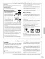 5
5
-
 6
6
-
 7
7
-
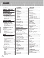 8
8
-
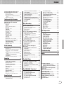 9
9
-
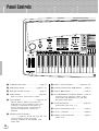 10
10
-
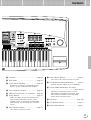 11
11
-
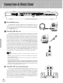 12
12
-
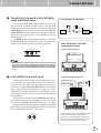 13
13
-
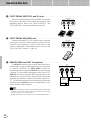 14
14
-
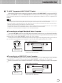 15
15
-
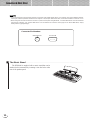 16
16
-
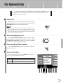 17
17
-
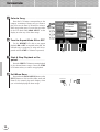 18
18
-
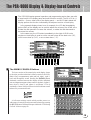 19
19
-
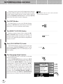 20
20
-
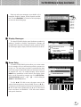 21
21
-
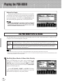 22
22
-
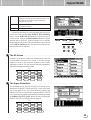 23
23
-
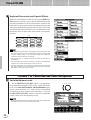 24
24
-
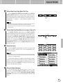 25
25
-
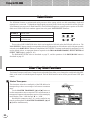 26
26
-
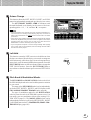 27
27
-
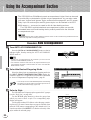 28
28
-
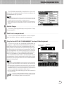 29
29
-
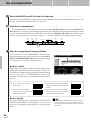 30
30
-
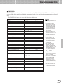 31
31
-
 32
32
-
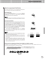 33
33
-
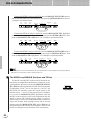 34
34
-
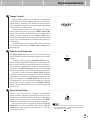 35
35
-
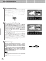 36
36
-
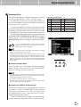 37
37
-
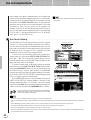 38
38
-
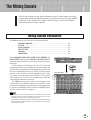 39
39
-
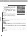 40
40
-
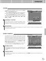 41
41
-
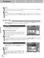 42
42
-
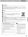 43
43
-
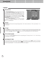 44
44
-
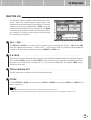 45
45
-
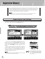 46
46
-
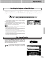 47
47
-
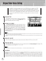 48
48
-
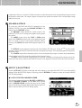 49
49
-
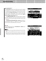 50
50
-
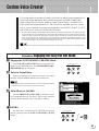 51
51
-
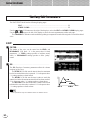 52
52
-
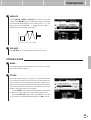 53
53
-
 54
54
-
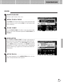 55
55
-
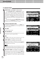 56
56
-
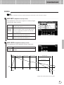 57
57
-
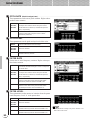 58
58
-
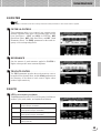 59
59
-
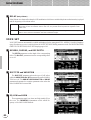 60
60
-
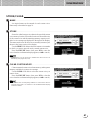 61
61
-
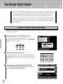 62
62
-
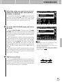 63
63
-
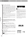 64
64
-
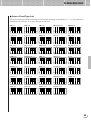 65
65
-
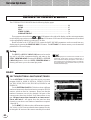 66
66
-
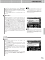 67
67
-
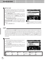 68
68
-
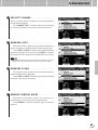 69
69
-
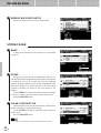 70
70
-
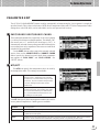 71
71
-
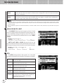 72
72
-
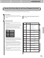 73
73
-
 74
74
-
 75
75
-
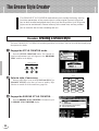 76
76
-
 77
77
-
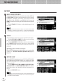 78
78
-
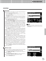 79
79
-
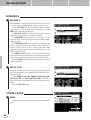 80
80
-
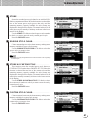 81
81
-
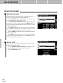 82
82
-
 83
83
-
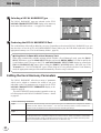 84
84
-
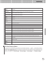 85
85
-
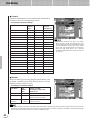 86
86
-
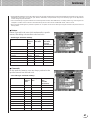 87
87
-
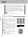 88
88
-
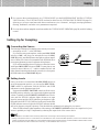 89
89
-
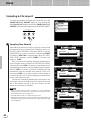 90
90
-
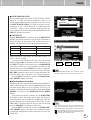 91
91
-
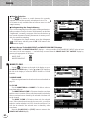 92
92
-
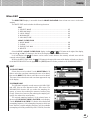 93
93
-
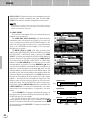 94
94
-
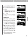 95
95
-
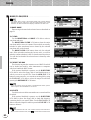 96
96
-
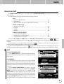 97
97
-
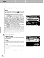 98
98
-
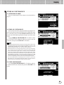 99
99
-
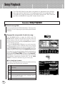 100
100
-
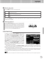 101
101
-
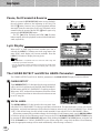 102
102
-
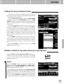 103
103
-
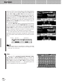 104
104
-
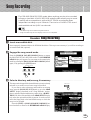 105
105
-
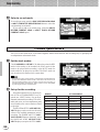 106
106
-
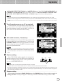 107
107
-
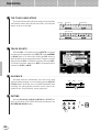 108
108
-
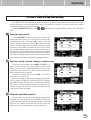 109
109
-
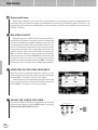 110
110
-
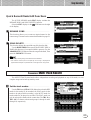 111
111
-
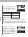 112
112
-
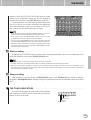 113
113
-
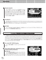 114
114
-
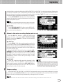 115
115
-
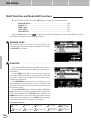 116
116
-
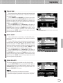 117
117
-
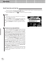 118
118
-
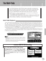 119
119
-
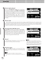 120
120
-
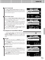 121
121
-
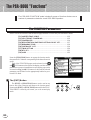 122
122
-
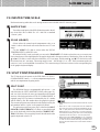 123
123
-
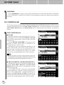 124
124
-
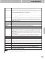 125
125
-
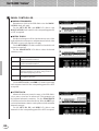 126
126
-
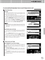 127
127
-
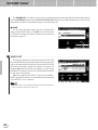 128
128
-
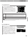 129
129
-
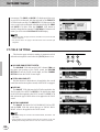 130
130
-
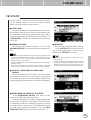 131
131
-
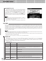 132
132
-
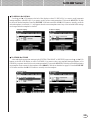 133
133
-
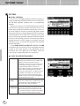 134
134
-
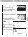 135
135
-
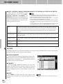 136
136
-
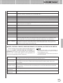 137
137
-
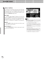 138
138
-
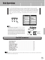 139
139
-
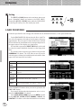 140
140
-
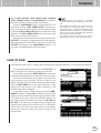 141
141
-
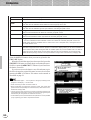 142
142
-
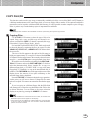 143
143
-
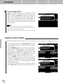 144
144
-
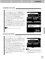 145
145
-
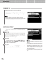 146
146
-
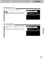 147
147
-
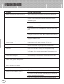 148
148
-
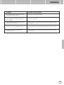 149
149
-
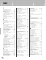 150
150
-
 151
151
-
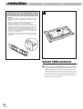 152
152
-
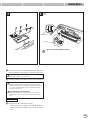 153
153
-
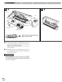 154
154
-
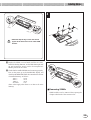 155
155
-
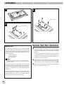 156
156
-
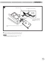 157
157
-
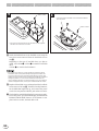 158
158
-
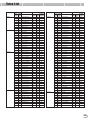 159
159
-
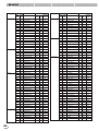 160
160
-
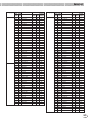 161
161
-
 162
162
-
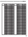 163
163
-
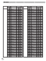 164
164
-
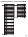 165
165
-
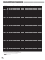 166
166
-
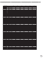 167
167
-
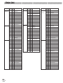 168
168
-
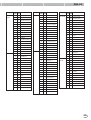 169
169
-
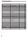 170
170
-
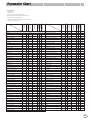 171
171
-
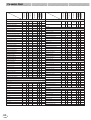 172
172
-
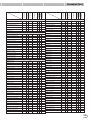 173
173
-
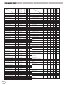 174
174
-
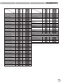 175
175
-
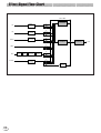 176
176
-
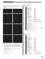 177
177
-
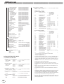 178
178
-
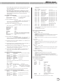 179
179
-
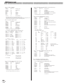 180
180
-
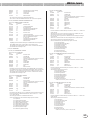 181
181
-
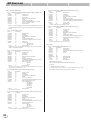 182
182
-
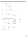 183
183
-
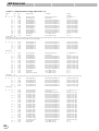 184
184
-
 185
185
-
 186
186
-
 187
187
-
 188
188
-
 189
189
-
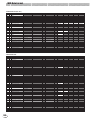 190
190
-
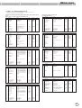 191
191
-
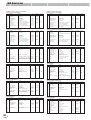 192
192
-
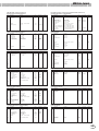 193
193
-
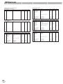 194
194
-
 195
195
-
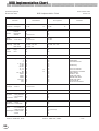 196
196
-
 197
197
-
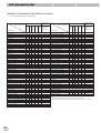 198
198
-
 199
199
-
 200
200
-
 201
201
-
 202
202
-
 203
203
-
 204
204
-
 205
205
-
 206
206


Yamaha PSR-8000 Handleiding
- Categorie
- Synthesizer
- Type
- Handleiding
- Deze handleiding is ook geschikt voor
in andere talen
- English: Yamaha PSR-8000 User manual
- italiano: Yamaha PSR-8000 Manuale utente
- русский: Yamaha PSR-8000 Руководство пользователя
- français: Yamaha PSR-8000 Manuel utilisateur
- español: Yamaha PSR-8000 Manual de usuario
- Deutsch: Yamaha PSR-8000 Benutzerhandbuch
- português: Yamaha PSR-8000 Manual do usuário
- dansk: Yamaha PSR-8000 Brugermanual
- suomi: Yamaha PSR-8000 Ohjekirja
- čeština: Yamaha PSR-8000 Uživatelský manuál
- svenska: Yamaha PSR-8000 Användarmanual
- Türkçe: Yamaha PSR-8000 Kullanım kılavuzu
- polski: Yamaha PSR-8000 Instrukcja obsługi
- română: Yamaha PSR-8000 Manual de utilizare