Yamaha RX-V2092 Handleiding
- Categorie
- Ontvanger
- Type
- Handleiding
Deze handleiding is ook geschikt voor

Natural Sound AV Receiver
Récepteur audiovisuel “Son Naturel”
OWNER’S MANUAL
MODE D’EMPLOI
POWER
DIGITAL/
PRO LOGIC
ENHANCED
MOVIE
THEATER
TV
SPORTS
STADIUM
DISCO
CONCERT
HALL
ROCK
CONCERT
CHURCHJAZZ CLUB
EFFECT
VCR 2 DVD
/
LDVCR 1
VIDEO AUX
TAPE (MD) TV/DBS
TUNER
CD
PHONO
VOLUME
l6
20
28
40
60
l2
8
4
2
0
–dB
SPEAKERSPHONES
A
ON
OFF
B
BASS
EXTENSION
TONE
BYPASS
BASS TREBLE BALANCE
55
4
3
2
l
0
l
2
3
4
LR
55
4
3
2
l
0
l
2
3
4
55
4
3
2
l
0
l
2
3
4
VIDEO AUX
S VIDEO VIDEO L AUDIO R
DELAY
/
C
/
R
/
F
/
SWFR
MAN’L
/
AUTO FM
TUNING
MODE
AUTO
/
MAN’L MONO
SET
MENU
FM/AM
DOWN
TUNING
UP
MEMORY
EDIT
NATURAL SOUND AV RECEIVER RX–V2092
CINEMA DSP
7ch
A
/
B
/
C
/
D
/
E
1
2 3 4 5 6
7
8
VCR 2
VIDEO AUX
REC OUT
VCR 1
TV/DBS
PHONO
CD
TUNER
DVD/LD
SOURCE
TAPE (MD)

1 Read Instructions – All the safety
and operating instructions should be read
before the unit is operated.
2 Retain Instructions – The safety and
operating instructions should be retained
for future reference.
3 Heed Warnings – All warnings on the
unit and in the operating instructions
should be adhered to.
4 Follow Instructions – All operating
and other instructions should be followed.
5 Water and Moisture – The unit
should not be used near water – for
example, near a bathtub, washbowl,
kitchen sink, laundry tub, in a wet
basement, or near a swimming pool, etc.
6 Carts and Stands – The unit should
be used only with a cart or stand that is
recommended by the manufacturer.
6A A unit and cart
combination should be
moved with care. Quick
stops, excessive force, and
uneven surfaces may cause
the unit and cart combination to overturn.
7 Wall or Ceiling Mounting – The unit
should be mounted to a wall or ceiling
only as recommended by the
manufacturer.
8 Ventilation – The unit should be
situated so that its location or position
does not interfere with its proper
ventilation. For example, the unit should
not be situated on a bed, sofa, rug, or
similar surface, that may block the
ventilation openings; or placed in a built-
in installation, such as a bookcase or
cabinet that may impede the flow of air
through the ventilation openings.
9 Heat – The unit should be situated
away from heat sources such as
radiators, stoves, or other appliances that
produce heat.
10 Power Sources – The unit should be
connected to a power supply only of the
type described in the operating
instructions or as marked on the unit.
11 Power-Cord Protection – Power-
supply cords should be routed so that
they are not likely to be walked on or
pinched by items placed upon or against
them, paying particular attention to cords
at plugs, convenience receptacles, and
the point where they exit from the unit.
12 Cleaning – The unit should be
cleaned only as recommended by the
manufacturer.
13 Nonuse Periods – The power cord of
the unit should be unplugged from the
outlet when left unused for a long period
of time.
14 Object and Liquid Entry – Care
should be taken so that objects do not fall
into and liquids are not spilled into the
inside of the unit.
15 Damage Requiring Service – The
unit should be serviced by qualified
service personnel when:
A. The power-supply cord or the plug
has been damaged;
or
B. Objects have fallen, or liquid has
been spilled into the unit;
or
C. The unit has been exposed to rain;
or
D. The unit does not appear to operate
normally or exhibits a marked change in
performance;
or
E. The unit has been dropped, or the
cabinet damaged.
16 Servicing – The user should not
attempt to service the unit beyond those
means described in the operating
instructions. All other servicing should be
referred to qualified service personnel.
17 Power Lines – An outdoor antenna
should be located away from power lines.
18 Grounding or Polarization –
Precautions should be taken so that the
grounding or polarization is not defeated.
RISK OF ELECTRIC SHOCK
DO NOT OPEN
CAUTION: TO REDUCE THE RISK OF
ELECTRIC SHOCK, DO NOT REMOVE
COVER (OR BACK), NO USER-SERVICEABLE
PARTS INSIDE, REFER SERVICING TO
QUALIFIED SERVICE PERSONNEL.
The lightning flash with arrowhead
symbol, within an equilateral triangle,
is intended to alert you to the
presence of uninsulated “dangerous
voltage” within the product’s
enclosure that may be of sufficient
magnitude to constitute a risk of
electric shock to persons.
The exclamation point within an
equilateral triangle is intended to alert
you to the presence of important
operating and maintenance
(servicing) instructions in the
literature accompanying the
appliance.
•
Explanation of Graphical Symbols
CAUTION
WARNING
TO REDUCE THE RISK OF FIRE OR
ELECTRIC SHOCK, DO NOT EXPOSE
THIS UNIT TO RAIN OR MOISTURE.
SAFETY INSTRUCTIONS

We Want You Listening For A Lifetime
(for US customers only)
YAMAHA and the Electronic Industries Association’s Consumer Electronics Group
want you to get the most out of your equipment by playing it at a safe
level. One that lets the sound come through loud and clear without
annoying blaring or distortion – and, most importantly, without affecting
your sensitive hearing. Since hearing damage from loud sounds is often
undetectable until it is too late, YAMAHA and the Electronic Industries
Association’s Consumer Electronics Group recommend you to avoid
prolonged exposure from excessive volume levels.
English
19 For US customers only:
Outdoor Antenna Grounding – If an
outside antenna is connected to this unit,
be sure the antenna system is grounded
so as to provide some protection against
voltage surges and built-up static
charges. Article 810 of the National
Electrical Code, ANSI/NFPA 70, provides
information with regard to proper
grounding of the mast and supporting
structure, grounding of the lead-in wire to
an antenna discharge unit, size of
grounding conductors, location of
antenna discharge unit, connection to
grounding electrodes, and requirements
for the grounding electrode.
Note to CATV system installer:
This reminder is provided to call the
CATV system installer’s attention to
Article 820-40 of the NEC that
provides guidelines for proper
grounding and, in particular, specifies
that the cable ground shall be
connected to the grounding system of
the building, as close to the point of
cable entry as practical.
FCC INFORMATION
(for US customers only)
1. IMPORTANT NOTICE : DO NOT MODIFY THIS UNIT!
This product, when installed as indicated in the instructions contained in this
manual, meets FCC requirements. Modifications not expressly approved by
Yamaha may void your authority, granted by the FCC, to use the product.
2. IMPORTANT : When connecting this product to accessories and/or another
product use only high quality shielded cables. Cable/s supplied with this product
MUST be used. Follow all installation instructions. Failure to follow instructions
could void your FCC authorization to use this product in the USA.
3. NOTE : This product has been tested and found to comply with the requirements
listed in FCC Regulations, Part 15 for Class “B” digital devices. Compliance with
these requirements provides a reasonable level of assurance that your use of
this product in a residential environment will not result in harmful interference
with other electronic devices.
This equipment generates/uses radio frequencies and, if not installed and used
according to the instructions found in the users manual, may cause interference
harmful to the operation of other electronic devices.
Compliance with FCC regulations does not guarantee that interference will not
occur in all installations. If this product is found to be the source of interference,
which can be determined by turning the unit “OFF” and “ON”, please try to
eliminate the problem by using one of the following measures:
Relocate either this product or the device that is being affected by the
interference.
Utilize power outlets that are on different branch (circuit breaker or fuse) circuits
or install AC line filter/s.
In the case of radio or TV interference, relocate/reorient the antenna. If the
antenna lead-in is 300 ohm ribbon lead, change the lead-in to coaxial type
cable.
If these corrective measures do not produce satisfactory results, please contact
the local retailer authorized to distribute this type of product. If you can not
locate the appropriate retailer, please contact Yamaha Electronics Corp., U.S.A.
6660 Orangethorpe Ave, Buena Park, CA 90620.
The above statements apply ONLY to those products distributed by Yamaha
Corporation of America or its subsidiaries.
SPECIAL NOTES FOR FCC COMPOSITE DEVICE (for US
customers only)
This device is a composite system. The digital device component may not cause
harmful interference.
EXAMPLE OF ANTENNA GROUNDING
MAST
GROUND
CLAMP
ANTENNA
LEAD IN
WIRE
ANTENNA
DISCHARGE UNIT
(NEC SECTION 810–20)
GROUNDING CONDUCTORS
(NEC SECTION 810–21)
GROUND CLAMPS
POWER SERVICE GROUNDING
ELECTRODE SYSTEM
(NEC ART 250. PART H)
ELECTRIC
SERVICE
EQUIPMENT
NEC – NATIONAL ELECTRICAL CODE

Congratulations!
You are the proud owner of a Yamaha Digital Sound Field Processing (DSP) System—an
extremely sophisticated audio component. The DSP system takes full advantage of Yamaha’s
undisputed leadership in the field of digital audio processing to bring you a whole new world of
listening experiences. Follow the instructions in this manual carefully when setting up your system,
and the DSP system will sonically transform your room into a wide range of listening
environments—anything from a famous concert hall to a cozy jazz club. In addition, you get
incredible realism from Dolby-Surround encoded video sources using the built-in Dolby Pro Logic
Surround Decoder and Dolby Digital (AC-3) Decoder.
Seven built-in channels of amplification on this model mean that no additional amplifiers are
required to enjoy advanced digital sound field processing.
Rather than tell you about the wonders of digital sound field processing, however, let’s get right
down to the business of setting up the system and trying out its many capabilities. Please read this
operation manual carefully and store it in a safe place for later reference.

1
English
1. PLEASE READ THIS MANUAL CAREFULLY
To assure the finest performance, please read this
manual carefully. Keep it in a safe place for future
reference.
2. AVOID EXCESSIVE HEAT, HUMIDITY, DUST
AND VIBRATION
Keep the unit away from locations where it is likely to be
exposed to high temperatures or humidity—such as
near radiators, stoves, etc. Also avoid locations which
are subject to excessive dust accumulation or vibration
which could cause mechanical damage.
3. INSTALL THE UNIT IN WELL-VENTILATED
CONDITION
The openings on the cabinet assure proper ventilation
of the unit. If these openings are obstructed, the
temperature inside the cabinet will rise rapidly.
Therefore, avoid placing objects against these
openings, and install the unit in well-ventilated
condition. Make sure to allow a space of at least 10
cm behind, 20 cm on the both sides and 30 cm above
the top panel of the unit. Otherwise it may not only
damage the unit, but also cause fire.
4. KEEP THE AC POWER PLUG
DISCONNECTED DURING VACATION ETC.
When not planning to use this unit for long periods of
time (ie., vacation, etc.), disconnect the AC power
plug from the wall outlet.
5. AVOID PHYSICAL SHOCKS
Strong physical shocks to the unit can cause damage.
Handle it with care.
6. DO NOT OPEN THE UNIT OR ATTEMPT
REPAIRS OR MODIFICATIONS YOURSELF
This product contains no user-serviceable parts. Refer
all maintenance to qualified Yamaha service personnel.
Opening the unit and/or tampering with the internal
circuitry will make servicing difficult and will endanger
you and your unit.
7. MAKE SURE POWER IS OFF BEFORE
MAKING OR REMOVING CONNECTIONS
Always turn power OFF prior to connecting or
disconnecting cables. This is important to prevent
damage to the unit itself as well as other connected
equipment.
8. USE THIS UNIT PROPERLY
Do not use force on switches, controls or connection
wires. When moving the unit, first disconnect the
power plug and the wires connected to other
equipment. Never pull the wires themselves.
9. TAKE CARE OF THE VOLUME CONTROL
SETTING
Always set the VOLUME control to “–
∞
” before
starting the audio source play. Increase the volume
gradually to an appropriate level after playback has
been started.
10. HANDLE CABLES CAREFULLY
Always plug and unplug cables—including the AC
cord—by gripping the connector, not the cord.
11. PREVENT LIGHTNING DAMAGE
To prevent lightning damage, disconnect the AC
power plug and disconnect the antenna cable when
there is an electrical storm.
12. CLEAN WITH A SOFT DRY CLOTH
Never use solvents such as benzine or thinner to clean
the unit. Wipe clean with a soft, dry cloth.
13. USE THIS UNIT WITH THE CORRECT
VOLTAGE
The voltage to be used must be the same as that
specified on this unit. Using this unit with a higher
voltage than that which is specified is dangerous and
may result in a fire or other type of accident causing
damage. YAMAHA will not be held responsible for any
damage resulting from use of this unit with a voltage
other than that which is specified.
IMPORTANT!
Please record the model and serial number of your
unit in the space below.
Model:
Serial No.:
The serial number is located on the rear of the unit.
Retain this Owner’s Manual in a safe place for future
reference.
Voltage Selector (General Model only)
The voltage selector on the rear panel of this unit
must be set for your local mains voltage
BEFORE plugging into the AC mains supply.
Voltages are 110/120/220/240 AC, 50/60 Hz.
WARNING
To reduce the risk of fire or electric shock, do not
expose this unit to rain or moisture.
CAUTION (FOR CANADA MODEL)
TO PREVENT ELECTRIC SHOCK, MATCH WIDE
BLADE OF PLUG TO WIDE SLOT AND FULLY
INSERT.
FOR CANADIAN CUSTOMER
THIS CLASS B DIGITAL APPARATUS MEETS ALL
REQUIREMENTS OF THE CANADIAN INTERFERENCE-
CAUSING EQUIPMENT REGULATIONS.
The apparatus is not disconnected from the AC
power source as long as it is connected to the wall
outlet, even if the apparatus itself is turned off.
WARNING
Do not change the IMPEDANCE SELECTOR
switch setting while the power to this unit is
on, otherwise this unit may be damaged.
IF THIS UNIT FAILS TO TURN ON WHEN THE
POWER SWITCH IS PRESSED
The IMPEDANCE SELECTOR switch may not be
set to either end closely. If so, set the switch to
either end closely.
PRECAUTIONS
A
B
SWITCHED
AC OUTLETS
IMPEDANCE SELECTOR
VOLTAGE SELECTOR
I20V
60Hz
I00W
MAX.
TOTAL
CENTER C OR D: 4
Ω
MIN./ SPEAKER
SET SPEAKER MODE
C
D: 4
Ω
MIN./ SPEAKER
SET SPEAKER MODE
REAR
6
Ω
MIN./ SPEAKER
MAIN
A
OR
B: 4
Ω
MIN./ SPEAKER
A B
: 8
Ω
MIN./ SPEAKER
FRONT EFFECT
: 6
Ω
MIN./ SPEAKER
CENTER C OR D: 8
Ω
MIN./ SPEAKER
SET SPEAKER MODE
C
D: 4
Ω
MIN./ SPEAKER
SET SPEAKER MODE
REAR
8
Ω
MIN./ SPEAKER
MAIN
A
OR
B: 8
Ω
MIN./ SPEAKER
A B
: 6
Ω
MIN./ SPEAKER
FRONT EFFECT
: 8
Ω
MIN./ SPEAKER
IMPEDANCE
SELECTOR
(General model)

SAFETY INSTRUCTIONS...........................................Inside the cover
PRECAUTIONS...................................................................................1
GETTING STARTED ...........................................................................3
FEATURES ..........................................................................................5
SPEAKER SETUP.............................................................................10
CONTROLS & THEIR FUNCTIONS.................................................13
FRONT PANEL................................................................................13
DISPLAY PANEL.............................................................................16
CONNECTIONS.................................................................................18
REAR PANEL PARTS AND THEIR FUNCTIONS..........................18
REAR PANEL SWITCH AND CONTROL SETTINGS...................22
GENERAL INSTRUCTIONS FOR CONNECTIONS.....................22
CONNECTING AUDIO/VIDEO SOURCE EQUIPMENT
TO THIS UNIT .................................................................................23
ANTENNA CONNECTIONS...........................................................27
CONNECTING SPEAKER SYSTEMS...........................................30
SELECTING THE OUTPUT MODES SUITABLE FOR YOUR
SPEAKER SYSTEM .......................................................................35
CONNECTING AND CONTROLLING ROOM 2 EQUIPMENT.......38
CONNECTIONS..............................................................................38
ROOM 2 REMOTE CONTROL UNIT.............................................39
SPEAKER BALANCE ADJUSTMENT ............................................41
ADJUSTMENTS IN THE “SET MENU”MODE................................43
GENERAL OPERATION...................................................................46
PLAYING A SOURCE.....................................................................46
RECORDING A SOURCE TO AUDIO/VIDEO TAPE
(OR DUBBING FROM A TAPE TO ANOTHER).............................48
TUNING OPERATIONS.....................................................................50
AUTOMATIC TUNING.....................................................................50
MANUAL TUNING...........................................................................50
PRESET TUNING ..............................................................................51
MANUAL PRESET TUNING...........................................................51
AUTOMATIC PRESET TUNING.....................................................52
EXCHANGING PRESET STATIONS..............................................53
SELECTING SOUND FIELD PROGRAMS......................................54
CANCELING THE EFFECT SOUND .............................................55
DESCRIPTIONS OF THE SOUND FIELD PROGRAMS..............56
ADJUSTING DELAY TIME AND EACH SPEAKER OUTPUT
LEVEL..............................................................................................59
SETTING THE SLEEP TIMER...........................................................61
REMOTE CONTROL UNIT...............................................................62
BASIC OPERATIONS (When the lid is open) ................................62
LEARNING NEW CONTROL FUNCTIONS (When the lid is open)
.........................................................................................................64
USING OPERATION CONTROL KEYS (When the lid is closed)
.........................................................................................................67
MACRO OPERATIONS (When the lid is closed) ...........................70
LEARNING A NEW FUNCTION.....................................................73
MAKING A NEW MACRO...............................................................75
CLEARING LEARNED FUNCTIONS.............................................76
TROUBLESHOOTING ......................................................................78
SPECIFICATIONS .............................................................................81
2
CONTENTS

3
English
GETTING STARTED
Unpacking
If you haven’t already done so, carefully remove this unit and its
accessories from the box and wrapping material.You should find the
unit itself and the following accessories.
Installing the Remote Control Unit Batteries
Since the remote control unit will be used for many of this unit’s
control operations, you should begin by installing the supplied
batteries.
1. Turn the remote control unit over and slide the battery
compartment cover downward in the direction of the arrow.
2. Insert the batteries (LR6, AA, UM-3 type), being careful to align
them with the polarity markings on the inside of the battery
compartment.
3. Close the battery compartment cover.
Remote control (for
the main room)
User function stickers
Batteries
1
3
2
Indoor FM antenna
AM loop antenna
Antenna adapter
(U.S.A. and Canada models only)
Room 2 remote
control unit
Remote control unit (for the main room)
Room 2 remote control unit
1
3
2

4
* For the remote control unit for the main room only
After you insert batteries (or you exchange batteries with new
ones), press the RESET button before using the remote control
unit.
Remote control transmitter operation range
Notes
●
There should be no large obstacles between the remote control
unit and the main unit.
●
If the remote control sensor is directly illuminated by strong
lighting (especially an inverter type of fluorescent lamp etc.), it
might cause the remote control unit to work incorrectly. In this
case, reposition the main unit to avoid direct lighting.
Notes about the Remote Control Unit
● When you notice that remote control operation has become
erratic, or the distance from which the remote control will function
has decreased, it’s time to replace the batteries. Always replace all
batteries at the same time.
● This remote control uses an advanced, highly directional infrared
beam.Be sure to aim the remote control directly at the remote
control sensor on the main unit when operating.
Open/close the control door
When it is not necessary to operate controls inside the control
door, close the door.
To open the door
To close the door
30°
30°
Remote control
sensor
Within approximately
6 m (19.7 feet)
RESET button

5
English
This unit incorporates a sophisticated, multi-program digital
sound field processor.The processor allows you to electronically
expand and change the shape of the audio sound field from both
audio and video sources, creating a theater-like experience in your
listening room.This unit has a total of 10 digital sound field
processor (DSP) modes.You can create an excellent audio sound
field by selecting a suitable sound field (this will, of course, depend
on what you will be listening to), and adding desired adjustments.
In addition, this unit incorporates a Dolby Pro Logic Surround
decoder and Dolby Digital (AC-3) decoder for multi-channel sound
reproduction of Dolby Surround encoded video sources.The
operation of the Dolby Pro Logic Surround or Dolby Digital (AC-3)
decoder can be controlled by selecting a corresponding DSP
program including combined operations of the Yamaha DSP and
the Dolby Pro Logic Surround or Dolby Digital (AC-3) decoder.
Digital Sound Field Processing
What is it that makes live music so good? Today’s advanced
sound reproduction technology lets you get extremely close to the
sound of a live performance, but chances are you’ll still notice
something missing, the acoustic environment of the live concert
hall. Extensive research into the exact nature of the sonic
reflections that create the ambience of a large hall has made it
possible for Yamaha engineers to bring you this same sound in
your own listening room, so you’ll feel all the sound of a live
concert.What’s more, our technicians, armed with sophisticated
measuring equipment, have even made it possible to capture the
acoustics of a variety of actual concert halls, jazz clubs, theaters,
etc. from around the world, to allow you to accurately recreate any
one of these live performance environments, all in your own home.
FEATURES

6
Dolby Pro Logic Surround
This unit employs a Dolby Pro Logic Surround decoder similar
to professional Dolby Stereo decoders used in many movie
theaters.By using the Dolby Pro Logic Surround decoder, you can
experience the dramatic realism and impact of Dolby Surround
movie theater sound in your own home. Dolby Pro Logic employs a
four channel five speaker system.The Pro Logic Surround system
divides the input signal into four levels: the left and right main
channels, the center channel (used for dialog), and the rear
surround sound channels (used for sound effects, background
noise, and other ambient noises).The center channel allows
listeners seated in even less-than-ideal positions to hear the dialog
originating from the action on the screen while experiencing good
stereo imaging. Dolby Surround is encoded on the sound track of
pre-recorded video tapes, laser discs, and some TV/cable
broadcasts.When you play a source encoded with Dolby Surround
on this unit, the Dolby Pro Logic Surround decoder decodes the
signal and distributes the surround-sound effects.
This Dolby Pro Logic Surround Decoder employs a digital
signal processing system.This system improves the stability of
sound at each channel and crosstalk between channels, so that
positioning of sounds around the room is more accurate compared
with conventional analog signal processing systems.
In addition, this unit features a built-in automatic input balance
control.This always assures you the best performance without
manual adjustment.
Dolby Digital (AC-3)
The built-in Dolby Digital (AC-3) Decoder leads you into a
totally new sound experiences.
Dolby Digital (AC-3) is a new generation of multi-channel digital
audio technology, or the newest spatial sound processing format
developed for 35 mm film-movies by employing a new kind of low
bit-rate audio coding.
Dolby Digital (AC-3) is a digital surround sound system that
provides completely independent multi-channel audio to
consumers.In multi-channel form, Dolby Digital (AC-3) provides
five full range channels in what is sometimes referred to as a “3/2”
configuration: three front channels (left, center and right), plus two
surround channels.A sixth bass-only effect channel is also
provided for output of LFE (low frequency effect), or low bass
effects that are independent of other channels.This channel is
counted as 0.1, thus giving rise to the term 5.1 channels in total.
Compared to Dolby Pro Logic that is referred to a “3/1” system
(left front, center, right front and just one surround channel), Dolby
Digital (AC-3) features two surround channels, called stereo or
split surrounds, each offering the same full range fidelity as the
three front channels.
Sound of wide dynamic range reproduced by the five full range
channels presents listeners much excitement that has never been
experienced before.Precise sound orientation by the discrete
digital sound processing expands realism that the original movie
possesses.

7
English
Laser Disc is a home audio format that could benefit from
Dolby Digital (AC-3). In the near future, Dolby Digital (AC-3) will
also be applied to DBS, CATV, DVD and HDTV.The ongoing
release of Dolby Stereo Digital theatrical films now underway will
provide an immediate source of Dolby Digital (AC-3) encoded
video software.
Manufactured under license from Dolby Laboratories Licensing
Corporation.“Dolby”, “AC-3”, “Pro Logic”, and the double-D symbol
are trademarks of Dolby Laboratories Licensing Corporation.
Copyright 1992 Dolby Laboratories, Inc. All rights reserved.
The following original functions make the surround-sound effect
of Dolby Digital (AC-3) become the most suitable for your audio
system and the listening conditions.
● Dynamic range (sound scale) of source can be changed so
that it will be suitable for the listening conditions.
● Output of low bass from any channel can be assigned to
either the MAIN SPEAKERS terminals or SUBWOOFER
terminals to maximize system performance.
● Output of LFE can be assigned to either the MAIN
SPEAKERS terminals or SUBWOOFER terminals to
maximize system performance.
Dolby Surround + DSP (CINEMA DSP)
Dolby Surround sound system shows its full ability in a large
movie theater, because movie sounds are originally designed to be
reproduced in a large movie theater using many speakers. It is
difficult to create a sound environment similar to that of a movie
theater in your listening room, because the room size, materials of
inside walls, the number of speakers, etc. of your listening room is
much different from those of a movie theater.
Yamaha DSP technology made it possible to present you with
nearly the same sound experience as that of a large movie theater
in your listening room by compensating for lack of presence and
dynamics in your listening room with its original digital sound fields
combined with Dolby Surround sound field.
The YAMAHA “CINEMA DSP” logo indicates those programs
are created by the combination of Dolby Surround and YAMAHA
DSP technology.
CINEMA DSP
7ch

8
Dolby Pro Logic + 2 Digital Sound Fields
Digital sound fields are created on the presence side and the
rear surround side of the Dolby Pro Logic Surround-decoded
sound field respectively.They create a wide acoustic environment
and emphasize surround-effect in the room, letting you feel much
presence as if you are watching a movie in a popular Dolby Stereo
theater.
This combination is available when the sound field program No.
2, No. 3 or No. 4 is selected, and the input signal of source is
analog, PCM audio or encoded with the Dolby Digital (AC-3) in 2-
channels.
Dolby Digital (AC-3) + 3 Digital Sound Fields
Digital sound fields are created on the presence side and the
independent left and right surround sides of the Dolby Digital (AC-
3)-decoded sound field respectively.They create a wide acoustic
environment and much surround effect in the room without losing
high channel separation.With wide dynamic range of Dolby Digital
(AC-3) sound, this sound field combination lets you feel as if you
are watching a movie in the newest Dolby Stereo Digital theater.
This will be the most ideal home theater sound at the present time.
This combination is available when the sound field program No.
2, No. 3 or No. 4 is selected, and the input signal of source is
encoded with the Dolby Digital (AC-3) (except in 2-channels).

9
English
Video superimpose
If you connect your video cassette recorder, LD player, video
monitor, etc. to this unit, you can take advantage of this unit’s
capability to display program titles and information for various
setting changes and adjustments on your video monitor’s screen.
This information will be superimposed over the video image.
If there is no video source connected or it is turned off, the
information will be displayed over a blue colored background.
NOTE:The program titles and other information are also displayed
on the display panel of this unit.
TEST DSP
EFFECT LEVEL
FRONT 0dB
/
SPEAKERS
A
DSP

10
Setting Up Your Speaker System
This unit has been designed to provide the best sound field
quality with a full seven-speaker system setup, using two extra
pairs of effect speakers to generate the sound field plus one center
speaker for dialog.We therefore recommend that you use a seven-
speaker setup. A four-speaker system using only one pair of effect
speakers for the sound field will still provide impressive ambience
and effects, however, and may be a good way to begin with this
unit.You can always upgrade to the full seven speaker system
later. In the 4 or 5 speaker system, the Digital Sound Field
Processing is still performed, but the main speakers are used for
both the main channels and the front effect channels.
Use of the Center Dialog Speaker Is Recommended
When playing back a source with the DSP programs No. 1
through No. 4, or when the Dolby Digital (AC-3) is decoded with
any DSP program used, if the source contains center-channel
signals, dialog, vocals etc. are output from the center channel.
Therefore, if you want to maximize the performance of your
Audio/Video home theater system, it is recommended that you use
a center channel speaker.
If for some reason it is not practical to use a center speaker, it
is possible to enjoy movie viewing without it.Best results, however,
are obtained with the full system.
Use of a Subwoofer Expands Your Sound Field
It is also possible to further expand your system with the
addition of a subwoofer and amplifier.The use of a subwoofer is
effective not only for reinforcing bass frequencies from any or all
channels, but also for reproducing the LFE (low frequency effect)
sound with high fidelity when playing back a source with the Dolby
Digital (AC-3) decoded.You may wish to choose the convenience
of a Yamaha Active Servo Processing Subwoofer System, which
has its own built-in power amplifier.
SPEAKER SETUP

11
English
4 Speaker System
Simplest system.
You can enjoy widely diffused sound
by only adding two additional speaker
units at the rear.
FRONT MIX switch—Set to ON.
(See page 22.)
CENTER SPEAKER—Set to PHNTM.
(See page 35.)
5 Speaker System
Good for Audio/Video sources.
By the use of center speaker, center
sounds (dialog, vocals etc.) are
precisely localized.
FRONT MIX switch—Set to ON.
(See page 22.)
CENTER SPEAKER—Set to NRML
or WIDE. (See page 35.)
6 Speaker System
Good for sound fields from 2-
channel stereo sources.
When a normal stereo source is
played back with the sound field
programs No. 5 through No. 10, a
sound effect matching that of a 7-
speaker system can be obtained. The
addition of front left and right effect
speakers produces a more effective
sound field.
FRONT MIX switch—Set to OFF.
(See page 22.)
CENTER SPEAKER—Set to PHNTM.
(See page 35.)
7 Speaker System
This is the recommended speaker
system, providing the best sound
effects.
When a normal stereo source is
played back with the sound field
programs No. 5 through No. 10, using
both sets of effect speakers (front and
rear), reproduces the most effective
sound field. When using the sound
field programs No. 1 through No. 4 or
when using any program with the
Dolby Digital (AC-3) decoded, the
center speaker provides precise center
localization.
FRONT MIX switch—Set to OFF.
(See page 22.)
CENTER SPEAKER—Set to NRML
or WIDE. (See page 35.)
Four Possible Types of Speaker System Configurations Recommended

12
Speakers and Speaker Placement
Your full seven-speaker system will require three speaker pairs:
the MAIN SPEAKERS (your normal stereo speakers), the FRONT
EFFECT SPEAKERS and the REAR SPEAKERS, plus the
CENTER SPEAKER.You may also be using a subwoofer.
The MAIN SPEAKERS should be high performance models
and have enough power handling capacity to accept the maximum
output of your audio system.
Other speakers do not have to be equal to the MAIN
SPEAKERS.For precise sound localization, however, it is ideal to
use high performance models that can reproduce sounds in full
range for the CENTER SPEAKER and the FRONT EFFECT and
REAR SPEAKERS.
Place the MAIN SPEAKERS in the normal position.
Place the FRONT EFFECT SPEAKERS further apart than the
MAIN SPEAKERS, on either side of and a few feet behind and
above the MAIN SPEAKER pair.
Place the REAR SPEAKERS behind your listening position.
They should be nearly six feet up from the floor.
Place the CENTER SPEAKER precisely between the two MAIN
SPEAKERS.(To avoid interference, keep the speaker above or
below the television monitor, or use a magnetically shielded
speaker.)
If using a SUBWOOFER, such as a Yamaha Active Servo
Subwoofer System, the position of the speaker is not so critical
because low bass tones are not highly directional.
Main speaker
Front effect speaker
Center speaker
Rear speaker
Subwoofer

13
English
FRONT PANEL
CONTROLS & THEIR FUNCTIONS
POWER
DIGITAL/
PRO LOGIC
ENHANCED
MOVIE
THEATER
TV
SPORTS
STADIUM
DISCO
CONCERT
HALL
ROCK
CONCERT
CHURCHJAZZ CLUB
EFFECT
VCR 2 DVD
/
LDVCR 1
VIDEO AUX
TAPE (MD) TV/DBS
TUNER
CD
PHONO
VOLUME
l6
20
28
40
60
l2
8
4
2
0
–dB
SPEAKERSPHONES
A
ON
OFF
B
BASS
EXTENSION
TONE
BYPASS
BASS TREBLE BALANCE
55
4
3
2
l
0
l
2
3
4
LR
55
4
3
2
l
0
l
2
3
4
55
4
3
2
l
0
l
2
3
4
VIDEO AUX
S VIDEO VIDEO L AUDIO R
DELAY
/
C
/
R
/
F
/
SWFR
MAN’L
/
AUTO FM
TUNING
MODE
AUTO
/
MAN’L MONO
SET
MENU
FM/AM
DOWN
TUNING
UP
MEMORY
EDIT
NATURAL SOUND AV RECEIVER
RX–V2092
CINEMA DSP
7ch
A
/
B
/
C
/
D
/
E
1
2 3 4 5 6 7 8
VCR 2
VIDEO AUX
REC OUT
VCR 1
TV/DBS
PHONO
CD
TUNER
DVD/LD
SOURCE
TAPE (MD)
1 4576 8
QPONK
LIH
J M
G
FEDCBA09
23
(General Model)
* For control keys on the remote control unit, see pages 62 to 64.

14
1 POWER Switch
Turns this unit on and off.
* When you press this switch to turn the power on, you will hear
a click and a sound of the built-in fan rotating for a moment.
2 Standby Indicator (Except U.S.A.and Canada models)
While the power of this unit is on, pressing the (SYSTEM
POWER) OFF key on the remote control unit switches this unit
to the standby mode. In this mode, the standby indicator is
illuminated.
3 Remote Control Sensor
Signals from the remote control unit are received here.
4 Display Panel
See pages 16 to 17.
5 DSP Program Selector Buttons
Select a DSP program.When a button is pressed, the name of
selected program lights up on the display panel.
6 Input Selector Buttons
Selects an input source that you want to listen to (and watch).
7 EFFECT Switch
Normally ON, this switch can be turned OFF to disable output
from the center and effect speakers so that the sound becomes
normal 2-channels.
* Even if this switch is off, when the Dolby Digital (AC-3) is
decoded, signals at all channels are distributed to the main
channels and output from the main speakers.
8 Master VOLUME Control
Simultaneously controls volume level at all outputs: front effect,
main, rear effect, center, and subwoofer. (This does not affect
REC OUT level.)
* When the volume is decreased by pressing the MUTE key on
the remote control unit, the indicator on the master VOLUME
control flashes on and off.
9 PHONES Jack
When you listen with headphones, connect the headphones to
the PHONES jack.You can listen to the sound to be output from
the main speakers through headphones.
When listening with headphones privately, set both the
SPEAKERS A and B switches to the OFF position and switch
off the digital sound field processor (so that no DSP program
name is illuminated on the display panel) by pressing the
EFFECT switch.
0 SPEAKERS Switches
Set the switch A or B (or both A and B) for the main speakers
(connected to this unit) you will use to the ON position. Set the
switch for the main speakers you will not use to the OFF
position. Selected main speakers are shown by the lighting of
“SPEAKERS A” and/or “SPEAKERS B” on the display panel.
A A/B/C/D/E Switch
Press this switch to select a desired group (A–E) of preset
stations.
B BASS EXTENSION Switch
When pressed inward (ON), boosts bass frequency response
at the main left and right channels while maintaining overall
tonal balance.If you do not have a subwoofer, the use of this
switch will be effective to reinforce the bass frequencies.

15
English
C TONE BYPASS switch
When this switch is pressed inward (ON), the input signal does
not pass through the tone (BASS and TREBLE) control circuitry
so that it is unaffected by the tone control circuitry. Use this
switch to obtain pure sound and to check the tone control
setting. Press this switch to release it outward (OFF) to use the
tone control circuitry.
D BASS and TREBLE Controls
Adjust low and high frequency response respectively for the
main channels only.
E BALANCE Control
Adjusts the left and right output volume to the Main Speakers to
compensate for sound imbalance caused by speaker positions
or listening room conditions.
F Preset Station Number Selector Buttons
Select a preset station number (1 to 8).
G REC OUT Selector
Selects the source to be recorded to a tape deck or
VCR independently of the setting of the input selector buttons.
However, when set to the SOURCE position, the setting of the
input selector buttons decides the source to be recorded to a
tape deck or VCR.
H FM/AM Switch
Press this switch to switch the reception band to FM or AM.
I MEMORY (MAN’L/AUTO FM) Button
When this button is pressed, the MEMORY indicator flashes for
about 5 seconds. During this period, select a desired preset
station number by pressing the corresponding preset station
number selector button to enter the displayed station into the
memory.
When this button is pressed and held for about 3 seconds, the
automatic preset tuning begins.(Refer to page 52 for details.)
J TUNING DOWN/UP Button
Used for tuning. Press the “UP” side to tune in to higher
frequencies, and press the “DOWN” side to tune in to lower
frequencies.
K EDIT Button
This button is used to exchange the places of two preset
stations with each other.
L TUNING MODE (AUTO/MAN’L MONO) Switch
Press this switch to switch the tuning mode to automatic or
manual. To select the automatic tuning mode, press this switch
so that “AUTO TUNING” lights up on the display panel. To
select the manual tuning mode, press this switch so that “AUTO
TUNING” goes off.
M DELAY/C/R/F/SWFR Switch
Whenever pressed, selects the item of changing delay time,
center speaker output level, rear speaker output level, front
effect speaker output level and subwoofer output level in turn.
* Depending on a mode of this unit, the number of selections is
reduced. For example, when the built-in digital sound field
processor (including the Dolby Pro Logic Decoder or the
Dolby Digital (AC-3) Decoder) is off, only the item for
changing subwoofer output level can be selected.
N –/+ Button
Adjusts the level of item selected by pressing the
DELAY/C/R/F/SWFR switch.Moreover, performs setting
changes and adjustments for functions selected by pressing
the SET MENU switch.
O SET MENU Switch
Whenever pressed, selects functions in the SET MENU mode.

16
1 Preset Station Number Display
Shows the selected preset station number (1 to 8) and its group
(A to E).
2 ROOM 2 Indicator
Lights up when you switch the input source for the second
room by using the Room 2 remote control unit in the main
room.
3 Input Source/Station Frequency Display
Shows the currently selected input source, or the currently
selected station frequency and the band (FM or AM) when this
unit is in the tuner input source mode.
4 Multi-informatiom Display
Shows the currently selected DSP program, or information for
several adjustments or setting changes made on this unit.
DISPLAY PANEL
DIGITAL
ENHANCED
PRESET
kHz
ROOM 2
MHz
AM
FM
MEMORY
AUTO TUNING
SPEAKERS
A
SPEAKERS
B
STEREO
0 20 40 60 I00
ROOM 2 CONTROL
TAPE 2 MONITOR
PCM
DIGITAL
70
mm
DIGITAL
SLEEP
mS dB
DSP
PRO LOGIC
1
7 8 9 0 A B C65
2 3 4
P Auxiliary Input Jacks (VIDEO AUX)
Connect an auxiliary video or audio unit such as a camcorder to
these jacks. If the connected video unit has a S video output
terminal, connect it to the S VIDEO jack to obtain a high resolution
picture.The unit connected to these jacks can be selected by the
corresponding input selector button and REC OUT selector.
Q Control Door
See page 4 for how to open and close the control door.

17
English
5 MEMORY Indicator
When the MEMORY button is pressed, this indicator flashes for
about 5 seconds. During this period, the displayed station can
be programmed to the memory by using the A/B/C/D/E switch
and the preset station number selector buttons.
6 AUTO TUNING Indicator
Lights up when this unit is in the automatic tuning mode.
7 ROOM 2 CONTROL Indicator
Lights up momentarily when the Room 2 remote control unit is
used in the second room.
8 SPEAKERS A/B Indicators
The indicator A or B which corresponds to the currently
selected main speakers lights up. If both main speakers A or B
are selected, both indicators light up.
9 STEREO Indicator
Lights up when an FM stereo broadcast with sufficient signal
strength is received.
0 Signal-level Meter
Indicates the signal level of the received station.
If multipath interference is detected, the indication decreases.
A Digital Audio Input Signal Indicators
When digital audio signals not encoded with the Dolby Digital
(AC-3) are input to this unit, “PCM DIGITAL” lights up.
When digital audio signals encoded with the Dolby Digital
(AC-3) are input to this unit, “ DIGITAL” lights up.
B DIGITAL, DSP and PRO LOGIC indicators
“ DIGITAL” lights up when the built-in Dolby Digital (AC-3)
Decoder is on and the signals of selected source encoded with
the Dolby Digital (AC-3) is not in 2-channels.“DSP” lights up
when the built-in digital sound field processor is on, and “
PRO LOGIC” lights up when the built-in Dolby Pro Logic
Surround Decoder is on. Depending on the selected DSP
program, both “ DIGITAL” and “DSP”, or both “DSP” and “
PRO LOGIC” will light up.
C SLEEP Indicator
Lights up while the built-in SLEEP timer is functioning.

18
PHONO
VIDEO
DVD/LD
TV/DBS
IN
VCR 1
OUT
IN
VCR 2
OUT
ROOM 2
OUT
DVD/LD
TV/DBS
CENTER
C OR D
C D
SEE INSTRUCTION MANUAL
FOR CORRECT SETTING.
CENTER
CAUTION
IN
VCR 1
OUT
IN
VCR 2
OUT
MONITOR
OUT
MAIN CH SUB
WOOFER
FRONT
EFFECT
REAR
PRE
OUT
MAIN
IN
S VIDEO
1
CD
3
TAPE
PB
4
REC
OUT
TAPE(MD)
COAXIAL
OPTICAL
DVD/LD
IN OUT
DVD/LD
TV/DBS
FM
ANT
75Ω
UNBAL.
AM
ANT
GND
AUDIO SIGNAL
PCM/ DIGITAL IN
(AC
–
3 DIGITAL IN)
REMOTE
CONTROL
FREQUENCY
STEP
GND
AUDIO SIGNAL VIDEO SIGNAL OUTPUT SPEAKERS
COUPLER OUTPUT
5ch 7ch
ON OFF
PAL NTSC
MONITOR
OUT
FRONT
MIX
—
I0dB 0dB
MAIN
LEVEL
CC
D
A
B
A
B
D
REAR
FRONT
EFFECT
MAIN
SWITCHED
AC OUTLETS
IMPEDANCE SELECTOR
VOLTAGE SELECTOR
FM
50kHz
I00kHz
AM
9kHz
I0kHz
I20V
60Hz
I00W
MAX.
TOTAL
CENTER C OR D: 4
Ω
MIN./ SPEAKER
SET SPEAKER MODE
C
D: 4
Ω
MIN./ SPEAKER
SET SPEAKER MODE
REAR
6
Ω
MIN./ SPEAKER
MAIN
A
OR
B: 4
Ω
MIN./ SPEAKER
A B
: 8
Ω
MIN./ SPEAKER
FRONT EFFECT
: 6
Ω
MIN./ SPEAKER
CENTER C OR D: 8
Ω
MIN./ SPEAKER
SET SPEAKER MODE
C
D: 4
Ω
MIN./ SPEAKER
SET SPEAKER MODE
REAR
8
Ω
MIN./ SPEAKER
MAIN
A
OR
B: 8
Ω
MIN./ SPEAKER
A B
: 6
Ω
MIN./ SPEAKER
FRONT EFFECT
: 8
Ω
MIN./ SPEAKER
AB ECGFDHIJMN
O
LK
1
23 4 5 67 8 90
REAR PANEL PARTS AND THEIR FUNCTIONS
Before you start making connections make sure all related electronic components are turned OFF.
CONNECTIONS
(General Model)
To
AC outlet

19
English
1 Antenna Connection Terminals
Connect the included indoor FM antenna to the FM ANT
terminal and connect the included AM loop antenna to the AM
ANT and GND terminals.To heighten safety and reduce
interference, connect the GND terminal to a good earth ground.
For improving reception quality, you can connect outdoor FM
and/or AM antenna to these terminals (See pages 27 to 29 for
details.)
2 FREQUENCY STEP Switch (General Model only)
Because the interstation frequency spacing differs in different
areas, set this switch to the position suitable for the frequency
spacing in your area.
Before sliding this switch, disconnect the AC power plug of this
unit from the AC outlet.
3 AUDIO SIGNAL Connection Jacks (for Audio Source
Equipment)
Connect the inputs and/or outputs of your audio equipment.
4 AUDIO/VIDEO SIGNAL Connection Jacks (for Video Source
Equipment)
Connect the audio and video inputs and/or outputs of your
video equipment. In place of the VIDEO jacks, the S VIDEO
jacks can be used for higher resolution and improved picture
quality if your VCR, monitor, etc. are equipped with S-VIDEO
connectors.
5 CENTER OUTPUT Jacks
Center-channel line outputs.Can be connected to input jack(s)
of one or two external power amplifier(s) to drive the center
speaker(s).
6 CENTER SPEAKERS Terminals
When using the built-in center-channel amplifier, connect one
or two center speakers here.
7 Center Speaker Switch
Set to “C + D” when using two center speakers, or to “C OR D”
when using only one center speaker.
8 FRONT EFFECT SPEAKERS Terminals
When using the built-in front effect-channel amplifier, connect
the front effect speakers here.
9 REAR SPEAKERS Terminals
When using the built-in rear-channel amplifier, connect the rear
speakers here.
0 VOLTAGE SELECTOR (General Model only)
Be sure to set to the line voltage in your area before applying
power. Consult your dealer if unsure of the correct setting.
A GND Terminal
Connects the ground wire of the turntable to produce minimum
hum. In some cases, however, better results may be obtained
with the ground wire disconnected.
B PCM/ DIGITAL IN (COAXIAL and OPTICAL) jacks
Can be connected with audio/video units that have a coaxial or
optical digital output jack.Connect a unit that is connected to
the DVD/LD AUDIO/VIDEO SIGNAL connection jacks to the
DVD/LD COAXIAL or OPTICAL jack.
Connect a unit that is connected to the TV/DBS AUDIO/VIDEO
SIGNAL connection jacks to the TV/DBS COAXIAL jack.
* If, for example, your LD player has an AC-3 RF output jack
and no digital output jack for AC-3 discrete audio signals,
connect the AC-3 RF output jack to the DVD/LD COAXIAL or
OPTICAL jack of this unit by way of an RF demodulator
(separate purchase).

20
C ROOM 2 OUT Jacks
These jacks output audio and video signals to the equipment in
the second room.The input source selection is made using the
Room 2 remote control unit. Refer to “CONNECTING AND
CONTROLLING ROOM 2 EQUIPMENT” on page 38.
D REMOTE CONTROL IN and OUT Jacks
The IN jack receives the commands from the Room 2 remote
control unit.The OUT jack outputs the commands at the IN jack
from the Room 2 remote control unit. Refer to “CONNECTING
AND CONTROLLING ROOM 2 EQUIPMENT” on page 38.
E Video NTSC/PAL Switch (General Model only)
Set this switch to the position corresponding to the standard
that your video equipment employs.
F FRONT MIX Switch
Set to “OFF (7ch)” when setting up a full 7 or 6 speaker system,
or to “ON (5ch)” when setting up a 5 or 4 speaker system.
G MAIN LEVEL Switch
Normally set to “0 dB”. If desired, you can decrease the main-
channel output level at the MAIN SPEAKERS terminals by 10
dB by setting this switch to “–10 dB”.
H PRE OUT Jacks
Main-channel line output. Connected with jumper bars to MAIN
IN jacks when the built-in amplifier is used. Connected to input
jacks of external stereo power amplifier (MAIN IN or TAPE
PLAY jacks of integrated amplifier or receiver) when using
external amplification.
I MAIN IN Jacks
Line input to built-in main-channel amplifier. Connected with
jumper bars to PRE OUT jacks when the built-in amplifier is
used. Not connected when using an external power amplifier.
J SUBWOOFER Jacks
When using one subwoofer, connect its amplifier input to either
of these jacks.When using two subwoofers, connect their
amplifiers to these jacks respectively.
Frequencies below 90 Hz distributed from the main, center
and/or rear channels are output to these jacks.
Signals of LFE (low frequency effect) generated when the
Dolby Digital (AC-3) is decoded are also output if they are
assigned to these jacks.
K FRONT EFFECT OUTPUT Jacks
Front-channel line output. Can be connected to input jacks of
an external stereo power amplifier driving the front effect
speakers.

21
English
L REAR OUTPUT Jacks
Rear-channel line output. Can be connected to input jacks of an
external stereo power amplifier driving the rear speakers.
M MAIN SPEAKERS Terminals
This unit is equipped with 2 sets of MAIN SPEAKERS terminals
to allow you to connect 2 main speaker systems to this unit.
When using this unit’s built-in main-channel amplifier, connect
the main speakers here.The jumper bars must be plugged in to
connect the MAIN IN jacks to the PRE OUT jacks.
N IMPEDANCE SELECTOR Switch
Select the position whose requirements your speaker system
meets.
O SWITCHED AC OUTLET(S)
You may plug other audio/video units into these sockets as long
as their combined power consumption does not exceed the
specified value shown.“Switched” means that these
components are turned on and off by this unit’s power switch.

22
REAR PANEL SWITCH AND CONTROL
SETTINGS
There are several switches and controls on the rear panel that
you’ll have to check before operating your system, and it’s a good
idea to do it before you connect cables. Locate the MAIN LEVEL
slide switch (G) and FRONT MIX slide switch (F). Make sure the
MAIN LEVEL switch is set to “0 dB” and the FRONT MIX switch is
set to “OFF” for 7 or 6 speaker driving.
In a 5 or 4 speaker system, set the FRONT MIX switch to “ON”.
For General model only, set the NTSC/PAL switch (E) to the
position corresponding to the standard which your video
equipment employs and set the FREQUENCY STEP switch (2) to
the position suitable for the frequency spacing in your area.
For the setting of IMPEDANCE SELECTOR switch (N), see
page 34.
For the setting of the center speaker switch (7), see page 32.
GENERAL INSTRUCTIONS FOR
CONNECTIONS
Make sure that you have the left (L) and right (R) channels
correctly connected.That means that jacks marked “L” on this unit
must be connected to jacks marked “L” on other units.Likewise
with the “R” jacks.This is easy if you remember to always use the
red plug for the “R” jacks and the white plug for the “L” jacks.
For connections with audio/video source equipment, use RCA
type pin plug cables with the exception described later.
With speaker connections you must also be sure that the
polarity is correct. For each amplifier and each channel, connect
the plus (+) terminal of the amplifier to the plus terminal of the
speaker, and connect the minus (–) terminal of the amplifier to the
minus terminal of the speaker.To keep track of polarity, use a
speaker cable that has one of the two wires marked by a stripe or
a different color.

23
English
PHONO
VIDEO
DVD/LD
TV/DBS
IN
VCR 1
OUT
IN
VCR 2
OUT
ROOM 2
OUT
DVD/LD
TV/DBS
IN
VCR 1
OUT
IN
VCR 2
OUT
MONITOR
OUT
S VIDEO
1
CD
3
TAPE
PB
4
REC
OUT
TAPE(MD)
COAXIAL
OPTICAL
DVD/LD
IN OUT
DVD/LD
TV/DBS
FM
ANT
75Ω
UNBAL.
AM
ANT
GND
AUDIO SIGNAL
PCM/ DIGITAL IN
(AC
–
3 DIGITAL IN)
REMOTE
CONTROL
FREQUENCY
STEP
GND
AUDIO SIGNAL VIDEO SIGNAL
5ch 7ch
ON OFF
PAL NTSC
MONITOR
OUT
FRONT
MIX
—
I0dB 0dB
MAIN
LEVEL
FM
50kHz
I00kHz
AM
9kHz
I0kHz
OUTPUT
GND
OUTPUT
LINE OUT
LINE IN
VIDEO IN
AUDIO IN
VIDEO IN
AUDIO OUT
VIDEO OUT
VIDEO IN
AUDIO IN
VIDEO OUT
AUDIO OUT
VIDEO OUT
AUDIO OUT
AUDIO OUT
VIDEO OUT
CONNECTING AUDIO/VIDEO SOURCE EQUIPMENT TO THIS UNIT
BASIC CONNECTIONS
* If you have YAMAHA audio/video unit numbered as 1, 3 or 4 on the rear panel, connections can be made easily by making sure to
connect the output (or input) terminals of each unit to the same-numbered terminals of this unit.
* For shaded parts, see pages 24 to 26.
Turntable
CD player
Tape deck (MD recorder)
LD (DVD) player
TV/Satellite tuner
Video cassette
recorder 1
Video cassette
recorder 2
Monitor TV
(General Model)

24
CONNECTING TO DIGITAL (OPTICAL AND COAXIAL)
JACKS
If your LD (DVD) player, TV/satellite tuner, etc. are equipped
with coaxial or optical digital audio signal output jacks, they can be
connected to this unit’s COAXIAL and/or OPTICAL digital signal
input jacks.
To make a connection between optical digital audio signal
jacks, remove the cover from each jack, and then connect them by
using a commercially available optical fiber cable that conforms to
EIAJ standards.Other cables might not function correctly.
Even if you connect an audio/video unit to the OPTICAL (or
COAXIAL) jack of this unit, you must keep the unit connected with
the same named analog audio signal jacks of this unit, because
digital signal cannot be recorded by a tape deck or VCR connected
to this unit, and digital signal also will not be output from the
AUDIO SIGNAL ROOM 2 OUT jacks.You can switch the selection
of input signals between “digital” and “analog” easily. (See page 47
for details.)
NOTE:When connecting an audio/video unit to both of the digital
and analog jacks of this unit, make sure to connect to both jacks of
the same name.
NOTE: Be sure to attach the cover when the OPTICAL jack is not
being used, in order to protect the jack from dust.
NOTE: All digital audio signal input jacks are applicable to the
sampling frequency of 32 kHz, 44.1 kHz and 48 kHz.
PHONO
DVD/LD
TV/DBS
IN
VCR 1
OUT
IN
VCR 2
OUT
ROOM 2
OUT
1
CD
3
TAPE
PB
4
REC
OUT
TAPE(MD)
COAXIAL
OPTICAL
DVD/LD
IN OUT
DVD/LD
TV/DBS
FM
ANT
75Ω
UNBAL.
AM
ANT
GND
AUDIO SIGNAL
PCM/ DIGITAL IN
(AC
–
3 DIGITAL IN)
REMOTE
CONTROL
FREQUENCY
STEP
GND
AUDIO SIGNAL
PAL NTSC
FM
50kHz
I00kHz
AM
9kHz
I0kHz
COAXIAL
DIGITAL OUT
COAXIAL
DIGITAL OUT
OPTICAL
DIGITAL OUT
ANALOG OUT
ANALOG OUT
LD (DVD) player
TV/Satellite tuner

25
English
Notes on connecting with an LD player equipped
with an AC-3 RF output
If your LD player has AC-3 RF signal output jack and no digital
signal output jack for AC-3 discrete audio signals, connect the AC-
3 RF signal output jack to this unit’s OPTICAL (or COAXIAL) digital
signal input jack by using an RF demodulator (separate purchase).
First, connect the AC-3 RF signal output jack of the LD player to
the AC-3 RF signal input jack of the RF demodulator. Next,
connect the optical (or coaxial) digital signal output jack of the RF
demodulator to the OPTICAL (or COAXIAL) digital signal input jack
of this unit.
This connection is necessary for inputting audio signals encoded
with the Dolby Digital (AC-3) on the LD player to this unit.
It is also necessary to connect the LD player to this unit’s
analog audio signal input jacks regardless of the AC-3 RF signal
connection, for playing back an LD source with the Dolby Pro Logic
Surround decoded or in normal stereo (or monaural).
If desired, you can also connect the digital signal output jack
(for 2-channel audio signals) of the LD player to this unit. If you will
do so, connect it to the COAXIAL digital signal input jack of this
unit, and connect the RF demodulator to the OPTICAL digital
signal input jack of this unit.
By this connection, if the input mode of the DVD/LD source is in
“AUTO”, you can enjoy listening to sounds decoded with the Dolby
Digital (AC-3) when you play a disc encoded with the Dolby Digital
(AC-3) though signals are input to both OPTICAL and COAXIAL
digital signal input jacks of this unit simultaneously (because
signals input to the OPTICAL jack take priority of signals input to
the COAXIAL jack).
See page 47 for details about switching the input mode.
NOTES
●
If, for example, you play a CD on the LD player (which can play
a CD also), there is no input to the OPTICAL jack, so the
signals input to the COAXIAL jack take priority. In this case,
switch off the RF demodulator to listen to CD sound surely.
However, if your RF demodulator is the Yamaha model APD-1,
you do not have to switch it off.
●
When you want to play a source encoded with the Dolby Digital
(AC-3) without decoding the Dolby Digital (AC-3), you must
switch off the power to the RF demodulator.
PHONO
DVD/LD
TV/DBS
IN
VCR 1
OUT
IN
VCR 2
OUT
ROOM 2
OUT
1
CD
3
TAPE
PB
4
REC
OUT
TAPE(MD)
COAXIAL
OPTICAL
DVD/LD
IN OUT
DVD/LD
TV/DBS
FM
ANT
75Ω
UNBAL.
AM
ANT
GND
AUDIO SIGNAL
PCM/ DIGITAL IN
(AC
–
3 DIGITAL IN)
REMOTE
CONTROL
FREQUENCY
STEP
GND
AUDIO SIGNAL
PAL NTSC
FM
50kHz
I00kHz
AM
9kHz
I0kHz
ANALOG OUT
AC-3 RF
OUT
COAXIAL
DIGITAL OUT
COAXIAL
DIGITAL OUT
OPTICAL
DIGITAL OUT
AC-3 RF
IN
RF demodulator
(YAMAHA APD-1 etc.)
LD player

26
CONNECTING TO S VIDEO JACKS
If your video cassette recorder, LD player, etc. and your monitor
are equipped with “S” (high-resolution) video terminals, connect
them to this unit’s S VIDEO jacks, and connect this unit’s
S VIDEO MONITOR OUT jack to the “S” video input of your
monitor. Otherwise, connect the composite video jacks from your
video cassette recorder, LD player, etc. to the VIDEO jacks of this
unit, and connect this unit’s VIDEO MONITOR OUT jack to the
composite video input of your monitor.
NOTE: If video signals are sent to both S VIDEO input and VIDEO
input jacks, the signals will be sent to their respective output jacks
independently.
NOTE: If your unit is the General Model, be sure the NTSC/PAL
switch has been correctly set to the standard that your video
equipment employs. U.S.A. and Canada models have no switch
and use the NTSC standard, while other models without a switch
use the PAL standard.
Notes about the Video superimpose
● If you watch a video source that is connected to both S VIDEO
and VIDEO input jacks of this unit, signals of screen display
information are output from only the S VIDEO MONITOR OUT
jack.
● When no video signal is input to either S VIDEO or VIDEO input
jacks of this unit, signals of screen display information are
output from both S VIDEO MONITOR OUT and VIDEO
MONITOR OUT jacks with a color background.
* For the General Model, if the NTSC/PAL switch on the rear
panel is set to “PAL”, nothing will be output from either S
VIDEO MONITOR OUT or VIDEO MONITOR OUT jack in this
case.
VIDEO
DVD/LD
TV/DBS
IN
VCR 1
OUT
IN
VCR 2
OUT
ROOM 2
OUT
DVD/LD
TV/DBS
IN
VCR 1
OUT
IN
VCR 2
OUT
MONITOR
OUT
S VIDEO
AUDIO SIGNAL VIDEO SIGNAL
PAL NTSC
MONITOR
OUT
VIDEO IN
S-VIDEO IN
VIDEO
OUT
S-VIDEO
OUT
VIDEO IN
S-VIDEO IN
S-VIDEO
OUT
VIDEO
OUT
VIDEO
OUT
S-VIDEO
OUT
VIDEO IN
S-VIDEO IN
VIDEO OUT
S-VIDEO OUT
LD (DVD) player
TV/Satellite tunerVideo cassette recorder 1
Video cassette recorder 2
Monitor TV

PHONO
DVD/LD
TV/DBS
IN
VCR 1
OUT
IN
VCR 2
OUT
ROOM 2
OUT
1
CD
3
TAPE
PB
4
REC
OUT
TAPE(MD)
COAXIAL
OPTICAL
DVD/LD
IN OUT
DVD/LD
TV/DBS
FM
ANT
75Ω
UNBAL.
AM
ANT
GND
AUDIO SIGNAL
PCM/ DIGITAL IN
(AC
–
3 DIGITAL IN)
REMOTE
CONTROL
FREQUENCY
STEP
GND
AUDIO SIGNAL
PAL NTSC
FM
50kHz
I00kHz
AM
9kHz
I0kHz
27
English
ANTENNA CONNECTIONS
● Each antenna should be connected to the designated terminals correctly, referring to the following figure.
● Both AM and FM indoor antennas are included with this unit. In general, these antennas will probably provide sufficient signal strength.
Nevertheless, a properly installed outdoor antenna will give clearer reception than an indoor one.If you experience poor reception
quality, an outdoor antenna may result in improvement.
Outdoor FM antenna
Outdoor AM antenna
AM loop
antenna
(included)
Ground
75-ohm/300-ohm
antenna adapter
75-ohm/300-ohm
antenna adapter
75-ohm coaxial cable
300-ohm feeder
Indoor FM
antenna
(included)

28
Connecting the indoor FM antenna
Connect the included indoor antenna to the 75Ω UNBAL. FM
ANT terminal.
NOTE
If you connect an outdoor FM antenna to this unit, do not connect
the indoor FM antenna to this unit.
Connecting the AM loop antenna
1. Press the tab and unlock the terminal hole.
2. Connect the AM loop antenna lead wires to the AM ANT and
GND terminals.
3. Return the tab back to the original position to lock the lead
wires.Lightly pull on the lead wires to confirm a good connection.
4. Attach the loop antenna to the antenna stand.
5. Tune to an AM station and then position the loop antenna for
best reception. Orient the AM loop antenna so that the best
reception is obtained.Try other stations, and find the position that
gives the best overall reception.
NOTES
● The AM loop antenna should be placed apart from the main
unit.The antenna may be hung on a wall.
● The AM loop antenna should be kept connected, even if an
outdoor AM antenna is connected to this unit.
1
3
2
Loop antenna
Antenna stand

29
English
Optional outdoor FM antenna
Consult with your dealer or authorized service center about the
best method of selecting and erecting an outdoor FM antenna.
The choice of the feeder cable is also important.Flat ribbon-
shaped twin-lead cable performs well electrically, and is cheaper
and somewhat easier to handle when routing it through windows
and around rooms.Coaxial cable is more expensive, does a much
better job of minimizing interference, is less prone to the effects of
weather and close-by metal objects, and is nearly as good a signal
conductor as feeder cable, particularly for foam-type coaxial
cables. Coaxial cable is somewhat more difficult to install at the
point where the cable enters the building. If coaxial cable is
selected, make sure the antenna is designed to be used with that
type of cable.
Use a 75-ohm/300-ohm antenna adapter (not included) or a
75-ohm antenna adapter (not included) for connections.
Notes for FM antenna installation
● To minimize automobile ignition noise, locate the antenna as far
from heavy traffic as possible.
● Keep the feeder cable or coaxial cable as short as possible. Do
not bundle or roll up excess cable.
● The antenna should be at least two meters (6.6 feet) from
reinforced concrete walls or metal structures.
Optional outdoor AM antenna
In steel buildings or at a great distance from the transmitter, it
may be necessary to install an outside long wire antenna.
GND terminal
For maximum safety and minimum interference, connect the
GND terminal to a good earth ground. A good earth ground is a
metal stake driven into moist earth.
300-ohm feeder cable
75-ohm coaxial cable
75-ohm coaxial cable
300-ohm feeder cable
75-ohm coaxial cable
75-ohm/300-ohm antenna adapter
75-ohm antenna adapter

30
CONNECTING SPEAKER SYSTEMS
Connect the SPEAKERS terminals to your speakers with wire
of the proper gauge, cut as short as possible.If the connections
are faulty, no sound will be heard from the speakers. Make sure
that the polarity of the speaker wires is correct, that is, + and –
markings are observed.If these wires are reversed, the sound will
be unnatural and will lack bass. Do not let the bare speaker wires
touch each other or any other metal part as this could damage this
unit and/or speakers.
NOTE: Use speakers with the specified impedance shown on the
rear of this unit.
Red: positive (+)
Black:negative (–)
➀ Unscrew the knob.
➁ Insert the bare wire.
[Remove approx. 5mm (1/4”)
insulation from the speaker
wires.]
➂ Tighten the knob and
secure the wire.
NOTE: Banana Plug connections are also possible (except
Singapore model). Simply insert the Banana Plug connector into
the corresponding terminal.
1
2
3

31
English
CONNECTING THE MAIN SPEAKERS TO THIS UNIT
One or two sets of MAIN speakers can be connected to this
unit.
If you use two sets of MAIN speakers, connect one set to the
MAIN SPEAKERS A terminals, and connect another set to the B
terminals. If you use only one set of MAIN speakers, connect them
to either the MAIN SPEAKERS A or B terminals. Make sure that
the jumper bars between the PRE OUT and MAIN IN jacks on the
rear panel are in place.
It is also possible to use an external power amplifier if more
power is desired. In this case, remove the jumper bars and connect
the PRE OUT jacks to the INPUT jacks of a stereo power amplifier
with a stereo pin cable—making sure to connect the left and right
channels correctly. Connect the MAIN speakers to the speaker
output terminals of the power amplifier.
Set the SPEAKERS switch A or B (or both A and B) on the
front panel corresponding to the main speakers you will use to the
ON position. Set the switch for the main speakers you will not use
to the OFF position. Selected main speakers are shown by the
lighting of “SPEAKERS A” and/or “SPEAKERS B” on the display
panel.
PRE OUT
INPUT
Main speaker A Main speaker A
Main speaker B Main speaker B
Power amplifier
This unit

32
CONNECTING THE FRONT EFFECT SPEAKERS,
REAR SPEAKERS AND THE CENTER SPEAKER(S)
TO THIS UNIT
Connect the FRONT effect speakers to the FRONT EFFECT
SPEAKERS terminals of this unit.
If the FRONT effect speakers are not used, the FRONT MIX
switch should be set to “ON”.
Connect the REAR speakers to the REAR SPEAKERS
terminals of this unit.
Connect the CENTER speaker to the CENTER SPEAKERS
terminals. If you will be using one CENTER speaker, connect it to
either the C or D terminals and set the CENTER speaker switch so
that it is released outward (“C OR D” position).If using two
CENTER speakers, connect them to the C and D terminals, and
press the switch inward (“C +D” position). If, however, you will not
be using a CENTER speaker, be sure to set the CENTER
SPEAKER mode to “PHNTM” (phantom). (See page 35.)
NOTE:The speaker connections above are fine for most
applications.If for some reason, however, you wish to use an
external power amp for any or all of the front effect, rear and center
channels, connect the line level output jack(s) for each channel to
the INPUT jacks of the external amp and connect the
corresponding speaker pair to the speaker terminals of the
external amp.
LR
LR
Center speaker
Center speaker
Center speaker
Front effect
speaker
Front effect
speaker
Rear speaker
Rear speaker
This unit

33
English
ADDING A SUBWOOFER
You may wish to add a subwoofer to reinforce the bass
frequencies.
This unit provides line-level subwoofer outputs. If you use one
subwoofer, connect either of the SUBWOOFER jacks to the INPUT
jack of the subwoofer amplifier, and connect the speaker terminals
of the subwoofer amplifier to the subwoofer.
If you wish to obtain more presence in your listening room, the
use of two subwoofers is recommended.To connect two
subwoofers to this unit, connect one SUBWOOFER jack to the
INPUT jack of the amplifier driving a subwoofer, and the other
SUBWOOFER jack to the INPUT jack of the amplifier driving the
other subwoofer, and then connect each subwoofer to the
corresponding amplifier.
With some subwoofers, including the Yamaha Active Servo
Processing Subwoofer System, the amplifier and subwoofer are in
the same unit.
Subwoofer system
Subwoofer systemSubwoofer system
MAIN CH SUB
WOOFER
FRONT
EFFECT
REAR
PRE
OUT
MAIN
IN
COUPLER OUTPUT
MAIN CH SUB
WOOFER
FRONT
EFFECT
REAR
PRE
OUT
MAIN
IN
COUPLER OUTPUT

34
Switching the IMPEDANCE SELECTOR switch on the
rear panel
Select the position whose requirements your speaker system
meets.Be sure to switch this only when the power of this unit is
turned off.
(Upper position)
Center:If you use one center speaker, the impedance of the
speaker must be 4Ω or higher.
If you use two center speakers, the impedance of each
speaker must be 4Ω or higher.
Rear: (U.S.A.and Canada models:)
The impedance of each speaker must be 4Ω or higher.
(Australia, Singapore and General models:)
The impedance of each speaker must be 6Ω or higher.
Main: If you use one pair of main speakers, the impedance of
each speaker must be 4Ω or higher.
If you use two pairs of main speakers, the impedance of
each speaker must be 8Ω or higher.
Front effect:
The impedance of each speaker must be 6Ω or higher.
WARNING
Do not change the IMPEDANCE SELECTOR switch setting
while the power to this unit is on, otherwise this unit may be
damaged.
IF THIS UNIT FAILS TO TURN ON WHEN THE POWER
SWITCH IS PRESSED
The IMPEDANCE SELECTOR switch may not be set to either
end closely. If so, set the switch to either end closely.
(Lower position)
Center:If you use one center speaker, the impedance of the
speaker must be 8Ω or higher.
If you use two center speakers, the impedance of each
speaker must be 4Ω or higher.
Rear: The impedance of each speaker must be 8Ω or higher.
Main: If you use one pair of main speakers, the impedance of
each speaker must be 8Ω or higher.
(Except Canada model:)
If you use two pairs of main speakers, the impedance of
each speaker must be 16Ω or higher.
Front effect:
The impedance of each speaker must be 8Ω or higher.
(General model)
A
B
SWITCHED
AC OUTLETS
IMPEDANCE SELECTOR
VOLTAGE SELECTOR
I20V
60Hz
I00W
MAX.
TOTAL
CENTER C OR D: 4
Ω
MIN./ SPEAKER
SET SPEAKER MODE
C
D: 4
Ω
MIN./ SPEAKER
SET SPEAKER MODE
REAR
6
Ω
MIN./ SPEAKER
MAIN
A
OR
B: 4
Ω
MIN./ SPEAKER
A B
: 8
Ω
MIN./ SPEAKER
FRONT EFFECT
: 6
Ω
MIN./ SPEAKER
CENTER C OR D: 8
Ω
MIN./ SPEAKER
SET SPEAKER MODE
C
D: 4
Ω
MIN./ SPEAKER
SET SPEAKER MODE
REAR
8
Ω
MIN./ SPEAKER
MAIN
A
OR
B: 8
Ω
MIN./ SPEAKER
A B
: 6
Ω
MIN./ SPEAKER
FRONT EFFECT
: 8
Ω
MIN./ SPEAKER
IMPEDANCE
SELECTOR

35
English
SELECTING THE OUTPUT MODES SUITABLE FOR YOUR SPEAKER SYSTEM
This unit provides you the following four functions to determine the method of distributing output signals to speakers suitable for your audio
system.When speaker connections are all completed, select a proper position on each function to make the best use of your speaker
system.
4. CENTER SPEAKER
5. REAR SPEAKER
6. MAIN SPEAKER
7. LFE/BASS OUT
4. CENTER SPEAKER
Choices: NRML/WIDE/PHNTM
Preset position: NRML
NRML (Normal):
Select this position when you use a center speaker that is
smaller than the main speakers. In this position, low bass
signals (below 90 Hz) at the center channel are output
from the main speakers (or the SUBWOOFER jacks if the
SMALL position is selected on “6. MAIN SPEAKER” and
the SWFR position is selected on “7. LFE/BASS OUT”).
WIDE: Select this position when your center speaker is
approximately the same size as the main speakers.
PHNTM (Phantom):
Select this position when you do not have a center
speaker.The center channel sound will be output from the
left and right main speakers.
5. REAR SPEAKER
Choices: SMALL/LARGE
Preset position: SMALL
SMALL:
Select this position if your rear speakers do not have a
high ability for bass reproduction.
In this position, low bass signals (below 90 Hz) at the rear
channels are output from the SUBWOOFER jacks (or the
main speakers if the MAIN position is selected on “7.
LFE/BASS OUT”).
LARGE:
Select this position if your rear speakers have a high ability
for bass reproduction, or a subwoofer is connected to the
rear speaker in parallel.
In this position, full range signals are output from the rear
speakers.
DESCRIPTION OF EACH FUNCTION

36
6. MAIN SPEAKER
Choices: SMALL/LARGE
Preset position: LARGE
SMALL:
Select this position if your main speakers do not have a
high ability for bass reproduction. However, if your system
does not include a subwoofer, do not select this position.
In this position, low bass signals (below 90 Hz) at the main
channels are output from the SUBWOOFER jacks (if the
SWFR or BOTH position is selected on “7. LFE/BASS
OUT”).
LARGE:
Select this position if your main speakers have a high
ability for bass reproduction.
In this position, full range signals present at the main
channels are output from the main speakers.
7. LFE/BASS OUT
Choices: MAIN/SWFR/BOTH
Preset position: SWFR
MAIN: Select this position if your system does not include a
subwoofer.
In this position, full range signals present at the main
channels, signals from the LFE channel and other low
bass signals that are selected on “4. CENTER SPEAKER”
to “6. MAIN SPEAKER” to be distributed from other
channels are output from the main speakers.
SWFR/BOTH:
Select either the SWFR or BOTH position if your system
includes a subwoofer.
In either position, signals at LFE channel and other low
bass signals that are selected on “4. CENTER SPEAKER”
to “6. MAIN SPEAKER” to be distributed from other
channels are output from the SUBWOOFER jacks.
When the LARGE position is selected on “6. MAIN
SPEAKER”, in the SWFR position, no signal is distributed
from the main channels to the SUBWOOFER jacks,
however in the BOTH position, low bass signals from the
main channels are output to both of the main speakers and
the SUBWOOFER jacks.

37
English
METHOD OF CHANGING SELECTIONS
Operations should be made watching information on this unit’s
display panel or the monitor screen.
1. Turn the power of this unit on. (If you want to display
information on the monitor, turn the power of the monitor on.)
If you will use the remote control unit, set the TIME/LEVEL·SET
MENU switch to the SET MENU position on the remote control
unit.
NOTE: Be sure to use the remote control unit with the lid open.
2. Press once or more until “4. CENTER SPEAKER” appears on
the display.
3. Press “+” or “–” once or more so that the arrow points the
position you will select.
4. Press once or more until the title of another function on which
you will change the selection appears on the display.
5. Press “+” or “–” once or more so that the arrow points the
position you will select.
6. Repeat step 4 and 5 to change selections on other functions in
the same way.
Front panel
Front panel
or
Remote control
Remote control
Front panel
or
Remote control
POWER
TIME/LEVEL
SET MENU
SET
MENU
Front panel
or
Remote control
SET
MENU
Front panel
or
Remote control

38
You can make up a multi-room audio/video system with this
unit. In this system, this unit and Yamaha audio/video units
connected to this unit in the main room can be controlled by using
the provided Room 2 remote control unit from the second room so
that this unit sends audio and video signals (different from ones
selected in the main room) to the amplifier, monitor TV, etc. in the
second room.
CONNECTIONS
To use the multi-room functions of this unit, you need the
following additional optional products:
● An infrared signal receiver for the second room
● An infrared emitter in the main room
This emitter transmits the infrared signals from the Room 2
remote control unit in the second room to the other components
in the main room (for example, CD player or LD player).
● An amplifier and speakers for the second room
● A video monitor for the second room
NOTE
Since there are so many ways to connect and use this unit in a
multi-room installation, we recommend that you consult with a
custom installation specialist for the Room 2 connections which
will best meet your requirements.
*
1
:Some Yamaha models are able to connect directly to this unit
via the REMOTE CONTROL OUT jacks.If you own these
products, the use of an infrared emitter may not be necessary.
A Sample of system configuration and connections
CONNECTING AND CONTROLLING ROOM 2 EQUIPMENT
REMOTE CONTROL OUT
AUDIO SIGNAL ROOM 2 OUT
VIDEO SIGNAL ROOM 2 OUT
REMOTE CONTROL IN
LD player etc.
Amplifier
Monitor TV
Room 2 remote
control unit
Infrared signal receiver
Main Room
Second Room
This unit
Infrared emitter
*
1

39
English
ROOM 2 REMOTE CONTROL UNIT
This remote control unit makes input source selections on this
unit and controls Yamaha remote control-compatible CD player,
tape deck, LD player and/or tuner connected to this unit for the
second room independent of the input source selections for the
main room.
NAMES OF KEYS AND THEIR FUNCTIONS
1 LD player keys
Controls LD player.
2 Tape deck keys
Controls tape deck.
* DIR A, B and A/B are applicable only to double cassette tape
deck.
* For a single cassette deck with automatic reverse function,
pressing DIR A will reverse the direction of tape running.
3 Tuner keys
Controls tuner.
+: Selects higher preset station number.
–: Selects lower preset station number.
A/B/C/D/E: Selects the group (A – E) of preset station numbers.
4 CD player keys
Controls compact disc player.
* DISC is applicable only to compact disc changer.
DIR BDIR A
PLAY
DISC
POWER ON VOLUME ROOM 2
PLAY
PRESET
A/B/C/D/E
–+
CHAPTER STOP
PAUSE/STOP
–+
OFF
TAPE
A/B
LD
PLAY
TUNER
CD
PHONO
TV/DBSVCR 2 VCR 1V–AUX DVD/LD
ROOM 2 REMOTE CONTROLLER
3
4
5
6
1
2
7

40
5 POWER ON and OFF keys
(U.S.A.and Canada models)
Pressing the POWER ON key turns the power of this unit on and
pressing the OFF key turns the power off.
(Except U.S.A.and Canada models)
While the power is on, pressing the OFF key switches the unit from
the power-on mode to the standby mode, and pressing the
POWER ON key switches the unit from the standby mode to the
power-on mode. (In the standby mode, the standby indicator on the
front panel is illuminated.)
6 VOLUME ROOM 2 + (up) and – (down) keys
Increase or decrease the output level of signals sent to the
amplifier in the second room only.
7 Input selector keys
Selects input source.
Note on using the remote control units
If you use the Room 2 remote control unit (for the second room) in
the main room, the input selector keys of this remote control unit
affect the settings in the second room, not the main room.The
other keys on the remote control unit work the same in both the
main room and the second room.
Display panel information
1 Lights up when you switch the input source for the second
room by using the Room 2 remote control unit in the main
room.The name of selected source also lights up.
2 Lights up momentarily when the Room 2 remote control unit is
used in the second room.
CAUTION
In some cases, adjustments made using the Room 2 remote
control unit may not be evident on this unit.For example, if both
the main room and second room are set to the tuner, it is possible
for the person in the second room to change the station.This may
be a problem, especially when you are taping a source without
directly monitoring it.
ROOM 2
SPEAKERS
A
ROOM 2 CONTROL
1
2

41
English
This operation uses an internal test-tone generator for balancing
the levels of the main, center, rear and front effect speakers.
The adjustment of each speaker output level should be done at
your listening position with the remote control unit.Otherwise, the
result may not be satisfactory.
NOTE: Be sure to use the remote control unit with the lid open.
1. Set the TIME/LEVEL·SET MENU switch on the remote control to
the TIME/LEVEL position.
2. Depress the TEST key on the remote
control so that “TEST DOLBY SUR.” appears
on the display panel to enter test mode.A
hiss-like calibration signal should be heard
from the left main speaker, center speaker(s),
right main speaker, right rear speaker and left
rear speaker in turn (see diagram).Adjust the
master VOLUME to a normal listening level.
* The state of test-tone output is shown on the display panel and
the monitor screen.(On the monitor screen, it is shown by an
image of audio listening room.) This is convenient for adjusting
each speaker level.
3. Press the or key to select the speaker whose level you will
adjust.
* Whenever the key is pressed, the speaker selection changes
in turn as follows.
Pressing the key changes the speaker in the reverse order.
* If the CENTER SPEAKER mode is set to “PHNTM”(phantom),
“CENTER” cannot be selected.(See page 35.)
4. Adjust the level of the speaker selected in step 3 by pressing the
+ or – key so that it becomes almost as same as that of the main
speakers.
* While adjusting, the test-tone is fixed on the selected speaker.
5. Repeat step 3 and 4 to adjust the level of other speakers.
SPEAKER BALANCE ADJUSTMENT
Left main Center Right main
Right rear
LEFT CENTER RIGHT
Left rear
LEFT
SURROUND
RIGHT
SURROUND
TIME/LEVEL
SET MENU
Remote control
Remote control
Remote control
Remote control
TEST
CENTER
R SUR.
L SUR.
Center
Right rear
Left rear

42
NOTE: If there is insufficient volume from the effect speakers, you
may decrease the main speaker volume level by setting the MAIN
LEVEL switch on the rear panel to “–10 dB”, and adjust each speaker
level again.Volume controls on external power amplifiers may also be
adjusted if necessary to achieve proper balance.
NOTE: If not using a center speaker, be sure to set the “4.CENTER
SPEAKER” in the SET MENU mode to the PHNTM (phantom)
position.You will then hear the center channel test tone from the left
and right main speakers.
6. For the front effect speaker level adjustment, depress the TEST
key on the remote control again so that “TEST DSP” appears on the
display panel. A calibration signal should be heard from the main
speakers and the front effect speakers in turn (see diagram).
* If the FRONT MIX switch on the rear panel is set to “ON (5ch)”,
the front effect speaker level cannot be adjusted by this method.
7. Adjust the front effect speaker level by pressing the + or – key so
that it becomes almost as same as that of the main speakers.
* While adjusting, the test-tone is fixed on the front effect speaker.
8. When this adjustment is finished, press the TEST key once again.
NOTE: Once you have completed these adjustments, use only
VOLUME control of this unit or MASTER VOLUME keys of the
remote control unit to adjust the whole listening volume.Do not
change any other volume setting in the system.
Main Front
MAIN FRONT
Remote control
Remote control
TEST
Remote control
TEST

43
English
The following eight types of functions maximize the performance
of your system and expand your enjoyment for audio listening and
video watching.
1. CENTER DELAY
2. DYNAMIC RANGE
3. LFE LEVEL
4. CENTER SPEAKER
5. REAR SPEAKER
6. MAIN SPEAKER
7. LFE/BASS OUT
8. INPUT MODE (TV/DBS)
METHOD OF SETTING CHANGE AND ADJUSTMENT
Operations should be made watching information on this unit’s
display panel or the monitor screen.If you want to display information
on the monitor, turn the power of the monitor on.
1. If you will use the remote control unit, set the TIME/LEVEL·SET
MENU switch to the SET MENU position on the remote control unit.
NOTE: Be sure to use the remote control unit with the lid open.
2. Select the function (title) on which you will make a change.
3. Select any desired position or edit parameters on the function.
In the same way, make a setting change or adjustment on any
other function.
ADJUSTMENTS IN THE “SET MENU” MODE
Remote control
Remote control
Front panel
or
or
Front panel
Remote control
TIME/LEVEL
SET MENU
SET
MENU

44
DESCRIPTIONS OF THE FUNCTIONS
1. CENTER DELAY (Adjusting the delay of center
sounds (dialog etc.))
Control range: 0 ms to 5 ms (in 1 ms step)
Preset value: 0 ms
* This adjustment is effective only when the Dolby Digital (AC-3)
is decoded and the signals of selected source encoded with the
Dolby Digital (AC-3) contain center-channel signals.
Adjusts the delay between the main sounds (at the main
channels) and dialog etc. (at the center channel).
The larger the value, the later the dialog etc. is generated.
This is for making sounds from the left main, center and right
main speakers reach your listening position at the same time by
delaying the sound from the center speaker if the distance from the
center speaker to your listening position is shorter than the
distance from the left or right main speaker to your listening
position.
2. DYNAMIC RANGE (Adjusting dynamic range)
Choices: MAX/STD/MIN
Preset position: MAX
* This adjustment is effective only when the Dolby Digital (AC-3)
is decoded.
MAX: “Dynamic range” is the difference between the maximum
level and the minimum level of sounds.Sounds on a movie
originally designed for movie theaters feature very wide
dynamic range.
Dolby Digital (AC-3) technology can bring the original
sound track into a home audio format with this wide
dynamic range unchanged.
In this position, a source encoded with the Dolby Digital
(AC-3) is reproduced in the original sound track’s wide
dynamic range providing you with powerful sounds like a
movie theater.
Selecting this position will be more ideal if you can listen to
a source in a high output level in a room specially
soundproofed for audio/video enjoyment.
STD (Standard):
Powerful sounds of extremely wide dynamic range are not
always suitable for home use. Depending upon the
condition of your listening environment, it may not possible
to increase the sound output level as high as a movie
theater, however, in a level proper for listening to in your
room, the low level parts of source sound cannot be heard
as well because they will be lost among noises in your
environment.
Dolby Digital (AC-3) technology also makes it possible to
reduce an original sound track’s dynamic range for a home
audio format by “compressing” the data.
In this position, a source encoded with the Dolby Digital
(AC-3) is reproduced in the “compressed” dynamic range
of the source suitable for low level listening.
MIN: In this position, dynamic range is more reduced than in the
STD position. Selecting this position will be effective when
you must listen to a source in extremely low level.

45
English
3. LFE LEVEL (Adjusting the output level at the LFE
(low frequency effect) channel)
Control range: –20 dB to 0 dB (in 1 dB step)
Preset value: 0 dB
* This adjustment is effective only when the Dolby Digital (AC-3) is
decoded and the signals of selected source encoded with the
Dolby Digital (AC-3) contain LFE signals.
Adjusts the output level at the LFE (low frequency effect)
channel. If the LFE signals are mixed with signals at other
channels to output them from the same speakers, the ratio of LFE
signal level to the level of other signals are adjusted. (See page 6
for details about the LFE channel.)
4. CENTER SPEAKER 6. MAIN SPEAKER
5. REAR SPEAKER 7. LFE/BASS OUT
See pages 35 to 37 for details. (Once you have selected proper
modes, you do not have to make a setting change until any
alteration is made in your speaker system.)
8. INPUT MODE (Selecting the initial input mode of the
sources connected to the TV/DBS input jacks)
For the sources connected to the TV/DBS input jacks of this
unit only, you can designate the input mode that is automatically
selected when the power of this unit is switched on.
AUTO: In this position, the AUTO input mode is always selected
when the power of this unit is switched on.
LAST: In this position, the input mode you have selected last time
is memorized and will not be changed even if the power of
this unit is switched on.
*
See page 47 for details about switching the input mode.

46
PLAYING A SOURCE
NOTE: If you will use the remote control unit, be sure to use it with
the lid open.
1. Set the master VOLUME control to minimum.
2. Turn the power on.
3. Select an input source.
The selected source is shown by the display panel and the monitor
screen.For the DVD/LD or TV/DBS source, its current input mode is
also shown.
* To change the input mode for the DVD/LD or TV/DBS source,
press the input selector button for the currently selected source
once or more until the desired input mode (AUTO or ANALOG)
is shown on the display panel.(See page 47 for details on
switching the input mode.)
4. Play the source.(For detailed information on tuning operations,
refer to page 50.)
5. Increase the setting of the master VOLUME control to your
listening level.
Adjust the BASS, TREBLE, BALANCE controls, etc., or select a
desired sound field program. (See page 54.)
GENERAL OPERATION
Front panel
Front panel
or
Remote control
Front panel
or
Remote control
l6
20
28
40
60
l2
8
4
2
0
–dB
VOLUME
Front panel
POWER
DVD
/
LDVCR 1
TAPE (MD) TV/DBS
DVD/LD
Front panel
or
Remote control
DVD
/
LDVCR 1
TAPE (MD) TV/DBS
DVD/LD
SPEAKERS
A
DIGITAL
DIGITAL
SPEAKERS
A
PRO LOGIC
l6
20
28
40
60
l2
8
4
2
0
–dB
VOLUME
MASTER VOLUME
MUTE

47
English
Notes on using the input selector buttons
• Note that pressing on each input selector button selects the
source which is connected to the corresponding input terminals
on the rear panel.
* To select the source connected to the VIDEO AUX terminals
on the front panel, press VIDEO AUX.
• Once you play a video source, its video image will not be
interrupted even if the input selector button for an audio source
is selected.
• When you select an input source by pressing the
corresponding input selector button, the DSP program (or the
state of no DSP program is used) which was used when the
same input source was selected the last time will automatically
recalled.
Switching the input mode (for DVD/LD and
TV/DBS)
This unit allows you to switch the input mode only for sources
connected to the DVD/LD and TV/DBS input jacks (on the rear of this
unit) that input two or three types of signals to this unit.
The following two input modes are provided.
AUTO: For the source connected to the DVD/LD input jacks:
This mode is automatically selected when you turn on the
power of this unit. In this mode, input signal is
automatically selected by the following order of priority.
1.Digital input signal from the OPTICAL jack
2.Digital input signal from the COAXIAL jack
3.Analog input signal
For the source connected to the TV/DBS input jacks:
This mode is automatically selected when you turn on the
power of this unit if the “AUTO” position is selected on “8.
INPUT MODE” in the SET MENU mode.(See page 45 for
details.) In this mode, input signal is automatically selected
by the following order of priority.
1.Digital input signal from the COAXIAL jack
2.Analog input signal
ANALOG:
In this mode, only analog input signal is selected even
though digital signal is input at the same time.
Select this mode when you want to use the analog input
signal instead of the digital input signal.
NOTE: For the TV/DBS source only, the input mode selected on the
function “8. INPUT MODE” in the SET MENU mode is selected when
you turn on the power of this unit.

Notes on input mode selection
• To play back a source with the Dolby Digital (AC-3) decoded, set
the input mode to “AUTO”.
• When you want to enjoy a source which has normal 2-channel
signals with a Dolby Pro Logic Surround program, select the
ANALOG mode.
• In the AUTO mode, there may be a case depending on some LD
players or DVD players that when you make a search on a source
encoded with the Dolby Digital (AC-3) during the play and then
the play is restored, sound output is interrupted for a moment
because the digital input signal is selected again.
RECORDING A SOURCE TO
AUDIO/VIDEO TAPE (OR DUBBING
FROM A TAPE TO ANOTHER)
NOTE: If you will use the remote control unit, be sure to use it with
the lid open.
1. Set the REC OUT selector to the SOURCE position.
2. Select the source you want to record.
3. Play the source and increase the setting of the master VOLUME
control to confirm it.(For detailed information on tuning operations,
refer to page 50.)
4. Set the tape deck, MD recorder or VCR used for recording to the
recording mode.
48
Front panel
VCR 2
VIDEO AUX
REC OUT
VCR 1
TV/DBS
PHONO
CD
TUNER
DVD/LD
SOURCE
TAPE (MD)
Front panel
or
Remote control
DVD
/
LDVCR 1
TAPE (MD) TV/DBS
DVD/LD
Front panel
or
Remote control
l6
20
28
40
60
l2
8
4
2
0
–dB
VOLUME
MASTER VOLUME
MUTE

49
English
Regardless of the setting of input selector buttons, when you set
the REC OUT selector to a position other than “SOURCE”, the
source selected by the REC OUT selector can be recorded by other
tape deck (MD recorder) and/or VCRs connected to this unit.
While recording a source by setting the REC OUT selector to the
position other than SOURCE as described above, the following
operations can be made at the same time.
●
You can monitor the audio (or the audio and video) signals being
recorded by selecting the recording unit (TAPE (MD), VCR 1 or
VCR 2) with the corresponding input selector button.
●
You can watch or listen to any other source by selecting it with the
corresponding input selector button.
NOTE: Adjusting the master VOLUME, BASS, TREBLE controls,
etc., or selecting a sound field program has no effect on the material
being recorded.
NOTE: Composite video and S video signals pass independently
through this unit’s video circuits.Therefore, when recording or
dubbing video signals, if your video source unit is connected to
provide only a S video (or only a composite video) signal, you can
record only a S video (or only a composite video) signal on your
VCR.
NOTE: A source that is connected to this unit between digital jacks
only cannot be recorded by a tape deck or VCR connected to this
unit.
NOTE: Please check the copyright laws in your country to record
from records, compact discs, radio, etc.Recording of copyright
material may infringe copyright laws.
If you watch a video software that uses scramble or
encoded signals to prevent it from being dubbed, there may
be a case that display information superimposed on the
picture and/or the picture itself is disturbed due to those
signals.

50
AUTOMATIC TUNING
1. Select “TUNER” as the input source.
2. Select the reception band (FM or AM) confirming it on the
display panel.
3. If
“AUTO TUNING” is not illuminated on the display panel, press once
so that it lights up.
4. Begin the automatic tuning search.
To tune to a higher frequency, press the right side once.
To tune to a lower frequency, press the left side once.
• If the station where tuning search stops is not the desired one,
press again.
• If the tuning search does not stop at the desired station
(because the signals of the station are weak), change to the
MANUAL TUNING method.
MANUAL TUNING
1. Select “TUNER” as the input source.
2. Select the reception band (FM or AM) confirming it on the
display panel.
3. If
“AUTO TUNING” is illuminated on the display panel, press once so
that it goes off.
4. Tune to a desired station manually.
To continue tuning search, press and hold the button.
NOTE
If you tune to an FM station manually, it is received in monaural
mode automatically to increase the signal quality.
TUNING OPERATIONS
Normally, if station signals are strong and there is no interference, quick automatic-search tuning (AUTOMATIC TUNING) is possible.
However, if signals of the station you want to select are weak, you must tune to it manually (MANUAL TUNING).
FM AM
or
or
FM AM
or
or
DOWN
TUNING
UP
AUTO TUNING
TUNING
MODE
AUTO
/
MAN’L MONO
DOWN
TUNING
UP
Front panel
Front panel
Front panel
Front panel
Front panel
Front panel
FM/AM
FM/AM
TUNING
MODE
AUTO
/
MAN’L MONO
Front panel
TUNER PHONO
Remote control
TUNER
Front panel
TUNER PHONO
Remote control
TUNER
or
or

51
English
To store stations
1. Tune to a desired station.
(Refer to the previous page for tuning procedure.)
2. Select a desired group (A – E) of preset stations confirming it
on the display panel.
3. Press the MEMORY button.
4. Select a preset station number where you want to program the
station before “MEMORY” goes off from the display.
• In the same way, program other stations to A2, A3 ... A8.
• You can program more stations to preset station numbers on
other groups in the same way by selecting other groups in step
2.
To recall a preset station
1. Select the group of preset stations.
2. Select the preset station number.
NOTES
• A new setting can be programmed in place of the former one.
• For presets, the setting of the reception mode (stereo or
monaural) is stored along with the station frequency.
Memory back-up
The memory back-up circuit prevents the programmed data from
being lost even if the POWER switch is set off or the power plug is
disconnected from the AC outlet or the power is cut due to
temporary power failure. If, however, the power is cut for more
than one week, the memory may be erased. If so, it can be re-
programmed by simply following the PRESET TUNING steps.
PRESET TUNING
Press once or more.
Press once or more.
Shows the displayed station
has been programmed to A1.
MAN’L
/
AUTO FM
MEMORY
MEMORY
A
/
B
/
C
/
D
/
E
PRESET
MANUAL PRESET TUNING
This unit can store station frequencies selected by tuning operation. With this function, you can recall any desired station by only
selecting the preset station number where it is stored. Up to 40 stations (8 stations x 5 groups) can be stored.
Front panel
Front panel
Front panel
Front panel
Front panel
PRESET
MHz
FM
STEREO
0
20
l00
ROOM 2 CONTROL
40 60
SPEAKERS
AUTO TUNING
A
SPEAKERS
B
ROOM 2
1
2 3 4 5 6 7 8
A
/
B
/
C
/
D
/
E
1
2 3 4 5 6 7 8
Flashes on and off for
about 5 seconds.

52
AUTOMATIC PRESET TUNING
You can also make use of an automatic preset tuning function
for FM stations only. By this function, this unit performs automatic
tuning and stores FM stations with strong signals sequentially. Up
to 40 stations are stored automatically in the same way as in the
manual preset tuning method on page 51.
To store stations
1. Select the FM band.
2. Press and hold the MEMORY button for about 3 seconds.
3. To tune to higher frequencies, press right side once.
To tune to lower frequencies, press left side once.
* If the TUNING button is not pressed, in a while, the automatic
preset tuning begins automatically toward higher frequencies.
The automatic preset tuning begins from the frequency
currently displayed. Received stations are programmed to A1, A2
... A8 sequentially.
* If more than 8 stations are received, they are also
programmed to the preset station numbers on other groups (B,
C, D and E) in that order.
If you want to store the first station received by the automatic
preset tuning to a desired preset station number.
If, for example, you want to store the first received station to C5,
select “C5” by using the A/B/C/D/E switch and the preset station
number selector buttons after pressing the MEMORY button in
step 2.Then press the TUNING button.The first received station is
stored to C5, and next stations to C6, C7 ... sequentially.
If stations are stored up to E8, the automatic preset tuning is
finished automatically.
When the automatic preset tuning is finished
The display shows the frequency of the last preset station.
Check the contents and the number of preset stations by following
the procedure of the section “To recall a preset station” on page
51.
To recall a preset station
Simply follow the procedure of the section “To recall a preset
station” on page 51.
FM/AM
FM
MAN’L
/
AUTO FM
MEMORY
Flashes.
DOWN
TUNING
UP
PRESET
MEMORY
AUTO TUNING
Front panel
Front panel
Front panel

53
English
NOTES
• You can replace a preset station by another FM or AM station
manually by simply following the procedure of the section “To
store stations” on page 51.
• If the number of received stations is not enough to be stored up
to E8, the search is finished automatically after searching all
frequencies.
• With this function, only FM stations with sufficient signal
strength are stored automatically. If the station you want to
program is weak in signal strength, tune in to it with the
MANUAL TUNING method (in monaural) and program it by
following the procedure of the section “To store stations” on
page 51.
EXCHANGING PRESET STATIONS
You can exchange the places of two preset stations with each
other as shown below.
Example)
If you want to shift the preset station on E1 to A5, and vice versa.
1. Recall the preset station on E1 (by following the method of “To
recall a preset station” on page 51).
2. Press the EDIT button.
3. Next, recall the preset station on A5 by following the same
method with step 1.
4. Press the EDIT button.
Flashes.
EDIT
MEMORY
PRESET
MEMORY
PRESET
EDIT
Front panel
Front panel
Shows the exchange of stations is
completed.

54
This unit has 10 programs for digital sound field processing, 6
from actual acoustic environments from around the world, and 4
programs for Audio/Video sources including sources encoded with
Dolby Pro Logic surround or Dolby Digital (AC-3).
To select a DSP program
Simply pressing a DSP program selector button on the front panel
or a DSP program selector key on the remote control unit turns on
the digital sound field processor and select the corresponding
program directly.The name of selected program lights up on the
display panel and the monitor screen.
To enjoy a video source with the Dolby Pro Logic
Surround or Dolby Digital (AC-3) decoded
When you select the program No. 1, 2 or 3, and the input signal
of the source is 2-channel stereo, Dolby Pro Logic Surround is
decoded.When some program is selected and the input signal of the
source is encoded with the Dolby Digital (AC-3), Dolby Digital (AC-3)
is automatically decoded.
• The following indicators on the display panel show you what
sound processing is being made.
• In addition, for the program No.1, 2 and 3, the name of the
program on the display panel or the monitor screen will change
according to the type of decoding.(See pages 56–57 for details.)
NOTE: If the input signals of source encoded with the Dolby Digital
(AC-3) are in 2-channels only, the sound processing for them is
similar to that for analog or PCM audio signals.
SELECTING SOUND FIELD PROGRAMS
Lights up when the Dolby Digital (AC-3) is being decoded and the
signals of selected source encoded with the Dolby Digital (AC-3) is
not in 2-channels.
Lights up when the Digital Sound Field Processing is being made.
Lights up when the Dolby Pro Logic Surround is being decoded.
Front panel
Remote control
DIGITAL/
PRO LOGIC
ENHANCED
MOVIE
THEATER
TV
SPORTS
STADIUM
DISCO
CONCERT
HALL
ROCK
CONCERT
CHURCHJAZZ CLUB
123
SPORTS
STADIUM
DISCO
TV
456
ROCK
JAZZ CLUB
CHURCH
789
HALL
0
DIGITAL/
PRO LOGIC
ENHANCED
MOVIE
THEATER
3
DIGITAL
DSP
PRO LOGIC
DIGITAL
PCM AC
–
3
PRO LOGIC
or

55
English
CANCELING THE EFFECT SOUND
The EFFECT switch on the front panel and the EFFECT ON/OFF
key on the remote control unit make it simple to compare the normal
stereo sound with the fully processed effect sound.
To cancel the effect sound and monitor only the main sound,
press the EFFECT ON/OFF key or the EFFECT switch.Press the
EFFECT ON/OFF key or the EFFECT switch a second time to
restore normal operation.
NOTES
• If the effect sound is canceled when signals encoded with the
Dolby Digital (AC-3) are input to this unit, signals of all channels
are mixed and are output from the main speakers.
• If the EFFECT switch or the EFFECT ON/OFF key is pressed to
turn effect sounds OFF when the Dolby Digital (AC-3) is decoded,
it may happen that sound is output faintly or not output normally
depending on a source.In that case, press the EFFECT switch or
the EFFECT ON/OFF key to turn effect sounds ON, or use input
signals not encoded with the Dolby Digital (AC-3).
Front panel
or
Remote control
EFFECT
EFFECT
ON/OFF

56
1. DOLBY PRO LOGIC
When the input signal is analog or PCM audio ( )
Speaker output:main, center, rear
DOLBY DIGITAL
When the input signal is Dolby Digital ( )
Speaker output:main, center, rear
Reproduces video discs, video tapes and
similar sources which are Dolby Surround
encoded and bear the “DOLBY
SURROUND” logo.
The built-in Dolby Pro Logic Surround
decoder or Dolby Digital (AC-3) decoder
precisely reproduces sounds and sound
effects of a source encoded with Dolby
Surround.The realization of a highly efficient
decoding process improves crosstalk and
channel separation and makes sound
positioning smoother and more precise.
2. DOLBY PRO LOGIC ENHANCED
When the input signal is analog or PCM audio
()
Speaker output:main, center, rear, front effect
DOLBY DIGITAL ENHANCED
When the input signal is Dolby Digital ( )
Speaker output:main, center, rear, front effect
Reproduces video discs, video tapes and
similar sources which are Dolby Surround
encoded and bear the “DOLBY
SURROUND” logo.
This program ideally simulates the multi-
surround speaker systems of the 35 mm film
theater.The Dolby Surround decoding and
the digital sound field processing is
precisely performed without altering the
originally designed sound orientation.The
surround effects produced by this sound
field folds the viewer naturally from the rear
to the left and right and toward the screen.
NOTE: If the main channel sound is considerably altered by
overadjustment of the BASS or TREBLE controls, the relationship
with the rear channels may produce an unnatural effect.
DIGITAL
DSP
DSP
PRO LOGIC
DIGITAL
PRO LOGIC
DESCRIPTIONS OF THE SOUND FIELD PROGRAMS
The following list gives brief descriptions of the sound fields produced by each of the DSP programs.Keep in mind that most of these
are precise digital recreations of actual acoustic environments.The data for them was recorded at the locations described using
sophisticated sound field measurement equipment.
* The channel level balance between the left rear speaker and the right rear speaker may vary depending on the sound field you are
listening to.This is due to the fact that most of these sound field recreations are actual acoustic environments.

57
English
3. MOVIE THEATER
When the input signal is analog or PCM audio
()
Speaker output:main, center, rear, front effect
DIGITAL MOVIE THEATER
When the input signal is Dolby Digital ( )
Speaker output:main, center, rear, front effect
Ideal for reproducing video discs, video
tapes and similar sources which are Dolby
Surround encoded and bear the “DOLBY
SURROUND” logo.
This program is ideal for precisely
reproducing the sound design of the newest
70 mm/Dolby Digital multi-track films.The
sound field is made to be similar to that of the
newest movie theaters, so the reverberations
of the sound field itself are restrained as
much as possible.The three dimensional
feeling of the sound field is emphasized, and
dialog is precisely oriented on the screen.
You can enjoy watching Sci-Fi, adventure
movies, etc. with much presence.
4. TV SPORTS
When the input signal is analog or PCM audio ( )
Speaker output:main, center, rear, front effect
When the input signal is Dolby Digital ( )
Speaker output:main, center, rear, front effect
This program is furnished with a tight sound
field in which the sound will not spread
excessively on the front side, but the rear
surround side produces a dynamic sound
expansion.This program is the most suitable
for sports programs.
5. STADIUM
When the input signal is analog or PCM audio ( )
Speaker output:main, rear, front effect
When the input signal is Dolby Digital ( )
Speaker output:main, center, rear, front effect
This program gives you long delays between
direct sounds and effect sounds, and
extraordinarily spacious feel of a large
stadium.
6. DISCO
When the input signal is analog or PCM audio ( )
Speaker output:main, rear, front effect
When the input signal is Dolby Digital ( )
Speaker output:main, center, rear, front effect
This program recreates the acoustic
environment of a lively disco in the heart of
a very lively city.The sound is dense and
highly concentrated.It is also characterized
by a high-energy, “immediate” sound.
DIGITAL
DSP
DSP
DIGITAL
DSP
DSP
DIGITAL
DSP
DSP
DIGITAL
DSP
DSP
PRO LOGIC

58
7. ROCK CONCERT
When the input signal is analog or PCM audio ( )
Speaker output:main, rear, front effect
When the input signal is Dolby Digital ( )
Speaker output:main, center, rear, front effect
This program is ideally suited for rock music.
You will experience a very dynamic or lively
sound field.
8. JAZZ CLUB
When the input signal is analog or PCM audio ( )
Speaker output:main, rear, front effect
When the input signal is Dolby Digital ( )
Speaker output:main, center, rear, front effect
This is a small, cozy jazz club with a low
ceiling.The sound is very close and intimate.
9. CHURCH
When the input signal is analog or PCM audio ( )
Speaker output:main, rear, front effect
When the input signal is Dolby Digital ( )
Speaker output:main, center, rear, front effect
This program recreates the acoustic
environment of a big church with a high
pointed dome and columns along the sides.
This interior produces very long
reverberations.
10.CONCERT HALL
When the input signal is analog or PCM audio ( )
Speaker output:main, rear, front effect
When the input signal is Dolby Digital ( )
Speaker output:main, center, rear, front effect
In this program, the center will appear to be
deep behind the main speakers, creating an
expansive large hall ambience. Orchestra
and opera music are suited for this sound
field.
NOTE: If the FRONT MIX switch on the rear panel is set to the
“ON (5ch)” position, no sound is output from the front effect
speakers, no matter what program is selected.
Besides, if the “PHNTM” position is selected on “4. CENTER
SPEAKER” in the SET MENU mode, no sound is output from
the center speaker(s).
DIGITAL
DSP
DSP
DIGITAL
DSP
DSP
DIGITAL
DSP
DSP
DIGITAL
DSP
DSP

59
English
In using the digital sound field processor including the Dolby Pro
Logic Decoder or the Dolby Digital (AC-3) Decoder, you can adjust
delay time between the main sound and effect sound, and each
speaker output level as you prefer.
NOTE:These adjustments can be made only when the effect
sound is on. If and/or (or ) is not
illuminated on the display panel, press the EFFECT switch on the
front panel or the EFFECT ON/OFF key on the remote control unit
so that at least one of those indicators lights up on the display
panel.
1. If you will use the remote control unit, set the TIME/LEVEL·SET
MENU switch to the TIME/LEVEL position on the remote control unit.
NOTE: Be sure to use the remote control unit with the lid open.
2. Press once or more until the name of item on which you will make
an adjustment appears on the display panel.
Whenever pressed, the selection changes as follows.
* Depending on a mode of this unit, the number of selections is
reduced.
* Pressing the key on the remote control unit changes the
selection in the reverse order.
3. Adjust its level.
4. Repeat step 2 and 3 to make adjustments on other items.
PRO LOGIC
DIGITAL
DSP
ADJUSTING DELAY TIME AND EACH SPEAKER OUTPUT LEVEL
Remote control
TIME/LEVEL
SET MENU
or
Front panel
Remote control
DELAY TIME
FRONT LEVEL
CENTER LEVEL
R SUR. LEVEL
L SUR. LEVEL
SWFR LEVEL
(Delay time)
(Center speaker output
level)
(Right rear speaker output
level)
(Left rear speaker output
level)
(Front effect speaker
output level)
(Subwoofer output level)
Remote control
Front panel
or
DELAY
/
C
/
R
/
F
/
SWFR

60
Adjusting delay time
You can adjust the time difference between the beginning of the
sound from the main speakers and the beginning of the effect
sound from the rear or front effect speakers.
The larger the value, the later the effect sound is generated.
This adjustment can be made to all programs individually.
NOTES
• Adding too much delay will cause an unnatural effect with some
sources.
• When the –/+ button is pressed, sound is momentarily
interrupted.
Adjusting output level of the front effect, center, right
rear and left rear speakers, and subwoofer
If desired, you can adjust the sound output level of the each
speaker even if the output level is already set in “SPEAKER
BALANCE ADJUSTMENT” on pages 41 to 42.
NOTES
• Output level of the front effect speakers cannot be adjusted
when the program DOLBY PRO LOGIC (DOLBY DIGITAL) is
selected.
• Output level of the center speaker cannot be adjusted when the
program STADIUM, DISCO, ROCK CONCERT, JAZZ CLUB,
CHURCH or CONCERT HALL is selected, and the input signal
is analog, PCM audio or encoded with the Dolby Digital (AC-3)
in 2-channels.
• Once the output level is adjusted, the level value will be the
same in all the digital sound field programs.
NOTE
The values of the delay time and each speaker level you set the
last time will remain memorized even when the power of this unit is
off.
However, if the power cord is kept disconnected for more than one
week, these values will be automatically changed back to the
original factory settings.
Program
1. DOLBY PRO LOGIC
DOLBY DIGITAL
2. PRO LOGIC ENHANCED
DOLBY DIGITAL ENHANCED
3. MOVIE THEATER
DIGITAL MOVIE THEATER
4. TV SPORTS
5. STADIUM
6. DISCO
7. ROCK CONCERT
8. JAZZ CLUB
9. CHURCH
10. CONCERT HALL
Control range (ms)
15 to 30
0 to 15
15 to 30
0 to 15
15 to 30
1 to 50
1 to 50
1 to 50
1 to 50
1 to 50
1 to 50
1 to 50
1 to 50
Speakers
FRONT
CENTER
RIGHT SURROUND
LEFT SURROUND
SUBWOOFER
Preset value
0
0
0
0
0
Control range (dB)
MIN, –20 to +10
MIN, –20 to +10
MIN, –20 to +10
MIN, –20 to +10
MIN, –20 to 0

61
English
If you use the SLEEP timer of this unit, you can make this unit
turn off automatically. When you are going to sleep while enjoying
a broadcast or other desired input source, this timer function is
helpful.
NOTES
• The SLEEP timer can be controlled only with the remote
control unit.
• The components on which the SLEEP timer is effective are the
sources connected to the SWITCHED AC OUTLET(S) on the
rear panel of this unit.
To set the SLEEP time
1. Press the SLEEP key.
Press once or more to select the desired SLEEP time.
Whenever the SLEEP key is pressed, the SLEEP time will
change as follows.
After a while, the display returns to the indication before the
SLEEP timer is set.
2. The unit will be turned off automatically at the selected SLEEP
time.
To cancel the selected SLEEP time
Press the SLEEP key once or more so that “SLEEP OFF”
appears on the display panel. (It will soon disappear and the
“SLEEP” indicator will go off from the display panel.)
NOTE
The SLEEP timer setting can also be canceled by turning off the
power with the POWER switch or disconnecting the power plug of
this unit from the AC outlet.
SETTING THE SLEEP TIMER
120 90 60 30
(Minutes)
The SLEEP timer is off (OFF).
(The state before the SLEEP
key is pressed.)
SLEEP
SLEEP
SLEEP
Indicates the SLEEP time.
Lights up.

62
The remote control unit provided with this unit is designed to
control all the most commonly used functions of this unit. If the CD
player, tape deck, LD player etc.connected to this unit are
YAMAHA components designed for remote control compatibility,
then this remote control unit will also control various functions of
each component.
* For basic operations, use the remote control unit with the lid
open.
NAMES OF KEYS AND THEIR FUNCTIONS
1 Tape deck keys
Controls tape deck.
(The A/B/C switch (
G) should be set to the “A” position.)
* DIR A, B and A/B are applicable only to double cassette tape
deck.
* For a single cassette deck with automatic reverse function,
pressing DIR A will reverse the direction of tape running.
2 CD/LD player keys
Controls compact disc player or LD player.
(To control compact disc player, set the A/B/C switch (
G) to the
“A” position.To control LD player, set the A/B/C switch (
G) to the
“C” position.)
* DISC is applicable only to compact disc changer.
* STOP is applicable only to LD player.
3 Tuner keys
Controls tuner.
(The A/B/C switch (
G) should be set to the “A” position.)
+: Selects higher preset station number.
–: Selects lower preset station number.
A/B/C/D/E: Selects the group (A – E) of preset station numbers.
REMOTE CONTROL UNIT
BASIC OPERATIONS (When the lid is open)
Side panel
Lid is open.
MACROQUICK
OFFSLOW
LIGHT
TAPE
A/B
REC/PAUSE
BA
A
CD
TUNER
VCR 1
VCR 2
B
DVD/LD
V-AUX
PHONO
EFFECT
ON/OFF
TV/DBS
C
DIR
DISCSTOP
TRANSMIT
/LEARN
LEARNCLEAR MACRO
PRESET
A/B/C/D/E
DIGITAL/
PRO LOGIC
ENHANCED
MOVIE
THEATER
123
SPORTS
STADIUM
DISCO
TV
456
ROCK
JAZZ CLUB
CHURCH
789
HALL
TIME/LEVEL
SET MENU
TEST
SLEEP
SP B
SP A
MASTER VOLUME
TV
VCR
OFF
SYSTEM
POWER
0
+10
MUTE
REMOTE CONTROL
TRANSMITTER
1
3
2
4
7
0
C
G
E
E
F
D
I
B
A
8
5
9
H
6

63
English
4 DSP program selector keys
Selects a DSP program when the built-in digital sound field
processor (including the Dolby Pro Logic Surround Decoder or the
Dolby Digital (AC-3) Decoder) is on.
5 TEST key
Used when you make speaker balance adjustment to maximize
the performance of your audio/video system including this unit.
(For details, refer to page 41–42.)
6 SP A and SP B keys
Select the main speakers A or B (or both A and B) you will use by
pressing the corresponding key “SP A” or “SP B” (or both keys) so
that “SPEAKERS A” or “SPEAKERS B” (or both of them) lights up
on the display panel.To cancel selected speakers, press the
corresponding key so that the corresponding indicator goes off
from the display panel.
7 SLEEP timer key
This key is used to turn the built-in SLEEP timer on and off, and to
set the SLEEP time.(See page 61 for details.)
8 TIME/LEVEL·SET MENU switch
Set to the TIME/LEVEL position when you will make an adjustment
on delay time, center speaker output level, rear speaker output
level, front effect speaker level or subwoofer level.Set to the SET
MENU position when you will make an adjustment or setting
change on a function in the SET MENU mode.
9 SYSTEM POWER and OFF keys
(U.S.A.and Canada models)
Pressing the SYSTEM POWER key turns the power of this unit on
and pressing the OFF key turns the power off.
(Except U.S.A.and Canada models)
While the power is on, pressing the OFF key switches the unit from
the power-on mode to the standby mode and pressing the
SYSTEM POWER key switches the unit from the standby mode to
the power-on mode. (In the standby mode, the standby indicator on
the front panel is illuminated.)
0 RESET button
This button is inside the battery compartment.
Press this button to “reset” the internal microcomputer which
controls remote control operations. Microcomputer “reset” is
necessary when the remote control freezes.
* Pressing the RESET button will not erase learned functions.
A MASTER VOLUME (up) and (down) keys
Turns the volume level up and down.
B MUTE key
When pressed, this key mutes the volume level.To resume the
original volume level, press this key again.
While muting, the indicator on the VOLUME control flashes
continuously.
C / and –/+ keys
(up) and (down) keys change items (or functions) in the
mode selected by the TIME/LEVEL·SET MENU switch. – and +
keys make an adjustment or setting change on the item (or
function) selected by the or key.
RESET button

64
D EFFECT ON/OFF key
Switches on/off the digital sound field processor (including the
Dolby Pro Logic Surround Decoder or the Dolby Digital (AC-3)
Decoder).
E Input selector keys
Selects input source.
F A/B/C indicators
The position (A, B or C) selected by the A/B/C switch is shown in
red.
G A/B/C switch
This switch must be used only when the lid of the remote control
unit is open. (This switch will not function when the lid is closed.)
Normally, set this switch to the “A” position.When controlling a
Yamaha LD player by using the CD/LD player keys (
2), set this
switch to the “C” position.
H TRANSMIT/LEARN indicator
Lights up when the remote control unit is transmitting infrared
signals (when a command key is pressed).
I LIGHT key
If this key is pressed, some of the keys on the remote control unit
light up for about 5 seconds. If this key is pressed while those keys
are lighting up, they stop lighting.
NOTE
When using the keys to control Yamaha components, identify
them with your component’s keys.If these keys are identical,
their functions will be the same.For each key function, refer to
the corresponding instruction in your component’s manual.
LEARNING NEW CONTROL FUNCTIONS
(When the lid is open)
This is a learning remote control unit. The shaded keys in
the illustration shown right can be programmed to “learn” control
functions from other remote control units.By learning key-functions
from other remote control unit, this unit can then be used in place
of one or more other remote control units, thus making operation
of your various audio and video components more convenient.
Some of the “learning-capable” keys are originally empty and
others have already been preset with functions to control this unit
and other Yamaha components.You can store new functions to
them (in place of preset functions) as desired.
* See pages 73 to 74 for the learning method.
* See pages 76 to 77 for clearing a learned function (or all
learned functions).
NOTE
If the memory capacity of the remote control unit becomes full, no
further learning is possible even if some learning-capable keys are
not occupied with new functions. If, for example, you store only
Yamaha codes into this remote control unit, up to about 50
functions can be stored. Store new functions to the learnable-
capable keys which are useful for you.

65
English
*
1
:
These buttons are used for learning a new function or clearing a learned
function (or all learned functions). See pages 73 to 77 for details.
Keys which can have three functions (1, 2, 3, 4)
In the “Learning-capable” keys, the keys of groups numbered
1–4 in the illustration at left can have three functions.This is
because they have three memory areas (A, B and C). (One
function per area.) You can store new functions into the area B and
C, and use three functions on a key by switching the memory
areas with the A/B/C switch. (Area A cannot learn a new function.)
To use these keys:
1. Before using a key, select the area A, B or C of the key on
which the function you want to use is stored by using the A/B/C
switch.
2. Press the key.
The original factory settings of these keys are as follows.
NOTE
The area A of any key cannot learn a new function.To store a new
function to a key, store it into the area B or C.
A
Preset with functions
for controlling a
Yamaha tape deck.
Preset with functions
for controlling a
Yamaha CD player.
(STOP is empty.)
Preset with functions
for controlling the built-
in tuner.
Preset as the DSP
program selector keys
(1–9, 0) and the TEST
key.
(+10 is empty.)
B
Empty
Empty
Empty
Preset as the DSP
program selector keys
(1–9, 0) and the TEST
key.
(+10 is empty.)
C
Empty
Preset with functions
for controlling a
Yamaha LD player.
(DISC is empty.)
Empty
Preset as the DSP
program selector keys
(1–9, 0) and the TEST
key.
(+10 is empty.)
1
2
3
4
The position of A/B/C switch
TAPE
A
CD
TUNER
VCR 1
VCR 2
B
DVD/LD
V-AUX
PHONO
EFFECT
ON/OFF
TV/DBS
C
DIR
TRANSMIT
/LEARN
LEARNCLEAR MACRO
PRESET
A/B/C/D/E
123
SPORTS
STADIUM
DISCO
TV
456
ROCK
JAZZ CLUB
CHURCH
789
HALL
TIME/LEVEL
SET MENU
TEST
SLEEP
SP B
SP A
MASTER VOLUME
TV
VCR
OFF
SYSTEM
POWER
0
+10
MUTE
REMOTE CONTROL
TRANSMITTER
A/B
REC/PAUSE
BA
DISCSTOP
DIGITAL/
PRO LOGIC
ENHANCED
MOVIE
THEATER
1
1
2
3
4
2
A/B/C switch
Lid is open.
*
1

66
Empty keys (1, 2)
These are empty keys.Each key can learn a function from
another remote control unit.
For example, the TV key is useful for storing the function of your
TV’s power switch, and the VCR key can be used for your VCR’s
power switch.
NOTE
If a key which has a preset function learns a new function, the
preset function will not be deleted, but disabled.When the learned
function is cleared, the preset function is restored. (For information
on clearing a learned function, refer to pages 76 to 77.)
About the marks shown on the remote control unit
The marks on the remote control unit signify functions of keys,
input sources, etc.
Examples)
(tape): Shows tape deck, VCR, etc.
(disc): Shows CD player, LD player, etc.
(radio wave): Shows tuner, TV/BS tuner, etc.
These marks are helpful for storing new functions.
Examples)
• The area B of keys
1 is suitable for storing functions to control
your VCR.
• The area B of keys
3 is suitable for storing functions to control
your TV/BS tuner.
About the lighting of keys
When you press an input selector key, it lights up for about 3
seconds.
When an input selector key in the group of selected memory
area (A, B or C) is pressed, the mark of key group (
1–3) which
is the same as the mark of the selected input selector key lights up
for about 3 seconds.
Example)
Conversely, when a key of group
1–3 is pressed, its mark
and the input selector key with the same mark in the group of the
selected memory area light up for about 3 seconds.
This feature may be helpful for you if you store functions for
controlling an input source to a group of keys whose mark lights up
when the corresponding input selector key is pressed.
TAPE
A/B
REC/PAUSE
BA
A
TUNER
VCR 1
B
DIR
DSCSTOP
TRANSMIT
/LEARN
LEARNCLEAR MACRO
CD
Red (This shows that the
memory area A is
selected.)
Lights up.

67
English
When the lid of the remote control unit is closed, you
can easily operate Yamaha components including learned
functions by using the OPERATION CONTROL keys.
When the lid is closed, the OPERATION CONTROL
keys substitute for the keys of group numbered
1, 2 or
3 and the (+10) key on the left illustration.To use these
keys, you do not have to switch the A/B/C switch.The
functions which the OPERATION CONTROL keys carry out
are determined by which input selector key was pressed
before you use the OPERATION CONTROL keys.
NOTE
When the lid is closed, the EFFECT, MASTER VOLUME,
MUTE, TV and VCR keys will function in the same way as
when the lid is open.
* If the MACRO switch on the side of the remote control
unit is set to “OFF”, when the lid is closed, the SYSTEM
POWER and OFF keys also will function in the same way
as when the lid is open.
USING OPERATION CONTROL KEYS (When the lid is closed)
REMOTE CONTROL
TRANSMITTER
TAPE
CD
TUNER
VCR 1
VCR 2
DVD/LD
V-AUX
PHONO
TV/DBS
TV
VCR
OFF
SYSTEM
POWER
MUTE
MASTER
VOLUME
OPERATION
CONTROL
EFFECT
TRANSMIT
TAPE
A/B
REC/PAUSE
BA
A
CD
TUNER
VCR 1
VCR 2
B
DVD/LD
V-AUX
PHONO
EFFECT
ON/OFF
TV/DBS
C
DIR
DISCSTOP
TRANSMIT
/LEARN
LEARNCLEAR MACRO
PRESET
A/B/C/D/E
123
SPORTS
STADIUM
DISCO
TV
456
ROCK
JAZZ CLUB
CHURCH
789
HALL
TIME/LEVEL
SET MENU
TEST
SLEEP
SP B
SP A
MASTER VOLUME
TV
VCR
OFF
SYSTEM
POWER
0
+10
MUTE
REMOTE CONTROL
TRANSMITTER
DIGITAL/
PRO LOGIC
ENHANCED
MOVIE
THEATER
1
2
3
(+10)
Input selector keys
OPERATION CONTROL keys
Lid is closed.
*
2
*
2
:
These keys are originally empty. If these keys have learned functions, pressing
them executes those learned functions.

68
See the table below for a combination of an input selector key and key functions which the OPERATION CONTROL keys carry out.
(Also, refer to the table on page 65.)
Pressing the “V-AUX” or “PHONO” input selector key has no effect on the OPERATION CONTROL keys.
Selected input selector
Key functions which the OPERATION CONTROL keys carry out
Functions in area A of keys 1 (except REC/PAUSE, A/B, DIR A and B)
Functions in area A of keys 2 (except STOP, DISC, and )
Functions in area A of keys 3 and (+10)
Functions in area B of keys 1 (except REC/PAUSE, A/B, DIR A and B)
Functions in area B of keys 2 (except STOP, DISC, and )
Functions in area B of keys 3 and (+10)
Functions in area C of keys 1 (except REC/PAUSE, A/B, DIR A and B)
Functions in area C of keys 2 (except STOP, DISC, and )
Functions in area C of keys 3 and (+10)
TAPE
CD
TUNER
VCR 1
VCR 2
DVD/LD
TV/DBS
Examples of operations controlled by using the OPERATION
CONTROL keys
To operate a Yamaha CD player
1. Press the “CD” input selector key.
2. Use the OPERATION CONTROL keys. (They carry out the
functions in area A of keys
2.)
To operate your VCR
1. Press the “VCR” input selector key.
2. Use the OPERATION CONTROL keys. (They carry out the
functions in area B of keys 1.This area is originally preset
with no function.You must store the functions related to
controlling the VCR in area B of keys
1 beforehand.)
OPERATION
CONTROL
Play
Skip to
previous track
Skip to next track
Pause or Stop
OPERATION
CONTROL
Play
Rewind
Fast forward
Pause or Stop

69
English
NOTES
• If the OPERATION CONTROL keys substitute for keys which
has no function (empty), no command is carried out.
According to your plan, store functions from other remote
control units into an empty area of those keys.(Refer to pages
73 to 74 for the learning method.)
• While playing an audio/video unit, if you want to operate
another unit by using the remote control unit (for example, if
you want to rewind a tape on your VCR while listening to a CD),
you should open the lid of the remote control unit and use the
A/B/C switch and the corresponding keys.
(If you press an input selector key with the lid closed to change
the functions of the OPERATION CONTROL keys to the
functions for controlling a VCR, the input of currently playing
CD source is canceled.)
About the lighting of keys
When an input selector key is pressed, the pressed key and
only the available OPERATION CONTROL keys (which substitute
for the keys stored with the preset functions or learned functions)
light up for about 3 seconds. So you can know what keys are
available at a glance.
Conversely, when an OPERATION CONTROL key is pressed,
all of the available OPERATION CONTROL keys and the currently
selected input selector key light up.
TUNER
OPERATION
CONTROL

70
MACRO OPERATIONS (When the lid is
closed)
“Macro” is a command which defines a sequence of several
operations.
The keys shown in the right illustrations (as “preset macro
keys”) are also preset with macros, in addition to individual
functions.
Each macro key is preset so that simply pressing it alone will
carry out several functions of other keys on this remote control
unit sequentially. (To know what key functions are sequentially
carried out by pressing each preset macro key, see the next
page.)
Macros can be used only when the lid is closed and the
MACRO switch is set to “SLOW” or “QUICK”.(If “OFF” is
selected, no macro will function even if the lid is closed.)
Preset macro keys are originally preset with macros. If you
prefer, however, you can change the contents of a macro key by
storing a desired series of functions on it.You can store up to
seven functions onto a macro key. (See page 75 for the learning
method.)
Setting the MACRO switch
OFF: In this position, no macro will function even if the lid of
remote control unit is closed.
QUICK:In this position, when a macro key is pressed, each
command is transmitted at 0.5 second intervals.
SLOW: In this position, when a macro key is pressed, each
command is transmitted at 3 second intervals.
REMOTE CONTROL
TRANSMITTER
TAPE
CD
TUNER
VCR 1
VCR 2
DVD/LD
V-AUX
PHONO
TV/DBS
TV
VCR
OFF
SYSTEM
POWER
MUTE
MASTER
VOLUME
OPERATION
CONTROL
EFFECT
TRANSMIT
MACROQUICK
OFFSLOW
LIGHT
TAPE
A/B
REC/PAUSE
BA
A
CD
TUNER
VCR 1
VCR 2
B
DVD/LD
V-AUX
PHONO
EFFECT
ON/OFF
TV/DBS
C
DIR
DISCSTOP
TRANSMIT
/LEARN
LEARNCLEAR MACRO
PRESET
A/B/C/D/E
123
SPORTS
STADIUM
DISCO
TV
456
ROCK
JAZZ CLUB
CHURCH
789
HALL
TIME/LEVEL
SET MENU
TEST
SLEEP
SP B
SP A
MASTER VOLUME
TV
VCR
OFF
SYSTEM
POWER
0
+10
MUTE
REMOTE CONTROL
TRANSMITTER
DIGITAL/
PRO LOGIC
ENHANCED
MOVIE
THEATER
1
2
Lid is closed.
(Set the MACRO switch to
“QUICK” or “SLOW”.)
Preset macro keys
MACRO switch

71
English
Macro key
1st 2nd
–
3rd
–
Function of the key which operates when a macro key is pressed
Preset macro keys and the key functions which they carry out sequentially are as follows. (Also, refer to the table on
page 65.)
SYSTEM
POWER
OFF
SYSTEM
POWER
OFF
TV
VCR
Macro key
1st
(Turning the power of this unit on)
2nd
(Selecting an input source)
3rd
(Playing a source)
“”on area A of keys 1
“”on area A of keys 2
–
“”on area B of keys 1
“”on area B of keys 2
–
“”on area C of keys 1
“”on area C of keys 2
–
–
–
Function of the key (and area) which operates when a macro key is pressed
TAPE
CD
TUNER
VCR 1
VCR 2
DVD/LD
V-AUX
PHONO
TV/DBS
TAPE
CD
TUNER
VCR 1
VCR 2
DVD/LD
V-AUX
PHONO
TV/DBS
SYSTEM
POWER

72
NOTES
• A key in which no function is stored will carry out no command.
• If it occurs that this unit will not receive the second command
because the internal operation of the first command takes a
long time, set the MACRO switch to the “SLOW” position, or
add no function or repeat the same command between the first
command and the next command.
• If you will program the power on/off switching function of TV,
VCR, etc. as part of a macro sequence, note that it switches
the current mode to the other (“on” to “off”, or “off” to “on”).
For example, when you press the macro key, if the power of TV,
VCR, etc. is already on, the power will be turned off even
though you may not want it to do so.
• Once you press a macro key, this unit will not receive the
command of another key (even if it is pressed) until this unit
finishes carrying out all commands of the macro key.Take
notice of this especially when the MACRO switch is in the
“SLOW” position.
• Once you press a macro key, you must keep the remote control
unit directed at the main unit’s remote control sensor until the
remote control unit finishes transmitting all command signals of
the macro key.
• You can use the OPERATION CONTROL keys also while using
the macro functions.

73
English
1 Place this remote control unit and the other remote control unit
so that they face each other.
2 Press the LEARN button using the point of a mechanical pencil
etc.
* If there is no operation for about 30 seconds after the LEARN
button is pressed, the TRANSMIT/LEARN indicator flashes
rapidly and the current mode is canceled.If this occurs,
repeat this step.
3 If necessary, select the memory area by using the A/B/C switch
on the side panel of the remote control unit.
4 Press the key on this remote control unit in which you will store
a new function.
* If a key which cannot learn another function is pressed, the
TRANSMIT/LEARN indicator flashes rapidly and the current
mode is canceled. If this occurs, repeat this step.
* If there is no operation for about 30 seconds after a key is
pressed, the TRANSMIT/LEARN indicator flashes rapidly and
the mode before you began learning operations is restored. If
this occurs, restart from step 2.
LEARNING A NEW FUNCTION
V-AUX
PHONO
EFFECT
ON/OFF
123
SPORTS
STADIUM
DISCO
TV
456
ROCK
JAZZ CLUB
CHURCH
789
TEST
+10
Lights up.
V-AUX
PHONO
EFFECT
ON/OFF
123
ORTS
STADIUM
DISCO
TV
56
CLUB
CHURCH
9
EST
This remote control
unit
Other remote
control unit
About 5–10 cm
(2–4 in.)
TRANSMIT
/LEARN
LEARNCLEAR MACRO
Flashes slowly.

74
5 Press and hold the key (on the other remote control unit) which
has the function you want to store.
* When learning is finished, the TRANSMIT/LEARN indicator
stops lighting and then begins flashing slowly.
* If a signal is not successfully received, the
TRANSMIT/LEARN indicator flashes rapidly and the mode
prior to step 4 is restored. If this occurs, restart from step 4.
* If memory capacity is full, the TRANSMIT/LEARN indicator
flashes rapidly to show you that learning is impossible, and
then the mode before you began learning operations is
restored.
6 Repeat step 3–5 to store more functions.
7 When you finish the learning operation, press the LEARN
button.
NOTES
• Newly learned functions will replace previously learned
functions.
• If there is no more room in the memory area for a function to be
learned, the TRANSMIT/LEARN indicator will flash rapidly. In
this case, even if some keys are not occupied with functions
from other remote control units, no further learning is possible.
• If the lid is closed while learning and about 5 seconds pass, the
TRANSMIT/LEARN indicator flashes rapidly and the mode
before you began learning operations is restored. If this occurs,
restart from step 2. However, if the lid is opened within 5
seconds, the mode before the lid was closed is restored.
• There may occasionally be instances in which, due to the
signal-coding and modulation employed by the other remote
control unit, this remote control unit will not be able to “learn” its
signals.
LEARNCLEAR MACRO
V-AUX
PHONO
EFFECT
ON/OFF
123
SPORTS
STADIUM
DISCO
TV
456
OCK
JAZZ CLUB
CHURCH
89
TEST
10

75
English
A new macro can be programmed onto any preset macro key in
place of preset functions.(See page 70 to know what keys are
preset macro keys.) You can make as many as 13 new macro
keys.A macro key can learn as many as seven functions of other
keys.
NOTE
If you store a continuous command such as lowering of volume
level, it will become a short command when it is carried out as a
part of macro.
1 Press the MACRO button using the point of a mechanical
pencil etc.
* If there is no operation for about 30 seconds after the
MACRO button is pressed, the TRANSMIT/LEARN indicator
flashes rapidly and the mode before you pressed the MACRO
button is restored.If this occurs, press the MACRO button
again.
2 Press a preset macro key on which you want to make a new
macro.
* If a key other than a preset macro key is pressed, the
TRANSMIT/LEARN indicator flashes rapidly and the current
mode is canceled. If this occurs, repeat this step.
3 Press a key whose function you want to store as the first
function of the new macro.
* If a key whose function cannot be stored as a command of
macro is pressed, the TRANSMIT/LEARN indicator flashes
rapidly and the current mode is canceled.If this occurs,
repeat this step.
* If about 30 seconds pass before a key is pressed, the
TRANSMIT/LEARN indicator flashes rapidly and the mode
before you began learning operations is restored. If this
occurs, restart from step 1.
4 Repeat step 3 to store the second, the third and more
functions.You can store up to seven key functions in series as a
macro.
* If the seventh key function has been learned, the
TRANSMIT/LEARN indicator flashes rapidly and the mode
before you began learning operations is restored. (This shows
that the key has completed learning a series of functions as a
macro.) If this occurs, you do no have to follow the next step.
5 When you finish learning, press the MACRO button.
MAKING A NEW MACRO
Goes off.
(When learning is finished,
this indicator lights up again.)
TRANSMIT
/LEARN
LEARNCLEAR MACRO
Flashes slowly.
CD
TRANSMIT
/LEARN
Lights up.
SYSTEM
POWER
TRANSMIT
/LEARN
LEARNCLEAR MACRO

A
B
C
REMOTE CONTROL
TRANSMITTER
It is recommended to write down new key functions you
stored on the provided user function stickers and paste them
on the reverse side of the remote control unit or the reverse
side of the remote control unit’s lid.
Memory back-up
All of the learned functions will be retained while you replace
the batteries. However, if no batteries are installed for a few
hours, the learned functions will be erased and will have to be
learned again.
CLEARING LEARNED FUNCTIONS
To Clear a Learned Function
1 To clear a learned key function, press the LEARN button using
the point of a mechanical pencil, etc.
To clear a macro you made, press the MACRO button.
2 Press and hold the CLEAR button using the point of a
mechanical pencil, etc.
3 Holding the CLEAR button pressed, press and hold the key
whose function you want to clear until the indicator flashes 3 times.
To clear two or more functions sequentially, do not release the
CLEAR button pressed, and repeat this step.
NOTE
If you clear a learned function of a key, the originally preset
function of the key is restored (except the keys which are originally
preset with no function.)
76
TRANSMIT
/LEARN
LEARNCLEAR MACRO
LEARNCLEAR MACRO
Flashes slowly.
or
CD
TRANSMIT
/LEARN
Flashes.

77
English
To Clear All Learned Functions
1 Select the kind of key functions all of which you want to clear by
using the MACRO switch on the side panel of the remote control
unit.
OFF: Select this position if you want to clear all of the learned
functions except macros.
QUICK:Select this position if you want to clear all of the macros
you made only.
SLOW: Select this position if you want to clear all of the learned
functions including macros.
2 Press the CLEAR button using the point of a mechanical pencil,
etc.
* If one of the following operation is made after you press the
CLEAR button, the TRANSMIT/LEARN indicator flashes
rapidly and the current mode is canceled.If this occurs, press
the CLEAR button again.
• MACRO switch is switched to another position.
• Another key is pressed.
• There is no operation for about 30 seconds.
3 Press and hold the CLEAR button again.While holding the
CLEAR button pressed, press and hold the MASTER VOLUME
and keys simultaneously until the indicator flashes 7 times.
MUTE
TRANSMIT
/LEARN
Flashes.
MACROQUICK
OFFSLOW
LEARNCLEAR MACRO
TRANSMIT
/LEARN
Flashes slowly.

78
PROBLEM
Power does not come on.
The unit turns off suddenly soon after the
power is turned on.
Hum.
No sound.
No sound from the effect speakers.
No sound from the front effect speakers.
No sound from the center speaker.
Poor bass reproduction.
The sound suddenly goes off.
The volume level cannot be increased, or
sound is distorted.
The sound field cannot be recorded.
POSSIBLE CAUSE
AC cord not properly plugged in.
The IMPEDANCE SELECTOR switch on the rear
panel is not set to the upper or the lower end
exactly.
Bad cable connection.
Bad or incorrect input connection.
Incorrect input source selection.
Digital signals other than PCM audio or the Dolby
Digital (AC-3) encoded signals which this unit
cannot reproduce are input to this unit by playing a
CD-ROM etc.
The EFFECT switch is set off.
A Dolby Surround decoding program is being used
with material not encoded with Dolby Surround.
The FRONT MIX switch is set to “ON”.
The sound field program No. 1 “DOLBY PRO
LOGIC (DOLBY DIGITAL)” is selected.
The CENTER SPEAKERS mode is in “PHNTM”.
One of the sound field programs No. 5 to No. 10 is
selected when the input signal of source is 2-
channel stereo (analog/PCM).
The input signals of source encoded with the Dolby
Digital (AC-3) do not have center channel signals.
The LFE/BASS OUT mode is in the SWFR or
BOTH position, though your system does not
include a subwoofer.
Output mode selection for each channel (MAIN,
CENTER or REAR) is improper.
The protection circuit has activated because of
short circuit etc.
The power to the component connected to the
REC OUT jacks of this unit is off.
It is not possible to record the sound field on a tape
deck connected to this unit’s TAPE REC OUT
jacks.
WHAT TO DO
Carefully plug AC plug into outlet.
Set the switch to the upper or the lower end exactly.
Firmly plug in all connection cables.
Check connections.
Select the appropriate input source with the input selector buttons.
Play a source whose signals this unit can reproduce.
Press the EFFECT switch to turn it on.
Use a different sound field program.
Set the FRONT MIX switch to “OFF”.
Select another program.
Select the appropriate mode.
Select another program.
Refer to the instructions for the source currently played.
Select the MAIN position.
Make output mode selections suitable for your speaker system.
Turning the unit off and then on will reset the protection circuit.
Turn the power to the component on.
TROUBLESHOOTING
General

79
English
PROBLEM
The remote control unit does not work.
The remote control unit does not function
properly.
Learning cannot be made successfully.
(The TRANSMIT/LEARN indicator does not
light up or flash.)
Continuous functions such as volume are
learned, but operate only for a moment
before stopping.
POSSIBLE CAUSE
The batteries of this remote control unit are
weak.
The internal microcomputer “freezes”.
Wrong distance or angle.
Direct sunlight or lighting (of an inverter type of
flourescent lamp etc.) is striking the remotecontrol
sensor of the main unit.
The internal microcomputer “freezes”.
The batteries of this remote control unit and/or
the other remote control unit are weak.
The distance between the two remote control
units is too long or too short.
The signal coding or modulation of the other
remote control unit is not compatible with this
remote control unit.
Memory capacity is full.
The internal microcomputer “freezes”.
Learning process incomplete.
WHAT TO DO
Replace the batteries with new ones and press the RESET button on
the remote control unit.
Press the RESET button on the remote control unit.
The remote control unit will function from a maximum range of 6 meters,
no more than 30 degrees off-axis from the front panel.
Change position of the main unit.
Press the RESET button on the remote control unit.
Replace the batteries (and press the RESET button for this remote
control unit).
Place the remote control units with the proper distance.
Learning is not possible.
Further learning is not possible without deleting unnecessary
commands.
Press the RESET button on the remote control unit.
Be sure to press and hold the function key on the other remote control
until the TRANSMIT/LEARN indicator begins flashing slowly.
PROBLEM
This unit will not operate properly.
A source cannot be recorded by a tape deck
or VCR connected to this unit.
Noise from nearby TV or tuner.
The sound is degraded when listening with
the headphones connected to the compact
disc player or cassette deck that are
connected with this unit.
POSSIBLE CAUSE
The internal microcomputer has been frozen by an
external electric shock (lightning, excessive static
electricity, etc.) or power supply with low voltage.
The source unit is connected to this unit between
digital jacks only.
This unit is too close to the affected equipment.
The power to this unit is off.
WHAT TO DO
Unplug the AC power cord from the wall AC outlet, and then plug in again
after about one minute.
Make additional connection between analog jacks.
Move the unit further away from the affected equipment.
Turn the power to this unit on.
Remote control unit

80
PROBLEM
FM stereo reception is noisy.
There is distortion and clear reception
cannot be obtained even with a good FM
antenna.
A desired FM station cannot be tuned in
with the automatic tuning method.
Previously preset stations can no longer be
tuned in.
A desired AM station cannot be tuned in
with the automatic tuning method.
There are continuous crackling and hissing
noises.
There are buzzing and whining noises
(especially in the evening).
POSSIBLE CAUSE
Because of the characteristics of FM stereo
broadcasts, this is limited to cases where the
transmitter is too far away or the antenna input is
poor.
There is multipath interference.
The station is too weak.
This unit has been unplugged for a long period.
Weak signal or loose antenna connections.
Noises will result from ligtning, fluorescent lamps,
motors, thermostats and other electrical
equipment.
A television set is being used nearby.
WHAT TO DO
Check the antenna connections.
Try using a high quality directional FM antenna.
Set the TUNING MODE button to the manual tuning mode.
Adjust antenna placement to eliminate multipath interference.
Use the manual tuning method.
Use a high quality directional FM antenna.
Repeat the presetting procedure.
Tighten the AM loop antenna connections and rotate it for best
reception.
Use the manual tuning method.
Use an outdoor antenna and a ground wire. This will help somewhat
but it is difficult to eliminate all noise.
Relocate this unit away from the TV.
Tuner

81
English
SPECIFICATIONS
AUDIO SECTION
Minimum RMS Output Power Per Channel
Main (20 Hz – 20 kHz 0.02% THD 8Ω) ....................................... 100W+100W
Center (20 Hz – 20 kHz 0.02% THD 8Ω) ............................................... 100W
Front Effect (1 kHz 0.05% THD 8Ω)..................................................25W+25W
Rear (20 Hz – 20 kHz 0.02% THD 8Ω) ....................................... 100W+100W
Dynamic Power Per Channel
(by IHF Dynamic Headroom Measuring Method)
[U.S.A., Canada and General models]
MAIN L/R (8Ω/6Ω/4Ω/2Ω) .......................................... 140W/170W/220W/320W
Maximum Output Power [General model only]
MAIN L/R (1 kHz 10% THD 8Ω) .................................................. 135W+135W
Dynamic Headroom [U.S.A., Canada and General models]
MAIN L/R (8Ω) ............................................................................................ 1.46 dB
DIN Standard Output Power Per Channel [Europe and U.K. models]
MAIN L/R (1 kHz 0.7% THD 4Ω) ............................................................. 160W
IEC Power [Europe and U.K. models]
MAIN L/R (1 kHz 0.015% THD 8Ω) ......................................................... 115W
Damping Factor
MAIN L/R (20 Hz – 20 kHz 8Ω) .................................................................. 200
Input Sensitivity/Impedance (100W/8Ω)
CD/TAPE/DVDzLD/TVzDBS/VCR/VIDEO AUX .......................... 150 mV/47 kΩ
PHONO MM.................................................................................2.5 mV/47 kΩ
MAIN IN ..............................................................................................1V/47 kΩ
Maximum Input Signal (1 kHz 0.05% THD, EFFECT ON)
CD/TAPE/DVDzLD/TVzDBS/VCR/VIDEO AUX.......................................... 2.2V
PHONO MM ........................................................................................ 110 mV
Output Level/Impedance
REC OUT.................................................................................. 150 mV/2.7 kΩ
PRE OUT
MAIN, CENTER, REAR, FRONT EFFECT..................................... 1V/1.2 kΩ
SUBWOOFER (MAIN SPEAKERS: SMALL) .............................. 3.4V/1.2 kΩ
Maximum Voltage Output (20 Hz – 20 kHz, 1% THD)
PRE OUT (MAIN L/R)................................................................................... 3V
Headphone Jack Rated Output/Impedance
Output Level (CD Input 150 mV, RL=8Ω).................................................. 0.5V
Impedance .............................................................................................. 440Ω
Frequency Response (20 Hz – 20 kHz)
CD/TAPE/DVDzLD/TVzDBS/VCR/VIDEO AUX to MAIN L/R SP OUT
........................................................................................................... 0±0.5 dB
RIAA Equalization Deviation (20 Hz – 20 kHz)
PHONO MM ........................................................................................0±0.5 dB
Total Harmonic Distortion
PHONO MM to REC OUT, 20 Hz – 20 kHz, 1V.......................... 0.01% or less
MAIN IN to SP OUT (MAIN L/R, CENTER), 20 Hz–20 kHz, 50W/8Ω
.................................................................................................. 0.008% or less
CD/TAPE/DVDzLD/TVzDBS/VCR/VIDEO AUX to SP OUT
(MAIN L/R, CENTER), 20 Hz – 20 kHz, 50W/8Ω...................... 0.015% or less
CD/TAPE/DVDzLD/TVzDBS/VCR/VIDEO AUX to SP OUT
(REAR L/R), 1 kHz, 50W/8Ω......................................................... 0.3% or less
CD/TAPE/DVDzLD/TVzDBS/VCR/VIDEO AUX to SP OUT
(FRONT L/R), 1 kHz, 12.5W/8Ω ................................................... 0.3% or less
DIGITAL IN (DVD/LD) to SP OUT (MAIN L/R, CENTER, REAR L/R),
20 Hz – 20 kHz, 50W/8Ω ............................................................ 0.03% or less
Signal-to-Noise Ratio (IHF-A Network)
CD/TAPE/DVDzLD/TVzDBS/VCR/VIDEO AUX (Input Shorted 150 mV)
(EFFECT OFF) ...................................................................... More than 96 dB
PHONO MM (Input Shorted 5 mV) (EFFECT OFF)................More than 86 dB
Residual Noise (IHF-A Network)
MAIN L/R SP OUT................................................................................. 150 µV
Channel Separation (Vol –30 dB)
CD/TAPE/DVDzLD/TVzDBS/VCR/VIDEO AUX Input 5.1 kΩ Shorted
(EFFECT OFF) 1 kHz/10 kHz ................................... More than 60 dB/45 dB
PHONO MM Input Shorted (EFFECT OFF)
1 kHz/10 kHz ..............................................................More than 60 dB/55 dB
Tone Control Characteristics
Bass
Boost/Cut ............................................................................... ±10 dB (50 Hz)
Turnover frequency ............................................................................ 350 Hz
Treble
Boost/Cut ............................................................................. ±10 dB (20 kHz)
Turnover frequency ........................................................................... 3.5 kHz

82
BASS EXTENSION (MAIN L/R) .................................................... +6 dB (50 Hz)
Filter Characteristics (Highcut Filter)
SUBWOOFER (fc = 90 Hz) .............................................................. 24 dB/oct.
VIDEO SECTION
Video Signal Type
[U.S.A. and Canada Models]....................................................................NTSC
[Australia and Singapore models].............................................................. PAL
[General Model] .............................................................................. NTSC/PAL
Video Signal Level ........................................................................... 1 Vp-p/75Ω
S-Video Signal Level
Y .................................................................................................... 1 Vp-p/75Ω
C ............................................................................................. 0.286 Vp-p/75Ω
Maximum Input Level .......................................................... More than 1.5 Vp-p
Signal-to-Noise Ratio ................................................................................ 50 dB
Monitor Out Frequency Response ................................ 5 Hz – 10 MHz, –3 dB
FM SECTION
Tuning Range
[U.S.A. and Canada models]....................................................87.5 – 107.9 MHz
[Australia, Singapore and General models] .............................87.5 – 108.0 MHz
50 dB Quieting Sensitivity (IHF, 75 ohms)
Mono.....................................................................................1.55 µV (15.1 dBf)
Stereo ......................................................................................21 µV (37.7 dBf)
Usable Sensitivity
DIN, Mono (S/N 26 dB)
[Australia and Singapore models]
...........................................................0.9 µV
DIN, Stereo (S/N 46 dB)
[Australia and Singapore models]
............................................................24 µV
Image Response Ratio
[U.S.A., Canada and General models]........................................................45 dB
[Australia and Singapore models]
..............................................................80 dB
IF Response Ratio
[U.S.A., Canada and General models].....................................................70 dB
[Australia and Singapore models].............................................................80 dB
Spurious Response Ratio.............................................................................70 dB
AM Suppression Ratio..................................................................................55 dB
Capture Ratio................................................................................................1.5 dB
Alternate Channel Selectivity
[U.S.A., Canada and General models]........................................................85 dB
Selectivity (two signals, 40 kHz Dev.
±
300 kHz)
[Australia and Singapore models]
..............................................................70 dB
Signal-to-Noise Ratio
(IHF) Mono/Stereo
[U.S.A., Canada and General models]...........................................80 dB/75 dB
(DIN-Weighted, 40 kHz Dev.) Mono/Stereo
[Australia and Singapore models]
.................................................75 dB/70 dB
Harmonic Distortion
Mono/Stereo (1 kHz)..............................................................................0.1/0.2%
Stereo Separation (1 kHz) ..........................................................................50 dB
Frequency Response (20 Hz – 15 kHz)...............................................0 ±1.5 dB

83
English
AM SECTION
Tuning Range
[U.S.A., Canada and General models].......................................530 – 1,710 kHz
[Australia and Singapore models]
.............................................531 – 1,611 kHz
Usable Sensitivity.................................................................................100 µV/m
Selectivity....................................................................................................32 dB
Signal-to-Noise Ratio..................................................................................50 dB
Image Response Ratio ...............................................................................40 dB
Spurious Response Ratio..........................................................................50 dB
Harmonic Distortion (1 kHz)........................................................................0.3%
AUDIO SECTION (TUNER)
Output Level/Impedance
FM (100% mod., 1 kHz)
[U.S.A., Canada and General models]................................500 mV/2.2 k-ohms
[Australia and Singapore models]
......................................400 mV/2.2 k-ohms
AM (30% mod., 1 kHz)..........................................................150 mV/2.2 k-ohms
GENERAL
Power Supply
U.S.A. and Canada models ..................................................... AC 120V/60 Hz
Singapore model ..................................................................... AC 230V/50 Hz
Australia model ....................................................................... AC 240V/50 Hz
General model ............................................... AC 110/120/220/240V 60/50 Hz
Power Consumption
U.S.A. model ............................................................................................450W
Canada model .............................................................................500W/640 VA
Australia, Singapore and General models............................................... 480W
AC Outlet(s)
3 SWITCHED OUTLETS
[U.S.A., Canada, Singapore and General models] .............. 100W max. total
1 SWITCHED OUTLET
[Australia model] .......................................................................... 100W max.
Dimensions (W x H x D)
Except General model................................................... 435 x 170 x 476.5 mm
(17-1/8” x 6-11/16” x 18-3/4”)
General model (with side panels).................................. 473 x 170 x 476.5 mm
(18-5/8” x 6-11/16” x 18-3/4”)
General model (without side panels)............................. 435 x 170 x 476.5 mm
(17-1/8” x 6-11/16” x 18-3/4”)
Weight
Except General model.................................................... 20.0 kg (44 lbs. 0 oz.)
General model (with side panels)................................... 22.0 kg (48 lbs. 6 oz.)
General model (without side panels).............................. 20.0 kg (44 lbs. 0 oz.)
* Specifications are subject to change without notice.

YAMAHA ELECTRONICS CORPORATION, USA 6660 ORANGETHORPE AVE., BUENA PARK, CALIF. 90620, U.S.A.
YAMAHA CANADA MUSIC LTD. 135 MILNER AVE., SCARBOROUGH, ONTARIO M1S 3R1, CANADA
YAMAHA ELECTRONIK EUROPA G.m.b.H. SIEMENSSTR. 22-34, 25462 RELLINGEN BEI HAMBURG, F.R. OF GERMANY
YAMAHA ELECTRONIQUE FRANCE S.A. RUE AMBROISE CROIZAT BP70 CROISSY-BEAUBOURG 77312 MARNE-LA-VALLEE CEDEX02, FRANCE
YAMAHA ELECTRONICS (UK) LTD. YAMAHA HOUSE, 200 RICKMANSWORTH ROAD WATFORD, HERTS WD1 7JS, ENGLAND
YAMAHA SCANDINAVIA A.B. J A WETTERGRENS GATA 1, BOX 30053, 400 43 VÄSTRA FRÖLUNDA, SWEDEN
YAMAHA MUSIC AUSTRALIA PTY, LTD. 17-33 MARKET ST., SOUTH MELBOURNE, 3205 VIC., AUSTRALIA
VY77200 Printed in Japan
Documenttranscriptie
NATURAL SOUND CINEMA DSP 7ch AV RECEIVER RX–V2092 DIGITAL/ PRO LOGIC ENHANCED MOVIE THEATER TV SPORTS STADIUM DISCO ROCK CONCERT JAZZ CLUB CHURCH CONCERT HALL EFFECT VOLUME l6 VCR 2 VCR 1 20 DVD/LD l2 28 8 POWER A/B/C/D/E 1 2 3 4 5 6 VIDEO AUX TAPE (MD) TV/DBS TUNER PHONO CD 4 40 2 60 8 7 0 –dB l ON OFF 0 l 2 3 4 A PHONES SPEAKERS 4 5 B BASS TONE EXTENSION BYPASS l 2 3 5 0 l 2 l 2 3 3 4 4 5 5 0 SOURCE DVD/LD l 2 2 3 3 4 4 L5 5R TAPE (MD) TV/DBS TUNER VCR 1 CD VCR 2 FM/AM MAN’L/AUTO FM TREBLE BALANCE SET MENU VIDEO AUX MEMORY BASS DELAY/C/R DOWN TUNING UP /F/SWFR AUTO/MAN’L MONO PHONO REC OUT Natural Sound AV Receiver Récepteur audiovisuel “Son Naturel” EDIT TUNING MODE S VIDEO VIDEO L AUDIO R VIDEO AUX OWNER’S MANUAL MODE D’EMPLOI SAFETY INSTRUCTIONS CAUTION RISK OF ELECTRIC SHOCK DO NOT OPEN CAUTION: TO REDUCE THE RISK OF ELECTRIC SHOCK, DO NOT REMOVE COVER (OR BACK), NO USER-SERVICEABLE PARTS INSIDE, REFER SERVICING TO QUALIFIED SERVICE PERSONNEL. • Explanation of Graphical Symbols The lightning flash with arrowhead symbol, within an equilateral triangle, is intended to alert you to the presence of uninsulated “dangerous voltage” within the product’s enclosure that may be of sufficient magnitude to constitute a risk of electric shock to persons. The exclamation point within an equilateral triangle is intended to alert you to the presence of important operating and maintenance (servicing) instructions in the literature accompanying the appliance. WARNING TO REDUCE THE RISK OF FIRE OR ELECTRIC SHOCK, DO NOT EXPOSE THIS UNIT TO RAIN OR MOISTURE. 1 Read Instructions – All the safety and operating instructions should be read before the unit is operated. 2 Retain Instructions – The safety and operating instructions should be retained for future reference. 3 Heed Warnings – All warnings on the unit and in the operating instructions should be adhered to. 4 Follow Instructions – All operating and other instructions should be followed. 5 Water and Moisture – The unit should not be used near water – for example, near a bathtub, washbowl, kitchen sink, laundry tub, in a wet basement, or near a swimming pool, etc. 6 Carts and Stands – The unit should be used only with a cart or stand that is recommended by the manufacturer. 6A A unit and cart combination should be moved with care. Quick stops, excessive force, and uneven surfaces may cause the unit and cart combination to overturn. 7 Wall or Ceiling Mounting – The unit should be mounted to a wall or ceiling only as recommended by the manufacturer. 8 Ventilation – The unit should be situated so that its location or position does not interfere with its proper ventilation. For example, the unit should not be situated on a bed, sofa, rug, or similar surface, that may block the ventilation openings; or placed in a builtin installation, such as a bookcase or cabinet that may impede the flow of air through the ventilation openings. 9 Heat – The unit should be situated away from heat sources such as radiators, stoves, or other appliances that produce heat. 10 Power Sources – The unit should be connected to a power supply only of the type described in the operating instructions or as marked on the unit. 11 Power-Cord Protection – Powersupply cords should be routed so that they are not likely to be walked on or pinched by items placed upon or against them, paying particular attention to cords at plugs, convenience receptacles, and the point where they exit from the unit. 14 Object and Liquid Entry – Care should be taken so that objects do not fall into and liquids are not spilled into the inside of the unit. 15 Damage Requiring Service – The unit should be serviced by qualified service personnel when: A. The power-supply cord or the plug has been damaged; or B. Objects have fallen, or liquid has been spilled into the unit; or C. The unit has been exposed to rain; or D. The unit does not appear to operate normally or exhibits a marked change in performance; or E. The unit has been dropped, or the cabinet damaged. 16 Servicing – The user should not attempt to service the unit beyond those means described in the operating instructions. All other servicing should be referred to qualified service personnel. 12 Cleaning – The unit should be cleaned only as recommended by the manufacturer. 17 Power Lines – An outdoor antenna 13 Nonuse Periods – The power cord of 18 Grounding or Polarization – the unit should be unplugged from the outlet when left unused for a long period of time. should be located away from power lines. Precautions should be taken so that the grounding or polarization is not defeated. Outdoor Antenna Grounding – If an outside antenna is connected to this unit, be sure the antenna system is grounded so as to provide some protection against voltage surges and built-up static charges. Article 810 of the National Electrical Code, ANSI/NFPA 70, provides information with regard to proper grounding of the mast and supporting structure, grounding of the lead-in wire to an antenna discharge unit, size of grounding conductors, location of antenna discharge unit, connection to grounding electrodes, and requirements for the grounding electrode. Note to CATV system installer: This reminder is provided to call the CATV system installer’s attention to Article 820-40 of the NEC that provides guidelines for proper grounding and, in particular, specifies that the cable ground shall be connected to the grounding system of the building, as close to the point of cable entry as practical. ANTENNA LEAD IN WIRE GROUND CLAMP ANTENNA DISCHARGE UNIT (NEC SECTION 810–20) ELECTRIC SERVICE EQUIPMENT This device is a composite system. The digital device component may not cause harmful interference. FCC INFORMATION (for US customers only) 1. IMPORTANT NOTICE : DO NOT MODIFY THIS UNIT! This product, when installed as indicated in the instructions contained in this manual, meets FCC requirements. Modifications not expressly approved by Yamaha may void your authority, granted by the FCC, to use the product. 2. IMPORTANT : When connecting this product to accessories and/or another product use only high quality shielded cables. Cable/s supplied with this product MUST be used. Follow all installation instructions. Failure to follow instructions could void your FCC authorization to use this product in the USA. EXAMPLE OF ANTENNA GROUNDING MAST SPECIAL NOTES FOR FCC COMPOSITE DEVICE (for US customers only) GROUNDING CONDUCTORS (NEC SECTION 810–21) 3. NOTE : This product has been tested and found to comply with the requirements listed in FCC Regulations, Part 15 for Class “B” digital devices. Compliance with these requirements provides a reasonable level of assurance that your use of this product in a residential environment will not result in harmful interference with other electronic devices. This equipment generates/uses radio frequencies and, if not installed and used according to the instructions found in the users manual, may cause interference harmful to the operation of other electronic devices. Compliance with FCC regulations does not guarantee that interference will not occur in all installations. If this product is found to be the source of interference, which can be determined by turning the unit “OFF” and “ON”, please try to eliminate the problem by using one of the following measures: GROUND CLAMPS POWER SERVICE GROUNDING ELECTRODE SYSTEM (NEC ART 250. PART H) NEC – NATIONAL ELECTRICAL CODE We Want You Listening For A Lifetime (for US customers only) YAMAHA and the Electronic Industries Association’s Consumer Electronics Group want you to get the most out of your equipment by playing it at a safe level. One that lets the sound come through loud and clear without annoying blaring or distortion – and, most importantly, without affecting your sensitive hearing. Since hearing damage from loud sounds is often undetectable until it is too late, YAMAHA and the Electronic Industries Association’s Consumer Electronics Group recommend you to avoid prolonged exposure from excessive volume levels. Relocate either this product or the device that is being affected by the interference. Utilize power outlets that are on different branch (circuit breaker or fuse) circuits or install AC line filter/s. In the case of radio or TV interference, relocate/reorient the antenna. If the antenna lead-in is 300 ohm ribbon lead, change the lead-in to coaxial type cable. If these corrective measures do not produce satisfactory results, please contact the local retailer authorized to distribute this type of product. If you can not locate the appropriate retailer, please contact Yamaha Electronics Corp., U.S.A. 6660 Orangethorpe Ave, Buena Park, CA 90620. The above statements apply ONLY to those products distributed by Yamaha Corporation of America or its subsidiaries. English 19 For US customers only: Congratulations! You are the proud owner of a Yamaha Digital Sound Field Processing (DSP) System—an extremely sophisticated audio component. The DSP system takes full advantage of Yamaha’s undisputed leadership in the field of digital audio processing to bring you a whole new world of listening experiences. Follow the instructions in this manual carefully when setting up your system, and the DSP system will sonically transform your room into a wide range of listening environments—anything from a famous concert hall to a cozy jazz club. In addition, you get incredible realism from Dolby-Surround encoded video sources using the built-in Dolby Pro Logic Surround Decoder and Dolby Digital (AC-3) Decoder. Seven built-in channels of amplification on this model mean that no additional amplifiers are required to enjoy advanced digital sound field processing. Rather than tell you about the wonders of digital sound field processing, however, let’s get right down to the business of setting up the system and trying out its many capabilities. Please read this operation manual carefully and store it in a safe place for later reference. PRECAUTIONS 8. USE THIS UNIT PROPERLY To assure the finest performance, please read this manual carefully. Keep it in a safe place for future reference. Do not use force on switches, controls or connection wires. When moving the unit, first disconnect the power plug and the wires connected to other equipment. Never pull the wires themselves. 2. AVOID EXCESSIVE HEAT, HUMIDITY, DUST AND VIBRATION Keep the unit away from locations where it is likely to be exposed to high temperatures or humidity—such as near radiators, stoves, etc. Also avoid locations which are subject to excessive dust accumulation or vibration which could cause mechanical damage. 3. INSTALL THE UNIT IN WELL-VENTILATED CONDITION The openings on the cabinet assure proper ventilation of the unit. If these openings are obstructed, the temperature inside the cabinet will rise rapidly. Therefore, avoid placing objects against these openings, and install the unit in well-ventilated condition. Make sure to allow a space of at least 10 cm behind, 20 cm on the both sides and 30 cm above the top panel of the unit. Otherwise it may not only damage the unit, but also cause fire. 4. KEEP THE AC POWER PLUG DISCONNECTED DURING VACATION ETC. When not planning to use this unit for long periods of time (ie., vacation, etc.), disconnect the AC power plug from the wall outlet. 5. AVOID PHYSICAL SHOCKS Strong physical shocks to the unit can cause damage. Handle it with care. 6. DO NOT OPEN THE UNIT OR ATTEMPT REPAIRS OR MODIFICATIONS YOURSELF 9. TAKE CARE OF THE VOLUME CONTROL SETTING Voltage Selector (General Model only) The voltage selector on the rear panel of this unit must be set for your local mains voltage BEFORE plugging into the AC mains supply. Voltages are 110/120/220/240 AC, 50/60 Hz. Always set the VOLUME control to “– ∞” before starting the audio source play. Increase the volume gradually to an appropriate level after playback has been started. WARNING 10. HANDLE CABLES CAREFULLY CAUTION (FOR CANADA MODEL) TO PREVENT ELECTRIC SHOCK, MATCH WIDE BLADE OF PLUG TO WIDE SLOT AND FULLY INSERT. Always plug and unplug cables—including the AC cord—by gripping the connector, not the cord. 11. PREVENT LIGHTNING DAMAGE To prevent lightning damage, disconnect the AC power plug and disconnect the antenna cable when there is an electrical storm. English 1. PLEASE READ THIS MANUAL CAREFULLY To reduce the risk of fire or electric shock, do not expose this unit to rain or moisture. FOR CANADIAN CUSTOMER THIS CLASS B DIGITAL APPARATUS MEETS ALL REQUIREMENTS OF THE CANADIAN INTERFERENCECAUSING EQUIPMENT REGULATIONS. 12. CLEAN WITH A SOFT DRY CLOTH Never use solvents such as benzine or thinner to clean the unit. Wipe clean with a soft, dry cloth. The apparatus is not disconnected from the AC power source as long as it is connected to the wall outlet, even if the apparatus itself is turned off. 13. USE THIS UNIT WITH THE CORRECT VOLTAGE The voltage to be used must be the same as that specified on this unit. Using this unit with a higher voltage than that which is specified is dangerous and may result in a fire or other type of accident causing damage. YAMAHA will not be held responsible for any damage resulting from use of this unit with a voltage other than that which is specified. This product contains no user-serviceable parts. Refer all maintenance to qualified Yamaha service personnel. Opening the unit and/or tampering with the internal circuitry will make servicing difficult and will endanger you and your unit. IMPORTANT! 7. MAKE SURE POWER IS OFF BEFORE MAKING OR REMOVING CONNECTIONS Serial No.: Always turn power OFF prior to connecting or disconnecting cables. This is important to prevent damage to the unit itself as well as other connected equipment. The serial number is located on the rear of the unit. Retain this Owner’s Manual in a safe place for future reference. Please record the model and serial number of your unit in the space below. WARNING Do not change the IMPEDANCE SELECTOR switch setting while the power to this unit is on, otherwise this unit may be damaged. IF THIS UNIT FAILS TO TURN ON WHEN THE POWER SWITCH IS PRESSED The IMPEDANCE SELECTOR switch may not be set to either end closely. If so, set the switch to either end closely. VOLTAGE SELECTOR Model: AC OUTLETS SWITCHED I20V 60Hz I00W MAX. TOTAL IMPEDANCE SELECTOR A B CENTER C OR D: 4ΩMIN./ SPEAKER SET SPEAKER MODE C D: 4ΩMIN./ SPEAKER SET SPEAKER MODE REAR 6ΩMIN./ SPEAKER MAIN A OR B: 4ΩMIN./ SPEAKER A B: 8ΩMIN./ SPEAKER FRONT EFFECT: 6ΩMIN./ SPEAKER CENTER C OR D: 8ΩMIN./ SPEAKER SET SPEAKER MODE C D: 4ΩMIN./ SPEAKER SET SPEAKER MODE REAR 8ΩMIN./ SPEAKER MAIN A OR B: 8ΩMIN./ SPEAKER A B: 6ΩMIN./ SPEAKER FRONT EFFECT: 8ΩMIN./ SPEAKER IMPEDANCE SELECTOR (General model) 1 CONTENTS SAFETY INSTRUCTIONS...........................................Inside the cover PRECAUTIONS ...................................................................................1 GETTING STARTED ...........................................................................3 FEATURES ..........................................................................................5 SPEAKER SETUP.............................................................................10 CONTROLS & THEIR FUNCTIONS .................................................13 FRONT PANEL................................................................................13 DISPLAY PANEL .............................................................................16 CONNECTIONS.................................................................................18 REAR PANEL PARTS AND THEIR FUNCTIONS..........................18 REAR PANEL SWITCH AND CONTROL SETTINGS...................22 GENERAL INSTRUCTIONS FOR CONNECTIONS .....................22 CONNECTING AUDIO/VIDEO SOURCE EQUIPMENT TO THIS UNIT .................................................................................23 ANTENNA CONNECTIONS...........................................................27 CONNECTING SPEAKER SYSTEMS...........................................30 SELECTING THE OUTPUT MODES SUITABLE FOR YOUR SPEAKER SYSTEM .......................................................................35 CONNECTING AND CONTROLLING ROOM 2 EQUIPMENT.......38 CONNECTIONS..............................................................................38 ROOM 2 REMOTE CONTROL UNIT .............................................39 SPEAKER BALANCE ADJUSTMENT ............................................41 ADJUSTMENTS IN THE “SET MENU” MODE................................43 GENERAL OPERATION ...................................................................46 PLAYING A SOURCE .....................................................................46 RECORDING A SOURCE TO AUDIO/VIDEO TAPE (OR DUBBING FROM A TAPE TO ANOTHER).............................48 2 TUNING OPERATIONS.....................................................................50 AUTOMATIC TUNING .....................................................................50 MANUAL TUNING...........................................................................50 PRESET TUNING ..............................................................................51 MANUAL PRESET TUNING...........................................................51 AUTOMATIC PRESET TUNING .....................................................52 EXCHANGING PRESET STATIONS..............................................53 SELECTING SOUND FIELD PROGRAMS......................................54 CANCELING THE EFFECT SOUND .............................................55 DESCRIPTIONS OF THE SOUND FIELD PROGRAMS ..............56 ADJUSTING DELAY TIME AND EACH SPEAKER OUTPUT LEVEL..............................................................................................59 SETTING THE SLEEP TIMER...........................................................61 REMOTE CONTROL UNIT ...............................................................62 BASIC OPERATIONS (When the lid is open) ................................62 LEARNING NEW CONTROL FUNCTIONS (When the lid is open) .........................................................................................................64 USING OPERATION CONTROL KEYS (When the lid is closed) .........................................................................................................67 MACRO OPERATIONS (When the lid is closed) ...........................70 LEARNING A NEW FUNCTION.....................................................73 MAKING A NEW MACRO...............................................................75 CLEARING LEARNED FUNCTIONS.............................................76 TROUBLESHOOTING ......................................................................78 SPECIFICATIONS .............................................................................81 GETTING STARTED Installing the Remote Control Unit Batteries If you haven’t already done so, carefully remove this unit and its accessories from the box and wrapping material.You should find the unit itself and the following accessories. Since the remote control unit will be used for many of this unit’s control operations, you should begin by installing the supplied batteries. English Unpacking 1. Turn the remote control unit over and slide the battery compartment cover downward in the direction of the arrow. Batteries 2. Insert the batteries (LR6, AA, UM-3 type), being careful to align them with the polarity markings on the inside of the battery compartment. 3. Close the battery compartment cover. Remote control unit (for the main room) User function stickers Remote control (for the main room) Room 2 remote control unit 2 1 3 Room 2 remote control unit Indoor FM antenna 2 AM loop antenna Antenna adapter (U.S.A. and Canada models only) 1 3 3 * For the remote control unit for the main room only After you insert batteries (or you exchange batteries with new ones), press the RESET button before using the remote control unit. RESET button Notes about the Remote Control Unit ● When you notice that remote control operation has become erratic, or the distance from which the remote control will function has decreased, it’s time to replace the batteries. Always replace all batteries at the same time. ● This remote control uses an advanced, highly directional infrared beam. Be sure to aim the remote control directly at the remote control sensor on the main unit when operating. Open/close the control door Remote control transmitter operation range When it is not necessary to operate controls inside the control door, close the door. To open the door Remote control sensor Within approximately 6 m (19.7 feet) 30° 30° To close the door Notes ● There should be no large obstacles between the remote control unit and the main unit. ● If the remote control sensor is directly illuminated by strong lighting (especially an inverter type of fluorescent lamp etc.), it might cause the remote control unit to work incorrectly. In this case, reposition the main unit to avoid direct lighting. 4 FEATURES In addition, this unit incorporates a Dolby Pro Logic Surround decoder and Dolby Digital (AC-3) decoder for multi-channel sound reproduction of Dolby Surround encoded video sources. The operation of the Dolby Pro Logic Surround or Dolby Digital (AC-3) decoder can be controlled by selecting a corresponding DSP program including combined operations of the Yamaha DSP and the Dolby Pro Logic Surround or Dolby Digital (AC-3) decoder. Digital Sound Field Processing What is it that makes live music so good? Today’s advanced sound reproduction technology lets you get extremely close to the sound of a live performance, but chances are you’ll still notice something missing, the acoustic environment of the live concert hall. Extensive research into the exact nature of the sonic reflections that create the ambience of a large hall has made it possible for Yamaha engineers to bring you this same sound in your own listening room, so you’ll feel all the sound of a live concert. What’s more, our technicians, armed with sophisticated measuring equipment, have even made it possible to capture the acoustics of a variety of actual concert halls, jazz clubs, theaters, etc. from around the world, to allow you to accurately recreate any one of these live performance environments, all in your own home. English This unit incorporates a sophisticated, multi-program digital sound field processor. The processor allows you to electronically expand and change the shape of the audio sound field from both audio and video sources, creating a theater-like experience in your listening room. This unit has a total of 10 digital sound field processor (DSP) modes. You can create an excellent audio sound field by selecting a suitable sound field (this will, of course, depend on what you will be listening to), and adding desired adjustments. 5 6 Dolby Pro Logic Surround Dolby Digital (AC-3) This unit employs a Dolby Pro Logic Surround decoder similar to professional Dolby Stereo decoders used in many movie theaters. By using the Dolby Pro Logic Surround decoder, you can experience the dramatic realism and impact of Dolby Surround movie theater sound in your own home. Dolby Pro Logic employs a four channel five speaker system. The Pro Logic Surround system divides the input signal into four levels: the left and right main channels, the center channel (used for dialog), and the rear surround sound channels (used for sound effects, background noise, and other ambient noises). The center channel allows listeners seated in even less-than-ideal positions to hear the dialog originating from the action on the screen while experiencing good stereo imaging. Dolby Surround is encoded on the sound track of pre-recorded video tapes, laser discs, and some TV/cable broadcasts. When you play a source encoded with Dolby Surround on this unit, the Dolby Pro Logic Surround decoder decodes the signal and distributes the surround-sound effects. The built-in Dolby Digital (AC-3) Decoder leads you into a totally new sound experiences. This Dolby Pro Logic Surround Decoder employs a digital signal processing system. This system improves the stability of sound at each channel and crosstalk between channels, so that positioning of sounds around the room is more accurate compared with conventional analog signal processing systems. Compared to Dolby Pro Logic that is referred to a “3/1” system (left front, center, right front and just one surround channel), Dolby Digital (AC-3) features two surround channels, called stereo or split surrounds, each offering the same full range fidelity as the three front channels. In addition, this unit features a built-in automatic input balance control. This always assures you the best performance without manual adjustment. Sound of wide dynamic range reproduced by the five full range channels presents listeners much excitement that has never been experienced before. Precise sound orientation by the discrete digital sound processing expands realism that the original movie possesses. Dolby Digital (AC-3) is a new generation of multi-channel digital audio technology, or the newest spatial sound processing format developed for 35 mm film-movies by employing a new kind of low bit-rate audio coding. Dolby Digital (AC-3) is a digital surround sound system that provides completely independent multi-channel audio to consumers. In multi-channel form, Dolby Digital (AC-3) provides five full range channels in what is sometimes referred to as a “3/2” configuration: three front channels (left, center and right), plus two surround channels. A sixth bass-only effect channel is also provided for output of LFE (low frequency effect), or low bass effects that are independent of other channels. This channel is counted as 0.1, thus giving rise to the term 5.1 channels in total. Manufactured under license from Dolby Laboratories Licensing Corporation. “Dolby”, “AC-3”, “Pro Logic”, and the double-D symbol are trademarks of Dolby Laboratories Licensing Corporation. Copyright 1992 Dolby Laboratories, Inc. All rights reserved. The following original functions make the surround-sound effect of Dolby Digital (AC-3) become the most suitable for your audio system and the listening conditions. Dolby Surround + DSP (CINEMA DSP) Dolby Surround sound system shows its full ability in a large movie theater, because movie sounds are originally designed to be reproduced in a large movie theater using many speakers. It is difficult to create a sound environment similar to that of a movie theater in your listening room, because the room size, materials of inside walls, the number of speakers, etc. of your listening room is much different from those of a movie theater. English Laser Disc is a home audio format that could benefit from Dolby Digital (AC-3). In the near future, Dolby Digital (AC-3) will also be applied to DBS, CATV, DVD and HDTV. The ongoing release of Dolby Stereo Digital theatrical films now underway will provide an immediate source of Dolby Digital (AC-3) encoded video software. Yamaha DSP technology made it possible to present you with nearly the same sound experience as that of a large movie theater in your listening room by compensating for lack of presence and dynamics in your listening room with its original digital sound fields combined with Dolby Surround sound field. CINEMA DSP 7ch ● ● ● Dynamic range (sound scale) of source can be changed so that it will be suitable for the listening conditions. Output of low bass from any channel can be assigned to either the MAIN SPEAKERS terminals or SUBWOOFER terminals to maximize system performance. Output of LFE can be assigned to either the MAIN SPEAKERS terminals or SUBWOOFER terminals to maximize system performance. The YAMAHA “CINEMA DSP” logo indicates those programs are created by the combination of Dolby Surround and YAMAHA DSP technology. 7 Dolby Pro Logic + 2 Digital Sound Fields Dolby Digital (AC-3) + 3 Digital Sound Fields Digital sound fields are created on the presence side and the rear surround side of the Dolby Pro Logic Surround-decoded sound field respectively. They create a wide acoustic environment and emphasize surround-effect in the room, letting you feel much presence as if you are watching a movie in a popular Dolby Stereo theater. Digital sound fields are created on the presence side and the independent left and right surround sides of the Dolby Digital (AC3)-decoded sound field respectively. They create a wide acoustic environment and much surround effect in the room without losing high channel separation. With wide dynamic range of Dolby Digital (AC-3) sound, this sound field combination lets you feel as if you are watching a movie in the newest Dolby Stereo Digital theater. This will be the most ideal home theater sound at the present time. This combination is available when the sound field program No. 2, No. 3 or No. 4 is selected, and the input signal of source is analog, PCM audio or encoded with the Dolby Digital (AC-3) in 2channels. 8 This combination is available when the sound field program No. 2, No. 3 or No. 4 is selected, and the input signal of source is encoded with the Dolby Digital (AC-3) (except in 2-channels). If you connect your video cassette recorder, LD player, video monitor, etc. to this unit, you can take advantage of this unit’s capability to display program titles and information for various setting changes and adjustments on your video monitor’s screen. This information will be superimposed over the video image. English Video superimpose If there is no video source connected or it is turned off, the information will be displayed over a blue colored background. TEST DSP EFFECT LEVEL / FRONT 0dB NOTE: The program titles and other information are also displayed on the display panel of this unit. SPEAKERS A DSP 9 SPEAKER SETUP Setting Up Your Speaker System Use of the Center Dialog Speaker Is Recommended This unit has been designed to provide the best sound field quality with a full seven-speaker system setup, using two extra pairs of effect speakers to generate the sound field plus one center speaker for dialog. We therefore recommend that you use a sevenspeaker setup. A four-speaker system using only one pair of effect speakers for the sound field will still provide impressive ambience and effects, however, and may be a good way to begin with this unit. You can always upgrade to the full seven speaker system later. In the 4 or 5 speaker system, the Digital Sound Field Processing is still performed, but the main speakers are used for both the main channels and the front effect channels. When playing back a source with the DSP programs No. 1 through No. 4, or when the Dolby Digital (AC-3) is decoded with any DSP program used, if the source contains center-channel signals, dialog, vocals etc. are output from the center channel. Therefore, if you want to maximize the performance of your Audio/Video home theater system, it is recommended that you use a center channel speaker. If for some reason it is not practical to use a center speaker, it is possible to enjoy movie viewing without it. Best results, however, are obtained with the full system. Use of a Subwoofer Expands Your Sound Field It is also possible to further expand your system with the addition of a subwoofer and amplifier. The use of a subwoofer is effective not only for reinforcing bass frequencies from any or all channels, but also for reproducing the LFE (low frequency effect) sound with high fidelity when playing back a source with the Dolby Digital (AC-3) decoded. You may wish to choose the convenience of a Yamaha Active Servo Processing Subwoofer System, which has its own built-in power amplifier. 10 4 Speaker System 5 Speaker System 6 Speaker System 7 Speaker System Simplest system. Good for Audio/Video sources. Good for sound fields from 2channel stereo sources. This is the recommended speaker system, providing the best sound effects. You can enjoy widely diffused sound by only adding two additional speaker units at the rear. By the use of center speaker, center sounds (dialog, vocals etc.) are precisely localized. When a normal stereo source is played back with the sound field programs No. 5 through No. 10, a sound effect matching that of a 7speaker system can be obtained. The addition of front left and right effect speakers produces a more effective sound field. When a normal stereo source is played back with the sound field programs No. 5 through No. 10, using both sets of effect speakers (front and rear), reproduces the most effective sound field. When using the sound field programs No. 1 through No. 4 or when using any program with the Dolby Digital (AC-3) decoded, the center speaker provides precise center localization. FRONT MIX switch—Set to ON. (See page 22.) CENTER SPEAKER—Set to PHNTM. (See page 35.) FRONT MIX switch—Set to ON. (See page 22.) CENTER SPEAKER—Set to NRML or WIDE. (See page 35.) FRONT MIX switch—Set to OFF. (See page 22.) CENTER SPEAKER—Set to PHNTM. (See page 35.) FRONT MIX switch—Set to OFF. (See page 22.) CENTER SPEAKER—Set to NRML or WIDE. (See page 35.) English Four Possible Types of Speaker System Configurations Recommended 11 Speakers and Speaker Placement Your full seven-speaker system will require three speaker pairs: the MAIN SPEAKERS (your normal stereo speakers), the FRONT EFFECT SPEAKERS and the REAR SPEAKERS, plus the CENTER SPEAKER. You may also be using a subwoofer. The MAIN SPEAKERS should be high performance models and have enough power handling capacity to accept the maximum output of your audio system. Other speakers do not have to be equal to the MAIN SPEAKERS. For precise sound localization, however, it is ideal to use high performance models that can reproduce sounds in full range for the CENTER SPEAKER and the FRONT EFFECT and REAR SPEAKERS. Place the MAIN SPEAKERS in the normal position. Place the FRONT EFFECT SPEAKERS further apart than the MAIN SPEAKERS, on either side of and a few feet behind and above the MAIN SPEAKER pair. Main speaker Place the REAR SPEAKERS behind your listening position. They should be nearly six feet up from the floor. Subwoofer Place the CENTER SPEAKER precisely between the two MAIN SPEAKERS. (To avoid interference, keep the speaker above or below the television monitor, or use a magnetically shielded speaker.) If using a SUBWOOFER, such as a Yamaha Active Servo Subwoofer System, the position of the speaker is not so critical because low bass tones are not highly directional. 12 Front effect speaker Rear speaker Center speaker CONTROLS & THEIR FUNCTIONS 1 2 3 NATURAL SOUND 4 5 6 7 8 English FRONT PANEL CINEMA DSP 7ch AV RECEIVER RX–V2092 DIGITAL/ PRO LOGIC ENHANCED DISCO ROCK CONCERT MOVIE THEATER JAZZ CLUB TV SPORTS STADIUM CHURCH CONCERT HALL EFFECT VOLUME l6 VCR 2 VCR 1 20 DVD/LD l2 28 8 POWER A/B/C/D/E 1 2 3 4 5 6 7 VIDEO AUX TAPE (MD) TV/DBS TUNER PHONO CD 4 40 2 60 8 0 –dB l ON OFF 0 l 2 3 4 A PHONES 9 0 BASS TONE EXTENSION BYPASS AB C 0 l 2 3 4 5 l 2 3 4 5 B SPEAKERS l 2 3 DVD/LD l 2 3 4 4 5 SOURCE 0 2 3 4 L5 5 TAPE (MD) TV/DBS TUNER VCR 1 CD FM/AM MAN’L/AUTO FM TREBLE D BALANCE E SET MENU VIDEO AUX 5R MEMORY BASS DELAY/C/R DOWN TUNING UP /F/SWFR AUTO/MAN’L MONO PHONO VCR 2 F EDIT TUNING MODE REC OUT G HI K L N O J M S VIDEO VIDEO L AUDIO R VIDEO AUX P Q (General Model) * For control keys on the remote control unit, see pages 62 to 64. 13 1 POWER Switch Turns this unit on and off. * When you press this switch to turn the power on, you will hear a click and a sound of the built-in fan rotating for a moment. 2 Standby Indicator (Except U.S.A. and Canada models) While the power of this unit is on, pressing the (SYSTEM POWER) OFF key on the remote control unit switches this unit to the standby mode. In this mode, the standby indicator is illuminated. 3 Remote Control Sensor Signals from the remote control unit are received here. 4 Display Panel See pages 16 to 17. 5 DSP Program Selector Buttons Select a DSP program. When a button is pressed, the name of selected program lights up on the display panel. 6 Input Selector Buttons Selects an input source that you want to listen to (and watch). 7 EFFECT Switch Normally ON, this switch can be turned OFF to disable output from the center and effect speakers so that the sound becomes normal 2-channels. * Even if this switch is off, when the Dolby Digital (AC-3) is decoded, signals at all channels are distributed to the main channels and output from the main speakers. 8 Master VOLUME Control Simultaneously controls volume level at all outputs: front effect, main, rear effect, center, and subwoofer. (This does not affect REC OUT level.) * When the volume is decreased by pressing the MUTE key on the remote control unit, the indicator on the master VOLUME control flashes on and off. 9 PHONES Jack When you listen with headphones, connect the headphones to the PHONES jack. You can listen to the sound to be output from the main speakers through headphones. When listening with headphones privately, set both the SPEAKERS A and B switches to the OFF position and switch off the digital sound field processor (so that no DSP program name is illuminated on the display panel) by pressing the EFFECT switch. 0 SPEAKERS Switches Set the switch A or B (or both A and B) for the main speakers (connected to this unit) you will use to the ON position. Set the switch for the main speakers you will not use to the OFF position. Selected main speakers are shown by the lighting of “SPEAKERS A” and/or “SPEAKERS B” on the display panel. A A/B/C/D/E Switch Press this switch to select a desired group (A–E) of preset stations. B BASS EXTENSION Switch When pressed inward (ON), boosts bass frequency response at the main left and right channels while maintaining overall tonal balance. If you do not have a subwoofer, the use of this switch will be effective to reinforce the bass frequencies. 14 When this switch is pressed inward (ON), the input signal does not pass through the tone (BASS and TREBLE) control circuitry so that it is unaffected by the tone control circuitry. Use this switch to obtain pure sound and to check the tone control setting. Press this switch to release it outward (OFF) to use the tone control circuitry. D BASS and TREBLE Controls Adjust low and high frequency response respectively for the main channels only. E BALANCE Control Adjusts the left and right output volume to the Main Speakers to compensate for sound imbalance caused by speaker positions or listening room conditions. F Preset Station Number Selector Buttons Select a preset station number (1 to 8). G REC OUT Selector Selects the source to be recorded to a tape deck or VCR independently of the setting of the input selector buttons. However, when set to the SOURCE position, the setting of the input selector buttons decides the source to be recorded to a tape deck or VCR. H FM/AM Switch Press this switch to switch the reception band to FM or AM. I MEMORY (MAN’L/AUTO FM) Button When this button is pressed, the MEMORY indicator flashes for about 5 seconds. During this period, select a desired preset station number by pressing the corresponding preset station number selector button to enter the displayed station into the memory. When this button is pressed and held for about 3 seconds, the automatic preset tuning begins. (Refer to page 52 for details.) J TUNING DOWN/UP Button Used for tuning. Press the “UP” side to tune in to higher frequencies, and press the “DOWN” side to tune in to lower frequencies. English C TONE BYPASS switch K EDIT Button This button is used to exchange the places of two preset stations with each other. L TUNING MODE (AUTO/MAN’L MONO) Switch Press this switch to switch the tuning mode to automatic or manual. To select the automatic tuning mode, press this switch so that “AUTO TUNING” lights up on the display panel. To select the manual tuning mode, press this switch so that “AUTO TUNING” goes off. M DELAY/C/R/F/SWFR Switch Whenever pressed, selects the item of changing delay time, center speaker output level, rear speaker output level, front effect speaker output level and subwoofer output level in turn. * Depending on a mode of this unit, the number of selections is reduced. For example, when the built-in digital sound field processor (including the Dolby Pro Logic Decoder or the Dolby Digital (AC-3) Decoder) is off, only the item for changing subwoofer output level can be selected. N –/+ Button Adjusts the level of item selected by pressing the DELAY/C/R/F/SWFR switch. Moreover, performs setting changes and adjustments for functions selected by pressing the SET MENU switch. O SET MENU Switch Whenever pressed, selects functions in the SET MENU mode. 15 P Auxiliary Input Jacks (VIDEO AUX) Connect an auxiliary video or audio unit such as a camcorder to these jacks. If the connected video unit has a S video output terminal, connect it to the S VIDEO jack to obtain a high resolution picture. The unit connected to these jacks can be selected by the corresponding input selector button and REC OUT selector. Q Control Door See page 4 for how to open and close the control door. DISPLAY PANEL 1 2 3 4 ROOM 2 AM FM PRESET DIGITAL kHz MHz ENHANCED 70 mm mS dB MEMORY TAPE 2 MONITOR AUTO TUNING SPEAKERS SPEAKERS A B ROOM 2 CONTROL 56 7 8 STEREO PCM 0 20 40 60 9 0 1 Preset Station Number Display Shows the selected preset station number (1 to 8) and its group (A to E). 2 ROOM 2 Indicator Lights up when you switch the input source for the second room by using the Room 2 remote control unit in the main room. 16 DIGITAL DIGITAL DSP I00 A B PRO LOGIC SLEEP C 3 Input Source/Station Frequency Display Shows the currently selected input source, or the currently selected station frequency and the band (FM or AM) when this unit is in the tuner input source mode. 4 Multi-informatiom Display Shows the currently selected DSP program, or information for several adjustments or setting changes made on this unit. When the MEMORY button is pressed, this indicator flashes for about 5 seconds. During this period, the displayed station can be programmed to the memory by using the A/B/C/D/E switch and the preset station number selector buttons. 0 Signal-level Meter Indicates the signal level of the received station. If multipath interference is detected, the indication decreases. A Digital Audio Input Signal Indicators When digital audio signals not encoded with the Dolby Digital (AC-3) are input to this unit, “PCM DIGITAL” lights up. When digital audio signals encoded with the Dolby Digital (AC-3) are input to this unit, “ DIGITAL” lights up. 6 AUTO TUNING Indicator Lights up when this unit is in the automatic tuning mode. 7 ROOM 2 CONTROL Indicator Lights up momentarily when the Room 2 remote control unit is used in the second room. 8 SPEAKERS A/B Indicators The indicator A or B which corresponds to the currently selected main speakers lights up. If both main speakers A or B are selected, both indicators light up. 9 STEREO Indicator Lights up when an FM stereo broadcast with sufficient signal strength is received. English 5 MEMORY Indicator B DIGITAL, DSP and PRO LOGIC indicators “ DIGITAL” lights up when the built-in Dolby Digital (AC-3) Decoder is on and the signals of selected source encoded with the Dolby Digital (AC-3) is not in 2-channels. “DSP” lights up when the built-in digital sound field processor is on, and “ PRO LOGIC” lights up when the built-in Dolby Pro Logic Surround Decoder is on. Depending on the selected DSP program, both “ DIGITAL” and “DSP”, or both “DSP” and “ PRO LOGIC” will light up. C SLEEP Indicator Lights up while the built-in SLEEP timer is functioning. 17 CONNECTIONS REAR PANEL PARTS AND THEIR FUNCTIONS Before you start making connections make sure all related electronic components are turned OFF. 1 2 3 4 5 6 7 8 9 0 (General Model) FREQUENCY STEP AUDIO SIGNAL AUDIO SIGNAL VIDEO SIGNAL S VIDEO VIDEO OUTPUT SPEAKERS CENTER C PHONO FM DVD/LD DVD/LD TV/DBS TV/DBS IN IN VOLTAGE SELECTOR FRONT EFFECT C AM 50kHz 9kHz I00kHz I0kHz 1 D AM ANT VCR 1 VCR 1 OUT OUT IN IN VCR 2 VCR 2 OUT OUT ROOM 2 OUT MONITOR OUT D C OR D C D I20V 60Hz I00W MAX. TOTAL 3 GND TAPE PB TAPE(MD) 4 FM ANT REC OUT PCM/ DIGITAL IN (AC–3 DIGITAL IN) 75Ω UNBAL. DVD/LD GND TV/DBS COAXIAL CAUTION REAR SEE INSTRUCTION MANUAL FOR CORRECT SETTING. A COUPLER MAIN CH PRE MAIN OUT IN MAIN IMPEDANCE SELECTOR A CENTER C OR D: 4ΩMIN./ SPEAKER SET SPEAKER MODE C D: 4ΩMIN./ SPEAKER SET SPEAKER MODE REAR 6ΩMIN./ SPEAKER MAIN A OR B: 4ΩMIN./ SPEAKER A B: 8ΩMIN./ SPEAKER FRONT EFFECT: 6ΩMIN./ SPEAKER OUTPUT SUB WOOFER FRONT EFFECT REAR B B CENTER C OR D: 8ΩMIN./ SPEAKER SET SPEAKER MODE C D: 4ΩMIN./ SPEAKER SET SPEAKER MODE REAR 8ΩMIN./ SPEAKER MAIN A OR B: 8ΩMIN./ SPEAKER A B: 6ΩMIN./ SPEAKER FRONT EFFECT: 8ΩMIN./ SPEAKER OPTICAL DVD/LD IN OUT PAL NTSC MONITOR OUT REMOTE CONTROL A 18 B CD E ON OFF —I0dB 0dB 5ch 7ch FRONT MAIN MIX LEVEL F G To AC outlet AC OUTLETS SWITCHED CENTER CD H IJ KL M N O Connect the included indoor FM antenna to the FM ANT terminal and connect the included AM loop antenna to the AM ANT and GND terminals. To heighten safety and reduce interference, connect the GND terminal to a good earth ground. For improving reception quality, you can connect outdoor FM and/or AM antenna to these terminals (See pages 27 to 29 for details.) 2 FREQUENCY STEP Switch (General Model only) Because the interstation frequency spacing differs in different areas, set this switch to the position suitable for the frequency spacing in your area. Before sliding this switch, disconnect the AC power plug of this unit from the AC outlet. 3 AUDIO SIGNAL Connection Jacks (for Audio Source Equipment) Connect the inputs and/or outputs of your audio equipment. 4 AUDIO/VIDEO SIGNAL Connection Jacks (for Video Source Equipment) Connect the audio and video inputs and/or outputs of your video equipment. In place of the VIDEO jacks, the S VIDEO jacks can be used for higher resolution and improved picture quality if your VCR, monitor, etc. are equipped with S-VIDEO connectors. 5 CENTER OUTPUT Jacks Center-channel line outputs. Can be connected to input jack(s) of one or two external power amplifier(s) to drive the center speaker(s). 7 Center Speaker Switch Set to “C + D” when using two center speakers, or to “C OR D” when using only one center speaker. English 1 Antenna Connection Terminals 8 FRONT EFFECT SPEAKERS Terminals When using the built-in front effect-channel amplifier, connect the front effect speakers here. 9 REAR SPEAKERS Terminals When using the built-in rear-channel amplifier, connect the rear speakers here. 0 VOLTAGE SELECTOR (General Model only) Be sure to set to the line voltage in your area before applying power. Consult your dealer if unsure of the correct setting. A GND Terminal Connects the ground wire of the turntable to produce minimum hum. In some cases, however, better results may be obtained with the ground wire disconnected. B PCM/ DIGITAL IN (COAXIAL and OPTICAL) jacks Can be connected with audio/video units that have a coaxial or optical digital output jack. Connect a unit that is connected to the DVD/LD AUDIO/VIDEO SIGNAL connection jacks to the DVD/LD COAXIAL or OPTICAL jack. Connect a unit that is connected to the TV/DBS AUDIO/VIDEO SIGNAL connection jacks to the TV/DBS COAXIAL jack. * If, for example, your LD player has an AC-3 RF output jack and no digital output jack for AC-3 discrete audio signals, connect the AC-3 RF output jack to the DVD/LD COAXIAL or OPTICAL jack of this unit by way of an RF demodulator (separate purchase). 6 CENTER SPEAKERS Terminals When using the built-in center-channel amplifier, connect one or two center speakers here. 19 C ROOM 2 OUT Jacks These jacks output audio and video signals to the equipment in the second room. The input source selection is made using the Room 2 remote control unit. Refer to “CONNECTING AND CONTROLLING ROOM 2 EQUIPMENT” on page 38. D REMOTE CONTROL IN and OUT Jacks The IN jack receives the commands from the Room 2 remote control unit. The OUT jack outputs the commands at the IN jack from the Room 2 remote control unit. Refer to “CONNECTING AND CONTROLLING ROOM 2 EQUIPMENT” on page 38. E Video NTSC/PAL Switch (General Model only) Set this switch to the position corresponding to the standard that your video equipment employs. F FRONT MIX Switch Set to “OFF (7ch)” when setting up a full 7 or 6 speaker system, or to “ON (5ch)” when setting up a 5 or 4 speaker system. G MAIN LEVEL Switch Normally set to “0 dB”. If desired, you can decrease the mainchannel output level at the MAIN SPEAKERS terminals by 10 dB by setting this switch to “–10 dB”. H PRE OUT Jacks Main-channel line output. Connected with jumper bars to MAIN IN jacks when the built-in amplifier is used. Connected to input jacks of external stereo power amplifier (MAIN IN or TAPE PLAY jacks of integrated amplifier or receiver) when using external amplification. I MAIN IN Jacks Line input to built-in main-channel amplifier. Connected with jumper bars to PRE OUT jacks when the built-in amplifier is used. Not connected when using an external power amplifier. J SUBWOOFER Jacks When using one subwoofer, connect its amplifier input to either of these jacks. When using two subwoofers, connect their amplifiers to these jacks respectively. Frequencies below 90 Hz distributed from the main, center and/or rear channels are output to these jacks. Signals of LFE (low frequency effect) generated when the Dolby Digital (AC-3) is decoded are also output if they are assigned to these jacks. K FRONT EFFECT OUTPUT Jacks Front-channel line output. Can be connected to input jacks of an external stereo power amplifier driving the front effect speakers. 20 Rear-channel line output. Can be connected to input jacks of an external stereo power amplifier driving the rear speakers. English L REAR OUTPUT Jacks M MAIN SPEAKERS Terminals This unit is equipped with 2 sets of MAIN SPEAKERS terminals to allow you to connect 2 main speaker systems to this unit. When using this unit’s built-in main-channel amplifier, connect the main speakers here. The jumper bars must be plugged in to connect the MAIN IN jacks to the PRE OUT jacks. N IMPEDANCE SELECTOR Switch Select the position whose requirements your speaker system meets. O SWITCHED AC OUTLET(S) You may plug other audio/video units into these sockets as long as their combined power consumption does not exceed the specified value shown. “Switched” means that these components are turned on and off by this unit’s power switch. 21 REAR PANEL SWITCH AND CONTROL SETTINGS GENERAL INSTRUCTIONS FOR CONNECTIONS There are several switches and controls on the rear panel that you’ll have to check before operating your system, and it’s a good idea to do it before you connect cables. Locate the MAIN LEVEL slide switch (G) and FRONT MIX slide switch (F). Make sure the MAIN LEVEL switch is set to “0 dB” and the FRONT MIX switch is set to “OFF” for 7 or 6 speaker driving. Make sure that you have the left (L) and right (R) channels correctly connected. That means that jacks marked “L” on this unit must be connected to jacks marked “L” on other units. Likewise with the “R” jacks. This is easy if you remember to always use the red plug for the “R” jacks and the white plug for the “L” jacks. In a 5 or 4 speaker system, set the FRONT MIX switch to “ON”. For connections with audio/video source equipment, use RCA type pin plug cables with the exception described later. For General model only, set the NTSC/PAL switch (E) to the position corresponding to the standard which your video equipment employs and set the FREQUENCY STEP switch (2) to the position suitable for the frequency spacing in your area. For the setting of IMPEDANCE SELECTOR switch (N), see page 34. For the setting of the center speaker switch (7), see page 32. 22 With speaker connections you must also be sure that the polarity is correct. For each amplifier and each channel, connect the plus (+) terminal of the amplifier to the plus terminal of the speaker, and connect the minus (–) terminal of the amplifier to the minus terminal of the speaker. To keep track of polarity, use a speaker cable that has one of the two wires marked by a stripe or a different color. English CONNECTING AUDIO/VIDEO SOURCE EQUIPMENT TO THIS UNIT BASIC CONNECTIONS * If you have YAMAHA audio/video unit numbered as 1, 3 or 4 on the rear panel, connections can be made easily by making sure to connect the output (or input) terminals of each unit to the same-numbered terminals of this unit. AUDIO OUT VIDEO OUT LD (DVD) player (General Model) FREQUENCY STEP AUDIO SIGNAL AUDIO SIGNAL PHONO FM TV/DBS TV/DBS IN IN VCR 1 VCR 1 OUT OUT AUDIO OUT VIDEO OUT TV/Satellite tuner AM ANT 3 GND TAPE PB TAPE(MD) 4 FM ANT LINE IN DVD/LD 1 CD OUTPUT LINE OUT DVD/LD AM 50kHz 9kHz I00kHz I0kHz CD player VIDEO SIGNAL S VIDEO VIDEO REC OUT 75Ω UNBAL. PCM/ DIGITAL IN (AC–3 DIGITAL IN) DVD/LD GND IN IN VCR 2 VCR 2 OUT OUT ROOM 2 OUT MONITOR OUT TV/DBS COAXIAL Tape deck (MD recorder) AUDIO OUT VIDEO OUT AUDIO IN VIDEO IN AUDIO OUT VIDEO OUT AUDIO IN VIDEO IN Video cassette recorder 2 OPTICAL DVD/LD IN OUT REMOTE CONTROL PAL NTSC MONITOR OUT ON OFF —I0dB 0dB 5ch 7ch FRONT MAIN MIX LEVEL GND Video cassette recorder 1 VIDEO IN OUTPUT Monitor TV Turntable * For shaded parts, see pages 24 to 26. 23 CONNECTING TO DIGITAL (OPTICAL AND COAXIAL) JACKS LD (DVD) player If your LD (DVD) player, TV/satellite tuner, etc. are equipped with coaxial or optical digital audio signal output jacks, they can be connected to this unit’s COAXIAL and/or OPTICAL digital signal input jacks. ANALOG OUT OPTICAL DIGITAL OUT COAXIAL DIGITAL OUT FREQUENCY STEP AUDIO SIGNAL AUDIO SIGNAL PHONO FM DVD/LD AM 50kHz 9kHz I00kHz I0kHz 1 TV/DBS CD To make a connection between optical digital audio signal jacks, remove the cover from each jack, and then connect them by using a commercially available optical fiber cable that conforms to EIAJ standards. Other cables might not function correctly. Even if you connect an audio/video unit to the OPTICAL (or COAXIAL) jack of this unit, you must keep the unit connected with the same named analog audio signal jacks of this unit, because digital signal cannot be recorded by a tape deck or VCR connected to this unit, and digital signal also will not be output from the AUDIO SIGNAL ROOM 2 OUT jacks. You can switch the selection of input signals between “digital” and “analog” easily. (See page 47 for details.) AM ANT IN VCR 1 3 GND OUT TAPE PB TAPE(MD) 4 FM ANT IN REC OUT 75Ω UNBAL. VCR 2 PCM/ DIGITAL IN (AC–3 DIGITAL IN) DVD/LD GND OUT TV/DBS ROOM 2 OUT COAXIAL OPTICAL DVD/LD TV/Satellite tuner COAXIAL DIGITAL OUT IN OUT PAL NTSC REMOTE CONTROL ANALOG OUT NOTE: When connecting an audio/video unit to both of the digital and analog jacks of this unit, make sure to connect to both jacks of the same name. NOTE: Be sure to attach the cover when the OPTICAL jack is not being used, in order to protect the jack from dust. 24 NOTE: All digital audio signal input jacks are applicable to the sampling frequency of 32 kHz, 44.1 kHz and 48 kHz. If your LD player has AC-3 RF signal output jack and no digital signal output jack for AC-3 discrete audio signals, connect the AC3 RF signal output jack to this unit’s OPTICAL (or COAXIAL) digital signal input jack by using an RF demodulator (separate purchase). First, connect the AC-3 RF signal output jack of the LD player to the AC-3 RF signal input jack of the RF demodulator. Next, connect the optical (or coaxial) digital signal output jack of the RF demodulator to the OPTICAL (or COAXIAL) digital signal input jack of this unit. This connection is necessary for inputting audio signals encoded with the Dolby Digital (AC-3) on the LD player to this unit. NOTES ● If, for example, you play a CD on the LD player (which can play a CD also), there is no input to the OPTICAL jack, so the signals input to the COAXIAL jack take priority. In this case, switch off the RF demodulator to listen to CD sound surely. However, if your RF demodulator is the Yamaha model APD-1, you do not have to switch it off. ● When you want to play a source encoded with the Dolby Digital (AC-3) without decoding the Dolby Digital (AC-3), you must switch off the power to the RF demodulator. English Notes on connecting with an LD player equipped with an AC-3 RF output LD player It is also necessary to connect the LD player to this unit’s analog audio signal input jacks regardless of the AC-3 RF signal connection, for playing back an LD source with the Dolby Pro Logic Surround decoded or in normal stereo (or monaural). ANALOG OUT AC-3 RF OUT FREQUENCY STEP COAXIAL DIGITAL OUT AUDIO SIGNAL PHONO FM DVD/LD AM 50kHz 9kHz I00kHz I0kHz If desired, you can also connect the digital signal output jack (for 2-channel audio signals) of the LD player to this unit. If you will do so, connect it to the COAXIAL digital signal input jack of this unit, and connect the RF demodulator to the OPTICAL digital signal input jack of this unit. By this connection, if the input mode of the DVD/LD source is in “AUTO”, you can enjoy listening to sounds decoded with the Dolby Digital (AC-3) when you play a disc encoded with the Dolby Digital (AC-3) though signals are input to both OPTICAL and COAXIAL digital signal input jacks of this unit simultaneously (because signals input to the OPTICAL jack take priority of signals input to the COAXIAL jack). See page 47 for details about switching the input mode. AUDIO SIGNAL 1 TV/DBS CD AM ANT IN VCR 1 3 GND OUT TAPE PB TAPE(MD) 4 FM ANT AC-3 RF IN COAXIAL DIGITAL OUT OPTICAL DIGITAL OUT RF demodulator (YAMAHA APD-1 etc.) IN REC OUT 75Ω UNBAL. VCR 2 PCM/ DIGITAL IN (AC–3 DIGITAL IN) DVD/LD GND OUT TV/DBS ROOM 2 OUT COAXIAL OPTICAL DVD/LD IN OUT PAL NTSC REMOTE CONTROL 25 CONNECTING TO S VIDEO JACKS LD (DVD) player VIDEO OUT S-VIDEO OUT Video cassette recorder 1 TV/Satellite tuner Notes about the Video superimpose ● If you watch a video source that is connected to both S VIDEO and VIDEO input jacks of this unit, signals of screen display information are output from only the S VIDEO MONITOR OUT jack. ● When no video signal is input to either S VIDEO or VIDEO input jacks of this unit, signals of screen display information are output from both S VIDEO MONITOR OUT and VIDEO MONITOR OUT jacks with a color background. * For the General Model, if the NTSC/PAL switch on the rear panel is set to “PAL”, nothing will be output from either S VIDEO MONITOR OUT or VIDEO MONITOR OUT jack in this case. 26 DVD/LD DVD/LD TV/DBS TV/DBS OUT OUT IN IN VCR 2 VCR 2 OUT OUT ROOM 2 OUT MONITOR OUT S-VIDEO OUT IN VCR 1 VIDEO OUT VIDEO OUT IN VCR 1 S-VIDEO IN S-VIDEO OUT VIDEO IN S-VIDEO OUT VIDEO OUT VIDEO SIGNAL S VIDEO VIDEO PAL NTSC MONITOR OUT S-VIDEO IN NOTE: If your unit is the General Model, be sure the NTSC/PAL switch has been correctly set to the standard that your video equipment employs. U.S.A. and Canada models have no switch and use the NTSC standard, while other models without a switch use the PAL standard. VIDEO IN NOTE: If video signals are sent to both S VIDEO input and VIDEO input jacks, the signals will be sent to their respective output jacks independently. S-VIDEO IN AUDIO SIGNAL VIDEO IN If your video cassette recorder, LD player, etc. and your monitor are equipped with “S” (high-resolution) video terminals, connect them to this unit’s S VIDEO jacks, and connect this unit’s S VIDEO MONITOR OUT jack to the “S” video input of your monitor. Otherwise, connect the composite video jacks from your video cassette recorder, LD player, etc. to the VIDEO jacks of this unit, and connect this unit’s VIDEO MONITOR OUT jack to the composite video input of your monitor. Monitor TV Video cassette recorder 2 ● ● Each antenna should be connected to the designated terminals correctly, referring to the following figure. Both AM and FM indoor antennas are included with this unit. In general, these antennas will probably provide sufficient signal strength. Nevertheless, a properly installed outdoor antenna will give clearer reception than an indoor one. If you experience poor reception quality, an outdoor antenna may result in improvement. English ANTENNA CONNECTIONS Outdoor AM antenna Outdoor FM antenna Indoor FM antenna (included) FREQUENCY STEP AUDIO SIGNAL AUDIO SIGNAL PHONO FM 1 TV/DBS CD AM ANT 75-ohm/300-ohm antenna adapter 75-ohm coaxial cable AM loop antenna (included) DVD/LD AM 50kHz 9kHz I00kHz I0kHz IN VCR 1 3 GND OUT TAPE PB TAPE(MD) 4 FM ANT IN REC OUT 75Ω UNBAL. VCR 2 PCM/ DIGITAL IN (AC–3 DIGITAL IN) DVD/LD GND OUT TV/DBS ROOM 2 OUT COAXIAL OPTICAL 75-ohm/300-ohm antenna adapter DVD/LD IN OUT PAL NTSC REMOTE CONTROL 300-ohm feeder Ground 27 Connecting the indoor FM antenna 4. Attach the loop antenna to the antenna stand. Connect the included indoor antenna to the 75Ω UNBAL. FM ANT terminal. NOTE If you connect an outdoor FM antenna to this unit, do not connect the indoor FM antenna to this unit. Connecting the AM loop antenna Loop antenna Antenna stand 5. Tune to an AM station and then position the loop antenna for best reception. Orient the AM loop antenna so that the best reception is obtained. Try other stations, and find the position that gives the best overall reception. 1. Press the tab and unlock the terminal hole. 2. Connect the AM loop antenna lead wires to the AM ANT and GND terminals. 3. Return the tab back to the original position to lock the lead wires. Lightly pull on the lead wires to confirm a good connection. 1 3 2 28 NOTES ● The AM loop antenna should be placed apart from the main unit. The antenna may be hung on a wall. ● The AM loop antenna should be kept connected, even if an outdoor AM antenna is connected to this unit. Consult with your dealer or authorized service center about the best method of selecting and erecting an outdoor FM antenna. The choice of the feeder cable is also important. Flat ribbonshaped twin-lead cable performs well electrically, and is cheaper and somewhat easier to handle when routing it through windows and around rooms. Coaxial cable is more expensive, does a much better job of minimizing interference, is less prone to the effects of weather and close-by metal objects, and is nearly as good a signal conductor as feeder cable, particularly for foam-type coaxial cables. Coaxial cable is somewhat more difficult to install at the point where the cable enters the building. If coaxial cable is selected, make sure the antenna is designed to be used with that type of cable. 300-ohm feeder cable 75-ohm coaxial cable Notes for FM antenna installation ● To minimize automobile ignition noise, locate the antenna as far from heavy traffic as possible. ● Keep the feeder cable or coaxial cable as short as possible. Do not bundle or roll up excess cable. ● The antenna should be at least two meters (6.6 feet) from reinforced concrete walls or metal structures. English Optional outdoor FM antenna Optional outdoor AM antenna In steel buildings or at a great distance from the transmitter, it may be necessary to install an outside long wire antenna. GND terminal For maximum safety and minimum interference, connect the GND terminal to a good earth ground. A good earth ground is a metal stake driven into moist earth. Use a 75-ohm/300-ohm antenna adapter (not included) or a 75-ohm antenna adapter (not included) for connections. 300-ohm feeder cable 75-ohm coaxial cable 75-ohm/300-ohm antenna adapter 75-ohm coaxial cable 75-ohm antenna adapter 29 CONNECTING SPEAKER SYSTEMS Connect the SPEAKERS terminals to your speakers with wire of the proper gauge, cut as short as possible. If the connections are faulty, no sound will be heard from the speakers. Make sure that the polarity of the speaker wires is correct, that is, + and – markings are observed. If these wires are reversed, the sound will be unnatural and will lack bass. Do not let the bare speaker wires touch each other or any other metal part as this could damage this unit and/or speakers. NOTE: Use speakers with the specified impedance shown on the rear of this unit. Red: positive (+) Black: negative (–) 2 1 3 30 ➀ Unscrew the knob. ➁ Insert the bare wire. [Remove approx. 5mm (1/4”) insulation from the speaker wires.] ➂ Tighten the knob and secure the wire. NOTE: Banana Plug connections are also possible (except Singapore model). Simply insert the Banana Plug connector into the corresponding terminal. One or two sets of MAIN speakers can be connected to this unit. English CONNECTING THE MAIN SPEAKERS TO THIS UNIT Main speaker A If you use two sets of MAIN speakers, connect one set to the MAIN SPEAKERS A terminals, and connect another set to the B terminals. If you use only one set of MAIN speakers, connect them to either the MAIN SPEAKERS A or B terminals. Make sure that the jumper bars between the PRE OUT and MAIN IN jacks on the rear panel are in place. Main speaker A Power amplifier INPUT It is also possible to use an external power amplifier if more power is desired. In this case, remove the jumper bars and connect the PRE OUT jacks to the INPUT jacks of a stereo power amplifier with a stereo pin cable—making sure to connect the left and right channels correctly. Connect the MAIN speakers to the speaker output terminals of the power amplifier. PRE OUT This unit Set the SPEAKERS switch A or B (or both A and B) on the front panel corresponding to the main speakers you will use to the ON position. Set the switch for the main speakers you will not use to the OFF position. Selected main speakers are shown by the lighting of “SPEAKERS A” and/or “SPEAKERS B” on the display panel. Main speaker B Main speaker B 31 CONNECTING THE FRONT EFFECT SPEAKERS, REAR SPEAKERS AND THE CENTER SPEAKER(S) TO THIS UNIT Connect the FRONT effect speakers to the FRONT EFFECT SPEAKERS terminals of this unit. If the FRONT effect speakers are not used, the FRONT MIX switch should be set to “ON”. Front effect speaker L Front effect speaker Center speaker Center speaker Center speaker R Connect the REAR speakers to the REAR SPEAKERS terminals of this unit. Connect the CENTER speaker to the CENTER SPEAKERS terminals. If you will be using one CENTER speaker, connect it to either the C or D terminals and set the CENTER speaker switch so that it is released outward (“C OR D” position). If using two CENTER speakers, connect them to the C and D terminals, and press the switch inward (“C +D” position). If, however, you will not be using a CENTER speaker, be sure to set the CENTER SPEAKER mode to “PHNTM” (phantom). (See page 35.) This unit NOTE: The speaker connections above are fine for most applications. If for some reason, however, you wish to use an external power amp for any or all of the front effect, rear and center channels, connect the line level output jack(s) for each channel to the INPUT jacks of the external amp and connect the corresponding speaker pair to the speaker terminals of the external amp. L Rear speaker 32 R Rear speaker You may wish to add a subwoofer to reinforce the bass frequencies. This unit provides line-level subwoofer outputs. If you use one subwoofer, connect either of the SUBWOOFER jacks to the INPUT jack of the subwoofer amplifier, and connect the speaker terminals of the subwoofer amplifier to the subwoofer. If you wish to obtain more presence in your listening room, the use of two subwoofers is recommended. To connect two subwoofers to this unit, connect one SUBWOOFER jack to the INPUT jack of the amplifier driving a subwoofer, and the other SUBWOOFER jack to the INPUT jack of the amplifier driving the other subwoofer, and then connect each subwoofer to the corresponding amplifier. COUPLER MAIN CH PRE MAIN OUT IN COUPLER MAIN CH PRE MAIN OUT IN English ADDING A SUBWOOFER OUTPUT SUB WOOFER FRONT EFFECT REAR OUTPUT SUB WOOFER FRONT EFFECT REAR Subwoofer system Subwoofer system Subwoofer system With some subwoofers, including the Yamaha Active Servo Processing Subwoofer System, the amplifier and subwoofer are in the same unit. 33 Switching the IMPEDANCE SELECTOR switch on the rear panel Select the position whose requirements your speaker system meets. Be sure to switch this only when the power of this unit is turned off. VOLTAGE SELECTOR AC OUTLETS SWITCHED I20V 60Hz I00W MAX. TOTAL IMPEDANCE SELECTOR A B CENTER C OR D: 4ΩMIN./ SPEAKER SET SPEAKER MODE C D: 4ΩMIN./ SPEAKER SET SPEAKER MODE REAR 6ΩMIN./ SPEAKER MAIN A OR B: 4ΩMIN./ SPEAKER A B: 8ΩMIN./ SPEAKER FRONT EFFECT: 6ΩMIN./ SPEAKER CENTER C OR D: 8ΩMIN./ SPEAKER SET SPEAKER MODE C D: 4ΩMIN./ SPEAKER SET SPEAKER MODE REAR 8ΩMIN./ SPEAKER MAIN A OR B: 8ΩMIN./ SPEAKER A B: 6ΩMIN./ SPEAKER FRONT EFFECT: 8ΩMIN./ SPEAKER IMPEDANCE SELECTOR WARNING Do not change the IMPEDANCE SELECTOR switch setting while the power to this unit is on, otherwise this unit may be damaged. IF THIS UNIT FAILS TO TURN ON WHEN THE POWER SWITCH IS PRESSED The IMPEDANCE SELECTOR switch may not be set to either end closely. If so, set the switch to either end closely. (General model) (Upper position) Center: If you use one center speaker, the impedance of the speaker must be 4Ω or higher. If you use two center speakers, the impedance of each speaker must be 4Ω or higher. Center: If you use one center speaker, the impedance of the speaker must be 8Ω or higher. If you use two center speakers, the impedance of each speaker must be 4Ω or higher. Rear: (U.S.A. and Canada models:) The impedance of each speaker must be 4Ω or higher. Rear: The impedance of each speaker must be 8Ω or higher. (Australia, Singapore and General models:) The impedance of each speaker must be 6Ω or higher. Main: If you use one pair of main speakers, the impedance of each speaker must be 8Ω or higher. Main: 34 (Lower position) If you use one pair of main speakers, the impedance of each speaker must be 4Ω or higher. If you use two pairs of main speakers, the impedance of each speaker must be 8Ω or higher. Front effect: The impedance of each speaker must be 6Ω or higher. (Except Canada model:) If you use two pairs of main speakers, the impedance of each speaker must be 16Ω or higher. Front effect: The impedance of each speaker must be 8Ω or higher. This unit provides you the following four functions to determine the method of distributing output signals to speakers suitable for your audio system. When speaker connections are all completed, select a proper position on each function to make the best use of your speaker system. English SELECTING THE OUTPUT MODES SUITABLE FOR YOUR SPEAKER SYSTEM 4. CENTER SPEAKER 5. REAR SPEAKER 6. MAIN SPEAKER 7. LFE/BASS OUT DESCRIPTION OF EACH FUNCTION 4. CENTER SPEAKER 5. REAR SPEAKER Choices: NRML/WIDE/PHNTM Preset position: NRML Choices: SMALL/LARGE Preset position: SMALL NRML (Normal): Select this position when you use a center speaker that is smaller than the main speakers. In this position, low bass signals (below 90 Hz) at the center channel are output from the main speakers (or the SUBWOOFER jacks if the SMALL position is selected on “6. MAIN SPEAKER” and the SWFR position is selected on “7. LFE/BASS OUT”). WIDE: Select this position when your center speaker is approximately the same size as the main speakers. PHNTM (Phantom): Select this position when you do not have a center speaker. The center channel sound will be output from the left and right main speakers. SMALL: Select this position if your rear speakers do not have a high ability for bass reproduction. In this position, low bass signals (below 90 Hz) at the rear channels are output from the SUBWOOFER jacks (or the main speakers if the MAIN position is selected on “7. LFE/BASS OUT”). LARGE: Select this position if your rear speakers have a high ability for bass reproduction, or a subwoofer is connected to the rear speaker in parallel. In this position, full range signals are output from the rear speakers. 35 6. MAIN SPEAKER 7. LFE/BASS OUT Choices: SMALL/LARGE Preset position: LARGE Choices: MAIN/SWFR/BOTH Preset position: SWFR SMALL: Select this position if your main speakers do not have a high ability for bass reproduction. However, if your system does not include a subwoofer, do not select this position. In this position, low bass signals (below 90 Hz) at the main channels are output from the SUBWOOFER jacks (if the SWFR or BOTH position is selected on “7. LFE/BASS OUT”). LARGE: Select this position if your main speakers have a high ability for bass reproduction. In this position, full range signals present at the main channels are output from the main speakers. 36 MAIN: Select this position if your system does not include a subwoofer. In this position, full range signals present at the main channels, signals from the LFE channel and other low bass signals that are selected on “4. CENTER SPEAKER” to “6. MAIN SPEAKER” to be distributed from other channels are output from the main speakers. SWFR/BOTH: Select either the SWFR or BOTH position if your system includes a subwoofer. In either position, signals at LFE channel and other low bass signals that are selected on “4. CENTER SPEAKER” to “6. MAIN SPEAKER” to be distributed from other channels are output from the SUBWOOFER jacks. When the LARGE position is selected on “6. MAIN SPEAKER”, in the SWFR position, no signal is distributed from the main channels to the SUBWOOFER jacks, however in the BOTH position, low bass signals from the main channels are output to both of the main speakers and the SUBWOOFER jacks. Operations should be made watching information on this unit’s display panel or the monitor screen. 3. Press “+” or “–” once or more so that the arrow points the position you will select. Remote control Front panel 1. Turn the power of this unit on. (If you want to display information on the monitor, turn the power of the monitor on.) English METHOD OF CHANGING SELECTIONS or Front panel 4. Press once or more until the title of another function on which you will change the selection appears on the display. POWER Remote control Front panel If you will use the remote control unit, set the TIME/LEVEL·SET MENU switch to the SET MENU position on the remote control unit. NOTE: Be sure to use the remote control unit with the lid open. Remote control or 5. Press “+” or “–” once or more so that the arrow points the position you will select. TIME/LEVEL Remote control Front panel SET MENU 2. Press once or more until “4. CENTER SPEAKER” appears on the display. or Remote control Front panel SET MENU SET MENU or 6. Repeat step 4 and 5 to change selections on other functions in the same way. 37 CONNECTING AND CONTROLLING ROOM 2 EQUIPMENT CONNECTIONS To use the multi-room functions of this unit, you need the following additional optional products: ● An infrared signal receiver for the second room ● An infrared emitter in the main room This emitter transmits the infrared signals from the Room 2 remote control unit in the second room to the other components in the main room (for example, CD player or LD player). ● An amplifier and speakers for the second room ● A video monitor for the second room NOTE Since there are so many ways to connect and use this unit in a multi-room installation, we recommend that you consult with a custom installation specialist for the Room 2 connections which will best meet your requirements. A Sample of system configuration and connections Main Room This unit LD player etc. * 1 REMOTE CONTROL OUT AUDIO SIGNAL ROOM 2 OUT VIDEO SIGNAL ROOM 2 OUT REMOTE CONTROL IN You can make up a multi-room audio/video system with this unit. In this system, this unit and Yamaha audio/video units connected to this unit in the main room can be controlled by using the provided Room 2 remote control unit from the second room so that this unit sends audio and video signals (different from ones selected in the main room) to the amplifier, monitor TV, etc. in the second room. Infrared emitter Second Room Amplifier Monitor TV 1 Yamaha models are able to connect directly to this unit * :Some via the REMOTE CONTROL OUT jacks. If you own these products, the use of an infrared emitter may not be necessary. Room 2 remote control unit Infrared signal receiver 38 This remote control unit makes input source selections on this unit and controls Yamaha remote control-compatible CD player, tape deck, LD player and/or tuner connected to this unit for the second room independent of the input source selections for the main room. English ROOM 2 REMOTE CONTROL UNIT NAMES OF KEYS AND THEIR FUNCTIONS 1 LD player keys Controls LD player. ROOM 2 REMOTE CONTROLLER 1 – CHAPTER + V–AUX DIR A VCR 2 LD STOP PAUSE/STOP PLAY VCR 1 A/B – PRESET + A/B/C/D/E DISC PLAY 4 TAPE TUNER 7 CD PHONO OFF 5 2 Tape deck keys PLAY DIR B 2 3 TV/DBS DVD/LD POWER ON VOLUME ROOM 2 6 Controls tape deck. * DIR A, B and A/B are applicable only to double cassette tape deck. * For a single cassette deck with automatic reverse function, pressing DIR A will reverse the direction of tape running. 3 Tuner keys Controls tuner. +: Selects higher preset station number. –: Selects lower preset station number. A/B/C/D/E: Selects the group (A – E) of preset station numbers. 4 CD player keys Controls compact disc player. * DISC is applicable only to compact disc changer. 39 5 POWER ON and OFF keys (U.S.A. and Canada models) Pressing the POWER ON key turns the power of this unit on and pressing the OFF key turns the power off. (Except U.S.A. and Canada models) While the power is on, pressing the OFF key switches the unit from the power-on mode to the standby mode, and pressing the POWER ON key switches the unit from the standby mode to the power-on mode. (In the standby mode, the standby indicator on the front panel is illuminated.) 6 VOLUME ROOM 2 + (up) and – (down) keys Increase or decrease the output level of signals sent to the amplifier in the second room only. 7 Input selector keys Selects input source. Note on using the remote control units If you use the Room 2 remote control unit (for the second room) in the main room, the input selector keys of this remote control unit affect the settings in the second room, not the main room. The other keys on the remote control unit work the same in both the main room and the second room. 40 Display panel information 1 2 ROOM 2 ROOM 2 CONTROL SPEAKERS A 1 Lights up when you switch the input source for the second room by using the Room 2 remote control unit in the main room. The name of selected source also lights up. 2 Lights up momentarily when the Room 2 remote control unit is used in the second room. CAUTION In some cases, adjustments made using the Room 2 remote control unit may not be evident on this unit. For example, if both the main room and second room are set to the tuner, it is possible for the person in the second room to change the station. This may be a problem, especially when you are taping a source without directly monitoring it. SPEAKER BALANCE ADJUSTMENT 3. Press the adjust. or key to select the speaker whose level you will Remote control The adjustment of each speaker output level should be done at your listening position with the remote control unit. Otherwise, the result may not be satisfactory. NOTE: Be sure to use the remote control unit with the lid open. 1. Set the TIME/LEVEL·SET MENU switch on the remote control to the TIME/LEVEL position. Remote control English This operation uses an internal test-tone generator for balancing the levels of the main, center, rear and front effect speakers. * Whenever the key is pressed, the speaker selection changes in turn as follows. Center Right rear CENTER R SUR. TIME/LEVEL SET MENU 2. Depress the TEST key on the remote Remote control control so that “TEST DOLBY SUR.” appears on the display panel to enter test mode. A TEST hiss-like calibration signal should be heard from the left main speaker, center speaker(s), right main speaker, right rear speaker and left rear speaker in turn (see diagram). Adjust the master VOLUME to a normal listening level. * The state of test-tone output is shown on the display panel and the monitor screen. (On the monitor screen, it is shown by an image of audio listening room.) This is convenient for adjusting each speaker level. Left main Center Right main LEFT CENTER RIGHT Left rear Right rear LEFT SURROUND RIGHT SURROUND L SUR. Left rear Pressing the key changes the speaker in the reverse order. * If the CENTER SPEAKER mode is set to “PHNTM” (phantom), “CENTER” cannot be selected. (See page 35.) 4. Adjust the level of the speaker selected in step 3 by pressing the + or – key so that it becomes almost as same as that of the main speakers. * While adjusting, the test-tone is fixed on the selected speaker. Remote control 5. Repeat step 3 and 4 to adjust the level of other speakers. 41 NOTE: If there is insufficient volume from the effect speakers, you may decrease the main speaker volume level by setting the MAIN LEVEL switch on the rear panel to “–10 dB”, and adjust each speaker level again. Volume controls on external power amplifiers may also be adjusted if necessary to achieve proper balance. 7. Adjust the front effect speaker level by pressing the + or – key so that it becomes almost as same as that of the main speakers. * While adjusting, the test-tone is fixed on the front effect speaker. Remote control NOTE: If not using a center speaker, be sure to set the “4. CENTER SPEAKER” in the SET MENU mode to the PHNTM (phantom) position.You will then hear the center channel test tone from the left and right main speakers. 8. When this adjustment is finished, press the TEST key once again. 6. For the front effect speaker level adjustment, depress the TEST key on the remote control again so that “TEST DSP” appears on the display panel. A calibration signal should be heard from the main speakers and the front effect speakers in turn (see diagram). Remote control TEST Remote control TEST Main Front MAIN FRONT * If the FRONT MIX switch on the rear panel is set to “ON (5ch)”, the front effect speaker level cannot be adjusted by this method. 42 NOTE: Once you have completed these adjustments, use only VOLUME control of this unit or MASTER VOLUME keys of the remote control unit to adjust the whole listening volume. Do not change any other volume setting in the system. ADJUSTMENTS IN THE “SET MENU” MODE 1. CENTER DELAY 2. DYNAMIC RANGE 3. LFE LEVEL 4. CENTER SPEAKER 5. REAR SPEAKER 6. MAIN SPEAKER 7. LFE/BASS OUT 8. INPUT MODE (TV/DBS) METHOD OF SETTING CHANGE AND ADJUSTMENT Operations should be made watching information on this unit’s display panel or the monitor screen. If you want to display information on the monitor, turn the power of the monitor on. English The following eight types of functions maximize the performance of your system and expand your enjoyment for audio listening and video watching. 1. If you will use the remote control unit, set the TIME/LEVEL·SET MENU switch to the SET MENU position on the remote control unit. NOTE: Be sure to use the remote control unit with the lid open. Remote control TIME/LEVEL SET MENU 2. Select the function (title) on which you will make a change. Remote control Front panel SET MENU or 3. Select any desired position or edit parameters on the function. Front panel Remote control or In the same way, make a setting change or adjustment on any other function. 43 DESCRIPTIONS OF THE FUNCTIONS 1. CENTER DELAY (Adjusting the delay of center sounds (dialog etc.)) Control range: 0 ms to 5 ms (in 1 ms step) Preset value: 0 ms * This adjustment is effective only when the Dolby Digital (AC-3) is decoded and the signals of selected source encoded with the Dolby Digital (AC-3) contain center-channel signals. Adjusts the delay between the main sounds (at the main channels) and dialog etc. (at the center channel). The larger the value, the later the dialog etc. is generated. This is for making sounds from the left main, center and right main speakers reach your listening position at the same time by delaying the sound from the center speaker if the distance from the center speaker to your listening position is shorter than the distance from the left or right main speaker to your listening position. 2. DYNAMIC RANGE (Adjusting dynamic range) Choices: MAX/STD/MIN Preset position: MAX * 44 This adjustment is effective only when the Dolby Digital (AC-3) is decoded. MAX: “Dynamic range” is the difference between the maximum level and the minimum level of sounds. Sounds on a movie originally designed for movie theaters feature very wide dynamic range. Dolby Digital (AC-3) technology can bring the original sound track into a home audio format with this wide dynamic range unchanged. In this position, a source encoded with the Dolby Digital (AC-3) is reproduced in the original sound track’s wide dynamic range providing you with powerful sounds like a movie theater. Selecting this position will be more ideal if you can listen to a source in a high output level in a room specially soundproofed for audio/video enjoyment. STD (Standard): Powerful sounds of extremely wide dynamic range are not always suitable for home use. Depending upon the condition of your listening environment, it may not possible to increase the sound output level as high as a movie theater, however, in a level proper for listening to in your room, the low level parts of source sound cannot be heard as well because they will be lost among noises in your environment. Dolby Digital (AC-3) technology also makes it possible to reduce an original sound track’s dynamic range for a home audio format by “compressing” the data. In this position, a source encoded with the Dolby Digital (AC-3) is reproduced in the “compressed” dynamic range of the source suitable for low level listening. MIN: In this position, dynamic range is more reduced than in the STD position. Selecting this position will be effective when you must listen to a source in extremely low level. Control range: –20 dB to 0 dB (in 1 dB step) Preset value: 0 dB * This adjustment is effective only when the Dolby Digital (AC-3) is decoded and the signals of selected source encoded with the Dolby Digital (AC-3) contain LFE signals. Adjusts the output level at the LFE (low frequency effect) channel. If the LFE signals are mixed with signals at other channels to output them from the same speakers, the ratio of LFE signal level to the level of other signals are adjusted. (See page 6 for details about the LFE channel.) 4. CENTER SPEAKER 5. REAR SPEAKER 8. INPUT MODE (Selecting the initial input mode of the sources connected to the TV/DBS input jacks) For the sources connected to the TV/DBS input jacks of this unit only, you can designate the input mode that is automatically selected when the power of this unit is switched on. English 3. LFE LEVEL (Adjusting the output level at the LFE (low frequency effect) channel) AUTO: In this position, the AUTO input mode is always selected when the power of this unit is switched on. LAST: In this position, the input mode you have selected last time is memorized and will not be changed even if the power of this unit is switched on. * See page 47 for details about switching the input mode. 6. MAIN SPEAKER 7. LFE/BASS OUT See pages 35 to 37 for details. (Once you have selected proper modes, you do not have to make a setting change until any alteration is made in your speaker system.) 45 GENERAL OPERATION PLAYING A SOURCE NOTE: If you will use the remote control unit, be sure to use it with the lid open. * To change the input mode for the DVD/LD or TV/DBS source, press the input selector button for the currently selected source once or more until the desired input mode (AUTO or ANALOG) is shown on the display panel. (See page 47 for details on switching the input mode.) Front panel 1. Set the master VOLUME control to minimum. Front panel VCR 1 Remote control DVD/LD VOLUME DVD/LD or l6 20 l2 28 TAPE (MD) 8 TV/DBS 4 40 2 60 0 –dB 2. Turn the power on. PRO LOGIC SPEAKERS A Front panel POWER 4. Play the source. (For detailed information on tuning operations, refer to page 50.) 3. Select an input source. The selected source is shown by the display panel and the monitor screen. For the DVD/LD or TV/DBS source, its current input mode is also shown. 5. Increase the setting of the master VOLUME control to your listening level. Front panel VOLUME VCR 1 Remote control DVD/LD MASTER VOLUME l6 20 Front panel Remote control l2 28 8 4 40 or MUTE DVD/LD 2 60 or 0 TAPE (MD) TV/DBS –dB Adjust the BASS, TREBLE, BALANCE controls, etc., or select a desired sound field program. (See page 54.) SPEAKERS A 46 DIGITAL DIGITAL Switching the input mode (for DVD/LD and TV/DBS) This unit allows you to switch the input mode only for sources connected to the DVD/LD and TV/DBS input jacks (on the rear of this unit) that input two or three types of signals to this unit. English Notes on using the input selector buttons • Note that pressing on each input selector button selects the source which is connected to the corresponding input terminals on the rear panel. * To select the source connected to the VIDEO AUX terminals on the front panel, press VIDEO AUX. • Once you play a video source, its video image will not be interrupted even if the input selector button for an audio source is selected. • When you select an input source by pressing the corresponding input selector button, the DSP program (or the state of no DSP program is used) which was used when the same input source was selected the last time will automatically recalled. The following two input modes are provided. AUTO: For the source connected to the DVD/LD input jacks: This mode is automatically selected when you turn on the power of this unit. In this mode, input signal is automatically selected by the following order of priority. 1. Digital input signal from the OPTICAL jack 2. Digital input signal from the COAXIAL jack 3. Analog input signal For the source connected to the TV/DBS input jacks: This mode is automatically selected when you turn on the power of this unit if the “AUTO” position is selected on “8. INPUT MODE” in the SET MENU mode. (See page 45 for details.) In this mode, input signal is automatically selected by the following order of priority. 1. Digital input signal from the COAXIAL jack 2. Analog input signal ANALOG: In this mode, only analog input signal is selected even though digital signal is input at the same time. Select this mode when you want to use the analog input signal instead of the digital input signal. NOTE: For the TV/DBS source only, the input mode selected on the function “8. INPUT MODE” in the SET MENU mode is selected when you turn on the power of this unit. 47 Notes on input mode selection • To play back a source with the Dolby Digital (AC-3) decoded, set the input mode to “AUTO”. • When you want to enjoy a source which has normal 2-channel signals with a Dolby Pro Logic Surround program, select the ANALOG mode. • In the AUTO mode, there may be a case depending on some LD players or DVD players that when you make a search on a source encoded with the Dolby Digital (AC-3) during the play and then the play is restored, sound output is interrupted for a moment because the digital input signal is selected again. RECORDING A SOURCE TO AUDIO/VIDEO TAPE (OR DUBBING FROM A TAPE TO ANOTHER) NOTE: If you will use the remote control unit, be sure to use it with the lid open. 1. Set the REC OUT selector to the SOURCE position. Front panel SOURCE DVD/LD TAPE (MD) TUNER TV/DBS CD VCR 1 PHONO VCR 2 VIDEO AUX REC OUT 2. Select the source you want to record. Front panel VCR 1 Remote control DVD/LD DVD/LD or TAPE (MD) TV/DBS 3. Play the source and increase the setting of the master VOLUME control to confirm it. (For detailed information on tuning operations, refer to page 50.) Front panel Remote control VOLUME MASTER VOLUME l6 20 l2 28 8 4 40 or MUTE 2 60 0 –dB 4. Set the tape deck, MD recorder or VCR used for recording to the recording mode. 48 While recording a source by setting the REC OUT selector to the position other than SOURCE as described above, the following operations can be made at the same time. ● ● You can monitor the audio (or the audio and video) signals being recorded by selecting the recording unit (TAPE (MD), VCR 1 or VCR 2) with the corresponding input selector button. You can watch or listen to any other source by selecting it with the corresponding input selector button. NOTE: Adjusting the master VOLUME, BASS, TREBLE controls, etc., or selecting a sound field program has no effect on the material being recorded. English Regardless of the setting of input selector buttons, when you set the REC OUT selector to a position other than “SOURCE”, the source selected by the REC OUT selector can be recorded by other tape deck (MD recorder) and/or VCRs connected to this unit. NOTE: Composite video and S video signals pass independently through this unit’s video circuits. Therefore, when recording or dubbing video signals, if your video source unit is connected to provide only a S video (or only a composite video) signal, you can record only a S video (or only a composite video) signal on your VCR. NOTE: A source that is connected to this unit between digital jacks only cannot be recorded by a tape deck or VCR connected to this unit. NOTE: Please check the copyright laws in your country to record from records, compact discs, radio, etc. Recording of copyright material may infringe copyright laws. If you watch a video software that uses scramble or encoded signals to prevent it from being dubbed, there may be a case that display information superimposed on the picture and/or the picture itself is disturbed due to those signals. 49 TUNING OPERATIONS Normally, if station signals are strong and there is no interference, quick automatic-search tuning (AUTOMATIC TUNING) is possible. However, if signals of the station you want to select are weak, you must tune to it manually (MANUAL TUNING). AUTOMATIC TUNING MANUAL TUNING 1. Select “TUNER” as the input source. 1. Select “TUNER” as the input source. Remote control Front panel TUNER PHONO TUNER or TUNER 2. Select the reception band (FM or AM) confirming it on the display panel. Front panel Remote control Front panel PHONO TUNER or 2. Select the reception band (FM or AM) confirming it on the display panel. Front panel FM FM/AM or or AM 3. If “AUTO TUNING” is not illuminated on the display panel, press once so that it lights up. FM FM/AM or or AM 3. If “AUTO TUNING” is illuminated on the display panel, press once so that it goes off. Front panel Front panel AUTO/MAN’L MONO AUTO/MAN’L MONO AUTO TUNING TUNING MODE 4. Begin the automatic tuning search. To tune to a higher frequency, press the right side once. To tune to a lower frequency, press the left side once. TUNING MODE 4. Tune to a desired station manually. To continue tuning search, press and hold the button. Front panel Front panel DOWN TUNING DOWN TUNING • • 50 UP UP If the station where tuning search stops is not the desired one, press again. If the tuning search does not stop at the desired station (because the signals of the station are weak), change to the MANUAL TUNING method. NOTE If you tune to an FM station manually, it is received in monaural mode automatically to increase the signal quality. PRESET TUNING This unit can store station frequencies selected by tuning operation. With this function, you can recall any desired station by only selecting the preset station number where it is stored. Up to 40 stations (8 stations x 5 groups) can be stored. To store stations To recall a preset station 1. Tune to a desired station. (Refer to the previous page for tuning procedure.) 1. Select the group of preset stations. English MANUAL PRESET TUNING Front panel A/B/C/D/E 2. Select a desired group (A – E) of preset stations confirming it on the display panel. Press once or more. Front panel 2. Select the preset station number. A/B/C/D/E PRESET Front panel 1 2 3 4 5 6 7 8 Press once or more. 3. Press the MEMORY button. Front panel MEMORY MAN’L/AUTO FM MEMORY Flashes on and off for about 5 seconds. NOTES • A new setting can be programmed in place of the former one. • For presets, the setting of the reception mode (stereo or monaural) is stored along with the station frequency. 4. Select a preset station number where you want to program the station before “MEMORY” goes off from the display. Front panel 1 PRESET 2 3 4 ROOM 2 FM MHz STEREO AUTO TUNING ROOM 2 CONTROL • • 5 6 7 8 Shows the displayed station has been programmed to A1. Memory back-up The memory back-up circuit prevents the programmed data from being lost even if the POWER switch is set off or the power plug is disconnected from the AC outlet or the power is cut due to temporary power failure. If, however, the power is cut for more than one week, the memory may be erased. If so, it can be reprogrammed by simply following the PRESET TUNING steps. SPEAKERS SPEAKERS A B 0 20 40 60 l00 In the same way, program other stations to A2, A3 ... A8. You can program more stations to preset station numbers on other groups in the same way by selecting other groups in step 2. 51 AUTOMATIC PRESET TUNING You can also make use of an automatic preset tuning function for FM stations only. By this function, this unit performs automatic tuning and stores FM stations with strong signals sequentially. Up to 40 stations are stored automatically in the same way as in the manual preset tuning method on page 51. If you want to store the first station received by the automatic preset tuning to a desired preset station number. If, for example, you want to store the first received station to C5, select “C5” by using the A/B/C/D/E switch and the preset station number selector buttons after pressing the MEMORY button in step 2. Then press the TUNING button. The first received station is stored to C5, and next stations to C6, C7 ... sequentially. If stations are stored up to E8, the automatic preset tuning is finished automatically. To store stations 1. Select the FM band. Front panel FM FM/AM The automatic preset tuning begins from the frequency currently displayed. Received stations are programmed to A1, A2 ... A8 sequentially. * If more than 8 stations are received, they are also programmed to the preset station numbers on other groups (B, C, D and E) in that order. 2. Press and hold the MEMORY button for about 3 seconds. Front panel MAN’L/AUTO FM PRESET MEMORY MEMORY AUTO TUNING Flashes. 3. To tune to higher frequencies, press right side once. To tune to lower frequencies, press left side once. Front panel DOWN TUNING * 52 UP If the TUNING button is not pressed, in a while, the automatic preset tuning begins automatically toward higher frequencies. When the automatic preset tuning is finished The display shows the frequency of the last preset station. Check the contents and the number of preset stations by following the procedure of the section “To recall a preset station” on page 51. To recall a preset station Simply follow the procedure of the section “To recall a preset station” on page 51. EXCHANGING PRESET STATIONS You can exchange the places of two preset stations with each other as shown below. English NOTES • You can replace a preset station by another FM or AM station manually by simply following the procedure of the section “To store stations” on page 51. • If the number of received stations is not enough to be stored up to E8, the search is finished automatically after searching all frequencies. • With this function, only FM stations with sufficient signal strength are stored automatically. If the station you want to program is weak in signal strength, tune in to it with the MANUAL TUNING method (in monaural) and program it by following the procedure of the section “To store stations” on page 51. Example) If you want to shift the preset station on E1 to A5, and vice versa. 1. Recall the preset station on E1 (by following the method of “To recall a preset station” on page 51). 2. Press the EDIT button. Front panel PRESET EDIT MEMORY Flashes. 3. Next, recall the preset station on A5 by following the same method with step 1. PRESET MEMORY 4. Press the EDIT button. Front panel EDIT Shows the exchange of stations is completed. 53 SELECTING SOUND FIELD PROGRAMS This unit has 10 programs for digital sound field processing, 6 from actual acoustic environments from around the world, and 4 programs for Audio/Video sources including sources encoded with Dolby Pro Logic surround or Dolby Digital (AC-3). To select a DSP program Simply pressing a DSP program selector button on the front panel or a DSP program selector key on the remote control unit turns on the digital sound field processor and select the corresponding program directly. The name of selected program lights up on the display panel and the monitor screen. Front panel DIGITAL/ PRO LOGIC DISCO ENHANCED ROCK CONCERT MOVIE THEATER JAZZ CLUB To enjoy a video source with the Dolby Pro Logic Surround or Dolby Digital (AC-3) decoded When you select the program No. 1, 2 or 3, and the input signal of the source is 2-channel stereo, Dolby Pro Logic Surround is decoded. When some program is selected and the input signal of the source is encoded with the Dolby Digital (AC-3), Dolby Digital (AC-3) is automatically decoded. • Lights up when the Dolby Digital (AC-3) is being decoded and the signals of selected source encoded with the Dolby Digital (AC-3) is not in 2-channels. Remote control TV SPORTS CHURCH DIGITAL/ MOVIE PRO LOGIC ENHANCED THEATER STADIUM CONCERT HALL or 1 2 3 TV SPORTS STADIUM DISCO 4 5 6 ROCK 7 The following indicators on the display panel show you what sound processing is being made. Lights up when the Digital Sound Field Processing is being made. JAZZ CLUB CHURCH 8 9 HALL 3 0 DIGITAL DSP PRO LOGIC Lights up when the Dolby Pro Logic Surround is being decoded. DIGITAL PCM AC–3 PRO LOGIC • In addition, for the program No. 1, 2 and 3, the name of the program on the display panel or the monitor screen will change according to the type of decoding. (See pages 56–57 for details.) NOTE: If the input signals of source encoded with the Dolby Digital (AC-3) are in 2-channels only, the sound processing for them is similar to that for analog or PCM audio signals. 54 The EFFECT switch on the front panel and the EFFECT ON/OFF key on the remote control unit make it simple to compare the normal stereo sound with the fully processed effect sound. English CANCELING THE EFFECT SOUND To cancel the effect sound and monitor only the main sound, press the EFFECT ON/OFF key or the EFFECT switch. Press the EFFECT ON/OFF key or the EFFECT switch a second time to restore normal operation. Front panel Remote control EFFECT EFFECT or ON/OFF NOTES • If the effect sound is canceled when signals encoded with the Dolby Digital (AC-3) are input to this unit, signals of all channels are mixed and are output from the main speakers. • If the EFFECT switch or the EFFECT ON/OFF key is pressed to turn effect sounds OFF when the Dolby Digital (AC-3) is decoded, it may happen that sound is output faintly or not output normally depending on a source. In that case, press the EFFECT switch or the EFFECT ON/OFF key to turn effect sounds ON, or use input signals not encoded with the Dolby Digital (AC-3). 55 DESCRIPTIONS OF THE SOUND FIELD PROGRAMS The following list gives brief descriptions of the sound fields produced by each of the DSP programs. Keep in mind that most of these are precise digital recreations of actual acoustic environments. The data for them was recorded at the locations described using sophisticated sound field measurement equipment. * The channel level balance between the left rear speaker and the right rear speaker may vary depending on the sound field you are listening to. This is due to the fact that most of these sound field recreations are actual acoustic environments. 1. DOLBY PRO LOGIC When the input signal is analog or PCM audio ( Speaker output: main, center, rear DOLBY DIGITAL When the input signal is Dolby Digital ( Speaker output: main, center, rear DIGITAL PRO LOGIC ) ) Reproduces video discs, video tapes and similar sources which are Dolby Surround encoded and bear the “DOLBY SURROUND” logo. The built-in Dolby Pro Logic Surround decoder or Dolby Digital (AC-3) decoder precisely reproduces sounds and sound effects of a source encoded with Dolby Surround. The realization of a highly efficient decoding process improves crosstalk and channel separation and makes sound positioning smoother and more precise. 2. DOLBY PRO LOGIC ENHANCED When the input signal is analog or PCM audio PRO LOGIC ) ( DSP Speaker output: main, center, rear, front effect DOLBY DIGITAL ENHANCED When the input signal is Dolby Digital ( DIGITAL Speaker output: main, center, rear, front effect DSP ) Reproduces video discs, video tapes and similar sources which are Dolby Surround encoded and bear the “DOLBY SURROUND” logo. This program ideally simulates the multisurround speaker systems of the 35 mm film theater. The Dolby Surround decoding and the digital sound field processing is precisely performed without altering the originally designed sound orientation. The surround effects produced by this sound field folds the viewer naturally from the rear to the left and right and toward the screen. NOTE: If the main channel sound is considerably altered by overadjustment of the BASS or TREBLE controls, the relationship with the rear channels may produce an unnatural effect. 56 DIGITAL MOVIE THEATER When the input signal is Dolby Digital ( DIGITAL Speaker output: main, center, rear, front effect 5. STADIUM When the input signal is analog or PCM audio ( DSP ) Speaker output: main, rear, front effect When the input signal is Dolby Digital ( DIGITAL DSP ) Speaker output: main, center, rear, front effect DSP ) English 3. MOVIE THEATER When the input signal is analog or PCM audio PRO LOGIC ) ( DSP Speaker output: main, center, rear, front effect This program gives you long delays between direct sounds and effect sounds, and extraordinarily spacious feel of a large stadium. Ideal for reproducing video discs, video tapes and similar sources which are Dolby Surround encoded and bear the “DOLBY SURROUND” logo. This program is ideal for precisely reproducing the sound design of the newest 70 mm/Dolby Digital multi-track films. The sound field is made to be similar to that of the newest movie theaters, so the reverberations of the sound field itself are restrained as much as possible. The three dimensional feeling of the sound field is emphasized, and dialog is precisely oriented on the screen. You can enjoy watching Sci-Fi, adventure movies, etc. with much presence. 4. TV SPORTS 6. DISCO When the input signal is analog or PCM audio ( DSP ) Speaker output: main, center, rear, front effect When the input signal is Dolby Digital ( DIGITAL DSP ) Speaker output: main, center, rear, front effect This program is furnished with a tight sound field in which the sound will not spread excessively on the front side, but the rear surround side produces a dynamic sound expansion. This program is the most suitable for sports programs. When the input signal is analog or PCM audio ( DSP ) Speaker output: main, rear, front effect When the input signal is Dolby Digital ( DIGITAL DSP ) Speaker output: main, center, rear, front effect This program recreates the acoustic environment of a lively disco in the heart of a very lively city. The sound is dense and highly concentrated. It is also characterized by a high-energy, “immediate” sound. 57 7. ROCK CONCERT 9. CHURCH When the input signal is analog or PCM audio ( DSP ) Speaker output: main, rear, front effect When the input signal is Dolby Digital ( DIGITAL DSP ) Speaker output: main, center, rear, front effect When the input signal is analog or PCM audio ( DSP ) Speaker output: main, rear, front effect When the input signal is Dolby Digital ( DIGITAL DSP ) Speaker output: main, center, rear, front effect This program is ideally suited for rock music. You will experience a very dynamic or lively sound field. 8. JAZZ CLUB This program recreates the acoustic environment of a big church with a high pointed dome and columns along the sides. This interior produces very long reverberations. 10. CONCERT HALL When the input signal is analog or PCM audio ( DSP ) Speaker output: main, rear, front effect When the input signal is Dolby Digital ( DIGITAL DSP ) Speaker output: main, center, rear, front effect This is a small, cozy jazz club with a low ceiling. The sound is very close and intimate. When the input signal is analog or PCM audio ( DSP ) Speaker output: main, rear, front effect When the input signal is Dolby Digital ( DIGITAL DSP ) Speaker output: main, center, rear, front effect In this program, the center will appear to be deep behind the main speakers, creating an expansive large hall ambience. Orchestra and opera music are suited for this sound field. NOTE: If the FRONT MIX switch on the rear panel is set to the “ON (5ch)” position, no sound is output from the front effect speakers, no matter what program is selected. Besides, if the “PHNTM” position is selected on “4. CENTER SPEAKER” in the SET MENU mode, no sound is output from the center speaker(s). 58 In using the digital sound field processor including the Dolby Pro Logic Decoder or the Dolby Digital (AC-3) Decoder, you can adjust delay time between the main sound and effect sound, and each speaker output level as you prefer. NOTE: These adjustments can be made only when the effect DIGITAL (or PRO LOGIC ) is not sound is on. If DSP and/or illuminated on the display panel, press the EFFECT switch on the front panel or the EFFECT ON/OFF key on the remote control unit so that at least one of those indicators lights up on the display panel. 1. If you will use the remote control unit, set the TIME/LEVEL·SET MENU switch to the TIME/LEVEL position on the remote control unit. NOTE: Be sure to use the remote control unit with the lid open. Remote control TIME/LEVEL SET MENU 2. Press once or more until the name of item on which you will make an adjustment appears on the display panel. Whenever pressed, the selection changes as follows. DELAY TIME CENTER LEVEL R SUR. LEVEL L SUR. LEVEL FRONT LEVEL SWFR LEVEL English ADJUSTING DELAY TIME AND EACH SPEAKER OUTPUT LEVEL (Delay time) (Center speaker output level) (Right rear speaker output level) (Left rear speaker output level) (Front effect speaker output level) (Subwoofer output level) * Depending on a mode of this unit, the number of selections is reduced. * Pressing the key on the remote control unit changes the selection in the reverse order. 3. Adjust its level. Front panel Remote control Remote control Front panel or DELAY/C/R /F/SWFR or 4. Repeat step 2 and 3 to make adjustments on other items. 59 Adjusting delay time Adjusting output level of the front effect, center, right rear and left rear speakers, and subwoofer You can adjust the time difference between the beginning of the sound from the main speakers and the beginning of the effect sound from the rear or front effect speakers. The larger the value, the later the effect sound is generated. This adjustment can be made to all programs individually. Program Control range (ms) 1. DOLBY PRO LOGIC DOLBY DIGITAL 2. PRO LOGIC ENHANCED DOLBY DIGITAL ENHANCED 3. MOVIE THEATER DIGITAL MOVIE THEATER 4. TV SPORTS 5. STADIUM 6. DISCO 7. ROCK CONCERT 8. JAZZ CLUB 9. CHURCH 10. CONCERT HALL 15 to 30 0 to 15 15 to 30 0 to 15 15 to 30 1 to 50 1 to 50 1 to 50 1 to 50 1 to 50 1 to 50 1 to 50 1 to 50 NOTES • Adding too much delay will cause an unnatural effect with some sources. • When the –/+ button is pressed, sound is momentarily interrupted. 60 If desired, you can adjust the sound output level of the each speaker even if the output level is already set in “SPEAKER BALANCE ADJUSTMENT” on pages 41 to 42. Speakers Control range (dB) Preset value FRONT CENTER RIGHT SURROUND LEFT SURROUND SUBWOOFER MIN, –20 to +10 MIN, –20 to +10 MIN, –20 to +10 MIN, –20 to +10 MIN, –20 to 0 0 0 0 0 0 NOTES • Output level of the front effect speakers cannot be adjusted when the program DOLBY PRO LOGIC (DOLBY DIGITAL) is selected. • Output level of the center speaker cannot be adjusted when the program STADIUM, DISCO, ROCK CONCERT, JAZZ CLUB, CHURCH or CONCERT HALL is selected, and the input signal is analog, PCM audio or encoded with the Dolby Digital (AC-3) in 2-channels. • Once the output level is adjusted, the level value will be the same in all the digital sound field programs. NOTE The values of the delay time and each speaker level you set the last time will remain memorized even when the power of this unit is off. However, if the power cord is kept disconnected for more than one week, these values will be automatically changed back to the original factory settings. SETTING THE SLEEP TIMER 2. The unit will be turned off automatically at the selected SLEEP time. English If you use the SLEEP timer of this unit, you can make this unit turn off automatically. When you are going to sleep while enjoying a broadcast or other desired input source, this timer function is helpful. To cancel the selected SLEEP time NOTES • The SLEEP timer can be controlled only with the remote control unit. • The components on which the SLEEP timer is effective are the sources connected to the SWITCHED AC OUTLET(S) on the rear panel of this unit. Press the SLEEP key once or more so that “SLEEP OFF” appears on the display panel. (It will soon disappear and the “SLEEP” indicator will go off from the display panel.) SLEEP To set the SLEEP time 1. Press the SLEEP key. Indicates the SLEEP time. SLEEP SLEEP NOTE The SLEEP timer setting can also be canceled by turning off the power with the POWER switch or disconnecting the power plug of this unit from the AC outlet. Lights up. Press once or more to select the desired SLEEP time. Whenever the SLEEP key is pressed, the SLEEP time will change as follows. (Minutes) 120 90 60 30 The SLEEP timer is off (OFF). (The state before the SLEEP key is pressed.) After a while, the display returns to the indication before the SLEEP timer is set. 61 REMOTE CONTROL UNIT BASIC OPERATIONS (When the lid is open) LEARN MACRO REC/PAUSE E G NAMES OF KEYS AND THEIR FUNCTIONS H TRANSMIT /LEARN CLEAR The remote control unit provided with this unit is designed to control all the most commonly used functions of this unit. If the CD player, tape deck, LD player etc. connected to this unit are YAMAHA components designed for remote control compatibility, then this remote control unit will also control various functions of each component. * For basic operations, use the remote control unit with the lid open. A/B TAPE A CD 1 TUNER A DIR VCR 1 B STOP B DISC DVD/LD TV/DBS 2 1 Tape deck keys VCR 2 C 3 PRESET A/B/C/D/E DIGITAL/ MOVIE PRO LOGIC ENHANCED THEATER 4 Controls tape deck. (The A/B/C switch (G) should be set to the “A” position.) * DIR A, B and A/B are applicable only to double cassette tape deck. * For a single cassette deck with automatic reverse function, pressing DIR A will reverse the direction of tape running. F 1 2 3 TV SPORTS STADIUM DISCO 4 5 6 ROCK V-AUX JAZZ CLUB CHURCH 7 8 HALL +10 9 TEST E PHONO EFFECT ON/OFF D SP A TIME/LEVEL C SYSTEM POWER OFF SET MENU MASTER VOLUME QUICK SLEEP MACRO SP B TV MUTE VCR OFF 9 B SLOW 5 6 7 8 LIGHT 0 A REMOTE CONTROL TRANSMITTER 62 2 CD/LD player keys Controls compact disc player or LD player. (To control compact disc player, set the A/B/C switch (G) to the “A” position. To control LD player, set the A/B/C switch (G) to the “C” position.) * DISC is applicable only to compact disc changer. * STOP is applicable only to LD player. 3 Tuner keys 0 Lid is open. I Side panel Controls tuner. (The A/B/C switch (G) should be set to the “A” position.) +: Selects higher preset station number. –: Selects lower preset station number. A/B/C/D/E: Selects the group (A – E) of preset station numbers. Selects a DSP program when the built-in digital sound field processor (including the Dolby Pro Logic Surround Decoder or the Dolby Digital (AC-3) Decoder) is on. 5 TEST key Used when you make speaker balance adjustment to maximize the performance of your audio/video system including this unit. (For details, refer to page 41–42.) 6 SP A and SP B keys Select the main speakers A or B (or both A and B) you will use by pressing the corresponding key “SP A” or “SP B” (or both keys) so that “SPEAKERS A” or “SPEAKERS B” (or both of them) lights up on the display panel. To cancel selected speakers, press the corresponding key so that the corresponding indicator goes off from the display panel. 9 SYSTEM POWER and OFF keys (U.S.A. and Canada models) Pressing the SYSTEM POWER key turns the power of this unit on and pressing the OFF key turns the power off. (Except U.S.A. and Canada models) While the power is on, pressing the OFF key switches the unit from the power-on mode to the standby mode and pressing the SYSTEM POWER key switches the unit from the standby mode to the power-on mode. (In the standby mode, the standby indicator on the front panel is illuminated.) 0 RESET button This button is inside the battery compartment. Press this button to “reset” the internal microcomputer which controls remote control operations. Microcomputer “reset” is necessary when the remote control freezes. * Pressing the RESET button will not erase learned functions. 7 SLEEP timer key RESET button This key is used to turn the built-in SLEEP timer on and off, and to set the SLEEP time. (See page 61 for details.) 8 TIME/LEVEL·SET MENU switch Set to the TIME/LEVEL position when you will make an adjustment on delay time, center speaker output level, rear speaker output level, front effect speaker level or subwoofer level. Set to the SET MENU position when you will make an adjustment or setting change on a function in the SET MENU mode. English 4 DSP program selector keys A MASTER VOLUME (up) and Turns the volume level up and down. (down) keys B MUTE key When pressed, this key mutes the volume level. To resume the original volume level, press this key again. While muting, the indicator on the VOLUME control flashes continuously. C / and –/+ keys (up) and (down) keys change items (or functions) in the mode selected by the TIME/LEVEL·SET MENU switch. – and + keys make an adjustment or setting change on the item (or function) selected by the or key. 63 D EFFECT ON/OFF key Switches on/off the digital sound field processor (including the Dolby Pro Logic Surround Decoder or the Dolby Digital (AC-3) Decoder). E Input selector keys Selects input source. F A/B/C indicators The position (A, B or C) selected by the A/B/C switch is shown in red. G A/B/C switch This switch must be used only when the lid of the remote control unit is open. (This switch will not function when the lid is closed.) Normally, set this switch to the “A” position. When controlling a Yamaha LD player by using the CD/LD player keys (2), set this switch to the “C” position. H TRANSMIT/LEARN indicator Lights up when the remote control unit is transmitting infrared signals (when a command key is pressed). I LIGHT key If this key is pressed, some of the keys on the remote control unit light up for about 5 seconds. If this key is pressed while those keys are lighting up, they stop lighting. NOTE When using the keys to control Yamaha components, identify them with your component’s keys. If these keys are identical, their functions will be the same. For each key function, refer to the corresponding instruction in your component’s manual. 64 LEARNING NEW CONTROL FUNCTIONS (When the lid is open) This is a learning remote control unit. The shaded keys in the illustration shown right can be programmed to “learn” control functions from other remote control units. By learning key-functions from other remote control unit, this unit can then be used in place of one or more other remote control units, thus making operation of your various audio and video components more convenient. Some of the “learning-capable” keys are originally empty and others have already been preset with functions to control this unit and other Yamaha components. You can store new functions to them (in place of preset functions) as desired. * See pages 73 to 74 for the learning method. * See pages 76 to 77 for clearing a learned function (or all learned functions). NOTE If the memory capacity of the remote control unit becomes full, no further learning is possible even if some learning-capable keys are not occupied with new functions. If, for example, you store only Yamaha codes into this remote control unit, up to about 50 functions can be stored. Store new functions to the learnablecapable keys which are useful for you. Keys which can have three functions (1, 2, 3, 4) * In the “Learning-capable” keys, the keys of groups numbered TRANSMIT /LEARN CLEAR LEARN 1–4 in the illustration at left can have three functions. This is MACRO REC/PAUSE A/B TAPE A TUNER A DIR VCR 1 B STOP B DISC DVD/LD TV/DBS 2 A/B/C switch CD 1 VCR 2 C 3 PRESET 2 A/B/C/D/E DIGITAL/ MOVIE PRO LOGIC ENHANCED THEATER 4 1 2 3 TV SPORTS STADIUM DISCO 4 5 6 ROCK because they have three memory areas (A, B and C). (One function per area.) You can store new functions into the area B and C, and use three functions on a key by switching the memory areas with the A/B/C switch. (Area A cannot learn a new function.) To use these keys: 1. Before using a key, select the area A, B or C of the key on which the function you want to use is stored by using the A/B/C switch. 2. Press the key. The original factory settings of these keys are as follows. V-AUX PHONO JAZZ CLUB CHURCH 7 8 9 HALL +10 TEST EFFECT ON/OFF 0 1 SP A TIME/LEVEL SP B SLEEP SET MENU SYSTEM POWER 2 MASTER VOLUME TV 1 English 1 3 MUTE VCR OFF 4 The position of A/B/C switch B C A Empty Preset with functions Empty for controlling a Yamaha tape deck. Preset with functions Empty Preset with functions for controlling a for controlling a Yamaha LD player. Yamaha CD player. (DISC is empty.) (STOP is empty.) Empty Empty Preset with functions for controlling the builtin tuner. Preset as the DSP Preset as the DSP Preset as the DSP program selector keys program selector keys program selector keys (1–9, 0) and the TEST (1–9, 0) and the TEST (1–9, 0) and the TEST key. key. key. (+10 is empty.) (+10 is empty.) (+10 is empty.) REMOTE CONTROL TRANSMITTER Lid is open. 1 : These buttons are used for learning a new function or clearing a learned * function (or all learned functions). See pages 73 to 77 for details. NOTE The area A of any key cannot learn a new function. To store a new function to a key, store it into the area B or C. 65 Empty keys (1, 2) About the lighting of keys These are empty keys. Each key can learn a function from another remote control unit. For example, the TV key is useful for storing the function of your TV’s power switch, and the VCR key can be used for your VCR’s power switch. When you press an input selector key, it lights up for about 3 seconds. NOTE If a key which has a preset function learns a new function, the preset function will not be deleted, but disabled. When the learned function is cleared, the preset function is restored. (For information on clearing a learned function, refer to pages 76 to 77.) When an input selector key in the group of selected memory area (A, B or C) is pressed, the mark of key group (1–3) which is the same as the mark of the selected input selector key lights up for about 3 seconds. Example) Lights up. About the marks shown on the remote control unit TRANSMIT /LEARN CLEAR LEARN MACRO REC/PAUSE A/B The marks on the remote control unit signify functions of keys, input sources, etc. TAPE A CD Red (This shows that the memory area A is selected.) TUNER Examples) (tape): Shows tape deck, VCR, etc. (disc): Shows CD player, LD player, etc. (radio wave): Shows tuner, TV/BS tuner, etc. These marks are helpful for storing new functions. Examples) • The area B of keys 1 is suitable for storing functions to control your VCR. • The area B of keys 3 is suitable for storing functions to control your TV/BS tuner. 66 A STOP DIR VCR 1 B D SC B Conversely, when a key of group 1–3 is pressed, its mark and the input selector key with the same mark in the group of the selected memory area light up for about 3 seconds. This feature may be helpful for you if you store functions for controlling an input source to a group of keys whose mark lights up when the corresponding input selector key is pressed. CLEAR REMOTE CONTROL TRANSMITTER LEARN MACRO REC/PAUSE A/B TUNER VCR 1 DVD/LD TV/DBS TAPE Input selector keys TAPE CD When the lid of the remote control unit is closed, you can easily operate Yamaha components including learned functions by using the OPERATION CONTROL keys. TRANSMIT /LEARN TRANSMIT A CD 1 TUNER A DIR VCR 1 B STOP B DISC DVD/LD TV/DBS 2 VCR 2 VCR 2 C 2 * 3 PRESET A/B/C/D/E PHONO EFFECT OPERATION CONTROL SYSTEM POWER MASTER VOLUME TV OPERATION CONTROL keys DIGITAL/ MOVIE PRO LOGIC ENHANCED THEATER V-AUX 1 2 3 TV SPORTS STADIUM DISCO 5 6 4 ROCK V-AUX PHONO JAZZ CLUB CHURCH 7 8 HALL +10 9 TEST EFFECT ON/OFF 0 SP A TIME/LEVEL (+10) SP B SLEEP When the lid is closed, the OPERATION CONTROL keys substitute for the keys of group numbered 1, 2 or 3 and the (+10) key on the left illustration. To use these keys, you do not have to switch the A/B/C switch. The functions which the OPERATION CONTROL keys carry out are determined by which input selector key was pressed before you use the OPERATION CONTROL keys. NOTE When the lid is closed, the EFFECT, MASTER VOLUME, MUTE, TV and VCR keys will function in the same way as when the lid is open. * If the MACRO switch on the side of the remote control unit is set to “OFF”, when the lid is closed, the SYSTEM POWER and OFF keys also will function in the same way as when the lid is open. SET MENU SYSTEM POWER MASTER VOLUME TV MUTE VCR English USING OPERATION CONTROL KEYS (When the lid is closed) MUTE VCR OFF OFF REMOTE CONTROL TRANSMITTER Lid is closed. 2 : These keys are originally empty. If these keys have learned functions, pressing * them executes those learned functions. 67 See the table below for a combination of an input selector key and key functions which the OPERATION CONTROL keys carry out. (Also, refer to the table on page 65.) Key functions which the OPERATION CONTROL keys carry out Selected input selector Functions in area A of keys 1 (except REC/PAUSE, A/B, DIR A and B) TAPE Functions in area A of keys 2 (except STOP, DISC, CD and ) TUNER Functions in area A of keys 3 and VCR 1 Functions in area B of keys 1 (except REC/PAUSE, A/B, DIR A and B) (+10) DVD/LD Functions in area B of keys 2 (except STOP, DISC, TV/DBS Functions in area B of keys 3 and and ) (+10) Functions in area C of keys 1 (except REC/PAUSE, A/B, DIR A and B) VCR 2 Functions in area C of keys 2 (except STOP, DISC, Functions in area C of keys 3 and and ) (+10) Pressing the “V-AUX” or “PHONO” input selector key has no effect on the OPERATION CONTROL keys. Examples of operations controlled by using the OPERATION CONTROL keys To operate a Yamaha CD player 1. Press the “CD” input selector key. 2. Use the OPERATION CONTROL keys. (They carry out the functions in area A of keys 2.) Skip to previous track OPERATION CONTROL Play To operate your VCR 1. Press the “VCR” input selector key. 2. Use the OPERATION CONTROL keys. (They carry out the functions in area B of keys 1. This area is originally preset with no function. You must store the functions related to controlling the VCR in area B of keys 1 beforehand.) Skip to next track OPERATION CONTROL Rewind Play Fast forward Pause or Stop Pause or Stop 68 • English NOTES • If the OPERATION CONTROL keys substitute for keys which has no function (empty), no command is carried out. According to your plan, store functions from other remote control units into an empty area of those keys. (Refer to pages 73 to 74 for the learning method.) While playing an audio/video unit, if you want to operate another unit by using the remote control unit (for example, if you want to rewind a tape on your VCR while listening to a CD), you should open the lid of the remote control unit and use the A/B/C switch and the corresponding keys. (If you press an input selector key with the lid closed to change the functions of the OPERATION CONTROL keys to the functions for controlling a VCR, the input of currently playing CD source is canceled.) About the lighting of keys When an input selector key is pressed, the pressed key and only the available OPERATION CONTROL keys (which substitute for the keys stored with the preset functions or learned functions) light up for about 3 seconds. So you can know what keys are available at a glance. OPERATION CONTROL TUNER Conversely, when an OPERATION CONTROL key is pressed, all of the available OPERATION CONTROL keys and the currently selected input selector key light up. 69 MACRO OPERATIONS (When the lid is closed) Preset macro keys TRANSMIT /LEARN CLEAR TRANSMIT “Macro” is a command which defines a sequence of several operations. LEARN REC/PAUSE REMOTE CONTROL TRANSMITTER TAPE A CD 1 CD TUNER TUNER A VCR 1 DIR VCR 1 B STOP B DISC DVD/LD DVD/LD TV/DBS 2 TV/DBS VCR 2 VCR 2 C PRESET A/B/C/D/E DIGITAL/ MOVIE PRO LOGIC ENHANCED THEATER V-AUX 1 2 3 TV SPORTS STADIUM DISCO 5 6 4 PHONO Preset macro keys are originally preset with macros. If you prefer, however, you can change the contents of a macro key by storing a desired series of functions on it. You can store up to seven functions onto a macro key. (See page 75 for the learning method.) ROCK EFFECT OPERATION CONTROL V-AUX PHONO JAZZ CLUB CHURCH 7 8 HALL +10 9 TEST EFFECT ON/OFF 0 LIGHT SP A TIME/LEVEL MUTE MACRO switch SLOW TV QUICK MASTER VOLUME OFF MACRO SP B SYSTEM POWER SLEEP SET MENU SYSTEM POWER MASTER VOLUME TV MUTE VCR OFF VCR OFF REMOTE CONTROL TRANSMITTER Lid is closed. (Set the MACRO switch to “QUICK” or “SLOW”.) 70 A/B TAPE The keys shown in the right illustrations (as “preset macro keys”) are also preset with macros, in addition to individual functions. Each macro key is preset so that simply pressing it alone will carry out several functions of other keys on this remote control unit sequentially. (To know what key functions are sequentially carried out by pressing each preset macro key, see the next page.) Macros can be used only when the lid is closed and the MACRO switch is set to “SLOW” or “QUICK”. (If “OFF” is selected, no macro will function even if the lid is closed.) Setting the MACRO switch OFF: In this position, no macro will function even if the lid of remote control unit is closed. QUICK: In this position, when a macro key is pressed, each command is transmitted at 0.5 second intervals. SLOW: In this position, when a macro key is pressed, each command is transmitted at 3 second intervals. MACRO English Preset macro keys and the key functions which they carry out sequentially are as follows. (Also, refer to the table on page 65.) Function of the key (and area) which operates when a macro key is pressed Macro key 1st (Turning the power of this unit on) 2nd (Selecting an input source) 3rd (Playing a source) TAPE TAPE “ ” on area A of keys 1 CD CD “ ” on area A of keys 2 TUNER TUNER VCR 1 VCR 1 “ ” on area B of keys 1 DVD/LD “ ” on area B of keys 2 DVD/LD SYSTEM POWER TV/DBS TV/DBS VCR 2 VCR 2 – – “ ” on area C of keys 1 “ ” on area C of keys 2 – V-AUX V-AUX – PHONO PHONO – Function of the key which operates when a macro key is pressed Macro key SYSTEM POWER 1st SYSTEM POWER 2nd 3rd TV VCR – OFF – OFF 71 NOTES • A key in which no function is stored will carry out no command. • If it occurs that this unit will not receive the second command because the internal operation of the first command takes a long time, set the MACRO switch to the “SLOW” position, or add no function or repeat the same command between the first command and the next command. • If you will program the power on/off switching function of TV, VCR, etc. as part of a macro sequence, note that it switches the current mode to the other (“on” to “off”, or “off” to “on”). For example, when you press the macro key, if the power of TV, VCR, etc. is already on, the power will be turned off even though you may not want it to do so. • Once you press a macro key, this unit will not receive the command of another key (even if it is pressed) until this unit finishes carrying out all commands of the macro key. Take notice of this especially when the MACRO switch is in the “SLOW” position. • Once you press a macro key, you must keep the remote control unit directed at the main unit’s remote control sensor until the remote control unit finishes transmitting all command signals of the macro key. • You can use the OPERATION CONTROL keys also while using the macro functions. 72 1 Place this remote control unit and the other remote control unit so that they face each other. 3 If necessary, select the memory area by using the A/B/C switch on the side panel of the remote control unit. English LEARNING A NEW FUNCTION This remote control unit TV RTS O 1 Other remote control unit ST 2 AD M 5 IU IS D UB 3 CL ES -A V H RC U CH 9 6 CO U X H P T O T C FE F EF / O F ON N O 4 Press the key on this remote control unit in which you will store a new function. About 5–10 cm (2–4 in.) Lights up. 0 +1 P 3 CO IS D 2 6 H M IU RC AD U CH 9 5 UB ST CL TE ZZ JA 8 ST 7 CK RO TV RTS O 4 SP 1 2 Press the LEARN button using the point of a mechanical pencil etc. X U -A V O T C FE F EF /OF ON N O H TRANSMIT /LEARN CLEAR LEARN MACRO Flashes slowly. * If there is no operation for about 30 seconds after the LEARN button is pressed, the TRANSMIT/LEARN indicator flashes rapidly and the current mode is canceled. If this occurs, repeat this step. * If a key which cannot learn another function is pressed, the TRANSMIT/LEARN indicator flashes rapidly and the current mode is canceled. If this occurs, repeat this step. * If there is no operation for about 30 seconds after a key is pressed, the TRANSMIT/LEARN indicator flashes rapidly and the mode before you began learning operations is restored. If this occurs, restart from step 2. 73 5 Press and hold the key (on the other remote control unit) which has the function you want to store. O N O H P 3 T C CO FE F IS D EF / O F 2 6 ON H M IU RC U CH 9 5 UB ST CL TE ZZ JA 8 ST K OC TV RTS O 4 SP 1 AD 0 1 -A V X U * When learning is finished, the TRANSMIT/LEARN indicator stops lighting and then begins flashing slowly. * If a signal is not successfully received, the TRANSMIT/LEARN indicator flashes rapidly and the mode prior to step 4 is restored. If this occurs, restart from step 4. * If memory capacity is full, the TRANSMIT/LEARN indicator flashes rapidly to show you that learning is impossible, and then the mode before you began learning operations is restored. 6 Repeat step 3–5 to store more functions. 7 When you finish the learning operation, press the LEARN button. CLEAR 74 LEARN MACRO NOTES • Newly learned functions will replace previously learned functions. • If there is no more room in the memory area for a function to be learned, the TRANSMIT/LEARN indicator will flash rapidly. In this case, even if some keys are not occupied with functions from other remote control units, no further learning is possible. • If the lid is closed while learning and about 5 seconds pass, the TRANSMIT/LEARN indicator flashes rapidly and the mode before you began learning operations is restored. If this occurs, restart from step 2. However, if the lid is opened within 5 seconds, the mode before the lid was closed is restored. • There may occasionally be instances in which, due to the signal-coding and modulation employed by the other remote control unit, this remote control unit will not be able to “learn” its signals. A new macro can be programmed onto any preset macro key in place of preset functions. (See page 70 to know what keys are preset macro keys.) You can make as many as 13 new macro keys. A macro key can learn as many as seven functions of other keys. 3 Press a key whose function you want to store as the first function of the new macro. SYSTEM POWER TRANSMIT /LEARN NOTE If you store a continuous command such as lowering of volume level, it will become a short command when it is carried out as a part of macro. 1 Press the MACRO button using the point of a mechanical pencil etc. TRANSMIT /LEARN CLEAR LEARN MACRO Flashes slowly. * If there is no operation for about 30 seconds after the MACRO button is pressed, the TRANSMIT/LEARN indicator flashes rapidly and the mode before you pressed the MACRO button is restored. If this occurs, press the MACRO button again. 2 Press a preset macro key on which you want to make a new macro. CD TRANSMIT /LEARN English MAKING A NEW MACRO Goes off. (When learning is finished, this indicator lights up again.) * If a key whose function cannot be stored as a command of macro is pressed, the TRANSMIT/LEARN indicator flashes rapidly and the current mode is canceled. If this occurs, repeat this step. * If about 30 seconds pass before a key is pressed, the TRANSMIT/LEARN indicator flashes rapidly and the mode before you began learning operations is restored. If this occurs, restart from step 1. 4 Repeat step 3 to store the second, the third and more functions. You can store up to seven key functions in series as a macro. * If the seventh key function has been learned, the TRANSMIT/LEARN indicator flashes rapidly and the mode before you began learning operations is restored. (This shows that the key has completed learning a series of functions as a macro.) If this occurs, you do no have to follow the next step. 5 When you finish learning, press the MACRO button. Lights up. * If a key other than a preset macro key is pressed, the TRANSMIT/LEARN indicator flashes rapidly and the current mode is canceled. If this occurs, repeat this step. CLEAR LEARN MACRO 75 It is recommended to write down new key functions you stored on the provided user function stickers and paste them on the reverse side of the remote control unit or the reverse side of the remote control unit’s lid. CLEARING LEARNED FUNCTIONS To Clear a Learned Function 1 To clear a learned key function, press the LEARN button using the point of a mechanical pencil, etc. To clear a macro you made, press the MACRO button. or TRANSMIT /LEARN CLEAR LEARN MACRO A Flashes slowly. B C 2 Press and hold the CLEAR button using the point of a mechanical pencil, etc. CLEAR LEARN MACRO REMOTE CONTROL TRANSMITTER 3 Holding the CLEAR button pressed, press and hold the key whose function you want to clear until the indicator flashes 3 times. CD Memory back-up All of the learned functions will be retained while you replace the batteries. However, if no batteries are installed for a few hours, the learned functions will be erased and will have to be learned again. TRANSMIT /LEARN Flashes. To clear two or more functions sequentially, do not release the CLEAR button pressed, and repeat this step. NOTE If you clear a learned function of a key, the originally preset function of the key is restored (except the keys which are originally preset with no function.) 76 1 Select the kind of key functions all of which you want to clear by using the MACRO switch on the side panel of the remote control unit. SLOW QUICK OFF 3 Press and hold the CLEAR button again. While holding the CLEAR button pressed, press and hold the MASTER VOLUME and keys simultaneously until the indicator flashes 7 times. English To Clear All Learned Functions TRANSMIT /LEARN MACRO MUTE Flashes. OFF: Select this position if you want to clear all of the learned functions except macros. QUICK: Select this position if you want to clear all of the macros you made only. SLOW: Select this position if you want to clear all of the learned functions including macros. 2 Press the CLEAR button using the point of a mechanical pencil, etc. TRANSMIT /LEARN CLEAR LEARN MACRO Flashes slowly. * If one of the following operation is made after you press the CLEAR button, the TRANSMIT/LEARN indicator flashes rapidly and the current mode is canceled. If this occurs, press the CLEAR button again. • MACRO switch is switched to another position. • Another key is pressed. • There is no operation for about 30 seconds. 77 TROUBLESHOOTING General PROBLEM Power does not come on. The unit turns off suddenly soon after the power is turned on. Hum. No sound. No sound from the effect speakers. No sound from the front effect speakers. No sound from the center speaker. Poor bass reproduction. The sound suddenly goes off. The volume level cannot be increased, or sound is distorted. The sound field cannot be recorded. 78 POSSIBLE CAUSE AC cord not properly plugged in. The IMPEDANCE SELECTOR switch on the rear panel is not set to the upper or the lower end exactly. Bad cable connection. Bad or incorrect input connection. Incorrect input source selection. Digital signals other than PCM audio or the Dolby Digital (AC-3) encoded signals which this unit cannot reproduce are input to this unit by playing a CD-ROM etc. The EFFECT switch is set off. A Dolby Surround decoding program is being used with material not encoded with Dolby Surround. The FRONT MIX switch is set to “ON”. The sound field program No. 1 “DOLBY PRO LOGIC (DOLBY DIGITAL)” is selected. The CENTER SPEAKERS mode is in “PHNTM”. One of the sound field programs No. 5 to No. 10 is selected when the input signal of source is 2channel stereo (analog/PCM). The input signals of source encoded with the Dolby Digital (AC-3) do not have center channel signals. The LFE/BASS OUT mode is in the SWFR or BOTH position, though your system does not include a subwoofer. Output mode selection for each channel (MAIN, CENTER or REAR) is improper. The protection circuit has activated because of short circuit etc. The power to the component connected to the REC OUT jacks of this unit is off. It is not possible to record the sound field on a tape deck connected to this unit’s TAPE REC OUT jacks. WHAT TO DO Carefully plug AC plug into outlet. Set the switch to the upper or the lower end exactly. Firmly plug in all connection cables. Check connections. Select the appropriate input source with the input selector buttons. Play a source whose signals this unit can reproduce. Press the EFFECT switch to turn it on. Use a different sound field program. Set the FRONT MIX switch to “OFF”. Select another program. Select the appropriate mode. Select another program. Refer to the instructions for the source currently played. Select the MAIN position. Make output mode selections suitable for your speaker system. Turning the unit off and then on will reset the protection circuit. Turn the power to the component on. A source cannot be recorded by a tape deck or VCR connected to this unit. Noise from nearby TV or tuner. The sound is degraded when listening with the headphones connected to the compact disc player or cassette deck that are connected with this unit. POSSIBLE CAUSE The internal microcomputer has been frozen by an external electric shock (lightning, excessive static electricity, etc.) or power supply with low voltage. The source unit is connected to this unit between digital jacks only. This unit is too close to the affected equipment. The power to this unit is off. WHAT TO DO Unplug the AC power cord from the wall AC outlet, and then plug in again after about one minute. POSSIBLE CAUSE The batteries of this remote control unit are weak. The internal microcomputer “freezes”. Wrong distance or angle. WHAT TO DO Replace the batteries with new ones and press the RESET button on the remote control unit. Press the RESET button on the remote control unit. The remote control unit will function from a maximum range of 6 meters, no more than 30 degrees off-axis from the front panel. Change position of the main unit. English PROBLEM This unit will not operate properly. Make additional connection between analog jacks. Move the unit further away from the affected equipment. Turn the power to this unit on. Remote control unit PROBLEM The remote control unit does not work. The remote control unit does not function properly. Learning cannot be made successfully. (The TRANSMIT/LEARN indicator does not light up or flash.) Continuous functions such as volume are learned, but operate only for a moment before stopping. Direct sunlight or lighting (of an inverter type of flourescent lamp etc.) is striking the remotecontrol sensor of the main unit. The internal microcomputer “freezes”. The batteries of this remote control unit and/or the other remote control unit are weak. The distance between the two remote control units is too long or too short. The signal coding or modulation of the other remote control unit is not compatible with this remote control unit. Memory capacity is full. The internal microcomputer “freezes”. Learning process incomplete. Press the RESET button on the remote control unit. Replace the batteries (and press the RESET button for this remote control unit). Place the remote control units with the proper distance. Learning is not possible. Further learning is not possible without deleting unnecessary commands. Press the RESET button on the remote control unit. Be sure to press and hold the function key on the other remote control until the TRANSMIT/LEARN indicator begins flashing slowly. 79 Tuner PROBLEM FM stereo reception is noisy. There is distortion and clear reception cannot be obtained even with a good FM antenna. A desired FM station cannot be tuned in with the automatic tuning method. Previously preset stations can no longer be tuned in. A desired AM station cannot be tuned in with the automatic tuning method. There are continuous crackling and hissing noises. There are buzzing and whining noises (especially in the evening). 80 POSSIBLE CAUSE Because of the characteristics of FM stereo broadcasts, this is limited to cases where the transmitter is too far away or the antenna input is poor. There is multipath interference. WHAT TO DO Check the antenna connections. Try using a high quality directional FM antenna. Set the TUNING MODE button to the manual tuning mode. The station is too weak. Use the manual tuning method. Use a high quality directional FM antenna. Repeat the presetting procedure. This unit has been unplugged for a long period. Weak signal or loose antenna connections. Noises will result from ligtning, fluorescent lamps, motors, thermostats and other electrical equipment. A television set is being used nearby. Adjust antenna placement to eliminate multipath interference. Tighten the AM loop antenna connections and rotate it for best reception. Use the manual tuning method. Use an outdoor antenna and a ground wire. This will help somewhat but it is difficult to eliminate all noise. Relocate this unit away from the TV. SPECIFICATIONS Minimum RMS Output Power Per Channel Main (20 Hz – 20 kHz 0.02% THD 8Ω) ....................................... 100W+100W Center (20 Hz – 20 kHz 0.02% THD 8Ω) ............................................... 100W Front Effect (1 kHz 0.05% THD 8Ω)..................................................25W+25W Rear (20 Hz – 20 kHz 0.02% THD 8Ω) ....................................... 100W+100W Dynamic Power Per Channel (by IHF Dynamic Headroom Measuring Method) [U.S.A., Canada and General models] MAIN L/R (8Ω/6Ω/4Ω/2Ω) .......................................... 140W/170W/220W/320W Maximum Output Power [General model only] MAIN L/R (1 kHz 10% THD 8Ω) .................................................. 135W+135W Dynamic Headroom [U.S.A., Canada and General models] MAIN L/R (8Ω) ............................................................................................ 1.46 dB DIN Standard Output Power Per Channel [Europe and U.K. models] MAIN L/R (1 kHz 0.7% THD 4Ω) ............................................................. 160W IEC Power [Europe and U.K. models] MAIN L/R (1 kHz 0.015% THD 8Ω) ......................................................... 115W Damping Factor MAIN L/R (20 Hz – 20 kHz 8Ω) .................................................................. 200 Input Sensitivity/Impedance (100W/8Ω) CD/TAPE/DVDzLD/TVzDBS/VCR/VIDEO AUX .......................... 150 mV/47 kΩ PHONO MM.................................................................................2.5 mV/47 kΩ MAIN IN ..............................................................................................1V/47 kΩ Maximum Input Signal (1 kHz 0.05% THD, EFFECT ON) CD/TAPE/DVDzLD/TVzDBS/VCR/VIDEO AUX .......................................... 2.2V PHONO MM ........................................................................................ 110 mV Output Level/Impedance REC OUT.................................................................................. 150 mV/2.7 kΩ PRE OUT MAIN, CENTER, REAR, FRONT EFFECT..................................... 1V/1.2 kΩ SUBWOOFER (MAIN SPEAKERS: SMALL) .............................. 3.4V/1.2 kΩ Maximum Voltage Output (20 Hz – 20 kHz, 1% THD) PRE OUT (MAIN L/R)................................................................................... 3V Headphone Jack Rated Output/Impedance Output Level (CD Input 150 mV, RL=8Ω).................................................. 0.5V Impedance .............................................................................................. 440Ω Frequency Response (20 Hz – 20 kHz) CD/TAPE/DVDzLD/TVzDBS/VCR/VIDEO AUX to MAIN L/R SP OUT ........................................................................................................... 0±0.5 dB English AUDIO SECTION RIAA Equalization Deviation (20 Hz – 20 kHz) PHONO MM ........................................................................................0±0.5 dB Total Harmonic Distortion PHONO MM to REC OUT, 20 Hz – 20 kHz, 1V.......................... 0.01% or less MAIN IN to SP OUT (MAIN L/R, CENTER), 20 Hz–20 kHz, 50W/8Ω .................................................................................................. 0.008% or less CD/TAPE/DVDzLD/TVzDBS/VCR/VIDEO AUX to SP OUT (MAIN L/R, CENTER), 20 Hz – 20 kHz, 50W/8Ω...................... 0.015% or less CD/TAPE/DVDzLD/TVzDBS/VCR/VIDEO AUX to SP OUT (REAR L/R), 1 kHz, 50W/8Ω......................................................... 0.3% or less CD/TAPE/DVDzLD/TVzDBS/VCR/VIDEO AUX to SP OUT (FRONT L/R), 1 kHz, 12.5W/8Ω ................................................... 0.3% or less DIGITAL IN (DVD/LD) to SP OUT (MAIN L/R, CENTER, REAR L/R), 20 Hz – 20 kHz, 50W/8Ω ............................................................ 0.03% or less Signal-to-Noise Ratio (IHF-A Network) CD/TAPE/DVDzLD/TVzDBS/VCR/VIDEO AUX (Input Shorted 150 mV) (EFFECT OFF) ...................................................................... More than 96 dB PHONO MM (Input Shorted 5 mV) (EFFECT OFF) ................More than 86 dB Residual Noise (IHF-A Network) MAIN L/R SP OUT................................................................................. 150 µV Channel Separation (Vol –30 dB) CD/TAPE/DVDzLD/TVzDBS/VCR/VIDEO AUX Input 5.1 kΩ Shorted (EFFECT OFF) 1 kHz/10 kHz ................................... More than 60 dB/45 dB PHONO MM Input Shorted (EFFECT OFF) 1 kHz/10 kHz ..............................................................More than 60 dB/55 dB Tone Control Characteristics Bass Boost/Cut ............................................................................... ±10 dB (50 Hz) Turnover frequency ............................................................................ 350 Hz Treble Boost/Cut ............................................................................. ±10 dB (20 kHz) Turnover frequency ........................................................................... 3.5 kHz 81 BASS EXTENSION (MAIN L/R) .................................................... +6 dB (50 Hz) Filter Characteristics (Highcut Filter) SUBWOOFER (fc = 90 Hz) .............................................................. 24 dB/oct. VIDEO SECTION Video Signal Type [U.S.A. and Canada Models]....................................................................NTSC [Australia and Singapore models] .............................................................. PAL [General Model] .............................................................................. NTSC/PAL Video Signal Level ........................................................................... 1 Vp-p/75Ω S-Video Signal Level Y .................................................................................................... 1 Vp-p/75Ω C ............................................................................................. 0.286 Vp-p/75Ω Maximum Input Level .......................................................... More than 1.5 Vp-p Signal-to-Noise Ratio ................................................................................ 50 dB Monitor Out Frequency Response ................................ 5 Hz – 10 MHz, –3 dB FM SECTION Tuning Range [U.S.A. and Canada models]....................................................87.5 – 107.9 MHz [Australia, Singapore and General models] .............................87.5 – 108.0 MHz 50 dB Quieting Sensitivity (IHF, 75 ohms) Mono .....................................................................................1.55 µV (15.1 dBf) Stereo ......................................................................................21 µV (37.7 dBf) Usable Sensitivity DIN, Mono (S/N 26 dB) [Australia and Singapore models]...........................................................0.9 µV DIN, Stereo (S/N 46 dB) [Australia and Singapore models]............................................................24 µV Image Response Ratio [U.S.A., Canada and General models]........................................................45 dB [Australia and Singapore models] ..............................................................80 dB IF Response Ratio [U.S.A., Canada and General models] .....................................................70 dB [Australia and Singapore models].............................................................80 dB Spurious Response Ratio.............................................................................70 dB AM Suppression Ratio ..................................................................................55 dB Capture Ratio ................................................................................................1.5 dB Alternate Channel Selectivity [U.S.A., Canada and General models]........................................................85 dB Selectivity (two signals, 40 kHz Dev. ±300 kHz) [Australia and Singapore models] ..............................................................70 dB Signal-to-Noise Ratio (IHF) Mono/Stereo [U.S.A., Canada and General models] ...........................................80 dB/75 dB (DIN-Weighted, 40 kHz Dev.) Mono/Stereo [Australia and Singapore models] .................................................75 dB/70 dB Harmonic Distortion Mono/Stereo (1 kHz) ..............................................................................0.1/0.2% Stereo Separation (1 kHz) ..........................................................................50 dB Frequency Response (20 Hz – 15 kHz) ...............................................0 ±1.5 dB 82 GENERAL Tuning Range [U.S.A., Canada and General models] .......................................530 – 1,710 kHz [Australia and Singapore models] .............................................531 – 1,611 kHz Power Supply U.S.A. and Canada models ..................................................... AC 120V/60 Hz Singapore model ..................................................................... AC 230V/50 Hz Australia model ....................................................................... AC 240V/50 Hz General model ............................................... AC 110/120/220/240V 60/50 Hz Usable Sensitivity .................................................................................100 µV/m Selectivity ....................................................................................................32 dB Signal-to-Noise Ratio..................................................................................50 dB Image Response Ratio ...............................................................................40 dB Spurious Response Ratio ..........................................................................50 dB Harmonic Distortion (1 kHz)........................................................................0.3% AUDIO SECTION (TUNER) Output Level/Impedance FM (100% mod., 1 kHz) [U.S.A., Canada and General models]................................500 mV/2.2 k-ohms [Australia and Singapore models] ......................................400 mV/2.2 k-ohms AM (30% mod., 1 kHz) ..........................................................150 mV/2.2 k-ohms English AM SECTION Power Consumption U.S.A. model ............................................................................................450W Canada model .............................................................................500W/640 VA Australia, Singapore and General models............................................... 480W AC Outlet(s) 3 SWITCHED OUTLETS [U.S.A., Canada, Singapore and General models] .............. 100W max. total 1 SWITCHED OUTLET [Australia model] .......................................................................... 100W max. Dimensions (W x H x D) Except General model................................................... 435 x 170 x 476.5 mm (17-1/8” x 6-11/16” x 18-3/4”) General model (with side panels).................................. 473 x 170 x 476.5 mm (18-5/8” x 6-11/16” x 18-3/4”) General model (without side panels)............................. 435 x 170 x 476.5 mm (17-1/8” x 6-11/16” x 18-3/4”) Weight Except General model.................................................... 20.0 kg (44 lbs. 0 oz.) General model (with side panels)................................... 22.0 kg (48 lbs. 6 oz.) General model (without side panels).............................. 20.0 kg (44 lbs. 0 oz.) * Specifications are subject to change without notice. 83 YAMAHA YAMAHA YAMAHA YAMAHA YAMAHA YAMAHA YAMAHA ELECTRONICS CORPORATION, USA 6660 ORANGETHORPE AVE., BUENA PARK, CALIF. 90620, U.S.A. CANADA MUSIC LTD. 135 MILNER AVE., SCARBOROUGH, ONTARIO M1S 3R1, CANADA ELECTRONIK EUROPA G.m.b.H. SIEMENSSTR. 22-34, 25462 RELLINGEN BEI HAMBURG, F.R. OF GERMANY ELECTRONIQUE FRANCE S.A. RUE AMBROISE CROIZAT BP70 CROISSY-BEAUBOURG 77312 MARNE-LA-VALLEE CEDEX02, FRANCE ELECTRONICS (UK) LTD. YAMAHA HOUSE, 200 RICKMANSWORTH ROAD WATFORD, HERTS WD1 7JS, ENGLAND SCANDINAVIA A.B. J A WETTERGRENS GATA 1, BOX 30053, 400 43 VÄSTRA FRÖLUNDA, SWEDEN MUSIC AUSTRALIA PTY, LTD. 17-33 MARKET ST., SOUTH MELBOURNE, 3205 VIC., AUSTRALIA VY77200 Printed in Japan-
 1
1
-
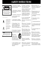 2
2
-
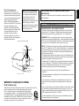 3
3
-
 4
4
-
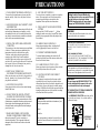 5
5
-
 6
6
-
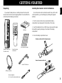 7
7
-
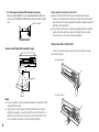 8
8
-
 9
9
-
 10
10
-
 11
11
-
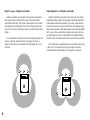 12
12
-
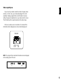 13
13
-
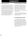 14
14
-
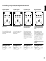 15
15
-
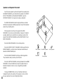 16
16
-
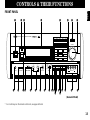 17
17
-
 18
18
-
 19
19
-
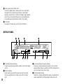 20
20
-
 21
21
-
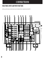 22
22
-
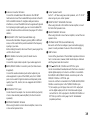 23
23
-
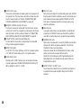 24
24
-
 25
25
-
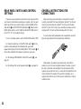 26
26
-
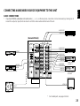 27
27
-
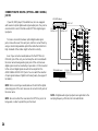 28
28
-
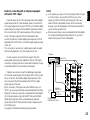 29
29
-
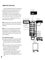 30
30
-
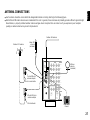 31
31
-
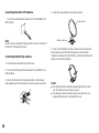 32
32
-
 33
33
-
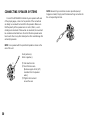 34
34
-
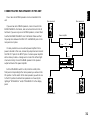 35
35
-
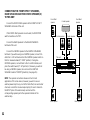 36
36
-
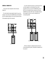 37
37
-
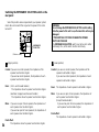 38
38
-
 39
39
-
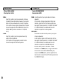 40
40
-
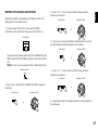 41
41
-
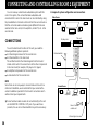 42
42
-
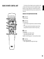 43
43
-
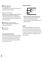 44
44
-
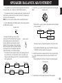 45
45
-
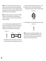 46
46
-
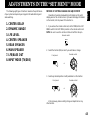 47
47
-
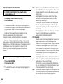 48
48
-
 49
49
-
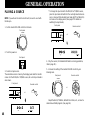 50
50
-
 51
51
-
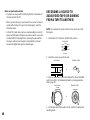 52
52
-
 53
53
-
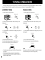 54
54
-
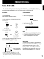 55
55
-
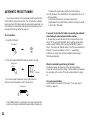 56
56
-
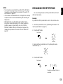 57
57
-
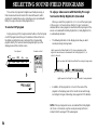 58
58
-
 59
59
-
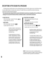 60
60
-
 61
61
-
 62
62
-
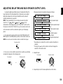 63
63
-
 64
64
-
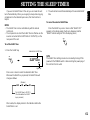 65
65
-
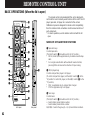 66
66
-
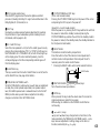 67
67
-
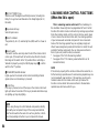 68
68
-
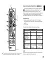 69
69
-
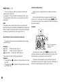 70
70
-
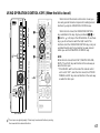 71
71
-
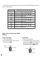 72
72
-
 73
73
-
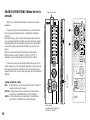 74
74
-
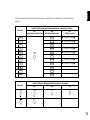 75
75
-
 76
76
-
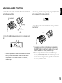 77
77
-
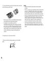 78
78
-
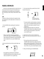 79
79
-
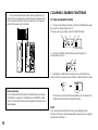 80
80
-
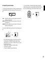 81
81
-
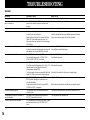 82
82
-
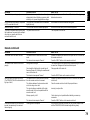 83
83
-
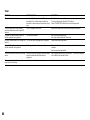 84
84
-
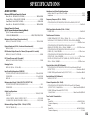 85
85
-
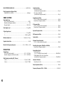 86
86
-
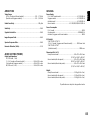 87
87
-
 88
88


Yamaha RX-V2092 Handleiding
- Categorie
- Ontvanger
- Type
- Handleiding
- Deze handleiding is ook geschikt voor
in andere talen
- English: Yamaha RX-V2092 User manual
- italiano: Yamaha RX-V2092 Manuale utente
- русский: Yamaha RX-V2092 Руководство пользователя
- français: Yamaha RX-V2092 Manuel utilisateur
- español: Yamaha RX-V2092 Manual de usuario
- Deutsch: Yamaha RX-V2092 Benutzerhandbuch
- português: Yamaha RX-V2092 Manual do usuário
- dansk: Yamaha RX-V2092 Brugermanual
- suomi: Yamaha RX-V2092 Ohjekirja
- čeština: Yamaha RX-V2092 Uživatelský manuál
- svenska: Yamaha RX-V2092 Användarmanual
- Türkçe: Yamaha RX-V2092 Kullanım kılavuzu
- polski: Yamaha RX-V2092 Instrukcja obsługi
- română: Yamaha RX-V2092 Manual de utilizare