
ISTRUZIONI PER L’INSTALLAZIONE
INSTALLATION INSTRUCTIONS
INSTRUCTIONS POUR L’INSTALLATION
INSTALLATIONSANLEITUNG
INSTALLATIE-AANWIJZINGEN
INSTRUCCIONES DE INSTALACIÓN
INSTRUKCJE INSTALACJI
NÁVOD K INSTALACI A ÚDRŽBĚ

Manuale valido per le versioni rmware 1.x
Manual valid for rmware versions 1.x
Manuel valide pour les versions micrologiciel 1.x
Gültiges Handbuch für die Firmware-Versionen 1.x
Handleiding geldig voor de rmware-versies 1.x
Manual válido para las versiones rmware 1.x
Instrukcja obowiązuje dla wersji rmware 1.x
Příručka platná pro verze rmwaru 1.x

IT - ITALIANO pag 4
GB - ENGLISH page 11
FR - FRANÇAIS page 18
DE - DEUTSCH seite 25
NL - NEDERLANDS bladz 32
ES - ESPAÑOL pág 39
PL - POLSKI str 46
CZ - ČEŠTINA strana 53

ITALIANO
IT
4
INDICE
Legenda 4
Avvertenze 4
1. Generalità 4
1.1 Dati Tecnici 5
2. Installazione 7
3. Interfaccia utente 8
4. Come aggiornare e.sylink ed e.sybox 9
LEGENDA
Nella trattazione sono stati usati i seguenti simboli:
Situazione di pericolo generico. Il mancato rispetto delle pre-
scrizioni che lo seguono può provocare danni alle persone
e alle cose.
AVVERTENZE
Prima di procedere all’installazione leggere attentamente questa
documentazione.
L’installazione ed il funzionamento dovranno essere conformi
alla regolamentazione di sicurezza del paese di installazione
del prodotto. Tutta l’operazione dovrà essere eseguita a regola
d’arte.
Il mancato rispetto delle norme di sicurezza, oltre a creare
pericolo per l’incolumità delle persone e danneggiare le apparec-
chiature, farà decadere ogni diritto di intervento in garanzia.
Personale Specializzato
È consigliabile che l’installazione venga eseguita da perso-
nale competente e qualicato, in possesso dei requisiti tecnici
richiesti dalle normative speciche in materia.
Per personale qualicato si intendono quelle persone che per
la loro formazione, esperienza ed istruzione, nonché le cono-
scenze delle relative norme, prescrizioni provvedimenti per la
prevenzione degli incidenti e sulle condizioni di servizio, sono
stati autorizzati dal responsabile della sicurezza dell’impianto
ad eseguire qualsiasi necessaria attività ed in questa essere
in grado di conoscere ed evitare qualsiasi pericolo.
(Denizione per il personale tecnico IEC 364)
L’apparecchio non è destinato ad essere usato da persone
(bambini compresi) le cui capacità siche sensoriali e mentali
siano ridotte, oppure con mancanza di esperienza o di
conoscenza, a meno che esse abbiano potuto beneciare, at-
traverso l’intermediazione di una persona responsabile della
loro sicurezza, di una sorveglianza o di istruzioni riguardanti
l’uso dell’apparecchio. I bambini devono essere sorvegliati
per sincerarsi che non giochino con l’apparecchio.
Sicurezza
L’utilizzo è consentito solamente se l’impianto elettrico è
contraddistinto da misure di sicurezza secondo le Normative
vigenti nel paese di installazione del prodotto (per l’Italia CEI
64/2).
Una mancata osservanza delle avvertenze può creare situazioni di peri-
colo per le persone o le cose e far decadere la garanzia del prodotto.
1- GENERALITÀ
e.sylink è l’accessorio DAB dotato di interfaccia wireless 802.15.4, nato
per permettere ad e.sybox di avvalersi di ingressi digitali (pressostato,
galleggiante, ecc.), controllare 2 uscite relay (allarmi, ecc.)e dare la
possibilità di connettere un sensore di pressione ausiliario,in modo da
poterlo utilizzare come riferimento per il set point di pressione.

ITALIANO
IT
5
1.1 Dati Tecnici
Tensione di alimentazione 24 V ± 20%
Corrente [mA] MIN : 55 @ 24V
MAX: 150 @ 24 V
Dimensioni [mm] 105 x 94 x60 (6 moduli DIN)
Peso (g) 200
Classe di protezione IP 20
Temperatura di esercizio [°C] 0 - 50
e.sylink è dotato di n°4 ingressi digitali optoisolati (connettore J3) ,
n°2 uscite relay NO (normalmente aperto) (Connettore J15) ed ha a
disposizione un ingresso per n° 1 sensore di pressione remoto (J31).
Sono presenti 10 led per interfaccia utente e 2 tasti.
Ingressi digitali
I 4 ingressi digitali sono optoisolati, possono essere eccitati sia con
tensioni continue negative e positive, sia in corrente alternata 50-60 Hz.
La Tabella 1 descrive le caratteristiche ed i limiti degli ingressi digitali:
Caratteristiche degli ingressi
Ingressi DC [V] Ingressi AC 50-60
Hz [Vrms]
Tensione minima di
accensione [V]
8 6
Tensione massima di
spegnimento [V]
2 1.5
Tensione massima
ammissibile[V]
36 36
Corrente assorbita a
12V [mA]
3.3 3.3
Max sezione del cavo
accettata[mm²]
1.5
Le connessioni dei terminali optoisolati avvengono applicando una
tensione ai terminali oppure collegando a ponticello il segnale comune
a GND e collegando il segnale I ad un contatto (es. Galleggiante,
pressostato, ecc.)
Tabella 1: Caratteristiche ingressi
Figura 1: e.sylink

ITALIANO
IT
6
Cablaggio Ingressi
Ingresso connesso a contatto
pulito
Ingresso in
tensione
Ingresso Contatto pulito tra i pin Ponticello Collegamento
I1 I1-VS CB - GND I1 - CB
I2 I2-VS CB - GND I2 - CB
I3 I3-VS CC - GND I3 - CC
I4 I4-VS CC - GND I4 - CC
Nella Figura 1 viene descritta a puro titolo di esempio, una modalità di
ingresso (Connessione ad Input 1).
Tabella 2 : Cablaggio Ingressi
Contatti di uscita:
Le connessioni delle uscite elencate di seguito fanno riferimento alla
morsettiera a 9 poli (J15) indicate con la serigraa O1, O2 e CA.
La Tabella 3 descrive le caratteristiche e limiti dei contatti di uscita.
Caratteristiche dei contatti di uscita
Tipo di contatto
NO (Normalmente
aperto)
Max tensione sopportabile [V] 24
Max corrente sopportabile [A]
5 -> carico resistivo
2,5 -> carico induttivo
Max sezione del cavo accettata [mm²] 2,5
Di seguito è mostrato nella Figura 2 un esempio di collegamento sui
contatti di uscita.
Tabella 3: Caratteristiche contatti di uscita
Figura 3: Esempio collegamento uscite
Figura 2: Esempio cablaggio ingresso I1, ingresso a contatto pulito

ITALIANO
IT
7
All’avvio si accendono tutti i led per 2 secondi, per poter vericarne il
corretto funzionamento.
In caso di anomalie si accenderà il led FAULT, nella maniera descritta
dalla Tabella 5 .
Adesso procedere alla connessione con uno o più e.sybox, come
descritto nel capitolo 3.
ATTENZIONE: Per poter collegare e.sylink ad e.sybox vericare che
la versione FW di e.sybox sia 4.xx o superiore. Per controllare la
versione FW fare riferimento al manuale di installazione di e.sybox. In
caso di versione precedente aggiornare e.sybox alla versione 4.xx o
Per esempi di applicazioni pratiche implementabili su e.sylink, fare
riferimento al manuale di installazione e.sybox.
Sensore di pressione:
e.sylink permette l’utilizzo di n°1 sensore di pressione remoto, diretta-
mente sul connettore a 4 poli J31.
Per ulteriori informazioni fare riferimento al manuale di installazione
di e.sybox.
2- INSTALLAZIONE
e.sylink deve essere installato in ambiente chiusi, non è adatto per
installazioni all’aperto o soggette ad alto grado di umidità.
Prima di collegare e.sylink alla tensione di alimentazione, effettuare
tutti i cablaggi necessari, collegando gli INPUT e OUTPUT nella con-
gurazione desiderata, opzionalmente collegare il sensore di pressione
ed impostare su e.sybox le congurazioni di input e output desiderate
(fare riferimento al manuale di installazione e.sybox).
A questo punto fornire ad e.sylink la tensione di alimentazione, come
descritto nella Figura 3. La Figura 3 mostra, a puro titolo di esempio,
un cablaggio di alimentazione , usufruendo di un alimentatore 24 VDC
per montaggio in barra DIN.
Figura 4: Esempio collegamento alimentazione e.sylink

ITALIANO
IT
8
superiore come descritto nel capitolo 4, altrimenti contattare un centro
assistenza DAB(ww.dabpumps.com).
3- INTERFACCIA UTENTE
Su e.sylink sono presenti led per indicare lo stato di funzionamento
del sistema. La Tabella 4 descrive il signicato di ogni led presente
sull’interfaccia utente:
Caratteristiche dei led
LED COLORE Descrizione
POWER
Bianco
Acceso: e.sylink alimentato
Spento: e.sylink non alimentato
FAULT
Rosso
Spento: nessuna anomalia
Acceso o lampeggiante: vedi Tabella 5
IN Verde
Spento: Ingresso non eccitato
Acceso: Ingresso eccitato
OUT Giallo
Spento: contatto relay aperto
Acceso: contatto relay chiuso
Blu
Spento: e.sylink non connesso e con-
gurazione wireless non presente
Acceso: e.sylink connesso
Lampeggiante: e.sylink non connesso,
ma con congurazione wireless
presente
Verde Sensore di Pressione collegato
La Tabella 5 descrive le possibile anomalie riscontrabili da e.sylink.
Fault LED FAULT
Generico Acceso sso
Tensione alimentazione non suf-
ciente per corretto pilotaggio relay
3 lampeggi ogni 4 secondi
Tensione di alimentazione non
sufciente per alimentazione
sensore di pressione
2 lampeggi ogni 4 secondi
Versione protocollo wireless non
compatibile
1 lampeggio ogni 4 secondi
Tabella 4: Caratteristiche LED
Tabella 5 : Anomalie
Figura 5: Interfaccia e.sylink

ITALIANO
IT
9
Procedura di Associazione
La funzionalità base di e.sylink è quella di potersi collegare tramite
un’interfaccia wireless 802.15.4, dotata di protocollo proprietario DAB,
con uno o più e.sybox.
E’ possibile collegare e.sylink ad un e.sybox o a più e.sybox seguendo
la seguente procedura:
• Alimentare e.sylink
• Raggiungere su e.sybox la pagina AS (vedi manuale e.sybox),
premere il tasto ‘+’ per almeno 5 secondi, attendere che il led blu
(sul display e.sybox) lampeggi ogni 2 secondi.
• Premere il tasto destro su e.sylink per almeno 5 secondi, at-
tendere quindi che il led blu (vedi tabella 4) si accenda sso.
Per interrompere la procedura è possibile premere il tasto sinistro su e.sylink.
In caso di disconnessione momentanea da e.sybox, il led blu
lampeggerà per indicare che il dispositivo non è connesso,
ma sta cercando di ripristinare la connessione.
La congurazione della rete wireless viene mantenuta anche in caso
di temporanea mancata alimentazione o spegnimento del dispositivo.
Procedura di disconnessione e azzeramento congurazione
wireless
Premere per 5 secondi il tasto sinistro. Se l’operazione è andata a
buon ne il led blu risulterà spento.
4 - COME AGGIORNARE E.SYLINK ED E.SYBOX
e.sylink ha la possibilità di aggiornare il proprio rmware tramite connessio-
ne USB e di aggiornare il rmware di e.sybox tramite connessione wireless.
Collegando e.sylink al PC tramite il cavo USB in dotazione, si potrà
visualizzare al suo interno un le .bin contenente il rmware di e.sylink
ed il rmware per poter aggiornare e.sybox. Il le contenuto sarà del tipo
EsyBox_Vxxx.yy_EsyLink_Vkkk.zz.bin, dove xxx.yy rappresenta la ver-
sione fw di e.sybox, mentre kkk.zz rappresenta la versione fw di e.sylink.
Procedura per aggiornamento le .bin su esylink
Per cambiare il rmware di e.sylink o aggiornare con una versione
recente e.sybox dovrete disporre del le .bin con la versione più re-
cente di e.sylink ed e.sybox rilasciata da DAB (www.dabpumps.com),
un Pc dotato di sistema operativo Windows 7, Vista e XP ed il cavo
usb con connettore di tipo B dato in dotazione ad e.sylink.
Se si desidera sostituire il le con una nuova versione, seguire la
procedura descritta sotto:
1 - Accendere e.sylink tenendo premuto un tasto qualsiasi
2 - Sul pc apparirà l’unità disco e.sylink
3 - Cancellare il le presente
4 - Copiare il nuovo le .bin
E’ possibile quindi aggiornare e.sybox mediante e.sylink, tramite
l’interfaccia wireless 802.15.4. Per fare ciò i due dispositivi non neces-
sitano di essere associati tra di loro. L’aggiornamento ha la durata di
1 minuto circa.
Procedura per aggiornamento e.sybox tramite e.sylink
Sulla
centralina
e.sylink
1 Spegnere la pompa e.sybox che si intende aggiornare
2 Posizionare la centralina e.sylink nelle immediate
vicinanze della pompa e.sybox
3 Disconnettere la centralina e.sylink dall’alimentazione
4
Tenendo premuti i 2 tasti contemporaneamen-
te, alimentare la centralina e.sylink.
5
Rilasciare i tasti e vericare che il LED verde sia
acceso.
Adesso l’e.sylink è pronta e rimarrà in attesa per circa un
minuto.

ITALIANO
IT
10
Sulla
pompa
e.sybox
6 Tenendo premuti i tasti [MODE] e [-], alimentare la
pompa e.sybox
7 Rilasciare i tasti
A questo punto il display dell’e.sybox visualizzerà la
scritta “LV LOADER v y.x” ed una barra di riempimento
vuota; dopo alcuni istanti la barra inizierà a riempirsi,
evidenziando l’avvenuto inizio della fase aggiornamen-
to che impiegherà circa un minuto.
Al termine di questa fase, l’e.sybox si resetterà in
modo automatico avviando il nuovo programma.
Adesso è necessario controllare che il rmware sia
correttamente installato.
• Una volta riavviata la pompa, il display visualizza
la home page. Premere il tasto [MODE] per 6 volte
no alla pagina VE.
• Se nella pagina VE alla scritta “SW V.” è visua-
lizzata la versione attesa, l’operazione è terminata
con successo.
Ripetere questa procedura per aggiornare altri e.sybox
In caso di aggiornamento non avvenuto, su e.sylink si accenderà il
led rosso Fault.
La Tabella 1 descrive il numero di lampeggi del led FAULT di e.sylink
in caso di errori e le azioni da osservare.
Codice err. Causa Azione da intraprendere
6 lampeggi Errore durante
l’aggiornamento
Ripetere la procedura
5 lampeggi Il rmware installato
su e.sybox è più
recente di quello che
risiede su e.sylink.
Il sistema funziona correttamente.
Vericare eventuale disponibilità di
versione Firmware più recente.
4 lampeggi Firmware e.sybox
non presente o
corrotto
Caricare il le .bin corretto
Tabella 6 : Errori segnalati dal led fault

ENGLISH
GB
11
INDEX
Key 11
Warnings 11
1. General 11
1.1 Technical Data 12
2. Installation 14
3. User interface 15
4. How to update e.sylink and e.sybox 16
KEY
The following symbols have been used in the discussion:
Situation of general danger. Failure to respect the
instructions that follow may cause harm to persons and
property.
WARNINGS
Read this documentation carefully before installation.
Installation and operation must comply with the local safety
regulations in force in the country in which the product is
installed. Everything must be done in a workmanlike manner.
Failure to respect the safety regulations not only causes risk
to personal safety and damage to the equipment, but invali-
dates every right to assistance under guarantee.
Skilled personnel
It is advisable that installation be carried out by competent,
skilled personnel in possession of the technical qualications
required by the specic legislation in force.
The term skilled personnel means persons whose training,
experience and instruction, as well as their knowledge of the
respective standards and requirements for accident preven-
tion and working conditions, have been approved by the
person in charge of plant safety, authorizing them to perform
all the necessary activities, during which they are able to
recognize and avoid all dangers. (Denition for technical
personnel IEC 364).
The appliance is not intended to be used by persons (includ-
ing children) with reduced physical, sensory or mental capaci-
ties, or who lack experience or knowledge, unless, through
the mediation of a person responsible for their safety, they
have had the benet of supervision or of instructions on the
use of the appliance. Children must be supervised to ensure
that they do not play with the appliance.
Safety
Use is allowed only if the electric system is in possession
of safety precautions in accordance with the regulations in
force in the country where the product is installed (for Italy
CEI 64/2).
Failure to observe the warnings may create situations of risk for
persons or property and will void the product guarantee.
1- GENERAL
e.sylink is the DAB accessory with wireless interface 802.15.4, de-
signed to allow the e.sybox to use digital inputs (pressure switch, oat,
etc.), to control 2 relay outputs (alarms, etc.) and to offer the possibility
of connecting an auxiliary pressure sensor, so that it can be used as
reference for the pressure set point.

ENGLISH
GB
12
1.1 Technical Data
Supply voltage 24 V ± 20%
Current [mA] MIN : 55 @ 24V
MAX: 150 @ 24 V
Dimensions [mm] 105 x 94 x60 (6 DIN modules)
Weight (g) 200
Protection class IP 20
Working temperature [°C] 0 - 50
The e.sylink has 4 optoinsulated digital inputs (connector J3), 2 NO
(normally open) relay outputs (connector J15) and has an output for 1
remote pressure sensor (J31). There are 10 leds for the user interface
and 2 keys.
Digital inputs
The digital inputs are optoinsulated, they can be energised either with
continuous negative and positive voltages or with alternating current
at 50-60 Hz. Table 1 describes the characteristics and the limits of the
digital inputs:
Characteristics of the inputs
DC inputs [V] AC inputs 50-60
Hz [Vrms]
Minimum switch-on
voltage [V]
8 6
Maximum switch-off
voltage [V]
2 1.5
Maximum admissible
voltage [V]
36 36
Current absorbed at 12V
[mA]
3.3 3.3
Max. accepted cable
section [mm²]
1.5
The optoinsulated terminals are connected by applying a voltage to the
terminals or by connecting the common signal to GND as a jumper and
connecting the signal I to a contact (e.g. oat, pressure switch, etc.)
Table 1: Input characteristics
Figure 1: e.sylink
Left key
Right
key

ENGLISH
GB
13
Input wiring
Input connected to clean contact Voltage input
Input Clean contact between pins Jumper Connection
I1 I1-VS CB - GND I1 - CB
I2 I2-VS CB - GND I2 - CB
I3 I3-VS CC - GND I3 - CC
I4 I4-VS CC - GND I4 - CC
An input mode is described in Figure 1, just as an example (Connec-
tion to Input 1)
Table 2: Input wiring
Output contacts:
The connections of the outputs listed below refer to the 9-pole terminal
board (J15), indicated with screen printing O1, O2 and CA.
Table 3 describes the characteristics and limits of the output contacts.
Characteristics of the output contacts
Type of contact NO (Normally open)
Max. bearable voltage [V] 24
Max. bearable current [A]
5 -> resistive load
2,5 -> inductive load
Max. accepted cable section [mm²] 2,5
An example of connection on the output contacts is shown below in Figure 2.
Table 3: Characteristics of the output contacts
Figure 2: Example of wiring of input I1, input with clean contact
Figure 3: Example of output connection

ENGLISH
GB
14
At start all the leds are lit for 2 seconds, in order to check their correct
operation.
In the event of malfunction the FAULT leds will light up, as described
in Table 5.
Now make the connection with one e.sybox or more, as described in
chapter 3.
ATTENTION: In order to connect e.syLink to e.syBox check that the
FW version of e.sybox is 4.xx or higher. To check the FW version, re-
fer to the e.sybox installation manual. In the case of a previous version
update the e.sybox to version 4.xx or higher as described in chapter 4,
For examples of practical applications that can be implemented on the
e.sylink, refer to the e.sybox installation manual.
Pressure sensor:
e.sylink allows the use of 1 remote pressure sensor, directly on the
4-pole connector J31.
For further information refer to the e.sybox installation manual.
2- INSTALLATION
e.sylink must be installed in closed environments, it is not suitable for
open-air installations or where there is a high level of humidity.
Before connecting e.sylink to the supply voltage, make all the neces-
sary wiring, connecting the INPUTS and OUTPUTS in the desired
conguration, optionally connect the pressure sensor and set the
desired input and output congurations on the e.sybox (refer to the
e.sybox installation manual).
At this point power the e.syLink with the supply voltage, as described
in Figure 3. Figure 3 shows, just as an example, a supply wiring, using
a 24 VDC feeder for assembly on a DIN bar.
Figure 4: Example of e.sylink power supply connection

ENGLISH
GB
15
otherwise contact a DAB assistance centre (www.dabpumps.com).
3- USER INTERFACE
On the e.sylink there are leds indicating the system operating status.
Table 4 describes the meaning of each leds on the user interface:
Characteristics of the leds
LEDS COLOUR Description
POWER
White
On: e.sylink powered
Off: e.sylink not powered
FAULT
Red
Off: no fault
On or blinking: see Table 5
IN Green
Off: Input not energised
On: Input energised
OUT Yellow
Off: relay contact open
On: relay contact closed
Blue
Off: e.sylink not connected
and wireless conguration
not present
On: e.sylink connected
Blinking: e.sylink not
connected, but with wireless
conguration present
Green Pressure Sensor connected
Table 5 described the possible faults that may be found by e.sylink
Fault LED FAULT
General On with xed light
Supply voltage not sufcient
for correct relay control
3 blinks every 4 seconds
Supply voltage not sufcient to
power the pressure sensor
2 blinks every 4 seconds
Wireless protocol version not
compatible.
1 blink every 4 seconds
Table 5: Faults
Figure 5: e.sylink Interface
Table 4: leds characteristics

ENGLISH
GB
16
Association procedure
The basic function of the e.sylink is that it can be connected by means
of a wireless interface 802.15.4, equipped with a protocol owned by
DAB, to one or more e.sybox units.
It is possible to connect the e.sylink to an e.sybox or to several
e.sybox units using the following procedure:
• Supply power to the e.sylink
• Go to page AS (see e.sybox manual) on the e.sybox, press
the ‘+’ key for at least 5 seconds, wait for the blue leds (on the
e.sybox display) to blink every 2 seconds.
• Press the right key on the e.sylink for at least 5 seconds, then
wait until the system 1 blue leds (see table 4) is lit with a
xed light.
To interrupt the procedure it is possible to press the left key on the e.sylink.
In the event of a momentary disconnection from e.sybox, the blue
led blinks to indicate that the device is not connected, but is trying
to restore the connection.
The wireless network conguration is maintained even in the case of a
temporary power cut or if the device is switched off.
Disconnection procedure and resetting of the wireless conguration.
Hold down the left key for 5 seconds. If the operation has been
successful the System 1 blue leds will be off.
4 - HOW TO UPDATE E.SYLINK AND E.SYBOX
e.sylink has the possibility of updating its rmware through a USB connec-
tion and of updating e.sybox rmware by means of a wireless connection.
When the e.sylink is connected to the PC using the USB cable provided,
a .bin le can be seen in it which contains the e.sylink rmware and the
rmware for updating the e.sybox. The le will be of the type EsyBox_
Vxxx.yy_EsyLink_Vkkk.zz.bin, where xxx.yy represents the fw version of
e.sybox, while kkk.zz represents the fw version of e.sylink
Procedure for updating the .bin le on e.sylink:
To change the e.sylink rmware or update e.sybox with a recent
version you must have the .bin le with the most recent version of
e.sylink and e.sybox issued by DAB (www.dabpumps.com), a PC with
Windows 7, Vista or XP operative system and the USB cable with B
type connector supplied with e.sylink.
If you want to replace the le with a new version, follow the procedure
described below:
1 - Switch on the e.sylink, holding down any key.
2 - The e.sylink disk unit will appear on the PC
3 - Delete the le present
4 - Copy the new .bin le
It is now possible to update e.sybox with e.sylink, using the wireless
interface 802.15.4. To do this the two devices do not need to be asso-
ciated with each other. Updating takes about 1 minute.
Procedure for updating e.sybox with e.sylink:
On the
e.sylink
control
unit
1 Switch off the e.sybox pump you want to update.
2 Position the e.sylink control unit in the immediate
vicinity of the e.sybox pump
3 Disconnect the e.sylink control unit from the power supply
4
Holding down the 2 keys simultaneously,
supply power to the e.sylink control unit.
5
Release the keys and check that the green LED
is lit.
The e.sylink is now ready and will remain in standby for
about one minute.

ENGLISH
GB
17
On the
e.sybox
pump
6 Holding down the keys [MODE] and [-], supply power
to the e.sybox
7 Release the keys.
At this point the e.sybox display will show the message
“LV LOADER v y.x” and an empty progress bar; after
a few moments the bar will start to ll, showing that
the updating phase has started which will take about
one minute.
At the end of this phase the e.sybox will reset automa-
tically, starting the new program.
Now it is necessary to check that the rmware is
correctly installed.
• Once the pump has been restarted, the display
shows the home page. Press the [MODE] key 6
times until page VE is shown.
• If the expected version is shown on page VE
under the heading “SW V.”, the operation has been
successfully completed.
Repeat this procedure to update other e.sybox units.
If the update has not been successful, the red Fault led will light up on
the e.sylink.
Table 1 describes the number of blinks of the e.sylink FAULT led in the
case of errors and the actions to be taken.
Error code Cause Action to be taken
6 blinks Error during updating Repeat the procedure
5 blinks The rmware instal-
led on the e.sybox is
more recent than that
in the e.sylink.
The system is working correctly.
Check it a more recent Firmware
version is available.
4 blinks e.sybox rmware not
present or corrupted
Load the correct .bin le
Table 6: Errors indicated by the fault leds

FRANÇAIS
FR
18
SOMMAIRE
Légende 18
Avertissements 18
1. Généralités 18
1.1 Données techniques 19
2. Installation 21
3. Interface utilisateur 22
4. Comment mettre à jour e.sylink et e.sybox 23
LÉGENDE
Les symboles suivants sont employés dans le présent document:
Situation de danger générique. Le non-respect des
prescriptions suivantes peut provoquer des blessures aux
personnes et des dommages aux choses.
AVERTISSEMENTS
Avant de procéder à l’installation, lire attentivement la docu-
mentation présente.
L’installation et le fonctionnement devront être conformes à
la réglementation de sécurité du pays dans lequel le produit
est installé. Toute l’opération devra être effectuée dans les
règles de l’art.
Le non-respect des normes de sécurité provoque un danger
pour les personnes et peut endommager les appareils. De
plus, il annulera tout droit d’intervention sous garantie.
Personnel spécialisé
Il est conseillé de faire effectuer l’installation par du personnel
compétent et qualié, disposant des connaissances tech-
niques requises par les normatives spéciques en la matière.
Le terme personnel qualié entend des personnes qui, par
leur formation, leur expérience et leur instruction, ainsi que par
leur connaissance des normes, prescriptions et dispositions
traitant de la prévention des accidents et des conditions de
service, ont été autorisées par le responsable de la sécurité
de l’installation à effectuer toutes les activités nécessaires et
sont donc en mesure de connaître et d’éviter tout danger.
(Dénition du personnel technique CEI 364)
L’appareil n’est pas destiné à être utilisé par des personnes
(y compris les enfants) dont les capacités physiques, sen-
sorielles et mentales sont réduites, ou ne disposant pas de
l’expérience ou de la connaissance nécessaires, sauf si elles
ont pu bénécier, par le biais d’une personne responsable de
leur sécurité, de suivi et d’instructions traitant de l’utilisation de
l’appareil. Les enfants doivent être surveillés, an de vérier
qu’ils ne jouent pas avec l’appareil.
Sécurité
L’utilisation n’est permise que si l’installation électrique est
dotée des mesures de sécurité prévues par les normatives
en vigueur dans le pays d’installation du produit (pour l’Italie
CEI 64/2).
Le non-respect des avertissements peut engendrer des situations
dangereuses pour les personnes et les choses et annuler la garantie
du produit.
1- GÉNÉRALITÉS
e.sylink est un accessoire DAB doté d’une interface sans l 802.15.4,
conçu pour permettre d’équiper e.sybox d’entrées numériques (pres-
sostat, otteur, etc.), de contrôler 2 sorties relais (alarmes, etc.) et de
donner la possibilité de brancher un capteur de pression auxiliaire, an
de pouvoir l’utiliser comme référence pour le point de réglage de la
pression.

FRANÇAIS
FR
19
1.1 Données techniques
Tension d’alimentation 24 V ± 20%
Courant [mA] MIN : 55 @ 24V
MAX: 150 @ 24 V
Dimensions [mm] 105 x 94 x60 (6 modules DIN)
Poids (g) 200
Classe de protection IP 20
Température d’exercice [°C] 0 - 50
e.sylink est doté de 4 entrées numériques opto-isolées (connecteur
J3), 2 sorties relais NO (normalement ouvert) (Connecteur J15) et
dispose d’une entrée pour 1 capteur de pression distant (J31).
Chaque interface utilisateur comprend 10 DEL et 2 touches.
Entrées numériques
Les 4 entrées numériques sont opto-isolées, elles peuvent être exci-
tées aussi bien par des tensions continues négatives et positives que
par un courant alternatif 50-60 Hz.
Le Tableau 1 décrit les caractéristiques et limites des entrées numériques:
Caractéristiques des entrées
Entrées
CC [V]
Entrées CA 50-
60 Hz [Vrms]
Tension minimum d’allumage [V] 8 6
Tension maximum d’arrêt [V] 2 1.5
Tension maximum admissible [V] 36 36
Courant absorbé à 12V
[mA]
3.3 3.3
Section câble max admissible
[mm²]
1.5
Les branchements des bornes opto-isolées sont effectués en mettant
les bornes sous tension ou en reliant le signal commun à la mise à la
terre par le biais d’un pont et en branchant le signal I à un contact (ex.
otteur, pressostat, etc.)
Tableau 1 : Caractéristiques entrées
Figure 1 : e.sylink
Touche
gauche
Touche
droite

FRANÇAIS
FR
20
Câblage entrées
Entrée branchée à un contact propre
Entrée sous
tension
Entrée Contact propre entre les broches Pont Branchement
I1 I1-VS CB - GND I1 - CB
I2 I2-VS CB - GND I2 - CB
I3 I3-VS CC - GND I3 - CC
I4 I4-VS CC - GND I4 - CC
La Figure 1 décrit, au seul titre d’exemple, une modalité d’entrée
(Branchement à l’Entrée 1).
Tableau 2: Câblage entrées
Contacts de sortie :
Les branchements des sorties énumérées ci-dessous font référence
au bornier à 9 pôles (J15). Elles sont indiquées par les sérigraphies
O1, O2 et CA. Le Tableau 3 décrit les caractéristiques et limites des
contactas de sortie.
Caractéristiques des contacts de sortie
Type de contact NO (Normalement Ouvert)
Tension max prise en charge [V] 24
Courant max pris en charge [A]
5 -> charge résistive
2,5 -> charge inductive
Section de câble max admissible
[mm²]
2,5
La Figure 2 illustre un exemple de branchement sur les contacts de sortie.
Tableau 3 : Caractéristiques des contacts de sortie
Figure 2 : Exemple de câblage entrée I1, entrée à contact propre
Figure 3 : Exemple de branchement des sorties

FRANÇAIS
FR
21
Au démarrage, toutes les DEL s’allument pendant 2 secondes an de
pouvoir vérier le fonctionnement.
En cas d’anomalie, la DEL FAULT (panne) s’allumera comme indiqué
au Tableau 5 .
Procéder alors au branchement d’un ou plusieurs e.sybox, comme
décrit au chapitre 3.
ATTENTION: Pour pouvoir brancher e.sylink à e.sybox, vérier que
la version FW d’e.sybox soit 4.xx ou supérieure. Pour contrôler la
version FW, consulter le manuel d’installation de e.sybox. En cas
Pour consulter des exemples d’applications pratiques sur e.sylink,
faire référence au manuel d’installation de e.sybox.
Capteur de pression:
e.sylink permet d’utiliser un capteur de pression distant directement
sur le connecteur à 4 pôles J31.
Pour de plus amples informations, consulter le manuel d’installation
de e.sybox.
2- INSTALLATION
e.sylink doit être installé dans un environnement fermé. Il n’est pas
adapté aux installations en extérieur ou soumises à une humidité
importante.
Avant de brancher e.sylink à la tension d’alimentation, effectuer tous
les câblages nécessaires en branchant les ENTRÉES et SORTIES
selon la conguration voulue. En option, brancher le capteur de pres-
sion et paramétrer sur e.sybox les congurations d’entrée et de sortie
voulues (faire référence au manuel d’installation e.sybox).
Fournir alors à e.sylink la tension d’alimentation tel que décrit à la
Figure 3. A simple titre d’exemple, la Figure 3 illustre un câblage d’ali-
mentation effectué à l’aide d’un alimentateur 24 VCC pour le montage
de la barre DIN.
Figure 4: Exemple de branchement d’alimentation e.sylink

FRANÇAIS
FR
22
de version précédente mettre à jour e.sybox à la version 4.xx ou
supérieure suivant les indications du chapitre 4, ou bien contacter un
centre SAV DAB (www.dabpumps.com).
3- INTERFACE UTILISATEUR
e.sylink comprend des DEL indiquant l’état de fonctionnement du
système. Le Tableau 4 décrit la signication de chacune des DEL de
l’interface utilisateur:
Caractéristiques des DEL
DEL COULEUR Description
POWER
Blanc
Allumée: e.sylink alimenté
Éteinte: e.sylink non alimenté
FAULT
Rouge
Éteinte: aucune anomalie
Allumée ou clignotante : voir Tableau 5
IN Vert
Éteinte: entrée non excitée
Allumée: entrée excitée
OUT Jaune
Éteinte: contact relais ouvert
Allumée: contact relais fermé
Bleu
Éteinte: e.sylink non branché et la
conguration sans l est non présente
Allumée: e.sylink branché
Clignotante : e.sylink non branché,
mais la conguration sans l est
présente
Vert Capteur de pression branché
Le Tableau 5 décrit les anomalies qui peuvent se produire sur e.sylink
Anomalies DEL FAULT
Générique Allumée xe
Tension d’alimentation insufsante
pour le bon pilotage du relais
3 clignotements toutes les
4 secondes
Tension d’alimentation insufsante
pour l’alimentation du capteur de
pression
2 clignotements toutes les
4 secondes
Version protocole sans l non
compatible
1 clignotement toutes les 4
secondes
Tableau 4 : Caractéristiques DEL
Tableau 5: Anomalies
Figure 5: Interface e.sylink

FRANÇAIS
FR
23
Procédure d’association
e.sylink a pour fonction de base de se brancher à un ou plusieurs
e.sybox à travers une interface sans l 802.15.4 dotée d’un protocole
propriétaire DAB.
e.sylink peut être connecté à un ou plusieurs e.sybox selon la
procédure suivante:
• Alimenter e.sylink
• Sur e.sybox, aller à la page AS (voir manuel e.sybox), appuyer
sur la touche « + » pendant 5 secondes au moins, attendre
que la DEL bleue (sur l’écran e.sybox) clignote toutes les 2
secondes.
• Appuyer sur la touche droite sur e.sylink pendant 5 secondes
au moins, attendre que la DEL bleue (voir tableau 4) s’allume
de manière xe.
Pour interrompre la procédure, appuyer sur la touche gauche sur
e.sylink.
Si e.sybox est temporairement déconnecté, la DEL bleue clignotera
pour indiquer que le dispositif n’est pas branché mais qu’il essaie de
rétablir la connexion.
La conguration du réseau sans l est maintenue même en cas de
coupure momentanée d’alimentation ou lorsque le dispositif est éteint.
Procédure de débranchement et remise à zéro de la conguration
sans l
Appuyer sur la touche gauche pendant 5 secondes. Si l’opération
réussit, la DEL bleue sera éteinte.
4 - COMMENT METTRE À JOUR E.SYLINK ET E.SYBOX
e.sylink a la possibilité de mettre à jour son rmware par connexion USB et
de mettre à jour le rmware d’e.sybox par connexion sans l.
En connectant e.sylink au PC au moyen du câble USB fourni, on pourra af-
cher un chier .bin contenant le rmware d’e.sylink et le rmware servant
à mettre à jour e.sybox. Le chier contenu sera de type EsyBox_Vxxx.
yy_EsyLink_Vkkk.zz.bin, où xxx.yy représente la version fw d’e.sybox,
tandis que kkk.zz représente la version fw d’e.sylink.
Procédure pour mise à jour du chier .bin sur esylink:
Pour changer le rmware d’e.sylink ou mettre à jour e.sybox à une
version récente, vous devrez disposer du chier .bin avec la version
plus récente d’e.sylink et e.sybox délivrée par DAB (www.dabpumps.
com), d’un PC avec système d’exploitation Windows 7, Vista ou XP et
du câble USB avec connecteur de type B fourni avec e.sylink.
Si vous souhaitez remplacer le chier par une nouvelle version, suivre
la procédure décrite ci-dessous:
1 - Allumer e.sylink en maintenant enfoncée une touche quelconque
2 - L’unité disque e.sylink s’afchera sur le PC
3 - Effacer le chier présent
4 - Copier le nouveau chier .bin
Il est alors possible de mettre à jour e.sybox par le biais d’e.sylink, à
travers l’interface sans l 802.15.4. Pour le faire, les deux dispositifs
n’ont pas besoin d’être associés entre eux. La mise à jour dure
environ 1 minute.
Procédure pour mise à jour d’e.sybox par le biais d’e.sylink:
Sur le
coffret
e.sylink
1 Éteindre la pompe e.sybox que l’on désire mettre à jour
2 Positionner le coffret e.sylink à proximité immédiate de la
pompe e.sybox
3 Déconnecter le coffret e.sylink de l’alimentation
4
En appuyant simultanément sur les 2 touches ,
alimenter le coffret e.sylink.
5
Relâcher les touches et vérier que la DEL verte est allumée.
Maintenant l’e.sylink est prêt et restera en attente pendant
environ une minute.

FRANÇAIS
FR
24
Sur la
pompe
e.sybox
6 En maintenant enfoncées les touches [MODE] et [-],
alimenter la pompe e.sybox
7 Relâcher les touches
L’écran d’e.sybox afchera le message « LV LOADER
v y.x » et une barre de progression vide ; au bout de
quelques instants, la barre commencera à se remplir en
indiquant le début de la phase de mise à jour qui prendra
environ une minute.
À la n de cette phase, l’e.sybox se réinitialisera en
automatique en lançant le nouveau programme.
Il faut contrôler maintenant que le rmware est correcte-
ment installé.
• Une fois que la pompe a redémarré, l’écran afche la
page d’accueil. Appuyer sur la touche [MODE] 6 fois
jusqu’à la page VE.
• Si dans la page VE au niveau de « SW V. », la ver-
sion afchée est la version correcte, l’opération s’est
conclue avec succès.
Répéter cette procédure pour mettre à jour d’autres e.sybox
Si la mise à jour n’a pas été faite, sur e.sylink la DEL rouge Fault
s’allumera.
Le Tableau 1 décrit le nombre de clignotements de la DEL FAULT d’e.
sylink en cas d’erreurs et les actions à effectuer.
Code err. Cause Action à entreprendre
6 clignote-
ments
Erreur durant la mise
à jour
Répéter la procédure
5 clignote-
ments
Le rmware installé
sur e.sybox est plus
récent que celui
qui est présent sur
e.sylink.
Le système fonctionne cor-
rectement. Vérier l’éventuelle
disponibilité de version rmware
plus récente.
4 clignote-
ments
Firmware e.sybox
non présent ou altéré
Charger le chier .bin correct
Tableau 6: Erreurs signalées par la DEL fault

DEUTSCH
DE
25
INHALT
Legende 25
Hinweise 25
1. Allgemeines 25
1.1 Technische Daten 26
2. Installation 28
3. Benutzerschnittstelle 29
4. Aktualisieren von e.sylink und e.sybox 30
LEGENDE
Folgende Symbole wurden im Dokument verwendet:
Allgemeine Gefahrensituation. Die nicht erfolgte Einhaltung
der nach dem Symbol angeführten Vorschriften kann
Schäden an Personen und Dingen verursachen.
HINWEISE
Allgemeine Gefahrensituation Die nicht erfolgte Einhal-
tung der nach dem Symbol angeführten Vorschriften kann
Schäden an Personen und Dingen verursachen.
Vor Installationsbeginn aufmerksam diese Dokumentation
durchlesen.
Installation und Betrieb müssen mit den Sicherheitsvorschrift-
en des Installationslandes des Produktes übereinstimmen.
Der gesamte Vorgang muss fachgerecht ausgeführt werden.
Neben der Gefahr für die Unversehrtheit der Personen und
der Verursachung von Schäden an den Geräten, bewirkt die
fehlende Einhaltung der Sicherheitsvorschriften den Verfall
jeglichen Rechtes auf einen Garantieeingriff.
Fachpersonal
Es ist empfehlenswert, dass die Installation durch kompetentes und
qualiziertes Personal erfolgt, das über die technischen Anforder-
ungen verfügt, die in den speziellen Vorschriften für diesen Bereich
vorgesehen sind.
Qualiziertes Personal sind die Personen, die aufgrund ihrer
Ausbildung, Erfahrung und Schulung sowie aufgrund der Kenntnis
der entsprechenden Normen, Vorschiften und Maßnahmen zur
Unfallverhütung und zu den Betriebsbedingungen vom Sicherheits-
verantwortlichen der Anlage autorisiert wurden, jegliche erforderliche
Aktivität auszuführen und dabei in der Lage sind, Gefahren zu erken-
nen und zu vermeiden.
(Denition für technisches Personal IEC 364)
Das Gerät ist nicht für den Gebrauch durch Personen (einschließlich
Kinder) mit verringerten physischen oder mentalen Fähigkeiten oder
fehlender Erfahrung oder Kenntnissen bestimmt, es sei denn, dass
diese durch die Vermittlung einer für ihre Sicherheit verantwortlichen
Person eingewiesen oder beaufsichtigt werden oder Anweisungen
erhalten. Kinder müssen beaufsichtigt werden, damit sichergestellt
ist, dass sie nicht mit dem Gerät spielen.
Sicherheit
Der Gebrauch ist nur dann erlaubt, wenn die elektrische Anlage durch
Sicherheitsvorschriften gemäß den im Installationsland des Produktes
geltenden Verordnungen gekennzeichnet ist (für Italien CEI 64/2).
Die fehlende Beachtung der Hinweise kann Gefahrensituationen für Personen
oder Dinge verursachen und zur Unwirksamkeit der Produktgarantie führen.
1- ALLGEMEINES
e.sylink ist das Zubehörteil von DAB mit Wireless-Schnittstelle
802.15.4, das entstanden ist, um der.sybox Digitaleingänge zur Verfü-
gung zu stellen (Druckwächter, Schwimmer, usw.), 2 Relaisausgänge
zu kontrollieren (Alarme, usw.) und die Möglichkeit zu geben, einen

DEUTSCH
DE
26
zusätzlichen Drucksensor anzuschließen, der als Bezug für den
Drucksollwert verwendet werden kann.
1.1 Technische Daten
Versorgungsspannung 24 V ± 20%
Strom [mA] MIN : 55 @ 24V / MAX: 150 @ 24 V
Abmessungen [mm] 105 x 94 x60 (6 DIN Module)
Gewicht (g) 200
Schutzklasse IP 20
Betriebstemperatur [°C] 0 - 50
e.sylink bietet 4 optoisolierte Digitaleingänge (Verbinder J3), 2
Relaisausgänge NO (Arbeitskontakt) (Verbinder J15), sowie einen
Eingang für 1 entfernten Drucksensor (J31).
Am Gerät benden sich 10 LEDS für die Benutzerschnittstelle und 2
Tasten.
Digitaleingänge
Die 4 Digitaleingänge sind optoisoliert und können sowohl mit negati-
ver und positiver Gleichspannung, als auch in Wechselstrom 50-60 Hz
angeregt werden.
In der Tabelle 1 sind die Charakteristiken und die Grenzwerte der
Digitaleingänge beschrieben:
Charakteristiken der Eingänge
Eingänge
DC [V]
Eingänge AC
50-60 Hz [Vrms]
Min. Einschaltspannung [V] 8 6
Max. Abschaltspannung [V] 2 1.5
Zulässige max. Spannung [V] 36 36
Stromaufnahme bei 12V [mA] 3.3 3.3
Max. annehmbarer Kabelquer-
schnitt [mm²]
1.5
Die Verbindungen der optoisolierten Endverschlüsse erfolgen mit
Anwendung einer Spannung an die Endverschlüsse, oder durch
Überbrücken des gemeinsamen Signals an GND und Anschließen des
Signals I an einen Kontakt (z.B. Schwimmer, Druckwächter, usw.)
Tabelle 1: Merkmale der Eingänge
Abbildung 1: e.sylink
Linke
Taste
Rechte
Taste

DEUTSCH
DE
27
Verdrahtung der Eingänge
Eingang an sauberen Kontakt
angeschlossen
Eingang unter
Spannung
Eingang
Sauberer Kontakt
zwischen den Pins
Brücke Anschluss
I1 I1-VS CB - GND I1 - CB
I2 I2-VS CB - GND I2 - CB
I3 I3-VS CC - GND I3 - CC
I4 I4-VS CC - GND I4 - CC
Die Abbildung 1 beschreibt ein Beispiel für einen Eingangsmodus
(Anschluss Input 1).
Tabelle 2: Verdrahtung der Eingänge
Ausgangskontakte:
Die Anschlüsse der nachstehend angeführten Ausgänge beziehen
sich auf die 9 polige Klemmenleiste (J15) mit dem Aufdruck O1, O2
und CA. In der Tabelle 3 sind die Charakteristiken und Grenzwerte der
Ausgangskontakte beschrieben.
Charakteristiken der Ausgangskontakte
Kontakttyp: NO (Arbeitskontakt)
Max. ertragbare Spannung [V] 24
Max. ertragbarer Strom [A]
5 -> Widerstandsbelastung
2,5 -> Induktive Belastung
Max. annehmbarer Kabelquer-
schnitt [mm²]
2,5
Die nachstehende Abbildung 2 zeigt ein Anschlussbeispiel an den
Ausgangskontakten.
Tabelle 3: Charakteristiken der Ausgangskontakte
Abbildung 3: Beispiel für den Anschluss der Ausgänge
Abb 2: Verdrahtungsbeispiel Eingang I1, Eingang mit sauberem Kontakt

DEUTSCH
DE
28
Beim Einschalten schalten sich alle LEDS 2 Sekunden lang ein, damit
die korrekte Funktion überprüft werden kann.
Im Falle von Anomalien schaltet sich die LEDS FAULT ein, wie in der
Tabelle 5 beschrieben.
Jetzt die Verbindung zu einer oder mehreren e.sybox herstellen, wie
im Kapitel 3 beschrieben.
ACHTUNG: Für die Verbindung von e.syLink mit e.sybox sicherstel-
len, dass die FW Version von e.sybox gleich 4.xx oder höher ist. Die
FW Version kann in der Installationsanleitung von e.sybox kontrolliert
Abbildung 4: Beispiel für den Anschluss des e.sylink an die
Für praktische, an e.syLink implementierbare Anwendungsbeispiele
die Installationsanleitung von e.sybox konsultieren.
Drucksensor:
e.sylink ermöglicht die Verwendung von 1 entfernten Drucksensor,
direkt am 4-poligen Verbinder J31.
Für weitere Informationen die Installationsanleitung von e.sybox
konsultieren.
2- INSTALLATION
e.sylink soll in geschlossenen Räumen installiert werden und eignet
sich nicht für die Installation im Freien oder in sehr feuchten Räumen.
Bevor e.sylink an die Versorgungsspannung angelegt wird, sämtliche
erforderlichen Verdrahtungen herstellen und INPUT und OUTPUT mit
der gewünschten Konguration anschließen, fakultativ den Drucksen-
sor anschließen und an der e.sybox die gewünschten Kongurationen
von Input und Output eingeben (die Installationsanleitung von e.sybox
konsultieren).
Nun e.sylink mit der Versorgungsspannung beliefern, wie in der
Abbildung 3 beschrieben. Die Abbildung 3 zeigt ein Beispiel für eine
Versorgungsverdrahtung mit einem 24 VDC Netzteil für die Montage
an einer DIN Anschlussleiste.

DEUTSCH
DE
29
werden. Im Falle einer früheren Version ist e.sybox auf die Version
4.xx oder höher zu aktualisieren, wie im Kapitel 4 beschrieben; an-
dernfalls eine DAB-Kundendienststelle kontaktieren (www.dabpumps.
com).
3- BENUTZERSCHNITTSTELLE
An e.sylink benden sich LEDS, die den Betriebsstatus des Systems
anzeigen. In der Tabelle 4 wird die Bedeutung der einzelnen LEDS an
der Benutzerschnittstelle beschrieben:
Merkmale der LEDS
LEDS FARBE Beschreibung
POWER
Weiß
Ein: e.sylink gespeist
Aus: e.sylink nicht gespeist
FAULT
Rot
Off: no fault
On or blinking: see Table 5
Abbildung 5: Schnittstelle
IN Grün
Aus: Eingang nicht angeregt
Ein: Eingang angeregt
OUT Gelb
Aus: Relaiskontakt offen
Ein: Relaiskontakt Geschlossen
Blau
Aus: e.sylink nicht angeschlossen und mit
präsenter Wireless-nicht Konguration
An: e.sylink angeschlossen
Blinkend: e.sylink nicht angeschlossen, je-
doch mit präsenter Wireless-Konguration
Grün Drucksensor angeschlossen
In der Tabelle 5 werden die mit e.sylink möglichen Anomalien beschrieben.
Fault LED FAULT
Allgemein Bleibend eingeschaltet
Versorgungsspannung un-
zureichend für die korrekte
Relaissteuerung
3-maliges Blinken alle 4 Sekunden
Versorgungsspannung
unzureichend für Speisung
des Drucksensors
2-maliges Blinken alle 4 Sekunden
Version des Wireless-Pro-
tokolls nicht kompatibel
1 Mal Blinken alle 4 Sekunden
Tabelle 4: Merkmale der LEDS
Tabelle 5: Anomalien

DEUTSCH
DE
30
Zuordnungsverfahren
Die Grundfunktion von e.sylink ist, dass es mittels Wireless Schnitt-
stelle 802.15.4, mit Besitzerprotokoll DAB, mit einem oder mehreren
e.sybox verbunden werden kann.
Es ist möglich e.sylink an eine e.sybox oder mehrere e.sybox anzu-
schließen, indem die folgende Prozedur befolgt wird:
• e.sylink unter Spannung setzen
• An der e.sybox die Seite AS (siehe Betriebsanleitung e.sybox)
aufrufen, die Taste ‘+’ mindestens 5 Sekunden lang drücken und
warten, bis die blaue LEDs (am Display e.sybox) alle 2 Sekunden
blinkt.
• Die rechte Taste am e.sylink mindestens 5 Sekunden lang
drücken und warten, bis die blaue LEDs (siehe Tabelle 4) sich
bleibend einschaltet.
Die Prozedur kann abgebrochen werden, indem die linke Taste am
e.sylink gedrückt wird.
Im Falle einer momentanen Trennung von e.syBox, blinkt die blaue
LEDs um anzuzeigen, dass die Vorrichtung nicht angeschlossen
ist und versucht, die Verbindung wieder herzustellen.
Die Konguration des Wireless-Netzes bleibt auch nach einem mo-
mentanen Stromausfall oder Ausschalten der Vorrichtung erhalten.
Prozedur für Netzabschaltung und Nullstellen der Wireless-
Konguration
5 Sekunden lang die linke Taste drücken. Sofern der Vorgang positiv
abgeschlossenen wurde, wird die blaue LEDs aus sein.
4 - AKTUALISIEREN VON E.SYLINK UND E.SYBOX
e.sylink bietet die Möglichkeit die eigene Firmware mittels USB-Verbindung
und die Firmware von e.sybox mittels Wireless-Verbindung zu aktualisieren.
Indem e.sylink mit dem mitgelieferten USB-Kabel mit dem PC verbunden
wird, kann dort eine Datei .bin visualisiert werden, die die Firmware von
e.sylink und die Firmware für die Aktualisieren von e.sybox enthält. Die
enthaltene Datei ist vom Typ EsyBox_Vxxx.yy_EsyLink_Vkkk.zz.bin,
wobei xxx.yy für die Firmware-Version von e.sybox, und kkk.zz für die
Firmware-Version von e.sylink steht.
Aktualisierungsverfahren Datei .bin am e.sylink:
Um die Firmware von e.sylink zu wechseln oder e.sybox mit einer
neueren Version zu aktualisieren, wird die Datei .bin mit der neuesten
von DAB (www.dabpumps.com) herausgegebenen Version von
e.sylink und e.sybox, ein PC mit Betriebssystem Windows 7, Vista und
XP benötigt, sowie ein USB Kabel mit Verbinder des Typs B vorliegen,
wie es zusammen mit e.sylink geliefert wird.
Soll die Datei gegen eine neue Version ausgetauscht werden, ist die
nachstehend beschriebene Prozedur zu befolgen:
1 - e.sylink durch Drücken einer beliebigen Taste aktivieren
2 - Am PC erscheint das Laufwerk e.sylink
3 - Die vorhandene Datei löschen
4 - Die neue Datei .bin kopieren
Nun kann e.sybox mittels e.sylink über die Wireless-Schnittstelle 802.15.4
aktualisiert werden. Dazu ist es nicht erforderlich, dass die beiden Vor-
richtungen einander zugeordnet sind. Das Update dauert zirka 1 Minute.
Aktualisierungsverfahren e.sybox mittels e.sylink
Am
Steuer-
gerät
e.sylink
1 Die zu aktualisierende Pumpe e.sybox deaktivieren
2 Das Steuergerät e.sylink in nächster Nähe zu e.sybox aufstellen
3 Das Steuergerät e.sylink von der Versorgung trennen
4
Durch gleichzeitiges Gedrückthalten der 2 Tasten
das Steuergerät e.sylink unter Spannung setzen.
5
Die Tasten loslassen und prüfen, ob die grüne LED leuchtet.
Nun ist e.sylink betriebsbereit und verbleibt zirka eine Minute im
Wartezustand.

DEUTSCH
DE
31
An der
Pumpe
e.sybox
6 Durch Gedrückthalten der Tasten [MODE] und [-] die
Pumpe e.sybox unter Spannung setzen
7 Die Tasten wieder loslassen
Danach erscheint am Display der e.sybox die Aufschrift “LV
LOADER v y.x” und eine leere Fortschrittsleiste; nach einigen
Augenblicken beginnt die Leiste sich zu füllen, um den Verlauf
der Aktualisierung anzuzeigen, die ungefähr eine Minute dauert.
Am Ende dieser Phase setzt sich e.sybox automatisch zurück
und das neue Programm wird gestartet.
Nun muss kontrolliert werden, ob die Firmware korrekt installiert
wurde.
• Nachdem die Pumpe wieder aktiviert ist, erscheint am
Display die Homepage.
Die Taste [MODE] 6 Mal drücken, bis die Seite VE erreicht
ist.
• Wenn auf der Seite VE unter der Aufschrift “SW V.” die
erwartete Version angezeigt wird, gilt der Vorgang als
erfolgreich abgeschlossen
.
Um weitere e.sybox zu aktualisieren, diesen Vorgang wie-
derholen
Falls die Aktualisierung nicht erfolgt ist, leuchtet am e.sylink die rote
LED Fault.
In der Tabelle 1 ist angegeben, wie oft die LED FAULT des e.sylink im
Falle von Fehlern blinkt und wie jeweils vorzugehen ist.
Fehlercode Ursache Abhilfe
6 Mal
blinken
Fehler während
Aktualisieren
Die Prozedur wiederholen
5 Mal
blinken
Die an e.sybox
installierte Firmware
ist jünger als die an
e.sylink vorhandene.
Das System funktioniert korrekt.
Kontrollieren, ob eine neuere
Firmware-Version verfügbar ist.
4 Mal
blinken
Firmware e.sybox
nicht vorhanden oder
fehlerhaft
Die korrekte Datei .bin laden
Tabelle 6: Von der LED Fault signalisierte Fehler

NEDERLANDS
NL
32
INHOUD
Legenda 32
Waarschuwingen 32
1. Algemene informatie 32
1.1 Technische gegevens 33
2. Installatie 35
3. Gebruikersinterface 36
4. Updaten van e.sylinks en e.sybox’en 37
LEGENDA
In deze publicatie zijn de volgende symbolen gebruikt:
Situatie met algemeen gevaar. Het niet in acht nemen van
de voorschriften die na dit symbool volgen kan persoonlijk
letsel of materiële schade tot gevolg hebben.
WAARSCHUWINGEN
Alvorens de installatie uit te voeren moet deze documentatie
aandachtig worden doorgelezen.
De installatie en de werking moeten plaatsvinden conform
de veiligheidsvoorschriften van het land waar het product
wordt geïnstalleerd. De hele operatie moet worden uitgevoerd
volgens de regels der kunst.
Het niet in acht nemen van de veiligheidsvoorschriften
heeft tot gevolg dat elk recht op garantie komt te vervallen,
afgezien nog van het feit dat het gevaar oplevert voor de ge-
zondheid van personen en beschadiging van de apparatuur.
Gespecialiseerd personeel
Het is aan te raden de installatie te laten uitvoeren door
bekwaam, gekwaliceerd personeel, dat voldoet aan de
technische eisen die worden gesteld door de specieke nor-
men op dit gebied.
Met gekwaliceerd personeel worden die personen bedoeld
die gezien hun opleiding, ervaring en training, alsook
vanwege hun kennis van de normen, voorschriften en veror-
deningen inzake ongevallenpreventie en de bedrijfsomstan-
digheden toestemming hebben gekregen van degene die
verantwoordelijk is voor de veiligheid van de installatie om
alle nodige handelingen te verrichten, en hierbij in staat zijn
gevaren te onderkennen en te vermijden.
(Denitie van technisch personeel IEC 364)
Het apparaat is niet bedoeld voor gebruik door personen
(waaronder kinderen) met lichamelijke, sensoriële en mentale
beperkingen of die onvoldoende ervaring of kennis ervan
hebben, tenzij zij bij het gebruik van het apparaat onder
toezicht staan van of geïnstrueerd worden door iemand die
verantwoordelijk is voor hun veiligheid. Op kinderen moet
toezicht gehouden worden om er zeker van te zijn dat zij niet
met het apparaat spelen.
Veiligheid
Het gebruik is uitsluitend toegestaan als de elektrische instal-
latie is aangelegd met de veiligheidsmaatregelen volgens
de normen die van kracht zijn in het land waar het product
geïnstalleerd is (voor Italië CEI 64/2).
Het niet in acht nemen van de waarschuwingen kan gevaarlijke situa-
ties veroorzaken voor personen of voorwerpen, en doet de garantie op
het product vervallen.
1- ALGEMENE INFORMATIE
De e.sylink is de accessoire van DAB met een draadloze interface
802.15.4, die ontworpen is met het doel om de e.sybox te gebruiken
met digitale ingangen (drukschakelaar, vlotter, enz.), 2 relaisuitgangen
te besturen (alarmen enz.) en de mogelijkheid te bieden een hulpdruk-
sensor aan te sluiten, zodat hij kan worden gebruikt als referentie voor
drukinstelpunten.

NEDERLANDS
NL
33
1.1 Technische gegevens
Voedingsspanning 24 V ± 20%
Stroom [mA] MIN: 55 bij 24 V
MAX: 150 bij 24 V
Afmetingen [mm] 105 x 94 x 60 (6 DIN-modules)
Gewicht (g) 200
Beschermingsklasse IP 20
Bedrijfstemperatuur [°C]] 0 - 50
De e.sylink heeft 4 optisch geïsoleerde digitale ingangen (connector
J3), 2 relaisuitgangen met arbeidscontact (connector J15), en beschikt
over een ingang voor 1 remote druksensor (J31).
Er zijn 10 leds als gebruikersinterface aanwezig en 2 toetsen.
Digitale ingangen
De 4 digitale ingangen zijn optisch geïsoleerd, kunnen zowel worden
bekrachtigd met continue negatieve en positieve spanningen, alsook
met een wisselstroom van 50-60 Hz
In Tabel 1 worden de kenmerken en grenzen van de digitale ingangen
beschreven:
Kenmerken van de ingangen
Gelijkstroom-
ingangen [V]
Wisselstroom-
ingangen 50-60
Hz [Vrms]
Min. inschakelspanning [V] 8 6
Max. uitschakelspanning [V] 2 1.5
Max. toelaatbare spanning [V] 36 36
Opgenomen stroom bij 12
V [mA]
3.3 3.3
Max. aanvaardbare kabeldo-
orsnede [mm²]
1.5
De optisch geïsoleerde klemmen worden verbonden door spanning
op de klemmen toe te passen of door het gemeenschappelijke signaal
met een brug aan te sluiten op GND en het signaal I te verbinden met
een contact (bv. vlotter, drukschakelaar, enz.)
Afbeelding 1: e.sylink
Rechter
toets
Linker
toets
Tabel 1: Kenmerken van de ingangen

NEDERLANDS
NL
34
Bedrading ingangen
Ingang verbonden met potentiaalvrij
contact
Ingang onder
spanning
Ingang
Potentiaalvrij contact
tussen de pinnen
Brug Verbinding
I1 I1-VS CB - GND I1 - CB
I2 I2-VS CB - GND I2 - CB
I3 I3-VS CC - GND I3 - CC
I4 I4-VS CC - GND I4 - CC
Op afbeelding 1 wordt, zuiver als voorbeeld, een ingangswijze be-
schreven (verbinding met Input 1).
Tabel 2: Bedrading van ingangen
Uitgangscontacten:
De verbindingen van de hieronder genoemde uitgangen verwijzen
naar het 9-polige klemmenbord (J15) en worden aangegeven met
de zeefdrukken O1, O2 en CA. In Tabel 3 worden de kenmerken en
limieten van de uitgangscontacten beschreven.
Kenmerken van de uitgangscontacten
Type contact NO (arbeidscontact)
Max. getolereerde spanning [V] 24
Max. getolereerde stroom [A]
5 -> resistieve belasting
2,5 -> inductieve belasting
Max. aanvaardbare kabeldoorsnede
[mm²]
2,5
Hieronder wordt op afbeelding 2 een aansluitvoorbeeld van de
uitgangscontacten gegeven.
Tabel 3: Kenmerken van de uitgangscontacten
Afb 2: Aansluitvoorbeeld van ingang I1, ingang met potentiaalvrij contact
Afbeelding 3: Aansluitvoorbeeld van de uitgangen

NEDERLANDS
NL
35
Bij de start gaan alle leds 2 seconden branden, om de juiste werking
ervan te kunnen controleren.
In het geval van storingen gaat de FAULT- leds branden op de manier
die beschreven is in Tabel 5.
Maak nu de verbinding met een of meer e.sybox’en, zoals beschreven
is in hoofdstuk 3.
LET OP: om de e.sylink te kunnen verbinden met de e.sybox moet
worden nagegaan of de FW-versie van de e.sybox 4.xx of hoger is.
Zie de installatiehandleiding van de e.sybox om de FW-versie te con-
Voor voorbeelden van praktische toepassingen die mogelijk zijn op de
e.sylink, zie de installatiehandleiding van de e.sybox.
Druksensor:
met de e.sylink kan 1 remote druksensor worden gebruikt,
rechtstreeks op de 4-polige connector J31.
Zie voor verdere informatie de installatiehandleiding van de e.sybox.
2- INSTALLATIE
De e.sylink moet worden geïnstalleerd in een gesloten ruimte, is niet
geschikt voor installatie in de open lucht of plaatsen met een hoge
vochtigheidsgraad.
Alvorens de e.sylink te verbinden met de voedingsspanning, moeten
alle nodige bedradingen tot stand worden gebracht, door de INPUTS
en de OUTPUTS in de gewenste conguratie te verbinden. Als optie
kan de druksensor worden aangesloten en kunnen op de e.sybox de
gewenste ingangs - en uitgangsconguraties worden ingesteld (zie de
installatiehandleiding van de e.sybox).
Schakel nu de voedingsspanning naar de e.sylink in, zoals besch-
reven is op afbeelding 3. Afbeelding 3 toont, zuiver als voorbeeld,
een voedingsbedrading waarbij gebruik gemaakt wordt van een 24 V
gelijkstroom-voedingsapparaat voor montage op een DIN-rail.
Afbeelding 4: Example of e.sylink power supply connection

NEDERLANDS
NL
36
troleren. Als de versie ouder is, moet de e.sybox worden geüpdatet tot
versie 4.xx of hoger zoals beschreven in hoofdstuk 4, of anders moet
contact worden opgenomen met een assistentiecentrum van DAB
(www.dabpumps.com).
3- GEBRUIKERSINTERFACE
Op de e.sylink zitten leds waarmee de bedrijfsstatus van het systeem
wordt aangegeven. In Tabel 4 wordt de betekenis van iedere leds die
deel uitmaakt van de gebruikersinterface beschreven:
Kenmerken van de leds
LEDS KLEUR Beschrijving
POWER
Wit
Aan: e.sylink gevoed
Uit: e.sylink niet gevoed
FAULT
Rood
Uit: geen storing
Aan of knipperend: zie
Tabel 5
Afbeelding 5: e.sylink interface
IN Groen
Uit: ingang niet bekrachtigd
Aan: ingang bekrachtigd
OUT Geel
Uit: relaiscontact open
Aan: relaiscontact dicht
Blauw
Uit: e.sylink niet verbonden
en aanwezig met draadloze
niet conguratie
Aan: e.sylink verbonden
Knipperend: e.sylink niet
verbonden, maar aanwezig
met draadloze conguratie
Groen Druksensor verbonden
In Tabel 5 worden de mogelijke storingen beschreven die kunnen
worden geconstateerd door e.sylink
Fault LED FAULT
Algemeen Vast brandend
Voedingsspanning onvoldoen-
de voor juiste relaisbesturing
3 knippersignalen elke 4
seconden
Voedingsspanning onvoldoen-
de voor voeding druksensor
2 knippersignalen elke 4
seconden
Versie draadloos protocol niet
compatibel
1 knippersignaal elke 4
seconden
Tabel 4: Kenmerken van de leds
Tabel 5: Storingen

NEDERLANDS
NL
37
Koppelingsprocedure
De basisfunctie van e.sylink is de mogelijkheid om verbinding te ma-
ken, via een draadloze interface 802.15.4 die beschikt over een door
DAB zelf ontwikkeld protocol, met één of meer e.sybox’en.
Het is mogelijk e.sylink te verbinden met een e.syBox of met meerde-
re e.sybox’en volgens deze procedure:
• Schakel de voeding van de e.sylink in
• Ga op de e.sybox naar de pagina AS (zie de e.sybox-handleiding),
druk minstens 5 seconden op de toets ‘+’, wacht tot de blauwe
blauwe led (op het e.sybox-display) om de 2 seconden knippert.
• Druk de rechter toets op de e.sylink minstens 5 seconden in,
wacht tot de blauwe led (zie tabel 4) vast gaat branden.
Om de procedure te onderbreken kan de linker toets op e.sylink
worden ingedrukt.
Bij een tijdelijke afkoppeling van e.sybox, knippert de blauwe leds
om aan te geven dat het apparaat niet verbonden is, maar probeert de
verbinding te herstellen.
De conguratie van het draadloze netwerk wordt ook gehandhaafd in
het geval van een tijdelijke uitval van de voeding of uitschakeling van
het apparaat.
Procedure voor afkoppeling en reset van de draadloze conguratie
Druk 5 seconden op de linker toets. Als de operatie goed verlopen is,
brandt de blauwe leds niet meer.
4 - UPDATEN VAN E.SYLINKS EN E.SYBOX’EN
De rmware van de e.sylink kan worden geüpdatet via de USB-aansluiting
en de rmware van de e.sybox via een draadloze verbinding.
Door de e.sylink met behulp van de meegeleverde USB-kabel te verbinden
met de pc, kan een .bin-bestand worden weergegeven. Dit bestand bevat
de rmware van e.sylink en de rmware om de e.sybox te kunnen updaten.
Het betreffende bestand is van het type EsyBox_Vxxx.yy_EsyLink_Vkkk.
zz.bin, waarbij xxx.yy de fw-versie van de e.sybox is, terwijl kkk.zz staat
voor de fw-versie van de e.sylink.
Procedure voor het updaten van het .bin-bestand op e.sylink:
Om de rmware van de e.sylink te veranderen of te updaten tot
een recente versie van de e.sybox, moet u beschikken over het
.bin-bestand met de meest recente versie van e.sylink en e.sybox
die is uitgegeven door DAB (www.dabpumps.com) , een pc met
besturingssysteem Windows 7, Vista of XP en de USB-kabel met een
connector van het type B, die meegeleverd is bij e.sylink.
Als u het bestand wilt vervangen door een nieuwe versie, volg dan de
onderstaande procedure:
1 - Schakel de e.sylink in door een willekeurige toets ingedrukt te houden
2 - Op de pc verschijnt het e.sylink schijfstation
3 - Wis het aanwezige bestand
4 - Kopieer het nieuwe .bin-bestand
Het is dus mogelijk de e.sybox te updaten door middel van de e.sylink,
via de draadloze interface 802.15.4. Om dit te doen hoeven de
twee apparaten niet aan elkaar gekoppeld te zijn. De update duurt
ongeveer 1 minuut.
Procedure voor het updaten van e.sybox’en via e.sylink
Op de
e.sylink-
bestu-
ringseen-
heid
1 Schakel de e.sybox-pomp die u wilt updaten uit
2 Zet de e.sylink-besturingseenheid vlak in de buurt van
de e.sybox-pomp
3 Koppel de e.sylink-besturingseenheid los van de
voeding
4
Schakel door de 2 toetsen gelijktijdig ingedrukt te
houden de voeding van de e.sylink-besturingseenheid in.
5
Laat de toetsen los en controleer of de groene led brandt.
De e.sylink is nu gereed en blijft ongeveer één minuut in
afwachting.

NEDERLANDS
NL
38
Op de
e.sybox-
pomp
6 Schakel door de toetsen [MODE] en [-] ingedrukt te
houden de voeding naar de e.sybox-pomp in
7 Laat de toetsen los
Op dit punt verschijnt op het display van de e.sybox de
tekst “LV LOADER v y.x” en een lege progressiebalk;
na enkele ogenblikken begint de balk zich te vullen om
aan te geven dat de updatefase is begonnen. Deze
fase neemt ongeveer één minuut in beslag.
Aan het einde van deze fase wordt de e.sybox
automatisch gereset en wordt het nieuwe programma
gestart.
Nu moet worden gecontroleerd of de rmware correct
is geïnstalleerd.
• Nadat de pomp weer is gestart, geeft het display
de homepagina weer. Druk 6 keer op de toets
[MODE] tot aan de pagina VE.
• Als op de pagina VE bij de tekst “SW V.” de
verwachte versie wordt weergegeven, is de opera-
tie met succes voltooid.
Herhaal deze procedure om andere e.sybox’en te updaten
Als de update niet heeft plaatsgevonden, gaat op de e.sylink de rode
storingsled (Fault) branden.
Tabel 1 beschrijft het aantal knippersignalen van de FAULT-led wan-
neer er fouten zijn, en de actie die moet worden ondernomen.
Foutcode Oorzaak Te ondernemen actie
6 knipper-
signalen
Fout tijdens de
update
Herhaal de procedure
5 knipper-
signalen
De rmware die
op de e.sybox is
geïnstalleerd is
recenter dan die op
de e.sylink.
Het systeem functioneert naar
behoren. Controleer of er
eventueel een recentere rmware
beschikbaar is.
4 knipper-
signalen
Firmware van
e.sybox ontbreekt of
is beschadigd
Laad het juiste .bin-bestand.
Tabel 6: Door de fault-led gesignaleerde fouten

ESPAÑOL
ES
39
ÍNDICE
Leyenda 39
Advertencias 39
1. Datos generales 39
1.1 Datos técnicos 40
2. Instalación 42
3. Interfaz de usuario 43
4. Cómo actualizar e.sylink y e.sybox 44
LEYENDA
En el manual se han utilizado los siguientes símbolos:
Situación de peligro genérico. El incumplimiento de las
prescripciones indicadas por este símbolo puede provocar
daños a las personas y a los bienes.
ADVERTENCIAS
Antes de proceder con la instalación, lea detenidamente esta
documentación.
La instalación y el funcionamiento deberán ser llevados a
cabo de acuerdo con las normas de seguridad del país de
instalación del producto. Todas las operaciones deberán ser
realizadas correctamente.
El incumplimiento de las normas de seguridad, además de
ser peligroso para las personas y dañar los equipos, provoca
la caducidad de la garantía.
Personal especializado
Se aconseja que la instalación sea llevada a cabo por personal
capacitado y cualificado, que posea los conocimientos técnicos
requeridos por las normativas específicas en materia.
Se define personal cualificado las personas que por su
formación, experiencia, instrucción y conocimientos de las
normas respectivas, prescripciones y disposiciones para la
prevención de accidentes y sobre las condiciones de trabajo,
están autorizadas por el jefe de la seguridad del sistema a
realizar cualquier trabajo que sea necesario y que, durante
dicho trabajo, logre darse cuenta y evitar cualquier tipo de
peligro.
(Definición de personal técnico IEC 364)
El equipo no está destinado para ser utilizado por personas o
niños cuyas capacidades físicas, sensoriales o mentales sean
reducidas, o bien que sean inexpertos o sin conocimiento,
salvo que sean supervisados por una persona responsable
de su seguridad, que les controle y les dé las instrucciones
oportunas para utilizar el equipo. Controle que los niños no
jueguen con el equipo.
Seguridad
El uso está permitido únicamente si la instalación eléctrica
está caracterizada por medidas de seguridad según las
Normativas vigentes en el país de instalación del producto
(en Italia CEI 64/2).
El incumplimiento de las advertencias podría crear situaciones peli-
grosas para las personas o bienes y la garantía perdería su validez.
1- DATOS GENERALES
e.sylink es el accesorio DAB dotado de interfaz inalámbrica 802.15.4,
realizado para que e.sybox funcione con entradas digitales (preso-
stato, otador, etc.), también para controlar 2 salidas relé (alarmas,
etc.) y dar la posibilidad de conectar un sensor de presión auxiliar, de
manera que se pueda utilizar como referencia para el punto de ajuste
de presión.

ESPAÑOL
ES
40
1.1 Datos técnicos
Tensión de alimentación 24 V ± 20%
Corriente [ma] MIN : 55 @ 24V
MAX: 150 @ 24 V
Dimensiones [mm] 105 x 94 x60 (6 módulos DIN)
Peso (g) 200
Clase de protección IP 20
Temperatura de ejercicio [°C] 0 - 50
e.sylink está dotado de 4 entradas digitales optoaisladas (conector
J3) , 2 salidas relé NO (normalmente abierto) (conector J15) y una
entrada destinada a 1 sensor de presión remoto (J31).
Está provisto de 10 leds para la interfaz usuario y 2 teclas.
Entradas digitales
Las 4 entradas digitales son optoaisladas y se pueden excitar tanto con ten-
siones continuas negativas y positivas como con corriente alterna 50-60 Hz.
En la tabla 1 guran las características y los límites de las entradas digitales:
Características de las entradas
Entradas DC [V] Entradas AC
50-60 Hz
[Vrms]
Tensión mínima de
encendido [V]
8 6
Tensión máxima de apagado
[V]
2 1.5
Tensión máxima admitida
[V]
36 36
Corriente absorbida a 12V
[ma]
3.3 3.3
Máx sección del cable
admitida [mm²]
1.5
Los terminales optoaislados se conectan aplicando una tensión a los
mismos o conectando con puente la señal común a GND y la señal I a
un contacto (ej.: otador, presostato, etc.)
Tabla 1: Características de las entradas
Figura 1: e.sylink
Tecla
derecha
Tecla
izquierda

ESPAÑOL
ES
41
Cableado de las entradas
Entrada conectada a contacto limpio
Entrada en
tensión
Entrada
Contacto limpio
entre los pins
Puente Conexión
I1 I1-VS CB - GND I1 - CB
I2 I2-VS CB - GND I2 - CB
I3 I3-VS CC - GND I3 - CC
I4 I4-VS CC - GND I4 - CC
En la gura 1 se describe, sólo como ejemplo, una modalidad de
entrada (conexión de input 1).
Tabla 2 : Cableado Entradas
Contactos de salida:
Las conexiones de las salidas enumeradas a continuación tienen
como referencia el terminal de bornes de 9 polos (J15) indicadas con
la serigrafía O1, O2 y CA. La tabla 3 describe las características y
límites de los contactos de salida.
Características de los contactos de salida
Tipo de contacto NO (Normalmente abierto)
Máx tensión soportable [V] 24
Máx corriente soportable [A]
5 -> carga resistiva
2,5 -> carga inductiva
Máx sección del cable admitida [mm²] 2,5
Se muestra a continuación en la gura 2 un ejemplo de conexión en
los contactos de salida.
Tabla 3 : Características de los contactos de salida
Fig. 2: Ejemplo de cableado entrada I1, entrada de contacto limpio
Figura 3: Ejemplo de conexión salidas

ESPAÑOL
ES
42
Al ponerlo en marcha se encienden todos los leds por 2 segundos,
para vericar su funcionamiento correcto.
En caso de anomalías se encenderá el leds FALLO, tal como se
describe en la tabla 5.
Ahora realizar la conexión con uno o más e.sybox conforme a las
indicaciones del capítulo 3.
ATENCIÓN: para conectar e.sylink a e.sybox, vericar que la versión
FW de e.sybox sea 4.xx o superior. Para controlar la versión FW tener
como referencia el manual de instalación de e.sybox. -
En caso de versión anterior, actualizar e.sybox a la versión 4.xx o
Para disponer de ejemplos de aplicaciones prácticas implementables
en e.sylink, consultar el manual de instalación de e.sybox.
Sensor de presión:
e.sylink permite el uso de 1 sensor de presión remoto directamente en
el conector de 4 polos J31.
Para más informaciones consultar el manual de instalación relativo
a e.sybox.
2- INSTALACIÓN
Se deberá instalar e.sylink en locales cerrados, dado que no es apto
para montarlo en espacios abiertos ni en ambientes muy húmedos.
Antes de conectar e.sylink a la tensión de alimentación, efectuar
todos los cableados necesarios, conectando los INPUT y OUTPUT
con la conguración deseada. Opcionalmente conectar el sensor de
presión y congurar en e.sybox las conguraciones de input y output
deseadas (tener como referencia el manual de instalación e.sybox).
Ahora conectar la tensión de alimentación de e.sylink como se
describe en la gura 3. En esta gura aparece, sólo como ejemplo,
un cableado de alimentación utilizando un alimentador 24 VDC para
montaje en barra DIN.
Figura 4: Ejemplo de conexión de la alimentación e.sylink

ESPAÑOL
ES
43
superior como descrito en el capítulo 4, diversamente contactar con
un centro de asistencia DAB (ww.dabpumps.com).
3- INTERFAZ DE USUARIO
e.sylink está provisto de leds para indicar el estado de funcionamiento
del sistema. La tabla 4 describe el signicado de cada leds incorpora-
do en la interfaz de usuario:
Características de los leds
LED COLOR Descripción
POWER
Blanco
Encendido: e.sylink alimen-
tado
Apagado: e.sylink no
alimentado
FAULT
Rojo
Apagado: ninguna anomalía
Encendido o parpadeante:
ver tabla 5
IN Verde
Apagado: entrada no
excitada
Encendido: entrada excitada
OUT Amarillo
Apagado: contacto relé
abierto
Encendido: contacto relé
cerrado
Azul
Apagado: e.sylink no conec-
tado y con no conguración
inalámbrica presente
Encendido: e.sylink co-
nectado
Parpadeante: e.sylink no
conectado, pero con congu-
ración inalámbrica presente
Verde Sensor de presión conectado
En la tabla 5 guran las posibles anomalías detectables por e.sylink.
Fallo LED FALLO
Genérico Encendido jo
Tensión de alimentación no
suciente para un control relé
correcto
3 parpadeos cada 4 segundos
Tabla 4: Características de los leds
Figura 5: Interfaz de e.sylink

ESPAÑOL
ES
44
Tensión de alimentación no
suciente para la alimentación
del sensor de presión
2 parpadeos cada 4 segundos
Versión de protocolo wireless
no compatible
1 parpadeo cada 4 segundos
Procedimiento de Asociaciٕón
La función básica de e.sylink es la de poder conectarse, a través de
una interfaz inalámbrica 802.15.4 dotada de protocolo propietario DAB,
con uno o varios e.sybox.
Es posible conectar el e.sylink a uno o varios e.sybox usando este
procedimiento:
• Alimentar e.sylink
• IIr a la página AS (ver el manual e.sybox) en e.sybox, pulsar la
tecla ‘+’ por al menos 5 segundos y esperar que el led azul (en el
display e.sybox) parpadee cada 2 segundos.
• Pulsar la tecla derecha del e.sylink por al menos 5 segundos y esperar
que el leds azul (ver la tabla 4) se encienda con luz ja..
Para interrumpir el procedimiento pulsar la tecla izquierda del e.sylink.
En caso de desconexión momentánea de e.sybox, el leds azul par-
padeará para indicar que el dispositivo no está conectado, sino que
está intentando restablecer la conexión.
La conguración de la red inalámbrica se mantiene incluso con fallo
momentáneo de la alimentación del dispositivo o si se apaga.
Procedimiento de desconexión y puesta a cero de la congura-
ción inalámbrica
Pulsar la tecla izquierda por 5 segundos. Si el resultado de la opera-
ción es positiva, el leds azul permanecerá apagado.
Tabla 5: Anomalías
4 - CÓMO ACTUALIZAR E.SYLINK Y E.SYBOX
e.sylink puede actualizar su rmware mediante conexión USB así como el
rmware de e.sybox a través de conexión wireless.
Conectando e.sylink al PC con el cable USB en equipamiento, se visuali-
zará en su interior un chero.bin que contiene el rmware de e.sylink y el
rmware para poder actualizar e.sybox. El chero será de tipo EsyBox_
Vxxx.yy_EsyLink_Vkkk.zz.bin, donde xxx.yy representa la versión fw de
e.sybox, mientras que kkk.zz representa la versión fw de e.sylink.
Procedimiento para actualizar el chero .bin de esylink:
Para cambiar el rmware de e.sylink o actualizar con una versión re-
ciente e.sybox, se deberá disponer del chero .bin con la versión más
reciente de e.sylink y e.sybox realizada por DAB (www.dabpumps.
com), un Pc provisto de sistema operativo Windows 7, Vista y XP y el
cable usb con conector de tipo B en equipamiento con e.sylink.
Si se desea sustituir el chero con una nueva versión, hay que efec-
tuar las operaciones indicadas a continuación:
1 - Encender el e.sylink manteniendo apretada cualquier tecla
2 - Aparecerá en el PC la unidad disco e.sylink
3 - Cancelar el chero presente
4 - Copiar el nuevo le .bin
Por tanto es posible actualizar e.sybox mediante e.sylink, usando
la interfaz wireless 802.15.4. Para ello no es necesario que los dos
dispositivos estén asociados entre sí. La actualización tarda cerca de
1 minuto.
Procedimiento para actualizar e.sybox mediante e.sylink

ESPAÑOL
ES
45
en la
centralita
e.sylink
1 Apagar la bomba e.sybox que se desea actualizar
2 Colocar la centralita e.sylink en proximidad de la e.sybox
3 Desconectar la alimentación de la centralita e.sylink
4
Manteniendo apretadas las dos teclas a la vez,
alimentar la centralita e.sylink.
5
Soltar las teclas y verificar que el LED verde esté encendido.
Ahora e.sylink está lista y permanecerá en espera por cerca de
un minuto.
en la
bomba
e.sybox
6 Manteniendo apretadas las teclas [MODE] y [-],
alimentar la bomba e.sybox
7 Soltar las teclas
En este momento el display de e.sybox visualizará las
palabras “LV LOADER v y.x” y una barra de llenado
vacía; tras unos momentos la barra comenzará a
llenarse, poniendo en relieve el comienzo de la fase de
actualización que tardará cerca de un minuto.
Al terminar esta fase, el e.sybox se reactivará automáti-
camente poniendo en marcha el nuevo programa.
Ahora hay que controlar que el rmware esté instalado
correctamente.
• Una vez puesta en marcha la bomba, el display
visualiza la página inicial. Pulsar la tecla [MODE] 6
veces hasta la página VE.
•Si en la página VE, en correspondencia de la
palabra “SW V.” se visualiza la versión deseada, el
nal de la operación es correcta.
Repetir este procedimiento para actualizar otros e.sybox
De no haberse realizado la actualización, en encenderá en el e.sylink
el led rojo de fallo.
La Tabla 1 describe el número de parpadeos del led FALLO de
e.sylink en caso de errores y las acciones a efectuar.
Código de err. Causa Acción a efectuar
6 parpadeos Error durante la
actualización
Repetir el procedimiento
5 parpadeos El rmware insta-
lado en e.sybox es
más reciente que
el incorporado en
e.sylink.
El sistema funciona correcta-
mente. Vericar la eventual
disponibilidad de una versión
rmware más reciente.
4 parpadeos Firmware e.sybox
no presente o
corrompido
Cargar el chero .bin correcto
Tabla 6: Errores señalados por el led de fallo

POLSKI
PL
46
SPIS TREŚCI
Klucz 46
Ostrzeżenia 46
1. Informacje ogólne 46
1.1 Dane techniczne 47
2. Instalacja 49
3. Interfejs użytkownika 50
4. Jak zaktualizować e.sylink i e.sybox 51
KLUCZ
W instrukcji użyto następujących symboli:
Sytuacja ogólnego niebezpieczeństwa. Nieprzestrzeganie
poniższych wskazówek, może spowodować zagrożenie dla
osób i mienia.
OSTRZEŻENIA
Przed instalacją należy uważnie przeczytać niniejszą
dokumentację. Instalacja i obsługa urządzenia muszą być
zgodne z lokalnymi przepisami bezpieczeństwa obowiązującymi
w kraju, w którym zainstalowany jest produkt. Wszystko musi
być wykonane w profesjonalny sposób. Nieprzestrzeganie
przepisów bezpieczeństwa powoduje nie tylko zagrożenie dla
bezpieczeństwa osobistego i ryzyko uszkodzenia sprzętu, ale
unieważnia wszelkie prawo do pomocy w ramach gwarancji.
Wykwalikowany personel
Wskazane jest, aby instalacja została przeprowadzona
przez kompetentnych, wykwalikowanych pracowników
posiadających kwalikacje techniczne wymagane przez
określone obowiązujące przepisy.
Termin wykwalikowany personel oznacza osoby, które
zostały odpowiednio przeszkolone i posiadają odpowiednie
doświadczenie i znajomość odpowiednich standardów i
wymogów dotyczących zapobiegania wypadkom i warunków
pracy, zostały zatwierdzone przez osobę odpowiedzialną za
bezpieczeństwo instalacji, i zostały upoważnione do wykony-
wania wszystkich niezbędnych działań, podczas których są
w stanie rozpoznać wszelkie niebezpieczeństwa i unikać ich.
(Denicja personelu technicznego IEC 364).
Urządzenie nie jest przeznaczone do użytku przez osoby (w
tym dzieci) o ograniczonej sprawności zycznej, zmysłowej
lub psychicznej, lub które nie mają odpowiedniego
doświadczenia lub wiedzy, chyba że pod nadzorem osoby
odpowiedzialnej za ich bezpieczeństwo, lub pod warunkiem
udzielenia odpowiednich instrukcji na temat korzystania z
urządzenia. Należy dopilnować, aby dzieci nie bawiły się
urządzeniem
Bezpieczeństwo
Stosowanie jest dozwolone tylko wtedy, gdy instalacja
elektryczna jest wyposażona w środki bezpieczeństwa
zgodnie z przepisami obowiązującymi w kraju, w którym jest
zainstalowany produkt (dla Włoch CEI 64/2).
Nieprzestrzeganie ostrzeżeń może wiązać się z zagrożeniem dla osób
lub mienia oraz spowodować utratę gwarancji produktu.
1- INFORMACJE OGÓLNE
e.sylink jest akcesorium DAB z bezprzewodowym interfejsem 802.15.4,
zaprojektowanym tak, aby umożliwić e.sybox wykorzystanie wejść
cyfrowych (czujnik ciśnienia, pływak, itd.), do sterowania 2 wyjściami
przekaźnikowymi (alarmy, itd.) i oferuje możliwość podłączenia pomoc-
niczego czujnika ciśnienia, tak aby mógł on być stosowany jako punkt
odniesienia do punktu nastawy ciśnienia.

POLSKI
PL
47
1.1 Dane techniczne
Napięcie zasilania 24 V ± 20%
Prąd [mA] MIN : 55 @ 24V
MAX: 150 @ 24 V
Wymiary [mm] 105 x 94 x60 (moduły6 DIN)
Waga (g) 200
Klasa ochrony IP 20
Temperatura pracy [°C] 0 - 50
e.sylink posiada 4 optoizolowane wejścia cyfrowe (konektor J3), 2
NO (normalnie otwarte) wyjścia przekaźnikowe (konektor J15) i ma
wyjście na 1 czujnik zdalnego ciśnienia (J31). Istnieje 10 LED dla
interfejsu użytkownika i 2 klawisze.
Wejścia cyfrowe
Wejścia cyfrowe są optoizolowane, mogą być zasilane albo z ciągłym
napięciem ujemnym i dodatnim lub zmiennym prądem przy50-60 Hz.
Tabela 1 opisuje cechy i limity wejść cyfrowych:
Charakterystyki wejść
Wejścia
DC [V]
Wejścia AC 50-60
Hz [Vrms]
Minimalne napięcie włączenia
[V]
8 6
Maksymalne napięcie
wyłączenia [V]
2 1.5
Maksymalne dopuszczalne
napięcie [V]
36 36
Prąd pobierany przy 12V [Ma] 3.3 3.3
Maksymalny dopuszczalny
przekrój kabla [mm²]
1.5
Optoizolowane zaciski są połączone przez przyłożenie napięcia do
zacisków lub poprzez połączenie wspólnego sygnału do masy w
zworce i łączenia sygnału I do kontaktu (np. pływak, czujnik ciśnienia,
itd.)
Tabela 1: Parametry wejść
Rys. 1: e.sylink
Lewy
klawisz
Prawy
klawisz

POLSKI
PL
48
Podłączenie wejść
Wejście podłączone do czystego
styku
Napięcie wejścia
Wejście
Oczyścić kontakt
pomiędzy pinami
Zworka Połączenie
I1 I1-VS CB - GND I1 - CB
I2 I2-VS CB - GND I2 - CB
I3 I3-VS CC - GND I3 - CC
I4 I4-VS CC - GND I4 - CC
Na rysunku nr 1 przedstawiono przykładowy tryb wprowadzania
(Podłączenie do wejścia 1)
Tabela 2 : Podłączenie wejść
Styki wyjściowe:
Połączenia wyjść wymienione poniżej odnoszą się do 9-biegunowej
listwy zaciskowej (J15), oznaczonej sitodrukiem O1, O2 i CA.
Tabela 3 opisuje cechy i limity styków wyjściowych.
Charakterystyka styków wyjściowych
Typ styku NO (Normalnie otwarty)
Maks. znośne napięcie [V] 24
Maks. znośny prąd [A]
5 -> obciążenie
rezystancyjne
2,5 -> obciążenie
indukcyjne
Maks. dop. przekrój kabla [mm²] 2,5
Przykład połączenia styków wyjściowych przedstawiono poniżej na
rysunku.
Tabela 3: Charakterystyka styków wyjściowych
Rys. 3: Przykład podłączenia wyjścia
Rys. 2: Przykład okablowania wejścia I1, wejście z czystym styk

POLSKI
PL
49
Na początku wszystkie diody świecą się przez 2 sekundy, co ma na
celu sprawdzenie ich prawidłowego działania.
W przypadku awarii diod FAULT (AWARIA) świeci się, jak opisano w
tabeli 5.
Teraz nawiązać połączenie z jednym lub więcej e.sybox, jak to opisa-
no w rozdziale 3.
UWAGA: W celu połączenia e.syLink do e.syBox sprawdzić, czy wer-
sja FW e.sybox to 4.xx czy nowsza. Aby sprawdzić wersję FW, należy
zajrzeć do instrukcji montażu e.sybox. W przypadku poprzedniej
wersji należy wykonać aktualizację e.sybox do wersji 4.xx lub wyższej,
Przykłady praktycznych zastosowań, które mogą być realizowane na
e.sylink - zob. instrukcja obsługi e.sybox.
Czujnik ciśnienia:
e.sylink umożliwia stosowanie 1 zdalnego czujnika ciśnienia,
bezpośrednio na 4-stykowym złączu J31.
Dalsze informacje znajdują się w instrukcji montażu e.sybox.
2- INSTALACJA
e.sylink musi należy instalować w pomieszczeniach zamkniętych, nie
nadaje się do instalowania w otwartej przestrzeni lub w miejscach, w
których występuje wysoki poziom wilgotności.
Przed podłączeniem e.sylink do napięcia zasilania, wykonać
wszystkie niezbędne połączenia przewodów, łączące WEJŚCIA i
WYJŚCIA w pożądanej konguracji, opcjonalnie podłączyć czujnik
ciśnienia i ustawić odpowiednie konguracje wejścia i wyjścia na
e.sybox (dostępne w instrukcji montażu e.sybox).
Teraz uruchomić zasilanie e.syLink, jak pokazano na rysunku 3.
Rysunek 3 pokazuje przykładowe kablowanie zasilające za pomocą
podajnika 24 VDC do montażu na szynie DIN.
Rys. 4: Przykład przyłącza sieciowego e.sylink

POLSKI
PL
50
jak to opisano w rozdziale 4, lub skontaktować się z centrum pomocy
DAB (www.dabpumps.com).
3- INTERFEJS UŻYTKOWNIKA
Na e.sylink są diody LED informujące o stanie pracy systemu.
Tabela 4 opisuje znaczenie poszczególnych diod LED w interfejsie
użytkownika:
Charakterystyka diod
DIODY KOLOR Opis
ZASILA-
NIE Biała
On: zasilany e.sylink
Off: nie zasilany e.sylink
BLĄD
Czerwona
Off: nie ma błędu
On lub migajaca: patrz tabela 5
IN Zielona
Off: Wejście nie wzbudzone
On: Wejście wzbudzone
OUT Żółta
Off: styk przekaźnika otwarty
On: styk przekaźnika zamknięty
Niebieska
Off: e.sylink nie podłączony i kongu-
racja sieci bezprzewodowej nieobecna
On: e.sylink podłączony Miga: e.sylink
nie podłączony, ale obecna kongu-
racja bezprzewodowa
Zielona Czujnik ciśnienia podłączony
Tabela 5 opisuje ewentualne błędy, które mogą być wykryte przez
e.sylink
Błąd BŁĄD LED
Ogólnie Wł. ze stałym światłem
Napięcie zasilania nie jest
wystarczające dla prawidłowego
sterowania przekaźnikiem
3 mignięcia co 4 sekundy
Napięcie zasilania nie wystarcza
do zasilania czujnika ciśnienia
2 mignięcia co 4 sekundy
Bezprzewodowa wersja protokołu
nie kompatybilna.
1 mignięcie co 4 sekundy
Tabella 4: Opis diod LED
Tabella 5 : Błędy
Rys. 5: interfejs e.sylink

POLSKI
PL
51
Procedura powiązywania
Podstawową funkcją e.sylink jest to, że może on być połączony za
pomocą interfejsu bezprzewodowego 802.15.4, wyposażonego w
protokół należący do DAB, do jednego lub kilku urządzeń e.sybox.
Możliwe jest połączenie e.sylink do e.sybox lub do kilku jednostek
e.sybox, stosując następującą procedurę:
• Podłączyć zasilanie do e.sylink
• Wejść na ekran AS (patrz instrukcja e.sybox) na e.sybox,
przytrzymać klawisz ‘+’ przez co najmniej 5 sekund, zaczekać,
aż niebieskie diody LED (na ekranie e.sybox) zaczną migać co
2 sekundy.
• Przytrzymać prawy klawisz na e.sylink przez co najmniej 5
sekund, następnie zaczekać, aż system 1 niebieskich ledów
(patrz tabela 4) zapali się na stałe.
Aby przerwać procedurę, możliwe jest naciśnięcie lewego klawisza na e.sylink.
W przypadku natychmiastowego odłączenia od e.sybox, niebieska dioda
miga, aby pokazać że urządzenie nie jest podłączone, ale stara się
przywrócić połączenie.
Konguracja sieci bezprzewodowej jest utrzymywana nawet w
przypadku chwilowego zaniku zasilania lub gdy urządzenie jest
wyłączone.
Procedura rozłączania i kasowania konguracji bezprzewodowej.
Przytrzymaj wciśnięty lewy klawisz przez 5 sekund. Jeśli operacja
była skuteczna System 1 niebieskich ledów zostanie wyłączony.
4 - JAK ZAKTUALIZOWAĆ E.SYLINK I E.SYBOX
e.sylink ma możliwość aktualizacji oprogramowania poprzez połączenie
USB i aktualizację oprogramowania e.sybox poprzez połączenie bezpr-
zewodowe. Po podłączeniu e.sylink do komputera za pomocą dostarczo-
nego kabla USB, wyświetla się plik .bin, który zawiera oprogramowanie
e.sylink i oprogramowanie do aktualizacji e.sybox. Plik będzie plikiem typu
EsyBox_ Vxxx.yy_EsyLink_Vkkk.zz.bin, gdzie xxx.yy oznacza wersję
fw e.sybox, podczas gdy kkk.zz oznacza wersję fw e.sylink.
Procedura aktualizacji pliku bin na e.sylink
Aby zmienić oprogramowanie e.sylink lub aktualizować e.sybox
z najnowszej wersji, niezbędny jest plik bin z najnowszą wersją
e.sylink i e.sybox wydanego przez DAB (www.dabpumps.com), PC
z systemem operacyjnym Windows 7, Vista lub XP i kabel USB z
konwektorem typu B dostarczonego z e.sylink.
Jeśli chcesz zastąpić plik nową wersją, należy postępować zgodnie z
procedurą opisaną poniżej:
1 - Włączyć e.sylink, przytrzymując dowolny klawisz.
2 - Na komputerze pojawi się dysk zewnętrzny e.sylink
3 - Usunąć obecny plik
4 - Skopiować nowy plik .bin
Obecnie możliwa jest aktualizacja e.sybox z e.sylink za pomocą inter-
fejsu bezprzewodowego 802.15.4. Aby to zrobić, oba urządzenia nie
muszą być ze sobą powiązane. Aktualizacja trwa około 1 minuty.
Procedura aktualizacji e.sybox z e.sylink
Na
urządzeniu
sterującym
e.sylink
1 Wyłączyć e.sybox pompy, która będzie aktualizowane
2 Ustawić sterownik e.sylink w bezpośrednim
sąsiedztwie pompy e.sybox
3 Odłączyć sterownik e.sylink od zasilania
4
Przytrzymując jednocześn 2 klawisze , włączyć
zasilanie do jednostki sterującej e.sylink.
5 Zwolnić klawisze i sprawdź, czy świeci się zielona
dioda
E.sylink jest już gotowy i będzie pozostawać w stanie
czuwania przez około jedną minutę.

POLSKI
PL
52
Na pompie
e.sybox
6 Przytrzymując przyciski [MODE] i [-],podłączyć
zasilanie e.sybox
7 Zwolnić przyciski.
W tym momencie wyświetlacz e.sybox pokaże komu-
nikat “ŁADOWARKA LV v yx” i pusty pasek postępu;
po kilku chwilach pasek zacznie się wypełniać,
pokazując, że faza aktualizacji rozpoczęła się, i że
potrwa około jednej minuty.
Pod koniec tej fazy e.sybox automatycznie zresetuje
się, rozpoczynając nowy program.
Teraz konieczne jest sprawdzenie, czy oprogramowa-
nie zostało prawidłowo zainstalowane.
• Gdy pompa została ponownie uruchomiona,
wyświetlacz pokazuje stronę startową. Nacisnąć
przycisk [MODE] 6 razy do ukazania sie strony
VE.
• Jeśli oczekiwana wersja pokazana jest na stronie
VE pod nagłówkiem “SW V.”, operacja została
pomyślnie zakończona.
Powtórzyć tę procedurę, aby aktualizować inne jednostki
e.sybox.
Jeśli udało się poprawnie przeprowadzić aktualizację, zaświeci się
czerwona dioda LED na e.sylink.
Tabela 1 przedstawia liczbę mignięć w e.sylink diod LED w przypadku
błędów, oraz działania jakie należy podjąć.
Kod błędu Przyczyna Niezbędne działania
6 mignięć Błąd w trakcie
aktualizacji
Powtórzyć procedurę
5 mignięć Zainstalowane na
e.sybox oprogra-
mowanie sprzętowe
jest nowsze niż w
e.sylink
System działa prawidłowo.
Sprawdź to, nowsza wersja opro-
gramowania jest dostępna.
4 mignięć Brak lub błąd
oprogramowania na
e.sybox
Wprowadź prawidłowy plik .bin
Tabela 6: Błędy wskazywane przez usterki diod

ČEŠTINA
CZ
53
OBSAH
Legenda k symbolům 53
Upozornění 53
1. Všeobecné informace 53
1.1 Technické údaje 53
2. Instalace 56
3. Uživatelský interface 57
4. Jak aktualizovat e.Sylink a e.Sybox 58
LEGENDA K SYMBOLŮM
V tomto návodu jsou použity následující symboly:
Obecné nebezpečí: Při nedodržení následujících instrukcí
může dojít k poškození osob a majetku.
UPOZORNĚNÍ
Před započetím instalace si pečlivě prostudujte tento návod.
Instalace a provoz musí být v souladu s bezpečnostními
normami a pravidly platnými v zemi, kde je zařízení instalováno.
Vše musí být provedeno odborným způsobem. Nedodržení
bezpečnostních předpisů by mohlo vést nejen k ohrožení života
a zdraví osob, ale i k poškození zařízení a ke ztrátě práva na
uplatnění záruky.
Odborný personál
Je bezpodmínečně nutné, aby instalace byla provedena jen
kompetentním odborným personálem s patřičnou technickou
kvalikací danou legislativou v zemi instalace zařízení.
Termínem „odborný personál“ se rozumí osoba, která
je odborně způsobilá, zkušená a znalá všech norem a
požadavků pro provedení správné instalace, a to při dodržení
veškerých bezpečnostních norem a preventivních opatření.
(Denice technického personálu viz směrnice IEC 60634).
Toto zařízení nesmějí používat osoby (včetně dětí) se
sníženou fyzickou, senzorickou nebo mentální schopností,
osoby, které mají nedostatek zkušeností nebo znalostí, jak
s výrobkem zacházet, bez dohledu zkušené osoby, která
odpovídá za jejich bezpečnost, má na tyto osoby dohlížet či
má instrukce, jak s výrobkem zacházet. Děti musejí být pod
dohledem, aby si se zařízením nehrály.
Bezpečnost
Použití je dovoleno pouze v případě, že elektrický systém
vyhovuje bezpečnostním pravidlům a normám platným v zemi
instalace výrobku
Nedodržení těchto instrukcí může způsobit ohrožení osobní bezpečnosti
a poškodit zařízení, navíc uživatel ztrácí právo na uplatnění záruky.
1- VŠEOBECNÉ INFORMACE
E.SYLINK je příslušenství DAB s bezdrátovým interface 802.15.4,
navržené pro použití digitálních vstupů čerpadla E.SYBOX (tlakové
spínače, plovák, atd.), k řízení 2 reléových výstupů (alarmy, atd.).
Nabízí možnost připojení přídavného tlakového čidla, takže může být
použito jako referenční čidlo pro nastavení tlaku.
1.1 Technické údaje
Napájecí napětí 24 V ± 20%
Proud (mA) MIN : 55 @ 24V
MAX: 150 @ 24 V

ČEŠTINA
CZ
54
Rozměry (mm) 105 x 94 x60 (6 DIN modulů)
Hmotnost (g) 200
Stupeň krytí IP 20
Provozní teplota (°C) 0 - 50
E.SYLINK je vybaven 4 optickými izolovanými digitálními vstupy
(konektor J3), 2 NO (bez proudu otevřeno) reléovými výstupy (konek-
tor J15) a má výstup pro 1 externí tlakové čidlo (J31).
Dále je zde 10 led kontrolek pro uživatelský interface a 2 tlačítka.
Digitální vstupy
Digitální vstupy jsou optoizolované, mohou být napájeny buď spojitým
záporným nebo kladným napětím nebo střídavým proudem při 50 – 60
Hz. Tabulka 1 popisuje charakteristiky a limity digitálních vstupů:
Charakteristiky vstupů
DC vstupy (V) AC vstupy 50-60
Hz (Vrms)
Minimální spínací napětí
(V)
8 6
Maximální vypínací
napětí (V)
2 1.5
Maximální přípustné
napětí (V)
36 36
Odběr proudu při 12
V (mA)
3.3 3.3
Max. přípustný průřez
kabelu (mm2)
1.5
Optické izolované svorky jsou připojeny vedením napětí ke svorkám
nebo připojením společného signálu ke GND jako propojky a
připojením signálu I k nějakému kontaktu (např. plováku, tlakovému
spínači, atd.).
Zapojení vstupů
Vstup připojený k prázdnému
kontaktu
Napětí vstupu
Tabulka 1: Charakteristiky vstupů
Levé
tlačÍtko
Pravé
tlačÍtko
Obrázek 1: e.sylink

ČEŠTINA
CZ
55
Vstup
Prázdný kontakt mezi
svorkami
Propojka Připojení
I1 I1-VS CB - GND I1 - CB
I2 I2-VS CB - GND I2 - CB
I3 I3-VS CC - GND I3 - CC
I4 I4-VS CC - GND I4 - CC
Režim vstupu je popsán na obrázku 2, pouze jako příklad (Připojení
ke Vstupu I1)
Výstupní kontakty:
Zapojení výstupů popsaných níže se vztahuje k 9pólové svorkovnici
Tabulka 2: Zapojení vstupů
(J15), označené sítotiskem O1, O2 a CA.
Tabulka 3 popisuje charakteristiky a limity výstupních kontaktů.
Charakteristiky výstupních kontaktů
Typ kontaktu
NO (bez proudu
otevřeno)
Max. přípustné napětí (V) 24
Max. přípustný proud (A)
5 -> odporová zátěž
2,5 -> indukční zátěž
Max. dovolený průřez kabelu (mm2) 2,5
Příklad zapojení výstupních kontaktů je zobrazen na obrázku 2.
Příklady praktických aplikací, které mohou být použity se zařízením
Tabulka 3: Charakteristiky výstupních kontaktů
Obrázek 3: Příklad zapojení výstupů
Obrázek 2: Příklad zapojení vstupu 1, vstup s prázdným kontaktem

ČEŠTINA
CZ
56
Po spuštění se na 2 sekundy rozsvítí všechny LED kontrolky, aby bylo
možné zkontrolovat jejich správný provoz.
V případě nějaké poruchy se rozsvítí LED kontrolka signalizující
danou PORUCHU, jak je popsáno v Tabulce 5.
Nyní proveďte připojení s jedním nebo s více E.SYBOXY, jak je
popsáno v kapitole 3.
POZOR: Abyste mohli propojit E.SYLINK s E.SYBOXEM, zkontrolujte,
že je verze rmwaru (FW) E.SYBOXU 4.xx nebo vyšší. Jak zjistit verzi
FW naleznete v instalačním manuálu k E.SYBOXU.
E.SYLINK naleznete v instalačním manuálu k čerpadlu E.SYBOX.
Tlakové čidlo:
E.SYLINK umožňuje použití 1 externího tlakového čidla, přímo na
4pólový konektor J31.
Více informací viz instalační manuál k E.SYBOXU.
2- INSTALACE
E.SYLINK musí být instalován v uzavřených prostorách, není vhodný
pro venkovní instalace nebo instalace v místech s vysokou úrovní
vlhkosti.
Před připojením E.SYLINKU k napájecímu napětí, proveďte veškerá
potřebná elektrická zapojení, zapojení VSTUPŮ (I) a VÝSTUPŮ
(O) do požadovaných kongurací, případně připojte tlakové čidlo a
proveďte žádaná nastavení vstupů a výstupů na čerpadle E.SYBOX
(viz instalační manuál k E.SYBOXU).
Poté připojte E.SYLINK k napájecímu napětí dle schématu na obrázku
4. Obrázek 4 ukazuje, pouze jako příklad, přívodní vodič používající
24 VDC napájecí zařízení pro montáž na montážní lištu.
Obrázek 4: Příklad připojení E.SYLINKU k napájecímu napětí

ČEŠTINA
CZ
57
V případě starších verzí FW aktualizujte na verzi 4.xx nebo vyšší,
postup je popsán v kapitole 4.
3- UŽIVATELSKÝ INTERFACE
Na zařízení E.SYLINK jsou LED kontrolky signalizující provozní
stav systému. Tabulka 4 popisuje význam každé LED kontrolky na
uživatelském interface.
Charakteristiky LED kontrolek
LED Barva Popis
POWER
Bílá
rozsvícena: E.SYLINK spuštěn
zhasnuta: E.SYLINK vypnut
ALARM
Červená
zhasnuta: bez poruchy
rozsvícena nebo bliká: viz Tabulka 5
IN
(VSTUPY)
Zelená
zhasnuta: vstup není napájen
rozsvícena: vstup napájen
OUT
(VÝSTUPY)
Žlutá
zhasnuta: reléový kontakt otevřený
rozsvícena: reléový kontakt uzavřený
Modrá
zhasnuta: E.SYLINK není připojen
a není aktivováno ani bezdrátové
připojení
rozsvícena: E.SYLINK připojen
bliká: E.SYLINK není připojen, ale je
přítomno bezdrátové připojení
Zelená připojeno tlakové čidlo
Tabulka 5 popisuje možné poruchy, které mohou být zařízením
E.SYLINK rozpoznány:
Porucha Led kontrolka
Obecná rozsvícena
Napájecí napětí není dostačující
pro správné řízení relé
3x zabliká každé 4 sekundy
Napájecí napětí není dostačující
pro napájení tlakového čidla
2x zabliká každé 4 sekundy
Není kompatibilní verze
bezdrátového protokolu
1x zabliká každé 4 sekundy
Tabulka 4: Charakteristiky LED kontrolek
Tabulka 5 : Poruchy
Obrázek 5: e.sylink interface

ČEŠTINA
CZ
58
Postup přiřazení
Základní funkcí zařízení E.SYLINK je, že může být propojeno pomocí
bezdrátového rozhraní (interface) 802.15.4, vybaveného protokolem
DAB, k jedné či více E.SYBOX jednotkám.
E.SYLINK je možné připojit k jednomu E.SYBOXU nebo k několika
E.SYBOXŮM a to následujícím způsobem:
• Připojte E.SYLINK k napájení.
• Přejděte na stránku AS (viz manuál k E.SYBOXU) na
E.SYBOXU, podržte stisknuté tlačítko „+“ po dobu alespoň 5
sekund, až modrá LED kontrolka (na displeji E.SYBOXU) začne
každé 2 sekundy blikat.
• Podržte stisknuté pravé tlačítko na E.SYLINKU po dobu
alespoň 5 sekund, poté počkejte, až se rozsvítí modrá LED
systému 1 (viz tabulka 4).
Pokud si přejete tento proces přerušit, stiskněte levé tlačítko na E.SYLINKU.
V případě krátkodobého odpojení od E.SYBOXU, se rozbliká modrá LED
která signalizuje, že je zařízení odpojeno, ale snaží se připojení obnovit.
Nastavení bezdrátové sítě je uchováno i v případě dočasného výpadku
napájení, nebo pokud je zařízení vypnuto.
Proces odpojení a resetování bezdrátového připojení:
Podržte stisknuté levé tlačítko po dobu 5 sekund. Pokud byla tato ope-
race úspěšná, modrá LED systému 1 zhasne.
4 - JAK AKTUALIZOVAT E.SYLINK A E.SYBOX
E.SYLINK nabízí možnost aktualizace rmwaru pomocí USB připojení a
aktualizace E.SYBOX rmwaru pomocí bezdrátového připojení.
Když je E.SYLINK připojen k počítači pomocí dodávaného USB kabelu, je
zobrazen soubor .bin, který obsahuje E.SYLINK rmware a také rmware
pro aktualizaci E.SYBOXU. Tento soubor bude typu Esybox_Vxxx.yy_
EsyLink_Vkkk.zz.bin, kde xxx.yy představuje verzi rmwaru E.SYBOXU,
zatímco kkk.zz představuje verzi rmwaru E.SYLINKU.
Postup pro aktualizaci .bin souboru na E.SYLINKU
K tomu, abyste mohli změnit rmware E.SYLINKU nebo aktualizovat
E.SYBOX na nejnovější verzi, potřebujete soubor .bin s poslední
verzí E.SYLINK a E.SYBOX vydanou výrobcem DAB PUMPS (www.
dabpumps.com), PC s operačním systémem Windows 7, Vista nebo
XP a USB kabel s konektorem typu B dodávaný společně s E.SYLINK
zařízením.
Pokud si přejete nahradit soubor za novou verzi, postupujte
následovně:
1 - Spusťte zařízení E.SYLINK a stiskněte jakékoliv tlačítkoù
2 - Na monitoru PC se objeví disková jednotka E.SYLINK
3 - Vymažte aktuální soubor
4 - Zkopírujte nový .bin soubor
Nyní je možné aktualizovat E.SYBOX s E.SYLINKEM pomocí
bezdrátového rozhraní 802.15.4. Pro tuto akci nemusejí být tato dvě
zařízení vzájemně přiřazena. Aktualizace trvá zhruba 1 minutu.
Postup aktualizace E.SYBOXU s E.SYLINKEM
Na
E.SYLINK
ovládací
jednotce
1 Vypněte čerpadlo E.SYBOX, které si přejete aktua-
lizovat.
2 Umístěte ovládací jednotku E.SYLINK do
bezprostřední blízkosti čerpadla E.SYBOX.
3 Odpojte ovládací jednotku E.SYLINK od napájení.
4
Podržte současně 2 tlačítka , obnovte napájení
k ovládací jednotce E.SYLINK.
5 Uvolněte tato tlačítka a zkontrolujte, že je rozsvícena
zelená LED kontrolka .
E.SYLINK je nyní připraven a zůstane v pohotovostním
režimu po dobu asi jedné minuty.

ČEŠTINA
CZ
59
Na
E.SYBOX
čerpadle
6 Podržte stisknutá tlačítka „MODE“ a „-„ a přitom
spusťte čerpadlo E.SYBOX.
7 Uvolněte tlačítka.
V tomto bodě displej E.SYBOXU zobrazí zprávu „LV
LOADER v y.x“ a prázdný graf; po chvíli se tento graf
začne vyplňovat a signalizovat, že byla započata fáze
aktualizace, která bude trvat přibližně jednu minutu.
Po ukončení této fáze se E.SYBOX automaticky
resetuje a spustí nový program.
Nyní je nutné zkontrolovat, že je správně nainstalován
rmware.
• Poté, co bylo čerpadlo znovu spuštěno, displej
zobrazí domovskou stránku. Stiskněte 6x tlačítko
MODE, až se zobrazí stránka VE.
• Pokud je na stránce VE pod nadpisem „SW V.“
zobrazena očekávaná verze, byla tato operace
úspěšně dokončena.
Pro aktualizaci dalších E.SYBOX jednotek opakujte tento
postup.
Pokud nebyla tato aktualizace úspěšná, na E.SYLINKU se rozsvítí
červená LED kontrolka pro signalizaci PORUCHY.
Tabulka 1 popisuje počet zablikání E.SYLINK LED kontrolky pro
signalizaci PORUCH v případě chyby a také akci, která musí být
provedena.
Kód chyby Příčina Náprava
6 zablikání Chyba během proce-
su přiřazování.
Opakujte tento proces
5 zablikání Firmware instalo-
vaný na E.SYBOXU
je novější, než ten v
E.SYLINKU.
Systém pracuje správně. Zkontro-
lujte, zda není k dispozici novější
verze rmwaru.
4 zablikání Firmware
E.SYBOXU není
nainstalován či je
soubor porušený.
Nahrajte správný .bin soubor
Tabulka 6: Poruchy signalizované LED kontrolkou

10/15 cod.60164705
DAB PUMPS S.p.A.
Via M. Polo, 14 - 35035 Mestrino (PD) - Italy
Tel. +39 049 5125000 - Fax +39 049 5125950
www.dabpumps.com
DAB PUMPS LTD.
Units 4 and 5, Stortford Hall Industrial Park,
Dunmow Road, Bishops Stortford, Herts
CM23 5GZ - UK
Tel.: +44 1279 652 776
Fax: +44 1279 657 727
DAB PUMPEN DEUTSCHLAND GmbH
Tackweg 11
D - 47918 Tönisvorst - Germany
Tel.: +49 2151 82136-0
Fax: +49 2151 82136-36
DAB UKRAINE Representative Office
Regus Horizon Park
4M. Hrinchenka St, suit 147
03680 Kiev. UKRAINE
Tel. +38 044 391 59 43
DAB PRODUCTION HUNGARY KFT.
H-8800
Nagykanizsa, Buda Ernó u.5
Hungary
Tel. +36.93501700
DAB PUMPS DE MÉXICO, S.A. DE C.V.
Av Gral Álvaro Obregón 270, officina 355
Hipódromo, Cuauhtémoc 06100
México, D.F.
Tel. +52 55 6719 0493
DAB PUMPS B.V.
Albert Einsteinweg, 4
5151 DL Drunen - Nederland
Tel.: +31 416 387280
Fax: +31 416 387299
DAB PUMPS B.V.
Brusselstraat 150
B-1702 Groot-Bijgaarden - Belgium
Tel.: +32 2 4668353
Fax: +32 2 4669218
DAB PUMPS IBERICA S.L.
Avenida de Castilla nr.1 Local 14
28830 - San Fernando De Henares - Madrid
Spain
Ph.: +34 91 6569545
Fax: +34 91 6569676
DAB PUMPS INC.
3226 Benchmark Drive
Ladson, SC 29456 USA
Ph. : 1-843-824-6332
Toll Free : 1-866-896-4DAB (4322)
Fax : 1-843-797-3366
OOO DAB PUMPS
Novgorodskaya str, 1, bld G, office 308
127247 Moscow - Russia
Tel.: +7 495 122 00 35
Fax: +7 495 122 00 36
DAB PUMPS CHINA
No.40 Kaituo Road, Qingdao Economic &
Technological Development Zone
Qingdao City, Shandong Province, China
PC: 266500
Tel.: +8653286812030-6270
Fax: +8653286812210
DWT South Africa
Podium at Menlyn, 3rd Floor, Unit 3001b,
43 Ingersol Road, C/O Lois and Atterbury,
Menlyn, Pretoria, 0181 South-Africa
Tel +27 12 361 3997
Fax +27 12 361 3137
DAB PUMPS POLAND SP. z.o.o.
Mokotow Marynarska
ul. Postępu 15C
02-676 Warszawa - Poland
Tel. +48 223 81 6085
-
 1
1
-
 2
2
-
 3
3
-
 4
4
-
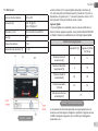 5
5
-
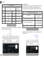 6
6
-
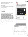 7
7
-
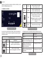 8
8
-
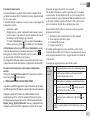 9
9
-
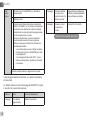 10
10
-
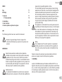 11
11
-
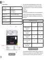 12
12
-
 13
13
-
 14
14
-
 15
15
-
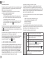 16
16
-
 17
17
-
 18
18
-
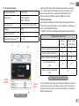 19
19
-
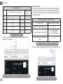 20
20
-
 21
21
-
 22
22
-
 23
23
-
 24
24
-
 25
25
-
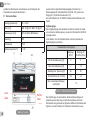 26
26
-
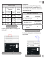 27
27
-
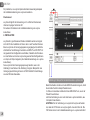 28
28
-
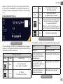 29
29
-
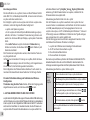 30
30
-
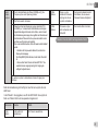 31
31
-
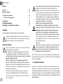 32
32
-
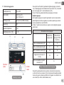 33
33
-
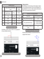 34
34
-
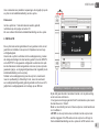 35
35
-
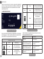 36
36
-
 37
37
-
 38
38
-
 39
39
-
 40
40
-
 41
41
-
 42
42
-
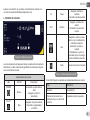 43
43
-
 44
44
-
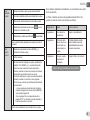 45
45
-
 46
46
-
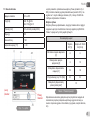 47
47
-
 48
48
-
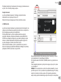 49
49
-
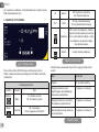 50
50
-
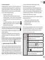 51
51
-
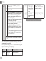 52
52
-
 53
53
-
 54
54
-
 55
55
-
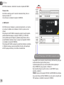 56
56
-
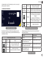 57
57
-
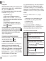 58
58
-
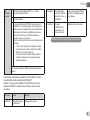 59
59
-
 60
60


DAB E.SYLINK Handleiding
- Type
- Handleiding
- Deze handleiding is ook geschikt voor
in andere talen
- English: DAB E.SYLINK Operating instructions
- italiano: DAB E.SYLINK Istruzioni per l'uso
- français: DAB E.SYLINK Mode d'emploi
- español: DAB E.SYLINK Instrucciones de operación
- Deutsch: DAB E.SYLINK Bedienungsanleitung
- slovenčina: DAB E.SYLINK Návod na používanie
- polski: DAB E.SYLINK Instrukcja obsługi