
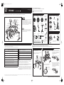
This manual describes the standard assembly of the DTX950K.
After assembling the parts and connecting the cords as shown below, the Drum Trigger Module is ready to be turned on.
•To assemble the unit, make sure you have the following four pack-
ages: HXR4LD (Rack System), DTP900 (Pad Set), DTP902 (Pad
Set), DTX900 (Drum Trigger Module).
• This manual covers how to attach the Pads and Drum Trigger Mod-
ule to the Rack System HXR4LD, for which assembly has already
been completed. Before performing the instructions described in
this manual, make sure to complete the Rack System HXR4LD by
following the corresponding Assembly Manual.
Before assembling the unit, lay a drum mat (sold separately) on the
floor. Alternately, to prevent damaging the floor, lay the cardboard of
the included packages, etc. on the floor before handling the Hi-Hat
Stand HS740A and Kick Pad KP125W.
Before using, please read this assembly manual, and use this product in a safe and proper manner.
* Please keep this manual in a safe place for future reference.
* Make sure to read the Assembly Manual of the Rack System and the Owner’s Manual of the Pad.
NOTICE
• Make sure you hold onto the plug, not the cable, when connecting or disconnecting the cable. Also,
never place any heavy or sharp objects on the cable. Applying excessive force to the cable may
result in damage to the cable, such as the wires being severed, etc.
• Do not step on or place heavy objects on the product. It may result in damage.
• Do not use or keep the product in places with extremely high temperature (places in direct sunlight,
close to a heater, in a closed car, etc.) or high humidity (bathroom, outside on a rainy day, etc.).
Doing so may result in deformation, discoloration, damage or deterioration.
• When cleaning the product, do not use benzine, thinner or alcohol as it may result in discoloration
or deformation. Please wipe with a soft cloth or a damp cloth that has been wrung out thoroughly. If
the product is soiled or sticky, use a neutral detergent on a cloth then wipe with a damp cloth that
has been wrung out thoroughly to remove any remaining detergent. Also pay close attention so as
not to let the water and detergent come into contact with the cushions used in the product; doing so
may result in deterioration.
* Specifications and descriptions in this owner’s manual are for information purposes only. Yamaha Corp. reserves the right to change or modify products or specifications at any time without prior notice. Since specifica-
tions, equipment or options may not be the same in every locale, please check with your Yamaha dealer.
DTX950K
Assembly Manual
EN
Unit Standard Assembly
PCY155
(Cymbal Pad)
PCY135
(Cymbal Pad)
PCY135
(Cymbal Pad)
XP100T
(Tom Pad)
XP120T
(Tom Pad)
KP125W
(Kick Pad)
RHH135
(Real Hi-Hat Pad)
Drum Trigger
module DTX900
CH750
(Cymbal Holder)
CH755
(Cymbal Holder)
CH750
(Cymbal Holder)
SS662
(Snare Stand)
XP120SD
(Snare Pad)
HS740A
(Hi-Hat Stand)
HXR4LD
(Rack System)
IMPORTANT
NOTICE
PRECAUTIONS
If this symbol is ignored and the equipment is used improperly, fatal
injury to persons or serious damage could occur.
• Do not let small children assemble or set up this product by themselves, or they may be injured.
Always assemble this product with adult supervision.
• Be careful with the edges of the Cymbal Holders and the Tom Holders. The sharp holder ends
may result in injury.
• Be careful with the edges of the spurs attached to the Kick Pad and foot pedal. The sharp ends
may result in injury.
• If this product is used with a Rack System or Cymbal Stand, make sure all bolts are tightened
firmly. Also, when adjusting the height or angle, do not suddenly loosen the bolts. Loose bolts
may result in the rack overturning or parts dropping, causing injury.
• Always set the product on a flat and solid surface. Placement on a sloping, unstable surface or on
steps may result in the product being unstable and subject to overturning.
• When setting up the product, please pay close attention to the handling and setting of cables.
Carelessly placed cables may cause the user and others to trip and fall.
• Do not alter the product. Doing so may result in injury or damage/deterioration to the product.
• Do not sit or step on the rack. The rack may overturn or be damaged, resulting in injury.
WARNING
If this symbol is ignored and the equipment is used improperly,
there is a danger or injury to persons handling the equipment, and
material damage could occur.
•Watch your fingers when adjusting clamps. They may become pinched, resulting in injury.
• Be careful around pipe ends, inside the pipe and screw ends. Metal shavings, etc. may injure your
fingers.
• Do not put your hands or feet under the foot pedal or foot switch. They may be pinched, resulting
in injury.
• Do not attach acoustic drums to the electronic drum rack. Clamps may be damaged and drums
may drop, causing injury.
CAUTION
Assembling the Rack System
For details, refer to the Assembly Manual of the HXR4LD.
Checking the contents of each package
Mounting the Pads and the Drum Trigger Module on the Rack System
Mount the Pads and the Trigger Module on the Rack System. Then position the Kick Pad and the Hi-Hat.
1
2
Package 1 [DTP900]
❑ PCY135
(Cymbal Pad) (2)
❑ PCY155
(Cymbal Pad) (1)
❑ RHH135
(Real Hi-Hat Pad) (1)
❑ KP125W
(Kick Pad) (1)
❑ CH750
(Cymbal Holder) (2)
❑ SS662
(Snare Stand) (1)
❑ Stand base for the
RHH135 (1)
❑ Hi-Hat clutch for the
RHH135 (1)
❑ Cable band for the
RHH135 (1)
❑ Stoppers for the
PCY135/155 (3)
❑ Felts for the
PCY135/155 (3)
❑ 2.5m stereo phone
cables (7)
❑ 4m stereo phone
cables (4)
❑ Cable bands (10)
❑ 2m spiral tube (1)
* You can cut this tube to any desired length and
use it in order to take up any slack of the cables.
❑ Owner’s Manuals
(for each Pad)
• PCY65/65S/135/155
• KP125W
• RHH135
❑ Tuning key (1)
Package 3 [Drum Trigger Module DTX900]
❑ Drum Trigger Module
DTX900 (1)
❑ Module stand fastening
screws (4)
❑ Module Stand (1)
❑ AC Power
Adaptor (1)
❑ DTX900 Owner’s Manual (1)
❑ DTX900 Data List (1)
Package 2 [DTP902]
❑ XP100T (Tom Pad) (2) ❑ Clamp bolt (4)
❑ CH755
(Cymbal Holder) (1)
❑ HS740A
(Hi-Hat Stand) (1)
❑ XP120T (Tom Pad) (2)
❑ XP120SD (Snare Pad) (1)
❑ XP100T/100SD/120T/120SD
Owner’s Manual (1)
❑ Assembly Manual (this sheet, 1)
3
1. Remove the cap of the rack by loosening the screw on
the top of the vertical support.
2. Attach the Cymbal Holders (CH750 x 2 and CH755 x 1)
to the Rack System as shown below.
Attaching the Cymbal Holder
CH750
CH750
CH755
1. Attach the clamp bolt then tighten it with five or
six turns on each of three Tom Pads.
2. Attach four Tom Pads to the clamp rods on the
rack respectively. As shown below, attach the
Tom Pad to the rod part so that the rod part is to
be inserted to the hole of the Tom Pad, then
tighten the clamp bolt firmly.
3. If you want to change the location (height and
angle) of the Tom Pad, use the clamp bolts A, B
and C. Loosen the one of the clamp bolts,
adjust the location of the Pad, then make sure
to tighten the clamp bolts again before adjust-
ing another clamp bolt.
Attaching the Tom Pad
XP100T
XP120T
Clamp bolt (to be
tightened as shown)
Tom pad (back side)
Clamp rod
Rod parts
Tom pad
Clamp bolt
To be
inserted
Clamp bolt B
Clamp bolt C
Clamp bolt A
Continued on the next page (on the back side)
U.R.G., Pro Audio & Digital Musical Instrument Division, Yamaha Corporation
©2009 Yamaha Corporation
WT58990 910PO***.*01A0
Printed in Japan

1. Remove the wing nut and the two felt washers from
the Cymbal Holder. Then turn the tilter sleeve in a
counterclockwise direction and remove it.
2. Attach the stopper to the Cymbal Holder, and fix at
a position where the L-shaped part of the stopper is
on the opposite side from you. To fix the position of
the stopper, use the tuning key and tighten the key
bolt firmly.
3. Attach the tilter sleeve removed in step 1 to the
Cymbal Holder again, and tighten it in a clockwise
direction.
4. Attach one of the felt washers removed in step 1 to
the Cymbal Holder. The other felt washer will not be
used within the standard assembly described in this
manual.
5. Insert the end of the L-shaped part of the stopper
into the oval-shaped hole (shown as a) on the
Cymbal Pad to set the Pad on the Holder.
* Cymbal Pad PCY135 is very similar to Real High-
Hat Pad RHH135. Check the model name on the
reverse side.
6. Attach the included round-shaped felt with a large
hole-diameter to the Cymbal Holder, then attach
the wing nut removed in step 1 and tighten it. Turn
the wing nut until you are certain that the Cymbal
Pad is attached. The Cymbal Pad is designed to
shake when you hit the surface, even when the
wing nut is tightened securely.
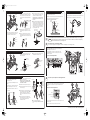
Attaching the Cymbal Pad
PCY135
PCY155
PCY135
Cymbal
holder
Wing nut
Felt washer
Tilter sleeve
Tuning key
Key bolt
Stopper
Felt washer
Tilter sleeve
Felt washer supplied
with the Cymbal Pad
a
Wing nut
1. Attach the included module stand to the back side
of the Drum Trigger Module by using the module
stand fastening screws.
2. Attach the module stand onto the holder clamp,
then tighten the knob to fix the position.
Attaching the Drum Trigger Module
Drum Trigger
Module
Module stand
fastening screw
Drum Trigger Module
(back side)
Module stand
Front side of
the module
Holder Clamp
Drum Trigger Module
+ module stand
Knob
1. If a drum mat (sold separately) is not available, lay
a sheet of cardboard on the floor to prevent
scratching the surface.
2. Loosen the wing bolt (shown with a) of the Hi-Hat
Stand.
3. Spread out the legs of the tripod part until it stands
stable. Tighten the wing bolt loosened in step 2.
4. Insert the radius rod into the hole of the frame as
shown below.
5. As shown at right, loosen the wing bolt (shown with
b) to remove the hi-hat clutch.
* The hi-hat clutch is not used within the standard
assembly described in this manual. Use the hi-hat
clutch included in the RHH135.
6. Pull out the hi-hat shaft ı from the upper pipe Å.
7. Insert the hi-hat shaft ı removed in step 6 into the
nut of the lower pipe Ç.
8. Insert the upper pipe Å into the hi-hat shaft ı from
above, then tighten the wing bolt (shown with c at
right) at the position where the cymbal support
plate is positioned at the middle area of the hi-hat
shaft ı.
9. Remove the felt washer and the cymbal support
plate attached above the support plate, since they
are not used within the standard assembly
described in this manual.
10. Set the Real Hi-Hat Pad RHH135.
* Refer to “Setting Up” in the RHH135 Owner’s Man-
ual.
Assembling the Hi-Hat Stand
Radius rod
Radius rod
Wing bolt
a
B
B
C
A
A
B
A
Hi-Hat clutch
Cymbal
support
plate
Support
plate
Cymbal sup-
port plate
c
b
Felt washer
Locate the Hi-Hat Stand, Kick Pad and Snare Stand as desired, referring to “Unit Standard Assembly” on the front page.
Before assembling the unit, lay a drum mat (sold separately) on the floor. If a drum mat is not available, lay the cardboard of the included package
under the Hi-Hat Stand and Kick Pad to prevent damaging the floor.
Connecting the pads to the Drum Trigger Module
Connect the cables plugged into the Output jacks of the Pads to the Input jacks of the Drum Trigger module.
Connect the AC power adaptor to the Drum Trigger Module.
The assembly is now completed.
* For information about the next steps such as tuning the power on/off and checking the actual sound,
refer to “Setting Up” in the Owner’s Manual of the Drum Trigger Module.
1. If a drum mat (sold separately) is not available, lay a sheet of cardboard on the
floor to prevent scratching the surface.
2. Attach the foot pedal (sold separately) to the Kick Pad KP125W, then fix the
position so that the beater will hit the center of the Pad.
* Refer to the Owner’s Manual of the KP125W.
Assembling the Kick Pad
Pad
KP125W
(Kick Pad)
Beater
Foot pedal
(sold separately)
1. Spread out the legs of the tripod part then locate the Snare Stand on the floor.
2. Spread out the basket part of the Snare Stand, set the Snare Pad XP120SD on
the basket part, then use the adjustment knob to fix the Snare Pad.
Assembling the Snare Stand and Snare Pad
Basket
XP120SD
(Snare Pad)
Legs
Adjustment
knob
4
NOTICE
5
1. As shown at right, connect the Pads with the Trigger Input jacks (q
SNARE – !0 KICK/!1 and HI-HAT CONTROL jack) of the Drum Trigger
Module by using the stereo phone cables.
• Insert the straight plugs of the cable into the Trigger Input jacks of the
Drum Trigger Module, then insert the L-shaped plugs of the cables into
each corresponding Pad.
Rear panel of the Drum Trigger Module
!0 !1 iyrw
ou t e
q
Jacks of the Pads
i
y
r
w
u
e
q
t
RHH135
KP125W
o
!0 !1
6
1. Make sure the F (Standby/On) switch is set to the Standby position (?), then
connect the AC power adaptor to the DC IN jack on the rear panel. Twist the cable
around the cable clip to prevent the DC plug from inadvertently being discon-
nected.
2. Use the cable bands to bind the cables to the rack as shown at right. If necessary,
use the spiral tube.
3. Connect the other end of the AC power adaptor to the AC outlet.
DC IN jack
Cable clip
F (Standby/On) switch
Rear panel of the Drum Trigger Module
Documenttranscriptie
dtx950k_B3_en_1009.fm Page 1 Friday, October 9, 2009 4:41 PM DTX950K Assembly Manual EN U.R.G., Pro Audio & Digital Musical Instrument Division, Yamaha Corporation ©2009 Yamaha Corporation WT58990 910PO***.*01A0 Printed in Japan This manual describes the standard assembly of the DTX950K. After assembling the parts and connecting the cords as shown below, the Drum Trigger Module is ready to be turned on. 1 2 Assembling the Rack System For details, refer to the Assembly Manual of the HXR4LD. Checking the contents of each package Package 1 [DTP900] ❑ PCY135 ❑ PCY155 (Cymbal Pad) (2) Unit Standard Assembly ❑ RHH135 (Cymbal Pad) (1) ❑ XP100T (Tom Pad) (2) ❑ Stand base for the (Real Hi-Hat Pad) (1) ❑ Clamp bolt (4) ❑ HS740A (Hi-Hat Stand) (1) RHH135 (1) IMPORTANT PCY135 (Cymbal Pad) CH750 (Cymbal Holder) Package 2 [DTP902] PCY155 (Cymbal Pad) • CH750 (Cymbal Holder) • XP100T (Tom Pad) PCY135 (Cymbal Pad) RHH135 (Real Hi-Hat Pad) To assemble the unit, make sure you have the following four packages: HXR4LD (Rack System), DTP900 (Pad Set), DTP902 (Pad Set), DTX900 (Drum Trigger Module). This manual covers how to attach the Pads and Drum Trigger Module to the Rack System HXR4LD, for which assembly has already been completed. Before performing the instructions described in this manual, make sure to complete the Rack System HXR4LD by following the corresponding Assembly Manual. ❑ CH755 ❑ XP120T (Tom Pad) (2) (Cymbal Holder) (1) ❑ Hi-Hat clutch for the RHH135 (1) ❑ KP125W ❑ CH750 (Kick Pad) (1) ❑ SS662 (Cymbal Holder) (2) (Snare Stand) (1) ❑ XP120SD (Snare Pad) (1) ❑ Cable band for the RHH135 (1) HS740A (Hi-Hat Stand) CH755 (Cymbal Holder) NOTICE ❑ XP100T/100SD/120T/120SD Before assembling the unit, lay a drum mat (sold separately) on the floor. Alternately, to prevent damaging the floor, lay the cardboard of the included packages, etc. on the floor before handling the Hi-Hat Stand HS740A and Kick Pad KP125W. KP125W (Kick Pad) ❑ Assembly Manual (this sheet, 1) PCY135/155 (3) Package 3 [Drum Trigger Module DTX900] ❑ 2.5m stereo phone XP120T (Tom Pad) Drum Trigger module DTX900 Owner’s Manual (1) ❑ Stoppers for the cables (7) ❑ 4m stereo phone ❑ Cable bands (10) ❑ AC Power DTX900 (1) ❑ Felts for the HXR4LD (Rack System) ❑ Module Stand (1) ❑ Drum Trigger Module cables (4) Adaptor (1) PCY135/155 (3) XP120SD (Snare Pad) SS662 (Snare Stand) ❑ 2m spiral tube (1) ❑ Tuning key (1) * You can cut this tube to any desired length and use it in order to take up any slack of the cables. ❑ Owner’s Manuals (for each Pad) • PCY65/65S/135/155 • KP125W • RHH135 ❑ DTX900 Owner’s Manual (1) ❑ DTX900 Data List (1) ❑ Module stand fastening screws (4) PRECAUTIONS Before using, please read this assembly manual, and use this product in a safe and proper manner. 3 * Please keep this manual in a safe place for future reference. * Make sure to read the Assembly Manual of the Rack System and the Owner’s Manual of the Pad. WARNING If this symbol is ignored and the equipment is used improperly, fatal injury to persons or serious damage could occur. CAUTION If this symbol is ignored and the equipment is used improperly, there is a danger or injury to persons handling the equipment, and material damage could occur. Mounting the Pads and the Drum Trigger Module on the Rack System Mount the Pads and the Trigger Module on the Rack System. Then position the Kick Pad and the Hi-Hat. Attaching the Cymbal Holder Attaching the Tom Pad 1. Remove the cap of the rack by loosening the screw on 2. Attach four Tom Pads to the clamp rods on the the top of the vertical support. • Do not let small children assemble or set up this product by themselves, or they may be injured. Always assemble this product with adult supervision. • Watch your fingers when adjusting clamps. They may become pinched, resulting in injury. • Be careful with the edges of the Cymbal Holders and the Tom Holders. The sharp holder ends may result in injury. • Be careful around pipe ends, inside the pipe and screw ends. Metal shavings, etc. may injure your fingers. • Be careful with the edges of the spurs attached to the Kick Pad and foot pedal. The sharp ends may result in injury. • Do not put your hands or feet under the foot pedal or foot switch. They may be pinched, resulting in injury. • If this product is used with a Rack System or Cymbal Stand, make sure all bolts are tightened firmly. Also, when adjusting the height or angle, do not suddenly loosen the bolts. Loose bolts may result in the rack overturning or parts dropping, causing injury. • Do not attach acoustic drums to the electronic drum rack. Clamps may be damaged and drums may drop, causing injury. 2. Attach the Cymbal Holders (CH750 x 2 and CH755 x 1) to the Rack System as shown below. rack respectively. As shown below, attach the Tom Pad to the rod part so that the rod part is to be inserted to the hole of the Tom Pad, then tighten the clamp bolt firmly. XP100T Tom pad • Always set the product on a flat and solid surface. Placement on a sloping, unstable surface or on steps may result in the product being unstable and subject to overturning. • When setting up the product, please pay close attention to the handling and setting of cables. Carelessly placed cables may cause the user and others to trip and fall. • Do not alter the product. Doing so may result in injury or damage/deterioration to the product. • Do not sit or step on the rack. The rack may overturn or be damaged, resulting in injury. Rod parts CH750 CH750 XP120T NOTICE • Make sure you hold onto the plug, not the cable, when connecting or disconnecting the cable. Also, never place any heavy or sharp objects on the cable. Applying excessive force to the cable may result in damage to the cable, such as the wires being severed, etc. • When cleaning the product, do not use benzine, thinner or alcohol as it may result in discoloration or deformation. Please wipe with a soft cloth or a damp cloth that has been wrung out thoroughly. If the product is soiled or sticky, use a neutral detergent on a cloth then wipe with a damp cloth that has been wrung out thoroughly to remove any remaining detergent. Also pay close attention so as not to let the water and detergent come into contact with the cushions used in the product; doing so may result in deterioration. To be inserted 3. If you want to change the location (height and • Do not step on or place heavy objects on the product. It may result in damage. • Do not use or keep the product in places with extremely high temperature (places in direct sunlight, close to a heater, in a closed car, etc.) or high humidity (bathroom, outside on a rainy day, etc.). Doing so may result in deformation, discoloration, damage or deterioration. Clamp bolt Clamp rod 1. Attach the clamp bolt then tighten it with five or CH755 six turns on each of three Tom Pads. angle) of the Tom Pad, use the clamp bolts A, B and C. Loosen the one of the clamp bolts, adjust the location of the Pad, then make sure to tighten the clamp bolts again before adjusting another clamp bolt. Clamp bolt (to be tightened as shown) Clamp bolt C Tom pad (back side) Clamp bolt A Clamp bolt B * Specifications and descriptions in this owner’s manual are for information purposes only. Yamaha Corp. reserves the right to change or modify products or specifications at any time without prior notice. Since specifications, equipment or options may not be the same in every locale, please check with your Yamaha dealer. Continued on the next page (on the back side) dtx950k_B3_en_1009.fm Page 2 Friday, October 9, 2009 4:41 PM Attaching the Cymbal Pad PCY155 PCY135 PCY135 2. Attach the stopper to the Cymbal Holder, and fix at a position where the L-shaped part of the stopper is on the opposite side from you. To fix the position of the stopper, use the tuning key and tighten the key bolt firmly. 5. Insert the end of the L-shaped part of the stopper into the oval-shaped hole (shown as a) on the Cymbal Pad to set the Pad on the Holder. * Cymbal Pad PCY135 is very similar to Real HighHat Pad RHH135. Check the model name on the reverse side. Assembling the Kick Pad Assembling the Snare Stand and Snare Pad 1. If a drum mat (sold separately) is not available, lay a sheet of cardboard on the 1. Spread out the legs of the tripod part then locate the Snare Stand on the floor. 2. Spread out the basket part of the Snare Stand, set the Snare Pad XP120SD on floor to prevent scratching the surface. 2. Attach the foot pedal (sold separately) to the Kick Pad KP125W, then fix the the basket part, then use the adjustment knob to fix the Snare Pad. position so that the beater will hit the center of the Pad. * Refer to the Owner’s Manual of the KP125W. Stopper Tuning key Key bolt 6. Attach the included round-shaped felt with a large hole-diameter to the Cymbal Holder, then attach the wing nut removed in step 1 and tighten it. Turn the wing nut until you are certain that the Cymbal Pad is attached. The Cymbal Pad is designed to shake when you hit the surface, even when the wing nut is tightened securely. 3. Attach the tilter sleeve removed in step 1 to the 1. Remove the wing nut and the two felt washers from the Cymbal Holder. Then turn the tilter sleeve in a counterclockwise direction and remove it. Felt washer supplied with the Cymbal Pad Cymbal Holder again, and tighten it in a clockwise direction. Basket KP125W (Kick Pad) Pad Beater Adjustment knob XP120SD (Snare Pad) Legs Foot pedal (sold separately) Wing nut a 4. Attach one of the felt washers removed in step 1 to the Cymbal Holder. The other felt washer will not be used within the standard assembly described in this manual. Wing nut Felt washer Felt washer Tilter sleeve 4 Locate the Hi-Hat Stand, Kick Pad and Snare Stand as desired, referring to “Unit Standard Assembly” on the front page. 5 Connecting the pads to the Drum Trigger Module NOTICE Tilter sleeve Cymbal holder Before assembling the unit, lay a drum mat (sold separately) on the floor. If a drum mat is not available, lay the cardboard of the included package under the Hi-Hat Stand and Kick Pad to prevent damaging the floor. Connect the cables plugged into the Output jacks of the Pads to the Input jacks of the Drum Trigger module. 1. As shown at right, connect the Pads with the Trigger Input jacks (q Attaching the Drum Trigger Module 1. Attach the included module stand to the back side of the Drum Trigger Module by using the module stand fastening screws. 2. Attach the module stand onto the holder clamp, then tighten the knob to fix the position. Jacks of the Pads SNARE – !0 KICK/!1 and HI-HAT CONTROL jack) of the Drum Trigger Module by using the stereo phone cables. • Insert the straight plugs of the cable into the Trigger Input jacks of the Drum Trigger Module, then insert the L-shaped plugs of the cables into each corresponding Pad. y u i q r Rear panel of the Drum Trigger Module Module stand fastening screw Drum Trigger Module t e w Drum Trigger Module + module stand Knob RHH135 Module stand Drum Trigger Module (back side) Holder Clamp !0 !1 i o u y t r e w q Front side of the module KP125W !0 o !1 Assembling the Hi-Hat Stand 1. If a drum mat (sold separately) is not available, lay a sheet of cardboard on the floor to prevent scratching the surface. 2. Loosen the wing bolt (shown with a) of the Hi-Hat Stand. 3. Spread out the legs of the tripod part until it stands stable. Tighten the wing bolt loosened in step 2. 4. Insert the radius rod into the hole of the frame as shown below. b) to remove the hi-hat clutch. Hi-Hat clutch * The hi-hat clutch is not used within the standard assembly described in this manual. Use the hi-hat clutch included in the RHH135. 6. Pull out the hi-hat shaft ı from the upper pipe Å. 7. Insert the hi-hat shaft ı removed in step 6 into the nut of the lower pipe Ç. 8. Insert the upper pipe Å into the hi-hat shaft ı from above, then tighten the wing bolt (shown with c at right) at the position where the cymbal support plate is positioned at the middle area of the hi-hat shaft ı. Wing bolt a 6 5. As shown at right, loosen the wing bolt (shown with B b B C Felt washer B A Cymbal support plate A Support plate Cymbal support plate c Radius rod Radius rod 1. Make sure the F (Standby/On) switch is set to the Standby position (?), then connect the AC power adaptor to the DC IN jack on the rear panel. Twist the cable around the cable clip to prevent the DC plug from inadvertently being disconnected. Rear panel of the Drum Trigger Module A Cable clip F (Standby/On) switch 9. Remove the felt washer and the cymbal support plate attached above the support plate, since they are not used within the standard assembly described in this manual. Connect the AC power adaptor to the Drum Trigger Module. DC IN jack 10. Set the Real Hi-Hat Pad RHH135. * Refer to “Setting Up” in the RHH135 Owner’s Manual. 2. Use the cable bands to bind the cables to the rack as shown at right. If necessary, use the spiral tube. 3. Connect the other end of the AC power adaptor to the AC outlet. The assembly is now completed. * For information about the next steps such as tuning the power on/off and checking the actual sound, refer to “Setting Up” in the Owner’s Manual of the Drum Trigger Module.-
 1
1
-
 2
2


in andere talen
- English: Yamaha DTX950K Owner's manual
- italiano: Yamaha DTX950K Manuale del proprietario
- русский: Yamaha DTX950K Инструкция по применению
- français: Yamaha DTX950K Le manuel du propriétaire
- español: Yamaha DTX950K El manual del propietario
- Deutsch: Yamaha DTX950K Bedienungsanleitung
- português: Yamaha DTX950K Manual do proprietário
- dansk: Yamaha DTX950K Brugervejledning
- suomi: Yamaha DTX950K Omistajan opas
- čeština: Yamaha DTX950K Návod k obsluze
- 日本語: Yamaha DTX950K 取扱説明書
- svenska: Yamaha DTX950K Bruksanvisning
- Türkçe: Yamaha DTX950K El kitabı
- polski: Yamaha DTX950K Instrukcja obsługi
- română: Yamaha DTX950K Manualul proprietarului