
POWERED MONITOR SPEAKER
MSP10STUDIO
Owner’s manual
Mode d’emploi
Bedienungsanleitung
Manual de instrucciones
M

3
Thank you for purchasing the Yamaha MSP10STUDIO powered monitor speaker
system. The MSP10STUDIO features a compact bass reflex cabinet, with a 20 cm
two-way cone speaker and a 2.5 cm titanium dome speaker.
This powered bi-amplifier speaker system faithfully reproduces sound and can be
used for a wide range of applications, from personal home recordings to serious
professional use. Please read this Owner’s Manual thoroughly to make the best use of
the MSP10STUDIO’s quality functions for the longest period of time, and keep the
manual in a safe place.
WARNING
•Connect this unit’s power cord only to an AC outlet of
the type stated in this Owner’s Manual or as marked on
the unit. Failure to do so is a fire and electrical shock
hazard.
•Do not allow water to enter this unit or allow the unit to
become wet. Fire or electrical shock may result.
•Do not place heavy objects, including this unit, on top of
the power cord. A damaged power cord is a fire and elec-
trical shock hazard. In particular, be careful not to place
heavy objects on a power cord covered by a carpet.
•Do not place a container with liquid or small metal
objects on top of this unit. Liquid or metal objects inside
this unit are a fire and electrical shock hazard.
•Do not scratch, bend, twist, pull, or heat the power cord.
A damaged power cord is a fire and electrical shock haz-
ard.
•If lightning begins to occur, turn off the power switch of
the unit as soon as possible, and unplug the power cable
plug from the electrical outlet.
•If there is a possibility of lightning, do not touch the
power cable plug if it is still connected. Doing so may be
an electrical shock hazard.
•Do not modify the unit. Doing so is a fire and electrical
shock hazard.
•Do not remove the unit’s cover. You could receive an
electrical shock. If you think internal inspection, main-
tenance, or repair is necessary, contact your dealer.
•If the power cord is damaged (i.e., cut or a bare wire is
exposed), ask your dealer for a replacement. Using the
unit with a damaged power cord is a fire and electrical
shock hazard.
•If you notice any abnormality, such as smoke, odor, or
noise, or if a foreign object or liquid gets inside the unit,
turn it off immediately. Remove the power cord from the
AC outlet. Consult your dealer for repair. Using the unit
in this condition is a fire and electrical shock hazard.
• Should this unit be dropped or the cabinet be damaged,
turn the power switch off, remove the power plug from
the AC outlet, and contact your dealer. If you continue
using the unit without heeding this instruction, fire or
electrical shock may result.
CAUTION
•Keep this unit away from the following locations:
-Locations exposed to oil splashes or steam, such as
near cooking stoves, humidifiers, etc.
-Unstable surfaces, such as a wobbly table or slope.
-Locations exposed to excessive heat, such as inside a
car with all the windows closed, or places that receive
direct sunlight.
-Locations subject to excessive humidity or dust accu-
mulation.
•Do not place the power cord close to a heater. It may
melt, causing fire or electrical shock.
•Hold the power cord plug when disconnecting it from an
AC outlet. Never pull the cord. A damaged power cord is
a potential fire and electrical shock hazard.
•Do not touch the power plug with wet hands. Doing so
is a potential electrical shock hazard.
•This unit has ventilation holes at the bottom and rear to
prevent the internal temperature rising too high. Do not
block them. Blocked ventilation holes are a fire hazard.
In particular, do not
- place the unit on its side or upside down,
- place the unit in any poorly-ventilated location such as
a bookcase or closet.
-cover the unit with a table cloth or place it on a carpet
or bed.
PRECAUTIONS – for safe operation –
Operation
Installation
In case an abnormality occurs during operation
Installation

4
•To relocate the unit, turn the power switch off, remove
the power plug from the AC outlet, and remove all con-
necting cables. Damaged cables may cause fire or electri-
cal shock.
•This unit is heavy. Use two or more people to carry it.
•Allow enough free space around the unit for normal
ventilation. This should be: 10 cm at the sides, 30 cm
behind, and 60 cm above.
If the airflow is not adequate, the unit will heat up inside
and may cause a fire.
•Turn off all musical instruments, and audio equipment
when connecting to this unit. Use the correct connecting
cables and connect as specified.
•Always lower the volume control to minimum before
turning on the power to this unit. A sudden blast of
sound may damage your hearing.
•Do not output distorted sounds for long periods of time,
as this will cause the speaker to heat up, leading to a fire
hazard.
•Do not raise the volume of headphones or speakers to a
level that makes you feel uncomfortable. Listening to
loud music for long periods can damage your hearing.
•If you know you will not use this unit for a long period
of time, such as when going on vacation, remove the
power plug from the AC outlet. Leaving it connected is a
potential fire hazard.
•To prevent electrical shock when cleaning the unit,
remove the power plug from the AC outlet.
• XLR-type connectors are wired as follows: pin 1: ground,
pin 2: hot (+), and pin 3: cold (–).
•Using a mobile telephone near this unit may induce
noise. If noise occurs, use the telephone away from the
unit.
•This speaker is magnetic shielded. However, if a nearby
monitor displays any uneven colors, place it further away
from the monitor.
•You may feel a flow of air in and out of the port on this
unit. This is not abnormal and sometimes occurs when a
program with a lot of bass range is played.
Operation
Maintenance
PRECAUTIONS – for correct operation –
Connector pin assignments
Influence on cell phone usage
Operation
WARNING: THIS APPARATUS MUST BE EARTHED
IMPORTANT
THE WIRES IN THIS MAINS LEAD ARE COLOURED IN
ACCORDANCE WITH THE FOLLOWING CODE:
GREEN-AND-YELLOW : EARTH
BLUE : NEUTRAL
BROWN : LIVE
As the colours of the wires in the mains lead of this apparatus may
not correspond with the coloured markings identifying the terminals in
your plug, proceed as follows:
The wire which is coloured GREEN and YELLOW must be
connected to the terminal in the plug which is marked by the letter E
or by the safety earth symbol or coloured GREEN and YELLOW.
The wire which is coloured BLUE must be connected to the terminal
which is marked with the letter N or coloured BLACK.
The wire which is coloured BROWN must be connected to the
terminal which is marked with the letter L or coloured RED.
* This applies only to products distributed by YAMAHA KEMBLE
MUSIC (U.K.) LTD.

5
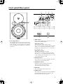
Front panel/Rear panel
1
Power/Clip indicator
This indicator lights up green when you turn ON
the POWER switch on the rear panel. If the output
level is too high, causing clipping at the amplifier,
the indicator lights up red. In this case, lower the
input level.
2
TRIM switches
These switches enable you to adjust the bass and
treble for the MSP10STUDIO.
LOW: three positions
The LOW switch adjusts the bass range.
At a frequency of 50 Hz, changing the setting from
“0” to “–1.5” will cut the bass range by 1.5 dB.
Changing the setting from “0” to “–3” will cut the
bass range by 3 dB.
HIGH: three positions
The HIGH switch adjusts the treble.
At a frequency of 10 kHz, changing the setting
from “0” to “+1.5” will boost the treble range by
1.5 dB. Changing the setting from “0” to “–1.5” will
cut the treble range by 1.5 dB.
3
LOW CUT switch
This switch turns on or off the high-pass filter that
cuts frequency ranges below 80 Hz.
4
SENSITIVITY control
Adjust the volume according to the output
sensitivity of the connected device.
(The factory default setting is “MIN.”)
5
INPUT jack
This is an XLR-type balanced input jack.
6
POWER switch
This switch turns the power to the MSP10STUDIO
on and off. When you turn this switch on, the
power/clip indicator lights up green.
1
POWER
ON OFF
1
3
2
2345
6

6
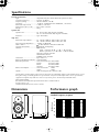
Specifications
General specifications
Type........................................... Amplified 2Way Bass Reflex Powered Speaker (Bi-Amp.)
Crossover Frequency.................. 2.0 kHz, 30 dB/oct
Frequency Range ....................... 40 Hz to 40 kHz (–10 dB)
Sensitivity .................................. –10 dB at –6 dB position (for 100 dB/SPL, 1 m on Axis)
Maximum Output Level.............110 dB (1 m on Axis)
Dimensiones (W
×
H
×
D).......... 265
×
420
×
329 mm
Weight....................................... 20 kg
Speaker unit
Speaker Unit..............................LF: 20 cm Cone (4
Ω
, magnetic shielded)
HF: 2.5 cm Titan Dome (8
Ω
, magnetic shielded)
Enclosure...................................Type: Bass Reflex
Amp. unit
Maximum Output Power............ LF: 120 W at 400 Hz, THD= 0.02%, RL= 4
Ω
HF: 60 W at 10 kHz, THD= 0.02%, RL= 8
Ω
Input Sensitivity/Impedance .......–6 dB to +4 dB/10 k
Ω
Hum & Noise............................. –67 dBu (Volume= Min) DIN Audio filter
Signal to Noise Ratio.................. 98 dB (IEC-A Weighting)
Controls..................................... TRIM Switch
LOW: 3 positions (0 dB, –1.5 dB, –3 dB at 50 Hz)
HIGH: 3 positions (+1.5 dB, 0 dB, –1.5 dB at 10 kHz)
LOW CUT Switch: ON/OFF
SENSITIVITY Control
POWER Switch: ON/OFF
Connectors ............................... Input XLR-3-31
Power Indicator/Clip Indicator ... Green/Red LED
Power Requirement....................USA and Canada: AC 120 V, 60 Hz
Europe: AC 230 V, 50 Hz
Korea: AC 220 V, 60 Hz
Australia: AC 240 V, 50 Hz
Power Consumption...................USA and Canada: 150W
Others: 170W
Option....................................... Wall mounting bracket BWS251-300
Specifications and descriptions in this owner’s manual are for information purposes only. Yamaha Corp. reserves
the right to change or modify products or specifications at any time without prior notice. Since specifications,
equipment or options may not be the same in every locale, please check with your Yamaha dealer.
For European Model
Purchaser/User Information specified in EN55103-1 and EN55103-2.
Inrush Current: 11A
Conformed Environment: E1, E2, E3 and E4
Dimensions
Performance graph
Standard frequency response
61.5
D: 329
2625.5
W: 265
H: 420
85
120
2-M8 Screws
Unit: mm
10k1k100
20
FREQUENCY
(Hz)
RESPONSE (dB)
–40
–30
–20
–10
0
+10

7
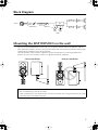
Block Diagram
Mounting the MSP10STUDIO on the wall
You can install the MSP10STUDIO on the wall using an optional Yamaha wall bracket BWS251-300. For
more information on how to install it, refer to the instructions that come with the wall bracket. For the angle
and position of installation, refer to the figure below.
The wall should be strong enough to support the speaker and equivalent to a sheet of plywood with a
thickness of 18 mm (11/16 inches) or more. Use appropriate tools for installation.
• Recommend for new constructions.
• Ask an installation specialist for instruction.
• Some installation parts may deteriorate due to friction or corrosion over a long period of time. For safety,
check these parts and condition regularly.
LPF
HPF
TRIM
HIGHLOW
–1.5
0
+1.5
–3
–1.5
0
EQ
HPF
LOW CUTSENSITIVITY
INPUT
Correct installation Incorrect installation

Yamaha Manual Library
http://www2.yamaha.co.jp/manual/english/
M.D.G., Pro Audio & Digital Musical Instrument Division, Yamaha Corporation
© 2002 Yamaha Corporation
V879530 207IPEPx.x-01A0
Printed in Taiwan
-
 1
1
-
 2
2
-
 3
3
-
 4
4
-
 5
5
-
 6
6
-
 7
7


in andere talen
- English: Yamaha MSP10STUDIO Owner's manual
- italiano: Yamaha MSP10STUDIO Manuale del proprietario
- русский: Yamaha MSP10STUDIO Инструкция по применению
- français: Yamaha MSP10STUDIO Le manuel du propriétaire
- español: Yamaha MSP10STUDIO El manual del propietario
- Deutsch: Yamaha MSP10STUDIO Bedienungsanleitung
- português: Yamaha MSP10STUDIO Manual do proprietário
- dansk: Yamaha MSP10STUDIO Brugervejledning
- čeština: Yamaha MSP10STUDIO Návod k obsluze
- 日本語: Yamaha MSP10STUDIO 取扱説明書
- svenska: Yamaha MSP10STUDIO Bruksanvisning
- Türkçe: Yamaha MSP10STUDIO El kitabı
- polski: Yamaha MSP10STUDIO Instrukcja obsługi
- română: Yamaha MSP10STUDIO Manualul proprietarului