STIEBEL ELTRON SHU 5 SLi comfort SMALL WATER HEATER Installatie gids
- Type
- Installatie gids

BEDIENUNG UND INSTALLATION
OPERATION AND INSTALLATION
UTILISATION ET INSTALLATION
BEDIENING EN INSTALLATIE
OBSLUHA A INSTALACE
KEZELÉS ÉS TELEPÍTÉS
ЭКСПЛУАТАЦИЯ И УСТАНОВКА
Geschlossener (druckfester) Warmwasser-Kleinspeicher | Sealed unvented
(pressurised) small water heaters | Petit chauffe-eau ECS (sous pression) | Gesloten
(drukvaste), kleine warmwaterboiler | Malý tlakový zásobník teplé vody | Kisméretű
zárt (nyomás alatti) elektromos vízmelegítő | Малогабаритный накопительный
водонагреватель закрытого типа (напорный)
» SHU 5 SLi comfort
» SHU 5 SL GB
» SHU 10 SLi comfort
comfort
82
°C
35
55
65
Eco

2 | SHU 5 | SHU 10 www.stiebel-eltron.com
INHALT | BESONDERE HINWEISE
BESONDERE HINWEISE
- Das Gerät kann von Kindern ab 8 Jahren sowie
von Personen mit verringerten physischen, sen-
sorischen oder mentalen Fähigkeiten oder Man-
gel an Erfahrung und Wissen benutzt werden,
wenn sie beaufsichtigt werden oder bezüglich
des sicheren Gebrauchs des Gerätes unterwiesen
wurden und die daraus resultierenden Gefahren
verstanden haben. Kinder dürfen nicht mit dem
Gerät spielen. Reinigung und Benutzer-Wartung
dürfen nicht von Kindern ohne Beaufsichtigung
durchgeführt werden.
- Bei festem Anschluss an das Stromnetz über eine
Geräteanschlussdose muss das Gerät über eine
Trennstrecke von mindestens 3mm allpolig vom
Netzanschluss getrennt werden können.
- Das Anschlusskabel darf bei Beschädigung oder
Austausch nur durch einen vom Hersteller be-
rechtigten Fachhandwerker mit dem originalen
Ersatzteil ersetzt werden.
- Befestigen Sie das Gerät wie in Kapitel „Installati-
on/ Montage“ beschrieben.
- Beachten Sie den maximal zulässigen Druck
(siehe Kapitel „Installation/ Technische Daten/
Datentabelle“).
- Das Gerät steht unter Druck. Während der Auf-
heizung tropft das Ausdehnungswasser aus dem
Sicherheitsventil.
- Betätigen Sie regelmäßig das Sicherheits-
ventil, um einem Festsitzen z.B. durch Kalk-
ablagerungen vorzubeugen.
- Entleeren Sie das Gerät wie in Kapitel „Installati-
on/ Wartung/ Gerät entleeren“ beschrieben.
- Dimensionieren Sie die Ablaufleitung so, dass bei
voll geöffnetem Sicherheitsventil das Wasser un-
gehindert ablaufen kann.
- Montieren Sie die Ablaufleitung des Sicherheits-
ventils mit einer stetigen Abwärtsneigung in
einem frostfreien Raum.
BESONDERE HINWEISE
BEDIENUNG
1. Allgemeine Hinweise ����������������������������������������3
1.1 Sicherheitshinweise ��������������������������������������������� 3
1.2 Andere Markierungen in dieser Dokumentation ���������� 3
1.3 Maßeinheiten ����������������������������������������������������� 3
2. Sicherheit �����������������������������������������������������3
2.1 Bestimmungsgemäße Verwendung ������������������������� 3
2.2 Sicherheitshinweise ��������������������������������������������� 3
2.3 Prüfzeichen ������������������������������������������������������� 4
3. Gerätebeschreibung �����������������������������������������4
3.1 Bedienung��������������������������������������������������������� 4
4. Reinigung, Pflege und Wartung ����������������������������4
5. Problembehebung �������������������������������������������4
INSTALLATION
6. Sicherheit �����������������������������������������������������5
6.1 Allgemeine Sicherheitshinweise ������������������������������ 5
6.2 Vorschriften, Normen und Bestimmungen ����������������� 5
6.3 Hinweise zur Sicherheitsgruppe ������������������������������ 5
7. Gerätebeschreibung �����������������������������������������5
7.1 Lieferumfang ����������������������������������������������������� 5
7.2 Notwendiges Zubehör ������������������������������������������ 5
8. Vorbereitungen ����������������������������������������������� 5
8.1 Montageort ������������������������������������������������������� 5
9. Montage �������������������������������������������������������6
9.1 Sicherheitsgruppe montieren ��������������������������������� 6
9.2 Montage des Gerätes ������������������������������������������� 6
9.3 Wasseranschluss ������������������������������������������������� 6
9.4 Elektrischer Anschluss ������������������������������������������ 6
10. Inbetriebnahme ����������������������������������������������7
10.1 Erstinbetriebnahme ��������������������������������������������� 7
10.2 Wiederinbetriebnahme ����������������������������������������� 7
11. Einstellungen �������������������������������������������������7
11.1 Temperaturbegrenzung einstellen ��������������������������� 7
12. Außerbetriebnahme �����������������������������������������7
13. Störungsbehebung �������������������������������������������7
13.1 Sicherheitstemperaturbegrenzer aktivieren ��������������� 8
14. Wartung �������������������������������������������������������8
14.1 Gerät entleeren �������������������������������������������������� 8
14.2 Gerät öffnen ������������������������������������������������������ 8
14.3 Gerät entkalken �������������������������������������������������� 8
14.4 Schutzleiter prüfen ���������������������������������������������� 8
14.5 Anschlusskabel austauschen ���������������������������������� 8
14.6 Temperaturfühler im Schutzrohr positionieren ����������� 8
15. Technische Daten ��������������������������������������������� 9
15.1 Maße und Anschlüsse ������������������������������������������ 9
15.2 Elektroschaltplan ������������������������������������������������ 9
15.3 Aufheizdiagramm ����������������������������������������������� 10
15.4 Landesspezifische Zulassungen und Zeugnisse ����������10
15.5 Extreme Betriebs- und Störfallbedingungen �������������� 10
15.6 Angaben zum Energieverbrauch ����������������������������10
15.7 Datentabelle ����������������������������������������������������� 10
GARANTIE
UMWELT UND RECYCLING
MONTAGESCHABLONE SHU 5 SLI | SHU 5 SL GB (IN DER MITTE
DIESER ANLEITUNG)

BEDIENUNG
Allgemeine Hinweise
DEUTSCH
www.stiebel-eltron.com SHU 5 | SHU 10 | 3
- Der Ablauf des Sicherheitsventils muss zur Atmo-
sphäre geöffnet bleiben.
BEDIENUNG
1. Allgemeine Hinweise
Die Kapitel „Besondere Hinweise“ und „Bedienung“ richten sich
an den Gerätebenutzer und den Fachhandwerker.
Das Kapitel „Installation“ richtet sich an den Fachhandwerker.
Hinweis
Lesen Sie diese Anleitung vor dem Gebrauch sorgfältig
durch und bewahren Sie sie auf.
Geben Sie die Anleitung ggf. an einen nachfolgenden
Benutzer weiter.
1.1 Sicherheitshinweise
1.1.1 Aufbau von Sicherheitshinweisen
! SIGNALWORT Art der Gefahr
Hier stehen mögliche Folgen bei Nichtbeachtung des Si-
cherheitshinweises.
Hier stehen Maßnahmen zur Abwehr der Gefahr.
1.1.2 Symbole, Art der Gefahr
Symbol Art der Gefahr
Verletzung
Stromschlag
Verbrennung
(Verbrennung, Verbrühung)
1.1.3 Signalworte
SIGNALWORT Bedeutung
GEFAHR Hinweise, deren Nichtbeachtung schwere Verletzungen
oder Tod zur Folge haben.
WARNUNG Hinweise, deren Nichtbeachtung schwere Verletzungen
oder Tod zur Folge haben kann.
VORSICHT Hinweise, deren Nichtbeachtung zu mittelschweren oder
leichten Verletzungen führen kann.
1.2 Andere Markierungen in dieser Dokumentation
Hinweis
Allgemeine Hinweise werden mit dem nebenstehenden
Symbol gekennzeichnet.
Lesen Sie die Hinweistexte sorgfältig durch.
Symbol Bedeutung
Sachschaden
(Geräte-, Folge-, Umweltschaden)
Geräteentsorgung
Dieses Symbol zeigt Ihnen, dass Sie etwas tun müssen.
Die erforderlichen Handlungen werden Schritt für Schritt
beschrieben.
1.3 Maßeinheiten
Hinweis
Wenn nicht anders angegeben, sind alle Maße in Milli-
meter.
2. Sicherheit
2.1 Bestimmungsgemäße Verwendung
Das geschlossene (druckfeste) Gerät ist für die Erwärmung von
Trinkwasser bestimmt. Mit dem Gerät können Sie eine oder meh-
rere Entnahmestellen versorgen.
Das Gerät ist für den Einsatz im häuslichen Umfeld vorgesehen.
Es kann von nicht eingewiesenen Personen sicher bedient wer-
den. In nicht häuslicher Umgebung, z.B. im Kleingewerbe, kann
das Gerät ebenfalls verwendet werden, sofern die Benutzung in
gleicher Weise erfolgt.
Eine andere oder darüber hinausgehende Benutzung gilt als nicht
bestimmungsgemäß. Zum bestimmungsgemäßen Gebrauch ge-
hört auch das Beachten dieser Anleitung sowie der Anleitungen
für eingesetztes Zubehör.
2.2 Sicherheitshinweise
WARNUNG Verbrennung
Die Armatur kann während des Betriebs eine Temperatur
von über 60°C annehmen.
Bei Auslauftemperaturen größer 43°C besteht Verbrü-
hungsgefahr.
! WARNUNG Verletzung
Der Temperatur-Einstellknopf darf nur durch einen Fach-
handwerker abgezogen werden.
! WARNUNG Verletzung
Das Gerät kann von Kindern ab 8 Jahren sowie von Per-
sonen mit verringerten physischen, sensorischen oder
mentalen Fähigkeiten oder Mangel an Erfahrung und
Wissen benutzt werden, wenn sie beaufsichtigt werden
oder bezüglich des sicheren Gebrauchs des Gerätes un-
terwiesen wurden und die daraus resultierenden Gefah-
ren verstanden haben. Kinder dürfen nicht mit dem Gerät
spielen. Reinigung und Benutzer-Wartung dürfen nicht
von Kindern ohne Beaufsichtigung durchgeführt werden.
Falls Kinder oder Personen mit eingeschränkten körperlichen, sen-
sorischen oder geistigen Fähigkeiten das Gerät benutzen, empfeh-
!
!

BEDIENUNG
Gerätebeschreibung
4 | SHU 5 | SHU 10 www.stiebel-eltron.com
len wir eine dauerhafte Temperaturbegrenzung. Die Begrenzung
kann der Fachhandwerker einstellen.
! Sachschaden
Wenn die Ablaufleitung des Sicherheitsventils verschlos-
sen wird, kann das Ausdehnungswasser zu einem Was-
serschaden führen.
Verschließen Sie nicht die Ablaufleitung.
! Sachschaden
Das Gerät und die Armatur sind vom Nutzer vor Frost zu
schützen.
2.3 Prüfzeichen
Siehe Typenschild am Gerät.
3. Gerätebeschreibung
Das geschlossene (druckfeste) Gerät hält ständig den Wasserin-
halt mit der vorgewählten Temperatur bereit. Das Gerät schaltet
sich automatisch ein, sobald die Temperatur im Gerät unter den
eingestellten Wert sinkt.
Je nach Jahreszeit ergeben sich bei verschiedenen Kaltwasser-
temperaturen unterschiedliche maximale Mischwasser- und Aus-
laufmengen.
Hinweis
Der Fachhandwerker kann eine Temperaturbegrenzung
am Gerät vornehmen (siehe „Installation/ Einstellungen/
Temperaturbegrenzung einstellen“).
Hinweis
Das Gerät steht unter Wasserleitungsdruck. Wenn sich der
Speicher aufheizt, vergrößert sich das Wasservolumen.
Dabei tropft das Ausdehnungswasser durch das Sicher-
heitsventil ab. Dies ist ein notwendiger und normaler
Vorgang.
3.1 Bedienung
Die gewünschte Warmwasser-Auslauftemperatur können Sie am
Temperatur-Einstellknopf stufenlos einstellen. Während des Auf-
heizvorgangs leuchtet die Aufheizanzeige.
D0000047406
1
2
1 Aufheizanzeige
2 Temperatur-Einstellknopf
Systembedingt können die Temperaturen vom Sollwert abwei-
chen.
°C = kalt. Bei dieser Einstellung ist das Gerät vor Frost ge-
schützt. Die Armatur und die Wasserleitung sind nicht
geschützt.
Eco = empfohlene Energiesparstellung (ca. 60°C), geringe
Wassersteinbildung
82 = maximal einstellbare Temperatur
4. Reinigung, Pflege und Wartung
Verwenden Sie keine scheuernden oder anlösenden Reini-
gungsmittel. Zur Pflege und Reinigung des Gerätes genügt
ein feuchtes Tuch.
Kontrollieren Sie regelmäßig die Armaturen. Kalk an den
Armaturausläufen können Sie mit handelsüblichen Entkal-
kungsmitteln entfernen.
Lassen Sie die Funktion der Sicherheitsgruppe regelmäßig
von einem Fachhandwerker prüfen.
Fast jedes Wasser scheidet bei hohen Temperaturen Kalk aus.
Dieser setzt sich im Gerät ab und beeinflusst die Funktion und
Lebensdauer des Gerätes. Die Heizkörper sollten deshalb bei Be-
darf entkalkt werden. Der Fachhandwerker, der die örtliche Was-
serqualität kennt, nennt Ihnen den Zeitpunkt für eine Entkalkung.
5. Problembehebung
Störung Ursache Behebung
Das Gerät liefert kein
warmes Wasser.
Der Temperatur-Ein-
stellknopf ist auf „°C“
gestellt.
Schalten Sie das Gerät durch
Drehen des Temperatur-Ein-
stellknopfes ein.
Am Gerät liegt keine
Spannung an.
Prüfen Sie den Stecker/ die
Sicherungen in der Hausinstal-
lation.
Wasser kann nur mit
einer verminderten
Zapfmenge gezapft
werden.
Der Strahlregler in der
Armatur ist verkalkt.
Entkalken / erneuern Sie den
Strahlregler.
Starke Siedegeräu-
sche im Gerät.
Das Gerät ist verkalkt. Lassen Sie das Gerät vom Fach-
handwerker entkalken.
Wasser tropft nach
dem Aufheizen aus
dem Sicherheitsven-
til der Sicherheits-
gruppe.
Das Sicherheitsventil
ist verkalkt oder ver-
schmutzt.
Schalten Sie das Gerät aus.
Schalten Sie das Gerät drucklos,
indem Sie das Gerät von der
Spannungsversorgung und der
Wasserzufuhr trennen. Lassen
Sie das Sicherheitsventil vom
Fachhandwerker prüfen.
Können Sie die Ursache nicht beheben, rufen Sie den Fachhand-
werker. Zur besseren und schnelleren Hilfe teilen Sie ihm die
Nummer vom Typenschild mit (000000-0000-000000).
Typ:
Nr.: ...... - .... - ......
D0000047804
SHU...

DEUTSCH
www.stiebel-eltron.com SHU 5 | SHU 10 | 5
INSTALLATION
Sicherheit
INSTALLATION
6. Sicherheit
Die Installation, Inbetriebnahme sowie Wartung und Reparatur
des Gerätes darf nur von einem Fachhandwerker durchgeführt
werden.
6.1 Allgemeine Sicherheitshinweise
Wir gewährleisten eine einwandfreie Funktion und Betriebssicher-
heit nur, wenn das für das Gerät bestimmte Original-Zubehör und
die originalen Ersatzteile verwendet werden.
6.2 Vorschriften, Normen und Bestimmungen
Hinweis
Beachten Sie alle nationalen und regionalen Vorschriften
und Bestimmungen.
6.3 Hinweise zur Sicherheitsgruppe
! Sachschaden
Der Betriebsüberdruck darf nicht überschritten werden.
! Sachschaden
Die Ablaufleitung der Sicherheitsgruppe muss mit Gefälle
verlegt und zur Atmosphäre geöffnet sein.
! Sachschaden
Eine regelmäßige Wartung und Betätigung der Sicher-
heitseinrichtung ist erforderlich (siehe Installationsan-
leitung der Sicherheitsgruppe).
Bei der Verwendung eines Kunststoff-Geruchverschlusses (z.B.
DN40 für die Spüle) entfällt das Tauchrohr der SVMT. Verbinden
Sie den Überlauftrichter z.B. mit dem Spülmaschinenanschluss.
7. Gerätebeschreibung
Das geschlossene (druckfeste) Gerät ist nur für eine Untertisch-
montage geeignet. Das Gerät ist zur Versorgung einer oder mehre-
rer Entnahmestellen für die Erwärmung von Kaltwasser bestimmt.
Das Gerät darf nur mit Druckarmaturen und in Verbindung mit der
Sicherheitsgruppe SVMT installiert werden (siehe Kapitel „Instal-
lation/ Gerätebeschreibung/ Notwendiges Zubehör“).
7.1 Lieferumfang
Mit dem Gerät wird geliefert:
- Wandaufhängung
SHU 10 SLi
- Montageschablone
7.2 Notwendiges Zubehör
Für die geschlossene Betriebsweise ist das folgende Zubehör er-
hältlich:
- Sicherheitsgruppe SVMT für eine Untertischmontage
- Wasserverteiler T-Stücke
8. Vorbereitungen
Wasserinstallation
Eine Sicherheitsgruppe ist erforderlich.
Armaturen
Es dürfen nur Druckarmaturen in Verbindung mit der Sicherheits-
gruppe SVMT installiert werden.
8.1 Montageort
! Sachschaden
Die Installation des Gerätes darf nur in einem frostfreien
Raum erfolgen.
! Sachschaden
Montieren Sie das Gerät an die Wand. Die Wand muss
ausreichend tragfähig sein.
! Sachschaden
Das Gerät ist nur für eine Untertischmontage geeignet.
Die Wasseranschlüsse des Gerätes zeigen nach oben.
Hinweis
Achten Sie darauf, dass das Gerät für Wartungsarbeiten
frei zugänglich ist.
Montieren Sie das Gerät senkrecht und in der Nähe der Entnah-
mestelle.
82
°C
35
55
65
Eco
65
400-450
500
100-200
26�02�06�0206

6 | SHU 5 | SHU 10 www.stiebel-eltron.com
INSTALLATION
Montage
9. Montage
! Sachschaden
Beachten Sie beim Einsatz von Kunststoff-Rohrsystemen
die extremen Betriebs- und Störfallbedingungen, die
am Gerät auftreten können (siehe Kapitel „Installation/
Technische Daten/ Extreme Betriebs- und Störfallbedin-
gungen“).
Um zwei Waschtische zu versorgen, verwenden Sie die „Was-
serverteiler T-Stücke“ (siehe Kapitel „Installation/ Gerätebe-
schreibung/ Notwendiges Zubehör“).
Verlegen Sie die Verbindungen zur zweiten Armatur bauseits
zum Beispiel in 10mm Kupferrohr.
9.1 Sicherheitsgruppe montieren
Montieren Sie die Sicherheitsgruppe in der Kaltwasser-Zulei-
tung des Gerätes.
Beachten Sie die Hinweise zur Sicherheitsgruppe
(siehe Kapitel „Installation/ Sicherheit/ Hinweise zur
Sicherheitsgruppe“).
Berücksichtigen Sie die Hinweise in der Installationsanwei-
sung der Sicherheitsgruppe.
9.2 Montage des Gerätes
Zeichnen Sie die Bohrlöcher mit der Montageschablone an
(SHU 10 SLi beiliegend oder SHU5SLi | SHU5SLGB im Mit-
telteil dieser Anleitung).
Bohren Sie die Löcher und setzen Sie geeignete Dübel ein.
Befestigen Sie die Wandaufhängung mit geeigneten
Schrauben.
Hängen Sie das Gerät auf die Wandaufhängung.
Hinweis
Sie können das überschüssige Anschlusskabel in das Ka-
beldepot legen.
26�02�06�0201
9.3 Wasseranschluss
! Sachschaden
Führen Sie alle Wasseranschluss- und Installationsarbei-
ten nach Vorschrift aus.
! Sachschaden
Beim Festdrehen der Verschraubungen müssen Sie mit
einem geeigneten Schraubenschlüssel gegenhalten.
85
°C
35
55
65
Eco
comfor t
D0000034825
14 19
! Sachschaden
Das Gerät kann funktionsunfähig werden.
Vertauschen Sie nicht die Wasseranschlüsse.
Stellen Sie die Durchflussmenge ein (siehe Anleitung
der Sicherheitsgruppe). Beachten Sie die maximal
zulässige Durchflussmenge bei voll geöffneter Arma-
tur (siehe Kapitel „Installation/ Technische Daten/
Datentabelle“).
Schließen Sie die hydraulischen Anschlüsse flach-
dichtend an.
Ordnen Sie die Farbkennzeichnung der Armaturen-Wasseran-
schlüsse und des Gerätes einander zu:
- Rechts blau = „Kaltwasser Zulauf“
- Links rot = „Warmwasser Auslauf“
Schrauben Sie die Wasseranschlüsse der Armatur fest an das
Gerät.
Hinweis
Achten Sie darauf, dass die Wasseranschlüsse bei der
Montage nicht geknickt werden. Vermeiden Sie Zugspan-
nung beim Einbau.
9.4 Elektrischer Anschluss
WARNUNG Stromschlag
Führen Sie alle elektrischen Anschluss- und Installations-
arbeiten nach Vorschrift aus.
WARNUNG Stromschlag
Bei festem Anschluss an das Stromnetz über eine Gerä-
teanschlussdose muss das Gerät über eine Trennstrecke
von mindestens 3mm allpolig vom Netzanschluss ge-
trennt werden können.
WARNUNG Stromschlag
Achten Sie darauf, dass das Gerät an den Schutzleiter
angeschlossen ist.
! Sachschaden
Die auf dem Typenschild angegebene Spannung muss mit
der Netzspannung übereinstimmen.
Beachten Sie das Typenschild.

DEUTSCH
www.stiebel-eltron.com SHU 5 | SHU 10 | 7
INSTALLATION
Inbetriebnahme
Folgende elektrische Anschlussmöglichkeiten sind zulässig:
SHU 5 SLi SHU 5 SL GB SHU 10 SLi
Anschluss an eine frei zugängliche
Schutzkontaktsteckdose mit ent-
sprechendem Stecker
X
-
X
Festanschluss an eine Gerätean-
schlussdose mit Schutzleiter
X X X
10. Inbetriebnahme
WARNUNG Stromschlag
Die Inbetriebnahme darf nur durch einen Fachhandwer-
ker unter Beachtung der Sicherheitsvorschriften erfolgen.
10.1 Erstinbetriebnahme
! Sachschaden
Wenn die Reihenfolge (erst Wasser, dann Strom) nicht
eingehalten wird, spricht der Sicherheitstemperaturbe-
grenzer an.
Gehen Sie wie folgt vor:
Erneuern Sie ggf. den Temperaturregler.
Machen Sie den Sicherheitstemperaturbegrenzer
durch Drücken des Rückstellknopfes einsatzbereit
(siehe Kapitel „Installation/ Störungsbehebung/ Si-
cherheitstemperaturbegrenzer aktivieren“).
1. 2.
D0000049325
Öffnen Sie entweder das Warmwasser-Ventil der Armatur
oder stellen Sie den Einhandmischer auf „warm“, bis Wasser
blasenfrei austritt.
Prüfen Sie die Sicherheitsgruppe. Beim Anlüften muss der
volle Wasserstrahl herauslaufen.
Stecken Sie den Stecker in die Schutzkontaktsteckdose oder
schalten Sie die Sicherung in der Hausinstallation ein.
Wählen Sie eine Temperatur.
Prüfen Sie die Dichtheit aller Wasserinstallationen.
10.1.1 Übergabe des Gerätes
Erklären Sie dem Benutzer die Funktion des Gerätes. Machen
Sie ihn mit dem Gebrauch vertraut.
Weisen Sie den Benutzer auf mögliche Gefahren hin, speziell
die Verbrühungsgefahr.
Übergeben Sie diese Anleitung und falls vorhanden die An-
leitungen vom Zubehör.
10.2 Wiederinbetriebnahme
Siehe Kapitel „Installation/ Inbetriebnahme/ Erstinbetriebnah-
me“.
11. Einstellungen
11.1 Temperaturbegrenzung einstellen
85
°C
35
55
65
Eco
comfor t
26�02�06�0007
1 2
1 Temperatur-Einstellknopf
2 Begrenzungsring
Mit dem Begrenzungsring unter dem Temperatur-Einstellknopf
können Sie den Einstellbereich des Temperatur-Einstellknopfes
auf eine maximale Temperatur begrenzen.
Drehen Sie den Temperatur-Einstellknopf in Nullstellung (bis
Linksanschlag auf „°C“).
Ziehen Sie den Temperatur-Einstellknopf und den Begren-
zungsring ab.
Setzen Sie den Begrenzungsring mit der gewünschten maxi-
malen Einstellung auf die Reglerachse auf.
Montieren Sie den Temperatur-Einstellknopf in Nullstellung
(°C).
12. Außerbetriebnahme
Trennen Sie das Gerät vom Stromnetz, indem Sie den Ste-
cker ziehen oder die Sicherung in der Hausinstallation
ausschalten.
Entleeren Sie das Gerät (siehe Kapitel „Installation/ War-
tung/ Gerät entleeren“).
13. Störungsbehebung
Störung Ursache Behebung
Das Gerät liefert kein
warmes Wasser.
Der Sicherheitstem-
peraturbegrenzer hat
ausgelöst.
Beheben Sie die Fehlerursache.
Erneuern Sie ggf. den Tempe-
raturregler. Machen Sie den
Sicherheitstemperaturbegrenzer
wieder einsatzbereit, indem
Sie den Rückstellknopf am Si-
cherheitstemperaturbegrenzer
eindrücken.
Starke Siedegeräu-
sche im Gerät.
Das Gerät ist verkalkt. Entkalken Sie das Gerät.

8 | SHU 5 | SHU 10 www.stiebel-eltron.com
INSTALLATION
Wartung
13.1 Sicherheitstemperaturbegrenzer aktivieren
26�02�06�0171
Drücken Sie den Rückstellknopf ein.
14. Wartung
WARNUNG Stromschlag
Trennen Sie bei allen Arbeiten das Gerät allpolig vom
Stromnetz.
Demontieren Sie das Gerät bei Wartungsarbeiten.
14.1 Gerät entleeren
WARNUNG Verbrennung
Beim Entleeren kann heißes Wasser austreten.
Entleeren Sie das Gerät über die Anschlussstutzen.
14.2 Gerät öffnen
85
°C
35
55
65
Eco
comfort
26�02�06�0202
Ziehen Sie den Temperatur-Einstellknopf und den Begren-
zungsring ab.
Schrauben Sie die Schrauben unter dem Temperatur-Ein-
stellknopf heraus.
Öffnen Sie die Gerätekappe, indem Sie die Riegelschrauben
nach innen absenken und die Kappe aufschwenken und
abnehmen.
14.3 Gerät entkalken
Demontieren Sie den Heizflansch.
Entfernen Sie durch vorsichtiges Klopfen den groben Kalk
vom Heizkörper.
Tauchen Sie den Heizkörper bis zur Flanschplatte in Entkal-
kungsmittel ein.
14.4 Schutzleiter prüfen
Prüfen Sie den Schutzleiter (in Deutschland z.B. DGUV3) an
einem Wasseranschlussstutzen und am Schutzleiterkontakt
des Anschlusskabels.
14.5 Anschlusskabel austauschen
Das Anschlusskabel darf nur von einem Fachhandwerker mit dem
originalen Ersatzteil ersetzt werden. Alternativ können Sie die
elektrische Leitung H05VV-F3x1,0 verwenden.
26�02�06�0205
Legen Sie das Anschlusskabel in die Führung.
14.6 Temperaturfühler im Schutzrohr positionieren
Führen Sie beim Austausch des Temperaturreglers und des
Sicherheitstemperaturbegrenzers die Temperaturfühler in
das Schutzrohr.
L2
L1
26�02�01�0370
L1 Temperaturregler
L2 Sicherheitstemperaturbegrenzer
L1 L2
SHU 5 SLi 170 180
SHU 5 SL GB 170 180
SHU 10 SLi 160 180

DEUTSCH
www.stiebel-eltron.com SHU 5 | SHU 10 | 9
INSTALLATION
Technische Daten
15. Technische Daten
15.1 Maße und Anschlüsse
SHU 5 SLi | SHU 10 SLi
c06 c01
100
a10
70
a30
a20
i13
14
D0000024351
SHU 5 SLi SHU 10 SLi
a10 Gerät Höhe mm 421 503
a20 Gerät Breite mm 263 295
a30 Gerät Tiefe mm 230 275
c01 Kaltwasser Zulauf Außengewinde G 3/8 A G 3/8 A
c06 Warmwasser
Auslauf
Außengewinde G 3/8 A G 3/8 A
i13 Wandaufhängung Höhe mm 328 363
Lochabstand hori-
zontal
mm 140 200
SHU 5 SL GB
c06 c01
100
a10
70
a30
a20
i13
14
D0000047346
SHU 5 SL GB
a10 Gerät Höhe mm 421
a20 Gerät Breite mm 263
a30 Gerät Tiefe mm 230
c01 Kaltwasser Zulauf Außengewinde G 3/8 A
c06 Warmwasser Auslauf Außengewinde G 3/8 A
i13 Wandaufhängung Höhe mm 328
Lochabstand horizontal mm 140
15.2 Elektroschaltplan
1/N/PE ~ 220 - 240V
ϑ>
ϑ>
L N
D0000047076

10 | SHU 5 | SHU 10 www.stiebel-eltron.com
INSTALLATION | GARANTIE | UMWELT UND RECYCLING
Technische Daten
15.3 Aufheizdiagramm
Die Aufheizdauer ist abhängig von der Verkalkung und der Rest-
wärme. Die Aufheizzeit bei einem Kaltwasserzulauf mit 10°C und
maximaler Temperatureinstellung entnehmen Sie dem Diagramm.
35 40 45 50 55 60 65 70 75 80 85
0
5
10
15
20
25
30
1
2
84�02�02�0044
x Temperatur in °C
y Dauer in min
1 2kW 10l-Gerät
2 2kW 5l-Gerät
15.4 Landesspezifische Zulassungen und Zeugnisse
Die Prüfzeichen sind auf dem Typenschild ersichtlich.
15.5 Extreme Betriebs- und Störfallbedingungen
Im Störfall kann in der Installation kurzzeitig eine Temperatur von
maximal 105 °C auftreten.
15.6 Angaben zum Energieverbrauch
Produktdatenblatt: Konventionelle Warmwasserbereiter nach
Verordnung (EU) Nr. 812/2013 und 814/2013
SHU 5 SLi SHU 5 SL
GB
SHU 10 SLi
222151 222153 222187
Hersteller STIEBEL
ELTRON
STIEBEL
ELTRON
STIEBEL
ELTRON
Lastprofil XXS XXS XXS
Energieeffizienzklasse A A A
Energetischer Wirkungsgrad %37 37 36
Jährlicher Stromverbrauch kWh 497 497 507
Temperatureinstellung ab
Werk
°C 55 55 55
Schallleistungspegel dB(A) 15 15 15
Täglicher Stromverbrauch kWh 2,313 2,313 2.370
15.7 Datentabelle
SHU 5 SLi SHU 5 SL GB SHU 10 SLi
222151 222153 222187
Hydraulische Daten
Nenninhalt l 5 5 10
Mischwassermenge
40 °C
l 10 10 19
Elektrische Daten
Nennspannung V220 230 240 220 230 240 220 230 240
Nennleistung kW 1,8 2,0 2,2 1,8 2,0 2,2 1,8 2,0 2,2
Nennstrom A8,3 8,7 9,1 8,3 8,7 9,1 8,3 8,7 9,1
Absicherung A 10 10 10 10 10 10 10 10 10
Phasen 1/N/PE 1/N/PE 1/N/PE
Frequenz Hz 50/60 50/60 50/60
Einsatzgrenzen
Temperatureinstell-
bereich
°C ca. 35 - 82 ca. 35 - 82 ca. 35 - 82
Max. zulässiger
Druck
MPa 0,7 0,7 0,7
Max. Durchfluss-
menge
l/
min
5 5 10
Energetische Daten
Bereitschaftsener-
gieverbrauch/24 h
bei 65 °C
kWh
0,29
0,29
0,36
Energieeffizienz-
klasse
A A A
Ausführungen
Schutzart (IP) IP24 D IP24 D IP24 D
Montageart Untertisch Untertisch Untertisch
Bauart geschlossen geschlossen geschlossen
Innenbehälter Werk-
stoff
Kupfer Kupfer Kupfer
Werkstoff Wärme-
dämmung
EPS EPS EPS
Gehäusematerial PS PS PS
Farbe weiß weiß weiß
Anschlüsse
Wasseranschluss G 3/8 A G 3/8 A G 3/8 A
Dimensionen
Tiefe mm 230 230 275
Höhe mm 421 421 503
Breite mm 263 263 295
Gewichte
Gewicht kg 5,2 5,2 7,6
Garantie
Für außerhalb Deutschlands erworbene Geräte gelten nicht
die Garantiebedingungen unserer deutschen Gesellschaften.
Vielmehr kann in Ländern, in denen eine unserer Tochterge-
sellschaften unsere Produkte vertreibt, eine Garantie nur von
dieser Tochtergesellschaft erteilt werden. Eine solche Garantie
ist nur dann erteilt, wenn die Tochtergesellschaft eigene Ga-
rantiebedingungen herausgegeben hat. Darüber hinaus wird
keine Garantie erteilt.
Für Geräte, die in Ländern erworben werden, in denen keine
unserer Tochtergesellschaften unsere Produkte vertreibt, er-
teilen wir keine Garantie. Etwaige vom Importeur zugesicherte
Garantien bleiben hiervon unberührt.
Umwelt und Recycling
Bitte helfen Sie, unsere Umwelt zu schützen. Entsorgen Sie die
Materialien nach der Nutzung gemäß nationalen Vorschriften.

www.stiebel-eltron.com SHU 5 | SHU 10 | 11
ENGLISH
CONTENTS | SPECIAL INFORMATION
SPECIAL INFORMATION
- The appliance may be used by children aged 8
and older and persons with reduced physical,
sensory or mental capabilities or a lack of ex-
perience and know-how, provided that they are
supervised or they have been instructed on how
to use the appliance safely and have understood
the resulting risks. Children must never play with
the appliance. Children must never clean the ap-
pliance or perform user maintenance unless they
are supervised.
- In the case of permanent connection to the power
supply via a junction box, ensure that the appli-
ance can be isolated from the mains by an isola-
tor that disconnects all poles with at least 3mm
contact separation.
- The power cable may only be replaced (for exam-
ple if damaged) by a qualified contractor author-
ised by the manufacturer, using an original spare
part.
- Secure the appliance as described in chapter "In-
stallation/ Installation".
- Observe the maximum permissible pressure (see
chapter "Installation/ Specification/ Data table").
- The appliance is pressurised. During the heat-up
process, expansion water will drip from the safety
valve.
- Regularly activate the safety valve to prevent
it from becoming blocked, e.g. by limescale
deposits.
- Drain the appliance as described in chapter "In-
stallation/ Maintenance/ Draining the appliance".
- Size the drain pipe so that water can drain off un-
impeded when the safety valve is fully opened.
- Fit the drain pipe of the safety valve with a con-
stant downward slope and in a room free from
the risk of frost.
- The safety valve drain must remain open to the
atmosphere.
SPECIAL INFORMATION
OPERATION
1. General information ��������������������������������������� 12
1.1 Safety instructions ����������������������������������������������12
1.2 Other symbols in this documentation ���������������������� 12
1.3 Units of measurement �����������������������������������������12
2. Safety �������������������������������������������������������� 12
2.1 Intended use �����������������������������������������������������12
2.2 Safety instructions ����������������������������������������������12
2.3 Test symbols �����������������������������������������������������13
3. Appliance description ������������������������������������� 13
3.1 Operation ��������������������������������������������������������� 13
4. Cleaning, care and maintenance ������������������������� 13
5. Troubleshooting �������������������������������������������� 13
INSTALLATION
6. Safety �������������������������������������������������������� 14
6.1 General safety instructions ����������������������������������� 14
6.2 Instructions, standards and regulations ������������������� 14
6.3 Information on the safety assembly ������������������������ 14
7. Appliance description ������������������������������������� 14
7.1 Standard delivery ����������������������������������������������� 14
7.2 Required accessories ������������������������������������������ 14
8. Preparation ������������������������������������������������� 14
8.1 Installation site �������������������������������������������������� 14
9. Installation �������������������������������������������������� 15
9.1 Installing the safety assembly �������������������������������� 15
9.2 Appliance installation ������������������������������������������ 15
9.3 Water connection ����������������������������������������������� 15
9.4 Power supply ����������������������������������������������������15
10. Commissioning ��������������������������������������������� 16
10.1 Initial start-up ��������������������������������������������������� 16
10.2 Recommissioning ����������������������������������������������� 16
11. Settings ����������������������������������������������������� 16
11.1 Setting the temperature limit �������������������������������� 16
12. Shutdown ��������������������������������������������������� 16
13. Troubleshooting �������������������������������������������� 16
13.1 Activating the high limit safety cut-out �������������������� 16
14. Maintenance ������������������������������������������������ 17
14.1 Draining the appliance ���������������������������������������� 17
14.2 Opening the appliance ����������������������������������������� 17
14.3 Descaling the appliance ��������������������������������������� 17
14.4 Checking the earth conductor �������������������������������� 17
14.5 Replacing the power cable ����������������������������������� 17
14.6 Positioning the temperature sensor in its protective
pipe ���������������������������������������������������������������� 17
15. Specification ������������������������������������������������ 17
15.1 Dimensions and connections ��������������������������������� 17
15.2 Wiring diagram ������������������������������������������������� 18
15.3 Heat-up diagram ������������������������������������������������ 18
15.4 Country-specific approvals and certifications ������������� 18
15.5 Extreme operating and fault conditions ������������������� 18
15.6 Details on energy consumption ������������������������������ 18
15.7 Data table �������������������������������������������������������� 19
GUARANTEE
ENVIRONMENT AND RECYCLING
INSTALLATION TEMPLATE SHU 5 SLI | SHU 5 SL GB (INSIDE
THESE INSTRUCTIONS)

OPERATION
General information
12 | SHU 5 | SHU 10 www.stiebel-eltron.com
OPERATION
1. General information
The chapters "Special Information" and "Operation" are intended
for users and qualified contractors.
The chapter "Installation" is intended for qualified contractors.
Note
Read these instructions carefully before using the appli-
ance and retain them for future reference.
Pass on the instructions to a new user if required.
1.1 Safety instructions
1.1.1 Structure of safety instructions
! KEYWORD Type of risk
Here, possible consequences are listed that may result
from failure to observe the safety instructions.
Steps to prevent the risk are listed.
1.1.2 Symbols, type of risk
Symbol Type of risk
Injury
Electrocution
Burns
(burns, scalding)
1.1.3 Keywords
KEYWORD Meaning
DANGER Failure to observe this information will result in serious
injury or death.
WARNING Failure to observe this information may result in serious
injury or death.
CAUTION Failure to observe this information may result in non-seri-
ous or minor injury.
1.2 Other symbols in this documentation
Note
General information is identified by the adjacent symbol.
Read these texts carefully.
Symbol Meaning
Material losses
(appliance damage, consequential losses and environmen-
tal pollution)
Appliance disposal
This symbol indicates that you have to do something. The ac-
tion you need to take is described step by step.
1.3 Units of measurement
Note
All measurements are given in mm unless stated oth-
erwise.
2. Safety
2.1 Intended use
This sealed unvented (pressurised) appliance is intended for heat-
ing domestic hot water. You can use the appliance to supply one
or several draw-off points.
This appliance is intended for domestic use. It can be used safely
by untrained persons. The appliance can also be used in a non-do-
mestic environment, e.g.in a small business, as long as it is used
in the same way.
Any other use beyond that described shall be deemed inappropri-
ate. Observation of these instructions and of instructions for any
accessories used is also part of the correct use of this appliance.
2.2 Safety instructions
WARNING Burns
During operation, the tap can reach temperatures in ex-
cess of 60 °C.
There is a risk of scalding at outlet temperatures in ex-
cess of 43 °C.
! WARNING Injury
The temperature selector should only be removed by a
qualified contractor.
! WARNING Injury
The appliance may be used by children aged 8 and older
and persons with reduced physical, sensory or mental
capabilities or a lack of experience and know-how, pro-
vided that they are supervised or they have been in-
structed on how to use the appliance safely and have
understood the resulting risks. Children must never play
with the appliance. Children must never clean the ap-
pliance or perform user maintenance unless they are
supervised.
Where children or persons with limited physical, sensory or men-
tal abilities are allowed to use this appliance, we recommend a
permanent temperature limit. A qualified contractor can set this
limit.
!
!

OPERATION
Appliance description
www.stiebel-eltron.com SHU 5 | SHU 10 | 13
ENGLISH
! Material losses
If the drain pipe of the safety valve is sealed, the expan-
sion water may cause water damage.
Never close the drain pipe.
! Material losses
The user should protect the appliance and its tap against
frost.
2.3 Test symbols
See type plate on the appliance.
3. Appliance description
The sealed unvented (pressurised) appliance constantly maintains
the water content at the pre-selected temperature. The appliance
switches on automatically as soon as its temperature falls below
the set value.
Subject to season, varying cold water temperatures can result in
different maximum mixed water and outlet volumes.
Note
A qualified contractor can set a temperature limit on the
appliance (see "Installation/ Settings/ Setting the tem-
perature limit").
Note
The appliance is under mains water pressure. The water
volume increases as the cylinder is being heated up. Dur-
ing this process, expansion water drips out through the
safety valve. This is a necessary and normal process.
3.1 Operation
You can set any required DHW outlet temperature at the tem-
perature selector. The heat-up indicator illuminates during the
heat-up process.
D0000047406
1
2
1 Heat-up indicator
2 Temperature selector
Depending on the system, the actual temperatures may vary from
the set value.
°C = Cold. On this setting, the appliance is protected from
frost. The tap and the water line are not protected.
Eco = Recommended energy saving setting (approx. 60°C),
minor scaling
82 = Highest selectable temperature
4. Cleaning, care and maintenance
Never use abrasive or corrosive cleaning agents. A damp
cloth is sufficient for cleaning the appliance.
Check the taps regularly. Limescale deposits at the tap out-
lets can be removed using commercially available descaling
agents.
Have the function of the safety assembly checked regularly by
a qualified contractor.
Almost every type of water will deposit limescale at high temper-
atures. This settles inside the appliance and affects both the per-
formance and service life. The heating elements should therefore
be descaled if necessary. A qualified contractor who is aware of
the local water quality will tell you when the next descaling is due.
5. Troubleshooting
Fault Cause Remedy
The appliance does
not supply hot water.
The temperature se-
lector is set to “°C”.
Switch the appliance ON by
turning the temperature se-
lector.
No power at the ap-
pliance.
Check the plug/ fuses in the
fuse box.
Water can only be
drawn at a reduced
rate.
The aerator in the tap
is scaled up.
Descale / replace the aerator.
Loud boiling noises
inside the appliance.
The appliance is scaled
up.
Have the appliance descaled by
a qualified contractor.
Water drips from the
safety valve of the
safety assembly after
heating has stopped.
The safety valve is
scaled up or dirty.
Switch the appliance off. De-
pressurise the appliance by
disconnecting it from the power
and water supply. Have the
safety valve checked by a quali-
fied contractor.
If you cannot remedy the fault, notify your qualified contractor.
To facilitate and speed up your request, provide the number from
the type plate (000000-0000-000000).
Typ:
Nr.: ...... - .... - ......
D0000047804
SHU...

14 | SHU 5 | SHU 10 www.stiebel-eltron.com
INSTALLATION
Safety
INSTALLATION
6. Safety
Only a qualified contractor should carry out installation, commis-
sioning, maintenance and repair of the appliance.
6.1 General safety instructions
We guarantee trouble-free function and operational reliability only
if original accessories and spare parts intended for the appliance
are used.
6.2 Instructions, standards and regulations
Note
Observe all applicable national and regional regulations
and instructions.
6.3 Information on the safety assembly
! Material losses
Never exceed the operating pressure.
! Material losses
Route the drain pipe of the safety assembly with a slope
and leave it open to the atmosphere.
! Material losses
The safety equipment requires regular maintenance and
activation (see installation instructions of the safety as-
sembly).
If using a plastic stench trap (e.g. DN40 for the sink), there is no
need for the SVMT immersion pipe. Connect the overflow funnel,
e.g. using the washing machine connection.
7. Appliance description
The sealed unvented (pressurised) appliance is only suitable for
undersink installation. The appliance is intended for heating cold
water and for supplying one or several draw-off points.
The appliance may only be installed with pressure taps in con-
junction with the SVMT safety assembly (see chapter "Installation/
Appliance description/ Required accessories").
7.1 Standard delivery
Delivered with the appliance are the following:
- Wall mounting bracket
SHU 10 SLi
- Installation template
7.2 Required accessories
The following accessories are available for sealed unvented op-
eration:
- SVMT safety assembly for undersink installation
- Water distribution tees
8. Preparation
Water installation
A safety assembly is required.
Taps/valves
Only install pressure taps in conjunction with the SVMT safety
assembly.
8.1 Installation site
! Material losses
Install the appliance in a room free from the risk of frost.
! Material losses
Mount the appliance on the wall. The wall must have a
sufficient load-bearing capacity.
! Material losses
The appliance is only suitable for undersink installation.
The water connections of the appliance point upwards.
Note
Ensure that the appliance is freely accessible for main-
tenance work.
Always install the appliance vertically and near the draw-off point.
82
°C
35
55
65
Eco
65
400-450
500
100-200
26�02�06�0206

www.stiebel-eltron.com SHU 5 | SHU 10 | 15
ENGLISH
INSTALLATION
Installation
9. Installation
! Material losses
When using plastic pipework, observe the extreme op-
erating and fault conditions that can occur on the appli-
ance (see chapter "Installation/ Specification/ Extreme
operating and fault conditions").
To provide a supply to two washbasins, use the "water dis-
tribution tees" (see chapter "Installation/ Appliance descrip-
tion/ Required accessories").
Run the connections to the second tap on site, e.g. in 10mm
copper pipe.
9.1 Installing the safety assembly
Fit the safety assembly in the cold water supply line of the
appliance.
Observe the information on the safety assembly (see chapter
"Installation/ Safety/ Information on the safety assembly").
Observe the information in the safety assembly installation
instructions.
9.2 Appliance installation
Use the installation template to mark the drill holes (SHU
10 SLi supplied separately or SHU5SLi | SHU5SLGB inside
these instructions).
Drill the holes and insert suitable rawl plugs.
Secure the wall mounting bracket using suitable screws.
Hang the appliance on the wall mounting bracket.
Note
Surplus cable can be stored in the cable compartment.
26�02�06�0201
9.3 Water connection
! Material losses
Carry out all water connection and installation work in
accordance with regulations.
! Material losses
When tightening the fittings, counterhold with a suitable
spanner.
85
°C
35
55
65
Eco
comfor t
D0000034825
14 19
! Material losses
The appliance may lose its function.
Never interchange the water connections.
Set the flow rate (see safety assembly instructions).
Observe the maximum permissible flow rate with a
fully opened tap (see chapter "Installation/ Specifi-
cation/ Data table").
Connect the hydraulic connections with flat gaskets.
Match up the colour coding on the water connections of the tap
and the appliance:
- R.h. side blue = "Cold water inlet"
- L.h. side red = "DHW outlet"
Secure the tap connections to the appliance.
Note
Ensure that the water connections are not kinked during
installation. Prevent any tensioning during installation.
9.4 Power supply
WARNING ELECTROCUTION
Carry out all electrical connection and installation work
in accordance with relevant regulations.
WARNING ELECTROCUTION
In the case of permanent connection to the power supply
via a junction box, ensure that the appliance can be iso-
lated from the mains by an isolator that disconnects all
poles with at least 3mm contact separation.
WARNING ELECTROCUTION
Ensure that the appliance is earthed.
! Material losses
The voltage specified on the type plate must match the
mains voltage.
Observe the type plate.

16 | SHU 5 | SHU 10 www.stiebel-eltron.com
INSTALLATION
Commissioning
The following electrical connections are permissible:
SHU 5
SLi
SHU 5
SL GB
SHU 10
SLi
Connection to a freely accessible standard socket
with matching plug
X - X
Permanent connection to an appliance junction box
with earth conductor
X X X
10. Commissioning
WARNING ELECTROCUTION
Commissioning may only be carried out by a qualified
contractor in accordance with safety regulations.
10.1 Initial start-up
! Material losses
If you fail to follow the correct sequence (first water, then
power), the high limit safety cut-out will trip.
Proceed as follows:
If necessary, replace the temperature controller.
Make the high limit safety cut-out operational by
pressing the reset button (see chapter "Installation/
Troubleshooting/ Activating the high limit safety
cut-out").
1. 2.
D0000049325
Either open the DHW valve of the tap or set the mono lever
mixer tap to "hot" until the water that flows out is free of air
bubbles.
Check the safety assembly. When purging, ensure that a full
jet of water flows out.
Insert the plug into the standard socket or set the fuse/MCB
in the fuse box.
Select a temperature.
Check the entire hydraulic installation for tightness.
10.1.1 Appliance handover
Explain the functions of the appliance to the user. Show the
user how to operate the appliance.
Make the user aware of potential dangers, especially the risk
of scalding.
Hand over these instructions and, if applicable, the instruc-
tions for any accessories.
10.2 Recommissioning
See chapter "Installation/ Commissioning/ Initial start-up".
11. Settings
11.1 Setting the temperature limit
85
°C
35
55
65
Eco
comfor t
26�02�06�0007
1 2
1 Temperature selector
2 Limiting ring
Placing the limiting ring behind the temperature selector allows
you to limit the setting range of the temperature selector to a
specific maximum temperature.
Turn the temperature selector to zero (fully anti-clockwise to
"°C").
Pull off the temperature selector and the limiting ring.
Push the limiting ring with the required maximum setting
onto the controller shaft.
Mount the temperature selector set to zero (°C).
12. Shutdown
Isolate the appliance from the power supply by removing the
plug or by tripping the MCB in the fuse box.
Drain the appliance (see chapter "Installation/ Maintenance/
Draining the appliance").
13. Troubleshooting
Fault Cause Remedy
The appliance does
not supply hot water.
The high limit safety
cut-out has tripped.
Remedy the cause of the fault. If
necessary, replace the temper-
ature controller. Reset the high
limit safety cut-out by pressing
reset button on the high limit
safety cut-out.
Loud boiling noises
inside the appliance.
The appliance is scaled
up.
Descale the appliance.
13.1 Activating the high limit safety cut-out
26�02�06�0171
Push the reset button.

www.stiebel-eltron.com SHU 5 | SHU 10 | 17
ENGLISH
INSTALLATION
Maintenance
14. Maintenance
WARNING Electrocution
Before any work on the appliance, disconnect all poles of
the appliance from the power supply.
Dismantle the appliance for maintenance work.
14.1 Draining the appliance
WARNING Burns
Hot water may escape during draining.
Drain the appliance via its connectors.
14.2 Opening the appliance
85
°C
35
55
65
Eco
comfort
26�02�06�0202
Pull off the temperature selector and the limiting ring.
Remove the screws from underneath the temperature
selector.
To open the appliance cover lower the bolt screws inwards
and pivot the cover upwards, then remove it.
14.3 Descaling the appliance
Remove the flanged immersion heater.
Carefully tap the heating element to remove coarse limescale
deposits.
Immerse the heating element up to the flange plate in desca-
ling agent.
14.4 Checking the earth conductor
Check the earth conductor (in Germany DGUV3 for example)
across a water connector and the earth conductor contact of
the power cable.
14.5 Replacing the power cable
The power cable must only be replaced by a qualified contractor
with an original spare part. Alternatively, the H05VV-F3x1.0 cable
may be used.
26�02�06�0205
Route the power cable along the cable guide.
14.6 Positioning the temperature sensor in its
protective pipe
When replacing the temperature controller and the high limit
safety cut-out, guide the temperature sensors into the pro-
tective pipe.
L2
L1
26�02�01�0370
L1 Temperature controller
L2 High limit safety cut-out
L1 L2
SHU 5 SLi 170 180
SHU 5 SL GB 170 180
SHU 10 SLi 160 180
15. Specification
15.1 Dimensions and connections
SHU 5 SLi | SHU 10 SLi
c06 c01
100
a10
70
a30
a20
i13
14
D0000024351
SHU 5 SLi SHU 10 SLi
a10 Appliance Height mm 421 503
a20 Appliance Width mm 263 295
a30 Appliance Depth mm 230 275
c01 Cold water inlet Male thread G 3/8 A G 3/8 A
c06 DHW outlet Male thread G 3/8 A G 3/8 A
i13 Wall mounting
bracket
Height mm 328 363
Horizontal hole
spacing
mm 140 200

18 | SHU 5 | SHU 10 www.stiebel-eltron.com
INSTALLATION
Specication
SHU 5 SL GB
c06 c01
100
a10
70
a30
a20
i13
14
D0000047346
SHU 5 SL GB
a10 Appliance Height mm 421
a20 Appliance Width mm 263
a30 Appliance Depth mm 230
c01 Cold water inlet Male thread G 3/8 A
c06 DHW outlet Male thread G 3/8 A
i13 Wall mounting bracket Height mm 328
Horizontal hole spacing mm 140
15.2 Wiring diagram
1/N/PE ~ 220 - 240V
ϑ>
ϑ>
L N
D0000047076
15.3 Heat-up diagram
The heat-up period depends on the degree of scaling and residual
heat. For the heat-up time for a cold water supply at 10 °C and a
maximum temperature setting, see the diagram.
35 40 45 50 55 60 65 70 75 80 85
0
5
10
15
20
25
30
1
2
84�02�02�0044
x Temperature in °C
y Duration in min
1 2kW 10lappliance
2 2kW 5lappliance
15.4 Country-specific approvals and certifications
The test symbols can be seen on the type plate.
15.5 Extreme operating and fault conditions
In the case of faults, a peak temperature of up to 105 °C may briefly
occur in the system.
15.6 Details on energy consumption
Product datasheet: Conventional water heaters to regulation (EU)
no. 814/2013
SHU 5 SLi SHU 5 SL
GB
SHU 10 SLi
222151 222153 222187
Manufacturer STIEBEL
ELTRON
STIEBEL
ELTRON
STIEBEL
ELTRON
Load profile XXS XXS XXS
Energy efficiency class A A A
Energy conversion efficiency %37 37 36
Annual power consumption kWh 497 497 507
Default temperature setting °C 55 55 55
Sound power level dB(A) 15 15 15
Daily power consumption kWh 2.313 2.313 2,370

www.stiebel-eltron.com SHU 5 | SHU 10 | 19
ENGLISH
INSTALLATION | GUARANTEE | ENVIRONMENT AND RECYCLING
Specication
15.7 Data table
SHU 5 SLi SHU 5 SL GB SHU 10 SLi
222151 222153 222187
Hydraulic data
Nominal capacity l 5 5 10
Mixed water volume
at 40°C
l 10 10 19
Electrical data
Rated voltage V220 230 240 220 230 240 220 230 240
Rated output kW 1.8 2.0 2.2 1.8 2.0 2.2 1.8 2.0 2.2
Rated current A8.3 8.7 9.1 8.3 8.7 9.1 8.3 8.7 9.1
MCB/fuse rating A 10 10 10 10 10 10 10 10 10
Phases 1/N/PE 1/N/PE 1/N/PE
Frequency Hz 50/60 50/60 50/60
Application limits
Temperature setting
range
°C Approx. 35 - 82 Approx. 35 - 82 Approx. 35 - 82
Max. permissible
pressure
MPa 0.7 0.7 0.7
Max. flow rate l/
min
5 5 10
Energy data
Standby energy
consumption/24 h at
65 °C
kWh
0.29
0.29
0.36
Energy efficiency
class
A A A
Versions
IP rating IP24 D IP24 D IP24 D
Type of installation Undersink Undersink Undersink
Type Sealed unvented Sealed unvented Sealed unvented
Internal cylinder
material
Copper Copper Copper
Thermal insulation
material
EPS EPS EPS
Casing material PS PS PS
Colour White White White
Connections
Water connection G 3/8 A G 3/8 A G 3/8 A
Dimensions
Depth mm 230 230 275
Height mm 421 421 503
Width mm 263 263 295
Weights
Weight kg 5.2 5.2 7.6
Guarantee
The guarantee conditions of our German companies do not
apply to appliances acquired outside of Germany. In countries
where our subsidiaries sell our products a guarantee can only
be issued by those subsidiaries. Such guarantee is only grant-
ed if the subsidiary has issued its own terms of guarantee. No
other guarantee will be granted.
We shall not provide any guarantee for appliances acquired in
countries where we have no subsidiary to sell our products.
This will not aect warranties issued by any importers.
Environment and recycling
We would ask you to help protect the environment. After use,
dispose of the various materials in accordance with national
regulations.

20 | SHU 5 | SHU 10 www.stiebel-eltron.com
TABLE DES MATIÈRES
REMARQUES PARTICULIÈRES
UTILISATION
1. Remarques générales ������������������������������������� 21
1.1 Consignes de sécurité ������������������������������������������ 21
1.2 Autres repérages utilisés dans cette documentation ���� 21
1.3 Unités de mesure ����������������������������������������������� 21
2. Sécurité ����������������������������������������������������� 21
2.1 Utilisation conforme ������������������������������������������� 21
2.2 Consignes de sécurité ������������������������������������������ 21
2.3 Label de conformité �������������������������������������������� 22
3. Description de l’appareil ���������������������������������� 22
3.1 Utilisation ��������������������������������������������������������22
4. Nettoyage, entretien et maintenance �������������������� 22
5. Aide au dépannage ���������������������������������������� 23
INSTALLATION
6. Sécurité ����������������������������������������������������� 23
6.1 Consignes de sécurité générales ����������������������������23
6.2 Prescriptions, normes et directives �������������������������23
6.3 Remarques à propos du groupe de sécurité ��������������23
7. Description de l’appareil ���������������������������������� 23
7.1 Fournitures������������������������������������������������������� 23
7.2 Accessoires nécessaires ��������������������������������������� 23
8. Travaux préparatoires ������������������������������������� 23
8.1 Lieu de montage ������������������������������������������������ 24
9. Montage ����������������������������������������������������� 24
9.1 Montage du groupe de sécurité ����������������������������� 24
9.2 Montage de l’appareil ����������������������������������������� 24
9.3 Raccordement hydraulique ����������������������������������� 24
9.4 Raccordement électrique ������������������������������������� 25
10. Mise en service ��������������������������������������������� 25
10.1 Première mise en service �������������������������������������25
10.2 Remise en marche ����������������������������������������������25
11. Réglages ���������������������������������������������������� 25
11.1 Réglage de la limitation de température ������������������ 25
12. Mise hors service ������������������������������������������ 26
13. Aide au dépannage ���������������������������������������� 26
13.1 Activation du limiteur de sécurité ��������������������������� 26
14. Maintenance ������������������������������������������������ 26
14.1 Vidange de l’appareil ������������������������������������������ 26
14.2 Ouverture de l’appareil ���������������������������������������� 26
14.3 Détartrage de l’appareil ��������������������������������������� 26
14.4 Contrôle du conducteur de mise à la terre ���������������� 26
14.5 Remplacement du câble de raccordement ���������������� 26
14.6 Positionnement de la sonde de température dans le
tube de protection ���������������������������������������������� 27
15. Données techniques ��������������������������������������� 27
15.1 Cotes et raccordements ���������������������������������������� 27
15.2 Schéma électrique ���������������������������������������������� 27
15.3 Courbe de chauffe ����������������������������������������������28
15.4 Homologations et certificats propres au pays ������������ 28
15.5 Conditions extrêmes de fonctionnement et de
dysfonctionnement ��������������������������������������������� 28
15.6 Indications relatives à la consommation énergétique ��� 28
15.7 Tableau de données ��������������������������������������������28
GARANTIE
ENVIRONNEMENT ET RECYCLAGE
GABARIT DE MONTAGE SHU5SLI| SHU5SLGB (EN PAGE CEN-
TRALE DE CETTE NOTICE)
REMARQUES
PARTICULIÈRES
- L’appareil peut être utilisé par des enfants dès
l’âge de 8ans ainsi que par des personnes aux
facultés physiques, sensorielles ou mentales
réduites ou par des personnes sans expérience
sous surveillance ou après formation à l’utilisa-
tion en toute sécurité de l’appareil si les dangers
potentiels ont été compris. Ne laissez pas les en-
fants jouer avec l’appareil. Ni le nettoyage ni la
maintenance relevant de l’utilisateur ne doivent
être effectués par des enfants sans surveillance.
- Quand l’appareil est connecté au réseau élec-
trique de manière fixe par le biais d’une boîte de
raccordement, il faut pouvoir le déconnecter à
l’aide d’un disjoncteur omnipolaire ayant une ou-
verture minimale des contacts de 3mm.
- Seul un installateur habilité par le fabricant peut
remplacer par une pièce de rechange d’origine le
câble de raccordement, en cas de détérioration
ou de changement.
- Fixez l’appareil comme indiqué au chapitre «Ins-
tallation/ Montage».
- Tenez compte de la pression maximale admissible
(voir le chapitre «Installation/ Données tech-
niques/ Tableau de données»).
- L’appareil est sous pression. Pendant la montée
en température, de l’eau d’expansion s’écoule de
la soupape de sécurité.
- Actionnez régulièrement la soupape de sécurité
afin d’éviter tout grippage dû aux dépôts de cal-
caire par exemple.
- Vidangez l’appareil comme indiqué au cha-
pitre «Installation/ Maintenance/ Vidange de
l’appareil».

www.stiebel-eltron.com SHU 5 | SHU 10 | 21
FRANÇAIS
REMARQUES PARTICULIÈRES | UTILISATION
Remarques générales
- La conduite de sortie doit être dimensionnée de
sorte que l’eau puisse s’écouler librement lorsque
la soupape de sécurité est entièrement ouverte.
- Installez la conduite de sortie de la soupape de
sécurité avec une pente constante vers le bas
dans un local à l’abri du gel.
- L’évacuation de la soupape de sécurité doit être
ouverte à l’air libre.
UTILISATION
1. Remarques générales
Les chapitres «Remarquesparticulières» et «Utilisation»
s’adressent aux utilisateurs de l’appareil et aux installateurs.
Le chapitre «Installation» s’adresse aux installateurs.
Remarque
Lisez attentivement cette notice avant utilisation et
conservez-la soigneusement.
Le cas échéant, veuillez remettre cette notice au nouvel
utilisateur.
1.1 Consignes de sécurité
1.1.1 Structure des consignes de sécurité
! MENTION D’AVERTISSEMENT Nature du danger
Sont indiqués ici les risques éventuellement encourus
en cas de non-observation de la consigne de sécurité.
Sont indiquées ici les mesures permettant de pallier
le danger.
1.1.2 Symboles, nature du danger
Symbole Nature du danger
Blessure
Électrocution
Brûlure
(brûlure, ébouillantement)
1.1.3 Mentions d’avertissement
MENTION
D’AVERTISSE-
MENT
Signification
DANGER Caractérise des remarques dont le non-respect entraîne de
graves lésions, voire la mort.
AVERTISSEMENT Caractérise des remarques dont le non-respect peut entraî-
ner de graves lésions, voire la mort.
ATTENTION Caractérise des remarques dont le non-respect peut entraî-
ner des lésions légères ou moyennement graves.
1.2 Autres repérages utilisés dans cette
documentation
Remarque
Le symbole ci-contre caractérise des remarques géné-
rales.
Lisez attentivement les remarques.
Ce symbole signale une action à entreprendre. Les actions
nécessaires sont décrites étape par étape.
1.3 Unités de mesure
Remarque
Sauf indication contraire, toutes les cotes sont exprimées
en millimètres.
2. Sécurité
2.1 Utilisation conforme
L’appareil en circuit fermé (sous pression) a été conçu pour chauf-
fer de l’eau sanitaire. Cet appareil peut alimenter un ou plusieurs
points de soutirage.
L’appareil est destiné à une utilisation domestique. Il peut être
utilisé sans risques par des personnes qui ne disposent pas de
connaissances techniques particulières. L’appareil peut également
être utilisé dans un environnement non domestique, par exemple
dans de petites entreprises, à condition que son utilisation soit
du même ordre.
Tout autre emploi est considéré comme non conforme. Une utili-
sation conforme de l’appareil implique le respect de cette notice
et de celles relatives aux accessoires utilisés.
2.2 Consignes de sécurité
AVERTISSEMENT Brûlure
La température de la robinetterie peut dépasser 60°C
en service.
Danger de brûlures à des températures de sortie supé-
rieures à 43°C.
! AVERTISSEMENT Blessure
Le bouton de réglage de température ne doit être retiré
que par un installateur.
!

UTILISATION
Description de l’appareil
22 | SHU 5 | SHU 10 www.stiebel-eltron.com
! AVERTISSEMENT Blessure
L’appareil peut être utilisé par des enfants dès l’âge de
8ans ainsi que par des personnes aux facultés physiques,
sensorielles ou mentales réduites ou par des personnes
sans expérience sous surveillance ou après formation à
l’utilisation en toute sécurité de l’appareil si les dangers
potentiels ont été compris. Ne laissez pas les enfants
jouer avec l’appareil. Ni le nettoyage ni la maintenance
relevant de l’utilisateur ne doivent être effectués par des
enfants sans surveillance.
Nous recommandons d’installer un limiteur de température si des
enfants ou des personnes aux facultés physiques, sensorielles ou
mentales réduites utilisent l’appareil. La fonction de limitation de
température doit être réglée par l’installateur.
! Dommages matériels
Si la conduite de sortie de la soupape de sécurité est
fermée, l’eau d’expansion risque de provoquer des dom-
mages.
Ne fermez pas la conduite de sortie.
! Dommages matériels
L’appareil et la robinetterie doivent être protégés du gel
par l’utilisateur.
2.3 Label de conformité
Voir la plaque signalétique sur l’appareil.
3. Description de l’appareil
Cet appareil en circuit fermé (sous pression) maintient disponible
le cubage d’eau à une température préréglée. L’appareil est auto-
matiquement activé dès que la température à l’intérieur n’atteint
plus la valeur réglée.
La température de l’eau froide étant différente selon la saison, le
débit maximal d’eau mélangée et de sortie peut varier.
Remarque
L’installateur peut limiter la température au niveau de
l’appareil (voir «Installation/ Réglages/ Réglage de la
limitation de température»).
Remarque
L’appareil est soumis à la pression de la conduite d’eau.
Lorsque le ballon se réchauffe, le volume d’eau augmente
et de l’eau d’expansion s’échappe de la soupape de sécu-
rité. Ceci est un processus nécessaire et normal.
3.1 Utilisation
La température de sortie désirée de l’ECS peut être réglée en
continu avec le bouton de réglage de température. Le voyant «ré-
chauffement» s’allume en phase de réchauffement.
D0000047406
1
2
1 Voyant «Réchauffement»
2 Bouton de réglage de température
Pour des raisons techniques liées au système, les températures
réelles peuvent différer de la valeur de consigne.
°C = froid. Dans cette position, l’appareil est protégé du gel.
Ni la robinetterie ni la conduite d’eau ne sont proté-
gées.
Eco = Position «économie d’énergie» recommandée (env.
60°C), formation de tartre réduite
82 = température maximale réglable
4. Nettoyage, entretien et
maintenance
N’utilisez aucun produit de nettoyage abrasif ou corrosif.
Un chiffon humide suffit pour le nettoyage et l’entretien de
l’appareil.
Contrôlez régulièrement les robinetteries. Vous pouvez éli-
miner le tartre au niveau des becs de robinetteries avec les
produits de détartrage du commerce.
Faîtes contrôler régulièrement le bon fonctionnement du
groupe de sécurité par un installateur.
Presque toutes les eaux déposent du calcaire à des températures
élevées. Celui-ci se dépose dans l’appareil et affecte son fonc-
tionnement et sa longévité. Les corps de chauffe doivent donc
être détartrés, si besoin est. L’installateur qui connaît la qualité
de l’eau locale vous dira quand il convient d’effectuer le prochain
détartrage.

www.stiebel-eltron.com SHU 5 | SHU 10 | 23
FRANÇAIS
UTILISATION | INSTALLATION
Aide au dépannage
5. Aide au dépannage
Défaut Cause Remède
L’appareil ne produit
pas d’eau chaude
sanitaire.
Le bouton de réglage
de température est po-
sitionné sur «°C».
Mettez l’appareil en marche en
tournant le bouton de réglage
de température.
L’appareil n’est pas
sous tension.
Contrôlez la fiche ainsi que les
fusibles de l’installation domes-
tique.
La quantité pom-
pable au point de
soutirage est réduite.
Le régulateur de jet
de la robinetterie est
entartré.
Détartrez / remplacez le régula-
teur de jet.
L’appareil émet de
forts bruits d’ébul-
lition.
L’appareil est entartré.
Faites détartrer l’appareil par
un installateur.
Le chauffage termi-
né, de l’eau s’écoule
de la soupape de
sécurité du groupe
de sécurité.
La soupape de sécu-
rité est entartrée ou
encrassée.
Éteignez l’appareil. Mettez
l’appareil hors pression en le
débranchant de l’alimentation
électrique et de l’arrivée d’eau.
Faites vérifier la soupape de sé-
curité par un installateur.
Appelez un installateur si vous ne réussissez pas à éliminer la
cause du problème. Pour obtenir une assistance efficace et rapide,
communiquez-lui le numéro indiqué sur la plaque signalétique
(000000-0000-000000).
Typ:
Nr.: ...... - .... - ......
D0000047804
SHU...
INSTALLATION
6. Sécurité
L’installation, la mise en service, la maintenance et la réparation
de l’appareil doivent uniquement être réalisées par un installateur
qualifié.
6.1 Consignes de sécurité générales
Nous ne garantissons le bon fonctionnement et la sécurité de
fonctionnement de l’appareil que si des accessoires et pièces de
rechange d’origine sont utilisés.
6.2 Prescriptions, normes et directives
Remarque
Respectez la législation et les prescriptions nationales et
locales en vigueur.
6.3 Remarques à propos du groupe de sécurité
! Dommages matériels
La surpression de service ne doit pas être dépassée.
! Dommages matériels
La conduite de sortie du groupe de sécurité doit être
posée en pente et à l’air libre.
! Dommages matériels
Il est indispensable d’effectuer la maintenance du dispo-
sitif de sécurité et de l’actionner à intervalles réguliers
(voir les instructions d’installation du groupe de sécurité).
La mise en place d’une bonde en matière synthétique (par ex.
DN40 pour un évier) permet de supprimer le tube doigt de gant
du SVMT. Reliez le trop-plein au raccordement du lave-vaisselle
par exemple.
7. Description de l’appareil
L’appareil en circuit fermé (sous pression) est conçu exclusivement
pour un montage sous évier. L’appareil sert à alimenter un ou
plusieurs points de soutirage d’eau chaude depuis une source
d’eau froide.
L’appareil ne doit être installé qu’avec une robinetterie sous pres-
sion et le groupe de sécurité SVMT (voir le chapitre «Installation /
Description de l’appareil / Accessoires indispensables»).
7.1 Fournitures
Fournitures accompagnant l’appareil:
- Support mural
SHU 10 SLi
- Gabarit de montage
7.2 Accessoires nécessaires
Il est possible de se procurer les accessoires suivants pour le mode
de fonctionnement sous pression:
- Groupe de sécurité SVMT pour montage sous évier
- Tés de distributeur hydraulique
8. Travaux préparatoires
Installation hydraulique
Le groupe de sécurité est indispensable.
Robinetteries
L’installation doit impérativement comporter une robinetterie sous
pression en combinaison avec le groupe de sécurité SVMT.

24 | SHU 5 | SHU 10 www.stiebel-eltron.com
INSTALLATION
Montage
8.1 Lieu de montage
! Dommages matériels
L’appareil doit impérativement être installé dans un local
hors gel.
! Dommages matériels
Montez l’appareil au mur. Le mur doit être suffisamment
porteur.
! Dommages matériels
L’appareil convient uniquement au montage sous évier.
Les raccords hydrauliques de l’appareil sont orientés vers
le haut.
Remarque
Veillez à ce que l’appareil soit accessible pour les travaux
de maintenance.
Posez l’appareil verticalement à proximité du point de soutirage.
82
°C
35
55
65
Eco
65
400-450
500
100-200
26�02�06�0206
9. Montage
! Dommages matériels
Si une tuyauterie en matière synthétique est utilisée,
tenez compte des conditions extrêmes de fonctionnement
et de dysfonctionnement pouvant apparaître au niveau
de l’appareil (voir le chapitre «Installation / Données
techniques / Conditions extrêmes de fonctionnement et
de dysfonctionnement»).
Pour alimenter deux lavabos, utilisez les «tés de distributeur
hydraulique» (voir le chapitre «Installation / Description de
l’appareil / Accessoires nécessaires»).
Les raccords vers la deuxième robinetterie doivent être
posés à la charge du client, en tube de cuivre de 10mm par
exemple.
9.1 Montage du groupe de sécurité
Installez le groupe de sécurité sur la conduite d’arrivée d’eau
froide de l’appareil.
Tenez compte des instructions concernant le groupe de sécu-
rité (voir le chapitre «Installation/ Sécurité/ Remarques à
propos du groupe de sécurité»).
Tenez compte des remarques mentionnées dans les instruc-
tions d’installation du groupe de sécurité.
9.2 Montage de l’appareil
Tracez les trous de perçage à l’aide du gabarit de montage
(SHU 10 SLi en annexe ou SHU5SLi | SHU5SLGB en page
centrale de cette notice).
Percez les trous et posez des chevilles adaptées.
Fixez le support mural avec des vis appropriées.
Suspendez l’appareil au support mural.
Remarque
L’excédent de câble de raccordement peut être entreposé
dans le bac à câbles.
26�02�06�0201
9.3 Raccordement hydraulique
! Dommages matériels
Exécutez tous les travaux de raccordement et d’installa-
tion hydrauliques selon les prescriptions.
! Dommages matériels
Lors du serrage des raccords vissés, exercez un couple
contraire à l’aide d’une clé plate appropriée.
85
°C
35
55
65
Eco
comfor t
D0000034825
14 19

www.stiebel-eltron.com SHU 5 | SHU 10 | 25
FRANÇAIS
INSTALLATION
Mise en service
! Dommages matériels
L’appareil risque de ne plus fonctionner.
N’intervertissez pas les raccords hydrauliques.
Réglez le débit (voir la notice du groupe de sécu-
rité). Tenez compte du débit maximal admissible
avec la robinetterie grande ouverte (voir le chapitre
«Installation / Données techniques / Tableau de
données»).
Réalisez les raccords hydrauliques avec des joints
plats.
Accordez les codes couleur des raccords hydrauliques de la robi-
netterie à ceux de l’appareil:
- Le bleu à droite = «Arrivée eau froide»
- Le rouge à gauche = «Sortie eau chaude»
Vissez fermement les raccords hydrauliques de la robinette-
rie à l’appareil.
Remarque
Veillez à ne pas plier les raccords hydrauliques lors du
montage. Évitez de provoquer des tensions de traction
lors du montage.
9.4 Raccordement électrique
AVERTISSEMENT ÉLECTROCUTION
Exécutez tous les travaux de raccordement et d’installa-
tion électriques selon les prescriptions.
AVERTISSEMENT ÉLECTROCUTION
Quand l’appareil est connecté au réseau électrique de
manière fixe par le biais d’une boîte de raccordement,
il faut pouvoir le déconnecter à l’aide d’un disjoncteur
omnipolaire ayant une ouverture minimale des contacts
de 3mm.
AVERTISSEMENT ÉLECTROCUTION
Veillez à ce que l’appareil soit raccordé au conducteur
de mise à la terre.
! Dommages matériels
La tension figurant sur la plaque signalétique doit cor-
respondre à la tension du réseau électrique.
Respectez les indications de la plaque signalétique.
Les raccordements électriques suivants sont autorisés:
SHU 5 SLi SHU 5 SL GB SHU 10 SLi
Branchement sur une prise secteur
avec terre facilement accessible
avec fiche correspondante
X
-
X
Raccordement fixe à une boîte de
raccordement avec conducteur de
mise à la terre
X
X
X
10. Mise en service
AVERTISSEMENT ÉLECTROCUTION
La mise en service doit uniquement être réalisée par un
installateur en tenant compte des consignes de sécurité.
10.1 Première mise en service
! Dommages matériels
Le limiteur de sécurité se déclenche si la séquence
«d’abord l’eau, puis le courant» n’est pas respectée.
Procédez comme suit:
Le cas échéant, remplacez le thermostat.
Réactivez le limiteur de sécurité en appuyant sur le
bouton de réarmement (voir le chapitre «Installa-
tion/Aide au dépannage/Activation du limiteur de
sécurité»).
1. 2.
D0000049325
Ouvrez la vanne d’eau chaude sanitaire de la robinetterie
ou positionnez le mitigeur monocommande sur «Chaud»
jusqu’à ce que l’eau s’écoule sans bulle.
Contrôlez le groupe de sécurité. L’eau doit sortir à plein jet
lors de la purge.
Branchez la fiche dans la prise secteur avec terre ou enclen-
chez le disjoncteur de l’installation domestique.
Sélectionnez la température désirée.
Contrôlez l’étanchéité des installations hydrauliques.
10.1.1 Remise de l’appareil au client
Expliquez les différentes fonctions de l’appareil à l’utilisateur.
Familiarisez-le avec le fonctionnement de l’appareil.
Indiquez à l’utilisateur les risques encourus, notamment le
danger de brûlures.
Remettez-lui cette notice et éventuellement les notices des
accessoires.
10.2 Remise en marche
Voir le chapitre «Installation / Mise en service / Première mise
en service».

26 | SHU 5 | SHU 10 www.stiebel-eltron.com
INSTALLATION
Réglages
11. Réglages
11.1 Réglage de la limitation de température
85
°C
35
55
65
Eco
comfor t
26�02�06�0007
1 2
1 Bouton de réglage de température
2 Bague de limitation
Vous pouvez limiter la plage de réglage du bouton de réglage de
température à une température maximale au moyen de la bague
de limitation placée sous celui-ci.
Tournez le bouton de réglage de température jusqu’à la posi-
tion zéro (vers la gauche jusqu’en butée sur «°C»).
Retirez le bouton et la bague de limitation.
Placez la bague de limitation à la température maximale
souhaitée sur l’axe du régulateur.
Replacez le bouton en position zéro (°C).
12. Mise hors service
Déconnectez l’appareil du réseau électrique en débranchant
la fiche de la prise secteur ou en déclenchant le disjoncteur
de l’installation domestique.
Vidangez l’appareil (voir le chapitre «Installation / Mainte-
nance / Vidange de l’appareil»).
13. Aide au dépannage
Défaut Cause Remède
L’appareil ne produit
pas d’eau chaude
sanitaire.
Le limiteur de sécurité
s’est déclenché.
Éliminez la cause du défaut. Le
cas échéant, remplacez le ther-
mostat. Réactivez le limiteur de
sécurité en appuyant sur le bou-
ton de réarmement du limiteur.
L’appareil émet de
forts bruits d’ébul-
lition.
L’appareil est entartré.
Détartrez l’appareil.
13.1 Activation du limiteur de sécurité
26�02�06�0171
Appuyez sur le bouton de réarmement.
14. Maintenance
AVERTISSEMENT Électrocution
Mettez l’appareil hors tension sur tous les pôles avant
toute intervention.
Démontez l’appareil durant les travaux de maintenance.
14.1 Vidange de l’appareil
AVERTISSEMENT Brûlure
L’eau vidangée peut être très chaude.
Vidangez l’appareil via le manchon de raccordement.
14.2 Ouverture de l’appareil
85
°C
35
55
65
Eco
comfort
26�02�06�0202
Retirez le bouton et la bague de limitation.
Dévissez les vis situées sous le bouton de réglage de
température.
Ouvrez le capot en abaissant vers l’intérieur les vis de blo-
cage, puis basculez le capot vers le haut pour le retirer.
14.3 Détartrage de l’appareil
Démontez la bride électrique.
Enlevez le gros du tartre du corps de chauffe en tapotant
dessus avec précaution.
Plongez le corps de chauffe dans le produit de détartrage
jusqu’à la bride.
14.4 Contrôle du conducteur de mise à la terre
Contrôlez le conducteur de mise à la terre (par ex. DGUV3 en
Allemagne) au niveau d’un raccord hydraulique et du contact
de mise à la terre du câble de raccordement.
14.5 Remplacement du câble de raccordement
Le câble de raccordement doit uniquement être remplacé par un
installateur et par une pièce de rechange d’origine. Un câble élec-
trique H05VV-F3x1,0 peut également être utilisé.
26�02�06�0205
Faites passer le câble de raccordement dans le guide.

www.stiebel-eltron.com SHU 5 | SHU 10 | 27
FRANÇAIS
INSTALLATION
Données techniques
14.6 Positionnement de la sonde de température
dans le tube de protection
Lors du remplacement du thermostat ainsi que du limiteur
de sécurité, vous devez positionner la sonde de température
dans le tube de protection.
L2
L1
26�02�01�0370
L1 Thermostat
L2 Limiteur de sécurité
L1 L2
SHU 5 SLi 170 180
SHU 5 SL GB 170 180
SHU 10 SLi 160 180
15. Données techniques
15.1 Cotes et raccordements
SHU 5 SLi | SHU 10 SLi
c06 c01
100
a10
70
a30
a20
i13
14
D0000024351
SHU 5 SLi SHU 10 SLi
a10 Appareil Hauteur mm 421 503
a20 Appareil Largeur mm 263 295
a30 Appareil Profondeur mm 230 275
c01 Arrivée eau froide Filetage mâle G 3/8 A G 3/8 A
c06 Sortie eau chaude Filetage mâle G 3/8 A G 3/8 A
i13 Support mural Hauteur mm 328 363
Entraxe horizontal mm 140 200
SHU 5 SL GB
c06 c01
100
a10
70
a30
a20
i13
14
D0000047346
SHU 5 SL GB
a10 Appareil Hauteur mm 421
a20 Appareil Largeur mm 263
a30 Appareil Profondeur mm 230
c01 Arrivée eau froide Filetage mâle G 3/8 A
c06 Sortie eau chaude Filetage mâle G 3/8 A
i13 Support mural Hauteur mm 328
Entraxe horizontal mm 140
15.2 Schéma électrique
1/N/PE ~ 220 - 240V
ϑ>
ϑ>
L N
D0000047076

28 | SHU 5 | SHU 10 www.stiebel-eltron.com
INSTALLATION | GARANTIE | ENVIRONNEMENT ET RECYCLAGE
Données techniques
15.3 Courbe de chauffe
La durée de chauffe dépend du niveau d’entartrage et de la cha-
leur résiduelle. Le temps de montée en température avec une ar-
rivée d’eau froide à 10°C et le réglage maximal de la température
sont indiqués sur la courbe.
35 40 45 50 55 60 65 70 75 80 85
0
5
10
15
20
25
30
1
2
84�02�02�0044
x Température en °C
y Durée en minutes
1 2kW Appareil de 10l
2 2kW Appareil de 5l
15.4 Homologations et certificats propres au pays
Les labels de conformité figurent sur la plaque signalétique.
15.5 Conditions extrêmes de fonctionnement et de
dysfonctionnement
En cas de panne, la température peut monter temporairement
jusqu’à 105 °C à l’intérieur de l’installation.
15.6 Indications relatives à la consommation
énergétique
Fiche produit: Chauffe-eau conventionnels selon règlement (UE)
n° 814/2013
SHU 5
SLi
SHU 5 SL
GB
SHU 10
SLi
222151 222153 222187
Fabricant STIEBEL
ELTRON
STIEBEL
ELTRON
STIEBEL
ELTRON
Profil de soutirage XXS XXS XXS
Classe d’efficacité énergétique A A A
Efficacité énergétique pour le chauf-
fage de l’eau par conditions clima-
tiques moyennes
%
37
37
36
Consommation annuelle d’électricité kWh 497 497 507
Réglage d’usine de la température °C 55 55 55
Niveau de puissance acoustique dB(A) 15 15 15
Consommation journalière d’élec-
tricité
kWh 2,313 2,313 2.370
15.7 Tableau de données
SHU 5 SLi SHU 5 SL GB SHU 10 SLi
222151 222153 222187
Données hydrauliques
Capacité nominale l 5 5 10
Quantité d’eau mélan-
gée 40°C
l 10 10 19
Données électriques
Tension nominale V220 230 240 220 230 240 220 230 240
Puissance nominale kW 1,8 2,0 2,2 1,8 2,0 2,2 1,8 2,0 2,2
Courant nominal A8,3 8,7 9,1 8,3 8,7 9,1 8,3 8,7 9,1
Protection A 10 10 10 10 10 10 10 10 10
Phases 1/N/PE 1/N/PE 1/N/PE
Fréquence Hz 50/60 50/60 50/60
Limites d’utilisation
Plage de réglage de
température
°C 35 à 82 env. 35 à 82 env. 35 à 82 env.
Pression maximale
admissible
MPa 0,7 0,7 0,7
Débit maximal l/min 5 5 10
Données énergétiques
Consommation éner-
gétique en état de dis-
ponibilité/24h à 65°C
kWh
0,29
0,29
0,36
Classe d’efficacité
énergétique
A A A
Versions
Indice de protection
(IP)
IP24 D IP24 D IP24 D
Mode de montage Sous évier Sous évier Sous évier
Construction sous pression sous pression sous pression
Matériau du ballon
intérieur
Cuivre Cuivre Cuivre
Matériau de l’isolation
thermique
PSE PSE PSE
Matériau du boîtier PS PS PS
Couleur blanc blanc blanc
Raccordements
Raccordement hydrau-
lique
G 3/8 A G 3/8 A G 3/8 A
Dimensions
Profondeur mm 230 230 275
Hauteur mm 421 421 503
Largeur mm 263 263 295
Poids
Poids kg 5,2 5,2 7,6
Garantie
Les conditions de garantie de nos sociétés allemandes ne
s’appliquent pas aux appareils achetés hors d’Allemagne. Au
contraire, c’est la liale chargée de la distribution de nos pro-
duits dans le pays qui est seule habilitée à accorder une garan-
tie. Une telle garantie ne pourra cependant être accordée que
si la liale a publié ses propres conditions de garantie. Il ne sera
accordé aucune garantie par ailleurs.
Nous n’accordons aucune garantie pour les appareils achetés
dans des pays où aucune liale de notre société ne distribue
nos produits. D’éventuelles garanties accordées par l’importa-
teur restent inchangées.
Environnement et recyclage
Merci de contribuer à la préservation de notre environnement.
Après usage, procédez à l’élimination des matériaux conformé-
ment à la réglementation nationale.
GABARIT DE MONTAGE SHU5SLI| SHU5SLGB

www.stiebel-eltron.com SHU 5 | SHU 10 | 29
NEDERLANDS
INHOUD | BZONDERE INFO
BIJZONDERE INFO
BEDIENING
1. Algemene aanwijzingen ����������������������������������� 30
1.1 Veiligheidsaanwijzingen ��������������������������������������30
1.2 Andere aandachtspunten in deze documentatie ���������30
1.3 Maateenheden ��������������������������������������������������30
2. Veiligheid ��������������������������������������������������� 30
2.1 Voorgeschreven gebruik ��������������������������������������30
2.2 Veiligheidsaanwijzingen ��������������������������������������30
2.3 Keurmerk ��������������������������������������������������������� 31
3. Toestelbeschrijving ���������������������������������������� 31
3.1 Bediening �������������������������������������������������������� 31
4. Reiniging, verzorging en onderhoud ��������������������� 31
5. Problemen verhelpen �������������������������������������� 31
INSTALLATIE
6. Veiligheid ��������������������������������������������������� 32
6.1 Algemene veiligheidsaanwijzingen ������������������������� 32
6.2 Voorschriften, normen en bepalingen���������������������� 32
6.3 Aanwijzingen voor de veiligheidsgroep �������������������� 32
7. Toestelbeschrijving ���������������������������������������� 32
7.1 Inhoud van het pakket ����������������������������������������� 32
7.2 Noodzakelijk toebehoren �������������������������������������� 32
8. Voorbereidingen ������������������������������������������� 32
8.1 Montageplaats �������������������������������������������������� 32
9. Montage ����������������������������������������������������� 33
9.1 Veiligheidsgroep monteren ����������������������������������� 33
9.2 Montage van het toestel ��������������������������������������� 33
9.3 Wateraansluiting ������������������������������������������������ 33
9.4 Elektrische aansluiting ����������������������������������������34
10. Ingebruikname ��������������������������������������������� 34
10.1 Eerste ingebruikname �����������������������������������������34
10.2 Opnieuw in gebruik nemen �����������������������������������34
11. Instellingen ������������������������������������������������� 34
11.1 Temperatuurbegrenzing instellen ��������������������������� 34
12. Buitendienststelling ��������������������������������������� 35
13. Storingen verhelpen ��������������������������������������� 35
13.1 Veiligheidstemperatuurbegrenzer activeren �������������� 35
14. Onderhoud �������������������������������������������������� 35
14.1 Het toestel aftappen�������������������������������������������� 35
14.2 Toestel openen ��������������������������������������������������35
14.3 Toestel ontkalken �����������������������������������������������35
14.4 Aardleiding controleren ��������������������������������������� 35
14.5 Aansluitkabel vervangen �������������������������������������� 35
14.6 Temperatuursensor in schermpijp positioneren ��������� 36
15. Technische gegevens��������������������������������������� 36
15.1 Afmetingen en aansluitingen���������������������������������36
15.2 Elektriciteitsschema ��������������������������������������������36
15.3 Opwarmdiagram ������������������������������������������������ 37
15.4 Plaatselijke vergunningen en certificaten �����������������37
15.5 Extreme werkings- en storingsomstandigheden ��������� 37
15.6 Gegevens over het energieverbruik ������������������������� 37
15.7 Gegevenstabel ��������������������������������������������������� 37
GARANTIE
MILIEU EN RECYCLING
MONTAGESJABLOON SHU 5 SLI | SHU 5 SL GB (IN HET MIDDEN
VAN DEZE HANDLEIDING)
BZONDERE INFO
- Het toestel kan door kinderen vanaf 8 jaar, als-
mede door personen met verminderde fysieke,
sensorische of geestelijke vermogens of met een
gebrek aan ervaring en kennis gebruikt worden,
wanneer er toezicht op hen gehouden wordt, of
wanneer ze met betrekking tot het veilige gebruik
van het toestel geïnstrueerd zijn en de gevaren
die daaruit ontstaan, begrepen hebben. Kinde-
ren mogen niet met het toestel spelen. Kinderen
mogen zonder toezicht geen reiniging of gebrui-
kersonderhoud uitvoeren.
- Bij vaste aansluiting op het elektriciteitsnet via
een aansluitdoos moet het toestel met een af-
stand van minstens 3 mm op alle polen van het
elektriciteitsnet kunnen losgekoppeld worden.
- De aansluitkabel mag bij beschadiging of vervan-
ging alleen vervangen worden door een origineel
onderdeel en door een installateur die daartoe
door de fabrikant gemachtigd is.
- Monteer het toestel zoals beschreven in het
hoofdstuk "Installatie/montage".
- Neem de maximaal toegelaten druk in acht
(zie hoofdstuk "Installatie/technische gegevens/
gegevenstabel").
- Het toestel staat onder druk. Tijdens verwarming
druppelt expansiewater uit de veiligheidsklep.
- Stel periodiek de veiligheidsklep in werking,
zodat vastzitten, bv. door kalkafzettingen, voorko-
men wordt.
- Tap het toestel af zoals beschreven in het hoofd-
stuk "Installatie/onderhoud/het toestel aftappen".
- Let er bij het bepalen van de afmetingen van
de afvoerleiding op dat het water bij volledig
geopende veiligheidsklep ongehinderd kan afge-
voerd worden.
- Monteer de afvoerleiding van de veiligheidsklep
met een constante afwaartse helling in een vorst-
vrije ruimte.
- De afvoerleiding van de veiligheidsklep moet aan
de atmosfeerzijde geopend blijven.

BEDIENING
Algemene aanwzingen
30 | SHU 5 | SHU 10 www.stiebel-eltron.com
BEDIENING
1. Algemene aanwijzingen
De hoofdstukken "Bijzondere info" en "Bediening" zijn bedoeld
voor de gebruiker van het toestel en voor de installateur.
Het hoofdstuk "Installatie" is bestemd voor de installateur.
Info
Lees deze handleiding voor gebruik zorgvuldig door en
bewaar deze op een veilige plaats.
Overhandig de handleiding in voorkomende gevallen aan
een volgende gebruiker.
1.1 Veiligheidsaanwijzingen
1.1.1 Structuur veiligheidsaanwijzingen
! TREFWOORD Soort gevaar
Hier staan mogelijke gevolgen, wanneer de veiligheids-
aanwijzing wordt genegeerd.
Hier staan maatregelen om het gevaar af te wen-
den.
1.1.2 Symbolen, soort gevaar
Symbool Soort gevaar
Letsel
Elektrische schok
Verbranding
(Verbranding, verschroeiing)
1.1.3 Trefwoorden
TREFWOORD Betekenis
GEVAAR Aanwijzingen die leiden tot zwaar letsel of overlijden, wan-
neer deze niet in acht worden genomen.
WAARSCHUWING Aanwijzingen die kunnen leiden tot zwaar letsel of overlij-
den, wanneer deze niet in acht worden genomen.
VOORZICHTIG Aanwijzingen die kunnen leiden tot middelmatig zwaar of
licht letsel, wanneer deze niet in acht worden genomen.
1.2 Andere aandachtspunten in deze documentatie
Info
Algemene aanwijzingen worden aangeduid met het sym-
bool dat hiernaast staat.
Lees de aanwijzingsteksten grondig door.
Symbool Betekenis
Materiële schade
(toestel-, gevolg-, milieuschade)
Het toestel afdanken
Dit symbool geeft aan dat u iets moet doen. De vereiste han-
delingen worden stapsgewijs beschreven.
1.3 Maateenheden
Info
Tenzij anders wordt vermeld, worden alle maten in mil-
limeter aangegeven.
2. Veiligheid
2.1 Voorgeschreven gebruik
Het gesloten (drukvaste) toestel is bedoeld voor de opwarming
van drinkwater. Dit toestel is geschikt voor één of meer tappunten.
Het toestel is bestemd voor gebruik in een huishoudelijke omge-
ving. Het kan veilig bediend worden door personen die daarover
niet geïnstrueerd zijn. Het toestel kan eveneens buiten een huis-
houden gebruikt worden, bv. in het kleinbedrijf, voor zover het
op dezelfde wijze gebruikt wordt.
Elk ander gebruik geldt niet als gebruik conform de voorschrif-
ten. Tot gebruik conform de voorschriften behoort ook het in acht
nemen van deze handleiding evenals de handleidingen voor de
gebruikte accessoires.
2.2 Veiligheidsaanwijzingen
WAARSCHUWING verbranding
De temperatuur van de kraan kan bij gebruik hoger wor-
den dan 60°C.
Bij uitlooptemperaturen van meer dan 43°C bestaat ge-
vaar voor brandwonden.
! WAARSCHUWING letsel
Alleen een installateur heeft toestemming de tempera-
tuurinstelknop eraf te trekken.
! WAARSCHUWING letsel
Het toestel kan door kinderen vanaf 8 jaar, alsmede
door personen met verminderde fysieke, sensorische of
geestelijke vermogens of met een gebrek aan ervaring
en kennis gebruikt worden, wanneer er toezicht op hen
gehouden wordt, of wanneer ze met betrekking tot het
veilige gebruik van het toestel geïnstrueerd zijn en de
gevaren die daaruit ontstaan, begrepen hebben. Kinde-
ren mogen niet met het toestel spelen. Kinderen mogen
zonder toezicht geen reiniging of gebruikersonderhoud
uitvoeren.
Als kinderen of personen met verminderde fysieke, sensorische
of geestelijke vermogens het toestel gebruiken, adviseren we een
permanente temperatuurbegrenzing. De begrenzing kan door de
installateur ingesteld worden.
!
!

BEDIENING
Toestelbeschrving
www.stiebel-eltron.com SHU 5 | SHU 10 | 31
NEDERLANDS
! Materiële schade
Als de afvoerleiding van de veiligheidsklep gesloten
wordt, kan het expansiewater waterschade veroorzaken.
Sluit de afvoerleiding niet af.
! Materiële schade
Het toestel en de kraan dienen door de gebruiker tegen
vorst beschermd te worden.
2.3 Keurmerk
Zie het typeplaatje op het toestel.
3. Toestelbeschrijving
Het gesloten (drukvaste) toestel houdt het water continu op de
vooraf ingestelde temperatuur. Het toestel wordt automatisch
ingeschakeld zodra de temperatuur in het toestel onder de inge-
stelde waarde daalt.
Afhankelijk van het seizoen leveren verschillende koudwater-
temperaturen verschillende maximale mengwatervolumes en
uitloopvolumes.
Info
De installateur kan een temperatuurbegrenzing op het
toestel instellen (zie hoofdstuk: "Installatie/instellingen/
temperatuurbegrenzing instellen").
Info
Het toestel staat onder druk van de waterleiding. Wan-
neer de boiler verwarmd wordt, neemt het watervolume
toe. Het expansiewater druipt dan af door de veiligheids-
klep. Dit is een noodzakelijk en normaal proces.
3.1 Bediening
U kunt de gewenste uitlooptemperatuur van het warm water
traploos instellen met de temperatuurinstelknop. Tijdens het op-
warmen is de opwarmindicator aan.
D0000047406
1
2
1 Opwarmindicator
2 Temperatuurinstelknop
Bepaald door het systeem kunnen de temperaturen afwijken van
de gevraagde waarde.
°C = Koud. Met deze instelling is het toestel beschermd
tegen vorst. De kraan en de waterleiding zijn niet be-
schermd.
Eco = Aanbevolen energiespaarstand (ca. 60 °C), geringe st-
eenvorming
82 = Maximale insteltemperatuur
4. Reiniging, verzorging en onderhoud
Gebruik geen schurende reinigingsmiddelen of reinigings-
middelen met oplosmiddelen. Een vochtige doek volstaat om
het toestel te onderhouden en te reinigen.
Controleer periodiek de kranen. Verwijder kalk op de kraan-
uitlopen met in de handel verkrijgbare ontkalkingsmiddelen.
Laat de werking van de veiligheidsgroep regelmatig controle-
ren door een installateur.
Bijna al het water geeft kalk af bij hoge temperaturen. De kalk
slaat neer in het toestel en beïnvloedt de werking en de levensduur
van het toestel. De verwarmingselementen moeten daarom, indien
nodig, ontkalkt worden. De installateur, die op de hoogte is van
de plaatselijke waterkwaliteit, deelt u mee wanneer de volgende
ontkalking moet worden uitgevoerd.
5. Problemen verhelpen
Storing Oorzaak Oplossing
Het toestel levert
geen warm water.
De temperatuurin-
stelknop is ingesteld
op "°C".
Schakel het toestel in door
de temperatuurinstelknop te
draaien.
Het toestel heeft geen
spanning.
Controleer de stekker/de zeke-
ringen van de huisinstallatie.
Water kan alleen
met een verminderd
volume worden af-
getapt.
De straalregelaar in de
kraan is verkalkt.
Ontkalk/vervang de straalre-
gelaar.
Sterke kookgeluiden
in het toestel.
Er heeft zich kalk afge-
zet in het toestel.
Laat het toestel door de installa-
teur ontkalken.
Er druppelt water uit
de veiligheidsklep
van de veiligheids-
groep na het verwar-
men.
Er heeft zich kalk afge-
zet in de veiligheids-
klep of de veiligheids-
klep is vervuild.
Schakel het toestel uit. Maak het
toestel drukloos door het los te
koppelen van de voeding en de
watertoevoer. Laat de veilig-
heidsklep door een installateur
controleren.
Waarschuw de installateur als u de oorzaak zelf niet kunt verhel-
pen. Houd het nummer op het typeplaatje (000000-0000-000000)
bij de hand voor een betere en snellere afhandeling.
Typ:
Nr.: ...... - .... - ......
D0000047804
SHU...

32 | SHU 5 | SHU 10 www.stiebel-eltron.com
INSTALLATIE
Veiligheid
INSTALLATIE
6. Veiligheid
Installatie, ingebruikname, evenals onderhoud en reparatie van
het toestel mogen alleen door een gekwalificeerde installateur
uitgevoerd worden.
6.1 Algemene veiligheidsaanwijzingen
Wij waarborgen de goede werking en de bedrijfszekerheid uit-
sluitend bij gebruik van originele onderdelen en vervangingson-
derdelen voor het toestel.
6.2 Voorschriften, normen en bepalingen
Info
Neem alle nationale en regionale voorschriften en be-
palingen in acht.
6.3 Aanwijzingen voor de veiligheidsgroep
! Materiële schade
De werkdruk mag niet overschreden worden.
! Materiële schade
De afvoerleiding van de veiligheidsgroep moet een verval
hebben en naar de atmosfeer geopend zijn.
! Materiële schade
Regelmatig onderhoud en de ingebruikname van de vei-
ligheidsinrichting zijn verplicht (zie de installatiehandlei-
ding van de veiligheidsgroep).
Wanneer u een kunststof stankafsluiter (bijv. DN 40 voor het aan-
recht) gebruikt, is de dompelbuis van de SVMT niet meer nodig.
Verbind de overlooptrechter bijv. met de vaatwasmachineaan-
sluiting.
7. Toestelbeschrijving
Het gesloten (drukvaste) toestel is alleen geschikt voor onder-
bouwmontage. Het toestel dient om koud water op te warmen
voor één of meer tappunten.
Het toestel mag alleen met drukkranen en in combinatie met de
veiligheidsgroep SVMT geïnstalleerd worden (zie hoofdstuk "In-
stallatie/toestelbeschrijving/noodzakelijk toebehoren").
7.1 Inhoud van het pakket
Bij het toestel wordt het volgende geleverd:
- Wandbevestiging
SHU 10 SLi
- Montagesjabloon
7.2 Noodzakelijk toebehoren
Voor een gesloten werkwijze is het volgende toebehoren verkrijg-
baar:
- Veiligheidsgroep SVMT voor onderbouwmontage
- Waterverdeling T-stukken
8. Voorbereidingen
Waterinstallatie
Een veiligheidsgroep is vereist.
Kranen
Er mogen alleen drukkranen in combinatie met de veiligheids-
groep SVMT geïnstalleerd worden.
8.1 Montageplaats
! Materiële schade
Het toestel mag alleen in een vorstvrije ruimte geïnstal-
leerd worden.
! Materiële schade
Monteer het toestel aan de muur. De muur moet voldoen-
de draagvermogen hebben.
! Materiële schade
Het toestel is alleen geschikt voor onderbouwmontage.
De wateraansluitingen van het toestel wijzen omhoog.
Info
Zorg ervoor dat het toestel vrij toegankelijk is voor on-
derhoudswerkzaamheden.
Monteer het toestel verticaal en in de buurt van het tappunt.
82
°C
35
55
65
Eco
65
400-450
500
100-200
26�02�06�0206

www.stiebel-eltron.com SHU 5 | SHU 10 | 33
NEDERLANDS
INSTALLATIE
Montage
9. Montage
! Materiële schade
Houd bij gebruik van kunststofbuizen rekening met de ex-
treme werkomstandigheden en storingssituaties die zich
in het toestel kunnen voordoen (zie hoofdstuk "Installatie/
technische gegevens/extreme werkings- en storingsom-
standigheden").
Voor de wateraanvoer van twee wastafels gebruikt u de "Wa-
terverdeler T-stukken" (zie hoofdstuk "Installatie/toestelbe-
schrijving/noodzakelijk toebehoren").
Leg bijvoorbeeld de leidingen naar de tweede kraan ter
plaatse aan met 10 mm koperbuis.
9.1 Veiligheidsgroep monteren
Monteer de veiligheidsgroep in de koudwateraanvoerleiding
van het toestel.
Houd rekening met de aanwijzingen voor de veiligheidsgroep
(zie hoofdstuk "Installatie/veiligheid/instructies voor de
veiligheidsgroep").
Houd rekening met de instructies in de installatiehandleiding
van de veiligheidsgroep.
9.2 Montage van het toestel
Teken de boorgaten af met het montagesjabloon (SHU 10 SLi
bijgevoegd of SHU5SLi | SHU5SLGB in het middelste ge-
deelte van deze handleiding).
Boor de gaten en plaats geschikte pluggen.
Monteer de wandbevestiging met geschikte schroeven.
Hang het toestel aan de wandbevestiging.
Info
U kunt de overtollige aansluitkabel in de kabelopberging
plaatsen.
26�02�06�0201
9.3 Wateraansluiting
! Materiële schade
Voer alle werkzaamheden voor wateraansluiting en in-
stallatie uit conform de voorschriften.
! Materiële schade
Bij het vastdraaien van de schroefkoppelingen dient u
deze tegen te houden met een geschikte schroefsleutel.
85
°C
35
55
65
Eco
comfor t
D0000034825
14 19
! Materiële schade
Het toestel kan defect raken.
Verwissel de wateraansluitingen niet.
Stel het debiet in (zie de handleiding voor de vei-
ligheidsgroep). Houd rekening met het maximaal
toegelaten debiet bij volledig geopende kraan (zie
"Installatie/technische gegevens/gegevenstabel").
Sluit de hydraulische aansluitingen met een vlakke
afdichting aan.
Stem de kleurcode van de kraan-wateraansluitingen en van het
toestel op elkaar af:
- Rechts blauw = "Koudwatertoevoer"
- Links rood = "Warmwateruitloop"
Schroef de wateraansluitingen van de kraan vast op het
toestel.
Info
Let erop dat de wateraansluitingen tijdens de montage
niet geknikt worden. Vermijd trekspanning tijdens de
montage.

34 | SHU 5 | SHU 10 www.stiebel-eltron.com
INSTALLATIE
Ingebruikname
9.4 Elektrische aansluiting
WAARSCHUWING ELEKTRISCHE SCHOK
Voer alle werkzaamheden voor elektriciteitsaansluitingen
en installatie uit conform de voorschriften.
WAARSCHUWING ELEKTRISCHE SCHOK
Bij vaste aansluiting op het elektriciteitsnet via een aan-
sluitdoos moet het toestel met een afstand van minstens
3 mm op alle polen van het elektriciteitsnet kunnen los-
gekoppeld worden.
WAARSCHUWING ELEKTRISCHE SCHOK
Zorg ervoor dat het toestel is aangesloten op de aard-
leiding.
! Materiële schade
De op het typeplaatje aangegeven spanning moet over-
eenkomen met de netspanning.
Neem de gegevens op het typeplaatje in acht.
De volgende elektrische aansluitmogelijkheden zijn toegelaten:
SHU 5 SLi SHU 5 SL GB SHU 10 SLi
Aansluiting op een vrij toegankelijk,
geaard stopcontact met overeen-
komstige stekker
X
-
X
Vaste aansluiting op een toestel-
contactdoos met aardleiding
X X X
10. Ingebruikname
WAARSCHUWING ELEKTRISCHE SCHOK
De ingebruikname mag alleen uitgevoerd worden door
een installateur die rekening houdt met alle veiligheids-
voorschriften.
10.1 Eerste ingebruikname
! Materiële schade
Wanneer de volgorde (eerst water, dan stroom) niet
wordt nageleefd, treedt de veiligheidstemperatuurbe-
grenzer in werking.
Ga als volgt te werk:
Vervang eventueel de temperatuurregelaar.
Druk op de resetknop om de veiligheidstempera-
tuurbegrenzer gereed te maken voor gebruik (zie
hoofdstuk "Installatie/storingen verhelpen/veilig-
heidstemperatuurbegrenzer activeren").
1. 2.
D0000049325
Open de warmwaterklep van de kraan of zet de eenhendel
mengkraan op "warm" totdat het water zonder bellen naar
buiten stroomt.
Test de veiligheidsgroep. Bij het openzetten moet er een volle
waterstraal uitlopen.
Steek de stekker in het geaarde stopcontact of schakel de ze-
kering van de huisinstallatie in.
Kies een temperatuur.
Test of alle waterinstallaties lekdicht zijn.
10.1.1 Overdracht van het toestel
Leg aan de gebruiker uit hoe het toestel werkt. Instrueer
hem over het gebruik.
Wijs de gebruiker op mogelijk gevaar, met name het gevaar
van brandwonden.
Overhandig deze handleiding en de handleidingen van het
eventuele toebehoren.
10.2 Opnieuw in gebruik nemen
Zie hoofdstuk "Installatie/ingebruikname/eerste ingebruikname".
11. Instellingen
11.1 Temperatuurbegrenzing instellen
85
°C
35
55
65
Eco
comfor t
26�02�06�0007
1 2
1 Temperatuurinstelknop
2 Begrenzingsring
Met behulp van de begrenzingsring onder de temperatuurinstel-
knop kunt u het instelbereik van de temperatuurinstelknop tot een
maximale waarde begrenzen.
Draai de temperatuurinstelknop naar de nulstand (tot tegen
de linkeraanslag op "°C").
Trek de temperatuurinstelknop en de begrenzingsring van
het toestel.
Zet de begrenzingsring met de gewenste maximale instelling
op de regelas.
Monteer de temperatuurinstelknop in de nulstand (°C).

MONTAGESCHABLONE | INSTALLATION TEMPLATE | GABARIT DE MONTAGE | MONTAGESJABLOON |
MONTÁŽNÍ ŠABLONA | SZERELŐSABLON |
SHU 5 SLi | SHU 5 SL GB


26�02�06�0097
antitropfcomfort
85
°C
35
55
65
Eco

NOTIZEN | NOTES | NOTITIES | POZNÁMKY | MEGJEGYZÉSEK | ДЛЯ
ЗАМЕТОК

www.stiebel-eltron.com SHU 5 | SHU 10 | 35
NEDERLANDS
INSTALLATIE
Buitendienststelling
12. Buitendienststelling
Koppel het toestel los van het elektriciteitsnet door de stekker
uit het stopcontact te trekken of de zekering van de huisin-
stallatie uit te schakelen.
Tap het toestel af (zie het hoofdstuk "Installatie/onderhoud/
toestel aftappen").
13. Storingen verhelpen
Storing Oorzaak Oplossing
Het toestel levert
geen warm water.
De veiligheidstem-
peratuurbegrenzer is
geactiveerd.
Verhelp de oorzaak van de fout.
Vervang eventueel de tempe-
ratuurregelaar. Maak de vei-
ligheidstemperatuurbegrenzer
weer gereed voor gebruik door
de resetknop op de begrenzer in
te drukken.
Sterke kookgeluiden
in het toestel.
Er heeft zich kalk afge-
zet in het toestel.
Ontkalk het toestel.
13.1 Veiligheidstemperatuurbegrenzer activeren
26�02�06�0171
Druk de resetknop in.
14. Onderhoud
WAARSCHUWING elektrische schok
Scheid alle polen van het toestel van het elektriciteitsnet
voor aanvang van alle werkzaamheden.
Demonteer het toestel bij onderhoudswerken.
14.1 Het toestel aftappen
WAARSCHUWING verbranding
Tijdens het aftappen kan er heet water uit het toestel
lopen.
Tap het toestel af via de aansluitstompen.
14.2 Toestel openen
85
°C
35
55
65
Eco
comfort
26�02�06�0202
Trek de temperatuurinstelknop en de begrenzingsring van
het toestel.
Draai de schroeven onder de temperatuurinstelknop uit.
Open de bovenkap door de vergrendelschroeven naar binnen
te laten zakken en de kap uit te zwenken en af te nemen.
14.3 Toestel ontkalken
Demonteer de verwarmingsflens.
Verwijder grove kalk van het verwarmingselement door
voorzichtig te kloppen.
Dompel het verwarmingselement tot aan de flensplaat in het
ontkalkingsmiddel.
14.4 Aardleiding controleren
Controleer de aardleiding (conform het AREI/Algemeen Re-
glement voor elektrische installaties) bij een wateraansluit-
stomp en bij het aardleidingcontact van de aansluitkabel.
14.5 Aansluitkabel vervangen
De aansluitkabel mag alleen door een installateur vervangen
worden door een origineel onderdeel. Als alternatief kunt u de
elektrische kabel H05VV-F3x1,0 gebruiken.
26�02�06�0205
Plaats de aansluitkabel in de geleiding.

36 | SHU 5 | SHU 10 www.stiebel-eltron.com
INSTALLATIE
Technische gegevens
14.6 Temperatuursensor in schermpijp positioneren
Steek bij vervanging van de temperatuurregelaar en vei-
ligheidstemperatuurbegrenzer de temperatuursensor in de
schermpijp.
L2
L1
26�02�01�0370
L1 Temperatuurregelaar
L2 Veiligheidstemperatuurbegrenzer
L1 L2
SHU 5 SLi 170 180
SHU 5 SL GB 170 180
SHU 10 SLi 160 180
15. Technische gegevens
15.1 Afmetingen en aansluitingen
SHU 5 SLi | SHU 10 SLi
c06 c01
100
a10
70
a30
a20
i13
14
D0000024351
SHU 5 SLi SHU 10 SLi
a10 Toestel Hoogte mm 421 503
a20 Toestel Breedte mm 263 295
a30 Toestel Diepte mm 230 275
c01 Koudwatertoevoer Buitendraad G 3/8 A G 3/8 A
c06 Warmwateruitloop Buitendraad G 3/8 A G 3/8 A
i13 Wandbevestiging Hoogte mm 328 363
Gatafstand hori-
zontaal
mm 140 200
SHU 5 SL GB
c06 c01
100
a10
70
a30
a20
i13
14
D0000047346
SHU 5 SL GB
a10 Toestel Hoogte mm 421
a20 Toestel Breedte mm 263
a30 Toestel Diepte mm 230
c01 Koudwatertoevoer Buitendraad G 3/8 A
c06 Warmwateruitloop Buitendraad G 3/8 A
i13 Wandbevestiging Hoogte mm 328
Gatafstand horizontaal mm 140
15.2 Elektriciteitsschema
1/N/PE ~ 220 - 240V
ϑ>
ϑ>
L N
D0000047076

www.stiebel-eltron.com SHU 5 | SHU 10 | 37
NEDERLANDS
INSTALLATIE | GARANTIE | MILIEU EN RECYCLING
Technische gegevens
15.3 Opwarmdiagram
Het opwarmdiagram is afhankelijk van de verkalking en van de
restwarmte. De opwarmtijd bij een koudwatertoevoer van 10 °C
en maximale temperatuurinstelling vindt u in het diagram.
35 40 45 50 55 60 65 70 75 80 85
0
5
10
15
20
25
30
1
2
84�02�02�0044
x Temperatuur in°C
y Duur in min
1 2kW 10l-toestel
2 2kW 5l-toestel
15.4 Plaatselijke vergunningen en certificaten
De keurmerken zijn vermeld op het typeplaatje.
15.5 Extreme werkings- en storingsomstandigheden
In geval van een storing kan de temperatuur in de installatie kort-
stondig tot maximaal 105 °C stijgen.
15.6 Gegevens over het energieverbruik
Productgegevensblad: Conventionele warmwaterbereider volgens
verordening (EU) nr. 814/2013
SHU 5 SLi SHU 5 SL
GB
SHU 10 SLi
222151 222153 222187
Fabrikant STIEBEL
ELTRON
STIEBEL
ELTRON
STIEBEL
ELTRON
Tapprofiel XXS XXS XXS
Energieklasse A A A
Energetisch rendement %37 37 36
Jaarlijks stroomverbruik kWh 497 497 507
Temperatuurinstelling af fa-
briek
°C 55 55 55
Geluidsniveau dB(A) 15 15 15
Dagelijks stroomverbruik kWh 2,313 2,313 2.370
15.7 Gegevenstabel
SHU 5 SLi SHU 5 SL GB SHU 10 SLi
222151 222153 222187
Hydraulische gegevens
Nominale inhoud l 5 5 10
Mengwatervolume
40 °C
l 10 10 19
Elektrische gegevens
Nominale spanning V220 230 240 220 230 240 220 230 240
Nominaal vermogen kW 1,8 2,0 2,2 1,8 2,0 2,2 1,8 2,0 2,2
Nominale stroom A8,3 8,7 9,1 8,3 8,7 9,1 8,3 8,7 9,1
Zekering A 10 10 10 10 10 10 10 10 10
Fasen 1/N/PE 1/N/PE 1/N/PE
Frequentie Hz 50/60 50/60 50/60
Werkingsgebied
Temperatuurinstel-
bereik
°C ca. 35 - 82 ca. 35 - 82 ca. 35 - 82
Max. toegelaten druk MPa 0,7 0,7 0,7
Max. debiet l/min 5 5 10
Energiegegevens
Energieverbruik in
stand-by/24uur bij
65 °C
kWh
0,29
0,29
0,36
Energieklasse A A A
Uitvoeringen
Beschermingsgraad (IP) IP24 D IP24 D IP24 D
Montagewijze Onderbouw Onderbouw Onderbouw
Uitvoering gesloten gesloten gesloten
Materiaal binnenre-
servoir
Koper Koper Koper
Materiaal isolatie EPS EPS EPS
Materiaal behuizing PS PS PS
Kleur wit wit wit
Aansluitingen
Wateraansluiting G 3/8 A G 3/8 A G 3/8 A
Afmetingen
Diepte mm 230 230 275
Hoogte mm 421 421 503
Breedte mm 263 263 295
Gewichten
Gewicht kg 5,2 5,2 7,6
HET MIDDEN VAN DEZE HANDLEIDING)
Garantie
Voor toestellen die buiten Duitsland zijn gekocht, gelden de
garantievoorwaarden van onze Duitse ondernemingen niet.
Bovendien kan in landen waar één van onze dochtermaat-
schappijen verantwoordelijk is voor de verkoop van onze
producten, alleen garantie worden verleend door deze doch-
termaatschappij. Een dergelijk garantie wordt alleen verstrekt,
wanneer de dochtermaatschappij eigen garantievoorwaarden
heeft gepubliceerd. In andere situaties wordt er geen garantie
verleend.
Voor toestellen die in landen worden gekocht waar wij geen
dochtermaatschappijen hebben die onze producten verkopen,
verlenen wij geen garantie. Een eventueel door de importeur
verzekerde garantie blijft onverminderd van kracht.
Milieu en recycling
Wij verzoeken u ons te helpen ons milieu te beschermen. Doe
de materialen na het gebruik weg overeenkomstig de natio-
nale voorschriften.

38 | SHU 5 | SHU 10 www.stiebel-eltron.com
OBSAH | ZVLÁŠTNÍ POKYNY
ZVLÁŠTNÍ POKYNY
- Přístroj smí používat děti od 8let a osoby se sní-
ženými fyzickými, senzorickými nebo mentálními
schopnostmi nebo snedostatkem zkušeností a
znalostí pouze pod dozorem nebo po poučení
obezpečném používání přístroje, a poté, co po-
rozuměly nebezpečí, které zjeho používání plyne.
Nenechávejte děti, aby si spřístrojem hrály. Čiš-
tění a údržbu, kterou má provádět uživatel, nesmí
provádět samotné děti bez dozoru.
- Přístroj musí být možné vpřípadě pevného připo-
jení ksíti odpojit odsítě navšech pólech navzdá-
lenost nejméně 3mm.
- Přívodní kabel smí při poškození nebo při výmě-
ně nahradit originálním náhradním dílem pouze
autorizovaný servis soprávněním výrobce.
- Upevněte přístroj způsobem popsaným vkapitole
„Instalace/ Montáž“.
- Dodržujte maximální dovolený tlak (viz kapitola
„Instalace/ Technické údaje/ Tabulka stechnic-
kými údaji“).
- Přístroj je pod tlakem. Během ohřevu z pojistné-
ho ventilu odkapává přebytečná voda.
- Pravidelně otáčejte hlavičkou pojistného ventilu,
abyste zabránili jeho zablokování usazeninami
vodního kamene.
- Vypusťte přístroj způsobem podle popisu vkapi-
tole „Instalace/ Údržba/ Vypuštění přístroje“.
- Odtok dimenzujte tak, aby vpřípadě zcela ote-
vřeného pojistného ventilu mohla voda plynule
odtékat.
- Namontujte odtokové potrubí pojistného ventilu
splynulým spádem vnezamrzající místnosti.
- Odtok pojistného ventilu musí zůstat otevřený do
atmosféry.
ZVLÁŠTNÍ POKYNY
OBSLUHA
1. Obecné pokyny ��������������������������������������������� 39
1.1 Bezpečnostní pokyny ������������������������������������������ 39
1.2 Jiné symboly použité vtéto dokumentaci ������������������ 39
1.3 Měrné jednotky ������������������������������������������������� 39
2. Bezpečnost �������������������������������������������������� 39
2.1 Správné používání ���������������������������������������������� 39
2.2 Bezpečnostní pokyny ������������������������������������������39
2.3 Kontrolní symbol ������������������������������������������������40
3. Popis přístroje ���������������������������������������������� 40
3.1 Obsluha �����������������������������������������������������������40
4. Čištění, péče a údržba ������������������������������������� 40
5. Odstranění problémů �������������������������������������� 40
INSTALACE
6. Bezpečnost �������������������������������������������������� 41
6.1 Všeobecné bezpečnostní pokyny ���������������������������� 41
6.2 Předpisy, normy a ustanovení ������������������������������� 41
6.3 Upozornění o bezpečnostní skupině ������������������������ 41
7. Popis přístroje ���������������������������������������������� 41
7.1 Rozsah dodávky ������������������������������������������������� 41
7.2 Potřebné příslušenství ����������������������������������������� 41
8. Příprava ����������������������������������������������������� 41
8.1 Místo montáže ��������������������������������������������������� 41
9. Montហ������������������������������������������������������ 42
9.1 Montáž bezpečnostní skupiny ��������������������������������42
9.2 Montáž přístroje ������������������������������������������������42
9.3 Vodovodní přípojka��������������������������������������������� 42
9.4 Připojení elektrického napětí �������������������������������� 42
10. Uvedení do provozu ���������������������������������������� 43
10.1 První uvedení do provozu ������������������������������������� 43
10.2 Opětovné uvedení do provozu�������������������������������� 43
11. Nastavení ��������������������������������������������������� 43
11.1 Nastavení omezení teploty ������������������������������������43
12. Uvedení mimo provoz ������������������������������������� 43
13. Odstraňování poruch �������������������������������������� 43
13.1 Aktivace bezpečnostního omezovače teploty �������������43
14. Údržba ������������������������������������������������������� 44
14.1 Vypuštění přístroje ���������������������������������������������44
14.2 Otevření přístroje ����������������������������������������������� 44
14.3 Zbavte přístroj vodního kamene �����������������������������44
14.4 Kontrola ochranného vodiče ����������������������������������44
14.5 Výměna přívodního kabelu ����������������������������������� 44
14.6 Umístění čidla teploty do ochranné trubky ����������������44
15. Technické údaje �������������������������������������������� 44
15.1 Rozměry a přípojky���������������������������������������������44
15.2 Schéma elektrického zapojení ������������������������������� 45
15.3 Diagram ohřevu ������������������������������������������������� 45
15.4 Potvrzení a osvědčení platná vjednotlivých zemích ����� 45
15.5 Extrémní provozní podmínky a podmínky vpřípadě
poruchy ����������������������������������������������������������� 45
15.6 Údaje ke spotřebě energie ������������������������������������45
15.7 Tabulka údajů ���������������������������������������������������46
ZÁRUKA
ŽIVOTNÍ PROSTŘEDÍ A RECYKLACE
MONTÁŽNÍ ŠABLONA PRO SHU 5 SLI | SHU 5 SL GB (UPROSTŘED
TOHOTO NÁVODU)

OBSLUHA
Obecné pokyny
www.stiebel-eltron.com SHU 5 | SHU 10 | 39
ČESKY
OBSLUHA
1. Obecné pokyny
Kapitoly „Zvláštní pokyny“ a „Obsluha“ jsou určeny uživatelům
přístroje a instalačním technikům.
Kapitola „Instalace“ je určena instalačním technikům.
Upozornění
Dříve, než zahájíte provoz, si pozorně přečtěte tento
návod a pečlivě jej uschovejte.
Případně předejte návod dalšímu uživateli.
1.1 Bezpečnostní pokyny
1.1.1 Struktura bezpečnostních pokynů
! UVOZUJÍCÍ SLOVO - Druh nebezpečí
Zde jsou uvedeny možné následky nedodržení bezpeč-
nostních pokynů.
Zde jsou uvedena opatření kodvrácení nebezpečí.
1.1.2 Symboly, druh nebezpečí
Symbol Druh nebezpečí
Úraz
Úraz elektrickým proudem
Popálení
(popálení, opaření)
1.1.3 Uvozující slova
UVOZUJÍCÍ
SLOVO
Význam
NEBEZPEČÍ Pokyny, jejichž nedodržení má za následek vážné nebo
smrtelné úrazy.
VÝSTRAHA Pokyny, jejichž nedodržení může mít za následek vážné
nebo smrtelné úrazy.
POZOR Pokyny, jejichž nedodržení může mít za následek středně
vážné nebo lehké úrazy.
1.2 Jiné symboly použité vtéto dokumentaci
Upozornění
Obecné pokyny jsou označeny symbolem zobrazeným
vedle.
Texty upozornění čtěte pečlivě.
Symbol Význam
Věcné škody
(poškození přístroje, následné škody, poškození životního
prostředí)
Likvidace přístroje
Tento symbol vás vyzývá kurčitému jednání. Potřebné úkony
jsou popsány po jednotlivých krocích.
1.3 Měrné jednotky
Upozornění
Pokud není uvedeno jinak, jsou všechny rozměry uvedeny
vmilimetrech.
2. Bezpečnost
2.1 Správné používání
Tlakový přístroj je určen kohřevu pitné vody. Přístrojem lze na-
pájet jedno nebo více odběrných míst.
Přístroj je určen kpoužití vdomácnostech. Mohou jej tedy bezpeč-
ně obsluhovat neškolené osoby. Lze jej používat i mimo domác-
nosti, např. v drobném průmyslu, pokud způsob použití v takových
oblastech odpovídá určení přístroje.
Jiné použití nebo použití nad rámec daného rozsahu je považová-
no za použití vrozporu surčením. Kpoužití vsouladu surčením
patří také dodržování tohoto návodu a návodů kpoužívanému
příslušenství.
2.2 Bezpečnostní pokyny
VÝSTRAHA popálení
Armatura může za provozu dosáhnout teploty vyšší než
60 °C.
Pokud je výstupní teplota vyšší než 43°C hrozí nebezpečí
opaření.
! VÝSTRAHA úraz
Tlačítko regulátoru teploty smí demontovat pouze od-
borník.
! VÝSTRAHA úraz
Přístroj smí používat děti od 8let a osoby se sníženými
fyzickými, senzorickými nebo mentálními schopnostmi
nebo snedostatkem zkušeností a znalostí pouze pod do-
zorem nebo po poučení obezpečném používání přístroje,
a poté, co porozuměly nebezpečí, které zjeho používání
plyne. Nenechávejte děti, aby si spřístrojem hrály. Čiště-
ní a údržbu, kterou má provádět uživatel, nesmí provádět
samotné děti bez dozoru.
Pokud přístroj používají děti nebo osoby somezenými tělesnými,
senzorickými nebo duševními schopnostmi, doporučujeme trvalé
omezení teploty. Omezení může nastavit autorizovaný servis.
!
!

OBSLUHA
Popis přístroje
40 | SHU 5 | SHU 10 www.stiebel-eltron.com
! Věcné škody
Pokud je odtokové potrubí pojistného ventilu uzavřeno,
může expandovaná voda způsobit škody.
Odtokové potrubí nezavírejte.
! Věcné škody
Uživatel musí přístroj a armaturu chránit před mrazem.
2.3 Kontrolní symbol
Viz typový štítek na přístroji.
3. Popis přístroje
Tlakový přístroj trvale udržuje objem vody na nastavené teplotě.
Přístroj se automaticky zapíná v okamžiku, kdy teplota v přístroji
klesne pod nastavenou hodnotu.
Podle ročního období dochází vzávislosti na různé teplotě studené
vody krozdílu mezi maximálním množstvím smíšené a odebírané
vytékající vody.
Upozornění
Autorizovaný servis může nastavit omezení teploty na
přístroji (viz „Instalace/ Nastavení/ Nastavení omezení
teploty“).
Upozornění
Přístroj je vystaven tlaku z vodovodního potrubí. Při za-
hřívání zásobníku se zvětšuje objem vody. Rozpínající se
voda přitom odkapává z pojistného ventilu. To je nezbytný
a běžný jev.
3.1 Obsluha
Požadovanou výstupní teplotu vody můžete plynule nastavovat
tlačítkem regulátoru teploty. Během ohřívání svítí ukazatel ohřevu.
D0000047406
1
2
1 Ukazatel ohřevu
2 Regulátor teploty
Následkem podmínek vsystému se mohou teploty lišit od poža-
dovaných hodnot.
°C = studená. Při tomto nastavení je přístroj chráněn před
zamrznutím. Armatura a vodovodní potrubí nejsou
chráněny.
Eco = doporučená úspora energie (asi 60 °C), nízká tvorba
vodního kamene
82 = maximální nastavitelná teplota
4. Čištění, péče a údržba
Nepoužívejte abrazivní čisticí prostředky nebo prostředky
obsahující rozpouštědla. Košetřování a údržbě přístroje stačí
vlhká textilie.
Kontrolujte pravidelně armatury. Vodní kámen na výtocích
zarmatur odstraníte běžnými prostředky kodstranění vodní-
ho kamene.
Funkci bezpečnostní skupiny nechejte pravidelně zkontrolovat
vautorizovaném servisu.
Téměř vkaždé vodě se při vyšších teplotách vylučuje vápník.
Ten se v přístroji usazuje a ovlivňuje funkci a životnost přístroje.
Proto musíte podle potřeby provést odstranění vodního kamene
ztopných těles. Autorizovaný servis, který zná kvalitu místní vody,
stanoví termín dalšího odstranění vodního kamene.
5. Odstranění problémů
Závada Příčina Odstranění
Přístroj nedodává
horkou vodu.
Tlačítko regulátoru
teploty je nastaveno
na „°C“.
Přístroj zapněte otočením regu-
látoru teploty.
Výpadek napájení pří-
stroje.
Zkontrolujte konektor/ pojistky
domovní instalace.
Voda teče v menším
množství.
Usměrňovač toku v
armatuře je zanesený
vodním kamenem.
Odstraňte vodní kámen/ vy-
měňte usměrňovač toku vody.
Velmi hlučný ohřev
přístroje.
Přístroj je zanesen
vodním kamenem.
Předejte přístroj autorizované-
mu servisu k odstranění vodní-
ho kamene.
Po ohřevu odkapává
voda z pojistného
ventilu bezpečnostní
skupiny.
Pojistný ventil je zane-
sen vodním kamenem
nebo je znečištěný.
Vypněte přístroj. Uvolněte zpří-
stroje tlak odpojením přístroje
od napájení a od přívodu vody.
Nechejte pojistný ventil zkontro-
lovat vautorizovaném servisu.
Pokud nelze příčinu odstranit, kontaktujte odborníka. Kzískání
lepší a rychlejší pomoci sdělte číslo ztypového štítku (000000-
0000-000000).
Typ:
Nr.: ...... - .... - ......
D0000047804
SHU...

www.stiebel-eltron.com SHU 5 | SHU 10 | 41
ČESKY
INSTALACE
Bezpečnost
INSTALACE
6. Bezpečnost
Instalaci, uvedení do provozu, údržbu a opravy přístroje smí pro-
vádět pouze odborník.
6.1 Všeobecné bezpečnostní pokyny
Řádnou funkci a spolehlivý provoz lze zaručit pouze vpřípadě
použití původního příslušenství a originálních náhradních dílů
určených pro tento přístroj.
6.2 Předpisy, normy a ustanovení
Upozornění
Dodržujte všechny národní a místní předpisy a ustano-
vení.
6.3 Upozornění o bezpečnostní skupině
! Věcné škody
Nesmí dojít kpřekročení provozního tlaku.
! Věcné škody
Odtokové potrubí bezpečnostní skupiny musí být polože-
no se spádem a musí být otevřeno do atmosféry.
! Věcné škody
Je nezbytná pravidelná údržba a manipulace s bezpeč-
nostní skupinou (viz návod k instalaci bezpečnostní sku-
piny).
Při použití plastové protiprachové uzávěrky (např. DN 40 pro dřez)
odpadá jímka pro čidlo skupiny SVMT. Přepadovou nálevku spojte
např. s přípojkou myčky nádobí.
7. Popis přístroje
Tlakový přístroj je vhodný pouze kmontáži pod odběrné místo.
Ohřívač vody je určen knapájení jednoho nebo několika odběrných
míst teplou vodou.
Přístroj smíte instalovat pouze stlakovými armaturami a spolu s
bezpečnostní skupinou SVMT (viz kapitola „Instalace/ Popis pří-
stroje/ Potřebné příslušenství“).
7.1 Rozsah dodávky
Spolu s přístrojem je dodávána:
- Zavěšení na zeď
SHU 10 SLi
- Montážní šablona
7.2 Potřebné příslušenství
Pro tlakový provoz je kdostání následující příslušenství:
- Bezpečnostní skupina SVMT pod odběrné místo
- Rozdělovače vody tvarovky T
8. Příprava
Vodovodní instalace
Je zapotřebí bezpečnostní skupina.
Armatury
Ve spojení s bezpečnostní skupinou SVMTsmějí být instalovány
pouze tlakové armatury.
8.1 Místo montáže
! Věcné škody
Instalaci přístroje smíte provést pouze v místnosti chrá-
něné před mrazem.
! Věcné škody
Namontujte přístroj nastěnu. Stěna musí mít dostatečnou
nosnost.
! Věcné škody
Přístroj je vhodný jen kmontáži pod odběrné místo. Pří-
pojky vody k přístroji směřují nahoru.
Upozornění
Pamatujte, že přístroj musí být volně přístupný pro údrž-
bu.
Přístroj montujte ve svislé poloze vblízkosti odběrného místa.
82
°C
35
55
65
Eco
65
400-450
500
100-200
26�02�06�0206

42 | SHU 5 | SHU 10 www.stiebel-eltron.com
INSTALACE
Montáž
9. Montáž
! Věcné škody
Při použití plastových potrubních systémů pamatujte na
extrémní provozní podmínky a podmínky vpřípadě poru-
chy, které mohou na přístroji vzniknout (viz kapitola „In-
stalace/ Technické údaje/ Extrémní provozní podmínky
a podmínky vpřípadě poruchy“).
K napájení dvou umyvadel použijte „rozdělovače vody tva-
rovky T“ (viz kapitola „Instalace / Popis přístroje / Potřebné
příslušenství“).
Spojení sdruhou armaturou instalujte vmístě instalace, na-
příklad použitím měděné trubky 10mm.
9.1 Montáž bezpečnostní skupiny
Namontujte bezpečnostní skupinu do přívodu studené vody
do přístroje.
Dodržujte upozornění kbezpečnostní skupině (viz kapi-
tola „Instalace/ Bezpečnost/ Upozornění kbezpečnostní
skupině“).
Dbejte pokynů vnávodu kinstalaci bezpečnostní skupiny.
9.2 Montáž přístroje
Vyznačte otvory pro vrtání pomocí montážní šablony (přilo-
žené SHU 10 SLi nebo uprostřed u tohoto návodu u SHU5SLi
| SHU5SLGB).
Vyvrtejte příslušné otvory a vložte do nich vhodné
hmoždinky.
Upevněte konzolu na zeď vhodnými šrouby.
Zavěste přístroj na nástěnnou konzolu.
Upozornění
Přebytečný přívodní kabel můžete uložit do úložného
prostoru pro kabel.
26�02�06�0201
9.3 Vodovodní přípojka
! Věcné škody
Veškeré vodovodní přípojky a instalace provádějte podle
předpisů.
! Věcné škody
Při utahování šroubení musíte použít kpřidržení vhodný
druhý klíč.
85
°C
35
55
65
Eco
comfor t
D0000034825
14 19
! Věcné škody
Přístroj může být nefunkční.
Nezaměňujte přípojky vody.
Nastavte průtokové množství (viz návod k bez-
pečnostní skupině). Přitom dbejte na maximální
přípustné průtokové množství při zcela otevřené
armatuře (viz kapitola „Instalace / Technické údaje /
Tabulka údajů“).
Hydraulické přípojky připojte s plochým těsněním.
Přiřaďte dle barevného označení přípojky vody na armatuře a na
přístroji.
- Vpravo modrá = „Přítok studené vody“
- Vlevo červená = „Výtok teplé vody“
Pevně přišroubujte vodovodní přípojky armatury k přístroji.
Upozornění
Dbejte na to, aby se přípojky vody při montáži neohnuly.
Při montáži zabraňte tahovému namáhání.
9.4 Připojení elektrického napětí
VÝSTRAHA ELEKTRICKÝ PROUD
Veškerá elektrická zapojení a instalace provádějte podle
předpisů.
VÝSTRAHA ELEKTRICKÝ PROUD
Přístroj musí být možné vpřípadě pevného připojení ksíti
odpojit odsítě navšech pólech navzdálenost nejméně
3mm.
VÝSTRAHA ELEKTRICKÝ PROUD
Pamatujte, že přístroj musí být připojen kochrannému
vodiči.
! Věcné škody
Napětí uvedené na typovém štítku se musí shodovat se
síťovým napětím.
Dodržujte údaje uvedené na typovém štítku.

www.stiebel-eltron.com SHU 5 | SHU 10 | 43
ČESKY
INSTALACE
Uvedení do provozu
Jsou přípustné následující možnosti elektrického připojení:
SHU 5 SLi SHU 5 SL GB SHU 10 SLi
Připojení k volně přístupné zásuvce
s ochranným kontaktem s odpoví-
dající zástrčkou
X
-
X
Pevné připojení k přípojné krabici
přístroje s ochranným vodičem
X X X
10. Uvedení do provozu
VÝSTRAHA ELEKTRICKÝ PROUD
Uvedení doprovozu smí provádět pouze odborník při
dodržení bezpečnostních předpisů.
10.1 První uvedení do provozu
! Věcné škody
Pokud nebude dodrženo správné pořadí (nejprve voda,
potom el. proud), aktivuje se bezpečnostní omezovač
teploty.
Postupujte takto:
V případě potřeby vyměňte regulátor teploty.
Uveďte bezpečnostní omezovač teploty do poho-
tovostního režimu stisknutím tlačítka Reset (viz
kapitola „Instalace/ Odstraňování poruch/ Aktivace
bezpečnostního omezovače teploty“).
1. 2.
D0000049325
Otevřete ventil teplé vody na armatuře nebo nastavte páko-
vou baterii na „teplou“, dokud není zajištěn plynulý proud
vody.
Zkontrolujte bezpečnostní skupinu. Po pootevření musí vyté-
kat plný proud vody.
Zástrčku zasuňte do zásuvky s ochranným kontaktem nebo
zapněte pojistku ve vnitřní instalaci.
Nastavte teplotu.
Zkontrolujte těsnost veškerého vodovodního těsnění.
10.1.1 Předání přístroje
Vysvětlete uživateli funkci přístroje. Seznamte jej sobsluhou.
Upozorněte uživatele na možná rizika, především na nebez-
pečí opaření.
Předejte tento návod a návody kpřípadnému příslušenství.
10.2 Opětovné uvedení do provozu
Viz kapitolu „Instalace/ Uvedení do provozu / První uvedení do
provozu“.
11. Nastavení
11.1 Nastavení omezení teploty
85
°C
35
55
65
Eco
comfor t
26�02�06�0007
1 2
1 Regulátor teploty
2 Vymezovací prstenec
Omezovacím kroužkem pod knoflíkem regulátoru teploty lze roz-
sah nastavení knoflíku regulátoru teploty omezit na maximální
teplotu.
Knoflík regulátoru teploty otočte do nulové polohy (doleva
nadoraz na „°C“).
Vytáhněte tlačítko regulátoru teploty a vyjměte vymezovací
prstenec.
Omezovací kroužek s požadovaným maximálním nastavením
nasaďte na osu regulátoru.
Knoflík regulátoru teploty namontujte v nulové poloze (°C).
12. Uvedení mimo provoz
Přístroj odpojte od elektrické sítě vytažením zástrčky nebo
vypnutím pojistky ve vnitřní instalaci.
Vypusťte vodu z přístroje (viz kapitola „Instalace/ Údržba/
Vypuštění přístroje“).
13. Odstraňování poruch
Závada Příčina Odstranění
Přístroj nedodává
horkou vodu.
Zareagoval bezpeč-
nostní omezovač
teploty.
Odstraňte příčinu závady. V pří-
padě potřeby vyměňte regulátor
teploty. Uveďte bezpečnostní
omezovač teploty opět do po-
hotovostního režimu stisknutím
tlačítka Reset na omezovači.
Velmi hlučný ohřev
přístroje.
Přístroj je zanesen
vodním kamenem.
Odvápněte přístroj.
13.1 Aktivace bezpečnostního omezovače teploty
26�02�06�0171
Stiskněte tlačítko Reset.

44 | SHU 5 | SHU 10 www.stiebel-eltron.com
INSTALACE
Údržba
14. Údržba
VÝSTRAHA elektrický proud
Při všech činnostech odpojte přístroj na všech pólech od
elektrické sítě.
Během údržby přístroj demontujte.
14.1 Vypuštění přístroje
VÝSTRAHA popálení
Při vypouštění může vytékat horká voda.
Vypusťte vodu zpřístroje připojovacím hrdlem.
14.2 Otevření přístroje
85
°C
35
55
65
Eco
comfort
26�02�06�0202
Vytáhněte tlačítko regulátoru teploty a vyjměte vymezovací
prstenec.
Odšroubujte šrouby pod knoflíkem regulátoru teploty.
Uvolněte víko přístroje zapuštěním upevňovacích šroubů do-
vnitř. Otevřete víko jeho vychýlením a sundejte je.
14.3 Zbavte přístroj vodního kamene
Demontujte topnou přírubu.
Opatrným poklepem odstraňte hrubé usazeniny vodního ka-
mene z topného tělesa.
Ponořte topné těleso až po desku příruby do dekalcifikačního
prostředku.
14.4 Kontrola ochranného vodiče
Zkontrolujte ochranný vodič (vNěmecku např. DGUV3) na
hrdle kpřipojení vody a na kontaktu ochranného vodiče pří-
vodního kabelu.
14.5 Výměna přívodního kabelu
Přívodní kabel smí vyměnit pouze autorizovaný servis za originální
náhradní díl. Alternativně můžete použít přívodní kabel H05VV-
-F3x1,0.
26�02�06�0205
Vložte přívodní kabel do vedení.
14.6 Umístění čidla teploty do ochranné trubky
Při výměně regulátoru teploty a bezpečnostního omezovače
teploty zaveďte teplotní čidlo do ochranné trubky.
L2
L1
26�02�01�0370
L1 Regulátor teploty
L2 Bezpečnostní omezovač teploty
L1 L2
SHU 5 SLi 170 180
SHU 5 SL GB 170 180
SHU 10 SLi 160 180
15. Technické údaje
15.1 Rozměry a přípojky
SHU 5 SLi | SHU 10 SLi
c06 c01
100
a10
70
a30
a20
i13
14
D0000024351
SHU 5 SLi SHU 10 SLi
a10 Přístroj Výška mm 421 503
a20 Přístroj Šířka mm 263 295
a30 Přístroj Hloubka mm 230 275
c01 Přívod studené vody Vnější závit G 3/8 A G 3/8 A
c06 Výstup teplé vody Vnější závit G 3/8 A G 3/8 A
i13 Zavěšení na zeď Výška mm 328 363
Vodorovný roze-
stup mezi otvory
mm 140 200

www.stiebel-eltron.com SHU 5 | SHU 10 | 45
ČESKY
INSTALACE
Technické údaje
SHU 5 SL GB
c06 c01
100
a10
70
a30
a20
i13
14
D0000047346
SHU 5 SL GB
a10 Přístroj Výška mm 421
a20 Přístroj Šířka mm 263
a30 Přístroj Hloubka mm 230
c01 Přívod studené vody Vnější závit G 3/8 A
c06 Výstup teplé vody Vnější závit G 3/8 A
i13 Zavěšení na zeď Výška mm 328
Vodorovný rozestup
mezi otvory
mm 140
15.2 Schéma elektrického zapojení
1/N/PE ~ 220–240V
ϑ>
ϑ>
L N
D0000047076
15.3 Diagram ohřevu
Doba ohřevu závisí na usazeném vodním kameni a na zbytkovém
teple. Doba ohřevu studené vody oteplotě 10°C na přítoku při
nastavené maximální teplotě je uvedena vdiagramu.
35 40 45 50 55 60 65 70 75 80 85
0
5
10
15
20
25
30
1
2
84�02�02�0044
x Teplota ve °C
y doba vmin.
1 2kW Přístroj 10l
2 2kW Přístroj 5l
15.4 Potvrzení a osvědčení platná vjednotlivých
zemích
Kontrolní značky jsou uvedeny na typovém štítku.
15.5 Extrémní provozní podmínky a podmínky
vpřípadě poruchy
Vpřípadě poruchy se může instalace krátkodobě zahřát maxi-
málně na 105°C.
15.6 Údaje ke spotřebě energie
List technických údajů k výrobku: Běžné zařízení k přípravě teplé
vody v souladu s nařízením (EU) č. 814/2013
SHU 5 SLi SHU 5 SL
GB
SHU 10 SLi
222151 222153 222187
Výrobce STIEBEL
ELTRON
STIEBEL
ELTRON
STIEBEL
ELTRON
Zátěžový profil XXS XXS XXS
Třída energetické účinnosti A A A
Energetická účinnost %37 37 36
Roční spotřeba el. energie kWh 497 497 507
Nastavení teploty od výrobce °C 55 55 55
Hladina akustického výkonu dB(A) 15 15 15
Denní spotřeba el. energie kWh 2,313 2,313 2.370

46 | SHU 5 | SHU 10 www.stiebel-eltron.com
INSTALACE | ZÁRUKA | ŽIVOTNÍ PROSTŘEDÍ A RECYKLACE
Technické údaje
15.7 Tabulka údajů
SHU 5 SLi SHU 5 SL GB SHU 10 SLi
222151 222153 222187
Údaje ohydraulickém systému
Jmenovitý objem l 5 5 10
Množství smíšené
vody 40°C
l 10 10 19
Elektrotechnické údaje
Jmenovité napětí V220 230 240 220 230 240 220 230 240
Jmenovitý výkon kW 1,8 2,0 2,2 1,8 2,0 2,2 1,8 2,0 2,2
Jmenovitý proud A8,3 8,7 9,1 8,3 8,7 9,1 8,3 8,7 9,1
Jištění A 10 10 10 10 10 10 10 10 10
Fáze 1/N/PE 1/N/PE 1/N/PE
Frekvence Hz 50/60 50/60 50/60
Meze použitelnosti
Rozsah nastavení
teplot
°C cca. 35 - 82 cca. 35 - 82 cca. 35 - 82
Max. dovolený tlak MPa 0,7 0,7 0,7
Max. průtok l/
min.
5 5 10
Energetické údaje
Tepelná ztráta /
24hod. při 65°C
kWh 0,29 0,29 0,36
Třída energetické
účinnosti
A A A
Provedení
Krytí (IP) IP24 D IP24 D IP24 D
Způsob montáže Pod umyvadlo Pod umyvadlo Pod umyvadlo
Druh konstrukce Tlaková Tlaková Tlaková
Materiál vnitřní
nádrže
Měď Měď Měď
Materiál tepelné
izolace
EPS EPS EPS
Materiál krytu PS PS PS
Barva bílá bílá bílá
Přípojky
Vodovodní přípojka G 3/8 A G 3/8 A G 3/8 A
Rozměry
Hloubka mm 230 230 275
Výška mm 421 421 503
Šířka mm 263 263 295
Hmotnosti
Hmotnost kg 5,2 5,2 7,6
ZÁRUKA
ŽIVOTNÍ PROSTŘEDÍ A RECYKLACE
MONTÁŽNÍ ŠABLONA PRO SHU 5 SLI | SHU 5
SL GB (UPROSTŘED TOHOTO NÁVODU)
Záruka
Pro přístroje nabyté mimo území Německa neplatí záruční
podmínky poskytované našimi rmami vNěmecku. Vzemích,
ve kterých některá znašich dceřiných společností distribuuje
naše výrobky, poskytuje záruku jenom tato dceřiná společnost.
Takovou záruku lze poskytnout pouze tehdy, pokud dceřiná
společnost vydala vlastní záruční podmínky. Jinak nelze záruku
poskytnout.
Na přístroje zakoupené vzemích, ve kterých nejsou naše vý-
robky distribuovány žádnou zdceřiných společností, nepo-
skytujeme žádnou záruku. Případné záruky závazně přislíbené
dovozcem zůstávají proto nedotčené.
Životní prostředí a recyklace
Pomozte nám chránit naše životní prostředí. Materiály po pou-
žití zlikvidujte v souladu s platnými národními předpisy.

www.stiebel-eltron.com SHU 5 | SHU 10 | 47
MAGYAR
TARTALOM | KÜLÖNLEGES TUDNIVALÓK
KÜLÖNLEGES
TUDNIVALÓK
- A készüléket a 8éves kort betöltött gyermekek,
valamint a testi, érzékszervi vagy szellemi fogya-
tékossággal élők, nem hozzáértő és a terméket
nem ismerő személyek csak megfelelő felügyelet
mellett, vagy a készülék biztonságos használatá-
val kapcsolatos alapvető utasítások és a kapcsoló-
dó veszélyek ismeretében használhatják. Gyerme-
kek nem játszhatnak a készülékkel. A tisztítást és
a felhasználói karbantartást gyermekek felügyelet
nélkül nem végezhetik.
- Készülék-csatlakozódobozon keresztül történő fix
hálózati bekötés esetén biztosítani kell, hogy a
készülék minden pólusát legalább 3mm-es elvá-
lasztó távolsággal lehessen leválasztani.
- Meghibásodás vagy csere esetén a csatlakozó-
vezeték cseréjét csak a gyártó által feljogosí-
tott szakember végezheti eredeti pótalkatrész
felhasználásával.
- A készüléket a „Telepítés/ Szerelés“ c. fejezetben
leírtak szerint szerelje fel.
- Ügyeljen a megengedett maximális nyomásra
(lásd a „Telepítés/ Műszaki adatok/ Adattáblá-
zat“ c. fejezetet).
- A készülék nyomás alatt áll. Felfűtés alatt a táguló
víz csepeg a biztonsági szelepből.
- Rendszeresen működtesse a biztonsági sze-
lepet; így elkerülhető a szelep pl. vízkő miatti
megszorulása.
- Ürítse le a készüléket, a „Telepítés/ Karbantar-
tás/ A készülék leürítése“ c. fejezet szerint.
- A lefolyócsövet úgy kell méretezni, hogy teljesen
nyitott biztonsági szelepnél a víz akadálytalanul
elfolyhasson.
KÜLÖNLEGES TUDNIVALÓK
KEZELÉS
1. Általános tudnivalók ��������������������������������������� 48
1.1 Biztonsági utasítások ������������������������������������������48
1.2 A dokumentumban használt egyéb jelölések �������������48
1.3 Mértékegységek ������������������������������������������������48
2. Biztonság ���������������������������������������������������� 48
2.1 Rendeltetésszerű használat �����������������������������������48
2.2 Biztonsági utasítások ������������������������������������������48
2.3 Tanúsítvány ������������������������������������������������������ 49
3. A készülék leírása ������������������������������������������ 49
3.1 Kezelés ������������������������������������������������������������ 49
4. Tisztítás, ápolás és karbantartás ������������������������� 49
5. Hibaelhárítás ����������������������������������������������� 49
TELEPÍTÉS
6. Biztonság ���������������������������������������������������� 50
6.1 Általános biztonsági tudnivalók �����������������������������50
6.2 Előírások, szabványok és rendelkezések ������������������� 50
6.3 Megjegyzések a biztonsági szerelvényhez �����������������50
7. A készülék leírása ������������������������������������������ 50
7.1 Szállítási tartozékok �������������������������������������������� 50
7.2 Szükséges tartozékok ������������������������������������������50
8. Előkészületek ����������������������������������������������� 50
8.1 Szerelési hely ���������������������������������������������������� 50
9. Szerelés ����������������������������������������������������� 51
9.1 Biztonsági szerelvények felszerelése ����������������������� 51
9.2 A készülék felszerelése ���������������������������������������� 51
9.3 Vízcsatlakozás ��������������������������������������������������� 51
9.4 Elektromos csatlakozás ���������������������������������������� 51
10. Üzembe helyezés ������������������������������������������� 52
10.1 Első üzembe helyezés ������������������������������������������ 52
10.2 Ismételt üzembe helyezés ������������������������������������� 52
11. Beállítások �������������������������������������������������� 52
11.1 A hőmérséklet-korlátozás beállítása ����������������������� 52
12. Üzemen kívül helyezés ������������������������������������ 52
13. Üzemzavar-elhárítás ��������������������������������������� 52
13.1 A biztonsági hőmérsékletet-korlátozó aktiválása �������� 53
14. Karbantartás ������������������������������������������������ 53
14.1 A készülék leürítése �������������������������������������������� 53
14.2 A készülék felnyitása �������������������������������������������53
14.3 A készülék vízkőmentesítése ��������������������������������� 53
14.4 A védővezeték ellenőrzése ������������������������������������ 53
14.5 A tápkábel kicserélése ����������������������������������������� 53
14.6 A hőmérsékletérzékelő pozicionálása a védőcsőben ���� 53
15. Műszaki adatok ��������������������������������������������� 54
15.1 Méretek és csatlakozók ����������������������������������������54
15.2 Villamos kapcsolási rajz ��������������������������������������� 54
15.3 Felmelegítési grafikon ����������������������������������������� 55
15.4 Országspecifikus engedélyek és tanúsítványok ����������� 55
15.5 Szélsőséges üzemi és üzemzavari körülmények ���������� 55
15.6 Az energiafogyasztásra vonatkozó adatok ����������������� 55
15.7 Adattábla ��������������������������������������������������������� 55
GARANCIA
KÖRNYEZETVÉDELEM ÉS ÚJRAHASZNOSÍTÁS
SZERELŐSABLON SHU 5 SLI | SHU 5 SL GB (AZ ÚTMUTATÓ KÖZE-
PÉN)

KEZELÉS
Általános tudnivalók
48 | SHU 5 | SHU 10 www.stiebel-eltron.com
- A biztonsági szelep lefolyócsövét folytonos esés-
sel, fagymentes helyiségben kell felszerelni.
- A biztonsági szelep lefolyójának a légkör felé
nyitva kell maradnia.
KEZELÉS
1. Általános tudnivalók
A „Különleges tudnivalók“, valamint a „Kezelés“ c. fejezet a fel-
használók és a szakemberek részére készült.
A „Telepítés“ c. fejezet a szakemberek részére készült.
Megjegyzés
Használat előtt figyelmesen olvassa el ezt az útmutatót,
és őrizze meg.
Adja át az útmutatót is a következő tulajdonosnak, ha a
készüléket továbbadja.
1.1 Biztonsági utasítások
1.1.1 A biztonsági utasítások felépítése
! JELZŐSZÓ A veszély jellege
Itt a biztonsági utasítások figyelmen kívül hagyásából
adódó lehetséges következmények találhatók.
Itt a veszély elhárításához szükséges intézkedések
találhatók.
1.1.2 Szimbólumok, a veszély jellege
Szimbólum A veszély jellege
Sérülés
Áramütés
Égési sérülés
(Égési sérülés, forrázás)
1.1.3 Jelzőszavak
JELZŐSZÓ Jelentése
VESZÉLY Olyan utasítások, amelyek figyelmen kívül hagyása súlyos
sérüléshez vagy halálhoz vezet.
FIGYELMEZTETÉS Olyan utasítások, amelyek figyelmen kívül hagyása súlyos
sérüléshez vagy halálhoz vezethet.
VIGYÁZAT Olyan utasítások, amelyek figyelmen kívül hagyása közepe-
sen súlyos vagy könnyű sérülésekhez vezethet.
1.2 A dokumentumban használt egyéb jelölések
Megjegyzés
Az általános utasításokat a mellettük lévő szimbólumok
jelölik.
Figyelmesen olvassa el az utasításokat.
Ez a szimbólum teendőkre utal. A szükséges műveleteket lé-
pésről lépésre ismertetjük.
1.3 Mértékegységek
Megjegyzés
Egyéb megadás hiányában a méretek mm-ben értendők.
2. Biztonság
2.1 Rendeltetésszerű használat
A zárt (nyomásálló) készülék ivóvíz felmelegítésére szolgál. A ké-
szülékkel egyszerre egy vagy több vízelvételi hely is kiszolgálható.
A készülék háztartási környezetben történő alkalmazásra készült.
A készülék betanítás nélkül is biztonságosan használható. A készü-
lék nem háztartási környezetben, pl. a kisiparban is használható,
amennyiben a felhasználás módja azonos.
Más jellegű vagy ezen túlmenő felhasználás nem minősül rendel-
tetésszerűnek. A rendeltetésszerű használathoz tartozik a jelen
útmutató, valamint a használt tartozékok útmutatóinak figyelembe
vétele is.
2.2 Biztonsági utasítások
FIGYELMEZTETÉS Égési sérülés
A csaptelep hőmérséklete működés közben 60°C-nál is
magasabb lehet.
43°C-nál magasabb kiömlési hőmérséklet esetén fennáll
a leforrázás veszélye.
! FIGYELMEZTETÉS Sérülés
A hőmérséklet-beállító gombot csak szakember szerel-
heti le.
! FIGYELMEZTETÉS Sérülés
A készüléket a 8éves kort betöltött gyermekek, valamint
a testi, érzékszervi vagy szellemi fogyatékossággal élők,
nem hozzáértő és a terméket nem ismerő személyek csak
megfelelő felügyelet mellett, vagy a készülék biztonsá-
gos használatával kapcsolatos alapvető utasítások és a
kapcsolódó veszélyek ismeretében használhatják. Gyer-
mekek nem játszhatnak a készülékkel. A tisztítást és a
felhasználói karbantartást gyermekek felügyelet nélkül
nem végezhetik.
Ha készüléket gyermekek vagy testi, érzékszervi, illetve szellemi
fogyatékosságokkal élő személyek használják, akkor ajánlott a
hőmérsékletet tartósan korlátozni. A hőmérséklet-határolót szak-
ember tudja beállítani.
!

KEZELÉS
A készülék leírása
www.stiebel-eltron.com SHU 5 | SHU 10 | 49
MAGYAR
! Anyagi kár
Ha a biztonsági szelep lefolyócsövét elzárják, akkor a víz
tágulása vízkárt okozhat.
A lefolyócsövet nem szabad elzárni.
! Anyagi kár
A készüléket és a csaptelepet az üzemeltetőnek védeni
kell a fagytól.
2.3 Tanúsítvány
Lásd a készülék típustábláját.
3. A készülék leírása
A zárt (nyomásálló) készülék a víztartályában folyamatosan az
előre beállított hőmérsékleten tartja a vizet. Ha a készülékben
található víz hőmérséklete a beállított érték alá süllyed, a készülék
automatikusan bekapcsol.
Az évszaktól függő, különböző hidegvíz-hőmérsékleteknél más
és más maximális keverékvíz-mennyiség és kifolyási mennyiség
várható.
Megjegyzés
A szakember hőmérséklet-korlátozást állíthat be a készü-
léken (lásd „Beszerelés / Beállítások /Hőmérséklet-kor-
látozás beállítása“).
Megjegyzés
A készülék a vízhálózat nyomásával azonos nyomás alatt
áll. A tároló felfűtésekor a víz térfogata növekszik. Ilyen-
kor a a tágulási víz a biztonsági szelepen át kicsepeg. Ez
egy szükséges és normális folyamat.
3.1 Kezelés
A meleg víz kívánt kiömlési hőmérsékletét a hőmérséklet-beállító
gombbal lehet fokozatmentesen beállítani. A felmelegítési folya-
mat közben világít a felmelegítés-kijelző.
D0000047406
1
2
1 Felmelegítés-kijelző
2 Hőmérséklet beállító gomb
A rendszerből jellegéből adódóan a hőmérséklet eltérhet a be-
állított értéktől.
°C = Hideg. Ennél a beállításnál a készülék fagyveszélytől
védve van. A szerelvény és a vízvezeték nem rendelke-
zik fagyvédelemmel.
Eko = Ajánlott energiatakarékos állás (kb. 60°C), csekély víz-
kőképződés
82 = Maximális beállítható hőmérséklet
4. Tisztítás, ápolás és karbantartás
A súroló vagy oldó/maró hatású tisztítószerek használata
tilos! A készülék ápolása és tisztítása egy nedves kendővel
elvégezhető.
Rendszeresen ellenőrizze a csaptelepeket. A kifolyócsöveken
kicsapódott vízkő boltban kapható vízkőoldóval eltávolítható.
A biztonsági szerelvény működését rendszeresen ellenőriz-
tesse le egy szakemberrel.
Magas hőmérsékleten majdnem minden vízből vízkő válik ki. Az
lerakódik a készülékben, befolyásolva annak működését és élet-
tartamát. A fűtőtestet ezért szükség esetén vízkőmentesíteni kell.
A helyi vízminőséget ismerő szakember meg tudja mondani a
vízkőmentesítés időpontját.
5. Hibaelhárítás
Hiba Ok Elhárítás
A készülék nem szol-
gáltat meleg vizet.
A hőmérséklet-beállító
gomb „°C“ állásban
van.
Kapcsolja be a készüléket a
hőmérséklet beállító gomb el-
forgatásával.
A készülék nincs fe-
szültség alatt.
Ellenőrizze a csatlakozódugót /
a biztosítékokat az épület elekt-
romos rendszerében.
Csak kis vízmeny-
nyiség jön a csapte-
lepből.
A csaptelep sugársza-
bályozója elvízköve-
sedett.
Vízkőmentesítse/cserélje ki a
sugárszabályozót.
A készülékből erős
forrászaj hallatszik.
A készülék elvízköve-
sedett.
Végeztesse el a készülék vízkő-
mentesítését egy szakemberrel.
Felfűtés után csepeg
a víz a biztonsági
szerelvény biztonsági
szelepéből.
A biztonsági szelep
elvízkövesedett vagy
szennyeződött.
Kapcsolja ki a készüléket. Nyo-
másmentesítse a készüléket
úgy, hogy lecsatlakoztatja a vil-
lamos tápellátásról és a vízbe-
kötésről. A biztonsági szelepet
szakemberrel ellenőriztesse.
Ha az okokat nem tudja elhárítani, hívjon szakembert. A jobb és
gyorsabb segítség érdekében adja meg a típustáblán látható gyári
számot (000000-0000-000000).
Typ:
Nr.: ...... - .... - ......
D0000047804
SHU...

50 | SHU 5 | SHU 10 www.stiebel-eltron.com
TELEPÍTÉS
Biztonság
TELEPÍTÉS
6. Biztonság
A készülék telepítését, üzembe helyezését, illetve karbantartását
és javítását csak szakember végezheti el.
6.1 Általános biztonsági tudnivalók
A kifogástalan működést és üzembiztonságot csak abban az eset-
ben garantáljuk, ha a készülékhez az ajánlott eredeti tartozékokat
és eredeti cserealkatrészeket használják.
6.2 Előírások, szabványok és rendelkezések
Megjegyzés
Minden nemzeti, valamint helyi előírást és rendeletet
vegyen figyelembe.
6.3 Megjegyzések a biztonsági szerelvényhez
! Anyagi kár
A nyomás nem haladhatja meg az üzemi túlnyomás ér-
tékét.
! Anyagi kár
A biztonsági szerelvény lefolyócsövét megfelelő eséssel
kell elvezetni, és annak nyitottnak kell lennie a légkör felé.
! Anyagi kár
A biztonsági szerelvényt rendszeres karbantartásáról és
működtetéséről gondoskodni kell (lásd a biztonsági sze-
relvény telepítési útmutatóját).
Műanyag bűzzár (pl. DN40 átmérőjű a mosogatóhoz) használata
esetén nincs szükség az SVMT süllyesztett csőre. Kösse össze a
túlfolyótölcsért pl. a mosogatógép-csatlakozóval.
7. A készülék leírása
A zárt (nyomásálló) készülék csak pult alá szerelhető. A készülék
egy vagy több elvételi helyet tud ellátni, és hideg víz felmelegí-
tésére szolgál.
A készüléket csak nyomásálló szerelvényekkel és az SVMT bizton-
sági szerelvénnyel szabad felszerelni (lásd a „Telepítés / A készülék
leírása / Szükséges tartozékok“ című fejezetet).
7.1 Szállítási tartozékok
A készülék szállítási terjedelme:
- Fali felfüggesztés
SHU 10 SLi
- Szerelősablon
7.2 Szükséges tartozékok
Zárt üzemmódhoz a következő tartozék kapható:
- SVMT biztonsági szerelvény pult alatti szereléshez
- Vízelosztó T-idomok
8. Előkészületek
Vízszerelés
Biztonsági szelep használata mindenképp szükséges.
Szerelvények
Csak nyomásálló szerelvények szerelhetők be, az SVMT biztonsági
szerelvényekkel együtt.
8.1 Szerelési hely
! Anyagi kár
A készüléket csak fagymentes helyiségben szabad fel-
szerelni.
! Anyagi kár
Szerelje a készüléket a falra. A fal teherbírása megfelelő
kell, hogy legyen.
! Anyagi kár
A készülék csak pult alá szerelhető. A készülék vízcsatla-
kozóinak felfelé kell mutatniuk.
Megjegyzés
Ügyeljen arra, hogy a készülék a karbantartási munká-
latokhoz szabadon hozzáférhető legyen.
A készüléket mindig függőleges helyzetben és az elvételi hely kö-
zelében kell felszerelni.
82
°C
35
55
65
Eco
65
400-450
500
100-200
26�02�06�0206

www.stiebel-eltron.com SHU 5 | SHU 10 | 51
MAGYAR
TELEPÍTÉS
Szerelés
9. Szerelés
! Anyagi kár
Műanyag csőrendszer használata esetén figyelembe kell
venni a szélsőséges üzemi körülményeit, és a készülék
esetleges üzemzavara esetén fellépő körülményeket
(lásd a „Telepítés / Műszaki adatok / Szélsőséges üzemi
és üzemzavari körülmények“ című fejezetet).
Két mosdókagyló ellátásához „vízelosztó T-idomokat“ (lásd
„Beszerelés / Készülék leírása / Szükséges tartozékok“ feje-
zet) kell használni.
A második csaptelephez a hozzávezetéseket a kivitelezőnek
kell kialakítania, pl. 10mm átmérőjű réz csőből.
9.1 Biztonsági szerelvények felszerelése
A biztonsági szerelvényt a készülék hidegvíz-hozzávezetésébe
kell szerelni.
Figyelembe kell venni a biztonsági szerelvényre vonatkozó
utasításokat (lásd a „Telepítés / Biztonság / A biztonsági sze-
relvényre vonatkozó utasítások“ című fejezetet).
Vegye figyelembe a biztonsági szerelvény telepítési útmuta-
tójában közölt megjegyzéseket.
9.2 A készülék felszerelése
Rajzolja fel a furatok helyeit a szerelősablonokkal (mellé-
kelt SHU 10 Sli vagy az útmutató középső részén található
SHU5Sli | SHU5SLGB).
Fúrja ki a lyukakat és helyezze be a megfelelő tipliket.
Rögzítse a felfüggesztő konzolt megfelelő csavarokkal.
Akassza fel a készüléket a felfüggesztő konzolra.
Megjegyzés
A fölösleges csatlakozókábelt a kábeltárolóba helyezheti.
26�02�06�0201
9.3 Vízcsatlakozás
! Anyagi kár
Minden vízbekötési és szerelési munkát az előírásoknak
megfelelően kell elvégezni.
! Anyagi kár
A csavarkötések meghúzásakor megfelelő csavarkulccsal
ellen kell tartani.
85
°C
35
55
65
Eco
comfor t
D0000034825
14 19
! Anyagi kár
A készülék működésképtelenné válhat.
Ne cserélje fel a vízcsatlakozókat.
Állítsa be az átfolyó vízmennyiséget (lásd a bizton-
sági szerelvény használati útmutatóját). Ügyeljen a
maximálisan megengedett átfolyó mennyiség bizto-
sítására teljesen nyitott csap esetén (lásd a „Telepí-
tés / Műszaki adatok / Adattábla“ c. fejezetet).
Csatlakoztassa a hidraulikus csatlakozókat lapos
tömítéssel.
A színjelölések alapján rendelje egymáshoz a csaptelep és a ké-
szülék vízcsatlakozóit:
- Jobb oldali kék = „hidegvíz-bevezetés“
- Bal oldali piros = „melegvíz-kifolyó“
Csavarozza rá szorosan a csaptelep vízcsatlakozóit a
készülékre.
Megjegyzés
Vigyázzon arra, hogy a szereléskor a vízcsatlakozók ne-
hogy megtörjenek. A beszereléskor kerülje el húzófe-
szültségeket.
9.4 Elektromos csatlakozás
FIGYELMEZTETÉS ÁRAMÜTÉS
Minden villamos bekötési és szerelési munkát a vonatkozó
előírásoknak megfelelően kell elvégezni.
FIGYELMEZTETÉS ÁRAMÜTÉS
Készülék-csatlakozódobozon keresztül történő fix hálózati
bekötés esetén biztosítani kell, hogy a készülék minden
pólusát legalább 3mm-es elválasztó távolsággal lehessen
leválasztani.
FIGYELMEZTETÉS ÁRAMÜTÉS
Ügyeljen arra, hogy a készülék mindenképp össze legyen
kötve a védőfölddel!
! Anyagi kár
A típustáblán megadott feszültségnek egyeznie kell a
hálózati feszültséggel.
Vegye figyelembe a típustáblát.

52 | SHU 5 | SHU 10 www.stiebel-eltron.com
TELEPÍTÉS
Üzembe helyezés
Az elektromos csatlakoztatás a következő módokon megengedett:
SHU 5 SLi SHU 5 SL GB SHU 10 SLi
Csatlakoztatás szabadon hozzáfér-
hető földelt konnektorba megfelelő
csatlakozódugóval
X
-
X
Fix bekötés védővezetékkel rendel-
kező csatlakozódobozba
X X X
10. Üzembe helyezés
FIGYELMEZTETÉS ÁRAMÜTÉS
Az üzembe helyezést csak szakember végezheti el, a biz-
tonsági előírások figyelembe vételével!
10.1 Első üzembe helyezés
! Anyagi kár
Ha nem tartják be a megfelelő sorrendet (először a víz,
majd azután a villamos tápellátás), akkor működésbe lép
a biztonsági hőmérséklet-korlátozó.
A következőképp járjon el:
Adott esetben cserélje ki a hőmérséklet-szabályzót.
A visszaállító gomb lenyomásával kapcsolja a biz-
tonsági hőmérséklet-korlátozót üzemkész állapotba
(lásd a „Telepítés / Üzemzavar-elhárítás / A bizton-
sági hőmérséklet-korlátozó aktiválása“ című fejeze-
tet).
1. 2.
D0000049325
Nyissa ki az csaptelep melegvízszelepét, vagy állítsa az egy-
karú keverőcsapot „meleg“ helyzetbe amíg a víz buborék-
mentesen nem áramlik ki.
Ellenőrizze a biztonsági szerelvényt. Lelevegőztetéskor a tel-
jes vízsugárnak ki kell folynia.
Dugja a csatlakozódugót a földelt konnektorba, vagy kapcsol-
ja fel a biztosítót a villamos kapcsolószekrényben.
Állítson be egy hőmérsékletet.
Vizsgálja meg, hogy a vízszerelvények nem szivárognak-e.
10.1.1 A készülék átadása
Magyarázza el a felhasználónak a készülék működését. Is-
mertesse meg s felhasználót a készülék használatával.
Figyelmeztesse a felhasználót a lehetséges veszélyekre, külö-
nösen a leforrázás veszélyére.
Adja tovább ezt az útmutatót és a tartozékok (ha vannak)
útmutatóit.
10.2 Ismételt üzembe helyezés
Lásd a „Telepítés / Üzembe helyezés / Első üzembevétel“ c. fe-
jezetet.
11. Beállítások
11.1 A hőmérséklet-korlátozás beállítása
85
°C
35
55
65
Eco
comfor t
26�02�06�0007
1 2
1 Hőmérséklet beállító gomb
2 Korlátozó gyűrű
A hőmérséklet-beállítógomb alatt található korlátozó gyűrűvel a
hőmérséklet-beállítógomb beállítási tartományát egy maximális
hőmérsékletre korlátozhatja.
Csavarja a hőmérséklet-beállítógombot nulla állásra (ütközé-
sig balra „°C“-ra).
Húzza le a hőmérséklet-beállítógombot és a korlátozó
gyűrűt.
Helyezze fel a korlátozó gyűrűt a kívánt maximális beállítás
helyzetében a szabályzótengelyre.
Szerelje fel a szabályzógombot nullás állásra (°C).
12. Üzemen kívül helyezés
Válassza le a készüléket az elektromos hálózatról; ehhez
húzza ki a csatlakozódugót vagy kapcsolja le a készülék háló-
zati biztosítóját a villamos kapcsolószekrényben.
Ürítse le a készüléket, lásd a „Telepítés/ Karbantartás/ A
készülék leürítése“ c. fejezetet.
13. Üzemzavar-elhárítás
Hiba Ok Elhárítás
A készülék nem szol-
gáltat meleg vizet.
A biztonsági hő-
mérséklet-korlátozó
kioldott.
Szüntesse meg a hiba okát.
Adott esetben cserélje ki a hő-
mérséklet-szabályzót. Kapcsolja
biztonsági hőmérséklet-korláto-
zó ismét üzemkész állapotba a
rajta található visszaállító gomb
lenyomásával.
A készülékből erős
forrászaj hallatszik.
A készülék elvízköve-
sedett.
Vízkőmentesítse a készüléket.

www.stiebel-eltron.com SHU 5 | SHU 10 | 53
MAGYAR
TELEPÍTÉS
Karbantartás
13.1 A biztonsági hőmérsékletet-korlátozó
aktiválása
26�02�06�0171
Nyomja be a visszaállítás gombot.
14. Karbantartás
FIGYELMEZTETÉS Áramütés
Bármely munkavégzés esetén a készülék minden pólusát
le kell választani a hálózatról!
Karbantartási munkák esetén szerelje le a készüléket.
14.1 A készülék leürítése
FIGYELMEZTETÉS Égési sérülés
Leürítéskor a készülékből forró víz léphet ki.
A készüléket a csatlakozócsonkokon keresztül kell leüríteni.
14.2 A készülék felnyitása
85
°C
35
55
65
Eco
comfort
26�02�06�0202
Húzza le a hőmérséklet-beállítógombot és a korlátozó
gyűrűt.
Csavarja ki a hőmérséklet-beállító gomb alatti csavarokat.
Nyissa fel a készülék fedelét, úgy, hogy a reteszcsavarokat
befelé süllyeszti, a fedelet pedig felhajtja, majd leveszi.
14.3 A készülék vízkőmentesítése
Szerelje ki a fűtőbetétet.
Óvatos kopogtatással távolítsa el a vízkő nagyobb részeit a
fűtőbetétről.
Merítse a fűtőbetétet vízkőoldó szerbe a karimalemezig.
14.4 A védővezeték ellenőrzése
Vizsgálja meg a földelővezetéket (Németországban pl.
DGUV3) egy vízcsatlakozó csonknál és a csatlakozókábel
védővezeték-érintkezőjénél.
14.5 A tápkábel kicserélése
A csatlakozóvezeték cseréjét csak szakember végezheti, eredeti
cserealkatrészt használva. Alternatív megoldásként használhat
H05VV-F3x1,0 típusú elektromos vezetéket.
26�02�06�0205
Tegye a csatlakozóvezetéket a vezetőelembe.
14.6 A hőmérsékletérzékelő pozicionálása a
védőcsőben
A hőmérsékletszabályozó és a biztonsági hőmérséklet-
korlátozó cseréjekor vezesse a hőmérséklet-érzékelőt a
védőcsőbe.
L2
L1
26�02�01�0370
L1 Hőmérsékletszabályozó
L2 Biztonsági hőmérsékletkorlátozó
L1 L2
SHU 5 SLi 170 180
SHU 5 SL GB 170 180
SHU 10 SLi 160 180

54 | SHU 5 | SHU 10 www.stiebel-eltron.com
TELEPÍTÉS
Műszaki adatok
15. Műszaki adatok
15.1 Méretek és csatlakozók
SHU 5 SLi | SHU 10 SLi
c06 c01
100
a10
70
a30
a20
i13
14
D0000024351
SHU 5 SLi SHU 10 SLi
a10 Készülék Magasság mm 421 503
a20 Készülék Szélesség mm 263 295
a30 Készülék Mélység mm 230 275
c01 Hidegvíz bevezetés Külső menet G 3/8 A G 3/8 A
c06 Melegvíz kifolyó Külső menet G 3/8 A G 3/8 A
i13 Fali felfüggesztés Magasság mm 328 363
Vízszintes lyuktá-
volság
mm 140 200
SHU 5 SL GB
c06 c01
100
a10
70
a30
a20
i13
14
D0000047346
SHU 5 SL GB
a10 Készülék Magasság mm 421
a20 Készülék Szélesség mm 263
a30 Készülék Mélység mm 230
c01 Hidegvíz bevezetés Külső menet G 3/8 A
c06 Melegvíz kifolyó Külső menet G 3/8 A
i13 Fali felfüggesztés Magasság mm 328
Vízszintes lyuktávolság mm 140
15.2 Villamos kapcsolási rajz
1/N/PE ~ 220 - 240V
ϑ>
ϑ>
L N
D0000047076

www.stiebel-eltron.com SHU 5 | SHU 10 | 55
MAGYAR
TELEPÍTÉS
Műszaki adatok
15.3 Felmelegítési grafikon
A felfűtési idő a vízkövesedés mértékétől és a maradék hőtől függ.
A felfűtési időt 10°C-os bemenő hidegvíz és maximális hőmérsék-
let beállítása esetén a mellékelt grafikon mutatja.
35 40 45 50 55 60 65 70 75 80 85
0
5
10
15
20
25
30
1
2
84�02�02�0044
x Hőmérséklet, °C
y Időtartam percben
1 2kW 10l-es készülék
2 2kW 5l-es készülék
15.4 Országspecifikus engedélyek és tanúsítványok
A tanúsítványok szimbólumai a típustáblán láthatók.
15.5 Szélsőséges üzemi és üzemzavari körülmények
Üzemzavar esetén a készülékben rövid ideig akár 105 °C hőmér-
séklet is felléphet.
15.6 Az energiafogyasztásra vonatkozó adatok
Termékadatlap: Hagyományos vízmelegítő készülék a 814/2013/
EU rendelet előírásai szerint
SHU 5
SLi
SHU 5
SL GB
SHU 10
SLi
222151 222153 222187
Gyártó STIEBEL
ELTRON
STIEBEL
ELTRON
STIEBEL
ELTRON
Terhelési profil XXS XXS XXS
Energia-felhasználás hatékonysági
osztály
A A A
Energetikai hatásfok %37 37 36
Éves villamos energia felhasználás kWh 497 497 507
Gyárilag beállított hőmérsékletérték °C 55 55 55
Hangteljesítményszint dB(A) 15 15 15
Napi villamos energia fogyasztás kWh 2,313 2,313 2.370
15.7 Adattábla
SHU 5 SLi SHU 5 SL GB SHU 10 SLi
222151 222153 222187
Hidraulikus adatok
Névleges térfogat l 5 5 10
Kevertvíz-mennyiség,
40°C esetén
l 10 10 19
Elektromos adatok
Névleges feszültség V220 230 240 220 230 240 220 230 240
Névleges teljesít-
mény
kW 1,8 2,0 2,2 1,8 2,0 2,2 1,8 2,0 2,2
Névleges árame-
rősség
A 8,3 8,7 9,1 8,3 8,7 9,1 8,3 8,7 9,1
Biztosító A 10 10 10 10 10 10 10 10 10
Fázisok 1/N/PE 1/N/PE 1/N/PE
Frekvencia Hz 50/60 50/60 50/60
Üzemhatárok
Beállítható hőmér-
séklettartomány
°C kb. 35 ... 82 kb. 35 ... 82 kb. 35 ... 82
Max. megengedett
nyomás
MPa 0,7 0,7 0,7
Max. átfolyó meny-
nyiség
l/perc 5 5 10
Energetikai adatok
24órás készenléti
energiafelhasználás
65°C-on
kWh
0,29
0,29
0,36
Energiahatékonysági
osztály
A A A
Kivitelek
Védettség (IP) IP24 D IP24 D IP24 D
Szerelési mód pult alatti pult alatti pult alatti
Szerkezet zárt zárt zárt
Belső tartály anyaga Vörösréz Vörösréz Vörösréz
A hőszigetelés
anyaga
EPS EPS EPS
A ház anyaga PS PS PS
Szín fehér fehér fehér
Csatlakozók
Vízcsatlakozás G 3/8 A G 3/8 A G 3/8 A
Méretek
Mélység mm 230 230 275
Magasság mm 421 421 503
Szélesség mm 263 263 295
Súlyadatok
Súly kg 5,2 5,2 7,6

56 | SHU 5 | SHU 10 www.stiebel-eltron.com
GARANCIA | KÖRNYEZETVÉDELEM ÉS ÚJRAHASZNOSÍTÁS
Garancia
A Németországon kívül vásárolt készülékekre nem érvénye-
sek cégünk németországi vállalatainak garanciális feltételei.
Az olyan országokban, amelyekben termékeinket egy leány-
vállaltunk terjeszti, a garanciát elsősorban a leányvállalatunk
biztosítja. Garancia csak akkor nyújtható, ha az adott leányvál-
lalat kiadta saját garanciális feltételeit. Azon felül semmilyen
garanciát nem nyújtunk.
Az olyan készülékekre nem tudunk garanciát biztosítani, ame-
lyek olyan országokban vásároltak meg, amelyekben nincs le-
ányvállalatunk. Ezek a rendelkezések nem érintik az importőr
által biztosított esetleges garanciát.
Környezetvédelem és
újrahasznosítás
Kérjük, segítsen a környezet védelmében. Használat után az
anyagokat a helyi hatósági előírások szerint kell hulladékba
juttatni.
KÖRNYEZETVÉDELEM ÉS ÚJRAHASZNOSÍTÁS
SZERELŐSABLON SHU 5 SLI | SHU 5 SL GB (AZ ÚT
MUTATÓ KÖZEPÉN)

www.stiebel-eltron.com SHU 5 | SHU 10 | 57
РУССКИЙ
|
- 8, -
,
,
-
, -
-
. -
.
, -
,
.
-
-
3 .
- -
-
, -
, -
.
- ,
«/ ».
-, -
(. «-
/ /
»).
- .
-
.
СПЕЦИАЛЬНЫЕ УКАЗАНИЯ
ЭКСПЛУАТАЦИЯ
1. Общие указания ��������������������������� 58
1.1 ____________ 58
1.2 ___ 58
1.3 ________________________ 58
2. Техника безопасности ���������������������� 59
2.1 _______________ 59
2.2 ____________ 59
2.3 _________________ 59
3. Описание устройства ���������������������� 59
3.1 ______________________________ 59
4. Чистка, уход и техническое обслуживание ��� 60
5. Поиск и устранение проблем ��������������� 60
УСТАНОВКА
6. Техника безопасности ���������������������� 60
6.1 _____ 60
6.2 , ________ 60
6.3 ________ 60
7. Описание устройства ���������������������� 60
7.1 _________________________ 61
7.2 ______________ 61
8. Подготовительные мероприятия ������������ 61
8.1 ____________________________ 61
9. Монтаж ����������������������������������� 61
9.1 ______ 61
9.2 ___________________________ 62
9.3 ________________ 62
9.4 ________________ 62
10. Ввод в эксплуатацию ����������������������� 63
10.1 ________________ 63
10.2 _____________ 63
11. Настройки �������������������������������� 63
11.1 ________ 63
12. Вывод из эксплуатации ��������������������� 63
13. Поиск и устранение неисправностей �������� 63
13.1
______________________________ 64
14. Техническое обслуживание ����������������� 64
14.1 _____________________ 64
14.2 _______________________ 64
14.3 _________________ 64
14.4 ____________ 64
14.5 ______________ 64
14.6
____________________________________ 64
15. Технические характеристики ��������������� 65
15.1 ____________________ 65
15.2 _______________________ 65
15.3 _________________________ 66
15.4 _____ 66
15.5
______________ 66
15.6 __________ 66
15.7 ________________________ 66
ГАРАНТИЯ
ЗАЩИТА ОКРУЖАЮЩЕЙ СРЕДЫ И УТИЛИЗАЦИЯ
МОНТАЖНЫЙ ШАБЛОНSHU 5 SLI | SHU 5 SL GB (ВЛО-
ЖЕН В ИНСТРУКЦИЮ)

58 | SHU 5 | SHU 10 www.stiebel-eltron.com
|
- -
(, - -
),
.
- -
«/ -
/ ».
-
,
.
- -
-
, .
-
.
1. Общие указания
« » «» -
.
«» .
.
-
.
1.1 Указания по технике безопасности
1.1.1 Структура указаний по технике безопасности
!
-
.
-
.
1.1.2 Символы, вид опасности
(, )
1.1.3 Сигнальные слова
, -
.
-
,
.
,
.
1.2 Другие обозначения в данной
документации
.
.
( ,
)
. -
.
1.3 Единицы измерения
,
.
!
!

www.stiebel-eltron.com SHU 5 | SHU 10 | 59
РУССКИЙ
2. Техника безопасности
2.1 Использование по назначению
()
. -
.
.
.
, , ,
-
.
-
.
-
, -
.
2.2 Указания по технике безопасности
60°C.
43°C -
.
!
-
.
!
8, -
,
, -
, -
-
.
.
-
,
, .
-
, -
, -
.
.
!
-
,
, .
!
!
.
2.3 Знак технического контроля
. .
-
.
3. Описание устройства
()
, .
-
.
, -
-
.
-
(. «/ /
»).
-
. -
.
-
. .
3.1 Эксплуатация
-
.
.
D0000047406
1
2
1
2
,
.
°C = . -
.
.
Eco =
(.60°C),
.
82 =

,
60 | SHU 5 | SHU 10 www.stiebel-eltron.com
4. Чистка, уход и техническое
обслуживание
.
.
. -
-
.
.
. -
-
. -
.
,
.
5. Поиск и устранение проблем
-
.
-
-
-
«°C».
-
.
-
.
-
.
-
.
-
.
-
.
-
.
.
.
-
-
.
-
-
.
. -
,
,
.
-
.
-
, .
,
(000000-0000-000000).
Typ:
Nr.: ...... - .... - ......
D0000047804
SHU...
6. Техника безопасности
, ,
-
.
6.1 Общие указания по технике
безопасности
-
.
6.2 Предписания, стандарты и положения
.
6.3 Указания по предохранительному узлу
!
.
!
-
.
!
(. -
).
(,
DN40 ) SVMT -
. , ,
.
7. Описание устройства
()
. -
.
-
SVMT (. «/ / -
»).

www.stiebel-eltron.com SHU 5 | SHU 10 | 61
РУССКИЙ
7.1 Комплект поставки
:
-
SHU 10 SLi
-
7.2 Необходимые принадлежности
-
:
- SVMT
-
8. Подготовительные
мероприятия
Водопроводные работы
.
Смесители
SVMT -
.
8.1 Место монтажа
!
-
.
!
. -
.
!
.
.
-
-
.
, -
.
82
°C
35
55
65
Eco
65
400-450
500
100-200
26_02_06_0206
9. Монтаж
!
-
(. «/ -
/ -
»).
(.
«/ /
»).
,
,
10.
9.1 Монтаж предохранительного
комплекта
.
-
(. «/ -
/
»).
, -
.

62 | SHU 5 | SHU 10 www.stiebel-eltron.com
9.2 Монтаж прибора
( SHU 10 SLi
SHU5SLi | SHU5SLGB,
).
.
.
.
-
.
26_02_06_0201
9.3 Подключение к водопроводу
!
.
!
-
.
85
°C
35
55
65
Eco
comfor t
D0000034825
14 19
!
.
-
.
(. -
). -
(. «/
/ -
»).
.
,
:
- ()= ;
- ()= .
.
-
.
.
9.4 Электрическое подключение
-
.
-
3
.
.
!
.
-
.
-
:
SHU 5
SLi
SHU 5
SL GB
SHU
10 SLi
-
X
-
X
X X X

www.stiebel-eltron.com SHU 5 | SHU 10 | 63
РУССКИЙ
10. Ввод в эксплуатацию
-
.
10.1 Первый ввод в эксплуатацию
!
-
( , -
)
.
:
-
.
(. «/ -
/ -
»).
1. 2.
D0000049325
-
«
» , -
.
.
.
.
.
.
10.1.1 Передача прибора
.
.
, -
.
, , -
.
10.2 Повторный ввод в эксплуатацию
. «/ /
».
11. Настройки
11.1 Настройка ограничителя температуры
85
°C
35
55
65
Eco
comfor t
26_02_06_0007
1 2
1
2
-
, .. .
( , «°C»).
-
.
, -
.
,
(«°C»).
12. Вывод из эксплуатации
,
.
(. «/ -
/ »).
13. Поиск и устранение
неисправностей
-
.
-
-
.
-
. -
-
.
-
,
.
-
.
.
.

64 | SHU 5 | SHU 10 www.stiebel-eltron.com
13.1 Активация предохранительного
ограничителя температуры
26_02_06_0171
.
14. Техническое обслуживание
.
.
14.1 Опорожнение прибора
.
.
14.2 Открывание прибора
85
°C
35
55
65
Eco
comfort
26_02_06_0202
-
.
.
; -
, .
14.3 Удаление накипи из прибора
.
.
.
14.4 Проверка защитного проводника
(, -
— DGUV3) -
.
14.5 Замена кабеля электропитания
-
.
H05VV-F3x1,0.
26_02_06_0205
.
14.6 Установка датчика температуры в
защитную трубку
-
.
L2
L1
26_02_01_0370
L1
L2
L1 L2
SHU 5 SLi 170 180
SHU 5 SL GB 170 180
SHU 10 SLi 160 180

www.stiebel-eltron.com SHU 5 | SHU 10 | 65
РУССКИЙ
15. Технические характеристики
15.1 Размеры и подключения
SHU 5 SLi | SHU 10 SLi
c06 c01
100
a10
70
a30
a20
i13
14
D0000024351
SHU 5 SLi SHU 10 SLi
a10 421 503
a20 263 295
a30 230 275
c01
G 3/8 A G 3/8 A
c06 .
G 3/8 A G 3/8 A
i13
328 363
140 200
SHU 5 SL GB
c06 c01
100
a10
70
a30
a20
i13
14
D0000047346
SHU 5 SL GB
a10 421
a20 263
a30 230
c01 G 3/8 A
c06 .
G 3/8 A
i13
328
140
15.2 Электрическая схема
1/N/PE ~ 220–240В
ϑ>
ϑ>
L N
D0000047076

66 | SHU 5 | SHU 10 www.stiebel-eltron.com
15.3 Диаграмма нагрева
.
10°C -
.
35 40 45 50 55 60 65 70 75 80 85
0
5
10
15
20
25
30
1
2
84_02_02_0044
x °C
y
1 2 10
2 2 5
15.4 Государственные допуски и
свидетельства
-
.
15.5 Экстремальные условия эксплуатации
и возникновение неисправностей
105 °C.
15.6 Характеристики энергопотребления
: -
( 814/2013)
SHU 5
SLi
SHU 5
SL GB
SHU 10
SLi
222151 222153 222187
STIEBEL
ELTRON
STIEBEL
ELTRON
STIEBEL
ELTRON
XXS XXS XXS
A A A
%37 37 36
kWh 497 497 507
°C 55 55 55
(A) 15 15 15
-
kWh 2,313 2,313 2.370
15.7 Таблица параметров
SHU 5 SLi SHU 5 SL GB SHU 10 SLi
222151 222153 222187
-
5 5 10
-
40°C
10
10
19
-
B 220 230 240 220 230 240 220 230 240
-
1,8 2,0 2,2 1,8 2,0 2,2 1,8 2,0 2,2
A8,3 8,7 9,1 8,3 8,7 9,1 8,3 8,7 9,1
A10 10 10 10 10 10 10 10 10
1/N/PE 1/N/PE 1/N/PE
50/60 50/60 50/60
-
-
°C
. 35–82
. 35–82
. 35–82
.
0,7 0,7 0,7
. / 5 5 10
-
/24
65°C
*
0,29
0,29
0,36
-
A A A
(IP) IP24 D IP24 D IP24 D
-
-
-
-
-
EPS EPS EPS
PS PS PS
G 3/8 A G 3/8 A G 3/8 A
230 230 275
421 421 503
263 263 295
5,2 5,2 7,6

www.stiebel-eltron.com SHU 5 | SHU 10 | 67
РУССКИЙ
Гарантия
Приборы, приобретенные за пределами Германии, не под-
падают под условия гарантии немецких компаний. К тому
же в странах, где продажу нашей продукции осуществляет
одна из наших дочерних компаний, гарантия предоставля-
ется исключительно этой дочерней компанией. Такая га-
рантия предоставляется только в случае, если дочерней
компанией изданы собственные условия гарантии. За пре-
делами этих условий никакая гарантия не предоставляется.
На приборы, приобретенные в странах, где ни одна из
наших дочерних компаний не осуществляет продажу
нашей продукции, никакие гарантии не распространяют-
ся. Это не затрагивает гарантий, которые могут предостав-
ляться импортером.
Защита окружающей среды и
утилизация
Внесите свой вклад в охрану окружающей среды. Утили-
зацию использованных материалов следует производить
в соответствии с национальными нормами.
| |
SHU 5 SLI | SHU 5 SL GB

Deutschland
STIEBEL ELTRON GmbH & Co. KG
Dr.-Stiebel-Straße 33 | 37603 Holzminden
Tel. 05531 702-0 | Fax 05531 702-480
info@stiebel-eltron.de
www.stiebel-eltron.de
Verkauf Tel. 05531 702-110 | Fax 05531 702-95108 | info-center@stiebel-eltron.de
Kundendienst Tel. 05531 702-111 | Fax 05531 702-95890 | kundendienst@stiebel-eltron.de
Ersatzteilverkauf Tel. 05531 702-120 | Fax 05531 702-95335 | ersatzteile@stiebel-eltron.de
Irrtum und technische Änderungen vorbehalten! | Subject to errors and technical changes! | Sous réserve
d‘erreurs et de modifications techniques! | Onder voorbehoud van vergissingen en technische wijzigingen!|
Salvo error o modificación técnica! | Excepto erro ou alteração técnica | Zastrzeżone zmiany techniczne i
ewentualne błędy | Omyly a technické změny jsou vyhrazeny! | A muszaki változtatások és tévedések jogát
fenntartjuk! | Отсутствие ошибок не гарантируется. Возможны технические изменения. | Chyby a
technické zmeny sú vyhradené! Stand 9375
Australia
STIEBEL ELTRON Australia Pty. Ltd.
6 Prohasky Street | Port Melbourne VIC 3207
Tel. 03 9645-1833 | Fax 03 9645-4366
info@stiebel.com.au
www.stiebel.com.au
Austria
STIEBEL ELTRON Ges.m.b.H.
Gewerbegebiet Neubau-Nord
Margaritenstraße 4 A | 4063 Hörsching
Tel. 07221 74600-0 | Fax 07221 74600-42
info@stiebel-eltron.at
www.stiebel-eltron.at
Belgium
STIEBEL ELTRON bvba/sprl
't Hofveld 6 - D1 | 1702 Groot-Bijgaarden
Tel. 02 42322-22 | Fax 02 42322-12
info@stiebel-eltron.be
www.stiebel-eltron.be
China
STIEBEL ELTRON (Tianjin) Electric Appliance
Co., Ltd.
Plant C3, XEDA International Industry City
Xiqing Economic Development Area
300085 Tianjin
Tel. 022 8396 2077 | Fax 022 8396 2075
info@stiebeleltron.cn
www.stiebeleltron.cn
Czech Republic
STIEBEL ELTRON spol. s r.o.
K Hájům 946 | 155 00 Praha 5 - Stodůlky
Tel. 251116-111 | Fax 235512-122
info@stiebel-eltron.cz
www.stiebel-eltron.cz
Finland
STIEBEL ELTRON OY
Kapinakuja 1 | 04600 Mäntsälä
Tel. 020 720-9988
info@stiebel-eltron.fi
www.stiebel-eltron.fi
France
STIEBEL ELTRON SAS
7-9, rue des Selliers
B.P 85107 | 57073 Metz-Cédex 3
Tel. 0387 7438-88 | Fax 0387 7468-26
info@stiebel-eltron.fr
www.stiebel-eltron.fr
Hungary
STIEBEL ELTRON Kft.
Gyár u. 2 | 2040 Budaörs
Tel. 01 250-6055 | Fax 01 368-8097
info@stiebel-eltron.hu
www.stiebel-eltron.hu
Japan
NIHON STIEBEL Co. Ltd.
Kowa Kawasaki Nishiguchi Building 8F
66-2 Horikawa-Cho
Saiwai-Ku | 212-0013 Kawasaki
Tel. 044 540-3200 | Fax 044 540-3210
info@nihonstiebel.co.jp
www.nihonstiebel.co.jp
Netherlands
STIEBEL ELTRON Nederland B.V.
Daviottenweg 36 | 5222 BH 's-Hertogenbosch
Tel. 073 623-0000 | Fax 073 623-1141
info@stiebel-eltron.nl
www.stiebel-eltron.nl
Poland
STIEBEL ELTRON Polska Sp. z O.O.
ul. Działkowa 2 | 02-234 Warszawa
Tel. 022 60920-30 | Fax 022 60920-29
biuro@stiebel-eltron.pl
www.stiebel-eltron.pl
Russia
STIEBEL ELTRON LLC RUSSIA
Urzhumskaya street 4,
building 2 | 129343 Moscow
Tel. 0495 7753889 | Fax 0495 7753887
info@stiebel-eltron.ru
www.stiebel-eltron.ru
Slovakia
TATRAMAT - ohrievače vody s.r.o.
Hlavná 1 | 058 01 Poprad
Tel. 052 7127-125 | Fax 052 7127-148
info@stiebel-eltron.sk
www.stiebel-eltron.sk
Switzerland
STIEBEL ELTRON AG
Industrie West
Gass 8 | 5242 Lupfig
Tel. 056 4640-500 | Fax 056 4640-501
info@stiebel-eltron.ch
www.stiebel-eltron.ch
Thailand
STIEBEL ELTRON Asia Ltd.
469 Moo 2 Tambol Klong-Jik
Amphur Bangpa-In | 13160 Ayutthaya
Tel. 035 220088 | Fax 035 221188
info@stiebeleltronasia.com
www.stiebeleltronasia.com
United Kingdom and Ireland
STIEBEL ELTRON UK Ltd.
Unit 12 Stadium Court
Stadium Road | CH62 3RP Bromborough
Tel. 0151 346-2300 | Fax 0151 334-2913
info@stiebel-eltron.co.uk
www.stiebel-eltron.co.uk
United States of America
STIEBEL ELTRON, Inc.
17 West Street | 01088 West Hatfield MA
Tel. 0413 247-3380 | Fax 0413 247-3369
info@stiebel-eltron-usa.com
www.stiebel-eltron-usa.com
A 275988-41080-9432
4<AMHCMN=hfjiic>
-
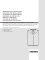 1
1
-
 2
2
-
 3
3
-
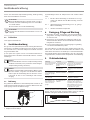 4
4
-
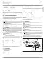 5
5
-
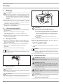 6
6
-
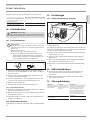 7
7
-
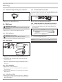 8
8
-
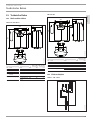 9
9
-
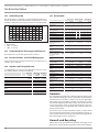 10
10
-
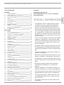 11
11
-
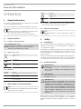 12
12
-
 13
13
-
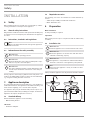 14
14
-
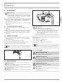 15
15
-
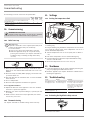 16
16
-
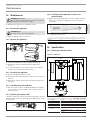 17
17
-
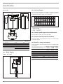 18
18
-
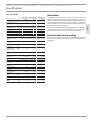 19
19
-
 20
20
-
 21
21
-
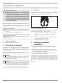 22
22
-
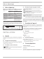 23
23
-
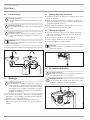 24
24
-
 25
25
-
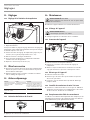 26
26
-
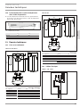 27
27
-
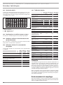 28
28
-
 29
29
-
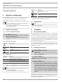 30
30
-
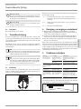 31
31
-
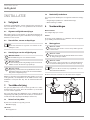 32
32
-
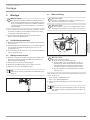 33
33
-
 34
34
-
 35
35
-
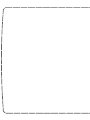 36
36
-
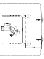 37
37
-
 38
38
-
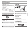 39
39
-
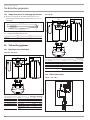 40
40
-
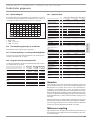 41
41
-
 42
42
-
 43
43
-
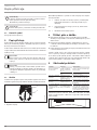 44
44
-
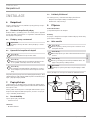 45
45
-
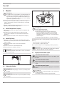 46
46
-
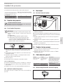 47
47
-
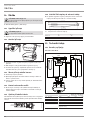 48
48
-
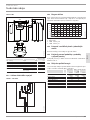 49
49
-
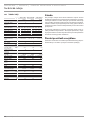 50
50
-
 51
51
-
 52
52
-
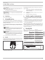 53
53
-
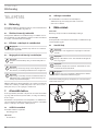 54
54
-
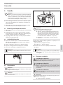 55
55
-
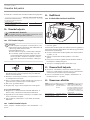 56
56
-
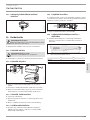 57
57
-
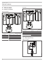 58
58
-
 59
59
-
 60
60
-
 61
61
-
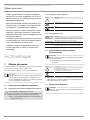 62
62
-
 63
63
-
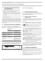 64
64
-
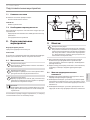 65
65
-
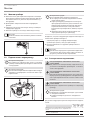 66
66
-
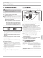 67
67
-
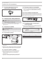 68
68
-
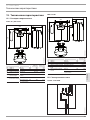 69
69
-
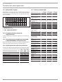 70
70
-
 71
71
-
 72
72


STIEBEL ELTRON SHU 5 SLi comfort SMALL WATER HEATER Installatie gids
- Type
- Installatie gids
in andere talen
Gerelateerde artikelen
-
STIEBEL ELTRON 222153 Operation and Installation
-
-
-
-
-
-
-
STIEBEL ELTRON UFP 5 h Operation Instruction
-
-