Yamaha HTR-5930 de handleiding
- Categorie
- AV-ontvangers
- Type
- de handleiding
Deze handleiding is ook geschikt voor

HTR-5930
AV Receiver
OWNER’S MANUAL
U
01EN_HTR-5930_U_cv-1.fm Page 1 Monday, December 12, 2005 8:55 AM

IMPORTANT SAFETY INSTRUCTIONS
i
• Explanation of Graphical Symbols
The lightning flash with arrowhead symbol, within an
equilateral triangle, is intended to alert you to the
presence of uninsulated “dangerous voltage” within
the product’s enclosure that may be of sufficient
magnitude to constitute a risk of electric shock to
persons.
The exclamation point within an equilateral triangle
is intended to alert you to the presence of important
operating and maintenance (servicing) instructions in
the literature accompanying the appliance.
1 Read Instructions – All the safety and operating instructions
should be read before the product is operated.
2 Retain Instructions – The safety and operating instructions
should be retained for future reference.
3 Heed Warnings – All warnings on the product and in the
operating instructions should be adhered to.
4 Follow Instructions – All operating and use instructions
should be followed.
5 Cleaning – Unplug this product from the wall outlet before
cleaning. Do not use liquid cleaners or aerosol cleaners.
6 Attachments – Do not use attachments not recommended by
the product manufacturer as they may cause hazards.
7 Water and Moisture – Do not use this product near water –
for example, near a bath tub, wash bowl, kitchen sink, or
laundry tub; in a wet basement; or near a swimming pool;
and the like.
8 Accessories – Do not place this product on an unstable cart,
stand, tripod, bracket, or table. The product may fall,
causing serious injury to a child or adult, and serious
damage to the product. Use only with a cart, stand, tripod,
bracket, or table recommended by the manufacturer, or sold
with the product. Any mounting of the product should
follow the manufacturer’s instructions, and should use a
mounting accessory recommended by the manufacturer.
9 A product and cart combination should be moved with care.
Quick stops, excessive force, and uneven surfaces may
cause the product and cart combination to
overturn.
10 Ventilation – Slots and openings in the cabinet are provided
for ventilation and to ensure reliable operation of the
product and to protect it from overheating, and these
openings must not be blocked or covered. The openings
should never be blocked by placing the product on a bed,
sofa, rug, or other similar surface. This product should not
be placed in a built-in installation such as a bookcase or rack
unless proper ventilation is provided or the manufacturer’s
instructions have been adhered to.
11 Power Sources – This product should be operated only from
the type of power source indicated on the marking label. If
you are not sure of the type of power supply to your home,
consult your product dealer or local power company. For
products intended to operate from battery power, or other
sources, refer to the operating instructions.
12 Grounding or Polarization – This product may be equipped
with a polarized alternating current line plug (a plug having
one blade wider than the other). This plug will fit into the
power outlet only one way. This is a safety feature. If you
are unable to insert the plug fully into the outlet, try
reversing the plug. If the plug should still fail to fit, contact
your electrician to replace your obsolete outlet. Do not
defeat the safety purpose of the polarized plug.
13 Power-Cord Protection – Power-supply cords should be
routed so that they are not likely to be walked on or pinched
by items placed upon or against them, paying particular
attention to cords at plugs, convenience receptacles, and the
point where they exit from the product.
14 Lightning – For added protection for this product during a
lightning storm, or when it is left unattended and unused for
long periods of time, unplug it from the wall outlet and
disconnect the antenna or cable system. This will prevent
damage to the product due to lightning and power-line
surges.
15 Power Lines – An outside antenna system should not be
located in the vicinity of overhead power lines or other
electric light or power circuits, or where it can fall into such
power lines or circuits. When installing an outside antenna
system, extreme care should be taken to keep from touching
such power lines or circuits as contact with them might be
fatal.
16 Overloading – Do not overload wall outlets, extension
cords, or integral convenience receptacles as this can result
in a risk of fire or electric shock.
17 Object and Liquid Entry – Never push objects of any kind
into this product through openings as they may touch
dangerous voltage points or short-out parts that could result
in a fire or electric shock. Never spill liquid of any kind on
the product.
18 Servicing – Do not attempt to service this product yourself
as opening or removing covers may expose you to
dangerous voltage or other hazards. Refer all servicing to
qualified service personnel.
19 Damage Requiring Service – Unplug this product from the
wall outlet and refer servicing to qualified service personnel
under the following conditions:
a) When the power-supply cord or plug is damaged,
b) If liquid has been spilled, or objects have fallen into the
product,
c) If the product has been exposed to rain or water,
IMPORTANT SAFETY INSTRUCTIONS
CAUTION
CAUTION: TO REDUCE THE RISK OF
ELECTRIC SHOCK, DO NOT REMOVE
COVER (OR BACK). NO USER-SERVICEABLE
PARTS INSIDE. REFER SERVICING TO
QUALIFIED SERVICE PERSONNEL.
RISK OF ELECTRIC SHOCK
DO NOT OPEN

IMPORTANT SAFETY INSTRUCTIONS
ii
EXAMPLE OF ANTENNA GROUNDING
MAST
GROUND
CLAMP
ANTENNA
LEAD IN
WIRE
ANTENNA
DISCHARGE UNIT
(NEC SECTION 810–20)
GROUNDING CONDUCTORS
(NEC SECTION 810–21)
GROUND CLAMPS
POWER SERVICE GROUNDING
ELECTRODE SYSTEM
(NEC ART 250. PART H)
ELECTRIC
SERVICE
EQUIPMENT
NEC – NATIONAL ELECTRICAL CODE
d) If the product does not operate normally by following
the operating instructions. Adjust only those controls
that are covered by the operating instructions as an
improper adjustment of other controls may result in
damage and will often require extensive work by a
qualified technician to restore the product to its normal
operation,
e) If the product has been dropped or damaged in any
way, and
f) When the product exhibits a distinct change in perfor-
mance - this indicates a need for service.
20 Replacement Parts – When replacement parts are required,
be sure the service technician has used replacement parts
specified by the manufacturer or have the same
characteristics as the original part. Unauthorized
substitutions may result in fire, electric shock, or other
hazards.
21 Safety Check – Upon completion of any service or repairs to
this product, ask the service technician to perform safety
checks to determine that the product is in proper operating
condition.
22 Wall or Ceiling Mounting – The unit should be mounted
to a wall or ceiling only as recommended by the
manufacturer.
23 Heat – The product should be situated away from heat
sources such as radiators, heat registers, stoves, or other
products (including amplifiers) that produce heat.
24 Outdoor Antenna Grounding – If an outside antenna or
cable system is connected to the product, be sure the antenna
or cable system is grounded so as to provide some
protection against voltage surges and built-up static charges.
Article 810 of the National Electrical Code, ANSI/NFPA 70,
provides information with regard to proper grounding of the
mast and supporting structure, grounding of the lead-in wire
to an antenna discharge unit, size of grounding conductors,
location of antenna discharge unit, connection to grounding
electrodes, and requirements for the grounding electrode.
Note to CATV system installer:
This reminder is provided to call the CATV system installer’s
attention to Article 820-40 of the NEC that provides
guidelines for proper grounding and, in particular, specifies
that the cable ground shall be connected to the grounding
system of the building, as close to the point of cable entry as
practical.
FCC INFORMATION (for US customers)
1 IMPORTANT NOTICE: DO NOT MODIFY THIS
UNIT!
This product, when installed as indicated in the
instructions contained in this manual, meets FCC
requirements. Modifications not expressly approved by
Yamaha may void your authority, granted by the FCC, to
use the product.
2 IMPORTANT: When connecting this product to
accessories and/or another product use only high quality
shielded cables. Cable/s supplied with this product MUST
be used. Follow all installation instructions. Failure to
follow instructions could void your FCC authorization to
use this product in the USA.
3 NOTE: This product has been tested and found to comply
with the requirements listed in FCC Regulations, Part 15
for Class “B” digital devices. Compliance with these
requirements provides a reasonable level of assurance that
your use of this product in a residential environment will
not result in harmful interference with other electronic
devices.
This equipment generates/uses radio frequencies and, if
not installed and used according to the instructions found
in the users manual, may cause interference harmful to the
operation of other electronic devices.
Compliance with FCC regulations does not guarantee that
interference will not occur in all installations. If this
product is found to be the source of interference, which
can be determined by turning the unit “OFF” and “ON”,
please try to eliminate the problem by using one of the
following measures:
Relocate either this product or the device that is being
affected by the interference.
Utilize power outlets that are on different branch (circuit
breaker or fuse) circuits or install AC line filter/s.
In the case of radio or TV interference, relocate/reorient
the antenna. If the antenna lead-in is 300 ohm ribbon lead,
change the lead-in to coaxial type cable.
If these corrective measures do not produce satisfactory
results, please contact the local retailer authorized to
distribute this type of product. If you can not locate the
appropriate retailer, please contact Yamaha Electronics
Corp., U.S.A. 6660 Orangethorpe Ave, Buena Park, CA
90620.
The above statements apply ONLY to those products
distributed by Yamaha Corporation of America or its
subsidiaries.

CAUTION: READ THIS BEFORE OPERATING YOUR UNIT.
iii
1 To assure the finest performance, please read this
manual carefully. Keep it in a safe place for future
reference.
2 Install this sound system in a well ventilated, cool,
dry, clean place – away from direct sunlight, heat
sources, vibration, dust, moisture, and/or cold.
Allow ventilation space of at least 30 cm on the top,
20 cm on the left and right, and 20 cm on the back of
this unit.
3 Locate this unit away from other electrical
appliances, motors, or transformers to avoid
humming sounds.
4 Do not expose this unit to sudden temperature
changes from cold to hot, and do not locate this unit
in a environment with high humidity (i.e. a room with
a humidifier) to prevent condensation inside this
unit, which may cause an electrical shock, fire,
damage to this unit, and/or personal injury.
5 Avoid installing this unit where foreign object may
fall onto this unit and/or this unit may be exposed to
liquid dripping or splashing. On the top of this unit,
do not place:
– Other components, as they may cause damage
and/or discoloration on the surface of this unit.
– Burning objects (i.e. candles), as they may cause
fire, damage to this unit, and/or personal injury.
– Containers with liquid in them, as they may fall
and liquid may cause electrical shock to the user
and/or damage to this unit.
6 Do not cover this unit with a newspaper, tablecloth,
curtain, etc. in order not to obstruct heat radiation. If
the temperature inside this unit rises, it may cause
fire, damage to this unit, and/or personal injury.
7 Do not plug in this unit to a wall outlet until all
connections are complete.
8 Do not operate this unit upside-down. It may
overheat, possibly causing damage.
9 Do not use force on switches, knobs and/or cords.
10 When disconnecting the power cable from the wall
outlet, grasp the plug; do not pull the cord.
11 Do not clean this unit with chemical solvents; this
might damage the finish. Use a clean, dry cloth.
12 Only voltage specified on this unit must be used.
Using this unit with a higher voltage than specified
is dangerous and may cause fire, damage to this
unit, and/or personal injury. YAMAHA will not be
held responsible for any damage resulting from use
of this unit with a voltage other than specified.
13 To prevent damage by lightning, keep the power
cord and outdoor antennas disconnected from a
wall outlet or the unit during a lightning storm.
14 Do not attempt to modify or fix this unit. Contact
qualified YAMAHA service personnel when any
service is needed. The cabinet should never be
opened for any reasons.
15 When not planning to use this unit for long periods
of time (i.e. vacation), disconnect the AC power plug
from the wall outlet.
16 Install this unit near the AC outlet and where the AC
power plug can be reached easily.
17 Be sure to read the “TROUBLESHOOTING” section
on common operating errors before concluding that
this unit is faulty.
18 Before moving this unit, press STANDBY/ON to set
this unit in the standby mode, and disconnect the
AC power plug from the wall outlet.
19 VOLTAGE SELECTOR (Asia and General models
only)
The VOLTAGE SELECTOR on the rear panel of this
unit must be set for your local main voltage BEFORE
plugging into the AC wall outlet.
Voltages are 110–120/220–240 V AC, 50/60 Hz.
We Want You Listening For A Lifetime
YAMAHA and the Electronic Industries Association’s Consumer
Electronics Group want you to get the most out of your
equipment by playing it at a safe level. One that lets the sound
come through loud and clear without annoying blaring or
distortion – and, most importantly, without affecting your
sensitive hearing.
Since hearing damage from loud sounds is often
undetectable until it is too late, YA M A H A and the
Electronic Industries Association’s Consumer
Electronics Group recommend you to avoid
prolonged exposure from excessive volume levels.
CAUTION: READ THIS BEFORE OPERATING YOUR UNIT.
WARNING
TO REDUCE THE RISK OF FIRE OR ELECTRIC
SHOCK, DO NOT EXPOSE THIS UNIT TO RAIN
OR MOISTURE.
This unit is not disconnected from the AC power
source as long as it is connected to the wall outlet, even
if this unit itself is turned off by STANDBY/ON. This
state is called the standby mode. In this state, this unit
is designed to consume a very small quantity of power.
FOR CANADIAN CUSTOMERS
To prevent electric shock, match wide blade of plug to
wide slot and fully insert.
This Class B digital apparatus complies with Canadian
ICES-003.
IMPORTANT
Please record the serial number of this unit in the space
below.
MODEL:
Serial No.:
The serial number is located on the rear of the unit.
Retain this Owner’s Manual in a safe place for future
reference.

1
PREPARATIONINTRODUCTION
BASIC
OPERATION
ADVANCED
OPERATION
ADDITIONAL
INFORMATION
FEATURES............................................................. 2
GETTING STARTED............................................ 3
Supplied accessories .................................................. 3
Installing batteries in the remote control ................... 3
CONTROLS AND FUNCTIONS ......................... 4
Front panel ................................................................. 4
Remote control........................................................... 6
Front panel display .................................................... 8
Rear panel .................................................................. 9
CONNECTIONS .................................................. 10
Placing speakers....................................................... 10
Connecting speakers ................................................ 11
Information on jacks and cable plugs ...................... 13
Connecting video components................................. 14
Connecting audio components................................. 17
Connecting the FM and AM antennas ..................... 18
Connecting the power cable..................................... 19
Turning on the power............................................... 19
SETUP ................................................................... 20
Using BASIC MENU .............................................. 20
PLAYBACK.......................................................... 23
Basic operations....................................................... 23
Additional operations............................................... 25
SOUND FIELD PROGRAMS............................. 30
Sound field program descriptions............................ 31
RECORDING ....................................................... 34
FM/AM TUNING ................................................. 35
Automatic tuning ..................................................... 35
Manual tuning.......................................................... 36
Automatic preset tuning........................................... 37
Manual preset tuning ............................................... 38
Selecting preset stations........................................... 39
Exchanging preset stations ...................................... 40
XM® SATELLITE RADIO TUNING ............... 41
What is XM Satellite Radio? ................................... 41
Connecting the XM Connect-and-Play
digital antenna ..................................................... 41
XM Satellite Radio controls and functions.............. 42
Activating XM Satellite Radio ................................ 43
Basic XM Satellite Radio operations....................... 44
Selecting the XM Satellite Radio search mode ....... 45
Setting XM Satellite Radio preset channels ............ 49
Displaying the XM Satellite Radio information...... 50
SET MENU ............................................................52
Using SET MENU................................................... 53
SOUND MENU....................................................... 53
INPUT MENU......................................................... 55
OPTION MENU...................................................... 56
REMOTE CONTROL FEATURES ...................57
Controlling this unit, a TV, or other components.... 57
Setting remote control codes ................................... 59
TROUBLESHOOTING .......................................60
RESETTING THE SYSTEM...............................65
GLOSSARY...........................................................66
Audio information ................................................... 66
Sound field program information ............................ 67
Video information.................................................... 67
SPECIFICATIONS...............................................68
CONTENTS
INTRODUCTION
PREPARATION
BASIC OPERATION
ADVANCED OPERATION
ADDITIONAL INFORMATION

FEATURES
2
Built-in 5-channel power amplifier
◆ Minimum RMS output power
[U.S.A. and Canada models]
(0.9% THD, 1 kHz, 8 Ω/6 Ω)
Front: 110 W + 110 W
Center: 110 W
Surround: 110 W + 110 W
[Other models]
(0.9% THD, 1 kHz, 6 Ω)
Front: 100 W + 100 W
Center: 100 W
Surround: 100 W + 100 W
Decoders and DSP circuits
◆ Proprietary YAMAHA technology for the creation of
multi-channel surround sound
◆ Dolby Digital decoder
◆ Dolby Pro Logic/Dolby Pro Logic II decoder
◆ DTS decoder
◆ Virtual CINEMA DSP
◆ SILENT CINEMA
™
Sophisticated AM/FM tuner
◆ 40-station random and direct preset tuning
◆ Automatic preset tuning
◆ Preset station shifting capability (preset editing)
XM Satellite Radio (U.S.A. model only)
◆ XM Satellite Radio tuning capability (Using the “XM
Connect-and-Play digital antenna” sold separately)
Other features
◆ 192-kHz/24-bit D/A converter
◆ 6 additional input jacks for discrete multi-channel input
◆ A SET MENU that allows you to optimize this unit to
suit your individual audiovisual system
◆ Component video input/output capability
(3 COMPONENT VIDEO INs and 1 MONITOR
OUT)
◆ Optical and coaxial digital audio signal jacks
◆ Sleep timer
◆ Night listening mode
◆ Remote control with preset remote control codes
• y indicates a tip for your operation.
• Some operations can be performed by using either the buttons on the front panel or the ones on the remote control. In case the button
names differ between the front panel and the remote control, the button name on the remote control is given in parentheses.
• This manual is printed prior to production. Design and specifications are subject to change in part as a result of improvements, etc. In
case of differences between the manual and product, the product has priority.
Manufactured under license from Dolby Laboratories.
“Dolby”, “Pro Logic”, and the double-D symbol are trademarks
of Dolby Laboratories.
“SILENT CINEMA” is a trademark of YAMAHA
CORPORATION.
“DTS” and “DTS Digital Surround” are registered trademarks of
Digital Theater Systems, Inc.
The XM name and related logos are registered trademarks of XM
Satellite Radio Inc.
FEATURES

GETTING STARTED
3
INTRODUCTION
Check that you received all of the following parts.
1 Press the part and slide the battery
compartment cover off.
2 Insert the two supplied batteries (AA, R06,
UM-3) according to the polarity markings
(+ and –) on the inside of the battery
compartment.
3 Slide the cover back until it snaps into place.
• Change all of the batteries if you notice a decrease in the
operation range of the remote control.
• Do not use an old battery together with a new one.
• Do not use different types of batteries (such as alkaline and
manganese batteries) together. Read the packaging carefully as
these different types of batteries may have the same shape and
color.
• If the batteries have leaked, dispose of them immediately. Avoid
touching the leaked material or letting it come into contact with
clothing, etc. Clean the battery compartment thoroughly before
installing new batteries.
• Do not throw away batteries with general house waste; dispose
of them correctly in accordance with your local regulations.
• If the remote control is without batteries for more than
2 minutes, or if exhausted batteries remain in the remote
control, the contents of the memory may be cleared. When the
memory is cleared, insert new batteries, set up the remote
control code and program any acquired functions that may have
been cleared.
GETTING STARTED
Supplied accessories
Installing batteries in the remote control
POWER
STANDBY
POWER
AV
POWER
TV
POWER
TV
ENT.
+10
09
STRAIGHT
NIGHT
B
SPEAKERS
A
8765
5CH STEREOSTANDARD
432
1
MOVIEENTERTAINMUSIC
2CH STEREO
V-AU XVCRDTV/CBLDVD
SLEEP
TUNERMD/CD-RCD
TV
AMP
CODE SET
MUTE
INPUTMUTE
REC
MULTI CH IN
AUDIO
DISC SKIP
VOLUME
+
–
+
–
+
–
CHVOL
SET MENU
ENTER
PRESET/CH
SRCH MODEBAND
LEVEL
MENU
TEST
MEMORY
A-E/CAT.
RETURN
DISPLAY
TITLE
+
–
Remote control
Batteries (2)
(AA, R06, UM-3)
Indoor FM antenna
(U.S.A., Canada, China, Asia
and General models)
AM loop antenna
Indoor FM antenna
(U.K., Europe, Australia
and Korea models)
1
3
2
Notes

CONTROLS AND FUNCTIONS
4
The XM Satellite Radio controlling functions in the following buttons (SEARCH MODE, XM, CATEGORY, PRESET/TUNING/CH
l / h, MEMORY, and DISPLAY) are only applicable to the U.S.A. model and are operational only when “XM” is selected as the
input source. For details, see “XM Satellite Radio controls and functions” on page 42.
1 STANDBY/ON
Turns on this unit or sets it to the standby mode.
• In the standby mode, this unit consumes a small amount of
power in order to receive infrared-signals from the remote
control.
• When you turn on this unit, there will be a 4 to 5-second delay
before this unit can reproduce sound.
2 Remote control sensor
Receives signals from the remote control.
3 PRESET/TUNING
• Switches the function of PRESET/TUNING/CH
l
/
h
between selecting preset station numbers and selecting
the tuning frequency.
• Edits the assignments of present stations.
4 FM/AM
Switches the reception band between FM and AM.
5 A/B/C/D/E
Selects one of the 5 preset station groups (A to E) when
“FM” or “AM” is selected as the input source.
6 PRESET/TUNING/CH l / h
• Selects one of the 8 preset station numbers (1 to 8)
when “FM” or “AM” is selected as the input source.
The colon (:) is displayed in the front panel display.
• Selects the tuning frequency when “FM” or “AM” is
selected as the input source. The colon (:) is not
displayed in the front panel display.
7 Front panel display
Shows information about the operational status of this unit.
8 MEMORY
Stores a preset station in the memory. Hold down this
button for more than 3 seconds to start automatic preset
tuning.
9 TUNING MODE
Switches between automatic tuning (the AUTO indicator
is turned on) and manual tuning (the AUTO indicator is
turned off).
0 VOLUME
Controls the output level of all audio channels.
This does not affect the AUDIO OUT (REC) level.
CONTROLS AND FUNCTIONS
Front panel
Note
PRESET/TUNING/CH
VOLU ME
STANDBY
/ON
PHONES
SILENT CINEMA
SPEAKERS
A/B/OFF
FM/AMPRESET/TUNING
A/B/C/D/E
lh
NEXT
AUTO/MAN'LMAN'L/AUTO FM
MEMORY
TUNING MODE
EFFECT
STRAIGHT
TONE CONTROL
BASS/TREBLE
l PROGRAM h
EDIT
INPUT MODE
l INPUT h
MULTI CH INPUT
SET MENU
SEARCH MODE
XM
CATEGORY
DISPLAY
1
ABCD FEGHI
234 5 678 9 0
(U.S.A. model)
Notes
Note

CONTROLS AND FUNCTIONS
5
INTRODUCTION
A PHONES jack
Outputs audio signals for private listening with
headphones.
• When you connect headphones, no signals are output at the
SUBWOOFER OUTPUT jack or at the SPEAKERS terminals.
• All Dolby Digital and DTS audio signals are mixed down to the
left and right headphone channels.
B SPEAKERS
Turns on or off the set of front speakers connected to the A
and/or B terminals on the rear panel.
C STRAIGHT
Turns the sound field programs off or on. When this unit is
in the “STRAIGHT” mode, 2-channel or multi-channel
input signals are output directly from their respective
speakers without effect processing.
D TONE CONTROL
Adjusts the bass/treble balance of the front left and right
speakers in conjunction with BASS/TREBLE +/–.
E BASS/TREBLE +/–
Adjusts the bass/treble balance of the front left and right
speakers in conjunction with TONE CONTROL.
F PROGRAM l / h
Selects sound field programs.
G INPUT MODE
Selects either digital or analog input signals exclusively or
sets this unit to automatically detect the type of input
signals and select the corresponding input signals when
one component is connected via both digital and analog
connections.
H INPUT l / h
Selects the desired input source.
I MULTI CH INPUT
Selects the component connected to the MULTI CH
INPUT jacks as the input source.
The input source connected to the MULTI CH INPUT jacks takes
priority over the source selected with INPUT l / h on the front
panel (or the input selector buttons on the remote control).
Notes
Note

CONTROLS AND FUNCTIONS
6
This section describes the function of each control on the
remote control used to control this unit. To operate other
components, see “REMOTE CONTROL FEATURES” on
page 57.
The XM Satellite Radio controlling functions in the following
buttons (BAND, MEMORY, SRCH MODE, DISPLAY, cursor
buttons u / d / j / i, numeric buttons and ENT.) are only
applicable to the U.S.A. model and are operational only when
“XM” is selected as the input source. For details, see “XM
Satellite Radio controls and functions” on page 42.
■ Controlling this unit
Press AMP to control this unit.
1 Infrared signal transmitter
Outputs infrared control signals. Aim the transmitter at the
component you want to operate.
2 Input selector buttons
Select the input source you want to control.
3 Sound field program selector buttons
Select sound field programs.
4 SPEAKERS A/B
Turn on or off the set of front speakers connected to the A
and/or B terminals on the rear panel.
5 LEVEL
Selects the speaker channel to be adjusted.
6 Cursor buttons u / d / j / i
Select and adjust sound field program parameters or SET
MENU items.
7 TEST
Outputs the test tone to adjust the speaker levels.
8 STANDBY
Sets this unit to the standby mode.
9 POWER
Turns on this unit.
0 SLEEP
Sets the sleep timer.
A MULTI CH IN
Selects the component connected to the MULTI CH
INPUT jacks as the input source when using an external
decoder, etc.
B CODE SET
Use to set up remote control codes.
C AMP
Sets the remote control to the operation mode of this unit.
D VOLUME +/–
Controls the output level of all audio channels.
This does not affect the AUDIO OUT (REC) level.
Remote control
Note
POWER
STANDBY
POWER
AV
POWER
TV
POWER
TV
ENT.
+10
09
STRAIGHT
NIGHT
B
SPEAKERS
A
8765
5CH STEREOSTANDARD
432
1
MOVIEENTERTAINMUSIC
2CH STEREO
V-AUXVCRDTV/CBLDVD
SLEEP
TUNERMD/CD-RCD
TV
AMP
CODE SET
MUTE
INPUTMUTE
REC
MULTI CH IN
AUDIO
DISC SKIP
VOLUME
+
–
+
–
+
–
CHVOL
SET MENU
ENTER
PRESET/CH
SRCH MODEBAND
LEVEL
MENU
TEST
MEMORY
A-E/CAT.
RETURN
DISPLAY
TITLE
+
–
4
18
9
0
A
B
C
D
E
F
G
H
2
3
5
6
7
(U.S.A. model)
Note

CONTROLS AND FUNCTIONS
7
INTRODUCTION
E MUTE
Mutes the audio output. Press again to restore the audio
output to the previous volume level.
F STRAIGHT
Turns the sound field programs off or on. When this unit is
in the “STRAIGHT” mode, 2-channel or multi-channel
input signals are output directly from their respective
speakers without effect processing.
G NIGHT
Turns on or off the night listening mode.
H SET MENU
Enters “SET MENU”.
■ Controlling the TUNER functions
To control the TUNER function, press TUNER and then
BAND repeatedly to select “FM” or “AM” as the input
source.
3 Numeric buttons
Select preset stations.
5 BAND
Switches the reception band between “FM” and “AM”.
6 A-E/CAT. j / i, PRESET/CH u / d
Press A-E/CAT. j / i to select a preset station group (A to
E) and PRESET/CH u / d to select a preset station
number (1 to 8).
■ Using the remote control
The remote control transmits a directional infrared ray.
Be sure to aim the remote control directly at the remote
control sensor on this unit during operation.
• Do not spill water or other liquids on the remote control.
• Do not drop the remote control.
• Do not leave or store the remote control in the following types
of conditions:
– places of high humidity, such as near a bath
– places of high temperature, such as near a heater or stove
– places of extremely low temperatures
– dusty places
Notes
30º 30º
Approximately 6 m (20 ft)

CONTROLS AND FUNCTIONS
8
The XM indicator is only applicable to the U.S.A. model and lights up only when “XM” is selected as the input source. For details, see
“Basic XM Satellite Radio operations” on page 44.
1 Decoder indicators
The respective indicator lights up when any of the
decoders of this unit function.
2 VIRTUAL indicator
Lights up when Virtual CINEMA DSP is active.
3 SILENT CINEMA indicator
Lights up when headphones are connected and a sound
field program is selected.
4 Input source indicators
A corresponding cursor lights up to show the currently
selected input source.
5 MEMORY indicator
Flashes to show that a station can be stored.
6 MUTE indicator
Flashes while the MUTE function is on.
7 VOLUME level indicator
Indicates the current volume level.
8 PCM indicator
Lights up when this unit is reproducing PCM (Pulse Code
Modulation) digital audio signals.
9 STANDARD indicator
Lights up when the “STANDARD” program is selected.
0 NIGHT indicator
Lights up when you select a night listening mode.
A Speaker indicators
Light up according to the set of front speakers selected.
B Headphones indicator
Lights up when headphones are connected.
C CINEMA DSP indicator
Lights up when you select a CINEMA DSP program.
D HiFi DSP indicator
Lights up when you select a HiFi DSP program.
E Multi-information display
Shows the name of the current program and other
information when adjusting or changing settings.
F AUTO indicator
Lights up when this unit is in the automatic tuning mode.
G TUNED indicator
Lights up when this unit is tuned into a station.
H STEREO indicator
Lights up when this unit is receiving a strong signal for an
FM stereo broadcast while the AUTO indicator is lit.
I SLEEP indicator
Lights up while the sleep timer is on.
J Input channel indicators
Indicate the channel components of the current digital
input signal.
K XM indicator
Lights up when “XM” is selected as the input source.
Front panel display
Note
VIRTUAL
SILENT CINEMA
STANDARD NIGHT
AB
SP
HiFi DSP
XM
AUTO
TUNED
STEREO
MEMORY
MUTE
VOLUME
SLEEP
ft
dB
LFE SL SR
L
C
R
dB
VCR
V-AUX
DTV/CBL
DVD
MD/CD-R
TUNER CD
DIGITAL
PCM
PL
PL
E
890ACBD
K
FGH I J
312 4 5 76
(U.S.A. model only)

CONTROLS AND FUNCTIONS
9
INTRODUCTION
1 XM jack (U.S.A. model only)
See page 41 for connection information.
2 MULTI CH INPUT jacks
See page 16 for connection information.
3 Video component jacks
See page 14 for connection information.
4 COMPONENT VIDEO jacks
See page 16 for connection information.
5 Antenna terminals
See page 18 for connection information.
6 DIGITAL INPUT jacks
See pages 14 and 15 for connection information.
7 Audio component jacks
See page 17 for connection information.
8 SUBWOOFER OUTPUT jack
See page 12 for connection information.
9 SPEAKERS terminals
See page 11 for connection information.
0 IMPEDANCE SELECTOR
(U.S.A. and Canada models only)
See page 11 for details.
VOLTAGE SELECTOR
(Asia and General models only)
See page 19 for details.
Rear panel
MULTI CH INPUT
FRONT
CENTER
SUB
WOOFER
SURROUND
CD
MD/
CD-R
(PLAY)
(REC)
IN
OUT
L
R
DIGITAL
INPUT
DVD
COAXIAL
3
DTV/CBL
OPTICAL
DVD
AUDIO
AUDIO
L
R
DVD
DTV/
CBL
IN
OUT
VCR
VCR
V-AUX
VIDEO
OUTPUT
SUB
WOOFER
MONITOR
OUT
DTV/
CBL
DV
D
A
B
C
COMPONENT VIDEO
PBYPR
MONITOR OUT
SURROUND
L
R
AM
ANT
GND
FM
ANT
TUNER
2
1
SPEAKERS
CLASS 2 WIRING
L
R
B
A
FRONT
CENTER
FRON
T
L
R
IMPEDANCE SELECTOR
XM
12 3 4 5
67 8 9 0
(U.S.A. model)

CONNECTIONS
10
The speaker layout below shows the standard ITU-R
*
speaker setting. You can use it to enjoy CINEMA DSP and
multi-channel audio sources.
*
ITU-R is the radio communication sector of the ITU
(International Telecommunication Union).
■ Front speakers (FL and FR)
The front speakers are used for the main source sound plus
effect sounds. Place these speakers an equal distance from
the ideal listening position. The distance of each speaker
from each side of the video monitor should be the same.
■ Center speaker (C)
The center speaker is for the center channel sounds
(dialog, vocals, etc.). If for some reason it is not practical
to use a center speaker, you can do without it. Best results,
however, are obtained with the full system. Place the
center speaker centrally between the front speakers and as
close to the monitor as possible, such as directly over or
under it.
■ Surround speakers (SL and SR)
The surround speakers are used for effect and surround
sounds. Place these speakers behind your listening
position, facing slightly inwards, about 1.8 m (6 ft) above
the floor.
■ Subwoofer (SW)
The use of a subwoofer, such as the YAMAHA Active
Servo Processing Subwoofer System, is effective not only
for reinforcing bass frequencies from any or all channels,
but also for high fidelity reproduction of the LFE (low-
frequency effect) channel included in Dolby Digital and
DTS software. The position of the subwoofer is not so
critical, because low bass sounds are not highly
directional. But it is better to place the subwoofer near the
front speakers. Turn it slightly toward the center of the
room to reduce wall reflections.
CONNECTIONS
Placing speakers
60˚
30˚
FL
FR
C
SL
SR
SR
80˚
SL
FR
FL
C
SL
SR
SW
1.8 m (6 ft)

11
CONNECTIONS
PREPARATION
Be sure to connect the left channel (L), right channel (R),
“+” (red) and “–” (black) properly. If the connections are
faulty, no sound will be heard from the speakers, and if the
polarity of the speaker connections is incorrect, the sound
will be unnatural and lack bass.
• Use speakers with the specified impedance
shown on the rear panel of this unit.
• Before connecting the speakers, make sure
that this unit is turned off.
• Do not let the bare speaker wires touch each
other or do not let them touch any metal part
of this unit. This could damage this unit and/or
speakers.
• Use magnetically shielded speakers. If this
type of speakers still creates the interference
with the monitor, place the speakers away
from the monitor.
(U.S.A. and Canada models only)
If you are to use 6 ohm speakers, be sure to set
the IMPEDANCE SELECTOR switch on the rear
panel to the upper position using a straight slot
screwdriver.
■ Before connecting to the SPEAKERS
terminal
A speaker cord is actually a pair of insulated cables
running side by side. Cables are colored or shaped
differently, perhaps with a stripe, groove or ridges.
Connect the striped (grooved, etc.) cable to the “+” (red)
terminals of this unit and your speaker. Connect the plain
cable to the “–” (black) terminals.
Remove approximately 10 mm (3/8”) of insulation
from the end of each speaker cable and then
twist the bare wires of the cable together to
prevent short circuits.
■ Connecting to the FRONT A SPEAKERS
terminals
1 Loosen the knob.
2 Insert the bare end of the speaker wire into
the hole on the terminal.
3 Tighten the knob to secure the wire.
Connecting the banana plug
(except U.K., Europe, Korea and Asia models)
The banana plug is a single-pole electrical connector
widely used to terminate speaker cables.
First, tighten the knob and then insert the banana plug
connector into the end of the corresponding terminal.
■ Connecting to the FRONT B, CENTER,
and SURROUND SPEAKERS terminals
1 Press down the tab.
2 Insert the bare end of the speaker wire into
the hole on the terminal.
3 Release the tab to secure the wire.
Connecting speakers
CAUTION
Switch
position
Speaker Impedance level
Upper
FRONT A or B
CENTER
SURROUND
The impedance of each
speaker must be 6 Ω or
higher.
Lower
FRONT A or B
CENTER
SURROUND
The impedance of each
speaker must be 8 Ω or
higher.
10 mm (3/8”)
1
2
3
Red: positive (+)
Black: negative (–)
Banana plug
3
1
2
Red: positive (+)
Black: negative (–)

12
CONNECTIONS
■ FRONT terminals
Connect one or two speaker systems (1, 2) to these
terminals. If you use only one front speaker system,
connect it to the FRONT A terminals.
■ CENTER terminals
Connect a center speaker (3) to these terminals.
■ SURROUND terminals
Connect surround speakers (4, 5) to these terminals.
■ SUBWOOFER OUTPUT jack
Connect a subwoofer with built-in amplifier (6) (such as
the YAMAHA Active Servo Processing Subwoofer
System) to this jack.
MULTI CH INPUT
FRONT
CENTER
SUB
WOOFER
SURROUND
CD
MD/
CD-R
(PLAY)
(REC)
IN
OUT
L
R
DIGITAL
INPUT
DVD
COAXIA
L
3
DTV-CBL
OPTICAL
DVD
AUDIO
AUDIO
L
R
DVD
DTV/
CBL
IN
OUT
VCR
VCR
V-AUX
VIDEO
OUTPUT
SUB
WOOFER
MONITOR
OUT
DTV/
CBL
DV
D
A
B
C
COMPONENT VIDEO
PBYPR
MONITOR OUT
SURROUND
L
R
AM
ANT
GND
FM
ANT
TUNER
2
1
SPEAKERS
CLASS 2 WIRING
L
R
B
A
FRONT
CENTER
FRON
T
L
R
IMPEDANCE SELECTOR
XM
5
31 2
2
4
1
6
Subwoofer Center
speaker
Front speakers (A)
LeftRight
Surround speakers
Front speakers (B)
LeftRight
LeftRight
(U.S.A. model)
6
1
2
5
4
3
Speaker layout

13
CONNECTIONS
PREPARATION
■ Audio jacks
This unit has three types of audio jacks (analog audio,
digital audio coaxial, and digital audio optical).
Connection depends on the availability of audio jacks on
your other components.
AUDIO jacks
For conventional analog audio signals transmitted via left
and right analog audio cables. Connect red plugs to the
right jacks and white plugs to the left jacks.
DIGITAL AUDIO COAXIAL jacks
For digital audio signals transmitted via coaxial digital
audio cables.
DIGITAL AUDIO OPTICAL jacks
For digital audio signals transmitted via optical digital
audio cables.
• You can use the digital jacks to input PCM, Dolby Digital and
DTS bitstreams. When you connect components to both the
COAXIAL and OPTICAL jacks, priority is given to the signals
input at the COAXIAL jack. All digital input jacks are
compatible with 96-kHz sampling digital signals.
• This unit handles digital and analog signals independently. Thus
audio signals input at the analog jacks are output only at the
analog AUDIO OUT (REC) jacks.
• Pull out the cap from the optical jack before you connect the
fiber optic cable. Do not discard the cap. When you are not
using the optical jack, be sure to put the cap back in place. This
cap protects the jack from dust.
■ Video jacks
This unit has two types of video jacks (composite video,
and component video). Connection depends on the
availability of input jacks on your video monitor.
VIDEO jacks
For conventional composite video signals transmitted via
composite video cables.
COMPONENT VIDEO jacks
For component signals, separated into the luminance (Y)
and chrominance (P
B, PR) video signals transmitted on
separate wires of component video cables.
Information on jacks and cable plugs
VIDEO
COMPONENT VIDEO
Y PB PR
PB
Y
P
R
V
COAXIAL
DIGITAL AUDIO
AUDIO
OPTICAL
DIGITAL AUDIO
R
L
C
O
R
L
Left and right
analog audio
cable plugs
Optical
digital
audio cable
plug
Coaxial
digital audio
cable plug
Composite
video cable
plug
Component
video cable
plugs
Audio jacks and cable plugs Video jacks and cable plugs
(Red)(White) (Orange) (Yellow) (Green) (Blue) (Red)
Notes
Video signal flow for MONITOR OUT
Output
(MONITOR OUT)
Input
COMPONENT
VIDEO
VIDEO

14
CONNECTIONS
■ Connecting a video monitor
Connect the video input jack of your video monitor to the
MONITOR OUT jack.
■ Connecting a DVD player/cable TV/
satellite tuner
Connect the coaxial digital audio signal output jack of
your DVD player to the DIGITAL INPUT DVD
COAXIAL jack and connect the video signal output jack
of the component to the DVD VIDEO jack of this unit.
Connect the optical digital audio signal output jack of
your cable TV or satellite tuner to the DIGITAL INPUT
DTV/CBL jack and connect the video signal output jack
of the component to the DTV/CBL VIDEO jack of this
unit.
y
• Use the AUDIO jacks of this unit for a video component which
does not have optical digital output jack. To enjoy the surround
sound, use the sound field program selector buttons on the
remote control (see page 30).
• If your DVD player does not have a coaxial digital output jack
but has an optical cable, connect the jack to the DIGITAL
INPUT DVD OPTICAL.
• You can also connect a video monitor, DVD player, digital TV,
and cable TV to this unit using the COMPONENT VIDEO
connections (see page 16).
■ Connecting a DVD recorder/VCR
Connect the audio signal input jacks of your video
component to the VCR AUDIO OUT jacks of this unit.
Then connect the video signal input jack of the video
component to the VCR VIDEO OUT jack of this unit for
picture recording.
Connect the audio signal output jacks of your component to
the VCR AUDIO IN jacks of this unit. Then connect the
video signal output jack of the component to the VCR
VIDEO IN jack of this unit to play a source from your
recording component.
• Once you have connected a recording component to this unit,
keep the component turned on while using this unit. If the
power is turned off, this unit may distort the sound from other
components.
• Be sure to connect your video source components in the same
way you connect your video monitor to this unit. For example,
if you connect your video monitor to this unit using a VIDEO
connection, connect your video source components to this unit
using the VIDEO connections.
■ Connecting another video component
Connect the video signal output jack of your component to
the V-AUX VIDEO jack of this unit.
Connect the audio signal output jacks of the component to
the V-AUX AUDIO jacks of this unit.
Connecting video components
Notes
MULTI CH INPUT
FRONT
CENTER
SUB
WOOFER
SURROUND
CD
MD/
CD-R
(PLAY)
(REC)
IN
OUT
L
R
DIGITAL
INPUT
DVD
COAXIA
L
3
DTV/CBL
OPTICAL
DVD
AUDIO
AUDIO
L
R
DVD
DTV/
CBL
IN
OUT
VCR
VCR
V-AUX
VIDEO
OUTPUT
SUB
WOOFER
MONITOR
OUT
DTV/
CBL
DV
D
A
B
C
COMPONEN
PY
MONITOR OUT
SUR
R
R
2
1
XM
VC
L R
V
O
DVD player
Video monitor
Video in
Audio out
Video out
Audio
out
Audio
out

15
CONNECTIONS
PREPARATION
MULTI CH INPUT
FRONT
CENTER
SUB
WOOFER
SURROUND
CD
MD/
CD-R
(PLAY)
(REC)
IN
OUT
L
R
DIGITAL
INPUT
DVD
COAXIA
L
3
DTV/CBL
OPTICAL
DVD
AUDIO
AUDIO
L
R
DVD
DTV/
CBL
IN
OUT
VCR
VCR
V-AUX
VIDEO
OUTPUT
SUB
WOOFER
MONITOR
OUT
DTV/
CBL
DV
D
A
B
C
COMPONEN
PY
MONITOR OUT
SUR
R
R
2
1
XM
O
V
L R
VV
LR LR
Cable TV or
Satellite tuner
DVD recorder or
VCR
Audio
out
Audio inAudio out Video outVideo in
Video
out
Audio out
MULTI CH INPUT
FRONT
CENTER
SUB
WOOFER
SURROUND
CD
MD/
CD-R
(PLAY)
(REC)
IN
OUT
L
R
DIGITAL
INPUT
DVD
COAXIA
L
3
DTV/CBL
OPTICAL
DVD
AUDIO
AUDIO
L
R
DVD
DTV/
CBL
IN
OUT
VCR
VCR
V-AUX
VIDEO
OUTPUT
SUB
WOOFER
MONITOR
OUT
DTV/
CBL
DV
D
A
B
C
COMPONEN
PY
MONITOR OUT
SUR
R
R
2
1
XM
L R
V
Another video
component
Audio
out
Video
out

16
CONNECTIONS
■ Connecting to the COMPONENT VIDEO jacks
You can enjoy high-quality pictures by connecting your video monitor and video source components to this unit using
COMPONENT VIDEO connections.
Be sure to connect your video source components in the same way you connect your video monitor to this unit. For example, if you
connect your video monitor to this unit using a COMPONENT VIDEO connection, connect your video source components to this unit
using the COMPONENT VIDEO connection.
■ Connecting to the MULTI CH INPUT jacks
This unit is equipped with 6 additional input jacks (FRONT L/R, CENTER, SURROUND L/R and SUBWOOFER) for
discrete multi-channel input from a multi-format player, external decoder or sound processor. Connect the output jacks
on your multi-format player or external decoder to the MULTI CH INPUT jacks. Be sure to match the left and right
output jacks to the left and right input jacks for the front and surround channels.
• When you select the component connected to the MULTI CH INPUT jacks as the input source (see page 25), this unit automatically
turns off the digital sound field processor, and you cannot select sound field programs.
• This unit does not redirect signals input at the MULTI CH INPUT jacks to accommodate for missing speakers. We recommend that
you connect a 5.1-channel speaker system before using this feature.
• When headphones are used, signals are output only from the front left and right channels.
Note
Notes
VCR
DTV/
CBL
DV
D
A
B
C
COMPONENT VIDEO
PBYPR
MONITOR OUT
SURROUND
L
R
PR
PB
Y
PR
PB
Y
PR
PB
Y
PB
PR
Y
Video monitor
DVD player
DVD recorder or
VCR
Video out
Video out
Video out
Video in
Cable TV or
satellite tuner
MULTI CH INPUT
FRONT
CENTER
SUB
WOOFER
SURROUND
CD
DIGITAL
INPUT
DVD
COAXIAL
3
AUDIO
L
R
DVD
DTV/
CBL
IN
V-AUX
VID
E
XM
LR
LR
Multi-format player or
external decoder
Surround outCenter out
Subwoofer out Front out

17
CONNECTIONS
PREPARATION
■ Connecting a CD player
Connect the output jacks of your CD player to the CD
jacks of this unit.
y
To make a digital connection to a CD player, select the
corresponding setting for DIGITAL INPUT jacks in “INPUT
ASSIGN” (see page 55).
■ Connecting a CD recorder/MD recorder
Connect the input jacks of your CD recorder or MD
recorder to the MD/CD-R OUT (REC) jacks.
Connect the output jacks of your CD recorder or MD
recorder to the MD/CD-R IN (PLAY) jacks to play a
source from your recording component.
Once you have connected a recording component to this unit,
keep the component turned on while using this unit. If the
component is turned off, this unit may distort the sound from
other components.
Connecting audio components
Note
MULTI CH INPUT
FRONT
CENTER
SUB
WOOFER
SURROUND
CD
MD/
CD-R
(PLAY)
(REC)
IN
OUT
L
R
DIGITAL
INPUT
DVD
COAXIA
L
3
DTV-CBL
OPTICAL
DVD
AUDIO
AUDIO
L
R
DVD
DTV/
CBL
IN
OUT
VCR
V-AUX
OUTPUT
SUB
WOOFER
2
1
XM
L
R
L
R
L
R
CD player
CD recorder or
MD recorder
Audio out
Audio out
Audio in

18
CONNECTIONS
Both FM and AM indoor antennas are supplied with this
unit. In general, these antennas should provide sufficient
signal strength. Connect each antenna correctly to the
designated terminals.
• The AM loop antenna should be placed away from this unit.
• A properly installed outdoor antenna provides clearer reception
than an indoor one. If you experience poor reception quality,
install an outdoor antenna. Consult the nearest authorized
YAMAHA dealer or service center about outdoor antennas.
• The AM loop antenna should always be connected, even if an
outdoor AM antenna is connected to this unit.
■ Connecting the AM loop antenna
1 Set up the AM loop antenna.
2 Press down the tab of the AM ANT terminal.
3 Insert the one of the AM loop antenna lead
wires into the AM ANT terminal.
4 Release the tab back to secure the wire.
5 Repeat steps 2 through 4 to connect the
other lead wire to the GND terminal.
Once you have properly connected the AM loop
antenna to this unit, orient the AM loop antenna for
the best reception when you tune into AM stations.
Connecting the FM and AM antennas
Notes
AM
ANT
GND
FM
ANT
TUNER
AM loop
antenna
(supplied)
Ground
For maximum safety and minimum
interference, connect the antenna GND
terminal to a good earth ground. A good
earth ground is a metal stake driven into
moist earth.
Indoor FM
antenna
(supplied)
Outdoor AM antenna
Use a 5 to 10 m (16 to 32 ft) of
vinyl-covered wire extended
outdoors from a window.

19
CONNECTIONS
PREPARATION
Once all connections are complete, plug the power cable
into the AC wall outlet.
IMPEDANCE SELECTOR
(U.S.A. and Canada models only)
Before connecting the power cable into the AC wall outlet,
check that the impedance selector setting is correct.
VOLTAGE SELECTOR
(Asia and General models only)
The VOLTAGE SELECTOR on the rear panel of this unit
must be set for your local voltage BEFORE plugging the
power cable into the AC wall outlet. Improper setting of
the VOLTAGE SELECTOR may cause damage to this
unit and create a potential fire hazard.
Select the switch position (upper or lower)
according to your local voltage using a straight
slot screwdriver.
Voltages are 110-120/220-240 V AC, 50/60 Hz.
When all connections are complete, turn on this unit.
Press STANDBY/ON on the front panel (or
POWER on the remote control) to turn on this
unit.
Press STANDBY/ON on the front panel again (or press
STANDBY on the remote control) to set this unit to the
standby mode.
Connecting the power cable
CAUTION
IMPEDANCE SELECTOR
(U.S.A. model)
Power cable
110V-120V
220V-240V
VOLTAGE
SELECTOR
Turning on the power
Memory back-up
The memory back-up circuit prevents the stored data
from being lost even if this unit is in the standby mode.
However, the stored data will be lost in case the power
cable is disconnected from the AC wall outlet or if the
power supply is cut off for more than one week.
PRESET/TUNING/CH
VOLUME
STANDBY
/ON
PHONES
SILENT CINEMA
SPEAKERS
A/B/OFF
FM/AMPRESET/TUNING
A/B/C/D/E
lh
NEXT
AUTO/MAN'LMAN'L/AUTO FM
MEMORY
TUNING MODE
EFFECT
STRAIGHT
TONE CONTROL
BASS/TREBLE
l PROGRAM h
EDIT
INPUT MODE
l INPUT h
MULTI CH INPUT
SET MENU
SEARCH MODE
XM
CATEGORY
DISPLAY
POWER
TV
TV
AMP
CODE SET
REC
MULTI CH IN
DISC SKIP
V-A UXVCRDTV/CBLDVD
SLEEPTUNERMD/CD-RCD
POWER
STANDBY
POWERPOWER
AVTV
AUDI O
+++
STANDBY/ON
POWER
STANDBY
/ON
POWER
or
Front panel
Remote control

SETUP
20
The “BASIC MENU” feature is a useful way to set up
your system quickly and with minimal effort.
y
• If you wish to configure this unit manually using more precise
adjustments, use the detailed parameters in “SOUND MENU”
(see page 53).
• Altering any parameters in “SETUP” resets all parameters
manually adjusted in “SOUND MENU” (see page 53).
• Initial settings are indicated in bold under each parameter.
Before you begin:
• Press SPEAKERS on the front panel repeatedly (or press
SPEAKERS A/B on the remote control) to select the front
speakers you want to use.
• Make sure you disconnect your headphones from this unit.
1 Press AMP and then SET MENU.
“BASIC MENU” appears in the front panel display.
If the front panel display shows anything other than
“BASIC MENU”, press SET MENU repeatedly until
“BASIC MENU” appears.
2 Press i to enter “BASIC MENU”.
“1 SETUP” appears in the front panel display.
3 Press i to enter “1 SETUP”.
“ROOM” appears in the front panel display.
4 Press j / i to select the desired setting.
Select the size of the room where you have installed
your speakers. In general, the room sizes are defined
as follows:
Choices: S, M, L
[U.S.A. and Canada models]
S (small) 16 x 13 ft, 200 ft
2
(4.8 x 4.0 m, 20 m
2
)
M (medium) 20 x 16 ft, 300 ft
2
(6.3 x 5.0 m, 30 m
2
)
L (large) 26 x 19 ft, 450 ft
2
(7.9 x 5.8 m, 45 m
2
)
[Other models]
S (small) 3.6 x 2.8 m, 10 m
2
M (medium) 4.8 x 4.0 m, 20 m
2
L (large) 6.3 x 5.0 m, 30 m
2
5 Press d to enter “SUBWOOFER” and then
press j / i to select the desired setting.
Choices: YES, NONE
• Select “YES” if you have a subwoofer in your
system.
• Select “NONE” if you do not have a subwoofer in
your system.
SETUP
Using BASIC MENU
Note
STRAIGHT
NIGHT
B
5CH STEREOSTANDARD
MOVIEENTERTAIN
TV
AMP
INPUT
LEVEL
TEST
SPEAKERS
A
MEMORY
2CH STEREO
+
–
A-E/CAT.
MUSIC
MUTE
SET MENU
PRESET/CH
SRCH MODEBAND
VOLUME
+
–
+
–
+
–
CHVOL
ENT.
+10
09
8765
432
1
MUTE
ENTER
MENU
RETURN
DISPLAY
TITLE
1
5-7,9,11,13-15
2-6,8,10,12,13
1
(U.S.A. model)
AMP
SET MENU
SRCH MODE
MENU
ENTER
PRESET/CH
A-E/CAT.
+
–
ENTER
PRESET/CH
A-E/CAT.
+
–
ENTER
PRESET/CH
A-E/CAT.
+
–
ENTER
PRESET/CH
A-E/CAT.
+
–
ENTER
PRESET/CH
A-E/CAT.
+
–

21
SETUP
PREPARATION
6 Press d to confirm your selection and then
press j / i to select the number of speakers
connected to this unit.
7 Press d to confirm your selection.
“iSET CANCEL” appears in front panel display.
8 Press j / i to select the desired setting.
Choices: SET, CANCEL
• Select “SET” to apply the settings you made.
• Select “CANCEL” to cancel the setup procedure
without making any changes.
y
You can also press SET MENU repeatedly to cancel the
setup procedure.
9 Press d to confirm your selection.
If you selected “SET” in the previous step, you will
hear a test tone from each speaker in turn.
“CHECK:TestTone” appears in the front panel
display for a few seconds and then “CHECK OK?”
appears in the front panel display.
y
The indicator of the speaker currently outputting the test
tone flashes in the front panel display.
10 Press j / i to select the desired setting.
Choices: YES, NO
• Select “YES” to complete the setup procedure if
the test tone levels from each speaker were
satisfactory.
• Select “NO” to proceed to the speaker level
adjustment menu to balance the output level of
each speaker.
11 Press d to confirm your selection.
• If you selected “YES” in the previous step, the
setup procedure is completed and the display
returns to the “BASIC MENU”.
• If you selected “NO” in the previous step, the
speaker level adjustment display appears in the
front panel display.
Choice Display Speakers
2spk
Front L/R
3spk
Front L/R, Center
4spk
Front L/R, Surround L/R
5spk
Front L/R, Center, Surround L/R
ENTER
PRESET/CH
A-E/CAT.
+
–
ENTER
PRESET/CH
A-E/CAT.
+
–
LL C R
SL SB SR
LL CR
SL SB SR
LL C R
SL SB SR
LL C R
SL SB
SB
SR
ENTER
PRESET/CH
A-E/CAT.
+
–
ENTER
PRESET/CH
A-E/CAT.
+
–
ENTER
PRESET/CH
A-E/CAT.
+
–
ENTER
PRESET/CH
A-E/CAT.
+
–
ENTER
PRESET/CH
A-E/CAT.
+
–

22
SETUP
12 Press j / i to adjust the balance between the
front left and right speakers.
13 Press d / u to select a speaker and then j / i
to adjust the balance.
Press i to increase the value.
Press j to decrease the value.
• Select “C” to adjust the balance between the front
left and center speakers.
• Select “SL” to adjust the balance between the front
left and surround left speakers.
• Select “SR” to adjust the balance between the
surround left and surround right speakers.
• Select “SWFR” to adjust the balance between the
front left speaker and the subwoofer.
14 To confirm the settings, press d / u
repeatedly until “2 SP LEVEL” appears in the
front panel display.
15 Press d repeatedly until the menu
disappears.
ENTER
PRESET/CH
A-E/CAT.
+
–
ENTER
PRESET/CH
A-E/CAT.
+
–
ENTER
PRESET/CH
A-E/CAT.
+
–
ENTER
PRESET/CH
A-E/CAT.
+
–
ENTER
PRESET/CH
A-E/CAT.
+
–

PLAYBACK
23
BASIC
OPERATION
Extreme caution should be exercised when you play back CDs encoded in DTS. If you play back a CD
encoded in DTS on a DTS-incompatible CD player, you will only hear some unwanted noise that may
damage your speakers. Check whether your CD player supports CDs encoded in DTS. Also, check the
sound output level of your CD player before you play back a CD encoded in DTS.
1 Turn on the video monitor connected to this
unit.
2 Press SPEAKERS on the front panel
repeatedly (or press AMP and then
SPEAKERS A/B on the remote control) to
select the front speakers you want to use.
The respective speaker indicators lights up in the
front panel display.
3 Press INPUT l / h on the front panel
repeatedly (or press one of the input selector
buttons on the remote control) to select the
desired input source.
The name of the currently selected input source
appears in the front panel display for a few seconds.
If you are to select an input source connected via digital
connections, set “INPUT MODE” to “AUTO” or “DTS”
(see page 26).
4 Start playback on the selected component or
select a broadcast station.
• When a multi-channel signal (Dolby Digital or
DTS) is input digitally, this unit decodes the signal
and reproduces surround sound.
• Refer to the operating instructions for the source
component.
• See page 35 for details about FM/AM tuning
instructions.
• See page 41 for details about XM Satellite Radio
tuning instructions.
PLAYBACK
CAUTION
Basic operations
STRAIGHT
NIGHT
AUDI O
VOLUME
+
–
+
–
+
–
CHVOL
ENT.
+10
09
8765
432
1
MUTE
B
5CH STEREOSTANDARD
MOVIEENTERTAIN
TV
AMP
INPUT
LEVEL
SPEAKERS
A
2CH STEREO
MUSIC
CODE SET
MUTE
REC
MULTI CH IN
DISC SKIP
SET MENU
V-A UXVCRDTV/CBLDVD
SLEEPTUNERMD/CD-RCD
2
2
7
5
3
PRESET/TUNING/CH
VOLUME
STANDBY
/ON
PHONES
SILENT CINEMA
SPEAKERS
A/B/OFF
FM/AMPRESET/TUNING
A/B/C/D/E
lh
NEXT
AUTO/MAN'LMAN'L/AUTO FM
MEMORY
TUNING MODE
EFFECT
STRAIGHT
TONE CONTROL
BASS/TREBLE
l PROGRAM h
EDIT
INPUT MODE
l INPUT h
MULTI CH INPUT
SET MENU
SEARCH MODE
XM
CATEGORY
DISPLAY
2667 53
SPEAKERS
A/B/OFF
AMP
09
B
SPEAKERS
A
or
Remote controlFront panel
Note
Front panel
V-AUXVCRDTV/CBLDVD
MD/CD-RCD
I
NPU
T
Remote control
or
VCR
V-AUX
DTV/CBL
DVD
MD/CD-R
TUNER CD
DVD AUTO
Selected input source Input mode
Selected input source

24
PLAYBACK
5 Rotate VOLUME on the front panel (or press
VOLUME +/– on the remote control) to adjust
the volume to the desired output level.
If you connected a recording component to the VCR OUT,
or MD/CD-R OUT (REC) jacks, and you notice distortion
or low volume during playback from other components, try
turning on the recording component.
6 Press TONE CONTROL on the front panel
repeatedly to select “BASS” or “TREBLE”
and then press BASS/TREBLE +/– to adjust
the corresponding frequency response level.
• Select “BASS” to adjust the low-frequency
response.
• Select “TREBLE” to adjust the high-frequency
response.
• Speaker and headphone adjustments are stored
independently.
• When “TONE BYPASS” (see page 55) is set to “AUTO”,
and “BASS” and “TREBLE” are set to 0 dB, audio output
automatically bypasses the tone control circuitry of this
unit.
• If you increase or decrease the high-frequency or low-
frequency sound to an extreme level, the tonal quality of
the surround speakers may not match that of the front left
and right speakers.
• TONE CONTROL is not effective when the component
connected to the MULTI CH INPUT jacks is selected as
the input source (see page 25).
7 Press PROGRAM l / h on the front panel
repeatedly (or press one of the sound field
program selector buttons on the remote
control repeatedly) to select the desired
sound field program.
The name of the selected sound field program appears
in the front panel display.
See page 31 for details about sound field programs.
• Choose a sound field program based on your listening
preference, not merely on the name of the program.
• When you select an input source, this unit automatically
selects the last sound field program used with the
corresponding input source.
• Sound field programs cannot be selected when the
component connected to the MULTI CH INPUT jacks is
selected as the input source (see page 25).
• When sampling frequencies higher than 48 kHz are input,
this unit is automatically set to the “STEREO” mode.
• To display information about the currently selected input
source in the front panel display, see page 28 for details.
Note
Notes
VOLUME
V
O
L
UM
E
+
–
or
TONE CONTROL
BASS/TREBLE
Notes
l PROGRAM h
STRAIGHT
NIGHT
ENT.
+10
09
8765
432
1
B
5CH STEREOSTANDARD
MOVIEENTERTAIN
SPEAKERS
A
2CH STEREO
MUSIC
Front panel
or
Remote control
The Roxy Thtr
Currently selected
surround field program

25
PLAYBACK
BASIC
OPERATION
■ Listening with headphones using
SILENT CINEMA
SILENT CINEMA allows you to enjoy multi-channel
music or movie sound, including Dolby Digital and DTS
sources, through ordinary headphones. SILENT CINEMA
activates automatically whenever you connect headphones
to the PHONES jack while listening to CINEMA DSP or
HiFi DSP sound field programs (see page 31). When
activated, the SILENT CINEMA indicator lights up in the
front panel display.
• SILENT CINEMA does not activate when the component
connected to the MULTI CH INPUT jacks is selected as the
input source.
• SILENT CINEMA is not effective when “2CH STEREO” (see
page 31) is selected or when this unit is in the “STRAIGHT”
mode (see page 33).
• The sound from the LFE channel will be mixed and output from
the headphones.
■ Muting the audio output
Press MUTE on the remote control to mute the
audio output.
Press MUTE again to resume the audio output.
y
• You can also rotate VOLUME on the front panel or VOLUME
+/– on the remote control to resume the audio output.
• You can adjust the muting level by using “AUDIO MUTE” in
“OPTION MENU” (see page 56).
• The MUTE indicator flashes in the front panel display when the
audio output is muted and disappears from the front panel
display when the audio output is resumed.
If you change the input source or the sound field program while
the audio output is being muted, this unit resumes the audio
output.
■ Selecting the MULTI CH INPUT
component as the input source
Use this feature to select the component connected to the
MULTI CH INPUT jacks (see page 16) as the input
source.
Press MULTI CH INPUT on the front panel (or
MULTI CH IN on the remote control) so that
“MULTI CH INPUT” appears in the front panel
display.
When “MULTI CH INPUT” is shown in the front panel display,
no other source can be played. To select another input source with
INPUT l / h on the front panel (or one of the input selector
buttons on the remote control), press MULTI CH INPUT (or
MULTI CH IN on the remote control) so that “MULTI CH
INPUT” disappears from the front panel display.
■ Using the night listening mode
The night listening mode is designed to improve
listenability at lower volumes or at night.
Press AMP on the remote control and then press
NIGHT to select “NIGHT ON”.
y
When a night listening mode is selected, the NIGHT indicator
lights up in the front panel display.
• You can use the night listening mode with any of the sound field
programs.
• The night listening mode may vary in effectiveness depending
on the input source and the surround sound settings you use.
Additional operations
Notes
Note
MUTE
Note
Notes
MULTI CH INPUT
MULTI CH IN
Front panel
Remote control
or
+10
NIGHT
AMP

26
PLAYBACK
■ Selecting the input modes
This unit comes with a variety of input jacks. Do the
following to select the type of input signals you want to
use.
y
• We recommend setting “INPUT MODE” to “AUTO” in most
cases.
• You can adjust the default input mode of this unit by using the
“INPUT MODE” parameter in “INPUT MENU” (see page 55).
• To play DTS-encoded CDs when using a digital audio
connection, be sure to set “INPUT MODE” to “DTS”.
• Depending on the player, DTS decoding may not be performed
correctly even if you make a digital connection between this
unit and the player.
1 Press INPUT l / h on the front panel to
select the desired input source.
2 Press INPUT MODE on the front panel
repeatedly to select the desired input mode.
AUTO Automatically selects input signals in
the following order:
1) Digital signals
2) Analog signals
DTS Selects only digital signals encoded in
DTS. If no DTS signals are input, no
sound is output.
ANALOG Selects only analog signals. If no
analog signals are input, no sound is
output.
When “INPUT MODE” is set to “AUTO”, this unit
automatically switches to the appropriate decoder if a Dolby
Digital or DTS signal is detected.
■ Adjusting speaker levels during
playback
You can adjust the output level of each speaker while
listening to a music source. This is also possible when
playing sources input at the MULTI CH INPUT jacks.
1 Press AMP on the remote control and then
press LEVEL repeatedly to select the speaker
you want to adjust.
• Select “FRONT L” to adjust the front left speaker
output level.
• Select “CENTER” to adjust the center speaker
output level.
• Select “FRONT R” to adjust the front right speaker
output level.
• Select “SUR. R” to adjust the surround right
speaker output level.
• Select “SUR. L” to adjust the surround left speaker
output level.
• Select “SWFR” to adjust the subwoofer output
level.
y
Once you press LEVEL on the remote control, you can also
select the speaker by pressing u / d.
2 Press j / i on the remote control to adjust the
speaker output level.
The control range is from +10 dB to –10 dB for the
center and surround speakers, and from 0 dB to
–20 dB for the front speakers and subwoofer.
• This operation will override the level adjustments made in
“SETUP” (see page 20).
• You cannot adjust speaker levels if “SPEAKER SET” in
“SOUND MENU” (see page 53) is set to “NONE”.
• You cannot adjust the subwoofer level if “BASS” in
“SPEAKER SET” (see page 53) in the set menu is set to
“FRNT”.
• If you use LEVEL to adjust speaker levels, the speaker levels
you previously set with the test tone will also change.
• If you select “SETUP” (see page 20) and then select “SET”,
speaker levels change in response to any changes you make in
“SETUP”.
Notes
Note
I
NPU
T
INPUT MODE
VCR
V-AUX
DTV/CBL
DVD
MD/CD-R
TUNER CD
DVD AUTO
Currently selected
input source
Currently selected
input mode
Currently selected
input sources
Notes
AMP
TITLE
LEVEL
BAND
ENTER
PRESET/CH
A-E/CAT.
+
–

27
PLAYBACK
BASIC
OPERATION
■ Using the test tone
Use the test tone to set speaker levels so that the volume
from each speaker is identical when heard from your
listening position. This is also possible when playing
sources input at the MULTI CH INPUT jacks.
1 Press AMP on the remote control and then
press TEST.
The unit will output a test tone.
2 Press u / d repeatedly to select a speaker to
adjust.
• Select “TEST LEFT” to adjust the front left
speaker output level.
• Select “TEST CENTER” to adjust the center
speaker output level.
• Select “TEST RIGHT” to adjust the front right
speaker output level.
• Select “TEST SUR.R” to adjust the surround right
speaker output level.
• Select “TEST SUR.L” to adjust the surround left
speaker output level.
• Select “TEST SUBWOOFER” to adjust the
subwoofer output level.
3 Press j / i on the remote control to adjust the
speaker output level.
The control range is from +10 dB to –10 dB for the
center and surround speakers, and from 0 dB to
–20 dB for the front speakers and subwoofer.
4 Press TEST on the remote control when you
have completed your adjustment.
The test tone halts.
• You cannot use the test tone if headphones are connected to the
PHONES jack. Remove the headphones from the PHONES
jack.
• This operation will override the level adjustments made in
“SETUP” (see page 20).
• You cannot adjust speaker levels if “SPEAKER SET” in
“SOUND MENU” (see page 53) is set to “NONE”.
• You cannot adjust the subwoofer level if “BASS” in
“SPEAKER SET” (see page 53) in the set menu is set to
“FRNT”.
• If you use TEST to adjust speaker levels, the speaker levels you
previously adjust during playback will also change.
• If you select “SETUP” (see page 20) and then select “SET”,
speaker levels change in response to any changes you make in
“SETUP”.
y
Depending on the source, the speaker levels set with the test tone
may not be to your liking. In this case, adjust the speaker levels
while listening to the source.
AMP
RETURN
TEST
MEMORY
ENTER
PRESET/CH
A-E/CAT.
+
–
ENTER
PRESET/CH
A-E/CAT.
+
–
RETURN
TEST
MEMORY
Notes

28
PLAYBACK
■ Displaying information about the input
source
You can display the format, sampling frequency, channel
and bit rate of the current input signal.
1 Press one of the input selector buttons on
the remote control to select the desired input
source.
2 Press AMP on the remote control and then
press STRAIGHT to select “STRAIGHT”.
3 Press u / d to display the following
information about the input source.
FORMAT
Signal format display. When this unit cannot detect a
digital signal, it automatically switches to analog
input.
Display status: Analog, Digital, Dolby Digital, DTS,
PCM, Unknown Digital
“Unknown Digital” appears when this unit detects any
undecodable digital signal.
CHANNEL
Number of source channels in the input signal (front/
surround/LFE). For example, a multi-channel
soundtrack with 3 front channels, 2 surround
channels and LFE, is displayed as “3/2/LFE”.
SAMPLING
Sampling frequency.
Display status: 32kHz, 44.1kHz, 48kHz, 64kHz,
88.2kHz, 96kHz
BITRATE
Bit rate.
y
When you are displaying information about the input source, this
unit is in the “STRAIGHT” mode (see page 33). To turn back the
sound field program on, press STRAIGHT again.
AMP
ENT.
STRAIGHT
ENTER
PRESET/CH
A-E/CAT.
+
–
Note

29
PLAYBACK
BASIC
OPERATION
■ Using the sleep timer
Use this feature to automatically set this unit to the
standby mode after a certain amount of time. The sleep
timer is useful when you are going to sleep while this unit
is playing or recording a source.
Press SLEEP on the remote control repeatedly to
set the amount of time.
Each time you press SLEEP, the front panel display
changes as shown below.
The SLEEP indicator flashes while you are switching the
amount of time for the sleep timer. Once the sleep timer is
set, the SLEEP indicator lights up in the front panel
display, and the display returns to the selected sound field
program.
To cancel the sleep timer, press SLEEP on the remote
control repeatedly until “SLEEP OFF” appears in the front
panel display.
The SLEEP indicator turns off and “SLEEP OFF”
disappears after a few seconds.
y
The sleep timer setting can also be canceled by pressing
STANDBY/ON on the front panel (or STANDBY on the remote
control) to set this unit to the standby mode.
■ Playing video sources in the
background
You can combine a video image from a video source with
sound from an audio source. For example, you can enjoy
listening to classical music while viewing beautiful
scenery from the video source on the video monitor.
Press the input selector buttons on the remote
control to select a video source and then an
audio source.
If you want to enjoy an audio source input at the MULTI CH
INPUT jacks together with a video source, first select the video
source and then press MULTI CH INPUT on the front panel (or
MULTI CH IN on the remote control) to select the component
connected to the MULTI CH INPUT jacks as the input source
(see page 25).
SLEEP
SLEEP 90min
SLEEP 60minSLEEP 30minSLEEP OFF
SLEEP 120min
SLEEP
SLEEP 120min
Flashes
SLEEP
The Roxy Thtr
Lights up
Note
Audio sources
Video sources
V-AUXVCRDTV/CBLDVD
TUNERMD/CD-RCD

SOUND FIELD PROGRAMS
30
This unit is equipped with a variety of precise digital decoders that allow you to enjoy multi-channel playback from
almost any stereo or multi-channel sound source. This unit is also equipped with a YAMAHA digital sound field
processing (DSP) chip containing several sound field programs which you can use to enhance your playback experience.
• Choose a sound field program based on your listening preference, not merely on the name of the program.
• When you select an input source, this unit automatically selects the last sound field program used with the corresponding input source.
• Sound field programs cannot be selected when the component connected to the MULTI CH INPUT jacks is selected as the input
source (see page 25).
• When sampling frequencies higher than 48 kHz are input, this unit is automatically set to the “STEREO” mode.
■ Front panel operations
Press PROGRAM l / h on the front panel
repeatedly.
The name of the selected sound field program appears in
the front panel display.
■ Remote control operations
Press AMP on the remote control and then press
one of the sound field program selector buttons
repeatedly.
The name of the selected sound field program appears in
the front panel display.
SOUND FIELD PROGRAMS
Notes
PRESET/TUNING/CH
VOLUME
STANDBY
/ON
PHONES
SILENT CINEMA
SPEAKERS
A/B/OFF
FM/AMPRESET/TUNING
A/B/C/D/E
lh
NEXT
AUTO/MAN'LMAN'L/AUTO FM
MEMORY
TUNING MODE
EFFECT
STRAIGHT
TONE CONTROL
BASS/TREBLE
l
PROGRAM
h
EDIT
INPUT MODE
l
INPUT
h
MULTI CH INPUT
SET MENU
SEARCH MODE
XM
CATEGORY
DISPLAY
(U.S.A. model)
PROGRAM l / h
STRAIGHT
NIGHT
VOLUME
+
–
+
–
+
–
CHVOL
ENT.
+10
09
8765
432
1
MUTE
B
5CH STEREOSTANDARD
MOVIEENTERTAIN
TV
AMP
INPUT
SPEAKERS
A
2CH STEREO
MUSIC
MUTE
(U.S.A. model)
AMP
Sound field program
selector buttons

31
SOUND FIELD PROGRAMS
BASIC
OPERATION
y
The sound field programs are compatible with all Dolby Digital, DTS, and Dolby Surround sources. Set “INPUT MODE” to “AUTO”
(see page 26) to enable this unit to automatically switch to the appropriate digital decoder according to the input signal.
• The sound field programs of this unit are recreations of real-world acoustic environments made from precise measurements taken in
the actual concert hall, music venue, movie theater, etc. Thus, you may notice variations in the strength of the reflections coming from
the front, back, left and right.
• Choose a sound field program based on your listening preference, not merely on the name of the program itself.
Sound field program descriptions
Remote
control
button
Program Features
2CH STEREO
2CH STEREO
Downmixes multi-channel sources to 2 channel or plays back 2-channel sources as they are.
MUSIC
Concert Hall
HiFi DSP processing. This program produces the excitement of a live concert hall.
The Roxy Thtr
HiFi DSP processing. The program reproduces the dynamic rock music environment of
“The Roxy Theatre”, one of the hottest rock clubs in L.A. The listener’s virtual seat is at the
center-left of the hall.
ENTERTAIN
Game
CINEMA DSP processing. This program adds the dynamics and thrills of the three-
dimensional surround sound effect.
TV Sports
CINEMA DSP processing. This program enhances the experience of watching sports by
producing the ambient sounds of the crowd and the stadium.
MOVIE
Movie Spacious
CINEMA DSP processing. This program offers clear dialog with a wide sound field for
movie scenes. It is ideal for any type of movie, live music and game contents.
Movie Dramatic
CINEMA DSP processing. This program creates a live sound field by emphasizing the
dramatic scene changes of action movies and games.
STANDARD
STANDARD
Standard processing for the selected decoder.
5CH STEREO
5CH STEREO
Using this program increases the listening position range. This is a sound field suitable for
background music at parties.
Notes

32
SOUND FIELD PROGRAMS
■ Enjoying 2-channel sources using the
standard decoders
Signals input from 2-channel sources can also be played
back on multi-channels.
Press AMP on the remote control and then
STANDARD on the remote control repeatedly to
select a decoder.
You can select from the following decoders depending on
the type of source you are playing and your personal
preference.
y
You can also select a decoder by pressing j / i on the remote
control while the decoder type is displayed in the front panel
display.
■ Editing sound fields parameters
You can enjoy good quality sound with the factory preset
parameters. Although you do not have to change the initial
settings, you can change some of the parameters to better
suit the input source or your listening room.
1 While listening to a source, press AMP on the
remote control and then press u / d to
select the parameters.
2 Press j / i to change parameter value.
You cannot change parameter values when “MEM. GUARD” in
“OPTION MENU” is set to “ON” (see page 56).
STANDARD Functions
PRO LOGIC
Dolby Pro Logic processing for any
sources
PLII Movie
Dolby Pro Logic II processing for
movie sources
PLII Music
Dolby Pro Logic II processing for
music sources
AMP
5
STANDARD
Note
ENTER
PRESET/CH
A-E/CAT.
+
–
ENTER
PRESET/CH
A-E/CAT.
+
–

33
SOUND FIELD PROGRAMS
BASIC
OPERATION
For 2CH STEREO:
Direct DIRECT
Function: 2-channel stereo direct. Bypasses the
decoders and DSP processors of this unit
for pure hi-fi stereo sound when playing
2-channel analog sources.
Choices: AUTO, OFF
y
• The “AUTO” setting bypasses the decoders and DSP processors
only when “BASS” and “TREBLE” are set to 0 dB (see
page 24).
• When multi-channel signals (Dolby Digital and DTS) are input,
they are downmixed to 2 channels and output from the front left
and right speakers.
• The low-frequency signals input from the front left and right
speakers are redirected to the subwoofer in the following cases:
– “BASS” is set to “BOTH” (see page 54).
– “FRONT” is set to “SML” (see page 54) and “BASS” is set to
“SWFR” (see page 54).
For PRO LOGIC II Music:
Panorama PANORAMA
Function: Sends stereo signals to the surround
speakers as well as the front speakers for
a wraparound effect.
Choices: OFF, ON
Dimension DIMENSION
Function: Gradually adjusts the sound field either
towards the front or towards the rear.
Control range: –3 (towards the rear) to +3 (towards the
front), initial setting is STD (standard).
Center width CT WIDTH
Function: Adjusts the center image from all three
front speakers to varying degrees. A
larger value adjusts the center image
towards the front left and right speakers.
Control range: 0 (center channel sound is output only
from center speaker) to 7 (center channel
sound is output only from front left and
right speakers), initial setting is 3.
■ Using Virtual CINEMA DSP
Virtual CINEMA DSP allows you to enjoy the CINEMA
DSP programs without surround speakers by creating
virtual speakers.
If you set “SURR”
to “NONE” (see page 54), Virtual
CINEMA DSP activates automatically whenever you
select a CINEMA DSP program (see page 31).
Virtual CINEMA DSP will not activate even when “SURR” is set
to “NONE” (see page 54) in the following cases:
– When “2CH STEREO” (see page 31) is selected or when this
unit is in the “STRAIGHT” mode.
– When the component connected to the MULTI CH INPUT
jacks is selected as the input source (see page 25).
– When headphones are connected to the PHONES jack.
■ Listening to unprocessed input signals
When this unit is in the “STRAIGHT” mode, multi-
channel sources are decoded straight into the appropriate
channels without any additional effect processing. 2-
channel stereo sources are output from only the front left
and right speakers.
1 Press AMP on the remote control and then
STRAIGHT to select “STRAIGHT”.
2 To deactivate the “STRAIGHT” mode, press
STRAIGHT on the remote control again so
that “STRAIGHT” disappears from the front
panel display.
The sound field program is turned back on.
y
You can also select “STRAIGHT” by pressing STRAIGHT
on the front panel.
Note
ENT.
STRAIGHT
AMP

RECORDING
34
Recording adjustments and other operations are performed from the recording components. Refer to the operating
instructions for those components.
• When this unit is set to the standby mode, you cannot record between other components connected to this unit.
• The settings of TONE CONTROL (see page 24), VOLUME, speaker levels (see page 26) and the sound field programs (see page 31)
do not affect recorded material.
• The source connected to the MULTI CH INPUT jacks of this unit cannot be recorded.
• Digital signals input at the DIGITAL INPUT jacks are not output at the analog AUDIO OUT (REC) jacks for recording. Therefore, if
your source component is connected to provide only digital signals, you cannot record the source.
• A given input source is not output on the same OUT (REC) channel.
• Check the copyright laws in your country to record from CDs, radio, etc. Recording of copyrighted material may infringe copyright
laws.
• The XM Satellite Radio signals cannot be output at the AUDIO OUT (REC) jacks.
y
Do a test recording before you start an actual recording.
1 Turn on all the connected components.
2 Press INPUT l / h on the front panel
repeatedly (or press one of the input selector
buttons on the remote control) to select the
source component you want to record from.
3 Start playback on the selected source
component or select a broadcast station.
4 Start recording on the recording component.
RECORDING
Notes
If you play back a video source that uses scrambled or encoded signals to prevent it from being dubbed, the picture
itself may be disturbed due to those signals.
PRESET/TUNING/CH
VOLUME
STANDBY
/ON
PHONES
SILENT CINEMA
SPEAKERS
A/B/OFF
FM/AMPRESET/TUNING
A/B/C/D/E
lh
NEXT
AUTO/MAN'LMAN'L/AUTO FM
MEMORY
TUNING MODE
EFFECT
STRAIGHT
TONE CONTROL
BASS/TREBLE
l
PROGRAM
h
EDIT
INPUT MODE
l
INPUT
h
MULTI CH INPUT
SET MENU
SEARCH MODE
XM
CATEGORY
DISPLAY
2
POWER
TV AVTV
AUDIO
REC
MULTI CH IN
V-A UXVCRDTV/CBLDVD
SLEEPTUNERMD/CD-RCD
POWER
STANDBY
POWERPOWER
2
(U.S.A. model)
(U.S.A. model)
I
NPU
T
V-AUXVCRDTV/CBLDVD
MD/CD-RCD
or
Front panel Remote control

FM/AM TUNING
35
BASIC
OPERATION
There are 2 tuning methods: automatic and manual. Automatic tuning is effective when station signals are strong and
there is no interference. If the signal from the station you want to select is weak, tune into it manually. You can also use
the automatic and manual preset tuning features to store up to 40 stations (A1 to E8: 8 preset station numbers in each of
the 5 preset station groups). Furthermore, you can recall any preset stations and exchange the assignment of two preset
stations with each other.
Automatic tuning is effective when station signals are
strong and there is no interference.
1 Press INPUT l / h repeatedly so that
“TUNER” is displayed in the front panel
display.
2 Press FM/AM to select the reception band
(FM or AM).
3 Press TUNING MODE so that the AUTO
indicator lights up in the front panel display.
If a colon (:) appears in the front panel display,
automatic tuning is not possible. Press PRESET/
TUNING to turn the colon (:) off.
4 Press PRESET/TUNING/CH l / h once to
begin automatic tuning.
When this unit is tuned into a station, the TUNED
indicator lights up and the frequency of the received
station is shown in the front panel display.
•Press h to tune into a higher frequency.
•Press l to tune into a lower frequency.
FM/AM TUNING
Automatic tuning
PRESET/TUNING/CH
VOLUME
STANDBY
/ON
PHONES
SILENT CINEMA
SPEAKERS
A/B/OFF
FM/AMPRESET/TUNING
A/B/C/D/E
lh
NEXT
AUTO/MAN'LMAN'L/AUTO FM
MEMORY
TUNING MODE
EFFECT
STRAIGHT
TONE CONTROL
BASS/TREBLE
l
PROGRAM
h
EDIT
INPUT MODE
l
INPUT
h
MULTI CH INPUT
SET MENU
SEARCH MODE
XM
CATEGORY
DISPLAY
3
2413
(U.S.A. model)
I
NPU
T
FM/AM
XM
AUTO/MAN'L
TUNING MODE
DISPLAY
AUTO
A
AM
1440
kHz
Lights up
No colon (:)
PRESET/TUNING
EDIT
SEARCH MODE
AUTO
TUNED
A
AM
1530
kHz
PRESET/TUNING/CH
lh
SET MENU
Lights up

36
FM/AM TUNING
If the signal received from the station you want to select is
weak, tune into it manually.
Manually tuning into an FM station automatically switches the
tuner to monaural reception to increase the signal quality.
1 Press INPUT l / h repeatedly so that
“TUNER” is displayed in the front panel
display.
2 Press FM/AM to select the reception band
(FM or AM).
3 Press TUNING MODE so that the AUTO
indicator disappears from the front panel
display.
If a colon (:) appears in the front panel display,
manual tuning is not possible. Press PRESET/
TUNING to turn the colon (:) off.
4 Press PRESET/TUNING/CH l / h to tune
into the desired station manually.
•Press h to tune into a higher frequency.
•Press l to tune into a lower frequency.
• Hold down the button to continue searching.
Manual tuning
Note
PRESET/TUNING/CH
VOLUME
STANDBY
/ON
PHONES
SILENT CINEMA
SPEAKERS
A/B/OFF
FM/AMPRESET/TUNING
A/B/C/D/E
lh
NEXT
AUTO/MAN'LMAN'L/AUTO FM
MEMORY
TUNING MODE
EFFECT
STRAIGHT
TONE CONTROL
BASS/TREBLE
l
PROGRAM
h
EDIT
INPUT MODE
l
INPUT
h
MULTI CH INPUT
SET MENU
SEARCH MODE
XM
CATEGORY
DISPLAY
3
2413
(U.S.A. model)
I
NPU
T
FM/AM
XM
AUTO/MAN'L
TUNING MODE
DISPLAY
A
AM
1440
kHz
No colon (:)
PRESET/TUNING
EDIT
SEARCH MODE
PRESET/TUNING/CH
lh
SET MENU

37
FM/AM TUNING
BASIC
OPERATION
You can use the automatic preset tuning feature to store
FM stations with strong signals up to 40 (A1 to E8: 8
preset station numbers in each of the 5 preset station
groups) of those stations in order. You can then recall any
preset station easily by selecting the preset station number.
1 Press INPUT l / h repeatedly so that
“TUNER” is displayed in the front panel
display.
2 Press FM/AM to select “FM” as the reception
band.
3 Press and hold MEMORY for more than 3
seconds.
The preset station number as well as the MEMORY
and AUTO indicators flashes. After approximately 5
seconds, automatic presetting starts from the current
frequency and proceeds toward the higher
frequencies.
When automatic preset tuning is completed, the front
panel display shows the frequency of the last preset
station.
y
You can select the preset station group and the preset station
number where the first received station will be stored by pressing
A/B/C/D/E on the front panel and then PRESET/TUNING/CH
l / h.
• Any stored station data existing under a preset station number is
cleared when you store a new station under the same preset
station number.
• If the number of received stations does not reach 40 (E8),
automatic preset tuning automatically stops after searching for
all the available stations.
• Only FM stations with sufficient signal strength are stored
automatically by automatic preset tuning. If the station you
want to store is weak in signal strength, tune into it manually
and store it as described in “Manual preset tuning” on page 38.
Automatic preset tuning
(U.S.A. model)
PRESET/TUNING/CH
VOLUME
STANDBY
/ON
PHONES
SILENT CINEMA
SPEAKERS
A/B/OFF
FM/AMPRESET/TUNING
A/B/C/D/E
lh
NEXT
AUTO/MAN'LMAN'L/AUTO FM
MEMORY
TUNING MODE
EFFECT
STRAIGHT
TONE CONTROL
BASS/TREBLE
l
PROGRAM
h
EDIT
INPUT MODE
l
INPUT
h
MULTI CH INPUT
SET MENU
SEARCH MODE
XM
CATEGORY
DISPLAY
213
I
NPU
T
FM/AM
XM
Notes
MAN'L/AUTO FM
MEMORY
Flashes
Flash
AUTO
MEMORY
A1:FM 87.5 MHz

38
FM/AM TUNING
You can also store up to 40 stations (A1 to E8: 8 preset
station numbers in each of the 5 preset station groups)
manually.
1 Tune into a station automatically or manually.
See pages 35 and 36 for tuning instructions.
When this unit is tuned into a station, the front panel
display shows the frequency of the station received.
2 Press MEMORY.
The MEMORY indicator flashes in the front panel
display for approximately 5 seconds.
3 Press A/B/C/D/E repeatedly to select a preset
station group (A to E) while the MEMORY
indicator is flashing.
The preset station group letter appears. Check that the
colon (:) appears in the front panel display.
4 Press PRESET/TUNING/CH l / h to select a
preset station number (1 to 8) while the
MEMORY indicator is flashing.
•Press h to select a higher preset station number.
•Press l to select a lower preset station number.
5 Press MEMORY while the MEMORY indicator
is flashing.
The station band and frequency appear in the front
panel display with the preset station group and
number you have selected.
6 Repeat steps 1 through 5 to store other
stations.
• Any stored station data existing under a preset station
number is cleared when you store a new station under the
same preset station number.
• The reception mode (stereo or monaural) is stored along
with the station frequency.
Manual preset tuning
(U.S.A. model)
PRESET/TUNING/CH
VOLUME
STANDBY
/ON
PHONES
SILENT CINEMA
SPEAKERS
A/B/OFF
FM/AMPRESET/TUNING
A/B/C/D/E
lh
NEXT
AUTO/MAN'LMAN'L/AUTO FM
MEMORY
TUNING MODE
EFFECT
STRAIGHT
TONE CONTROL
BASS/TREBLE
l
PROGRAM
h
EDIT
INPUT MODE
l
INPUT
h
MULTI CH INPUT
SET MENU
SEARCH MODE
XM
CATEGORY
DISPLAY
3 2,54
TUNED
A
AM
630
kHz
MAN'L/AUTO FM
MEMORY
MEMORY
Flashes
A/B/C/D/E
NEXT
CATEGORY
Preset station
group
Flashes
Colon (:)
TUNED
MEMORY
:
C
AM
630
kHz
Notes
PRESET/TUNING/CH
lh
SET MENU
TUNED
MEMORY
:
C3
AM
630
kHz
Preset station number
Flashes
The displayed station has been stored as C3.
MAN'L/AUTO FM
MEMORY
TUNED
:
C3
AM
630
kHz

39
FM/AM TUNING
BASIC
OPERATION
You can tune into any desired station simply by selecting
the preset station group and number under which it was
stored.
y
When performing this operation with the remote control, press
TUNER to select “FM” or “AM” as the input source.
1 Press A/B/C/D/E on the front panel (or A-E/
CAT. j / i on the remote control) repeatedly to
select the desired preset station group (A to
E).
The preset station group letter appears in the front
panel display and changes each time you press the
button.
2 Press PRESET/TUNING/CH l / h on the
front panel (or PRESET/CH u / d on the
remote control) to select the desired preset
station number (1 to 8).
The preset station group and number appear in the
front panel display along with the station band and
frequency.
y
You can select the desired preset station number (1 to 8) directly
by pressing the numeric buttons on the remote control.
Selecting preset stations
(U.S.A. model)
(U.S.A. model)
PRESET/TUNING/CH
VOLUME
STANDBY
/ON
PHONES
SILENT CINEMA
SPEAKERS
A/B/OFF
FM/AMPRESET/TUNING
A/B/C/D/E
lh
NEXT
AUTO/MAN'LMAN'L/AUTO FM
MEMORY
TUNING MODE
EFFECT
STRAIGHT
TONE CONTROL
BASS/TREBLE
l
PROGRAM
h
EDIT
INPUT MODE
l
INPUT
h
MULTI CH INPUT
SET MENU
SEARCH MODE
XM
CATEGORY
DISPLAY
12
STRAIGHT
NIGHT
B
5CH STEREOSTANDARD
MOVIEENTERTAIN
LEVEL
TEST
SPEAKERS
A
MEMORY
2CH STEREO
+
–
A-E/CAT.
MUSIC
SET MENU
PRESET/CH
SRCH MODEBAND
ENT.
+10
09
8765
432
1
ENTER
MENU
RETURN
DISPLAY
TITLE
2
1
A/B/C/D/E
NEXT
CATEGORY
ENTER
PRESET/CH
A-E/CAT.
+
–
or
Front panel
Remote control
PRESET/TUNING/CH
lh
SET MENU
:
E1
FM
87.5
MHz
ENTER
PRESET/CH
A-E/CAT.
+
–
or
Front panel
Remote control

40
FM/AM TUNING
You can exchange the assignments of two preset stations
with each other. The example below describes the
procedure to exchange preset station “E1” with “A5”.
1 Select preset station “E1” using A/B/C/D/E
and PRESET/TUNING/CH l / h.
See “Selecting preset stations” on page 39.
2 Press and hold PRESET/TUNING for more
than 3 seconds.
“E1” and the MEMORY indicator flash in the front
panel display.
3 Select preset station “A5” using A/B/C/D/E
and PRESET/TUNING/CH l / h.
“A5” and the MEMORY indicator flash in the front
panel display.
See “Selecting preset stations” on page 39.
4 Press PRESET/TUNING again.
“EDIT E1–A5” appears in the front panel display and
the assignments of the two preset stations are
exchanged.
Exchanging preset stations
PRESET/TUNING/CH
VOLUME
STANDBY
/ON
PHONES
SILENT CINEMA
SPEAKERS
A/B/OFF
FM/AMPRESET/TUNING
A/B/C/D/E
lh
NEXT
AUTO/MAN'LMAN'L/AUTO FM
MEMORY
TUNING MODE
EFFECT
STRAIGHT
TONE CONTROL
BASS/TREBLE
l
PROGRAM
h
EDIT
INPUT MODE
l
INPUT
h
MULTI CH INPUT
SET MENU
SEARCH MODE
XM
CATEGORY
DISPLAY
2,4 3 3
(U.S.A. model)
PRESET/TUNING
EDIT
SEARCH MODE
MEMORY
:
E1
FM
87.5
MHz
Flashes
Flashes
MEMORY
:
A5
FM
90.6
MHz
A/B/C/D/E
NEXT
CATEGORY
PRESET/TUNING/CH
lh
SET MENU
Flashes
Flashes
EDIT E1-A5
PRESET/TUNING
EDIT
SEARCH MODE

XM® SATELLITE RADIO TUNING
41
BASIC
OPERATION
XM Satellite Radio is the satellite radio service with
millions of listeners across the United States, broadcasting
live daily. The XM Satellite Radio channel lineup includes
more than 150 digital channels of choice from coast to
coast: 67 commercial-free music channels, featuring hip
hop to opera, classical to country, bluegrass to blues; 33
channels of premier sports, talk, comedy, children’s and
entertainment programming; and more than 20 channels
of the traffic and weather information for major
metropolitan areas nationwide.
Because XM Satellite Radio is a subscription service, you
will need to set up an account and activate service with
XM using your XM Satellite Radio ID number. To check
your ID number, follow “Activating XM Satellite Radio”
on page 43. For further information on XM Satellite Radio
services, visit the XM Satellite Radio website at
“http://www.xmradio.com/”.
• The XM Satellite Radio service is only available in the 48
contiguous United States (not available in Alaska and Hawaii).
• XM Connect-and-Play digital antenna and monthly subscription
are sold separately. For details, visit the XM Satellite Radio
website at “http://www.xmradio.com/”.
■ Information from XM Satellite Radio Inc.
Hardware and required basic monthly subscription sold
separately. Premium Channel available at additional
monthly cost. Installation costs and other fees and taxes,
including a one-time activation fee may apply.
Subscription fee is consumer only. All fees and
programming subject to change. Channels with frequent
explicit language are indicated with an “XL”. Channel
blocking is available for XM radio receivers by calling
“1-800-XM-RADIO (1-800-967-2346)”. Subscriptions
subject to Customer Agreement available at xmradio.com.
Only available in the 48 continuous United States. © 2005
XM Satellite Radio Inc. All rights reserved. All other
trademarks are the property of their respective owners.
Connect the XM Connect-and-Play digital antenna
accessory (sold separately) to the XM jack on the rear
panel of this unit. For details, see the operating
instructions provided with the XM Connect-and-Play
digital antenna.
• For information on obtaining the XM Connect-and-Play digital
antenna, visit the XM Satellite Radio website at
“http://www.xmradio.com/” or consult your local retailer that
sells XM Ready products.
• To ensure the optimal reception of the XM Satellite Radio
signals, the XM Connect-and-Play digital antenna must be
placed at or near a southerly facing window with no obstacles in
the path to the sky. You can mount it indoors or outdoors.
XM
®
SATELLITE RADIO TUNING
What is XM Satellite Radio?
Notes
Connecting the XM Connect-and-
Play digital antenna
Notes
MULTI CH INPUT
FRONT
CENTER
SUB
WOOFER
SURROUND
CD
MD/
CD-R
(PLAY)
(REC)
IN
OUT
L
R
DIGITAL
INPUT
CD
COAXIAL
3
DTV/CBL
OPTICAL
DVD
AUDIO
2
1
XM
XM Connect-and-Play
digital antenna
(U.S.A. model)

42
XM® SATELLITE RADIO TUNING
The following controls are available only when “XM” is selected as the input source. Press INPUT l / h on the front panel repeatedly
so that “TUNER” is displayed in the front panel display and then press XM on the front panel repeatedly (or press TUNER on the
remote control and then press BAND repeatedly) to select “XM” as the input source.
■ Front panel functions
1 SEARCH MODE (PRESET/TUNING)
Changes the search mode between the All Channel
Search, Category Search, and Preset Search modes
(see page 45).
2 XM (FM/AM)
Switches the reception band to XM.
3 CATEGORY (A/B/C/D/E)
(All Channel Search mode)
Changes the channel category while staying in the All
Channel Search mode.
(Category Search mode)
Changes the channel category.
(Preset Search mode)
Changes the preset channel group (A to E).
4 PRESET/TUNING/CH l / h
(All Channel Search mode)
Searches for a channel within all channels. Press and hold
for quick search.
(Category Search mode)
Searches for a channel within the selected category. Press
and hold for quick search.
(Preset Search mode)
Changes the preset channel number (1 to 8).
5 MEMORY
Stores a preset channel in the memory (see page 49).
6 DISPLAY (TUNING MODE)
Switches the XM information such as channel
number/name, category, artist name/song title in the front
panel display (see page 50).
■ Remote control functions
1 Numeric buttons
(All Channel Search or Category Search mode)
Use 1 to 9 and 0 to enter a channel number directly.
(Preset Search mode)
Use 1 to 8 to enter a preset channel number directly.
2 BAND
Switches the reception band to XM.
3 A-E/CAT. j / i, PRESET/CH u / d
(All Channel Search mode)
Press A-E/CAT. j / i to change the channel category.
Press PRESET/CH u / d to search for a channel within
all channels. Press and hold for quick search.
(Category Search mode)
Press A-E/CAT. j / i to change the channel category.
Press PRESET/CH u / d to search for a channel within
the selected category. Press and hold for quick search.
(Preset Search mode)
Press A-E/CAT. j / i to change the preset channel group
(A to E).
Press PRESET/CH u / d to change the preset channel
number (1 to 8).
4 MEMORY
Stores a preset channel in the memory (see page 49).
5 ENT.
Confirms an entered channel number in the Direct
Number Access mode (see page 48).
6 SRCH MODE
Changes the search mode between the All Channel
Search, Category Search, and Preset Search modes
(see page 45).
7 DISPLAY
Switches the XM information such as channel
number/name, category, artist name/song title in the front
panel display (see page 50).
XM Satellite Radio controls and functions
Note
PRESET/TUNING/CH
FM/AMPRESET/TUNING
A/B/C/D/E
lh
NEXT
AUTO/MAN'LMAN'L/AUTO FM
MEMORY
TUNING MODE
EFFECT
STRAIGHT
TONE CONTROL
BASS/TREBLE
l PROGRAM h
EDIT
INPUT MODE
l INPUT h
MULTI CH INPUT
SET MENU
SEARCH MODE
XM
CATEGORY
DISPLAY
12 3 4 5 6
(U.S.A. model)
STRAIGHT
NIGHT
ENT.
+10
09
8765
432
1
MUTE
ENTER
MENU
RETURN
DISPLAY
TITLE
B
5CH STEREOSTANDARD
MOVIEENTERTAIN
INPUT
LEVEL
TEST
SPEAKERS
A
MEMORY
2CH STEREO
+
–
A-E/CAT.
MUSIC
MUTE
SET MENU
PRESET/CH
SRCH MODE
BAND
1
3
2
4
5
6
7
(U.S.A. model)

43
XM® SATELLITE RADIO TUNING
BASIC
OPERATION
To sign up for an account with the XM Satellite Radio
service, an XM Satellite Radio ID number is required.
Follow the procedure below to check your ID number, and
then visit the website at “http://activate.xmradio.com/” or
call “1-800-XM-RADIO (1-800-967-2346)” with a major
credit card handy for signing up.
1 Press INPUT l / h on the front panel
repeatedly so that “TUNER” is displayed in
the front panel display and then press XM on
the front panel repeatedly to select “XM” as
the input source.
2 Check the XM Satellite Radio reception level
and adjust the orientation of the XM Connect-
and-Play digital antenna for a better
percentage of the reception level.
y
You can display the XM Satellite Radio reception level by
using “XM ANT.” in “OPTION MENU” (see page 56).
• If “CHECK ANTENNA” appears in the front panel
display, the XM Connect-and-Play digital antenna may not
be connected to the XM jack on the rear panel of this unit
properly. See “Connecting the XM Connect-and-Play
digital antenna” on page 41 and check the connection.
• “XM ANT.” in “OPTION MENU” (see page 56) cannot
be adjusted by using the remote control. Instead, you need
to adjust the orientation of the XM Connect-and-Play
digital antenna connected to the XM jack of this unit for a
better percentage of the reception level.
3 Press PRESET/TUNING/CH l / h on the
front panel to select channel “0”.
You cannot select channel “0” if the All Channel Search
mode (see page 45) is not selected.
4 Check the XM Satellite Radio ID number
displayed in the front panel display and write
it down.
ID:_____________________________________
Activating XM Satellite Radio
PRESET/TUNING/CH
VOLUME
STANDBY
/ON
PHONES
SILENT CINEMA
SPEAKERS
A/B/OFF
FM/AMPRESET/TUNING
A/B/C/D/E
lh
NEXT
AUTO/MAN'LMAN'L/AUTO FM
MEMORY
TUNING MODE
EFFECT
STRAIGHT
TONE CONTROL
BASS/TREBLE
l
PROGRAM
h
EDIT
INPUT MODE
l
INPUT
h
MULTI CH INPUT
SET MENU
SEARCH MODE
XM
CATEGORY
DISPLAY
131
(U.S.A. model)
I
NPU
T
FM/AM
XM
Notes
Note
PRESET/TUNING/CH
lh
SET MENU

44
XM® SATELLITE RADIO TUNING
1 Press INPUT l / h on the front panel
repeatedly so that “TUNER” is displayed in
the front panel display and then press XM on
the front panel repeatedly (or press TUNER
on the remote control and then press BAND
repeatedly) to select “XM” as the input
source.
The XM indicator lights up in the front panel display
and the XM Satellite Radio information (such as
channel number/name, category, artist name/song
title) for the currently selected channel appears in the
front panel display.
y
• When you select “XM” as the input source, this unit
automatically recalls the previously selected channel.
• You can change the kind of channel information by
pressing DISPLAY on the remote control repeatedly
(see page 50).
The XM Satellite Radio signals cannot be output at the
AUDIO OUT (REC) jacks.
2 Search for a channel by using one of the XM
Satellite Radio search modes.
See “Selecting the XM Satellite Radio search mode”
on page 45 for details.
3 Set XM Satellite Radio preset channels, if
desired.
See “Setting XM Satellite Radio preset channels” on
page 49 for details.
4 Display the XM Satellite Radio information in
the front panel display.
See “Displaying the XM Satellite Radio information”
on page 50 for details.
Basic XM Satellite Radio
operations
PRESET/TUNING/CH
VOLUME
STANDBY
/ON
PHONES
SILENT CINEMA
SPEAKERS
A/B/OFF
FM/AMPRESET/TUNING
A/B/C/D/E
lh
NEXT
AUTO/MAN'LMAN'L/AUTO FM
MEMORY
TUNING MODE
EFFECT
STRAIGHT
TONE CONTROL
BASS/TREBLE
l
PROGRAM
h
EDIT
INPUT MODE
l
INPUT
h
MULTI CH INPUT
SET MENU
SEARCH MODE
XM
CATEGORY
DISPLAY
11
STRAIGHT
NIGHT
AUDI O
VOLUME
+
–
+
–
+
–
CHVOL
ENT.
+10
09
8765
432
1
MUTE
ENTER
MENU
RETURN
DISPLAY
TITLE
B
5CH STEREOSTANDARD
MOVIEENTERTAIN
TV
AMP
INPUT
LEVEL
TEST
SPEAKERS
A
MEMORY
2CH STEREO
+
–
A-E/CAT.
MUSIC
CODE SET
MUTE
REC
MULTI CH IN
DISC SKIP
SET MENU
PRESET/CH
SRCH MODEBAND
V-A UXVCRDTV/CBLDVD
SLEEPTUNERMD/CD-RCD
1
1
(U.S.A. model)
(U.S.A. model)
Note
I
NPU
T
TITLE
LEVEL
BAND
TUNER
FM/AM
XM
or
Remote control
Front panel

45
XM® SATELLITE RADIO TUNING
BASIC
OPERATION
You can search for the desired channel using one of the
three search modes (All Channel Search, Category Search,
and Preset Search modes). You can also enter the channel
number directly to select the desired channel by using the
Direct Number Access mode (see page 48).
■ All Channel Search mode
1 Select “XM” as the input source.
See “Basic XM Satellite Radio operations” on
page 44 for details.
2 Press SEARCH MODE on the front panel (or
SRCH MODE on the remote control)
repeatedly to select “ALL CH SEARCH”.
3 Press CATEGORY on the front panel (or
A-E/CAT. j / i on the remote control)
repeatedly to change the channel category.
4 Press PRESET/TUNING/CH l / h on the
front panel (or PRESET/CH u / d on the
remote control) repeatedly to search for a
channel within all channels.
y
You can search for a channel quickly by pressing and
holding PRESET/TUNING/CH l / h on the front panel
(or PRESET/CH u / d on the remote control).
Selecting the XM Satellite Radio
search mode
PRESET/TUNING/CH
VOLUME
STANDBY
/ON
PHONES
SILENT CINEMA
SPEAKERS
A/B/OFF
FM/AMPRESET/TUNING
A/B/C/D/E
lh
NEXT
AUTO/MAN'LMAN'L/AUTO FM
MEMORY
TUNING MODE
EFFECT
STRAIGHT
TONE CONTROL
BASS/TREBLE
l
PROGRAM
h
EDIT
INPUT MODE
l
INPUT
h
MULTI CH INPUT
SET MENU
SEARCH MODE
XM
CATEGORY
DISPLAY
342
(U.S.A. model)
STRAIGHT
NIGHT
ENT.
+10
09
8765
432
1
ENTER
MENU
RETURN
DISPLAY
TITLE
B
5CH STEREOSTANDARD
MOVIEENTERTAIN
LEVEL
TEST
SPEAKERS
A
MEMORY
2CH STEREO
+
–
A-E/CAT.
MUSIC
SET MENU
PRESET/CH
SRCH MODE
BAND
2
3
4
(U.S.A. model)
PRESET/TUNING
EDIT
SEARCH MODE
MENU
SET MENU
SRCH MODE
or
Front panel Remote control
A/B/C/D/E
NEXT
CATEGORY
ENTER
PRESET/CH
A-E/CAT.
+
–
Front panel Remote control
or
PRESET/TUNING/CH
lh
SET MENU
Remote control
Front panel
or
ENTER
PRESET/CH
A-E/CAT.
+
–

46
XM® SATELLITE RADIO TUNING
■ Category Search mode
1 Select “XM” as the input source.
See “Basic XM Satellite Radio operations” on
page 44 for details.
2 Press SEARCH MODE on the front panel (or
SRCH MODE on the remote control)
repeatedly to select “CAT SEARCH”.
3 Press CATEGORY on the front panel (or
A-E/CAT. j / i on the remote control)
repeatedly to change the channel category.
4 Press PRESET/TUNING/CH l / h on the
front panel (or PRESET/CH u / d on the
remote control) repeatedly to search for a
channel within the selected channel
category.
y
You can search for a channel quickly by pressing and
holding PRESET/TUNING/CH l / h on the front panel
(or PRESET/CH u / d on the remote control).
PRESET/TUNING/CH
VOLUME
STANDBY
/ON
PHONES
SILENT CINEMA
SPEAKERS
A/B/OFF
FM/AMPRESET/TUNING
A/B/C/D/E
lh
NEXT
AUTO/MAN'LMAN'L/AUTO FM
MEMORY
TUNING MODE
EFFECT
STRAIGHT
TONE CONTROL
BASS/TREBLE
l
PROGRAM
h
EDIT
INPUT MODE
l
INPUT
h
MULTI CH INPUT
SET MENU
SEARCH MODE
XM
CATEGORY
DISPLAY
342
(U.S.A. model)
STRAIGHT
NIGHT
ENT.
+10
09
8765
432
1
ENTER
MENU
RETURN
DISPLAY
TITLE
B
5CH STEREOSTANDARD
MOVIEENTERTAIN
LEVEL
TEST
SPEAKERS
A
MEMORY
2CH STEREO
+
–
A-E/CAT.
MUSIC
SET MENU
PRESET/CH
SRCH MODE
BAND
2
3
4
(U.S.A. model)
PRESET/TUNING
EDIT
SEARCH MODE
SET MENU
SRCH MODE
MENU
or
Front panel Remote control
A/B/C/D/E
NEXT
CATEGORY
ENTER
PRESET/CH
A-E/CAT.
+
–
Front panel
Remote control
or
PRESET/TUNING/CH
lh
SET MENU
ENTER
PRESET/CH
A-E/CAT.
+
–
Remote control
Front panel
or

47
XM® SATELLITE RADIO TUNING
BASIC
OPERATION
■ Preset Search mode
Prior to selecting a preset channel in the Preset Search
mode, you must preset XM Satellite Radio channels. For
details, see “Setting XM Satellite Radio preset channels”
on page 49.
y
All preset channels (A1 to E8) recalls “001 Preview” by the initial
factory setting.
1 Select “XM” as the input source.
See “Basic XM Satellite Radio operations” on
page 44 for details.
2 Press SEARCH MODE on the front panel (or
SRCH MODE on the remote control)
repeatedly to select “PRESET SEARCH”.
3 Press CATEGORY on the front panel (or
A-E/CAT. j / i on the remote control)
repeatedly to change the preset channel
group (A to E).
4 Press PRESET/TUNING/CH l / h on the
front panel (or PRESET/CH u / d on the
remote control) repeatedly to change the
preset channel number (1 to 8).
y
You can also select the preset channel number directly by
pressing the numeric buttons (1 to 8) on the remote control.
PRESET/TUNING/CH
VOLUME
STANDBY
/ON
PHONES
SILENT CINEMA
SPEAKERS
A/B/OFF
FM/AMPRESET/TUNING
A/B/C/D/E
lh
NEXT
AUTO/MAN'LMAN'L/AUTO FM
MEMORY
TUNING MODE
EFFECT
STRAIGHT
TONE CONTROL
BASS/TREBLE
l
PROGRAM
h
EDIT
INPUT MODE
l
INPUT
h
MULTI CH INPUT
SET MENU
SEARCH MODE
XM
CATEGORY
DISPLAY
342
(U.S.A. model)
STRAIGHT
NIGHT
ENT.
+10
09
8765
432
1
ENTER
MENU
RETURN
DISPLAY
TITLE
B
5CH STEREOSTANDARD
MOVIEENTERTAIN
LEVEL
TEST
SPEAKERS
A
MEMORY
2CH STEREO
+
–
A-E/CAT.
MUSIC
SET MENU
PRESET/CH
SRCH MODE
BAND
2
3
4
(U.S.A. model)
PRESET/TUNING
EDIT
SEARCH MODE
SET MENU
SRCH MODE
MENU
or
Front panel Remote controlFront panel
A/B/C/D/E
NEXT
CATEGORY
ENTER
PRESET/CH
A-E/CAT.
+
–
Front panel
Remote control
or
PRESET/TUNING/CH
lh
SET MENU
ENTER
PRESET/CH
A-E/CAT.
+
–
Remote control
Front panel
or

48
XM® SATELLITE RADIO TUNING
■ Direct Number Access mode
1 Select “XM” as the input source.
See “Basic XM Satellite Radio operations” on
page 44 for details.
2 Press SRCH MODE on the remote control
repeatedly to select “ALL CH SEARCH” or
“CAT SEARCH”.
3 Press the numeric buttons on the remote
control to enter the desired three-digit
channel number.
For example, to enter the number 123, press the
numeric buttons as shown below.
The display changes as follows.
Press the numeric buttons and ENT. on the
remote control to enter the desired one-digit
or two-digit channel number.
For example, to enter the number 12, press the
numeric buttons as shown below.
y
• If no button is pressed within a few seconds after you enter
a one-digit or two-digit number, this unit automatically
confirms the entered channel number.
• Pressing a button other than the numeric buttons or ENT.
cancels the Direct Number Access mode procedure.
(U.S.A. model)
STRAIGHT
NIGHT
AUDI O
VOLUME
+
–
+
–
+
–
CHVOL
ENT.
+10
09
8765
432
1
MUTE
ENTER
MENU
RETURN
DISPLAY
TITLE
B
5CH STEREOSTANDARD
MOVIEENTERTAIN
TV
AMP
INPUT
LEVEL
TEST
SPEAKERS
A
MEMORY
2CH STEREO
+
–
A-E/CAT.
MUSIC
CODE SET
MUTE
REC
MULTI CH IN
DISC SKIP
SET MENU
PRESET/CH
SRCH MODEBAND
V-A UXVCRDTV/CBLDVD
SLEEPTUNERMD/CD-R
CD
2
1
3
SET MENU
SRCH MODE
MENU
1
2CH STEREO
2
MUSIC
3
ENTERTAIN
<XM> -12
<XM>123
<XM> --1
1
2CH STEREO
2
MUSIC
STRAIGHT
ENT.
2
MUSIC

49
XM® SATELLITE RADIO TUNING
BASIC
OPERATION
You can use this feature to store up to 40 XM Satellite
Radio channels (A1 to E8: 8 preset channel numbers in
each of the 5 preset channel groups). You can then recall
any preset channel easily by selecting the preset channel
group and number as described in “Preset Search mode”
on page 47.
1 Search for a channel you want to set as a
preset channel by using one of the XM
Satellite Radio search modes.
See “Selecting the XM Satellite Radio search mode”
on page 45 for details.
2 Press MEMORY on the front panel (or
MEMORY on the remote control).
The MEMORY indicator flashes in the front panel
display for approximately 5 seconds.
You must proceed to and carry out steps 3 through 5 while
the MEMORY indicator is flashing in the front panel
display.
3 Press CATEGORY on the front panel (or
A-E/CAT. j / i on the remote control)
repeatedly to select a preset channel group
(A to E) while the MEMORY indicator is
flashing.
The preset channel group letter appears in the front
panel display.
Setting XM Satellite Radio preset
channels
PRESET/TUNING/CH
VOLUME
STANDBY
/ON
PHONES
SILENT CINEMA
SPEAKERS
A/B/OFF
FM/AMPRESET/TUNING
A/B/C/D/E
lh
NEXT
AUTO/MAN'LMAN'L/AUTO FM
MEMORY
TUNING MODE
EFFECT
STRAIGHT
TONE CONTROL
BASS/TREBLE
l
PROGRAM
h
EDIT
INPUT MODE
l
INPUT
h
MULTI CH INPUT
SET MENU
SEARCH MODE
XM
CATEGORY
DISPLAY
2,54
(U.S.A. model)
STRAIGHT
NIGHT
ENT.
+10
09
8765
432
1
ENTER
MENU
RETURN
DISPLAY
TITLE
B
5CH STEREOSTANDARD
MOVIEENTERTAIN
LEVEL
TEST
SPEAKERS
A
MEMORY
2CH STEREO
+
–
A-E/CAT.
MUSIC
SET MENU
PRESET/CH
SRCH MODE
BAND
3
4
2,5
(U.S.A. model)
[040] Deep Tra
Currently selected channel number
Note
MAN'L/AUTO FM
MEMORY
MEMORY
RETURN
TEST
MEMORY
Flashes
or
Front panel Remote control
MEMORY
C [040] Deep
Currently selected preset channel group
A/B/C/D/E
NEXT
CATEGORY
ENTER
PRESET/CH
A-E/CAT.
+
–
Front panel
Remote control
Flashes
or

50
XM® SATELLITE RADIO TUNING
4 Press PRESET/TUNING/CH l / h on the
front panel (or PRESET/CH u / d on the
remote control) repeatedly to select a preset
channel number (1 to 8) while the MEMORY
indicator is flashing.
The preset channel number appears in the front panel
display.
5 Press MEMORY on the front panel (or
MEMORY on the remote control) to set the
selected XM Satellite Radio channel as a
preset channel while the MEMORY indicator
is flashing.
A colon (:) appears next to the preset channel number
for confirmation, and the MEMORY indicator turns
off in the front panel display.
Once you set a new preset channel, the one previously
stored in the same preset channel group and number is
cleared.
You can display the XM Satellite Radio information (such
as channel number/name, category, artist name/song title)
for the currently selected channel in the front panel
display.
If a status message or an error message appears in the front panel
display, see the “XM Satellite Radio (U.S.A. model only)”
section in “TROUBLESHOOTING” on page 63 for appropriate
remedies.
■ Displaying the XM Satellite Radio
information in the front panel display
Press DISPLAY on the front panel or on the
remote control repeatedly to toggle between the
following XM Satellite Radio information display
modes.
Note
MEMORY
C5 [040] Deep
Currently selected preset channel number
PRESET/TUNING/CH
lh
SET MENU
ENTER
PRESET/CH
A-E/CAT.
+
–
Remote control
Front panel
or
Flashes
MAN'L/AUTO FM
MEMORY
RETURN
TEST
MEMORY
Front panel
Remote control
or
C5 [040] Deep :
Colon (:)
Displaying the XM Satellite Radio
information
Note
PRESET/TUNING/CH
VOLUME
STANDBY
/ON
PHONES
SILENT CINEMA
SPEAKERS
A/B/OFF
FM/AMPRESET/TUNING
A/B/C/D/E
lh
NEXT
AUTO/MAN'LMAN'L/AUTO FM
MEMORY
TUNING MODE
EFFECT
STRAIGHT
TONE CONTROL
BASS/TREBLE
l
PROGRAM
h
EDIT
INPUT MODE
l
INPUT
h
MULTI CH INPUT
SET MENU
SEARCH MODE
XM
CATEGORY
DISPLAY
(U.S.A. model)
ENTER
MENU
RETURN
DISPLAY
TITLE
LEVEL
TEST
MEMORY
+
–
A-E/CAT.
SET MENU
PRESET/CH
SRCH MODE
BAND
(U.S.A. model)
DISPLAY
DISPLAY
AUTO/MAN'L
TUNING MODE
DISPLAY
DISPLAY
Channel number/name
Channel category
Artist name/song title
or
Front panel
Remote control

51
XM® SATELLITE RADIO TUNING
BASIC
OPERATION
When the channel number/name is displayed:
When the channel category is displayed:
When the artist name/song title is displayed:
y
• The front panel display can indicate up to 14 alphanumeric
characters at once. You can set whether to display the XM
Satellite Radio information in the front panel display in a
continuous manner or by 14 alphanumeric characters at once by
using the “SCROLL” parameter in “OPTION MENU” (see
page 56).
• If the XM Satellite Radio information contains a character that
cannot be recognized by this unit, the character will be replaced
with a space.
If you press DISPLAY while the XM Satellite Radio information
display is scrolling from right to left in the front panel display, the
XM Satellite Radio information display mode toggles as
described above.
Note
[040] Deep Tra
<CAT>Rock
Coldplay / Clo

SET MENU
52
You can use the following parameters in “SET MENU” to adjust a variety of system settings and customize the way this
unit operates. Change the initial settings (indicated in bold under each parameter) to reflect the needs of your listening
environment.
■ BASIC MENU
Use this feature to set up your system quickly and with minimal effort (see page 20).
■ SOUND MENU
Use this menu to manually adjust any speaker settings, alter the quality and tone of the sound output by the system.
■ INPUT MENU
Use this menu to manually reassign the input jacks, select the input mode or rename the input source.
■ OPTION MENU
Use this menu to manually adjust the optional system parameters.
The “XM RADIO SET” parameter is only applicable to the U.S.A. model.
SET MENU
Parameter Features Page
1 SPEAKER SET
Selects the size of each speaker, the speakers for low-frequency signal output, and the
crossover frequency.
53
2 SP DISTANCE
Adjusts the delay time of each speaker.
54
3 LFE LEVEL
Adjusts the output level of the LFE channel for Dolby Digital or DTS signals.
54
4 D. RANGE
Adjusts the dynamic range of Dolby Digital or DTS signals.
55
5 TC.BYPASS
Adjusts the tone bypass settings.
55
Parameter Features Page
1 INPUT ASSIGN
Assigns the input jacks of this unit according to the component to be used.
55
2 INPUT MODE
Selects the initial input mode of the source.
55
Parameter Features Page
1 DISPLAY SET
Adjusts the brightness of the display.
56
2 MEM. GUARD
Locks sound field program parameters and other “SET MENU” settings.
56
3 AUDIO MUTE
Adjusts the muting level.
56
4 XM RADIO SET
Displays the current reception level of the XM Connect-and-Play digital antenna.
56
Note

53
SET MENU
ADVANCED
OPERATION
Use the remote control to access and adjust each
parameter.
y
• You can change the “SET MENU” parameters while this unit is
reproducing sound.
• You can use NEXT (A/B/C/D/E) and SET MENU +/–
(PRESET/TUNING/CH l / h) on the front panel to change
these settings, if “TUNER” is not selected as the input source.
Press NEXT to select the category or field you wish to change,
and SET MENU +/– to change the parameters.
1 Press AMP.
2 Press SET MENU repeatedly to display the
desired menu and then press i to enter the
menu.
y
Once you press SET MENU, you can also select the menu
by pressing u / d.
3 Press u / d repeatedly to select the item and
then press j / i to change the parameter.
Depending on the menu item, press u / d to select a
sub item, and then press j / i to change the parameter.
4 To exit, press u / d repeatedly until the
menu disappears.
Use this menu to manually adjust any speaker settings.
• If you select “SETUP” (see page 20) and then select “SET”
after adjusting the “SOUND MENU” parameters, the “SETUP”
parameters override the “SOUND MENU” parameters. Do not
enter “SETUP” unless you wish to change the “SOUND
MENU” parameters. If you accidentally enter “SETUP”, select
“CANCEL” to exit from “SETUP”.
• Some menu item settings have no effect when the unit is
reproducing a source with a digital signal sampling frequency
greater than 48 kHz.
■ Speaker settings 1 SPEAKER SET
Use this feature to manually adjust any speaker setting.
y
If you are not satisfied with the bass sounds from your speakers,
you can change these settings according to your preference.
Center speaker 1A CENTER
Choices: LRG (large), SML (small), NON (none)
• Select “LRG” if you have a large center speaker. The
entire range of the center channel signals is directed to
the center speaker.
• Select “SML” if you have a small center speaker. The
low-frequency signals of the center channel are
directed to the speakers selected with “1D BASS”.
• Select “NON” if you do not have a center speaker. The
entire range of the center channel signals is directed to
the front left and right speakers.
Front speakers 1B FRONT
Choices: LRG (large), SML (small)
• Select “SML” if you have small front speakers. The
low-frequency signals of the front channel are directed
to the speakers selected with “1D BASS”.
• Select “LRG” if you have large front speakers. The
entire range of the front left and right channel signals is
directed to the front left and right speakers.
Using SET MENU
STRAIGHT
NIGHT
VOLUME
+
–
+
–
+
–
CHVOL
ENT.
+10
09
8765
432
1
MUTE
ENTER
MENU
RETURN
DISPLAY
TITLE
B
5CH STEREOSTANDARD
MOVIEENTERTAIN
TV
AMP
INPUT
LEVEL
TEST
SPEAKERS
A
MEMORY
2CH STEREO
+
–
A-E/CAT.
MUSIC
MUTE
SET MENU
PRESET/CH
SRCH MODE
BAND
2
1
3
4
SOUND MENU
Notes

54
SET MENU
Surround left/right speakers 1C SURR
Choices: LRG (large), SML (small), NON (none)
• Select “LRG” if you have large surround left and right
speakers. The entire range of the surround channel
signals is directed to the surround left and right
speakers.
• Select “SML” if you have small surround left and right
speakers. The low-frequency signals of the surround
channel are directed to the speakers selected with “1D
BASS”.
• Select “NON” if you do not have surround speakers.
This will set this unit to the Virtual CINEMA DSP
mode (see page 33).
Bass out 1D BASS
Use this feature to select the speakers that output the LFE
(low-frequency effect) and the low-frequency signals.
Choices: SWFR (subwoofer), FRNT (front), BOTH
• Select “SWFR” if you connected a subwoofer. The
LFE signals as well as the low-frequency signals of
other speakers set to “SML” or to “NON” are directed
to the subwoofer.
• Select “FRNT” if you did not connect a subwoofer.
The LFE signals, the low-frequency signals of the front
left and right channels, and the low-frequency signals
of other speakers set to “SML” or to “NON” are all
directed to the front left and right speakers regardless
of the “1B FRONT” setting.
• Select “BOTH” if you connected a subwoofer. The
low-frequency signals of any source are output from
the subwoofer. The LFE signals as well as the low-
frequency signals of other speakers set to “SML” or to
“NON” are directed to the subwoofer. The low-
frequency signals of the front left and right channels
are directed to the front left and right speakers and the
subwoofer regardless of the “1B FRONT” setting.
■ Speaker distance 2 SP DISTANCE
Use this feature to manually adjust the distance of each
speaker and the delay applied to the respective channel.
Ideally, each speaker should be the same distance from the
main listening position. However, this is not possible in
most home situations. Thus, a certain amount of delay
must be applied to the sound from each speaker so that all
sounds will arrive at the listening position at the same
time.
Unit UNIT
Choices: meters, feet
Initial setting:
[U.S.A. and Canada models]: feet
[Other models]: meters
• Select “meters” to adjust speaker distances in meters.
• Select “feet” to adjust speaker distances in feet.
Speaker distances
Control range: 0.30 to 24.00 m (1.0 to 80.0 ft)
Control step: 0.10 m (0.5 ft)
Initial settings: 3.00 m (10.0 ft)
• Select “FRONT” to adjust the distance of the front
speaker.
• Select “CENTER” to adjust the distance of the center
speaker.
• Select “SURR” to adjust the distance of the surround
speaker.
• “CENTER” and “SURR” cannot be adjusted if “1A CENTER”
and “1C SURR” are set to “NON” respectively.
• No delay will be set if you set the same distance for “FRONT”,
“CENTER”, and “SURR”.
■ Low-frequency effect level 3 LFE LEVEL
Use this feature to adjust the output level of the LFE (low-
frequency effect) channel according to the capacity of
your subwoofer or headphones. The LFE channel carries
low-frequency special effects which are only added to
certain scenes. This setting is effective only when this unit
decodes Dolby Digital or DTS signals.
Control range: –20 to 0 dB
Control step: 1 dB
Speaker SP LFE
Adjusts the speaker LFE level.
Headphone HP LFE
Adjusts the headphone LFE level.
• Adjust the LFE level according to the capacity of your
subwoofer or headphones.
• Depending on the settings of “1D BASS”, some signals may not
be output at the SUBWOOFER OUTPUT jack.
Notes
Notes

55
SET MENU
ADVANCED
OPERATION
■ Dynamic range 4 D.RANGE
Use this feature to select the amount of dynamic range
compression to be applied to your speakers or
headphones. This setting is effective only when the unit is
decoding Dolby Digital and DTS signals.
Choices: MIN (minimum), STD (standard), MAX
(maximum)
Speaker SP D.R
Adjusts the speaker compression.
Headphone HP D.R
Adjusts the headphone compression.
• Select “MIN” if you regularly listen at low volume
levels.
• Select “STD” for general use.
• Select “MAX” to preserve the greatest amount of
dynamic range.
■ Tone bypass 5 TC.BYPASS
Use this feature to select whether audio output bypasses
tone control circuitry when “BASS” and “TREBLE” are
set to 0 dB (see page 24).
Choices: AUTO, OFF
• Select “AUTO” if you want signals to bypass tone
control circuitry to provide the purest signal possible.
• Select “OFF” if you do not want signals to bypass tone
control circuitry.
Use this menu to reassign input jacks or select the input
mode.
■ Input assignment 1 INPUT ASSIGN
Use this feature to assign the input jacks according to the
component to be used if the initial settings of this unit do
not correspond to your needs. Change the following
parameters to reassign the respective jacks and effectively
connect more components.
Once the input jacks are reassigned, you can select the
corresponding component by using INPUT l / h on the
front panel (or the input selector buttons on the remote
control).
For COMPONENT VIDEO jacks [A][B][C]
Choices: [A] DVD, DTV/CBL, VCR, V-AUX
[B] DVD, DTV/CBL, VCR, V-AUX
[C] DVD, DTV/CBL, VCR, V-AUX
For OPTICAL INPUT jacks 1 2
Choices: (1) DVD, DTV/CBL, CD, VCR, MD/CD-R,
V-AU X
(2) DVD, DTV/CBL, CD, VCR, MD/CD-R,
V-AU X
For COAXIAL INPUT jack 3
Choices: (3) DVD, DTV/CBL, CD, VCR, MD/CD-R,
V-AU X
• You cannot select a specific item more than once for the same
type of jack.
• When you connect a component to both the COAXIAL and
OPTICAL jacks, priority is given to the signals input at the
COAXIAL jack.
■ Input mode 2 INPUT MODE
Use this feature to designate the input mode for sources
connected to the DIGITAL INPUT jacks when you turn on
this unit (see page 26).
Choices: AUTO, LAST
• Select “AUTO” to allow this unit to automatically
detect the type of input signal and select the
appropriate input mode.
• Select “LAST” to set this unit to automatically select
the last input mode used for that source.
INPUT MENU
Note

56
SET MENU
Use this menu to adjust the optional system parameters.
■ Display settings 1 DISPLAY SET
Dimmer DIMMER
Use this feature to adjust the brightness of the front panel
display.
Choices: –
4 to 0
Control step: 1
• Press j to make the front panel display dimmer.
• Press i to make the front panel display brighter.
■ Memory guard 2 MEM. GUARD
Use this feature to prevent accidental changes to sound
field program parameter values and other system settings.
Choices: ON, OFF
• Select “OFF” to turn off the “MEM. GUARD” feature.
• Select “ON” to protect:
– Sound field program parameters
– All “MENU” items
– All speaker levels
When “MEM. GUARD” is set to “ON”, you cannot select and
adjust any other “SET MENU” items.
■ Audio mute 3 AUDIO MUTE
Use this feature to adjust how much the mute function
reduces the output volume.
Choices: MUTE, –50 dB, –20 dB
• Select “MUTE” to completely mute all the audio
output.
• Select “–50 dB” to reduce the current volume by
50 dB.
• Select “–20 dB” to reduce the current volume by
20 dB.
■ XM Radio setting 4 XM RADIO SET
XM Radio antenna XM ANT.
Use this feature to check the current reception level of the
XM Connect-and-Play digital antenna connected to the
XM jack of this unit (see page 41). For the best reception,
orient the XM Connect-and-Play digital antenna so that a
value of 60% or more is displayed here.
Display status: NONE, 0 to 100%
•
“
NONE” is displayed if the XM Connect-and-Play digital
antenna is not connected to this unit. In this case, check the
antenna connections (see page 41).
• The “XM ANTENNA” parameter cannot be adjusted by using
the remote control. Instead, you need to adjust the orientation of
the XM Connect-and-Play digital antenna connected to the XM
jack of this unit for a better percentage of the reception level.
XM Radio information display scroll SCROLL
Use this feature to set whether to scroll the XM Satellite
Radio information display in a continuous manner or by
14 alphanumeric characters at once (see page 50).
Choices: CONT, ONCE
• Select “CONT” to scroll the XM Satellite Radio
information display in a continuous manner.
• Select “ONCE” to scroll the XM Satellite Radio
information display by 14 alphanumeric characters at
once.
OPTION MENU
Note
Notes

REMOTE CONTROL FEATURES
57
ADVANCED
OPERATION
In addition to controlling this unit, the remote control can also operate other audiovisual components made by YAMAHA
and other manufacturers. To control other components, you must set up remote control with the appropriate remote
control codes (see page 59).
■ Controlling this unit
Press AMP to control this unit.
*1
These buttons always control this unit.
*2
These buttons control this unit only when AMP is pressed.
■ Controlling a TV
Press DTV/CBL to control your TV.
*1
To control your TV, you must set the appropriate remote
control code for DTV/CBL.
*2
These buttons always control your TV regardless of whether
you press DTV/CBL or not.
*3
These buttons control your TV only when DTV/CBL is
pressed. For details, see the “Digital TV/Cable TV” column on
page 58.
REMOTE CONTROL FEATURES
Controlling this unit, a TV, or other components
Notes
POWER
TV
STRAIGHT
NIGHT
AVTV
AUDI O
VOLUME
+
–
+
–
+
–
CHVOL
ENT.
+10
09
8765
432
1
MUTE
ENTER
MENU
RETURN
DISPLAY
TITLE
B
5CH STEREOSTANDARD
MOVIEENTERTAIN
TV
AMP
INPUT
LEVEL
TEST
SPEAKERS
A
MEMORY
2CH STEREO
+
–
A-E/CAT.
MUSIC
CODE SET
MUTE
REC
MULTI CH IN
DISC SKIP
SET MENU
PRESET/CH
SRCH MODEBAND
V-A UXVCRDTV/CBLDVD
SLEEPTUNERMD/CD-RCD
POWER
STANDBY
POWERPOWER
(U.S.A. model)
*1
AMP
*1
*2
Notes
Remote control Digital TV/Cable TV
TV POWER Turns on or off the power.
TV VOL +/–
Increases or decreases the volume
level.
TV CH +/– Changes the channel number.
TV MUTE Mutes the audio output.
TV INPUT Changes the input source.
POWER
TV
STRAIGHT
NIGHT
AVTV
AUDI O
VOLUME
+
–
+
–
+
–
CHVOL
ENT.
+10
09
8765
432
1
MUTE
ENTER
MENU
RETURN
DISPLAY
TITLE
B
5CH STEREOSTANDARD
MOVIEENTERTAIN
TV
AMP
INPUT
LEVEL
TEST
SPEAKERS
A
MEMORY
2CH STEREO
+
–
A-E/CAT.
MUSIC
CODE SET
MUTE
REC
MULTI CH IN
DISC SKIP
SET MENU
PRESET/CH
SRCH MODEBAND
V-A UXVCRDTV/CBLDVD
SLEEPTUNERMD/CD-RCD
POWER
STANDBY
POWERPOWER
(U.S.A. model)
*2
*2
DTV/CBL *1
*3

58
REMOTE CONTROL FEATURES
■ Controlling other components
Once you set the appropriate remote control codes (see
page 59), use the input selector buttons to select the
component you want to control. Note that some buttons
may not correctly operate the selected component.
*1
This button functions only when the original remote control of
the component has a POWER button.
*2
These buttons can operate your VCR when the remote control
code of your VCR is set in VCR and DTV/CBL is selected.
*3
When you use this button to record a source, press it twice
repeatedly to prevent a malfunction.
Notes
POWER
STANDBY
POWER
AV
POWER
TV
POWER
TV
V-A UXVCRDTV/CBLDVD
SLEEP
TUNERMD/CD-RCD
TV
AMP
CODE SET
MUTE
INPUTMUTE
REC
MULTI CH IN
AUDIO
DISC SKIP
VOLUME
+
–
+
–
+
–
CHVOL
ENT.
+10
09
STRAIGHT
NIGHT
B
SPEAKERS
A
8765
5CH STEREOSTANDARD
432
1
MOVIEENTERTAINMUSIC
2CH STEREO
MUTE
INPUTMUTE
–––
SET MENU
ENTER
PRESET/CH
SRCH MODEBAND
LEVEL
MENU
TEST
MEMORY
A-E/CAT.
RETURN
DISPLAY
TITLE
+
–
3
4
9
5
6
8
7
2
1
Remote
control
DVD player VCR
Digital TV/
Cable TV
CD player
MD/CD
recorder
Tuner
(FM/AM)
Tuner
(XM)
1 AV P OWE R
Power
*1
Power
*1
Power
*2
Power
*1
Power
*1
2 REC/
DISC SKIP
Disc skip
Rec
*3
Rec
*2, 3
Disc Skip Rec (MD)
p Play Play
Play
*2
Play Play
w Search backward Search backward
Search
backward
*2
Search backward Search backward
f Search forward Search forward
Search
forward
*2
Search forward Search forward
AUDIO Audio
e Pause Pause
Pause
*2
Pause Pause
b Skip backward Skip backward Skip backward
a Skip forward Skip forward Skip forward
s Stop Stop
Stop
*2
Stop Stop
3 0-9, +10
Numeric buttons Numeric buttons Numeric buttons Numeric buttons Numeric buttons Preset stations (1-8)
Preset channels (1-8)/
direct number access
4 TITLE
Title Band Band
5 PRESET/CH u
Up VCR channel up Preset up (1-8) Preset/channel up
PRESET/CH d Down VCR channel down Preset down (1-8) Preset/channel down
A-E/CAT. j Left Preset down (A-E)
Category/group
down
A-E/CAT. i Right Preset up (A-E) Category/group up
ENTER Select
6 RETURN
Return Memory
7 ENT.
Title/Index Enter Enter Index Index Enter
8 MENU
Menu Search mode
9 DISPLAY
Display Display Display Display Display

59
REMOTE CONTROL FEATURES
ADVANCED
OPERATION
You can control other components by setting the
appropriate remote control codes. You can set the remote
control codes for each input source. For a complete list of
available remote control codes, refer to “LIST OF
REMOTE CONTROL CODES” at the end of this manual.
The following table shows the default component
(Library: component category) and the remote control
code for each input source.
Remote Control Code Default Settings
*1
You can control this unit only.
*2
You can only set TV remote control codes in DTV/CBL.
You may not be able to operate your YAMAHA component even
if a YAMAHA remote control code is initially set as listed above.
In this case, try setting other YAMAHA remote control codes.
1 While holding down CODE SET, press one of
the input selector buttons to select the
component you want to set up.
You need to hold down CODE SET throughout this procedure.
2 While holding down CODE SET, press the
numeric buttons (0 to 9) to enter the three-
digit remote control code for the component
to be used.
Refer to “LIST OF REMOTE CONTROL CODES”
at the end of this manual.
• If the manufacturer of your component has more than one code,
try each of them until you find the correct one.
• You can only assign one remote control code to each input
selector button.
Setting remote control codes
Input
source
Library
(component
category)
Manufacturer
Default
code
CD CD YAMAHA 199
MD/CD-R CD-R YAMAHA 499
TUNER
*
1
TUNER YAMAHA Fixed
DVD DVD YAMAHA 699
DTV/
CBL*2
–––
VCR – – –
V-AU X – – –
Note
Note
Notes
CODE SET
V-AUXVCRDTV/CBLDVD
MD/CD-RCD
While holding
down
09
8765
432
1
B
5CH STEREOSTANDARD
MOVIEENTERTAIN
SPEAKERS
A
2CH STEREO
MUSIC
CODE SET
While holding
down

TROUBLESHOOTING
60
Refer to the table below when this unit does not function properly. If the problem you are experiencing is not listed below
or if the instruction below does not help, turn off this unit, disconnect the power cable, and contact the nearest authorized
YAMAHA dealer or service center.
■ General
TROUBLESHOOTING
Problem Cause Remedy
See
page
This unit fails to turn
on or enters the
standby mode soon
after the power is
turned on.
The power cable is not connected or the
plug is not completely inserted.
Connect the power cable firmly.
—
The speaker impedance setting is
incorrect.
Set the speaker impedance to match your speakers.
9, 11
The protection circuitry has been
activated.
Make sure that all speaker wire connections on this
unit and on all speakers are secure and that the wire
for each connection does not touch anything other
than its respective connection.
11
This unit has been exposed to a strong
external electric shock (such as lightning
or strong static electricity).
Set this unit to the standby mode, disconnect the
power cable, plug it back in after 30 seconds and then
use it normally.
—
No sound Incorrect input or output cable
connections.
Connect the cables properly. If the problem persists,
the cables may be defective.
13-17
No appropriate input mode has been
selected.
Select an appropriate input mode.
26
No appropriate input source has been
selected.
Select an appropriate input source with INPUT l /
h on the front panel (or the input selector buttons on
the remote control) and MULTI CH INPUT on the
front panel (or MULTI CH IN on the remote control).
23, 25
Speaker connections are not secure. Secure the connections.
11
The front speakers to be used have not
been selected properly.
Select the front speakers with SPEAKERS on the
front panel or SPEAKERS A/B on the remote control.
23
The volume is turned down. Turn up the volume.
—
The sound is muted. Press MUTE or VOLUME +/– on the remote control
to resume audio output and then adjust the volume.
25
Signals this unit cannot reproduce are
being input from a source component,
such as a CD-ROM.
Play a source whose signals can be reproduced by this
unit.
—

61
TROUBLESHOOTING
ADDITIONAL
INFORMATION
Problem Cause Remedy
See
page
The sound suddenly
goes off.
The protection circuitry has been activated
because of a short circuit, etc.
Check that the impedance selector setting is correct.
9, 11
Check that the speaker wires are not touching each
other and then turn this unit back on.
—
The sleep timer has turned off this unit. Turn on this unit, and play the source again.
—
The sound is muted. Press MUTE or VOLUME +/– on the remote control
to resume audio output.
25
Sound is heard from
the speaker on one
side only.
Incorrect cable connections. Connect the cables properly. If the problem persists,
the cables may be defective.
13-17
Incorrect settings in “SP LEVEL”. Adjust the “SP LEVEL” settings.
26
Only the center
speaker outputs
substantial sound.
When playing a monaural source with a
CINEMA DSP program, the source signal
is directed to the center channel, and the
front and surround speakers output effect
sounds.
No sound is heard
from the center
speaker.
“CENTER” in “SET MENU” is set to
“NONE”.
Set “CENTER” to “SML” or “LRG”.
53
One of the HiFi DSP programs (except for
5ch Stereo) has been selected.
Try another sound field program.
30
No sound is heard
from the surround
speakers.
“SURR” in “SPEAKER SET” is set to
“NONE”.
Set “SURR” to “SML” or “LRG”.
54
This unit is in the “STRAIGHT” mode
and a monaural source is being played
back.
Press STRAIGHT on the front panel so that
“STRAIGHT” disappears from the front panel
display.
33
No sound is heard
from the subwoofer.
“BASS” in “SPEAKER SET” is set to
“FRNT” when a Dolby Digital or DTS
signal is being played.
Set “BASS” to “SWFR” or “BOTH”.
54
“BASS” in “SPEAKER SET” is set to
“SWFR” or “FRNT” when a 2-channel
source is being played.
Set “BASS” to “BOTH”.
54
The source does not contain low-
frequency bass signals.

62
TROUBLESHOOTING
Problem Cause Remedy
See
page
Dolby Digital or DTS
sources cannot be
played. (Dolby Digital
or DTS indicator in
the front panel
display does not light
up.)
The connected component is not set to
output Dolby Digital or DTS digital
signals.
Make an appropriate setting following the operating
instructions for your component.
—
“INPUT MODE” is set to “ANALOG”. Set “INPUT MODE” to “AUTO” or “DTS”.
26
A humming sound is
heard.
Incorrect cable connections. Connect the audio cables firmly. If the problem
persists, the cables may be defective.
—
The volume level
cannot be increased,
or the sound is
distorted.
The component connected to the AUDIO
OUT (REC) jacks of this unit is turned
off.
Turn on the power of the component.
—
The sound effect
cannot be recorded.
It is not possible to record the sound effect
with a recording component.
A source cannot be
recorded by an
analog component
connected to the
AUDIO OUT (REC)
jacks.
The source component is not connected to
the analog AUDIO IN jacks of this unit.
Connect the source component to the analog AUDIO
IN jacks.
14, 17
The sound field
parameters and some
other settings of this
unit cannot be
changed.
“MEM. GUARD” in “OPTION MENU”
is set to “ON”.
Set “MEM. GUARD” to “OFF”.
56
This unit does not
operate properly.
The internal microcomputer has been
frozen by an external electric shock (such
as lightning or excessive static electricity)
or by a power supply with low voltage.
Disconnect the power cable from the AC wall outlet
and then plug it in again after about 30 seconds.
—
“CHECK SP WIRES”
appears in the front
panel display.
Speaker cables are short-circuited. Make sure all speaker cables are connected correctly.
11
There is noise
interference from
digital or radio
frequency equipment.
This unit is too close to the digital or high-
frequency equipment.
Move this unit further away from such equipment.
—
The picture is
disturbed.
The video source uses scrambled or
encoded signals to prevent dubbing.
This unit suddenly
enters the standby
mode.
The internal temperature becomes too
high and the overheat protection circuitry
has been activated.
Wait about 1 hour for this unit to cool down and then
turn it back on.
—

63
TROUBLESHOOTING
ADDITIONAL
INFORMATION
■ Tuner
■ XM Satellite Radio (U.S.A. model only)
If an operation takes longer than usual or an error occurs, one of the following messages may appear in the front panel
display. In this case, read the cause and follow the corresponding remedies.
Problem Cause Remedy
See
page
FM
FM stereo reception is
noisy.
The characteristics of FM stereo
broadcasts may cause this problem
when the transmitter is too far away or
the antenna input is poor.
Check the antenna connections.
18
Try using a high-quality directional FM
antenna.
—
Use the manual tuning method.
36
There is distortion, and
clear reception cannot
be obtained even with a
good FM antenna.
There is multi-path interference. Adjust the antenna position to eliminate
multi-path interference.
—
The desired station
cannot be tuned into
with the automatic
tuning method.
The signal is too weak. Use a high-quality directional FM antenna.
—
Use the manual tuning method.
36
Previously preset
stations can no longer
be tuned into.
This unit has been disconnected for a
long period.
Set preset stations.
37, 38
AM
The desired station
cannot be tuned into
with the automatic
tuning method.
The signal is weak or the antenna
connections are loose.
Tighten the AM loop antenna connections
and orient it for the best reception.
—
Use the manual tuning method.
36
There are continuous
crackling and hissing
noises.
Noises result from lightning,
fluorescent lamps, motors, thermostats
and other electrical equipment.
Use an outdoor antenna and a ground wire.
This will help somewhat, but it is difficult to
eliminate all noise.
—
There are buzzing and
whining noises.
A TV set is being used nearby. Move this unit away from the TV set.
—
Status message Cause Remedy
See
page
CHECK ANTENNA
The XM Connect-and-Play digital antenna
is not connected to the XM jack of this
unit or does not work properly.
Check the XM Connect-and-Play digital antenna
connections and orient it for the best reception level.
41
UPDATING
The XM user encryption code is being
updated.
Wait until the encryption code is updated.
—
NO SIGNAL
The signal is too weak. Check the XM Connect-and-Play digital antenna
connections and orient it for the best reception level.
41
LOADING
It takes longer than four seconds for audio
or text data to be decoded.
Wait until the decoding process has finished.
—
OFF AIR
The XM Satellite Radio channel you
selected is not currently broadcasting any
signals.
Check the channel number again or select another
XM Satellite Radio channel.
—
<XM> - - -
The Channel Station ID (SID) is no longer
available.
- - - / - - -
No artist name or song title is available.
<CAT> - - -
No channels are available for the selected
category.
Select another channel category by pressing
CATEGORY on the front panel (or A-E/CAT. j / i on
the remote control) repeatedly.
46

64
TROUBLESHOOTING
■ Remote control
Problem Cause Remedy
See
page
The remote control
does not work nor
function properly.
Wrong distance or angle. The remote control functions within a maximum
range of 6 m (20 ft) and no more than 30 degrees off-
axis from the front panel.
7
Direct sunlight or lighting (from an
inverter type of fluorescent lamp, etc.) is
striking the remote control sensor of this
unit.
Reposition this unit.
—
The batteries are weak. Replace all batteries.
3
The remote control code is not correctly
set.
Set the remote control code correctly using “LIST OF
REMOTE CONTROL CODES” at the end of this
manual.
59
Try setting another code for the same manufacturer
using “LIST OF REMOTE CONTROL CODES” at
the end of this manual.
59
Even if the remote control code is
correctly set, there are some models that
do not respond to the remote control.

RESETTING THE SYSTEM
65
ADDITIONAL
INFORMATION
Use this feature to reset all the parameters of this unit to the initial factory settings.
• This procedure completely resets all the parameters of this unit including the “SET MENU” parameters.
• The initial factory settings are activated next time you turn on this unit.
y
To cancel the initialization procedure at any time without making any changes, press STRAIGHT repeatedly to select “CANCEL” and
then press STANDBY/ON on the front panel.
1 Press STANDBY/ON on the front panel to set
this unit to the standby mode.
2 Press and hold STRAIGHT on the front panel
and then press STANDBY/ON to turn on this
unit.
The advanced setup menu appears in the front panel
display.
3 Press STRAIGHT on the front panel
repeatedly to select “RESET”.
Select “CANCEL” to cancel the initialization
procedure without making any changes.
4 Press STANDBY/ON on the front panel to
confirm your selection and set this unit to the
standby mode.
RESETTING THE SYSTEM
Notes
PRESET/TUNING/CH
VOLUME
STANDBY
/ON
PHONES
SILENT CINEMA
SPEAKERS
A/B/OFF
FM/AMPRESET/TUNING
A/B/C/D/E
lh
NEXT
AUTO/MAN'LMAN'L/AUTO FM
MEMORY
TUNING MODE
EFFECT
STRAIGHT
TONE CONTROL
BASS/TREBLE
l PROGRAM h
EDIT
INPUT MODE
l INPUT h
MULTI CH INPUT
SET MENU
SEARCH MODE
XM
CATEGORY
DISPLAY
2,31,2,4
(U.S.A. model)
STANDBY
/ON
EFFECT
STRAIGHT
STANDBY
/ON
While holding
down
EFFECT
STRAIGHT
PRESET -RESET
STANDBY
/ON

GLOSSARY
66
■ Dolby Digital
Dolby Digital is a digital surround sound system that gives
you completely independent multi-channel audio. With 3
front channels (front L/R and center), and 2 surround
stereo channels, Dolby Digital provides 5 full-range audio
channels. With an additional channel especially for bass
effects, called LFE (Low Frequency Effect), the system
has a total of 5.1-channels (LFE is counted as 0.1
channel). By using 2-channel stereo for the surround
speakers, more accurate moving sound effects and
surround sound environment are possible than with Dolby
Surround. The wide dynamic range from maximum to
minimum volume reproduced by the 5 full-range channels
and the precise sound orientation generated using digital
sound processing provide listeners with unprecedented
excitement and realism. With this unit, any sound
environment from monaural up to a 5.1-channel
configuration can be freely selected for your enjoyment.
■ Dolby Pro Logic II
Dolby Pro Logic II is an improved technique used to
decode vast numbers of existing Dolby Surround sources.
This new technology enables a discrete 5-channel
playback with 2 front left and right channels, 1 center
channel, and 2 surround left and right channels instead of
only 1 surround channel for conventional Pro Logic
technology. There are three modes available: “Music
mode” for music sources, “Movie mode” for movie
sources and “Game mode” for game sources.
■ Dolby Surround
Dolby Surround uses a 4-channel analog recording system
to reproduce realistic and dynamic sound effects: 2 front
left and right channels (stereo), a center channel for dialog
(monaural), and a surround channel for special sound
effects (monaural). The surround channel reproduces
sound within a narrow frequency range. Dolby Surround is
widely used with nearly all video tapes and laser discs,
and in many TV and cable broadcasts as well. The Dolby
Pro Logic decoder built into this unit employs a digital
signal processing system that automatically stabilizes the
volume on each channel to enhance moving sound effects
and directionality.
■ DTS (Digital Theater Systems)
Digital Surround
DTS digital surround was developed to replace the analog
soundtracks of movies with a 5.1-channel digital sound
track, and is now rapidly gaining popularity in movie
theaters around the world. Digital Theater Systems Inc.
has developed a home theater system so that you can enjoy
the depth of sound and natural spatial representation of
DTS digital surround in your home. This system produces
practically distortion-free 5.1-channel sound (technically,
left, right and center channels, 2 surround channels, plus
an LFE 0.1 channel as a subwoofer, for a total of 5.1-
channels).
■ ITU-R
ITU-R is the radio communication sector of the ITU
(International Telecommunication Union). ITU-R
recommends a standard speaker placement which is used
in many critical listening rooms, especially for mastering
purposes.
■ LFE 0.1 channel
This channel reproduces low-frequency bass signals. The
frequency range of this channel is from 20 Hz to 120 Hz.
This channel is counted as 0.1 because it only enforces a
low-frequency range compared to the full-range
reproduced by the other 5 channels in Dolby Digital or
DTS 5.1-channel systems.
■ PCM (Linear PCM)
Linear PCM is a signal format under which an analog
audio signal is digitized, recorded and transmitted without
using any compression. This is used as a method of
recording CDs and DVD audio. The PCM system uses a
technique for sampling the size of the analog signal per
very small unit of time. Standing for “Pulse Code
Modulation”, the analog signal is encoded as pulses and
then modulated for recording.
■ Sampling frequency and number of
quantized bits
When digitizing an analog audio signal, the number of
times the signal is sampled per second is called the
sampling frequency, while the degree of fineness when
converting the sound level into a numeric value is called
the number of quantized bits. The range of rates that can
be played back is determined based on the sampling rate,
while the dynamic range representing the sound level
difference is determined by the number of quantized bits.
In principle, the higher the sampling frequency, the wider
the range of frequencies that can be played back, and the
higher the number of quantized bits, the more finely the
sound level can be reproduced.
GLOSSARY
Audio information

67
GLOSSARY
ADDITIONAL
INFORMATION
■ CINEMA DSP
Since the Dolby Surround and DTS systems were
originally designed for use in movie theaters, their effect
is best felt in a theater having many speakers designed for
acoustic effects. Since home conditions, such as room
size, wall material, number of speakers, and so on, can
differ so widely, it is inevitable that there are differences in
the sound heard. Based on a wealth of actually measured
data, YAMAHA CINEMA DSP uses YAMAHA original
DSP technology to combine Dolby Pro Logic, Dolby
Digital and DTS systems to provide the audiovisual
experience of movie theater in the listening room of your
own home.
■ SILENT CINEMA
YAMAHA has developed a natural, realistic sound effect
DSP algorithm for headphones. Parameters for
headphones have been set for each sound field program so
that accurate representations of all the sound field
programs can be enjoyed on headphones.
■ Virtual CINEMA DSP
YAMAHA has developed a Virtual CINEMA DSP
algorithm that allows you to enjoy DSP surround effects
even without any surround speakers by using virtual
surround speakers. It is even possible to enjoy Virtual
CINEMA DSP using a minimal two-speaker system that
does not include a center speaker.
■ Component video signal
With the component video signal system, the video signal
is separated into the Y signal for the luminance and the PB
and P
R signals for the chrominance. Color can be
reproduced more faithfully with this system because each
of these signals is independent. The component signal is
also called the “color difference signal” because the
luminance signal is subtracted from the color signal. A
monitor with component input jacks is required in order to
output component signals.
■ Composite video signal
With the composite video signal system, the video signal
is composed of three basic elements of a video picture:
color, brightness and synchronization data. A composite
video jack on a video component transmits these three
elements combined.
Sound field program information Video information

SPECIFICATIONS
68
AUDIO SECTION
• Minimum RMS Output Power for Front, Center, Surround
[U.S.A. and Canada models]
1 kHz, 0.9% THD, 8 Ω/6 Ω ............................................ 110 W
[Other models]
1 kHz, 0.9% THD, 6 Ω ................................................... 100 W
• Maximum Output Power
[Europe model]
1 kHz, 0.7% THD, 4 Ω ................................................... 105 W
• Maximum Power
[Asia, China, Korea and General models]
1 kHz, 10% THD, 6 Ω ..................................................... 110 W
• Dynamic Power
[U.S.A. and Canada models] (Impedance Selector: 8 Ω)
(IHF, 8/6/4/2 Ω) ......................................... 120/140/160/180 W
[Other models]
(IHF, 6/4/2 Ω) .................................................... 105/135/165 W
• Frequency Response
CD, etc. to Front L/R ............................ 10 Hz to 100 kHz, –3 dB
• Total Harmonic Distortion
1 kHz, 50 W, 6 Ω, Front L/R .................................... 0.06% or less
• Signal to Noise Ratio (IHF-A Network)
CD (250 mV) to Front L/R, Effect Off ................. 100 dB or more
• Residual Noise (IHF-A Network)
Front L/R ................................................................ 150 µV or less
• Channel Separation (1 kHz/10 kHz)
CD, etc. (5.1 kΩ terminated) to Front L/R
................................................................... 60 dB/45 dB or more
• Tone Control (Front L/R)
BASS Boost/Cut .................................................... ±10 dB/100 Hz
TREBLE Boost/Cut .............................................. ±10 dB/20 kHz
• Phones Output .......................................................... 400 mV/470 Ω
• Input Sensitivity/Input Impedance
CD, etc. ................................................................. 200 mV/47 kΩ
MULTI CH INPUT ............................................... 200 mV/47 kΩ
• Output Level/Output Impedance
AUDIO OUT (REC) ............................................ 200 mV/1.2 kΩ
SUBWOOFER OUTPUT ........................................... 4 V/1.2 kΩ
VIDEO SECTION
• Video Signal Type
[U.S.A., Canada, Korea and General models] .................... NTSC
[Other models] ....................................................................... PAL
• Component Signal Level .............................................. 1 Vp-p/75 Ω
• Signal to Noise Ratio ................................................ 50 dB or more
• Frequency Response (MONITOR OUT)
Video Signal ............................................. 5 Hz to 10 MHz, –3 dB
Component Signal .................................... 5 Hz to 60 MHz, –3 dB
FM SECTION
• Tuning Range
[U.S.A. and Canada models] .......................... 87.5 to 107.9 MHz
[Other models] ............................................ 87.50 to 108.00 MHz
• 50 dB Quieting Sensitivity (IHF, 100% mod.)
Mono ................................................................. 2.8 µV (20.2 dBf)
• Signal to Noise Ratio (IHF)
Mono/Stereo ............................................................. 73 dB/70 dB
• Harmonic Distortion (1 kHz)
Mono/Stereo ................................................................ 0.5%/0.5%
AM SECTION
• Tuning Range
[U.S.A. and Canada models] .............................. 530 to 1710 kHz
[Asia and General models] ................. 530/531 to 1710/1611 kHz
[Other models] .................................................... 531 to 1611 kHz
GENERAL
• Power Supply
[U.S.A. and Canada models] ............................. 120 V AC, 60 Hz
[Australia model] ............................................... 240 V AC, 50 Hz
[U.K. and Europe models] ................................. 230 V AC, 50 Hz
[Korea model] .................................................... 220 V AC, 60 Hz
[China model] .................................................... 220 V AC, 50 Hz
[Asia and General models]
............................................. 110-120/220–240 V AC, 50/60 Hz
• Power Consumption
[U.S.A. and Canada models] ................................. 240 W/320 VA
[Other models] .................................................................... 240 W
• Standby Power Consumption
[U.S.A. and Canada models] ............................................... 0.5 W
[Other models] ..................................................................... 0.7 W
• Dimensions (W x H x D).................................. 435 x 151 x 315 mm
(17-1/8” x 5-15/16” x 12-7/16”)
• Weight .............................................................. 9.0 kg (19 lbs 13 oz)
* Specifications are subject to change without notice.
SPECIFICATIONS

APPENDIX
LIST OF REMOTE
CONTROL CODES
TV
ADMIRAL 292, 293
AIWA 294, 276, 283,
284
AKAI 295, 296
ALBA 296
AOC 297
BELL&HOWELL 292
BESTAR 298
BLAUPUNKT 229, 222
BLUE SKY 298
BRANDT 223
BROCSONIC 297
BUSH 296
CLATRONIC 298
CRAIG 224
CROSLEX 225
CURTIS MATHIS 297, 226
DAEWOO 297, 298, 224,
227, 228
DAYTRON 239
DUAL 298
DWIN 293
EMERSON 297, 224, 239,
232
FERGUSON 223, 265, 266
FIRST LINE 298
FISHER 295, 233
FRABA 298
FUNAI 277, 278
GE 293, 297, 234,
235, 236
GOODMANS 296, 298, 223
GRUNDIG 229, 238, 249
HITACHI 297, 239, 242,
243, 285
ICE 296
IRRADIO 296
ITT/NOKIA 244, 245
JC PENNY 293, 297, 234,
237
JVC 296, 246, 247,
286
KENDO 298
KTV 297, 239
LG/GOLDSTAR 297, 298,
239, 237
LOEWE 298, 248
LXI 293, 297, 225,
226, 233
MAGNAVOX 297, 225, 239
MARANTZ 298
MATSUI 295
MEMOREX 297
MITSUBISHI 299, 297, 259,
287
NEC 297, 252, 282
NOKIA 244, 245
NOKIA OCEANIC 245
NORDMENDE 265, 266
ONWA 296
PANASONIC 234, 235, 236,
253, 288, 211
PHILCO 297, 225, 239
PHILIPS 225
PIONEER 226, 235, 254,
255, 268
PORTLAND 297, 256
PROSCAN 293
PROTON 297
QUASAR 234, 235
RADIO SHACK299, 293, 297
RCA 293, 297, 234,
256, 257, 258
SABA 223, 269, 265,
266
SAMPO 297
SAMSUNG 297, 239, 248,
262, 275
SANYO 295, 233, 279,
272, 273, 274,
212
SCHNEIDER 296
SCOTT 297
SHARP 292, 239, 232,
213, 216
SIEMENS 229
SIGNATURE 292
SONY 263, 214
SYLVANIA 297, 225
TELEFUNKEN 269, 264, 265,
266
THOMSON 223, 266
TOSHIBA 292, 226, 267,
215
VIDECH 297, 242
WARDS 297, 239, 232
YAMAHA 299, 292, 253,
242
VCR
ADMIRAL 395
AIWA 396, 397, 398,
329
AKAI 322, 323, 324
AUDIO DYNAMIC 392, 394
BELL&HOWELL 393
BLAUPUNKT 325, 326
BROCSONIC 327
BUSH 322
CANON 325, 328
CGM 396, 332
CITIZEN 396
CRAIG 396, 363
CURTIS MATHIS 397, 328,
333
DAEWOO 328, 334, 335
DBX 392, 394
DIMENSIA 333
DYNATECH 397
EMERSON 327, 334, 396,
397
FISHER 393, 336
FUNAI 397
GE 328, 333, 387
GO VIDEO 353
GOODMANS 334, 337
GRUNDIG 332, 338
HITACHI 325, 333, 349,
342, 343
INSTANT REPLAY 325, 328
ITT/NOKIA 393
JC PENNY 392, 393, 394,
328, 333, 349,
396, 363
JVC 392, 394, 344,
345, 346, 347
KENDO 396
KENWOOD 392, 394, 396
LG/GOLDSTAR 396, 388
LOEWE 396, 337
LUXOR 395
LXI 393, 396, 397,
336, 349
MAGNAVOX 325, 326, 328
MARANTZ 392, 394
MARTA 396
MATSUI 396
MEMOREX 328, 336, 396,
397
MINOLTA 333, 349
MITSUBISHI 399, 344, 348,
359, 352, 353
MTC 363, 397
MULTITECH 397, 348, 354
NEC 392, 394, 344,
383
NOKIA 393, 395
NOKIA OCEANIC 395
OKANO 323
OLYMPIC 325, 328
ORION 327
PANASONIC 325, 328, 355,
378, 384, 385,
386
PENTAX 333, 349
PHILCO 325, 328, 397
PHILIPS 325, 326, 328,
337, 356, 357
PHONOLA 337
PILOT 396
PIONEER 325
QUASAR 325, 328
RCA/PROSCAN 325, 326,
328, 333, 335,
349, 358, 369,
363, 397
REALISTIC 393, 397, 328,
336, 359, 362,
396, 363
SAMSUNG 354, 358, 363,
364, 365, 366
SANSUI 394
SANYO 393, 336, 367
SCHNEIDER 337
SCOTT 399, 335, 336,
348, 359, 352,
354, 358
SELECO 322
SHARP 395, 362, 382
SIEMENS 393
SIGNATURE 2000 395, 397
SONY 368, 379, 372,
373, 374, 375
SYLVANIA 397, 325, 326,
328
SYMPHONIC 397
TANDBERG 334
TANDY 397
TASHIRO 396
TATUNG 392, 394
TEAC 392, 394, 397
TECHNICS 325, 328
TEKNIKA 396
TELEFUNKEN 376, 377
THOMAS 397
THORN 393, 396
TOSHIBA 335, 369, 389
TOTEVISON 363, 396
UNITECH 363
UNIVERSUM 396, 327, 376
VIDEOSONIC 363
W.WHOUSE 396
WARDS 395, 396, 336,
362
YAMAHA 399, 392, 393,
394
ZENITH 344, 368, 379,
396, 397
DVD player
DENON 623, 624
FUNAI 625
HITACHI 626
JVC 627
KENWOOD 628
LG/GOLD STAR 645
MITSUBISHI 629
ONKYO 632, 633, 634
PANASONIC 623, 635
PHILIPS 699, 647
PIONEER 636, 637, 638
RCA 639
SAMSUNG 642
SHARP 643
SONY 644
THOMSON 646
TOSHIBA 634
YAMAHA 699, 622, 623,
647
MD player
YAMAHA 599
CD player
YAMAHA 199
CD recorder
YAMAHA 499

YAMAHA ELECTRONICS CORPORATION, USA
6660 ORANGETHORPE AVE., BUENA PARK, CALIF. 90620, U.S.A.
YAMAHA CANADA MUSIC LTD.
135 MILNER AVE., SCARBOROUGH, ONTARIO M1S 3R1, CANADA
YAMAHA ELECTRONIK EUROPA G.m.b.H.
SIEMENSSTR. 22-34, 25462 RELLINGEN BEI HAMBURG, GERMANY
YAMAHA ELECTRONIQUE FRANCE S.A.
RUE AMBROISE CROIZAT BP70 CROISSY-BEAUBOURG 77312 MARNE-LA-VALLEE CEDEX02, FRANCE
YAMAHA ELECTRONICS (UK) LTD.
YAMAHA HOUSE, 200 RICKMANSWORTH ROAD WATFORD, HERTS WD18 7GQ, ENGLAND
YAMAHA SCANDINAVIA A.B.
J A WETTERGRENS GATA 1, BOX 30053, 400 43 VÄSTRA FRÖLUNDA, SWEDEN
YAMAHA MUSIC AUSTRALIA PTY, LTD.
17-33 MARKET ST., SOUTH MELBOURNE, 3205 VIC., AUSTRALIA
©
2006 All rights reserved.
Printed in China
WG72080
01EN_HTR-5930_U_cv-4.fm Page iii Monday, December 12, 2005 9:33 AM
Documenttranscriptie
01EN_HTR-5930_U_cv-1.fm Page 1 Monday, December 12, 2005 8:55 AM U HTR-5930 AV Receiver OWNER’S MANUAL IMPORTANT SAFETY INSTRUCTIONS IMPORTANT SAFETY INSTRUCTIONS 10 CAUTION RISK OF ELECTRIC SHOCK DO NOT OPEN CAUTION: TO REDUCE THE RISK OF ELECTRIC SHOCK, DO NOT REMOVE COVER (OR BACK). NO USER-SERVICEABLE PARTS INSIDE. REFER SERVICING TO QUALIFIED SERVICE PERSONNEL. • Explanation of Graphical Symbols The lightning flash with arrowhead symbol, within an equilateral triangle, is intended to alert you to the presence of uninsulated “dangerous voltage” within the product’s enclosure that may be of sufficient magnitude to constitute a risk of electric shock to persons. The exclamation point within an equilateral triangle is intended to alert you to the presence of important operating and maintenance (servicing) instructions in the literature accompanying the appliance. 1 2 3 4 5 6 7 8 9 i 11 Read Instructions – All the safety and operating instructions should be read before the product is operated. Retain Instructions – The safety and operating instructions should be retained for future reference. Heed Warnings – All warnings on the product and in the operating instructions should be adhered to. Follow Instructions – All operating and use instructions should be followed. Cleaning – Unplug this product from the wall outlet before cleaning. Do not use liquid cleaners or aerosol cleaners. Attachments – Do not use attachments not recommended by the product manufacturer as they may cause hazards. Water and Moisture – Do not use this product near water – for example, near a bath tub, wash bowl, kitchen sink, or laundry tub; in a wet basement; or near a swimming pool; and the like. Accessories – Do not place this product on an unstable cart, stand, tripod, bracket, or table. The product may fall, causing serious injury to a child or adult, and serious damage to the product. Use only with a cart, stand, tripod, bracket, or table recommended by the manufacturer, or sold with the product. Any mounting of the product should follow the manufacturer’s instructions, and should use a mounting accessory recommended by the manufacturer. A product and cart combination should be moved with care. Quick stops, excessive force, and uneven surfaces may cause the product and cart combination to overturn. 12 13 14 15 16 17 18 19 Ventilation – Slots and openings in the cabinet are provided for ventilation and to ensure reliable operation of the product and to protect it from overheating, and these openings must not be blocked or covered. The openings should never be blocked by placing the product on a bed, sofa, rug, or other similar surface. This product should not be placed in a built-in installation such as a bookcase or rack unless proper ventilation is provided or the manufacturer’s instructions have been adhered to. Power Sources – This product should be operated only from the type of power source indicated on the marking label. If you are not sure of the type of power supply to your home, consult your product dealer or local power company. For products intended to operate from battery power, or other sources, refer to the operating instructions. Grounding or Polarization – This product may be equipped with a polarized alternating current line plug (a plug having one blade wider than the other). This plug will fit into the power outlet only one way. This is a safety feature. If you are unable to insert the plug fully into the outlet, try reversing the plug. If the plug should still fail to fit, contact your electrician to replace your obsolete outlet. Do not defeat the safety purpose of the polarized plug. Power-Cord Protection – Power-supply cords should be routed so that they are not likely to be walked on or pinched by items placed upon or against them, paying particular attention to cords at plugs, convenience receptacles, and the point where they exit from the product. Lightning – For added protection for this product during a lightning storm, or when it is left unattended and unused for long periods of time, unplug it from the wall outlet and disconnect the antenna or cable system. This will prevent damage to the product due to lightning and power-line surges. Power Lines – An outside antenna system should not be located in the vicinity of overhead power lines or other electric light or power circuits, or where it can fall into such power lines or circuits. When installing an outside antenna system, extreme care should be taken to keep from touching such power lines or circuits as contact with them might be fatal. Overloading – Do not overload wall outlets, extension cords, or integral convenience receptacles as this can result in a risk of fire or electric shock. Object and Liquid Entry – Never push objects of any kind into this product through openings as they may touch dangerous voltage points or short-out parts that could result in a fire or electric shock. Never spill liquid of any kind on the product. Servicing – Do not attempt to service this product yourself as opening or removing covers may expose you to dangerous voltage or other hazards. Refer all servicing to qualified service personnel. Damage Requiring Service – Unplug this product from the wall outlet and refer servicing to qualified service personnel under the following conditions: a) When the power-supply cord or plug is damaged, b) If liquid has been spilled, or objects have fallen into the product, c) If the product has been exposed to rain or water, IMPORTANT SAFETY INSTRUCTIONS d) 20 21 22 23 If the product does not operate normally by following the operating instructions. Adjust only those controls that are covered by the operating instructions as an improper adjustment of other controls may result in damage and will often require extensive work by a qualified technician to restore the product to its normal operation, e) If the product has been dropped or damaged in any way, and f) When the product exhibits a distinct change in performance - this indicates a need for service. Replacement Parts – When replacement parts are required, be sure the service technician has used replacement parts specified by the manufacturer or have the same characteristics as the original part. Unauthorized substitutions may result in fire, electric shock, or other hazards. Safety Check – Upon completion of any service or repairs to this product, ask the service technician to perform safety checks to determine that the product is in proper operating condition. Wall or Ceiling Mounting – The unit should be mounted to a wall or ceiling only as recommended by the manufacturer. Heat – The product should be situated away from heat sources such as radiators, heat registers, stoves, or other products (including amplifiers) that produce heat. 24 Outdoor Antenna Grounding – If an outside antenna or cable system is connected to the product, be sure the antenna or cable system is grounded so as to provide some protection against voltage surges and built-up static charges. Article 810 of the National Electrical Code, ANSI/NFPA 70, provides information with regard to proper grounding of the mast and supporting structure, grounding of the lead-in wire to an antenna discharge unit, size of grounding conductors, location of antenna discharge unit, connection to grounding electrodes, and requirements for the grounding electrode. EXAMPLE OF ANTENNA GROUNDING MAST ANTENNA LEAD IN WIRE GROUND CLAMP ANTENNA DISCHARGE UNIT (NEC SECTION 810–20) ELECTRIC SERVICE EQUIPMENT GROUNDING CONDUCTORS (NEC SECTION 810–21) GROUND CLAMPS Note to CATV system installer: This reminder is provided to call the CATV system installer’s attention to Article 820-40 of the NEC that provides guidelines for proper grounding and, in particular, specifies that the cable ground shall be connected to the grounding system of the building, as close to the point of cable entry as practical. POWER SERVICE GROUNDING ELECTRODE SYSTEM (NEC ART 250. PART H) NEC – NATIONAL ELECTRICAL CODE FCC INFORMATION (for US customers) 1 IMPORTANT NOTICE: DO NOT MODIFY THIS UNIT! This product, when installed as indicated in the instructions contained in this manual, meets FCC requirements. Modifications not expressly approved by Yamaha may void your authority, granted by the FCC, to use the product. 2 IMPORTANT: When connecting this product to accessories and/or another product use only high quality shielded cables. Cable/s supplied with this product MUST be used. Follow all installation instructions. Failure to follow instructions could void your FCC authorization to use this product in the USA. 3 NOTE: This product has been tested and found to comply with the requirements listed in FCC Regulations, Part 15 for Class “B” digital devices. Compliance with these requirements provides a reasonable level of assurance that your use of this product in a residential environment will not result in harmful interference with other electronic devices. This equipment generates/uses radio frequencies and, if not installed and used according to the instructions found in the users manual, may cause interference harmful to the operation of other electronic devices. Compliance with FCC regulations does not guarantee that interference will not occur in all installations. If this product is found to be the source of interference, which can be determined by turning the unit “OFF” and “ON”, please try to eliminate the problem by using one of the following measures: Relocate either this product or the device that is being affected by the interference. Utilize power outlets that are on different branch (circuit breaker or fuse) circuits or install AC line filter/s. In the case of radio or TV interference, relocate/reorient the antenna. If the antenna lead-in is 300 ohm ribbon lead, change the lead-in to coaxial type cable. If these corrective measures do not produce satisfactory results, please contact the local retailer authorized to distribute this type of product. If you can not locate the appropriate retailer, please contact Yamaha Electronics Corp., U.S.A. 6660 Orangethorpe Ave, Buena Park, CA 90620. The above statements apply ONLY to those products distributed by Yamaha Corporation of America or its subsidiaries. ii CAUTION: READ THIS BEFORE OPERATING YOUR UNIT. CAUTION: READ THIS BEFORE OPERATING YOUR UNIT. 1 To assure the finest performance, please read this manual carefully. Keep it in a safe place for future reference. 2 Install this sound system in a well ventilated, cool, dry, clean place – away from direct sunlight, heat sources, vibration, dust, moisture, and/or cold. Allow ventilation space of at least 30 cm on the top, 20 cm on the left and right, and 20 cm on the back of this unit. 3 Locate this unit away from other electrical appliances, motors, or transformers to avoid humming sounds. 4 Do not expose this unit to sudden temperature changes from cold to hot, and do not locate this unit in a environment with high humidity (i.e. a room with a humidifier) to prevent condensation inside this unit, which may cause an electrical shock, fire, damage to this unit, and/or personal injury. 5 Avoid installing this unit where foreign object may fall onto this unit and/or this unit may be exposed to liquid dripping or splashing. On the top of this unit, do not place: – Other components, as they may cause damage and/or discoloration on the surface of this unit. – Burning objects (i.e. candles), as they may cause fire, damage to this unit, and/or personal injury. – Containers with liquid in them, as they may fall and liquid may cause electrical shock to the user and/or damage to this unit. 6 Do not cover this unit with a newspaper, tablecloth, curtain, etc. in order not to obstruct heat radiation. If the temperature inside this unit rises, it may cause fire, damage to this unit, and/or personal injury. 7 Do not plug in this unit to a wall outlet until all connections are complete. 8 Do not operate this unit upside-down. It may overheat, possibly causing damage. 9 Do not use force on switches, knobs and/or cords. 10 When disconnecting the power cable from the wall outlet, grasp the plug; do not pull the cord. 11 Do not clean this unit with chemical solvents; this might damage the finish. Use a clean, dry cloth. 12 Only voltage specified on this unit must be used. Using this unit with a higher voltage than specified is dangerous and may cause fire, damage to this unit, and/or personal injury. YAMAHA will not be held responsible for any damage resulting from use of this unit with a voltage other than specified. 13 To prevent damage by lightning, keep the power cord and outdoor antennas disconnected from a wall outlet or the unit during a lightning storm. 14 Do not attempt to modify or fix this unit. Contact qualified YAMAHA service personnel when any service is needed. The cabinet should never be opened for any reasons. 15 When not planning to use this unit for long periods of time (i.e. vacation), disconnect the AC power plug from the wall outlet. 16 Install this unit near the AC outlet and where the AC power plug can be reached easily. 17 Be sure to read the “TROUBLESHOOTING” section on common operating errors before concluding that this unit is faulty. 18 Before moving this unit, press STANDBY/ON to set this unit in the standby mode, and disconnect the AC power plug from the wall outlet. 19 VOLTAGE SELECTOR (Asia and General models only) The VOLTAGE SELECTOR on the rear panel of this unit must be set for your local main voltage BEFORE plugging into the AC wall outlet. Voltages are 110–120/220–240 V AC, 50/60 Hz. WARNING TO REDUCE THE RISK OF FIRE OR ELECTRIC SHOCK, DO NOT EXPOSE THIS UNIT TO RAIN OR MOISTURE. This unit is not disconnected from the AC power source as long as it is connected to the wall outlet, even if this unit itself is turned off by STANDBY/ON. This state is called the standby mode. In this state, this unit is designed to consume a very small quantity of power. FOR CANADIAN CUSTOMERS To prevent electric shock, match wide blade of plug to wide slot and fully insert. This Class B digital apparatus complies with Canadian ICES-003. IMPORTANT Please record the serial number of this unit in the space below. MODEL: Serial No.: The serial number is located on the rear of the unit. Retain this Owner’s Manual in a safe place for future reference. We Want You Listening For A Lifetime YAMAHA and the Electronic Industries Association’s Consumer Electronics Group want you to get the most out of your equipment by playing it at a safe level. One that lets the sound come through loud and clear without annoying blaring or distortion – and, most importantly, without affecting your sensitive hearing. iii Since hearing damage from loud sounds is often undetectable until it is too late, YAMAHA and the Electronic Industries Association’s Consumer Electronics Group recommend you to avoid prolonged exposure from excessive volume levels. CONTENTS FEATURES............................................................. 2 GETTING STARTED............................................ 3 Supplied accessories .................................................. 3 Installing batteries in the remote control ................... 3 CONTROLS AND FUNCTIONS ......................... 4 ADVANCED OPERATION SET MENU ............................................................52 Using SET MENU................................................... 53 SOUND MENU....................................................... 53 INPUT MENU......................................................... 55 OPTION MENU...................................................... 56 REMOTE CONTROL FEATURES ...................57 Controlling this unit, a TV, or other components.... 57 Setting remote control codes ................................... 59 PREPARATION Front panel ................................................................. 4 Remote control........................................................... 6 Front panel display .................................................... 8 Rear panel .................................................................. 9 INTRODUCTION INTRODUCTION ADDITIONAL INFORMATION PREPARATION CONNECTIONS .................................................. 10 Audio information ................................................... 66 Sound field program information ............................ 67 Video information.................................................... 67 BASIC OPERATION Placing speakers....................................................... 10 Connecting speakers ................................................ 11 Information on jacks and cable plugs ...................... 13 Connecting video components................................. 14 Connecting audio components................................. 17 Connecting the FM and AM antennas ..................... 18 Connecting the power cable..................................... 19 Turning on the power............................................... 19 TROUBLESHOOTING .......................................60 RESETTING THE SYSTEM...............................65 GLOSSARY...........................................................66 SPECIFICATIONS...............................................68 SETUP ................................................................... 20 Using BASIC MENU .............................................. 20 ADVANCED OPERATION BASIC OPERATION PLAYBACK.......................................................... 23 Basic operations....................................................... 23 Additional operations............................................... 25 SOUND FIELD PROGRAMS............................. 30 Sound field program descriptions............................ 31 RECORDING ....................................................... 34 FM/AM TUNING ................................................. 35 ADDITIONAL INFORMATION Automatic tuning ..................................................... 35 Manual tuning.......................................................... 36 Automatic preset tuning........................................... 37 Manual preset tuning ............................................... 38 Selecting preset stations........................................... 39 Exchanging preset stations ...................................... 40 XM® SATELLITE RADIO TUNING ............... 41 What is XM Satellite Radio? ................................... 41 Connecting the XM Connect-and-Play digital antenna ..................................................... 41 XM Satellite Radio controls and functions.............. 42 Activating XM Satellite Radio ................................ 43 Basic XM Satellite Radio operations....................... 44 Selecting the XM Satellite Radio search mode ....... 45 Setting XM Satellite Radio preset channels ............ 49 Displaying the XM Satellite Radio information...... 50 1 FEATURES FEATURES Built-in 5-channel power amplifier Sophisticated AM/FM tuner ◆ Minimum RMS output power ◆ 40-station random and direct preset tuning ◆ Automatic preset tuning ◆ Preset station shifting capability (preset editing) [U.S.A. and Canada models] (0.9% THD, 1 kHz, 8 Ω/6 Ω) Front: 110 W + 110 W Center: 110 W Surround: 110 W + 110 W [Other models] (0.9% THD, 1 kHz, 6 Ω) Front: 100 W + 100 W Center: 100 W Surround: 100 W + 100 W Decoders and DSP circuits ◆ Proprietary YAMAHA technology for the creation of multi-channel surround sound ◆ Dolby Digital decoder ◆ Dolby Pro Logic/Dolby Pro Logic II decoder ◆ DTS decoder ◆ Virtual CINEMA DSP ◆ SILENT CINEMA™ XM Satellite Radio (U.S.A. model only) ◆ XM Satellite Radio tuning capability (Using the “XM Connect-and-Play digital antenna” sold separately) Other features ◆ 192-kHz/24-bit D/A converter ◆ 6 additional input jacks for discrete multi-channel input ◆ A SET MENU that allows you to optimize this unit to suit your individual audiovisual system ◆ Component video input/output capability (3 COMPONENT VIDEO INs and 1 MONITOR OUT) ◆ Optical and coaxial digital audio signal jacks ◆ Sleep timer ◆ Night listening mode ◆ Remote control with preset remote control codes • y indicates a tip for your operation. • Some operations can be performed by using either the buttons on the front panel or the ones on the remote control. In case the button names differ between the front panel and the remote control, the button name on the remote control is given in parentheses. • This manual is printed prior to production. Design and specifications are subject to change in part as a result of improvements, etc. In case of differences between the manual and product, the product has priority. Manufactured under license from Dolby Laboratories. “Dolby”, “Pro Logic”, and the double-D symbol are trademarks of Dolby Laboratories. “SILENT CINEMA” is a trademark of YAMAHA CORPORATION. 2 “DTS” and “DTS Digital Surround” are registered trademarks of Digital Theater Systems, Inc. The XM name and related logos are registered trademarks of XM Satellite Radio Inc. GETTING STARTED GETTING STARTED INTRODUCTION Supplied accessories Check that you received all of the following parts. Remote control STANDBY POWER TV AV CD MD/CD-R TUNER SLEEP DVD DTV/CBL VCR POWER POWER Batteries (2) (AA, R06, UM-3) AM loop antenna V-AUX MULTI CH IN REC AUDIO DISC SKIP CODE SET AMP TV + VOL + + CH VOLUME – – MUTE INPUT 2CH STEREO MUSIC – 1 2 MUTE STANDARD 5 ENTERTAIN 3 A SPEAKERS B 9 4 0 7 8 NIGHT STRAIGHT +10 ENT. LEVEL SET MENU TITLE MENU BAND – Indoor FM antenna (U.K., Europe, Australia and Korea models) SRCH MODE + ENTER TEST A-E/CAT. DISPLAY RETURN MEMORY Indoor FM antenna (U.S.A., Canada, China, Asia and General models) MOVIE 5CH STEREO 6 PRESET/CH Installing batteries in the remote control Notes 2 1 3 1 Press the part and slide the battery compartment cover off. 2 Insert the two supplied batteries (AA, R06, UM-3) according to the polarity markings (+ and –) on the inside of the battery compartment. 3 Slide the cover back until it snaps into place. • Change all of the batteries if you notice a decrease in the operation range of the remote control. • Do not use an old battery together with a new one. • Do not use different types of batteries (such as alkaline and manganese batteries) together. Read the packaging carefully as these different types of batteries may have the same shape and color. • If the batteries have leaked, dispose of them immediately. Avoid touching the leaked material or letting it come into contact with clothing, etc. Clean the battery compartment thoroughly before installing new batteries. • Do not throw away batteries with general house waste; dispose of them correctly in accordance with your local regulations. • If the remote control is without batteries for more than 2 minutes, or if exhausted batteries remain in the remote control, the contents of the memory may be cleared. When the memory is cleared, insert new batteries, set up the remote control code and program any acquired functions that may have been cleared. 3 CONTROLS AND FUNCTIONS CONTROLS AND FUNCTIONS Front panel Note The XM Satellite Radio controlling functions in the following buttons (SEARCH MODE, XM, CATEGORY, PRESET/TUNING/CH l / h, MEMORY, and DISPLAY) are only applicable to the U.S.A. model and are operational only when “XM” is selected as the input source. For details, see “XM Satellite Radio controls and functions” on page 42. 1 2 3 4 5 6 7 8 9 0 VOLUME STANDBY /ON PRESET/TUNING SEARCH MODE FM/AM XM A/B/C/D/E PHONES SPEAKERS A/B/OFF STRAIGHT l PRESET/TUNING/CH h MEMORY SET MENU MAN'L/AUTO FM NEXT l PROGRAM TUNING MODE DISPLAY CATEGORY EDIT h l INPUT INPUT MODE AUTO/MAN'L h MULTI CH INPUT EFFECT TONE CONTROL BASS/TREBLE SILENT CINEMA (U.S.A. model) A B C D E F 1 STANDBY/ON Turns on this unit or sets it to the standby mode. Notes • In the standby mode, this unit consumes a small amount of power in order to receive infrared-signals from the remote control. • When you turn on this unit, there will be a 4 to 5-second delay before this unit can reproduce sound. 2 Remote control sensor Receives signals from the remote control. 3 PRESET/TUNING • Switches the function of PRESET/TUNING/CH l / h between selecting preset station numbers and selecting the tuning frequency. • Edits the assignments of present stations. 4 FM/AM Switches the reception band between FM and AM. 5 A/B/C/D/E Selects one of the 5 preset station groups (A to E) when “FM” or “AM” is selected as the input source. G H I 6 PRESET/TUNING/CH l / h • Selects one of the 8 preset station numbers (1 to 8) when “FM” or “AM” is selected as the input source. The colon (:) is displayed in the front panel display. • Selects the tuning frequency when “FM” or “AM” is selected as the input source. The colon (:) is not displayed in the front panel display. 7 Front panel display Shows information about the operational status of this unit. 8 MEMORY Stores a preset station in the memory. Hold down this button for more than 3 seconds to start automatic preset tuning. 9 TUNING MODE Switches between automatic tuning (the AUTO indicator is turned on) and manual tuning (the AUTO indicator is turned off). 0 VOLUME Controls the output level of all audio channels. Note This does not affect the AUDIO OUT (REC) level. 4 CONTROLS AND FUNCTIONS A PHONES jack Outputs audio signals for private listening with headphones. INTRODUCTION Notes • When you connect headphones, no signals are output at the SUBWOOFER OUTPUT jack or at the SPEAKERS terminals. • All Dolby Digital and DTS audio signals are mixed down to the left and right headphone channels. B SPEAKERS Turns on or off the set of front speakers connected to the A and/or B terminals on the rear panel. C STRAIGHT Turns the sound field programs off or on. When this unit is in the “STRAIGHT” mode, 2-channel or multi-channel input signals are output directly from their respective speakers without effect processing. D TONE CONTROL Adjusts the bass/treble balance of the front left and right speakers in conjunction with BASS/TREBLE +/–. E BASS/TREBLE +/– Adjusts the bass/treble balance of the front left and right speakers in conjunction with TONE CONTROL. F PROGRAM l / h Selects sound field programs. G INPUT MODE Selects either digital or analog input signals exclusively or sets this unit to automatically detect the type of input signals and select the corresponding input signals when one component is connected via both digital and analog connections. H INPUT l / h Selects the desired input source. I MULTI CH INPUT Selects the component connected to the MULTI CH INPUT jacks as the input source. Note The input source connected to the MULTI CH INPUT jacks takes priority over the source selected with INPUT l / h on the front panel (or the input selector buttons on the remote control). 5 CONTROLS AND FUNCTIONS Remote control This section describes the function of each control on the remote control used to control this unit. To operate other components, see “REMOTE CONTROL FEATURES” on page 57. Note The XM Satellite Radio controlling functions in the following buttons (BAND, MEMORY, SRCH MODE, DISPLAY, cursor buttons u / d / j / i, numeric buttons and ENT.) are only applicable to the U.S.A. model and are operational only when “XM” is selected as the input source. For details, see “XM Satellite Radio controls and functions” on page 42. 1 2 8 POWER POWER POWER TV AV STANDBY CD MD/CD-R TUNER SLEEP DVD DTV/CBL VCR V-AUX MULTI CH IN REC AUDIO DISC SKIP CODE SET AMP + + VOL CH VOLUME – – – MUTE INPUT 2CH STEREO MUSIC 1 2 MUTE 3 STANDARD 5 6 7 MOVIE 9 0 3 4 6 9 0 7 8 NIGHT STRAIGHT +10 ENT. LEVEL SET MENU TITLE MENU BAND SRCH MODE – A-E/CAT. DISPLAY RETURN MEMORY + ENTER TEST 1 Infrared signal transmitter Outputs infrared control signals. Aim the transmitter at the component you want to operate. 2 Input selector buttons Select the input source you want to control. 3 Sound field program selector buttons Select sound field programs. 4 SPEAKERS A/B Turn on or off the set of front speakers connected to the A and/or B terminals on the rear panel. 6 Cursor buttons u / d / j / i Select and adjust sound field program parameters or SET MENU items. 7 TEST Outputs the test tone to adjust the speaker levels. A B 8 STANDBY Sets this unit to the standby mode. C 9 POWER Turns on this unit. D 0 SLEEP Sets the sleep timer. E A MULTI CH IN Selects the component connected to the MULTI CH INPUT jacks as the input source when using an external decoder, etc. F G H B CODE SET Use to set up remote control codes. 5CH STEREO A SPEAKERS B 4 5 ENTERTAIN Press AMP to control this unit. 5 LEVEL Selects the speaker channel to be adjusted. TV + ■ Controlling this unit C AMP Sets the remote control to the operation mode of this unit. D VOLUME +/– Controls the output level of all audio channels. PRESET/CH Note This does not affect the AUDIO OUT (REC) level. (U.S.A. model) 6 CONTROLS AND FUNCTIONS E MUTE Mutes the audio output. Press again to restore the audio output to the previous volume level. The remote control transmits a directional infrared ray. Be sure to aim the remote control directly at the remote control sensor on this unit during operation. G NIGHT Turns on or off the night listening mode. 30º H SET MENU Enters “SET MENU”. 30º INTRODUCTION F STRAIGHT Turns the sound field programs off or on. When this unit is in the “STRAIGHT” mode, 2-channel or multi-channel input signals are output directly from their respective speakers without effect processing. ■ Using the remote control Approximately 6 m (20 ft) ■ Controlling the TUNER functions To control the TUNER function, press TUNER and then BAND repeatedly to select “FM” or “AM” as the input source. 3 Numeric buttons Select preset stations. 5 BAND Switches the reception band between “FM” and “AM”. 6 A-E/CAT. j / i, PRESET/CH u / d Press A-E/CAT. j / i to select a preset station group (A to E) and PRESET/CH u / d to select a preset station number (1 to 8). Notes • Do not spill water or other liquids on the remote control. • Do not drop the remote control. • Do not leave or store the remote control in the following types of conditions: – places of high humidity, such as near a bath – places of high temperature, such as near a heater or stove – places of extremely low temperatures – dusty places 7 CONTROLS AND FUNCTIONS Front panel display Note The XM indicator is only applicable to the U.S.A. model and lights up only when “XM” is selected as the input source. For details, see “Basic XM Satellite Radio operations” on page 44. 1 23 4 VCR VIRTUAL SILENT CINEMA STANDARD DIGITAL NIGHT V-AUX DTV/CBL 5 DVD TUNER CD AUTO TUNED STEREO MEMORY MUTE VOLUME SP AB HiFi DSP PL XM SLEEP ft PL PCM 8 MD/CD-R 6 7 dB 9 0 A B C D E dB L C R LFE SL SR F G H I J K (U.S.A. model only) 1 Decoder indicators The respective indicator lights up when any of the decoders of this unit function. 2 VIRTUAL indicator Lights up when Virtual CINEMA DSP is active. 3 SILENT CINEMA indicator Lights up when headphones are connected and a sound field program is selected. 4 Input source indicators A corresponding cursor lights up to show the currently selected input source. 5 MEMORY indicator Flashes to show that a station can be stored. 6 MUTE indicator Flashes while the MUTE function is on. 7 VOLUME level indicator Indicates the current volume level. 8 PCM indicator Lights up when this unit is reproducing PCM (Pulse Code Modulation) digital audio signals. 9 STANDARD indicator Lights up when the “STANDARD” program is selected. 0 NIGHT indicator Lights up when you select a night listening mode. A Speaker indicators Light up according to the set of front speakers selected. B Headphones indicator Lights up when headphones are connected. 8 C CINEMA DSP indicator Lights up when you select a CINEMA DSP program. D HiFi DSP indicator Lights up when you select a HiFi DSP program. E Multi-information display Shows the name of the current program and other information when adjusting or changing settings. F AUTO indicator Lights up when this unit is in the automatic tuning mode. G TUNED indicator Lights up when this unit is tuned into a station. H STEREO indicator Lights up when this unit is receiving a strong signal for an FM stereo broadcast while the AUTO indicator is lit. I SLEEP indicator Lights up while the sleep timer is on. J Input channel indicators Indicate the channel components of the current digital input signal. K XM indicator Lights up when “XM” is selected as the input source. CONTROLS AND FUNCTIONS Rear panel 2 XM 3 MULTI CH INPUT AUDIO R 4 VIDEO L 5 TUNER COMPONENT VIDEO Y PB INTRODUCTION 1 IMPEDANCE SELECTOR PR DVD FRONT DVD 3 AM ANT DTV/ CBL DTV/ CBL SURROUND DIGITAL INPUT A DVD B GND CENTER SUB WOOFER VCR FM ANT C V-AUX SPEAKERS COAXIAL OPTICAL DTV/CBL 2 1 R OUT R A FRONT L B MONITOR OUT VCR IN (PLAY) DVD CLASS 2 WIRING IN CD FRONT SURROUND L CENTER R L MD/ CD-R OUT (REC) SUB WOOFER R MONITOR OUT L AUDIO OUTPUT (U.S.A. model) 6 7 8 1 XM jack (U.S.A. model only) See page 41 for connection information. 2 MULTI CH INPUT jacks See page 16 for connection information. 3 Video component jacks See page 14 for connection information. 9 0 0 IMPEDANCE SELECTOR (U.S.A. and Canada models only) See page 11 for details. VOLTAGE SELECTOR (Asia and General models only) See page 19 for details. 4 COMPONENT VIDEO jacks See page 16 for connection information. 5 Antenna terminals See page 18 for connection information. 6 DIGITAL INPUT jacks See pages 14 and 15 for connection information. 7 Audio component jacks See page 17 for connection information. 8 SUBWOOFER OUTPUT jack See page 12 for connection information. 9 SPEAKERS terminals See page 11 for connection information. 9 CONNECTIONS CONNECTIONS ■ Front speakers (FL and FR) Placing speakers The speaker layout below shows the standard ITU-R* speaker setting. You can use it to enjoy CINEMA DSP and multi-channel audio sources. * ITU-R is the radio communication sector of the ITU (International Telecommunication Union). FL C FR SL SR 80˚ SR ■ Subwoofer (SW) FR SW SR C SL 1.8 m (6 ft) 10 The center speaker is for the center channel sounds (dialog, vocals, etc.). If for some reason it is not practical to use a center speaker, you can do without it. Best results, however, are obtained with the full system. Place the center speaker centrally between the front speakers and as close to the monitor as possible, such as directly over or under it. The surround speakers are used for effect and surround sounds. Place these speakers behind your listening position, facing slightly inwards, about 1.8 m (6 ft) above the floor. 60˚ FL ■ Center speaker (C) ■ Surround speakers (SL and SR) 30˚ SL The front speakers are used for the main source sound plus effect sounds. Place these speakers an equal distance from the ideal listening position. The distance of each speaker from each side of the video monitor should be the same. The use of a subwoofer, such as the YAMAHA Active Servo Processing Subwoofer System, is effective not only for reinforcing bass frequencies from any or all channels, but also for high fidelity reproduction of the LFE (lowfrequency effect) channel included in Dolby Digital and DTS software. The position of the subwoofer is not so critical, because low bass sounds are not highly directional. But it is better to place the subwoofer near the front speakers. Turn it slightly toward the center of the room to reduce wall reflections. CONNECTIONS ■ Connecting to the FRONT A SPEAKERS terminals Connecting speakers Be sure to connect the left channel (L), right channel (R), “+” (red) and “–” (black) properly. If the connections are faulty, no sound will be heard from the speakers, and if the polarity of the speaker connections is incorrect, the sound will be unnatural and lack bass. 2 1 Red: positive (+) Black: negative (–) 3 CAUTION (U.S.A. and Canada models only) If you are to use 6 ohm speakers, be sure to set the IMPEDANCE SELECTOR switch on the rear panel to the upper position using a straight slot screwdriver. 1 Loosen the knob. 2 Insert the bare end of the speaker wire into the hole on the terminal. 3 Tighten the knob to secure the wire. Connecting the banana plug (except U.K., Europe, Korea and Asia models) The banana plug is a single-pole electrical connector widely used to terminate speaker cables. First, tighten the knob and then insert the banana plug connector into the end of the corresponding terminal. Banana plug Switch position Speaker Upper FRONT A or B CENTER SURROUND The impedance of each speaker must be 6 Ω or higher. Lower FRONT A or B CENTER SURROUND The impedance of each speaker must be 8 Ω or higher. Impedance level ■ Connecting to the FRONT B, CENTER, and SURROUND SPEAKERS terminals ■ Before connecting to the SPEAKERS terminal A speaker cord is actually a pair of insulated cables running side by side. Cables are colored or shaped differently, perhaps with a stripe, groove or ridges. Connect the striped (grooved, etc.) cable to the “+” (red) terminals of this unit and your speaker. Connect the plain cable to the “–” (black) terminals. Remove approximately 10 mm (3/8”) of insulation from the end of each speaker cable and then twist the bare wires of the cable together to prevent short circuits. 10 mm (3/8”) 3 1 Red: positive (+) Black: negative (–) 2 1 Press down the tab. 2 Insert the bare end of the speaker wire into the hole on the terminal. 3 Release the tab to secure the wire. 11 PREPARATION • Use speakers with the specified impedance shown on the rear panel of this unit. • Before connecting the speakers, make sure that this unit is turned off. • Do not let the bare speaker wires touch each other or do not let them touch any metal part of this unit. This could damage this unit and/or speakers. • Use magnetically shielded speakers. If this type of speakers still creates the interference with the monitor, place the speakers away from the monitor. CONNECTIONS Front speakers (A) Right Left Surround speakers Right Left XM MULTI CH INPUT AUDIO R VIDEO L TUNER COMPONENT VIDEO Y PB 2 1 5 4 IMPEDANCE SELECTOR PR DVD DIGITAL INPUT DVD 3 FRONT DVD SURROUND DTV/ CBL A AM ANT DTV/ CBL B GND CENTER SUB WOOFER VCR FM ANT C V-AUX SPEAKERS COAXIAL OPTICAL DTV-CBL CD 2 1 R OUT R A FRONT L B MONITOR OUT VCR IN (PLAY) DVD CLASS 2 WIRING IN FRONT SURROUND CENTER R L L MD/ CD-R OUT (REC) SUB WOOFER R MONITOR OUT L AUDIO OUTPUT (U.S.A. model) 6 Subwoofer 3 1 Center speaker 2 Right Left Front speakers (B) ■ FRONT terminals Connect one or two speaker systems (1, 2) to these terminals. If you use only one front speaker system, connect it to the FRONT A terminals. 1 ■ CENTER terminals 6 Connect a center speaker (3) to these terminals. ■ SURROUND terminals Connect surround speakers (4, 5) to these terminals. ■ SUBWOOFER OUTPUT jack 2 3 5 Connect a subwoofer with built-in amplifier (6) (such as the YAMAHA Active Servo Processing Subwoofer System) to this jack. Speaker layout 12 4 CONNECTIONS Information on jacks and cable plugs Audio jacks and cable plugs DIGITAL AUDIO R COAXIAL OPTICAL (White) (Red) (Orange) L R C AUDIO Left and right Coaxial analog audio digital audio cable plugs cable plug COMPONENT VIDEO Y PB PR VIDEO (Yellow) (Green) (Blue) (Red) O V Y PB PR Optical digital audio cable plug Composite video cable plug PREPARATION DIGITAL AUDIO L Video jacks and cable plugs Component video cable plugs ■ Audio jacks ■ Video jacks This unit has three types of audio jacks (analog audio, digital audio coaxial, and digital audio optical). Connection depends on the availability of audio jacks on your other components. This unit has two types of video jacks (composite video, and component video). Connection depends on the availability of input jacks on your video monitor. AUDIO jacks For conventional analog audio signals transmitted via left and right analog audio cables. Connect red plugs to the right jacks and white plugs to the left jacks. DIGITAL AUDIO COAXIAL jacks For digital audio signals transmitted via coaxial digital audio cables. DIGITAL AUDIO OPTICAL jacks For digital audio signals transmitted via optical digital audio cables. Notes • You can use the digital jacks to input PCM, Dolby Digital and DTS bitstreams. When you connect components to both the COAXIAL and OPTICAL jacks, priority is given to the signals input at the COAXIAL jack. All digital input jacks are compatible with 96-kHz sampling digital signals. • This unit handles digital and analog signals independently. Thus audio signals input at the analog jacks are output only at the analog AUDIO OUT (REC) jacks. • Pull out the cap from the optical jack before you connect the fiber optic cable. Do not discard the cap. When you are not using the optical jack, be sure to put the cap back in place. This cap protects the jack from dust. VIDEO jacks For conventional composite video signals transmitted via composite video cables. COMPONENT VIDEO jacks For component signals, separated into the luminance (Y) and chrominance (PB, PR) video signals transmitted on separate wires of component video cables. Video signal flow for MONITOR OUT Input Output (MONITOR OUT) COMPONENT VIDEO VIDEO 13 CONNECTIONS ■ Connecting a DVD recorder/VCR Connecting video components Connect the audio signal input jacks of your video component to the VCR AUDIO OUT jacks of this unit. Then connect the video signal input jack of the video component to the VCR VIDEO OUT jack of this unit for picture recording. Connect the audio signal output jacks of your component to the VCR AUDIO IN jacks of this unit. Then connect the video signal output jack of the component to the VCR VIDEO IN jack of this unit to play a source from your recording component. ■ Connecting a video monitor Connect the video input jack of your video monitor to the MONITOR OUT jack. ■ Connecting a DVD player/cable TV/ satellite tuner Connect the coaxial digital audio signal output jack of your DVD player to the DIGITAL INPUT DVD COAXIAL jack and connect the video signal output jack of the component to the DVD VIDEO jack of this unit. Connect the optical digital audio signal output jack of your cable TV or satellite tuner to the DIGITAL INPUT DTV/CBL jack and connect the video signal output jack of the component to the DTV/CBL VIDEO jack of this unit. Notes • Once you have connected a recording component to this unit, keep the component turned on while using this unit. If the power is turned off, this unit may distort the sound from other components. • Be sure to connect your video source components in the same way you connect your video monitor to this unit. For example, if you connect your video monitor to this unit using a VIDEO connection, connect your video source components to this unit using the VIDEO connections. y • Use the AUDIO jacks of this unit for a video component which does not have optical digital output jack. To enjoy the surround sound, use the sound field program selector buttons on the remote control (see page 30). • If your DVD player does not have a coaxial digital output jack but has an optical cable, connect the jack to the DIGITAL INPUT DVD OPTICAL. • You can also connect a video monitor, DVD player, digital TV, and cable TV to this unit using the COMPONENT VIDEO connections (see page 16). DVD player Audio out C O XM Connect the video signal output jack of your component to the V-AUX VIDEO jack of this unit. Connect the audio signal output jacks of the component to the V-AUX AUDIO jacks of this unit. Video out Audio out Audio out ■ Connecting another video component L MULTI CH INPUT V R AUDIO R VIDEO L COMPONEN Y P DVD DIGITAL INPUT DVD 3 COAXIAL OPTICAL DTV/CBL FRONT DVD SURROUND DTV/ CBL C V-AUX IN MONITOR OUT VCR IN (PLAY) R OUT SURR Video in MD/ CD-R OUT (REC) SUB WOOFER R V MONITOR OUT L AUDIO 14 B VCR CD 1 DTV/ CBL CENTER SUB WOOFER 2 DVD A OUTPUT Video monitor CONNECTIONS Audio out Cable TV or Satellite tuner O Video out Audio out V XM MULTI CH INPUT AUDIO R VIDEO L L R COMPONEN Y P DVD 3 DVD COAXIAL OPTICAL DTV/CBL DVD SURROUND DTV/ CBL B VCR C V-AUX IN CD MONITOR OUT VCR IN (PLAY) 1 DTV/ CBL CENTER SUB WOOFER 2 DVD A PREPARATION DIGITAL INPUT FRONT R OUT SURR MD/ CD-R OUT (REC) SUB WOOFER R MONITOR OUT L AUDIO OUTPUT L R L Audio out V R Audio in V Video in Video out DVD recorder or VCR Another video component Video out Audio out V XM MULTI CH INPUT AUDIO R VIDEO L L R COMPONEN Y P DVD DIGITAL INPUT DVD 3 COAXIAL OPTICAL DTV/CBL FRONT DVD SURROUND DTV/ CBL B VCR C V-AUX IN CD MONITOR OUT VCR IN (PLAY) 1 DTV/ CBL CENTER SUB WOOFER 2 DVD A R OUT SURR MD/ CD-R OUT (REC) SUB WOOFER R MONITOR OUT L AUDIO OUTPUT 15 CONNECTIONS ■ Connecting to the COMPONENT VIDEO jacks You can enjoy high-quality pictures by connecting your video monitor and video source components to this unit using COMPONENT VIDEO connections. Note Be sure to connect your video source components in the same way you connect your video monitor to this unit. For example, if you connect your video monitor to this unit using a COMPONENT VIDEO connection, connect your video source components to this unit using the COMPONENT VIDEO connection. DVD player Y Video out PB COMPONENT VIDEO Y PB PR PR DVD Cable TV or satellite tuner A DTV/ CBL Y B Video out PB VCR C PR R DVD recorder or VCR Y MONITOR OUT SURROUND L Video out PB PR Video monitor Y Video in PB PR ■ Connecting to the MULTI CH INPUT jacks This unit is equipped with 6 additional input jacks (FRONT L/R, CENTER, SURROUND L/R and SUBWOOFER) for discrete multi-channel input from a multi-format player, external decoder or sound processor. Connect the output jacks on your multi-format player or external decoder to the MULTI CH INPUT jacks. Be sure to match the left and right output jacks to the left and right input jacks for the front and surround channels. XM AUDIO MULTI CH INPUT R DVD DTV/ CBL SURROUND DIGITAL INPUT DVD COAXIAL 3 SUB WOOFER VIDE L FRONT CENTER V-AUX IN CD R Center out R L L Surround out Subwoofer out Front out Multi-format player or external decoder Notes • When you select the component connected to the MULTI CH INPUT jacks as the input source (see page 25), this unit automatically turns off the digital sound field processor, and you cannot select sound field programs. • This unit does not redirect signals input at the MULTI CH INPUT jacks to accommodate for missing speakers. We recommend that you connect a 5.1-channel speaker system before using this feature. • When headphones are used, signals are output only from the front left and right channels. 16 CONNECTIONS ■ Connecting a CD recorder/MD recorder Connecting audio components Connect the output jacks of your CD player to the CD jacks of this unit. Connect the input jacks of your CD recorder or MD recorder to the MD/CD-R OUT (REC) jacks. Connect the output jacks of your CD recorder or MD recorder to the MD/CD-R IN (PLAY) jacks to play a source from your recording component. y Note ■ Connecting a CD player To make a digital connection to a CD player, select the corresponding setting for DIGITAL INPUT jacks in “INPUT ASSIGN” (see page 55). Once you have connected a recording component to this unit, keep the component turned on while using this unit. If the component is turned off, this unit may distort the sound from other components. MULTI CH INPUT CD player PREPARATION XM Audio out AUDIO R L FRONT DVD L DTV/ CBL SURROUND R DIGITAL INPUT DVD 3 CENTER SUB WOOFER V-AUX Audio out L COAXIAL OPTICAL DTV-CBL 1 Audio in L VCR IN (PLAY) DVD CD recorder or MD recorder IN CD 2 R OUT MD/ CD-R OUT (REC) SUB WOOFER R L AUDIO OUTPUT R 17 CONNECTIONS Connecting the FM and AM antennas Both FM and AM indoor antennas are supplied with this unit. In general, these antennas should provide sufficient signal strength. Connect each antenna correctly to the designated terminals. ■ Connecting the AM loop antenna 1 Set up the AM loop antenna. 2 Press down the tab of the AM ANT terminal. 3 Insert the one of the AM loop antenna lead wires into the AM ANT terminal. 4 Release the tab back to secure the wire. 5 Repeat steps 2 through 4 to connect the other lead wire to the GND terminal. Once you have properly connected the AM loop antenna to this unit, orient the AM loop antenna for the best reception when you tune into AM stations. Notes • The AM loop antenna should be placed away from this unit. • A properly installed outdoor antenna provides clearer reception than an indoor one. If you experience poor reception quality, install an outdoor antenna. Consult the nearest authorized YAMAHA dealer or service center about outdoor antennas. • The AM loop antenna should always be connected, even if an outdoor AM antenna is connected to this unit. Outdoor AM antenna AM loop Indoor FM antenna antenna (supplied) (supplied) Use a 5 to 10 m (16 to 32 ft) of vinyl-covered wire extended outdoors from a window. TUNER AM ANT GND FM ANT Ground For maximum safety and minimum interference, connect the antenna GND terminal to a good earth ground. A good earth ground is a metal stake driven into moist earth. 18 CONNECTIONS Connecting the power cable Once all connections are complete, plug the power cable into the AC wall outlet. Power cable Turning on the power When all connections are complete, turn on this unit. STANDBY/ON VOLUME IMPEDANCE SELECTOR STANDBY /ON PRESET/TUNING SEARCH MODE FM/AM XM A/B/C/D/E STRAIGHT SPEAKERS A/B/OFF l PRESET/TUNING/CH h h PROGRAM TUNING MODE DISPLAY MAN'L/AUTO FM SET MENU NEXT l MEMORY CATEGORY EDIT PHONES l INPUT MODE INPUT AUTO/MAN'L h MULTI CH INPUT EFFECT BASS/TREBLE TONE CONTROL PREPARATION SILENT CINEMA STANDBY POWER MD/CD-R TUNER SLEEP DTV/CBL VCR POWER POWER TV AV CD DVD POWER V-AUX MULTI CH IN REC AUDIO DISC SKIP CODE SET AMP TV + + + (U.S.A. model) CAUTION IMPEDANCE SELECTOR (U.S.A. and Canada models only) Before connecting the power cable into the AC wall outlet, check that the impedance selector setting is correct. VOLTAGE SELECTOR (Asia and General models only) The VOLTAGE SELECTOR on the rear panel of this unit must be set for your local voltage BEFORE plugging the power cable into the AC wall outlet. Improper setting of the VOLTAGE SELECTOR may cause damage to this unit and create a potential fire hazard. Select the switch position (upper or lower) according to your local voltage using a straight slot screwdriver. Voltages are 110-120/220-240 V AC, 50/60 Hz. VOLTAGE SELECTOR Press STANDBY/ON on the front panel (or POWER on the remote control) to turn on this unit. POWER STANDBY /ON Front panel or Remote control Press STANDBY/ON on the front panel again (or press STANDBY on the remote control) to set this unit to the standby mode. Memory back-up The memory back-up circuit prevents the stored data from being lost even if this unit is in the standby mode. However, the stored data will be lost in case the power cable is disconnected from the AC wall outlet or if the power supply is cut off for more than one week. 110V-120V 220V-240V 19 SETUP SETUP The “BASIC MENU” feature is a useful way to set up your system quickly and with minimal effort. 3 Press i to enter “1 SETUP”. y • If you wish to configure this unit manually using more precise adjustments, use the detailed parameters in “SOUND MENU” (see page 53). • Altering any parameters in “SETUP” resets all parameters manually adjusted in “SOUND MENU” (see page 53). • Initial settings are indicated in bold under each parameter. Using BASIC MENU – A-E/CAT. PRESET/CH “ROOM” appears in the front panel display. 4 Press j / i to select the desired setting. Note – Before you begin: • Press SPEAKERS on the front panel repeatedly (or press SPEAKERS A/B on the remote control) to select the front speakers you want to use. • Make sure you disconnect your headphones from this unit. AMP TV + VOL + + CH VOLUME – – MUTE INPUT PRESET/CH Select the size of the room where you have installed your speakers. In general, the room sizes are defined as follows: Choices: S, M, L [U.S.A. and Canada models] S (small) 16 x 13 ft, 200 ft2 (4.8 x 4.0 m, 20 m2) M (medium) 20 x 16 ft, 300 ft2 (6.3 x 5.0 m, 30 m2) L (large) 26 x 19 ft, 450 ft2 (7.9 x 5.8 m, 45 m2) [Other models] S (small) 3.6 x 2.8 m, 10 m2 M (medium) 4.8 x 4.0 m, 20 m2 L (large) 6.3 x 5.0 m, 30 m2 1 – MUSIC 1 2 STANDARD 5 ENTERTAIN MOVIE 3 4 5CH STEREO 6 A SPEAKERS B 9 7 8 NIGHT STRAIGHT +10 ENT. 0 LEVEL SET MENU TITLE MENU BAND – SRCH MODE + ENTER TEST DISPLAY PRESET/CH (U.S.A. model) 1 1 5-7,9,11,13-15 A-E/CAT. RETURN MEMORY 2-6,8,10,12,13 + ENTER A-E/CAT. MUTE 2CH STEREO + ENTER 5 Press d to enter “SUBWOOFER” and then press j / i to select the desired setting. Press AMP and then SET MENU. – AMP MENU + ENTER – PRESET/CH + ENTER A-E/CAT. A-E/CAT. SET MENU PRESET/CH SRCH MODE “BASIC MENU” appears in the front panel display. If the front panel display shows anything other than “BASIC MENU”, press SET MENU repeatedly until “BASIC MENU” appears. 2 Press i to enter “BASIC MENU”. – + ENTER A-E/CAT. PRESET/CH “1 SETUP” appears in the front panel display. 20 Choices: YES, NONE • Select “YES” if you have a subwoofer in your system. • Select “NONE” if you do not have a subwoofer in your system. SETUP 6 Press d to confirm your selection and then press j / i to select the number of speakers connected to this unit. 9 Press d to confirm your selection. – + ENTER A-E/CAT. – – + ENTER + ENTER A-E/CAT. PRESET/CH A-E/CAT. PRESET/CH Choice Display 2spk L C R SL SB SR Speakers Front L/R y The indicator of the speaker currently outputting the test tone flashes in the front panel display. 3spk 4spk L C R SL SB SR Front L/R, Center L C R SL SB SR Front L/R, Surround L/R 10 Press j / i to select the desired setting. – + ENTER A-E/CAT. PRESET/CH 5spk 7 L C R SL SB SR Front L/R, Center, Surround L/R Choices: YES, NO • Select “YES” to complete the setup procedure if the test tone levels from each speaker were satisfactory. • Select “NO” to proceed to the speaker level adjustment menu to balance the output level of each speaker. Press d to confirm your selection. – + ENTER A-E/CAT. 11 PRESET/CH “iSET CANCEL” appears in front panel display. Press d to confirm your selection. – + ENTER A-E/CAT. 8 Press j / i to select the desired setting. – + ENTER A-E/CAT. PRESET/CH PRESET/CH • If you selected “YES” in the previous step, the setup procedure is completed and the display returns to the “BASIC MENU”. • If you selected “NO” in the previous step, the speaker level adjustment display appears in the front panel display. Choices: SET, CANCEL • Select “SET” to apply the settings you made. • Select “CANCEL” to cancel the setup procedure without making any changes. y You can also press SET MENU repeatedly to cancel the setup procedure. 21 PREPARATION If you selected “SET” in the previous step, you will hear a test tone from each speaker in turn. “CHECK:TestTone” appears in the front panel display for a few seconds and then “CHECK OK?” appears in the front panel display. PRESET/CH SETUP 12 Press j / i to adjust the balance between the front left and right speakers. – + ENTER A-E/CAT. PRESET/CH 13 Press d / u to select a speaker and then j / i to adjust the balance. Press i to increase the value. Press j to decrease the value. – – + ENTER + ENTER A-E/CAT. A-E/CAT. PRESET/CH PRESET/CH • Select “C” to adjust the balance between the front left and center speakers. • Select “SL” to adjust the balance between the front left and surround left speakers. • Select “SR” to adjust the balance between the surround left and surround right speakers. • Select “SWFR” to adjust the balance between the front left speaker and the subwoofer. 14 To confirm the settings, press d / u repeatedly until “2 SP LEVEL” appears in the front panel display. – + ENTER A-E/CAT. PRESET/CH 15 Press d repeatedly until the menu disappears. – + ENTER A-E/CAT. PRESET/CH 22 PLAYBACK PLAYBACK CAUTION Extreme caution should be exercised when you play back CDs encoded in DTS. If you play back a CD encoded in DTS on a DTS-incompatible CD player, you will only hear some unwanted noise that may damage your speakers. Check whether your CD player supports CDs encoded in DTS. Also, check the sound output level of your CD player before you play back a CD encoded in DTS. Basic operations 3 VOLUME Press INPUT l / h on the front panel repeatedly (or press one of the input selector buttons on the remote control) to select the desired input source. STANDBY /ON PRESET/TUNING SEARCH MODE FM/AM SPEAKERS A/B/OFF l PRESET/TUNING/CH h A/B/C/D/E XM PROGRAM TUNING MODE DISPLAY MAN'L/AUTO FM SET MENU NEXT l STRAIGHT MEMORY CATEGORY EDIT PHONES h l INPUT INPUT MODE AUTO/MAN'L h INPUT MULTI CH INPUT EFFECT TONE CONTROL or 6 6 7 3 CD MD/CD-R TUNER SLEEP DVD DTV/CBL VCR V-AUX 5 Front panel VCR V-AUX Remote control The name of the currently selected input source appears in the front panel display for a few seconds. 3 MULTI CH IN REC AUDIO DISC SKIP Selected input source CODE SET 2 5 AMP TV + + + VOL CH VOLUME – – – MUTE INPUT 2CH STEREO MUSIC ENTERTAIN MOVIE 1 2 3 4 VCR STANDARD 5 6 A SPEAKERS B 9 7 5CH STEREO 0 7 8 NIGHT STRAIGHT +10 ENT. LEVEL V-AUX DVD MUTE 2 MD/CD-R DTV/CBL Selected input source DTV/CBL DVD MD/CD-R TUNER CD AUTO Input mode SET MENU Note 1 Turn on the video monitor connected to this unit. 2 Press SPEAKERS on the front panel repeatedly (or press AMP and then SPEAKERS A/B on the remote control) to select the front speakers you want to use. The respective speaker indicators lights up in the front panel display. If you are to select an input source connected via digital connections, set “INPUT MODE” to “AUTO” or “DTS” (see page 26). 4 SPEAKERS A/B/OFF AMP or Front panel A SPEAKERS B 9 0 Start playback on the selected component or select a broadcast station. • When a multi-channel signal (Dolby Digital or DTS) is input digitally, this unit decodes the signal and reproduces surround sound. • Refer to the operating instructions for the source component. • See page 35 for details about FM/AM tuning instructions. • See page 41 for details about XM Satellite Radio tuning instructions. Remote control 23 BASIC OPERATION 2 CD DVD BASS/TREBLE SILENT CINEMA PLAYBACK 5 Rotate VOLUME on the front panel (or press VOLUME +/– on the remote control) to adjust the volume to the desired output level. VOLUME + or VOLUME – 7 Press PROGRAM l / h on the front panel repeatedly (or press one of the sound field program selector buttons on the remote control repeatedly) to select the desired sound field program. The name of the selected sound field program appears in the front panel display. See page 31 for details about sound field programs. l Note Front panel If you connected a recording component to the VCR OUT, or MD/CD-R OUT (REC) jacks, and you notice distortion or low volume during playback from other components, try turning on the recording component. or 2CH STEREO MUSIC 1 2 STANDARD 6 5 Press TONE CONTROL on the front panel repeatedly to select “BASS” or “TREBLE” and then press BASS/TREBLE +/– to adjust the corresponding frequency response level. TONE CONTROL h PROGRAM 3 MOVIE 4 5CH STEREO 6 A SPEAKERS B 9 ENTERTAIN 0 7 8 NIGHT STRAIGHT +10 ENT. Remote control BASS/TREBLE • Select “BASS” to adjust the low-frequency response. • Select “TREBLE” to adjust the high-frequency response. The Roxy Thtr Currently selected surround field program Notes • Speaker and headphone adjustments are stored independently. • When “TONE BYPASS” (see page 55) is set to “AUTO”, and “BASS” and “TREBLE” are set to 0 dB, audio output automatically bypasses the tone control circuitry of this unit. • If you increase or decrease the high-frequency or lowfrequency sound to an extreme level, the tonal quality of the surround speakers may not match that of the front left and right speakers. • TONE CONTROL is not effective when the component connected to the MULTI CH INPUT jacks is selected as the input source (see page 25). 24 Notes • Choose a sound field program based on your listening preference, not merely on the name of the program. • When you select an input source, this unit automatically selects the last sound field program used with the corresponding input source. • Sound field programs cannot be selected when the component connected to the MULTI CH INPUT jacks is selected as the input source (see page 25). • When sampling frequencies higher than 48 kHz are input, this unit is automatically set to the “STEREO” mode. • To display information about the currently selected input source in the front panel display, see page 28 for details. PLAYBACK Additional operations ■ Listening with headphones using SILENT CINEMA SILENT CINEMA allows you to enjoy multi-channel music or movie sound, including Dolby Digital and DTS sources, through ordinary headphones. SILENT CINEMA activates automatically whenever you connect headphones to the PHONES jack while listening to CINEMA DSP or HiFi DSP sound field programs (see page 31). When activated, the SILENT CINEMA indicator lights up in the front panel display. ■ Selecting the MULTI CH INPUT component as the input source Use this feature to select the component connected to the MULTI CH INPUT jacks (see page 16) as the input source. Press MULTI CH INPUT on the front panel (or MULTI CH IN on the remote control) so that “MULTI CH INPUT” appears in the front panel display. MULTI CH INPUT Notes Front panel ■ Muting the audio output Press MUTE on the remote control to mute the audio output. Press MUTE again to resume the audio output. MUTE Note When “MULTI CH INPUT” is shown in the front panel display, no other source can be played. To select another input source with INPUT l / h on the front panel (or one of the input selector buttons on the remote control), press MULTI CH INPUT (or MULTI CH IN on the remote control) so that “MULTI CH INPUT” disappears from the front panel display. ■ Using the night listening mode The night listening mode is designed to improve listenability at lower volumes or at night. Press AMP on the remote control and then press NIGHT to select “NIGHT ON”. y • You can also rotate VOLUME on the front panel or VOLUME +/– on the remote control to resume the audio output. • You can adjust the muting level by using “AUDIO MUTE” in “OPTION MENU” (see page 56). • The MUTE indicator flashes in the front panel display when the audio output is muted and disappears from the front panel display when the audio output is resumed. Note If you change the input source or the sound field program while the audio output is being muted, this unit resumes the audio output. Remote control AMP NIGHT +10 y When a night listening mode is selected, the NIGHT indicator lights up in the front panel display. Notes • You can use the night listening mode with any of the sound field programs. • The night listening mode may vary in effectiveness depending on the input source and the surround sound settings you use. 25 BASIC OPERATION • SILENT CINEMA does not activate when the component connected to the MULTI CH INPUT jacks is selected as the input source. • SILENT CINEMA is not effective when “2CH STEREO” (see page 31) is selected or when this unit is in the “STRAIGHT” mode (see page 33). • The sound from the LFE channel will be mixed and output from the headphones. MULTI CH IN or PLAYBACK ■ Selecting the input modes This unit comes with a variety of input jacks. Do the following to select the type of input signals you want to use. y • We recommend setting “INPUT MODE” to “AUTO” in most cases. • You can adjust the default input mode of this unit by using the “INPUT MODE” parameter in “INPUT MENU” (see page 55). ■ Adjusting speaker levels during playback You can adjust the output level of each speaker while listening to a music source. This is also possible when playing sources input at the MULTI CH INPUT jacks. 1 Press AMP on the remote control and then press LEVEL repeatedly to select the speaker you want to adjust. Notes AMP • To play DTS-encoded CDs when using a digital audio connection, be sure to set “INPUT MODE” to “DTS”. • Depending on the player, DTS decoding may not be performed correctly even if you make a digital connection between this unit and the player. 1 TITLE BAND • Select “FRONT L” to adjust the front left speaker output level. • Select “CENTER” to adjust the center speaker output level. • Select “FRONT R” to adjust the front right speaker output level. • Select “SUR. R” to adjust the surround right speaker output level. • Select “SUR. L” to adjust the surround left speaker output level. • Select “SWFR” to adjust the subwoofer output level. Press INPUT l / h on the front panel to select the desired input source. INPUT 2 LEVEL Press INPUT MODE on the front panel repeatedly to select the desired input mode. y INPUT MODE Once you press LEVEL on the remote control, you can also select the speaker by pressing u / d. 2 Currently selected input sources VCR V-AUX DTV/CBL DVD MD/CD-R TUNER Press j / i on the remote control to adjust the speaker output level. CD – DVD Currently selected input source AUTO DTS ANALOG AUTO Currently selected input mode Automatically selects input signals in the following order: 1) Digital signals 2) Analog signals Selects only digital signals encoded in DTS. If no DTS signals are input, no sound is output. Selects only analog signals. If no analog signals are input, no sound is output. Note When “INPUT MODE” is set to “AUTO”, this unit automatically switches to the appropriate decoder if a Dolby Digital or DTS signal is detected. 26 + ENTER A-E/CAT. PRESET/CH The control range is from +10 dB to –10 dB for the center and surround speakers, and from 0 dB to –20 dB for the front speakers and subwoofer. Notes • This operation will override the level adjustments made in “SETUP” (see page 20). • You cannot adjust speaker levels if “SPEAKER SET” in “SOUND MENU” (see page 53) is set to “NONE”. • You cannot adjust the subwoofer level if “BASS” in “SPEAKER SET” (see page 53) in the set menu is set to “FRNT”. • If you use LEVEL to adjust speaker levels, the speaker levels you previously set with the test tone will also change. • If you select “SETUP” (see page 20) and then select “SET”, speaker levels change in response to any changes you make in “SETUP”. PLAYBACK ■ Using the test tone Use the test tone to set speaker levels so that the volume from each speaker is identical when heard from your listening position. This is also possible when playing sources input at the MULTI CH INPUT jacks. 1 Press AMP on the remote control and then press TEST. The unit will output a test tone. AMP TEST RETURN MEMORY 2 Press u / d repeatedly to select a speaker to adjust. – + ENTER Notes • You cannot use the test tone if headphones are connected to the PHONES jack. Remove the headphones from the PHONES jack. • This operation will override the level adjustments made in “SETUP” (see page 20). • You cannot adjust speaker levels if “SPEAKER SET” in “SOUND MENU” (see page 53) is set to “NONE”. • You cannot adjust the subwoofer level if “BASS” in “SPEAKER SET” (see page 53) in the set menu is set to “FRNT”. • If you use TEST to adjust speaker levels, the speaker levels you previously adjust during playback will also change. • If you select “SETUP” (see page 20) and then select “SET”, speaker levels change in response to any changes you make in “SETUP”. y Depending on the source, the speaker levels set with the test tone may not be to your liking. In this case, adjust the speaker levels while listening to the source. A-E/CAT. BASIC OPERATION PRESET/CH • Select “TEST LEFT” to adjust the front left speaker output level. • Select “TEST CENTER” to adjust the center speaker output level. • Select “TEST RIGHT” to adjust the front right speaker output level. • Select “TEST SUR.R” to adjust the surround right speaker output level. • Select “TEST SUR.L” to adjust the surround left speaker output level. • Select “TEST SUBWOOFER” to adjust the subwoofer output level. 3 Press j / i on the remote control to adjust the speaker output level. – + ENTER A-E/CAT. PRESET/CH The control range is from +10 dB to –10 dB for the center and surround speakers, and from 0 dB to –20 dB for the front speakers and subwoofer. 4 Press TEST on the remote control when you have completed your adjustment. The test tone halts. TEST RETURN MEMORY 27 PLAYBACK ■ Displaying information about the input source FORMAT Signal format display. When this unit cannot detect a digital signal, it automatically switches to analog input. Display status: Analog, Digital, Dolby Digital, DTS, PCM, Unknown Digital You can display the format, sampling frequency, channel and bit rate of the current input signal. 1 2 Press one of the input selector buttons on the remote control to select the desired input source. Note “Unknown Digital” appears when this unit detects any undecodable digital signal. Press AMP on the remote control and then press STRAIGHT to select “STRAIGHT”. CHANNEL Number of source channels in the input signal (front/ surround/LFE). For example, a multi-channel soundtrack with 3 front channels, 2 surround channels and LFE, is displayed as “3/2/LFE”. STRAIGHT AMP ENT. 3 Press u / d to display the following information about the input source. – PRESET/CH BITRATE Bit rate. + ENTER A-E/CAT. 28 SAMPLING Sampling frequency. Display status: 32kHz, 44.1kHz, 48kHz, 64kHz, 88.2kHz, 96kHz y When you are displaying information about the input source, this unit is in the “STRAIGHT” mode (see page 33). To turn back the sound field program on, press STRAIGHT again. PLAYBACK ■ Using the sleep timer Use this feature to automatically set this unit to the standby mode after a certain amount of time. The sleep timer is useful when you are going to sleep while this unit is playing or recording a source. Press SLEEP on the remote control repeatedly to set the amount of time. Each time you press SLEEP, the front panel display changes as shown below. ■ Playing video sources in the background You can combine a video image from a video source with sound from an audio source. For example, you can enjoy listening to classical music while viewing beautiful scenery from the video source on the video monitor. Press the input selector buttons on the remote control to select a video source and then an audio source. SLEEP SLEEP 120min SLEEP OFF SLEEP 90min SLEEP 30min SLEEP 60min MD/CD-R TUNER DVD DTV/CBL VCR Audio sources V-AUX Video sources Note If you want to enjoy an audio source input at the MULTI CH INPUT jacks together with a video source, first select the video source and then press MULTI CH INPUT on the front panel (or MULTI CH IN on the remote control) to select the component connected to the MULTI CH INPUT jacks as the input source (see page 25). SLEEP SLEEP 120min Flashes SLEEP The Roxy Thtr Lights up To cancel the sleep timer, press SLEEP on the remote control repeatedly until “SLEEP OFF” appears in the front panel display. The SLEEP indicator turns off and “SLEEP OFF” disappears after a few seconds. y The sleep timer setting can also be canceled by pressing STANDBY/ON on the front panel (or STANDBY on the remote control) to set this unit to the standby mode. 29 BASIC OPERATION The SLEEP indicator flashes while you are switching the amount of time for the sleep timer. Once the sleep timer is set, the SLEEP indicator lights up in the front panel display, and the display returns to the selected sound field program. CD SOUND FIELD PROGRAMS SOUND FIELD PROGRAMS This unit is equipped with a variety of precise digital decoders that allow you to enjoy multi-channel playback from almost any stereo or multi-channel sound source. This unit is also equipped with a YAMAHA digital sound field processing (DSP) chip containing several sound field programs which you can use to enhance your playback experience. Notes • Choose a sound field program based on your listening preference, not merely on the name of the program. • When you select an input source, this unit automatically selects the last sound field program used with the corresponding input source. • Sound field programs cannot be selected when the component connected to the MULTI CH INPUT jacks is selected as the input source (see page 25). • When sampling frequencies higher than 48 kHz are input, this unit is automatically set to the “STEREO” mode. ■ Front panel operations ■ Remote control operations (U.S.A. model) AMP AMP VOLUME TV + VOL STANDBY /ON PRESET/TUNING SEARCH MODE FM/AM XM A/B/C/D/E PHONES SPEAKERS A/B/OFF l MEMORY SET MENU MAN'L/AUTO FM TUNING MODE PROGRAM + CH VOLUME – – MUTE INPUT 2CH STEREO MUSIC 1 2 – DISPLAY NEXT STRAIGHT l PRESET/TUNING/CH h CATEGORY EDIT + h l INPUT MUTE AUTO/MAN'L h INPUT MODE MULTI CH INPUT ENTERTAIN MOVIE 3 4 EFFECT TONE CONTROL BASS/TREBLE STANDARD 5 SILENT CINEMA 5CH STEREO 6 A SPEAKERS B 9 PROGRAM l / h Press PROGRAM l / h on the front panel repeatedly. The name of the selected sound field program appears in the front panel display. 30 0 7 8 NIGHT STRAIGHT +10 ENT. Sound field program selector buttons (U.S.A. model) Press AMP on the remote control and then press one of the sound field program selector buttons repeatedly. The name of the selected sound field program appears in the front panel display. SOUND FIELD PROGRAMS Sound field program descriptions Remote control button 2CH STEREO MUSIC Program Features 2CH STEREO Downmixes multi-channel sources to 2 channel or plays back 2-channel sources as they are. Concert Hall HiFi DSP processing. This program produces the excitement of a live concert hall. The Roxy Thtr HiFi DSP processing. The program reproduces the dynamic rock music environment of “The Roxy Theatre”, one of the hottest rock clubs in L.A. The listener’s virtual seat is at the center-left of the hall. Game CINEMA DSP processing. This program adds the dynamics and thrills of the threedimensional surround sound effect. TV Sports CINEMA DSP processing. This program enhances the experience of watching sports by producing the ambient sounds of the crowd and the stadium. Movie Spacious CINEMA DSP processing. This program offers clear dialog with a wide sound field for movie scenes. It is ideal for any type of movie, live music and game contents. Movie Dramatic CINEMA DSP processing. This program creates a live sound field by emphasizing the dramatic scene changes of action movies and games. STANDARD Standard processing for the selected decoder. 5CH STEREO Using this program increases the listening position range. This is a sound field suitable for background music at parties. ENTERTAIN MOVIE 5CH STEREO y The sound field programs are compatible with all Dolby Digital, DTS, and Dolby Surround sources. Set “INPUT MODE” to “AUTO” (see page 26) to enable this unit to automatically switch to the appropriate digital decoder according to the input signal. Notes • The sound field programs of this unit are recreations of real-world acoustic environments made from precise measurements taken in the actual concert hall, music venue, movie theater, etc. Thus, you may notice variations in the strength of the reflections coming from the front, back, left and right. • Choose a sound field program based on your listening preference, not merely on the name of the program itself. 31 BASIC OPERATION STANDARD SOUND FIELD PROGRAMS ■ Enjoying 2-channel sources using the standard decoders Signals input from 2-channel sources can also be played back on multi-channels. Press AMP on the remote control and then STANDARD on the remote control repeatedly to select a decoder. AMP ■ Editing sound fields parameters You can enjoy good quality sound with the factory preset parameters. Although you do not have to change the initial settings, you can change some of the parameters to better suit the input source or your listening room. 1 STANDARD While listening to a source, press AMP on the remote control and then press u / d to select the parameters. 5 You can select from the following decoders depending on the type of source you are playing and your personal preference. STANDARD Functions PRO LOGIC Dolby Pro Logic processing for any sources PLII Movie Dolby Pro Logic II processing for movie sources – A-E/CAT. PRESET/CH 2 Press j / i to change parameter value. – PLII Music Dolby Pro Logic II processing for music sources y You can also select a decoder by pressing j / i on the remote control while the decoder type is displayed in the front panel display. 32 + ENTER + ENTER A-E/CAT. PRESET/CH Note You cannot change parameter values when “MEM. GUARD” in “OPTION MENU” is set to “ON” (see page 56). SOUND FIELD PROGRAMS For 2CH STEREO: Direct DIRECT Function: 2-channel stereo direct. Bypasses the decoders and DSP processors of this unit for pure hi-fi stereo sound when playing 2-channel analog sources. Choices: AUTO, OFF y • The “AUTO” setting bypasses the decoders and DSP processors only when “BASS” and “TREBLE” are set to 0 dB (see page 24). • When multi-channel signals (Dolby Digital and DTS) are input, they are downmixed to 2 channels and output from the front left and right speakers. • The low-frequency signals input from the front left and right speakers are redirected to the subwoofer in the following cases: – “BASS” is set to “BOTH” (see page 54). – “FRONT” is set to “SML” (see page 54) and “BASS” is set to “SWFR” (see page 54). For PRO LOGIC II Music: Dimension DIMENSION Function: Gradually adjusts the sound field either towards the front or towards the rear. Control range: –3 (towards the rear) to +3 (towards the front), initial setting is STD (standard). Center width CT WIDTH Function: Adjusts the center image from all three front speakers to varying degrees. A larger value adjusts the center image towards the front left and right speakers. Control range: 0 (center channel sound is output only from center speaker) to 7 (center channel sound is output only from front left and right speakers), initial setting is 3. Virtual CINEMA DSP allows you to enjoy the CINEMA DSP programs without surround speakers by creating virtual speakers. If you set “SURR” to “NONE” (see page 54), Virtual CINEMA DSP activates automatically whenever you select a CINEMA DSP program (see page 31). Note Virtual CINEMA DSP will not activate even when “SURR” is set to “NONE” (see page 54) in the following cases: – When “2CH STEREO” (see page 31) is selected or when this unit is in the “STRAIGHT” mode. – When the component connected to the MULTI CH INPUT jacks is selected as the input source (see page 25). – When headphones are connected to the PHONES jack. ■ Listening to unprocessed input signals When this unit is in the “STRAIGHT” mode, multichannel sources are decoded straight into the appropriate channels without any additional effect processing. 2channel stereo sources are output from only the front left and right speakers. 1 Press AMP on the remote control and then STRAIGHT to select “STRAIGHT”. AMP STRAIGHT ENT. 2 To deactivate the “STRAIGHT” mode, press STRAIGHT on the remote control again so that “STRAIGHT” disappears from the front panel display. The sound field program is turned back on. y You can also select “STRAIGHT” by pressing STRAIGHT on the front panel. 33 BASIC OPERATION Panorama PANORAMA Function: Sends stereo signals to the surround speakers as well as the front speakers for a wraparound effect. Choices: OFF, ON ■ Using Virtual CINEMA DSP RECORDING RECORDING Recording adjustments and other operations are performed from the recording components. Refer to the operating instructions for those components. Notes • When this unit is set to the standby mode, you cannot record between other components connected to this unit. • The settings of TONE CONTROL (see page 24), VOLUME, speaker levels (see page 26) and the sound field programs (see page 31) do not affect recorded material. • The source connected to the MULTI CH INPUT jacks of this unit cannot be recorded. • Digital signals input at the DIGITAL INPUT jacks are not output at the analog AUDIO OUT (REC) jacks for recording. Therefore, if your source component is connected to provide only digital signals, you cannot record the source. • A given input source is not output on the same OUT (REC) channel. • Check the copyright laws in your country to record from CDs, radio, etc. Recording of copyrighted material may infringe copyright laws. • The XM Satellite Radio signals cannot be output at the AUDIO OUT (REC) jacks. y Do a test recording before you start an actual recording. If you play back a video source that uses scrambled or encoded signals to prevent it from being dubbed, the picture itself may be disturbed due to those signals. (U.S.A. model) 1 Turn on all the connected components. 2 Press INPUT l / h on the front panel repeatedly (or press one of the input selector buttons on the remote control) to select the source component you want to record from. VOLUME STANDBY /ON PRESET/TUNING SEARCH MODE FM/AM XM EDIT PHONES SPEAKERS A/B/OFF STRAIGHT l PRESET/TUNING/CH h A/B/C/D/E DISPLAY PROGRAM MAN'L/AUTO FM SET MENU NEXT l TUNING MODE MEMORY CATEGORY h l INPUT INPUT MODE AUTO/MAN'L h MULTI CH INPUT EFFECT TONE CONTROL BASS/TREBLE SILENT CINEMA 2 INPUT or 2 POWER POWER TV AV STANDBY POWER CD MD/CD-R TUNER SLEEP DVD DTV/CBL VCR V-AUX Front panel CD MD/CD-R DVD DTV/CBL VCR V-AUX Remote control MULTI CH IN REC AUDIO (U.S.A. model) 34 3 Start playback on the selected source component or select a broadcast station. 4 Start recording on the recording component. FM/AM TUNING FM/AM TUNING There are 2 tuning methods: automatic and manual. Automatic tuning is effective when station signals are strong and there is no interference. If the signal from the station you want to select is weak, tune into it manually. You can also use the automatic and manual preset tuning features to store up to 40 stations (A1 to E8: 8 preset station numbers in each of the 5 preset station groups). Furthermore, you can recall any preset stations and exchange the assignment of two preset stations with each other. Automatic tuning 3 Automatic tuning is effective when station signals are strong and there is no interference. Press TUNING MODE so that the AUTO indicator lights up in the front panel display. TUNING MODE DISPLAY AUTO/MAN'L (U.S.A. model) VOLUME Lights up STANDBY /ON PRESET/TUNING SEARCH MODE FM/AM XM A/B/C/D/E SPEAKERS A/B/OFF STRAIGHT PROGRAM DISPLAY MAN'L/AUTO FM SET MENU NEXT l TUNING MODE MEMORY CATEGORY EDIT PHONES l PRESET/TUNING/CH h h l INPUT INPUT MODE AUTO/MAN'L AUTO h MULTI CH INPUT EFFECT TONE CONTROL BASS/TREBLE 3 2 1 4 1 AM 1440 kHz BASIC OPERATION A SILENT CINEMA No colon (:) 3 If a colon (:) appears in the front panel display, automatic tuning is not possible. Press PRESET/ TUNING to turn the colon (:) off. Press INPUT l / h repeatedly so that “TUNER” is displayed in the front panel display. PRESET/TUNING SEARCH MODE EDIT INPUT 4 2 Press FM/AM to select the reception band (FM or AM). FM/AM Press PRESET/TUNING/CH l / h once to begin automatic tuning. When this unit is tuned into a station, the TUNED indicator lights up and the frequency of the received station is shown in the front panel display. • Press h to tune into a higher frequency. • Press l to tune into a lower frequency. XM l PRESET/TUNING/CH h SET MENU Lights up AUTO TUNED A AM 1530 kHz 35 FM/AM TUNING Manual tuning 3 If the signal received from the station you want to select is weak, tune into it manually. Press TUNING MODE so that the AUTO indicator disappears from the front panel display. TUNING MODE Note DISPLAY AUTO/MAN'L Manually tuning into an FM station automatically switches the tuner to monaural reception to increase the signal quality. (U.S.A. model) A VOLUME AM 1440 kHz STANDBY /ON PRESET/TUNING SEARCH MODE FM/AM XM A/B/C/D/E SPEAKERS A/B/OFF STRAIGHT l PRESET/TUNING/CH h PROGRAM No colon (:) TUNING MODE DISPLAY MAN'L/AUTO FM SET MENU NEXT l MEMORY CATEGORY EDIT PHONES h l INPUT INPUT MODE AUTO/MAN'L h If a colon (:) appears in the front panel display, manual tuning is not possible. Press PRESET/ TUNING to turn the colon (:) off. MULTI CH INPUT EFFECT TONE CONTROL BASS/TREBLE SILENT CINEMA 3 2 4 1 3 PRESET/TUNING SEARCH MODE EDIT 1 Press INPUT l / h repeatedly so that “TUNER” is displayed in the front panel display. INPUT 4 Press PRESET/TUNING/CH l / h to tune into the desired station manually. • Press h to tune into a higher frequency. • Press l to tune into a lower frequency. • Hold down the button to continue searching. l PRESET/TUNING/CH h 2 SET MENU Press FM/AM to select the reception band (FM or AM). FM/AM XM 36 FM/AM TUNING Automatic preset tuning 3 You can use the automatic preset tuning feature to store FM stations with strong signals up to 40 (A1 to E8: 8 preset station numbers in each of the 5 preset station groups) of those stations in order. You can then recall any preset station easily by selecting the preset station number. Press and hold MEMORY for more than 3 seconds. The preset station number as well as the MEMORY and AUTO indicators flashes. After approximately 5 seconds, automatic presetting starts from the current frequency and proceeds toward the higher frequencies. (U.S.A. model) MEMORY MAN'L/AUTO FM VOLUME STANDBY /ON PRESET/TUNING SEARCH MODE FM/AM XM A/B/C/D/E SPEAKERS A/B/OFF STRAIGHT l PRESET/TUNING/CH h PROGRAM TUNING MODE DISPLAY MAN'L/AUTO FM SET MENU NEXT l MEMORY CATEGORY EDIT PHONES h l INPUT INPUT MODE Flash AUTO/MAN'L h MULTI CH INPUT EFFECT TONE CONTROL BASS/TREBLE SILENT CINEMA AUTO 2 1 MEMORY A1:FM 87.5 MHz 3 Flashes Press INPUT l / h repeatedly so that “TUNER” is displayed in the front panel display. INPUT 2 y You can select the preset station group and the preset station number where the first received station will be stored by pressing A/B/C/D/E on the front panel and then PRESET/TUNING/CH l / h. Notes Press FM/AM to select “FM” as the reception band. FM/AM XM • Any stored station data existing under a preset station number is cleared when you store a new station under the same preset station number. • If the number of received stations does not reach 40 (E8), automatic preset tuning automatically stops after searching for all the available stations. • Only FM stations with sufficient signal strength are stored automatically by automatic preset tuning. If the station you want to store is weak in signal strength, tune into it manually and store it as described in “Manual preset tuning” on page 38. 37 BASIC OPERATION 1 When automatic preset tuning is completed, the front panel display shows the frequency of the last preset station. FM/AM TUNING Manual preset tuning 4 You can also store up to 40 stations (A1 to E8: 8 preset station numbers in each of the 5 preset station groups) manually. Press PRESET/TUNING/CH l / h to select a preset station number (1 to 8) while the MEMORY indicator is flashing. • Press h to select a higher preset station number. • Press l to select a lower preset station number. (U.S.A. model) l PRESET/TUNING/CH h VOLUME SET MENU STANDBY /ON PRESET/TUNING SEARCH MODE FM/AM XM A/B/C/D/E SPEAKERS A/B/OFF STRAIGHT PROGRAM TUNING MODE MEMORY DISPLAY NEXT l l PRESET/TUNING/CH h CATEGORY EDIT PHONES MAN'L/AUTO FM SET MENU h l INPUT AUTO/MAN'L Flashes h INPUT MODE MULTI CH INPUT EFFECT TONE CONTROL BASS/TREBLE SILENT CINEMA TUNED C3 : AM 3 4 2,5 MEMORY 630 kHz Preset station number 1 Tune into a station automatically or manually. See pages 35 and 36 for tuning instructions. 5 TUNED A 630 kHz AM Press MEMORY while the MEMORY indicator is flashing. The station band and frequency appear in the front panel display with the preset station group and number you have selected. When this unit is tuned into a station, the front panel display shows the frequency of the station received. MEMORY MAN'L/AUTO FM 2 Press MEMORY. The MEMORY indicator flashes in the front panel display for approximately 5 seconds. TUNED MEMORY MEMORY C3 : AM MAN'L/AUTO FM Flashes 3 Press A/B/C/D/E repeatedly to select a preset station group (A to E) while the MEMORY indicator is flashing. The preset station group letter appears. Check that the colon (:) appears in the front panel display. A/B/C/D/E CATEGORY NEXT Flashes TUNED C : AM Preset station Colon (:) group 38 MEMORY 630 kHz 630 kHz The displayed station has been stored as C3. 6 Repeat steps 1 through 5 to store other stations. Notes • Any stored station data existing under a preset station number is cleared when you store a new station under the same preset station number. • The reception mode (stereo or monaural) is stored along with the station frequency. FM/AM TUNING Selecting preset stations 2 You can tune into any desired station simply by selecting the preset station group and number under which it was stored. (U.S.A. model) Press PRESET/TUNING/CH l / h on the front panel (or PRESET/CH u / d on the remote control) to select the desired preset station number (1 to 8). The preset station group and number appear in the front panel display along with the station band and frequency. VOLUME STANDBY /ON PRESET/TUNING SEARCH MODE FM/AM STRAIGHT SPEAKERS A/B/OFF l PRESET/TUNING/CH h A/B/C/D/E XM PROGRAM l PRESET/TUNING/CH h DISPLAY MAN'L/AUTO FM SET MENU NEXT l TUNING MODE MEMORY CATEGORY EDIT PHONES h l INPUT INPUT MODE or AUTO/MAN'L TONE CONTROL – + ENTER h MULTI CH INPUT SET MENU EFFECT A-E/CAT. BASS/TREBLE SILENT CINEMA PRESET/CH Front panel Remote control 1 2 2CH STEREO MUSIC 1 2 STANDARD 5 ENTERTAIN MOVIE 3 4 5CH STEREO 6 A SPEAKERS B 9 0 7 8 NIGHT STRAIGHT +10 ENT. LEVEL SET MENU TITLE MENU BAND SRCH MODE – + ENTER 2 E1 : FM 87.5 MHz A-E/CAT. DISPLAY PRESET/CH 1 y You can select the desired preset station number (1 to 8) directly by pressing the numeric buttons on the remote control. (U.S.A. model) y When performing this operation with the remote control, press TUNER to select “FM” or “AM” as the input source. 1 Press A/B/C/D/E on the front panel (or A-E/ CAT. j / i on the remote control) repeatedly to select the desired preset station group (A to E). The preset station group letter appears in the front panel display and changes each time you press the button. A/B/C/D/E or CATEGORY – + ENTER A-E/CAT. NEXT PRESET/CH Front panel Remote control 39 BASIC OPERATION TEST RETURN MEMORY FM/AM TUNING Exchanging preset stations 3 You can exchange the assignments of two preset stations with each other. The example below describes the procedure to exchange preset station “E1” with “A5”. Select preset station “A5” using A/B/C/D/E and PRESET/TUNING/CH l / h. “A5” and the MEMORY indicator flash in the front panel display. See “Selecting preset stations” on page 39. (U.S.A. model) l PRESET/TUNING/CH h A/B/C/D/E CATEGORY VOLUME SET MENU NEXT STANDBY /ON PRESET/TUNING SEARCH MODE FM/AM XM A/B/C/D/E SPEAKERS A/B/OFF STRAIGHT l PRESET/TUNING/CH h PROGRAM TUNING MODE DISPLAY MAN'L/AUTO FM SET MENU NEXT l MEMORY CATEGORY EDIT PHONES h l INPUT MODE INPUT AUTO/MAN'L h MULTI CH INPUT EFFECT TONE CONTROL BASS/TREBLE SILENT CINEMA Flashes 2,4 3 3 MEMORY 1 Select preset station “E1” using A/B/C/D/E and PRESET/TUNING/CH l / h. See “Selecting preset stations” on page 39. 2 Press and hold PRESET/TUNING for more than 3 seconds. “E1” and the MEMORY indicator flash in the front panel display. A5 : FM 90.6 MHz Flashes 4 Press PRESET/TUNING again. “EDIT E1–A5” appears in the front panel display and the assignments of the two preset stations are exchanged. PRESET/TUNING SEARCH MODE EDIT PRESET/TUNING SEARCH MODE EDIT Flashes EDIT MEMORY E1 : FM 87.5 MHz Flashes 40 E1-A5 XM® SATELLITE RADIO TUNING XM® SATELLITE RADIO TUNING What is XM Satellite Radio? XM Satellite Radio is the satellite radio service with millions of listeners across the United States, broadcasting live daily. The XM Satellite Radio channel lineup includes more than 150 digital channels of choice from coast to coast: 67 commercial-free music channels, featuring hip hop to opera, classical to country, bluegrass to blues; 33 channels of premier sports, talk, comedy, children’s and entertainment programming; and more than 20 channels of the traffic and weather information for major metropolitan areas nationwide. Connecting the XM Connect-andPlay digital antenna Connect the XM Connect-and-Play digital antenna accessory (sold separately) to the XM jack on the rear panel of this unit. For details, see the operating instructions provided with the XM Connect-and-Play digital antenna. XM Connect-and-Play digital antenna XM BASIC OPERATION Because XM Satellite Radio is a subscription service, you will need to set up an account and activate service with XM using your XM Satellite Radio ID number. To check your ID number, follow “Activating XM Satellite Radio” on page 43. For further information on XM Satellite Radio services, visit the XM Satellite Radio website at “http://www.xmradio.com/”. MULTI CH INPUT FRONT Notes SURROUND DIGITAL INPUT • The XM Satellite Radio service is only available in the 48 contiguous United States (not available in Alaska and Hawaii). • XM Connect-and-Play digital antenna and monthly subscription are sold separately. For details, visit the XM Satellite Radio website at “http://www.xmradio.com/”. CD COAXIAL OPTICAL DTV/CBL CENTER CD 2 IN (PLAY) DVD 1 ■ Information from XM Satellite Radio Inc. Hardware and required basic monthly subscription sold separately. Premium Channel available at additional monthly cost. Installation costs and other fees and taxes, including a one-time activation fee may apply. Subscription fee is consumer only. All fees and programming subject to change. Channels with frequent explicit language are indicated with an “XL”. Channel blocking is available for XM radio receivers by calling “1-800-XM-RADIO (1-800-967-2346)”. Subscriptions subject to Customer Agreement available at xmradio.com. Only available in the 48 continuous United States. © 2005 XM Satellite Radio Inc. All rights reserved. All other trademarks are the property of their respective owners. 3 SUB WOOFER MD/ CD-R OUT (REC) R L AUDIO (U.S.A. model) Notes • For information on obtaining the XM Connect-and-Play digital antenna, visit the XM Satellite Radio website at “http://www.xmradio.com/” or consult your local retailer that sells XM Ready products. • To ensure the optimal reception of the XM Satellite Radio signals, the XM Connect-and-Play digital antenna must be placed at or near a southerly facing window with no obstacles in the path to the sky. You can mount it indoors or outdoors. 41 XM® SATELLITE RADIO TUNING XM Satellite Radio controls and functions Note The following controls are available only when “XM” is selected as the input source. Press INPUT l / h on the front panel repeatedly so that “TUNER” is displayed in the front panel display and then press XM on the front panel repeatedly (or press TUNER on the remote control and then press BAND repeatedly) to select “XM” as the input source. ■ Front panel functions ■ Remote control functions (U.S.A. model) PRESET/TUNING SEARCH MODE FM/AM XM A/B/C/D/E DISPLAY NEXT STRAIGHT PROGRAM TUNING MODE MEMORY CATEGORY EDIT l l PRESET/TUNING/CH h MAN'L/AUTO FM SET MENU h l INPUT INPUT MODE INPUT MUSIC ENTERTAIN 1 2 3 MUTE 1 STANDARD 5 9 h MULTI CH INPUT BASS/TREBLE 2 3 4 MOVIE 4 5CH STEREO 6 A SPEAKERS B AUTO/MAN'L EFFECT TONE CONTROL MUTE 2CH STEREO 0 7 8 NIGHT STRAIGHT +10 ENT. LEVEL SET MENU TITLE MENU BAND SRCH MODE – MEMORY + ENTER TEST A-E/CAT. DISPLAY RETURN 5 6 PRESET/CH 7 (U.S.A. model) 1 2 3 4 5 6 1 SEARCH MODE (PRESET/TUNING) Changes the search mode between the All Channel Search, Category Search, and Preset Search modes (see page 45). 1 Numeric buttons (All Channel Search or Category Search mode) Use 1 to 9 and 0 to enter a channel number directly. (Preset Search mode) Use 1 to 8 to enter a preset channel number directly. 2 XM (FM/AM) Switches the reception band to XM. 2 BAND Switches the reception band to XM. 3 CATEGORY (A/B/C/D/E) (All Channel Search mode) Changes the channel category while staying in the All Channel Search mode. (Category Search mode) Changes the channel category. (Preset Search mode) Changes the preset channel group (A to E). 3 A-E/CAT. j / i, PRESET/CH u / d (All Channel Search mode) Press A-E/CAT. j / i to change the channel category. Press PRESET/CH u / d to search for a channel within all channels. Press and hold for quick search. (Category Search mode) Press A-E/CAT. j / i to change the channel category. Press PRESET/CH u / d to search for a channel within the selected category. Press and hold for quick search. (Preset Search mode) Press A-E/CAT. j / i to change the preset channel group (A to E). Press PRESET/CH u / d to change the preset channel number (1 to 8). 4 PRESET/TUNING/CH l / h (All Channel Search mode) Searches for a channel within all channels. Press and hold for quick search. (Category Search mode) Searches for a channel within the selected category. Press and hold for quick search. (Preset Search mode) Changes the preset channel number (1 to 8). 5 MEMORY Stores a preset channel in the memory (see page 49). 6 DISPLAY (TUNING MODE) Switches the XM information such as channel number/name, category, artist name/song title in the front panel display (see page 50). 4 MEMORY Stores a preset channel in the memory (see page 49). 5 ENT. Confirms an entered channel number in the Direct Number Access mode (see page 48). 6 SRCH MODE Changes the search mode between the All Channel Search, Category Search, and Preset Search modes (see page 45). 7 DISPLAY Switches the XM information such as channel number/name, category, artist name/song title in the front panel display (see page 50). 42 XM® SATELLITE RADIO TUNING Activating XM Satellite Radio 2 To sign up for an account with the XM Satellite Radio service, an XM Satellite Radio ID number is required. Follow the procedure below to check your ID number, and then visit the website at “http://activate.xmradio.com/” or call “1-800-XM-RADIO (1-800-967-2346)” with a major credit card handy for signing up. y You can display the XM Satellite Radio reception level by using “XM ANT.” in “OPTION MENU” (see page 56). (U.S.A. model) Notes • If “CHECK ANTENNA” appears in the front panel display, the XM Connect-and-Play digital antenna may not be connected to the XM jack on the rear panel of this unit properly. See “Connecting the XM Connect-and-Play digital antenna” on page 41 and check the connection. • “XM ANT.” in “OPTION MENU” (see page 56) cannot be adjusted by using the remote control. Instead, you need to adjust the orientation of the XM Connect-and-Play digital antenna connected to the XM jack of this unit for a better percentage of the reception level. VOLUME STANDBY /ON PRESET/TUNING SEARCH MODE FM/AM XM A/B/C/D/E SPEAKERS A/B/OFF STRAIGHT PROGRAM TUNING MODE MEMORY DISPLAY NEXT l l PRESET/TUNING/CH h CATEGORY EDIT PHONES MAN'L/AUTO FM SET MENU h l INPUT INPUT MODE AUTO/MAN'L h MULTI CH INPUT EFFECT TONE CONTROL BASS/TREBLE SILENT CINEMA 1 1 Press INPUT l / h on the front panel repeatedly so that “TUNER” is displayed in the front panel display and then press XM on the front panel repeatedly to select “XM” as the input source. 3 BASIC OPERATION 1 3 Check the XM Satellite Radio reception level and adjust the orientation of the XM Connectand-Play digital antenna for a better percentage of the reception level. Press PRESET/TUNING/CH l / h on the front panel to select channel “0”. l PRESET/TUNING/CH h SET MENU INPUT Note FM/AM XM You cannot select channel “0” if the All Channel Search mode (see page 45) is not selected. 4 Check the XM Satellite Radio ID number displayed in the front panel display and write it down. ID:_____________________________________ 43 XM® SATELLITE RADIO TUNING Basic XM Satellite Radio operations 1 (U.S.A. model) VOLUME STANDBY /ON PRESET/TUNING SEARCH MODE FM/AM SPEAKERS A/B/OFF STRAIGHT l PRESET/TUNING/CH h A/B/C/D/E XM PROGRAM TUNING MODE DISPLAY MAN'L/AUTO FM SET MENU NEXT l MEMORY CATEGORY EDIT PHONES h l INPUT INPUT MODE AUTO/MAN'L h MULTI CH INPUT EFFECT TONE CONTROL BASS/TREBLE SILENT CINEMA 1 1 Press INPUT l / h on the front panel repeatedly so that “TUNER” is displayed in the front panel display and then press XM on the front panel repeatedly (or press TUNER on the remote control and then press BAND repeatedly) to select “XM” as the input source. The XM indicator lights up in the front panel display and the XM Satellite Radio information (such as channel number/name, category, artist name/song title) for the currently selected channel appears in the front panel display. INPUT CD MD/CD-R TUNER SLEEP DVD DTV/CBL VCR V-AUX FM/AM 1 XM MULTI CH IN REC AUDIO DISC SKIP Front panel CODE SET AMP or TV + + + VOL CH VOLUME – – MUTE INPUT – 2CH STEREO MUSIC 1 2 STANDARD 5 ENTERTAIN MOVIE 3 4 9 BAND 0 7 8 NIGHT STRAIGHT +10 LEVEL MENU BAND SRCH MODE y + ENTER TEST • When you select “XM” as the input source, this unit automatically recalls the previously selected channel. • You can change the kind of channel information by pressing DISPLAY on the remote control repeatedly (see page 50). A-E/CAT. DISPLAY RETURN MEMORY Remote control ENT. SET MENU TITLE – TITLE 5CH STEREO 6 A SPEAKERS B 1 LEVEL TUNER MUTE PRESET/CH (U.S.A. model) Note The XM Satellite Radio signals cannot be output at the AUDIO OUT (REC) jacks. 44 2 Search for a channel by using one of the XM Satellite Radio search modes. See “Selecting the XM Satellite Radio search mode” on page 45 for details. 3 Set XM Satellite Radio preset channels, if desired. See “Setting XM Satellite Radio preset channels” on page 49 for details. 4 Display the XM Satellite Radio information in the front panel display. See “Displaying the XM Satellite Radio information” on page 50 for details. XM® SATELLITE RADIO TUNING Selecting the XM Satellite Radio search mode 3 You can search for the desired channel using one of the three search modes (All Channel Search, Category Search, and Preset Search modes). You can also enter the channel number directly to select the desired channel by using the Direct Number Access mode (see page 48). A/B/C/D/E VOLUME STANDBY /ON PRESET/TUNING SEARCH MODE FM/AM l PRESET/TUNING/CH h A/B/C/D/E XM PROGRAM TUNING MODE DISPLAY MAN'L/AUTO FM SET MENU NEXT l MEMORY CATEGORY EDIT STRAIGHT h l INPUT INPUT MODE + ENTER A-E/CAT. NEXT PRESET/CH Front panel (U.S.A. model) SPEAKERS A/B/OFF – or CATEGORY ■ All Channel Search mode PHONES Press CATEGORY on the front panel (or A-E/CAT. j / i on the remote control) repeatedly to change the channel category. 4 Remote control Press PRESET/TUNING/CH l / h on the front panel (or PRESET/CH u / d on the remote control) repeatedly to search for a channel within all channels. AUTO/MAN'L h MULTI CH INPUT EFFECT TONE CONTROL BASS/TREBLE SILENT CINEMA l PRESET/TUNING/CH h or – A-E/CAT. 3 2CH STEREO MUSIC 1 2 STANDARD 5 MOVIE 3 4 0 7 8 NIGHT STRAIGHT +10 ENT. SET MENU MENU TITLE SRCH MODE BAND – You can search for a channel quickly by pressing and holding PRESET/TUNING/CH l / h on the front panel (or PRESET/CH u / d on the remote control). A-E/CAT. DISPLAY RETURN MEMORY 2 + ENTER TEST Remote control y 5CH STEREO 6 LEVEL 4 Front panel ENTERTAIN A SPEAKERS B 9 PRESET/CH 4 3 PRESET/CH (U.S.A. model) 1 Select “XM” as the input source. See “Basic XM Satellite Radio operations” on page 44 for details. 2 Press SEARCH MODE on the front panel (or SRCH MODE on the remote control) repeatedly to select “ALL CH SEARCH”. PRESET/TUNING SET MENU or SEARCH MODE EDIT Front panel MENU SRCH MODE Remote control 45 BASIC OPERATION 2 + ENTER SET MENU XM® SATELLITE RADIO TUNING ■ Category Search mode (U.S.A. model) 3 VOLUME Press CATEGORY on the front panel (or A-E/CAT. j / i on the remote control) repeatedly to change the channel category. STANDBY /ON PRESET/TUNING SEARCH MODE FM/AM l PRESET/TUNING/CH h A/B/C/D/E XM TUNING MODE MEMORY A/B/C/D/E DISPLAY CATEGORY EDIT MAN'L/AUTO FM SET MENU NEXT AUTO/MAN'L or CATEGORY PHONES STRAIGHT SPEAKERS A/B/OFF l PROGRAM h l INPUT INPUT MODE h TONE CONTROL – + ENTER MULTI CH INPUT NEXT EFFECT A-E/CAT. BASS/TREBLE SILENT CINEMA PRESET/CH Remote control Front panel 2 3 4 2CH STEREO MUSIC 1 2 STANDARD 5 MOVIE 3 4 5CH STEREO 6 A SPEAKERS B 9 7 8 NIGHT STRAIGHT +10 ENT. 0 LEVEL 4 4 ENTERTAIN SET MENU TITLE MENU BAND SRCH MODE – TEST A-E/CAT. DISPLAY RETURN MEMORY 2 + ENTER Press PRESET/TUNING/CH l / h on the front panel (or PRESET/CH u / d on the remote control) repeatedly to search for a channel within the selected channel category. 3 PRESET/CH (U.S.A. model) l PRESET/TUNING/CH h or – 1 2 Select “XM” as the input source. See “Basic XM Satellite Radio operations” on page 44 for details. Press SEARCH MODE on the front panel (or SRCH MODE on the remote control) repeatedly to select “CAT SEARCH”. SET MENU PRESET/TUNING or SEARCH MODE MENU EDIT SRCH MODE Front panel 46 Remote control + ENTER A-E/CAT. SET MENU PRESET/CH Front panel Remote control y You can search for a channel quickly by pressing and holding PRESET/TUNING/CH l / h on the front panel (or PRESET/CH u / d on the remote control). XM® SATELLITE RADIO TUNING ■ Preset Search mode Prior to selecting a preset channel in the Preset Search mode, you must preset XM Satellite Radio channels. For details, see “Setting XM Satellite Radio preset channels” on page 49. 3 Press CATEGORY on the front panel (or A-E/CAT. j / i on the remote control) repeatedly to change the preset channel group (A to E). y All preset channels (A1 to E8) recalls “001 Preview” by the initial factory setting. A/B/C/D/E or CATEGORY (U.S.A. model) – A-E/CAT. PRESET/CH VOLUME PRESET/TUNING FM/AM A/B/C/D/E XM STRAIGHT SPEAKERS A/B/OFF l PRESET/TUNING/CH h MEMORY SET MENU MAN'L/AUTO FM NEXT l PROGRAM TUNING MODE DISPLAY CATEGORY EDIT PHONES Remote control Front panel STANDBY /ON SEARCH MODE h l INPUT INPUT MODE AUTO/MAN'L h MULTI CH INPUT EFFECT TONE CONTROL BASS/TREBLE SILENT CINEMA 2 3 4 2CH STEREO MUSIC 1 2 STANDARD ENTERTAIN 3 A SPEAKERS B 9 4 0 4 l PRESET/TUNING/CH h 7 8 NIGHT STRAIGHT +10 ENT. LEVEL SET MENU TITLE MENU SRCH MODE BAND – 2 3 PRESET/CH Select “XM” as the input source. See “Basic XM Satellite Radio operations” on page 44 for details. 2 Press SEARCH MODE on the front panel (or SRCH MODE on the remote control) repeatedly to select “PRESET SEARCH”. Front panel Remote control You can also select the preset channel number directly by pressing the numeric buttons (1 to 8) on the remote control. SET MENU PRESET/TUNING or Front panel A-E/CAT. y 1 EDIT + ENTER PRESET/CH DISPLAY (U.S.A. model) SEARCH MODE – A-E/CAT. RETURN MEMORY or SET MENU + ENTER TEST Press PRESET/TUNING/CH l / h on the front panel (or PRESET/CH u / d on the remote control) repeatedly to change the preset channel number (1 to 8). MOVIE 5CH STEREO 6 4 MENU SRCH MODE Remote control 47 BASIC OPERATION 5 + ENTER NEXT XM® SATELLITE RADIO TUNING ■ Direct Number Access mode 3 CD MD/CD-R TUNER DVD DTV/CBL VCR SLEEP V-AUX 1 MULTI CH IN REC AUDIO DISC SKIP CODE SET AMP Press the numeric buttons on the remote control to enter the desired three-digit channel number. For example, to enter the number 123, press the numeric buttons as shown below. TV + VOL + + CH VOLUME – – MUTE INPUT – 2CH STEREO MUSIC ENTERTAIN 1 2 3 MUTE 2CH STEREO MUSIC ENTERTAIN MOVIE 1 2 3 4 STANDARD 5 5CH STEREO 6 A SPEAKERS B 9 7 8 NIGHT STRAIGHT 0 +10 LEVEL MENU TITLE BAND – SRCH MODE TEST 2 The display changes as follows. + ENTER A-E/CAT. DISPLAY RETURN MEMORY 3 ENT. SET MENU PRESET/CH (U.S.A. model) 1 Select “XM” as the input source. See “Basic XM Satellite Radio operations” on page 44 for details. 2 Press SRCH MODE on the remote control repeatedly to select “ALL CH SEARCH” or “CAT SEARCH”. <XM> --1 <XM> -12 SET MENU MENU <XM>123 SRCH MODE Press the numeric buttons and ENT. on the remote control to enter the desired one-digit or two-digit channel number. For example, to enter the number 12, press the numeric buttons as shown below. 2CH STEREO 1 MUSIC 2 STRAIGHT ENT. y • If no button is pressed within a few seconds after you enter a one-digit or two-digit number, this unit automatically confirms the entered channel number. • Pressing a button other than the numeric buttons or ENT. cancels the Direct Number Access mode procedure. 48 XM® SATELLITE RADIO TUNING Setting XM Satellite Radio preset channels 2 You can use this feature to store up to 40 XM Satellite Radio channels (A1 to E8: 8 preset channel numbers in each of the 5 preset channel groups). You can then recall any preset channel easily by selecting the preset channel group and number as described in “Preset Search mode” on page 47. Press MEMORY on the front panel (or MEMORY on the remote control). The MEMORY indicator flashes in the front panel display for approximately 5 seconds. MEMORY TEST or RETURN MEMORY MAN'L/AUTO FM Front panel Remote control (U.S.A. model) VOLUME MEMORY STANDBY /ON PRESET/TUNING SEARCH MODE FM/AM SPEAKERS A/B/OFF STRAIGHT l PRESET/TUNING/CH h A/B/C/D/E XM PROGRAM Flashes DISPLAY MAN'L/AUTO FM SET MENU NEXT l TUNING MODE MEMORY CATEGORY EDIT PHONES h l INPUT AUTO/MAN'L h INPUT MODE MULTI CH INPUT EFFECT TONE CONTROL BASS/TREBLE SILENT CINEMA Note 4 2,5 2CH STEREO MUSIC 1 2 STANDARD 5 ENTERTAIN 3 A SPEAKERS B 9 0 8 NIGHT STRAIGHT +10 ENT. MENU SRCH MODE BAND + ENTER TEST A-E/CAT. DISPLAY RETURN MEMORY PRESET/CH (U.S.A. model) 1 3 SET MENU TITLE – 4 7 LEVEL 4 2,5 MOVIE 5CH STEREO 6 3 Search for a channel you want to set as a preset channel by using one of the XM Satellite Radio search modes. See “Selecting the XM Satellite Radio search mode” on page 45 for details. Press CATEGORY on the front panel (or A-E/CAT. j / i on the remote control) repeatedly to select a preset channel group (A to E) while the MEMORY indicator is flashing. The preset channel group letter appears in the front panel display. A/B/C/D/E or CATEGORY – + ENTER A-E/CAT. NEXT PRESET/CH Front panel Remote control Flashes [040] Deep Tra Currently selected channel number MEMORY C [040] Deep Currently selected preset channel group 49 BASIC OPERATION You must proceed to and carry out steps 3 through 5 while the MEMORY indicator is flashing in the front panel display. XM® SATELLITE RADIO TUNING 4 Press PRESET/TUNING/CH l / h on the front panel (or PRESET/CH u / d on the remote control) repeatedly to select a preset channel number (1 to 8) while the MEMORY indicator is flashing. The preset channel number appears in the front panel display. Displaying the XM Satellite Radio information You can display the XM Satellite Radio information (such as channel number/name, category, artist name/song title) for the currently selected channel in the front panel display. (U.S.A. model) l PRESET/TUNING/CH h or – VOLUME + ENTER A-E/CAT. SET MENU STANDBY /ON PRESET/CH PRESET/TUNING SEARCH MODE FM/AM A/B/C/D/E XM Remote control PHONES SPEAKERS A/B/OFF STRAIGHT l PRESET/TUNING/CH h PROGRAM DISPLAY MAN'L/AUTO FM SET MENU NEXT l TUNING MODE MEMORY CATEGORY EDIT Front panel h l INPUT INPUT MODE AUTO/MAN'L h MULTI CH INPUT EFFECT TONE CONTROL BASS/TREBLE SILENT CINEMA Flashes DISPLAY MEMORY C5 [040] Deep LEVEL MENU BAND SRCH MODE – A-E/CAT. DISPLAY RETURN MEMORY + ENTER TEST Currently selected preset channel number 5 SET MENU TITLE DISPLAY PRESET/CH (U.S.A. model) Press MEMORY on the front panel (or MEMORY on the remote control) to set the selected XM Satellite Radio channel as a preset channel while the MEMORY indicator is flashing. A colon (:) appears next to the preset channel number for confirmation, and the MEMORY indicator turns off in the front panel display. MEMORY TEST or RETURN MEMORY MAN'L/AUTO FM Front panel Remote control Note If a status message or an error message appears in the front panel display, see the “XM Satellite Radio (U.S.A. model only)” section in “TROUBLESHOOTING” on page 63 for appropriate remedies. ■ Displaying the XM Satellite Radio information in the front panel display Press DISPLAY on the front panel or on the remote control repeatedly to toggle between the following XM Satellite Radio information display modes. TUNING MODE DISPLAY AUTO/MAN'L C5 :[040] Deep Channel number/name Front panel or Channel category Colon (:) DISPLAY Note Once you set a new preset channel, the one previously stored in the same preset channel group and number is cleared. 50 Remote control Artist name/song title XM® SATELLITE RADIO TUNING When the channel number/name is displayed: [040] Deep Tra When the channel category is displayed: <CAT>Rock When the artist name/song title is displayed: Coldplay / Clo y BASIC OPERATION • The front panel display can indicate up to 14 alphanumeric characters at once. You can set whether to display the XM Satellite Radio information in the front panel display in a continuous manner or by 14 alphanumeric characters at once by using the “SCROLL” parameter in “OPTION MENU” (see page 56). • If the XM Satellite Radio information contains a character that cannot be recognized by this unit, the character will be replaced with a space. Note If you press DISPLAY while the XM Satellite Radio information display is scrolling from right to left in the front panel display, the XM Satellite Radio information display mode toggles as described above. 51 SET MENU SET MENU You can use the following parameters in “SET MENU” to adjust a variety of system settings and customize the way this unit operates. Change the initial settings (indicated in bold under each parameter) to reflect the needs of your listening environment. ■ BASIC MENU Use this feature to set up your system quickly and with minimal effort (see page 20). ■ SOUND MENU Use this menu to manually adjust any speaker settings, alter the quality and tone of the sound output by the system. Parameter Features Page 1 SPEAKER SET Selects the size of each speaker, the speakers for low-frequency signal output, and the crossover frequency. 53 2 SP DISTANCE Adjusts the delay time of each speaker. 54 3 LFE LEVEL Adjusts the output level of the LFE channel for Dolby Digital or DTS signals. 54 4 D. RANGE Adjusts the dynamic range of Dolby Digital or DTS signals. 55 5 TC.BYPASS Adjusts the tone bypass settings. 55 ■ INPUT MENU Use this menu to manually reassign the input jacks, select the input mode or rename the input source. Parameter Features Page 1 INPUT ASSIGN Assigns the input jacks of this unit according to the component to be used. 55 2 INPUT MODE Selects the initial input mode of the source. 55 ■ OPTION MENU Use this menu to manually adjust the optional system parameters. Parameter Features Page 1 DISPLAY SET Adjusts the brightness of the display. 56 2 MEM. GUARD Locks sound field program parameters and other “SET MENU” settings. 56 3 AUDIO MUTE Adjusts the muting level. 56 4 XM RADIO SET Displays the current reception level of the XM Connect-and-Play digital antenna. 56 Note The “XM RADIO SET” parameter is only applicable to the U.S.A. model. 52 SET MENU Using SET MENU SOUND MENU Use the remote control to access and adjust each parameter. Use this menu to manually adjust any speaker settings. Notes AMP TV + + + VOL CH VOLUME – – MUTE INPUT 1 – MUTE 2CH STEREO MUSIC 1 2 STANDARD 5 ENTERTAIN MOVIE 3 4 5CH STEREO 6 A SPEAKERS B 9 0 7 8 NIGHT STRAIGHT +10 ENT. LEVEL SET MENU MENU TITLE 4 SRCH MODE BAND – TEST A-E/CAT. DISPLAY RETURN MEMORY 2 + ENTER PRESET/CH 3 • If you select “SETUP” (see page 20) and then select “SET” after adjusting the “SOUND MENU” parameters, the “SETUP” parameters override the “SOUND MENU” parameters. Do not enter “SETUP” unless you wish to change the “SOUND MENU” parameters. If you accidentally enter “SETUP”, select “CANCEL” to exit from “SETUP”. • Some menu item settings have no effect when the unit is reproducing a source with a digital signal sampling frequency greater than 48 kHz. ■ Speaker settings 1 SPEAKER SET y Use this feature to manually adjust any speaker setting. • You can change the “SET MENU” parameters while this unit is reproducing sound. • You can use NEXT (A/B/C/D/E) and SET MENU +/– (PRESET/TUNING/CH l / h) on the front panel to change these settings, if “TUNER” is not selected as the input source. Press NEXT to select the category or field you wish to change, and SET MENU +/– to change the parameters. y Press AMP. 2 Press SET MENU repeatedly to display the desired menu and then press i to enter the menu. y Center speaker 1A CENTER Choices: LRG (large), SML (small), NON (none) • Select “LRG” if you have a large center speaker. The entire range of the center channel signals is directed to the center speaker. • Select “SML” if you have a small center speaker. The low-frequency signals of the center channel are directed to the speakers selected with “1D BASS”. • Select “NON” if you do not have a center speaker. The entire range of the center channel signals is directed to the front left and right speakers. Once you press SET MENU, you can also select the menu by pressing u / d. Front speakers 1B FRONT Choices: LRG (large), SML (small) 3 Press u / d repeatedly to select the item and then press j / i to change the parameter. Depending on the menu item, press u / d to select a sub item, and then press j / i to change the parameter. 4 To exit, press u / d repeatedly until the menu disappears. • Select “SML” if you have small front speakers. The low-frequency signals of the front channel are directed to the speakers selected with “1D BASS”. • Select “LRG” if you have large front speakers. The entire range of the front left and right channel signals is directed to the front left and right speakers. 53 ADVANCED OPERATION 1 If you are not satisfied with the bass sounds from your speakers, you can change these settings according to your preference. SET MENU Surround left/right speakers 1C SURR Choices: LRG (large), SML (small), NON (none) • Select “LRG” if you have large surround left and right speakers. The entire range of the surround channel signals is directed to the surround left and right speakers. • Select “SML” if you have small surround left and right speakers. The low-frequency signals of the surround channel are directed to the speakers selected with “1D BASS”. • Select “NON” if you do not have surround speakers. This will set this unit to the Virtual CINEMA DSP mode (see page 33). Bass out 1D BASS Use this feature to select the speakers that output the LFE (low-frequency effect) and the low-frequency signals. Choices: SWFR (subwoofer), FRNT (front), BOTH • Select “SWFR” if you connected a subwoofer. The LFE signals as well as the low-frequency signals of other speakers set to “SML” or to “NON” are directed to the subwoofer. • Select “FRNT” if you did not connect a subwoofer. The LFE signals, the low-frequency signals of the front left and right channels, and the low-frequency signals of other speakers set to “SML” or to “NON” are all directed to the front left and right speakers regardless of the “1B FRONT” setting. • Select “BOTH” if you connected a subwoofer. The low-frequency signals of any source are output from the subwoofer. The LFE signals as well as the lowfrequency signals of other speakers set to “SML” or to “NON” are directed to the subwoofer. The lowfrequency signals of the front left and right channels are directed to the front left and right speakers and the subwoofer regardless of the “1B FRONT” setting. ■ Speaker distance 2 SP DISTANCE Use this feature to manually adjust the distance of each speaker and the delay applied to the respective channel. Ideally, each speaker should be the same distance from the main listening position. However, this is not possible in most home situations. Thus, a certain amount of delay must be applied to the sound from each speaker so that all sounds will arrive at the listening position at the same time. Unit UNIT Choices: meters, feet Initial setting: [U.S.A. and Canada models]: feet [Other models]: meters • Select “meters” to adjust speaker distances in meters. • Select “feet” to adjust speaker distances in feet. Speaker distances Control range: 0.30 to 24.00 m (1.0 to 80.0 ft) Control step: 0.10 m (0.5 ft) Initial settings: 3.00 m (10.0 ft) • Select “FRONT” to adjust the distance of the front speaker. • Select “CENTER” to adjust the distance of the center speaker. • Select “SURR” to adjust the distance of the surround speaker. Notes • “CENTER” and “SURR” cannot be adjusted if “1A CENTER” and “1C SURR” are set to “NON” respectively. • No delay will be set if you set the same distance for “FRONT”, “CENTER”, and “SURR”. ■ Low-frequency effect level 3 LFE LEVEL Use this feature to adjust the output level of the LFE (lowfrequency effect) channel according to the capacity of your subwoofer or headphones. The LFE channel carries low-frequency special effects which are only added to certain scenes. This setting is effective only when this unit decodes Dolby Digital or DTS signals. Control range: –20 to 0 dB Control step: 1 dB Speaker SP LFE Adjusts the speaker LFE level. Headphone HP LFE Adjusts the headphone LFE level. Notes • Adjust the LFE level according to the capacity of your subwoofer or headphones. • Depending on the settings of “1D BASS”, some signals may not be output at the SUBWOOFER OUTPUT jack. 54 SET MENU ■ Dynamic range 4 D.RANGE Use this feature to select the amount of dynamic range compression to be applied to your speakers or headphones. This setting is effective only when the unit is decoding Dolby Digital and DTS signals. Choices: MIN (minimum), STD (standard), MAX (maximum) Speaker SP D.R Adjusts the speaker compression. Headphone HP D.R Adjusts the headphone compression. • Select “MIN” if you regularly listen at low volume levels. • Select “STD” for general use. • Select “MAX” to preserve the greatest amount of dynamic range. ■ Tone bypass 5 TC.BYPASS Use this feature to select whether audio output bypasses tone control circuitry when “BASS” and “TREBLE” are set to 0 dB (see page 24). Choices: AUTO, OFF • Select “AUTO” if you want signals to bypass tone control circuitry to provide the purest signal possible. • Select “OFF” if you do not want signals to bypass tone control circuitry. INPUT MENU Use this menu to reassign input jacks or select the input mode. ■ Input assignment 1 INPUT ASSIGN Use this feature to assign the input jacks according to the component to be used if the initial settings of this unit do not correspond to your needs. Change the following parameters to reassign the respective jacks and effectively connect more components. Once the input jacks are reassigned, you can select the corresponding component by using INPUT l / h on the front panel (or the input selector buttons on the remote control). For COMPONENT VIDEO jacks [A][B][C] Choices: [A] DVD, DTV/CBL, VCR, V-AUX [B] DVD, DTV/CBL, VCR, V-AUX [C] DVD, DTV/CBL, VCR, V-AUX For OPTICAL INPUT jacks 1 2 Choices: (1) DVD, DTV/CBL, CD, VCR, MD/CD-R, V-AUX (2) DVD, DTV/CBL, CD, VCR, MD/CD-R, V-AUX For COAXIAL INPUT jack 3 Choices: (3) DVD, DTV/CBL, CD, VCR, MD/CD-R, V-AUX ■ Input mode 2 INPUT MODE Use this feature to designate the input mode for sources connected to the DIGITAL INPUT jacks when you turn on this unit (see page 26). Choices: AUTO, LAST • Select “AUTO” to allow this unit to automatically detect the type of input signal and select the appropriate input mode. • Select “LAST” to set this unit to automatically select the last input mode used for that source. 55 ADVANCED OPERATION Note • You cannot select a specific item more than once for the same type of jack. • When you connect a component to both the COAXIAL and OPTICAL jacks, priority is given to the signals input at the COAXIAL jack. SET MENU OPTION MENU Use this menu to adjust the optional system parameters. ■ Display settings 1 DISPLAY SET Dimmer DIMMER Use this feature to adjust the brightness of the front panel display. Choices: – 4 to 0 Control step: 1 • Press j to make the front panel display dimmer. • Press i to make the front panel display brighter. ■ Memory guard 2 MEM. GUARD Use this feature to prevent accidental changes to sound field program parameter values and other system settings. Choices: ON, OFF • Select “OFF” to turn off the “MEM. GUARD” feature. • Select “ON” to protect: – Sound field program parameters – All “MENU” items – All speaker levels Note When “MEM. GUARD” is set to “ON”, you cannot select and adjust any other “SET MENU” items. ■ Audio mute 3 AUDIO MUTE Use this feature to adjust how much the mute function reduces the output volume. Choices: MUTE, –50 dB, –20 dB • Select “MUTE” to completely mute all the audio output. • Select “–50 dB” to reduce the current volume by 50 dB. • Select “–20 dB” to reduce the current volume by 20 dB. 56 ■ XM Radio setting 4 XM RADIO SET XM Radio antenna XM ANT. Use this feature to check the current reception level of the XM Connect-and-Play digital antenna connected to the XM jack of this unit (see page 41). For the best reception, orient the XM Connect-and-Play digital antenna so that a value of 60% or more is displayed here. Display status: NONE, 0 to 100% Notes • “NONE” is displayed if the XM Connect-and-Play digital antenna is not connected to this unit. In this case, check the antenna connections (see page 41). • The “XM ANTENNA” parameter cannot be adjusted by using the remote control. Instead, you need to adjust the orientation of the XM Connect-and-Play digital antenna connected to the XM jack of this unit for a better percentage of the reception level. XM Radio information display scroll SCROLL Use this feature to set whether to scroll the XM Satellite Radio information display in a continuous manner or by 14 alphanumeric characters at once (see page 50). Choices: CONT, ONCE • Select “CONT” to scroll the XM Satellite Radio information display in a continuous manner. • Select “ONCE” to scroll the XM Satellite Radio information display by 14 alphanumeric characters at once. REMOTE CONTROL FEATURES REMOTE CONTROL FEATURES In addition to controlling this unit, the remote control can also operate other audiovisual components made by YAMAHA and other manufacturers. To control other components, you must set up remote control with the appropriate remote control codes (see page 59). Controlling this unit, a TV, or other components ■ Controlling this unit ■ Controlling a TV Press AMP to control this unit. Press DTV/CBL to control your TV. POWER POWER TV AV *2 POWER STANDBY CD MD/CD-R TUNER SLEEP DVD DTV/CBL VCR V-AUX *1 DTV/CBL *1 MULTI CH IN REC POWER POWER TV AV STANDBY POWER SLEEP CD MD/CD-R TUNER DVD DTV/CBL VCR AUDIO DISC SKIP DISC SKIP CODE SET AMP + VOL TV + + + CH VOLUME – – INPUT *2 *1 – CODE SET AMP AMP TV MUTE VOL + + CH VOLUME – – MUTE INPUT 2CH STEREO MUSIC – 1 2 MUTE MUTE 2CH STEREO MUSIC 1 2 STANDARD 5 ENTERTAIN MOVIE 3 4 A SPEAKERS B 9 0 8 NIGHT STRAIGHT +10 ENT. *3 *2 TEST LEVEL SET MENU MENU SRCH MODE + ENTER A-E/CAT. DISPLAY RETURN MEMORY PRESET/CH These buttons always control this unit. These buttons control this unit only when AMP is pressed. ENT. PRESET/CH ADVANCED OPERATION *2 STRAIGHT +10 TEST (U.S.A. model) (U.S.A. model) *1 8 NIGHT BAND DISPLAY Notes 0 – + A-E/CAT. RETURN 4 7 TITLE SRCH MODE ENTER MOVIE 3 5CH STEREO A SPEAKERS B MENU BAND ENTERTAIN 6 9 SET MENU TITLE MEMORY 5 7 LEVEL – STANDARD 5CH STEREO 6 V-AUX MULTI CH IN REC AUDIO Notes *1 To control your TV, you must set the appropriate remote control code for DTV/CBL. *2 These buttons always control your TV regardless of whether you press DTV/CBL or not. Remote control *3 Digital TV/Cable TV TV POWER Turns on or off the power. TV VOL +/– Increases or decreases the volume level. TV CH +/– Changes the channel number. TV MUTE Mutes the audio output. TV INPUT Changes the input source. These buttons control your TV only when DTV/CBL is pressed. For details, see the “Digital TV/Cable TV” column on page 58. 57 REMOTE CONTROL FEATURES ■ Controlling other components Once you set the appropriate remote control codes (see page 59), use the input selector buttons to select the component you want to control. Note that some buttons may not correctly operate the selected component. 1 Notes 2 POWER POWER TV AV CD MD/CD-R DVD DTV/CBL STANDBY POWER TUNER SLEEP VCR MULTI CH IN REC AUDIO *1 This button functions only when the original remote control of the component has a POWER button. *2 These buttons can operate your VCR when the remote control code of your VCR is set in VCR and DTV/CBL is selected. *3 When you use this button to record a source, press it twice repeatedly to prevent a malfunction. Remote control 1 2 TV + VOL + + CH VOLUME – – MUTE INPUT CD player MD/CD recorder Power *1 REC/ DISC SKIP Disc skip Rec *3 Rec *2, 3 Disc Skip Rec (MD) Play Play Play *2 Play Play Search backward Search backward *2 Search backward Search backward Search forward Search forward *2 Search forward Search forward Pause Pause *2 e Search forward Pause Skip backward a Skip forward 0-9, +10 TITLE 3 2CH STEREO MUSIC 1 2 5 3 MOVIE 4 5CH STEREO 6 A SPEAKERS B 9 4 5 6 ENTERTAIN STANDARD 7 8 NIGHT STRAIGHT +10 ENT. 0 LEVEL MENU BAND SRCH MODE – + ENTER TEST 9 A-E/CAT. DISPLAY RETURN MEMORY 7 8 SET MENU TITLE PRESET/CH Tuner (FM/AM) Tuner (XM) Preset stations (1-8) Preset channels (1-8)/ direct number access Audio b s – MUTE – Power *1 Search backward – INPUT MUTE Power *2 f Pause Pause Skip backward Skip backward Skip forward Skip forward Stop Stop Stop *2 Stop Stop Numeric buttons Numeric buttons Numeric buttons Numeric buttons Numeric buttons Title PRESET/CH u Up VCR channel up PRESET/CH d Down VCR channel down Band Band Preset up (1-8) Preset/channel up Preset down (1-8) Preset/channel down Left Preset down (A-E) Category/group down A-E/CAT. i Right Preset up (A-E) Category/group up ENTER Select A-E/CAT. j 58 AMP Power *1 AUDIO 6 7 8 9 Digital TV/ Cable TV VCR CODE SET Power *1 w 4 5 DVD player DISC SKIP AV POWER p 3 V-AUX – MUTE RETURN ENT. MENU DISPLAY Return Title/Index Memory Enter Enter Index Index Display Display Display Menu Display Enter Search mode Display REMOTE CONTROL FEATURES Setting remote control codes 1 You can control other components by setting the appropriate remote control codes. You can set the remote control codes for each input source. For a complete list of available remote control codes, refer to “LIST OF REMOTE CONTROL CODES” at the end of this manual. The following table shows the default component (Library: component category) and the remote control code for each input source. Remote Control Code Default Settings Library (component category) Manufacturer Default code CD CD YAMAHA 199 MD/CD-R CD-R YAMAHA 499 TUNER *1 TUNER YAMAHA Fixed DVD YAMAHA CODE SET While holding down CD MD/CD-R DVD DTV/CBL VCR V-AUX Note You need to hold down CODE SET throughout this procedure. Input source DVD While holding down CODE SET, press one of the input selector buttons to select the component you want to set up. 699 2 While holding down CODE SET, press the numeric buttons (0 to 9) to enter the threedigit remote control code for the component to be used. Refer to “LIST OF REMOTE CONTROL CODES” at the end of this manual. CODE SET While holding down 2CH STEREO MUSIC ENTERTAIN MOVIE 1 2 3 4 STANDARD 5 5CH STEREO 6 7 8 A SPEAKERS B *2 – – – VCR – – – V-AUX – – – You can control this unit only. You can only set TV remote control codes in DTV/CBL. 0 Notes • If the manufacturer of your component has more than one code, try each of them until you find the correct one. • You can only assign one remote control code to each input selector button. Note You may not be able to operate your YAMAHA component even if a YAMAHA remote control code is initially set as listed above. In this case, try setting other YAMAHA remote control codes. 59 ADVANCED OPERATION *1 9 DTV/ CBL*2 TROUBLESHOOTING TROUBLESHOOTING Refer to the table below when this unit does not function properly. If the problem you are experiencing is not listed below or if the instruction below does not help, turn off this unit, disconnect the power cable, and contact the nearest authorized YAMAHA dealer or service center. ■ General Problem This unit fails to turn on or enters the standby mode soon after the power is turned on. No sound 60 Cause Remedy See page The power cable is not connected or the plug is not completely inserted. Connect the power cable firmly. The speaker impedance setting is incorrect. Set the speaker impedance to match your speakers. 9, 11 The protection circuitry has been activated. Make sure that all speaker wire connections on this unit and on all speakers are secure and that the wire for each connection does not touch anything other than its respective connection. 11 This unit has been exposed to a strong external electric shock (such as lightning or strong static electricity). Set this unit to the standby mode, disconnect the power cable, plug it back in after 30 seconds and then use it normally. — Incorrect input or output cable connections. Connect the cables properly. If the problem persists, the cables may be defective. 13-17 No appropriate input mode has been selected. Select an appropriate input mode. No appropriate input source has been selected. Select an appropriate input source with INPUT l / h on the front panel (or the input selector buttons on the remote control) and MULTI CH INPUT on the front panel (or MULTI CH IN on the remote control). Speaker connections are not secure. Secure the connections. 11 The front speakers to be used have not been selected properly. Select the front speakers with SPEAKERS on the front panel or SPEAKERS A/B on the remote control. 23 The volume is turned down. Turn up the volume. — The sound is muted. Press MUTE or VOLUME +/– on the remote control to resume audio output and then adjust the volume. 25 Signals this unit cannot reproduce are being input from a source component, such as a CD-ROM. Play a source whose signals can be reproduced by this unit. — — 26 23, 25 TROUBLESHOOTING Problem The sound suddenly goes off. Sound is heard from the speaker on one side only. Cause The protection circuitry has been activated because of a short circuit, etc. Remedy See page Check that the impedance selector setting is correct. 9, 11 Check that the speaker wires are not touching each other and then turn this unit back on. — The sleep timer has turned off this unit. Turn on this unit, and play the source again. — The sound is muted. Press MUTE or VOLUME +/– on the remote control to resume audio output. 25 Incorrect cable connections. Connect the cables properly. If the problem persists, the cables may be defective. 13-17 Incorrect settings in “SP LEVEL”. Adjust the “SP LEVEL” settings. 26 Only the center speaker outputs substantial sound. When playing a monaural source with a CINEMA DSP program, the source signal is directed to the center channel, and the front and surround speakers output effect sounds. No sound is heard from the center speaker. “CENTER” in “SET MENU” is set to “NONE”. Set “CENTER” to “SML” or “LRG”. 53 One of the HiFi DSP programs (except for 5ch Stereo) has been selected. Try another sound field program. 30 “SURR” in “SPEAKER SET” is set to “NONE”. Set “SURR” to “SML” or “LRG”. 54 This unit is in the “STRAIGHT” mode and a monaural source is being played back. Press STRAIGHT on the front panel so that “STRAIGHT” disappears from the front panel display. 33 “BASS” in “SPEAKER SET” is set to “FRNT” when a Dolby Digital or DTS signal is being played. Set “BASS” to “SWFR” or “BOTH”. 54 “BASS” in “SPEAKER SET” is set to “SWFR” or “FRNT” when a 2-channel source is being played. Set “BASS” to “BOTH”. 54 No sound is heard from the surround speakers. No sound is heard from the subwoofer. The source does not contain lowfrequency bass signals. ADDITIONAL INFORMATION 61 TROUBLESHOOTING Problem Cause Remedy See page Dolby Digital or DTS sources cannot be played. (Dolby Digital or DTS indicator in the front panel display does not light up.) The connected component is not set to output Dolby Digital or DTS digital signals. Make an appropriate setting following the operating instructions for your component. — “INPUT MODE” is set to “ANALOG”. Set “INPUT MODE” to “AUTO” or “DTS”. 26 A humming sound is heard. Incorrect cable connections. Connect the audio cables firmly. If the problem persists, the cables may be defective. — The volume level cannot be increased, or the sound is distorted. The component connected to the AUDIO OUT (REC) jacks of this unit is turned off. Turn on the power of the component. — The sound effect cannot be recorded. It is not possible to record the sound effect with a recording component. A source cannot be recorded by an analog component connected to the AUDIO OUT (REC) jacks. The source component is not connected to the analog AUDIO IN jacks of this unit. Connect the source component to the analog AUDIO IN jacks. The sound field parameters and some other settings of this unit cannot be changed. “MEM. GUARD” in “OPTION MENU” is set to “ON”. Set “MEM. GUARD” to “OFF”. 56 This unit does not operate properly. The internal microcomputer has been frozen by an external electric shock (such as lightning or excessive static electricity) or by a power supply with low voltage. Disconnect the power cable from the AC wall outlet and then plug it in again after about 30 seconds. — “CHECK SP WIRES” appears in the front panel display. Speaker cables are short-circuited. Make sure all speaker cables are connected correctly. 11 There is noise interference from digital or radio frequency equipment. This unit is too close to the digital or highfrequency equipment. Move this unit further away from such equipment. — The picture is disturbed. The video source uses scrambled or encoded signals to prevent dubbing. This unit suddenly enters the standby mode. The internal temperature becomes too high and the overheat protection circuitry has been activated. Wait about 1 hour for this unit to cool down and then turn it back on. — 62 14, 17 TROUBLESHOOTING ■ Tuner Problem Cause FM stereo reception is noisy. FM AM ■ Remedy The characteristics of FM stereo broadcasts may cause this problem when the transmitter is too far away or the antenna input is poor. See page Check the antenna connections. 18 Try using a high-quality directional FM antenna. — Use the manual tuning method. 36 There is distortion, and clear reception cannot be obtained even with a good FM antenna. There is multi-path interference. Adjust the antenna position to eliminate multi-path interference. — The desired station cannot be tuned into with the automatic tuning method. The signal is too weak. Use a high-quality directional FM antenna. — Use the manual tuning method. 36 Previously preset stations can no longer be tuned into. This unit has been disconnected for a long period. Set preset stations. The desired station cannot be tuned into with the automatic tuning method. The signal is weak or the antenna connections are loose. Tighten the AM loop antenna connections and orient it for the best reception. — Use the manual tuning method. 36 There are continuous crackling and hissing noises. Noises result from lightning, fluorescent lamps, motors, thermostats and other electrical equipment. Use an outdoor antenna and a ground wire. This will help somewhat, but it is difficult to eliminate all noise. — There are buzzing and whining noises. A TV set is being used nearby. Move this unit away from the TV set. — 37, 38 XM Satellite Radio (U.S.A. model only) If an operation takes longer than usual or an error occurs, one of the following messages may appear in the front panel display. In this case, read the cause and follow the corresponding remedies. See page Cause Remedy CHECK ANTENNA The XM Connect-and-Play digital antenna is not connected to the XM jack of this unit or does not work properly. Check the XM Connect-and-Play digital antenna connections and orient it for the best reception level. 41 UPDATING The XM user encryption code is being updated. Wait until the encryption code is updated. — NO SIGNAL The signal is too weak. Check the XM Connect-and-Play digital antenna connections and orient it for the best reception level. 41 LOADING It takes longer than four seconds for audio or text data to be decoded. Wait until the decoding process has finished. — OFF AIR The XM Satellite Radio channel you selected is not currently broadcasting any signals. Check the channel number again or select another XM Satellite Radio channel. — <XM> - - - The Channel Station ID (SID) is no longer available. - - - No artist name or song title is available. Select another channel category by pressing CATEGORY on the front panel (or A-E/CAT. j / i on the remote control) repeatedly. 46 / - - - <CAT> - - - No channels are available for the selected category. 63 ADDITIONAL INFORMATION Status message TROUBLESHOOTING ■ Remote control Problem The remote control does not work nor function properly. Cause See page Wrong distance or angle. The remote control functions within a maximum range of 6 m (20 ft) and no more than 30 degrees offaxis from the front panel. 7 Direct sunlight or lighting (from an inverter type of fluorescent lamp, etc.) is striking the remote control sensor of this unit. Reposition this unit. — The batteries are weak. Replace all batteries. 3 The remote control code is not correctly set. Set the remote control code correctly using “LIST OF REMOTE CONTROL CODES” at the end of this manual. 59 Try setting another code for the same manufacturer using “LIST OF REMOTE CONTROL CODES” at the end of this manual. 59 Even if the remote control code is correctly set, there are some models that do not respond to the remote control. 64 Remedy RESETTING THE SYSTEM RESETTING THE SYSTEM Use this feature to reset all the parameters of this unit to the initial factory settings. Notes • This procedure completely resets all the parameters of this unit including the “SET MENU” parameters. • The initial factory settings are activated next time you turn on this unit. y To cancel the initialization procedure at any time without making any changes, press STRAIGHT repeatedly to select “CANCEL” and then press STANDBY/ON on the front panel. (U.S.A. model) 3 VOLUME STANDBY /ON STRAIGHT PRESET/TUNING SEARCH MODE FM/AM XM A/B/C/D/E STRAIGHT SPEAKERS A/B/OFF PROGRAM TUNING MODE MEMORY DISPLAY NEXT l l PRESET/TUNING/CH h CATEGORY EDIT PHONES Press STRAIGHT on the front panel repeatedly to select “RESET”. MAN'L/AUTO FM SET MENU h l INPUT INPUT MODE AUTO/MAN'L h EFFECT MULTI CH INPUT EFFECT TONE CONTROL BASS/TREBLE SILENT CINEMA 1,2,4 1 2,3 STANDBY /ON 2 PRESET -RESET Press STANDBY/ON on the front panel to set this unit to the standby mode. Select “CANCEL” to cancel the initialization procedure without making any changes. 4 STANDBY /ON ADDITIONAL INFORMATION Press and hold STRAIGHT on the front panel and then press STANDBY/ON to turn on this unit. The advanced setup menu appears in the front panel display. Press STANDBY/ON on the front panel to confirm your selection and set this unit to the standby mode. While holding down STRAIGHT STANDBY /ON EFFECT 65 GLOSSARY GLOSSARY Audio information ■ Dolby Digital Dolby Digital is a digital surround sound system that gives you completely independent multi-channel audio. With 3 front channels (front L/R and center), and 2 surround stereo channels, Dolby Digital provides 5 full-range audio channels. With an additional channel especially for bass effects, called LFE (Low Frequency Effect), the system has a total of 5.1-channels (LFE is counted as 0.1 channel). By using 2-channel stereo for the surround speakers, more accurate moving sound effects and surround sound environment are possible than with Dolby Surround. The wide dynamic range from maximum to minimum volume reproduced by the 5 full-range channels and the precise sound orientation generated using digital sound processing provide listeners with unprecedented excitement and realism. With this unit, any sound environment from monaural up to a 5.1-channel configuration can be freely selected for your enjoyment. ■ Dolby Pro Logic II Dolby Pro Logic II is an improved technique used to decode vast numbers of existing Dolby Surround sources. This new technology enables a discrete 5-channel playback with 2 front left and right channels, 1 center channel, and 2 surround left and right channels instead of only 1 surround channel for conventional Pro Logic technology. There are three modes available: “Music mode” for music sources, “Movie mode” for movie sources and “Game mode” for game sources. ■ Dolby Surround Dolby Surround uses a 4-channel analog recording system to reproduce realistic and dynamic sound effects: 2 front left and right channels (stereo), a center channel for dialog (monaural), and a surround channel for special sound effects (monaural). The surround channel reproduces sound within a narrow frequency range. Dolby Surround is widely used with nearly all video tapes and laser discs, and in many TV and cable broadcasts as well. The Dolby Pro Logic decoder built into this unit employs a digital signal processing system that automatically stabilizes the volume on each channel to enhance moving sound effects and directionality. 66 ■ DTS (Digital Theater Systems) Digital Surround DTS digital surround was developed to replace the analog soundtracks of movies with a 5.1-channel digital sound track, and is now rapidly gaining popularity in movie theaters around the world. Digital Theater Systems Inc. has developed a home theater system so that you can enjoy the depth of sound and natural spatial representation of DTS digital surround in your home. This system produces practically distortion-free 5.1-channel sound (technically, left, right and center channels, 2 surround channels, plus an LFE 0.1 channel as a subwoofer, for a total of 5.1channels). ■ ITU-R ITU-R is the radio communication sector of the ITU (International Telecommunication Union). ITU-R recommends a standard speaker placement which is used in many critical listening rooms, especially for mastering purposes. ■ LFE 0.1 channel This channel reproduces low-frequency bass signals. The frequency range of this channel is from 20 Hz to 120 Hz. This channel is counted as 0.1 because it only enforces a low-frequency range compared to the full-range reproduced by the other 5 channels in Dolby Digital or DTS 5.1-channel systems. ■ PCM (Linear PCM) Linear PCM is a signal format under which an analog audio signal is digitized, recorded and transmitted without using any compression. This is used as a method of recording CDs and DVD audio. The PCM system uses a technique for sampling the size of the analog signal per very small unit of time. Standing for “Pulse Code Modulation”, the analog signal is encoded as pulses and then modulated for recording. ■ Sampling frequency and number of quantized bits When digitizing an analog audio signal, the number of times the signal is sampled per second is called the sampling frequency, while the degree of fineness when converting the sound level into a numeric value is called the number of quantized bits. The range of rates that can be played back is determined based on the sampling rate, while the dynamic range representing the sound level difference is determined by the number of quantized bits. In principle, the higher the sampling frequency, the wider the range of frequencies that can be played back, and the higher the number of quantized bits, the more finely the sound level can be reproduced. GLOSSARY Sound field program information Video information ■ CINEMA DSP ■ Component video signal Since the Dolby Surround and DTS systems were originally designed for use in movie theaters, their effect is best felt in a theater having many speakers designed for acoustic effects. Since home conditions, such as room size, wall material, number of speakers, and so on, can differ so widely, it is inevitable that there are differences in the sound heard. Based on a wealth of actually measured data, YAMAHA CINEMA DSP uses YAMAHA original DSP technology to combine Dolby Pro Logic, Dolby Digital and DTS systems to provide the audiovisual experience of movie theater in the listening room of your own home. With the component video signal system, the video signal is separated into the Y signal for the luminance and the PB and PR signals for the chrominance. Color can be reproduced more faithfully with this system because each of these signals is independent. The component signal is also called the “color difference signal” because the luminance signal is subtracted from the color signal. A monitor with component input jacks is required in order to output component signals. ■ SILENT CINEMA YAMAHA has developed a natural, realistic sound effect DSP algorithm for headphones. Parameters for headphones have been set for each sound field program so that accurate representations of all the sound field programs can be enjoyed on headphones. ■ Composite video signal With the composite video signal system, the video signal is composed of three basic elements of a video picture: color, brightness and synchronization data. A composite video jack on a video component transmits these three elements combined. ■ Virtual CINEMA DSP YAMAHA has developed a Virtual CINEMA DSP algorithm that allows you to enjoy DSP surround effects even without any surround speakers by using virtual surround speakers. It is even possible to enjoy Virtual CINEMA DSP using a minimal two-speaker system that does not include a center speaker. ADDITIONAL INFORMATION 67 SPECIFICATIONS SPECIFICATIONS AUDIO SECTION FM SECTION • Minimum RMS Output Power for Front, Center, Surround [U.S.A. and Canada models] 1 kHz, 0.9% THD, 8 Ω/6 Ω ............................................ 110 W [Other models] 1 kHz, 0.9% THD, 6 Ω ................................................... 100 W • Tuning Range [U.S.A. and Canada models] .......................... 87.5 to 107.9 MHz [Other models] ............................................ 87.50 to 108.00 MHz • Maximum Output Power [Europe model] 1 kHz, 0.7% THD, 4 Ω ................................................... 105 W • Maximum Power [Asia, China, Korea and General models] 1 kHz, 10% THD, 6 Ω ..................................................... 110 W • 50 dB Quieting Sensitivity (IHF, 100% mod.) Mono ................................................................. 2.8 µV (20.2 dBf) • Signal to Noise Ratio (IHF) Mono/Stereo ............................................................. 73 dB/70 dB • Harmonic Distortion (1 kHz) Mono/Stereo ................................................................ 0.5%/0.5% AM SECTION • Dynamic Power [U.S.A. and Canada models] (Impedance Selector: 8 Ω) (IHF, 8/6/4/2 Ω) ......................................... 120/140/160/180 W [Other models] (IHF, 6/4/2 Ω) .................................................... 105/135/165 W • Tuning Range [U.S.A. and Canada models] .............................. 530 to 1710 kHz [Asia and General models] ................. 530/531 to 1710/1611 kHz [Other models] .................................................... 531 to 1611 kHz • Frequency Response CD, etc. to Front L/R ............................ 10 Hz to 100 kHz, –3 dB GENERAL • Total Harmonic Distortion 1 kHz, 50 W, 6 Ω, Front L/R .................................... 0.06% or less • Signal to Noise Ratio (IHF-A Network) CD (250 mV) to Front L/R, Effect Off ................. 100 dB or more • Residual Noise (IHF-A Network) Front L/R ................................................................ 150 µV or less • Channel Separation (1 kHz/10 kHz) CD, etc. (5.1 kΩ terminated) to Front L/R ................................................................... 60 dB/45 dB or more • Tone Control (Front L/R) BASS Boost/Cut .................................................... ±10 dB/100 Hz TREBLE Boost/Cut .............................................. ±10 dB/20 kHz • Phones Output .......................................................... 400 mV/470 Ω • Input Sensitivity/Input Impedance CD, etc. ................................................................. 200 mV/47 kΩ MULTI CH INPUT ............................................... 200 mV/47 kΩ • Output Level/Output Impedance AUDIO OUT (REC) ............................................ 200 mV/1.2 kΩ SUBWOOFER OUTPUT ........................................... 4 V/1.2 kΩ VIDEO SECTION • Video Signal Type [U.S.A., Canada, Korea and General models] .................... NTSC [Other models] ....................................................................... PAL • Component Signal Level .............................................. 1 Vp-p/75 Ω • Signal to Noise Ratio ................................................ 50 dB or more • Frequency Response (MONITOR OUT) Video Signal ............................................. 5 Hz to 10 MHz, –3 dB Component Signal .................................... 5 Hz to 60 MHz, –3 dB 68 • Power Supply [U.S.A. and Canada models] ............................. 120 V AC, 60 Hz [Australia model] ............................................... 240 V AC, 50 Hz [U.K. and Europe models] ................................. 230 V AC, 50 Hz [Korea model] .................................................... 220 V AC, 60 Hz [China model] .................................................... 220 V AC, 50 Hz [Asia and General models] ............................................. 110-120/220–240 V AC, 50/60 Hz • Power Consumption [U.S.A. and Canada models] ................................. 240 W/320 VA [Other models] .................................................................... 240 W • Standby Power Consumption [U.S.A. and Canada models] ............................................... 0.5 W [Other models] ..................................................................... 0.7 W • Dimensions (W x H x D).................................. 435 x 151 x 315 mm (17-1/8” x 5-15/16” x 12-7/16”) • Weight .............................................................. 9.0 kg (19 lbs 13 oz) * Specifications are subject to change without notice. LIST OF REMOTE CONTROL CODES TV ADMIRAL AIWA 292, 293 294, 276, 283, 284 AKAI 295, 296 ALBA 296 AOC 297 BELL&HOWELL 292 BESTAR 298 BLAUPUNKT 229, 222 BLUE SKY 298 BRANDT 223 BROCSONIC 297 BUSH 296 CLATRONIC 298 CRAIG 224 CROSLEX 225 CURTIS MATHIS 297, 226 DAEWOO 297, 298, 224, 227, 228 DAYTRON 239 DUAL 298 DWIN 293 EMERSON 297, 224, 239, 232 FERGUSON 223, 265, 266 FIRST LINE 298 FISHER 295, 233 FRABA 298 FUNAI 277, 278 GE 293, 297, 234, 235, 236 GOODMANS 296, 298, 223 GRUNDIG 229, 238, 249 HITACHI 297, 239, 242, 243, 285 ICE 296 IRRADIO 296 ITT/NOKIA 244, 245 JC PENNY 293, 297, 234, 237 JVC 296, 246, 247, 286 KENDO 298 KTV 297, 239 LG/GOLDSTAR 297, 298, 239, 237 LOEWE 298, 248 LXI 293, 297, 225, 226, 233 MAGNAVOX 297, 225, 239 MARANTZ 298 MATSUI 295 MEMOREX 297 MITSUBISHI 299, 297, 259, 287 NEC 297, 252, 282 NOKIA 244, 245 NOKIA OCEANIC 245 NORDMENDE 265, 266 ONWA 296 PANASONIC 234, 235, 236, 253, 288, 211 PHILCO 297, 225, 239 PHILIPS 225 PIONEER 226, 235, 254, 255, 268 PORTLAND 297, 256 PROSCAN 293 PROTON 297 QUASAR 234, 235 RADIO SHACK299, 293, 297 RCA 293, 297, 234, 256, 257, 258 SABA 223, 269, 265, 266 SAMPO 297 SAMSUNG 297, 239, 248, 262, 275 SANYO 295, 233, 279, 272, 273, 274, 212 SCHNEIDER 296 SCOTT 297 SHARP 292, 239, 232, 213, 216 SIEMENS 229 SIGNATURE 292 SONY 263, 214 SYLVANIA 297, 225 TELEFUNKEN 269, 264, 265, 266 THOMSON 223, 266 TOSHIBA 292, 226, 267, 215 VIDECH 297, 242 WARDS 297, 239, 232 YAMAHA 299, 292, 253, 242 VCR ADMIRAL AIWA 395 396, 397, 398, 329 AKAI 322, 323, 324 AUDIO DYNAMIC 392, 394 BELL&HOWELL 393 BLAUPUNKT 325, 326 BROCSONIC 327 BUSH 322 CANON 325, 328 CGM 396, 332 CITIZEN 396 CRAIG 396, 363 CURTIS MATHIS 397, 328, 333 DAEWOO 328, 334, 335 DBX 392, 394 DIMENSIA 333 DYNATECH 397 EMERSON 327, 334, 396, 397 FISHER 393, 336 FUNAI 397 GE 328, 333, 387 GO VIDEO GOODMANS GRUNDIG HITACHI 353 334, 337 332, 338 325, 333, 349, 342, 343 INSTANT REPLAY 325, 328 ITT/NOKIA 393 JC PENNY 392, 393, 394, 328, 333, 349, 396, 363 JVC 392, 394, 344, 345, 346, 347 KENDO 396 KENWOOD 392, 394, 396 LG/GOLDSTAR 396, 388 LOEWE 396, 337 LUXOR 395 LXI 393, 396, 397, 336, 349 MAGNAVOX 325, 326, 328 MARANTZ 392, 394 MARTA 396 MATSUI 396 MEMOREX 328, 336, 396, 397 MINOLTA 333, 349 MITSUBISHI 399, 344, 348, 359, 352, 353 MTC 363, 397 MULTITECH 397, 348, 354 NEC 392, 394, 344, 383 NOKIA 393, 395 NOKIA OCEANIC 395 OKANO 323 OLYMPIC 325, 328 ORION 327 PANASONIC 325, 328, 355, 378, 384, 385, 386 PENTAX 333, 349 PHILCO 325, 328, 397 PHILIPS 325, 326, 328, 337, 356, 357 PHONOLA 337 PILOT 396 PIONEER 325 QUASAR 325, 328 RCA/PROSCAN 325, 326, 328, 333, 335, 349, 358, 369, 363, 397 REALISTIC 393, 397, 328, 336, 359, 362, 396, 363 SAMSUNG 354, 358, 363, 364, 365, 366 SANSUI 394 SANYO 393, 336, 367 SCHNEIDER 337 SCOTT 399, 335, 336, 348, 359, 352, 354, 358 SELECO 322 SHARP 395, 362, 382 SIEMENS 393 SIGNATURE 2000 395, 397 SONY 368, 379, 372, 373, 374, 375 SYLVANIA 397, 325, 326, 328 SYMPHONIC 397 TANDBERG 334 TANDY 397 TASHIRO 396 TATUNG 392, 394 TEAC 392, 394, 397 TECHNICS 325, 328 TEKNIKA 396 TELEFUNKEN 376, 377 THOMAS 397 THORN 393, 396 TOSHIBA 335, 369, 389 TOTEVISON 363, 396 UNITECH 363 UNIVERSUM 396, 327, 376 VIDEOSONIC 363 W.WHOUSE 396 WARDS 395, 396, 336, 362 YAMAHA 399, 392, 393, 394 ZENITH 344, 368, 379, 396, 397 DVD player DENON 623, 624 FUNAI 625 HITACHI 626 JVC 627 KENWOOD 628 LG/GOLD STAR 645 MITSUBISHI 629 ONKYO 632, 633, 634 PANASONIC 623, 635 PHILIPS 699, 647 PIONEER 636, 637, 638 RCA 639 SAMSUNG 642 SHARP 643 SONY 644 THOMSON 646 TOSHIBA 634 YAMAHA 699, 622, 623, 647 MD player YAMAHA 599 CD player YAMAHA 199 CD recorder YAMAHA 499 APPENDIX 01EN_HTR-5930_U_cv-4.fm Page iii Monday, December 12, 2005 9:33 AM © 2006 YAMAHA ELECTRONICS CORPORATION, USA 6660 ORANGETHORPE AVE., BUENA PARK, CALIF. 90620, U.S.A. YAMAHA CANADA MUSIC LTD. 135 MILNER AVE., SCARBOROUGH, ONTARIO M1S 3R1, CANADA YAMAHA ELECTRONIK EUROPA G.m.b.H. SIEMENSSTR. 22-34, 25462 RELLINGEN BEI HAMBURG, GERMANY YAMAHA ELECTRONIQUE FRANCE S.A. RUE AMBROISE CROIZAT BP70 CROISSY-BEAUBOURG 77312 MARNE-LA-VALLEE CEDEX02, FRANCE YAMAHA ELECTRONICS (UK) LTD. YAMAHA HOUSE, 200 RICKMANSWORTH ROAD WATFORD, HERTS WD18 7GQ, ENGLAND YAMAHA SCANDINAVIA A.B. J A WETTERGRENS GATA 1, BOX 30053, 400 43 VÄSTRA FRÖLUNDA, SWEDEN YAMAHA MUSIC AUSTRALIA PTY, LTD. 17-33 MARKET ST., SOUTH MELBOURNE, 3205 VIC., AUSTRALIA All rights reserved. Printed in China WG72080-
 1
1
-
 2
2
-
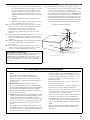 3
3
-
 4
4
-
 5
5
-
 6
6
-
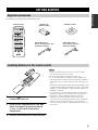 7
7
-
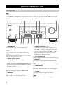 8
8
-
 9
9
-
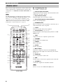 10
10
-
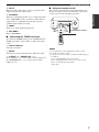 11
11
-
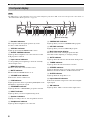 12
12
-
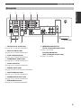 13
13
-
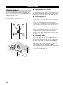 14
14
-
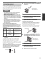 15
15
-
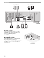 16
16
-
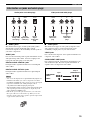 17
17
-
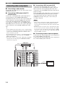 18
18
-
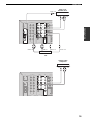 19
19
-
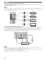 20
20
-
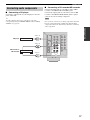 21
21
-
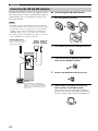 22
22
-
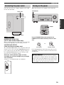 23
23
-
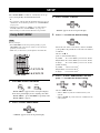 24
24
-
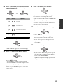 25
25
-
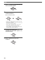 26
26
-
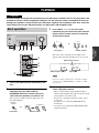 27
27
-
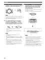 28
28
-
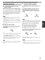 29
29
-
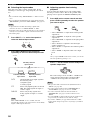 30
30
-
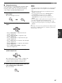 31
31
-
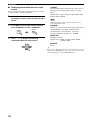 32
32
-
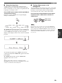 33
33
-
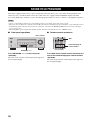 34
34
-
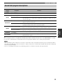 35
35
-
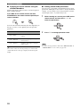 36
36
-
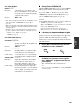 37
37
-
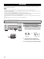 38
38
-
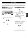 39
39
-
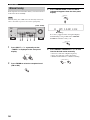 40
40
-
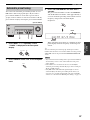 41
41
-
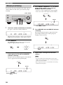 42
42
-
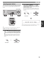 43
43
-
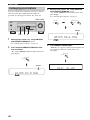 44
44
-
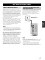 45
45
-
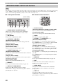 46
46
-
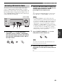 47
47
-
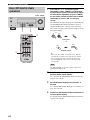 48
48
-
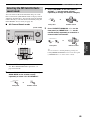 49
49
-
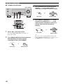 50
50
-
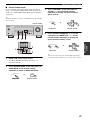 51
51
-
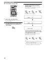 52
52
-
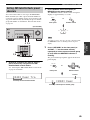 53
53
-
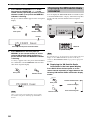 54
54
-
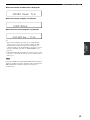 55
55
-
 56
56
-
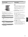 57
57
-
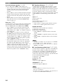 58
58
-
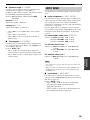 59
59
-
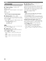 60
60
-
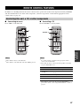 61
61
-
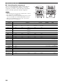 62
62
-
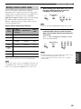 63
63
-
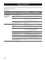 64
64
-
 65
65
-
 66
66
-
 67
67
-
 68
68
-
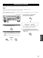 69
69
-
 70
70
-
 71
71
-
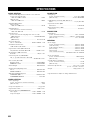 72
72
-
 73
73
-
 74
74


Yamaha HTR-5930 de handleiding
- Categorie
- AV-ontvangers
- Type
- de handleiding
- Deze handleiding is ook geschikt voor
in andere talen
- English: Yamaha HTR-5930 Owner's manual
- italiano: Yamaha HTR-5930 Manuale del proprietario
- русский: Yamaha HTR-5930 Инструкция по применению
- français: Yamaha HTR-5930 Le manuel du propriétaire
- español: Yamaha HTR-5930 El manual del propietario
- Deutsch: Yamaha HTR-5930 Bedienungsanleitung
- português: Yamaha HTR-5930 Manual do proprietário
- dansk: Yamaha HTR-5930 Brugervejledning
- suomi: Yamaha HTR-5930 Omistajan opas
- čeština: Yamaha HTR-5930 Návod k obsluze
- svenska: Yamaha HTR-5930 Bruksanvisning
- Türkçe: Yamaha HTR-5930 El kitabı
- polski: Yamaha HTR-5930 Instrukcja obsługi
- română: Yamaha HTR-5930 Manualul proprietarului