ESAB Aristo Retrofit I/O Interface Universal 255 Handleiding
- Categorie
- Lassysteem
- Type
- Handleiding
Deze handleiding is ook geschikt voor

NL
Valid for serial no. 222-xxx-xxxx0461 314 001 NL 20130531
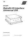
Aristo
Retrofit I/O Interface
Universal 255
Gebruiksaanwijzing

- 2 -

- 3 -
TOCh
Recht op wijzigingen zonder voorafgaande mededeling voorbehouden.
1 VEILIGHEID 4.......................................................
2 INLEIDING 6.........................................................
2.1 Apparatuur 6...............................................................
3 TECHNISCHE GEGEVENS 6..........................................
4 INSTALLATIE 6......................................................
4.1 Plaatsing 7.................................................................
4.2 Aansluitinstructies 8.........................................................
Overige 8........................................................................
5 BEDIENING 9........................................................
5.1 Aansluitingen en bedieningselementen 9.......................................
6 ONDERHOUD 10......................................................
6.1 Inspectie en reiniging 10......................................................
7 PROBLEMEN OPLOSSEN 10..........................................
8 RESERVEONDERDELEN BESTELLEN 10...............................
9 CONNECTION & FUNCTION DESCRIPTION OF I/O SIGNALS 11..........
9.1 Connection table for I/O signals on robot side 11.................................
9.2 Input data I/O signals from robot controller to welding equipment 13.................
9.3 Output data I/O signals from the welding equipment to the robot controller 15........
SCHEMA 16.............................................................
BESTELNUMMER 18.....................................................
ACCESSOIRES 19.......................................................

© ESAB AB 2013
- 4 -
br08d1h
1 VEILIGHEID
De gebruiker van een ESAB uitrusting draagt de uiteindelijke verantwoordelijkheid voor de veilig
heidsmaatregelen die van toepassing zijn voor het personeel dat met of in de buurt van de
installatie werkt. De veiligheidsmaatregelen moeten voldoen aan de eisen die aan dit type
uitrusting gesteld worden. De inhoud van deze aanbevelingen moet beschouwd worden als
een aanvulling op de normale regels die van toepassing zijn voor een werkplaats.
Alle handelingen moeten uitgevoerd worden door personeel dat goed op de hoogte is van de wer
king van de uitrusting. Een verkeerd maneuver kan tot een abnormale situatie leiden waardoor
de operateur gewond kan raken en de machine beschadigd kan worden.
1. Al het personeel dat met de machine werkt, moet goed op de hoogte zijn van:
S de bediening
S de plaats van de noodstop
S de werking
S de geldende veiligheidsvoorschriften
S de las- en snijtechniek
2. De operateur moet controleren:
S of er zich geen onbevoegden binnen het werkgebied van de lasuitrusting bevinden,
voor hij begint te werken.
S of er niemand op een onbeschermde plaats staat wanneer de lichtboog wordt ontsto
ken.
3. De werkplaats moet:
S doelmatig zijn
S tochtvrij zijn
4. Persoonlijke veiligheidsuitrusting
S Draag altijd de aanbevolen persoonlijke veiligheidsuitrusting, waaronder een veilig
heidsbril, niet-ontvlambare kleding en veiligheidshandschoenen.
S Draag nooit loszittende kleding zoals sjaals, armbanden, ringen e.d. die beklemd kun
nen raken, of brandwonden kunnen veroorzaken.
5. Algemene veiligheidsvoorschriften
S Controleer of de aangeduide retourleiders goed aangesloten zijn.
S Alleen bevoegd personeel mag aan de elektrische eenheden werken.
S De benodigde brandblusuitrusting moet gemakkelijk bereikbaar zijn op een duidelijk
aangegeven plaats.
S Wanneer de uitrusting in gebruik is, mag hij niet gesmeerd worden en mag er geen
onderhoud uitgevoerd worden.
NL

© ESAB AB 2013
- 5 -
br08d1h
WAARSCHUWING
Lees deze gebruiksaanwijzing grondig door voor u overgaat tot installatie en gebruik.
De vlamboog en het snijden kunnen gevaarlijk zijn voor uzelf en voor anderen; daarom met u
voorzichtig zijn bij het lassen en snijden. Volg de veiligheidsvoorschriften van uw werkgever
op. Ze moeten gebaseerd zijn op de waarschuwingstekst van de producent.
ELEKTRISCHE SCHOK - Kan dodelijk zijn
S Installeer en aard de uitrusting volgens de geldende normen.
S Raak delen die onder stroom staan en elektroden niet aan met onbedekte handen of met natte
beschermuitrusting.
S Zorg dat u geïsoleerd bent van aarde en van het werkstuk.
S Zorg ervoor dat u een veilige werkhouding hebt.
ROOK EN GAS - Kunnen uw gezondheid schaden
S Zorg ervoor dat u niet met uw gezicht in de rook hangt.
S Ververs regelmatig de lucht in de werkruimte en zorg ervoor dat de rook en het gas afgezogen
worden.
LICHTSTRALEN - Kunnen de ogen beschadigen en de huid verbranden
S Bescherm uw ogen en uw lichaam. Gebruik een geschikte lashelm met filter en draag altijd be
schermende kleding.
S Scherm uw werkruimte af met geschikte beschermmiddelen of gordijnen, zodat niemand anders
gewond kan raken.
BRANDGEVAAR
S De vonken kunnen brand veroorzaken. Zorg er daarom voor dat er geen brandgevaarlijk mate
riaal in de buurt is.
LAWAAI - Geluidsoverlast kan het gehoor beschadigen
S Bescherm uw oren. Gebruik gehoorbeschermers of andere gehoorbescherming.
S Waarschuw omstanders voor de gevaren.
BIJ DEFECTEN - Neem contact op met een vakman.
BESCHERM UZELF EN ANDEREN!
LET OP!
Lees deze gebruiksaanwijzing grondig door voor u
overgaat tot installatie en gebruik.
LET OP!
Dit product is uitsluitend bedoeld voor booglassen.
Breng afgedankte elektronische apparatuur naar een recyclestation!
In overeenstemming met de Europese richtlijn 2002/96/EG betreffende afgedankte
elektrische en elektronische apparatuur en de toepassing hiervan overeenkomstig
nationale regelgeving, moet elektrische en/of elektronische apparatuur aan het einde van
de levensduur naar een recyclestation worden gebracht.
Als verantwoordelijke voor de apparatuur moet u zelf informatie inwinnen over
goedgekeurde inzamelpunten.
Neem voor meer informatie contact op met de dichtstbijzijnde ESAB-dealer.
ESAB heeft alle benodigde lasbeschermingsvoorzieningen en accessoires
voor u.
NL

© ESAB AB 2013
- 6 -
br08d1h
2 INLEIDING
De Retrofit I/O Interface Universal 255 controleert de CAN-bussignalen,
converteert deze van de stroombron naar de lasrobot en wordt gebruikt voor
stroombronnen aangestuurd door een CAN-bus, zoals Mig 4000i of Mig 5000i met
U8
2
I/O.
De Retrofit I/O Interface Universal 255 converteert analoge en digitale signalen
naar veldbuscommunicatie (CAN) en van veldbussignalen naar digitale en analoge
signalen.
2.1 Apparatuur
De Retrofit I/O Interface Universal 255 wordt geleverd met een handleiding,
besturingskabel , 48-polige mofplug en 0-kabel die de interface en de robotkast met
elkaar verbindt.
ESAB heeft alle benodigde lasbeschermingsvoorzieningen en accessoires
voor u.
3 TECHNISCHE GEGEVENS
Retrofit I/O Interface Universal 255
Netspanning (van robot) 24 V DC
Zekering 1 A
Robotaansluiting 48-pens aansluiting
Gewicht 6,1 kg
Afmetingen (l x b x h) 365 x 351 x 110 mm
Beschermingsklasse IP23
Veiligheidsnorm
De IP-code geeft de beveiligingsklasse aan, d.w.z. de graad van bescherming tegen vaste voorwer
pen en vocht. Een apparaat met IP 23 is bestemd voor gebruik zowel binnen- als buitenshuis.
4 INSTALLATIE
De installatie dient door een bevoegd persoon te worden uitgevoerd.
LET OP!
Dit product is bestemd voor industrieel gebruik. In een woonomgeving kan dit product
radiostoring veroorzaken. Het is de verantwoordelijkheid van de gebruiker om
passende voorzorgsmaatregelen te nemen.
WAARSCHUWING!
Bij het lassen in een omgeving met verhoogd elektrisch gevaar, mogen
alleen stroombronnen die speciaal geschikt zijn voor dergelijke
omgevingen worden gebruikt. Deze stroombronnen zijn voorzien van het
symbool .
NL

© ESAB AB 2013
- 7 -
br08d1h
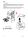
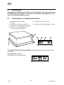
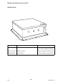
4.1 Plaatsing
De Retrofit I/O Interface Universal 255 wordt geïnstalleerd boven de stroombron.
Verwijder het rubberen matje (C) van de stroombron en schuif daarna de flens van
de interfacekast (A) in de zijprofielen (B) van de stroombron. Zie de afbeelding
hieronder.
BELANGRIJK! Draai de 3 schroeven aan de voorzijde van de interfacekast
voldoende stevig aan om er zeker van te zijn dat er een elektrische verbinding wordt
gemaakt. Controleer of de elektrische verbinding tot stand is gebracht.
NL

© ESAB AB 2013
- 8 -
br08d1h
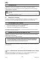
4.2 Aansluitinstructies
De volledige beschrijvingen van de stroombron/draadaanvoereenheid zijn te vinden
in de aparte handleidingen.
1 Aansluitkabels van de lasstroombron naar
de draadaanvoereenheid.
4 Aristo U8
2
2 CAN-busaansluiting (12-polige Burndy)
van de lasstroombron naar de I/O
Interface.
5 Aansluiting tussen stroombron en robot
kast (spanning kabel 0 V)
3 Besturingskabel tussen de Retrofit I/O
Interface Universal 255 en de robot
controller
Overige
0-kabel 6 mm
2
S De 0-kabel 6 mm
2
tussen de stroombron en de robotkast wordt geleverd in een lengte van
15 m en moet tijdens de installatie op de gewenste lengte worden gesneden.
Opstarttijd
S De opstarttijd van de interfacekast als de stroom/spanning is geactiveerd, kan maximaal 1
minuut worden vertraagd.
NL

© ESAB AB 2013
- 9 -
br08d1h
5 BEDIENING
De algemene veiligheidsvoorschriften voor het gebruik van de hier beschreven
uitrusting vindt u op pagina 4. Lees deze voorschriften zorgvuldig door, voor
dat u de uitrusting in gebruik neemt.
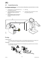
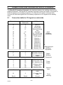
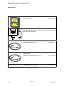
5.1 Aansluitingen en bedieningselementen
1 Indicatielampje (WIT), voeding
van robot.
3 Zekering / 1 A 24 VDC van robot
2 Aansluiting voor signalen naar/van de
lastoorts van de robot (48-polige connector)
4 Aansluiting voor reinigingsstation van toorts
5 Aansluiting voor bedieningskabel van
stroombron (12-pens CAN-bus)
De Retrofit I/O Interface Universal 255 wordt aangesloten op de robotkast en de
stroombron.
Het typeplaatje zit op de
achterzijde van de interfacekast.
NL

© ESAB AB 2013
- 10 -
br08d1h
6 ONDERHOUD
Regelmatig onderhoud is belangrijk voor een veilige, betrouwbare werking.
Alleen personen met de juiste elektrische kennis (bevoegd personeel) mogen de
veiligheidsplaten verwijderen.
LET OP!
Alle garantievoorwaarden van de leverancier komen te vervallen als de klant zelf tijdens
de garantieperiode reparaties uitvoert.
6.1 Inspectie en reiniging
Controleer regelmatig of de interfacekast een elektrische verbinding heeft met de
stroombron en of de aansluitingen goed zijn aangesloten en niet defect zijn.
7 PROBLEMEN OPLOSSEN
S Is het indicatielampje (wit) aan de voorzijde gedoofd?
Controleer of de zekering niet is doorgebrand.
S Controleer of de bedrading goed in de connectors zit.
De volledige beschrijvingen van de stroombron, de draadaanvoereenheid en het bedieningspaneel
zijn te vinden in de aparte handleidingen.
8 RESERVEONDERDELEN BESTELLEN
Reparaties en elektrisch onderhoud moeten worden uitgevoerd door een erkende
ESAB-onderhoudsmonteur.
Gebruik alleen originele ESAB-onderdelen.
Retrofit I/O Interface Universal 255 is zodanig geconstrueerd en getest dat deze vol
doet aan de internationale en europese norm 60974-1 en 60974-10. Na onderhoud-
of reparatiewerkzaamheden dient de uitvoerende instantie erop toe te zien dat het
product nog steeds voldoet aan de bovengenoemde norm.
Reserveonderdelen kunt u bestellen via de ESAB-dealer. Zie de laatste pagina van
deze publicatie.
* * *
LET OP! 9. BESCHRIJVING VAN AANSLUITING EN WERKING VAN I/O-SIGNA
LEN
is uitsluitend beschikbaar in het Engels en is in eerste instantie bedoeld voor de
integrator en de installatie van de interfacekast op pagina 11.
NL

- 11 -
br08d2e
9 CONNECTION & FUNCTION DESCRIPTION OF I/O SIGNALS
The Retrofit I/O Interface Universal is the interface between the welding robot and the
welding equipment. The Retrofit I/O Interface Universal converts the robot's I/O signals to
field bus signals to the welding equipment. The Retrofit I/O Interface Universal also
converts the field bus signals from the welding equipment to I/O signals to the welding
robot.
9.1 Connection table for I/O signals on robot side
Connection Cable number
Robot side
I/O Signals
H 8 Weld on
J 9 Gas purge
K 10 Inching wire
L 11 Reverse inching
wire
M 12 Air purge
N 13 0V = Quick stop
P 14 analogue active
R 15 Touch sense
S 16 Memory 1
T 17 Memory 2
U 18 Memory 4
V 19 Memory 8
X 21 Memory 16
W 20 Memory 32
Y 22 Memory 64
Z 23 Memory 128
E 5 Voltage reference
F 6 Wirefeed reference
G 7 0V reference to
robot
a 24 Arc acknow.
b 25 Touch sense resp.
c 26 0V = Machine error
d 27 Collision detect
e 28 Weld busy
f 29 Remote active
A 1 24V supply from
robot
B 2 0V supply from
robot
Shield Shield Ground
Input
Output
Power
General
Torch
Analogue
supply
Equipment
Equipment
cleaning
Input
stop
Equipment
Welding
Welding
Welding

- 12 -
br08d2e
v 30 G-Stop
u 31 G-Stop
p 32 G-Stop
q 33 G-Stop
g 34 Lubrication
h 35 Lubrication clea
ning
i 36 Lubrication finish

- 13 -
br08d2e
9.2 Input data I/O signals from robot controller to welding
equipment
Weld ON (Cable no 8)
The signal starts the welding process, but before the welding process starts the
quick stop and stop signals are checked to ensure that they are not active.
Quick stop (Cable no 13)
The signal stops the equipment if it is active in the welding process, it carries out a
normal stop without crater filling. The function is used when a quick stop (low signal
0V) is required but it gives a normal burnback time to prevent the wire sticking in the
weld pool. The signal also blocks the start command.
Wire inching (Cable no 10)
Used when one wants to feed wire without welding voltage.
The signal starts the wire feed without the welding voltage being activated. The wire
feed unit is ramping up the wire feed speed. If the signal is active during the welding
process, the command is ignored.
If both welding and wire inching are activated at the same time the equipment will
ignore the wire inching command and start the welding process.
Gas purge (Cable no 9)
Gas flushing is used when measuring the gas flow or to flush any air or moisture
from the gas hoses before welding starts. Gas flushing is carried out without voltage
or wire feed occurring.
Welding start always activates the gas valve even if the manual gas command is
given. In the same way the gas valve for gas post flow is always closed if it is not
closed already.
Gas flushing operates parallel to the gas pre-flow and gas post-flow functions. To
control the welding gas from the robot, set the gas pre-flow to minimum and the gas
post-flow to maximum, and then control the welding gas using the gas flushing
functions.
Air purge (Cable no 12)
The signal controls the valve for air cleaning welding spatter.
Touch sense (Cable no 15)
This command is used by the robot to sense where the wire is.
When the function is active, the power source will give out current limited, idle
voltage to see if the wire is in contact with the workpiece. On contact, the output
signal ”Touch sense response” is activated.

- 14 -
br08d2e
Analogue Active (Not availabe for the moment)
The signal is used to switch between the analogue and digital remote modes.
Analogue Active allows analogue control of the welding parameters, voltage, arc
voltage and the wire feed speed.
If the welding method SuperPulse is to be used, the ”analogue active” signal must be
deactivated.
When the analogue method is activated the power source will not use the preset
values for wire feed speed and voltage when new welding data is selected. When
”analogue active” is activated the robot controls arc voltage and wire feed speed
using analogue signals.
With the analogue active signal deactivated, welding data is exchanged with preset
welding data such as voltage, wire feed speed to fixed set welding parameters.
The pre-programmed welding data (schedules) is requested from the control box
U8
2
welding data memory.
Welding data (Memory) (Cable 16-23)
With the signals memory 1, 2, 4, 8, 15, 32, 64, 128 one accesses saved welding data
(schedules) in U8
2
I/O.
The binary coded combinations of these signals can be used to recall the memories
1-255 in the U8
2
I/O memory bank.
A complete set of welding data includes all settings that can be made in U8
2
I/O, see
the instruction manual for U8
2
.
Voltage reference (Cable no 5 - Not available at the moment)
This signal is used by the robot for analogue control of the welding voltage if
analogue active is selected. It stretches from 0-10V and corresponds to welding
voltage socket as follows.
0V reference gives a deviation on the selected arc voltage of -10V
10V reference gives a deviation on the selected arc voltage of +10V
If the machine is in non-synergy mode, the equipment will use the appreciated value.
0V reference gives arc voltage 8V
10V reference gives arc voltage 60V
Wire feed speed reference signal (Cable no 6 - Not available at the moment)
The signal is used by the robot to make analogue adjustments to the wire feed
speed. The internal solution is 0.1 m/min.
Input voltage
0 V Mini. value for wire feed (normally 0.8 m/min) (RoboFeed)
10 V Max. value for wire feed (normally 30 m /min)

- 15 -
br08d2e
9.3 Output data I/O signals from the welding equipment to the
robot controller
Arc acknowledge (Cable no 25)
The signal is activated after established welding start if the voltage and current
strength lie within weldable limits. The signal disappears if welding cannot be
established.
The criterion for establishing a welding arc is that the process control has passed the
start- procedure, which means that only a short circuit is not sufficient to meet the
criteria. Normal delay from the first contact, which is acknowledged by the welding
arc (wire feed time for this after the first contact is established ) is in the range of 2 to
20 ms. If there is a poor start to the welding arc the ”Arc acknowledge” is further
delayed.
Touch sense response (Cable no 26)
This signal indicates contact in the welding circuit, i.e. that the wire is in contact with
the workpiece. To obtain ”touch sense response” the ”touch sense” input signal must
be activated.
Collision detect (Cable no 26)
The signal comes via the internal CAN bus from the feeding mechanism (RoboFeed).
The signal indicates that the robot's breaker has activated. The interface activates a
relay which breaks two safety loops from the robot, at which the robot orders a quick
stop of both robot and the welding equipment.
The output is high when the welding gun breaker is tripped (the signal is sent to the
robot).
Machine error (Cable no 27)
The signal is low (0V) when an error has been detected in the welding equipment.
Weld busy (Cable no 28)
This signal indicates when the welding equipment is occupied with welding. The
signal can be configurated in the U82 I/O configuration menu.
Remote active (Cable no 29)
Remote active is activated when remote is chosen in U8
2
.
General stop (Cable no 30-33)
Can be used as an electrical stop, to stop the servo motors on the robot, when
collision detect signal is low (0V).

© ESAB AB 2013
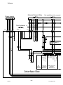
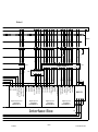
Schema
Com 0V
Com 0V
Wire 0-10V
Voltage 0-10V
0V
CAN HIGH
CAN LOW
24VR
0VR
24VR
0VR
Reserve
Reserve
Remote Active
Weld Busy
Filter board 1
Digital output from
equipment
Bus
resistor
External General Stop
Torch cleaner
C1
D
XS04
24VR
E
0VR
C B A
X1
X2
HL1
024023
3
4
R2
026025
5
6
A1
A2
R1
414
154
KL3062
101
603
102
505
103
401
XP01
A
X5
3
X5
1 2
B K L E G
i
XS03
h g G F E
45
J4
6
J1
1 2 3
53 17
KL9010
Power source
A
XS01
B K L E G
4
XP03
i h g v u p q
v u p q
224 223 221
222114
201
A1
A2
R2
022
G F E
W1
33323130
567
343536
KL2134:2
14 583276
612
711
815
27
d
d
315
613
712
415
615
614
714
713
X6
1 2 3 4
616
715
X7
1
2
Analog input
to equipment
Interface Box
Not available at the moment
- 16 -
br08dia

© ESAB AB 2013
24VR
0VR
24VR
0VR
Collision Detect
Machine Error=0V
Tourch Sense R.
Arc Acknowledge
Memory 8
Memory 4
Memory 2
Memory 1
Wire Feeder
Reserve
Reserve
Tourche Sense
Reserv
Analog Active
Quick Stop
Air Purque
Reverse Wire
Inching
Gas Purge
Weld On
0V
CAN LOW
CAN HIGH
Memory 128
Memory 64
Memory 32
Memory 16
Reserve
Reserve
Reserve
Reserve
Filter board 2
Filter board 1
Digital input to
equipment
Digital input to
equipment
Digital input to
equipment
Digital output from
equipment
Robot
AP1
KL2134:1
104
304
105205
106
1001
KL1408:2
001
1808
002
1704
003
1607
004
1503
008
1101
KL1408:1
111
3
4
R1
011807
012
703
014
502
015405
016
301
BK5151
017
200
218
A1
A2
FU1
1A
018
124
c b a V U T S R N M K J H B A
123
J5
18 17 16 15 14 13 12 11 10 9 8 7 6 5 4 3
J6
2 1
4 5 6
J2
1 2 3 4 5 6 7 8 9 10 11 12 13 14 15 16
J3
2 1
-+
24
V
0
V
12 56374812 56374814 583276
W2
4 3 1
Interface Box
7 2 3
N M K J H B Ac b a V U T S R
16171819
242526
606
904
15
13 12 10 9
8
2
1
14
11
LP
LP
010
013
28
e
e
29
f
f
005
1405
220302
12 563748
KL1408:3
AP1
AP2
J2
1
5
1
6
1
7
1
8
J5
4 3 2 1
Z Y X
Z Y X
212223 20
W
W
1504
1603
1701
1801
1806
1702
1605
1501
202
203
Shield
- 17 -
br08dia

Retrofit I/O Interface Universal 255
© ESAB AB 2013
Bestelnummer
- 18 -
br08o
Ordering no. Denomination Notes
0461 090 884 Retrofit I/O Interface Universal 255 Includes the Control cables, see on
page 19 and a Instruction manual.
0461 314 001 Instruction manual Retrofit I/O Interface Universal 255
0459 839 091 Spare parts list Retrofit I/O Interface Universal 255

Retrofit I/O Interface Universal 255
© ESAB AB 2013
Accessoires
- 19 -
br08acc
Aristo
[
U8
2+
I/O ........................... 0460 820 883
Rebuilding kit Incl. Adapter (12 pole to 10 pole) .
Mig 4002, 5002 and 6502
0461 322 880
Extension cable (U8
2
, 7,5 m) ................. 0460 877 891
Control cable
Retrofit I/O to power source (1,7 m) ........... 0461 319 880 *
Control cable (7,5 m, 48-pole) ................. 0461 321 880
* Included in 0461 090 884 Retrofit I/O Interface Universal 255

www.esab.com
110915© ESAB AB
ESAB subsidiaries and representative offices
Europe
AUSTRIA
ESAB Ges.m.b.H
Vienna-Liesing
Tel: +43 1 888 25 11
Fax: +43 1 888 25 11 85
BELGIUM
S.A. ESAB N.V.
Heist-op-den-Berg
Tel: +32 70 233 075
Fax: +32 15 257 944
BULGARIA
ESAB Kft Representative Office
Sofia
Tel/Fax: +359 2 974 42 88
THE CZECH REPUBLIC
ESAB VAMBERK s.r.o.
Vamberk
Tel: +420 2 819 40 885
Fax: +420 2 819 40 120
DENMARK
Aktieselskabet ESAB
Herlev
Tel: +45 36 30 01 11
Fax: +45 36 30 40 03
FINLAND
ESAB Oy
Helsinki
Tel: +358 9 547 761
Fax: +358 9 547 77 71
FRANCE
ESAB France S.A.
Cergy Pontoise
Tel: +33 1 30 75 55 00
Fax: +33 1 30 75 55 24
GERMANY
ESAB GmbH
Solingen
Tel: +49 212 298 0
Fax: +49 212 298 218
GREAT BRITAIN
ESAB Group (UK) Ltd
Waltham Cross
Tel: +44 1992 76 85 15
Fax: +44 1992 71 58 03
ESAB Automation Ltd
Andover
Tel: +44 1264 33 22 33
Fax: +44 1264 33 20 74
HUNGARY
ESAB Kft
Budapest
Tel: +36 1 20 44 182
Fax: +36 1 20 44 186
ITALY
ESAB Saldatura S.p.A.
Bareggio (Mi)
Tel: +39 02 97 96 8.1
Fax: +39 02 97 96 87 01
THE NETHERLANDS
ESAB Nederland B.V.
Amersfoort
Tel: +31 33 422 35 55
Fax: +31 33 422 35 44
NORWAY
AS ESAB
Larvik
Tel: +47 33 12 10 00
Fax: +47 33 11 52 03
POLAND
ESAB Sp.zo.o.
Katowice
Tel: +48 32 351 11 00
Fax: +48 32 351 11 20
PORTUGAL
ESAB Lda
Lisbon
Tel: +351 8 310 960
Fax: +351 1 859 1277
ROMANIA
ESAB Romania Trading SRL
Bucharest
Tel: +40 316 900 600
Fax: +40 316 900 601
RUSSIA
LLC ESAB
Moscow
Tel: +7 (495) 663 20 08
Fax: +7 (495) 663 20 09
SLOVAKIA
ESAB Slovakia s.r.o.
Bratislava
Tel: +421 7 44 88 24 26
Fax: +421 7 44 88 87 41
SPAIN
ESAB Ibérica S.A.
Alcalá de Henares (MADRID)
Tel: +34 91 878 3600
Fax: +34 91 802 3461
SWEDEN
ESAB Sverige AB
Gothenburg
Tel: +46 31 50 95 00
Fax: +46 31 50 92 22
ESAB international AB
Gothenburg
Tel: +46 31 50 90 00
Fax: +46 31 50 93 60
SWITZERLAND
ESAB AG
Dietikon
Tel: +41 1 741 25 25
Fax: +41 1 740 30 55
UKRAINE
ESAB Ukraine LLC
Kiev
Tel: +38 (044) 501 23 24
Fax: +38 (044) 575 21 88
North and South America
ARGENTINA
CONARCO
Buenos Aires
Tel: +54 11 4 753 4039
Fax: +54 11 4 753 6313
BRAZIL
ESAB S.A.
Contagem-MG
Tel: +55 31 2191 4333
Fax: +55 31 2191 4440
CANADA
ESAB Group Canada Inc.
Missisauga, Ontario
Tel: +1 905 670 02 20
Fax: +1 905 670 48 79
MEXICO
ESAB Mexico S.A.
Monterrey
Tel: +52 8 350 5959
Fax: +52 8 350 7554
USA
ESAB Welding & Cutting Products
Florence, SC
Tel: +1 843 669 44 11
Fax: +1 843 664 57 48
Asia/Pacific
AUSTRALIA
ESAB South Pacific
Archerfield BC QLD 4108
Tel: +61 1300 372 228
Fax: +61 7 3711 2328
CHINA
Shanghai ESAB A/P
Shanghai
Tel: +86 21 2326 3000
Fax: +86 21 6566 6622
INDIA
ESAB India Ltd
Calcutta
Tel: +91 33 478 45 17
Fax: +91 33 468 18 80
INDONESIA
P.T. ESABindo Pratama
Jakarta
Tel: +62 21 460 0188
Fax: +62 21 461 2929
JAPAN
ESAB Japan
Tokyo
Tel: +81 45 670 7073
Fax: +81 45 670 7001
MALAYSIA
ESAB (Malaysia) Snd Bhd
USJ
Tel: +603 8023 7835
Fax: +603 8023 0225
SINGAPORE
ESAB Asia/Pacific Pte Ltd
Singapore
Tel: +65 6861 43 22
Fax: +65 6861 31 95
SOUTH KOREA
ESAB SeAH Corporation
Kyungnam
Tel: +82 55 269 8170
Fax: +82 55 289 8864
UNITED ARAB EMIRATES
ESAB Middle East FZE
Dubai
Tel: +971 4 887 21 11
Fax: +971 4 887 22 63
Africa
EGYPT
ESAB Egypt
Dokki-Cairo
Tel: +20 2 390 96 69
Fax: +20 2 393 32 13
SOUTH AFRICA
ESAB Africa Welding & Cutting Ltd
Durbanvill 7570 - Cape Town
Tel: +27 (0)21 975 8924
Distributors
For addresses and phone
numbers to our distributors in
other countries, please visit our
home page
www.esab.com
-
 1
1
-
 2
2
-
 3
3
-
 4
4
-
 5
5
-
 6
6
-
 7
7
-
 8
8
-
 9
9
-
 10
10
-
 11
11
-
 12
12
-
 13
13
-
 14
14
-
 15
15
-
 16
16
-
 17
17
-
 18
18
-
 19
19
-
 20
20


ESAB Aristo Retrofit I/O Interface Universal 255 Handleiding
- Categorie
- Lassysteem
- Type
- Handleiding
- Deze handleiding is ook geschikt voor
in andere talen
Gerelateerde papieren
-
ESAB Retrofit I/O Interface Robot S3 A350 - Aristo® For ABB Handleiding
-
ESAB Retrofit I/O Interface Motoman – Aristo® - For Motoman Handleiding
-
ESAB Retrofit Mig 4004i WeldCloud™ Handleiding
-
ESAB Mig 4004i Pulse Handleiding
-
-
-
-
ESAB U82 Aristo Handleiding
-
-
ESAB U82 Handleiding