
0DT872 • Rev. 01-12-2021
www.ditecdoor.com
Handleiding voor installatie, onderhoud, gebruik
(Vertaling)
Installation manual, maintenance, use.
(Translation)
NL
EN
Ditec Soft Reset Food

- 2 -
0DT872 01-12-2021
INHOUDSOPGAVE VAN DE ONDERWERPEN
Hoofdst. Onderwerp ............................................................................................................................ Pag.
1. ALGEMENE WAARSCHUWINGEN M.B.T. DE VEILIGHEID ..................................................... 2
2. TECHNISCHE KENMERKEN ..................................................................................................... 3
3. MECHANISCHE INSTALLATIE
3.1 Controles van de doorgangsruimte ......................................................................................... 4
3.2 Montage op de vloer ............................................................................................................... 4
3.3 Bevestiging deur ..................................................................................................................... 4
3.4 Reductiemotor K22 ................................................................................................................. 4
3.5 Installatie van de veiligheidsinrichting SLE (lineaire encoder) ................................................ 4
3.6 Positionering van het doek ...................................................................................................... 4
3.7 Bevestiging carter stijl ............................................................................................................. 4
3.8 Bevestiging motorcarter en cover aanslag tegengestelde zijde .............................................. 4
3.9 Bevestiging cover bak ............................................................................................................. 4
4. ELEKTRISCHE AANSLUITINGEN
4.1 aansluiting motor ..................................................................................................................... 5
4.2 SLE-verbinding (primaire veiligheid) ....................................................................................... 6
4.3 aansluitingen op de bedieningskaart ...................................................................................... 6
5. ELEKTRONISCH BEDIENINGSPANEEL
5.2 52E (inverter) - aansluitingen .................................................................................................. 7
6. MENU PROGRAMMAZIONE
6.1 Menu di installazione ............................................................................................................ 12
6.2 Menu avanzato ..................................................................................................................... 13
6.3 Menu opening met timer ....................................................................................................... 14
6.4 Menu service ......................................................................................................................... 15
6.5 Messaggi display .................................................................................................................. 15
6.6 Interblocco ............................................................................................................................ 15
7. INSTELLINGEN EN START
7.1 Regeling van de veiligheidsinrichting SLE (lineaire encoder) ............................................... 16
8. OPSPOREN VAN STORINGEN ................................................................................................. 17
9. ONDERHOUDSSCHEMA ......................................................................................................... 18
Alle rechten voorbehouden
Alle gegevens en specicaties werden met grote zorg opgesteld en gecontroleerd. De fabrikant is echter niet aansprakelijk voor
eventuele vergissingen, weglatingen of onvolledige gegevens te wijten aan technische redenen of redenen in verband met illustraties.
Optioneel accessoire
1. ALGEMENE WAARSCHUWINGEN M.B.T. DE VEILIGHEID
Deze installatiehandleiding is uitsluitend bedoeld voor
vakkundig competent personeel.
De installatie, de elektrische aansluitingen en de afstellingen
moeten uitgevoerd worden met inachtneming van Goed
Vakmanschap en de geldende voorschriften.
Lees de instructies aandacht voordat u begint met de installatie
van het product. Een onjuiste installatie kan een bron van gevaar
vormen. De verpakkingsmaterialen (kunststof, polystyrol, enz.)
mogen niet in het milieu worden achtergelaten en moeten buiten
bereik van kinderen worden gehouden aangezien deze een
mogelijke bron van gevaar kunnen zijn.
Controleer, voor de installatie, of het product intact is. Installeer
het product niet in een explosieve omgeving en atmosfeer:
aanwezigheid van gas of ontvlambare dampen vormen een
groot gevaar voor de veiligheid. Voordat u de deur installeert,
alle structurele wijzigingen met betrekking tot een veilige
doorgang en de bescherming of afscherming van alle gebieden
waar risico bestaat van beknelling, het afsnijden of meesleuren
van ledematen en gevaar in het algemeen.
Controleer of de bestaande structuur voldoet aan de
noodzakelijke vereisten voor stevigheid en stabiliteit. De
veiligheidsvoorzieningen (fotocellen, gevoelige randen,
noodstop, enz.) moeten geïnstalleerd worden rekening houdend
met: de geldende voorschriften en richtlijnen, de criteria van
Goed Vakmanschap, de installatie-omgeving, de werkingslogica
van het systeem en de krachten die ontwikkeld worden door
gemotoriseerde deuren of hekken.
De veiligheidsvoorzieningen moeten eventuele gebieden van
de deur beschermen waar risico op beknelling, het afsnijden
of afrukken van ledematen en gevaar in het algemeen bestaat.
Bevestig de waarschuwingen die door de geldende voorschriften
voorzien zijn om de gevaarlijke zones aan te geven.
Bij elke installatie moet de indicatie van de identifcatiegegevens
van de deur zichtbaar blijven.
Voordat de elektrische voeding wordt aangesloten
moet u zich ervan verzekeren dat de gegevens op
het plaatje overeenkomen met die van het elektriciteitsnet.
Zorg op het voedingsnet voor een omnipolaire schakelaar/
scheidingsvoorziening met een opening tussen de contacten
van 3 mm of meer. Controleer of er bovenstrooms van de
elektrische installatie een geschikte dierentieelschakelaar en
een beveiliging tegen overspanning. Sluit de deur aan op een
eectieve aardingsinstallatie uitgevoerd volgens de geldende
veiligheidsvoorschriften. De fabrikant van de deur wijst elke
aansprakelijkheid af als bestanddelen worden geïnstalleerd
die niet compatibel zijn wat veiligheid en goede werking betreft
of als wijzigingen van eender welke aard worden uitgevoerd
zonder de specieke toesteming van de fabrikant zelf. Voor
de eventuele reparatie of vervanging van onderdelen mogen
uitsluitend orginele Ditec vervangingsonderdelen gebruikt
worden. De installateur moet alle informatie verschaen met
betrekking tot de automatische en handmatige werking en
de noodbediening van de gemotoriseerde deur of hek, en
de gebruiker van het systeem de gebruiksaanwijzing geven.
Safety Top
TSafety Top L
T L

- 3 - 0DT872 01-12-2021
2. TECHNISCHE KENMERKEN
ELEKTRONISCH PANEEL 52E (INVERTER)
Voedingsspanning ............................................................................................................................ 230 V eenfase 50/60 Hz
Dimensionering lijn .......................................................................................................................................................16 A
Voeding hulpbedieningselementen.............................................................................................................................24V
Vermogen motor ...........................................................................................................................................................0,6 KW
Beschermingsgraad bedieningspaneel ........................................................................................................................... IP 66
Bedrijfstemperatuur ................................................................................................................................................- 5 + 50 °C
Ref. Beschrijving
1Zijaanslagen
2Bak
3Oprolas
4SLE (lineaire encoder)
5Geleider in polizene bovenste deel
6Geleider in polizene onderste deel
7Steun voor bevestiging van geleider
8Verticaal hoekproel
9Steunveer van geleider
10 Bevestigingsschroef van geleider
11 Afdekplaat van stijl
Ref. Beschrijving
12 Reductiemotor K22
13 Inrichting voor handmatige manoeuvre
14 Stang voor handmatige manoeuvre
15 Elektronisch bedieningspaneel
16 Fotocel
17 Doek in polyester
18 Raam in transparant PVC
19 Verticale versterkingsstroken
20 Onderste rand met zand als tegengewicht
21 Motorcarter en aanslag tegengestelde zijde motor
Zorg voor geleiders met de juiste doorsnede: houd rekening met de vermelde stroomopname en met de lengte en de
ligging van de kabels.
7
5
4
6
8
10
9
16
1
21
5
6
8
3
18
17
20
19
11
2
1
12
13
21
14
15
NL

- 4 -
0DT872 01-12-2021
3. MECHANISCHE INSTALLATIE
Zie de tekeningen van de mechanische installatie op pagina 23 - 24 -25 - 26 (uit te nemen blad in het midden)
3.1 Controles van de doorgangsruimte (g.1).
• Controleer de afmetingen van de ruimte en of ze overeenkomen met de maten van de geleverde deur, rekening houdend
met eventuele noodzakelijke tolerantie indien de installatie binnen de spanwijdte plaats moet vinden.
• Controleer of er geen obstakels zijn die de montage van de structuur belemmeren.
• Verzeker u ervan dat de steunvlakken waterpas zijn en pas deze eventueel aan met behulp van geschikte wiggen.
• Controleer de stevigheid van de structuur van de ruimte: er moet een veilige verankering gegarandeerd worden met behulp
van beugels of pluggen. In geval van onvoldoende of twijfelachtige stevigheid moet er gezorgd worden voor een geschikte
zelfdragende metalen structuur.
3.2 Montage op de vloer (g.2)
• Leg de bak en de stijlen op de grond, bevestig de stijlen op de bak met behulp van zelfborgende moeren M8 (A) via de
geschroefdrade inzetstukken (B) die aanwezig zijn op de aanslagen.
3.3 Bevestiging deur (g.4)
• Til de deur verticaal op en zet ze tegen de muurruimte (g.3)
• Plaats de verticale stijlen loodrecht en bevestig ze op de gemerkte plekken (C). Maat van de pluggen M8 (D).
• Boor op de centrale as van het sleufgat (C)
• Controleer of de montage rechthoekig is en meet daarvoor de diagonalen.
3.4 Reductiemotor K22 (g.5)
• Regel de buers (E) om de motor verticaal te stellen (de buers moeten lichtjes op de achterwand drukken).
• Blokkeer de buer met behulp van de contramoer (F) nadat de regeling is uitgevoerd.
Handmatig manoeuvre (indien voorzien), breng de inrichting aan volgens de aanwijzingen op (g.6).
Sluit het veiligheidsmicrocontact aan volgens het betreende schema en controleer of het correct werkt: het microcontact
dient de rotatie van de motor bij het inschakelen van de handmatige manoeuvre te blokkeren.
3.5 Installatie van de veiligheidsinrichting SLE (lineaire encoder)
• De SLE-inrichting moet op de schuifgeleider van de exibele deur bevestigd worden aan de motorzijde, zoals is aangeduid
in (g.7), en moet verbonden worden zoals is aangeduid in hoofdstuk 5.
3.6 Positionering van het doek
• Zet de bovenste delen van de geleiders (G) dicht bij elkaar, gebruik een hefboom aan de buitenkant (g.8).
• Breng elk bevestigingselement van de doek (H) aan in zijn geleider; verwijder, om de werkzaamheid gemakkelijker uit te
voeren, de eerste schroef met buer (I).
• Wikkel het doek zodanig af dat de onderste rand zich een halve meter onder de opening voor het inbrengen van het doek
bevindt (g.8).
3.7 Bevestiging carter stijl
• In geval van een verzinkte deur moeten de carters tegen de lip (1) van de stijl gelegd worden en moeten ze op de lip (2)
(g.9A) zelf met een klik gesloten worden.
• In geval van een deur van roestvrij staal moeten de covers bevestigd worden met schroeven M4 (g.9B).
3.8 Bevestiging motorcarter en cover aanslag tegengestelde zijde
• Bevestig de motorcarter bovenaan op de aanslag met schroeven M6 (L), en zijdelings met schroeven M8 (M) (g. 10).
• Bevestig de cover van de aanslag met schroeven M6x16 (O) (g.11).
3.9 Bevestiging cover bak
• Bevestig de cover van de bak met schroeven M6x16(N) (g.11).

- 5 - 0DT872 01-12-2021
M
3 ~
140
0
U
V
W
9029
4327
Ø9
12
13
4. ELEKTRISCHE AANSLUITINGEN
De meegeleverde bekabeling voorziet niet in een tussenliggende connector, maar ze verbinden elk apparaat rechtstreeks
met de besturingskaart.
4.1. AANSLUITING MOTOR
KANT BESTURINGSKAART: steek de twee kabels voor motor en rem (code 9635) door de kabelwartels 4 en 3 (g.11).
Steek de thermische beschermingskabel door de kabelwartel 7. Monteer de connectoren op de besturingskaart zoals
aangegeven in par. 5.1.
KANT MOTOR: open de aansluitdoos, ontkoppel en verwijder de kabels 4327 en 9029 (g. 12). Boor een gat Ø9 in de doos
(g. 13) en plaats de doorvoertule, aanwezig op de bekabeling 9634. Plaats de bekabeling 9634 en 9635 en sluit ze aan
op de terminals zoals weergegeven in par. 5.1. Sluit de kabel met ringmoer aan op de encoder (g.14).
1 2 3 4
5 6 7 8
11
Blauw
Zwart
Grijs
Wit
Rood
Geel/Groen
Zwart
Bruin
Verbinding
verbreken
14
Motor (9635)
Rem (9635)
Thermische bescherming (9634)
NL

- 6 -
0DT872 01-12-2021
SLE
Tx Rx
ENC
9634
230 V
9635
9635
8457
230V
1 2 3 4
5 6 7 8
9016 8457
15
16
Grijs Zwart
4.3. AANSLUITINGEN OP DE BEDIENINGSKAART
Steek de bekabeling door de relevante kabelwartels:
- Encoder - kabelwartel 1
- SLE (8457) - kabelwartel 2
- Fotocellen - kabelwartels 5 and 6
- Voeding (niet meegeleverd) - kabelwartel 8
Sluit alle bekabeling aan op de besturingskaart zoals getoond in par. 5.1.
In het geval dat de deur wordt gewassen, verdient het de voorkeur om de kabels niet in gesloten kabelgoten (pijpen
of andere) te steken om waterstagnatie te voorkomen, maar om open beugels te bieden om de kabels vast te maken.
Figuur 16 toont schematisch de geleverde bedrading en hun positionering.
4.2 SLE-VERBINDING (PRIMAIRE VEILIGHEID)
Koppel de bekabeling 9016 los en verwijder deze uit de SLE. Plaats de bekabeling 8457 en plaats de connector op de
SLE-printplaat (g. 15).
Motor (9635)
Rem (9635)
SLE (8457)
Encoder
Fotocel RX
Fotocel TX
Thermische bescherming (9634)
Voeding 230V
Zorg voor geleiders met de juiste doorsnede: houd rekening met de vermelde stroomopname en met de lengte en de
ligging van de kabels.

- 7 - 0DT872 01-12-2021
5.1 ELEKTRONISCH BEDIENINGSPANEEL 52E (INVERTER) - Aansluitingen
INGANGEN
Bediening Functie Beschrijving
1 2 N.G. STOP Als op het programmeermenu (pag.15 punt 16)
het contact 1-2 vrijgegeven is, hoort bij de opening van het contact ook de
STOP van de deur
1 3 N.O. Openen De sluiting van het contact activeert het openen.
1 4 N.O. Sluiting De sluiting van het contact activeert het sluiten.
41 40 N.G. Veiligheid bij
omkering
De opening van het veiligheidscontact veroorzaakt de omkering van de
beweging (heropening) tijdens de sluitingsfase.
1 8 N.G. Veiligheid bij
omkering
De opening van het veiligheidscontact veroorzaakt de omkering van de
beweging (heropening) tijdens de sluitingsfase.
1 20 N.O. Gedeeltelijke
opening
De sluiting van het contact activeert een gedeeltelijke opening waarvan de
duur ingesteld wordt met het geavanceerde menu.
1 11 N.G. Sluitstand De opening van het contact geeft de sluitstand aan. (max. 50 mA)
1 13 N.G. Openingsstand De opening van het contact geeft de openingsstand aan. (max. 50 mA)
1 9 N.G. Met bediener Via keuzeschakelaar
UITGANGEN
Uitgang Waarde Beschrijving
1
0
+
-24 V= / 0,5 A
Voeding hulpstukken.
Uitgang voor voeding van externe hulpstukken, lampen voor staat van auto-
maat inbegrepen.
LAMP 230 V~
Knipperlicht (FML).
Niet-intermitterend signaal (jumper ON op FML).
Wordt geactiveerd tijdens het openen en sluiten.
-F +F 200 V= / 0,2 A
Elektrische rem van motor.
De uitgang is actief de gehele duur van de beweging zowel in opening als in
sluiting.
U W V
M
3 ~
230 V~ / 6 A Driefasemotor.
M2 Veiligheid / Bedieningen
M3 Signaal positie
M4 Vergrendeling
M4A Terug
M5 Motor / Motorrem
M6 Thermische beveiliging motor
M7 Absolute encoder
J4 Remweerstand
OPEN Hulpkaart schakelbord
VEILIGHEID Hulpkaart veiligheid
CONNECTOREN OP SCHAKELBORD
52E NL

- 8 -
0DT872 01-12-2021
P5 P3 P4P1 P2
41 40 20 9 8 4 3 2 1 1 0 LAMP111 12 13
ON
OFF 1 2 3 4 5 6 7 8
DL
23456 7
DL
M7
M4A
M5
M6
M3
BACK
M4
1 IN NC C NO
M2
J4
15
S3 S4
S5 S2
SAFETY OPEN
F2F1
230 V
50/60 Hz
GND
L N
K22
M
3 ~
140
+F -F U V W
ENCODER
0 11
41 FC FA OUT
R1
1
ON
PWR SA
23 4
SLE
8457
0
U
V
W
9635
9635
9635
9634
9635
Rx
Tx
115876
115877
1 2 3 4
5 6 7 8
Rem
Wit
Geel
Groen
Bruin
Blauw
Zwart
Zwart
Blauw
Blauw
Zwart
STOP
Grijs
Wit
Rood
Geel/Groen
Zwart
Bruin
T
Zwart (Niet verbonden)
Bruin
Blauw
Zwart
Bruin
Blauw
Rood
Blauw
Geel
Groen
Roze
Wit
Bruin
Grijs
Roze
Wit
Groen
Grijs
Geel
Blauw
Bruin
Rood
52E
Motor (9635)
Rem (9635)
SLE (8457)
Encoder
Fotocel RX
Fotocel TX
Thermische bescherming
(9634)
Voeding 230V
Het loskoppelen van de bedrading van de absolute encoder
veroorzaakt de reset van de posities van de eindschakelaars.

- 9 - 0DT872 01-12-2021
P5 P3 P4P1 P2
41 40 20 9 8 4 3 2 1 1 0 LAMP111 12 13
ON
OFF 1 2 3 4 5 6 7 8
DL
23456 7
DL
M7
M4A
M5
M6
M3
BACK
M4
1 IN NC C NO
M2
J4
15
S3 S4
S5 S2
SAFETY OPEN
F2F1
230 V
50/60 Hz
GND
L N
K22
M
3 ~
140
+F -F U V W
ENCODER
0
U
V
W
9635
9635
9635
9634
9635
0 11
41 FC FA OUT
R1
1
ON
PWR SA
23 4
SLE
8457
1 2 3 4
5 6 7 8
RX TX
Rem
Wit
Geel
Groen
Bruin
Blauw
Zwart
Zwart
Blauw
Blauw
Zwart
STOP
Grijs
Wit
Rood
Geel/Groen
Zwart
Bruin
Rood
Blauw
Geel
Groen
Roze
Wit
Bruin
Grijs
Roze
Wit
Groen
Grijs
Geel
Blauw
Bruin
Rood
52E
Motor (9635)
Rem (9635)
SLE (8457)
Encoder
Fotocel RX
Fotocel TX
Thermische bescherming
(9634)
Voeding 230V
Het loskoppelen van de bedrading van de absolute encoder
veroorzaakt de reset van de posities van de eindschakelaars.
Geel (Niet verbonden)
Zwart
Bruin
Wit
Grijs
Blauw
E5BFSY10B
(TOPL)
LT
Knip de connector door en sluit
de draden aan op de terminals
op de besturingskaart
NL

- 10 -
0DT872 01-12-2021
Dip - schakelaar
Beschrijving OFF ON
DIP 1 Later gebruik – –
DIP 2 Toegang tot geavanceerd menu Uitgeschakeld. Vrijgegeven.
DIP 3 Vrijgave van trimmers Uitgeschakeld. Vrijgegeven.
DIP 4 Meter
TOT: Aantal bewegingen
SVC: Bewegingen niet uitgevoerd tijdens bediening
Uitgeschakeld. Vrijgegeven.
DIP 5 Toegang tot bedieningsmenu Uitgeschakeld. Vrijgegeven.
DIP 6
Inrichting voor weergave van gegevens i.v.m.
werking van deur
(F. bedrijf, S. bus, S. piek, S. bus)
Uitgeschakeld. Vrijgegeven.
DIP 7 Later gebruik – –
DIP 8 Menu cyclische werking Uitgeschakeld. Vrijgegeven.
LED Brandt
DL2 Sluitstand
DL3 Vertraging
DL6 Gedeeltelijke opening
DL7 Openingsstand
DL15 Automatische start
Drukknoppen Beschrijving
S2 GEBRUIKT VOOR PROGRAMMERING
S3 NIET GEBRUIKT
S4 NIET GEBRUIKT
S5 GEBRUIKT VOOR PROGRAMMERING
Werking
Standaard
Werking
Programmering
Drukknop LED Drukknop
Activeert het
openen.
- De brandende groene led geeft de aanwezigheid van de
24 V= voeding aan. Scrollen van menu
Activeert het
gedeeltelijk openen. Bevestigt
Schakelt de STOP-
functie in en uit.
- De brandende rode led geeft de activering van de STOP aan.
- De knipperende rode led geeft de activering van de
beveiligingen aan.
- De kort knipperende rode led geeft aan dat de
bedieningsdrempelwaarde bereikt is
Activeert het sluiten. Scrollen van menu
ON
REGELINGEN EN MELDINGEN
52E
Trimmer Beschrijving
P1 - P2 - P3 - P4
NIET GEBRUIKT
P5 Regeling van displaycontrast.
0 s 30 s
0 MAX

- 11 - 0DT872 01-12-2021
ZEKERINGEN
ID Waarden Afmetingen Circuit
F1 - F2 12A - 500V 10.3 x 38 Eenfaseleiding
COMMANDO AANTEKENINGEN
Openingsstand op 200 mm van de dwarsbalk
Gedeeltelijke openingsstand van 200 mm van de vloer tot
de positie van de opening
Sluitstand op de vloer
REGELING VAN POSITIES
PROBLEMEN OPSPOREN
Meldingen op het display Probleem Controle
Stroomlimiet overschreden Vereiste motorkoppel groter
dan de beschikbare.
• Verlaag de openingssnelheid.
• Controleer de voeding.
• Controleer de voedingskabels.
Encoderbatterij Batterij van absolute encoder
is leeg of fout in aezen van
positie
• Zet het schakelbord uit, wacht 3 minuten en koppel
de voeding terug aan.
Probeer opnieuw als het probleem niet verholpen is.
• Als de melding encoderbatterij blijft aanstaan,
vervangt u de encoder.
Remweerstand inschakelen Spanning op BUS hoger dan
de drempelwaarde
• Zet het schakelbord uit, wacht 3 minuten en koppel
de voeding terug aan.
• Als de fout zich opnieuw voordoet, controleert u of
de spanning op de BUS lager ligt dan 360 V.
Spanning BUS Max. Spanning van BUS hoger dan
de drempelwaarde
• Zet het schakelbord uit, wacht 3 minuten en koppel
de voeding terug aan.
• Controleer de voedingsspanning van het schakelbord.
P5 P3 P4P1 P2
41 40 20 9 8 4 3 2 1 1 0 LAMP111 12 13
ON
OFF 12345678
DL
23456 7
DL
M7
M4A
M5
M6
M3
BACK
M4
1 IN NC C NO
M2
J4
15
S3 S4
S5 S2
SAFETY OPEN
F2F1
230 V
50/60 Hz
GND
L N
+F -F U V W
ON
52E NL

- 12 -
0DT872 01-12-2021
6 PROGRAMMEERMENU
STAP Keuzen 1ste niveau Keuzen 2de niveau Scrollen van menu Aantekeningen
1Sel. Taal
Bevestigen met:
Bevestigen met: ENGLISH
ITALIAN
FRANÇAIS
DEUTCH
ESPANOL - POLSKA
CESKY - MAGYAR
2Model deur
Kies SOFT RESET
Bevestigen met:
Bevestigen met: SOFT RESET
SECTOR RESET
SMART PLUS
SECTOR PLUS
TRAFFIC C
SMART RESET
3Beheer posities
Kies ENCODER
Bevestigen met:
Bevestigen met: ENCODER
EINDSCHAKELAAR
4Beheer van motor
Kies de juiste positie
Bevestigen met:
Bevestigen met: LINKS
RECHTS
5IJking van posities
De deur wordt verplaatst naar de ge-
wenste positie in de modus met bedie-
ner en aan een lage snelheid.
Positie bevestigen met:
Bevestigen met: POSITIE SLUIT
GEDEELTELIJK
OPENINGSSTAND
POSITIE OPENT
6Modus commando
Bevestigen met:
Selecteer 1-9: de bediening zal
impulsief zijn als 1-9 is gesloten of met
bediener als 1-9 is geopend
Bevestigen met: IMPULS
MET BEDIENER
INPUT 1 - 9
7BEVESTIG GEGEVENS Bevestigen met:
6.1 INSTALLATIEMENU
Wanneer het schakelbord wordt aangezet, geeft het toestel de meldingen DITEC en VERSIE FW van microprocessor en
kaart weer en opent automatisch het installatiemenu met de melding SEL TAAL.
PROGRAMMERING UITGEVOERD
De deur is nu geprogrammeerd en werkt aan de snelheidswaarden die standaard worden ingesteld.
Met de deur IN BEWEGING worden de waarden van de spanning en de stroom op de BUS op het display weergegeven.
Bevestigen met
Tijdens de programmering moeten alle kabels losgekoppeld worden die zijn aangesloten op PIN 3 - 4 - 20

- 13 - 0DT872 01-12-2021
6.2 GEAVANCEERD MENU
Het geavanceerde menu dient om de positie van de eindschakelaars, die eerder ingesteld werden, te wijzigen
en om de ingestelde defaultparameters te wijzigen.
Om het geavanceerde menu te openen:
- Zet de deur in STOP
- Zet DIP 2 op ON
Op het display wordt “IJK ENCODER”, het eerste trefwoord van het geavanceerde menu, weergegeven.
1 2 3 4 5 6 7 8
ON
ZET NA DE BEËINDIGING VAN DE PROGRAMMERING DIP2 OP OFF
Tijdens de programmering moeten alle kabels losgekoppeld worden die zijn aangesloten op PIN 3 - 4 - 20
STAP Keuzen 1ste niveau Scrollen Bevestigen Keuzen 2de niveau Aantekeningen
1 IJking van Encoder
Positie sluit
De deur wordt verplaatst naar de
gewenste positie in de modus met
bediener en aan een lage snelheid.
U dient alle posities (sluiting,
gedeeltelijke opening, opening) in
te stellen.
2Uitsluiting van fotocel
(stap enkel voor
deuren Reset)
Waarde wijzigen
(1 eenheid ≅ 3mm)
Als de waarde toeneemt, verhoogt
de positie van de by-pass van de
fotocel
3 Uitsluiting primaire
beveiliging
Waarde wijzigen
(1 eenheid ≅ 3mm)
Als de waarde toeneemt, verhoogt
de positie van de by-pass van de
primaire beveiliging
4 Automatische sluiting
(default JA met T= 5 s)
JA
NEE
5 Tijd voor automatische
sluiting
Variante tijd
Optie enkel ter beschikking als
onder punt 4) JA is gekozen.
Waarde van variabele van 0 tot
100 sec.
6 Modus commando
Impuls
Selecteer 1-9: de bediening zal
impulsief zijn als 1-9 is gesloten of
met bediener als 1-9 is geopend
Met bediener
INPUT 1 - 9
7 Beveiliging in opening
JA
Als JA ingesteld is, gaat de gesloten
deur die een openingscommando
ontvangt niet open als de fotocel in
bedrijf is.
NEE
8 Vergrendeling
GEEN
VERGRENDELING
SLUIS: deur 2 gaat open met ex-
terne bediening alleen als deur 1
gesloten is.
VERGRENDELING: deur 2 gaat
automatisch open na de sluiting
van deur 1
SLUIS
VERGRENDELING
9 Voorafgaande
knippering opening
(default nee)
JA
De voorafgaande knippering heeft
een vaste duur van
3 sec.
NEE
10 Vervroeging gradiënt
opening
WAARDE WIJZIGEN
(1 eenheid ≅ 3mm)
Als de waarde toeneemt, verhoogt
de vertragingsruimte in opening.
11 Openingssnelheid
in (Hz)
WAARDE
WIJZIGEN
Waarden instellen die groter zijn
dan de defaultwaarden moet
geëvalueerd worden in functie
van de deurafmetingen en van de
werkingsomstandigheden.
NL

- 14 -
0DT872 01-12-2021
STAP Keuzen 1ste niveau Scrollen Bevestigen Keuzen 2de niveau Aantekeningen
12 Sluitsnelheid
in (Hz)
WAARDE
WIJZIGEN
Grotere waarden instellen moet
geëvalueerd worden in functie
van de deurafmetingen en van de
werkingsomstandigheden.
13 Activering Alarm
Service
JA
NEE
RESET? Reset van de telling van de
ontbrekende bewegingen tot de
service
14 Drempelwaarde
bediening
WAARDE
WIJZIGEN
Optie enkel ter beschikking als
onder punt 14) JA is gekozen.
Waarde instellen met stappen van
1000 cycli. Max 200.000 cycli
15 Vrijgave stop 1-2
JA
Als JA ingesteld is, hoort bij de
opening van het contact 1-2 ook
de STOP van de deur.
NEE
16 Remweerstand (default
NEE)
JA
Stel JA in wanneer de deur
voorzien is van remweerstand.
NEE
17 RESET PARAMETERS
BEVESTIG
Als u bevestigt, gaat u terug naar
het installatiemenu.
STAP Keuzen 1ste niveau Scrollen Bevestigen Keuzen 2de niveau Aantekeningen
1CYCL. WERKING
TIMER OFF
Timer niet actief
TIMER ON Timer actief
2TIJDSEENHEID
MIN.
Interval in minuten
SEC. Interval in seconden
3INTERVAL OPENING
1 …200
Instelling interval opening
4TIJDSDUUR PAUZE
1….200
Instelling tijdsduur pauze bij
geopende deur
5TOT
WAARDE
Weergave totaal aantal
uitgevoerde bewegingen
6 RESET CYCLI
RESET?
Reset telling totaal aantal
bewegingen
ZET NA DE BEËINDIGING VAN DE PROGRAMMERING DIP2 OP OFF
6.3 Menu opening met timer
Met deur in STOP en DIP 8 in ON wordt het menu CYCLISCHE WERKING bereikt. Wanneer die modus wordt geactiveerd,
is het mogelijk om een opening met timer aan regelmatige intervallen in te stellen. Zodra de timing is ingesteld, moet de
DIP 8 op OFF geplaatst worden.
Wanneer de CYCLISCHE WERKING actief is, geeft de display elke 2 sec het volgende weer:
TOT cycli - ontbrekende tijd tot de volgende opening/TIJD OPENING

- 15 - 0DT872 01-12-2021
+24V
INPUT
1 IN NC C NO
QE 52E
QE 52E
+24V
INPUT
1 IN NC C NO
M4 M4
6.4 Bedieningsmenu (een wachtwoord wordt gevraagd)
Met het bedieningsmenu kunt u de drempelwaarden van de remweerstand en de drempelwaarde van de overstroom wijzigen
en van de anti-windfunctie op de inwerkingtreding van de encoder.
Om het bedieningsmenu te openen:
- Zet de deur in STOP
- Zet DIP5 op ON
- Voer het wachtwoord in: sequentie drukknoppen OPEN - OPEN - SLUIT - GEDEELTELIJKE OPENING
6.5 Meldingen op het display
6.6 Vergrendeling
1 2 3 4 5 6 7 8
ON
STAP Keuzen 1ste niveau Aantekeningen
1SP. REMMING MIN
Default 340Vdc
Limiet voor gedeeltelijke activering van de remweerstand
2SP. REMMNING MAX
Default 380Vdc
Limiet voor totale activering van de remweerstand
3 LIMIET OVERSTROOM
Default 10A
Als de stroom op de BUS de ingestelde drempelwaarde overschrijdt, gaat de
deur open aan de helft van de snelheid om de stroomopname te verlagen.
4HELLING GRADIËNT OPENING Verandert de helling van de vertragingsgradiënt in opening. Default 15.
(Als de waarde toeneemt, wordt de ruimte van de gradiënt gereduceerd).
5STATUS ACCU Weergave % accu encoder van 0% tot 100%
6LIJST ALARMEN De laatste 50 alarmen worden weergegeven: Overstroom; busspanning buiten
limiet, inwerkingtreding van remweerstand, overtemperatuur inverter, storing
driver motor (encoder). Om af te sluiten drukt u op gedeeltelijke opening.
MELDING SITUATIE AANTEKENINGEN
Ditec deur gesloten in afwachting van commando
Opening vbus iBUS deur in openingsbeweging
Deur open - tijd voor automatische sluiting deur open
Sluiting vbus iBUS deur in sluitingsbeweging
Input 40 gesloten; input 8 open inwerkingtreding fotocel Tijdens beweging deur
input 40 open; input 8 gesloten inwerkingtreding encoder (SLE) Tijdens beweging deur
Thermische beveiliging of microschake-
laar ontgrendeling open
Inwerkingtreding veiligheidsmicroschakelaar
op inrichting manuele opening / inwerkingtre-
ding thermische beveiliging motor.
Beveiliging open actief fotocel ingeschakeld bij gesloten deur en
deur die niet opengaat
Melding die enkel verschijnt als op
het geavanceerde menu (stap 7) de
functie "beveiliging opening" inge-
steld is op JA.
Deur in stop stopbediening actief
ZET NA DE BEËINDIGING VAN DE PROGRAMMERING DIP5 TERUG OP OFF
Logische
werking
DEUR 1 DEUR 2
Durante la programmazione disconnettere tutti i cavi collegati con PIN 3 - 4 - 20
NL

- 16 -
0DT872 01-12-2021
7. INSTELLING
7.1 Regeling van de veiligheidsinrichting SLE (lineaire encoder)
Dip -
schakelaar
Beschrijving
OFF ON
DIP 1
Type schakelbord
48E / 52E /
DIP 2
Waarneming obstakel
na eindschakelaar
sluiting FC
Uitgeschakeld
Vrijgegeven
(alleen elektroni-
sche bedienings-
panelen met
INVERTER)
DIP 3
Gevoeligheidsschaal
HOOG
(deuren sluiten
snel)
LAAG
(deuren sluiten
langzaam)
DIP 4
Polariteit van eind-
schakelaar
0 = gemeen-
schappelijk
eindschakelaar
48E
1 = gemeen-
schappelijk
eindschakelaar
52E)
Trimmer Beschrijving
R1
Regeling van de gevoeligheid voor
obstakels.
(standaard op het minimum)
LED Aan / Knippert Uit
PWR Er is voeding Er is geen voeding
SA
• Initialisatie
• Inwerkingtreding door obstakel
• Test in uitvoering
• Test faalt / alarm
Normale werking
geen obstakel.
MAX MIN
SLE

- 17 - 0DT872 01-12-2021
8. PROBLEMEN OPSPOREN
COMMANDO
PROBLEEM
CONTROLE
Om het even welk
commando in om het
even welke stand van
het doek
Het doek en de motor
worden niet verplaatst
• STOP geactiveerd (led “Stop” op knoppenbord blijft branden)
• Motor met thermische beveiliging
• Veiligheidsmicroschakelaar van de handmatige manoeuvre
geactiveerd
• Een van de elektriciteitsinrichtingen is defect (elektronisch
bedieningspaneel, motor, aansluitkabel van motor)
Commando voor
opening bij gesloten
doek
De motor beweegt niet
• Bediening voor opening niet correct aangesloten of defect
(bedieningen 1 - 3)
• Bediening voor sluiting altijd geactiveerd of kortgesloten
Commando voor
sluiting bij open doek
De motor beweegt niet
• Bediening voor opening niet correct aangesloten of defect
(bord bedieningen 1 - 4)
• Beveiliging geactiveerd (led van Stopknop knippert)
• Bediening voor opening altijd geactiveerd of kortgesloten
• Autotest van beveiligingen faalt (Stopled knopperbord staat uit
Activering van de
Stop tijdens een
manoeuvre
De motor stopt niet
• Stopcommando werkt niet of is niet juist aangesloten (led van
Stop op knoppenbord gaat niet branden)
De motor stopt met
vertraging
• Motorrem is versleten of defect
Activering van een
beveiliging tijdens de
sluiting
De beweging van de deur
wordt niet omgekeerd
• Veiligheidsinrichting is defect of is niet correct aangesloten
• Controleer de aardingsaanslutingen.
• Controleer de bypass-positie van de fotocellen
Automatische
sluiting is actief bij
open doek
De deur sluit niet automa-
tisch na de tijdspanne in-
gesteld met TC
• Vrijgave van de automatische sluiting is niet correct uitgevoerd
• Bediening voor opening altijd geactiveerd of kortgesloten
• Autotest van beveiligingen faalt
Tijdens een
manoeuvre
Het doek stopt niet
regelmatig bij de
eindschakelaar
• Controleer de motorrem.
• Controleer de aansluiting magneet encoder / drijfas
NB: zie voor de specieke diagnose van het inverterbord 52E ook op pag. 9
Alvorens werkzaamheden en werk binnenin de elektronische apparaten uit te voeren, dient u te
controleren of de stroomtoevoerleiding losgekoppeld is
De instructies die volgens zijn alleen bedoeld voor gekwaliceerd en bevoegd personeel. Specieke
wetten en bepalingen dienen altijd in acht genomen te worden, ook als dat niet uitdrukkelijk vermeld wordt.
Gebruik voor reparaties en vervangingen altijd en alleen originele reservedelen van Ditec.
GEVAAR
LET OP
NL

- 18 -
0DT872 01-12-2021
HET DOEK OPNIEUW INBRENGEN
• Zet de bovenste delen van de geleiders (G) dicht bij elkaar, gebruik een hefboom aan de buitenkant.
• Breng elk bevestigingselement van de doek (H) aan in zijn geleider; verwijder, om de werkzaamheden
gemakkelijker uit te voeren, de eerste schroef met buer (I).
• Wikkel het doek zodanig af dat de onderste rand zich een halve meter onder de opening voor het inbrengen van het
doek bevindt.
H
G
I
9. ONDERHOUDSSCHEMA ELKE 6 MAANDEN
Er moeten regelmatig inspecties worden uitgevoerd,
met inachtneming van de geldende landelijke
voorschriften en van de productdocumentatie, door
gekwalificeerde en door Ditec opgeleide technici.
De frequentie van de onderhoudswerkzaamheden moet
voldoen aan de geldende landelijke voorschriften en aan
de productdocumentatie.
Veiligheidsinrichtingen
• Controleer of de inrichting SLE (lineaire encoder) correct
werkt
• Controleer of de veiligheidsfotocellen correct werken
Zijgeleiders
• Controleer de slijtage van de zijgeleiders
Bevestiging / Montage
• Haal de schroeven aan die de verticale stijlen op de
bovenste dwarsbalk vastmaken
• Controleer of de deur goed vastgemaakt is op de ruimte
Motoren
• Controleer of de motor correct bevestigd is
• Controleer de werking van de encoder en de status van
de accu van de encoder
• Controleer de slijtage van de remschijf. Vervang indien
nodig de schijf
• Controleer de werking en de integriteit van het
antivibratiesysteem van de motor (g.5).
Oprolas van doek
• Controleer de bevestigingen van de lagersteunen
• Smeer de lagersteunen
Reiniging scharnier
• Controleer de slijtage en de reiniging van het scharnier
doek/geleider
Beschrijving Code
Cycli / uur Zware
omgevings-
omstandighe-
den
(1)
<10
Low Trac
<30
Medium
Trac
>30
High Trac
Maanden Maanden Maanden
Remschijf 622337 36 24 12 12
Bovenste geleider
29448ARR
29448ARL
29448B
48 36 24 24
Onderste geleider BGBST 48 36 24 24
Veer compensatie geleider KSPRING 36 24 12 12
Lensgroep en spacer SLE 6GLSLEC 36 24 12 12
Antivibratiesystemen motor 5AV402510 48 36 24 24
(1) Vuile of stoge omgeving, bedrijfstemperatuur in de buurt van 0 °C of hoger dan 35 °C, druk van de wind
binnen 20% van de voorziene maximale limiet.
9.1. Onderhoudsschema
In de volgende tabel zijn de aanbevolen intervals weergegeven, op basis van gebruiksmaanden, voor de
vervanging van de onderdelen tijdens het preventief onderhoud.

- 19 - 0DT872 01-12-2021
AANWIJZINGEN VOOR GEBRUIK EN ONDERHOUD
ALGEMENE WAARSCHUWINGEN M.B.T. DE VEILIGHEID
Deze handleiding maakt integraal en essentieel onderdeel uit van het product en moet overhandigd
worden aan de gebruiker van het product. Dit document moet bewaard worden en overhandigd
worden aan eventuele volgende gebruikers van het systeem. Het betreende automatische systeem
is een "deur met verticale beweging", is bestemd voor het gebruik waarvoor deze uitdrukkelijk is
ontworpen. Elk ander gebruik wordt als oneigenlijk en dus gevaarlijk beschouwd. Assa Abloy Entrance
Systems AB kan niet aansprakelijk gesteld worden voor schade veroorzaakt door oneigenlijk, foutief
of onredelijk gebruik. Het apparaat kan gebruikt worden door kinderen die 8 jaar of ouder zijn en
door personen met beperkte fysieke, zintuigelijke of mentale vermogens of zonder ervaring of de
noodzakelijke kennis, mits ze onder toezicht staan of aanwijzingen hebben gekregen over het veilige
gebruik en de gevaren van het apparaat. De reiniging en het onderhoud dat de gebruiker uitvoert
mag niet door kinderen zonder toezicht worden uitgevoerd.
VOORZORGSMAATREGELEN VOOR HET GEBRUIK
• Kom niet binnen de actieradius van de deur tijdens de beweging.
• In geval van een defect of SLEhte werking de hoofdschakelaar uitschakelen. De
onderhoudswerkzaamheden, instelling of reparatie mogen uitsluitend verricht worden door hiervoor
opgeleid en geautoriseerd personeel.
• Elk automatisch systeem is vergezeld van een “Handleiding voor installatie en onderhoud”, waarin
onder andere het periodieke onderhoudsschema is evrmeld, geadviseerd wordt om met name alle
veiligheidsvoorzieningen te controleren.
DRUKKNOPPEN
• Volledige opening: hiermee wordt de deur volledig geopend. De instelling van de slag vindt plaats
met behulp van een eindaanslagmicroschakelaar.
• Gedeeltelijke opening: opent de deur tot het punt dat op een tijdstip ingesteld is met de trimmer RP.
• STOP: leidt tot het onmiddellijke stoppen van de deur.
• Sluiting: hiermee wordt de deur volledig gesloten. De instelling van de slag vindt plaats met behulp
van een eindaanslagmicroschakelaar.
OPTIONEEL DS - HANDMATIGE MANOEUVRE
• Om het doek handmatig omhoog te brengen, in geval van afwezigheid van voeding of een defect,
het doek omhoogbrengen tot de stand van geopende deur zoals afgebeeld.
LOSMAKEN EN ONVERHANDIGEN AAN DE GEBRUIKER
Installer:
Sluit
Opent
Laat tijdens de normale werking van de deur de stang
voor de handmatige manoeuvre niet aan de ring hangen.
Gebruik de speciale clips voor bevestiging aan de wand
Dynaco Europe n.v.
Waverstraat 21
B-9310 MOORSEL
TVA/BTW: BE 439,752,567 RCA/HRA 64232
Tel. (+32) 53 72 98 98
Fax (+32) 53 72 98 50
NL

- 20 -
0DT872 01-12-2021
Datum Cyclusteller Handtekening Datum Cyclusteller Handtekening
9. ONDERHOUDSSCHEMA ELKE 6 MAANDEN
Er moeten regelmatig inspecties worden uitgevoerd,
met inachtneming van de geldende landelijke
voorschriften en van de productdocumentatie, door
gekwalificeerde en door Ditec opgeleide technici.
De frequentie van de onderhoudswerkzaamheden moet
voldoen aan de geldende landelijke voorschriften en aan
de productdocumentatie.
Veiligheidsinrichtingen
• Controleer of de inrichting SLE (lineaire encoder) correct
werkt
• Controleer of de veiligheidsfotocellen correct werken
Zijgeleiders
• Controleer de slijtage van de zijgeleiders
Bevestiging / Montage
• Haal de schroeven aan die de verticale stijlen op de
bovenste dwarsbalk vastmaken
• Controleer of de deur goed vastgemaakt is op de ruimte
Motoren
• Controleer of de motor correct bevestigd is
• Controleer de werking van de encoder en de status van
de accu van de encoder
• Controleer de slijtage van de remschijf. Vervang indien
nodig de schijf
• Controleer de werking en de integriteit van het
antivibratiesysteem van de motor (g.5).
Oprolas van doek
• Controleer de bevestigingen van de lagersteunen
• Smeer de lagersteunen
Reiniging scharnier
• Controleer de slijtage en de reiniging van het scharnier
doek/geleider
Beschrijving Code
Cycli / uur Zware
omgevings-
omstandighe-
den
(1)
<10
Low Trac
<30
Medium
Trac
>30
High Trac
Maanden Maanden Maanden
Remschijf 622337 36 24 12 12
Bovenste geleider
29448ARR
29448ARL
29448B
48 36 24 24
Onderste geleider BGBST 48 36 24 24
Veer compensatie geleider KSPRING 36 24 12 12
Lensgroep en spacer SLE 6GLSLEC 36 24 12 12
Antivibratiesystemen motor 5AV402510 48 36 24 24
(1) Vuile of stoge omgeving, bedrijfstemperatuur in de buurt van 0 °C of hoger dan 35 °C, druk van de wind
binnen 20% van de voorziene maximale limiet.
9.1. Onderhoudsschema
In de volgende tabel zijn de aanbevolen intervals weergegeven, op basis van gebruiksmaanden, voor de
vervanging van de onderdelen tijdens het preventief onderhoud.

- 21 - 0DT872 01-12-2021
GEBRUIKSAANWIJZINGEN
Bedieningscategorie 4 (minimum 5 jaren van bedrijf
met 300 cycli per dag)
Gebruik: INTENS (voor industriële en commerciële
ingangen met intens gebruik)
• De bedieningscategorie, de gebruikstijden en
het aantal opeenvolgende cycli geven alleen een
algemeen idee. Ze werden op statistische wijze
gemeten in gemiddelde gebruiksvoorwaarden
en zijn niet zeker voor elk afzonderlijk geval. Ze
verwijzen naar de tijdspanne dat het product
functioneert zonder dat buitengewoon onderhoud
nodig is.
• Elke automatische ingang heeft variabele
elementen, onder andere: wrijving, uitbalancering en
omgevingsomstandigheden die zowel de duur als de
kwaliteit van de werking van de automatische ingang
of delen ervan (onder andere de automatismen)
fundamenteel kunnen wijzigen. De monteur is
verantwoordelijk voor het toepassen van de juiste
veiligheidscoëfficiënten voor elke afzonderlijke
installatie.
GELUIDSDRUK
geluidsdrukniveau LPa ≤ 70 dBa
ONTMANTELING
Voor demontage van de unit. De deur wordt
gedemonteerd in omgekeerde volgorde van de
installatieprocedure. De deuren moeten op een
milieuvriendelijke manier en in overeenstemming met
de lokale voorschriften worden afgevoerd.
REINIGINGSINSTRUCTIES
(DEUR EN ONDERDELEN)
Hoge druk moet worden vermeden op het gordijn
en elektrische apparaten, of in het geval van
onvermijdbaar, niet op korte afstand.
Warm water of andere reinigingsvloeistoen kunnen
worden gebruikt als ≤ 40°.
Over reinigingsproducten:
• Alle soorten reinigingsmiddelen kunnen worden
gebruikt, bij voorkeur van het niet-ionische type. Een
beperkte hoeveelheid alcohol mag aanwezig zijn
• de aanwezigheid van sterk oxiderende bestanddelen
als bleekmiddel (hypochloride, peroxiden...)
vermijden.
• Sterke alkalische reinigingsmiddelen moeten
worden vermeden, vooral voor continue reiniging.
Hetzelfde geldt voor zeer zure producten
• de aanwezigheid van schurend materiaal in de
reinigingsvloeistof vermijden
• Het gebruik van sterke polaire oplosmiddelen
als MEK, aceton, ethers, dimethylformaldehyde,
cyclohexanon enz. is sterk verboden.
• Het gebruik van koolwaterstoffen moet worden
vermeden. Het kan worden gebruikt voor een
occasionele reiniging of ontvetting.
VERKLARING VAN OVEREENKOMST
Wij:
Assa Abloy Entrance Systems AB
Lodjursgatan 10
SE-261 44 Landskrona
Zweden
verklaren onder eigen verantwoordelijkheid dat het
apparaat met benaming/omschrijving:
SOFT RESET FOOD
Deur met sneloprolsysteem zonder tegengewicht
met prestatieniveaus zoals verklaard in de Verklaring
van prestatie en op het productetiket, en met
elektrische motor zoals aangegeven in de bijgeleverde
handleiding voor installatie, voldoet aan de volgende
richtlijnen:
2006/42/EC Machinery Directive (MD)
2014/30/EU Electromagnetic Compatibility
Directive (EMCD)
2011/65/EU On the restriction of the use of
certain hazardous substances
in electrical and electronic
equipment (RoSH)
Toegepaste geharmoniseerde Europese normen:
EN 13241-1 EN 61000-6-2 EN 61000-6-3
EN 60335-1 EN 60204-1
Andere toegepaste normen of technische specicaties:
EN 60335-2-103
De onderstaande aangemelde instantie (neem
voor het volledige adres contact op met Assa Abloy
Entrance Systems AB) heeft een certificaat van
typeonderzoek voor het apparaat waarvan sprake
uitgereikt:
CSI Spa Reg. - N° 0497
Het productieproces garandeert de overeenstemming
van het apparaat met het technisch dossier.
Het productieproces wordt volgens de regels
gecontroleerd door derden.
LOSMAKEN EN ONVERHANDIGEN AAN DE GEBRUIKER
NL

- 22 -
0DT872 01-12-2021
LIJST VAN BESTANDDELEN
Referentie Beschrijving Hoeveelheid
ALinkerstijl 1
BRechterstijl 1
CLinkerafdekplaat 1
DRechterafdekplaat 1
EOprolas 1
FMotor K22 1
GMotorcarter en aanslag tegengestelde zijde motor 1
HSchakelbord 1
IDoos met hulpstukken 1
B
A
D
CIH
F
G
E

TEKENINGEN VAN MECHANISCHE INSTALLATIE
13 mm
A B
2
312
PL 93.593.5 73.5
312
590
max. 200
600
LT = PL + 352
HT = PH + 510 50**
PH
142
250*
590
PH 200 310
300
1
Photocell with
safety package
Self-repair limit

TEKENINGEN VAN MECHANISCHE INSTALLATIE
X
Y
4
D
C
3

MECHANICAL INSTALLATION DRAWINGS
90°
17 mm
Ø9
STOP
CNODS
V
W
U
M4x8
7
5
6
EF

MECHANICAL INSTALLATION DRAWINGS
13 mm
10 mm
H
G
L
M
I
8 9
10
O
O
N
11 INOX M 6x16 4 mm
N

- 27 - 0DT872 01-12-2021
PACKING LIST
Reference Description Quantity
ALeft column 1
BRight column 1
CLeft Cover 1
DRight Cover 1
ETransom with rolled curtain 1
FK22 Motor 1
GMotor carter and opposite side plate cover 1
HControl unit 1
IHardware box 1
B
A
D
CIH
F
G
E
EN

- 28 -
0DT872 01-12-2021
CONTENTS
Chap. Topic ..................................................................................................................................... Page
1. GENERAL SAFETY PRECAUTIONS ....................................................................................... 28
2. TECHNICAL CHARACTERISTICS ........................................................................................... 29
3. MECHANICAL INSTALLATION
3.1 Check of the opening ............................................................................................................ 30
3.2 Assembly on the oor ............................................................................................................ 30
3.3 Door xing ............................................................................................................................. 30
3.4 Gear motor K22 .................................................................................................................... 30
3.5 Installation of the safety device SLE (Safety Linear Encoder) .............................................. 30
3.6 Curtain positioning ................................................................................................................ 30
3.7 Column cover xing .............................................................................................................. 30
3.8 Motor and side plate cover xing .......................................................................................... 30
3.9 Transom cover xing ............................................................................................................. 30
4. ELECTRICAL CONNECTIONS
4.1 Motor connection .................................................................................................................. 31
4.2 SLE connection (primary safety) ........................................................................................... 32
4.3 Connections to the control board .......................................................................................... 32
5. ELECTRONIC CONTROL PANEL
5.1 52E (inverter) - connections .................................................................................................. 33
6. PROGRAMMING MENU
6.1 Installation menu ................................................................................................................... 38
6.2 Advanced menu .................................................................................................................... 39
6.3 Timed opening menu ............................................................................................................ 40
6.4 Service menu ........................................................................................................................ 41
6.5 Display messages ................................................................................................................. 41
6.6 Interlock ................................................................................................................................ 41
7. ADJUSTING AND STARTING
7.1 Adjustment of the Safety Linear Encoder (SLE) ................................................................... 42
8. TROUBLESHOOTING .............................................................................................................. 43
9. MAINTENANCE ........................................................................................................................ 44
All right reserved
All data and specications have been drawn up and checked with the greatest care. The manufacturer cannot however take
any responsibility for eventual errors, ommisions or incomplete data due to technical or illustrative purposes.
Optional accessory
1. GENERAL SAFETY PRECAUTIONS
This installation manual is intended for professionally
competent personnel only.
The installation, the electrical connections and the settings
must be completed in conformity with good workmanship
and with the laws in force.
Read the instructions carefully before beginning to install the
product. Incorrect installation may be a source of danger.
Packaging materials (plastics, polystyrene, etc) must not be
allowed to litter the environment and must be kept out of the
reach of children for whom they may be a source of danger.
Before beginning the installation check that the product is in
perfect condition.
Do not install the product in explosive areas and atmospheres:
the presence of ammable gas or fumes represents a serious
threat to safety.
Before installing the door, make all the structural modications
necessary in order to create safety clerance and to guard or
isolate all the compression, shearing, trapping and general
danger areas.
Check that the existing structure has the necessary strength
and stability.
The safety devices must protect against compression, shearing,
trapping and general danger areas of the motorized door.
Display the signs required by law to identify danger areas.
Each installation must bear a visible indication of the data
identifying the motorised door.
Before connecting to the mains check that the rating is
correct for the destination power requirements.
A multipolar isolation switch with minimum contact gaps of 3
mm must be included in the mains supply.
Check that upstream of the electrical installation there is an
adequate dierential switch and a suitable circuit breaker.
Ensure that the motorised door has an earth terminal in
acwireance with the safety adjustements in force.
The manufacturer of the door declines all responsability in
cases where components which are incompatible with the
safe and correct operation of the product only original spare
parts must be used or whenever modications of any nature
are made that have not been specically authorised by the
manufacturer.
For repairs or replacements of products only Ditec original
spare parts must be used.
The tter must supply all information corcerning the automatic,
the manual and emergency operation of the motorised door or
gate, and must provide the user the device with the operating
instructions.
Safety Top
TSafety Top L
T L

- 29 - 0DT872 01-12-2021
2. TECHNICAL CHARACTERISTICS
Ref. Description
1Lateral plate of the transom
2Transom
3Rolling shaft
4Linear Encoder (SLE)
5Polyzene guide upper section
6Polyzene guide lower section
7Fixing plate of the guide
8Angular vertical post
9Supporting spring
10 Fixing screw
11 Column cover
Ref. Description
12 Geared motor K22
13 Manual driving device
14 Manual driving rod
15 Electronic board
16 Photocell
17 Polyester curtain
18 PVC transparent window
19 Vertical re reinforcing strips
20 Bottom edge with sand ballast
21 Motor carter and opposite side plate cover
Correctly size the line conductor cross-section by referring to the indicated absorption and taking the length and
installation of the cables into account.
7
5
4
6
8
10
9
16
1
21
5
6
8
3
18
17
20
19
11
2
1
12
13
21
14
15
CONTROL PANEL INVERTER (52E)
Power supply voltage ................................................................................................................... 230 V monofase 50/60 Hz
Line sizing ...................................................................................................................................................................16 A
Auxiliary control power voltage ...................................................................................................................................24V
Motor rating ..................................................................................................................................................................0,6 KW
Control board protection class ......................................................................................................................................... IP 66
Operating temperature ...........................................................................................................................................- 5 + 50 °C
EN

- 30 -
0DT872 01-12-2021
3. MECHANICAL INSTALLATION
See the relevant drawings of the mechanical installation at page. 23 - 24 -25 - 26 (central sheet to be removed).
3.1 Check of the opening (g.1).
• Check the dimensions of the opening and their correspondence to the overall dimensions of the door supplied, taking into
consideration any necessary tolerances in the case of installation in an archway.
• Check that no existing structures obstruct the assembly of the door.
• Ensure the resting surfaces are level and, if necessary, adapt them using appropriate shims.
• Check the solidity of the opening: secure anchorage must be ensured by means of brackets or anchor plugs. In the case
of insucient or dubious solidity, it is necessary to create an adequate self-supporting metal structure.
3.2 Assembly on the oor (g.2)
• Place crosspiece and columns on the oor, x columns to the crosspiece with M8 self-locking nuts (A) through the threaded
inserts (B) present on the side plate.
3.3 Door xing (g.4)
• Lift the door and place it on the opening (g.3).
• Check the verticality of the columns and x them in the indicated points (C). Anchor plug dimension M8 (D).
• Drill in the center of the slotted holes (C).
• Check the perpendicularity of the assembly by measuring the diagonals
3.4 Gear motor K22 (g.5)
• Adjust the silent blocks (E) to get the motor in a vertical position (the silent blocks must result slightly compressed on the
rear wall).
• After adjustment, lock the silent blocks with the nut (F).
For manual operation (if foreseen), insert the device following the indications (g.6).
Connect the micro-contact by observing the relevant diagram and check it functions correctly: the micro-contact must
cut o motor rotation when manual operation is activated
3.5 Installation of the safety device SLE (Safety Linear Encoder)
• The SLE must be xed to the sliding guide of the exible door, on motor side, as shown in (g.7) and connected as shown
at paragraph 5.
3.6 Curtain positioning
• Move the guide (G) inward by pushing the outer side (g.8).
• Insert each tooth of the curtain side edge (H) in the relevant guide; to make easier the operation remove the higher screw (I).
• Roll down the curtain so the bottom edge is 0,5 m beneath the curtain inlet slot (g.8).
3.7 Column cover xing
• Galvanized door; place the cover on to the edge (1) of the column and click it on the edge (2) (g.9A).
• Stainless steel door; x the covers with M4 screws (g.9B).
3.8 Motor and side plate cover xing
• Fix the top of motor cover to the side plate with M6 screw (L) and the side with M8 screws (M) (g. 10).
• Fix the side plate cover, inside, with screws M6x16 (O) (g.11).
3.9 Transom cover xing
• Fix transom cover with screws M6x16 (N) (g.11).

- 31 - 0DT872 01-12-2021
M
3 ~
140
0
U
V
W
9029
4327
Ø9
12
13
4. ELECTRICAL CONNECTIONS
The supplied cablings don't provide any intermediate connection, but they directly connect each device to the control board.
4.1. MOTOR CONNECTION
CONTROL BOARD SIDE: insert the two cablings for motor and brake (code 9635), through the cable glands 4 and 3 (g.11).
Insert the thermal protection cable through the cable gland 7. Fit the connectors on the control board as shown at par. 5.1.
MOTOR SIDE: open the junction box, disconnect and remove the cablings 4327 and 9029 (g. 12). Drill a hole Ø9 on the
box (g. 13) and insert the grommet, present on the cabling 9634. Insert the cablings 9634 and 9635 and connect to the
terminals as shown at par.5.1. Connect the cable with ring nut to the encoder (g.14).
1 2 3 4
5 6 7 8
11
Blue
Black
Grey
White
Rod
Yellow/green
Black
Brown
Disconnect
14
Motor (9635)
Brake (9635)
Thermal protection (9634)
EN

- 32 -
0DT872 01-12-2021
SLE
Tx Rx
ENC
9634
230 V
9635
9635
8457
230V
1 2 3 4
5 6 7 8
Correctly size the line conductor cross-section by referring to the indicated absorption and taking the length and
installation of the cables into account.
9016 8457
15
16
Grey Black
4.3. CONNECTIONS TO THE CONTROL BOARD
Insert the cablings through the relevant cable glands:
- Encoder - cable gland 1
- SLE (8457) - cablegland 2
- Photocells - cable glands 5 e 6
- Power supply (not provided) - cable gland 8
Connect all the cablings to the control board as shown at par. 5.1.
In the event that the door is subject to washing, it is preferable not to insert the cables into closed conduits (pipes or others)
to avoid water stagnation, but provide open supports to house the cables. Fig.16 schematically shows the wiring supplied
and their positioning.
4.2. SLE CONNECTION (PRIMARY SAFETY)
Disconnect and remove from the SLE the cabling 9016. Insert the cabling 8457 and t the connector on the SLE PCB
(g.15).
Motor (9635)
Brake (9635)
SLE (8457)
Encoder
Photocell RX
Photocell TX
Thermal protection (9634)
Power supply 230V

- 33 - 0DT872 01-12-2021
5.1 52E CONTROL PANEL (INVERTER) - Connections
INPUTS
Command Function Description
1 2 NC STOP If on the programming menu (page 15 point 16)
Contact 1-2 enabled, opening of the contact STOPS the door
1 3 NO Opening The closure of the contact activates the opening operation.
1 4 NO Closure The closure of the contact activates the closing operation.
41 40 NC Reversal safety
contact
Opening the safety contact triggers a reversal of the movement (reopening)
during the closing operation.
1 8 NC Reversal safety
contact
Opening the safety contact triggers a reversal of the movement (reopening)
during the closing operation.
1 20 NO Partial opening Closing of the contact activates a partial opening operation of the duration set
with the advanced menu.
1 11 NC Closing position Opening of the contact indicates the closing position. (max. 50 mA)
1 13 NC Opening position Opening of the contact indicates the opening position. (max. 50 mA)
1 9 NC Dead man By external selector
OUTPUTS
Output Value Description
1
0
+
-24V = / 0.5A
Power supply to accessories.
Power supply output for external accessories, including automation status
lamps.
LAMP 230 V~
Flashing light (FLM).
Non-ashing signal (jumper ON on FML).
Activated during opening and closing operations.
-F +F 200 V = / 0.2 A Motor electric brake.
The output is active for the duration of both the opening and closing operation.
U W V
M
3 ~
230 V~ / 6 A Three-phase motor.
M2 Safety device / Commands
M3 Position signal
M4 Interlock
M4A Back
M5 Motor / brake motor
M6 Thermal motor
M7 Absolute encoder
J4 Brake resistance
OPEN Auxiliary panel card
SAFETY Auxiliary safety card
CONTROL PANEL CONNECTORS
52E EN

- 34 -
0DT872 01-12-2021
P5 P3 P4P1 P2
41 40 20 9 8 4 3 2 1 1 0 LAMP111 12 13
ON
OFF 1 2 3 4 5 6 7 8
DL
23456 7
DL
M7
M4A
M5
M6
M3
BACK
M4
1 IN NC C NO
M2
J4
15
S3 S4
S5 S2
SAFETY OPEN
F2F1
230 V
50/60 Hz
GND
L N
K22
M
3 ~
140
+F -F U V W
ENCODER
0 11
41 FC FA OUT
R1
1
ON
PWR SA
23 4
SLE
8457
0
U
V
W
9635
9635
9635
9634
9635
Rx
Tx
115876
115877
1 2 3 4
5 6 7 8
T
Black (free detached)
Brown
Blu
Black
Brown
Blue
Brake
White
Yellow
Green
Brown
Blue
Black
Black
Blue
Blue
Black
STOP
Grey
White
Red
Yellow/green
Black
Brown
Red
Blue
Yellow
Green
Pink
White
Brown
Grey
Pink
White
Green
Grey
Yellow
Blue
Brown
Red
When the absolute encoder wiring is disconnected, the
positions of the limit switches are reset.
52E
Motor (9635)
Brake (9635)
SLE (8457)
Encoder
Photocell RX
Photocell TX
Thermal protection (9634)
Power supply 230V

- 35 - 0DT872 01-12-2021
P5 P3 P4P1 P2
41 40 20 9 8 4 3 2 1 1 0 LAMP111 12 13
ON
OFF 1 2 3 4 5 6 7 8
DL
23456 7
DL
M7
M4A
M5
M6
M3
BACK
M4
1 IN NC C NO
M2
J4
15
S3 S4
S5 S2
SAFETY OPEN
F2F1
230 V
50/60 Hz
GND
L N
K22
M
3 ~
140
+F -F U V W
ENCODER
0
U
V
W
9635
9635
9635
9634
9635
0 11
41 FC FA OUT
R1
1
ON
PWR SA
23 4
SLE
8457
1 2 3 4
5 6 7 8
RX TX
Green (free detached)
Black
Brown
White
Grey
Blue
E5BFSY10B
(TOPL)
LT
Brake
White
Yellow
Green
Brown
Blue
Black
Black
Blue
Blue
Black
STOP
Grey
White
Red
Yellow/green
Black
Brown
Red
Blue
Yellow
Green
Pink
White
Brown
Grey
Pink
White
Green
Grey
Yellow
Blue
Brown
Red
When the absolute encoder wiring is disconnected, the
positions of the limit switches are reset.
52E
Motor (9635)
Brake (9635)
SLE (8457)
Encoder
Photocell RX
Photocell TX
Thermal protection (9634)
Power supply 230V
Cut the connector
and connect wires to
terminals on control
board
EN

- 36 -
0DT872 01-12-2021
Standard
Operating
Programming
Operating
Button LED Button
Starts the opening
operation.
- The green LED on indicates the presence of the 24 V= power
supply. Menu scrolling
Starts the partial
opening operation. Conrm
Starts and stops the
STOP operation.
- The red LED on indicates that the STOP has been activated.
- The ashing red LED indicates that the safety devices have been activated.
- The quick ashing red LED indicates that the service threshold has been
reached
Starts the closing
operation. Menu scrolling
ON
ADJUSTMENTS AND SIGNALS
52E
Trimmer Description
P1 - P2 - P3 - P4
NOT USED
P5 Adjustment of display contrast.
0 s 30 s
0 MAX
Dip-switches Description OFF ON
DIP 1 Future use – –
DIP 2 Access to advanced menu Disabled. Enabled
DIP 3 Trimmer enabling Disabled Enabled
DIP 4 Counter
TOT: Number of operations
SVC: Number of operations left until service
Disabled Enabled
DIP 5 Access to service menu Disabled Enabled
DIP 6 Door operating data display
(F working, I Bus, I peak, V Bus) Disabled Enabled
DIP 7 Future use – –
DIP 8 Cyclic operation menu Disabled Enabled
LED On
DL2 Closing position
DL3 Deceleration
DL6 Partial opening
DL7 Opening position
DL15 Autostart
Buttons Description
S2 USED FOR PROGRAMMING
S3 NOT USED
S4 NOT USED
S5 USED FOR PROGRAMMING

- 37 - 0DT872 01-12-2021
FUSES
ID Value Size Circuit
F1 - F2 12A - 500V 10.3 x 38 Single phase line
COMMAND NOTES
Opening position at 200 mm from the crosspiece
Partial opening position From 200 mm, from oor to
opening position
Closing position on floor
POSITION ADJUSTMENT
TROUBLESHOOTING
Display message Problem Check
Current limit exceeded Requested motor torque
exceeds available torque.
• Reduce opening speed.
• Check power supply.
• Check power supply wiring.
Encoder battery Absolute encoder battery at or
position read error
• Switch o the control panel, wait 3 minutes and
reconnect the power supply.
If the problem is not resolved, try again.
• If the encoder battery message remains displayed,
replace the encoder.
Insert brake resistance Voltage on BUS exceeds
threshold
• Switch o the control panel, wait 3 minutes and
reconnect the power supply.
• If the error reoccurs, check that the voltage on the
BUS is lower than 360 V.
Max. BUS voltage BUS voltage exceeds threshold • Switch o the control panel, wait 3 minutes and
reconnect the power supply.
• Check the control panel power supply voltage.
52E P5 P3 P4P1 P2
41 40 20 9 8 4 3 2 1 1 0 LAMP111 12 13
ON
OFF 12345678
DL
23456 7
DL
M7
M4A
M5
M6
M3
BACK
M4
1 IN NC C NO
M2
J4
15
S3 S4
S5 S2
SAFETY OPEN
F2F1
230 V
50/60 Hz
GND
L N
+F -F U V W
ON
EN

- 38 -
0DT872 01-12-2021
6 PROGRAMMING MENU
STEP 1st level options 2nd level options Menu scrolling Notes
1Select language
Conrm with:
Conrm with: ENGLISH
ITALIAN
FRANÇAIS
DEUTCH
ESPANOL - POLSKA
CESKY - MAGYAR
2Door model
Choose SOFT RESET
Conrm with:
Conrm with: SOFT RESET
SECTOR RESET
SMART PLUS
SECTOR PLUS
TRAFFIC C
SMART RESET
3Position control
oose ENCODER
Conrm with:
Conrm with: ENCODER
LIMIT SWITCH
4Motor control
Choose the correct position
Conrm with:
Conrm with: LEFT
RIGHT
5Calibrating positions
The door will move to the desired
position in man present mode and at
low speed.
Conrm position with:
Conrm with: CLOSED POSITION
PARTIAL OPEN POS.
OPEN POSITION
6Command mode
Conrm with:
Selecting 1-9: if 1-9 is closed, the
command mode will be impulsive, if
1-9 is open the command mode will be
“dead man”
Conrm with: IMPULSIVE
MAN PRESENT
INPUT 1-9
7CONFIRM DATA Conrm with:
6.1 INSTALLATION MENU
When the control panel is switched on, after showing the messages DITEC and microprocessor and card FW VERSION,
the device automatically enters the installation menu and displays the message SELECT LANGUAGE.
PROGRAMMING COMPLETED
The door is now programmed and operating with the set default speed values.
With the door MOVING, the voltage and current values will be displayed on the BUS.
Conrm with
Remove cables from PIN 3, 4, 20 during programming

- 39 - 0DT872 01-12-2021
6.2 ADVANCED MENU
The advanced menu allows you to modify the position of the limit switches which have previously been set
and modify the set default parameters.
To access the Advanced Menu:
- STOP the door
- Set DIP 2 to ON
“ENCODER CALIB.”, the rst item in the advanced menu, will appear on the display. 1 2 3 4 5 6 7 8
ON
ONCE PROGRAMMING HAS ENDED, SET DIP2 TO OFF
Remove cables from PIN 3, 4, 20 during programming
STEP 1st level options Scrolling Conrm 2nd level options Notes
1 Encoder Calibration
Closed position
The door will move to the desired
position in man present mode and
at low speed. All the positions
(closing, partial opening, opening)
must be set.
2 Photocell excluded
(step present only for
Reset doors)
Change value
(1 unit ≅ 3mm)
By increasing the value, the
position of the photocell by-pass is
raised
3 Primary safety device
excluded
Change value
(1 unit ≅ 3mm)
By increasing the value, the
position of the primary safety by-
pass is raised
4 Automatic closing
(default SI with T= 5 s)
YES
NO
5 Automatic closing time
Time variant
Option available only if YES has
been selected for point 4).
Value ranging from 0 to 100 sec.
6 Command mode
Impulsive
Selecting 1-9: if 1-9 is closed, the
command mode will be impulsive,
if 1-9 is open the command mode
will be “dead man”
Man present
INPUT 1-9
7 Opening safety device
YES
If set to YES, the closed door that
receives an opening command
does not open if the photocell is
activated.
NO
8 Interlock
NO INTERLOCK
AIRLOCK: door 2 opens with ex-
ternal command only if door 1 is
closed.
INTERLOCK: door 2 opens auto-
matically when door 1 has closed
AIRLOCK
INTERLOCK
9Pre-ashing when
opening
(default no)
YES
Pre-ashing has a set time of
3 sec.
NO
10 Opening ramp advance
CHANGE VALUE
(1 unit ≅ 3mm)
When the value increases, the
deceleration distance when
opening increases.
11 Opening speed
in (Hz)
CHANGE VALUE
The setting of values that are
higher than the default ones
must be assessed according to
door dimensions and operating
conditions.
EN

- 40 -
0DT872 01-12-2021
ONCE PROGRAMMING HAS ENDED, SET DIP2 TO OFF
STEP 1st level options Scrolling Conrm 2nd level options Notes
12 Closing speed
in (Hz)
CHANGE VALUE
The setting of higher values
must be assessed according to
door dimensions and operating
conditions.
13 Service Alarm
YES
NO
RESET? Restart the service count down
14 Service thresh
CHANGE VALUE
Option available only if YES has
been selected for point 14).
Set value to steps of 1000 cycles
Max 200,000 cycles
15 Enable stop 1-2
YES
If set to YES, opening of the
contact 1-2 STOPS the door.
NO
16 Brake resistance
(default NO)
YES
Set to YES when the door is
supplied with brake resistance.
NO
17 PARAMETER RESET
CONFIRM
Conrm to go back to the
installation menu.
STEP 1st level options Scrolling Conrm 2nd level options Notes
1 CYCLIC MODE
TIMER OFF
Timer not active
TIMER ON Timer active
2 TIME UNIT
MIN.
Timer by minuts
SEC. Timer by seconds
3OPENING TIME
1 …200
Set the regular time intervals
4 AUTO CLOS.TIME
1….200
Set the time during which the door
remains open
5TOT
VALUE
Cycle counter
6 RESET CYCLES
RESET?
Cycle counter reset
6.3 Timed opening menu
With door in STOP position and DIP 8 ON you enter the menu CYCLIC MODE. By activating this mode it is possible to set
a timed opening at regular time intervals. Once the mode is set put DIP 8 OFF.
When CYCLIC MODE is active, the display shows every 2 sec:
TOT cycle - count down to next open/OPENING TIME

- 41 - 0DT872 01-12-2021
6.4 Service menu (password required)
The Service menu is used to modify the brake resistance thresholds, the overcurrent threshold
and the anti-wind function when the encoder intervenes.
To access the Service menu:
- STOP the door
- Set DIP5 to ON
- Enter the PW: button sequence OPEN- OPEN- CLOSE- PARTIAL OPENING
6.5 Display messages
6.6 Interlock
1 2 3 4 5 6 7 8
ON
STEP 1st level options Notes
1 MIN BRAKING VOLT.
Default 340Vdc
Threshold for partial intervention of braking resistance
2 MAX BRAKING VOLT.
Default 380Vdc
Threshold for total intervention of braking resistance
3 OVERCURRENT LIMIT
Default 10A
If the current on the BUS exceeds the set threshold, the door opens at half the
speed to reduce absorption.
4 RAMP SLOPE DURING
OPENING
Changes the slope of the deceleration ramp when opening. Default 15.
(If the value is increased, the ramp distance is reduced).
5 BATTERY LEVEL Visualizes the encoder battery charge level from 0% to 100%
6 ALARM LIST The last 50 alarms are displayed: Overcurrent; bus voltage exceeds limit,
Intervention of brake resistance, inverter overtemperature, faulty motor driver
(encoder). To exit, press partial opening
MESSAGE SITUATION NOTES
Ditec door closed waiting for command
Opening of VBUS IBUS door opening
Door open - automatic closing time Door open
Closing of VBUS IBUS door closing
Input 40 closed; input 8 open intervention of photocell When door is moving
input 40 open; input 8 closed intervention of encoder (SLE) When door is moving
Thermal or release micro open Intervention of safety micro on manual
opening device / intervention of motor
thermal switch.
Opening safety device activated photocell engaged when door is
closed and door does not open
Message that only appears if the
"opening safety" function is set to YES
on the advanced menu (step 7).
Door stopped stop command activated
ONCE PROGRAMMING HAS ENDED, SET DIP5 TO OFF
+24V
INPUT
1 IN NC C NO
QE 52E
QE 52E
+24V
INPUT
1 IN NC C NO
M4 M4
Logical
operation
DOOR 1 DOOR 2
Remove cables from PIN 3, 4, 20 during programming
EN

- 42 -
0DT872 01-12-2021
7. ADJUSTING AND STARTING
7.1 Adjustment of the Safety Linear Encoder (SLE)
Trimmer Description
R1 Adjustment of reaction sensitivity
(default on minimum)
LED ON / Flashing OFF
PWR Power supply on Power supply o
SA
• Initialisation
• Intervention due to obstacle
• Test running
• Test failed / alarm
Normal operating
no obstacle.
Dip-
switches
Description OFF ON
DIP 1 Control panel type 48E / 52E /
DIP 2
Obstacle detected
after FC closing
limit switch
Disabled
Enabled (only
control panels
with INVERTER)
DIP 3 Scale of sensitivity
HIGH
(doors close
quickly)
LOW
(doors close
slowly)
DIP 4 Limit switch
polarity
0 = Limit switch
common 48E
1 = Limit switch
common 52E)
MAX MIN
SLE

- 43 - 0DT872 01-12-2021
8. TROUBLESHOOTING
COMMAND PROBLEM CHECK
Any command with the
curtain in any position
The curtain and the
motor do not move
•
STOP activated (“Stop” LED on push-button panel permanently on)
• Motor with thermal switch activated
• Manual operation safety micro activated
• One of the power devices faulty (control panel, motor, motor
connection cable)
Opening command with
curtain closed
The motor does not
move
• Opening command not connected correctly or faulty
(commands 1 - 3)
• Closing command always activated or short-circuited
Closing command with
curtain open
The motor does not
move
• Closing command not connected correctly or faulty
(commands 1 - 4)
• Safety device activated (Stop button LED ashing)
• Opening command always activated or short-circuited
• Failed safety device autotest (Stop LED on push-button panel
OFF)
Stop activated during
an operation
The motor does not
stop
• Stop command not working or incorrectly connected (Stop
LED on push-button panel does not come on)
The motor stops late • Motor brake worn or faulty
Activation of a safety
device during closing
Door movement is not
reversed
• Safety device faulty or not connected correctly
• Check earth connections.
• Check photocell bypass position.
Automatic closure
activated with curtain
open
The door does not close
automatically after the
time set with TC
• Automatic closure not enabled correctly
• Opening command always activated or short-circuited
• Failed safety device autotest
During an operation The curtain does not
stop correctly at the limit
switch
• Check motor brake
• Check connection of encoder magnet to the motor shaft
NB: for diagnostics specically for the inverter panel 52E, also see page 37
Before performing and operations and working on the electronic equipment make sure that the power
supply has been disconnected
The following instructions are for qualied and authorised personnel only. Specic laws and standards
must always be complied with even when not expressly indicated.
For repair work or replacements, use only original Ditec spare parts.
DANGER
WARNING
EN

- 44 -
0DT872 01-12-2021
• Close the upper part of the plastic guides (P) by pushing on the outer side.
• Insert each tooth side edge (Q) of the curtain in the relevant guide, if necessary to make easier the operation
remove the higher screw (R).
• Roll down the curtain so the bottom edge is 0.5m beneath the curtain inlet slot.
REINSERT THE CURTAIN
H
G
I
9. MAINTENANCE TO BE CARRIED OUT EVERY 6 MONTHS
Regular inspections should be made according to national
regulations and product documentation by a Ditec trained
and qualied technician. The number of service occasions
should be in accordance with national requirements and
with the product documentation.
Safety Devices
• Check the correct operation of the safety device Linear
Encoder (SLE)
• Check the correct operation of the safety photocells
Side guides
• Check the guides wearing and the relevant curtain
sliding
Installation / Fitting
• Tighten the tting screws of the uprights with the
crosspiece
• Check the anchoring of the door to the door frame
Motor
• Check the xing of the motor to the relevant support
• Check if encoder is working and its battery level
• Check the brake disc wearing. If necessary replace
the disc
• Check motor silent block operation and integrity
Main Shaft
• Check the good bearing supports xing
• Lubricate the support of the bearings by suitable grease
inlet
Zipper status
• Check wearing and cleaning of the zipper
Part Part number
Cycles / hour operation Abusive
Environment
(1)
<10
Low Trac
<30
Medium Trac
>30
High Trac
Months Months Months
Brake disc 622337 36 24 12 12
Upper guide
29448ARR
29448ARL
29448B
48 36 24 24
Lower guide BGBST 48 36 24 24
Guide compensation spring KSPRING 36 24 12 12
Lens group and spacer for SLE 6GLSLEC 36 24 12 12
Motor silent block 5AV402510 48 36 24 24
(1) Dirty or dusty environment, operating temperature near to 0°C or over 35°C, wind pressure within 20% of maximum limit.
9.1 Maintenance Plan
The table below shows the recommended interval - in months - when to replace parts during preventive maintenance.

- 45 - 0DT872 01-12-2021
DETACH AND DELIVER TO THE CUSTOMER
USE INSTRUCTIONS
GENERAL SAFETY PRECAUTIONS
This user handbook is an integral and essential part of the product and must be delivered to the users.
Keep this document and pass it on to any future users.
This automation is a “vertical-roll door”; it must be used for the specic purpose for which it was
designed. Any other use is to be considered inappropriate and so dangerous. Assa Abloy Entrance
Systems AB declines all responsibility for damage caused by improper, incorrect or unreasonable use.
The device may be used by children over the age of 8 and by people with reduced physical, sensorial
or mental abilities, or lack of experience or knowledge, as long as they are properly supervised or
have been instructed in the safe use of the device and the relative hazards.
Cleaning and maintenance work must not be carried out by children unless they are supervised.
USE PRECAUTIONS
• Do not enter the door action area while the door is moving.
• In the event of a fault or malfunctioning, turn o the main switch. The operations of maintenance,
adjustment and repair must be carried out by skilled and authorised sta.
• Each automation has its own “Installation and Maintenance handbook”, reporting the periodical
maintenance plan. Please take care to check all the safety devices.
BUTTONS
• Full opening: the door opens completely. The stroke can be xed via the end stop microswitch.
• Partial opening: the door opens partially, to a point time-regulated by the RP trimmer.
• STOP: the door stops immediately.
• Closing: the door closes completely. The stroke can be xed via the end stop microswitch.
OPTIONAL DS - MANUAL OPERATION
• To manually raise the curtain in the event of a power failure or fault, raise the curtain to the “open
door” position, as shown.
Installer:
Do not leave the manual operation rod hanging on the
ring during normal door operating. Use the special wall-
mounted fastening clip
Close
Open
Dynaco Europe n.v.
Waverstraat 21
B-9310 MOORSEL
TVA/BTW: BE 439,752,567 RCA/HRA 64232
Tel. (+32) 53 72 98 98
Fax (+32) 53 72 98 50
EN

- 46 -
0DT872 01-12-2021
Part Part number
Cycles / hour operation Abusive
Environment
(1)
<10
Low Trac
<30
Medium Trac
>30
High Trac
Months Months Months
Brake disc 622337 36 24 12 12
Upper guide
29448ARR
29448ARL
29448B
48 36 24 24
Lower guide BGBST 48 36 24 24
Guide compensation spring KSPRING 36 24 12 12
Lens group and spacer for SLE 6GLSLEC 36 24 12 12
Motor silent block 5AV402510 48 36 24 24
(1) Dirty or dusty environment, operating temperature near to 0°C or over 35°C, wind pressure within 20% of maximum limit.
Date Cycle counter Signature Date Cycle counter Signature
9.1 Maintenance Plan
The table below shows the recommended interval - in months - when to replace parts during preventive maintenance.
9. MAINTENANCE TO BE CARRIED OUT EVERY 6 MONTHS
Regular inspections should be made according to national
regulations and product documentation by a Ditec trained
and qualied technician. The number of service occasions
should be in accordance with national requirements and
with the product documentation.
Safety Devices
• Check the correct operation of the safety device Linear
Encoder (SLE)
• Check the correct operation of the safety photocells
Side guides
• Check the guides wearing and the relevant curtain
sliding
Installation / Fitting
• Tighten the tting screws of the uprights with the
crosspiece
• Check the anchoring of the door to the door frame
Motor
• Check the xing of the motor to the relevant support
• Check if encoder is working and its battery level
• Check the brake disc wearing. If necessary replace
the disc
• Check motor silent block operation and integrity
Main Shaft
• Check the good bearing supports xing
• Lubricate the support of the bearings by suitable grease
inlet
Zipper status
• Check wearing and cleaning of the zipper

- 47 - 0DT872 01-12-2021
APPLICATIONS
Use: 4 (minimum 5 years of working life with 300
cycles a day)
Applications: INTENSE (for industrial and commercial
access with intense use).
• Service class, running times, and the number
of consecutive cycles are to be taken as merely
indicative having been statistically determined under
average operating conditions, and cannot therefore
be applied to each individual case. Reference is to
the period when the product functions without the
need for any extraordinary maintenance.
• Independent variables such as friction, balancing
and environmental factors may substantially alter
the lifespan or performance characteristics of the
automatic access or parts thereof (including the
automatic systems). It is the responsibility of the
installer to adopt suitable safety measures for each
single installation.
SOUND PRESSURE
sound pressure level LPa ≤ 70 dBa
DISMANTLING
For disassembly of the unit. The door is dismantled
in the reverse sequence of the installation procedure.
The doors should be disposed of in an environmentally
responsible manner and according to local stipulations.
CLEANING INSTRUCTIONS
(DOOR AND COMPONENTS)
High pressure should be avoided on curtain and
electrical devices or in case not at close range.
Warm water or other cleaning liquids can be used if
≤ 40°.
About cleaning products:
• all sorts of detergents can be used, preferably of the
non-ionic type. Limited amount of alcohols may be
present
• avoid the presence of strong oxidizing ingredients
as bleaching agents (hypochloride, peroxides…)
• Strong alkaline cleaners should be avoided,
especially for continuous cleaning. The same
accounts for very acidic products
• avoid the presence of abrasive material in the
cleaning liquid
• The use of strong polar solvents as MEK, acetone,
ethers, dimethylformaldehyde, cyclohexanon etc is
strongly forbidden
• The use of hydrocarbons should be avoided. It might
be used for an occasional cleaning or degreasing
DECLARATION OF CONFORMITY
We:
Assa Abloy Entrance Systems AB
Lodjursgatan 10
SE-261 44 Landskrona
Sweden
declare under our sole responsibility that the type of
equipment with name / description:
SOFT RESET FOOD
Roll-up high speed door
With performance levels as declared in the
accompanying Declaration of Performance and the
product label, and electrical drive unit as identied in
the log book provided with it, is in compliance with the
following directives:
2006/42/EC Machinery Directive (MD)
2014/30/EU Electromagnetic Compatibility
Directive (EMCD)
2011/65/EU On the restriction of the use of
certain hazardous substances
in electrical and electronic
equipment (RoSH)
Harmonized European standards which have been
applied:
EN 13241-1 EN 61000-6-2 EN 61000-6-3
EN 60335-1 EN 60204-1
Other standards or technical specications, which
have been applied:
EN 60335-2-103
EC type examination or certicate issued by a notied
or competent body (for full address, please contact
Assa Abloy Entrance Systems AB) concerning the
equipment:
CSI Spa Reg. - N° 0497
The manufacturing process ensures the compliance
of the equipment with the technical le.
The manufacturing process is regularly accessed by
3rd party.
DETACH AND DELIVER TO THE CUSTOMER
EN

0DT872NLEN - 01-12-2021
Ditec C/O Dynaco Europe n.v.
Waverstraat 21
B-9310 MOORSEL
TVA/BTW: BE 439,752,567 RCA/HRA 64232
© ASSA ABLOY
-
 1
1
-
 2
2
-
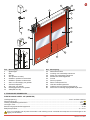 3
3
-
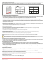 4
4
-
 5
5
-
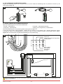 6
6
-
 7
7
-
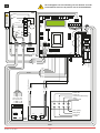 8
8
-
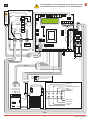 9
9
-
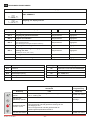 10
10
-
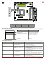 11
11
-
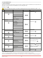 12
12
-
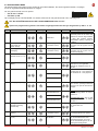 13
13
-
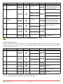 14
14
-
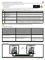 15
15
-
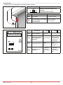 16
16
-
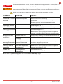 17
17
-
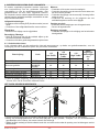 18
18
-
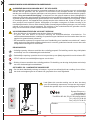 19
19
-
 20
20
-
 21
21
-
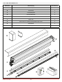 22
22
-
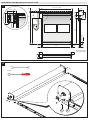 23
23
-
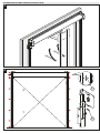 24
24
-
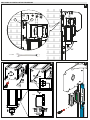 25
25
-
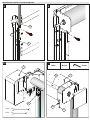 26
26
-
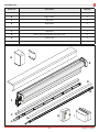 27
27
-
 28
28
-
 29
29
-
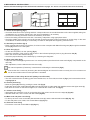 30
30
-
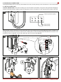 31
31
-
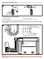 32
32
-
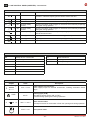 33
33
-
 34
34
-
 35
35
-
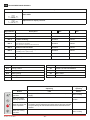 36
36
-
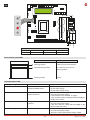 37
37
-
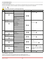 38
38
-
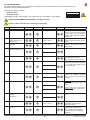 39
39
-
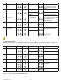 40
40
-
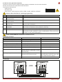 41
41
-
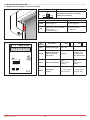 42
42
-
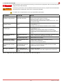 43
43
-
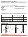 44
44
-
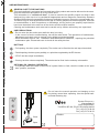 45
45
-
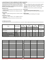 46
46
-
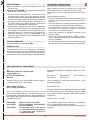 47
47
-
 48
48


