Yamaha RX V2095RDS Handleiding
- Categorie
- Ontvanger
- Type
- Handleiding
Deze handleiding is ook geschikt voor

OWNER’S MANUAL
MODE D’EMPLOI
BEDIENUNGSANLEITUNG
BRUKSANVISNING
MANUALE DI ISTRUZIONI
MANUAL DE INSTRUCCIONES
GEBRUIKSAANWIJZING
OWNER’S MANUAL
MODE D’EMPLOI
BEDIENUNGSANLEITUNG
BRUKSANVISNING
MANUALE DI ISTRUZIONI
MANUAL DE INSTRUCCIONES
GEBRUIKSAANWIJZING
NATURAL SOUND AV RECEIVER
AMPLI-TUNER AUDIO-VIDEO
G
NATURAL SOUND AV RECEIVER RX V2095RDS
CINEMA DSP
7ch
VOLUME
INPUT SELECTOR
INPUT MODE
l6
20
28
40
60
l2
8
4
2
0
–dB
BASS TREBLE BALANCE
VCR 2
VIDEO AUX
REC OUT
VCR 1
TV/DBS
PHONO
TUNER
CD
DVD/LD
SOURCE
TAPE/MD
VIDEO AUX
EFFECT
A/B/C/D/E
PRESET STATIONS
TUNING
EXT. DECODER
55
4
3
2
l
0
l
2
3
4
LR
55
4
3
2
l
0
l
2
3
4
55
4
3
2
l
0
l
2
3
4
STANDBY/ON
PHONES
BASS
EXTENSION
TONE
BYPASS
A
SPEAKERS
B
PROGRAM
RDS MODE
EON
EDIT
FM/AM
MODE
MEMORY
START
PRESET
/TUNING
TUNING
MODE
PTY SEEK
MAN’L/AUTO FM AUTO/MAN’L MONO

Congratulations!
You are the proud owner of a Yamaha Digital Sound Field Processing (DSP)
System—an extremely sophisticated audio component. The DSP system takes full
advantage of Yamaha’s undisputed leadership in the field of digital audio processing
to bring you a whole new world of listening experiences. Follow the instructions in this
manual carefully when setting up your system, and the DSP system will sonically
transform your room into a wide range of listening environments—anything from a
famous concert hall to a cozy jazz club. In addition, you get incredible realism from
most of surround-sound encoded video sources available in the market using the built-
in Dolby Pro Logic Surround Decoder, Dolby Digital Decoder and DTS Decoder.
Seven built-in channels of amplification on this model mean that no additional
amplifiers are required to enjoy advanced digital sound field processing.
Rather than tell you about the wonders of digital sound field processing, however,
let’s get right down to the business of setting up the system and trying out its many
capabilities. Please read this operation manual carefully and store it in a safe place for
later reference.

1
English
CAUTION .................................................................. 2
INTRODUCTION ....................................................... 3
Features .................................................................... 3
What’s DSP?............................................................. 4
GETTING STARTED ................................................ 7
Getting started.......................................................... 7
Unpacking.............................................................. 7
Opening and closing the front cover ...................... 7
Installing batteries in the remote controller ........... 8
Notes about the remote controller.......................... 8
Controls and their functions................................... 9
Front panel............................................................. 9
Display panel........................................................ 12
PREPARATION ...................................................... 13
Speaker setup......................................................... 13
Connections ........................................................... 15
Audio/video source equipment ............................ 15
Speakers ............................................................. 21
Antennas ............................................................. 24
Plugging in this unit ............................................. 26
On screen display.................................................. 27
Selecting the output modes
(“SET MENU” mode) ............................................. 28
Speaker balance adjustment ................................ 31
BASIC OPERATION ............................................... 34
Playing a source .................................................... 34
Recording a source to tape (or MD) or dubbing
from tape (or MD) to tape (or MD)......................... 39
Sound control......................................................... 41
Tuning ..................................................................... 42
Basic operation ................................................... 42
Preset tuning........................................................ 43
Receiving RDS stations .........................................47
Displaying RDS data.............................................47
Selecting your desired program type from among
preset RDS stations (PTY SEEK).........................50
Automatic selection of desired program when
broadcasting starts................................................51
Using digital sound field processor (DSP) ......... 52
Playing a source with an effect of the digital
sound field processor (DSP)................................ 52
Adjusting output level of the center, right rear,
left rear, front effect speakers and subwoofer...... 55
Brief overview of digital sound field programs...... 57
ADVANCED FEATURES ....................................... 62
SET MENU mode ................................................... 62
Creating your own sound fields .......................... 66
Setting the SLEEP timer ....................................... 71
REMOTE CONTROLLER ....................................... 72
Basic operation (Cover is open) .......................... 72
Using the “learning-capable” keys
(Cover is open)....................................................... 74
Using OPERATION CONTROL keys
(Cover is closed) ................................................... 76
Macro operations (Cover is closed) .................... 78
Methods of learning and clearing functions ....... 80
TROUBLESHOOTING ............................................ 83
SPECIFICATIONS .................................................. 86
CONTENTS

2
1. To assure the finest performance, please read this manual
carefully. Keep it in a safe place for future reference.
2. Install this unit in a cool, dry, clean place – away from
windows, heat sources, sources of excessive vibration,
dust, moisture and cold. Avoid sources of humming
(transformers, motors). To prevent fire or electrical shock,
do not expose the unit to rain or water.
3. Never remove the unit cover. Contact your dealer if an
object falls inside the unit.
4. Do not use force on switches, controls or connection wires.
When moving the unit, first disconnect the power plug and
the wires connected to other equipment. Never pull on the
wires themselves.
5. The openings on the unit cover assure proper ventilation of
the unit. If these openings are obstructed, the temperature
inside the unit will rise rapidly. Therefore, avoid placing
objects against these openings, and install the unit in a
well-ventilated area to prevent fire and damage.
<Europe and U.K. models>
Be sure to allow a space of at least 10 cm behind, 20 cm
on the both sides and 30 cm above the top panel of the
unit to prevent fire and damage.
6. The voltage used must be the same as that specified on
this unit. Using this unit with a higher voltage than
specified is dangerous and may result in fire or other
accidents. YAMAHA will not be held responsible for any
damage resulting from use of this unit with a voltage other
than specified.
7. Digital signals generated by this unit may interfere with
other equipment such as tuners, receivers or TVs. Move
this unit farther away from such equipment if interference
is observed.
8. Always set the VOLUME control to “–
∞
” before starting
the audio source play. Increase the volume gradually to an
appropriate level after playback has been started.
9. Do not attempt to clean the unit with chemical solvents;
this might damage the finish. Use a clean, dry cloth.
10.Be sure to read the “TROUBLESHOOTING” section
regarding common operating errors before concluding that
the unit is faulty.
11.When not planning to use this unit for long periods of time,
disconnect the AC power plug from the wall outlet.
12.To prevent lightning damage, disconnect the AC power
plug and antenna cable when there is an electrical storm.
13.Grounding or polarization – Precautions should be taken
so that the grounding or polarization of an appliance is not
defeated.
14.Do not connect an audio unit to the AC outlet on the rear
panel if the equipment requires more power than the outlet
is rated to provide.
IMPORTANT
Please record the serial number of your unit in the space
below.
Model:
Serial No.:
The serial number is located on the rear of the unit.
Retain this Owner’s Manual in a safe place for future
reference.
WARNING
TO REDUCE THE RISK OF FIRE OR ELECTRIC
SHOCK, DO NOT EXPOSE THIS UNIT TO RAIN OR
MOISTURE.
This unit is not disconnected from the AC power source as
long as it is connected to the wall outlet, even if this unit
itself is turned off. This state is called the standby mode.
In this mode, this unit is designed to consume a small
amount of power.
WARNING
Do not change the IMPEDANCE SELECTOR switch
setting while the power to this unit is on, otherwise this
unit may be damaged.
IF THIS UNIT FAILS TO TURN ON WHEN THE
STANDBY/ON SWITCH IS PRESSED;
The IMPEDANCE SELECTOR switch may not be set to
either end. If so, set the switch to either end when this unit
is in the standby mode.
For U.K. customers
If the socket outlets in the home are not suitable for the plug
supplied with this appliance, it should be cut off and an
appropriate 3 pin plug fitted. For details, refer to the
instructions described below.
Note: The plug severed from the mains lead must be
destroyed, as a plug with bared flexible cord is hazardous if
engaged in a live socket outlet.
Special Instructions for U.K. Model
IMPORTANT
THE WIRES IN MAINS LEAD ARE COLOURED IN
ACCORDANCE WITH THE FOLLOWING CODE:
Blue: NEUTRAL
Brown: LIVE
As the colours of the wires in the mains lead of this
apparatus may not correspond with the coloured markings
identifying the terminals in your plug, proceed as follows:
The wire which is coloured BLUE must be connected to the
terminal which is marked with the letter N or coloured
BLACK. The wire which is coloured BROWN must be
connected to the terminal which is marked with the letter L
or coloured RED. Making sure that neither core is
connected to the earth terminal of the three pin plug.
OR CORRECT SETTING.
KERS
A
B
REAR
AIN
SWITCHED
AC OUTLETS
IMPEDANCE SELECTOR
CENTER : 4
Ω
MIN. / SPEAKER
FRONT
:6
Ω
MIN. / SPEAKER
REAR
:6
Ω
MIN. / SPEAKER
MAIN A OR B
:4
Ω
MIN. / SPEAKER
A B
:8
Ω
MIN. / SPEAKER
CENTER : 8
Ω
MIN. / SPEAKER
FRONT
:8
Ω
MIN. / SPEAKER
REAR
:8
Ω
MIN. / SPEAKER
MAIN A OR B
:8
Ω
MIN. / SPEAKER
A B
:
I
6
Ω
MIN. / SPEAKER
( SURROUND )
SET BEFORE POWER ON
I00W MAX.
TOTAL
IMPEDANCE
SELECTOR
(Europe model)
CAUTION : Read this before operating your unit.

3
English
7 Channel Power Amplification
Main: 100W + 100W (8Ω) RMS Output
Power, 0.02% THD, 20–20,000 Hz
Center: 100W (8Ω) RMS Output Power,
0.02% THD, 20–20,000 Hz
Rear: 100W + 100W (8Ω) RMS Output
Power, 0.02% THD, 20–20,000 Hz
Front effect:
25W + 25W (8Ω) RMS Output
Power, 0.05% THD, 1 kHz
Multi-Mode Digital Sound Field
Processing
●
Digital Sound Field Processor (DSP)
●
Dolby Digital Decoder
●
Dolby Pro Logic Surround Decoder
●
DTS Decoder
●
CINEMA DSP: Theater-like Sound
Experience by the Combination of
YAMAHA DSP Technology and Dolby
Digital, Dolby Pro Logic or DTS
●
Automatic Input Balance Control for
Dolby Pro Logic Surround
●
Test Tone Generator for Easier Speaker
Balance Adjustment
●
Speaker Output Mode Selection
Capability for the Most Suitable Use of
Your Speaker System
Sophisticated FM/AM Tuner
● 40-Station Random Access Preset Tuning
● Automatic Preset Tuning
● Preset Station Shifting Capability (Preset
Editing)
● Multi-Functions for RDS Broadcast
Reception
● IF Count Direct PLL Synthesizer Tuning
System
Others
●
“SET MENU” Mode which Provides You
with 8 Titles of Setting Changes and
Adjustments for Optimizing This Unit for
Your Audio/Video System
● BASS EXTENSION Button for Reinforcing
Bass Response
● On Screen Display Function Helpful in
Controlling This Unit
●
REC OUT Selector which is Independent of
Input Source Selection
● SLEEP Timer
●
OPTICAL and COAXIAL Digital Audio
Signal Terminals
●
6 Channel External Decoder Input for Other
Future Formats
● Video Signal Input/Output Capability
(Including S Video Connections)
●
Multi-Functional
remote controller
with
“Learning” Capability
Features
INTRODUCTION

4
Welcome to the exciting world of digital home entertainment.
This unit is one of the most complete and advanced AV
receiver available. Some of the more advanced features may
not be familiar to you, but they are easy to use. State-of-the-art
technologies such as Dolby Digital and Digital Theater
Systems (DTS) may be new to your home, but you have
probably experienced the amazing realism they bring to feature
films in theaters around the world.
To make the listening experience even more enjoyable, this
unit includes a number of exclusive, digitally created listening
environments known as digital sound fields. Choosing a sound
field program is like transporting yourself to such venues as an
outdoor arena, a European church, or a cozy jazz club. Take
some time now to read more about these features and enjoy
the new experiences this unit brings to your home theater.
Digital Sound Field Processing
Technological advances in sound reproduction over the last 30
years have enhanced the listening experience with improved
clarity, precision and power. However, something has still been
missing: The atmosphere and acoustic ambiance of the public
venue. Our Yamaha engineers have extensively researched
the nature of sound acoustics and the way sound reflects
inside a room. We sent these engineers to famous theaters
and concert halls around the world to measure the acoustics of
those venues with sophisticated microphones. The data they
collected is used to recreate these environments in digital
sound fields. Some of these digital sound fields are created
using data measured directly at the original venue; others are
created from combinations of data to form unique
environments for specific purposes.
Of course, that only solves half of the problem. These
engineers have no way of knowing the acoustics of your
listening room, so we’ve made it possible for you to adjust the
various parameters of this data to tailor each virtual venue to
your taste. You can use these sound fields to enhance any
source and in combination with any of the following surround
sound technologies. Some are designed especially for music,
and some especially for movies.
Dolby Pro Logic Surround
Dolby Surround has been used in movie theaters since the
mid-seventies. It has also been available in home
entertainment systems since the late eighties and continues to
be a popular format for home theater systems. It uses four
discrete channels and five speakers to reproduce realistic and
dynamic sound effects: two main channels (left and right), a
center channel for dialog, and a rear channel for special sound
effects. The rear channel reproduces sound within a narrow
frequency range.
Most video tapes and laser discs include Dolby Surround
encoding as do many TV and cable broadcasts. The Dolby Pro
Logic Surround decoder built into this unit employs a digital
signal processing system that stabilizes each channel for even
more accurate sound positioning than is available with
standard analog processors.
Introduction
What’s DSP?
INTRODUCTION

5
English
Dolby Digital is the next level of Dolby Surround sound system
developed for 35 mm film-movies by employing low bit-rate
audio coding.
Dolby Digital is a digital surround sound system that provides
completely independent multi-channel audio to you. Dolby
Digital provides five full range channels in what is sometimes
referred to as a “3/2” configuration: three front channels (left,
center and right), and two surround channels. A sixth bass-only
effect channel is also provided for output of LFE (low frequency
effect), or low bass effects that are independent of other
channels. (This is called the “LFE channel”.) This channel is
counted as 0.1, thus giving rise to the term 5.1 channels in
total.
Compared to Dolby Pro Logic that is referred to a “3/1” system
(left front, center, right front and just one surround channel),
Dolby Digital features two surround channels, called stereo or
split surrounds, each offering the same full range fidelity as the
three front channels.
By using the built-in Dolby Digital decoder, you can experience
the dramatic realism and impact of Dolby Digital theater sound
in your home.
Wide dynamic range of sound reproduced by the five full range
channels and precise sound orientation by the digital sound
processing presents listeners much excitement and realism
that has never been experienced before.
Dolby Digital forms 5.1 channels as mentioned left, and
moreover, it can also form fewer channels, for example 2
channel stereo and monaural. You may be able to find some 2
channel stereo and/or monaural sources encoded with Dolby
Digital in the market.
Laserdisc and DVD are home audio formats that could benefit
from Dolby Digital. In the near future, Dolby Digital will also be
applied to DBS, CATV and HDTV. The ongoing release of
Dolby Stereo Digital theatrical films now underway will provide
an immediate source of Dolby Digital encoded video software.
Manufactured under license from Dolby Laboratories. “Dolby”,
“AC-3”, “Pro Logic”, and the double-D symbol are trademarks
of Dolby Laboratories.
DTS (Digital Theater Systems) system was developed to
replace analog soundtracks of movies with six discrete
channels of digital soundtracks, and now, it is installed in many
theaters around the world. The DTS digital playback system
changed the way we experienced movies in theaters with six
discrete channels of superb digital audio.
The DTS technology, through intense research and
development, made it possible to deliver a similar
encode/decode discrete technology to home audio surround-
sound entertainment.
The DTS Digital Surround is an encode/decode system which
delivers six channels of master-quality, 20-bit audio; technically
5.1 channels, which means 5 full-range (left, center, right and
two surround) channels, plus a subwoofer (LFE) channel (as
“0.1”). It is compatible with the 5.1 speaker configurations that
are currently available for home theater systems
The DTS Digital Surround algorithm is designed to encode the
six channels of 20-bit audio onto some laserdiscs, compact
discs and DVDs with considerably less data-compression.
By using the DTS decoder built into this unit, you can
experience the dramatic realism and impact of the DTS
installed theater’s high quality sound in your home.
Laserdisc, compact disc and DVD are home audio format
within which DTS can represent its high quality multi-channel
audio. (In addition to movies on laserdiscs, many exciting new
multi-channel music recordings will also become available in
the form of DTS-encoded compact discs.)
Manufactured under license from Digital Theater Systems, Inc.
US Pat. No. 5,451,942 and other world-wide patents issued
and pending. “DTS”, “DTS Digital Surround”, are trademarks of
Digital Theater Systems, Inc. Copyright 1996 Digital Theater
Systems, Inc. All Rights Reserved.
DTS Digital Surround
Dolby Digital
INTRODUCTION

6
Dolby Pro Logic + 2 Digital Sound Fields
Digital sound fields are created on the presence side and
the rear surround side of the Dolby Pro Logic Surround-
decoded sound field respectively. They create a wide
acoustic environment and emphasize surround-effect in the
room, letting you feel much presence as if you were
watching a movie in a popular Dolby Surround theater.
This combination is available when the digital sound field
program No. 8, 9, 10, 11 or “PRO LOGIC/Enhanced” of No.
12 is selected, and the input signal of the source is analog,
PCM audio or encoded with the Dolby Digital in 2-channels.
Dolby Digital or DTS + 3 Digital Sound Fields
Digital sound fields are created on the presence side and
the independent left and right surround sides of the Dolby
Digital-decoded or the DTS-decoded sound field
respectively. They create a wide acoustic environment and
much surround effect in the room without losing high
channel separation. With wide dynamic range of Dolby
Digital or DTS sound, this sound field combination lets you
feel as if you were watching a movie in the newest Dolby
Digital theater or DTS installed theater. This is the most
ideal home theater sound at the present time.
This combination is available when the digital sound field
program No. 8, 9, 10, 11 or “DOLBY DIGITAL (or DTS
DIGITAL SUR.)/Enhanced” of No. 12 is selected, and the
input signal of the source is encoded with the Dolby Digital
(except in 2-channels) or encoded with the DTS.
CINEMA DSP: Dolby Surround + DSP / DTS + DSP
The Dolby Surround sound and DTS systems show their full
ability in a large movie theater, because movie sounds are
originally designed to be reproduced in a large movie theater
that uses a multitude of speakers. Trying to create a sound
environment similar to that of a movie theater in your home is
difficult because of the room size, material inside the walls, the
number of speakers, and so on. In other words, your listening
room is very different from a movie theater.
However, Yamaha DSP technology allows you to create nearly
the same sound experience as that of a large movie theater in
your home by compensating for the lack of presence and
dynamics in the listening room with original digital sound fields
combined with Dolby Surround or DTS Digital Surround
sounds.
The YAMAHA “CINEMA DSP” logo indicates those programs
that are created by the combination of YAMAHA DSP
technology and Dolby Surround or DTS.
CINEMA DSP
INTRODUCTION

7
English
GETTING STARTED
Getting started
Remote controller
User function stickers
Indoor FM Antenna
AM Loop Antenna
Batteries (size AA, LR6, UM-3)
Unpacking
Carefully remove this unit and accessories from the box. You should find the unit itself and the following accessories.
Close the front cover whenever the controls inside the panel are not used.
To open the front cover
Opening and closing the front cover
To close the front cover

8
Installing batteries in the remote
controller
Since the remote controller will be used for many of this unit’s
control operations, you should begin by installing the supplied
batteries.
1. Turn the remote controller over and slide the battery
compartment cover in the direction of the arrow.
2. Insert the batteries (AA, LR6, UM-3 type) according to the
polarity markings on the inside of the battery compartment.
3. Close the battery compartment cover.
Note on the remote controller for the main room
After the batteries are inserted, press the RESET button before
using the remote controller.
Notes about the remote controller
Battery replacement
If you find that the remote controller must be used closer to the
main unit, the batteries are weak. Replace both batteries with
new ones.
Notes
●
Use only AA, R6, UM-3 batteries.
(It is recommended to use an LR6 type to use the remote
controller for a long period of time.)
●
Be sure the polarities are correct. (See the illustration inside
the battery compartment.)
●
Remove the batteries if the remote controller is not used for
an extended period of time.
●
If batteries leak, dispose of them immediately. Avoid
touching the leaked material and contact with clothing, etc.
Clean the battery compartment thoroughly before installing
new batteries.
Remote controller operation range
Notes
●
The area between the remote controller and the main unit
must be clear of large obstacles.
●
Do not expose the remote control sensor to strong lighting,
in particular, an inverter type fluorescent lamp. Otherwise,
the remote controller may not work properly. If necessary,
position the main unit away from direct lighting.
1
3
2
RESET button
30°
30°
Remote control
sensor
Within approximately
6 m (19.7 feet)
GETTING STARTED

9
English
Controls and their functions
Front panel
NATURAL SOUND AV RECEIVER RX V2095RDS
CINEMA DSP
7ch
VOLUME
INPUT SELECTOR
INPUT MODE
l6
20
28
40
60
l2
8
4
2
0
–dB
PHONES
BASS
EXTENSION
BASS TREBLE BALANCE
TONE
BYPASS
VCR 2
VIDEO AUX
REC OUT
VCR 1
TV/DBS
PHONO
TUNER
CD
DVD/LD
SOURCE
TAPE/MD
VIDEO AUX
EFFECT
A/B/C/D/EA
SPEAKERS
B
PROGRAM
PRESET STATIONS
TUNING
EXT. DECODER
STANDBY/ON
55
4
3
2
l
0
l
2
3
4
LR
55
4
3
2
l
0
l
2
3
4
55
4
3
2
l
0
l
2
3
4
B
1
E G ICJ
23 4
5
6
87 0 A9 D FH
RDS MODE
EON
EDIT
FM/AM
MODE
MEMORY
START
PRESET
/TUNING
TUNING
MODE
PTY SEEK
MAN’L/AUTO FM AUTO/MAN’L MONO
RDS MODE
EON
EDIT
FM/AM
MODE
MEMORY
START
PRESET
/TUNING
TUNING
MODE
PTY SEEK
MAN’L/AUTO FM AUTO/MAN’L MONO
O
K
L M N
PQR
1 STANDBY/ON switch
Press this switch to turn on the power. Press this switch again
to set this unit in the standby mode.
* A click from the switch and the initial rotation of the built-in
fan will be heard when the power is turned on.
Standby mode
This unit is still using a small amount of power in this mode
in order to be ready to receive infrared-signals from the
remote controller.
2 Remote control sensor
Receives signals from the remote controller.
3 Display panel
Displays a variety of information. (Refer to page 12 for details.)
4 INPUT MODE button
Press this button to select how input signals are received from
sources that output two or more types of signals. The “AUTO”,
“DTS” and “ANALOG” modes are available. The “AUTO”,
“D.D.RF”, “DTS”, “DGTL” and “ANALOG” modes are available
for DVD/LD sources. Refer to page 37 for details.
5 INPUT SELECTOR
Turn this knob to select the input source.
The selected source will be shown on the display.
6 Master VOLUME control
Simultaneously controls volume for all output sounds; front
effect, main, rear, center and subwoofer. (The REC OUT level
is not affected.)
* The indicator on the master VOLUME control will flash when
the volume is decreased by pressing the MUTE key on the
remote controller.
For the remote controller, refer to pages 72 to 73.
GETTING STARTED

10
7
SPEAKERS switches
Press the switch A or B (or both) for the main speakers you will
use to select them. Press the switch for the main speakers you
will not use again to cancel them. On the display panel,
“SPEAKERS A” and/or “SPEAKERS B” will be illuminated,
depending on which main speakers are being selected.
8 PHONES jack
Headphones can be plugged into this jack for private listening.
You can listen to the sound to be output from the main
speakers through headphones. When listening with
headphones privately, press both SPEAKERS A and B
switches to cancel both of the main speakers A and B, and turn
off the digital sound field processor by pressing the EFFECT
button so that no DSP program name is illuminated on the
display panel.
9 PROGRAM selector button
Press this button in the or direction to select a digital
sound field processing program.
0 BASS EXTENSION button
Press this button inward (ON) to boost the bass frequency
response at the main left and right channels while maintaining
overall tonal balance. This function is effective for reinforcing
the bass frequencies when a subwoofer is not used.
A TONE BYPASS button
Press this button inward (ON) to bypass the tone (BASS and
TREBLE) control circuitry. This function is used for outputting
pure sound and checking the tone control settings. The tone
control circuitry can be used when this button is released
outward (OFF).
B EFFECT button
Press this button to turn on and off the output from the center,
rear and front effect speakers. The sound becomes normal 2-
channel when this function is turned off.
However, this does not apply to Dolby Digital or DTS. The
signals at all channels will be distributed to the main channels
and output from the main speakers, even if the output from the
center, rear and front effect speakers are turned off, when
Dolby Digital or DTS is decoded.
C BASS and TREBLE controls
Rotate these knobs to adjust the low and high frequency
response for the left and right main channels only.
D EXT. DECODER button
Press this button to select the input signals from the
EXTERNAL DECODER INPUT terminals as the input source.
This function takes priority over the INPUT SELECTOR setting.
“EXT. DECODER IN” will be illuminated on the display panel.
The source selected with the INPUT SELECTOR knob
becomes the current input source when “EXT. DECODER IN”
is not illuminated on the display panel.
E BALANCE control
This knob controls the sound from the main speakers only.
The balance of the output volume to the left and right main
speakers can be adjusted to compensate for sound imbalances
caused by the speaker location or listening room conditions.
F A/B/C/D/E button
Press this button to select a group (A–E) of preset stations.
G REC OUT selector
Rotate this knob to select the source for recording to an MD
recorder (or tape deck) or VCR. This setting is independent of
the INPUT SELECTOR setting, except when the REC OUT
selector is set to the SOURCE position. Then the INPUT
SELECTOR is used to select the source for recording to the
MD recorder (or tape deck) or VCR.
H PRESET STATIONS/TUNING button
This button is used for the PRESET STATIONS function when
“ : ” is illuminated on the display, and the TUNING function
when “ : ” is not illuminated. The following explains these
functions in detail.
PRESET STATIONS :
Selects a preset station number (from 1 to 8).
Press the side to select a higher preset station number.
Press the side to select a lower preset station number.
TUNING :
Used for tuning. Press the side to tune in to a higher
frequency, and press the side to tune in to a lower
frequency.
When this unit is in the PTY SEEK mode, pressing this button
changes the currently selected program type.
I VIDEO AUX terminals
Connect an auxiliary video or audio input source unit such as a
camcorder to these terminals. A video unit with a S video
output terminal can be connected to the S VIDEO terminal to
obtain a high resolution picture. The source can be selected
with the INPUT SELECTOR and REC OUT selector.
J Front cover
Refer to page 7 on how to open and close the front cover.
PHONES
GETTING STARTED

11
English
GETTING STARTED
K RDS MODE button
When an RDS station is received, pressing this button changes
the display mode into the PS mode, PTY mode, RT mode
and/or CT mode (if the station employs these RDS data
services) in turn.
L EON button
Press this button to select a desired program type (NEWS,
INFO, AFFAIRS, SPORT) when you want to call a radio
program of that program type automatically.
M PTY SEEK MODE button
Press this button to set the unit to the PTY SEEK mode.
N PTY SEEK START button
Press this button to begin searching for a station after the
desired program type is selected in the PTY SEEK mode.
O PRESET/TUNING (EDIT) button
Press this button to alternately illuminate and turn off
“PRESET” on the display panel
. This button switches the
function of the PRESET STATIONS/TUNING button.
This button is also used to exchange the places of two preset
stations with each other.
P FM/AM button
Press this button to switch the reception band between FM and AM.
Q MEMORY (MAN’L/AUTO FM) button
Use this button to enter a station to memory. Refer to the
section “Manual preset tuning” on page 43 for details.
Hold down this button for more than 3 seconds to start
automatic preset tuning. Refer to page 45 for details.
R TUNING MODE (AUTO/MAN’L MONO) button
Press this button to switch the tuning mode between automatic
and manual. To select the automatic tuning mode, press this
button so that the “AUTO” indicator is illuminated on the
display. To select the manual tuning mode, press this button so
that the “AUTO” indicator is not illuminated.

12
Display panel
DIGITAL
PRO LOGIC
DSP
SPEAKERS
AB
TAPE/MD
CD
TUNER
PHONO
DVD/LD
TV/DBS
VCR 1
VCR 2
V-AUX
MEMORY
PS PTY
RT CT
STEREO
AUTO
EON
PTY HOLD
NEWS
INFO
SPORT
AFFAIRS
SLEEP
2 74 5 631
980 BA CD
1 indicators
Either of the “dts” indicators will be illuminated when the built-in
DTS decoder is turned on.
A red “dts” indicator will be illuminated when playing a compact
disc or laserdisc encoded with DTS.
An orange “dts” indicator will be illuminated when playing a
DVD encoded with DTS.
An orange “dts” indicator may be illuminated when playing a
laserdisc encoded with DTS after a video-CD or DVD on a
DVD/LD combi-player.
2 Multi-information display
This display shows the current DSP program and the status of
adjustments and setting changes. Several statuses can be
viewed at one time.
The current station frequency and band (AM or FM) will also
appear when the tuner source input mode is selected.
3 STEREO indicator
This indicator will be illuminated when an FM stereo broadcast
with sufficient signal strength is received.
4 MEMORY indicator
A flashing MEMORY indicator means a station can be saved,
as explained in the following:
Press the MEMORY button. The MEMORY indicator will flash
about 5 seconds. While the indicator is flashing, program the
displayed station to memory by using the A/B/C/D/E and
PRESET STATIONS/TUNING buttons.
5 RDS mode indicators
The name(s) of the RDS mode(s) employed by the currently
received RDS station is (are) illuminated. Illumination of the
indicator on the head of a name shows that the corresponding
RDS mode is now selected.
6 AUTO indicator
This indicator will be illuminated during the automatic tuning
mode.
7 Input source indicators
One of the arrows for these indicators will be illuminated
depending on which source is selected.
8 DIGITAL and PRO LOGIC indicators
The DIGITAL indicator will be illuminated when the built-in
Dolby Digital decoder is on and the signals of the source
encoded with Dolby Digital are not 2-channels.
The PRO LOGIC indicator will be illuminated when the
built-in Dolby Pro Logic Surround Decoder is on.
9 DSP indicator
This indicator will be illuminated when the built-in digital sound
field processor is on.
0 SPEAKERS A/B indicators
One of these indicators will be illuminated depending on which
main speakers are selected. Both indicators will be illuminated
when both speakers A and B are selected.
A EON indicator
This indicator will be illuminated when an RDS station that
employs the EON data service is received.
B Program type name indicators
The name selected in the EON mode is illuminated.
C PTY HOLD indicator
This indicator will be illuminated while the search is performed
in the PTY SEEK mode.
D SLEEP indicator
This indicator will be illuminated when the built-in SLEEP timer
is on.
GETTING STARTED
SPEAKERS
A
TAPE/MD
CD
TUNER
PHONO
DVD/LD
TV/DBS
VCR 1
VCR 2
V-AUX
MEMORY
STEREO
AUTO
Indicates the signal level of the received station.
If multipath interference is detected, the
indication decreases.

13
English
This unit has been designed to provide the best sound field
quality with a full seven-speaker system setup, using a pair of
main speakers to output main source sounds, two extra pairs
of effect speakers to generate the sound field plus one center
speaker for dialog. We therefore recommend that you use a
seven-speaker setup. A four-speaker system using only one
pair of effect speakers for the sound field will still provide
impressive ambience and effects, however, and may be a
good way to begin with this unit. You can always upgrade to
the full seven-speaker system later. In the 4 or 5 speaker
system, the Digital Sound Field Processing is still performed,
but the main speakers are used for both the main channels
and the front effect channels.
Use of the center dialog speaker is
recommended
When playing back a source with Dolby Pro Logic decoded, or
playing back a source which contains center-channel signals
with Dolby Digital or DTS decoded, dialog, vocals etc. are
output from the center channel. Therefore, if you want to
maximize the performance of your Audio/Video home theater
system, it is recommended that you use a center channel
speaker.
If, for some reason, it is not practical to use a center speaker, it
is possible to enjoy the movie without it. Best results, however,
are obtained with the full system.
Use of a subwoofer expands your sound
field
It is also possible to further expand your system with the
addition of a subwoofer and amplifier. The use of a subwoofer
is effective not only for reinforcing bass frequencies from any
or all channels, but also for reproducing signals at the
subwoofer channel with high fidelity during playing back a
source with Dolby Digital or DTS decoded. You may wish to
choose the convenience of a Yamaha Active Servo Processing
Subwoofer System, which has its own built-in power amplifier.
Speaker setup
m Speakers and speaker placement
Your full seven-speaker system will require three speaker
pairs: the MAIN SPEAKERS (your normal stereo speakers),
the FRONT EFFECT SPEAKERS and the REAR SPEAKERS,
plus the CENTER SPEAKER. You may also be using a
SUBWOOFER.
The MAIN SPEAKERS should be high performance models
and have enough power handling capacity to accept the
maximum output of your audio system.
Other speakers do not have to be equal to the MAIN
SPEAKERS. For precise sound localization, however, it is
ideal to use high performance models that can reproduce
sounds in full range for the CENTER SPEAKER, the FRONT
EFFECT and REAR SPEAKERS.
Place the MAIN SPEAKERS in the ordinary position.
Place the FRONT EFFECT SPEAKERS further apart than the
MAIN SPEAKERS, on either side of and 0.5–1m behind and
above the MAIN SPEAKER pair.
Place the REAR SPEAKERS behind your listening position.
They should be nearly 1.8m above the floor.
Place the CENTER SPEAKER precisely between the two
MAIN SPEAKERS. (To avoid interference, keep the speaker
above or below the television monitor, or use a magnetically
shielded speaker.)
If using a SUBWOOFER, such as a Yamaha Active Servo
Processing Subwoofer System, the position of the speaker is
not so critical because low bass tones are not highly
directional.
m Setting up your speaker system
Main speaker
Front effect speaker
Center speaker
Rear speaker
Subwoofer
PREPARATION

14
4 Speaker System
Basic system.
You can enjoy widely diffused sound by only adding a pair of
rear speakers to a basic stereo speaker system.
1E. SYS. SETUP—Set to 5ch. (See page 29.)
1A. CENTER SP—Set to NONE. (See page 28.)
6 Speaker System
Good for sound fields from 2-channel stereo sources.
When a normal stereo source is played back with the sound
field programs No. 1 through No. 7, a sound effect matching
that of a 7-speaker system can be obtained. The addition of
front left and right effect speakers produces a more effective
sound field.
1E. SYS. SETUP—Set to 7ch. (See page 29.)
1A. CENTER SP—Set to NONE. (See page 28.)
5 Speaker System
Good for Audio/Video sources.
By the use of a center speaker, center sounds (dialog, vocals
etc.) are precisely localized.
1E. SYS. SETUP—Set to 5ch. (See page 29.)
1A. CENTER SP—Set to LRG or SML. (See page 28.)
7 Speaker System
This is the recommended speaker system, providing the
best sound effects.
The rear speakers and the front effect speakers produces a
360-degree sound field, and the center speaker provides
precise center localization.
You can experience the amazing YAMAHA “CINEMA DSP”
sound fields completely with the 7 speaker system.
1E. SYS. SETUP—Set to 7ch. (See page 29.)
1A. CENTER SP—Set to LRG or SML. (See page 28.)
m Recommended speaker system configurations
PREPARATION

15
English
Caution: Plug in this unit and other components after all connections are completed.
All connections must be correct, that is to say L (left) to L, R (right) to R, “+” to “+” and “–” to “–”. Also refer to the owner’s manual for
each of your components.
Audio/video source equipment
●
Use RCA type pin plug cables for audio/video units with the exception described later.
●
The output (or input) terminals of YAMAHA audio/video units numbered as 1, 3, 4, etc. on the rear panel must be connected to
the same-numbered terminals of this unit.
VIDEO
DVD/LD
TV/DBS
IN
VCR 1
OUT
IN
VCR 2
OUT
VIDEO
S VIDEO
DVD/LD
TV/DBS
IN
VCR 1
OUT
IN
VCR 2
OUT
MONITOR
OUT
S VIDEO
75Ω
UNBAL.
AM
ANT
FM
ANT
GND
AUDIO SIGNAL VIDEO SIGNAL
TV/DBSCD
CDDVD/LD
TAPE/MD
IN
(PLAY)
OUT
(REC)
DVD/LD
EXTERNAL
DECODER
INPUT
MAIN
SUB WOOFER
CENTER
SURROUND
DIGITAL
RF SIGNAL
COAXIAL
DIGITAL SIGNAL
OPTICAL
PHONO
1
CD
AUDIO SIGNAL
TAPE/MD
3
4
IN
( PLAY )
OUT
( REC )
GND
OUTPUT
GND
OUTPUT
LINE OUT
LINE IN
(Europe model)
Turntable
MD recorder,
Tape deck, etc.
CD player
m Basic connections of audio units
(*1): GND terminal (For turntable use)
Connecting the ground wire of the turntable to the GND
terminal will normally minimize hum, but in some cases
better results may be obtained with the ground wire
disconnected.
: Indicates the direction of signals.
Connections
PREPARATION
(*1)

16
For connecting with a TV monitor that uses a 21 pin
connector for input
Make a connection as figured below with a commercially
available scart-plug connector cable.
PHONO
1
CD
75Ω
UNBAL.
AM
ANT
FM
ANT
GND
AUDIO SIGNAL
GND
TV/DBSCD
CDDVD/LD
TAPE/MD
IN
(PLAY)
OUT
(REC)
DVD/LD
EXTERNAL
DECODER
INPUT
TAPE/MD
3
4
IN
( PLAY )
OUT
( REC )
MAIN
SUB WOOFER
CENTER
SURROUND
DIGITAL
RF SIGNAL
COAXIAL
DIGITAL SIGNAL
OPTICAL
VIDEO
DVD/LD
TV/DBS
IN
VCR 1
OUT
IN
VCR 2
OUT
VIDEO
S VIDEO
DVD/LD
TV/DBS
IN
VCR 1
OUT
IN
VCR 2
OUT
MONITOR
OUT
S VIDEO
AUDIO SIGNAL VIDEO SIGNAL
VIDEO IN
VIDEO OUT
AUDIO OUT
VIDEO OUT
AUDIO OUT
AUDIO OUT
VIDEO OUT
AUDIO IN
VIDEO IN
AUDIO IN
VIDEO IN
AUDIO OUT
VIDEO OUT
(Europe model)
(Europe model)
LD player or
DVD player
TV monitor
No connection
TV monitor
m Basic connections of video units
Video cassette
recorder 2
Scart-plug connector
cable
Video cassette
recorder 1
TV/Satellite tuner
PREPARATION
VIDEO AUX terminals (on the front panel)
These terminals are used to connect a video input source such
as a camcorder.
VIDEO AUX
S VIDEO
L
R
VIDEO
VIDEO OUT
S VIDEO OUT
AUDIO OUT L
AUDIO OUT R
Camcorder
: S-video cable
(Refer to page 19 for details
about the S VIDEO terminal.)
IN
VCR 2
OUT
IN
VCR 2
OUT
MAIN
PRE
OUT
MAIN
IN
75Ω
UNBAL.
FM
ANT
GND
COUPLER
TV/DBSCD
CDDVD/LD
TAPE/MD
IN
(PLAY)
OUT
(REC)
DVD/LD
EXTERNAL
DECODER
INPUT
MAIN
SUB WOOFER
CENTER
SURROUND
DIGITAL
RF SIGNAL
COAXIAL
DIGITAL SIGNAL
OPTICAL
VIDEO
S VIDEO
MONITOR
OUT
VIDEO
AUDIO L
AUDIO R

17
English
PREPARATION
Notes
●
When you connect an audio/video unit to both of the digital
and analog terminals of this unit, make sure to connect to
both terminals of the same name.
●
Be sure to attach the covers when the OPTICAL terminals
are not being used, in order to protect the terminals from
dust.
●
In order to make this unit perform successful DTS-decoding,
the DTS bitstream must not be altered, manipulated or
corrupted in the process of sending the DTS bitstream from
the DIGITAL OUT terminal of an external unit to a digital
signal input terminal of this unit.
●
All digital audio signal input terminals are applicable to the
sampling frequency of 32 kHz, 44.1 kHz and 48 kHz.
: Optical fiber cable
: Coaxial cable
PHONO
VIDEO
DVD/LD
TV/DBS
IN
VCR 1
OUT
IN
VCR 2
OUT
VIDEO
S VIDEO
DVD/LD
TV/DBS
IN
VCR 1
OUT
IN
VCR 2
OUT
MONITOR
OUT
S VIDEO
1
CD
75Ω
UNBAL.
AM
ANT
FM
ANT
GND
AUDIO SIGNAL
GND
AUDIO SIGNAL VIDEO SIGNAL
EXTERNAL
DECODER
INPUT
TAPE/MD
3
4
IN
( PLAY )
OUT
( REC )
MAIN
SUB WOOFER
CENTER
SURROUND
TV/DBSCD
CDDVD/LD
TAPE/MD
IN
(PLAY)
OUT
(REC)
DVD/LD
DIGITAL
RF SIGNAL
COAXIAL
DIGITAL SIGNAL
OPTICAL
OPTICAL
DIGITAL OUT
COAXIAL
DIGITAL OUT
OPTICAL
DIGITAL
OUT
OPTICAL
DIGITAL
IN
OPTICAL
DIGITAL
OUT
OPTICAL
DIGITAL
OUT
MD recorder, DAT,
etc.
CD player
TV/Satellite tunerLD player or DVD player
(Europe model)
m Connecting to digital (OPTICAL and COAXIAL) terminals
If your CD player, MD recorder, LD player, DVD player,
TV/satellite tuner, etc. are equipped with coaxial or optical
digital audio signal output terminals, they can be connected to
this unit’s COAXIAL or OPTICAL, or both terminals.
Digital audio signals are transmitted with less loss than analog
audio signals. In addition, digital audio signal connections are
necessary, especially for an LD player, a DVD player or a CD
player to send signals encoded with Dolby Digital or DTS to
this unit.
To make an optical digital connection between this unit and an
external unit, remove the cover from each optical terminal, and
then connect them by using a commercially available optical
fiber cable that conforms to EIAJ standards. Other cables
might not function correctly.
Even if you connect an audio/video unit to the OPTICAL (or
COAXIAL) terminal of this unit, you must keep the unit
connected with the same named analog audio signal terminals
of this unit, because digital signal cannot be recorded by a tape
deck or VCR connected to only analog audio signal terminals
of this unit. You can switch the selection of input signals
between “digital” and “analog” easily. (See page 37 for details.)
* However, if you connect an MD recorder or DAT to this
unit’s OPTICAL TAPE/MD IN and OUT terminals, it can
record input sources connected to this unit’s OPTICAL
digital signal input terminals.

18
PHONO
1
CD
75Ω
UNBAL.
AM
ANT
FM
ANT
GND
AUDIO SIGNAL
GND
EXTERNAL
DECODER
INPUT
TAPE/MD
3
4
IN
( PLAY )
OUT
( REC )
MAIN
SUB WOOFER
CENTER
SURROUND
DVD/LD
TV/DBS
IN
VCR 1
OUT
IN
VCR 2
OUT
AUDIO SIGNAL
TV/DBSCD
CDDVD/LD
TAPE/MD
IN
(PLAY)
OUT
(REC)
DVD/LD
DIGITAL
RF SIGNAL
COAXIAL
DIGITAL SIGNAL
OPTICAL
DIGITAL OUT
ANALOG OUT
DOLBY DIGITAL
RF OUT
(Europe model)
PREPARATION
If your DVD/LD/CD combi-player has a DOLBY DIGITAL RF
signal output terminal, connect it to this unit’s DIGITAL RF
SIGNAL input terminal. Audio signals of an LD source encoded
with the Dolby Digital are input to this unit by this connection.
* To play back an LD source with the Dolby Digital decoded,
set the input mode of DVD/LD to “AUTO” or “D.D.RF”.
(Refer to page 37 for details.)
It is also necessary to connect the DVD/LD/CD combi-player to
this unit’s analog audio signal input terminals regardless of the
DOLBY DIGITAL RF signal connection. This is for playing back
a source with Dolby Pro Logic Surround decoded or in normal
stereo (or monaural).
You must also connect the optical digital signal output terminal
of the DVD/LD/CD combi-player to the OPTICAL DVD/LD
digital signal input terminal of this unit.
This connection is necessary for playing back a DVD source
with Dolby Digital or DTS decoded, and playing back an LD
source with DTS decoded.
Note
DOLBY DIGITAL RF audio input signal cannot be recorded by
a tape deck, MD recorder or VCR. To record a source played
back on the DVD/LD/CD combi-player, it must be connected to
the OPTICAL digital audio signal input terminal and analog
audio signal input terminals of this unit.
m Connecting to DOLBY DIGITAL RF output of the DVD/LD/CD combi-player
DVD/LD/CD
combi-player

19
English
VIDEO
DVD/LD
TV/DBS
IN
VCR 1
OUT
IN
VCR 2
OUT
VIDEO
S VIDEO
DVD/LD
TV/DBS
IN
VCR 1
OUT
IN
VCR 2
OUT
MONITOR
OUT
S VIDEO
AUDIO SIGNAL VIDEO SIGNAL
VIDEO
IN
S-VIDEO
OUT
VIDEO
OUT
VIDEO
OUT
S-VIDEO
IN
S-VIDEO
OUT
VIDEO IN
S-VIDEO IN
VIDEO OUT
S-VIDEO OUT
S-VIDEO OUT
VIDEO OUT
VIDEO IN
S-VIDEO IN
m Connecting to S VIDEO terminals
If your video cassette recorder, LD player, etc. and your
monitor are equipped with “S” video terminals, connect them to
this unit’s S VIDEO terminals, and connect this unit’s S VIDEO
MONITOR OUT terminal to the “S” video input of your monitor.
With this connection, you can play back and record high quality
pictures. Otherwise, connect the “composite” video terminals
from your video cassette recorder, LD player, etc. to the
VIDEO terminals of this unit, and connect this unit’s VIDEO
MONITOR OUT terminal to the “composite” video input of your
monitor.
Note
If video signals are sent to both S VIDEO input and VIDEO
input terminals, the signals will be sent to their respective
output terminals.
Notes about the Video superimpose
●
If you watch a video source that is connected to both S
VIDEO and VIDEO input terminals of this unit, signals of
screen display information are output from only the S
VIDEO MONITOR OUT terminal.
●
When no video signal is input to either S VIDEO or VIDEO
input terminals of this unit, signals of screen display
information are output from both S VIDEO MONITOR OUT
and VIDEO MONITOR OUT terminals with a color
background.
S VIDEO terminals
This unit provides you with S VIDEO terminals in addition
to standard type VIDEO terminals.
S VIDEO terminals transmit video signals separated into
luminance (Y) signals and color (C) signals. In comparison
with S VIDEO terminals, standard type VIDEO terminals
transmit “composite” video signals.
LD player or DVD player
TV/Satellite tuner
Video cassette recorder 1
Video cassette recorder 2
TV monitor
PREPARATION
: S-video cable

20
This unit is equipped with additional 6-channel audio signal
input terminals (for left main, right main, center, left rear
surround, right rear surround and subwoofer channels) for
inputting signals from an external decoder of a future format to
this unit.
To listen to a sound by reproducing signals input to these
terminals, press the EXT. DECODER button on the front panel
so that “EXT. DECODER IN” appears on the display. By doing
so, the signals input to these terminals are sent to the
corresponding SPEAKERS terminals and OUTPUT terminals
of this unit.
Notes
●
When signals input to these terminals are selected, the
digital sound field processor cannot be used.
●
The settings of “1A” to “1E” in the SET MENU mode have
no effect on the signals input to these terminals. The setting
of “1F. MAIN LEVEL” is effective. (Refer to pages 28 to 29
for details.)
●
The adjustments of the output level of the center speaker,
rear speakers and subwoofer are effective when the signals
input to these terminals are selected as the input source.
(Refer to pages 55 to 56 for details.)
m
Connecting an external decoder of a future format to this unit
PHONO
VIDEO
DVD/LD
TV/DBS
IN
VCR 1
OUT
IN
VCR 2
OUT
VIDEO
S VIDEO
DVD/LD
TV/DBS
IN
VCR 1
OUT
IN
VCR 2
OUT
MONITOR
OUT
S VIDEO
1
CD
75Ω
UNBAL.
AM
ANT
FM
ANT
GND
AUDIO SIGNAL
GND
AUDIO SIGNAL VIDEO SIGNAL
TV/DBSCD
CDDVD/LD
TAPE/MD
IN
(PLAY)
OUT
(REC)
DVD/LD
TAPE/MD
3
4
IN
( PLAY )
OUT
( REC )
DIGITAL
RF SIGNAL
COAXIAL
DIGITAL SIGNAL
OPTICAL
EXTERNAL
DECODER
INPUT
MAIN
SUB WOOFER
CENTER
SURROUND
SUBWOOFER
OUT
SURROUND OUT
CENTER
OUT
MAIN OUT
External decoder
(Europe model)
PREPARATION

21
English
Speakers
SEE INSTRUCTION MANUAL FOR CORRECT SETTING.
CENTER
FRONT
CAUTION
MAIN
CENTER
FRONT REAR
( SURROUND )
PRE
OUT
MAIN
IN
SPEAKERS
COUPLER OUTPUT
A
B
A
B
REAR
MAIN
IMPEDANCE SELECTOR
CENTER : 4
Ω
MIN. / SPEAKER
FRONT
:6
Ω
MIN. / SPEAKER
REAR
:6
Ω
MIN. / SPEAKER
MAIN A OR B
:4
Ω
MIN. / SPEAKER
A B
:8
Ω
MIN. / SPEAKER
CENTER : 8
Ω
MIN. / SPEAKER
FRONT
:8
Ω
MIN. / SPEAKER
REAR
:8
Ω
MIN. / SPEAKER
MAIN A OR B
:8
Ω
MIN. / SPEAKER
A B
:
I
6
Ω
MIN. / SPEAKER
SUB
WOOFER
( SURROUND )
SET BEFORE POWER ON
Center speaker
Front effect speakers
Left
Right
Left
Right
Main speakers A
Rear speakers
Subwoofer system
Left
Right
Left
Right
Use speakers with the specified impedance shown on the rear of this unit.
Red: positive (+)
Black: negative (–)
➀
Loosen the knob.
➁
Insert the bare wire.
[Remove approx. 5mm
(1/4”) insulation from
the speaker wires.]
➂
Tighten the knob and
secure the wire.
1
2
3
How to Connect:
Connect the SPEAKERS terminals to your speakers with the
wire of the proper gauge (keep as short as possible). If the
connections are faulty, no sound will be heard from the
speakers. Make sure that the polarity of the speaker wires is
correct. That is the + and – markings are observed. If these
wires are reversed, the sound will be unnatural and lack bass.
Caution
Do not let the bare speaker wires touch each other or any
metal part of this unit. This could damage this unit or the
speakers, or both.
PREPARATION
Main speakers B

22
WARNING
Do not change the IMPEDANCE SELECTOR switch
setting while the power to this unit is on, otherwise this
unit may be damaged.
IF THIS UNIT FAILS TO TURN ON WHEN THE
STANDBY/ON SWITCH IS PRESSED:
The IMPEDANCE SELECTOR switch may not be set to
either end. If so, set the switch to either end when this unit
is in the standby mode.
Select the position whose requirements your speaker system
meets.
(Upper position)
Center: The impedance of the speaker must be 4Ω or higher.
Front effect:
The impedance of each speaker must be 6Ω or
higher.
Rear: The impedance of each speaker must be 6Ω or
higher.
Main: If you use one pair of main speakers, the impedance
of each speaker must be 4Ω or higher.
If you use two pairs of main speakers, the impedance
of each speaker must be 8Ω or higher.
(Lower position)
Center: The impedance of the speaker must be 8Ω or higher.
Front effect:
The impedance of each speaker must be 8Ω or
higher.
Rear: The impedance of each speaker must be 8Ω or
higher.
Main: If you use one pair of main speakers, the impedance
of each speaker must be 8Ω or higher.
If you use two pairs of main speakers, the impedance
of each speaker must be 16Ω or higher.
m IMPEDANCE SELECTOR switch
SEE INSTRUCTION MANUAL FOR CORRECT SETTING.
CAUTION
SPEAKERS
A
B
A
B
REAR
MAIN
SWITCHED
AC OUTLETS
IMPEDANCE SELECTOR
CENTER : 4
Ω
MIN. / SPEAKER
FRONT
:6
Ω
MIN. / SPEAKER
REAR
:6
Ω
MIN. / SPEAKER
MAIN A OR B
:4
Ω
MIN. / SPEAKER
A B
:8
Ω
MIN. / SPEAKER
CENTER : 8
Ω
MIN. / SPEAKER
FRONT
:8
Ω
MIN. / SPEAKER
REAR
:8
Ω
MIN. / SPEAKER
MAIN A OR B
:8
Ω
MIN. / SPEAKER
A B
:
I
6
Ω
MIN. / SPEAKER
( SURROUND )
SET BEFORE POWER ON
I00W MAX.
TOTAL
(Europe model)
IMPEDANCE SELECTOR
Note on main speaker connections:
One or two speaker systems can be connected to this unit. If
you use only one speaker system, connect it to either the
SPEAKERS A or B terminals.
Note on a subwoofer connection:
You may wish to add a subwoofer to reinforce low frequencies
or to output low bass sound from the subwoofer channel when
reproducing discrete signals.
When using a subwoofer, connect the SUBWOOFER terminal
of this unit to the INPUT terminal of the subwoofer amplifier,
and connect the speaker terminals of the subwoofer amplifier
to the subwoofer.
With some subwoofers, including the Yamaha Active Servo
Processing Subwoofer System, the amplifier and subwoofer
are in the same unit. Such a subwoofer needs only the
connection between the SUBWOOFER terminal of this unit
and the INPUT terminal of the subwoofer.
(Refer to page 23 for details about the SUBWOOFER
terminal.)
PREPARATION

23
English
The speaker connections described on page 21 are fine for
most applications. If for some reason, however, you wish to
drive main, center, front effect and/or rear speakers with your
existing amplifier, etc., the following terminals are available for
connecting external amplifier(s) to this unit.
1 MAIN PRE OUT/MAIN IN terminals
The PRE OUT terminals are for main channel line output,
and the MAIN IN terminals are for line input to the built-in
main channel amplifier. The PRE OUT and MAIN IN
terminals must be connected with jumper bars when the
built-in amplifier is used.
However, if you drive main speakers with an external
stereo power amplifier, first remove the jumper bars, and
then connect the input terminals of the external amplifier
(MAIN IN or AUX terminals of an amplifier or a receiver)
to the PRE OUT terminals. No connection is needed to
the MAIN IN terminals.
* Output signals from the PRE OUT terminals are
affected by the use of BASS, TREBLE, BALANCE
controls and BASS EXTENSION button and the TONE
BYPASS button.
2 SUBWOOFER terminal
When using a subwoofer, connect its amplifier input to
this terminal. Low frequencies distributed from the main,
center and/or rear channels are output from this terminal.
(The cut-off frequency of this terminal is 90 Hz.) Signals
of LFE (low frequency effect) generated when Dolby
Digital or DTS is decoded are also output if they are
assigned to this terminal.
3 CENTER terminal
This terminal is for center channel line output.
If you drive a center speaker with an external power
amplifier, connect the input terminal of the external
amplifier to this terminal.
There is no connection to this terminal when you use the
built-in amplifier.
4 FRONT terminals
These terminals are for front effect channel line output.
If you drive front effect speakers with an external stereo
power amplifier, connect the input terminals of the
external amplifier (MAIN IN or AUX terminals of an
amplifier or a receiver) to these terminals.
There is no connection to these terminals when you use
the built-in amplifier.
5 REAR (SURROUND) terminals
These terminals are for rear channel line output.
If you drive rear speakers with an external stereo power
amplifier, connect the input terminals of the external
amplifier (MAIN IN or AUX terminals of an amplifier or a
receiver) to these terminals.
There is no connection to these terminals when you use
the built-in amplifier.
Notes
•
Output level of signals from all of these terminals are
adjusted by the use of VOLUME control on the front panel
or MASTER VOLUME keys on the remote controller.
•
If an external power amplifier is connected to the
CENTER, FRONT or REAR output terminals, do not use
the corresponding SPEAKERS terminals (CENTER,
FRONT or REAR).
m To drive main, center, front effect and/or rear speakers with external
amplifiers
MAIN
CENTER
FRONT REAR
( SURROUND )
PRE
OUT
MAIN
IN
COUPLER OUTPUT
SUB
WOOFER
1 4 523
PREPARATION

24
Antennas
●
Each antenna should be connected to the designated terminals correctly, as shown in the following figure.
●
Both AM and FM indoor antennas are included with this unit. In general, these antennas will probably provide sufficient signal
strength. Nevertheless, a properly installed outdoor antenna will give clearer reception than an indoor one. If you experience poor
reception quality only with the indoor antennas, the use of an outdoor antenna may result in improvement.
PHONO
1
CD
AUDIO SIGNAL
GND
CD
CDDVD/LD
TAPE/MD
IN
(PLAY)
OUT
(REC)
EXTERNAL
DECODER
INPUT
TAPE/MD
3
4
IN
( PLAY )
OUT
( REC )
MAIN
SUB WOOFER
CENTER
SURROUND
DIGITAL
RF SIGNAL
COAXIAL
DIGITAL SIGNAL
75Ω
UNBAL.
AM
ANT
FM
ANT
GND
Outdoor FM antenna
Outdoor AM antenna
AM loop
antenna
(included)
Ground
75-ohm/300-ohm
antenna adapter
75-ohm coaxial cable
300-ohm flat ribbon
cable
Indoor FM
antenna
(included)
m Connecting the AM loop antenna
1.Press the tab and unlock the terminal hole.
2.Connect the AM loop antenna lead wires to the AM ANT and
GND terminals.
3.Return the tab back to the original position to lock the lead
wires. Lightly pull on the lead wires to confirm a good
connection.
4.Attach the loop antenna to the antenna stand.
5.Orient the AM loop antenna so that the best reception is
obtained.
Notes
●
The AM loop antenna should be placed apart from the main
unit. The antenna may be hung on a wall.
●
The AM loop antenna should be kept connected, even if an
outdoor AM antenna is connected to this unit.
1
3
2
Loop antenna
Antenna stand
PREPARATION
(Europe model)
75-ohm/300-ohm
antenna adapter

25
English
m Connecting the indoor FM antenna
Connect the included indoor antenna to the 75Ω UNBAL. FM
ANT terminal.
Note
Do not use an outdoor FM antenna and the indoor FM
antenna at the same time.
GND terminal
For maximum safety and minimum interference, connect
the GND terminal to a good ground. A good ground is a
metal stake driven into moist earth.
PREPARATION
m Optional outdoor FM antenna
Consult your dealer or authorized service center about the best
method of selecting and erecting an outdoor FM antenna.
The choice of the flat ribbon cable is also important. Flat ribbon
cable performs well electrically, and is cheaper and somewhat
easier to handle when routing it through windows and around
rooms. Coaxial cable is more expensive, does a much better
job of minimizing interference, is less prone to the effects of
weather and close-by metal objects, and is nearly as good a
signal conductor as flat ribbon cable. Coaxial cable is
somewhat more difficult to install at the point where the cable
enters the building. If coaxial cable is selected, make sure the
antenna is designed to be used with this type of cable.
* Use a 75-ohm/300-ohm antenna adapter (not included) or a
75-ohm antenna adapter (not included) for connections.
300-ohm flat ribbon cable 75-ohm coaxial cable
75-ohm/300-ohm antenna adapter
Notes for FM antenna installation
●
To minimize the influence of automobile ignition noise,
locate the antenna as far from heavy traffic as possible.
●
Keep the flat ribbon cable or coaxial cable as short as
possible. Do not bundle or roll up an excess of the cable.
●
The antenna should be at least two meters (6.6 feet) from
reinforced concrete walls or metal structures.
300-ohm flat
ribbon cable
75-ohm coaxial
cable
75-ohm antenna
adapter
75-ohm coaxial
cable
m Optional outdoor AM antenna
If this unit is placed in steel buildings or an area far from
broadcasting stations, it may be necessary to install an outside
long wire antenna.

26
•
After completing all connections, plug the AC power cord
into an AC outlet.
•
Unplug the AC power cord from the AC outlet if this unit is
not to be used for a long period of time.
ON MANUAL FOR CORRECT SETTING.
SPEAKERS
A
B
REAR
MAIN
SWITCHED
AC OUTLETS
IMPEDANCE SELECTOR
CENTER : 4
Ω
MIN. / SPEAKER
FRONT
:6
Ω
MIN. / SPEAKER
REAR
:6
Ω
MIN. / SPEAKER
MAIN A OR B
:4
Ω
MIN. / SPEAKER
A B
:8
Ω
MIN. / SPEAKER
CENTER : 8
Ω
MIN. / SPEAKER
FRONT
:8
Ω
MIN. / SPEAKER
REAR
:8
Ω
MIN. / SPEAKER
MAIN A OR B
:8
Ω
MIN. / SPEAKER
A B
:
I
6
Ω
MIN. / SPEAKER
( SURROUND )
SET BEFORE POWER ON
I00W MAX.
TOTAL
To AC outlet
(Europe model)
Plugging in this unit
AC OUTLETS (3 SWITCHED OUTLETS)
Use these to connect the power cords of your components to
this unit.
The power to the SWITCHED outlets is controlled by this unit’s
STANDBY/ON switch or the remote controller’s SYSTEM
POWER ON and STANDBY keys. These outlets will supply
power to any connected unit whenever this unit is turned on.
The maximum power (total power consumption of components)
that can be connected to the SWITCHED AC OUTLETS is
100W.
PREPARATION
(*1):
(*1)

27
English
PREPARATION
If you connect your VCR, LD player, video monitor, etc. to this
unit, you can take advantage of this unit’s capability to display
program titles, parameter data and information for various
setting changes and adjustments on your video monitor
screen. This information will be superimposed over the video
image.
If there is no video source connected or it is turned off, the
information will be displayed over a blue colored background.
Note: The program titles, parameter data and other
information are also displayed on the display panel of this unit.
Selecting a type of display
You can change the type of display showing various
information on the monitor screen by pressing the ON
SCREEN display key on the remote controller.
Press this key to change the screen to a full or simple display,
or no display at all.
(Example)
Full display
Simple display
Goes off after being displayed for
several seconds.
Notes
●
When making a setting change or adjustment in the SET
MENU mode, or adjusting the speaker balance by using the
test tone, information is fully displayed on the monitor
screen even if another type of display is currently selected.
●
Information displayed on the monitor screen in this way
cannot be recorded by a VCR.
A
B
C
REMOTE CONTROL
TRANSMITTER
ON SCREEN
On screen display

28
1A. CENTER SP
Choices: LARGE (LRG)/SMALL (SML)/NONE
Preset position: LRG
LRG: When your center speaker is approximately the same
size as the main speakers.
SML: When you use a center speaker that is smaller than
the main speakers.
In this position, low bass signals (below 90 Hz) at the
center channel are output from the SUBWOOFER
terminals (or the main speakers if the MAIN position
is selected on “1D. LFE/BASS OUT”).
NONE: When you do not have a center speaker.
The center channel sound will be output from the left
and right main speakers.
1B. REAR SP
Choices: LARGE/SMALL
Preset position: LARGE
LARGE: If your rear speakers have a high ability for bass
reproduction, or a subwoofer is connected to the rear
speaker in parallel.
In this position, full range signals are output from the
rear speakers.
SMALL: If your rear speakers do not have a high ability for
bass reproduction.
In this position, low bass signals (below 90 Hz) at the
rear channels are output from the SUBWOOFER
terminals (or the main speakers if the MAIN position
is selected on “1D. LFE/BASS OUT”).
The following functions control the output signals to the speakers in your audio system. When speaker connections are all
completed, select a proper position on each function to maximize the performance of your speaker system.
* For details about the SET MENU mode, refer to pages 62 to 65.
1. SPEAKER SET
1A. CENTER SP
1B. REAR SP
1C. MAIN SP
1D. LFE/BASS OUT
1E. SYS. SETUP
1F. MAIN LEVEL
m Function description
Selecting the output modes (“SET MENU” mode)
PREPARATION

29
English
1C. MAIN SP
Choices: LARGE/SMALL
Preset position: LARGE
LARGE: If your main speakers have a high ability for bass
reproduction.
In this position, full range signals present at the main
channels are output from the main speakers.
SMALL: If your main speakers do not have a high ability for
bass reproduction. However, if your system does not
include a subwoofer, do not select this position.
In this position, low bass signals (below 90 Hz) at the
main channels are output from the SUBWOOFER
terminals (if the SW or BOTH position is selected on
“1D. LFE/BASS OUT”).
1D. LFE/BASS OUT
Choices: SW/MAIN/BOTH
Preset position: SW
MAIN: If your system does not include a subwoofer.
In this position, full range signals present at the main
channels, signals from the LFE channel and other
low bass signals that are selected on “1A. CENTER
SP” to “1C. MAIN SP” to be distributed from other
channels are output from the main speakers.
SW/BOTH:
Select either the SW or BOTH position if your system
includes a subwoofer.
In either position, signals at LFE channel and other
low bass signals that are selected on “1A. CENTER
SP” to “1C. MAIN SP” to be distributed from other
channels are output from the SUBWOOFER
terminals.
When the LARGE position is selected on “1C. MAIN
SP”, in the SW position, no signal is distributed from
the main channels to the SUBWOOFER terminals,
however in the BOTH position, low bass signals from
the main channels are output to both of the main
speakers and the SUBWOOFER terminals.
1E. SYS. SETUP
Choices: 7ch/5ch
Preset position: 7ch
7ch: If your speaker system includes a pair of front effect
speakers.
5ch: If your speaker system does not include a pair of
front effect speakers.
Sound signals at the left and right front effect
channels are distributed to the left and right main
channels respectively, and output from the main
speakers.
1F. MAIN LEVEL
Choices: Normal/–10dB
Preset position: Normal
Normal: Normally, select this position.
–10dB: If the volume levels to the center, rear and/or front
effect speakers are lower than the level to the main
speakers even though they are adjusted to
maximum.
The volume level to the main speakers are
decreased by 10 dB, so you can adjust the speaker
output level balance properly.
PREPARATION
Note
The settings of “1A” to “1E” have no effect on the signals input
to the EXTERNAL DECODER INPUT terminals on the rear of
this unit.

NATURAL SOUND AV RECEIVER RX V2095 RDS
CINEMA DSP
7ch
VOLUME
INPUT SELECTOR
INPUT MODE
l6
20
28
40
60
l2
8
4
2
0
–dB
PHONES
BASS
EXTENSION
BASS TREBLE BALANCE
TONE
BYPASS
VIDEO AUX
EFFECT
A/B/C/D/EA
SPEAKERS
B
PROGRAM
PRESET STATIONS
TUNING
EXT. DECODER
STANDBY/ON
55
4
3
2
l
0
l
2
3
4
LR
55
4
3
2
l
0
l
2
3
4
55
4
3
2
l
0
l
2
3
4
EDIT
FM/AM
EON
MEMORY
MODE START
PRESET
/TUNING
RDS MODE
TUNING
MODE
MAN’L/AUTO FM AUTO/MAN’L MONO
PTY SEEK
VCR 2
VIDEO AUX
REC OUT
VCR 1
TV/DBS
PHONO
TUNER
CD
DVD/LD
SOURCE
TAPE/MD
30
m Changing selections
Refer to the display panel or the monitor screen when changing the selections.
1 Set the PARAMETER/SET MENU switch on the remote
controller to the SET MENU position.
Note: The cover of the remote controller must be open.
2 Turn on the power of this unit. (If necessary, turn on the
power of the monitor to display information.)
3 Select the function “1. SPEAKER SET” by using the
“
”
or “ ” key. (The title will appear on the display).
4
5 Use the “+” or “–” key to position the arrow-shaped
cursor at the desired selection.
6 Follow the same procedure for “1B. REAR SP”, “1C.
MAIN SP”, “1D. LFE/BASS OUT”, “1E. SYS. SETUP”
and/or “1F. MAIN LEVEL”.
First select the function by following step 3, and then
select the proper position by following step 5.
Front panel
Press once.
Remote control
Remote control
STANDBY/ON
PARAMETER
SET MENU
SPEAKERS
A
TAPE/MD
CD
TUNER
PHONO
DVD/LD
TV/DBS
VCR 1
VCR 2
V-AUX
SPEAKERS
A
TAPE/MD
CD
TUNER
PHONO
DVD/LD
TV/DBS
VCR 1
VCR 2
V-AUX
Remote control
SPEAKERS
A
TAPE/MD
CD
TUNER
PHONO
DVD/LD
TV/DBS
VCR 1
VCR 2
V-AUX
EXT. DEC.
PHONO
EFFECT
ON/OFF
123
CLUB
ENTER-
TAINMENT
JAZZ
STADIUM
THEATER 1
MOVIE
THEATER 2
MOVIE
VIDEO
CONCERT
THEATER
TV
CONCERT
ROCK
456
789
PARAMETER
SET MENU
SLEEP
ON SCREEN
LEVEL
TEST
MASTER VOLUME
TV
VCR
STANDBY
SYSTEM
POWER ON
10 11
MUTE
/
DTS
SURROUND
12
2
2
1
3, 4, 5
Remote control
Remote control
or
SYSTEM
POWER ON
Cursor
PREPARATION

NATURAL SOUND AV RECEIVER RX V2095 RDS
CINEMA DSP
7ch
VOLUME
INPUT SELECTOR
INPUT MODE
l6
20
28
40
60
l2
8
4
2
0
–dB
PHONES
BASS
EXTENSION
BASS TREBLE BALANCE
TONE
BYPASS
VIDEO AUX
EFFECT
A/B/C/D/EA
SPEAKERS
B
PROGRAM
PRESET STATIONS
TUNING
EXT. DECODER
STANDBY/ON
55
4
3
2
l
0
l
2
3
4
LR
55
4
3
2
l
0
l
2
3
4
55
4
3
2
l
0
l
2
3
4
EDIT
FM/AM
EON
MEMORY
MODE START
PRESET
/TUNING
RDS MODE
TUNING
MODE
MAN’L/AUTO FM AUTO/MAN’L MONO
PTY SEEK
VCR 2
VIDEO AUX
REC OUT
VCR 1
TV/DBS
PHONO
TUNER
CD
DVD/LD
SOURCE
TAPE/MD
31
English
1
Set to the “
∞
” position.
2 Turn on the power.
3 Select main speakers A or B. The corresponding
indicator will be illuminated.
* Both speakers A and B can be selected.
4
Set to the “0” position.
5
Set to the “OFF ( )”.
6 Set the PARAMETER/SET MENU switch on the
remote controller to the PARAMETER position.
7 Press the TEST key on the remote controller so that
“TEST DOLBY SUR.” appears on the display to enter
the test mode.
This procedure lets you adjust the sound output level balance between the main, center, rear and front effect speakers using the
built-in test tone generator. After the adjustments, the sound output level heard at the listening position will be the same from each
speaker. This is important for the best performance of the digital sound field processor, the Dolby Digital decoder, the Dolby Pro
Logic Surround decoder and the DTS decoder.
The adjustment of each speaker output level should be done at your listening position with the remote controller.
Note: The cover of the remote controller must be open.
BASS TREBLE BALANCE
55
4
3
2
l
0
l
2
3
4
LR
55
4
3
2
l
0
l
2
3
4
55
4
3
2
l
0
l
2
3
4
VOLUME
l6
20
28
40
60
l2
8
4
2
0
–dB
STANDBY/ON
1
2
BASS
EXTENSION
TONE
BYPASS
53 4
EXT. DEC.
PHONO
EFFECT
ON/OFF
V-AUX
PRESET
A/B/C/D/E
CHURCH
123
CLUB
ENTER-
TAINMENT
JAZZ
STADIUM
THEATER 1
MOVIE
THEATER 2
MOVIE
VIDEO
CONCERT
THEATER
TV
CONCERT
ROCK
456
HALL 1 HALL 2
789
PARAMETER
SET MENU
SLEEP
ON SCREEN
LEVEL
TEST
MASTER VOLUME
TV
VCR
STANDBY
SYSTEM
POWER ON
10 11
MUTE
/
DTS
SURROUND
12
2
TEST
Front panel
Front panel
Front panel
Front panel
Front panel
7
6
Remote control
Remote control
Remote control
SYSTEM
POWER ON
or
CONTINUED
PARAMETER
SET MENU
Speaker balance adjustment
PREPARATION
A
SPEAKERS
B

NATURAL SOUND AV RECEIVER RX V2095 RDS
CINEMA DSP
7ch
VOLUME
INPUT SELECTOR
INPUT MODE
l6
20
28
40
60
l2
8
4
2
0
–dB
PHONES
BASS
EXTENSION
BASS TREBLE BALANCE
TONE
BYPASS
VIDEO AUX
EFFECT
A/B/C/D/EA
SPEAKERS
B
PROGRAM
PRESET STATIONS
TUNING
EXT. DECODER
STANDBY/ON
55
4
3
2
l
0
l
2
3
4
LR
55
4
3
2
l
0
l
2
3
4
55
4
3
2
l
0
l
2
3
4
EDIT
FM/AM
EON
MEMORY
MODE START
PRESET
/TUNING
RDS MODE
TUNING
MODE
MAN’L/AUTO FM AUTO/MAN’L MONO
PTY SEEK
VCR 2
VIDEO AUX
REC OUT
VCR 1
TV/DBS
PHONO
TUNER
CD
DVD/LD
SOURCE
TAPE/MD
32
8 Turn up the volume.
You will hear a test tone (like pink noise) from the left main
speaker, then the center speaker, then the right main
speaker, then the right rear speaker, and then the left rear
speaker, for about 2.5 seconds each. The display changes
as shown below.
* The state of the test tone output is also shown on the
monitor screen by an image of the audio listening room.
This is convenient for adjusting each speaker level.
* If the function “1A. CENTER SP” in the SET MENU mode
is set in the “NONE” position, you will hear the center
channel test tone from the left and right main speakers.
9 Adjust the BALANCE control so that the effect sound
output level of the left main speaker and the right main
speaker are the same.
10 Adjust the sound output levels of the center speaker
and the rear speakers so that they become almost
the same as the main speakers.
How to adjust:
Pressing the + or – key adjusts the level to the speaker
(except the main speakers) currently outputting the test
tone.
* Pressing the + key raises and the – key lowers the
level.
* While adjusting, the test tone is fixed on the selected
speaker.
If desired, you can select a speaker to output the test
tone by pressing the or key once or more so that
“CENTER”, “RIGHT SURROUND” or “LEFT
SURROUND” appears on the display.
* While holding the or key pressed, the test tone
is fixed on the selected speaker.
* “CENTER” shows the center speaker is selected,
“RIGHT SURROUND” shows the right rear speaker,
and “LEFT SURROUND” shows the left rear speaker.
* The output level of the selected speaker can be
adjusted by the + or – key.
MUTE
BALANCE
55
4
3
2
l
0
l
2
3
4
LR
Main (L)
Main (R)
Center
Rear (L)
Rear (R)
Remote control
Front panel
Remote control
Remote control
TEST DOLBY SUR.
EFFECT LEVEL
CENTER 2dB
+
EFFECT
ON/OFF
STADIUM
THEATER 1
MOVIE
THEATER 2
MOVIE
VIDEO
CONCERT
THEATER
TV
789
PARAMETER
SET MENU
SLEEP
ON SCREEN
LEVEL
TEST
MASTER VOLUME
TV
VCR
STANDBY
SYSTEM
POWER ON
10 11
MUTE
/
DTS
SURROUND
12
10
8
9
CONTINUED
PREPARATION

33
English
11 For the front effect speaker level adjustment, press
the TEST key on the remote controller again so that
“TEST DSP” appears on the display.
A calibration signal should be heard from the main
speakers and the front effect speakers in turn.
12 Adjust the front effect speaker level by pressing the
+ or – key so that it becomes almost the same as
the main speakers.
* While adjusting, the test tone is fixed on the front
effect speaker.
* Pressing the or key makes the test tone fix
on the left front effect speaker and the right front
effect speaker respectively. This is helpful for you
to check that each speaker is correctly connected
to this unit.
13 When the adjustment is finished, press the TEST
key once again to cancel the test tone.
Notes
●
Once you have completed these adjustments, you can
adjust the sound level on your audio system by using the
VOLUME control (or the MASTER VOLUME keys on the
remote controller) only.
●
If you use external power amplifiers, you may also use
their volume controls to obtain proper balance.
●
If the function “1A. CENTER SP” in the SET MENU mode
is set in the “NONE” position, in step 10, the sound output
level of the center speaker cannot be adjusted. This is
because in this mode, the center sound is automatically
output from the left and right main speakers.
●
If there is insufficient sound output from the center and
rear speakers, you may decrease the main speaker
output level by setting the function “1F. MAIN LEVEL” in
the SET MENU mode in the “–10dB” position.
Remote control
Remote control
Disappears
TEST
Remote control
TEST
EXT. DEC.
PHONO
EFFECT
ON/OFF
123
CLUB
ENTER-
TAINMENT
JAZZ
STADIUM
THEATER 1
MOVIE
THEATER 2
MOVIE
VIDEO
CONCERT
THEATER
TV
CONCERT
ROCK
456
789
PARAMETER
SET MENU
SLEEP
ON SCREEN
LEVEL
TEST
MASTER VOLUME
TV
VCR
STANDBY
SYSTEM
POWER ON
10 11
MUTE
/
DTS
SURROUND
12
12
11, 13
Main
Front effect
PREPARATION

NATURAL SOUND AV RECEIVER RX V2095 RDS
CINEMA DSP
7ch
VOLUME
INPUT SELECTOR
INPUT MODE
l6
20
28
40
60
l2
8
4
2
0
–dB
PHONES
BASS
EXTENSION
BASS TREBLE BALANCE
TONE
BYPASS
VIDEO AUX
EFFECT
A/B/C/D/EA
SPEAKERS
B
PROGRAM
PRESET STATIONS
TUNING
EXT. DECODER
STANDBY/ON
55
4
3
2
l
0
l
2
3
4
LR
55
4
3
2
l
0
l
2
3
4
55
4
3
2
l
0
l
2
3
4
EDIT
FM/AM
EON
MEMORY
MODE START
PRESET
/TUNING
RDS MODE
TUNING
MODE
MAN’L/AUTO FM AUTO/MAN’L MONO
PTY SEEK
VCR 2
VIDEO AUX
REC OUT
VCR 1
TV/DBS
PHONO
TUNER
CD
DVD/LD
SOURCE
TAPE/MD
1
Set to the “
∞
” position.
2 Turn on the power.
3 Select main speakers A or B. The corresponding
indicator will be illuminated.
Front panel
* Both speakers A and B can be selected.
4 Select an input source.
(For video sources, turn on the TV/monitor.)
The selected source is shown on the display panel and
the monitor screen.
Name of the selected input source
To select the source connected to the EXTERNAL
DECODER INPUT terminals, press the EXT. DECODER
button. “EXT. DECODER IN” will be illuminated on the
display. (Refer to page 36 for details.)
34
VOLUME
l6
20
28
40
60
l2
8
4
2
0
–dB
STANDBY/ON
1
2
4
4
3
Front panel
or
Remote control
DVD/LD
SPEAKERS
A
TAPE/MD
CD
TUNER
PHONO
DVD/LD
TV/DBS
VCR 1
VCR 2
V-AUX
TAPE/MD
A/B
REC/PAUSE
BA
A
CD
TUNER
VCR 1
B
DVD/LD
EXT. DEC.
PHONO
EFFECT
ON/OFF
TV/DBS
V-AUX
VCR 2
C
DIR
DISCSTOP
PRESET
A/B/C/D/E
CHURCH
123
CLUB
ENTER-
TAINMENT
JAZZ
STADIUM
THEATER 1
MOVIE
THEATER 2
MOVIE
VIDEO
CONCERT
THEATER
TV
CONCERT
ROCK
456
HALL 1 HALL 2
789
PARAMETER
SET MENU
SLEEP
ON SCREEN
LEVEL
TEST
MASTER VOLUME
TV
VCR
STANDBY
SYSTEM
POWER ON
10 11
MUTE
/
DTS
SURROUND
12
Front panel
Front panel
2
Remote control
SYSTEM
POWER ON
or
BASIC OPERATION
Playing a source
A
SPEAKERS
B
CONTINUED

NATURAL SOUND AV RECEIVER RX V2095 RDS
CINEMA DSP
7ch
VOLUME
INPUT SELECTOR
INPUT MODE
l6
20
28
40
60
l2
8
4
2
0
–dB
PHONES
BASS
EXTENSION
BASS TREBLE BALANCE
TONE
BYPASS
VIDEO AUX
EFFECT
A/B/C/D/EA
SPEAKERS
B
PROGRAM
PRESET STATIONS
TUNING
EXT. DECODER
STANDBY/ON
55
4
3
2
l
0
l
2
3
4
LR
55
4
3
2
l
0
l
2
3
4
55
4
3
2
l
0
l
2
3
4
EDIT
FM/AM
EON
MEMORY
MODE START
PRESET
/TUNING
RDS MODE
TUNING
MODE
MAN’L/AUTO FM AUTO/MAN’L MONO
PTY SEEK
VCR 2
VIDEO AUX
REC OUT
VCR 1
TV/DBS
PHONO
TUNER
CD
DVD/LD
SOURCE
TAPE/MD
35
English
BASIC OPERATION
75
5
7
8
TAPE/MD
A/B
REC/PAUSE
BA
A
CD
TUNER
VCR 1
B
DVD/LD
EXT. DEC.
PHONO
EFFECT
ON/OFF
TV/DBS
V-AUX
VCR 2
C
DIR
DISCSTOP
PRESET
A/B/C/D/E
CHURCH
123
CLUB
ENTER-
TAINMENT
JAZZ
STADIUM
THEATER 1
MOVIE
THEATER 2
MOVIE
VIDEO
CONCERT
THEATER
TV
CONCERT
ROCK
456
HALL 1 HALL 2
789
PARAMETER
SET MENU
SLEEP
ON SCREEN
LEVEL
TEST
MASTER VOLUME
TV
VCR
STANDBY
SYSTEM
POWER ON
10 11
MUTE
/
DTS
SURROUND
12
8
5 The current input mode is also shown for a source that
inputs two or more types of signals to this unit.
To change the input mode, press the INPUT MODE button
on the front panel or the input selector key for the currently
selected source on the remote controller. (Refer to page 37
for details on switching the input mode.)
6 Play the source. (Refer to page 42 for details on
tuning.)
7
Adjust the output level.
8 Adjust the BASS, TREBLE, BALANCE controls, etc.
(refer to page 41) and use the digital
sound field processor. (Refer to pages 52–54.)
Front panel
or
Remote control
Input mode
INPUT MODE
DVD/LD
SPEAKERS
A
TAPE/MD
CD
TUNER
PHONO
DVD/LD
TV/DBS
VCR 1
VCR 2
V-AUX
Front panel
or
Remote control
VOLUME
l6
20
28
40
60
l2
8
4
2
0
–dB
MASTER VOLUME
MUTE

36
When you finish using this unit
Press the STANDBY/ON switch on the front panel or the
STANDBY key on the remote controller to enter the standby
mode.
To select the source connected to this unit’s
EXTERNAL DECODER INPUT terminals as
the input source.
Press the EXT. DECODER button. “EXT. DECODER IN” will
appear on the display.
Note
The input source selected in this way has priority over any
other input source already selected.
To select another input source, press the EXT. DECODER
button again so that “EXT. DECODER IN” goes off from the
display, and then use the INPUT SELECTOR.
Notes on input source selection
●
Note that selecting an input source means that the source
which is connected to the corresponding input terminals on
the rear panel is selected.
* To select the source connected to the VIDEO AUX
terminals on the front panel, select “V-AUX”.
●
The setting of the EXT. DECODER button cannot be
canceled by selecting another input source. To cancel it,
press the EXT. DECODER button again so that “EXT.
DECODER IN” goes off from the display.
●
If you select a video input source without canceling the
setting of the EXT. DECODER button, you will see the
picture of the video input source and hear the sound of the
source selected by the EXT. DECODER button.
●
If a different audio source is selected with the input selector
keys on the remote controller while enjoying a video source,
the sound from the newly selected audio source is heard,
but the picture from the video source can still be seen.
●
When you select an input source, the DSP program (or the
state of no DSP program is used) which was used when the
same input source was last selected will be automatically
recalled.
●
If a nonstandardized source is played back, or the unit
playing back a source is not operating correctly, “INPUT
DATA ERR” appears on the display.
Front panel
EXT. DECODER
STANDBY/ON
Front panel
Remote control
STANDBY
or
Remote control
EXT. DEC.
or
BASIC OPERATION

37
English
v For CD, TAPE/MD and TV/DBS sources:
The following three input modes are provided.
AUTO:
This mode is automatically selected when you turn on the
power of this unit.
In this mode, input signal is automatically selected by the
following order of priority.
1. Digital signal encoded with Dolby Digital or DTS, or normal
digital input signals (PCM)
2. Analog input signal (ANALOG)
* For a CD source, if digital signals are input from both of the
OPTICAL and COAXIAL terminals, the digital signal from
the COAXIAL terminal is selected.
DTS:
In this mode, only digital input signals encoded with DTS is
selected even though other signals are input at the same time.
ANALOG
In this mode, only analog input signals are selected even
though digital signals are input at the same time.
Select this mode when you want to use analog input signals
instead of digital input signals.
v For DVD/LD source:
The following five input modes are provided.
AUTO:
This mode is automatically selected when you turn on the
power to this unit.
In this mode, the input signal is automatically selected by the
following order of priority.
1. Dolby Digital RF signal (DOLBY DIGITAL)
2. Digital signal encoded with Dolby Digital or DTS, or normal
digital input signals (PCM)
3. Analog input signal (ANALOG)
D.D.RF:
In this mode, only Dolby Digital RF signal is selected.
DTS:
In this mode, only digital input signals encoded with DTS are
selected even though other signals are input at the same time.
DGTL:
In this mode, only digital input signals (DOLBY DIGITAL, DTS
or PCM) are selected even though other types of signals are
input at the same time.
ANALOG
In this mode, only analog input signals are selected even
though other types of signals are input at the same time.
BASIC OPERATION
m Switching the input mode
This unit allows you to switch the input mode for sources that send two or more types of signals to this unit.

38
Notes on input mode selection
●
The input mode for a TV/DBS source is selected with
function “7. TV/DBS INPUT” in the SET MENU mode. This
unit will be automatically set to the selected input mode
when the power is turned on.
●
Set the input mode to the AUTO or D.D.RF mode to play a
DVD/LD source encoded with Dolby Digital.
●
Select the ANALOG mode to play a normal 2-channel
source with a Dolby Pro Logic Surround program.
●
The sound output may be interrupted in some LD and DVD
players in the following situation:
The input mode is set to AUTO. A search is made while
playing the disc encoded with Dolby Digital or DTS, then
disc playing is restored. The sound output is interrupted for
a moment because the digital input signal was selected
again.
●
The input mode cannot be changed for PHONO, TUNER,
VCR 1, VCR 2 and VIDEO AUX sources because only
analog signals are used.
●
The present input mode appears on the front display and
monitor screen when the input source is changed to
DVD/LD, CD, TAPE/MD or TV/DBS, or the input mode is
changed.
The present input signal also appears when the input mode
is changed to AUTO, as shown in the following figure.
* However, the present input signal will not appear when
the input mode is switched during the speaker test mode.
Only AUTO will be displayed.
Notes on playing a source encoded with DTS
●
Select the DTS mode when playing an LD or CD source
encoded with DTS. (Red “dts” indicator is illuminated on
the display panel.) If the “AUTO” mode is selected, a
noise may be heard just after playback begins.
Do not play these sources in the ANALOG mode
because only background noise will be output from the
speakers.
●
This unit is automatically locked in the DTS decoding
mode when playing a CD or LD source encoded with
DTS in the AUTO mode to prevent background noise in
future operation. The red “dts” indicator will be flashing.
In the above mode, no sound will be heard if a disc with
normal digital signals (PCM) is played from a CD or LD
source. The INPUT MODE button on the front panel, or,
the input selector key for the current source on the
remote controller must be pressed so that “PCM”
appears on the display panel.
BASIC OPERATION
SPEAKERS
A
TAPE/MD
CD
TUNER
PHONO
DVD/LD
TV/DBS
VCR 1
VCR 2
V-AUX

NATURAL SOUND AV RECEIVER RX V2095 RDS
CINEMA DSP
7ch
VOLUME
INPUT SELECTOR
INPUT MODE
l6
20
28
40
60
l2
8
4
2
0
–dB
PHONES
BASS
EXTENSION
BASS TREBLE BALANCE
TONE
BYPASS
VIDEO AUX
EFFECT
A/B/C/D/EA
SPEAKERS
B
PROGRAM
PRESET STATIONS
TUNING
EXT. DECODER
STANDBY/ON
55
4
3
2
l
0
l
2
3
4
LR
55
4
3
2
l
0
l
2
3
4
55
4
3
2
l
0
l
2
3
4
EDIT
FM/AM
EON
MEMORY
MODE START
PRESET
/TUNING
RDS MODE
TUNING
MODE
MAN’L/AUTO FM AUTO/MAN’L MONO
PTY SEEK
VCR 2
VIDEO AUX
REC OUT
VCR 1
TV/DBS
PHONO
TUNER
CD
DVD/LD
SOURCE
TAPE/MD
39
English
1 Set the REC OUT selector to the SOURCE position.
2 Select the source you want to record.
3 Play the source and then turn the VOLUME control up
to confirm the input source. (Refer to page 42 for
details on tuning.)
4 Begin recording to the tape deck (or MD recorder etc.)
or VCR connected to this unit.
32
Note: The cover must be open when using the remote controller.
Front panel
Front panel
or
Remote control
CD
2
3
TAPE/MD
A/B
REC/PAUSE
BA
A
CD
TUNER
VCR 1
B
DVD/LD
EXT. DEC.
PHONO
EFFECT
ON/OFF
TV/DBS
V-AUX
VCR 2
C
DIR
DISCSTOP
PRESET
A/B/C/D/E
CHURCH
123
CLUB
ENTER-
TAINMENT
JAZZ
STADIUM
THEATER 1
MOVIE
THEATER 2
MOVIE
VIDEO
CONCERT
THEATER
TV
CONCERT
ROCK
456
HALL 1 HALL 2
789
PARAMETER
SET MENU
SLEEP
ON SCREEN
LEVEL
TEST
MASTER VOLUME
TV
VCR
STANDBY
SYSTEM
POWER ON
10 11
MUTE
/
DTS
SURROUND
12
Front panel
or
Remote control
VOLUME
l6
20
28
40
60
l2
8
4
2
0
–dB
MASTER VOLUME
MUTE
1
VCR 2
VIDEO AUX
REC OUT
VCR 1
TV/DBS
PHONO
TUNER
CD
DVD/LD
SOURCE
TAPE/MD
Recording a source to tape (or MD) or dubbing from tape (or MD)
to tape (or MD)
m Recording the playing source to tape (or MD)
BASIC OPERATION

NATURAL SOUND AV RECEIVER RX V2095 RDS
CINEMA DSP
7ch
VOLUME
INPUT SELECTOR
INPUT MODE
l6
20
28
40
60
l2
8
4
2
0
–dB
PHONES
BASS
EXTENSION
BASS TREBLE BALANCE
TONE
BYPASS
VIDEO AUX
EFFECT
A/B/C/D/EA
SPEAKERS
B
PROGRAM
PRESET STATIONS
TUNING
EXT. DECODER
STANDBY/ON
55
4
3
2
l
0
l
2
3
4
LR
55
4
3
2
l
0
l
2
3
4
55
4
3
2
l
0
l
2
3
4
EDIT
FM/AM
EON
MEMORY
MODE START
PRESET
/TUNING
RDS MODE
TUNING
MODE
MAN’L/AUTO FM AUTO/MAN’L MONO
PTY SEEK
VCR 2
VIDEO AUX
REC OUT
VCR 1
TV/DBS
PHONO
TUNER
CD
DVD/LD
SOURCE
TAPE/MD
40
m Recording a source to tape (or MD) while listening to (or watching) another
source
The source (except for “SOURCE”) that is selected with the REC OUT selector can be recorded to a tape deck (MD recorder)
and/or VCR, regardless of the INPUT SELECTOR setting.
1 Select the source you want to record.
2 Play the source.
3 Select the source with the INPUT SELECTOR and
adjust the VOLUME control to check the sound output.
4 Begin recording on the tape deck (or MD recorder etc.)
or VCR.
5 The sound and/or picture of the recording can be
monitored by selecting the tape deck (or VCR) with the
INPUT SELECTOR.
6 Selecting another source to enjoy with the INPUT
SELECTOR will not effect the recording.
Note: The cover must be open when using the remote controller.
Front panel
or
Remote control
CD
VCR 2
VIDEO AUX
REC OUT
VCR 1
TV/DBS
PHONO
TUNER
CD
DVD/LD
SOURCE
TAPE/MD
Front panel
or
or
Remote control
VOLUME
l6
20
28
40
60
l2
8
4
2
0
–dB
MASTER VOLUME
MUTE
TAPE/MD
3
1
3, 5, 6
3, 5, 6
3
TAPE/MD
A/B
REC/PAUSE
BA
A
CD
TUNER
VCR 1
B
DVD/LD
EXT. DEC.
PHONO
EFFECT
ON/OFF
TV/DBS
V-AUX
VCR 2
C
DIR
DISCSTOP
PRESET
A/B/C/D/E
CHURCH
123
CLUB
ENTER-
TAINMENT
JAZZ
STADIUM
THEATER 1
MOVIE
THEATER 2
MOVIE
VIDEO
CONCERT
THEATER
TV
CONCERT
ROCK
456
HALL 1 HALL 2
789
PARAMETER
SET MENU
SLEEP
ON SCREEN
LEVEL
TEST
MASTER VOLUME
TV
VCR
STANDBY
SYSTEM
POWER ON
10 11
MUTE
/
DTS
SURROUND
12
BASIC OPERATION

41
English
Notes on recording
●
The VOLUME, BASS, TREBLE, BALANCE controls, the
BASS EXTENSION button and the settings of DSP have
no effect on the material being recorded.
●
Composite video and S video signals pass independently
through this unit’s video circuits. Therefore, when recording or
dubbing video signals, if your video source unit is connected
to provide only a S video (or only a composite video) signal,
you can record only a S video (or only a composite video)
signal on your VCR.
●
A source that is connected to this unit between optical
digital terminals only cannot be recorded by a tape deck or
VCR other than the tape deck (or MD recorder etc.)
connected to the OPTICAL TAPE/MD OUT terminal of this
unit.
●
Dolby Digital RF audio input signal cannot be recorded by a
tape deck or VCR. To record an LD source, the LD player
must be connected to the OPTICAL digital audio signal
input terminal and/or analog audio signal input terminals of
this unit.
●
A source of signals input to the EXTERNAL DECODER
INPUT terminals of this unit cannot be recorded.
●
Please check the copyright laws in your country to record
from records, compact discs, radio, etc. Recording of
copyright material may infringe on copyright laws.
If you play back a video source that uses scramble or
encoded signals to prevent it from being dubbed, there may
be a case that display information superimposed on the
picture and/or the picture itself is disturbed due to those
signals.
BASIC OPERATION
m Adjusting the BALANCE control
Adjust the balance of the output volume to the left and right
speakers to compensate for sound imbalance caused by
speaker location or listening room conditions.
Note
This control is effective only for the sound from the main
speakers.
m Using the BASS EXTENSION
button
Press this button inward (ON) to boost the bass frequency
response at the main left and right channels while maintaining
overall tonal balance. This function is effective for reinforcing
the bass frequencies when a subwoofer is not used.
m Adjusting the BASS and TREBLE
controls
BASS : Turn this knob clockwise to increase (or counter-
clockwise to decrease) the low frequency
response.
TREBLE : Turn this knob clockwise to increase (or counter
clockwise to decrease) the high frequency response.
Note
These controls are effective only for the sound from the main
speakers.
m Using the TONE BYPASS button
Press this button inward (ON) to bypass the tone (BASS and
TREBLE) control circuitry. This function is used for outputting
pure sound and checking the tone control settings. The tone
control circuitry can be used when this button is released
outward (OFF).
BASS TREBLE
55
4
3
2
l
0
l
2
3
4
55
4
3
2
l
0
l
2
3
4
BASS
EXTENSION
TONE
BYPASS
BALANCE
55
4
3
2
l
0
l
2
3
4
LR
BASS
EXTENSION
TONE
BYPASS
Sound control

NATURAL SOUND AV RECEIVER RX V2095 RDS
CINEMA DSP
7ch
VOLUME
INPUT SELECTOR
INPUT MODE
l6
20
28
40
60
l2
8
4
2
0
–dB
PHONES
BASS
EXTENSION
BASS TREBLE BALANCE
TONE
BYPASS
VIDEO AUX
EFFECT
A/B/C/D/EA
SPEAKERS
B
PROGRAM
PRESET STATIONS
TUNING
EXT. DECODER
STANDBY/ON
55
4
3
2
l
0
l
2
3
4
LR
55
4
3
2
l
0
l
2
3
4
55
4
3
2
l
0
l
2
3
4
EDIT
FM/AM
EON
MEMORY
MODE START
PRESET
/TUNING
RDS MODE
TUNING
MODE
MAN’L/AUTO FM AUTO/MAN’L MONO
PTY SEEK
VCR 2
VIDEO AUX
REC OUT
VCR 1
TV/DBS
PHONO
TUNER
CD
DVD/LD
SOURCE
TAPE/MD
42
Tuning
BASIC OPERATION
1 Select “TUNER” as the input source.
2 Select the reception band. “FM” or “AM” will be
illuminated.
3
4 If “ : ” is illuminated on the display, press the
PRESET/TUNING button to turn it off.
5 Tune to the desired station manually.
* Hold down the button to continue the tuning search.
1 Select “TUNER” as the input source.
2 Select the reception band. “FM” or “AM” will be
illuminated.
3
4 If “ : ” is illuminated on the display, press the
PRESET/TUNING button to turn it off.
5 Press the side once to tune in to a higher
frequency.
Press the side once to tune in to a lower frequency.
* Press the button again if the tuning search does not stop at
the correct station.
* Use manual tuning if the tuning search does not stop at the
correct station because the signals are weak.
Quick automatic-search tuning (automatic tuning) is effective when the station signals are strong with no interference. However,
manual tuning can be used during less-than-ideal conditions.
Notes
●
Manually selecting an FM station will automatically change
the reception to monaural to increase the signal quality.
●
If an RDS station that employs PS data service is received,
its station name is shown on the display.
m Automatic tuning m Manual tuning
FM/AM
TUNING
MODE
AUTO/MAN’L MONO
TUNING
MODE
AUTO/MAN’L MONO
PRESET STATIONS
TUNING
PRESET STATIONS
TUNING
Turn the “AUTO”
indicator off.
2
1
3
4
5
or
FM/AM
or
AUTO
EDIT
PRESET
/TUNING
EDIT
PRESET
/TUNING
Basic operation
SPEAKERS
A
Turn this indicator off.
SPEAKERS
A
Turn this indicator off.

NATURAL SOUND AV RECEIVER RX V2095 RDS
CINEMA DSP
7ch
VOLUME
INPUT SELECTOR
INPUT MODE
l6
20
28
40
60
l2
8
4
2
0
–dB
PHONES
BASS
EXTENSION
BASS TREBLE BALANCE
TONE
BYPASS
VIDEO AUX
EFFECT
A/B/C/D/EA
SPEAKERS
B
PROGRAM
PRESET STATIONS
TUNING
EXT. DECODER
STANDBY/ON
55
4
3
2
l
0
l
2
3
4
LR
55
4
3
2
l
0
l
2
3
4
55
4
3
2
l
0
l
2
3
4
EDIT
FM/AM
EON
MEMORY
MODE START
PRESET
/TUNING
RDS MODE
TUNING
MODE
MAN’L/AUTO FM AUTO/MAN’L MONO
PTY SEEK
VCR 2
VIDEO AUX
REC OUT
VCR 1
TV/DBS
PHONO
TUNER
CD
DVD/LD
SOURCE
TAPE/MD
43
English
BASIC OPERATION
1 Tune to a station.
(Refer to the previous page for the tuning procedure.)
2
3 Select a group (A – E) of preset stations before the
“MEMORY” indicator goes off. The group will appear on
the display.
4 Select a preset station number (1 to 8) where you want
to program the station before the “MEMORY” indicator
goes off.
Press the side to select a higher preset station
number.
Press the side to select a lower preset station
number.
5 Press the MEMORY button before the “MEMORY”
indicator goes off.
* In the same way, program other stations to A-2, A-3 ... A-8.
* You can program more stations to preset station numbers
on other groups in the same way by selecting other
groups in step 3.
Notes
• A new setting can be programmed in place of the former
one.
• For presets, the setting of the reception mode (stereo or
monaural) is stored along with the station frequency.
Memory back-up
The memory back-up circuit prevents the programmed data
from being lost even if this unit is set to the standby mode or
the power plug is disconnected from the AC outlet or the
power is cut due to a temporary power failure. If, however, the
power is cut for about two weeks, the memory may be
deleted. If so, it can be re-programmed by simply following
the Preset tuning steps.
m Manual preset tuning
This unit can store station frequencies selected by the tuning operation. With this function, you can recall any desired station only by
selecting the preset station number. Up to 40 stations (8 stations x 5 groups) can be stored.
To store stations
3
2, 5
4
MEMORY
MAN’L/AUTO FM
MEMORY
MAN’L/AUTO FM
MEMORY
A/B/C/D/E
SPEAKERS
A
Flashes on and off
for about 5 seconds.
SPEAKERS
A
TAPE/MD
CD
TUNER
PHONO
DVD/LD
TV/DBS
VCR 1
VCR 2
V-AUX
STEREO
AUTO
PRESET STATIONS
TUNING
Preset tuning
Shows the displayed station has been
programmed to A-1.

NATURAL SOUND AV RECEIVER RX V2095 RDS
CINEMA DSP
7ch
VOLUME
INPUT SELECTOR
INPUT MODE
l6
20
28
40
60
l2
8
4
2
0
–dB
PHONES
BASS
EXTENSION
BASS TREBLE BALANCE
TONE
BYPASS
VIDEO AUX
EFFECT
A/B/C/D/EA
SPEAKERS
B
PROGRAM
PRESET STATIONS
TUNING
EXT. DECODER
STANDBY/ON
55
4
3
2
l
0
l
2
3
4
LR
55
4
3
2
l
0
l
2
3
4
55
4
3
2
l
0
l
2
3
4
EDIT
FM/AM
EON
MEMORY
MODE START
PRESET
/TUNING
RDS MODE
TUNING
MODE
MAN’L/AUTO FM AUTO/MAN’L MONO
PTY SEEK
VCR 2
VIDEO AUX
REC OUT
VCR 1
TV/DBS
PHONO
TUNER
CD
DVD/LD
SOURCE
TAPE/MD
44
BASIC OPERATION
To recall a preset station
13
2
1 Select the group of preset stations.
2 “ : ” must be illuminated on the display to recall preset
stations. If necessary, press the PRESET/TUNING
button.
3 Select the preset station number.
A/B/C/D/E
PRESET STATIONS
TUNING
EDIT
PRESET
/TUNING
SPEAKERS
A
SPEAKERS
A
SPEAKERS
A
TAPE/MD
CD
TUNER
PHONO
DVD/LD
TV/DBS
VCR 1
VCR 2
V-AUX
STEREO
AUTO

NATURAL SOUND AV RECEIVER RX V2095 RDS
CINEMA DSP
7ch
VOLUME
INPUT SELECTOR
INPUT MODE
l6
20
28
40
60
l2
8
4
2
0
–dB
PHONES
BASS
EXTENSION
BASS TREBLE BALANCE
TONE
BYPASS
VIDEO AUX
EFFECT
A/B/C/D/EA
SPEAKERS
B
PROGRAM
PRESET STATIONS
TUNING
EXT. DECODER
STANDBY/ON
55
4
3
2
l
0
l
2
3
4
LR
55
4
3
2
l
0
l
2
3
4
55
4
3
2
l
0
l
2
3
4
EDIT
FM/AM
EON
MEMORY
MODE START
PRESET
/TUNING
RDS MODE
TUNING
MODE
MAN’L/AUTO FM AUTO/MAN’L MONO
PTY SEEK
VCR 2
VIDEO AUX
REC OUT
VCR 1
TV/DBS
PHONO
TUNER
CD
DVD/LD
SOURCE
TAPE/MD
45
English
1
2 Press and hold the MEMORY button for more than 3
seconds
After approx. 5 seconds, the automatic preset tuning begins
from the currently displayed frequency toward higher
frequencies. Received stations are programmed to A-1,
A-2 ... A-8 sequentially.
* If more than 8 stations are received, they are also
programmed to the preset station numbers on other groups
(B, C, D and E) in that order.
If you want to store the first station received by the
automatic preset tuning to the desired preset station
number;
If, for example, you want to store the first received station to
C-5, select “C-5” by using the A/B/C/D/E (
1) button and the
PRESET STATIONS/TUNING (
2) button after the MEMORY
button is pressed in step 2. (These operations must be done
before the automatic preset tuning begins.)
The first received station is stored to C-5, and next stations to
C-6, C-7 ... sequentially. If stations are stored up to E-8, the
automatic preset tuning will be finished automatically.
If you want to make the automatic preset tuning
toward lower frequencies;
In step 2, after the MEMORY button is pressed (and then the
desired preset station number is selected), press the
PRESET/TUNING (
3) button to make “ : ” go off from the
display. Then press the left side of the PRESET STATIONS/
TUNING (
2) button. (These operations must be done before
the automatic preset tuning begins.)
The automatic preset tuning begins toward lower frequencies.
m Automatic preset tuning
You can make use of an automatic preset tuning function for RDS stations. With this function, this unit performs automatic tuning
and stores RDS stations with strong signals sequentially. Up to 40 stations are stored automatically in the same way as in the
manual preset tuning method on page 43.
To store stations
FM/AM
➁
➀
12
➂
BASIC OPERATION
Flashes
MEMORY
MAN’L/AUTO FM
SPEAKERS
A
TAPE/MD
CD
TUNER
PHONO
DVD/LD
TV/DBS
VCR 1
VCR 2
V-AUX
MEMORY
STEREO
AUTO
When the automatic preset tuning is finished
The display shows the frequency of the last preset station.
Check the contents and the number of preset stations by
following the procedure of the section “To recall a preset
station” on page 44.
To recall a preset station
Simply follow the procedure of the section “To recall a preset
station” on page 44.
A recalled station is shown by the frequency (and the station
name if the station employs PS data service) on the display.
Notes
●
You can replace a preset station by another FM or AM
station manually by simply following the procedure of the
section “To store stations” on page 43.
●
The automatic preset tuning search will be performed
through all RDS network frequencies until stations are
stored up to E-8. If the number of received stations is not
enough to be stored up to E-8, the search is finished
automatically after searching all frequencies.
●
With this function, only RDS stations with sufficient signal
strength are stored automatically. If the station you want to
program is weak in signal strength, tune to it in monaural
manually and program it by following the procedure of the
section “To store stations” on page 43.
* There may be a case that this function cannot receive a
station which could be received by the automatic tuning
method. This is because this function receives a large volume
of PI (Program Identification) data along with the station.

NATURAL SOUND AV RECEIVER RX V2095 RDS
CINEMA DSP
7ch
VOLUME
INPUT SELECTOR
INPUT MODE
l6
20
28
40
60
l2
8
4
2
0
–dB
PHONES
BASS
EXTENSION
BASS TREBLE BALANCE
TONE
BYPASS
VIDEO AUX
EFFECT
A/B/C/D/EA
SPEAKERS
B
PROGRAM
PRESET STATIONS
TUNING
EXT. DECODER
STANDBY/ON
55
4
3
2
l
0
l
2
3
4
LR
55
4
3
2
l
0
l
2
3
4
55
4
3
2
l
0
l
2
3
4
EDIT
FM/AM
EON
MEMORY
MODE START
PRESET
/TUNING
RDS MODE
TUNING
MODE
MAN’L/AUTO FM AUTO/MAN’L MONO
PTY SEEK
VCR 2
VIDEO AUX
REC OUT
VCR 1
TV/DBS
PHONO
TUNER
CD
DVD/LD
SOURCE
TAPE/MD
46
BASIC OPERATION
m Exchanging preset stations
You can exchange the places of two preset stations with each other as shown below.
Example)
If you want to exchange the preset stations on E-1 and A-5
with each other.
1 Recall the preset station on E-1 (by following the
method of “To recall a preset station” on page 44).
2
3 Recall the preset station on A-5 by following the same
method with step 1.
4
Shows the exchange of stations is completed.
Flashes.
Flashes.
EDIT
PRESET
/TUNING
EDIT
PRESET
/TUNING
SPEAKERS
A
SPEAKERS
A
2, 4
SPEAKERS
A
TAPE/MD
CD
TUNER
PHONO
DVD/LD
TV/DBS
VCR 1
VCR 2
V-AUX
MEMORY
STEREO
AUTO
Press and hold for
more than 3 seconds.

47
English
BASIC OPERATION
RDS (Radio Data System) is a data transmission system gradually being introduced by FM stations in many countries. Stations
using this system transmit an inaudible stream of data in addition to the normal radio signal.
RDS data contains various information, such as PI (Program Identification), PS (Program Service name), PTY (Program Type), RT
(Radio Text), CT (Clock Time), EON (Enhanced Other Networks), etc.
RDS function is carried out among the network stations.
* This unit utilizes PI, PS, PTY, RT, CT and EON to receive RDS broadcast stations.
Displaying RDS data
In areas where RDS broadcasts cannot be received, the RDS broadcast functions do not operate. (Skip the procedures from pages
47 to 51.)
The following five modes are available in this unit for displaying
RDS data.
PS (Program Service name) mode:
Displays the name of the RDS station now being received.
PTY (Program Type) mode:
Displays the type of the program on the RDS station now being
received. There are 15 program types for classifying RDS
stations. Refer to the next page for details.
RT (Radio Text) mode:
Displays information about the program (such as the title of the
song, name of the singer, etc.) on the RDS station now being
received.
CT (Clock Time) mode:
Displays the current time. This signal comes from the RDS
station now being received.
EON (Enhanced Other Networks)
mode:
Select a program type with the EON button. The unit will
automatically change to a station that starts to broadcast that
type of program. When the program is finished, the unit will
return to the original program.
DIGITAL
PRO LOGIC
DSP
SPEAKERS
A
TAPE/MD
CD
TUNER
PHONO
DVD/LD
TV/DBS
VCR 1
VCR 2
V-AUX
PS PTY
RT CT
STEREO
AUTO
EON
SPORT
Receiving RDS stations

48
BASIC OPERATION
News:
Short accounts of facts, events and publicly
expressed views, reportage and actuality.
Current affairs:
Topical program expanding or enlarging
upon the news, generally in different
presentation style or concept, including
documentary debate, or analysis.
Information:
Program whose purpose is to impart advice
in the widest sense, including meteorological
reports and forecasts, consumer affairs,
medical help, etc.
Sport:
Program concerned with any aspect of sport.
Education:
Program intended primarily to educate, of
which the formal element is fundamental.
Drama:
All radio plays and serials.
Culture:
Programs concerned with any aspect of
national or regional culture, including
religious affairs, philosophy, social science,
language, theatre, etc.
Science:
Programs about the natural sciences and
technology.
Varied:
Used for mainly speech-based programs
usually of light-entertainment nature, not
covered by above categories. Examples are:
quizzes, panel games, personality interviews,
comedy and satire.
Pop:
Commercial music, which would generally be
considered to be of current popular appeal,
often featuring in current or recent record
sales charts.
Rock:
Contemporary modern music, usually written
and performed by young musicians.
M.O.R.:
(Middle of the Road Music). Common term to
describe music considered to be “easy-
listening”, as opposed to Pop, Rock or
Classical. Music in this category is often but
not always, vocal, and usually of short
duration (<5 min.)
Light classics:
Classical Musical for general, rather than
specialist appreciation. Examples of music in
this category are instrumental music, and
vocal or choral works.
Serious classics:
Performances of major orchestral works,
symphonies, chamber music etc., and
including Grand Opera.
Other music:
Musical styles not fitting into any of the above
categories. Particularly used for specialist
music, of which Jazz, Rhythm & Blues, Folk,
Country, and Reggae are examples.
NEWS
AFFAIRS
INFO
SPORT
EDUCATE
DRAMA
CULTURE
SCIENCE
VARIED
POP M
ROCK M
M.O.R. M
LIGHT M
CLASSICS
OTHER M
m Program types in the PTY mode

49
English
BASIC OPERATION
m Changing the RDS modes
When an RDS station is received, “PS”, “PTY”, “RT” and/or “CT” that correspond to the RDS data services employed by the station
light up on the display. By pressing the RDS MODE button once or more, you can change the display mode among the RDS modes
employed by the received station in the order shown below. (The RDS mode not employed by the station cannot be selected.)
Illumination of the indicator on the head of the name of an RDS mode shows that the corresponding RDS mode is now selected.
* When an RDS station is received, do not press the RDS MODE button until one or more names of RDS modes light up on the
display. If the button is pressed before one or more names light up on the display, the mode cannot be changed. This is because
the unit has not received all of the RDS data on the station yet.
* If no name of RDS mode lights up on the display, the mode cannot be changed.
PS mode The name of the station being received is displayed.
If the station does not employ the PS data service, this mode
will not be selected.
PTY mode The type of the program currently broadcasted on the station
is displayed. If the station does not employ the PTY data
service, this mode will not be selected.
(You can make this unit search for a station which is
broadcasting a program of your desired program type. For
details, refer to the next page.)
RT mode Information about the program currently broadcasted on the
station is displayed. Information is displayed by a maximum
of 64 Roman Alphabets including umlaut sign. If other
characters are used on the RT data, they are replaced by
under-bars and displayed.
If the station does not employ the RT data service, this mode
will not be selected.
CT mode Current time is displayed in the following form. The CT data
from the station being received changes every minute.
If the reception of data is accidentally cut off, “CT WAIT” may
light up. If the station does not employ the CT data service,
this mode will not be selected.
RDS MODE
Notes
• RDS data service cannot be utilized by this unit if the received signal is not strong enough. Especially, the RT (Radio Text mode)
needs sufficient data to be received, so the RT mode may not display even if other RDS modes (PS, PTY, etc.) are displayed.
• RDS data reception may not be possible due to poor reception conditions. If so, press the TUNING MODE button so that the
“AUTO” indicator goes off from the display. Though the reception mode is changed to monaural by this operation, when you
change the display to an RDS mode, RDS data may be displayed.
• If the signal strength becomes weakened by external interference when receiving an RDS station, the RDS data service may be
cut off suddenly and “
...
WAIT” will light up on the display.
Hour Minute

NATURAL SOUND AV RECEIVER RX V2095 RDS
CINEMA DSP
7ch
VOLUME
INPUT SELECTOR
INPUT MODE
l6
20
28
40
60
l2
8
4
2
0
–dB
PHONES
BASS
EXTENSION
BASS TREBLE BALANCE
TONE
BYPASS
VIDEO AUX
EFFECT
A/B/C/D/EA
SPEAKERS
B
PROGRAM
PRESET STATIONS
TUNING
EXT. DECODER
STANDBY/ON
55
4
3
2
l
0
l
2
3
4
LR
55
4
3
2
l
0
l
2
3
4
55
4
3
2
l
0
l
2
3
4
EDIT
FM/AM
EON
MEMORY
MODE START
PRESET
/TUNING
RDS MODE
TUNING
MODE
MAN’L/AUTO FM AUTO/MAN’L MONO
PTY SEEK
VCR 2
VIDEO AUX
REC OUT
VCR 1
TV/DBS
PHONO
TUNER
CD
DVD/LD
SOURCE
TAPE/MD
50
BASIC OPERATION
1 Set the unit in the PTY SEEK mode.
* The program type of the station now being received or
“NEWS” flashes on the display.
2 Select the desired program type.
3 Begin searching all preset RDS stations.
* The “PTY HOLD” indicator will be illuminated on the
display.
• If a station which broadcasts the program type you selected
is found, the unit stops at the station and the display shows
its frequency after showing the flashing name of the
program type.
• If the selected station is not the desired one, press the PTY
SEEK START button once more.
The unit begins searching for another station which
broadcasts the same program type.
• To stop the search, press the PTY SEEK START button
once more.
To cancel this function
If the PTY SEEK MODE button is pressed once more, the PTY
SEEK mode will be canceled.
Selecting your desired program type from among preset RDS stations
(PTY SEEK)
By designating a program type, the unit automatically searches all preset stations for an RDS station which broadcasts a program of
that program type.
* There are 15 program types for classifying RDS stations. For details, refer to page 48.
Flashes.
Flashes.
PRESET STATIONS
TUNING
MODE
START
PTY SEEK
TAL
LOGIC
P
PS
RT
STERE
EON
SPOR
312
MODE
START
PTY SEEK

NATURAL SOUND AV RECEIVER RX V2095 RDS
CINEMA DSP
7ch
VOLUME
INPUT SELECTOR
INPUT MODE
l6
20
28
40
60
l2
8
4
2
0
–dB
PHONES
BASS
EXTENSION
BASS TREBLE BALANCE
TONE
BYPASS
VIDEO AUX
EFFECT
A/B/C/D/EA
SPEAKERS
B
PROGRAM
PRESET STATIONS
TUNING
EXT. DECODER
STANDBY/ON
55
4
3
2
l
0
l
2
3
4
LR
55
4
3
2
l
0
l
2
3
4
55
4
3
2
l
0
l
2
3
4
EDIT
FM/AM
EON
MEMORY
MODE START
PRESET
/TUNING
RDS MODE
TUNING
MODE
MAN’L/AUTO FM AUTO/MAN’L MONO
PTY SEEK
VCR 2
VIDEO AUX
REC OUT
VCR 1
TV/DBS
PHONO
TUNER
CD
DVD/LD
SOURCE
TAPE/MD
51
English
BASIC OPERATION
1 Make sure that the “EON” indicator is illuminated on the
display.
* If the “EON” indicator is not illuminated on the display,
receive an (or another) RDS station so that the “EON”
indicator will be illuminated on the display.
2 Select the desired program type, NEWS, INFO,
AFFAIRS or SPORT.
The search is performed among all preset RDS stations in the
background. If a program is found, the program will be
automatically received when it starts broadcasting.
3 When the broadcast of the selected program ends, the
previously received program (or another program of
the same station) is recalled.
To cancel this function
Press the EON button once or more, so that no program type
name is illuminated on the display.
Becomes illuminated.
EON
Automatic selection of desired program when broadcasting starts
This function uses the EON (Enhanced Other Networks) data service on the RDS station network.
Only by selecting a desired program type (NEWS, INFO, AFFAIRS or SPORT), this unit automatically searches all preset RDS
stations for a station that broadcasts that program type (though you cannot check the searching process), and, if found, receives a
program when its broadcast starts in place of the program now being received.
* This function can be used only when an RDS station that employs the EON data service is received. (When such a station is
received, the “EON” indicator will be illuminated on the display.)
L
C
DV
TV
PS PTY
RT CT
STEREO
AUTO
EON
NEWS
DIGITAL
PRO LOGIC
DSP
SPEAKERS
A
TAPE/MD
CD
TUNER
PHONO
DVD/LD
TV/DBS
VCR 1
VCR 2
V-AUX
PS PTY
RT CT
STEREO
AUTO
EON
DIGITAL
PRO LOGIC
DSP
SPEAKERS
A
TAPE/MD
CD
TUNER
PHONO
DVD/LD
TV/DBS
VCR 1
VCR 2
V-AUX
PS PTY
RT CT
STEREO
AUTO
EON
Flashes.
DIGITAL
PRO LOGIC
DSP
SPEAKERS
A
TAPE/MD
CD
TUNER
PHONO
DVD/LD
TV/DBS
VCR 1
VCR 2
V-AUX
PS PTY
RT CT
STEREO
AUTO
EON
NEWS
Press once
or more.
2

NATURAL SOUND AV RECEIVER RX V2095 RDS
CINEMA DSP
7ch
VOLUME
INPUT SELECTOR
INPUT MODE
l6
20
28
40
60
l2
8
4
2
0
–dB
PHONES
BASS
EXTENSION
BASS TREBLE BALANCE
TONE
BYPASS
VIDEO AUX
EFFECT
A/B/C/D/EA
SPEAKERS
B
PROGRAM
PRESET STATIONS
TUNING
EXT. DECODER
STANDBY/ON
55
4
3
2
l
0
l
2
3
4
LR
55
4
3
2
l
0
l
2
3
4
55
4
3
2
l
0
l
2
3
4
EDIT
FM/AM
EON
MEMORY
MODE START
PRESET
/TUNING
RDS MODE
TUNING
MODE
MAN’L/AUTO FM AUTO/MAN’L MONO
PTY SEEK
VCR 2
VIDEO AUX
REC OUT
VCR 1
TV/DBS
PHONO
TUNER
CD
DVD/LD
SOURCE
TAPE/MD
52
Using digital sound field processor (DSP)
Playing a source with an effect of the digital sound field processor (DSP)
B
DVD/LD
EXT. DEC.
PHONO
EFFECT
ON/OFF
TV/DBS
V-AUX
VCR 2
C
DISCSTOP
PRESET
A/B/C/D/E
CHURCH
123
CLUB
ENTER-
TAINMENT
JAZZ
STADIUM
THEATER 1
MOVIE
THEATER 2
MOVIE
VIDEO
CONCERT
THEATER
TV
CONCERT
ROCK
456
HALL 1 HALL 2
789
PARAMETER
SET MENU
SLEEP
ON SCREEN
LEVEL
TEST
10 11
/
DTS
SURROUND
12
This unit incorporates a sophisticated, multi-program digital sound field processor. The processor allows you to electronically expand
and change the shape of the audio sound field from both audio and video sources, creating a theater-like experience in your
listening room. You can create an excellent audio sound field by selecting a suitable sound field program (this will, of course, depend
on what you will be listening to), and adding desired adjustments.
In addition, this unit incorporates a Dolby Digital decoder and a Dolby Pro Logic Surround decoder for multi-channel sound
reproduction of sources encoded with Dolby Surround, and a DTS decoder for multi-channel sound reproduction of sources encoded
with DTS. The operation of these decoders can be controlled by selecting a corresponding DSP program including a combined
operation of YAMAHA DSP and Dolby Digital, Dolby Pro Logic Surround or DTS.
This unit has 12 programs for digital sound field processing; 7 from actual acoustic environments from around the world, and 5
programs for Audio/Video sources. In addition, each program has two subprograms. All programs contain various parameters that
can be adjusted to the listener’s taste.
For details about digital sound field programs, refer to pages 57 to 61.
1 Follow steps 1 to 7 shown in “Playing a source” on pages 34 to 35.
2 When operating on the front panel:
If no program name is illuminated on the display panel,
press the EFFECT button to turn on the digital sound
field processor so that a name of a DSP program
lights up on the display panel and the monitor screen.
2
2
When operating on the remote controller:
Set the PARAMETER/SET MENU switch to the
PARAMETER position.
Note: The cover of the remote controller must be open.
PARAMETER
SET MENU
CONTINUED
EFFECT
BASIC OPERATION

NATURAL SOUND AV RECEIVER RX V2095 RDS
CINEMA DSP
7ch
VOLUME
INPUT SELECTOR
INPUT MODE
l6
20
28
40
60
l2
8
4
2
0
–dB
PHONES
BASS
EXTENSION
BASS TREBLE BALANCE
TONE
BYPASS
VIDEO AUX
EFFECT
A/B/C/D/EA
SPEAKERS
B
PROGRAM
PRESET STATIONS
TUNING
EXT. DECODER
STANDBY/ON
55
4
3
2
l
0
l
2
3
4
LR
55
4
3
2
l
0
l
2
3
4
55
4
3
2
l
0
l
2
3
4
EDIT
FM/AM
EON
MEMORY
MODE START
PRESET
/TUNING
RDS MODE
TUNING
MODE
MAN’L/AUTO FM AUTO/MAN’L MONO
PTY SEEK
VCR 2
VIDEO AUX
REC OUT
VCR 1
TV/DBS
PHONO
TUNER
CD
DVD/LD
SOURCE
TAPE/MD
53
English
3 Select a program that is suitable for the source.
The name of the selected program lights up on the display panel and the monitor screen.
4
●
A
djust the output level of each speaker. (For details, refer to the corresponding descriptions on pages 55 and 56.)
●
You can create your own sound field taste. (For details, refer to pages 66 to 70.)
Notes
●
Program selection can be made to individual input sources. Once you select a program, it is linked with the input source selected
at this time. So, when you select the same input source the next time, the same program will be automatically recalled.
●
If you prefer to cancel the DSP, press the EFFECT button. The sound will be the normal 2-channel stereo without surround
sound effect.
●
When a monaural sound source is played with the program PRO LOGIC (Normal/Enhanced), a proper effect will not be
obtained. Moreover, sound may become unnatural depending on the settings of the speaker output modes (1A to 1D) in the SET
MENU mode.
●
When this unit’s Dolby Pro Logic Surround decoder, Dolby Digital decoder or DTS decoder is used, if the main-source sound is
considerably altered by overadjustment of the BASS or TREBLE control, the relationship between the center and rear channels
may produce an unnatural effect.
●
When a source of signals input to the EXTERNAL DECODER INPUT terminals of this unit is selected, the DSP cannot be used
and the EFFECT button also will not function.
SPEAKERS
A
TAPE/MD
CD
TUNER
PHONO
DVD/LD
TV/DBS
VCR 1
VCR 2
V-AUX
CHURCH
123
CLUB
JAZZ
STADIUM
THEATER 1
MOVIE
THEATER 2
MOVIE
VIDEO
CONCEFIT
THEATER
TV
CONCERT
ROCK
TAINMENT
ENTER-
456
HALL 1 HALL 2
789
10 11
/
DTS
SURROUND
12
Subprogram name
Program name
Press once or more.
a)
b) Select a desired subprogram by pressing the same
DSP program selector key once or more, or by
pressing the +/– keys.
PROGRAM
DVD/LD
EXT. DEC.
PHONO
EFFECT
ON/OFF
TV/DBS
V-AUX
VCR 2
C
PRESET
A/B/C/D/E
CHURCH
123
CLUB
ENTER-
TAINMENT
JAZZ
STADIUM
THEATER 1
MOVIE
THEATER 2
MOVIE
VIDEO
CONCERT
THEATER
TV
CONCERT
ROCK
456
HALL 1 HALL 2
789
PARAMETER
SET MENU
SLEEP
ON SCREEN
LEVEL
TEST
10 11
/
DTS
SURROUND
12
3
3
3
When operating on the front panel: When operating on the remote controller:
BASIC OPERATION

54
m To enjoy a video source encoded
with Dolby Pro Logic Surround,
Dolby Digital or DTS
When you select the program No. 10, 11 or 12, and the input
signal of the source is 2-channel stereo, Dolby Pro Logic
Surround is decoded. When some program is selected and the
input signal of the source is encoded with Dolby Digital, Dolby
Digital is automatically decoded.
When some program is selected and the input signal of the
source is encoded with DTS, DTS is automatically decoded.
The following indicators on the display panel show you what
sound processing is being made.
1 Lights up when a DVD source encoded with DTS is played
back and DTS is decoded.
2 Lights up when an LD source or a CD source encoded with
DTS is played back and DTS is decoded.
3 Lights up when Dolby Digital is being decoded and the
signals of selected source encoded with Dolby Digital is
not in 2-channels.
4 Lights up when Dolby Pro Logic Surround is being
decoded.
5 Lights up when Digital Sound Field Processor is turned
on.
The display panel or the monitor screen will show the selected
subprogram according to the type of the decoding.
Notes
●
Dolby Digital will not be decoded if the source that is not
encoded with Dolby Digital.
DTS will not be decoded if the source that is not encoded
with DTS.
●
If the input signals of source encoded with Dolby Digital
are in 2-channels only, the sound processing for them is
similar to that for analog or PCM audio signals.
●
The indicator 3 will also light up when the input mode is set
to “D.D.RF” even if no signal encoded with Dolby Digital is
input to this unit.
Note
If you change the LD (or CD) being played back with DTS
decoded to another disc not encoded with DTS when the red
“dts” indicator is illuminated, playing back the newly selected
disc will output no sound. In this state, the red “dts” indicator
flashes to show that this unit is locked in the DTS-decoding
mode.
To play back the disc normally, change the current DTS-
decoding mode to another mode by pressing an input selector
key on the remote controller or the INPUT MODE button on
the front panel so that the red “dts” indicator turns off.
m To cancel the effect sound
The EFFECT button on the front panel or the EFFECT ON/OFF
key on the remote controller make it simple to compare the
normal stereo sound with the fully processed effect sound.
To cancel the effect sound and monitor only the main sound,
press the EFFECT ON/OFF key or the EFFECT button. Press
the EFFECT ON/OFF key or the EFFECT button a second time
to restore the effect sound.
Notes
●
If the effect sound is canceled when signals encoded with
Dolby Digital or DTS are input to this unit, signals of all
channels are mixed and are output from the main speakers.
●
If the EFFECT button or the EFFECT ON/OFF key is pressed
to turn effect sounds off when Dolby Digital or DTS is
decoded, it may happen that sound is output faintly or not
output normally depending on a source. In that case, press the
EFFECT button or the EFFECT ON/OFF key to turn effect
sounds ON, or use input signals not encoded with Dolby
Digital or DTS.
●
If the EFFECT button or the EFFECT ON/OFF key is
pressed to turn effect sounds off, some information is shown
on the display panel depending on the type of the current
digital input signals. When Dolby Digital is decoded, for
example, the sampling frequency and channel formation of
the decoded signal is shown on the display panel.
ex.)
* If the input source is a Dolby Digital KARAOKE source, “K”
is shown at the head of channel formation.
DIGITAL
PRO LOGIC
DSP
DIGITAL SOURCE
AC 3 DTS PCM
1
3
2
4
5
Front panel
or
Remote control
EFFECT
EFFECT
ON/OFF
Sampling frequency is
48 kHz.
Three channels at the front
Two channels at the rear
EFFECT OFF
fs=48k in : 3/2
BASIC OPERATION

55
English
Adjusting output level of the center, right rear, left rear, front effect speakers
and subwoofer
You can adjust the sound output level of the each speaker
even if the output level is already set in “Speaker balance
adjustment” on pages 31 to 33.
1 Set the PARAMETER/SET MENU switch on the remote
controller to the PARAMETER position.
2
3 Press one of the keys shown below once or more until
the name of the speaker(s) whose level you want to
adjust appears on the display.
Whenever pressed, the selection changes as the above chart
shows.
* Pressing the key on the remote controller changes the
selection in the reverse order.
4 Adjust the level on the selected speaker(s).
5 Repeat steps 2 and 3 to make adjustments on the other
speaker(s).
CENTER
R SUR.
L SUR.
FRONT
SWFR
(Center speaker output level)
(Right rear speaker output level)
(Left rear speaker output level)
(Front effect speaker output level)
(Subwoofer output level)
m Method of adjustment
This adjustment can be made only by using the remote controller.
Note: The cover of the remote controller must be open.
LEVEL
LEVEL
PARAMETER
SET MENU
or
EXT. DEC.
PHONO
EFFECT
ON/OFF
V-AUX
CHURCH
123
CLUB
ENTER-
TAINMENT
JAZZ
STADIUM
THEATER 1
MOVIE
THEATER 2
MOVIE
VIDEO
CONCERT
THEATER
TV
CONCERT
ROCK
456
HALL 1 HALL 2
789
PARAMETER
SET MENU
SLEEP
ON SCREEN
LEVEL
TEST
MASTER VOLUME
TV
VCR
STANDBY
SYSTEM
POWER ON
10 11
MUTE
/
DTS
SURROUND
12
2, 3
3, 4
1
BASIC OPERATION

56
Notes
●
Once the output level is adjusted, the level value will be the
same in all the digital sound field programs.
●
The value of each speaker output level you set the last time
will remain memorized even when this unit is in the standby
mode.
However, if the power cord is disconnected for more than
one week, these values will be automatically changed to the
factory default settings.
●
If the function “1A. CENTER SP” in the SET MENU mode is
set in the “NONE” position, the center speaker output level
cannot be adjusted. This is because, in this mode, the
center sound is automatically output from the left and right
main speakers.
●
When one of the DSP programs No. 1 to 7 is selected, the
center speaker output level cannot be adjusted.
●
When is not illuminated on the display, the
front effect speaker output level cannot be adjusted.
DSP
BASIC OPERATION
Speakers
CENTER
RIGHT SURROUND (R SUR.)
LEFT SURROUND (L SUR.)
FRONT
SUBWOOFER (SWFR)
Preset value
0
0
0
0
0
Control range (dB)
MIN, –20 to +10
MIN, –20 to +10
MIN, –20 to +10
MIN, –20 to +10
MIN, –20 to 0

57
English
The following list gives you a brief description of the sound fields produced by each of the DSP programs. Keep in mind that most of
these are precise digital recreations of actual acoustic environments. The data for these sound fields were recorded at actual
locations using sophisticated sound field measurement equipment.
Note
The channel level balance between the left and right rear effect speakers may vary depending on the sound field you are
listening in. This is due to the fact that most of these sound field recreations are actual acoustic environments.
m Program No. 1 to 7: Hi-Fi DSP programs (for audio sources)
●
When the input signal is analog or PCM audio: ( )
Speaker output: main, rear, front effect
●
When the input signal is encoded with the Dolby Digital (not in 2 channels): ( )
Speaker output: main, center, rear, front effect
●
When the input signal is encoded with the DTS: ( )
Speaker output: main, center, rear, front effect
DSP
DSP
DIGITAL
DSP
FEATURE
This is a large fan-shaped concert hall in Munich which has approximately
2500 seats. Almost the whole interior is made of wood. There is relatively
little reflection from the right and left walls, and sounds spread finely and
beautifully.
A classic shoe-box type concert hall with approximately 1700 seats. Pillars
and ornate carvings create extremely complex reflections. Those
reflections and the reflections from all directions of the hall produce a very
full, rich sound.
This is a large 2600-seat concert hall in the United States which features a
fairly traditional European design. The interior is relatively simple,
suggesting an American taste. Sound of the middle and high frequencies
are richly and beautifully reproduced.
A large round concert hall with a rich surround effect. Pronounced reflections
from all directions emphasize the extension of sounds. You will experience
the sound field with a great deal of presence sitting at about the center
position near the stage.
This sound field is also effective for karaoke. This is because you feel as if
you are standing on a real stage.
Recreates the acoustic environment of a big church with a high pointed dome
and columns along the sides. This interior produces very long reverberations.
This program features a sound field created by the refectory (dining hall) of
the monastery, a beautiful medieval Gothic structure located in Royaumont on
the outskirts of Paris. The dome-like spaces in the ceiling formed by the
supporting pillars cause reverberations to echo and create a beautiful,
lingering tone.
No. PROGRAM SUBPROGRAM (TYPE)
1 CONCERT Europe Hall A
HALL 1
Europe Hall B
2 CONCERT U.S.A. Hall C
HALL 2
Live Concert
3 CHURCH Freiburg
Royaumont
Brief overview of digital sound field programs
BASIC OPERATION

58
FEATURE
This is the sound field at stage front in “The Bottom Line”, a famous New
York Jazz club. The floor can seat 300 people to the left and right in a
sound field offering real and vibrant sound.
A jazz club in New York. It is in a basement and has a relatively spacious
floor area. The reflection pattern is similar to that of a small hall.
The ideal program for lively, dynamic rock music. The data for this program
was recorded at LA’s “hottest” rock club.
This program gives you long delays between direct sounds and effect
sounds, and extraordinarily spacious feel of a large arena theater.
Recreates the acoustic environment of a lively disco in the heart of a very
lively city. The sound is dense and highly concentrated. It is also
characterized by a high-energy, “immediate” sound.
This is a sound field suitable for background music at parties where you
can hear the sound directly from the rear as well, thus realizing music
enjoyment over a wide area.
This program gives you the long delays and extraordinarily spacious feel
of an outdoor stadium in Los Angeles that is no less than 300 meters (990
feet) in diameter.
An outdoor stadium with the typical bowl-shaped seating arrangement.
The reflections from seats far from your position are sensed in all
directions.
No. PROGRAM SUBPROGRAM (TYPE)
4 JAZZ CLUB The Bottom Line
Village Gate
5 ROCK Roxy Theatre
CONCERT
Arena
6
ENTERTAINMENT
Disco
Party
7 STADIUM Anaheim
Bowl
BASIC OPERATION

59
English
FEATURE
Provides excellent depth of vocals and overall clarity, restraining
excessive reverberation.
For opera, the orchestra pit and the stage are ideally combined, letting you
feel a full presence sound. The rear surround side of the sound field is
relatively moderated, however, it reproduces beautiful sound by the use of
the data of a concert hall. You will not be tired from long watching of an
opera.
Produces an enthusiastic atmosphere and lets you feel that you are in the
midst of the action, as if attending an actual jazz or rock concert.
The indirect sound constituent spreads on the surround side of the sound
field by the use of data of a large round hall for the surround side, so the
image space around the screen and the sound space are fully expanded.
This program is for reproducing monaural video sources (old movies etc.).
Monaural sounds are reproduced with much presence by the front
presence side of the sound field and optimum reverberation effect. The
use of the center speaker makes conversations more audible, obtaining a
pleasant mix of conversations and picture.
Though the front presence side of the sound field is relatively narrow, the
rear surround side employs the sound environment of a large concert hall.
With this program, you can enjoy watching various TV programs such as
the news, variety shows, music programs or sports programs. In a stereo
broadcast of a sports game, the commentator is oriented at the center
position, and the shouts and the atmosphere in the stadium spread on the
surround side, however, spreading of them to the rear side is properly
restrained.
No. PROGRAM SUBPROGRAM (TYPE)
8 CONCERT Classical/Opera
VIDEO
Pop/Rock
9 TV THEATER Mono Movie
Variety/Sports
m Program No. 8 to 12: CINEMA-DSP programs (for Audio/Video sources)
●
These programs use the Dolby Pro Logic decoder, the Dolby Digital decoder or the DTS decoder.
●
Speaker output for each program is as follows.
No. 8, 9, 10, 11: main, center, rear, front effect
No. 12 (Normal): main, center, rear
No. 12 (Enhanced): main, center, rear, front effect
●
For program No. 8 and 9 only, indicators light up as follows.
When the input signal is analog or PCM audio: ( )
When the input signal is encoded with the Dolby Digital (not in 2 channels): ( )
When the input signal is encoded with the DTS: ( )
DSP
DSP
DIGITAL
DSP
BASIC OPERATION

60
FEATURE
Creates the extremely wide sound field of a movie
theater. It precisely reproduces the source sound in
detail, giving both the video and the sound field
incredible reality. Any kind of video sources encoded
with Dolby Surround or DTS (especially large-scale
movie productions) are ideal for use with this program.
Clearly reproduces dialog and sound effects in the latest
sound design of science fiction films, thus creating a
broad and expansive cinematic space amid the silence.
You can enjoy science fiction films in a virtual-space
sound field that includes Dolby Pro Logic, Dolby Digital
and DTS-encoded software employing the most
advanced techniques.
Ideal for precisely reproducing the sound design of the
newest multi-track films. The sound field is made to be
similar to that of the newest movie theaters, so the
reverberations of the sound field itself are restrained as
much as possible. The data of the sound field of an
opera house are used for the front presence side, so the
three dimensional feeling of the sound field is
emphasized, and dialog is precisely oriented on the
screen. By using the data of the sound field of a concert
hall on the rear surround side, powerful reverberations
are generated. You can enjoy watching action, adventure
movies, etc. with much presence.
This program is for reproducing sounds on a multi-track
film, and characterized by a soft and extensive sound
field. The front presence side of the sound field is
relatively narrow. It spatially spreads all around and
toward the screen, restraining echo effect of
conversations without losing clarity. For the surround
side, the harmony of music or chorus sounds beautifully
in a wide space at the rear of the sound field.
No. PROGRAM SUBPROGRAM (TYPE)
10 MOVIE 70 mm Spectacle
THEATER 1 ()
Functions when the input signal is analog
or PCM audio or encoded with Dolby
Digital in 2 channels.
DGTL Spectacle
()
Functions when the input signal is encoded
with Dolby Digital not in 2 channels.
DTS Spectacle
()
Functions when the input signal is encoded
with DTS.
70 mm Sci-Fi
()
Functions when the input signal is analog
or PCM audio or encoded with Dolby
Digital in 2 channels.
DGTL Sci-Fi
()
Functions when the input signal is encoded
with Dolby Digital not in 2 channels.
DTS Sci-Fi
()
Functions when the input signal is encoded
with DTS.
11 MOVIE 70 mm Adventure
THEATER 2 ()
Functions when the input signal is analog
or PCM audio or encoded with Dolby
Digital in 2 channels.
DGTL Adventure
()
Functions when the input signal is encoded
with Dolby Digital not in 2 channels.
DTS Adventure
()
Functions when the input signal is encoded
with DTS.
70 mm General
()
Functions when the input signal is analog
or PCM audio or encoded with Dolby
Digital in 2 channels.
DGTL General
()
Functions when the input signal is encoded
with Dolby Digital not in 2 channels.
DTS General
()
Functions when the input signal is encoded
with DTS.
DSP
DSP
DIGITAL
DSP
PRO LOGIC
DSP
DSP
DIGITAL
DSP
PRO LOGIC
DSP
DSP
DIGITAL
DSP
PRO LOGIC
DSP
DSP
DIGITAL
DSP
PRO LOGIC
●
Program No. 10 to 11 are suitable for reproducing video discs, video tapes and similar sources which are encoded with Dolby
Surround (bearing the “DOLBY SURROUND” or “DOLBY DIGITAL” logo) or encoded with DTS (bearing the “dts” logo).
BASIC OPERATION

61
English
FEATURE
The built-in Dolby Pro Logic Surround decoder, the Dolby
Digital decoder or the DTS decoder precisely reproduces
sounds and sound effects of a source encoded with Dolby
Surround or DTS. The realization of a highly efficient
decoding process improves crosstalk and channel
separation and makes sound positioning smoother and
more precise.
Ideally simulates the multi-surround speaker systems of
the newest film theater. The digital sound field processing
and the Dolby Surround decoding or the DTS decoding
are precisely performed without altering the originally
designed sound orientation. The surround effects
produced by this sound field fold the viewer naturally from
the rear to the left and right and toward the screen.
No. PROGRAM SUBPROGRAM (TYPE)
12 /DTS PRO LOGIC/Normal ()
SURROUND Functions when the input signal is analog
or PCM audio or encoded with Dolby
Digital in 2 channels.
DOLBY DIGITAL/Normal ()
Functions when the input signal is encoded
with Dolby Digital not in 2 channels.
DTS DIGITAL SUR./Normal ()
Functions when the input signal is encoded
with DTS.
PRO LOGIC/Enhanced
()
Functions when the input signal is analog
or PCM audio or encoded with Dolby
Digital in 2 channels.
DOLBY DIGITAL/Enhanced
()
Functions when the input signal is encoded
with Dolby Digital not in 2 channels.
DTS DIGITAL SUR./Enhanced
()
Functions when the input signal is encoded
with DTS.
DSP
DSP
DIGITAL
DSP
PRO LOGIC
DIGITAL
PRO LOGIC
Note: If the “NONE” position is selected on “1A. CENTER SP” in the SET MENU mode, no sound is output from
the center speaker(s).
●
Program No. 12 is for reproducing video discs, video tapes and similar sources which are encoded with Dolby Surround (bearing
the “DOLBY SURROUND” or “DOLBY DIGITAL” logo) or encoded with DTS (bearing the “dts” logo).
BASIC OPERATION

62
ADVANCED FEATURES
Refer to the information in the display panel or monitor screen
during operation. The monitor power must be turned on to
display information on the monitor.
1 Set the PARAMETER/SET MENU switch on the remote
controller to the SET MENU position.
Note: The cover of the remote controller must be open.
2 To make changes, select the applicable function by using
the following keys.
3 Select the desired position or edit parameter for the
function by using the following keys.
4 Repeat steps 2 and 3 to change a setting or adjust for
another function.
Note
The key on the remote controller can be used to change
selections in the reverse order of the key.
1. SPEAKER SET
1A. CENTER SP
1B. REAR SP
1C. MAIN SP
1D. LFE/BASS OUT
1E. SYS. SETUP
1F. MAIN LEVEL
2. DLBY DGTL SET
2A. LFE LEVEL
2B. D-RANGE
3. DTS SET
3A. LFE LEVEL
4. CENTER DELAY
05. PARAMETER INI
06. MEMORY GUARD
07. TV/DBS INPUT
08. DIMMER
Remote control
Remote control
PARAMETER
SET MENU
m Changes and adjustments
The following eight functions maximize the performance of your system and increase the enjoyment of audio listening and video
watching.
“SET MENU” mode
EXT. DEC.
PHONO
EFFECT
ON/OFF
CHURCH
123
CLUB
ENTER-
TAINMENT
JAZZ
STADIUM
THEATER 1
MOVIE
THEATER 2
MOVIE
VIDEO
CONCERT
THEATER
TV
CONCERT
ROCK
456
HALL 1 HALL 2
789
PARAMETER
SET MENU
SLEEP
ON SCREEN
LEVEL
TEST
MASTER VOLUME
TV
VCR
STANDBY
SYSTEM
POWER ON
10 11
MUTE
/
DTS
SURROUND
12
2, 3
1

63
English
1. SPEAKER SET (Selecting the output modes suitable for your speaker system)
Refer to pages 28 to 30 for details. (Once you have selected proper modes, you do not have to make a setting change, unless your
speaker system is modified.)
m Function description
2. DLBY DGTL (DOLBY DIGITAL) SET
Adjusting method
After selecting the title “2. DLBY DGTL SET” in step 2 on page 62, press the + or – key to display the title “2A. LFE LEVEL”. To
select the title “2B. D-RANGE”, press the
key. (To select the title
“2A. LFE LEVEL” again, press the key.) Then make a
setting change or adjustment with the + or – key.
2A. LFE LEVEL [Adjusting the output level at the LFE (low frequency effect) channel]
●
Control range: –20 dB to 0 dB
Preset value: 0 dB
●
This adjustment is effective only when Dolby Digital is
decoded and the signals of the selected source encoded
with Dolby Digital contain LFE signals.
Adjusts the output level at the LFE (low frequency effect)
channel. If the LFE signals are mixed with signals of other
channels and they are output from the same speakers, the ratio
of LFE signals to other signals can be adjusted. (Refer to page 5
for details about the LFE channel.)
ADVANCED FEATURES
●
Choices: MAX/STD/MIN
Preset position: MAX
●
This adjustment is effective only when Dolby Digital is
decoded.
“Dynamic range” is the difference between the maximum level
and the minimum level of sounds. Sounds on a movie
originally designed for movie theaters feature very wide
dynamic range.
Dolby Digital technology can bring the original sound track into
a home audio format with this wide dynamic range unchanged.
Powerful sounds of extremely wide dynamic range are not
always suitable for home use. Depending upon the condition of
your listening environment, it may not be possible to increase
the sound output level as high as a movie theater. However, in
a level suitable for listening in your room, the low level parts of
source sound cannot be heard well because they will be lost
among noises in your environment.
Dolby Digital technology also made it possible to reduce an
original sound track’s dynamic range for a home audio format
by “compressing” the data of sound.
MAX: In this position, a source encoded with Dolby Digital
is reproduced in the original sound track’s wide
dynamic range providing you with powerful sounds
like a movie theater.
Selecting this position will be more ideal if you can
listen to a source in a high output level in a room
specially soundproofed for audio/video enjoyment.
STD (Standard):
In this position, a source encoded with Dolby Digital
is reproduced in the “compressed” dynamic range of
the source suitable for low level listening.
MIN: In this position, dynamic range is more reduced than
in the STD position. Selecting this position will be
effective when you must listen to a source in an
extremely low level.
* In this position, it may happen that sound is output
faintly or not output normally depending on a
source. In that case, select the MAX or STD
position.
2B. D-RANGE (Adjusting dynamic range)

64
ADVANCED FEATURES
4. CENTER DELAY [Adjusting the delay of center sounds (dialog etc.)]
●
Control range: 0 ms to 5 ms (in 1 ms step)
Preset value: 0 ms
●
This adjustment is effective only when Dolby Digital or
DTS is decoded and the signals of the selected source
encoded with Dolby Digital or DTS contain center
channel signals.
Adjusts the delay between the main sounds (at the main
channels) and dialog etc. (at the center channel).
The larger the value, the later the dialog etc. is generated.
In your audio system, the distance from the center speaker to
your listening position may be shorter than the distance from
the left or right main speaker to your listening position. In that
case, sounds from the left main, center and right main
speakers can reach your listening position at the same time by
delaying the sound from the center speaker.
5. PARAMETER INI (Initializing parameters on a DSP program)
You can initialize all parameter settings on a DSP program.
Note that a DSP program has two or three subprograms; all
parameters on both subprograms are initialized by this
operation.
Initializing method
After selecting this function (title) in step 2 on page 62, press
the + or – key to display the DSP program numbers (1 – 12). A
program number whose parameters has been changed is
marked with “
*
”. Press a DSP program selector key
corresponding to the program number whose parameters you
want to initialize. When initialized, the “
*
” mark will disappear.
3. DTS SET
Adjusting method
After selecting the title “3. DTS SET” in step 2 on page 62, press the + or – key to display the title “3A. LFE LEVEL”. Then adjust its
level with the + or – key.
3A. LFE LEVEL [Adjusting the output level at the LFE (low frequency effect) channel]
●
Control range: –10 dB to 10 dB
Preset value: 0 dB
●
This adjustment is effective only when DTS is decoded and
the signals of the selected source encoded with DTS
contain LFE signals.
Adjusts the output level at the LFE (low frequency effect)
channel. If the LFE signals are mixed with signals of other
channels and they are output from the same speakers, the ratio
of LFE signals to other signals can be adjusted. (Refer to page 5
for details about the LFE channel.)

65
English
7. TV/DBS INPUT (Selecting the initial input mode of the source connected to the
TV/DBS input terminals)
For the source connected to the TV/DBS input terminals of this
unit, you can designate the input mode that is automatically
selected when the power of this unit is switched on.
AUTO: In this position, the AUTO input mode is always
selected when the power of this unit is switched on.
LAST: In this position, the input mode you have selected the
last time is memorized and will not be changed even if
the power of this unit is switched off.
* Refer to page 37 for details about switching the input mode.
8. DIMMER (Changing brightness of the display panel)
You can adjust the brightness of the display panel in five
degree increments.
6. MEMORY GUARD (Locking DSP parameters and other adjustments)
If you wish to prevent accidental alteration to DSP parameters
and other adjustments on this unit, select “ON”. In this position,
they are locked and cannot be changed. The following
functions on this unit can be locked by this operation.
• DSP parameters
• Other functions in the “SET MENU” mode
• ON SCREEN display key
• LEVEL key
• TEST key
ADVANCED FEATURES

66
What is a sound field?
In order to explain the impressive functions of the DSP, we
need to first understand what a sound field really is.
What really creates the rich, full tones of a live instrument are
the multiple reflections from the walls of the room. In addition
to making the sound “live”, these reflections enable us to tell
where the player is situated, and the size and shape of the
room in which we are sitting. We can even tell whether it is
highly reflective with steel and glass surfaces, or more
absorbent with wood panels, carpeting and curtains.
The elements of a sound field
In any environment, in addition to the direct sound coming
straight to our ears from the player’s instrument, there are two
distinct types of sound reflections that combine to make up the
sound field:
(1) Early Reflections.
Reflected sounds reach our ears extremely rapidly
(50 ms — 100 ms after the direct sound), after reflecting
from one surface only—for example, from the ceiling or a
wall. These reflections fall into specific patterns as shown
in the diagram on page 68 for any particular environment,
and provide vital information to our ears. Early reflections
actually add clarity to the direct sound.
(2) Reverberations.
These are caused by reflections from more than one
surface—walls, ceiling, the back of the room—so
numerous that they merge together to form a continuous
sonic “afterglow”. They are non-directional, and lessen the
clarity of the direct sound.
Direct sound, early reflections and subsequent reverberation
taken together help us to determine the subjective size and
shape of the room, and it is this information that the DSP
reproduces in order to create sound fields.
If you could create the appropriate early reflections and
subsequent reverberations in your listening room, you would
be able to create your own listening environment. The
acoustics in your room could be changed to those of a concert
hall, a dance floor, or virtually any size room at all. This ability
to create sound fields at will is exactly what Yamaha has done
with the DSP.
DSP programs consist of some parameters to determine
apparent room size, reverberation time, distance from you to
the performer, etc. In each program, these parameters are
preset with values precisely calculated by Yamaha to create
the sound field unique for the program. It is recommended to
use DSP programs without changing values of parameters,
however, this unit also allows you to create your own sound
fields. Starting with one of the built-in programs, you can adjust
those parameters. Even if the power cord of this unit is
disconnected from the AC outlet, your custom sound fields will
remain in the DSP’s memory for about two weeks. The
following page details how to make your own sound fields.
In addition to the “TYPE” parameter which selects the
subprograms within each DSP program (for example, “Europe
Hall A”, and “Europe Hall B” for the program 1. “CONCERT
HALL 1”), each program also has a set of parameters that
allow you to change the characteristics of the acoustic
environment to precisely create the effect you want. These
parameters correspond to the many natural acoustic factors
that create the sound field you experience in an actual concert
hall or other listening environment. The size of the room, for
example, affects the length of time between the “early
reflections”—that is, the first few widely spaced reflections you
hear after the direct sound. The “ROOM SIZE” parameter
provided in many of the DSP programs alters the timing
between these reflections, thus changing the shape of the
“room” you hear. In addition to room size, the shape of the
room and the characteristics of its surfaces have a significant
effect on the final sound. Surfaces that absorb sound, for
example, cause the reflections and reverberations to die out
quicker, while highly reflective surfaces allow the reflections to
carry on for a longer period of time. The DSP parameters allow
you to control these and many other factors that contribute to
your personal sound field, allowing you to essentially
“redesign” the concert halls, theaters, etc. provided to create
custom-tailored listening environments that ideally match your
mood and music.
Refer to “Descriptions of the digital sound field parameters” on
pages 68 to 70 for a description of what each parameter does,
how it effects the sound, and its control range.
Creating your own sound fields
ADVANCED FEATURES

67
English
m Selecting and editing program parameters
This adjustment can be made only by using the remote controller and watching the monitor screen or the display panel.
Note
Information on the monitor screen would be
easier to see than the display panel.
1 Set the PARAMETER/SET MENU switch to the
PARAMETER position.
Note: The cover of the remote controller must be open.
2 Turn your monitor on. If the currently selected type of
display is not the full display, press the ON SCREEN
display key and select the full display.
3 If no DSP program is selected, select a desired
program.
The selected program name and its parameters will be
displayed on the monitor screen. The arrow-shaped
cursor points to the subprogram name.
4 Select the desired subprogram.
Press the button for
the currently selected
program once or more.
5 Select the parameter which you want to edit.
6 Change the value on the selected parameter to create
the effect you want.
“+” increases the value of the selected parameter, and “–”
decreases the value of the selected parameter. In both cases
you can hold the key down to quickly move to the desired
value.
The display will pause for a moment at the initial set value of
the parameter as a reminder. (On the monitor screen, the
*
mark at the head of the parameter name will disappear upon
reaching the initial set value of the parameter.)
Notes
●
For details about parameters, refer to pages 68 to 70.
●
Parameter edits made in this way will remain in effect even
if power is lost due to a power failure or the power plug is
disconnected from the AC outlet for about two weeks, after
which all parameters, as well as other adjustments or
setting changes on this unit, will return to their initial values
or conditions.
PARAMETER
SET MENU
ON SCREEN
CHURCH
123
CLUB
JAZZ
STADIUM
THEATER 1
MOVIE
THEATER 2
MOVIE
VIDEO
CONCEFIT
THEATER
TV
CONCERT
ROCK
TAINMENT
ENTER-
456
HALL 1 HALL 2
789
10 11
/
DTS
SURROUND
12
CHURCH
123
CLUB
JAZZ
STADIUM
THEATER 1
MOVIE
THEATER 2
MOVIE
VIDEO
CONCEFIT
THEATER
TV
CONCERT
ROCK
TAINMENT
ENTER-
456
HALL 1 HALL 2
789
10 11
/
DTS
SURROUND
12
or
Subprogram
EXT. DEC.
PHONO
EFFECT
ON/OFF
V AUX
CHURCH
123
CLUB
ENTER-
TAINMENT
JAZZ
STADIUM
THEATER 1
MOVIE
THEATER 2
MOVIE
VIDEO
CONCERT
THEATER
TV
CONCERT
ROCK
456
HALL 1 HALL 2
789
PARAMETER
SET MENU
SLEEP
ON SCREEN
LEVEL
TEST
10 11
/
DTS
SURROUND
12
ADVANCED FEATURES
4, 5, 6
1
2
3, 4

68
m Descriptions of the digital sound field parameters
Not all of the following parameters are found in every program.
●
ROOM SIZE
How it Affects the Sound:
Changes the apparent size of the music venue. The larger
the value, the larger the simulated room will sound.
What it Does:
Adjusts the timing between the early reflections. Early
reflections are the first group of reflections you hear before
the subsequent, dense reverberation begins.
Control Range:
0.1 – 2.0
Standard setting is 1.0.
Changing this parameter from 1 to 2 increases the apparent
volume of the room eight times (length, width, and height all
doubled).
P. ROOM SIZE (Presence Room Size)
Adjusts the apparent space size of the front presence sound
field. The larger the value, the longer the interval between
reflections becomes, which increases the depth of the sound
source.
S. ROOM SIZE (Surround Room Size)
Adjusts the apparent space size of the rear surround sound field.
The larger the value, the larger the surround sound field
becomes.
●
INIT. DLY (Initial Delay)
How it Affects the Sound:
Changes the apparent distance from the source sound.
Since the distance between a sound source and a reflective
surface determines the delay between the direct sound and
the first reflection, this parameter changes the location of the
sound source within the acoustic environment.
What it Does:
Adjusts the delay between the direct sound and the first
reflection heard by the listener.
Control Range:
1 – 99 milliseconds
For a small living room this parameter would be set for a small
value. Large values for a big room. Larger values produce an
echo effect.
P. INIT. DLY (Presence Initial Delay)
Adjusts the delay between the direct sound and the first reflection
on the presence side of the sound field. The larger the value, the
later the first reflection begins.
Control Range:
1 – 99 milliseconds
S. INIT. DLY (Surround Initial Delay)
Adjusts the delay between the direct sound and the first reflection
on the rear surround side of the sound field. The larger the value,
the later the first reflection begins.
Control Range:
1 – 49 milliseconds
INIT. DLY INIT. DLY INIT. DLY
Level
Direct sound
Early reflections
Time
Small space
Small
Level
Direct sound
Early reflections
Time
Large
Level
Direct sound
Early reflections
Time
Large space
Level
Time
Small
Level Level
Time
Time
Large
Direct sound
Early reflections
ADVANCED FEATURES

69
English
●
LIVENESS
How it Affects the Sound:
This parameter changes the apparent reflectivity of the walls
in the hall.
The early reflections from a sound source will lose intensity
(decay) much faster in a room with acoustically absorbent
wall surfaces than in one which has mostly reflective
surfaces. A room with highly reflective surfaces in which the
early reflections decay slowly is termed “live”, while a room
with absorbent characteristics in which the reflections decay
rapidly is termed “dead”. The LIVENESS parameter lets you
adjust the early reflection decay rate, and thus the “liveness”
of the room.
What it Does:
Changes the rate at which the early reflections decay.
Control Range:
0 – 10.
LIVENESS (Presence Liveness)
Adjusts the apparent reflectivity of the walls on the front presence
sound field. The larger the value, the more reflective the front
presence sound field becomes.
S. LIVENESS (Surround Liveness)
Adjusts the apparent reflectivity of the walls on the rear surround
sound field. The larger the value, the more reflective the rear
surround sound field becomes.
●
REV. TIME (Reverberation Time)
How it Affects the Sound:
The natural reverberation time of a room depends primarily
on its size and the characteristics of its inner surfaces. This
parameter, therefore, changes the apparent size of the
acoustic environment over an extremely wide range.
What it Does:
Adjusts the amount of time it takes for the level of the dense,
subsequent reverberation sound to decay by 60 dB (1 kHz).
Control Range:
1.0 – 5.0 seconds.
The reverb time in a small-to-medium size hall would be
between 1 and 2, and in a large hall it is normally between 2
and 3.
REV. TIME
60 dB
REV. TIME
60 dB
REV. TIME
60 dB
Level
Time
Small
Level Level
Time
Time
Large
Direct sound
Dead Live
Level
Reverberations Reverberations Reverberations
Time
Small
Level Level
Time
Time
Large
Direct sound
Early reflections
ADVANCED FEATURES

70
●
REV. LEVEL (Reverberation Level)
This parameter adjusts the volume of the reverberation sound.
The larger the value, the stronger the reverberation becomes.
Control Range:
0 – 100%
●
S. DELAY (Surround Delay)
Adjusts the delay between the direct sound and the first reflection
on the rear surround side sound field. The larger the value, the
later the surround sound field is generated.
Control Range:
When Dolby Pro Logic Surround is decoded:
15 – 30 milliseconds
When Dolby Digital or DTS is decoded:
0 – 15 milliseconds
When a program without Dolby Surround or DTS
encoded is used:
15 – 49 milliseconds
REV. LEVEL
Level
Direct sound
Time
ADVANCED FEATURES

71
English
1 Select the source using the INPUT SELECTOR and
start playback (or select a broadcast station) on the
source unit.
2 Press the SLEEP key repeatedly until the desired
SLEEP time appears on the display.
* “SLEEP time” is the time that elapses before this unit
is automatically turned into the standby mode.
Each time you press the SLEEP key, the SLEEP time
changes as follows.
After a while, the display returns to the original indication.
To cancel the SLEEP timer
Press the SLEEP key repeatedly until “SLEEP OFF” appears
on the display. (After a while, the display returns to the original
indication.)
Note
The SLEEP timer setting can also be canceled by setting this
unit into the standby mode with the STANDBY/ON switch on
the front panel (or the STANDBY key on the remote controller)
or disconnecting the power plug of this unit from the AC outlet.
A
B
C
REMOTE CONTROL
TRANSMITTER
SLEEP
A
B
C
REMOTE CONTROL
TRANSMITTER
SLEEP
Use the built-in SLEEP timer to automatically turn this unit into the standby mode after the time you set elapses. The SLEEP timer is
useful when you plan to fall asleep while this unit is playing back or recording a source. The SLEEP timer also automatically turns off
external units connected to the SWITCHED AC OUTLETS on the rear of this unit. The SLEEP timer can only be set using the
remote controller.
To set the SLEEP time
120 90 60 30
SLEEP OFF
(The SLEEP timer is off.)
(Minutes)
Indicates the SLEEP time.
Flashes.
SPEAKERS
A
TAPE/MD
CD
TUNER
PHONO
DVD/LD
TV/DBS
VCR 1
VCR 2
V-AUX
SLEEP
Setting the SLEEP timer
ADVANCED FEATURES

72
The remote controller is designed to control the most commonly used functions. If the CD player, tape deck, LD player, etc. is a
YAMAHA component with remote control compatibility, this remote controller will also control various functions.
* For basic operations, the cover must be opened.
m Key name and function
MACROQUICK
OFFSLOW
A/B
REC/PAUSE
BA
A
B
EFFECT
ON/OFF
C
DIR
DISCSTOP
TRANSMIT
/LEARN
LEARNCLEAR MACRO
PRESET
A/B/C/D/E
CHURCH
123
CLUB
JAZZ
STADIUM
THEATER 1
MOVIE
THEATER 2
MOVIE
VIDEO
CONCEFIT
THEATER
TV
CONCERT
ROCK
TAINMENT
ENTER-
456
HALL 1 HALL 2
789
PARAMETER
SET MENU
SLEEP
ON SCREEN
LEVEL
TEST
MASTER VOLUME
TV
VCR
STANDBY
SYSTEM
POWER ON
10 11
MUTE
REMOTE CONTROL
TRANSMITTER
/
DTS
SURROUND
12
TAPE/MD
CD
TUNER
VCR 1
VCR 2
V-AUX
DVD/LD
EXT. DEC.
PHONO
TV/DBS
1
3
2
4
7
8
9
A
D
I
G
G
E
F
C
B
5
J
6
LIGHT
K
H
0
View with the Side view
cover opened.
REMOTE CONTROLLER
Basic operation (Cover is open)
The remote controller can operate the main unit as well as other Yamaha audio and video components. The Macro feature allows
you to program a series of functions in sequence onto a single key, or you can use one of the preset macros to operate other
Yamaha components in your home theater. This remote controller also has a sophisticated Learn feature that allows it to acquire
functions from other remote controllers you use with other components in your system (or other household appliances) equipped
with infrared remote control receivers. This feature makes it possible for you to reduce the number of remote controllers in your
listening room.

73
English
REMOTE CONTROLLER
1 TAPE/MD keys
These keys control tape decks or MD recorders.
The A/B/C switch (
I) should be set to the “A” position to
control tape decks, and “C” position for MD recorders.
* The DIR A, B and A/B keys apply only to double cassette
tape decks.
* Pressing the DIR A key will reverse the tape direction on a
single cassette tape deck with the automatic reverse
function.
* The and keys work as follows.
For tape decks:
: Rewinds a tape.
: Advances a tape fast.
For MD recorders:
: Locates the beginning of the current or previous
track.
: Locates the beginning of the next track.
2 CD/DVD/LD player keys
These keys control compact disc players, DVD players or LD
players.
Set the A/B/C switch (
I) to the “A” position to control
compact disc players, “B” position for DVD players and “C”
position for LD players.
* The DISC key is used for disc changers only.
* The STOP key is used for DVD players and LD players only.
3 Tuner keys
Control tuners.
The A/B/C switch (
I) should be set to the “A” position.
+: Press this key to select the next preset station number.
–: Press this key to select the previous preset station
number.
A/B/C/D/E: Selects the group (A – E) of preset station
numbers.
4 DSP program selector keys
Press a key to select a DSP program when the built-in digital
sound field processor is on. Includes the Dolby Pro Logic
Surround decoder, Dolby Digital decoder, and DTS decoder.
5 LEVEL key
This key is used to adjust the output level of the center, rear
and front effect speakers, and subwoofer. First, press this key
(several times) to select the speaker(s). The name will be
illuminated on the display. Then press the + or – keys (
D
) to
change the output level.
6 PARAMETER/SET MENU switch
Set this switch to “PARAMETER” to edit a DSP program
parameter. Set to “SET MENU” to adjust or make changes in a
function in the SET MENU mode.
7 TEST key
This key is used when adjusting the speaker balance. (Refer to
pages 31 to 33.)
8 SLEEP timer key
Press this key to turn the built-in SLEEP timer on and off, and
set the SLEEP time. (Refer to page 71.)
9 ON SCREEN display key
Press this key to change the type of display on the monitor
screen. Three types of displays are available.
Each time the key is pressed, the information can be changed
to a full, simple and no display.
0 SYSTEM POWER ON and STANDBY keys
Press the SYSTEM POWER ON key to turn on the power.
Press the STANDBY key to set this unit in the standby mode.
A RESET button
This button is inside the battery compartment.
Press this button to reset the internal microcomputer for
controling remote control operations. This button is used when
the remote controller “freezes”.
* Learned functions will not be erased when this button is
pressed.
B MASTER VOLUME (up) and (down) keys
Press these keys to increase or decrease the volume.
C MUTE key
Press this key to mute the volume. The volume can be returned to
the original level by pressing any remote controller key which
controls this unit.
The indicator on the VOLUME control flashes during the mute mode.
D / and –/+ keys
The (up) and (down) keys change the parameters or
functions according to the mode selected by the
PARAMETER/SET MENU switch. The – and + keys adjust or
make changes in the parameter or function.
E EFFECT ON/OFF key
Press this key to turn on/off the digital sound field processor,
which includes the Dolby Pro Logic Surround decoder, Dolby
Digital decoder and DTS decoder.
F EXT. DEC. key
Press this key to select the input signals from the EXTERNAL
DECODER INPUT terminals as the input source. This function
takes priority over the input selector key setting. “EXT.
DECODER IN” will be illuminated on the display panel.
The source selected with the input selector keys becomes the
current input source when “EXT. DECODER IN” is not
illuminated on the display panel.
G Input selector keys
Press a key to select the input source.
H A/B/C indicators
One of these indicators will turn to red depending on the
position of the A/B/C switch.
I A/B/C switch
Normally this switch is set to the “A” position. Use the “B”
position to control a Yamaha DVD player with the CD/DVD/LD
player keys (
2
). Use the “C” position to control a Yamaha LD
player with the CD/DVD/LD player keys (
2
), or control a
Yamaha MD recorder with the TAPE/MD keys (
1
).
J TRANSMIT/LEARN indicator
This indicator will be illuminated when a key is pressed on the
remote controller. (Transmitting infrared signals.)
K LIGHT key
Press this key to turn on the light for some of the keys about 5
seconds. The light can be turned off by pressing the key again.
Note
The functions of the keys to control other Yamaha
components are the same as the corresponding keys on
those components. Refer to those components’ instruction
manuals for details.
RESET button

74
REMOTE CONTROLLER
This is a learning remote controller. The shaded keys in the illustration shown below can be programmed to “learn” control
functions from other remote controllers. This unit can be used in place of other remote controllers by learning their functions. It will
be much convenient for you to operate various audio and video components.
Some of the “learning-capable” keys are originally empty and others have already been preset with functions to control this unit and
other Yamaha components. You can store new functions to them (in place of preset functions) as desired.
* See page 80 for the learning method.
* See page 82 for clearing a learned function (or all learned functions).
Note
If the memory capacity of the remote controller becomes full, no further learning is possible even if some learning-capable keys are
not occupied with new functions. If, for example, you store Yamaha codes only into this remote controller, up to about 50 functions
can be stored. Therefore, we recommend that only required functions be stored.
Keys which can have three functions (1, 2, 3, 4)
In the “Learning-capable” keys, the keys numbered 1–4 in the
illustration on the left can have three functions. This is because they
have three memory areas (A, B and C). (One function per area.)
You can store new functions into the area B and C, and use three
functions on a key by switching the memory areas with the A/B/C
switch. (Area A cannot learn a new function.)
To use these keys:
1. Before using a key, select area A, B or C of the key on which the
function you want to use is stored by using the A/B/C switch.
2. Press the key.
The default settings of these keys are as follows.
Preset with
functions for
controlling a
Yamaha tape
deck.
Preset with
functions for
controlling a
Yamaha CD
player.
(STOP is empty.)
Preset with
functions for
controlling the
built-in tuner.
Preset as the DSP
program selector
keys.
Empty
Preset with functions
for controlling a
Yamaha DVD player
(except the models
DVD-1000 and
DVD-S700)
.
Empty
Preset as the DSP
program selector
keys.
Preset with functions
for controlling a
Yamaha MD
recorder.
(A/B, DIR A and B
are empty.)
Preset with
functions for
controlling a
Yamaha LD player.
(DISC is empty.)
Empty
Preset as the DSP
program selector
keys.
4
1
2
3
The position of A/B/C switch
A
B
EFFECT
ON/OFF
C
TRANSMIT
/LEARN
LEARNCLEAR MACRO
PRESET
A/B/C/D/E
CHURCH
123
CLUB
JAZZ
STADIUM
THEATER 1
MOVIE
THEATER 2
MOVIE
VIDEO
CONCERT
THEATER
TV
CONCERT
ROCK
TAINMENT
ENTER-
456
HALL 1 HALL 2
789
PARAMETER
SET MENU
SLEEP
ON SCREEN
LEVEL
TEST
MASTER VOLUME
TV
VCR
STANDBY
SYSTEM
POWER ON
10 11
MUTE
REMOTE CONTROL
TRANSMITTER
/
DTS
SURROUND
12
TAPE/MD
CD
TUNER
VCR 1
VCR 2
DVD/LD
V-AUX
EXT. DEC.
PHONO
TV/DBS
DIR
STOP DISC
REC/PAUSE
A/B
BA
1
3
2
4
1
2
A/B/C switch
Cover is open.
(
*
1): These buttons are used for learning a new function
or clearing a learned function (or all learned
functions). For details, refer to pages 80 to 82.
(
*
1)
Using the “learning-capable” keys (Cover is open)
A
TAPE/MD
CD
TUNER
B
VCR 1
DVD/LD
TV/DBS
C
VCR 2
V-AUX

75
English
Notes
• Area A cannot learn a new function. To store a new function,
store it onto area B or C.
• If a key which has a preset function learns a new function,
the preset function will not work but is not deleted. When the
learned function is cleared, the preset function is restored.
(For information on clearing a learned function, refer to page
82.)
Empty keys (1, 2)
These are empty keys. Each key can learn a function from
another remote controller.
For example, the TV key is useful for storing the function of
your TV’s power switch, and the VCR key can be used for your
VCR’s power switch.
About the marks on the remote controller
An input selector key and other control keys which have the
same mark will work for the same input source.
These marks are also helpful for storing new functions.
Examples)
• Area B of keys 1 is suitable for storing functions to control
your VCR.
• Area B of keys 3 is suitable for storing functions to control
your TV/BS tuner.
About the lighting of keys
When you press an input selector key, it lights up for about 3
seconds.
When an input selector key in the group of selected memory
area (A, B or C) is pressed, the mark of a key group (
1–3)
which is the same as the mark of the selected input selector
key lights up for about 3 seconds.
Example:
Conversely, when a key of the group
1–3 is pressed, its
mark and the input selector key with the same mark in the
group of the selected memory area light up for about 3
seconds.
This feature may be helpful for you if you store functions for
controlling an input source to a group of keys whose mark
lights up when the corresponding input selector key is pressed.
Mark Meaning
Tape (Tape deck, VCR, etc.)
Disc (CD player, LD player, etc.)
Radio wave (Tuner, TV/BS tuner, etc.)
REMOTE CONTROLLER
TAPE/MD
A/B
REC/PAUSE
BA
A
TUNER
VCR 1
B
DIR
DSCSTOP
TRANSMIT
/LEARN
LEARNCLEAR MACRO
CD
Red (This shows that
memory area A is
selected.)
Lights up.
To record new functions
It is recommended that you write down stored key functions
on the provided user function stickers and paste them on the
reverse side of the remote controller or the reverse side of
the remote controller’s cover.
Memory back-up
All of the learned functions will be retained while you
replace the batteries. However, if no batteries are
installed for a few hours, the learned functions will be
erased and will have to be learned again.
A
B
C
REMOTE CONTROL
TRANSMITTER

76
REMOTE CONTROLLER
When the cover of the remote controller is closed, you can easily operate Yamaha components including learned functions by using
the OPERATION CONTROL keys.
REMOTE CONTROL
TRANSMITTER
TAPE/MD
CD
TUNER
VCR 1
VCR 2
DVD/LD
V-AUX
EXT. DEC.
PHONO
TV/DBS
TV
VCR
MUTE
MASTER
VOLUME
OPERATION
CONTROL
EFFECT
TRANSMIT
A/B
REC/PAUSE
BA
A
B
EFFECT
ON/OFF
C
DIR
DISCSTOP
TRANSMIT
/LEARN
LEARNCLEAR MACRO
PRESET
A/B/C/D/E
CHURCH
123
CLUB
JAZZ
STADIUM
THEATER 1
MOVIE
THEATER 2
MOVIE
VIDEO
CONCERT
THEATER
TV
CONCERT
ROCK
TAINMENT
ENTER-
456
HALL 1 HALL 2
789
PARAMETER
SET MENU
SLEEP
ON SCREEN
LEVEL
TEST
MASTER VOLUME
TV
VCR
STANDBY
SYSTEM
POWER ON
10 11
MUTE
REMOTE CONTROL
TRANSMITTER
/
DTS
SURROUND
12
TAPE/MD
CD
TUNER
VCR 1
VCR 2
DVD/LD
V-AUX
EXT. DEC.
PHONO
TV/DBS
STANDBY
SYSTEM
POWER ON
1
2
3
Input selector keys
OPERATION CONTROL keys
Cover is closed.
When the cover is closed, the OPERATION CONTROL keys
substitute for the keys numbered 1, 2 or 3 on the above
illustration. To use these keys, you do not have to switch the
A/B/C switch. The functions of the OPERATION CONTROL
keys are determined by the input selector key pressed before
using the OPERATION CONTROL keys.
Note
Whether the cover is opened or closed, the EFFECT,
MASTER VOLUME, MUTE, TV and VCR keys will not change
their functions.
* If the MACRO switch on the side of the remote controller is
set to “OFF”, the SYSTEM POWER ON and STANDBY
keys will not also change their functions whether the cover
is opened or closed.
(
*
1): This key is originally empty. If this key has a learned
function, pressing this key executes the learned function.
Using OPERATION CONTROL keys (Cover is closed)
(
*
1)

77
English
REMOTE CONTROLLER
Notes
• If an OPERATION CONTROL key is substituted for a key
which has no function (empty), then a command will not be
carried out.
Depending on your plan, store functions from other remote
controllers into an empty area of those keys. (Refer to page
80 for the learning method.)
• While playing an audio/video unit, if you want to operate
another unit by using the remote controller (for example, if
you want to rewind a videotape while listening to a CD), you
should open the cover of the remote controller and use the
A/B/C switch and the corresponding keys.
(If you press an input selector key with the cover closed to
change the functions of the OPERATION CONTROL keys to
the functions for controlling a VCR, the input of currently
playing CD source is canceled.)
About the lighting of keys
When an input selector key is pressed, the pressed key and
only the available OPERATION CONTROL keys (which
substitute for the keys stored with the preset functions or
learned functions) light up for about 3 seconds. So you will
know what keys are available at a glance.
Conversely, when an OPERATION CONTROL key is pressed,
all of the available OPERATION CONTROL keys and the
currently selected input selector key light up.
TUNER
OPERATION
CONTROL
Examples of operations controlled by using the
OPERATION CONTROL keys
To operate a Yamaha CD player
1. Press the “CD” input selector key.
2. Use the OPERATION CONTROL keys. (They carry out the
functions in area A of keys
2.)
To operate your VCR
1. Press the “VCR” input selector key.
2. Use the OPERATION CONTROL keys. (They carry out the
functions in area B of keys
1. This area is originally preset
with no function. You must store the functions related to
controlling the VCR in area B of keys
1 beforehand.)
Selected input selector key
Key functions which the OPERATION CONTROL keys carry out
Functions in area A of keys
1 (except REC/PAUSE, A/B, DIR A and B)
Functions in area A of keys
2 (except STOP, DISC, and )
Functions in area A of keys
3
Functions in area B of keys 1 (except REC/PAUSE, A/B, DIR A and B)
Functions in area B of keys
2 (except STOP, DISC, and )
Functions in area B of keys
3
Functions in area C of keys 1 (except REC/PAUSE, A/B, DIR A and B)
Functions in area C of keys
2 (except STOP, DISC, and )
Functions in area C of keys
3
See the table below for a combination of an input selector key and key functions which the OPERATION CONTROL keys carry out.
(Also, refer to the table on page 74.)
Pressing the “PHONO” or “EXT. DEC.” input selector key has no effect on the OPERATION CONTROL keys.
TAPE/MD
CD
TUNER
VCR 1
VCR 2
DVD/LD
V-AUX
TV/DBS
OPERATION
CONTROL
Play
Skip to
previous track
Skip to next
track
Pause or Stop
OPERATION
CONTROL
Play
Rewind Fast forward
Pause or Stop

78
REMOTE CONTROLLER
Macro operations (Cover is closed)
REMOTE CONTROL
TRANSMITTER
TAPE/MD
CD
TUNER
VCR 1
VCR 2
DVD/LD
PHONO
V-AUX
EXT. DEC.
TV/DBS
TV
VCR
MUTE
MASTER
VOLUME
OPERATION
CONTROL
EFFECT
TRANSMIT
MACROQUICK
OFFSLOW
LIGHT
A/B
REC/PAUSE
BA
A
B
EFFECT
ON/OFF
C
DIR
DISCSTOP
TRANSMIT
/LEARN
LEARNCLEAR MACRO
PRESET
A/B/C/D/E
CHURCH
123
CLUB
JAZZ
STADIUM
THEATER 1
MOVIE
THEATER 2
MOVIE
VIDEO
CONCERT
THEATER
TV
CONCERT
ROCK
TAINMENT
ENTER-
456
HALL 1 HALL 2
789
PARAMETER
SET MENU
SLEEP
ON SCREEN
LEVEL
TEST
MASTER VOLUME
TV
VCR
STANDBY
SYSTEM
POWER ON
10 11
MUTE
REMOTE CONTROL
TRANSMITTER
/
DTS
SURROUND
12
TAPE/MD
CD
TUNER
VCR 1
VCR 2
DVD/LD
V-AUX
EXT. DEC.
PHONO
TV/DBS
STANDBY
SYSTEM
POWER ON
1
2
Cover is closed.
(Set the MACRO switch to
“QUICK” or “SLOW”.)
Preset macro keys
MACRO switch
The Macro feature makes it possible to operate a series of
functions by pressing just one key. For example, when you want
to play a CD, normally you would turn on the equipment, select
the CD input, and press the play key to start playback. Using the
Macro feature you can operate all those functions by simply
pressing the CD macro key. The preset macro keys (the input
selector keys and SYSTEM POWER ON/STANDBY keys with an
orange mark next to them) are preset with macro programs.
If you prefer, however, you can change the contents of a
macro key by storing a desired series of functions on it. You
can store up to seven functions onto a macro key. (Refer to
page 81 for making a new macro.)
Macros can be used only when the cover is closed and the
MACRO switch is set to “SLOW” or “QUICK”. (If “OFF” is
selected, no macro will function even if the cover is closed.)
Setting the MACRO switch
OFF: In this position, no macro will function even if the
cover of the remote controller is closed.
QUICK: In this position, when a macro key is pressed, each
command is transmitted at 0.5 second intervals.
SLOW: In this position, when a macro key is pressed, each
command is transmitted at 3 second intervals.

79
English
REMOTE CONTROLLER
Macro key
1st
(Turns on this unit.)
2nd
(Selects an input source.)
3rd
(Starts playback of a source.)
“”on area A of keys
1
“”on area A of keys 2
–
“”on area B of keys
1
“”on area B of keys 2
–
“”on area C of keys
1
“”on area C of keys 2
–
–
–
Function of the key (and area) carried out when a macro key is pressed
Macro key
1st
Turns on this unit.
Sets this unit to the standby
mode.
2nd
Carries out the function of the
TV key.
–
3rd
Carries out the function of the
VCR key.
–
Function of the key carried out when a macro key is pressed
The Macro feature allows you to operate several remote control functions in a programmed order by pressing one macro key.
(Also, refer to the table on page 74.)
Notes
• A key in which no function is stored will carry out no
command.
• If it occurs that this unit will not receive the second command
because the internal operation of the first command takes a
long time, set the MACRO switch to the “SLOW” position.
• Once you press a macro key, this unit will not receive the
command of another key (even if it is pressed) until this unit
finishes carrying out all commands of the macro key. Take
notice of this especially when the MACRO switch is in the
“SLOW” position.
• Once you press a macro key, you must keep the remote
controller directed at the main unit’s remote control sensor
until the remote controller finishes transmitting all command
signals of the macro key.
• You can also use the OPERATION CONTROL keys while
using the macro functions.
TAPE/MD
CD
TUNER
VCR 1
VCR 2
DVD/LD
V-AUX
PHONO
EXT. DEC.
TV/DBS
TAPE/MD
CD
TUNER
VCR 1
VCR 2
DVD/LD
V-AUX
PHONO
EXT. DEC.
TV/DBS
SYSTEM
POWER ON
SYSTEM
POWER ON
STANDBY
SYSTEM
POWER ON
STANDBY
TV
VCR

80
REMOTE CONTROLLER
m Learning a new function
1 Place this remote controller and the other remote
controller so that they face each other.
2
* If there is no operation for about 30 seconds after the
LEARN button is pressed, the TRANSMIT/LEARN indicator
flashes rapidly and the current mode is canceled. Repeat
this step.
3 If necessary, select the memory area by using the A/B/C
switch on the side panel of the remote controller.
4 Press the key on this remote controller in which you will
store a new function.
* If a key which cannot learn another function is pressed, the
TRANSMIT/LEARN indicator flashes rapidly and the current
mode is canceled. Repeat this step.
* If there is no operation for about 30 seconds after a key is
pressed, the TRANSMIT/LEARN indicator flashes rapidly
and the mode before you began learning operations is
restored. Restart from step 2.
5 Press and hold the key (on the other remote controller)
which has the function you want to store.
When learning is finished, the TRANSMIT/LEARN indicator
stops lighting. You can release the key. Then the indicator
begins flashing slowly.
* If a signal is not successfully received, the
TRANSMIT/LEARN indicator flashes rapidly and the mode
prior to step 4 is restored. Restart from step 4.
* If memory capacity is full, the TRANSMIT/LEARN indicator
flashes rapidly to show you that learning is impossible, and
then the mode before you began learning operations is
restored.
6 Repeat steps 3–5 to store more functions.
7 When you finish the learning operation, press the
LEARN button.
Notes
●
Newly learned functions will replace previously learned
functions.
●
If there is no more room in the memory area for a function to
be learned, the TRANSMIT/LEARN indicator will flash
rapidly. In this case, even if some keys are not occupied
with functions from other remote controllers, no further
learning is possible.
●
If you close the cover while learning, and then about 5
seconds pass, the TRANSMIT/LEARN indicator flashes
rapidly and the mode before beginning learning operations
is restored. Restart from step 2. However, if you open the
cover within 5 seconds, the mode before closing the cover is
restored.
●
There may occasionally be instances in which, due to the
signal-coding and modulation employed by the other remote
controller, this remote controller will not be able to “learn” its
signals.
●
When you press the LEARN, MACRO or CLEAR button, or
the RESET button inside of the battery compartment by
using a sharp-pointed thing, be careful not to damage the
button. If you will use a mechanical pencil, make sure that
the lead is retracted.
V-AUX
PHONO
EFFECT
ON/OFF
123
SPORTS
STADIUM
DISCO
TV
456
ROCK
JAZZ CLUB
CHURCH
789
TEST
E
+10
Lights up.
V-AUX
PHONO
EFFECT
ON/OFF
123
ORTS
STADIUM
DISCO
TV
56
CLUB
CHURCH
9
EST
This remote
controller
Other remote
controller
About 5–10 cm
(2–4 in.)
TRANSMIT
/LEARN
LEARNCLEAR MACRO
Flashes slowly.
(Press by using a ball-point
pen or similar object.)
LEARNCLEAR MACRO
V-AUX
PHONO
EFFECT
ON/OFF
123
SPORTS
STADIUM
DISCO
TV
456
OCK
JAZZ CLUB
CHURCH
89
TEST
10
Methods of learning and clearing functions

m Making a new macro
A new macro can be programmed onto any preset macro key in place of the factory preset functions. (See page 78 to know what
keys are preset macro keys.) You can make as many as 13 new macro keys. A macro key can learn as many as seven functions of
other keys.
Note
If you store a continuous function such as lowering the volume level, it may not work well when carried out as a part of macro.
81
English
REMOTE CONTROLLER
1
* If there is no operation for about 30 seconds after the
MACRO button is pressed, the TRANSMIT/LEARN
indicator flashes rapidly and the mode before you pressed
the MACRO button is restored. Press the MACRO button
again.
2 Press a preset macro key on which you want to make a
new macro.
* If a key other than a preset macro key is pressed, the
TRANSMIT/LEARN indicator flashes rapidly and the
current mode is canceled. Repeat this step.
3 Press a key whose function you want to store as the first
function of the new macro.
* If a key whose function cannot be stored as a command of
macro is pressed, the TRANSMIT/LEARN indicator flashes
rapidly and the current mode is canceled. Repeat this step.
* If about 30 seconds pass before a key is pressed, the
TRANSMIT/LEARN indicator flashes rapidly and the mode
before you began learning operations is restored. Restart
from step 1.
4 Repeat step 3 to store the second, the third and more
functions. You can store up to seven key functions in
series as a macro.
* If the seventh key function has been learned, the
TRANSMIT/LEARN indicator flashes rapidly and the mode
before you began learning operations is restored. (This
shows that the key has completed learning a series of
functions as a macro.) You do not have to follow the next
step.
5 When you finish learning, press the MACRO button.
Notes
• If, for example, you store a function whose operation takes a
long time as the first command, add a command which has
no function between the first command and the second
command, or repeat the second command again.
• If you program the power on/off switching function of TV,
VCR, etc. as a part of a macro sequence, note that it
switches the current mode to the other (“on” to “off”, or “off”
to “on”).
For example, when you press the macro key, if the power of
TV, VCR, etc. is already on, the power will be turned off even
though you may not want it to do so.
LEARNCLEAR MACRO
Goes off.
(When learning is finished,
this indicator lights up again.)
TRANSMIT
/LEARN
LEARNCLEAR MACRO
Flashes slowly.
CD
TRANSMIT
/LEARN
Lights up.
SYSTEM
POWER ON
TRANSMIT
/LEARN

82
REMOTE CONTROLLER
1 To clear a learned key function, press the LEARN button
using a ball-point pen or similar object.
To clear a macro you made, press the MACRO button.
2 Press and hold the CLEAR button using a ball-point pen
or similar object.
3 Holding the CLEAR button pressed, press and hold the
key whose function you want to clear until the indicator
flashes 3 times.
To clear two or more functions sequentially, do not
release the CLEAR button, and repeat this step.
Note
If you clear a learned function of a key, the key is restored by
the originally preset function. (except the keys which are
originally preset with no function.)
To Clear a Learned Function To Clear All Learned Functions
1 Select the kind of key functions all of which you want to
clear by using the MACRO switch on the side panel of
the remote controller.
OFF: Select this position if you want to clear all of the
learned functions except macros.
QUICK: Select this position if you want to clear all of the
macros you made.
SLOW: Select this position if you want to clear all of the
learned functions including macros.
2 Press the CLEAR button using a ball-point pen or
similar object.
* If one of the following is made after you press the CLEAR
button, the TRANSMIT/LEARN indicator flashes rapidly
and the current mode is canceled. Press the CLEAR
button again.
• MACRO switch is switched to another position.
• Another key is pressed.
• There is no operation for about 30 seconds.
3 Press and hold the CLEAR button again. While holding
down the CLEAR button, press and hold the MASTER
VOLUME and keys simultaneously until the
indicator flashes 7 times.
MACROQUICK
OFFSLOW
m Clearing learned functions
TRANSMIT
/LEARN
LEARNCLEAR MACRO
LEARNCLEAR MACRO
Flashes slowly.
or
CD
TRANSMIT
/LEARN
Flashes.
LEARNCLEAR MACRO
TRANSMIT
/LEARN
Flashes slowly.
MUTE
TRANSMIT
/LEARN
Flashes.

83
English
Refer to the chart below when this unit does not function properly. If the problem you are experiencing is not listed below or if the
instruction below does not help, disconnect the power cord and contact your authorized YAMAHA dealer or service center.
Problem
The unit fails to turn on when the
STANDBY/ON switch is pressed, or turns
into the standby mode suddenly soon after
the power is turned on.
This unit does not work normally.
No sound or no picture.
No picture
The sound suddenly goes off.
Only one side speaker outputs the sound.
No sound from the effect speakers.
No sound from the front effect speakers.
No sound from the center speaker.
Poor bass reproduction.
Sound “hums”.
The volume level is low while playing a
record.
The volume level cannot be increased, or
sound is distorted.
Cause
Power cord is not plugged in or is not
completely inserted.
The IMPEDANCE SELECTOR switch on the
rear panel is not set to either end.
There is an influence of strong external
noise (lightning, excessive static electricity,
etc.) or a misoperation on this unit while
using this unit.
Incorrect output cord connections.
Appropriate input source is not selected.
Speaker connections are not secure.
Digital signals other than PCM audio and
Dolby Digital (or DTS) encoded signals
which this unit cannot reproduce are input to
this unit by playing a CD-ROM etc.
There is no S video terminal connection
between this unit and the TV, though S
video signals are input to this unit.
The protection circuit has been activated
because of short circuit etc.
The SLEEP timer came on.
Incorrect setting of the BALANCE control.
Incorrect cord connections.
The EFFECT button is set off.
A Dolby Surround (or DTS) decoding
program is being used with material not
encoded with Dolby Surround (or DTS).
The function “1E. SYS. SETUP” in the SET
MENU mode is set to the “5ch” position.
PRO LOGIC/Normal, DOLBY DIGITAL/
Normal or DTS DIGITAL SUR./Normal of
the DSP program No. 12 is selected.
The function “1A. CENTER SP” in the SET
MENU mode is set to the “NONE” position.
One of the DSP programs No. 1 to No. 7 is
selected when the input signal of source is
2-channel stereo (analog/PCM).
The input signals of source encoded with
Dolby Digital or DTS do not have center
channel signals.
The function “1D. LFE/BASS OUT” in the
SET MENU mode is set in the SW or BOTH
position, though your system does not
include a subwoofer.
Output mode selection for each channel
(MAIN, CENTER or REAR) is improper.
Incorrect cord connections.
No connection from the turntable to the
GND terminal.
The record is being played on a turntable
with an MC cartridge.
The component connected to the TAPE/MD
OUT terminals of this unit is turned off.
What to Do
Firmly plug in the power cord.
Set the switch to either end when this unit is
in the standby mode.
Turn this unit into the standby mode and
disconnect the AC power cord from the AC
outlet. After about 30 seconds have passed,
connect the power and operate this unit
again.
Connect the cords properly. If the problem
persists, the cords may be defective.
Select the appropriate input source with the
INPUT SELECTOR or the EXT. DECODER
button.
Secure the connections.
Play a source whose signals this unit can
reproduce.
Connect this unit’s S VIDEO MONITOR OUT
terminal to the TV’s S video input terminal.
Turn this unit into the standby mode, and
then turn on to reset the protection circuit.
Cancel the SLEEP timer function.
Adjust it to the appropriate position.
Connect the cords properly. If the problem
persists, the cords may be defective.
Press the EFFECT button to turn it on.
Use a different sound field program.
Set to the “7ch” position.
Select another program (or subprogram).
Select the appropriate position.
Select another program.
Refer to the instructions for the source
currently played.
Select the MAIN position.
Make output mode selections suitable for
your speaker system.
Firmly connect the audio plugs. If the
problem persists, the cords may be defective.
Make the GND connection between the
turntable and this unit.
The player should be connected to the unit
through the MC head amplifier.
Turn on the power to the component.
General
TROUBLESHOOTING

84
TROUBLESHOOTING
Problem
The remote controller does not work.
The remote controller does not function
properly.
Learning cannot be made successfully.
(The TRANSMIT/LEARN indicator does not
light up or flash.)
Continuous functions such as volume are
learned, but operate only for a moment
before stopping.
Cause
The batteries of this remote controller are
weak.
The internal microcomputer “freezes”.
Wrong distance or angle.
Direct sunlight or lighting (of an inverter type
of fluorescent lamp etc.) is striking the remote
control sensor of the main unit.
The internal microcomputer “freezes”.
The batteries of this remote controller and/or
the other remote controller are weak.
The distance between the two remote
controllers is too far or short.
The signal coding or modulation of the other
remote controller is not compatible with this
remote controller.
Memory capacity is full.
The internal microcomputer “freezes”.
Learning process incomplete.
What to Do
Replace the batteries with new ones and
press the RESET button on the remote
controller.
Press the RESET button on the remote
controller.
The remote controller will function from a
maximum range of 6 meters, no more than 30
degrees off-axis from the front panel.
Change position of the main unit.
Press the RESET button on the remote
controller.
Replace the batteries (and press the RESET
button for this remote controller).
Place the remote controllers at the proper
distance.
Learning is not possible.
Further learning is not possible without
deleting unnecessary commands.
Press the RESET button on the remote
controller.
Be sure to press and hold the function key on
the other remote controller until the
TRANSMIT/LEARN indicator begins flashing
slowly.
Remote controller
Problem
DSP parameters and some other settings
on this unit cannot be changed.
“INPUT DATA ERR” appears on the display
and no sound is heard.
The sound field cannot be recorded.
This unit does not operate properly.
A source cannot be recorded by a tape
deck or VCR connected to this unit.
Noise from nearby TV or tuner.
The sound is degraded when listening with
the headphones connected to the compact
disc player or tape deck that is connected
with this unit.
Cause
The function “6. MEMORY GUARD” in the
SET MENU mode is set to the “ON” position.
A nonstandardized source is played back, or
the unit playing back a source is
misoperating.
It is not possible to record the sound field on
a tape deck connected to this unit’s
TAPE/MD OUT terminals.
The internal microcomputer has been frozen
by an external electric shock (lightning,
excessive static electricity, etc.) or power
supply with low voltage.
The source unit is connected to this unit
between digital terminals only.
This unit is too close to the affected
equipment.
This unit is in the standby mode.
What to Do
Set to the “OFF” position.
Check the source, or turn off the unit playing
back the source and then turn on again.
Unplug the AC power cord from the wall AC
outlet, and then plug in again after about one
minute.
Make additional connection between analog
terminals.
Move the unit further away from the affected
equipment.
Turn the power to this unit on.

85
English
TROUBLESHOOTING
Problem
A loud hissing noise is heard when you
play back a source encoded with DTS.
A percussive noise is heard when you
begin playing back a source encoded with
DTS.
No sound is heard when you play back a
source encoded with DTS, even though the
“AUTO” or “DTS” input mode is selected
on this unit.
No sound is heard when you play back an
MD onto which you have recorded a
source encoded with DTS.
No sound is heard when you play back a
DAT onto which you have recorded a
source encoded with DTS.
No sound is heard when you play back a
source (CD etc.) even though the currently
selected input mode is “AUTO”.
Problem
FM stereo reception is noisy.
There is distortion and clear reception
cannot be obtained even with a good
FM antenna.
A desired station cannot be tuned in
with the automatic tuning method.
Previously preset stations can no
longer be tuned in.
A desired station cannot be tuned in
with the automatic tuning method.
There are continuous crackling and
hissing noises.
There are buzzing and whining noises
(especially in the evening).
Cause
The player which plays back the source is
not connected to a digital audio signal input
terminal of this unit.
The “ANALOG” input mode is selected on
this unit.
If the “AUTO” input mode is selected,
depending on some sources, there may be a
case that a noise is heard while this unit is
identifying the format of input signal.
The DTS decoder built into this unit does not
function because the player has a digital
volume control and it is set at a position
other than “maximum”, “neutral” or
“ineffective”.
A source encoded with DTS cannot be
recorded onto an MD.
Depending on a DAT deck, a source
encoded with DTS cannot be recorded onto
a DAT.
In the “AUTO” mode, DTS-decoding mode
cannot be changed to the normal (PCM)
digital signal input mode automatically.
Cause
Because of the characteristics of FM stereo
broadcasts, this is limited to cases where
the transmitter is too far away or the
antenna input is poor.
There is multipath interference.
The station is too weak.
This unit has been unplugged for a long
period.
Weak signal or loose antenna connections.
Noises result from lightning, fluorescent
lamps, motors, thermostats and other
electrical equipment.
A television set is being used nearby.
What to Do
The player must be connected to a digital
audio signal input terminal of this unit besides
analog audio signal terminal connections.
Select a proper input mode on this unit to turn
on the DTS decoder built into this unit.
Set the input mode of the currently selected
input source to “DTS”.
Set the player’s digital volume control at the
maximum, neutral or ineffective position.
Press the INPUT MODE button on the front
panel or the input selector button (for the
currently selected source) on the remote
controller so that “PCM” appears on the
display.
What to Do
Check the antenna connections.
Try using a high quality directional FM
antenna.
Set the TUNING MODE button to the manual
tuning mode.
Adjust antenna placement to eliminate
multipath interference.
Use the manual tuning method.
Use a high quality directional FM antenna.
Repeat the presetting procedure.
Tighten the AM loop antenna connections
and rotate it for best reception.
Use the manual tuning method.
Use an outdoor antenna and a ground wire.
This will help somewhat but it is difficult to
eliminate all the noises.
Relocate this unit away from the TV.
When playing back a source encoded with DTS:
Tuner
Notes
• It is necessary to use a DTS decoder to play back a source encoded with DTS, so the player which plays back a source must be
connected to a digital audio input terminal of this unit in the way described in this manual. If this connection is not made or only a
D-to-A converter is used without using a DTS decoder, when you play back a source, only a loud hiss noise will be heard.
• If you make a search (or skip etc.) operation while playing back a source encoded with DTS, the “dts” indicator goes out from the
display. This is because this unit automatically changes the DTS-decoding mode to the standard (PCM) digital signal input mode
to prevent a noise from being output.
• A source encoded with DTS cannot be recorded onto analog audio and video tapes, and also, an analog tape recorded with a
source encoded with DTS cannot be played back.
The same result is obtained for MDs and DATs (depending on a DAT deck used for recording and/or playback).
FMAM

86
AUDIO SECTION
Minimum RMS Output Power Per Channel
(When both channels are driven)
MAIN L/R (20 Hz to 20 kHz, 0.02%
THD, 8 ohms) ....................... 100W+100W
CENTER (20 Hz to 20 kHz, 0.02%
THD, 8 ohms) ................................... 100W
REAR L/R (20 Hz to 20 kHz, 0.02%
THD, 8 ohms) .........................100W+100W
FRONT L/R (1 kHz, 0.05% THD, 8 ohms)
....................................................25W+25W
Maximum Power [China and General
models only]
1 kHz, 10% THD
, 8 ohms
(When both channels are driven)
MAIN L/R................................135W+135W
CENTER.............................................135W
REAR L/R...............................135W+135W
FRONT L/R.................................35W+35W
Dynamic Power Per Channel
(by IHF Dynamic Headroom Measuring Method)
[U.S.A., Canada, China and General models
only]
MAIN L/R (8 ohms/6 ohms/4 ohms/2 ohms)
(When both channels are driven)
...............................140W/170W/220W/320W
Dynamic Headroom
[U.S.A., Canada, China and General models
only]
MAIN L/R (8 ohms) .......................... 1.46 dB
DIN Standard Output Power Per Channel
[Europe and Singapore models only]
MAIN L/R (1 kHz, 0.7% THD, 4 ohms)
(When both channels are driven) ..... 160W
IEC Power [Europe and Singapore models
only]
MAIN L/R (1 kHz, 0.015% THD, 8 ohms)
(When both channels are driven)........ 115W
Power Band Width (20 Hz to 20 kHz)
8 ohms, 50W, 0.08% THD
(When both channels are driven)
...........................................10 Hz to 50 kHz
Damping Factor
MAIN L/R (20 Hz to 20 kHz, 8 ohms)
.............................................. More than 200
Input Sensitivity/Impedance (100W/8 ohms)
CD/TAPEzMD/DVDzLD/TVzDBS/VCR 1
/VCR 2/VIDEO AUX........ 150 mV/47 k-ohms
PHONO MM......................2.5 mV/47 k-ohms
MAIN IN ...................................1V/47 k-ohms
Maximum Input Signal (1 kHz, 0.05% THD)
CD/TAPEzMD/DVDzLD/TVzDBS/VCR 1
/VCR 2/VIDEO AUX (EFFECT ON)....... 2.3V
PHONO MM ..................................... 110 mV
Output Level/Impedance
REC OUT....................... 150 mV/1.0 k-ohms
PRE OUT
MAIN, CENTER, REAR, FRONT
.......................................... 1.0V/1.5 k-ohms
SUBWOOFER (MAIN SP: SMALL)
(EFFECT OFF) ................ 4.0V/1.5 k-ohms
ZONE 2 OUT [U.S.A., Canada, Australia,
China, Singapore and General models
only] ................................. 1.0V/1.5 k-ohms
Maximum Voltage Output
(20 Hz to 20 kHz, 1% THD)
PRE OUT (MAIN L/R)........... More than 3V
Headphone Jack Rated Output/Impedance
Output Level
CD/TAPEzMD/DVDzLD/TVzDBS/VCR 1
/VCR 2/VIDEO AUX Input: 1 kHz,
150 mV, RL=8 ohms .......................... 0.5V
Impedance .................................... 440 ohms
Frequency Response (20 Hz to 20 kHz)
CD/TAPEzMD/DVDzLD/TVzDBS/VCR 1
/VCR 2/VIDEO AUX to MAIN L/R SP OUT
....................................................... 0±0.5 dB
RIAA Equalization Deviation
(20 Hz to 20 kHz)
PHONO MM..................................0±0.5 dB
Total Harmonic Distortion (20 Hz to 20 kHz)
CD/TAPEzMD/DVDzLD/TVzDBS/VCR 1
/VCR 2/VIDEO AUX to PRE OUT
(MAIN L/R), 1V................. Less than 0.008%
PHONO MM to REC OUT, 3V
........................................... Less than 0.01%
MAIN IN to SP OUT (MAIN L/R, CENTER),
50W/8 ohms..................... Less than 0.008%
Signal-to-Noise Ratio (IHF-A Network)
CD/TAPEzMD/DVDzLD/TVzDBS/VCR 1
/VCR 2/VIDEO AUX (Input Shorted)
(EFFECT OFF) .................. More than 96 dB
PHONO MM (Input Shorted 5 mV)
(EFFECT OFF)....................More than 86 dB
Residual Noise (IHF-A Network)
MAIN L/R SP OUT............ Less than 170 µV
Channel Separation (Vol. –30 dB)
CD/TAPEzMD/DVDzLD/TVzDBS/VCR 1
/VCR 2/VIDEO AUX Input 5.1 k-ohms
Shorted (EFFECT OFF)
1 kHz/10 kHz ........ More than 60 dB/45 dB
PHONO MM Input Shorted (EFFECT OFF)
1 kHz/10 kHz ..........More than 60 dB/55 dB
Tone Control Characteristics
Bass
Boost/Cut ........................... ±10 dB (50 Hz)
Turnover frequency ........................ 350 Hz
Treble
Boost/Cut ......................... ±10 dB (20 kHz)
Turnover frequency ....................... 3.5 kHz
Bass Extension (MAIN L/R)
....................................................+6 dB (50 Hz)
Filter Characteristics
MAIN L/R, CENTER, REAR L/R
(MAIN, CENTER, REAR SP: SMALL)
(H.P.F.) .......................fc = 90 Hz, 12 dB/oct.
SUBWOOFER (L.P.F.)
.................................... fc = 90 Hz, 18 dB/oct.
Gain Tracking Error (0 to –60 dB)
MAIN L/R ....................................3 dB or less
Audio Muting ............................................ –
∞
VIDEO SECTION
Video Signal Type
[U.S.A. and Canada models]................NTSC
[Europe, Australia and Singapore models]
............................................................... PAL
[China and General models] ....... NTSC/PAL
Video Signal Level ................. 1 Vp-p/75 ohms
S-Video Signal Level
Y ......................................... 1 Vp-p/75 ohms
C .................................. 0.286 Vp-p/75 ohms
Maximum Input Level ....... More than 1.5 Vp-p
Signal-to-Noise Ratio ........... More than 50 dB
Monitor Out Frequency Response
..................................... 5 Hz to 10 MHz, –3 dB
FM SECTION
Tuning Range
[U.S.A. and Canada models]
..........................................87.5 to 107.9 MHz
[Europe, Australia, China, Singapore and
General models] ...............87.5 to 108.0 MHz
50 dB Quieting Sensitivity (IHF, 75 ohms,
100% mod., 1 kHz)
[U.S.A., Canada, China and General
models only]
Mono.................................1.6 µV (15.3 dBf)
Stereo................................23 µV (38.5 dBf)
Usable Sensitivity (75 ohms)
[Europe, Australia and Singapore
models only]
DIN, Mono (S/N 26 dB) .....................0.9 µV
DIN, Stereo (S/N 46 dB).....................28 µV
Alternate Channel Selectivity (±400 kHz)
[U.S.A., Canada, China and General
models only]..........................................75 dB
Selectivity (two signals, 40 kHz Dev. ±300
kHz)
[Europe, Australia and Singapore
models only] .........................................55 dB
SPECIFICATIONS

87
English
SPECIFICATIONS
Signal-to-Noise Ratio
(IHF) Mono/Stereo
[U.S.A., Canada, China and General
models] ....................................81 dB/75 dB
(DIN-Weighted, 40 kHz Dev.) Mono/Stereo
[Europe, Australia and Singapore models]
.................................................75 dB/69 dB
Harmonic Distortion (1 kHz)
[U.S.A., Canada, China and General models]
Mono/Stereo..................................0.1/0.2%
[Europe, Australia and Singapore models]
Mono/Stereo (40 kHz Dev.)...........0.1/0.2%
Stereo Separation (1 kHz)
[U.S.A., Canada, China and General models]
..............................................................48 dB
[Europe, Australia and Singapore models
(40 kHz Dev.)].......................................48 dB
Frequency Response
20 Hz to 15 kHz..................................0±1 dB
AM SECTION
Tuning Range
[U.S.A., Canada, China and General models]
........................................... 530 to 1,710 kHz
[Europe, Australia and Singapore models]
............................................531 to 1,611 kHz
Usable Sensitivity..............................300 µV/m
Signal-to-Noise Ratio ..............................52 dB
AUDIO SECTION
Output Level/Impedance
FM (100% mod., 1 kHz)
[U.S.A., Canada, China and General
models] ........................550 mV/1.0 k-ohms
[Europe, Australia and Singapore models
(40 kHz Dev.)] ..............550 mV/1.0 k-ohms
AM (30% mod., 1 kHz)....150 mV/1.0 k-ohms
GENERAL
Power Supply
[U.S.A. and Canada models]
............................................. AC 120V/60 Hz
[Europe and Singapore models]
............................................. AC 230V/50 Hz
[Australia model] .................. AC 240V/50 Hz
[China and General models]
................... AC 110/120/220/240V 50/60 Hz
Power Consumption
[U.S.A., Europe, Australia, China, Singapore
and General models] .......................... 480W
[Canada model]........................480W/630 VA
Maximum Power Consumption
[General model only] ...........................770W
AC Outlets
3 SWITCHED OUTLETS
[U.S.A., Europe, Canada, China, Singapore
and General models] ....... 100W max. total
1 SWITCHED OUTLET
[Australia model] ...................... 100W max.
Dimensions (W x H x D)
[U.S.A., Canada, Australia, Singapore, China
and General models (without side panels)]
..................................... 435 x 171 x 470 mm
(17-1/8” x 6-3/4” x 18-1/2”)
[U.S.A., Canada, Australia, Singapore, China
and General models (with side panels)]
.................................. 473 x 171.5 x 470 mm
(18-5/8” x 6-3/4” x 18-1/2”)
[Europe model]............. 435 x 171 x 470 mm
(17-1/8” x 6-3/4” x 18-1/2”)
Weight
[U.S.A., Canada, Australia, Singapore, China
and General models (without side panels)]
........................................ 20.0 kg (44.0 lbs.)
[U.S.A., Canada, Australia, Singapore,
China and General models (with side
panels)] ............................ 21.5 kg (47.3 lbs.)
[Europe model]................. 20.0 kg (44.0 lbs.)
Accessories..........................Remote controller
Batteries
User function stickers
AM loop antenna
Indoor FM antenna
* Specifications are subject to change without
notice.

YAMAHA ELECTRONICS CORPORATION, USA 6660 ORANGETHORPE AVE., BUENA PARK, CALIF. 90620, U.S.A.
YAMAHA CANADA MUSIC LTD. 135 MILNER AVE., SCARBOROUGH, ONTARIO M1S 3R1, CANADA
YAMAHA ELECTRONIK EUROPA G.m.b.H. SIEMENSSTR. 22-34, 25462 RELLINGEN BEI HAMBURG, F.R. OF GERMANY
YAMAHA ELECTRONIQUE FRANCE S.A. RUE AMBROISE CROIZAT BP70 CROISSY-BEAUBOURG 77312 MARNE-LA-VALLEE CEDEX02, FRANCE
YAMAHA ELECTRONICS (UK) LTD. YAMAHA HOUSE, 200 RICKMANSWORTH ROAD WATFORD, HERTS WD1 7JS, ENGLAND
YAMAHA SCANDINAVIA A.B. J A WETTERGRENS GATA 1, BOX 30053, 400 43 VÄSTRA FRÖLUNDA, SWEDEN
YAMAHA MUSIC AUSTRALIA PTY, LTD. 17-33 MARKET ST., SOUTH MELBOURNE, 3205 VIC., AUSTRALIA
Printed in Japan
V281600
Documenttranscriptie
G NATURAL SOUND AV RECEIVER AMPLI-TUNER AUDIO-VIDEO NATURAL SOUND AV RECEIVER CINEMA DSP 7ch RX V2095RDS VOLUME INPUT SELECTOR l6 20 STANDBY/ON l2 28 8 60 2 4 40 INPUT MODE 0 –dB SPEAKERS A B PROGRAM EFFECT A/B/C/D/E EXT. DECODER PTY SEEK PRESET STATIONS TUNING RDS MODE PRESET /TUNING PHONES BASS TONE EXTENSION BYPASS BASS l 0 TREBLE l 2 l 2 3 3 4 4 5 5 0 BALANCE l 2 l 2 3 3 4 4 5 5 0 l DVD/LD 2 2 3 3 4 4 L5 5R EDIT REC OUT SOURCE TAPE/MD TV/DBS VCR 1 VCR 2 EON MODE START FM/AM MEMORY TUNING MODE MAN’L/AUTO FM AUTO/MAN’L MONO VIDEO AUX CD TUNER PHONO VIDEO AUX OWNER’S MANUAL MODE D’EMPLOI BEDIENUNGSANLEITUNG BRUKSANVISNING MANUALE DI ISTRUZIONI MANUAL DE INSTRUCCIONES GEBRUIKSAANWIJZING Congratulations! You are the proud owner of a Yamaha Digital Sound Field Processing (DSP) System—an extremely sophisticated audio component. The DSP system takes full advantage of Yamaha’s undisputed leadership in the field of digital audio processing to bring you a whole new world of listening experiences. Follow the instructions in this manual carefully when setting up your system, and the DSP system will sonically transform your room into a wide range of listening environments—anything from a famous concert hall to a cozy jazz club. In addition, you get incredible realism from most of surround-sound encoded video sources available in the market using the builtin Dolby Pro Logic Surround Decoder, Dolby Digital Decoder and DTS Decoder. Seven built-in channels of amplification on this model mean that no additional amplifiers are required to enjoy advanced digital sound field processing. Rather than tell you about the wonders of digital sound field processing, however, let’s get right down to the business of setting up the system and trying out its many capabilities. Please read this operation manual carefully and store it in a safe place for later reference. English CONTENTS CAUTION .................................................................. 2 BASIC OPERATION ............................................... 34 Playing a source .................................................... 34 INTRODUCTION ....................................................... 3 Features .................................................................... 3 Recording a source to tape (or MD) or dubbing from tape (or MD) to tape (or MD)......................... 39 What’s DSP?............................................................. 4 Sound control......................................................... 41 Tuning ..................................................................... 42 GETTING STARTED ................................................ 7 Basic operation ................................................... 42 Preset tuning ........................................................ 43 Getting started.......................................................... 7 Receiving RDS stations .........................................47 Unpacking .............................................................. 7 Displaying RDS data .............................................47 Opening and closing the front cover ...................... 7 Selecting your desired program type from among preset RDS stations (PTY SEEK) .........................50 Installing batteries in the remote controller ........... 8 Notes about the remote controller.......................... 8 Controls and their functions ................................... 9 Automatic selection of desired program when broadcasting starts................................................51 Front panel ............................................................. 9 Using digital sound field processor (DSP) ......... 52 Display panel........................................................ 12 Playing a source with an effect of the digital sound field processor (DSP) ................................ 52 PREPARATION ...................................................... 13 Adjusting output level of the center, right rear, left rear, front effect speakers and subwoofer...... 55 Speaker setup......................................................... 13 Brief overview of digital sound field programs...... 57 Connections ........................................................... 15 Audio/video source equipment ............................ 15 ADVANCED FEATURES ....................................... 62 Speakers ............................................................. 21 Antennas ............................................................. 24 Plugging in this unit ............................................. 26 On screen display .................................................. 27 SET MENU mode ................................................... 62 Creating your own sound fields .......................... 66 Setting the SLEEP timer ....................................... 71 Selecting the output modes (“SET MENU” mode) ............................................. 28 REMOTE CONTROLLER ....................................... 72 Speaker balance adjustment ................................ 31 Basic operation (Cover is open) .......................... 72 Using the “learning-capable” keys (Cover is open) ....................................................... 74 Using OPERATION CONTROL keys (Cover is closed) ................................................... 76 Macro operations (Cover is closed) .................... 78 Methods of learning and clearing functions ....... 80 TROUBLESHOOTING ............................................ 83 SPECIFICATIONS .................................................. 86 1 CAUTION : Read this before operating your unit. 1. To assure the finest performance, please read this manual carefully. Keep it in a safe place for future reference. 2. Install this unit in a cool, dry, clean place – away from windows, heat sources, sources of excessive vibration, dust, moisture and cold. Avoid sources of humming (transformers, motors). To prevent fire or electrical shock, do not expose the unit to rain or water. 3. Never remove the unit cover. Contact your dealer if an object falls inside the unit. 4. Do not use force on switches, controls or connection wires. When moving the unit, first disconnect the power plug and the wires connected to other equipment. Never pull on the wires themselves. 5. The openings on the unit cover assure proper ventilation of the unit. If these openings are obstructed, the temperature inside the unit will rise rapidly. Therefore, avoid placing objects against these openings, and install the unit in a well-ventilated area to prevent fire and damage. This unit is not disconnected from the AC power source as long as it is connected to the wall outlet, even if this unit itself is turned off. This state is called the standby mode. In this mode, this unit is designed to consume a small amount of power. WARNING Do not change the IMPEDANCE SELECTOR switch setting while the power to this unit is on, otherwise this unit may be damaged. IF THIS UNIT FAILS TO TURN ON WHEN THE STANDBY/ON SWITCH IS PRESSED; The IMPEDANCE SELECTOR switch may not be set to either end. If so, set the switch to either end when this unit is in the standby mode. <Europe and U.K. models> Be sure to allow a space of at least 10 cm behind, 20 cm on the both sides and 30 cm above the top panel of the unit to prevent fire and damage. (Europe model) KERS REAR 6. The voltage used must be the same as that specified on this unit. Using this unit with a higher voltage than specified is dangerous and may result in fire or other accidents. YAMAHA will not be held responsible for any damage resulting from use of this unit with a voltage other than specified. AC OUTLETS SWITCHED I00W MAX. TOTAL ( SURROUND ) OR CORRECT SETTING. AIN A 7. Digital signals generated by this unit may interfere with other equipment such as tuners, receivers or TVs. Move this unit farther away from such equipment if interference is observed. B CENTER : 4ΩMIN. / SPEAKER FRONT : 6ΩMIN. / SPEAKER REAR : 6ΩMIN. / SPEAKER MAIN A OR B: 4ΩMIN. / SPEAKER A B : 8ΩMIN. / SPEAKER CENTER : 8ΩMIN. / SPEAKER FRONT : 8ΩMIN. / SPEAKER REAR : 8ΩMIN. / SPEAKER MAIN A OR B: 8ΩMIN. / SPEAKER A B : I 6ΩMIN. / SPEAKER SET BEFORE POWER ON IMPEDANCE SELECTOR 8. Always set the VOLUME control to “– ∞” before starting the audio source play. Increase the volume gradually to an appropriate level after playback has been started. 9. Do not attempt to clean the unit with chemical solvents; this might damage the finish. Use a clean, dry cloth. IMPEDANCE SELECTOR 10. Be sure to read the “TROUBLESHOOTING” section regarding common operating errors before concluding that the unit is faulty. 11. When not planning to use this unit for long periods of time, disconnect the AC power plug from the wall outlet. 12. To prevent lightning damage, disconnect the AC power plug and antenna cable when there is an electrical storm. 13. Grounding or polarization – Precautions should be taken so that the grounding or polarization of an appliance is not defeated. For U.K. customers If the socket outlets in the home are not suitable for the plug supplied with this appliance, it should be cut off and an appropriate 3 pin plug fitted. For details, refer to the instructions described below. Note: The plug severed from the mains lead must be destroyed, as a plug with bared flexible cord is hazardous if engaged in a live socket outlet. 14. Do not connect an audio unit to the AC outlet on the rear panel if the equipment requires more power than the outlet is rated to provide. IMPORTANT Please record the serial number of your unit in the space below. Model: Serial No.: The serial number is located on the rear of the unit. Retain this Owner’s Manual in a safe place for future reference. WARNING TO REDUCE THE RISK OF FIRE OR ELECTRIC SHOCK, DO NOT EXPOSE THIS UNIT TO RAIN OR MOISTURE. 2 Special Instructions for U.K. Model IMPORTANT THE WIRES IN MAINS LEAD ARE COLOURED IN ACCORDANCE WITH THE FOLLOWING CODE: Blue: NEUTRAL Brown: LIVE As the colours of the wires in the mains lead of this apparatus may not correspond with the coloured markings identifying the terminals in your plug, proceed as follows: The wire which is coloured BLUE must be connected to the terminal which is marked with the letter N or coloured BLACK. The wire which is coloured BROWN must be connected to the terminal which is marked with the letter L or coloured RED. Making sure that neither core is connected to the earth terminal of the three pin plug. Features 7 Channel Power Amplification Main: 100W + 100W (8Ω) RMS Output Power, 0.02% THD, 20–20,000 Hz Center: 100W (8Ω) RMS Output Power, 0.02% THD, 20–20,000 Hz Rear: 100W + 100W (8Ω) RMS Output Power, 0.02% THD, 20–20,000 Hz Front effect: 25W + 25W (8Ω) RMS Output Power, 0.05% THD, 1 kHz Multi-Mode Digital Sound Field Processing ● Digital Sound Field Processor (DSP) ● Dolby Digital Decoder ● Dolby Pro Logic Surround Decoder ● DTS Decoder ● CINEMA DSP: Theater-like Sound Experience by the Combination of YAMAHA DSP Technology and Dolby Digital, Dolby Pro Logic or DTS ● Automatic Input Balance Control for Dolby Pro Logic Surround ● Test Tone Generator for Easier Speaker Balance Adjustment ● Speaker Output Mode Selection Capability for the Most Suitable Use of Your Speaker System English INTRODUCTION Sophisticated FM/AM Tuner ● 40-Station Random Access Preset Tuning ● Automatic Preset Tuning ● Preset Station Shifting Capability (Preset Editing) ● Multi-Functions for RDS Broadcast Reception ● IF Count Direct PLL Synthesizer Tuning System Others ● “SET MENU” Mode which Provides You with 8 Titles of Setting Changes and Adjustments for Optimizing This Unit for Your Audio/Video System ● BASS EXTENSION Button for Reinforcing Bass Response ● On Screen Display Function Helpful in Controlling This Unit ● REC OUT Selector which is Independent of Input Source Selection ● SLEEP Timer ● OPTICAL and COAXIAL Digital Audio Signal Terminals ● 6 Channel External Decoder Input for Other Future Formats ● Video Signal Input/Output Capability (Including S Video Connections) ● Multi-Functional remote controller with “Learning” Capability 3 INTRODUCTION What’s DSP? Introduction Welcome to the exciting world of digital home entertainment. This unit is one of the most complete and advanced AV receiver available. Some of the more advanced features may not be familiar to you, but they are easy to use. State-of-the-art technologies such as Dolby Digital and Digital Theater Systems (DTS) may be new to your home, but you have probably experienced the amazing realism they bring to feature films in theaters around the world. To make the listening experience even more enjoyable, this unit includes a number of exclusive, digitally created listening environments known as digital sound fields. Choosing a sound field program is like transporting yourself to such venues as an outdoor arena, a European church, or a cozy jazz club. Take some time now to read more about these features and enjoy the new experiences this unit brings to your home theater. Digital Sound Field Processing Technological advances in sound reproduction over the last 30 years have enhanced the listening experience with improved clarity, precision and power. However, something has still been missing: The atmosphere and acoustic ambiance of the public venue. Our Yamaha engineers have extensively researched the nature of sound acoustics and the way sound reflects inside a room. We sent these engineers to famous theaters and concert halls around the world to measure the acoustics of those venues with sophisticated microphones. The data they collected is used to recreate these environments in digital sound fields. Some of these digital sound fields are created using data measured directly at the original venue; others are created from combinations of data to form unique environments for specific purposes. Of course, that only solves half of the problem. These engineers have no way of knowing the acoustics of your listening room, so we’ve made it possible for you to adjust the various parameters of this data to tailor each virtual venue to your taste. You can use these sound fields to enhance any source and in combination with any of the following surround sound technologies. Some are designed especially for music, and some especially for movies. Dolby Pro Logic Surround Dolby Surround has been used in movie theaters since the mid-seventies. It has also been available in home entertainment systems since the late eighties and continues to be a popular format for home theater systems. It uses four discrete channels and five speakers to reproduce realistic and dynamic sound effects: two main channels (left and right), a center channel for dialog, and a rear channel for special sound effects. The rear channel reproduces sound within a narrow frequency range. 4 Most video tapes and laser discs include Dolby Surround encoding as do many TV and cable broadcasts. The Dolby Pro Logic Surround decoder built into this unit employs a digital signal processing system that stabilizes each channel for even more accurate sound positioning than is available with standard analog processors. INTRODUCTION Dolby Digital is the next level of Dolby Surround sound system developed for 35 mm film-movies by employing low bit-rate audio coding. Dolby Digital is a digital surround sound system that provides completely independent multi-channel audio to you. Dolby Digital provides five full range channels in what is sometimes referred to as a “3/2” configuration: three front channels (left, center and right), and two surround channels. A sixth bass-only effect channel is also provided for output of LFE (low frequency effect), or low bass effects that are independent of other channels. (This is called the “LFE channel”.) This channel is counted as 0.1, thus giving rise to the term 5.1 channels in total. Compared to Dolby Pro Logic that is referred to a “3/1” system (left front, center, right front and just one surround channel), Dolby Digital features two surround channels, called stereo or split surrounds, each offering the same full range fidelity as the three front channels. Dolby Digital forms 5.1 channels as mentioned left, and moreover, it can also form fewer channels, for example 2 channel stereo and monaural. You may be able to find some 2 channel stereo and/or monaural sources encoded with Dolby Digital in the market. English Dolby Digital Laserdisc and DVD are home audio formats that could benefit from Dolby Digital. In the near future, Dolby Digital will also be applied to DBS, CATV and HDTV. The ongoing release of Dolby Stereo Digital theatrical films now underway will provide an immediate source of Dolby Digital encoded video software. Manufactured under license from Dolby Laboratories. “Dolby”, “AC-3”, “Pro Logic”, and the double-D symbol are trademarks of Dolby Laboratories. By using the built-in Dolby Digital decoder, you can experience the dramatic realism and impact of Dolby Digital theater sound in your home. Wide dynamic range of sound reproduced by the five full range channels and precise sound orientation by the digital sound processing presents listeners much excitement and realism that has never been experienced before. DTS Digital Surround DTS (Digital Theater Systems) system was developed to replace analog soundtracks of movies with six discrete channels of digital soundtracks, and now, it is installed in many theaters around the world. The DTS digital playback system changed the way we experienced movies in theaters with six discrete channels of superb digital audio. The DTS technology, through intense research and development, made it possible to deliver a similar encode/decode discrete technology to home audio surroundsound entertainment. The DTS Digital Surround is an encode/decode system which delivers six channels of master-quality, 20-bit audio; technically 5.1 channels, which means 5 full-range (left, center, right and two surround) channels, plus a subwoofer (LFE) channel (as “0.1”). It is compatible with the 5.1 speaker configurations that are currently available for home theater systems By using the DTS decoder built into this unit, you can experience the dramatic realism and impact of the DTS installed theater’s high quality sound in your home. Laserdisc, compact disc and DVD are home audio format within which DTS can represent its high quality multi-channel audio. (In addition to movies on laserdiscs, many exciting new multi-channel music recordings will also become available in the form of DTS-encoded compact discs.) Manufactured under license from Digital Theater Systems, Inc. US Pat. No. 5,451,942 and other world-wide patents issued and pending. “DTS”, “DTS Digital Surround”, are trademarks of Digital Theater Systems, Inc. Copyright 1996 Digital Theater Systems, Inc. All Rights Reserved. The DTS Digital Surround algorithm is designed to encode the six channels of 20-bit audio onto some laserdiscs, compact discs and DVDs with considerably less data-compression. 5 INTRODUCTION CINEMA DSP: Dolby Surround + DSP / DTS + DSP The Dolby Surround sound and DTS systems show their full ability in a large movie theater, because movie sounds are originally designed to be reproduced in a large movie theater that uses a multitude of speakers. Trying to create a sound environment similar to that of a movie theater in your home is difficult because of the room size, material inside the walls, the number of speakers, and so on. In other words, your listening room is very different from a movie theater. However, Yamaha DSP technology allows you to create nearly the same sound experience as that of a large movie theater in your home by compensating for the lack of presence and dynamics in the listening room with original digital sound fields combined with Dolby Surround or DTS Digital Surround sounds. CINEMA DSP The YAMAHA “CINEMA DSP” logo indicates those programs that are created by the combination of YAMAHA DSP technology and Dolby Surround or DTS. Dolby Pro Logic + 2 Digital Sound Fields Dolby Digital or DTS + 3 Digital Sound Fields Digital sound fields are created on the presence side and the rear surround side of the Dolby Pro Logic Surrounddecoded sound field respectively. They create a wide acoustic environment and emphasize surround-effect in the room, letting you feel much presence as if you were watching a movie in a popular Dolby Surround theater. Digital sound fields are created on the presence side and the independent left and right surround sides of the Dolby Digital-decoded or the DTS-decoded sound field respectively. They create a wide acoustic environment and much surround effect in the room without losing high channel separation. With wide dynamic range of Dolby Digital or DTS sound, this sound field combination lets you feel as if you were watching a movie in the newest Dolby Digital theater or DTS installed theater. This is the most ideal home theater sound at the present time. This combination is available when the digital sound field program No. 8, 9, 10, 11 or “PRO LOGIC/Enhanced” of No. 12 is selected, and the input signal of the source is analog, PCM audio or encoded with the Dolby Digital in 2-channels. This combination is available when the digital sound field program No. 8, 9, 10, 11 or “DOLBY DIGITAL (or DTS DIGITAL SUR.)/Enhanced” of No. 12 is selected, and the input signal of the source is encoded with the Dolby Digital (except in 2-channels) or encoded with the DTS. 6 Getting started English GETTING STARTED Unpacking Carefully remove this unit and accessories from the box. You should find the unit itself and the following accessories. Remote controller Indoor FM Antenna AM Loop Antenna Batteries (size AA, LR6, UM-3) User function stickers Opening and closing the front cover Close the front cover whenever the controls inside the panel are not used. To open the front cover To close the front cover 7 GETTING STARTED Installing batteries in the remote controller Notes about the remote controller Battery replacement Since the remote controller will be used for many of this unit’s control operations, you should begin by installing the supplied batteries. 1. Turn the remote controller over and slide the battery compartment cover in the direction of the arrow. 2. Insert the batteries (AA, LR6, UM-3 type) according to the polarity markings on the inside of the battery compartment. 3. Close the battery compartment cover. If you find that the remote controller must be used closer to the main unit, the batteries are weak. Replace both batteries with new ones. Notes ● Use only AA, R6, UM-3 batteries. (It is recommended to use an LR6 type to use the remote controller for a long period of time.) ● Be sure the polarities are correct. (See the illustration inside the battery compartment.) ● Remove the batteries if the remote controller is not used for an extended period of time. ● If batteries leak, dispose of them immediately. Avoid touching the leaked material and contact with clothing, etc. Clean the battery compartment thoroughly before installing new batteries. Remote controller operation range 2 1 3 Remote control sensor Note on the remote controller for the main room After the batteries are inserted, press the RESET button before using the remote controller. Within approximately 6 m (19.7 feet) 30° 30° RESET button Notes ● The area between the remote controller and the main unit must be clear of large obstacles. ● Do not expose the remote control sensor to strong lighting, in particular, an inverter type fluorescent lamp. Otherwise, the remote controller may not work properly. If necessary, position the main unit away from direct lighting. 8 GETTING STARTED English Controls and their functions Front panel 1 2 3 NATURAL SOUND AV RECEIVER 4 6 5 CINEMA DSP 7ch RX V2095RDS VOLUME INPUT SELECTOR l6 20 l2 28 STANDBY/ON 8 4 40 INPUT MODE 2 60 0 –dB SPEAKERS A B PHONES PROGRAM EFFECT BASS TONE EXTENSION BYPASS BASS l 0 l 2 3 89 0 AB 3 4 5 C l 2 4 5 BALANCE l 3 4 5 0 2 3 4 7 TREBLE l 2 5 0 l 2 3 3 4 L5 5R SOURCE TAPE/MD TV/DBS VCR 1 VCR 2 RDS MODE EON MODE START PRESET /TUNING FM/AM MEMORY TUNING MODE MAN’L/AUTO FM EDIT REC OUT DVD/LD 2 4 PTY SEEK PRESET STATIONS TUNING A/B/C/D/E EXT. DECODER AUTO/MAN’L MONO VIDEO AUX CD TUNER PHONO VIDEO AUX D EF G H I J L K For the remote controller, refer to pages 72 to 73. M N PTY SEEK EON RDS MODE PRESET /TUNING FM/AM EDIT O 1 STANDBY/ON switch Press this switch to turn on the power. Press this switch again to set this unit in the standby mode. * A click from the switch and the initial rotation of the built-in fan will be heard when the power is turned on. Standby mode This unit is still using a small amount of power in this mode in order to be ready to receive infrared-signals from the remote controller. 2 Remote control sensor Receives signals from the remote controller. 3 Display panel Displays a variety of information. (Refer to page 12 for details.) P MODE START MEMORY TUNING MODE MAN’L/AUTO FM AUTO/MAN’L MONO Q R 4 INPUT MODE button Press this button to select how input signals are received from sources that output two or more types of signals. The “AUTO”, “DTS” and “ANALOG” modes are available. The “AUTO”, “D.D.RF”, “DTS”, “DGTL” and “ANALOG” modes are available for DVD/LD sources. Refer to page 37 for details. 5 INPUT SELECTOR Turn this knob to select the input source. The selected source will be shown on the display. 6 Master VOLUME control Simultaneously controls volume for all output sounds; front effect, main, rear, center and subwoofer. (The REC OUT level is not affected.) * The indicator on the master VOLUME control will flash when the volume is decreased by pressing the MUTE key on the remote controller. 9 GETTING STARTED 7 SPEAKERS switches D EXT. DECODER button Press the switch A or B (or both) for the main speakers you will use to select them. Press the switch for the main speakers you will not use again to cancel them. On the display panel, “SPEAKERS A” and/or “SPEAKERS B” will be illuminated, depending on which main speakers are being selected. Press this button to select the input signals from the EXTERNAL DECODER INPUT terminals as the input source. This function takes priority over the INPUT SELECTOR setting. “EXT. DECODER IN” will be illuminated on the display panel. The source selected with the INPUT SELECTOR knob becomes the current input source when “EXT. DECODER IN” is not illuminated on the display panel. 8 PHONES jack Headphones can be plugged into this jack for private listening. You can listen to the sound to be output from the main speakers through headphones. When listening with headphones privately, press both SPEAKERS A and B switches to cancel both of the main speakers A and B, and turn off the digital sound field processor by pressing the EFFECT button so that no DSP program name is illuminated on the display panel. PHONES E BALANCE control This knob controls the sound from the main speakers only. The balance of the output volume to the left and right main speakers can be adjusted to compensate for sound imbalances caused by the speaker location or listening room conditions. F A/B/C/D/E button Press this button to select a group (A–E) of preset stations. G REC OUT selector 9 PROGRAM selector button Press this button in the or direction to select a digital sound field processing program. 0 BASS EXTENSION button Press this button inward (ON) to boost the bass frequency response at the main left and right channels while maintaining overall tonal balance. This function is effective for reinforcing the bass frequencies when a subwoofer is not used. A TONE BYPASS button Press this button inward (ON) to bypass the tone (BASS and TREBLE) control circuitry. This function is used for outputting pure sound and checking the tone control settings. The tone control circuitry can be used when this button is released outward (OFF). Rotate this knob to select the source for recording to an MD recorder (or tape deck) or VCR. This setting is independent of the INPUT SELECTOR setting, except when the REC OUT selector is set to the SOURCE position. Then the INPUT SELECTOR is used to select the source for recording to the MD recorder (or tape deck) or VCR. H PRESET STATIONS/TUNING button This button is used for the PRESET STATIONS function when “ : ” is illuminated on the display, and the TUNING function when “ : ” is not illuminated. The following explains these functions in detail. PRESET STATIONS : Selects a preset station number (from 1 to 8). Press the side to select a higher preset station number. Press the side to select a lower preset station number. TUNING : Used for tuning. Press the frequency, and press the frequency. side to tune in to a higher side to tune in to a lower B EFFECT button Press this button to turn on and off the output from the center, rear and front effect speakers. The sound becomes normal 2channel when this function is turned off. However, this does not apply to Dolby Digital or DTS. The signals at all channels will be distributed to the main channels and output from the main speakers, even if the output from the center, rear and front effect speakers are turned off, when Dolby Digital or DTS is decoded. When this unit is in the PTY SEEK mode, pressing this button changes the currently selected program type. C BASS and TREBLE controls Rotate these knobs to adjust the low and high frequency response for the left and right main channels only. J Front cover 10 I VIDEO AUX terminals Connect an auxiliary video or audio input source unit such as a camcorder to these terminals. A video unit with a S video output terminal can be connected to the S VIDEO terminal to obtain a high resolution picture. The source can be selected with the INPUT SELECTOR and REC OUT selector. Refer to page 7 on how to open and close the front cover. GETTING STARTED English K RDS MODE button When an RDS station is received, pressing this button changes the display mode into the PS mode, PTY mode, RT mode and/or CT mode (if the station employs these RDS data services) in turn. L EON button Press this button to select a desired program type (NEWS, INFO, AFFAIRS, SPORT) when you want to call a radio program of that program type automatically. M PTY SEEK MODE button Press this button to set the unit to the PTY SEEK mode. N PTY SEEK START button Press this button to begin searching for a station after the desired program type is selected in the PTY SEEK mode. O PRESET/TUNING (EDIT) button Press this button to alternately illuminate and turn off “PRESET” on the display panel. This button switches the function of the PRESET STATIONS/TUNING button. This button is also used to exchange the places of two preset stations with each other. P FM/AM button Press this button to switch the reception band between FM and AM. Q MEMORY (MAN’L/AUTO FM) button Use this button to enter a station to memory. Refer to the section “Manual preset tuning” on page 43 for details. Hold down this button for more than 3 seconds to start automatic preset tuning. Refer to page 45 for details. R TUNING MODE (AUTO/MAN’L MONO) button Press this button to switch the tuning mode between automatic and manual. To select the automatic tuning mode, press this button so that the “AUTO” indicator is illuminated on the display. To select the manual tuning mode, press this button so that the “AUTO” indicator is not illuminated. 11 GETTING STARTED Display panel 1 2 3456 MEMORY DVD/LD PS PTY TV/DBS RT CT STEREO AUTO VCR 1 EON PTY HOLD NEWS VCR 2 INFO V-AUX SPORT AFFAIRS DIGITAL PRO LOGIC DSP SPEAKERS A B 89 0 AB 1 indicators Either of the “dts” indicators will be illuminated when the built-in DTS decoder is turned on. A red “dts” indicator will be illuminated when playing a compact disc or laserdisc encoded with DTS. An orange “dts” indicator will be illuminated when playing a DVD encoded with DTS. An orange “dts” indicator may be illuminated when playing a laserdisc encoded with DTS after a video-CD or DVD on a DVD/LD combi-player. 2 Multi-information display This display shows the current DSP program and the status of adjustments and setting changes. Several statuses can be viewed at one time. The current station frequency and band (AM or FM) will also appear when the tuner source input mode is selected. MEMORY STEREO AUTO SPEAKERS A DVD/LD TAPE/MD TV/DBS CD VCR 1 TUNER VCR 2 PHONO V-AUX Indicates the signal level of the received station. If multipath interference is detected, the indication decreases. 3 STEREO indicator This indicator will be illuminated when an FM stereo broadcast with sufficient signal strength is received. 4 MEMORY indicator A flashing MEMORY indicator means a station can be saved, as explained in the following: Press the MEMORY button. The MEMORY indicator will flash about 5 seconds. While the indicator is flashing, program the displayed station to memory by using the A/B/C/D/E and PRESET STATIONS/TUNING buttons. 5 RDS mode indicators The name(s) of the RDS mode(s) employed by the currently received RDS station is (are) illuminated. Illumination of the indicator on the head of a name shows that the corresponding RDS mode is now selected. 12 7 TAPE/MD CD TUNER PHONO C SLEEP D 6 AUTO indicator This indicator will be illuminated during the automatic tuning mode. 7 Input source indicators One of the arrows for these indicators will be illuminated depending on which source is selected. 8 DIGITAL and PRO LOGIC indicators The DIGITAL indicator will be illuminated when the built-in Dolby Digital decoder is on and the signals of the source encoded with Dolby Digital are not 2-channels. The PRO LOGIC indicator will be illuminated when the built-in Dolby Pro Logic Surround Decoder is on. 9 DSP indicator This indicator will be illuminated when the built-in digital sound field processor is on. 0 SPEAKERS A/B indicators One of these indicators will be illuminated depending on which main speakers are selected. Both indicators will be illuminated when both speakers A and B are selected. A EON indicator This indicator will be illuminated when an RDS station that employs the EON data service is received. B Program type name indicators The name selected in the EON mode is illuminated. C PTY HOLD indicator This indicator will be illuminated while the search is performed in the PTY SEEK mode. D SLEEP indicator This indicator will be illuminated when the built-in SLEEP timer is on. English PREPARATION Speaker setup m Setting up your speaker system This unit has been designed to provide the best sound field quality with a full seven-speaker system setup, using a pair of main speakers to output main source sounds, two extra pairs of effect speakers to generate the sound field plus one center speaker for dialog. We therefore recommend that you use a seven-speaker setup. A four-speaker system using only one pair of effect speakers for the sound field will still provide impressive ambience and effects, however, and may be a good way to begin with this unit. You can always upgrade to the full seven-speaker system later. In the 4 or 5 speaker system, the Digital Sound Field Processing is still performed, but the main speakers are used for both the main channels and the front effect channels. Use of the center dialog speaker is recommended If, for some reason, it is not practical to use a center speaker, it is possible to enjoy the movie without it. Best results, however, are obtained with the full system. Use of a subwoofer expands your sound field It is also possible to further expand your system with the addition of a subwoofer and amplifier. The use of a subwoofer is effective not only for reinforcing bass frequencies from any or all channels, but also for reproducing signals at the subwoofer channel with high fidelity during playing back a source with Dolby Digital or DTS decoded. You may wish to choose the convenience of a Yamaha Active Servo Processing Subwoofer System, which has its own built-in power amplifier. When playing back a source with Dolby Pro Logic decoded, or playing back a source which contains center-channel signals with Dolby Digital or DTS decoded, dialog, vocals etc. are output from the center channel. Therefore, if you want to maximize the performance of your Audio/Video home theater system, it is recommended that you use a center channel speaker. m Speakers and speaker placement Your full seven-speaker system will require three speaker pairs: the MAIN SPEAKERS (your normal stereo speakers), the FRONT EFFECT SPEAKERS and the REAR SPEAKERS, plus the CENTER SPEAKER. You may also be using a SUBWOOFER. The MAIN SPEAKERS should be high performance models and have enough power handling capacity to accept the maximum output of your audio system. Other speakers do not have to be equal to the MAIN SPEAKERS. For precise sound localization, however, it is ideal to use high performance models that can reproduce sounds in full range for the CENTER SPEAKER, the FRONT EFFECT and REAR SPEAKERS. Place the MAIN SPEAKERS in the ordinary position. Place the FRONT EFFECT SPEAKERS further apart than the MAIN SPEAKERS, on either side of and 0.5–1m behind and above the MAIN SPEAKER pair. Place the REAR SPEAKERS behind your listening position. They should be nearly 1.8m above the floor. Place the CENTER SPEAKER precisely between the two MAIN SPEAKERS. (To avoid interference, keep the speaker above or below the television monitor, or use a magnetically shielded speaker.) If using a SUBWOOFER, such as a Yamaha Active Servo Processing Subwoofer System, the position of the speaker is not so critical because low bass tones are not highly directional. Main speaker Subwoofer Front effect speaker Center speaker Rear speaker 13 PREPARATION m Recommended speaker system configurations 4 Speaker System 5 Speaker System Basic system. Good for Audio/Video sources. You can enjoy widely diffused sound by only adding a pair of rear speakers to a basic stereo speaker system. By the use of a center speaker, center sounds (dialog, vocals etc.) are precisely localized. 1E. SYS. SETUP—Set to 5ch. (See page 29.) 1A. CENTER SP—Set to NONE. (See page 28.) 1E. SYS. SETUP—Set to 5ch. (See page 29.) 1A. CENTER SP—Set to LRG or SML. (See page 28.) 6 Speaker System Good for sound fields from 2-channel stereo sources. When a normal stereo source is played back with the sound field programs No. 1 through No. 7, a sound effect matching that of a 7-speaker system can be obtained. The addition of front left and right effect speakers produces a more effective sound field. 1E. SYS. SETUP—Set to 7ch. (See page 29.) 1A. CENTER SP—Set to NONE. (See page 28.) 14 7 Speaker System This is the recommended speaker system, providing the best sound effects. The rear speakers and the front effect speakers produces a 360-degree sound field, and the center speaker provides precise center localization. You can experience the amazing YAMAHA “CINEMA DSP” sound fields completely with the 7 speaker system. 1E. SYS. SETUP—Set to 7ch. (See page 29.) 1A. CENTER SP—Set to LRG or SML. (See page 28.) PREPARATION English Connections Caution: Plug in this unit and other components after all connections are completed. All connections must be correct, that is to say L (left) to L, R (right) to R, “+” to “+” and “–” to “–”. Also refer to the owner’s manual for each of your components. Audio/video source equipment ● ● Use RCA type pin plug cables for audio/video units with the exception described later. The output (or input) terminals of YAMAHA audio/video units numbered as 1, 3, 4, etc. on the rear panel must be connected to the same-numbered terminals of this unit. m Basic connections of audio units GND OUTPUT Turntable (Europe model) AUDIO SIGNAL CD player AUDIO SIGNAL PHONO OUTPUT VIDEO SIGNAL S VIDEO VIDEO DVD/LD DVD/LD TV/DBS TV/DBS 1 CD 3 AM ANT MD recorder, Tape deck, etc. IN IN IN VCR 1 VCR 1 OUT OUT ( PLAY ) TAPE/MD GND LINE OUT LINE IN 4 OUT ( REC ) FM ANT MAIN 75Ω UNBAL. SURROUND IN IN VCR 2 VCR 2 OUT OUT GND EXTERNAL DECODER INPUT SUB WOOFER (*1) S VIDEO MONITOR OUT DIGITAL RF SIGNAL DVD/LD (*1): GND terminal (For turntable use) Connecting the ground wire of the turntable to the GND terminal will normally minimize hum, but in some cases better results may be obtained with the ground wire disconnected. CENTER OPTICAL IN CD COAXIAL CD OUT VIDEO (PLAY) TAPE/MD (REC) DVD/LD TV/DBS DIGITAL SIGNAL : Indicates the direction of signals. 15 PREPARATION m Basic connections of video units LD player or DVD player AUDIO OUT VIDEO OUT (Europe model) TV/Satellite tuner AUDIO OUT VIDEO OUT AUDIO SIGNAL AUDIO SIGNAL PHONO VIDEO VIDEO SIGNAL S VIDEO DVD/LD DVD/LD TV/DBS TV/DBS 1 CD IN IN VCR 1 VCR 1 OUT OUT IN ( PLAY ) TAPE/MD GND 4 OUT ( REC ) FM ANT MAIN 75Ω UNBAL. IN IN VCR 2 VCR 2 OUT OUT SURROUND Video cassette recorder 1 AUDIO OUT VIDEO OUT VIDEO IN AUDIO IN 3 AM ANT Video cassette recorder 2 GND VIDEO OUT AUDIO OUT VIDEO IN AUDIO IN EXTERNAL DECODER INPUT SUB WOOFER CENTER S VIDEO MONITOR OUT DIGITAL RF SIGNAL DVD/LD OPTICAL IN CD COAXIAL CD VIDEO OUT (PLAY) TAPE/MD (REC) DVD/LD TV/DBS DIGITAL SIGNAL TV monitor VIDEO IN VIDEO AUX terminals (on the front panel) These terminals are used to connect a video input source such as a camcorder. For connecting with a TV monitor that uses a 21 pin connector for input Make a connection as figured below with a commercially available scart-plug connector cable. VIDEO AUX (Europe model) FM ANT MAIN 75Ω UNBAL. SURROUND IN IN VCR 2 VCR 2 OUT OUT COUPLER MAIN PRE MAIN OUT IN GND EXTERNAL DECODER INPUT AUDIO OUT R R SUB WOOFER CENTER S VIDEO AUDIO OUT L MONITOR OUT L DIGITAL RF SIGNAL S VIDEO Camcorder DVD/LD OPTICAL IN CD COAXIAL CD VIDEO OUT (PLAY) TAPE/MD (REC) DVD/LD TV/DBS DIGITAL SIGNAL : S-video cable No connection VIDEO (Refer to page 19 for details about the S VIDEO terminal.) TV monitor 16 Scart-plug connector cable AUDIO R VIDEO S VIDEO OUT AUDIO L VIDEO OUT PREPARATION Even if you connect an audio/video unit to the OPTICAL (or COAXIAL) terminal of this unit, you must keep the unit connected with the same named analog audio signal terminals of this unit, because digital signal cannot be recorded by a tape deck or VCR connected to only analog audio signal terminals of this unit. You can switch the selection of input signals between “digital” and “analog” easily. (See page 37 for details.) * However, if you connect an MD recorder or DAT to this unit’s OPTICAL TAPE/MD IN and OUT terminals, it can record input sources connected to this unit’s OPTICAL digital signal input terminals. If your CD player, MD recorder, LD player, DVD player, TV/satellite tuner, etc. are equipped with coaxial or optical digital audio signal output terminals, they can be connected to this unit’s COAXIAL or OPTICAL, or both terminals. Digital audio signals are transmitted with less loss than analog audio signals. In addition, digital audio signal connections are necessary, especially for an LD player, a DVD player or a CD player to send signals encoded with Dolby Digital or DTS to this unit. To make an optical digital connection between this unit and an external unit, remove the cover from each optical terminal, and then connect them by using a commercially available optical fiber cable that conforms to EIAJ standards. Other cables might not function correctly. English m Connecting to digital (OPTICAL and COAXIAL) terminals Notes ● When you connect an audio/video unit to both of the digital and analog terminals of this unit, make sure to connect to both terminals of the same name. ● Be sure to attach the covers when the OPTICAL terminals are not being used, in order to protect the terminals from dust. ● In order to make this unit perform successful DTS-decoding, the DTS bitstream must not be altered, manipulated or corrupted in the process of sending the DTS bitstream from the DIGITAL OUT terminal of an external unit to a digital signal input terminal of this unit. ● All digital audio signal input terminals are applicable to the sampling frequency of 32 kHz, 44.1 kHz and 48 kHz. (Europe model) AUDIO SIGNAL AUDIO SIGNAL PHONO VIDEO SIGNAL S VIDEO VIDEO DVD/LD DVD/LD TV/DBS TV/DBS 1 CD 3 AM ANT IN IN IN VCR 1 VCR 1 OUT OUT ( PLAY ) CD player TAPE/MD GND 4 OUT ( REC ) COAXIAL DIGITAL OUT OPTICAL DIGITAL OUT FM ANT MAIN 75Ω UNBAL. SURROUND IN IN VCR 2 VCR 2 OUT OUT GND EXTERNAL DECODER INPUT SUB WOOFER CENTER S VIDEO MONITOR OUT DIGITAL RF SIGNAL DVD/LD OPTICAL DIGITAL OUT : Optical fiber cable OPTICAL IN CD COAXIAL CD VIDEO OUT (PLAY) TAPE/MD (REC) DVD/LD TV/DBS DIGITAL SIGNAL OPTICAL DIGITAL IN MD recorder, DAT, etc. OPTICAL DIGITAL OUT LD player or DVD player OPTICAL DIGITAL OUT TV/Satellite tuner : Coaxial cable 17 PREPARATION m Connecting to DOLBY DIGITAL RF output of the DVD/LD/CD combi-player You must also connect the optical digital signal output terminal of the DVD/LD/CD combi-player to the OPTICAL DVD/LD digital signal input terminal of this unit. This connection is necessary for playing back a DVD source with Dolby Digital or DTS decoded, and playing back an LD source with DTS decoded. If your DVD/LD/CD combi-player has a DOLBY DIGITAL RF signal output terminal, connect it to this unit’s DIGITAL RF SIGNAL input terminal. Audio signals of an LD source encoded with the Dolby Digital are input to this unit by this connection. * To play back an LD source with the Dolby Digital decoded, set the input mode of DVD/LD to “AUTO” or “D.D.RF”. (Refer to page 37 for details.) Note DOLBY DIGITAL RF audio input signal cannot be recorded by a tape deck, MD recorder or VCR. To record a source played back on the DVD/LD/CD combi-player, it must be connected to the OPTICAL digital audio signal input terminal and analog audio signal input terminals of this unit. It is also necessary to connect the DVD/LD/CD combi-player to this unit’s analog audio signal input terminals regardless of the DOLBY DIGITAL RF signal connection. This is for playing back a source with Dolby Pro Logic Surround decoded or in normal stereo (or monaural). DVD/LD/CD combi-player DIGITAL OUT ANALOG OUT DOLBY DIGITAL RF OUT (Europe model) AUDIO SIGNAL AUDIO SIGNAL DVD/LD PHONO 1 TV/DBS CD 3 AM ANT IN IN ( PLAY ) TAPE/MD GND VCR 1 4 OUT OUT ( REC ) FM ANT MAIN IN VCR 2 75Ω UNBAL. SURROUND OUT GND EXTERNAL DECODER INPUT SUB WOOFER DIGITAL RF SIGNAL DVD/LD 18 CENTER OPTICAL IN CD COAXIAL CD OUT (PLAY) TAPE/MD (REC) DVD/LD TV/DBS DIGITAL SIGNAL PREPARATION If your video cassette recorder, LD player, etc. and your monitor are equipped with “S” video terminals, connect them to this unit’s S VIDEO terminals, and connect this unit’s S VIDEO MONITOR OUT terminal to the “S” video input of your monitor. With this connection, you can play back and record high quality pictures. Otherwise, connect the “composite” video terminals from your video cassette recorder, LD player, etc. to the VIDEO terminals of this unit, and connect this unit’s VIDEO MONITOR OUT terminal to the “composite” video input of your monitor. Note If video signals are sent to both S VIDEO input and VIDEO input terminals, the signals will be sent to their respective output terminals. Notes about the Video superimpose ● ● English m Connecting to S VIDEO terminals If you watch a video source that is connected to both S VIDEO and VIDEO input terminals of this unit, signals of screen display information are output from only the S VIDEO MONITOR OUT terminal. When no video signal is input to either S VIDEO or VIDEO input terminals of this unit, signals of screen display information are output from both S VIDEO MONITOR OUT and VIDEO MONITOR OUT terminals with a color background. S VIDEO terminals This unit provides you with S VIDEO terminals in addition to standard type VIDEO terminals. S VIDEO terminals transmit video signals separated into luminance (Y) signals and color (C) signals. In comparison with S VIDEO terminals, standard type VIDEO terminals transmit “composite” video signals. LD player or DVD player AUDIO SIGNAL VIDEO OUT S-VIDEO OUT VIDEO VIDEO SIGNAL S VIDEO DVD/LD DVD/LD TV/DBS TV/DBS IN IN VCR 1 VCR 1 OUT OUT IN IN VCR 2 VCR 2 OUT OUT TV/Satellite tuner S-VIDEO OUT VIDEO OUT S-VIDEO IN VIDEO IN VIDEO OUT VIDEO S-VIDEO IN MONITOR OUT S-VIDEO OUT S VIDEO VIDEO IN VIDEO IN S-VIDEO IN S-VIDEO OUT VIDEO OUT Video cassette recorder 1 Video cassette recorder 2 TV monitor : S-video cable 19 PREPARATION m Connecting an external decoder of a future format to this unit This unit is equipped with additional 6-channel audio signal input terminals (for left main, right main, center, left rear surround, right rear surround and subwoofer channels) for inputting signals from an external decoder of a future format to this unit. To listen to a sound by reproducing signals input to these terminals, press the EXT. DECODER button on the front panel so that “EXT. DECODER IN” appears on the display. By doing so, the signals input to these terminals are sent to the corresponding SPEAKERS terminals and OUTPUT terminals of this unit. Notes ● When signals input to these terminals are selected, the digital sound field processor cannot be used. ● The settings of “1A” to “1E” in the SET MENU mode have no effect on the signals input to these terminals. The setting of “1F. MAIN LEVEL” is effective. (Refer to pages 28 to 29 for details.) ● The adjustments of the output level of the center speaker, rear speakers and subwoofer are effective when the signals input to these terminals are selected as the input source. (Refer to pages 55 to 56 for details.) (Europe model) AUDIO SIGNAL AUDIO SIGNAL PHONO VIDEO VIDEO SIGNAL S VIDEO DVD/LD DVD/LD TV/DBS TV/DBS 1 CD 3 AM ANT IN IN IN VCR 1 VCR 1 OUT OUT ( PLAY ) TAPE/MD GND 4 OUT MAIN OUT External decoder SURROUND OUT ( REC ) FM ANT MAIN 75Ω UNBAL. CENTER OUT SUBWOOFER OUT SURROUND IN IN VCR 2 VCR 2 OUT OUT GND EXTERNAL DECODER INPUT SUB WOOFER CENTER S VIDEO MONITOR OUT DIGITAL RF SIGNAL DVD/LD 20 OPTICAL IN CD COAXIAL CD OUT (PLAY) TAPE/MD (REC) DVD/LD TV/DBS DIGITAL SIGNAL VIDEO PREPARATION English Speakers Use speakers with the specified impedance shown on the rear of this unit. Front effect speakers Rear speakers Left Right Right Left SPEAKERS CENTER REAR FRONT ( SURROUND ) CAUTION SEE INSTRUCTION MANUAL FOR CORRECT SETTING. MAIN A Center speaker COUPLER MAIN PRE MAIN OUT IN OUTPUT CENTER FRONT A REAR ( SURROUND ) B B CENTER : FRONT : REAR : MAIN A OR B: A B: 4ΩMIN. / SPEAKER 6ΩMIN. / SPEAKER 6ΩMIN. / SPEAKER 4ΩMIN. / SPEAKER 8ΩMIN. / SPEAKER CENTER : FRONT : REAR : MAIN A OR B: A B: 8ΩMIN. / SPEAKER 8ΩMIN. / SPEAKER 8ΩMIN. / SPEAKER 8ΩMIN. / SPEAKER I 6ΩMIN. / SPEAKER SET BEFORE POWER ON IMPEDANCE SELECTOR SUB WOOFER Subwoofer system Right Left Main speakers B Right Left Main speakers A How to Connect: Connect the SPEAKERS terminals to your speakers with the wire of the proper gauge (keep as short as possible). If the connections are faulty, no sound will be heard from the speakers. Make sure that the polarity of the speaker wires is correct. That is the + and – markings are observed. If these wires are reversed, the sound will be unnatural and lack bass. Caution Do not let the bare speaker wires touch each other or any metal part of this unit. This could damage this unit or the speakers, or both. Red: positive (+) Black: negative (–) 2 1 3 ➀ Loosen the knob. ➁ Insert the bare wire. [Remove approx. 5mm (1/4”) insulation from the speaker wires.] ➂ Tighten the knob and secure the wire. 21 PREPARATION Note on main speaker connections: Note on a subwoofer connection: One or two speaker systems can be connected to this unit. If you use only one speaker system, connect it to either the SPEAKERS A or B terminals. You may wish to add a subwoofer to reinforce low frequencies or to output low bass sound from the subwoofer channel when reproducing discrete signals. When using a subwoofer, connect the SUBWOOFER terminal of this unit to the INPUT terminal of the subwoofer amplifier, and connect the speaker terminals of the subwoofer amplifier to the subwoofer. With some subwoofers, including the Yamaha Active Servo Processing Subwoofer System, the amplifier and subwoofer are in the same unit. Such a subwoofer needs only the connection between the SUBWOOFER terminal of this unit and the INPUT terminal of the subwoofer. (Refer to page 23 for details about the SUBWOOFER terminal.) m IMPEDANCE SELECTOR switch WARNING Do not change the IMPEDANCE SELECTOR switch setting while the power to this unit is on, otherwise this unit may be damaged. IF THIS UNIT FAILS TO TURN ON WHEN THE STANDBY/ON SWITCH IS PRESSED: The IMPEDANCE SELECTOR switch may not be set to either end. If so, set the switch to either end when this unit is in the standby mode. Select the position whose requirements your speaker system meets. (Upper position) Center: The impedance of the speaker must be 4Ω or higher. Front effect: The impedance of each speaker must be 6Ω or higher. Rear: The impedance of each speaker must be 6Ω or higher. Main: If you use one pair of main speakers, the impedance of each speaker must be 4Ω or higher. If you use two pairs of main speakers, the impedance of each speaker must be 8Ω or higher. (Europe model) SPEAKERS REAR AC OUTLETS (Lower position) SWITCHED I00W MAX. TOTAL ( SURROUND ) CAUTION A B Center: The impedance of the speaker must be 8Ω or higher. SEE INSTRUCTION MANUAL FOR CORRECT SETTING. MAIN A B CENTER : 4ΩMIN. / SPEAKER FRONT : 6ΩMIN. / SPEAKER REAR : 6ΩMIN. / SPEAKER MAIN A OR B: 4ΩMIN. / SPEAKER A B : 8ΩMIN. / SPEAKER CENTER : 8ΩMIN. / SPEAKER FRONT : 8ΩMIN. / SPEAKER REAR : 8ΩMIN. / SPEAKER MAIN A OR B: 8ΩMIN. / SPEAKER A B : I 6ΩMIN. / SPEAKER Front effect: The impedance of each speaker must be 8Ω or higher. SET BEFORE POWER ON IMPEDANCE SELECTOR IMPEDANCE SELECTOR 22 Rear: The impedance of each speaker must be 8Ω or higher. Main: If you use one pair of main speakers, the impedance of each speaker must be 8Ω or higher. If you use two pairs of main speakers, the impedance of each speaker must be 16Ω or higher. PREPARATION The speaker connections described on page 21 are fine for most applications. If for some reason, however, you wish to drive main, center, front effect and/or rear speakers with your existing amplifier, etc., the following terminals are available for connecting external amplifier(s) to this unit. COUPLER MAIN PRE MAIN OUT IN CENTER OUTPUT FRONT 3 1 REAR ( SURROUND ) 4 2 34 MAIN PRE OUT/MAIN IN terminals FRONT terminals These terminals are for front effect channel line output. If you drive front effect speakers with an external stereo power amplifier, connect the input terminals of the external amplifier (MAIN IN or AUX terminals of an amplifier or a receiver) to these terminals. There is no connection to these terminals when you use the built-in amplifier. 5 The PRE OUT terminals are for main channel line output, and the MAIN IN terminals are for line input to the built-in main channel amplifier. The PRE OUT and MAIN IN terminals must be connected with jumper bars when the built-in amplifier is used. However, if you drive main speakers with an external stereo power amplifier, first remove the jumper bars, and then connect the input terminals of the external amplifier (MAIN IN or AUX terminals of an amplifier or a receiver) to the PRE OUT terminals. No connection is needed to the MAIN IN terminals. * Output signals from the PRE OUT terminals are affected by the use of BASS, TREBLE, BALANCE controls and BASS EXTENSION button and the TONE BYPASS button. 2 CENTER terminal This terminal is for center channel line output. If you drive a center speaker with an external power amplifier, connect the input terminal of the external amplifier to this terminal. There is no connection to this terminal when you use the built-in amplifier. SUB WOOFER 1 English m To drive main, center, front effect and/or rear speakers with external amplifiers 5 REAR (SURROUND) terminals These terminals are for rear channel line output. If you drive rear speakers with an external stereo power amplifier, connect the input terminals of the external amplifier (MAIN IN or AUX terminals of an amplifier or a receiver) to these terminals. There is no connection to these terminals when you use the built-in amplifier. Notes • Output level of signals from all of these terminals are adjusted by the use of VOLUME control on the front panel or MASTER VOLUME keys on the remote controller. • If an external power amplifier is connected to the CENTER, FRONT or REAR output terminals, do not use the corresponding SPEAKERS terminals (CENTER, FRONT or REAR). SUBWOOFER terminal When using a subwoofer, connect its amplifier input to this terminal. Low frequencies distributed from the main, center and/or rear channels are output from this terminal. (The cut-off frequency of this terminal is 90 Hz.) Signals of LFE (low frequency effect) generated when Dolby Digital or DTS is decoded are also output if they are assigned to this terminal. 23 PREPARATION Antennas ● ● Each antenna should be connected to the designated terminals correctly, as shown in the following figure. Both AM and FM indoor antennas are included with this unit. In general, these antennas will probably provide sufficient signal strength. Nevertheless, a properly installed outdoor antenna will give clearer reception than an indoor one. If you experience poor reception quality only with the indoor antennas, the use of an outdoor antenna may result in improvement. Outdoor AM antenna Indoor FM antenna (included) Outdoor FM antenna (Europe model) AM loop antenna (included) AUDIO SIGNAL PHONO 1 CD 3 AM ANT IN ( PLAY ) 75-ohm/300-ohm antenna adapter 75-ohm coaxial cable TAPE/MD GND 4 OUT ( REC ) FM ANT MAIN 75Ω UNBAL. SURROUND GND EXTERNAL DECODER INPUT SUB WOOFER 75-ohm/300-ohm antenna adapter DIGITAL RF SIGNAL DVD/LD CENTER IN CD COAXIAL CD OUT (PLAY) TAPE/MD (REC) DIGITAL SIGNAL 300-ohm flat ribbon cable Ground m Connecting the AM loop antenna 1. Press the tab and unlock the terminal hole. 4. Attach the loop antenna to the antenna stand. Loop antenna 2. Connect the AM loop antenna lead wires to the AM ANT and GND terminals. 3. Return the tab back to the original position to lock the lead wires. Lightly pull on the lead wires to confirm a good connection. 1 3 Antenna stand 5. Orient the AM loop antenna so that the best reception is obtained. 2 Notes The AM loop antenna should be placed apart from the main unit. The antenna may be hung on a wall. ● The AM loop antenna should be kept connected, even if an outdoor AM antenna is connected to this unit. ● 24 PREPARATION Connect the included indoor antenna to the 75Ω UNBAL. FM ANT terminal. GND terminal For maximum safety and minimum interference, connect the GND terminal to a good ground. A good ground is a metal stake driven into moist earth. English m Connecting the indoor FM antenna Note Do not use an outdoor FM antenna and the indoor FM antenna at the same time. m Optional outdoor AM antenna If this unit is placed in steel buildings or an area far from broadcasting stations, it may be necessary to install an outside long wire antenna. m Optional outdoor FM antenna Consult your dealer or authorized service center about the best method of selecting and erecting an outdoor FM antenna. The choice of the flat ribbon cable is also important. Flat ribbon cable performs well electrically, and is cheaper and somewhat easier to handle when routing it through windows and around rooms. Coaxial cable is more expensive, does a much better job of minimizing interference, is less prone to the effects of weather and close-by metal objects, and is nearly as good a signal conductor as flat ribbon cable. Coaxial cable is somewhat more difficult to install at the point where the cable enters the building. If coaxial cable is selected, make sure the antenna is designed to be used with this type of cable. * Use a 75-ohm/300-ohm antenna adapter (not included) or a 75-ohm antenna adapter (not included) for connections. 300-ohm flat ribbon cable 75-ohm/300-ohm antenna adapter 75-ohm coaxial cable 300-ohm flat ribbon cable 75-ohm coaxial cable 75-ohm coaxial cable 75-ohm antenna adapter Notes for FM antenna installation ● To minimize the influence of automobile ignition noise, locate the antenna as far from heavy traffic as possible. ● Keep the flat ribbon cable or coaxial cable as short as possible. Do not bundle or roll up an excess of the cable. ● The antenna should be at least two meters (6.6 feet) from reinforced concrete walls or metal structures. 25 PREPARATION Plugging in this unit • After completing all connections, plug the AC power cord into an AC outlet. • Unplug the AC power cord from the AC outlet if this unit is not to be used for a long period of time. SPEAKERS To AC outlet REAR AC OUTLETS SWITCHED I00W MAX. TOTAL ( SURROUND ) ON MANUAL FOR CORRECT SETTING. MAIN A B CENTER : FRONT : REAR : MAIN A OR B: A B: 4ΩMIN. / SPEAKER 6ΩMIN. / SPEAKER 6ΩMIN. / SPEAKER 4ΩMIN. / SPEAKER 8ΩMIN. / SPEAKER CENTER : FRONT : REAR : MAIN A OR B: A B: 8ΩMIN. / SPEAKER 8ΩMIN. / SPEAKER 8ΩMIN. / SPEAKER 8ΩMIN. / SPEAKER I 6ΩMIN. / SPEAKER SET BEFORE POWER ON IMPEDANCE SELECTOR (*1) (Europe model) (*1): AC OUTLETS (3 SWITCHED OUTLETS) Use these to connect the power cords of your components to this unit. The power to the SWITCHED outlets is controlled by this unit’s STANDBY/ON switch or the remote controller’s SYSTEM POWER ON and STANDBY keys. These outlets will supply power to any connected unit whenever this unit is turned on. The maximum power (total power consumption of components) that can be connected to the SWITCHED AC OUTLETS is 100W. 26 PREPARATION English On screen display If you connect your VCR, LD player, video monitor, etc. to this unit, you can take advantage of this unit’s capability to display program titles, parameter data and information for various setting changes and adjustments on your video monitor screen. This information will be superimposed over the video image. If there is no video source connected or it is turned off, the information will be displayed over a blue colored background. Selecting a type of display You can change the type of display showing various information on the monitor screen by pressing the ON SCREEN display key on the remote controller. Press this key to change the screen to a full or simple display, or no display at all. A B C ON SCREEN REMOTE CONTROL TRANSMITTER (Example) Full display Note: The program titles, parameter data and other information are also displayed on the display panel of this unit. Simple display Goes off after being displayed for several seconds. Notes ● When making a setting change or adjustment in the SET MENU mode, or adjusting the speaker balance by using the test tone, information is fully displayed on the monitor screen even if another type of display is currently selected. ● Information displayed on the monitor screen in this way cannot be recorded by a VCR. 27 PREPARATION Selecting the output modes (“SET MENU” mode) The following functions control the output signals to the speakers in your audio system. When speaker connections are all completed, select a proper position on each function to maximize the performance of your speaker system. * For details about the SET MENU mode, refer to pages 62 to 65. 1. SPEAKER SET 1A. CENTER SP 1B. REAR SP 1C. MAIN SP 1D. LFE/BASS OUT 1E. SYS. SETUP 1F. MAIN LEVEL m Function description 1A. CENTER SP 1B. REAR SP Choices: LARGE (LRG)/SMALL (SML)/NONE Preset position: LRG Choices: LARGE/SMALL Preset position: LARGE LRG: When your center speaker is approximately the same size as the main speakers. SML: When you use a center speaker that is smaller than the main speakers. In this position, low bass signals (below 90 Hz) at the center channel are output from the SUBWOOFER terminals (or the main speakers if the MAIN position is selected on “1D. LFE/BASS OUT”). NONE: 28 When you do not have a center speaker. The center channel sound will be output from the left and right main speakers. LARGE: If your rear speakers have a high ability for bass reproduction, or a subwoofer is connected to the rear speaker in parallel. In this position, full range signals are output from the rear speakers. SMALL: If your rear speakers do not have a high ability for bass reproduction. In this position, low bass signals (below 90 Hz) at the rear channels are output from the SUBWOOFER terminals (or the main speakers if the MAIN position is selected on “1D. LFE/BASS OUT”). PREPARATION 1E. SYS. SETUP Choices: LARGE/SMALL Preset position: LARGE Choices: 7ch/5ch Preset position: 7ch LARGE: If your main speakers have a high ability for bass reproduction. In this position, full range signals present at the main channels are output from the main speakers. 7ch: If your speaker system includes a pair of front effect speakers. 5ch: If your speaker system does not include a pair of front effect speakers. Sound signals at the left and right front effect channels are distributed to the left and right main channels respectively, and output from the main speakers. SMALL: If your main speakers do not have a high ability for bass reproduction. However, if your system does not include a subwoofer, do not select this position. In this position, low bass signals (below 90 Hz) at the main channels are output from the SUBWOOFER terminals (if the SW or BOTH position is selected on “1D. LFE/BASS OUT”). 1D. LFE/BASS OUT 1F. MAIN LEVEL Choices: SW/MAIN/BOTH Preset position: SW Choices: Normal/–10dB Preset position: Normal MAIN: If your system does not include a subwoofer. In this position, full range signals present at the main channels, signals from the LFE channel and other low bass signals that are selected on “1A. CENTER SP” to “1C. MAIN SP” to be distributed from other channels are output from the main speakers. SW/BOTH: Select either the SW or BOTH position if your system includes a subwoofer. In either position, signals at LFE channel and other low bass signals that are selected on “1A. CENTER SP” to “1C. MAIN SP” to be distributed from other channels are output from the SUBWOOFER terminals. When the LARGE position is selected on “1C. MAIN SP”, in the SW position, no signal is distributed from the main channels to the SUBWOOFER terminals, however in the BOTH position, low bass signals from the main channels are output to both of the main speakers and the SUBWOOFER terminals. English 1C. MAIN SP Normal: Normally, select this position. –10dB: If the volume levels to the center, rear and/or front effect speakers are lower than the level to the main speakers even though they are adjusted to maximum. The volume level to the main speakers are decreased by 10 dB, so you can adjust the speaker output level balance properly. Note The settings of “1A” to “1E” have no effect on the signals input to the EXTERNAL DECODER INPUT terminals on the rear of this unit. 29 PREPARATION m Changing selections Refer to the display panel or the monitor screen when changing the selections. 2 1 1 NATURAL SOUND AV RECEIVER VOLUME 20 INPUT MODE 2 2 60 0 EFFECT PRESET STATIONS TUNING A/B/C/D/E EXT. DECODER PTY SEEK RDS MODE PRESET /TUNING BASS l 0 TREBLE l 2 l 2 3 3 4 4 5 5 0 l 2 3 3 4 4 5 REC OUT BALANCE l 2 5 0 l DVD/LD 2 2 3 3 4 4 L5 5R VCR 1 VCR 2 EON MODE START FM/AM MEMORY TUNING MODE MAN’L/AUTO FM EDIT SOURCE TAPE/MD TV/DBS PHONO EXT. DEC. 8 11 9 / DTS SURROUND EFFECT ON/OFF 12 PARAMETER 3, 4, 5 TEST 4 –dB PROGRAM 6 8 40 BASS TONE EXTENSION BYPASS 7 l2 28 STANDBY/ON 3 TV CONCERT VIDEO THEATER STADIUM LEVEL l6 PHONES 5 10 INPUT SELECTOR SPEAKERS A B 4 MOVIE MOVIE THEATER 1 THEATER 2 CINEMA DSP 7ch RX V2095 RDS 2 ROCK ENTERCONCERT TAINMENT JAZZ CLUB SET MENU SLEEP ON SCREEN SYSTEM POWER ON AUTO/MAN’L MONO MASTER VOLUME TV VIDEO AUX CD TUNER PHONO VIDEO AUX MUTE VCR STANDBY 1 Set the PARAMETER/SET MENU switch on the remote controller to the SET MENU position. Note: The cover of the remote controller must be open. Remote control 4 Remote control PARAMETER SET MENU 2 Press once. Turn on the power of this unit. (If necessary, turn on the power of the monitor to display information.) Remote control Front panel SYSTEM POWER ON DVD/LD TAPE/MD TV/DBS CD VCR 1 TUNER VCR 2 PHONO V-AUX SPEAKERS A STANDBY/ON or 5 3 Use the “+” or “–” key to position the arrow-shaped cursor at the desired selection. Select the function “1. SPEAKER SET” by using the “ ” or “ ” key. (The title will appear on the display). Remote control Remote control DVD/LD TAPE/MD TV/DBS CD VCR 1 TUNER VCR 2 PHONO V-AUX SPEAKERS A Cursor SPEAKERS A 30 DVD/LD TAPE/MD TV/DBS CD VCR 1 TUNER VCR 2 PHONO V-AUX 6 Follow the same procedure for “1B. REAR SP”, “1C. MAIN SP”, “1D. LFE/BASS OUT”, “1E. SYS. SETUP” and/or “1F. MAIN LEVEL”. First select the function by following step 3, and then select the proper position by following step 5. PREPARATION This procedure lets you adjust the sound output level balance between the main, center, rear and front effect speakers using the built-in test tone generator. After the adjustments, the sound output level heard at the listening position will be the same from each speaker. This is important for the best performance of the digital sound field processor, the Dolby Digital decoder, the Dolby Pro Logic Surround decoder and the DTS decoder. The adjustment of each speaker output level should be done at your listening position with the remote controller. Note: The cover of the remote controller must be open. English Speaker balance adjustment 1 2 PRESET A/B/C/D/E V-AUX NATURAL SOUND AV RECEIVER 6 7 2 CINEMA DSP 7ch RX V2095 RDS VOLUME INPUT SELECTOR l6 20 l2 28 STANDBY/ON 8 4 40 INPUT MODE 2 60 0 –dB SPEAKERS A B PROGRAM PHONES EFFECT PRESET STATIONS TUNING A/B/C/D/E EXT. DECODER PTY SEEK RDS MODE PRESET /TUNING BASS TONE EXTENSION BYPASS BASS 0 l TREBLE l 2 l 2 3 3 4 l 2 l DVD/LD 2 3 4 5 0 2 3 4 5 REC OUT BALANCE l 3 4 5 0 2 START TUNING MODE MAN’L/AUTO FM AUTO/MAN’L MONO TUNER VCR 2 4 L5 MODE MEMORY VIDEO AUX CD VCR 1 3 4 5 EON FM/AM EDIT SOURCE TAPE/MD TV/DBS PHONO VIDEO AUX 5R HALL 1 HALL 2 CHURCH 1 2 3 ROCK ENTERCONCERT TAINMENT JAZZ CLUB 4 5 6 EXT. DEC. TV CONCERT VIDEO THEATER STADIUM 7 8 MOVIE MOVIE THEATER 1 THEATER 2 10 LEVEL PHONO 11 EFFECT 9 / DTS SURROUND ON/OFF 12 PARAMETER TEST SET MENU SLEEP ON SCREEN SYSTEM POWER ON MASTER VOLUME TV 35 4 MUTE VCR STANDBY 1 5 Front panel VOLUME Front panel l6 20 BASS TONE EXTENSION BYPASS l2 28 8 4 40 2 60 Set to the “OFF ( 0 –dB Set to the “∞” position. 2 6 Turn on the power. Set the PARAMETER/SET MENU switch on the remote controller to the PARAMETER position. Remote control Front panel )”. Remote control SYSTEM POWER ON PARAMETER or STANDBY/ON SET MENU 3 Select main speakers A or B. The corresponding indicator will be illuminated. Front panel SPEAKERS A B 7 Press the TEST key on the remote controller so that “TEST DOLBY SUR.” appears on the display to enter the test mode. Remote control TEST * Both speakers A and B can be selected. Front panel 4 BASS l 0 TREBLE l l 2 2 3 3 4 4 5 5 0 BALANCE l 2 l 2 3 3 4 4 5 5 0 l 2 CONTINUED 2 3 3 4 4 L5 5R Set to the “0” position. 31 PREPARATION TV CONCERT VIDEO THEATER STADIUM 7 NATURAL SOUND AV RECEIVER 8 10 VOLUME INPUT SELECTOR EFFECT 9 MOVIE MOVIE THEATER 1 THEATER 2 CINEMA DSP 7ch RX V2095 RDS / DTS SURROUND ON/OFF 12 11 l6 20 l2 LEVEL STANDBY/ON 28 8 60 2 PARAMETER 10 4 40 TEST INPUT MODE SET MENU 0 –dB SLEEP ON SCREEN SPEAKERS A B PHONES PROGRAM EFFECT PRESET STATIONS TUNING A/B/C/D/E EXT. DECODER PTY SEEK RDS MODE PRESET /TUNING BASS TONE EXTENSION BYPASS BASS l 0 TREBLE l 2 l 2 3 4 5 5 0 l 2 3 3 4 4 5 5 REC OUT BALANCE l 2 3 4 0 l DVD/LD 2 2 3 3 4 4 L5 5R EDIT SOURCE TAPE/MD TV/DBS VCR 1 VCR 2 EON MODE START FM/AM MEMORY TUNING MODE MAN’L/AUTO FM MASTER VOLUME AUTO/MAN’L MONO SYSTEM POWER ON VIDEO AUX CD TV TUNER PHONO VIDEO AUX MUTE 9 8 VCR 8 STANDBY 9 Turn up the volume. Remote control Adjust the BALANCE control so that the effect sound output level of the left main speaker and the right main speaker are the same. Front panel BALANCE MUTE l 0 l 2 2 3 3 4 4 L5 You will hear a test tone (like pink noise) from the left main speaker, then the center speaker, then the right main speaker, then the right rear speaker, and then the left rear speaker, for about 2.5 seconds each. The display changes as shown below. Main (L) Center Main (R) 10 5R Adjust the sound output levels of the center speaker and the rear speakers so that they become almost the same as the main speakers. How to adjust: Pressing the + or – key adjusts the level to the speaker (except the main speakers) currently outputting the test tone. * Pressing the + key raises and the – key lowers the level. * While adjusting, the test tone is fixed on the selected speaker. Remote control Rear (R) Rear (L) * The state of the test tone output is also shown on the monitor screen by an image of the audio listening room. This is convenient for adjusting each speaker level. TEST DOLBY SUR. If desired, you can select a speaker to output the test tone by pressing the or key once or more so that “CENTER”, “RIGHT SURROUND” or “LEFT SURROUND” appears on the display. * While holding the or key pressed, the test tone is fixed on the selected speaker. * “CENTER” shows the center speaker is selected, “RIGHT SURROUND” shows the right rear speaker, and “LEFT SURROUND” shows the left rear speaker. * The output level of the selected speaker can be adjusted by the + or – key. Remote control EFFECT LEVEL CENTER + 2dB * If the function “1A. CENTER SP” in the SET MENU mode is set in the “NONE” position, you will hear the center channel test tone from the left and right main speakers. CONTINUED 32 PREPARATION 2 5 6 EXT. DEC. TV CONCERT VIDEO THEATER STADIUM 7 8 MOVIE MOVIE THEATER 1 THEATER 2 10 11, 13 PHONO ROCK ENTERCONCERT TAINMENT 4 LEVEL 3 English 1 JAZZ CLUB 11 9 / DTS SURROUND EFFECT ON/OFF 12 PARAMETER 12 TEST SET MENU SLEEP ON SCREEN SYSTEM POWER ON MASTER VOLUME TV MUTE VCR STANDBY 11 For the front effect speaker level adjustment, press the TEST key on the remote controller again so that “TEST DSP” appears on the display. 13 When the adjustment is finished, press the TEST key once again to cancel the test tone. Remote control Remote control TEST TEST Disappears A calibration signal should be heard from the main speakers and the front effect speakers in turn. Notes Once you have completed these adjustments, you can adjust the sound level on your audio system by using the VOLUME control (or the MASTER VOLUME keys on the remote controller) only. ● If you use external power amplifiers, you may also use their volume controls to obtain proper balance. ● If the function “1A. CENTER SP” in the SET MENU mode is set in the “NONE” position, in step 10, the sound output level of the center speaker cannot be adjusted. This is because in this mode, the center sound is automatically output from the left and right main speakers. ● If there is insufficient sound output from the center and rear speakers, you may decrease the main speaker output level by setting the function “1F. MAIN LEVEL” in the SET MENU mode in the “–10dB” position. ● Main Front effect 12 Adjust the front effect speaker level by pressing the + or – key so that it becomes almost the same as the main speakers. * While adjusting, the test tone is fixed on the front effect speaker. Remote control * Pressing the or key makes the test tone fix on the left front effect speaker and the right front effect speaker respectively. This is helpful for you to check that each speaker is correctly connected to this unit. 33 BASIC OPERATION Playing a source REC/PAUSE A/B TAPE/MD A 4 2 CD 1 TUNER A DIR VCR 1 B STOP B DISC DVD/LD NATURAL SOUND AV RECEIVER CINEMA DSP 7ch RX V2095 RDS 4 TV/DBS VOLUME INPUT SELECTOR VCR 2 l6 20 l2 28 STANDBY/ON C 8 4 40 PRESET INPUT MODE A/B/C/D/E 2 60 V-AUX 0 –dB SPEAKERS A B PHONES PROGRAM EFFECT PRESET STATIONS TUNING A/B/C/D/E EXT. DECODER PTY SEEK RDS MODE PRESET /TUNING BASS TONE EXTENSION BYPASS BASS l 0 TREBLE l 2 l 2 3 3 4 4 5 5 0 l 2 3 4 4 5 REC OUT BALANCE l 2 3 0 l DVD/LD 2 2 3 3 4 5 4 L5 MODE START FM/AM MEMORY TUNING MODE MAN’L/AUTO FM EDIT SOURCE TAPE/MD TV/DBS EON HALL 2 CHURCH 1 2 3 4 TUNER VCR 2 5 6 7 8 9 / DTS SURROUND MOVIE MOVIE THEATER 1 THEATER 2 10 LEVEL 2 3 EXT. DEC. TV CONCERT VIDEO THEATER STADIUM PHONO PHONO ROCK ENTERCONCERT TAINMENT JAZZ CLUB AUTO/MAN’L MONO VIDEO AUX CD VCR 1 VIDEO AUX 5R HALL 1 EFFECT ON/OFF 12 11 PARAMETER TEST SET MENU SLEEP ON SCREEN SYSTEM POWER ON MASTER VOLUME TV MUTE VCR STANDBY 1 4 Front panel VOLUME l6 20 l2 28 8 Select an input source. (For video sources, turn on the TV/monitor.) The selected source is shown on the display panel and the monitor screen. 4 40 Front panel 2 60 Remote control 0 –dB Set to the “∞” position. 2 DVD/LD or Turn on the power. Front panel Remote control SYSTEM POWER ON STANDBY/ON or 3 Select main speakers A or B. The corresponding indicator will be illuminated. Front panel SPEAKERS A B * Both speakers A and B can be selected. 34 SPEAKERS A DVD/LD TAPE/MD TV/DBS CD VCR 1 TUNER VCR 2 PHONO V-AUX Name of the selected input source To select the source connected to the EXTERNAL DECODER INPUT terminals, press the EXT. DECODER button. “EXT. DECODER IN” will be illuminated on the display. (Refer to page 36 for details.) CONTINUED BASIC OPERATION English REC/PAUSE A/B TAPE/MD A CD 5 7 TUNER A DIR VCR 1 B STOP B DISC DVD/LD 5 TV/DBS NATURAL SOUND AV RECEIVER VCR 2 CINEMA DSP 7ch RX V2095 RDS C VOLUME INPUT SELECTOR l6 20 l2 28 8 60 2 PRESET A/B/C/D/E V-AUX STANDBY/ON 4 40 INPUT MODE 8 0 –dB SPEAKERS A B PHONES PROGRAM EFFECT BASS TONE EXTENSION BYPASS l 0 TREBLE l 2 l 2 3 3 4 5 l 2 3 4 4 5 5 0 l DVD/LD 2 2 3 3 4 4 L5 5R PTY SEEK REC OUT BALANCE l 3 4 5 0 2 PRESET STATIONS TUNING A/B/C/D/E EXT. DECODER BASS VCR 1 VCR 2 EON MODE START PRESET /TUNING FM/AM MEMORY TUNING MODE EDIT SOURCE TAPE/MD TV/DBS RDS MODE MAN’L/AUTO FM HALL 1 HALL 2 CHURCH 1 2 3 ROCK ENTERCONCERT TAINMENT JAZZ CLUB 4 5 7 VIDEO AUX 8 MOVIE MOVIE THEATER 1 THEATER 2 CD TUNER 10 PHONO VIDEO AUX LEVEL 6 EXT. DEC. TV CONCERT VIDEO THEATER STADIUM AUTO/MAN’L MONO PHONO 11 EFFECT 9 / DTS SURROUND ON/OFF 12 PARAMETER TEST SET MENU 7 SLEEP ON SCREEN 8 SYSTEM POWER ON MASTER VOLUME TV MUTE VCR STANDBY 5 The current input mode is also shown for a source that inputs two or more types of signals to this unit. To change the input mode, press the INPUT MODE button on the front panel or the input selector key for the currently selected source on the remote controller. (Refer to page 37 for details on switching the input mode.) Front panel 6 Play the source. (Refer to page 42 for details on tuning.) 7 Front panel Remote control VOLUME Remote control l6 20 DVD/LD MASTER VOLUME l2 28 8 or INPUT MODE 4 40 or MUTE 2 60 0 –dB DVD/LD TAPE/MD TV/DBS CD VCR 1 TUNER VCR 2 PHONO V-AUX SPEAKERS A Input mode Adjust the output level. 8 Adjust the BASS, TREBLE, BALANCE controls, etc. (refer to page 41) and use the digital sound field processor. (Refer to pages 52–54.) 35 BASIC OPERATION When you finish using this unit Press the STANDBY/ON switch on the front panel or the STANDBY key on the remote controller to enter the standby mode. Front panel Remote control STANDBY/ON or STANDBY To select the source connected to this unit’s EXTERNAL DECODER INPUT terminals as the input source. Press the EXT. DECODER button. “EXT. DECODER IN” will appear on the display. Front panel Remote control EXT. DECODER EXT. DEC. or Note The input source selected in this way has priority over any other input source already selected. To select another input source, press the EXT. DECODER button again so that “EXT. DECODER IN” goes off from the display, and then use the INPUT SELECTOR. 36 Notes on input source selection ● Note that selecting an input source means that the source which is connected to the corresponding input terminals on the rear panel is selected. * To select the source connected to the VIDEO AUX terminals on the front panel, select “V-AUX”. ● The setting of the EXT. DECODER button cannot be canceled by selecting another input source. To cancel it, press the EXT. DECODER button again so that “EXT. DECODER IN” goes off from the display. ● If you select a video input source without canceling the setting of the EXT. DECODER button, you will see the picture of the video input source and hear the sound of the source selected by the EXT. DECODER button. ● If a different audio source is selected with the input selector keys on the remote controller while enjoying a video source, the sound from the newly selected audio source is heard, but the picture from the video source can still be seen. ● When you select an input source, the DSP program (or the state of no DSP program is used) which was used when the same input source was last selected will be automatically recalled. ● If a nonstandardized source is played back, or the unit playing back a source is not operating correctly, “INPUT DATA ERR” appears on the display. BASIC OPERATION This unit allows you to switch the input mode for sources that send two or more types of signals to this unit. v For CD, TAPE/MD and TV/DBS sources: v For DVD/LD source: The following three input modes are provided. The following five input modes are provided. AUTO: AUTO: This mode is automatically selected when you turn on the power of this unit. In this mode, input signal is automatically selected by the following order of priority. This mode is automatically selected when you turn on the power to this unit. In this mode, the input signal is automatically selected by the following order of priority. 1. Digital signal encoded with Dolby Digital or DTS, or normal digital input signals (PCM) 2. Analog input signal (ANALOG) 1. Dolby Digital RF signal (DOLBY DIGITAL) 2. Digital signal encoded with Dolby Digital or DTS, or normal digital input signals (PCM) 3. Analog input signal (ANALOG) * For a CD source, if digital signals are input from both of the OPTICAL and COAXIAL terminals, the digital signal from the COAXIAL terminal is selected. D.D.RF: DTS: DTS: In this mode, only digital input signals encoded with DTS is selected even though other signals are input at the same time. In this mode, only digital input signals encoded with DTS are selected even though other signals are input at the same time. ANALOG DGTL: In this mode, only analog input signals are selected even though digital signals are input at the same time. Select this mode when you want to use analog input signals instead of digital input signals. In this mode, only digital input signals (DOLBY DIGITAL, DTS or PCM) are selected even though other types of signals are input at the same time. English m Switching the input mode In this mode, only Dolby Digital RF signal is selected. ANALOG In this mode, only analog input signals are selected even though other types of signals are input at the same time. 37 BASIC OPERATION Notes on input mode selection ● The input mode for a TV/DBS source is selected with function “7. TV/DBS INPUT” in the SET MENU mode. This unit will be automatically set to the selected input mode when the power is turned on. ● Set the input mode to the AUTO or D.D.RF mode to play a DVD/LD source encoded with Dolby Digital. ● Select the ANALOG mode to play a normal 2-channel source with a Dolby Pro Logic Surround program. ● The sound output may be interrupted in some LD and DVD players in the following situation: The input mode is set to AUTO. A search is made while playing the disc encoded with Dolby Digital or DTS, then disc playing is restored. The sound output is interrupted for a moment because the digital input signal was selected again. ● The input mode cannot be changed for PHONO, TUNER, VCR 1, VCR 2 and VIDEO AUX sources because only analog signals are used. ● The present input mode appears on the front display and monitor screen when the input source is changed to DVD/LD, CD, TAPE/MD or TV/DBS, or the input mode is changed. The present input signal also appears when the input mode is changed to AUTO, as shown in the following figure. SPEAKERS A DVD/LD TAPE/MD TV/DBS CD VCR 1 TUNER VCR 2 PHONO V-AUX * However, the present input signal will not appear when the input mode is switched during the speaker test mode. Only AUTO will be displayed. 38 Notes on playing a source encoded with DTS Select the DTS mode when playing an LD or CD source encoded with DTS. (Red “dts” indicator is illuminated on the display panel.) If the “AUTO” mode is selected, a noise may be heard just after playback begins. Do not play these sources in the ANALOG mode because only background noise will be output from the speakers. ● This unit is automatically locked in the DTS decoding mode when playing a CD or LD source encoded with DTS in the AUTO mode to prevent background noise in future operation. The red “dts” indicator will be flashing. In the above mode, no sound will be heard if a disc with normal digital signals (PCM) is played from a CD or LD source. The INPUT MODE button on the front panel, or, the input selector key for the current source on the remote controller must be pressed so that “PCM” appears on the display panel. ● BASIC OPERATION English Recording a source to tape (or MD) or dubbing from tape (or MD) to tape (or MD) m Recording the playing source to tape (or MD) REC/PAUSE A/B TAPE/MD A 2 3 CD TUNER A DIR VCR 1 B STOP B DISC DVD/LD 2 TV/DBS NATURAL SOUND AV RECEIVER CINEMA DSP 7ch RX V2095 RDS VCR 2 C VOLUME INPUT SELECTOR l6 20 l2 28 8 60 2 PRESET A/B/C/D/E V-AUX STANDBY/ON 4 40 INPUT MODE HALL 1 HALL 2 CHURCH 1 2 3 PHONO 0 SPEAKERS A B PHONES PROGRAM EFFECT PRESET STATIONS TUNING A/B/C/D/E EXT. DECODER BASS l 0 TREBLE l 2 l 2 3 3 4 l 3 4 5 4 5 0 l 2 3 4 5 0 2 REC OUT BALANCE l DVD/LD 2 2 3 VCR 1 3 4 5 VCR 2 4 L5 5R EON MODE START FM/AM MEMORY TUNING MODE EDIT SOURCE TAPE/MD TV/DBS 4 PTY SEEK RDS MODE PRESET /TUNING BASS TONE EXTENSION BYPASS MAN’L/AUTO FM ROCK ENTERCONCERT TAINMENT JAZZ CLUB –dB 5 7 VIDEO AUX 8 MOVIE MOVIE THEATER 1 THEATER 2 CD TUNER PHONO 10 VIDEO AUX LEVEL 6 EXT. DEC. TV CONCERT VIDEO THEATER STADIUM AUTO/MAN’L MONO 11 EFFECT 9 / DTS SURROUND ON/OFF 12 PARAMETER TEST SET MENU SLEEP ON SCREEN 1 SYSTEM POWER ON MASTER VOLUME 3 TV MUTE VCR STANDBY Note: The cover must be open when using the remote controller. 1 Set the REC OUT selector to the SOURCE position. 3 Play the source and then turn the VOLUME control up to confirm the input source. (Refer to page 42 for details on tuning.) Front panel Front panel REC OUT DVD/LD SOURCE TAPE/MD TV/DBS VCR 1 VCR 2 Remote control CD VOLUME TUNER l6 PHONO 20 VIDEO AUX MASTER VOLUME l2 28 8 4 40 2 Select the source you want to record. Front panel Remote control or or MUTE 2 60 0 –dB CD 4 Begin recording to the tape deck (or MD recorder etc.) or VCR connected to this unit. 39 BASIC OPERATION m Recording a source to tape (or MD) while listening to (or watching) another source The source (except for “SOURCE”) that is selected with the REC OUT selector can be recorded to a tape deck (MD recorder) and/or VCR, regardless of the INPUT SELECTOR setting. 3, 5, 6 REC/PAUSE 3 A/B TAPE/MD A CD TUNER A DIR VCR 1 B STOP B DISC DVD/LD NATURAL SOUND AV RECEIVER CINEMA DSP 7ch RX V2095 RDS 3, 5, 6 TV/DBS VOLUME INPUT SELECTOR l6 20 l2 28 STANDBY/ON C 4 40 INPUT MODE VCR 2 8 2 60 PRESET 0 A/B/C/D/E –dB SPEAKERS A B PROGRAM PHONES EFFECT PRESET STATIONS TUNING A/B/C/D/E EXT. DECODER RDS MODE PRESET /TUNING BASS TONE EXTENSION BYPASS BASS l 0 TREBLE l 2 l 2 3 3 4 4 5 5 0 l l 2 2 3 l DVD/LD 2 3 4 5 0 2 3 4 REC OUT BALANCE 3 4 5 4 L5 5R VCR 1 VCR 2 EON MODE START FM/AM MEMORY TUNING MODE MAN’L/AUTO FM EDIT SOURCE TAPE/MD TV/DBS V-AUX PTY SEEK AUTO/MAN’L MONO HALL 1 HALL 2 CHURCH 1 2 3 ROCK ENTERCONCERT TAINMENT JAZZ CLUB VIDEO AUX CD TUNER PHONO 4 5 6 EXT. DEC. PHONO TV CONCERT VIDEO THEATER VIDEO AUX STADIUM 7 8 MOVIE MOVIE THEATER 1 THEATER 2 10 LEVEL 1 11 9 / DTS SURROUND EFFECT ON/OFF 12 PARAMETER TEST SET MENU SLEEP ON SCREEN SYSTEM POWER ON MASTER VOLUME TV 3 MUTE VCR STANDBY Note: The cover must be open when using the remote controller. 1 4 Select the source you want to record. Begin recording on the tape deck (or MD recorder etc.) or VCR. REC OUT DVD/LD SOURCE TAPE/MD TV/DBS CD VCR 1 5 TUNER VCR 2 PHONO VIDEO AUX 2 3 Play the source. Front panel Select the source with the INPUT SELECTOR and adjust the VOLUME control to check the sound output. or l6 MASTER VOLUME l2 8 4 40 2 60 0 –dB 40 TAPE/MD or 6 CD VOLUME 28 Remote control Remote control Front panel 20 The sound and/or picture of the recording can be monitored by selecting the tape deck (or VCR) with the INPUT SELECTOR. or MUTE Selecting another source to enjoy with the INPUT SELECTOR will not effect the recording. BASIC OPERATION ● ● ● Dolby Digital RF audio input signal cannot be recorded by a tape deck or VCR. To record an LD source, the LD player must be connected to the OPTICAL digital audio signal input terminal and/or analog audio signal input terminals of this unit. A source of signals input to the EXTERNAL DECODER INPUT terminals of this unit cannot be recorded. Please check the copyright laws in your country to record from records, compact discs, radio, etc. Recording of copyright material may infringe on copyright laws. English Notes on recording ● The VOLUME, BASS, TREBLE, BALANCE controls, the BASS EXTENSION button and the settings of DSP have no effect on the material being recorded. ● Composite video and S video signals pass independently through this unit’s video circuits. Therefore, when recording or dubbing video signals, if your video source unit is connected to provide only a S video (or only a composite video) signal, you can record only a S video (or only a composite video) signal on your VCR. ● A source that is connected to this unit between optical digital terminals only cannot be recorded by a tape deck or VCR other than the tape deck (or MD recorder etc.) connected to the OPTICAL TAPE/MD OUT terminal of this unit. If you play back a video source that uses scramble or encoded signals to prevent it from being dubbed, there may be a case that display information superimposed on the picture and/or the picture itself is disturbed due to those signals. Sound control m Adjusting the BALANCE control Adjust the balance of the output volume to the left and right speakers to compensate for sound imbalance caused by speaker location or listening room conditions. m Adjusting the BASS and TREBLE controls BASS l 0 3 4 l 0 l 2 3 4 5 BALANCE TREBLE l 2 5 0 l 2 2 3 3 4 4 5 5 l 2 2 3 3 4 4 L5 5R Note This control is effective only for the sound from the main speakers. m Using the BASS EXTENSION button Press this button inward (ON) to boost the bass frequency response at the main left and right channels while maintaining overall tonal balance. This function is effective for reinforcing the bass frequencies when a subwoofer is not used. BASS TONE EXTENSION BYPASS BASS : Turn this knob clockwise to increase (or counterclockwise to decrease) the low frequency response. TREBLE : Turn this knob clockwise to increase (or counter clockwise to decrease) the high frequency response. Note These controls are effective only for the sound from the main speakers. m Using the TONE BYPASS button Press this button inward (ON) to bypass the tone (BASS and TREBLE) control circuitry. This function is used for outputting pure sound and checking the tone control settings. The tone control circuitry can be used when this button is released outward (OFF). BASS TONE EXTENSION BYPASS 41 BASIC OPERATION Tuning Basic operation Quick automatic-search tuning (automatic tuning) is effective when the station signals are strong with no interference. However, manual tuning can be used during less-than-ideal conditions. NATURAL SOUND AV RECEIVER CINEMA DSP 7ch RX V2095 RDS VOLUME INPUT SELECTOR l6 20 l2 28 STANDBY/ON INPUT MODE 1 3 8 4 40 2 60 0 –dB SPEAKERS A B PHONES PROGRAM EFFECT A/B/C/D/E EXT. DECODER BASS l 0 TREBLE l 2 3 4 5 5 0 l 2 4 RDS MODE l 2 3 4 4 5 REC OUT BALANCE l 2 3 5 5 m Automatic tuning 2 PTY SEEK PRESET /TUNING BASS TONE EXTENSION BYPASS 3 1 PRESET STATIONS TUNING 0 l DVD/LD 2 2 3 3 4 4 L5 5R MODE START MEMORY TUNING MODE MAN’L/AUTO FM AUTO/MAN’L MONO VIDEO AUX CD VCR 1 VCR 2 EON FM/AM EDIT SOURCE TAPE/MD TV/DBS TUNER PHONO VIDEO AUX 2 4 m Manual tuning 1 Select “TUNER” as the input source. Select the reception band. “FM” or “AM” will be illuminated. 2 FM/AM Select “TUNER” as the input source. Select the reception band. “FM” or “AM” will be illuminated. FM/AM or 3 or 3 TUNING MODE AUTO/MAN’L MONO AUTO 4 If “ : ” is illuminated on the display, press the PRESET/TUNING button to turn it off. 4 TUNING MODE Turn the “AUTO” indicator off. AUTO/MAN’L MONO If “ : ” is illuminated on the display, press the PRESET/TUNING button to turn it off. Turn this indicator off. Turn this indicator off. PRESET /TUNING PRESET /TUNING EDIT EDIT SPEAKERS A SPEAKERS A 5 Press the frequency. Press the side once to tune in to a higher side once to tune in to a lower frequency. 5 Tune to the desired station manually. PRESET STATIONS TUNING PRESET STATIONS TUNING * Hold down the button to continue the tuning search. * Press the button again if the tuning search does not stop at the correct station. * Use manual tuning if the tuning search does not stop at the correct station because the signals are weak. 42 Notes ● Manually selecting an FM station will automatically change the reception to monaural to increase the signal quality. ● If an RDS station that employs PS data service is received, its station name is shown on the display. BASIC OPERATION English Preset tuning m Manual preset tuning This unit can store station frequencies selected by the tuning operation. With this function, you can recall any desired station only by selecting the preset station number. Up to 40 stations (8 stations x 5 groups) can be stored. NATURAL SOUND AV RECEIVER CINEMA DSP 7ch RX V2095 RDS VOLUME INPUT SELECTOR l6 20 l2 28 STANDBY/ON 8 4 40 INPUT MODE 2 60 0 –dB SPEAKERS A B PHONES PROGRAM EFFECT PRESET STATIONS TUNING A/B/C/D/E EXT. DECODER PTY SEEK RDS MODE PRESET /TUNING BASS TONE EXTENSION BYPASS BASS l 0 TREBLE l 2 l 2 3 3 4 4 5 0 l 2 3 3 4 5 4 5 REC OUT BALANCE l 2 5 0 l DVD/LD 2 2 3 3 4 4 L5 5R EON MODE START FM/AM MEMORY TUNING MODE MAN’L/AUTO FM EDIT SOURCE TAPE/MD TV/DBS AUTO/MAN’L MONO VIDEO AUX CD VCR 1 TUNER VCR 2 PHONO VIDEO AUX 2, 5 3 4 To store stations 1 5 Tune to a station. (Refer to the previous page for the tuning procedure.) Press the MEMORY button before the “MEMORY” indicator goes off. MEMORY MAN’L/AUTO FM 2 MEMORY MEMORY MAN’L/AUTO FM Flashes on and off for about 5 seconds. 3 STEREO AUTO SPEAKERS A Select a group (A – E) of preset stations before the “MEMORY” indicator goes off. The group will appear on the display. PRESET STATIONS TUNING Press the number. Press the number. side to select a higher preset station side to select a lower preset station CD VCR 1 TUNER VCR 2 PHONO V-AUX * In the same way, program other stations to A-2, A-3 ... A-8. * You can program more stations to preset station numbers on other groups in the same way by selecting other groups in step 3. SPEAKERS A Select a preset station number (1 to 8) where you want to program the station before the “MEMORY” indicator goes off. TAPE/MD TV/DBS Shows the displayed station has been programmed to A-1. A/B/C/D/E 4 DVD/LD Notes A new setting can be programmed in place of the former one. • For presets, the setting of the reception mode (stereo or monaural) is stored along with the station frequency. • Memory back-up The memory back-up circuit prevents the programmed data from being lost even if this unit is set to the standby mode or the power plug is disconnected from the AC outlet or the power is cut due to a temporary power failure. If, however, the power is cut for about two weeks, the memory may be deleted. If so, it can be re-programmed by simply following the Preset tuning steps. 43 BASIC OPERATION NATURAL SOUND AV RECEIVER CINEMA DSP 7ch RX V2095 RDS VOLUME INPUT SELECTOR l6 20 l2 28 STANDBY/ON 8 4 40 INPUT MODE 2 60 0 –dB SPEAKERS A B PHONES PROGRAM EFFECT PRESET STATIONS TUNING A/B/C/D/E EXT. DECODER PTY SEEK RDS MODE PRESET /TUNING BASS TONE EXTENSION BYPASS BASS l 0 TREBLE l 2 l 2 3 3 4 4 5 5 0 2 l 2 3 3 4 4 5 5 REC OUT BALANCE l 0 l DVD/LD 2 2 3 3 4 4 L5 5R EON MODE START FM/AM MEMORY TUNING MODE MAN’L/AUTO FM EDIT SOURCE TAPE/MD TV/DBS VCR 1 VCR 2 AUTO/MAN’L MONO VIDEO AUX CD TUNER PHONO VIDEO AUX 1 3 2 To recall a preset station 1 Select the group of preset stations. 3 Select the preset station number. PRESET STATIONS TUNING A/B/C/D/E SPEAKERS A 2 “ : ” must be illuminated on the display to recall preset stations. If necessary, press the PRESET/TUNING button. STEREO AUTO PRESET /TUNING EDIT SPEAKERS A SPEAKERS A 44 DVD/LD TAPE/MD TV/DBS CD VCR 1 TUNER VCR 2 PHONO V-AUX BASIC OPERATION You can make use of an automatic preset tuning function for RDS stations. With this function, this unit performs automatic tuning and stores RDS stations with strong signals sequentially. Up to 40 stations are stored automatically in the same way as in the manual preset tuning method on page 43. NATURAL SOUND AV RECEIVER English m Automatic preset tuning CINEMA DSP 7ch RX V2095 RDS VOLUME INPUT SELECTOR l6 20 l2 28 STANDBY/ON 8 4 40 INPUT MODE 2 60 0 –dB SPEAKERS A B PHONES PROGRAM EFFECT BASS l 0 l 2 3 3 4 0 PTY SEEK RDS MODE l 2 3 3 4 5 0 l DVD/LD 2 2 3 4 5 REC OUT BALANCE l 2 4 5 5 3 4 4 L5 5R EDIT SOURCE TAPE/MD TV/DBS VCR 1 VCR 2 EON MODE START FM/AM MEMORY TUNING MODE MAN’L/AUTO FM AUTO/MAN’L MONO VIDEO AUX CD TUNER PHONO VIDEO AUX ➀ ➁ ➂1 2 To store stations 2 TREBLE l 2 1 PRESET STATIONS TUNING A/B/C/D/E EXT. DECODER PRESET /TUNING BASS TONE EXTENSION BYPASS If you want to store the first station received by the automatic preset tuning to the desired preset station number; FM/AM Press and hold the MEMORY button for more than 3 seconds MEMORY MAN’L/AUTO FM MEMORY STEREO AUTO DVD/LD TAPE/MD TV/DBS CD VCR 1 TUNER VCR 2 PHONO V-AUX SPEAKERS A Flashes After approx. 5 seconds, the automatic preset tuning begins from the currently displayed frequency toward higher frequencies. Received stations are programmed to A-1, A-2 ... A-8 sequentially. * If more than 8 stations are received, they are also programmed to the preset station numbers on other groups (B, C, D and E) in that order. When the automatic preset tuning is finished The display shows the frequency of the last preset station. Check the contents and the number of preset stations by following the procedure of the section “To recall a preset station” on page 44. To recall a preset station Simply follow the procedure of the section “To recall a preset station” on page 44. A recalled station is shown by the frequency (and the station name if the station employs PS data service) on the display. If, for example, you want to store the first received station to C-5, select “C-5” by using the A/B/C/D/E (1) button and the PRESET STATIONS/TUNING (2) button after the MEMORY button is pressed in step 2. (These operations must be done before the automatic preset tuning begins.) The first received station is stored to C-5, and next stations to C-6, C-7 ... sequentially. If stations are stored up to E-8, the automatic preset tuning will be finished automatically. If you want to make the automatic preset tuning toward lower frequencies; In step 2, after the MEMORY button is pressed (and then the desired preset station number is selected), press the PRESET/TUNING (3) button to make “ : ” go off from the display. Then press the left side of the PRESET STATIONS/ TUNING (2) button. (These operations must be done before the automatic preset tuning begins.) The automatic preset tuning begins toward lower frequencies. Notes ● You can replace a preset station by another FM or AM station manually by simply following the procedure of the section “To store stations” on page 43. ● The automatic preset tuning search will be performed through all RDS network frequencies until stations are stored up to E-8. If the number of received stations is not enough to be stored up to E-8, the search is finished automatically after searching all frequencies. ● With this function, only RDS stations with sufficient signal strength are stored automatically. If the station you want to program is weak in signal strength, tune to it in monaural manually and program it by following the procedure of the section “To store stations” on page 43. * There may be a case that this function cannot receive a station which could be received by the automatic tuning method. This is because this function receives a large volume of PI (Program Identification) data along with the station. 45 BASIC OPERATION m Exchanging preset stations You can exchange the places of two preset stations with each other as shown below. NATURAL SOUND AV RECEIVER CINEMA DSP 7ch RX V2095 RDS VOLUME INPUT SELECTOR l6 20 l2 28 STANDBY/ON 8 4 40 INPUT MODE 2 60 0 –dB SPEAKERS A B PHONES PROGRAM EFFECT PRESET STATIONS TUNING A/B/C/D/E EXT. DECODER PTY SEEK RDS MODE PRESET /TUNING BASS TONE EXTENSION BYPASS BASS l 0 TREBLE l 2 l 2 3 3 4 4 5 5 0 2 l 2 3 3 4 4 5 5 REC OUT BALANCE l 0 l DVD/LD 2 2 3 3 4 4 L5 5R EDIT SOURCE TAPE/MD TV/DBS VCR 1 VCR 2 Recall the preset station on E-1 (by following the method of “To recall a preset station” on page 44). MODE START MEMORY TUNING MODE MAN’L/AUTO FM AUTO/MAN’L MONO VIDEO AUX CD TUNER PHONO VIDEO AUX 2, 4 Example) If you want to exchange the preset stations on E-1 and A-5 with each other. 1 EON FM/AM 4 2 PRESET /TUNING EDIT PRESET /TUNING EDIT SPEAKERS A Flashes. Press and hold for more than 3 seconds. 3 Recall the preset station on A-5 by following the same method with step 1. MEMORY STEREO AUTO SPEAKERS A SPEAKERS A TAPE/MD TV/DBS CD VCR 1 TUNER VCR 2 PHONO V-AUX Shows the exchange of stations is completed. Flashes. 46 DVD/LD BASIC OPERATION English In areas where RDS broadcasts cannot be received, the RDS broadcast functions do not operate. (Skip the procedures from pages 47 to 51.) Receiving RDS stations RDS (Radio Data System) is a data transmission system gradually being introduced by FM stations in many countries. Stations using this system transmit an inaudible stream of data in addition to the normal radio signal. RDS data contains various information, such as PI (Program Identification), PS (Program Service name), PTY (Program Type), RT (Radio Text), CT (Clock Time), EON (Enhanced Other Networks), etc. RDS function is carried out among the network stations. * This unit utilizes PI, PS, PTY, RT, CT and EON to receive RDS broadcast stations. Displaying RDS data DIGITAL PRO LOGIC DSP SPEAKERS A PS PTY RT CT STEREO AUTO EON SPORT DVD/LD TAPE/MD TV/DBS CD VCR 1 TUNER VCR 2 PHONO V-AUX The following five modes are available in this unit for displaying RDS data. PS (Program Service name) mode: CT (Clock Time) mode: Displays the name of the RDS station now being received. Displays the current time. This signal comes from the RDS station now being received. PTY (Program Type) mode: Displays the type of the program on the RDS station now being received. There are 15 program types for classifying RDS stations. Refer to the next page for details. RT (Radio Text) mode: EON (Enhanced Other Networks) mode: Select a program type with the EON button. The unit will automatically change to a station that starts to broadcast that type of program. When the program is finished, the unit will return to the original program. Displays information about the program (such as the title of the song, name of the singer, etc.) on the RDS station now being received. 47 BASIC OPERATION m Program types in the PTY mode NEWS News: Short accounts of facts, events and publicly expressed views, reportage and actuality. AFFAIRS Current affairs: Topical program expanding or enlarging upon the news, generally in different presentation style or concept, including documentary debate, or analysis. INFO Information: Program whose purpose is to impart advice in the widest sense, including meteorological reports and forecasts, consumer affairs, medical help, etc. SPORT Sport: Program concerned with any aspect of sport. EDUCATE Education: Program intended primarily to educate, of which the formal element is fundamental. DRAMA Drama: All radio plays and serials. CULTURE Culture: Programs concerned with any aspect of national or regional culture, including religious affairs, philosophy, social science, language, theatre, etc. SCIENCE Science: Programs about the natural sciences and technology. 48 VARIED Varied: Used for mainly speech-based programs usually of light-entertainment nature, not covered by above categories. Examples are: quizzes, panel games, personality interviews, comedy and satire. POP M Pop: Commercial music, which would generally be considered to be of current popular appeal, often featuring in current or recent record sales charts. ROCK M Rock: Contemporary modern music, usually written and performed by young musicians. M.O.R. M M.O.R.: (Middle of the Road Music). Common term to describe music considered to be “easylistening”, as opposed to Pop, Rock or Classical. Music in this category is often but not always, vocal, and usually of short duration (<5 min.) LIGHT M Light classics: Classical Musical for general, rather than specialist appreciation. Examples of music in this category are instrumental music, and vocal or choral works. CLASSICS Serious classics: Performances of major orchestral works, symphonies, chamber music etc., and including Grand Opera. OTHER M Other music: Musical styles not fitting into any of the above categories. Particularly used for specialist music, of which Jazz, Rhythm & Blues, Folk, Country, and Reggae are examples. BASIC OPERATION When an RDS station is received, “PS”, “PTY”, “RT” and/or “CT” that correspond to the RDS data services employed by the station light up on the display. By pressing the RDS MODE button once or more, you can change the display mode among the RDS modes employed by the received station in the order shown below. (The RDS mode not employed by the station cannot be selected.) Illumination of the indicator on the head of the name of an RDS mode shows that the corresponding RDS mode is now selected. * When an RDS station is received, do not press the RDS MODE button until one or more names of RDS modes light up on the display. If the button is pressed before one or more names light up on the display, the mode cannot be changed. This is because the unit has not received all of the RDS data on the station yet. * If no name of RDS mode lights up on the display, the mode cannot be changed. PS mode The name of the station being received is displayed. If the station does not employ the PS data service, this mode will not be selected. PTY mode The type of the program currently broadcasted on the station is displayed. If the station does not employ the PTY data service, this mode will not be selected. (You can make this unit search for a station which is broadcasting a program of your desired program type. For details, refer to the next page.) RT mode Information about the program currently broadcasted on the station is displayed. Information is displayed by a maximum of 64 Roman Alphabets including umlaut sign. If other characters are used on the RT data, they are replaced by under-bars and displayed. If the station does not employ the RT data service, this mode will not be selected. CT mode Current time is displayed in the following form. The CT data from the station being received changes every minute. RDS MODE Hour English m Changing the RDS modes Minute If the reception of data is accidentally cut off, “CT WAIT” may light up. If the station does not employ the CT data service, this mode will not be selected. Notes • RDS data service cannot be utilized by this unit if the received signal is not strong enough. Especially, the RT (Radio Text mode) needs sufficient data to be received, so the RT mode may not display even if other RDS modes (PS, PTY, etc.) are displayed. • RDS data reception may not be possible due to poor reception conditions. If so, press the TUNING MODE button so that the “AUTO” indicator goes off from the display. Though the reception mode is changed to monaural by this operation, when you change the display to an RDS mode, RDS data may be displayed. • If the signal strength becomes weakened by external interference when receiving an RDS station, the RDS data service may be cut off suddenly and “...WAIT” will light up on the display. 49 BASIC OPERATION Selecting your desired program type from among preset RDS stations (PTY SEEK) By designating a program type, the unit automatically searches all preset stations for an RDS station which broadcasts a program of that program type. * There are 15 program types for classifying RDS stations. For details, refer to page 48. NATURAL SOUND AV RECEIVER CINEMA DSP 7ch RX V2095 RDS VOLUME INPUT SELECTOR l6 20 l2 28 STANDBY/ON 8 4 40 INPUT MODE 2 60 0 –dB SPEAKERS A B PHONES PROGRAM EFFECT PRESET STATIONS TUNING A/B/C/D/E EXT. DECODER PTY SEEK RDS MODE PRESET /TUNING BASS TONE EXTENSION BYPASS BASS l 0 TREBLE l 2 l 2 3 3 4 4 5 5 0 2 l 2 3 3 4 4 5 5 REC OUT BALANCE l 0 l DVD/LD 2 2 3 3 4 4 L5 5R TV/DBS EON MODE START FM/AM MEMORY TUNING MODE MAN’L/AUTO FM EDIT SOURCE TAPE/MD AUTO/MAN’L MONO VIDEO AUX CD VCR 1 TUNER VCR 2 PHONO VIDEO AUX 2 1 1 3 Set the unit in the PTY SEEK mode. 3 Begin searching all preset RDS stations. PTY SEEK PTY SEEK MODE MODE START START Flashes. * The program type of the station now being received or “NEWS” flashes on the display. PS RT STERE EON TAL LOGIC 2 P SPOR Select the desired program type. Flashes. PRESET STATIONS TUNING * The “PTY HOLD” indicator will be illuminated on the display. • • • If a station which broadcasts the program type you selected is found, the unit stops at the station and the display shows its frequency after showing the flashing name of the program type. If the selected station is not the desired one, press the PTY SEEK START button once more. The unit begins searching for another station which broadcasts the same program type. To stop the search, press the PTY SEEK START button once more. To cancel this function If the PTY SEEK MODE button is pressed once more, the PTY SEEK mode will be canceled. 50 BASIC OPERATION English Automatic selection of desired program when broadcasting starts This function uses the EON (Enhanced Other Networks) data service on the RDS station network. Only by selecting a desired program type (NEWS, INFO, AFFAIRS or SPORT), this unit automatically searches all preset RDS stations for a station that broadcasts that program type (though you cannot check the searching process), and, if found, receives a program when its broadcast starts in place of the program now being received. * This function can be used only when an RDS station that employs the EON data service is received. (When such a station is received, the “EON” indicator will be illuminated on the display.) NATURAL SOUND AV RECEIVER CINEMA DSP 7ch RX V2095 RDS VOLUME INPUT SELECTOR l6 20 l2 28 STANDBY/ON 8 4 40 INPUT MODE 2 60 0 –dB SPEAKERS A B PHONES PROGRAM EFFECT PRESET STATIONS TUNING A/B/C/D/E EXT. DECODER PTY SEEK RDS MODE PRESET /TUNING BASS TONE EXTENSION BYPASS BASS l 0 TREBLE l 2 l 2 3 3 4 4 5 5 0 2 l 2 3 3 4 4 5 5 REC OUT BALANCE l 0 l DVD/LD 2 2 3 3 4 4 L5 5R EON MODE START FM/AM MEMORY TUNING MODE MAN’L/AUTO FM EDIT SOURCE TAPE/MD TV/DBS AUTO/MAN’L MONO VIDEO AUX CD VCR 1 TUNER VCR 2 PHONO VIDEO AUX 2 1 Make sure that the “EON” indicator is illuminated on the display. PS PTY RT CT STEREO AUTO EON DIGITAL PRO LOGIC DSP SPEAKERS A DVD/LD TAPE/MD TV/DBS CD VCR 1 TUNER VCR 2 PHONO When the broadcast of the selected program ends, the previously received program (or another program of the same station) is recalled. DIGITAL PRO LOGIC V-AUX DSP SPEAKERS A * If the “EON” indicator is not illuminated on the display, receive an (or another) RDS station so that the “EON” indicator will be illuminated on the display. 2 3 PS PTY RT CT STEREO AUTO EON DVD/LD TAPE/MD TV/DBS CD VCR 1 TUNER VCR 2 PHONO V-AUX To cancel this function Press the EON button once or more, so that no program type name is illuminated on the display. Select the desired program type, NEWS, INFO, AFFAIRS or SPORT. EON DV PS PTY RT CT STEREO AUTO EON NEWS L C Press once or more. TV Becomes illuminated. The search is performed among all preset RDS stations in the background. If a program is found, the program will be automatically received when it starts broadcasting. DIGITAL PRO LOGIC DSP SPEAKERS A PS PTY RT CT STEREO AUTO EON NEWS DVD/LD TAPE/MD TV/DBS CD VCR 1 TUNER VCR 2 PHONO V-AUX Flashes. 51 BASIC OPERATION Using digital sound field processor (DSP) This unit incorporates a sophisticated, multi-program digital sound field processor. The processor allows you to electronically expand and change the shape of the audio sound field from both audio and video sources, creating a theater-like experience in your listening room. You can create an excellent audio sound field by selecting a suitable sound field program (this will, of course, depend on what you will be listening to), and adding desired adjustments. In addition, this unit incorporates a Dolby Digital decoder and a Dolby Pro Logic Surround decoder for multi-channel sound reproduction of sources encoded with Dolby Surround, and a DTS decoder for multi-channel sound reproduction of sources encoded with DTS. The operation of these decoders can be controlled by selecting a corresponding DSP program including a combined operation of YAMAHA DSP and Dolby Digital, Dolby Pro Logic Surround or DTS. This unit has 12 programs for digital sound field processing; 7 from actual acoustic environments from around the world, and 5 programs for Audio/Video sources. In addition, each program has two subprograms. All programs contain various parameters that can be adjusted to the listener’s taste. For details about digital sound field programs, refer to pages 57 to 61. Playing a source with an effect of the digital sound field processor (DSP) STOP B DISC DVD/LD TV/DBS NATURAL SOUND AV RECEIVER CINEMA DSP 7ch RX V2095 RDS VOLUME INPUT SELECTOR VCR 2 l6 20 l2 28 STANDBY/ON INPUT MODE C 8 4 40 PRESET 2 60 A/B/C/D/E 0 V-AUX –dB SPEAKERS A B PHONES PROGRAM EFFECT BASS TONE EXTENSION BYPASS BASS l 0 TREBLE l 2 l 2 3 3 4 4 5 5 0 l 2 3 4 4 5 5 0 l DVD/LD 2 2 3 3 4 4 L5 5R PTY SEEK REC OUT BALANCE l 2 3 PRESET STATIONS TUNING A/B/C/D/E EXT. DECODER VCR 1 VCR 2 EON MODE START PRESET /TUNING FM/AM MEMORY TUNING MODE EDIT SOURCE TAPE/MD TV/DBS RDS MODE MAN’L/AUTO FM HALL 1 1 AUTO/MAN’L MONO VIDEO AUX JAZZ CLUB CD TUNER PHONO 4 VIDEO AUX STADIUM 7 2 HALL 2 CHURCH 2 3 5 LEVEL 6 EXT. DEC. TV CONCERT VIDEO THEATER 8 MOVIE MOVIE THEATER 1 THEATER 2 10 PHONO ROCK ENTERCONCERT TAINMENT 11 9 / DTS SURROUND EFFECT ON/OFF 12 PARAMETER TEST 2 SET MENU SLEEP ON SCREEN 1 Follow steps 1 to 7 shown in “Playing a source” on pages 34 to 35. 2 When operating on the front panel: When operating on the remote controller: If no program name is illuminated on the display panel, press the EFFECT button to turn on the digital sound field processor so that a name of a DSP program lights up on the display panel and the monitor screen. Set the PARAMETER/SET MENU switch to the PARAMETER position. Note: The cover of the remote controller must be open. EFFECT PARAMETER SET MENU CONTINUED 52 BASIC OPERATION English DVD/LD NATURAL SOUND AV RECEIVER TV/DBS CINEMA DSP 7ch RX V2095 RDS VOLUME INPUT SELECTOR l6 20 28 STANDBY/ON VCR 2 l2 8 INPUT MODE C 4 40 2 60 PRESET 0 A/B/C/D/E –dB V-AUX SPEAKERS A B PHONES PROGRAM EFFECT BASS TONE EXTENSION BYPASS BASS l 0 l 2 3 4 4 5 5 TREBLE BALANCE 0 0 l 2 3 PRESET STATIONS TUNING A/B/C/D/E EXT. DECODER l 2 l 2 3 3 4 4 5 5 l 2 2 3 4 L5 REC OUT 5R TV/DBS VCR 1 VCR 2 EON MODE START PRESET /TUNING FM/AM MEMORY TUNING MODE MAN’L/AUTO FM EDIT SOURCE DVD/LD TAPE/MD 3 4 PTY SEEK RDS MODE AUTO/MAN’L MONO VIDEO AUX CD TUNER HALL 2 CHURCH 1 2 3 4 5 6 7 8 9 MOVIE MOVIE THEATER 1 THEATER 2 10 3 EXT. DEC. TV CONCERT VIDEO THEATER STADIUM LEVEL PHONO ROCK ENTERCONCERT TAINMENT JAZZ CLUB 3 PHONO VIDEO AUX HALL 1 / DTS SURROUND EFFECT ON/OFF 12 11 PARAMETER TEST SET MENU SLEEP ON SCREEN 3 3 Select a program that is suitable for the source. When operating on the front panel: When operating on the remote controller: a) HALL 1 HALL 2 CHURCH 1 2 3 PROGRAM JAZZ CLUB 4 STADIUM 7 ROCK ENTERCONCERT TAINMENT 5 8 MOVIE MOVIE THEATER 1 THEATER 2 Press once or more. 10 6 CONCEFIT TV VIDEO THEATER 11 9 / DTS SURROUND 12 b) Select a desired subprogram by pressing the same DSP program selector key once or more, or by pressing the +/– keys. The name of the selected program lights up on the display panel and the monitor screen. Subprogram name ● ● TAPE/MD TV/DBS CD VCR 1 TUNER VCR 2 PHONO V-AUX SPEAKERS A 4 DVD/LD Program name Adjust the output level of each speaker. (For details, refer to the corresponding descriptions on pages 55 and 56.) You can create your own sound field taste. (For details, refer to pages 66 to 70.) Notes Program selection can be made to individual input sources. Once you select a program, it is linked with the input source selected at this time. So, when you select the same input source the next time, the same program will be automatically recalled. ● If you prefer to cancel the DSP, press the EFFECT button. The sound will be the normal 2-channel stereo without surround sound effect. ● When a monaural sound source is played with the program PRO LOGIC (Normal/Enhanced), a proper effect will not be obtained. Moreover, sound may become unnatural depending on the settings of the speaker output modes (1A to 1D) in the SET MENU mode. ● When this unit’s Dolby Pro Logic Surround decoder, Dolby Digital decoder or DTS decoder is used, if the main-source sound is considerably altered by overadjustment of the BASS or TREBLE control, the relationship between the center and rear channels may produce an unnatural effect. ● When a source of signals input to the EXTERNAL DECODER INPUT terminals of this unit is selected, the DSP cannot be used and the EFFECT button also will not function. ● 53 BASIC OPERATION m To enjoy a video source encoded with Dolby Pro Logic Surround, Dolby Digital or DTS Note If you change the LD (or CD) being played back with DTS decoded to another disc not encoded with DTS when the red “dts” indicator is illuminated, playing back the newly selected disc will output no sound. In this state, the red “dts” indicator flashes to show that this unit is locked in the DTS-decoding mode. To play back the disc normally, change the current DTSdecoding mode to another mode by pressing an input selector key on the remote controller or the INPUT MODE button on the front panel so that the red “dts” indicator turns off. When you select the program No. 10, 11 or 12, and the input signal of the source is 2-channel stereo, Dolby Pro Logic Surround is decoded. When some program is selected and the input signal of the source is encoded with Dolby Digital, Dolby Digital is automatically decoded. When some program is selected and the input signal of the source is encoded with DTS, DTS is automatically decoded. The following indicators on the display panel show you what sound processing is being made. 1 2 3 DIGITAL 4 5 PRO LOGIC DSP DIGITAL SOURCE AC 3 DTS PCM m To cancel the effect sound The EFFECT button on the front panel or the EFFECT ON/OFF key on the remote controller make it simple to compare the normal stereo sound with the fully processed effect sound. To cancel the effect sound and monitor only the main sound, press the EFFECT ON/OFF key or the EFFECT button. Press the EFFECT ON/OFF key or the EFFECT button a second time to restore the effect sound. 1 Lights up when a DVD source encoded with DTS is played Front panel back and DTS is decoded. 2 Lights up when an LD source or a CD source encoded with DTS is played back and DTS is decoded. 3 Lights up when Dolby Digital is being decoded and the signals of selected source encoded with Dolby Digital is not in 2-channels. 4 Lights up when Dolby Pro Logic Surround is being decoded. 5 Lights up when Digital Sound Field Processor is turned on. EFFECT Notes If the effect sound is canceled when signals encoded with Dolby Digital or DTS are input to this unit, signals of all channels are mixed and are output from the main speakers. ● ● If the EFFECT button or the EFFECT ON/OFF key is pressed to turn effect sounds off when Dolby Digital or DTS is decoded, it may happen that sound is output faintly or not output normally depending on a source. In that case, press the EFFECT button or the EFFECT ON/OFF key to turn effect sounds ON, or use input signals not encoded with Dolby Digital or DTS. ● If the EFFECT button or the EFFECT ON/OFF key is pressed to turn effect sounds off, some information is shown on the display panel depending on the type of the current digital input signals. When Dolby Digital is decoded, for example, the sampling frequency and channel formation of the decoded signal is shown on the display panel. ● ● If the input signals of source encoded with Dolby Digital are in 2-channels only, the sound processing for them is similar to that for analog or PCM audio signals. ● The indicator 3 will also light up when the input mode is set to “D.D.RF” even if no signal encoded with Dolby Digital is input to this unit. ON/OFF or The display panel or the monitor screen will show the selected subprogram according to the type of the decoding. Notes Dolby Digital will not be decoded if the source that is not encoded with Dolby Digital. DTS will not be decoded if the source that is not encoded with DTS. Remote control EFFECT ex.) EFFECT OFF fs=48k in : 3/2 Sampling frequency is 48 kHz. Three channels at the front Two channels at the rear * If the input source is a Dolby Digital KARAOKE source, “K” is shown at the head of channel formation. 54 BASIC OPERATION English Adjusting output level of the center, right rear, left rear, front effect speakers and subwoofer You can adjust the sound output level of the each speaker even if the output level is already set in “Speaker balance adjustment” on pages 31 to 33. CENTER (Center speaker output level) R SUR. (Right rear speaker output level) L SUR. (Left rear speaker output level) FRONT (Front effect speaker output level) SWFR (Subwoofer output level) m Method of adjustment This adjustment can be made only by using the remote controller. Note: The cover of the remote controller must be open. 3 V-AUX HALL 1 1 HALL 2 CHURCH 2 3 4 5 6 7 8 10 / DTS SURROUND ON/OFF 12 11 PARAMETER LEVEL 3, 4 TEST SET MENU or SLEEP ON SCREEN 1 Press one of the keys shown below once or more until the name of the speaker(s) whose level you want to adjust appears on the display. EFFECT 9 MOVIE MOVIE THEATER 1 THEATER 2 LEVEL EXT. DEC. TV CONCERT VIDEO THEATER STADIUM 2, 3 PHONO ROCK ENTERCONCERT TAINMENT JAZZ CLUB SYSTEM POWER ON MASTER VOLUME TV MUTE VCR STANDBY Whenever pressed, the selection changes as the above chart shows. * Pressing the key on the remote controller changes the selection in the reverse order. 1 Set the PARAMETER/SET MENU switch on the remote controller to the PARAMETER position. 4 Adjust the level on the selected speaker(s). PARAMETER SET MENU 2 LEVEL 5 Repeat steps 2 and 3 to make adjustments on the other speaker(s). 55 BASIC OPERATION Speakers Control range (dB) Preset value CENTER RIGHT SURROUND (R SUR.) LEFT SURROUND (L SUR.) FRONT SUBWOOFER (SWFR) MIN, –20 to +10 MIN, –20 to +10 MIN, –20 to +10 MIN, –20 to +10 MIN, –20 to 0 0 0 0 0 0 Notes ● Once the output level is adjusted, the level value will be the same in all the digital sound field programs. ● 56 The value of each speaker output level you set the last time will remain memorized even when this unit is in the standby mode. However, if the power cord is disconnected for more than one week, these values will be automatically changed to the factory default settings. ● If the function “1A. CENTER SP” in the SET MENU mode is set in the “NONE” position, the center speaker output level cannot be adjusted. This is because, in this mode, the center sound is automatically output from the left and right main speakers. ● When one of the DSP programs No. 1 to 7 is selected, the center speaker output level cannot be adjusted. ● DSP When is not illuminated on the display, the front effect speaker output level cannot be adjusted. BASIC OPERATION English Brief overview of digital sound field programs The following list gives you a brief description of the sound fields produced by each of the DSP programs. Keep in mind that most of these are precise digital recreations of actual acoustic environments. The data for these sound fields were recorded at actual locations using sophisticated sound field measurement equipment. Note The channel level balance between the left and right rear effect speakers may vary depending on the sound field you are listening in. This is due to the fact that most of these sound field recreations are actual acoustic environments. m Program No. 1 to 7: Hi-Fi DSP programs (for audio sources) ● ● ● DSP When the input signal is analog or PCM audio: ( ) Speaker output: main, rear, front effect When the input signal is encoded with the Dolby Digital (not in 2 channels): ( Speaker output: main, center, rear, front effect DSP When the input signal is encoded with the DTS: ( ) Speaker output: main, center, rear, front effect No. 1 2 3 PROGRAM CONCERT HALL 1 CONCERT HALL 2 CHURCH SUBPROGRAM (TYPE) DIGITAL DSP ) FEATURE Europe Hall A This is a large fan-shaped concert hall in Munich which has approximately 2500 seats. Almost the whole interior is made of wood. There is relatively little reflection from the right and left walls, and sounds spread finely and beautifully. Europe Hall B A classic shoe-box type concert hall with approximately 1700 seats. Pillars and ornate carvings create extremely complex reflections. Those reflections and the reflections from all directions of the hall produce a very full, rich sound. U.S.A. Hall C This is a large 2600-seat concert hall in the United States which features a fairly traditional European design. The interior is relatively simple, suggesting an American taste. Sound of the middle and high frequencies are richly and beautifully reproduced. Live Concert A large round concert hall with a rich surround effect. Pronounced reflections from all directions emphasize the extension of sounds. You will experience the sound field with a great deal of presence sitting at about the center position near the stage. This sound field is also effective for karaoke. This is because you feel as if you are standing on a real stage. Freiburg Recreates the acoustic environment of a big church with a high pointed dome and columns along the sides. This interior produces very long reverberations. Royaumont This program features a sound field created by the refectory (dining hall) of the monastery, a beautiful medieval Gothic structure located in Royaumont on the outskirts of Paris. The dome-like spaces in the ceiling formed by the supporting pillars cause reverberations to echo and create a beautiful, lingering tone. 57 BASIC OPERATION No. 4 5 6 7 58 PROGRAM JAZZ CLUB ROCK CONCERT ENTERTAINMENT STADIUM SUBPROGRAM (TYPE) FEATURE The Bottom Line This is the sound field at stage front in “The Bottom Line”, a famous New York Jazz club. The floor can seat 300 people to the left and right in a sound field offering real and vibrant sound. Village Gate A jazz club in New York. It is in a basement and has a relatively spacious floor area. The reflection pattern is similar to that of a small hall. Roxy Theatre The ideal program for lively, dynamic rock music. The data for this program was recorded at LA’s “hottest” rock club. Arena This program gives you long delays between direct sounds and effect sounds, and extraordinarily spacious feel of a large arena theater. Disco Recreates the acoustic environment of a lively disco in the heart of a very lively city. The sound is dense and highly concentrated. It is also characterized by a high-energy, “immediate” sound. Party This is a sound field suitable for background music at parties where you can hear the sound directly from the rear as well, thus realizing music enjoyment over a wide area. Anaheim This program gives you the long delays and extraordinarily spacious feel of an outdoor stadium in Los Angeles that is no less than 300 meters (990 feet) in diameter. Bowl An outdoor stadium with the typical bowl-shaped seating arrangement. The reflections from seats far from your position are sensed in all directions. BASIC OPERATION ● These programs use the Dolby Pro Logic decoder, the Dolby Digital decoder or the DTS decoder. ● Speaker output for each program is as follows. English m Program No. 8 to 12: CINEMA-DSP programs (for Audio/Video sources) No. 8, 9, 10, 11: main, center, rear, front effect No. 12 (Normal): main, center, rear No. 12 (Enhanced): main, center, rear, front effect ● For program No. 8 and 9 only, indicators light up as follows. When the input signal is analog or PCM audio: ( ) DSP When the input signal is encoded with the Dolby Digital (not in 2 channels): ( When the input signal is encoded with the DTS: ( ) DSP No. 8 9 PROGRAM CONCERT VIDEO TV THEATER SUBPROGRAM (TYPE) DIGITAL DSP ) FEATURE Classical/Opera Provides excellent depth of vocals and overall clarity, restraining excessive reverberation. For opera, the orchestra pit and the stage are ideally combined, letting you feel a full presence sound. The rear surround side of the sound field is relatively moderated, however, it reproduces beautiful sound by the use of the data of a concert hall. You will not be tired from long watching of an opera. Pop/Rock Produces an enthusiastic atmosphere and lets you feel that you are in the midst of the action, as if attending an actual jazz or rock concert. The indirect sound constituent spreads on the surround side of the sound field by the use of data of a large round hall for the surround side, so the image space around the screen and the sound space are fully expanded. Mono Movie This program is for reproducing monaural video sources (old movies etc.). Monaural sounds are reproduced with much presence by the front presence side of the sound field and optimum reverberation effect. The use of the center speaker makes conversations more audible, obtaining a pleasant mix of conversations and picture. Variety/Sports Though the front presence side of the sound field is relatively narrow, the rear surround side employs the sound environment of a large concert hall. With this program, you can enjoy watching various TV programs such as the news, variety shows, music programs or sports programs. In a stereo broadcast of a sports game, the commentator is oriented at the center position, and the shouts and the atmosphere in the stadium spread on the surround side, however, spreading of them to the rear side is properly restrained. 59 BASIC OPERATION ● Program No. 10 to 11 are suitable for reproducing video discs, video tapes and similar sources which are encoded with Dolby Surround (bearing the “DOLBY SURROUND” or “DOLBY DIGITAL” logo) or encoded with DTS (bearing the “dts” logo). No. 10 PROGRAM MOVIE THEATER 1 SUBPROGRAM (TYPE) 70 mm Spectacle DSP ( PRO LOGIC ) Functions when the input signal is analog or PCM audio or encoded with Dolby Digital in 2 channels. FEATURE Creates the extremely wide sound field of a movie theater. It precisely reproduces the source sound in detail, giving both the video and the sound field incredible reality. Any kind of video sources encoded with Dolby Surround or DTS (especially large-scale movie productions) are ideal for use with this program. DGTL Spectacle DIGITAL DSP ( ) Functions when the input signal is encoded with Dolby Digital not in 2 channels. DTS Spectacle DSP ( ) Functions when the input signal is encoded with DTS. 70 mm Sci-Fi DSP ( PRO LOGIC ) Functions when the input signal is analog or PCM audio or encoded with Dolby Digital in 2 channels. DGTL Sci-Fi DIGITAL DSP ( ) Functions when the input signal is encoded with Dolby Digital not in 2 channels. Clearly reproduces dialog and sound effects in the latest sound design of science fiction films, thus creating a broad and expansive cinematic space amid the silence. You can enjoy science fiction films in a virtual-space sound field that includes Dolby Pro Logic, Dolby Digital and DTS-encoded software employing the most advanced techniques. DTS Sci-Fi DSP ( ) Functions when the input signal is encoded with DTS. 11 MOVIE THEATER 2 70 mm Adventure DSP ( PRO LOGIC ) Functions when the input signal is analog or PCM audio or encoded with Dolby Digital in 2 channels. DGTL Adventure DIGITAL DSP ( ) Functions when the input signal is encoded with Dolby Digital not in 2 channels. DTS Adventure DSP ( ) Functions when the input signal is encoded with DTS. 70 mm General DSP ( PRO LOGIC ) Functions when the input signal is analog or PCM audio or encoded with Dolby Digital in 2 channels. DGTL General DIGITAL DSP ( ) Functions when the input signal is encoded with Dolby Digital not in 2 channels. DTS General DSP ( ) Functions when the input signal is encoded with DTS. 60 Ideal for precisely reproducing the sound design of the newest multi-track films. The sound field is made to be similar to that of the newest movie theaters, so the reverberations of the sound field itself are restrained as much as possible. The data of the sound field of an opera house are used for the front presence side, so the three dimensional feeling of the sound field is emphasized, and dialog is precisely oriented on the screen. By using the data of the sound field of a concert hall on the rear surround side, powerful reverberations are generated. You can enjoy watching action, adventure movies, etc. with much presence. This program is for reproducing sounds on a multi-track film, and characterized by a soft and extensive sound field. The front presence side of the sound field is relatively narrow. It spatially spreads all around and toward the screen, restraining echo effect of conversations without losing clarity. For the surround side, the harmony of music or chorus sounds beautifully in a wide space at the rear of the sound field. BASIC OPERATION Program No. 12 is for reproducing video discs, video tapes and similar sources which are encoded with Dolby Surround (bearing the “DOLBY SURROUND” or “DOLBY DIGITAL” logo) or encoded with DTS (bearing the “dts” logo). No. 12 PROGRAM /DTS SURROUND SUBPROGRAM (TYPE) FEATURE PRO LOGIC/Normal ( ) Functions when the input signal is analog or PCM audio or encoded with Dolby Digital in 2 channels. The built-in Dolby Pro Logic Surround decoder, the Dolby Digital decoder or the DTS decoder precisely reproduces sounds and sound effects of a source encoded with Dolby Surround or DTS. The realization of a highly efficient decoding process improves crosstalk and channel separation and makes sound positioning smoother and more precise. PRO LOGIC DIGITAL ) DOLBY DIGITAL/Normal ( Functions when the input signal is encoded with Dolby Digital not in 2 channels. English ● DTS DIGITAL SUR./Normal ( ) Functions when the input signal is encoded with DTS. PRO LOGIC/Enhanced DSP ( PRO LOGIC ) Functions when the input signal is analog or PCM audio or encoded with Dolby Digital in 2 channels. DOLBY DIGITAL/Enhanced DSP DIGITAL ( ) Functions when the input signal is encoded with Dolby Digital not in 2 channels. Ideally simulates the multi-surround speaker systems of the newest film theater. The digital sound field processing and the Dolby Surround decoding or the DTS decoding are precisely performed without altering the originally designed sound orientation. The surround effects produced by this sound field fold the viewer naturally from the rear to the left and right and toward the screen. DTS DIGITAL SUR./Enhanced DSP ( ) Functions when the input signal is encoded with DTS. Note: If the “NONE” position is selected on “1A. CENTER SP” in the SET MENU mode, no sound is output from the center speaker(s). 61 ADVANCED FEATURES “SET MENU” mode The following eight functions maximize the performance of your system and increase the enjoyment of audio listening and video watching. 1. SPEAKER SET 2. DLBY DGTL SET 1A. CENTER SP 2A. LFE LEVEL 1B. REAR SP 2B. D-RANGE 1C. MAIN SP 05. PARAMETER INI 06. MEMORY GUARD 07. TV/DBS INPUT 3. DTS SET 1D. LFE/BASS OUT 08. DIMMER 3A. LFE LEVEL 1E. SYS. SETUP 4. CENTER DELAY 1F. MAIN LEVEL m Changes and adjustments HALL 1 1 HALL 2 CHURCH 2 3 4 5 7 8 MOVIE MOVIE THEATER 1 THEATER 2 10 1 6 EXT. DEC. TV CONCERT VIDEO THEATER STADIUM LEVEL PHONO ROCK ENTERCONCERT TAINMENT JAZZ CLUB 11 EFFECT 9 / DTS SURROUND ON/OFF 12 PARAMETER 2, 3 TEST SET MENU SLEEP ON SCREEN SYSTEM POWER ON MASTER VOLUME TV MUTE VCR STANDBY Refer to the information in the display panel or monitor screen during operation. The monitor power must be turned on to display information on the monitor. 1 Set the PARAMETER/SET MENU switch on the remote controller to the SET MENU position. Note: The cover of the remote controller must be open. 3 Select the desired position or edit parameter for the function by using the following keys. Remote control PARAMETER SET MENU 2 To make changes, select the applicable function by using the following keys. Remote control 4 Repeat steps 2 and 3 to change a setting or adjust for another function. Note The key on the remote controller can be used to change selections in the reverse order of the key. 62 ADVANCED FEATURES English m Function description 1. SPEAKER SET (Selecting the output modes suitable for your speaker system) Refer to pages 28 to 30 for details. (Once you have selected proper modes, you do not have to make a setting change, unless your speaker system is modified.) 2. DLBY DGTL (DOLBY DIGITAL) SET Adjusting method After selecting the title “2. DLBY DGTL SET” in step 2 on page 62, press the + or – key to display the title “2A. LFE LEVEL”. To select the title “2B. D-RANGE”, press the key.) Then make a key. (To select the title “2A. LFE LEVEL” again, press the setting change or adjustment with the + or – key. 2A. LFE LEVEL [Adjusting the output level at the LFE (low frequency effect) channel] ● Control range: –20 dB to 0 dB Preset value: 0 dB ● This adjustment is effective only when Dolby Digital is decoded and the signals of the selected source encoded with Dolby Digital contain LFE signals. Adjusts the output level at the LFE (low frequency effect) channel. If the LFE signals are mixed with signals of other channels and they are output from the same speakers, the ratio of LFE signals to other signals can be adjusted. (Refer to page 5 for details about the LFE channel.) 2B. D-RANGE (Adjusting dynamic range) ● Choices: MAX/STD/MIN Preset position: MAX ● This adjustment is effective only when Dolby Digital is decoded. “Dynamic range” is the difference between the maximum level and the minimum level of sounds. Sounds on a movie originally designed for movie theaters feature very wide dynamic range. Dolby Digital technology can bring the original sound track into a home audio format with this wide dynamic range unchanged. Powerful sounds of extremely wide dynamic range are not always suitable for home use. Depending upon the condition of your listening environment, it may not be possible to increase the sound output level as high as a movie theater. However, in a level suitable for listening in your room, the low level parts of source sound cannot be heard well because they will be lost among noises in your environment. Dolby Digital technology also made it possible to reduce an original sound track’s dynamic range for a home audio format by “compressing” the data of sound. MAX: In this position, a source encoded with Dolby Digital is reproduced in the original sound track’s wide dynamic range providing you with powerful sounds like a movie theater. Selecting this position will be more ideal if you can listen to a source in a high output level in a room specially soundproofed for audio/video enjoyment. STD (Standard): In this position, a source encoded with Dolby Digital is reproduced in the “compressed” dynamic range of the source suitable for low level listening. MIN: In this position, dynamic range is more reduced than in the STD position. Selecting this position will be effective when you must listen to a source in an extremely low level. * In this position, it may happen that sound is output faintly or not output normally depending on a source. In that case, select the MAX or STD position. 63 ADVANCED FEATURES 3. DTS SET Adjusting method After selecting the title “3. DTS SET” in step 2 on page 62, press the + or – key to display the title “3A. LFE LEVEL”. Then adjust its level with the + or – key. 3A. LFE LEVEL [Adjusting the output level at the LFE (low frequency effect) channel] ● Control range: –10 dB to 10 dB Preset value: 0 dB ● This adjustment is effective only when DTS is decoded and the signals of the selected source encoded with DTS contain LFE signals. Adjusts the output level at the LFE (low frequency effect) channel. If the LFE signals are mixed with signals of other channels and they are output from the same speakers, the ratio of LFE signals to other signals can be adjusted. (Refer to page 5 for details about the LFE channel.) 4. CENTER DELAY [Adjusting the delay of center sounds (dialog etc.)] ● Control range: 0 ms to 5 ms (in 1 ms step) Preset value: 0 ms ● This adjustment is effective only when Dolby Digital or DTS is decoded and the signals of the selected source encoded with Dolby Digital or DTS contain center channel signals. Adjusts the delay between the main sounds (at the main channels) and dialog etc. (at the center channel). The larger the value, the later the dialog etc. is generated. In your audio system, the distance from the center speaker to your listening position may be shorter than the distance from the left or right main speaker to your listening position. In that case, sounds from the left main, center and right main speakers can reach your listening position at the same time by delaying the sound from the center speaker. 5. PARAMETER INI (Initializing parameters on a DSP program) You can initialize all parameter settings on a DSP program. Note that a DSP program has two or three subprograms; all parameters on both subprograms are initialized by this operation. Initializing method After selecting this function (title) in step 2 on page 62, press the + or – key to display the DSP program numbers (1 – 12). A program number whose parameters has been changed is marked with “ ”. Press a DSP program selector key corresponding to the program number whose parameters you want to initialize. When initialized, the “ ” mark will disappear. * * 64 ADVANCED FEATURES If you wish to prevent accidental alteration to DSP parameters and other adjustments on this unit, select “ON”. In this position, they are locked and cannot be changed. The following functions on this unit can be locked by this operation. • • • • • English 6. MEMORY GUARD (Locking DSP parameters and other adjustments) DSP parameters Other functions in the “SET MENU” mode ON SCREEN display key LEVEL key TEST key 7. TV/DBS INPUT (Selecting the initial input mode of the source connected to the TV/DBS input terminals) For the source connected to the TV/DBS input terminals of this unit, you can designate the input mode that is automatically selected when the power of this unit is switched on. AUTO: In this position, the AUTO input mode is always selected when the power of this unit is switched on. LAST: In this position, the input mode you have selected the last time is memorized and will not be changed even if the power of this unit is switched off. * Refer to page 37 for details about switching the input mode. 8. DIMMER (Changing brightness of the display panel) You can adjust the brightness of the display panel in five degree increments. 65 ADVANCED FEATURES Creating your own sound fields What is a sound field? In order to explain the impressive functions of the DSP, we need to first understand what a sound field really is. What really creates the rich, full tones of a live instrument are the multiple reflections from the walls of the room. In addition to making the sound “live”, these reflections enable us to tell where the player is situated, and the size and shape of the room in which we are sitting. We can even tell whether it is highly reflective with steel and glass surfaces, or more absorbent with wood panels, carpeting and curtains. The elements of a sound field In any environment, in addition to the direct sound coming straight to our ears from the player’s instrument, there are two distinct types of sound reflections that combine to make up the sound field: (1) Early Reflections. Reflected sounds reach our ears extremely rapidly (50 ms — 100 ms after the direct sound), after reflecting from one surface only—for example, from the ceiling or a wall. These reflections fall into specific patterns as shown in the diagram on page 68 for any particular environment, and provide vital information to our ears. Early reflections actually add clarity to the direct sound. (2) Reverberations. These are caused by reflections from more than one surface—walls, ceiling, the back of the room—so numerous that they merge together to form a continuous sonic “afterglow”. They are non-directional, and lessen the clarity of the direct sound. Direct sound, early reflections and subsequent reverberation taken together help us to determine the subjective size and shape of the room, and it is this information that the DSP reproduces in order to create sound fields. If you could create the appropriate early reflections and subsequent reverberations in your listening room, you would be able to create your own listening environment. The acoustics in your room could be changed to those of a concert hall, a dance floor, or virtually any size room at all. This ability to create sound fields at will is exactly what Yamaha has done with the DSP. 66 DSP programs consist of some parameters to determine apparent room size, reverberation time, distance from you to the performer, etc. In each program, these parameters are preset with values precisely calculated by Yamaha to create the sound field unique for the program. It is recommended to use DSP programs without changing values of parameters, however, this unit also allows you to create your own sound fields. Starting with one of the built-in programs, you can adjust those parameters. Even if the power cord of this unit is disconnected from the AC outlet, your custom sound fields will remain in the DSP’s memory for about two weeks. The following page details how to make your own sound fields. In addition to the “TYPE” parameter which selects the subprograms within each DSP program (for example, “Europe Hall A”, and “Europe Hall B” for the program 1. “CONCERT HALL 1”), each program also has a set of parameters that allow you to change the characteristics of the acoustic environment to precisely create the effect you want. These parameters correspond to the many natural acoustic factors that create the sound field you experience in an actual concert hall or other listening environment. The size of the room, for example, affects the length of time between the “early reflections”—that is, the first few widely spaced reflections you hear after the direct sound. The “ROOM SIZE” parameter provided in many of the DSP programs alters the timing between these reflections, thus changing the shape of the “room” you hear. In addition to room size, the shape of the room and the characteristics of its surfaces have a significant effect on the final sound. Surfaces that absorb sound, for example, cause the reflections and reverberations to die out quicker, while highly reflective surfaces allow the reflections to carry on for a longer period of time. The DSP parameters allow you to control these and many other factors that contribute to your personal sound field, allowing you to essentially “redesign” the concert halls, theaters, etc. provided to create custom-tailored listening environments that ideally match your mood and music. Refer to “Descriptions of the digital sound field parameters” on pages 68 to 70 for a description of what each parameter does, how it effects the sound, and its control range. ADVANCED FEATURES English m Selecting and editing program parameters This adjustment can be made only by using the remote controller and watching the monitor screen or the display panel. Note Information on the monitor screen would be easier to see than the display panel. V AUX HALL 1 1 3, 4 JAZZ CLUB 4 STADIUM 7 HALL 2 CHURCH 2 3 5 1 2 1 Set the PARAMETER/SET MENU switch to the PARAMETER position. Note: The cover of the remote controller must be open. LEVEL 6 EXT. DEC. TV CONCERT VIDEO THEATER 8 MOVIE MOVIE THEATER 1 THEATER 2 10 PHONO ROCK ENTERCONCERT TAINMENT 11 EFFECT 9 / DTS SURROUND ON/OFF 12 PARAMETER 4, 5, 6 TEST SET MENU SLEEP ON SCREEN 4 PARAMETER Select the desired subprogram. HALL 1 HALL 2 CHURCH 1 2 3 JAZZ CLUB 4 STADIUM SET MENU 7 ROCK ENTERCONCERT TAINMENT 5 8 MOVIE MOVIE THEATER 1 THEATER 2 2 10 Turn your monitor on. If the currently selected type of display is not the full display, press the ON SCREEN display key and select the full display. 6 CONCEFIT TV VIDEO THEATER 11 or 9 / DTS SURROUND 12 Press the button for the currently selected program once or more. ON SCREEN 5 3 Select the parameter which you want to edit. If no DSP program is selected, select a desired program. HALL 1 1 JAZZ CLUB 4 STADIUM 7 HALL 2 CHURCH 2 3 ROCK ENTERCONCERT TAINMENT 5 8 MOVIE MOVIE THEATER 1 THEATER 2 10 6 CONCEFIT TV VIDEO THEATER 11 6 9 / DTS SURROUND Change the value on the selected parameter to create the effect you want. 12 The selected program name and its parameters will be displayed on the monitor screen. The arrow-shaped cursor points to the subprogram name. Subprogram “+” increases the value of the selected parameter, and “–” decreases the value of the selected parameter. In both cases you can hold the key down to quickly move to the desired value. The display will pause for a moment at the initial set value of the parameter as a reminder. (On the monitor screen, the mark at the head of the parameter name will disappear upon reaching the initial set value of the parameter.) * Notes ● For details about parameters, refer to pages 68 to 70. ● Parameter edits made in this way will remain in effect even if power is lost due to a power failure or the power plug is disconnected from the AC outlet for about two weeks, after which all parameters, as well as other adjustments or setting changes on this unit, will return to their initial values or conditions. 67 ADVANCED FEATURES m Descriptions of the digital sound field parameters Not all of the following parameters are found in every program. ● ROOM SIZE P. ROOM SIZE (Presence Room Size) How it Affects the Sound: Changes the apparent size of the music venue. The larger the value, the larger the simulated room will sound. Adjusts the apparent space size of the front presence sound field. The larger the value, the longer the interval between reflections becomes, which increases the depth of the sound source. What it Does: Adjusts the timing between the early reflections. Early reflections are the first group of reflections you hear before the subsequent, dense reverberation begins. S. ROOM SIZE (Surround Room Size) Adjusts the apparent space size of the rear surround sound field. The larger the value, the larger the surround sound field becomes. Control Range: 0.1 – 2.0 Standard setting is 1.0. Changing this parameter from 1 to 2 increases the apparent volume of the room eight times (length, width, and height all doubled). Level Level Direct sound Level Direct sound Direct sound Early reflections Early reflections Early reflections Large Small Time Time Time Small space Large space ● INIT. DLY (Initial Delay) P. INIT. DLY (Presence Initial Delay) How it Affects the Sound: Changes the apparent distance from the source sound. Since the distance between a sound source and a reflective surface determines the delay between the direct sound and the first reflection, this parameter changes the location of the sound source within the acoustic environment. Adjusts the delay between the direct sound and the first reflection on the presence side of the sound field. The larger the value, the later the first reflection begins. Control Range: 1 – 99 milliseconds What it Does: Adjusts the delay between the direct sound and the first reflection heard by the listener. S. INIT. DLY (Surround Initial Delay) Adjusts the delay between the direct sound and the first reflection on the rear surround side of the sound field. The larger the value, the later the first reflection begins. Control Range: 1 – 99 milliseconds For a small living room this parameter would be set for a small value. Large values for a big room. Larger values produce an echo effect. Level Level Control Range: 1 – 49 milliseconds Direct sound Early reflections Small INIT. DLY 68 Time Level Large INIT. DLY Time INIT. DLY Time ADVANCED FEATURES LIVENESS (Presence Liveness) How it Affects the Sound: This parameter changes the apparent reflectivity of the walls in the hall. English ● LIVENESS Adjusts the apparent reflectivity of the walls on the front presence sound field. The larger the value, the more reflective the front presence sound field becomes. The early reflections from a sound source will lose intensity (decay) much faster in a room with acoustically absorbent wall surfaces than in one which has mostly reflective surfaces. A room with highly reflective surfaces in which the early reflections decay slowly is termed “live”, while a room with absorbent characteristics in which the reflections decay rapidly is termed “dead”. The LIVENESS parameter lets you adjust the early reflection decay rate, and thus the “liveness” of the room. S. LIVENESS (Surround Liveness) Adjusts the apparent reflectivity of the walls on the rear surround sound field. The larger the value, the more reflective the rear surround sound field becomes. What it Does: Changes the rate at which the early reflections decay. Control Range: 0 – 10. Level Level Small Large Time Dead Level Direct sound Time Live Time ● REV. TIME (Reverberation Time) How it Affects the Sound: Control Range: The natural reverberation time of a room depends primarily on its size and the characteristics of its inner surfaces. This parameter, therefore, changes the apparent size of the acoustic environment over an extremely wide range. 1.0 – 5.0 seconds. The reverb time in a small-to-medium size hall would be between 1 and 2, and in a large hall it is normally between 2 and 3. What it Does: Adjusts the amount of time it takes for the level of the dense, subsequent reverberation sound to decay by 60 dB (1 kHz). Level Level 60 dB Direct sound Level Early reflections Small 60 dB Time REV. TIME Reverberations Large 60 dB Time REV. TIME Reverberations REV. TIME Time Reverberations 69 ADVANCED FEATURES ● REV. LEVEL (Reverberation Level) This parameter adjusts the volume of the reverberation sound. The larger the value, the stronger the reverberation becomes. Control Range: 0 – 100% Level Direct sound REV. LEVEL Time ● S. DELAY (Surround Delay) Adjusts the delay between the direct sound and the first reflection on the rear surround side sound field. The larger the value, the later the surround sound field is generated. Control Range: When Dolby Pro Logic Surround is decoded: 15 – 30 milliseconds When Dolby Digital or DTS is decoded: 0 – 15 milliseconds When a program without Dolby Surround or DTS encoded is used: 15 – 49 milliseconds 70 ADVANCED FEATURES English Setting the SLEEP timer Use the built-in SLEEP timer to automatically turn this unit into the standby mode after the time you set elapses. The SLEEP timer is useful when you plan to fall asleep while this unit is playing back or recording a source. The SLEEP timer also automatically turns off external units connected to the SWITCHED AC OUTLETS on the rear of this unit. The SLEEP timer can only be set using the remote controller. To set the SLEEP time 1 To cancel the SLEEP timer Select the source using the INPUT SELECTOR and start playback (or select a broadcast station) on the source unit. Press the SLEEP key repeatedly until “SLEEP OFF” appears on the display. (After a while, the display returns to the original indication.) A 2 B Press the SLEEP key repeatedly until the desired SLEEP time appears on the display. * “SLEEP time” is the time that elapses before this unit is automatically turned into the standby mode. C SLEEP REMOTE CONTROL TRANSMITTER A B SLEEP C Note The SLEEP timer setting can also be canceled by setting this unit into the standby mode with the STANDBY/ON switch on the front panel (or the STANDBY key on the remote controller) or disconnecting the power plug of this unit from the AC outlet. REMOTE CONTROL TRANSMITTER Indicates the SLEEP time. DVD/LD TAPE/MD TV/DBS CD VCR 1 TUNER VCR 2 PHONO V-AUX SPEAKERS A SLEEP Flashes. Each time you press the SLEEP key, the SLEEP time changes as follows. (Minutes) 120 90 60 30 SLEEP OFF (The SLEEP timer is off.) After a while, the display returns to the original indication. 71 REMOTE CONTROLLER The remote controller can operate the main unit as well as other Yamaha audio and video components. The Macro feature allows you to program a series of functions in sequence onto a single key, or you can use one of the preset macros to operate other Yamaha components in your home theater. This remote controller also has a sophisticated Learn feature that allows it to acquire functions from other remote controllers you use with other components in your system (or other household appliances) equipped with infrared remote control receivers. This feature makes it possible for you to reduce the number of remote controllers in your listening room. Basic operation (Cover is open) The remote controller is designed to control the most commonly used functions. If the CD player, tape deck, LD player, etc. is a YAMAHA component with remote control compatibility, this remote controller will also control various functions. * For basic operations, the cover must be opened. m Key name and function J TRANSMIT /LEARN CLEAR LEARN MACRO REC/PAUSE G A/B TAPE/MD A CD 1 TUNER A DIR VCR 1 B STOP B DISC DVD/LD I TV/DBS 2 VCR 2 C V-AUX HALL 1 HALL 2 CHURCH 1 2 3 JAZZ CLUB ROCK ENTERCONCERT TAINMENT 4 5 8 MOVIE MOVIE THEATER 1 THEATER 2 10 LEVEL EXT. DEC. 11 9 / DTS SURROUND EFFECT ON/OFF F E 12 LIGHT 7 PARAMETER D TEST MACRO SET MENU SLEEP ON SCREEN SYSTEM POWER ON OFF 5 6 7 8 9 6 TV CONCEFIT VIDEO THEATER STADIUM G PHONO MASTER VOLUME QUICK 4 H A/B/C/D/E TV MUTE VCR STANDBY 0 C SLOW 3 PRESET B A REMOTE CONTROL TRANSMITTER View with the cover opened. 72 Side view K REMOTE CONTROLLER For MD recorders: : Locates the beginning of the current or previous track. : Locates the beginning of the next track. 2 CD/DVD/LD player keys These keys control compact disc players, DVD players or LD players. Set the A/B/C switch (I) to the “A” position to control compact disc players, “B” position for DVD players and “C” position for LD players. * The DISC key is used for disc changers only. * The STOP key is used for DVD players and LD players only. 3 Tuner keys Control tuners. The A/B/C switch (I) should be set to the “A” position. +: Press this key to select the next preset station number. –: Press this key to select the previous preset station number. A/B/C/D/E: Selects the group (A – E) of preset station numbers. 4 DSP program selector keys Press a key to select a DSP program when the built-in digital sound field processor is on. Includes the Dolby Pro Logic Surround decoder, Dolby Digital decoder, and DTS decoder. A RESET button This button is inside the battery compartment. Press this button to reset the internal microcomputer for controling remote control operations. This button is used when the remote controller “freezes”. * Learned functions will not be erased when this button is pressed. RESET button B MASTER VOLUME (up) and (down) keys Press these keys to increase or decrease the volume. C MUTE key Press this key to mute the volume. The volume can be returned to the original level by pressing any remote controller key which controls this unit. The indicator on the VOLUME control flashes during the mute mode. D / and –/+ keys The (up) and (down) keys change the parameters or functions according to the mode selected by the PARAMETER/SET MENU switch. The – and + keys adjust or make changes in the parameter or function. E EFFECT ON/OFF key Press this key to turn on/off the digital sound field processor, which includes the Dolby Pro Logic Surround decoder, Dolby Digital decoder and DTS decoder. F EXT. DEC. key Press this key to select the input signals from the EXTERNAL DECODER INPUT terminals as the input source. This function takes priority over the input selector key setting. “EXT. DECODER IN” will be illuminated on the display panel. The source selected with the input selector keys becomes the current input source when “EXT. DECODER IN” is not illuminated on the display panel. 5 LEVEL key This key is used to adjust the output level of the center, rear and front effect speakers, and subwoofer. First, press this key (several times) to select the speaker(s). The name will be illuminated on the display. Then press the + or – keys (D) to change the output level. G Input selector keys 6 PARAMETER/SET MENU switch Set this switch to “PARAMETER” to edit a DSP program parameter. Set to “SET MENU” to adjust or make changes in a function in the SET MENU mode. I A/B/C switch 7 TEST key This key is used when adjusting the speaker balance. (Refer to pages 31 to 33.) 8 SLEEP timer key Press this key to turn the built-in SLEEP timer on and off, and set the SLEEP time. (Refer to page 71.) 9 ON SCREEN display key Press this key to change the type of display on the monitor screen. Three types of displays are available. Each time the key is pressed, the information can be changed to a full, simple and no display. 0 SYSTEM POWER ON and STANDBY keys Press the SYSTEM POWER ON key to turn on the power. Press the STANDBY key to set this unit in the standby mode. English 1 TAPE/MD keys These keys control tape decks or MD recorders. The A/B/C switch (I) should be set to the “A” position to control tape decks, and “C” position for MD recorders. * The DIR A, B and A/B keys apply only to double cassette tape decks. * Pressing the DIR A key will reverse the tape direction on a single cassette tape deck with the automatic reverse function. * The and keys work as follows. For tape decks: : Rewinds a tape. : Advances a tape fast. Press a key to select the input source. H A/B/C indicators One of these indicators will turn to red depending on the position of the A/B/C switch. Normally this switch is set to the “A” position. Use the “B” position to control a Yamaha DVD player with the CD/DVD/LD player keys (2). Use the “C” position to control a Yamaha LD player with the CD/DVD/LD player keys (2), or control a Yamaha MD recorder with the TAPE/MD keys (1). J TRANSMIT/LEARN indicator This indicator will be illuminated when a key is pressed on the remote controller. (Transmitting infrared signals.) K LIGHT key Press this key to turn on the light for some of the keys about 5 seconds. The light can be turned off by pressing the key again. Note The functions of the keys to control other Yamaha components are the same as the corresponding keys on those components. Refer to those components’ instruction manuals for details. 73 REMOTE CONTROLLER Using the “learning-capable” keys (Cover is open) This is a learning remote controller. The shaded keys in the illustration shown below can be programmed to “learn” control functions from other remote controllers. This unit can be used in place of other remote controllers by learning their functions. It will be much convenient for you to operate various audio and video components. Some of the “learning-capable” keys are originally empty and others have already been preset with functions to control this unit and other Yamaha components. You can store new functions to them (in place of preset functions) as desired. * See page 80 for the learning method. * See page 82 for clearing a learned function (or all learned functions). Note If the memory capacity of the remote controller becomes full, no further learning is possible even if some learning-capable keys are not occupied with new functions. If, for example, you store Yamaha codes only into this remote controller, up to about 50 functions can be stored. Therefore, we recommend that only required functions be stored. Keys which can have three functions (1, 2, 3, 4) In the “Learning-capable” keys, the keys numbered 1–4 in the illustration on the left can have three functions. This is because they have three memory areas (A, B and C). (One function per area.) You can store new functions into the area B and C, and use three functions on a key by switching the memory areas with the A/B/C switch. (Area A cannot learn a new function.) (*1) TRANSMIT /LEARN CLEAR LEARN MACRO REC/PAUSE A/B TAPE/MD A To use these keys: 1. Before using a key, select area A, B or C of the key on which the 1 TUNER A DIR VCR 1 B STOP B DISC DVD/LD TV/DBS 2 PRESET The default settings of these keys are as follows. The position of A/B/C switch 2 TAPE/MD A/B/C/D/E 1 JAZZ CLUB HALL 2 CHURCH 2 3 4 5 6 7 8 MOVIE MOVIE THEATER 1 THEATER 2 10 11 9 / DTS SURROUND EFFECT ON/OFF C B CD DVD/LD TUNER TV/DBS V-AUX Empty 1 Preset with functions for controlling a Yamaha tape deck. Preset with functions for controlling a Yamaha MD recorder. (A/B, DIR A and B are empty.) 2 Preset with functions for controlling a Yamaha CD player. (STOP is empty.) Preset with functions for controlling a Yamaha DVD player (except the models DVD-1000 and DVD-S700). Preset with functions for controlling a Yamaha LD player. (DISC is empty.) Preset with functions for controlling the built-in tuner. Preset as the DSP program selector keys. Empty Empty EXT. DEC. TV CONCERT VIDEO THEATER STADIUM LEVEL PHONO ROCK ENTERCONCERT TAINMENT VCR 2 VCR 1 A V-AUX HALL 1 4 function you want to use is stored by using the A/B/C switch. 2. Press the key. VCR 2 C 3 A/B/C switch CD 12 PARAMETER TEST SET MENU SLEEP ON SCREEN SYSTEM POWER ON MASTER VOLUME TV 1 MUTE VCR STANDBY REMOTE CONTROL TRANSMITTER Cover is open. (*1): These buttons are used for learning a new function or clearing a learned function (or all learned functions). For details, refer to pages 80 to 82. 74 3 4 Preset as the DSP Preset as the DSP program selector program selector keys. keys. REMOTE CONTROLLER About the lighting of keys When you press an input selector key, it lights up for about 3 seconds. English Notes • Area A cannot learn a new function. To store a new function, store it onto area B or C. • If a key which has a preset function learns a new function, the preset function will not work but is not deleted. When the learned function is cleared, the preset function is restored. (For information on clearing a learned function, refer to page 82.) When an input selector key in the group of selected memory area (A, B or C) is pressed, the mark of a key group (1–3) which is the same as the mark of the selected input selector key lights up for about 3 seconds. Example: Empty keys (1, 2) These are empty keys. Each key can learn a function from another remote controller. For example, the TV key is useful for storing the function of your TV’s power switch, and the VCR key can be used for your VCR’s power switch. Lights up. TRANSMIT /LEARN CLEAR LEARN MACRO REC/PAUSE A/B About the marks on the remote controller TAPE/MD A CD Mark Meaning Red (This shows that memory area A is selected.) TUNER Tape (Tape deck, VCR, etc.) A STOP Disc (CD player, LD player, etc.) Radio wave (Tuner, TV/BS tuner, etc.) An input selector key and other control keys which have the same mark will work for the same input source. These marks are also helpful for storing new functions. Examples) • Area B of keys 1 is suitable for storing functions to control your VCR. • Area B of keys 3 is suitable for storing functions to control your TV/BS tuner. To record new functions It is recommended that you write down stored key functions on the provided user function stickers and paste them on the reverse side of the remote controller or the reverse side of the remote controller’s cover. DIR VCR 1 B D SC B Conversely, when a key of the group 1–3 is pressed, its mark and the input selector key with the same mark in the group of the selected memory area light up for about 3 seconds. This feature may be helpful for you if you store functions for controlling an input source to a group of keys whose mark lights up when the corresponding input selector key is pressed. Memory back-up All of the learned functions will be retained while you replace the batteries. However, if no batteries are installed for a few hours, the learned functions will be erased and will have to be learned again. A B C REMOTE CONTROL TRANSMITTER 75 REMOTE CONTROLLER Using OPERATION CONTROL keys (Cover is closed) When the cover of the remote controller is closed, you can easily operate Yamaha components including learned functions by using the OPERATION CONTROL keys. TRANSMIT /LEARN TRANSMIT CLEAR REMOTE CONTROL TRANSMITTER LEARN MACRO REC/PAUSE A/B TAPE/MD CD TUNER VCR 1 DVD/LD TV/DBS Input selector keys TAPE/MD A CD 1 TUNER A DIR VCR 1 B STOP B DISC DVD/LD TV/DBS 2 VCR 2 VCR 2 C (*1) 3 V-AUX PRESET A/B/C/D/E V-AUX HALL 1 1 EXT. DEC. EFFECT OPERATION CONTROL SYSTEM POWER ON MASTER VOLUME TV OPERATION CONTROL keys PHONO JAZZ CLUB HALL 2 CHURCH 2 3 4 5 6 EXT. DEC. TV CONCERT VIDEO THEATER STADIUM 7 8 MOVIE MOVIE THEATER 1 THEATER 2 10 LEVEL PHONO ROCK ENTERCONCERT TAINMENT 11 9 / DTS SURROUND EFFECT ON/OFF 12 PARAMETER TEST SET MENU SLEEP ON SCREEN SYSTEM POWER ON MASTER VOLUME TV MUTE MUTE VCR VCR STANDBY STANDBY REMOTE CONTROL TRANSMITTER Cover is closed. When the cover is closed, the OPERATION CONTROL keys substitute for the keys numbered 1, 2 or 3 on the above illustration. To use these keys, you do not have to switch the A/B/C switch. The functions of the OPERATION CONTROL keys are determined by the input selector key pressed before using the OPERATION CONTROL keys. Note Whether the cover is opened or closed, the EFFECT, MASTER VOLUME, MUTE, TV and VCR keys will not change their functions. * If the MACRO switch on the side of the remote controller is set to “OFF”, the SYSTEM POWER ON and STANDBY keys will not also change their functions whether the cover is opened or closed. (*1): This key is originally empty. If this key has a learned function, pressing this key executes the learned function. 76 REMOTE CONTROLLER To operate a Yamaha CD player 1. Press the “CD” input selector key. 2. Use the OPERATION CONTROL keys. (They carry out the functions in area A of keys 2.) OPERATION CONTROL Skip to previous track To operate your VCR 1. Press the “VCR” input selector key. 2. Use the OPERATION CONTROL keys. (They carry out the functions in area B of keys 1. This area is originally preset with no function. You must store the functions related to controlling the VCR in area B of keys 1 beforehand.) Play OPERATION CONTROL Skip to next track English Examples of operations controlled by using the OPERATION CONTROL keys Play Rewind Fast forward Pause or Stop Pause or Stop See the table below for a combination of an input selector key and key functions which the OPERATION CONTROL keys carry out. (Also, refer to the table on page 74.) Selected input selector key TAPE/MD CD Key functions which the OPERATION CONTROL keys carry out Functions in area A of keys 1 (except REC/PAUSE, A/B, DIR A and B) Functions in area A of keys 2 (except STOP, DISC, and ) TUNER Functions in area A of keys 3 VCR 1 Functions in area B of keys 1 (except REC/PAUSE, A/B, DIR A and B) DVD/LD Functions in area B of keys 2 (except STOP, DISC, TV/DBS Functions in area B of keys 3 VCR 2 ) Functions in area C of keys 1 (except REC/PAUSE, A/B, DIR A and B) Functions in area C of keys 2 (except STOP, DISC, V-AUX and and ) Functions in area C of keys 3 Pressing the “PHONO” or “EXT. DEC.” input selector key has no effect on the OPERATION CONTROL keys. Notes • If an OPERATION CONTROL key is substituted for a key which has no function (empty), then a command will not be carried out. Depending on your plan, store functions from other remote controllers into an empty area of those keys. (Refer to page 80 for the learning method.) • While playing an audio/video unit, if you want to operate another unit by using the remote controller (for example, if you want to rewind a videotape while listening to a CD), you should open the cover of the remote controller and use the A/B/C switch and the corresponding keys. (If you press an input selector key with the cover closed to change the functions of the OPERATION CONTROL keys to the functions for controlling a VCR, the input of currently playing CD source is canceled.) About the lighting of keys When an input selector key is pressed, the pressed key and only the available OPERATION CONTROL keys (which substitute for the keys stored with the preset functions or learned functions) light up for about 3 seconds. So you will know what keys are available at a glance. OPERATION CONTROL TUNER Conversely, when an OPERATION CONTROL key is pressed, all of the available OPERATION CONTROL keys and the currently selected input selector key light up. 77 REMOTE CONTROLLER Macro operations (Cover is closed) The Macro feature makes it possible to operate a series of functions by pressing just one key. For example, when you want to play a CD, normally you would turn on the equipment, select the CD input, and press the play key to start playback. Using the Macro feature you can operate all those functions by simply pressing the CD macro key. The preset macro keys (the input selector keys and SYSTEM POWER ON/STANDBY keys with an orange mark next to them) are preset with macro programs. If you prefer, however, you can change the contents of a macro key by storing a desired series of functions on it. You can store up to seven functions onto a macro key. (Refer to page 81 for making a new macro.) Macros can be used only when the cover is closed and the MACRO switch is set to “SLOW” or “QUICK”. (If “OFF” is selected, no macro will function even if the cover is closed.) Setting the MACRO switch OFF: In this position, no macro will function even if the cover of the remote controller is closed. QUICK: In this position, when a macro key is pressed, each command is transmitted at 0.5 second intervals. SLOW: In this position, when a macro key is pressed, each command is transmitted at 3 second intervals. Preset macro keys TRANSMIT /LEARN TRANSMIT CLEAR REMOTE CONTROL TRANSMITTER LEARN MACRO REC/PAUSE A/B TAPE/MD TAPE/MD A 1 CD CD TUNER TUNER VCR 1 A DIR VCR 1 B STOP B DISC DVD/LD DVD/LD 2 TV/DBS TV/DBS VCR 2 VCR 2 C PRESET A/B/C/D/E V-AUX V-AUX HALL 1 1 PHONO JAZZ CLUB 2 3 5 7 8 MOVIE MOVIE THEATER 1 THEATER 2 OPERATION CONTROL LIGHT 10 LEVEL PHONO 6 EXT. DEC. TV CONCERT VIDEO THEATER STADIUM EFFECT CHURCH ROCK ENTERCONCERT TAINMENT 4 EXT. DEC. HALL 2 11 9 / DTS SURROUND EFFECT ON/OFF 12 PARAMETER SLOW TV MUTE MACRO switch MASTER VOLUME QUICK SYSTEM POWER ON OFF MACRO TEST SET MENU SLEEP ON SCREEN SYSTEM POWER ON MUTE VCR VCR STANDBY STANDBY REMOTE CONTROL TRANSMITTER Cover is closed. (Set the MACRO switch to “QUICK” or “SLOW”.) 78 MASTER VOLUME TV REMOTE CONTROLLER English The Macro feature allows you to operate several remote control functions in a programmed order by pressing one macro key. (Also, refer to the table on page 74.) Function of the key (and area) carried out when a macro key is pressed Macro key 2nd (Selects an input source.) 1st (Turns on this unit.) 3rd (Starts playback of a source.) TAPE/MD TAPE/MD “ ” on area A of keys 1 CD CD “ ” on area A of keys 2 TUNER TUNER VCR 1 VCR 1 “ ” on area B of keys 1 DVD/LD “ ” on area B of keys 2 DVD/LD SYSTEM POWER ON TV/DBS TV/DBS VCR 2 VCR 2 – – “ ” on area C of keys 1 “ ” on area C of keys 2 V-AUX V-AUX – PHONO PHONO – EXT. DEC. EXT. DEC. – Function of the key carried out when a macro key is pressed Macro key 1st SYSTEM POWER ON Turns on this unit. SYSTEM POWER ON 2nd Carries out the function of the TV key. 3rd Carries out the function of the VCR key. TV VCR Sets this unit to the standby mode. – – STANDBY STANDBY Notes • A key in which no function is stored will carry out no command. • If it occurs that this unit will not receive the second command because the internal operation of the first command takes a long time, set the MACRO switch to the “SLOW” position. • Once you press a macro key, this unit will not receive the command of another key (even if it is pressed) until this unit finishes carrying out all commands of the macro key. Take notice of this especially when the MACRO switch is in the “SLOW” position. • • Once you press a macro key, you must keep the remote controller directed at the main unit’s remote control sensor until the remote controller finishes transmitting all command signals of the macro key. You can also use the OPERATION CONTROL keys while using the macro functions. 79 REMOTE CONTROLLER Methods of learning and clearing functions m Learning a new function 1 Place this remote controller and the other remote controller so that they face each other. 5 Press and hold the key (on the other remote controller) which has the function you want to store. This remote controller TV RTS O 1 ST 2 2 ST K OC AD IU M 5 3 N O V U -A O H X P ST TE T C FE F EF / O F ON H RC U CH 9 CO IS 6 D O H X 0 1 B U CL ZZ JA 8 U -A P T ES V H RC U CH 9 CO IS 6 D UB 3 CL TV RTS O 4 M 5 IU SP AD 1 Other remote controller LEARN MACRO (Press by using a ball-point pen or similar object.) Flashes slowly. When learning is finished, the TRANSMIT/LEARN indicator stops lighting. You can release the key. Then the indicator begins flashing slowly. * If a signal is not successfully received, the TRANSMIT/LEARN indicator flashes rapidly and the mode prior to step 4 is restored. Restart from step 4. * If memory capacity is full, the TRANSMIT/LEARN indicator flashes rapidly to show you that learning is impossible, and then the mode before you began learning operations is restored. * If there is no operation for about 30 seconds after the LEARN button is pressed, the TRANSMIT/LEARN indicator flashes rapidly and the current mode is canceled. Repeat this step. 6 3 7 If necessary, select the memory area by using the A/B/C switch on the side panel of the remote controller. O TRANSMIT /LEARN CLEAR T C FE F EF / O F ON 2 N About 5–10 cm (2–4 in.) Repeat steps 3–5 to store more functions. When you finish the learning operation, press the LEARN button. CLEAR 4 Press the key on this remote controller in which you will store a new function. Lights up. O N O H P 3 T C CO FE F IS D EF /OF 2 6 ON H M IU RC AD U ST CH 9 1 5 UB TV RTS ST CL O TE ZZ JA 8 4 0 CK RO +1 7 SP X U -A V E * If a key which cannot learn another function is pressed, the TRANSMIT/LEARN indicator flashes rapidly and the current mode is canceled. Repeat this step. * If there is no operation for about 30 seconds after a key is pressed, the TRANSMIT/LEARN indicator flashes rapidly and the mode before you began learning operations is restored. Restart from step 2. 80 LEARN MACRO Notes ● Newly learned functions will replace previously learned functions. ● If there is no more room in the memory area for a function to be learned, the TRANSMIT/LEARN indicator will flash rapidly. In this case, even if some keys are not occupied with functions from other remote controllers, no further learning is possible. ● If you close the cover while learning, and then about 5 seconds pass, the TRANSMIT/LEARN indicator flashes rapidly and the mode before beginning learning operations is restored. Restart from step 2. However, if you open the cover within 5 seconds, the mode before closing the cover is restored. ● There may occasionally be instances in which, due to the signal-coding and modulation employed by the other remote controller, this remote controller will not be able to “learn” its signals. ● When you press the LEARN, MACRO or CLEAR button, or the RESET button inside of the battery compartment by using a sharp-pointed thing, be careful not to damage the button. If you will use a mechanical pencil, make sure that the lead is retracted. REMOTE CONTROLLER English m Making a new macro A new macro can be programmed onto any preset macro key in place of the factory preset functions. (See page 78 to know what keys are preset macro keys.) You can make as many as 13 new macro keys. A macro key can learn as many as seven functions of other keys. Note If you store a continuous function such as lowering the volume level, it may not work well when carried out as a part of macro. 1 4 TRANSMIT /LEARN CLEAR LEARN MACRO Flashes slowly. * If there is no operation for about 30 seconds after the MACRO button is pressed, the TRANSMIT/LEARN indicator flashes rapidly and the mode before you pressed the MACRO button is restored. Press the MACRO button again. 2 Press a preset macro key on which you want to make a new macro. CD TRANSMIT /LEARN Lights up. * If a key other than a preset macro key is pressed, the TRANSMIT/LEARN indicator flashes rapidly and the current mode is canceled. Repeat this step. 3 Press a key whose function you want to store as the first function of the new macro. SYSTEM POWER ON Repeat step 3 to store the second, the third and more functions. You can store up to seven key functions in series as a macro. * If the seventh key function has been learned, the TRANSMIT/LEARN indicator flashes rapidly and the mode before you began learning operations is restored. (This shows that the key has completed learning a series of functions as a macro.) You do not have to follow the next step. 5 When you finish learning, press the MACRO button. CLEAR LEARN MACRO Notes • If, for example, you store a function whose operation takes a long time as the first command, add a command which has no function between the first command and the second command, or repeat the second command again. • If you program the power on/off switching function of TV, VCR, etc. as a part of a macro sequence, note that it switches the current mode to the other (“on” to “off”, or “off” to “on”). For example, when you press the macro key, if the power of TV, VCR, etc. is already on, the power will be turned off even though you may not want it to do so. TRANSMIT /LEARN Goes off. (When learning is finished, this indicator lights up again.) * If a key whose function cannot be stored as a command of macro is pressed, the TRANSMIT/LEARN indicator flashes rapidly and the current mode is canceled. Repeat this step. * If about 30 seconds pass before a key is pressed, the TRANSMIT/LEARN indicator flashes rapidly and the mode before you began learning operations is restored. Restart from step 1. 81 REMOTE CONTROLLER m Clearing learned functions To Clear a Learned Function 1 To Clear All Learned Functions To clear a learned key function, press the LEARN button using a ball-point pen or similar object. To clear a macro you made, press the MACRO button. 1 Select the kind of key functions all of which you want to clear by using the MACRO switch on the side panel of the remote controller. or SLOW QUICK OFF MACRO TRANSMIT /LEARN CLEAR LEARN MACRO OFF: Flashes slowly. 2 Press and hold the CLEAR button using a ball-point pen or similar object. Select this position if you want to clear all of the learned functions except macros. QUICK: Select this position if you want to clear all of the macros you made. SLOW: Select this position if you want to clear all of the learned functions including macros. 2 CLEAR LEARN MACRO Press the CLEAR button using a ball-point pen or similar object. TRANSMIT /LEARN 3 CLEAR Holding the CLEAR button pressed, press and hold the key whose function you want to clear until the indicator flashes 3 times. CD TRANSMIT /LEARN Flashes. To clear two or more functions sequentially, do not release the CLEAR button, and repeat this step. Note If you clear a learned function of a key, the key is restored by the originally preset function. (except the keys which are originally preset with no function.) LEARN MACRO Flashes slowly. * If one of the following is made after you press the CLEAR button, the TRANSMIT/LEARN indicator flashes rapidly and the current mode is canceled. Press the CLEAR button again. • MACRO switch is switched to another position. • Another key is pressed. • There is no operation for about 30 seconds. 3 Press and hold the CLEAR button again. While holding down the CLEAR button, press and hold the MASTER VOLUME and keys simultaneously until the indicator flashes 7 times. TRANSMIT /LEARN MUTE Flashes. 82 Refer to the chart below when this unit does not function properly. If the problem you are experiencing is not listed below or if the instruction below does not help, disconnect the power cord and contact your authorized YAMAHA dealer or service center. English TROUBLESHOOTING General Problem Cause What to Do The unit fails to turn on when the STANDBY/ON switch is pressed, or turns into the standby mode suddenly soon after the power is turned on. Power cord is not plugged in or is not completely inserted. Firmly plug in the power cord. The IMPEDANCE SELECTOR switch on the rear panel is not set to either end. Set the switch to either end when this unit is in the standby mode. This unit does not work normally. There is an influence of strong external noise (lightning, excessive static electricity, etc.) or a misoperation on this unit while using this unit. Turn this unit into the standby mode and disconnect the AC power cord from the AC outlet. After about 30 seconds have passed, connect the power and operate this unit again. No sound or no picture. Incorrect output cord connections. Connect the cords properly. If the problem persists, the cords may be defective. Appropriate input source is not selected. Select the appropriate input source with the INPUT SELECTOR or the EXT. DECODER button. Speaker connections are not secure. Secure the connections. Digital signals other than PCM audio and Dolby Digital (or DTS) encoded signals which this unit cannot reproduce are input to this unit by playing a CD-ROM etc. Play a source whose signals this unit can reproduce. No picture There is no S video terminal connection between this unit and the TV, though S video signals are input to this unit. Connect this unit’s S VIDEO MONITOR OUT terminal to the TV’s S video input terminal. The sound suddenly goes off. The protection circuit has been activated because of short circuit etc. Turn this unit into the standby mode, and then turn on to reset the protection circuit. The SLEEP timer came on. Cancel the SLEEP timer function. Incorrect setting of the BALANCE control. Adjust it to the appropriate position. Incorrect cord connections. Connect the cords properly. If the problem persists, the cords may be defective. The EFFECT button is set off. Press the EFFECT button to turn it on. A Dolby Surround (or DTS) decoding program is being used with material not encoded with Dolby Surround (or DTS). Use a different sound field program. The function “1E. SYS. SETUP” in the SET MENU mode is set to the “5ch” position. Set to the “7ch” position. PRO LOGIC/Normal, DOLBY DIGITAL/ Normal or DTS DIGITAL SUR./Normal of the DSP program No. 12 is selected. Select another program (or subprogram). The function “1A. CENTER SP” in the SET MENU mode is set to the “NONE” position. Select the appropriate position. One of the DSP programs No. 1 to No. 7 is selected when the input signal of source is 2-channel stereo (analog/PCM). Select another program. The input signals of source encoded with Dolby Digital or DTS do not have center channel signals. Refer to the instructions for the source currently played. The function “1D. LFE/BASS OUT” in the SET MENU mode is set in the SW or BOTH position, though your system does not include a subwoofer. Select the MAIN position. Output mode selection for each channel (MAIN, CENTER or REAR) is improper. Make output mode selections suitable for your speaker system. Incorrect cord connections. Firmly connect the audio plugs. If the problem persists, the cords may be defective. No connection from the turntable to the GND terminal. Make the GND connection between the turntable and this unit. The volume level is low while playing a record. The record is being played on a turntable with an MC cartridge. The player should be connected to the unit through the MC head amplifier. The volume level cannot be increased, or sound is distorted. The component connected to the TAPE/MD OUT terminals of this unit is turned off. Turn on the power to the component. Only one side speaker outputs the sound. No sound from the effect speakers. No sound from the front effect speakers. No sound from the center speaker. Poor bass reproduction. Sound “hums”. 83 TROUBLESHOOTING Problem Cause What to Do DSP parameters and some other settings on this unit cannot be changed. The function “6. MEMORY GUARD” in the SET MENU mode is set to the “ON” position. Set to the “OFF” position. “INPUT DATA ERR” appears on the display and no sound is heard. A nonstandardized source is played back, or the unit playing back a source is misoperating. Check the source, or turn off the unit playing back the source and then turn on again. The sound field cannot be recorded. It is not possible to record the sound field on a tape deck connected to this unit’s TAPE/MD OUT terminals. This unit does not operate properly. The internal microcomputer has been frozen by an external electric shock (lightning, excessive static electricity, etc.) or power supply with low voltage. Unplug the AC power cord from the wall AC outlet, and then plug in again after about one minute. A source cannot be recorded by a tape deck or VCR connected to this unit. The source unit is connected to this unit between digital terminals only. Make additional connection between analog terminals. Noise from nearby TV or tuner. This unit is too close to the affected equipment. Move the unit further away from the affected equipment. The sound is degraded when listening with the headphones connected to the compact disc player or tape deck that is connected with this unit. This unit is in the standby mode. Turn the power to this unit on. Remote controller Problem The remote controller does not work. The remote controller does not function properly. Learning cannot be made successfully. (The TRANSMIT/LEARN indicator does not light up or flash.) Continuous functions such as volume are learned, but operate only for a moment before stopping. 84 Cause What to Do The batteries of this remote controller are weak. Replace the batteries with new ones and press the RESET button on the remote controller. The internal microcomputer “freezes”. Press the RESET button on the remote controller. Wrong distance or angle. The remote controller will function from a maximum range of 6 meters, no more than 30 degrees off-axis from the front panel. Direct sunlight or lighting (of an inverter type of fluorescent lamp etc.) is striking the remote control sensor of the main unit. Change position of the main unit. The internal microcomputer “freezes”. Press the RESET button on the remote controller. The batteries of this remote controller and/or the other remote controller are weak. Replace the batteries (and press the RESET button for this remote controller). The distance between the two remote controllers is too far or short. Place the remote controllers at the proper distance. The signal coding or modulation of the other remote controller is not compatible with this remote controller. Learning is not possible. Memory capacity is full. Further learning is not possible without deleting unnecessary commands. The internal microcomputer “freezes”. Press the RESET button on the remote controller. Learning process incomplete. Be sure to press and hold the function key on the other remote controller until the TRANSMIT/LEARN indicator begins flashing slowly. TROUBLESHOOTING Cause What to Do FM stereo reception is noisy. Because of the characteristics of FM stereo broadcasts, this is limited to cases where the transmitter is too far away or the antenna input is poor. Check the antenna connections. Try using a high quality directional FM antenna. Set the TUNING MODE button to the manual tuning mode. There is distortion and clear reception cannot be obtained even with a good FM antenna. There is multipath interference. Adjust antenna placement to eliminate multipath interference. A desired station cannot be tuned in with the automatic tuning method. The station is too weak. Use the manual tuning method. Use a high quality directional FM antenna. Previously preset stations can no longer be tuned in. This unit has been unplugged for a long period. Repeat the presetting procedure. A desired station cannot be tuned in with the automatic tuning method. Weak signal or loose antenna connections. Tighten the AM loop antenna connections and rotate it for best reception. There are continuous crackling and hissing noises. Noises result from lightning, fluorescent lamps, motors, thermostats and other electrical equipment. Use an outdoor antenna and a ground wire. This will help somewhat but it is difficult to eliminate all the noises. There are buzzing and whining noises (especially in the evening). A television set is being used nearby. Relocate this unit away from the TV. FM Problem English Tuner AM Use the manual tuning method. When playing back a source encoded with DTS: Problem Cause What to Do The player which plays back the source is not connected to a digital audio signal input terminal of this unit. The player must be connected to a digital audio signal input terminal of this unit besides analog audio signal terminal connections. The “ANALOG” input mode is selected on this unit. Select a proper input mode on this unit to turn on the DTS decoder built into this unit. A percussive noise is heard when you begin playing back a source encoded with DTS. If the “AUTO” input mode is selected, depending on some sources, there may be a case that a noise is heard while this unit is identifying the format of input signal. Set the input mode of the currently selected input source to “DTS”. No sound is heard when you play back a source encoded with DTS, even though the “AUTO” or “DTS” input mode is selected on this unit. The DTS decoder built into this unit does not function because the player has a digital volume control and it is set at a position other than “maximum”, “neutral” or “ineffective”. Set the player’s digital volume control at the maximum, neutral or ineffective position. No sound is heard when you play back an MD onto which you have recorded a source encoded with DTS. A source encoded with DTS cannot be recorded onto an MD. No sound is heard when you play back a DAT onto which you have recorded a source encoded with DTS. Depending on a DAT deck, a source encoded with DTS cannot be recorded onto a DAT. No sound is heard when you play back a source (CD etc.) even though the currently selected input mode is “AUTO”. In the “AUTO” mode, DTS-decoding mode cannot be changed to the normal (PCM) digital signal input mode automatically. A loud hissing noise is heard when you play back a source encoded with DTS. Press the INPUT MODE button on the front panel or the input selector button (for the currently selected source) on the remote controller so that “PCM” appears on the display. Notes • It is necessary to use a DTS decoder to play back a source encoded with DTS, so the player which plays back a source must be connected to a digital audio input terminal of this unit in the way described in this manual. If this connection is not made or only a D-to-A converter is used without using a DTS decoder, when you play back a source, only a loud hiss noise will be heard. • If you make a search (or skip etc.) operation while playing back a source encoded with DTS, the “dts” indicator goes out from the display. This is because this unit automatically changes the DTS-decoding mode to the standard (PCM) digital signal input mode to prevent a noise from being output. • A source encoded with DTS cannot be recorded onto analog audio and video tapes, and also, an analog tape recorded with a source encoded with DTS cannot be played back. The same result is obtained for MDs and DATs (depending on a DAT deck used for recording and/or playback). 85 SPECIFICATIONS AUDIO SECTION Minimum RMS Output Power Per Channel (When both channels are driven) MAIN L/R (20 Hz to 20 kHz, 0.02% THD, 8 ohms) ....................... 100W+100W CENTER (20 Hz to 20 kHz, 0.02% THD, 8 ohms) ................................... 100W REAR L/R (20 Hz to 20 kHz, 0.02% THD, 8 ohms) .........................100W+100W FRONT L/R (1 kHz, 0.05% THD, 8 ohms) ....................................................25W+25W Maximum Power [China and General models only] 1 kHz, 10% THD, 8 ohms (When both channels are driven) MAIN L/R ................................135W+135W CENTER.............................................135W REAR L/R ...............................135W+135W FRONT L/R.................................35W+35W Dynamic Power Per Channel (by IHF Dynamic Headroom Measuring Method) [U.S.A., Canada, China and General models only] MAIN L/R (8 ohms/6 ohms/4 ohms/2 ohms) (When both channels are driven) ...............................140W/170W/220W/320W Dynamic Headroom [U.S.A., Canada, China and General models only] MAIN L/R (8 ohms) .......................... 1.46 dB DIN Standard Output Power Per Channel [Europe and Singapore models only] MAIN L/R (1 kHz, 0.7% THD, 4 ohms) (When both channels are driven) ..... 160W IEC Power [Europe and Singapore models only] MAIN L/R (1 kHz, 0.015% THD, 8 ohms) (When both channels are driven)........ 115W Power Band Width (20 Hz to 20 kHz) 8 ohms, 50W, 0.08% THD (When both channels are driven) ...........................................10 Hz to 50 kHz Damping Factor MAIN L/R (20 Hz to 20 kHz, 8 ohms) .............................................. More than 200 Input Sensitivity/Impedance (100W/8 ohms) CD/TAPEzMD/DVDzLD/TVzDBS/VCR 1 /VCR 2/VIDEO AUX ........ 150 mV/47 k-ohms PHONO MM ......................2.5 mV/47 k-ohms MAIN IN ...................................1V/47 k-ohms Maximum Input Signal (1 kHz, 0.05% THD) CD/TAPEzMD/DVDzLD/TVzDBS/VCR 1 /VCR 2/VIDEO AUX (EFFECT ON) ....... 2.3V PHONO MM ..................................... 110 mV 86 Output Level/Impedance REC OUT ....................... 150 mV/1.0 k-ohms PRE OUT MAIN, CENTER, REAR, FRONT .......................................... 1.0V/1.5 k-ohms SUBWOOFER (MAIN SP: SMALL) (EFFECT OFF) ................ 4.0V/1.5 k-ohms ZONE 2 OUT [U.S.A., Canada, Australia, China, Singapore and General models only] ................................. 1.0V/1.5 k-ohms Maximum Voltage Output (20 Hz to 20 kHz, 1% THD) PRE OUT (MAIN L/R) ........... More than 3V Headphone Jack Rated Output/Impedance Output Level CD/TAPEzMD/DVDzLD/TVzDBS/VCR 1 /VCR 2/VIDEO AUX Input: 1 kHz, 150 mV, RL=8 ohms .......................... 0.5V Impedance .................................... 440 ohms Frequency Response (20 Hz to 20 kHz) CD/TAPEzMD/DVDzLD/TVzDBS/VCR 1 /VCR 2/VIDEO AUX to MAIN L/R SP OUT ....................................................... 0±0.5 dB RIAA Equalization Deviation (20 Hz to 20 kHz) PHONO MM ..................................0±0.5 dB Bass Extension (MAIN L/R) ....................................................+6 dB (50 Hz) Filter Characteristics MAIN L/R, CENTER, REAR L/R (MAIN, CENTER, REAR SP: SMALL) (H.P.F.) .......................fc = 90 Hz, 12 dB/oct. SUBWOOFER (L.P.F.) .................................... fc = 90 Hz, 18 dB/oct. Gain Tracking Error (0 to –60 dB) MAIN L/R ....................................3 dB or less Audio Muting ............................................ – ∞ VIDEO SECTION Video Signal Type [U.S.A. and Canada models] ................NTSC [Europe, Australia and Singapore models] ............................................................... PAL [China and General models] ....... NTSC/PAL Video Signal Level ................. 1 Vp-p/75 ohms S-Video Signal Level Y ......................................... 1 Vp-p/75 ohms C .................................. 0.286 Vp-p/75 ohms Maximum Input Level ....... More than 1.5 Vp-p Total Harmonic Distortion (20 Hz to 20 kHz) CD/TAPEzMD/DVDzLD/TVzDBS/VCR 1 /VCR 2/VIDEO AUX to PRE OUT (MAIN L/R), 1V ................. Less than 0.008% PHONO MM to REC OUT, 3V ........................................... Less than 0.01% MAIN IN to SP OUT (MAIN L/R, CENTER), 50W/8 ohms ..................... Less than 0.008% Signal-to-Noise Ratio (IHF-A Network) CD/TAPEzMD/DVDzLD/TVzDBS/VCR 1 /VCR 2/VIDEO AUX (Input Shorted) (EFFECT OFF) .................. More than 96 dB PHONO MM (Input Shorted 5 mV) (EFFECT OFF) ....................More than 86 dB Residual Noise (IHF-A Network) MAIN L/R SP OUT ............ Less than 170 µV Channel Separation (Vol. –30 dB) CD/TAPEzMD/DVDzLD/TVzDBS/VCR 1 /VCR 2/VIDEO AUX Input 5.1 k-ohms Shorted (EFFECT OFF) 1 kHz/10 kHz ........ More than 60 dB/45 dB PHONO MM Input Shorted (EFFECT OFF) 1 kHz/10 kHz ..........More than 60 dB/55 dB Tone Control Characteristics Bass Boost/Cut ........................... ±10 dB (50 Hz) Turnover frequency ........................ 350 Hz Treble Boost/Cut ......................... ±10 dB (20 kHz) Turnover frequency ....................... 3.5 kHz Signal-to-Noise Ratio ........... More than 50 dB Monitor Out Frequency Response ..................................... 5 Hz to 10 MHz, –3 dB FM SECTION Tuning Range [U.S.A. and Canada models] ..........................................87.5 to 107.9 MHz [Europe, Australia, China, Singapore and General models] ...............87.5 to 108.0 MHz 50 dB Quieting Sensitivity (IHF, 75 ohms, 100% mod., 1 kHz) [U.S.A., Canada, China and General models only] Mono.................................1.6 µV (15.3 dBf) Stereo ................................23 µV (38.5 dBf) Usable Sensitivity (75 ohms) [Europe, Australia and Singapore models only] DIN, Mono (S/N 26 dB) .....................0.9 µV DIN, Stereo (S/N 46 dB).....................28 µV Alternate Channel Selectivity (±400 kHz) [U.S.A., Canada, China and General models only]..........................................75 dB Selectivity (two signals, 40 kHz Dev. ±300 kHz) [Europe, Australia and Singapore models only] .........................................55 dB SPECIFICATIONS Harmonic Distortion (1 kHz) [U.S.A., Canada, China and General models] Mono/Stereo ..................................0.1/0.2% [Europe, Australia and Singapore models] Mono/Stereo (40 kHz Dev.) ...........0.1/0.2% Stereo Separation (1 kHz) [U.S.A., Canada, China and General models] ..............................................................48 dB [Europe, Australia and Singapore models (40 kHz Dev.)].......................................48 dB Frequency Response 20 Hz to 15 kHz ..................................0±1 dB AM SECTION Tuning Range [U.S.A., Canada, China and General models] ........................................... 530 to 1,710 kHz [Europe, Australia and Singapore models] ............................................531 to 1,611 kHz Usable Sensitivity ..............................300 µV/m Signal-to-Noise Ratio ..............................52 dB AUDIO SECTION Output Level/Impedance FM (100% mod., 1 kHz) [U.S.A., Canada, China and General models] ........................550 mV/1.0 k-ohms [Europe, Australia and Singapore models (40 kHz Dev.)] ..............550 mV/1.0 k-ohms AM (30% mod., 1 kHz) ....150 mV/1.0 k-ohms GENERAL Power Supply [U.S.A. and Canada models] ............................................. AC 120V/60 Hz [Europe and Singapore models] ............................................. AC 230V/50 Hz [Australia model] .................. AC 240V/50 Hz [China and General models] ................... AC 110/120/220/240V 50/60 Hz Power Consumption [U.S.A., Europe, Australia, China, Singapore and General models] .......................... 480W [Canada model]........................480W/630 VA Maximum Power Consumption [General model only] ...........................770W AC Outlets 3 SWITCHED OUTLETS [U.S.A., Europe, Canada, China, Singapore and General models] ....... 100W max. total 1 SWITCHED OUTLET [Australia model] ...................... 100W max. Dimensions (W x H x D) [U.S.A., Canada, Australia, Singapore, China and General models (without side panels)] ..................................... 435 x 171 x 470 mm (17-1/8” x 6-3/4” x 18-1/2”) [U.S.A., Canada, Australia, Singapore, China and General models (with side panels)] .................................. 473 x 171.5 x 470 mm (18-5/8” x 6-3/4” x 18-1/2”) [Europe model] ............. 435 x 171 x 470 mm (17-1/8” x 6-3/4” x 18-1/2”) English Signal-to-Noise Ratio (IHF) Mono/Stereo [U.S.A., Canada, China and General models] ....................................81 dB/75 dB (DIN-Weighted, 40 kHz Dev.) Mono/Stereo [Europe, Australia and Singapore models] .................................................75 dB/69 dB Weight [U.S.A., Canada, Australia, Singapore, China and General models (without side panels)] ........................................ 20.0 kg (44.0 lbs.) [U.S.A., Canada, Australia, Singapore, China and General models (with side panels)] ............................ 21.5 kg (47.3 lbs.) [Europe model] ................. 20.0 kg (44.0 lbs.) Accessories ..........................Remote controller Batteries User function stickers AM loop antenna Indoor FM antenna * Specifications are subject to change without notice. 87 YAMAHA YAMAHA YAMAHA YAMAHA YAMAHA YAMAHA YAMAHA ELECTRONICS CORPORATION, USA 6660 ORANGETHORPE AVE., BUENA PARK, CALIF. 90620, U.S.A. CANADA MUSIC LTD. 135 MILNER AVE., SCARBOROUGH, ONTARIO M1S 3R1, CANADA ELECTRONIK EUROPA G.m.b.H. SIEMENSSTR. 22-34, 25462 RELLINGEN BEI HAMBURG, F.R. OF GERMANY ELECTRONIQUE FRANCE S.A. RUE AMBROISE CROIZAT BP70 CROISSY-BEAUBOURG 77312 MARNE-LA-VALLEE CEDEX02, FRANCE ELECTRONICS (UK) LTD. YAMAHA HOUSE, 200 RICKMANSWORTH ROAD WATFORD, HERTS WD1 7JS, ENGLAND SCANDINAVIA A.B. J A WETTERGRENS GATA 1, BOX 30053, 400 43 VÄSTRA FRÖLUNDA, SWEDEN MUSIC AUSTRALIA PTY, LTD. 17-33 MARKET ST., SOUTH MELBOURNE, 3205 VIC., AUSTRALIA Printed in Japan V281600-
 1
1
-
 2
2
-
 3
3
-
 4
4
-
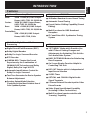 5
5
-
 6
6
-
 7
7
-
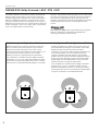 8
8
-
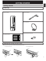 9
9
-
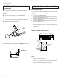 10
10
-
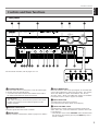 11
11
-
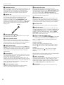 12
12
-
 13
13
-
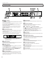 14
14
-
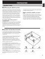 15
15
-
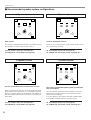 16
16
-
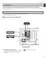 17
17
-
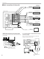 18
18
-
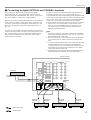 19
19
-
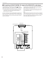 20
20
-
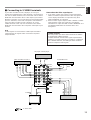 21
21
-
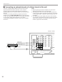 22
22
-
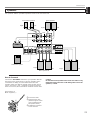 23
23
-
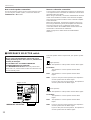 24
24
-
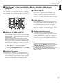 25
25
-
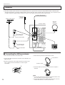 26
26
-
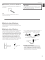 27
27
-
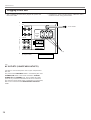 28
28
-
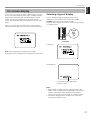 29
29
-
 30
30
-
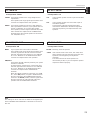 31
31
-
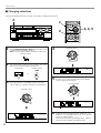 32
32
-
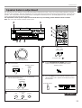 33
33
-
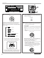 34
34
-
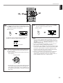 35
35
-
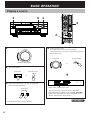 36
36
-
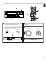 37
37
-
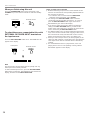 38
38
-
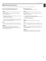 39
39
-
 40
40
-
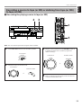 41
41
-
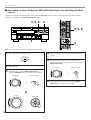 42
42
-
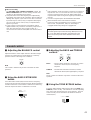 43
43
-
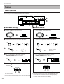 44
44
-
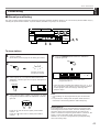 45
45
-
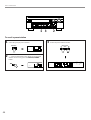 46
46
-
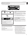 47
47
-
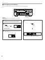 48
48
-
 49
49
-
 50
50
-
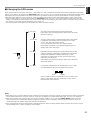 51
51
-
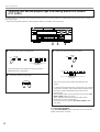 52
52
-
 53
53
-
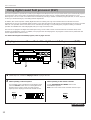 54
54
-
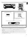 55
55
-
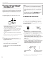 56
56
-
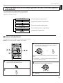 57
57
-
 58
58
-
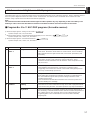 59
59
-
 60
60
-
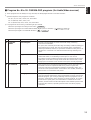 61
61
-
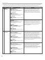 62
62
-
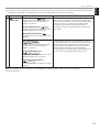 63
63
-
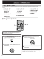 64
64
-
 65
65
-
 66
66
-
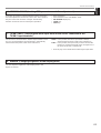 67
67
-
 68
68
-
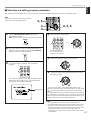 69
69
-
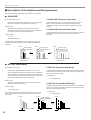 70
70
-
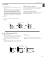 71
71
-
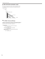 72
72
-
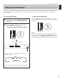 73
73
-
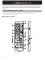 74
74
-
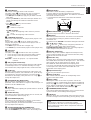 75
75
-
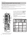 76
76
-
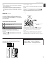 77
77
-
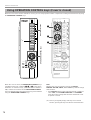 78
78
-
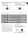 79
79
-
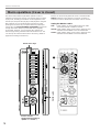 80
80
-
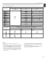 81
81
-
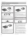 82
82
-
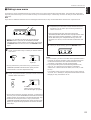 83
83
-
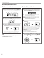 84
84
-
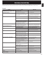 85
85
-
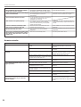 86
86
-
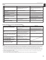 87
87
-
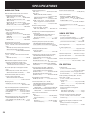 88
88
-
 89
89
-
 90
90


Yamaha RX V2095RDS Handleiding
- Categorie
- Ontvanger
- Type
- Handleiding
- Deze handleiding is ook geschikt voor
in andere talen
- English: Yamaha RX V2095RDS User manual
- italiano: Yamaha RX V2095RDS Manuale utente
- русский: Yamaha RX V2095RDS Руководство пользователя
- français: Yamaha RX V2095RDS Manuel utilisateur
- español: Yamaha RX V2095RDS Manual de usuario
- Deutsch: Yamaha RX V2095RDS Benutzerhandbuch
- português: Yamaha RX V2095RDS Manual do usuário
- dansk: Yamaha RX V2095RDS Brugermanual
- suomi: Yamaha RX V2095RDS Ohjekirja
- čeština: Yamaha RX V2095RDS Uživatelský manuál
- svenska: Yamaha RX V2095RDS Användarmanual
- Türkçe: Yamaha RX V2095RDS Kullanım kılavuzu
- polski: Yamaha RX V2095RDS Instrukcja obsługi
- română: Yamaha RX V2095RDS Manual de utilizare