Panasonic WHSDC03H3E51 Handleiding
- Categorie
- Ruimteverwarmingstoestellen
- Type
- Handleiding

Nederlands Italiano Español English
Operating Instructions
Air-to-Water Heatpump
Model No.
Indoor Unit Outdoor Unit
WH-SDC03H3E5-1
WH-SDC05H3E5-1
WH-SDC07H3E5-1
WH-SDC09H3E5-1
WH-UD03HE5-1
WH-UD05HE5-1
WH-UD07HE5-1
WH-UD09HE5-1
WH-SDC12H6E5
WH-SDC16H6E5
WH-UD12HE5
WH-UD16HE5
WH-SDC09H3E8
WH-SDC12H9E8
WH-SDC16H9E8
WH-UD09HE8
WH-UD12HE8
WH-UD16HE8
WH-SQC09H3E8
WH-SQC12H9E8
WH-SQC16H9E8
WH-UQ09HE8
WH-UQ12HE8
WH-UQ16HE8
WH-SXC09H3E5
WH-SXC12H6E5
WH-UX09HE5
WH-UX12HE5
WH-SXC09H3E8
WH-SXC12H9E8
WH-SXC16H9E8
WH-UX09HE8
WH-UX12HE8
WH-UX16HE8
Operating Instructions
Air-to-Water Heatpump
2-27
Thank you for purchasing Panasonic
product.
Before operating the system, please read these
operating instructions thoroughly and keep them for
future reference.
Installation Instructions attached.
Instrucciones de funcionamiento
Bomba de calor Aire-Agua
28-53
Gracias por comprar un producto
Panasonic.
Antes de utilizar la unidad, sírvase leer
atentamente estas instrucciones de funcionamiento
y conservarlas para futuras consultas.
Instrucciones de instalación adjuntas.
Istruzioni operative
Pompa di calore Aria-acqua
54-79
Grazie per aver acquistato un prodotto
Panasonic.
Prima di utilizzare l’unità, leggere attentamente le
istruzioni e conservare questo opuscolo per potervi
fare riferimento in futuro.
Istruzioni per l’installazione allegate.
Gebruiksaanwijzing
Air-to-Water Warmtepomp
80-105
Hartelijk dank voor het aanschaffen van
een Panasonic-product.
Lees voor u het apparaat gebruikt deze
gebruikshandleiding grondig en bewaar deze voor
toekomstig gebruik.
De instructies voor installatie zijn bijgevoegd.
ACXF55-21971
Manufactured by:
Panasonic AVC Networks Czech, s.r.o.
U Panasoniku 1, 320 84 Plzeň , Czech Republic

2
Table of contents
Safety precautions .........................................................4-6
Remote Controller buttons and display .........................7-9
Initialization .......................................................................9
Quick Menu ....................................................................10
Menus ........................................................................10-23
For user
1 Function setup ...................................................10-11
1.1 Weekly timer
1.2 Holiday timer
1.3 Quiet timer
1.4 Room heater
1.5 Tank heater
1.6 Sterilization
2 System check ....................................................11-12
2.1 Energy monitor
2.2 Water temperatures
2.3 Error history
2.4 Compressor
2.5 Heater
3 Personal setup ...................................................12-13
3.1 Touch sound
3.2 LCD contrast
3.3 Backlight
3.4 Backlight intensity
3.5 Clock format
3.6 Date & Time
3.7 Language
3.8 Unlock password
4 Service contact .......................................................13
4.1 Contact 1 / Contact 2
For installer
5 Installer setup > System setup ...........................14-18
5.1 Optional PCB connectivity
5.2 Zone & Sensor
5.3 Heater capacity
5.4 Anti freezing
5.5 Tank connection
5.6 Buffer tank connection
5.7 Tank heater
5.8 Base pan heater
5.9 Alternative outdoor sensor
5.10 Bivalent connection
5.11 External SW
5.12 Solar connection
5.13 External error signal
5.14 Demand control
5.15 SG ready
5.16 External compressor SW
5.17 Circulation liquid
5.18 Heat-Cool SW
5.19 Force heater
6 Installer setup > Operation setup .......................18-22
6.1 Heat
6.2 Cool
6.3 Auto
6.4 Tank
7 Installer setup > Service setup ...........................22-23
7.1 Pump maximum speed
7.2 Pump down
7.3 Dry concrete
7.4 Service contact
Cleaning instructions ......................................................24
Troubleshooting .........................................................25-26
Information ......................................................................27

3
English
Outdoor
Unit
Power Supply
Solar Panel
Radiator
Shower
Fan Coil
Unit
Floor
Heating
Water Tank Unit
Indoor Unit
Remote Controller
The illustrations in this manual are for explanation purposes only and may differ from the actual unit.
They are subject to change without notice for future improvement.
System overview
Before use, make sure the system has been installed correctly by an
authorised dealer according to the given instructions.
• Panasonic Air-to-Water Heatpump is a split system, consisting of two units: indoor and outdoor units. This system
is designed to operate with Panasonic Water Tank Unit. Unless used together with the Panasonic Water Tank Unit,
Panasonic does not guarantee any normal operation nor the reliability of the system.
• These operating instructions describe how to operate the system using the indoor and outdoor units.
• As for the operation of other products such as water tank, radiator, external thermo controller, and underfloor units, refer
to the operating instructions of each product.
• Some functions described in this manual may not be applicable to your system.
• Consult your nearest authorised dealer for further information.
*1 The system is locked to operate without COOL mode. It can be unlocked only by authorised installers or our authorised
service partners.
*2 Only displayed when COOL mode is unlocked (This means when COOL mode is available)
Operating conditions
HEATING
*
1
COOLING
For H (series) WH-SDC series WH-SXC series, WH-SQC series
Water outlet temperature (°C)
(Min. / Max.)
20 / 55
20 / 55 (Below Ambient -15°C) *
3
20 / 60 (Above Ambient -10°C) *
3
5 / 20
Outdoor ambient temperature (°C)
(Min. / Max.)
-20 / 35 -28 / 35 16 / 43
When the outdoor temperature is out of the range in the table, the heating capacity will drop significantly and the outdoor unit
may stop operating for its protection.
The unit will restart automatically after the outdoor temperature returns to the specified range.
*3 Between outdoor ambient -10°C and -15°C, the water outlet temperature gradually decreases from 60°C to 55°C.

4
To prevent personal injury, injury to
others or property damage, please
comply with the following:
Incorrect operation due to failure to
follow instructions below may cause
harm or damage, the seriousness of
which is classified as below:
WARNING
This sign warns of
death or serious
injury.
CAUTION
This sign warns of
injury or damage
to property.
The instructions to be followed are
classified by the following symbols:
This symbol denotes
an action that is
PROHIBITED.
These symbols denote
actions COMPULSORY.
WARNING
Indoor unit and outdoor unit
This appliance may be used by
children aged from 8 years and
above and persons with reduced
physical, sensory or mental
capabilities or lack of experience
and knowledge if they have been
given supervision or instruction
concerning use of the appliance
in a safe way and understand
the hazards involved. Children
shall not play with the appliance.
Cleaning and user maintenance
shall not be made by children
without supervision.
Please consult an authorised
dealer or specialist to clean the
internal parts, repair, install,
remove and reinstall the unit.
Improper installation and
handling will cause leakage,
electric shock or fire.
Confirm with an authorised
dealer or specialist on usage of
any specified refrigerant type.
Using refrigerant type other than
the specified may cause product
damage, burst and injury etc.
Do not install the unit in
a potentially explosive or
flammable atmosphere. Failure
to do so could result in fire.
Do not insert your fingers
or other objects into the
indoor or outdoor unit; the
rotating parts may cause
injury.
Safety precautions

5
English
Do not touch the outdoor unit
during lightning, it may cause an
electric shock.
Do not sit or step on the
unit, you may fall down
accidentally.
Do not install the indoor unit
outdoors. This is designed for
indoor installation only.
Power supply
Do not use a
modified cord, joint
cord, extension
cord or unspecified
cord to prevent
overheating and fire.
To prevent overheating, fire or
electric shock:
• Do not share the same power
outlet with other equipment.
• Do not operate with wet hands.
• Do not bend or twist power
supply cord.
If the supply cord is damaged,
it must be replaced by the
manufacturer, service agent or
similarly qualified persons in
order to avoid a hazard.
This unit is equipped with
Residue Current Circuit Breaker
(RCCB). Ask an authorised
dealer to check RCCB operation
regularly, especially after
installation, inspection, and
maintenance. RCCB malfunction
may result in electric shock and/
or fire.
It is strongly recommended that
Install Residual Current Device
(RCD) on-site to prevent electric
shock and/or fire.
Before obtaining access to
terminals, all supply circuits must
be disconnected.
Stop using the product if any
abnormality/failure occurs and
disconnect the power supply.
(Risk of smoke/fire/electric
shock)
Examples of abnormality/failure
• RCCB trips frequently.
• Burning smell is observed.
• Abnormal noise or vibration of
the unit is observed.
• Hot water leaks from the indoor
unit.
Contact your local dealer
immediately for maintenance/
repair.
Wear gloves during inspection
and maintenance.
This equipment must be earthed
to prevent electrical shock or fire.
Prevent electric shock by
disconnecting the power supply
- Before cleaning or servicing.
- When extended non-use.
This appliance is for multiple
uses. To avoid electric shock,
burn and/or fatal injury, make
sure to disconnect all power
supplies before accessing any
terminal in the indoor unit.
Safety precautions

6
CAUTION
Indoor unit and outdoor unit
Do not wash the indoor unit
with water, benzine, thinner
or scouring powder to avoid
damage or corrosion on the unit.
Do not install the unit close
to any combustibles or in a
bathroom. Otherwise, it may
cause electric shock and/or fire.
Do not touch the water discharge
pipe of the indoor unit during
operation.
Do not place any material on the
unit or under it.
Do not touch the sharp
aluminium fin; sharp parts
may cause injury.
Do not use the system during
sterilization in order to prevent
scalding with hot water, or
overheating of shower.
Prevent water leakage by
ensuring that the drainage pipe
is connected properly.
After a long period of use, make
sure the installation rack is not
deteriorated. The deteriorated
rack may cause the unit to fall
down.
Ask an authorised dealer
to determine the level of
sterilization function field settings
according to the local laws and
regulations.
Remote Controller
Do not wet the Remote
Controller. Failure to do so may
result in electric shock and/or
fire.
Do not press the buttons on the
Remote Controller using hard
and sharp objects. Failure to do
so may cause damage to the
unit.
Do not wash the Remote
Controller using water, benzine,
thinner or scouring powder.
Do not inspect or maintain the
Remote Controller by yourself.
Consult an authorised dealer in
order to prevent personal injury
caused by incorrect operation.
Safety precautions

7
English
Remote Controller buttons and display
Buttons / Indicator
1
Quick Menu button
(For more details, refer to the separate
Quick Menu Guide.)
2
Back button
Returns to the previous screen
3 LCD Display
4
Main Menu button
For function setup
5
ON/OFF button
Starts/Stops operation
6
Operation indicator
Illuminates during operation, blinks during
alarm.
Press centre
No glove
No pen
2
1
4
5
6
3
Cross key buttons
Selects an item.
Enter button
Fixes the selected content.
Up
Down
Left Right
Safety precautions / Remote Controller buttons and display

8
Remote Controller buttons and display
Display
1 Mode selection
*
1,
*
2
AUTO
• Depending on the preset outdoor
temperature, the system selects
HEAT or *
1,
*
2
COOL operation mode.
Auto Heat Auto Cool
*
1,
*
2
COOL • COOL operation is either turned
ON or OFF.
• The outdoor unit provides cooling
to the system.
*
1,
*
2
AUTO
+ TANK
• Depending on the preset outdoor
temperature, the system selects
HEAT + TANK or *
1,
*
2
COOL +
TANK operation mode.
Auto Heat Auto Cool
*
1,
*
2
COOL
+ TANK
• The outdoor unit provides cooling
to the system.
• The outdoor unit provides heating
when boiling tank.
HEAT
• HEAT operation is either turned
ON or OFF.
• The outdoor unit provides heat to
the system.
TANK • TANK operation is either turned
ON or OFF.
• The outdoor unit provides heat to
the water tank.
HEAT
+ TANK
• The outdoor unit provides heat to
the water tank and the system.
• This mode can be selected only
when the water tank is installed.
* The direction icons point to the currently
active mode.
• Room operation / Tank operation.
• Deice operation.
2
Operation icons
The status of operation is displayed.
Icon will not display (under operation OFF screen) whenever operation is OFF except weekly timer.
Holiday operation status Weekly Timer operation status Quiet operation status
Zone: Room Thermostat
→Internal sensor status
Powerful operation status
Demand Control or
SG ready or SHP status
Room Heater status Tank Heater status Solar status
Bivalent status
(Boiler)
2 43
1
5
6
7
*1
The system is locked to operate without COOL mode. It can be unlocked only by authorised installers or our authorised service partners.
*2 Only displayed when COOL mode is unlocked (This means when COOL mode is available).

9
English
Initialization
Before starting to install the various menu settings, please initiate the Remote Controller by selecting the language of
operation and installing the date and time correctly.
When power is turned on for the first time, it becomes the setting screen automatically. It can also be set from personal
setting of the menu.
Selecting the language
LCD blinking
Wait while the display is initializing.
When initializing screen ends, it turns to
normal screen.
When any button is pressed, language setting
screen appears.
1
Scroll with
and to select the language.
2
Press to confirm the selection.
Setting the clock
1
Select with
or how to display the time,
either 24h or am/pm format (for example, 15:00
or 3:00 pm).
2
Press to confirm the selection.
3
Use
and to select year, month, day, hour
and minutes. (Select and move with and
press to confirm.)
4
Once the time is set, time and day will appear
on the display even if the Remote Controller is
turned OFF.
3 Temperature of each zone
4 Time and day
5 Water Tank temperature
6 Outdoor temperature
7 Sensor type/Set temperature type icons
Water Temperature
→Compensation curve
Water Temperature
→Direct
Pool only
Room Thermostat
→External
Room Thermostat
→Internal
Remote Controller buttons and display / Initialization

10
Menus
For user
Select menus and determine settings according to the system
available in the household. All initial settings must be done by an
authorised dealer or a specialist. It is recommended that all alterations
of the initial settings are also done by an authorised dealer or a
specialist.
• After initial installation, you may manually adjust the settings.
• The initial setting remains active until the user changes it.
• The Remote Controller can be used for multiple installations.
• Ensure the operation indicator is OFF before setting.
• The system may not work properly if set wrongly.
Please consult an authorised dealer.
To display <Main Menu>:
To select menu:
To confirm the selected content:
After the initial settings have been completed, you can select a quick menu from the following options and edit the setting.
1
Press
to display the quick menu.
Force DHW Powerful Quiet Force Heater
Weekly Timer Force Defrost Error Reset R/C Lock
2
Use to select menu.
3
Press to turn on/off the select menu.
Quick Menu
Menu Default Setting Setting Options / Display
1 Function setup
1.1
Weekly timer
Once the weekly timer is set
up, User can edit from Quick
Menu.
To set up to 6 patterns of
operation on a daily basis.
• Disabled if Heat-Cool SW
is select “Yes” or if Force
Heater is on.
Timer setup
Select day of the week and
set the patterns needed
(Time / Operation ON/OFF / Mode)
Timer copy
Select day of the week

11
English
Menu Default Setting Setting Options / Display
1.2
Holiday timer
To save energy, a holiday
period may be set to either turn
OFF the system or lower the
temperature during the period.
OFF
ON
Holiday start and end.
Date and time
OFF or lowered temperature
• Weekly timer setting may be temporarily disabled during Holiday timer setting
but it will be restored once the Holiday timer is completed.
1.3
Quiet timer
To operate quietly during the
preset period.
6 patterns may be set.
Level 0 means the mode is off.
Time to start Quiet :
Date and time
Level of quietness:
0 ~ 3
1.4
Room heater
To set the room heater ON
or OFF.
OFF
1.5
Tank heater
To set the tank heater ON or
OFF.
OFF
• Available only if connected to the tank.
1.6
Sterilization
To set the auto sterilization ON
or OFF.
OFF
• Available only if connected to the tank.
• Do not use the system during sterilization in order to prevent scalding with hot water, or overheating of shower.
• Ask an authorised dealer to determine the level of sterilization function field settings according to the local laws and
regulations.
2 System check
2.1
Energy monitor
Present or historical chart
of energy consumption,
generation or COP.
Present
Select and retrieve
Historical chart
Select and retrieve
• COP= Coefficient of Performance.
• For historical chart, the period is selected from 1 day/1 week/1year.
• Energy consumption (kWh) of heating, *
1,
*
2
cooling, tank and total may be retrieved.
• The total power consumption is an estimated value based on AC 230 V and may
differ from value measured by precise equipment.
2.2
Water temperatures
Shows all water temperatures
in each area.
Actual water temperature of 8 items:
Inlet / Outlet / Zone 1 / Zone 2 / Tank / Buffer
tank / Solar / Pool
Select and retrieve
Menus
For user
Quick Menu / Menus
*1
The system is locked to operate without COOL mode. It can be unlocked only by authorised installers or our authorised service partners.
*2 Only displayed when COOL mode is unlocked (This means when COOL mode is available).

12
Menus
For user
Menu Default Setting Setting Options / Display
2.3
Error history
• Refer to Troubleshooting for
error codes.
• The most recent error code is
displayed at the top.
Select and retrieve
2.4
Compressor
Shows the compressor
performance.
Select and retrieve
2.5
Heater
Total hours of ON time for
Room heater/Tank heater.
Select and retrieve
3 Personal setup
3.1
Touch sound
Turns the operation sound
ON/OFF.
ON
3.2
LCD contrast
Sets the screen contrast.
3
3.3
Backlight
Sets the duration of screen
backlight.
1 min
3.4
Backlight intensity
Sets screen backlight
brightness.
4
3.5
Clock format
Sets the type of clock display.
24h

13
English
Menu Default Setting Setting Options / Display
3.6
Date & Time
Sets the present date and
time.
Year / Month / Day / Hour / Min
3.7
Language
Sets the display language for
the top screen.
• For Greek, please refer to the
English version.
ENGLISH / FRANÇAIS /
DEUTSCH / ITALIANO /
ESPAÑOL / DANISH /
SWEDISH / NORWEGIAN /
POLISH / CZECH /
NEDERLANDS / TÜRKÇE /
SUOMI / MAGYAR /
SLOVENŠČINA / HRVATSKI
3.8
Unlock password
4 digit password for all the
settings.
0000
4 Service contact
4.1
Contact 1 / Contact 2
Preset contact number for
installer.
Select and retrieve
Menus

14
Menus
For installer
Menu Default Setting Setting Options / Display
5 Installer setup System setup
5.1
Optional PCB connectivity
To connect to the external PCB
required for servicing.
No
• If the external PCB is connected (optional), the system will have following additional functions:
1
Buffer tank connection and control over its function and temperature.
2
Control over 2 zones (including the swimming pool and the function to heat water in it).
3
Solar function (the solar thermal panels connected to either the DHW (Domestic Hot Water) Tank or the Buffer Tank.
4
External compressor switch.
5
External error signal.
6
SG ready control.
7
Demand control.
8
Heat-Cool SW
5.2
Zone & Sensor
To select the sensors and to
select either 1 zone or 2 zone
system.
Zone
• After selecting 1 or 2 zone system, proceed to
the selection of room or swimming pool.
• If the swimming pool is selected, the
temperature must be selected for
T temperature between 0 °C ~10 °C.
Sensor
* For room thermostat, there is a further
selection of external or internal.
5.3
Heater capacity
To reduce the heater power if
unnecessary.*
3 kW / 6 kW / 9 kW
3 kW / 6 kW / 9 kW
* Options of kW vary
depending on the model.
5.4
Anti freezing
To activate or deactivate the
water freeze prevention when
the system is OFF.
Yes
5.5
Tank connection
To connect tank to the system.
No
5.6
Buffer tank connection
To connect tank to the system
and if selected YES, to set
T temperature.
• The optional PCB
connectivity must be selected
YES to enable the function.
• If the optional PCB
connectivity is not selected,
the function will not appear
on the display.
No
Yes
5 °C Set T for Buffer Tank

15
English
Menu Default Setting Setting Options / Display
5.7
Tank heater
To select external or internal
tank heater and if External is
selected, set a timer for the
heater to come on.
* This option is available if
Tank connection is selected
(YES).
Internal
External
0:20
Tank heater ON time
set.
5.8
Base pan heater
To select whether or not
optional base pan heater is
connected.
* Type A - The base pan heater
activates only during
deice operation.
* Type B -The base pan heater
activates when
outdoor ambient
temperature is 5 °C
or lower.
No
Yes
A
Set base pan heater
type*.
5.9
Alternative outdoor sensor
To select an alternative
outdoor sensor.
No
5.10
Bivalent connection
To select a bivalent connection
to allow an additional heat
source such as a boiler to
heat-up the buffer tank and
domestic hot water tank
when heatpump capacity is
insufficient at low outdoor
temperature. The bivalent
feature can be set-up either in
alternative mode (heatpump
and boiler operate alternately),
or in parallel mode (both
heatpump and boiler operate
simultaneously), or in advance
parallel mode (heatpump
operates and boiler turns on
for buffer-tank and/or domestic
hot water depending on the
control pattern setting options).
No
Yes
-5 °C
Set outdoor temperature
for turn ON Bivalent
connection.
Yes After selecting the outdoor temperature
Control pattern
Alternative / Parallel / Advanced parallel
• Select advanced parallel for bivalent use of
the tanks.
Menus

16
Menu Default Setting Setting Options / Display
Control pattern Advanced parallel
Heat Selection of the tank
• “Heat” implies Buffer Tank and “DHW” implies
Domestic Hot Water Tank.
Control pattern
Advanced parallel Heat Yes
• Buffer Tank is activated only after selecting
“Yes”.
-8 °C
Set the temperature
threshold to start the
bivalent heat source.
0:30
Delay timer to start the
bivalent heat source
(in hour and minutes).
-2 °C
Set the temperature
threshold to stop the
bivalent heat source.
0:30
Delay timer to stop the
bivalent heat source
(in hour and minutes).
Control pattern Advanced parallel DHW Yes
• DHW Tank is activated only after selecting
“Yes”.
0:30
Delay timer to start the
bivalent heat source
(in hour and minutes).
Menus
For installer

17
English
Menu Default Setting Setting Options / Display
5.11
External SW
No
5.12
Solar connection
• The optional PCB
connectivity must be selected
YES to enable the function.
• If the optional PCB
connectivity is not selected,
the function will not appear
on the display.
No
Yes
Buffer tank Selection of the tank
Yes After selecting the tank
10 °C Set
T ON temperature
Yes After selecting the tank T ON temperature
5 °C
Set
T OFF
temperature
Yes After selecting the tank T ON temperature T OFF temperature
5 °C
Set Antifreeze
temperature
Yes After selecting the tank T ON temperature T OFF temperature
After setting the antifreeze temperature
80 °C Set Hi limit
Menus

18
Menu Default Setting Setting Options / Display
5.13
External error signal
No
5.14
Demand control
No
5.15
SG ready
No
Yes
120 %
Capacity (1) & (2) of
Buffer Tank and DHW
Tank (in %)
5.16
External compressor SW
No
5.17
Circulation liquid
To select whether to circulate
water or glycol in the system.
Water
5.18
Heat-Cool SW
No
5.19
Force heater
To turn on Force heater either
manually (by default) or
automatically.
Manual
6 Installer setup Operation setup
To access to the four major
functions or modes.
4 main modes
Heat / *
1,
*
2
Cool / *
1,
*
2
Auto / Tank
Menus
For installer
*1
The system is locked to operate without COOL mode. It can be unlocked only by authorised installers or our authorised service partners.
*2 Only displayed when COOL mode is unlocked (This means when COOL mode is available).

19
English
Menu Default Setting Setting Options / Display
Installer setup Operation setup
6.1
Heat
To set various water &
ambient temperatures for
heating.
Water temp. for heating ON /
Outdoor temp. for heating OFF /
T for heating ON /
Outdoor temp. for heater ON
Water temp. for heating ON
Compensation
curve
Heating ON
temperatures in
compensation curve or
direct input.
Water temp. for heating ON Compensation curve
X axis: -5 °C, 15 °C
Y axis: 55 °C, 35 °C
Input the 4 temperature
points
(2 on horizontal X axis,
2 on vertical Y axis).
• Temperature range: X axis: -15 °C ~ 15 °C, Y axis: See below
• Temperature range for the Y axis input depends on the model:
1. WH-SDC model : 20°C ~ 55°C
2. WH-SHF model & Back up heater is enabled: 25°C ~ 65°C
3. WH-SHF model & Back up heater is disabled: 35°C ~ 65°C
4. WH-SXC/SQC model : 20°C ~ 60°C
• If 2 zone system is selected, the 4 temperature points must also be input for Zone 2.
• “Zone 1” and “Zone 2” will not appear on the display if only 1 zone system.
Water temp. for heating ON Direct
35 °C
Temperature for heating
ON
• Min. ~ Max. range is conditional as follows:
1. WH-SDC model : 20°C ~ 55°C
2. WH-SHF model & Back up heater is enabled: 25°C ~ 65°C
3. WH-SHF model & Back up heater is disabled: 35°C ~ 65°C
4. WH-SXC/SQC model : 20°C ~ 60°C
• If 2 zone system is selected, temperature set point must input for Zone 2.
• “Zone 1” and “Zone 2” will not appear on the display if only 1 zone system.
Outdoor temp. for heating OFF
24 °C
Temperature for heating
OFF
Menus

20
Menu Default Setting Setting Options / Display
T for heating ON
5 °C
Set T for heating
ON.
Outdoor temp. for heater ON
0 °C
Temperature for
heater ON
6.2
*
1,
*
2
Cool
To set various water & ambient
temperatures for cooling.
Water temperatures for cooling ON
and
T for cooling ON.
Water temp. for cooling ON
Compensation curve
Cooling ON
temperatures in
compensation curve or
direct input.
Water temp. for cooling ON Compensation curve
X axis: 20 °C, 30 °C
Y axis: 15 °C, 10 °C
Input the 4 temperature
points
(2 on horizontal X axis,
2 on vertical Y axis)
• If 2 zone system is selected, the 4 temperature points must also be input for Zone 2.
• “Zone 1” and “Zone 2” will not appear on the display if only 1 zone system.
Water temp. for cooling ON Direct
10 °C
Set temperature for
Cooling ON
• If 2 zone system is selected, temperature set point must input for Zone 2.
• “Zone 1” and “Zone 2” will not appear on the display if only 1 zone system.
T for cooling ON
5 °C Set
T for cooling ON
Menus
For installer
*1
The system is locked to operate without COOL mode. It can be unlocked only by authorised installers or our authorised service partners.
*2 Only displayed when COOL mode is unlocked (This means when COOL mode is available).

21
English
Menu Default Setting Setting Options / Display
6.3
*
1,
*
2
Auto
Automatic switch from Heat to
Cool or Cool to Heat.
Outdoor temperatures for switching from Heat
to Cool or Cool to Heat.
Outdoor temp. for (Heat to Cool) /
Outdoor temp. for (Cool to Heat)
Outdoor temp. for (Heat to Cool)
15 °C
Set outdoor temperature
for switching
from Heat to Cool.
Outdoor temp. for (Cool to Heat)
10 °C
Set outdoor temperature
for switching
from Cool to Heat.
6.4
Tank
Setting functions for the tank.
• Available only if connected to
the tank.
Floor operation time (max) /
Tank heat up time (max) /
Tank re-heat temp. /
Sterilization
• The display will show 3 functions at a time.
Floor operation time (max)
8:00
Maximum time for floor
operation
(in hours and minutes)
Tank heat up time (max)
1:00
Maximum time for
heating the tank
(in hours and minutes)
Tank re-heat temp.
-8 °C
Set temperature to
perform reboil of tank
water.
Menus

22
Menu Default Setting Setting Options / Display
Sterilization
Sterilization may be set for 1 or
more days of the week.
Sun / Mon / Tue / Wed / Thu / Fri / Sat
Sterilization: Time
Time of the selected day(s) of the week to
sterilize the tank.
0:00 ~ 23:59
Sterilization: Boiling temp.
65 °C
Set boiling temperatures
for sterilize the tank.
Sterilization: Ope. time (max)
0:10
Set sterilizing time
(in hours and minutes)
7 Installer setup Service setup
7.1
Pump maximum speed
To set the maximum speed of
the pump.
Setting the flow rate, max. duty and operation
ON/OFF of the pump.
Flow rate: XX:X L/min
Max. Duty: 0x40 ~ 0xFE,
Pump: ON/OFF/Air Purge
7.2
Pump down
To set the pump down
operation.
Pump down operation
ON
Menus
For installer

23
English
Menu Default Setting Setting Options / Display
Installer setup Service setup
7.3
Dry concrete
To dry the concrete (floor,
walls, etc.) during construction.
Do not use this menu for any
other purposes and in period
other than during
construction.
Edit to set the temperature of dry concrete.
ON / Edit
Edit
Stages: 1
Temperature: 25 °C
Heating temperature for
drying the concrete.
Select the desired
stages: 1 ~ 10,
range: 1 ~ 99
ON
Confirm the setting temperatures of dry
concrete for each stage.
7.4
Service contact
To set up to 2 contact names
and numbers for the User.
Service engineer’s name and contact number.
Contact 1 / Contact 2
Contact 1 / Contact 2
Contact name or number.
Name / phone icon
Input name and number.
Contact name: alphabet a ~ z.
Contact number: 1 ~ 9
Menus

Indoor unit
• Do not splash water directly.
Wipe the unit gently with a soft
dry cloth.
24
Cleaning instructions
To ensure optimal performance of the system, cleaning has to be carried out at regular intervals.
Consult an authorised dealer.
• Disconnect the power supply before cleaning.
• Do not use benzine, thinner or scouring powder.
• Use only soap (
pH7) or neutral household detergent.
• Do not use water hotter than 40 °C.
Water filter
• Clean the water filter at least once a year.
Failure to do so may cause the filter to clog up,
which may lead to system breakdown. Consult
an authorised dealer.
Outdoor unit
• Do not obstruct the air inlet and outlet vents.
Failure to do so may result in low performance
or system breakdown. Remove any obstruction
to assure the ventilation.
• When it snows, clean and remove snow
around the outdoor unit to prevent the air inlet
and outlet vents from being covered with snow.
Inspection
• In order to ensure optimal performance of the units,
seasonal inspections on the units, water filter and field
wiring have to be carried out at regular intervals. Consult
an authorised dealer regarding maintenance.
• Clear any obstruction on the air inlet and outlet vents of
the outdoor unit.
For extended non-use
• Disconnect the power supply.
Non serviceable criteria
Disconnect the power supply
then please consult an authorised dealer under the
following conditions:
• Abnormal noise during operation.
• Water/foreign particles have entered the Remote
Controller.
• Water leaks from the indoor unit.
• Circuit breaker switches off frequently.
• Power cord becomes excessively warm.
0.2
0.4
0.30.1
MPa
bar
2
13
4
Water pressure gauge
• Do not press or hit the glass cover using hard
and sharp objects. Failure to do so may cause
damage to the unit.
• Ensure that the water pressure is between 0.05
and 0.3 MPa (0.1 MPa = 1 bar).
• In case the water pressure is out of the above
range, consult an authorised dealer.

25
English
The following symptoms do not indicate malfunction.
Symptom Cause
Water flowing sound during operation. • Refrigerant flow inside the unit.
Operation is delayed a few minutes
after restarting.
• The delay is a protection for the compressor.
Outdoor unit emits water/steam. • Condensation or evaporation occurring in the pipes.
Steam comes out of the outdoor unit in
the heating mode.
• It is caused by defrost operation in the heat exchanger.
Outdoor unit does not operate. • It is caused by the protection control of the system when outdoor temperature is
out of the operating range.
System operation switches off. • It is caused by the protection control of the system. When the water inlet
temperature is lower than 10 °C, the compressor stops and the backup heater
power turns on.
System is hard to heat up. • When the panel and the floor are heated simultaneously, warm water temperature
may decrease, which may reduce the heating ability of the system.
• When the outdoor air temperature is low, the system may need longer time to heat
up.
• Discharge outlet or intake inlet in the outdoor unit is blocked by some obstacle,
such as a pile of snow.
• When the preset water outlet temperature is low, the system may need longer time
to heat up.
System does not heat up instantly. • System will take some time to heat up the water if it starts to operate at cold water
temperature.
Backup heater is automatically turned
ON when it is disabled.
• It is caused by the protection control of the indoor unit heat exchanger.
Operation starts automatically when
the timer is not set.
• Sterilization timer has been set.
Loud refrigerant noise continues for
several minutes.
• It is caused by protection control during deice operation at outdoor ambient
temperature lower than -10 °C.
*
1,
*
2
COOL mode is unavailable. • System has locked to operate in HEAT mode only.
Check the following before calling for servicing.
Symptom Check
Operation in HEAT/*
1,
*
2
COOL mode is
not working efficiently.
• Set the temperature correctly.
• Close the panel heater/cooler valve.
• Clear any obstruction in the air inlet and air outlet vents of the outdoor unit.
Noisy during operation. • Outdoor unit or indoor unit has been installed at an incline.
• Close the cover properly.
System does not work. • Circuit breaker has tripped/activated.
Operation LED is not lit or nothing is
displayed on the Remote Controller.
• Power supply is working correctly, or a power failure has occurred.
Troubleshooting
Cleaning instructions / Troubleshooting
*1
The system is locked to operate without COOL mode. It can be unlocked only by authorised installers or our authorised service partners.
*2 Only displayed when COOL mode is unlocked (This means when COOL mode is available).

26
Error No. Error explanation
H12
Capacity mismatch
H15
Compressor sensor error
H20
Pump error
H23
Refrigerant sensor error
H27
Service valve error
H28
Solar sensor error
H31
Pool sensor error
H36
Buffer tank sensor error
H38
Brand mismatch error
H42
Low pressure protection
H43
Zone 1 sensor error
H44
Zone 2 sensor error
H62
Water flow error
H63
Low pressure sensor error
H64
High pressure sensor error
H65
Deice water circulation error
H67
External thermistor 1 error
H68
External thermistor 2 error
H70
Back-up heater OLP error
H72
Tank sensor error
H74
PCB communication error
H75
Low water temp protection
H76
RC-Indoor communication error
H90
Indoor-Outdoor communication error
H91
Tank heater OLP error
H95
Voltage connection error
H98
High pressure protection
H99
Indoor freeze prevention
Error No. Error explanation
F12
Pressure switch activated
F14
Poor compressor rotation
F15
Fan motor lock error
F16
Current protection
F20
Compressor overload protection
F22
Transistor module overload protection
F23
DC peak
F24
Refrigerant cycle error
F25
*
1,
*
2
Cool / heat cycle error
F27
Pressure switch error
F29
Low discharge super heat
F30
Water outlet sensor 2 error
F32
Internal thermostat error
F36
Outdoor ambient sensor error
F37
Water inlet sensor error
F40
Outdoor discharge sensor error
F41
Power factor correction error
F42
Outdoor heat exchanger sensor error
F43
Outdoor defrost sensor error
F45
Water outlet sensor error
F46
Current transformer disconnection
F48
Evaporator outlet sensor error
F49
Bypass outlet sensor error
F95
*
1,
*
2
Cooling high pressure error
* Some error code may not be applicable to your model.
Consult authorised dealer for clarification.
Blinking
Error number
Troubleshooting
Below is a list of error codes that may appear on the
display when there is some trouble with the system setting
or operation.
When the display shows an error code as indicated below,
contact the number registered in the Remote Controller or
a nearest authorised installer.
All switches are disabled except
and .
*1
The system is locked to operate without COOL mode. It can be unlocked only by authorised installers or our authorised service partners.
*2 Only displayed when COOL mode is unlocked (This means when COOL mode is available).

27
English
Information when connect to Network Adaptor (Optional Accessories Part)
WARNING
Before use, check the safety around the Air-to-Water system. Confirm human and living objects at
surrounding before operation.
Incorrect operation due to failure to follow instructions may cause harm and damage.
Confirm the below before operation (inside premises)
- Timer setting condition. Unpredictable on/off operation may cause serious injury or damage to human and
living objects.
Confirm the below before and during operation (outside from premises)
- If is known someone in the premises, notify the person from outside of new operation setting prior executing.
This is to avoid sudden shock to the person and any serious health breakdown duly from operation changed.
- Please do not use this appliance when infant, physical dissability person or elderly who unable to operate the
appliance by themselves in the premises.
- Check the setting and operation status frequently.
- Stop the operation when error code is displayed and consult an authorised dealer or specialist.
Please confirm before use
• The system may not usable when communication condition is bad. Please check “Operation Status” from the application
display after operation. The following condition may happen in the remote operation.
- Cannot operate, operation time is not reflected.
- Air-to-Water operation is not reflected when operation is set outside of premises.
• It is recommended to lock screen the smart phone device to prevent miss-operation.
• Do not use other remote controller, communication and operation device not specified by an authorised dealer or specialist.
• Use under the agreement of “Terms of Service” and “Handling of Personal Information” of Panasonic Smart Application.
• For extended non-use of Panasonic Smart Application, disconnect the network adaptor from the device.
Information for Users on Collection and Disposal of Old Equipment
These symbols on the products, packaging, and/or accompanying documents mean that used electrical and
electronic products should not be mixed with general household waste.
For proper treatment, recovery and recycling of old products, please take them to applicable collection points
in accordance with your national legislation.
By disposing of these products correctly, you will help to save valuable resources and prevent any potential
negative effects on human health and the environment which could otherwise arise from inappropriate waste
handling.
For more information about collection and recycling of old products, please contact your local municipality,
your waste disposal service or the point of sale where you purchased the items.
Penalties may be applicable for incorrect disposal of this waste, in accordance with national legislation.
For business users in the European Union
If you wish to discard electrical and electronic equipment, please contact your dealer or supplier for further
information.
[Information on Disposal in other Countries outside the European Union]
These symbols are only valid in the European Union. If you wish to discard these items, please contact your
local authorities or dealer and ask for the correct method of disposal.
Information
Troubleshooting / Information

28
Contenido
Precauciones de seguridad .......................................30-32
Botones y pantalla de mando a distancia ..................33-35
Inicialización ...................................................................35
Menú rápido ....................................................................36
Menús ........................................................................36-49
Para el usuario
1 Config. de funciones ..........................................36-37
1.1 Temporiz. semanal
1.2 Temporiz. vacaciones
1.3 Temp. modo silenc.
1.4 Calent. sala
1.5 Resistencia depósito
1.6 Esterilización
2 Comprob. sistema ..............................................37-38
2.1 Monitor de energía
2.2 Tª agua
2.3 Historial de errores
2.4 Compresor
2.5 Resisitencia
3 Config. personal .................................................38-39
3.1 Sonido de contacto
3.2 Contraste LCD
3.3 Retroiluminación
3.4 Intesidad retroilum.
3.5 Formato de hora
3.6 Fecha y Hora
3.7 Idioma
3.8 Desbloq. contraseña
4 Contacto de servicio ...............................................39
4.1 Contacto 1 / Contacto 2
Para el instalador
5 Config. instalador > Ajuste del sistema ...............40-44
5.1 Conectividad opcional placa base
5.2 Zona y sensor
5.3 Capacid. resistencia
5.4 Anti congelacion
5.5 Conexión de dep.
5.6 Conexión del depósito de inercia
5.7 Resistencia depósito
5.8 Res. band. condens.
5.9 Sensor exterior alternativo
5.10 Conexión Bivalente
5.11 Interr. Externo
5.12 Conexión solar
5.13 Señal ext. error
5.14 Control de demanda
5.15 SG ready
5.16 Interr. compres. ext.
5.17 Circul. líquido
5.18 Calor-Frio SW
5.19 Calefactor forzado
6 Config. instalador > Ajuste de operación ...........44-48
6.1 Calor
6.2 Frío
6.3 Auto
6.4 Depósito
7 Config. instalador > Config. servicio ...................48-49
7.1 Máxima velocidad de la bomba
7.2 Recogida de refrig.
7.3 Pavim. seco
7.4 Contacto de servicio
Instrucciones de limpieza ...............................................50
Localización de averías .............................................51-52
Información .....................................................................53

Condiciones de funcionamiento
CALENTAMIENTO
*
1
ENFRIAMIENTO
Para H (serie) Serie
WH-SDC Serie WH-SXC, Serie WH-SQC
Temperatura de salida de agua (°C)
(Mín. / Máx.)
20 / 55
20 / 55 (inferior al ambiente -15 °C) *
3
20 / 60 (superior al ambiente -10 °C) *
3
5 / 20
Temperatura ambiente exterior (ºC)
(Mín. / Máx.)
-20 / 35 -28 / 35 16 / 43
Si la temperatura ambiente exterior está fuera del rango de temperaturas de la tabla, la capacidad térmica disminuirá
significativamente y la unidad exterior podría pararse como medida de protección.
La unidad arrancará de forma automática cuando la temperatura ambiente exterior vuelva a estar dentro del rango especificado.
*3 Cuando la temperatura ambiente exterior se encuentra entre -10 °C y -15 °C, la temperatura de salida del agua baja desde
60 °C hasta 55 °C de manera gradual.
29
Español
Antes de utilizar este sistema se debe cerciorar de su correcta instalación por
parte de un distribuidor autorizado, conforme a las instrucciones facilitadas.
• La bomba de calor aire-agua Panasonic es un sistema partido, compuesto por dos elementos: unidad interior y
unidad exterior. Este sistema se ha diseñado para funcionar junto con un acumulador ACS Panasonic. Panasonic no
garantizará el funcionamiento normal ni la fiabilidad de este sistema en caso no utilizarlo junto con su acumulador ACS
Panasonic.
• Estas instrucciones de funcionamiento describen cómo manejar el sistema utilizando las unidades interior y exterior.
• Para conocer el funcionamiento de otros productos como el acumulador ACS, el radiador, el termostato externo y las
unidades de suelo radiante, consulte las instrucciones de funcionamiento de cada producto.
• Es posible que algunas de las funciones descritas en este manual no se apliquen a su sistema.
• Si necesitara obtener más información puede consultar a su distribuidor autorizado más próximo.
*1 El sistema está bloqueado para funcionar sin el modo FRÍO. Sólo pueden desbloquearlo los instaladores o los servicios
técnicos autorizados.
*2 Se muestra sólo con el modo FRÍO desbloqueado (Esto quiere decir cuando el modo FRÍO esté disponible).
Unidad
Exterior
Alimentación
Eléctrica
Panel solar
Radiador
Ducha
Unidad Tipo
Fan Coil
Suelo
radiante
Acumulador ACS
Unidad Interior
Mando a
distancia
Las ilustraciones de este manual sirven únicamente para describir las explicaciones y pueden no coincidir exactamente
con las del aparato suministrado.
Están sujetas a cambios sin previo aviso con el fin de mejorar el producto.
Vista general del sistema

30
Para evitar lesiones personales,
lesiones a terceros, o daños
materiales, cumpla lo siguiente:
El uso incorrecto por no seguir las
instrucciones puede causar daños o
averías; su gravedad se clasifica con
las indicaciones siguientes:
ADVERTENCIA
Esta indicación
advierte del
posible peligro
de muerte o de
daños graves.
PRECAUCIÓN
Esta indicación
advierte de los
posibles daños
o desperfectos
materiales.
Las instrucciones que deben seguirse
están clasificadas mediante los
siguientes símbolos:
Este símbolo denota
una acción que está
PROHIBIDA.
Estos símbolos indican
aquellas acciones que
son OBLIGATORIAS.
ADVERTENCIA
Unidad interior y unidad exterior
Este aparato puede ser utilizado
por niños a partir de 8 años y
personas con dicapacidad física,
sensorial o mental o falta de
experiencia y conocimientos
si están bajo supervisión o han
recibido instrucciones relativas
al uso del aparato de un modo
seguro y comprenden los riesgos
implícitos. Los niños no deben
jugar con el aparato. La limpieza
y el mantenimiento no debe ser
realizado por niños sin supervisión.
Por favor, consulte a un distribuidor
autorizado o especialista para
limpiar las partes internas, reparar,
instalar, eliminar y reinstalar la
unidad. Una incorrecta manipulación
e instalación puede causar fugas,
descargas eléctricas o incendios.
Confirme con el servicio técnico
autorizado o el especialista el uso
del tipo de refrigerante especificado.
Utilizar un tipo de refrigerante
diferente al tipo especificado puede
provocar daños en el producto,
explosiones y lesiones, etc.
No instale la unidad en ambientes
potencialmente explosivos o
inflamables. En caso contrario,
podría provocar accidentes de
incendios.
No introduzca los dedos u
otros objetos en la unidad
interior o exterior, ya que las
partes rotatorias le podrían
provocar lesiones.
Precauciones de seguridad

31
Español
No toque la unidad exterior durante
un relámpago, ya que podría causar
una descarga eléctrica.
No se siente o apoye sobre
la unidad, se podría caer
accidentalmente.
No instale la unidad interior en el
exterior. Este modelo está diseñado
para instalarse sólo en el interior.
Fuente de energía
No comparta la misma
salida eléctrica con
otros equipos para
evitar el calentamiento
e incendios.
Para evitar el sobrecalentamiento,
incendio o descarga eléctrica:
•
No comparta la misma toma de
corriente con otros equipos.
•
No lo manipule con las manos
mojadas.
•
No doble ni retuerza el cable de
alimentación.
Para evitar riesgos, si el cable de
alimentación está dañado y es
necesario cambiarlo, deberá hacerlo
el fabricante, un representante
del servicio técnico o una persona
cualificada.
Esta unidad está equipada con un
interruptor diferencial (RCCB). Pida
a un servicio técnico autorizado que
verifique regularmente el funcionamiento
del interruptor diferencial (RCCB),
especialmente después de la
instalación, inspección o mantenimiento.
Un mal funcionamiento del interruptor
diferencial (RCCB) puede provocar una
descarga eléctrica y/o un incendio.
Se recomienda altamente conectarlo
a un diferencial (RCD) de la
instalación para prevenir descargas
eléctricas y/o incendios.
Todos los circuitos de alimentación
se deben desconectar antes de
acceder a los terminales.
En caso de que ocurra cualquier
fallo o anomalía con este
producto, debe dejar de utilizarlo
y desconectar su alimentación.
(Riesgo de humo/fuego/
descarga eléctrica)
Ejemplos de anomalía/fallo
• El RCCB salta frecuentemente.
• Se percibe olor a humo.
• Se observa ruido anormal o
vibración en la unidad.
• Filtraciones de agua caliente
desde la unidad interior.
Contacte inmediatamente con
su proveedor local para su
mantenimiento/reparación.
Para realizar inspecciones o
mantenimiento póngase guantes.
Este equipo deberá conectarse
a tierra para evitar descargas
eléctricas o incendios.
Desconecte la alimentación
eléctrica para evitar descargas
- Antes de limpiarlo o repararlo.
- En períodos prolongados sin
utilizar.
Este es un electrodoméstico
para usos múltiples. Para
evitar descargas eléctricas,
quemaduras o daño mortal,
cerciórese de desconectar todos
los cables de alimentación antes
de acceder a cualquier terminal
de la unidad interior.
Precauciones de seguridad

32
PRECAUCIÓN
Unidad interior y unidad exterior
No lave la unidad interior con agua,
benceno, disolvente o limpiador en
polvo para evitar daños o corrosión
en la unidad.
No instale la unidad cerca a ningún
combustible o en un baño. De lo
contrario, podría producir descargas
eléctricas y/o incendios.
No toque el tubo de vaciado
de la unidad interior durante su
funcionamiento.
No deje ningún material encima o
debajo de la unidad.
No tocar las partes de
aluminio angulosas, pueden
causar daños.
No utilice el sistema durante
la esterilización para prevenir
quemaduras por agua caliente o el
sobrecalentamiento de la ducha.
Evite las fugas de agua
asegurándose que conecta
correctamente la tubería de drenaje.
Tras un período prolongado sin
utilizarlo, asegúrese de que el
bastidor de instalación no se
encuentra deteriorado. El deterioro
del bastidor puede causar que la
unidad se desprenda.
Para determinar los ajustes del nivel
de la función de esterilización de
acuerdo con las leyes y reglamentos
locales, consulte a un distribuidor
autorizado.
Mando a distancia
No moje el mando a distancia.
De hacerlo, podría provocar
descargas eléctricas y/o
incendios.
No presione los botones del
mando a distancia con objetos
duros y punzantes. De hacerlo,
podría causar daños a la unidad.
No limpie el mando a distancia
con agua, benceno, disolvente o
polvo abrasivo.
No inspeccione ni mantenga
usted mismo el mando a
distancia. Para prevenir daños
personales debidos a manejo
incorrecto, consulte a un
distribuidor autorizado.
Precauciones de seguridad

33
Español
Botones y pantalla de mando a distancia
2
1
4
5
6
Botones / Indicador
1
Botón Menú rápido
(Para mayor detalle, consulte la guía
específica del menú rápido)
2
Botón Atrás
Vuelve a la pantalla anterior
3 Pantalla LCD
4
Botón Menú principal
Para ajustar funciones
5
Botón ON/OFF
Arranque/parada de funcionamiento
6
Indicador de funcionamiento
Iluminado durante el funcionamiento,
destella en estado de alerta
3
Presionar en el
centro
No use guantes
No use
bolígrafos
Botones del teclado en cruz
Seleccionan un elemento.
Tecla Entrar
Fija el elemento seleccionado.
Arriba
Abajo
Izquierda
Derecha
Precauciones de seguridad / Botones y pantalla de mando a distancia

34
Botones y pantalla de mando a distancia
2 43
1
5
6
7
Pantalla
1 Selección del modo
*
1,
*
2
AUTO
• El sistema selecciona el funcionamiento
en modo CALOR o
*
1,
*
2
FRÍO.
Calor
automático
Frío
automático
*
1,
*
2
FRÍO • El funcionamiento de FRÍO está
ENCENDIDO o APAGADO.
• La unidad exterior está
suministrando frío al sistema.
*
1,
*
2
AUTO +
DEPOSITO
• El sistema selecciona el
funcionamiento en modo CALOR
+ DEPOSITO o *
1,
*
2
FRÍO +
DEPOSITO en función del ajuste de
la temperatura ambiente exterior.
Calor
automático
Frío
automático
*
1,
*
2
FRÍO
+ DEPOSITO
• La unidad exterior está
suministrando frío al sistema.
• La unidad exterior suministra calor
cuando hierbe el acumulador.
CALOR
•
EL funcionamiento de CALOR está
ENCENDIDO o APAGADO.
•
La unidad exterior está suministrando
calor al sistema.
DEPOSITO
•
El funcionamiento del DEPÓSITO
está ENCENDIDO o APAGADO.
•
La unidad exterior está suministrando
calor al acumulador ACS.
CALOR
+
DEPOSITO
• La unidad exterior está suministrando
calor al acumulador ACS y al sistema.
• Este modo solo se puede seleccionar
si se ha instalado el acumulador ACS.
* Los iconos de dirección apuntan hacia el
modo activo actual.
• Funcionamiento interior /
funcionamiento del
acumulador ACS.
• Funcionamiento del dispositivo.
2
Iconos de funcionamiento
Muestran el estado de funcionamiento.
El icono de estado se oculta (en la pantalla de desactivar funciones) mientras la funcionalidad esté desactivada
excepto con el temporizador semanal.
Estado de funcionamiento
vacacional
Estado del programador
semanal
Estado de funcionamiento
silencioso
Zona: termostato de ambiente
→
Estado del sensor interno
Estado de funcionamiento
potente
Control de demanda
Estado de SG armado o SHP
Estado del radiador interior
Estado de la resistencia del
acumulador ACS
Estado de solar
Estado de bivalencia
(Caldera)
*1
El sistema está bloqueado para funcionar sin el modo FRÍO. Sólo pueden desbloquearlo los instaladores o los servicios técnicos autorizados.
*2 Se muestra sólo con el modo FRÍO desbloqueado (Esto quiere decir cuando el modo FRÍO esté disponible).

35
Español
Inicialización
Antes de comenzar con los diversos menús de ajustes, configure el mando a distancia seleccionando el idioma de trabajo e
instalando la fecha y hora correctamente.
Cuando se enciende por primera vez, se convierte en la pantalla de configuración automáticamente. También se puede
configurar desde la configuración personal del menú.
Seleccionar el idioma
LCD
parpadeante
Espere mientras se inicializa la pantalla.
Cuando la pantalla termina de inicializarse,
vuelve a la pantalla normal.
Al presionar cualquier botón, aparece la
pantalla de configuración de idioma.
1
Muévase por la lista con
y para
seleccionar el idioma.
2
Pulse para confirmar la selección.
Configurar el reloj
1
Seleccione con
o el formato para
mostrar la hora, entre 24h o am/pm, (por
ejemplo: 15:00 o 3:00 pm).
2
Pulse para confirmar la selección.
3
Utilice
y para seleccionar año, mes, día,
hora y minuto. (Seleccione y desplácese con
y presione para confirmar.)
4
La pantalla mostrará la hora establecida
incluso con el mando a distancia APAGADO.
3 Temperaturas por cada zona
4 Hora y día
5 Temperatura del acumulador ACS
6 Temperatura ambiente exterior
7 Iconos del tipo de sensor / modo de ajuste de la temperatura
Temperatura del agua
→Curva de compensación
Temperatura del agua
→Directa
Sólo piscina
Termostato de habitación
→Externo
Termostato de habitación
→Interno
Botones y pantalla de mando a distancia / Inicialización

36
Menús
Para el usuario
Seleccione solo los menús y establezca la configuración en función
del sistema instalado en su hogar. Todos los ajustes iniciales los debe
realizar un distribuidor autorizado o un especialista. Se recomienda
que cualquier alteración sobre los ajustas de inicio también los realice
un distribuidor autorizado o un especialista.
•
Tras la instalación inicial podrá ajustar la configuración manualmente.
•
La configuración inicial estará activa hasta que la modifique el usuario.
•
Es posible utilizar el mando a distancia para múltiples instalaciones.
• Antes de configurar cerciórese de que el indicador de
funcionamiento está en OFF.
• El sistema podría no funcionar si se configura de forma incorrecta.
Consulte al distribuidor autorizado.
Para mostrar <Menu principal>:
Para seleccionar un menú:
Para confirmar el contenido seleccionado:
Una vez terminados los ajustes iniciales, es posible seleccionar un menú rápido para editar los ajustes de cualquiera de las
siguientes opciones.
1
Pulse
para mostrar el menú rápido.
ACS forzado Potente Silencioso Calefactor forzado
Temporiz. semanal Desescarche forzado Borrar errores Bloqueo R/C
2
Utilice
para seleccionar un menú.
3
Pulse para activar o desactivar el menú seleccionado.
Menú rápido
Menú
Configuración
por defecto
Opciones de ajustes / Pantalla
1 Config. de funciones
1.1
Temporiz. semanal
Tras establecer la
programación semanal el
usuario tiene la posibilidad
de editarla mediante el menú
rápido.
Para establecer hasta 6
patrones de funcionamiento
con frecuencia diaria.
• Queda deshabilitado al
configurar el interruptor de
frío-calor en “Sí” o si se activa
la resistencia forzada.
Config. temporizador
Seleccione el día y a continuación los patrones
que necesite.
(Tiempo / Funcionamiento encendido/apagado / Modo)
Copia temporiz.
Seleccione el día de la semana

37
Español
Menú
Configuración
por defecto
Opciones de ajustes / Pantalla
1.2
Temporiz. vacaciones
Es posible establecer un
periodo vacacional durante el
que se permite o bien apagar
el sistema o bien atenuar
la temperatura para ahorrar
energía.
OFF
ON
Inicio y final del periodo vacacional.
Fecha y hora
Apagado o temperatura atenuada
• El ajuste del programador semanal quedará deshabilitado durante el periodo
vacacional, pero se restaurará una vez finalizado.
1.3
Temp. modo silenc.
Para el funcionamiento
silencioso durante el período
establecido.
Se pueden ajustar 6 patrones.
El nivel 0 significa modo de
apagado.
Hora de inicio silencioso:
Fecha y hora
Nivel de silencio:
0 ~ 3
1.4
Calent. sala
Para encender o apagar el
radiador interior.
OFF
1.5
Resistencia depósito
Para encender o apagar la
resistencia del acumulador
ACS.
OFF
• Está disponible solo si el acumulador ACS se encuentra conectado.
1.6
Esterilización
Para encender o apagar la
esterilización automática.
OFF
• Está disponible solo si el acumulador ACS se encuentra conectado.
• No utilice el sistema durante la esterilización para prevenir quemaduras por agua caliente o el sobrecalentamiento de la ducha.
• Para determinar los ajustes del nivel de la función de esterilización de acuerdo con las leyes y reglamentos locales,
consulte a un distribuidor autorizado.
2 Comprob. sistema
2.1
Monitor de energía
Gráfico de consumo energético,
generación o COP actuales o
históricos.
Actual
Seleccionar para mostrar
Gráficos históricos
Seleccionar para mostrar
• COP = Coeficiente de rendimiento.
• La graduación del gráfico histórico se selecciona entre 1 día / 1 semana / 1 año.
• Es posible mostrar el consumo energético (kWh) de la calefacción, *
1,
*
2
la
refrigeración, el acumulador ACS o total.
• El consumo eléctrico total es un valor estimado basado en AC 230 V y puede
diferir del valor medido con un equipo preciso.
2.2
Tª agua
Muestra todas las temperaturas
de agua en cada zona.
Temperatura real del agua en 8 elementos:
Retorno / Impulsión / Zona 1 / Zona 2 /
Depósito / Dep. inercia / Solar / Piscina
Seleccionar para mostrar
Menús
Para el usuario
Menú rápido / Menús
*1
El sistema está bloqueado para funcionar sin el modo FRÍO. Sólo pueden desbloquearlo los instaladores o los servicios técnicos autorizados.
*2 Se muestra sólo con el modo FRÍO desbloqueado (Esto quiere decir cuando el modo FRÍO esté disponible).

38
Menús
Para el usuario
Menú
Configuración
por defecto
Opciones de ajustes / Pantalla
2.3
Historial de errores
• Diríjase a Solución de
problemas para consultar los
códigos de error.
• El código de error más
reciente se muestra al
principio.
Seleccionar para mostrar
2.4
Compresor
Muestra el rendimiento del
compresor.
Seleccionar para mostrar
2.5
Resisitencia
Horas de funcionamiento
del calentador de reserva /
resistencia del acumulador
ACS.
Seleccionar para mostrar
3 Config. personal
3.1
Sonido de contacto
Conecta o desconecta el
sonido del teclado.
ON
3.2
Contraste LCD
Establece el contraste de la
pantalla.
3
3.3
Retroiluminación
Ajusta la duración de cada.
1 minuto
3.4
Intesidad retroilum.
Ajusta el brillo de
retroiluminación de la pantalla.
4
3.5
Formato de hora
Establece el formato del reloj.
24h

39
Español
Menú
Configuración
por defecto
Opciones de ajustes / Pantalla
3.6
Fecha y Hora
Establece la fecha y la hora
actual.
Año / Mes / Día / Hora / Min
3.7
Idioma
Establece el idioma para la
pantalla superior.
• Para el griego, consulte la
versión en inglés.
ENGLISH / FRANÇAIS /
DEUTSCH / ITALIANO /
ESPAÑOL / DANISH /
SWEDISH / NORWEGIAN /
POLISH / CZECH /
NEDERLANDS / TÜRKÇE /
SUOMI / MAGYAR /
SLOVENŠČINA / HRVATSKI
3.8
Desbloq. contraseña
Contraseña de 4 dígitos para
los ajustes.
0000
4 Contacto de servicio
4.1
Contacto 1 / Contacto 2
Predefina el número de
contacto para el instalador.
Seleccionar para mostrar
Menús

40
Menús
Para el instalador
Menú
Configuración
por defecto
Opciones de ajustes / Pantalla
5 Config. instalador Ajuste del sistema
5.1
Conectividad opcional placa base
Conexión para la PCB externa
necesaria para el mantenimiento.
No
• Si se conecta la PCB externa (opcional), el sistema dispondrá de las siguientes funciones adicionales:
1
Conexión del depósito de inercia con el control de sus funciones y su temperatura.
2
Control sobre 2 zonas (incluida la piscina y la función de calentamiento del agua contenida).
3
Función Solar (los paneles térmicos solares conectados al acumulador ACS (agua caliente sanitaria) y el depósito de inercia.
4
Interruptor del compresor externo.
5
Señal ext. error.
6
Control de SG armado.
7
Control de demanda.
8
Calor-Frio SW.
5.2
Zona y sensor
Para seleccionar los sensores
y seleccionar o el sistema de la
zona 1 o el 2.
Zona
•
Después de seleccionar el sistema de zona
1 y 2, vaya a la selección de habitación o
piscina.
• Al seleccionar la piscina, deberá
seleccionar un intervalo de T de
temperatura entre 0 °C~10 °C.
Sensor
* Al seleccionar el termostato ambiente,
además debe seleccionar si es interno o
externo.
5.3
Capacid. resistencia
Para reducir el excedente de
potencia de la resistencia.*
3 kW / 6 kW / 9 kW
3 kW / 6 kW / 9 kW
*
Las opciones en kW se muestran
dependiendo del modelo.
5.4
Anti congelacion
Para activar o desactivar la
función del sistema de prevención
de congelación de agua cuando la
unidad está en OFF.
Si
5.5
Conexión de dep.
Para conectar el depósito de
inercia al sistema.
No
5.6
Conexión del depósito de inercia
Para conectar el depósito
al sistema y, al seleccionar
Si, para establecer el
T de
temperatura.
•
Se debe seleccionar SÍ en la
conectividad de la PCB externa
para habilitar esta función.
•
Si no selecciona la conectividad
de la PCB externa, la pantalla no
mostrará esta función.
No
Si
5 °C
Para establecer
T del
depósito de inercia

41
Español
Menú
Configuración
por defecto
Opciones de ajustes / Pantalla
5.7
Resistencia depósito
Para seleccionar el calentador
interno o si se selecciona el
externo, temporice cuándo se
activa el calentador.
* Esta opción está disponible
si se selecciona Conexión de
dep. (SÍ).
Interno
Externo
0:20
Hora programada
de encendido de la
resistencia del depósito.
5.8
Res. band. condens.
Para seleccionar o no el
calentador de bandeja base.
* Tipo A - La resistencia de
la bandeja base se
activa solo durante el
funcionamiento del
depósito.
* Tipo B -La resistencia de la
bandeja base se activa
cuando la temperatura
ambiente exterior es
igual o inferior a 5ºC.
No
Si
A
Establece el tipo*
de resistencia de la
bandeja base.
5.9
Sensor exterior alternativo
Para seleccionar un sensor
exterior alternativo.
No
5.10
Conexión Bivalente
La selección de una conexión bivalente
permite utilizar una fuente de calor
adicional, por ejemplo una caldera,
para calentar el depósito de inercia
y el acumulador de agua caliente
sanitaria cuando la capacidad de la
bomba de calor es insuficiente en
presencia de una temperatura exterior
baja. La característica bivalente puede
configurarse en el modo alternativo (con
funcionamiento alternativo de la bomba
de calor y la caldera) o en el modo
paralelo (con la bomba de calor y la
caldera funcionando simultáneamente),
o bien en el modo paralelo avanzado
(con la bomba de calor en marcha y
encendiendo la caldera para calentar el
depósito de inercia y/o el acumulador
de agua caliente sanitaria en función
de las opciones seleccionadas en la
tendencia de control).
No
Si
-5 °C
Establece la
temperatura ambiente
exterior que activará la
conexión bivalente.
Si Tras seleccionar la temperatura ambiente exterior.
Tendencia de control
Alternativo / Paralelo / Paralelo Avanzado
• Selecciona Paralelo Avanzado para el uso
bivalente de los acumuladores.
Menús

42
Menú
Configuración
por defecto
Opciones de ajustes / Pantalla
Tendencia de control Paralelo Avanzado
Calor
Selección del
acumulador
• “Calor” implica depósito de inercia y “ACS”
implica acumulador ACS doméstico.
Tendencia de control
Paralelo Avanzado Calor Si
• El depósito de inercia solo se activa tras
seleccionar “Si”.
-8 °C
Ajuste el límite de
temperatura para iniciar
la fuente de calor
bivalente.
0:30
Temporizador de
retardo para iniciar
la fuente de calor
bivalente
(en horas y minutos).
-2 °C
Ajuste el límitie de
temperature para parar
la fuernte de calor
bivalente.
0:30
Temporizador de
retardo para parar
la fuente de calor
bivalente
(en horas y minutos).
Tendencia de control Paralelo Avanzado ACS Si
• El acumulador ACS solo se activa tras
seleccionar “Si”.
0:30
Temporizador de
retardo para iniciar
la fuente de calor
bivalente
(en horas y minutos).
Menús
Para el instalador

43
Español
Menú
Configuración
por defecto
Opciones de ajustes / Pantalla
5.11
Interr. Externo
No
5.12
Conexión solar
• Se debe seleccionar SÍ en
la conectividad de la PCB
externa para habilitar esta
función.
• Si no selecciona la
conectividad de la PCB
externa, la pantalla no
mostrará esta función.
No
Si
Dep. inercia
Selección del
acumulador
Si Tras seleccionar el acumulador
10 °C
Establece el
T de
temperatura para el
encendido
Si Tras seleccionar el acumulador T de temperatura ON
5 °C
Establece el
T
temperatura para el
apagado
Si Tras seleccionar el acumulador T temperatura ON
T temperatura OFF
5 °C
Establece la
temperatura para anti
congelación
Si Tras seleccionar el acumulador T temperatura ON
T temperatura OFF Tras establecer la temperatura anti congelación
80 °C Establece el límite Alto
Menús

44
Menú
Configuración
por defecto
Opciones de ajustes / Pantalla
5.13
Señal ext. error
No
5.14
Control de demanda
No
5.15
SG ready
No
Si
120 %
Capacidad (1) y (2) del
depósito de inercia y
del acumulador ACS
(en %)
5.16
Interr. compres. ext.
No
5.17
Circul. líquido
Selecciona si hacer circular
agua o etilenglicol por el
sistema.
Agua
5.18
Calor-Frio SW
No
5.19
Calefactor forzado
Para encender la resistencia
forzada manualmente (por
defecto) o automáticamente.
Manual
6 Config. instalador Ajuste de operación
Permite acceder a las
funciones y modos principales.
4 modos principales
Calor / *
1,
*
2
Frío / *
1,
*
2
Auto / Depósito
Menús
Para el instalador
*1
El sistema está bloqueado para funcionar sin el modo FRÍO. Sólo pueden desbloquearlo los instaladores o los servicios técnicos autorizados.
*2 Se muestra sólo con el modo FRÍO desbloqueado (Esto quiere decir cuando el modo FRÍO esté disponible).

45
Español
Menú
Configuración
por defecto
Opciones de ajustes / Pantalla
Config. instalador Ajuste de operación
6.1
Calor
Permite establecer
temperaturas del agua y
ambiente para calor.
Tª de agua para calor ON /
Tª exterior para calor OFF /
T para calor ON /
Tª exterior para calentador act.
Tª de agua para calor ON
Curva
compensación
Temperaturas para
activar el calor por curva
de compensación o por
entrada directa.
Tª de agua para calor ON Curva compensación
Eje X: -5 °C, 15 °C
Eje Y: 55 °C, 35 °C
Indique los 4 puntos de
temperatura
(2 en el eje horizontal X,
2 en el eje vertical Y)
• Rango de temperaturas: Eje X: -15 °C ~ 15 °C, eje Y: Lea a continuación
• El rango de temperaturas en el eje Y se indica dependiendo del modelo:
1. Modelo WH-SDC: 20 °C ~ 55 °C
2. Modelo WH-SHF cuando la resistencia eléctrica de apoyo está activada: 25 °C ~ 65 °C
3. Modelo WH-SHF cuando la resistencia eléctrica de apoyo está desactivada: 35 °C ~ 65 °C
4. Modelo WH-SXC/SQC: 20 °C ~ 60 °C
•
Si se selecciona el sistema de la zona 2, los puntos de temperatura 4 también se
deben introducir para la zona 2.
•
Si el sistema dispone de una sola zona, en la pantalla no se muestra “Zona1” ni “Zona2”.
Tª de agua para calor ON Directo
35 °C
Temperatura a la que se
activa el calor
• El rango Mín. ~ Máx. queda condicionado según:
1. Modelo WH-SDC: 20 °C ~ 55 °C
2. Modelo WH-SHF cuando la resistencia eléctrica de apoyo está activada: 25 °C ~ 65 °C
3. Modelo WH-SHF cuando la resistencia eléctrica de apoyo está desactivada: 35 °C ~ 65 °C
4. Modelo WH-SXC/SQC: 20 °C ~ 60 °C
• Si se selecciona el sistema de la zona 2, los puntos de temperatura se deben introducir
para la zona 2.
• Si el sistema dispone de una sola zona, en la pantalla no se muestra “Zona1” ni “Zona2”.
Tª exterior para calor OFF
24 °C
Temperatura a la que se
desactiva el calor
Menús

46
Menú
Configuración
por defecto
Opciones de ajustes / Pantalla
T para calor ON
5 °C
Ajuste
T para
calefacción
encendida.
Tª exterior para calentador act.
0 °C
Temperatura a la que
se activa el calor
6.2
*
1,
*
2
Frío
Permite establecer varias
temperaturas del agua y
ambiente para frío.
Temperaturas del agua para frío ON
y
T para frío ON.
Tª agua para frío ON
Curva compensación
Temperaturas para
activar el frío por curva
de compensación o por
entrada directa.
Tª agua para frío ON Curva compensación
Eje X: 20 °C, 30 °C
Eje Y: 15 °C, 10 °C
Indique los 4 puntos de
temperatura
(2 en el eje horizontal X,
2 en el eje vertical Y)
• Si se selecciona el sistema de la zona 2, los puntos de temperatura 4 también se deben introducir para
la zona 2.
• Si el sistema dispone de una sola zona, en la pantalla no se muestra “Zona1” ni “Zona2”.
Tª agua para frío ON Directo
10 °C
Temperatura a la que se
activa el frío
• Si se selecciona el sistema de la zona 2, los puntos de temperatura se deben introducir para la zona 2.
• Si el sistema dispone de una sola zona, en la pantalla no se muestra “Zona1” ni “Zona2”.
T para frío ON
5 °C
Establece T para
activar el frío
Menús
Para el instalador
*1
El sistema está bloqueado para funcionar sin el modo FRÍO. Sólo pueden desbloquearlo los instaladores o los servicios técnicos autorizados.
*2 Se muestra sólo con el modo FRÍO desbloqueado (Esto quiere decir cuando el modo FRÍO esté disponible).

47
Español
Menú
Configuración
por defecto
Opciones de ajustes / Pantalla
6.3
*
1,
*
2
Auto
Cambio automático de Calor a
Frío y de Frío a Calor.
Temperatura ambiente exterior a la que se
cambia de Calor a Frío o de Frío a Calor.
Tª exterior para (calor a frío) /
Tª exterior para (frío a calor)
Tª exterior para (calor a frío)
15 °C
Establece la
temperatura ambiente
exterior para el cambio
de Calor a Frío.
Tª exterior para (frío a calor)
10 °C
Establece la
temperatura ambiente
exterior para el cambio
de Frío a Calor.
6.4
Depósito
Configuración de funciones
para el acumulador ACS.
• Está disponible solo si
el acumulador ACS se
encuentra conectado.
Tª operación del suelo (máx.) /
Tiempo calen. Depós. (Máx.) /
Tª de re-calent. depósito /
Esterilización
• La pantalla muestra 3 funciones simultáneamente.
Tª operación del suelo (máx.)
8:00
Límite máximo para el
tiempo de producción
(en horas y minutos).
Tiempo calen. Depós. (Máx.)
1:00
Tiempo máximo de
suministro de calor para
el acumulador ACS
(en horas y minutos).
Tª de re-calent. depósito
-8 °C
Ajuste la temperatura
para volver a hervir el
agua del depósito.
Menús

48
Menú
Configuración
por defecto
Opciones de ajustes / Pantalla
Esterilización
Se puede ajustar la esterilización
para 1 o más dias de la semana.
Dom / Lun / Mar / Mie / Jue / Vier / Sab
Esterilización: Tiempo
Hora del día (los días) de la semana
seleccionado(s) para esterilizar el acumulador
ACS.
0:00 ~ 23:59
Esterilización: Tª caldera
65 °C
Establece la
temperatura de
calentamiento para
la esterilización del
acumulador ACS.
Esterilización: Tiem. op. (máx)
0:10
Establece la duración
de la esterilización
(en horas y minutos).
7 Config. instalador Config. servicio
7.1
Máxima velocidad de la bomba
Para establecer la máxima
velocidad de la bomba.
Para establecer el flujo, el régimen de trabajo
máximo y encender y apagar la bomba.
Caudal: XX:X L/min
Serv. Max.: 0x40 ~ 0xFE,
Bomba: ON/OFF/Purga aire
7.2
Recogida de refrig.
Para iniciar el ciclo de bombeo
de vacío.
Operación de bombeo
ON
Menús
Para el instalador

49
Español
Menú
Configuración
por defecto
Opciones de ajustes / Pantalla
Config. instalador Config. servicio
7.3
Pavim. seco
Para secar el hormigón (de
suelo, paredes, etc.) durante la
construcción.
No utilice este menú para
otro propósito o en momento
distinto de la construcción.
Editar para establecer la temperatura del
hormigón seco.
ON / Edición
Edición
Etapas: 1
Temperatura: 25 °C
Temperatura de calor
para secar el hormigón.
Seleccione las etapas
deseadas, 1 ~ 10,
rango: 1 ~ 99
ON
Confirme las temperaturas de secado del
hormigón para cada etapa.
7.4
Contacto de servicio
Para establecer el nombre y el
número de teléfono de hasta
dos contactos para el usuario.
Nombre y número de contacto de ingeniero de
servicio
Contacto 1 / Contacto 2
Contacto 1 / Contacto 2
Nombre o número de teléfono.
Icono de nombre / número
Introduzca el nombre y el número.
Nombre del contacto: alfabético a ~ z.
Número del contacto: 1 ~ 9
Menús

50
Instrucciones de limpieza
Unidad interior
• Evite salpicaduras directas de agua.
Limpie la unidad suavemente con un paño
suave y seco.
Para garantizar un funcionamiento óptimo de la unidad, la limpieza se debe realizar en intervalos regulares.
Consulte a un distribuidor autorizado.
• Desconecte la alimentación antes de la limpieza.
• No utilice benceno, disolvente o limpiador en polvo.
• Utilice sólo jabones (
pH7) o detergentes domésticos neutros.
• No utilice agua con una temperatura superior a 40 °C.
Filtro
• Limpie el filtro de agua al menos una vez al
año. De no limpiarlo, el filtro se puede taponar,
lo que puede ocasionar averías en el sistema.
Consulte a un distribuidor autorizado.
Unidad exterior
• Nunca obstruya las rejillas de entrada y salida
de ventilación. La obstrucción podría provocar
bajo rendimiento o averías en el sistema.
Elimine cualquier obstrucción para asegurar la
ventilación.
• Al nevar limpie y retire la nieve del entorno de
la unidad exterior para evitar que cubra las
rejillas de entrada y salida de ventilación.
Inspección
• Para poder asegurar un funcionamiento óptimo de la
unidad, se deben realizar inspecciones trimestrales de
las unidades, filtro de agua y cableado de la instalación.
Consulte a un distribuidor autorizado en relación con el
mantenimiento.
• Limpie cualquier obstrucción en las ventilaciones de
entrada y salida de aire de la unidad exterior.
Si no se va a utilizar la unidad
durante un período prolongado de
tiempo
• Desconecte la alimentación antes de limpiarla.
Necesidades de servicio técnico
Desconecte la alimentación eléctrica
y a continuación consulte con un distribuidor autorizado
en cualquiera de las siguientes situaciones:
• Si escucha ruidos extraños durante el funcionamiento.
• Si entra agua o elementos extraños en el mando a
distancia.
• Filtraciones de agua desde la unidad interior.
• Si el interruptor del circuito salta frecuentemente.
• El cable de alimentación se calienta demasiado.
0.2
0.4
0.30.1
MPa
bar
2
13
4
Manómetro
• No presione sobre el cristal con objetos duros y
punzantes. De hacerlo, podría causar daños a
la unidad.
• Cerciórese de que la presión del agua se
encuentra entre 0,05 y 0,3 MPa (0,1 MPa =
1 bar).
• En caso de que se encuentre fuera del rango
admisible, avise a un distribuidor autorizado.

51
Español
Las siguientes señales no indican un mal funcionamiento.
Síntoma Causa
Se escucha un sonido similar a agua
fluyendo durante el funcionamiento.
• Flujo del refrigerante en el interior de la unidad.
El aparato tarda varios minutos en
funcionar tras volver a encenderlo.
• El retardo es una medida de protección del compresor de la unidad.
La unidad exterior emite agua o vapor. • Se produce condensación o evaporación en los tubos.
La unidad exterior produce vapor
funcionando en modo calor.
• Lo produce el intercambiador de calor en la función de descongelación.
No funciona la unidad exterior. • Provocado por el control de protección del sistema cuando la temperatura
ambiente exterior está fuera del rango operativo.
El sistema se apaga. • Provocado por el control de protección del sistema. Cuando la temperatura del
agua de acometida es inferior a 10 ºC, se detiene el compresor y se enciende la
resistencia eléctrica de apoyo.
Es difícil calentar el sistema. • Al calentar simultáneamente el panel y el suelo radiante, se puede reducir la
temperatura del agua del circuito, reduciendo a su vez la capacidad calorífica del
sistema.
• Cuando la temperatura ambiente exterior es baja, el sistema puede requerir un
calentamiento más prolongado.
• El tubo de descarga o la acometida de agua se encuentran bloqueados por algún
obstáculo como puede ser un montón de nieve.
• Cuando la temperatura del retorno es baja, el sistema puede requerir un tiempo
de calentamiento prolongado.
El sistema no calienta
instantáneamente.
• El sistema puede tomar un mayor tiempo para calentar el agua cuando comienza
a funcionar desde una temperatura de agua fría.
La resistencia eléctrica de apoyo se
enciende automáticamente al ser
deshabilitada.
• Provocado por el control de protección del intercambiador de calor de la unidad
interior.
El funcionamiento se inicia sin que
esté ajustada la programación.
• Se ha ajustado el temporizador de esterilización.
Se escucha fuerte ruido del
refrigerante durante muchos minutos.
• Provocado por el control de protección durante el funcionamiento del dispositivo
bajo una temperatura ambiente exterior inferior a -10 ºC.
El modo *
1,
*
2
FRÍO no se encuentra
disponible.
• El sistema se ha bloqueado para funcionar solo en modo CALOR.
Compruebe lo siguiente antes de llamar a un técnico.
Síntoma Compruebe
El modo CALOR/*
1,
*
2
FRÍO no
funciona eficientemente.
• Programe la temperatura correctamente.
• Cierre la válvula del panel calefactor/refrigerador.
• Limpie cualquier obstrucción en las ventilaciones de entrada y salida de aire de la
unidad exterior.
Funcionamiento ruidoso. • La unidad exterior o la unidad interior están inclinadas.
• Cierre la tapa correctamente.
El sistema no funciona. • El interruptor de protección ha actuado.
El LED de funcionamiento está
apagado o no se muestra nada en el
mando a distancia.
• La fuente de alimentación funciona o existe un corte en el suministro de corriente.
Localización de averías
Instrucciones de limpieza / Localización de averías
*1
El sistema está bloqueado para funcionar sin el modo FRÍO. Sólo pueden desbloquearlo los instaladores o los servicios técnicos autorizados.
*2 Se muestra sólo con el modo FRÍO desbloqueado (Esto quiere decir cuando el modo FRÍO esté disponible).

52
Cód. de
error
Explicación del problema
H12
Error de capacidad
H15
Error del sensor de compresor
H20
Error de la bomba
H23
Error del sensor del refrigerante
H27
Error en válvula de servicio
H28
Error del sensor del solar
H31
Error del sensor de la piscina
H36
Error del sensor de depósito de inercia
H38
Error de desajuste de marca
H42
Protección de presión baja
H43
Error sensor zona 1
H44
Error sensor zona 2
H62
Error de caudal de agua
H63
Error del sensor de presión baja
H64
Error del sensor de presión alta
H65
Error de circulación del agua de desescarche
H67
Error de la sonda 1 exterior
H68
Error de la sonda 2 exterior
H70
Error del protector térmico de la resistencia de apoyo
H72
Error de la sonda del depósito
H74
Error de comunicación placa eléctronica
H75
Protección Tª agua baja
H76
Error de comunicación del mando a distancia
H90
Error comunicación unidad interior - unidad exterior
H91
Error protector térmico resistencia depósito
H95
Error de conexión de alimentación
H98
Protección de alta presión
H99
Prevención de congelación de la unidad interior
Cód. de
error
Explicación del problema
F12
Interruptor de presión activado
F14
Rotación anormal del compresor
F15
Error motor ventilador bloqueado
F16
Protección de corriente
F20
Protección de sobrecarga del compresor
F22
Protección de sobrecarga del módulo
de transistors
F23
Pico de corriente continua
F24
Error en el ciclo de refrigeración
F25
*
1,
*
2
Error en el ciclo Calor / Frío
F27
Anomalía en el interruptor de presión
F29
Baja descarga de sobrecalentamiento
F30
Error del sensor 2 del agua de impulsión
F32
Error del termostato interior
F36
Error de sensor de Tª ambiente exterior
F37
Error del sensor del agua de retorno
F40
Error del sensor de temperatura de descarga
F41
Anomalía en el factor de potencia
F42
Anomalía en el sensor del
intercambiador de calor exterior
F43
Error del sensor de desescarche
F45
Error del sensor temperatura salida del agua
F46
Transformador de corriente desconectado
F48
Anomalía en el sensor de temperatura
del evaporador
F49
Error del sensor de salida del bypass
F95
*
1,
*
2
Error de alta presion en refrigeración
* Es posible que algún código de error no se aplique a
su modelo. Consulte a un distribuidor autorizado para
cualquier aclaración.
Parpadea
Código de error
Localización de averías
A continuación encontrará la lista de los códigos de
error que puede mostrar la pantalla en caso de aparecer
problemas en la configuración o en su funcionamiento.
Cuando la pantalla muestra un error tal como se muestra
abajo, contacte con el número que haya registrado en
el mando a distancia o con el instalador autorizado más
cercano.
Todos los interruptores están deshabilitados excepto
y .
*1
El sistema está bloqueado para funcionar sin el modo FRÍO. Sólo pueden desbloquearlo los instaladores o los servicios técnicos autorizados.
*2 Se muestra sólo con el modo FRÍO desbloqueado (Esto quiere decir cuando el modo FRÍO esté disponible).

53
Español
Información
Localización de averías / Información
Información para conectar el adaptador de red (accesorio opcional)
ADVERTENCIA
Antes del uso, verifique la seguridad alrededor del sistema aire-agua. Confirme antes del
funcionamiento las personas y demás seres vivos que haya alrededor.
El uso incorrecto por no seguir las instrucciones puede causar daños y averías.
Confirme lo siguiente antes del funcionamiento (en el interior del inmueble)
- Estado de preparación del temporizador. Un encendido o apagado imprevisto puede causar lesiones o
daños a las personas y demás seres vivos.
Confirme lo siguiente antes y durante el funcionamiento (en el exterior del inmueble)
- Si hay alguien en el inmueble, avísele desde el exterior de la nueva configuración de funcionamiento antes
de ejecutarla.
La finalidad de este aviso es evitar que la persona sufra un sobresalto repentino y cualquier problema grave
para la salud derivados del cambio de funcionamiento.
- No utilice este aparato cuando en el inmueble se encuentren niños, personas con alguna discapacidad física
o ancianos que no puedan manejar el aparato sin ayuda externa.
- Compruebe regularmente la configuración y el estado de funcionamiento.
- Detenga el funcionamiento si aparece un código de error y consulte a un distribuidor o especialista
autorizado.
Confirme lo siguiente antes del uso
• Es posible que no se pueda usar el sistema si el estado de comunicación es deficiente. Compruebe el estado de
funcionamiento en la pantalla de la aplicación después del funcionamiento. En el funcionamiento remoto puede ocurrir
lo siguiente:
- Fallo de funcionamiento, el tiempo de funcionamiento no se refleja.
- El funcionamiento aire-agua no se refleja cuando se configura fuera del inmueble.
• Se recomienda bloquear la pantalla del smartphone para evitar este fallo de funcionamiento.
• No utilice otro dispositivo de control remoto, comunicación o manejo no especificado por un distribuidor o especialista
autorizado.
• Utilice el aparato conforme al contrato de “Términos de servicio” y “Gestión de información personal” de Panasonic
Smart Application.
• Si no se va a utilizar la app Panasonic Smart Application durante un periodo prolongado de tiempo, desconecte el
adaptador de red del dispositivo.
Información para Usuarios sobre la Recolección y Eliminación de aparatos viejos
Estos símbolos en los productos, embalajes y/o documentos adjuntos, significan que los aparatos eléctricos y
electrónicos no deberían ser mezclados con los desechos domésticos.
Para el adecuado tratamiento, recuperación y reciclaje de los productos viejos llévelos a los puntos de
recogida de acuerdo con su legislación nacional.
Al desechar estos aparatos correctamente, usted estará ayudando a preservar recursos valiosos y a prevenir
cualquier potencial efecto negativo sobre la salud de la humanidad y el medio ambiente que, de lo contrario,
podría surgir de un manejo inapropiado de los residuos.
Para mayor información sobre la recuperación y el reciclado de aparatos viejos, por favor, contacte con su
ayuntamiento, su servicio de eliminación de residuos o el comercio donde adquirió estos aparatos.
Podrán aplicarse penas por la eliminación incorrecta de estos residuos, de acuerdo a la legislación nacional.
Para usuarios empresariales en la Unión Europea
Si usted desea desechar aparatos eléctricos y electrónicos, por favor contacte con su distribuidor o proveedor
a fin de obtener mayor información.
[Informacion sobre la Eliminación en otros Países fuera de la Unión Europea]
Estos símbolos sólo son válidos dentro de la Unión Europea. Si desea desechar estos objetos, por favor
contacte con sus autoridades locales o distribuidor y consulte por el método correcto de eliminación.

54
Indice
Misure di sicurezza ....................................................56-58
Pulsanti e display del comando .................................59-61
Inizializzazione ...............................................................61
Menu rapido ....................................................................62
Menu ..........................................................................62-75
Per l’utente
1 Imp. funzioni ......................................................62-63
1.1 Progr. settimanale
1.2 Timer vacanza
1.3 Timer Mod. silenz.
1.4 Resistenza back-up
1.5 Resistenza ACS
1.6 Sterilizzazione
2 Controllo sistema ...............................................63-64
2.1 Monitor energia
2.2 Temperature acqua
2.3 Storico errori
2.4 Compressore
2.5 Resistenza
3 Imp. personali ....................................................64-65
3.1 Suono tasti
3.2 Contrasto LCD
3.3 Retroilluminazione
3.4 Intensità retroill.
3.5 Formato orologio
3.6 Data e Ora
3.7 Lingua
3.8 Sblocco password
4 Contatto assistenza ................................................65
4.1 Contatto 1 / Contatto 2
Per l’installatore
5 Imp. installazione > Impostazioni sistema ..........66-70
5.1 Connettività PCB opzionale
5.2 Zona e sensore
5.3 Capacità resistenza di back-up
5.4 Anti congelamento
5.5 Conn. serbatoio
5.6 Connes. Accum. Imp.
5.7 Resistenza ACS
5.8 Cavo scaldante
5.9 Sensore esterno alternativo
5.10 Conn. bivalente
5.11 Interrut. est.
5.12 Connessione solare
5.13 Segnale err. esterno
5.14 0-10 V
5.15 SG ready
5.16 Interrut. compressore est.
5.17 Liquido circolazione
5.18 SW risc./raff.
5.19 Forza resistenza
6 Imp. installazione > Impostaz.funzioni ...............70-74
6.1 Risc.
6.2 Raff.
6.3 Auto
6.4 Serbatoio
7 Imp. installazione > Config. assistenza...............74-75
7.1 Massima velocità della pompa
7.2 Pump down
7.3 Asciugatura massetto
7.4 Contatto assistenza
Istruzioni per il lavaggio ..................................................76
Soluzione dei problemi ..............................................77-78
Informazioni ....................................................................79

55
Italiano
Unità
Esterna
Alimentazione
Pannello Solare
Radiatore
Doccia
Ventilconvettore
Pavimento
radiante
Serbatoio di
acqua calda
sanitaria
Unità Interna
Comando
Le illustrazioni contenute in questo manuale sono riportate esclusivamente a scopo esplicativo e potrebbero differire
dall’apparecchio vero e proprio.
I contenuti del presente manuale sono soggetti a modifica senza preavviso e verranno aggiornati in base alle innovazioni future.
Panoramica del sistema
Prima dell’uso, assicurarsi che il sistema sia stato installato correttamente
da un rivenditore autorizzato in base alle istruzioni fornite.
• La pompa di calore Aria-acqua Panasonic è un sistema split che presenta due unità: interna ed esterna. Questo
sistema è stato progettato per funzionare con serbatoio dell’acqua Panasonic. Se non viene utilizzato insieme al
serbatoio dell’acqua Panasonic, Panasonic non garantisce il funzionamento normale, né l’affidabilità del sistema.
• Le presenti istruzioni operative descrivono come utilizzare il sistema utilizzando le unità interna ed esterna.
• Per il funzionamento di altri prodotti quali serbatoio dell’acqua, radiatore, termo-controllo esterno e pannelli radianti,
vedere le istruzioni operative di ciascun prodotto.
• Alcune funzioni descritte in questo manuale potrebbero non essere applicabili al sistema.
• Consultare il rivenditore autorizzato locale per ulteriori informazioni.
*1 Il sistema è bloccato per funzionare senza modalità FREDDO. Può essere sbloccato solo dagli installatori autorizzati e
dai nostri partner di assistenza autorizzati.
*2
Viene visualizzato solo quando la modalità FREDDO è sbloccata (Ciò significa quando è disponibile la modalità FREDDO)
Condizioni operative
RISCALDAMENTO
*
1
RAFFREDDAMENTO
Per H (serie)
Serie WH-SDC Serie WH-SXC, Serie WH-SQC
Temperatura di uscita dell’acqua (°C)
(Min. / Max.)
20 / 55
20 / 55 (sotto la temperatura
ambiente -15°C) *
3
20 / 60 (sopra la temperatura
ambiente -10°C) *
3
5 / 20
Temperatura ambiente esterno (°C)
(Min. / Max.)
-20 / 35
-28 / 35
16 / 43
Quando la temperatura esterna non è compresa nella tabella, la capacità di riscaldare diminuirà sensibilmente e l’unità esterna può
arrestarsi per sicurezza.
L’unità si riavvia automaticamente quando la temperatura esterna rientra nella gamma specificata.
*3
Tra la temperatura esterna di -10°C e -15°C, la temperatura di uscita dell’acqua si riduce gradualmente da 60°C a 55°C.

56
Per evitare lesioni personali, lesioni ad
altri o danni alla proprietà, rispettare
quanto segue:
In caso di uso scorretto dovuto alla
mancata osservanza delle istruzioni, si
possono provocare iincidenti o danni
di varia natura, la cui gravità è indicata
dai seguenti simboli:
AVVERTENZA
Questo simbolo
indica un pericolo
di morte o lesioni
gravi.
ATTENZIONE
Questo simbolo
indica un rischio
di lesioni o danni
materiali.
Le istruzioni sono classificate in varie
tipologie, contrassegnate dai seguenti
simboli:
Questo simbolo indica
un’azione PROIBITA.
Questi simboli indicano
azioni OBBLIGATORIE.
AVVERTENZA
Unità interna e unità esterna
L’uso di questo apparecchio non
è destinato a bambini di 8 anni
e oltre e persone con capacità
fisiche, sensoriali o mentali ridotte,
o mancanza di esperienza o
competenza, a meno che non
siano supervisionate o istruite
sull’uso sicuro dell’apparecchio
e comprendano i rischi implicati.
I bambini non devono giocare
con l’apparecchio. La pulizia e la
manutenzione da parte dell’utente
non devono essere effettuate da
bambini senza supervisione.
Per la pulizia delle parti interne,
la riparazione, l’installazione, la
rimozione e la reinstallazione
dell’unità, consultare un rivenditore
autorizzato o uno specialista.
L’installazione e la manipolazione
sbagliate causeranno perdite,
scosse o incendio.
Consultare un rivenditore autorizzato o
uno specialista per l’uso di qualunque
tipo di refrigerante specificato.
L’uso di un refrigerante diverso da
quello specificato potrebbe causare
danni al prodotto, ustioni e lesioni, ecc.
Non installare l’unità in un ambiente
con atmosfera potenzialmente
esplosiva o infiammabile. La
mancata esecuzione di ciò può
causare un incendio.
Non inserire dita o altri oggetti
nell’unità interna o esterna; i
componenti rotanti possono
provocare lesioni.
Misure di sicurezza

57
Italiano
Non toccare l’unità esterna durante
temporali con fulmini, ciò potrebbe
provocare una scossa elettrica.
Non sedersi o camminare
sull’unità, si può cadere in
modo accidentale.
Non installare l’unità interna all’esterno.
Ciò è progettato esclusivamente per
l’installazione interna.
Alimentazione
Per evitare
surriscaldamento
e incendio, non
utilizzare un cavo
modificato, un
connettore, una
prolunga o un cavo
non specificato.
Per evitare surriscaldamento,
incendio o shock elettrico:
•
Non condividere la presa di
corrente con alri apparecchi.
•
Non utilizzare con mani bagnate.
•
Non piegare o girare il cavo di
alimentazione elettrica.
Se il cavo di alimentazione è stato
danneggiato, rivolgersi al produttore,
ad un centro di assistenza
autorizzato o ad un tecnico
qualificato onde evitare rischi.
Questa unità è dotata di un
interruttore di corrente residua
(RCCB). Chiedere a un rivenditore
autorizzato di controllare regolarmente
il funzionamento di RCCB, soprattutto
dopo l’installazione, l’ispezione e la
manutenzione. Un malfunzionamento
di RCCB potrebbe causare scosse e/o
incendi.
Per evitare scosse e/o incendio,
si raccomanda fortemente
l’installazione di un interruttore
differenziale (RCD).
Prima di accedere ai terminali, è
necessario disconnettere tutti i
circuiti di alimentazione.
Smettere di usare il prodotto
quando si verifica un’anomalia/
guasto e scollegare
l’alimentazione. (Rischio di fumo/
fiamme/scosse elettrice)
Esempi di anormalità/guasto
• RCCB scatta frequentemente.
• Si sente un odore di bruciato.
• Si nota un rumore o vibrazione
anormale dell’unità.
• L’unità interna perde acqua
calda.
Contattare immediatamente
il rivenditore locale per la
manutenzione/riparazione.
Indossare guanti durante
l’ispezione e la manutenzione.
Il presente apparecchio deve
avere la messa a terra per
prevenire scosse o incendio.
Evitare scosse scollegando
l’alimentazione
- Prima di pulire o eseguire la
manutenzione.
- In caso di inutilizzo prolungato
dell’apparecchio.
Questo apparecchio consente
vari usi. Per evitare scosse
elettriche, ustioni e/o lesioni
mortali, assicurarsi di scollegare
l’alimentazione prima di
accedere a qualsiasi terminale
nell’unità interna.
Misure di sicurezza

58
ATTENZIONE
Unità interna e unità esterna
Non lavare l’unità interna con acqua,
benzina, diluenti o polveri detergenti
aggressive al fine di evitare danni o
corrosione all’unità.
Non installare l’unità accanto a
combustibili o in un bagno. In caso
contrario, si possono causare
scosse elettriche e/o incendio.
Non toccare il tubo di scarico
dell’acqua dell’unità interna durante
il funzionamento.
Non collocare alcun materiale
sull’unità o sotto di essa.
Non toccare l’aletta in
alluminio affilata; parti affilate
possono causare delle lesioni.
Non utilizzare il sistema durante
la sterilizzazione per evitare
scottature con acqua calda o il
surriscaldamento della doccia.
Evitare perdite d’acqua
assicurandosi che il tubo di scarico
sia collegato correttamente.
Dopo un lungo periodo di utilizzo,
assicurarsi che la struttura di
sostegno installata non si sia
deteriorata. La struttura di sostegno
deteriorata potrebbe causare la
caduta dell’unità.
Richiedere a personale tecnico
specializzato quali parametri di
sterilizzazione inserire.
Telecomando
Non bagnare il telecomando.
Il venir meno a ciò può
comportare scosse elettriche e/o
incendio.
Non premere i pulsanti del
telecomando con oggetti duri e
taglienti. Il venir meno a ciò può
comportare danni all’unità.
Non lavare il telecomando
con acqua, benzina, diluenti o
prodotti pulenti aggressivi.
Non eseguire procedure di
ispezione o manutenzione del
telecomando da soli. Rivolgersi
a un rivenditore autorizzato per
evitare lesioni personali causate
da un uso non corretto.
Misure di sicurezza

59
Italiano
Pulsanti e display del comando
Pulsanti / Indicatore
1
Pulsante Menu rapido
(Per ulteriori dettagli, fare riferimento alla
Guida rapida dei menu a parte.)
2
Pulsante Indietro
Ritorna alla schermata precedente
3 Display LCD
4
Pulsante Menu principale
Per l’impostazione delle funzioni
5
Pulsante ON/OFF
Avvia/arresta il funzionamento
6
Indicatore di funzionamento
Si accende durante il funzionamento, si
spegne in caso di allarme.
Premere al
centro
Senza guanti
Senza penna
2
1
4
5
6
3
Pulsanti di direzione
Seleziona una voce.
Tasto Invio
Conferma il contenuto selezionato.
Su
Giù
Sinistra Destra
Misure di sicurezza / Pulsanti e display del comando

60
Pulsanti e display del comando
Display
1 Selezione modalità
*
1,
*
2
AUTO
•
A seconda della temperatura esterna
preimpostata, il sistema seleziona la modalità
operativa CALDO o *
1,
*
2
FREDDO.
Caldo
automatico
Freddo
automatico
*
1,
*
2
FREDDO
•
Il funzionamento in FREDDO è acceso
o spento.
•
La pompa di calore fornisce il
raffrescamento dell’impianto.
*
1,
*
2
AUTO +
SERBATOIO
•
A seconda della temperatura esterna
preimpostata, il sistema seleziona la modalità
operativa CALDO + SERBATOIO o *
1,
*
2
FREDDO + SERBATOIO.
Caldo
automatico
Freddo
automatico
*
1,
*
2
FREDDO
+ SERBATOIO
•
La pompa di calore fornisce il
raffrescamento dell’impianto.
•
La pompa di calore riscalda il serbatoio
dell’acqua calda sanitaria.
CALDO
•
Il funzionamento in CALDO è acceso o
spento.
•
La pompa di calore fornisce il
riscaldamento dell’impianto.
SERBATOIO
•
Il funzionamento SERBATOIO è acceso o
spento.
•
La pompa di calore fornisce il riscaldamento
del serbatoio di acqua calda sanitaria.
CALDO +
SERBATOIO
•
La pompa di calore fornisce il
riscaldamento dell’impianto e del serbatoio
dell’acqua calda sanitaria.
•
Questa modalità può essere selezionata
solo quando si installa il serbatoio
dell’acqua calda sanitaria.
*
Le icone di direzione sono rivolte verso la modalità
attualmente attiva.
•
Impianto / serbatoio acqua calda
sanitaria.
•
Sbrinamento
2
Icone operative
Viene visualizzato lo stato operativo delle varie funzioni.
L’icona non viene visualizzata (nella schermata di funzionamento OFF) quando l’operazione è disabilitata., tranne
Progr. settimanale.
Stato operativo Vacanza
Stato operativo Programma
settimanale
Stato operativo Silenz.
Termostato ambiente interno
abilitato
Stato operativo Powerful
Stato 0-10V o
SG ready o Smart HP
Stato resistenza per impianto Stato resistenza per ACS Stato Solare
Stato Bivalente
(Caldaia)
*1
Il sistema è bloccato per funzionare senza modalità FREDDO. Può essere sbloccato solo dagli installatori autorizzati e dai nostri partner di assistenza autorizzati.
*2 Viene visualizzato solo quando la modalità FREDDO è sbloccata (Ciò significa quando è disponibile la modalità FREDDO).
2 43
1
5
6
7

61
Italiano
Inizializzazione
Prima di iniziare ad impostare i vari parametri del menu, avviare il comando selezionando la lingua operativa e impostando la
data e l’ora corrette.
Quando viene attivata l’alimentazione per la prima volta, appare automaticamente la schermata di impostazione.
Selezione della lingua
Display LCD
lampeggiante
Attendere l’inizializzazione del display.
Una volta terminata l’inizializzazione, si torna
alla schermata normale.
Alla pressione di un qualsiasi pulsante, appare
la schermata di impostazione della lingua.
1
Scorrere con
e per selezionare la lingua.
2
Premere per confermare la scelta.
Impostazione dell’orologio
1
Selezionare con
o la modalità di
visualizzazione dell’ora: in formato 24 ore o am/
pm (ad esempio, 15:00 o 3:00 pm).
2
Premere
per confermare la scelta.
3
Usare
e per selezionare anno, mese,
giorno, ora e minuti. (Selezionare e spostarsi
con quindi premere per confermare.)
4
Una volta impostata l’ora, sul display vengono
visualizzati ora e giorno anche se si spegne il
comando.
3 Temperatura di ogni zona (dell’acqua o dell’aria a seconda del controllo scelto)
4 Ora e giorno
5 Temperatura serbatoio dell’acqua calda sanitaria
6 Temperatura esterna
7 Icone tipo di sensore/tipo di temperatura impostata
Temperatura acqua
→Curva di compens.
Temperatura acqua
→Diretto
Solo piscina
Termostato amb.
→Esterno
Termostato amb.
→Interno
Pulsanti e display del comando / Inizializzazione

62
Menu
Per l’utente
Selezionare i menu e determinare le impostazioni in base al sistema
disponibile nella casa. Tutte le impostazioni iniziali devono essere
effettuate da un rivenditore autorizzato o uno specialista. Si consiglia
che anche tutte le modifiche delle impostazioni iniziali vengano
effettuate da un rivenditore autorizzato o uno specialista.
• Dopo l’installazione iniziale, è possibile regolare manualmente le
impostazioni.
• L’impostazione iniziale rimane attiva finché l’utente non la modifica.
• Il telecomando può essere utilizzato per varie installazioni.
• Assicurarsi che l’indicatore di funzionamento sia spento prima
dell’impostazione.
• Il sistema potrebbe non funzionare correttamente se impostato in
modo errato.
Consultare un rinvenitore autorizzato.
Per visualizzare <Menu principale>:
Per selezionare il menu:
Per confermare il contenuto selezionato:
Al termine delle impostazioni iniziali, è possibile selezionare un menu rapido dalle seguenti opzioni e modificare
l’impostazione.
1
Premere
per visualizzare il menu rapido.
ACS forzato Powerful Modalità silenziosa Forza risc.
Progr. settimanale Sbrinamento forzato Reset errore Blocco R/C
2
Utilizzare per selezionare il menu.
3
Premere per attivare/disattivare il menu selezionato.
Menu rapido
Menu
Impostazione
predefinita
Opzioni di impostazione / Display
1 Imp. funzioni
1.1
Progr. settimanale
Una volta impostato Progr.
settimanale, l’utente può
modificarlo dal Menu rapido.
Per configurare fino a 6
programmi al giorno.
• Disabilitato se si seleziona
“Sì” per SW risc./raff. o si
attiva la resistenza forzata.
Configurazione orari
Selezionare il giorno della settimana e impostare
i programmi necessari
(Ora / ON/OFF / Modalità)
Copia orari
Selezionare il giorno della settimana

63
Italiano
Menu
Impostazione
predefinita
Opzioni di impostazione / Display
1.2
Timer vacanza
Per risparmiare energia, è
possibile impostare un periodo
di vacanza per spegnere
il sistema o abbassare la
temperatura durante il periodo.
OFF
ON
Inizio e fine vacanza.
Data e ora
Spento o temperatura abbassata
• L’impostazione Progr. settimanale potrebbe essere disabilitata durante
l’impostazione Timer vacanza, ma viene ripristinata al termine di Timer vacanza.
1.3
Timer Mod. silenz.
Per funzionare in silenzio nel
periodo preimpostato.
Possono essere impostati 6
programmi.
Il livello 0 indica che la modalità
è disattivata.
Ora di inizio Silenz.:
Data e ora
Livello di silenziosità:
0~3
1.4
Resistenza back-up
Per attivare o disattivare la
resistenza di back-up per il
riscaldamento.
OFF
1.5
Resistenza ACS
Per attivare o disattivare la
resistenza del serbatoio acqua calda
sanitaria.
OFF
• Disponibile solo in caso di collegamento al serbatoio.
1.6
Sterilizzazione
Per attivare o disattivare la
sterilizzazione automatica.
OFF
• Disponibile solo in caso di collegamento al serbatoio.
•
Non utilizzare il sistema durante la sterilizzazione per evitare scottature con acqua calda o il surriscaldamento della doccia.
• Richiedere a personale tecnico specializzato quali parametri di sterilizzazione inserire.
2 Controllo sistema
2.1
Monitor energia
Dati attuali o storici di consumo
energia, generazione o COP.
Attuale
Seleziona e recupera
Storico dati
Seleziona e recupera
• COP= Coefficiente di prestazioni.
• Per i dati storici, il periodo viene selezionato da 1 giorno/1 settimana/1 anno.
• È possibile visualizzare il consumo di energia (kWh) di riscaldamento,
*
1,
*
2
raffreddamento, serbatoio e totale.
• Il consumo totale di alimentazione è un valore stimato in base a CA 230 V e può
essere diverso dal valore misurato da un’apparecchiatura di precisione.
2.2
Temperature acqua
Mostra tutte le temperature
dell’acqua in ogni area.
Temperatura effettiva dell’acqua di 8 elementi:
Ingresso / Uscita / Zona 1 / Zona 2 / Serbatoio /
Accum. imp. / Solare / Piscina
Seleziona e recupera
Menu
Per l’utente
Menu rapido / Menu
*1
Il sistema è bloccato per funzionare senza modalità FREDDO. Può essere sbloccato solo dagli installatori autorizzati e dai nostri partner di assistenza autorizzati.
*2 Viene visualizzato solo quando la modalità FREDDO è sbloccata (Ciò significa quando è disponibile la modalità FREDDO).

64
Menu
Per l’utente
Menu
Impostazione
predefinita
Opzioni di impostazione / Display
2.3
Storico errori
• Fare riferimento a Soluzione
dei problemi per i codici di
errore.
• Il codice di errore più recente
viene visualizzato per primo.
Seleziona e recupera
2.4
Compressore
Mostra le prestazioni del
compressore.
Seleziona e recupera
2.5
Resistenza
Ore totali di accensione della
resistenza di riserva della pompa
di calore e della resistenza
del serbatoio di acqua calda
sanitaria.
Seleziona e recupera
3 Imp. personali
3.1
Suono tasti
Attiva/disattiva i suoni operativi.
ON
3.2
Contrasto LCD
Imposta il contrasto dello
schermo.
3
3.3
Retroilluminazione
Imposta la durata della
retroilluminazione dello schermo.
1 minuto
3.4
Intensità retroill.
Imposta la luminosità della
retroilluminazione dello schermo.
4
3.5
Formato orologio
Imposta il tipo di visualizzazione
dell’orologio.
24 H

65
Italiano
Menu
Impostazione
predefinita
Opzioni di impostazione / Display
3.6
Data e Ora
Imposta la data e l’ora attuali.
Anno / Mes / Gio / Ora / Min
3.7
Lingua
Imposta la lingua di
visualizzazione della schermata
principale.
• Per greco, fare riferimento alla
versione inglese.
ENGLISH / FRANÇAIS /
DEUTSCH / ITALIANO /
ESPAÑOL / DANISH /
SWEDISH / NORWEGIAN /
POLISH / CZECH /
NEDERLANDS / TÜRKÇE /
SUOMI / MAGYAR /
SLOVENŠČINA / HRVATSKI
3.8
Sblocco password
Password a 4 cifre per tutte le
impostazioni.
0000
4 Contatto assistenza
4.1
Contatto 1 / Contatto 2
Visualizzazione del numero di
contatto dell’installatore.
Seleziona e recupera
Menu

66
Menu
Per l’installatore
Menu
Impostazione
predefinita
Opzioni di impostazione / Display
5 Imp. installazione Impostazioni sistema
5.1
Connettività PCB opzionale
Per il collegamento alla PCB
opzionale.
No
• Se viene collegata la PCB esterna (opzionale), il sistema presenta le seguenti funzioni supplementari:
1
Connessione accumulo inerziale e controllo su funzione e temperatura.
2
Controllo su 2 zone (inclusa la piscina e la funzione di riscaldamento dell’acqua in essa).
3
Funzione Solare (i pannelli solari termici collegati al Serbatoio ACS (acqua calda ad uso domestico) o al Serb. accumulo.
4
Segnale esterno stand-by
5
Segnale errore
6
Comando Smart Grid ready
7
0-10V
8
SW risc./raff.
5.2
Zona e sensore
Per selezionare i sensori e il
sistema a 1 o 2 zone.
Zona
• Dopo aver selezionato il sistema a 1 o 2 zone,
procedere alla selezione della stanza o della piscina.
• Se si seleziona la piscina, la temperatura deve
essere selezionata con un T tra 0 °C e 10 °C.
Sensore
* Per il termostato ambiente, è presente una
ulteriore selezione tra esterno o interno.
5.3
Capacità resistenza di back-up
Per ridurre la potenza della
resistenza di back-up, se non
necessaria.*
3 kW / 6 kW / 9 kW
3 kW / 6 kW / 9 kW
* Le opzioni di kW variano in
base al modello.
5.4
Anti congelamento
Per attivare o disattivare la funzione
anticongelamento dell’acqua
quando il sistema è spento.
Sì
5.5
Conn. serbatoio
Per collegare il serbatoio
dell’acqua calda sanitaria.
No
5.6
Connes. Accum. Imp.
Per collegare l’accumulo
inerziale e, se si seleziona SÌ,
per impostare la temperatura T.
• La connettività del PCB
opzionale deve essere
selezionata su SÌ per abilitare
la funzione.
• Se non si seleziona la
connettività del PCB opzionale, la
funzione non appare sul display.
No
Sì
5 °C
Impostare T per
accumulo

67
Italiano
Menu
Impostazione
predefinita
Opzioni di impostazione / Display
5.7
Resistenza ACS
Per selezionare la resistenza
del serbatoio di acqua calda
sanitaria esterna o interna,
impostare un timer per
selezionare quando attivarla.
* Questa opzione è disponibile
se si seleziona Conn.
serbatoio (SÌ).
Interno
Esterno
0:20
Ora di attivazione Risc.
serbatoio impostata.
5.8
Cavo scaldante
Per selezionare se il cavo
scaldante opzionale è collegato
o meno.
* Tipo A -Il cavo riscaldante
si attiva in fase di
sbrinamento.
* Tipo B -Il cavo riscaldante
si attiva quando la
temperatura ambiente
esterno è di 5 °C o
inferiore.
No
Sì
A
Impostare il tipo di
funzionamento del cavo
scaldante.*
5.9
Sensore esterno alternativo
Selezionare un sensore di
temperatura esterna alternativo.
No
5.10
Conn. bivalente
Per selezionare una connessione
bivalente per consentire ad una
fonte di calore supplementare,
ad esempio una caldaia, di
riscaldare il serbatoio di accumulo
e il serbatoio di acqua calda
sanitaria quando la capacità della
pompa di calore è insufficiente a
temperatura esterna bassa. La
funzione bivalente può essere
configurata in modo alternato
(la pompa di calore e la caldaia
funzionano alternativamente),
in modo parallelo (la pompa di
calore e la caldaia funzionano
contemporaneamente) o in modo
parallelo alternato (la pompa
di calore funziona e la caldaia
si accende per il serbatoio di
accumulo e/o l’acqua calda
sanitaria a seconda delle opzioni di
impostazione del tipo di comando).
No
Sì
-5 °C
Impostare la
temperatura esterna per
attivare Conn. bivalente.
Sì Dopo aver selezionato la temperatura esterna
Tipo di comando
Alternato / Parallelo / Parallelo avanzato
• Selezionare Parallelo avanzato per utilizzare
entrambi i generatori con condizioni di lavoro
specifiche sul tempo e sulle temperature.
Menu

68
Menu
Impostazione
predefinita
Opzioni di impostazione / Display
Tipo di comando Parallelo avanzato
Risc. Selezione del serbatoio
• “Risc.” implica accumulo inerziale e “ACS” si
riferisce al serbatoio di acqua calda sanitaria.
Tipo di comando
Parallelo avanzato Risc. Sì
• Serb. accumulo si attiva solo dopo aver
selezionato “Sì”.
-8 °C
Impostare la soglia di
temperatura per avviare
la fonte di calore
bivalente.
0:30
Ritardo per avviare la
fonte di calore bivalente
(in ore e minuti).
-2 °C
Impostare la soglia
di temperatura per
arrestare la fonte di
calore bivalente.
0:30
Ritardo per arrestare la
fonte di calore bivalente
(in ore e minuti).
Tipo di comando Parallelo avanzato ACS Sì
• Serbatoio ACS si attiva solo dopo aver
selezionato “Sì”.
0:30
Ritardo per avviare la
fonte di calore bivalente
(in ore e minuti).
Menu
Per l’installatore

69
Italiano
Menu
Impostazione
predefinita
Opzioni di impostazione / Display
5.11
Interrut. est.
No
5.12
Connessione solare
• La connettività del PCB
opzionale deve essere
selezionata su SÌ per abilitare
la funzione.
• Se non si seleziona la
connettività del PCB
opzionale, la funzione non
appare sul display.
No
Sì
Accum. imp. Selezione del serbatoio
Sì Dopo aver selezionato il serbatoio
10 °C
Impostare Temperatura
T ON
Sì Dopo aver selezionato il serbatoio Temperatura T ON
5 °C
Impostare Temperatura
T OFF
Sì Dopo aver selezionato il serbatoio Temperatura T ON
Temperatura T OFF
5 °C
Impostare Temperatura
antigelo
Sì Dopo aver selezionato il serbatoio Temperatura T ON
Temperatura T OFF Dopo aver impostato la temperatura antigelo
80 °C
Impostare Limite
massimo di temperatura
Menu

70
Menu
Impostazione
predefinita
Opzioni di impostazione / Display
5.13
Segnale err. esterno
No
5.14
0-10 V
No
5.15
SG ready
No
Sì
120 %
Capacità (1) e (2) di
Serb. accumulo e
Serbatoio ACS (in %)
5.16
Interrut. compressore est.
No
5.17
Liquido circolazione
Per selezionare la circolazione
di acqua o glicole nel sistema.
Acqua
5.18
SW risc./raff.
No
5.19
Forza resistenza
Per attivare Resistenza
forzata manualmente
(impostazione predefinita) o
automaticamente.
Manual
6 Imp. installazione Impostaz.funzioni
Per accedere alle quattro
funzioni o modalità principali.
4 modalità principali
Risc. / *
1,
*
2
Raff. / *
1,
*
2
Auto / Serbatoio
Menu
Per l’installatore
*1
Il sistema è bloccato per funzionare senza modalità FREDDO. Può essere sbloccato solo dagli installatori autorizzati e dai nostri partner di assistenza autorizzati.
*2 Viene visualizzato solo quando la modalità FREDDO è sbloccata (Ciò significa quando è disponibile la modalità FREDDO).

71
Italiano
Menu
Impostazione
predefinita
Opzioni di impostazione / Display
Imp. installazione Impostaz.funzioni
6.1
Risc.
Per impostare varie
temperature dell’acqua per il
riscaldamento.
Set-point acqua riscaldam. /
Temp. esterna per spegnere risc. /
T per acc. risc. /
Temp. est. per resistenza ON
Set-point acqua riscaldam.
Curva di compens.
Temperature
per accendere il
riscaldamento in curva
di compensazione o
diretto.
Set-point acqua riscaldam. Curva di compens.
Asse X: -5 °C, 15 °C
Asse Y: 55 °C, 35 °C
Immettere i 4 punti di
temperatura
(2 sull’asse X
orizzontale, 2 sull’asse
Y verticale).
• Gamma di temperatura: Asse X: -15 °C ~ 15 °C, asse Y: Vedere di seguito
• La gamma di temperatura per l’ingresso dell’asse Y dipende dal modello:
1. Modello WH-SDC: 20°C ~ 55°C
2. Modello WH-SHF e resistenza di back-up abilitata: 25°C ~ 65°C
3. Modello WH-SHF e resistenza di back-up disabilitata: 35°C ~ 65°C
4. Modello WH-SXC/SQC: 20°C ~ 60°C
• Se si seleziona Sistema zona 2, devono essere immessi anche i 4 punti di
temperatura per Zona 2.
• “Zona1” e “Zona2” non compaiono sul display se abilito solo una zona.
Set-point acqua riscaldam. Diretto
35 °C
Temperatura
per accendere il
riscaldamento
• La gamma Min. ~ Max. è impostata come segue:
1. Modello WH-SDC: 20°C ~ 55°C
2. Modello WH-SHF e resistenza di back-up abilitata: 25°C ~ 65°C
3. Modello WH-SHF e resistenza di back-up disabilitata: 35°C ~ 65°C
4. Modello WH-SXC/SQC: 20°C ~ 60°C
• Se viene attivata la zona 2, inserire anche i punti di temperatura per la zona 2.
• “Zona1” e “Zona2” non compaiono sul display se abilito solo una zona.
Temp. esterna per spegnere risc.
24 °C
Temperatura
per spegnere il
riscaldamento
Menu

72
Menu
Impostazione
predefinita
Opzioni di impostazione / Display
T per acc. risc.
5 °C
Impostare
T per
acc. risc.
Temp. est. per resistenza ON
0 °C
Temperatura per
accendere la
resistenza di back-up
6.2
*
1,
*
2
Raff.
Per impostare varie temperature
dell’acqua o ambiente per il
raffreddamento.
Temp. acqua per accensione raff.
e
T per accendere il raffreddamento.
Set-point acqua raffresc.
Curva di compens.
Temperature
per accendere il
raffreddamento in curva
di compensazione o
diretto.
Set-point acqua raffresc. Curva di compens.
Asse X: 20 °C, 30 °C
Asse Y: 15 °C, 10 °C
Immettere i 4 punti di
temperatura
(2 sull’asse X
orizzontale, 2 sull’asse
Y verticale)
• Se si seleziona Sistema zona 2, devono essere immessi anche i 4 punti di temperatura per Zona 2.
• “Zona1” e “Zona2” non compaiono sul display se abilito solo una zona.
Set-point acqua raffresc. Diretto
10 °C
Impostare la
temperatura per
accendere il
raffreddamento
• Se viene attivata la zona 2, inserire anche i punti di temperatura per la zona 2.
• “Zona1” e “Zona2” non compaiono sul display se abilito solo una zona.
T per acc. raff.
5 °C
Impostare T
per accendere il
raffreddamento
Menu
Per l’installatore
*1
Il sistema è bloccato per funzionare senza modalità FREDDO. Può essere sbloccato solo dagli installatori autorizzati e dai nostri partner di assistenza autorizzati.
*2 Viene visualizzato solo quando la modalità FREDDO è sbloccata (Ciò significa quando è disponibile la modalità FREDDO).

73
Italiano
Menu
Impostazione
predefinita
Opzioni di impostazione / Display
6.3
*
1,
*
2
Auto
Commutazione automatica da
Caldo a Freddo e da Freddo
a Caldo.
Temperature esterne per la commutazione
automatica da Caldo a Freddo e da Freddo
a Caldo.
Temp. esterna da risc. a raff. /
Temp. esterna da raff. a risc.
Temp. esterna da risc. a raff.
15 °C
Impostare la
temperatura esterna per
la commutazione
da Caldo a Freddo.
Temp. esterna da raff. a risc.
10 °C
Impostare la
temperatura esterna per
la commutazione
da Freddo a Caldo.
6.4
Serbatoio
Impostazione delle funzioni del
serbatoio.
• Disponibile solo in caso di
collegamento al serbatoio.
Durata funz. imp. (max) /
Durata risc. serb. (max) /
Temp. riavvio serb. /
Sterilizzazione
• Sul display vengono mostrate 3 funzioni per volta.
Durata funz. imp. (max)
8:00
Tempo massimo di
funzionamento della
pompa di calore
sull’impianto
(in ore e minuti)
Durata risc. serb. (max)
1:00
Tempo massimo per
il riscaldamento del
serbatoio
(in ore e minuti)
Temp. riavvio serb.
-8 °C
Impostare la
temperatura per la
ripartenza in modalità
ACS.
Menu

74
Menu
Impostazione
predefinita
Opzioni di impostazione / Display
Sterilizzazione
La sterilizzazione può essere impostata
per 1 o più giorni della settimana.
Dom / Lun / Mar / Mer / Gio / Ven / Sab
Sterilizzazione: Ora
Ora del giorno della settimana selezionato per
sterilizzare il serbatoio.
0:00 ~ 23:59
Sterilizzazione: temp. serbatoio
65 °C
Impostare le
temperature da
raggiungere per
sterilizzare il serbatoio.
Sterilizzazione: durata (max)
0:10
Impostare la durata
di mantenimento
della temperatura di
sterilizzazione
(in ore e minuti)
7 Imp. installazione Config. assistenza
7.1
Massima velocità della pompa
Per impostare la velocità
massima della pompa.
Impostazione della portata, del carico max.
e dell’accensione/dello spegnimento della
pompa.
Portata: XX:X l/min
Car. max: 0x40 ~ 0xFE,
Pompa: ON/OFF/Sfiato
7.2
Pump down
Per impostare il pump down.
Funzionamento del Pump down
ON
Menu
Per l’installatore

75
Italiano
Menu
Impostazione
predefinita
Opzioni di impostazione / Display
Imp. installazione Config. assistenza
7.3
Asciugatura massetto
Per asciugare massetto
(pavimento, pareti, ecc.)
durante la costruzione.
Non utilizzare questo menu
per altri scopi e in periodi
diversi dalla costruzione.
Modificare per impostare la temperatura del
massetto.
ON / Modifica
Modifica
Fasi: 1
Temperatura: 25 °C
Temperatura di
riscaldamento per
asciugare il massetto.
Selezionare le fasi
desiderate: 1 ~ 10,
gamma: 1~99
ON
Verificare le temperature dell’impostazione
dell’asciugatura massetto per ogni fase.
7.4
Contatto assistenza
Per configurare fino a 2 nomi e
numeri di contatto per l’utente.
Nome e numero di contatto del tecnico di
assistenza.
Contatto 1 / Contatto 2
Contatto 1 / Contatto 2
Nome o numero di contatto.
Icona del nome/numero di telefono
Immettere nome e numero.
Nome contatto: lettere a ~ z.
Numero contatto: 1~9
Menu

76
Istruzioni per il lavaggio
Unità interna
• Non spruzzare direttamente acqua.
Asciugare l’apparecchio con un panno morbido
e asciutto.
Per assicurare una performance ottimale del sistema, la pulizia deve essere eseguita a intervalli regolari.
Rivolgersi a un rivenditore autorizzato.
• Scollegare l’alimentazione prima della pulizia.
• Non lavare l’apparecchio con benzina, solventi o polveri abrasive.
• Impiegare esclusivamente saponi o detergenti neutri per la casa (
pH7).
• Non usare acqua ad una temperatura superiore a 40 °C.
Filtro
• Pulire il filtro almeno una volta all’anno. Il venir
meno a ciò può comportare l’ostruzione del
filtro, con una conseguente rottura del sistema.
Rivolgersi a un rivenditore autorizzato.
Unità esterna
• Non ostruire le bocchette di ingresso ed uscita
dell’aria. Il venir meno a ciò può ridurre le
prestazioni o causare la rottura del sistema.
Rimuovere le ostruzioni per garantire la
ventilazione.
• Quando nevica, eliminare la neve attorno
all’unità esterna per evitare che le bocchette
di ingresso ed uscita dell’aria siano coperte
di neve.
Ispezione
• Per garantire le prestazioni ottimali delle unità, le
ispezioni stagionali delle unità, del filtro e dell’impianto
elettrico di campo devono essere eseguite ad intervalli
regolari. Rivolgersi a un rivenditore autorizzato per
informazioni sulla manutenzione.
• Eliminare le eventuali ostruzioni alle bocchette di
ingresso ed uscita dell’aria dell’unità esterna.
Prima di lunghi periodi di inattività
• Scollegare l’alimentazione.
Funzionamento anomalo
Scollegare l’alimentazione
e rivolgersi a un rivenditore autorizzato nei seguenti casi:
• Durante il funzionamento si sentono rumori anomali.
• Penetrazione di acqua o di corpi estranei nel
telecomando.
• L’unità interna perde acqua.
• L’interruttore salvavita scatta frequentemente.
• Il cavo di alimentazione si surriscalda eccessivamente.
0.2
0.4
0.30.1
MPa
bar
2
13
4
Indicatore di pressione dell’acqua
• Non premere o urtare il coperchio di vetro con
oggetti duri e taglienti. Il venir meno a ciò può
comportare danni all’unità.
• Assicurarsi che la pressione dell’acqua sia
compresa tra 0,05 e 0,3 MPa (0,1 MPa = 1 bar).
• Se la pressione dell’acqua non rientra nella
gamma precedente, rivolgersi a un rivenditore
autorizzato.

77
Italiano
Le condizioni seguenti indicano un guasto.
Condizione Causa
Rumore di acqua durante il
funzionamento.
• Flusso del refrigerante all’interno dell’unità.
L’operazione è ritardata di qualche
minuto dopo il riavvio.
• Il ritardo è una protezione del compressore.
Dall’unità esterna fuoriesce acqua/
vapore.
• Condensa o evaporazione nei tubi.
Fuoriesce vapore dall’unità esterna in
modalità di riscaldamento.
• È causato dallo scongelamento nello scambiatore di calore.
L’unità esterna non funziona. • È dovuto al comando di sicurezza del sistema quando la temperatura esterna
non rientra nella gamma di funzionamento.
Il sistema si spegne. • È dovuto al comando di sicurezza del sistema. Quando la temperatura d’ingresso
dell’acqua è inferiore a 10 °C, il compressore si arresta e il riscaldatore di riserva
si accende.
Il sistema si riscalda lentamente. • Quando il pannello e il pavimento vengono riscaldati simultaneamente, la
temperatura dell’acqua calda potrebbe diminuire, con una conseguente riduzione
della capacità di riscaldamento del sistema.
• Quando la temperatura dell’aria esterna è bassa, il sistema potrebbe richiedere
più tempo per riscaldarsi.
• L’uscita di scarico o l’ingresso di aspirazione dell’unità esterna sono ostruiti da un
ostacolo, ad esempio un mucchio di neve.
• Quando la temperatura di uscita dell’acqua preimpostata è bassa, il sistema
potrebbe richiedere più tempo per riscaldarsi.
Il sistema non si riscalda
immediatamente.
• Il sistema richiede del tempo per riscaldare l’acqua se inizia a funzionare a
temperatura dell’acqua fredda.
Il riscaldatore di riserva si accende
automaticamente quando viene
disabilitato.
• È dovuto al comando di sicurezza dello scambiatore di calore dell’unità interna.
Il funzionamento si avvia
automaticamente quando il timer non
è impostato.
• Timer di sterilizzazione impostato.
Un forte rumore del refrigerante
continua per qualche minuto.
• È dovuto al comando di sicurezza durante lo scongelamento ad una temperatura
ambiente esterno inferiore a -10 °C.
La modalità *
1,
*
2
FREDDO non è
disponibile.
• Il sistema si è bloccato per funzionare solo in modalità CALDO.
Eseguire i controlli seguenti prima di rivolgersi all’assistenza.
Condizione Controllare
La modalità CALDO/*
1,
*
2
FREDDO
non funziona in maniera efficiente.
• Impostare la temperatura corretta.
• Chiudere la valvola del riscaldatore/radiatore a pannello.
• Eliminare le eventuali ostruzioni alle bocchette di ingresso ed uscita dell’aria
dell’unità esterna.
Rumore durante il funzionamento. • L’unità esterna o interna è stata installata in maniera inclinata.
• Chiudere correttamente il coperchio.
Il sistema non funziona. • L’interruttore si è attivato.
Il LED di funzionamento non è
acceso o non è visualizzato niente sul
telecomando.
• L’alimentazione funziona correttamente o si è verificata un’interruzione di corrente.
Soluzione dei problemi
Istruzioni per il lavaggio / Soluzione dei problemi
*1
Il sistema è bloccato per funzionare senza modalità FREDDO. Può essere sbloccato solo dagli installatori autorizzati e dai nostri partner di assistenza autorizzati.
*2 Viene visualizzato solo quando la modalità FREDDO è sbloccata (Ciò significa quando è disponibile la modalità FREDDO).

78
N. errore Spiegazione errore
H12
Errore abbinamento capacità
H15
Errore sensore del compressore
H20
Errore pompa
H23
Errore sensore del refrigerante
H27
Errore valvola di servizio
H28
Errore sensore solare
H31
Errore sensore piscina
H36
Errore sensore serbatoio di accumulo
H38
Errore abbinamento genere
H42
Protezione bassa pressione
H43
Errore sensore zona 1
H44
Errore sensore zona 2
H62
Errore portata acqua insufficiente
H63
Errore sensore di bassa pressione
H64
Errore sensore di alta pressione
H65
Errore anticongelamento acqua
H67
Errore termistore esterno 1
H68
Errore termistore esterno 2
H70
Errore OLP riscaldatore di back-up
H72
Errore sensore serbatoio
H74
Errore di comunicazione PCB
H75
Protezione temp. acqua bassa
H76
Errore di comunicazione RC-unità interna
H90
Errore di comunicazione tra unità
interna ed esterna
H91
Errore OLP resistenza di booster
H95
Errore collegamento tensione
H98
Protezione alta pressione
H99
Prevenzione anticong. unità interna
N. errore Spiegazione errore
F12
Attivazione pressostato
F14
Anomalia nella rotazione compressore
F15
Errore blocco motore del ventilatore
F16
Protezione da sovracorrente
F20
Protezione da sovraccarico del
compressore
F22
Protezione da surriscaldamento modulo
transistor
F23
Picco corrente continua
F24
Errore ciclo refrigerante
F25
Errore comm. *
1,
*
2
risc. e raff.
F27
Errore pressostato
F29
Basso valore di surriscaldamento
F30
Errore sensore 2 uscita acqua
F32
Errore termostato interno
F36
Errore sensore ambiente unità esterna
F37
Errore sensore ingresso acqua
F40
Errore sensore scarico unità esterna
F41
Errore di correzione del fattore di potenza
F42
Errore del sensore dello scambiatore di
calore esterno
F43
Errore sensore sbrinamento unità esterna
F45
Errore sensore uscita acqua
F46
Scollegamento del trasformatore di corrente
F48
Errore sensore uscita evaporatore
F49
Errore sensore uscita bypass
F95
*
1,
*
2
Errore alta pressione raffreddamento
* Alcuni codici di errore potrebbero non essere applicabili
al modello.Consultare un rivenditore autorizzato per
chiarimenti.
Lampeggiante
Numero errore
Soluzione dei problemi
Di seguito è riportato un elenco dei codici di errore che
possono apparire sul display in caso di problemi di
impostazione o funzionamento del sistema.
Quando sul display viene visualizzato un codice di errore
come indicato di seguito, contattare il numero registrato
nel telecomando o un installatore autorizzato locale.
Tutti gli interruttori sono disabilitati, tranne
e .
*1
Il sistema è bloccato per funzionare senza modalità FREDDO. Può essere sbloccato solo dagli installatori autorizzati e dai nostri partner di assistenza autorizzati.
*2 Viene visualizzato solo quando la modalità FREDDO è sbloccata (Ciò significa quando è disponibile la modalità FREDDO).

79
Italiano
Informazioni
Soluzione dei problemi / Informazioni
Informazioni quando si collega l’adattatore di rete (accessorio opzionale)
AVVERTENZE
Prima dell’uso, controllare la sicurezza intorno all’impianto Aria-acqua. Verificare la presenza di
persone e oggetti in movimento nelle vicinanze prima del funzionamento.
Un uso non corretto dovuto alla mancata osservanza delle istruzioni potrebbe causare lesioni o
danni.
Verificare quanto segue prima dell’uso (all’interno dei locali)
- Condizione di impostazione del timer. Un’accensione/uno spegnimento imprevisti potrebbero causare lesioni
gravi o danni a persone e oggetti in movimento.
Verificare quanto segue prima e durante l’uso (all’esterno dei locali)
- Se si è a conoscenza della presenza di qualcuno nei locali, avvisare la persona dall’esterno della nuova
impostazione delle funzioni prima dell’esecuzione.
Ciò consente di evitare improvvise scosse elettriche alla persona e gravi problemi di salute dal cambio di
funzionamento.
- Non utilizzare questo apparecchio se bambini, disabili o anziani, che non sono in grado di far funzionare
l’apparecchio da soli, si trovano nei locali.
- Verificare di frequente lo stato di impostazione e funzionamento.
- Arrestare l’apparecchio quando viene visualizzato il codice di errore e consultare un rivenditore autorizzato o
uno specialista.
Verificare prima dell’uso
• Il sistema potrebbe non essere utilizzato in caso di condizione di comunicazione scadente. Controllare “Stato operativo”
nel display dell’applicazione dopo l’uso. La seguente condizione potrebbe verificarsi in caso di funzionamento remoto.
- Impossibile azionare. Il tempo di funzionamento non è indicato.
- Il funzionamento dell’impianto Aria-acqua non è indicato se si imposta l’uso fuori dai locali.
• Si consiglia di bloccare lo schermo dello smartphone per evitare il mancato funzionamento.
• Non utilizzare telecomando, comunicazioni e dispositivi di funzionamento non specificati da un rivenditore autorizzato o
uno specialista.
• Utilizzare in base a quanto indicato in “Termini di servizio” e “Gestione dei dati personali” di Panasonic Smart
Application.
• In caso di inutilizzo prolungato di Panasonic Smart Application, scollegare l’adattatore di rete dal dispositivo.
Informazioni per gli utenti sulla raccolta e l’eliminazione di vecchie apparecchiature
Questi simboli sui prodotti, sull’imballaggio, e/o sulle documentazioni o manuali accompagnanti i prodotti
indicano che i prodotti elettrici ed elettronici usati non devono essere buttati nei rifiuti domestici generici.
Per un trattamento adeguato, recupero e riciclaggio di vecchi prodotti vi invitiamo a portarli negli appositi punti
di raccolta secondo la legislazione vigente nel vostro paese.
Smaltendo correttamente questi prodotti, contribuirete a salvare importanti risorse e ad evitare i potenziali
effetti negativi sulla salute umana e sull’ambiente che altrimenti potrebbero verificarsi in seguito ad un
trattamento inappropriato dei rifiuti.
Per ulteriori informazioni sulla raccolta e sul riciclaggio di vecchi prodotti, vi preghiamo di contattare il vostro
comune, i vostri operatori per lo smaltimento dei rifiuti o il punto vendita dove avete acquistato gli articoli.
Sono previste e potrebbero essere applicate sanzioni qualora questi rifiuti non siano stati smaltiti in modo
corretto ed in accordo con la legislazione nazionale.
Per utenti commerciali nell’Unione Europea
Se desiderate eliminare apparecchiature elettriche ed elettroniche, vi preghiamo di contattare il vostro
commerciante od il fornitore per maggiori informazioni.
[Informazioni sullo smaltimento rifiuti in altri Paesi fuori dall’Unione Europea]
Questi simboli sono validi solo all’interno dell’Unione Europea. Se desiderate smaltire questi articoli,
vi preghiamo di contattare le autorità locali od il rivenditore ed informarvi sulle modalità per un corretto
smaltimento.

80
Inhoudsopgave
Veiligheidsmaatregelen .............................................82-84
Knoppen en scherm van de afstandsbediening ........85-87
Initialisering .....................................................................87
Snelmenu .......................................................................88
Menu's .....................................................................88-101
Voor gebruiker
1 Functie instellen .................................................88-89
1.1 Week-timer
1.2 Vakantie-timer
1.3 Geluidsreductie-tim.
1.4 Vrijg. back-up heat.
1.5 Tankverwarming
1.6 Sterilisatie
2 Systeem check ..................................................89-90
2.1 Energiemonitor
2.2 Watertemperaturen
2.3 Fout geschiedenis
2.4 Compressor
2.5 Verwarmer
3 Persoonlijke instell. ............................................90-91
3.1 Toetsgeluid
3.2 Contrast LCD
3.3 Achtergrondverl.
3.4 Achtergr. verlichting
3.5 Klokweergave
3.6 Datum & tijd
3.7 Taal
3.8 Wachtwoord ontgr.
4 Service contactpers. ...............................................91
4.1 Cont.per 1 / Cont.per 2
Voor installateur
5 Instell. installateur > Systeeminstellingen ..........92-96
5.1 Optionele print
5.2 Zone & Sensor
5.3 Verw.cap. Back-up
5.4 Vorstbeveiliging
5.5 Aansluiting tank
5.6 Aansluiting buffertank
5.7 Tankverwarming
5.8 Bodemplaat-verw.
5.9 Alternatieve buitensensor
5.10 Bivalente aansluiting
5.11 Externe schakeling
5.12 Aansl zonnecollector
5.13 Externe foutmelding
5.14 Vraagsturing
5.15 Gereed voor SG
5.16 Externe compressor schakeling
5.17 Vloeistofcirculatie
5.18 Modeschakeling
5.19 Geforceerd verw.
6 Instell. installateur > Bedrijfsinstellingen ..........96-100
6.1 Verw.
6.2 Koelen
6.3 Auto
6.4 Tapwater
7 Instell. installateur > Service instellingen ........100-101
7.1 Maximale pompsnelheid
7.2 Afpompen
7.3 Betondrogen
7.4 Service contactpers.
Reinigingsinstructies .....................................................102
Problemen Oplossen .............................................103-104
Informatie ......................................................................105

81
Nederlands
Buitenunit
Stroom
Toevoer
Zonnepaneel
Radiator
Douche
Ventilator
convector
Vloerverwarming
Watertankunit
Binnenunit
Afstandsbediening
De afbeeldingen in deze handleiding zijn alleen bedoeld als toelichting en kunnen afwijken van het daadwerkelijke
uiterlijk van het apparaat.
Deze handleiding kan zonder voorafgaande kennisgeving worden gewijzigd ter verbetering.
Systeemoverzicht
Zorg ervoor dat het systeem juist is geïnstalleerd door een erkende dealer
volgens de verstrekte instructies, voordat u het gaat gebruiken.
• De Panasonic Lucht-naar-Water warmtepomp is een split systeem en bestaat uit twee units: een binnen- en een
buitenunit. Dit systeem is ontworpen om met de Panasonic watertankunit te werken. Panasonic garandeert uitsluitend een
normale werking en betrouwbaarheid van het systeem als het samen met de Panasonic watertankunit wordt toegepast.
• Deze gebruikshandleiding beschrijft hoe het systeem met binnen- en buitenunits moet worden bediend.
• Zie voor de bediening van andere producten, zoals de watertank, radiator, externe temperatuurbesturing en units onder
de vloer, de bedieningshandleiding van het betreffende product.
• Het kan zijn dat sommige functies die in deze handleiding zijn beschreven, niet van toepassing zijn op uw systeem.
• Neem contact op met uw dichtstbijzijnde erkende dealer voor meer informatie.
*1 Het systeem is beveiligd zodat het niet zonder de stand COOL kan worden gebruikt. De beveiliging kan worden
verwijderd door een erkende installateur of onze erkende onderhoudspartners.
*2 Wordt alleen weergegeven als de stand COOL niet beveiligd is (Dat wil zeggen als de stand COOL beschikbaar is).
Bedrijfsomstandigheden
VERWARMEN
*
1
KOELEN
Voor H (-serie)
WH-SDC
-serie
WH-SXC
-serie
, WH-SQC
-serie
Temperatuur wateruitlaat (°C)
(min. / max.)
20 / 55
20 / 55 (onder
omgevingstemperatuur -15 °C) *
3
20 / 60 (boven
omgevingstemperatuur -10 °C) *
3
5 / 20
Omgevingstemperatuur buiten (°C)
(min. / max.)
-20 / 35 -28 / 35 16 / 43
Wanneer de buitentemperatuur buiten het in de tabel genoemde temperatuurbereik ligt, zal de verwarmingscapaciteit
aanzienlijk afnemen en kan de buitenunit ter beveiliging worden uitgeschakeld.
De unit start weer automatisch nadat de buitentemperatuur binnen het aangegeven bereik is teruggekomen.
*3 Tussen een omgevingstemperatuur buiten van -10 °C en -15 °C, zal de wateruitlaattemperatuur geleidelijk verminderen
van 60 °C naar 55 °C.

82
Houd u aan de volgende instructies
zodat persoonlijk letsel, bij u of bij
iemand anders, of materiële schade
wordt voorkomen:
Onjuiste bediening wegens het niet
opvolgen van de instructies kan leiden
tot letsel of schade, waarvan de ernst
wordt geclassificeerd zoals hieronder
is aangegeven:
WAARSCHUWING
Met dit teken
wordt u
gewaarschuwd
voor de dood of
ernstig letsel.
OPGEPAST
Met dit teken
wordt u
gewaarschuwd
voor letsel of
schade aan
eigendommen.
De op te volgen instructies worden
aangeduid met de volgende symbolen:
Dit symbool verwijst
naar een handeling die
VERBODEN is.
Deze symbolen geven
VERPLICHTE acties
aan.
WAARSCHUWING
Binnenunit En Buitenunit
Dit apparaat kan worden gebruikt
door kinderen vanaf de leeftijd
van 8 jaar en door personen met
een verminderd fysiek, zintuiglijk
of verstandelijk vermogen, of
zonder ervaring of kennis, als dat
plaatsvindt onder toezicht van of na
instructie over het veilig gebruik van
het apparaat en zij begrijpen welke
risico's er zijn. Kinderen mogen niet
met het apparaat spelen. Reiniging
en door gebruiker uit te voeren
onderhoud mag niet zonder toezicht
door kinderen worden uitgevoerd.
Neem contact op met een erkende
dealer of gespecialiseerde vakman
voor het schoonmaken, repareren,
installeren, verwijderen of opnieuw
installeren van de unit. Onjuiste
installatie en behandeling zal
lekkage, een elektrische schok of
brand tot gevolg hebben.
Vraag een erkende dealer of
vakman naar het gebruik van het
voorgeschreven koelmiddel.
Het gebruik van koelmiddelen
anders dan aangegeven kan schade
aan het product, ongevallen en letsel
veroorzaken, enz.
Installeer de unit niet in een ruimte
waar explosie- of brandgevaar kan
ontstaan. Houdt u zich niet aan deze
instructie, dan kan dat brand tot
gevolg hebben.
Steek niet uw vingers of een
voorwerp in de binnen- of
buitenunit, de draaiende delen
kunnen letsel veroorzaken.
Veiligheidsmaatregelen

83
Nederlands
Raak de buitenunit niet aan tijdens
onweer, dit zou een elektrische
schok kunnen veroorzaken.
Ga niet op het apparaat zitten
of staan, omdat u per ongeluk
zou kunnen vallen.
Installeer de binnenunit niet buiten.
Het is ontworpen voor alleen
installatie binnen.
Stroomvoorziening
Voorkom oververhitting
of brand, gebruik niet
een snoer waarin
wijzigingen zijn
aangebracht of dat uit
meerdere stukken is
samengesteld of een
verlengsnoer of een
snoer van onbekende
herkomst.
Om oververhitting, brand of
elektrische schokken te voorkomen:
•
Sluit geen andere apparaten aan
op hetzelfde stopcontact.
•
Bedien het apparaat niet met natte
handen.
•
Zorg dat er geen knikken in de
voedingskabel komen.
Als het netsnoer beschadigd is,
moet deze door de fabrikant,
een onderhoudsmonteur of een
vergelijkbaar gekwalificeerd persoon
vervangen worden om mogelijk
risico te voorkomen.
Deze unit is voorzien van een
aardlekautomaat. Vraag een erkende
dealer om de aardlekautomaat
regelmatig na te kijken, in het
bijzonder na installatie, inspectie
en onderhoud. Storing van de
aardlekautomaat kan een elektrische
schok en/of brand veroorzaken.
Het is sterk aanbevolen ter plaatse
een aardlekschakelaar te installeren,
zodat een elektrische schok en/of
brand wordt voorkomen.
Vóór het verkrijgen van toegang
tot de aansluitklemmen moet de
stroomvoorziening worden afgesloten.
Stop met het gebruik van het
product als er een afwijking/
storing optreedt en sluit de
stroomvoorziening af. (Risico op
rook/brand/elektrische schok)
Voorbeelden van abnormaliteit/
storing
•
De aardlekautomaat schakelt vaak uit.
•
Men merkt een brandgeur op.
•
Er wordt een abnormaal geluid of
trilling van de eenheid opgemerkt.
•
Er lekt warm water uit de
binnenunit.
Neem onmiddellijk contact op met
uw plaatselijke leverancier voor
onderhoud/reparatie.
Draag handschoenen bij
inspectie en onderhoud.
Deze apparatuur moet worden
geaard om te voorkomen dat een
elektrische schok of brand ontstaat.
Voorkom een elektrische schok door
de stroomvoorziening af te sluiten:
-
voor reiniging of onderhoud
-
bij langdurige perioden zonder
gebruik.
Dit apparaat kan voor meerdere
doeleinden worden gebruikt. Om
elektrische schokken, brandwonden
en/of dodelijke verwondingen te
voorkomen, moet u ervoor zorgen dat
de stroomvoorziening is uitgeschakeld
voordat u de aansluitklemmen in de
binnenunit aanraakt.
Veiligheidsmaatregelen

84
OPGEPAST
Binnenunit En Buitenunit
Maak de binnenunit niet schoon
met water, wasbenzine, thinner
of een schuurmiddel om
schade en roest van de unit te
voorkomen.
Installeer de unit niet vlak bij
brandbare stoffen of in een
badkamer. Anders kan dit
elektrische schokken en/of brand
veroorzaken.
Raak de waterafvoerleiding van
de binnenunit niet aan terwijl
deze werkt.
Zet geen materialen op of onder
de unit.
Raak de scherpe aluminium
vin niet aan; scherpe delen
kunnen verwondingen
veroorzaken.
Gebruik het systeem niet tijdens
de sterilisatie om brandwonden
door heet water of oververhitting
van een douche te voorkomen.
Voorkom waterlekkage door te
zorgen dat de afvoerleiding juist
is aangesloten.
Controleer als u de apparatuur
lange tijd hebt gebruikt dat
de installatiebeugels nog in
goede staat zijn. Als de beugels
aangetast zijn, kan de unit naar
beneden vallen.
Vraag een erkende dealer de
hoogte van de instellingen
voor de sterilisatiefunctie te
bepalen in overeenstemming
met plaatselijke wetgeving en
voorschriften.
Afstandsbediening
Maak de afstandsbediening niet
nat. Als dit toch nat wordt, kan
dat een elektrische schok en/of
brand veroorzaken.
Druk de toetsen van de
afstandsbediening niet in met
een hard en scherp voorwerp.
Dit kan schade aan de unit
toebrengen.
Maak de afstandsbediening niet
schoon met water, wasbenzine,
thinner of een schuurmiddel.
Voer niet zelf inspecties
of onderhoud uit aan de
afstandsbediening. Neem
contact op met een erkende
dealer om persoonlijk letsel
veroorzaakt door onjuiste
bediening te voorkomen.
Veiligheidsmaatregelen

85
Nederlands
Knoppen en scherm van de afstandsbediening
Knoppen / Controlelampjes
1
Snelmenu-knop
(Zie voor meer details de aparte snelmenu-
handleiding.)
2
Terug-knop
Gaat terug naar het vorige scherm.
3 LCD-scherm
4
Hoofdmenu-knop
Voor het instellen van de functies.
5
AAN/UIT-knop
Start/stopt de werking.
6
Controlelampje bediening
Brandt tijdens de werking, knippert bij alarm.
Druk in het
midden
Geen
handschoenen
Gebruik geen
pen
2
1
4
5
6
3
Pijltjestoetsen
Selecteert een onderdeel.
Enter-knop
Bevestigt het gekozen onderdeel.
Omhoog
Omlaag
Links Rechts
Veiligheidsmaatregelen / Knoppen en scherm van de afstandsbediening

86
Knoppen en scherm van de afstandsbediening
Scherm
1 Standkeuze
*
1,
*
2
AUTO
• Afhankelijk van de vooraf ingestelde
buitentemperatuur selecteert het systeem
de stand VERW. of *
1,
*
2
KOELEN.
Automatisch
verwarmen
Automatisch
koelen
*
1,
*
2
KOELEN
• De koelfunctie staat AAN of UIT.
• De buitenunit voorziet in koeling
voor het systeem.
*
1,
*
2
AUTO +
TAPWATER
•
Afhankelijk van de vooraf ingestelde
buitentemperatuur selecteert het systeem de
stand VERW. + TAPWATER of *
1,
*
2
KOELEN
+ TAPWATER.
Automatisch
verwarmen
Automatisch
koelen
*
1,
*
2
KOELEN
+ TAPWATER
• De buitenunit voorziet in koeling
voor het systeem.
• De buitenunit voorziet in
verwarming voor het opwarmen
van de tank.
VERW.
• De verwarmingsfunctie staat AAN
of UIT.
• De buitenunit voorziet in
verwarming voor het systeem.
TAPWATER
• De werking van de tank staat AAN
of UIT.
• De buitenunit voorziet in
verwarming voor de watertank.
VERW. +
TAPWATER
• De buitenunit voorziet in
verwarming voor de watertank en
het systeem.
• Deze stand kan alleen worden
geselecteerd als de watertank is
geïnstalleerd.
* De richting-icoontjes geven de huidige
actieve stand aan.
• Ruimte in bedrijf / Tank in bedrijf.
• Ontdooien in bedrijf.
2
Functie-icoontjes
De bedrijfstoestand wordt weergegeven.
Icoontje wordt niet weergegeven (ook bij scherm UIT) als de functie UIT staat, met uitzondering van het week-timer icoontje.
Vakantiestand ingeschakeld Week-timerstand ingeschakeld Slaapstand ingeschakeld
Zone: Ruimtethermostaat
→
Interne sensor ingeschakeld
Extra vermogen stand
ingeschakeld
Vraagbesturing of Gereed voor
SG of SHP ingeschakeld
Ruimteverwarming ingeschakeld
Tankverwarming ingeschakeld Zonnepanelen ingeschakeld
Bivalente werking ingeschakeld
(Boiler)
*1 Het systeem is beveiligd zodat het niet zonder de stand COOL kan worden gebruikt. De beveiliging kan worden verwijderd door een
erkende installateur of onze erkende onderhoudspartners.
*2 Wordt alleen weergegeven als de stand COOL niet beveiligd is (Dat wil zeggen als de stand COOL beschikbaar is).
2 43
1
5
6
7

87
Nederlands
Initialisering
Voordat de diverse menu-instellingen worden geconfigureerd, moet u eerst de afstandsbediening opstarten door de taal te
kiezen en de datum en tijd in te stellen.
Als de stroom voor het eerst wordt ingeschakeld, wordt automatisch het instellingsscherm getoond. Het kan ook ingesteld
worden door een persoonlijke instelling in het menu.
Kiezen van de taal
LCD knippert
Wacht terwijl het scherm opstart.
Zodra het scherm is opgestart, verandert het
naar het normale scherm.
Als een willekeurige knop wordt ingedrukt,
verschijnt het scherm voor de taalinstellingen.
1
Loop met
en door het menu en kies de
taal.
2
Druk op om de keuze te bevestigen.
Instellen van de klok
1
Kies met
of hoe de tijd moet worden
weergegeven, hetzij 24- of 12-uursnotatie (bijv.
15:00 of 3:00).
2
Druk op
om de keuze te bevestigen.
3
Gebruik
en om het jaar, de maand, dag,
uur en minuten te kiezen. (Selecteer en beweeg
met en druk op voor bevestiging.)
4
Zodra de tijd is ingesteld, wordt de tijd en
dag op het scherm weergegeven zelfs als de
afstandsbediening UIT staat.
3 Temperatuur van elke zone
4 Tijd en dag
5 Temperatuur watertank
6 Buitentemperatuur
7 Type sensor/ Icoontjes ingestelde temperatuur
Watertemperatuur
→ Compensatiecurve
Watertemperatuur
→ Direct
Alleen zwembad
Ruimtethermostaat
→ Extern
Ruimtethermostaat
→ Intern
Knoppen en scherm van de afstandsbediening / Initialisering

88
Menu's
Voor gebruiker
Kies de menu's en bepaal de instellingen in overeenstemming met
het aanwezige systeem in huis. Alle eerste instellingen moeten door
een bevoegde dealer of een vakman worden uitgevoerd. Het is
aanbevolen dat alle wijzigingen van de eerste instellingen ook door
een bevoegde dealer of vakman worden uitgevoerd.
• Na de eerste instellingen kunt u deze handmatig aanpassen.
• De eerste instellingen blijven actief totdat de gebruiker deze wijzigt.
• De afstandsbediening kan voor meerdere installaties worden
gebruikt.
• Zorg ervoor dat het controlelampje van de bediening UIT staat
voordat u instellingen wijzigt.
• Mogelijk werkt het systeem niet juist als het niet goed is ingesteld.
Vraag advies aan een officiële dealer.
Voor weergave van het <Hoofdmenu>:
Voor het kiezen van het menu:
Voor bevestiging van het gekozen onderdeel:
Nadat de eerste instellingen afgerond zijn, kunt u een snelmenu kiezen uit de volgende opties en de instellingen bewerken.
1
Druk op
om het snelmenu weer te geven.
Forceren
warmtapwater
Extra vermogen Stil Forceren verwarming
Week-timer Forceren ontdooien Reset foutmelding Vergrendel R/C
2
Gebruik om het menu te kiezen.
3
Druk op om het geselecteerde menu aan/uit te zetten.
Snelmenu
Menu
Standaard instelling
Instellingsopties / Weergave
1 Functie instellen
1.1
Week-timer
Zodra de week-timer is ingesteld,
kan een gebruiker dit aanpassen in
het snelmenu.
Voor een dag kunnen er max. 6
schema´s voor de werking worden
ingesteld.
•
Niet beschikbaar als voor de
verwarmingkoeling schakeling
“Ja” is geselecteerd of als
forceren verwarming aan staat.
Timerinstelling
Selecteer de dag van de week en stel de
benodigde schema's in
(tijd / Functie AAN/UIT / stand).
Timer kopie
Selecteer de dag van de week.

89
Nederlands
Menu
Standaard instelling
Instellingsopties / Weergave
1.2
Vakantie-timer
Om energie te besparen kunt
u voor een vakantieperiode
instellen dat het systeem
uitgezet wordt of de
temperatuur in deze periode
verlaagd wordt.
UIT
Aan
Begin en einde van de vakantie.
Dag en tijd.
UIT of verlaagde temperatuur.
•
De instelling van de week-timer kan tijdelijk niet beschikbaar zijn tijdens het instellen van
de vakantie-timer, maar wordt weer ingeschakeld als vakantie-timer is afgerond.
1.3
Geluidsreductie-tim.
Voor een stille werking tijdens
de ingestelde periode.
Er kunnen 6 schema's worden
ingesteld.
Niveau 0 betekent dat de stand
uit staat.
Tijd voor start van de stille stand:
Dag en tijd.
Niveau van de stilte:
0 ~ 3
1.4
Vrijg. back-up heat.
Voor het AAN- of UITzetten van
de ruimteverwarming.
UIT
1.5
Tankverwarming
Voor het AAN- of UITzetten van
de tankverwarming.
UIT
• Alleen beschikbaar indien aangesloten op de tank.
1.6
Sterilisatie
Voor het AAN- of UITzetten van
de automatische sterilisatie.
UIT
• Alleen beschikbaar indien aangesloten op de tank.
•
Gebruik het systeem niet tijdens de sterilisatie om brandwonden door heet water of oververhitting van een douche te voorkomen.
• Vraag een erkende dealer de hoogte van de instellingen voor de sterilisatiefunctie te bepalen in overeenstemming
met plaatselijke wetgeving en voorschriften.
2 Systeem check
2.1
Energiemonitor
Grafiek van het huidige of
historische energieverbruik
opwekking of COP.
Huidig
Kiezen en ophalen.
Historische grafiek
Kiezen en ophalen.
• COP = Prestatiecoëfficiënt.
• Voor de historische grafiek kunt u kiezen uit 1 dag/1 week/1 jaar.
•
U kunt het energieverbruik (kWh) ophalen van verwarming, *
1,
*
2
koeling, tank en totaal.
• Het totale energieverbruik is een schatting op basis van AC 230 V en kan verschillen
van de werkelijke waarde zoals gemeten door precisieapparatuur.
2.2
Watertemperaturen
Toont de watertemperaturen in
elke ruimte.
De huidige watertemperatuur van 8 onderdelen:
Retour / Aanvoer / Zone 1 / Zone 2 /
Tapwater / Buffertank / Zonnecol. / Zwembad
Kiezen en ophalen.
Menu's
Voor gebruiker
Snelmenu / Menu's
*1 Het systeem is beveiligd zodat het niet zonder de stand COOL kan worden gebruikt. De beveiliging kan worden verwijderd door een
erkende installateur of onze erkende onderhoudspartners.
*2 Wordt alleen weergegeven als de stand COOL niet beveiligd is (Dat wil zeggen als de stand COOL beschikbaar is).

90
Menu's
Voor gebruiker
Menu
Standaard instelling
Instellingsopties / Weergave
2.3
Fout geschiedenis
• Zie hoofdstuk
probleemoplossing voor
foutcodes.
• De laatste foutcode wordt
bovenaan weergegeven.
Kiezen en ophalen.
2.4
Compressor
Toont de prestaties van de
compressor.
Kiezen en ophalen.
2.5
Verwarmer
Totale aantal uren dat back-up
verwarming/tankverwarming
AAN staat.
Kiezen en ophalen.
3 Persoonlijke instell.
3.1
Toetsgeluid
Zet het geluid voor de
bediening AAN/UIT.
Aan
3.2
Contrast LCD
Instelling van het contrast van
het scherm.
3
3.3
Achtergrondverl.
Stelt de tijd in hoe lang de
achtergrondverlichting van het
scherm brandt.
1 min
3.4
Achtergr. verlichting
Stelt de helderheid van de
achtergrondverlichting van het
scherm in.
4
3.5
Klokweergave
Stelt het type klokweergave in.
24 uur

91
Nederlands
Menu
Standaard instelling
Instellingsopties / Weergave
3.6
Datum & tijd
Stelt de huidige datum en
tijd in.
Jaar / maand / dag / Uur / Min
3.7
Taal
Stelt de weergavetaal voor het
bovenste scherm in.
• Voor Grieks, zie de Engelse
versie.
ENGLISH / FRANÇAIS /
DEUTSCH / ITALIANO /
ESPAÑOL / DANISH /
SWEDISH / NORWEGIAN /
POLISH / CZECH /
NEDERLANDS / TÜRKÇE /
SUOMI / MAGYAR /
SLOVENŠČINA / HRVATSKI
3.8
Wachtwoord ontgr.
Wachtwoord van 4 cijfers voor
alle instellingen.
0000
4 Service contactpers.
4.1
Cont.per 1 / Cont.per 2
Vooraf ingestelde nummer van
de contactpersoon voor de
installateur.
Kiezen en ophalen.
Menu's

92
Menu's
Voor installateur
Menu
Standaard instelling
Instellingsopties / Weergave
5 Instell. installateur Systeeminstellingen
5.1
Optionele print
Voor aansluiting van een
extern PCB dat nodig is voor
onderhoud.
Nee
• Als er een extern PCB wordt aangesloten (optioneel), zal het systeem de volgende aanvullende functies hebben:
1
Aansluiting buffertank en besturing van de functie en temperatuur.
2
Besturing van 2 zones (inclusief zwembad en de verwarmingsfunctie van het water daarin).
3
Besturing zonnepanelen (de zonnepanelen die op de warmtapwatertank of de buffertank zijn aangesloten).
4
Externe compressor schakeling.
5
Externe foutmelding.
6
Besturing gereed voor Smart Grid.
7
Vraagbesturing.
8
Warmte-koude schakeling
5.2
Zone & sensor
Voor het selecteren van de
sensoren en de keuze tussen
1-zone of 2-zone systeem.
Zone
• Na keuze van een 1- of 2-zone systeem
gaat u verder met de keuze tussen kamer of
zwembad.
• Als zwembad wordt geselecteerd, moet de
temperatuur voor
T worden gekozen tussen
0 °C ~10 °C.
Sensor
* Voor de ruimtethermostaat is er een verdere
keuze tussen intern of extern.
5.3
Verw.cap. Back-up
Om het vermogen van de
verwarming te verminderen als
dat te hoog is.*
3 kW / 6 kW / 9 kW
3 kW / 6 kW / 9 kW
* Opties voor kW variëren
afhankelijk van het model.
5.4
Vorstbeveiliging
Voor het in- of uitschakelen
van de vorstbeveiliging als het
systeem UIT staat.
Ja
5.5
Aansluiting tank
Voor de aansluiting van de
tank op het systeem.
Nee
5.6
Aansluiting buffertank
Voor de aansluiting van de tank
op het systeem en als JA is
gekozen om T temperatuur in
te stellen.
•
Bij de optionele PCB-
aansluiting moet JA worden
gekozen om deze functie te
gebruiken.
•
Als de optionele PCB-
aansluiting niet is geselecteerd,
zal deze functie niet op het
scherm verschijnen.
Nee
Ja
5 °C
Stel
T in voor
buffertank.

93
Nederlands
Menu
Standaard instelling
Instellingsopties / Weergave
5.7
Tankverwarming
Voor het selecteren van interne
of externe tankverwarming
en als extern is gekozen, het
instellen van een timer voor
het starten van de verwarming.
* Deze optie is beschikbaar
als aansluiting tank is
geselecteerd (JA).
Intern
Extern
0:20
Instelling van
de tijd wanneer
tankverwarming AAN
staat.
5.8
Bodemplaat-verw.
Voor het selecteren of
de optionele onderplaat-
verwarming wel of niet is
aangesloten.
* Type A -De onderplaat-
verwarming wordt
alleen tijdens
het ontdooien
ingeschakeld.
* Type B -De onderplaat-
verwarming wordt
ingeschakeld als de
omgevingstemperatuur
buiten 5 °C of lager is.
Nee
Ja
A
Stel type onderplaat-
verwarming in*.
5.9
Alternatieve buitensensor
Voor het selecteren van een
alternatieve buitensensor.
Nee
5.10
Bivalente aansluiting
Selectie van een
tweevoudige aansluiting
biedt de mogelijkheid een
aanvullende warmtebron
te gebruiken, zoals een
boiler om de buffertank
en warmtapwatertank te
verwarmen als de capaciteit
van de warmtepomp
onvoldoende is door
lage buitentemperaturen.
De tweevoudige functie
kan worden ingesteld
als afzonderlijke stand
(warmtepomp en boiler werken
afwisselend) of gelijktijdige
stand (zowel warmtepomp als
boiler werken gelijktijdig) of in
geavanceerd gelijktijdige stand
(warmtepomp werkt en boiler
schakelt in voor buffertank en/
of warmtapwater afhankelijk
van de instelopties van het
besturingsschema.
Nee
Ja
-5 °C
Stel de
buitentemperatuur in
voor het AANzetten
van de tweevoudige
aansluiting.
Ja Na selectie van de buitentemperatuur
Bivalent regeling
Alternatief / Parallel / Geavanceerd parallel
• Selecteer geavanceerd gelijktijdig voor het
tweevoudige gebruik van de tanks.
Menu's

94
Menu
Standaard instelling
Instellingsopties / Weergave
Bivalent regeling Geavanceerd parallel
Verw. Keuze van de tank.
• "Verw." betekent buffertank en "Tapwater"
betekent warmtapwatertank.
Bivalent regeling
Geavanceerd parallel Verw. Ja
• De buffertank wordt alleen na het selecteren
van "Ja" geactiveerd.
-8 °C
Stel de
temperatuurdrempel in
waarbij de tweevoudige
warmtebron
ingeschakeld wordt.
0:30
Vertragingstijd voor start
van de tweevoudige
warmtebron
(in uren en minuten).
-2 °C
Stel de
temperatuurdrempel in
waarbij de tweevoudige
warmtebron
uitgeschakeld wordt.
0:30
Vertragingstijd voor
het stoppen van
de tweevoudige
warmtebron
(in uren en minuten).
Bivalent regeling Geavanceerd parallel Tapwater Ja
• De warmtapwatertank wordt alleen na het
selecteren van "Ja" geactiveerd.
0:30
Vertragingstijd voor start
van de tweevoudige
warmtebron
(in uren en minuten).
Menu’s
Voor installateur

95
Nederlands
Menu
Standaard instelling
Instellingsopties / Weergave
5.11
Externe schakeling
Nee
5.12
Aansl zonnecollector
• Bij de optionele PCB-
aansluiting moet JA worden
gekozen om deze functie te
gebruiken.
• Als de optionele PCB-
aansluiting niet is
geselecteerd, zal deze
functie niet op het scherm
verschijnen.
Nee
Ja
Buffertank Keuze van de tank.
Ja Na keuze van de tank
10 °C
Stel
T in voor AAN-
temperatuur.
Ja Na keuze van de tank T voor AAN-temperatuur
5 °C
Stel
T in voor UIT-
temperatuur.
Ja Na keuze van de tank T voor AAN-temperatuur
T voor UIT-temperatuur
5 °C
Stel vorstvrij-
temperatuur in.
Ja Na keuze van de tank T voor AAN-temperatuur
T voor UIT-temperatuur Na instelling van de vorstvrij-temperatuur
80 °C Stel hoge limiet in.
Menu's

96
Menu
Standaard instelling
Instellingsopties / Weergave
5.13
Externe foutmelding
Nee
5.14
Vraagsturing
Nee
5.15
Gereed voor SG
Nee
Ja
120 %
Capaciteit (1) & (2)
of buffertank en
warmtapwatertank
(in %).
5.16
Externe compressor schakeling
Nee
5.17
Vloeistofcirculatie
Voor het selecteren tussen
water en glycol in het
circulatiesysteem.
Water
5.18
Modeschakelling
Nee
5.19
Geforceerd verw.
Om verwarmen geforceerd
op handmatig (standaard) of
automatisch aan te zetten.
Handm
6 Instell. installateur Bedrijfsinstellingen
Voor toegang tot de vier
belangrijkste functies en
standen.
4 hoofdstanden
Verw. / *
1,
*
2
Koelen / *
1,
*
2
Auto / Tapwater
Menu’s
Voor installateur
*1 Het systeem is beveiligd zodat het niet zonder de stand COOL kan worden gebruikt. De beveiliging kan worden verwijderd door een
erkende installateur of onze erkende onderhoudspartners.
*2 Wordt alleen weergegeven als de stand COOL niet beveiligd is (Dat wil zeggen als de stand COOL beschikbaar is).

97
Nederlands
Menu
Standaard instelling
Instellingsopties / Weergave
Instell. installateur Bedrijfsinstellingen
6.1
Verw.
Om diverse water- en
omgevingstemperaturen
voor verwarming in te
stellen.
Watertemperatuur verwarmen /
Buitentemp. voor verwarm. UIT /
T Aanvoer-retour /
Vrijgave buitentemperatuur
Watertemperatuur verwarmen
Compensation
curve
(Compensatiecurve)
Verwarming
AAN-temperaturen in
de compensatiecurve of
met directe ingave.
Watertemperatuur verwarmen Stooklijn verw.
X-as: -5 °C, 15 °C
Y-as: 55 °C, 35 °C
Geef de 4
temperatuurpunten in
(2 op de horizontale
X-as, 2 op de verticale
Y-as).
• Temperatuurbereik: X-as: -15 °C ~ 15 °C, Y-as: Zie hieronder.
• Temperatuurbereik voor de ingave Y-as hangt af van het model:
1. Model WH-SDC: 20 °C ~ 55 °C
2.
Model WH-SHF & back-upverwarming is ingeschakeld: 25 °C ~ 65 °C
3.
Model WH-SHF & back-upverwarming is uitgeschakeld: 35 °C ~ 65 °C
4.
Model WH-SXC/SQC: 20 °C ~ 60 °C
•
Als 2-zone systeem is geselecteerd, moeten de 4 temperatuurpunten ook voor zone 2
worden ingegeven.
• "Zone1" en "Zone2" verschijnen bij een 1-zone systeem niet op het scherm.
Watertemperatuur verwarmen
Direct
35 °C
Temperatuur voor
verwarming AAN.
• Min. ~ max. bereik heeft de volgende voorwaarden:
1. Model WH-SDC: 20 °C ~ 55 °C
2.
Model WH-SHF & back-upverwarming is ingeschakeld: 25 °C ~ 65 °C
3.
Model WH-SHF & back-upverwarming is uitgeschakeld: 35 °C ~ 65 °C
4.
Model WH-SXC/SQC: 20 °C ~ 60 °C
•
Als een 2-zone systeem is geselecteerd, moeten de instelwaarden voor de
temperatuur voor zone 2 worden ingegeven.
•
“Zone1” en “Zone2” verschijnen bij een 1-zone systeem niet op het scherm.
Buitentemp. voor verwarm. UIT
24 °C
Temperatuur voor
verwarming UIT.
Menu's

98
Menu
Standaard instelling
Instellingsopties / Weergave
T Aanvoer-retour
5 °C
Stel
T in voor
verwarming AAN.
Vrijgave buitentemperatuur
0 °C
Temperatuur voor
verwarming AAN
6.2
*
1,
*
2
Koelen
Om diverse water- en
omgevingstemperaturen voor
koeling in te stellen.
Watertemperaturen voor koeling AAN
en
T voor koeling AAN.
Stooklijn koelen
Stooklijn verw.
Koeling AAN-
temperaturen in de
compensatiecurve of
met directe ingave.
Stooklijn koelen Stooklijn verw.
X-as: 20 °C, 30 °C
Y-as: 15 °C, 10 °C
Geef de 4
temperatuurpunten in
(2 op de horizontale
X-as, 2 op de verticale
Y-as).
• Als 2-zone systeem is geselecteerd, moeten de 4 temperatuurpunten ook voor
zone 2 worden ingegeven.
• "Zone1" en "Zone2" verschijnen bij een 1-zone systeem niet op het scherm.
Stooklijn koelen Direct
10 °C
Stel temperatuur in voor
koeling AAN.
• Als een 2-zone systeem is geselecteerd, moeten de instelwaarden voor de
temperatuur voor zone 2 worden ingegeven.
• “Zone1” en “Zone2” verschijnen bij een 1-zone systeem niet op het scherm.
T Retour-Aanvoer
5 °C
Stel
T in voor koeling
AAN.
Menu’s
Voor installateur
*1 Het systeem is beveiligd zodat het niet zonder de stand COOL kan worden gebruikt. De beveiliging kan worden verwijderd door een
erkende installateur of onze erkende onderhoudspartners.
*2 Wordt alleen weergegeven als de stand COOL niet beveiligd is (Dat wil zeggen als de stand COOL beschikbaar is).

99
Nederlands
Menu
Standaard instelling
Instellingsopties / Weergave
6.3
*
1,
*
2
Auto
Automatisch wisselen van
verwarmen naar koelen of
koelen naar verwarmen.
Buitentemperaturen voor wisselen van
verwarmen naar koelen of koelen naar
verwarmen.
Buitentemp. voor (verw -> koel) /
Buitentemp. voor (koel -> verw)
Buitentemp. voor (verw -> koel)
15 °C
Stel buitentemperatuur
in voor wisselen van
verwarmen naar koelen.
Buitentemp. voor (koel -> verw)
10 °C
Stel buitentemperatuur
in voor wisselen van
koelen naar verwarmen.
6.4
Tapwater
Instellingsfuncties voor de
tank.
• Alleen beschikbaar indien
aangesloten op de tank.
Werkingstijd verwarmen (max.) /
Opwarmtijd tank (max.) / Schakel differentie
tank / Sterilisatie
• Het scherm toont 3 functies tegelijk.
Werkingstijd verwarmen (max.)
8:00
Maximale tijd
voor werking van
vloerverwarming.
(in uren en minuten).
Opwarmtijd tank (max.)
1:00
Maximale tijd voor
opwarmen van de tank.
(in uren en minuten).
Schakel differentie tank
-8 °C
Stel de temperatuur in
waarbij het water in de
tank weer moet worden
opgewarmd.
Menu's

100
Menu
Standaard instelling
Instellingsopties / Weergave
Sterilisatie
Sterilisatie kan voor 1 of meerdere
dagen per week worden ingesteld.
Zo / Ma / Di / Wo / Do / Vr / Za
Sterilisatie: Tijd
Tijd op de gekozen dag(en) van de week om de
tank te steriliseren.
0:00 ~ 23:59
Sterilisatie: Tapwatertemp.
65 °C
Stel de
kooktemperatuur in
voor het steriliseren van
de tank
Sterilisatie: Werk.tijd (max.)
0:10
Stel de sterilisatietijd in.
(in uren en minuten)
7 Instell. installateur Service instellingen
7.1
Maximale pompsnelheid
Voor het instellen van de
maximum snelheid van de
pomp.
Instelling van het debiet, max. taak en AAN/UT
werking van de pomp.
Waterflow: XX:X L/min
Max. flow: 0x40 ~ 0xFE,
Pomp: Aan/UIT/Ontlucht.
7.2
Afpompen
Voor het instellen van de
functie afpompen.
Afpompen
Aan
Menu’s
Voor installateur

101
Nederlands
Menu
Standaard instelling
Instellingsopties / Weergave
Instell. installateur Service instellingen
7.3
Betondrogen
Voor het drogen van beton
(vloer, wanden, enz.) tijdens
de bouw.
Gebruik dit menu niet voor
andere doeleinden en alleen in
de periode tijdens
de bouw.
Bewerk dit om de temperatuur in te stellen voor
het drogen van beton.
Aan / Bewerken
Bewerken
Stappen: 1
Temperatuur: 25 °C
Verwarmingstemperatuur
voor het drogen van
beton.
Kies de gewenste
stappen: 1 ~ 10,
bereik: 1 ~ 99
Aan
Bevestig voor elke stap de ingestelde
temperatuur voor het drogen van beton.
7.4
Service contactpers.
Stel max. 2 namen
en nummers in van
contactpersonen voor de
gebruiker.
Naam en telefoonnummer van
onderhoudsmonteur.
Cont.per 1 / Cont.per 2
Cont.per 1 / Cont.per 2
Naam of nummer contactpersoon
Name / icoontje telefoon
Geef naam en nummer in.
Naam contactpersoon: alfabet a ~ z.
Nummer contactpersoon: 1 ~ 9
Menu's

102
Reinigingsinstructies
Binnenunit
• Spat niet direct water op de unit.
Veeg de unit zachtjes af met een zachte, droge
doek.
Voor optimale prestaties van het systeem moet het apparaat regelmatig gereinigd worden.
Neem contact op met een erkende dealer.
• Sluit de stroomvoorziening af voordat u het apparaat reinigt.
• Gebruik geen benzeen, verdunner of schuurpoeder.
• Gebruik alleen zeep (
pH7) of milde reinigingsmiddelen voor huishoudelijk gebruik.
• Gebruik geen water dat warmer is dan 40 °C.
Waterfilter
• Reinighet waterfilter minstens 1 keer per jaa.
Het filter kan verstopt raken, wat kan leiden tot
uitval van het systeem. Neem contact op met
een geautoriseerde dealer.
Buitenunit
• Blokkeer de luchtinlaat- of luchtuitlaatopening
niet. Als dat toch gebeurt kan dit lagere
prestaties of een storing van het systeem tot
gevolg hebben. Verwijder alle belemmeringen
om zeker te zijn van een goede ventilatie.
• Maak bij sneeuwval de ruimte rondom de
buitenunit schoon om te voorkomen dat de
luchtinlaat- en luchtuitlaatopening door sneeuw
worden bedekt.
Inspectie
• Voor het optimaal functioneren van de units moeten er
periodieke inspecties aan de units, het waterfilter en de
bedrading voor de aansluiting worden uitgevoerd. Neem
voor het onderhoud contact op met een erkende dealer.
• Verwijder alle belemmeringen van de luchtinlaat- en
luchtuitlaatopeningen van de buitenunit.
Bij Langdurige Inactiviteit
• Sluit de stroomvoorziening af.
Omstandigheden waarin u hulp
moet inroepen
Sluit de stroomvoorziening af.
Neem dan contact op met een erkende dealer als de
volgende omstandigheden optreden:
• Een abnormaal lawaai tijdens de werking.
• Er is water/verontreinigingen in de afstandsbediening
binnengedrongen.
• Er lekt water uit de binnenunit.
• De zekering springt regelmatig uit.
• De stroomdraad wordt veel te warm.
0.2
0.4
0.30.1
MPa
bar
2
13
4
Waterdrukmeter
• Druk niet op het glas van de meter en raak het
niet met een hard en scherp voorwerp. Dit kan
schade aan de unit toebrengen.
• Zorg dat de waterdruk tussen 0,05 en 0,3 MPa
(0,1 MPa = 1 bar) is.
• Als de waterdruk buiten de hierboven genoemde
waarden ligt, moet u contact opnemen met een
erkende dealer.

103
Nederlands
De volgende symptomen geven niet een defect aan.
Symptoom Oorzaak
Tijdens werking klinkt er geluid van
stromend water.
• Stromend koelmiddel in het apparaat.
Het apparaat begint pas na enkele
minuten vertraging nadat het opnieuw
is opgestart.
• De vertraging dient ter bescherming van de compressor.
Er komt water/stoom uit de buitenunit. • Er treedt condensatie of verdamping op in de leidingen.
In de verwarmingsstand komt er stoom
uit de buitenunit.
• Dit wordt veroorzaakt door de werking van het ontdooien in de warmtewisselaar.
De buitenunit werkt niet. • Dit wordt veroorzaakt door het beveiligingssysteem van de unit als de
buitentemperatuur buiten het werkbereik ligt.
De werking van het systeem schakelt
uit.
• Dit wordt veroorzaakt door het beveiligingssysteem van de unit. Als de
waterinlaattemperatuur lager is dan 10 °C dan stopt de compressor en de back-up
verwarming wordt ingeschakeld.
Het is moeilijk om het systeem op te
warmen.
• Als het paneel en de vloer gelijktijdig worden verwarmd, kan de
warmwatertemperatuur zakken waardoor de verwarmingscapaciteit van het
systeem minder kan worden.
• Als de buitentemperatuur laag is, kan het systeem meer tijd nodig hebben om op
te warmen.
• De uitlaatopening of inlaatopening van de buitenunit is door iets geblokkeerd,
zoals bijvoorbeeld een laag sneeuw.
• Als de vooraf ingestelde wateruitlaattemperatuur laag is, kan het systeem meer
tijd nodig hebben om op te warmen.
Het systeem warmt niet onmiddellijk
op.
• Het systeem heeft enige tijd nodig om het water op te warmen als het begint te
werken op de koudwatertemperatuur.
De back-up verwarming schakelt
automatisch AAN terwijl deze
uitgeschakeld is.
• Dit wordt veroorzaakt door het beveiligingssysteem van de warmtewisselaar van
de binnenunit.
De werking start automatisch als de
timer niet ingesteld is.
• De sterilisatie-timer is ingesteld.
Hard lawaai van het koelmiddel duurt
enige minuten.
• Dit wordt veroorzaakt door het beveiligingssysteem tijdens het ontdooien bij een
omgevingstemperatuur buiten van minder dan -10 °C.
*
1,
*
2
De stand KOELEN is niet beschikbaar.
• Het systeem is vergrendeld en werkt alleen in de stand VERW..
Controleer het volgende voordat u een onderhoudsmonteur belt.
Symptoom Controleer
De stand VERW./*
1,
*
2
KOELEN werkt
niet goed.
• Stel de temperatuur correct in.
• Sluit de thermostaatkraan van de radiator.
• Verwijder alle belemmeringen bij de luchtinlaat- en luchtuitlaatopeningen van de
buitenunit.
Luidruchtig tijdens werking. • De buitenunit of binnenunit is niet waterpas geïnstalleerd.
• Sluit het deksel goed.
Het systeem werkt niet. • De zekering is doorgebrand/geactiveerd.
De controle LED van de bediening
brandt niet of er wordt niets op het
scherm van de afstandsbediening
weergegeven.
• De stroomvoorziening werkt niet juist of er is een stroomstoring opgetreden.
Problemen Oplossen
Reinigingsinstructies / Problemen Oplossen
*1 Het systeem is beveiligd zodat het niet zonder de stand KOELEN kan worden gebruikt. De beveiliging kan worden verwijderd door een
erkende installateur of onze erkende onderhoudspartners.
*2 Wordt alleen weergegeven als de stand KOELEN niet beveiligd is (Dat wil zeggen als de stand KOELEN beschikbaar is).

104
Fout nr. Foutbeschrijving
H12
Capaciteit onjuist
H15
Fout sensor van compressor
H20
Fout pomp
H23
Fout sensor van koelmiddel
H27
Fout hoofdafsluiter
H28
Fout sensor van zonnepanelen
H31
Fout sensor van zwembad
H36
Fout sensor buffertank
H38
Fout niet-overeenkomend fabrikaat
H42
Beveiliging lage druk
H43
Fout sensor zone 1
H44
Fout sensor zone 2
H62
Fout waterdebiet
H63
Fout sensor lage druk
H64
Fout sensor hoge druk
H65
Fout watercirculatie ontdooien
H67
Fout externe thermistor 1
H68
Fout externe thermistor 2
H70
Fout overbelastingsbeveiliging back-up verwarming
H72
Fout tanksensor
H74
Communicatiefout PCB
H75
Beveiliging lage watertemperatuur
H76
Communicatiefout bediening binnen
H90
Communicatiefout binnen-buiten
H91
Fout overbelastingsbeveiliging tankverwarming
H95
Fout aansluitspanning
H98
Beveiliging hoge druk
H99
Voorkoming bevriezing binnen
Fout nr. Foutbeschrijving
F12
Drukschakelaar geactiveerd
F14
Slechte rotatie van compressor
F15
Fout vergrendeling ventilatormotor
F16
Stroombeveiliging
F20
Overbelastingsbeveiliging compressor
F22
Overbelastingsbeveiliging
transistormodule
F23
Piek in gelijkstroom
F24
Fout koelcyclus
F25
*
1,
*
2
Fout koel- / verwarmingscyclus
F27
Fout drukschakelaar
F29
Lage afvoer oververhit
F30
Fout sensor 2 wateruitlaat
F32
Fout interne thermostaat
F36
Fout sensor omgevingstemp. buiten
F37
Fout sensor waterinlaat
F40
Fout sensor afvoer buiten
F41
Fout correctie vermogensfactor
F42
Fout sensor warmtewisselaar buiten
F43
Fout sensor ontdooien buiten
F45
Fout sensor wateruitlaat
F46
Uitschakeling stroomtransformator
F48
Fout sensor verdamperuitlaat
F49
Fout sensor bypassuitlaat
F95
*
1,
*
2
Fout koeling hoge druk
* Sommige foutcodes kunnen niet van toepassing zijn
voor uw model. Neem contact op met een erkende
dealer voor meer informatie.
Knippert
Foutnummer
Problemen Oplossen
Hieronder vindt u een lijst met foutcodes die op het
scherm kunnen verschijnen als er problemen zijn met de
instellingen of werking van het systeem.
Als het scherm een foutcode weergeeft zoals hieronder
aangegeven, neem dan contact op met de contactpersoon
aangegeven in de afstandsbediening of met de
dichtstbijzijnde erkende installateur.
Alle knoppen zijn niet beschikbaar behalve
en
.
*1 Het systeem is beveiligd zodat het niet zonder de stand COOL kan worden gebruikt. De beveiliging kan worden verwijderd door een
erkende installateur of onze erkende onderhoudspartners.
*2 Wordt alleen weergegeven als de stand COOL niet beveiligd is (Dat wil zeggen als de stand COOL beschikbaar is).

105
Nederlands
Informatie
Problemen Oplossen / Informatie
Informatie bij verbinding met een netwerkadapter (optionele accessoire)
WAARSCHUWING
Controleer voor gebruik de veiligheid rond het Lucht-naar-Water systeem. Controleer of mensen en
dieren in de buurt zijn vóór inbedrijfstelling.
Onjuiste werking door het niet opvolgen van de instructies kan letsel of schade veroorzaken.
Controleer het volgende vóór inbedrijfstelling (in het pand)
- Stand van de tijdsinstelling. Onverwachte in- en uitschakeling kan ernstig letsel of schade aan mensen en
dieren veroorzaken.
Controleer het volgende vóór en tijdens de werking (buiten het pand)
- Als bekend is dat er iemand in het pand is, moet de persoon van buitenaf worden ingelicht over nieuwe
instellingen, voordat ze worden toegepast.
Dit moet gebeuren om te vermijden dat de persoon door de gewijzigde werking een plotselinge schok
ondervindt en ernstige gezondheidsklachten kan krijgen.
- Gebruik dit apparaat niet als er kinderen, lichamelijk gehandicapten of ouderen in het pand zijn die niet in
staat zijn het apparaat zelf te bedienen.
- Controleer de instelling en staat van werking regelmatig.
- Stop de werking als er een foutcode wordt weergegeven en neem contact op met een erkende dealer of
specialist.
Bevestig vóór het gebruik
• Als de communicatieverbinding slecht is, kan het systeem misschien niet worden gebruikt. Controleer na bediening de
“staat van werking” op het scherm van de applicatie. De volgende problemen kunnen zich voordoen bij de bediening op
afstand.
- Kan niet werken, inschakeltijd wordt niet weergegeven.
- De werking van het Lucht-naar-Water systeem wordt niet weergegeven als de bediening buiten het pand plaatsvindt.
• Het is aanbevolen om het scherm van de smartphone te vergrendelen om onbedoelde bediening te voorkomen.
• Gebruik geen ander apparaat voor afstandsbediening, communicatie en bediening dan gespecificeerd door een erkende
dealer of specialist.
• Gebruik valt onder de overeenkomst over “servicevoorwaarden” en “behandeling van persoonlijke informatie” van de
Panasonic Smart Application.
• Maak de netwerkadapter los van het apparaat, als u de Panasonic Smart Application langdurig niet gebruikt.
Informatie voor gebruikers met betrekking tot het verzamelen en verwijderen van oud apparatuur
Deze symbolen op de producten, verpakkingen, en/of begeleidende documenten betekenen dat gebruikte
elektrische en elektronische producten niet met het algemene huishoudelijke afval gemengd mogen worden.
Voor een juiste verwerking, hergebruik en recycling van oude producten, gelieve deze in te leveren bij de
desbetreffende inleverpunten in overeenstemming met uw nationale wetgeving.
Door deze producten correct te verwijderen draagt u uw steentje bij tot het beschermen van waardevolle
middelen en tot de preventie van potentiële negatieve effecten op de gezondheid van de mens en op het
milieu die anders door een onvakkundige afvalverwerking zouden kunnen ontstaan.
Voor meer informatie over het verzamelen en recycleren van oude producten, gelieve contact op te nemen
met uw plaatselijke gemeente, uw afvalverwijderingsdiensten of de winkel waar u de goederen gekocht hebt.
Voor een niet-correcte verwijdering van dit afval kunnen boetes opgelegd worden in overeenstemming met de
nationale wetgeving.
Voor zakengebruikers in de Europese Unie
Indien u elektrische en elektronische uitrusting wilt vewijderen, neem dan contact op met uw dealer voor meer
informatie.
[Informatie over de verwijdering in andere landen buiten de Europese Unie]
Deze symbolen zijn enkel geldig in de Europese Unie. Indien u wenst deze producten te verwijderen, neem
dan contact op met uw plaatselijke autoriteiten of dealer, en vraag informatie over de correcte wijze om deze
producten te verwijderen.

Memo

Memo

ACXF55-21971
FC0319-1
Panasonic Corporation
Website: http://www.panasonic.com
© Panasonic Corporation 2019
Authorised representative in EU
Panasonic Testing Centre
Panasonic Marketing Europe GmbH
Winsbergring 15, 22525 Hamburg, Germany
Country Hotline Phone Number Country Hotline Phone Number
Austria 0800 - 700666 Hungary +36 1 382 60 60
Baltic +46 (0)8 680 26 00 Netherlands +31(0)736402538
Bulgaria +359 2 971 29 69 Norway +47 210 339 99
Croatia +36 1 382 60 60 Poland +48 22 29 53 727
Czech Republic +420 236 032 511 Spain +34 (0) 902 153 060
Denmark +45 369 277 99 Sweden +46 (0)8 566 426 88
Finland +358 923 195 432 Switzerland 0800 - 001074
France +33(0) 892 183 184 UK/Ireland +44 (0) 1344 853 393
Germany 0800 - 2002223
Printed in the Czech Republic
-
 1
1
-
 2
2
-
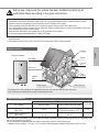 3
3
-
 4
4
-
 5
5
-
 6
6
-
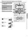 7
7
-
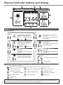 8
8
-
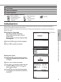 9
9
-
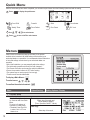 10
10
-
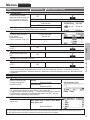 11
11
-
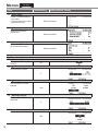 12
12
-
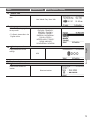 13
13
-
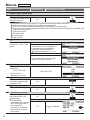 14
14
-
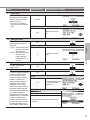 15
15
-
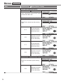 16
16
-
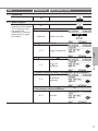 17
17
-
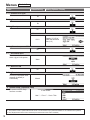 18
18
-
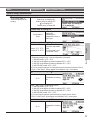 19
19
-
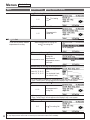 20
20
-
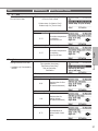 21
21
-
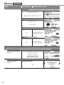 22
22
-
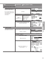 23
23
-
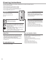 24
24
-
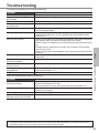 25
25
-
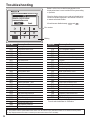 26
26
-
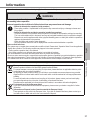 27
27
-
 28
28
-
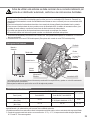 29
29
-
 30
30
-
 31
31
-
 32
32
-
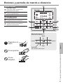 33
33
-
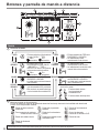 34
34
-
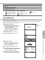 35
35
-
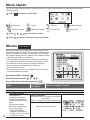 36
36
-
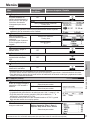 37
37
-
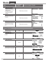 38
38
-
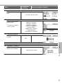 39
39
-
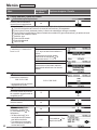 40
40
-
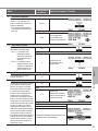 41
41
-
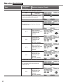 42
42
-
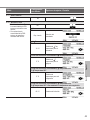 43
43
-
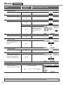 44
44
-
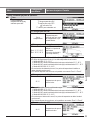 45
45
-
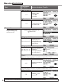 46
46
-
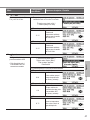 47
47
-
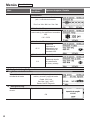 48
48
-
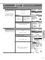 49
49
-
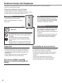 50
50
-
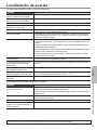 51
51
-
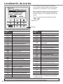 52
52
-
 53
53
-
 54
54
-
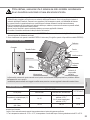 55
55
-
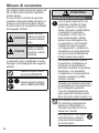 56
56
-
 57
57
-
 58
58
-
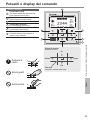 59
59
-
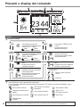 60
60
-
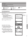 61
61
-
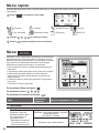 62
62
-
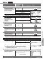 63
63
-
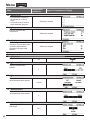 64
64
-
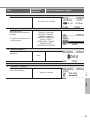 65
65
-
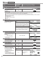 66
66
-
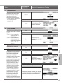 67
67
-
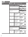 68
68
-
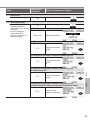 69
69
-
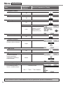 70
70
-
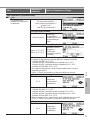 71
71
-
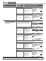 72
72
-
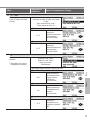 73
73
-
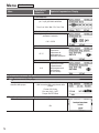 74
74
-
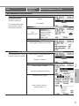 75
75
-
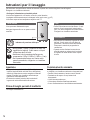 76
76
-
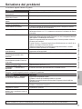 77
77
-
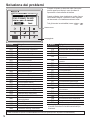 78
78
-
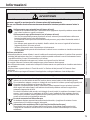 79
79
-
 80
80
-
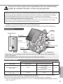 81
81
-
 82
82
-
 83
83
-
 84
84
-
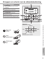 85
85
-
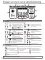 86
86
-
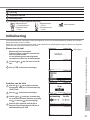 87
87
-
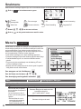 88
88
-
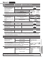 89
89
-
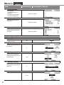 90
90
-
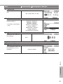 91
91
-
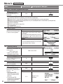 92
92
-
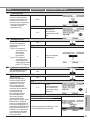 93
93
-
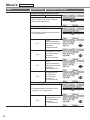 94
94
-
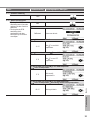 95
95
-
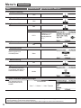 96
96
-
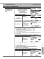 97
97
-
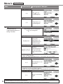 98
98
-
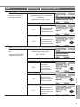 99
99
-
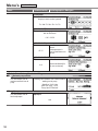 100
100
-
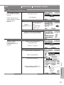 101
101
-
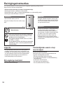 102
102
-
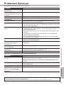 103
103
-
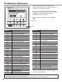 104
104
-
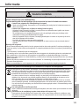 105
105
-
 106
106
-
 107
107
-
 108
108


Panasonic WHSDC03H3E51 Handleiding
- Categorie
- Ruimteverwarmingstoestellen
- Type
- Handleiding