
Owner’s Manual
Bedienungsanleitung
Mode d’emploi
Manual de instrucciones
U.R.G., Pro Audio & Digital Musical Instrument Division, Yamaha Corporation
© 2004 Yamaha Corporation
WD03290 402MWZC1.3-01A0
Printed in Indonesia
Yamaha Manual Library
http://www2.yamaha.co.jp/manual/english/

The above warning is located on the top of the unit.
Explanation of Graphical Symbols
The lightning flash with arrowhead symbol
within an equilateral triangle is intended to
alert the user to the presence of uninsulated
“dangerous voltage” within the product’s
enclosure that may be of sufficient magnitude
to constitute a risk of electric shock to persons.
The exclamation point within an equilateral
triangle is intended to alert the user to the
presence of important operating and
maintenance (servicing) instructions in the
literature accompanying the product.
IMPORTANT SAFETY INSTRUCTIONS
1 Read these instructions.
2Keep these instructions.
3 Heed all warnings.
4 Follow all instructions.
5 Do not use this apparatus near water.
6 Clean only with dry cloth.
7 Do not block any ventilation openings. Install in
accordance with the manufacturer’s instructions.
8 Do not install near any heat sources such as
radiators, heat registers, stoves, or other apparatus
(including amplifiers) that produce heat.
9 Do not defeat the safety purpose of the polarized or
grounding-type plug. A polarized plug has two blades
with one wider than the other. A grounding type plug
has two blades and a third grounding prong. The wide
blade or the third prong are provided for your safety. If
the provided plug does not fit into your outlet, consult
an electrician for replacement of the obsolete outlet.
10 Protect the power cord from being walked on or
pinched particularly at plugs, convenience
receptacles, and the point where they exit from the
apparatus.
11 Only use attachments/accessories specified by
the manufacturer.
12 Use only with the cart, stand,
tripod, bracket, or table specified
by the manufacturer, or sold with
the apparatus. When a cart is
used, use caution when moving
the cart/apparatus combination
to avoid injury from tip-over.
13 Unplug this apparatus during
lightning storms or when unused for long periods of time.
14 Refer all servicing to qualified service personnel.
Servicing is required when the apparatus has been
damaged in any way, such as power-supply cord or
plug is damaged, liquid has been spilled or objects
have fallen into the apparatus, the apparatus has been
exposed to rain or moisture, does not operate
normally, or has been dropped.
CAUTION: TO REDUCE THE RISK OF
ELECTRIC SHOCK, DO NOT REMOVE
COVER (OR BACK). NO USER-SERVICEABLE
PARTS INSIDE. REFER SERVICING TO
QUALIFIED SERVICE PERSONNEL.
CAUTION
RISK OF ELECTRIC SHOCK
DO NOT OPEN
WARNING
TO REDUCE THE RISK OF FIRE OR ELECTRIC SHOCK, DO NOT EXPOSE THIS APPARATUS TO RAIN OR MOISTURE.
IMPORTANT NOTICE FOR THE UNITED KINGDOM
Connecting the Plug and Cord
WARNING: THIS APPARATUS MUST BE EARTHED IMPORTANT. The wires in this mains lead are coloured in
accordance with the following code:
GREEN-AND-YELLOW : EARTH
BLUE : NEUTRAL
BROWN : LIVE
As the colours of the wires in the mains lead of this apparatus may not correspond with the coloured markings
identifying the terminals in your plug proceed as follows:
The wire which is coloured GREEN-and-YELLOW must be connected to the terminal in the plug which is marked
by the letter E or by the safety earth symbol or colored GREEN or GREEN-and-YELLOW.
The wire which is coloured BLUE must be connected to the terminal which is marked with the letter N or
coloured BLACK.
The wire which is coloured BROWN must be connected to the terminal which is marked with the letter L or
coloured RED.
• This applies only to products distributed by Yamaha-Kemble Music (U.K.) Ltd. (3 wires)

ENGLISH
3
XLR-type connectors are wired as follows (IEC60268 standard): pin 1:
ground, pin 2: hot (+), and pin 3: cold (-).
Yamaha cannot be held responsible for damage caused by improper use
or modifications to the device.
Always turn the power off when the device is not in use.
The performance of components with moving contacts, such as switches,
volume controls, connectors, and fans, deteriorates over time. Consult
qualified Yamaha service personnel about replacing defective components.
European models
Purchaser/User Information specified in EN55103-1 and EN55103-2.
Inrush Current: 2 A
Conforms to Environments: E1, E2, E3 and E4
(5)-1
MIC LINE AMPLIFIER
PRECAUTIONS
PLEASE READ CAREFULLY BEFORE PROCEEDING
* Please keep this manual in a safe place for future reference.
WARNING
Always follow the basic precautions listed below to avoid the possibility of serious injury or even death from electrical
shock, short-circuiting, damages, fire or other hazards. These precautions include, but are not limited to, the following:
• Only use the voltage specified as correct for the device. The required
voltage is printed on the name plate of the device.
• Use only the included power cord.
• Do not place the power cord near heat sources such as heaters or radiators,
and do not excessively bend or otherwise damage the cord, place heavy
objects on it, or place it in a position where anyone could walk on, trip over,
or roll anything over it.
• Do not open the device or attempt to disassemble the internal parts or
modify them in any way. The device contains no user-serviceable parts. If it
should appear to be malfunctioning, discontinue use immediately and have
it inspected by qualified Yamaha service personnel.
• Do not expose the device to rain, use it near water or in damp or wet
conditions, or place containers on it containing liquids which might spill
into any openings.
• Never insert or remove an electric plug with wet hands.
• If the power cord or plug becomes frayed or damaged, or if there is a
sudden loss of sound during use of the device, or if any unusual smells or
smoke should appear to be caused by it, immediately turn off the power
switch, disconnect the electric plug from the outlet, and have the device
inspected by qualified Yamaha service personnel.
• If this device should be dropped or damaged, immediately turn off the
power switch, disconnect the electric plug from the outlet, and have the
device inspected by qualified Yamaha service personnel.
CAUTION
Always follow the basic precautions listed below to avoid the possibility of physical injury to you or others, or damage
to the device or other property. These precautions include, but are not limited to, the following:
• Remove the electric plug from the outlet when the device is not to be used
for extended periods of time, or during electrical storms.
• When removing the electric plug from the device or an outlet, always hold
the plug itself and not the cord. Pulling by the cord can damage it.
• Before moving the device, remove all connected cables.
• Do not expose the device to excessive dust or vibrations, or extreme cold
or heat (such as in direct sunlight, near a heater, or in a car during the day)
to prevent the possibility of panel disfiguration or damage to the internal
components.
• Do not place the device in an unstable position where it might accidentally
fall over.
• Do not use the device in the vicinity of a TV, radio, stereo equipment,
mobile phone, or other electric devices. Otherwise, the device, TV, or radio
may generate noise.
• Before connecting the device to other devices, turn off the power for all
devices. Before turning the power on or off for all devices, set all volume
levels to minimum.
• Do not insert your fingers or hand in any gaps or openings on the device.
•Avoid inserting or dropping foreign objects (paper, plastic, metal, etc.) into
any gaps or openings on the device. If this happens, turn off the power
immediately and unplug the power cord from the AC outlet. Then have the
device inspected by qualified Yamaha service personnel.
• Do not rest your weight on the device or place heavy objects on it, and
avoid use excessive force on the buttons, switches or connectors
.
Power supply/Power cord
Do not open
Water warning
If you notice any abnormality
Power supply/Power cord
Location
Connections
Handling caution

ENGLISH
4
MIC LINE AMPLIFIER
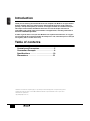
Introduction
Thank you for choosing the Yamaha MLA8 mic line amplifier. The MLA8 is an eight-channel
mic/line amplifier. The input section features balanced XLR connectors, high-quality mic
preamps, +48V phantom power per channel, and support for both mic and line-level inputs.
The output section features Euroblock connectors and a D-sub 25-pin connector for
compatibility with a wide variety of installations and applications, including connection to
the Yamaha DM2000 Digital Mixer.
In order to get the most out of your new MLA8 and its sophisticated functions, we suggest
you read through this manual thoroughly. Also keep it in a safe, convenient place so that you
can regularly refer to it when necessary.
Table of contents
Controls and Connectors . . . . . . . . . . . . . . 5
Connection Example . . . . . . . . . . . . . . . . . . 6
Specifications . . . . . . . . . . . . . . . . . . . . . . 19
Dimensions . . . . . . . . . . . . . . . . . . . . . . . . 21
• Illustrations in this manual are for explanatory purposes only, and may not match the actual appearance of the product during operation.
• Company names and product names used in this Owner’s Manual are trademarks or registered trademarks of their respective owners.
• Yamaha Pro Audio global web site:
http://www.yamahaproaudio.com/

ENGLISH
5
MIC LINE AMPLIFIER
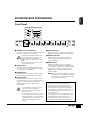
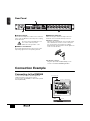
Controls and Connectors
Front Panel
1
POWER switch and indicator
This switch turns the power on or off. Press the switch
in to turn it on (the Power indicator lights).
To avoid loud noise from the speakers, first
turn on the power to the connected devices
that are closest to the sound source.
Example: Sound source
➞
MLA8
➞
Mixer
➞
Power
amplifier
To turn off the power to the system, reverse
the order described above.
2
[ ] buttons
This button switches the high pass filter (HPF) on or
off for each channel, cutting frequencies below 80Hz.
Press the button in to turn HPF on.
3
[26dB] buttons
Pressing this button turns on the attenuator for each
channel, attenuating the input signal level by 26dB.
4 [+48V] switches
This switch supplies phantom power to pins 2 and 3 of
the XLR-type input connectors on each channel. Turn this
switch on if you are using condenser microphones
requiring external +48V power with the INPUT
(XLR) connector.
• To avoid damage to speakers, be sure to
turn off any connected amplifier (or
powered speakers) before turning these
switches on or off.
• Be sure to leave these switches off if you do
not need phantom power. If you connect to
an unbalanced device or to an ungrounded
transformer while these switches are on, it
may result in humming noise or even
damage.
5 PEAK indicators
Light up in red when the signal level via the channel’s
GAIN control comes within 3dB of the clipping level.
6 SIGNAL indicators
Light up in green when the signal level via the
channel’s GAIN control reaches within 10dB of the
nominal (rated) level.
7 GAIN controls
Adjust the gain applied to the input signal level.
If level is low (e.g., mic input) turn the [26dB] button
off, and adjust the input levels from -60dBu to -16dBu.
If the signal level is high (e.g., line input), turn the
[26dB] button on, and adjust the input levels from
-34dBu to +10dBu.
n To get the best balance between the S/N ratio
and the dynamic range, adjust the gain so that
the Peak indicator comes on just as the signal
approaches its maximum level.
-16
+10 -34
-60
GAIN
-16
+10 -34
-60
GAIN
SIGNAL
PEAK
OFF ON
+48V
SIGNAL
PEAK
OFF ON
+48V
8080
-16
+10 -34
-60
GAIN
SIGNAL
PEAK
OFF ON
+48V
80
-16
+10 -34
-60
GAIN
SIGNAL
PEAK
OFF ON
+48V
80
-16
+10 -34
-60
GAIN
SIGNAL
PEAK
OFF ON
+48V
80
-16
+10 -34
-60
GAIN
SIGNAL
PEAK
OFF ON
+48V
80
-16
+10 -34
-60
GAIN
SIGNAL
PEAK
OFF ON
+48V
80
-16
+10 -34
-60
GAIN
SIGNAL
PEAK
OFF ON
+48V
80
1
23
45678
MIC LINE AMPLIFIER
POWER
ON / OFF
26dB 26dB26dB26dB26dB26dB26dB26dB
-16
+10 -34
-60
GAIN
SIGNAL
PEAK
OFF ON
+48V
80
26dB
1
2
3
4
5
6
7
80
Security cover
This device has two holes for installing the
protective cover on each side of the front panel
(size: M3, distance between holes: 423mm). To
prevent operation errors and inadvertent changes,
you can attach a user-made cover to the front
panel. Yamaha, however, does not make a security
cover for the device.
If you attach such a cover yourself, make sure that
the securing screws do not protrude inside the front
panel by more than 15mm. To avoid the cover
touching the knob, be sure to leave a space of
about 20mm between the front panel and the cover.

ENGLISH
6
MIC LINE AMPLIFIER
Rear Panel
8 AC IN connector
Connect the included power cord here. First, connect the
power cord to the MLA8, then insert the power cord plug
into the AC outlet.
Be sure to use the included power cord.
Use of other cords may result in
malfunction, heat generation, or fire.
9 INPUT 1–8 connectors
These balanced XLR-3-31-type connectors are used to
input analog signals to the corresponding channels.
) OUTPUT connectors
There are two types of balanced output connectors:
Euroblock connectors and D-sub 25-pin connector.
●Euroblock connectors
The device has four Euroblock connectors with six pins.
These dual channel connectors consist of three pins:
hot, cold, ground on each channel. The supplied
Euroblock plugs should be wired as shown. Tighten the
screws to secure the wires.
●D-sub 25pin connector
Using the optional I/O card (MY8-AD96), you can
connect to the Yamaha DM2000 Digital Mixer.
Connection Example
Connecting to the DM2000
You can connect the device to Yamaha digital audio
equipment using the D-sub 25-pin connector.
For connection to the DM2000, you will need the optional
I/O card (MY8-AD96).
1234
5678
INPUT
123
4567
8
GG
ANALOG
OUTPUT
+4dBu
OUTPUT +4dBu
AC IN
)
9
8
+
–
G
OUT PUT
D-sub 25-pin cable
Optional I/O card MY8-AD96
Digital mixer DM2000
MLA8
1234
5678
INPUT
123
4567
8
GG
ANALOG
OUTPUT
+4dBu
OUTPUT +4dBu
MIC LINE AMPLIFIER
MODEL MAL8
MADE IN INDONESIA
AC IN

ENGLISH
DEUTSCH
FRANÇAIS
ESPAÑOL
19
MIC LINE AMPLIFIER
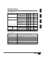
Specifications
Electrical Characteristics
0 dBu is referenced to 0.775 V rms.
General Specifications
Conditions MIN TYP MAX UNIT
Total Harmonic Distortion (THD+N)
20 Hz - 20 k Hz @ +14 dBu, 10 k ohms,
GAIN Maximum
0.1 %
20 Hz - 20 k Hz @ +14 dBu, 10 k ohms,
GAIN Minimum
0.01 %
Frequency Response
20 Hz - 20 k Hz @ +4 dBu, 10 k ohms,
GAIN Maximum
–
1
0 0.5 dB
20 Hz - 20 k Hz @ +4 dBu, 10 k ohms,
GAIN Minimum
–
0.5
0 0.5 dB
Hum & Noise (20 Hz - 20 k Hz)
PAD OFF, GAIN Maximum
( Sensitivity =
–
60 dBu )
–
128
(68 dB S/N)
dBu
PAD ON , GAIN Maximum
( Sensitivity =
–
34 dBu )
–
99
(65 dB S/N)
dBu
Rs=150 ohms
PAD OFF, GAIN Minimum
( Sensitivity =
–
16 dBu )
–
108
(92 dB S/N)
dBu
Hum & Noise are measured with a 6 dB/octave
filter @12.7 k Hz; equivalent to a 20 k Hz filter
with infinite dB/octave attenuation.
PAD ON , GAIN Minimum
( Sensitivity = +10 dBu )
–
82
(92 dB S/N)
dBu
Maximum Voltage Gain CH IN to CH OUT 64 dB
Crosstalk
Adjacent Inputs @ 1 k Hz –90 dB
PAD ON,
GAIN Minimum
@ 10 k Hz
–
70
dB
CH INPUT GAIN control variable 44 dB
CH INPUT PAD switch 26 dB
CH High Pass Filter
80 Hz, 12 dB/octave
Turn over /roll-off frequency of shelving : 3 dB below maximum variable level.
Phantom Power
+48 V DC is applied to balanced inputs for powering condenser microphones via 6.8 k ohms
current-limiting/isolation resistors.
CH PEAK LED
One red LED per channel. Comes on when post
–
GAIN signal level reaches
+
17 dBu.
CH SIGNAL LED
One green LED per channel. Comes on when post
–
GAIN signal level reaches -10 dBu.
Included Accessories
Power Supply Cord, Euroblock Connectors ( 3P x 8 ), Rubber Feet ( x 4 ), Owner's Manual
Power Consumption 25 W
Dimensions (W x H x D) 480 mm x 44 mm x 375.5 mm
Weight 4.7 kg

ENGLISH DEUTSCH FRANÇAIS ESPAÑOL
20
MIC LINE AMPLIFIER
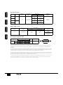
Iuput Characteristics
*1: 0 dBu is referenced to 0.775 Vrms.
Output Characteristics
*1: 0 dBu is referenced to 0.775 Vrms.
D-sub 25pin Assignment Table
Specifications and descriptions in this owner’s manual are for information purposes only. Yamaha Corp. reserves the right to change or modify products or
specifications at any time without prior notice. Since specifications, equipment or options may not be the same in every locale, please check with your
Yamaha dealer.
Die technischen Daten und Beschreibungen in dieser Bedienungsanleitung dienen nur der Information. Yamaha Corp. behält sich das Recht vor, Produkte
oder deren technische Daten jederzeit ohne vorherige Ankündigung zu verändern oder zu modifizieren. Da die technischen Daten, das Gerät selbst oder
Sonderzubehör nicht in jedem Land gleich sind, setzen Sie sich im Zweifel bitte mit Ihrem Yamaha-Händler in Verbindung.
Les caractéristiques techniques et les descriptions du mode d’femploi ne sont données que pour information. Yamaha Corp. se réserve le droit de changer ou
modifier les produits et leurs caractéristiques techniques à tout moment sans aucun avis. Du fait que les caractéristiques techniques, les équipements et les
options peuvent différer d’fun pays à l’fautre, adressez-vous au distributeur Yamaha le plus proche.
Las especificaciones y descripciones de este manual del propietario tienen sólo el propósito de servir como información. Yamaha Corp. se reserva el derecho a
efectuar cambios o modificaciones en los productos o especificaciones en cualquier momento sin previo aviso. Puesto que las especificaciones, equipos u
opciones pueden no ser las mismas en todos los mercados, solicite información a su distribuidor Yamaha.
PAD Gain
Actual Load
Impedance
For Use With
Nominal
Input Level *1
Connector In
Amplifier unit
Nominal Max. before Clip
0
–
60
3 k ohms
50
–
600 ohms Mics
600 ohms Lines
–
60 dBu
(0.775 mV)
–
40 dBu
(7.75 mV)
XLR-3-31type
(balanced)
26
–
34 dBu
(15.5 mV)
–
14 dBu
(155 mV)
0
–
16
–
16 dBu
(123 mV)
+4 dBu
(1.23 V)
26
+
10 dBu
(2.45 V)
+
30 dBu
(24.5 V)
Actual Source
Impedance
For Use With
Nominal
Output Level *1
Connector In
Amplifier unit
Nominal Max. before Clip
150 ohms 10 k ohms Lines
+4 dBu
(1.23 V)
+24 dBu
(12.3 V)
Euroblock connectors
(balanced)
D-SUB 25P
female connector
(balanced)
Signal
Output Ch
Open GND
12345678
Pin
Hot 24 10217184151
13
2, 5, 8, 11 ,16,
19, 22, 25
Cold 12 23 9 20 6 17 3 14
25
14
13
1

ENGLISH
DEUTSCH
FRANÇAIS
ESPAÑOL
21
MIC LINE AMPLIFIER
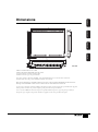
Dimensions
*When the included rubber feet are attached
*Wenn die mitgelieferten Gummifüße angebracht wurden
*Lorsque les pieds en caoutchouc fournis sont fixés
*Cuando se colocan los apoyos de goma incluidos
If you do not intend to rack-mount the MLA8, attach the included rubber feet to the bottom surface of the device.
Attach the rubber feet in the positions marked by small circles on the bottom.
Wenn Sie keine Rack-Montage des MLA8 beabsichtigen, befestigen Sie die mitgelieferten Gummifüße an der Geräteunterseite.
Befestigen Sie die Gummifüße an den Positionen an der Unterseite, die durch kleine Kreise markiert sind.
Si vous n'avez pas l'intention de monter le MLA8 en bâti, fixez les pieds en caoutchouc fournis sur la partie inférieure de l'appareil.
Fixez les pieds en caoutchouc aux positions marquées par des petits cercles sur la partie inférieure.
Si no va a montar el MLA8 en un bastidor, coloque en la superficie inferior del aparato los apoyos de goma que se incluyen.
Coloque los apoyos de goma en las posiciones marcadas con pequeños círculos en la parte inferior del aparato.
439
430
375.5
353.5
17
348
43
51
220
65
350
480
44
45
22
423
-16
+10 -34
-60
GAIN
-16
+10 -34
-60
GAIN
SIGNAL
PEAK
OFF ON
+48V
SIGNAL
PEAK
OFF ON
+48V
8080
-16
+10 -34
-60
GAIN
SIGNAL
PEAK
OFF ON
+48V
80
-16
+10 -34
-60
GAIN
SIGNAL
PEAK
OFF ON
+48V
80
-16
+10 -34
-60
GAIN
SIGNAL
PEAK
OFF ON
+48V
80
-16
+10 -34
-60
GAIN
SIGNAL
PEAK
OFF ON
+48V
80
-16
+10 -34
-60
GAIN
SIGNAL
PEAK
OFF ON
+48V
80
-16
+10 -34
-60
GAIN
SIGNAL
PEAK
OFF ON
+48V
80
1
23
45678
MIC LINE AMPLIFIER
POWER
ON / OFF
26dB 26dB26dB26dB26dB26dB26dB26dB
*
Unit: mm

For details of products, please contact your nearest Yamaha
representative or the authorized distributor listed below.
Pour plus de détails sur les produits, veuillez-vous adresser à Yamaha ou
au distributeur le plus proche de vous figurant dans la liste suivante.
Die Einzelheiten zu Produkten sind bei Ihrer unten aufgeführten
Niederlassung und bei Yamaha Vertragshändlern in den jeweiligen
Bestimmungsländern erhältlich.
Para detalles sobre productos, contacte su tienda Yamaha más cercana
o el distribuidor autorizado que se lista debajo.
CANADA
Yamaha Canada Music Ltd.
135 Milner Avenue, Scarborough, Ontario,
M1S 3R1, Canada
Tel: 416-298-1311
U.S.A.
Yamaha Corporation of America
6600 Orangethorpe Ave., Buena Park, Calif. 90620,
U.S.A.
Tel: 714-522-9011
MEXICO
Yamaha de Mexico S.A. De C.V.,
Departamento de ventas
Javier Rojo Gomez No.1149, Col. Gpe Del
Moral, Deleg. Iztapalapa, 09300 Mexico, D.F.
Tel: 55-5804-0600
BRAZIL
Yamaha Musical do Brasil LTDA.
Av. Rebouças 2636, São Paulo, Brasil
Tel: 011-3085-1377
ARGENTINA
Yamaha Music Latin America, S.A.
Sucursal de Argentina
Viamonte 1145 Piso2-B 1053,
Buenos Aires, Argentina
Tel: 1-4371-7021
PANAMA AND OTHER LATIN
AMERICAN COUNTRIES/
CARIBBEAN COUNTRIES
Yamaha Music Latin America, S.A.
Torre Banco General, Piso 7, Urbanización Marbella,
Calle 47 y Aquilino de la Guardia,
Ciudad de Panamá, Panamá
Tel: +507-269-5311
THE UNITED KINGDOM
Yamaha-Kemble Music (U.K.) Ltd.
Sherbourne Drive, Tilbrook, Milton Keynes,
MK7 8BL, England
Tel: 01908-366700
GERMANY
Yamaha Music Central Europe GmbH
Siemensstraße 22-34, 25462 Rellingen, Germany
Tel: 04101-3030
SWITZERLAND/LIECHTENSTEIN
Yamaha Music Central Europe GmbH,
Branch Switzerland
Seefeldstrasse 94, 8008 Zürich, Switzerland
Tel: 01-383 3990
AUSTRIA
Yamaha Music Central Europe GmbH,
Branch Austria
Schleiergasse 20, A-1100 Wien, Austria
Tel: 01-60203900
THE NETHERLANDS
Yamaha Music Central Europe,
Branch Nederland
Clarissenhof 5-b, 4133 AB Vianen, The Netherlands
Tel: 0347-358 040
BELGIUM/LUXEMBOURG
Yamaha Music Central Europe GmbH,
Branch Belgium
Rue de Geneve (Genevastraat) 10, 1140 - Brussels,
Belgium
Tel: 02-726 6032
FRANCE
Yamaha Musique France
BP 70-77312 Marne-la-Vallée Cedex 2, France
Tel: 01-64-61-4000
ITALY
Yamaha Musica Italia S.P.A.
Combo Division
Viale Italia 88, 20020 Lainate (Milano), Italy
Tel: 02-935-771
SPAIN/PORTUGAL
Yamaha-Hazen Música, S.A.
Ctra. de la Coruna km. 17, 200, 28230
Las Rozas (Madrid), Spain
Tel: 91-639-8888
SWEDEN
Yamaha Scandinavia AB
J. A. Wettergrens Gata 1
Box 30053
S-400 43 Göteborg, Sweden
Tel: 031 89 34 00
DENMARK
YS Copenhagen Liaison Office
Generatorvej 8B
DK-2730 Herlev, Denmark
Tel: 44 92 49 00
NORWAY
Norsk filial av Yamaha Scandinavia AB
Grini Næringspark 1
N-1345 Østerås, Norway
Tel: 67 16 77 70
OTHER EUROPEAN COUNTRIES
Yamaha Music Central Europe GmbH
Siemensstraße 22-34, 25462 Rellingen, Germany
Tel: +49-4101-3030
Yamaha Corporation,
Asia-Pacific Music Marketing Group
Nakazawa-cho 10-1, Hamamatsu, Japan 430-8650
Tel: +81-53-460-2313
TURKEY/CYPRUS
Yamaha Music Central Europe GmbH
Siemensstraße 22-34, 25462 Rellingen, Germany
Tel: 04101-3030
OTHER COUNTRIES
Yamaha Music Gulf FZE
LB21-128 Jebel Ali Freezone
P.O.Box 17328, Dubai, U.A.E.
Tel: +971-4-881-5868
THE PEOPLE’S REPUBLIC OF CHINA
Yamaha Music & Electronics (China) Co.,Ltd.
25/F., United Plaza, 1468 Nanjing Road (West),
Jingan, Shanghai, China
Tel: 021-6247-2211
INDONESIA
PT. Yamaha Music Indonesia (Distributor)
PT. Nusantik
Gedung Yamaha Music Center, Jalan Jend. Gatot
Subroto Kav. 4, Jakarta 12930, Indonesia
Tel: 21-520-2577
KOREA
Yamaha Music Korea Ltd.
Tong-Yang Securities Bldg. 16F 23-8 Yoido-dong,
Youngdungpo-ku, Seoul, Korea
Tel: 02-3770-0660
MALAYSIA
Yamaha Music Malaysia, Sdn., Bhd.
Lot 8, Jalan Perbandaran, 47301 Kelana Jaya,
Petaling Jaya, Selangor, Malaysia
Tel: 3-78030900
SINGAPORE
Yamaha Music Asia Pte., Ltd.
No.11 Ubi Road 1, No.06-02,
Meiban Industrial Building, Singapore
Tel: 747-4374
TAIWAN
Yamaha KHS Music Co., Ltd.
3F, #6, Sec.2, Nan Jing E. Rd. Taipei.
Taiwan 104, R.O.C.
Tel: 02-2511-8688
THAILAND
Siam Music Yamaha Co., Ltd.
891/1 Siam Motors Building, 15-16 floor
Rama 1 road, Wangmai, Pathumwan
Bangkok 10330, Thailand
Tel: 02-215-2626
OTHER ASIAN COUNTRIES
Yamaha Corporation,
Asia-Pacific Music Marketing Group
Nakazawa-cho 10-1, Hamamatsu, Japan 430-8650
Tel: +81-53-460-2317
AUSTRALIA
Yamaha Music Australia Pty. Ltd.
Level 1, 99 Queensbridge Street, Southbank,
Victoria 3006, Australia
Tel: 3-9693-5111
COUNTRIES AND TRUST
TERRITORIES IN PACIFIC OCEAN
Yamaha Corporation,
Asia-Pacific Music Marketing Group
Nakazawa-cho 10-1, Hamamatsu, Japan 430-8650
Tel: +81-53-460-2313
NORTH AMERICA
CENTRAL & SOUTH AMERICA
EUROPE
AFRICA
MIDDLE EAST
ASIA
OCEANIA
HEAD OFFICE Yamaha Corporation, Pro Audio & Digital Musical Instrument Division
Nakazawa-cho 10-1, Hamamatsu, Japan 430-8650
Tel: +81-53-460-2441
PA09

Owner’s Manual
Bedienungsanleitung
Mode d’emploi
Manual de instrucciones
U.R.G., Pro Audio & Digital Musical Instrument Division, Yamaha Corporation
© 2004 Yamaha Corporation
WD03290 402MWZC1.3-01A0
Printed in Indonesia
Yamaha Manual Library
http://www2.yamaha.co.jp/manual/english/
Documenttranscriptie
Owner’s Manual Bedienungsanleitung Mode d’emploi Manual de instrucciones Yamaha Manual Library http://www2.yamaha.co.jp/manual/english/ U.R.G., Pro Audio & Digital Musical Instrument Division, Yamaha Corporation © 2004 Yamaha Corporation WD03290 402MWZC1.3-01A0 Printed in Indonesia Explanation of Graphical Symbols The lightning flash with arrowhead symbol within an equilateral triangle is intended to alert the user to the presence of uninsulated “dangerous voltage” within the product’s enclosure that may be of sufficient magnitude to constitute a risk of electric shock to persons. CAUTION RISK OF ELECTRIC SHOCK DO NOT OPEN The exclamation point within an equilateral triangle is intended to alert the user to the presence of important operating and maintenance (servicing) instructions in the literature accompanying the product. CAUTION: TO REDUCE THE RISK OF ELECTRIC SHOCK, DO NOT REMOVE COVER (OR BACK). NO USER-SERVICEABLE PARTS INSIDE. REFER SERVICING TO QUALIFIED SERVICE PERSONNEL. The above warning is located on the top of the unit. IMPORTANT SAFETY INSTRUCTIONS 1 2 3 4 5 6 7 8 9 10 Read these instructions. Keep these instructions. Heed all warnings. Follow all instructions. Do not use this apparatus near water. Clean only with dry cloth. Do not block any ventilation openings. Install in accordance with the manufacturer’s instructions. Do not install near any heat sources such as radiators, heat registers, stoves, or other apparatus (including amplifiers) that produce heat. Do not defeat the safety purpose of the polarized or grounding-type plug. A polarized plug has two blades with one wider than the other. A grounding type plug has two blades and a third grounding prong. The wide blade or the third prong are provided for your safety. If the provided plug does not fit into your outlet, consult an electrician for replacement of the obsolete outlet. Protect the power cord from being walked on or pinched particularly at plugs, convenience receptacles, and the point where they exit from the 11 12 13 14 apparatus. Only use attachments/accessories specified by the manufacturer. Use only with the cart, stand, tripod, bracket, or table specified by the manufacturer, or sold with the apparatus. When a cart is used, use caution when moving the cart/apparatus combination to avoid injury from tip-over. Unplug this apparatus during lightning storms or when unused for long periods of time. Refer all servicing to qualified service personnel. Servicing is required when the apparatus has been damaged in any way, such as power-supply cord or plug is damaged, liquid has been spilled or objects have fallen into the apparatus, the apparatus has been exposed to rain or moisture, does not operate normally, or has been dropped. WARNING TO REDUCE THE RISK OF FIRE OR ELECTRIC SHOCK, DO NOT EXPOSE THIS APPARATUS TO RAIN OR MOISTURE. IMPORTANT NOTICE FOR THE UNITED KINGDOM Connecting the Plug and Cord WARNING: THIS APPARATUS MUST BE EARTHED IMPORTANT. The wires in this mains lead are coloured in accordance with the following code: GREEN-AND-YELLOW : EARTH BLUE : NEUTRAL BROWN : LIVE As the colours of the wires in the mains lead of this apparatus may not correspond with the coloured markings identifying the terminals in your plug proceed as follows: The wire which is coloured GREEN-and-YELLOW must be connected to the terminal in the plug which is marked by the letter E or by the safety earth symbol or colored GREEN or GREEN-and-YELLOW. The wire which is coloured BLUE must be connected to the terminal which is marked with the letter N or coloured BLACK. The wire which is coloured BROWN must be connected to the terminal which is marked with the letter L or coloured RED. • This applies only to products distributed by Yamaha-Kemble Music (U.K.) Ltd. (3 wires) ENGLISH PRECAUTIONS PLEASE READ CAREFULLY BEFORE PROCEEDING * Please keep this manual in a safe place for future reference. WARNING Always follow the basic precautions listed below to avoid the possibility of serious injury or even death from electrical shock, short-circuiting, damages, fire or other hazards. These precautions include, but are not limited to, the following: Power supply/Power cord Water warning • Only use the voltage specified as correct for the device. The required voltage is printed on the name plate of the device. • Use only the included power cord. • Do not place the power cord near heat sources such as heaters or radiators, and do not excessively bend or otherwise damage the cord, place heavy objects on it, or place it in a position where anyone could walk on, trip over, or roll anything over it. • Do not expose the device to rain, use it near water or in damp or wet conditions, or place containers on it containing liquids which might spill into any openings. • Never insert or remove an electric plug with wet hands. If you notice any abnormality • If the power cord or plug becomes frayed or damaged, or if there is a sudden loss of sound during use of the device, or if any unusual smells or smoke should appear to be caused by it, immediately turn off the power switch, disconnect the electric plug from the outlet, and have the device inspected by qualified Yamaha service personnel. • If this device should be dropped or damaged, immediately turn off the power switch, disconnect the electric plug from the outlet, and have the device inspected by qualified Yamaha service personnel. Do not open • Do not open the device or attempt to disassemble the internal parts or modify them in any way. The device contains no user-serviceable parts. If it should appear to be malfunctioning, discontinue use immediately and have it inspected by qualified Yamaha service personnel. CAUTION Always follow the basic precautions listed below to avoid the possibility of physical injury to you or others, or damage to the device or other property. These precautions include, but are not limited to, the following: Power supply/Power cord Connections • Remove the electric plug from the outlet when the device is not to be used for extended periods of time, or during electrical storms. • When removing the electric plug from the device or an outlet, always hold the plug itself and not the cord. Pulling by the cord can damage it. • Before connecting the device to other devices, turn off the power for all devices. Before turning the power on or off for all devices, set all volume levels to minimum. Handling caution Location • Do not insert your fingers or hand in any gaps or openings on the device. • Avoid inserting or dropping foreign objects (paper, plastic, metal, etc.) into any gaps or openings on the device. If this happens, turn off the power immediately and unplug the power cord from the AC outlet. Then have the device inspected by qualified Yamaha service personnel. • Do not rest your weight on the device or place heavy objects on it, and avoid use excessive force on the buttons, switches or connectors. • Before moving the device, remove all connected cables. • Do not expose the device to excessive dust or vibrations, or extreme cold or heat (such as in direct sunlight, near a heater, or in a car during the day) to prevent the possibility of panel disfiguration or damage to the internal components. • Do not place the device in an unstable position where it might accidentally fall over. • Do not use the device in the vicinity of a TV, radio, stereo equipment, mobile phone, or other electric devices. Otherwise, the device, TV, or radio may generate noise. XLR-type connectors are wired as follows (IEC60268 standard): pin 1: ground, pin 2: hot (+), and pin 3: cold (-). Always turn the power off when the device is not in use. The performance of components with moving contacts, such as switches, volume controls, connectors, and fans, deteriorates over time. Consult qualified Yamaha service personnel about replacing defective components. Yamaha cannot be held responsible for damage caused by improper use or modifications to the device. European models Purchaser/User Information specified in EN55103-1 and EN55103-2. Inrush Current: 2 A Conforms to Environments: E1, E2, E3 and E4 (5)-1 MIC LINE AMPLIFIER 3 ENGLISH Introduction Thank you for choosing the Yamaha MLA8 mic line amplifier. The MLA8 is an eight-channel mic/line amplifier. The input section features balanced XLR connectors, high-quality mic preamps, +48V phantom power per channel, and support for both mic and line-level inputs. The output section features Euroblock connectors and a D-sub 25-pin connector for compatibility with a wide variety of installations and applications, including connection to the Yamaha DM2000 Digital Mixer. In order to get the most out of your new MLA8 and its sophisticated functions, we suggest you read through this manual thoroughly. Also keep it in a safe, convenient place so that you can regularly refer to it when necessary. Table of contents Controls and Connectors . . . . . . . . . . . . . . 5 Connection Example . . . . . . . . . . . . . . . . . . 6 Specifications . . . . . . . . . . . . . . . . . . . . . . 19 Dimensions . . . . . . . . . . . . . . . . . . . . . . . . 21 • Illustrations in this manual are for explanatory purposes only, and may not match the actual appearance of the product during operation. • Company names and product names used in this Owner’s Manual are trademarks or registered trademarks of their respective owners. • Yamaha Pro Audio global web site: http://www.yamahaproaudio.com/ 4 MIC LINE AMPLIFIER ENGLISH Controls and Connectors Front Panel 80 2 PEAK 5 26dB SIGNAL 6 3 7 4 OFF ON +48V -16 +10 -60 -34 GAIN MIC LINE AMPLIFIER 1 80 PEAK 26dB SIGNAL OFF ON +48V -16 +10 2 80 PEAK 26dB SIGNAL GAIN -60 -34 OFF ON +48V -16 +10 3 80 PEAK 26dB SIGNAL GAIN -60 -34 OFF ON +48V -16 +10 4 80 PEAK 26dB SIGNAL GAIN -60 -34 OFF ON +48V -16 +10 5 80 PEAK 26dB SIGNAL GAIN -60 -34 OFF ON +48V -16 +10 6 80 PEAK 26dB SIGNAL GAIN -60 -34 OFF ON +48V -16 +10 7 80 PEAK GAIN -60 -34 OFF ON +48V -16 +10 8 80 PEAK 26dB SIGNAL POWER 26dB SIGNAL GAIN -60 -34 OFF ON +48V -16 +10 GAIN -60 -34 ON / OFF 1 1 POWER switch and indicator This switch turns the power on or off. Press the switch in to turn it on (the Power indicator lights). 5 PEAK indicators Light up in red when the signal level via the channel’s GAIN control comes within 3dB of the clipping level. To avoid loud noise from the speakers, first turn on the power to the connected devices that are closest to the sound source. Example: Sound source ➞ MLA8 ➞ Mixer ➞ Power 6 SIGNAL indicators To turn off the power to the system, reverse the order described above. 7 GAIN controls amplifier 2 [ 80 ] buttons This button switches the high pass filter (HPF) on or off for each channel, cutting frequencies below 80Hz. Press the button in to turn HPF on. 3 [26dB] buttons Pressing this button turns on the attenuator for each channel, attenuating the input signal level by 26dB. 4 [+48V] switches This switch supplies phantom power to pins 2 and 3 of the XLR-type input connectors on each channel. Turn this switch on if you are using condenser microphones requiring external +48V power with the INPUT (XLR) connector. • To avoid damage to speakers, be sure to turn off any connected amplifier (or powered speakers) before turning these switches on or off. • Be sure to leave these switches off if you do not need phantom power. If you connect to an unbalanced device or to an ungrounded transformer while these switches are on, it may result in humming noise or even damage. Light up in green when the signal level via the channel’s GAIN control reaches within 10dB of the nominal (rated) level. Adjust the gain applied to the input signal level. If level is low (e.g., mic input) turn the [26dB] button off, and adjust the input levels from -60dBu to -16dBu. If the signal level is high (e.g., line input), turn the [26dB] button on, and adjust the input levels from -34dBu to +10dBu. n To get the best balance between the S/N ratio and the dynamic range, adjust the gain so that the Peak indicator comes on just as the signal approaches its maximum level. Security cover This device has two holes for installing the protective cover on each side of the front panel (size: M3, distance between holes: 423mm). To prevent operation errors and inadvertent changes, you can attach a user-made cover to the front panel. Yamaha, however, does not make a security cover for the device. If you attach such a cover yourself, make sure that the securing screws do not protrude inside the front panel by more than 15mm. To avoid the cover touching the knob, be sure to leave a space of about 20mm between the front panel and the cover. MIC LINE AMPLIFIER 5 ENGLISH Rear Panel ) AC IN ANALOG OUTPUT +4dBu 8 7 6 5 4 8 G 3 2 7 6 5 4 3 2 1 G 1 INPUT OUTPUT +4dBu 8 9 8 AC IN connector ) OUTPUT connectors Connect the included power cord here. First, connect the power cord to the MLA8, then insert the power cord plug into the AC outlet. There are two types of balanced output connectors: Euroblock connectors and D-sub 25-pin connector. Be sure to use the included power cord. Use of other cords may result in malfunction, heat generation, or fire. 9 INPUT 1–8 connectors ●Euroblock connectors The device has four Euroblock connectors with six pins. These dual channel connectors consist of three pins: hot, cold, ground on each channel. The supplied Euroblock plugs should be wired as shown. Tighten the screws to secure the wires. These balanced XLR-3-31-type connectors are used to input analog signals to the corresponding channels. G – + ●D-sub 25pin connector Using the optional I/O card (MY8-AD96), you can connect to the Yamaha DM2000 Digital Mixer. Connection Example Connecting to the DM2000 You can connect the device to Yamaha digital audio equipment using the D-sub 25-pin connector. For connection to the DM2000, you will need the optional I/O card (MY8-AD96). D-sub 25-pin cable Optional I/O card MY8-AD96 Digital mixer DM2000 MLA8 OUT PUT MIC LINE AMPLIFIER MODEL MAL8 AC IN ANALOG OUTPUT +4dBu MADE IN INDONESIA 8 7 6 5 4 OUTPUT +4dBu 6 MIC LINE AMPLIFIER 3 2 8 G 7 6 5 G 1 INPUT 4 3 2 1 ENGLISH Specifications Electrical Characteristics MAX UNIT 20 Hz - 20 k Hz @ +14 dBu, 10 k ohms, GAIN Maximum 0.1 % 20 Hz - 20 k Hz @ +14 dBu, 10 k ohms, GAIN Minimum 0.01 % 20 Hz - 20 k Hz @ +4 dBu, 10 k ohms, GAIN Maximum –1 0 0.5 dB 20 Hz - 20 k Hz @ +4 dBu, 10 k ohms, GAIN Minimum –0.5 0 0.5 dB PAD OFF, GAIN Maximum ( Sensitivity = –60 dBu ) –128 (68 dB S/N) dBu PAD ON , GAIN Maximum ( Sensitivity = –34 dBu ) –99 (65 dB S/N) dBu PAD OFF, GAIN Minimum ( Sensitivity = –16 dBu ) –108 (92 dB S/N) dBu Hum & Noise are measured with a 6 dB/octave PAD ON , GAIN Minimum filter @12.7 k Hz; equivalent to a 20 k Hz filter ( Sensitivity = +10 dBu ) with infinite dB/octave attenuation. –82 (92 dB S/N) dBu Frequency Response Hum & Noise (20 Hz - 20 k Hz) Rs=150 ohms Maximum Voltage Gain Crosstalk CH IN to CH OUT 64 dB Adjacent Inputs @ 1 k Hz –90 dB PAD ON, GAIN Minimum @ 10 k Hz –70 dB CH INPUT GAIN control variable CH INPUT PAD switch DEUTSCH TYP FRANÇAIS Total Harmonic Distortion (THD+N) MIN ESPAÑOL Conditions 44 dB 26 dB 0 dBu is referenced to 0.775 V rms. General Specifications CH High Pass Filter 80 Hz, 12 dB/octave Turn over /roll-off frequency of shelving : 3 dB below maximum variable level. Phantom Power +48 V DC is applied to balanced inputs for powering condenser microphones via 6.8 k ohms current-limiting/isolation resistors. CH PEAK LED One red LED per channel. Comes on when post – GAIN signal level reaches +17 dBu. CH SIGNAL LED One green LED per channel. Comes on when post – GAIN signal level reaches -10 dBu. Included Accessories Power Supply Cord, Euroblock Connectors ( 3P x 8 ), Rubber Feet ( x 4 ), Owner's Manual Power Consumption 25 W Dimensions (W x H x D) 480 mm x 44 mm x 375.5 mm Weight 4.7 kg MIC LINE AMPLIFIER 19 ENGLISH Iuput Characteristics PAD Actual Load Impedance Gain Input Level *1 For Use With Nominal 0 –60 26 Max. before Clip –60 dBu (0.775 mV) –40 dBu (7.75 mV) –34 dBu (15.5 mV) –14 dBu (155 mV) –16 dBu (123 mV) +4 dBu (1.23 V) +10 dBu (2.45 V) +30 dBu (24.5 V) 50 – 600 ohms Mics 600 ohms Lines 3 k ohms DEUTSCH Nominal 0 –16 26 Connector In Amplifier unit XLR-3-31type (balanced) *1: 0 dBu is referenced to 0.775 Vrms. Output Characteristics FRANÇAIS Actual Source Impedance Output Level *1 For Use With Nominal 150 ohms Nominal Max. before Clip +4 dBu (1.23 V) 10 k ohms Lines Connector In Amplifier unit Euroblock connectors (balanced) +24 dBu (12.3 V) D-SUB 25P female connector (balanced) ESPAÑOL *1: 0 dBu is referenced to 0.775 Vrms. D-sub 25pin Assignment Table Output Ch Signal Pin 1 2 3 4 5 Hot 24 10 Cold 12 23 6 7 21 7 9 20 8 18 4 15 1 6 17 3 14 Open GND 13 2, 5, 8, 11 ,16, 19, 22, 25 13 25 1 14 Specifications and descriptions in this owner’s manual are for information purposes only. Yamaha Corp. reserves the right to change or modify products or specifications at any time without prior notice. Since specifications, equipment or options may not be the same in every locale, please check with your Yamaha dealer. Die technischen Daten und Beschreibungen in dieser Bedienungsanleitung dienen nur der Information. Yamaha Corp. behält sich das Recht vor, Produkte oder deren technische Daten jederzeit ohne vorherige Ankündigung zu verändern oder zu modifizieren. Da die technischen Daten, das Gerät selbst oder Sonderzubehör nicht in jedem Land gleich sind, setzen Sie sich im Zweifel bitte mit Ihrem Yamaha-Händler in Verbindung. Les caractéristiques techniques et les descriptions du mode d’femploi ne sont données que pour information. Yamaha Corp. se réserve le droit de changer ou modifier les produits et leurs caractéristiques techniques à tout moment sans aucun avis. Du fait que les caractéristiques techniques, les équipements et les options peuvent différer d’fun pays à l’fautre, adressez-vous au distributeur Yamaha le plus proche. Las especificaciones y descripciones de este manual del propietario tienen sólo el propósito de servir como información. Yamaha Corp. se reserva el derecho a efectuar cambios o modificaciones en los productos o especificaciones en cualquier momento sin previo aviso. Puesto que las especificaciones, equipos u opciones pueden no ser las mismas en todos los mercados, solicite información a su distribuidor Yamaha. 20 MIC LINE AMPLIFIER ENGLISH Dimensions 439 430 51 DEUTSCH 43 ESPAÑOL 375.5 353.5 348 FRANÇAIS 220 17 480 423 MIC LINE AMPLIFIER 1 45 * 44 22 80 PEAK 26dB SIGNAL OFF ON +48V -16 +10 2 80 PEAK 26dB SIGNAL GAIN -60 -34 OFF ON +48V -16 +10 3 80 PEAK 26dB SIGNAL GAIN -60 -34 OFF ON +48V -16 +10 4 80 PEAK 26dB SIGNAL GAIN -60 -34 OFF ON +48V -16 +10 5 80 PEAK 26dB SIGNAL GAIN -60 -34 OFF ON +48V -16 +10 6 80 PEAK 26dB SIGNAL GAIN -60 -34 OFF ON +48V -16 +10 7 80 PEAK 26dB SIGNAL GAIN -60 -34 OFF ON +48V -16 +10 8 80 PEAK POWER 26dB SIGNAL GAIN -60 -34 OFF ON +48V -16 +10 GAIN -60 -34 ON / 65 OFF Unit: mm 350 *When the included rubber feet are attached *Wenn die mitgelieferten Gummifüße angebracht wurden *Lorsque les pieds en caoutchouc fournis sont fixés *Cuando se colocan los apoyos de goma incluidos If you do not intend to rack-mount the MLA8, attach the included rubber feet to the bottom surface of the device. Attach the rubber feet in the positions marked by small circles on the bottom. Wenn Sie keine Rack-Montage des MLA8 beabsichtigen, befestigen Sie die mitgelieferten Gummifüße an der Geräteunterseite. Befestigen Sie die Gummifüße an den Positionen an der Unterseite, die durch kleine Kreise markiert sind. Si vous n'avez pas l'intention de monter le MLA8 en bâti, fixez les pieds en caoutchouc fournis sur la partie inférieure de l'appareil. Fixez les pieds en caoutchouc aux positions marquées par des petits cercles sur la partie inférieure. Si no va a montar el MLA8 en un bastidor, coloque en la superficie inferior del aparato los apoyos de goma que se incluyen. Coloque los apoyos de goma en las posiciones marcadas con pequeños círculos en la parte inferior del aparato. MIC LINE AMPLIFIER 21 For details of products, please contact your nearest Yamaha representative or the authorized distributor listed below. Pour plus de détails sur les produits, veuillez-vous adresser à Yamaha ou au distributeur le plus proche de vous figurant dans la liste suivante. NORTH AMERICA CANADA Yamaha Canada Music Ltd. 135 Milner Avenue, Scarborough, Ontario, M1S 3R1, Canada Tel: 416-298-1311 Die Einzelheiten zu Produkten sind bei Ihrer unten aufgeführten Niederlassung und bei Yamaha Vertragshändlern in den jeweiligen Bestimmungsländern erhältlich. Para detalles sobre productos, contacte su tienda Yamaha más cercana o el distribuidor autorizado que se lista debajo. Yamaha Music Central Europe GmbH, Branch Belgium Rue de Geneve (Genevastraat) 10, 1140 - Brussels, Belgium Tel: 02-726 6032 FRANCE U.S.A. Yamaha Corporation of America 6600 Orangethorpe Ave., Buena Park, Calif. 90620, U.S.A. Tel: 714-522-9011 CENTRAL & SOUTH AMERICA MEXICO Yamaha de Mexico S.A. De C.V., Departamento de ventas Javier Rojo Gomez No.1149, Col. Gpe Del Moral, Deleg. Iztapalapa, 09300 Mexico, D.F. Tel: 55-5804-0600 BRAZIL Yamaha Musical do Brasil LTDA. Av. Rebouças 2636, São Paulo, Brasil Tel: 011-3085-1377 ARGENTINA Yamaha Music Latin America, S.A. Sucursal de Argentina Viamonte 1145 Piso2-B 1053, Buenos Aires, Argentina Tel: 1-4371-7021 PANAMA AND OTHER LATIN AMERICAN COUNTRIES/ CARIBBEAN COUNTRIES Yamaha Music Latin America, S.A. Torre Banco General, Piso 7, Urbanización Marbella, Calle 47 y Aquilino de la Guardia, Ciudad de Panamá, Panamá Tel: +507-269-5311 EUROPE Yamaha Musique France BP 70-77312 Marne-la-Vallée Cedex 2, France Tel: 01-64-61-4000 ITALY Yamaha Musica Italia S.P.A. Combo Division Viale Italia 88, 20020 Lainate (Milano), Italy Tel: 02-935-771 SPAIN/PORTUGAL Yamaha-Hazen Música, S.A. Ctra. de la Coruna km. 17, 200, 28230 Las Rozas (Madrid), Spain Tel: 91-639-8888 SWEDEN Yamaha Scandinavia AB J. A. Wettergrens Gata 1 Box 30053 S-400 43 Göteborg, Sweden Tel: 031 89 34 00 GERMANY Yamaha Music Central Europe GmbH Siemensstraße 22-34, 25462 Rellingen, Germany Tel: 04101-3030 SWITZERLAND/LIECHTENSTEIN Yamaha Music Central Europe GmbH, Branch Switzerland Seefeldstrasse 94, 8008 Zürich, Switzerland Tel: 01-383 3990 YS Copenhagen Liaison Office Generatorvej 8B DK-2730 Herlev, Denmark Tel: 44 92 49 00 NORWAY Norsk filial av Yamaha Scandinavia AB Grini Næringspark 1 N-1345 Østerås, Norway Tel: 67 16 77 70 OTHER EUROPEAN COUNTRIES Yamaha Music Central Europe GmbH Siemensstraße 22-34, 25462 Rellingen, Germany Tel: +49-4101-3030 AUSTRIA Yamaha Music Central Europe GmbH, Branch Austria Schleiergasse 20, A-1100 Wien, Austria Tel: 01-60203900 AFRICA Yamaha Corporation, Asia-Pacific Music Marketing Group Nakazawa-cho 10-1, Hamamatsu, Japan 430-8650 Tel: +81-53-460-2313 MIDDLE EAST TURKEY/CYPRUS Yamaha Music Central Europe GmbH Siemensstraße 22-34, 25462 Rellingen, Germany Tel: 04101-3030 Yamaha Music Gulf FZE LB21-128 Jebel Ali Freezone P.O.Box 17328, Dubai, U.A.E. Tel: +971-4-881-5868 Yamaha Music & Electronics (China) Co.,Ltd. 25/F., United Plaza, 1468 Nanjing Road (West), Jingan, Shanghai, China Tel: 021-6247-2211 INDONESIA PT. Yamaha Music Indonesia (Distributor) PT. Nusantik Gedung Yamaha Music Center, Jalan Jend. Gatot Subroto Kav. 4, Jakarta 12930, Indonesia Tel: 21-520-2577 KOREA Yamaha Music Korea Ltd. Tong-Yang Securities Bldg. 16F 23-8 Yoido-dong, Youngdungpo-ku, Seoul, Korea Tel: 02-3770-0660 MALAYSIA Yamaha Music Malaysia, Sdn., Bhd. Lot 8, Jalan Perbandaran, 47301 Kelana Jaya, Petaling Jaya, Selangor, Malaysia Tel: 3-78030900 Yamaha Music Asia Pte., Ltd. No.11 Ubi Road 1, No.06-02, Meiban Industrial Building, Singapore Tel: 747-4374 DENMARK OTHER COUNTRIES THE PEOPLE’S REPUBLIC OF CHINA SINGAPORE THE UNITED KINGDOM Yamaha-Kemble Music (U.K.) Ltd. Sherbourne Drive, Tilbrook, Milton Keynes, MK7 8BL, England Tel: 01908-366700 ASIA BELGIUM/LUXEMBOURG TAIWAN Yamaha KHS Music Co., Ltd. 3F, #6, Sec.2, Nan Jing E. Rd. Taipei. Taiwan 104, R.O.C. Tel: 02-2511-8688 THAILAND Siam Music Yamaha Co., Ltd. 891/1 Siam Motors Building, 15-16 floor Rama 1 road, Wangmai, Pathumwan Bangkok 10330, Thailand Tel: 02-215-2626 OTHER ASIAN COUNTRIES Yamaha Corporation, Asia-Pacific Music Marketing Group Nakazawa-cho 10-1, Hamamatsu, Japan 430-8650 Tel: +81-53-460-2317 OCEANIA AUSTRALIA Yamaha Music Australia Pty. Ltd. Level 1, 99 Queensbridge Street, Southbank, Victoria 3006, Australia Tel: 3-9693-5111 COUNTRIES AND TRUST TERRITORIES IN PACIFIC OCEAN Yamaha Corporation, Asia-Pacific Music Marketing Group Nakazawa-cho 10-1, Hamamatsu, Japan 430-8650 Tel: +81-53-460-2313 THE NETHERLANDS Yamaha Music Central Europe, Branch Nederland Clarissenhof 5-b, 4133 AB Vianen, The Netherlands Tel: 0347-358 040 HEAD OFFICE Yamaha Corporation, Pro Audio & Digital Musical Instrument Division Nakazawa-cho 10-1, Hamamatsu, Japan 430-8650 Tel: +81-53-460-2441 PA09 Owner’s Manual Bedienungsanleitung Mode d’emploi Manual de instrucciones Yamaha Manual Library http://www2.yamaha.co.jp/manual/english/ U.R.G., Pro Audio & Digital Musical Instrument Division, Yamaha Corporation © 2004 Yamaha Corporation WD03290 402MWZC1.3-01A0 Printed in Indonesia-
 1
1
-
 2
2
-
 3
3
-
 4
4
-
 5
5
-
 6
6
-
 7
7
-
 8
8
-
 9
9
-
 10
10
-
 11
11


in andere talen
- English: Yamaha MLA8 User manual
- italiano: Yamaha MLA8 Manuale utente
- русский: Yamaha MLA8 Руководство пользователя
- français: Yamaha MLA8 Manuel utilisateur
- español: Yamaha MLA8 Manual de usuario
- Deutsch: Yamaha MLA8 Benutzerhandbuch
- português: Yamaha MLA8 Manual do usuário
- dansk: Yamaha MLA8 Brugermanual
- suomi: Yamaha MLA8 Ohjekirja
- čeština: Yamaha MLA8 Uživatelský manuál
- 日本語: Yamaha MLA8 ユーザーマニュアル
- svenska: Yamaha MLA8 Användarmanual
- Türkçe: Yamaha MLA8 Kullanım kılavuzu
- polski: Yamaha MLA8 Instrukcja obsługi
- română: Yamaha MLA8 Manual de utilizare
Gerelateerde artikelen
-
Yamaha MGP16X/MGP12X Handleiding
-
Yamaha EMX 5016CF Handleiding
-
-
Yamaha Mixing Console MG10XUF Handleiding
-
Yamaha MG12XUK de handleiding
-
Yamaha MGP32X Handleiding
-
-
Yamaha MG12XU 12 Channel Stereo USB Mixer de handleiding
-
Yamaha DME24N Handleiding
-